

Page 1

IBM ATM Workgroup Solutions:
Implementing the 8285 ATM Switch
December 1996
SG24-4817-00
This soft copy for use by IBM employees only.
Page 2

Page 3

IBML
International Technical Support Organization
IBM ATM Workgroup Solutions:
Implementing the 8285 ATM Switch
December 1996
SG24-4817-00
This soft copy for use by IBM employees only.
Page 4

This soft copy for use by IBM employees only.
Take Note!
Before using this information and the product it supports, be sure to read the general information in
Appendix F, “Special Notices” on page 277.
First Edition (December 1996)
This edition applies to the ATM Workgroup Switch with microcode level 1.4.
Comments may be addressed to:
IBM Corporation, International Technical Support Organization
Dept. HZ8 Building 678
P.O. Box 12195
Research Triangle Park, NC 27709-2195
When you send information to IBM, you grant IBM a non-exclusive right to use or distribute the information in any
way it believes appropriate without incurring any obligation to you.
Copyright International Business Machines Corporation 1996. All rights reserved.
Note to U.S. Government Users — Documentation related to restricted rights — Use, duplication or disclosure is
subject to restrictions set forth in GSA ADP Schedule Contract with IBM Corp.
Page 5

This soft copy for use by IBM employees only.
Contents
Figures . . . . . . . . . . . . . . . . . . . . . . . . . . . . . . . . . . . . . . . . . . . vii
Tables
Preface
How This Redbook Is Organized
The Team That Wrote This Redbook
Comments Welcome
Chapter 1. Introduction to ATM Networks
1.1 ATM Fundamentals
. . . . . . . . . . . . . . . . . . . . . . . . . . . . . . . . . . . . . . . . . . . ix
. . . . . . . . . . . . . . . . . . . . . . . . . . . . . . . . . . . . . . . . . . xi
........................... xi
......................... xii
. . . . . . . . . . . . . . . . . . . . . . . . . . . . . . . . . xiii
...................... 1
. . . . . . . . . . . . . . . . . . . . . . . . . . . . . . . . . 1
1.1.1 ATM Cells
1.1.2 ATM Connections
1.1.3 ATM Addressing
1.1.4 ATM Data Flows
. . . . . . . . . . . . . . . . . . . . . . . . . . . . . . . . . . . 1
. . . . . . . . . . . . . . . . . . . . . . . . . . . . . . . 2
. . . . . . . . . . . . . . . . . . . . . . . . . . . . . . . . 2
............................... 3
Chapter 2. Introduction to the IBM 8285 Nways ATM Workgroup Switch
2.1 8285 Components
2.2 Bas e Unit
2.2.1 Internal Features
2.2.2 8285 Front Panel
2.2.3 155 Mbps ATM I/O Card
2.3 Expansion Unit (FC 5502)
2.3.1 Internal Features
2.3.2 Front Panel
2.4 Installable Modules
. . . . . . . . . . . . . . . . . . . . . . . . . . . . . . . . . . 9
. . . . . . . . . . . . . . . . . . . . . . . . . . . . . . . . . . . . . . 10
. . . . . . . . . . . . . . . . . . . . . . . . . . . . . . . 10
................................ 11
........................... 13
............................. 13
. . . . . . . . . . . . . . . . . . . . . . . . . . . . . . . 14
. . . . . . . . . . . . . . . . . . . . . . . . . . . . . . . . . . . 14
. . . . . . . . . . . . . . . . . . . . . . . . . . . . . . . . 16
... 9
Chapter 3. Functional Overview of the IBM 8285
3.1 IBM 8285 Architecture Overview
3.2 Switching Fabric
. . . . . . . . . . . . . . . . . . . . . . . . . . . . . . . . . . 22
3.2.1 Switching in the IBM 8285
3.2.2 Switching Scenarios
3.3 Control Point Codes
3.3.1 Control Point Levels
3.3.2 Control Point V1.2
3.3.3 Control Point V1.3
3.3.4 Control Point V1.4
. . . . . . . . . . . . . . . . . . . . . . . . . . . . . 25
................................ 28
............................. 29
............................... 30
............................... 30
............................... 31
......................... 17
.......................... 22
3.4 ATM Backplane / Expansion Unit Connection
3.5 LAN Emulation Server Functions
Chapter 4. IBM 8285 ATM Modules
......................... 33
......................... 35
4.1 Modules Currently Available for the 8285 ATM Subsystem
4.2 Some Common Elements among the 8285 Modules
4.2.1 M a x i m um Capacity
4.2.2 Variable VPC/VCC Value Ranges
. . . . . . . . . . . . . . . . . . . . . . . . . . . . . . 36
...................... 36
4.3 ATM 12-Port 25 Mbps UTP Concentrator Module
4.3.1 Sample Scenarios
. . . . . . . . . . . . . . . . . . . . . . . . . . . . . . . 38
................. 17
................. 33
......... 35
............. 36
............... 38
4.4 ATM 2-Port 155 Mbps Flexible Media Module and ATM 3-Port 155 Mbps
LAN Concentration Module
4.4.1 D if ferences between the 2- and 3-Port ATM Modules
4.4.2 ATM 155 Mbps Media Module Traffic Management
.............................. 42
.......... 43
........... 43
Copyright IBM Corp. 1996 iii
Page 6

This soft copy for use by IBM employees only.
4.4.3 Sample Scenarios . . . . . . . . . . . . . . . . . . . . . . . . . . . . . . . 43
4.5 ATM 4-Port 100 Mbps MIC Fiber Module and the ATM 4-Port 100 Mbps
SC Fiber Module
4.5.1 Sample Scenarios
4.6 Video Distribution Module
4.6.1 MPEG Fundamentals
4.6.2 Configuring the Video Distribution Module
4.6.3 Sample Scenarios
4.7 ATM 4-Port TR/Ethernet Bridge Module
4.7.2 Sample Configurations Using ATM TR/Ethernet Bridge Module
4.7.3 ATM TR/Ethernet Bridge Module and LAN Emulation
4.7.4 Association between IP and MAC Address
4.7.5 ATM TR/Ethernet Bridge Module Configuration Utility Program
4.7.6 Running and Stored Configuration Parameters
4.8 ATM WAN Module
4.8.1 A02 WAN ATM Physical Interface Supported
4.8.2 VPD Installation Considerations
4.8.3 Sample Scenario
4.9 LAN Switching Modules
4.9.1 Description
4.9.2 Sample Scenarios
.................................... 46
. . . . . . . . . . . . . . . . . . . . . . . . . . . . . . . 46
............................. 48
. . . . . . . . . . . . . . . . . . . . . . . . . . . . . 48
................ 52
. . . . . . . . . . . . . . . . . . . . . . . . . . . . . . . 54
.................... 57
... 58
......... 61
................ 62
... 62
............. 66
................................. 67
............... 67
...................... 68
. . . . . . . . . . . . . . . . . . . . . . . . . . . . . . . 69
.............................. 71
. . . . . . . . . . . . . . . . . . . . . . . . . . . . . . . . . . . 71
. . . . . . . . . . . . . . . . . . . . . . . . . . . . . . . 77
Chapter 5. 8285 ATM Network Specifications
5.1 ATM Connections
. . . . . . . . . . . . . . . . . . . . . . . . . . . . . . . . . . 81
5.1.1 Supported VPI and VCI Range
5.1.2 S upported Virtual Connection Types
5.1.3 Maximum Number of Connections Supported
5.1.4 How PVCs Are Supported
5.1.5 H ow t o Con fig ure PVCs
5.1.6 How PVPs Are Supported
5.1.7 H ow to Define PVPs
.......................... 83
........................... 83
.......................... 85
.............................. 85
5.1.8 How a VPI/VCI Is Allocated to SVCs
5.1.9 How Point-to-Multipoint Connections Are Supported
5.1.10 8285 LAN Emulation Specifications
5.2 Traffic Management
. . . . . . . . . . . . . . . . . . . . . . . . . . . . . . . . 89
................... 81
....................... 81
.................... 82
.............. 82
.................... 86
.......... 87
.................... 88
5.2.1 Service Classes Supported by the IBM 8285 ATM Workgroup
Chapter 6. IBM 8285 Planning and Installing
6.1 Physical Planning
6.1.1 Packaging
6.1.2 Physical Specifications
6.1.3 ATM Ports and Cabling
6.1.4 Planning for Availability
6.2 Logical Planning
6.2.1 Capacity Planning
6.2.2 Standards Compliances
6.3 Install
. . . . . . . . . . . . . . . . . . . . . . . . . . . . . . . . . . . . . . . . 105
6.3.1 Physical Installation
6.3.2 8285 Console
. . . . . . . . . . . . . . . . . . . . . . . . . . . . . . . . . . 91
. . . . . . . . . . . . . . . . . . . . . . . . . . . . . . . . . . . 91
. . . . . . . . . . . . . . . . . . . . . . . . . . . . 92
............................ 95
........................... 97
. . . . . . . . . . . . . . . . . . . . . . . . . . . . . . . . . . 97
. . . . . . . . . . . . . . . . . . . . . . . . . . . . . . . 97
. . . . . . . . . . . . . . . . . . . . . . . . . . 103
. . . . . . . . . . . . . . . . . . . . . . . . . . . . . 105
. . . . . . . . . . . . . . . . . . . . . . . . . . . . . . . . . 105
.................... 91
6.3.3 ATM Concentration Module Basic Configuration Process Steps
6.4 Microcode/Picocode Considerations
6.4.1 Reasons for Upgrading Microcode
6.4.2 Acquiring the Latest Microcode
6.4.3 Upgrading the Microcode
. . . . . . . . . . . . . . . . . . . . . 110
.................... 110
...................... 111
......................... 115
..... 90
.. 109
iv ATM Workgroup Solutions: Implementing the 8285 ATM Switch
Page 7

This soft copy for use by IBM employees only.
Chapter 7. IBM 8285 Configuration ......................... 123
7.1 Configuring Classical IP
7.1.1 C lassical IP Parameters
7.1.2 Configuring a Simple CIP Network
7.1.3 Troubleshooting Your CIP Network
7.1.4 Configuring a Local Multi-Switch Network for CIP
7.2 Configuring LAN Emulation
7.2.1 8285 LAN Emulation Functions Overview
7.2.2 LAN Emulation Parameters
7.2.3 Configuring a Simple LANE Network
7.2.4 Troubleshooting Your LANE Network
............................. 123
.......................... 123
.................... 123
.................... 126
........... 128
........................... 131
................ 131
........................ 131
................... 135
.................. 139
Chapter 8. IBM 8285 Management
8.1 Management Information Bases (MIBs)
8.2 IBM Nways Campus Manager ATM Overview
8.3 IBM Nways Campus Manager ATM for AIX
8.3.1 Overview
8.3.2 Prerequisites
. . . . . . . . . . . . . . . . . . . . . . . . . . . . . . . . . . . 149
. . . . . . . . . . . . . . . . . . . . . . . . . . . . . . . . . 154
......................... 145
................... 145
................ 148
................. 149
8.3.3 Using Nways Campus Manager ATM for AIX with IBM 8285
8.3.4 I BM 8285 Node Related Information
8.4 Nways Manager for Windows
8.4.1 Overview
8.4.2 Prerequisites
. . . . . . . . . . . . . . . . . . . . . . . . . . . . . . . . . . . 167
. . . . . . . . . . . . . . . . . . . . . . . . . . . . . . . . . 170
.......................... 167
8.4.3 Using Nways Manager for Windows with IBM 8285
Appendix A. 8285 ATM Control Point Commands
A.1 Command Line Interface
............................ 171
A.1.1 How to Access the Command Line Interface
A.1.2 Access Mode
. . . . . . . . . . . . . . . . . . . . . . . . . . . . . . . . 173
A.1.3 How to Change Administrator and User Password
A.1.4 Resetting the Password to Factory Default
A.1.5 How to Change Terminal Settings
A.2 IBM 8285 ATM Command List
......................... 176
Appendix B. Pinouts for Ports and Cables
................... 159
.......... 170
................ 171
.............. 171
.......... 173
............... 174
.................... 174
.................... 179
B.1 Pinouts for ATM25 and Other Common Network Connectors
B.2 Other Cabling Considerations
B.2.1 Converter Cables
B.2.2 Crossover Cables
. . . . . . . . . . . . . . . . . . . . . . . . . . . . . . 180
. . . . . . . . . . . . . . . . . . . . . . . . . . . . . . 180
......................... 179
..... 156
...... 179
Appendix C. Part Numbers for Key Components
................ 181
Appendix D. Hints and Tips for the ATM 4-Port TR/Ethernet Bridge Module 183
Appendix E. IBM ATM Campus Switch Private MIBs
Appendix F. Special Notices
Appendix G. Related Publications
. . . . . . . . . . . . . . . . . . . . . . . . . . . . 277
. . . . . . . . . . . . . . . . . . . . . . . . . 279
G.1 International Technical Support Organization Publications
G.2 Redbooks on CD-ROMs
G.3 Other Publications
How To Get ITSO Redbooks
How IBM Employees Can Get ITSO Redbooks
............................. 279
. . . . . . . . . . . . . . . . . . . . . . . . . . . . . . . . 279
............................. 281
.................. 281
............. 195
........ 279
Contents v
Page 8

This soft copy for use by IBM employees only.
How Customers Can Get ITSO Redbooks ..................... 282
IBM Redbook Order Form
.............................. 283
Glossary
. . . . . . . . . . . . . . . . . . . . . . . . . . . . . . . . . . . . . . . . . 285
List of Abbreviations
Index
. . . . . . . . . . . . . . . . . . . . . . . . . . . . . . . . . . . . . . . . . . . 295
................................. 291
vi ATM Workgroup Solutions: Implementing the 8285 ATM Switch
Page 9

This soft copy for use by IBM employees only.
Figures
1. ATM Addressing Format Cell . . . . . . . . . . . . . . . . . . . . . . . . . . 2
2. ATM UNI/NNI Format Data Cells
3. ATM Call Establishment
4. ATM Classical IP using ARP Server
5. Front Panel of the IBM 8285 Nways ATM Workgroup Switch Base Unit
6. Front Panel of the IBM 8285 Nways ATM Workgroup Switch Expansion
. . . . . . . . . . . . . . . . . . . . . . . . . . . . . . . . . . . . . . . . . 14
Unit
7. Inserting a Module in the Expansion Unit
8. Attaching the Expansion Interface Cable
9. Hardware Architecture of the IBM 8285 Nways ATM Workgroup Switch
Base Unit
10. Hardware Architecture of the IBM 8285 Nways ATM Workgroup Switch
Base and Expansion Unit
11. Internal Cell Format of the IBM 8285 Nways ATM Workgroup Switch
12. ATM 12-Port 25 Mbps UTP Concentrator Module Workgroup
13. 8285 Low-Cost Configuration Implementation
14. 8285 with ATM 12-Port 25 Mbps UTP Concentrator Modules as an
Access Switch
15. ATM 2-Port 155 Mbps Flexible Media Module High-Performance
Workgroup
16. ATM 3-Port 155 Mbps LAN Concentration Module with Redundant
Backbone Links
17. ATM 100 Mbps MIC/SC Fiber Module Workgroup Configuration
18. ATM 100 Mbps MIC/SC Fiber Module with Redundant ATM Backbone
Links
19. Typical MEPG-2 Picture Sequence Showing Picture Types
20. Video Distribution Module Workgroup Configuration
21. Video Distribution Module for Campus Video Distribution
22. Video Distribution Module with ATM WAN for Enterprise Video
Distribution
23. Local LAN to ATM Server Bridging
24. Local LAN Bridging and ATM Server Access
25. Campus LAN Interconnect and ATM Server Access
26. ATM TR/Ethernet Bridge Module Configuration Window
27. The ATM TR/Ethernet Bridge Module Service Port Connection
28. Windows Displayed by the ATM TR/Ethernet Bridge Module
Configurator
29. A Typical ATM WAN Module Configuration
30. Relieving Token-Ring Congestion with LAN Switching Module
31. Relieving Ethernet Congestion with LAN Switching Module
32. Sample PVC Configuration
33. Sample PVP Configuration
34. LAN Information Frame Location
35. Complex ATM Network Using ATM 8285
36. Logon Screen of the IBM 8285 Console
37. Sample Screen to Check the Physical Installation
38. Simple CIP Network - Physical View
39. Simple CIP Network - Logical View
40. Multi-Switch CIP Network - Physical View
41. Multi-Switch CIP Network - Logical View
42. A Simple LANE Network - Physical View
. . . . . . . . . . . . . . . . . . . . . . . . . . . . . . . . . . . . . . 18
. . . . . . . . . . . . . . . . . . . . . . . . . . . . . . . . . . . . . . . . 47
. . . . . . . . . . . . . . . . . . . . . . . . 3
. . . . . . . . . . . . . . . . . . . . . . . . . . . . . 4
. . . . . . . . . . . . . . . . . . . . . . 6
. 11
. . . . . . . . . . . . . . . . . . . 15
. . . . . . . . . . . . . . . . . . . 16
............................ 21
.. 24
....... 39
................ 40
. . . . . . . . . . . . . . . . . . . . . . . . . . . . . . . . . . . 41
. . . . . . . . . . . . . . . . . . . . . . . . . . . . . . . . . . . . . 44
. . . . . . . . . . . . . . . . . . . . . . . . . . . . . . . . . . 45
..... 46
........ 51
............ 54
......... 55
. . . . . . . . . . . . . . . . . . . . . . . . . . . . . . . . . . . . . 56
...................... 59
................ 60
............ 61
.......... 63
...... 64
. . . . . . . . . . . . . . . . . . . . . . . . . . . . . . . . . . . . 65
.................. 70
...... 77
........ 79
........................... 83
........................... 86
........................ 89
.................. 103
................... 107
............ 108
..................... 124
..................... 124
................. 128
.................. 129
.................. 136
Copyright IBM Corp. 1996 vii
Page 10

This soft copy for use by IBM employees only.
43. A Simple LANE Network - Logical View ................... 136
44. The Console Screen of a Simple LANE Network Configuration
45. The Sample Console Screen to Check the Physical Connection
46. The Sample Console Screen to Check the LANE Registration
47. The Sample Console Screen to Check the LANE Registration
48. NetView for AIX Root Submap
49. ATM Campus Submap
50. ATM Campus Submap
............................. 158
............................. 159
51. IBM 8285 ATM Node View - Star
52. IBM 8285 Node Profile Panel
53. IBM 8285 Node Configuration Panel
54. IBM 8285 Device View
............................. 163
55. IBM 8285 Node Call Logging Panel
56. IBM 8285 Node LAN Emulation Panel
57. ELAN View
. . . . . . . . . . . . . . . . . . . . . . . . . . . . . . . . . . . . 167
58. Changing Administrator Password
59. Changing User Password
60. Changing the Terminal Baud Rate
61. Changing the Terminal Data Bits
62. Changing the Terminal Parity
63. Changing the Terminal Stop Bits
64. Changing the Terminal Prompt
65. Disabling the Terminal Auto Hangup
66. Changing the Terminal Timeout
67. Saving the Terminal Settings
68. Showing the Terminal Settings
69. Output from Show Terminal Command
........................ 157
....................... 160
......................... 161
..................... 162
..................... 166
.................... 166
...................... 173
........................... 174
...................... 174
....................... 174
......................... 175
....................... 175
........................ 175
.................... 175
....................... 176
......................... 176
........................ 176
................... 176
..... 138
.... 140
..... 141
..... 142
viii ATM Workgroup Solutions: Implementing the 8285 ATM Switch
Page 11

This soft copy for use by IBM employees only.
Tables
1. Control Point Levels Summary of the IBM 8285 Nways ATM Workgroup
Switch
2. ATM Buses Implemented in the IBM 8285 Nways ATM Workgroup
Switch
3. ATM 155 Mbps Media Module Supported I/O Cards
4. Video Distribution Module Comparison of MPEG-2 and Motion-JPEG
5. VC Values by Port for VDM Module (VP=0)
6. ATM Physical Interface Support
7. A02 WAN I/O Card VPD Part Numbers
8. A Comparison of 8285 Token-Ring LAN Switch Modules
9. A Comparison of 8285 Ethernet LAN Switch Modules
10. Bandwidth Improvement with Token-Ring LAN Switch Module
11. Bandwidth Improvement with Ethernet LAN Switch Module
12. Supported Connection Type by the A-CPSW Module
13. LANE Information Field Lengths
14. Types of Traffic
15. Traffic Management Functions Support
16. Environmental Specifications of the IBM 8285 Nways ATM Workgroup
Switch
17. Mechanical Specifications of the IBM 8285 Nways ATM Workgroup
Switch
18. Power Supply Specifications of the 8285
19. Power Supply Specifications of Future 8285 Models
20. Power Budget of the 8285 Expansion Chassis
21. Connection Capacity of IBM 8285 Nways ATM Workgroup Switch
22. Transmit Delay (Latency per Port)
23. Bandwidth Capacity of the IBM 8285 Nways ATM Workgroup Switch
24. LES/BUS Capacity of the IBM 8285 Nways ATM Workgroup Switch
25. TRS Capacity of the IBM 8285 Nways ATM Workgroup Switch and IBM
8260 Nways Multiprotocol Switching Hub
26. References and Process Quick Guide
27. Filenames for System Upgrade Microcode (Release 1.0-1.2)
28. Filenames for System Upgrade Microcode (Release 1.3-1.4)
29. Filenames for Module Upgrade Microcode (Release 1.4)
30. Download Errors and Suggested Fixes
31. Swap Errors and Suggested Fixes
32. Necessary Parameters for 8285 #1
33. Necessary Parameters for 8285 #2
34. IX Status Messages and Causes
35. Address Assignment Rule for the IBM 8285 Nways ATM Workgroup
Switch LAN Emulation Components
36. Necessary Parameters for 8285#1
37. 8285 Configurations SET Commands Quick Reference List
38. IBM 8285 Nways ATM Workgroup Switch ATM Command List
39. RJ-45 Pin Assignments by Network Type
40. Pin Assignments for Converter Cable (P/N 10H3904)
41. Pin Assignments for Switch-to-Switch Crossover Cable
42. Spare Parts and Accessories
. . . . . . . . . . . . . . . . . . . . . . . . . . . . . . . . . . . . . . . . 29
. . . . . . . . . . . . . . . . . . . . . . . . . . . . . . . . . . . . . . . . 33
. . . . . . . . . . . . . . . . . . . . . . . . . . . . . . . . . . . . . . . . 92
. . . . . . . . . . . . . . . . . . . . . . . . . . . . . . . . . . . . . . . . 93
. . . . . . . . . . . . 42
. . 52
. . . . . . . . . . . . . . . . . 53
. . . . . . . . . . . . . . . . . . . . . . . . 67
. . . . . . . . . . . . . . . . . . . . 69
. . . . . . . . . . 75
. . . . . . . . . . . 75
...... 78
........ 79
............ 82
........................ 89
.................................. 89
.................... 90
................... 93
............ 93
................ 94
.... 98
....................... 98
.. 99
.. 100
.................. 101
.................... 109
...... 114
...... 114
........ 114
................... 119
...................... 120
..................... 124
..................... 129
....................... 130
..................... 132
...................... 137
....... 172
..... 177
.................. 179
........... 180
......... 180
......................... 181
Copyright IBM Corp. 1996 ix
Page 12

This soft copy for use by IBM employees only.
x ATM Workgroup Solutions: Implementing the 8285 ATM Switch
Page 13

This soft copy for use by IBM employees only.
Preface
This redbook provides a detailed overview of the IBM 8285 Nways ATM
Workgroup Switch, from both functional and operational viewpoints. It provides
everything you need to know to plan, implement, debug, manage, and maintain
an ATM network using the 8285 switch. It includes scripted and tested
configuration scenarios to simplify and expedite the initial implementation, and
debugging and tuning guidelines to optimize the ATM network. In addition, it
covers the very latest modules and features of the 8285/8260 family of ATM
switches, including the ATM WAN Module, and the Video Distribution Module.
This book is intended for all networking personnel involved in planning,
implementing, and/or maintaining an ATM network based on the IBM 8285
Nways ATM Workgroup Switch. A working knowledge of ATM is helpful but not
necessary.
How This Redbook Is Organized
This redbook contains 296 pages. It is organized as follows:
•
Chapter 1, “Introduction to ATM Networks”
This chapter provides an overview of ATM, LAN Emulation, and Classical IP
networks. This information provides a basis for understanding many of the
operational aspects of the IBM 8285 Nways ATM Workgroup Switch.
•
Chapter 2, “Introduction to the IBM 8285 Nways ATM Workgroup Switch”
This chapter provides an overview of the major features of the IBM 8285
Base Unit and the IBM 8285 Expansion Chassis. T his information will
familiarize the reader with the overall layout and design of the 8285 switch
•
Chapter 3, “Functional Overview of the IBM 8285”
This chapter provides a detailed view of the functions of the 8285 switch and
how it performs them. Included are details about the internal architecture,
switching mechanisms (including an in-depth technical description of the
switching process), control point codes, and the capabilities of the integrated
Forum-Compliant LAN Emulation server.
•
Chapter 4, “IBM 8285 ATM Modules”
This chapter provides an overview of the many modules that can be installed
with the 8285 switch. These modules provide performance and flexibility,
and enable the 8285 switch to be used in a wide variety of network
configurations.
•
Chapter 5, “8285 ATM Network Specifications”
This chapter provides an overview of the ATM capabilities specific to the
8285 switch. The overview includes discussions of which ATM features are
supported, what the maximum system capabilities are, and how these
capabilities might be implemented.
•
Chapter 6, “IBM 8285 Planning and Installing”
Copyright IBM Corp. 1996 xi
Page 14

This soft copy for use by IBM employees only.
This chapter provides an overview of the 8285 installation process. This
includes physical and logical planning information, as well as details about
the 8285 microcode and how to upgrade it.
•
Chapter 7, “IBM 8285 Configuration”
This chapter provides information on how to configure and troubleshoot a
network of 8285 switches. Both Classical IP ATM networks and LAN
Emulation ATM networks are discussed. Actual console samples are
included, where appropriate, to facilitate understanding.
•
Chapter 8, “IBM 8285 Management”
This chapter provides a discussion of how to manage an 8285 network using
either an ASCII console or an SNMP-based network management platform.
Various operational aspects are discussed as well.
•
Appendix A, “ 8285 ATM Control Point Commands”
This appendix provides an overview of the 8285 console, its functions, and its
supported commands.
•
Appendix B, “Pinouts for Ports and Cables”
This appendix provides pin-out diagrams for the ATM25 RJ-45 ports.
•
Appendix C, “Part Numbers for Key Components”
This appendix contains a list of components and part numbers.
•
Appendix D, “Hints and Tips for the ATM 4-Port TR/Ethernet Bridge Module”
This appendix contains information concerning the latest release of code for
the ATM 4-Port TR/Ethernet Bridge Module.
•
Appendix E, “ IBM ATM Campus Switch Private MIBs”
This appendix contains the latest version of the IBM campus ATM switch
private MIB.
The Team That Wrote This Redbook
This redbook was produced by a team of specialists from around the world
working for the Systems Management and Networking ITSO Center, Raleigh.
This project was designed and managed by Georges Tardy, LAN Campus
Specialist at the Systems Management and Networking ITSO Center, Raleigh,
working in La Gaude, France. He joined IBM in 1965, and was previously a
hardware development engineer of campus hub products at La Gaude
Laboratory, France.
The authors of this document are:
Marc Fleuette is a Senior Networking Technical Specialist from the IBM North
American Sales and Services organization. He has been with IBM for nine
years, in both marketing and technical positions, including two years as
Technical Internetworking Marketing Specialist. He currently provides pre-sales
technical support for IBM′s family of campus internetworking products, including
hubs, routers, and switches, for both ATM and traditional LANs. He has a B.S. in
Industrial Engineering and a B.A. in History/English, both from Lehigh University
in Bethlehem, PA, USA.
xii ATM Workgroup Solutions: Implementing the 8285 ATM Switch
Page 15

This soft copy for use by IBM employees only.
Tadashi Murayama is an Advisory Networking I/T Specialist in IBM Japan. He
has been with IBM Japan for 11 years in the Field Support Organization and has
been in charge of the networking products, such as the CCU/NCP and the LAN
products. He holds a degree in LL.B. from Gakusyuin University in Tokyo,
Japan. His areas of expertise include traditional SNA networking, legacy LAN
protocols (token-ring, Ethernet, FDDI), and campus ATM protocols and related
products.
Thanks to the following people for their invaluable contributions to this project:
Aroldo Yuji Yai
Systems Management and Networking ITSO Center, Raleigh.
Ange Aznar
IBM La Gaude
Our grateful acknowledgement for their contribution to this work by the following
IBM La Gaude Product Engineering people:
Benoit Panier
Michel Leblais
Pierre-Olivier Martin
Olivier Caillau
Bernard Putois
Jacques Baroghel
Eric Montagnon
Comments Welcome
We want our redbooks to be as helpful as possible. Should you have any
comments about this or other redbooks, please send us a note at the following
address:
redbook@vnet.ibm.com
Your comments are important to us!
Preface xiii
Page 16

This soft copy for use by IBM employees only.
xiv ATM Workgroup Solutions: Implementing the 8285 ATM Switch
Page 17

This soft copy for use by IBM employees only.
Chapter 1. Introduction to ATM Networks
This book is designed to help you to get the most effective use of the IBM 8285
Nways ATM Workgroup Switch as you implement an ATM network. Before going
into further details about the 8285, however, it might be useful to review the
basics of ATM networking, addressing, and data flows.
1.1 ATM Fundamentals
Asynchronous Transfer Mode (ATM) is a high-performance network technology
that is rapidly becoming the standard for high-speed LAN and WAN networks,
both public and private. It combines the flexibility and resiliency of
connection-less protocols, such as TCP/IP, with the efficiency and manageability
of session-oriented protocols, such as SNA. This is because ATM uses small,
cells
fixed-size packets called
hop-by-hop along a pre-determined
avoid congestion or failures. Both of these concepts are discussed below.
which are transported across the network
virtual path
that can be quickly changed to
1.1.1 AT M Cells
ATM uses the concept of cells as its basic delivery vehicle. These cells are
similar to the packets (or frames) used in traditional networks, except for two
distinguishing features:
1. Fixed Cell Size
All ATM cells are 53-bytes long, of which 48 bytes are payload, and 5 bytes
are header information. This payload-size provides the best combination of
efficiency (favoring large payloads for data) and latency (favoring small
payloads for time-sensitive applications such as voice and video).
The header contains all the information necessary for the cell to enter the
network, to be carried to its next (intermediate) destination, and to identify
simple errors (single-bit) that might occur.
The most important thing about the fixed cell size, however, is that it enables
cells to be switched simply and efficiently, in hardware, without costly (in
time and money) large buffers.
2. Minimal Routing Information
ATM cells are connection-oriented, which means that they are not
responsible for identifying a destination or determining the best route. In
fact, the only routing information necessary is the current hop information
(which the next switch uses in its forwarding decision). And, since all cells
for a given session follow the same path, no provision is necessary for
out-of-sequence arrival. Thus, unlike traditional LAN packets, sequencing
numbers are not required, and addressing at the MAC and network layers is
eliminated (for native ATM applications). The result is more data, less
overhead, and simpler hardware-based switching
Copyright IBM Corp. 1996 1
Page 18

1.1.2 A TM Connections
ATM, being session-oriented, requires that a path through the network be
determined and maintained for the duration of the session. This path is
comprised of
linked together to form a
connection), which are aggregated into
channel (VC), a virtual path can be a
connection) or a
importantly, a virtual path can be switched to a new route (to avoid congestion
or a failure) without affecting or individually processing the VCs it contains.
Connections through the network can be either fixed and pre-determined, or can
be defined dynamically through a signalling protocol. A pre-determined path,
defined by the network operator, is called a
while a dynamically determined temporary path is called a
connection
is adequate capacity in the network to meet the requisite end-to-end bandwidth
and Quality of Service (QoS) parameters, or if an existing connection can be
preempted to make it possible to meet bandwidth and QoS requirements.
This soft copy for use by IBM employees only.
virtual channel links
virtual channel connection
virtual path connection
(switch-to-switch connections), which are
(VCC) (end-to-end
virtual paths
virtual path link
(VPC) (end-to-end connection). More
permanent virtual connection
(VP). Just like a virtual
(switch-to-switch
(PVC),
switched virtual
(SVC). I n either case, a connection will be implemented only if there
1.1.3 AT M Addressing
Figure 1. ATM Addressing Format Cell
An ATM address consists of two parts: a 13-byte network prefix and a 7-byte
terminal identifier (consisting of a 6-byte
selector
can be found in
Guide
following addressing restrictions:
field). Further information on specific requirements for ATM addressing
IBM 8285 Nways ATM Workgroup Switch: Installation and User′s
and in ISO-8348 (CCITT X.213). O f specific relevance to us, are the
2 ATM Workgroup Solutions: Implementing the 8285 ATM Switch
end station identifier
(ESI), and a 1-byte
Page 19

This soft copy for use by IBM employees only.
1. The network prefix must be unique and consistent within a given ATM
network. It is defined at each switch in the network and consists of an
11-byte network address and a 2-byte area identifier, which is further divided
in to a 1-byte
ATM Cluster Number
This results in a hierarchical network topology of:
a. An ATM network comprised of
b. ATM sub-networks (or clusters) comprised of
c. ATM hubs
In any given ATM network, all switches will have an ATM address with the
same first 11 bytes. In any given ATM cluster, all switches will have an
address with the same first 12 bytes, and every switch will have a unique
13-byte network prefix.
This hierarchical organization allows for very efficient topology calculation
and distribution, since updates can be localized to a given cluster, or, where
appropriate, to devices connected to an adjacent cluster or network.
2. The network prefix must begin with either 39 (corresponding to IEEE 802
(LAN) Format), 45 (corresponding to ITU-T (E.164) Format), or 47
(corresponding to OSI Format). Generally speaking, it doesn′t matter which
format you choose, however, specific bytes have specific significance in each
format, and, consequently, care should be taken in choosing a format,
especially if your ATM network will be connected to other ATM networks.
(ACN), and a 1-byte
Hub Number
(HN).
1.1.4 ATM Data Flows
Figure 2. ATM UNI/NNI Format Data Cells
Chapter 1. Introduction to ATM Networks 3
Page 20
This soft copy for use by IBM employees only.
Because ATM allows for dynamic registration of resources, signalling processes
have been established to provide for initial registration, connection setup, and
connection teardown, whether the connection is native ATM, ATM
Forum-Compliant LAN Emulation, or Classical IP (CIP).
1.1.4.1 Basic ATM Signalling
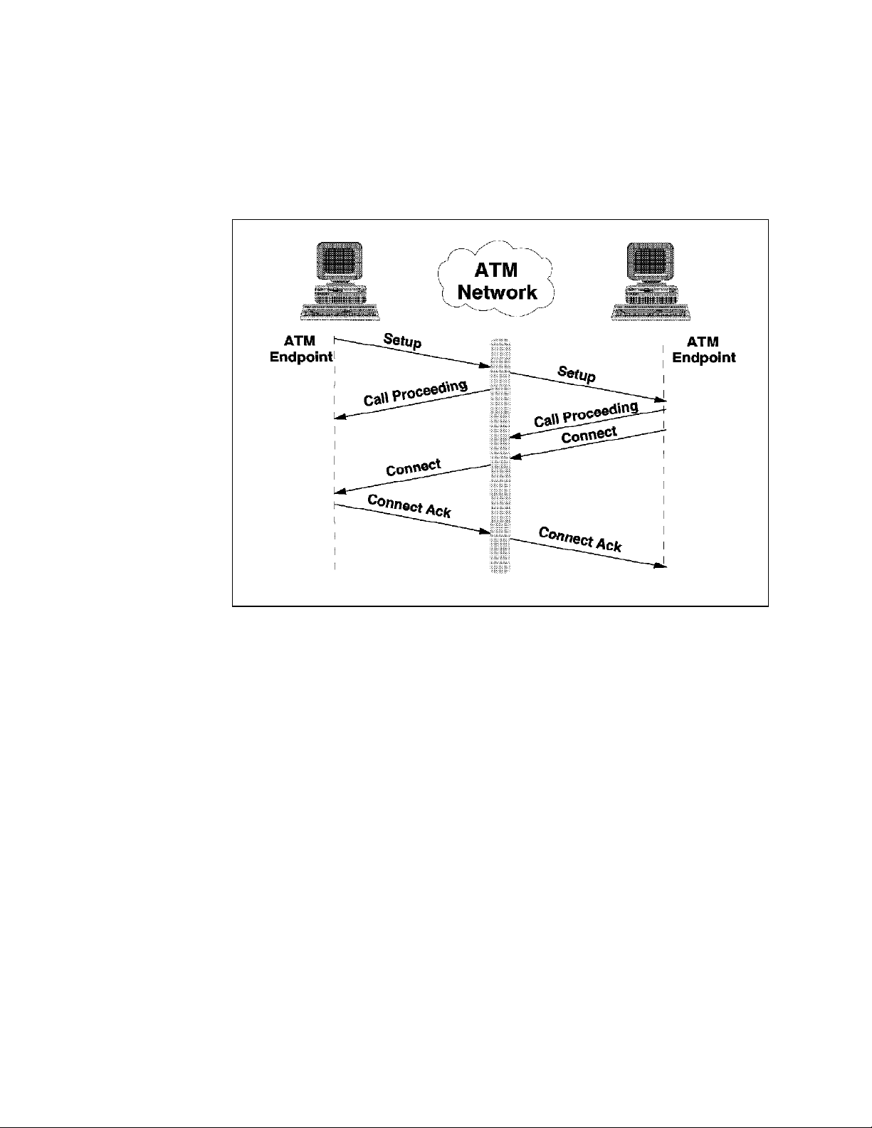
Figure 3. ATM Call Establishment
For an endstation to communicate in a switched environment such as ATM, it
must register with the network, request a connection when necessary, and clear
the connection when through. For native ATM endstations, this is done by the
following:
Initial Registration:
first register its full ATM address with its associated switch. This signalling
process is described in ATM UNI Specification 3.0 (based on ITU-T Q.93B
recommendations), or more recently, in ATM UNI Specification 3.1 (based on
ITU-T Q.2931 recommendations) and is performed when the endstation is
activated. During this process, the workstation receives its 13-byte network
prefix from the switch, appends its own local address (ESI plus selector), and
registers its complete ATM address with the switch.
Connection Setup:
endstation, it must first establish a connection to it. It does this by issuing a
SETUP request to the ATM network.
If the requested address is local, the switch acknowledges the request by issuing
a CALL PROCEEDING response to the requesting endstation and forwarding the
SETUP request to the requested endstation, which acknowledges receipt with a
CALL PROCEEDING response.
When an endstation wishes to enter the network, it must
When an endstation wishes to communicate with another
4 ATM Workgroup Solutions: Implementing the 8285 ATM Switch
Page 21

This soft copy for use by IBM employees only.
If the requested endstation is not local, the switch will forward the request to the
correct switch based on routing information compiled and maintained by the
8285 ATM Control Point′s Topology and Routing Services (TRS) subsystem. The
path will be selected based on the
between the end-points. This path information is appended to the setup request
and is used by intermediate switches to determine the next hop through the
network. There can be no more than 15 hops in any given path.
If the requested workstation is able to accept the incoming connection, it issues
a CONNECT response to the network, which forwards it back to the requesting
workstation, where it is acknowledged by issuing a CONNECT ACK response to
the network which forwards it to the destination endstation to complete the call
set-up process.
widest
path (not the
shortest
) available
Connection Tear-Down:
When an endstation wishes to end a connection, it
issues a DISCONNECT request to the network. The network acknowledges the
request by returning a RELEASE response (instructing the requesting endstation
to drop all resources associated with the call), and by forwarding the
DISCONNECT on to the destination workstation, which acknowledges the request
by returning a RELEASE command to the network. The process is completed
when the requesting endstation returns a RELEASE COMPLETE to the network,
which forwards it to the destination endstation, indicating that the call has been
dropped and the associated resources freed up.
1.1.4.2 ATM Forum-Compliant LAN Emulation (LANE)
LAN emulation simplifies a migration from a traditional LAN environment to an
ATM switched environment by superimposing LAN interfaces on top of the
underlying ATM transport and by supporting traditional LAN addressing (at the
media access control (MAC) layer) as well as broadcast and multicast
capabilities. This means that LAN-based applications run unchanged, yet now
have access to to the network and to network-attached resources at scalable
speeds from 25 Mbps to 155 Mbps and beyond.
The signalling process used by LANE is analogous to that for basic ATM
signalling, except that instead of a control point providing directory services,
there is now a LAN Emulation Server (LES) which provides directory services at
the MAC layer (which provides MAC address to ATM address mapping) for LAN
Emulation Clients (LECs). The 8285 ATM Control Point has two LES entities,
which together can handle 128 clients, distributed between two Ethernet or
token-ring ELANs. Either of the 8285 ATM Control Point′s two LECs can use
these internal LESs or can be configured to use an external LES, such as the
IBM Multiprotocol Switched Services Server, providing for greater flexibility, for
larger ELANs, and for inter-ELAN routing and bridging.
Emulating a traditional LAN environment requires the ability to allow for
broadcast traffic (common in a connectionless environment), while handling it in
a fashion optimized for a connection-oriented environment. This function is
addressed by the Broadcast/Unknown address Server (BUS), which attempts,
with the LES, to convert MAC broadcast traffic to a specific ATM destination
address. The 8285 ATM Control Point integrates this BUS function with the
internal LES function. Either of the 8285 ATM Control Point′s two LE clients can
also be configured to use an external BUS, such as the IBM Multiprotocol
Switched Services Server, providing for very sophisticated broadcast
management, especially in IP and IPX environments.
Chapter 1. Introduction to ATM Networks 5
Page 22
This soft copy for use by IBM employees only.
To avoid having to configure the LES′s address at each endstation, LANE
provides for a Lan Emulation Configuration Server (LECS), which LECs can query
for their proper LES address. This enables backup LESs to be configured, since
should the primary LES fail, the LECS merely has to direct connections to a
backup LES without having to change any configuration in the workstation.
Although the 8285 ATM Control Point does not contain an LECS, either or both of
the internal LECs can be configured to use an external LECS, such as that
provided by the IBM Multiprotocol Switched Services Server.
This section was intended only as an overview of LANE. For a more detailed
description of these functions, please see
SG24-5003 and
Overview
ATM Campus Introduction, Planning, and Troubleshooting
, GA27-4089.
IBM 8260 As a Campus ATM Switch
,
1.1.4.3 Classical IP (CIP)
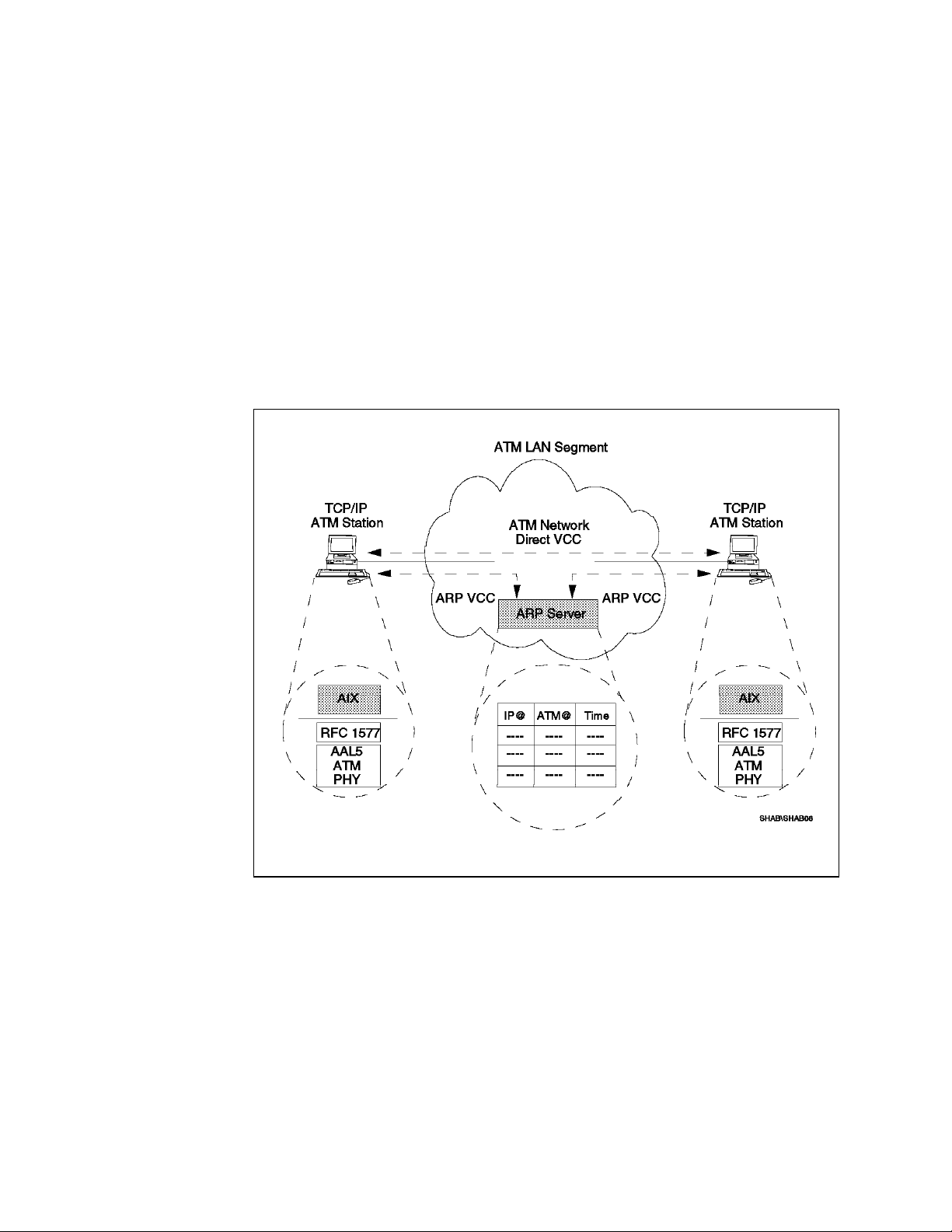
Figure 4. ATM Classical IP using ARP Server
Classical IP (RFC 1577) is a protocol-specific VLAN (PVLAN) technology that has
been widely adopted in the Internet working community. It provides for layer 3
routing of IP datagrams over an ATM network. In many ways, it is analogous to
LANE. For instance, all endstations must register with an address resolution
server (called a LES in LANE, but an
in CIP). Once the endstation is registered with the address resolution server, it
is, by definition, part of a virtual broadcast domain (an ELAN in LANE
terminology, but a VLAN in CIP, known as a
ATM Control Point has a single CIP client entity.
Here are the CIP data flows:
6 ATM Workgroup Solutions: Implementing the 8285 ATM Switch
Address Resolution Protocol (ARP) Server
Logical IP Subnet
(LIS)). The 8285
Page 23

This soft copy for use by IBM employees only.
CIP Address Registration:
Because in CIP there is no function analogous to the
LECS in LANE, each endstation must be configured with the ATM address of its
ARP server. The ARP client establishes a connection to the ARP server, and
notifies it of its IP address and its ATM address. The ARP server adds these to
its ARP table, so that it can respond properly to other ARP requests.
CIP Address Resolution:
When a CIP client wishes to establish IP
communication with another IP device, it issues an ARP to the ARP server to
determine the ATM address of the other device. If the ARP server has an entry
that matches the IP address of the requested device, it returns the ATM address
of that device to the requesting endstation, which caches it in its own ARP table.
If however, the ARP server doesn′t have the IP address in its ARP table, it
returns an ARP_FAILURE to the requesting client. The client now forwards the
unresolvable address to its default gateway for further handling. If the gateway
can resolve the address, it returns its IP and ATM addresses to the client to be
cached. If the gateway cannot resolve the address, it returns an ARP_FAILURE
to the client and the address resolution process terminates.
CIP Data Forwarding:
When a device wishes to forward data to another CIP
device, it must first check to see if it knows the other device′s ATM address (that
is, its ARP table contains an entry for the desired destination device). If so, it
merely establishes a direct connection with the other device, and forwards data
to it. If not, it must first resolve the address (see “CIP Address Resolution”
above), then setup a connection, and then forward data directly.
A more complete discussion of Classical IP can be found in
Campus ATM Switch
, SG24-5003 and
Troubleshooting Overview
, GA27-4089.
ATM Campus Introduction, Planning, and
IBM 8260 As a
Chapter 1. Introduction to ATM Networks 7
Page 24

This soft copy for use by IBM employees only.
8 ATM Workgroup Solutions: Implementing the 8285 ATM Switch
Page 25

This soft copy for use by IBM employees only.
Chapter 2. Introduction to the IBM 8285 Nways ATM Workgroup Switch
The IBM 8285 Nways ATM Workgroup Switch (hereafter called the 8285 switch) is
an ATM switch for the workgroup environment that provides a low-cost ATM
solution as either a stand-alone switch or as an access node to the rest of the
enterprise. Using your existing wiring it provides up to 25 Mbps of bandwidth to
users. The 8285 switch can connect users to any ATM network at speeds up to
155 Mbps, and even has forum-compliant LAN emulation built-in to make
implementation easier.
In addition, the IBM 8285 Nways ATM Workgroup Switch is expandable, using the
optional 8285 expansion chassis which enables it to take advantage of most of
the many ATM modules available for the IBM 8260 Nways Multiprotocol
Switching Hub. This provides you with ability to:
•
Create even larger workgroups
•
Service more high-speed devices (such as servers)
•
Provide more bandwidth in to your ATM backbone network
•
Connect existing token-ring or Ethernet users directly to the ATM backbone
•
Connect to remote sites using public ATM services at speeds from 34 Mbps
up to 155 Mbps
•
Distribute video information across your ATM network and make it
accessible using standard TV monitors
The following sections provide an overview of the 8285 switch.
2.1 8285 Components
The 8285 switch is comprised of the following components:
•
Standard:
− Base Unit:
•
Optional:
− 155 Mbps ATM I/O Card which can be installed in the IBM 8285 Base
− Expansion Unit
− Installable 8285/8260 ATM Modules
- 12 ATM 25.6 Mbps ports
- I/O slot for optional uplink (see below)
Unit:
- Multi-mode Fiber (MMF)
- Single-mode Fiber (SMF)
Copyright IBM Corp. 1996 9
Page 26

2.2 Base Unit
This soft copy for use by IBM employees only.
Note
Although there are two models of the 8285 switch, the 8285-00B and the
8285-00P, they are identical except that the latter includes 12 workstation
adapters, providing a total solution at a special bundled price.
The base unit is comprised of the following:
•
Internal Features:
− An ATM cell switching function
− A switch control function, called the 8285 ATM Control Point
•
Front Panel Features:
− Ports:
- 12 ATM ports that support ATM 25.6 Mbps operation over standard
copper wiring
− LEDs:
− Connectors:
2.2.1 Internal Features
The IBM 8285 Base Unit contains a planar which controls the 8285 switch and its
external interfaces.
2.2.1.1 ATM Cell Switching in the IBM 8285 Base Unit
The ATM switching mechanism installed in the base only switches ATM cells
between ports in the base unit. This is accomplished by basically taking what
would normally be the backplane output and connecting it directly to what would
normally be the backplane input.
When an IBM 8285 Expansion Chassis is connected to the IBM 8285 Base Unit,
however, this connection is disabled, and the traffic from the IBM 8285 Base Unit
uses the switch-on-a-chip that is incorporated in the IBM 8285 Expansion
Chassis.
- A slot for an optional high-speed uplink to provide 155 Mbps access
to either a server or to an ATM backbone
- System Status
- Port Status
- A connector to connect the optional expansion unit
- A connector to connect a standard ASCII console
2.2.1.2 8285 ATM Control Point
The 8285 ATM Control Point is integrated in the base unit and provides the
following functions:
•
Manages the functions of the IBM 8285 Base Unit as well as the optional
8285 Expansion Chassis and its inserted modules.
10 ATM Workgroup Solutions: Implementing the 8285 ATM Switch
Page 27
This soft copy for use by IBM employees only.
•
Controls the ATM cell switching between appropriate ports and performs the
functions associated with the establishment and management of ATM
circuits.
•
Provides a management interface (via an SNMP manager or an
ASCII/TELNET terminal) for monitoring, configuration, and microcode
distribution.
•
Provides an Forum-Compliant LAN Emulation implementation which
supports:
− Integrated LAN Emulation Server (LES)/Broadcast and Unknown Server
(BUS)
There are two instances of the LES/BUS in the 8285 ATM Control Point,
allowing up to two Emulated LANs (ELANs), either token-ring or Ethernet,
to be configure.
− Integrated LAN Emulation Client (LEC)
There are two instances of the LEC configurable in the 8285 ATM Control
Point, allowing the 8285 ATM Control Point to be accessible from up to
two ELANs, either token-ring or Ethernet.
− LAN Emulation Configuration Server (LECS)
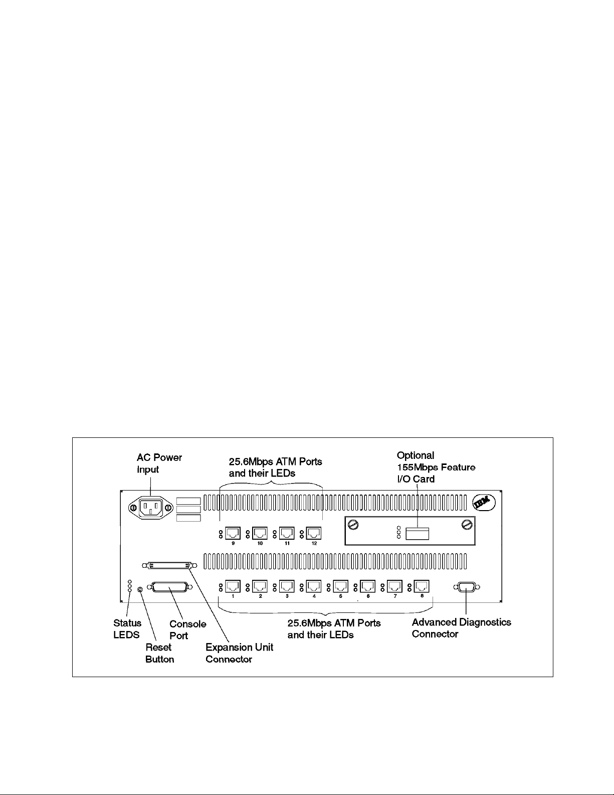
2.2.2 8285 Front Panel
Figure 5 shows the front panel of the IBM 8285 base unit.
Although the LECS function is not integrated in to the 8285 ATM Control
Point, support is provided for using an external LECS by using its
well-known address, or by getting its ATM address through the ILMI
protocol.
Figure 5. Front Panel of the IBM 8285 Nways ATM Workgroup Switch Base Unit
As found in the Figure 5, there are ports, LEDs, connectors and a button that the
user can access from the front panel.
Chapter 2. Introduction to the IBM 8285 Nways ATM Workgroup Switch 11
Page 28

This soft copy for use by IBM employees only.
2.2.2.1 Ports
The IBM 8285 Base Unit has the following ATM ports:
•
12 ATM25 Ports
− Fully compliant with the
ATM Forum Physical Interface Specification for
25.6 Mbps over Twisted Pair Cable
− Use standard RJ-45 connectors
− Support standard twisted pair cabling, either shielded or unshielded
•
1 ATM155 Port (Optional):
This port is further described in 2.2.3, “155 Mbps ATM I/O Card” on page 13.
2.2.2.2 LEDs
The front panel has LEDs for two purposes:
1. Port LEDs:
•
Port Enable
•
Output Activity
2. Switch Status LEDs:
•
Power
•
OK
•
Fault
2.2.2.3 Connectors
The front panel has four connectors:
•
Power Input
The power input connector matches the country-specific power cord that is
shipped with the base unit. The power supply itself is an auto-sensing
universal power supply.
•
Console Port
The console port is a standard RS-232 25-pin D-shell male interface for
connecting either an ASCII console or a modem in order to perform the
initial configuration.
•
Expansion Connector
The expansion connector is a 68-pin female connector used to attach the IBM
8285 Expansion Chassis using an expansion interface cable shipped with the
IBM 8285 Expansion Chassis shipping group.
•
Advanced Diagnostics Connector
The advanced diagnostics connector is a 9-pin connector used only by
authorized service personnel for advanced diagnostics. This connector is
not needed in any case to install and configure the 8285 switch.
12 ATM Workgroup Solutions: Implementing the 8285 ATM Switch
Page 29

This soft copy for use by IBM employees only.
2.2.2.4 Reset Button
The reset button resets both the IBM 8285 Base Unit and the optional IBM 8285
Expansion Chassis with its inserted modules.
For more information about the LEDs, the connectors, and the reset button, refer
IBM 8285 Nways ATM Workgroup Switch: Installation and User′s Guide
to the
SA33-0381.
2.2.3 155 Mbps ATM I/O Card
The 155 Mbps ATM I/O Card is an optional card installable in the 155 Mbps
Feature I/O Card Slot of the base unit. There are two types of 155 Mbps ATM I/O
Cards available, Multimode Fiber (FC 5500) and Single-Mode Fiber (FC 5501). It
becomes the 13th port of base unit and can be linked to an ATM station or to
another ATM switch that supports ATM 155, such as another 8285 switch or an
8260 hub.
2.2.3.1 Connectors
Both I/O cards have SC connectors.
2.2.3.2 LEDs
The 155 Mbps ATM I/O Card has the following LEDs:
•
Status
•
Output Activity
•
Error
,
2.3 Expansion Unit (FC 5502)
The 8285 Expansion Chassis provides three slots to receive IBM 8260/8285 ATM
modules, extending the 8285 switch′s functions and capacities.
The IBM 8285 Expansion Chassis consists of the following:
•
Internal Features:
− An ATM backplane that is similar to the one used in the 8260 hub.
− A planar containing a switch-on-a-chip, which connects the base unit
ATM ports to each other and to other ATM modules in the IBM 8285
Expansion Chassis.
•
External Features:
− Slots
− Connectors
− LEDs
− A rack-mountable chassis with an integrated, auto-sensing universal
power supply
Chapter 2. Introduction to the IBM 8285 Nways ATM Workgroup Switch 13
Page 30

2.3.1 Internal Features
The IBM 8285 Expansion Chassis has two primary internal features.
2.3.1.1 ATM Backplane
The IBM 8285 Expansion Chassis contains an ATM backplane that is effectively a
three-slot version of the 8260 hub′s ATM backplane. That is to say, it is a
completely passive backplane with female connectors. It is capable of
supporting most 8260 hub ATM modules.
Note
However, there are some differences between the ATM backplanes of the
IBM 8285 and IBM 8260. Specifically, the IBM 8260 ATM Control Point and
Switch Module cannot be used in the IBM 8285 Expansion Chassis. For more
information, refer to Chapter 3, “Functional Overview of the IBM 8285” on
page 17.
2.3.1.2 ATM P lanar
The IBM 8285 Expansion Chassis contains a planar which has a switch-on-a-chip
switching module. When connected to the IBM 8285 Base Unit with the
expansion interface cable, the switch-on-a-chip performs all the port-to-port cell
switching:
•
Between ports in the IBM 8285 Base Unit
•
Between ports in the IBM 8285 Base Unit and ATM modules in the IBM 8285
Expansion Chassis
•
Between ports on ATM modules in the IBM 8285 Expansion Chassis
This soft copy for use by IBM employees only.
2.3.2 Front Panel
Figure 6 shows the front panel of the IBM 8285 expansion unit.
Figure 6. Front Panel of the IBM 8285 Nways ATM Workgroup Switch Expansion Unit
14 ATM Workgroup Solutions: Implementing the 8285 ATM Switch
Page 31

This soft copy for use by IBM employees only.
As shown in the Figure 6, there are slots, LEDs, and connectors that the user
can access from the front panel.
2.3.2.1 Slots
The expansion unit has three slots that can support most of the IBM 8260 ATM
modules. The modules that are supported in the IBM 8285 Expansion Chassis
are listed in Chapter 4.
Figure 7 shows how the modules are inserted in the IBM 8285 Expansion
Chassis.
Figure 7. Inserting a Module in the Expansion Unit
2.3.2.2 LEDs
The expansion unit has the following switch status LEDs:
•
Power
•
OK
•
Fault
2.3.2.3 Connectors
The expansion unit front panel has two connectors:
•
Power Input
•
Base Connector
The base unit connector is a 68-pin female connector just like expansion unit
connector of the base unit. It is connected to the IBM 8285 Base Unit by the
expansion interface cable which is shipped with the expansion unit.
Chapter 2. Introduction to the IBM 8285 Nways ATM Workgroup Switch 15
Page 32

This soft copy for use by IBM employees only.
Figure 8. Attaching the Expansion Interface Cable
For more information about the LEDs and the connectors, refer to the
Nways ATM Workgroup Switch: Installation and User
2.4 Installable Modules
All ATM modules designed for the IBM 8260 Nways Multiprotocol Switching Hub
can be used in the IBM 8285 Expansion Chassis. Refer to 4.1, “Modules
Currently Available for the 8285 ATM Subsystem” on page 35 for the list of
modules that are officially supported with the 8285 switch.
′
s Guide
IBM 8285
, SA33-0381.
16 ATM Workgroup Solutions: Implementing the 8285 ATM Switch
Page 33

This soft copy for use by IBM employees only.
Chapter 3. Functional Overview of the IBM 8285
This chapter contains the following sections describing the functional overview of
the IBM 8285:
•
IBM 8285 Architecture Overview
•
Switching Fabric
•
Control Point Codes
•
ATM Backplane / Expansion Unit Connection
•
LAN Emulation Server Functions
3.1 IBM 8285 Architecture Overview
This section discusses the architecture of the IBM 8285.
Figure 9 on page 18 shows the hardware architecture of the IBM 8285 Base Unit.
Copyright IBM Corp. 1996 17
Page 34

This soft copy for use by IBM employees only.
Figure 9. Hardware Architecture of the IBM 8285 Nways ATM Workgroup Switch Base Unit
As shown above, the IBM 8285 Base Unit contains the following functional
components:
18 ATM Workgroup Solutions: Implementing the 8285 ATM Switch
Page 35

This soft copy for use by IBM employees only.
•
Management and Control Components:
− Control Point components:
- Processing Components
•
Flash memory, to store the microcode
•
8M byte DRAM, for operational code and tables
•
Motorola M68040 processor, to execute the microcode
- Management Components:
•
M360 processor, to handle the console interface (the same as the
IBM 8260)
•
Data Handling Components:
− CAP/CAD components to process cells, both inbound and outbound
− Specific Front End (SFE) components to handle the physical interfaces,
inbound and outbound, for all ATM ports, including:
- ATM 25 Mbps ports
- ATM 155 Mbps port. While this SFE is physically located on the
optional 155 Mbps ATM I/O Card, it can be treated as functionally
part of the base unit.
- ATM control-point port.
3.1.1.1 8285 ATM Control Point
The 8285 ATM Control Point has a processor and flash memory. The flash
memory holds the boot strap code and also the operational code. The control
point performs the following functions:
•
Signalling entities
•
Resource management
•
Address mapping
•
Topology and route selection
•
Node management and inband or out-of-band console interface
•
Integrated LES/BUS
The control point manages the rest of the ATM subsystem by sending control
cells via an internal port connected to the 25 Mbps HS.SFE.
3.1.1.2 CAP, CAD and SFE
The CAP, CAD and SFE are internal components implemented on the IBM 8285
Base Unit, as well as in each of the ATM modules. Their functions are as
follows:
•
CAP/CAD Components:
− CAP (Common ATM Processor)
The CAP handles the cell routing, queuing, scheduling, and traffic
management. It determines what the routing header for the internal cell
should be and gives the information to the CAD to build the cell.
− CAD (Common ATM Datamover)
Chapter 3. Functional Overview of the IBM 8285 19
Page 36

This soft copy for use by IBM employees only.
The CAD function prepares the cell for transmission to the switch. The
CAD builds the internal cell in its RAM according to instructions given by
the CAP.
As described in 3.1, “IBM 8285 Architecture Overview” on page 17, the IBM
8285 base unit is treated as a single module and all ports in the base unit
share two sets of CAP/CAD, one set to handle the inbound cells, called
CAP_up and CAD_up, and the other set to handle the outbound cells, called
CAP_down and CAD_down.
•
SFE (Specific Front End)
The SFE handles the ATM front-end concentration and dispatch. Its main
role is to deliver the cell from any ATM interface to the CAD.
There are three sets of SFE components in the base unit: an
inbound/outbound pair for the ATM25 ports, called HS.SFE_up/HS.SFE_down,
an inbound/outbound pair for the ATM155 port, called SFE_up/SFE_down, and
a single, bidirectional SFE used by the control point, called the CP SFE.
In addition, each ATM module also uses CAP, CAD, and SFE components, but in
two sets: an inbound set (CAP_Up, CAD_Up, and SFE_Up), and an outbound set
(CAP_Down, CAD_Down, and SFE_Down). Note that this slightly different from
the 8285 switch which has the additional CP SFE, and which connects CAD_up
directly to CAD_down when operating without an expansion unit.
Figure 10 on page 21 shows the hardware architecture of the IBM 8285 Base
Unit when connected to the IBM 8285 Expansion Chassis.
20 ATM Workgroup Solutions: Implementing the 8285 ATM Switch
Page 37

This soft copy for use by IBM employees only.
Figure 10. Hardware Architecture of the IBM 8285 Nways ATM Workgroup Switch Base
and Expansion Unit
When the IBM 8285 expansion unit is installed, its switch chip, called a
switch-on-a-chip, becomes the primary cell switch for the 8285 system. The
CAD_up and CAD_down devices in the base unit and in any ATM modules link
directly to this switch. Another way of saying this is that the link between the
base unit′s CAD_up and CAD_down is disabled, and all cells (even port-to-port)
within the base unit or within an individual ATM module, are switched through
the switch-on-a-chip.
Chapter 3. Functional Overview of the IBM 8285 21
Page 38

This soft copy for use by IBM employees only.
Additional Information
The switch-on-a-chip is a scalable, non-blocking, shared buffer switching
module that was developed at the IBM Research Laboratory in Zurich,
Switzerland. This is the same switch that is used in other IBM ATM switches,
such as the IBM 8260 Nways Multiprotocol Switching Hub and the IBM Nways
2220 Broadband Network Switch.
The architecture of the expansion unit is similar to that of the IBM 8260:
•
Each module contains CAP/CAD components to interface to the ATM
backplane.
•
The ATM backplane is fully passive and uses female connectors to improve
availability.
•
The ATM backplane is point-to-point wired to connect each module directly
to the switch-on-a-chip.
Note
not
This means that the IBM 8260 ATM CPSW Module is
supported in the
IBM 8285 Expansion Chassis, which also means that any
CPSW-exclusives, such as switch redundancy, are not supported.
However, the architecture is different in several key ways:
•
The control point is in a separate module (the base unit) from the switch.
•
The control point shares a set of CAP/CAD components with the ATM ports.
3.2 Switching Fabric
As described above, there are two switching mechanisms used in the IBM 8285,
depending on whether the base unit is operating with or without an expansion
unit. The following sections describe in detail the switching mechanism in each
case.
3.2.1 Switching in the IBM 8285
This section describes the switching mechanism in the IBM 8285.
Before going into further details about the switching function of the 8285 switch,
it is necessary to understand the internal frame format it uses. This format is
described below.
3.2.1.1 Internal Cell Format
The 8285 switch uses the same internal frame format, a 64-byte extension of the
standard 53-byte ATM cell, as the 8260 hub. This cell is constructed by the
following process:
•
The ATM cell received from a port by the SFE.
•
The SFE calculates a header error check value and compares it to the HEC
that arrived in the cell′s header.
•
If no error is detected (the calculated and transmitted HEC values match),
the SFE strips the HEC from the cell′s header and sends the resulting 52-byte
ATM cell to the CAP/CAD.
22 ATM Workgroup Solutions: Implementing the 8285 ATM Switch
Page 39

This soft copy for use by IBM employees only.
•
The CAP/CAD adds a 2-byte internal header (called a
and 1-byte trailer.
The RH contains the information necessary to route the internal cell.
Basically, the switching information is contained in the Source Blade (SB)
and Target Blade (TB) fields, which correspond to ports on the
switch-on-a-chip, and which the switch uses in order forward the cell to the
correct blade(s). The switch itself does not use destination port or VPC/VCC
number when switching the cell. However, at the module level, the
CAP/CAD would forward the cell to the appropriate port(s) based on the
target port (TP)
Note: In this context,
common CAP/CAD. This is normally a module, such as an ATM
media module or the ATM Control Point and Switch module of the
IBM 8260. However, by this definition, the IBM 8285 Base Unit can be
considered a blade or module as well, since its ports share a
common CAP/CAD.
Figure 11 on page 24 shows the internal cell format used in the IBM 8285. Note
the internal cell format will be changed in future releases but the concept should
remain similar and able to be referenced.
contained in the format field of the RH.
blade
refers to the set of components that share a
routing header (RH)
),
Chapter 3. Functional Overview of the IBM 8285 23
Page 40

This soft copy for use by IBM employees only.
1 1 1 1 1 1 1 1 1 1 2 2 2 2 2 2 2 2 2 2 3 3
0 1 2 3 4 5 6 7 8 9 0 1 2 3 4 5 6 7 8 9 0 1 2 3 4 5 6 7 8 9 0 1
┌────────────────┬───────────────┬───────┬───────┬────────────────┐
│ TB │ TBE │LCBAul │ SB │ LCBAuh │ ─┐
├────────┬───────┴───────────────┼───────┴───────┼────────────────┤ │ RH (8 byte)
│ │ NBA │ F1 │ F2 │ ─┘
├────────┼───────────────┬───────┴───────────────┴───────┬─────┬──┤
│ GFC │ VPI │ VCI │ PT │CL│ ── ATM Header
├────────┴───────────────┴───────────────────────────────┴─────┴──┤ (4 byte: without HEC)
││
││
││
││
││
││
│ ATM payload (48 byte) │
││
││
││
││
││
││
├─────────────────────────────────────────────────────────────────┤
│ Future Use │
└─────────────────────────────────────────────────────────────────┘
TB: Target Blade
TBE: Target Blade Extension
LCBAul: Leaf Control Block Address up(inbound) lower port
LCBAuh: Leaf Control Block Address up(inbound) higher port
NBA: Next Buffer Address
F1: Format Field 1st
F2: Format Field 2nd
GFC: Generic Flow Control
VPI: Virtual Path Identifier
VCI: Virtual Channel Identifier
PT: Payload Type
CL: Cell Loss Priority
HEC: Header Error Control
Figure 11. Internal Cell Format of the IBM 8285 Nways ATM Workgroup Switch
3.2.1.2 Switching without the Switch Chip
When no expansion chassis is connected, the IBM 8285 Base Unit implements a
direct connection between CAD_up and CAD_down. This means that inbound
cells would undergo the following process:
1. The SFE_up strips the HEC from valid cells and forwards the cell to the
CAD_up.
2. The CAD_up prepares the internal cell and forwards it directly to the
CAD_down.
3. The CAD_down uses the RH information to determine which ports to forward
the cell to, strips the internal header, and forwards the 52-byte cell to the
SFE_down.
24 ATM Workgroup Solutions: Implementing the 8285 ATM Switch
Page 41

This soft copy for use by IBM employees only.
4. The SFE_down performs the appropriate label-swapping, calculates a new
HEC, and forwards the 53-byte cell across the physical interface.
Blade number 0 is assigned to the blade for the base unit.
Note
blade number
The
physical slot number
3.2.1.3 Switching the Switch Chip
When the IBM 8285 Expansion Chassis, with its switch-on-a-chip, is connected,
the connection between the base unit′s CAD_up and CAD_down is disabled, and
all traffic flows through the switch-on-a-chip. This means that Step 2 above
becomes the following:
•
2A. The CAD_up prepares the internal cell and forwards it across the
expansion interface cable to the switch-on-a-chip.
•
2B. The switch-on-a-chip decides which blade(s) to forward the cell to and
forwards it to the CAD_down of the target blade(s) for further handling.
3.2.2 Switching Scenarios
The following describes the process of how cells are switched from one port to
another port in the IBM 8285. To understand this process it is best to follow a
cell as it enters one port and exits another and to see what actually happens as
it goes through the various components. Please refer to 3.2.1.1, “Internal Cell
Format” on page 22, as the following discussion assumes that you are already
familiar with the internal cell format.
•
Point-to-Point Routing
is used for the internal switching and is different from
.
The following describes what happens to a cell in a point-to-point connection:
1. Receive the cell.
a. CAD_Up prepares in advance, for every port, the address of the next
cell assembly buffer. This is the location where the internal cell will
be built in CAD_Store.
b. An ATM cell is received by SFE_Up. Here the HEC of the ATM
header gets checked. If it is a bad cell, it is discarded, otherwise the
HEC is stripped and the remaining 52 bytes are delivered to CAD_Up.
c. The connection from SFE_Up to CAD_Up is 32-bits wide so the cell is
transferred in 13 4-byte blocks. There are port lines between SFE_Up
and CAD_Up which indicate what port the cell came from. Using
these port lines, the 4-byte block transfers can be mixed from
different ports. For example, deliver a 4-byte block from Port 1, then
deliver a 4-byte block from Port 2, then deliver a 4-byte block from
Port 1 and so on. This ensures that no time is wasted in delivering
data from a port that has no cells.
d. When the first 4-byte block of a cell gets transferred, one of the
control lines is raised to indicate the beginning of a cell.
e. The SFE forwards each 4-byte block of the cell to CAD_Up, which
stores it in CAD_Store using the address of the next cell assembly
buffer prepared previously. However, CAD_Up skips the first 8 bytes,
which are reserved for the routing header, before it stores the first
Chapter 3. Functional Overview of the IBM 8285 25
Page 42

This soft copy for use by IBM employees only.
4-byte block. A 4-bit register pointing to the lower address of where
the next 4-byte block should go is updated and is used as a
displacement pointer from the cell buffer address.
f. CAD_Up writes
assembled in the CAD_Store, CAD_Up puts the cell buffer address in
a general queue, to allow for cell assembly ending almost at same
time (one cycle of SFE_Up/CAD_Up interface). Each cell will then be
dequeued on a first-in/first-out basis from the general queue, and
CAD_Up sends a copy of the first 4-byte block and the source port
(SP) to CAP_Up. CAD_Up prepares the address of the next assembly
cell buffer for this port. The address is determined from the port
number, which indicates a register pointing to where these 4-bytes
should be placed. This register is also updated.
2. Prepare the routing header (RH).
a. The first 4-byte block of a cell is the first 4 bytes of the ATM cell
header which contains the VPI/VCI. When CAP_Up receives the first
4-byte block with SP it now has all the information it needs to identify
a particular connection: SP, VPI and VCI. From these three values,
CAP_Up determines the inbound leaf control block address
(LCBAup), which is the pointer to the leaf control block (LCB) for this
connection.
b. The LCB contains the target blade (TB). TB, LCBAup and source
blade (SB), and RB/NRB connection parameter are given to CAD_Up
to be written to the header of the internal cell in CAD_Store.
CAP_Up knows the address of the beginning of this cell, so that the
address is also given to CAD_Up to ensure that the information is
written in the correct place in CAD_Store. In the case of an unknown
SP/VP/VC, the cell is released by CAP_Up by sending to CAD_Up the
cell buffer address, which can be used for another data movement.
source port (SP)
in RH. When the cell is completely
CAP_Up also performs smart discard on NRB AAL5 frame flows,
which purges cells on an AAL5 frame basis in the case of NRB node
congestion.
3. Place the cell in the queue.
The cell is put by CAD_Up into the appropriate output queue (with the
RB/NRB indication) so that prioritization of traffic can occur. There is an
RB queue and an NRB queue.
The cell is now ready to be switched.
4. Switch the cell.
This step depends on whether or not the IBM 8285 has an expansion
unit. In other words, whether the switching is done by the CAP/CAD or
by the switch chip. When the IBM 8285 is installed without the expansion
unit, the switching is done as follows:
a. The connection between CAD_Up and CAD_Down has been enabled
because the IBM 8285 does not have the switch chip.
b. The cell is switched from CAD_Up to CAD_Down immediately.
When the IBM 8285 is installed with the expansion unit, the switching is
done as follows:
a. When the expansion unit installed, all connections between the
switch chip and the CAP/CADs are enabled. And then, the direct
26 ATM Workgroup Solutions: Implementing the 8285 ATM Switch
Page 43

This soft copy for use by IBM employees only.
connection between CAD_Up and CAD_Down in the base unit is
disabled.
b. When the switch chip indicates to CAD_Up to give the next cell,
CAD_Up gives the first cell from the appropriate queue based on its
priority mechanism (RB over NRB Queue)
c. The cell is delivered to the switch chip, and the pointers of that
queue are updated.
d. The switch chip switches the cell based on TB.
5. Receive the cell into the target blade.
a. CAD_Down has prepared a location in advance for the next cell.
b. CAD_Down receives the cell into CAD_Store in the general queue.
c. CAD_Down dequeues the cell and sends CAP_Down a copy of the
RH, which contains the LCBAup and the source blade.
6. Place the cell in the correct output queue and prepare it for transfer to
SFE_Down.
a. Using SB and LCBAup, CAP_Down determines LCBAdown.
LCBAdown points to the LCB for the connection in the outbound
blade. The LCB has VPI/VCI out, target port (TP), RB/NRB and
Multicast indication. There is also part of the LCB in a shadow zone
in CAD_Store for performance reasons.
b. LCBAdown TP, NRB/RB, and Multicast indications from the LCB are
given to CAD_Down.
CAD_Down queues the cell in the corresponding target port queue (one
RB and one NRB per port) with the indication received from CAP_Down
and prepares it for transfer to SFE_Down.
7. Prepare and send a new ATM cell.
a. When SFE_Down asks for the next cell of a port, CAD_Down moves
the contents of LCBshadow, which has VPI/VCI out and the type of
swapping (SWAP_TYPE) to be performed, plus the 52-byte cell to
SFE_Down.
b. SFE_Down modifies the header based on SWAP_TYPE. SWAP_TYPE
indicates if only the VP needs to be swapped, if both the VP and VC
need to be swapped or neither need to be swapped. The PTI field is
always retrieved from the incoming header.
c. SFE generates HEC.
d. SFE presents the cell to the specific interface.
•
Point-to-Multipoint Routing
In a point-to-multipoint (multicast) connection, the process is very similar.
Steps remain the same right up until the cell is ready to be switched. The
TB field actually indicates that this cell is part of a multicast connection by
having the first bit of TB set to 1. The other 7 bits form the multicast ID
(MID). In a point-to-point connection, the first bit is set to 0 and the other 7
bits indicate the target blade.
1. Switch the cell.
This step depends on the IBM 8285 has a expansion unit or not. In other
words, the switching is done by the CAP/CAD or the switch chip. When
Chapter 3. Functional Overview of the IBM 8285 27
Page 44

This soft copy for use by IBM employees only.
the IBM 8285 is installed without the expansion unit, the switching is
done as follows:
a. The cell is switched from CAD_Up to CAD_Down immediately as well
as the case of point-to-point connection. The CAP_Up does not
recognize the multicast ID.
When the IBM 8285 installed with the expansion unit, the switching is
done as follows:
a. The switch chip recognizes that the TB is actually a Multicast ID;
thus, using the MID as a pointer, it looks at its switch multicast tree
table to get 16 bits. Each bit corresponds to a blade. If the bit is on,
then that blade is part of the multicast tree.
b. The switch chip switches the cell to the target blades based on the
multicast tree table.
2. Receive the cell into the target blade.
This step is the same as in a point-to-point connection described earlier.
3. Place the cell in the correct output queue and prepare for transfer to
SFE_Down.
a. Using SB and LCBA, CAP_Down determines LCBAdown. Since this
is a multicast connection, LCBAdown actually points to a chain of
LCBs. Each LCB in the chain represents the branches on the
multicast tree on this blade. Each LCB in the chain has VPI/VCI out,
SWAP_TYPE and target port (TP) and last multicast (Last_MC)
indication. There is also a shadow of the LCB chain in CAD_Store
for performance reasons.
b. The same steps as in the unicast case apply. But when the cell has
been sent to SFE_Down, the CAD_Down will re-enqueue this cell in
the general queue so that CAP will reprocess this cell with the next
LCB in the chain. This is done till CAP_Down finds the LAST_MC
indication in the LCB.
4. Prepare and send a new ATM cell.
These scenarios assume that the appropriate tables have been assembled
already by the 8285 ATM Control Point and stored in the appropriate CAP/CAD.
This would be done, for instance, during the call establishment process. To
communicate such information to internal devices (such as CAD, CAP, an SFE),
the 8285 ATM Control Point uses a special port number, F (which is unique
within the switch), and special internal cells, called guided cells, which can be
discriminated from the other internal cells, called swapped cells, by its format
field.
3.3 Control Point Codes
There are three types of control point microcode:
•
Boot Code
This resides in flash memory on the control point and is the first thing that
executes after a power-on or reset. It contains initialization, diagnostics and
support for download out-of-band commands. This code executes straight
from flash memory and is normally used to load the operational code.
•
Operational Code
28 ATM Workgroup Solutions: Implementing the 8285 ATM Switch
Page 45

This soft copy for use by IBM employees only.
This code is also on the control point and is executed once the boot code
has finished. There are two copies of the code stored in the flash memory.
One of these copies is identified as current and is loaded into RAM during
the initialization process. This code is executed from RAM. The second
copy of the operational code allows new operational code to be loaded into
the control point while the control point is running, and then swapped (which
resets the ATM subsystem) when it is less disruptive to network operations.
•
FPGA Code
This code configures the various internal chips on the IBM 8285 base unit so
that they perform their desired ATM functions. There are two copies of the
FPGA code stored in flash memory. One of these copies is identified as
current code. The current code is loaded into the internal chips of the
appropriate components during the initialization process. The second copy
of the FPGA code allows new FPGA code to be loaded while the IBM 8285 is
operational, and then swapped (which resets the ATM subsystem) when it is
less disruptive to network operations.
The following sections describe the code levels that are currently shipped, are
announced, or are available in the future.
3.3.1 Control Point Levels
Table 1 lists the levels of control point code that are currently available for the
8285 switch.
Table 1. Control Point Levels Summary of the IBM 8285 Nways ATM Workgroup Switch
Control Point
Level
V1.0.0 March 1996 Initial release
V1.0.1 April 1996 Fixed some problems in initial release
V1.2.0 July 1996 TR LEC, EU, and 8260 modules support 1
V1.3.0 October 1996 New 8260 module support 2
V1.4.0 October 1996 Connection capacity increased, Variable VPC/VCI, ABR flow
Available Highlights
control and PVC multipoint support3
Notes:
1 Except A-CPSW, MSS Server and 8271/8272 modules
2 A3-MB155 module
3 ATM firmware upgrade kit required
These control point microcode levels (except the obsolete ones) are available on
the Internet and can be downloaded via the Web or by FTP. And the code can
be downloaded into the IBM 8285 either out-of-band via a SLIP-connected
workstation, or inband via an FTP file transfer. For more information about how
to get and download the code, refer to 6.4, “Microcode/Picocode Considerations”
on page 110.
Chapter 3. Functional Overview of the IBM 8285 29
Page 46

3.3.2 Control Point V1.2
The Control Point V1.2 has been available since July 1996. It contains the
operational code V1.2.0, the boot code V1.2.0 and FPGA 3. The FPGA is optional
but highly recommended.
The highlights of new and enhancement functions are as follows:
•
Token-Ring (IEEE 802.5) LAN Emulation Client (LEC) Support
The previous levels allowed the inband monitoring of the IBM 8285 in a
Classical IP environment as well as in Forum-Compliant LAN Emulation
(Ethernet / IEEE 802.3). This support has been extended to Token-Ring (IEEE
802.5) Forum-Compliant LAN Emulation.
•
Expansion Unit and 8260 ATM Modules Support:
This level supports the IBM 8285 Expansion Unit and IBM 8260 ATM modules
as follows:
− ATM 4-Port 100 Mbps MIC Fiber Module
− ATM 4-Port 100 Mbps SC Fiber Module
− ATM 2-Port 155 Mbps Flexible Media Module
This soft copy for use by IBM employees only.
− ATM 12-Port 25 Mbps UTP Concentrator Module
− ATM 4-Port Ethernet/TR Bridge Module
− ATM WAN Module
When this level became available, it supported all IBM 8260 ATM media
and bridge modules then announced. However, there are the following
modules are currently announced and not supported by the IBM 8285
expansion unit:
•
•
•
MIB Enhancement (MIB 1.5)
The IBM private MIB for the IBM 8285 is enhanced corresponding to the
other enhancements.
3.3.3 Control Point V1.3
The Control Point V1.3 has been available since October 1996. It contains the
operational code V1.3.0 and the boot code V1.3.0. No FPGA is included in this
level.
Note
MSS Module
8271/8272 LAN Switch Modules
The highlights of new and enhancement functions are as follows:
•
New 8260 ATM Modules Support
In addition to the control point level V1.2, this level supports the new IBM
8260 ATM modules as follows:
− ATM 3-Port 155 Mbps LAN Concentration Module
•
MIB Enhancement (MIB 1.6)
The IBM private MIB for the IBM 8285 is enhanced corresponding to the
other enhancements.
30 ATM Workgroup Solutions: Implementing the 8285 ATM Switch
Page 47

This soft copy for use by IBM employees only.
3.3.4 Control Point V1.4
The Control Point V1.4 has been available since October 1996 as well as the
V1.3. I t contains the operational code V1.4.0, the boot code V1.4.0 and FPGA
code 0B40 and 0C10. The FPGA code 0C10 is for the ATM 3-port 155 Mbps LAN
Concentration module, ATM 12-port 25 Mbps UTP Concentrator module and for
the 8285 Base Unit. The FPGA code 0B40 is for the others.
This level is also called as the ATM Firmware Upgrade Kit (MES 5099) and the
FPGA upgrade is mandatory. The boot and operational code V1.4.0 supports
several functions with new FPGA codes in addition to the functions provided by
V1.3.0 of those codes. The FPGA codes for all available ATM modules are
contained in the ATM Firmware Upgrade Kit.
The highlights of new and enhancement functions are as follows:
•
Increase of Number of Connections
For all ATM media modules currently announced, the number of bidirectional
connections is increased from 992 to 4,064 per ATM blade. However, the
maximum number of connections per an IBM 8285 is 2,048 due to the
limitation of its control point.
•
Variable Range of VPI/VCI Values Support
The ITU-T define the ATM cell format and the virtual path identifier (VPI) and
virtual channel identifier (VCI) have 8 bits (VPI value comprised between 0
and 256) and 16 bits (VCI value comprised between 0 and 65536). However,
in actual campus network, the full address range should not be used and the
UNI specification allows you to restrict the number of active VPI and VCI bits.
The IBM 8285 supports a 14 or 12-bit address range for VPI/VCI depending
on which port is used. And prior to the control point V1.3, the range was
fixed to a 2-bit VPI (0 through 3) and 10-bit VCI (0 through 1023) for the 25
Mbps ports (base unit and 25Mbps module) and 4-bit VPI (0 through 15) and
10-bit (0 through 1023) for the other ports. The control point V1.4 supports
variable range of VPC/VCC. This function allows you to have more virtual
path connections (VPCs) or virtual channel connections (VCCs) than previous
levels along with the customer requirement. The range supported on an
ATM port depends on which port is used.
− For the 25 Mbps ports:
One of the following three patterns of range can be selected:
- VPI/VCI: 0 bit/12 bits (VPI=0, VCI=0 through 4095)
- VPI/VCI: 2 bits/10 bits (VPI=0 through 3, VCI=0 through 1023)
- VPI/VCI: 4 bits/8 bits (VPI=0 through 15, VCI=0 through 256)
− For the other ports:
One of the following three patterns of range can be selected:
- VPI/VCI: 0 bit/14 bits (VPI=0, VCI=0 through 16383)
- VPI/VCI: 4 bits/10 bits (VPI=0 through 15, VCI=0 through 1023)
- VPI/VCI: 6 bits/8 bits (VPI=0 through 63, VCI=0 through 256)
In addition, the network administrator can define upper limits for VPI/VCI
values to meet specific ranges supported by some ATM UNI devices. The
ATM Forum-Compliant UNI stations inform the ATM switch about the
supported values of VPI/VCI. In case a station fails to do so, this may
Chapter 3. Functional Overview of the IBM 8285 31
Page 48

This soft copy for use by IBM employees only.
prevent interworking with the IBM ATM switches. This function solves this
problem by allowing the the network administrator to set the VPC/VCC range
on a given ATM port on the ATM switch, thereby enabling the interworking
with non-compliant devices. For example, you can restrict the VPI value
equal to 0 and VCI value comprised between 0 and 63 by specifying 0/6 as
the VPI/VCI.
Note
must
If you change the VPI/VCI range for the SSI or NNI port, you
specify
the same value on both ends.
•
ABR Flow Control Support
On the ATM 12-port 25 Mbps UTP Concentrator module, the ATM 3-port 155
Mbps LAN Concentration module, and on the 12-port 25 Mbps base unit, the
end user can add the ATM Forum-compliant
available bit rate (ABR)
flow
control through Explicit Forward Congestion Notification Indication (EFCI)
marking. When congestion occurs due to excessive traffic flow, the IBM 8285
and 8260 modules can now mark the EFCI bit in the ATM cells to indicate a
congestion condition asking the destination station to notify the source
device to reduce its traffic.
•
Increase Buffer Size
When multiple ATM sources try to send traffic over one link (for instance the
one to which a server is attached), using UBR or ABR class of service,
congestion conditions might occur because the aggregate traffic exceeds the
capacity of the LAN traffic over ATM. By having a larger buffer size (8,000
cells) the A12-MB25 and A3-MB155 modules are able to absorb bursts of
traffic of longer duration, thereby delaying the trigger of the congestion
control mechanism, such as Early Packet Discard. This improves the overall
response time and relieves end systems from extra frame retransmissions.
•
PVC Multipoint Support
In addition to the existing support of point-to-multipoint SVCs, this introduces
the smart PVC point-to-multipoint function. Point-to-multipoint trees can be
defined now with either fixed permanent virtual paths (PVPs) or fixed
permanent virtual channels (PVCs). You only need to define the parameters
(VP or VP/VC values) for the root of the tree and the leaves, without any
definition for intermediate switches. In case of failure on these intermediate
switches, the connections are automatically re-established.
•
New 8260 ATM Modules Support
In addition to the control point level V1.2, this level supports the new IBM
8260 ATM modules as follows:
− ATM 3-Port 155 Mbps LAN Concentration Module
•
MIB Enhancement (MIB 1.6)
The IBM private MIB for the IBM 8285 is enhanced corresponding to the
other announcements.
32 ATM Workgroup Solutions: Implementing the 8285 ATM Switch
Page 49

This soft copy for use by IBM employees only.
3.4 ATM Backplane / Expansion Unit Connection
As described in Figure 9 on page 18, there are several ATM buses to connect
each component of IBM 8285. The buses between CAP/CADs or CAP/CAD and
the switch chip are called as the ATM backplane. In the IBM 8285, the ATM
backplane is extended to the connection between the base and expansion unit.
When the IBM 8285 is installed with the expansion unit, they are connected by a
special cable, called the
other hand, as described in some documents, such as the
Campus ATM Switch
The difference comes from the number of modules supported by the IBM 8285
and the IBM 8260 whether or not it supports the redundant switch configuration.
Except for the redundant switch function, both of the IBM 8285 and IBM 8260 ATM
backplanes are fully equivalent functionally to an ATM blade.
You can find the pin layout of the IBM 8285 expansion interface in the appendix
IBM 8285 Nways ATM Workgroup Switch: Installation and User′s Guide
of the
For more information about the IBM 8260 ATM backplane, refer to
Campus ATM Switch
Table 2 shows the characteristics of typical buses implemented in the IBM 8285.
expansion interface cable
, all ATM modules have 120 pins for backplane connection.
, SG24-5003.
, which has 68 pins. O n the
IBM 8260 As a
.
IBM 8260 As a
Table 2. ATM Buses Implemented in the IBM 8285 Nways ATM Workgroup Switch
Bus Location Bus Speed
CAD_Up and CAD_Down (ATM backplane in the base unit) 256 Mbps (32 MHz x 8 bit
parallel)
CP SFE and 25 Mbps HS.SFE_Up/Down 256 Mbps / FDX 1
25 Mbps HS.SFE_Up/Down or 155 Mbps SFE_Up/Down and
CAD_Up/Down
CAD_Up/Down and the switch chip (ATM backplane across the
expansion unit)
512 Mbps (16 MHz x 32 bit
parallel) / FDX 1
256 Mbps / FDX 1
Note
1 FDX means each up (inbound) and down (outbound) works
simultaneously and the maximum capacity should be double (256
Mbps/FDX : 512 Mbps).
As described above, the internal bandwidth for each blade should be 256 Mbps.
However, we have to consider that the IBM 8285 uses a 64-byte internal cell
instead of a 53-byte ATM standardized cell. As a result, the available ATM
bandwidth for the ATM cell transfer should be decreased from the internal
bandwidth, 256 Mbps per blade, to 212 Mbps (256 Mbps x 53/64) per blade by the
overhead of the internal cell header/trailer.
3.5 LAN Emulation Server Functions
The IBM 8285 integrates a Forum-compliant LAN Emulation Server (LES) and
Broadcast and Unknown Server (BUS) functions in the control point. The
LES/BUS functions are performed with or without external a LAN Emulation
Configuration Server (LECS).
The IBM 8285 can support up to two sets of the LES/BUS functions with any
combinations of the types of LAN emulation, token-ring (IEEE 802.5) and Ethernet
Chapter 3. Functional Overview of the IBM 8285 33
Page 50

This soft copy for use by IBM employees only.
(IEEE 802.3). The maximum number of the LAN Emulation Clients (LECs) is 128
regardless the number of the LES/BUS, so it should be the sum of the LECs
supported by the IBM 8285 when two LES/BUS are used.
The LES/BUS gives an impact on CP performance when running so that the
processor and memory are mainly shared between signaling, BUS and routing.
However, it is designed to prevent the CP traffic from the delay and buffer
accumulation by assigning lower priority to the broadcast traffic.
34 ATM Workgroup Solutions: Implementing the 8285 ATM Switch
Page 51

This soft copy for use by IBM employees only.
Chapter 4. IBM 8285 ATM Modules
This chapter describes the various functions and features that are available on
8285 ATM modules.
4.1 Modules Currently Available for the 8285 ATM Subsystem
The current ATM modules for the IBM 8285 are:
•
ATM 12-Port 25 Mbps UTP Concentrator Module
•
ATM 2-Port 155 Mbps Flexible Media Module
− 1-port ATM 155Mbps Multi-mode Fiber I/O card
− 1-port ATM 155 Mbps Single-mode Fiber I/O card
− 1-port ATM 155 Mbps UTP/STP I/O card (RJ-45)
− 1-port ATM 155 Mbps STP I/O card (DB9)
•
ATM 3-Port 155 Mbps LAN Concentration Module
− 1-port ATM 155Mbps Multi-mode Fiber I/O card
− 1-port ATM 155 Mbps Single-mode Fiber I/O card
− 1-port ATM 155 Mbps UTP/STP I/O card (RJ-45)
− 1-port ATM 155 Mbps STP I/O card (DB9)
•
ATM 4-Port 100 Mbps MIC Fiber Module
•
ATM 4-Port 100 Mbps SC Fiber Module
•
Video Distribution Module
•
ATM 4-Port TR/Ethernet Bridge Module
•
ATM WAN Module
− 1-port E3 I/O card
− 1-port DS3 I/O card
− 1-port OC3 I/O card (SMF)
− 1-port OC3 I/O card (MMF)
− 1-port STM1 I/O card (SMF)
− 1-port STM1 I/O card (MMF)
Copyright IBM Corp. 1996 35
Page 52

This soft copy for use by IBM employees only.
4.2 Some Common Elements among the 8285 Modules
The following sections describe some of the common elements shared by the
8285 modules.
4.2.1 Maximum Capacity
All 8285 modules have a backplane capacity of 212 Mbps. In order to provide
guaranteed service, the maximum configurable reserved bandwidth is 185 Mbps
(85% of 212 Mbps). The non-reserved traffic will use whatever bandwidth is
available, including bandwidth that is reserved but not being used.
4.2.2 Variable VPC/VCC Value Ranges
With the latest release of 8285 code (Release 1.4), the 8285 modules now support
variable VPC/VCC range values. That is to say, they allow you to manage your
network more precisely by allocating varying numbers of bits to the VPC and
VCC portions of the header on a port-by-port basis.
Note
must
The VPC/VCC range
be the same on both ends of an SSI or NNI link.
With one exception, noted below, all of the modules allocate 14 bits to the
VPC/VCC portion of the header, which you can allocate in one of the following
ways:
•
Mode 0/14 (all 14 bits assigned to VCC):
− VPC=0
− VCC range is 0-16383
•
Mode 4/10 (4 bits for VPC, 10 bits for VCC):
− VPC range is 0-15
− VCC range is 0-1023
•
Mode 6/8 (6 bits for VPC, 8 bits for VCC):
− VPC range is 0-63
− VCC range is 0-255
The exception to the above is the newest module, the ATM 12-Port 25 Mbps UTP
Concentrator Module, which allocates only 12 bits to the VPC/VCC portion of the
header, and which allows the following modes:
•
Mode 0/12 (all 12 bits assigned to VCC):
− VPC=0
− VCC range is 0-4095
•
Mode 2/10 (2 bits for VPC, 10 bits for VCC):
− VPC range is 0-3
− VCC range is 0-1023
•
Mode 4/8 (4 bits for VPC, 8 bits for VCC):
− VPC range is 0-15
− VCC range is 0-255
36 ATM Workgroup Solutions: Implementing the 8285 ATM Switch
Page 53

This soft copy for use by IBM employees only.
For all modules, you can define upper limits for VP/VC values at the port level to
facilitate interoperability with certain ATM devices that have constraints on what
values they will accept. This is done using the Set PORT command, which has a
new parameter, VPI_VCI: #bits_vpi.#bits_vci.
Chapter 4. IBM 8285 ATM Modules 37
Page 54

This soft copy for use by IBM employees only.
4.3 ATM 12-Port 25 Mbps UTP Concentrator Module
The ATM 25 Mbps UTP Concentrator Module is a single-slot concentrator module
that provides low-cost access to a high-performance ATM network. It is ideal for
upgrading your legacy LAN users and for providing higher performance to new
users.
It has the following characteristics:
•
12 Forum-Compliant ATM 25.6 RJ-45 ports capable of supporting shielded
and unshielded twisted pair cabling.
•
Supports user-to-switch, server-to-switch, and switch-to-switch connections in
any combination.
•
Supports ATM Forum Available Bit Rate (ABR) Service using Explicit Forward
Congestion Control (EFCI) marking.
•
Has a large 8,000 cell buffer to smooth bursts of traffic without triggering
congestion control mechanisms.
•
Supports UNI 3.0, UNI 3.1, and UNI translation.
•
Expands IBM 8285 Nways ATM Workgroup Switch capacity up to 48 ports
with optional 8285 Expansion Chassis (FC# 5502).
4.3.1 Sam ple Scenarios
The ATM 12-Port 25 Mbps UTP Concentrator Module is a high-performance card
that is very cost-effective for connecting high-bandwidth users and servers into a
workgroup or an ATM network. In addition, it can be used to provide redundant
links to a backbone or server to provide higher bandwidth and improved
reliability. Figure 12 on page 39, Figure 14 on page 41, and Figure 13 on
page 40 show some ways the ATM 12-Port 25 Mbps UTP Concentrator Module
can be used with the 8285 switch.
38 ATM Workgroup Solutions: Implementing the 8285 ATM Switch
Page 55

This soft copy for use by IBM employees only.
Figure 12. ATM 12-Port 25 Mbps UTP Concentrator Module Workgroup
The first example, a workgroup configuration, shows how you might set up a
very cost-effective stand-alone workgroup by merely changing adapters in the
workstations and connecting them to the 8285 switch. This simple change
provides up to 25 Mbps of bandwidth to the desktop for up to 48 users per 8285,
and gives them access to a high-speed server.
Chapter 4. IBM 8285 ATM Modules 39
Page 56

This soft copy for use by IBM employees only.
Figure 13. 8285 Low-Cost Configuration Implementation
The second example shows a building with 8285s on floors and in the basement.
The backbone and server are working at 155 Mbps. By ordering an 8285 model
00P, it is possible to create an ATM network at a very attractive price, since it
provides both the base unit and 12 ATM25 workstation adapters at a special
bundled price.
40 ATM Workgroup Solutions: Implementing the 8285 ATM Switch
Page 57

This soft copy for use by IBM employees only.
Figure 14. 8285 with ATM 12-Port 25 Mbps UTP Concentrator Modules as an Access
Switch
The third example shows how you can connect the ATM25 workgroup into the
backbone network to access additional high-speed resources using only the
standard ATM 155 Mbps uplink. In this capacity, the 8285 makes an excellent
ATM floor switch, especially when used in conjunction with the IBM 8260 Nways
Multiprotocol Switching Hub as the backbone or collapse-point switch.
By implementing a second backbone link (using either the ATM 2-Port 155 Mbps
Flexible Media Module or the ATM 3-Port 155 Mbps LAN Concentration Module)
connected to a different switch in the backbone, you can take advantage of the
additional bandwidth during normal operations, and provide availability to your
workgroup even if one of the collapse-point switches fails.
Chapter 4. IBM 8285 ATM Modules 41
Page 58

This soft copy for use by IBM employees only.
4.4 ATM 2-Port 155 Mbps Flexible Media Module and ATM 3-Port 155 Mbps
LAN Concentration Module
The ATM 2-Port 155 Mbps Flexible Media Module and the ATM 3-Port 155 Mbps
LAN Concentration Module are single-slot concentrator modules that are ideal
for high-speed connections to both local resources and to devices up to 20 Km
away. They have the following characteristics in common:
•
Provide two or three ports, each capable of supporting a 155 Mbps
(full-duplex) connection to either a user, a server, or another switch. The
traffic received from these ports will be multiplexed into the backplane
connection between the ATM 155 Mbps Media Module and the
switch-on-a-chip.
Each port can support any of the following I/O cards:
Table 3. ATM 155 Mbps Media Module Supported I/O Cards
Feature Part Number Interface Cable
8800 58G9667 SC Multi-Mode Fiber
8801 58G9855 SC Single-Mode Fiber
8802 58G9856 RJ-45 UTP5/STP
8803 58G9857 DB9 STP
•
Support either SONET STS-3C or SDH STM-1 on any port at speeds of
155.520 Mbps.
STS-3c Limitations
The STS-3c implementation is a Lite implementation, which, although fully
compliant with ATM Forum standards, is lacking some of the
management and overhead portions of a full SONET implementation. It
will interoperate with the 1-port OC3 I/O card (SMF) and the 1-port OC3
I/O card (MMF) that are installed in an ATM WAN Module. However,
neither the 1-port ATM 155 Mbps Single-mode Fiber I/O card nor the
1-port ATM 155 Mbps UTP/STP I/O card (RJ-45) are suitable for direct
connection to a public bearer service other than dark fiber. In addition,
there may be incompatibilities with certain adapters that expect a full
SONET implementation.
STM-1 Limitations
The STM-1 implementation is a Lite implementation, lacking some of the
management and overhead portions of a full SDH implementation. It will
interoperate with the 1-port STM1 I/O card (SMF) and the 1-port STM1 I/O
card (MMF) that are installed in an ATM WAN Module. However, neither
the 1-port ATM 155 Mbps Single-mode Fiber I/O card nor the 1-port ATM
155 Mbps UTP/STP I/O card (RJ-45) are suitable for direct connection to a
public bearer service. In addition, there may be incompatibilities with
certain adapters that expect a full SDH implementation.
Please refer to
Asynchronous Transfer Mode (ATM): Technical Overview
more information on the SONET and SDH standards.
•
Hot-pluggable in any slot in the 8285 Expansion Chassis.
•
Support UNI, SSI, and NNI on either port in any combination.
42 ATM Workgroup Solutions: Implementing the 8285 ATM Switch
for
Page 59

This soft copy for use by IBM employees only.
•
Support UNI 3.0 and/or UNI 3.1 on all ports and will attempt to adapt to the
standards of the connected device. That is to say, if a remote UNI 3.1 device
needs to connect to a UNI 3.0 device connected to the ATM 155 Mbps
module, the module will attempt to translate between the two at the output
port.
4.4.1 Differences between the 2- and 3-Port ATM Modules
Although these two modules are very similar, there are some key differences.
Specifically, the ATM 3-Port 155 Mbps LAN Concentration Module has the
following additional features:
•
Supports ATM Forum Available Bit Rate (ABR) Service using Explicit Forward
Congestion Control (EFCI) marking.
•
Has a large 8,000 cell buffer to smooth bursts of traffic without triggering
congestion control mechanisms.
4.4.2 ATM 155 Mbps Media Module Traffic Management
The ATM 155 Mbps Media Module provides reserved bandwidth (RB) and
non-reserved bandwidth (NRB) with the following caveats:
•
For RB traffic, the maximum bandwidth that can be reserved is 85% of the
total throughput capacity, which is:
− Port Interface: 131 Mbps (85% of 155 Mbps)
− Backplane Interface: 180 Mbps (85% of 212 Mbps)
4.4.2.1 Reserved Bandwidth Constraints
In order to fairly allocate reserved bandwidth among its ports, the ATM 155 Mbps
modules will enforce traffic limitations on each port that is configured for SSI, as
follows:
•
For a single SSI link between two 8285s, the maximum bandwidth that can be
reserved is 131 Mbps (85% of 155 Mbps).
•
If a second SSI port is configured, the amount of reserved bandwidth for the
first port will be recalculated and each SSI link will be allocated 90 Mbps
(50% of 180 Mbps). If the peak cell rate (PCR) in the first SSI port exceeds 90
Mbps when you try to configure the second port, the command setting for the
second SSI port will be rejected since the first port could not be throttled
back.
•
If a third SSI port is configured (on the ATM 3-Port 155 Mbps LAN
Concentration Module only), the amount of reserved bandwidth for the first
two ports will be recalculated and each SSI link will be allocated 60 Mbps
(33% of 180 Mbps). If the peak cell rate (PCR) in either of the first two SSI
ports exceeds 60 Mbps when you try to configure the third port, the
command setting for the third SSI port will be rejected since the other ports
could not be throttled back.
4.4.3 Sam ple Scenarios
The ATM 155 Mbps Media Modules are high-performance cards that are ideal for
connecting high-bandwidth users and servers into either a workgroup or an ATM
network. In addition, they can be used to provide redundant links to a backbone
or server to provide higher bandwidth and improved reliability. Figure 15 on
page 44 shows how the ATM 2-Port 155 Mbps Flexible Media Module can be
used as a concentrator for a high-performance workgroup.
Chapter 4. IBM 8285 ATM Modules 43
Page 60

This soft copy for use by IBM employees only.
Figure 15. ATM 2-Port 155 Mbps Flexible Media Module High-Performance Workgroup
In this scenario, six users are connected to the 8285 via a high-performance ATM
155 Mbps adapter, such as the IBM Turboways ATM 155 Mbps Adapter,
connected in to ATM 2-Port 155 Mbps Flexible Media Modules installed in the
8285 Expansion Chassis. This allows all six users to access the ATM 155 Mbps
server, connected to the ATM 155 Mbps port on the base unit, for such
bandwidth-intensive applications as CAD/CAM, video playback, etc. In addition,
12 ATM25 users can access the same high-performance ATM server for such
applications as video conferencing and traditional LAN server applications.
44 ATM Workgroup Solutions: Implementing the 8285 ATM Switch
Page 61

This soft copy for use by IBM employees only.
Figure 16. ATM 3-Port 155 Mbps LAN Concentration Module with Redundant Backbone
Links
Figure 16 shows how you can use the ATM 3-Port 155 Mbps LAN Concentration
Module to connect a high-performance workgroup into the backbone network to
access additional high-speed resources. In this case, up to eight users, using
workstations with high-performance ATM 155 Mbps adapters, such as the IBM
Turboways ATM 155 Mbps Adapter, are connected in to ATM 3-Port 155 Mbps
LAN Concentration Modules installed in the 8285 Expansion Chassis. This
enables each user to access resources across the ATM backbone network. B y
providing redundant backbone links, preferably to separate backbone switches,
the ATM 3-Port 155 Mbps LAN Concentration Module also provides aggregate
backbone access bandwidth as high as 310 Mbps and ensures availability to the
workgroup should one of the links fail. Up to 12 ATM25 users can also take
advantage of this increased bandwidth and availability.
Whether as a workgroup solution or as a backbone solution, the ATM 2-Port 155
Mbps Flexible Media Module and the ATM 3-Port 155 Mbps LAN Concentration
Module meet the needs of bandwidth-intensive applications, with the ATM 3-Port
155 Mbps LAN Concentration Module offering more ports, a lower price/port, and
additional buffering to handle bursty traffic.
Chapter 4. IBM 8285 ATM Modules 45
Page 62

This soft copy for use by IBM employees only.
4.5 ATM 4-Port 100 Mbps MIC Fiber Module and the ATM 4-Port 100 Mbps SC
Fiber Module
The ATM 4-Port 100 Mbps MIC Fiber Module and the ATM 4-Port 100 Mbps SC
Fiber Module are single-slot concentrator modules that are identical except for
they have MIC and SC connectors, respectively. They have the following
characteristics:
•
Hot-pluggable in any slot in the 8285 Expansion Chassis.
•
Each module provides four taxi ports, each capable of supporting 100 Mbps
(full-duplex). The traffic received from these ports will be multiplexed into
the backplane connection between the A4-FB100 module and the
switch-on-a-chip.
•
Support for workstation connections (UNI) up to 2 km from the 8285.
•
Support for a connection between two A4-FB100 ports (SSI/NNI) up to 3 km.
4.5.1 Sam ple Scenarios
The 4-port 100 Mbps modules are high-performance cards that are very
cost-effective for connecting high-bandwidth users and servers into a workgroup
or an ATM network. In addition, they can be used to provide redundant links to
a backbone or server to provide higher bandwidth and improved reliability.
Figure 17 and Figure 18 on page 47 show some ways the 4-port 100 Mbps
modules can be used with the 8285.
Figure 17. ATM 100 Mbps MIC/SC Fiber Module Workgroup Configuration
The first example, a workgroup configuration, shows how you might set up a
very cost-effective high-performance stand-alone workgroup, providing up to 100
Mbps bandwidth to as many as 16 power users, 25 Mbps of bandwidth to as
46 ATM Workgroup Solutions: Implementing the 8285 ATM Switch
Page 63

This soft copy for use by IBM employees only.
many as 12 ATM25 desktops, and give them all 155 Mbps access to an ATM
server. When used in conjunction with IBM′s Turboways 100 Mbps ATM
Adapters on the workstations, performance can meet or exceed some 155 Mbps
adapter/switch combinations.
Figure 18. ATM 100 Mbps MIC/SC Fiber Module with Redundant ATM Backbone Links
The second example, above, shows how you can connect the high-performance
workgroup into the backbone network to access additional high-speed resources.
By implementing a second backbone link connected to a different switch in the
backbone, you can provide additional bandwidth for your users and enhance the
network′s availability to your workgroup even if one of the collapse-point
switches fails.
Chapter 4. IBM 8285 ATM Modules 47
Page 64

4.6 Video Distribution Module
The Video Distribution Module is a double-slot video concentrator module that
can be used to provide low-cost, high-quality, video distribution to standard TV
monito rs. It has the following characteristics:
•
Eight independently addressable MPEG-2 decoder ports. Each port can
support an MPEG-2 video stream encoded at data rates of 1.5-15 Mbps
simultaneously.
•
Eight separate audio and video output connections:
− Video: composite baseband NTSC (EIA Standard RS-170A) or PAL (in
Release 1.1):
- Video Resolutions:
•
•
•
•
This soft copy for use by IBM employees only.
SIF: 352x240 pixels (NTSC)
HHR or Half-D1: 352x480 pixels (NTSC)
CCIR-601 or Broadcast: 704x480 pixels (NTSC)
Comparable PAL resolutions
− Audio: stereo, balanced or unbalanced
•
Supports MPEG-2 Main Level, Main Profile (4:2:0) video and MPEG-1 audio.
•
Supports MPEG-2 Elementary Stream or MPEG-1 Elementary Stream
encapsulated in an MPEG-2 Transport Stream at speeds of up to 15 Mbps.
•
Supports a Single Program Transport Stream (that is, one video and one
audio program).
•
Supports Closed Caption data and Extended Data Services information in
accordance with
•
Supports ATM for PVC and SVC Connections using UNI 3.1.
•
Can receive video input from any ATM device that can access the 8285
EIA 608: Recommended Practice for Line 21
.
switch via the the ATM network.
•
Supports frame synchronization using GENLOCK inputs.
•
Functions as an H.310 AAL-5 Receive-Only Terminal (ROT). H.310 is an ITU
standard for broadcast-quality audiovisual communication over broadband
networks using MPEG-2 video over high-speed ATM networks. The standard
includes subparts such as:
− H.262 (MPEG-2 video standard)
− H.222.0 (MPEG-2 Program and Transport Stream)
− H.222.1 (MPEG-2 streams over ATM)
− Various audio compression standards
•
Can be monitored, but not configured via the 8285 ATM Control Point.
4.6.1 MP EG Fundamentals
MPEG-2 is an International Telecommunication Union (ITU) standard for
digitizing, compressing, and multiplexing video and audio information. The
predecessor to MPEG-2 is MPEG-1, which is widely used in low-end video and
PC software-based encoding and decoding environments. MPEG-1 is a desktop
48 ATM Workgroup Solutions: Implementing the 8285 ATM Switch
Page 65

This soft copy for use by IBM employees only.
quality, low bandwidth, and low resolution standard with fixed limited rates.
MPEG-2 expands upon MPEG-1 in all directions:
•
Higher quality (at the expense of higher bandwidth requirements)
•
Higher resolutions (up to HDTV levels)
•
Tremendous flexibility in compression rates.
MPEG-2 provides the standard for high-quality motion video compression. It is
accepted by all segments of the entertainment, broadcasting, and video editing
industry.
4.6.1.1 MPEG-2 Data Streams
MPEG-2 allows for the multiplexing of many independent audio and video
streams (called
information and audio/video correlation information.
There are two types of system stream:
1. Program data stream
Elementary Streams
) into a
System Stream
, with synchronization
This is suitable in environments where reliable storage is ensured.
2. Transport data stream
This is designed to transmit audiovisual content over networks.
The MPEG-2 transport data stream carries video and audio in the same data
stream within separate fields. All video and audio material is stamped with
presentation time stamps at the time of encoding. These time stamps are
synchronized during the decoding process. This ensures synchronization of
data without perceivable jitter.
4.6.1.2 Multiplexing and Synchronization
MPEG-2 defines a
synchronize multiple video and audio streams, and other private data. The
system layer includes clocking information between the encoder and decoder.
Even when an MPEG-2 stream is stored, the decoder may read the clock values
to accurately recreate the motion picture.
The system layer also removes storage and transmission dependencies from
MPEG-2. Since the system layer is self-clocking, MPEG-2 does not require
synchronized transmission lines. Error checking fields add robustness to the
transmission layer.
In comparison, there is no standardized system layer for M-JPEG. Therefore, it
must record and transmit video and audio separately. The lack of a standard
prevents M-JPEG encoded material from being freely exchanged. It cannot be
recorded for future playback due to the absence of built-in timing information.
M-JPEG requires a synchronous transmission line, that is, a more expensive
communications network.
system layer
that provides the ability to multiplex and
Chapter 4. IBM 8285 ATM Modules 49
Page 66

This soft copy for use by IBM employees only.
4.6.1.3 Motion Interpretation and Improved Compression
MPEG-2 interprets motion between successive images and takes advantage of
motion to improve compression while sustaining the same level of perceived
image quality. The MPEG-2 motion interpretation uses a combination of two
kinds of frames to do this:
•
An anchor frame:
− Intra-Frame (I-Frame):
- Only exploits spatial redundancy to compress information
within the frame
- Contains all information to reconstruct the image; does not depend
on another frame
•
A difference frame, which can be either:
− Predictive Frame (P-Frame):
- Exploits temporal and spatial redundancy to compress video frame
- Must reference a previous anchor frame to reconstruct the image
- Can be anchors to other P or B frames
− Bidirectionally Predictive Frame (B-Frame)
- Exploits temporal and spatial redundancy to compress video frame
- Must reference an anchor frame
- Cannot be an anchor to another frame
A typical encoded frame sequence might look like the one in Figure 19 on
page 51.
50 ATM Workgroup Solutions: Implementing the 8285 ATM Switch
Page 67

This soft copy for use by IBM employees only.
Figure 19. Typical MEPG-2 Picture Sequence Showing Picture Types
Since the anchor frame is sent only intermittently, and only changes are sent for
the intervening frames, significant bandwidth savings can be realized, with
minimum degradation of picture quality. It should be noted, however, that
response time may be unacceptably affected in some situations when using full
IPB compression. This can be remedied by using just I and P frames, resulting
in similar delays to M-JPEG but requiring much less bandwidth.
4.6.1.4 Audio Compression
The MPEG-2 system multiplex layer allows for various audio compression
standards to be used, and the definition of a standard compression scheme
ensures compatibility between vendors. In comparison, M-JPEG does not include
an audio standard. Audio is transmitted separately from the video.
4.6.1.5 MPEG Summary
MPEG-2 is superior to M-JPEG because of its ability to multiplex and to
synchronize, to interpret motion and to provide improved compression, and to
transport multiple different audio compression data streams.
Table 4 on page 52 provides a convenient comparison of the two technologies.
Chapter 4. IBM 8285 ATM Modules 51
Page 68

This soft copy for use by IBM employees only.
Table 4. Video Distribution Module Comparison of MPEG-2 and Motion-JPEG
Feature MPEG-2 M-JPEG
System Layer Provides audio and video
synchronization.
Record on Servers Yes Must record video and
Motion Compression Yes No
Standard Auto
Compression
Compression Algorithm DCT DCT
MPEG-1 Compatibility System layer can carry
Private Data for Closed
Captioning
Yes No
MPEG-1. MPEG-2
equipment downward
compatible with MPEG-1.
Yes No
No system layer, that is,
no standard
synchronization method.
audio separately, leading
to synchronization
problems.
No
Bandwidth Requirements
for High Quality Video
ATM Compatibility MPEG-2 Transport
Standardization MPEG-2 video and
I-Frame Less
I + P Frame Less
IPB Frame Less
Streams can be carried
over AAL5 and can take
advantage of variable bit
rate services.
MPEG-1 audio encoding
are standard. H.310
encompasses MPEG-2
and defines operational
specifications for MPEG-2
over ATM video
conferencing.
20 Mbps
than 18
Mbps.
than 12
Mbps.
than
6-8
Mbps.
Requires circuit-switched,
constant bit rate (AAL1)
services for accurate
voice and video
synchronization.
Video conferencing and
transmission using
M-JPEG is not
standardized.
Proprietary
implementations cause
interoperability problems.
4.6.2 Configuring the Video Distribution Module
The Video Distribution Module is a relatively simple module to configure since it
is merely a target for an ATM stream from another source. The process is as
follows:
•
Enable the VDM port as a UNI interface:
In the following example:
− The second port of the VDM for our video output is set.
52 ATM Workgroup Solutions: Implementing the 8285 ATM Switch
Page 69

This soft copy for use by IBM employees only.
− VPI 4 and VCI 10 values are used.
− UNI signalling is set.
− Flow control is disabled.
− ILMI handshaking is disabled, forcing UNI 3.1 signalling.
8285> set port 3.2 disable
8285> set port 3.2 enable vpi_vci:4.10 uni flow_control:off ilmi:off_sig_3_1
•
Configure one PVC between the VDM port and the video source port, either
local or remote, using the SET PVC command:
SET PVC local_slot.port pvc_id remote_slot.port remote_hub_number path_type
local_slot.port The slot and port number for a local end of the PVC.
pvc_id This allows you to define multiple PVCs per port.
remote_slot.port The slot and port number for the other end of the PVC.
remote_hub_number
local_vpi remote_vpi bw_alloc bandwidth
The hub number (13th byte of the ATM address) of the
other hub. Can match the local hub number for local
PVCs.
path_type Specifies the type of virtual path connection.
local_vpi The vp.vc value for the local end of the PVC. See
Table 5 for allowable values.
remote_vpi The vp.vc value for the other end of the PVC. S ee
Table 5 for allowable values.
bw_alloc The bandwidth allocation algorithm to be used:
BEST_EFFORT
−
− RESERVED_BANDWIDTH
bandwidth The amount of bandwidth to allocate, if bw_alloc has
been set to RESERVED_BANDWIDTH.
Table 5. VC Values by Port for VDM Module (VP=0)
Port First Second Third Fourth Fifth Sixth Seventh Eighth
VC
Value
With the following command, the video source, an IBM 8300 Video Access
Node is directly connected to the 155 Mbps port on the base unit.
8285>set pvc 1.13 1 3.2 02 channel 0.33 0.33 best-effort
32 33 34 35 36 37 38 39
Chapter 4. IBM 8285 ATM Modules 53
Page 70

Reminder
Remember that the vpi.vci pairs that you specify must match those
configured in the devices at each end of the PVC. In this case, the VDM
forces values of 0.32, 0.33, etc., but your source device must be configured to
match the vpi.vci values that you configured above.
4.6.3 Sam ple Scenarios
The Video Distribution Module is designed to provide cost-effective distribution of
video and audio programs, either real-time or from a server, to either a
workgroup or an ATM network.
It is ideal for such applications as distance learning, online education, and
real-time news updates. Figure 20, Figure 21 on page 55, and Figure 22 on
page 56 show some ways the Video Distribution Module can be used with the
8285 switch
This soft copy for use by IBM employees only.
Figure 20. Video Distribution Module Workgroup Configuration
The first example, a workgroup configuration, shows how you might set up a
very cost-effective stand-alone workgroup, providing video distribution from a
video server to a group of users (with video connections) and/or TV monitors.
54 ATM Workgroup Solutions: Implementing the 8285 ATM Switch
Page 71

This soft copy for use by IBM employees only.
Figure 21. Video Distribution Module for Campus Video Distribution
The second example shows how you can connect the workgroup into the
backbone network to access additional video resources such as TV feeds and
video servers, such as the IBM 8300 Video Access Node.
Chapter 4. IBM 8285 ATM Modules 55
Page 72

This soft copy for use by IBM employees only.
Figure 22. Video Distribution Module with ATM WAN for Enterprise Video Distribution
The third example, shows how you might use the VDM module with the ATM
WAN Module to provide access to video resources throughout the enterprise
using publicly available ATM WAN services, accessed with the ATM WAN
Module at speeds from E3 to OC-3/STM-1.
56 ATM Workgroup Solutions: Implementing the 8285 ATM Switch
Page 73

This soft copy for use by IBM employees only.
4.7 ATM 4-Port TR/Ethernet Bridge Module
The ATM TR/Ethernet Bridge Module is a two-slot module that functions as a
multiport bridge providing a simple way to connect shared media LAN segments
to a high-speed ATM backbone. This is an ideal way to begin a migration to an
ATM backbone, especially for those customers running flat or bridged networks
today, since it is completely transparent to your shared media users.
The main features of this module are:
•
Provides four external ports for interconnection to either Ethernet (IEEE 802.3
and DIX V2) or token-ring (IEEE 802.5) LANs. This module does not allow the
mixing of various LAN types.
•
Provides media-speed bridging between all four LAN ports even
when configured for full-duplex token-ring.
•
Provides a single UNI 3.0-compatible ATM interface to the ATM backplane of
the 8285 Expansion Chassis.
•
The ATM port supports clients for either Forum-compliant LAN Emulation
(LANE) or IBM LAN Emulation (IBMLE). This enables traditional LAN users
connected to one of the external ports to access transparently devices (for
instance, servers) on a high-speed ATM ELAN, either LANE or IBMLE.
Note
The emulated LAN must be the same type of LAN as the one used on the
four LAN ports. This means that the ATM 4-Port TR/Ethernet Bridge
Module cannot be used to connect Ethernet devices to token-ring devices
across an ATM network. However, such connectivity can be provided
when the ATM TR/Ethernet Bridge Module is used in conjunction with an
ATM router such as the IBM Multiprotocol Switched Services Server
•
Supports standard source route bridging (SRB) when the ports are
configured to use token-ring. This enables easy migration from existing
token-ring backbones to high-speed ATM backbones.
•
Supports transparent bridging when the ports are configured to use Ethernet.
•
Supports 256 virtual circuits (VCs) over the ATM connection.
•
Supports both Generic Flow Control (GFC) and Operation and
Maintenance/Flow 5 (OAM-5) to throttle traffic in a congestion situation.
•
Supports powerful, flexible filtering of inbound LAN traffic:
− In the token-ring environment, filters can be based on:
- Hop count
- MAC address
- Ring number
- Source service access point (SAP)
- Subnetwork access protocol (SNAP)
− In an Ethernet environment, filters can be based on:
- MAC address
- Source service access point (SAP)
- Ethertype
Chapter 4. IBM 8285 ATM Modules 57
Page 74

This soft copy for use by IBM employees only.
These filters can be activated and prioritized at both the bridge level and
the port level to provide even greater control over your network traffic.
•
Comes with an easy-to-learn, easy-to-use graphical configuration program to
simplify the task of configuring and managing the bridge module.
•
Management of the ATM LAN Bridge module is done using SNMP. The
SNMP agent within the module supports various MIBs.
Note
The SNMP agent in this module is accessible via IP over any of the ATM
or LAN ports. Since the ATM port supports only LANE or IBMLE, any
ATM-attached management station must support LANE or IBMLE. This
implies that ATM-attached stations using Classical IP over ATM (RFC
1577) cannot communicate with this module directly over ATM. However,
an ATM router, such as the IBM Multiprotocol Switched Services Server,
can interconnect ELANs running CIP and LANE, and provide SNMP
access at the IP layer.
4.7.1.1 LAN Ports
The ATM TR/Ethernet Bridge Module has four LAN ports that can be configured
(via the configuration program) to be used either as token-ring or as Ethernet
ports.
Ports 1 and 3 on the module are always accessed via an RJ-45 interface for both
token-ring and Ethernet.
Ports 2 and 4 can be accessed via the following interfaces:
•
An RJ-45 interface that can be used by token-ring or Ethernet
•
An AUI interface that can be used by Ethernet only
4.7.1.2 ATM Port
The ATM port on the ATM-LAN bridge does not have an external interface and
communicates with the switch-on-a-chip and the 8285 ATM Control Point via the
ATM backplane in the 8285 Expansion Chassis. The ATM interface complies with
UNI 3.0 specifications.
4.7.1.3 RS-232 Console Port
In addition to the LAN ports, the ATM TR/Ethernet Bridge Module has an RS-232
console port (also known as a service port). The service port enables you to
connect a workstation to the ATM TR/Ethernet Bridge Module to load new
configuration, microcode, etc.
Note: After the initial configuration, you can also access the ATM TR/Ethernet
Bridge Module inband through LAN or ATM ports to load new configuration,
microcode, etc.
4.7.2 Sample Configurations Using ATM TR/Ethernet Bridge Module
The following sections show you some examples of using the ATM 4-Port
TR/Ethernet Bridge Module.
58 ATM Workgroup Solutions: Implementing the 8285 ATM Switch
Page 75

This soft copy for use by IBM employees only.
4.7.2.1 Local LAN to LAN Server Bridging
Figure 23 shows an example of using the ATM-LAN bridge as a means of
bridging three token-ring LANs together while providing all users, including the
ATM25 users, with access to a LAN server. Note the console connects to the
base unit and to the bridge module; this is required for the initial configuration of
the bridge module.
Figure 23. Local LAN to ATM Server Bridging
Figure 24 on page 60 shows an example of using the ATM-LAN bridge as a
means of bridging three Ethernet LANs together while providing all users,
including the ATM25 users, with access to both a LAN server and to an
ATM-attached server for very demanding applications.
Chapter 4. IBM 8285 ATM Modules 59
Page 76

This soft copy for use by IBM employees only.
Figure 24. Local LAN Bridging and ATM Server Access
4.7.2.2 Campus LAN Interconnect and ATM Server Access
Figure 25 on page 61 shows an example of using the ATM-LAN bridge as a
means of bridging four LANs together with four LANs remotely, interconnecting
them with a high-speed ATM backbone while providing all users, including the
ATM25 users, with access to an ATM-attached server for very demanding
applications.
Note
All LANs configured on a specific module must be of the same type, Ethernet
or token-ring. Moreover, the workstations connected to that port will only be
able to communicate directly with other devices supporting that same kind of
LAN type, whether natively (via another ATM/LAN bridge), or via LAN
emulation. This limitation can be overcome using an ATM router such as the
IBM Multiprotocol Switched Services Server.
60 ATM Workgroup Solutions: Implementing the 8285 ATM Switch
Page 77

This soft copy for use by IBM employees only.
Figure 25. Campus LAN Interconnect and ATM Server Access
4.7.3 ATM TR/Ethernet Bridge Module and LAN Emulation
The ATM TR/Ethernet Bridge Module provides connectivity between traditional
LANs (token-ring or Ethernet) and ATM networks by sending LAN frames
transparently over the ATM network using LAN emulation to resolve
MAC-to-ATM addresses.
The IBM LAN emulation service allows the ATM network to emulate the services
of either a token-ring or an Ethernet LAN. The LAN emulation service is
provided jointly by a LAN emulation server (LE server) and the LAN emulation
client (LE client) software running in the device attached to the ATM network.
As an LE client, the ATM TR/Ethernet Bridge Module is able to find the correct
ATM destination, to set up the connection, and to switch LAN traffic to that
destination on behalf of a LAN endstation. It is self-learning, meaning that it is
able to discover its ATM partners and to establish connections on an as-needed
basis.
Chapter 4. IBM 8285 ATM Modules 61
Page 78

4.7.4 Association between IP and MAC Address
The ATM TR/Ethernet Bridge Module can be reached via four LAN ports and/or
one ATM port, but it has only a single IP address that is assigned to it at the
time of configuration. This IP address will be associated with the first port on the
ATM TR/Ethernet Bridge Module that connects to a network successfully. If
more than one port is configured for the ATM TR/Ethernet Bridge Module, there
will be a race condition to determine which port is associated with the IP
address.
The MAC address of the port associated with the IP address will be used in the
response to the ARP requests sent to the IP address of the ATM TR/Ethernet
Bridge Module, regardless of the port on which the ARP request is received. If
the port which is associated with the IP address of the ATM TR/Ethernet Bridge
Module becomes disabled (say the cable is disconnected), the IP-to-MAC
address association will remain unchanged. This means that the ATM
TR/Ethernet Bridge Module will still respond to ARP requests with the MAC
address of the port that was initially associated with the IP address of the ATM
TR/Ethernet Bridge Module. This ensures that the ARP table entry in the
stations that communicate with the ATM TR/Ethernet Bridge Module via the IP
will still be valid regardless of the fact that the port with that MAC address may
be down.
This soft copy for use by IBM employees only.
If the ATM TR/Ethernet Bridge Module is reset and the MAC address of another
port is associated with the IP address of the ATM TR/Ethernet Bridge Module,
the ARP table entry in the stations that were communicating with the ATM
TR/Ethernet Bridge Module will become invalid. Those stations will not be able
to communicate with the ATM-LAN Bridge module via IP until their ARP table
entry is aged-out or is deleted by the user to allow the IP station to discover the
new MAC address associated with the ATM TR/Ethernet Bridge Module.
Therefore, if you have problems communicating with the ATM TR/Ethernet
Bridge Module via IP, one of the first things that you can do is to delete the ARP
entry in your IP workstation to enable it to rediscover the ATM TR/Ethernet
Bridge Module via the ARP process.
4.7.5 ATM TR/Ethernet Bridge Module Configuration Utility Program
The Configuration Utility Program is a DOS/Windows-based application that
enables a user to modify the ATM TR/Ethernet Bridge Module′s configuration
parameters, to change the operating code, and to use minimal mode. The
following is the list of the functions that can be performed using the
Configuration Utility Program:
•
Create a bridge profile
•
Edit a bridge profile
•
View a bridge profile
•
Save a bridge profile to the hard disk
•
Delete a bridge profile from the hard disk
•
Send a bridge profile to the ATM TR/Ethernet Bridge Module
•
Retrieve current configuration parameters from an ATM-LAN Bridge Module
•
Load new operational parameters from an ATM-LAN Bridge Module
•
View vital product data (VPD) for an ATM TR/Ethernet Bridge Module
•
Erase the configuration for an ATM TR/Ethernet Bridge Module
62 ATM Workgroup Solutions: Implementing the 8285 ATM Switch
Page 79

This soft copy for use by IBM employees only.
•
Perform a memory dump of the ATM TR/Ethernet Bridge Module
To install the Configuration Utility Program, insert the diskette that contains the
program in the diskette drive in your workstation, start Windows, and select Run
from the Program Manager File menu. This procedure starts the execution of
the install.exe file from the diskette, which installs the Configuration Utility
Program. When the installation is complete, the ATM TR/Ethernet Bridge
Module configuration group will appear as an icon on the Program Manager
window (see Figure 26).
Figure 26. ATM TR/Ethernet Bridge Module Configuration Window
To use the Configuration Utility Program to manage the ATM TR/Ethernet Bridge
Module, the workstation running this program must be able to access the ATM
TR/Ethernet Bridge Module either via the service port or through a LAN or ATM
port.
To use the service port, the workstation must be directly attached to the serial
EIA 232 port (labeled service on the ATM TR/Ethernet Bridge Module, see
Figure 27 on page 64) and must use the Serial Line Internet Protocol (SLIP) to
communicate with the ATM TR/Ethernet Bridge Module. Therefore, make sure
that the TCP/IP protocol is running in the workstation, and that SLIP is correctly
set up in the TCP/IP configuration.
Chapter 4. IBM 8285 ATM Modules 63
Page 80

This soft copy for use by IBM employees only.
Figure 27. The ATM TR/Ethernet Bridge Module Service Port Connection
To access the ATM TR/Ethernet Bridge Module via a LAN or ATM port, the
workstation running the Configuration Utility Program must have IP connectivity
through the network (either directly or through bridges, routers, etc.) to be able
to reach the ATM TR/Ethernet Bridge Module′s LAN or ATM port. In this case,
the TCP/IP stack in the workstation must be configured to provide such a
connectivity.
Note: At the initial startup of the ATM TR/Ethernet Bridge Module, you must use
the direct connection to access the module in order to load a valid configuration.
After that, you may use either direct or LAN/ATM connections to access the ATM
TR/Ethernet Bridge Module for subsequent configurations.
The Configuration Utility Program provides a set of windows that allow you to
configure and manage the ATM TR/Ethernet Bridge Module. Figure 28 on
page 65 shows how you can navigate between various windows provided by the
Configuration Utility Program.
64 ATM Workgroup Solutions: Implementing the 8285 ATM Switch
Page 81

This soft copy for use by IBM employees only.
Figure 28. Windows Displayed by the ATM TR/Ethernet Bridge Module Configurator
For more information about how to install and use the Configuration Utility
Program, please refer to
Installation and User
Nways 8285 ATM TR/Ethernet LAN Bridge Module:
′
s Guide
, SA33-0361.
Chapter 4. IBM 8285 ATM Modules 65
Page 82

This soft copy for use by IBM employees only.
4.7.6 Running and Stored Configuration Parameters
When the ATM TR/Ethernet Bridge Module is running, there are always the
following two sets of parameters stored:
•
Running parameters
These are the parameter values that are in use by the operational code.
•
Stored parameters
These are the parameter values that exist in FLASH memory and are used
only during the startup.
The stored parameters in the FLASH memory can be changed using the
Configuration Utility Program by downloading new values for the configuration
parameters. This can be done by creating a file of new parameter values (called
profile) and sending this file to the ATM TR/Ethernet Bridge Module. To use new
parameters as the running parameters, you need to restart the ATM TR/Ethernet
Bridge Module.
Once the ATM TR/Ethernet Bridge Module is in operational mode, you can only
view and change the stored parameters using the Configuration Utility Program.
To view and change the running parameters, you must use an SNMP
management station.
66 ATM Workgroup Solutions: Implementing the 8285 ATM Switch
Page 83

This soft copy for use by IBM employees only.
4.8 ATM WAN Module
The ATM WAN Module is a single-slot WAN concentrator module that has the
following characteristics:
•
Provides wide-area access to campus ATM networks at speeds ranging from
E3 (34.368 Mbps) to OC3/STM-1 (155.520 Mbps), when the bandwidth
management capabilities of an external ATM WAN switch are not desired.
•
Supports switch-to-switch and switch-to-server connections at speeds up to
OC3/STM-1.
•
Interfaces directly to the circuit installed by your service provider.
•
Supports both UNI and NNI.
•
Supports reserved bandwidth (RB) service (QOS class 1 under UNI 3.0).
•
Is hot-pluggable in any available slot in the 8285 Expansion Chassis.
•
Supports both internal and external clocking.
•
Up to 3 ATM WAN Modules can be supported in the 8285 Expansion Chassis,
providing up to 6 ATM WAN ports.
•
Features four standard interfaces:
− Two backplane interfaces:
- An ATM backplane interface, which enables both data and control
flows to the switch-on-a-chip and the 8285 ATM Control Point,
respectively.
- A standard tri-channel interface, which provides power and other
control signals.
− Two I/O interfaces, which enable the attachment of any combination of
the following I/O cards:
- 1-port E3 I/O card (E3: 34.368 Mbps) BNC interface
- 1-port DS3 I/O card (DS-3/T3: 44.736 Mbps) BNC interface
- 1-port OC3 I/O card (SMF) (OC3: 155.520 Mbps) SC interface
- 1-port OC3 I/O card (MMF) (OC3: 155.520 Mbps) SC interface
- 1-port STM1 I/O card (SMF) (STM-1: 155.520 Mbps) SC interface
- 1-port STM1 I/O card (MMF) (STM-1: 155.520 Mbps) SC interface
For each of these cards, the receive port is the left one, and the transmit
port is the right one.
4.8.1 A02 WAN ATM Physical Interface Supported
The following table lists the ATM physical interfaces with WAN module interfaces
supported:
Table 6 (Page 1 of 2). ATM Physical Interface Support
Layer Rate (Mbps) Cable Coding A02 WAN
OC-48 2488 SMF STS-48 No
OC-24 1244 SMF STS-24 No
OC-12 622.08 SMF STS-12c No
Chapter 4. IBM 8285 ATM Modules 67
Support
Page 84

This soft copy for use by IBM employees only.
Table 6 (Page 2 of 2). ATM Physical Interface Support
Layer Rate (Mbps) Cable Coding A02 WAN
Support
STS-12c 622.08 UTP-5 (4 pairs) No
OC-3/STM-1 155.52 MMF/SMF NRZI Yes
STS-3c 155.52 MMF/SMF NRZI Yes
STS-3c 155.52 UTP-5/STP NRZI No
155 155.52 MMF 8B/10B No
155 155.52 STP 8B/10B No
TAXI 100 MMF 4B/5B No
STS-1 51.84 UTP-3 CAP-16 No
DS-3/T3 44.7 Coax (BNC) NRZI Yes
E3 34.4 Coax (BNC) NRZI Yes (Note 1)
E1 2.048 Bipolar-AMI NRZI No
T1 1.544 Bipolar-AMI NRZI No
25 25.6 UTP/STP 4B/5B No
Note 1: Country Homologation dependency.
4.8.2 VPD Installation Considerations
Each I/O card ships with a special VPD (vital product data) PROM
(Programmable Read-Only Memory) chip. Before you can install the A02 WAN
module, you must attach the I/O cards and install the VPD chips. Details on the
installation process can be found in
′
Installation and User
•
The VPD PROM sockets are next to their respective I/O cards. That is, the
left (or top) socket is matched with the left I/O card, while the right (or
bottom) socket is matched with the right I/O card. Arrows have been placed
on both sockets pointing to their respective I/O cards.
•
There is only one correct way to insert the VPD PROM in each socket. This
can be done by aligning the notch on the chip with the notch on the socket.
However, inserting the chip backwards will not damage it; the port simply
will not be able to register properly with the 8285 ATM Control Point.
Reversing the chip should solve the problem.
•
Any VPD PROM that ships with an A02 WAN I/O card can be used with any of
the other I/O cards without affecting card function. However, the card will
not be listed properly in the configuration, which could be very confusing to
someone managing the network. It is
match the VPD PROM part numbers with their respective I/O cards as listed
in Table 7 on page 69
s Guide
IBM 8260/8285 ATM WAN Module:
. The following are a few additional considerations:
strongly advised
that you carefully
68 ATM Workgroup Solutions: Implementing the 8285 ATM Switch
Page 85

This soft copy for use by IBM employees only.
Table 7. A02 WAN I/O Card VPD Part Numbers
Card Name Feature Code Part Number VPD Part Number
1-port E3 I/O card 8501 51H4335
1-port DS3 I/O
card
1-port OC3 I/O
card (SMF)
1-port OC3 I/O
card (MMF)
1-port STM1 I/O
card (SMF)
1-port STM1 I/O
card (MMF)
51H4570
51H4604
(Switzerland)
51H4605 (Sweden)
51H4605 (UK)
51H4606 (New
Zealand)
8502 51H4338 51H4571
8503 51H4558 51H4572
8504 51H4673 51H4852
8505 51H4557 51H4573
8506 51H4674 51H4853
4.8.3 Sa mple Scenario
The ATM WAN Module is designed to provide high-speed access to the WAN
network for all 8285-attached devices, whether native ATM or connected via the
ATM 4-Port TR/Ethernet Bridge Module.
Figure 29 on page 70 shows some ways the ATM WAN Module can be used with
the 8285.
Chapter 4. IBM 8285 ATM Modules 69
Page 86

This soft copy for use by IBM employees only.
Figure 29. A Typical ATM WAN Module Configuration
The scenario depicts a possible client/server environment in which the
workstation must access both servers, and in which both servers must exchange
information such as files and images. The ATM WAN Module allows each site to
access the common backbone network at the most cost-effective speed, from E-3
for the workstation to DS-3/T3 and even STM-1/OC-3 for the servers.
70 ATM Workgroup Solutions: Implementing the 8285 ATM Switch
Page 87

This soft copy for use by IBM employees only.
4.9 LAN Switching Modules
Attention
The following section is included as a preview of module support that might
become available in 1997.
The 8285 is capable of supporting the following LAN switching modules:
•
Token-Ring:
− 2-slot 8272 ATM/LAN Switch Module
− 3-slot 8272 ATM/LAN Switch Module
− 2-slot 8272 LAN Switch Module with the following:
4.9.1 Description
- 8272 LAN Switch ATM Backplane Upgrade
− 3-slot 8272 LAN Switch Module with the following:
- 8272 LAN Switch ATM Backplane Upgrade
•
Ethernet:
− 2-slot 8271 ATM/LAN Switch Module
− 3-slot 8271 ATM/LAN Switch Module
− 2-slot 8271 LAN Switch Module with the following:
- 8271 LAN Switch ATM Backplane Upgrade
− 3-slot 8271 LAN Switch Module with the following:
- 8271 LAN Switch ATM Backplane Upgrade
Notes:
1
2
3
4
1Becomes functionally identical to 2-slot 8272 ATM/LAN Switch Module.
2Becomes functionally identical to 3-slot 8272 ATM/LAN Switch Module.
3Becomes functionally identical to 2-slot 8271 ATM/LAN Switch Module.
4Becomes functionally identical to 3-slot 8271 ATM/LAN Switch Module.
The LAN switch modules that could be supported by the 8285 provide existing
LAN users high-performance, cost-effective access to the ATM backbone as well
as media-speed LAN switching for microsegmentation.
Direct ATM backplane connectivity allows segments of LAN users to be
interconnected to other LANs users segment via LAN switching or high-speed
ATM switching.
These modules feature the following:
•
Common Features:
− Support media-speed transmission on all ports simultaneously, even in
full-duplex mode
− Support half- or full-duplex transmission on each port independently
Chapter 4. IBM 8285 ATM Modules 71
Page 88

This soft copy for use by IBM employees only.
− Support port mirroring (TokenProbe or Etherprobe) whereby one port can
monitor any LAN port for the purposes of connecting a LAN analysis tool
− Support three switching modes to optimize performance:
1. Cut-Through Switching
In this mode, the switch reads in the address portion of the frame
header, makes a forwarding decision strictly based on destination
address, and forwards the header and the remainder of the packet to
the destination port while the packet is still arriving. This optimizes
forwarding performance, but does not filter out bad frames.
2. Store-and-Forward Switching
In this mode, the switch reads the entire packet into a buffer and
performs a full CRC check on it before forwarding good packets to
the destination port. This eliminates bad frames, but with a greater
latency.
3. Adaptive Switching
This feature allows the switch to run in cut-through mode (for high
performance and low latency) until the number of bad packets
received surpasses a user-settable threshold within a given period of
time. It then automatically switches to store-and-forward mode to
avoid propagating bad packets. When the number of bad packets
falls to acceptable levels, the switch reverts automatically to
cut-through mode. The net result is to give the highest possible
performance with the least number of errors.
− Provides a Virtual Switch capability that allows the switch to operate as
though it were actually several (up to 8) switches. That is to say, traffic
arriving on a port can only be forwarded to ports within its group. This
also means that broadcasts are isolated within each virtual switch.
− Support inbound MAC address filtering which allows:
- Blocking of packet based on source or the destination MAC address.
- Forwarding to specific ports based on source MAC address.
- Forcing traffic to specific ports based on the destination MAC
address.
•
Token-Ring Features:
− Supports 8 shielded TRN UTP/STP RJ45 lobe ports using either UTP
category 3,4, or 5 cabling, or STP cabling.
Note
These ports do not support RI or RO connections. Use the 2-Port
Fiber RI/RO UFC to handle RI or RO connections.
− Have either two UFC slots (2-slot modules) or four UFC slots (3-slot
modules), which can contain any combination of the following UFCs:
- 4-Port UTP/STP
This UFC adds an additional four switched TRN ports to the module.
•
Interface: RJ45
•
Cabling: STP; UTP categories 3, 4, and 5
72 ATM Workgroup Solutions: Implementing the 8285 ATM Switch
Page 89

This soft copy for use by IBM employees only.
- 2-Port Fiber RI/RO UFC
This UFC enables switching between token-ring segments as far as 2
km away.
•
Interface: ST
•
Cabling: Multimode fiber
- 1-Port ATM 155 Mbps Multimode Fiber UFC
This UFC provides an ATM interface that enables token-ring attached
users to interoperate with ATM-attached devices that comply with the
ATM Forum LAN Emulation specifications:
•
Interface: SC
•
Cabling: Multimode fiber
•
Supports token-ring/IEEE 802.5 emulated LAN types.
- 1-Port RMON UFC
− Support up to 1792 filter table entries per port, but no more than 10,000
filter table entries per module. These filter table entries can be either
MAC addresses or source-route descriptor entries. These entries can be
aged-out based upon configurable parameters at the port and module
level.
− Support a bandwidth aggregation feature, TokenPipe, which allows
different LAN switching modules to be connected by up to four full-duplex
connections, providing up to 128 Mbps of bandwidth between 8272
switching modules.
− Support source route bridging that is fully compatible with existing
source route bridges.
− Support source route switching, in which frames are forwarded based on
destination MAC addresses for locally attached stations and based on
the routing information within the token-ring frame for non-locally
attached stations (as is the case with source routing bridges to a
maximum of seven bridge hops).
Note
If the module is configured for source route switching, all token-ring
and
LAN ports
emulated token-ring LAN ports share the same ring
number.
− Gather statistics by:
- Port
- Connected station
- Switch
− Support Plug-and-Play installation by automatically initializing as a
multiport transparent bridge. This allows the module to learn the
network addresses and eliminates all pre-installation configuration
requirements. In most cases, however, you will eventually want to
customize this initial configuration with such parameters as an IP
address, SNMP parameters, and port filters.
Each port automatically identifies what kind of token-ring connection it
has, determining whether it is:
Chapter 4. IBM 8285 ATM Modules 73
Page 90

This soft copy for use by IBM employees only.
- A lobe port to another concentrator
- A dedicated connection to a single device
- A connection to another token ring switch
- Operating at 4 or 16 Mbps
- Operating in half- or full-duplex mode
These automatic configuration capabilities can be disabled, for instance
when connecting to an auto-speed-sensing adapter.
− Support a transparent spanning tree configuration fully compliant with
IEEE 802.1d standards. T his ensures that there is only one path active to
any segment in the network. The spanning tree function has
configurable parameters for both port cost and port priority, enabling
more accurate management of your network topology.
− Support a maximum frame size of 4540 bytes. In cut-through mode,
frames larger than 4540 bytes will be truncated and terminated with an
abort sequence. In store-and-forward mode, the switch port will reject
frames larger than 4540 bytes and will generate an error on the port.
•
Ethernet Features:
− Support 12 10Base-T RJ-45 MDI-X ports using standard UTP category 3,
4, or 5 cabling or STP cabling.
Note
When using STP cabling, the patch cables at the switch port and at
the workstation port should have an impedance-matching balun.
− Have either two UFC slots (2-slot modules) or four UFC slots (3-slot
modules), which can contain any combination of the following UFCs:
- 4-port Ethernet 10Base-T UFC:
This UFC adds an additional four switched Ethernet ports to the
module:
•
Interface: RJ45
•
Cabling: STP; UTP categories 3, 4, and 5
- 3-port Ethernet 10Base-FL UFC:
This UFC enables switching between Ethernet segments that are
physically distant (up to 2 kilometers away) from the module:
•
Interface: ST
•
Cabling: Multimode fiber
- 1-port Ethernet 100BaseT UFC:
This UFC provides one 100BaseT Ethernet port for a connection to a
100BaseT backbone segment or directly to a LAN station or server
equipped with a 100BaseT Ethernet adapter:
•
Interface: RJ45
•
Cabling: STP; UTP categories 3, 4, and 5
- 1-port Ethernet 100BaseFx UFC:
74 ATM Workgroup Solutions: Implementing the 8285 ATM Switch
Page 91

This soft copy for use by IBM employees only.
This UFC provides one 100BaseFx Ethernet port for a connection to a
100BaseFx backbone segment or directly to a LAN station or server
equipped with a 100BaseFx Ethernet adapter as far as 2 km away:
•
Interface: ST
•
Cabling: Multimode fiber
- 1-Port ATM 155 Mbps Multimode Fiber UFC
This UFC provides an ATM interface that enables Ethernet-attached
users to interoperate with ATM-attached devices that comply with the
ATM Forum LAN Emulation specifications:
•
Interface: SC
•
Cabling: Multimode fiber
•
Supports Ethernet/IEEE 802.3 emulated LAN types.
− Support up to 1790 active Ethernet addresses per port, but no more than
10,000 addresses per module. These addresses can be aged-out based
upon configurable parameters at the port and module level.
− Support a bandwidth aggregation feature, EtherPipe, which allows
different LAN switching modules to be connected by up to four full-duplex
connections, providing up to 80 Mbps of bandwidth between 8271
switching modules.
− Gather statistics by:
- Port
- Connected station
- Switch
− Support Plug-and-Play installation by automatically initializing as a
multi-port transparent bridge. This allows the module to learn the
network addresses and eliminates all pre-installation configuration
requirements. In most cases, however, you will eventually want to
customize this initial configuration with such parameters as an IP
address, SNMP parameters, and port filters.
Table 8 and Table 9 provide comparisons of the token-ring modules and the
Ethernet modules, respectively.
Table 8. A Comparison of 8285 Token-Ring LAN Switch Modules
Module Feature Maximum Number of Ports
Copper Fiber
(RI/RO)
2-slot 8272 ATM/LAN Switch Module 5208 16 4 2
3-slot 8272 ATM/LAN Switch Module 5308 24 8 4
ATM 155
Table 9 (Page 1 of 2). A Comparison of 8285 Ethernet LAN Switch Modules
Module Feature Maximum Number of Ports
10Base-T 10Base-F 100BaseT 100BaseF ATM 155
2-slot 8271 ATM/LAN
Switch Module
5212 20 6 2 2 2
Chapter 4. IBM 8285 ATM Modules 75
Page 92

This soft copy for use by IBM employees only.
Table 9 (Page 2 of 2). A Comparison of 8285 Ethernet LAN Switch Modules
Module Feature Maximum Number of Ports
10Base-T 10Base-F 100BaseT 100BaseF ATM 155
3-slot 8271 ATM/LAN
Switch Module
5312 28 12 4 4 4
4.9.1.1 ATM UFC I/O Feature
There are 2 ATM UFCs available, one ATM 1-port UFC for the Ethernet LAN
switches and one ATM 1-port UFC for the token-ring LAN switches.
ATM 155 Mbps UFC:
The ATM Multimode Fiber UFC achieves the ATM-to-LAN
connection by providing an ATM Forum-compliant LAN emulation proxy client
(LEC). I t features the following:
•
Supports a single ATM 155 Mbps multimode fiber interface with SC
connectors.
•
Supports SONET STS-3c framing.
•
Supports both UNI 3.0 and UNI 3.1 in accordance with ATM Forum
specifications.
•
Supports switched virtual connections (SVCs) only and does not support
permanent virtual connections (PVCs).
•
Supports best effort (Unspecified QoS), variable bit rate (VBR), and
continuous bit rate (CBR) connections in accordance with ATM Adaptation
Layer 5 (AAL-5) specifications.
•
Supports up to 3072 virtual channel connections (VCCs), requiring one VCC
for each unique source/destination LEC pair.
•
Supports up to eight emulated LANs (ELANs), each represented by a logical
emulated LAN port (ELP), all sharing the same physical link to the ATM
network. However, it is not possible to have two ELPs assigned to the same
ELAN on a single ATM UFC.
•
Does not support the VPI field of the virtual path/channel identifier.
•
Supports up to eight LECs which are compatible with LES/LECS Version 1.0
implementations. Each LEC can be pre-configured with the address of its
required LAN Emulation Server (LES) or can discover the address of its LES
dynamically via communication with a LAN Emulation Configuration Server
(LECS).
•
Supports full media-speed throughput in both directions on its full-duplex
ATM connection, assembling or disassembling an aggregate of
approximately 177 Kbps (thousand 64-byte frames per second).
•
Supports the following management interfaces:
− LEC MIB (ATM Forum LEC Management Specification Version 1.0)
− AToM MIB (RFC 1695)
− Interface group of MIB-II (RFC 1213 and 1573), enhanced to include ATM
The switch′s SNMP agent is accessible though any of the Ethernet or
token-ring LAN ports. When the LAN switch is configured with an ATM UFC,
the switch′s SNMP agent is also accessible via an emulated LAN connection
across an ATM port.
76 ATM Workgroup Solutions: Implementing the 8285 ATM Switch
Page 93

This soft copy for use by IBM employees only.
Note
If the module is configured for source route switching, all token-ring LAN
and
ports
emulated token-ring LAN ports share the same ring number.
4.9.2 Sam ple Scenarios
The 8285 LAN switching modules complement the IBM 8285 Base Unit′s
cost-effective ATM25 capabilities and can serve as the basis for a smooth
migration from traditional shared-media LANs to the high-performance ATM
networks of the future. Here are some scenarios that could be implemented.
4.9.2.1 Stand-Alone Token-Ring Migration
In this scenario, a workgroup of 80 users and 4 servers has run out of bandwidth
on its local token-ring network. A very simple way to alleviate this constraint is
to implement an 8285 switch with a 3-slot 8272 ATM/LAN Switch Module right in
the same wiring closet, as illustrated in Figure 30.
Figure 30. Relieving Token-Ring Congestion with LAN Switching Module
The first change to make is to move all four servers off of the common ring and
give them dedicated bandwidth. If we use full-duplex token-ring adapters, such
as the IBM Auto LANStreamer MC32 Adapter or the IBM Auto LANStreamer PCI
Adapter, we can enable the servers for full-duplex operation, connect them to a
LAN switch port, and let the LAN switch module automatically provide each
server with 32 Mbps of dedicated bandwidth.
In addition, if we choose we can take advantage of the 8285 switch′s 155 Mbps
ATM port by installing a high-performance ATM adapter, such as the IBM
Turboways 155 Mbps adapter, in our most heavily used server.
Chapter 4. IBM 8285 ATM Modules 77
Page 94

This soft copy for use by IBM employees only.
Next, we can use microsegmentation to reduce the number of workstations that
have to share the token-ring′s 16 Mbps of bandwidth. The segment size is
limited only by the granularity of the token-ring concentrators you are using. If
you are using a port-switching hub, such as the IBM 8260 Nways Multiprotocol
Switching Hub, you can make your segments any size from two devices up to the
architectural limit of the token-ring. And for those users who need the most
performance that token-rings can provide, simply connect them directly to a port
on the LAN switch module. This will provide them with up to 32 Mbps of
dedicated bandwidth. In this case, since we have already used up 3 of our 24
available token-ring ports for the servers, we can have as many as 21 segments
switched by the LAN Switching module.
Finally, to further reduce the number of workstations sharing token-ring
bandwidth, you can begin to move some of your power users directly to the ATM
network by installing ATM25 adapter cards, such as the IBM Turboways 25
adapter, in their workstations, running the simple migration utility, and
connecting them to an ATM 25 Mbps port on the IBM 8285 Base Unit. They now
have dedicated bandwidth of 25 Mbps to their desktop and access to all of the
resources of the ATM network, while still retaining access to the shared media
resources, such as the full-duplex token-ring servers. We do that with 12 of our
workstations, reducing the number of workstations on shared token ring
segments to 68.
Table 10 illustrates the before and after effects of our changes on the available
bandwidth.
Table 10. Bandwidth Improvement with Token-Ring LAN Switch Module
Device Maximum Bandwidth Available
After...(Kbps)
Server
Offload
Primary Server 32000 155000 155000 155000 811x
Secondary Server 32000 32000 32000 32000 167x
Token-Ring
Desktop
ATM Desktop 200 200 4000 25000 130x
200 200 4000 49423 25x
ATM
Server
Micro-
segment
-ation1
ATM25
Offload
Bandwidth
Improvement
Ratio2
Note:
1In this case assuming an even distribution of four workstations per
segment on each of 21 available token-ring segments.
2Calculated by dividing the total bandwidth available after the change
by the original bandwidth available per device, which was calculated by
dividing the total bandwidth available by the number of devices sharing it.
In this case, the original bandwidth calculation is: 16,000 Kbps/segment *
1 segment / (80 users + 4 servers) = 191 Kbps/device.
3.This is an average value. The 12 segments with three
devices/segment would actually receive 5,333 Kbps while the remaining
nine segments would have four devices apiece, each receiving 4,000
Kbps.
78 ATM Workgroup Solutions: Implementing the 8285 ATM Switch
Page 95

This soft copy for use by IBM employees only.
Using a similar analysis, we can see in Table 11 on page 79, the bandwidth
improvement possible for a constrained Ethernet environment of 40 users and 4
servers. In this scenario, we have added an 8285 switch with an 3-slot 8271
ATM/LAN Switch Module as shown in Figure 31 on page 79. In this case,
however, rather than move our secondary servers to full-duplex Ethernet, we will
go directly to 100base-Tx, providing each secondary server with 100 Mbps of
dedicated bandwidth.
Figure 31. Relieving Ethernet Congestion with LAN Switching Module
Note
The choice of 100Base-Tx in this scenario is merely to demonstrate the
versatility of the LAN Switch modules in conjunction with the 8285 switch.
For the purposes of the example, we could have just as easily moved all of
the servers to ATM directly, providing 155 Mbps to each server. Or we could
have connected a shared 100Base-Tx segment to the LAN switch module to
access resources on that segment and to provide ATM access to the
100Base-Tx users.
Table 11 illustrates the before and after results of our changes.
Table 11 (Page 1 of 2). Bandwidth Improvement with Ethernet LAN Switch Module
Device Maximum Bandwidth Available (Kbps) Bandwidth
Server
Offload
Primary Server 100000 155000 155000 155000 682x
Secondary Server 100000 100000 100000 100000 440x
ATM
Server
Micro-
segment
-ation1
ATM25
Offload
Improvement
Ratio2
Chapter 4. IBM 8285 ATM Modules 79
Page 96

This soft copy for use by IBM employees only.
Table 11 (Page 2 of 2). Bandwidth Improvement with Ethernet LAN Switch Module
Device Maximum Bandwidth Available (Kbps) Bandwidth
Server
Offload
Ethernet Desktop 250 250 4000 57143 25x
ATM Desktop 250 250 4000 25000 110x
ATM
Server
Micro-
segment
-ation1
ATM25
Offload
Improvement
Ratio2
Note:
1In this case assuming an even distribution of three workstations per
segment on each of 16 available Ethernet segments.
2Calculated by dividing the total bandwidth available after the change
by the original bandwidth available per device, which was calculated by
dividing the total bandwidth available by the number of devices sharing it.
In this case, the original bandwidth calculation is: 10,000 Kbps/segment *
1 segment / (40 users + 4 servers) = 227 Kbps/device. To be fair, this is
a nominal value: in reality, the available bandwidth on a shared Ethernet
segment rarely exceeds 40-50% of the rated bandwidth because of
collisions and re-transmissions.
3This is an average value. The four segments with one device would
actually receive 10,000 Kbps/device, while the remaining 12 segments
would have two devices a piece, each receiving 5,000 Kbps.
80 ATM Workgroup Solutions: Implementing the 8285 ATM Switch
Page 97

This soft copy for use by IBM employees only.
Chapter 5. 8285 ATM Network Specifications
This chapter gives ATM connections and Traffic management specifications
supported by the 8285.
5.1 A TM Connections
The IBM 8285 provides support for the following types of connections:
•
Permanent Virtual Connection (PVC)
Two types of PVCs are supported:
− PVC for virtual channel connections (VCC)
− PVC for virtual path connection (VPC), also known as permanent virtual
path (PVP)
•
Permanent Virtual Path (PVP)
Note that PVPs are not supported when they span over NNI links. However,
PVPs are supported over SSI links.
•
Switched Virtual Connection (SVC)
Note: Switched virtual path (SVP) is not supported by the IBM 8285.
5.1.1 Supported VPI and VCI Range
The virtual path identifiers (VPIs) and virtual channel identifiers (VCIs) supported
by the 8285 are depending the control point version.
Version 1.3:
For the 25 Mbps port:
•
VPIs are in the range 0-3.
•
VCIs are in the range of 32-1023.
For the other ports:
•
VPIs are in the range 0-15.
•
VCIs are in the range of 32-1023.
Note that certain workstation adapters have limited addressing capability as far
as the supported VPIs and VCIs are concerned. These limitations are based on
the number of bits in the ATM header that are recognizable by the workstation
adapter and are defined in the ILMI packets exchanged by the adapter. The 8285
dynamically adjusts the supported VPI and VCI range on a port to the capability
of the attached workstation at the ILMI exchange.
Version 1.4:
For the 25 Mbps ports:
One of the following three modes (ranges) can be selected:
•
VPI/VCI: 0 bit/12 bits (VPI=0, VCI=0 through 4095)
•
VPI/VCI: 2 bits/10 bits (VPI=0 through 3, VCI=0 through 1023)
•
VPI/VCI: 4 bits/8 bits (VPI=0 through 15, VCI=0 through 2556)
Copyright IBM Corp. 1996 81
Page 98

For the other ports:
One of the following three modes (ranges) can be selected:
•
VPI/VCI: 0 bit/14 bits (VPI=0, VCI=0 through 16383)
•
VPI/VCI: 4 bits/10 bits (VPI=0 through 15, VCI=0 through 1023)
•
VPI/VCI: 6 bits/8 bits (VPI=0 through 63, VCI=0 through 256)
For more details refer to 3.3.4, “Control Point V1.4” on page 31.
5.1.2 Supported Virtual Connection Types
Table 12 shows the type of virtual connections supported by the IBM 8285.
Table 12. Supported Connection Type by the A-CPSW Module
Connection Type Supported?
Unidirectional point-to-point No
Bidirectional point-to-point with symmetric bandwidth Yes
Bidirectional point-to-point with asymmetric bandwidth No 1
Unidirectional point-to-multipoint Yes
Bidirectional point-to-multipoint No
multipoint-to-multipoint No
This soft copy for use by IBM employees only.
1 If a call setup request with asymmetrical bandwidth requirement is received,
the 8285 will establish the call with the higher peak rate used for both directions.
5.1.3 Maximum Number of Connections Supported
The maximum number of supported connections depends on their type
(point-to-point or point-to-multipoint) and for point-to-multipoint connections on
the number of parties per connection. The following are the rules you can use to
determine the number of connections supported in your environment:
•
The IBM 8285 has 4,096 connection control blocks.
•
Each point-to-point connection requires two control blocks.
•
Each party on a point-to-multipoint connection requires one connection
control block.
•
The maximum number of point-to-point connections supported by an IBM
8285 with its expansion is 2,048 regardless the expansion unit installation.
•
The maximum number of point-to-multipoint trees supported is 127.
•
The maximum number of parties supported for all the point-to-multipoint
trees is 1024.
•
The maximum number of PVCs is 100.
•
The maximum number of point-to-point connection per media modules or
base unit is 2048 with Version 1.4 (was 992).
•
The maximum number of parties for point-to-multipoint connections for the
base unit or per media module is 1024.
•
The maximum number of point-to-point connection per 8285 port is 2048.
82 ATM Workgroup Solutions: Implementing the 8285 ATM Switch
Page 99

This soft copy for use by IBM employees only.
•
The maximum number of VPI connections supported per 25 Mbps port is 16
and 64 for the others.
5.1.4 How PVCs Are Supported
To support PVCs, the 8285 maps them internally onto SVCs. This allows the PVC
to be automatically reestablished using an alternate path in case of a link or
node failure on the original path supporting the PVC. In addition, the parameters
specified for the setting of the PVCs are saved in the NVRAM of the 8285 to
provide automatic reestablishment of the PVC after the 8285 power off or reset
condition.
Note that the information about PVCs is only stored in NVRAM after the
connection is activated. This is to ensure that only the current and valid PVCs
are restarted.
When an 8285 is restarted and an SVC is to be established before all the PVCs
have been reestablished, a problem could occur if that SVC is allocated a label
that is owned by one of the PVCs. To overcome this problem, the 8285 always
checks to see if a label is not reserved by a PVC before allocating it to an SVC.
5.1.5 How to Configure PVCs
PVCs can be set up using the command line interface or the Nways Campus
manager program. The following example shows how to configure a PVC for the
configuration shown in Figure 32.
Figure 32. Sample PVC Configuration
Chapter 5. 8285 ATM Network Specifications 83
Page 100

This soft copy for use by IBM employees only.
8285A>set pvc 2.1 100 1.9 2 channel 0.500 0400 best_effort
Note that in this example, we have chosen the following attributes for the PVC:
•
Workstation attached on the local 8285: slot.port 2.1.
•
Workstation attached on the remote 8285: slot.port 1.9.
•
PVC_id = 100.
This is an arbitrary number that you can use to identify the PVC on various
displays.
•
Remote hub identifier = 2.
This identifies the hub number (HN) of the remote hub (the hub on which the
PVC terminates) within the cluster.
•
VPI/VCI on the local hub:
− VPI = 1
− VCI = 500
•
VPI/VCI on the remote hub:
− VPI = 0
− VCI = 400
•
PVC type = best_effort.
The VPI/VCI values chosen for each port must be free at the time of defining the
PVC. You can find out the VPI/VCI values that are currently allocated to the
other connections on the port by using the Nways Campus manager ATM for
AIX. I f you are not sure which VPI/VCI is available for allocation, you may use
the following command, which will allow the 8285 Control-Point available VPI/VCI
pair that is assigned for the PVC on each port:
8285A>set pvc 2.1 100 1.9 2 channel * * best_effort
You can display the configuration information about a specific PVC or all the
PVCs using the SHOW PVC command. The following example shows the output
that will be displayed as a result of this command:
8285A> set pvc 2.1 100 1.9 2 channel 0.400 0.500 best_effort
PVC set and started.
8285A> show pvc all
Local endpoint | Remote endpoint |
-----------------------------|-------------------|
Port id type Vpi/Vci | Port Vpi/Vci HNb| role |QOS| Status
-----------------------------|-------------------|---------|---|--------
2.01 100 PTP-PVC 0/500 |1.09 0/400 2| Primary | BE|Active
1.09 1001 PTP-PVC 0/400 |2.01 0/500 1|Secondary| BE|Active
8285A>
You may display additional information about the configuration of the PVC by
using the verbose parameter in the SHOW PVC command as shown in the
following example:
84 ATM Workgroup Solutions: Implementing the 8285 ATM Switch
 Loading...