

Page 1

IBM PC Server and Windows NT
Integration Guide
March 1997
SG24-4763-00
This soft copy for use by IBM employees only.
Page 2

Page 3

IBML
International Technical Support Organization
IBM PC Server and Windows NT
Integration Guide
March 1997
SG24-4763-00
This soft copy for use by IBM employees only.
Page 4

This soft copy for use by IBM employees only.
Take Note!
Before using this information and the product it supports, be sure to read the general information in
Appendix F, “Special Notices” on page 163.
First Edition (March 1997)
This edition applies to current models of IBM PC Servers for use with Windows NT Server 4.0
Comments may be addressed to:
IBM Corporation, International Technical Support Organization
Dept. HZ8 Building 678
P.O. Box 12195
Research Triangle Park, NC 27709-2195
When you send information to IBM, you grant IBM a non-exclusive right to use or distribute the information in any
way it believes appropriate without incurring any obligation to you.
Copyright International Business Machines Corporation 1997. All rights reserved.
Note to U.S. Government Users — Documentation related to restricted rights — Use, duplication or disclosure is
subject to restrictions set forth in GSA ADP Schedule Contract with IBM Corp.
Page 5

This soft copy for use by IBM employees only.
Contents
Preface . . . . . . . . . . . . . . . . . . . . . . . . . . . . . . . . . . . . . . . . . . vii
The Team That Wrote This Redbook
Comments Welcome
......................... vii
. . . . . . . . . . . . . . . . . . . . . . . . . . . . . . . . . viii
Chapter 1. Introduction
1.1 Where Windows NT is Heading
1.2 IBM and Windows NT
. . . . . . . . . . . . . . . . . . . . . . . . . . . . . . . . . 1
......................... 1
............................... 1
1.3 IBM PC Server and Windows NT Integration Guide
Chapter 2. Hardware Configuration
2.1 The BIOS Setup Program
2.1.2 BIOS Updates
. . . . . . . . . . . . . . . . . . . . . . . . . . . . . . . . . 9
2.2 EISA Configuration Utility
2.3 SCSISelect Utility Program
2.4 System Partition Programs
2.5 RAID Adapter Utilities
............................... 36
. . . . . . . . . . . . . . . . . . . . . . . . . 3
............................. 3
............................. 9
............................ 12
............................ 17
2.5.1 SCSI-2 F/W PCI RAID and Streaming RAID Adapter
2.5.2 P C ServeRAID SCSI Adapter
Chapter 3. Pre-installation Considerations
3.1 Hardware Requirements
. . . . . . . . . . . . . . . . . . . . . . . . . . . . . 61
........................ 49
. . . . . . . . . . . . . . . . . . . . . 61
3.1.1 Enhanced IDE (EIDE) Drive Considerations
3.1.2 H ardware Configuration
3.2 Setup Options
. . . . . . . . . . . . . . . . . . . . . . . . . . . . . . . . . . . . 63
3.2.1 Unsupported Setup Methods
3.2.2 The WINNT Command
3.3 Viruses
3.4 Disk Compression
3.5 HPFS Support
3.6 Disk Partitioning
3.7 Plug and Play
. . . . . . . . . . . . . . . . . . . . . . . . . . . . . . . . . . . . . . . . 65
. . . . . . . . . . . . . . . . . . . . . . . . . . . . . . . . . 65
. . . . . . . . . . . . . . . . . . . . . . . . . . . . . . . . . . . . 65
. . . . . . . . . . . . . . . . . . . . . . . . . . . . . . . . . . 65
.................................... 66
3.8 Upgrading from Windows 95
3.9 Upgrading from Windows NT 3.51
3.10 Installation Over the Network
. . . . . . . . . . . . . . . . . . . . . . . . . . . 62
........................ 64
............................ 64
........................... 67
........................ 67
.......................... 68
............. 2
.......... 36
................ 61
Chapter 4. Installation Using ServerGuide 3.0
4.1 ServerGuide 3.0 and NT 4.0
4.2 Starting ServerGuide
4.3 ServerGuide Main Menu
4.3.1 CoPilot
4.3.2 AutoPilot
. . . . . . . . . . . . . . . . . . . . . . . . . . . . . . . . . . . . . 75
. . . . . . . . . . . . . . . . . . . . . . . . . . . . . . . . . . . . 76
............................ 72
................................ 72
............................. 73
4.4 Installing Windows NT Using ServerGuide
Chapter 5. Installing Windows NT Server 4.0
5.1 IBM Servers Used
5.2 Pre-installation Checklist
5.3 Installing NT 4.0
5.3.1 Starting the Process
5.3.2 Choosing a Disk Controller
................................. 81
. . . . . . . . . . . . . . . . . . . . . . . . . . . . . 81
................................... 81
............................. 82
......................... 82
5.3.3 Specifying Additional Adapters
5.3.4 Potential Errors Detecting Disk Controllers
Copyright IBM Corp. 1997 iii
................... 71
................... 76
.................... 81
....................... 84
................ 86
Page 6

This soft copy for use by IBM employees only.
5.3.5 System Analysis . . . . . . . . . . . . . . . . . . . . . . . . . . . . . . . . 88
5.3.6 Basic Configuration and HAL Options
5.3.7 Selecting the Correct HAL
5.3.8 Partitioning
5.3.9 Formatting
5.3.10 File Transfer
. . . . . . . . . . . . . . . . . . . . . . . . . . . . . . . . . . . 91
. . . . . . . . . . . . . . . . . . . . . . . . . . . . . . . . . . . 93
. . . . . . . . . . . . . . . . . . . . . . . . . . . . . . . . . 94
5.4 If Your Server Fails to Restart
5.5 Gathering Information
. . . . . . . . . . . . . . . . . . . . . . . . . . . . . . . 94
5.5.1 Naming the Server
5.5.2 S electing the Server Type
5.5.3 The Administrator Password
5.5.4 The Emergency Repair Disk
.......................... 90
.......................... 94
.............................. 95
.......................... 95
........................ 96
......................... 96
5.5.5 S el e ct in g General Components
5.6 Installing Windows NT Networking
5.6.1 N e twork Options
. . . . . . . . . . . . . . . . . . . . . . . . . . . . . . . . 97
5.6.2 Installing Network Adapters
5.6.3 N e twork Protocols
5.6.4 Selecting Services
. . . . . . . . . . . . . . . . . . . . . . . . . . . . . . . 99
. . . . . . . . . . . . . . . . . . . . . . . . . . . . . 100
........................ 97
......................... 97
5.6.5 Specifics of the Auto LANStreamer PCI Adapter
5.6.6 Changing the Protocol Binding Order
5.6.7 Joining a Domain
5.7 Finishing Setup
. . . . . . . . . . . . . . . . . . . . . . . . . . . . . . . . . . 102
5.8 Basic Trouble Shooting
.............................. 102
............................. 102
5.8.1 Determining Which Services Have Started
5.8.2 U sing the Event Log
............................ 103
................... 89
....................... 96
............ 101
.................. 101
............... 103
Chapter 6. TME 10 NetFinity Overview
....................... 107
6.1 What is TME 10 NetFinity under Windows NT?
6.2 Connectivity Options
. . . . . . . . . . . . . . . . . . . . . . . . . . . . . . . 107
6.3 Installing TME 10 NetFinity from Windows NT
6.3.1 I ns tallation of TME 10 NetFinity Services
6.3.2 Installation of TME 10 NetFinity Manager
6.4 TME 10 NetFinity Configuration
6.5 TME 10 NetFinity Main Menu
6.6 System Monitor
6.7 Hints and Tips
. . . . . . . . . . . . . . . . . . . . . . . . . . . . . . . . . . 116
................................... 117
Chapter 7. Performance Monitor Overview
7.1 Starting Performance Monitor
......................... 112
.......................... 115
.................... 119
......................... 119
7.2 Collecting Data with Performance Monitor
7.3 Chart View
7.4 Alert View
7.5 Log View
7.6 Report View
. . . . . . . . . . . . . . . . . . . . . . . . . . . . . . . . . . . . . 120
. . . . . . . . . . . . . . . . . . . . . . . . . . . . . . . . . . . . . 124
. . . . . . . . . . . . . . . . . . . . . . . . . . . . . . . . . . . . . . 126
. . . . . . . . . . . . . . . . . . . . . . . . . . . . . . . . . . . . 129
Chapter 8. Monitoring and Performance Tuning
8.1 Performance Bottlenecks
8.2 Multitasking
8.3 Virtual Memory
8.4 CPU Bottlenecks
. . . . . . . . . . . . . . . . . . . . . . . . . . . . . . . . . . . . 131
. . . . . . . . . . . . . . . . . . . . . . . . . . . . . . . . . . 132
. . . . . . . . . . . . . . . . . . . . . . . . . . . . . . . . . 134
8.5 Memory Bottlenecks
8.6 Hard Disk Bottlenecks
8.7 Network Components Bottleneck
8.8 Network Bottlenecks
8.8.1 Network Design Issues
. . . . . . . . . . . . . . . . . . . . . . . . . . . . 131
. . . . . . . . . . . . . . . . . . . . . . . . . . . . . . . 136
.............................. 140
....................... 142
. . . . . . . . . . . . . . . . . . . . . . . . . . . . . . . 143
........................... 144
............... 107
................ 108
................ 108
................ 110
.................. 120
................. 131
iv PC Server and Windows NT Integration Guide
Page 7

This soft copy for use by IBM employees only.
Appendix A. Sources of Drivers and Information ................ 147
A.1 Compatibility Information
A.2 Device Drivers
A.3 Tuning Information
A.4 Other Information
. . . . . . . . . . . . . . . . . . . . . . . . . . . . 147
. . . . . . . . . . . . . . . . . . . . . . . . . . . . . . . . . . 147
. . . . . . . . . . . . . . . . . . . . . . . . . . . . . . . . 148
. . . . . . . . . . . . . . . . . . . . . . . . . . . . . . . . 148
Appendix B. I BM TechConnect Program
B.1 Certification
. . . . . . . . . . . . . . . . . . . . . . . . . . . . . . . . . . . . 151
Appendix C. Windows NT Server 4.0 Service Packs
C.1.1 I nst alling the Service Pack
C.2 Emergency Repair Disk (ERD)
C.3 Adding New Components to the System
Appendix D. Tips on Windows NT and IBM Hardware
D.1 IBM SCSI-2 Streaming RAID Adapter/A
D.2 IBM Auto ISA Token-Ring Adapter
D.3 Micro Channel Network Adapters
..................... 151
.............. 153
........................ 153
......................... 154
................... 154
............. 155
................... 155
...................... 155
....................... 155
D.4 IBM 100/10 PCI Ethernet Adapter Hangs with IBM Server 320/520
D.5 Micro Channel LANStreamer Adapter
D.6 PCI LANStreamer Adapter Hangs When Shutting Down
.................... 156
......... 156
D.7 Problems Associated with Third Party OEM Network Driver Diskettes
D.8 Token-Ring Adapters
Appendix E. The Hardware Abstraction Layer (HAL)
E.1 Upgrading the HAL for Multiprocessor Use
E.1.1 Resolving Problems with the UPTOMP.EXE Utility
E.2 Reinstalling Windows NT to Upgrade the HAL
E.2.1 Using the Backup Domain Controller
. . . . . . . . . . . . . . . . . . . . . . . . . . . . . . 157
.............. 159
................. 159
........... 160
............... 160
.................. 161
... 156
. 157
Appendix F. Special Notices
Appendix G. Related Publications
. . . . . . . . . . . . . . . . . . . . . . . . . . . . 163
. . . . . . . . . . . . . . . . . . . . . . . . . 165
G.1 International Technical Support Organization Publications
G.2 Redbooks on CD-ROMs
G.3 Other Publications
How to Get ITSO Redbooks
How IBM Employees Can Get ITSO Redbooks
How Customers Can Get ITSO Redbooks
IBM Redbook Order Form
Index
. . . . . . . . . . . . . . . . . . . . . . . . . . . . . . . . . . . . . . . . . . . 171
ITSO Redbook Evaluation
............................. 165
. . . . . . . . . . . . . . . . . . . . . . . . . . . . . . . . 165
............................. 167
.................. 167
..................... 168
.............................. 169
............................... 173
........ 165
Contents v
Page 8

This soft copy for use by IBM employees only.
vi PC Server and Windows NT Integration Guide
Page 9

This soft copy for use by IBM employees only.
Preface
This redbook will help you implement Windows NT Server 4.0 on an IBM PC
Server and to understand how to configure for the best performance. It explores
the tools necessary to configure the server hardware, presents topics that should
be considered before installing Windows NT, and details the options and process
of installing the code onto your IBM PC Server.
Performance monitoring is also covered in detail complete with example uses of
Performance Monitor and TME 10 NetFinity to determine what performance
bottlenecks may exist in your configuration.
Some knowledge of PC servers and Windows NT is assumed.
This redbook is a follow-on from
, SG24-4578-00.
Guide
The Team That Wrote This Redbook
This redbook was produced by a team of specialists from around the world
working at the Systems Management and Networking ITSO Center, Raleigh.
David Watts is an Advisory ITSO Specialist for PC Servers at the ITSO Center in
Raleigh. He conducts residencies and writes redbooks on IBM PC Servers and
network operating systems. His most recent publications include the
Selection Guide
recently as a server specialist for the IBM PC Company in Australia. He has a
Bachelor of Engineering degree from the University of Queensland and had
worked for IBM Australia for nine years.
Tim Kearby is an Advisory ITSO Specialist for PC Servers at the ITSO Center in
Raleigh. He conducts residencies and writes redbooks on IBM PC Servers and
network operating systems. Tim has held various positions in his IBM career
including assignments in product development, systems engineering, and
consulting. He holds a Bachelors of Science degree in Electrical Engineering
from Purdue University.
Pieter Joubert is a Microsoft Certified Systems Engineer at the Network Station
Management Center, Johannesburg South Africa He writes extensively and
serves as a field consultant for IBM in all areas of the Microsoft Networking
Products. Before joining the IBM, Pieter worked in the Network Consulting
Division of EDS South Africa.
. He has been working with PCs for the past 14 years, most
IBM PC Server and Windows NT Integration
PC Server
Michael Ringel is a Senior Consultant for IBM PC Servers at the IBM PC Server
Competence Center in Frankfurt, Germany. Michael has held various positions
in his IBM career including assignments in education, PC product management,
marketing support, and consulting. In addition he worked at the ITSO Center in
Austin as international assignee, conducting residencies and writing numerous
best-selling redbooks in the area of OS/2 LAN Server and NetWare from IBM.
His most recent publications include the redbook
Configuration and Sizing
This redbook is a follow-on from
, SG24-4578-00. The authors of this publication were:
Guide
Copyright IBM Corp. 1997 vii
.
IBM PC Server and Windows NT Integration
IBM PC Server Disk Subsystem
Page 10

Tim Kearby
Angelo Rimoldi
Wuilbert Martinez Zamora
Jean-Paul Simoen
Thanks to the following people for their invaluable contributions to this project:
Gail Wojton, Melinda Allen
Systems Management and Networking ITSO Center, Raleigh.
Marc Shelley, Dave Laubscher
IBM PC Server Technology Center, Research Triangle Park
Pat Gibney
NT Systems Manager, Research Triangle Park
Peter Hedges, Alan Waite
IBM PC Institute, Australia
Comments Welcome
This soft copy for use by IBM employees only.
Your comments are important to us!
We want our redbooks to be as helpful as possible. Please send us your
comments about this or other redbooks in one of the following ways:
•
Fax the evaluation form found in “ITSO Redbook Evaluation” on page 173 to
the fax number shown on the form.
•
Use the electronic evaluation form found on the Redbooks Home Pages at
the following URLs:
For Internet users
http://www.redbooks.ibm.com
For IBM Intranet users http://w3.itso.ibm.com/redbooks
•
Send us a note at the following address:
redbook@vnet.ibm.com
viii PC Server and Windows NT Integration Guide
Page 11

This soft copy for use by IBM employees only.
Chapter 1. Introduction
Windows NT Server 4.0 is one of the major network operating systems available
on the market today, and is continuing to gain market acceptance. At the time of
publishing, previews are being shown of what may appear in version 5.0 of the
product. This demonstrates the fact the product is being developed and refined
to meet market demand.
Some features that set NT 4.0 apart from NT 3.51 include the following:
•
Revamped Windows 95 look and feel.
•
Integral DNS service.
•
Internet Server 2.0.
•
Front Page, a new Web publishing tool.
•
Several refinements to the system, with some major sections of code
rewritten to run faster.
In this redbook, we aim to demonstrate how easy and quickly NT 4.0 can be
installed on the range of IBM PC servers from the IBM PC Server 310 right up to
the IBM PC Server 704 and Server 720.
This book is not designed to teach you how to use Windows NT - it is assumed
that you are already familiar with the operating system. Rather, this book is
designed to aid you in installing and tuning NT 4.0 on your new IBM PC Server.
We have tested the installations on a variety of current and recent servers and
adapters so as to provide as much insight as possible into using the hardware
that you, the readers, are likely to have.
1.1 Where Windows NT is Heading
Naturally, Microsoft is continuing to enhance the operating system and is already
in beta test for the next version of the product, Version 5.0.
A press release dated November 4, 1996 announcing a preview of the Windows
NT Server 5.0 was shown to developers at Microsoft′s Professional Developer′s
Conference. It stated a number of enhancements to the product, including:
•
Active Directory
•
Active Server
•
Management Console
The full text of the press release can be found at URL:
http://www.microsoft.com/corpinfo/PRESS/1996/Nov96/MSNT5PR.htm
1.2 IBM and Windows NT
IBM continues to consider Windows NT to be one of the major network operating
systems of choice for its PC Server customers. To this end, IBM has committed
a large amount of resources to ensure that Windows NT runs at its best on IBM
hardware.
The Kirkland Programming Center is one of IBM′s major interfaces to Microsoft.
Located in Kirkland, Washington, the facility is five miles from Microsoft′s
Redmond campus, allowing quick access to the Microsoft team.
Copyright IBM Corp. 1997 1
Page 12

This soft copy for use by IBM employees only.
The mission at the Kirkland Center is to adapt Microsoft′s products to IBM
hardware to satisfy customer requirements. This requires early involvement in
the design cycle, timely adaptation and porting, development of complimentary
software and drivers, extensive testing, and performance monitoring. The close
working relationship to Microsoft, both physical and personal, allows this to
happen. Kirkland has direct, high-speed data links to Microsoft that allow for
instant access to key databases residing on Microsoft Servers.
The center′s development and test teams are responsible for the porting efforts,
as well as developing and testing new software, drivers, and HALs (hardware
abstraction layers). The Kirkland technical support people help IBM′s marketing
and sales teams, and our defect support team provides Level 3 support to IBM′s
Help Centers around the world.
IBM has been a certified Microsoft Solution Provider since 1994, and was actively
involved in the early development of Windows NT Server 4.0. IBM is also
formalizing technical management and hardware compatibility arrangements
with Microsoft to speed the development of open solutions.
IBM became a certified Microsoft Compatibility Laboratory site for Windows NT
in April, 1996. Because we can perform our own Windows-logo certifications, we
can bring products to market sooner - and with far fewer system compatibility
problems. IBM is also one of eight companies world-wide to participate in the
Microsoft OEM Technical Management Program.
IBM PC Company is enhancing its use of Windows NT on its complete product
line. As well as PC servers, IBM desktop PCs are also certified for Windows NT.
The ThinkPad family provides simply the best mobile support for Windows NT in
the industry. The Aptiva family is anticipating Windows NT by moving device
drivers to the Windows Driver Model, to ensure portability between Windows 95
and Windows NT.
IBM software is also being written for or ported to Windows NT across the board.
Some software, such as the ServeRAID SCSI RAID adapter online management
tool runs on Windows NT and Windows 95. Most of IBM software development
teams that write code for the PC platform have or have plans for running their
applications and server code to run on Windows NT. This shows the
commitment IBM has to the operating system.
1.3 IBM PC Server and Windows NT Integration Guide
This redbook should help you install NT 4.0 on your IBM PC Server and provide
assistance with the monitoring of its performance in your production
environment and tune it to maximize the potential of your IT investment.
The following chapter discusses the configuration of the hardware itself, though
the use of SCSI and RAID utilities, CMOS setups and reference partitions.
Chapter 3 through Chapter 5 describe the process of installing Windows NT
Server 4.0 both with ServerGuide 3.0 and without.
Finally, Windows NT′s Performance Monitor and TME 10 NetFinity are then
discussed. We describe how to use them to monitor and tune the performance
of your server.
2 PC Server and Windows NT Integration Guide
Page 13

This soft copy for use by IBM employees only.
Chapter 2. Hardware Configuration
This chapter focuses on the setup and configuration of your IBM PC Server
hardware. The most common tasks are presented here. For more information
about these tasks, please see the user guides that came with your system.
The different technologies used to implement the PC Server family require
different methods for configuration. Unfortunately, there is no one common
configuration program that can be run on a machine to completely configure it.
In most cases, multiple programs will need to run in order to complete this
process.
This chapter gives instructions on using the various configuration programs and
when to use each one. There are some model dependencies, however. If you
see differences between what you see on your machine and what is documented
here, consult the user guides that comes with the system.
The configuration programs and a brief explanation of each are listed below:
•
BIOS setup
This program is used to configure system options on PCI/EISA/ISA machines.
The system options include such things as diskette and hard disk options,
video subsystem, and system memory.
•
EISA configuration utility
This utility is used to configure I/O adapters on machines with an EISA bus.
•
SCSISelect Utility
This utility allows you to configure the SCSI subsystem on PCI/EISA/ISA
machines. RAID subsystems are usually handled separately.
•
System Partition programs
These programs allow you to configure system options, I/O adapters, and the
SCSI subsystem on Micro Channel machines. They are either on the
reference partition of the server′s hard disk, or on a reference diskette, or a
combination of both.
•
RAID utility
This utility allows you to configure the RAID subsystem on machines
equipped with a RAID adapter.
These configuration programs are updated from time to time. The latest
versions can be found on IBM PC Company′s web site. Refer to Appendix A,
“Sources of Drivers and Information” on page 147 for more information.
2.1 The BIOS Setup Program
The setup program is used to configure system options on ISA and EISA
machines. The system options include such things as diskette and hard disk
options, video subsystem, and system memory. These parameters are
controlled by system BIOS and, hence, need to be modified before the operating
system boots.
Copyright IBM Corp. 1997 3
Page 14

This soft copy for use by IBM employees only.
For this redbook, we have used the PC Server 330 for the screen shots and
descriptions. The BIOS in this machine is indicative of the current range of PC
Servers from IBM.
To access the setup program:
1. Turn on the server and watch the screen for the blue IBM logo to appear.
2. When prompted, press the F1 key
3. Follow the instructions on the panel to view or change the configuration as
described below.
4. To exit the setup program, select Exit Setup from the main menu.
When you successfully enter the BIOS setup program, the main menu appears,
shown in Figure 1 for the PC Server 330:
IBM SurePath Setup - (c) Copyright IBM Corporation 1996
┌───────────────────────────────┐
│ Configuration/Setup Utility │
├───────────────────────────────┤
│ • System Summary │
│ • System Information │
│ • Devices and I/O Ports │
│ • Date and Time │
│ • Alarm/Wakeup Settings │
│ • System Security │
│ • Start Options │
│ • Advanced Setup │
││
│ Save Settings │
│ Restore Settings │
│ Load Default Settings │
││
│ Exit Setup │
└───────────────────────────────┘
<F1> Help <><> Move
Figure 1. BIOS Setup Program - Main Menu (PC Server 330)
<Esc> Exit <Enter> Select
Each menu option is described below.
2.1.1.1 System Summary
Selecting this option shows you a read-only summary of your server. Some of
these line items are changeable using other main menu options.
┌───────────────────────────────────────┐
│ System Summary │
├───────────────────────────────────────┤
│ Processor Pentium Pro (sA1) │
│ Processor Speed 200 Mhz │
│ Math Coprocessor Internal │
│ System Memory 640 KB │
│ Extended Memory 31 MB │
│ Cache Size 256 KB │
│ Shadow RAM 384 KB │
│ System ROM E0000h - FFFFFh │
│ PCI Data Parity NMI [Enabled ] │
│ Diskette Drive A: [1.44 MB 3.5″ ] │
│ Diskette Drive B: [Not installed] │
│ Mouse [Installed ] │
└───────────────────────────────────────┘
4 PC Server and Windows NT Integration Guide
Page 15

This soft copy for use by IBM employees only.
2.1.1.2 System Information
This choice also shows read-only summaries of your server, divided into two
sections:
•
Product Data
•
PCI Routing
Selecting Product Data shows you the following information (as per our test
Server 330):
┌─────────────────────────────────────────────┐
│ Product Data │
├─────────────────────────────────────────────┤
│ Machine Type/Model 8640ESS │
│ Flash EEPROM Revision Level RAET27AUS │
│ System Board Identifier J113965H38X │
│ System Serial Number 23LG592 │
│ BIOS Date 11/18/96 │
└─────────────────────────────────────────────┘
On our test server, we see it is a Server 330 (machine type/model 8640-ESS) with
a serial number 23LG592, and a BIOS level RAET27AUS dated 11/18/96. This
information is required by IBM Service if you need to place a service call on
your machine. The machine type/model and serial number should match the
numbers printed on the bottom of the front of your server.
Selecting PCI Routing shows you the following information.
┌─────────────────────────────────────────────┐
│ PCI Routing │
├─────────────────────────────────────────────┤
│ Planar SCSI INT_A is Routed to IRQ11 │
│ Planar Ethernet INT_A is Routed to IRQ10 ││
│ PCI Slot 1 INT_A is not Routed ││
│ PCI Slot 1 INT_B is not Routed ││
│ PCI Slot 1 INT_C is not Routed ││
│ PCI Slot 1 INT_D is not Routed ││
│ PCI Slot 2 INT_A is not Routed ││
│ PCI Slot 2 INT_B is not Routed ││
│ PCI Slot 2 INT_C is not Routed ││
│ PCI Slot 2 INT_D is not Routed ││
│ PCI Slot 3 INT_A is not Routed ││
│ PCI Slot 3 INT_B is not Routed ││
│ PCI Slot 3 INT_C is not Routed ││
│ PCI Slot 3 INT_D is not Routed ││
│ PCI Slot 4 INT_A is not Routed ││
│ PCI Slot 4 INT_B is not Routed ││
│ PCI Slot 4 INT_C is not Routed │
└─────────────────────────────────────────────┘
This window indicates the IRQs to which the PCI interrupts are routed to. It is a
scrollable window.
2.1.1.3 Devices and I/O Ports
This option from the main menu gives you the ability to change the details of
your ports and diskette drives.
Chapter 2. Hardware Configuration 5
Page 16

This soft copy for use by IBM employees only.
┌────────────────────────────────────────────────┐
│ Devices and I/O Ports │
├────────────────────────────────────────────────┤
│ Serial Port A Address [3F8h-IRQ 4] │
│ Serial Port B Address [2F8h-IRQ 3] │
│ Infrared [Disabled] │
│ Infrared DMA [Disabled] │
││
│ Parallel Port [3BCh-IRQ 7] │
│ Parallel Port Mode [Standard] │
│ Parallel Port Extended Mode [ ] │
││
│ Mouse [Installed ] │
││
│ Diskette Drive A: [1.44 MB 3.5″ ] │
│ Diskette Drive B: [Not installed] │
└────────────────────────────────────────────────┘
You can specify the I/O address and IRQ for the two COM: ports on your server,
the I/O address of the Infrared port (if your PC Server has one, like the Server
330) and the address and type of parallel port (standard, bidirectional, EPP/ECP).
2.1.1.4 Alarm/Wakeup Settings
With this option, you can configure your server to automatically start at a set
time up to one month in advance.
┌────────────────────────────────────────────────────────────────┐
│ Alarm/Wakeup Settings │
├────────────────────────────────────────────────────────────────┤
│ Warning: │
││
│ If you enable a choice on this menu and save │
│ the settings, the server will be halted and │
│ must be powered off. The Wakeup choices are │
│ disabled when the server is restarted. │
││
│ Wakeup Timer [Disabled ] │
│ Wakeup Date [10] │
│ Wakeup Time [00:00:00] │
│ Wakeup on Ring [Disabled] │
└────────────────────────────────────────────────────────────────┘
Note: This setting is to start the server one time only. You cannot use it to start
multiple times. Once you set this option, you must power off the server. If you
manually power the server back on, the wakeup options will be disabled, and
you will need to reset them.
2.1.1.5 System Security
From here, you can specify a power-on password (POP) and an administrator
password.
Selecting Power-on Password lets you set change or delete the POP. You can
also specify if a prompt for the POP (if it is set) will appear at boot time.
If the POP is set and you specify On for Password Prompt, the server will not
boot until you enter the password. If you specify Off, the system will boot with
the keyboard locked and user input will be ignored until the POP is entered.
6 PC Server and Windows NT Integration Guide
Page 17

This soft copy for use by IBM employees only.
┌─────────────────────────────────────────────────────┐
│ Power-on Password │
├─────────────────────────────────────────────────────┤
│ Enter your new power-on password twice. │
││
│ Enter Power-on Password [ ] │
│ Enter Power-on Password Again [ ] │
││
│ Set or Change Power-on Password │
│ Delete Power-on Password │
││
│ Password Prompt [On ] │
└─────────────────────────────────────────────────────┘
The administrator password, if set, restricts access to the BIOS setup program to
authorized users only.
┌──────────────────────────────────────────────────────────┐
│ Administrator Password │
├──────────────────────────────────────────────────────────┤
│ Enter your new administrator password twice. │
││
│ Enter Administrator Password [ ] │
│ Enter Administrator Password Again [ ] │
││
│ Set or Change Administrator Password │
│ Delete Administrator Password │
││
│ Power-on password changeable by user [No ] │
└──────────────────────────────────────────────────────────┘
2.1.1.6 Start Options
Selecting this option shows the following window:
┌────────────────────────────────────────────────────┐
│ Start Options │
├────────────────────────────────────────────────────┤
│ Keyboard NumLock State [Off] │
│ Keyboard Speed [Fast ] │
│ Keyboardless Operation Mode [Disabled] │
││
│ First Startup Device [Diskette Drive 0] │
│ Second Startup Device [Hard Disk 0 ] │
│ Third Startup Device [Disabled ] │
│ Fourth Startup Device [Disabled ] │
││
│ Power On Self Test [Quick ] │
│ Virus Detection [Disabled] │
└────────────────────────────────────────────────────┘
You can specify the state of NumLock at boot time, and the repeat rate of the
keyboard. You can also specify whether the server can be started with or
without a keyboard.
This window also lets you specify the order in which devices in your system are
checked for bootable media. You can specify diskette drives, hard drives or
network adapter (some systems also allow the CD-ROM to be bootable).
You can also specify if built-in virus detection is enabled at boot time, and if you
want Quick or Enhanced POST.
Chapter 2. Hardware Configuration 7
Page 18

This soft copy for use by IBM employees only.
2.1.1.7 Advanced Setup
Selecting this menu choice shows you this window:
┌─────────────────────────────────────────────────────────────────────┐
│ Advanced Setup │
├─────────────────────────────────────────────────────────────────────┤
│ Warning: │
│ │
│ Items on the following menus control advanced hardware features. │
│ If they are configured incorrectly, the system might │
│ malfunction. │
│ │
│ • Cache Control │
│ • ROM Shadowing │
│ • PCI Bus Control │
└─────────────────────────────────────────────────────────────────────┘
Figure 2. BIOS Advanced Setup
Selecting Cache Control gives you the following window:
┌───────────────────────────────────────────┐
│ Cache Control │
├───────────────────────────────────────────┤
│ Cache State [Enabled ] │
│ Cache Type [Write-Back ] │
│ Cache Size 256KB │
│ Video BIOS caching [Enabled ] │
│ Video Buffer caching [Disabled] │
│ Option ROM caching [Disabled] │
└───────────────────────────────────────────┘
Here, you can enable or disable the L2 cache, specify whether the cache is
write-back or write-through, and view the amount of cache that is installed in
your server.
You can also specify if Video BIOS (C0000h - C7000h), Video Buffer (B0000h BFFFFh) is cached into main memory. You can also enable whether you can to
cache (shadow) ROM areas. If you enable this, you can specify which
components of ROM you wish to shadow in ROM Shadowing on the Advanced
Setup menu (Figure 2). Doing so enhances system performance.
The ROM Shadowing option gives you the following choices:
┌──────────────────────────────────────────────┐
│ ROM Shadowing │
├──────────────────────────────────────────────┤
│ F0000h - FFFFFh (System BIOS) Enabled │
│ E0000h - EFFFFh (System BIOS) Enabled │
│ D8000h - DFFFFh [Disabled] │
│ D0000h - D7FFFh [Disabled] │
│ C8000h - CFFFFh [Enabled ] │
│ C0000h - C7FFFh Enabled │
└──────────────────────────────────────────────┘
Here, you can specify which components of ROM you wish to cache in main
memory.
Note: If the address range is used for an adapter card buffer, do not enable
shadowing
Selecting PCI Bus Control shows you the following panel.
8 PC Server and Windows NT Integration Guide
Page 19

This soft copy for use by IBM employees only.
┌──────────────────────────────────────┐
│ PCI Bus Control │
├──────────────────────────────────────┤
│ PCI Data Parity NMI [Enabled ] │
│ CPU-PCI Write Buffers [Disabled] │
│ SCSI ROM Address [C8000 ] │
│ PCI Primary Bus MLT [30h] │
│ PCI Secondary Bus MLT [90h] │
│ • PCI Interrupt Requests │
└──────────────────────────────────────┘
PCI Data Parity NMI enables the generation of a non-maskable interrupt when a
PCI data parity error occurs. CPU-PCI Write Buffers enables the CPU to PCI
write posting. SCSI ROM Address lets you specify the I/O address of the
server′s imbedded SCSI controller. The PCI Master Latency Timer values can
be set for both the primary and secondary buses.
2.1.2 BI OS Updates
The BIOS of PCI/EISA servers are located in a flash ROM on the motherboard. If
necessary, it can be updated with a new version that can be obtained from the
Web.
For more information on how to obtain BIOS updates, please refer to
Appendix A, “Sources of Drivers and Information” on page 147.
2.2 EISA Configuration Utility
This utility is used when you add or remove an ISA or EISA adapter. We use an
example to illustrate the process. In our example, we add an Auto Token-Ring
16/4 ISA adapter in slot 3 of a PC Server 320. The steps to complete the process
are as follows:
1. Boot with the EISA configuration utility diskette.
2. Answer Y to the following question:
Do you want to configure your system now [Y,N]?
3. The welcome panel will appear. Press Enter to continue. A panel similar to
the one in Figure 3 on page 10 will then appear.
Chapter 2. Hardware Configuration 9
Page 20

This soft copy for use by IBM employees only.
Steps in configuring your computer
Step 1 : Important EISA configuration information
Step 2 : Add or remove boards
Step 3 : View or edit details
Step 4 : Examine switches or print report
Step 5 : Save and Exit
Select=Enter <Cancel=ESC>
Figure 3. EISA Configuration Utility - Steps
EISA Configuration Utility Help=F1
If you are not familiar with the ISA and EISA cards, you can read the
information in step 1; otherwise, you can skip to step 2.
A panel similar to the one in Figure 4 will appear.
Listed are the boards and options detected in your computer.
. Press INSERT to add the boards or options which could not
be detected or which you plan to install
. Press DEL to remove the highlighted board from your configuration
. Press F7 to move the highlighted board to another slot
. Press F10 when you have completed the step
System IBM Dual Pentium PCI EISA System Board
Slot 1 IBM Auto 16/4 Token-Ring ISA Adapter
Slot 2 (Empty)
Slot 3 (Empty)
Slot 4 (Empty)
Slot 5 (Empty)
Slot 6 (Empty)
Embedded PCI SCSI Controller
EISA Configuration Utility Help=F1
Figure 4. EISA Configuration Utility - Adding or Removing Boards
10 PC Server and Windows NT Integration Guide
Page 21

This soft copy for use by IBM employees only.
EISA Configuration Diskettes
EISA adapters are shipped with a diskette that contains a configuration
file (a .CFG file) that the EISA configuration utility needs so that it knows
what parameters are available for the adapter. This .CFG file should be
copied to the EISA configuration diskette. If the file has been copied to
the diskette, the EISA adapter is added automatically.
If you have not copied the .CFG file, you will be prompted to insert the
adapter′s configuration diskette into the diskette drive during this process
and the .CFG file will be copied to your diskette.
Our token-ring adapter is recognized but not in the correct slot. This is
because it is not possible for EISA systems to determine what slot ISA
adapters are in. So we must tell the system what slot it is in by
adapter to the correct slot.
4. To move the ISA adapter to the correct slot:
a. With the arrow key, select the desired adapter.
b. Press F7. A Move Confirmation panel appears:
┌─────────────────── Move Confirmation ────────────────┐
││
│ Board Name: IBM Auto 16/4 Token-Ring ISA Adapter │
││
├──────────────────────────────────────────────────────┤
│ OK=ENTER <Cancel=ESC> │
└──────────────────────────────────────────────────────┘
moving
the
c. Select OK.
d. With the arrow key, select the destination slot and press Enter.
e. Press F10 to return to the EISA Configuration menu.
5. View or edit details
After adding EISA or ISA adapters, you will often need to view and/or edit the
settings for the adapter. To view or edit an adapter′s details:
a. From the Main menu, select Step 3: View or edit details with the arrow
key.
b. Press Enter to view configuration details. You will see a panel similar to
that shown in Figure 5.
┌───────────────────── Step 3: View or edit details ──────────────────────┐
│ │
│ Press Enter to edit the functions of the highlighted item. │
│ Press F6 to edit its resources (IRQs, DMAs, I/O ports, or memory). │
│ Press F10 when you have finished this step. │
│ │
│ │
│ System - IBM Dual Pentium PCI-EISA System Board │
│ SYSTEM BOARD MEMORY │
│ System Base Memory................... 640K Base Memory │
│ Total System Memory.................. 16MB Total Memory │
│ Memory Gap between 15-16Megs......... Memory Gap Enabled │
│ │
│ System Board I/O Resource allocation │
│ Serial Port A........................ COM1 or COM3 - Enabled │
│ Serial Port B........................ COM2 or COM4 - Enabled │
│ Parallel Port........................ Parallel Port LPT1 - Enabled │
│ Floppy Controller.................... Floppy Controller - Enabled │
│ ISA IDE Controller................... Secondary IDE IRQ 15 - Enabled │
│ Reserved System Resources............ Reserved System Resources │
└─────────────────────────────────────────────────────────────────────────┘
Figure 5. EISA Configuration Utility - View/Edit Details
Chapter 2. Hardware Configuration 11
Page 22

This soft copy for use by IBM employees only.
Use the Edit Resources option to change interrupt request levels, I/O
addresses and other parameters whose settings may need to be changed to
avoid conflicts with other devices.
Note
Sometimes changing a setting during this step requires you to change a
switch or jumper setting on the system board or on an adapter.
When finished, press F10 to exit and return to the EISA Configuration menu.
6. Examine switches or print report
You can use this option to display the correct switch and jumper settings for
the installed devices that have switches and jumpers. You can also choose
to print a system configuration report. To do this:
a. Use the arrow key to select Step 4 and press Enter.
b. Select the board(s) marked with an arrow and press Enter.
c. The necessary switch/jumpers settings are displayed in a panel similar
to the one shown in Figure 6.
┌────────────────────────────────────────────────────┐
│ System - IBM Dual Pentium PCI-EISA System Board │
││
│ Jumper Name: W1 - Level 1 Cache │
││
│ Default factory settings: │
│ OFF │
││
│ Change settings to: │
│ OFF │
│ ┌───────┐ │
││ . . │ │
│ └───────┘ │
│12 │
└────────────────────────────────────────────────────┘
Figure 6. EISA Configuration Utility - Jumper Settings
d. Press F7 if you want to print configuration settings. You can print:
•
Settings for selected board or option
•
Settings for selected board or option to a file
•
All configuration settings
•
All configuration settings to a file
e. When finished, press F10 to return to the Configuration menu.
7. Select Step 5 and press Enter to save your configuration.
2.3 SCSISelect Utility Program
This utility is used on PCI/EISA models of the IBM PC Server line and lets you
configure the non-RAID SCSI controller. For instruction on how to configure the
RAID controller see 2.5, “RAID Adapter Utilities” on page 36.
Specifically, SCSISelect allows you to do the following:
•
View and modify parameters for the SCSI controller
•
View and modify parameters of SCSI devices
•
Perform low-level formatting of attached SCSI hard disks
To access the SCSISelect Utility Program, do the following:
12 PC Server and Windows NT Integration Guide
Page 23

This soft copy for use by IBM employees only.
1. Turn on the server and watch the screen.
2. When the message
simultaneously.
A panel similar to the one in Figure 7 will appear.
┌────────── Adapter AIC-7880 Ultra/Ultra W at Bus:Device 01:04h ──────────────┐
│ │
│ │
│ Would you like to configure the host adapter, or run the │
│ SCSI disk utilities? Select the option and press <Enter> │
│ Press <F5> to switch between color and monochrome modes │
│ │
│ │
│ │
│ │
│ ┌───────────── Options ────────────────┐ │
│ │ Configure/View Host Adapter Settings │ │
│ │ SCSI Disk Utilities │ │
│ └──────────────────────────────────────┘ │
│ │
│ │
│ │
│ │
│ │
│ │
│ │
│ │
│ │
│ │
└─────────────────────────────────────────────────────────────────────────────┘
Figure 7. IBM PC Server SCSISelect Utility Program - Main Menu
Press <Ctrl><A> appears, press Ctrl and A
•
Press Enter to go to the Configure/View Host Adapter Settings option.
A panel similar to the one in Figure 8 will appear.
┌───────── Configuration/View Host Adapter Settings ──────────┐
│ │
│ Configuration │
│ │
│ SCSI Bus Interface Definitions │
│ Host Adapter SCSI ID 7 │
│ SCSI Parity Checking 1 Enabled │
│ Host Adapter SCSI Termination 2 Low ON/High OFF │
│ │
│ Additional Options │
│ Boot Device Options Press <Enter> │
│ SCSI Device Configuration Press <Enter> │
│ Advanced Configurations Options Press <Enter> │
│ │
│ <F6> - Reset to Host Adapter Defaults │
│ │
│ │
│ │
└──────────────────────────────────────────────────────────────────────┘
Figure 8. IBM PC Server SCSISelect Utility Program - Host Adapter Settings
The fields on this panel are described as follows:
1 SCSI Parity Checking
Select this option to enable or disable SCSI Parity Checking on the host
adapter. If enabled, the host adapter will check parity when reading from
the SCSI bus to verify the correct transmission of data from your SCSI
devices. SCSI Parity Checking should be disabled if any attached SCSI
device does not support SCSI parity. Most currently available SCSI devices
do support SCSI parity.
Chapter 2. Hardware Configuration 13
Page 24

This soft copy for use by IBM employees only.
2 Host Adapter SCSI Termination
All SCSI interfaces use daisy-chained cabling. The cable starts at the
adapter and goes to the first device, and then out of that device to the next
device and so on until it reaches the last device in the chain. The last
device has an incoming cable and a
terminator
absorb potential signal reflections on the SCSI bus that would cause
interference. The last device on the bus must always be terminated.
The SCSI-2 Fast/Wide PCI adapter that came with the PCI/EISA server has
three connectors that can be the starting points for a daisy-chained cable:
one 8-bit, 50-pin (SCSI-I) internal connector, one 16-bit, 68-pin (SCSI-II Wide)
internal cable connector, plus another 16-bit, 68-pin external connector. The
adapter has built-in terminators on these connectors.
The setting for the Host Adapter SCSI termination needs to be configured
depending on which connectors are used. This option is comprised of two
entries, a low and a high. You can think of them as software jumpers. Each
entry, low and high, can take on either an on or off value, thereby giving four
possible different combinations of the two entries. The chart below shows
the proper values of these entries depending upon which connectors have
been used.
. The terminators are used to
Note
Only two of the three connectors can be used, either the two internal or
one internal and one external.
Table 1. Host Adapter SCSI Termination Parameter
16-bit (68-pin)
internal connector
Yes On On
Yes Yes Off Off
Yes Yes Off On
8-bit (50-pin)
internal connector
Yes On On
Yes Yes Off On
16-bit (68-pin)
external
connector
Yes On On
Low
value
High
value
After configuring the host adapter, you need to configure the SCSI devices. To
do this, from the panel shown in Figure 8 on page 13:
•
Use the arrow keys to select SCSI Device Configuration.
•
Press Enter.
A panel similar to the one in Figure 9 on page 15 will appear.
14 PC Server and Windows NT Integration Guide
Page 25

This soft copy for use by IBM employees only.
┌──────────────────── SCSI Device Configuration ──────────────────────┐
│ │
│ SCSI Device ID #0 #1 #2 #3 #4 #5 #6 #7 │
│ ───────────────────────────────────────────────────────────────────── │
│ Initiate Sync Negotiation 1 Yes Yes Yes Yes Yes Yes Yes Yes │
│ Max Sync Transfer Rate 2 10.0 10.0 10.0 10.0 10.0 10.0 10.0 10.0 │
│ Enable disconnection 3 Yes Yes Yes Yes Yes Yes Yes Yes │
│ Initiate Wide negotiation 4 Yes Yes Yes Yes Yes Yes Yes Yes │
│ ──── Options listed below have NO EFFECT if the BIOS is disabled ──── │
│ Send start unit command 5 No No No No No No No No │
│ Include in BIOS Scan 6 Yes Yes Yes Yes Yes Yes Yes Yes │
│ │
│ SCSI Device ID #8 #9 #10 #11 #12 #13 #14 #15 │
│ ───────────────────────────────────────────────────────────────────── │
│ Initiate Sync Negotiation Yes Yes Yes Yes Yes Yes Yes Yes │
│ Max Sync Transfer Rate 10.0 10.0 10.0 10.0 10.0 10.0 10.0 10.0 │
│ Enable disconnection Yes Yes Yes Yes Yes Yes Yes Yes │
│ Initiate Wide negotiation Yes Yes Yes Yes Yes Yes Yes Yes │
│ ──── Options listed below have NO EFFECT if the BIOS is disabled ──── │
│ Send start unit command No No No No No No No No │
│ Include in BIOS Scan Yes Yes Yes Yes Yes Yes Yes Yes │
│ │
└───────────────────────────────────────────────────────────────────────┘
Figure 9. PC Server 320 SCSISelect Utility Program - SCSI Device Configuration
To modify settings on this panel:
•
Use the arrow keys to select the parameter to modify.
•
Press Enter to edit the value.
•
Use the arrow keys to select the new value or press Esc to quit.
•
Press Enter to validate the new value.
The fields in this panel are described below:
1 Initiate Sync Negotiation
The host adapter always responds to synchronous negotiation if the SCSI
device initiates it. However, when this field is set to Yes, the host adapter
will initiate synchronous negotiation with the SCSI device.
Some older SCSI-1 devices do not support synchronous negotiation. Set
Initiate Sync Negotiation for these devices to avoid malfunction.
2 Maximum Sync Transfer Rate
The default value is 10.0 MBps for SCSI-II Fast devices. If you are using
SCSI-II Fast/Wide devices, the effective maximum transfer rate is 20.0 MBps.
Older SCSI-1 devices do not support fast data transfer rates. If the transfer
rate is set too high, this may cause your server to operate erratically or
even hang. Select 5.0 Mbps for any SCSI-I devices.
3 Enable Disconnection
This option determines whether the host adapter allows a SCSI device to
disconnect from the SCSI bus (also known as the Disconnect/Reconnect
function).
You should leave the option set to Yes if two or more SCSI devices are
connected to optimize bus performance. If only one SCSI device is
connected, set Enable Disconnection to No to achieve better performance.
4 Send Start Unit Command
Enabling this option reduces the load on your server′s power supply by
allowing the SCSI devices to power-up one at a time when you boot the
server. Otherwise, the devices all power-up at the same time.
Chapter 2. Hardware Configuration 15
Page 26

This soft copy for use by IBM employees only.
The SCSI-2 Fast and Wide Adapters issue the start unit command to each
drive one at a time. The SCSI-2 Fast/Wide Streaming RAID adapter issues
the start unit command to two drives at a time.
Note
In order to take advantage of this option, verify that the autostart jumpers
have been removed on hard drives. Otherwise, the drives will spin up
twice: once at Power on Reset (POR) time and again when the adapter
sends the start unit command.
5 Include in BIOS SCAN
This option determines whether the host adapter BIOS supports devices
attached to the SCSI bus without the need for device driver software. When
set to Yes, the host adapter BIOS controls the SCSI device. When set to No,
the host adapter BIOS does not search the SCSI ID.
Notes:
1. The Send start unit and Include in BIOS Scan options have no effect if BIOS
is disabled in the Advanced Configuration Options panel (see Figure 10).
2. Disabling the host adapter BIOS frees up 8-10 KB memory address space
and can shorten boot-up time, but you should only disable this option if the
peripherals on the SCSI bus are all controlled by device drivers and do not
need the BIOS (for example, a CD-ROM).
After completing the device configuration, there are a few more parameters that
need to be configured. To do this:
•
Press ESC to quit the SCSI Device Configuration menu.
•
Use the arrow keys to select the Advanced Configuration Options menu.
•
Press Enter.
A panel similar to the one in Figure 10 will appear.
┌───────────────────── Advanced Configuration Options ────────────────────────┐
│ │
│ │
│ Reset SCSI Bus at IC Initialization Enabled │
│ │
│─── Options listed below have NO EFFECT if the BIOS is disabled──────────────│
│ │
│ Host Adapter BIOS (configuration utility reserves BIOS space) Enabled │
│ Support Removable disks under BIOS as Fixed Disks Boot only │
│ Extended BIOS translation for DOS drives > 1 GByte Enabled │
│ Display <Ctrl-A> message during BIOS initialization Enabled │
│ Multiple LUN support Disabled │
│ BIOS support for bootable CD-ROM Enabled │
│ BIOS support for Int13 Extensions Enabled │
│ Support for Ultra SCSI speed Enabled │
│ │
│ │
│ │
│ │
│ │
│ │
│ │
│ │
│ │
└─────────────────────────────────────────────────────────────────────────────┘
Figure 10. PC Server 320 SCSISelect Utility Program - Advanced Configuration
To modify the settings on this panel:
16 PC Server and Windows NT Integration Guide
Page 27

This soft copy for use by IBM employees only.
•
Use the arrow keys to select the parameter to modify.
•
Press Enter to edit the parameter.
•
Use the arrow keys to select the new value or press Esc to quit.
•
Press Enter to validate the new value.
When finished:
•
Press Esc to quit the SCSI Advanced Configuration options menu.
•
Press Esc to quit the Configuration menu.
•
Use the arrow keys to select the SCSI Disk Utilities.
•
Press Enter.
A panel similar to the one in Figure 11 will appear.
┌──────────────── Select SCSI ID Disk and Press <Enter> ──────────────┐
│ │
│ SCSI ID #0 : IBM DPES-31080 │
│ SCSI ID #1 : No device │
│ SCSI ID #2 : No device │
│ SCSI ID #3 : IBM CDRM 00203 │
│ SCSI ID #4 : No device │
│ SCSI ID #5 : No device │
│ SCSI ID #6 : No device │
│ SCSI ID #7 : AHA-2940/AHA-2940W │
│ SCSI ID #8 : No device │
│ SCSI ID #9 : No device │
│ SCSI ID #10 : No device │
│ SCSI ID #11 : No device │
│ SCSI ID #12 : No device │
│ SCSI ID #13 : No device │
│ SCSI ID #14 : No device │
│ SCSI ID #15 : No device │
│ │
└──────────────────────────────────────────────────────────────────────┘
Figure 11. PC Server 320 SCSISelect Utility Program - DASD Information
This panel shows the devices that are attached to the adapter and their SCSI
IDs. I t will also allow you to perform a low-level format of the disk or to scan it
for media defects if desired. To do this:
•
Use the arrow keys to select the DASD to format.
•
Follow the directions on the panel.
When finished:
•
Press Esc to quit the SCSI disk utility.
•
Select Yes to confirm.
You have now completed the SCSI subsystem configuration.
Don′t forget to save changes before you exit.
2.4 System Partition Programs
If you have a PCI/MCA machine, you will run the system programs. The system
programs are a set of utility programs you can use to configure the SCSI
subsystem, system options, and I/O adapters. Also, you can use them to set
passwords, change the date and time, and test the server. In effect, they are the
equivalent of Setup, EISA Configuration and SCSISelect for a PCI/EISA machine.
Chapter 2. Hardware Configuration 17
Page 28

This soft copy for use by IBM employees only.
These programs are obtainable in several ways:
•
Shipped with the server on two diskettes called the reference diskette and
the diagnostic diskette.
•
Created from images for these diskettes on the ServerGuide CD-ROM that is
shipped with the system.
•
On the system partition of the machine.
Non-array systems are shipped with the system programs already installed
in a protected area of the hard disk called the system partition. The system
partition is protected against operating-system read, write, and format
operations to guard against accidental erasure or modification. Disk-array
systems do not have a system partition.
You can start the system programs in one of two ways:
1. Boot using the system partition.
2. Boot using reference diskette.
The system partition should be used if available. The reference diskette is
normally used to:
•
Configure and test disk-array models (since there is no system partition).
•
Test non-array models if you cannot start the system programs from the
system partition.
•
Reconstruct the programs on the system partition of a non-array model when
you replace the hard disk drive or if the programs are damaged.
•
To install the DOS keyboard-password program and other stand-alone utility
programs.
2.4.1.1 Starting from the System Partition
To start the system programs from the system partition:
1. Turn off the server.
2. Remove all media (diskettes, CD-ROMs, or tapes) from all drives.
3. Turn on the server. The IBM logo appears on the panel.
4. When the F1 prompt appears, press F1. A second IBM logo panel appears,
followed by the system programs Main Menu. The Main Menu is shown in
Figure 12 on page 19.
To select an option:
1. Use the up arrow key or down arrow key to highlight a choice.
2. Press Enter.
2.4.1.2 Starting from the Reference Diskette
To start the system programs from the reference diskette:
1. Turn off the server.
2. Insert the reference diskette into your diskette drive.
3. Turn on the system.
After a few moments, the system programs Main Menu appears. It will look
similar to the one in Figure 12 on page 19.
To select an option:
18 PC Server and Windows NT Integration Guide
Page 29

This soft copy for use by IBM employees only.
1. Use the up arrow key or down arrow key to highlight a choice.
2. Press Enter.
2.4.1.3 Main Menu Options
Regardless of whether you started the system programs by booting from the
system partition or from the reference diskette, the main menu similar to
Figure 12 will be displayed.
Select one:
1. Start Operating System 1
2. Backup/Restore system programs 2
3. Update system programs 3
4. Set configuration 4
5. Set Features 5
6. Copy an option diskette 6
7. Test the computer 7
8. More utilities 8
Figure 12. System Programs - Main Menu
Enter F1=Help F3=Exit
Main Menu
The following are the options available on the Main Menu:
1 Start Operating System
Exits from the system programs and loads the operating system.
2 Backup/Restore system programs
Makes a backup copy of the system programs from the hard disk to diskette
or restores the system programs from the diskette to hard disk.
3 Update system programs
Periodically, updated versions of the reference diskette and diagnostic
diskette are made available. This option copies a new version of the system
programs to the system partition. This option does not apply to disk-array
models.
Note
This utility will only install system programs that are a later version than
the ones already installed on the system partition.
Chapter 2. Hardware Configuration 19
Page 30

This soft copy for use by IBM employees only.
4 Set configuration
This option contains programs used to view, change, back up, or restore the
configuration information. It also contains the Automatic Configuration
program.
The configuration information consists of:
•
Installed system options
•
Memory size
•
Adapter locations and assignments
•
SCSI subsystem parameters
5 Set Features
This option allows you to set system parameters such as date and time, type
of console, startup sequence, fast startup mode, and passwords.
6 Copy an options diskette
Micro Channel machines use configuration files called adapter descriptor
files (.ADF files) in order to know what parameters and values are available
for the adapter. This option copies configuration and diagnostic files from
an option diskette to the system partition or to the backup copy of the
system programs diskettes. The server needs these files to make the new
options operational.
Attention!
This utility will prompt you for both the reference diskette and the
diagnostic diskette so that the proper programs can be copied from the
adapter option diskette to these diskettes. Make sure that you have
copies of both diskettes before you select this utility. These diskettes
can be obtained from Diskette Factory on the ServerGuide CD.
7 Test the computer
Run diagnostics on the system hardware. These tests show if the hardware
is working properly. If a hardware problem is detected, an error message
appears explaining the cause of the problem and the action to take.
8 More utilities
This option is a set of utilities that displays information which is helpful when
service is required. Revision levels and the system error log are some of
the utilities available in this option.
2.4.1.4 Backup/Restore System Programs Menu
When you select this option from the Main Menu, a panel like the one in
Figure 13 on page 21 will appear.
20 PC Server and Windows NT Integration Guide
Page 31

This soft copy for use by IBM employees only.
Select One:
1. Backup the system diskette 1
2. Backup the system partition 2
3. Restore the system partition 3
Enter F1=Help F3=Exit
Figure 13. System Programs - Backup/Restore System Programs Menu
Backup / Restore System Programs
The following options are available:
1 Backup the system diskettes
Makes a backup copy of the Reference and Diagnostic diskettes.
2 Backup the system partition
Makes a backup of the system partition from the hard disk drive to diskettes.
You need two diskettes to perform this procedure.
3 Restore the system partition
Restores the system partition from the backup diskettes. Use this utility
program to rebuild the system partition in case of accidental loss or
damage. (Note: you can only use this option when the system programs are
running from a diskette.)
2.4.1.5 Set Configuration Menu
The Set Configuration menu allows you to work with the system configuration.
Select this option to view, change, backup or restore the configuration. The Set
Configuration menu is shown in Figure 14 on page 22.
Chapter 2. Hardware Configuration 21
Page 32

This soft copy for use by IBM employees only.
Set Configuration
Select One:
1. View configuration 1
2. Change configuration 2
3. Backup configuration 3
4. Restore configuration 4
5. Run automatic configuration 5
6. Display memory map 6
7. Set and view SCSI device configuration 7
Enter F1=Help F3=Exit
Figure 14. System Programs - Set Configuration Menu
The following options are available:
1 View configuration
This displays the present configuration information that includes the size of
the memory installed in the server, the assignment of the built-in features,
and the location of installed adapters and their parameter settings.
Figure 15 on page 23 is an example of a configuration panel.
Note: You cannot make changes from this panel.
22 PC Server and Windows NT Integration Guide
Page 33

This soft copy for use by IBM employees only.
Total System Memory
Installed memory....................................32768KB(32.0MB)
Usable Memory.......................................32584KB(31.6MB)
Built In Features
Installed Memory....................................32768KB(32.0MB)
Diskette drive 0 Type...............................2.88MB 3.5″
Math Coprocessor....................................Installed
Num Lock............................................Off
Display F1 prompt...................................Yes
Hands-off configuration.............................Disable
First Serial Port(A)................................SERIAL 1, IRQ4
Second Serial Port(B)...............................SERIAL 2, IRQ3
High Speed Parallel Port A..........................Parallel 1
Parallel Port A DMA Arbitration Level...............Shared level 7
Parallel Port A SCB I/O address.....................8100 - 8102
Unauthorized - Access Monitor.......................Enabled
Usable system-board memory..........................ECC
Bypass system programs on error.....................Disabled
Processor...........................................90MHz Pentium
View Configuration
Slot-1 IBM SCSI-2 Fast/Wide Streaming RAID Adapter/A
Interrupt Level.....................................Level E
BIOS Base Address...................................C800-0C9FFF
I/O address.........................................C00-1C1F
DMA arbitration level...............................Level 8
Tower configuration.................................2 Towers
Data parity exception handling support..............Enabled
Micro Channel streaming.............................Enabled
INT 13 Support......................................Enabled A
Slot2 - Empty
Slot3 - Empty
Slot4 - Empty
Slot5 - SVGA Adapter
ROM address........................................c0000h-c7FFFh
F1=Help F3=Exit F8=Fwd
Figure 15. System Programs - View Configuration Panel
Booting from a RAID Drive
If you plan to install your operating system on a drive that is connected
to a RAID controller, ensure you have INT 13 Support (shown at
Figure 15) set to Enabled.
A in
If you do not, you will not be able to boot any RAID adapter-attached
drives.
Chapter 2. Hardware Configuration 23
Page 34

This soft copy for use by IBM employees only.
2 Change configuration
Change configuration allows you to change configuration information used
by the server. Use the Home, End, Page Up, Page Down, Up and Down
arrow keys to move from field to field, and F5 and F6 to scroll through the
choices. Use F10 to save the changes to non-volatile CMOS RAM.
If a setting conflicts with another, an asterisk (*) appears next to the conflicts
and the word conflicts appears at the right corner of the windows. You must
remove all conflicts before the configuration can be saved.
Note: Some settings are set by the system and cannot be overridden. The
user can change only those settings that have not been set by the system.
These are the settings enclosed in brackets (
[..]).
3 Backup configuration
This makes a copy of the configuration information stored in CMOS RAM to
the hard disk system partition or to the reference diskette. Back up the
configuration of your server every time an adapter is added, removed or a
configuration assignment is changed.
4 Restore configuration
This retrieves the configuration information that the user saved previously
with the backup configuration program and restores this information to the
CMOS RAM.
5 Run automatic configuration
This verifies and updates the configuration information. Use this program
after an adapter is added or removed or to configure the server. The
automatic configuration program sets system-board features first, and then
adapters one at time, starting with the lowest numbered slot.
After you use this choice, select Backup configuration to make a copy of the
new configuration information.
Notes:
1. Running automatic configuration resets parameters to their default
values.
2. This option can be used whenever the default values for adapters will be
adequate. If the default values need to be changed, then you must use
the Change configuration option discussed previously. Often, the
automatic configuration can be used as a starting point to ensure no
settings conflict. Then, the change configuration can be used to fine
tune any desired settings.
3. If you had a configuration where specific values were required and you
experience problems after running automatic configuration, you need to
change the parameters back to the required values.
6 Display memory map
This displays how memory in the address range 0C0000H through 0DFFFFH
is being used by any adapters installed in the server. It identifies each
device using this space by name and shows the addresses being used by
that device.
This choice is helpful to determine what parts of the memory in the server
are not being used (for example, to find space available for an expanded
24 PC Server and Windows NT Integration Guide
Page 35

This soft copy for use by IBM employees only.
memory specification (EMS) page frame. Figure 16 on page 25 shows the
Memory Map panel.
0C000H
SVGA Adapter
Micro Channel slot............................5
Size(in KB)...................................32
0C8000H
IBM SCSI-2 Fast/Wide Streaming RAID Adapter
Micro Channel Slot............................1
Size(in KB)...................................8
0CA000H
Memory not being used
Size(in KB)...................................88
Memory Map
Figure 16. Set Configuration - Memory Map
F1=Help F3=Exit
7 Set and view SCSI device configuration
This displays the current SCSI device settings, and allows you to make
changes for some devices. If a setting causes a conflict with another, an
asterisk (*) appears next to the conflicts. Figure 17 on page 26 is an
example of a SCSI configuration panel.
Note
view
For disk-array models, you can
you must use the IBM RAID controller diskette to
settings. The IBM RAID controller diskette can be obtained from Diskette
Factory on the ServerGuide CD-ROM.
settings for the RAID adapter. However,
change
the RAID adapter
Chapter 2. Hardware Configuration 25
Page 36

This soft copy for use by IBM employees only.
Set and View SCSI Device Configuration
SCSI Configuration Verification................[Enabled]
Slot 1-IBM SCSI-2 Fast/Wide Adapter
SCSI Address (ID)...........................7
SCSI Device
Device type............................Hard Disk
Device Address (ID,LUN)................6,0
Device size ...........................540MB
Presence error reporting...............[Enabled]
SCSI Device
Device Type............................ROM Device
Device address (ID,LUN)................3,0
Presence error reporting...............[Disabled]
Not present............................[Keep]
F1=Help F3=Exit F5=Previous F6=Next F10=Save
Figure 17. Set Configuration - SCSI Device Configuration
The Presence error reporting field on this panel works as follows:
•
When presence error reporting is set to Enabled on a device, POST reports a
configuration error if the device is disconnected or turned off.
•
When presence error is set to Disabled on a device, POST does not check to
see if the device is attached or turned on.
The Not present field instructs the system on what actions to take for an
individual SCSI device that was previously configured but was not found during
this discovery process. Using the Keep setting will cause the configuration
program to leave the device in the configuration. Using the Remove setting will
cause the device to be permanently removed from the configuration. To remove
a SCSI device:
1. Locate the Not present field for the SCSI device you want to remove.
2. Highlight the Keep setting; then press F5 or F6 to change it to Remove.
3. Press F10 to save the changed setting.
2.4.1.6 Set Features Menu
When the user selects this option from the Main Menu, a panel similar to the one
in Figure 18 on page 27 will appear.
26 PC Server and Windows NT Integration Guide
Page 37

This soft copy for use by IBM employees only.
Set Features
Select one:
1. Set date and time 1
2. Set password and unattended start mode 2
3. Set keyboard speed 3
4. Set console 4
5. Set startup sequence 5
6. Set fast startup mode 6
7. Set power-on features 7
Figure 18. Set Features Menu
Enter F1=Help F3=Exit
The features found on this menu are described below:
1 Set date and time
This allows you to set the current date and time. Once set, CMOS RAM
keeps the date and time even when the system is powered off.
2 Set password and unattended start mode
This helps prevent the use of the server by unauthorized persons. Two types
of passwords are available from this option:
•
Power-on password
•
Administrator password
Refer to 2.4.1.7, “Set Passwords and Security Features” on page 29 for
details.
3 Set keyboard speed
This changes the speed at which characters respond when you type. There
are two options:
•
Normal keyboard
The normal keyboard speed displays the character on the screen at the
rate of 10 characters per second.
•
Fast keyboard
The fast keyboard speed displays the character on the screen at the rate
of 30 characters per second.
4 Set console
This changes the server console. The server console is the hardware that
you use to communicate with your server. There are three options for this
setting:
1. Display and keyboard
Chapter 2. Hardware Configuration 27
Page 38

This soft copy for use by IBM employees only.
Select this option if you want to use a display and keyboard as the
server console. Errors will occur when the server is turned on if the
display or the keyboard is not attached.
2. Display only
Select this option if you want to use a display without a keyboard as the
server console.
3. No console
Select this option if you want to use the server without a system console.
If you select this option, you can remove the monitor, the keyboard, and
any attached ASCII terminal and the system will still come up without
the errors normally associated with a missing keyboard or missing
monitor.
5 Set startup sequence
This option lets you select the sequence of the drives on which the system
searches for a valid boot record when you turn it on.
The default startup sequence is the first diskette drive followed by the first
hard disk. You can alter this sequence with this utility. Figure 19 shows an
example of the startup sequence when one hard disk is installed.
Startup Number Device
1 . . . . . .[2.88Mb 3.5-inch diskette drive ]
2 . . . . . .[SCSI ROM device slot 1 bus 0 (ID,LUN)..6,0]
3 . . . . . .[Hard disk drive 0 ]
4 . . . . . .[Not selected ]
Figure 19. Set Startup Sequence Panel
F1=Help F3=Exit F5=Previous F6=Next F10=Save
To change the startup sequence, move the cursor to the device box and use
the F5 and F6 keys to toggle the options. The devices that you can choose
will be determined by the number of devices that you have installed. A
maximum of four devices may be selected in the startup sequence.
Set Startup Sequence
6 Set fast startup mode
If enabled, the server runs a less extensive POST routine at cold boot time,
thereby reducing the amount of startup time required by the system prior to
loading the operating system.
Note
You will save some startup time in this mode. However, in the unlikely
event of a memory failure, you might not be aware of it until you begin
using your operating system.
28 PC Server and Windows NT Integration Guide
Page 39

This soft copy for use by IBM employees only.
7 Set power-on features
This panel lets you set the options for when and how the server can be
started. It can be turned on automatically at a set time, or be turned on
from a remote location through a modem.
When you select this option from the Set Features menu, a panel similar to
the one in Figure 20 will appear.
Serial-Port Power-On mode..................[Disabled] A
Real-Time-Clock Power-On mode..............[Enabled] B
Power-On day of the month.............01
Power-On time.........................12:00
System-error restart.......................[Disabled] C
Figure 20. Set Power-On Features Panel
F1=Help F3=Exit F9=Toggle
The features on this panel are described below:
Set Power-On Features
A Serial-Port Power-On Mode
This option allows you to start the server using a modem. When this
option is enabled, the server starts when the modem detects an
incoming call on the attached phone line.
B Real-Time Clock Power-On Mode
When this option is enabled, the server will turn on when the present
time matches the day and time values you have entered.
If you want the server to start only on a certain day of the month, type
the date in the space provided. If you want the server to start every
day, you must leave this field without a date. Figure 20 shows an
example where the server will be powered on the fifth day of every
month at 12:00 PM.
C System-Error Restart
When the system-error restart feature is enabled, the server can
automatically restart in situations that would normally result in the
server stopping or locking up.
2.4.1.7 Set Passwords and Security Features
When you select this option from the Set Features menu (Figure 18 on page 27),
a panel similar to the one in Figure 21 on page 30 will appear.
Chapter 2. Hardware Configuration 29
Page 40

This soft copy for use by IBM employees only.
Set Passwords and Security features
Select one:
1. Set Power-On password 1
2. Change Power-On password 2
3. Remove Power-On password 3
4. Set unattended start mode 4
5. Set privileged-access password 5
6. Change privileged-access password 6
7. Remove privileged-access password 7
8. Set unauthorized-access monitor 8
Enter F1=Help F3=Exit
Figure 21. Set Passwords and Security Features
Some of the features found on this panel are described below:
1 Set power-on password
This prevents unauthorized use of the server. After you set the power-on
password, a password prompt will appear each time the server is powered
on.
To use the server, type the correct password at the password prompt and
then press Enter. If the password was not entered correctly, you will see a
message that says the password was incorrect and you will be be prompted
to try again. If you do not enter the correct password after three tries, you
must turn the system off and then on again before further attempts are
possible.
Note
If you forget the power-on password, you can remove it by moving
jumper JMP1 on the system board. This jumper is located above the
memory connectors.
2 Change power-on password
This option displays the instructions for changing the current power-on
password, which are:
1. Turn off the server and wait a few seconds, then turn it on.
2. The following message will appear:
Enter password
Type the current password followed by a space, the new password
followed by a space, and the new password again.
30 PC Server and Windows NT Integration Guide
Page 41

This soft copy for use by IBM employees only.
3. Press Enter.
3 Remove power-on password
This option shows the instructions for removing the current power-on
password, which are:
1. Turn off the server and wait a few seconds, then turn it on.
2. The following message will appear:
Enter password
Type the current password followed by a space.
3. Press Enter.
Unattended Mode
If the unattended start mode is active, you must remove it before you can
change or remove the power-on password because the password prompt
does not appear when the unattended start mode is set.
4 Set unattended start mode
The unattended start mode locks the keyboard and mouse when the system
is powered on, but it allows the operating system and startup files to be
loaded. The keyboard and mouse remain locked until you enter the
power-on password.
This mode is useful for unattended operations and for network servers
because it allows authorized network users access to information on the
server but prohibits unauthorized access via the system keyboard and
mouse.
When the server is in the unattended mode, the password prompt will not
appear unless an attempt to start the system from a diskette or other
removable media is issued. If you start the server from a removable media,
the password prompt will appear and you must enter the correct power-on
password to continue.
Power-on Password
A power-on password must be set on the server before you can set the
unattended start mode because it locks the keyboard and mouse when
the system is powered on.
5 Set privileged-access mode
This option allows you to set a privileged-access password (also called an
administrator password). If set, this password is needed to start the system
programs.
Before the privileged-access password can be set, the privileged-access
switch at location JMP2 on the system board must be placed in the change
state (position 0).
Attention!
Do not forget the privileged-access password. If you forget this
password, the system board must be replaced before you can regain
access to your system.
Chapter 2. Hardware Configuration 31
Page 42

This soft copy for use by IBM employees only.
6 Change privileged-access password
This option allows you to change the administrator password. You must
know the current privileged-access password in order to complete the
procedure.
7 Remove privileged password
This option removes the administrator password. You must know the
current privileged-access password in order to complete the procedure.
8 Set unauthorized-access monitor
If your system is equipped with a tamper-evident cover, you can select this
option to enable or disable the unauthorized-access monitor feature. This
feature works with the privileged-access password. If both features are
enabled, the server will alert you if someone attempts to tamper with the
locked covers. If tampering is detected, the actions taken are dependent
upon the operating system. Some possible actions include halting the
system and/or displaying and logging an error message.
If this feature is set and it then gets subsequently activated by cover
tampering, on the next boot, the system will display a message and force
the operator to enter the administrator password. If this password is not
entered correctly, the system will not come up.
2.4.1.8 Test the Computer
This option is the primary method of testing the system. It can be used to test
both the internal components of the system as well as the keyboard and some
external devices. The amount of time required to test all components depends
on the number of components. The more optional adapters and devices you
have attached to the server, the longer the testing takes.
If you cannot determine whether a problem is caused by the hardware or by
software, you can run the diagnostic programs to confirm that the hardware is
working properly. If a hardware problem is detected, an error message appears
explaining the cause of the problem and the action to take.
Note: If you start the system programs from the reference diskette and select
this option, a message prompts you to insert the diagnostic diskette.
2.4.1.9 More Utilities Menu
When you select this option from the Main Menu, a panel similar to the one in
Figure 22 on page 33 will appear.
32 PC Server and Windows NT Integration Guide
Page 43

This soft copy for use by IBM employees only.
Select one:
1. Display revision levels 1
2. Display system error log 2
3. Stand-alone utility information 3
4. Set system identification 4
5. Set character font 5
Enter F1=Help F3=Exit
Figure 22. More Utilities Menu
More Utilities
This panel has the following options:
1 Display revision levels
This displays information that you might need if you required service. If you
have a printer attached, you can print the information presented on the
panel by pressing the Print Screen key. Figure 23 is an example of a panel
displayed with this option.
Display Revision Levels
BIOS part number 06H3367
Date
Model F8
Submodel 47
Revision level 3
Reference diskette version 1.31
Diagnostic diskette version Not available
Config. util. version 3.10
IML image name
F1=Help F3=Exit
Figure 23. Display Revision Level Panel
2 Display system error log
This displays and resets the entries in the error log. As errors occur, they
are recorded in this log. Error log information is helpful when service is
required. Figure 24 on page 34 is the System Error Log panel.
Chapter 2. Hardware Configuration 33
Page 44

This soft copy for use by IBM employees only.
System Error Log page 1 of 1
Type of error: Processor board replaced
Previous system identifier: 00001B4B
Previous manufacturing identifier: 30343236
Model: F8
Submodel: 47
BIOS revision level: 03
Number of occurrences: 1
Date of error: 01/30/95 Time of error:19:55
F1=More information F3=Exit F4=Clear Entry
Figure 24. System Error Log Panel
3 Stand-alone utility information
This describes how to use the additional utilities available on the diagnostic
diskette. Some of these programs can be used only with specific operating
systems.
4 Set and view system identification
This lets you view the system′s vital product data (VPD). VPD includes the
machine and model number, serial number, and part identification codes for
the system board and processor board.
5 Set character font
This option allows to change the default font in the server. It displays
examples of the available fonts and allows you to choose one. This will
become the default font at the next cold boot time.
2.4.1.10 Advanced Diagnostic Program
The advanced diagnostic program is intended to be used by trained service
technicians or very experienced users who can correctly interpret the advanced
diagnostic panel messages. It is an alternative method of testing the server.
An advantage of running the Advanced Diagnostic program is that if you suspect
a specific area of the server is causing a problem, you can choose to test only
that area. This will take less time than testing all of the components in the
server.
To start the Advanced Diagnostic program:
1. Start the system programs.
2. When the system programs main menu appears, press and hold Ctrl and
then press A. A message appears telling you to insert the diagnostic
diskette.
3. Insert the diagnostic diskette.
34 PC Server and Windows NT Integration Guide
Page 45

This soft copy for use by IBM employees only.
After a few seconds, a panel similar to the one in Figure 25 on page 35 appears.
Select One:
1. Run System Checkout 1
2. Format the hard disk 2
Enter F1=Help F3=Exit
Advanced Diagnostic Menu
Figure 25. Advanced Diagnostic Menu
The following choices are available:
1 Run System Checkout
This option allows you to test individual components in the system either
one time or continuously. You can then view any errors that were logged in
the process.
2 Low-Level Format Program
On non-disk array models, you have the option of formatting your hard disk
during the advanced diagnostic testing. The advanced diagnostic format
program is a low-level format program. It will completely reformat the disk,
which includes removing the system partition.
Depending on the hard disk capacity, the low-level format program could
take up to two hours.
Use the low-level format program in the following cases:
•
When you are installing software that requires a low-level format
•
When you get re-occurring messages from the diagnostic test directing
you to run the low-level format program on the hard disk
•
As a last resort before replacing a failing hard disk drive
•
If you want to erase the system partition
Servers with RAID Adapters
For non-disk array models, you must run the low-level format program
from the diskette.
For disk-array models, you must use the programs provided on the RAID
utility diskette to format the hard disk drives.
Chapter 2. Hardware Configuration 35
Page 46

This soft copy for use by IBM employees only.
2.5 RAID Adapter Utilities
On PC Servers with SCSI RAID adapters, the RAID utility is used to configure the
attached SCSI devices. This section describes two of the utilities used on IBM
PC Servers:
1. The utility for the IBM SCSI-2 Fast/Wide Streaming RAID Adapter/A and the
IBM SCSI-2 Fast/Wide PCI RAID adapters. See 2.5.1, “SCSI-2 F/W PCI RAID
and Streaming RAID Adapter.”
2. The utility for the PC ServeRAID SCSI Adapter. Refer to 2.5.2, “PC
ServeRAID SCSI Adapter” on page 49.
2.5.1 SCSI-2 F/W PCI RAID and Streaming RAID Adapter
This utility comes on a bootable diskette that is shipped with every RAID Server.
Also, it can be rebuilt if necessary with the Diskette Factory option from the
ServerGuide.
The IBM RAID utility allows you to configure disk arrays as well as view the
status of the arrays already defined. It provides a graphical display of the
defined arrays and provides diagnostic information to assist you if a hard disk
within the array malfunctions.
The common configuration tasks that are described here are as follows:
1. Verify the configuration
2. Low-level format of the disks
3. Defining a hot-spare drive
4. Creating a disk array
5. Defining logical drives
6. Look at the drives information
7. Back up/restore the configuration
After booting with the RAID Controller program diskette, if more than one RAID
adapter is installed, it will prompt you to select the adapter you want to work
with (see Figure 26 on page 37). Otherwise, a panel similar to the one in
Figure 27 on page 37 will appear.
36 PC Server and Windows NT Integration Guide
Page 47

This soft copy for use by IBM employees only.
IBM RAID Controller Configuration Ver 2.12
┌──────────────────────────────┐
│ Select Adapter │
├──────────────────────────────┤
│ 1. Help │
│ 2. RAID Controller in slot 1 │
│ 3. RAID Controller in slot 2 │
│ 4. Exit │
└──────────────────────────────┘
Figure 26. RAID Configuration Program - Adapter Selection
Use the arrow keys to select the adapter you want to configure and press Enter.
A panel similar to the one in Figure 27 will appear.
IBM RAID Controller Configuration Ver 2.12
Adapter in Slot 1
┌───────────────────────────────┐
│ Main Menu │
├───────────────────────────────┤
│1. Help │
│2. View configuration │
│3. Create/delete Array │
│4. Initialize/synchronize array│
│5. Rebuild device │
│6. Advanced functions │
│7. Drive information │
│8. Exit │
└───────────────────────────────┘
Figure 27. RAID Configuration Program - Main Menu
2.5.1.1 Drive Information
During this first step, we verify that all the installed units are recognized and
available for future use.
Select Drive Information on the main menu.
The following panel appears:
Chapter 2. Hardware Configuration 37
Page 48

This soft copy for use by IBM employees only.
┌─────────────────────────────────────────────┐ │ ┌─────┐ │ │ ┌─────┐ │
│ Drive ID IBM DFHSS2W 1717 │ │5 └ RDY ┘ │ │5 └ ┘ │
│ Drive Capacity 2150MB │ │ ┌─────┐ │ │ ┌─────┐ │
│ Soft Error 0 │ │6 └ RDY ┘ │ │6 └ ┘ │
│ Hard Error 0 │ │ ┌─────┐ │ │ ┌─────┐ │
│ Misc Error 0 │ │7 └ CDR ┘ │ │7 └ ┘ │
└─────────────────────────────────────────────┘ └───────────┘ └───────────┘
IBM RAID Controller Configuration Ver 2.12
Adapter in Slot 1
┌────────────────────────────┐ ┌───────────┐ ┌───────────┐
│ Drive Information │ │┌─────────┐│ │┌─────────┐│
└────────────────────────────┘ │└Ch 1┘│ │└Ch 2┘│
│┌─Bay │ │┌─Bay │
││ Array ──┐│ ││ Array ──┐│
│ ┌─────┐ │ │ ┌─────┐ │
│1 └ ┘ │ │1 └ ┘ │
│ ┌─────┐ │ │ ┌─────┐ │
│2 └ ┘ │ │2 └ ┘ │
│ ┌─────┐ │ │ ┌─────┐ │
│3 └ RDY ┘ │ │3 └ ┘ │
│ ┌─────┐ │ │ ┌─────┐ │
│4 └ RDY ┘ │ │4 └ ┘ │
Figure 28. RAID Configuration Program - Drive Information
The columns on the right show any devices attached to each channel on the
adapter. The box on the left shows information about a specific device. The unit
whose information is displayed is highlighted on the right.
Use the up and down arrow keys to display the information for other devices.
The RAID Utility shows device type and/or status for each device that it
recognizes. The devices may take on several states that you may encounter
when running the Utility.
Here is a list of indicators we used along with a description of each:
•
CDR = A CD-ROM device.
•
DDD = A hard disk which is defunct.
•
FMT = A hard disk which is being formatted.
•
HSP = A hard disk which ch has been defined as hot-spare drive.
•
OFL = A hard disk which is being used to rebuild a defunct drive. This is an
intermediate state between DDD and ONL.
•
ONL = A hard disk which has been assigned to an array.
•
RDY = A hard disk which is ready to use but not assigned to an array or
defined as hot-spare drive.
•
TAP = A tape drive.
•
UFM = A hard disk which is unformatted. The drive requires a low-level
format before it can be used.
2.5.1.2 Formatting the Disks
If your DASD devices appear as UNF, or if you have experienced some problems
with them, you can low-level format the disks.
If your disks appear as RDY, and you don′t want to reformat, then you can skip
over this section.
38 PC Server and Windows NT Integration Guide
Page 49

This soft copy for use by IBM employees only.
To format a device:
1. From the main menu, select Advanced Functions.
The following menu appears:
IBM RAID Controller Configuration Ver 2.12
Adapter in Slot 1
┌───────────────────────────────┐
│ Advanced Functions │
├───────────────────────────────┤
│1. Help │
│2. Backup config. to diskette │
│3. Restore config. to diskette │
│4. Change write policy │
│5. Format drive │
│6. Change RAID parameters │
│7. Exit │
└───────────────────────────────┘
Figure 29. RAID Configuration Program - Advanced Functions Menu
2. Select Format drive.
3. With the spacebar, select the devices to format. They appear as FMT.
4. Press Enter to format the selected drives.
Notes
All the desired devices may be selected and formatted together to reduce the
time necessary for formatting.
The operation can be time consuming. It takes approximately 20 minutes to
format six 2 GB disks attached to the same adapter.
Chapter 2. Hardware Configuration 39
Page 50

This soft copy for use by IBM employees only.
┌───────────────────────────────┐ ┌───────────┐ ┌───────────┐
│ Advanced Functions │ │┌─────────┐│ │┌─────────┐│
├───────────────────────────────┤ │└Ch 1┘│ │└Ch 2┘│
│1. Help │ │┌─Bay │ │┌─Bay │
│2. Backup config. to diskette │ ││ Array ──┐│ ││ Array ──┐│
│3. Restore config. to diskette │ │ ┌─────┐ │ │ ┌─────┐ │
│4. Change write policy │ │1 └ ┘ │ │1 └ ┘ │
│5. Format drive │ │ ┌─────┐ │ │ ┌─────┐ │
│6. Change RAID parameters │ │2 └ ┘ │ │2 └ ┘ │
│7. Exit │ │ ┌─────┐ │ │ ┌─────┐ │
└───────────────────────────────┘ │3 └ FMT ┘ │ │3 └ ┘ │
Figure 30. RAID Configuration Program - DASD Formatting
Change RAID Parameters:
IBM RAID Controller Configuration Ver 2.12
Adapter in Slot 1
│ ┌─────┐ │ │ ┌─────┐ │
│4 └ FMT ┘ │ │4 └ ┘ │
│ ┌─────┐ │ │ ┌─────┐ │
│5 └ FMT ┘ │ │5 └ ┘ │
│ ┌─────┐ │ │ ┌─────┐ │
│6 └ FMT │ │6 └ ┘ │
│ ┌─────┐ │ │ ┌─────┐ │
│7 └ ┘ │ │7 └ ┘ │
└───────────┘ └───────────┘
The panel for changing RAID parameters is shown in
Figure 31.
┌─────────┐ ┌─────────┐ ┌─────────┐ ┌───────┐ │ ┌─────┐ │ │ ┌─────┐ │
│Stripe │ │Rebuild │ │Parity │ │Read │ │4 └ RDY ┘ │ │4 └ ┘ │
│Unit Size│ │Priority │ │Placement│ │Ahead │ │ ┌─────┐ │ │ ┌─────┐ │
│ 8K │ │ High │ │ RA │ │ On │ │5 └ RDY ┘ │ │5 └ ┘ │
├─────────┤ ├─────────┤ ├─────────┤ ├───────┤ │ ┌─────┐ │ │ ┌─────┐ │
│ 8K │ │1 Equal │ │1 RA │ │1 On │ │6 └ RDY ┘ │ │6 └ ┘ │
│ 16K │ │2 High │ │2 LS │ │2 Off │ │ ┌─────┐ │ │ ┌─────┐ │
│ 32K │ │3 Low │ └─────────┘ └───────┘ │7 └ ┘ │ │7 └ ┘ │
│ 64K │ └─────────┘ └───────────┘ └───────────┘
└─────────┘
Figure 31. RAID Configuration Program - Change RAID parameters
IBM RAID Controller Configuration Ver 2.12
Adapter in Slot 1
┌───────────────────────────────┐ ┌───────────┐ ┌───────────┐
│ Advanced Functions │ │┌─────────┐│ │┌─────────┐│
├───────────────────────────────┤ │└Ch 1┘│ │└Ch 2┘│
│1. Help │ │┌─Bay │ │┌─Bay │
│2. Backup Config. to Diskette │ ││ Array ──┐│ ││ Array ──┐│
│3. Restore Config. to Diskette │ │ ┌─────┐ │ │ ┌─────┐ │
│4. Change Write Policy │ │1 └ ┘ │ │1 └ ┘ │
│5. Format Drive │ │ ┌─────┐ │ │ ┌─────┐ │
│6. Change RAID parameters │ │2 └ ┘ │ │2 └ ┘ │
│7. Exit │ │ ┌─────┐ │ │ ┌─────┐ │
└───────────────────────────────┘ │3 └ RDY ┘ │ │3 └ ┘ │
The following fields are configurable:
•
Stripe Unit Size
This parameter should be chosen such that the stripe unit size is close to the
size of the system I/O requests. The default is set to 8 KB.
Note: Once data is stored in the logical drive, the stripe unit cannot be
changed without destroying data in the logical drives.
40 PC Server and Windows NT Integration Guide
Page 51

This soft copy for use by IBM employees only.
•
Rebuild Priority
This parameter sets the priority of the execution order of the rebuild I/O
requests with respect to the system I/O requests. The rebuild priority can be
changed without affecting data in the logical drive.
•
Parity Placement
Parity placement defines how parity is placed in the disk array with respect
to the data. F igure 32 shows the differences between left symmetric and
right asymmetric parity placement.
AAA-LLL are the data stripe units; PP0-PP3 are the corresponding parity
units.
Right Asymmetric (RA) Left Symmetric (LS)
Disk Disk Disk Disk Disk Disk Disk Disk
1 2 3 4 1 2 3 4
PP0 AAA BBB CCC AAA BBB CCC PP0
DDD PP1 EEE FFF EEE FFF PP1 DDD
GGG HHH PP2 III III PP2 GGG HHH
JJJ KKK LLL PP3 PP3 JJJ KKK LLL
Figure 32. Parity Placement in a RAID Subsystem
The default value is right asymmetric. In some situations, you may want to
try Left Symmetric to improve performance.
Note: Once a parity placement scheme is chosen and data is stored in the
logical drives, it cannot be changed without destroying data in the logical
drives.
•
Read-Ahead
Normally the IBM SCSI-2 Fast/Wide Streaming RAID adapter transfers data
from a disk to its local cache in steps of stripe unit size. This provides
excellent overall performance when workloads tend to be sequential.
However, if the workload is random and system I/O requests are smaller
than stripe unit size, reading ahead to the end of the stripe unit will result in
a wasted SCSI bus bandwidth and wasted disk utilization.
When Read-Ahead is set to Off, the size of data transfer from the disk to the
local cache is equal to the system I/O request size, and no read-ahead to the
end of the stripe unit size is performed.
Note: The Read-Ahead setting can be modified without destroying data in a
logical unit.
2.5.1.3 Defining a Hot-Spare Disk
After selecting Create/Delete Array from the main menu of the IBM RAID
Configuration program, the following panel appears:
Chapter 2. Hardware Configuration 41
Page 52

This soft copy for use by IBM employees only.
IBM RAID Controller Configuration Ver 2.12
Adapter in Slot 1
┌────────────────────────────┐ ┌───────────┐ ┌───────────┐
│ Create/Delete Array │ │┌─────────┐│ │┌─────────┐│
├────────────────────────────┤ │└Ch 1┘│ │└Ch 2┘│
│1. Help │ │┌─Bay │ │┌─Bay │
│2. Define hot-spare drive │ ││ Array ──┐│ ││ Array ──┐│
│3. Delete disk array │ │ ┌─────┐ │ │ ┌─────┐ │
│4. Create disk array │ │1 └ ┘ │ │1 └ ┘ │
│5. Define Logical drive │ │ ┌─────┐ │ │ ┌─────┐ │
│6. Format drive │ │2 └ ┘ │ │2 └ ┘ │
│7. Exit │ │ ┌─────┐ │ │ ┌─────┐ │
└────────────────────────────┘ │3 └ RDY ┘ │ │3 └ ┘ │
│ ┌─────┐ │ │ ┌─────┐ │
│4 └ RDY ┘ │ │4 └ ┘ │
│ ┌─────┐ │ │ ┌─────┐ │
│5 └ RDY ┘ │ │5 └ ┘ │
│ ┌─────┐ │ │ ┌─────┐ │
│6 └ RDY │ │6 └ ┘ │
│ ┌─────┐ │ │ ┌─────┐ │
│7 └ ┘ │ │7 └ ┘ │
└───────────┘ └───────────┘
Figure 33. RAID Configuration Program - Create/Delete Array Menu
1. Select Define hot-spare drive. The cursor becomes active in the Bay/Array
selection list.
2. Use the up and down arrow keys to select the RDY (ready) drive to be used
as a hot-spare and press Enter. The RDY status changes to HSP (hot-spare).
Figure 34 on page 43 shows an example where a hot-spare disk has been
defined.
3. Press Esc to validate.
Notes:
1. The hot-spare drive is not associated with any array. If more than one array
is defined, you need only one hot-spare drive for all the arrays.
2. If the disks have different sizes, the hot-spare drive must be the largest.
42 PC Server and Windows NT Integration Guide
Page 53

This soft copy for use by IBM employees only.
IBM RAID Controller Configuration Ver 2.12
Adapter in Slot 1
┌────────────────────────────┐ ┌───────────┐ ┌───────────┐
│ Create/Delete Array │ │┌─────────┐│ │┌─────────┐│
├────────────────────────────┤ │└Ch 1┘│ │└Ch 2┘│
│1. Help │ │┌─Bay │ │┌─Bay │
│2. Define hot-spare drive │ ││ Array ──┐│ ││ Array ──┐│
│3. Delete disk array │ │ ┌─────┐ │ │ ┌─────┐ │
│4. Create disk array │ │1 └ ┘ │ │1 └ ┘ │
│5. Define Logical drive │ │ ┌─────┐ │ │ ┌─────┐ │
│6. Format drive │ │2 └ ┘ │ │2 └ ┘ │
│7. Exit │ │ ┌─────┐ │ │ ┌─────┐ │
└────────────────────────────┘ │3 └ HSP ┘ │ │3 └ ┘ │
│ ┌─────┐ │ │ ┌─────┐ │
│4 └ RDY ┘ │ │4 └ ┘ │
│ ┌─────┐ │ │ ┌─────┐ │
│5 └ RDY ┘ │ │5 └ ┘ │
│ ┌─────┐ │ │ ┌─────┐ │
│6 └ RDY │ │6 └ ┘ │
│ ┌─────┐ │ │ ┌─────┐ │
│7 └ ┘ │ │7 └ ┘ │
└───────────┘ └───────────┘
Figure 34. RAID Configuration Program - Hot-Spare Disk Definition
2.5.1.4 Creating a Disk Array
1. Select Create/Delete Array from the Main Menu.
2. Select Create Disk Array from the Create/Delete Array menu and press
Enter.
3. Using the Enter key, select each drive you want included in the array you are
now defining. The devices will be highlighted as they are selected and the
status changes from RDY to ONL (online). Also, the array ID (A for the first
one, then B and so on) appears behind the drives that make up the array.
4. Press Esc to validate.
┌───────────────┬───────────────────────────┐ │4 └ ONL ┘ A│ │4 └ ┘ │
│Array Arrays │ Log Size RAID Date │ │ ┌─────┐ │ │ ┌─────┐ │
│ID Size (MB)│ Drv (MB) Level Created │ │5 └ ONL ┘ A│ │5 └ ┘ │
├───────────────┼───────────────────────────┤ │ ┌─────┐ │ │ ┌─────┐ │
│ A 6450 │ │ │6 └ ONL A│ │6 └ ┘ │
│ │ │ │ ┌─────┐ │ │ ┌─────┐ │
│ │ │ │7 └ ┘ │ │7 └ ┘ │
└───────────────┴───────────────────────────┘ └───────────┘ └───────────┘
IBM RAID Controller Configuration Ver 2.12
Adapter in Slot 1
┌───────────┐ ┌───────────┐
│┌─────────┐│ │┌─────────┐│
│└Ch 1┘│ │└Ch 2┘│
│┌─Bay │ │┌─Bay │
││ Array ──┐│ ││ Array ──┐│
│ ┌─────┐ │ │ ┌─────┐ │
│1 └ ┘ │ │1 └ ┘ │
│ ┌─────┐ │ │ ┌─────┐ │
│2 └ ┘ │ │2 └ ┘ │
│ ┌─────┐ │ │ ┌─────┐ │
│3 └ HSP ┘ │ │3 └ ┘ │
│ ┌─────┐ │ │ ┌─────┐ │
Figure 35. RAID Configuration Program - Disk Array Creation
Chapter 2. Hardware Configuration 43
Page 54

This soft copy for use by IBM employees only.
5. Press any key to return.
Now that an array has been defined, it is necessary to create the logical drives
on this array. Logical drive definitions for created arrays must be done before
exiting the Create/Delete Array menu.
Notes:
1. Up to four arrays can be defined per controller.
2. An array can be defined across the two channels of one controller.
3. You cannot define an array across two controllers.
4. For maximum performance and configuration flexibility, all installed drives
should be configured into a single-disk array. Where data separation is
desired, use separate logical drives on the same disk array. Each of these
logical drives will appear as a separate physical disk to software programs
like FDISK, and may be further divided into logical partitions. With this
approach, if additional physical drives are added at a later date, they can be
easily added as a second array without reconfiguring the original drives.
2.5.1.5 Defining Logical Drives
1. Select Define Logical drive from the Create/Delete Array menu. The following
panel appears:
┌───────────────┬───────────────────────────┐ │4 └ ONL ┘ A│ │4 └ ┘ │
│Array Arrays │ Log Size RAID Date │ │ ┌─────┐ │ │ ┌─────┐ │
│ID Size (MB)│ Drv (MB) Level Created │ │5 └ ONL ┘ A│ │5 └ ┘ │
├───────────────┼───────────────────────────┤ │ ┌─────┐ │ │ ┌─────┐ │
│ A 6450 │ │ │6 └ ONL A│ │6 └ ┘ │
│ │ │ │ ┌─────┐ │ │ ┌─────┐ │
│ │ │ │7 └ ┘ │ │7 └ ┘ │
└───────────────┴───────────────────────────┘ └───────────┘ └───────────┘
IBM RAID Controller Configuration Ver 2.12
Adapter in Slot 1
┌────────────────────────────┐ ┌───────────┐ ┌───────────┐
│ Create/Delete Array │ │┌─────────┐│ │┌─────────┐│
├────────────────────────────┤ │└Ch 1┘│ │└Ch 2┘│
│1. Help │ │┌─Bay │ │┌─Bay │
│2. Define hot-spare drive │ ││ Array ──┐│ ││ Array ──┐│
│3. Delete disk array │ │ ┌─────┐ │ │ ┌─────┐ │
│4. Create disk array │ │1 └ ┘ │ │1 └ ┘ │
│5. Define Logical drive │ │ ┌─────┐ │ │ ┌─────┐ │
│6. Format drive │ │2 └ ┘ │ │2 └ ┘ │
│7. Exit │ │ ┌─────┐ │ │ ┌─────┐ │
└────────────────────────────┘ │3 └ HSP ┘ │ │3 └ ┘ │
│ ┌─────┐ │ │ ┌─────┐ │
Figure 36. RAID Configuration Program - Logical Drive Definition
2. Highlight the array to be defined and press Enter.
The define logical drive pop-up window appears.
44 PC Server and Windows NT Integration Guide
Page 55

This soft copy for use by IBM employees only.
┌──────────┐ ┌────────────────────────────┐ ┌───────────┐ ┌───────────┐
│Select │ │ Create/Delete Array │ │┌─────────┐│ │┌─────────┐│
│RAID │ ├────────────────────────────┤ │└Ch 1┘│ │└Ch 2┘│
│Level │ │1. Help │ │┌─Bay │ │┌─Bay │
├──────────┤ │2. Define hot-spare drive │ ││ Array ──┐│ ││ Array ──┐│
│1. RAID-5 │ │3. Delete disk array │ │ ┌─────┐ │ │ ┌─────┐ │
│2. RAID-0 │ │4. Create disk array │ │1 └ ┘ │ │1 └ ┘ │
│3. RAID-1 │ │5. Define Logical drive │ │ ┌─────┐ │ │ ┌─────┐ │
└──────────┘ │6. Format drive │ │2 └ ┘ │ │2 └ ┘ │
┌───────────────┬───────────────────────────┐ │4 └ ONL ┘ A│ │4 └ ┘ │
│Array Arrays │ Log Size RAID Date │ ┌─────┐ │ │ ┌─────┐ │
│ID Size (MB)│ Drv (MB) Level Created │ │5 └ ONL ┘ A│ │5 └ ┘ │
├───────────────┼───────────────────────────┤ │ ┌─────┐ │ │ ┌─────┐ │
│ A 6450 │ │ │6 └ ONL A│ │6 └ ┘ │
│ │ │ │ ┌─────┐ │ │ ┌─────┐ │
│ │ │ │7 └ ┘ │ │7 └ ┘ │
└───────────────┴───────────────────────────┘ └───────────┘ └───────────┘
IBM RAID Controller Configuration Ver 2.12
Adapter in Slot 1
│7. Exit │ │ ┌─────┐ │ │ ┌─────┐ │
└────────────────────────────┘ │3 └ HSP ┘ │ │3 └ ┘ │
│ ┌─────┐ │ │ ┌─────┐ │
Figure 37. RAID Configuration Program - Logical Drive Definition - Array Selection
Notes:
a. If only one hard disk has been assigned to the array, RAID level 0 will be
automatically assigned and the pop-up menu does not appear.
b. If only two hard disks are assigned to the array, RAID-5 is not selectable,
since at least three hard disk drives in an array are necessary to assign
RAID level 5 to one of the logical drives.
c. Define any RAID-5 logical drives first. This is because the first logical
drive seen will be the first RAID-5 drive created and will be assigned
drive letter C. In this way, the operating system will be installed on a
RAID-5 drive.
d. The three RAID levels (0, 1 and 5) can be mixed in the same array
allowing the user to chose the optimum RAID level for each data type.
e. It is, however, not recommended to mix RAID-0 with the others levels if a
hot-spare drive is defined, since an automatic rebuild would not be
possible.
3. Assign the RAID level wanted and press Enter.
The logical drive size pop-up menu shows the space available in this array
for logical drives.
RAID-5 has been chosen in this example.
Chapter 2. Hardware Configuration 45
Page 56

This soft copy for use by IBM employees only.
┌───────────┐ ┌────────────────────────────┐ ┌───────────┐ ┌───────────┐
│Enter Size │ │ Create/Delete Array │ │┌─────────┐│ │┌─────────┐│
│of Logical │ ├────────────────────────────┤ │└Ch 1┘│ │└Ch 2┘│
│Drive, (MB)│ │1. Help │ │┌─Bay │ │┌─Bay │
├───────────┤ │2. Define hot-spare drive │ ││ Array ──┐│ ││ Array ──┐│
│: 4300 │ │3. Delete disk array │ │ ┌─────┐ │ │ ┌─────┐ │
└───────────┘ │4. Create disk array │ │1 └ ┘ │ │1 └ ┘ │
┌───────────────┬───────────────────────────┐ │4 └ ONL ┘ A│ │4 └ ┘ │
│Array Arrays │ Log Size RAID Date │ ┌─────┐ │ │ ┌─────┐ │
│ID Size (MB)│ Drv (MB) Level Created │ │5 └ ONL ┘ A│ │5 └ ┘ │
├───────────────┼───────────────────────────┤ │ ┌─────┐ │ │ ┌─────┐ │
│ A 6450 │ │ │6 └ ONL A│ │6 └ ┘ │
│ │ │ │ ┌─────┐ │ │ ┌─────┐ │
│ │ │ │7 └ ┘ │ │7 └ ┘ │
└───────────────┴───────────────────────────┘ └───────────┘ └───────────┘
IBM RAID Controller Configuration Ver 2.12
Adapter in Slot 1
│5. Define Logical drive │ │ ┌─────┐ │ │ ┌─────┐ │
│6. Format drive │ │2 └ ┘ │ │2 └ ┘ │
│7. Exit │ │ ┌─────┐ │ │ ┌─────┐ │
└────────────────────────────┘ │3 └ HSP ┘ │ │3 └ ┘ │
│ ┌─────┐ │ │ ┌─────┐ │
Figure 38. RAID Configuration Program - RAID Level Selection
4. Enter the size needed, within the limitation (for example, 400).
5. Press Enter to confirm.
6. As shown in Figure 39, information about the new logical drive appears in
the logical drive list.
┌───────────────┬───────────────────────────┐ │4 └ ONL ┘ A│ │4 └ ┘ │
│Array Arrays │ Log Size RAID Date │ ┌─────┐ │ │ ┌─────┐ │
│ID Size (MB)│ Drv (MB) Level Created │ │5 └ ONL ┘ A│ │5 └ ┘ │
├───────────────┼───────────────────────────┤ │ ┌─────┐ │ │ ┌─────┐ │
│ A 6450 │ A0 400 RAID-5 08/24/95 │ │6 └ ONL A│ │6 └ ┘ │
│ │ │ │ ┌─────┐ │ │ ┌─────┐ │
│ │ │ │7 └ ┘ │ │7 └ ┘ │
└───────────────┴───────────────────────────┘ └───────────┘ └───────────┘
IBM RAID Controller Configuration Ver 2.12
Adapter in Slot 1
┌────────────────────────────┐ ┌───────────┐ ┌───────────┐
│ Create/Delete Array │ │┌─────────┐│ │┌─────────┐│
├────────────────────────────┤ │└Ch 1┘│ │└Ch 2┘│
│1. Help │ │┌─Bay │ │┌─Bay │
│2. Define hot-spare drive │ ││ Array ──┐│ ││ Array ──┐│
│3. Delete disk array │ │ ┌─────┐ │ │ ┌─────┐ │
│4. Create disk array │ │1 └ ┘ │ │1 └ ┘ │
│5. Define Logical drive │ │ ┌─────┐ │ │ ┌─────┐ │
│6. Format drive │ │2 └ ┘ │ │2 └ ┘ │
│7. Exit │ │ ┌─────┐ │ │ ┌─────┐ │
└────────────────────────────┘ │3 └ HSP ┘ │ │3 └ ┘ │
│ ┌─────┐ │ │ ┌─────┐ │
Figure 39. RAID Configuration Program - Size Definition
7. Repeat the procedures for the other logical drives and arrays.
46 PC Server and Windows NT Integration Guide
Page 57

This soft copy for use by IBM employees only.
Note
It is not necessary to define multiple logical drives of the same RAID
level. You can partition these logical drives the same way you partition a
real disk when you install the operating system.
8. Select Exit to leave this menu.
9. Select Yes to save the changes.
Figure 40 shows an example of a completed array definition that includes
two logical drives: one 400MB RAID-5 array and one 2925MB RAID-1 array.
┌───────────────┬───────────────────────────┐ │4 └ ONL ┘ A│ │4 └ ┘ │
│Array Arrays │ Log Size RAID Date │ │ ┌─────┐ │ │ ┌─────┐ │
│ID Size (MB)│ Drv (MB) Level Created │ │5 └ ONL ┘ A│ │5 └ ┘ │
├───────────────┼───────────────────────────┤ │ ┌─────┐ │ │ ┌─────┐ │
│ A 6450 │ A0 400 RAID-5 08/24/95 │ │6 └ ONL A│ │6 └ ┘ │
│ │ A1 2925 RAID-1 08/24/95 │ │ ┌─────┐ │ │ ┌─────┐ │
│ │ │ │7 └ ┘ │ │7 └ ┘ │
└───────────────┴───────────────────────────┘ └───────────┘ └───────────┘
IBM RAID Controller Configuration Ver 2.12
Adapter in Slot 1
┌───────────┐ ┌───────────┐
│┌─────────┐│ │┌─────────┐│
│└Ch 1┘│ │└Ch 2┘│
│┌─Bay │ │┌─Bay │
││ Array ──┐│ ││ Array ──┐│
│ ┌─────┐ │ │ ┌─────┐ │
│1 └ ┘ │ │1 └ ┘ │
│ ┌─────┐ │ │ ┌─────┐ │
│2 └ ┘ │ │2 └ ┘ │
│ ┌─────┐ │ │ ┌─────┐ │
│3 └ HSP ┘ │ │3 └ ┘ │
│ ┌─────┐ │ │ ┌─────┐ │
Figure 40. RAID Configuration Program - Result
2.5.1.6 Setting the Write Policy
Now that the logical drives have been created, you may wish to change the write
policy for these drives.
If you want to change the write policy:
1. Select Advanced functions from the main menu.
2. Select Change write policy.
3. Use the up and down arrow keys to select the logical drive.
4. Press Enter to toggle the write policy.
The different options are as follows:
•
WB for Write-Back
In the write-back mode, the completion status is sent before the data is
actually written to the drives. While this mode will yield higher performance,
it is critical to protect the DASD power to ensure the write operations
actually complete, since the processor thinks the operation has been
completed.
•
WT for Write-Through
Chapter 2. Hardware Configuration 47
Page 58

This soft copy for use by IBM employees only.
In write-through mode, the data is written directly to the disk and no
acknowledgement is sent until the operation is complete. This is the default.
2.5.1.7 Initializing the Array
If you are using RAID level 1 or 5, you must select Initialize logical drives for
proper operation. This sets the drive to a predetermined state. Any data existing
on the drive is overwritten with zeros, and the corresponding parity is initialized
to the correct value.
1. Select Initialize/synchronize array from the main menu.
2. Select Initialize logical drive.
3. Select the logical drive you want to initialize by pressing the spacebar.
4. Press Enter to start the initialization.
5. Select Yes to confirm.
2.5.1.8 Backup/Restoring the Configuration
The array configuration is stored on EEPROM on the adapter. It is very
important to back up this configuration on a diskette. If the adapter ever needs
to be replaced, the configuration can be restored to the new adapter without the
need to reconfigure the array. Otherwise, the array would need to be redefined
and your data would be lost.
This is important not only at installation time but whenever the array
configuration changes. For example, if a hot-spare drive is defined and
subsequently, a drive fails and the hot-spare is enabled, the array configuration
is updated. If you are unable to restore the configuration
before, it would have the same effect as re-initializing the arrays: all data would
be lost.
Backup Recommended
strongly
We
To back up the configuration:
1. Select Advanced functions from the Main Menu.
2. Select Backup config. to diskette.
3. Press Enter.
4. Enter the filename you want for backup (CONFIG is the default).
5. Insert a diskette to hold the backup file.
6. Press Enter.
To restore the configuration:
1. Select Advanced functions from the Main Menu.
2. Select Restore config. from diskette.
3. Press Enter.
4. Enter the filename you used for backup.
5. Insert the diskette used for backup.
6. Press Enter.
recommend that the configuration be backed up.
exactly
as it was
A panel similar to the one in Figure 41 on page 49 will appear. This shows
you the date when the backup was performed.
48 PC Server and Windows NT Integration Guide
Page 59

This soft copy for use by IBM employees only.
┌─────────┐ ┌───────────────────────────────┐
│ Confirm │ │ Advanced Functions │
├─────────┤ ├───────────────────────────────┤
│ 1. No │ │1. Help │
│ 2. Yes │ │2. Backup config. to diskette │
└─────────┘ │3. Restore config. to diskette │
┌─────────────────────────────────────────────┐
│ File backed up on Aug 24, 1995 at 18:33:37 │
└─────────────────────────────────────────────┘
IBM RAID Controller Configuration Ver 2.12
Figure 41. RAID Configuration Program - Advanced Functions Menu
7. Select Yes to confirm.
2.5.2 PC ServeRAID SCSI Adapter
The ServeRAID Adapter is a high-performance, three-channel PCI RAID adapter.
This technologically advanced RAID controller supports up to 45 SCSI-2
Fast/Wide or UltraSCSI hard drives to satisfy mission critical applications that
require protection for large amounts of data.
Adapter in Slot 1 (2.14)
│4. Change write policy │
│5. Format drive │
│6. Change RAID parameters │
│7. Exit │
└───────────────────────────────┘
The ServeRAID Adapter achieves outstanding performance through the use of a
RISC processor, 4 MB of cache, and a dual PCI bus architecture with a local PCI
bus. These attributes significantly improve system performance by reducing
traffic on the system local bus and by rapidly processing complex RAID
algorithms with a high-speed processor.
IBM incorporates logical drive migration with the ServeRAID Adapter. This new
technology allows changes to be made to the RAID configuration while the PC
Server is up and running. Using online utilities, new RAID arrays can be added
and RAID levels modified without deleting the original array, or requiring the
data to be restored from a backup source.
For added security, the ServeRAID Adapter stores critical RAID configuration
information in multiple locations on the adapter and hard disk making disaster
recovery or migrating hard drives from one server to another quick and easy.
This means hard drives can now be removed from your server and installed in
another server or external enclosure in any order. The ServeRAID Adapter
takes care of getting the configurations from the hard drives and remapping
them as necessary.
This adapter contains three internal connectors, one for each channel, and one
external connector. Three of the four connectors can be used for attachment of
SCSI devices.
Chapter 2. Hardware Configuration 49
Page 60

This soft copy for use by IBM employees only.
2.5.2.1 ServeRAID Adapter Support Diskettes
Prior to publication, IBM released version 2.0 of the support diskettes for the
ServeRAID Adapter. The two major functional enhancements that this new
version provided are:
1. Internal Hot-Swap Drive Support for the IBM PC Server 704
The IBM PC ServeRAID SCSI Adapter is now supported on the IBM PC
Server 704, for both internal hot-swap disk drives and externally attached
hot-swap disk drives. This enhances the already-robust PC Server 704 and
adds flexibility to its RAID configurations.
To use the IPM PC ServeRAID SCSI adapter in the PC Server 704, the server
must be at BIOS Level 7 or higher and the PC ServeRAID SCSI Adapter
firmware and BIOS must be at Level 2.
2. Logical Drive Migration capabilities
Logical Drive Migration (LDM) for the IBM PC ServeRAID SCSI Adapter is
now available, extending the power and control of your IBM PC Server RAID
implementations.
The primary LDM functions allow you to add capacity to your RAID arrays by
increasing the size of the logical drives, or by creating additional free space
to create new logical drives.
The new LDM code provides the following functions:
•
Expand the array by adding up to three physical drives at a time. While
expanding the array, the logical drive size can be increased or kept
unchanged. While the logical drive size remains unchanged, the
increased space can be used to define additional logical drives.
•
Change the RAID level on-the-fly from RAID-0 to RAID-5 by adding a
drive and from RAID-5 to RAID-0 by removing a drive. All logical drives
in the array must be at the same RAID level.
•
Change RAID level on-the-fly from two-drive RAID-1 to RAID-5 by adding
one physical drive.
•
Concurrent I/O support: During the LDM process logical drives can be
accessed by users.
•
Degraded Mode support: While LDM is in progress and the logical drive
goes to Critical mode due to physical drive failure, LDM will continue to
run normally. LDM will not start if the logical drive is already in Critical
mode.
•
Power Failure Recovery: Should a power failure occur during LDM, the
operation restarts from the point of interruption when power is restored.
Logical Drive Migration functions are controlled from the ServeRAID
Administration and Monitoring Utility. Refer to 2.5.2.5, “Administration and
Monitoring Utility” on page 57 for information about this utility.
At the time of publication, the current levels of the ServeRAID software are:
•
ServeRAID Configuration Disk V2.00
•
ServeRAID Driver and Utility Disk V2.00
•
ServeRAID SCO BTLD Disk V2.00
•
ServeRAID Administration and Monitoring Utility V2.00
•
ServeRAID BIOS/Firmware V2.00
50 PC Server and Windows NT Integration Guide
Page 61

This soft copy for use by IBM employees only.
Images of these diskettes plus an online (HTML) version of the ServeRAID
Installation and User′s Guide are available from IBM′s PC Server Web site.
Refer to Appendix A, “Sources of Drivers and Information” on page 147 for
details.
2.5.2.2 IBM PC Server Support
To support the ServeRAID firmware, you should update the BIOS level of your
IBM PC Servers to the latest level. Refer to Appendix A , “Sources of Drivers
and Information” on page 147 for information on where to get the latest BIOS
code. As a minimum, the BIOS must be at the following BIOS levels:
Table 2. BIOS Levels Required for ServeRAID Adapter
Server BIOS Level Required
PC Server 310 Not Supported
PC Server 320 PCI/MCA 19A
PC Server 320 PCI/EISA M54PE-15T3
PC Server 325 All
PC Server 330 All
PC Server 520 PCI/MCA 19A
PC Server 520 PCI/EISA M54PE-15T3
PC Server 720 07
PC Server 704 7
PC Server 704 Considerations:
The 704′s internal drive bays are managed directly over the SCSI bus (rather
than through a separate DASD status cable) via an intelligent SCSI processor
device embedded in each internal hot-swap backplane.
All devices on a single SCSI channel must be assigned a unique ID. Since the
704′s internal backplanes are themselves SCSI devices, one of the SCSI IDs on
each of the ServeRAID adapter′s internal channels will be assigned to each
backplane. The PC Server 704 assigns each internal hot-swap backplane to
SCSI ID 6 (which corresponds to bay 7).
To view the ServeRAID′s current SCSI device ID assignments, please use one of
the ServeRAID utilities (such as the Configuration Diskette, the Monitor utility, or
the BIOS-based Mini-Config Utility). The bay/ID assigned to the backplane will
appear as a SBY (standby) or PRC (processor) device.
2.5.2.3 ServeRAID Configuration Utility
The configuration utility allows you to do maintenance on your ServeRAID
configuration. Boot from the diskette to run the utility. The main menu will
appear (Figure 42 on page 52):
Chapter 2. Hardware Configuration 51
Page 62

This soft copy for use by IBM employees only.
Select a choice using the Up Arrow () and Down Arrow () keys and press Enter.
Press Esc to return to previous menu.
Figure 42. ServeRAID Adapter Main Menu
IBM PC ServeRAID Adapter Disk Array Configuration Ver. 2.00
Adapter Number: 1 Bus Number: 0 Host ID = Null Config
┌───────────────────────────────────┐
│ Main Menu │
├───────────────────────────────────┤
│ 1. Help │
│ 2. View Configuration │ 2
│ 3. EZ-RAID Configuration │ 3
│ 4. Create/Delete/Copy Log Drive │ 4
│ 5. Initialize/Synchronize Log Dr │ 5
│ 6. Rebuild/Device Management │ 6
│ 7. Advanced Functions │ 7
│ 8. Exit │
└───────────────────────────────────┘
Your choices from the main menu are:
2 View Configuration
This option lets you see how your system is presently configured. The
physical drives will have the following states:
CDR device is a CD-ROM
DDD the drive has become defunct; it does not respond to commands
DHS the drive is defined as a hot-spare, but is now defunct
EMP the drive was present but has now been removed and the slot is
empty
HSP the drive is a hot-spare for use when a similar drive fails
INI the device is the ServeRAID controller itself (initiator)
ONL the drive is online and part of an array (the array letter A,B etc is
listed to the right of the status in the View Configuration panel)
PRC Reserved. In use by a component of the system (eg the backplane)
RBL the drive is being rebuilt
RDY the drive is available but not in use
SBY the drive has been spun down by the adapter and is in standby mode
SHS the drive is a standby hot-spare
TAP the device is a tape drive
The status of the logical drives can be:
CRT the logical drive is in a critical state, although it is still functioning
despite the failure of one of its physical devices
FRE the logical drive is not defined
LDM the logical drive is undergoing a RAID level change using Logical
Drive Migration functions
OKY The logical drive is functioning correctly
OFL The logical drive is offline and not accessible. This occurs when
more physical drives fail that the RAID level can cope with (that is, 1
for RAID-0 and 2 for RAID-1 and RAID-5)
SYS Reserved state
52 PC Server and Windows NT Integration Guide
Page 63

This soft copy for use by IBM employees only.
3 EZ-RAID Configuration
This option give you an automatic method to create an IBM PC ServeRAID
configuration based on the number of physical drives that are in the ready
(RDY) state. The bays are scanned for the physical drives in the RDY state.
A maximum of nine drives will be selected on a first-found, first-selected
basis. The following configurations will be created based on the number of
RDY physical drives:
Table 3. Configurations that EZ-RAID Creates Based on Drives Available
Physical Drives Available RAID Level Created Hot-Spare Defined
1 0 no
2 1 no
3 5 no
4-9 5 yes
Upon defining this configuration, EZ-RAID will automatically initialize and
synchronize your logical array.
Note: If you require a configuration other than these, you will need to
manually configure your arrays using Create/Delete/Copy.
4 Create/Delete/Copy
Select this option if you are configuring your system for the first time or if
you have added or removed a disk drive. More panels will be provided for
you to accomplish your task.
5 Initialize/Synchronize
Select Initialize/Synchronize logical drive if you want to prepare a freshly
created logical drive for use or if you want the system to recompute the
parity data in the drive.
6 Rebuild/Device Management
This choice is used when you replace a defunct drive and/or reconstruct the
data on a failed drive. You can also select Drive information to view SCSI
devices connected to the RAID Adapter. You can view drive IDs, capacities,
and error records. The Device Error Table can also be erased.
7 Advanced Functions
This choice shows you a menu as shown in Figure 43 on page 54 gives you
access to a number of advanced functions:
Chapter 2. Hardware Configuration 53
Page 64

This soft copy for use by IBM employees only.
Select a choice using the Up Arrow () and Down Arrow () keys and press Enter.
Press Esc to return to previous menu.
Figure 43. ServeRAID Adapter Advanced Functions Menu
IBM PC ServeRAID Adapter Disk Array Configuration Ver. 2.00
Adapter Number: 1 Bus Number: 0 Host ID = Null Config
┌───────────────────────────────────┐┌────────┬────────┬────────┐
│ Advanced Functions ││┌─Ch 1─┐│┌─Ch 2─┐│┌─Ch 3─┐│
├───────────────────────────────────┤│└─Array┐│└─Array┐│└─Array┐│
│ 1. Help ││ ┌Bay ││ ┌Bay ││ ┌Bay ││
2│ 2. Backup IPS ServeRAID Config ││ 1 --- │ 1 --- │ 1 ONL A│
3│ 3. Restore/Convert Saved Config ││ 2 --- │ 2 --- │ 2 ONL A│
4│ 4. Change Write Policy ││ 3 --- │ 3 --- │ 3 HSP │
5│ 5. Change RAID Parameters ││ 4 --- │ 4 --- │ 4 --- │
6│ 6. IBM RAID Subsystem Diagnostic ││ 5 --- │ 5 --- │ 5 --- │
7│ 7. Init/View/Synchronize Config ││ 6 --- │ 6 --- │ 6 --- │
8│ 8. Display/Change Adapter Params ││ 7 --- │ 7 --- │ 7 CDR │
│ 9. Exit ││ 8 INI │ 8 INI │ 8 INI │
└───────────────────────────────────┘│ 9 --- │ 9 --- │ 9 --- │
│10 --- │10 --- │10 --- │
│11 --- │11 --- │11 --- │
│12 --- │12 --- │12 --- │
│13 --- │13 --- │13 --- │
│14 --- │14 --- │14 --- │
│15 --- │15 --- │15 --- │
│16 --- │16 --- │16 --- │
└────────┴────────┴────────┘
2 Backup IPS ServeRAID Config; and
3 Restore/Convert Saved Config
These two options let you back up or restore the disk array configuration to
or from a diskette. This should be done when ever the configuration
changes (either manually by you, or automatically when a hot-spare is used
to replace a defunct drive).
Back up to Diskette!
We strongly recommend you back up your ServeRAID configuration to
diskette whenever a change is made.
The Restore/Convert option also helps you upgrade from a PCI RAID or
Streaming RAID adapter by converting your previous configuration.
Note: There are some limitations to this conversion option. See the
ServeRAID User′s Guide for more information.
4 Change Write Policy
Select Change write policy to configure a logical drive of an array to work in
either the write-through mode or the write-back mode. In the write-back
mode, the completion status is sent before the data is actually written to the
drives. Write-back mode generally provides higher performance with
increased risk of data loss in the event of power failure. In Write-through
mode completion status is sent after the data is written to the drives.
5 Change RAID Parameters
Change RAID Parameters allows you fine tune the RAID subsystem:
•
Stripe unit size - should be set to the size of I/O requests
•
Rebuild priority - specify which has higher priority: rebuild I/O or system
I/O
•
Auto rearrange - allows the adapter to resolve configuration related
conflicts automatically.
•
Read ahead - toggles the cache read ahead up to the end of stripe unit.
54 PC Server and Windows NT Integration Guide
Page 65

This soft copy for use by IBM employees only.
6 IBM RAID Subsystem Diagnostic
Select this option to run the ServeRAID Adapter self test. Low-level
formatting of drives is provided as well as a drive media test.
7 Init/View/Synchronize Config
This option lets you initialize the configuration of the adapter back to the
factory defaults. The ServeRAID Adapter stores critical configuration
information in a number of locations to ensure the data is not lost:
•
NVRAM on the adapter
•
EEPROM on the adapter
•
On each online (ONL) or rebuilt (RBL) drive
•
On diskette (upon request)
This option lets you view each of these stored configurations, and when a
discrepancy exists, you can select which one to use as a basis for
synchronization.
The RAID adapter also maintains a list of all changes to its RAID
configuration. A power-on change list, wrong SCSI ID list, and an
unidentified drive list are updated when devices are added or moved.
Changes to the devices′ state also affect these list. This option allows the
user to view all of this information.
8 Display/Change Adapter Params
Select Display/Change Adapter Params to display the adapter′s status or to
write a new adapter configuration Host ID. The adapter′s SCSI channel ID
and speed may also be changed.
2.5.2.4 Mini-Configuration Utility
The mini-configuration program is a quick way to display the adapter settings
and to perform a limited set of configuration functions without using the
configuration utility on diskette.
Upon booting the server with the ServeRAID controller installed, you will see:
Press <Ctrl+I> for MiniConfig Utility
If you have more than one adapter installed, you can select which adapter to
work with. The main menu now appears (Figure 44 on page 56):
Chapter 2. Hardware Configuration 55
Page 66

This soft copy for use by IBM employees only.
IBM PC ServeRAID Adapter Disk Array MiniConfiguration Utility Ver. 2.00
┌──────────────────────────────────┐
│ Main Menu │
├──────────────────────────────────┤
│ View Adapter Status │
│ View Configuration │
│ Advanced Functions │
│ Exit │
└──────────────────────────────────┘
Select a choice using the Up and Down Arrow keys, then press Enter.
Figure 44. ServeRAID Adapter Mini-Configuration Utility
As well as viewing both the adapter status and the logical drive configuration,
you can perform a subset of administrative functions that you can do with the
configuration utility. Selecting Advanced Functions from the menu gives you a
window:
┌─────────────────────────────────────┐
│ Advanced Functions │
├─────────────────────────────────────┤
│ Reset Adapter │
│ Initialize Configuration │
│ Import Configuration from Drive(s) │
│ Boot CD-ROM and INT13 Extensions │
│ Adapter and PCI Information │
│ Exit │
└─────────────────────────────────────┘
The options you can select here are:
•
Reset Adapter
The option resets the adapter and runs all internal diagnostics. This does
not affect the data on the drives.
•
Initialize Configuration
This option resets the adapter configuration to factory defaults, and places
all drives in the ready (RDY) state.
Note: All configuration data will be lost.
•
Import Configuration from Drive(s)
This option reads the configuration from the drives and copies it to NVRAM
and EEPROM on the adapter.
Note: Configurations store in the adapter will be lost.
•
Boot CD-ROM and INT13 Extensions
Figure 45 on page 57 appears to allow you to configure the CD-ROM boot
options. See “Boot CD-ROM Configuration” on page 57 for more
information.
•
Adapter and PCI Information
56 PC Server and Windows NT Integration Guide
Page 67

This soft copy for use by IBM employees only.
This displays data about the adapter hardware and the PCI registers.
Boot CD-ROM Configuration:
This menu choice gives you options to support
bootable CD-ROMs. If you wish to boot from CD-ROM, set each option to Yes
and then save the configuration to the adapter.
┌───────────────────────────────────────────┐
│ Boot CD-ROM Configuration │
├───────────────────────────────────────────┤
│ BIOS Support for Bootable CD-ROM No │
│ Display Boot CD-ROM Menu No │
│ BIOS Support for Int13 Extensions No │
│ Save Configuration in Adapter │
│ Exit │
└───────────────────────────────────────────┘
Figure 45. ServeRAID Adapter Boot CD-ROM Configuration
2.5.2.5 Administration and Monitoring Utility
The administration and monitoring utility provides a superset of the functions
provided by the configuration utility discussed in 2.5.2.3, “ServeRAID
Configuration Utility” on page 51, including Logical Drive Migration. It is
installed by inserting the Administration and Monitoring Utility diskette and
typing:
A:\SETUP
The administration utility can also be installed on another Windows NT or
Windows 95 workstation to manage the ServeRAID subsystem remotely.
Figure 46 shows the main window of the administration utility.
Figure 46. ServeRAID Administration and Monitoring Utility
Refer to the User′s Guide for more information.
Chapter 2. Hardware Configuration 57
Page 68

This soft copy for use by IBM employees only.
2.5.2.6 Possible POST Errors
During POST, the ServeRAID adapter compares the stored configuration
information to the configuration that is actually present. If a discrepancy exists,
one or more status messages appear after POST completes, but before the
operating system loads. You will be given a list of choice to select from.
Possible messages include:
New drives installed:
You will see:
Following new drives found
(old state: new state: ch:bay)
[...a list of drives...]
This is an informational message only.
Configured drives are missing:
You will see:
Following drives not responding
(old state: new state: ch:bay)
[...a list of drives...]
Possible choices here are:
F4 Retry. You would select this, for example, if you forgot to turn on an
external enclosure.
F5 Accept the new state that the adapter will assign to the drives. You
might press F5 when, in a RAID-5 or RAID-1 configuration, a drive has
started in DDD (defunct) mode. In this instance, you can continue to
boot the server in critical mode to enable you to replace the faulty
drive while the server is running.
Configured drives are not in the configured location:
that a previously configured drive is present, but the drive is in a new location,
the following message appears:
When the adapter detects
Following drives found in new location
(old ch: old bay: > new ch: new bay)
[...a list of drives...]
Here you can select:
F4 Retry. You might press F4 once you have moved the drives back to
their original locations.
F6 Accept the drives in their new locations.
New adapter or Imported Drives:
here the adapter has detected that the drives installed in the server are new to
this machine, but were part of a different ServeRAID adapter configuration. You
will see:
Following new drives found
(″host id″: old ch:old bay: new ch:new bay)
[...a list of drives...]
or
Identifiers for the following drives do not match configuration
(″host id″: channel:bay > channel:bay)
[...a list of drives...]
Included in the message is the identifier (Host ID) of the other ServeRAID
Adapter. From here, you have the following choices:
58 PC Server and Windows NT Integration Guide
Unlike the “New drives installed” message,
Page 69

This soft copy for use by IBM employees only.
F4 Retry.
F7 Restore the configuration from diskette. Press F7 when you replace a
faulty adapter or when you move an entire disk array from one
system to another without also moving the adapter.
New Adapter
There may be situations (for example using a factory-fresh
adapter as the replacement) where the F7 option does not appear.
If you need to restore a configuration from diskette, do the
following:
1. Restart the server.
2. When prompted during POST, press Ctrl+I to enter the
MiniConfiguration Utility.
3. Select Advanced Functions.
4. Select Import Configuration from Drives to Adapter.
5. Follow the instructions on the panel.
Chapter 2. Hardware Configuration 59
Page 70

This soft copy for use by IBM employees only.
60 PC Server and Windows NT Integration Guide
Page 71

This soft copy for use by IBM employees only.
Chapter 3. Pre-installation Considerations
This chapter is aimed at providing guidelines regarding hardware, software and
capacity consideration requirements when installing NT 4.0.
Windows NT Server 4.0 is a 32-bit operating system and is very hardware
intensive. With most 16-bit operating systems, such as DOS, hardware is not
accessed until it is required. Under Windows NT, hardware drivers are written to
and polled much more heavily for input/output (I/O) instructions. H ardware
problems that have gone unnoticed or have seemed to be minor under other
operating systems are likely to be amplified when running under Windows NT.
3.1 Hardware Requirements
The following are the minimum hardware requirements for installing NT 4.0:
•
16 MB of RAM
•
VGA level video support
•
Keyboard
•
IDE, EIDE, SCSI, or ESDI hard disk drive
•
486/25 processor or better
•
CD-ROM drive, 1.44 MB or 1.2 MB floppy disk drive, or active network
connection
•
Network card
IBM Adapters
Refer to Appendix D, “Tips on Windows NT and IBM Hardware” on page 155
for information about common problems found with IBM network adapters.
Although the minimum memory requirement is 16 MB, this offers only minimal
functionality. As a result, Microsoft recommends 32 MB of RAM or more.
Microsoft also recommends a 486DX2/50 or better processor. The minimum
space requirements for Windows NT Server 4.0 is 124 MB.
See 3.2, “Setup Options” on page 63 for more information.
Verify that there are no power-on self-test (POST) errors prior to starting the
installation process. Also, make certain that each adapter and peripheral device
is set to an independent IRQ, memory address, and DMA channel.
3.1.1 Enhanced IDE (EIDE) Drive Considerations
NT 4.0 supports only the following EIDE addressing schemes:
•
Logical Block Addressing (LBA)
•
ONTrack Disk Manager
•
EZDrive
•
Extended Cylinder Head Sector (ECHS)
Note: Only the IBM PC Server 310 has an EIDE controller as standard.
Copyright IBM Corp. 1997 61
Page 72

3.1.2 Hardware Configuration
In order to successfully install Windows NT, we recommend that you obtain the
following information:
Adapter Card Required information
Video Adapter or chipset type
Network Card IRQ, I/O address, DMA (if used) connector type (BNC,
SCSI Controller Adapter model or chipset, IRQ and bus type
Mouse Mouse type, port (COM1, COM2, bus or PS/2(R))
I/O Port IRQ, I/0 address, DMA (if used) for each I/O port
Sound Card IRQ, I/O address, DMA (if used) for each card
Internal Modem card IRQ, I/O address, DMA (if used) for each modem
External Modem IRQ, I/O address, DMA (if used) for each modem
To aid you in obtaining this information, two utilities are provided on the
Windows NT installation CD-ROM: NTHQ and SCSITOOL.
3.1.2.1 The NTHQ Utility
NTHQ utility is provided on the Windows NT installation CD-ROM, which you will
find in the SUPPORT\HQTOOL directory. This utility will obtain most of the
necessary hardware setting information required to complete the installation.
This soft copy for use by IBM employees only.
twisted pair, etc)
Note: If you have all the required information, it is not necessary to use this
utility.
To create the NTHQ bootable utility diskette, do the following:
1. Go to the X:\SUPPORT\HQTOOL directory (where X: is your CD-ROM drive).
2. Insert a floppy disk in drive A:.
3. Run
4. With the disk in the drive, restart the computer.
5. The utility will run a cut-down Windows 3.1 system from the diskette to
Note: The MAKEDISK command will run under DOS or Windows NT.
MAKEDISK.
enable you to view the detected configuration.
3.1.2.2 The SCSITOOL Utility
Also on the Windows NT CD-ROM is the SCSITOOL utility for obtaining SCSI
information. This tool currently only supports SCSI adapters from Adaptec and
BusLogic. If you have all the required information it is not necessary to use this
utility.
Note: If you use a SCSI adapter that requires a driver diskette, such as the
ServeRAID Adapter, then this utility will not detect your SCSI subsystem.
To create the SCSITOOL bootable utility diskette, do the following:
1. Go to the X:\SUPPORT\SCSITOOL directory (where X: is you CD-ROM drive).
2. Insert a floppy disk in drive A:.
3. Run
4. With the disk in the drive, restart the computer.
MAKEDISK.
Note: The MAKEDISK command will run under DOS or Windows NT.
62 PC Server and Windows NT Integration Guide
Page 73

This soft copy for use by IBM employees only.
3.1.2.3 Unsupported Hardware
NT 4.0 does not currently support the following controller and BIOS
enhancements:
•
32-bit I/O BIOS switch
•
Enhanced drive access
•
Multiple block addressing or rapid IDE
•
Write-back cache on disk controllers
•
Power management features
3.2 Setup Options
There are three options you can use to install NT 4.0 that are supported by
Microsoft:
1. Standard Setup
Installing directly from the CD-ROM as described in Chapter 5, “Installing
Windows NT Server 4.0” on page 81 or from diskettes is almost always the
best method of setting up your Windows NT system. It offers the best
support for alternate Hardware Abstraction Layers (HALs), timing and
third-party drivers. If you have a supported CD-ROM drive, you should
choose this setup method. This installation method requires a minimum of
124 MB of free space.
This is the method we recommend for use with IBM PC Servers.
Creating Boot Diskettes?
If you misplace the setup disks for the standard setup, run either
/OX or WINNT32 /OX from the I386 directory on the installation CD-ROM to
create new boot disks for a standard setup.
You can also ServerGuide to build these diskettes. Refer to 4.3.2,
“AutoPilot” on page 76 for more information.
2. WINNT or WINNT32 Setup
This method was designed for network installations or for computers with
unsupported CD-ROM drives. It builds the boot disks and performs a file
copy of the setup directory to the hard disk drive before the setup procedure
begins. It is the second best choice after the standard setup. This
installation method also requires a minimum of 124 MB of free space.
See 3.2.2, “The WINNT Command” on page 64 for more information on the
WINNT command.
3. Installing over a Network
For networks where the Windows NT installation files are kept on a central
server, network installations can be accomplished using the WINNT
command or by copying the entire I386 directory from the setup CD-ROM to
the hard disk drive and then running
can reduce network traffic and dependency. The stability of your network
can have a detrimental impact on your installation process when installing
across the network. One of the more common problems is that the NetBIOS
protocol time-outs are set incorrectly. This will cause the installation
process to fail, especially if the server you are installing from is busy. If you
copying the entire I386 directory from the CD-ROM to the hard disk you will
need 223 MB of free space.
WINNT from the local disk drive. This
WINNT
Chapter 3. Pre-installation Considerations 63
Page 74

See 3.10, “Installation Over the Network” on page 68 for more details.
Note: The method of copying the I386 directory can also be used when there
are drive or driver issues that otherwise block the use of the CD-ROM.
We used the standard setup method (option 1) in our testing.
3.2.1 Unsupported Setup Methods
WINNT /B or WINNT32 /B is used for a floppy-less setup. It copies the boot files to
the root of drive C and then uses the hard disk as if it were the boot disk. If you
have timing issues on your computer, such as problems accessing the hard disk
drive or similar error messages, this method can be used, but WINNT is much
more reliable. Please note that this method will fail if you are running
BIOS-level virus protection.
WINNT /W allows you to set up Windows NT from within Windows, bypassing the
drive locking and enhanced driver issues involved with a Windows NT setup.
Again, this bypasses many of the Windows NT setup safety features and is not
recommended.
WINNT /U is the command for unattended setup. This can only be used on
systems where all the components are standard and no user input is required. If
there are any problems, the setup will stop until the problem is resolved.
This soft copy for use by IBM employees only.
3.2.2 The WINNT Command
Windows NT includes both a 16-bit and a 32-bit version of setup. Both provide
the same basic functionality but the 32-bit version, WINNT32.EXE, will only run on
Windows NT and can be used to upgrade an existing installation of Windows NT.
The WINNT.EXE and WINNT32.EXE command line parameters are:
WINNT [/S[:]sourcepath] [/T[:]tempdrive] [/I[:]inffile] [/U[:scriptfile]] [/R[X]:directory] [/E:command]
Where the parameters have the following meanings:
[:]sourcepath Specifies the source location of Windows NT files. Must be a
/S
[:]tempdrive Specifies a drive to contain temporary setup files. If not
/T
[:]inffile Specifies the filename (no path) of the setup information file.
/I
/B Floppyless operation (requires /s).
/U Unattended operation and optional script file (requires /s).
/R: Specifies optional directory to be installed.
/RX Specifies optional directory to be copied.
/E: Specifies command to be executed at the end of GUI setup.
full path of the form x:\
default is the current directory.
specified, setup will attempt to locate a drive for you.
The default is DOSNET.INF.
[path ] or \\server\share[\path]. The
/W Used with WINNT.EXE only for starting setup from within
Windows 3.x or Windows 95. The /B option is disabled in this
mode.
64 PC Server and Windows NT Integration Guide
Page 75

This soft copy for use by IBM employees only.
3.3 Viruses
NT 4.0 will not install on a system infected by a virus.
One of the common problems associated with a virus infection rears it head
while you are busy installing, as described in Chapter 5, “Installing Windows NT
Server 4.0” on page 81. You may encounter an error stop (a blue screen with
error codes) right after the FAT file system has loaded. This symptom is usually
associated with a boot sector virus infection. The troubleshooting guide
documents several other errors caused by viruses. You can find the latest
troubleshooting guide from Microsoft at the following URL:
http://www.microsoft.com/kb
If your system is infected, use IBM AntiVirus to remove the virus prior to
attempting a Windows NT setup. You can create AntiVirus diskettes from
ServerGuide′s Diskette Factory. Refer to 4.3, “Serv erGuide Main Menu” on
page 73 for more information.
3.4 Disk Compression
3.5 HPFS Support
NT 4.0 will not access any drives if they are compressed by any method other
than the NTFS file compression in NT 3.51. All compression methods, including
Microsoft DoubleSpace, Stacker, or any other hardware compression method is
not compatible with NT 4.0.
In order to allow NT 4.0 to access data on a drive compressed with Microsoft
double space, you could run the following command to uncompress the drive. In
this example, C: is the boot drive.
COMPACT C:\ /U
Note: You will not be able to compress the root of the NT 4.0 boot drive. Any
upgrade or installation to the compressed root will fail.
The high-performance file system (HPFS) is no longer addressable or convertible
under Windows NT 4.0. If you have an HPFS volume, conversion must occur
prior to upgrading your system to Windows NT 4.0.
If there is no previous version of Windows NT on your system, and the data on
an HPFS partition needs to be accessed from Windows NT, you must back up the
data on the partition and reformat the partition to FAT or NTFS. S ome partition
information created for HPFS or the Boot Manager installation of OS/2 should be
removed using the tools they were created with. For example, use OS/2′s
FDISK.EXE to remove the Boot Manager partition.
3.6 Disk Partitioning
Microsoft recommends NT 4.0 be installed on a partition of at least 300 MB in
size, although we recommend a 400 MB or larger system partition.
We also suggest the boot partition be formatted as FAT for servers that do not
require C2 secure classification, and NTFS for those that do. This space is used
Chapter 3. Pre-installation Considerations 65
Page 76

This soft copy for use by IBM employees only.
for the Windows NT code, page file and DOS or Windows 95 installation.
Formatting the boot partition with the FAT file system gives you the ability to
boot to DOS if necessary, to copy over drivers, or boot files in the event of a file
corruption or upgrade problem.
We recommend that all other partitions on your server be formatted with NTFS
for performance reasons.
Partition Size
DOS uses the FAT file system, which limits partitions to 2 GB. During the
installation process, Windows NT creates your boot partition as FAT and then
later converts them to NTFS if you requested it. As a result, Windows NT
imposes a 2 GB upper limit on the size of your boot drive partition.
We recommend that only one logical drive should initially be defined to install NT
4.0 because, in our experience, we have found that when defining more than one
logical drive, Windows NT may hang during the initial installation process.
Additional logical drives can be defined after the NT 4.0 installation is complete,
using Windows NT′s disk administrator.
We also recommend that any partitioning be performed under DOS prior to
starting the installation. The DOS FDISK program (compared to the NT 4.0
facilities during the setup phase) allows greater flexibility in deleting and
redefining partitions that already exist. A problem sometimes occurs when you
have previously defined partitions on your hard drive and you try to delete them
during the NT 4.0 installation process. You delete them but they do not show as
combined free space but as separate free space. That is, you are not able to
reclaim the free space as a single entity to create partitions that differ in size
from the original ones.
Tip
If your system is partitioned in such a fashion as to keep the operating
system and the data separate and you loose the administrative password,
you could destroy the partition where the operating system is installed.
Re-install Windows NT and take ownership of all the files on the data
partition.
This will give you access to the files but you will lose any security settings of
your system in the process. Depending on the way your system was
configured, you could lose all your data, so the method described should be
used as a last resort.
3.7 Plug and Play
Windows NT Server 4.0 does not use the plug and play BIOS features that the
IBM servers support. Plug and play support is planned for the next version of
NT.
The problem that you could encounter while the plug and play BIOS features of
your server is enabled occurs during the POST (power-on self-test). The plug
and play BIOS feature changes settings on the adapters to avoid any conflicts.
66 PC Server and Windows NT Integration Guide
Page 77

This soft copy for use by IBM employees only.
NT 4.0 is not aware of any of these changes and the device drivers that address
these adapters will fail.
We recommend that, if possible, you should disable these BIOS features of your
server and on any adapters in the server.
Note: Some of the IBM PC Servers, such as the PC Server 320 have the ability
to disable the BIOS. This is usually in the advanced section of the BIOS utility.
Other servers, such as the PC Server 330 do not have the ability to disable plug
and play, however this should not present any problems.
3.7.1.1 Using Windows 95 to Install Plug and Play Devices
If you have a combination of devices that you find great difficulty in setting up
due to classes in interrupts, DMA settings or I/O addresses, you could try the
following (although they are tedious and time consuming).
Enable all the plug and play features of your devices as well as of the server.
Install Windows 95 and reboot the server several times. During this process,
Windows 95 will address the plug and play features and try to find the optimal
settings. This procedure works best if all the devices are plug and play enabled.
After you have established the correct hardware settings, disable the plug
features and proceed with the installation process as described in Chapter 5,
“Installing Windows NT Server 4.0” on page 81.
3.8 Upgrading from Windows 95
There is currently no provision made within NT 4.0 to upgrade from Windows 95.
This should be addressed in the upcoming release of Microsoft Windows NT 5.0.
It is unfortunate since most of the 32-Bit applications that run under Windows 95
will run under NT 4.0.
Note: You will have to check the documentation of the individual applications to
determine which of the Windows 95 applications will run under NT 4.0.
3.9 Upgrading from Windows NT 3.51
We recommend that you install NT 4.0 in a new directory instead of upgrading
your present version. There are some basic precautions that you have to
adhere to in order to make your upgrade successful:
1. We recommend that you start by making an ERD (emergency repair disk).
This can be done by running
directory. This will keep a safe copy of your user security database as well
as all the setting information of your server.
RDISK.EXE from the \WINNT\SYSTEM32\
Note: Remember to keep a note of the administrator password when you
make the ERD, as you might need it when you restore information from it.
Only the administrator password you choose at the time of making the ERD
will apply, even if you subsequently change the password.
2. Make a full backup of your server and remember to include the registry
information.
3. Make a note of all the installed devices and their hardware settings.
Chapter 3. Pre-installation Considerations 67
Page 78

4. Find any device driver diskettes that pertain to adapters installed in your
server . If possible, try to establish by checking the time and date stamp of
the files if they are newer than any supplied with NT 4.0.
5. Refer to both the Microsoft and IBM hardware compatibility lists. These can
be found on the Web. R efer to Appendix A, “Sources of Drivers and
Information” on page 147 for the URLs.
6. Make a note of any IP addresses, server name, share names or any other
relevant information in case you have to rebuild the server.
7. Start the installation process as described in Chapter 5, “Installing Windows
NT Server 4.0” on page 81.
8. Proceed to the point in the installation process where you are asked whether
you want to install a fresh copy or you want to upgrade to the newer version.
Choose to upgrade.
9. Complete the installation.
3.10 Installation Over the Network
The preferred method of installing Windows NT is by using the installation
diskettes and CD-ROM provided by Microsoft. If you are unable to use this
method as described in Chapter 5, “Installing Windows NT Server 4.0” on
page 81, you could consider the method described below. This method is
intended to demonstrate how to install NT from an existing Microsoft NT network
server, workstation or Windows 95 device. It should deliver the same results as
the method described in Chapter 5, “Installing Windows NT Server 4.0” on
page 81, although it is slower.
This soft copy for use by IBM employees only.
1. Insert the NT 4.0 CD-ROM disk in a CD-ROM drive that you can connect to
from the new server. Alternatively, copy the contents of at least the I386
directory to a server.
2. Share the CD-ROM or data directory where you copied the NT code to to
allow the new server to access it.
3. Partition the new server by using the DOS
Note: Be careful to make sure that you specify the first partition as active;
otherwise, you will not be able to boot from it.
4. Format the first partition with the FAT file system using DOS or the Windows
FORMAT /S command.
95
5. Install the DOS network client on your server. You can find the DOS client
software on the NT Installation CD, in the \CLIENTS\ directory.
6. Reboot the new server and log on to the network.
7. Connect to the CD-ROM drive or directory in the existing server using the
NET USE command, for example:
FDISK.EXE utility.
NET USE * \\BIGMOTHER\I386
This will connect the first available drive letter to the I386 share located on
the specified server.
8. From the shared drive, enter the command
installation process by copying the NT code across the network to your local
disk.
WINNT /B. This will start the
68 PC Server and Windows NT Integration Guide
Page 79

This soft copy for use by IBM employees only.
9. Once the copying process is complete, NT 4.0 will modify the boot partition.
The server will reboot and the installation process continues.
Chapter 3. Pre-installation Considerations 69
Page 80

This soft copy for use by IBM employees only.
70 PC Server and Windows NT Integration Guide
Page 81

This soft copy for use by IBM employees only.
Chapter 4. Installation Using ServerGuide 3.0
ServerGuide is a set of CD-ROMs containing installation tools and code designed
to aid users to install their operating systems with a minimum of effort. It is
included with all new IBM PC Servers.
The current version, ServerGuide 3.0, aids the installation of all major operating
systems and either provides the encrypted operating system code for use after
the purchase of the encryption key, or it aids the installation of the
(customer-supplied) retail version of the operating system.
ServerGuide 3.0 provides encrypted versions of the following:
•
OS/2 2.11 SMP
•
LAN Server 4.0 Entry
•
LAN Server 4.0 Advanced
•
Windows NT Server 3.51
•
NetWare from IBM Version 3.12
•
NetWare from IBM Version 4.1
•
NetWare from IBM Version 4.1 SMP
•
SCO Open Server 5.0.2 Enterprise System
•
SCO SMP Extensions
ServerGuide 3.0 provides aids in the installation of the following
customer-supplied retail packages:
•
OS/2 2.11 SMP
•
OS/2 Warp Server Version 4
•
OS/2 Warp Server Advanced Version 4
•
Windows NT Server 3.51
•
Windows NT Server 4.0
•
NetWare from IBM Version 3.12
•
NetWare from IBM Version 4.1
•
NetWare from IBM Version 4.1 SMP
•
NetWare Version 4.11
•
SCO Open Server 5.0.2 Enterprise System
In addition, ServerGuide 3.0 provides the following products and installation tools
at no additional charge:
•
Lotus Notes Release 4.1
•
Lotus Internotes Publisher
•
IBM AntiVirus Desktop Edition Version 2.5
•
APC PowerChute plus
•
TME 10 NetFinity Manager and Services Version 4.0
•
AutoPilot
•
Book Factory
•
Diskette Factory
This redbook discusses the installation of Windows NT Server 4.0.
Copyright IBM Corp. 1997 71
Page 82

4.1 ServerGuide 3.0 and NT 4.0
For the purposes of this document, this chapter concentrates on the aspects of
ServerGuide 3.0 as it pertains to the installation of Windows NT Server 4.0.
For the installation of NT 4.0, ServerGuide provides assistance building driver
diskettes for the various IBM products and the installation diskettes for Windows
NT. However, you will have to make sure that the drivers that you create from
the ServerGuide CD-ROM are newer than those provided with the product. You
can do this by checking their time and date stamps.
Essentially the Windows NT installation diskettes created by ServerGuide are the
same as the disks supplied in the NT 4.0 CD-ROM retail packaging. If you have
all the necessary driver diskettes available for the hardware that you are
installing, you can proceed directly to Chapter 5, “Installing Windows NT Server
4.0” on page 81, which covers the installation process.
Note
The NT 4.0 code is not included in CD-ROM disks that are included in the
ServerGuide 3.0 package. You will have to supply a commercial version to
install NT 4.0.
This soft copy for use by IBM employees only.
4.2 Starting ServerGuide
Make sure that the write protect tab of the ServerGuide boot diskette is set to
write enable. ServerGuide needs to write to the diskette from time to time to
store information about your configuration and choices across reboots.
Write Protect Tab
If the write protect tab on the ServerGuide startup diskette is set to the write
protect position, the server will continuously reboot and ServerGuide will not
start. Ensure the diskette is write enabled.
To start ServerGuide, perform the following steps:
1. Insert the ServerGuide boot diskette.
2. Place the CD-ROM marked Main in the CD-ROM drive.
3. Power up or reboot the server.
Server Reboots
During this initial phase of ServerGuide, your server may reboot once or
twice. This is normal. These reboots are necessary as ServerGuide
adds a partition to your drive to accommodate the code it temporarily
installs to control the process.
4. Choose a language.
The first panel to be displayed after the booting process completes is the
one to select your keyboard and language, as shown in Figure 47 on
page 73.
72 PC Server and Windows NT Integration Guide
Page 83

This soft copy for use by IBM employees only.
Figure 47. ServerGuide 3.0 Country and Keyboard Selections
Select your country and keyboard; then on the following panel, confirm these
choices.
Note: ServerGuide will now perform a hardware detection function to
determine which IBM components are installed in the server.
5. At this point, the main menu is displayed (Figure 48 on page 74).
4.3 ServerGuide Main Menu
From the main menu (Figure 48 on page 74), you can select a number of
different options:
•
Read Me
This displays some further information about ServerGuide 3.0. It describes
how to recreate your ServerGuide diskette should it be damaged, machine
requirements for installation using ServerGuide, and any particular
restrictions for each operating system including unsupported IBM adapters.
It is recommended that you review the README file before you start.
Note: The README file can be viewed on a separate OS/2 machine directly
from the main CD-ROM by issuing the command (where x: is your CD-ROM
drive):
view x:\mri\en\readme.inf
•
Overview
This option introduces you to ServerGuide, and explains what functions it can
perform to help you install your operating systems.
•
Book Factory
Chapter 4. Installation Using ServerGuide 3.0 73
Page 84

This soft copy for use by IBM employees only.
Figure 48. ServerGuide 3.0 Main Menu
From here, you can view online or print (in PostScript format) any of the
following:
− Manuals that came with your IBM PC Server
− The TME 10 NetFinity publications
− The various integration guides, including the previous version of this
book
− The PC Server Selection Guide
•
Diskette Factory
This lets you created reference, driver, diagnostic and utility diskettes for
your hardware and operating system. You can select diskettes suitable for
your PC Server (which ServerGuide automatically detects), diskettes for IBM
and some non-IBM adapters, and diskettes to install IBM AntiVirus, and TME
10 NetFinity.
•
Utility Programs
From here, you can:
− View your hardware configuration using the System Information Tool.
− Perform RAID administration on your SCSI RAID subsystem using TME 10
NetFinity′s RAID Administration.
− Start AutoPilot to guide you through the process of configuring your
server in preparation for operating system installation. AutoPilot is
discussed in more detail in 4.3.2, “AutoPilot” on page 76.
•
Operating System Installation
Here you can install any of the supported operating systems using either
your own license or an activation key purchased from IBM.
74 PC Server and Windows NT Integration Guide
Page 85

This soft copy for use by IBM employees only.
For NT 4.0, you can use your own license code only; an activation key is not
available for this version. You will then be prompted to insert your retail
CD-ROM (US version only) to verify your license before ServerGuide will
create your custom installation diskettes. Blank diskettes are provided for
this use.
•
Applications and Demonstrations
This option shows product demonstrations on APC PowerChute and SCO
OpenServer as well as instructions on how to install the Lotus Notes 4.1,
Lotus Notes InterNotes Web Publisher, IBM AntiVirus and APC PowerChute
and TME 10 NetFinity.
4.3.1 CoPilot
ServerGuide CoPilot is a facility to install the additional software that is provided
in the ServerGuide package. CoPilot can be started by running
the CoPilot CD-ROM #1 (SCW95.EXE works for Windows NT as well as Windows
95).
\SCW95.EXE from
Figure 49. ServerGuide 3.0 CoPilot
The CoPilot utility is shown in Figure 49. By selecting the appropriation product
you wish to install on this machine, and clicking on the install button
( ), the install utility for that product will start.
For APC PowerChute, you can also view a demonstration of the product by
clicking on the demonstration button .
Note: The demonstration button is only active when there is a demo to show for
that particular application.
Chapter 4. Installation Using ServerGuide 3.0 75
Page 86

4.3.2 AutoPilot
This soft copy for use by IBM employees only.
AutoPilot lets you learn about ServerGuide and then be guided step-by-step
through the hardware configuration of the server. It includes checking (and if
necessary updating) the BIOS level, configuring the adapters, and configuring
the disk arrays. At each stage, the server online documentation is available for
reference.
AutoPilot will display some of the following choices. An example of this is
shown in Figure 50.
•
ServerGuide overview
•
RAID configuration (when a RAID adapter is detected in your system)
•
Micro Channel configuration (when detected)
•
EISA configuration (when detected)
•
Flash BIOS update (when the update is available)
Figure 50. ServerGuide 3.0 AutoPilot
Many of the options will help you create the appropriate diskettes and then
request that you reboot the server to perform the action.
4.4 Installing Windows NT Using ServerGuide
ServerGuide aids your installation by helping you build the necessary diskettes
for use during the installation process. To install Windows NT using ServerGuide
3.0, perform the following steps:
1. From the main menu, select Operating System Installation.
2. The list of supported operating systems is shown. Click on Microsoft
Windows NT Server.
3. The panel shown in Figure 51 on page 77 appears.
76 PC Server and Windows NT Integration Guide
Page 87

This soft copy for use by IBM employees only.
Figure 51. Selecting NT 4.0 from ServerGuide 3.0
Notice that Transfer License from retail package option is the only option
available. ServerGuide 3.0 only supports installing NT 4.0 from the retail
version of the code supplied by you.
4. Select Installed Adapters
ServerGuide 3.0 automatically detects what hardware you have installed in
your server. For our test Server 320, Figure 52 on page 78 is displayed. If
your network adapter is not listed, continue with the installation. The drivers
required may either be part of the NT 4.0 CD-ROM or they may be on the
Web. See Appendix A, “Sources of Drivers and Information” on page 147
for information about suitable Web sites.
Notes:
a. If your hard disk adapter is not listed and the adapter does not have a
problem, then you may not be able to use ServerGuide to install NT 4.0.
b. ISA network adapters cannot be detected by ServerGuide 3.0.
Once you are satisfied with this panel, click on the forward button ( ) to
continue with the installation.
5. A message box now appears saying:
If your Network Adapter is not listed under Optional Diskette Packages,
your CD includes the latest device drivers (or you have an adapter
requiring manual configuration).
If your adapter is listed, create the diskette package to ensure you
have the latest device drivers provided with ServerGuide.
Click on ? for more information.
Click on OK to remove this message box to display the diskette packages.
Chapter 4. Installation Using ServerGuide 3.0 77
Page 88
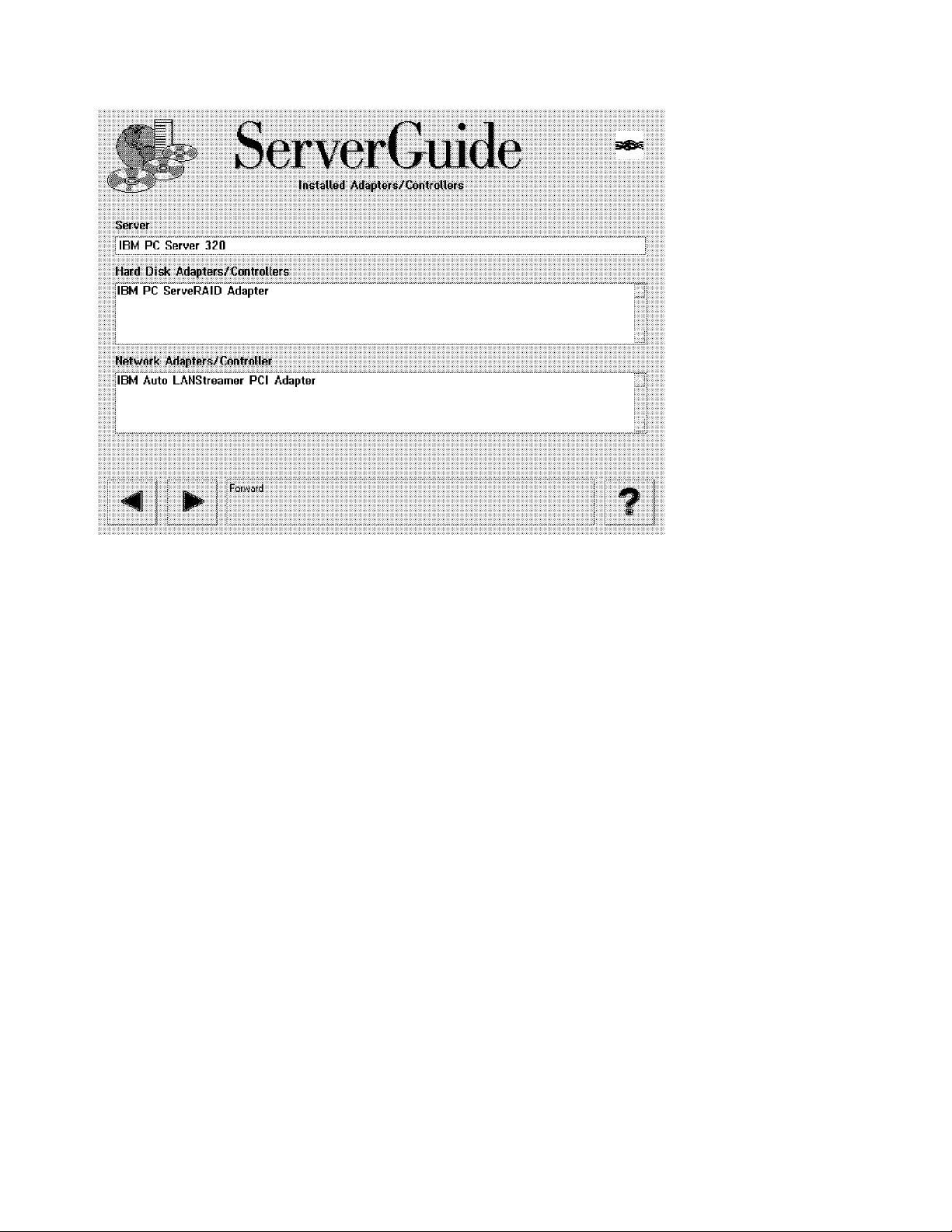
This soft copy for use by IBM employees only.
Figure 52. ServerGuide 3.0 Installed Adapters/Controllers. ServerGuide automatically detects what adapters you
have installed. This figure shows the result on our test Server 320.
6. A listbox now appears showing recommended diskette packages and
optional diskette packages. Select the ones you want to build.
For our test Server 320, Figure 53 on page 79 is displayed. The optional
diskette packages may include drivers that are at a later level than those
supplied on the NT 4.0 CD-ROM.
Note: Packages such as TME 10 NetFinity can be installed directly from
CD-ROM onto your server without the use of diskettes by using the CoPilot
installation utility. Refer to 4.3.1, “CoPilot” on page 75 for more information.
78 PC Server and Windows NT Integration Guide
Page 89

This soft copy for use by IBM employees only.
Figure 53. ServerGuide 3.0 Installation Diskette Packages. The Setup Diskettes package contains the three boot
diskettes for NT 4.0. The TME 10 NetFinity package contains diskettes for TME 10 NetFinity Manager.
7. If you wish to build any of the packages, ensure they are selected. Then
press the forward button ( ) to continue.
You will then be given the opportunity to de-select any specific diskettes
within the packages. After clicking on the forward button, you will be
prompted to insert appropriate CD-ROMs and insert successive blank
diskettes into your diskette drive to create the diskettes. Write the
appropriate label information on each diskette for future reference.
Note: Some diskette packages (for example, the NT 4.0 Setup Diskettes)
require that the diskettes be blank as well as formatted prior to being used
in the process. You may need to use another computer to prepare the
diskettes you wish to use.
8. Insert the NT 4.0 Setup Boot Disk and click on the forward button to begin the
NT 4.0 installation.
Your server reboots and the installation process continues at Chapter 5,
“Installing Windows NT Server 4.0” on page 81.
Note: If you wish to go back and create other diskettes you can click on the
backward button.
Chapter 4. Installation Using ServerGuide 3.0 79
Page 90

This soft copy for use by IBM employees only.
80 PC Server and Windows NT Integration Guide
Page 91

This soft copy for use by IBM employees only.
Chapter 5. Installing Windows NT Server 4.0
This chapter describes the installation of Windows NT Server 4.0 using the
commercially available version of the software. The installation process will be
specified in general terms that relate to all IBM PC server models. A ny
information relating to specific models of the server range are noted.
5.1 IBM Servers Used
We tested this installation process with the full range of currently available IBM
PC servers with various combinations of the following devices:
•
SCSI adapters
− Integrated SCSI-2 Ultra F/W controller
− IBM PCI SCSI-2 F/W RAID adapter
− IBM ServeRAID adapter
− IBM Streaming RAID adapter/A
•
SCSI drives
− 3 x 2.25 GB drives in a non-RAID setup
− 3 x 2.25 GB drives configured as one RAID-5 array
•
NIC adapters
− Integrated AMD Ethernet controller
− PCI Auto LANStreamer
5.2 Pre-installation Checklist
You should ensure you have done the following before you start:
•
Prepared your RAID array and initialized all logical drives created using the
RAID administration utility provided with the server.
•
Partitioned your logical drives. We recommend certain configuration
parameters, as discussed in 3.6, “Disk Partitioning” on page 65.
•
Checked that you have all the necessary device driver diskettes ready or can
access them from another computer if required.
•
Checked that you have the Install from CD-ROM installation diskettes and not
the Install from Network installation diskettes. To build the correct diskettes
from the Windows NT CD-ROM, run the command
WINNT32 /OX from an existing Windows NT machine.
Note: Read Chapter 3, “Pre-installation Considerations” on page 61 for some
helpful hints.
WINNT /OX from DOS, or
5.3 Installing NT 4.0
The installation process is divided into two components:
1. Hardware setup
2. Software/network setup
The first component is text-based and asks you to make selections, such as
hardware, disk controller, Hardware Abstraction Layer (HAL), and any
Copyright IBM Corp. 1997 81
Page 92

partitioning that you may require. The second component, following a reboot,
sets up the software options and builds the networking environment for this
machine.
5.3.1 Starting the Process
Insert the NT 4.0 installation diskette 1 in drive A: and the NT 4.0 CD-ROM in
your server′s CD-ROM drive, and boot the server. When prompted, remove
diskette 1 and insert diskette 2. At the bottom of your panel, a message is
displayed indicating the progress of files loading and the files currently being
loaded.
Note
If your system error traps (a blue panel is displayed with error codes) after
loading the FAT file system, it is highly probable that your server is infected
with a boot sector virus. Use a commercial anti-virus application to disinfect
your server before continuing.
The Windows NT kernel starts and the initial setup panel appears (see
Figure 54).
This soft copy for use by IBM employees only.
Windows NT Server Setup
=======================
Welcome to Setup.
The Setup program for the Microsoft(R) Windows NT operating system
version 4.0 prepares Windows NT to run on your computer.
* To learn more about Windows NT Setup before continuing, press F1.
* To set up Windows NT version 4.0 now, press ENTER
* To repair a damaged Windows NT version 4.0 installation, press R.
* To quit Setup without installing Windows NT, press F3.
ENTER=Continue R=Repair F3=Exit
Figure 54. Initial Setup Panel
If you are re-installing Windows NT, press R; otherwise press Enter to continue.
Windows NT now attempts to detect any standard floppy controllers, as well as
any hard disk controllers and devices attached to it.
5.3.2 Choosing a Disk Controller
The disk controller chosen is critical because NT will not function if the wrong
one is chosen.
82 PC Server and Windows NT Integration Guide
Page 93

This soft copy for use by IBM employees only.
Tip
Check the location (path) of the device drivers on the diskettes supplied by
the manufacturers before you start the installation process, as you will not
have the opportunity during the next section of the installation process.
NT 4.0 setup displays the following panel (Figure 55):
Windows NT Server Setup
=======================
Setup automatically detects floppy disk controllers and standard
ESDI/IDE hard disks without user intervention. However on some
computers detection of certain other mass storage devices, such as
SCSI adapters and CD-ROM drives, can cause the computer to become
unresponsive or to malfunction temporarily.
For this reason you can bypass Setup′ s mass storage device detection
and manually select SCSI adapters, CD-ROM drives, and special disk
controllers (such as drive arrays) for installation.
* To continue, press ENTER.
Setup will attempt to detect mass storage devices in your
computer.
* To skip mass storage device detection, press S.
Setup will allow you to manually select SCSI adapters,
CD-ROM drives, and special disk controllers for installation.
F3=Exit ENTER=Continue S=Skip Detection
Figure 55. Selecting a Disk Controller During Installation
Streaming RAID Adapter
In the Server 720 and Server 500, the Micro Channel SCSI-2 Streaming RAID
Adapter/A may not be correctly recognized by Windows NT. The symptoms
are that the operating system cannot find the CD-ROM drive.
The solution is to press S to skip detection of disk controllers and when
prompted insert the Driver/Configuration diskette in the drive to select “IBM
RAID Controller” instead.
See Appendix A, “Sources of Drivers and Information” on page 147 for
information on where to get the latest driver diskettes.
Press Enter to continue. Setup asks you to insert setup diskette 3 to continue
the device detection and installation process. At the bottom of the setup panel,
the device drivers currently being loaded is shown. Each detected adapter or
device is shown. For the PC Servers 325, 330 and 704, the panel shown is
similar to Figure 56 on page 84.
If the disk controllers that Windows NT detects are all the ones you have in your
server, press Enter to continue and proceed to 5.3.5, “System Analysis” on
page 88.
Chapter 5. Installing Windows NT Server 4.0 83
Page 94

This soft copy for use by IBM employees only.
Windows NT Server Setup
=======================
Setup has recognized the following mass storage devices in your
computer:
Adaptec AHA-294X-394X/AIC-78XX SCSI Controller
* To specify additional SCSI adapters, CD-ROM drives, or special
disk controllers for use with Windows NT, including those for
which you have a device support disk from a mass storage device
manufacturer, press S.
* If you do not have any device support disks from a mass storage
device manufacturer, or do not want to specify additional
mass storage device for use with Windows NT, press ENTER.
S=Specify Additional Device ENTER=Continue F3=Exit
Figure 56. Disk Controllers Detected During Installation. This panel applies to the PC
Servers 325, 330 and 704; other servers are similar.
5.3.3 Specifying Additional Adapters
If the listed disk controllers do not include all the disk controllers in use in your
server, continue on here; otherwise skip to 5.3.5, “System Analysis” on page 88.
There are two major reasons why your disk controller may not have been
automatically detected:
1. You have more than one controller (for example, an integrated controller and
an adapter in a slot) and the controller detected was not the one you have
your disks attached to.
2. You have an adapter for which the driver required was not included on the
NT 4.0 CD-ROM (for example, the ServeRAID adapter).
In either instance, you will need to press S when the panel shown in Figure 56 is
displayed.
84 PC Server and Windows NT Integration Guide
Page 95

This soft copy for use by IBM employees only.
Windows NT Server Setup
=======================
You have asked to specify an additional SCSI adapter, CD-ROM drive,
or special disk controller for use with Windows NT.
* To select a mass storage device from the following list,
use the UP or DOWN ARROW key to move the highlight to
to the mass storage device you want, and then press ENTER.
* To return to the previous panel without specifying an additional
mass storage device for use with Windows NT, press ESC.
+----------------------------------------------------------(More )--+
| IBM MCA SCSI Host Adapter |
| IDE CD-ROM (ATAPI 1.2)/PCI IDE Controller |
| Mitsumi CD-ROM Controller |
| Mylex DAC960/Digital SWXCR-Ex Raid Controller |
|. |
|. |
| UltraStor 14F/14B/34F/34FA/34FB SCSI Host Adapter |
| Other (requires disk provided by a hardware manufacturer) |
+--------------------------------------------------------------------+
ENTER=Select F3=Exit ESC=Cancel
Figure 57. Installing Additional Disk Controllers
Select the appropriate adapter and press Enter. If the adapter you are using or
the device is not listed on the panel shown above, select the following option:
Other (requires disk provided by a hardware manufacturer)
After selecting this option, the system will prompt you to insert the
Manufacturer-supplied hardware support disk into the diskette drive. This will
usually be supplied with the adapter. If it is an IBM adapter, the diskette will be
available from the ServerGuide Diskette Factory, or from the IBM PC Company
Web site. Refer to Appendix A, “Sources of Drivers and Information” on
page 147 for more information on where to get drivers.
If the diskette supplied has the correct files, the following window will be
displayed (Figure 58):
Windows NT Server Setup
=======================
You have chosen to install a SCSI adapter, CD-ROM drive, or
special disk controller provided by a hardware manufacturer.
* To select a mass storage device from the following list,
use the UP or DOWN ARROW key to move the highlight to
to the mass storage device you want, and then press ENTER.
* To return to the previous panel without specifying an additional
mass storage device for use with Windows NT, press ESC.
+------------------------------------------------------------------+
| IBM PC ServeRAID Adapter |
| |
| |
| |
| |
| |
+------------------------------------------------------------------+
ENTER=Select ESC=Cancel
Figure 58. Installing Drivers from Diskette
Chapter 5. Installing Windows NT Server 4.0 85
Page 96

This soft copy for use by IBM employees only.
Select the adapter you have installed in your server (in this example, the IBM PC
ServeRAID adapter), and press Enter.
Setup then returns you to the panel showing all the currently selected adapters
(Figure 59). You may repeat the process in selecting additional adapters until
you have finished the mass storage device selection process.
Windows NT Server Setup
=======================
Setup has recognized the following mass storage devices in your
computer:
Adaptec AHA-294X-394X/AIC-78XX SCSI Controller
IBM PC ServeRAID Adapter
* To specify additional SCSI adapters, CD-ROM drives, or special
disk controllers for use with Windows NT, including those for
which you have a device support disk from a mass storage device
manufacturer, press S.
* If you do not have any device support disks from a mass storage
device manufacturer, or do not want to specify additional
mass storage device for use with Windows NT, press ENTER.
S=Specify Additional Device ENTER=Continue F3=Exit
Figure 59. Listing All Recognized Disk Adapters (Detected and Selected)
If all the required adapters and devices are displayed, then press Enter to
continue; otherwise press S and to repeat the mass storage device selection
process as shown above.
5.3.4 Potential Errors Detecting Disk Controllers
There are typically two possible reasons why unexpected messages occur at this
point:
1. No controllers or the wrong disk controllers listed.
If you have additional or other mass storage device adapters installed in
your server, you should supply any driver diskette supplied by the
manufacturers; otherwise, the installation process could fail. In addition, it is
a good idea before starting the installation process to check the location
(path) of the device drivers on the diskette.
Some manufacturers provide the drivers and the OEMSETUP.INF file on the
diskette′s root directory, others in a subdirectory usually called NT for the
Windows NT device drivers.
2. Incorrect installation diskettes used.
There are two possible sets of three installation diskettes that can be built by
running a program from the CD-ROM:
a. “Install from CD-ROM” diskettes, using the command
b. “Install from Network” diskettes, using the command WINNT /X
In this section, we are installing from the NT 4.0 CD-ROM, so the command
WINNT /OX (or WINNT32 /OX if running it from an existing Windows NT system)
should be used. If you use the
86 PC Server and Windows NT Integration Guide
WINNT /OX
/X switch when you wish to install from the
Page 97

This soft copy for use by IBM employees only.
CD-ROM, the following two error panels are likely to occur at this point (see
Figure 60 on page 87 and Figure 61 on page 87).
Windows NT Server Setup
=======================
Setup has determined that your computers startup disk is new or has
been erased, or that an operating system is installed on your computer
with which Windows NT cannot coexist.
If such an operating system is installed on your computer, continuing
Setup may damage or destroy it.
If the hard disk is new or has been erased, or you want to discard its
current contents, you can choose to continue Setup.
. To continue Setup, press C. WARNING: Any data currently on your
computer′ s startup hard disk will be permanently lost.
. To exit Setup, press F3
C=Continue Setup F3=Exit
Figure 60. Detecting Freshly Configured Arrays
After pressing C, the following panel will appear (see Figure 61):
Windows NT Setup
================
Setup is unable to locate the hard drive partition prepared by the
MS-DOS portion of Setup.
When you run the MS-DOS Windows NT Setup program, you must specify a
temporary drive that is supported by Windows NT. See your System Guide
for more information.
Setup cannot continue. Press F3 to exit.
F3=Exit
Figure 61. Setup is Unable to Locate MS-DOS Partition
These panels appear because the incorrect command line parameters were
used when the installation disks were created for the CD-ROM installation.
You have boot-up diskettes that have been created using the
line parameters. These startup diskettes fail at this point because they are
expecting the installation process to have been started from a network drive
or directly from the CD-ROM after booting from DOS. If started in this
fashion, Windows NT creates two temporary directories on the temporary
partition and expects to be able to access the hard drives where the
temporary installation files have been transferred to. At this point, Windows
NT has not loaded the device drivers needed to access the RAID controller.
/X or command
Chapter 5. Installing Windows NT Server 4.0 87
Page 98

To overcome the problem, recreate the installation disks. The correct syntax
is
This will correct the problem in most cases when the installation process is
restarted with the freshly created installation disks.
On the Windows NT Server Setup panel, press Enter if this information is correct,
or S to specify additional devices or adapters that you have in your server. You
will need to provide the driver diskette when prompted. If you pressed S,
continue reading. If you pressed Enter, go to 5.3.5, “System Analysis.”
5.3.5 System Analysis
At this point, all of the disk controllers should have been specified, either
automatically detected by Windows NT, or manually selected by you. The setup
program will now continue the installation process.
Windows NT will then load the required device drivers and the file system (NTFS)
drivers.
You may see the panel shown in Figure 62. This will appear if you have any
disks (or logical disks as defined in the RAID configuration) that are larger than
1024 cylinders (approximately 528 MB). Press Enter to continue. In most cases
you can ignore this message and Windows NT will work correctly with the IBM
disk controllers that it supports.
This soft copy for use by IBM employees only.
WINNT /OX from a DOS prompt or WINNT32 /OX while running NT 3.5 or later.
Windows NT Server Setup
=======================
Setup has determined that one or more of your hard disks has more than
1024 cylinders.
Because MS-DOS is normally limited to 1024 cylinders per hard disk,
some hard disk controllers offer special configuration options to
allow access to large disks in their entirety. These options are known
as sector translation modes. If a disk has only slightly more than 1024
cylinders, or such a mode is not enabled, a small portion of the disk
remains inaccessible to MS-DOS. Consult your computer or hard disk
controller documentation for more information about sector translation
and large hard disks.
If disk sizes appear too small when Setup later displays information
about hard disks it has located, you should exit Setup and check your
CMOS drive type settings. Consult your computer or hard disk controller
documentation for more information about CMOS drive type settings.
Note that this message does not necessarily indicate an error
condition. It is intended to alert you to the fact that one or more of
your hard disks may actually be larger than the size for which it is
currently configured.
Press ENTER to continue.
Enter=Continue
Figure 62. Disks Larger Than 1024 Cylinders
As this may be the first installation, your hard disks may need to be partitioned
and/or formatted. You will see the display shown in Figure 63 on page 89.
Press C to continue.
88 PC Server and Windows NT Integration Guide
Page 99

This soft copy for use by IBM employees only.
RAID Arrays and Logical Drives
Remember, when using drives attached to an IBM RAID controller, the
physical drives are combined into a RAID array. Within this array, you can
specify how much of the total available (drive array) disk space will be
assigned to a certain RAID level (RAID-0, -1 or -5). T his particular disk space
is called a logical drive. However, this logical drive is presented by the RAID
controller as a single disk drive to Windows NT. This (logical) drive needs to
be partitioned and formatted in the same fashion as any other disk drive.
Windows NT Server Setup
=======================
Setup has Determined that your computer′ s startup hard disk is new
or has been erased, or that an operating system is installed on your
computer with which Windows NT cannot coexist.
If such an operating system is installed on your computer; continuing
Setup may damage or destroy it.
If the hard disk is new or has been erased, or you want to discard
its current contents, you can choose to continue Setup.
* To continue Setup, press C. Warning: Any data currently on
your computer′ s startup hard disk will be permanently lost.
* To exit Setup, press F3.
C=Continue Setup F3=Exit
Figure 63. Unformatted or Unsupported Operating System Already Installed
Setup displays the Windows NT Licensing Agreement. Please read it carefully
and make sure you do not violate any terms or conditions of this licensing
agreement. Use the Page Down key to scroll through the licensing conditions
and press F8 to comply and to continue with the NT 4.0 installation.
5.3.6 Basic Configuration and HAL Options
The next panel shown in Figure 64 on page 90 is where you define the basic
configurations of your server. For example at this point you can choose to install
your server as either a uni- or multiprocessor system. You can also specify
what kind of display is attached, the type of keyboard, its layout, and so on.
Each option may be selected and modified according to the type and
configuration of your server.
Chapter 5. Installing Windows NT Server 4.0 89
Page 100

This soft copy for use by IBM employees only.
Windows NT Server Setup
=======================
Setup has determined that your computer contains the following
hardware and software components:
Computer: MPS Multiprocessor PC
Display: Auto Detect
Keyboard: XT, AT, or Enhanced Keyboard (83-104 Keys)
Keyboard Layout: US
Pointing Device: Microsoft Mouse Port Mouse (includes Ball Point)
No Changes: The above list matches my computer.
If you want to change any item in the list, press the UP or DOWN
ARROW key to move the highlight to the item you want to change.
Then press ENTER to see alternatives for that item.
When all items in the list are correct, move the highlight to
″The above list matches my computer″ and press ENTER.
ENTER=Select F3=Exit
Figure 64. Initial Hardware Configuration
5.3.7 Selecting the Correct HAL
Now you need to select the correct Hardware Abstraction Layer (HAL) code.
Refer to Appendix E, “The Hardware Abstraction Layer (HAL)” on page 159 for a
discussion about the HAL.
Select the Computer option and press Enter. The panel in Figure 65 will be
displayed.
Windows NT Server Setup
=======================
You have asked to change the type of computer to be installed.
* To select a computer from the following list,
use the UP or DOWN ARROW key to move the highlight to
to the computer type you want, and then press ENTER.
* To return to the previous panel without changing your
computer type, press ESC.
+------------------------------------------------------------------+
| AST Manhattan SMP |
| Compaq SystemPro Multiprocessor or 100% Compatible |
| Corollary C-bus Architecture |
| Corollary C-bus Architecture Micro Channel Architecture |
| IBM PS/2 or other Micro Channel-based PC |
| MPS Uniprocessor PC |
| MPS Multiprocessor PC |
| MPS Multiprocessor Micro Channel PC |
| NCR System 3000 Model 3360/3450/3550 |
| Olivetti LSX5030/40 |
| Standard PC |
| Standard PC with C-Step i486 |
| Wyse Series 7000i Model 740MP/760MP |
| Other (requires disk provided by a hardware manufacturer) |
+------------------------------------------------------------------+
ENTER=Select F3=Exit ESC=Cancel
Figure 65. Selecting the HAL
90 PC Server and Windows NT Integration Guide
 Loading...