

Page 1

IBM Systems
ServeRAID Manager
Installation and User's Guide
Version 8.30
Page 2

Page 3

IBM Systems
ServeRAID Manager
Installation and User's Guide
Version 8.30
Page 4

Note
Before using this information and the product it supports, read the information in Appendix D,
"Notices."
Fourth Edition (June 2006)
This edition applies to version 8.30 of IBM Director and to all subsequent releases and modifications until otherwise
indicated in new editions.
© Copyright International Business Machines Corporation 1999, 2006. All rights reserved.
US Government Users Restricted Rights – Use, duplication or disclosure restricted by GSA ADP Schedule Contract
with IBM Corp.
Page 5

Contents
Figures . . . . . . . . . . . . . . vii
Tables . . . . . . . . . . . . . . .ix
About this book . . . . . . . . . . .xi
Conventions and terminology . . . . . . . .xi
Related information . . . . . . . . . . . .xi
How to send your comments . . . . . . . . xiv
Chapter 1. Getting started . . . . . . .1
Introducing IBM Director . . . . . . . . . .1
Using IBM Director Console . . . . . . . . .2
The IBM Director Console interface . . . . . .2
IBM Director Console toolbar . . . . . . . .3
Panes in IBM Director Console . . . . . . .4
Working with tables . . . . . . . . . . .5
Starting tasks . . . . . . . . . . . . .6
ServeRAID Manager . . . . . . . . . . . .6
Operating systems supported by ServeRAID
Manager . . . . . . . . . . . . . . . .7
Chapter 2. Installing ServeRAID
Manager . . . . . . . . . . . . . .11
Installing the ServeRAID Manager extension on a
Windows server . . . . . . . . . . . . .12
Installing the ServeRAID Manager extension on a
Linux server . . . . . . . . . . . . . .13
Installing the ServeRAID Manager extension on a
Windows console . . . . . . . . . . . .14
Installing the ServeRAID Manager extension on a
Linux console . . . . . . . . . . . . . .15
Installing the ServeRAID Manager extension on a
managed Windows system . . . . . . . . .16
Installing the ServeRAID Manager extension on a
managed Linux system . . . . . . . . . .17
Installing the ServeRAID Manager extension on a
managed NetWare system . . . . . . . . .18
Chapter 3. Using ServeRAID Manager 21
Introducing the ServeRAID Manager . . . . . .21
What’s new in the ServeRAID TM Manager . .21
About ServeRAID Manager . . . . . . . .21
Using the ServeRAID Manager interface . . . .30
Finding information on the World Wide We b . .31
IBM ServeRAID publications . . . . . . .31
Understanding RAID technology . . . . . . .32
Understanding stripe-unit size . . . . . . .32
Understanding RAID level-0 . . . . . . . .33
Understanding RAID level-1 . . . . . . . .35
Understanding RAID level-1 Enhanced . . . .36
Understanding RAID level-5 . . . . . . . .38
Understanding RAID level-5 Enhanced . . . .39
Understanding RAID level-5EE . . . . . . .41
Understanding RAID level-6 . . . . . . . .43
Understanding RAID level-x0 . . . . . . .45
Understanding RAID volumes . . . . . . .47
Selecting a RAID level and tuning performance 48
Selecting the RAID level by array capacity . . .50
Software and hardware support of RAID levels 52
RAID levels that can use a hot-spare or standby
hot-spare drive . . . . . . . . . . . .53
Selecting the RAID level in the migration wizard 54
Starting the ServeRAID Manager task . . . . .54
Logging in to the ServeRAID Manager . . . . .55
Logging out of the ServeRAID Manager . . . . .56
Using the ServeRAID Manager from the command
line . . . . . . . . . . . . . . . . .56
Using the ServeRAID Manager with screen-reading
software . . . . . . . . . . . . . . .56
Using the ServeRAID Manager in bootable-CD
mode . . . . . . . . . . . . . . . .57
Accessing the ServeRAID Manager using the
keyboard . . . . . . . . . . . . . . .58
Verifying that the ServeRAID Manager agent is
running . . . . . . . . . . . . . . . .59
ServeRAID Manager and LED flash states . . . .60
Chapter 4. Managing ServeRAID
devices . . . . . . . . . . . . . .63
Configuring ServeRAID controllers and enclosures
in the Configuration wizard . . . . . . . . .63
Configuring an enclosure: the basic steps . . .63
Configuring ServeRAID SCSI controllers
(ServeRAID series 3, 4, 5, 6, and 7K) . . . . .63
Configuring ServeRAID SAS, SATA, and
HostRAID controllers (ServeRAID-7t,
ServeRAID-8i, HostRAID) . . . . . . . .68
Selecting controllers to update . . . . . . .75
Configuring ServeRAID enclosures . . . . .75
Configuring NetWare user authentication . . .82
Copying the configuration from drives . . . .83
Restore the configuration to the factory-default
settings . . . . . . . . . . . . . . .83
Saving a printable configuration and event logs 84
Working with systems in the ServeRAID
Manager . . . . . . . . . . . . . .88
Modifying logical drives using the
Configuration wizard . . . . . . . . . . 172
Tuning your system for optimal performance 188
Managing storage devices . . . . . . . . 197
Adding a remote system . . . . . . . . . 204
Viewing the ServeRAID Manager event log . . . 205
Using the ServeRAID Manager agent . . . . . 206
Starting the ServeRAID Manager agent . . . . 206
Viewing the ServeRAID Manager event log . . 207
Configuring the ServeRAID Manager agent . . 208
Configuring the ServeRAID Manager agent >
general settings . . . . . . . . . . . . 209
Using the ServeRAID Manager agent . . . . 210
© Copyright IBM Corp. 1999, 2006 iii
Page 6

Using Security Manager . . . . . . . . . .211
Security Manager menu bar . . . . . . .211
Security Manager toolbar . . . . . . . . 212
Adding a user in the Security Manager . . . . 212
Deleting a user in the Security Manager . . . 213
Modifying a user in the Security Manager . . . 213
Using SNMP Trap Manager . . . . . . . . 213
SNMP Trap Manager menu bar . . . . . . 213
SNMP Trap Manager toolbar . . . . . . . 214
Adding a system in the SNMP Trap Manager 214
Deleting a system in the SNMP Trap Manager 214
Modifying a system in the SNMP Trap Manager 215
Managing software and firmware . . . . . . 215
Confirming your software update . . . . . 215
Changing BIOS-compatibility mapping . . . . 215
Updating BIOS and firmware code . . . . . 216
Selecting ROM update images . . . . . . . 216
Chapter 5. Troubleshooting
ServeRAID Manager . . . . . . . . 217
Could not copy the configuration from the drives:
controller [number] . . . . . . . . . . . 217
Could not restore the configuration to the
factory-default settings: controller [number] . . . 217
Could not unblock logical drive [number]:
controller [number] . . . . . . . . . . . 218
Could not create a hot-spare drive: controller
[number], < drive location> Could not create a
standby hot-spare drive: controller [number], <
drive location> . . . . . . . . . . . . . 218
Could not delete array: controller [number], array
[letter] . . . . . . . . . . . . . . . . 218
Could not delete all of the arrays: controller
[number] . . . . . . . . . . . . . . . 219
Could not delete logical drive: controller [number],
logical drive [number] . . . . . . . . . . 219
Logical drive was not initialized: controller
[number], logical drive [number] . . . . . . . 219
Could not start the logical drive synchronization:
controller [number], logical drive [number] . . . 219
Could not set the drive to online: controller
[number], < drive location> . . . . . . . . 220
Could not remove the defunct drive: controller
[number], < drive location> . . . . . . . . 220
Could not replace the defunct drive: controller
[number], < drive location> . . . . . . . . 220
Could not delete the hot-spare drive: controller
[number], < drive location> Could not delete the
standby hot-spare drive: controller [number], <
drive location> . . . . . . . . . . . . . 221
Could not set the merge-group number: controller
[number], logical drive [number] . . . . . . . 221
Could not blink the device lights . . . . . . . 221
The battery-backup cache device needs a new
battery: controller [number] . . . . . . . . 222
The battery-backup cache device is defective:
controller [number] . . . . . . . . . . . 222
Background polling commands are not responding:
controller [number] . . . . . . . . . . . 222
Commands are not responding: controller
[number] . . . . . . . . . . . . . . . 222
Rebuild failed: controller [number], logical drive
[number] . . . . . . . . . . . . . . . 223
Synchronization failed: controller [number], logical
drive [number] . . . . . . . . . . . . . 223
Migration [logical-drive migration type] failed:
controller [number], logical drive [number] . . . 224
Compression failed: controller [number], logical
drive [number] . . . . . . . . . . . . . 224
Decompression failed: controller [number], logical
drive [number] . . . . . . . . . . . . . 224
defunct drive: controller [number], < drive
location> . . . . . . . . . . . . . . . 225
PFA detected for drive: controller [number], <
drive location> . . . . . . . . . . . . . 225
Logical drive is offline: controller [number], logical
drive [number] . . . . . . . . . . . . . 225
Logical drive is critical: controller [number], logical
drive [number] . . . . . . . . . . . . . 225
Logical drive is blocked: controller [number],
controller [number] [number] . . . . . . . . 225
Could not communicate with controller: controller
[number] . . . . . . . . . . . . . . . 226
User name or password is not valid . . . . . . 226
ServeRAID Manager failed to start at port number
[number] . . . . . . . . . . . . . . . 226
No controllers were found in this system. . . . . 227
Host name [ID] is unknown or the network is
down . . . . . . . . . . . . . . . . 227
Failed to connect to host name [ID] due to
incompatible versions [Local=number
Remote=number] . . . . . . . . . . . . 227
Unable to connect to the remote system . . . . 228
Array [letter] storage space still available. . . . . 228
Physical drives in array [letter] contain unusable
space . . . . . . . . . . . . . . . . 228
Hot spare is too small for use by at least one array. 229
Could not start logical drive migration: controller
[number] logical drive [number] . . . . . . . 229
Could not enable the hot-swap rebuild operation:
controller [number] . . . . . . . . . . . 229
Could not create logical drive: controller [number],
logical drive [number] . . . . . . . . . . 230
Logical drive was not initialized: controller
[number], logical drive [number] . . . . . . . 230
Logical drive must be synchronized: controller
[number], logical drive [number] . . . . . . . 230
[Number] ready drives still available. . . . . . 231
Cannot communicate with the remote system . . 231
Error getting controller configuration. . . . . . 232
Agent is running in local only mode. . . . . . 232
Networking support is not available. . . . . . 233
Could not send the event to the system. . . . . 233
Failed to connect to host name [ID] at port number
[number]. . . . . . . . . . . . . . . . 234
Failed to connect to host name [ID] due to
incompatible versions [Local=id Remote=id]. . . . 235
ServeRAID Manager failed to start at port number
[number]. . . . . . . . . . . . . . . . 235
Refused connection from [remote system ID]. . . 235
FlashCopy with backup failed: controller [number],
logical drive [number] . . . . . . . . . . 236
iv ServeRAID Manager Installation and User's Guide
Page 7

Could not import configuration with more than
eight drives into a ServeRAID-3L controller. . . . 236
Could not copy the configuration from the drives:
controller [number], < drive location> . . . . . 236
Possible non-warranted physical drive found:
controller [number], < device location> . . . . . 237
Could not set the host name: controller [number] 237
Could not set the partner host name: controller
[number] . . . . . . . . . . . . . . . 237
Could not change the rebuild rate: controller
[number], < device location> . . . . . . . . 238
Could not change the stripe-unit size: controller
[number], < device location> . . . . . . . . 238
Could not change the write-cache mode: controller
[number], logical drive [number] . . . . . . . 238
Could not change the SCSI transfer speed:
controller [number], channel [number] . . . . . 238
Could not enable unattended mode: controller
[number] . . . . . . . . . . . . . . . 239
Could not disable unattended mode: controller
[number] . . . . . . . . . . . . . . . 239
Could not enable read cache: controller [number] 239
Could not disable read cache: controller [number] 239
Could not set the SCSI initiator ID: controller
[number] . . . . . . . . . . . . . . . 240
Could not switch the active and passive
controllers. . . . . . . . . . . . . . . 240
Could not clear the controller event logs for system
[number]. . . . . . . . . . . . . . . . 240
Could not copy the configuration from the
non-shared logical drives (merge group [number]):
controller [number] . . . . . . . . . . . 241
Could not change the BIOS-compatibility mapping
to [Extended or Limited]: controller [number] . . 241
Could not change the write-cache mode: controller
[number], channel [number], SCSI ID [number] . . 241
Enclosure device is not responding: controller
[number], channel [number] . . . . . . . . 241
Enclosure fan [number] is malfunctioning:
controller [number], channel [number] . . . . . 242
Enclosure power supply [number] is
malfunctioning: controller [number], channel
[number] . . . . . . . . . . . . . . . 242
Enclosure temperature is out of normal range:
controller [number], channel [number] . . . . . 242
Could not save the event logs: controller [number] 243
Version mismatch detected: controller [number] 243
Compaction failed: controller [number], logical
drive [number] . . . . . . . . . . . . . 243
Expansion failed: controller [number], logical drive
[number] . . . . . . . . . . . . . . . 244
Battery has exceeded normal operating
temperature: battery controller [number] . . . . 244
Network connection was not found and/or host
name was not resolved. . . . . . . . . . . 244
One or more logical drives contain a bad stripe:
controller [number], logical drive [number] . . . 244
Exception removing timer from active queue . . . 245
Set drive to defunct: controller [number], < device
location> . . . . . . . . . . . . . . . 246
Set drive to defunct: controller [number], < device
location> . . . . . . . . . . . . . . . 246
Set drive to defunct: controller [number], < device
location> . . . . . . . . . . . . . . . 246
Set drive to defunct: controller [number], < device
location> . . . . . . . . . . . . . . . 247
Set drive to defunct: controller [number], < device
location> . . . . . . . . . . . . . . . 248
Set drive to defunct: controller [number], < device
location> . . . . . . . . . . . . . . . 248
Set drive to defunct: controller [number], < device
location> . . . . . . . . . . . . . . . 248
Set drive to defunct: controller [number], < device
location> . . . . . . . . . . . . . . . 249
Set drive to defunct: controller [number], < device
location> . . . . . . . . . . . . . . . 249
Set drive to defunct: controller [number], < device
location> . . . . . . . . . . . . . . . 250
Set drive to defunct: controller [number], < device
location> . . . . . . . . . . . . . . . 250
Set drive to defunct: controller [number], < device
location> . . . . . . . . . . . . . . . 250
Set drive to defunct: controller [number], < device
location> . . . . . . . . . . . . . . . 250
Set drive to defunct: controller [number], < device
location> . . . . . . . . . . . . . . . 250
This event log entry is informational. . . . . . 251
Appendix A. Accessibility features for
IBM Director . . . . . . . . . . . . 253
Appendix B. Glossary . . . . . . . . 261
A . . . . . . . . . . . . . . . . . 261
alien array . . . . . . . . . . . . . 261
array . . . . . . . . . . . . . . . 261
auto-synchronization . . . . . . . . . . 261
B . . . . . . . . . . . . . . . . . 261
battery-backup cache . . . . . . . . . . 261
BIOS-compatibility mapping - Extended . . . 261
BIOS-compatibility mapping - Limited . . . . 261
BIOS-compatibility mapping . . . . . . . 261
block . . . . . . . . . . . . . . . 261
blocked . . . . . . . . . . . . . . 261
C . . . . . . . . . . . . . . . . . 262
cluster . . . . . . . . . . . . . . . 262
compaction . . . . . . . . . . . . . 262
compression . . . . . . . . . . . . . 262
controller . . . . . . . . . . . . . . 262
controller names . . . . . . . . . . . 262
copy back . . . . . . . . . . . . . 262
critical . . . . . . . . . . . . . . . 263
D . . . . . . . . . . . . . . . . . 263
data mirroring . . . . . . . . . . . . 263
data scrubbing . . . . . . . . . . . . 263
data striping . . . . . . . . . . . . . 263
decompression . . . . . . . . . . . . 263
defunct . . . . . . . . . . . . . . 263
distributed spare drive . . . . . . . . . 263
E . . . . . . . . . . . . . . . . . 263
enclosure . . . . . . . . . . . . . . 263
Contents v
Page 8

expansion . . . . . . . . . . . . . 263
F . . . . . . . . . . . . . . . . . 264
fault tolerance . . . . . . . . . . . . 264
firmware . . . . . . . . . . . . . . 264
FlashCopy . . . . . . . . . . . . . 264
FlashCopy virtual size . . . . . . . . . 264
foreign array . . . . . . . . . . . . 264
free space . . . . . . . . . . . . . 264
G . . . . . . . . . . . . . . . . . 264
GB . . . . . . . . . . . . . . . . 264
H . . . . . . . . . . . . . . . . . 264
high availability . . . . . . . . . . . 264
hot add . . . . . . . . . . . . . . 264
hot-pluggable . . . . . . . . . . . . 265
hot-spare drive . . . . . . . . . . . . 265
hot-swap rebuild . . . . . . . . . . . 265
hot-swappable . . . . . . . . . . . . 265
I . . . . . . . . . . . . . . . . . . 265
Impacted . . . . . . . . . . . . . . 265
integrated RAID controller . . . . . . . . 265
initialize logical drive . . . . . . . . . 265
initiator identifiers . . . . . . . . . . . 265
IPSSEND command-line program . . . . . 265
L . . . . . . . . . . . . . . . . . 266
logical drive . . . . . . . . . . . . . 266
logical-drive migration . . . . . . . . . 266
LSI 1030 controller . . . . . . . . . . . 266
M . . . . . . . . . . . . . . . . . 266
management station . . . . . . . . . . 266
MB . . . . . . . . . . . . . . . . 266
merge-group number . . . . . . . . . . 266
merge-group state . . . . . . . . . . . 266
migrating . . . . . . . . . . . . . . 266
mirror role . . . . . . . . . . . . . 266
N . . . . . . . . . . . . . . . . . 266
network-attached storage . . . . . . . . 266
Notification Manager . . . . . . . . . . 267
O . . . . . . . . . . . . . . . . . 267
offline . . . . . . . . . . . . . . . 267
okay . . . . . . . . . . . . . . . 267
online . . . . . . . . . . . . . . . 267
P . . . . . . . . . . . . . . . . . 267
parity . . . . . . . . . . . . . . . 267
parity block . . . . . . . . . . . . . 267
partner name . . . . . . . . . . . . 267
physical drive . . . . . . . . . . . . 267
PFA . . . . . . . . . . . . . . . 267
plug-in . . . . . . . . . . . . . . 267
POST . . . . . . . . . . . . . . . 267
preferred owner . . . . . . . . . . . 268
Q . . . . . . . . . . . . . . . . . 268
quorum drive . . . . . . . . . . . . 268
R . . . . . . . . . . . . . . . . . 268
restore to factory-default settings . . . . . . 268
rack enclosure . . . . . . . . . . . . 268
RAID . . . . . . . . . . . . . . . 268
RAID level-0 . . . . . . . . . . . . 268
RAID level-1 . . . . . . . . . . . . 268
RAID level-1E . . . . . . . . . . . . 268
RAID level-5 . . . . . . . . . . . . 269
RAID level-5E . . . . . . . . . . . . 269
RAID level-5EE . . . . . . . . . . . . 269
RAID level-6 . . . . . . . . . . . . 269
RAID level-x0 . . . . . . . . . . . . 269
RAID signature . . . . . . . . . . . . 269
read-ahead cache mode . . . . . . . . . 269
read-ahead cache mode - Adaptive . . . . . 269
read-ahead cache mode - Disabled . . . . . 270
read-ahead cache mode - Enabled . . . . . 270
ready . . . . . . . . . . . . . . . 270
rebuild . . . . . . . . . . . . . . 270
rebuild rate . . . . . . . . . . . . . 270
rebuilding . . . . . . . . . . . . . 270
recurring task . . . . . . . . . . . . 270
ROM Update wizard . . . . . . . . . . 270
S . . . . . . . . . . . . . . . . . 270
ServeRAID Manager Mini-configuration
program . . . . . . . . . . . . . . 270
SAF-TE . . . . . . . . . . . . . . 270
scheduled task . . . . . . . . . . . . 270
SCSI . . . . . . . . . . . . . . . 271
SCSI initiator ID . . . . . . . . . . . 271
SCSI-transfer speed . . . . . . . . . . 271
segment . . . . . . . . . . . . . . 271
ServeRAID Manager . . . . . . . . . . 271
shared drives . . . . . . . . . . . . 271
small computer system interface . . . . . . 271
spanned array . . . . . . . . . . . . 271
standby hot spare . . . . . . . . . . . 271
stripe-unit size . . . . . . . . . . . . 271
stripes . . . . . . . . . . . . . . . 272
sub-logical drive . . . . . . . . . . . 272
Synchronize . . . . . . . . . . . . . 272
T . . . . . . . . . . . . . . . . . 272
throughput . . . . . . . . . . . . . 272
U . . . . . . . . . . . . . . . . . 272
unattended mode . . . . . . . . . . . 272
unattended mode -- Disabled . . . . . . . 272
unattended mode -- Enabled . . . . . . . 272
W . . . . . . . . . . . . . . . . . 272
write-cache mode . . . . . . . . . . . 272
write-cache mode -- Write-back . . . . . . 272
write-cache mode -- Write-through . . . . . 273
Appendix C. Notices . . . . . . . . 275
Trademarks . . . . . . . . . . . . . . 276
Glossary . . . . . . . . . . . . . 279
Glossary . . . . . . . . . . . . . . . 279
Index . . . . . . . . . . . . . . . 289
vi ServeRAID Manager Installation and User's Guide
Page 9

Figures
1. Hardware in an IBM Director environment 2
2. IBM Director Console . . . . . . . . .2
3. IBM Director Console toolbar . . . . . . .3
© Copyright IBM Corp. 1999, 2006 vii
Page 10

viii ServeRAID Manager Installation and User's Guide
Page 11

Tables
1. Operating systems supported by System x
servers and third-party Intel-based systems . .8
2. Operating systems supported by System i
platforms and System p servers . . . . . .9
3. Operating systems supported by System z
servers . . . . . . . . . . . . . .9
4. Keyboard shortcuts for windows . . . . . 253
5. Keyboard shortcuts for option panes 253
6. Keyboard shortcuts for dialogs . . . . . . 253
7. Keyboard shortcuts for scroll panes . . . . 253
8. Keyboard shortcuts for split panes . . . . 254
9. Keyboard shortcuts for notebooks (tabbed
panes) . . . . . . . . . . . . . . 254
10. Keyboard shortcuts for frames . . . . . . 254
11. Keyboard shortcuts for internal frames 255
12. Keyboard shortcuts for menu bar . . . . . 255
13. Keyboard shortcuts for menus . . . . . . 255
14. Keyboard shortcuts for menu items . . . . 255
15. Keyboard shortcuts for check-box menu items 256
16. Keyboard shortcuts for radio-button menu
items . . . . . . . . . . . . . . 256
17. Keyboard shortcuts for pop-up menus 256
18. Keyboard shortcuts for toolbar . . . . . . 256
19. Keyboard shortcuts for tool tips . . . . . 256
20. Keyboard shortcuts for text fields . . . . . 257
21. Keyboard shortcuts for text panes . . . . . 257
© Copyright IBM Corp. 1999, 2006 ix
Page 12

x ServeRAID Manager Installation and User's Guide
Page 13

About this book
This book provides instructions for using IBM
systems-management tasks. IBM Director consists of the following tools to meet
your systems-management needs:
v IBM Director Console is the graphical user interface (GUI) for IBM Director
Server. Using IBM Director Console, you can conduct comprehensive systems
management using either a drop-and-drag action or a single click.
v IBM Director command-line interface (dircli) is the command-line interface for
IBM Director Server. You can use a command-line prompt to access, control, and
gather information from IBM Director Server.
This documentation also provides planning and implementation information for
event management.
Conventions and terminology
These notices are designed to highlight key information:
®
Director 4.20 for
Note: These notices provide important tips, guidance, or advice.
Important:
Attention:
An attention notice appears before the instruction or situation in which damage
can occur.
Related information
Besides this documentation, there is additional information related to IBM Director.
IBM Director resources on the World Wide Web
The following We b pages provide resources for understanding, using, and
troubleshooting IBM Director and other system-management tools.
IBM Director information center
IBM Director Web site on ibm.com
These notices provide information or advice that might help you avoid
inconvenient or difficult situations.
These notices indicate possible damage to programs, devices, or data.
publib.boulder.ibm.com/infocenter/eserver/v1r2/topic/diricinfo/
fqm0_main.html
Updated periodically, the IBM Director information center contains the
most recent documentation available on a wide range of topics.
®
www.ibm.com/servers/eserver/xseries/systems_management/
ibm_director/
The IBM Director Web site on ibm.com has links to downloads and
documentation for all currently supported versions of IBM Director.
Information on this site includes:
v Downloads and documentation for the following IBM Director releases:
– IBM Director 5.10 Update 3 (5.10.3)
© Copyright IBM Corp. 1999, 2006 xi
Page 14

– IBM Director 5.10 Update 2 (5.10.2)
– IBM Director 5.10 Update 1 (5.10.1)
– IBM Director 5.10
– IBM Director 4.22
– IBM Director 4.22 Upward Integration Modules (UIMs)
– IBM Director 4.21
– IBM Director 4.20
v IBM Director Hardware and Software Support Guide document, which lists
supported IBM systems and all supported operating systems. It is
updated every 6 to 8 weeks.
v Printable documentation for IBM Director available in Portable
Document Format (PDF) in several languages
Director Software Developers Kit information center
IBM
publib.boulder.ibm.com/infocenter/dirinfo/toolkit/index.jsp
The IBM Director Software Developers Kit (SDK) information center
provides information about the IBM Director SDK – a set of tools and
documentation to help extend the capabilities of IBM Director by using the
APIs and CLIs, creating tasks, and launching tools from the IBM Director
user interface.
IBM Systems Software information center
www.ibm.com/servers/library/infocenter/
This We b page provides information about IBM Virtualization Engine™,
IBM Director, External Application Launch Wizard, Virtual System
Manager, and other topics.
®
IBM ServerProven
page
www.ibm.com/servers/eserver/serverproven/compat/us/
This We b page provides information about IBM System x™, BladeCenter®,
and IntelliStation
®
hardware compatibility with IBM Director.
IBM Servers
www.ibm.com/servers/
This We b page on ibm.com links to information, downloads, and IBM
Director extensions such as Remote Deployment Manager, Capacity
Manager, Systems Availability and Software Distribution (Premium
Edition) for the following IBM products:
v IBM BladeCenter
v IBM System i
v IBM System p
v IBM System x
v IBM System z
™
™
™
IBM Virtualization Engine systems services fixes
www14.software.ibm.com/webapp/set2/sas/f/VirtualizationEngine/
home2.html
This We b page provides information about the required fixes for the
Virtualization Engine system services. The fixes include operating system
fixes that are required for each system service as well as application-level
fixes that are required for each system service to function correctly.
IBM forums
www.ibm.com/developerworks/forums/dw_esforums.jsp
xii ServeRAID Manager Installation and User's Guide
Page 15

This We b page on ibm.com links to several forums, available as Web pages
or using rich site summary (RSS) feeds, in which users can discuss
technology issues relating to IBM servers.
Three of these forums are of particular interest to IBM Director users:
System x IBM Director forum
www.ibm.com/developerworks/forums/dw_forum.jsp?forum=759
&cat=53
A forum for discussing any IBM Director topics. This We b page
includes a link for obtaining the forum using an RSS feed.
System x Server forum
www.ibm.com/developerworks/forums/dw_forum.jsp?forum=740
&cat=53
A forum for discussing System x server topics, including questions
related to drivers, firmware, operating systems, clustering, and
storage. This We b page includes a link for obtaining the forum
using an RSS feed.
IBM Director SDK forum
www.ibm.com/developerworks/forums/dw_forum.jsp?forum=849
&cat=53
A forum for discussing how to use the IBM Director SDK to extend
the functionality of IBM Director to meet your specific needs. This
Web page includes a link for obtaining the forum using an RSS
feed.
™
IBM Redbooks
publications
www.ibm.com/redbooks/
You can download the following documents from the IBM Redbooks Web page.
You can also search this Web page for documents that focus on specific IBM
hardware; such documents often contain systems-management material.
Note: Be sure to note the date of publication and to determine the level of IBM
Director software to which the Redbooks publication refers.
v Creating a Report of the Tables in the IBM Director 4.1 Database (TIPS0185)
v IBM Director Security (REDP-0417)
v IBM BladeCenter Systems Management with IBM Director V4.1 and Remote
Deployment Manager V4.1 (REDP-3776)
v Implementing IBM Director 5.10 (SG24-6188)
v Integrating IBM Director with Enterprise Management Solutions (SG24-5388)
®
v Managing IBM TotalStorage
NAS with IBM Director (SG24-6830)
v Monitoring Redundant Uninterruptible Power Supplies Using IBM Director
(REDP-3827)
Remote Supervisor Adapter
Remote Supervisor Adapter overview
www.ibm.com/support/docview.wss?uid=psg1MIGR-4UKSML
This We b page includes links to the Remote Supervisor Adapter User’s Guide
and the Remote Supervisor Adapter Installation Guide.
About this book xiii
Page 16

Remote Supervisor Adapter II overview
www.ibm.com/support/docview.wss?uid=psg1MIGR-50116
This We b page includes information about the Remote Supervisor Adapter
II.
Other documents
For planning purposes, the following documents might be of interest:
v Planning and Installation Guide - IBM BladeCenter (Type 8677)
v IBM Management Processor Command-Line Interface (MPCLI) User’s Guide version
5.10
How to send your comments
Your feedback is important in helping to provide the most accurate and highest
quality information. If you have any comments about this book or any other IBM
Director publication, use the form for reader’s comments is provided at the back of
this publication. If the form has been removed, you may address your comments
to:
International Business Machines Corporation
Design & Information Development
Department CGFA
PO Box 12195
Research Triangle Park, NC 27709-9990
U.S.A.
xiv ServeRAID Manager Installation and User's Guide
Page 17

Chapter 1. Getting started
Introducing IBM Director
This topic provides an overview of IBM Director.
IBM Director is an integrated suite of tools that provide you with comprehensive
system-management capabilities to maximize system availability and lower IT
costs. Its open, industry-standard design supports the management of a variety of
hardware and operating systems, including most Intel
systems and certain IBM System i, System p, System x, and System z servers.
IBM Director automates many of the processes that are required to manage
systems proactively, including capacity planning, asset tracking, preventive
maintenance, diagnostic monitoring, troubleshooting, and more. It has a graphical
user interface that provides easy access to both local and remote systems.
IBM Director can be used in environments with multiple operating systems and
integrated with robust workgroup and enterprise management software from IBM
(such as Tivoli
NetIQ, and BMC Software.
®
software), Computer Associates, Hewlett-Packard, Microsoft®,
®
microprocessor-based
IBM Director environment
IBM Director is designed to manage a complex environment that contains
numerous servers, desktop computers, workstations, mobile computers (notebook
computers), and assorted devices. IBM Director can manage up to 5000 Level-2
systems.
An IBM Director environment contains the following groups of hardware:
v One or more servers on which IBM Director Server is installed. Such servers are
called management servers.
v Servers, workstations, desktop computers, and mobile computers that are
managed by IBM Director. Such systems are called managed systems.
v Network devices, printers, or computers that have Simple Network Management
Protocol (SNMP) agents installed or embedded. Such devices are called SNMP
devices.
v Additional managed objects such as platforms and chassis. Collectively, all
managed systems, devices, and objects are referred to as managed objects.
1 on page 2 shows the hardware in an IBM Director environment.
Figure
© Copyright IBM Corp. 1999, 2006 1
Page 18
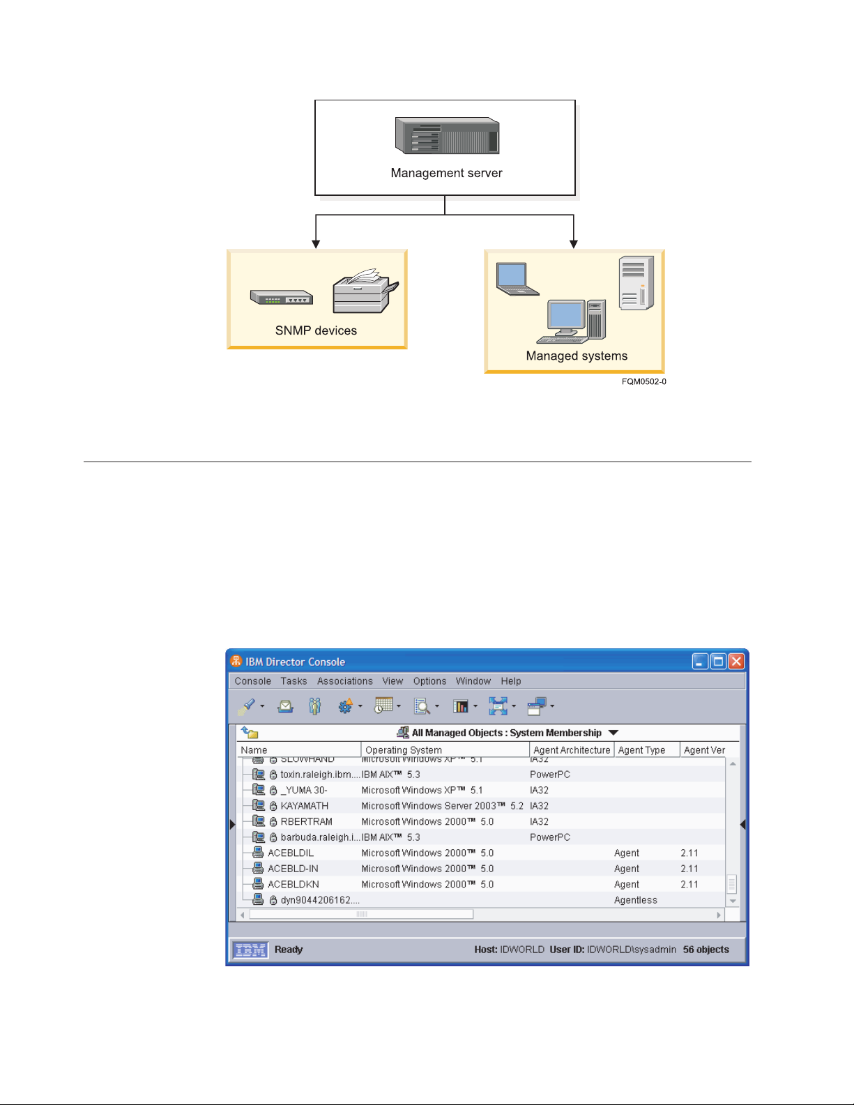
Figure 1. Hardware in an IBM Director environment
Using IBM Director Console
You can use IBM Director Console to group managed objects, view associations,
start tasks, and set IBM Director options and preferences.
The IBM Director Console interface
This topic describes the main components of the IBM Director Console interface.
Before you begin using IBM Director Console, review the layout of its interface.
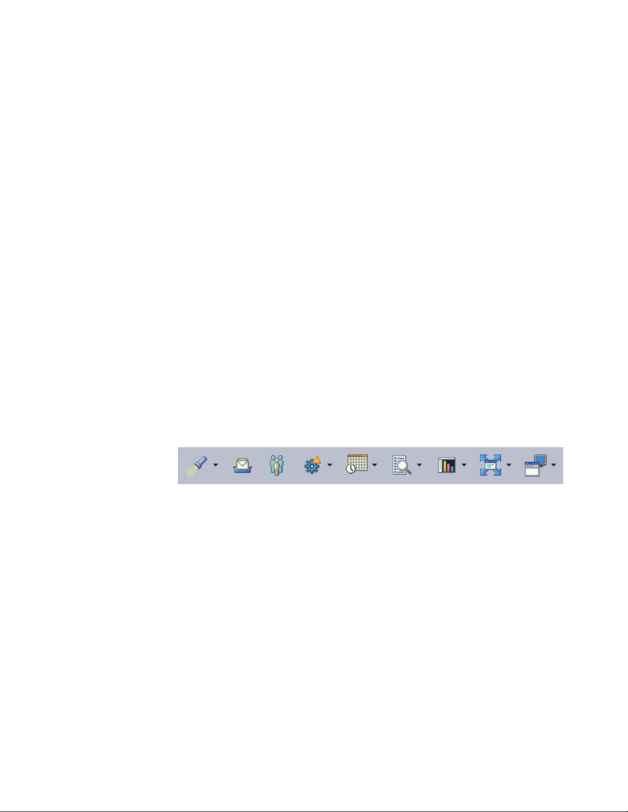
Figure 2. IBM Director Console
Along the top of the IBM Director Console interface is both a menu and a toolbar.
2 ServeRAID Manager Installation and User's Guide
Page 19
Below the menu and toolbar, one, two, or three panes will be visible. From left to
right, these are:
v Groups
v Group contents (pane title indicates selected group)
v Tasks
the panes is the marquee area and hardware-status alert display. The
Below
ticker-tape messages scroll across the marquee area. The hardware-status alert
display is located in the bottom-right corner of the interface.
At the bottom of the IBM Director Console interface is a status bar indicating the
ready or busy status of IBM Director, the host and login information for IBM
Director Server, and the number of managed objects in the Group Contents pane.
IBM Director Console is usually accessed on the management server. On
Windows
®
management servers, an additional, and separate, Server Status icon
displays the ready or busy status of IBM Director Server in the Windows system
tray.
Icons in the Windows tray, including the IBM Director Server Status icon,
Note:
may disappear when a user selects the Windows High Contrast display. To
enable display of the Server Status icon after selecting the high contrast
display, select All Programs → Startup → Server Status from the Start menu.
IBM Director Console toolbar
This topic describes each of the icons on the IBM Director Console.
Along the top of the IBM Director Console interface is a toolbar containing nine
icons.
Figure 3. IBM Director Console toolbar
From left to right, the icons are briefly described below:
Discover
Clicking the button for this icon starts discovery of all systems and
devices. Clicking the menu arrow for this icon allows you to select a type
of system or device to discover.
Message Browser
Clicking the button for this icon opens the Message Browser window.
User Administration
Clicking the button for this icon opens the User Administration window.
Event Action Plans
Clicking the button for this icon opens the Event Action Plan Builder
window. Clicking the menu arrow for this icon allows you to select the
Event Action Plan Wizard, event logging options, or help for event action
plans.
Scheduler
Clicking the button for this icon opens the Scheduler window. Clicking the
menu arrow for this icon allows you to open help for scheduler.
Chapter 1. Getting started 3
Page 20

Inventory
Clicking the button for this icon opens the Inventory Query Browser
window. Clicking the menu arrow for this icon allows you to build a
custom query, edit the software dictionary, collect inventory, create custom
collections, create or view inventory monitors, or open help for inventory.
Resource Monitors
Clicking the button for this icon opens the Resource Monitors window.
Clicking the menu arrow for this icon allows you to import a plan file,
open the All Available Recordings or All Available Thresholds window, or
open help for resource monitors.
Software Distribution
Clicking the button for this icon opens the Software Distribution Manager
window. Clicking the menu arrow for this icon allows you to manage file
distribution servers, view package history, create a package category, open
a software distribution package, or open help for software distribution.
Remote Control
Clicking the button for this icon opens the Remote Control window.
Clicking the menu arrow for this icon allows you to open help for remote
control.
Panes in IBM Director Console
The IBM Director Console interface includes three panes: Groups, Group Contents,
and Tasks.
You can resize the panes by dragging the borders between them. You can hide
either the Groups or Tasks pane by clicking on the border between that pane and
the Group Contents pane.
The Group Contents pane may not be hidden.
Note:
Groups
The Groups pane lists all the groups available, including the default
groups and any groups you have defined.
v Clicking a group selects that group for certain tasks performed from the
toolbar or the menu. It also selects that group in the Group Contents
pane.
v Right-clicking some groups also displays a context menu allowing tasks
to be performed on the group.
Contents
Group
The Group Contents pane lists the managed objects included in the group
selected in the Groups pane. The title of the Group Contents pane indicates
which group is selected.
v Clicking the title opens a menu from which you can select a group to
display.
v Clicking a listed object selects that object for certain tasks performed
from the toolbar or the menu.
v Right-clicking an object selects that object and displays a context menu
allowing tasks to be performed on the object.
The icon for each managed object indicates both the type of managed
object and its online status: icons for online objects appear in color, while
icons for offline objects appear in gray.
4 ServeRAID Manager Installation and User's Guide
Page 21

A padlock icon beside a managed object indicates that the object is secured
and inventory information about the object cannot be collected. To request
access to the object, right-click the managed object and click Request
Access. By providing a valid user name that has local administrative rights
to that managed object and password, you can access the system.
Notes:
1. (BladeCenter chassis and physical platforms only) The padlock
icon is displayed if a valid login profile does not exist for the
service processor. You can access the system using the Request
Access action as above.
2. (ISMP systems only) Yo u cannot log in to an ISMP directly, as it
lacks a userid and password. Instead, connect out-of-band to an
ISMP installed on an ASM interconnect network through a
Remote Supervisor Adapter or Remote Supervisor Adapter II
serving as the ASM gateway.
3. (ASM processor systems only) Use the Management Processor
Assistant to configure an out-of-band path to the ASM
processor system, then change the userid and password to
request access the physical platform using IBM Director
Console.
The Tasks pane lists tasks which can be performed in IBM Director.
Tasks
Although the list of tasks in the Task pane is static, not all tasks are
Note:
available for all groups or managed objects.
Right-clicking blank space in any pane displays a context menu from which you
can change the pane’s appearance or sorting, or perform tasks specific to that pane.
For example, in the Group Contents pane you can create new managed objects
manually, find and view objects, or perform actions on the selected group.
Working with tables
This topic describes general procedures for viewing tabular information in IBM
Director Console.
In IBM Director Console, information is often displayed in tables. You can
customize the display of data in many of these tables in several ways.
Note: Not all of these actions may be available for all tabular views. These actions
must be performed with a mouse or other pointing device, and are not
available through the keyboard.
Sort table data on a column
Click a column header to sort the data in the table by the values in that
column. Click the header again to change the sort order.
v An upward-pointing triangle symbol indicates the column is sorted in
ascending order
v A downward-pointing triangle symbol indicates the column is sorted in
descending order
v Some columns may have additional sort options that are displayed as
parenthetical text in the column header
Resize table columns
Drag the border of a table column heading to resize it.
Chapter 1. Getting started 5
Page 22

Rearrange table columns
Drag a table column heading left or right to a new column location to
rearrange table columns.
In addition, the details view of the Group contents pane in the main IBM Director
Console window may be customized by selecting what columns are displayed.
Right-click a column heading and select Customize columns. The Console
Preferences window opens to the Details View Preferences page. Select the
columns you wish to view, then click OK.
Starting tasks
This topic describes how to start tasks in IBM Director.
You can start most tasks in IBM Director in four ways:
v Dragging a task from the tasks pane onto a managed object (or a managed
group, in some cases)
v Dragging a managed object (or a managed group, in some cases) onto a task in
the tasks pane
v Right-clicking a managed object (or managed group, in some cases)
v Selecting the managed object or group, then selecting a task from the menu bar
Throughout this documentation, only dragging a task onto a managed object or
group is explained as the method of starting tasks, although you can use any of
the methods.
Some IBM Director functions, such as the Event Action Plan Builder and Scheduler,
may be started either from the menu bar or from the toolbar.
Note: When IBM Director Console is processing a task, the hourglass is displayed
ServeRAID Manager
Use the ServeRAID
adapters or controllers that are installed locally or remotely on servers. You can
view information that is related to controllers, arrays, logical drives, hot-spare
drives, and hard disk drives. Also, you can view configuration settings and events
(which are called notifications in the ServeRAID Manager task) and locate defunct
hard disk drives.
Note: The ServeRAID Manager task for IBM Director is not the same program as
Icon
for that window and you cannot use the mouse to work with the window.
Although it might be possible to work with the window using key strokes,
do not do so.
™
Manager task to configure, monitor, and maintain ServeRAID
the ServeRAID Manager (Standalone Edition) that is provided with the
ServeRAID hardware option. It is recommended that you not install both
versions on the same system.
Supported IBM
Director objects
6 ServeRAID Manager Installation and User's Guide
Level-2 managed systems
Page 23

Supported operating
systems
For detailed operating-system support information, see the IBM
Director information center on the We b at
publib.boulder.ibm.com/infocenter/eserver/ v1r2/topic/
diricinfo/fqm0_main.html.
Availability Extension to the IBM Director product. Yo u can download the
extension from the IBM Support We b site at www.ibm.com/
servers/eserver/xseries/ systems_management/ibm_director/.
Required hardware or
hardware limitations
Designed specifically for use on System x, xSeries®, and
Netfinity
®
servers. The following adapters or controllers must be
installed locally or remotely on these servers:
v ServeRAID adapters
v Integrated SCSI controllers with RAID capabilities
v Serial ATA controllers with integrated RAID
v Ultra320 SCSI controllers with integrated RAID
Required software None
Required protocols None
Required device
drivers
Mass Configuration
Applicable ServeRAID device drivers that support ServeRAID
hardware.
No
support
Scheduler support No
Files associated with
None
this task
Events associated with
this task
The ServeRAID Manager task for IBM Director generates the
following events:
v CIM > System > ServeRAID
v (SNMP events under iso) The iBMServeRAID events that are
contained under the ibmSystemMIB event type.
v Storage > ServeRAID Controller
The ServeRAID Manager (Standalone Edition) generates the
Note:
events that are contained under the SNMP > Hardware > Storage
> RAID event type.
For detailed events information, see in the IBM Director
information center on the Web at publib.boulder.ibm.com/
infocenter/eserver/
v1r2/topic/diricinfo/fqm0_main.html.
Operating systems supported by ServeRAID Manager
This topic provides information about the operating systems supported by the
ServeRAID Manager task.
Management-server support
This task is supported by IBM Director Server when installed on servers running
the following operating systems:
v Linux
v Windows
Managed-object support
The following tables list the operating systems that this task supports for managed
objects. Managed objects can include IBM System x, System i, System p, and
®
on System x
Chapter 1. Getting started 7
Page 24

System z hardware. Managed systems are a subset of managed objects that use
different levels of IBM Director support. This task can be used on Level-2 managed
systems only. These systems must be System x, xSeries, and Netfinity servers.
Table 1. Operating systems supported by System x servers and third-party Intel-based
systems
Operating system Level 2
Editions of Windows for 32-bit systems:
v Windows 2000, Advanced Server and Server Editions
Yes
v Windows Server 2003 Standard Edition
v Windows Server 2003 Enterprise Edition
v Windows 2000 Professional Edition
No
v Windows 2000 Datacenter Edition
v Windows XP Professional Edition
v Windows Server 2003 Web Edition
v Windows Server 2003 Datacenter Edition
Editions of Windows for 64-bit systems:
v Windows Server 2003 Standard x64 Edition
Yes
v Windows Server 2003 Enterprise x64 Edition
v Windows XP Professional x64 Edition
No
v Windows Server 2003 Web x64 Edition
v Windows Server 2003 Datacenter x64 Edition
v Windows Server 2003, Datacenter and Enterprise 64-bit Itanium
®
Editions
Versions of Linux for 32-bit systems:
v Red Hat Enterprise Linux AS, ES, and WS, version 3.0
Yes
v Red Hat Enterprise Linux AS, ES, and WS, version 4.0
v SUSE Linux Enterprise Server 8 for x86
v SUSE Linux Enterprise Server 9 for x86
v VMware ESX Server, versions 2.1, 2.5, 2.5.1 and 2.5.2, Console
v VMware ESX Server, versions 2.1, 2.5, 2.5.1 and 2.5.2, guest operating systems
v VMware GSX Server, versions 3.1 and 3.2, Console
No
v VMware GSX Server, versions 3.1 and 3.2, guest operating systems
Versions of Linux for 64-bit systems:
v Red Hat Enterprise Linux AS, ES, and WS, version 3.0, for AMD64 and
Yes
EM64T
v Red Hat Enterprise Linux AS, ES, and WS, version 4.0, for AMD64 and
EM64T
v SUSE Linux Enterprise Server 8 for AMD64
v SUSE Linux Enterprise Server 9 for AMD64 and EM64T
v Red Hat Enterprise Linux AS, version 3.0, for Intel Itanium
No
v Red Hat Enterprise Linux AS, version 4.0, for Intel Itanium
v SUSE Linux Enterprise Server 8 for Itanium Processor Family
v SUSE Linux Enterprise Server 9 for Itanium Processor Family
Other operating systems supported by System x servers:
Microsoft Virtual Server (guest operating system) No
NetWare, version 6.5 Yes
8 ServeRAID Manager Installation and User's Guide
Page 25

Table 2. Operating systems supported by System i platforms and System p servers
Operating system Level 2
v AIX 5L™, Version 5.2
No
v AIX 5L, Version 5.3
v i5/OS®, Version 5 Release 3
v i5/OS, Version 5 Release 4
v Red Hat Enterprise Linux AS, version 3.0, for IBM POWER
™
Note: System p servers require Red Hat Enterprise Linux AS, version 3.3 or
later, for IBM POWER.
v Red Hat Enterprise Linux AS, version 4.0, for IBM POWER
v SUSE Linux Enterprise Server 8 for IBM POWER
v SUSE Linux Enterprise Server 9 for IBM POWER
Table 3. Operating systems supported by System z servers
Operating system Level 2
v Red Hat Enterprise Linux AS, version 4.0, for IBM System z
No
v SUSE Linux Enterprise Server 9 for IBM System z
Chapter 1. Getting started 9
Page 26

10 ServeRAID Manager Installation and User's Guide
Page 27

Chapter 2. Installing ServeRAID Manager
This topic describes the general procedure for installing the ServeRAID Manager
extension for IBM Director 5.10.
ServeRAID Manager may be installed on both Windows and Linux platforms.
Installing ServeRAID Manager is performed in several steps, each of which is
described in a topic in this section.
1. Download the ServeRAID Manager extension.
a. In a Web browser, navigate to the following We b site: www.ibm.com/pc/
support/site.wss/document.do?lndocid=MIGR-61777.
b. Navigate to the ServeRAID Manager extension for your operating system,
and download the extension files to a temporary directory.
Install ServeRAID Manager on the management server.
2.
Option Description
Windows server “Installing the ServeRAID Manager extension on a
Windows server” on page 12
Linux server “Installing the ServeRAID Manager extension on a Linux
server” on page 13
3. Optional: Install ServeRAID Manager user-interface components for IBM
Director Console on remote management consoles.
Option Description
Windows console “Installing the ServeRAID Manager extension on a
Windows console” on page 14
Linux console “Installing the ServeRAID Manager extension on a Linux
console” on page 15
Note: ServeRAID Manager user-interface components for IBM Director Console
are automatically installed on the management server when the
ServeRAID Manager server components are installed. It is not necessary
or possible to separately install ServeRAID Manager console components
on a management server.
4. Install ServeRAID Manager components for IBM Director Agent on managed
systems.
Option Description
Windows systems “Installing the ServeRAID Manager extension on a
managed Windows system” on page 16
Linux systems “Installing the ServeRAID Manager extension on a
managed Linux system” on page 17
NetWare systems “Installing the ServeRAID Manager extension on a
managed NetWare system” on page 18
Note: ServeRAID Manager agent components are automatically installed on the
management server when the ServeRAID Manager server components
© Copyright IBM Corp. 1999, 2006 11
Page 28

are installed. It is not necessary or possible to separately install
ServeRAID Manager agent components on a management server.
Installing the ServeRAID Manager extension on a Windows server
This topic describes the procedure for installing the ServeRAID Manager extension
for IBM Director on a Windows management server.
Complete the following steps to install ServeRAID Manager on a Windows
management server:
1. Copy the downloaded installation files to a temporary directory on the
machine on which you will be performing the installation.
2. Close all applications, including any command-prompt windows.
3. Click Start → Run.
4. In the Run dialog, type the following command in the Open field and press
Enter:
download\raid\server\windows\serveraid_5.10_server_windows.exe
download represents the location to which the ServeRAID Manager download
package was unzipped.
5. In the first panel of the ServeRAID Manager Server InstallShield Wizard, click
Next.
6. In the second panel of the ServeRAID Manager Server InstallShield Wizard,
complete the following steps:
a. Ensure that the hard disk drive icon
Manager Server in the list box. If a different icon appears, click the icon
and select This feature, and all subfeatures, will be installed on local
hard drive from the menu.
b. Ensure that the hard disk drive icon
other features you wish to install. You can install the ServeRAID Manager
Agent, ServeRAID Manager Console, and IBM Management Station along
with ServeRAID Manager Server.
c. Click Next.
7. (Only if Management Station is being installed) In the next panel of the
ServeRAID Manager Server InstallShield Wizard, complete the following
steps:
a. Type the user name and password (enter twice for confirmation) for the
user for the ServeRAID Management Station service.
b. Click Next.
8. In the next panel of the ServeRAID Manager Server InstallShield Wizard, click
Install. A new panel displays the installation progress.
9. When installation has completed, click Finish.
10. In the dialog that appears, respond to the prompt to reboot the management
server. Click Yes to reboot immediately, or click No if you will reboot the
management server yourself.
appears to the left of ServeRAID
appears to the left of each of the
The management server must be rebooted before the ServeRAID Manager
extension will operate. After installing the server components of the ServeRAID
Manager extension, you need to install the console components.
12 ServeRAID Manager Installation and User's Guide
Page 29

Installing the ServeRAID Manager extension on a Linux server
This topic describes the procedure for installing ServeRAID Manager on a Linux
management server.
Complete the following steps to install ServeRAID Manager on a Linux
management server:
1. Copy the downloaded installation files to a temporary directory on the machine
on which you will be performing the installation. The downloaded installation
files are contained in a tar file. Use the tar -x command to extract the contents
to a temporary directory.
2. Stop IBM Director. From a command prompt, type the following command and
press Enter:
/opt/ibm/director/bin/twgstop
3. Change to the directory in which the installation package is located. Type the
following command and press Enter:
cd /download/raid/server/linux/
download represents the location into which the ServeRAID Manager download
package was extracted.
4. Optional: To install the management station service on the Linux management
server, perform the following substeps.
The management station is used to administer IBM System Storage
and IBM System Storage DS400 devices. This step is only necessary if both of
the following conditions are true:
v You wish to manage IBM System Storage DS300 and IBM System Storage
DS400 devices using IBM Director
v You do not have the standalone version of ServeRAID Manager installed
™
DS300
either of these conditions is not met, there is no need to install the
If
management station service.
Although it is possible to install the management station service on a
Note:
system other than that on which IBM Director Server is installed, this is
not a recommended configuration, and is not documented here. To use
the standalone version of ServeRAID Manager, or for instructions for
installing the management station service on a different system than the
management server on which IBM Director Server is installed, refer to
the documentation and downloads available on the ServeRAID Web site
at www.ibm.com/pc/support/site.wss/MIGR-495PES.html.
a. List the directory contents. There should be several files named
serveraid-mgmt-version-build.os.i586.rpm, with version, build, and os
indicating the version number, build number, and operating system for the
package. Note the version and build numbers for the following step.
b. Type one of the following commands (substituting the actual values for
version and build) and press Enter:
Installation scenario Command
Performing a new
rpm -ivh serveraid-mgmt-version-build.rhel33.i586.rpm
installation on Red Hat
Enterprise Linux AS, ES, and
WS, version 3.0 (Update 3
required)
Chapter 2. ServeRAID Manager 13
Page 30

Installation scenario Command
Upgrading from a previous
version on Red Hat
rpm -Uvh --relocate /opt/ibm/director=/opt/IBM/
director serveraid-mgmt-version-build.rhel33.i586.rpm
Enterprise Linux AS, ES, and
WS, version 3.0 (Update 3
required)
Performing a new
rpm -ivh serveraid-mgmt-version-build.rhel4.i586.rpm
installation on Red Hat
Enterprise Linux AS, ES, and
WS, version 4.0
Upgrading from a previous
version on Red Hat
rpm -Uvh --relocate /opt/ibm/director=/opt/IBM/
director serveraid-mgmt-version-build.rhel4.i586.rpm
Enterprise Linux AS, ES, and
WS, version 4.0
Performing a new
rpm -ivh serveraid-mgmt-version-build.sles8.i586.rpm
installation on SUSE Linux
Enterprise Server 8
Upgrading from a previous
version on SUSE Linux
rpm -Uvh --relocate /opt/ibm/director=/opt/IBM/
director serveraid-mgmt-version-build.sles8.i586.rpm
Enterprise Server 8
Performing a new
rpm -ivh serveraid-mgmt-version-build.sles9.i586.rpm
installation on SUSE Linux
Enterprise Server 9
Upgrading from a previous
version on SUSE Linux
rpm -Uvh --relocate /opt/ibm/director=/opt/IBM/
director
serveraid-mgmt-version-build.sles9.i586.rpm
Enterprise Server 9
The installation progress is displayed.
5. Type one of the following commands and press Enter:
Installation scenario Command
Performing a new
rpm -ivh RAIDLxServer-5.10-1.i386.rpm
installation
Upgrading from a previous
version
rpm -Uvh --relocate /opt/ibm/director=/opt/IBM/
director RAIDLxServer-5.10-1.i386.rpm
The installation progress is displayed.
6. Restart IBM Director Server. From a command prompt, type the following
command and press Enter:
/opt/ibm/director/bin/twgstart
The IBM Director ServeRAID Manager Server installation process installs the
server, console, and agent components of ServeRAID Manager on the management
server.
The management server must be rebooted before the ServeRAID Manager
extension will operate. After installing the server components of the ServeRAID
Manager extension, you need to install the console components.
Installing the ServeRAID Manager extension on a Windows console
This topic describes the procedure for installing the ServeRAID Manager extension
on a Windows management console.
14 ServeRAID Manager Installation and User's Guide
Page 31

The ServeRAID Manager extension should be installed on the management server
before installing the console components of ServeRAID Manager.
Complete the following steps to install the ServeRAID Manager extension on a
Windows management console:
1. Copy the downloaded installation files to a temporary directory on the machine
on which you will be performing the installation.
2. Close IBM Director Console.
3. Click Start → Run.
4. In the Run dialog, type the following command in the Open field and press
Enter:
download\raid\console\windows\serveraid_5.10_console_windows.exe
download represents the location into which the ServeRAID Manager download
package was unzipped.
5. In the first panel of the ServeRAID Manager Console InstallShield Wizard, click
Next.
6. In the second panel of the ServeRAID Manager Console InstallShield Wizard,
complete the following steps:
a. Ensure that the hard disk drive icon
appears to the left of ServeRAID
Manager Console in the list box. If a different icon appears, click the icon
and select This feature, and all subfeatures, will be installed on local hard
drive from the menu.
b. Click Next.
7. In the third panel of the ServeRAID Manager Console InstallShield Wizard,
click Install. A new panel displays the installation progress.
8. When installation has completed, click Finish.
9. Restart IBM Director Console.
After installing the console components of the extension, you need to install the
ServeRAID Manager Agent components on your managed systems.
Installing the ServeRAID Manager extension on a Linux console
This topic describes the procedure for installing ServeRAID Manager on a Linux
management console.
The ServeRAID Manager extension should be installed on the management server
before installing the console components of ServeRAID Manager.
Note: ServeRAID Manager user-interface components for IBM Director Console are
automatically installed on the management server when the ServeRAID
Manager server components are installed. It is not necessary or possible to
separately install ServeRAID Manager console components on a
management server.
Complete the following steps to install ServeRAID Manager on a Linux console:
1. Copy the downloaded installation files to a temporary directory on the machine
on which you will be performing the installation.
2. Close IBM Director Console.
3. Change to the directory in which the installation package is located. Type the
following command and press Enter:
Chapter 2. ServeRAID Manager 15
Page 32

cd /download/raid/console/linux/
download represents the location to which the ServeRAID Manager download
package was extracted.
4. Type one of the following commands and press Enter:
Installation scenario Command
Performing a new
installation
Upgrading from a previous
version
rpm -ivh RAIDLxConsole-5.10-1.i386.rpm
rpm -Uvh --relocate /opt/ibm/director=/opt/IBM/
director RAIDLxConsole-5.10-1.i386.rpm
The installation progress is displayed.
5. Restart IBM Director Console.
6. Remove the CD from the CD-ROM drive.
After installing the console components of the extension, you need to install the
ServeRAID Manager Agent components on your managed systems.
Installing the ServeRAID Manager extension on a managed Windows system
This topic describes the procedure for installing ServeRAID Manager on a
Windows managed system.
The following prerequisites apply to this installation:
v ServeRAID Manager should be installed on the management server and
management console before installing the agent components of ServeRAID
Manager on managed systems.
v IBM Director Agent should be installed on the managed system before installing
ServeRAID Manager.
An alternative installation method is to use Update Assistant and Software
Note:
Distribution. For more information, refer to the ″Creating software packages
to distribute″ section of the IBM Director Systems Management Guide.
Complete the following steps to install ServeRAID Manager on a Windows
managed system:
1. Copy the downloaded installation files to a temporary directory on the machine
on which you will be performing the installation. The downloaded installation
files are contained in a zip file. Use the unzip command to extract the contents
to a temporary directory.
2. Click Start → Run.
3. In the Run dialog, type the following command in the Open field and press
Enter:
download\raid\agent\windows\serveraid_5.10_agent_windows.exe
download represents the location to which the ServeRAID Manager download
package was extracted.
4. In the first panel of the ServeRAID Manager Agent InstallShield Wizard, click
Next.
5. In the second panel of the ServeRAID Manager Agent InstallShield Wizard,
complete the following steps:
16 ServeRAID Manager Installation and User's Guide
Page 33

a. Ensure that the hard disk drive icon
appears to the left of ServeRAID
Manager Agent in the list box. If a different icon appears, click the icon and
select This feature, and all subfeatures, will be installed on local hard
drive from the menu.
b. Click Next.
In the third panel of the ServeRAID Manager Agent InstallShield Wizard, click
6.
Install. A new panel displays the installation progress.
7. When installation has completed, click Finish.
8. In the dialog that appears, respond to the prompt to reboot the managed
system. Click Yes to reboot immediately, or click No if you will reboot the
managed system yourself.
You must reboot the managed system before the ServeRAID Manager Agent will
operate.
Installing the ServeRAID Manager extension on a managed Linux system
This topic describes the procedure for installing ServeRAID Manager on a Linux
managed system.
The following prerequisites apply to this installation:
v ServeRAID Manager should be installed on the management server and
management console before installing the agent components of ServeRAID
Manager on managed systems.
v IBM Director Agent should be installed on the managed system before installing
ServeRAID Manager.
An alternative installation method is to use Update Assistant and Software
Note:
Distribution. For more information, refer to the ″Creating software packages
to distribute″ section of the IBM Director Systems Management Guide.
Complete the following steps to install ServeRAID Manager on a Linux managed
system:
1. Copy the downloaded installation files to a temporary directory on the machine
on which you will be performing the installation. The downloaded installation
files are contained in a tar file. Use the tar -x command to extract the contents
to a temporary directory.
2. Change to the directory in which the installation package is located. Type the
following command and press Enter:
cd /download/raid/agent/linux/
download represents the location to which the ServeRAID Manager download
package was extracted.
3. Type one of the following commands and press Enter:
Installation scenario Command
Performing a new
installation (32-bit agent)
Performing a new
installation (64-bit agent for
Opteron or EM64T)
rpm -ivh RAIDLxAg-5.10-1.i386.rpm
rpm -ivh RAIDLxAg-5.10-1.x86_64.rpm
Chapter 2. ServeRAID Manager 17
Page 34

Installation scenario Command
Upgrading from a previous
version (32-bit agent)
Upgrading from a previous
version (64-bit agent for
Opteron or EM64T)
rpm -Uvh --relocate /opt/ibm/director=/opt/IBM/
director RAIDLxAg-5.10-1.i386.rpm
rpm -Uvh --relocate /opt/ibm/director=/opt/IBM/
director
RAIDLxAg-5.10-1.x86_64.rpm
The installation progress is displayed.
You must reboot the managed system before the ServeRAID Manager Agent will
operate.
Installing the ServeRAID Manager extension on a managed NetWare system
This topic describes the procedure for installing the ServeRAID Manager extension
on a NetWare managed system.
v The ServeRAID Manager extension should be installed on the management
server and management console before installing the agent components of the
ServeRAID Manager extension on managed systems.
v IBM Director Agent should be installed on the managed system before installing
the ServeRAID Manager extension.
To install the ServeRAID Manager extension, you must log on to the
Note:
NetWare server from a Windows workstation running the NetWare Client
for Windows. The SYS volume must be mapped as a drive to the system
running Windows. Also, you must have administrator or supervisor access
on the NetWare server.
Complete the following steps on the Windows workstation running NetWare Client
for Windows to install the ServeRAID Manager extension on a NetWare managed
system:
1. Copy the downloaded installation files to a temporary directory on the
Windows workstation on which you will be performing the installation.
2. Click Start → Run.
3. In the Run dialog, type the following command in the Open field and press
Enter:
download\raid\agent\windows\serveraid_5.10_agent_netware.exe
download represents the location to which the ServeRAID Manager extension
download package was saved.
4. If prompted for the language, select a language from the dropdown list and
click OK.
5. In the first panel of the IBM ServeRAID Manager Agent 5.10 Setup Wizard,
click Next.
6. In the second panel of the IBM ServeRAID Manager Agent 5.10 Setup Wizard,
complete the following steps:
a. Select the mapped NetWare drive on which to install ServeRAID Manager
extension Agent.
b. Click Next.
In the third panel of the ServeRAID Manager extension Agent InstallShield
7.
Wizard, click Install.
18 ServeRAID Manager Installation and User's Guide
Page 35

Note: ServeRAID Manager Agent is the only component in the list of
components to be installed, and should already be selected.
A new panel displays the installation progress.
8. When installation has completed, click Finish.
Chapter 2. ServeRAID Manager 19
Page 36

20 ServeRAID Manager Installation and User's Guide
Page 37

Chapter 3. Using ServeRAID Manager
Introducing the ServeRAID Manager
You might want to review the following information before using the ServeRAID
Manager:
v Using the ServeRAID Manager interface
v Configuring the ServeRAID controller: the basic steps
v What’s new in the ServeRAID Manager
v IBM ServeRAID publications
v Finding information on the World Wide We b
You can use the ServeRAID Manager to configure, administer, and monitor
controllers that are installed locally or remotely in your IBM xSeries servers.
The first time you start the ServeRAID Manager, it will display only your local
system. The local system is displayed in the Enterprise view ″tree″ and information
about the system is displayed in the right pane, in the Physical and Logical device
views.
Whenever you start the ServeRAID Manager after the first time, it will display an
unknown system icon
for any remote systems that you have added. When the
ServeRAID Manager connects with the remote systems, it will update the status in
the tree.
For additional information, see the IBM ServeRAID publications on the IBM
ServeRAID Support CD.
More information
v Using the ServeRAID Manager in bootable-CD mode
v Working with systems in the ServeRAID Manager
v Monitoring systems over the network
v ServeRAID software features
What’s new in the ServeRAID TM Manager
This release of the ServeRAID Manager has the following new features:
v Ability to manage FlashCopy backups of logical drive data in external storage
enclosures
About ServeRAID Manager
ServeRAID software features
You can use the ServeRAID software with the following controllers. Most advanced
features are available only with ServeRAID controllers.
ServeRAID features HostRAID
controller
ROM Update Wizard No Yes Yes Yes Yes Yes Yes
ServeRAID Manager Yes Ye s Yes Ye s Yes Ye s Yes
BIOS Configuration program Yes Yes Ye s Yes Yes Ye s Yes
© Copyright IBM Corp. 1999, 2006 21
ServeRAID8i/8k/8k-l
ServeRAID7K
ServeRAID- 7t ServeRAID-
6i/6i+
ServeRAID6M
ServeRAID- 5i
Page 38

ServeRAID features HostRAID
controller
ServeRAID8i/8k/8k-l
ServeRAID7K
ServeRAID- 7t ServeRAID-
6i/6i+
ServeRAID6M
Comand-Line Tool Yes Ye s Yes Ye s Yes Yes Ye s
IPSSEND FlashCopy function
No No Ye s No Yes Yes No
(Windows XP Professional,
Windows 2000, Windows
Server 2003, and Windows
NT only)
IPSMON (NetWare only) No No Ye s No Yes Yes Ye s
Copy Back No Yes Yes No Yes Ye s No
Clustering (Windows 2000
No No No No No Ye s No
and Windows NT only)
Failover (Windows 2000 and
Windows NT only)
No No No No No Ye s (Windows
2000 only)
RAID level-1, RAID level-1E Ye s (1 only) Yes Ye s Yes (1 only) Yes Yes Yes
RAID level-0, RAID level-5 Yes (0 only) Ye s Yes Ye s Yes Yes Ye s
RAID level-5E No No No No No No No
RAID level-5EE No Yes Yes No Yes Ye s No
RAID level-6 No Yes No No No No No
RAID level-x0 No Yes Yes Ye s (10 only) Yes Yes Ye s
ServeRAID features
Integrated RAID
controller ServeRAID-4 ServeRAID-3 ServeRAID-II
ServeRAID ROM Update Wizard No Yes Ye s Yes
ServeRAID Manager Yes Ye s Yes Ye s
ServeRAID Mini-Configuration program No Yes Ye s Yes
IPSSEND No Yes Ye s Yes
IPSSEND FlashCopy function (Windows XP
No Yes Ye s Yes
Professional, Windows 2000, Windows Server
2003, and Windows NT only)
IPSMON (NetWare only) No Yes Ye s Yes
Copy Back No No No No
Clustering (Windows 2000 and Windows NT
No Yes Ye s Yes
only)
Failover (Windows 2000 and Windows NT
No Yes Ye s Yes
only)
RAID level-1, RAID level-1E Yes (1 only) Ye s Yes Ye s
RAID level-0, RAID level-5 No Yes Ye s Yes
RAID level-5E No Yes Ye s No
RAID level-5EE No Yes ( except 4H) No No
RAID level-6 No No No No
RAID level-x0 No Ye s No No
ServeRAID- 5i
No
IBM ServeRAID-3 hardware features: The following table lists the hardware
features for the IBM ServeRAID-3 controllers:
Feature ServeRAID-3HB ServeRAID-3H ServeRAID-3L
Arrays (max.) 8 8 8
Battery-backup cache Yes Optional No
Cache memory 32 MB 32 MB 4 MB
Hard disk drives
(max.)
Logical drives (max.) 8 8 8
Microprocessor 40 MHz 40 MHz 25 MHz
22 ServeRAID Manager Installation and User's Guide
45 45 15
Page 39

Feature ServeRAID-3HB ServeRAID-3H ServeRAID-3L
SCSI channels 3 3 1
SCSI transfer speed
80 MB per sec. 80 MB per sec. 80 MB per sec.
(max.)
Supported RAID
levels
0, 1, 5, Enhanced-1
(1E), and Enhanced-5
(5E)
0, 1, 5, Enhanced-1
(1E), and Enhanced-5
(5E)
0, 1, 5, Enhanced-1
(1E), and Enhanced-5
(5E)
System PCI data bus 64 bit 64 bit 32 bit
IBM ServeRAID-4 hardware features: The following tables list the hardware
features for the IBM ServeRAID-4 controllers:
Feature ServeRAID-4H ServeRAID-4Mx ServeRAID-4Lx
Arrays (max.) 8 8 8
Battery-backup cache Yes Yes No
Cache memory 128 MB 64 MB 32 MB
Hard disk drives
60 30 15
(max.)
Logical drives (max.) 8 8 8
Microprocessor 266 MHz 100 MHz 100 MHz
SCSI channels 4 2 1
SCSI transfer speed
160 MB per sec. 160 MB per sec. 160 MB per sec.
(max.)
Supported RAID
levels
System PCI data bus 64 bit at 33 MHz 64 bit at 33 to 66
Feature ServeRAID-4M ServeRAID-4L
0, 1, 5, Enhanced-1
(1E), and Enhanced-5
(5E), 00, 10, 1E0, 50
0, 1, 5, Enhanced-1
(1E), and Enhanced-5
(5E), 00, 10, 1E0, 50
MHz
0, 1, 5, Enhanced-1
(1E), and Enhanced-5
(5E), 00, 10, 1E0, 50
64 bit at 33 to 66
MHz
Arrays (max.) 8 8
Battery-backup cache Yes No
Cache memory 64 MB 16 MB
Hard disk drives (max.) 30 15
Logical drives (max.) 8 8
Microprocessor 100 MHz 100 MHz
SCSI channels 2 1
SCSI transfer speed (max.) 160 MB per sec. 160 MB per sec.
Supported RAID levels 0, 1, 5, Enhanced-1 (1E), and
Enhanced-5 (5E), 00, 10, 1E0,
50
0, 1, 5, Enhanced-1 (1E), and
Enhanced-5 (5E), 00, 10, 1E0,
50
System PCI data bus 64 bit at 33 MHz 64 bit at 33 MHz
IBM ServeRAID-5i hardware features: The following tables list the hardware
features for the IBM ServeRAID-5i controller:
Chapter 3. Using ServeRAID Manager 23
Page 40

Feature ServeRAID-5i
Arrays (max.) 8
Battery-backup cache Yes
Cache memory 128 MB
Hard disk drives (max.) 30
Logical drives (max.) 8
Microprocessor 100 MHz
SCSI channels 0
SCSI transfer speed (max.) 320 MB per sec.
Supported RAID levels 0, 1, 5, Enhanced-1 (1E), 00, 10, 1E0, 50
System PCI data bus 64 bit at 66 MHz
Using the ServeRAID Manager interface
Before you begin using the ServeRAID Manager, take some time to review the
layout of its user interface.
v Menubar
v Toolbar
v Enterprise view
v Physical and Logical device views
v Event viewer
v Status bar
You can work with the ServeRAID Manager interface by doing any of the
following:
v Select actions from the menubar.
v Click an item on the toolbar.
v Right-click an object in the Enterprise view, the Physical devices view, or Logical
devices view.
v Drag and drop objects in the Configuration wizard.
v Double-click objects and events.
More information
v Using ServeRAID Manager Assist, hints and tips
v Finding information in the ServeRAID Manager
v Hints and tips (action)
v Searching for information in ServeRAID Manager Assist
v ServeRAID Manager accessibility features
v Setting your preferences in the ServeRAID Manager
ServeRAID Manager Assist, hints, and tips: Use ServeRAID Manager
Using
Assist to tour and familiarize yourself with objects in the ServeRAID Manager
Enterprise view and the Physical and Logical device views. Click an object to view
information about that object.
Tip: If you right-click an object, you can select Hints and tips to view information
about the object and the valid actions for that object.
24 ServeRAID Manager Installation and User's Guide
Page 41

Click
(Back) and
(Forward) to review pages already presented during
your current ServeRAID Manager Assist session.
If the ServeRAID Manager is installed on a server that is connected to a printer
and its operating system supports printing in the ServeRAID Manager, the
(Print) is displayed on the ServeRAID Manager Assist toolbar. Click this icon to
print the current page.
Note:
1. The ServeRAID Manager might print some pages with overlapping text.
2. You cannot print in bootable-CD mode.
search for terms in the ServeRAID Manager Assist pages, type one or more
To
words in the entry field and click
(Search). Search will list any page that
contains all the words you typed (it is a Boolean AND search). To search for a
specific phrase, surround the phrase with double quotes. For example,
″logical-drive migration.″
Note: The search is not case sensitive.
To exit the ServeRAID Manager Assist window, click
(Exit) and you return to
the ServeRAID Manager.
More information
v Finding information in the ServeRAID Manager
v Hints and tips (action)
v Searching for information in ServeRAID Manager Assist (action)
Finding
information in ServeRAID Manager:
Tip: If you want to learn more about objects in the Enterprise view or the Physical
and Logical devices views, right-click
If you want to learn more about the ServeRAID Manager interface, use the
tool tips that are displayed when you hover the mouse over a window
element.
Hints and tips .
If tool tips are not displayed when you hover over a window, verify that
Note:
tool tips are enabled. Click View → Tool tips to enable or disable tool tips.
If you want context-sensitive information about the current window (for example,
″Creating logical drives″ in the Configuration wizard), click Help → Information
about this window or the Help push-button.
Chapter 3. Using ServeRAID Manager 25
Page 42

The following items on the Help menu provide additional information resources:
v Search lets you search for terms in the ServeRAID Assist pages.
v ServeRAID publications lists IBM publications and where to find them.
v IBM online support lists IBM We b sites and available online support.
v What’s new in the ServeRAID Manager lists the new features delivered in this
version of the ServeRAID Manager program.
v About ServeRAID Manager reports the ServeRAID Manager version number,
copyright, and legal information.
More information
v Using ServeRAID Assist, hints, and tips
v Hints and tips (action)
v Searching for information in ServeRAID Assist (action)
hints and tips: Use this action to view information about objects in the
Using
Enterprise view or the Physical and Logical device views.
1. In the Enterprise view, Physical devices view, or Logical devices view, click an
object.
2. Right-click Hints and tips. The ServeRAID Manager Assist window opens.
To exit the ServeRAID Manager Assist window, click
to return to the
ServeRAID Manager.
More information
v Using ServeRAID Manager Assist, hints, and tips
Searching
for information in ServeRAID Manager Assist: Use this action to search the
ServeRAID Manager Assist pages.
1. Click Help → Search. The Search window opens.
2. Type one or more words in the entry field of the topic that you want to find.
Search looks for any page that contains all the words you typed (that is, it is a
Boolean AND search). To search for a specific phrase, surround the phrase with
double quotes. For example, ″logical-drive migration.″
The search is not case sensitive.
Note:
3. Click OK. The Search window opens listing all the pages that contain all the
words you typed.
4. Click a topic to view its information.
5. Click
ServeRAID
(Back) on the toolbar to view the Search listing again.
Manager accessibility features: Successful access to information and
use of information technology by people who have disabilities is known as
″accessibility.″
The ServeRAID Manager provides keyboard accessibility for its supported
operating systems.
On Microsoft Windows, the ServeRAID Manager works with the types of assistive
technologies used by people who have disabilities and also supports high-contrast
screen colors.
26 ServeRAID Manager Installation and User's Guide
Page 43

If you require accessibility, use the ServeRAID Manager on a Microsoft Windows
operating system. If you need to work with systems that are installed with other
operating systems, connect to these systems through the network using a Microsoft
Windows system.
More information
v Accessing the ServeRAID Manager using the keyboard
v Accessing the ServeRAID Manager using screen-reading software
v Adding remote systems
Setting your preferences in the ServeRAID Manager: You can change some
settings in the ServeRAID Manager to match your preferences.
The ServeRAID Manager uses an alarm to announce warning and error events.
You can turn the repeating alarm on and off, change the amount of time between
each repeating alarm, and change the duration of the alarm.
You can choose to hide the toolbar, the status bar, and the tool tips. To do so, click
View in the menubar and click the item you want to turn off.
Also, you can refresh the ServeRAID Manager, including the Enterprise view. Click
View → Refresh.
Additionally, you can adjust the size of the ServeRAID Manager viewing areas to
make it easier to see information in which you are interested. Just drag the
horizontal and vertical bars that separate the ServeRAID Manager panes.
More information
v Using the ServeRAID Manager interface
v Changing the alarm settings (action)
Using ServeRAID in a cluster environment
Note: This action is not supported when using the following:
v Integrated RAID controller
v ServeRAID-5i controller
v ServeRAID-6i/6i+ controller
v ServeRAID-7k controller
v ServeRAID-7t controller
v ServeRAID-8i controller
v ServeRAID-8k/8k-l controller
v HostRAID controller
cluster is a group of independent computer systems that work together as a
A
single logical system. A client interacts with a cluster as though it is a single server.
In other words, a cluster is a group of computers linked together in such a way
that they share and manage a set of resources that can support a number of users
at the same time.
The ServeRAID high-availability clustering solution is based on a two-server
cluster, where both servers can access the same storage devices, but only one
server at a time controls the storage devices shared by both servers. If one of the
two running servers fails, the remaining server automatically assumes control of
the shared resources managed by the failed server while still controlling its own
resources at the same time. The failed server can then be repaired offline without
Chapter 3. Using ServeRAID Manager 27
Page 44

the loss of time or work efficiency because the shared data and applications earlier
managed by the failed server are still online to the clients.
When the failed server is operational again, it can be placed back into the cluster;
the resources are reallocated between the two servers and the cluster resumes
normal operation.
You will need clustering hardware and software to configure a cluster. You can
install IBM ServeRAID Cluster Solution by using one of the following software
applications:
v Microsoft Cluster Server, which is part of Windows NT Server Enterprise
Edition.
v Microsoft Cluster Server using Windows 2000, which is part of Windows 2000
Advanced Server Edition.
Important:
Be sure to review Installing the IBM ServeRAID Cluster Solution.
Using Active PCI features
Note: This action is not supported when using the following:
v Integrated RAID controller
v ServeRAID-5i controller
v ServeRAID-6i/6i+ controller
v ServeRAID-6M controller under Windows operating systems
IBM servers support Active PCI (also called hot-plug PCI) features. You can
Some
use these features to install or remove PCI controllers without turning off the
server. The following table summarizes which operating systems support these
features.
Feature
Hot add Ye s Yes Yes No Yes
Hot remove No Yes Yes Yes Yes
Hot replace Yes No No No No
You can use the hot-add feature to add a controller to a running server, thus
expanding its capacity.
Windows NT
4.0
Windows
2000
Windows
Server 2003 NetWare 4.x NetWare 5.x
Note: If you are not using the hot-add feature, restore the controller to the
factory-default settings before configuring arrays and logical drives.
Use the hot-remove feature to remove a controller from a running server. If a
controller fails, use the hot-replace feature to replace a controller with an identical
controller.
Attention: Do not attempt a hot-replace operation on Windows 2000, Windows
Server 2003, or NetWare by hot-removing a failed controller and then hot-adding a
new controller. Loss of data can occur. If a controller fails on these operating
systems, you must shut down the server to replace the controller.
More information
v Using Windows NT 4.0 with Active PCI features
v Rebuilding a defunct drive
28 ServeRAID Manager Installation and User's Guide
Page 45

v Recovering from defunct drives
v Rebuilding a hot-swap drive
v Replacing a controller (action)
v Failing from the active to the passive controller (action)
Windows NT 4.0 with Active PCI features: To use Active PCI with
Using
Windows NT 4.0 and a ServeRAID-4 controller, you must install the following
software components in this order:
1. DMI Service provider. A free version is included on the IBM ServeRAID
Support CD in the following directory:
e:\WINNT\DMISP\setup.exe
where e is the CD-ROM drive.
This version is sufficient for most users’ needs, but a Y2K compliant
Note:
version is available at the following We b site:
http://www.enablers.com
2. IBM Hot Plug for Windows NT 4.0 Package, version 4.2 or later. This package
is available from the IBM Support Web site.
Note: Be sure to read the instructions and restrictions for this software
program.
3. ServeRAID Active PCI DMI component. This is component is installed
automatically when you install the ServeRAID Manager program.
To perform a hot-replace operation, start the IBM ServeRAID Hot Replace Wizard.
You can start this program from within either the IBM Hot Plug for Windows NT
4.0 program or the ServeRAID Manager program. Yo u can use the ServeRAID
Manager program to start the wizard either on the server with the failed controller,
or across the network from a remote installation of the ServeRAID Manager.
Note: It is useful to start the IBM ServeRAID Hot Replace Wizard from a remote
installation when the server with the failed controller does not have a
monitor.
More information
v Using Active PCI features
v Replacing a ServeRAID controller (action)
Understanding unattended mode
Unattended mode is a setting that alters how the ServeRAID Manager startup code
(that is, BIOS) handles failures during a system startup. Examples of possible
failures during the startup are the following:
v The BIOS cannot communicate with the controller.
v A physical drive state has changed.
v A logical drive state has changed.
You can set unattended mode: either Disabled or Enabled. The default is Disabled.
When unattended mode is disabled and the BIOS detects a failure, the system
remains at the recovery option screen and waits for the user to respond.
When unattended mode is enabled and the BIOS detects a failure, the system waits
for 30 seconds for the user to respond to the recovery options screen. If no user
Chapter 3. Using ServeRAID Manager 29
Page 46

responds, the BIOS automatically selects the first recovery option in the list and
continues the system startup process. This mode is useful for remote systems
where a user is not present for system startups.
Consider carefully whether to enable unattended mode. Depending on how you
use the system, unattended mode might be undesirable.
For example, consider a system that includes an enclosure of multiple physical
drives. If the enclosure is turned off when you start the system, the BIOS reports a
drive failure. If unattended mode is enabled, the BIOS accepts a recovery option
that changes the configuration. When the system restarts with the enclosure turned
on, the configuration is no longer correct and the system no longer works as
originally configured.
You can change unattended mode with the ServeRAID Manager in bootable-CD
mode only.
Note: If you are configuring your system for clustering, you must enable
unattended mode. If you use the ServeRAID Manager to enable your system
for clustering, the ServeRAID Manager automatically enables unattended
mode.
More information
v Enabling and disabling unattended mode (action)
v Configuring controllers for clustering (action)
v Using ServeRAID Manager in a cluster environment
Using the ServeRAID Manager interface
Before you begin using the ServeRAID Manager, take some time to review the
layout of its user interface.
v Menubar
v Toolbar
v Enterprise view
v Physical and Logical device views
v Event viewer
v Status bar
You can work with the ServeRAID Manager interface by doing any of the
following:
v Select actions from the menubar.
v Click an item on the toolbar.
v Right-click an object in the Enterprise view, the Physical devices view, or Logical
devices view.
v Drag and drop objects in the Configuration wizard.
v Double-click objects and events.
More information
v Using ServeRAID Manager Assist, hints and tips
v Finding information in the ServeRAID Manager
v Hints and tips (action)
v Searching for information in ServeRAID Manager Assist
30 ServeRAID Manager Installation and User's Guide
Page 47

v ServeRAID Manager accessibility features
v Setting your preferences in the ServeRAID Manager
Finding information on the World Wide Web
IBM home page http://www.ibm.com/pc/
IBM support page http://www.ibm.com/pc/support/
Complete the following steps to access ServeRAID and Clustering support:
1. From the Browse the support site list box, select Servers. The IBM xSeries,
Netfinity, and PC Server Support page opens.
2. From the Family list box, select ServeRAID or Clustering. The ServeRAID or
Clustering Support page opens.
3. Click one of the following options that appear in the left margin:
Downloadable files
Download the latest versions of Clustering software, the ServeRAID
Manager program, BIOS and firmware code, device-driver updates, and
other important information.
Hints and tips
Obtain useful information about IBM Clustering and ServeRAID
products, as well as tips for troubleshooting potential problems.
Online publications
Download the installation and user’s guides, references, white papers,
and other IBM publications.
All IBM ServeRAID publications are available on the IBM
Note:
ServeRAID Support CD.
From the . . . by Category list box, select RAID; a list of downloadable files
4.
appears below the list box.
IBM ServerProven compatibility page http://www.ibm.com/PC/us/compat/
Detailed information about server compatibility issues.
IBM ServeRAID publications
The following publications are available in Portable Data Format (PDF) on the
IBM ServeRAID Support CD in the /BOOKS directory:
v IBM ServeRAID User’s Reference (SRAID.PDF)
v IBM ServeRAID Installation Guide (series 4, 5, 6, and 7 controllers) (INSTALL.PDF)
v IBM ServeRAID Device Driver Installation Instructions (DEVDRV.PDF)
Use Adobe Acrobat Reader to view these publications. The IBM ServeRAID
Note:
Support CD contains the Acrobat Readers for Microsoft Windows, IBM OS/2,
and Linux in the /BOOKS/READERS directory.
If you are installing the IBM ServeRAID Cluster Solution, you might need to refer
to the IBM Shared Disk Clustering Hardware Reference. This publication provides
general information about planning and configuring a shared-disk cluster using
IBM server products. It contains illustrations, descriptions, and parts listings for
various high-availability, shared-disk cluster examples.
Note: You can obtain this publication from the IBM Support Web site.
Chapter 3. Using ServeRAID Manager 31
Page 48

In addition, the following IBM Redbooks might be of interest:
v Implementing Netfinity Disk Subsystems: ServeRAID SCSI, Fibre Channel, and SSA
v Tuning Netfinity Server for Performance: Getting the most out of Windows 2000 and
Windows NT 4.0
v Netfinity Director: Integration and Tools
v Netfinity Clustering Planning Guide
You can download these publications from the IBM We b site: www.ibm.com/
redbooks
Understanding RAID technology
Redundant array of independent disk (RAID) is the technology of grouping several
physical drives in a computer into an array that you can define as one or more
logical drives. Each logical drive appears to the operating system as a single drive.
This grouping technique greatly enhances logical-drive capacity and performance
beyond the physical limitations of a single physical drive.
When you group multiple physical drives into a logical drive, the ServeRAID
controller can transfer data in parallel from the multiple drives in the array. This
parallel transfer yields data-transfer rates that are many times higher than with
nonarrayed drives. This increased speed makes the system better able to meet the
throughput (the amount of data processed in a given amount of time) or
productivity needs of the multiple-user network environment.
The ability to respond to multiple data requests provides not only an increase in
throughput, but also a decrease in response time. The combination of parallel
transfers and simultaneous responses to multiple requests enables disk arrays to
provide a high level of performance in network environments.
More information
v Things to consider when changing the RAID level
v Understanding stripe-unit size
v RAID level-0
v RAID level-1
v RAID level-1E
v RAID level-5
v RAID level-5 Enhanced
v RAID level-5EE
v RAID level-6
v RAID level-x0
v RAID volumes
Understanding stripe-unit size
With RAID technology, data is striped across an array of physical drives. This
data-distribution scheme complements the way the operating system requests data.
The granularity at which data is stored on one drive of the array before subsequent
data is stored on the next drive of the array is called the stripe-unit size .
You can set the stripe-unit size to 8 KB, 16 KB, 32 KB, or 64 KB. You can maximize
the performance of your ServeRAID controller by setting the stripe-unit size to a
32 ServeRAID Manager Installation and User's Guide
Page 49

value that is close to the size of the system I/O requests. For example,
performance in transaction-based environments, which typically involve large
blocks of data, might be optimal when the stripe-unit size is set to 32 KB or 64 KB.
However, performance in file and print environments, which typically involve
multiple small blocks of data, might be optimal when the stripe-unit size is set to
8 KB or 16 KB.
The ServeRAID-7t, ServeRAID-8i, ServeRAID-8k/8k-l, and
HostRAID controllers do not support an 8 KB stripe-unit size. The ServeRAID-7t
ServeRAID-8i, and ServeRAID-8k/8k-l controllers support these additional
stripe-unit sizes: 128 KB, 256 KB, 512 KB, and 1024 KB.
The collection of stripe units, from the first drive of the array to the last drive of
the array, is called a stripe.
After you configure an array and store data on the logical drives, you
cannot change the stripe-unit size without destroying data in the logical drives.
You can set the stripe-unit size to 8 KB, 16 KB, 32 KB, or 64 KB. The default setting
is 8 KB data bytes.
v When the stripe-unit size is 8 KB or 16 KB, the maximum number of physical
drives in an array is 16.
v If you have a ServeRAID-3H or ServeRAID-3HB controller using ServeRAID
firmware (version 4.0, or later) and the stripe-unit size is 32 KB or 64 KB, the
maximum number of physical drives in an array is 16. Otherwise, when the
stripe-unit size is 32 KB or 64 KB, the maximum number of physical drives in an
array is 8.
v If you have a ServeRAID-4 controller and the stripe-unit size is set to 32 KB or
64 KB, the maximum number of physical drives in an array is 16.
More information
v Changing the stripe-unit size (action)
v Application environment groups reference
Understanding RAID level-0
RAID level-0 stripes the data across all the drives in the array. This offers
substantial speed enhancement, but provides no data redundancy. RAID level-0
provides the largest storage capacity of the RAID levels that are offered, because
no room is taken for redundant data or data-parity storage.
RAID level-0 requires a minimum of one drive and, depending upon the level of
firmware and the stripe-unit size, supports a maximum of 8 or 16 drives.
For ServeRAID-8i, ServeRAID-8k/8k-l, ServeRAID-7t, and
HostRAID controllers, RAID level-0 requires a minimum of two drives.
The following illustration shows an example of a RAID level-0 logical drive.
Chapter 3. Using ServeRAID Manager 33
Page 50

RAID level-0 example
Start with two physical drives.
Create an array using the two physical drives.
Then create a logical drive within that array.
The data is striped across the drives, creating blocks. Notice that the data is striped
across all the drives in the array, but no redundant data is stored.
A physical drive failure within the array results in loss of data in the logical drive
assigned RAID level-0, but only in that logical drive. If you have logical drives
assigned RAID level-1, 1E, 5, or 5E in the same array, they will not lose data.
If you have an array that contains only one physical drive, you can assign
Note:
only RAID level-0 to the logical drive in that array.
When you replace a failed drive, the controller can rebuild all the RAID level-1, 1E,
5, 5E, and 5EE logical drives automatically onto the replacement physical drive.
However, any data stored in a failed RAID level-0 logical drive is lost.
Although the risk of data loss is present, you might want to assign RAID level-0 to
one of the logical drives to take advantage of the speed this RAID level offers. Yo u
can use this logical drive to store data that you back up each day and can re-create
easily. You also might want to use a RAID level-0 logical drive when you require
maximum capacity.
34 ServeRAID Manager Installation and User's Guide
Page 51
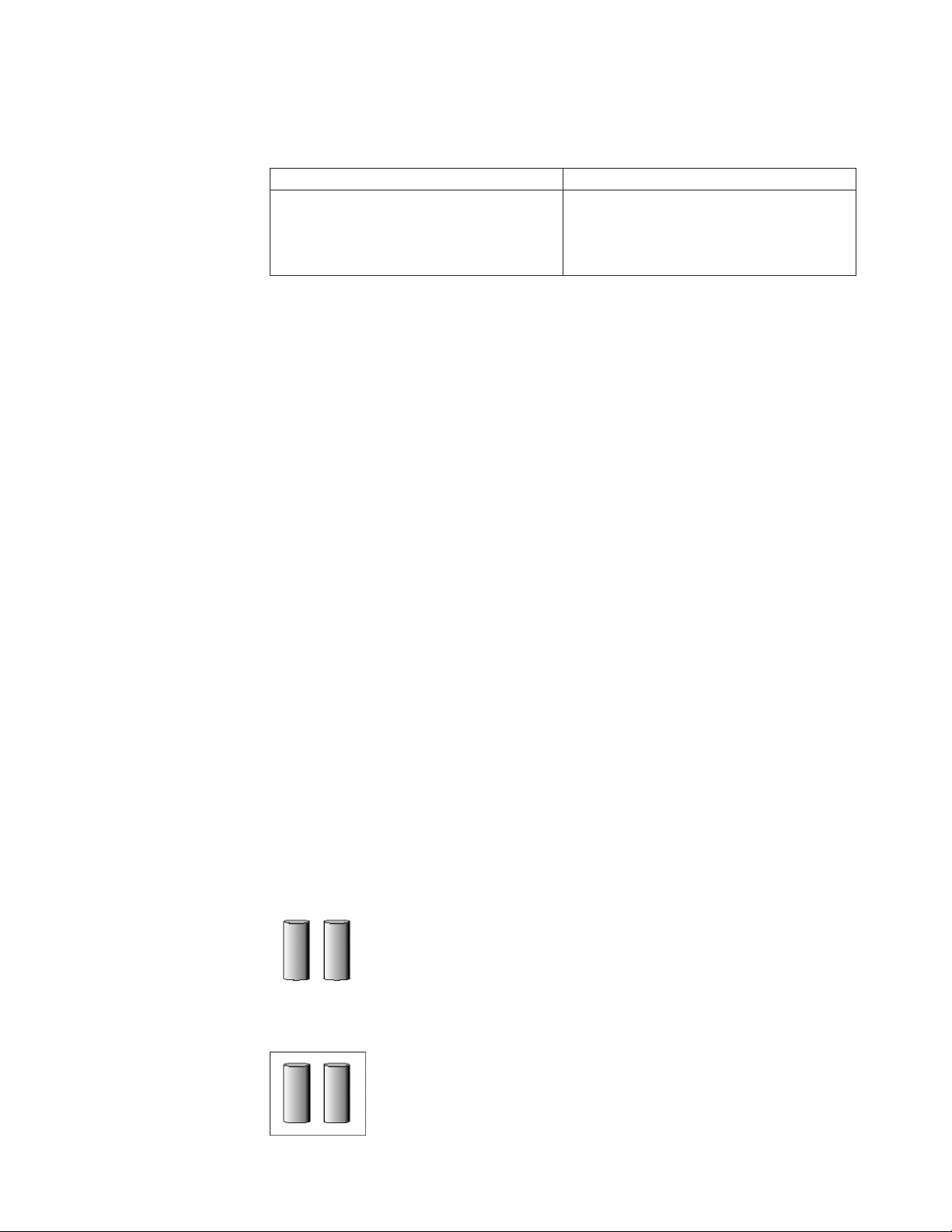
Advantages and disadvantages
RAID level-0 offers the following advantages and disadvantages.
Advantages Disadvantages
v Substantial speed enhancement
v Maximum utilization of physical drive
No data redundancy, resulting in data loss
in the event that a physical drive fails
storage capacity, because no room is taken
for redundant data or data-parity storage
More information
v Understanding RAID technology
v Understanding stripe-unit size
v Selecting a RAID level
v RAID level-1
v RAID level-1 Enhanced
v RAID level-5
v RAID level-5 Enhanced
v RAID level-5EE
v RAID level-6
v RAID level-x0
v RAID volumes
v Software and hardware support of RAID levels
Understanding RAID level-1
RAID level-1 uses data mirroring. Tw o physical drives are combined into an array,
and data is striped across the array. The first half of a stripe is the original data;
the second half of a stripe is a mirror (that is, a copy) of the data, but it is written
to the other drive in the RAID level-1 array.
RAID level-1 provides data redundancy and high levels of performance, but the
storage capacity is diminished. Because the data is mirrored, the capacity of the
logical drive when assigned RAID level-1 is 50% of the array capacity.
RAID level-1 requires two physical drives.
The following illustration shows an example of a RAID level-1 logical drive.
RAID level-1 example
Start with two physical drives.
Create an array using the two physical drives.
Chapter 3. Using ServeRAID Manager 35
Page 52

Then create a logical drive within that array.
The data is striped across the drives, creating blocks. Notice that the data on the
drive on the right is a copy of the data on the drive on the left.
With RAID level-1, if one of the physical drives fails, the controller switches read
and write requests to the remaining functional drive in the RAID level-1 array.
Advantages and disadvantages
RAID level-1 offers the following advantages and disadvantages.
Advantages Disadvantages
v 100% data redundancy
v High performance
Allows only 50% of the physical drive
storage capacity to be used
More information
v Understanding RAID technology
v Understanding stripe-unit size
v Selecting a RAID level
v RAID level-0
v RAID level-1 Enhanced
v RAID level-5
v RAID level-5 Enhanced
v RAID level-5EE
v RAID level-6
v RAID level-x0
v RAID volumes
v Software and hardware support of RAID levels
Understanding RAID level-1 Enhanced
RAID level-1 Enhanced (RAID level-1E) combines mirroring and data striping. This
RAID level stripes data and copies of the data across all of the drives in the array.
As with the standard RAID level-1, the data is mirrored, and the capacity of the
logical drive is 50% of the array capacity.
RAID level-1E has a similar profile to RAID level-1; it provides data redundancy
and high levels of performance, but the storage capacity is diminished. However,
RAID level-1E allows a larger number of physical drives to be used.
RAID level-1E requires a minimum of three drives and, depending upon the level
of firmware and the stripe-unit size, supports a maximum of 8 or 16 drives.
36 ServeRAID Manager Installation and User's Guide
Page 53
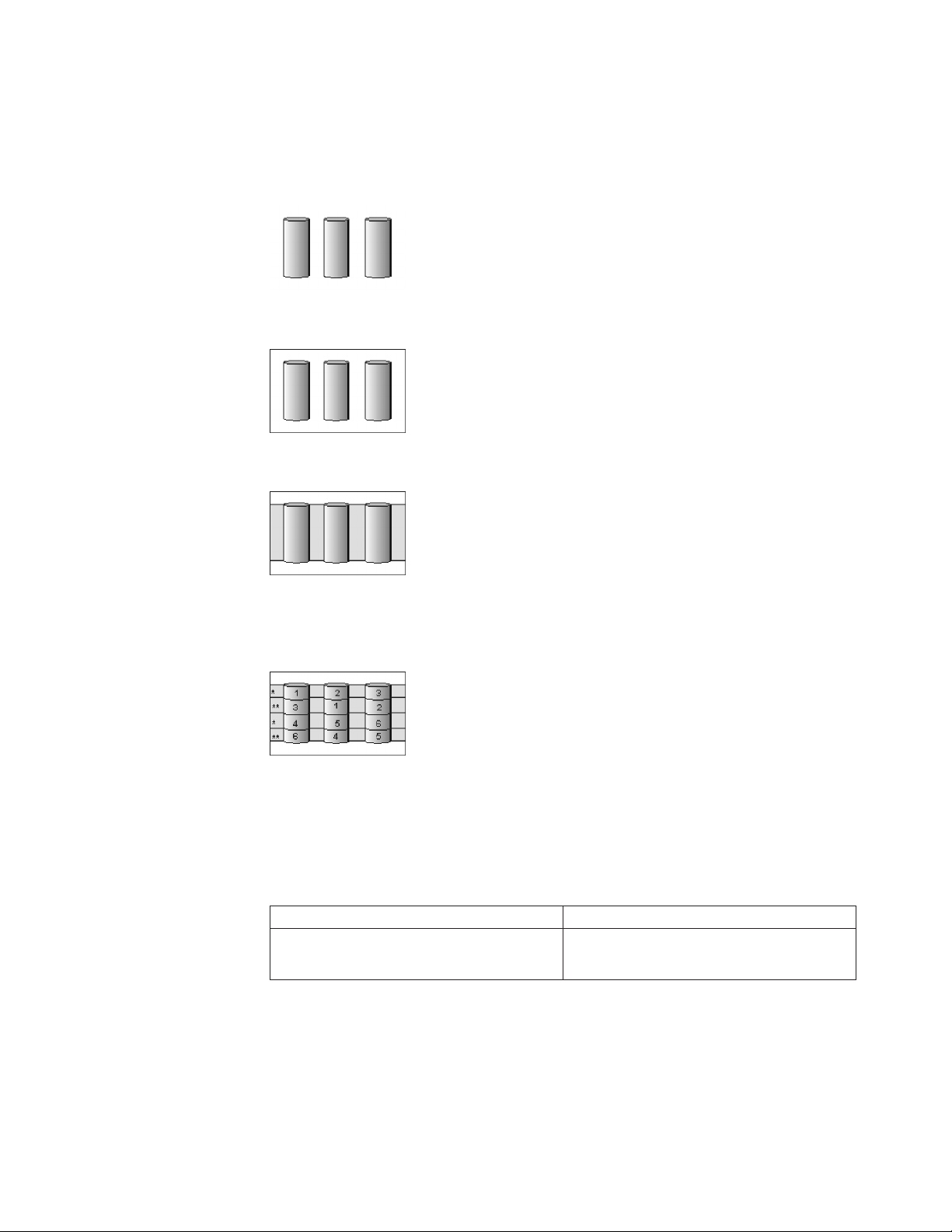
The following illustration is an example of a RAID level-1E logical drive.
RAID level-1 Enhanced example
Start with three physical drives.
Create an array using the physical drives.
Then create a logical drive within that array.
The data is striped across the drives, creating blocks. Notice that the stripe labeled
* is the data stripe and the stripe labeled ** is the copy of the preceding data
stripe. Also, notice that each block on the mirror stripe is shifted one drive.
With RAID level-1E, if one of the physical drives fails, the controller switches read
and write requests to the remaining functional drives in the RAID level-1E array.
Advantages and disadvantages
RAID level-1E offers the following advantages and disadvantages:
Advantages Disadvantages
v 100% data redundancy
v High performance
Allows only 50% of the physical drive
storage capacity to be used
More information
v Understanding RAID technology
v Understanding stripe-unit size
v Selecting a RAID level
v RAID level-0
v RAID level-1
v RAID level-5
Chapter 3. Using ServeRAID Manager 37
Page 54
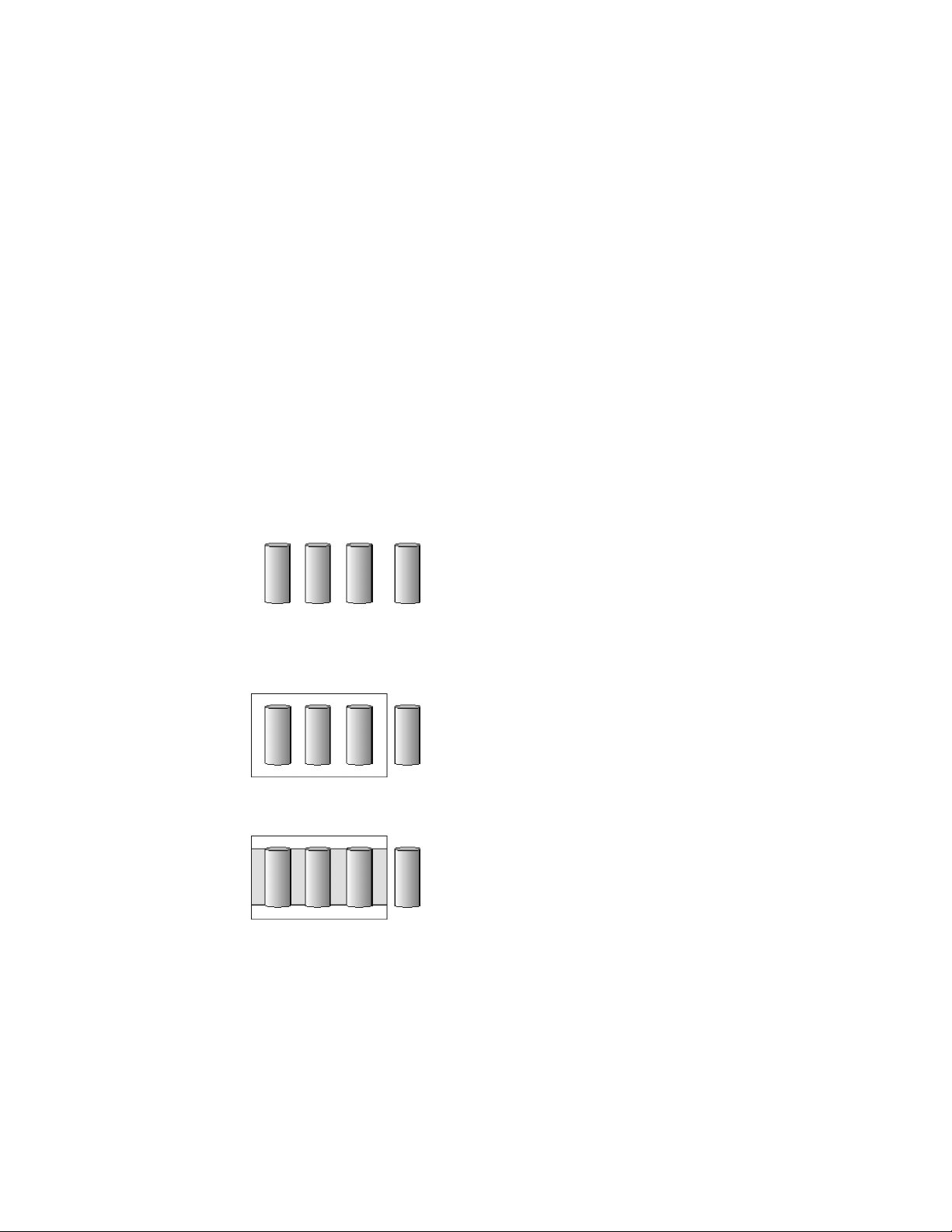
v RAID level-5 Enhanced
v RAID level-5EE
v RAID level-6
v RAID level-x0
v RAID volumes
Understanding RAID level-5
RAID level-5 stripes data and parity across all drives in the array.
RAID level-5 offers both data protection and increased throughput. When you
assign RAID level-5 to an array, the capacity of the array is reduced by the
capacity of one drive (for data-parity storage). RAID level-5 gives you higher
capacity than RAID level-1, but RAID level-1 offers better performance.
RAID level-5 requires a minimum of three drives and, depending upon the level of
firmware and the stripe-unit size, supports a maximum of 8 or 16 drives.
The following illustration is an example of a RAID level-5 logical drive.
RAID level-5 example
Start with four physical drives.
Create an array using three of the physical drives, leaving the fourth as a hot-spare
drive.
Then create a logical drive within that array.
The data is striped across the drives, creating blocks.
Notice that the storage of the data parity (denoted by *) also is striped, and it
shifts from drive to drive.
A parity block ( *) contains a representation of the data from the other blocks in
the same stripe. For example, the parity block in the first stripe contains data
representation of blocks 1 and 2.
38 ServeRAID Manager Installation and User's Guide
Page 55

If a physical drive fails in the array, the data from the failed physical drive is
reconstructed onto the hot-spare drive.
Advantages and disadvantages
RAID level-5 offers the following advantages and disadvantages.
Advantages Disadvantages
v 100% data protection
v Offers more physical drive storage
Lower performance than RAID level-1 and
level-1E
capacity than RAID level-1 or level-1E
More information
v Understanding RAID technology
v Understanding stripe-unit size
v Selecting a RAID level
v RAID level-0
v RAID level-1
v RAID level-1 Enhanced
v RAID level-5 Enhanced
v RAID level-5EE
v RAID level-6
v RAID level-x0
v RAID volumes
Understanding RAID level-5 Enhanced
Note: This RAID level is not available on all controllers.
RAID level-5E is the same as RAID level-5 with a built-in spare drive. Like RAID
level-5, this RAID level stripes data and parity across all of the drives in the array.
RAID level-5E offers both data protection and increased throughput. When an
array is assigned RAID level-5E, the capacity of the logical drive is reduced by the
capacity of two physical drives in the array (one for parity and one for the spare).
Reading from and writing to four physical drives is more efficient than reading
from and writing to three physical drives and an idle hot spare. Therefore, RAID
level-5E provides a higher level of performance than RAID level-5.
Chapter 3. Using ServeRAID Manager 39
Page 56

The spare drive is actually part of the RAID level-5E array, as shown in the
following example. With such a configuration, you cannot share the spare drive
with other arrays. If you want a spare drive for any other array, you must have
another spare drive for those arrays.
RAID level-5E requires a minimum of four drives and, depending upon the level
of firmware and the stripe-unit size, supports a maximum of 8 or 16 drives. RAID
level-5E is also firmware-specific.
Note: For RAID level-5E, you can have only one logical drive in an array. When
using RAID level-5E, you can have a maximum of seven logical drives on
the controller.
The following illustration is an example of a RAID level-5E logical drive.
RAID level-5 Enhanced example
Start with four physical drives.
Create an array using all four physical drives.
Then create a logical drive (labeled as 1) within the array. Notice that the
distributed spare drive is the free space (labeled as 2) shown below the logical
drive.
The data is striped across the drives, creating blocks in the logical drive. The
storage of the data parity (denoted by * ) is striped, and it shifts from drive to
drive as it does in RAID level-5. Notice that the spare drive is not striped.
If a physical drive fails in the array, the data from the failed drive is reconstructed.
The array undergoes compression, and the distributed spare drive becomes part of
the array. The logical drive remains RAID level-5E.
When you replace the failed drive, the data for the logical drive decompresses and
returns to the original striping scheme.
40 ServeRAID Manager Installation and User's Guide
Page 57

If you use a RAID level-5E logical drive in a failover or cluster configuration, the
RAID level-5E logical drive will not failover while undergoing compression or
decompression.
Advantages and disadvantages
RAID level-5E offers the following advantages and disadvantages.
Advantages Disadvantages
v 100% data protection
v Offers more physical drive storage
capacity than RAID level-1 or level-1E
v Higher performance than RAID level-5
v Lower performance than RAID level-1
and level-1E
v Supports only one logical drive per array
v Cannot share a hot-spare drive with other
arrays
v Not supported on all controllers
More information
v Understanding RAID technology
v Understanding stripe-unit size
v Selecting a RAID level
v RAID level-0
v RAID level-1
v RAID level-1 Enhanced
v RAID level-5
v RAID level-5EE
v RAID level-6
v RAID level-x0
v RAID volumes
Understanding RAID level-5EE
Note: This feature is not supported on all controllers.
RAID level-5EE is similar to RAID level-5E but with a more efficient distributed
spare and faster rebuild times. Like RAID level-5E, this RAID level stripes data
and parity across all of the drives in the array.
RAID level-5EE offers both data protection and increased throughput. When an
array is assigned RAID level-5EE, the capacity of the logical drive is reduced by
the capacity of two physical drives in the array: one for parity and one for the
spare.
The spare drive is part of the RAID level-5EE array. However, unlike RAID
level-5E, which uses contiguous free space for the spare, a RAID level-5EE spare is
interleaved with the parity blocks, as shown in the following example. This allows
Chapter 3. Using ServeRAID Manager 41
Page 58

data to be reconstructed more quickly if a physical drive in the array fails. With
such a configuration, you cannot share the spare drive with other arrays. If you
want a spare drive for any other array, you must have another spare drive for
those arrays.
RAID level-5EE requires a minimum of four drives and, depending upon the level
of firmware and the stripe-unit size, supports a maximum of 8 or 16 drives. RAID
level-5EE is also firmware-specific.
Note: For RAID level-5EE, you can have only one logical drive in an array.
The following illustration is an example of a RAID level-5EE logical drive.
RAID level-5EE example
Start with four physical drives.
Create an array using all four physical drives.
Then create a logical drive within the array.
The data is striped across the drives, creating blocks in the logical drive. The
storage of the data parity (denoted by *) is striped, and it shifts from drive to
drive as it does in RAID level-5E. The spare drive (denoted by S) is interleaved
with the parity blocks, and it also shifts from drive to drive.
If a physical drive fails in the array, the data from the failed drive is reconstructed.
The array undergoes compaction, and the distributed spare drive becomes part of
the array. The logical drive remains RAID level-5EE.
42 ServeRAID Manager Installation and User's Guide
Page 59

When you replace the failed drive, the data for the logical drive undergoes
expansion and returns to the original striping scheme.
Advantages and disadvantages
RAID level-5EE offers the following advantages and disadvantages.
Advantages
v 100% data protection
v Offers more physical drive storage capacity than RAID level-1 or
level-1E
v Higher performance than RAID level-5
v Faster rebuild than RAID level-5E
Disadvantages
v Lower performance than RAID level-1 and level-1E
v Supports only one logical drive per array
v Cannot share a hot-spare drive with other arrays
v Not supported on all controllers
More information
v Understanding RAID technology
v Understanding stripe-unit size
v Selecting a RAID level
v RAID level-0
v RAID level-1
v RAID level-1 Enhanced
v RAID level-5
v RAID level-6
v RAID level-x0
v RAID volumes
Understanding RAID level-6
RAID level-6 is similar to RAID level-5 but with two sets of parity information
instead of one. RAID level-6 stripes blocks of data and parity across all drives in
the array like RAID level-5, but adds a second set of parity information for each
block of data.
When you assign RAID level-6 to an array, the capacity of the array is reduced for
data-parity storage (the exact amount depends on the size of the drives in the
array). The second set of parity information is added to improve fault tolerance.
RAID level-6 can handle two simultaneous drive failures, where other single RAID
levels can handle, at most, only one.
RAID level-6 requires a minimum of four drives and supports a maximum of 16
drives. The maximum stripe-unit size depends on the number of drives in the
array.
The following illustration is an example of a RAID level-6 logical drive.
Chapter 3. Using ServeRAID Manager 43
Page 60
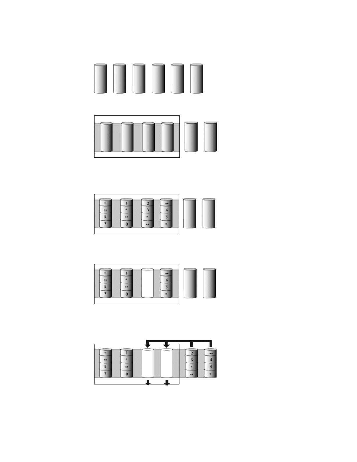
RAID level-6 example
Start with six physical drives.
Create a logical drive using four physical drives, leaving two for hot spare drives.
The data is striped across the drives, creating blocks in the logical drive. The
storage of the data parity (denoted by * and **) is striped, and it shifts from drive
to drive as it does in RAID level-5.
If a physical drive fails in the array, the logical drive is degraded but remains fault
tolerant.
If a second physical drive fails in the array, the data from the failed drives are
reconstructed onto the hot-spare drives, and the data for the logical drive return to
the original striping scheme.
44 ServeRAID Manager Installation and User's Guide
Page 61
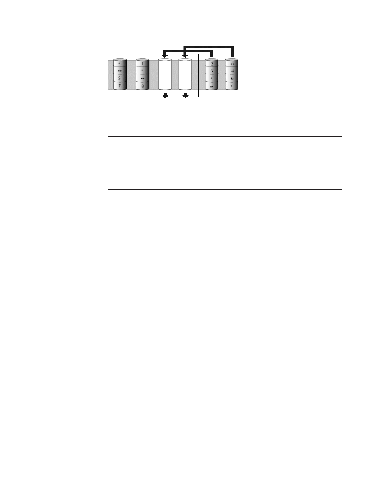
Advantages and disadvantages
RAID level-6 offers the following advantages and disadvantages.
Advantages Disadvantages
v 100% data protection
v Extremely high data fault tolerance
v Can sustain two simultaneous drive
failures
v Good solution for mission critical
applications
v Lower performance than RAID level-5
because of two parity drives
v Not supported on all controllers
More information
v Understanding RAID technology
v Understanding stripe-unit size
v Selecting a RAID level
v RAID level-0
v RAID level-1
v RAID level-1 Enhanced
v RAID level-5
v RAID level-5E Enhanced
v RAID level-x0
v RAID volumes
Understanding RAID level-x0
Note: RAID level-x0 is not available on all controllers.
RAID level-x0 refers to RAID level-00, 10, 1E0, 50 and 60. RAID level-x0 uses an
array of arrays, or a spanned array. The operating system uses the spanned array
logical drive in the same way as a regular array logical drive.
RAID level-x0 allows more physical drives in an array. The benefits of doing so are
larger logical drives, increased performance, and increased reliability. RAID level-0,
10, 1E, 5, 5E, and 6 cannot use more than 16 physical drives in an array; however,
RAID level-1E0, 50, and 60 support 60 to 128 drives.
RAID level-x0 requires a minimum of two drives and supports a maximum of 60
to 128 drives, depending on the controller.
The following illustration is an example of a RAID level-10 logical drive.
Chapter 3. Using ServeRAID Manager 45
Page 62

RAID level-10 example
Start with six physical drives.
Create three arrays (labeled A, B, and C), each array using two physical drives.
Then create a spanned array (labeled as *) that spans the three arrays.
A sub-logical drive is created within each array (A, B, and C). Then the data is
striped across the physical drives in the array, creating blocks.
Notice that, in each array, the data on the drive on the right is a copy of the data
on the drive on the left. This is because the sub-logical drives (A, B, and C) are
RAID level-1 in a RAID level-10 implementation (see the following table).
Then create a logical drive within the spanned array (*).
The data is striped across this logical drive, creating blocks ( 1- 12). Notice that
none of these blocks are redundant. This is because the logical drive is RAID
level-0 in a RAID level-x0 implementation (see the following table).
RAID level Sub-logical drive Spanned array logical drive
00 RAID level-0 RAID level-0
10 RAID level-1 RAID level-0
1E0 RAID level-1E RAID level-0
50 RAID level-5 RAID level-0
46 ServeRAID Manager Installation and User's Guide
Page 63

RAID level Sub-logical drive Spanned array logical drive
60 RAID level-6 RAID level-0
With RAID level-10, 1E0, and 50, if one of the physical drives fails in a sub-logical
drive, the ServeRAID controller switches read and write requests to the remaining
functional drives in the sub-logical drive. With RAID level-60, if one or two of the
physical drives fails in a sub-logical drive, the ServeRAID controller switches read
and write requests to the remaining functional drives in the sub-logical drive. With
RAID level-00, a physical drive failure within the sub-logical drive results in loss of
data.
Advantages and disadvantages
RAID level-x0 offers the following advantages and disadvantages.
Advantages Disadvantages
v Supports up to 60 physical drives on SCSI
controllers
v Supports up to 128 physical drives on
SAS and S ATA controllers
v 100% data redundancy (except for RAID
level-00)
v Not available on all controllers
v No data redundancy for RAID level-00
More information
v Understanding RAID technology
v Understanding stripe-unit size
v Selecting a RAID level
v RAID level-0
v RAID level-1
v RAID level-1 Enhanced
v RAID level-5
v RAID level-5 Enhanced
v RAID level-5EE
v RAID level-6
v RAID volumes
Understanding RAID volumes
Note: HostRAID controllers do not support RAID volumes.
For ServeRAID SAS controllers (8i/8k/8k-l) and the ServeRAID-7t S ATA controller,
the ServeRAID Manager supports the following RAID volume types:
v Simple Volume - a single disk drive or segment; not redundant.
v Spanned Volume - two or more disk drives or segment with the same or
different capacity, connected end-to-end. A spanned volume offers no
redundancy or performance advantage over a single drive.
v RAID Volume - two or more logical drives with the same RAID level,
connected end-to-end. The logical drives may have the same or different
capacity and are not striped together; they may be redundant, depending on the
RAID level.
Notes:
Chapter 3. Using ServeRAID Manager 47
Page 64

– You must create the individual logical drives before you create a
RAID Volume. Use the Configuration wizard to create the logical
drives; then, run the Configuration wizard again to create the RAID
Volume.
– When you create a RAID Volume, the ServeRAID Manager replaces
the individual logical drives with a single RAID Volume icon in the
Logical devices view; then, it reports the logical drives as deleted in
the event viewer. The event message is normal and does not indicate a
loss of data.
More information
v Understanding RAID technology
v Understanding stripe-unit size
v Selecting a RAID level
v RAID level-0
v RAID level-1
v RAID level-1 Enhanced
v RAID level-5
v RAID level-5 Enhanced
v RAID level-5EE
v RAID level-6
v RAID level-x0
Creating a simple volume
Use this action to create a simple volume. A simple volume is a single disk drive
or segment used for storage in a RAID system; it is not redundant.
Complete the following steps to create a simple volume:
1. In the Physical devices view, click
(online physical drive).
2. Right-click Create simple volume.
3. Click Yes to confirm.
More information
v Understanding RAID technology
Selecting a RAID level and tuning performance
Disk arrays are used to improve performance and reliability. The amount of
improvement depends on the application programs that you run on the server and
the RAID levels that you assign to the logical drive.
Each RAID level provides different levels of fault-tolerance (data redundancy),
utilization of physical drive capacity, and read and write performance. In addition,
the RAID levels differ in regard to the minimum and maximum number of
physical drives that are supported.
When selecting a RAID level for your system, consider the following factors.
Note: Not all RAID levels are supported by all ServeRAID controllers.
Data redun-
RAID level
RAID level-0 No 100% Superior Superior No 1 16
dancy
Physical
drive
capacity
utili- zation
Read performance
Write performance
Built-in
spare drive
Min.
number of
drives
48 ServeRAID Manager Installation and User's Guide
Max.
number of
drives
Page 65

Physical
RAID level
Data redundancy
drive
capacity
utili- zation
Read performance
Write performance
Built-in
spare drive
Min.
number of
drives
RAID level-1 Ye s 50% Very high Very high No 2 2
RAID
Yes 50% Very high Very high No 3 16
level-1E
RAID level-5 Ye s 67% to 94% Superior High No 3 16
RAID
Yes 50% to 88% Superior High Ye s 4 16
level-5E
RAID
Yes 50% to 88% Superior High Ye s 4 16
level-5EE
RAID level-6 Ye s 50% to 88% Very High High No 4 16
RAID
No 100% Superior Superior No 2 60
level-00
RAID
Yes 50% Very high Very high No 4 16
level-10
RAID
Yes 50% Very high Very high No 6 60
level-1E0
RAID
Yes 67% to 94% Superior High No 6 60 (SCSI) 128
level-50
RAID
Yes 50% to 88% Very High High No 8 128
level-60
Spanned
No 100% Superior Superior No 2 48
Volume
RAID
No 50% to 100% Superior Superior No 4 48
Volume
Max.
number of
drives
(SAS, SATA)
Physical drive utilization, read performance, and write performance depend on the
number of drives in the array. Generally, the more drives in the array, the better
the performance.
More information
v Understanding RAID technology
v Selecting the logical drive size
v Selecting the RAID level by array capacity
v Creating logical drives (action)
v Configuring RAID and creating arrays (action)
v Creating logical drives in the wizard
v Things to consider when changing the RAID level
Chapter 3. Using ServeRAID Manager 49
Page 66

Selecting the RAID level by array capacity
Note: Not all RAID levels are supported by all ServeRAID controllers.
If your array has... Consider this RAID level...
RAID level-0
One or more physical drives in an array.
Notes:
v This is the only choice if the array
contains only one physical drive.
v You can select RAID level-0 for any
logical drive.
Two physical drives. The default for two
RAID level-1
physical drives is RAID level-1.
Three or more physical drives. RAID level-1E
Three or more physical drives. RAID level-5
Four or more physical drives. RAID level-5E
Four or more physical drives. RAID level-5EE
Four or more physical drives. RAID level-6
Two or more physical drives. RAID level-00
Four or more physical drives. RAID level-10
Six or more physical drives. RAID level-1E0
Six or more physical drives. RAID level-50
Eight or more physical drives. RAID level-60
More information
v Selecting a RAID level and performance tuning
Example: Total disk capacity
Physical drives in an array can be of different capacities (1 GB, or 2 GB, for
example). The sum of the physical drives’ capacity grouped in an array is the total
disk capacity.
For example, if you group two 2 GB drives and one 3 GB drive into an array, the
total disk capacity is the 7 GB physically available.
2 GB 2 GB 3 GB
50 ServeRAID Manager Installation and User's Guide
Page 67

Similarly, if you group three 2 GB drives and 1 GB drive into an array, the total
disk capacity is the 7 GB physically available.
More information
v Example: Usable and unusable capacity
Example: Usable and unusable capacity
Physical drive capacities influence the way you create arrays and logical drives.
Drives in an array can be of different capacities (1 GB, or 2 GB, for example), but
RAID controllers treat them as if they all have the capacity of the smallest physical
drive.
For example, if you group two 2 GB drives and one 3 GB drive into an array, the
usable capacity of the array is 2 GB times 3, or 6 GB, not the 7 GB physically
available. The 7 GB is the total disk capacity. In the following diagram, usable
capacity is labeled as 1 and unusable capacity is labeled as 2.
2 GB 2 GB 3 GB
Similarly, if you group three 2 GB drives and 1 GB drive into an array, the usable
capacity of that array is 4 GB, not the 7 GB physically available. The 7 GB is the
total disk capacity. The remaining capacity left on the three 2 GB drive is unusable
capacity.
The optimal way to create arrays is to use physical drives that have the same
capacity. Doing so avoids unusable capacity
For the ServeRAID-8i, ServeRAID-8k/8k-l, and ServeRAID-7t controllers, usable
capacity is the same as the total disk capacity. That is, you can use the remaining
space to define another logical drive. The segments that make up the logical drive
must be the same size on each physical drive. For example, you can group two 1
GB segments with the remaining space from the previous example to define a 3 GB
logical drive. In the following diagram, the new logical drive is labeled 2; 4 GB of
usable capacity remain, 2 GB on each drive, labeled 3.
Chapter 3. Using ServeRAID Manager 51
Page 68

2 GB 2 GB 3GB 3 GB 3 GB
More information
v Example: Total disk capacity
v Understanding physical drive capacity and unusable capacity
Software and hardware support of RAID levels
RAID level ServeRAID software*
release that supports the
Hardware levels that
support the RAID level
RAID level
0 All ServeRAID on the board,
ServeRAID, ServeRAID-II,
ServeRAID-3 family,
ServeRAID-4 family,
ServeRAID-5i,
ServeRAID-6M,
ServeRAID-6i/6i+,
ServeRAID-7k,
ServeRAID-7t,
ServeRAID-8i/8k/8k-l
1 All ServeRAID on the board,
ServeRAID, ServeRAID-II,
ServeRAID-3 family,
ServeRAID-4 family,
ServeRAID-5i,
ServeRAID-6M,
ServeRAID-6i/6i+,
ServeRAID-7k,
ServeRAID-7t,
ServeRAID-8i/8k/8k-l,
integrated RAID controller
1E All ServeRAID on the board,
ServeRAID, ServeRAID-II,
ServeRAID-3 family,
ServeRAID-4 family,
ServeRAID-5i,
ServeRAID-6M,
ServeRAID-6i/6i+,
ServeRAID-7k,
ServeRAID-8i/8k/8k-l
52 ServeRAID Manager Installation and User's Guide
Page 69

RAID level ServeRAID software*
release that supports the
Hardware levels that
support the RAID level
RAID level
5 All ServeRAID on the board,
ServeRAID, ServeRAID-II,
ServeRAID-3 family,
ServeRAID-4 family,
ServeRAID-5i,
ServeRAID-6M,
ServeRAID-6i/6i+,
ServeRAID-7k,
ServeRAID-7t,
ServeRAID-8i/8k/8k-l
5E ServeRAID 3.50 or later ServeRAID-3 and
ServeRAID-4 families.
5EE ServeRAID 6.00 or later ServeRAID-4 family except
ServeRAID-4H,
ServeRAID-6M,
ServeRAID-6i/6i+,
ServeRAID-7k,
ServeRAID-8i/8k/8k-l
6 ServeRAID 7.30 or later ServeRAID-8i/8k/8k-l
x0 ServeRAID 4.00 or later ServeRAID-4 family,
ServeRAID-5i,
ServeRAID-6M,
ServeRAID-6i/6i+,
ServeRAID-7k,
ServeRAID-7t,
ServeRAID-8i/8k/8k-l
* ServeRAID software refers to BIOS, firmware, device drivers, programs, and so
forth.
RAID levels that can use a hot-spare or standby hot-spare drive
Hot-spare and standby hot-spare drives supply additional protection to a RAID
configuration. When you select the RAID level for your configuration, consider the
following:
RAID level Can use a hot spare? Can use a standby hot
spare?
0 No No
1 Yes Yes
1E Ye s Ye s
5 Yes Yes
5E * Ye s Ye s
5EE * Yes Yes
6 Yes No
00 No No
10 Yes Yes
1E0 Ye s Ye s
Chapter 3. Using ServeRAID Manager 53
Page 70

RAID level Can use a hot spare? Can use a standby hot
50 Yes Yes
60 Yes No
* RAID level-5E and RAID level-5EE integrate a distributed hot-spare drive, but
also can use traditional hot-spare and standby hot-spare drives. If a physical drive
fails in a RAID level-5E or level-5EE logical drive and the configuration includes a
hot-spare or standby hot-spare drive, the data is rebuilt on the hot-spare or
standby hot-spare drive. A RAID level-5E compression or RAID level-5EE
compaction does not occur. If a second physical drive fails in the RAID level-5E or
level-5EE logical drive, a data compression or compaction will take place on the
distributed hot-spare drive.
More information
v Understanding RAID level-5E
v Understanding RAID level-5EE
Selecting the RAID level in the migration wizard
To select a new RAID level for the array:
1. Click the RAID level radio button. Only the most common choices appear in
the list.
spare?
2. To choose a different RAID level, click Advanced settings; then, choose a RAID
level from the available options.
Note: Only valid RAID level migrations appear in the list. Migration
requirements for each RAID level are described here.
3. When you are ready to continue, click Next. The Modify Array window opens.
More information
v Things to consider when changing RAID levels
v Understanding RAID technology
Starting the ServeRAID Manager task
This topic describes how to start ServeRAID Manager in IBM Director.
To start ServeRAID Manager, in the IBM Director Console Tasks pane, drag the
ServeRAID Manager task onto a managed system that supports ServeRAID.
The left pane is the Enterprise view pane, and the right pane is the Physical and
Logical devices pane. The bottom pane is the event viewer.
54 ServeRAID Manager Installation and User's Guide
Page 71

You can use ServeRAID Manager to view information about RAID controllers and
the RAID subsystem, which includes arrays, logical drives, hot-spare drives, and
physical drives.
Logging in to the ServeRAID Manager
Use this action log into the ServeRAID Manager. You must log in when you first
start the ServeRAID Manager, or if you are logged out.
You can log into the ServeRAID Manager as:
v Administrator: The Administrator log in allows you to view and modify the
RAID configuration. You can create and delete logical drives, synchronize logical
drives, perform migrations, add and remove hot-spare drives, and verify logical
drives. To log in as Administrator, you must be a member of the Administrator
group for your operating system. Use the Administrator user name and
password or your own user name and password if you are a member of the
Administrator group.
v User: The User log in allows you to view the RAID configuration, verify logical
drives, and add and remove hot-spares. Yo u cannot create or delete logical
drives or perform migrations. To log in as User, use your normal network user
name and password.
On Linux systems, the user name and password is defined in
Note:
/etc/pam.d/storman.
v Guest: The Guest log in allows you to view the RAID configuration only. You
cannot change or modify any information. To log in as Guest, simply click
Cancel when the ServeRAID Manager Log In window opens.
Logging in at ServeRAID Manager startup
1. In the User Name field, type your user name.
2. In the Password field, type your password.
Note: The password is case sensitive.
3. Click Connect. (To log in as ″Guest″, click Cancel.)
Logging in if you are currently logged out or logged in as Guest
1. In the Enterprise view, click
2. Click Action → Log in. The ServeRAID Manager Log In window opens.
3. In the User Name field, type your user name.
4. In the Password field, type your password.
Note: The password is case sensitive.
5. Click Connect.
(system).
More information
v Logging out
v Configuring NetWare user authentication
Chapter 3. Using ServeRAID Manager 55
Page 72

Logging out of the ServeRAID Manager
Use this action to log out of the ServeRAID Manager.
1. In the Enterprise view, click
(system).
2. From Action menu, click Action → Log out.
Note: After log out, you can still use the ServeRAID Manager Guest account.
The Guest account allows you to view the RAID configuration but not
change it.
More information
v Logging in to the ServeRAID Manager
Using the ServeRAID Manager from the command line
You can use the following command-line parameters when starting the ServeRAID
Manager:
–h | –? | help
Displays basic help for the ServeRAID Manager.
–l
Starts the ServeRAID Manager in local-only mode.
The ServeRAID Manager does not obtain TCP/IP information and the
remote actions are disabled. The only system appearing in the Enterprise
view is the local system.
If you have remote systems defined in the Enterprise view when you run
in nonlocal-only mode (that is, not using the -l flag), they do not appear in
the Enterprise view when you run in local-only mode.
Starting in local-only mode does not change any remote systems you
Note:
have defined. The next time you start the ServeRAID Manager in
nonlocal-only mode, your remote systems will appear in the
Enterprise view again.
–r
Resets the Enterprise view. That is, it removes all remote systems from the
Enterprise view tree.
This command does not remove remote systems from the remote
Note:
notification list.
Using the ServeRAID Manager with screen-reading software
To use the ServeRAID Manager with screen-reading software, follow these
steps:</>
1. Download and install the Java 2 Platform for Microsoft Windows Operating
System:
2.
a. Go to http://java.sun.com/j2se/1.4.2/download.html and download the
Java 2 Platform Standard Edition Java Runtime Environment Version 1.4.2.
An executable is available for installation.
56 ServeRAID Manager Installation and User's Guide
Page 73

b. Follow the instructions provided by the installation program, accepting all
defaults.
Download and install the Java Access Bridge for Microsoft Windows Operating
3.
System:
4.
a. Go to http://java.sun.com/developer/earlyAccess/accessbridge/ and
download the compressed zip file. An older version is available at
http://java.sun.com/products/accessbridge/.
b. Extract the zip file and navigate to the Installer folder. Execute the file
Install.exe.
c. Make sure that the installation program detects the Java Virtual Machine
you just installed.
d. Follow the instructions provided by the installation program.
Install the screen reader software (ie, JAWS).
5.
6. Double click the RaidManAcc.bat file to start the ServeRAID Manager program.
7.
Note: Be sure that the java command is in your classpath. This should occur
automatically when you install the Java Virtual Machine. If not, edit the
batch file to explicitly point to the java.exe file found in the bin directory
of the Java installation.
More information
v Accessing the ServeRAID Manager using the keyboard
Using the ServeRAID Manager in bootable-CD mode
The ServeRAID Manager program operates in two ways:
v bootable-CD mode
v As an installed software program.
When you run the ServeRAID Manager program from the IBM ServeRAID Support
CD, you are using bootable-CD mode. The bootable-CD mode allows you to
configure your ServeRAID controller before you install your operating system. After
you have configured the ServeRAID controller and installed the operating system,
you also can use bootable-CD mode to fine-tune specific ServeRAID controller
settings.
To run the ServeRAID Manager program in bootable-CD mode, turn on the server;
then, insert the IBM ServeRAID Support CD (or the CD that contains the
ServeRAID Manager program that came with your server) into the CD-ROM drive.
If the ServeRAID Manager program detects unconfigured ServeRAID controllers
and ready drives, the program automatically starts the Configuration wizard.
These are the actions that are available in bootable-CD mode only:
v Changing the rebuild rate
v Changing the stripe-unit size
v Changing BIOS-compatibility mapping
v Changing the SCSI-transfer speed
v Enabling and disabling read-ahead cache mode
v Enabling and disabling unattended mode
v Changing the write-cache mode on a physical drive
Chapter 3. Using ServeRAID Manager 57
Page 74

v Changing the write-cache mode on a logical drives
v Configuring for clustering
Accessing the ServeRAID Manager using the keyboard
Use the following key combinations to navigate in windows, tables, text areas, and
the ServeRAID Manager tree.
Navigating in windows
Action Key Combination
Navigate out forward Tab
Navigate out backward Shift + Ta b
Activate Enter
Spacebar
Alt + character accelerator key, if defined
Navigate within group Arrow keys
Check / Uncheck Spacebar
To beginning of list Home
To end of list End
Select all entries in list Ctrl + A
Select additional item in list Ctrl + Spacebar
Navigate out of menu, toolbar and tool tip
Esc
components
Open or post menu Up arrow, Down arrow
Enter
Spacebar
Alt + character accelerator key, if defined
Retract menu Esc
Activate menu item Enter
Open submenu Right arrow
Retract submenu Left arrow
Toggle drop-down list Alt + Up arrow
Move to next link in We b page Ctrl + T
Activate link in Web page Ctrl + Spacebar
58 ServeRAID Manager Installation and User's Guide
Spacebar
Alt + character accelerator key, if defined
Esc
Alt + Down arrow
Page 75

Navigating in tables or text areas
Action Key Combination
Navigate out forward in table or text area Ctrl + Ta b
Navigate out backward in table or text area Ctrl + Shift + Tab
Move to next cell
(wrap to next row)
Move to previous cell
(wrap to previous row)
Tab
(Right arrow)
Shift + Ta b
(Left arrow)
Move to cell above Up
Move to cell below Down
Accessing and navigating in the tree
Action Key Combination
Accessing the tree pane Ctrl + Ta b
Expand entry Right
Collapse entry Left
Single select Ctrl + Spacebar
Other keyboard navigation shortcuts
Action Key Combination
Close active window Alt + F4
Display context menu for selected object Enter
Select controller, channel, or drive object Spacebar
Display selected object properties Alt + Enter
Open Help window F1
Expand/collapse physical and logical
Up arrow
devices
Down arrow
Display event detail window (focus in event
Spacebar
viewer)
More information
v ServeRAID Manager accessibility features
v Accessing the ServeRAID Manager using screen-reading software
Verifying that the ServeRAID Manager agent is running
Use the following procedure to verify that the ServeRAID Manager agent is
running on your system.
Chapter 3. Using ServeRAID Manager 59
Page 76

Windows 2000, Windows XP, Windows Server 2003
1. In the lower-left corner of the desktop, click Start → All Programs →
Administrative Tools → Services. The Services window opens.
2. In the Services table, verify that the ″ServeRAID Manager Agent″ is listed and
started.
Windows NT
1. In the lower-left corner of the desktop, click Start → Settings → Control Panel.
The Control Panel window opens.
2. Double-click Services. The Services window opens.
3. In the Services table, verify that the ″ServeRAID Manager Agent″ is listed and
started.
OS/2
1. Press Ctrl + Esc. The OS/2 Window List opens.
2. Verify that the ″ServeRAID Manager Agent″ is listed.
NetWare
1. Press Alt + Esc to cycle through the NetWare consoles.
2. Verify that ″ServeRAID Manager″ is displayed on the first line of a console
screen. If none of the console screens display ″ServeRAID Manager,″ the agent
is not running.
Linux, OpenServer, UnixWare and Open UNIX
1. Open a shell window.
2. At the command prompt, type the following:
ps -ef | grep RaidAgnt.sh
3. If the agent is running, the process is listed as the following: sh RaidAgnt.sh.
More information
v Using the ServeRAID agent
v Starting the ServeRAID Manager agent
v Configuring the ServeRAID Manager agent
ServeRAID Manager and LED flash states
The amber and blue LEDs are controlled by the backplane (for internal physical
drives) or enclosure (for external physical drives). Controllers send commands to
the backplane or enclosure processor to set a logical state for the LED, and the
subsystem translates that LED state into the following flash states:
Controller device state Slot state LED flash state
defunct Device is faulty On
Rebuilding Device is rebuilding Slow flash
Identify Identify the device Fast flash
Other No error Off
The green LED is an activity indicator for the physical drive and is controlled by
the physical drive.
60 ServeRAID Manager Installation and User's Guide
Page 77

More information
v Identifying devices (action)
v Using Identify to work with your systems
Chapter 3. Using ServeRAID Manager 61
Page 78

62 ServeRAID Manager Installation and User's Guide
Page 79

Chapter 4. Managing ServeRAID devices
Configuring ServeRAID controllers and enclosures in the Configuration wizard
Configuring an enclosure: the basic steps
The following steps are an overview of the enclosure configuration process:
1. In the Enterprise view, click
2. In the Logical devices view, click
Configuration wizard opens.
3. Select the physical drives that you want to include in your arrays or create as
hot-spare drives.
4. Define the logical drives for your arrays.
5. Define the authentication method for each logical drive (iSCSI initiators only).
6. Define the initiators that can access the enclosure.
7. Assign logical drives to initiators.
8. Review the configuration summary.
9. Click Apply. The ServeRAID Manager will configure the controller and
synchronize the logical drives.
(enclosure) that you want to configure.
; or click
on the toolbar. The
More information
v Configuring RAID
Configuring ServeRAID SCSI controllers (ServeRAID series 3, 4, 5, 6, and 7K)
Choosing between Express and Custom configuration
Note: If you intend to use your ServeRAID controllers in a Microsoft Windows
failover or clustering environment, review the ServeRAID publications
before configuring ServeRAID.
In the Configuration wizard, you can choose from two paths to configure your
ServeRAID subsystem:
v Click Express configuration for a quick and easy path for you to automatically
configure your ServeRAID controller. This path creates the most efficient
ServeRAID configuration based on the number and capacity of the ready
physical drives available in your system. If four or more ready drives of the
same capacity are available, this choice also will define a hot-spare drive.
Express configuration does the following:
– Creates arrays by grouping together same-sized physical drives.
– Creates one logical drive per array up to 2 terabytes (TB) maximum.
– Assigns a RAID level based on the number of physical drives in an array:
- An array with a single physical drive is assigned RAID level-0.
- An array with two physical drives is assigned RAID level-1.
- An array with three or more physical drives is assigned RAID level-5.
© Copyright IBM Corp. 1999, 2006 63
Page 80

Note: If the physical drive size exceeds 2TB, Express configuration removes
drives until the size is less than 2 TB. It creates an additional array
with the left-over drive(s).
– Designates a hot-spare drive for the controller. If one or more arrays has four
or more physical drives, the largest-sized drive from those arrays will be
designated the hot-spare drive.
When you choose Express configuration, you have the opportunity to
Note:
review and approve the configuration before the ServeRAID Manager
applies the configuration. If you need to modify the configuration, you
can do it from the configuration summary.
v Click Custom configuration for a path that lets you manually configure your
ServeRAID controller. Choose this path to do any of the following:
– Configure your controller manually.
– Assign RAID level-1E, RAID level-5E, RAID level-5EE, or RAID level-x0 to a
logical drive.
– Create more than one logical drive per array.
the Custom path, you can:
Using
– Select the physical drives that you want to include in each array and that you
want to use as hot-spare drives.
– Define the number, size, and RAID level of the logical drives for each array.
– Review the configuration summary.
Click Automatically initialize new logical drives. Initializing a logical drive erases
the first 1024 sectors on the drive and prevents access to any data previously
stored on the drive. Yo u can initialize the drive later if you do not choose
automatic initialization.
When you are ready to continue, click Next.
More information
v Understanding stripe-unit size
v Initializing a logical drive
v Understanding physical drive capacity and unusable capacity
Creating arrays and hot-spare drives
Complete the following steps to create arrays:
1. Start the custom configuration wizard and complete all previous steps.
2. Click the appropriate Array tab in the right pane:
3. Then, from the list of ready drives, select the drives you want to add to the
array:
4. Click
click
>> (Add selected drives) to add the drives to the array. Yo u can
>> (Add all drives) to move all ready drives to an array.
64 ServeRAID Manager Installation and User's Guide
Page 81

5. Repeat steps 2 and 3 for each additional array or hot-spare drive that you want
to configure.
6. If you do not want to create a spanned array, skip to step 6. Otherwise, select
the Span arrays check box
. Then, click Next. If you created two
arrays only, the ServeRAID Manager uses those arrays to create the spanned
array; continue to step 6. Otherwise, the Create Spanned Arrays window opens.
To create a spanned array, each array must have the same number of
Note:
physical drives.
7. After you select the ready drives for your arrays and hot-spare drive, click
Next. The Create Logical Drives window opens.
To return to the Express and Custom Configuration window, click Back. To leave
the Configuration wizard, click Cancel.
More information
v Understanding creating basic arrays
v Example: Express configuration
v Creating spanned arrays
v Understanding creating spanned arrays
v Configuring the ServeRAID controller: the basic steps
Creating spanned arrays
If you want to assign RAID level-x0 to an array, you must create a spanned array.
Note: Spanned arrays are supported only by IBM ServeRAID-4 Ultra160,
ServeRAID-5i Ultra320, ServeRAID-6M Ultra320, and ServeRAID-6i/6i+
Ultra320 SCSI controllers.
Complete the following steps to create one or more identical spanned arrays:
1. Start the custom configuration wizard and complete all previous steps.
2. In the list of arrays, click the arrays that you want to add to your spanned
3. Click
4. To create additional spanned arrays, click the New spanned array tab in the
5. Click Next; the Create Logical Drives window opens.
array.
>> (Add selected arrays) to add the arrays to the spanned array. You
can click
>> (Add all arrays) to move all arrays to the spanned array.
right pane.
Then, repeat steps 2 and 3.
To return to the Create Arrays window, click Back. To leave the Configuration
wizard, click Cancel.
More information
v Understanding RAID level-x0
v Understanding creating spanned arrays
Chapter 4. Managing ServeRAID devices 65
Page 82

Creating logical drives
Complete the following steps to create logical drives:
1. Start the custom configuration wizard and complete all previous steps.
2. Click the appropriate Array tab.
3. Select a RAID level from the drop-down list.
Note:
a. RAID level-5E and RAID level-5EE allow only one logical drive per
array.
b. If you are configuring a spanned array, you can set the RAID level
only for the first logical drive you create.
c. If you plan to use ″ Change RAID level,″ you must assign the same
RAID level to all logical drives within a single array.
Attention: Before assigning a logical drive RAID level-5E or RAID level-5EE,
consider the following. If a physical drive fails during a post-failover
resynchronization, the logical drive will enter the blocked state. Data might be
lost or damaged.
4. If you do not want to use the maximum size for the logical drive, type the size
in the Data (MB) field.
Note:
a. You can define up to eight logical drives per controller. There are two
exceptions:
v If an array contains a logical drive assigned RAID level-5E
v If you want to use the logical-drive migration feature
these cases, one logical drive slot must be left free; therefore, you
In
must define no more than seven logical drives.
b. Some operating systems have size limitations for logical drives.
Before you save the configuration, verify that the size of the logical
drive is appropriate for your operating system. For more detailed
information, see your operating-system documentation.
c. A logical drive cannot exceed 2048 GB (2 terabytes); the minimum
size is nMB, where n equals the number of drives in the array.
d. Typically, the first logical drive defined on the first ServeRAID
controller found by system BIOS during startup will be your startup
(boot) drive.
e. The actual logical-drive size might be slightly different from what
you select. The RAID level and the number of physical drives
66 ServeRAID Manager Installation and User's Guide
Page 83

determine the size of the logical drive. For example, an array
consisting of three, 1 GB physical drives with a requested RAID
level-0 logical drive of 1000 MB will actually contain only 999 MB
because the data is striped across all three drives, with 333 MB on
each drive.
If you have free space available and want to create additional logical drives,
5.
click
.
6. Repeat steps 3 through 5 for each logical drive that you want to define in this
array.
7. Repeat steps 2 through 6 for each additional array that you want to configure.
8. Click Next. The Configuration Summary window opens.
To return to the Create Arrays window, click Back. To leave the Configuration
wizard, click Cancel.
More information
v Selecting the RAID level by array capacity
v Selecting the array size
v Understanding physical drive capacity and unusable capacity
Confirming your express system configuration
Use the configuration summary to review all the changes that the ServeRAID
Manager will apply to your configuration:
1. Review the information that is displayed in the Configuration Summary
window. To change the configuration, click
.
or
Notes:
a. Additional notes and attentions regarding the configuration appear
in the event viewer.
b. Some operating systems have size limitations for logical drives.
Before you save the configuration, verify that the size of the logical
drive is appropriate for your operating system. For more detailed
information, see your operating-system documentation.
Click Apply; then, click Ye s when asked if you want to apply the new
2.
configuration. The configuration is saved in the ServeRAID controller and in
the physical drives.
Note: If you clicked Automatically initialize new logical drives, the ServeRAID
Manager will initialize the logical drives automatically.
3. When you have completed configuring your controllers, you can change certain
controller settings to fine-tune your configuration.
More information
v Configuration wizard notes and attentions
v Understanding logical-drive synchronization
v Initializing a logical drive
v Fine-tuning your system
Confirming your custom system configuration
Use the configuration summary to review all the changes that the ServeRAID
Manager will apply to your configuration:
Chapter 4. Managing ServeRAID devices 67
Page 84

1. Review the information that is displayed in the Configuration Summary
window. To change the configuration, click Back.
Note: Additional notes and attentions regarding the configuration appear in
the event viewer.
2. Click Apply; then, click Ye s when asked if you want to apply the new
configuration. The configuration is saved in the ServeRAID controller and in
the physical drives.
Note: If you clicked Automatically initialize new logical drives, the ServeRAID
Manager will initialize the logical drives automatically.
3. When you have completed configuring your controller, you can change certain
controller settings to fine-tune your configuration.
More information
v Configuration wizard notes and attentions
v Understanding logical-drive synchronization
v Initializing a logical drive
v Fine-tuning your system
Configuring ServeRAID SAS, SATA, and HostRAID controllers (ServeRAID-7t, ServeRAID-8i, HostRAID)
Choosing between Express and Custom configuration
In the Configuration wizard, you can choose from two paths to configure your
ServeRAID-8i, ServeRAID-8k/8k-l, ServeRAID-7t, or HostRAID controller:
v lick Express configuration for a quick and easy path for you to automatically
configure your controller. This path creates the most efficient configuration based
on the number and capacity of the ready physical drives available in your
system. If four or more ready drives of the same capacity are available, this
choice also will define a hot-spare drive.
Express configuration does the following:
– Creates one logical drive, up to 2 terabytes (TB) maximum, by grouping
together same-sized physical drives.
Note: If the physical drive size exceeds 2 terabytes (TB), Express
configuration removes drives until the size is less than 2 terabytes (TB).
It creates an additional logical drive with the left-over drive(s).
– Assigns a RAID level based on the number of available physical drives:
- A logical drive with a single physical drive is assigned RAID level-0.
- A logical drive with two physical drives is assigned RAID level-1.
- A logical drive with three physical drives is assigned RAID level-5.
For HostRAID controllers, Express configuration creates a RAID level-1
logical drive.
– Designates a hot-spare drive for the controller. If four or more ready drives
are available, the largest drive will be designated the hot-spare drive.
When you choose Express configuration, you have the opportunity to
Note:
review and approve the configuration before the ServeRAID Manager
applies the configuration. If you need to modify the configuration, you
can do it from the configuration summary.
68 ServeRAID Manager Installation and User's Guide
Page 85

v Click Custom configuration for a path that lets you manually configure your
controller. Choose this path to do any of the following:
– Define the RAID level of the logical drives.
– Select the physical drives that you want to include for each logical drive.
– Define the number and size of the logical drives.
– Fine tune your configuration for optimal performance
– Review the configuration summary.
When you are ready to continue, click Next.
More information
v Understanding stripe-unit size
v Understanding logical drive synchronization
v Understanding physical drive capacity and unusable capacity
Choosing between Express and Custom configuration
In the Configuration wizard, you can choose from two paths to configure your
integrated RAID controller subsystem:
v Click Express configuration for a quick and easy path for you to automatically
configure your integrated RAID controller.
Express configuration does the following:
– Creates an array by grouping the first two physical drives that appear in the
Physical devices view.
– Creates a RAID level-1 logical drive.
If you click Express, you will have the opportunity to review and approve
Note:
the configuration before the ServeRAID Manager applies the
configuration. If you need to modify the configuration, you can do so
from the configuration summary.
v Click Custom configuration for a path that lets you to manually configure your
integrated RAID controller. Choose this path to do any of the following:
– Configure your controller manually.
– Select the two physical drives that you want to configure.
– Create a hot-spare drive.
– Preserve data on a mirror primary drive .
Using this path, you can:
– Select the physical drives that you want to include in the array and that you
want to use as a hot-spare drive.
– Review the configuration summary.
To initialize the new logical drives, click Automatically initialize new logical
drives. Initializing a logical drive erases the first 1024 sectors on the drive and
prevents access to any data previously stored on the drive. Yo u can initialize the
drive later if you do not choose automatic initialization.
When you are ready to continue, click Next.
More information
v Understanding stripe-unit size
v Initializing a logical drive
Chapter 4. Managing ServeRAID devices 69
Page 86

Example: Express configuration: If your server contains the following:
v One 1024 MB ready drive,
v Two 2150 MB ready drives,
v And four 4300 MB ready drives,
Express configuration will create three arrays and one hot-spare drive as follows:
Array A:
The total capacity of this array is 1024 MB (1 x 1024 MB) and it contains
one, 1024 MB RAID level-0 logical drive.
Array B:
The total capacity of this array is 4300 MB (2 x 2150 MB) and it contains
one, 2150 MB RAID level-1 logical drive.
Array C:
The total capacity of this array is 12900 MB (3 x 4300 MB) and it contains
one, 8600 MB RAID level-5 logical drive.
Hot Spare:
Express configuration defines one of the four 4300 MB drives as a
hot-spare drive.
Notes:
1. When there are four or more ready drives of the same capacity, Express
configuration groups three of the drives into one array (as in Array C)
and defines one of the drives as a hot spare.
2. A hot-spare drive must be of equal or greater capacity than the drive
that it is intended to replace. In this configuration, the 4300 MB drive
can replace any failed drives in Array B or Array C. Array A is not
redundant, therefore a hot-spare drive is not used.
information
More
v Choosing between Express and Custom configuration in the wizard (SCSI)
v Choosing between Express and Custom configuration in the wizard (SAS,
SATA, HostRAID)
v Configuring RAID and creating arrays (action)
Choosing the RAID Level
Complete the following steps to choose the RAID level for the logical drive:
1. Click the RAID level radio button to choose the RAID level for the logical
drive. Only the most common choices appear in the list.
2. To choose a different RAID level, click Advanced settings; then, choose a RAID
level from the available options.
70 ServeRAID Manager Installation and User's Guide
Page 87

Note: Not all RAID levels are available on all controllers.
In addition to RAID Level-1E, 5EE, 6 and x0, the ServeRAID
Manager supports the following RAID types for the ServeRAID-8i,
ServeRAID-8k/8k-l, and ServeRAID-7t controllers:
3.
v Simple Volume - a single disk drive or segment; not redundant.
v Spanned Volume - two or more disk drives or segments with the same or
different capacity, connected end-to-end. A spanned volume offers no
redundancy or performance advantage over a single drive.
v RAID Volume - - two or more logical drives with the same RAID level,
connected end-to-end. The logical drives may have the same or different
capacity and are not striped together; they may be redundant, depending on
the RAID level.
Notes:
a. You must create the individual logical drives before you create a
RAID Volume. Use the Configuration wizard to create the logical
drives; then, run the Configuration wizard again to create the
RAID Volume.
b. When you create a RAID Volume, the ServeRAID Manager
replaces the individual logical drives with a single RAID Volume
icon in the Logical devices view; then, it reports the logical drives
as deleted in the event viewer. The event message is normal and
does not indicate a loss of data.
4. When you are ready to continue, click Next. The Create Logical Drives window
opens.
More information
v Understanding RAID technology
v Understanding stripe-unit size
v Understanding physical drive capacity and unusable capacity
Creating logical drives
Note: The ServeRAID-7t, ServeRAID-8i, and ServeRAID-8k/8k-l firmware supports
a maximum of 10 ″logical slices″ per physical drive.
Complete the following steps to create logical drives:
1. In the Physical devices view (on the right), click the drives you want the logical
drive to use. To view available segments on each disk drive, switch to the
full-size capacity view or relative-size capacity view.
Chapter 4. Managing ServeRAID devices 71
Page 88

Note: A segment shaded in light blue and outlined by a dashed line is not part
of any logical drive.
2. To select a hot-spare for the logical drive, or to deselect a hot-spare,
control-click the drive.
3. In the Name field, enter a name for the logical drive.
4. If you do not want to use the maximum size for the logical drive, click
Advanced settings; then, type the size in the Size (MB) field:
For HostRAID controllers, the logical drive uses all of the space on each
disk drive; you cannot adjust the logical drive size.
5. To configure the logical drive for optimal performance, adjust the advanced
settings as needed.
Note: The default settings usually are adequate for most applications.
6. If you have free space available and want to create additional logical drives,
click
; then, repeat steps 1-4.
7. When you are ready to continue, click Next. The Configuration Summary
window opens.
More information
v Understanding physical drive capacity and unusable capacity
Creating logical drives > advanced settings
Note: Not all options are available for all RAID levels.
Use the Advanced settings in the Configuration wizard to tune your logical drive
configuration for optimal performance. Yo u can set the following options:
v Write cache - Determines how data is stored in the controller’s cache memory.
You can choose from two available settings: write-through and write-back.
v stripe-unit size - Determines the amount of data, in kilobytes (KB), written to
one segment of a logical drive before the next segment is used for subsequent
data. Depending on the controller, you can choose a stripe-unit size from 16 KB
to 1024 KB.
72 ServeRAID Manager Installation and User's Guide
Page 89

Notes:
1. The default stripe size usually provides the best performance for
typical applications.
2. For RAID Level-6 and Level-60 logical drives, the number of choices
for stripe-unit size decreases as the number of disks in the logical
drive increases.
Read cache - Enables and disables read caching. When read-caching is enabled,
v
the controller monitors read access to the logical drive. If it detects a pattern, it
pre-loads the cache with the data that seems most likely to be read next. The
default is Enabled.
v Initialize method - Determines the method used to initialize the logical drive.
You can choose from three available methods:
– Auto-synchronization - For RAID Level-1 logical drives, copies the data
from the primary drive to the mirror drive. For RAID Level-5 logical drives,
computes and writes the correct parity for the entire logical drive.
Auto-synchronization can be a lengthy operation. The ServeRAID
Note:
Manager performs this task in the background. However, you cannot
use the logical drive until the task is complete.
– Clear - removes pre-existing data by overwriting every block in the logical
drive. This method is faster than auto-synchronization but the logical drive is
not available immediately.
For HostRAID controllers, the ServeRAID
Manager supports the Clear initialization method only.
– Quick - makes the logical drive available immediately. It is the fastest
method but should be used only for new physical disks.
Initialize priority - Adjusts the priority of the initialization task. The default is
v
High: initialize the logical drive as fast as possible.
When you are ready to continue, click Next. The Configuration Summary window
opens.
More information
v Understanding stripe-unit size
v Understanding write-cache mode for logical drives
v Understanding logical-drive synchronization
Confirming your integrated RAID controller subsystem configuration
Use the configuration summary to review all the changes that the ServeRAID
Manager will apply to your configuration:
1.
Review the information that is displayed in the Configuration Summary
window. To change the configuration, click Back.
2. Click Apply; then, click Ye s when asked if you want to apply the new
configuration. The configuration is saved in the integrated RAID controller.
Note: If you clicked Automatically initialize new logical drives, the ServeRAID
Manager will initialize the logical drives automatically.
Chapter 4. Managing ServeRAID devices 73
Page 90

More information
v Configuration wizard notes and attentions
v Understanding logical-drive synchronization
Confirming your integrated RAID controller subsystem configuration
Use the configuration summary to review all the changes that the ServeRAID
Manager will apply to your configuration:
1. Review the information that is displayed in the Configuration Summary
window. To change the configuration, click
Notes:
a. Additional notes and attentions regarding the configuration appear
in the event viewer.
b. Some operating systems have size limitations for logical drives.
Before you save the configuration, verify that the size of the logical
drive is appropriate for your operating system. For more detailed
information, see your operating-system documentation.
Click Apply; then, click Ye s when asked if you want to apply the new
2.
configuration. The configuration is saved in the integrated RAID controller.
.
Note: If you clicked Automatically initialize new logical drives, the ServeRAID
Manager will initialize the logical drives automatically.
More information
v Configuration wizard notes and attentions
v Understanding logical-drive synchronization
Confirming your system configuration
Use the configuration summary to review all the changes that the ServeRAID
Manager will apply to your configuration:
1. Review the information that is displayed in the Configuration Summary
window. To change your Express configuration, click
change your Custom configuration, click Back.
Note: Additional notes and attentions regarding the configuration appear in
the event viewer.
2. Click Apply; then, click Ye s when asked if you want to apply the new
configuration. The configuration is saved in the ServeRAID controller and in
the physical drives.
Note: The ServeRAID Manager will initialize the logical drives automatically.
The initialization method depends on the RAID level and controller type.
3. After you configure your controller, you can change certain controller settings
to fine-tune your configuration for optimal performance.
; to
Note: During Custom configuration, you can fine tune your configuration
using the Advanced settings in the Configuration wizard.
74 ServeRAID Manager Installation and User's Guide
Page 91

Attention: After you apply the configuration, the logical drives will display as
physical drives under your operating system. Before you can use these drives to
store data, you must partition and format the drives using the disk management
tools provided with your operating system. Each operating system provides its
own disk management tools. For example, under Microsoft Windows, use the
Computer Management tool to partition and format drives; then, assign each
logical drive to a drive letter. For more information, see your operating system
administrator’s guide.
More information
v Configuration wizard notes and attentions
v Understanding synchronizing logical drives
Selecting controllers to update
To select the ServeRAID controllers or enclosures to update:
1. In the tree, click the controller(s) or enclosure(s) you want to update. You can
also choose the controllers or enclosures you want to omit from the update
process.
For direct-attached storage devices, all controllers of the same type are selected
by default. If the controller or enclosure software is already up-to-date, it is
grayed out. To remove a controller or enclosure from the selection, just click it.
To force a controller or enclosure to be updated, for example, if you want
Note:
to down-level the software, press the Control key, then click the
controller or enclosure.
2. When you are ready to continue, click Next; the Update Summary window
opens.
Configuring ServeRAID enclosures
Choosing the configuration path
The Configuration wizard guides you through the configuration of your external
storage enclosure. You can use the Configuation wizard to create arrays and logical
drives for each controller in the enclosure. The Configuration wizard allows you to
add drives to the array; choose the RAID level for each logical drive; choose an
authentication method; and assign logical drives to users and machines (access
control).
Note:
v The maximum number of arrays depends on the number of physical disks
on the controller. You can configure one array per disk. Example: 4
physical disks=4 arrays maximum.
v You can create up to 64 logical drives per array.
v You can create up to 512 logical drives for each controller.
In the Enterprise view, click
1.
2. Right-click Configure storage, or click
Configuration wizard opens.
3. In the Select a configuration option field, choose a configuration path. Click
either:
v Create a logical drive in a new array
v Create a logical drive in existing array
(enclosure).
in the Logical devices view. The
Chapter 4. Managing ServeRAID devices 75
Page 92
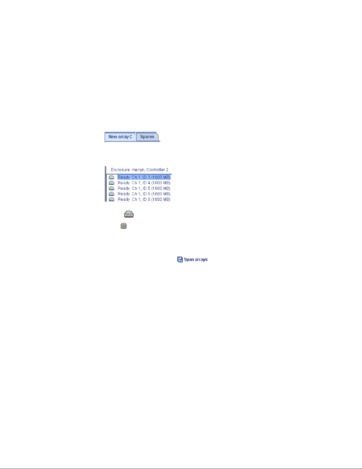
4. If you choose to create a logical drive in an existing array, select the array name
from the drop-down list.
5. Click Next. For new arrays, the Create Arrays window opens. For existing
arrays, the Create Logical Drives window opens.
More information
v Configuring an enclosure: the basic steps
v Increasing logical drive capacity
Creating arrays and hot-spare drives
Complete the following steps to create arrays:
1. Click the appropriate Array tab in the right pane:
2. Then, from the list of ready drives, select the drives you want to add to the
array:
3. Click
click
>> (Add selected drives) to add the drives to the array. Yo u can
>> (Add all drives) to move all ready drives to an array.
4. Repeat steps 1 and 2 for each additional array or hot-spare drive that you want
to configure.
5. If you do not want to create a spanned array, skip to step 5. Otherwise, select
the Span arrays check box
. Then, click Next. If you created two
arrays only, the ServeRAID Manager uses those arrays to create the spanned
array; continue to step 5. Otherwise, the Create Spanned Arrays window opens.
Note: To create a spanned array, each array must have the same number of
physical drives.
6. After you select the ready drives for your arrays and hot-spare drive, click
Next. The Create Logical Drives window opens.
To return to the Configuration Path window, click Back. To leave the Configuration
wizard, click Cancel.
More information
v Creating spanned arrays
v Understanding creating spanned arrays
Creating spanned arrays
If you want to assign RAID level-x0 to an array, you must create a spanned array.
Complete the following steps to create one or more identical spanned arrays:
1. In the list of arrays, click the arrays that you want to add to your spanned
array.
76 ServeRAID Manager Installation and User's Guide
Page 93
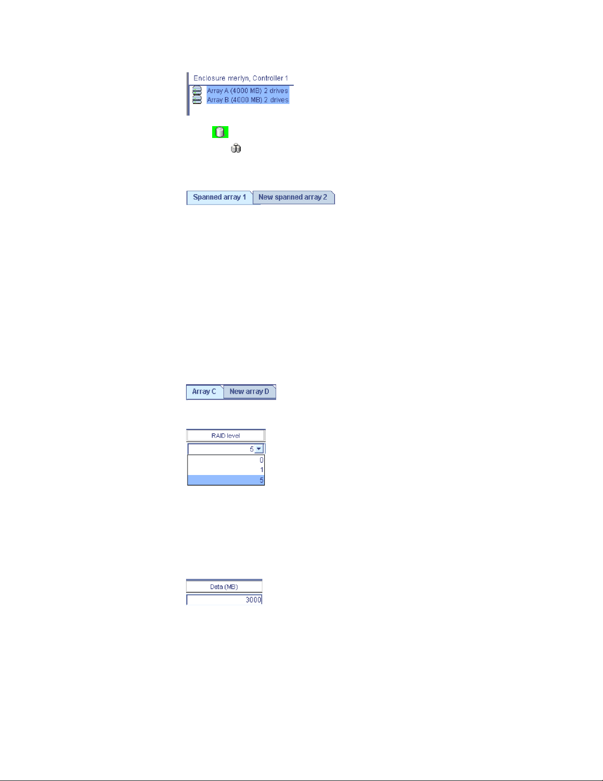
2. Click
can click
>> (Add selected arrays) to add the arrays to the spanned array. You
>> (Add all arrays) to move all arrays to the spanned arrays.
3. To create additional spanned arrays, click the New spanned array tab in the
right pane.
Then, repeat steps 1 and 2.
4. Click Next; the Create Logical Drives window opens.
To return to the Create Arrays window, click Back. To leave the Configuration
wizard, click Cancel.
More information
v Understanding RAID level-x0
v Understanding creating spanned arrays
Creating logical drives
Complete the following steps to create logical drives:
1. Click the appropriate Array tab.
2. Select a RAID level from the drop-down list.
v If you are configuring a spanned array, you can set the RAID level only for
the first logical drive you create.
v In addtion to the standard RAID levels (0, 1, 5, x0), you can also create a
simple volume: a single disk drive, non-redundant.
If you do not want to use the maximum size for the logical drive, type the size
3.
in the Data (MB) field.
Notes:
a. Some operating systems have size limitations for logical drives.
Before you save the configuration, verify that the size of the logical
drive is appropriate for your operating system. For more detailed
information, see your operating-system documentation.
b. A logical drive cannot exceed 2048 GB (2 terabytes); the minimum
size is 10MB.
Chapter 4. Managing ServeRAID devices 77
Page 94

c. Typically, the first logical drive defined on the first controller found
by system BIOS during startup will be your startup (boot) drive.
d. The actual logical-drive size might be slightly different from what
you select. The RAID level and the number of physical drives
determine the size of the logical drive. For example, an array
consisting of three, 1 GB physical drives with a requested RAID
level-0 logical drive of 1000 MB will actually contain only 999 MB
because the data is striped across all three drives, with 333 MB on
each drive.
4. From the Stripe Size drop-down list, select the stripe-unit for the logical drive.
Note: The default stripe-unit size is usually adequate for most applications.
5. From the Controller drop-down list, select the preferred owner for the logical
drive, Controller A or Controller B. (For single controller configurations, this
field is grayed out.)
You can only choose the controller for the first logical drive in the array.
Note:
6. If you have free space available and want to create additional logical drives,
click
. To create a new logical drive with the same
settings as the current logical drive, click
; then, choose
the number of replicas from the drop-down list.
Attention: Use care when allocating space for new a new logical drive. You
must leave enough space for FlashCopy backups to grow to their virtual size.
For example, if the virtual size of a FlashCopy backup is 20 GB, you must leave
at least 20 GB of free space in the array. Note that the Configuration wizard
displays the actual size of the first FlashCopy backup (not the virtual size), and
0 for all other FlashCopy backups.
7. Repeat steps 2 through 6 for each logical drive that you want to define in this
array.
8. Repeat steps 1 through 7 for each additional array you want to configure.
9. Click Next. Depending on the initiator type, the Define Authentication Method
window opens or the Define Initiators window opens.
To return to the Create Arrays window, click Back. To leave the Configuration
wizard, click Cancel.
Defining the authentication method
Note: The ServeRAID Manager supports authentication for iSCSI initiators only.
Use the Authentication Information window to define the authentication method
(if any) for each user permitted to use the logical drives in the array. Optionally,
you can enable Radius authentication (an external authentication service) and
define the SLP (Service Location Protocol) Scope name.
1. Select a logical drive from the list on the left.
2. From the Authentication type list, select the method used to authenticate users
of this logical drive. Yo u can choose:
v None - Do not authenticate users
v CHAP - Challenge Handshake Authentication Protocol
78 ServeRAID Manager Installation and User's Guide
Page 95

v SRP - Secure Remote Password
If you enabled authentication (by choosing CHAP or SRP), click
3.
; the
Global User Name and Password Management window opens. Then, add users
to the user list.
4. To enable Radius authentication for the CHAP authentication method, click
Radius authentication; then, enter the following:
v In the Primary server field, enter the host name or TCP/IP address of the
authentication service; then, in the Port field, enter the server’s startup port.
v In the Secondary server field, enter the host name or TCP/IP address of the
authentication service; then, in the Port field, enter the server’s startup port.
Radius authentication is supported by the CHAP authentication method
Note:
only.
5. To modify the default SLP Scope name, click Advanced settings; then, in the
SLP Scope Name field, type a unique scope name or choose an existing name
from the drop-down list.
6. Repeat steps 1 through 5 to enable authentication for additional logical drives.
To replicate the settings for all logical drives, click
.
7. When you are ready to continue, click Next. The Define Initiators window
opens.
To return to the Create Logical Drives window, click Back. To leave the
Configuration wizard, click Cancel.
More information
v Adding users to the user list
Defining initiator information
Use the Initiator Information window to define an alias, or ″friendly″ name, for
each initiator that can access the enclosure, including the initiator IQN (iSCSI
Qualified Name) or fibre channel port name. An initiator represents a machine on
the network that can access the enclosure.
The ServeRAID Manager displays previously defined initiators in a list. The alias is
shown on the left. Depending on the initiator type (iSCSI or fibre channel), the
IQN or port name is shown on the right. Initiator types are not mixed. You can
add a new initiator, modify an initiator, or delete an initiator.
To add an initiator:
1. Click
. Depending on the initiator type, the Add iSCSI Initiator window opens or the
Add Port Name window opens.
2. Follow the steps below to add an iSCSI initiator or add a fibre channel port
name.
3. When you are ready to continue, click Next. The Assign Logical Drives to
Initiators window opens.
To return to the previous Configuration Wizard window, click Back.
To leave the Configuration wizard, click Cancel.
Chapter 4. Managing ServeRAID devices 79
Page 96

Adding an iSCSI initiator
1. In the Initiator IQN field, type a well-formed IQN in the format:
iqn.yyyy-mm.s1.s2[.|:]s3 where:
v yyyy is the 4-digit year
v mm is the 2-digit month (01-12)
v s1 and s2 are 1-n character alphanumeric strings (for example, mydomain.com)
v s3 is 5 or more alphanumeric characters, separated from s2 by ’.’ or ’:’
In the Initiator alias filed, type a name for the initiator. The initiator alias must
2.
start with a letter. It can contain only letters and numbers.
3. Optionally, click Advanced settings; then, click the check boxes to enable or
disable the following features:
Communications with initiator include
separate status Protocol Data Unit (PDU).
Communications with initiator include PDU
alignment.
Initiator supports iSCSI ping.
Note: Refer to your initiator documentation for more information about these
features.
4. Click OK; then, repeat steps 1-3 to add additional initiators.
5. Click Cancel to close the Add iSCSI Initiator window.
Adding a fibre channel port name
1. In the Port Name field, enter the 16-character Port Name. Each octet (8
characters) can be separated by a ’:’ or ’-’.
2. In the Initiator alias field, type a name for the initiator. The initiator alias must
start with a letter. It can contain only letters and numbers.
3. Click OK; then, repeat steps 1 and 2 to add additional initiators.
Note: You can define a maximum of 255 ports (LUNs) for each fibre channel
initiator.
4. To automatically detect initiators on your network, click
. The Select a Discovered Initiator window opens.
Note: The button will be grayed out if no new initiators are detected.
Then, select a discovered initiator from the list.
5. Click Cancel to close the Add Port Name window.
More information
v Modifying and deleting initiator information
v Selecting discovered initiators
Selecting a discovered initiator
Use the Select a Discovered Initiator window to add an existing fibre channel
initiator to the list of initiators that can access the enclosure.
80 ServeRAID Manager Installation and User's Guide
Page 97

1.
From the Port Name list, select an initiator.
2. In the Initiator alias field, type a name for the initiator or accept the default.
The initiator alias must start with a letter. It can contain only letters and
numbers.
3. Click OK. The Select a Discovered Initiator window closes.
4. To select another discovered initiator, click
. Then, repeat
steps 1-3 to add additional initiators.
5.
Assigning logical drives to initiators
Note: You can assign up to 32 initiators to each logical drive.
Complete the following steps to assign logical drives to initiators:
1. Click the appropriate Initiator tab in the right pane. To allow anyone to access
the logical drive, regardless of users in the user list, click the Unrestricted tab.
2. Then, from the list of logical drives, select the drives you want the initiator to
access:
3. Click
initiator. Yo u can click
>> (Add selected drives) to assign the logical drives to the
>> (Add all drives) to assign all logical drives to
the initiator.
4. Repeat steps 1 and 2 for each initiator.
5. After you assign logical drives to initiators, click Next. The Configuration
Summary window opens.
To return to the Define Initiators window, click Back. To leave the Configuration
wizard, click Cancel.
Confirming your system configuration
Use the configuration summary to review all the changes that the ServeRAID
Manager will apply to your configuration:
1. Review the information that is displayed in the Configuration Summary
window. To change the configuration, click Back.
Note: The Configuration wizard displays the actual size of the first FlashCopy
backup (not its virtual size), and 0 for all other FlashCopy backups.
2. Click Yes when asked if you want to apply the new configuration. A status
window opens, displaying the progress of the operation. When finished, the
configuration is saved in the controller and physical drives in the enclosure.
Note: The ServeRAID Manager initializes the logical drives automatically.
Chapter 4. Managing ServeRAID devices 81
Page 98

More information
v Understanding logical-drive synchronization
v Initializing a logical drive
Configuring NetWare user authentication
NetWare user authentication may be configured in one of two ways: out-of-box
authentication and NDS authentication. The two methods are mutually exclusive.
Out-of-box authentication
Out-of-box authentication works as follows:
v Administrative access is exclusively granted to the ‘Admin’ user account, which
must be defined within the NetWare Bindery context of the server running the
ServeRAID Manager agent.
v User access is granted to all Bindery and NetWare Directory Services (NDS) user
accounts. For NDS users, the user account must reside within the same tree as
the server running the ServeRAID Manager agent.
logging into the ServeRAID Manager, NDS users must provide the fully
When
distinguished account name.
NDS authentication
NDS authentication is based on NDS group membership. To set up NDS group
membership, create and populate a NDS group for storage administration. After
you install the ServeRAID Manager, edit the ServeRAID Manager agent properties
file to restrict authentication to the new group.
For example:
1. Choose the group name ″.CN=StorageAdmins.O=Acme″.
Note: The group must reside within the same NDS tree as the server running
the ServeRAID Manager agent.
2. Using the Novell Administration utility, add the appropriate users to the new
group.
3. Add the following entry to the SYS:\RAIDMAN\RaidAgent.pps file:
agent.group.NetWareStorageAdmin=< fully distinguished group name>The
new entry should look like this :
agent.group.NetWareStorageAdmin=.CN=StorageAdmins.O=Acme
4. Restart the server.
Limited
user access is granted to all NDS user accounts.
More information
v Logging in to the ServeRAID Manager
v Adding a remote system
v Configuring the ServeRAID Manager agent
Novell NetWare considerations
(NetWare 5.x only) If you are preparing to install Novell NetWare 5.x from the
startable Novell NetWare 5.x CD, set the write-cache mode only to write-through
mode.
82 ServeRAID Manager Installation and User's Guide
Page 99

Attention: Do not attempt a hot-replace operation on Windows 2000, Windows
Server 2003, or NetWare by hot-removing a failed controller and then hot-adding a
new controller. Loss of data can occur. If a controller fails on these operating
systems, you must shut down the server to replace the controller.
Copying the configuration from drives
Note:
1. This action is not supported on the integrated RAID controller.
2. (Cluster environment only) Use this action to merge non-shared logical
drives.
this action to copy the configuration from all physical drives into a ServeRAID
Use
controller. This action is useful when replacing a controller and you want to
reestablish the original configuration on the new controller.
If you are replacing a controller in a cluster environment, you must first configure
the cluster parameters by using the ″ Configure for clustering″ action. The cluster
parameters are the following:
v The controller name
v The partner controller name
v The SCSI initiator IDs
After you have configured these parameters, you can use ″Copy configuration
from drives″ to copy the configuration from only the non-shared drives into the
new controller.
1. In the Enterprise view, click
(controller).
2. Right-click Copy configuration from drives.
3. If clustering is not enabled, go to step 4. Otherwise, right-click one of the
following from the menu:
v Non-shared 206
v Non-shared 207
4. A confirmation window opens; click Yes .
Restore the configuration to the factory-default settings
Note: This action is not supported on the following:
1. Integrated RAID controller
2. ServeRAID-7t controller
3. ServeRAID-8i controller
4. ServeRAID-8k/8k-l controller
5. HostRAID controller
6. Network storage controllers
this action to restore all parameters in the configuration to the factory-default
Use
settings:
1. In the Enterprise view, click
2. Right-click Restore to factory-default settings. A confirmation window opens.
3. Click Yes.
Attention: In the following step, the ServeRAID Manager will destroy all
data on these logical drives.
(controller).
Chapter 4. Managing ServeRAID devices 83
Page 100

4. If there are logical drives defined, click Ye s to delete all logical drives and
restore all parameters in the configuration to the factory defaults. If there are
no logical drives defined, the ServeRAID Manager automatically restores all
parameters in the configuration to the factory-default settings.
Saving a printable configuration and event logs
Use this action to save a report of your configuration and event logs that you can
print.
1. In the Enterprise view, click
2. Right-click ServeRAID Manager Actions → Save printable configuration and
event logs. The ServeRAID Manager creates one text file for each controller.
The file name is Raid x.log where x is a number assigned to the file.
Note: If you are in bootable-CD mode, you can save the files to a diskette in
the A drive only.
ServeRAID Manager copies to each text file all configuration information for
The
the following:
v The controller in the selected system
v Any physical drive on the controller
v Any array on the controller
v Any logical drive on the controller
v Device event logs
v defunct drive event logs
v Software event logs
v Hardware event logs
(server).
The ServeRAID Manager saves all events currently in the event log, not only the
events associated with the selected system.
More information
v Example: Printable configuration
v Saving a printable configuration
Saving a printable configuration
Use this action to save a report of your configuration that you can print.
1. In the Enterprise view, click
2. Right-click Save printable configuration. The Save File window opens.
3. Choose the directory and file name for your report. The default directory is the
directory in which the ServeRAID Manager is installed. The default file name is
RaidCfg.log.
If you are in bootable-CD mode, you can save to a diskette in the A
Note:
drive only.
ServeRAID Manager copies to a text file all configuration information for the
The
following:
v Each controller in the selected system
v All physical drives on the controller
v All arrays on the controller
v All logical drives on the controller
(system).
84 ServeRAID Manager Installation and User's Guide
 Loading...