

Page 1
®
ServeRAID M5210 SAS/SATA Controller
for IBM System x
User’s Guide
Part Number: 00D2437
Page 2

July 2014
Third Edition (July 2014)
© Copyright IBM Corporation 2013.
US Government Users Restricted Rights -- Use, duplication or disclosure restricted by GSA ADP
Schedule Contract with IBM Corp.
Page 3

ServeRAID M5210 SAS/SATA Controller for IBM System x User’s Guide
Bu ürünü kurmadan önce güvenlik bilgilerini okuyun.
Youq mwngz yungh canjbinj neix gaxgonq, itdingh aeu doeg aen
canjbinj soengq cungj vahgangj ancien siusik.
July 2014
Safety
Safety
- 3 -
Page 4

ServeRAID M5210 SAS/SATA Controller for IBM System x User’s Guide
July 2014
Safety
- 4 -
Page 5
ServeRAID M5210 SAS/SATA Controller for IBM System x User’s Guide
July 2014
Safety
- 5 -
Page 6

ServeRAID M5210 SAS/SATA Controller for IBM System x User’s Guide
Statement 28:
CAUTION:
The battery is a lithium ion battery. To avoid possible explosion, do not burn the
battery. Exchange it only with the approved part. Recycle or discard the battery
as instructed by local regulations.
July 2014
Safety
- 6 -
Page 7

ServeRAID M5210 SAS/SATA Controller for IBM System x User’s Guide
July 2014
Table of Contents
Table of Contents
Chapter 1: Overview . . . . . . . . . . . . . . . . . . . . . . . . . . . . . . . . . . . . . . . . . . . . . . . . . . . . . . . . . . . . . . . . . . . . . . . . . . . . . . . . . . . . . . . . . . . . . . . . . . . . . . . . . . . . 3
1.1 ServeRAID M5210 Controller Description . . . . . . . . . . . . . . . . . . . . . . . . . . . . . . . . . . . . . . . . . . . . . . . . . . . . . . . . . . . . . . . . . . . . . . . . . . . . . . . . . . . . . . . . . . . . .3
1.1.1 Controller Guidelines . . . . . . . . . . . . . . . . . . . . . . . . . . . . . . . . . . . . . . . . . . . . . . . . . . . . . . . . . . . . . . . . . . . . . . . . . . . . . . . . . . . . . . . . . . . . . . . . . . . . . . . . . 3
1.2 Integrated MegaRAID Mode and MegaRAID mode . . . . . . . . . . . . . . . . . . . . . . . . . . . . . . . . . . . . . . . . . . . . . . . . . . . . . . . . . . . . . . . . . . . . . . . . . . . . . . . . . . . .4
1.2.1 Supported RAID Level Upgrades . . . . . . . . . . . . . . . . . . . . . . . . . . . . . . . . . . . . . . . . . . . . . . . . . . . . . . . . . . . . . . . . . . . . . . . . . . . . . . . . . . . . . . . . . . . . . . 4
1.2.2 Summary of RAID Levels . . . . . . . . . . . . . . . . . . . . . . . . . . . . . . . . . . . . . . . . . . . . . . . . . . . . . . . . . . . . . . . . . . . . . . . . . . . . . . . . . . . . . . . . . . . . . . . . . . . . . . 4
1.3 Configuration Scenarios . . . . . . . . . . . . . . . . . . . . . . . . . . . . . . . . . . . . . . . . . . . . . . . . . . . . . . . . . . . . . . . . . . . . . . . . . . . . . . . . . . . . . . . . . . . . . . . . . . . . . . . . . . . . . .5
1.3.1 Number of Physical Disks Supported . . . . . . . . . . . . . . . . . . . . . . . . . . . . . . . . . . . . . . . . . . . . . . . . . . . . . . . . . . . . . . . . . . . . . . . . . . . . . . . . . . . . . . . . . . 6
1.4 Benefits of the SAS Interface. . . . . . . . . . . . . . . . . . . . . . . . . . . . . . . . . . . . . . . . . . . . . . . . . . . . . . . . . . . . . . . . . . . . . . . . . . . . . . . . . . . . . . . . . . . . . . . . . . . . . . . . . .7
1.4.1 PCI Express Architecture . . . . . . . . . . . . . . . . . . . . . . . . . . . . . . . . . . . . . . . . . . . . . . . . . . . . . . . . . . . . . . . . . . . . . . . . . . . . . . . . . . . . . . . . . . . . . . . . . . . . . . 7
1.4.2 Operating System Support. . . . . . . . . . . . . . . . . . . . . . . . . . . . . . . . . . . . . . . . . . . . . . . . . . . . . . . . . . . . . . . . . . . . . . . . . . . . . . . . . . . . . . . . . . . . . . . . . . . . 7
1.5 Benefits of the ServeRAID M5210 SAS/SATA Controller . . . . . . . . . . . . . . . . . . . . . . . . . . . . . . . . . . . . . . . . . . . . . . . . . . . . . . . . . . . . . . . . . . . . . . . . . . . . . . . .7
1.5.1 SAS Features . . . . . . . . . . . . . . . . . . . . . . . . . . . . . . . . . . . . . . . . . . . . . . . . . . . . . . . . . . . . . . . . . . . . . . . . . . . . . . . . . . . . . . . . . . . . . . . . . . . . . . . . . . . . . . . . . 8
1.5.2 SAS Array Limitations . . . . . . . . . . . . . . . . . . . . . . . . . . . . . . . . . . . . . . . . . . . . . . . . . . . . . . . . . . . . . . . . . . . . . . . . . . . . . . . . . . . . . . . . . . . . . . . . . . . . . . . . . 8
1.5.3 SATA III Features. . . . . . . . . . . . . . . . . . . . . . . . . . . . . . . . . . . . . . . . . . . . . . . . . . . . . . . . . . . . . . . . . . . . . . . . . . . . . . . . . . . . . . . . . . . . . . . . . . . . . . . . . . . . . . 9
1.5.4 PCI Express Performance. . . . . . . . . . . . . . . . . . . . . . . . . . . . . . . . . . . . . . . . . . . . . . . . . . . . . . . . . . . . . . . . . . . . . . . . . . . . . . . . . . . . . . . . . . . . . . . . . . . . . . 9
1.5.5 Usability Features. . . . . . . . . . . . . . . . . . . . . . . . . . . . . . . . . . . . . . . . . . . . . . . . . . . . . . . . . . . . . . . . . . . . . . . . . . . . . . . . . . . . . . . . . . . . . . . . . . . . . . . . . . . . 10
1.5.6 Flexibility Features. . . . . . . . . . . . . . . . . . . . . . . . . . . . . . . . . . . . . . . . . . . . . . . . . . . . . . . . . . . . . . . . . . . . . . . . . . . . . . . . . . . . . . . . . . . . . . . . . . . . . . . . . . . 10
1.5.7 CacheCade . . . . . . . . . . . . . . . . . . . . . . . . . . . . . . . . . . . . . . . . . . . . . . . . . . . . . . . . . . . . . . . . . . . . . . . . . . . . . . . . . . . . . . . . . . . . . . . . . . . . . . . . . . . . . . . . . . 10
1.5.8 Protection Information (T10-DIF) . . . . . . . . . . . . . . . . . . . . . . . . . . . . . . . . . . . . . . . . . . . . . . . . . . . . . . . . . . . . . . . . . . . . . . . . . . . . . . . . . . . . . . . . . . . . . 10
1.5.9 Drive Roaming . . . . . . . . . . . . . . . . . . . . . . . . . . . . . . . . . . . . . . . . . . . . . . . . . . . . . . . . . . . . . . . . . . . . . . . . . . . . . . . . . . . . . . . . . . . . . . . . . . . . . . . . . . . . . . 11
1.5.10 Drive Migration . . . . . . . . . . . . . . . . . . . . . . . . . . . . . . . . . . . . . . . . . . . . . . . . . . . . . . . . . . . . . . . . . . . . . . . . . . . . . . . . . . . . . . . . . . . . . . . . . . . . . . . . . . . . 12
1.5.11 New Drives Attached to a ServeRAID Controller . . . . . . . . . . . . . . . . . . . . . . . . . . . . . . . . . . . . . . . . . . . . . . . . . . . . . . . . . . . . . . . . . . . . . . . . . . . . . 12
1.5.12 Automatic Rebuilds on New Drives. . . . . . . . . . . . . . . . . . . . . . . . . . . . . . . . . . . . . . . . . . . . . . . . . . . . . . . . . . . . . . . . . . . . . . . . . . . . . . . . . . . . . . . . . . 13
1.5.13 System (JBOD) Drives. . . . . . . . . . . . . . . . . . . . . . . . . . . . . . . . . . . . . . . . . . . . . . . . . . . . . . . . . . . . . . . . . . . . . . . . . . . . . . . . . . . . . . . . . . . . . . . . . . . . . . . 13
1.6 Hardware Specifications. . . . . . . . . . . . . . . . . . . . . . . . . . . . . . . . . . . . . . . . . . . . . . . . . . . . . . . . . . . . . . . . . . . . . . . . . . . . . . . . . . . . . . . . . . . . . . . . . . . . . . . . . . . . .13
1.7 Technical Support. . . . . . . . . . . . . . . . . . . . . . . . . . . . . . . . . . . . . . . . . . . . . . . . . . . . . . . . . . . . . . . . . . . . . . . . . . . . . . . . . . . . . . . . . . . . . . . . . . . . . . . . . . . . . . . . . . .14
Chapter 2: ServeRAID M5210 SAS/SATA Controller for IBM System x User’s Guide . . . . . . . . . . . . . . . . . . . . . . . . . . . . . . . . . . . . . . . . . . . . . . . . . 15
2.1 Requirements. . . . . . . . . . . . . . . . . . . . . . . . . . . . . . . . . . . . . . . . . . . . . . . . . . . . . . . . . . . . . . . . . . . . . . . . . . . . . . . . . . . . . . . . . . . . . . . . . . . . . . . . . . . . . . . . . . . . . . .15
2.2 Hardware installation . . . . . . . . . . . . . . . . . . . . . . . . . . . . . . . . . . . . . . . . . . . . . . . . . . . . . . . . . . . . . . . . . . . . . . . . . . . . . . . . . . . . . . . . . . . . . . . . . . . . . . . . . . . . . . .15
2.3 Connecting a ServeRAID M5210 SAS/SATA Controller to a Drive Backplane on an Enclosure . . . . . . . . . . . . . . . . . . . . . . . . . . . . . . . . . . . . . . . . . . .17
2.4 After Installing the Controller . . . . . . . . . . . . . . . . . . . . . . . . . . . . . . . . . . . . . . . . . . . . . . . . . . . . . . . . . . . . . . . . . . . . . . . . . . . . . . . . . . . . . . . . . . . . . . . . . . . . . . . .18
Chapter 3: ServeRAID M5210 SAS/SATA Controller Characteristics . . . . . . . . . . . . . . . . . . . . . . . . . . . . . . . . . . . . . . . . . . . . . . . . . . . . . . . . . . . . . . . . 19
3.1 Board Layout and Connector Information . . . . . . . . . . . . . . . . . . . . . . . . . . . . . . . . . . . . . . . . . . . . . . . . . . . . . . . . . . . . . . . . . . . . . . . . . . . . . . . . . . . . . . . . . . . .19
3.2 Characteristics of the ServeRAID M5210 SAS/SATA Controller. . . . . . . . . . . . . . . . . . . . . . . . . . . . . . . . . . . . . . . . . . . . . . . . . . . . . . . . . . . . . . . . . . . . . . . . .21
3.2.1 Controller Specifications . . . . . . . . . . . . . . . . . . . . . . . . . . . . . . . . . . . . . . . . . . . . . . . . . . . . . . . . . . . . . . . . . . . . . . . . . . . . . . . . . . . . . . . . . . . . . . . . . . . . . 21
3.2.2 Array Performance Features. . . . . . . . . . . . . . . . . . . . . . . . . . . . . . . . . . . . . . . . . . . . . . . . . . . . . . . . . . . . . . . . . . . . . . . . . . . . . . . . . . . . . . . . . . . . . . . . . . 22
3.2.3 Fault Tolerance . . . . . . . . . . . . . . . . . . . . . . . . . . . . . . . . . . . . . . . . . . . . . . . . . . . . . . . . . . . . . . . . . . . . . . . . . . . . . . . . . . . . . . . . . . . . . . . . . . . . . . . . . . . . . . 23
3.2.4 Power Supply Requirements for the ServeRAID M5210 SAS/SATA Controller. . . . . . . . . . . . . . . . . . . . . . . . . . . . . . . . . . . . . . . . . . . . . . . . . . . 23
3.2.5 Operating and Non-operating Conditions . . . . . . . . . . . . . . . . . . . . . . . . . . . . . . . . . . . . . . . . . . . . . . . . . . . . . . . . . . . . . . . . . . . . . . . . . . . . . . . . . . . . 23
3.2.6 Safety Characteristics . . . . . . . . . . . . . . . . . . . . . . . . . . . . . . . . . . . . . . . . . . . . . . . . . . . . . . . . . . . . . . . . . . . . . . . . . . . . . . . . . . . . . . . . . . . . . . . . . . . . . . . . 23
Appendix A: Getting Help and Technical Assistance . . . . . . . . . . . . . . . . . . . . . . . . . . . . . . . . . . . . . . . . . . . . . . . . . . . . . . . . . . . . . . . . . . . . . . . . . . . . . . 24
A.1 Before You Call . . . . . . . . . . . . . . . . . . . . . . . . . . . . . . . . . . . . . . . . . . . . . . . . . . . . . . . . . . . . . . . . . . . . . . . . . . . . . . . . . . . . . . . . . . . . . . . . . . . . . . . . . . . . . . . . . . . . .24
A.2 Using the Documentation . . . . . . . . . . . . . . . . . . . . . . . . . . . . . . . . . . . . . . . . . . . . . . . . . . . . . . . . . . . . . . . . . . . . . . . . . . . . . . . . . . . . . . . . . . . . . . . . . . . . . . . . . .24
A.3 Getting Help and Information from the World Wide Web . . . . . . . . . . . . . . . . . . . . . . . . . . . . . . . . . . . . . . . . . . . . . . . . . . . . . . . . . . . . . . . . . . . . . . . . . . . .25
- 1 -
Page 8

ServeRAID M5210 SAS/SATA Controller for IBM System x User’s Guide
July 2014
Table of Contents
A.4 Software Service and Support . . . . . . . . . . . . . . . . . . . . . . . . . . . . . . . . . . . . . . . . . . . . . . . . . . . . . . . . . . . . . . . . . . . . . . . . . . . . . . . . . . . . . . . . . . . . . . . . . . . . . . .25
A.5 Hardware Service and Support . . . . . . . . . . . . . . . . . . . . . . . . . . . . . . . . . . . . . . . . . . . . . . . . . . . . . . . . . . . . . . . . . . . . . . . . . . . . . . . . . . . . . . . . . . . . . . . . . . . . . .25
A.6 IBM Taiwan Product Service . . . . . . . . . . . . . . . . . . . . . . . . . . . . . . . . . . . . . . . . . . . . . . . . . . . . . . . . . . . . . . . . . . . . . . . . . . . . . . . . . . . . . . . . . . . . . . . . . . . . . . . . .25
Appendix B: Notices . . . . . . . . . . . . . . . . . . . . . . . . . . . . . . . . . . . . . . . . . . . . . . . . . . . . . . . . . . . . . . . . . . . . . . . . . . . . . . . . . . . . . . . . . . . . . . . . . . . . . . . . . . . 26
B.1 Trademarks . . . . . . . . . . . . . . . . . . . . . . . . . . . . . . . . . . . . . . . . . . . . . . . . . . . . . . . . . . . . . . . . . . . . . . . . . . . . . . . . . . . . . . . . . . . . . . . . . . . . . . . . . . . . . . . . . . . . . . . .27
B.2 Important Notes . . . . . . . . . . . . . . . . . . . . . . . . . . . . . . . . . . . . . . . . . . . . . . . . . . . . . . . . . . . . . . . . . . . . . . . . . . . . . . . . . . . . . . . . . . . . . . . . . . . . . . . . . . . . . . . . . . . .27
B.3 Documentation Format . . . . . . . . . . . . . . . . . . . . . . . . . . . . . . . . . . . . . . . . . . . . . . . . . . . . . . . . . . . . . . . . . . . . . . . . . . . . . . . . . . . . . . . . . . . . . . . . . . . . . . . . . . . . .28
B.4 Electronic Emission Notices . . . . . . . . . . . . . . . . . . . . . . . . . . . . . . . . . . . . . . . . . . . . . . . . . . . . . . . . . . . . . . . . . . . . . . . . . . . . . . . . . . . . . . . . . . . . . . . . . . . . . . . . .28
- 2 -
Page 9

ServeRAID M5210 SAS/SATA Controller for IBM System x User’s Guide
July 2014
Chapter 1: Overview
1.1 ServeRAID M5210 Controller Description
The ServeRAID M5210 SAS/SATA controller is a PCI-Express 3.0, half-size, half-height RAID controller based on the
LSISAS3108 PCI Express-SAS/SATA I/O Processor chip.
The controller controls eight internal SAS/SATA ports through two SFF-8643 4i internal mini-SAS HD connectors. The
c
ontroller integrates eight high-performance SAS/SATA PHYs and a PCI Express bus master DMA core. Each of the
eight PHYs is capable of 12.0 Gb/s SAS link rates and 6.0 Gb/s SATA III link rates.
The controller brings 12.0 Gb/s SAS and 6.0 Gb/s SATA performance to host controller, workstation, and server designs.
he controller supports internal storage devices, which allows you to use a system that supports enterprise-class SAS
T
drives, and desktop-class SATA drives. The controller can connect to drives directly. Simplified cabling between
devices is an additional benefit.
ServeRAID M5210 Controller Description
Chapter 1: Overview
The LSISAS3108 ROC device increases syste
supports data striping across multiple disks, which reduces disk access time because multiple disks simultaneously
read or write data. In addition, the LSISAS3108 ROC device backs up data with either data mirroring or a parity block.
Either backup method enables you to recover lost data in the event of a disk failure. You can select the data backup
method that best suits your needs. A hardware RAID assist exclusive-OR (XOR) engine speeds parity generation and
checking and reduces system-access times.
The controller supports the SAS protocol as described in the S
III protocol defined by the Serial ATA Revision 3.0 Specification.
NOTE You cannot mix SAS drives and SATA drives within the same virtual drive.
Each port on the controller supports SAS devices and/or SATA devices using the following:
SAS Serial SCSI Protocol (SSP), which enables communication with other SAS devices
SATA, which enables communication with other SATA devices
Serial Management Protocol (SMP), which communicates topology management information directly with an
a
ttached SAS expander device
Serial Tunneling Protocol (STP), which enables communication with a SATA device through an attached expander
1.1.1 Controller Guidelines
before you install the controller, read the following guidelines:
m performance and provides fault-tolerant data storage. The LSISAS3108
erial Attached SCSI Standard, version 3.0, and the SATA
You can connect only one device per SAS PHY unless you use an expander
Cables have to meet the SAS specification
You cannot mix SAS drives and SATA drives in the same virtual drive
You cannot mix SAS Solid State Drives (SSDs) or SATA SSDs and existing mechanical drives (SAS or SATA) in the
same vir
You cannot mix Solid State SAS drives and Solid State SATA drives in the same virtual drive
tual drive
See Section 3.2.4, “Power Supply Requirements for th
the power requirements, and Section 3.2.5, “Operating and Non-operating Conditions”for information about the
minimum and the maximum temperature ranges.
e ServeRAID M5210 SAS/SATA Controller” for information about
- 3 -
Page 10
ServeRAID M5210 SAS/SATA Controller for IBM System x User’s Guide
July 2014
1.2 Integrated MegaRAID Mode and MegaRAID mode
The ServeRAID M5210 controller can run in either integrated MegaRAID (iMR) mode natively or in MegaRAID (MR)
mode with the addition of a transportable memory module.
Integrated MegaRAID Mode and MegaRAID mode
Chapter 1: Overview
iMR is a highly integrated, low-cost RAID solution made possibl
e by Fusion-MPT architecture. Integrated MegaRAID is
a processor-based, hardware RAID solution designed for system environments requiring redundancy and high
availability where a full-featured RAID implementation is not required or might be cost prohibitive.
The major advantage of iMR is that it provides RAID at the processo
r level, so it does not burden the CPU, which allows
for more efficient operation. iMR mode is native to the ServeRAID M5210 controller and does not require a
transportable memory module.
The major advantage of MR mode is that the it supports mor
e RAID levels than iMR mode. iMR mode supports RAID
levels 0, 1, 5, 10, and 50 and supports 64k stripe size only. MR mode supports RAID levels 0, 1, 5, 6, 10, 50, and 60 and
supports 64k to 1M stripe size.
NOTE iMR mode RAID 5 requires purchase of the Feature on Demand upgrade.
NOTE MR mode RAID 5/50 requires a transportable memory module (4 options).
NOTE MegaRAID RAID 6/60 requires a transportable memory module (4 options) and the Feature on Demand
upgrade.
See Section 1.2.1, “Supported RAID
Level Upgrades” for information about these upgrades.
See Section 1.2.2, “Summary of RAID Levels” for information about the supported RAID levels.
1.2.1 Supported RAID Level Upgrades
To use RAID levels 5, 6, 50, or 60 with this controller, you need to install a Feature on Demand upgrade and/or a
transportable memory module, depending on the RAID level.
This controller supports iMR RAID levels 5 and 50 with the following installed Feature on Demand upgrade:
ServeRAID M5200 Series Zero Cache/RAID 5 Upgrade for IBM System x
This controller supports MegaRAID RAID levels 5 and 50, with any of the following installed transportable memory
modules:
ServeRAID M5200 Series 1GB Cache/RAID 5 Upgrade for IBM System x
ServeRAID M5200 Series 1GB Flash/RAID 5 Upgrade for IBM System x
ServeRAID M5200 Series 2GB Flash/RAID 5 Upgrade for IBM System x
ServeRAID M5200 Series 4GB Flash/RAID 5 Upgrade for IBM System x
This controller supports MegaRAID RAID levels 6 and 60 with the ServeRAID M5200 Series RAID 6 Upgrade for IBM
System x
1.2.2 Summary of RAID Levels
RAID levels describe a system for ensuring the availability and redundancy of data stored on large disk subsystems.
- 4 -
Page 11
ServeRAID M5210 SAS/SATA Controller for IBM System x User’s Guide
July 2014
RAID 0 uses striping to provide high data throughput, especially for large files in an environment that does not require
fault tolerance.
Chapter 1: Overview
Configuration Scenarios
RAID 1 uses mirroring so that data written to one drive is simultaneous
ly written to another drive. This is good for
small databases or other applications that require small capacity but complete data redundancy.
RAID 5 uses disk striping and parity data across all drives
(distributed parity) to provide high data throughput,
especially for small random access.
RAID 6 uses distributed parity, with two independent parity blocks per stripe
, and disk striping. A RAID 6 virtual drive
can survive the loss of two drives without losing data. A RAID 6 drive group, which requires a minimum of three drives,
is similar to a RAID 5 drive group. Blocks of data and parity information are written across all drives. The parity
information is used to recover the data if one or two drives fail in the drive group.
RAID 10, a combination of RAID 0 and RAID 1, consists of striped data
across mirrored spans. A RAID 10 drive group is
a spanned drive group that creates a striped set from a series of mirrored drives. RAID 10 allows a maximum of eight
spans. You must use an even number of drives in each RAID virtual drive in the span. The RAID 1 virtual drives must
have the same stripe size. RAID 10 provides high data throughput and complete data redundancy but uses a larger
number of spans.
RAID 50, a combination of RAID 0 and RAID 5, uses distributed parit
y and disk striping. A RAID 50 drive group is a
spanned drive group in which data is striped across multiple RAID 5 drive groups. RAID 50 works best with data that
requires high reliability, high request rates, high data transfers, and medium-to-large capacity.
RAID 60, a combination of RAID 0 and RAID 6, uses distributed
parity, with two independent parity blocks per stripe in
each RAID set, and disk striping. A RAID 60 virtual drive can survive the loss of two drives in each of the RAID 6 sets
without losing data. It works best with data that requires high reliability, high request rates, high data transfers, and
medium-to-large capacity.
NOTE Having virtual drives of different RAID levels, such as RAID 0 and RAID 5, in the same drive group is not
allowed. For example, if an existing RAID 5 virtual drive is created out of partial space in an array, the next
virtual drive in the array has to be RAID 5 only.
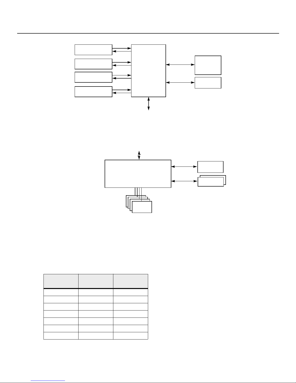
1.3 Configuration Scenarios
There are two main scenarios in which you can use this ServeRAID controller:
Low-end, internal SATA configuration: In this configuration, use the ServeRAID controller as a high-end SATA
compatible controller that connects to several SATA disks. This type of configuration is mostly for low-end or entry
level servers. Enclosure management is provided through out-of-band I2C bus. Side bands of both types of
internal SAS connectors support the SFF-8485 and SFF-8448 (SGPIO) interface.
Midrange, internal SAS configuration: This configuration is like the internal SATA configuration, but with high-end
disks. This type of configuration is more suitable for low-range to midrange servers.
The following figure shows a direct-connect configuration. The
The external memory bus provides a 32-bit memory bus, parity checking, and chip select signals for pipelined
synchronous burst static random access memory (PSBRAM), nonvolatile static random access memory (NVSRAM), and
Flash ROM.
Inter-IC (I2C) interface communicates with peripherals.
- 5 -
Page 12
ServeRAID M5210 SAS/SATA Controller for IBM System x User’s Guide
Flash ROM/
SAS
PCI Express
RAID Controller
SAS/SATA III Device
32-Bit Memory
Address/Data
Bus
PSBRAM/
I2C
SAS/SATA III Device
SAS/SATA III Device
SAS/SATA III Device
PCI Express Interface
NVSRAM
I
2
C
Interface
Flash ROM/
NVSRAM/
SRAM
I
2
C/UART
PCI Express Interface
SAS/SATA
Drives
8
SRAM
SRAMSDRAM
Peripheral
Bus
72-bit DDR/DDR2
with ECC
Interface
PCI Express to SAS ROC
SAS
RAID Controller
July 2014
Figure 1 Example of a SAS Direct Connect Application
The following figure shows an example of a ServeRAID controller configured with an expander that is connected to
SAS disks, SATA disks, or both.
Figure 2 Example of a ServeRAID Controller Configured with an Expander
Chapter 1: Overview
Configuration Scenarios
1.3.1 Number of Physical Disks Supported
Your configuration planning for your ServeRAID controller depends in part on the number of physical disks that you
want to use in a RAID array. The number of drives in an array determines the RAID levels that can be supported by this
controller. Only one RAID level can be assigned to each virtual disk. Tabl e 1 shows the minimum number and the
maximum number of drives required for each RAID level.
Tab le 1 Physical Devices Required for each RAID Level
Minimum # of
Physical Devices
Raid Level
0 1 32
1 2
5 3 32
6 3 32
10 4 32
50 6 32
60 6 32
Maximum # of
Physical Devices
32
- 6 -
Page 13

ServeRAID M5210 SAS/SATA Controller for IBM System x User’s Guide
July 2014
1.4 Benefits of the SAS Interface
SAS is a serial, point-to-point, enterprise-level device interface that leverages the proven SCSI protocol set. SAS
combines the advantages of SATA, SCSI, and Fibre Channel, and is the future mainstay of the enterprise and high-end
workstation storage markets. SAS offers a higher bandwidth per pin than parallel SCSI, and it improves signal and data
integrity.
The SAS interface uses the proven SCSI command set to ensure reliable data transfers, while providing the
connectivity and flexibility of point-to-point serial data transfers. The serial transmission of SCSI commands eliminates
clock-skew challenges. The SAS interface provides improved performance, simplified cabling, smaller connectors,
lower pin count, and lower power requirements when compared to parallel SCSI.
The ServeRAID M5210 SAS/SATA controller leverages a common electrical and physical connection interface that is
compatible with Serial ATA technology. The SAS protocols and SATA protocols use a thin, 7-wire connector instead of
the 68-wire SCSI cable or 26-wire ATA cable. The SAS/SATA III connector and cable are easier to manipulate, allow
connections to smaller devices, and do not inhibit airflow. The point-to-point SATA III architecture eliminates inherent
difficulties created by the legacy ATA master-slave architecture, while maintaining compatibility with existing ATA
firmware.
1.4.1 PCI Express Architecture
Chapter 1: Overview
Benefits of the SAS Interface
PCI Express is a local bus system designed to increase data transfers without slowing down the central processing unit
(CPU). You can install your ServeRAID M5210SAS/SATA controller in PCI Express computer systems with a standard
bracket type. With this controller in your system, you can connect SCSI devices and SATA devices over the bus.
PCI Express goes beyond the PCI specification in that it is intended as a unifying I/O architecture for various systems:
desktops, workstations, mobile, server, communications, and embedded devices.
1.4.2 Operating System Support
To check for the latest list of supported operating systems and to download the device drivers for those operating
systems, see http://www.ibm.com/systems/support/.
The ServeRAID M5210 controller uses Fusion-MPT architecture for all major operating systems, thinner device drivers,
and better performance.
1.5 Benefits of the ServeRAID M5210 SAS/SATA Controller
This section provides a summary of the features and the benefits of the ServeRAID M5210 SAS/SATA controller. It
contains information on SAS features, SATA features, PCI performance, integration, usability, and flexibility.
The controller offers the following features:
PCI Express x8 lane width
PCI Express performance up to 8 GT/s (1 GB/s) per lane
Two internal connectors
Support for RAID levels 0, 1, 5, 10, and 50 in iMR mode
Support for RAID levels 0, 1, 5, 6, 10, 50, and 60 in MR mode
To use RAID levels 5/50/6/60 with this controller, you need to install a Feature on Demand upgrade and/or a
transportable memory module. See
upgrades.
Section 1.2.1, “Supported RAID Level Upgrades” for information about these
- 7 -
Page 14

ServeRAID M5210 SAS/SATA Controller for IBM System x User’s Guide
July 2014
Advanced array configuration and management utilities
Online RAID level migration
Drive migration
Drive roaming
Media scan
No reboot necessary after expansion
More than 200 Qtags per array
User-specified rebuild rate
32-Kbyte nonvolatile random access memory (NVRAM) for storing RAID system configuration information; the
MegaRAID SAS firmware is stored in flash ROM for easy upgrade.
1.5.1 SAS Features
The following list describes the SAS features of the ServeRAID M5210 controller:
Provides eight fully independent PHYs
Supports 12.0 Gb/s SAS data transfers per PHY
Supports SSP to enable communication with other SAS devices
Supports SMP to communicate topology management information
Provides a serial, point-to-point, enterprise-level storage interface
Simplifies cabling between devices
Supports wide ports consisting of 2, 3, or 4 PHYs within a single quad port
Supports narrow ports consisting of a single PHY
Transfers data using SCSI information units
Benefits of the ServeRAID M5210 SAS/SATA Controller
Chapter 1: Overview
1.5.2 SAS Array Limitations
This section describes the array limitations of the controller. These include limitations such as the number of physical
disks supported, the maximum number of disks per controller, and the maximum number of virtual disks allowed per
controller.
Tab le 2 lists the array limitations for the ServeRAID M5210 controller.
Tab le 2 ServeRAID M5210 SAS/SATA Controller Array
Specification
Maximum virtual disks per controller 64
Maximum arrays per controller 128
Maximum virtual disks per array 16
Maximum physical devices per array 32
Maximum physical devices per controller
ServeRAID M5210
SAS/SATA Controller
128
NOTE Can support up
to 64 devices, but only
16 can be used in a
RAID configuration.
- 8 -
Page 15

ServeRAID M5210 SAS/SATA Controller for IBM System x User’s Guide
July 2014
Table 2 ServeRAID M5210 SAS/SATA Controller Array
Benefits of the ServeRAID M5210 SAS/SATA Controller
Chapter 1: Overview
Specification
Maximum hot spares per controller 128
Maximum spans per virtual disk 8
Maximum Ports 2
NOTE The maximum number of hot spares per array is equal to the maximum number of device drivers per
array.
The controller supports 64-bit logical block addressing (LBA), which makes it possible to connect a large number of
drives to the RAID controller, directly and through expanders. However, the actual number of drives that you can
attach depends on the limits listed in
The maximum drive numbers in Tab le 2 depend on how many physical devices you have connected to the controller.
For example, the maximum number of arrays per controller is equal to the number of physical disks supported by the
controller up to the limit of 128 arrays per controller. In addition, though you can have up to 16 virtual disks per array,
and up to 128 arrays per controller, there is a limit of 64 virtual disks per controller.
1.5.3 SATA III Features
The following list describes the SATA III features of the ServeRAID M5210 controller:
Supports SATA III data transfers of 6.0 Gb/s
Supports STP data transfers of 3.0 Gb/s
Provides a serial, point-to-point storage interface
Simplifies cabling between devices
Eliminates the master-slave construction used in parallel ATA
Allows addressing of multiple SATA III targets through an expander
Allows multiple initiators to address a single target (in a fail-over configuration) through an expander
Displays activity and fault indicators for each PHY
Supports Port Selector (for dual-port drives)
Each port on the controller supports SAS devices, SATA devices, or both using SSP, SMP, STP, and SATA. SSP enables
communication with other SAS devices.
Enables the controller to communicate with other SATA devices.
Supports staggered spin-up
Supports hot plug
ServeRAID M5210
SAS/SATA Controller
Tab le 1 rather than by the actual RAID volume capacity.
1.5.4 PCI Express Performance
The following list describes the PCI Express performance features of the ServeRAID M5210 Controller:
Provides a PCI Express 3.0 interface that:
— Supports a dedicated PCI Express bus
— Supports x8 lane configuration
— Supports transfer rates of up to 8 GT/s (1 GB/s) per lane
— Complies with the PCI Express Specification, Revision 3.0
Provides unequaled performance through the Fusion-MPT architecture
Provides high throughput and low CPU utilization to off load the host processor
- 9 -
Page 16

ServeRAID M5210 SAS/SATA Controller for IBM System x User’s Guide
July 2014
1.5.5 Usability Features
The following list describes the usability features of the ServeRAID M5210 controller:
Simplifies cabling with point-to-point, serial architecture
Supports smaller, thinner cables that do not restrict airflow
Provides drive spin-up sequencing control
Provides up to two LED signals for each PHY to indicate link activity and faults
Provides an I2C interface for enclosure management
Supports the external SAS Sideband signal SFF-8485 and SFF-8448 (SGPIO) standards.
1.5.6 Flexibility Features
These features increase the flexibility of the ServeRAID M5210 controller:
Supports a Flash ROM interface, a nonvolatile static RAM (NVSRAM) interface, and a pipelined synchronous burst
SRAM (PSBRAM) interface
Offers a flexible programming interface to tune I/O performance
Allows mixed connections to SAS targets or SATA III targets
Leverages compatible connectors for SAS connections and SATA III connections
Allows grouping of up to four PHYs in a single quad port to form a wide port
Allows programming of the World Wide Name
Benefits of the ServeRAID M5210 SAS/SATA Controller
Chapter 1: Overview
1.5.7 CacheCade
CacheCade is an advanced software option that is designed to accelerate the performance of hard disk drive (HDD)
arrays with only an incremental investment in SSD technology. The MegaRAID CacheCade software utilizes SSDs as a
dedicated pool of high-performance cache in front of HDDs to maximize I/O performance for transaction intensive
applications. The key benefits of this software option include:
Accelerated performance of existing HDD arrays with a small up-front investment
Read and Write caching of hot spot data for significant reduction in I/O latency
Optimized for real-world workloads of transaction-intensive applicaitons
Simple, intuitive management tools to assign and manage CacheCade SSD pool
These features help reduce latency bottlenecks for server-based HDD volumes. Applications are often constrained by
the performance limitations of their existing HDDs. With this type of storage infrastructure already in place, a switch to
a new array based purely on SSDs is cost prohibitive. Although SSDs are capable of many more transactions per
second than HDDs, SSDs have a very high cost per gigabyte and are not suited for heavy, large file workloads. You can
accelerate the performance of existing HDD arrays without making substantial investments in new hardware by
deploying LSI MegaRAID CacheCade software, which leverages SSDs in front of HDD volumes to create high-capacity,
high-performance controller cache pools.
1.5.8 Protection Information (T10-DIF)
The T10 Technical Committee of the INCITS standardized the basic requirements to implement a data protection
model for end-to-end data protection. This model protects your data within a storage system from various sources of
corruption that historically have gone undetected. Examples of corruption sources include hardware data path errors
(such as FIFO overruns and underruns), firmware errors (such as arithmetic overflow or incorrect pointer usage), and
external agents overwriting the data in memory.
- 10 -
Page 17

ServeRAID M5210 SAS/SATA Controller for IBM System x User’s Guide
July 2014
A fundamental component of the T10 data protection model is the addition of 8 bytes of extra protection information
transferred with each block of user data in the storage system, as shown in the following figure. Although not
specifically named in the T10 standards, this collection of 8 bytes is commonly referred to as the DIF. The DIF contains
three distinct values: a 2-byte logical block guard, a 2-byte logical block application tag, and a 4-byte logical block
reference tag. The T10 specification defines four types of usage models of data protection: Type 0, Type 1, Type 2, and
Type 3 (refer to the most current revision of INCITS T10/1799-D for further information)
Figure 3 T10 Data Integrity Field for MegaRAID Protection Information
1.5.9 Drive Roaming
Drive roaming occurs when the physical disks are changed to different ports on the same controller. When the drives
are placed on different channels, the controller detects the RAID configuration from the configuration data on the
drives.
Benefits of the ServeRAID M5210 SAS/SATA Controller
Chapter 1: Overview
NOTE In a clustering environment, drive roaming is supported within the same channel only.
Configuration data is saved in both the NVRAM on the RAID controller and on the drives attached to the controller.
This action maintains the integrity of the data on each drive, even if the drives have changed their target ID.
NOTE If you move a drive that is being rebuilt, the rebuild operation restarts; it does not resume from where
the rebuild operation stopped.
Follow these steps to use drive roaming:
1. Turn off the power to the server and all physical disks, enclosures, and system components. Disconnect the power
cords from the system.
2. Remove the server cover by following the instructions in the host system technical documentation.
3. Move the drives to different positions on the backplane to change the targets.
4. Determine the SAS target requirements.
5. Perform a safety check.
6. Make sure that the drives are inserted correctly.
7. Reinstall the server cover.
8. Reconnect the power cords to the system.
9. Turn on the power to the system.
10. The controller then detects the RAID configuration from the configuration data on the drives.
- 11 -
Page 18

ServeRAID M5210 SAS/SATA Controller for IBM System x User’s Guide
July 2014
1.5.10 Drive Migration
Drive migration is the transfer of a set of drives in an existing configuration from one controller to another. The
drives must remain on the same channel and must be reinstalled in the same order as in the original
configuration. The controller to which you migrate the drives cannot have an existing configuration.
NOTE Only whole virtual disks can be migrated automatically; partial virtual disks can be migrated manually.
NOTE Drive roaming and drive migration cannot be supported at the same time.
Follow these steps to migrate drives:
1. Make sure that you clear the configuration on the system to which you migrate the drives, to prevent a
configuration data mismatch between the drives and the NVRAM.
NOTE Whe n you migrate drives, m ove only the d isks that mak e up the virt ual disk (n ot all of the physical di sks
in an array), so that you do not have an NVRAM mismatch error (providing a configuration is on the
destination controller). The NVRAM mismatch error appears only if you move all of the drives to the other
controller.
Benefits of the ServeRAID M5210 SAS/SATA Controller
Chapter 1: Overview
2. Turn off the power to the server and all physical disks, enclosures, and system components. Disconnect the power
cords from the systems.
3. Open the host system, following the instructions in the host system technical documentation.
4. Remove the SAS cable connectors from the internal drives that you want to migrate.
5. Make sure that pin 1 on the cable matches pin 1 on the connector.
6. Make sure that the SAS cables conform to all SAS specifications.
7. Remove the physical disks from the first system, and insert them into drive bays on the second system.
8. Connect the SAS cables to the physical disks in the second system.
9. Determine the SAS target requirements.
10. Perform a safety check.
11. Make sure that all of the cables are attached correctly.
12. Make sure that the RAID controller is installed correctly.
13. Reinstall the server cover.
14. Reconnect the power cords to the system.
15. Turn on the power to the system.
16. The controller detects the RAID configuration from the configuration data on the drives.
1.5.11 New Drives Attached to a ServeRAID Controller
In the Integrated RAID mode, when you insert a new drive with valid metadata into a ServeRAID system, the drive
state of the new drive is either foreign or unconfigured bad.
The specific drive state depends on the Maintain PD Fail History setting, and whether the drive had been inserted in
the system before. The Maintain PD Fail History setting, when enabled, maintains the history of all drive failures.
- 12 -
Page 19

ServeRAID M5210 SAS/SATA Controller for IBM System x User’s Guide
July 2014
A foreign configuration is a storage configuration that already exists on the new drive that you install in the system.
The configuration utilities allow you to import the foreign configuration to the controller, or to clear the configuration
so you can create a new configuration using the new drive.
NOTE See the ServeRAID-M Software User’s Guide for the procedures used to import a foreign configuration
or change a drive state from unconfigured bad to unconfigured good.
1.5.12 Automatic Rebuilds on New Drives
Automatic rebuilds occur when the drive slot status changes. For example, an automatic rebuild occurs when you
insert a new drive or when you remove a drive and a hot spare replaces the removed drive.
1.5.13 System (JBOD) Drives
The iMR mode supports drives in pass-through mode, which are identified as "system" drives. These drives are also
known as JBOD (Just a Bunch of Disks) drives. When a drive without valid metadata is inserted in a system, if the drive
has a drive state of unconfigured good, it is identified as unconfigured good; otherwise, the drive is marked as a
system drive.
System drives are exposed directly to the operating system. The host system can read data from and write data to the
system drives; however, you cannot use system drives in a RAID configuration.
Chapter 1: Overview
Hardware Specifications
You can change system drives into unconfigured good drives (you can also change unconfigured good drives into
system drives). When a system drive is changed to an unconfigured good drive, the unconfigured good drive state of
the drive is maintained after reboot, drive removal, or drive insertion.
You can use system drives as bootable drives. iMR supports up to 63 system drives and up to 16 unconfigured good
drives.
1.6 Hardware Specifications
You can install your ServeRAID M5210 controller in a computer with a mainboard that has a PCI Express slot. Table 1.3
describes the hardware configuration features of the controller.
Tab le 3 ServeRAID M5210 SAS/SATA Controller
RAID Levels iMR Mode: 0, 1, 5, 10, and 50
Devices Supported per Port Up to 8 SAS devices or 8 SATA devices (such as drives and
Ports Eight Internal
Data Transfer Rate Up to 12Gb/s per phy
Bus PCI Express 3.0
Cache Function No. See the note at the bottom of this table
MR Mode: 0, 1, 5, 6, 10, 50, and, 60
NOTE To use certain RAID levels with this controller, you
need to install a Feature on Demand upgrade and/or a
transportable memory module. See Section1.3.1 for more
information
expanders)
- 13 -
Page 20

ServeRAID M5210 SAS/SATA Controller for IBM System x User’s Guide
July 2014
Table 3 ServeRAID M5210 SAS/SATA Controller
Multiple Virtual Disks per Controller Yes. Up to 64 virtual disks per controller
Multiple Arrays per Controller Yes. Up to 64 virtual disks per controller
Online Capacity Expansion Yes
Dedicated and Global Hot Spares Ye s
Hot Swap Devices Supported Ye s
Non-Disk Devices Supported Ye s
Mixed Capacity Physical Disks Supported Ye s
Number of Internal Connectors Two SFF-8643 4i internal mini-SAS HD connectors
Hardware Exclusive OR (XOR) Assistance Ye s
Direct I/O Ye s
Architecture Fusion-MPT
NOTE In MR mode, the ServeRAID M5210 SAS\SATA controller supports cache policy, which includes
write-back, write-through, adaptive read ahead, non-read ahead, read ahead, cache I/O, and direct I/O
settings. However, in iMR mode, the controller does not support these cache policy settings. See
Section 1.2, “Integrated MegaRAID Mode and MegaRAID mode” for more information about MR mode
and iMR mode.
Chapter 1: Overview
Technical Support
1.7 Technical Support
For information about the technical support available for this product, see Appendix A:
- 14 -
Page 21

ServeRAID M5210 SAS/SATA Controller for IBM System x User’s Guide
July 2014
Chapter 2: ServeRAID M5210 SAS/SATA Controller for IBM System x User’s Guide
Requirements
Chapter 2: ServeRAID M5210 SAS/SATA Controller for IBM System x
User’s Guide
2.1 Requirements
The following items are required for installation:
A ServeRAID M5210 SAS/SATA controller
A host system with an available PCI Express expansion slot
The ServeRAID M Documentation CD containing the documentation
The necessary internal cables
SAS physical disks or SATA physical disks (Disk drives or Solid State Devices, SSDs
NOTE For optimal performance, use an un-interruptible power supply.
2.2 Hardware installation
This section provides detailed instructions for installing a ServeRAID M5210 controller.
1. Unpack the Controller
Unpack and remove the controller. Inspect it for damage. If it appears damaged, or if any of the following items
are missing, contact your place of purchase. The controller is shipped with the following items:
A CD containing an electronic version of this User’s Guide and other related documentation
Warranty information
2. Turn off the Power to the System
Review all safety information provided with the server; then, turn off the power to the server, unplug the power
cords from the power supplies, disconnect the server from the network, and remove the server cover. See the
documentation provided with the server for instructions. Before you install the controller, make sure that the
server is disconnected from the power and from any networks.
3. Review the Controller Connectors
Refer to Chapter 3: ServeRAID M5210 SAS/SATA Controller Characteristics" for a diagram of the ServeRAID M5210
controller with its connectors.
4. Review the Controller Limitations
ReviewSection 1.1.1, “Controller Guidelines,” before you install the controller in the system.
5. Install the Controller
Select a PCI Express slot and align the controller’s PCI Express bus connector to the slot. Press down gently but
firmly to ensure that the controller is correctly seated in the slot. Secure the bracket to the server chassis.
Figure1 shows the installation of the ServeRAID M5210 controller in a PCI Express slot.
NOTE Some PCI Express slots support PCI Express graphics cards only. If a RAID controller is installed in one of those slots,
the controller does not function.
- 15 -
Page 22

ServeRAID M5210 SAS/SATA Controller for IBM System x User’s Guide
32-Bit Slots
(3.3 V Only)
PCI Express
x8 Slot
64-Bit Slot
(3.3 V Only)
Bracket
Screw
3_01856-00
Press
Here
Press
Here
July 2014
ATTENTION To avoid damage to the server, always remove the controller from the PCI Express slot before you relocate
or ship the server.
Figure 1 ServeRAID M5210 Controller Installation in a PCI Express Slot
Chapter 2: ServeRAID M5210 SAS/SATA Controller for IBM System x User’s Guide
Hardware installation
6. Connect SAS cables between the controller and the SAS backplane or any other SATA or SAS devices (if applicable)
Connect serial cables between the controller and a drive backplane or any other SATA or SAS devices. The preceding figure
shows the locations of the controller connectors. The controller uses two internal x4 mini-SAS HD (SFF-8643) connectors to
connect to internal devices. You may use other cables appropriate for your usage scenario as long as they conform to the
controller specifications and limitations as outlined in N2115 SAS/SATA HBA for IBM System x User’s Guide.
Refer to Section 2.3, “Connecting a ServeRAID M5210 SAS/SATA Controller to a Drive Backplane on an Enclosure,”
for details about connecting the controller to the enclosure.
7. Replace the cover and any power cords, and power up the system
Reinstall the server cover and reconnect the AC power cords; then, turn on the power to the server.
Make sure that the power is turned on to the SAS devices and the SATA III devices before or at the same time as
the host server. If the power is turned on to the server before it is turned on to the devices, the server might not
recognize the devices.
For the Unified Extensible Firmware Interface (UEFI), no BIOS message displays. Press F1 to enter System Setup.
Refer to your system user’s guide for specific configuration information.
Under other interfaces or operating systems, a BIOS message appears during boot. The firmware takes several
seconds to initialize. The configuration utility prompt times out after several seconds. The second portion of the
BIOS message displays the controller number, firmware version, and cache SDRAM size. The numbering of the
controller follows the PCI slot scanning order used by the host system board.
8. Install the Operating System Device Driver
- 16 -
Page 23

ServeRAID M5210 SAS/SATA Controller for IBM System x User’s Guide
July 2014
Chapter 2: ServeRAID M5210 SAS/SATA Controller for IBM System x User’s Guide
Connecting a ServeRAID M5210 SAS/SATA Controller to a Drive Backplane on an Enclosure
The controller can operate under various operating systems. To operate under these operating systems, you must
install the software device drivers. You can find and download the latest device drivers at
http://www.ibm.com/support/. For updates, click Downloads and device drivers.
Device driver updates are made available periodically. To ensure that you have the current version of the device
driver, download the latest device driver at http://www.ibm.com/support/. See the readme file that accompanies
the device driver for any updated information.
For details on installing the device driver, refer to the ServeRAID-M Device Driver Installation User’s Guide on the
ServeRAID matrix website at this link:
http://www-947.ibm.com/support/entry/portal/docdisplay?lndocid=MIGR-5086126
Be sure to use the latest Service Packs provided by the operating system manufacturer and to review the readme
file that accompanies the device driver.
2.3 Connecting a ServeRAID M5210 SAS/SATA Controller to a Drive Backplane on
an Enclosure
This section describes how to connect the ServeRAID M5210 SAS/SATA controller by cable to the drive backplane on
an enclosure. The enclosure can contain SAS drives and SATA drives.
Both the SAS protocols and the SATA protocols use a thin, 7-wire connector instead of the 68-wire SCSI cable or
26-wire ATA cable. An iPass™ cable with an internal x4 mini-SAS HD 4i (SFF-8643) connector at each end is used to
connect the controller to the drive backplane of an enclosure containing SAS drives and/or SATA drives.
NOTE Use only straight SAS cables, not cross-over SAS cables.
Follow these steps to connect the internal x4 mini-SAS HD 4i (SFF-8643) connector on the cable to the controller and
the drive backplane:
1. Read the safety information that comes with the controller.
2. Turn off the server and peripheral devices and disconnect the power cords.
3. Slide the server out of the server rack (if applicable).
4. Remove the server cover.
5. Plug the internal x4 mini-SAS HD 4i (SFF-8643) connector on one end of the cable into the x4 SAS port 0-3
connector on the controller, as shown in the following figure.
6. Plug the internal x4 mini-SAS HD 4i (SFF-8643) connector on the other end of the cable into the port connector on
the drive backplane.
You can use another cable to connect the other internal x4 mini-SAS HD 4i (8643) connector on the controller to
the other port connector on the drive backplane.
- 17 -
Page 24

ServeRAID M5210 SAS/SATA Controller for IBM System x User’s Guide
32-Bit Slots
(3.3 V Only)
PCI Express
x8 Slot
Bracket
Screw
3_01856-00
Press
Here
SFF-8643
Mini-SAS HD
Connector
Press
Here
July 2014
Figure 2 Connecting a ServeRAID M5210 Controller Internal Connector to a Drive Backplane
Chapter 2: ServeRAID M5210 SAS/SATA Controller for IBM System x User’s Guide
After Installing the Controller
7. Replace the server cover.
8. Slide the server into the rack.
9. Reconnect the power cords and any cables that you removed.
10. Turn on the peripheral devices and the server.
2.4 After Installing the Controller
After you install the controller, you must configure it and install the operating system device driver. The ServeRAID-M
Software User’s Guide instructs you on the configuration options and how to set them on your controller. The
ServeRAID-M Device Driver Installation User’s Guide provides detailed installation instructions for operating system
device drivers.
- 18 -
Page 25

ServeRAID M5210 SAS/SATA Controller for IBM System x User’s Guide
3_01857-00
J1A1 J6A1
J1A2
J1B1
J2B4
J1B7
J1B3
J1B2
J1B4
J1B5
J1B6
J4A1
July 2014
Chapter 3: ServeRAID M5210 SAS/SATA Controller Characteristics
Board Layout and Connector Information
Chapter 3: ServeRAID M5210 SAS/SATA Controller Characteristics
3.1 Board Layout and Connector Information
This subsection provides the board layout and connector information for the controller. The following subsections
provide graphics and connector information for the controller.
The following figure displays the connectors on the controller, which are described on Ta ble 1. Pin 1 on each
connector is highlighted in red
Figure 1 Card Layout for the ServeRAID M5210 SAS/SATA Controller
- 19 -
Page 26

ServeRAID M5210 SAS/SATA Controller for IBM System x User’s Guide
July 2014
Tab le 1 Controller Connectors
Connector Description Type Comments
Chapter 3: ServeRAID M5210 SAS/SATA Controller Characteristics
Board Layout and Connector Information
J1A1 x4 mini-SAS HD
Connector (2)
J1A2 Individual Drive Fault
LED Header
J1B2 Global Drive Activity
LED Header
SFF-8643 mini-SAS 4i
Internal Connector
Connect the controller by cable to SAS drives or SATA III
drives.
2-pin Connector Connects to a range of LEDs that will indicate which
connected drive has faulted.
A connected LED will blink indicating that there is activity
occurring in any of the connected drives.
J1B3 Write Pending LED
Header
J1B4 SBR Defaults Load
Jumper
J1B5 RAID Upgrade Key
Connector
2-pin Connector A connected LED will indicate that a write command is
pending by turning the LED on. This feature is used with the
write-back feature.
2-pin Connector When shunted provides the ability to bypass loading the
Bootstrap configuration from external SBR EEPROM device
and load the default system values within the ROC. This will
allow the hardware to recover the blank or corrupted SBR
device using Mega RAID software utilities.
Default mode of operation is to not have a shunt on this
jumper and load the Bootstrap configuration from external
SBR EEPROM device.
Allows a connection to a RAID upgrade key to allow
additional RAID level capabilities.
- 20 -
Page 27

ServeRAID M5210 SAS/SATA Controller for IBM System x User’s Guide
July 2014
Table 1 Controller Connectors
Connector Description Type Comments
J1B7 UART Header 4-pin Connector Provides access to an external UART dongle for serial
Chapter 3: ServeRAID M5210 SAS/SATA Controller Characteristics
Characteristics of the ServeRAID M5210 SAS/SATA Controller
communications access to each of the internal processors
within the SAS3108 ROC.
NOTE Signaling levels are +1.8Vdc and need a special ongle
for the correct interface. UART pins are clamped to +1.8Vdc
on the controller to protect the ROC.
J4A1 Local Cache Offloader
Connecter
J6A1 Global Drive Fault LED
Header
300-pin Board-to-Board
Connector
2-pin Connector A connected LED that indicates a failure in an attached
Used to connect one of 4 transportable memory
modules available for the ServeRAID M5210 controller.
drive.
3.2 Characteristics of the ServeRAID M5210 SAS/SATA Controller
Tab le 2 shows the general characteristics of the ServeRAID M5210 SAS/SATA controller
Tab le 2 SAS\SATA Controller Characteristics
Flash ROM
Yes Ye s Up to 12 Gb/s per port Plug and Play
The controller ensures data integrity by intelligently validating the compatibility of the SAS domain. The controller
Fusion-MPT architecture allows for thinner device drivers and better performance.
Serial
EEPROM
SAS Data Transfers SCSI Features SCSI Termination
Active
Scatter/Gather Activity LED
3.2.1 Controller Specifications
Tab le 3 lists the specifications for the ServeRAID m5210 SAS/SATA controller.
Tab le 3 Controller Specifications
Specification ServeRAID M5210 SAS/SATA
Processor
(PCI Express Host
Controller to PCI
Secondary I/O Controller)
Operating Voltage +3.3 V, +12 V
Card Size Low profile PCI Express controller card size
Array Interface to Host PCI Express Rev 3.0
Type of Drives Supported Serial Attached SCSI (SAS) and Serial ATA (SATA)
LSISAS3108 ROC device with Integrated PowerPC
processor
(2.713"
x 6.6")
- 21 -
Page 28

ServeRAID M5210 SAS/SATA Controller for IBM System x User’s Guide
July 2014
Table 3 Controller Specifications
Specification ServeRAID M5210 SAS/SATA
PCI Express Bus Data
Transfer Rate
·Up to 8 GT/s (1 GB/s) per lane
· x8 lane width
· Up to 2 GB/s per direction for SAS x4 cards
(4
GB/s total)
Serial Port 3-pin RS232-compatible connector (for manufacturing
only)
use
SAS Controller(s) One LSISAS3108 Single SAS controller
SAS Bus Speed 12 Gb/s
SAS Ports Two SAS connectors with four SAS ports each
Size of Flash ROM for
8 Mbytes
Firmware
Nonvolatile Random
32 Kbytes for storing RAID configuration
Access Memory
(NVRAM)
3.2.2 Array Performance Features
Chapter 3: ServeRAID M5210 SAS/SATA Controller Characteristics
Characteristics of the ServeRAID M5210 SAS/SATA Controller
Tab le 4 shows the array performance features for the ServeRAID M5210 SAS/SATA controller.
Tab le 4 Array Performance Features
Specification ServeRAID M5210 SAS/SATA Controller
PCI Express Host Data Transfer
Rate
Drive Data Transfer Rate 12.0 Gb/s per lane
Maximum Scatter/Gathers 26 elements
Maximum Size of I/O Requests 6.4 Mbytes in 64 Kbyte stripes
Maximum Queue Tags per Drive As many as the drive can accept
Stripe Sizes 8, 16, 32, or 64 Kbyte
Maximum Number of Concurrent
Commands
8 GT/s (1 GB/s) per lane
255
- 22 -
Page 29

ServeRAID M5210 SAS/SATA Controller for IBM System x User’s Guide
July 2014
Chapter 3: ServeRAID M5210 SAS/SATA Controller Characteristics
Characteristics of the ServeRAID M5210 SAS/SATA Controller
3.2.3 Fault Tolerance
Tab le 5 Fault Tolerance Features
Specification ServeRAID M5210 SAS/SATA Controller
Support for SMART Ye s
Drive Failure Detection Automatic
Drive Rebuild Using Hot Spares Automatic
Parity Generation and Checking Ye s
3.2.4 Power Supply Requirements for the ServeRAID M5210 SAS/SATA Controller
All power is supplied to the controller through the PCI Express 3.3V rails and the 12V rail. Onboard switching regulator
circuitry operating from the 3.3V rails and the 12V rail provide the necessary voltages. The following states determine
the typical current consumption of the controller:
1. During a hard reset
2. During a disk stress test
3. While sitting idle at the DOS prompt
4. During a disk stress test and deeply discharged Supercap pack.
The supply voltages are 12V ± 8 percent (from PCI edge connector only) and 3.3V ± - 9 percent (from PCI edge
connector only).
Tab le 6 Power Supply
PCI Edge Connector State1 State 2 State 3 State 4
3.3V Supply 0.540A 1.08 0.960A 1.08A
+12V Supply 0.780A 1.28A 1.06A 1.78A
3.3V Auxiliary Supply 0.010A 0.010A 0.010A 0.010A
Tabl e 6 lists the power supply for the controller for each of the three states at the different voltages.
3.2.5 Operating and Non-operating Conditions
The operating (thermal and atmospheric) conditions for the ServeRAID M5210 SAS/SATA controller are:
Relative humidity range is 20 percent to 80 percent noncondensing
Airflow must be at least 200 linear feet per minute (LFPM) to avoid operating the Intel IOP333 processor above the
maximum ambient temperature
Temperature range: +10 °C to +60 °C
The parameters for the non-operating (such as storage and transit) environment for the controller are:
Relative humidity range is 5 percent to 90 percent noncondensing
Temperature range: -30 °C to +80 °C
3.2.6 Safety Characteristics
The ServeRAID M5210 SAS/SATA controller meets or exceeds the requirements of UL flammability rating 94 V0. Each
bare board is also marked with the supplier name or trademark, type, and UL flammability rating. The board is
installed in a PCI Express bus slot, so all voltages are lower than the SELV 42.4 V limit.
- 23 -
Page 30

ServeRAID M5210 SAS/SATA Controller for IBM System x User’s Guide
July 2014
Appendix A: Getting Help and Technical Assistance
Appendix A: Getting Help and Technical Assistance
A.1 Before You Call
Before You Call
A.2 Using the Documentation
- 24 -
Page 31

ServeRAID M5210 SAS/SATA Controller for IBM System x User’s Guide
July 2014
Getting Help and Information from the World Wide Web
A.3 Getting Help and Information from the World Wide Web
A.4 Software Service and Support
A.5 Hardware Service and Support
Appendix A: Getting Help and Technical Assistance
A.6 IBM Taiwan Product Service
- 25 -
Page 32

ServeRAID M5210 SAS/SATA Controller for IBM System x User’s Guide
July 2014
Appendix B: Notices
Appendix B: Notices
- 26 -
Page 33

ServeRAID M5210 SAS/SATA Controller for IBM System x User’s Guide
IBM, the IBM logo, and ibm.com are trademarks of International
Business Machines Corp., registered in many jurisdictions worldwide.
Other product and service names might be trademarks of IBM or other
companies. A current list of IBM trademarks is available on the web at
"Copyright and trademark information"
at http://www.ibm.com/legal/copytrade.shtml
Adobe and PostScript are either registered trademarks or trademarks of
Adobe Systems Incorporated in the United States and/or other countries.
Cell Broadband Engine is a trademark of Sony Computer Entertainment, Inc., in the
United States, other countries, or both and is used under license
therefrom.
Intel, Intel Xeon, Itanium, and Pentium are trademarks
or registered trademarks of Intel Corporation or its subsidiaries
in the United States and other countries.
Java and all Java-based trademarks and logos are trademarks or registered
trademarks of Oracle and/or its affiliates.
Linux is a registered trademark of Linus
Torvalds in the United States, other countries, or both.
Microsoft, Windows, and Windows NT are trademarks of Microsoft Corporation in
the United States, other countries, or both.
UNIX is a registered trademark of The Open Group in the United States and other countries.
This product is not intended to be connected directly or indirectly by any means
whatsoever to interfaces of public telecommunications networks, nor is it intended
to be used in a public services network.
July 2014
B.1 Trademarks
Appendix B: Notices
Trademarks
B.2 Important Notes
- 27 -
Page 34

ServeRAID M5210 SAS/SATA Controller for IBM System x User’s Guide
July 2014
B.3 Documentation Format
B.4 Electronic Emission Notices
Appendix B: Notices
Documentation Format
- 28 -
Page 35

ServeRAID M5210 SAS/SATA Controller for IBM System x User’s Guide
IBM Deutschland GmbH
IBM Technical Regulations, Department M372
IBM-Allee 1,71139 Ehningen, Germany
Telephone: +49 7032 15 2941
Email: lugi@de.ibm.com
European Community contact:
July 2014
Appendix B: Notices
Electronic Emission Notices
- 29 -
Page 36

ServeRAID M5210 SAS/SATA Controller for IBM System x User’s Guide
GmbH
Abteilung M372
39
41
lugi
July 2014
Appendix B: Notices
Electronic Emission Notices
- 30 -
Page 37

ServeRAID M5210 SAS/SATA Controller for IBM System x User’s Guide
This is electromagnetic wave compatibility equipment
for business (Type A). Sellers and users need to pay
attention to it. This is for any areas other than home.
July 2014
Appendix B: Notices
Electronic Emission Notices
- 31 -
 Loading...