

Page 1
®
J4
J2
J6
85061-00
J5
J3
U1
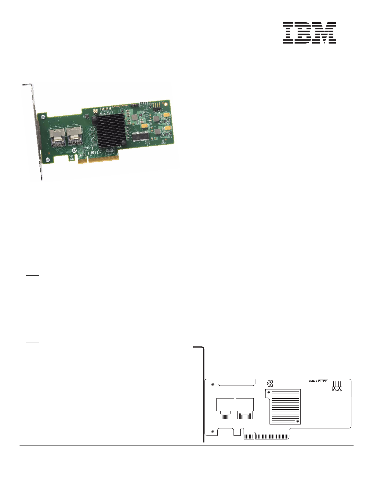
ServeRAID M1015 SAS/SATA
Controller
Quick Install Guide
Step 1 Unpack the Controller
Important: When you handle static-sensitive devices, take
precautions to avoid damage from static.
Unpack the controller in a static-free
environment. Remove the controller from the
antistatic bag and inspect it for damage. If the
controller appears to be damaged, or if the
ServeRAID M Support CD is missing, contact
your place of purchase.
The CD contains the following documents:
• ServeRAID M1015 SAS/SATA Controllers
Thank you for purchasing the ServeRAID M1015 SAS/SATA
controller. Please take a few minutes to read this Quick
Install Guide before you install your controller. For more
information about any topic covered in this guide, refer to the
other documents on your ServeRAID M Support CD.
The ServeRAID M1015 SAS/SATA (Serial Attached SCSI/
Serial ATA II) controller is PCI-Express 2.0, half-size, halfheight RAID controller based on the LSISAS2008 PCI
Express-SAS/SATA I/O Processor chip. The controller
controls eight internal 6 Gb/s SAS/SATA ports through two
SFF-8087 SAS x4 internal connectors.
Note
: Record your controller serial number in a safe
location in case you need to contact IBM.
You can use the ServeRAID M1000 Series Advanced
Feature Key to enable support for RAID 5 configurations and
self-encrypting disks (SED).
For more information about this controller and the Advanced
Feature Key, refer to the ServeRAID M1015 SAS/SATA
Controller User’s Guide on the ServeRAID M Support CD.
Note
: SATA II is the only type of SATA supported by
this RAID controller.
Step 2 Prepare the Computer
Attention: Before you install the controller, make sure that
Step 3 Review the Connectors
Figure 1 ServeRAID M1015 Card Layout
• ServeRAID-M Software User’s Guide
• ServeRAID-M Device Driver Installation User’s
Review all safety information provided with the
computer. Unplug the power cords from the
power supplies, disconnect the computer from
the network, and remove the computer cover.
See the documentation provided with the
computer for instructions.
the computer is disconnected from the power and
from any networks.
Figure 1 shows the location of the connectors.
User’s Guide
Guide
SERVERAID CONTROLLER INSTALLATION
Attention: Back up your data before you change your
system configuration. Otherwise, you might lose
data.
Perform the following steps to install your ServeRAID M1015
SAS/SATA controller.
Page 2
85061-03
Edge of
Motherboard
32-bit slots
(3.3 V)
PCI-e
slot
Bracket Screw
64-bit slots
(3.3 V)
Press here
Press here
Table 1 describes the connectors on the
ServeRAID M1015 controller.
Table 1 Jumpers and Connectors
Jumper/
Connector Type Description
J1 RISCwatch header 16-pin header
Reserved for IBM use.
J2 CPLD header 10-pin header
Reserved for IBM use.
J3 External LED drive
activity/fault header
J4 x4 Mini-SAS (SFF-
8087) Ports 0–3
internal connector
J5 x4 Mini-SAS (SFF-
8087) Ports 4–7
internal connector
J6 PCI Express x8
board edge
connector
TP1 Universal Asyn-
chronous Receiver/
Transmitter (UART)
debugging
U1 ServeRAID M1000
Series Advanced
Feature Key header
4-pin connector
Connects to external, bi-color
LEDs that indicates drive activity
or faults.
Connects the cables from the controller to SAS drives or SATA II
drives, or a SAS expander.
Connects the cables from the controller to SAS drives or SATA II
drives, or a SAS expander.
x8 interface that provides connections on both the top and the
bottom of the board.
4-pin connector
Reserved for IBM use.
2-pin connector
Enables support for RAID 5 configurations and self-encrypting disks
(SED) when you insert the
ServeRAID M1000 Series
Advanced Feature Key.
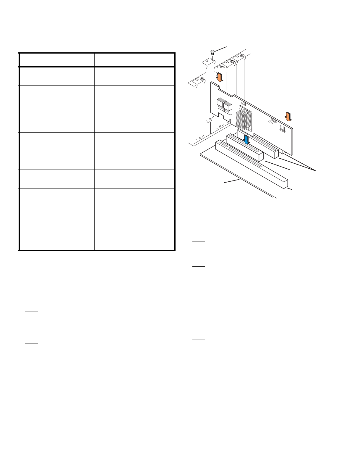
Step 4 Install the Controller on the Motherboard
Insert the controller in a PCI Express slot on the
motherboard, as shown in Figure 2.
Press down gently but firmly to seat the card
correctly in the slot. Secure the controller to the
computer chassis with the bracket screw.
Note
: This is a PCI Express x8 card and it can operate
in x8 or x16 slots. However, some PCI-E slots
support only PCIe graphics cards; if a RAID
controller is installed, it will not function.
Note
: Refer to your motherboard guide for information
about the PCI Express slot.
Figure 2 Installing the ServeRAID M1015 SAS/
SATA Controller
Step 5 Configure and Install the SAS Devices, SATA
II Devices or Both
Configure the SAS devices, SATA II devices, or
both, and install them in the external enclosure.
Note
: Refer to the documentation for the external
devices for pre-installation configuration
requirements.
Note
: The controllers support SATA II protocols but not
SATA I protocols. All references to SATA in this
guide are to SATA II.
Step 6 Connect the Controller to the SAS Devices,
SATA II Devices, or Both
Connect the cables between the controller and
the SAS devices, SATA II devices, or both. Refer
to the external device documentation to view
connector locations for the external devices.
Note
: Refer to the ServeRAID M1015 SAS/SATA
Controller User’s Guide for information about the
cables and the connectors.
Step 7 Turn on the Power to the Computer
Reinstall the computer cover and reconnect the
power cords.
Turn on the power to the computer, making sure
that the power is turned on to the SAS devices
and the SATA II devices before or at the same
time as the host computer. If the power is turned
on to the computer before it is turned on to the
2 of 4
Page 3

®
devices, the computer might not recognize the
devices.
For the United Extensible Firmware Interface
(uEFI), no BIOS message displays. Press F1 to
enter System Setup. Refer to your system user’s
guide for specific configuration information.
Under other interfaces or operating systems, a
BIOS message similar to the following displays
during boot:
LSI MEGARAID BIOS VERSION xxxx [date]
Copyright(c) 2009, LSI Corporation
HA-1 (Bus x Dev y) ServeRAID M1015
PCI-Express RAID Controller
Standard FW xxxx DRAM=xxx MB(SDRAM)
The firmware takes several seconds to initialize.
During this time the adapter scans the bus(es).
Step 8 Run the WebBIOS Configuration Utility
Run the WebBIOS Configuration Utility to
configure the physical arrays and the logical
drives. When the message Press <Ctrl><H> for
WebBIOS displays on the screen during boot,
press CTRL+H immediately to run the utility.
For systems using uEFI, refer to the system
publications for instructions on how to access
WebBIOS.
Note
: Refer to the ServeRAID-M Software User’s Guide
on the ServeRAID M Support CD for detailed
steps on configuring the physical arrays and the
logical drives.
Step 9 Install the Operating System Driver
The controller can operate under various
operating systems. To operate under these
operating systems, you must install software
drivers.
View the supported operating systems and
download the latest drivers for the controller at
http://www.ibm.com/support/. For updates, click
Downloads and drivers. Access the download
center and follow the steps to download the
driver.
Refer to the ServeRAID-M Device Driver
Installation User’s Guide on the CD for details on
installing the driver. Be sure to use the latest
Service Packs provided by the operating system
manufacturer and review the readme file that
accompanies the driver.
SUPPORTED RAID LEVELS
The ServeRAID M1015 controller supports drive groups
using the following RAID levels:
• RAID 0 (data striping): Data is striped across all drives
in the group, enabling very fast data throughput. There is
no data redundancy. All data is lost if any drive fails.
• RAID 1 (drive mirroring): Data is written simultaneously
to both drives in the drive group, providing complete data
redundancy if one drive fails. RAID 1 supports an even
number of drives from 2 to 32 in a single span.
• RAID 5 (drive striping with distributed parity): Data is
striped across all drives in the group. Part of the capacity
of each drive stores parity information that reconstructs
data if a drive fails. RAID 5 provides good data
throughput for applications with high read request rates.
• RAID 10 (RAID 1 and RAID 0 in spanned groups): Data
is mirrored on pairs of drives to provide complete data
redundancy and high data throughput rates.
Note
: Refer to the ServeRAID-M Software User’s Guide
on the ServeRAID M Support CD for more
information about RAID levels.
TECHNICAL SUPPORT
Refer to the Important Notices and Warranty Information
document for information about the technical support
available for this product.
IBM P/N: 49Y8632
First Edition (September 2009)
© Copyright International Business Machines Corporation 2009.
All rights reserved.
US Government Users Restricted Rights – Use, duplication or disclosure restricted
by GSA ADP Schedule Contract with IBM Corp.
IBM and the IBM logo are trademarks or registered trademarks of International
Business Machines Corporation in the United States, other countries, or both.
LSI, the LSI logo design, and MyStorage are trademarks or registered trademarks
of LSI Corporation. All other brand and product names may be trademarks of their
respective companies.
Page 4

 Loading...