

Page 1
Customer Engineering
Issued to:
Branch
Department:
Address:
If
this
Office:
__________________
manual
__________________
________________
________________
is
mislaid,
please
Manual
return
it
to
of
Instruction
the
above
_
_
_
_
address.
Selectric
I/O
®
Keyboard Printer
Page 2
PREFACE
This manual has
can
be
incorporated
The
particular
scribed.
This manual covers models
1
620
Mod.
been
model you
I\,
written
in
to
include
the
"Selectric"
are
concerned
731, 735, 765, 775,
the
I/O
with may not use
maximum hardware or mechanisms
Keyboard
1415,
1014,
Printer
all
of
Sabre,
thru
October
the
mechanisms
Stretch,
7040/44,
that
1964.
de-
All rights
Address comments
IBM
Office
to
reproduce
Products Divi"sion,
this
regarding
material
the
comments
Lexington,
are
reserved
of
this publi
Kentucky
by
IBM.
cation
40507
to:
Page 3
CONTENTS
Motor
Typehead
Tilt
Rotate
Keyboard
Print
Selection
Keyboard
Shift
Cycle Clutch
Alignment
Print
Print
Print
Mainspring
Operational
Operational
Operational
Spacebar.
Spacebar
Carrier
Carrier
Tabulator
Margin
and
Drive
.............................
Mechanism
Mechanism
Section
Selection
Contact
Lock
.........................
.................................
Operation
...........................
Mechanism
Mechanism
Escapement
.....................................•.............................
Cams
Selection
Contact
.. . ........................
Mechanism
Backspace
Indexing
Platen
Paper
Fabric Ribbon
Red Ribbon
Fabric Ribbon
...........................
Return
Return
.......................................•............................
Variabl.e
.............................
Control
Feed
and
(Early
Shift
(Late
...............................................................
"
.......................................
................................................................
..............................................................
and
Character
Unit
.....................
Assembly
.........................................................
(Early
Style)
(Late
Style)
......................•.....................................
and
Control
Unit
Assembly
(Print
(Early
Style)
(Late
Style)
...............................................................
................................................................
Release ME:tchanism
Style)
...............................................................
Style). " .........................................
Selection
.....................................................
........
....................................................
Mechanism
..............
(Late
Escapement)
.....................................................
...............•.....................................
.......................................................
.........................................
"
......................................
"
......................................
"
......................................
','
......................................
:
...........................................
.........................................
','
......................................
Style)
...............•.......................
,
.......................................
..........................................
'
.•.....................................
','
......................................
..............................................
,
...........
1
3
5
8
12
16
18
20
22
28
29
39
41
41.5
44
45
49
50.1
51
54
54.1
55
58.1
59
62
63
69
73
75
79
80
Page 4
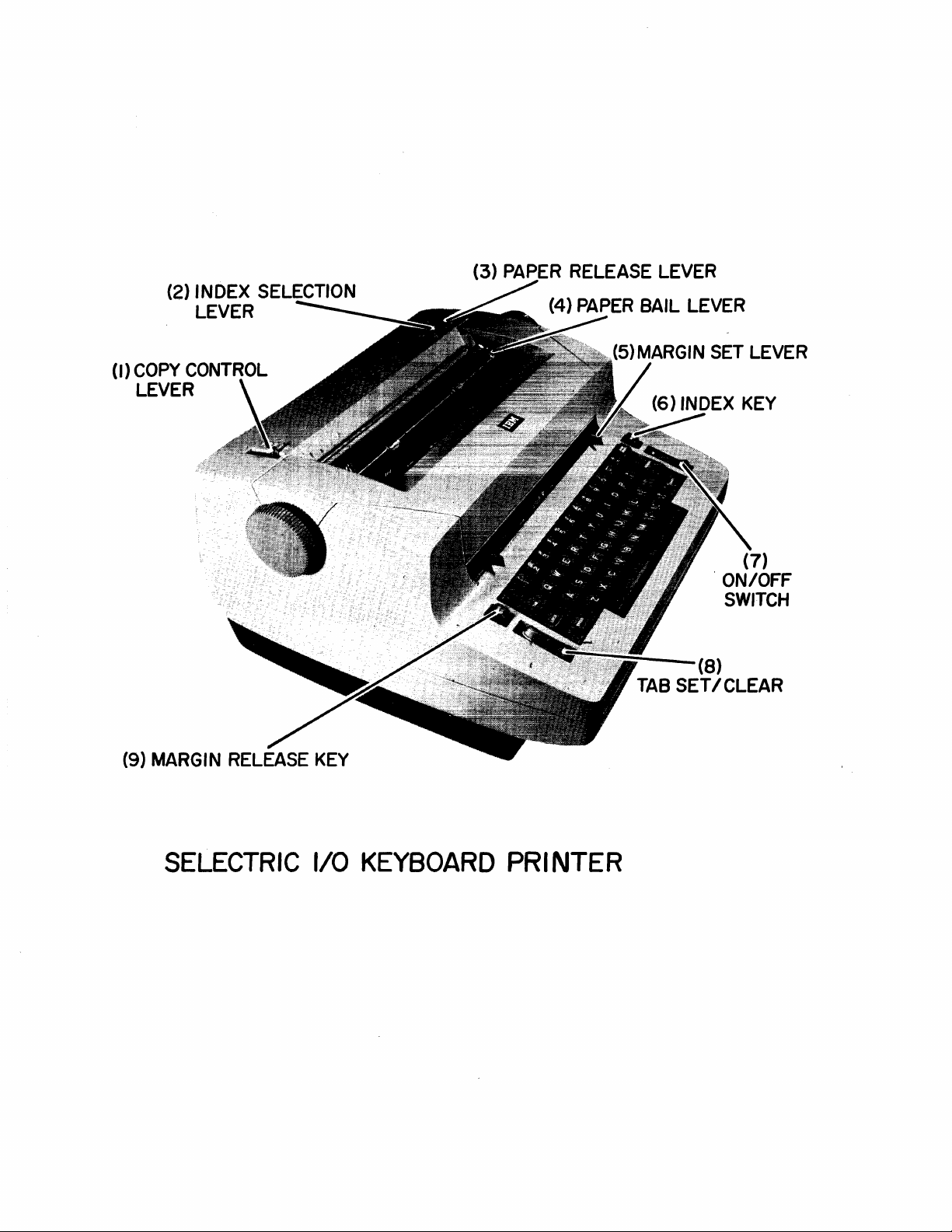
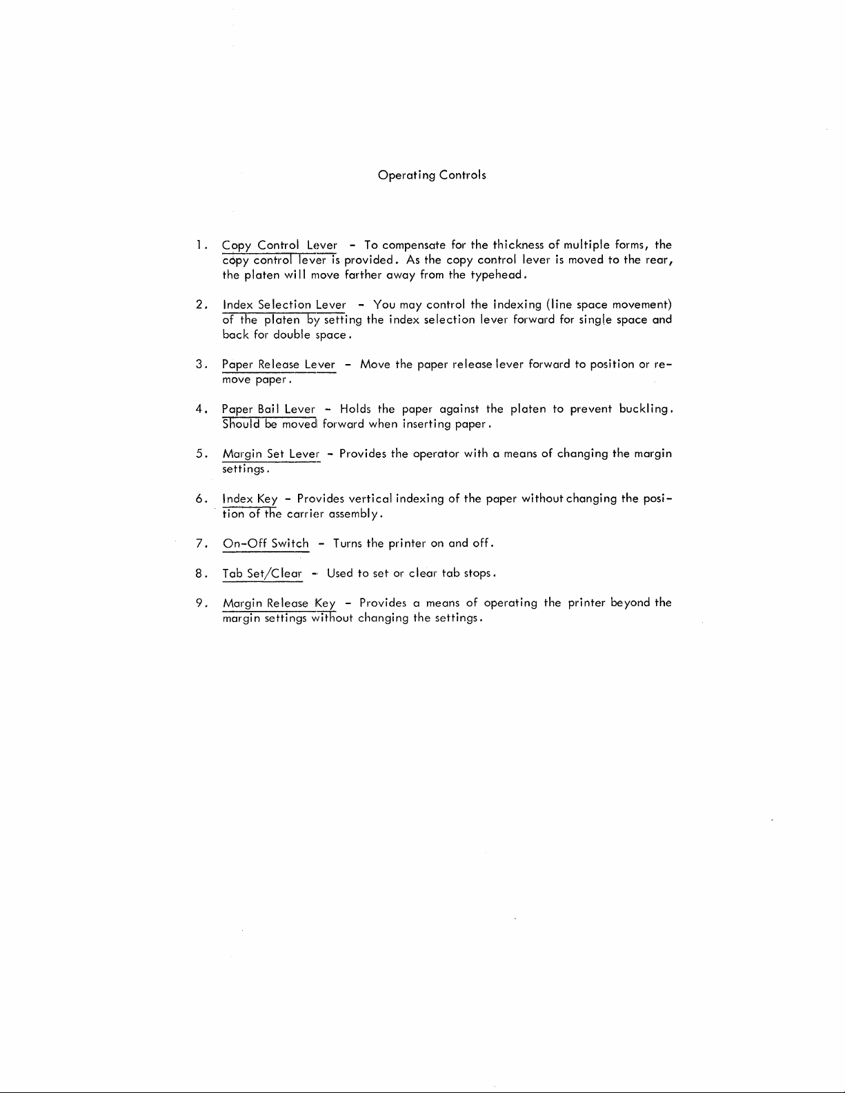
(2) INDEX SELECTION
LEVER
(I) COpy CONTROL
LEVER
(3)
PAPER RELEASE LEVER
(4)
PAPER
BAIL LEVER
TAB
(7)
ON/OFF
SWITCH
(8)
SET/CLEAR
SELECTRIC
1/0
KEYBOARD
PRINTER
Page 5
1.
2.
3.
4.
5.
Copy
Control
copy
control
the
platen
Index
Selection
of
the
back
for
Paper
move
paper.
Paper
Bai I
Should
Margin
settings.
platen
double
Re
lease
be
Set
Lever - To
lever
is
wi
II
move
Lever -You
b)/
setting
space.
Lever -Move
Lever
- Holds
moved
forward
Leve~
-
provided.
farther
the
when
Provides
Operating
compensate
As
the
away
from
may
index
selection
the
paper
the
paper
inserting
the
operator
Controls
for
copy
the
control
release
against
paper.
the
thickness
control
lever
typehead.
the
indexing
lever
forward
lever
forward
the
platen
with a means
of
multiple
is
(line
for
to
of
changing
moved
space
single
to
position
prevent
forms,
to
the
rear,
movement)
space
and
or
buckl
ing.
the
margin
the
re-
6. I ndex
tion
7.
On-Off
8.
Tab
9.
Margin
margin
Key -
of
the
Set/C
Release
settings
Provides
carrier
Switch
lear
assembly.
- Turns
-,
Used
Key -
without
vertical
to
the
set
indexing
pri
nter
or c I
ear
on
Provides a means
changing
the
of
the
and
tab
stops.
of
settings.
paper
off.
operating
without
the
changing
printer
the
beyond
posi-
the
Page 6

Page 7
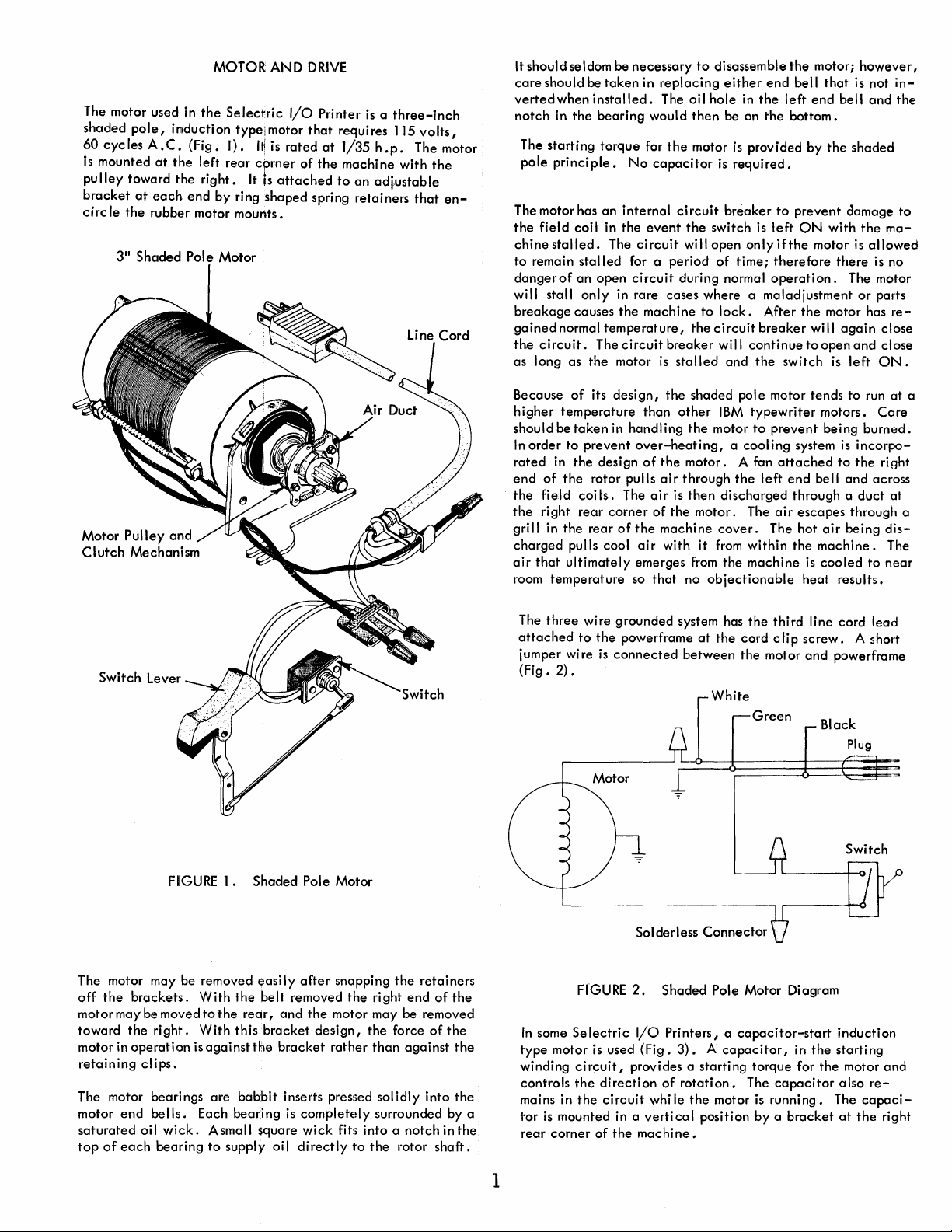
The motor used in
shaded
60
is
pulley
bracket
eirc
pole,
induction
cycles
A.
C.
mounted
at
toward
at
each
Ie
the
rubber motor mounts.
3"
Shaded Pole Motor
the
the
the
(Fig.
left
right.
end
MOTOR
Selectric
type: motor
1).
I~
rear
corner
It
by
ring
AND
I/O
is
rated
is
attached
shaped
DRIVE
Printer
that
of
the
spring
at
is a three-inch
requires 115
1/35 h .p.
machine
to
an
retainers
volts,
The motor
with
the
ad~ustable
that
en-
It should seldom be necessary
care
should be
vertedwhen
notch
in
The
starting
pole
principle.
The motor has
the
field
chine
stalled.
to
remain
dangerof
will stall
breakage
gained
the
circuit.
as long as
the
coil in
stalled
an
only
causes
normal
the
taken
in
replacing
installed.
bearing
torque
an
The
open
temperature,
The
The oil hole in
would
for
the
No
capacitor
internal
the
in rare cases where a maladjustment
the
circuit
motor
circuit
event
circuit
for a period
circuit
machine
breaker
is
stalled
to
disassemble
either
then
be on
motor
is
provided by
is
required.
breaker
the
switch
will
open
only
of
time;
during normal
to
lock.
the
circuit
will
continue
and
the
the
end
bell
the
left
the
bottom.
to
prevent
is
left
if
the
therefore
operation.
After
breaker
switch
end
ON
motor
the
wi
to
motor;
open
however,
that
is
not
bell
and
the
shaded
damage
with
the
is
allowed
there
The motor
or
motor has
II
again
and
is
left
in-
the
to
ma-
is no
parts
reclose
close
ON.
Motor
Clutch
Pulley
and
Mechanism
Because
higher
should be
In
rated
end
the
the
grill in
charged
air
room
The
attached
jumper wire
(Fig.
of
temperature
taken
order
to
in
the
of
the
field coi Is. The
right
the
pulls cool
that
ultimately
temperature
three
2).
its
design,
in handling
prevent
design
rotor pulls
rear
corner
rear
of
wire grounded system has
to
the
is
connected
the
than
other
over-heating,
of
the
air
through
air
is
of
the
the
machine
air
with it
emerges
so
that
powerframe
between
shaded pole motor tends
IBM
the
motor
motor. A fan
then
discharged through a
motor. The
cover.
from
from
no
objectionable
at
the
White
typewriter
to
prevent
a cool ing system is
the
left
The hot
within
the
machine
the
third line cord
cord c
the
motor
Green
attached
end
bell
air
escapes
the
machine.
is
heat
Ii p screw.
and
motors.
air
cooled
Black
to
run
Core
being
burned.
incorpo-
to
the
and
across
duct
through a
being
to
results.
lead
A short
powerframe
Plug
at
right
at
dis-
The
near
a
FIGURE
The motor may be removed easi
off
the
brackets.
motor may be moved
toward
motor in
retaining
The motor bearings
motor
saturated
top
of
end
each
the
right.
operation
cl ips.
bells.
oil
wick.
bearing
1.
Shaded Pole Motor
With
the
to
the
rear,
With
this
is
against
Each
the
are
babbit
bearing
Asmall square
to
supply oil
belt
bracket
Iy
after
snapping
removed
and
bracket
inserts pressed
is
completedy surrounded by a
directly
the
the
motor may be removed
design,
rather
wick
fits
the
right
the
force
than
against
solidly
into a notch
11'0
the
rotor
retainers
end
of
of
into
shaft.
the
the
the
the
inthe
1
Solderless
FIGURE
In
some
Selectric
type
motor is used
winding
controls
mains in
tor
rear
circuit,
the
the
is
mounted in a vel:tical position by a
corner
2.
Shaded Pole Motor Diagram
I/O
Printers, a
(Fig.
3). A capacitor,
provides a starting torque for
direction
circuit
of
the
of
rotation.
whi
Ie
machine.
the
Connector
capacitor-start
The
motor
is
in
the
capacitor
running.
bracket
Switch
induction
starting
the
motor
also
The
at
re-
capaci-
the
right
and
Page 8
Motor
Contactor
(835 Printer)
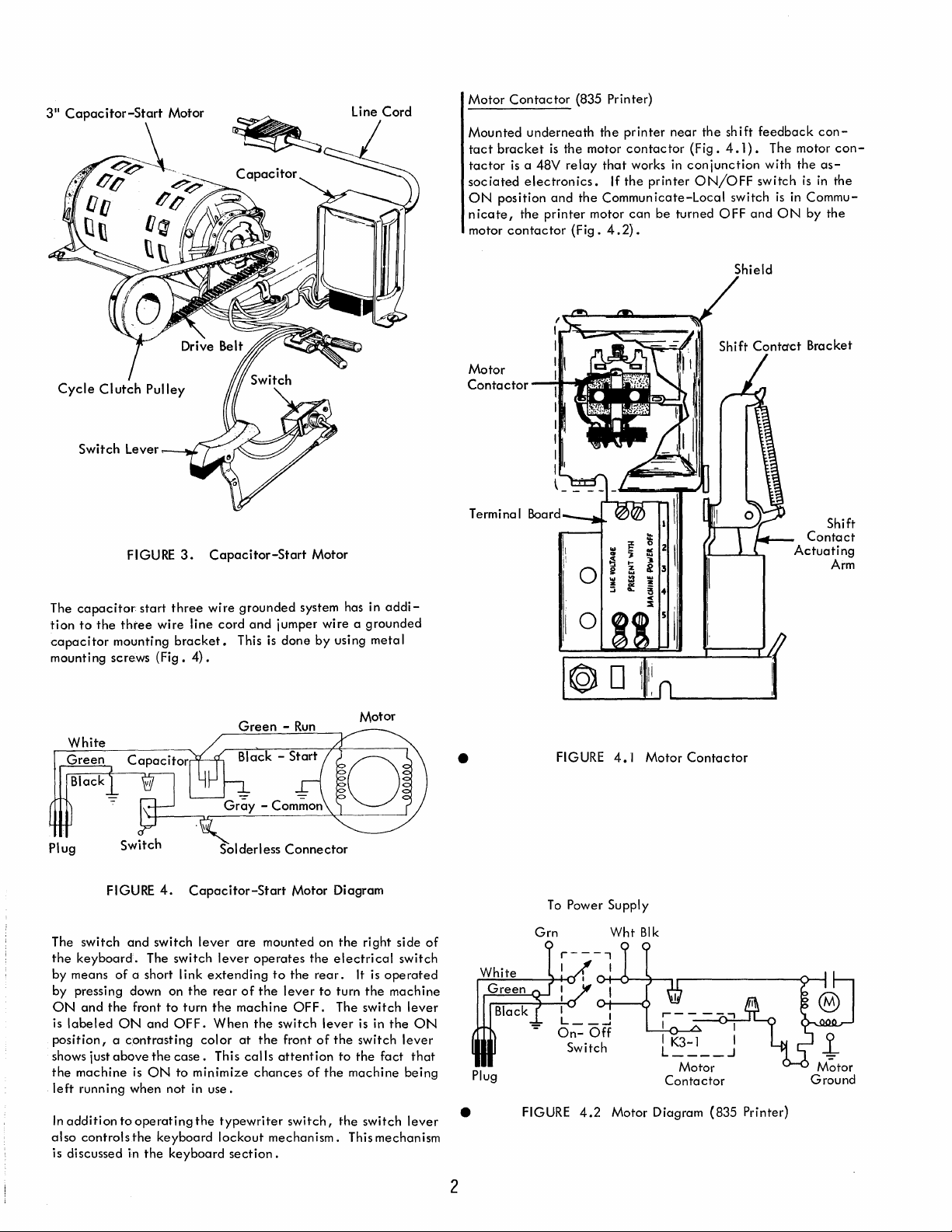
FIGURE
The
capacitor
tion
to
capacitor
mounting screws
the
three
mounting
start
three
wire
bracket.
(Fig.
3.
Capacitor-Start
wire
line
cord
4).
grounded
and
jumper
This
is
done
Motor
system has in
wire a grounded
by
using
addi-
metal
Mounted
tact
bracket
tactor
is
sociated
ON
position
nicate,
motor
contactor
Motor
Contactor
Terminal
underneath
is
the motor
a 48V
relay
electronics.
and
the
printer
(Fig.
-lI....,r; •
the
printer
contactor
that
works in
If
the
printer
the
Communicate-Local
motor
can
be
4.2).
...1~
~
...
E
IIC
..
".J
Z \
~
....
~
z
3
2
i
~
:;
$
~
z
§ ..
<
::i
0
near
the
(Fig.
conjunction
ON/OFF
turned
I
I
shift
4.1).
switch
OFF
Shield
feedback
The motor
with
switch
is
and
ON
con-
con-
the
as-
is
in
the
in
Commuby
the
Shift
Contact
Actuating
Arm
Green -Run
White
Green
Black
Plug Solderless
FIGURE
The switch
the
keyboard.
by means
by pressing down on
ON
and
the
is
labeled
position, a contrasting
shows just
the
left
In
also
is discussed in
above
machine
running when
addition
controls
4.
and
switch
The switch
of
a short I ink
front
ON
and
the
is
ON
to
operating
the
keyboard
the
Capacitor-Start
lever
lever
extending
the
rear
to
turn
the
OFF.
When
color
case.
This
to
minimize
not
in
use.
the
typewriter
lockout
keyboard
are
mounted
operates
of
the
machine
the
at
the
calls
chances
section.
mechanism.
Connector
Motor Diagram
on
the
electrical
to
the
rear.
lever
to
turn
OFF.
The switch
switch
lever
front
of
the
attention
of
the
switch,
Motor
the
right side
switch
It
is
operated
the
machine
lever
is in
the
switch
lever
to
the
fact
that
machine
the
This mechanism
switch
being
lever
ON
of
•
•
White
Green
Plug
Black
FIGURE
To
Grn
FIGURE
4.1
Power Supply
Wht
Blk
4.2
Motor Diagram
Motor
Contactor
Contactor
Motor
(835
Printer)
2
Page 9
Drive
An
eight-toothed
operation
rotation
of
of
the
the
speed reduction
motor
pulley
provides positive drive for
machine. A positive-drive
motor
pulley
to
the
cycle
of
3-5/8
to
1 .
belt
clutch
transfers
pulley
the
the
with a
The shaded pole motor has less starting torque
ci
tor-start
start under a heavi
has been
is
allowed
clutch
oped by
several
motors do not
The motor
and
extend
clutch
to
the
clutch
are
the
Centrifugal
of
the
a tooth
to
rotate
motor •
incorporated
to
engages
the
To
insure
Iy
loaded conditi
in
approach
to
drive
rotor causes
that
the
motor
normal operating
the
machine.
the
machine
mechanisms may have been tripped.
require a centrifugal
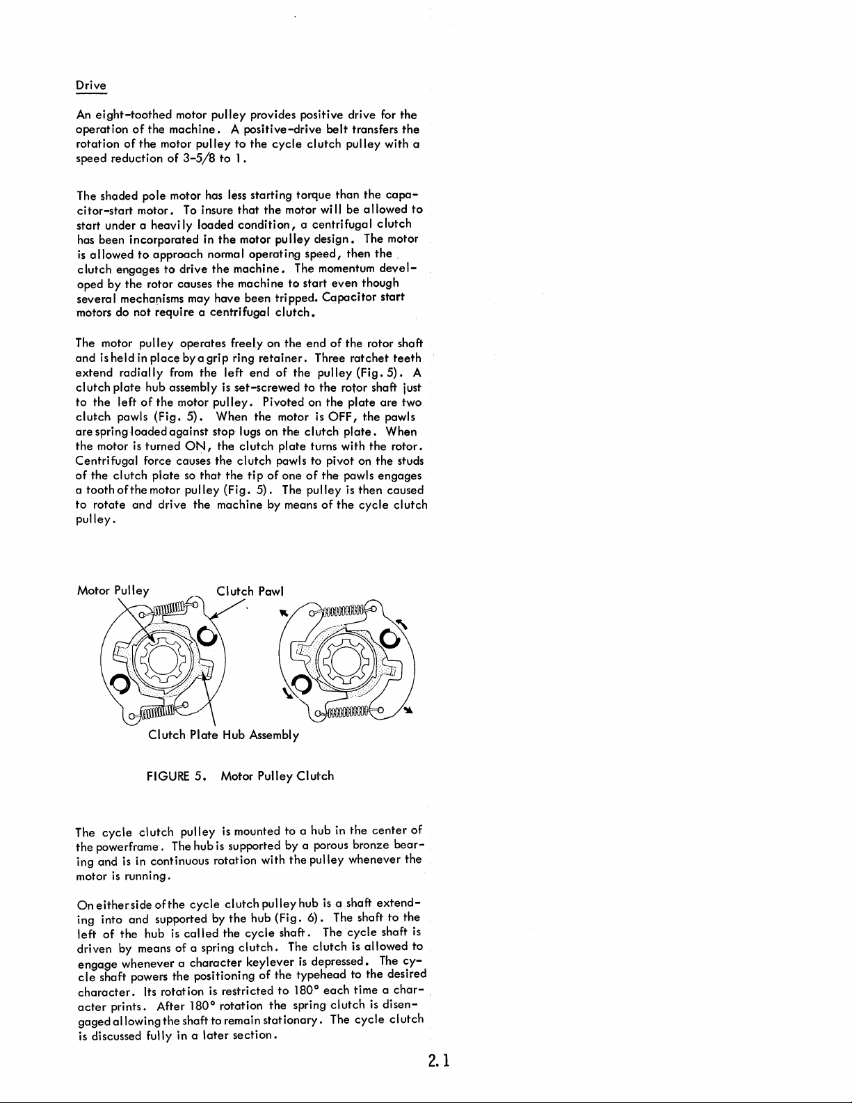
pulley
is
held in
place
radially
plate
hub assembly
left
of
the
pawls
(Fig.
spring loaded
motor
is
turned
force causes
cI
utch
plate
of
the
motor
and
drive
operates
by a grip ring
from
motor
5).
against
ON,
so
pulley
freely on
the
left
end
is
set-screwed
pulley.
When
the
stop lugs on
the
clutch
the
clutch
that
the
ti p
(Fig.
5).
the
machine by means
the
motor
on, a centrifuga I clutch
pulley
design.
speed,
The momentum
to
start
clutch.
the
end
retainer.
of
the
Three
to
pulley
the
Pivoted on
motor is
the
clutch
plate
turns with
pawls
tC)
of
one
of
The
pulley
pulley.
Motor Pulley
than
the
wi
II
be a 1I0wed
The motor
then
even
though
Capacitor
of
the
rotor shaft
ratchet
(Fig.
rotor shaft just
the
plate
OFF,
the
plate.
the
pivot on
the pawls
is
then
of
the
cycle
cape-
the,
devel-
start
teeth
5).
are
two
pawls
When
rotor.
the
studs
engages
caused
clutch
to
A
Clutch
FIGURE
The
cycle
clutch
the
powerframe. The hub
ing and
motor
On
ing into
left
is
in continuous rotation with
is
runn i
eitherside
and
of
the
hub is
driven by means
engage
cle
character.
acter
gaged
whenever a character
shaft powers the positioning
Its rotation
prints. After
allowing
Plate
5.
pulley
ng
.
of
the
cycle
supported by
called
of
a spring
180
the
shaft to remain
is discussed fully in a
Hub Assembly
Motor Pulley
is
mounted to a hub in
is
supported by a porous bronze
clutch
the
hub
the
cycle
clutch.
keylever
is
re$tricted
0
rotation
later
section.
Clutch
the
pulley
hub
(Fig.
shaft.
The
is
of
the
typehead
to
180
the
spring
stationary.
pulley
is
6).
The
clutch
depressed.
0
each
clutch
The
the
center
whenever
a shaft
extend-
The shaft to
cycle
shaft
is
allowed
The
to the desired
time a
is
disen-
cycle
clutch
of
bear-
the
the
is
to
cy-
char-
2.1
Page 10
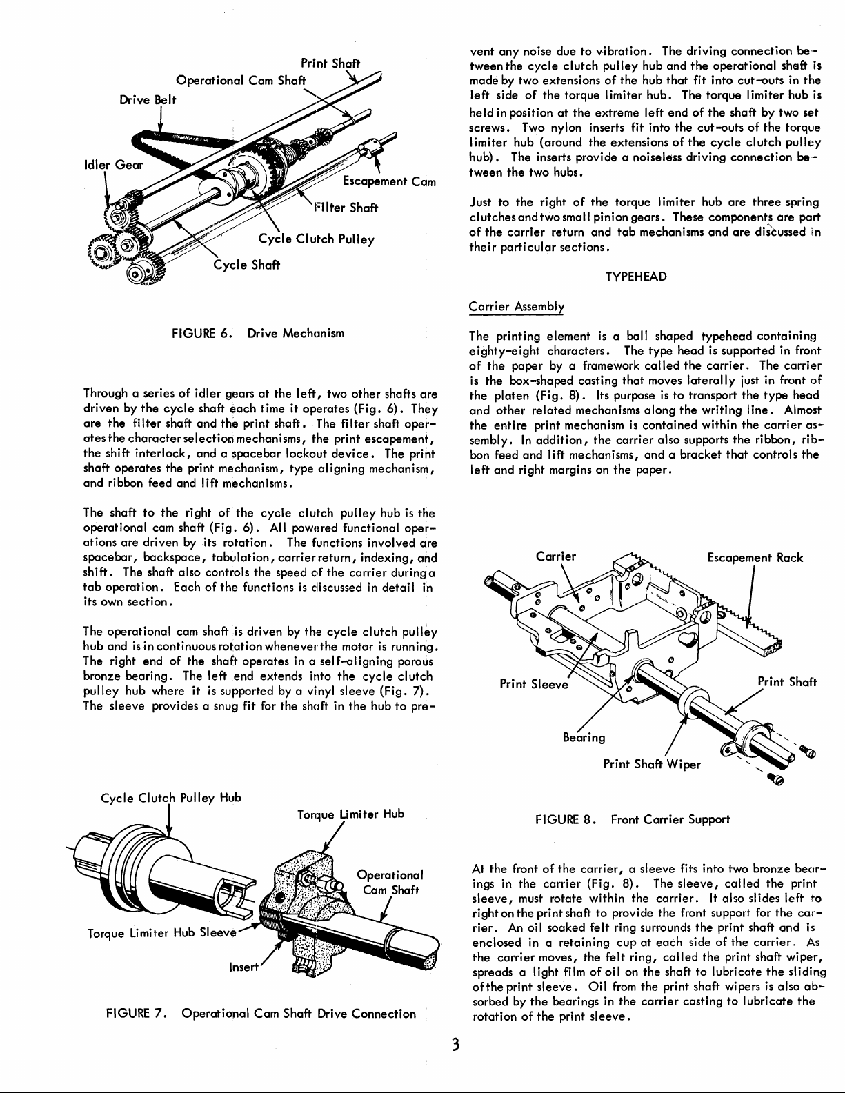
Print Shaft
lFi I ter
Shaft
vent
any
noise due
tween
the
cycle
made by two extensions
left
side
of
held
in position
screws. Two nylon inserts fit into
limiter
hub).
tween
Just
clutches
of
their
hub (around
The inserts provide a noiseless driving
the
two hubs.
to
the
and
the
carrier
particular
to
vibration.
clutch
pulley
of
the
the
torque limiter
at
the
extreme
the
extensions
right
of
the
torque limiter hub
two small pinion
return
and
tab
sections.
TYPEHEAD
The driving
hub
hub
hub.
left
gears.
mechanisms
connection
and
the
operational
that
fit into
The torque limiter hub is
end
of
the
of
the
These components
cut-outs
the
shaft by two set
cut-outs
cycle
connection
are
and
are
shsft is
of
the
clutch
three
are
di~ussed
be-
in
the
torque
pulley
be-
spring
part
in
FIGURE
Through a series
driven by
are
ates
the
shaft
and
The shaft
operational
ations
spacebar,
shift.
tab
its own
The
hub and
The right end
bronze
pulley
The
the
cycle
the
filter
shaft
the
characterselectior.l mechanisms,
shift
interlock,
operates
ribbon feed and lift mechanisms.
are
The shaft also controls
operation.
operational
sleeve
the print mechanism, type
to
the
cam shaft
driven by its
backspace,
Each
section.
cam shaft is driven by
isin
continuous rotation
of
bearing.
hub where
provides a snug fit for
of
right
the
The
idler
and
and a
it
6.
gears
shaft
~ach
the
spacebar
of
(Fig.
rotation.
tabulation,
of
the
shaft
left
end
is
supported by a vinyl
Drive Mechanism
at
the
left,
time
it
operates
print
shaft.
the
cycle
6).
All powered functional
the
functions
whenever
operates
extends
The
the
lockout
aligning
clutch
The functions involved
carrier
return,
speed
of
is
discussed in
the
the
in a
self-aligning
into
the
shaft in
two
other
(Fig.
filter
print
device.
pulley
the
carrier
cycle
motor
the
sleeve
the
shafts
6).
They
shaft
oper-
escapement,
The print
mechanism,
hub is
oper-
indexing,
during a
detail
clutch
pulley
is
running.
porous
cycle
c1utclh
(Fig.
7).
hub
to
pre-
are
the
are
and
in
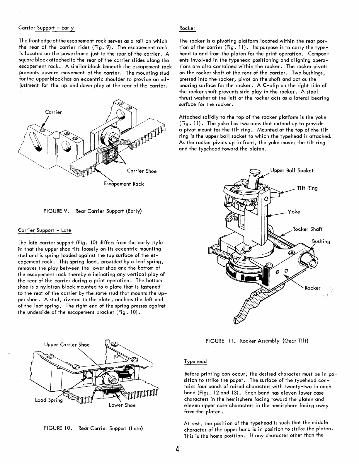
Carrier
The printing
eighty-eight
of
is
the
and
the
sembly.
bon feed and
left
Assembly
the
paper
the
box-shaped
platen
other
related
entire
In
and
right margins on
element
characters.
by a framework
(Fig.
print mechanism
addition,
lift
is a ball shaped
casting
8).
Its purpose
mechanisms
the
mechanisms,
the
The
type
called
that
moves
along
is
contained
carrier
also supports
and a bracket
paper.
is
to
typehead
head
is supported in front
the
carrier.
laterally
transport
the
writing
within
the
that
just in front
the
line.
the
containing
The
carrier
type
head
Almost
carrier
ribbon,
controls
of
asribthe
Cycle
Clutch
Torque Limiter
FIGURE
7.
Pulley
Hub
Hub
Sleeve
Operational
Cam Shaft Drive
Connection
At
the
front
ings in
sleeve,
right on
rier.
enclosed
the
spreads a light film
ofthe
sorbed by
rotation
the
must rotate
the
An
oil soaked
in a
carrier
print
the
of
3
FIGURE
of
the
carrier
print shaft
retaining
moves,
sleeve.
bearings in
the
print
8.
Front
Carrier
carrier, a sleeve
(Fig.
8).
The
within
the
of
Oil
the
to
provide
felt
ring surrounds
cup
felt
ring,
oil
on
from
the
sleeve.
carrier.
the
at
each
called
the
shaft
the
print shaft wipers is also
carrier
Support
fits into two bronze
sleeve,
front support for
It
the
side
of
the
to
lubricate
casting
called
also slides
print shaft
the
the
carrier.
print shaft
the
to
lubricate
the
bear-
print
left
car-
and
wiper,
sliding
the
to
is
As
ab-
Page 11
Carrier
The front
the
is
square block
escapement
prevents upward movement
forthe
Support - Early
edge
rear
of
located
upper block has
justment for
of
the
escapement
the
carrier
on the powerframe just
attached
rack.
the
A simi
up
to
an
and
rides
the
down
rack
(Fig.
rear
of
lar
block
of
the
eccentric
play
serves as a rail on which
9).
The
escapement
to
the
rear
of
the
carrier.
the
carrier
beneath
carrier.
shoulder
at
the
sl
ides
along
the
escapement
The mounting stud
to
provide
rear
of
the
rack
the
rack
an
ad-
carrier.
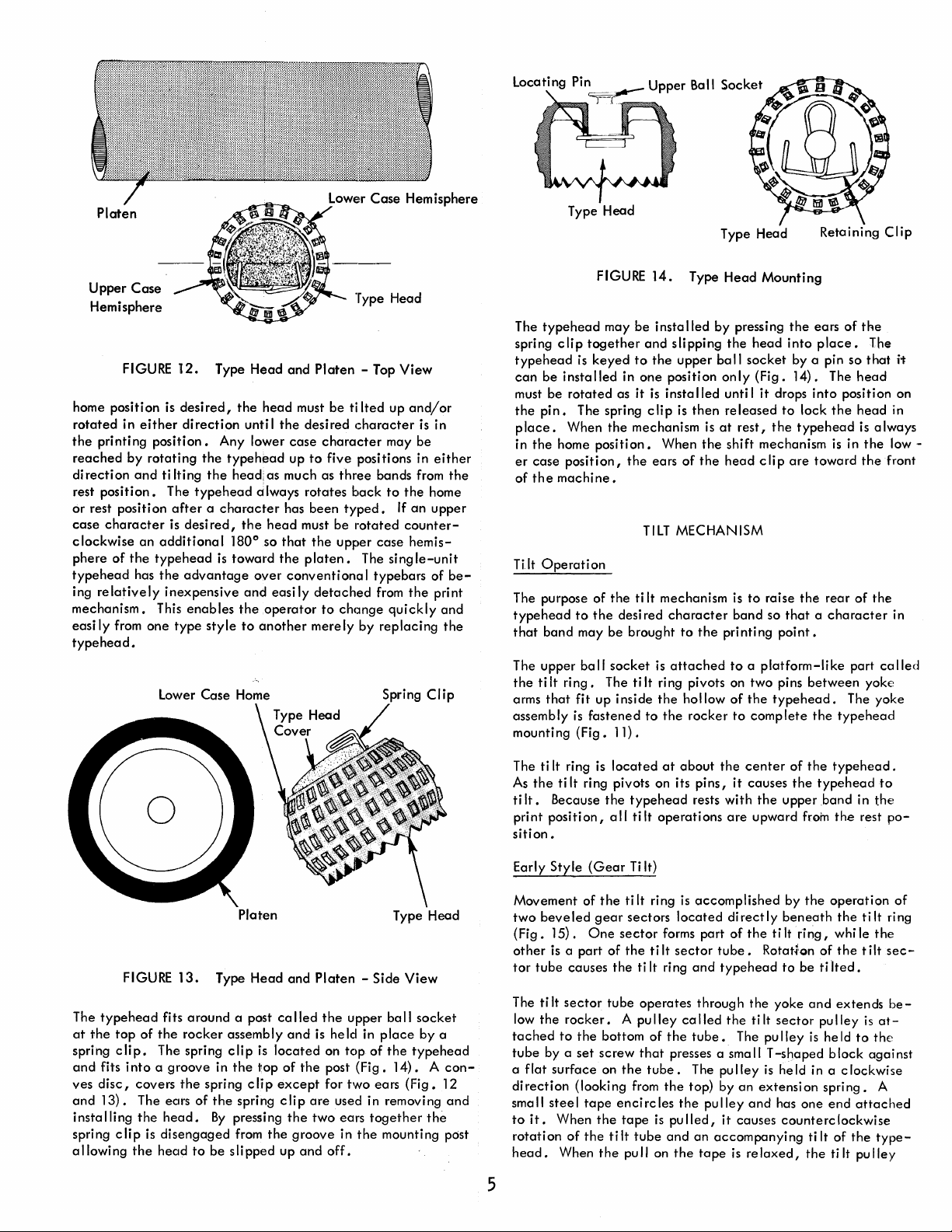
Rocker
The rocker
tion
of
A
head
to
ents
involved
tions
are
the
on
pressed
bearing surface for
the
rocker shaft prevents si de
thrust washer
surface for
is
a pivoting platform
the
carrier
and
from
the
in
the
also
contained
rocker shaft
into
the
rocker,
at
the
the
rocker.
(Fig.
11).
platen
for
type
head
within
at
the
rear
pivot on
the
rocker. A C-clip
left
of
the
located
Its
purpose
the
print
positioning
the
rocker.
of
the
carrier.
the
shaft
play
in
the
rocker
acts
within
the
rear
is
to
carry
the
operation.
and
aligning
The rocker pivots
and
on
the
rocker. A stee
as a
Compon-
Two bushings,
act
as
the
right
latera I bearing
por-
type-
opera-
side
I
of
Carrier
The
iin
stud
capement
removes
the
the
~hoe
to
per
of
the
Support - Late
late
that
the
and
the
escapement
rear of
is
a nylatron
the
rectr of
shoe. A stud,
the
leaf
underside
FIGURE
carrier
upper shoe fits loosely on its
is
spring loaded
rack.
the
spring.
support
This spring
play
rack
carrier
the
of
the
9.
Rear
Carrier
(Fig.
against
load,
between
block
carrier
riveted
the
thereby
The right end of
escapement
eliminating
during a print
mounted
by
the
to
the
10)
the
lower shoe
to a plate
same stud
bracket
Escapement Rack
Support (Early)
differs from
top
provided by a
operation.
plate,
the
the
eccentric
surface
and
the
any
vertical
that
that
anchors
spring presses
(Fig.
early
mounting
of
the
leaf
spring,
bottom of
play
The bottom
is
fastened
mounts
the
left
10).
style
es-
of
the
up-
end
against
Attached
(Fig.
a pivot mount for
ri
ng
As
and
solidly
11).
The yoke has two arms
is
the
upper ba
the
rocker pivots up in
the
typehead
to
the
the
II
toward
top
ti
It
ring.
socket
front,
the
of
the
to
platen.
rocker
that
Mounted
whi ch
the
yoke moves
platform is
extend
at
the
the
type
head
Upper Ball
up
to
top
the
Socket
Tilt Ring
the
yoke
provide
of
the
is
attached.
ti
It
ring
ti
It
FIGURE
10.
Rear
Carrier
Support
(late)
Typehead
Before printing
sition
to
tains four bands
band (Figs. 12
characters
eleven
from
the
At
rest,
character
This
is
the
4
FIGURE
strike
in
upper
platen.
the
of
home
11.
Rocker Assembly
can
occur,
the
paper.
of
raised
and
13).
the
hemisphere facing toward
case
characters
position
the
upper band
position.
the
The
characters
Each band has
of
the
typehead
is
If
desired
in
in position
any
(Gear
character
surface
of
the
with
twenty-two
eleven
the
hemisphere facing
is such
to
character
Tilt)
typehead
lower
the
platen
that
strike
other
must be in
con-
in
each
case
and
away'
the
middle
the
platen.
than
the
po-
Page 12
Platen
Lower
Case
Hemisphere
Type Head
Type Head
Retaining
Clip
Upper
Case
Hemisphere
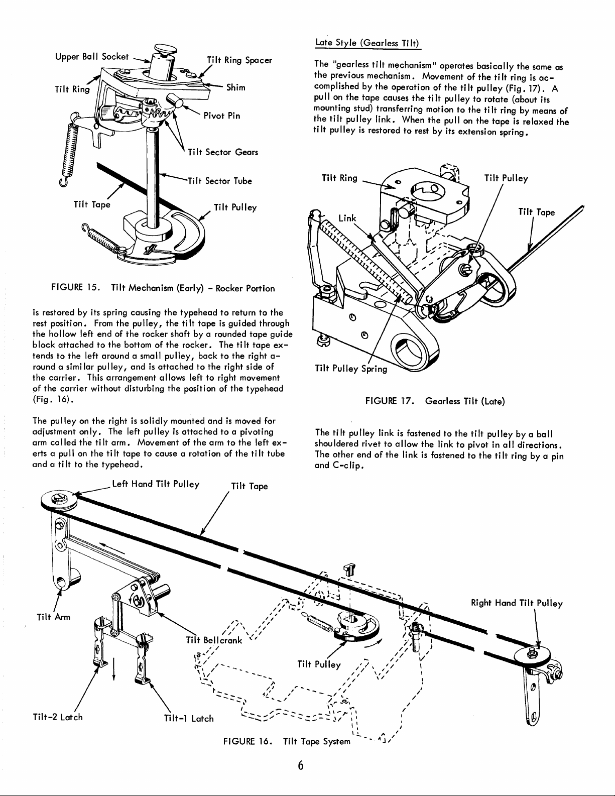
FIGURE
home position is
rotated
the
reached
di
rest
or rest position
case
clockwise
phere
typehead
ing
mechanism.
easi
typehead.
in
printing
recti
on
position.
character
of
relatively
Iy
from
either
position.
by
rotating
and
ti It'ing
an
additional
the
typehead
has
the
This
one
Lower Case Home
12.
Type
Head
desired,
direction
The
after a character
is
desired,
advantage
inexpensive
enables
type
the
unti I
Any lower
the
typehead
the
headi as much as
typehead
the
180
is
toward
and
the
style
to
0
Type Head
and
Platen
head
must
be
ti Ited up
the
desired
case
up
always
over
rotates
has
head
must be
so
that
the
platen.
conventiona I typebars
easily
operator
another
character
character
to
five positions in
three
back
been
typed.
rotated
the
upper
detached
to
chcmge
merely
- Top
may be
bands from
to
case
The
single-unit
from
quickly
by
replacing
Spring
View
and/or
is
the
home
If
an
counter-
hemis-
the
Clip
in
either
the
upper
of
be-
print
and
the
The
typehead
spring
clip
together
typehead
can
must be
the
place.
in
er
of
Tilt
The purpose of
typehead
that
The
the
arms
assembly
mounting
be
installed
rotated
pin.
When
the
home
case
position,
the
machine.
Operation
to
band
upper
ti
It
ring.
that
fit up inside
is
(Fig.
is
keyed
The spring c lip
the
may be brought
ba
fastened
FIGURE
may
be
to
in
as
it
the
mechanism
position.
the
the
ti
desi red
II
socket
The ti
11).
14.
Type
Head
installed
and
the
one
position
is
insta lied unti I
When
ears
TILT
It
mechanism is
character
is
It
ring pivots on two pins
the
to
the
by
pressing
slipping
upper
is
MECHANISM
to
attached
the
ball
only
then
released
is
at
the
shift mechanism
of
the
head
the
printing
hollow
rocker
rest,
band
to a platform-like
of
to
head
socket
to
the
complete
Mounting
the
ears
into
by a pin so
(Fig.
14). The
it
drops
into
to
lock
the
typehead
clip
are
toward
raise
the
so
that a character
point.
between
typehead.
the
of
place.
position on
the
is
in
rear
part
The yoke
typehead
the
The
that
head
head
is
the
the
of
the
yoke
it
in
always
low -
front
in
ca
lied
FIGURE
The
type
head
at
the
top
spring
clip.
and
fits
into a groove
ves
disc,
and
13). The
insta lIing
spring c lip
a
1I0wi
ng
the
13.
fits a round a post
of
the
rocker
The spring
covers
the
spring c
ears
of
the
head.
is
disengaged
head
to
Platen
Type
assemb I y
clip
in
the
the
spring
By
pressing
from
be s
lipped
Head
and
ca
lied
and
is
located
top
of
Ii p except
clip
the
the
groove
up
Platen
- Side
the
upper ba
is
he
Id
on
top
the
post
(Fig.
for
two
are
used in removing
two
ears
in
the
and
off.
Type Head
View
II
socket
in p
lace
by
of
the
typehead
14). A
ears
(Fig.
together
mounting post
the
a
con-
12
and
The ti
As
the
ti
It.
print
sition.
Early
Movement of
two
(Fig.
other
tor
The
low
tached
tube
a
flat
di
recti
sma
to
it.
rotati
head.
5
It
ring
is
ti
It
ring pivots on its
Because
position,
Style
beveled
15).
is a part
tube
tilt
the
by a
surface
on (looki
II
stee I tape
When
on
the
all
(Gear
the
gear
One
of
causes
sector
tube
rocker. A pulley
to
the
bottom
set
screw
on
the
of
the
ti
When
the
located
typehead
tilt
Ti
It)
ti
It
sectors
sector
the
the
ti
operates
that
the
tube.
ng
from
enci
rc les
tape
It
tube
pu
lion
at
about
pins,
rests
operations
ring
is
accomplished
located
forms part
ti
It
sector
It
ring
and
through
called
of
the
tube.
presses a sma
The
the
top) by
the
is
pulled,
and
an
the
tape
the
center
it
causes
with
the
are
upward from
directly
of
the
tube.
typehead
the
the
tilt
The pu Iley
II T -shaped
pulley
an
extensi on spri
pu lIey
and
it
causes
accompanyi
is
re
laxed,
of
the
typehead.
the
typeheadto
upper
band
the
by
the
operation
beneath
tilt
Rotati'on
to
yoke
sector
is
held in a
has
counterclockwise
ng
ring,
be
and
is
one
ti
the
the
while
of
the
tilted.
extends
pulley
he
Id
block
clockwise
end
It
of
ti
It
in
the
rest
tilt
the
tilt
is
at-
to
the
agai
ng.
A
attached
the
type-
pu
lIey
po-
of
ring
sec-
be-
nst
Page 13
late
Style
(Gearless
Ti
It)
FIGURE
is restored by its spring causing
rest
position.
the
hollow left
b lock
tends
to
round a simi lar
the
carrier.
of
the
(Fig.
15.
attached
the
left around a sma
This
carrier
without disturbing
16).
Tilt Mechanism (Early) - Rocker Portion
From
the
pulley,
end
of
the
rocker
to
the
bottom
pulley,
arrangement
and
of
is
Ti
Tilt Sector Tube
the
type
the
ti
It
shaft
the
rocker.
II
pu
"ey,
attached
allows left
the
position of
Tilt Ring
It
Sector
Tilt
head
to
tape
is
by
a rounded
The
back
to
to
the
right
to
right movement
Spacer
Gears
Pulley
return
guided
tape
ti
It
the
right
side
the
typehead
to
the
through
guide
tape
a-
of
ex-
The "gearless
the
previous mechanism. Movement
complished
pu
II
on
mounting stud) transferring motion
the
tilt
tilt
pulley
by
the
tape
pulley
is
restored
FIGURE 17.
tilt
m~chanism"
the
operation
causes
link.
When
to
the
rest
Gearless
operates
of
ti
It
the
by
the
pu
pull on
its
basically
of
the
ti It
pulley
lIey
to
rotate
to
the
ti It ring by means
the
tape
extension
Tilt
(late)
ti
It
ring is
(Fig.
(about its
spring.
the
is
relaxed
same as
ac-
17).
A
of
the
The
pulley
on
adjustment on
arm
ca
lied
the
erts a
pu
II
on
and
a ti
It
to
Tilt-2
latch
the
right is
Iy.
The left pu Iley
ti
It
arm.
the
ti
It
the
typehead.
left
solidly
Movem ent of
tape
to
cause a rotation
Hand Tilt
mounted
is
attached
Pulley
Tilt-1
the
latch
and
arm
is
moved for
to
a pivoting
to
the
left
of
the
ti It
,
.:~:::
ex-
tube
....
The
ti
It
pu
shouldered
The
other
and
C-clip.
IIey link
rivet
end
of
is
fastened
to
allow
the
link is fastened
the
to
link
the
to
ti
It
pu
pivot in
to
the
Iley
by
all
directions.
tilt
ring by a pin
a ba
II
FIGURE
16.
Tilt Tape System
6
Page 14

Latch Sai I
cycle
The
(Fig.
18).
cams.
pusher
the
motion
paired
to
shaft.
The
later.
shaft
has five
Two
The
to
position the·
operate
5-unit
positive
two
the
latch
and
double
cams,
positive
typehead.
bai I
latch
pusher
lobed cams mounted on
one
5-unit
,:am
and
two
and
one
5-unit
cam provide
The positive cams
located
cams
beneath
wi
1/
be
the
discussed
it
latch
are
cycle
lever
assembly
head
wi
concerned
deal
with rotating
is
referred
If
the
latches remain
pulled
down when
forward,
pulled
down during
od
of
operating
later
secti
II
receive.
with ti Iting
to
later.
it
is
not hooked
ons •
that
determines how much
The first
the
to
the
an
the
various latches forward
and
the
head,
head.
The
the
rear
bail
is
operated.
under
operation
the
tilt
third latches
whi
Ie
the
second
under
of
bai I
the
the
If
plate
latch
latch
plate,
any
and
rotate
to
the
three
on
from
they
latch
and
wi
bail.
is
discussed in
left
the
the
is
II
The
the
right
left
wi
held
not
meth-
are
II
be
be
FIGURE
The
cycle
shaft powers
operating
shaped
Two short arms
on a shaft mounted
bai I
spective
the
rollers
180
and
the
selector
frame
located
of
contains a roller
cyc
Ie
shaft
latch
bai I
applies a constant
0
,
the
is
a 1I0wed
against
bai I
the
is
to
t.....::-----
18.
Cycle
the
positioning
latch
just
beneath
the
frame
extend
to
the
powerframe. Each
that
is
cam.
An
cams.
forced down pivoting
return
Each
to
its upward positi
Positive Cams
Shaft
and
bai I. The
the
forward where
constant
Iy
extension
upward pressure
time
the
LCltch
of
the
latch
cyc
in
spring
cye
about
Latch Bail
Bail
typehead
bai I
Ie
shaft
si
de
contact
at
Ie
shaft
the
on.
by
is a box-
(Fig.
18).
they
pivot
of
the
latch
with its
the
rear of
to
hold
the
operates
bai I shaft
re-
Tilt
Differential
The two
by ball shouldered rivets
shoulders allows
isattachedbyadouble
bellcrankpivotsonastudat
The
lever;
greater
Tilt
tilt
connection
therefore
than
that
Pulley
latches
the
of
the
of
Tilt-2
are
latches
vertical
the
double
leverage
the
Latch
attached
(Fig.
to
pivot in
the
other.
at
each
20).
all
link
to
top
of
the
I ink
is
developed
Tilt Tape
Left Side Frame
Tilt Bel/crank
end
of
a short
The ball shape
directions.
the
tilt
bellcrank.
differential
not in
the
middle
by one
tilt
lever
of
the
The
lever
bracket.
of
latch
Latch
The
the
is
The rear of
the
recesses
latch
bai I
latch
has a lip formed
(Fig.
19).
Five
of
the
POl
Positive Cam
01
the
latch
contain
is a plate
An
extension
selector
Latch Bail
FIGURE
bai I
is
selector
attached
to
the
spring holds
latches
~l
;;==-*
19.
Latch Bail
recessed
latches.
rear
are
at
six
Across
by two
screws.
just under
each
components of
points.
the
Each
the
latch
the
~
o @ 0
\ ,
: 0
\ / ;
"--------<-
-SidE~View
Selector
\1
-~--
Latch Bail
All six
rear
of
selector
bai I
plate
to
the
differential
the
rear.
latch
Plate
of
20.
FIGURE
A horizontal I ink
tilt
arm.
Operation
left
to
exert
a pull on
referred to as
ofthehorizontallinkisincreasedatthepulley
age
deve
The left hand
shouldered pivot
zonta
horizontal
The
tilt
the
left
the
rear,
(Fig.
21).
left
end
the
differential
the'
loped.
regardless
to
prevent
bel/crank
latch
is held
only
the
As
the
of
the
tilt
tilt
screw.
of
is
lever
bracket.
Tilt Differential At
connects
pulley
the
rotated
to
right
latch
the
of
the
bel/crank
the
tilt
multiplying
is
mounted
This allows the
position
the
tilt
by a pull on
the
front whi Ie
latch
pulls down on its
pivots
against
The vertiCal I ink
top
tape.
of
tape
is
7
Rest
of
the
tilt
forces
the
The
tilt
arm
arm,
because
due
to
the
ti It arm on a ball
pulley
the
tilt
arm.
from
coming
the
tilt
the
right
forced down by
attached
a stop lug formed
from
bellcrank
tilt
the movement
to
remain
It
off
latches.
one
the
to
arm
to
is
sometimes
to
the
lever-
hori-
must remain
the
pulley.
When
remains
latch
lever,
out
the
lever
the
the
to
bail
the
from
is
Page 15
\
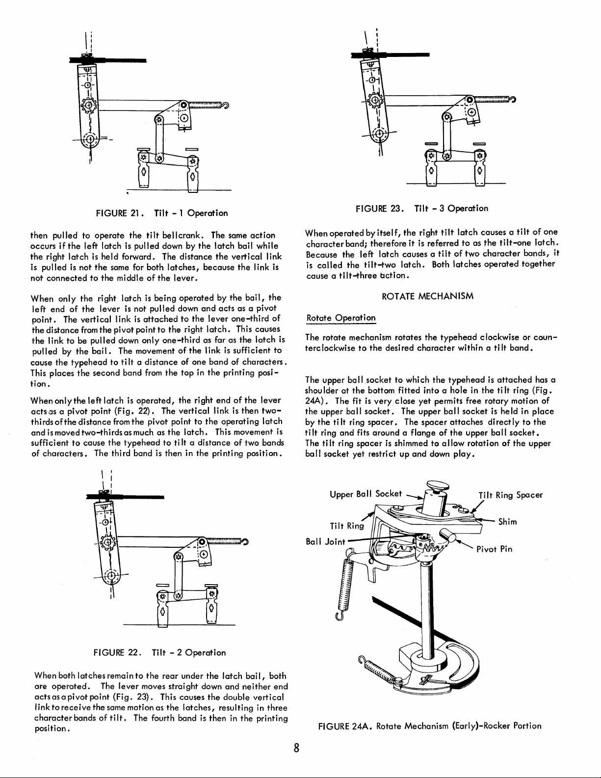
FIGURE
then
pulled to
occurs
if
the
right
pulled is not
is
not
connected
When
only
left
end
point.
the
the
pulled
cause
This places
tion.
When
acts,JS a pivot point
thirds
and
sufficient
of
The
distance
I ink
by
the
only
ofthe
is moved
characters.
operate
the
left
latch
latch
is
held forward. The
the
to
the
the
right
of
the
lever
vertical
from
the
to
be
pulled
the
bail.
typehead
the
second band
the
left
latch
distance
two-thirds
to
cause
The third band is then in
21.
the
tilt
is
pulled
same for both
middle
I ink is
pivot point
down
The movement
to
(Fig.
from
the
of
latch
is
is not
pulled
attached
only
ti
It a distance
from
is
operated,
22).
the
pivot point
as much as
typehead
Tilt - 1
bellcrank.
down by
latches,
the
lever.
being
operated
down
to
the
one-third
of
the
the
The
vertical
the
to
ti
Operation
The same
the
latch
distance
to
right
of one band of
top
latch.
It a distance
the
because
by
and
acts
the
lever
latch.
as far as
the
link is sufficient
in
the
printing
right
end
link is
to
the
operating
This movement is
the
printing
action
bail
while
vertical
the
link is
the
bail,
as a pivot
one-third
This causes
the
latch
characters.
posi-
of
the
lever
then
twolatch
of
two bands
position.
link
the
of
to
When
character
Because
is
cause a tilt-three
Rotate
The
is
terclockwise
The upper
shou Ider
24A).
the
by
tilt
The
ball
operated
called
Operation
rotate
The fit
upper
the
tilt
ring
tilt
socket
FIGURE
band;
the
left
the
mechanism rotates
to
ball
at
the
ball
ring
and
fits around a flange
ring
spacer
yet
by
itself,
therefore
latch
tilt-two
bction.
ROTATE
the
desired
socket
bottom
is
very
socket.
spacer.
is shimmed
restrict
23.
Tilt - 3
the
right
it
is referred
causes a
latch.
MECHANISM
character
to
which
fitted
c lose
yet
The upper
The
spacer
up
and
Operation
tilt
l.atch causes a
to
as
the
tilt
of
two
character
Both
latches
the
type
the
typehead
into
a hole in
permits free rotary motion of
ball
attaches
of
the
to
allow
down
play.
operated
head
clockwise or
within a
the
socket
upper
rotation
tilt
tilt-one
tilt
band.
is
attached
ti
It
ring
is held in
directly
ball
socket.
of
the
together
to
of
one
latch.
bands, it
coun-
has a
(Fig.
place
the
upper
When both
are
operated.
acts
as a pivot point
link
to
receive
character
position.
latches
the
bands
FIGURE
22.
remain
The
lever
(Fig.
same motion as
of
ti
It.
Ti
It - 2
Operation
to
the
rear
under
the
latch
moves straight down and
23).
This causes
the
The fourth band is then in
the
latches,
double
resulting in
bail,
neither
vertical
the
printing
both
end
three
8
Upper Ball Socket
FIGURE
24A.
Tilt Ring
Rotate Mechanism (Early)-Rocker Portion
Spacer
Page 16
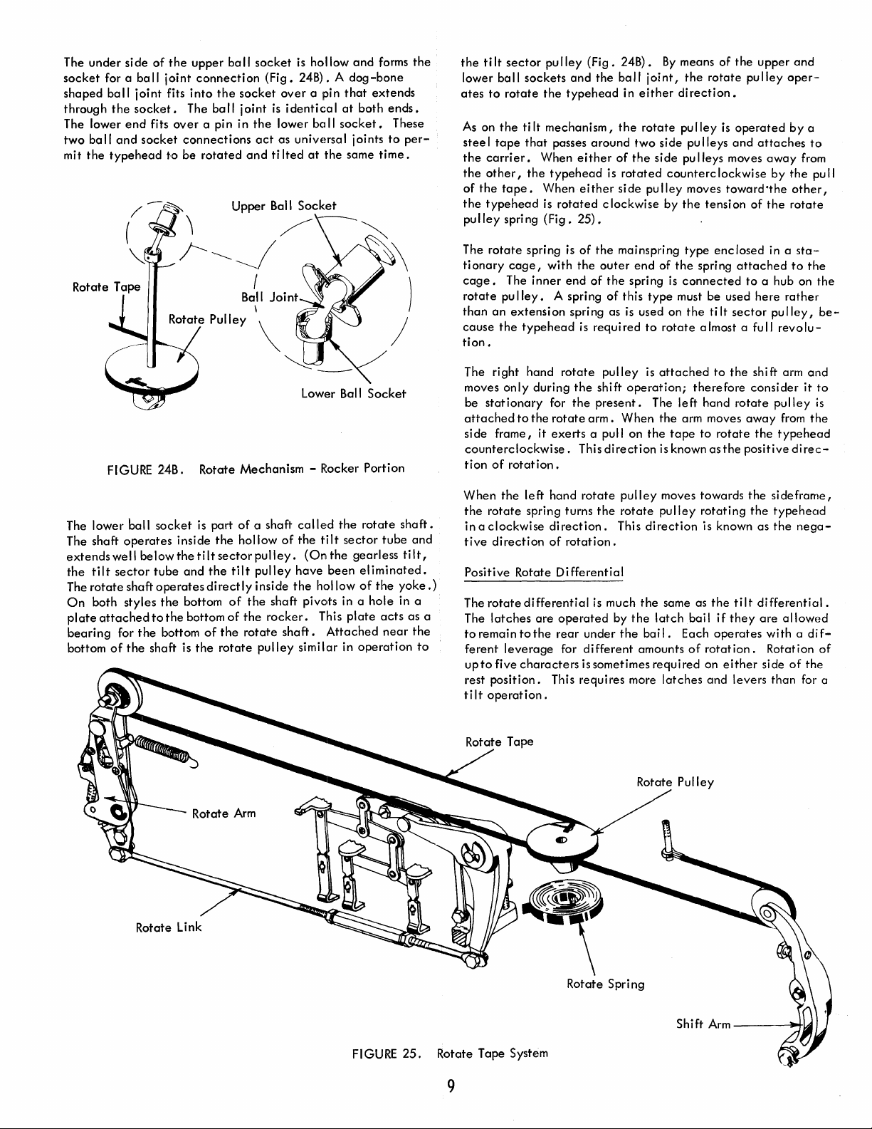
The
under
socket
for a ba
shaped
through
The lower
two
mit
ball
the
ba
the
type
side
II
end
and
(\
"J.
of
the
upper
ball
socket
II
joint
joint
socket.
fits
socket
head
/
--
connection
fits
into
The
over
a pin in
connections
to
be
rotated
~
the
ball
(Fig.
socket
joint
is
the
act
and
ti Ited
Upper Ball
_;--~~I
B~I
Joint
\ )
is
hollow
and
forms
24B). A
over
identical
lower be
as universal joints
Socket
a pin
at
the
dog-bone
that
at
II
socket.
same
extends
both
time.
/\--~
the
ends.
These
to
per-
~
)
the
ti
It
lower ba
ates
to
rotate
As
on
the
stee I tape
the
carrier.
the
other,
of
the
tape.
the
typehead
pulley
spring
The
rotate
ti
onary
cage.
rotate
pulley.
than
an
cause
the
tion.
sector
pu Iley
II
sockets
the
ti
It
mechanism,
that
When
the
When
is
(Fig.
spring
cage,
with
The
inner
extension
typehead
(Fig.
and
typehead
passes
around
either
typehead
either
rotated
25).
is
of
the
end
of
A spring
spring as
is
24B).
the
ba
in
the
of
the
is
rotated
side
clockwise
the
mainspring
outer
the
spring
of
this
is
required
II
j oi
either
rotate
two
side
side
pulley
end
of
type
used on
to
rotate
By
means
nt,
the
rotate
direction.
pu
lIey
pu Ileys
pu
lIeys moves
counterc
moves
by
the
tension
type
the
spri
is
connected
must be used
the
tilt
almost a full
of
the
upper
pu lIey
is
operated
and
attaches
away
lockwise by
toward'the
of
the
enclosed
ng
attached
to
a hub on
here
sector
and
oper-
by
the
other,
rotate
in a
sta-
to
rather
pulley,
revolu-
a
to
from
pu
the
II
the
be-
~--
lower
FIGURE 24B. Rotate Mechanism - Rocker Portion
lower
ball
socket
is part
of
The
The shaft
extends
the
tilt
The
rotate
On
both styles
plate
attached
bearing
bottom
of
operates
well
sector
shaftoperatesdirectly
for
the
inside
the
belowthetiltsectorpulley.
tube
and
the
the
bottom
to
the
bottom
the
bottom
shaft is
of
the
hollow
tilt
of
of
the
the
rotate
a shaft
the
rotate
called
of
the
(On
pulley
have
inside
the
shaft pivots in a
rocker.
shaft.
pulley
similar
Ball
the
tilt
sector
the
been
hollow
This
plate
Attached
in
Socket
rotate
shaft.
tube
gearless
eliminated.
of
the
yoke.)
hole
in a
acts
near
operation
and
tilt,
as a
the
to
The right hand
moves
only
during
be
stationary
attached
side frame, it
counterclockwise.
tion
of
When
the
the
rotate
in a
clockwise
tive
direction
Positive Rotate
The
rotate
The
latches
to
remain
ferent
leverage
upto
five
rest
position.
tilt
operation.
for
to
the
rotate
exerts
rotation.
left
hand
spring turns
direction.
of
differential
are
to
the
characters
This requires more
rotate
pulley
the
shift
the
present.
arm.
a pull on
This
direction
rotate
the
rotation.
Differential
is
much
operated
rear
for
by
under
different
is
sometimes
is
attached
operation;
The
When
the
the
is known
pulley
rotate
pulley
This
direction
the
the
latch
the
bai I. Each
amounts
required
to
the
therefore
left
hand
rotate
arm moves
tape
to
rotate
as
the
moves towards
rotating
is known as
same as
latches
the
bail
of
rotation.
on
and
tilt
if
they
operates
either
levers
shift arm
consider
pulley
away
from
the
typehead
positive
the
direc-
sideframe,
the
typehead
the
differential.
are
allowed
with
Rotation
side
of
than
and
it
the
nega-
a di
the
for a
to
is
fof
FIGURE
25.
Rotate Tape System
9
Rotate Spring
Shi ft
Arm
---
___
Page 17
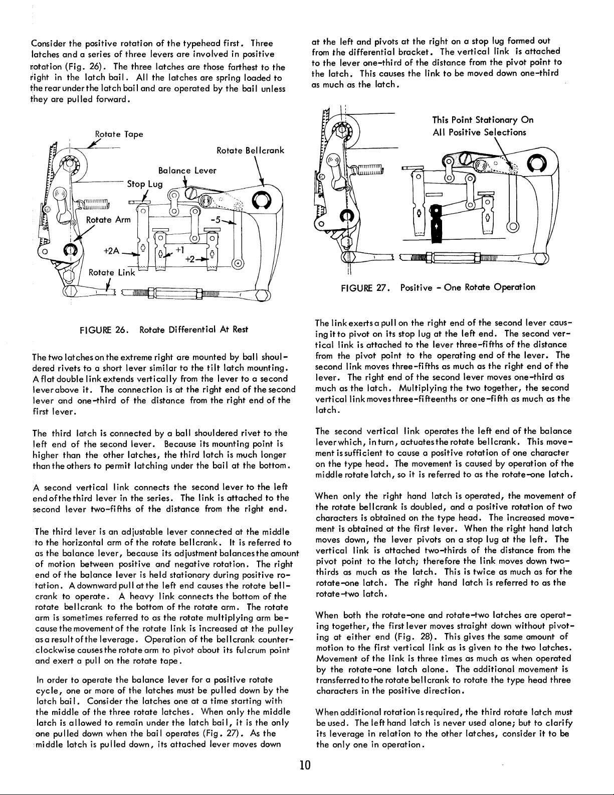
Consider
latches
Ilotation
right
in
the
rearunderthe
they
are
the
positive
and
a series of
(Fig.
26).
The
the
latch
bai I. All
latch
pulled forward.
rotation
three
three
bail
and
of
the
levers
latches
the
latches
are
typehead
are
involved in positive
are
operated
first.
those farthest
are
spring loaded
by
the
Three
to
the
to
bail unless
at
the
left
from
the
differential
to
the
lever
the
latch.
as much as
and
pivots
one-thi
This causes
the
latch.
at
the
bracket.
rd
of
the
the
right on a stop lug formed out
The
distance
link
to
vertical
be moved down
from
link is
the
pivot point
attached
one-third
to
FIGURE
The two
dered rivets
A flat double link
lever
'lever
fi
rst I
latches
above
and
ever.
to
it.
one-third
Rotate Tape
26.
on
the
extreme right
a short
extends
The
connection
of
lever
vertically
the
Rotate Bellcrank
Ba
lance
Lever
Rotate Differential At
are
mounted by ball
similar
is
at
distance
to
from
the
from
the
tilt
the
right
the
lever
Rest
latch
end
right
shoul-
mounting.
to
a second
of
the
second
end
of
the
FIGURE
The link
ing it
to
tical
link is
from
the
second link moves
lever.
much as
vertical
latch.
27.
exerts
a pull on
pivot on its stop lug
attached
pivot point to
The right end
the
latch.
link moves
This Point
All Positive
Positive -
the
to
three-fifths
of
Multiplying
three-fifteenths
right end
at
the
lever
the
the
second
One
the
operating
as much as
Stationary
Selections
Rotate
of
the
left
end.
three-fifths
end
lever
the
two
together,
or
one-fifth
Operation
second
The second
of
of
the
the
right
moves
one-third
as much as
On
lever
the
lever.
end
the
caus-
ver-
distance
The
of
the
as
second
the
The third
left
higher
than
A second
endofthethird
second
The third
to
the
as
the
of
end
tation.
crank to
rotate
arm is sometimes referred to as
cause
as a result
clockwise causes
and
In
cyc
latch bai
the
latch
one pulled down when
middle latch
latch
is
connected
end
of
the
second
than
the
the
others to permit
vertical
lever
lever
two-fifths
lever
is an
horizontal arm
balance
motion between positive and'
of
the
be
the
exert
order
Ie,
one or more of
middle of
is
lever,
balance
A downward pull
operate. A heavy
II
crank
movement
of
the
leverage.
a pull on
to
operate
I.
Consider
the
allowed
is
pulled
lever.
other
latches,
latching
I ink
connects
in
the
series.
of
adjustable
of
the
because its ad justment
lever
is held
at
the
to
the
bottom
of
the
rotate
Operation
the
rotate
arm
the
rotate
the
ba
lance
the
latches must be
the
latches one
three
rotate
to
remain under
the
bai I operates (Fig.
down, its
by a ball shouldered
Because its mounting point is
the
third
latch
under
the
the
second
The link is
the
distance
lever
rotate
negative
stationary
left end causes
link
of
the
I ink is increased
to
pivot
tape.
lever for a positive
latches.
the
attached
from
connected
bell
crank.
connects
the
rotate
rotate
multiplying arm
of
the
about
at
a time starting with
When only
latch
lever moves down
rivet
is much longer
bai I
at
the
lever
attached
the
at
It
is referred
balances
rotation.
during positive
the
rotate
the
bottom
arm. The
at
bellcrank
its fulcrum point
pu
lied down by
bail,
it
27).
to
bottom.
to
the
right
the
middle
the
The right
of
the
counter-
rotate
the
middle
is
the
As
the
the
left
to
the
end.
amount
ro-
bell-
the
rotate
be-
pulley
the
only
to
The second
leverwhich,
ment is sufficient
on
the
middle
When
the
rotate
characters
ment is
moves down,
vertical
pivot point
thirds as much as
rotate-one
rotate-two
When both
ing
together,
ing
at
motion to
Movement
by
the
transferred to
characters
When
be used. The left hand
its
leverage
the
only one in
vertical
in
type
head.
rotate
latch,
only
the
bell crank
is
obtained
obtained
the
I ink is
to
latch.
latch.
the
the
either
end
the
first
of
the
rotate-one
the
in
the
additional
in
turn,
to
The movement is caused by
right hand
at
lever
attached
the
latch;
the
The right hand
rotate-one
first
(Fig.
vertical
link is
rotate
positive
rotation is
relation
operation.
link
operates
actuates
cause a positive rotation
so it
is
referred
is
doubled,
on
the
the
first
pivots on a stop lug
two-thirds
therefore
latch.
and
lever
moves straight down without
28).
link as is given
three
latch
alone.
bell
crank
direction.
required,
latch
to
the
the
left
the
rotate
bellcrank.
to
as
the
latch
is
operated,
and a positive rotation
type
head.
lever.
This is
rotate-two
This gives
times as much as when
The
to
is
never
other
The increased
When
the
of
the
the
link moves down
twice
latch
is referred
the
additional
rotate
the
the
third
used
alone;
latches,
end
of
the
This
of
one
character
operation
rotate-one
the
movement
right hand
at
the
left.
distance
as much as for
latches
same amount
to
the
type
rotate
consider
from
to
are
two
operated
movement
head
latch
but
to
balance
move-
of
the
latch.
of
two
move-
latch
The
the
two-
the
as
the
operat-
pivot-
of
latches.
is
three
must
clarify
it
to
be
of
10
Page 18
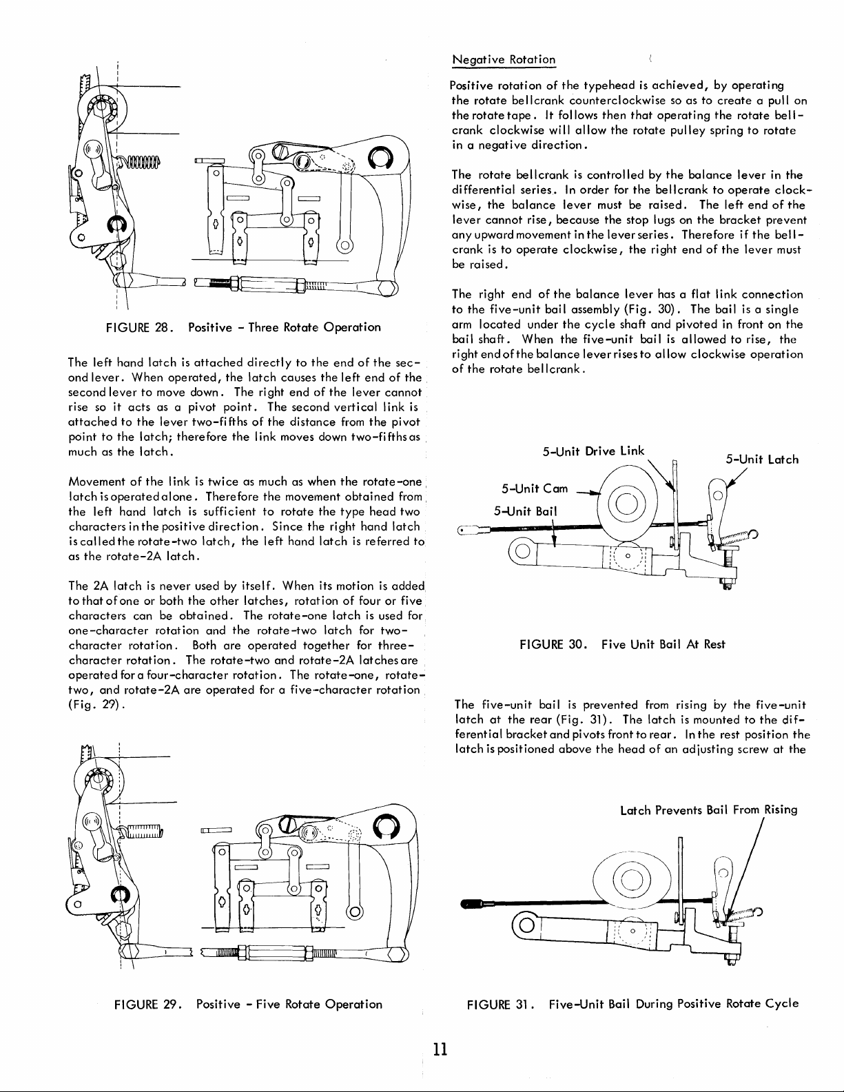
Negative
Rotation
FIGURE
The
left
hand
ond
lever.
second
lever
rise so
attached
point
much as
Movement
latch
the
characters
iscalledthe
as
it
to
the
the
isoperatedalone.
left
the
rotate-2A
latch
When
to
acts
to
the
latch;
latch.
of
the
hand
in
the
rotate-two
28.
Positive - Three Rotate!
is
attached
operated,
move
as a pivot
lever
therefore
link is
latch
positive
latch.
the
down.
point.
two-fifths
the
twice
Therefore
is
sufficient
direction.
latch,
The right
Operation
directly
latch
of
as much as when
the
to
the
causes
the
end
of
The
second
the
distance
link moves down
the
movement
to
rotate
the
Since
the
left
hand
latch
end
of
the
left
end
the
lever
vertical
from
the
two-fifthsas
the
rotate-one,
obtained
type
head
right hand
is
referred
sec-
of
the.
cannot
link
is
pivot
from,
two
latch
.
to
Positive
the
the
crank
in a
The
differential
wise,
lever
any
crank
be
The right
to
arm
bail
right
of
E--==--m:II-.--~
rotation
rotate
rotate
clockwise
negative
rotate
the
cannot
upward movement in
is
to
raised.
the
five-unit
located
shaft.
end
of
the
rotate
bellcrank
tape.
It follows
direction.
bellcrank
series.
balance
rise,
operate
end
of
bai I assembly
under
When
the
balance
bellcrank.
5-Unit
of
the
wi
because
clockwise,
the
the
the
typehead
counterclockwise
then
II
allow
is
controlled
In
order
lever
must be
the
the
balance
cycle
five-unit
lever
Drive Link
is
that
the
rotate
for
the
stop lugs on
lever
series.
the
lever
(Fig.
shaft
bail
rises
to
achieved,
so as to
operating
pulley
by
the
balance
bellcrank
raised.
Therefore
right
end
has a
flat
30).
The bai I is a
and
pivoted
is
allowed
allow
clockwise
by
create
the
spring
to
The
the
bracket
of
the
link
in front on
operating
a pull on
rotate
to
lever
operate
left
end
if
the
lever
connection
to
rise,
operation
bell-
rotate
in
the
clock-
of
the
prevent
bell-
must
single
the
the
The
2A
latch
to
that
of
one
characters
one-character
character
character
operated
two,
(Fig.
and
29).
rotation.
rotation.
for a
rotate-2A
is
never
or both
can
the
be
obtained.
rotation
The
four-character
are
used by
other
and
Both
are
rotate-two
operated
itself.
latches,
The
rotate-one
the
rotate-two
operated
rotation.
for a
When
its motion
rotation
latch
together
and
rotate-2A
The
rotate
five·-character
of
four or five
latch
for
for
latches
-one,
is
added
is used for
two-
three-
are
rotate-
rotation
The
five-unit
latch
at
ferential
latch
is
-
FIGURE
bail
the
rear
bracket
positioned
30.
is
prevented
(Fig.
31).
and
pivots front to
above
Five Unit Bail At Rest
from
rising by
The
latch
is
mounted
rear.
In
the
the
head
of
an
adjusting
Latch
Prevents
the
five-unit
to
the
di
rest position
screw
at
Bail From Rising
fthe
the
FIGURE
29.
Positive - Five Rotate
Operation
11
FIGURE
31.
Five-Unit
Bail During Positive Rotate
Cycle
Page 19
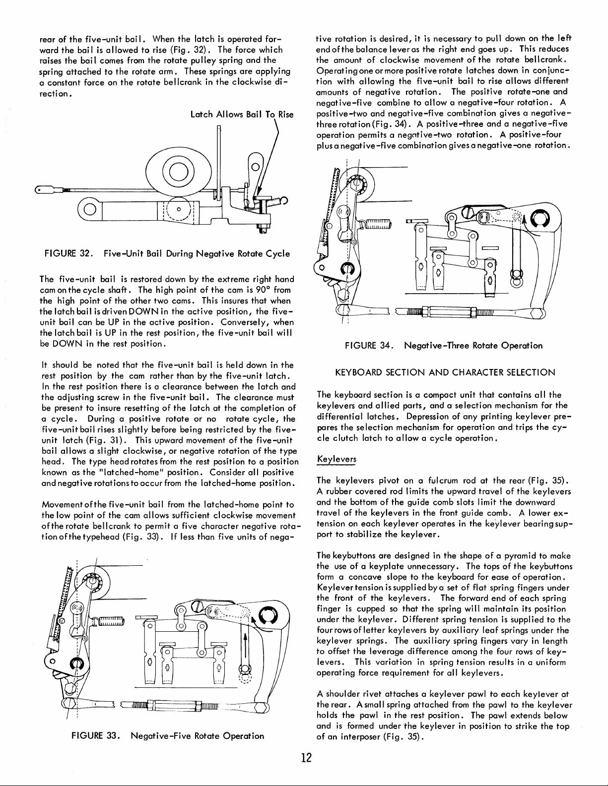
rear
of
ward
raises
spring
a
constant
recti
on.
the
the
bai I
the
bail
attached
five-unit
is a II
comes from
to
force on
bai I. When
owed
to
the
the
rotate
the
rotate
rise
(Fig.
rotate
arm.
bellcrank
the
latch
is
operated
32).
The force whi
pu
Iley spring
These springs
in
the
Latch Allows Bail
for-
and
the
are
applying
clockwise
To
ch
di-
Rise
tive
rotation
end
of
the
balance
the
amount
Operating
tion
amounts
negative-five
positive-two
three
operation
plus a
one
with
allowing
of
rotation
permits a
negative-five
is
desired,
of
clockwise
or
more positive
negative
combine to
and
(Fig.
it
leveras
the
five-unit
rotation.
negative-five
34). A positive-three
negntive-two
combination
is
necessary
the
right
movement
rotate
allow a negative-four
to
pull down on
end
goes
up.
of
the
rotate
latches
bail to rise allows
The
combination
rotation. A positive-four
gives a
down in con
positive
gives a negative-
and a negative-five
negative-one
the
This
reduces
bell
crank
different
rotate-one
rotation.
rotation.
left
•
junc-
and
A
FIGURE
The
cam on
the
the
unit
the
be
It
rest position by
In
the
be present
a
five-unit
unit
bail
head.
known
and
Movement
the
ofthe
tion
32.
five-unit
the
cycle
high
point
latch
bail
bai I
can
latch
bai I is
DOWN
should be
the
rest position
adjusting
cycle.
bail rises
latch
allows
The
as
the
negotive
of
low
point
rotate
ofthe
typehead
is
be
in
to
During a positive
(Fig.
a slight
type
rotations
the
bellcrank
Five-Unit
bail
shaft.
of
the
driven
UP
UP
the
rest
noted
the
screw in
insure
31).
head
"latched-home"
five-unit
of
the
Bail During
is
restored down by
The high point
other
DOWN
in
the
active
in
the
rest
position.
that
the
cam
rather
there
is a
the
resetting
slightly
This upward movement
clockwise,
rotates
to
occur
bai I
cam
allows
to
permit a five
(Fig.
33).
two
cams.
in
the
position.
position,
five-unit
than
clearance
five-unit
of
the
rotate
before
or
from
position.
from
from
sufficient
If
Negative
the
of
This insures
active
the
bail
by
between
bail.
latch
or
no
being
restricted
negative
the
rest position
the
latched-home
the
latched-home
character
less
than
Rotate
extreme
the
cam
position,
Conversely,
five-unit
is
held
the
five-unit
The
clearance
at
the
rotate
of
rotation
Consider
clockwise
five units
Cycle
right
hand
is
90°
from
that
when
the
five-
when
bai I wi
down in
latch.
the
latch
must
completion
cycle,
by
the
five-
the
five-unit
of
the
to
a position
all
positive
position.
point
movement
negative
of
nega-
II
the
and
of
the
type
to
rota-
FIGURE
KEYBOARD
The
keyboard
keylevers
differential
pares
the
cle
clutch
Keylevers
keylevers
The
A rubber
and
the
bottom
travel
of
tension on
port
to
stabi I
34.
section
and
allied
latches.
selection
latch
pivot
covered
of
the
keylevers
each
keylever
ize
Negative-Three
SECTION AND CHARACTER SELECTION
is a compact
parts,
and a selection
Depression
mechanism for
to
allow a cycle
on
a fulcrum rod
rod limits
the
the
keylever.
the
guide
comb slots I imit
in
the
front
operates
Rotate
unit
of
any
operation
operation.
upward
guide
in
the
Operation
that
contains
mechanism for
printing
and
at
the
rear
travel
of
the
comb.
keylever
all
keylever
trips
the
(Fig.
the
keylevers
downward
A lower
bearing
the
the
pre-
cy-
35).
ex-
sup-
FIGURE
33.
Negative-Five
Rotate
Operation
The keybuttons
the
use
form a concave
Keylevertension
the
front
finger
under
the
four rows
keylever
to
offset
levers.
operating
A
shoulder
the
rear.
holds
the
and
is
of
an
interposer
12
are
designed
of a keyplate
of
the
is
cupped
keylever.
of
letter
springs. The auxi I
the
leverage
This
variation
force
rivet
A small spring
pawl in
formed
unnecessary.
slope
issupplied
keylevers.
so
that
Different
keylevers
difference
requirement
attaches a keylever
the
under
the
(Fig.
35).
in
the
shape
of
a pyramid
The tops
to
the
keyboard
bya
set
of
The forward
the
spring
wi
spring
tension
by
auxi I iary
iary
spring fingers
among
in spring tension results in a uniform
for
all
keylevers.
pawl
attached
rest
keyleverin
from
position.
the
The pawl
position to strike
of
for
ease
flat
spring fingers under
end
of
II
maintain
is
leaf
springs
the
four rows
to
each
pawl to
to
the
keybuttons
of
operation.
each
spring
its position
supplied
under
vary
in
length
of
keylever
the
keyle~er
extends
below
the
make
to
the
the
key-
top
at
Page 20
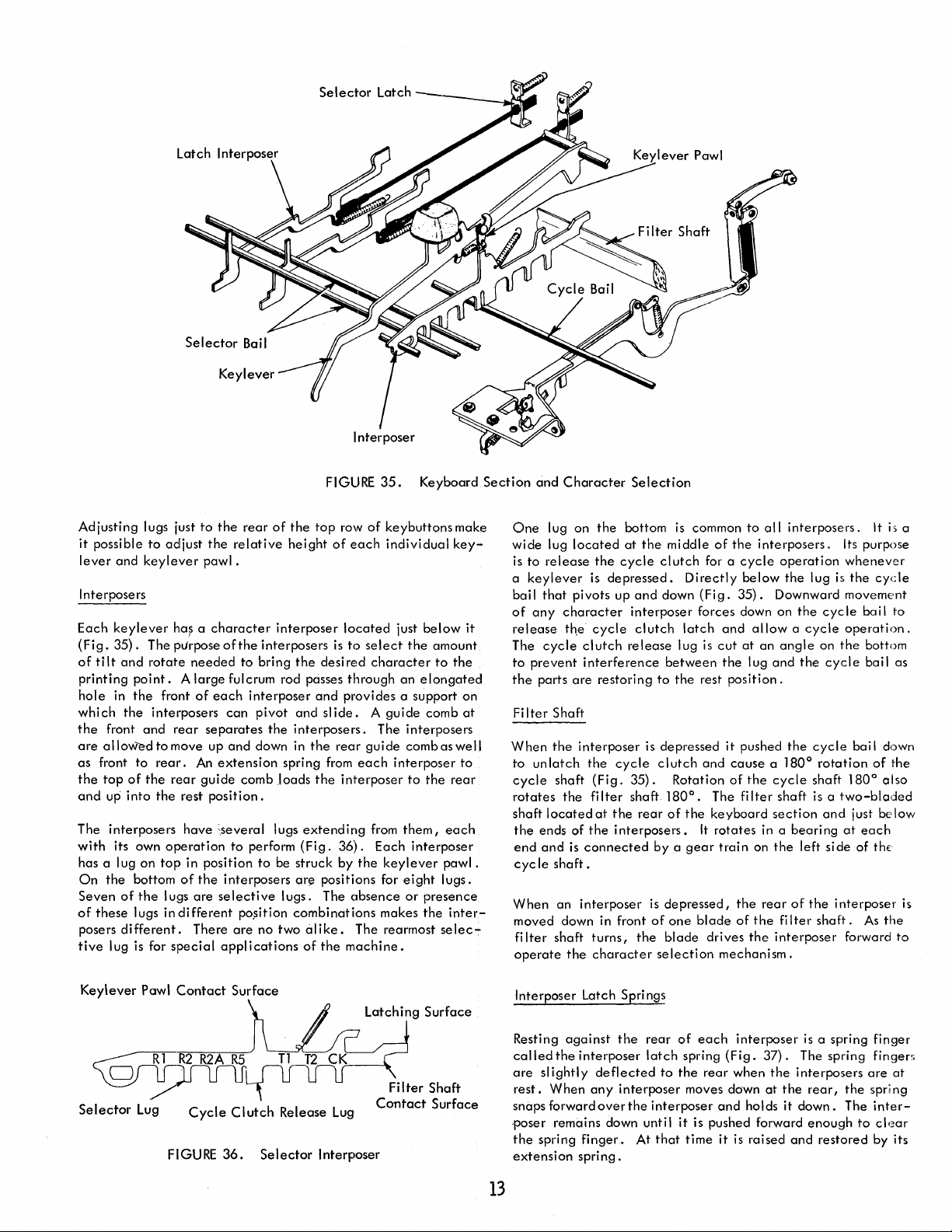
Selector
Latch
Adjusting
it
possible
lever
and
Interposers
Each
keylever
(Fig.
35).
of
ti It
and
printing
hole
which
the
are
as
the
and
The
with
has a lug
On
Seven
of
posers
tive
point. A large
in
the
the
front
allowe-dtomove
front
to
top
of
up
into
interposers
its own
on
the
bottom
of
the
these
lugs in
different.
lug is for
lugs just
to
keylever
The purpose
rotate
interposers
and
the
adjust
ha~
needed
front
of
rear
rear.
rear
the
rest
have
operation
top
in position
of
lugs
are
different
There
special
to
a
An
guide
the
the
rear
of
the
relative
pawl.
character
of
each
can
separates
up
and
extension
position.
~several
interposers
selective
applications
interposer
the
interposers
to
bring
fulcrum rod passes
interposer
pivot
the
down in
spring from
comb .loads
lugs
to
perform
to
be
lugs.
pO,sition
are
no two
FIGURE
the
top
row
height
of
each
located
is
to
the
desi
re~d
through
and
provides a support on
and
sl
ide. A guide
interposers.
the
rear
each
the
interposer
extending
(Fig.
36).
struck
by
ar~
positions for
The
obsence
combinations
alike.
of
The rearrnost selec-:-
the
machine.
35.
Keyboard
of
keybuttons
individual
just
below
select
the
character
an
elongated!
comb
The interposers
guide
combaswell
interposer
to
the
from
them,
Each
interposer
the
keylever
eight
or
presence
makes
the
make
key-
it
amount
to
the
at
to
rear
each
pawl.
lugs.
inter-
Section
and
Character
One
lug on
wide
lug
located
to
release
is
a
keylever
bail
that
pivots up
of
any
character
release
The
to
the
Fi
When
to
cycle
rotates
shaft
the
end
cyc
When
moved down in front
filter
operate
cycle
prevent
parts
Iter
Shaft
the
unlatch
shaft
located
ends
and
Ie
shaft.
an
shaft
the
are
the
of
is
the
Selection
the
bottom is common
at
the
cycle
is
depressed.
and
interposer
cycle
clutch
clutch
release
interference
restoring
interposer
the
cycle
(Fig.
35).
fi
Iter
shaft 180
at
the
the
interposers.
connected
interposer
turns,
the
character
the
middle
clutch
Directly
down
latch
lug is
between
to
the
is depressed
clutch
Rotation
0
rear
of
the
by a
gear
is
depressed,
of
one
blade
selection
to
all
of
the
interposers.
for a
cycle
operation
below
(Fig.
35).
Downward movement
forces down on
and
allow a cycle
cut
at
an
angle
the
lug
and
rest
position.
it
pushed
and
cause
a 1800 rotation
of
the
cycle
•
The
fi
Iter
shaft is a
keyboard
It
rotates
trai n on
blade
drives
mechanism.
the
of
the
section
ina
the
rear
the
fi
interposer
interposers.
Its purpose
whenever
the
lug
is
the
cycle
operation.
on
the
the
cycle
the
cycle
shaft 1800 also
two-bladed
and
beari
ng
at
left
si
de
of
the
interposer
Iter
shaft.
forward
It
is
the
cycle
bail to
bottom
bail as
bai I down
of
the
just
be
low
each
of
th(
As
the
to
a
is
Keylever
o
I
S
e
ector
Pawl
Contact
Rl
R2
~~
L
ug
Cycle
F
I
GU
R2A
RE
Surface
R5
Clutch
36.
Tl
12
Release Lug
Se I
ector
Latching
Surface
c~
Filter Shaft
Contact
Interposer
Surface
Interposer Latch Spri ngs
Resting
called
are
rest.
snaps forward
poser
the
extension
against
the
interposer
slightly
spring
deflected
When
any
over
remains down until
finger.
spring.
13
the
rear
latch
to
interposer
the
interposer
At
that
of
each
interposer
spring
(Fig.
the
rear
when
moves down
and
holds
it
is pushed forward
time
it
is raised
is
a spring
37).
The spring fingers
the
interposers
at
the
rear,
it
down.
enough
and
restored
finger
are
the
spring
The
inter-
to
cl'~ar
by its
at
Page 21
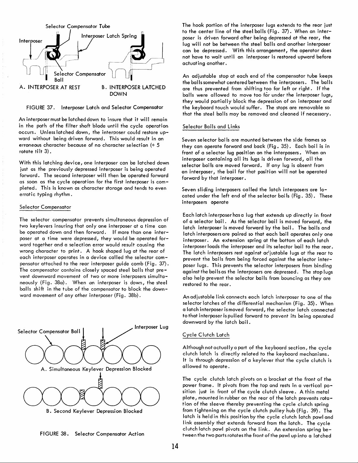
Selector
In:]OSer..
'I
[i
I U I Ball
A.
INTERPOSER
FIGURE
An
interposer
the
in
occurs.
ward
Selector
path
without
erroneous
rotate
ti
It
With
this
just as
forward. The
as
pleted.
erratic
Selector
The
two
be
poser
ward
wrong
each
pensator
The compensator
vent
neously
balls
ward movement
the
soon as
typing
selector
keylevers
operated
at
together
character
interposer
downward movement
shift in
Compensator
/~~yr
(]r~e~e~tor
AT
37.
Interposer Latch
must be
of
the
Unless
latched
being
character
3).
latching
This
Compensator
a time
attached
(Fig.
device,
previously depressed
second
the
cycle
is
known as
rhythm.
compensator prevents simultaneous depression
insuring
down
and
were
and a selection
to
operates
to
contains
380).
the
tube
of
any
Compensator
Tube
Lot:il/_
Compensator
REST
latched
fi
Iter
down,
driven
because
interposer
operation
that
then
depressed,
print.
the
When
of
other
Ball
shaft
one
character
in a
rear
closely
of
the
B. INTERPOSER
DOWN
and
Selector
down
to
insure
blade
unti I
the
the
interposer
forward. This would result in an
of no
character
interposer
interposer
wi
for
only
one
forward. If more
they
error
A hook shaped lug
device
interposer
spaced
two
or
an
interposer
compensator
interposer
can
II
then
be
the
first
storage
interposer
would be
would result
called
guide
steel
more interposers
to
(Fig.
:.
Compensator
that
it
wi
cycle
could
selection
be
latched
is
being
operated
interposer
and
tends
at
a time
than
operated
causing
at
the
the
selector
comb
balls
is
down,
block
38b).
LATCHED
II
remain
operation
restore
up-
(+
5
down
operated
forward
is
com-
to
even
can
one
inter-
for-
the
rear
of
com-
(Fig.
37).
that
pre-
simulta-
the
steel
the
down-
of
The hook portion
to
the
center
poser
is
driven forward
lug will not be
can
be
depressed.
not
have
to
actuating
An
the
are
balls
they
the
that
Selector
Seven
they
front
interposer
selector
an
forward
Seven sliding interposers
cated
interposers
Each
of a selector
latch
latch
interposer.
interposer
The
prevent
poser lugs. This prevents
against
also
restored to
An
selector
a
latch
to
that
downward by
Cycle
another.
adjustable
balls
somewhat
thus
prevented
were
would
keyboard
the
steel
Bails
se
lector
can
operate
of a selector
containing
bai
interposer,
by
under
latch
interposer
interposers
latch
the
the
help
prevent
adjustable
latches
interposer
interposer
Clutch
of
the
I ine
of
the
between
With
wait
unti I
stop
at
each
centered
from shi"fting
allowed
partially
Is
that
the
operate
interposer
An
loads
interposers rest
bai
bailsas
the
to
block
touch
would
balls
may be removed
and
Links
bai
Is
are
forward
lug position on
all
are
moved
the
bai I for
interposer.
left
end
has a lug
bai
I.
As
is moved forward by
are
paired
extension
the
interposer
Is
from
the
the
selector
rear.
I ink
connects
of
the
differential
ismoved
is
pulled
the
latch
Latch
interposer
steel
balls
after
being
the
steel
this
arrangement,
an
interposer
end
between
move
too
the
depression
suffer.
mounted
and
back
its lugs
forward.
that
position wi
called
of
the
se
that
the
selector
so
that
spring
and
against
being
forced
the
selector
interposers
bails
each
forward,
forward
bai I.
lugs
extends
(Fig.
depressed
balls
and
is restored upward before
of
the
compensator
the
too
for
far under
The stops
and
between
(Fig.
the
interposers.
is
driven
If
any
the
latch
lector
bai
extends
bai I
the
each
at
the
its
selector
ac'justable lugs
against
interposers
are
depressed.
from
latch
interposer
mechanism
the
selector
to
prevent
to
37).
When an
at
the
another
the
operator
interposers.
left
or
right.
the
interposer
of
an
interposer
are
removable so
cleaned
35).
lug
interposers
is
bai
bail
bottom
bouncing
if
the
si de frames so
Each bai I
forward,
is
absent
II
not be
Is
(Fig.
up
directly
moved forward,
I.
The bai
operates
of
bail
at
the
selector
from
The stop lugs
to
(Fig.
latch
its be ing
the
rear
inter-
rear,
interposer
does
tube
keeps
The
balls
If
lugs,
necessary.
is
When
an
all
the
from
operated
are
lo-
35).
These
in front
Is
and
only
each
latch
to
the
rear.
the
rear
inter-
binding
as
they
one
of
35).
When
connected
operated
just
the
the
and
in
the
one
to
are
the
00
A.
Simultaneous
Second
B.
FIGURE
38.
Keylever
Keylever Depression Blocked
Selector
Depression Blocked
Compensator
Action
Although
clutch
It is through depression
allowed
The
power frame. It pivots
sition
plate,
tion
from
latch
I ink assembly
cl utch
tween
not
latch
to
operate.
cycle
clutch
just in front
mounted in rubber on
of
the
sleeve
tightening
is
held
latch
the
two parts
14
actually
is
in
pawl pivots on
directly
latch
thereby
on
this
that
a part
related
of a keylever
pivots on a
from
of
the
the
cycle
position by
extends
rotates
of
the
keyboard
to
the
the
top
cycle
clutch
the
rear
preventing
clutch
the
cycle
forward from
the I ink.
the
front
of
section,
keyboard
that
the
bracket
and
of
pulley
the
at
rests in a
sleeve. A thin
the
latch
the
cycle
hub
clutch
the
latch.
An
extension
pawl up
the
cycle
mechanisms.
cycle
clutch
the
front
of
vertical
metal
prevents
clutch
(Fig.
latch
into a latched
spring
39).
pawl
The
cycle
spring
rota-
is
the
po-
The
and
be-
Page 22
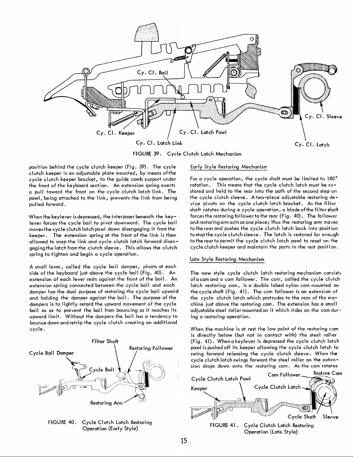
position
clutch
cycle
the
a pull
pawl,
pulled
When
lever
moves
behind
keeper
cl utch
front
toward
being
forward.
the
forces
the
keeper.
allowed
gaging
spring
A small
side
of
to
the
to
lever,
the
extension
extension
damper has
and
holding
dampers
is
bail so as
upward
bounce
limit.
down
cycle.
Cycle
Bail Damper
the
is
keeper
of
the
the
attached
keylever
the
cycle
clutch
The
extension
snap
latch
tighten
called
keyboard
of
each
spring
the
dual purpose
the
to I ightly
to
prevent
Without
and
cycle
an
adjustable
bracket,
keyboard
front on
to
is
depressed,
cycle
bai I
latch
the
I ink
from
the
and
begin a cycle
the
just
lever
connected
damper
retard
the
retrip
the
Cy.CI.
clutch
to
section.
the
the I ink,
to
pawl down
spring
and
cycle
clutch
cycle
above
rests
against
between
of
against
the
bail
the
dampers
cycle
Filter
FIGURE
keeper
plate
the
cycle
the
pivot
(Fig.
mounted,
guide
An
extension
clutch
prevents
interposer
downward.
comb support under
the
disengaging
at
the
front
of
clutch
latch
sleeve.
This
operation.
bai I
damper,
the
cycle
bail
the
front
the
cycle
restoring
the
bai
the
I;
The purpose
upward movement
from
bouncing
the
bail has a
clutch
creating
Shaft
Cy.
CI.
Latch Link
39.
39).
The
by means
spring
latch
link.
I ink from
beneath
The
the
the
cycle
it
from
I ink is
forward disen";
allows
the
pivots
(Fig.
40).
of
the
bail.
bai I
and
cycle
bai I upward
of
the
as
it
reaches
tendency
an
additional
Cycle
cycle
of
the
exerts·
The
being
key-
bai I
the
then
cl utch
at
each
An
each
of
the
cycle
An
its
to
Clutch
Latch Mechanism
Early
Style
cycle
For a
rotation.
stored
and
the
cycle
vice
pivots on
shaft
rotates
forces
the
and
restoring arm
to
the
rear
to
stop
the
tothe
"rear
cycle
clutch
Late
Style
The new
ofacamand
latch
restoring
the
cycle
the
cycle
chine
just
adjustable
ing a restoring
When
the
directly
is
(Fig.
41).
pawl is pushed
swing forward
cycle
clutch
sion drops down
Restoring Mechanism.
operation,
This means
held
to
clutch
the
during a
restoring follower
and
pushes
cycle
to
permit
keeper
the
cycle
that
the
the
rear
into
sleeve. A two-piece
cycle
clutch
cycle
to
actsasone
cI
utch
the
and
the
cycle
sleeve.
cycle
maintain
piece;
Restoring Mechanism
style
cycle
clutch
a cam
follower.
cam,
is a double
shaft
(Fig.
41).
The cam follower
clutch
latch
which
above
the
restoring
steel
roller
mounted on
operation.
machine
below
is
(but
at
rest
not in
Whenakeylever
off
its
keeper
releasing
latch
onto
the
swings forward
the
Cy.
shaft must be
cycle
clutch
the
path
of
latch
the
limited
second
adjustable
latch
bracket.
operation, a blade
the
rear
(Fig.
thus
the
clutch
latch
The
latch
clutch
latch
the
parts in
latch
restoring mechanism consists
The
cam,
of
40),
restoring arm moves
back
is
restored far
pawl
to
the
called
the
lobed nylon cam mounted on
is
an
protrudes
cam.
the
low point
contact
is depressed
allowing
cycle
restoring
it
the
to
The
which
with)
the
clutch
steel
cam.
the
rear
extension
riides on
of
the
the
the
cycle
cycle
clutch
sleeve.
roller
As
the
Cam Follower Restore
CI.
Latch
to
180
must be
restoring
As
the
step
the
filter
re-
on
de-
filter
shaft
The follower
into
position
enough
reset on
rest
cycle
the
position.
clutch
extension
of
the
ma-
has a small
the
cam
dur-
restoring cam
steel
roller
clutch
latch
latc.h
When
the
on
the
exten-
cam
rotates
0
of
to
Cam
FIGURE
40.
Restori ng
Cycle
Clutch
Operation
Arm
/'
Latch Restoring
(Early Style)
15
FIGURE
41.
Cycle
Cycle
Clutch
Operation
Clutch
Latch
Latch Restoring
(Late Style)
Page 23
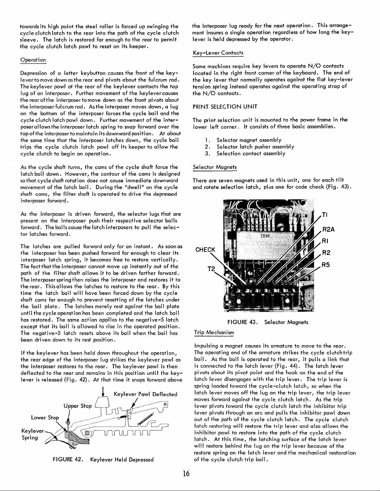
towards its high point
cycle
clutch
latch
to
sleeve.
the
Operation
Depression
lever
The
I ug
the
the
on
cycle
poser
topofthe
the
trips
cycle
The 'latch
cycle
clutch
of a letter
to
move down as
keylever
of
an
interposer.
rear
ofthe
interposerfulcrum rod.
the
bottom
clutch
allows
interposer to
same time
the
cycle
clutch
is
latch
pawl
at
interposer
of
the
latch
pawl down. Further movement
the
interposer
that
the
clutch
to
begin
the
steel
roller
is forced up swinging
the
rear
into
the
restored far enough
pawl
to
reset on its
keybutton causes
the
rear
end
pivots
the
rear
of
the
keylever
Further movement
to
move down as
As
the
interposer moves
interposer forces
latch
spring
maintain
interposer
an
its downward
latch
pawl
operation.
latches
off
path
of
the
to
the
keeper.
the
front
about
contacts
of
the
the
front pivots
the
cycle
to
snap forward
position.
down,
its
keeper
cycle
rear
to
of
the
ful
crum
keylever
down,
bail
of
the
the
cycle
to
allow
clutch
permit
the
the
causes
and
over
At
the
key-
rod.
top
about
a lug
the
inter-
the
about
bail
the
the
interposer
ment insures a single
lever
is
Key-Lever
Some machines require key levers
located
the
key
tension spring
the
N/O
PRINT SELEC.TION UNIT
The print
lower
left
1.
2.
3.
held
depressed by
Contacts
in
the
lever
that
contacts.
selection
corner.
Se
lector
Selector
Selection
lug
ready
for
operation
right front
normally
instead
operates
unit
is mounted
It
consists
magnet assembl y
latch
pusher assembly
contact
the
the
operator.
corner
operates
of
assembly
regardless
against
next
to
of
three
operation.
of
how long
operate
the
against
to
N/O
keyboard.
the
the
operating
the
power frame in
basic assemblies.
This
contacts
The
flat
key-lever
strap
arrange-
the
key-
end
of
of
the
As
the
cycle
shaft turns,
latch
bai I
down.
However,
so
that
cycle
shaft
rotation
movement
shaft cams, the
interposer forward.
As
present on the interposer push
forward. The bails
tor
The
the
interposer
The
path
The interposer spring
the
time
shaft cams far
the
unti I
has
except
The
been driven down
If
the
the
the
deflected
lever
Keylever.
Spring
of
the
latch
filter
the
interposer
latches
rear.
forward.
latches
interposer has been pushed forward far enough
fact
bai I
the
restored.
negative-5
rear
interposer restores
latch
that
of
the
This allows
the
latch
plate.
cycle
that
keylever
edge
to
is
released
are
pulled forward
spring, it becomes free
the
interposer
fi
Iter shaft allows it
bail
enough
The
operation
The same
its bail is
latch
has been
of
the
the
rear
(Fig.
FIGURE
the
cams
of
the
the
contour
does not cause immediate downward
bai
I.
During
shaft
is
operated
is
driven forward,
their
cause
the
latch
cannot
then
raises
the
the
latches
wi"
have
been forced down by
to
prevent
latches
to
its rest
interposer lug strikes
and remains in this position unti I
42.
has
been
action
allowed
resets
position.
held
to
the
42).
At
Keylever
merely rest
appl ies
to
above
down throughout
rear.
that
of
the
to
the
respective
interposers to pull the
only
for
move up
to
be driven
interposer
to
restore to
resetting
completed
to
rise in
its bai I when
The
time it snaps forward
Held
cycle
the
cams
"dwell"
drive
selector
an
instant.
to
restore
instantly
farther
and
the
of
the
against
and
the
negative-5
the
operated
the
the
keylever
keylever
Depressed
shaft force
is
designed
on
the
the
depressed
lugs
that
selector
selec-
As
to
clear
vertically.
out
of
forward.
restores it
rear.
By
the
cycle
latches
the
bai I
the
latch
position.
the
bai I has
operation,
pawl as
pawl
is
the
Deflected
the
cycle
are
bails
soon as
its
the
to
this
under
plate
bail
latch
then
key-
above
Selector
There
and
Trip Mechanism
Impulsing a magnet causes its armature
The
bai
is
pivots
latch
spring loaded toward
latch
moves forward
lever
lever
out
latch
inhibitor
latch.
wi
restore spring on
of
Magnets
are
seven magnets used in
rotate
selection
FIGURE
operating
I.
As
connected
about
lever
lever
pivots toward
pivots through an
of
the
restoring will restore
II
restore behind
the
cycle
end
the bai I
to
the
its pivot point
disengages with
moves
against
path
of
pawl
to
restore into
At
this
time,
the
clutch
latch,
43.
of
the
armature strikes
is
operated
latch
the
cycle-clutch
off
the
the
the
cycle
arc
the
cycle
the
the I ug
latch
trip
bail.
this
plus
one
Selector
to
lever
(Fig.
and
the
the
trip
lug on
cycle
clutch
and
pulls
clutch
the
trip
the
latching
on the
lever
the
the
clutch
path
surface
trip
and
unit,
for code
Magnets
to
rear,
44).
hook on
lever.
latch,
trip
lever,
latch.
latch
the
inhibitor
latch.
lever
and
of
the
lever
the
mechanical
one for
check
move
to
the
cycle
it
pulls a I ink
The
latch
the
end
The
trip
so when
the
As
the
inhibitor
The
cycle
also
cycle
of
the
because
each
tilt
(Fig.
TI
R2A
RI
R2
R5
the
rear.
clutch
lever
of
the
lever
the
trip
the
trip
trip
pawl down
clutch
allows
clutch
latch
lever
of
the
restoration
43).
trip
that
is
lever
the
16
Page 24
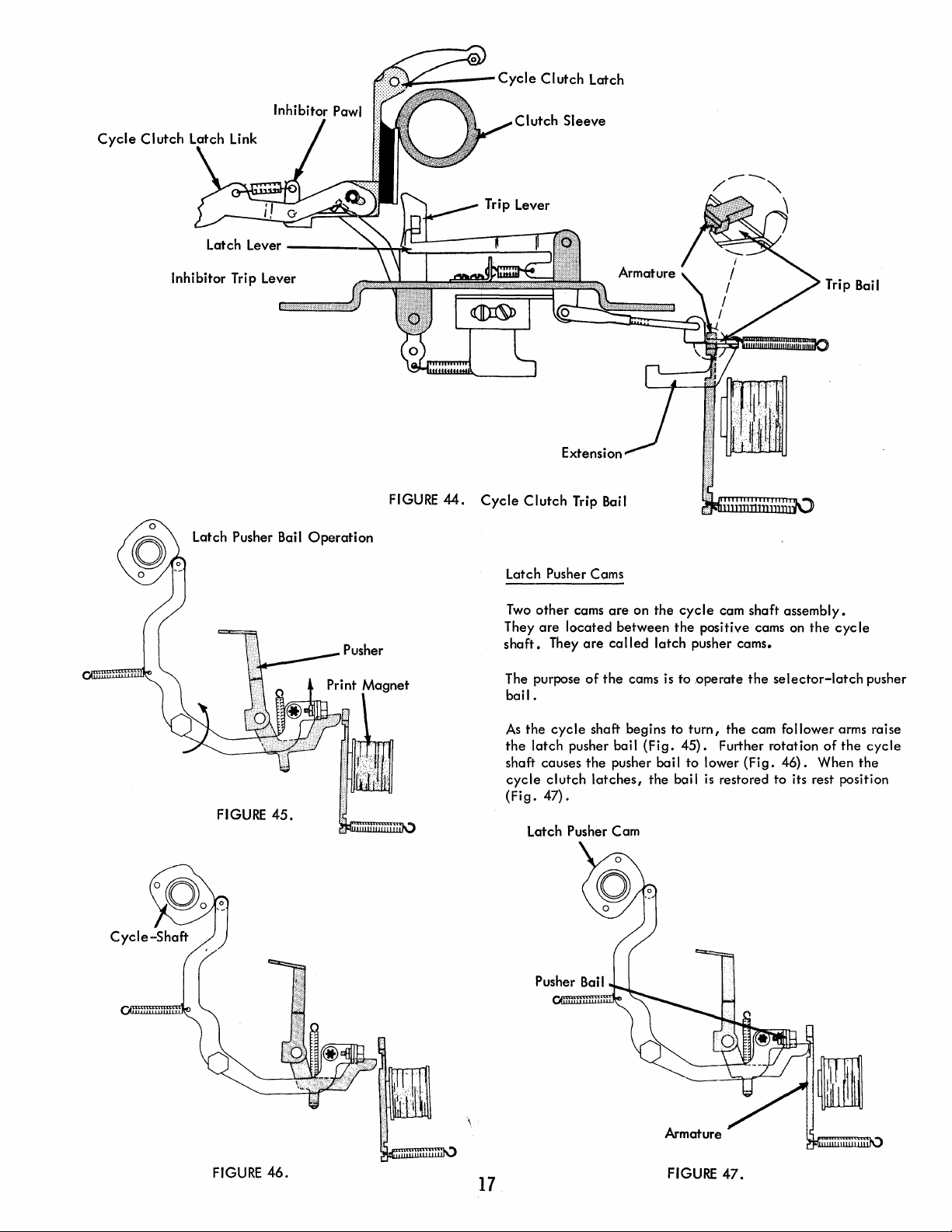
e«)~,--_--Cycle
Clutch
Latch
Latch Lever
Inhibitor Trip Lever
Latch Pusher Bail
---_
.
.......;:~~=--....._---!:-...-~
Operation
FIGURE
44.
Cycle
Clutch
Clutch
Sleeve
Trip Bail
Trip Bail
(0
Cycle-Shaft
FIGURE
0
45.
Latch Pusher Corns
Two
other
cams
ore
on the
cycle
cam shaft assembly.
are
They
shaft.
The purpose
bail.
print~
.....• , ..•
a.:.g
..
net
rdI
As
the
shaft causes
cycle
(Fig.
located
They
the
cycle
latch
pusher bail
clutch
47).
Latch Pusher Cam
between
are
called
latch
of
the
corns
is
shoft begins to
(Fig.
the
pusher bail to lower
latches,
the bail
the
positive cams on
pusher corns.
tooperote
turn,
45). Further rotation
the
the cam follower arms raise
(Fig.
is
restored to its rest position
the
cycle
selector-latch
of
the
46). When
pusher
cycle
the
FIGURE
46.
17
Armature
FIGURE
47.
Page 25

Selector
The
the
There
cluding
Latch Pusher
selector
power frame by a
are
seven
the
latch
pushers pivot on a shaft
bracket.
latch
pushers;
code
check
latch.
one
for
each
that
is mounted
selector
latch,
to
in-
The purpose
lector
The
latch
When
As
the
the
pusher moves forward,
latch
of
the
latches
the
wi
forward from under
pushers
bail rises,
pusher pivots on
II
be pushed forward,
latch
are
pusher
is
to
the
spring
loaded
the
tail
of
the
the
shaft,
the
contacting a selector
away
move
the
unwanted
selector-latch
toward
the
pusher
pusher follows
operating
from
the
bai I
Latch Extension
Latch
bail.
the
end
or
latch.
(Fig.
Pusher
se-
bail.
bail.
top
The
48).
of
Tail
Pusher Bail
Selector
Armature
netism
and
The
cycle
selection
the
pusher-bail
trip
bail.
selector
FIGURE
Armature
knock-off
to insure
clutch
magnet
The
trip
armatures
49.
Latch Pusher Restoring
Knock-off
is
provided
that
trip
bail provides a positive
armatures.
cam-follower
bail restoring imparts
(Fig.
50).
to
the
armatures restore
An
eccentric
arm restores
overcome
the
any
residual
quickly.
knock-offforthe
knock-off
the
knock-off
stud on
cycle
mag-
clutch
to
the
Selector
It
attracted
ated.
ing
pusher starts to rise
Because
the
fore,
to
Restoring
The
pusher
causing
moves
under
The pusher. bail must restore
the
be in
pushers
the
- Latch Pusher Bail
FIGURE
is important
wi
II
This
is
the
latching
the
armature
pusher
could
the
selector
be
operated
the
selector
bail.
the
pushers
to
the
the
selector-latch
armatures
the
notch
are
against
armatures
48.
to
note
that
keep
their
respective
accompl ished by
surface in
(Fig.
47).
kept
not
push
latch
is
as
the
bai I moves
Selector
latch
The bail forces
rear,
to
(Fig.
Latch Pushers
pushers
to
pivot
allowing
fully
restore.
of
the
the
49).
bai
armatures.
pusher bai I
Selector
the
the
the
the
left
are
on a shaft.
I.
the
- Latch Pusher
selector
latches
the
tai I of
notch
tai I of
latch
away
under
down.
restored by
the
tails
the
selector
pushers far enough
The
tails
and
armatures
from
being
the
pusher
of
the
armature
the
pusher from rising,
from
the
the
selector-latch
the
selector-latch
of
the
pushers
The
top
of
latches
of
the
pushers should
At
rest,
the
should not be
that
were
oper-
contact-
as
bai
I.
down,
the
pusher
to return
to
allow
tai
Is
of
touching
not
the
There-
bail
the
Cam Follower
FIGURE
SELECTION
The
selection
is
fastened
the
selector
check
and
the
(Fig.
51).
50.
CONTACT
contact
to
the
power frame. It
latches.
bottom
Selector
ASSEMBLY
assembly
The upper
contacts
Pusher
Armature
is
mounted
is
contacts
are
the
Knock-off
to a bracket
located
directly
are
used for
transmitting
that
below
code
contacts
18
Page 26
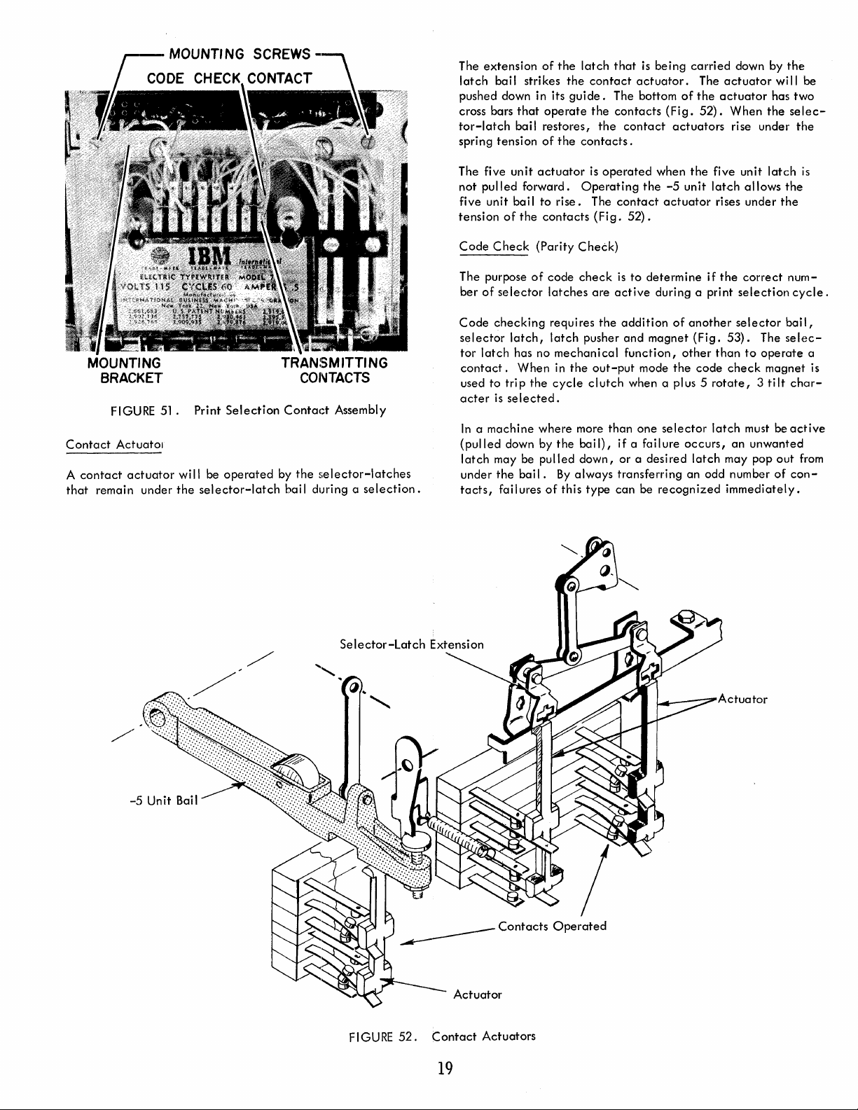
.-----
MOUNT'
NG
SCREWS
CONTACT
The
extension
latch
bai I stri kes
pushed down in its
cross bars
tor-latch
spring
tension
that
bail
of
operate
restores,
of
the
the
guide.
the
latch
that
contact
The bottom
the
contacts
the
contacts.
is
being
actuator.
contact
carried
The
of
the
(Fig.
52).
actuators
down by
actuator
actuator
When
rise under
wi
has
the
the
II
be
two
selec-
the
MOUNTING
BRACKET
Contact
contact
A
that
remain under
FIGURE
Actuatol
actuator
51.
will be
the
Print
Selection
operated
selector-latch
TRANSMITTING
CONTACTS
Contact
by
bai I during a
Assembly
the
selector-latches
selection.
The five
not
five unit bai I
tension
Code
The purpose
ber
Code
selector
tor
contact.
used to
acter
In a machine
(pulled
latch
under
tacts,
unit
pulled
of
Check
of
selector
checking
latch,
latch
trip
is
selected.
down by
may be
the
failures
forward.
the
has no
When
bail.
actuator
to
rise.
contacts
(Parity
of
code
latches
requires
latch
mechanical
in
the
cycle
where
the
pulled
By
of
is
Operating
Check)
check
pusher
the
clutch
more
bail),
down,
always
this
type
operated
The
contact
(Fig.
is
are
active
the
addition
and
function,
out-put
than
if
or a
transferring
can
when
the
the
-5
unit
actuator
52).
to
determine
during a print
of
another
magnet
mode
when a plus 5
one
a failure
desired
be
(Fig.
other
the
code
selector
occurs,
latch
an
recognized
five unit
latch
allows
rises under
if
the
correct
selection
selector
53).
The
than
to
operate
check
rotate, 3 tilt
latch
must be
an
unwanted
may pop
odd number
immediately.
latch
is
the
the
num-
cycle.
bail,
selec-
a
magnet is
char-
active
out
from
of
con-
FIGURE
52.
Contact
19
Actuators
Page 27
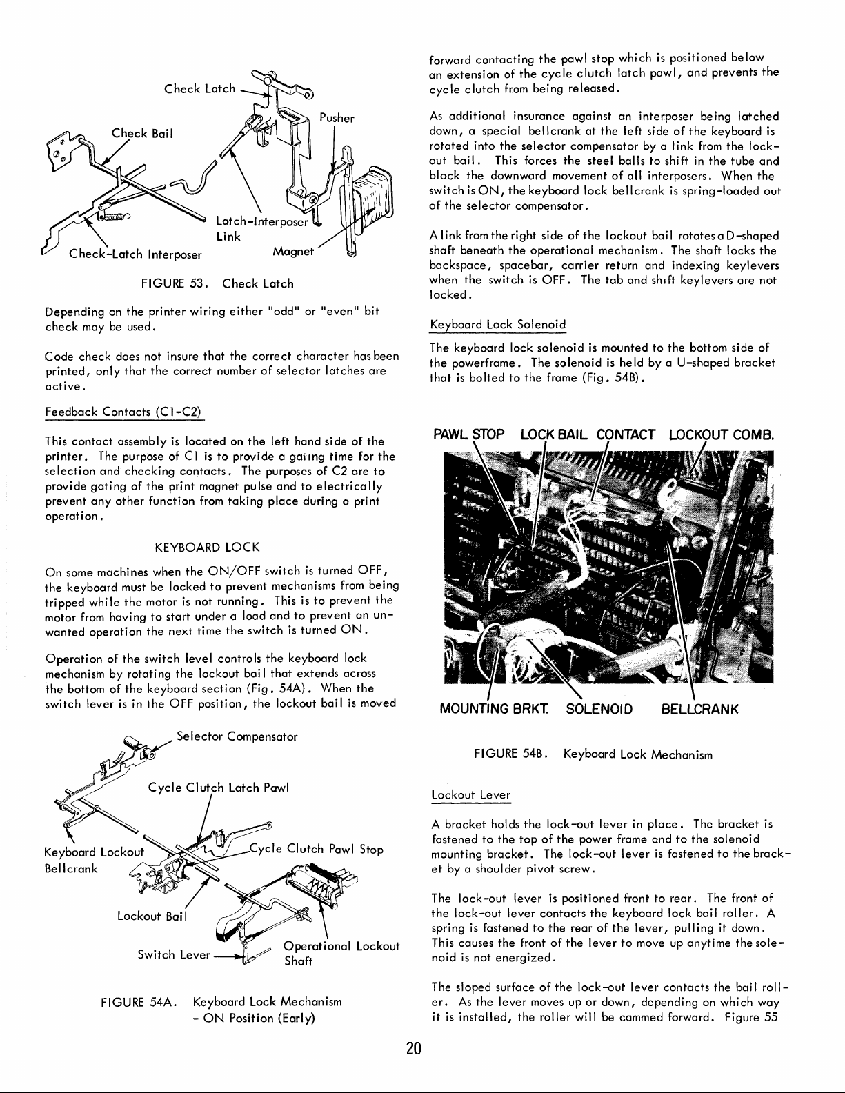
Depending
check
may
Code
check
printed,
active.
on
be
only
the
used.
does
that
Check
FIGURE
printer
not
insure
the
correct
Latch
53.
wiring
that
Check
either
the
number
Latch
"odd"
correct
of
selector
or
"even"
character
latches
has
bit
are
been
forward
an
cycle
As
down, a special
rotated
out
block
switch
of
A
shaft
backspace,
when
locked.
Keyboard Lock
The
the
that
contacting
extension
clutch
additional
into
bail.
the
downward
is
ON,
the
selector
link
from
beneath
the
switch
keyboard
powerframe.
is
bolted
of
from
the
This forces
the
the
right
the
spacebar,
lock
to
the
pawl
the
cycle
being
released.
insurance
bellcrank
selector
keyboard
compensator.
operational
is
Solenoid
The
the
against
compensator
the
movement
side
of
carrier
OFF.
solenoid
solenoid
frame
stop
clutch
at
the
steel
lock
the
lockout
mechanism.
return
The
tab
is
mounted
is
(Fig.
which
latch
pawl,
an
interposer
left
side
by a I ink from
balls
to
of
all
interposers.
bellcrank
bail
and
and
shift
held
by a U-shaped
54B).
is
positioned
and
being
of
the
shift in
to
the
is
spring-loaded
rotatesaD-shaped
The shaft locks
indexing
keylevers
the
bottom
below
prevents
latched
keyboard
the
lock-
tube
When
keylevers
are
side
bracket
the
is
and
the
out
the
not
of
Feedback
This
contact
printer.
selection
provide
prevent
operation.
On
the
tripped
motor from
wanted
Operation
mechanism
the
switch
gating
any
some
keyboard
whi Ie
operation
bottom
lever
Contacts
The purpose of
and
machines
having
of
by
of
(C
1-C2)
assembly
checking
other
must
the
the
rotating
the
is
is
of
the
print
function
KEYBOARD LOCK
when
be
locked
motor is
to
start
the
next
switch
keyboard
in
the
OFF
located
C1
is
contacts.
magnet
from
the
ON/OFF
to
not
under
time
level
the
lockout
section
position,
Selector
on
the
left
to
provide a gailng
The purposes
pulse
and
taking
place
switch
prevent
running.
a load
the
controls
Compensator
mechanisms from
This is
and
switch
the
bai I
that
(Fig.
54A).
the
lockout
hand
side
time
of
C2
to
electrically
during a print
is
turned
to
prevent
to
prevent
is
turned
ON.
keyboard
extends
lock
across
When
bai
I is moved
of
for
are
OFF,
an
the
the
the
to
being
the
un-
MOUNTING
FI
GURE
Lockout Lever
BRKT.
54B.
SOLENOID
Keyboard
Lock
BELLCRANK
Mechanism
FIGURE
Switch
54A.
Lever
-~f'l"-;:
Keyboard Lock
-
ON
Position
Mechanism
(Early)
20
bracket
A
fastened
mounting
et
by a
The
lock-out
the
lock-out
spring is
This
causes
noid
is
The
sloped
er.
As
it
is
installed,
holds
to
the
bracket.
shoulder
lever
fastened
the
not
energized.
surface
the
lever
the
top
pivot
lever
front
moves
the
lock-out
of
the
The
screw.
is
contacts
to
the
of
of
the
roller
lever
power frame
lock-out
positioned
the
rear
of
the
lever
lock
-out
up
or
down,
wi
II
be
in
place.
and
lever
front
keyboard
the
lever,
to
move up
lever
depending
cammed
to
is
fastened
to
rear.
lock
pull ing it
contacts
forward.
The
bracket
the
solenoi
to
The front
bail
anytime
the
on
which
the
roller.
down.
the
bai I
Figure
is
d
brack-
of
A
sole-
roll-
way
55
Page 28
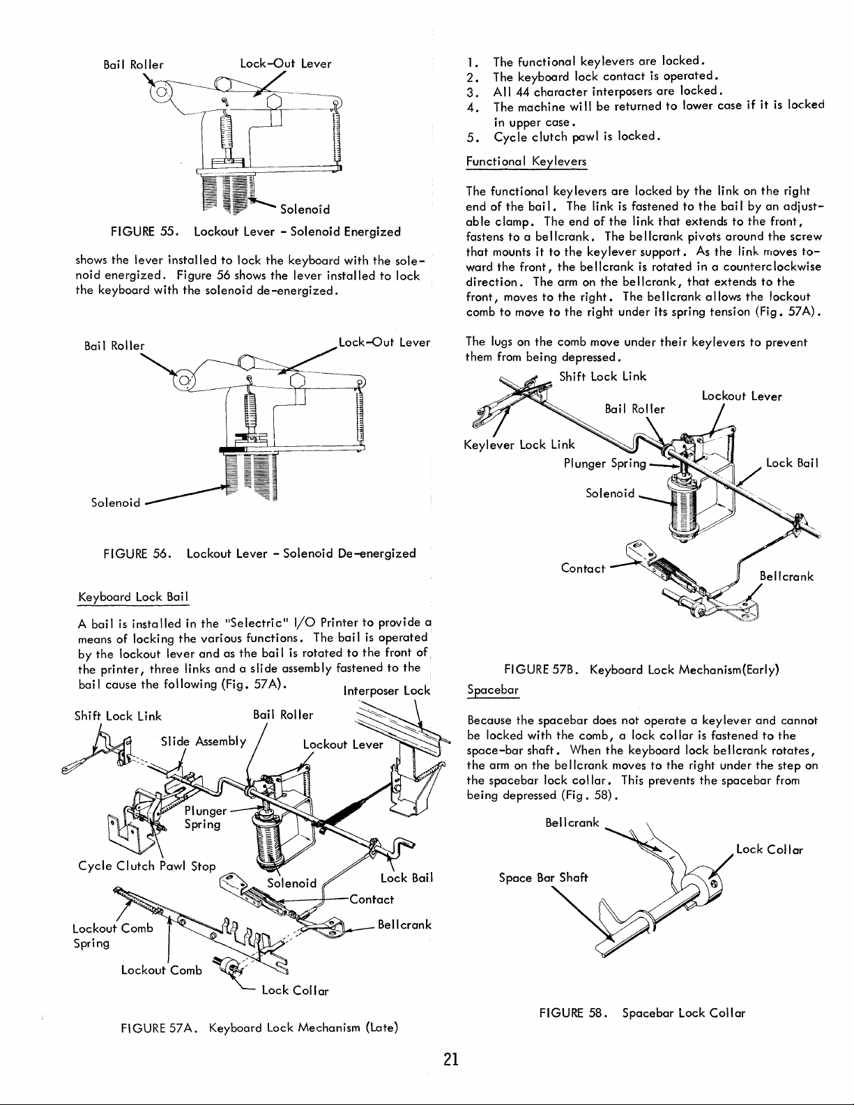
shows
noid
the
keyboard
FIGURE
the
lever
energized.
55.
installed
Figure
with
the
Lockout Lever -
to
lock
the
56
shows
the
solenoid
de-energized.
Solenoid
keyboard
lever
installed
Energized
with
the
to
sole-
lock
1.
The
functional
2.
The
keyboard
3.
All
44
character
4.
The
machine
in
upper
5.
Cycle
Functi ona I Keylevers
The
functional
end
of
the
able
clamp.
fastens
to
a be
that
mounts
ward
the
front,
direction.
front,
moves
comb
to
move
wi
case.
clutch
pawl
keylevers
bai
I.
The link is
The
end
Ilcrank.
it
to
the
the
The arm on
to
the
to
the
key
levers
are
lock
contact
interposers
II
be
is
of
The be Ilcrank pivots
keylever
be
IIcrank
the
right.
right
is
are
returned
locked.
are
locked
fastened
the
link
support.
is
rotated
bellcrank,
The be IIcrank a lIows
under
its spring
locked.
operated.
locked.
to
lower
by
the
to
that
extends
As
that
the
the
in a
extends
tension
case
if
link on
bai I
by
to
the
around
link moves
counterc
the
it
is
the
an
front,
the
lockwise
to
the
lockout
(Fig.
locked
right
adjust-
screw
to-
57
A).
Bai
I Roller
Solenoid
FIGURE
Keyboard Lock Bail
bail
A
means
by
the
the
pri
bail
cause
Shift Lock Link
~,:-_
is
installed
of
locking
lockout
nter,
the
56.
lever
three
following
Slide Assembly
~~,~
Lockout Lever -
in
the
"Selectric"
the
various
and
Ii nks
functions.
as
the
and
a s Ii de assemb
(Fig.
bai I
57A).
Solenoid
I/O
Printer
The
is
rotated
Iy
Lock-out
De-energized
bail
to
fastened
It
n
erposer
to
provide a
is
operated
the
front of,
to
Lever
the
L k
oc
The lugs on
them from
FIGURE
Spacebar
Because
be
space-bar
the
the
being
the
locked
arm on
spacebar
depressed
the
being
57B.
spacebar
with
shaft.
the
bellcrank
lock
comb move
depressed.
Shift Lock
Contact
the
comb,
When
collar.
(Fig.
under
their
keylevers
link
Lockout Lever
Keyboard Lock Mechanism{Early)
does not
58).
operate a key
a lock
the
keyboard
moves
to
This prevents
collar
the
is
lock
right
the
to
lever
fastened
be
Ilcrank
under
spacebar
prevent
and
to
the
rotates
the
step
from
cannot
I
on
Spring
Lockout Comb
FI
GURE
57
A.
Keyboard Lock Mechanism (Late)
21
FIGURE
58.
Spacebar
Lock
Collar
Lock
Collar
Page 29
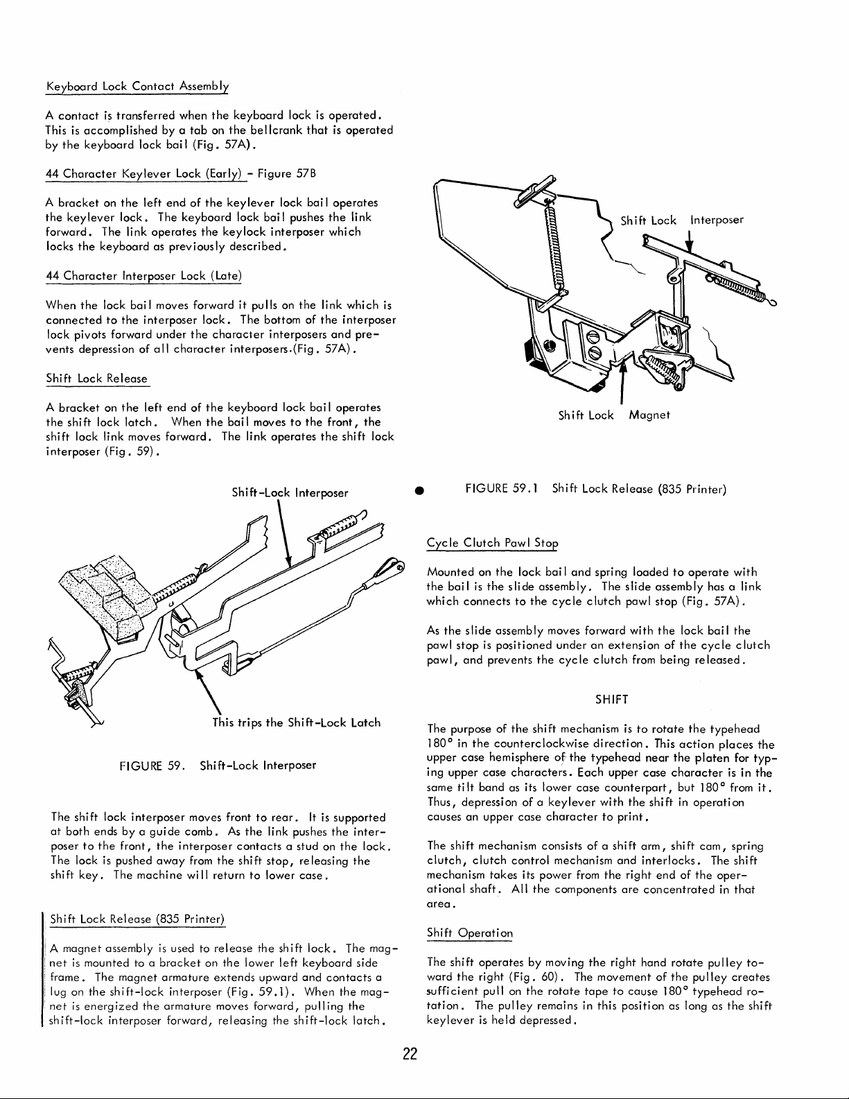
Keyboard
Lock
Contact
Assembly
contact
A
This is
accomplished
by
the
keyboard
44
Character
A
bracket
the
keylever
forward.
locks
the
44
Character
When
the
connected
lock
pivots
vents
depression
Shi ft Lock
A
bracket
the
shift
shift
lock
interposer
is
transferred
Keylever
on
the
lock.
The
link
keyboard
Interposer
lock bai I moves forward
to
the
forward
Re
lease
on
the
lock
latch.
link moves
(Fig.
59).
when
the
by a tab
lock
bai I (Fig.
left
end
The
operates
as
previously
interposer
under
of
all
left
end
forward.
on
Lock (Early) - Figure 57B
of
the
keyboard
the
Lock (Late)
lock.
the
character
character
of
the
When
the
keyboard
the
57A).
key
lock bai I pushes
keylock
described.
it
The bottom
interposers.(Fig.
keyboard
bai
I moves
The link
Shift-Lock
bellcrank
lever
lock
interposer
pulls on
interposers
lock
operates
lock
to
is
operated.
that
is
bai I operates
the
which
the
link
of
the
interposer
and
57A).
bai I operates
the
front,
the
shift
Interposer
operated
link
which
pre-
the
lock
~
Shift Lock
~
is
Sh
•
FIGURE
59.1
Shift
i ft Lock
Lock
Magnet
Release
(835 Printer)
The
shift
at
both
poser
to
The lock is
shift
key.
.
Shift
Lock
! A
magnet
;
net
is
mounted
frame.
lug on
'net
is
energized
shift-lock
lock
ends
the
The
Release
assembly
The
the
shift-lock
interposer
FIGURE
interposer
by a guide
front,
the
pushed
away
machine
(835 Printer)
to a
magnet
the
59.
moves front
comb.
interposer
from
wi
is
used to
bracket
armature
interposer
armature
forward,
Shift-Lock
As
the
contacts a stud
the
shift
II
return
release
on
the
lower
extends
(Fig.
moves
releasing
Interposer
to
rear.
link pushes
stop,
to
lower
the
shift
left
upward
59.1).
forward,
the
It
is
supported
the
on
releasing
case.
lock.
keyboard
and
contacts
When
pulling
shift-lock
the
The
the
the
inter-
lock.
the
mag-
side
mag-
latch.
Cyc
Ie
Clutch
Paw I
Stop
Mounted
the
which
As
pawl
pawl,
The purpose
1800 in
upper
i ng
same
Thus,
causes
The
clutch,
mechanism
ational
area
Shift
The
a
ward
sufficient
tation.
keylever
bail
is
connects
the
slide
stop
and
the
case
upper
ti
It
depression
an
shift
clutch
shaft.
.
Operation
shift
the
The
on
the
lock
the
slide
assembly.
to
the
assembly
is
positioned
prevents
counterclockwise
hemisphere
case
band
upper
mechanism
takes
operates
right
pull on
is
held
of
the
characters.
as its
of a keylever
case
control
its
All
by
(Fig.
the
pulley
depressed.
the
shift
lower
consists
power
the
60).
remains in
bai I and
cycle
moves forward
of
character
moving
rotate
spring
The
clutch
under
an
cycle
clutch
SHIFT
mechanism
direction.
the
typehead
Each
case
counterpart,
with
to
of a shift
mechanism
from
the
components
the
The
movement
tape
this
extension
upper
right
loaded
slide
pawl
with
from
is
to
the
print.
and
right
are
to
cause
position
to
operate
assembly
stop
(Fig.
the
lock
of
the
being
released.
rotate
the
This
action
near
the
platen
case
character
but
shift
in
operation
arm,
shift
interlocks.
end
of
the
concentrated
hand
rotate
of
the
pulley
1800 type
as long as
with
has a
link
57A).
bail
the
cycle
clutch
type
head
places
for
is in
1800 from
cam,
spring
The
shift
oper-
in
that
pu
Iley
creates
head
the
the
typ-
the
it.
to-
ro-
shift
22
Page 30
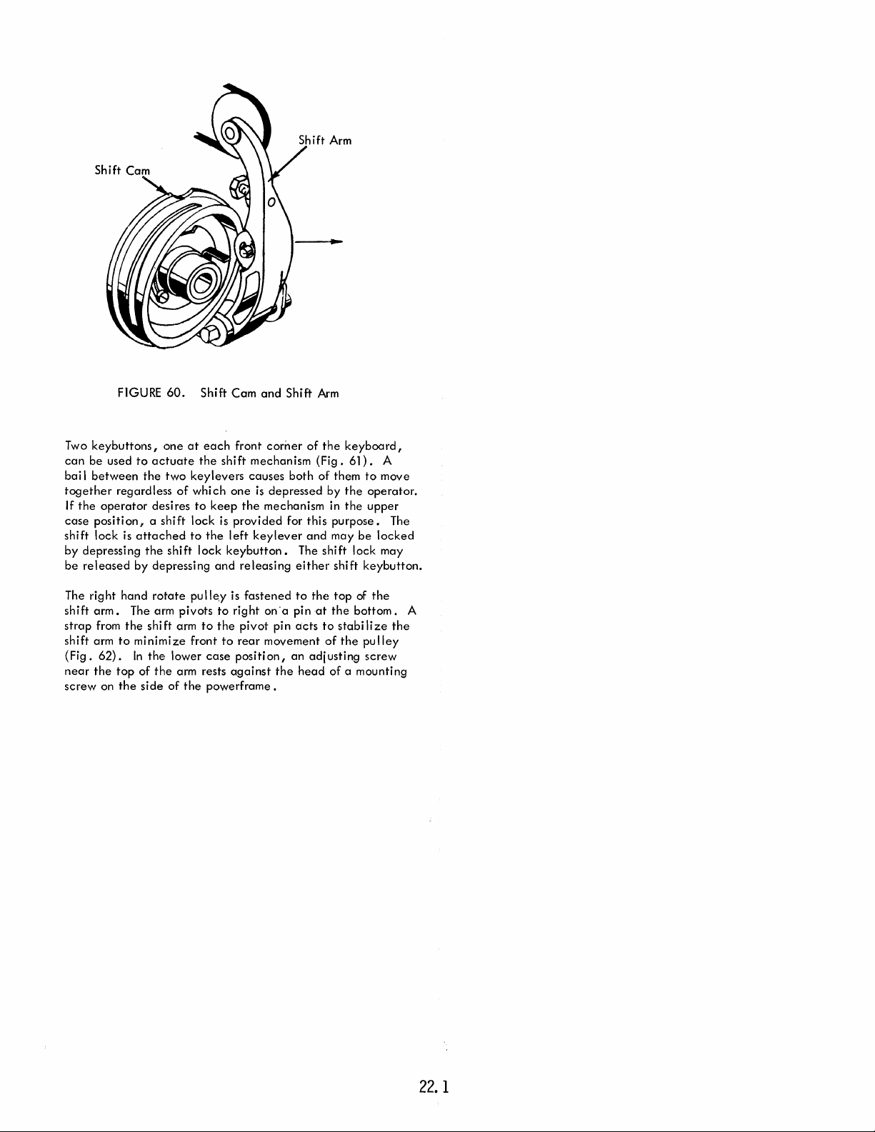
Two
keybuttons,
can
be
used
bai
I
between
together
If
the
operator
case
position, a shift
shift
lock
by
depressing
be
released
The
right
shift
arm.
strap
from
shift
arm
{Fig.
62).
near
the
top
screw
on
FIGURE
one
to
actuate
the
regardless
desires
is
attached
the
by
depressing
hand
rotate
The arm
the
shi ft arm
to
minimize
In
the
of
the
the
side
60.
at
two
keylevers
of
which
to
lock
to
shift
pulley
pivots
front
lower
arm rests
of
the
Shift
Cam
each
front
the
shift
causes
one
keep
the
is
provided
the
left
lock
keybutton.
and
releasing
is
fastened
to
right
to
the
pivot
to
rear
case
position,
against
powerframe.
and
Shift
corner
mechanism
both
is
depressed
mechanism in
for this
keylever
The
either
to
on
"a
pin
pin
acts
movement
an
the
head
Arm
of
the
keyboard,
(Fig.
of
them
by
the
the
purpose.
and
may
shift
shift
thE~
top
at
the
to
stabi
of
the
adjusting
of
a mounting
61).
A
to
move
operator.
upper
be
locked
lock may
keybutton.
of
the
bottom.
Ii
ze
pulley
screw
The
A
the
22.
1
Page 31

ShIft Bail
Shift
Release Arm
The shi ft arm must
eration. A disc-shaped
the
operational
operates
(Fig.
sition
a.
between
62).
on
the
"*f--I-~~Shi
LOWER CASE
FIGURE
The
power
be
shaft
bearing
two
roller
frame
Shift
ft
POSITION
62.
forced
to
shift
cam
outside
rollers
located
to
the
left
and
Shift Arm
Adi. Screw
Cam Roll
Cam
Shift
Operation -lRear
pivot
outward
fits
around
the
at
of
the
serves
as a
--I~-+-t~
er
b.
UPPER
FIGURE
for a shi ft
an
sideframe.
the
rear
cam
is in a
back-up
CASE
View
61.
extension
The
of
the
cam
fixed
roller
POSITION
op-
cam
po-
for
Shift
of
Release
the
shi ft arm
camming
on
the
cam
arm
The
ceives
erational
a
clutch
shift
desired.
connection
The
the
shou Ider
the
cam.
shaft
shaft
cam
is
fastened
clutch
the
clutch
with
time a shift
Mechanism
cam.
The
and
surface
the
perimeter.
two
rollers,
is
operated
into
upper
shift
cam
its
motion
shaft
mechanism
cam from
A spring
between
shift
cam mounts on a
operational
(Fig.
center
of
An
arbor
just
to
continuously
comes from
to
is
undersized
arbor
is
is
allowed
the
arbor
operation
roller
ri
des
is on
the
1800 to
case
rotates
from
turns
the
shaft
63).
this
bearing
(shift
the
right
this
the
cam
turning.
to
driving
on
the
the
cammi ng
the
right
When
the
shift
arm
the
(Fig.
62b).
only
during a shift
the
operational
continuously
is
required
operational
clutch
"makes"
the
operational
shoulder
bearing
The
operati
beyond
clutch
of
the
(Fig.
63).
arbor
by
and
encircles
and
wound in
Therefore,
collapse
the
cam.
occurs.
right
surface
side
low
is
in
high
to
shaft
and
ona I shaft
arbor)
shift
The
means
about
hand
is
of
the
point
of
lower
point
in
shaft.
when
the
engage
when a shift
and
"breaks"
shaft
on
the
is
free
the
right
is
set
cam
and
driving
of
a spring
the
the
same
any
time
the
arbor,
The cam
attached
of
the
cam.
cam
the
cam
case
(Fig.
order
operation
Since
motor
and
disengage
and
the
right
to
rotate
extends
side
screwed
turns
force
arbor.
direction
that
the
it
is
driven
to
the
The
rather
than
is
between
62).
to
force
and
re-
the
is
running,
operation
the
driving
shift
hand
side
about
through
of
the
shift
to
the
with
the
to
the
shift
clutch
that
The spring
that
spring
will
turn
1800 each
The
the
op-
the
is
cam.
of
this
23
Page 32

a.
Inner
Shift
LOWER
Lug
Clutch
CASE
Release Arm
POSITION
b.
Shift
UPPER
Outer
Clutch
CASE
Lug
Ratchet
POSITION
Usually a spring
when its
clutch
the
In
arbor) is
spring
spring
ues
pand
driving
In
in
to
spring
other
left
plate
driving
is wound
opposite
the
shift
directi
mechanism,
rotating
clutch
is
clutch
must
to
rotate.
the
inside
action
the
shift
mechanism,
the
unwound position so
allow
the
arbor
clutch,
is
rotated
end
of
the
attached
spring is formed
clutch
ratchet
like
part mounted on
large
C-clip
the
ratchet
the
ratchet
crease
whi
Ie
meter
The
shift
surface.
referred
outer
lug.
cam blocks
tation
holds
when
counterclockwise
in
size.
the
cam is
is
increased.
clutch
One
to
as
The shift
the
of
the
ratchet
FIGURE
clutch
hub turns in
and
slips
on.
continuously
wound.
be
The on Iy
diameter
will
stop.
to
slip
one
end
in
the
spring
to
the
to
the
(Fig.
63).
the
it
the
shift
Conversely,
rotated
ratchet
lug
is
nearer
the
inner
release
movement
(Fig.
63.
Shift
is
considered
the
direction
if
the
hub stops or
This is not
the
driving hub
in
the
In
order
to
allowed
unwinding
is
cam
right
way
of
the
the
shift spring
that
freely
of
the
formed
(Fig.
to
slip
to
do
spring
it
inside
spring must
direction
out
'63).
and
fits
The shift
end
of
the
in
place.
The
is
not being
causes
if
the
counterclockwise,
has
two
lugs 1800 apart
the
center
lug.
The
other
arm
pivoted
of
the
ratchet
64).
Clutch
to
be
true
of
(the
direction
stop
the
whi Ie
this
is
clutch
clutch
wi
II
be
it.
and
fits
The right
into a hole
clutch
shift
arbor
operated.
the
clutch
ratchet
than
lug is
lugs
one
that
rotates
all
spring
shift
shift
the
to
enlarge
so
must
enlarged
To
enlarge
be
held
of
the
into
ratchet
clutch
turns
is
held
the
the
called
just
in
to
that
the
spring
back
clutch
that
the
cam,
arbor
that
be
enough
while
spring.
an
adjustable
end
in
the
is
arbor.
freely
Rotation
spring
stationary
spring
on its
other
front
stop
tightens
in
clutches.
the
contin-
or
ex-
the
held
the
the
The
of
the
shift
gear-
A
inside
of
to
de-
dia-
left
and
is
the
of
the
to
ro-
When
the
to
decrease
tightens
the
cam
with
the
ratchet
raised
into
tum
of
further
crease
ly inside
Once
the
to
properly
stricted
controlled
and
operates
(Fig.
65).
Shift
Clutch
f.iounting
Shift
Detent
FIGURE
inner
around
to
cam
then
the
rotation
in
diameter
the
64.
Shift
lug is
released,
in
diameter
the
drive
and
contacts
its
path,
by its own spring
rotating
the
cam • The
clutch
spring 180
the
and
its
shift cam causes
causes
the
to
allow
spring.
shi ft re
clutch
shift cams momentum has
disengage
from
overthrowing
by
the
against
shift
the
the
spring
its rest
cam
inner
Spring
Plate
FIGURE
65.
Shift
Clutch
the
shift
shift
lease
rotation
it
to
rotate
the
shift
clutch
stop
which
lug
Arm
Release
clutch
clutch
clutch
0
•
The
arm,
is
stopped.
slight
spring
clutch
carried
position.
is
of
the
and
Arm
spring is
tension.
arbor
ratchet
outer
that
to
unwind
arbor
the
the
cam must
attached
shift
Detent
allowed
It
then
and
the
rotates
lug
of
has
been
The
momen-
Iy
farther.
and
to
slip
cam for
be
Overthrow
to
the
clutch
ratchet
hub
of
the
This
in-
free-
enough
re-
is
cam
Shift
Cam
The position
the
ratchet
release
attached
shift
to
levers
inner
keylever
the
rear
are
lug
arm is
to
and
at
of
of a keylever
of
the
inner
of
the
that
wi
controlled
the
end
is
depressed,
operate
rest,
the
shift
causes
lug
into
shift
II
of
the
release
be
stopped.
the
the
release
clutch
the
the
arm
The position
by
a link from
shift bai I
the
bail
shift
release
arm is in position
ratchet
release
path
of
arm
the
determines
the
arm
(Fig.
61).
rotates
to
arm.
(Fig.
64).
to
rise
out
outer
lug
the
lug
of
the
to a lever
When a
force
the
When
the
to
stop
Depressi on
of
the
(Fig.
64).
of
shift-
link
key-
the
path
24
As
long as
point
arm
to
release
back
spring
0
180
ratchet
clutch
of
the
the
shift
of
the
shift cam remains
the
right.
arm moves down
into
the
path
to
again
tighten
back
to
the
lower
then
contacts
as
before.
cam.
keylever
When
of
the
the
the
out
inner
and
case
re
is
keylever
of
drive
position.
lease
The shift cam
held
to
the
lug.
depressed,
the
path
the
arm
stop
rear
is
released,
of
This
shift
The
to
disengage
again
holding
the
outer
allows
cam
and
inner
controls
the
high
the
the
the
ratchet
lug
the
overthrow
shift
shift
lug
and
clutch
of
the
spring
Page 33

Note
that
the
shift cam stop
lug
of
the
ratchet
Whenever
lug)
the
shaped
throw
Mounted
cam is a small arm
though
character
for
lower
arm
on
the
to
place
lower
Cam overthrow
case
the
from
of
the
the
cause
acceleration,
automobile
spring
cam.
rides a raised
66).
of
the
upper
the
the
momentum
stop strikes
release
of
the
shift cam through
on
a pivot stud
the
detent
interrupter
the
shift
cam.
case
positi on a nylon
is
spring loaded
outside
the
cam in its proper rest position for both upper
case.
than
in shifting
lower
case
the
high point
roller
against
movement of
a noisy
steel
A nylon
The friction
cam
and
operation
must be braked in descending (1
shift arm
surface
and
lower
ratchet
the
arm absorbs
surface
is a greater
positi
a braking
brake
causes
always
when
the
ratchet
is
stopped by
of
the
cam
carries
rear
side
of
the
the
shock
the
shift
below
and
called
the
shift
detent
arms primary function
mechanism,
As
the
into
of
to
on,
to
the
the
the
cam.
brake
shoe,
on
applied
the
case.
cam
corresponding
the
upper
the
low point
receding
and
action
the
by
shift
it
approaches
roller
mounted on
cam.
problem in returning
case.
roller
of
surface
Excessive
parts
breakage.
is necessar'y
operates
attached
circumference
the
brake
action
follows
and
the
inner
to
is
This
of
behind
cam
are
release
the
stop further unti I
lug.
of
stopping
clutch
the
front
mm
is
to
ope?ate
also
used as a
either
detent
detenting
As
the
cam returns
the
shift arm is rolling
the
cam.
tends
speed
of
To
the
hi
II. A heavy
just in front
to
the
end
of
prevents
to
be
the
the
inner
operating.
arm (on
The horse shoe
ratchet.
of
(Fig.
the
notches
to
the
same as an
of
the
either
the
over-
the
shift
65).
Al-
the
detent
the
upper
shift
detent.
located'
acti
on helps
and
to
the
lower
to
The pressure
accelerate
cam cou
prevent
of
acceleration
same for both
the
the
cam
cam
shift
brake,
(Fig.
or
Id
Shift Cam Brake
operation
racter
a shift
detent
tensi on of
of
the
link.
prevents
action
interposer.
rage.
the
position
clutch
forward by its
printed.
'
Nylon
and
is
delayed
operati
must move out
the
the
keyboard
bail
is
rotated
The pawl blocks
the
re
does not
The
When
the
recess in
and
latch
the
the
link.
Shoe
FIGURE
an
on.
detent
lease
extension
66.
erroneous
by
blocking
When
the
of
the
lever
(Fig.
67).
up
into
the
of
the
prevent
the
interposer
shi ft
acti
cam.
The bai I is
pawl moves out
The
cycle
spring
Raised Braking
Shift Cam Brake
character
the
shi ft cam starts
recess in
operates
A small pawl on
rhe
path
forward movement
cyc
depression
is
merely
on
is
clutch
would
cycle
the
a bai I
of
the
Ie
clutch.
of
latched
completed,
rotated
of
the
path
latch
and
the
stored
clutch
result.
an
cam.
under
the
cycle
This
the
the
back
of
link is
of
keylever
down
character
Surface
Shift Cam
The
cha-
release
interlocking
detent
the
during
operati
on,
A forward
the
right
left
end
clutch
latch
the
link
nor
into
sto-
enters
to
the
rest
cycle
then
pulled
of
and
is
the
ex-
side
the
Character
If
the
shift is
pressed,
pleted.
Interrupter
already
the
character
Otherwise
Cycle
in process when a
the
must be
shift
Clutch
delayed
wou
Id
Latch
letter
until
be
interrupted
key
the
is
de-
shift
in rnid-
is
com-
If
the
shift
keylever
simultaneously,
ter
shaft has a
that
time a
collision
rupter
pawl
and
Cycle
Clutch
and a character
both will
chance
to
wi
the
bottom
Latch Link
operate
actuate
II
occur
of
for
the
between
the
cycle
key
an
shift
lever
are
instant
interlock.
the
character
clutch
depressed
until
latch
the
fil-
During
inter-
link.
FIGURE
67.
Character
25
Interrupt-er
Page 34

The
character
prevent
interrupter
able
pawl
rupter
Shift
parts
stop on
can
bail
Interlock
interrupter
damage.
bai I loads
the
yield
by
rotates.
mechanism must
A torsion spring around
the
interrupter
bai
I.
If a collision
overcoming
the
yield
in
the
pawl
against
occurs,
torsion spring as
the
order
to
character
an
adjust-
interrupter
the
inter-
Shift Cam
Operating
process of printing would result in parts
detent
typehead
tion
be
prevented
ward
We
as rong
An
fi
Iter shaft
shift
When
rests
operation
cycle
interlock
shift
operation
Shift
would
cou
of
the
the
platen.
have
seen
as
the
interlock
clutch
the
cycle
near
the
of
operation
cam
clutch
unti I
Interlock
the
shift mechanism when
be
engaged
Id
be
typehead
from
that
shift
arm is
(Fig.
68).
ratchet
mechanism
low
point
the
shift mechanism
begins,
to
actuate
ratchet
the
in a
against
can
be
operating
the
shift
clutch
operated
The
and
prevents
of
the
the
(Fig.
68b).
cycle
operation
the
ratchet
the
notch
platen.
allowed;
once
the
spring
clutch
is
by a cam on
interlock
rotation
is
at
rest, a roller
interlock
(Fig.
filter
shaft
interlock
This interrupts
is
the
of
therefore
prevented
engages
type
head
damage.
the
typehead
At this
time
typehead
remains
from
the
right
the
of
the
on
cam
allowing
68a).
As
rotates
causing
into
the
completed.
Shift
Clutch
is in
The
rotate
and
no
the
shift must
has
started
disengaged
rotating.
end
teeth
ratchet.
the
interlock
free
soon as a
teeth
of
the
shift
Ratchet
the
the
rota-
of
of
the
the
to-
the
the
Input
• FIGURE
When
the
shift
cam starts to
rides up
This
wh
put
tates
(Fig.
.cycle
onto
the
high
rotation
ich transfers motion to
interlock
forward
latch
68
.2).
Clutch
of
the
arm moves to
over
the
Cable
68.1
surface
shift
rear
Shift Cam
rotate,
cam
the
the
step
of
the
detent
input
rear
on
o
Detent
the
shift
sh
ift cam
pulls on
interlock
the
shift
the
cyc
cam
(Fig.
the
arm.
interlock
Ie
clutch
detent
68.1).
input
As
sleeve
roller
cable
the
arm
in-
ro-
@~@
Shift
a.
REST
POSITION
If
an
operator
striking a
fore
interlock.
because
known as
in shifting from
upper
against
what
ing
lock.
Shift
The shift to
print
on
the
filter
the
case
the
before
the
fi
To
Print
operation
the
cycle
character,
This
shift arm had
"beating
is
cam in lower
it
Iter
print
FIGURE
shou
Id
shaft had
could
the
upper
no
problem
begins
shaft
sufficient
Interlock
interlock
until
clutch
Interlock
68.
operate
the
shift cam
sufficient
cause
already
shift."
to
lower
because
case.
to
move
(835 Printer)
the
shift motion
trip mounting
Cam
b.
ACTIVE
Shift
Interlock
the
sh ift i mmedi
could
time
an
erroneous
begun
This
condition
case.
the
shift arm does not rest
The
cam must
the
shift
time
to
actuate
provides a means for
is
bracket.
ate
begin
to
actuate
character
to
move.
Shifting from lower
arm,
thereby
th",e
complete.
POSITION
I y
after
to
rotate
the
shift
to
This
occurs mostly
rotate
someallow-
shift
Inter-
delaying
It mounts
be-
print
is
to
a
~J.a.
• FIGURE
The shift
detent
that
operation
Shift Magnets Assembly
The shift magnet assembly is mounted
power frame
and
roller
the
their
68.2
interlock
enters
cycle
clutch
is
complete.
below
armatures
Shift
To
Print
Interlock
arm will remain engage<d until
the
detent
of
sleeve
will
the
shift
cam.
(Fig.
69).
the
not
shift
be
to
It
consists
Input
Interlock
I
nJ?ut
(Shown
cam.
released
the
right
of
Arm
Cabl e
Operated)
the
shift cam
This insures
until a shift
side
of
two magnets
the
26
Page 35

RELEASE
PI
N
CAM
FOLLOWER
ARM
The
upper
rear
and
case
magnet
formed
Pivot
case
serves
armature
end
of
Plate~
FIGURE
FIGURE
the
69.
armature
as a latching
is
upper
70.
Shift
has a
surface
spring
case
armature
Upper
Armature
Mechanism
formed
loaded
Case
end
(Fig.
to
the
(Fig.
Magnet
Coil
that
70).
extends
front
71).
The
against
to
lower
the
the
FIGURE
71.
Lower
Case
Stop
Magnet
Plate
26.
1
Page 36

When
the
place.
rear
contacts
to
the
rear.
t~e
shift
per
case
to
moves
sition,
ward into
per
(Fig.
the" lower
case
72).
upper
case
One,
the
upper
a stud on
Once
the
takes
place
as
armature moves
the
front,
to
case
armature in
the
path
the
of
magnet
case
the
shift
shift
release
normal.
down.
its
de-energized
armature
energized
the
upper
is
energized
magnet
armature
release
arm
Two,
The lower
mechanically
position,
case
armature's
two
actions
moving
arm pushing
is
pushed
the
formed
case
armature
position.
latches
by moving
formed
to
end
In
take
the
the
this
the
to
of
end
the
arm
rear,
up-
po-
up-
for-
Contact
The cam follower arm
is
The
the
so
In
low
shift arm by
low point
of
the
the
upper
Cam Follower
spring
loaded
contact
shift arm
the
lower
point
the
same
same
cam follower arm is positioned on
shift arm rests on
case,
(Fig.
90
of
the
cam
is
plane.
relative
or lower
toward
0
by
90
the
cam
75).
0
it
,
cam in
such
that
Therefore,
position when
case.
Actuating
ri
des
and
In
upper
•
the
is
detented
Since
wi
\I
rest midway
either
Points A
Arm
the
peri phery of
follows
high point
the
the
case,
so
cam follower arm leads
detent
and
B (Figs.
the
cam follower arm
the
shift cam is
the
contour
the
shift cam
of
the
the
shift arm rests on
between
position.
shift
cam.
It
of
the
cam.
the
cam
to
lead
is
detented
shift cam (Fig. 74).
the
the
the
high
and
The
contour
74
& 75)
are
in
wi
II
be in
detented
in
Mounting
Bracket
o
FIGURE
Attracting
upper
and
arm which is under spring load
position.
Shift
The shift
contact
to
the
the
case
armature.
the
operating
Contact
contact
assemblies mounted
right
side
CAM FOLLOWER MODE CONTACT
72.
Shift
lower
case
This a I lows the formed
end
to
move forward,
Assembly
assembly consists
of
the
power frame
Magnet
armature
to
to a plate.
Assembly
to
the
rear
allowing
return
to
of
a cam follower
The
(Fig.
73).
TRANSMITTING CONTACT
unlatches
end
the
lower
plate
to
the
is
snap
the
up
release
case
and
two
mounted
{
FIGURE
Assume a shift
cam
rotates
high
arm,
tion.
Returning
detent
shift cam
the
low dwell
1800 and
point.
the
arm is moved
to
with
the
rotates,
74.
Shift Cam
operation
As
the
lower
shift arm resting in
and
from lower
wi
II
detent
high
point
to
the
case,
the
the
cam follower arm moves
back
to
Detented
moves past
right
shift cam rotates 1800 and
its rest
to
upper
with
the
and
back
the
low
position.
Upper
Case
case.
shift arm on
the
cam follower
to
its rest
dwell.
to
the
The shift
the
posi-
will
As
the
left
into
FIGURE
73.
Shift
Contact
Assembly
27
FIGURE
75.
Shift Cam
Detented
Lower
Case
Page 37

center
position.
low
dwell,
the
its
center
or rest
NOTE: The
ment of
Shift
The
feedback
The assemblies
The assembly
76) •
the
Contact
contact
and
shift
As
the
follower
actuating
position.
actuating
cam.
Assemblies
assembli es operat·ed
transmitting
nearest
to
the
arm
the
rear
arm moves
operates
contacts.
front
is
the
arm moves in
to
the
only
during
by
the
actuating
are
the
feedback
transmitting
Transmitting
.J..-_--
and
right
and
the
contacts
out
of
back
move-
arm
are
contacts.
(Fig.
Contacts
Tab
the
to
When
the
ratchet
They both turn 1800 on
er
rides on
I
The
cycle
Everything
is powered
The
cycle
shaft
through
ported
the
A
The
the
ing a print
clutch
hub on
The
disengaging
cycle
sleeve
cycle
motor
cycle
Cycle
the
by a
clutch
inside
is
spring
the
Shaft
is
the
C-7
CYCLE CLUTCH OPERATION
operation
concerned
by
the
extends
left
side
self-aligning
pulley
the
clutch
pulley
running,
operation.
(Fig.
cycle
clutch
clutch
spring provides a means of
the
cycle
Latch Pusher
released
each
cam
causing
occurs
with
cycle
shaft
from
frame.
bearing.
hub in
hub
acts
is in continuous
but
the
A spring
77) is
the
pulley
shaft from
the
cam turns with
sh
ift
operation.
transfer
each
time a
printing a
either
the
center
The
left
the
center
as a
bearing
cycle
clutch
driving
and
the
Cam
of
character
character
directly
of
the
end
of
The right
of
for
rotation
shaft
operates
called
connection
a hub on
cycle
the
The
the
contacts.
on
or
indirectly.
machine
the
shaft
end
fits
the
machine.
the
cycle
whenever
the
between
the
cycle
engaging
clutch
ratchet.
cam
follow-
prints.
the
paper
is
into
shaft.
only
dur-
cycle
shaft.
and
pulley.
out
sup-
the
Shifting
mitting
to
tacts
Shi ft Mode
The shift mode
and
tacts
This is
is
with
the
pending upon
C-7
This assembly consists
which
to
contacts
lower
case,
are
operated
transmitting
indicate
accomplished
bolted
to
the
shift
tab
wi
II
Contact
is
mounted to
upper
the
Contacts
contacts
whether
the
rear
arm.
always
whether
Assembly (835 Printer)
~1§iii~~~5~~~S;
•
FIGURE
76.1
case,
are
operated
outer
by
the
contact
by
of
The mode
hold
of
the
C-7
Shift
the
inner
set
of
actuating
are
located
assemblies
the
printer
the
shift arm
the
shift
one
of
the
printer
N/O
shift
Cam
Contact
Contact
set
of
by
the
actuating
feedback
arm.
just
(Fig.
is
in
tab
arm,
and
contacts
the
contacts
is
in upper or lower
and
N/C
ratchet
(Fig.
Assembly
Actuator
Assembly
feedback
and
transmitting
above
73).
upper
or lower
(Fig.
moves
are
positioned
transferred
contacts
76.1).
(835
Arm
and
trans-
arm.
Shifting
con-
the
feedback
These
con-
case.
73).
This
tab
left
to
right
so
that
de-
case.
and
a cam
Cam Follower
Printer)
Cy.CI.
FIGURE
The
left
end
the
cycle
collar.
slot
the
just
The right
the
clutch
the
spring
cycle
when
projects
fits loosely
control for
The
in
the
left
end
the
position
cycle
pulley
shift
mechanism.)
is
slightly
clutch
the
into a notch
of
shaft
tip
collar.
of
end
clutch
pulley
hub
around,
the
77.
Cycle
the
cycle
and
is
of
the
This
the
spring
of
the
of
the
cycle
pulley
functions
less
than
so
rotates.
in
enclosing
right
end
Hub
On
Cy.
Clutch
clutch
spring fits
clamped
spring is
spring in
The inside
that
to
turned
arrangement
clutch
and
relation
clutch
(Fig.
77).
the
same as
the
diameter
the
spring
The right hand
the
cycle
the
of
the
cycle
Cycle
CI.
Pulley
- Exploded
around
this hub by
up so as
prevents
makes
to
spring
encircles
(The hub on
the
shift
diameter
clutch
spring
of
clutch
tip
of
sleeve.
clutch
clutch
of
the
View
the
to
any
it
possible
the
clutch
the
hub
will
the
spring.
Clutch
the
cycle
fit
slippage
shaft.
a hub on
the
cycle
arbor
cycle
on
tighten
spring
The
and
acts
Spring
hub on
clutch
into
to
clutch
the
clutch
sleeve
as a
a
at
ad-
on
28
Page 38

The
cycle
clutch
0
180
apart.
one
of
latch
latch,
the
clutch
clutch
farther
built
up
additional
spring
expand
the
that
ca
lied
spring.
after
in
is
in
about
As
steps on
is
placed
sleeve
the
the
rotation
the
winding breaks
the
spring.
sleeve
the
cyc
the
in
the
cyc
thereby
The left
right
cycle
given
unwinding
the
hub on
the
driving
has two steps on its
Ie
clutch
is drivi
clutch
sleeve
the
path
of
the
Ie
clutch
latch,
end
end
shaft,
stopping
is
to
of
the
stopped
filter
the
left
the
cycle
shaft,
direction
the
cycle
clutch
connection
exterior
ng
the
cyc
Ie
contacts a vertical
sleeve
(Fig.
78).
stops
the
rotati on
right end
because
and
end
of
and
causes
between
Cycle
clutch
of
print
the
pulley.
of
the
spring
the
shaft.
cycle
the
This
the
Clutch
momentum
spring
hub
surface
shaft,
This
of
cycle
rotates
This
clutch
to
un-
and
Sleeve
The shock
to
bounce
occurring, a check
ratchet
of
stopping
the
located
cycle
on
shaft
pawl drops
the
The pawl drops in when
the
overthrow
backwards.
left
end
the
clutch
of
into
a notch in a
of
the
is
the
cycle
To
prevent
cycle
shaft
disengaged.
Cycle
Check
shaft tends
this from
check
(Fig.
80).
Clutch
Pawl
FIGURE
Since
the
shaft
momentum,
side
notches in
as
an
by
its
an
of
the
nylon
the
overthrow stop
latch,
the
tum (expanding
contacts
the
lugs on
shaft.
Cy.
CI.
78.
Cycle
Clutch
tends
to
travel
overthrow stop is
cycle
clutch
left
side
of
the
(Fig.
79).
cycle
shaft
continues
the
cycle
clutch
the
sleeve
Collar
Cycle
CI
utch
Latch
Latch - Side
View
beyond its rest position
required.
restoring cam
cycle
When
spring) until
stopping
clutch
the
to
the
Two
lugs on
project
sleeve
sleeve
is stopped
rotate
under
the
nylon stop
overthrow of
and
due
the
into
operate
momen-
to
the
FIGURE
Both
the
overthrow
cycle
shaft
wi
II
pletion
of
each
rest position when
dwells
and
the
working
is
against
The shock
shaft,
through
the
designed
The same
stopping
the
ratchet,
shaped
The
clutch
sleeve.
because
hub
tire
of
the
which has
causes
the
working
of
stopping
and
print
the
collar,
cycle
clutch
to
absorb shock
effect
the
momentum
shift cam through
and
to
like
a horseshoe so
cycle
clutch
latch forward
The
clutch
of
its own spring
tightens
clutch
clutch
been
the
cycle
the
assembly
sleeve
moved
described.
80.
stop
return
cycle
the
shaft
latch.
is
true in
the
shift
is
spring
clutch
Cycle
and
exactly
operation.
positive
face
face
the
is
transmitted
the
overthrow
This is why
(vulcanized
the
of
the
overthrow
release
allowed
out
of
spring
tension.
and
rotates
then
contacts
back
to
Clutch
the
of a notch
of
overthrow
Check
check
pawl assure
to
its rest position
(The
cycle
selector
cams
on
the
check
of
the
from
stop,
the
the
rubber
Pawl
shaft
are
the
pawl.)
cycle
the
sleeve,
cycle
mounting).
on
check
cycle
clutch
shift mechanism. The shock
the
shaft
cam is transmitted from
stop,
the
lug on
arm.
The
release
that
it
can
to
engage
the
lath
then
quickly
drives
the
through 180
the
to
the
rear
be
disengaged
absorb this
by pivoting
of
the
decreases
The rotating
cycle
0
•
cycle
into
again
shock.
step
on
clutch
shaft.
The
second
clutch
its
path.
as previously
that
at
the
is
their
shaft,
shaft
and
the
arm is
the
the
in
diameter
The
latch
the
com-
in its
low
ratchet
fi
Iter
to
latch
of
cycle
clutch
pulley
en-
step
This
is
FIGURE 79.
Cycle
Clutch
Cy.
Stop
CI.
Sleeve
Alignment
horizontally
process
the
differently
elasticity
other
typehead
alignment
of
be
29
cannot
type
factors.
the
machine.
el
iminated.
is
the
process
and
vertically,
be
accomplished
head
because
by adjustment of
of
the
system, changing spring
All
these
to
vary
in a
of
the
typehead
Alignment
ALIGNMENT
of
positioning
to
an
by simply rotating
each
rotate
tolerances,
factors
haphazard
cause
way.
directly
variation
exact
and
affects
is
the
typehead,
printing
ti
It positi on
inertia,
loads,
the
alignment
Any
variati
the
undesirable
point.
and
is
affected
momentum,
and many
of
on in
print
quality
and
both
ti
Iting
the
must
This
Page 39

The
same
method
both
the
ti
operates
simpler
discussed in
these
alignment
Tilt
To
acters
the
position
cannot
cause
the
exact
siti
ific
mechanism
This bui
gearless
On
backlash
tends
for a
rect
of
pond
detent
ates
operated
detent
(Fig.
seat
and
"ti It ring
ring
basically
in
concepts
Alignment
insure
on
typehead
and
be
of
uncontrollable
detent
position
ons
the
amount
It-in
tilt
the
old
in
to
supply
given
this
error
the
ti It ring
to
the
mounts in a s
in
the
to
is
allowed
81).
in
the
locking
into
the
is
It
and
rotate
the
structure,
the
ti
It
is
required
problem.
that
any
character
the
typehead
prints,
locked.
accu
rately
mechanism
desired,
ti It
ring.
of
play
to
refine
play
is
and
is
commonly
style
ti It
the
ti
It
too
tilt
selection,
by
utilizing
contains
four ti It
notches
approximately
to
A
heavy
V-shaped
it
in
an
play"
that
proper
used
to
eliminate
mechanisms.
same
as
the
rotate
most
of
the
alignment
mechanism. A good
in
order
to
in
one
of
is
properly
the
tilt
As
previously
positi
oned
factors.
con
refine
after
This is
in
the
tilt
and
lock
located
mechanism,
ring
sector
much
or
the
the
four
positions.
lot
on
the
on
the
ti It
the
enter
one
extension
notch;
exact
print
enables
tilt
position.
aligned
ring must
mentioned,
by
its
To
overcome
and
lock
the
tilt
mechanism
accomplished
ring
and
the
ti It ring
in
the
ti It
referred
the
ti It ring
gears.
too
little
detenting
tilt
ring
V-shaped
A small arm
left
si de
ring.
When
correct
of
the
notches
spring
causes
thus camming
position.
the
ti It
detent
alignment
Since
properly
the
be
mechanism a lone
using a
pulley
to
as
If
motion
mechanism
play.
notches
of
tilt
variations
the
ti
It
mechanism
mechanism
concepts
understanding
diagnose
four bands
vertically
tilted
to
an
the
tilt
this
conditi
the
tilt
ring in
coarsely
by
placing a spec-
detenting
into
position.
link
on
"tilt
ring
play
is
the
ti It
mechanism
to
the
tilt
will
The
left
that
corres-
called
the
the
yoke
and
the
ti It ring
position,
in
the
the
detent
the
tilt
ring
It
is
the
built-in
to
cam
the
and
is
will
'be
of
an
of
char-
when
exact
ring
be-
on,
the
po-
the
play".
felt
as
ring
cor-
side
ti It
oper-
is
the
tilt
ti It ring
to
into,
ti It
in
not
exceed
sult.
To
certain
amount
tolerance.
the
"band
tolerance.
the
maximum
between
factors
accuracy
mentioned
the
insure
amount
of
coarse
The ti It
width"
Band
any
of
adjustments
ti It ring
that
of
wear
alignment
of
width
amount
two
of
that
play,
detenting
comes
variation
mechanism
the
ti
It
mechanism
in
the
of
coarse
the
four ti It
affect
can
be
/ /
/ /
,
/
1
or a detenting
failure
into
ti It
the
will
the
ti It
must
shou
Id
be
mechanism
alignment
positions
ti
It
ring
controlled
wi
\
fai
lure
not
occur
mechanism,
be
within
adjusted
II
be
within
is
defined
variation
(Fig.
82).
position,
by
the
c
Band
Width
wi
II
re-
after
the
specific
so
that
this
as
JYleasured
Of
the
only
the
Customer
a
Tilt
Since
position
of
the
each
ti It positi on
enter
the
tilt
ment
variation
Detent
the
of
tilt
and
ring
ti It
bottom in
FIGURE
detent
the
tilt
ring
mechanism
when
play.
This
between
81.
assumes
to
is
only
selected)
the
correct
means
any
Tilt
the
the
proper
to
that
two
Ring
Detenting
responsibi
place,
coarse
so
that
notch
without
the
of
the
lity
align
the
largest
four ti
Tilt Ring
of
refining
the
requirement
the
tilt
ti It
detent
uti
lizing
coarse
It
positions
ring
align-
can
all
the
(to
must
30
FIGURE
82.
Band
O-Tilt
l-Tilt
2-Tilt
3-Tilt
Width
Page 40

Engineer.
iation
there
characters
not
necessary
given
set
Coarse
the
a I
following
The more
will
be
and
the
more
to
achieve a band
up
tolerance.
ignment
a.
for
manner:
Half-cyc
placing
to
block
striking a keylever
accurate
in
the
narrow
each
Ie
the
the
the
adjustments,
ti It ring
tilt
the
Hooverometer
the
positi on
machine
cycle
position
band
width
clutch
(Fig.
width
any
can
under
83).
for
smaller
be
handle
sleeve
the
less
the
different
will
be.
than
observed
power
by
in
position
before
var-
It is
the
in
Performing
of
visually
there
is
in
ments) is
tem
affects
up
in a
definite
adjustment
Example:
the
four
tilt
O-Tilt
this
check
measuring
the
system,
causing
coarse
in system
Figure
positions.
for
each
how much
and
also
the
variation.
alignment
pattern.
85
By
can
easi
illustrates a coarse
1-
Ti
It
ti It
position
coarse
which
Each
in a
different
observing
Iy
be
diagnosed.
provides a method
alignment
adjustment
adjustment
manner
the
pattern, a mal-
alignment
2-
Tilt
variation
(or
adjust-
in
the
sys-
and
shows
check
3-
Tilt
of
When
Make
Is
Detented
Hooverometer
Vertical
LCltch
Pivot
Hal'f
Cycling
Certain
FIGURE
Cam
83.
After
make
half
a
ti on
of
ratchet.
in
the
(Fig.
certain
84).
Handle
And
Against
Pin
Machine
Shaft
Half
Cycling
half-cycling,
that
cycled
half
the
check
The
cycle
position
check
---,--+
Operation
turn
the
cycle
by
pawl
in
pawl
notch
on
....
the
machine
shaft
observing
the
cycle
should
the
check
is
resting
the
shaft
be
detented
off
and
posi-
check
ratchet
in
Note
from a
arm
(Fig.
the
ti
enough
FIGURE
that
tilt
86) is
It
differentia I system,
to
85.
there
is a progressive
zero
to
receiving
satisfy
the
a ti It
ti
Course
three.
equal
It
ring.
but
AI
is
ignment
loss
of
motion
This
indi
increments
not
mu
Check
to
cates
that
of
motion
Itiplying
the
the
the
ti It ring
ti
It
from
motion
FIGURE
b.
c.
84.
Half-cycling
c I
ude a II
Manua
ti
It
the
Allow
whi Ie
first
Ily
ring
play
upper
the
observing
contacts
the
Half
Cycle
is
done
under
stresses on
withdraw
ba
II
detent
the
by pressing Hght
socket.
to
re-enter
the
point
the
side
Operation
power
the
system.
detent
the
where
of
the
V-shaped
and
Iy
to
ti It ring
the
so as
remove
the
detent
to
in-
the
rear
notch
notch.
on
31
By
moving
arm,
more
same
increments
system.
Alignment
ll
ment
and
duction
notch.
and
in
cannot
problem
caused
seats
the
of
Fine a
ti
It ring
be
by
FIGURE
the
motion
can
IIfine
the
lignment
in
the
attributed
lies
in
one
tilt
link
wi
of
motion
be
separated
alignment
detent
notch.
notch,
the
carrier
of
the
86.
Tilt
down in
II
be
produced
produced
into
ll
•
into
the
occurs
Once
any
vertical
to
coarse
and
following:
Differential
the
elongated
to
by
two
stages:
Coarse
wide
alignment
portion
after
the
the
ti It
misalignment
alignment
rocker
too
much
the
ti
It
the
tilt
IIcoarse
of
detent
detent
adjustments.
area
and
upper
slot
on
ring for
differential
is
the
the
detent
moves
has
fu
lIy
problems
usually
ball
the
the
align-
intro-
up
into
seated
The
is
socket
tilt
Page 41

play;
side
play
carrier
shoe; ti
er
detent
conditions
Rotate Alignment
Since
the
eleven
ti It
the
gardless
is
mately
band
detent
has
tween
and
typehead
gagement
mechanism.
ti
It
also
width).
been
lower
ball
operates
positions,
detented
the
to
the
It
timing; or worn
can
cause
rotate
mechanism
of
its
complexity.
correct
Bui
refine
coarse
slots in
sockets.
in
(Fig.
with
the
in
the
tilt
detent;
ring
side
play;
rocker
poor
vertical
mechanism must position
it
is a great
The
alignment
also
apply
after
it
has
position (which
It-in
play
the
selected
aligned.
the
ball
The
rotate
V-shaped
87).
notches
It
is
spring
typehead.
Like
been
of
type
This
joint
vertical
loose
shaft
alignment.
deal
more complex than
concepts
to
the
rotate
the
ti
coarse
is
the
typehead
head
play
comes from
and
the
detent
cut
loaded
play
in
typehead
bearings.
It
aligned
within
position
pins
mounts
into
at
latch;
Any of
the
typehead
brought out under
mechanism
ring,
the
to
the
allowable
allows
after
backlash
in
the
on
the
the
skirt of
the
rear
the
rear
improp-
these
to
the
irre-
typehead
approxi-
the
rotate
the
head
upper
ti
It
ring
the
into
en-
be-
and
rotate
detent
cannot
It
detent
is
ti
actuating
87).
the
right side of a lower
the
detent
tent
moves down pushing
When
are a II
Movement of
detent
cam follower
the
print
position
surface
of
the
uating
The
rotate
detent
allows both
down
(Fig.
detent.
amount
the
tilt
detent
tions.
controlled
lever
The
lever
actuating
the
actuating
owed
to
the
cam through
i!>
sleeve
to
operate
of
the
cam follower
lever.
detent
does.
It
the
88).
If
the
of
travel
selection.
action
is
enter
by a small
located
pivots
ri
se •
pivoted
and
detent
contains
front
rotate
and
approximately
at
lever
lever
detent
the
detent
extends
the
detent
cam
is
toward
does not
and
A small
detent
timing of
With
under
extension
actuating
on a
an
the
the
notches
the
the
rear
is
operated
the
rotate
moves
cam follower
bracket
up
actuating
is
on
the
pivot
elongated
rear
of
flat
link
were
the
sliding
the
lever
left
side
and
extends
of
the
to
detent
to
the
lever
below
alongside
the
left
left
against
into
engagemen
hole
the
detent
at
the
pivoted
detent
arrangement,
same for
of
the
called
of
ti
It
the
down with
right,
is
controlled
the
lever.
side
at
to
top
at
would
all
typehead.
the
the
yoke
forward
detent.
left,
the
both
detents
(Fig.
87).
and
to
the
detent
The camming
so
that
the
detent
t as
the
front which
move up
stabi lizes
the
front,
vary
the
tilt
selec-
The
detent
(Fig.
along
When
ti
It
de-
it.
by
the
The
rear
cam in
operation
act-
the
ti
It
and
the
the
with
rotate
of
As
in
the
tilt
seated
in
the
by one
improper
the
typehead
has been
rest
position.
cannot
carrier
They must
As
problems
The problem
caused
tent;
er; binds in
strict
Detenting
The
gaged.
head
moved from
to
detent.
FIGURE
mechanism,
typehead
lies in
the
engagement
long as
87.
be
attributed
the
of
the
following:
detent
timing;
rear
carrier
from
cannot
be ti Ited or
be
completely
The
rotate
the
Detent
once
notch
carrier
shoe; or
escaping
he
Id
out
positioned.
before
detent
tilt
detent
Mechanism
the
rotate
any
horizontal
to
coarse
and
rocker
side
excessive
anything
properly.
rotated
of
engagement
the
typehead
operates
is
not
detent
alignment
area
play
in
side
with
They must
allowed
has
fully
misalignment
adjustments.
and
usually
the
rotate
play
of
the
that
will
re-
the
detents
unti I
the
also
be
can
be restored
against
to
the
rise,
derock-
en-
type-
re-
tilt
the
Active
Rest
While
against
tent
tents
the
the
rotate
tent
the
As
is
cam
for
As
positi on
disengaged
tion.
tent
high
the
notches
disengaged
bacl<
Position
Position~·
actuating
typehead,
same high
lower
cam.
right
the
continues
the
soon as
cam moves
lever
detenting
the
the
from
and
is
allowed
to
typehead
follower.
is
As
the
part
of
to
disengage
just as
to
the
FIGURE
typehead
high
part
lever
engaging
the
point
ti It
operati
This allows
permit
is
to
the
character
no longer
to a II
rocker
the
the
cam.
is
such
the
just as
rest positi
88.
Rotate
is
being
positioned,
of
the
detent
to
be
held
to
their
notches.
detent
cam
is
rotating,
for
the
cam
follower.
ons
have
been
to
move
to
the
right
the
detent
operation
being moved toward
turn,
necessary;
ow
the
is
cam
the
that
type
the
on.
of
the
but
it
maintains
has
printed,
therefore
typehead
restoring
follower
This
detents
head
type
to
back
action
from
both
detents
completes its positioning
head
starts
actuating
Detent
the
cam.
the
left
During
completed,
into
tilt
and
the
the
locking
to
restore
the
rest
to
causes
their
begin
to
rotate
cam follower
This causes
to
prevent
the
positioning
but
it
maintains
As
soon as
the
a recess in
lever
to
rotate
platen
same low
the
typehead
the
detents
to
the
position,
the
left
onto
the
detent
notches.
to
engage
and/or
Detent
the
the
the
cam
the
move
detents.
the
detent
point
can
rest
posi-
the
the
actuating
Timing
their
and
tilt
Link
is
dede-
of
fol-
de-
to
in
be
de-
of
are
32
Page 42

Wear
Compensator
A
wear
compensator
makes a
position.
compensate
lated
the
correction
components.
rotate
is a device
whenever
The
rotate
arm assembly is
for
wear
in
Because
arm assembly
the
is
referred
it
rotate
of
this
that
senses a position
detects
an)'
constructed
differentia
aspect
to
as
the
change
I system
of
its
wear
and
from
this
so as
to
and
re-
operation,
compensator.
slight
slot.
by
the
"The
ang
The
rotate
Basic
Ie
roller
to
each
other,
is
retained
tape
tensi on •
Compensator
thus forming a
in position in
Action
of
the
V-shaped
the
Wear
wedging
wedging
Compensator
slot
ll
Before going
compensator,
lem
created
The
rotate
pensating
system in
any
nections
ley
by wear)
recti
Removing
rotate
in
the
head
Positive
of
the
spring
on.
pu
negative
"dri
arm spring
the
that
and
wi
the
Iley
ft"
~(
into
the
it
is
necessary
by
wear
pulley
spring
negative
pivot
points,
oppose
the
compensating
II
be removed by
play
(which is
spring
to
direction.
.
~
):-
""-:-1
""'-)_-.._N_.e_g_.
P
:1
details
in
apply a constant
the
Drift
of
to
the
rotate
beneath
direction.
bearings,
combined
these
due
turn
the
This
______
the
understand
system.
the
Whenever
stop
tension
arm
springs in a
to
normal wear)
typehead
is
commonly
rrs;=l---C
operation
the
typehead
pressure on
pads,
of
spring,
(Fig.
Drift
__
1
-
....
f_-_-_-
of
the
alignment
and
the
wear
or
linkage
the
rotate
the
play
negative
allows
89)
referred
_____
wear
the
com-
rotate
occurs
pul-
(caused
slightly
to
as
O
)
prob-
at
con-
di-
the
...::....,,/
V-Shaped
Wedging
Slot
........ll.Ji,;,.;+--
Pivot
Pin
Drift---:.b-------{!}
As
wear
increases,
fai lure
failure
typehead.
The
head
pensator
compensating
Other
the
three
The
bracket
left-hand
The
arm
link is
arm.
tween
operates
and
of
coarse
would
wear
compensator
drift
whi ch
is
composed
components
wear
compensator
parts menti
rotate
arm
mounted
rotate
compensating
and
extends
fastened
The
upper
the
side-frames
in a long
the
upper
FIGURE
89.
Rotate System Drift
head
drift
could
or
fine
detenting
necessitate a readjustment
cannot
is
due
of
arm,
and a nylon
are
present
action.
oned.
(Fig.
90) pivots on a
to
the
pulley
arm pivots
in
two
to
the
extensi
vertical
E~xtensi
on
to
wear
three
left
si
operates
directi
lower
on
of
of
the
slot
of
the
prevent
in
the
basi c parts:
roller
that
At this
de
of
at
at
the
ons from
extension
the
compensating
rotate
in
the
compensati
become
wou
Id
wear
system.
between
are
indirectly
time,
large
the
the
same
of
arm.
rotate
excessive
occur.
(re-homing)
but
it
The
the
rotate
them
consider
pivot
power
frame.
top
of
the
point
as
the
pivot.
the
compensating
arm fits
The nylon
arm.
ng
arm
and
Detenting
of
does
prevent
wear
arm,
(Fig.
involved
only
pin in a
The
rotate
the
rotate
The
roller
This
are
at
the
com-
the
90).
in
the
arm.
rotate
be-
slot
a
FIGURE
Figure
position.
Figure
position.
of
frame when
tion.
the
90.
91
-A
a.
b.
c.
d.
91-B
rotate
Basic
shows
Note
The
sion on
arm in a
The
of
rotate
The
of
pensating
is a
the
The
the
shows
Note
arm
the
Components
the
wear
compensator
the
following in Figure
compensating
the
upper
negative
rotate
tape
the
rotate
pu
arm in a
rotate
link
the
compensating
arm spring
Iso opposi
compensating
nylon
V-shaped
the
that
is
wear
ng
roller
wedging
wear
compensator
the
eccentric
just
barely
compensator
Of
The
arm spring
extension
direction.
is
applying
Iley
spring)
negative
attached
arm is opposing
tension.
the
rotate
arm
and
is positi
touching
oned
slot.
stud mounted on
is in
Wear
Compensator
in a
zero
91-A:
is
applying
of
the
compensating
tension
to
the
top
direction
to
tape
the
in
the
the
also.
the
lower
The
tensi on
nylon
near
the
negative
machine
negative 5 posi-
rotate
ten-
(by means
of
the
extensi
the
com-
rotate
link
through
roller.
the
top
of
5
the
top
si
de
on
33
Page 43

Positive...---:-
o
1
- -2
...
-3
Negative
"'4-
-...s
Rotate Tape
--.; i ..........
---
1
0
-1
1
Drift
Tape
Nylon
Rotate
FIGURE
Roll
Arm
91
A.
Zero
Rotate Position
Compensgting
Side Frame
Arm
FIGURE
was introduced
system. The
spring removed
lowed
the
wear compensator
This
places
the
side
frame when
position.
and
arm when a
cannot
yond
rotate
there
it
continues
it
by
slot opens up
{Fig.
rotate
been
The
wants
to
negative 5 character
travel a full five units
the
sideframe.
arm
at
is
nothing
to
the
rotate
91-D}.
position,
compensated
-~I""'-Drift
91C.
rotate
rotate
supply five units of motion
exactly
travel
and
When
Zero
Rotate Position With Drift
into
the
rotate
system was
tape
tensi
on
and
the
play
in a
negative
to
"drift" in a
rotate
arm less than five units
the
rotate
differential
differential
The
sideframe limits
the
rotate
to
stop
the
the full five units
differential
the
nylon
the
wear
the
drift has been elimindted and wear has
for.
system is not
is
because
negative
motion
of
system.
roller
drops lower in
compensator returns
felt
the
compensating arm
direction
system
to
selected.
this wou
the
five
the
compensating
of
motion supplied
The
V-shaped
as
play
which
negative
away
is
in
aware
the
compensating
The
rotate
Id
carry
motion of
position.
the
to
(Wear)
in
the
al-
direction.
from
the
the
zero
of this
arm
it
the
Since
arm,
wedging
slot
the
zero
be-
to
Figure
91-C
position with
system.
Note
that
the
zero
rotate
FIGURE
shows
wear
position in a
918.
the
introduced
wear
compensator has dri fted
Negative
wear
compensator in
into
negative
5 Position
the
rotate
direction.
the
zero
differential
away
from
The
wear
rotate
the
that
Basically, this is how
for
the
wear compensator
overcome
differential
contacts
In
differential
tension
the
the
zero
of
34
the
wear
compensator works.
to
operate
the
effects of a changing spring load
system as
sideframe.
rotate
system
the
rotate
the
position,
that
are
pulley
eccentric
there
resisting
spring
efficiently,
stud on
are
the
and
we must
on
the
rotate
many parts in
combined spring
the
compensating arm
the
the
In
rotate
arm
order
rotate
Page 44

o
'-I
the
zero
rotate
squeezing
the
compensating
ler
is
squeezed
half
cycle
the
centric
stud just touches
position,
rubber
arm.
is
the
machine
the
roller
Pretend
flexing of
to a negative 5 position.
the
remains compressed. At this
amount of
wear
came
into
the
rotate
between
that
the
the
sideframe
time,
rotate
pulley
spring tension
the
rotate
arm
and
amount
differentia~
let's
differential
and
assume
the
the
rubber
system.
The
rubber
that
system.
ec-
roller
a large
is
the
rol-
Now,
FIGURE
91
D.
Negative
(Nylon
spring.
being stressed (flexed)
to
amount
stress (spri
return
During a
tate
starts
spring load on
of
rotate
tacting
begins
pulley
rest of
sion
keeps
against·
amount
roller
the
position.
wear
except
ative 5 rotate
To
ing
differen.tial
the
pressed easi Iy. With
All
the
parts
that
slightly.
be
extremely
of
tothei r original
strong
e lasti ci
ng
tensi on) be
ty
and
when
shape
negative 5 selection,
arm
contacts
to
oppose
the
compensating arm
differential
the
to
reduce
the
the
rotate
the
rotate
starts
sideframe),
also.
mach i ne
spring.
to
the
Even though a portion of
spring tension is being opposed by
the
rotate
pulley
spring tension is still
to
the
rotate
differential
the
system in a flexed
the
nylon
roller.
of
wear
in
the
rotate
to
drop.
The
wear
flexing
and
"drift"
negative
of
the
rotate
differential
The
wear
compensator would not compensate for
would
be
5 (sideframe would prevent drift
position).
summarize
an
nylon
the
above,
assumption. Suppose
could
be
placed
roller
is made out of soft rubber
the
Compensating
5 Position
With
Arm
Drift
Roller Drops)
are
opposing this spring tension
Although
rigid,
they
placed
reduced,
pu
under a stress. Shou
the
and
position.
the
eccentric
si
deframe • The
Iley spring tensi
differential
When
reduce
flexing
(due
of
do
steel
starts
the
to
the
steel
have
parts
stud
oni
to
spring load
the
rotate
the
sideframe,
through the nylon
condition
Under these
differential
maintaining pressure
conditions,
would not
parts
a measurable
wi
on
si
deframe now
and
reduce
rotate
differential
the
applying
roller.
a small
appear
Id
II
tend
the
the
to
on
arm
rotate
ten-
allow
are
the
ro-
that
con-
the
This
the
would only be absorbed in reducing
at
the
negative 5 rotate
apparent
let's
that
at
wear
in
all
rotate
positions
at
the
neg-
simplify
one
all
the
the
point.
situation
flexing in
Let's assume
that
can be
by
the
mak-
rotate
that
com-
compensator arm assembly in
to
the
(Wear shows up as
pull
the
top
removing
arm,
the
restricted
pensating arm
relieved
in
expand
pull
the
rubber
This means
tion
the
allowing
the
system was just enough
without
the
arm assembly ba.ck
rotate
link motion is going
roller
that
to
return
rotate
arm
play.)
of
the
compensating arm in a
play
from
the
by
the
sideframe,
and
the
pressure on
it
to
expand.
dropping.
before
the
rotate
the
rotate
to
the
zero
rotate
to
drift in a
The compensating arm spring would
differential
Now,
to a zero
arm
negative
Conclusion:
a.
Flexing in
Any lost motion from
b.
the
c.
The pressure on
rotate
the
arm
fore compensati
"Wear Compensator Rati 0
In
the
wear
compensator,
between
the
amount
compensating arm
ti on produced
of
the
rotate
at
arm
upper extension of
{by
the
directly
there
of
motion
the
rotate
top
of
the
depends upon
the
compensating arm through
roller.)
If
the
pivot point of
lower position {closer
the
compensating arm will
er
amount
of
moti on
sating arm for a
tom of
the
arm.
the
compensating arm has. undergone a
ratio
change
nylon
roller
whi
arm
at a negative 5 position.
The
ratio
change
sition
and
occurs as
position.
arm with
roller
as soon as
ential
wear
It
provides
sufficient
{without allowing
the
system. With
coming
sating arm spring
further in a
negative
the
compensating arm is
to
the
increase.
to
be
produced
given
amount of motion supplied
When this
occurs,
is required in order
Ie maintaining
begins
approximately
the
arm sweeps through
the
upper extension of
motion
it
to
to
slightest amount of wear is
the
pressure
into
the
differential
to
pull
the
direction
could
the
The
to
allow
if
the
to
be used
arm leaves
wi
II
not
position.
system
is
the
wi
II
cause
the
roller
on
takes
is a constant
supplied
link} and
rotate
rotate
link}
to
it
to
relax
the
correct
relax
the
drop so
relaxed
system allows-
top
of
the
opening up
negative
system. The
not follow
rubber
play
(caused
the
rubber
rotate
rotate
position,
to
the
receive
direction,
the
roller
would be
by
roller
link starts
compress
sideframe.
sufficient
rotate
wear)
some
Wear has caused
direction.
inherent.
rotate
differential
"dri ft
II
•
must
be
relaxed
place.
Change
II
leverage
to
the
that
arm.
(The movement
the
movement
bottom
amount
the
of
nylon
changed
the
leverage
This
will
cause a great-
the
top
of
the
compen-
to
the
is
correct
"ratio
at
to
change
the
pressure on
output
to
the
negative 4 po-
say
".
the
to a negative
the
compensating
pressure on
that
it
felt
on
com~nsating'
the
is
ready
in
the
the
roller,
tb~e
V-shaped
the
to
differ-
c;:ompen-
arm
com-
to
to
the
be-
ratio
the
of
of
the·
to
a
r¢lti
bot-
that
The
rotate
nylon
drop
any
wed-
of
mo-
to
mo-
0 of
the
5
35
Page 45

ging
slot.
This causes
compensati
In
order
the
must oppose
sator
the
that
system, from
This
slight
rection
of
output
arm
The
fect
duced amount
arm
nylon
ng
for
the
to
relax
all
rotate
arm
contacts
all
of
the
assist spri ng whi
spring load on
of
the
partial
amount
that
of
between a negative 4 and
ratio
change
by producing more motion
reaches
roller
the
compensati
the
nylon
relaxing
of
motion
the
link
the
rotate
of
of
motion from
the
negative
is
relaxed.
the
roller
to
move down in
wear.
of
the
pressure on
the
machine
rotate
spring tension (plus
ch
wi
II
be
differential
ng
arm spri
roller
on
of
the
differential
to
the
rotate
is
moving, thus resulting in a
link
to
the
negative 5 rotate
the
compensating arm overcomes this
to
the
5 position
sideframe,
covered
system
ng
thereby
down,
link in
bottom
the
top
rotate
and
the
nylon
later).
to
to
partially
system
of
of
link,
the
reduce
causi ng
creates
the
the
the
thus
pressure
the
slot
roller
when
the
sideframe
the
compen-
This causes
to
just
the
relax.
a
opposite
compensating
position.
arm for a
di-
reduction
ef-
re-
the
rotate
on
the
FIGURE
The compensating arm
Fitted
inside
which
is
compensati
solid
piece
and
negative
tive 4 position.
rotate
eccentri
the
pivot pin) beyond
pensating arm will
shou Ider
Since
the
pivot pin (closer
pivot point is shifted (between
from
the
say
that
92.
Compensating
contains
the
large pivot hole is
part
of
the
rotate
eccentric
ng
arm
and
the
rotate
as
they
rotate
about
rotate
positions up
If a negative
c arm
wi
II
be restri
the
negative
then
begin
on
the
rotate
eccentri c arm.
center
of
the
eccentric
to
the
rotate
pivot pin
the
to
the
eccentric
compensating arm has undergone a
Compensating
Arm
Pivot Hole
a large pivot hole
an
eccentric
arm
(Fig.
eccentri
the
to
five
cted
to
rotate
shoulder
link) and
negative 4 and
c arm
pivot pin for
approximately
character
4 position
shoulder,
is
from rotati
about
is
lower
the
compensating arm
it
(Fig.
shoulder
93).
act
as one
all
the
selected,
ng
and
the
the
eccentric
than
negative
is
correct
ratio
Arm
92).
The
positive
nega-
the
(about
com-
the
5)
to
change.
FIGURE
The
rotate
arm by means of
The
rotate
by means of
Wear
Bracket
Stop
Rotate
eccentri c arm,
solid arm
negative 4 rotate
the
lower extension
contacts
the
negative
and
the
arm continues
rotate
spring.
when
it
motion
is used up in
Thus,
93.
eccentric
arm
is
the
Com
Lug----
Eccentric
FIGURE
rotating
the
stop lug on
4 positi
compensating arm
to
pulley
spring is stronger
The
rotate
reaches
given
to
partially
wear
can
Mounting
arm is spring loaded
the
rotate
spring loaded
rotate
94.
rotate
about
position.
of
on).
follow the compensating arm
arm
the
negative 5 position.
the
compensating arm (due
be compensated
Of
Rotate
Eccentric
eccentric
pu
Iley
spring.
Arm)
Zero
arm,
and
the
pivot pin from a positive 5
During a
the
rotate
the
wear
The
ratio
is
stopped by
relaxing
arm spring
against
rotate
than
the
the
Therefore,
Rotate Position
compensating arm
negative 5 selection,
eccentric
compensator
eccentri
change
for.
the
the
rotate
begins.
rotate
Arm
against
machine
differential
the
rotate
(Fig.
94).
compensating arm
the
rotate
act
as one
arm
(Fig.
95)
c arm
The
additional
to
the
bracket
because
eccentric
(at
is
stopped
The
rotate
the
sideframe
ratio
system.
to
the
arm
change)
36
Page 46

Rotate
Arm
Eccentric
Spring
Compensator Assist
Spring
FIGURE
The
wear
compensator compensates for drift
in
the
system from
to
the
negative 5 cam.
whole
area,
the
entia
I system
in these
sator.
tion
Because
the
direction,
the
tive
After
in both
wear
The
itive
areas
Wear
of
the
there
typehead
relative
tape
system,
direction.
the
initial
the
sti
II
occurs,
wear
compensator
latches,
total
differential
these components
ation
(negative
of
the
band width
allowable
Figure
bearing on
band
96
points out two
the
An extension spring
connected
between
95.
the
rotate
major portion
and
related
is
the
major requirement
in
the
tape
wear
in
is
some drift due
is
initially
to
the
the
typehead
break-in
it
progresses
cannot
the
latch
are
not in use during a compensating
5).
Wear
and
must be considered when
width.
wear
compensator
called
the
The purpose of this spring
with,
and
applying pressure
out a posi
tate
lected
tape
allows
unwanted
tive
arm tends
because
system,
the
V-shaped
roller
operati
on.
t'o
overthrow beyond
of
a momentum
rotate
pu
Iley,
wedging slot
droppage.
Negative
arm down through
Although
of
wear
wear
linkages.
system
constitutes
the
system.
to
the
set ("homed")
rotate
detent.
will drift
period,
system
the
and
at a very
compensate for
bai
I,
and
the
at
these
other
springs
operation.
the
compensator assist spring
rotate
arm and
is
to
keep
against,
Wi
thout
built
type
head , etc.
to
5 Position
due
to
the
occurs throughout this
comes
from
the
Compensating for
of
the
wear
only
a small
wear
in
the
tape
to
favor
the
As
wear
comes
the
slightly
rate
tape
s low
in
of
wear
system. Although
rate.
wear
positive cams
points
constitute
achieving
which
have a direct
the
carriage
the
rotate
arm in
the
nylon
roller
the
assist spri
the
positive positi on
up in
ng 1 the
the
rotate
Thi
s
overthr~w
open up resulting in
the
wear
linkage
differwear
compen-
por-
system I
positive
into
the
nega-
levels off
in
the
pos-
because
oper-
a portion
an
is
side frame.
contact
through~
ro-
se-
arm,
96.
Wear
FIGURE
Compensator
The compensator damper spring (Figure 96) is a
designed
the
the
that
from rebounding off
the
to
absorb
the
negative 5 position.
components
wou
and
Id
otherwise resu
eliminates
the
V-shaped
wedging slot
shock
of
stopping
the
This prevents unnecessary stress
It.
side
vibrations
It a Iso
frame.
to
open,
in
the
prevents
Rebounding would
resulting in
droppage.
Detent
The timing of
controls
accurately
tape
to
tent
typehead,
its
page
engage
or
the
breakage
in
Detent
for
prints.
as
Timing
the
print
the
timing of
in
order
to
system or
engage
notch.
pu
lIeys. This cou
in
typehead
tape.
the
typehead
timing
the
detents
late
as possible without restri
the
If
the
the
wear
the
typehead
breakage
Also,
or
roller
For this
the
typehead.
typehead
this
occurred
rotate
compensator.
retarding
droppage
notch
can
also
to
begin
reasonthe
shaft
with
respect
the
detents.
prevent
too
soon,
Detent timing must
damage from occurring in
If
the
rotate
it
may
during a
tape
would
tend
Id
lead
to
tape
breakage'
If
the
too
soon during a positive
may result
when
affect
to
due
to
the
detent
because
the
head
print
the
alignment.
withdraw before
detent
timing shou
cting
to
the
detent
enter
negative
to
slacken
detent
the
continued
timing may
detent
is trying
the
the
type
storing.
leaf
spring
rotate
arm
tape
system
the
rotate
slight
cycle
is
allowed
the
wrong
rotation
and
or
roller
is
a \lowed
rotation,
lead
would remain
to
restore.
It
is
possible
type
head
Id
be
adjusted
head
from
at
on
arm
cause
roller
shaft
be
set
the
de-
of
the
jump off
drop-
to
tape
pull on
to
re-
37
Page 47

Several
portant
typehead
and
any
cycled
operated
It
timing
of
these
should
factors
are:
homing,
by
under
be
gagement,
This
is
to
prevent
properly
Head
positioned
Play
Figure 97
tent
notch
approximately
Head Play
Removed
The
In
Negative
Direction
affect
the
adjustments
of
the
print
are
changed,
hand
to
power.
noted
but
they
parts
illustrates
(of
the
.045".
detent
detent
actuating
shaft
check
the
that
the
are
driven
breakage
when
the
typehead
typehead).
timing.
of
the
relative
the
machine
detenting
detents
out
detents
play
This
Some of
rotate
lever
to
the
MUST ALWAYS
action
are
spring
of
engagement
shou
Id
the
try
by
showing a
built
and
and
cycle
typehead
to
engage.
in
play
the
most
ti
It
systems,
cam
adjustments,
shaft.
before
loaded
by
single
should
it
into
the
not
im-
be
is
cam.
debe
If
en-
be
Head
Play
Removed
The
Negative
Direction
Head
Play
Removed
The
Negative
Direction
In
In
~
FIGURE
~
98.
I
~
Band
Band
Width
Width
Rotate
That
Least
With
The
Rotate
That
Most
With
To
Detents
Negative
Respect
Detent
Selection
Detents
Negative
Respect
The
Selection
The
To
The
Detent
Band
Width
Band
width
the
rotate
rotate
se
the
rotate
clockwise
(Fig.
98).
The
typing
wi
II
coarse
detent)
when
rection.
tent
.010"
when
the
(Fig.
99) •
FIGURE 97.
is
defined
se
lecti
on
lection
that
detent.
(negative)
element
a lign
the
the
head
It
is IIhomed" so
to
.020" on
head
play
as
the
that
detents
detents
The
head
direction
is
"homed"
most
play
the
is
removed in
Typehead
difference
the
play
when
to
positive
is
removed in
that
this
negative
~
"Head
approximately
Play
in
the
least
most
negative
must
be
the
the
rotate
(with
rotate
side
the
negative
Head Play
Removed
The Positive
Direction
Play"
detenting
negative
with
removed in a
comparison
selection
respect
the
to
negative
selection
of
the
detent
direction
.045"
between
and
the
respect
is
made
that
the
rotate
di-
will
de-
notch
In
to
Head
Play~
Removed
The
Negative
Direction
The purpose
ing
of
the
rection
fore
detent
would
the
1/4
so
the
did
restrict
system.
of
the
In
of
this
typehead
that
the
typehead
not
lead
the
This homing
typehead
~
~-t-+-_
----+1
FIGURE
adjustment
whenever
rotate
starts
the
head
play.
.010"
r-Play
Timing Purposes
I
I
I I
I I
99.
detent
to
restore.
restoring
from restoring
adjustment
I
Typehead
is
it
can
t+-"Head
to
slightly
restores in
of
the
To
.020"
Utilized
Homing
begin
If
the
typehead,
causing
uses up
Of
The
For
Detent
The
Direction
Play"
retard
the
the
positive
to
withdraw
wi
thdrawa I of
the
breakage
approximately
Head
Positive
restor-
di-
be-
the
detent
in
38
Page 48

PRINT MECHANISM -
The purpose
against
print
cam
and
sembly.
character
operator
correspond
Print
The
print
rear
of
of
the
the
platen
mechanism consists
follower,
The
anvil
embossing. A copy
to
se
lect
to
the
Shaft
and
shaft
extends
the
ke>rlever fulcrum
by a self-aligning
side
frame
connects
cycle
shaft
gear.
This means
operation
complete
The
print
that
0
(180
revolution).
sleeve
shaft. A keyway
provides a
yet
through a
print
the
permits
shaft
print
rotary
latera
hole
(Fig.
sleeve
in
print
and
restore it
velocity
and
striker
the
front
thickness
Print
Sleeve
between
bearing.
the
The
ratio
each
time
rotation),
of
the
carrier
throughout
connection
I movement
the
print
100).
Whenever
is
rotated
EARLY
mechanism is
to
of
the
print
control
operate
control
to
rear
of
the
typing
the
rod.
A small
shaft,
through
between
the
cycle
the
print
assembly rides on
the
length
between
of
the
sleeve
and
the
by
the
key
STYLE
to
actuate
the
rest
position.
shaft,
print
plate,
and
rocker
to
limit
the
mechanism
positi on
of
the
material.
side
frames just
It
is
supported
gear
outside
idler
gears,
the
two
gears
shaft
completes a cycle
shaft
i~;
rotated
of
the
print
the
sleeve
carrier. A key
into
the
keyway
print
shaft
connection.
the
typehead
sleeve,
amount
allows
platen
to
at
each
the
to
is
360
the
print
shaft
and
the
fits
is
rotated,
The
as-
the
left
the
2:1.
0
of
print
of
the
to
end
(one
shaft
the
cam
surface
and
prevents
to
the
print
print
driving
Print Cam
rocker
The
print
cam
is
sleeve
connection
and
assembly is
called
the
it
from
rebounding.
sleeve
to
held
in position by
from moving
between
Follower
sleeve. A yoke-shaped
pivots on a stud
inside
restoring cam restores
The
print
provide
to
the
the
powered
part
called
the
right
rotation
two
right
sleeve
by
the
side
with
set
screws
and
and
print
the
print cam
of
the
cam
the
to
provide
the
cam on
carner
the
is
sleeve.
to
cam.
typehead
also
keyed
The
prevent
a solid
the
print
follower
(Fig.
the
101).
Print
Detent
The print
middle
the
type
the
print
shaft.
present
are
one
The cam
to
the
print
The
set
shifting
Sleeve
Cam
FIGURE 100. Print
sleeve
contains
cams
are
the
ribbon
head
a I ignment •
sleeve
by
the
Each cam
producti
is
secured
on pri nters
cam.)
at
the
left
is
the
sleeve
causing
screw
mounting
toward
the
left.
four cams
feed
Both
same
to
the
ribbon lift
the
also
prevents
key
the
detent
cam
Sleeve
(Fig.
cam
of
these
that
sleeve
to
Print
And Cams
100).
and
the
cams
extends
by
and
ri
cam.
rota'tE::
the
print
Key
detent
are
into
set
screws.
bbon
It
is
set-screwed
with
sleeve
Print
The
cam for
keyed
the
feed
the
Cam
two
to
print
(On
cams
sleeve.
from
The two arms
The
rear
of
The
velocity
of
the
rocker
this forked
forces
the
front
lower (slot)
of
the
rocker
plate.
platen
This rising
resulting in a
FIGURE
of
the
the
print
control
has a stud
slot
(Fig.
of
to
move up
by means
101.
follower
cam
follower
plate
that
102). When
the
follower
creating
of
the
action
powers
print
operation.
Print
are
which
projects
stud on
Print Cam
Mechanism
operated
contains
is
fastened
the
down
a rising
the
typing
by
into
and
print
causing
acti
the
velocity
the
print
a forked
to
the
operates
cam
rotates,
the
rear
on
to
element
cam.
slot.
right
in
of
the
front
control
to
the
side
it
fol-
The
CClm
Its
function
restore
this
operation"
print
it
cam
at
to
the
and
is
rest.
right
to
power
Two
The
moves
is a
double
the
camming
smaller
the
type
cam
typehead
surfaces
surface
head
to
called
t0ward
to
the
the
the
the
are
necessary
right
platen.
print
platen
is
called
The
cam.
and
for
larger
the
39
FIGURE 102. Print Cam
Print
Action
Cam
Follower
Page 49

When
the
is
facing toward
print
operati
dent
time for
position
the
machine
the
on
occur
the
typing
is
at
rest
front
late
selection
element
the
of
the
in
and
before
the
high
point
machine.
cycle
which allows
differential
the
print
of
the
print
This makes
mechanisms
operation
cam
the
suffi-
to
begins.
type
head embosses
hits
the
bottom
rocker
and
character
characters.
the
paper
to
of
the
anvi I
and
typehead.
This means
will be consistent with
the
correct
depth,
prevents further
that
the
impression for
little
variation
the
travel
between
stri
of
ker
the
each
the
The larger camming
called
the
restoring cam
the
rocker
back
to
thereby
accomplished by
cam fol
The camming
typehead
the
of
The
flight
near
all
emboss
lower.
platen.
the
rocker
contour
II
of
the
the
way
the
preventing
the
surface
is
powered
To
prevent
carries
of
the
the
rocker
platen.
to
the
paper
area.
Anvi I
and
Striker
the
it
wi
II
(Fig.
type
is
necessary
so
that
be
the
to
the
103).
between
bar
Because
platen,
th_e
typehead
acters
ker
attached
rocker
extending
angle-shaped
surface
the
any
rebound cam
Because
platen, a II
slightly,
head
same. A heavy
bottom of
Just
the
with
on
the
(Fig.
102).
rest positi on
rebounding from
restoring
of
to
the
and
the
roller
the
print cam
within a few thousands of
any
choking
typehead
is
the
such
typehead,
the
typehead
the
characters
even
those with a large surface
is
powered
to
restrict
nearly
the amount
amount of embossing for
arm co I led
the
rocker
under
the
front
side
frames
is
the
lip
extending
left of
Its
after
on
the
is
action,
remaining
that
when
the
the
print cam
purpose
the
typehead
occurring.
upper arm
designed
the
it
allows "free
the
typehead
is
powered
are
all
the
way
of
free
the
acts
as a stop for
of
the
carri
anvi
I.
to
the
rear.
is
is
to
power
prints
This
is
of
the
so
that
the
an
inch
momentum
distance.
is
nearly
forced
to
to
the
travel
all
char-
anvi I
stri-
er
and
It
is
an
As
the
of
of
the
Whenever
on long
the
carrier
carriage
prints in
machines,
downward flexing of
shaft occurs resulting in a loss
(Fig.
104)
located
casting limit this flexing
surface
of
the
anvil.
on
each
action
side
the
middle
of
impression.
(at
the
by
operating
Carri
er
of
the
Carrier
front) of
against·
Buffers
writing
the
print
the
carrier
the
line
buffers
top
FIGURE
103.
Anvil And Striker
FIGURE
Platen
The
purpose
to
provide a solid backing for
eration.
mined
to
Platen rubber may be
such as
may be
vary
platen
light,
considerably
slightly
with
platen.
The
platen
pivoted
platen
down
ping
camming
verti
at
may be removed by pressing
and
it
into
action
co I as we
40
104.
of
the
Carrier
platen
Buffers (Long
is
to
feed
the
The
quality
a large
in
Q....hardness
is
held
the
front on
lifting
of
extent
adversely
heat,
chemicals,
harder
diameter.
in position on
the
platen
type
by
the
than
This
density
each
carriage
out.
impression
condition of
affected
etc.
machine
comparable
position without depressing
of
the
II
as hori
latches
zonta
causes them
I p lay from
the
paper
a new
the
machine
the
It
may
Carriage)
paper
vertically
during a typing
obtained
the
is
platen.
by numerous factors
An
old or worn
platen
and
may
is
equipped
to
the number 2
by a
latch
plate
(Fig.
105).
rear
of
the
latches
be
installed
the
latches.
to
remove
the
platen.
deter-
platen
also
with a
by
The
all
and
op-
The
snap-
Page 50

Platen
Ecc.
Retaining
Plate
Copy
Control
Platen
Eccentric
Latch Pivot
Automatic
The
printing
ters
in positions
pression on
reason
'~or
typed
copy
all
characters,
a
print
cam
105.1)
•
Velocity
operation
32,
the
typed
this
is
by
producing
lorge or
that
has two
Selection
36, 38,
to
improve
- (UDual CamU)
of
all
the
upper
and
39,
and
42
produce a lighter
copy
than
all
the
other
the
general
a more uniform impression
small.
This
different
appearance
is
accomplished
camming
lower
positions.
surfaces
case
of
between
by
(Fig.
charac-
im-
The
the
using
FIGURE
Copy
Control
The purpose
platen
forward
material.
lationship
type
The
lever
lever
through
each
tached
rear,
tact
riage
mechanism move with
lever
platen
the
The
A spring
knob on
head
copy
located
is
attached
the
end
to
the
the
platen
ends
is
pulled
adjusting
normal
copy
the
Positioning
between
with
control
of
the
shaft
to
control
detent
105.
of
the
copy
or
back
the
the
paper.
is
operated
at
the
to
sides
of
the
shaft
carriage
rotates
eccentric
the
rear.
forward,
plates
position.
lever
attached
copy
control
PRINT MECHANISM -
Copy
control
for
different
the
platen
anvi I and
left
end
the
copy
the
powerframe.
operates
ends.
causi
retaining
The
the
carriage.
the
and
can
to
lever
Control
mechanism
maintains
the
by means
of
the
control
between
When
ng
the
eccentri c collars
platen
and
eccentric
force
the
be
set
in
the
powerframe
to
hold
Mechanism
is
to
thicknesses
point
of
carriage
shaft
An
adjusting
the
plates
entire
When
coll(]rs
carriCige forward
five
it
LATE
of
the
correct
of
impact
the
copy
(Fig.
that
extends
eccentri c collar
lever
is
moved
clnd
force
paper
the
copy
contact
different
acts
in
place.
STYLE
position
typing
of
control
105).
parts
at-
to
con-
the
feed
control
the
into
positions.
against
re-
the
out
to
car-
a
the
The
at
the
•
The low
The
low
vides
other.
ming
produced
regardless
A
under
cam
print
pivot
to
mechanism).
on
this
FIGURE
and
only
difference
and
high
the
type
Thus, a I
surface
by
selection
the
proper camming
whenever a character
cam follower assembl y
pin
located
the
rear
the
print
pin.
105.1
Print Cam (dual
high
points
of
both camming
is
in
the
points.
is
the
of
the
mechanism positions
of
the
The print cam follower
cam follower
The
contour
head
with
a lower
ighter
impression
used.
The
difference
two camming
impression
surface
is
in
the
right
print cam (just as
and
control
contour
impact
surfaces
the
selected
(Fig.
side
is
free
(profile)
of
one
is
produced
in
remains
lever
print
of
the
at
105.2)
of
the
it
is
roller
to
velocity)
surfaces
between
camming
velocity
when
type
head
proportional
setting.
cam
follower
dual
velocity
the
keyboard.
is mounted
carrier
in
the
old
mounts
sl
ide
left
are
identical.
surface
than
this cam·-
velocities
on
below
style
on
a pin
or
right
their
pro-
the
roller
print
The
a
and
print
on
The new
control
pression for
change
positioning
In
an
this mechanism is
riods,
trophe,
pression
Before
nism
locity
are
style
lever
the
addition,
automatic
commas,
hyphen,
control
going
it
is
necessary
selection
directly
print
which
any
over-all
the
the
velocity
into
related.
mechanism
permits
appl
ication
impression
impression
new
style
selection
to
provide a lighter
colon,
semi-colon,
and
underscore;
lever
may be
any
detai I on
to
first
mechanism
contains
the
operator
she may
of
the
control
lever
print
mechanism
mechanism.
regardless
set.
the
understand
operates
an
operator
to
regulate
type.
The
typehead
to
one
is
impression for
quotation
of
impression
how
the
since
both mechanisms
impression
the
operator
by
merely
of
five
settings.
equipped
The purpose
mark,
where
control
automatic
with
the
apos-
the
mecha-
im-
may
of
pe-
im-
ve-
41
•
FIGURE
105.2
Print Cam Follower Assembly
High
Low
Follower
Velocity
Velocity
Lobe
Lobe
Page 51

The camming surface or lobe on the print cam
the greatest impact
This
is
the right hand lobe on the print
lobe (producing less impact velocity)
ity
lobe (Fig.
velocity
105.2).
is
called
the high
cam.
is
called
that
produces
velocity
The left hand
the low
lobe.
veloc-
Yoke Actuating Lever
Tab Cord Anchor
Bracket
The roller
surface
which straddles the roller (Fig.
on a
sembly. The yoke
mounting
is:
of
t~e
pi n that
pin.
positioned (left or right) under
print cam by the print cam follower
protrudes
from
is
also free
the
105.3).
tab
to
sl
ide
either
The yoke
cord anchor
left
or right on its
camming
roller
is
mounted
bracket
yoke
as-
Velocity
Cable
FIGURE
•
A sheathed
to
hooked portion
Whenever a pull is produced on
the yoke
(stretching its spring) shifting the print cam follower roller
from
the high
print cam as shown in (Fig.
I'
Contro'l
I,;.::;
~<.:;.,:\
:-"
',:
..
;.;,;
I ,
~.,
I . 1
I"
l.l'Z
C':2200r0
105.4
Yoke Actuating Lever And Spring
cable
called
of
the yoke
actuati
ng
lever
velocity
the
wi
lobe
velocity
actuating
the
II
rotate
to
the low
105.5).
__
I
I.
:
..=;.='
2'~J
control
velocity
counterclockwise,
cable
lever (Fig.
control
velocity
lobe
fastens
105.4)
cable,
of
the
0
•
FIGURE
lever,
A
roller,
mounts on the
rivet.
This lever
The yoke
clockwise
chine) by the yoke
sion positions the roller
lobe
of
the
105.3
which controls the lateral position
actuating
direction
print cam as shown in (Fig.
Print Cam Follower Roller Yoke
tab
is
called
lever
(observed
actuati
cord anchor
the yoke
is
spring loaded
from
ng
lever spring. This spring
directly
bracket
actuating
at
the bottom
beneath the high
105.4).
of
the yoke and
by a shouldered
lever (Fig.
the rear in a
of
the
ma-
ten-
velocity
105.4).
I---J
. 1
!i..:
·:1
,,;,':"1
F'
'J
Pull
Produ~ed
On
Cable;.
i
\.
":-""
'-'~'\"
1 Yoke Actuating
r.
1 Lever Spring
1'1 I 1
'l
t~=~-,-T--=-·~
•
When the pull on the
yoke
positioning it under the high
(Fig.
FIGURE
actuati
105.4).
105.5
ng lever spri ng shifts the roll
Low
velocity
Roller Shifts
To
the Left
,:
:r:"'"
d
::
1 1
=~;...-~-_-_~~)
Velocity
control
velocity
Operation
cable
is
er
back
lobe
of
the print cam
relaxed,
to
the
the
ri
ght,
41.1
Page 52

Whenever
board) a
shift
This pull on
anyone
36,
a knob on
right
ward
• FIGURE
the
38,
lug on
(Fig.
a low
pullan
roller
of
the
39,
the
105.6).
to
the
selector
or
42
forward
the
velocity
the
cable
low
Selector
character
velocity
the
are
velocity
105.6
low
control
velocity
is
initiated
interposers
powered forward by
end
of
that
vane
Interposer
Low
is
cable
lobe on
at
the
that
interposer
causing
Low
Bellc:rank
Velocity
selected,
is
the
keyboard.
are
in positions
the
contacts
it
Velocity
Selection
(at
the
produced
print
cam.
When
fi I ter
shaft,
to
rotate
Vane
~
an
keyto
32,
for-
up-
follower
ing
about
heavy
spring hooked
the
latch
wise
direction.
The
velocity
the
follower.
loaded
cam
set
the
left
position
the
high
at
rest.
tour
of
on
the
follower.
(
I
I
I
\..
,-
and
the
adjustable
a stud on
mounting
against
screwed
of
the
of
the
part
Whenever
the
cam towards its low
velocity
- \
I) ~ __
_/
the
stud,
control
The upper
the
low
to
the
shift
interlock
cam is
of
one
the
control
---
stop
operates
keyboard sideframe
to
the
adjustable
spring loads
cable
is
hooked
extension
velocity
right
set
of
the
follower
cable
end
cam (Fig.
so
that
cam lobes
point,
by
cam
of
the
is
allowed
the
-
r
I I
I I
'-____
~ ~
_1
J
r-\
\ \
\
':...
as
one
piece
(Fig.
stop
and
anchored
the
follower in a
to
the
lower
of
the
follower
which
is a
double-lobed
the
fi
Iter shaft
105.7).
cam follower will
when
the
fi
Iter
to
follow
a pull will be
heavy
spring load on
--,
',-
....
pivot-
105.7).
to
clock-
extension
is
spri ng
directly
The
radial
be
shaft
the
con-
produced
A
of
to
on
is
the
The
left
bracket
comb
the
right
half
way
vane
vane
The low
of
the
Rotation
operation,
latch
rotation
adjustable
I
I
\..,
I
I
I
\
Adjustable
•
end
of
fastened
support.
hand
across
is
controlled
mounting
velocity
vane
outside
of
the
creates
to
rotate
of
the
stop
Stop
the
low
velocity
to
the
top
surface
The
right
end
of
keyboard
the
bracket.
vane
counterclockwise
latch
on
FIGURE 105.7
sideframe.
keyboard.)
by a
C-clip
vane
bellcrank
the
keyboard side frame
and
bellcrank,
a pull on
swings
the
low
velocity
the
it
vane
pivots in a mounting
of
the
front
the
vane
pivots in a hole in
(The
vane
The laterol position
located
out
Machine
is
fastened
link
about
of
cam
Cable
on
each
(Fig.
during
a low
causing
its mounting
the
operating
follower.
Clamp
,lilt Rest
to
the
keylever
extends
of
side
of
the
right
105.6).
velocity
low
stud.
path
The cam
guide
only
the
the
end
velocity
The
of
an
"Latch Swings
FIGURE 105.8 Beginning
•
The cam follower will begin
towards its low point
tated
out
105.8).
selected
(Fig.
105.,9) shows
toward
ing a pull
that
the
rest position but"ccinnot
powered
between
ing
action
also.
__
- -
~
I~,
'-....
---: -r"\
Latch Restoring Spring
•
Out
of
the
This occurs
at
the
keyboard.
the
low dwell
to
be
low
velocity
back
to
the
latch
not
only
/ -
",-
c)
-=
V
''::
/---
FIGURE
Of
whenever
path
of
each
the
produced
its rest
and
for
- - - .
C]
--
105.9
The
Way:,--9
Of A Low
to
follow
the
low
the
adjustable
time a low impression
low
of
the
latch
fully
position.
the
the
velocity
low
on the
is
adjustable
latch
cam follower
velocity
velocity
attempting
restore until
The
but for
---
Low
VelOCIty Cam
Follower
--
------
Low
(
J
Velocity
_____
----
Velocity
the
velocity
stop as shown in
latch
stop provides
the
""
'-
Operation
Operation
contour
cam,
control
to
the
Pull Being Produced
of
latch
character
riding
thereby
cable.
restore
back
cam follower
restoring spring
the
low
velocity
Low
Cam
the
cam
is
ro-
Fig.
is
down
caus-
Note
to
its
restor-
vane
Velocity
is
41.
2
Page 53

I
As
the low
restores
low
trol
back
velocity
cable
so
velocity
to
the high part
cam.
that
print operation
of
one
This relaxes the pull on the
the yoke
actuating
will shift the print cam follower roller
the high
velocity
lobe
of
the print
is
completing,
of
the
cam lobes on the
velocity
lever spring (Fig.
back
to
the right under
cam.
the follower
con-
105.4)
The
on
velocity
the
left
control
side
guide retains the
that
the
cable
will not hand down and rub on the dust shields
or
catch
in the mechanism while the dust shields
of
cable
cable
passes through a wire guide
the
carrier
as shown in
against the underside
(Fig.1051l).
of
the
carrier
are
located
The
so
removed.
If a high
low
velocity
velocity
latch
character
will remain
is
selected
at
rest in the
the stop on the cam follower. The cam
from
following the contour
therefore,
print cam
velocity
ation
To
prevent the print cam
follower
ing a
no pull is
Jollower roller remains to the right under the high
lobe
of
the print cam and a high
results.
roller as it shifts
velocity
selection
roller is held disengaged
has
shifted.
located
lower (Fig.
This
directly
105.10).
is
under the rear portion
through a triangular shaped
follower roller
from
rest position. The shifting
ning and
at
the
end
just when the print cam
of
the cam towards its low point
felt
on the
velocity
from
interfering with the print cam
from
one cam lobe
operation,
from
the print cam follower and
the print cam until the roller
accomplished by an
The stop
screw,
screw,
disengages
the print cam as the cam approaches its
of
the
roller
of
a low
velocity
is
leaving or approaching its rest
position.
Print Cam
at
the keyboard,
operating
follower
control
velocity
adjustable
of
the print cam
which
is
occurs
print
cycle
is
cable.
to
the other
threaded
the
at
the
which
the
path of
restricted
The
print
oper-
dur-
stop screw
fol-
print cam
begin-
is
•
FIGURE
A
cable
105
.1l)
hind the
The
cable
shields by a
105
..
11
Cable
Guide
deflector
prevents the
attached
velocity
to
carrier.
is
also clamped along the rear
center
cable
clamp on the powerframe and a
And
Cable
the escapement bracket
control
cable
guide lug on the right hand dust shield (Fig.
center
cable
position so
of
the
carriage
clamp maintains the
that
the
carrier
without being restricted by the
is
free
cable
to
travel the
from
edge
in its
Deflector
getting
of
the dust
105.12).
correct
entire
cable.
(Fig.
be-
The
lateral
length
Print Cam Follower
And Roller
•
FIGURE
The
velocity
eyelets
(with
flexible
105.10
control
at
cable
each
plastic-coated
Print Cam Follower Stop Screw
end) running through the
sheath.
the sheath transmitting motion
lower
to
the yoke
of
the
cable
mechanisms by
ing the ends
operate
efficiently
actuating
sheath
are
cable
clamps (Fig.
of
the sheath allows the
as a motion transmitting
consists
of
a thin strand
The wire slides freely within
from
the low
lever on the
clamped rigidly
105.5
velocity
center
velocity
carrier.
to
their respective
and
Both ends
105.7).
control
device.
of
wire
of
cam
Clamp-
cable
a
fol-
to
41.
•
Low
Velocity
This magnet
der the low
3
FIGURE
105.12
Center
Cable
Clamp
Magnet Assembly
is
mounted on the right hand keyboard frame,
velocity
latch
(Fig.
105.13).
un-
Page 54

Impression
I
I
-"""I(t---..,..j~~:f:.-
I
I
I
I
_ J
.;>"':-"
15'
I~';,"
A
I.
~.,'
f
L,
"'fl
I .
(~~{~~J
/'
- - " Control
/ Lever
,~,
,,'-,
,.
\
~',
..
\
'<..
1\""
--ll
.~;
...
'..;.,
"r
"
,",-"
~I
\,
\
1,\,
.J)\ I
<1'
•
"""
~
,
~
,
..
,)~
1"
Ii"}
\
I
/
,\
• FIGURE
When
the
armature
the
low
velocity
of
the
adjustable
105.14).
Low
Velocity
I
I
l
"
"
....
-
-,
(}
/-
Magnet
Mounting
Bracket
• FIGURE
The rest
previousl y
Terminal
105.14
of
-
the
low
described.
105.13
is
attracted,
latch
stop
Low
velocity
and
on
Velocity
Low
Velocity
it
contacts
rotates
the
Cam Follower
the
low
velocity
Magnet
operation
Magnet
an
latch
out
cam follower
Assembly
is
exactly
extension
of
the
Operation
the
same
on
way
(Fig.
as
Rocker Restoring
Spring
•
FIGURE
Changing
the
pin on
back
to a new position
lower
(Fig.
the
front to
powered
follower.
system
with
travel
determines
the
paper.
"
i
105.15
the
position
the
lower
105.15).
rear
Th
is
___
J
Print Cam Follower
Impression Control Mechanism
of
the
impression
position
that
the
plus
the
the
portion
in
the
Just
as
of
typehead
amount
velocity
of
forked
in
the
the
lever
the
early
pin
determines
receives
of
free
of
the
slot
typehead
control
fl
lever
causes
to move forward or
of
the
print
cam
style
print
mechanism,
the
amount
from
the
print
ight
that
is
in
upon
impact
fol-
of
cam
the
Impression Control Mechanism -
The impression made by
the
velocity
the
impression
velocity
the
typing
pression for
of
the
The impression
to
one
in its
selected
as
shown in
it
must
notches)
impression
th
is
could
of
control.
element
all
automatic
of
five
different
position
Fig.
be
pushed to
before
control
cause
the
control
characters
control
105.15. When
moving
typing
lever
By
increasing
with
velocity
by
the
lever
the
plate
the
typing
element
is
the
impression
can
selection
lever
may
impression
detent
right
itforward
across
to
("
Stick
element
upon
none
other
or decrecJsing
be
changed
mechanism.
be
positioned
settings.
notches
chang
ing
(disengaging
or
back.
the
teeth
become
loose.
Shift")
is
determined
impact
than a type
control
equally
The
cut
into a
the
lever
it
from
Do
not
o,n
the
with
the
velocity
lever,
regardless
by
the
lever
detent
to a new
the
ratchet
detent
by
the
paper,
head
the
operator
is
held
plate
setting
detent
the
plate
im-
of
as
41.
When
position,
in
the
of
powered
forked
in powered
of
the
fl
ight
the
entire
of
the
Th
is
is
tion
between
velocity
pression
creasing
in
type
constant
of
the
4
the
impression
the
pin on
forked
slot
travel
slot
in
the
travel
type
head
(determined
range
type
head
necessary
type
of
the
type
control
the
amount
head
velocity,
in
the
machine
typing
element.
control
the
of
the
that
follower
will
and
not
by
of
the
should
in
order
head
head
lever.
of
lower
follower
the
typing
is
be
felt
as a change
the
I imit
impression
change
to
maintain
detenting
is
In
other
free
fl
the
print
cycle
lever
is
extension
thereby
element
designed
as a change
of
powered
control
sl
ightly
and
increased
words, by
ight
to
time
regardless
pulled
forward to a new
moves toward
increasing
will
so
that
most
in
the
in
the
amount
travel).
lever
(approximately
the
correct
type
head
or
decreased
increasing
compensate
of
the
type
of
the
the
the
amount
receive.
of
the
rest position
of
free
Throughout
the free
timing
printing
by
the
or
for a
change
head
requires
impact
rear
The
change
f\
ight
.015).
rela-
as
im-
de-
veloc
the
ity
Page 55

Note
in
Figure
105.15that
,and
the
restoring
:now spring
irestoringspring). The
need
for
the
;a
carrier
support for long
'carrier
bon feed
buffers
bracket
loaded
anvil
have
roller
back
and
serves as a
the
anvil
has
been
to rest by a large
dual
velocity
striker.
been
The
carriage
el
iminated
buffer.
striker,
el
iminated.
print
anvil
mach ines
and
the
The
extension
cam
eliminates
is
now used
(Fig.
the
bottom
restoring
spring (rocker
rocker
only
105.16)
of
the
cam,
is
the
as
..
The
rib-
~5toP
Escapement Rack
lug
Escapement Pawl
Ribbon Feed
• FIGURE
escapement
The
rier
along
consists
escapement
and
the
Escapement Bracket Assembly
escapement
The
rear
of
the
capement
hind
the
106).
A stud
et
mounts
so
that
it pivots front
to
the
bracket
escapement
Other
components
are
only
Pivoting on
backspace
The
tab
bracket.
Bracket'
105.16
mechanism controls
the
writing
of
the
escapement
torque
escapement
bracket
carrier
rack
is
mounted
carrier
and
at
the
the
escapement
exerts
pawl.
indirectly
the
same stud with
pawl,
the tab
lever
latch
PRINT ESCAPEMENT
line.
bar,
cam
so
that
beneath
left
to
a force
are
present on
related
mounts on
kAnVil
Carrier
escapement
and
assembly
rear
rear.
Support l723-725}
the
The print
bracket
it
solidly
pawl
to
lever,
assembly,
trigger
follower
is a plate
moves with
to
the
the
escapement
corner
of
to
the
A small spring from
to
the
right
the
the
escapement
the
escapement
and
the
the
right
movement
escapement
escapement
lever
(Fig.
106).
attached
the
carrier.
power frame just
bracket
the
escapement
bottom
of
the
and
forward on
escapement
mechanism.
pawl
tab
lever
side
of
the
of
the
car-
mechanism
rack,
assembly,
to
the
The
esbe-
(Fig.
brack-
bracket
the
pawl
the
bracket
are
the
trigger.
escapement
that
Fi I ter
FIGURE
escapement
The
ing
point
the
pawl
holds
the
gainst
the
An
escapement
capement
teeth
(Fig.
the
pawl
the
pawl
lowed
to
next
tooth
it
until
The
the
This
terms of
They
determined
larger
The
erator's
machine
comes
amount
distance
is
known as
teeth
are
type
pitch
preference
Shaft
that
is
carrier
end
pawl
is
clears
move
(Fig.
ten
and
is
Eccentric
106.
pawl
contains
a Ilows
latera
engaged
107B). Because it
snapped
the
from
largely
styles
to
to
of
the
operation
to
the
the
back
107C).
to
rest
carrier
one
the
or spaces
and
twelve
by
require
type
style
and
be
used.
in
the
elongated
rear
to
rack
to
against
escapement
pitch
the
Collar
Escapement Cam Follower
Print Escapement Mechanism
an
I movement in
the
rack,
right so
is
obtained
out
of
the
right by
tooth.
the
front
The
carrier
the
is
a Ilowed
of
the
per
inch.
pitch.
pitch
more
together
by
the
application
elongated
the
that
the
hole
engagement
is
relatively
the
The
into
escapement
to
rack
machine
Two
The
of
the
space
are
hole
at
the
pawl.
force
of
the
mainspring
pivot stud rests
(Fig.
107A).
by forcing
pawl spring as soon as
escapement
engagement
then moves
move
tooth
pitches
type
machine,
for
determined
with
light in
pawl
is
determined
to
and
is
style
each
character.
for which
the
pawl
with
to
the
expressed in
are
to
because
by
its
mount-
Whi
Ie
a-
es-
the
rack
weight,
is
al-
the
the
right
(Fig.
107D).
by
next.
available.
be
used
the
op-
the
is
the
41.
5
Page 56

A.
B.
c.
Figure 107A
ing surfaces
space
This
clearance
space
pawl
pletion
ation
and
the
The
backspace
that
it wi
ing
an
the
backspace
tooth
operation.
two pawls would
capement
The
backspace
that
they
rear
independently.
backspace
illustrates a slight
of
rack
when
mechanism.
wi
II
properly
of
each
(this
is
when
backspace
II
operate
escapement
pawl cou
before
the
This
operation.
will
always
mechanism.
the
backspace
the
escapement
is
necessary
The
clearance
re-enter
backspace
the
rack
pawl requires
operation.
carrier
could
alternate
and
escapement
operation
escapement
is restoring
in unison with
Id
restore
began
cause
holding
move
The reason for this
clearance
pawl
and a tooth
pawl
for proper
insures
the
backspace
pawl
back
an
elongated
the
Without
back
to
move during
partial
the
pawl
together
between
is
holding
operation
that
rack
during a
is
holding
to
its rest
mounting
escapement
the
elongated
into
the
or
half
spacing
carrier
are
pinned
laterally
is
covered
the
on
the
the
of
the
the
backspace
at
the
repeat
the
position).
pawl
same
an
escapement
as
during
together
but
front
in
work-
back-
carrier.
back-
com-
oper-
carrier
hole
so
dur-
motion,
rack
the
an
es-
so
to
the
D.
FIGURE
Having
pawl movable
ventional
be moved
backspace
ment of
escapement
The
its tooth
mesh with
simi lar
mounted
through
ment a
rack
cause a backspace
The
close
cussed more
pawl
means
removed from
the
the
escapement
machines.
to
the
pawl
the
backspace
pawl
backspace
extends
the
to
that
to
the
elongated
1I0ws
latera
toward
the
backspace
association
fully
is
in mesh with its
that
both
right.
is
pawl
backspace
of
rear
operation
the
their
107.
Escapement Pawl
rack
directly
left
is
to
below
escapement
left
with
opposite
The
carrier
for a
backspace
mounted
pawl
the
left.
is
just
the
rack
of
the
holes in
I movement of
forces
operation.
is
the
escapement
in
the
backspace
rack
backspace
racks in
stationary
to
the
and
operation.
to
the
escapement
to
the
left
above
the
escapement
by a small
pawl.
power frame
the
the
pointed
when in
order
The
rack.
the
rack.
backspace
out
section.
and
escapement
for
the
Operation
and
the
escapement
arrangement
escapement
bracket,
forces
the
escapement
pawl.
by
This mounting
here
mechanism.
the
It
extension
backspace
shou Idered screws
Movement
pawl
to
because
The
rest
position.
pawls must be
carrier
to
on
con-
pawl must
Because
carrier
pawl,
is
the
backspace
move-
held in
spring
rack
arrange-
of
left
of
its
It
is
move
the
and
but
is
the
dis-
This
to
to
Torque
The
the
ment racks
and
end
clip
powerframe.
The rest positi on of
determined
contacts
sition
right
right
The
bar.
the
a lug
top
the
tripped
Rotation
just
bar
tension spring
to
space.
Because of
racks,
of pushing
the
ing
ment
has a large
to
bar
Bar
torque
bar
is a flat
powerframe just
(Fig.
escapement
pivots in a hole in the powerframe
holds
the
right
by a lug on
the tab
is
controlled
hand
tab
rack
hand
end
of
pivot
point
of
When
the
torque
rear.
The
escapement
that
extends
of
the
torque
pawls
to
the
out
of
their
of
the
escapement
sufficient
is
immediately
re-enter
the
carrier
of
the
trip
stop
actually
to
located
their
the
force
torque
the
pawls
moves toward
torque
to
occur.
head
any
bowing toward
pries
to
106).
pawls
end
the
rack.
by
mounting
the
torque
the
down just
bar
pivots
rear
causi
racks.
trip
the
rotated
racks
required
bar
tends
to
bar
could
To
that
extends
against
bar
that
the
rear
Its
purpose
out
of
in a
torque
the
left
On
late
an
adjustable
torque
bar
pivots,
pawl
ng
torque
pawls
back
at
the
to
limit
to
the
rear.
the
result in a fai lure of
overcome
the
the
pivots
between
of
the
backspace
is
to
trip
their
respective
casting.
large
mounting
bar
on
early
end
of
the
level
machines,
stop
plate
and
contacts
bar.
bar
is
near
the
top
and
backspace
behind
to
the
torque
the
rear,
it
the
ti
ps
of
the
bar
is
out
of
their
to
the
rest position by
right
end.
the
carrier
to
trip
the
bow toward
The
tendency
middle
of
the
this,
the
down in front of
front
(Fig.
pawl stud
to
the
si
and
the
backspace
racks.
A small
plate
on
level
machines
torque
bar
the
which
mounts on
a lug on
the
bottom of
of
the
bar
pawl
bar.
As
forces
the
pawls
to
instantaneous
racks.
This allows
movement
pawls out of
the
torque
pawl pivot stud
106).
trip
The torque
front
instead
increases
bar.
the
the
torque
The
the
pawls
the
escape-
des
of
escape-
The left
C-
the
that
rest
po-
the
the
the
moves
each
have
the
lugs
of
be
and
an
ex-
pawls
to
one
their
as
Bow-
bar
torque
is
to
42
Page 57

from
the
rack.
The
the
escapement
adjusted
chines
the
has an
eccentri c head.)
On
long
escapement
(Fig.
108). A back
to
be
the
flat
sided
carriage
torque bar
trip
same as
machines
powerframe provides
head of
in
head
stop mounted
the
the
pawl stud
the
center
of
the
at
the
ends.
has been
additional
to
prevent it from bowing
necessary
replaced
support
to
a stud
backing"
Torque Bar Back Stop
is
flat
sided so
torque bar
(On
late
with a stud
is
given
to
in
the
can
be
level
ma-
that
to
the
rear
machine
that
the:
Trigger
Escapement
Torque Bar
Guide
A.
REST
Escapement Torque
Escapement Trigger
POSITION
Escapement
Trigger
lever
Bar
FIGURE 1 08.
Torque
Escapement Trigger
The
escapement
order
to
obtain an
the
torque bar
escapement
cause
the
on
the
escapement trigger lever
torque bar lug by an extensi
the
trigger
trigger
et
end of
lever pivots
mounted
the
lever carries
trigger
extensi
tensi
The
lever
on
on
of
trigger
store as fast as
low poi
quickly
rect
nt.
in order
rack
sult in escapemeht
To
insure
trigger
is
escapement
formed
to
trigger
operates
escapement
contains
trigger
torque bar
a lug
hooks over
to
rotate
that
on
and a rear extension of
on
a shaft on
to
the
torque
the
is
spring
the
operat
lever
rear of
bar.
trigger
restored
from
is
the
the
powerframe just below
Downward movement of
down
and
held in
the
rear of
i ona I latch
cam
operated;
cam
can
rotate
The torque bar must be a
to
tooth.
Delaying
skipping,
that
the
torque bar
disengaged
trip
occurs.
the
rear
at
re-enter
from
the
the
the
especially
can
the
The
operational
right
operation.
the
(Fig.
spring
to
torque bar
torque bar
side.
of this rearward portion is a small
guide
(Fig.
109A). The trigger guide has a stud
the
left just in front of
portion of
down causing
lug
on
the
the
torque bar
trigger
the
restore without waiting for
trigger
lever.
contacts
trigger
(Fig.
the
escapement
to
be
109B).
the
this stud as
cammed
restoration of
Bar
Back Stop
to
rotate
the
The right
extends
lug
and
t<D
pu
109).
and
is
held forward
between
the
trigger
the
operational
rotate
the
the
rest position by an
the
lever up
bracket.
therefore,
from
the
II
owed
escapement
rE~storation
onl2
restore
quickly
lu!~
latch
Attached
plate
called
trigger. A beveled
the
to
the
The
torclue
torque bar in
end
the
rear.
lis downward
The
trigger
over
the
bottom of
lever.
latch
the
the
trigger
torque
bar.
to
a rear
it can
on
high point
to
restore more
pawl
to
the
pitch
machines.
enough,
just
after
bracket
to
the
the
trigger
extending
trigger moves
rear
off of
bar
can then
the
trigger
of
The
pivots
The
brack-
right
The
ex-
Iy
to
cor-
can
the
is
inside
and
to
the
rethe
re-
the
the
to
Escapement
Trigger_---.
..
lever
B. ACTIVE POSITION
FIGURE
The
same as the
tion comes
on
and
109.
late
style
moves with
Escapement Trigger
escapement
early
style
from
a screw with an
the
trigger
except
that
eccentric
escapement
operation
Escapement Cam
Because an
character
from
lobed
right
106).
operates
escapement
prints ,
a portion
cam,
called
end
of
the
Each time a
the
operation
the
power
of
the
cycle
the
escapement
fi
Iter shaft just inside
cycle
operation
cam 180
0
•
is
to
trip
mechanism. A small double
The escapement cam follower pivots
a
bracket
bottom of
the
link
tom
to
the
cam
at
of
the
trigger
just
the
each
the
top of
escapement
to
the
follower
time a
cycle
the
lever
below
rear of
is
operated
the
fi
Iter
operation
cam follower
trigger
lever.
its pivot point; therefore a forward
Operation
the
trigger knockoff
is
basically
head
{Early Style}
that
trigger lever {Fig.
necessary
the
escapement
cam,
the
occurs,
on
shaft.
to
the
occurs.
to
pull forward on
The
each
is
attached
powerframe (Fig.
the
filter
a long pin
A roller
rear by a lobe of
This
link is
connected
the
ac-
mounts
11
O}.
time a
is
taken
to
the
shaft
located
at
causes
the
in
the
the
bot-
43
Page 58

Escapement
Torque Bar
pull causes
the
torque
the
bar.
trigger
to
move down
at
the
rear
and
operate
Trigger-
Forces Trigger
FIGURE
Knockoff Eccentri c
110.
A.
REST
POSITION
To
Rear
B.
ACTIVE
Escapement Trigger
POSITION
Operation
Escapement
Torque Bar
(Late
Style)
Because
escapement
If
or might
would result in
alignment
upon
escapement
just
On
pivot
due
the
ot
motion wou
ment fai lure would
mained
Any
from
mainspring
toward
machine.
in
changed
tion.
should
the
carrier
trip
must
it
did,
the
carrier
be
moving when
an
and
possible smearing
the
timing
of
cam is
after
the
type
11
inch
machi nes on
pin
(Fig.
106)
to
the
pull
of
pivot pin by resting
pin
is
mounted.
Id
'be lost in
to
remove
time
the
escapement
their
racks,
supplies
the
right.
Notched
the
backplate
by
When working
be
turning
taken
(Fig.
to
is
relatively
not
might move
uneven
the
trip.
timed
head
leaves
Iy,
prevents
the
escapement
against
Without
the
result,
the
pawls from
MAINSPRING
the
carrier
the
tension
It
is
located
lugs
of
111).
the
entire
with
keep
it
occur
before
the
character
left
margin or poor
To
eliminate
so
that
the
a sma
the
the
the
collar,
flexing
if
not
and
backspace
is
pu
for a
at
the
mainspring
Tension
mainspring
the
mainspring,
under
light
and
moves
quickly,
the
character
before
the
character
is
printing.
of
the
character
this
the
escapement
platen
to
restore
II
eccentri c co
pin from bowing forward
trip
link.
The
bracket
of
enough
the
lied
\I
the
control.
in
some
the
pivot
trip
rack.
pawls
toward
movement
right
rear
cage
of
the
cage
extreme
mainspring
print.
This
horizontal
depending
possibility,
trip
occurs
to
liar
on
collar
which
the
of
the
trip
pin.
link
travel
are
removed
the
right.
of
the
corner
fit
into
to a new
care
printed
Escape-
the
the
rest.
the
braces
piv-
link
re-
The
carrier
of
the
slots
is
loca-
Carrier
FIGURE
111.
Mainspring
44
Cord Tens ion
And
Cord
Arm
System
Page 59

The
center
of
the
that
supports
extends
screwed
rolled
so
to
to
that
rotary force
the
the
to
the
rear
shaft.
it
the
fits
backplate
rear
into
into
hub
contains a
end of
the
escapement
the
mainspring where a hub
The inner end of
a groove in
and
escapement
the
ball
the
hub
shaft.
The escapement shaft extends forward through
bearing assembly in
at
the
forward
and
is
spirally
The grooves prevent
suring uniform tensi
The
escapement/tab
linen
cord.
The drum end of
a slot
at
the
around
outside
tends
carrier
shaft,
the
ing through
the
back
assembly.
the
drum
the
machine
to
drum winds up
the
end.
grooved
the
on
cord
rear of
the
and
right
the
the
left where it is
As
powerframe and has a drum
This drum
to
and
is
accept
cord
from
minimum
is a small,
the
ca
lied
the
the
escapement/tab
piling up
wear.
round
cord
is
knotted
nylon-covered
drum. The cord makes several turns
rides up
side
over a guide
of
the
machine
roller before pass-
(Fig.
cord passes around a
the
mainspring turns
the
cord
attached
to
move
to
the
the
right.
More than one operati
shaft.
volved
Between
The
gear
in both
the
powerframe
drum with a cord
cord
(Fig.
111).
carrier
and
exerts a pull
These operations
However,
the
carrier
escapement mechanism,
for
the
ment/tab
carri
er
carrier
to
to
cord must
retu
rn
The constant jerk
may
tend
to
stretch
to
become
slack
method has been provided whereby
removed
pu
tension arm
tween
stant
keep
rotates
turn cord
from
Iley
that
gui des
(Fig.
the
arm
pressure toward
the
slack
the
escapement shaft enough
tight.
both
and
on
teeth
at
the
carri
er
and
attached
This
cord
to
are
fully
return cord drum is
because
move
to
be
paid out
to
the I eft.
and
pull
them
creating
cords.
the
escapement cord
111). A
the
pulley
the
out
of
the
is
performed by
the
front of
return
and
the
backplate
to
it
simi lar
is
attached
the
left during
covered
it must
the
right.
from
to
which
slightly.
erratic
movement
Outsi de
pair
of spiral springs
mounting
right.
The pressure
escapement
the
the
cord drum
tabu lator
to
the
to
the
carrier
in
their
particular
significant
payout
Likewise,
its drum in order for
the
cords
This could
the
slack
the
powerframe,
is
mounted
bracket
cord.
to
keep
bearing assembly
shaft.
mainspring
and
supplies a
another
The
is
set-
is
ba
shaft
II
attached
cord drum
gear
cord.
on
the
drum
in-
and
fits
into
111).
Just
pulley
and
ex-
a hook on
the
escapement
carri
er
to
the
escapement
are
in-
operati
ons.
is
another
cord
escapement/tab
left side of
the
return.
sections.
in
the
cord in order
the
escape-
the
are
subjected
cause
the
cords
of
the
carrier.
is
automatically
the
to
the
cord
arched
be-
apply a con-
is
suffi ci
ent
to
This, in
the
turn,
carrier
re·
...
A
Operational
The two
operational
left hand cam is a double lobed cam
rotation
the
spacebar,
Cams
operational
shaft just inside
to
complete
backspace
cams
one
are
located
the
powerframe
operation.
and
tabulation
on
the
right side of
(Fig.
that
requires only 180
Its
purpose
mechanisms.
112).
is
to
the
The
power
The
right hand cam is a single lobed cam requiring 3600 rotation
to
complete
carrier
one
operation.
return mechanism
and
It
powers
operates
the
engaging of
the
indexing
the
mechan-
ism.
Each
operational
The mechanism
system
released
lection operation is discussed
Both
the
single
from
rise
the
cam completes an
cam,
because
0
360
for
the
is
used
in
the
ion must be as fast as
typing rhythm.
must
operate
of
the
carrier;
cam.
Both
repeat/non-repeat
sition,
too
they
rapidly
overthrow and fai lure
enough;
operate
A
screwed
therefore
the
ratchet,
to
assemblies
ratchet,
clutch
remain
act
one
ratchet
stationary.
as bearings for
Operational
cam must power more than one
to
be
operated
by depressing
and
the
low point
operation
to
is determined by a
the
desired
later
in this
keylever.
section.
double lobed cams have
the
high
point.
sooner than
The double lobed
the
single lobed
it requires only 1800 rotation compared
sing
Ie
lobed
cam.
The
faster double lobed cam
spacebar
quickly
therefore
the
carri
cause rapid indexing of
could
carrier
called
the
operati onal cam shaft
are
C-clipped
on
are
The
backspace
mechanism
the
print
because
action
and
the
in order
tabulation
in order to provide rapid positioning
they
also
er
return
and
feature.
create
the
return
the
each
allowed
Steel
the
When
inaccurate
of
the
index pawl
slower single lobed cam
and
indexing mechanisms.
operational
into
position on shoulders of
end.
The
operational
to
turn
sleeves
cams.
employ
indexing keylevers
clutch
while
fitted
the
operated
the
platen.
indexing
to
ratchet,
(Fig.
the
into
in
restore
112).
cam shaft
cam assemblies
the
Cam Shaft
function.
selection
The
the
same
to
spacebar
to
maintain
operations
double lobed
have
the
repeat
Operating
due
to
platen
quickly
is
used
to
is
set-
The
cam
the
and
cam bodies
se-
act-
po-
0
a
OPERATIONAL CAMS AND CONTROL MECHANISM
All powered
cam shaft
chine.
tabulation,
The
spacebar,
dexing mechanisms
mounted
by a spring
service
located
operations
on
the
right side midway
The powered operati ons
on
carrier
the
clutch
return,
backspace,
are
operated
operational
at
the
indexing,
tabulator,
cam
right end of
are
driven by
are
the
and
carrier
the
back
spacebar,
shift.
return,
operational
in
by two cam assemblies
shaft.
The shift
the
shaft outside
is
powerframe.
the
ma-
backspace,
and
in-
driven
the
Backspace/Spacebar/Tab
Cam
FIGURE
45
112.
Operational
Cams
Page 60

A cam
rotates
order
for
the
tional
clutch
such a manner
with
the
rotating
ever
the
pawl
the
cam
wi
II
Cam Pawl
only
cam
to
ratchet.
that
operational
is
permitted
rotate
when a
rotate
particular
it
must
be
operation
"locked"
Each cam has a pawl mounted
the
pawl
can
be
pivoted
clutch
ratchet
to
with
the
engage
ratchet
in
(Fig.
the
114).
is
to
into
(Fig.
clutch
desired.
the
opera-
to
it
in
engagement
113).
Whe~
ratchet,
In
FIGURE
FIGURE
The
operational
clutch
ratchet
The
clutch
wheel
assembly.
the
cam pawl
The
clutch
The disc
wheel
its movement is
pin
at
the
tip
wheel
that
has
the
cam whi
pin on
disengage
the
Ie
pawl
the
113.
114.
cam pawl
bya
disc
is
attached
is
operates
is
free
restricted
of
the
pawl fits
one
side
the
clutch
to
slide
pawl from
Operational
Operational
is
prevented
called
mounted
through
to
rotate
by
beveled
wheel
up
the
the
ratchet
the
to
and
to
the
an
oversized
on
contact
into
another
(Fig.
is
held
beveled
CI
utch
Wheel
Clutch
Release Arm
Cams At Rest
Cam
Active
from
engaging
clutch
wheel
forms a
part
cam assembly so
hole
the
cam
assembly,
with
the
cam
hole
114).
Movement of
stationary
side
of
(Fig.
115).
(Fig.
of
in
in
the
the
113).
the
that
the
pawl.
the
clutch
causes
hole
cam
disc.
but
A
the
and
Operational
FIGURE
merely
the
rotating
clutch
its spring
clutch
wheel.
lobed cam
assembly
for
the
single
tacts
and
double
lobed cam through 1800 and
through
particular
is
3600 allows
release
back
up
and
on
driven
lobed cam
stops a
function
115.
the
There
Iy
tooth
The cam pawl spring
with
the
clutch
ratchet.
after
the
pawl
is
disengaged
cause
the
cam
to
creep
ially
engage
cannot
gaged
To
prevent
resu Iting
The
check
it
has
as
from
the
rear
from a
extension
arm maintains
engaged
called
by
two
faci
litates
the
fully
engage
immediately
backward
noise,
a cam
pawl
engages a notch
rotated
ratchet
far
(Fig.
pivot
spring from
the
by
the
cam
the
cam
check
screws.
An
the
adjustment
ratchet
pin
Control
Clutch
clutch
arm
is
into
position
are
one
1800 for
wheel
allowed
only
for
the
the
Pawl Being
two
before
of
the
clutch
the
high
point
involved.
tries
to
pull
Unless
from
backward
and
create
the
ratchet
as
previously
creep
of
the
check
pawl
enough
two parts in
check
116).
located
each
ring.
for
The
just in front of
check
the
pawl
The ring is
eccentri c collar
of
the
Bracket Lug
----~~~
Disengaged
out
of
the
way.
to
restore,
to
contact a tooth
such
sing
Ie
double
the
clutch
wheel.
the
of
the
pawl
the
cam
the
ratchet,
allowing
a loud
because
it
teeth
lobed
cam.
lobed cam
release
Rotation
single
the
cam
into
is
held
the
buzzing
it
would be
is
for
lobed cam
to
engagement
the
pawl
described.
operati
ona I cams
is
in
the
check
provided
the
cam pawl
for
cam assembly as soon
to
pawls
extend
the
pawl
to
the
clutch
rest
position.
is
in a
disc-shaped
attached
on
one
of
the
cam
check
ring.
Backspace/Spacebar
As
soon as
pulled
of
the
the
double
The cam
and
360
arm
con-
of
operate
in position
spring
to
part-
sound.
disen-
and
the
each
cam.
be
disengaged
to
cams.
An
release
The
notch
part
to
the
cam
screws
Cam
by
0
the
the
wi
the
II
It
Movement
lease arm
assembly
tacts
the
rotates.
wheel.
Further
disengaged
release
(Fig.
pawl
arm
114).
into
of
the
clutch
pivoted
(Fig.
end
The
on a shaft
113). The
of
the
clutch
clutch
re
lease
rotation
from
the
ratchet
is
moved
down,
The cam pawl spring
engagement
with a tooth
wheel
below
clutch
release
arm stops
of
the
as
the
is
controlled
and
to
by
the
wheel has a tooth
arm as
the
the
movement of
cam
cau~es
the
described.
clutch
is
of
wheel
then a II
the
clutch
When
owed
the
clutch
rear
of
the
cam
that
con-
cam assembly
the:
pawl
to
be
the
clutch
is
released
to
pu
II
the
ratchet
by
re-
Cam
Check-i---+-
Ring
Check
..
Cam
Pawl
_
FIGURE
116.
Operational
Cam
Check
Pawl
46
Page 61

Keylever
Interposer Latch
Pawl
Index Pawl
Operational
The
operati
tained
in a
purpose
operated,
the
three
trol
ation
to
a cam
The
is
of
cam motion
purposes,
mechanism.
and
control
follower
principle
the
same;
Keylever
GUide
Control
ona I control
bracket
the
control
to
help
the
however,
Bracket
located
mechanism
the
to
the
each
They
with
cam, a restoring
to
transfer
of
operation
Pawl
FIGURE
Mechanism
mechanism is a
under
is
to
select
movement
selected
cam
are:
the
the
of
operation.
requires
an
interposer
cam
control, a clutch
device
the
cam motion
for
both
parts design differs
117.
the
operational
the
the
cam,
four
basic
for
cam
Carrier
compact
function
and
To
parts in its
to
select
the
to
the
control
slightly.
Return/Indexing
unit
con-
cams.
to
be
transfer
fulfill
these
con-
the
oper-
release
interposer,
operations.
mechanisms
Cam Follower
arm
The
and
Operational
1.
Each mechanism
to
select
to
be
through
latched
of
the
spring
interposer
Attached
latch.
poser so
The
latch
Control
Interposers
the
engaged.
slots in
forward on
bracket
loaded
and
to
The
that
hooks
Mechanism
operated
mechanism
These
the
operational
an
(Figs.
to
the
the
rear
the
front
latch
is spring
the
top
under
by
to
five
adjustable
117
and
rear
by
of
the
of
each
loaded
portion
the
keylever
the
cams requi res
be
operated
interposers
control
118).
an
extension
operational
interposer
forms a hook for
Operationa
guide
The
upward
pawl
and
operate
bracket
attached
I Latch
an
to
cause
front
and
to
interposers
spring
between
control
is
a sma
II
against
the
guide
bracket
interposer
the
cam
to
rear
are
the
front
are
each
the
bracket.
pivoting
the
inter-
interposer.
to
Interposer
FIGURE
118.
Backspace/Space/Tab
Operational
47
Control
Mechanism
Page 62

hold
the
interposer forward. When
down,
the
latch
clears
to
be
pu
lied
to
the
rear
pivots on
have
bracket
positive
up
by
The
spacebar
that
just
Depression
of
to
2.
Two
arms
sign
arms pivot on a shaft
Each
The forward extensi
the
tacted
extension down out of
the
of
tional
between
tive
the
interposer
to
move down
as
the
relatching
into
the
latched
the
guide
bracket.
carrier
above
the
the
cam pawl from
cam
the
keylevers
extends
keylever
rear.
Clutch
clutch
are
identical
to
conform
clutch
by an
to
clutch
control
the
release
return,
down through a
its own
of
Release
release
release
interposer.
be
release
release
action.
to
interposer
as
position
indexing,
each
particular
one
of
pawl
Arm
arms
in
to
their
on
the
driven.
bracket
the
the
bracket
to
perform its functi
so
that
allow
restores
the
latch
have a pawl
the
keylevers causes a lug
to
depress
are
operation
position in
at
the
arm has
blocks
ratchet.
The
the
path
In
the
arm
contacts
(Fig.
arm
and
allowing
the
entire
the
latch
to
the
can
very
after
it
has
backspace,
slotted
guide
interposer
the
interposer
present,
but
slightly
the
rear
of
the
three
extensions
the
clutch
The lower extension is
interposer
of
the
rest
position,
the
115).
This controls
the
clutch
interposer
the
interposer
on.
The
interposer will not
to
relatch
front.
quickly
been
attached
(Figs. 117
one for
machine.
cams
wheel
pivots
clutch
bottom of
whE_,~J
on
This insures
snap
cammed down
tabulating,
at
stud
to
at
and
each
different
(Fig.
from
to
the
wheel
the
rear
the
the
to
is
pushed
latch
the
guide
back
and
the
rear
a position
and
118).
the
bottom
release
cam.
The
in
de-
The
release
115).
the
pivot.
disengage
con-
forward
to
allow
extension
opera-
"bite"
insure
posi-
it
Pressure of
for proper
the
cam.
required
allow
4.
After
operation,
lease
of
the
The interposers
between
located
at
each
with
pivots
The restoring
where
the
cam follower
operation
cam follower from
This
accelerates
to
disengage
the
check
pawl
Interposer Restori ng Lever
an
interposer has
it must
arm may pivot
cam.
the
just
side
the
cam followers.
the
bottom of
it
can
Cam Follower
are
sides of
to
the
of
the
lever,
latch
be
roller
against
of
each
cam.
The spring tension forces
the
high point
the
cam enough
the
cam pawl
to
engage
been
restored forward so
back
restored by a bai
the
operational
rear
of
interposer restoring
the
restori ng
in
turn,
in
the
the
released
to
its rest position
the
interposers
Operation
lever
forces
the
rest
position.
the
cam
to
the
low point
to
give
the
from
the
ratchet
check
ring.
to
the
rear
that
the
to
stop
I-shaped
control
of
part
bracket
(Fig.
119).
lever
is
in
either
cam follower
forward
interposer forward
(Fig.
is
essential
of
overthrow
and
to
begin
clutch
the
that
pivots
and
A lug
contact
119).
the
to
an
re-
action
is
The
clutch
release
extension spring
check
pawl
3.
Cam Follower
Each cam has a cam follower designed
of
motion
cam followers
of
the
about
arms. A
uous
The
where
the
the
near
anism.
curs.
~am
The
erate
operate,
rier
operational
maintain
the
cams (Figs. 117
the
same pivot shaft
roller
contact
carrier
it
is
designed
cam
operates,
roller
is
the
rear
Each time
A return spring in
follower
backspace/spacebar/tab
th ree mechan isms. Because it has
the
return.
the
arm
is
restored
between
(Fig.
115).
cam
are
bellcrank
at
the
wi
th its parti cu lar
return/indexing
forced
of
the
and
holds
cam follower must
An
extension spring
latch
bracket
position of
the
into
vertical
and
that
top
of
in
the
the
rear
to
the
rear
cam follower
the
cam
the
the
acts
the
and
forward extensi on
linear
devices
118).
The cam followers pivot
supports
each
cam follower
cam.
cam follower
form
of
a bai I
of
the
follower
by
the
operates
operates,
indexing mechanism restores
roller
against
cam follower
be
wider
from
to
restore
roller
against
held
at
rest by
to
convert
motion
at
mounted just
the
clutch
extends
(Fig.
is
moved down as
cam.
A link
the
indexing
an indexing
the
cam.
is
designed
three
posi ti ons
than
that
the
cam follower
the
cam follower
the
cam
and
the
the
to
release
is
in
to
117).
attached
action
of
(Fig.
an
the
cam
rotary
rear.
the
contin-
the
When
mech-
to
to
the
to
The
rear
rear
oc-
the
op-
car-
the
and
118).
FIGURE
5.
Operational
In
addition
the
mechanism
indexing
recty
connected
leasing
The
interposers
the
tension spring maintains
Each
cated
the
The hook porti on
of
to
where
then
lected
the
backspace,
rear
of
latch
above
latches down causes
the
cam
the
rear,
it
hooks under
operated
mechanism
119.
Selection
to
causing cam
to
be
operated.
interposer.
cam resu
each
the
is
suspended from its own
the
follower.
the
to
Because
to
the
Its
spacebar,
have a
interposer (Figs. 117
rear
of
of
the
When one
latch
for
the
pu
II
down
(Fig.
Interposer Restoring
release,
cam follower
in
an
tabulating,
small,
the
latch
the
interposer.
it
to
operati ona I latches rests just in front
that
cam
on
119).
the
This
the
indexing mechanism
indexing
hook-like
and
against
operate
of
the
interposer is pushed
follower.
the
latch
Operation
interposer must
is
true
of
all
(Fig.
117), merely
operation.
and
carrier
latch
resting
118). A sma
the
interposer.
particular
the mechanism
interposers
mechanism
Pulling
and
anyone
The cam follower
actuate
except
is
return
against
II
involved.
is
snapped
to
the
the
set
the
dire-
ex-
of
rear
se-
up
lo-
is
48
Page 63

As
the
cam follower
the
front by
tween
(Fig.
from
under
To
insure a
rear
as soon as
down by
the
operati ona I control
any
forward movement of
pleted
pu
lied
The
carrier
its
beveled
the
interposer
the
the
interposer
119). Extending
the
complete
the
cam follower I
and
the
forward
return
forward
throughout
is
operated,
restoring
cam follower before
the
cam follower restores.
into
latch
lever.
and
the
the
operation,
operation
bracket
the
its rest positi
is not locked
edge
permits
the
the
This
operational
spring tends
the
begins.
it
moves down behind a lug of
(Fig.
latch
until
on
it
to
operation
interposer
causes
to
the
operation
latch
As
latch
pull
is
the
is
the
spring
to
extend
the
is
locked
latch
restored
be-
latch
completed.
to
the
is
pulled
120). The lug prevents
the
The
against
to
the
remain in
(Fig.
operation
latch
the
interposer.
rear,
117).
is
then
because
contact
is
to
out
com-
with
Operational
Interposer
FIGURE
6.
Operating
As
the
pawl
contacts
the
guide
spring.
arm rotating
be
engaged.
lective
The cam is driven by
follower
cam.
erational
time,
interposer forward. The
path of
The cam follower passes
stores
operational
the
rest position
This
unit
operationa
contact
120.
Operational
Sequence
desired
Movement of
actuates
to
keylever
an interposer forcing
bracket.
A lug
it
latch
to
move from
latch
the
clutch
the
rest position as
latch
OPERATIONAL SELECTION UNIT
is
mounted
I interposers
assembly
The interposer
on
the
interposer
down
at
At
the
same
to
the
rear
the
the
to
power
the
interposer restoring lever
wheel
is snapped forward
and
the
to
(Fig.
Operational
is
depressed,
the
front
time,
pushing it under
clutch
the
low point
cam follower pulls down
the
mechanism
clutch
ready
the
high point
it
operation
the
power frame
and
consists of a magnet unit
Latch"
Latch Locked
a lug of
it
down
is
pulled
contacts
to
the
ratchet
release
to
reaches
the
allow
the
interposer forces its
the
causing
to
the
and,
arm restores
disengage
of
the
the
against
is
completed.
directly
high point of
low
121).
To
The Rear
the
keylever
to
release
to
the
clutch
cam
cam
at
to
the
cam
point.
its interposer
rear
release
clutch
fo)
the
cam
on
the
the
same
restore
into
cam
and
below
it
lower.
the
clutch.
re-
and
from
by its
to
se-
the
op-
the
The
into
the
a
SCREW
attracted,
head
___
Operational
on
to
rear
the
control is
Operational
five magnet assemblies, one for
The magnets
to
the
power frame
it
to
be
tripped
on
the
the
link without removing
._---t~::r--Interposer
Magnet
to
the
d bearing point
the
link.
with
the
link.
FIGURE 121.
Magnet Unit
The magnet
each
bracket
When
power frame pulling down on a link
This causes an interposer
keylever.
vides a means
end.
Screw Link
N
yl
on Washer
the upper end
crowned nylon washer serves as
armature and
link
to
the
effective
tripped
scribed.
unit
contains
operational
that
the
armature is
The link extends through a hole in
FIGURE
move front
the
interposer.
is fastened
The
slotted
of
adjusting
'-
-------~]
122.
is
connected
the
head
length of
operational
LINK
Magnet
moves
(Fig.
without moving a
lower end of
--I-I~""
Magnet
interposer by a
This
interposer without changing
Once
the
same as previously
are
(Fig.
away
122).
the
Operation
allows
the
interposer
Unit
mounted
121).
from
the
the
link
armature,
Armature
clevis.
between
the
top
to
pro-
either
and
the
of
is
de-
a
A
the
49
Page 64

Contact
This assembly is comprised of five sets of
ing its own
Assembly
latch
(Fig.
123).
contacts,
LATCH
each
hav-
The arms
screw.
arms.
(Fig.
erational
causes
actuating
dered
contact
contacts
The
lower
end
125}.
The pin
rides out
the
screw,
are
mounted
The shou Idered screw provi des a pivot poi nt for
top of
has two
on
the
check
of
the
check
arm
down.
raising
that
has its latch
wi
II
be held
to
the
the
arm has a pin
eccentric
upper end of
pawl.
notch
in
pawl
The
the
inoperative
As
the
to
move
actuating
lower
operated,
contact
pins
the
the
cam
check
assembly by a shouldered
riveted
that
arm rides
rotates,
ring {Fig. 126}. This
down,
end.
wi
by
to
it,
serve as
pushing
arm pivots on
As
II
their
contact
underneath
the
check
the
the
bail
close.
latches
and
top
the
rises,
The
(Fig.
other
the
the
bai
the
pawl
of
shoul-
the
127).
Is
op-
the
MOLDED
FIGURE
The operating strap of
points
that
contacts
molded on
lated
the
There
the
contact
spacebar-backspace
actuating
are
operating
contact
Contact
Latching
FIGURE
are
carrier
actuating
123.
make with
closed
the
end
of
surface
latches.
Latch
Surface---",-","
124.
two
contact
return-index
arm.
arm.
contacts
Operational
each
contact
three
separate
held
the
operating straps
for
the
Operational
actuating
check
The
other
check
pawl and
BLOCK
open
bai I
and
Contact
arms.
pawl
is
Contact
set has
contacts
and
operated
called
Assembly
three
contact
{Fig. 124}.
by
a
bail.
A block
to
provide
a latching surface for
Assembly
One
is
operated
called
the
right hand
by
the
the
left hand
Contact
Bai
Is
an
tab-
The
insu-
by
is
FIGURE
When
the
actuating
As
the
moves
contact.
keeps
purpose
the
contact
FIGURE
the
check
top of
down.
With
the
contacts
of
this
126.
Actuating
127.
Contact
pawl returns
arm will restore under its own spring
the
actuating
The
contact
the
actuating
from resting
is
to
allow
by
the
interposer without
Arm
Operated
......tl..-_-
Bail
and
into
the
arm moves
bai
Is
lowering
arm
restored,
against
the
latches
By
Interposer
Latch
notch in
up,
the
wi
II
the
their
to
be moved
any
drag.
Check
Pawl
Latch Spring
Operation
the
check
tension.
lower end
restore
the
contact
latches.
The
away
ring,
bai I
from
Actuating
Arm
FIGURE
125.
Pivot
Actuating
Arm
Contact
The
assembly by a
50
Latches
latches
rotate
bracket.
on a shaft
that
The interposer moving
is
mounted
to
the
to
contact
the
rear,
Page 65

pushes
the
top
of
the
latch
to
the
rear.
This
is
accomplished
by
an
arm on
latch.
latch
pivots on
to
move
restores
OPERATIONAL CONTACT ASSEMBLY (Late Style)
As
the
to
the
by
its spring
the
interposer
top
the
front.
of
the
shaft
tension
latch
causing
As
the
that
extends
is pushed
the
interposer
(Fig.
lower
restores,
127).
down in front
to
the
rear,
end
of
the
the
of
the
latch
latch
the.
Contact
Actuator
This assembly
being
in a
seperate
(Fig.
127.
1)
is
comprised
•
molded
of
five sets
block
of
contacts,
and
having its own
each
latch
set
Contacts
Actuating
Contacts
Closed
Bail
Open
• FIGURE
The
contacts
actuator.
permitted
There
are
the
carrier
the
right hand
by
the
backspace-spacebar-tab
Both
of
these
actuating
127.1
are
normally
As
the
actuator
to
make.
two
contact
return-index
contact
bails
are
cams.
(Fig.
Operational
closed
moves
(Fig.
127.2)
actuating
contact
actuating
operated
127.3)
Contact
contacts
outward
bai Is.
actuating
bail.
contact
through
Block Assembly
held
open
the
contacts
One
is
operated
cam
and
called
The
other
is
(lctuating
linkage
bai
from
by
an
are
by
operated
I.
the
•
Cam Follower
Operational
Link
• FIGURE
FIGURE
127.3
127.2
Pivot
Actuating
Contact
Bail
Oper~ted
Operation
By
Actuating
Cam
50.
1
Page 66

Each
operational
to
it.
Each cam has its own
{Fig. 127.4}
Actuating
cam has a
Cam
contact
follower
acfuating
and
actuating
cam
attached
linkage.
When
the
operational
cam will
go
operating
arm.
will
assembly
the
enough
tors
tional
driven
will
tor
driven
The
the
tension to snap in front
driven
begin
to
the
low dwell
link
The
rear
pivot
the
and
machine.
to
transfer
wi
II
be held by
cam
continues
upward
pivot
the
rearward
forward
interposer
interposer.
rearward
to
rotate.
will move
of
the
actuating
permit
Only
the
by
the
actuating
into
the
and
follower
This
by
the
of
the
the
their
latched
wi
interposer
The
actuating
downward,
actuating
bail
away
actuators
unlatched
contacts.
respective
to
rotate,
hi~h
dwell
bai I rearward
contact
during
wi
II
be
II
leave
of
the
actuator
Interposer
block.
actuator
is
tripped,
actuating
cam {Fig.
arm will move
The
the
of
driven
the
bai I (Fi
cam
pivoting
fromthe
to
move toward
actuator
remainder
latches.
cam
follower
the
actuating
and
The
interposer
the
early
to
its rest position
actuator
as
the
g.
depress
the
operational
follower
127.3}.
contact
will move far
part
latch
actuator
127.6).
the
actuating
upward.
block
the
of
the
As
the
will
cam.
the
of
under
The
opera-
will
the
will
This
front
actua-
be
This
actua-
be
cycle.
by
spring
is
of
• FIGURE
an
When
ward.
interposer
actuator
The
bail.
The tai I
actuator
(Fig.
127.4
operational
of
rearward
latch
wi
II
is sti
II
127.5)
Operational
interposer
the
interposer
under
the
load
move down
held
depressed {rearward}
Cam And
is
tripped,
follower
of
the
out
of
the
Actuating
it
will move
will follow
latch
spring.
path
of
the
by
the
Cam
rear-
the
The
actuator.
actuating
Interposer
Follower
Follower
Mounting
Shaft
As
Stop
•
Acts
Latch
FIGURE
127.6
Contact
Latch
Operation
• FIGURE
127.5
Contact
Latch
Operation
50.2
Page 67

Auxiliary
Cam Follower
Feedback
The
top
rier
spacebar-backspace
The
the
tacts
As
are
The follower
129) •
Contact
feedback
of
the
return-index
carrier
cam follower
are
the
operated,
contacts
power
TAB-
FIGURE
return-index
operated
cam follower
lever
frame.
contact
128.
the
are
located
The
contact
and
the
contact
SPACEBAR-
lever.
by an auxi
lever
bail
restoring allows
(Fig.
Operational
contacts
The
tab-spacebar-backspace
liary
or
the
moves
down,
in
the
right
rear
corner
on
on
the
left
is
the
car-
one on
BACKSPACE CONTACT(C-5)
auxi liar}' cam follower
the
right is
128).
MAIN SPRING
Feedback
are
operated
cam follower
closing
the
Contacts
the
contact
the
by a
tab
lever.
contacts.
to
open
tab-
on
con-
lever
(Fig.
FIGURE
The
spacebar
of
moving
out typing a
spac
carrier
line.
The
backspace
operation.
cept
Spacebar
The
keybuttons.
from
shou Idered
keyboard
in
the
spacebar
the
ing
between
quickly
spacebar
for
the
Lever Mechanism - Early Level
spacebar
the
spacebar
sideframe.
right keyboard
causes
Nylon
129.
Feedback
SPACEBAR
mechanism provides
carrier
character
operates
pawl
The two
method of
mounts on
It
at
the
to
the
on
the
words, but
to
any
point toward
by tripping
out
of
their
escapement
actuating
the
is suspended
shaft
(Fig.
left
end
The right side pivots on
sideframe.
the
spacebar
Feedback
Pad
Contact
the
right one
paper.
it
maya
the
racks as on a
operations
the
keyboard just in front of
on
two arms
130).
and pivots in a
Vertical
shaft
Operation
operator
space
It
is
used
Iso
be used
the
right on
escapement
print
escapement
extending
The
spacebar
hole
motion of
to
rotate.
with a means
at
a time
escapement
are
identical
in
-a
mainly
to
space
the
writing
pawl
trigger
the
forward
shaft is
the
pivot
the
Contact
with-
for
the
and
ex-
lever.
left
screw
Spacebar
FIGURE
130.
Spacebar
51
Lever Mechanism
Spacebar
LeYer
Page 68

The
the
slot
spacebar
spacebar
in the
contains a metal
(at
the
spacebar
is a flat I leaf-type
lever
guide
comb support by two screws
function of restoring
spring a
tipping of
is
shaft. A guide
hole
Iso
guides
the
spacebar
provided by a
in
the
spacebar
lever
stud on
center).
return
spring
the
the
bottom of
stem.
The stem
spring.
that
spacebar
forward or
that
extends
the
lever
stem pressed
extends
The
spacebar
is mounted
and
to
its rest
the
spacebar
back.
forward from
fits through
into
the
down
return spring
to
the
front
performs
position.
stem
to
Additional
the
an
elongated
body of
into
a
key-
the
This
prevent
support
spacebar
early
style
spacebar
middle
of
the
keylever
function by blocking
stem
(Fig.
130).
Upward
stem. A step
shaft
spacebar
Repeat -
travel
(Fig.
of
in
133).
in
the
rest position
Optional
the
the
A vinyl
mechanism.
guard
at
the
downward
spacebar
stem
contacts
sleeve
to
Both
the
front
travel
is
limited by
the
on
the
prevent
styles
attach
of
the
machine
of
the
the
spacebar
bottom of
stem cushions
noise.
to
the
spacebar
the
spacebar
the
and
Attached
bar
tn
spacebar
contains
end
the
the
lever
ing
bracket.
operating
the
front
a slot in
of
an
spacebar
attached
pawl
the
interposer
to
the
right
arm whi ch
keylever
is
depressed
the
intermediate
is
depressed I
spacebar
then
pushes down
to
The
interposer
end
guide
the operating
end
unlatch
spacebar/backspace/tabu
operati
ona I
latch
under
The
spacebar
ball
a
(Fig.
pin on
tached
131).
latch
shouldered
The
the
operational
to
the
rear
is
mounted
rivet
spacebar
of
the
mainspring.
of
the
spacebar
extends
lever
lever
snaps
comb
that
the
pawl
to
fits
called
rear of
on
the
from
to
the
(Fig.
into
are
the
lating cam I
the
cam
follower.
to
the
to
permit free movement
latch
lever
latch
bracket
shaft
the
rear
130).
arm
is
raised.
a fork in
the
spacebar
the
spacebar
lowered.
spacebar
keylever
rear
I releases
and
pushes
spacebar
is
mounted on a
assembly
through a slot
powerframe just in front of
Adjusting Screw
is
the
space-
When
the
The arm
the
forward
lever.
lever
The
spacebar
interposer
pawl
guide
the
the
spacebar
lat-ch
lever
of
the
which
is
the
When
and
caus-
latch
pivot
at-
by
The downward
tions.
depression
permit a
The first limit allows a
of
repeat
pression.
An
extensi on spri
a first limit for
the
spring is formed
into
an
elongated
spacebar
repeat
when
in
causes
move
the
is
spring
the
repeat
repeat
the
into
repeat
the
Spacebar
Operating
Arm
travel
the
spacebar
operati
ng
the
mechanism
slot in
depressed I
are
raised.
spring
spring
spring
repeat
of
the
spacebar
single
causes
on.
A final limit prevehts further
at
the
front of
(Fig.
into
a long
hook.
the
~epeat
the
front of
The
spacebar
contacts
stud.
Further depression of
to
yield
positi
on.
Repeat Spring Stud
the
the
and
is
limited
operation
first limit
the
spacebar
132).
The hook
spring
the
spacebar
reaches
top
of
allow
at
two
only.
to
lever
The lower
is
stud.
As
lever
the
the
elongated
the
the
spacebar
posi-
Further
yield
to
de-
acts
as
end
of
connected
the
and
the
first limit
slot
spacebar
to
FIGURE
When
the
spacebar
lower I
the
spacebar
An adjusting
lever
causing
(Fig.
131).
rotate
ng
duri
and
backspace
capement
Spacebar
Two
styles of final stops have
screw
the
trigger
This causes
the
escapement
a pri nt escapemen t
pawls
operati
on
Stops
131.
latch
latch
on
are
takes
the
the
torque
Spacebar
is
operated
lever
latch
lever
pivots
lever
to
rotate
Latch
triggers on
in
the
same manner as
operati
on.
removed from
place.
been
produced
Operation
down by
about
contacts
about
the
trigger
Thus
the
their
the
cam
its pivot
the
trigger
its pivot pin
lever
it
escapemen t
racks
and
and
used on
fol-
pin.
to
does
an
es-
the
Spacebar
The
the
A
stabilizing
by a shou
link mounts on
This stud
support by two
tom
forward or
The
spring
anchored
repeat
final
eliminated
52
FIGURE
132.
Spacebar
New
Lever Mechanism - Late Level
late
level
early
spacebar
level.
mechanism
The main
link has been
Idered
rivet
(Fig.
and
pivots
about
is
of
the
fastened
spacebar
to
screws.
stem
a support on
The
to
back.
spacebar
that
stop
is
attached
to
one of
bail.
as found on
from
restoring
three
In
addition,
the
late
action
to
the
holes in
the
early
level
Style
difference
attached
133).
an
stabilizing
prevent
is
supplied
spacebar
the
the
spacebar
level
spacebar
Repeat Stop -
(Optional)
is
basically
is
to
the
The
rear
adjustable
the
front
in
the
bottom
porti on of
keylever
the
spacebar
guide
link controls
the
spacebar
by
operating
carrier
guide
from
an
extension
arm
return/backspace
stud
mechanism has been
mechanism.
same as
of
the
the
stud.
bearing
the
tipping
and
and
the
stem.
stem
bot-
Page 69

Stem
Stabil
izing
Link
Restoring Spring
Spacebar
As
the
trigger
the
of
them
wise
only
casionally
striking a
tween
ment
ficient
being
the
In
order
escapement
place
escapement
space
duces
letter
tion
the
Spacebar
movement
is
blocked
(Fig.
right
lockout
faces
poser
Lockout - Early
previously
print
escapement
lever
inter-relationship
together
if
they
one
space
letter
the
words. The
trip
because
time
actuated
print
escapement
to
the
spacebar
the
carrier.
the
possibi
operation.
is
not
stored.
spacebar
storage
of
134).
against
cam
on
the
is
free
FIGURE
mentioned,
operate
to
cause
an
of
causes
are
alternately
of
escapement
when
the
operator
keylever.
spacebar
the
escapement
,to
reset
above
down
again.
to
insure
that
the
following a
mechanism
is
completed.
The
lity
of
Failure results
The
spacebar
and
letter
is
accomplished
the
spacebar
by
the
spacebar
The lockout cam
the
escapement
is
held
to
the
two
cams.
to
operate
133.
Style
both
the
by
actuating
escapement
these
two mechanisms,
only
one
space
operated
wi
II
hits
As
a result no
fai
the
lug on
Operator
fai I
after a spacebar
spacebar
print
operation,
into
The
spacebar
spaceba(
spacebar
keylever
In
without
storage
fai lure during a
only
will fail
are
interposer.
lockout
is
spring-loaded
cam.
left
by
this
position,
interference
Spacebar
spacebar
result
the
Is
trigger
wi
storage
depressed
by
blocking
cam on
In
the
escapement
the
escapement
operation.
of
escapement.
too
rapidly
...
This happens
spacebar
to
the
timing seldom causes
II
if
The
the
lateral
space
operate
does not
torque
operati
alwClYs
it
is
unti I
can
then
feature
the
spacebar
to
store
interposer
the
rest
the
spacebar
(Fig.
necessary
the
toward
position,
camming
too
actuate
simultaneously.
filter
Lever Mechanism - Late Level
and
Because
operating
Like-
in
succession,
oc-
soon
after
appears
the
bar
the
greatly
be-
escape-
have
suf-
before
on.
the
to
print
operate
re-
letter-space-
opera-
only
if
rearward
travel
shaft
the
the
sur-
inter-
1 34A) •
of
both
to
Spacebar
FIGURE
Lockout Cam
A.
FILTER
134A.
Y"'~:---
SHAFT
Spacebar
(Repeat
AT
REST
Lockout Mechanism
Bail)
Escapement Cam
~Lockout
/ Blocks Path
Of
With
Shaft
(Optional)
Cam
Interposer
Filter
Actuated
During a
allows
the
high points
contact
tating
slot
the
the
with
in
the
right
path
(Fig.
of
charader
lockout
of
the
front
an
a lug on
operation,
cam
to
move toward
the
lateral
camming surfaces
134B). The lockout cam
fi
Iter
shaft
of
the
cam.
extensi on
at
the
the
spacebar
rotation
by a guide
As
the
bottom
interposer
of
the
the
is
prevented
bracket
lockout
of
the
filter
shaft
right
because
me
no longer in
from
that
fits in a
cam slides
cam moves
(Fig.
134B).
to
into
the
ro-
53
FIGURE 134B.
Interposer
Spacebar
B.
FILTER
SHAFT
Lockout Mechanism
ACTIVE
Page 70

If
the
spacebar
slightly
terposer
the
print
proaches
the
left
then
released
unti I it
will
remain
cycle
the
rest
by
the
interposer
contacts
tripped
has
been
position,
escapement
to
the
rear
is
tripped,
the
lockout
against
completed.
the
lockout
cam.
for a
spacebar
the
The
it
wi
II
cam
extension.
lockout
As
the
cam
spacebar
operation.
move
cam
filter
is
forced
interposer
to
the
until
shaft
The
ap-
back
rear
in-
to
is
spring
spacebar
pin on
bar
keylever
keylever
tacts
the
of
the
(Fig.
shaft
the
spacebar
is
spacebar
filter
135.1).
and
moves
and
as
depressed
interposer
shaft.
Depression
the
operating
the
operating
(Fig.
At
this
of
operating
arm fits in a
arm
135.1).
and
forces
point
the
the
spacebar,
arm
rotates
The
cycle
downward.
slot
downward,
keylever
it
downward
clutch
on
rotates
the
space-
pawl
in front
is
tripped
the
A
the
con-
Spacebar
The
spacebar
erational
sists
of a bracket,
follower)
cam
shaft
(Fig.
When
the
of
the
interlock
of
the
lobes on
lug on
clear
the
erates
to
Lockout - Late
interlock
control
and
135).
filter
shaft
interposer
the
the
lower
extension
adjustable
the
rear
mechanism
bracket
an
interlock
an
interlock
is in its rest
interlock
stop
duri ng a
Adjustable
Style
just
below
interposer
cam
is
resting on
cam.
of
the
on
the
spacebar
Spacebar
is
mounted
the
mounted
position
This
interlock
spacebar
operati
Interlock
Stop
filter
(which
on
the
the
high
allows
interposer
interposer
on
Cam
within
shaft.
acts
the
upper
point
the
(Fig.
the
op-
It
con-
as a
fi
Iter
extension
of
one
horizontal
to
just
as it
op-
135).
Spacebar
• FIGURE 135.1
Operating
and
the
extension
no-print
the
no-print
filter
on
vane,
shaft
the
link
Spacebar
drives
front
rotating
(Fig.
Spacebar
the
of
the
interposer
the
no-print
135.2).
Keylever
spacebar
Forward
Mechanism
interposer
moves a lug on
bellcrank
and
movement
Spring
forward.
the
pulling
of
the
An
on
link
FIGURE
Whenever a print
lock
cam will
terlock
bar
interposer.
the
interlock
ward
travel
completes
would
be
bar
operation
poser
is spring
its rest
spacebar
Spacebar
The
spacebar
ment
to
now regu ires
Located
operating
begin
interposer
interposer
of
the
its
cycle.
released
wou
loaded
position.
and
print
Mechanism
mechan
operate
the
on
the
arm
and
135.
operatio!'"
to
to
rise
If
the
spacebar
to
finish its
Id
complete.
This is
operation
ism
the
trigger
same
left
end
a lug to
Spacebar
occurs,
turn
causing
into
the
spacebar
wou
Id
interrupt
interposer
At
this
time
rearward
into
its
active
to
prevent
be
(Print
Escapement -835
of
the
assembly.
amount
of
of
the
spacebar
provide
Lockout
the
the
operating
interposer
unti I the
the
spacebar
Note
that
position
breakage
operated
835
Printer uses
time
as a character
for a
- (Late
filter
shaft
rear
portion
path
of
were
then
and
store
fi
Iter
interposer
travel
and
the
interlock
and
should
simultaneously.
Printer)
print
The
spacebar
shaft
is
the
spacebar
Style)
and
inter-
of
the
the
space-
released
the
rearshaft
the
space-
powered
both
escape-
operation
operation.
spacebar
tension
in-
inter-
to
the
54
•
FIGURE
135.2
Spacebar
Spacebar
Interposer
Interposer
Page 71

will
rotate
the
no-print
print
mechanism
print
mechanism
signed so
ing a
driven
135.4).
The "home"
to
that
no-print
far enough toward
reduce
the
no-print
cam follower {Fig.
{dual-velocity}.
when
operation 1 the
character
wear
in
from
the
latch
this
the
follower
is
selection
high enough
point
rocker
the
platen
selected
t,o c lear
135.3}.
on
roller
by
mechanism.
Operation
is
similar
The
no-print
sh
i fts to
assembly will not
to
cause
the
spacebar
to
the
cam
the
printing
the
stop on
of
the
late-style
is
de-
left
dur-
be
(Fig.
interposer
no-
the
escapement
rack
to
the
capement
of
the
backspace
escapement
space
pawl
cated
on
the
ment
rack.
the
backspace
tion.
pawl c licks from
next.
The
bracket
with
pawl
pawl
to
engages
back
of
Movement of
pawl
backspace
the
escapement
to
the
the
left
(Fig.
the
teeth
the
power frame just
the
to
the
left
one
tooth
pawl
is
pawl so
left
also
moves
136).
of a sliding
backspace
to
cause
of
the
mounted on
that
the
The
tip
backspace
below
rack
to
the
backspace
escapement
the
movement
carrier
and
of
the
back-
rack
the
escape-
the
left
forces
opera-
es-
lo-
(-
-
I
I
\
,
.......
No-Print
Bellcrank
•
___ ....
'-
I-:'\.-
'J
FIGURE
-----
135.3
----\
No-Print
...
_--
Mechanism
--n
-w-
~
, Escapement Torque Bar
~
~
~~~
Backspace
Cam
Follower Lever
Keylever Pawl
Rack
Backspace
Backspace Pawl
Interposer
•
Spacebar
The
termine
operation
The
of positioning
is used primari Iy in
but it may
point
The
Mechanism
check
magnet
selection
is
backspace
alsCi
toward
backspace
the
FIGURE
for a
same
mechanism provides
the
be
the
left
operates
Magnet
is
used to
space
as
carrier
error
used
on
135.4
Assembly (835 Printer)
pick
operation.
the
low
BACKSPACE
to
the
correcti
to
position
the
writing
by
forcing
No-Print
the
cycle
veloc
ity
the
left
one
on
and
the
line.
the
Cam
clutch
The
magnet
operator
space
in
centering
carrier
carri
er
and
de-
no-print
quickly
to
magnet
assembly.
with a method
at a time.
headings,
to
the
left
It
any
unti I
The
extension
bracket.
rack
from
tion.
The
fits
elongated
from
rack
The
next
cause
connection
during a
pawl from moving
Without
quire
each
54.
1
FIGURE
backspace
spring
Upon
restores
one
tooth
~scapement
into a slot
front
one
escapement
forces
the
slot
also
tooth
as
of
the
is
backspace
the
additional
pawl.
136.
rack
is
spring
between
completion
to
the
right causing
to
the
next
pawl has a small stud on its
in
the
backspace
to
rear
to
rack
carri
er
to
permits
elongated
stud
the
the
backspace
pivot holes in
necessary
to insure
operation
to
the
connection I the
travel
to
Backspace Mechanism
loaded
toward
the
rack
and
the
operational
of
the
operation,
the
backspace
in
preparation
pawl
allow
the
tooth
to
the
left
backspace
rack
restores
that
and
right as
the
compensate
(Fig.
backspace
for
(Fig.
escapement
the
next
137
pawl
to
(Fig.
the
two pawls I
the
pawls move
to
prevent
backspace
for
the
A)
the
right by
the
backspace
pawl
the
next
upper
surface
137).
The
pawl
as
the
backspace
•
click
into
137B).
the
backspace
rack
rack
wou
elongation
an
latch
to
click
opera-
that
slot
is
to
click
the
Be-
the
stud
together
restores.
Id
re-
in
Page 72

Escapement Pawl Moves
Next
To
A
..
BACKSPACE ACTUATING
Rack Tooth
STROKE
Backspace Interposer
Pin Holds Backspace
To
Pawl
the
space
The Left
..
BACKSPACE RESTORING STROKE
B
FIGURE
The
backspace
front
of
the
rack
top
of
erational
bellcrank
tion
of
the
hook
under
the
backspace
the
rear
the
cam
bellcrank. A large
of
the
bellcrank
force
the
The
intermediate
back
to
intermediate
machines
lever
is
the
power
chines.
notch
in
The
backspace
backspace
of
the
keyboard
mounted in
letter
keylevers.
and
the
tion. A keylever
rack
the
back
through
under
follower
obtain
shorter than
The 12
the
keylever
an
the
operational
latch
is
by a ball
latch.
the
bai I
interposer
the
operates
backspace
the
lever
than
on
frame.
pitch
right
interposer
keybutton
(Fig.
the
keyboard assembly in
Backspace Pawl Moves
To
Next
Escapement Pawl
Carrier
Holds
137.
Backspace
is
actuated
plate
(Fig.
136).
adjustable
latch
mounted
The
cam
to
backspace
proper throw of
is'
the
It
side.
An
guard
pawl
to
the
shouldered
latch
extends
of
the
operati
is
released,
follower.
pull
the
latch
headed
rack
the
adjusting
the
intermediate
to
the
lever
adjusted
10
pitch.
10
pitch
is
too
short
intermediate
The 10
is
released
located
extensi on spring
138).
restores
attached
at
The
Rack Tooth
Position
Operation
by a
bellcrank
The
intermediate
bracket.
horizontal
rivet
down
ona I cam
the
Operati
down
screw
left.
is
adjustable
the
backspace
farther
forward on
The 12
to
prevent
to
be used
lever
pitch
lever
by
the
upper
backspace
the
between
the
keylever
to
the
rear
Backspace Rack
Restores
The Right
pivoted
bellcrank
The
to
into
latch
on
rotating
backspace
pitch
is
depression of
right hand
same manner as
operates
lever
pivoted
backspace
arm
of
the
permit
free
position
follower.
is
pushed
of
the
cam
the
on
the
vertical
forward or
rack.
the
intermediate
interference
on
10
pitch
identified
is
unmarked.
keylever
the
keylever
to
the
rest
of
the
keylever
To
on
the
at
op-
back~
rota-
to
When
to
causes
backspace
alim
lever
to
The
12
pitch
with
ma-
by
a
the
corner
is
the
posi-
FIGURE
extends
above
the
causes
the
operation.
The upward
located
keylever
comb.
11
Inch Printer
carrier
The
powered return of
matic
line
The
carrier
onto
a drum
rier
return cord is
around two
a gu
ide
The drum has
escapement
tached
the
mainspring.
drum
to
Movement
the
mainspring
ment
shaft
from
the
(at
the
molded on its front
a small pinion
pivots
freely
a spring
tional
shaft.
in a
clockwise
wound
forms a
of
the
pinion
shaft. A clutch
the
spring
spring
around
point.
tional
shaft.
the
spring;
smaller
is
138.
down through a
backspace
interposer
travel
at
the
top
is
reached
return mechanism provides
spacing
return
at
the
pu
Ileys
roll
er,
and
spiral
cord
by
set
screws
wind up
operati
front
clutch
onto
part
The
the
to
the
to
in opposition
ona I cam
of
the
gear
on
the
the
The
direction
its
drum.
of
the
is
in
spring fits around
clutch. A steel
its hub so
clamp
The
but
no
than
the
Backspace
slotted
interposer.
to
be
of
the
of
the
gui de
when
CARRIER
the
carrier
of
the
operates
rear
of
hooked
at
the
attaches
grooves for winding up
drum.
Rotation
The
to
the
cord
left
opposes
tighten.
to
escapement
(Fig.
on
the
shaft
pinion is made
pinion
causing
The
spring
continuous
that
causes
shaft
turns in
tightening
inside
Keylever
guide
Depression
released
keylever
the
paper.
by
the
to
left,
of
and
the
shaft.
139).
operational
between
gear
carrier
clutch. A second
the
diameter
is
comb.
keylever
RETURN
to
the
winding
machine
the
bottom
extends
to
the
carri
carrier
escapement
the
escapement
move
the
mainspring
The power
mainspring is
The
shaft) has a
This
two
to
drives
the
return pinion has a hub
rotation
the
band
clamps
no
slippage
spring
the
occurs,
of
Mechanism
stud in position just
of
the
keylever
to
the
rear
to
begin
limited
left
return
the
beveled
the
carrier
to
tightening
by a fu
The final
bottoms in
the
operator
margin
the
carrier
(Fig.
139).
of
the
carrier,
back
to
er
return
the
cord
cord
shaft
just in front
shaft
carrier
to
escapement
shaft.
C-clips.
rotate
with
two
rotate
because
the
to
tension
rotate
taken
beveled
gear
The
with
escapement
return
hub just
the
hubs
the
left
can
occur
with
direction
the
clutch
Icrum rod
travel
the
with
and
an
return
the
right
cord
as on
drum is
causes
the
the
escape-
directly
cord drum
gear
meshes with
piniongear
By
the
cord
operational
to
complete
end
at
the
pinion hub
spring.
the
of
guide
a
auto-
cord
The
car-
passes
over
drum.
at-
of
the
left.
causing
means
a
opet
cord
to
to
the
of
the
that
opera-
of
the
the
of
-
drum
be
that
left
55
Page 73

If
the
clutch
spring
is
to
tighten,
the
spring
and
the
hub
it
is
to
end
of
the
carrier
friction
hub
pinion hub by a nylon shoe just
turn pinion
meter
spring resists
from
and
is
and
as
the
ceases
applied
drive
it
shoe
the
(Fig.
tightens
any
change
is
relaxed,
to
drive
return
causing
pini
on.
139).
around
the
clutch
the
The spring is pressed
The
clutch
the
in
size;
the
spring snaps
pinion.
friction
drive.
spring
spring
to
the
pinion
therefore,
By
against
to
tighten
rear
spring
hub.
must
exist
pressing
back
the
the
pinion hub,
around
against
of
the
carrier
decreases
The tension of
when
the
to
normal
between
loose
the
the
re-
in
dia-
pressure
size
the
cam
operates,
also
pulls down on
the
rear
of
the
The
carrier
return
latch
shaft
the
escapement
Attached
crank
the
cam follower moves
justing
rotates
acti
on causes
latch
bracket
is
called
solidly
ca
lied
screw
the
return
arm
the
clutch
the
cam follower pulls down on
the
index
pawl
carrier
follower,
that
at
the
the
trigger
to
clutch
at
the
three
causing a line
operational
pivots
rear
of
pivot
pin
lever
the
right
latch
the
right
side
latch
actuating
thi ngs
to
latch
around a shaft
the
powerframe
and
also
and
the
end
of
actuating
operational
of
the
arm
occur.
link,
space
is
mounted on
on
acts
as a
spacebar
the
pivot
arm
latch
carrier
and
pivot
the
attached
operation.
the
operational
(Fig.
140).
pivot
latch
pin
is a bell-
(Fig.
down,
return
pin.
latch.
the
carrier
point
lever.
140).
an
latch
This
It
at
The
for
As
ad-
arm
---
Operational
FIGURE
In
order
to
obtain
must press
until
lease
The power
taken
the
The
side
fulcrum rod
comb
same as for
When
at
the
poser
gaged
the
the
spring
the
carrier
the
clutch
to
operate
from
the
single
carrier
cam follower into position to be
keylever
the
backspace
at
the
the
keylever
rear of
to
the
and
pushes
return
operates
at
the
front.
the
backspace
the
rear.
139.
a full
against
has
reached
spring
the
lobed
keylever
keylever.
rear
The limits
is
depressed,
keylever
The
the
carri
Shaft
Carrier
carrier
to
end
shoe
at
the
and
interposer
Pivot Pin
Return Mechanism
return,
the
pinion hub
the
left
the
carrier
against
operational
sets
the
mechanism
right
side
The
keylever
operates
of
the
lever.
the
releases
er
return
the
causes
operati
Actuating
C.
C.
the
carrier
and
margin.
return
the
clutch
cam.
of
the
pivots around
in
the
keylever
keylever
keylever
carrier
the
cam
ona I
pulled
down.
Arm
C.
R. Pinion
R.
Clutch
R.
Clutch
return shoe
hold
it
It
must
then
operation.
spring
Depression of
into
operation.
keyboard
guide
travel
are
pawl
attached
return
inter-
to
be
latch
under
When
Spring
Arbor
there
is
be-
the
the
en-
the
re-
Clutch
latch
C.
R.
la
C.
R.
Operational
FIGURE
1 • The
of
the
escapement
the
escapement
140).
This prevents
as
the
carri
2.
The
pinion hub
ca
lied
the
pivot
pin pulls up on a
The lower
part
called
on
the
spring
against
drive
the
clutch
spring,
tended
clutch
spring.
3.
The
ted
positi on
pressure
Actuating
tch Arm
140.
top
er
carrier
and
carri
end
the
the
clutch
pinion
slightly
clutch
to
of
the
Arm
------.~
latch
Carrier
of
the
and
is
returned.
drives
er
of
carrier
rotates
gear.
the
to
maintain
shoe
Return
clutch
torque
bar
backspace
the
pawls from dragging
return
clutch
the
carrier
return
clutch
heavy
the
spring is
return
the
nylon shoe
spring forcing
After
heavy
carrier
maintain a constant
latch
actuating
pawl
against
Torque
latch
latch
actuating
to
the
pawls from
spring
return
arm,
extension
connected
actuating
the
the
shoe
return
arm
release
the
clutch
Bar
Operation
arm forces a lug
rear
rotating
their
racks
along
tightens
at
(at
spring
is
actuating
pressure
is
and
spring
around
operation.
the
left
spring
(Fig.
to a bellcrank-like
arm.
The upward pull
the
top
of
to
tighten
pressing
against
latched
to
continue
(Fig.
in
(11 Inch)
it
to
remove
(Fig.
their
the
An arm
end
of
the
141).
the
arm)
and
against
spring
the
the
opera-
the
140).
racks
the
is
ex-
The
56
Page 74

C.
C.
R.
Clutch
R.
Actuating
Spring
Arm
I
I
I
I
I
I
,
'"
""
NEW
STYLE
FIGURE
rear
hole.
carrier
powerframe.
latch
of
turn
down
to
The
position unti I
time
stored
The margin
front
lateral
margin,
margin
during a return
stop forcing
end
rack
unlatching
side
carrier
operates,
leasing
position by its spring
bar
shoe holds
position
of
is
the
clutch
latch
into
hold
carrier
the
to
of
of
to
frame
spring.
An
the
141.
Carrier
the
clutch
latch
eccentric
return
clutch
As
the
also
lowered.
latch
keeper.
its
active
it
down
(Fig.
return mechanism remains
the
carrier
clutch
is
unlatched
the
escapement
rack
is
the
carri
er.
movement.
a spring
rack
the
return
the
(Fig.
located
to
the
operation,
the
margin
margin
(Fig.
the
the
rack
left causes
bellcrank
142).
latch
unlatching
clutch
A small spring
shoe
141).
Return
Clutch
actuating
adjusting
latch
actuating
is a
When
position,
140).
mounted
The margin
When
right.
that
keeper
latch.
and
away
screw
which pivots
arm moves down
Spring
loaded
hook-like
the
clutch
the
reaches
rack
the
at
rack
contains
the
pivots on a stud outside
A link
link pulls
the
from
the
and
the
ready
between
rack
carrier
the
left
As
the
carrier
the
carri
to
the
a roll
pin
to
operate
connects
at
the
The
latch
action
connected
the
Actuating
arm
contains
connects
at
against
part
called
latch
keeper
latched
left
margin.
escapement
for a typing
the
side
has
is
away
end
of
moves
er
strikes
left.
pin.
the
the
rear.
As
the
keeper
is
restored
of
the
near
clutch
spring in
Mechanism
an
the
arm
the
rear
the
the
forward
the
carrier
has
been
hooks
over
in
the
pawl is
operation.
frames just in
(]
sma
II
amount
from
the
rack loads
to
the
the
left
The
extreme
Movement
carrier
the
bellcrank
the
bellcrank
forward
to
the
escapement
the
carrier
elongated
to
the
of
the
clutch
edge
re-
pulled
the
latch
active
At
that
re-
of
the
left
the
left
margin
right
of
the
return
right
to
the
re-
rest
torque
return
the
rest
FIGURE
so a
carrier
dexed
and
the
carrier
pulled
left
margin.
til
the
time
it
clutch
spring.
During
to
move
be
allowed
breakage
directly
on
the
arbor
the
torque
the
spring is
limiter
rier
return
limiter
spring.
C.
R.
Clutch
Arbor
142.
Carrier
return
the
carrier
return cord
farther
to
The pull
cam follower passes
restores
the
the
driven by
hub is
time
carrier,
to
to
the
fits
limiter
clamped
clutch
Cycle
and
the
slip
parts.
set
Return
operation
return spring
onto
the
left,
continues
allows
cord
is
the
carrier
in
order
The
the
operational
into a heavy
spring (Figs.
to
the
screwed
arbor
is
Clutch
Carrier
Latch Keeper
Clutch
must
occur.
the
drum. The
because
to
the
high point of
the
shoe
being
pulled
return
to
reduce
carrier
shaft.
clutch
143&
torque
to
the
operational
then driven by means
Pulley
Return
Unlatching
clutch
it
is
already
be
exerted
to
move
without being
clutch
+e
strain
return
clutch
The
spring
144).
limiter
The
attempts
carrier
the
away
at
The
hub
shaft.
Mechanism
platen
is
in-
to
wind
cannot
against
on
the
cam
from
mechanism must
and
arbor
large
the
left
left
and
of
the
the
cord un-
at
which
the
able
prevent
is
in-
shoulder
called
end
the
torque
The
car-
torque
be
of
The
clutch
latch
does not hold
position during a return
lower
immediately
next
operation.
in motion
turn
operation.
reduces
If
the
carrier
rier
return
latching.
releases
to
nothing more
operation
The cam
restore
Depression of
the
Because
is
already
begins,
is
operation;
to
the
interposer
the
carrier
than
another
resting
the
not
prevented
the
cam follower in
therefore
rest position
the
keylever
to
cause
is
already
tine spa'ce
at
the
left margin when a
clutch
is
from
the
cam
ready
with
the
another
prevented
operating,
carrier
in
motion,
operation.
the
active
and
for
the
carrier
from
however,
fol-
re-
this
car-
57
Torque
FIGURE
limiter
Spring
143.
Torque Limiter -
Cut
Away View
Page 75

Torque Limiter
Hub
Sleeve
C.
R.
Clutch
Arbor
Pivot
Pin
Torque Limiter
FIGURE 144. Torque Limiter -
The
operational
torque
limiter
slip.
The spring is
carrier
arbor
spring.
this
&
unwind
during
return
present
The
to
eccentric
when
beginning
celeration
between
even
arrangement.
right
accept
144).
the
normal
the
though
However,
end
an
adjusting
The
torque
carri
of a carrier
and
Spring
shaft
turns in
spring.
clutch
of
extension
extensi
carrier
er
prevent a jerky
heavy
arbor
the
arbor
it
is in
insuffi
the
torque
stud
on spri ng
limiter
cannot
This
spring
on
return.
move
return
Carrier
the
tends
and
considerably
over
and
the
unwinding
cient
limiter
connected
the
increases
spring
The
to
operation
C.
Return
Exploded
unwinding
to
expand
which
it
the
spring
driving
start.
force
spring is formed
torque
limiter
the
so
that
no
torque
the
left.
to
R.
Clutch
Pinion
direction
it
allowing
smaller
fits.
The
tends
to
direction
is
obtained
from
the
hub
force
slippage
limiter
It a Iso s lips
allow
Spring
View
of
it
than
the
friction
drive
the
of
the
from
into
an
eye
to
(Figs.
requ
i red
occurs
spring slips
at
smooth
ac-
the
an
143
to
eye
to
the
•
Attached
rotating
es
rier
ing
(Fig.
return
the
FIGURE 144.1
sol
idly
with
the
144.1).
clutch
carrier
return
LatchArm'~
Assembly
Intermediate Latch Actuating
to
the
arm is
As
arm
left
the
the
operational
attached
shoe
Carrier
into
side
pivot
to its
the
Return (Late)
of
the
latch
pin
for
pivot
left
spring
the
end
clutch.(Fig.
~
"W
Arm
,
actuating
operational
pin
rotates,
moves
arm
up,
and
latch
the
car-
forc-
144.2).
-
~
Carrier
The
carrier
re-designed
will
hold
The
transfer
mechanism
When
the
,
the
cam
,
down.
intermediate
it
rotates
dutch
latch.
rotates
the
torque
bar
rack.
its
,
the
operated
Return -
return
to
provide
these
adjustments
of
motion
(Fig.
carrier
follower,
A stud on
latch
the
arm
As
latch
causing
Further
position
Late
Style
operation
easier
has
144.1).
return
the
latch
the
carrier
actuating
and
pivots
the
carrier
actuating
the
escapement
motion
by
11
Inch
remains
accessibility
longer.
changed
operational
arm presses
return
arm,
the
carrier
return
arm
which
causes
the
the
latch
Mach
the
in
the
latch
lever
and
as
latch
contacts
pawl to
clutch
keeper.
ines
same.
for
adjustments
operational
is
pulled
the
carrier
fits in a
the
lever
return
latch
moves
the
be
removed
latch
Parts
have
latch
down
return
slot
of
moves down
pin
and
downward,
escapement
from
to
be
held
been
and
by
lever
the
•
it
in
FIGURE 144.2
The
carrier
position
time,
the
lowed
to
Carrier
The
following
carrier
section
printer
The
carrier
return
return
until
clutch
restore
Return (15
return
of
the
because
return
latch
arm
Carrier
mechanism
the
carrier
is
unlatched
back
into
In
.)
section
mechanism
mechanism
concerns
of
the
operational
which
reaches
the
on
is
longer
pivots
Return Shoe
remains
the
and
the
rack.
the
operational
the
long
different
carriage.
latch
is
freely
about a pivot
(Clearance)
latched
left
margin.
escapement
carriage
than
that
mounted
in
the
active
At
pawl
section
machines.
of
the
on
the
pin
that
is
al-
of
the
This
11
in.
carrier
mounted
58
Page 76

in
the
right
hand
powerframe.
return
pivot
pin
a
flat
spot
through
zonta
between
rier
return
arm forces down on
pin
to
rotate.
lever
(Fig.
by a bristo
on
the
top
lug on
these
latch
The
the
of
the
two
is
/
\
""
Camer
Lever
Return
Carrier
operational
carri
er
return
145) whi ch is
screw.
pivot
pin.
the
latch
carrier
return
pi
eces
loads them
pulled
down
the
carrier
Return_--t""""I'T'IIo
Latch
Arm
latch
bracket
latch
tightly
The bristo
An
adjusting
arm
contacts
lever
by
the
return
Carrier
Actuating
at
arm
strc:ldd
fastened
screw
screw
the
(Fig.
145).
together.
cam
follower,
lever
c1:lusing
Return Latch
the
rear
les
to
the
tightens
threaded
top
of
A spring
When
the
Arm
the
against
the
the
the
of
the
carri
same
hori-
latch
pivot
car-
er
The
carrier
re-designed
·will hold these adjustments
The transfer
mechan
presses
return
arm,
the
carrier
causing
Further motion
arm to
latch
latch
ism
is
pulled
the
lever
andas
carrier
return
actuating
the
be
latched
CARRIER
return
operation
to provide
of
motion has
(Fig.
145.
down
carrier
fits in a
the
lever
return
clutch
clutch
arm which
escapement
causes
in
RETURN -LATE
remains
easier
accessibility
longer.
changed
1). When
by
the
cam
return
lever
slot
of
the
moves down it
latch
shaft
latch
moves
contacts
pawl to
the
clutch
the
operated
CR
STYLE
the
same.
for
adjustments,
in
the
operational
the
carrier
return
follower,
down.
intermediate
rotates
and
downward,
the
be
removed
latch
position.
Latch
the
A stud on
latch
the
clutch
it
es~apement
from
and
latch
Actuating
Parts
operationa
latch
the
actuating
armand
latch.
rotates
torque
its
actuating
Arm
er
Carri
Clutch
have
been
and
latch
I
arm
car~ier
pivots
As
the
the
bar
rack.
Return
Arm
Carrier
Clutch
Riveted
with
This arm performs
chines
ment
pawls from
latch
The
a
forkedarm
turn
driving
the
clutch
a pull on
tuating
long
to
it
is
as
torque
down
carrier
clutch
connection
carrier
arm
arm.
carriage
Return
Arm
FIGURE
the
an
arm
it
does on
bar
their
to
return
located
arm
return
pivot
the
heavy
machines
its
From
145.
right
hand
called
the
same
the
(removing
racks) plus
latched
lever
on
pivot
pin
between
latch
pin
rotates
spring
this
Carrier
end
of
the
carrier
function
short
carriage.
the
operates
position.
has a pin
the
right
(Fig.
the
is
pulled
causing
attached
point
on
as on
the
Carrier
Latch
Return
the
pivot
return laf'ch
on
the
escapement
the
that
projects
hand
end
145).
This provides a solid
two
pivot
down,
the
the
to
the
the
operation
short
carriage.
Return
(15
pin
I()ng
It
rotates
and
carrier
of
pins.
carrier
clutch
carrier
Inch)
and
rotating
actuating
carriage
the
backspace
return
to
the
left
the
carrier
Whenever
return
arm
to
return
is
the
same on
arm.
ma-
eSCClpe-
clutch
into
re-
produce
ac-
Clutch
• FIGURE
The
pivot
return
position by
The
position'
time,
lowed to restore
side
Carri
The
One,
tact
the
ri
er
The
Latch
Shaft
carrier
pin
and
shoe
carrier
until the
the
clutch
er-Return
carrier
the
feedback
is
actuated
same as
return
carrier
of
the
return
the
into
the
return
return
the
interlock
return
power
145.1
Carrier
lever
also
rotates
carrier
the
carrier
is
back
Contacts
by
C5
return
spring
clutch.
return
clutch
mechanism remains
carrier
operati
interlock
frame in
reaches
unlatched
into
the
on requires
contact
the
carrier
contact.
contact.
is
contact
the
Return (Late)
the
clutch
arm forcing
The shoe
latch.
the
and
the
escapement
rack.
two
usually
The
return
second
upper
called
indexing
is mounted
corner
left-hand
latched
left
margin.
kinds
contact
(Fig.
operational
is
held
in
the
pawl
of
contacts.
C6.
cam
is a car-
to
146).
the
carrier
in
active
At
that
is
This
con-
follower
the
right
th
al-
is
58.1
Page 77

FIGURE
149.
Carrier-Return
INDEXING
Interlock
When
Unlatched
FIGURE
The
interlock
latch.
pose
When
normal
moves
ti on
When
latches
An
(Fig.
Carrier-Return
Extension
FIGURE
the
latch
position.
down,
the
extension holds
the
carrier
and
146.
contact
extension
147).
Latch
147.
is
in its rest
As
transferring
return
the
contact
Carrier-Return
is
operated
has
been
added
Carrier-Return
position,
the
latch
is
the
contact.
the
contact
operation
returns
to
CONTACT
Interlock
by
the
carrier
to
the
Clutch
the
operated,
In
transferred
is
completed,
norma I
Contact
latch
Latch
contact
the
the
latched
(Fig.
return
clutch
for this pur-
is in its
extension
posi-
(Fig.
148).
the
latch
149).
un-
Indexing
The indexing mechanism
tically.
ing
keylever.
the
index
operation
The
of
space
the
spacing
Indexing
ratchet
to
indexing mechanisms
Early
The
carrier
on
at
the
chet
cated
carri
either
carrier
keylever
index
the
platen,
either
lever
the
platen
Style
index
the
right hand
the
top
platen
in
just
er
An
indexing
the
carrier
Depressing
to
move
only.
selector
one
forward,
wi
II
take
is
achieved
at
the
right
so
Indexing
pawl pivots on a
(Fig.
150).
of
the
ratchet.
the
rest position by a lug on
to
the
is
operated
return
to
(not used on some printers) causes a
lever,
may
be
or
two
sing Ie
place
by
end
that
the
have
The
carriage
index pawl
The
rear
of
down by
operates
operation
the
carrier
the
left margin; whereas depressing
located
positi oned so
spaces during
line
if
the
a pawl
of
platen
carrier
index
the
to
line
can
be
keylever
return
to
the
that
spacing will
lever
is
that
engages
the
platen.
is
also
been
produced.
bellcrank
plate.
spring-loads
pawl
the
called
pivots just behind
A small extension spring
pawl
is
the
(Fig.
I ink
attached
space
obtained
or
the
special
keylever a Iso
rear of
the
mechanism
each
operation.
occur.
to
the
rear.
and
The
ratchet
rotated.
the
the
pawL toward
held
clear
upper
index
150).
As
at
the
paper
by
depress-
indexing
line
the
right
Double
rotates a
is
Two
index
the
of
the
the
the
rear,
ver-
causes
the
space
end
wi
II
With
locked
styles of
pawl
platen
rat-
stop
lo-
pawl
the
Keeper
FIGURE
148.
Latch
Carrier-Return
Interlock
Interlock
Contact
When Latched
59
FIGURE
150.
Index Pawl Rest Position
Index Pawl
Page 78

index pawl moves forward
spring
is
then
with
causes
ten.
the
platen
the
allowed
index
ratchet.
pawl
to
to
away
from
the
rotate
the
pawl
Further movement
rotate
the
platen
index
into
engagement
of
the
ratchet
stop.
carrier
and
The
pla-
The index
roller
the
roller
platen
accurate.
from
roller
each
The
dex
(Fig.
lower pulls down on
tion.
Platen
C.
detent
attached
platen
ratchet.
into
the
wi
II
not
As
one tooth
to
the
bottom
operati
on.
index
is
operated
pawl
carrier
151).
When
Ratchet
R./lndexing
at
bottom
creep
the
to
Cam
\
lever
the
The
ratchet
the
of
to
the
the
the
~
located
front
that
lever
of
the
teeth.
out
of
position
is
rotated,
next.
The
the
teeth
by
a link
rear
of
single
lobed cam
link
to
/
Index Pawl
Cam Follower
just
below
seats
between
is
spring-loaded
The
and
the
detent
to
that
the
effect a line
lever
insure
extends
operational
the
platen
roller
that
indexing
detent
spring forces
equal
down
rotates,
spacing
Index Pawl
..............
has a
two
teeth
of
to
hold
the
insures
that
wi
roller
moves
spacing on
from
the
cam follower
the
cam
opera-
Carrier
Pawl
Carrier
Link
the
II
the
in-
fol-
be
FIGURE
Index Multiplyi,ng Lever
152.
Double
Space
Indexing
Operation
FIGURE
Whether a
mined by how far
cause
the
each
operation,
uti
lized.
of
the
index
cam foil ower
lower prevents
During a
moves down
When
the
double
space
forward under
downward movement
operates,
the
cam
lever
to
to
cause
151.
single
or a
the
cam follower always moves
a system of multiplying
The index pawl
multiplying
(Fig.
the
single
line spacing
the
same amount as
index
selector
operation,
the
end
the
multiplying
follower.
pull down on
two line spaces
/
Single Space Indexing
double
space
operation
index
pawl
carrier
carrier
lever
151).
A lug
multiplying
lever
it
of
the
(Fig.
lever
This causes
the
index pawl
of
link is
that
at
lever
operation,
the
is
pushed
pivots
the
multiplying
152).
When
pivots where
the
movement
pivots
the
from pivoting up in front.
cam follower
front
Operation
link
the
same
the
leverage
attached
at
rear
of
the
multiplying
to
the
multiply
lever
the
cam follower
of
the
carrier
to
the
Index
Multiplying
Lever
\
occurs
is
pulled.
distance
to
the
rear
the
cam
(Fig.
rear
for a
control
blocking its
it
attaches
multiplying
link
sufficiently
platen
(Fig.
is
deter-
Be-
on
must be
the
front
of
the
fol-
lever
151).
lever
to
152).
A
double
lapse,
cam.
spacing,
This
too
overthrow,
double spacing stroke
stop,
platen
because
The
extra
far
the
ratchet
and
sing Ie
both
platen
rotation
because
speed
because
index pawl
of
of
of
the
an
index pawl stop is provided
to
block
FIGURE
space
are
operated
the
added
rotation
momentum
(Fig.
is
stopped
further
153.
operation
by
must
be
distance
tends
to
developed.
153).
and
rotation
Platen
Overthrow
require
the
same
accelerated
it is
cause
the
at
Upon
contact
locked
into
of
the
the
same time
rotatj
for double
to
be
platen
To
prevent
the
end of
with
mesh with
platen.
Stop
on of
rotated.
to
space
the
the
the
the
60
Page 79

Late
Style
The
new
curacy
from
the
method
The
index
means
of
the
index
is
always
solid Iy
operates,
and
pulls down on
Indexing
indexing
and
reliabi
earlier
of
selecting
mechanism is
the
index
multiplying
in
contact
to
the
powerframe
the
multiplying
mechanism
lity
of
the
design
mainly
sing Ie or double
operated
pawl
carrier
lever.
with multiplying
(Fig.
lever
the
index pawl
is
designed
indexing
in
the
by
link
The
rear
154).
pivots on
carrier
to
improve
operation.
index
pawl
spacing.
the
cam follower
connected
of
thE~
lever
stop
As
the
the
link
the
ac-
It differs
and
the
by
to
the
front
multiplying
attached
cam follower
cam follower
(Fig.
155).
of
lever
FIGURE
index
is
enter
the
pawl
155).
pawl
each
sufficient
double
the
the
platen
into
The
of
motion
mechanism is
travel
platen.
During a
to
forces
tacts
the
(Fig.
154.
carrier
time
se~t
for sing Ie or
space
platen
ratchet
overthrow
the
Multiplying
Index Mechanism -
link always
it
operates
to
cause
operation,
ratchet
tooth forward
ratchet
regardless
double
double
immediately.
stop.
teeth
to
Lever
Rest
Position
receives
space
the
two
The overthrow stop wedges
lock
the
()f
whether
spacing.
rc:>tation
index
pawl
The
index
spaces unti I
the
platen
same amount
the
The amount
of
the
is
allowed
pawl then
the
pawl
in position
of
con-
FIGURE
index
The
the
line
space
(Fig.
156).
position
small spring
spring-loads
lection
dex
ing
the
upper
farther
position,
space
the
to
lever
pawl stud
the
pawl
sing
Ie
space
step
from
the
cam
platen
155.
Index Mechanism -
pawl
entry
into
the
platen
cam
lever
attached
The cam leve.r has
contact
of
lever
ratchet.
a stud on
between
the
tp
to
the
the
index pawl stud maintains
Index
the
pawl toward
the
rear
contacts
rest
near
position,
cam
lever
platen
longer
Selector
the
(Fig.
and
index
in
the
lower
the
the
causing
delays
Lever
two
the
pawl
the
double
platen
index
1568).
ratchet
to
the
steps
side
and
platen.
step
ratchet
pawl stud
the
Thus
the
Active
of
the
space
of
the
index
contact
entry
is
index
at
the
index
the
pawl
With
position,
cam
(Fig.
in
the
of
Position
controlled
selection
forward
pawl.
carrier
the
index
lever
156A).
contacts
pawl
to
sing Ie
with
the
the
pawl
lever
end
A
se-
the
allow-
the
rest
space
line
into
by
in
in-
In
If
only a single
must be
one
pawl enters
rotation
overthrow stop
operation.
prevented
tooth
to
of
the
the
space
the
ratchet
platen.
at
operation
from
ratchet.
the
end
is
entering
is
The
the
The remaining
only
sufficient
index
of
the
stroke as on a
desired,
ratchet
pawl
contacts
the
unti I
travel
to
cause
index pawl
it
has passed
after
the
one
tooth
the
platen
double
space
index
of
61
A.
FIGURE
DOUBLE
156A.
SPACE
Index
POSITION
Selection
Mechanism
Page 80

The index
position by a
the
bottom
stud.
index
of
selection
selection
the
toggle
lever
B.
SINGLE
lever
hairpin
lever
that
contact
is
held
spring
is
restricted
SPACE
in
the
sing
Ie
or
double
(Fig.
156).
Movement
by
two extensions
the
hairpin spring mounting
POSITION
space
of
atthe
The
carrier
tion;
index
and
extends
tons.
lever
A stud in
keylever
tension spring from a lug on
the
keylever
return
therefore
keylever
An offset in
and
the
pivots on
toward
keybutton outside
the
side
to
limit
to
the
operation
index
alone
the
the
front on
the
key
frame fits through
the
over-all
rest
position.
has
been
will be
keylever
Iy
to
lever
places
the
right side frame
travel
the
keylever
discussed in
dealt
with
fu
Icrum rod
the
fi
rst row
the
end
an
elongated
of
the
keylever.
to
the
another
here.
The
at
the
rear
of
keybut-
of
the
key-
(Fig.
157).
hole in
An
stud restores
sec-
the
ex-
FIGURE
index
The
that
it
IIfloats
The pawl
extension
overthrow stop
dex
pawl
the
rest positi
As
the
index
chet
tooth.
rier
reaches
The pawl
the
platen.
index
stroke.
the
platen
index
pawl.
loaded
moves
with
platen
wedge
the
Index Keylever Mechanism
An
cam
ing
forward
ahead
it
and
reaches
into
momentum
indexing
follower.
either
156B. Index
pawl is
is
spring
carrier
carrier
ratchet
the
designed
II
forward during a portion
spring-loaded
between
(Fig.
156). A heavier
and
the
on.
mechanism
There is then a
the
end
is
The
platen
Without
With
against
of
the
reach
the
the
ratchet
of
operation
The cam may
index
operates,
of
the
operated
is thus caused
the
would
the
floating
the
index
the
overthrow stop
final
position.
and
the
platen.
occurs
or
carrier
Selection
with
an
forward in
the
pawl
base
tie
slight
elongated
so sharply
elongated
reach
the
index
ratchet
stroke,
block
any
be
caused
return
Mechanism
elongated
the
and
spring
rod holds
the
pawl
delay
slot in
to
hole
final position
pawl,
tooth.
the
pawl is
at
The pawl is then
any
further
time
interposer
pivot
of
the
index
rest position by
a hook on
between
the
engages
unti I
the
the
that
it
actually
move
ahead
in
the
the
As
the
able
the
same time
rotation
the
cam
to
operate
hole
so
stroke.
an
the
platen
the
in-
mechanism in
the
rat-
pawl
car-
index pawl.
"kicks"
of
the
index
pawl,
ahead
of
the
pawl
is
spring-
ratchet
to
move
the
able
to
due
to
operates
to
by
the
the
releas-
rear.
FIGURE
When
the
of
the
key
the
rear.
cur.
Standard
The
platen
of
means
mal writing
below
the
inserting
lines per inch
The
platen
new writing line so
tween
two
mechanism
be
engaged
operation.
hand
platen
held
to
the
ratchet
clutch
remains
is
157.
keylever
lever
depresses
This releases
variable
rotating
line.
writing
the
paper,
spacing.
ratchet
teeth
of
connects
for line spacing
The
clutch
knob toward
right,
stationary.
automatically
Keylever Restore Spring
Index Keylever Mechanism
is
depressed,
the
the
PLATEN
mechanism provides
the
platen
The
variable
line,
locating
and
for typing on lines
must remain
that
the
the
ratchet
the
ratchet
can
the
the
platen
re-engaged
the
key
index interposer
cam
allowing
VARIABLE
to
a position
is
used for typing
the
writing line
stationary
detent
roller
at
the
new
to
the
and
disengaged
be
disengaged
right.
As
can
be
rotated
When
the
by spring
lever
pawl
at
to
release
the operation
the
operator
other
than
above
after
of
other
when
selecting
wi
II
be
seated
position. A clutch
platen
so
that
for
the
by
pushing
long as
knob
the
freely
is
released,
tension.
knob
whi
the
it
to
with a
the
nor-
or
re-
than six
a
be-
it
can
variable
the
left
is
Ie
the
the
rear
to
oc-
62
Page 81

The left
that
operates
ratchet~.
driver
outer
side
rat ions causes
locked
When the.
platen
then
new
shaft
pression spring holds
play.
operate
pins on
right
of
to
side
of
the
form a
channel
left
to
right in
A compression spring
loads
the
driver
surface
the
engage
position.
that
and
the
disengage
of
the
platen
end
the
together
can
The
throug h ho les in
the
platen
and
driver
is
be
turned'
different
The left hand
slides left or right inside
shaft
has two pins
push rod
rest
against
knob
it
from
platen
ratchet
(Fig.
158). The
the
to
the
driver
mesh
plug
(Fig.
platen,
disengaged
turn
to
the
serrations
the
extend
the
toward
the
platen
the
as a
shaft
the
platen
the
contains
platen
slot
and
a Iways turns
between
left so
with
the
that
serrations
matching
158). The meshing
drive
r,
and
the
unit.
from
the
platen
desired
through
and
platen
toward
attached
platen
variable
right
end
position.
lock
the
knob
is
the
platen.
the
right
to
the
end
plug
the
end
driver.
is
transferred
plug.
two
heavy
variable
with
ratchet
serrations
ratchet
end
The
platen
mounted
A light
to
prevent
right
(Fig.
plug
to
to
lugs
driver
the
and
the
on
the
in-
of
the
ser-
to
be
plug,
the
driver
can
in
the
to
a
com-
free
end
that
158).
The
the
Movement
the
driver
tween
two
teeth
of
the
ratchet
mechanism
be
engaged
operation.
right-hand
is
he
the
the
clutch
A compression spring keeps
wardthe
tached
iable
of
the
ratchet.
the
Moving
When
ratchet
hand
driver
turned
Id
to
ratchet
right
to
drive
driver
platen
the
the
drivesit
platen
is
disengaged
by turning
connects
for line
The
platen
the
remains
is
automatically
the
is
mesh
The
guide.
variable
variable
knob is pushed toward
spacing
clutch
knob
left,
the
stationary.
(Fig.
same
shaft
to
the
with
variable
The
driver
and
the
the
ratchet
can
toward
platen
159). The
as
right,
matching
driver
platen
driver
causes normal
from
platen
at
to
and
disengaged
be
disengaged
the
can
When
re-engaged
the
right-hand
platen-variable
the
platen
the
serrations
is a Iso
guide
then
causes
is
engaged
the
ratchet
knob.
the
new
the
platen
left.
As
be
rotated
the
by
knob.
on
serrations
engaged
is
attached
the
with
spacing.
the
left,
and
position. A clutch
so
that
it
can
for
the
variable
by
pushing
long as
free
knob
spring
platen
When
the
inside
in two slots in
platen
the
ratchet,
When
the
the
platen
the
the
Iy
while
is
released,
tension.
knob
drive
the
outer
the
to
the
to
move.
the
variable
can
knob
to-
is
at-
varsurface
platen
platen.
the
right-
be
Platen
variable
The
line,
and
for
ing.
FIGURE
Variable
for
locating
typing
158.
- Pin Feed
is
used for
the
on lines
Platen
typing
writing
of
other
PUShRod~
~~
Ratchet
--"
Variable
above
line
than
Mechanism
or be low
after
six-lines-per-inch
the
reinserting
writing
the
paper,
spac-
FIGURE 159.
Tabu
lator
The
tabu
lator
quickly
For a
must
escapement
movement.
tion
be
proper
to a predetermined
tabulator
occur.
to
continue
controlled,
time.
Pinwheel
Guide
Platen
Variable
Operation
mechanism faci
operation
The stopping point must
and
backspace
The pawls must be
the
and
the
fr,
Driver
Pin-Feed
TABULATOR
point on
to
take
pawls must
movement.
pawls must restore
Ratchet
Piaten
litates
place,
latched
The
~
~
.',
.E
Assembly
positi oning
the
writing
several
be
predetermined.
b.e
In
speed
'
~
...
the
released
the
released
of
the
to
their
I
;~.
_
..
"
~~
VI
carrier
line.
basic
things
The
for
carr!er
POSI"-
carrier
racks
must
at
the
The
platen
new writing
ratchet
line so
must remain
that
the
detent
stationary
roller
when
wi
II
selecting
be
seated
a
be-
The power for a
thot
operates
63
tab
operation
the
back~pace
and
is
furnished by
the
spacebar
the
same cam
mechanisms.
Page 82

Tab
Set
and
A rack
of
tab
rack allows
carrier
wi
II
stops
operate
corresponding
clear
button
forward or
the
arm
front
at
the
back
of
rear
Clear
- Early
stops
located
the
operator
stop when
friction
to
each
located
to
set
the
button
operates
Style
just
to
select
the
tab
tight
in grooves
escapement
to
the
left
or c
lear a tab
is
depressed
to
rotate
to
the
the
keylever
position.
of
the
stop
(set),
the
rear
of
the
escapement
positions where
is
depressed.
of
the tab
The
keyboard may be rocked
(Fig.
the
set
front of
the
the
The
rack --one
tab
set
and
160).
When
and
clear
tab
rack
tab
up.
t
A.
C.
SET
OPERATION
CLEAR
OPERATION
D.
B.
SET
CLEAR
POSITION
POSITION
FIGURE
A
tab
stop stri kes a proj
blocking
rack
stop.
is
than
(clear)
escapement
is
is
ing
it
the
th(:!
rifJht
the
at
the
cont
i nues
When
restored
the
others
I:auses
rotated
released,
the
tab
is
the
escapement
carrier
set or c
end
of
set
position
the
right hand I imit of
160.
movement of
to
"rotate,
the
set
to
the
rest position leaving
(Fig.
the
bracket
further
the
tab
stop in
must be
lear
action
the
tab
at a II
(Fig.
Tab Set
Tab Set And
ecti
it
and
clear
161
B).
tab
stop
blocking
161
rack
is
the
cleared
bracket
positioned
can
rack
is
times
trave
and
Clear
Tab
Set
and
Clear
on on
the
the
tab
stop
is
forced
to
button
is
Depressing
to
strike
a stud
its movement whi
C).
When
restored
that
occur.
the tab
to
to
position
sets or
to
the
desired
The stop
final
disengage
I.
Bellcrank
Clear
Keybutton
Mechanism
escapement
(Fig.
161A).
rotate i nsi
released,
the
set
tab
the
rear
at
the
Ie
the
set
and c lear
the
rest
position,
(Fig.
1610).
clears
the tab
tab
at
the
stop
and
the tab
bracket
As
thetab
de
the
tab
the
tab
rack
stop lower
of
the
button
bottom
stop before
mechanism
of
the tab
remains in
rack
lever
leav-
Because
stop,
extreme
the
Tab
Set
and
Both
the
designed
"gang
cleared".
the
procedure
ation.
extreme
and
the
the
the
Figure 162
that
shaft
rack
which
the
163).
length
jections)
is
The
the
of
stop as
clear
mounted
jects
(Fig.
a
of
rack
position
This
(while holding
carrier
left
hand margin
entire
the
tab
that
is a slotted
are
tube
Sections
of
to
detent
tab
set
same as on
the
escapement
the tab
operation
to
the
162B). When
clear
operation,
the
detent
thereby
(Fig.
FIGURE
tab
on
right hand
length
runs through
set
are
the
on
to
161.
Clear -"Gang
rack
and
late
level machines so
Gang
for
clearing
is
accomplished
return
mechanism.
of
illustrates
stops
encircle
tube
screwed
guide
of
tab
rack
each
tab
each
tab
operation
the
rack
is
slightly
the
top
rear
just below
lug
restri cts
causing
1620).
Tab Set And
Clear"
the
tab
clear
clearing
all
by
margin,
the
the tab
slots for
spring fingers mounted across
old
bracket
rotates
of
the
the
depressing
tab
clear
it
wi
II
clear
rack.
a cross
that
stop.
stop in
the tab
section
and
the
center
mounts on
to
each
each
operate
The function
either
on
the
gang c lear
style."
blocking
top
different. A gang
the
escapement
the
tab
rack
gang
clear
the
tab
stop
Clear
mechanism has been
that
the
tab
stops
is
of
the
set
tab
positioning
the tab
button depressed)
As
the
carrier
every
set
of
the tab
operate
end
against
The
to
detent
freely
of
the
tab
shouldered
of
the
shaft.
individual
sma
II
of
its
set
or
mechanism remains
tab
stop strikes a
the
movement
the
rear
(Fig.
bracket
lugs on
rotates
finger
stop
to
rotate
top
which
from
Operation
tab
the
stops in one
the
travels
tab
about
rack.
tab
detent
the
cleared
clear
to
rotating
up
stops may be
term
given
carrier
at
clear
button
actuating
toward
stop across
rack.
Notice
a round
The
tab
bushings
The slots
stop
(Fig.
the
entire
lugs
(pro-
spring fingers
position.
projection
of
the
162A). The
finger
(Fig.
163)
the
tab
stops
the
front during
is
in
the
with
to
its
cleared
re-
to
oper-
the
i~
tab
pro-
path
the
64
Page 83

A.
SET
OPERATION
B.
SET
POSITION
Tab Rack
C.
CLEAR
FIGURE
During a
its
cleared
rack
{with
cleared
gang
clear
The
tab
operation
(Fig.
160).
on
the
The
tab
a
tendency
OPERATION
162.
Tab
gang
clear
position as
the
carrier} camming
position.
finger
rack
by
powerframe so
rack
The
provides
is
restored
an
extension
The spring pulls
is
restored
to
flip past
Set
and
operation
the
gang
angle
the
to
rest from
spring on
that
it
rather
the
rest
Contact
D.
CLEAR
Clear
Operation
the tab
clear
each
on
the
means for this camming
the
arm down
maintains a vertical
quickly
position.
Operating
rack
finger
set
left
side
either
the
set"
when
POSITION
(Gang
is
held
slides
tab
stop
of
the
the
set
and
clear
against
released
This
could
Lug (Early Style)
Clear)
rotated
along
back
to
tip
of
action.
or
clear
arm
two
pins
position.
and
partially
the
its
the
in
has
clear a stop
had just
past
rack
Keylever
The
right
keylever
does
the tab
Pawl
The
and
spacebar
been
the
rest
applies a slight
Assembly
tab
keylever
above
on
not
have
interposer.
Re
lease
tab
interposer
pushes
cam
FIGURE
the
163.
that
had just
cleared.
position, a leaf
braking
operates
the
shift
bai I
the
right
side
a stem for a
engages
tab
operational
follower.
Gang
been
set
To
prevent
spring
action
a bai I
(Fig.
164).
of
the
keybutton
the
backspace/spacebar
latch
AdjUSTing
Clear
Finger
or
partially
the
at
the
(Fig.
that
extends
The bai I
keyboard.
and
under
Plate
rack
from restoring
left
160).
from
This
is
used
the
set
a stop
end
of
the
left
operates
keylever
only
to
cam
backspace/
that
to
a
trip
FIGURE
Torque Bar
164.
Power Tab Mechanism
65
Page 84

Adjusting
Latch Stop
Plate
The
tab
crank
and,
spacebar
(Fig.
165).
A link
(Fig.
165).
rotates
The
tab
torque
so
that
Late
Style
The
tab
has
been
rier
return
the
torque
the
power
ed
so as
FIGURE
operational
as
the
cam-follower
connects
Rotating
the
bottom
torque
bar
bar.
The pivot point
the
bar
swings
- Tab
torque
bar
redesigned
mechanism.
bar
are
frame.
not
to
interfere
165.
latch
latch
is
lever,
the tab
torque
the
of
the
is
mounted
to
the
Operational
actuating
to
be
The parts which transmit motion up to
brought
The
right-hand
with
Power-Tab
is
connected
carried
the
bar
bellcrank,
torque
bar
the
is
near
rear.
Mechanism -
mechanism on
compatible
out
in front
the
mechanism.
Latch
to
down
by
bellcrank
to
the
raises
to
the
same as
the
top
with the
of
dust
shield
the
latch
the
backspace/
rotates
latch
bellcrank
the
link.
rear.
the
escapement
of
the
731
11
inch machines
late
the
center
has
bell-
clockwise
The
torque
style
section
been
redesign-
link
bar
car-
of
• FIGURE
Early Level
A small
capement
flexing toward
Lever Here
165.1
flat
spring
bracket
Backspace
Late Level Tab
attached
braces
the
front.
Pawl
the
(11
to
the
torque
Inch
Operational
Mach
ine)
left
rear
bar
to
prevent
Mechanism
corner
of
it
the
from
es-
The
tab
bearing
rower,
the tab
tion,
pushing up on
nects
to
direction.
extension
crank
moves down
the
rear.
operational
assembly.
lever
the
tab
bellcrank
An
adjusting
of
the tab
The
remainder
latch
As
arm
the tab
torque
the
bottom
is
the
latch
rotates
assembly,
screw
of
connected
is
carried
in a
link
(Fig.
connects
bar
and
of
the tab
the
tab
to
the tab
down
by
counterclockwise
165.1).
rotating
as
the
torque
operation
the
The link
it
in a clockwise
tab
bellcrank
right
end
bar
is
unchanged.
lever
the
of
is
arm
cam
direc-
con-
to
the
bell-
rotated
and
fol-
an
to
66
Escapement Pawl
FIGURE
166.
Pawl-Release
Operation
(Early)
Page 85

The
tab
lever
The
tab
lever
capement
the
holds them in
toward the
the
rear
pivots on
lever.
to
tab-lever
pawls
on
the
to
of a tab
bracket
escapement
rear,
escapement
out
of mesh with
the
When
release
the
keep
tab
out
tab
lever
the
cycle.
the
assembly
of
lever
is
operated
is a small
at
and
the
released
a I ug
and
escapement
the
tab
pawls,
their
racks (Fig.
holds the torque bar
is
latched
tab
Interlock
to the rear by
lever
the
rear.
backspace
at
the
backspace
their
bracket
lever
the
tab
to
hold it
out
contact
the
tab
pivoted
position.
front
racks
has moved far. enough
latch
to
167).
(Fig
on
the
top
The
tab
lever
releases
pawls from
pawls and forces them
(Fig.
at
the
.•
168) • This
operated
their
As
the
tab
of
the
tab
lever
166).
A small
the
right
end
swings into a
rear,'
tl)us
A torque bar
to
the
rear
is
for
torque
of
the
both
racks
and
lever
pivots
contacts
to
latch
of
the
to
the
notch
latching
lockout
as long as
necessary
the
duration
bar.
es-
the
tab
rear
in
the
the
•
tab
FIGURE
167.
Tab Torque
Tab-Latch
Bar
Operation
Tab Lever
(Early)
FIGURE
Late Level
The
late
(Fig.
the
except
tab
of
the
takes
tab
heading.
169).
also
operation
stead
tacts a trigger
rear
The trigger
which
of
nism
separate
168.
mechanism
torque bar
which,
has
an
the
place
is
the
interlock
Torque-Bar Lockout Tab (Early)
operates
contacting
in
upright lug toward
of
the
very similar to
the
tab
turn,
moves
the
the
lockout
same on both old
contact
tab
which
lever
tab
the
(Fig.
and
is
covered
the
lug
lever
front
168).
new
early.
to
(Fig.
under a
it
con-
the
The rest
mecha-
In-
169),
66.1
Page 86

Tab Lever
~
___
-f---
FIGURE
Overthrow
ab
Lever Imprisoned
Between Ears
169.
Tab Lever Trigger (Late)
Stop
On
Trigger
Pinion
Exceed
Collar
Clutch
Tighten
Tries
Speed
and
Causes
Spring
To
of
to
An
overthrow
extends
The stop
rack.
Tab
Governor
to
the
prevents
FIGURE
stop
rear
is
mounted
and
the tab
170.
down
lever
Tab
on
the
escapement
behind
from
the
being
Overthrow
trigger
thrown
Stop
bracket.
(Fig.
into
170).
the
It
tab
FIGURE
If
the
pinion
ati
ona I
shaft
clutch
spring causes
them
together.
the
pini on
gear
The mainspring
tighten
erate
sufficient
the
the
be
The
as
gear
moved
erning
of
tighten
The
pinion
for both
Tab
the
the
operational
tension
drag
present
motor;
therefore
no
faster
escapement
the
pinion will
and
the
at
the
action
carrier
travel,
the
tab
governor
gear.
tab
Un
latching
clutch
than
tab
and
171.
gear
is
turned
but
at a faster
it
During a
in
the
same
tension
spring.
shaft.
to
drive
in
the
the
the
normal
cord
drum
let
it.
escapement
proper
speed
is
obtained
because
governor
pinion is
This makes
carrier
Tab
Governor
in
the
same
rate
of
to
tighten
tab
causes
around
operation,
directi
on as
the
pinion
The mainspring
The mainspring does
the
operational
system.
speed
of
The
the
speed
can
wind up
The
gear
cord drum
during a
during
approximately
a short
distance
clutch
spring.
the
same
the
speed
return.
Mechanism
direction
speed,
the
the
the
the
to
then
shaft,
shaft
must
tab
governor
of
the
operational
the
ratio
between
allows
the
tab
operation.
is
size
as
of
the
carrier
fri
two
cord
operati
speed
tries
be
cord
carrier
the
required
the
carrier
as
the
oper-
cti
on
of
the
hubs
locking
drum drives
ona I shaft.
up
and
to
accel-
not
have
because
driven
pini on
of
by
can
shaft.
on Iy as fast
the
pinion
to
be
No
gov-
first
inch
to
return
the
same
The
carrier
speed
during a
insure
an
accurate
sive
wear
and
shock on
tion,
the
carrier
is
mainspring as during
ernor
operotes
ment
cord
The
beveled
the
tab
the
right
ates
between
have
hubs
screwed
shaft.
held
stationary
by limiting
drum winds up
gear
governor
of
the
cord
two
enclosed
to
the
shaft
The spring
and
on
pinion
collars.
is
tab
tab,
reduce
the
components.
pulled
to
an
escapement
the
the
the
escapement
located
drum
(Fig.
The
by a clutch
and
the
wound so
the
operational
operation
the
the
right by
speed
cord.
on
171).
left
spring.
pinion
that
it
must
noise,
and
During a
the
operation.
with
which
cord
drum meshes
the
operational
The pinion
collar
and
The
gear
pivots
slips when
shaft
is
be
controlled
prevent
tension
The
the
the
left
collar
freely
the
turning.
exces-
tab
opera-
of
tab
escal1e-
with
shaft
gear
pini on
on
pinion is
the
gov-
to
oper-
gear
is
set-
the
to
When
capement
rack
and
mounted
sion spring holds
moves toward
set
tab
The
carrier
tab
latch
hole
at
to
the
a Ilows
the
escapement
carri
er
the tab
a Ilows
67
the
carrier
reaches
pawl must
stop
the
movement
in
an
elongated
the
the
right,
stop
and
is
prevented
continues
with
it.
Movement
the
tab
lever
right in re lati on
it
to
drop off
rack
moves
the tab
lever
(Fig.
the
backspace
the
desired
be
a Ilowed
tab
the
of
hole
lever
tip
the
at
to
to
of
its
the
the
re-enter
carrier.
pivot
from movi
to
the
right
carrying
is
allowed
pivot.
the
(Fig.
172C).
As
the
escapement
to
the
tab
lever, a notch
lug
of
the
tab
172B). Further movement
latch
to
the
right
The
tab
lever
pawl
to
re-enter
stopping
point.
right.
tab
lever
ng
further
the
by
lever
out
of
then
its
rack.
point,
the
escapement
The
tab
As
the
contacts
(Fig.
pawls
the
elongated
pawl moves
in
and
restore
the
restores
lever
An
carrier
and
the
notch
the
exten-
172A).
pawl
to
of
the
of
and
es-
is
the
the
Page 87

Tab-Lever
Latch
The
trigger
latching
lever
in front of a
is
tab
lever
then
lever
travel
is
released
allowed
is restored by
and
moves
notch
the
backspace
to
the
of
the
carrier.
by
the
tab
in
the
to
move forward
the
right with
At
latch,
tab
lever
into
acti
on
pawl.
the
about
the
(Fig.
the
of
the
carrier
the
same time
tab
lever
173).
rest
spri ngs on
during
trigger
The
tab
position.
the
the
the
un-
tab
moves
levE'!r
The
tab
Carrier
Movement
Continues
+
Escapement Paw
Re I eased
Tab Lever
Carrier
Conti nues Unti I Stopped
By
It
ter
must be
correct
were
backspace
rack stopping
point.
this
Movement
The Escapement Pawl
should be
the
.-~--------:l---
FIGURE
rack before
allowed
tooth of
allowed
rack could
Delaying
possibility.
noted
the
to
the
From
Lug
I""",
172.
that
the
to
enter early
escapement
enter
allow
carrier
the
entry
A.
Remains
Latched
B.
-----~
-.~.~-~~---
Pawl Enters
Rack Teeth
-_mE:
,
__
..... _ ...
,'
Tab
Lever
C.
Tab-Unlatching
the
escapement
backspace
at
the
slightly
the
of
same
the
pawl.
to
insure
rack.
time,
backspace
to
backspace
Restores Toward The Front
pawl
If
the
Unlatched
Operation
is
allowed
The
escapement
that
it
wi
the
backspace
the
adjustment
pawl
left of
the
pawl prevents
II
to
enter
desired
enter
to
pawl
of
its
And
enpawl
the
the
Tab Torque
Trigger
Trigger Enters
Of
Tab Lever Allowing
Tab Lever
Forward
FIGURE 173. Tab Lever Trigger
When
the
tab
lever
to
reset for
the
notch
right by its spring
At
the
of
the
operation.
the
escapement
trigger
resting
the tab
pawl
tab
lever will
capement
tab
mechanism wou
release
Tab Interlock
The
tab
carriage
latch,
would strike
rier.
the tab
at
the
ment torque bar
bar
is
rotated
tab
lever
the
next
in
the
tab
same
time,
escapement
A forward extension of
bracket.
rests
against
against
is
the tab
The
rear
operated,
lever
can
not
allowed
also
pawl,
could be
lever
is
return
the
tab
lever
latch
from
of
the tab
counterc
cannot
the
prevented
operation.
lever
(Fig.
lockwise
No
To
Restore
trigger
operation.
lever,
into
position
the
tab
pawl
ready
the tab
tab
torque
cause
backspace
to
mesh
fail
to
if
the
tab
Id
then be
obtained.
pawl
right side of a
is
prevented
rotating
latch
174).
as during a
latch.
Bar
Holds
To
The Rear
Operation
restores,
the
lever lug resets
A lug
lever
deeply
reset
lever rests
from
If
attached
into
extends down behind
carrier
away
the
tab
As
the
trigger
tab
lever
is
snapped
to
be
operated
to
for pawl
bar.
to
inoperative,
latching
the
set
its
Whenever
from
release
the
tab
lever rests
at
the
rear
of
to
prevent
Imprope\r rest position
problems if
enough
the
tab
to
tab
from latching by restricting
latching
return,
into
right in front of
too
for
belcause
to
the
lever
were'
the
end of
stop locking
position.
the
escapement
the
the
tab
lever
is
allowed
moves
to
by
the
the
right in front
on
the
the
tab
the
trigger
the
backspace
its
rack.
t·o
the
rear.
no
\rear during a
allowed
the
the
the
tab
latch
lever.
Thus,
out
of
the
trigger.
next
against
lever
from
of
the
es-
pawl
to
tab
lever
car-
A lug
escape-
torque
is
The
The
the
68
Page 88

Tab Lever Cannot Latch
Although
Operated
To
The Rear
Escapement Torque
Bar
Tab Interlock
The
tab
mounted in
main
difference
ferred.
As
the tab
upward pulling upward
bar
rotates through an
tab
arm.
rear
si
de
as
the
torque bar continues
Contact
interlock
the
same
torque
However,
of
the
contact
is
the
bar
tab
the
arm
(Late)
is
a snap
place
as
the
old
manner in which
is
rotated
on
arc
trigger
and
the
the
trigger
the
trigger
wi
II
wi
II
be cammed toward
to
rotate.
action
style
the
tab
arm
lever.
lever
be
in
switch.
interlock.
contact
(Fig.
176) moves
Since
wi
II
cam off
contact
It
is
the
with
the
is
The
trans-
torque
the
the
rear
FIGURE
Tab Contacts
Tab
operation
C-5
(feedback
contact)
contact.
"Operational
contact
whole
Tab-Interlock
The
mounted inside
The
lock
which
The
that
stays made
tab
operation.
tab-interlock
tab
on
the
..
contact
174.
Carrier
may
operate
contact), a latch
identifies
first
two
Selection
Contact
contact
the
left side of
left
end
(Fig.
175).
three
the
(C-5,
Unit".
to
interlock
(Early)
is a mi
of
the
Return Tab Interlock
kinds of
type
operation
transmitting) were
The third
croswitch
the
torque
contacts.
contact
the
power frame by a
bar
(transmitting
and a tab
is a tab-interlock
machine
(Fig.
operates
These
interlock
covered
through
175).
bracket.
the
inter-
are
under
the
It
is
Actuating Lever
----...J.IIMt
Trigger
lever
FIGURE
With
the
torque bar
tact
to
operate
bar restores,
175.
Tab-Interlock
latched,
under its own spring
the tab
lowers opening
the
Contact
tab
rises allowing
tension.
the
contact.
(Early)
When
the
the
con-
torque
FIGURE
The motion
ing
lever
contact.
stores.
the tab
The new
ward or rearward motion
transfer
The term "margin" denotes
the
paper
margins
the
margin
ing
the
from
(Fig.
When
As
the
torque
arm
and
interlock
the
contact.
and
the
are
determined by
rack.
margin stops.
69
176.
Tab
Interlock
the
trigger
176)
to
the tab
allows
is considered positive
MARGIN CONTROL
typewritten
The
is transferred through
the
interlock
lever
is
unlatched
bar
restores
the
contact
applied
the
distance
material.
the
position of
carrier
travel
(Late)
the
the
to
to
contact
the
is
transferring
the
torque
trigger lever resets over
re-transfer.
action.
trigger
between
The left
the
restricted by
Either
lever will
the
and
margin stops
actuat-
the
bar
re-
up-
edge
right
contact-
of
on
Page 89

Margin Stops
The margin stops
is
positioned
rier.
meshes with
The number of
to
the
Margin
SI
ider
Margin
horizontally
Each margin
teeth
teeth
pitch
of
Set
Lever
and
Pin
Stop Latch
are
at
the
mounted
stop
has a
the
rear
per
inch
machine.
in
on
the
slider
of
in
the
margin
machine
and
the
margin
the
margin
rack.
in front
pin assembly
of
rack
(Fig.
rack
corresponds
Line Lock
The
the
that
rack
car-
177).
Bracket
The
left
hand margin
per.
An
extension
latch
pivoted
This
action
carrier
position.
Line Lock - (Early)
The purpose
board when
the
paper.
advertently
The
line
stop.
In
also
rings a
curs.
The
margin
plete
can
board
margin.
crank
shift in
poser.
stop.
a word or phrase
then
If
the
typist
is
into
lock
bellcrank
on a
forces
return
leaving
of
the
the
carrier
With
continue
lock mechanism is
addition
bell
bell
warns
In
return
the
continues
locked
after
The
keyboard
the
selector
forces
the
tube
stop
of
the
bracket
the
margin
the
line
lock mechanism is
has
the
keyboard
typing
to
operating
several
most
and
spaces
the
cases
before
carrier
typing
a few
is
compensator
the
block
controls
stop is
attached
rack
carrier
reached
at
that
operated
the
typist
this
the
to
begin
after
spaces
locked
steel
balls
the
depression
the
struck
to
resting
the
locked,
position.
line
before
that
the
allows
line
the
the
to
by
forcing a
(Fig.
of
left
by
to
the
the
left
at
to
right
the
by
the
lock,
the
line
carrier
sufficient
lock
next
bell
prevent
178).
the
of
margin on
the
carrier
to
the
loc~
hand
operator
right
the
occurs.
line.
rings,
typing on
special
compensator
any
the
margin stop
(Fig.
unlatch
left
margin
the
margin on
cannot
hand margin
margin stop
lock
action
is
near
space
The typist
the
bell-
The
keyboard
other
key-
the
to
key-
the
to
inter-
pa-
177).
the
in-
oc-
com-
FIGURE
Each margin stop has a margin
and
pin
assembly.
slot
in
the
front
Either margin
set
lever
to
the
then
by
sliding
location. A scribe
pointer
to
of
to
indicate
the
sca
Ie
the
carrier
Keyboard Lock
on
The margin
case
stop
may
rear
to
the
margin
line
the
the
front
indicates
177.
Left
so as
to
be
repositioned
disengage
stop
on
the
position
of
the
the
position
Interposer
Margin
set
set
be
accessible
along
margin
of
case. A pointer
lever
levers
the
the
of
Mechanism
attached
extend
by
pin from
the
rack
set
margin
the
to
the
pushing
the
to
lever
acts
stop
carrier.
to
the
slider
through a
operator.
the
margin
rack
and
the
desired
as a
in
relation
on
the
front
The
keyboard
welded
surface
pivot
arm
keyboard
the
fulcrum
connected
terposer
crank
Because
speed
to
on
farther
welded
keyboard
down
with
lock
the
bellringer
the
front
forward
to
the
lock
interposer.
lock
rod.
The
at
the
is
forced
into
the
of
the
machine's
which
\"'~----I
bellcrank
of
after
bai I moves downward forcing down on
bellcrank
keyboard
rear
down,
selector
the
interposers
bai I
the
by
an
the
character
is
actuated
near
the
line
lock
ringing
the
The
keyboard
pivot
on the
lock
interposer
extension
extension
compensator.
storage
can
i
ne
Lock
indirectly
left
end.
bracket
bel I (Fig.
lock
character
and
spring.
spring pulls
feature
be
depressed,
Bracket
by
A camming
forces
the
179).
interposer
interposer
bellcrank
When
the
and
it
an
bai I to
The
and
the
bell-
the
is
not
arm
the
are
in-
Keyboard Lock
Bell
crank
FIGURE
178.
Line Lock
70
Mechanism
- {Early Style}
Page 90

always possible for
selector
keyboard lock interposer
bellcrank
The light spring
extended
Keyboard Lock Interposer
Moves Down Info The
Path
compensator.
slightly.
Of
The
stops
Filter
the
against
connecting
Shaft
~
Keyboard Lock Bellcrank
Cannot
FIGURE
By
To
be sure
acter
into
contains
terposer.
spring-loaded
The arm is reli
terposer.
positioned in
fi
Iter shaft
board lock
stud on
board lock
tween
strong downward pull on
The keyboard lock
compensator
that
the
keyboard
can
enter
storage,
position by
an
the
the
the
keyboard lock
elongated
A stud
in
the
arm on
eved
When
the
operates
interposer
keyboard lock interposer cams
bellcrank
arm
at
to
the
keyboard lock
path
the
down.
and
the
bellcrank
the
earliest
the
is
keyboard lock
If a character
is
pivoted
the
top
the
Enter Compensator
179.
Stored
Character
is
the
keyboard lock be IIcrank
pivot hole
interposer
keyboard lock
permit downward mov,ement of
of
the
filter
stored
character
also
driven forward
The
bellcrank
thebellcrank
is
possible
bellcrank
is
in
storage
down,
the
keyboard lock
of
the
stee
I ba
I'Is
interposer
Line Lock Blocked
locked
interposer.
the
is
shaft
heavy
is
then
to
the
Character
Blocking Compensator
before
same
in position just
interposer
extended
(Fig.
snapped
instant.
Interposer
Interposer
another
The
,as a character
bellcrank
is
(Fig.
179).
interposer,
(Fig.
the
arm of
extension spring
and
180).
into
The keyboard
to
enter
when
(Fig.
bellcrank
(Fig.
down,
180).
creates
the
the
the
179).
is
char-
is
driven
interposer
in-
above
a
179).
the
in-
it
is
As
the
the
key-
The
the
key-
be-
a
selector
is
locked
space
been stored
because
carrier.
The
of
carrier
Moving
parts
gin
ringer
This allows
interposers.
The keyboard lock
an
,stud
lockbellcrank
rest
Line Lock - (Late)
On
terposer
found
on
ringer
at
one
because
The new line lock consists
lever
the
lever
causing
selector
tween
crank
designed
tween
of this new
must
hand
up
causing
added
been redesigned
at
with
later
depending
No
type
pi
ling
the
No
carrier
the
line
release
extension spring
position.
the
the
the
space
old
Note
Figure
and
the
may be moved through
spacebar,
lock
is
return or by depressing
the
to
restore and
bellcrank
the
on
the
new
and
that a sufficient
keyboard lock
bail,
earliest
late
of
the
and
the
style,
down (as
the
compensator
the
lever
and
lever
in Figure
and
178.
the
line lock
style
tip
each
margin.
over
the
to
restore
contact.
the
carrier
at
the
beginning
wi
II
occur
margin stop does not block
operational
backspace,
usually
carrier
keylever
interposer extends
style
to
keyboard lock
the
margin
released
to
the
unlock
rotates
out
of
line
lock parts
interposer
the
in position
line lock mechanism
its
operation
bellcrank,
snap
the
possible
after
the
character
keyboard lock
the
bellringer
the
carrier
tube
and
the
remains
181
that
is
now
one
The new
time
The
style
bracket
bellringer
the
rear
camming surface
rack
the
bellringer
to
reduce
Lost
motion
at
the
margin stop position
upon
whether
of
the
as a result
keys
are
affected
the
carrier
by
operating
the
margin
left or right allows
the
keyboard.
the
margin
the
path of
same as a
to
have
amount
bellcrank
instant.
carrier
storage
of
approaches
bellcrank
by
bellcrank.
the
the
piece
carrier
extension
to
rotate
flexing which
the
to
restore
is restored up
character
to
the
restore
been
of
spring tension
by
into
The keyboard may still lock
reaches
feature.
two
pieces,
bellcrank
bai I
operates
the
tension
same as
bellringer
as compared
helps
to
and
the
bellcrank,
is
returned
of
on
too. A back-up
bail.
caused a variation
or not a
line
of a linelock
return,
left under
the
eliminated.
the
to
The mounting
the
reduce
bellringer
the
the
The
character
lock
operation.
the
movement
by
the
line lock
or tabu
the
backspace
release
all
Depressing
rack
to
line
lock
to
rest unlocking
and
interposer.
bellcrank
the
keyboard lock in'-
operation
the
compensator
the
right hand margin
the
keyboard lock
(Fig.
181).
the
keyboard lock
the
right hand margin)
be loaded
of
the
old
style.
bellcrank
to
the
lost motion
bai
the
entire
through
bellcrank
line
lock
bellringer
caused
of
one
has
failure,
of
the
line
lock.
zone
by
use
lator.
or
keylever.
the
line
lock
the
mar-
move
the
bell-
bracket.
to
the
rear
The
the
keyboard
into
the
It has
been
can
be
placed
of
the
bell-
tube
Similar
into
the
spring
be-
of
the
bell-
has been
old
style
be-
I.
Because
margin
loss of motion
in
the
right
must ride
bracket
spring
bail
timing.
rack
is
has
The
the
by
to
re-
in
FIGURE
Both Interposers Driven
ForWard
180.
Keyboard Lock Interposer
By
The
Filter
Shaft
Operation
The I
ine
simplify
mounting hole in
This allows
ing spring tension
while
the
eliminates
depressed unti
71
lock
the
the
carrier
the
bracket
margin
the
stop
is
necessity
I
the
assembly has
release
margin stop
latch
to
whenever
against
of holding
carri
er
also
operation
latch
float
to
the
the
margin
the
left hand margin
the
is
moved
to
been redesigned
at
the
left
margin.
has been
left under its
release
margin
the
elongated.
is
stop.
release
left.
to
The
restor-
operated
This
button
Page 91

Bellringer
Bail
Bell
The
bell
and
is
the
bell
by
the
ine
just in front
pivoted
bracket
the
carrier
the
bellringer
left
end
position
bail
lever
restore.
stud
causing
of
the
bell
one
the
bai I lever
for
the
Bell
is
rung
(Fig.
action
on
the
attached
moves
of
the
(Fig.
to
An arm
bell
clapper
time.
next
Clapper
located
by
the
182).
of
the
of
right
bail
bail
182).
slip
the
bellcrank
When
resets
operati
on
the
be
II
clapper
The
bellringer
the
margin
margin
to
the
front
to
the
right,
to
rotate
operates
Further
off
the
of
the
bellcrank
causes
the
above
on.
Bellcrank
f;;.
left
side
attached
bell
clapper
bail
rack.
stop
of
the
forward.
the
rotation
bell
clapper
to
stop
it
to
spring
bellringer
the
bell
of
located
The
is
contacted
the
carri
bellcrank
bell
clapper
of
bellcrank
contacts
suddenly.
over
bail
clapper
FIGURE 181 .
the
keyboard
to a be
bellcrank
across
bellringer
by
er
(Fig.
pivots
A small
lever
into
the
bail
the
bell
The momentum
and
is
allowed
bellcrank
section
Ilcrank
is
operated
the
bellcrank
the
line
178).
causing
at
the
causes
allowing
mounting
strike
to
Line Lock
above
mach-
lock
As
the
active
the
it
the
restore,
ready
to
Mechanism
Margin
The purpose
ing on
either
margin
margin
path
The
keyboard
erates
lease
the
This
margin
mains in
the
An
keyboard
the
stops.
rack
of
margin
in a
lever
keylever
action
stops.
margin
extensi
rest positi
(Late
Style)
Release
of
the
margin
The
so
that
the
line
lock
release
(Fig.
183). A stud
slot
in
is
attached
causes
rotates
A lug on
the
path
release
on spring from
side
frame
on.
margin
of
margin
the
bracket
keylever
the
margin
the
the
margin
of
the
keylever
restores
release
the
paper
release
margin
to
the
margin
the
carrier
the
m.echanism is.
without
operates
stops move
on
the
pivots
at
at
the
rear
release
margin
release
rack
raising
left
end
return
depressed.
keylever
the
mechanism
Margin
t?
a~
low
reposltlo~lng
by
rotating
carrier.
the
of
lever.
rack.
lever
of
the
if
it
down
Final
upward
left
out
side
of
the
keylev~r
The margin
Depression
to
be
raised.
the
rear
of
margin
is
operated
to
a lug on
ard
holds
Release
Margin
rack
Lever
the
of
the
the
with
it
Stop
typ-
the
the
opre-
of
r~
the
in
Bell
FIGURE
182.
Bell Ringer
Mechanism
72
Margin
FIGURE
Release
183.
Keylever
Margin
Release
Margin
Mechanism
Rack
Page 92

Last Column
This
contact
is
transferred
bell-ringer
across
ringer
by
the
(Fig.
pivots causing
contact-actuating
contact.
Contact
bail
the
machine
bellcrank
line-lock
185).
is
by
As
the
- (Early)
located
the
contact
(Fig.
just in front
pivoted
bracket
the
carrier
bell-ringer
arm
on
184).
on
attached
at
the
the
left
actuating
The
the
moves
bail
left
side
of
the
arm
bell-ringer
of
the
margin
right margin
to
the
front
to
the
right,
to
rotate
end
of
the
machine
attached
bail
rack.
stop
is
of
the
the
forward.
bai I
operates
and
to
the
is
located
The
contacted
carrier
bellcrank
The
bell-
the
Note:
The Backup Spring Should
Formed to Touch
With All Parts At Rest
(Card
er
Away
R.
H. Margin)
the
From
Actuator
the
Be
FIGURE
184.
Last Column
-Col urnn
Last
Contact
Bell-Ringer
Contact
(Early)
Bail
Contact
alP
Contact
FIGURE
PAPER
Paper Feed
The purpose of
the
horizontal
machine
The
the
paper
assembly
roll assembly
long
paper
platen
is
the
and
feed
so
held
located
feed
186.
FEED
the
paper
and
the
to
feed
operates
that
it
against
beneath
contains
roll
shaft
Last Column
AND
RELEASE
feed
mechanism
vertical
the
must move as
the
four rubber rollers
and
paper
by
pressing
platen
the
molded
positions
vertically.
the
by
a front
platen
Contact
MECHANISMS
the
paper
platen
(Fig.
to
the
is
to
of
the
tightly
rotates.
and
187).
equally
shaft.
(Late)
control
paper
rear
in
against
feed
Each
spaced
both
the
The
roll
feed
a-
FIGURE
Last Column
This mechanism
The major
place
of
contacts
185.
Contact
difference
Actuating
- (Late)
operates
is
(Fig.
The Last-Colulmn
in
the
same
the
use
of a snap-action
186).
manner
Contact
as
the
old
style.
switch in
73
Feed
Roll
Front Feed Roll
FIGURE
187.
Arm
Paper
Feed Mechanism
Platen
Page 93

The front
arms. The front
ting
arm
feed
arms
The
arms.
the
carriage
connects
Pres~ure
the
The
the
the
deflector
maintain
As
mounted
tion
tor
As
platen.
to
feed
roll
shaft. A heavy
to
the
carriage
roll
against
provide
rear
paper
front
paper
platen
front
the
the
guides
the
position
feed
The
rear
feed
tie
the
of
the
feed
deflector
(Fig.
and
fits
the
paper
on
paper
the
platen
The
between
a means
roll
rod
rear
roll arms.
rear
over
correct
is
the
for its
paper
is
deflector
shaft
feed
roll arms
extension
tie
the
platen.
of
shaft
feed
roll arms
mounting arms
(Fig.
feed
rear
feed
acts
187).
feed
a stud on
position
inserted
case
at
left
between
turned,
the
rests
in
notches
pivot
on
spring from
rod
supplies
adjusting
rests in
189). A shoulder
roll arms
rolls
as a
It
is
supported
roll
arms.
the
into
the
rear
margin
the
paper
guides
front
the
Various holes in
the
pressure.
notches
pivot
on studs
that
extend
to
the
against
chute
of
the
the
the
feed
the
to
A lug
paper
the
deflector.
machine,
of
the
position.
rear
feed
is
forced
paper
roll
of
the
the
feed
each
pressure
of
the
at
forward from
screw
front
feed
platen
guide
the
beneath
at
each
feed
mounting arm
an
platen
The
roll
to
around
and
the
front
feed
roll
actua-
front
feed
of
the
the
feed
rear
feed
the
front
at
each
roll
arms.
is
supplied
paper
the
platen
end
of
adjustable
serves
to
paper
deflec-
and
the
move
with
the
platen
platen.
roll
roll
front
roll
roll
of
the
side
by
around
by
the
to
guide
posi-
platen.
the
in-
a Iso
feed
the
has
left
the
The
paper
bai I is
front
to
rear
operates
either
leased
The bai I rolls
spring
strict
be
pressure
bai I
Paper Release
The pressure
the
curately
per.
paper
(Fig.
of
actuati
each
to
the
position.
band
the
lateral
positioned
to
shaft.
platen
and
Paper
release
189).
the
feed
ng
shaft.
to
paper
verti
front
feed
roll.
supported
on
the
side
bai I
lever
rear
against
are
free
to
inside
each
motion
along
the
overcome
of
allow
to
release
lever
The front
roll
the
the
front
the
allow
easier
is
accomplished
located
of
release
Paper Feed Braces
ca
II y after
by a lever
of
the
machine. A hairpin
as a togg
the
rotate
bai I roll grips
of
bail
friction
and
operator
the
arm forward
platen
around
the
bail
shaft
rear
to
insertion
at
the
paper
Ie
of
feed
right
the
bottom
at
to
hold
or
forward in
the
the
rolls.
by
exerting
the
spring
rolls is
position
and
by
pulling
end
release
to
rotate
each
the
bai I
bai I
The
released
the
removal
of
lever
the
of
the
paper
end
that
spring
bai
I rolls
the
re-
shaft.
shaft
to
bail
rolls may
sufficient
band
on
from
paper
more
of
the
forward on
the
carriage
cams
the
feed
roll
pivots
A
re-
the
ac-
pa-
the
top
As
the
paper
is fed
ward
by
the
line
carrier
ing
area. A scale
reinserting
point.
acter
the
at
next
Above
rollers mounted on
paper
duce
(Fig.
the
typing
The marks on
space
bottom
the
top
character
the
against
the
188).
material
on
material
and
of
the
of
the
to
writing
the
possibi
FIGURE
the
lity
farther,
gage
The
each
into
horizontal
writing
card
be
line
the
platen
of
FIGURE
FIGURE 188B. Pin
188.
the
card
holder
line
gage
against
side
of
the
machine
the
scale
line. A single
holder
indicates
typed.
the
paper
paper
bai
above
overprinting
188A.
line
end
attached
the
the
indicate
edge
is
I.
the
Standard
Gage
of
the
paper
is
at
the
card
holder
assists in
platen
in
the
printing
holder
assists
the
to a specific
the
middle
on
the
scale
mark in
the
middle
engaged
These rollers hold
writing
on
Feed
Card
the
by
line
paper.
Holder
two
so as
guided
rear
of
hold-
typist
printing
of a charindicates
the
middle
of
the
rubber
the
to
re-
The rollers
up-
the
in
FIGURE
Two
feed
roll re
uating
shaft
As
the
shaft
front
feed
roll arms
feed
roll arms
thei r connecti
release
the
the
feed
paper
lever
roll
release
lease
and
rest
rotates,
are,
on
to
has
been
release
lever
Roll Release Arm
Feed
189.
Paper
levers
behind
the
feed
down,
away
in
turn,
the
front
pulled
arm
detents
to
hold
Release Mechanism
are
clamped
a lug
roll re lease levers
from
forced
feed
all
the
over
it
in
to
of
each
front
the
platen.
away
from
roll arms. When
way
forward,
the
point
the
released
the
the
feed
feed
rotate
The
platen
at
the
positi
Lever
roll
roll
the
the
front
on.
actarm.
the
rear
by
paper
end
of
of
74
Page 94

Paper
The
of
paper
tie
rod
Switch
paper
and
switch
in
the
is
(835
Printer)
is a microswitch
printer.
independent
The
of
switch
cover
used
is
mounted
removal
to
indicate
(Fig.
to
the
presence
the
carriage
189.1).
paper
of
the
in
switch
raises
the
microswitch
in
Rod
switch
the
paper
(Fig.
FIGURE
the
and
the
lockout
•
The
slot
paper
paper
arm
of
paper
Tie
• FIGURE
A
of
rear
I
switch
paper
printer
arm to
allows
printer.
189.2
switch
189.3).
189.1
arm
extends
switch
will
rotate
takes
bracket
by
Paper
roller
cause
to
the
microswitch
place
Paper
can
holding
Switch
through the,
(Fig.
189.
the
leading
the
rear.
when
Paper
Switch
Switch
Assembly (Side
be
used to inh
the
paper
Assembly
2).
The
to
operate.
there
switch
cover
Insertion
surface
rear
is
insufficient
Arm
ibit
and
into
of
the
tab
of
Re-transfer
View)
the
operation
arm to
the
of
the
the
•
FIGURE
189.3
Switch
LockolJt
Bracket
74.
1
Page 95

Pin Feed
The pin
pin
wheel
platen
causes
pins
project
to
the
over
the
the
platen
by
the
to
the
Platen
feed
assembly
cylinder.
them
to
into a slot
pin
wheel.
pins
turns.
cam
anchor
cover
just
platen
A cam in
project
and
assures
to
a Ilows
(Fig.
above
in
The
clamp
The pin
rod
(Fig.
the
rear
the
190) is
the
the
that
sheel
190).
of
use
pin
the
paper
holds
the
cam is
the
of
continuous
located
wheel
hub
of
clamp
the
paper
The
platen.
Olt
each
lifts
the
the
pin
which
perforated
will
be
prevented
anchor
......
Cam
Paper
rod
forms. A
end
of
pins
wheel.
is
attached
paper
pu
lied
from
is
mounted
Anchor
Clamp
the
and
The
down
up
as
turning
Rod
The ribbon mechanism is
mechanisms.
bon
feed
raises
the
prints
and
feed
and
the
printing
typing
the
end
The ribbon is a
cartridge
tains
two
is
constantly
unti I
the
clean,
is a
Located
the
ribbon load
Ribbon Lift
They
and
reverse
ribbon
then
reverse
point
operation.
of
the
ri
unit
for
spools on
fed from
ink
supply
effortless
to
the
are
to
the
lowers
mechanism moves
to
It
bbon is
9/16"
clean
which
right
lever
FABRIC
divided
the
ribbon
mechanism.
printing
it
to
allow a visible
provide
also
reverses
reached.
fabric
ribbon
handling.
the
one
spool
has
been
operati
on .
of
the
pointer
(Fig.
192).
RI
BBON
into
lift
The ribbon
point
the
an
unused
the
enclosed
The
ribbon is
to
the
depleted.
on
two
separate
mechanism
lift
before
the
writing
ribbon
laterally
portion
feeding
in a
cartridge
wound.
other
and
Replacing
the
carrier
distinct
and
the
mechanism
typehead
line.
for
the
direction
disposable
unit
con-
The ribbon
back
the
assembly
rib-
The
past
next
when
again
ribbon
is
Adjusting
Figure
191
It
should
with
turn
When a pin
be
in
the
feed
interference
Screw
FIGURE
shows
be
noted
the
platen
feed
platen
forward or
an
that
from
190.
inside
the
around
is used
released
the
feed
Pin
Wheel
view
cam is
the
the
position.
of
the
held
cam.
rolls.
Ass,embly
pin
sta·tionary
paper
This
wheel
release
prevents
assembly.
and
the
lever
should
paper
pins
Ribbon Lift
Ribbon Lift
Lever Ribbon Load Lever
FIGURE
When pushed
lift
guide
into
ribbon load
the
high
lift
ribbon
feed
then
be
easily
ribbon.
lever
plate
192.
to
the
right,
an
extreme
is
detented
position.
by simply
removed from
Ribbon Lift
the
load
lift position for
to
hold
The
cartridge
lifting
the
guide
it
Cam
Mechanism
lever
forces
accessibi
the
ribbon lift
can
be
off.
The ribbon
without
the
ribbon
Iity.
guide
removed from
can
touching
The
in
the
the
FIGURE
191.
Pin
Wheel
Assembly
Installing a new
With
the
ribbon
snapped
sides
the
ribbon spools
each
the
cartridge.
75
the
of
side
ribbon
can
into
the
of
ribbon is just
lift
be
inserted
place
ribbon
feed
into
the
feed
Retainer
guide
all
the
plate
still
into
in
one
ratchet
correct
springs
the
reverse
in
the
the
motion.
cores
position.
maintain
attached
of
the
extreme
guide
and
Tapered lugs on
automatically
Guide
the
lateral
to
the
above.
lift
the
position
guide
position,
cartridge
the
guide
lugs
at
lugs
of
Page 96

hold
the
cartridge
bon is
installed,
allow
the
ribbon
ready
for a typi ng
Ribbon Lift
The ribbon
control
192)
The mechanism is mounted
transported
bon
of
side
sure
Care
is
mechanism,
•
lift
cam is a sing Ie
the
print
that
must
that
the
must
not
installed
be
down
the
load
lift
guide
operati
lift
mechanism consists
and
by
the
carrier
lobed
sleeve.
cam
taken
The cam has a punch mark on
line
up
with
is
not
out
if
the
in a
reversed
to
prevent
lever
to
on •
the
ribbon lift
to
along
the
of
cam is
position.
is moved
restore
the
carrier
with
cam
print
time
replaced,
vibration.
back
to
its normal position
of a cam,
the
set-screwed
sleeve
with
guide
assembly
typehead.
key-away
the
print
to
cam
After
to
the
follower,
assembly
and
to
the
the
operati
insure
the
left
(Fig.
is
The
left
right
to
that
rib-
to
rib-
end
in-
on.
it
half
of
the
ribbon.
middle
the
high
of
The ribbon
position
overthrow
mechanism.
Ri
1.
The ribbon
mounted
The mechanism is
ment
of a single
ribbon.
lift
position
the
ri
bbon •
to
of
bbon Feed
Ribbon Feed
at
purposes.
The
lift
insure
the
and
feed
the
The
third
colored
extreme
and
is used for
guide
assembly is spring
that
it
will
ribbon
due
Reverse
and
reverse
top
of
the
detachable
position allowll
ribbon
to
left
position
typing
restore
to
the
momentum
mechanism is a
carrier
just in front
as a
unit
get
maximum
of
the
on
loaded
rapidly
for
typing
button
the
bottom
into
and
of
compact
of
repair
life
to
the
the
or
the
prevent
replace-
in
the
from
is
the
half
rest
lift
unit
typehead.
The cam makes
operation
carrier
Each
follower
ribbon lift
directly
raised,
sembly.
the
link from
pins
guide
The
by
the
the
consequently,
is
called
ribbon is
As
the
lower.
ribbon lift
the
nearer
be
In
addition
positions
lift
pivoted
control
the
cated
ton
lift
ribbon
maintain
occurs.
casting
operation
contains
control
above
the
control
The
front causing
each
at
the
front
in a
vertical
height
to
the
position
cam
follower.
slot,
very
the
not
the
ribbon lift
slot,
more
The link is
guide
follower
raised.
control
ribbon lift
to
control
is more
the
front
to
which
link is
under
lever
just
to
the
left
lever
lift
lever
its position unti 1
one
complete
The ribbon
above
and
to
of
the
cam raises
a long
slot.
link.
The ribbon lift
the
control
link forces up on
guide
the
side
of
the
position.
which
of
the
When
little
the
ribbon
stencil position.
used in
control
and
more motion is
also
assembly so
the
the
stenci
may
attached
the
front
is
spring-loaded
lever.
the
left
causes
and
seats
link.
assembly pivots on
ribbon
of
the
ribbon lift
carrier
the
ribbon
ribbon lift
the
motion is
lift
typing
link is moved toward
moved
effective
link is
moved,
1 position
be
selected
of
the
The ribbon
of
the
the
stud on
link
toward
into
notches
changed
revolution
lift
cam
the
rear
the
In
the
As
to
be
raised
to
maintain
wi
II
control
I ink
is
obtained
guide
It
is so
stencils.
obtained
nearer
that
the
in raising
there
by
to
the
ribbon lift
carrier
to
the
lift
carrier
the
the
each
follower
of
the
cam
slot
guide
the
cam
the
the
guide
be
raised
in
the
from
is
not
called
the
motion
the
the
higher
are
the
operator.
casting
rear
lever
pointer.
lever
front.
in
the
by
the
time a cycle
cam
follower.
is
the
assembly rests
follower
ribbon
carrier
at
the
attaches
the
ribbon
is
link in
extreme
the
raised
because
the
from
pivot
obtained
ribbon.
the
three
control
(Fig.
against
has a
Moving
to
force
The stud
control
operator.
pivots on
(Fig.
end
lift
casting
rear. A flat
determined
the
cam follower;
at
the
point
ribbon will
ribbon
the
192).
The cam
of
the
is
guide
asat
to
two
lift
slot
of
rear
of
all.
This
the
front in
cam
fol-
of
the
from
The
lift
The ribbon
lever
192). The
a stud on
button
lo-
the
but-
the
ribbon
of
the
lever
to
Each ribbon spool
core
of
a nylon ribbon
a
ratchet
The
between
The position
as
beneath
in
as well as front
tached
time
left
ratchet
The forward
the
ribbon
ratchets
the
pawl moves
the
plate.
to
it
operates
or right
depending
ribbon
feed
causes
them
the
the
feed
of
the
the
spool
are
operated
to
force
of
the
feed
to
the
ribbon
feed
The mounting
to
rear
pawl restores
(Fig.
into
engagement
upon
end
of
the
detent
plate.
Ribbon
feed
the
movement.
193). The spring
spring is
lever.
~~
( \
(~
\
~
"
___
"",,-~...
Ribbon
Feed
//
,::.1
Detent
))
Lever
ribbon
ratchet
to
by
ratchet
pawl
rear.
plate
the
the
direction
Feed
cartridge
turn
and
a pawl
determines
The
and
of
the
pawl
with
attached
The
Pawl
unit
(Fig.
193). Rotation
wind up
that
moves front
teeth
to
which
feed
pawl pivots on a pin
extends
pawl permits
An
extensi
to
the
also
the
correct
of
pull
to a lever
detent
Ribbon
~-~
/"
f
'g
Ribbon Feed
Pawl
fits
over
the
ribbon.
the
rear.
ratchet
up through a
left
on spring
rest position
holds
the
ribbon
of
the
spring.
called
lever
pivots on
Feed
Ratchet
__
I
~~
!J
~
~'
Detent
the
of
to
rear
is
fed
hole
to
right
at-
each
pawl
feed
the
)\~
The
extreme
position
to
the
where
left
is
right
no
the
hand position
ribbon lift is
low
lift
position used for typing on
of
avai
the
lable.
button is
The
the
next
stencil
position
the
top
76
FIGURE 193. Ribbon
Feed
Mechanism - Top
View
Page 97

When
the
lever
is
moved
oted
into
engagement
193).
When
the
detent
pawl
engages
The ribbon feed pawl
the
ribbon feed cam
print
sleeve.
complete
lower transfers
crank
whi ch
Sufficient
teeth
feed of
causes
eration.
completed
the
feed
to
insure
shaped notch in
right.
bon
feed.
to
The
revolution on
the
actuates
motion is
the
the
ribbon
At
the
its feeding
pawl.
that
it
Reversing
feed
ratchet.
feed
time
Care must be
isnot
the
the
to
with
lever
the
left hand
is
powered
located
cam
is
keyed
each
motion of
the
feed pawl
available
action
the
typehead
operation
installed
large part
cam
wi
the
right,
the
right hand feed
is
moved
ratchet.
to
the
directly
to
the
operation.
the
cam
to
from
the
The timing
to
occur
prints,
except
taken
in
in a reverse
of
the
II
change
the
feed pawl
to
the
rear
by
in
the
middle of
sleeve
A sliding cam
to
the
ribbon feed
the
rear
cam
to
of
the
ribbon feed cam
early
in
,the ribbon has
for
the
replacing
position. A V-
cam must be toward
the
timing
ratched
left,
the
the
action
and
rotates one
(Fig.
cause
the
cycle
restoring
the
of
is
piv(Fig.
feed
the
194).
a two
feed cam
the
fol-
bell-
of
rib-
of
op-
the
In
order for
wound
to
prevent rotation in
pawl must
ribbon feed
extension resting
tever
its
ratchet,
ti
on
of
Two
rear
so
slight drag
ribbon feed
spi lIing off excessive
2.
The ribbon
spool
to
the
the
in
operation,
tent
spring then pulls
versing operation is
direction
the
ribbon
from
the
other
be
disengaged
to
occur.
against a roller
(Fig.
193).
the
other
the
ribbon feed
flat
springs
that
Ribbon Reverse
is
emptied.
ratchet
opposite
lever
are
they
rest
applied
operation
is
fed from one spool
of
the
direction.
it
is
merely necessary
from one position
the
of parts movement
When one
The ribbon feed pawl must then be moved
to
wind onto one spool
sppol.
the
is
mounted
against
by
from
ribbon.
empty spool
pawl
the
Each
ratchet
unwinding
from
Each
detent
detent
disengaged depending upon
detent
to
the
the
springs prevents
spinning
To
to
into
same for both sides
is
direction.
the
supply side in order for
pawl has a long curved
on
the
ribbon feed
pawl is
lever.
the
ribbon feed
ribbon feed
the
supply spool and
to
the
other
to
begin feeding
achieve
another.
the
opposite.
a ribbon reversing
to
move the ribbon feed
reversed
it
must be
has a
detent
The
engaged
plate
ratchets.
the
jerk
unti I
The ribbon feed pawl
position.
except
detent
detent
with
the
of
the
the
that
un-
pawl
posi-
at
the
The
the
supply
ribbon
The
the
de-
re-
Ribbon Feed
Bellcrank
FIGURE
194.
Ribbon Feed Mechanism - Side View
The reversing
termine when
powering
Each ribbon feed
called
is
ribbon around
ger
into
spool
is
out of
the
of
the
reverse
chet
into position below
Reverse Trigger
operation
the
the
detent
the
ribbon reverse trigger
the
core
emptied,
core
trigger
requires a sensing mechanism
reverse is
ratchet
the
spool,
in
the
a hairpin spring forces the reverse trigger
through a slot in
to
take
place
and a means of
lever
from
one position
core
contains a small
(Fig.
the
ribbon holds
inactive
pivots down through a hole
the
positi
the
ratchet.
ribbon
to
195).
the
on.
When
spool.
Ribbon Feed
Ratchet Assembly
the
other.
bellcrank
As
long as
reverse
the
A portion
in
the
to
de-
there
trig-
ribbon
rat-
As
the
feed pawl restores
teeth
of
the
ratchet
pawl along
unwind
tent
low feed in one
pawl
the
the
ribbon.
is
spring-loaded
into
teeth
tends
To
direction
to
the
the
rest
to
prevent
into
only
front,
position.
rotate
any
the
(Fig.
it
slides along
the
ratchet
backward
teeth
of
193).
the
The
drag
of
backward and
rotation, a de-
the
ratchet
the
to
al-
77
Reverse Trigger Spring
FIGURE
195.
Ribbon Reverse Trigger
Page 98

The
empty
trigger
just
below
nected,
yoke
beneath
operati
rear
of
to a slot
sitions
ing upon
spool
to
contact
the
by means
on
of
the
the
pivot
in
the
the
front
which
rotates
slightly
and
actuate
ratchet
the
(Fig.
of a flat
ribbon
reverse
point
extends
reverse
ribbon spool is
of
interposer.
the
reverse
196).
link,
feed
lever.
farther
the
reverse
The
to
an
plate.
A stud on
up
through
Movement
interposer
being
emptied
causi
lever
reverse
arm
of
The
yoke
the
the
left or right
ng
the
reverse
which
pivots
lever
is
the
reverse
is
pivoted
yoke
at
the
feed
plate
of
the
yoke
depend-
(Fig.
197).
Ribbon Reverse
Interposer
con-
in-
by
po-
feed
pawl.
the
feed
pawl
hook
at
the
lever
to
the
posite
position.
detent
pawl
the
ratchet
spring pivots
chet.
The
front
rear
at
at
it
to
the
next
operati
drive
of
the
causing
Movement
the
full spool
empty
over
into
on
the
reverse
interposer
the
detent
of
and
spool.
engagement
of
the
interposer
pulls
the
detent
allows
As
ri
lever
the
with
bbon
the
to
lever
the
feed
feed
to
lug
pivot
pawl
pawl
the
opposite
cam causes
the
rear.
of
the
detent
to
the
disengages
to
engage
restores,
rat-
The
op-
the
its
FIGURE
FIGURE
Positioning
the
front
feed
detent
on
the
interposer,
196.
197.
the
of
the
lever
Ribbon Feed
Ribbon Reverse Mechanism - Rest Position
Pin Projects Through
Slot
Ribbon Reverse
reverse
interposer
(Fig.
is
posi ti
interposer
198).
Mechanism -Active
does two
hooks
around
The
interposer
oned
into
the
Lever
In
a lug on
path
Detent
Interposer
things.
the
lever,
of
the
Position
A hook
ribbon
mounted
ri
bbon
at
FIGURE
The purpose
the
ribbon reverse
reversing
shou
Id
the
interposer
Stenci
When
position, a latch
interrupt
ing
the
This causes
thereby
feed
mounting
by
a small
position
the
stencil
top
surface
operated
the
lug on
ing
the
operation
enough
Pushing
position) cams
releasing
cam.
198.
of
operation
become
lever.
I Lockout
the
ribbon lift
and
hold
ribbon
feed
the
locking out
latch
mounts on a stud on
bracket
hairpin
of
the
position,
of
a lug on
forward
the
follower
cam
back
because
motion
the
ribbon lift
the
the
follower
Ribbon Reverse Interposer And Lever
the
interposer
interposer
by
trapped
called
the
cam
ribbon
the
and
spring.
latch.
by
the
to
its low
the
to
operate
latch
lever
is
it
lever
from
the
ribbon
between
is
placed
the
ribbon
ribbon
feed
back
to
feed
cam
ribbon
spring
The ribbon lift
When
it
allows
the
the
cam
feed
cam,
and
prevents
point.
cam
follower
the
ribbon
lever
to
into
its
so
that
it
is
to
being
feed
the
ribbon
in its no lift or
feed
cam
its low
follower
feed
operation.
the
ribbon
loaded
is
pushed
latch
follower.
the
the
This
no
feed
the
left
inactive
can
be
into
prevent
choked
pawl,
feed
latch
follower
point
to
become
feed
its
lever
to
the
to
rotate
As
latch
hooks
follower
cripples
longer
pawl
(out
of
position,
operated
if
is
tFig.
active
the
receives
the
motion
off during a
the
feed
ratchet
from
The ribbon
follower
controls
right
effectively.
the
stenci
allowed
follow-
199).
crippled
position
into
against
follower
behind
from
the
feed
stenci
thereby
by
the
and
follow-
feed
of
pawl
I
to
the
the
is
I
78
Page 99

Energizing
forward so
in
the
cam-follower
up.
This pulls up
ribbon-lift
in front
of
the
red-shift
that
when
motion.
the
typehead.
magnet
the
cam
latch
the
ribbon-guide
This
follower
pu
lis
places
pulls
the
is pushed
the
ribbon-lift-arm
assembly
the
red portion
cam follower
up,
the
assembly
causing
of
the
latch
slot
more
ribbon
FIGURE
A
two-color
half
of
the
ribbon-lift
red
ribbon-shift
method for
follower
follower
Riding in
on
the
ribbon-lift-arm
the
ribbon-guide
ribbon is
ribbon
lever
changing
is
the
latch
the
slot
/'
/'"
199.
Stencil
RED
avai
is
black
can
be
mechanism provides a
color.
cam-follower
is
spring-loaded
in
the
assembly.
assembly.
Lockout Mechanism
RIBBON SHIFT
lable
for
and
the
set
to
print
Attached
latch
to
cam-follower
the
printer.
lower
half
either
red
magnet-controlled
to
the
ribbon-lift
(Fig.
200).
the
rear
of
the
latch
is a stud
This assembly
The
is
red.
or
black.
The
machine.
is
upper
The
cam
cam-
located
attached
The
to
Shift-Magnet
magnet
The
front
of
the
is
to
be
done
latch
must
be
Because
for
(similar
of
there
frame,
down
to
on
The loop
the
To
pulled
the
goes
the
the
the
latch
to
the
tape
the
back
to a pulley
another
the
carrier,
pull on
operate
down
latch.
back
latch
the
tape
pulley
of
up.
toward
Assembly
assembly pulls
machine
cam-follower
must
is
across
tape
the
the
(Fig.
To
and
in
red.
To
free
to
be
be
movable.
rotate
and
attached
goes
around a pu
to
a pu
on
the
on
the
and
is
attached
allows
cam-follower
latch
forward,
201)
shift
back
The spring on
tohe
read
the
cam-follower
holds
it
there
print
in
black,
spring-returned
latch
is
on
This is
tilt
tapes) around pu
to
the
right
si
Iley
on
lIey
on
the I eft-hand
end
of
the
red-magnet
left-hand
the
which
to
,taking
Ribbon-Shift Tape
to
carrier
latch.
the
pulls on
black,
the
cam-follower
power
the
to
red-magnet
the
up
latch
as long as
the
cam-follower
to
the
rear.
the
carrier,
done
by
Ileys.
de
of
the
carrier.
the
right-hand
frame,
cam-follower
move
without
armature
the
tape
red-magnet
the
slack
in
toward
the
printing
the
control
looping a
One
power
power
armature,
to a pulley
latch.
changing
to
pull on
armature
latch
pulls
the
tape.
the
tape
end
From
frame,
up
is
With
the
cam-follower
the
ribbon-lift-arm
cam-follower
cam
follower
stud on
the
ribbon
set
the
ribbon lifts
lift.
to
print
FIGURE
latch
assembly rides in
latch.
up,
arm assembly from
Note
black.
the
only
that
200.
When
vertical
to
the
black
the
manual
Red-Ribbon-Shift
toward
the
ribbon-lift
slot
being
the
the
in
the
pushed
portion,
ribbon-lift
rear,
the
stud on
vertical
latch
as in a normal
Mechanism
slot
cam pushes
prevents
up.
Therefore
lever
must
Ribbon-Lift Cam
in
the
the
the
be
When
magnet
up
(Fig.
to
snap
tion.
latch
When a
be
maintained
This
is
the
two
it
causes
201).
forward
It
is
the
red ribbon
one
due
FIGURE
magnet
the
This motion
latching
then
necessary
magnet
on
to
the
Black Ribbon Armature
Black-Shift
201.
assembly is used on a pulse
rear
armature.
ribbon shift assembly is
the
magnet
absence
Magnet
Shift-Magnet
of
the
red
ribbon
allows
the
black
the
mechanism in red ribbon
to
pulse
the
black
for
the
duration
of
any
latching
Assembly
armature
ribbon
magnet
ued
a pulse must
of
red
mechanism.
to
the
to
armature
posi-
to
printing.
red
move
un-
79
Page 100

FABRIC
The
design
and
operation
anism
is
basically
cept
for
the
areas
areas
wi
II
be
covered
Ribbon Feed
The motion for a
print
sleeve
called
cam
rotates
during a print
called
the
ribbon
direction
lever
heavy
feed
and
direction,
throughout a feed
upper
about
is
C-clipped
vertica I support
plate.
anchored
lug wi
An
to
causing
II
be
RIBBON MECHANISM
of
the
new
the
same
as
the
earlier
of
feed
and
reverse.
in this
section.
feed
operation
the
ribbon feed
feed
lever
its
mounting
to
its mounting stud
riveted
extension
the
support
the
lower
operation
explained
cycle,
to
stud
to
spring
loads
lug to
(Fig.
in
is
provided
and
it
pivot
(Fig.
the
fastened
the
202).
the
reverse
causes
ride
(LATE
style
fabric
level
Therefore,
by a cam on
detent
a cam
in
the
counterclockwise
202).
which
underside
to
the
lever
in a
against
The reason for
operation.
STYLE)
ribbon
mechanism
only
cam.
As
follower
The ribbon
is
located
of
the
ribbon
feed
lever
clockwise
the
cam
mech-
ex-
these
the
the
feed
on a
the
Feed
Plate
Lower
Lug
FIGURE 202 Ribbon
of
Feed
Feed
Lever (Beginning
Operation)
FIGURE
The
back
transmitted
feed
pawl.
plate
by a shouldered
to
the
vertical
pawl
into
time
the
drive
the
of
timing
in
the
print
bon has
ing
it
the
ratchet
this from
loaded
check
of
slides
pawl
completed
the
along
backwards,
into
pawl.
Feed
203
and
forth
to
the
This pawl is
lug
engagement
feed
cam
ribbon
feed
the
cam
cycle.
feed
pawl.
the
over
the
occurring
the
ratchet
Pawl
Ribbon
movement
ratchet
attached
rivet.
of
the
with
makes
one
ratchet
causes
the
At
the
its
feeding
As
teeth
into
ratchet
thus,
a lug on
teeth
Feed
& Reverse
of
the
teeth
of
to
An
extension
ribbon
feed
the
ratchet
revolution,
approximately
ribbon
time
the
operation
the
feed
its rest
teeth
tends
unwinding
the
ratchet
(Fig.
Ribbon
Screws
Plate
feed
and
a ribbon
pawl restores
204).
Feed
the
feed
spring
lever
teeth
the
feed
action
typehead
except
position.
to
rotate
the
ribbon.
detent
This lug
Plate
feed
loads
2-1/2
Mounting
reverse
ratchet
and
reverse
anchored
the
(Fig.
204).
feed
pawl wi
teeth.
to
occur
prints,
for
the
to
the
The
drag
the
ribbon
To
lever
acts
Mounting
plate
by a
feed
Each
early
the
ribrestorfront,
of
feed
prevent
is
spring-
as a
is
II
The
As
the
ribbon
direction
through a
plate
toward
is
mounted on
ner
that
tion
of
plate
passes through
plate
(Fig.
the
plate
is
secured
part
of
leverll
(Fig.
feed
lever
by
the
cam,
window
permits
the
as
and
the
in
the
the
rear
the
top
it
to
slide
cam. A shouldered
an
203).
Th
it
operates
guided
reversing
203).
is
is
rotated
its
upper
extension,
feed
and
(Fig.
202).
side
of
the
ribbon
back
and
rivet
elongated
rivet
acts
back
and
forth.
by a recessed
mechanism
called
in
the
counterclockwise
which
reversing
The
feed
feed
forth
with
anchored
slot
in
the
as a guide
The front
pin
that
the
plate,
and
reverse
plate
each
to
the
feed
for
the
of
is
riveted
IIratchet
projects
sl ides
in a
man-
revolu-
feed
and
reverse
rear
the
plate
to
detent
the
plate
of
a
80
Lug
Engages
Ratchet
FIGURE
Teeth
204
Lug
Check
A
Feed Pawl
Acts
&
Ratchet
As
Pawl
Checking
 Loading...