

Page 1

Please check out our eBay auctions for more great
deals on Factory Service Manuals:
Page 2

IBM ThinkPad
SelectaDock II
User's Guide
Page 3

Page 4

IBM ThinkPad
IBM
SelectaDock II
User's Guide
Page 5

Note
Before using this information and the product it supports, be sure to read the general information in
Appendix D.
First Edition (August 1996)
The following paragraph does not apply to the United Kingdom or any country where such
provisions are inconsistent with local law:
INTERNATIONAL BUSINESS MACHINES CORPORATION PROVIDES THIS PUBLICATION “AS IS”
WITHOUT ANY WARRANTY OF ANY KIND, EITHER EXPRESS OR IMPLIED, INCLUDING, BUT NOT
LIMITED TO, THE LIMITED WARRANTIES OF MERCHANTABILITY OR FITNESS FOR A PARTICULAR
PURPOSE. Some states do not allow disclaimer or express or implied warranties in certain transactions;
therefore, this statement may not apply to you.
This publication could include technical inaccuracies or typographical errors. Changes are periodically
made to the information herein; these changes will be incorporated in new editions of the publication. IBM
may make improvements or changes in the products or the programs described in this publication at any
time.
Requests for technical information about IBM products should be made to your IBM Authorized Dealer or
your IBM Marketing Representative.
Some parts of this manual are taken or adopted from the Adaptec EZ-SCSI documentation with
permission from Adaptec, Inc. IBM Corporation has rights and responsibility for this manual.
Copyright International Business Machines Corporation 1996. All rights reserved.
Portions of this manual are Copyright 1993, 1996 Adaptec, Inc. All rights reserved.
Note to U.S. Government Users — Documentation related to restricted rights — Use, duplication or
disclosure is subject to restrictions set forth in GSA ADP Schedule Contract with IBM Corp.
Page 6

Contents
Information Notices . . . . . . . . . . . . . . . . . . . . . . . . . . . . vi
Electrical Safety Notices ......................... vi
About This Book ............................ ix
Chapter 1. Introduction . . . . . . . . . . . . . . . . . . . . . . . . 1
Standard Features . . . . . . . . . . . . . . . . . . . . . . . . . . . . 4
Unpacking the Box ............................ 5
Locating the Features .......................... 6
SelectaDock II Status Indicators ................... 11
Chapter 2. Using the SelectaDock System ........... 13
Setting Up Your ThinkPad System .................. 14
Attaching or Removing the SelectaDock Base to or from the
Docking Station . . . . . . . . . . . . . . . . . . . . . . . . . . . . 18
Modes of Operation .......................... 23
Configuring the Computer for Docking and Undocking ...... 25
Cold Docking and Undocking ..................... 26
Hot or Warm Docking and Undocking ................ 28
Chapter 3. Installing and Removing Options .......... 33
Handling Internal Options ....................... 34
Installing or Removing a Drive in the UltraBay Tray ........ 35
Installing or Removing a Drive in the 1-Inch-High Drive Space . 44
Installing or Removing a Drive in the Half-Height Drive Space .. 49
Installing or Removing the PCI/ISA Adapter Card ......... 54
Installing or Removing a PC Card .................. 59
Using the MIDI/Joystick Port ..................... 61
Connecting External SCSI Devices ................. 63
Releasing the Latch .......................... 64
IDE Setup . . . . . . . . . . . . . . . . . . . . . . . . . . . . . . . . 64
Chapter 4. Using the Security Features ............. 67
Using the Security Key Lock ..................... 68
Securing the SelectaDock Docking System with the MicroSaver
Lock . . . . . . . . . . . . . . . . . . . . . . . . . . . . . . . . . . 72
Chapter 5. Setting Up for Sharing a SelectaDock System .. 73
Overview of Sharing a System .................... 74
Setup Procedure . . . . . . . . . . . . . . . . . . . . . . . . . . . . 75
Copyright IBM Corp. 1996 iii
Page 7

Chapter 6. Using the SCSI Controller .............. 79
Assigning SCSI IDs .......................... 80
Terminating the SCSI Port ...................... 80
SCSI Software Support ........................ 81
Chapter 7. Solving Problems . . . . . . . . . . . . . . . . . . . 83
Isolating a Problem Unit ........................ 85
Attention Indicator . . . . . . . . . . . . . . . . . . . . . . . . . . . 90
How to Run Tests ........................... 92
Troubleshooting Guide . . . . . . . . . . . . . . . . . . . . . . . . . 94
Getting Service . . . . . . . . . . . . . . . . . . . . . . . . . . . . 108
Appendix A. Tips, Hints, and Limitations ........... 109
Drive Letters . . . . . . . . . . . . . . . . . . . . . . . . . . . . . 110
Selecting Startup Drives ....................... 110
Using a Diskette Drive ........................ 113
Using Multiple Configurations for DOS .............. 113
If Multiple Configurations Are Not Supported ........... 114
Operating System Hints ....................... 114
Parameter Consideration for the Socket Service ......... 115
I/O Address for the Game Port ................... 115
Adapter Connector for Ethernet Adapter Card .......... 115
Limitations for Using ISA or PCI Adapter Option Cards ..... 116
Limitations for Suspend and Resume Functions ......... 116
Wrapping Around Cables ...................... 117
Using Windows NT .......................... 117
Turning the Computer and the SelectaDock Docking System On
and Off . . . . . . . . . . . . . . . . . . . . . . . . . . . . . . . . 117
Charging the Battery Pack of the Computer ........... 117
Limitations for Allocating I/O Resources X'330' to X'333' .. 117
Appendix B. Using the SCSI Support Software ....... 119
Installing EZ-SCSI for Windows .................. 121
Installing EZ-SCSI for DOS ..................... 122
Reinstalling Adaptec EZ-SCSI ................... 123
Viewing More Online Information .................. 124
Formatting Utilities . . . . . . . . . . . . . . . . . . . . . . . . . . 124
Appendix C. Specifications . . . . . . . . . . . . . . . . . . . 137
Physical Characteristics . . . . . . . . . . . . . . . . . . . . . . . 137
iv IBM ThinkPad SelectaDock II User's Guide
Page 8

Environmental Requirements . . . . . . . . . . . . . . . . . . . . 138
Electrical Characteristics . . . . . . . . . . . . . . . . . . . . . . 139
External Interfaces . . . . . . . . . . . . . . . . . . . . . . . . . . 139
IBM Power Cords ........................... 140
Appendix D. Product Warranty, Notices, and Statements . 143
Federal Communications Commission (FCC) Statement .... 148
Canadian Department of Communications Compliance Statement 148
Avis de conformité aux normes du ministère des
Communications du Canada ................... 149
European Community (EC) Directive Conformance Statement . 149
Index . . . . . . . . . . . . . . . . . . . . . . . . . . . . . . . . . . 151
Contents v
Page 9
Information Notices
This user's guide contains notices that relate to specific information or
text.
Indicates situations that are potentially lethal or extremely hazardous
to you. It appears in text
be dangerous.
Indicates situations that are potentially hazardous to you. It also
appears in text
hazardous.
ATTENTION
Indicates possible damage to programs, devices, system, or data. An
attention notice appears before the related instruction or situation in
which possible damage could occur.
DANGER
CAUTION
before
the instruction or situation that could
before
the instruction or situation that could be
Important
Provides important information or guidelines that you should be aware
of.
Note
Provides hints, tips, guidance, or advice.
Electrical Safety Notices
DANGER
Before you install or remove the option, unplug the power cord.
vi IBM ThinkPad SelectaDock II User's Guide
Page 10
DANGER
Power is controlled by the power switch of the computer. In an
emergency, turn off the power by unplugging the SelectaDock II
power cord. The electrical outlet should be near the SelectaDock
II and should be easily accessible.
DANGER
To avoid a shock hazard:
Do not connect or disconnect any cables or perform
installation, maintenance, or reconfiguration of this product
during an electrical storm.
The power cord must be connected to an outlet that has been
properly wired and grounded according to your local wiring
rules.
This equipment must have an earth ground.
Apparaten skall anslutas till jordat uttag när den ansluts till ett
nätverk.
Jordet stikkontakt skal benyttes når apparatet tilkobles
datanett.
Laite on liitettävä maadoitettuun pistorasiaan.
Any equipment to which this product is attached to must also
be connected to an outlet that has been properly wired and
grounded according to your local wiring rules.
Contents vii
Page 11
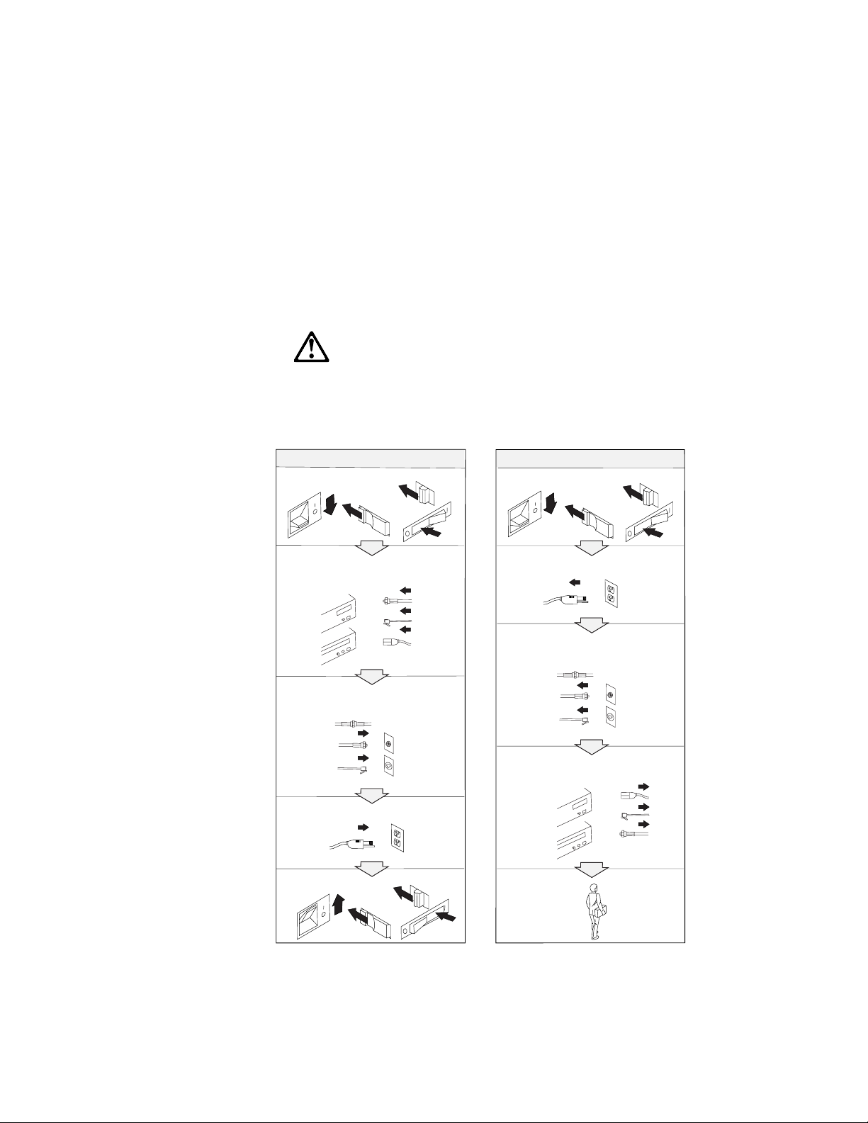
DANGER:
Electrical current from power, telephone, and communication
cable is hazardous. To avoid shock hazard, connect and
disconnect cables as shown below when installing, moving, or
opening the covers of this product or attached the devices.
The power cord must be used with a properly grounded outlet.
To Connect
Turn everything OFF.
First, attach all cables to devices.
Attach the signal cables to
receptacles.
Attach the power cord to an outlet.
To Disconnect
Turn everything OFF.
First, remove the power cord from
the outlet.
Remove signal cables from
receptacles.
Remove all cables from devices.
Turn the device ON.
Note: In the U.K., by law, the
telephone line cable must be
connected after the power cord.
Note: In the U.K., by law, the
power cord must be disconnected
after the telephone line cable.
viii IBM ThinkPad SelectaDock II User's Guide
Page 12

About This Book
This book contains information you need when you use the IBM
ThinkPad SelectaDock II docking station. It is organized into the
following chapters and appendixes:
Chapter 1, “Introduction,” introduces the features of the
SelectaDock II docking station.
Chapter 2, “Using the SelectaDock System,” provides the
procedures for setting up the SelectaDock II docking station,
modes of operation, configuration information, and information
about docking and undocking the computer to SelectaDock
system.
Chapter 3, “Installing and Removing Options,” describes how
to install and remove options.
Chapter 4, “Using the Security Features,” describes how you
can protect the SelectaDock system against unauthorized use and
theft.
Chapter 5, “Setting Up for Sharing a SelectaDock System,”
describes how to set up a system for multiple users to share the
SelectaDock system.
Chapter 6, “Using the SCSI Controller,” provides information
about configuring for and using the SCSI controller.
Chapter 7, “Solving Problems,” describes how you can isolate
and resolve SelectaDock II problems.
Appendix A, “Tips, Hints, and Limitations,” provides tips, hints,
and limitations that help you use a computer in the SelectaDock II
environment.
Appendix B, “Using the SCSI Support Software,” provides
information about the installation and use of the SCSI device
drivers and the SCSI diagnostics utility program.
Appendix C, “Specifications,” provides the specifications
associated with the SelectaDock II docking station, as well as the
power cords part numbers.
Appendix D, “Product Warranty, Notices, and Statements,”
contains the warranty statement for the SelectaDock II docking
station, notices, trademarks, the FCC statement, the CDCC
statement, and the EC directive conformance statement.
Copyright IBM Corp. 1996 ix
Page 13

x IBM ThinkPad SelectaDock II User's Guide
Page 14

Chapter 1. Introduction
This chapter contains:
Standard Features . . . . . . . . . . . . . . . . . . . . . . . . . . . . 4
Unpacking the Box ............................ 5
Locating the Features .......................... 6
Front View . . . . . . . . . . . . . . . . . . . . . . . . . . . . . . . 6
Side View . . . . . . . . . . . . . . . . . . . . . . . . . . . . . . . . 8
Rear View (Rear and Connector Covers Removed) ....... 9
Inner View . . . . . . . . . . . . . . . . . . . . . . . . . . . . . . 10
SelectaDock II Status Indicators ................... 11
The IBM ThinkPad SelectaDock II docking station works with the IBM
ThinkPad SelectaDock Base Model I to provide a complete docking
system for IBM ThinkPad 760E series computers.
Important
1. The SelectaDock II docking station supports only PCI bus
computers. It does not support ISA bus computers, even
though the SelectaDock Base Model I supports both PCI and
ISA bus computers. If you try to dock an unsupported
computer to the SelectaDock system, you will be alerted by the
Attention indicator and a series of beeps. If you try to hot- or
warm-dock an unsupported computer to the SelectaDock
system, the system will shut down automatically.
2. Make sure that you are using the latest system ROM version
in the ThinkPad system. See “Setting Up Your ThinkPad
System” on page 14.
Copyright IBM Corp. 1996 1
Page 15
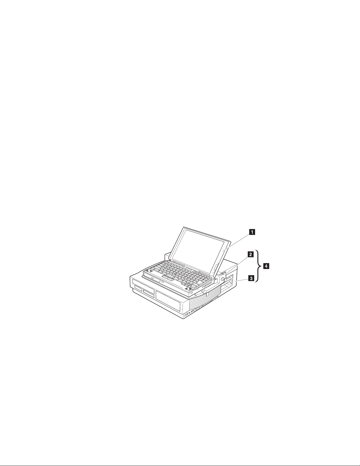
You need each of the following:
ThinkPad 760E series computer (hereafter called the
1 )
SelectaDock Base Model I (hereafter called the
SelectaDock base
2 )
SelectaDock II docking station (hereafter called the
3 )
SelectaDock Docking System (hereafter called the
system
4 ), consisting of the SelectaDock base plus the docking
SelectaDock
station.
computer
docking station
The
SelectaDock system
4 represents a single stationary unit to
which your computer is attached. In this guide, attaching or detaching
your computer to or from the SelectaDock system is called
undocking
. You dock or undock your computer to the SelectaDock
docking
system.
By installing the SelectaDock system, you greatly increase the
expandability of your computer.
The SelectaDock system's easy-to-use design also enables you to
dock or undock while the computer is powered on (hot docking and
undocking) with operating system support.
IBM ThinkPad SelectaDock II User's Guide
2
or
Page 16

Another highlight of the SelectaDock system is its strong security
features that protect every removable device in the system, including
the SelectaDock system itself, from theft. You can also use a hard
disk password on the drive installed in the docking station.
The docking station is also equipped with the UltraBay. You can
easily install an UltraBay-compatible CD-ROM drive, a diskette drive,
or up to two hard disk drives into the UltraBay.
Chapter 1. Introduction 3
Page 17

Standard Features
The following table summarizes the standard features of the
SelectaDock system:.
Audio features Audio line-out jack
Speaker-in jack
Headphone jack
Stereo speakers
Security features Security key lock
PCMCIA card (PC Card) lock
MicroSaver lock (with the SelectaDock Base Model I)
Multiuser support security
Cable management
features
Desktop-equivalent
features
With the SelectaDock Base Model I:
A mouse/pointing device connector
A keyboard/numeric keypad connector
An external diskette drive connector
A parallel connector
A serial connector
An external monitor connector
A MIDI/joystick port (sometimes called a game port)
Two full-size PCI/ISA adapter card shared slots
One half-size PCI slot
An UltraBay tray or a 1-inch-high bay
A half-height bay
An external SCSI-2 device connector
Two PCMCIA slots
4 IBM ThinkPad SelectaDock II User's Guide
Page 18
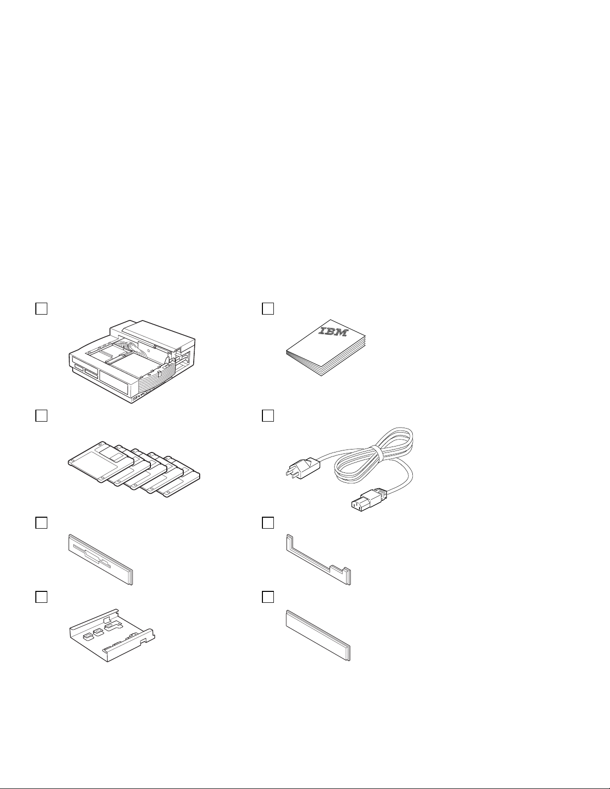
Unpacking the Box
When you unpack your docking station, check to be sure that you
have the following items. If any item is missing or damaged, call IBM
or your point of purchase.
SelectaDock II User's guide
5 diskettes Power cord
UltraBay bezel for diskette drive UltraBay bezel for CD-ROM drive
1-inch bay tray 1-inch-high blank bezel
Chapter 1. Introduction 5
Page 19
Locating the Features
This section identifies the features for the docking station. Symbols
for connectors are printed near each connector for easy identification.
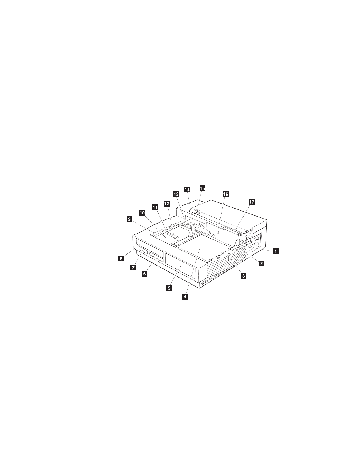
Front View
1 The multiuser lock enables multiple users
to share the SelectaDock system while
maintaining security. For more information,
see “Setup Procedure” on page 75.
2 The PC Card lock protects PC Cards from
being removed. For more information, see
“Installing or Removing a PC Card” on
page 59.
3 You can slide the SelectaDock base lock
to hold the SelectaDock base in position. For
more information, see “Attaching or Removing
the SelectaDock Base to or from the Docking
Station” on page 18.
6
IBM ThinkPad SelectaDock II User's Guide
4 The half-height drive space
accommodates drives such as an IDE drive or
a SCSI drive. For more information, see
“Installing or Removing a Drive in the
Half-Height Drive Space” on page 49.
5 The half-height drive space blank bezel
covers the front part of the drive space. It is
attached to your docking station when it is
shipped.
6 The status indicators indicate the current
status of the docking station. For more
information, see “SelectaDock II Status
Indicators” on page 11.
Page 20

7 The UltraBay eject hole is where you put
your fingers in to pull out the UltraBay tray.
For more information, see “Installing or
Removing a Drive in the UltraBay Tray” on
page 35.
8 The UltraBay blank bezel is removed
when a CD-ROM or diskette drive is installed
in the UltraBay. It is attached to your docking
station when it is shipped. For more
information, see “Installing or Removing a
Drive in the UltraBay Tray” on page 35.
9 The attaching guides are where the
SelectaDock base slits are inserted for
attaching. For more information, see
“Attaching or Removing the SelectaDock Base
to or from the Docking Station” on page 18.
1 The UltraBay tray is the tray on which
the UltraBay devices are attached. For more
information, see “Installing or Removing a
Drive in the UltraBay Tray” on page 35.
11 The UltraBay connector connects a
CD-ROM drive or a diskette drive. For more
information, see “Installing or Removing a
Drive in the UltraBay Tray” on page 35.
12 The UltraBay front HDD connector
connects a hard disk drive. It is located in the
front part of the UltraBay. For more
information, see “Installing or Removing a
Drive in the UltraBay Tray” on page 35.
13 The UltraBay back HDD connector
connects a hard disk drive. It is located in the
back part of the UltraBay. For more
information, see “Installing or Removing a
Drive in the UltraBay Tray” on page 35.
14 The UltraBay lock holds the UltraBay
tray to the docking station For more
information, see “Installing or Removing a
Drive in the 1-Inch-High Drive Space” on
page 44.
15 The MicroSaver lock hole is where you
can set the MicroSaver lock. For more
information, see “Securing the SelectaDock
Docking System with the MicroSaver Lock” on
page 72.
16 The feature jumpers enable or disable
the joystick feature by jumper blocks. For
more information, see “Using the MIDI/Joystick
Port” on page 61.
17 The SelectaDock base connector is a
system interface that connects the
SelectaDock base. For more information, see
“Attaching or Removing the SelectaDock Base
to or from the Docking Station” on page 18.
Chapter 1. Introduction 7
Page 21
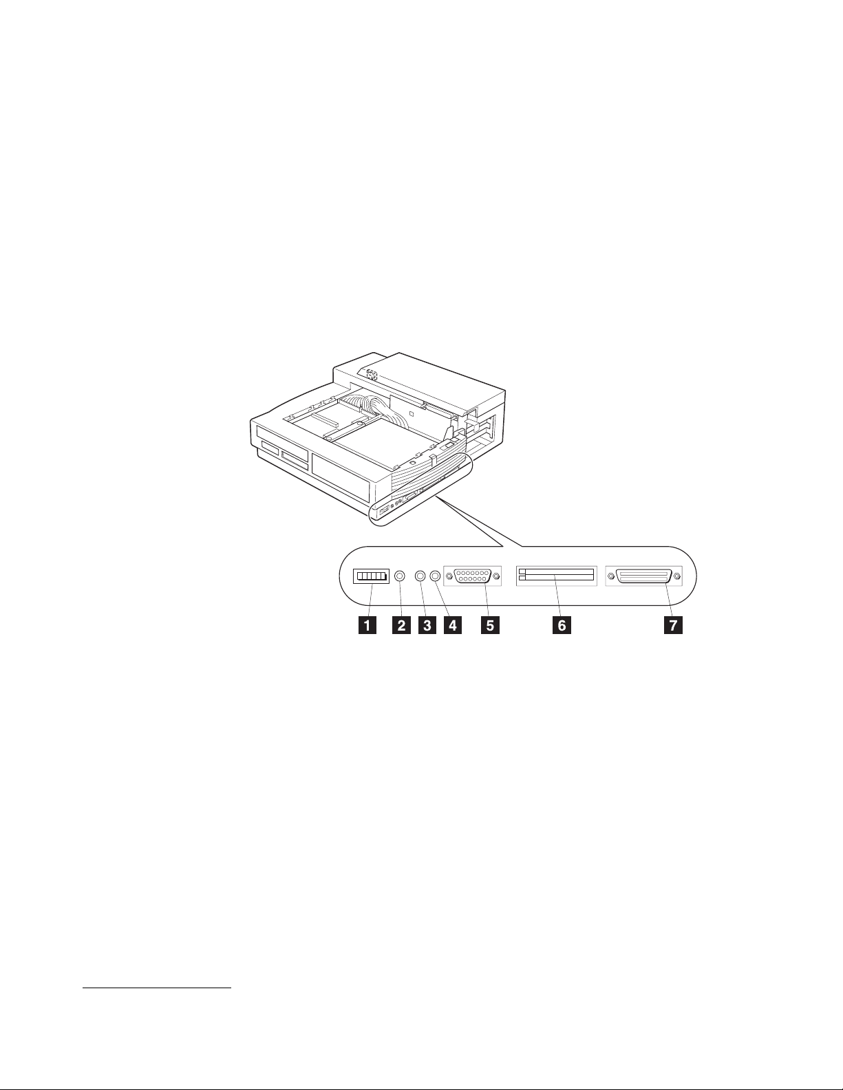
Side View
1 The volume knob is where you can adjust
the volume of the stereo sound.
2 The headphone jack is where you can
plug in a headphone.
3 The line-out jack provides audio stereo
output, and is where an external audio
equipment line-in can be plugged.
4 The speaker-in jack
*
provides audio stereo
input, and is where an external audio
equipment line-out can be plugged. This
signal is mixed internally with UltraBay
CD-ROM audio and with the audio sent from
your computer.
*
This speaker-in jack is for the speakers in the SelectaDock system, not for the speakers in your computer.
5 The MIDI/joystick port is where you
connect the MIDI/joystick cable. For more
information, see “Using the MIDI/Joystick Port”
on page 61.
6 The PCMCIA slots are where you can
insert 68-pin, credit-card-size PC Cards of the
same specifications as the computer's
PCMCIA slots. For more information, see
“Installing or Removing a PC Card” on
page 59.
7 The SCSI connector connects a SCSI
(Small Computer System Interface)-2 drive
cable. For more information, see “Connecting
External SCSI Devices” on page 63.
8 IBM ThinkPad SelectaDock II User's Guide
Page 22
Rear View (Rear and Connector Covers Removed)
1 The power connector connects the ac
power cord.
2 The PCI adapter card connectors is
where optional PCI adapter cards can be
installed (see Note). For more information,
see “Installing or Removing the PCI/ISA
Adapter Card” on page 54.
To remove the rear cover, see step 7 in “Installing an Adapter Card” on page 54.
3 The ISA adapter card connectors is
where optional ISA adapter cards can be
installed (see Note). For more information,
see “Installing or Removing the PCI/ISA
Adapter Card” on page 54.
Note:
Two adapter cards, either full ISA or
PCI, and an additional half PCI card,
can be installed at the same time.
Chapter 1. Introduction
9
Page 23
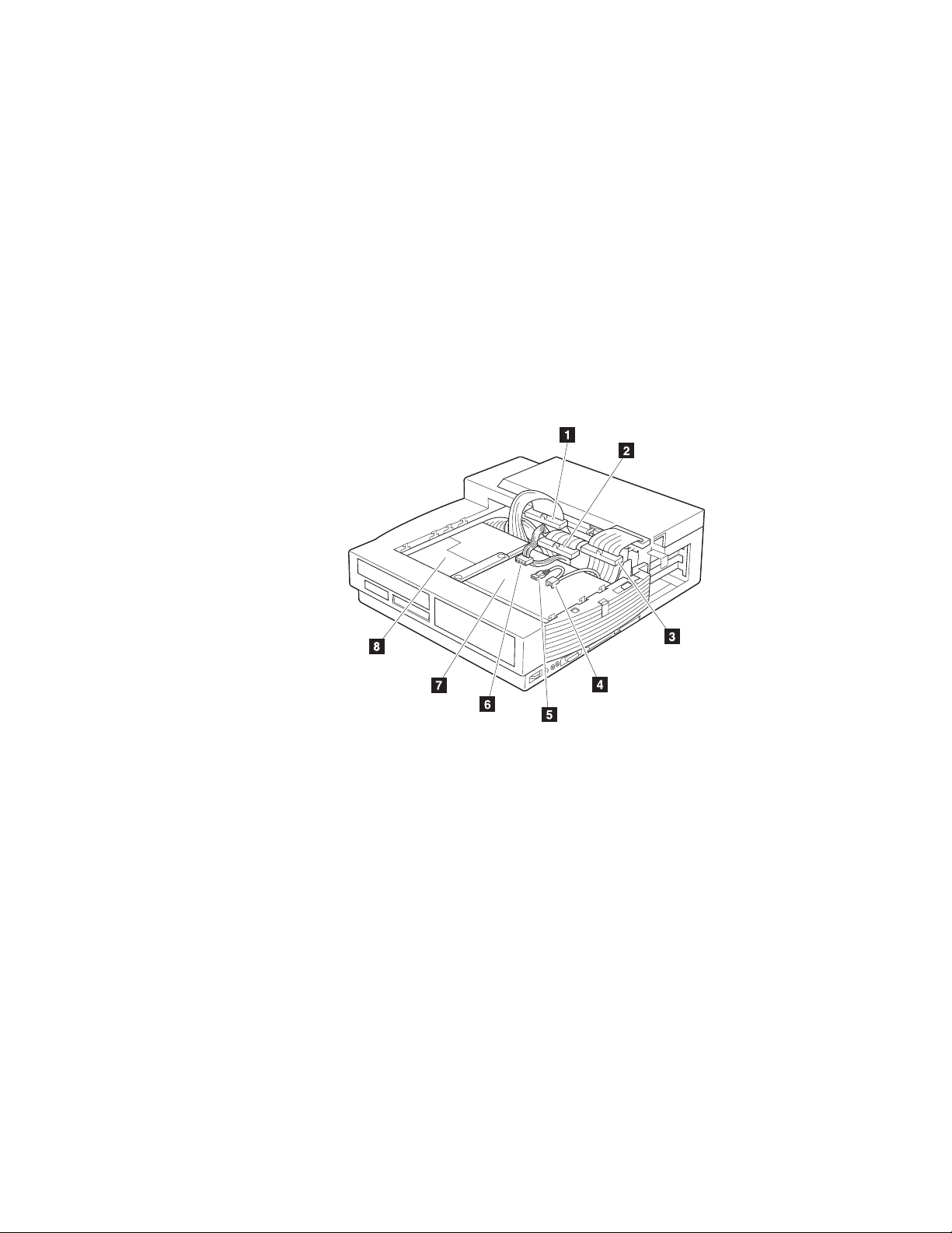
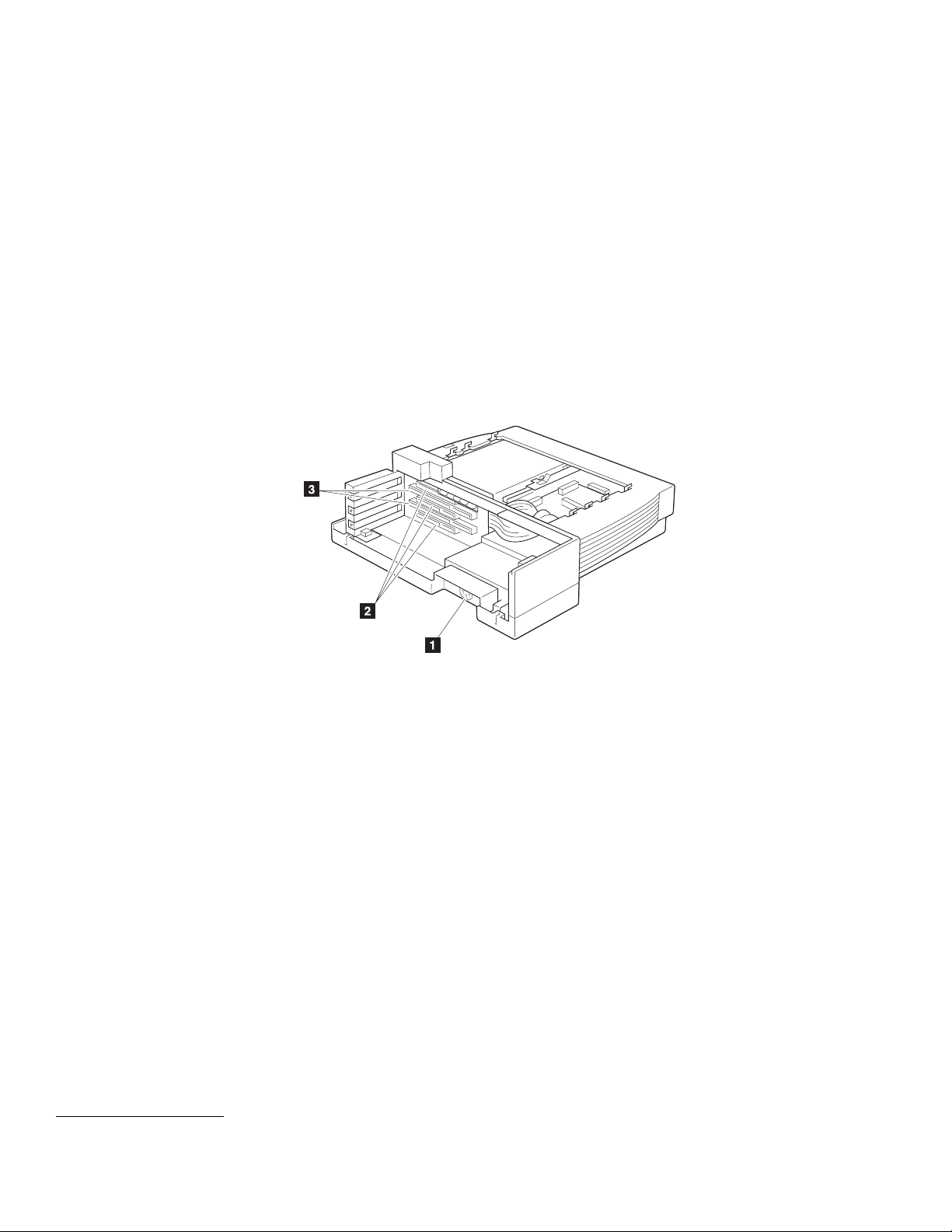
Inner View
1 The half-height drive space IDE
connector is used to connect an IDE drive in
the half-height drive space. For more
information, see “Installing or Removing a
Drive in the Half-Height Drive Space” on
page 49.
2 The half-height drive space SCSI
connector is used to connect a SCSI device
in the half-height drive space. For more
information, see “Installing or Removing a
Drive in the Half-Height Drive Space” on
page 49.
3 The 1-inch-high drive space SCSI
connector is used to connect a SCSI device
in the 1-inch-high drive space. For more
information, see “Installing or Removing a
Drive in the 1-Inch-High Drive Space” on
page 44.
10
IBM ThinkPad SelectaDock II User's Guide
4 , 5 Either one of the audio device
connectors is used to connect an audio
device installed in the docking station.
6 You can use the power connector to
connect a device to the docking station.
7 The half-height drive space is where you
can install a half-height drive. For more
information, see “Installing or Removing a
Drive in the Half-Height Drive Space” on
page 49.
8 The 1-inch-high drive space is where you
can install a 1-inch-high drive. For more
information, see “Installing or Removing a
Drive in the 1-Inch-High Drive Space” on
page 44.
Page 24
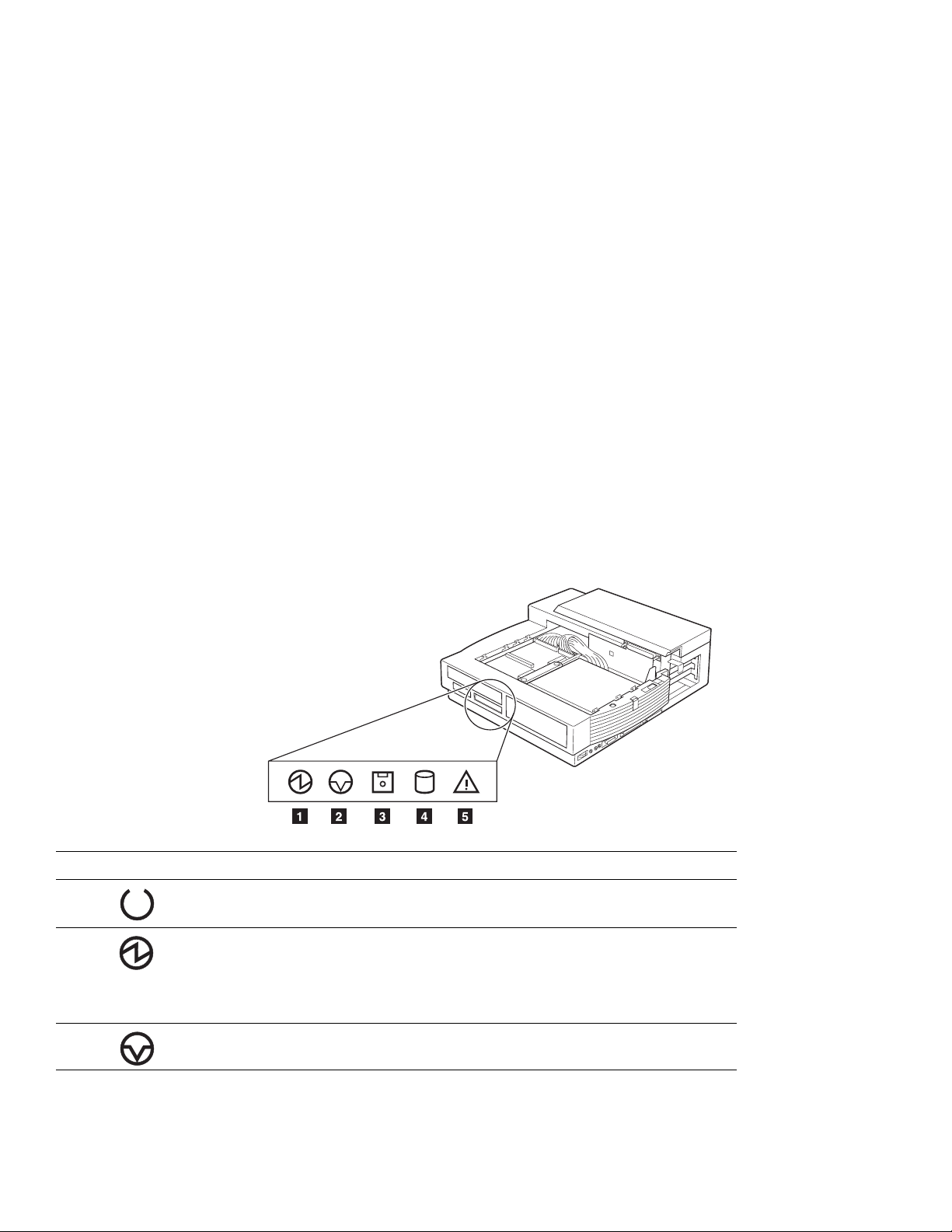
SelectaDock II Status Indicators
The status indicators show the current status of the system by their on
or off states or by blinking.
The following figure and table show the name and meaning of each
status indicator.
Note:
Symbol Indicator Name Lit Meaning
1 Docked On The computer is correctly docked with the
1 Power On On The computer power is turned on.
The symbol and indicator name of the status indicator 1
changes between Docked and Power On, as shown in the
table. The example in the figure shows the status indicator 1
when the computer power is turned on.
docking station.
Note:
2 Suspend Mode On The computer is in suspend mode.
Chapter 1. Introduction 11
The “Docked” indicator changes to
the “Power-On” indicator when the
computer power is turned on.
Page 25
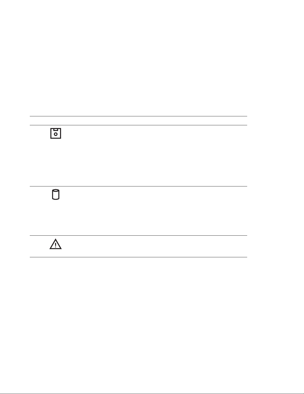
Symbol Indicator Name Lit Meaning
3 Diskette Drive
in Use
4 Docking Station
Hard Disk in Use
5 Attention On
On The diskette drive in the computer is being
On The hard disk drive in the docking station is
or
blinking
used.
Notes:
1. When an external diskette drive is used,
the indicator on the IBM ThinkPad FDD
External Attachment Kit turns on.
2. When a diskette drive in the UltraBay is
used, the indicator on the drive turns on.
accessed.
Note:
Turns on or blinks to alert users about an
operation. For more information, see
“Attention Indicator” on page 90.
This indicator is not lit if the hard disk
in the docking station is not
accessed, regardless of whether the
hard disk drive in your computer is
accessed.
12 IBM ThinkPad SelectaDock II User's Guide
Page 26

Chapter 2. Using the SelectaDock System
This chapter describes how to set up and use the SelectaDock
system.
This chapter contains:
Setting Up Your ThinkPad System
Setting Up ROM ........................... 14
Setting Up the ThinkPad Features Program ........... 14
Installing the ThinkPad Features Program for OS/2 Warp . 14
Installing the ThinkPad Features Program for DOS ..... 15
Installing the ThinkPad Features Program for Windows 3.11 16
Installing the ThinkPad Features Program for Windows 95 17
Attaching or Removing the SelectaDock Base to or from the
Docking Station . . . . . . . . . . . . . . . . . . . . . . . . . . . . 18
Attaching the SelectaDock Base to the Docking Station .... 18
Removing the SelectaDock Base from the Docking Station .. 21
Modes of Operation .......................... 23
Docking and Undocking Computer Modes ............ 23
Entering and Resuming or Waking Up from Computer Modes 24
Configuring the Computer for Docking and Undocking ...... 25
Cold Docking and Undocking ..................... 26
Cold Docking . . . . . . . . . . . . . . . . . . . . . . . . . . . . . 26
Cold Undocking . . . . . . . . . . . . . . . . . . . . . . . . . . . 27
Hot or Warm Docking and Undocking ................ 28
Hot or Warm Docking for Windows 95 .............. 29
Docking . . . . . . . . . . . . . . . . . . . . . . . . . . . . . . 29
Undocking . . . . . . . . . . . . . . . . . . . . . . . . . . . . . 29
Hot or Warm Docking for DOS or Windows 3.1 ......... 29
Docking . . . . . . . . . . . . . . . . . . . . . . . . . . . . . . 29
Undocking . . . . . . . . . . . . . . . . . . . . . . . . . . . . . 31
Limitation for Hot or Warm Docking and Undocking for DOS or
Windows 3.1 . . . . . . . . . . . . . . . . . . . . . . . . . . . . 32
.................. 14
Copyright IBM Corp. 1996 13
Page 27

Setting Up Your ThinkPad System
Setting Up ROM
When you use your SelectaDock system with your ThinkPad system,
you should make sure you are using the latest system ROM version in
the ThinkPad system. Do the following:
1. Make sure of the following:
Your computer is turned off.
Your computer is undocked.
The battery in your computer is fully charged.
Your computer is connected to ac power through the AC
adapter.
2. Insert the System Program Service Diskette into the diskette drive
of your computer.
3. Turn on the power.
4. Select “Update System Program.” Information is displayed that
indicates whether your system ROM version is the latest.
If your system ROM version is the latest, you do not need to update
the ROM in your computer. In this case, quit the program.
If your system ROM version is not the latest, follow the instructions on
the screen to update your computer's system ROM.
Notes:
1. If you update the system ROM, make sure not to turn off the
system power during the update.
2. Make sure to initialize CMOS after you update system ROM.
Since the values set by ThinkPad Features are cleared when you
initialize CMOS, make sure to reset those values.
Setting Up the ThinkPad Features Program
Installing the ThinkPad Features Program for OS/2 Warp
To install the ThinkPad Features program:
1
Start OS/2.
IBM ThinkPad SelectaDock II User's Guide
14
Page 28

2
Insert the Utility Diskette (OS/2) into the diskette drive.
Note:
3
Install the ThinkPad System Management device driver:
4
Open the OS/2 screen command prompt.
5
Go to the A: prompt and type INSTALL2; then press Enter.
Follow the instructions on the screen.
6
Install the Windows ThinkPad Features program for the
WIN-OS/2 session:
Use the latest version of the diskette, the one with the
SelectaDock II docking station or the one with the
ThinkPad system.
a) Open OS/2 System and then System Setup.
b) Select Device Driver Install.
c) Click on the Install... button.
d) Click on ThinkPad System Management Device Driver;
then click on OK.
a) Exit the OS/2 screen; then open the WIN-OS/2 full screen.
b) Follow the instructions in “Installing the ThinkPad Features
Program for Windows 3.11” on page 16.
7
Install the PS2 command programs in the DOS ThinkPad
Features program.
a) Exit the WIN-OS/2 full screen; then open the DOS full
screen.
b) Follow the instructions in “Installing the ThinkPad Features
Program for DOS.”
Installing the ThinkPad Features Program for DOS
To install the ThinkPad Features program:
1
Start DOS.
2
Insert the Utility Diskette (DOS, Personalization) into the diskette
drive.
Chapter 2. Using the SelectaDock System 15
Page 29
3
Type A:UINSTALL at the DOS prompt and press Enter.
The following screen appears:
Installation Options
Installation Source Drive
Type the SOURCE drive letter (A-Z). When you install a program, the
SOURCE drive letter is the location you are installing FROM.
Source Drive ...
Enter F1=Help F3=Exit
4
Press Enter.
5
Select Install DOS ThinkPad Features at the Installation
Options screen; then follow the instructions on the screen.
Installing the ThinkPad Features Program for Windows 3.11
If you are going to use Windows, install the ThinkPad Features
program for DOS first (see page 15); then do the following to install
the ThinkPad Features program for Windows 3.11:
1
Turn on the computer and start Windows.
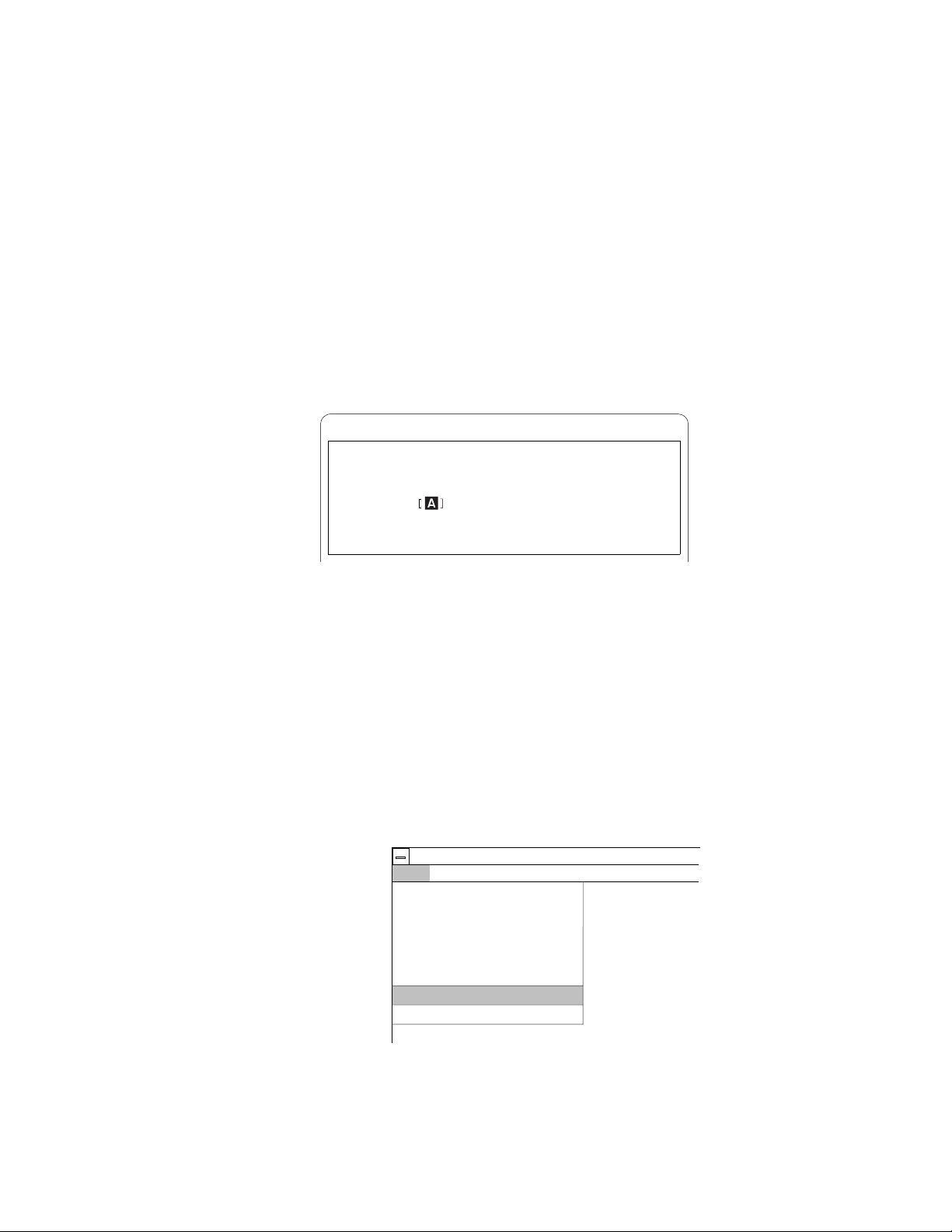
2
Select File from the Program Manager window; then select
Run... from the pull-down menu.
Program Manager
Options
File
New...
Open
Move...
Copy...
Delete...
Properties...
Run...
Exit Windows...
3
Insert the Utility Diskette (Windows 3.1 / Windows 95) into the
Windows
Enter
F7
F8
Del
Alt+Enter
Help
diskette drive.
4
Type A:\INSTALLW and press Enter.
IBM ThinkPad SelectaDock II User's Guide
16
Page 30

5
Follow the instructions on the screen.
Default choices are already highlighted at the Installation Options
screen.
Installing the ThinkPad Features Program for Windows 95
The ThinkPad Features program
If you installed Windows95 on a computer in which DOS/Windows
and its ThinkPad Features program were already installed,
ThinkPad Features program is migrated into the “Start Menu” of
Windows 95 automatically.
To start the ThinkPad Features program:
1
Click on Start.
2
Select Programs; then select ThinkPad.
3
Select ThinkPad Features.
for Windows
works on Windows 95.
the
If you installed Windows 95 on a blank hard disk
not installed the ThinkPad Features program:
Install the ThinkPad Features program using the Utility Diskette
supplied with the computer:
1
Insert ThinkPad Utility Diskette (Windows 3.1 / Windows 95)
into the diskette drive.
2
Click on Start.
3
Click on Run....
4
Type a:INSTALLW; then click on OK.
5
Follow the instructions on the screen.
or
if you have
Chapter 2. Using the SelectaDock System 17
Page 31

Attaching or Removing the SelectaDock Base to or from the Docking Station
This procedure describes how to attach or remove the SelectaDock
base to or from the docking station.
If you are going to install the options described in Chapter 3, you
must install them before attaching SelectaDock base to the docking
station.
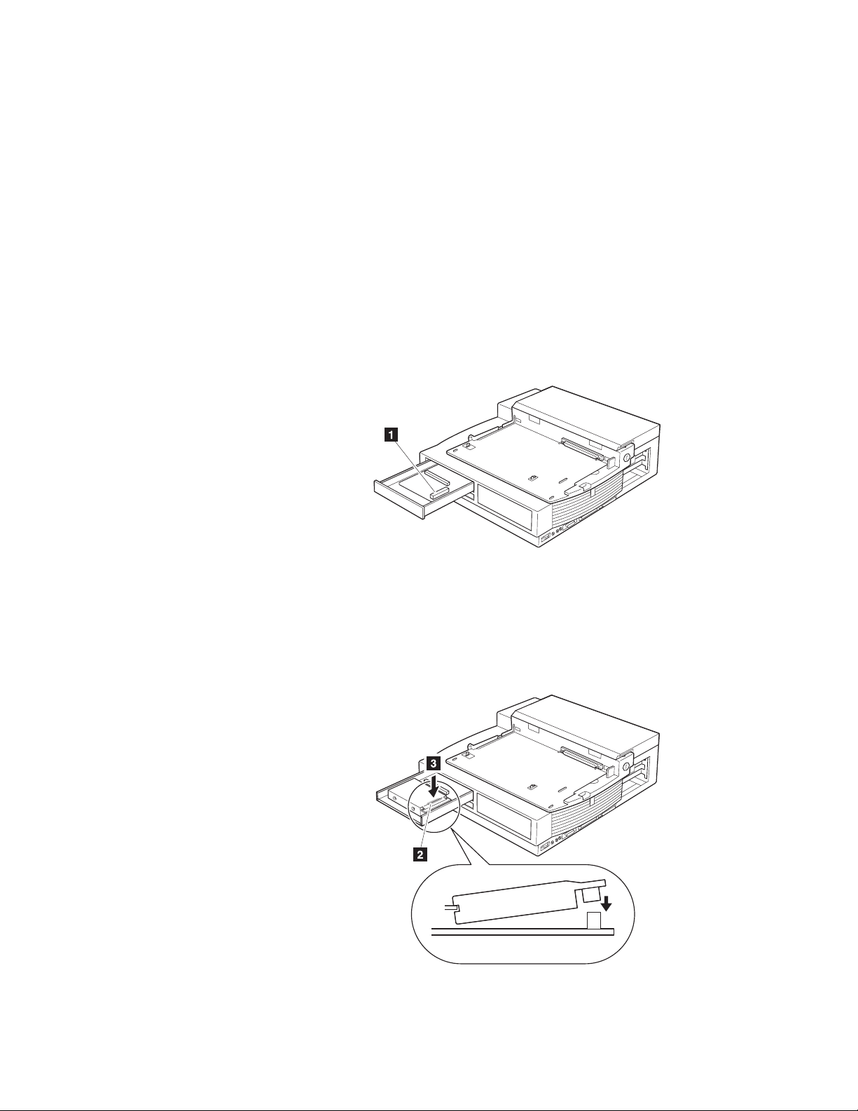
Attaching the SelectaDock Base to the Docking Station
To attach the SelectaDock base to the docking station, do the
following:
1
Remove the connector cover 1 from the docking station by
pulling out the hooks from the holes on the cover. Lift up the
cover 2 .
2
Hook the wire 1 into the hole.
18
IBM ThinkPad SelectaDock II User's Guide
Page 32

Note:
3
Make sure the security key on the SelectaDock base is set to
unlocked.
4
Place your docking station in an appropriate work space. If you
want to install a drive or an adapter now, refer to Chapter 3.
5
Identify the docking guides 1 at each side of the docking
station.
Make sure the cables are well bundled inside to place the
SelectaDock base in the docking station.
Chapter 2. Using the SelectaDock System 19
Page 33

6
Place the SelectaDock base in the docking station, aligning the
guides to the slits on the SelectaDock base while keeping a gap
2 of about 12 mm (0.5 in.). In this illustration, place the
SelectaDock base in the docking station so that the triangle on
the docking station faces the upper (white) triangle on the
SelectaDock base. Make sure that the SelectaDock base is fully
seated and that there is no side-to-side movement within the
docking station
7
Slide the SelectaDock base 3 forward carefully until it is fully
inserted. In this illustration, slide the base until its lower (black)
triangle faces the triangle on the docking station.
8
Raise the SelectaDock base lock 4 until it latches. This lock
plate fastens the right side of the SelectaDock base.
20 IBM ThinkPad SelectaDock II User's Guide
Page 34

9
Ensure a good connection by eliminating any gap between the
connectors as shown. If you see a gap, close it by pressing
firmly on the areas indicated by the two arrows until the triangles
on the SelectaDock base and the docking station face each
other.
10
Attach the connector cover to the docking station by inserting the
hooks into the holes on the cover.
This completes the attachment of the SelectaDock base to the docking
station.
Removing the SelectaDock Base from the Docking Station
To remove the SelectaDock base from the docking station, do the
following:
1
Remove the connector cover from the docking station by pulling
out the hooks from the holes on the cover.
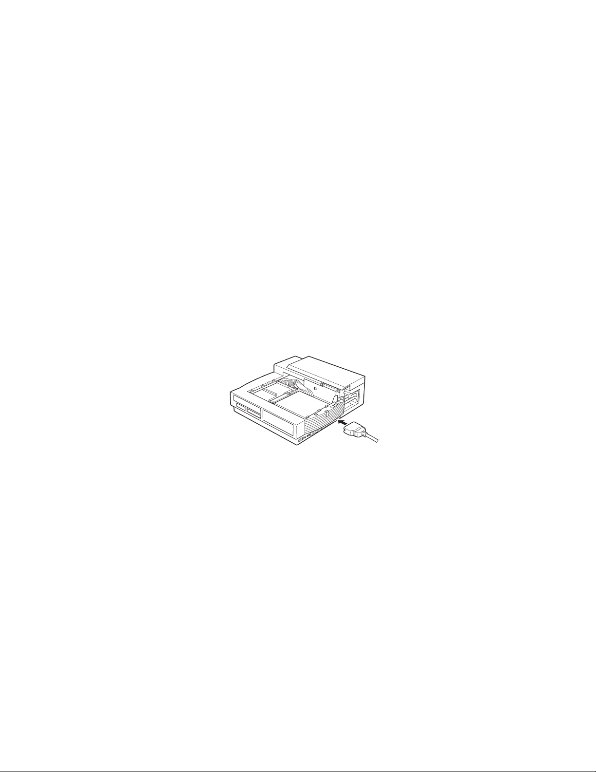
2
Detach all peripheral cables from the rear of the SelectaDock
base. Detach the ac power cord from the docking station.
3
Make sure the security key is set to the unlock position 1 .
4
Slide down the SelectaDock base lock to release the
SelectaDock base.
Chapter 2. Using the SelectaDock System 21
Page 35

5
Using the finger holes, pull the SelectaDock base toward you
horizontally until it is fully released 2 , and then lift it out of the
docking station.
6
Attach the connector cover to the docking station by inserting the
hooks into the holes on the cover.
This completes the removal of the SelectaDock base from the docking
station.
22 IBM ThinkPad SelectaDock II User's Guide
Page 36

Modes of Operation
You can now dock or undock your computer during operation,
suspend, or standby mode (when the operating system you are using
supports hot or warm docking) in addition to the normal power-off
state.
In this manual, the docking and undocking operations are called:
Hot docking or undocking
Docking or undocking while the computer is operating
or in standby mode.
Warm docking or undocking
Docking or undocking while the computer is in
suspend mode.
Cold docking or undocking
Docking or undocking after the computer is powered
off.
Docking and Undocking Computer Modes
The mode of the computer does not change during docking or
undocking operations.
Chapter 2. Using the SelectaDock System 23
Page 37

Entering and Resuming or Waking Up from Computer Modes
This table summarizes the ability of the computer docked in the
SelectaDock system to enter and resume or wake up from each
mode.
Attempt to Enter Can the Computer Enter This
Mode?
Suspend mode ( )
Standby mode ( )
Hibernation mode
( )
Yes (see Note 1) A power-on password is
Yes No
Yes (see Note 2) A power-on password is
Notes:
1. There are some limitations to entering suspend mode depending
on the operating system you are using. For example, your
computer cannot enter suspend mode when it is running on
Operating System/2 (OS/2) or when a SCSI device driver is
installed.
2. Do not dock or undock while the ThinkPad is in hibernation mode.
If you do so, the ThinkPad will reboot.
Is a Password Needed to
Resume or Wake Up?
needed if you have set one.
needed if you have set one.
24
IBM ThinkPad SelectaDock II User's Guide
Page 38

Configuring the Computer for Docking and Undocking
To use the computer with the SelectaDock system, you need to
specially configure the computer and the docking station:
When you first set up the computer and the docking station, dock
the computer in cold mode.
Assigning the computer resources to the devices attached to the
SelectaDock system by using the ThinkPad Features Program
installed in the computer. You must do this procedure whenever
the computer is docked to the SelectaDock system to avoid
resource conflict problem.
Installing necessary device drivers for devices attached to the
SelectaDock system into the operating system you are using.
The assignment of resources and the installation of device
drivers are always required when you add new hardware or you
specify a new software setting in the SelectaDock system.
If you are using IBM DOS or Microsoft Windows 3.1, and if you
want to make hot and warm docking possible, the following setup
is needed.
Activating the Docking Control program on the computer for
enabling hot or warm docking and undocking.
Detailed instructions on these setups are described in “Hot or Warm
Docking and Undocking” on page 28.
Chapter 2. Using the SelectaDock System 25
Page 39

Cold Docking and Undocking
This procedure describes how to dock and undock the computer to or
from the SelectaDock system.
The computer you are going to dock must be a 760E series or PCI
bus architecture computer. If you accidentally dock an ISA bus
computer, the docking station warns you with the Attention indicator
and beeps.
Cold Docking
To dock your computer to the SelectaDock system in cold mode, do
the following:
1
Turn off your computer.
2
Undock your computer from the SelectaDock base, if it is
docked.
Note:
3
Disconnect all peripheral devices cables from your computer.
4
If you want to protect the drives under the keyboard after
docking, set the lock on your computer. See the computer
user's guide for the procedure.
5
Plug the power cord in the power connector of the docking
station, and then into an electrical outlet.
6
Dock your computer to the SelectaDock system. If you are not
familiar with the computer docking procedure, See the
SelectaDock Base Model I Setup Guide
When performing these steps, if you need information
pertaining to the SelectaDock base, see the
Base Model I Setup Guide
.
.
SelectaDock
26
IBM ThinkPad SelectaDock II User's Guide
Page 40

7
Check that the Docked indicator 3 is lit.
8
Turn the security key to the locked position 2 if you want to
secure the devices. You can then remove the key.
9
Turn on your computer, using its power switch 1 . The
SelectaDock system powers on automatically; then the computer
starts to boot. Check that the Power On indicator on the
status indicator of the docking station is lit.
Note:
This completes the procedure for cold docking.
To set up optional devices, see Chapter 3.
Cold Undocking
This procedure describes how to undock your computer from the
SelectaDock system when the computer power is turned off by the
power switch (cold undocking).
1
Turn off your computer.
2
Turn the security key to the eject position to eject the computer.
3
Grasp the computer and lift it out.
This completes the procedure for cold undocking.
Chapter 2. Using the SelectaDock System 27
Page 41

Hot or Warm Docking and Undocking
This procedure describes how to dock and undock your computer to
and from the SelectaDock system with hot or warm docking and
undocking. Hot and warm docking means the computer is running or
in standby mode (hot docking and undocking), or in suspend mode
(warm docking and undocking).
The capability of hot and warm docking depends on the operating
system you are using:
Windows 95 DOS or Windows
3.1
Hot or warm
docking and
undocking is
supported.
Note:
To see whether your operating system supports hot and warm
docking, refer to the user's guide of your operating system.
Note:
To use hot or warm docking, you must cold-dock your computer to
the SelectaDock system at least once beforehand.
See “For
Windows
95” on
page 115.
If you are using DOS or Windows 3.1, the resolution of the
LCD of your computer must be the same as the external
display. Otherwise, the LCD will blank out when you use hot
or warm undocking.
Important
Hot or warm
docking and
undocking is
supported with the
Docking Control
Program.
OS/2 Warp and
Later or Windows
NT
Hot or warm
docking and
undocking is not
supported.
28 IBM ThinkPad SelectaDock II User's Guide
Page 42

Hot or Warm Docking for Windows 95
Docking
In the boot process after cold docking, the operating system tries to
set a configuration including the devices installed in the SelectaDock
system. After the configuration has been set up, you can dock your
computer in hot or warm mode. The SelectaDock system devices
immediately become available to your computer.
Undocking
To use hot or warm undocking for Windows 95, do the following:
1
There are two ways to eject your computer from the docking
station:
Select Eject in the Start Menu.
Turn the security key to the eject position and release the
key.
An eject request is made to the operating system.
If the operating system judges the request can be honored,
the computer ejects.
Considerable time may be required to complete the eject
process. To see if the eject process has completed, click on
the start icon. If “eject” appears, undocking is still in
progress. If not, the eject process has completed.
If the operating system rejects the request, messages
appear on the screen explaining the reason. In this case,
use cold undocking.
2
When you hear the beep sound, turn the security key to the eject
position again to eject the computer from the SelectaDock
system.
Hot or Warm Docking for DOS or Windows 3.1
Docking
To use hot or warm docking for DOS or Windows 3.1, do the
following:
Chapter 2. Using the SelectaDock System 29
Page 43

1
Make sure that the Docking Control program has been
activated to enable hot docking. The Docking Control program
can be installed from the utility diskette shipped with your
docking station, if you need to reinstall the program. Also, you
need to update the ThinkPad Utility Program to enable hot or
warm docking.
There are two options in Docking Control:
Hot/Warm docking/undocking (default: disable) and
Beep when docking/undocking (default: enable).
For Windows 3.1, do the following:
To enable the Hot/Warm docking/undocking option:
a) Select the Docking Control icon.
b) Select Enable hot/warm dock/undock in the menu that
appears.
To disable the Beep when docking/undocking option:
a) Select the Docking Control icon.
b) Select Disable beep when docking/undocking in the
menu that appears.
For DOS, do the following:
To enable hot or warm docking, type at the DOS command
prompt:
DOCK2 /ED
To disable beeping when docking, type at the DOS
command prompt:
DOCK2 /DB
2
Make sure that the SelectaDock base is attached to the docking
station and the security key is set to unlock.
3
Make sure that the power cord is connected to the docking
station.
4
Make sure that the AC Adapter cord is disconnected from your
computer.
5
Dock the computer to the SelectaDock system.
IBM ThinkPad SelectaDock II User's Guide
30
Page 44

The docking station power turns on automatically. You will hear
a beep (if the beep is not disabled). The Attention indicator
blinks.
6
Do the following to proceed with hot docking:
For Windows 3.1:
The Docking Control pops up a dialog box for selection.
Press the Full-Dock button to go to Fully docked. If you
want to continue in PassThru mode, press the PassThru
button.
For DOS:
At the DOS command prompt, type:
C:\THINKPAD\DOCK2
and press Enter.
If you want to continue in PassThru mode, type:
C:\THINKPAD\DOCK2 /P
and press Enter.
Note:
This completes hot or warm docking.
In these examples, the program is on the C drive.
Undocking
To use hot or warm undocking for DOS or Windows 3.1, do the
following:
1
Close all application programs that are opening the files on the
hard disk drives attached to the SelectaDock system or are
using devices that will be detached.
2
For Windows 3.1, double-click on the Docking Control icon, or
turn the security key to the eject position.
For DOS, turn the security key to the eject position.
This action activates an eject request signal to your computer,
and the computer sounds a beep if the beep is not disabled. It
resumes if it has been in suspend mode.
Chapter 2. Using the SelectaDock System 31
Page 45

Note:
3
Do one the following:
4
The system enters suspend mode and you will hear two
consecutive beep sounds. Turn the security key again to eject
the computer.
This completes hot or warm undocking.
If the system is not suspended, you can undock by using
either the UNDOCK2 command or the Docking Control
program without first turning the security key.
For Windows, the Docking Control program pops up a dialog
box. Press the Eject button.
For DOS, at a DOS command prompt, type:
C:\THINKPAD\UNDOCK2
and press Enter.
Limitation for Hot or Warm Docking and Undocking for DOS or
Windows 3.1
If you are using DOS or Windows 3.1, hot or warm docking and
undocking are not supported when a SCSI driver included in the
option diskette is loaded or when an IDE hard disk drive is installed.
IBM ThinkPad SelectaDock II User's Guide
32
Page 46

Chapter 3. Installing and Removing Options
By installing option drives, you can expand the capability of your
SelectaDock system. This chapter explains how to add or remove the
options.
To attach external drives to the SelectaDock base, see the
SelectaDock Base Model I Setup Guide
This chapter contains:
Handling Internal Options
Installing or Removing a Drive in the UltraBay Tray ........ 35
Supported Drives . . . . . . . . . . . . . . . . . . . . . . . . . . 35
Installing a Drive ........................... 35
Removing a Drive .......................... 43
Installing or Removing a Drive in the 1-Inch-High Drive Space . 44
Removing the UltraBay Tray .................... 44
Installing a Drive ........................... 45
Attaching a SCSI Device .................... 47
Removing a Drive .......................... 47
Installing or Removing a Drive in the Half-Height Drive Space .. 49
Installing a Drive ........................... 49
Removing a Drive .......................... 53
Installing or Removing the PCI/ISA Adapter Card ......... 54
Installing an Adapter Card ..................... 54
Removing an Adapter Card .................... 58
Installing or Removing a PC Card .................. 59
Plug and Play ............................ 60
Using the MIDI/Joystick Port ..................... 61
Connecting External SCSI Devices ................. 63
Releasing the Latch .......................... 64
IDE Setup . . . . . . . . . . . . . . . . . . . . . . . . . . . . . . . . 64
....................... 34
.
Copyright IBM Corp. 1996 33
Page 47

Handling Internal Options
DANGER
Before you install or remove the option, unplug the power cord.
ATTENTION
Do not open the static-protective package containing the option until
you are instructed to do so. Static electricity can damage the option.
When you are instructed to install the option, observe these
precautions as you open the static-protective package:
Touch the static-protective package containing the option to a
metallic portion of the docking station for at least 2 seconds. This
action reduces the static electricity from the package and from
your body.
Do not touch any exposed circuitry on the option.
Prevent other people from touching the option.
Limit your movement. Movement can cause static-electricity
buildup.
Always handle the option carefully and by its edges.
If you
must
put the option down after it has been removed from
the package, place the option on the static-protective package on
a level surface. Do not place the option on a metal table.
If the docking station has a dust cover over the UltraBay, remove
it.
34
IBM ThinkPad SelectaDock II User's Guide
Page 48

Installing or Removing a Drive in the UltraBay Tray
This section describes the procedures for installing or removing a
drive in the UltraBay space.
Supported Drives
Note:
You can install any of the following drives in the UltraBay. Each drive
should be compatible with the UltraBay of the 760E series computer.
Up to two IDE drives can be installed in the docking station.
ATTENTION
Only one diskette drive can be attached to the SelectaDock system at
the same time. When an external diskette drive is attached, do not
install a diskette drive in the UltraBay of the docking station. Trying to
operate with both drives can destroy diskette data.
The UltraBay tray is initially included in the docking station
when it is shipped. You can remove the UltraBay tray from the
docking station and instead use the space for a 1-inch-high
drive. To remove the UltraBay tray and use the 1-inch-high
drive space, see “Installing or Removing a Drive in the
1-Inch-High Drive Space” on page 44.
IBM ThinkPad 4X CD-ROM drive
IBM ThinkPad 6X CD-ROM drive
IBM ThinkPad diskette drive
IBM ThinkPad hard disk drive
Note:
If a noncompatible drive is installed in the UltraBay, the
Attention indicator and beeps warn you that the wrong drive is
installed.
Installing a Drive
To install a drive in the UltraBay, do the following:
1
Make sure the power is turned off.
2
If you are going to install a CD-ROM drive or diskette drive,
or if you are going to install a hard disk drive using the
Chapter 3. Installing and Removing Options 35
Page 49

UltraBay front HDD connector,
to step 3.
a) Undock the computer. See “Cold Docking and Undocking”
on page 26.
b) Remove the SelectaDock base from the docking station.
See “Removing the SelectaDock Base from the Docking
Station” on page 21.
c) Unlock the UltraBay lock knob at the back of the UltraBay by
pressing down the lock 1 . If you don't need do secure the
UltraBay tray, twist the lock 2 .
do the following. Otherwise, go
d) Pull out the UltraBay tray until it stops.
36 IBM ThinkPad SelectaDock II User's Guide
Page 50

e) Remove the blank bezel 1 .
Chapter 3. Installing and Removing Options 37
Page 51

f)
If you are going to install a CD-ROM drive or a diskette
drive,
do the following:
i. Remove the metal bracket 2 .
ii. Install the UltraBay bezel for diskette drive 3 or the
UltraBay bezel for CD-ROM drive 4 .
iii. Identify the connector for the diskette drive or CD-ROM
drive 5 .
iv. Align and insert your drive into the connector. Press the
area indicated by 6 until the drive seats firmly 7 .
IBM ThinkPad SelectaDock II User's Guide
38
Page 52

ATTENTION
To prevent damage to the drive, press only on the area
indicated by 6 .
v. When installing a CD-ROM drive or a diskette drive in
the UltraBay, hold the drive's wire hanger with the wire
hanger holder beside the UltraBay connector to ensure
enough clearance for the wire hanger.
vi. Set the drive removal handle in place.
vii. Attach the metal bracket.
viii. Push in the UltraBay tray.
ix. Attach the SelectaDock base, and then dock your
computer.
x. Go to step 4 on page 42.
CAUTION:
i. The CD-ROM drive uses a laser system. To ensure
correct use of this product, carefully read the
manual that came with the CD-ROM drive and keep
the manual for future reference. If the unit requires
maintenance, have it serviced by authorized
personnel.
ii. Use of controls, adjustments, or procedures other
than those specified may result in hazardous
radiation exposure.
iii. To prevent direct exposure to the laser beam, do not
open the enclosure.
Chapter 3. Installing and Removing Options 39
Page 53
g)
If you are going to install a hard disk drive using the
UltraBay front HDD connector,
do the following:
i. Identify the connector for the hard disk drive 1 .
ii. Align and insert your drive into the connector. Fit the
docking station onto the rear of the drive, as shown
below, before inserting the drive. Press the area
indicated by 2 until the drive seats firmly 3 .
ATTENTION
To prevent damage to the drive, press only on the area
indicated by 2 .
iii. Set the drive removal handle in place.
iv. Install the blank bezel.
IBM ThinkPad SelectaDock II User's Guide
40
Page 54

v. Push in the UltraBay tray.
vi. Attach the SelectaDock base, and then dock your
computer.
vii. Go to step 4 on page 42.
3
If you are going to install a hard disk drive using the
UltraBay back HDD connector,
a) Undock the computer. See “Cold Docking and Undocking”
on page 26.
b) Remove the SelectaDock base from the docking station.
See “Removing the SelectaDock Base from the Docking
Station” on page 21.
c) Identify the connector for the hard disk drive 1 .
do the following:.
d) Align and insert your drive into the connector. Fit the
docking station onto the rear of the drive, as shown below,
before inserting the drive. Press the area indicated by 2
until the drive seats firmly 3 .
ATTENTION
To prevent damage to the drive, press only on the area
indicated by 2 .
Chapter 3. Installing and Removing Options 41
Page 55

e) Set the drive removal handle in place.
f) Attach the SelectaDock base, and then dock your computer.
g) Go to step 4.
4
Check that the Attention indicator is not lit and no beeps are
heard.
Note:
5
Turn on the computer with the computer power switch.
6
If you installed a CD-ROM drive, install the device driver for the
CD-ROM drive by referring to the user's guide of your computer.
7
If you installed an IDE drive, see “IDE Setup” on page 64.
This completes the installation in the UltraBay.
42 IBM ThinkPad SelectaDock II User's Guide
If the Attention indicator comes on, verify that the drive
you just installed is compatible with the UltraBay or that
no more than two IDE drives are installed. If you are
sure the drive is compatible, remove and reinstall the
drive to ensure proper connection.
Page 56

Removing a Drive
To remove a drive from the UltraBay, do the installation procedure in
reverse order.
Chapter 3. Installing and Removing Options 43
Page 57

Installing or Removing a Drive in the 1-Inch-High Drive Space
This section describes the procedures for installing or removing a
drive in the 1-inch-high drive space.
Removing the UltraBay Tray
To use the 1-inch-high drive, you must first remove the UltraBay tray
from your docking station. To remove the UltraBay tray, do the
following:
1
Unlock the UltraBay lock knob at the back of the UltraBay by
pressing down the lock 1 . If you don't need to secure the
UltraBay tray, twist the lock 2 .
2
Pull out the cables connecting the docking station to the
UltraBay from the connectors.
3
Pull out the UltraBay tray until it stops.
4
Release the latch fastening the UltraBay tray to the docking
station.
44 IBM ThinkPad SelectaDock II User's Guide
Page 58

Installing a Drive
5
Pull out the UltraBay tray from the docking station.
To install a drive in the 1-inch-high drive space, do the following:
1
Screw the drive onto the tray 1 .
2
Push the tray with the drive into the 1-inch-high drive space 2 .
3
Connect the drive to the cable at the rear side of the drive
space.
4
Remove the top cover of the 1-inch-high drive space.
5
Install the 1-inch-high blank bezel.
6
Install the top cover of the 1-inch-high drive space.
Chapter 3. Installing and Removing Options 45
Page 59

Cable Connectors
If cable connectors are fastened together with a twist-tie,
undo the twist-tie and separate them.
46 IBM ThinkPad SelectaDock II User's Guide
Page 60

Attaching a SCSI Device
To attach a SCSI device, do the following:
Make sure the SCSI terminator is removed or disabled on the SCSI
device. To remove the SCSI terminator, see the SCSI device manual.
Enable the auto start of your SCSI device.
Insert the SCSI device into the 1-inch-high drive space. Leave
enough space in the back of the drive so the cables can be
connected.
Insert the two connectors 1 of the cables in the docking station to
the corresponding connectors of the SCSI device.
While pressing the connected cables so that they are not above the
SCSI device, push in the SCSI device until it completely stops and is
latched.
Install the 1-inch-high blank bezel.
This completes the installation in the 1-inch-high drive space.
Removing a Drive
To remove a drive from the 1-inch-high drive space, do the installation
procedure in reverse order.
Chapter 3. Installing and Removing Options 47
Page 61

Latch
If you need to remove a drive, you must release the latch. See
“Releasing the Latch” on page 64.
48 IBM ThinkPad SelectaDock II User's Guide
Page 62

Installing or Removing a Drive in the Half-Height Drive Space
This section describes the procedures for installing or removing a
drive in the half-height drive space.
Installing a Drive
To install a drive in the half-height drive space, do the following:
1
Remove the top cover 1 .
2
Remove the three screws attaching the half-height drive tray to
the half-height drive space 2 .
3
Pull up the tray from the half-height drive space 3 .
4
Make sure the front side of the tray is positioned in the front,
and screw the drive into the tray.
5
Attach the tray containing the drive to the half-height drive space
by driving in the screws.
Cable Connectors
If cable connectors are fastened together with a twist-tie,
undo the twist-tie and separate them.
Go to the applicable step.
Chapter 3. Installing and Removing Options 49
Page 63

Drive to Install Go to Step
IDE drive 5a on page 51.
SCSI device 5b on page 53.
50
IBM ThinkPad SelectaDock II User's Guide
Page 64

a) To attach the IDE drive, do the following:
Set the IDE mode in the drive to the cable select mode. To
select the cable select mode, see the instructions in the
manual accompanying your IDE drive. If you cannot select
the cable select mode, do one of the following:
If no hard disk is installed in the UltraBay, set the mode
to master mode.
If a hard disk is installed in the UltraBay, set the mode to
slave mode.
Insert the IDE drive into the half-height drive space. Leave
enough space in the back of the drive so the cables can be
connected.
Insert the connector of the IDE cable 1 to the connector of
the IDE drive.
While pressing the connected cables down so that they are
not above the half-height drive space, screw in the
half-height drive tray containing the IDE drive.
See “IDE Setup” on page 64.
Install the top cover.
Chapter 3. Installing and Removing Options 51
Page 65

CAUTION:
i. The CD-ROM drive uses a laser system. To ensure
correct use of this product, read the manual that
came with the CD-ROM drive carefully and keep the
manual for future reference. If the unit requires
maintenance, have it serviced by authorized
personnel.
ii. Use of controls, adjustments, or procedures other
than those specified may result in hazardous
radiation exposure.
iii. To prevent direct exposure to the laser beam, do not
open the enclosure.
52
IBM ThinkPad SelectaDock II User's Guide
Page 66

b) To attach a SCSI device, do the following:
Make sure the SCSI terminator is removed or disabled on
the SCSI device. To remove the SCSI terminator, see the
SCSI device manual.
Enable the auto start of your SCSI device.
Insert the SCSI device into the half-height drive space.
Leave enough space in the back of the drive so the cables
can be connected.
Insert the connector 1 of the SCSI cable in the docking
station to the corresponding connector of the SCSI device.
While pressing the connected cables so that they are not
above the half-height drive space, screw in the half-height
drive tray containing the SCSI device.
Install the top cover.
This completes the installation in the half-height drive space.
Removing a Drive
To remove a drive from the half-height drive space, do the installation
procedure in reverse order.
Chapter 3. Installing and Removing Options 53
Page 67

Installing or Removing the PCI/ISA Adapter Card
The docking station can accommodate two sets of a full-size, 16-bit
ISA bus adapter card or a 32-bit PCI bus adapter card. The lower
socket is for an ISA bus adapter card, and the upper socket is for a
PCI bus adapter card.
In addition, the docking station can accommodate another half-size
32-bit PCI bus adapter card.
Thus, the docking station can accommodate any of the following
combinations of PCI and ISA adapter cards:
3 PCI adapter cards
2 PCI adapter cards and 1 ISA adapter card
1 PCI adapter card and 2 ISA adapter cards
This section describes the procedures for installing and removing an
adapter card.
Installing an Adapter Card
To install an adapter card in the docking station, do the following:
1
Turn off the computer and remove the power cord from the
docking station.
2
Undock the computer from the SelectaDock system.
3
Remove all cables from the rear of the SelectaDock system for
easy access to the adapter slot.
4
Unlock the MicroSaver lock, if installed.
5
Turn the security key to unlock.
6
Remove the SelectaDock base.
7
Open and remove the rear cover.
54
IBM ThinkPad SelectaDock II User's Guide
Page 68

8
Set the adapter card switches or jumpers (if needed) using the
instructions supplied with the adapter card. Record any switch
or jumper information in this guide for future reference.
9
Remove the screws holding the metal bracket. Then remove the
metal bracket 1 .
10
Holding the adapter card by its edge with the components facing
up, align the card with the corresponding slot. Then insert it
2 .
Chapter 3. Installing and Removing Options 55
Page 69

Note:
11
Drive in the screw that held the metal bracket to secure the
adapter card in the socket 3 .
12
Attach and close the rear cover.
13
Attach the SelectaDock base.
14
Install the MicroSaver lock, if necessary.
15
Turn the security key to lock.
16
Reconnect the removed cables and power cord.
The lower connector is for the ISA adapter card, and
the upper connector is for the PCI adapter card.
17
To configure the adapter card into the system configuration
program,
Note:
IBM ThinkPad SelectaDock II User's Guide
56
do this step.
Perform this step before docking your computer to the
SelectaDock system for the first time.
Page 70

If you have installed a non-PNP (legacy ISA) adapter, assign
system resources to the adapter card you just installed by using
the ThinkPad Features program on your computer. The system
resources you assign are:
IRQ (hardware interrupt request). There are 16 IRQs in
the system, but certain IRQs are reserved by the system.
You can assign unused IRQs for the newly installed devices.
DMA (direct memory access channel). There are 8 DMA
channels: 0 through 7. Certain DMA channels are reserved
by the system. This resource is typically used by adapters
such as sound cards and SCSI adapters for transferring
large blocks of data.
I/O address. The input/output (I/O) address space extends
from X'0000' to X'FFFF'. The I/O ports of the features
and adapters are mapped here.
Memory address. This area has BIOS ROM and memory
mapped I/O area of the adapters.
IRQs and memory addresses are typically the most likely
sources of conflict. For instance, if your ISA adapter in your
SelectaDock system is using DMA channel 1, it will conflict with
the audio feature in the computer that uses DMA channels 0 and
1 when enabled. A typical example of such an adapter is the
Sound Blaster adapter.
Always try to select proper values to avoid resource conflict.
To use the ThinkPad Features program, do the following,
depending on the operating system you are using:
For Windows 95, OS/2 Warp, Windows 3.1, or Windows NT,
do the following:
a) Select the ThinkPad folder.
b) Select the ThinkPad Features icon.
c) Select the docking icon
.
d) Fill in all the items for the system resource information. Click
on the Help button if you need an explanation about an item.
Chapter 3. Installing and Removing Options 57
Page 71

For DOS, do the following:
a) At the DOS command prompt, enter:
PS2 ?
to show what command you can use to assign system
resources. See also the user's guide of the computer for
command details.
b) Assign the system resources.
This completes the installation of the adapter card.
Continue the installation instructions described in the documentation
shipped with the adapter card to install the device driver for the
operating system.
Removing an Adapter Card
To remove an adapter card, do the installation steps in reverse order.
58
IBM ThinkPad SelectaDock II User's Guide
Page 72

Installing or Removing a PC Card
Two PCMCIA slots on the docking station can accommodate either of
the following PC Card combinations:
Two Type I or Type II Cards
One Type III Card (lower slot only)
To install a PC Card, or to remove it, do the following:
1
Slide the PC Card lock to the unlocked position.
2
Determine which slot to use. The Type III card must be inserted
into the lower slot only.
3
Align the card in the slot, and insert until it is fully seated 1 .
4
Slide the PC Card lock to the locked position 2 . If the security
knob does not slide, leave it as it is.
This completes the installation of a PC Card.
To remove the card, press the corresponding eject button 3 .
Note:
Chapter 3. Installing and Removing Options 59
If you have difficulty pressing with your finger, use a pointed
device.
Page 73

Plug and Play
To use Plug and Play for a PC Card attached to the SelectaDock
system, install the PC Card Director program and the device driver for
the card.
Refer to the user's guide of your computer for details.
60 IBM ThinkPad SelectaDock II User's Guide
Page 74

Using the MIDI/Joystick Port
The docking station provides the MIDI/joystick port as a functional
replacement for the same port on the computer. The MIDI signals
through this port are directly connected to the computer's MIDI
controller. Therefore, if your computer does not have a MIDI game
port, you cannot use the MIDI feature.
The game controller for the joystick is added in the docking station.
The computer may or may not have a game controller, depending on
the model, but whenever it is docked in the docking station, the game
controller in the docking station is available and takes control. The
game controller in the computer, if the feature is installed, will be
disabled.
Also, the game controller in the docking station must share the
computer resources with some Sound Blaster–compatible ISA adapter
cards, if installed. Therefore, the game controller on the docking
station is disabled by an enable/disable jumper on the docking station
system board, as a default setting. When you use a joystick
connected to the docking station, the enable/disable jumper must be
set to the enable position.
To use the MIDI/joystick port, do the following:
1
Turn off the computer, and remove the power cord from the
SelectaDock system.
2
Connect a MIDI connector or a joystick cable to the port 1 .
Chapter 3. Installing and Removing Options 61
Page 75

3
Connect the other end of the cable to a MIDI equipment
connector or a joystick.
4
If you are going to use a joystick, go to the next step.
Otherwise, go to step 9.
5
If you have a Sound Blaster–compatible ISA adapter card
installed, do not try to use it.
Note:
6
Undock the computer and SelectaDock base using cold
undocking. See “Cold Docking and Undocking” on page 26.
7
Locate the game switch 2 , and transfer the right switch from
the OFF position to the ON position.
Note:
If you try to use the card at the same time as the port,
the computer will have resource conflict problems.
When you use the card, set the on/off jumper to the OFF
position (see step 7).
The game switch enables the functions of the joystick.
By turning this switch on, you can use the functions of the
joystick in the MIDI/joystick port of the docking station.
8
Attach the SelectaDock base and redock the computer. See
“Cold Docking and Undocking” on page 26.
9
Turn on your computer.
This completes the connection of the MIDI/joystick port.
62 IBM ThinkPad SelectaDock II User's Guide
Page 76
Connecting External SCSI Devices
You can connect external SCSI devices to the SCSI port connector.
The SCSI controller in the docking station conforms with the Fast
SCSI (SCSI-2) Adaptec AIC-7850 controller, and provides a port for
external drives that also conform with SCSI-1 or 2 specifications.
To install the drives, follow the installation instructions that came with
the SCSI device.
Enable the auto start of your SCSI device.
Notes:
1. The SCSI controller terminator in the docking station is
self-controlled and does not require setup by users. For external
devices in a SCSI device daisy chain, the farthest device from the
docking station must have a terminator.
2. SCSI cables to connect drives are supplied with the drive, or you
can purchase them at a computer store.
3. Turn on all external SCSI devices before you turn on the
SelectaDock system.
4. See Chapter 6 for more information for attaching SCSI devices.
Chapter 3. Installing and Removing Options 63
Page 77

Releasing the Latch
The latch is installed in the 1-inch-high drive space to hold the storage
device after it is inserted. To remove the storage device, the latch
must be released.
To release the latch to remove an internal storage device, press the
latch 1 in an inward direction.
IDE Setup
If you installed an IDE drive, make sure that a secondary IDE
controller is enabled by doing the following:
For DOS
1
At the DOS command prompt, enter:
PS2 ? IDE2
to show the status of the IDE adapter.
64
IBM ThinkPad SelectaDock II User's Guide
Page 78

2
If it is disabled, enter:
PS2 IDE2 Enable
to enable it.
3
Reboot the computer to make the change effective.
For OS/2 Warp, Windows 3.1, Windows NT, or Windows 95:
1
Select the ThinkPad folder.
2
Select the ThinkPad Features icon.
3
Select the docking icon .
4
Select Enable secondary IDE device on the screen that
appears.
5
Reboot the computer to make the change effective.
Chapter 3. Installing and Removing Options 65
Page 79

66 IBM ThinkPad SelectaDock II User's Guide
Page 80

Chapter 4. Using the Security Features
This chapter describes the security features of the SelectaDock
system in combination with the SelectaDock base. The security is
assured by the security key lock and the MicroSaver lock.
This chapter contains:
Using the Security Key Lock
Security Lock Description ..................... 68
Key Positions and Their Functions ................ 69
Security Lock Mechanism ..................... 70
Securing the SelectaDock Docking System with the MicroSaver
Lock . . . . . . . . . . . . . . . . . . . . . . . . . . . . . . . . . . 72
..................... 68
Copyright IBM Corp. 1996 67
Page 81

Using the Security Key Lock
You can secure all the removable devices on your computer and
docking station by setting the security lock. The security key can be
removed in the locked position only, so do not forget to remove the
key when you leave the computer unattended.
Security Lock Description
The security lock protects the following when locked:
Computer The computer cannot be removed when the key position is set to lock.
SelectaDock
Base Model I
Devices under
the computer
keyboard
PC Cards in the
computer
PC Cards in the
docking station
UltraBay drive The UltraBay security knob protects the UltraBay tray from being pulled out.
Adapter card The PCI/ISA bus adapter card is secured because the card cover cannot
The SelectaDock base is not removable when the security key is set to
lock.
Internal drives, such as a hard disk or CD-ROM, installed in the UltraBay
under the keyboard are secured by the lock on the computer.
The PC Cards are blocked by the card lock, which is linked with the
security key and slides over the PC Cards. The card lock is reversible to
adjust to your computer.
When you slide the PC Card lock, any PC Card in the docking station is
blocked and cannot be taken out.
be removed when the MicroSaver lock is used.
68 IBM ThinkPad SelectaDock II User's Guide
Page 82

Key Positions and Their Functions
The following shows the key positions of the security lock and their
corresponding functions:
Key Position Dock or
Undock
Possible?
Unlock Yes Yes Yes No
Lock No No Yes Yes
Note:
If you set the key position from unlock to lock while your
computer is docked to the SelectaDock system, the power
status (on or off) does not change.
If you set the key position from unlock to lock while your
computer is not docked to the SelectaDock system, docking
power is not turned on.
Base Unit
Removable?
Computer Can
Be Turned
On? (See
Note)
Key
Removable?
Chapter 4. Using the Security Features 69
Page 83

Security Lock Mechanism
The three positions of the security lock 1 are: lock, unlock, and
eject.
70
IBM ThinkPad SelectaDock II User's Guide
Page 84

The figure illustrates the mechanism used in the SelectaDock system,
which are covered by the security lock:
2 The computer PC Card lock on the SelectaDock base.
5 The multiuser lock.
6 The docking station PC Card lock.
7 The UltraBay security knob
The SelectaDock base lock 3 and the MicroSaver lock on the
SelectaDock base 4 are independent of the key position. They
provide additional security.
When the multiuser lock is turned on, multiple users can share the
docking station while maintaining data security.
When the PC Card lock is turned on, the eject buttons of the cards
are blocked, and the cards cannot be taken out.
Chapter 4. Using the Security Features 71
Page 85

Securing the SelectaDock Docking System with the MicroSaver Lock
You can secure the SelectaDock system to a table or other stationary
object by using a MicroSaver lock as shown.
Note
You can purchase the MicroSaver lock from a computer store.
The MicroSaver lock secures not only the SelectaDock base, but also
the docking station and the adapter cover.
Install the MicroSaver lock as shown. Refer to the instructions that
came with the lock for more information.
72 IBM ThinkPad SelectaDock II User's Guide
Page 86

Chapter 5. Setting Up for Sharing a SelectaDock Syste
This chapter describes how to set up the SelectaDock system to be
shared by multiple users.
This chapter contains:
Overview of Sharing a System
Setup Procedure . . . . . . . . . . . . . . . . . . . . . . . . . . . . 75
Removing the Multiuser Lock ................... 76
.................... 74
Copyright IBM Corp. 1996 73
Page 87

Overview of Sharing a System
When a single SelectaDock system is shared among a number of
users, each user can access the same database stored on the hard
disk that is installed in the docking station. The users can also share
other devices installed in the SelectaDock system.
If a password is set for the hard disk and for each user's computer,
the database can be protected from unauthorized access.
This shared system feature:
Enables an unlimited number of users to share a SelectaDock
system.
Prevents unauthorized use of the SelectaDock system.
Allows databases to have shared access.
Allows users to easily dock and undock their computers (because
there is no need to borrow the security key) and also enables
no-key control by the system administrator.
– The multiuser lock prevents the security key from being turned
to the locked position. This means that the security key
cannot be removed.
Allows hard disk password protection.
– Only one hard disk installed in the UltraBay hard disk
connectors can be password protected. If two hard disks are
installed in the UltraBay hard disk connectors, only the hard
disk installed in the back connector is password protected.
The main steps in this setup procedure are:
Setting a hard disk password for the drive
Installing the hard disk drive in the SelectaDock system
Setting a supervisor password for computers that will be used by
authorized users
Installing the multiuser lock in the docking station—an additional
security feature
74
IBM ThinkPad SelectaDock II User's Guide
Page 88

The setup procedure should be done by an administrator for the
multiuser group.
Setup Procedure
To set up a shared system, the administrator should do the following:
1
For each of the computers that will be used by authorized users,
set the same supervisor password.
Note:
2
In the administrator's computer, install a hard disk drive that will
be shared by the users.
3
Set the hard disk password the same as the supervisor
password.
4
After setting the hard disk password, move the drive to the
shared docking station.
5
Set the multiuser lock in the docking station:
Do not let the password be known to the users.
a) If needed, install any PC Cards in the docking station. See
“Installing or Removing a PC Card” on page 59 for how to
install PC Cards.
b) Make sure the security key is set to unlock.
c) Set the multiuser lock on.
Chapter 5. Setting Up for Sharing a SelectaDock System 75
Page 89

d) Make sure the UltraBay security knob is locked.
e) Attach the SelectaDock base.
f) Check that the security key cannot be turned to the locked
position.
g) Raise the SelectaDock base lock until it latches.
h) Set the MicroSaver lock to prevent undocking of the
SelectaDock base.
Now the SelectaDock system is ready to be used by users who bring
their computers to the SelectaDock system. Users dock their
computers to the SelectaDock system using cold docking. The users
can access the common hard disk drive without entering the
password.
This completes the setup of the shared system.
Removing the Multiuser Lock
To remove the multiuser lock, do the following:
1
Undock the computer.
2
Unlock the MicroSaver lock, if used.
3
Lower the SelectaDock base lock fully, and then remove the
SelectaDock base.
4
Unlock the multiuser lock.
Refer to the figure in step 5c on page 75, and reverse the
procedure.
76
IBM ThinkPad SelectaDock II User's Guide
Page 90

Hints for Using Passwords
The system administrator should not let the users know the
supervisor password or the hard disk password.
The users can use the SelectaDock system without entering either
the supervisor password or the hard disk password.
If users do not know the passwords, no user can reset or change
the hard disk password for the drive in the docking station, and no
users are able to change the computer configuration.
However, if users want to use their own supervisor password or
hard disk passwords:
1. The administrator sets the hard disk password for the drive to
be shared and informs all users of the password.
2. The administrator does not set supervisor passwords for the
user's computers.
3. When a user turns on a computer docked with the shared
system, the computer prompts for the hard disk password.
The user must enter the correct password.
4. Users can set their own passwords for any other hard disk
drives installed in their own computer, or they can set their
own supervisor password.
When users use the shared system, they must cold dock their
computer.
Chapter 5. Setting Up for Sharing a SelectaDock System 77
Page 91

78 IBM ThinkPad SelectaDock II User's Guide
Page 92

Chapter 6. Using the SCSI Controller
This chapter explains how to prepare for connecting SCSI devices to
the SCSI adapter.
Important
Read this chapter before installing any SCSI devices.
This chapter supersedes all other documents when conflicting
instructions are given. Refer to any relevant documents together
with this chapter.
When attaching SCSI devices, each drive SCSI ID must be assigned
and a terminator must be installed at the end of the drive daisy chain.
See “Terminating the SCSI Port” on page 80.
This chapter contains:
Assigning SCSI IDs
Terminating the SCSI Port ...................... 80
SCSI Software Support ........................ 81
.......................... 80
Copyright IBM Corp. 1996 79
Page 93

Assigning SCSI IDs
Each device attached to one SCSI port must have a different SCSI ID.
When you boot your PC, the SCSI Configured Auto Matically (SCAM)
program, included with the docking station, automatically assigns SCSI
IDs to SCAM-capable devices.
Conventional SCSI devices are not SCAM-capable; their SCSI IDs are
set by jumpers or switches and cannot be changed by SCAM
commands. This causes a problem only if two or more devices are
set to the same SCSI ID, which will create a conflict. To avoid this,
you must set the switch or jumper settings to a different SCSI ID. See
your SCSI device documentation for instructions on how to do this.
The default host adapter ID is SCSI ID 7.
If you need to assign SCSI IDs manually, assign SCSI IDs 0 and
1 to the first two SCSI hard disk drives in your system.
Terminating the SCSI Port
Note:
There are two types of SCSI devices: external SCSI devices
and internal SCSI devices. The descriptions in this section
pertains only to external SCSI devices. Internal SCSI devices
do not need terminators.
The last external SCSI device at the end of the daisy chain of drives
from the SCSI port must have a set of resistors called a
Terminators must be removed from, or disabled on, all other devices
on the SCSI port.
Most SCSI peripherals have built-in terminators that can be enabled or
only
disabled. Terminate
Terminating SCSI Devices
1
Read the manufacturer's documentation to determine how to
enable or disable termination on SCSI devices.
2
Install or enable terminators on the SCSI device at the
the SCSI port (cable).
80 IBM ThinkPad SelectaDock II User's Guide
the device at the end of the daisy chain.
terminator
end
.
of
Page 94

3
Remove or disable terminators on all other drives on the SCSI
port.
4
Be sure the SCSI cables are connected securely. They may
have been loosened if you changed jumper or switch settings on
the peripherals.
SCSI Software Support
See Appendix B to set up the SCSI adapter.
Chapter 6. Using the SCSI Controller 81
Page 95

82 IBM ThinkPad SelectaDock II User's Guide
Page 96

Chapter 7. Solving Problems
Computer problems can be caused by your notebook computer, the
SelectaDock base, the docking station, or the software used. To
simplify diagnosing problems, first isolate your problems to the
hardware unit, such as the computer, SelectaDock base, or docking
station. Then, if the problems are found to be caused by the docking
station, further analysis can be done to single out the cause by
running diagnostics or using troubleshooting guides. To help you
perform this isolation job, a step-by-step procedure is provided at the
beginning of this chapter.
Most problems can be diagnosed and solved with the assistance of
the self-tests and the diagnostics programs of your computer. By
using these diagnostic programs, you may be able to solve the
problem yourself or provide problem information to get your problem
unit fixed quickly. Make a note of all error messages, and be
prepared to give them to the service representative if you need to call
for service.
The troubleshooting charts and other information in this chapter will
help you do whatever corrective actions need to be taken for the
docking station problems.
Important
This book is to be used for the problems caused by the docking
station only. For problems caused by products other than the
docking station, use the documentation for that product.
The tests in this chapter are designed to test IBM products only.
Other products may cause misleading error information or incorrect
computer responses. Refer to the instructions supplied with those
products for testing information.
Copyright IBM Corp. 1996 83
Page 97

This chapter contains:
Isolating a Problem Unit ........................ 85
Attention Indicator . . . . . . . . . . . . . . . . . . . . . . . . . . . 90
If an ISA Computer Is Docked ................... 91
How to Run Tests ........................... 92
Internal Drive Test .......................... 92
SCSI Subsystem Test ....................... 93
Troubleshooting Guide . . . . . . . . . . . . . . . . . . . . . . . . . 94
Visible Problems . . . . . . . . . . . . . . . . . . . . . . . . . . . 96
Setup Problems . . . . . . . . . . . . . . . . . . . . . . . . . . . 97
Startup Problems . . . . . . . . . . . . . . . . . . . . . . . . . . 98
PC Card Problems ......................... 98
UltraBay Drive Problems ...................... 99
1-Inch-High Drive Space Problems ............... 100
Half-Height Drive Space Problems ............... 101
SCSI Device Problems ...................... 102
Audio Problems . . . . . . . . . . . . . . . . . . . . . . . . . . 104
Sound Blaster Problems ..................... 104
MIDI/Joystick (Game) Port Problems .............. 104
Adapter Problems . . . . . . . . . . . . . . . . . . . . . . . . . 105
Intermittent Problems . . . . . . . . . . . . . . . . . . . . . . . 105
Resource Conflict Problems ................... 106
Getting Service . . . . . . . . . . . . . . . . . . . . . . . . . . . . 108
84 IBM ThinkPad SelectaDock II User's Guide
Page 98

Isolating a Problem Unit
Use the following steps to determine what hardware unit is causing
your problem. If the problem source is obvious, such as broken
hardware, go directly to “Troubleshooting Guide” on page 94 for
further instructions.
Do the following to isolate the problem unit:
1
Turn off the computer.
2
Undock the computer.
3
Attach all necessary external devices to the computer directly.
4
If you can, test your computer by running the same jobs that
created your problem. Did the same problem remain?
Yes The problem is possibly caused by the following:
The computer
The peripherals
Cables that connects the computer and the
peripherals
Setup, operation, or software
Refer to the user's guide of your computer to further
analyze the problem.
No The problem occurs only when the computer is docked.
Go to step 6.
5
If you cannot run the same job that created your problem, run
the system diagnostic program. Did the program return an
error?
Chapter 7. Solving Problems 85
Page 99

Yes The problem is possibly caused by your computer.
Refer to the user's guide of your computer to further
analyze the problem.
No The problem occurs only when the computer is docked.
Go to the next step.
6
To isolate further, remove your SelectaDock base from the
docking station.
7
Dock your computer to the SelectaDock base and reconnect the
all external devices to the SelectaDock base. (See the
SelectaDock Base Model I Setup Guide
your SelectaDock base.)
8
If you can, test your computer by running the same jobs that
created your problem. Did the same problem remain?
Yes The SelectaDock base is causing the problem. Refer to
the
SelectaDock Base Model I Setup Guide
the problem.
, which was shipped with
to resolve
No Go to the next step.
If you cannot run the same job that created your problem, go to
the next step.
9
You are here because your problems occur only when you use
the computer docked into the docking station. Dock your
SelectaDock base and the computer to the docking station.
(See “Cold Docking and Undocking” on page 26.) Connect the
ac power cord to the docking station, but do not try to turn on
power yet.
10
Did the docked indicator on the docking station panel turn on?
Yes The docking station detected that your computer is
docked. Go to the next step.
No Your computer is not docked correctly. Go to “Setup
Problems” on page 97, and take the corrective actions
provided.
11
Turn on the external devices, and then the computer.
IBM ThinkPad SelectaDock II User's Guide
86
Page 100

Note:
12
Did the Attention indicator on the docking station panel turn on
or blink?
Yes An incorrect docking status has been detected. Go to
No Go to the next step.
13
Did the Power On indicator on the docking station panel turn on?
Yes Go to the next step.
No Go to “Setup Problems” on page 97, and take the
14
Did the boot operation complete as expected?
Yes Go to the next step.
No Go to “Startup Problems” on page 98, and take the
15
Do you have any UltraBay drive access problems?
This sequence is important because the computer checks
during its power-on self-test that the devices are powered
on and ready.
“Setup Problems” on page 97, and take the actions
provided.
actions provided.
actions provided.
Yes Go to “UltraBay Drive Problems” on page 99, and take
the actions provided.
No Go to the next step.
16
Do you have any 1-inch-high drive space access problems?
Yes Go to “1-Inch-High Drive Space Problems” on page 100,
and take the actions provided.
No Go to the next step.
17
Do you have any half-height drive space access problems?
Yes Go to “Half-Height Drive Space Problems” on page 101,
and take the actions provided.
No Go to the next step.
Chapter 7. Solving Problems 87
 Loading...