

Page 1

IBM VisualAge TeamConnection Enterprise Server
User’s Guide
Ve r s i o n 3 .0
IBM
SC34-4499-03
Page 2

Page 3

IBM VisualAge TeamConnection Enterprise Server
User’s Guide
Ve r s i o n 3 .0
IBM
SC34-4499-03
Page 4

Fourth Edition (March 1998)
Note
Before using this document, read the general information under “Notices” on page xiii.
This edition applies to Version 3.0 of the licensed program IBM TeamConnection and to all subsequent releases and
modifications until otherwise indicated in new editions. Make sure you are using the correct edition for the level of the
product.
Order publications by phone or fax. The IBM Software Manufacturing Company takes publication orders between 8:30
a.m. and 7:00 p.m. eastern standard time (EST). The phone number is (800) 879-2755. The fax number is (800)
284-4721.
You can also order publications through your IBM representative or the IBM branch office serving your locality.
Publications are not stocked at the address below.
A form for comments appears at the back of this publication. If the form has been removed, address your comments
to:
IBM Corporation
Attn: Information Development
Department T99B/Building 062
P.O. Box 12195
Research Triangle Park, NC, USA 27709-2195
You can fax comments to (919) 254-0206.
If you have comments about the product, address them to:
IBM Corporation
Attn: Department TH0/Building 062
P.O. Box 12195
Research Triangle Park, NC, USA 27709-2195
You can fax comments to (919) 254-4914.
When you send information to IBM, you grant IBM a nonexclusive right to use or distribute the information in any way
it believes appropriate without incurring any obligation to you.
© Copyright International Business Machines Corporation 1992, 1995, 1996, 1997, 1998. All rights reserved.
Note to U.S. Government Users — Documentation related to restricted rights — Use, duplication or disclosure is
subject to restrictions set forth in GSA ADP Schedule Contract with IBM Corp.
Page 5

Contents
Figures.......................... xi
Notices..........................xiii
Trademarks ........................ xv
About this book.......................xvii
How this book is organized ...................xvii
Conventions ........................xvii
Tell us what you think .....................xviii
Part 1. Introducing TeamConnection .................. 1
Chapter 1. An introduction to TeamConnection............ 3
TeamConnection definitions ................... 4
TeamConnection’s client/server architecture ............. 4
TeamConnection database .................. 5
Interfaces ........................ 5
Families......................... 6
Users and host lists..................... 6
Parts.......................... 6
Components ....................... 7
Releases ........................ 8
Work areas ....................... 8
Drivers ......................... 9
Defects and features ....................10
Processes ........................10
Build..........................11
Packaging ........................12
Roles people play ......................12
Part 2. Developing a product using TeamConnection ...........15
Chapter 2. Getting familiar with the TeamConnection client interfaces ...17
Using the GUI........................17
Starting the GUI ......................18
Stopping the GUI .....................19
Performing tasks with the GUI .................19
Using the Settings notebook ..................20
Online help information....................21
Using the command line interface .................21
Using the TeamConnection web client................22
Chapter 3. The basics of using TeamConnection ...........25
Laying the groundwork.....................25
© Copyright IBM Corp. 1992, 1995, 1996, 1997, 1998 iii
Page 6

Authority to perform tasks...................26
Finding objects within TeamConnection ...............27
Finding parts .......................27
Using work areas ......................28
Naming your work areas ...................29
Creating parts........................29
Naming your parts .....................30
Preparing to build your parts ..................30
Working with parts ......................31
Working in serial or concurrent development mode ..........31
Working with common parts ..................32
Getting parts from TeamConnection ...............33
Checking parts in to TeamConnection...............34
Finding different versions of TeamConnection objects ..........35
Versioning releases .....................35
Versioning work areas ....................36
Versioning drivers .....................37
Versioning parts ......................38
Working with defects and features .................38
Testing and verifying part changes .................39
Chapter 4. The states of TeamConnection objects...........41
Defects and features .....................41
The states of work areas ....................45
The states of drivers .....................47
Verification and test records ...................49
iv User’s Guide
Chapter 5. Working with no component or release processes ......51
Working in serial development ..................51
Accepting a defect .....................52
Creating a work area ....................53
Checking out a part .....................54
Searching for a part.....................55
Checking in a part .....................58
Verifying and testing part updates ................60
Freezing the work area....................65
Refreshing the work area ...................66
Building the application ...................67
Integrating the work area ...................68
Closing a defect ......................69
Working in concurrent development ................70
Refreshing the work area from the driver..............71
Integrating the work area ...................72
Reconciling differences....................73
Chapter 6. Working with component and release processes .......77
Moving through design, size, and review ...............78
Changing defect ownership ...................79
Accepting a defect ......................80
Page 7

Approving the fix.......................81
Checking out a part ......................82
Checking in the changes ....................83
Freezing the work area....................85
Building the application ...................86
Accepting fix records .....................87
Integrating changed parts into a release ...............88
Adding a driver member ...................88
Reconciling the differences ..................89
Refreshing the driver ....................91
Building the driver .....................92
Restricting the driver ....................93
Integrating the parts.....................94
Completing the driver ....................95
Testing the built application ..................96
Using a configured process ...................97
Retrieving a past version of a part .................97
Part 3. Using TeamConnection Notes Integrated Databases ........101
Chapter 7. Introduction to TeamConnection Integrated Notes Databases 103
Getting started .......................103
Prerequisites and dependencies .................104
Using TeamConnection with Lotus Notes...............104
Sources of user information ..................104
Database types ......................105
Forms and subforms ....................106
Views.........................107
Reviews ........................109
Document archiving .....................109
Chapter 8. Creating and Maintaining Integrated Notes Databases .....111
Initializing the original template and creating a database..........112
Creating customized production databases ..............116
Performing reconciliation ....................118
Database maintenance: refreshing design from a template .........119
Chapter 9. Database Design Strategies and Advanced Customization ....121
Rules of thumb and general advice.................121
Using the Customization setup facility ................122
Notes Database Customization .................123
Modify TeamConnectionAccess.................124
Reconciliation of Notes and TeamConnection Data ..........124
Advanced customization ....................125
Part 4. Using TeamConnection to build applications............127
Chapter 10. Basic build concepts ................129
Contents v
Page 8

The physical structure of the build function ..............129
The build object model.....................130
Parent-child relationships in a build tree ...............131
Working with a build tree ....................133
Putting the pieces together ...................135
Chapter 11. Installing, starting, and stopping build servers .......137
Installing the build function ...................137
Creating a build server on MVS .................137
Creating a build server on MVS/OE ...............139
Starting build servers using teamcbld ................140
Starting an MVS build server...................141
Starting the MVS/OE build server .................143
Creating build startup files (for non-MVS environments) ..........144
Stopping the build servers....................145
Stopping an MVS build server ..................145
Chapter 12. Working with build scripts and builders ..........147
Creating a builder ......................147
Writing a build script .....................150
Passing parameters to a build script ...............151
Writing a simple build script ..................153
Writing an executable file for a build script .............153
Testing a build script .....................154
Modifying the contents of a build script ...............155
Putting a builder to work ....................155
Removing a builder from a part ..................156
Working with VisualAge C++ and Templates.............157
vi User’s Guide
Chapter 13. Working with MVS build scripts and builders ........159
Creating a builder for MVS builds .................159
Writing an MVS build script ...................163
File name conversions for MVS .................164
Passing parameters to an MVS build script .............164
TeamConnection syntax for MVS build scripts ............165
Supported JCL syntax ....................166
Example of a build script for a C compile..............168
Example of a build script for a COBOL compile ...........170
Example of a build script for a link ................171
Chapter 14. Working with parsers ................175
Creating a parser ......................175
Writing a parser command file ..................177
Putting a parser to work ....................178
Removing a parser from a part ..................179
Chapter 15. Building an application: an example ...........181
Starting the build servers ....................183
Creating builders and parsers ..................184
Page 9

Creating the build tree for the application...............184
Starting the build on the client ..................189
Putting the build scripts to work ..................191
Finishing the job and reporting the results to the user ..........192
Monitoring the progress of a build .................192
Running a build in spite of errors .................193
Building all parts, regardless of build times ..............193
Finding out which parts will be built ................194
Canceling a build ......................194
More sample build trees ....................195
Defining multiple outputs from a single build event ..........195
Synchronizing the build of unrelated parts.............196
Part 5. Using TeamConnection to package products............199
Chapter 16. Using TeamConnection to package a product ........201
Setting up your build tree for packaging ...............202
Setting up a build tree for the gather tool..............202
Chapter 17. Using the Gather tool ................205
Using the teamcpak command for the Gather tool............205
Command line flags.....................206
Examples of the teamcpak gather command ............208
Writing a package file for the Gather tool...............208
Syntax rules for a Gather package file...............208
Chapter 18. Using the Tivoli Software Distribution packaging tool .....215
Using the teamcpak command with Tivoli Software Distribution .......215
Command line flags.....................216
Example of the teamcpak softdist command.............217
Writing a package file for Tivoli Software Distribution ...........217
Syntax rules for a Tivoli Software Distribution package file ........217
Keywords for a Tivoli Software Distribution package file .........218
Problem determination for the Tivoli Software Distribution tool ........220
Sample package file .....................221
Part 6. Appendixes ..........................225
Appendix A. Environment Variables................227
Setting environment variables ..................234
Appendix B. Importing makefile information into TeamConnection .....235
Creating a rules file ......................237
Appendix C. TeamConnection Merge ...............239
Appendix D. Enabling an OS/2 Workframe project for TeamConnection 241
Creating a TeamConnection-enabled Workframe project..........241
Contents vii
Page 10

Setting up your project options ..................241
Using your TeamConnection Workframe project ............242
Project actions ......................242
Part actions.......................243
Using your project: a simple scenario ................244
Appendix E. Enabling a Workframe/NT project for TeamConnection ....245
Setting up your project options: ..................245
Using your TeamConnection WorkFrame project ............246
Project actions .......................246
Part actions........................247
Appendix F. Enabling and Using the ENVY/Manager-TeamConnection Bridge 249
Overview of the ENVY/Manager-TeamConnection Bridge .........249
Scope of this documentation ..................250
Description of the ENVY/Manager-TeamConnection Bridge........250
Preparing to use the ENVY/Manager-TeamConnection Bridge ........251
Setting up the bridge environment ................252
Installing and activating the ENVY/Manager-TeamConnection Bridge ....253
Using the ENVY/Manager-TeamConnection Bridge ...........255
Setting default properties ...................255
Exporting ENVY components to TeamConnection ...........258
Importing ENVY components from TeamConnection ..........260
Using the ENVY/Manager-TeamConnection Bridge: a simple scenario for
VisualAge Generator developers.................261
Scenario assumptions ....................261
Exporting ENVY components to TeamConnection ...........262
Object mapping in TeamConnection ...............263
Build generation ......................263
Making a change to a member .................265
viii User’s Guide
Appendix G. Source Code Control User’s Guide ...........267
Differences between other source code control providers and TeamConnection . . 267
Projects vs Families.....................267
Installing the TeamConnection source code control DLL .........268
Connecting TeamConnection to an IDE ...............269
Removing the TeamConnection Source Code Control DLL ........269
Using TeamConnection as your source code control provider ........269
Before you start ......................269
Opening a project .....................270
Integrated features .....................270
Full features of TeamConnection ................271
Appendix H. Supported expandable keywords ............275
Appendix I. Authority and notification for TeamConnection actions ....277
Appendix J. Sample REXX execs, build scripts, and parsers .......301
Sample REXX execs .....................301
Page 11

Sample build scripts......................305
Sample parsers .......................306
Sample package files .....................306
Customer support ......................307
Bibliography ........................309
IBM VisualAge TeamConnection Enterprise Server library .........309
TeamConnection technical reports .................310
DB2...........................310
Related publications .....................311
Glossary .........................313
Index ..........................323
Readers’ Comments — We’d Like to Hear from You ..........333
Contents ix
Page 12

x User’s Guide
Page 13

Figures
1. A sample TeamConnection client/server network .......... 5
2. Sample of a component hierarchy ............... 7
3. Parts, releases, and components................ 8
4. Tasks window ......................18
5. Components window ....................26
6. Accept Defects window ...................53
7. Create Work Areas window .................54
8. Check Out Parts window ..................55
9. Part Filter window.....................56
10. Edit Task List window ...................57
11. Check In Parts window ...................59
12. Build Parts window ....................61
13. Extract Parts window....................62
14. Check Out Parts .....................63
15. Check In Parts window ...................64
16. Freeze Work Areas window .................65
17. Refresh Work Areas window .................67
18. Build Parts window ....................68
19. Integrate Work Areas window .................69
20. Verify Defects window ...................70
21. Refresh Work Areas window .................71
22. Integrate Work Areas window .................73
23. Reconcile Collision Record window ...............75
24. Modify Defect Owner window .................79
25. Accept Defects window ...................80
26. Accept Approval Records window ...............82
27. Check Out Parts window ..................83
28. Check In Parts window ...................84
29. Freeze Work Areas window .................85
30. Build Parts window ....................86
31. Complete Fix Records window ................87
32. Add Driver Members window .................88
33. Fix Work Areas window ...................89
34. Activate Fix Records window .................90
35. Refresh Work Areas window .................91
36. Refresh Drivers window...................92
37. Build Parts window ....................93
38. Restrict Drivers window ...................94
39. Commit Drivers window ...................94
40. Complete Drivers window ..................95
41. Accept Test Records window .................96
42. Notes Integrated Database Creation and Staging ..........112
43. The physical structure of TeamConnection ............129
44. Sample build object model for msgcat.exe.............133
45. The build tree for the hello application ..............134
46. Two versions of a build tree .................135
© Copyright IBM Corp. 1992, 1995, 1996, 1997, 1998 xi
Page 14

47. TeamConnection components on separate machines .........137
48. Create Builder window ...................148
49. Modify Part Properties window ................156
50. Modify Part Properties window ................157
51. Create Builder window ...................160
52. A JCL fragment for an MVS compile ..............168
53. A JCL fragment converted to a build script ............170
54. Create Parser window ...................176
55. Modify Part Properties window ................178
56. Modify Part Properties window ................180
57. Sample build tree .....................182
58. Sample build object model for msgcat.exe.............183
59. Create Parts window....................185
60. Create Parts window....................186
61. Modify Part Properties window ................187
62. Connect Parts window ...................188
63. The build tree display ...................189
64. Build Parts window ....................190
65. The build tree for robot.dll ..................195
66. The build tree for robot.app .................196
67. Part of the build tree for robot.app ...............202
68. Adding the gather step to the build tree .............204
xii User’s Guide
Page 15

Notices
References in this publication to IBM products, programs, or services do not imply that
IBM intends to make these available in all countries in which IBM operates. Any
reference to an IBM product, program, or service is not intended to state or imply that
only that IBM product, program, or service may be used. Subject to IBM’s valid
intellectual property or other legally protectable rights, any functionally equivalent
product, program, or service may be used instead of the IBM product, program, or
service. The evaluation and verification of operation in conjunction with other products,
except those expressly designated by IBM, are the responsibility of the user.
IBM may have patents or pending patent applications covering subject matter in this
document. The furnishing of this document does not give you any license to these
patents. You can send license inquiries, in writing, to the IBM Director of Licensing, IBM
Corporation, 500 Columbus Avenue, Thornwood, NY, USA 10594.
Licensees of this program who wish to have information about it for the purpose of
enabling: (i) the exchange of information between independently created programs and
other programs (including this one) and (ii) the mutual use of the information which has
been exchanged, should contact the Site Counsel, IBM Corporation, P.O. Box 12195,
3039 Cornwallis Road, Research Triangle Park, NC 27709-2195, USA. Such
information may be available, subject to appropriate terms and conditions, including in
some cases, payment of a fee.
The licensed program described in this document and all licensed material available for
it are provided by IBM under terms of the IBM Customer Agreement.
This document is not intended for production use and is furnished as is without any
warranty of any kind, and all warranties are hereby disclaimed including the warranties
of merchantability and fitness for a particular purpose.
IBM may change this publication, the product described herein, or both. These changes
will be incorporated in new editions of the publication.
This publication contains examples of data and reports used in daily business
operations. To illustrate them as completely as possible, the examples include the
names of individuals, companies, brands, and products. All of these names are fictitious
and any similarity to the names and addresses used by an actual business enterprise is
entirely coincidental.
© Copyright IBM Corp. 1992, 1995, 1996, 1997, 1998 xiii
Page 16

xiv User’s Guide
Page 17

Trademarks
The following terms are trademarks of International Business Machines Corporation in
the United States and/or other countries:
AIX® NetView®
C/370™ OpenEdition®
C Set ++® Operating System/2®
DB2® OS/2®
DB2 Universal Database® SOM®
IBM® SOMobjects@tm;
MVS™ TeamConnection™
MVS/ESA™ VisualAge®
MVS/XA™ XGA
ENVY is a registered trademark of Object Technology International, Inc.
Lotus and Lotus Notes are registered trademarks and Domino is a trademark of Lotus
Development Corporation.
Tivoli, Tivoli Management Environment, and TME 10 are trademarks of Tivoli Systems
Inc. in the United States and/or other countries.
The following terms are trademarks of other companies:
HP-UX 9.*, 10.0 and 10.01 for HP 9000 Series 700 and 800 computers are X/Open
Company UNIX 93 branded products. HP-UX 10.10 and 10.20 for HP 9000 Series 700
and 800 computers are X/Open Company UNIX 95 branded products.
UNIX is a registered trademark in the United States and other countries licensed
exclusively through X/Open Company Limited.
Intel and Pentium are registered trademarks of Intel Corporation.
Microsoft, Windows, Windows NT and the Windows logo are registered trademarks of
Microsoft Corporation.
Visual Basic and Visual C++ are trademarks of Microsoft Corporation.
PowerBuilder and Powersoft are registered trademarks of Sybase, Incorporated.
Java, HotJava, Network File System, NFS, Solaris and the Sun logo are trademarks or
registered trademarks of Sun Microsystems, Inc. in the United States and other
countries.
Netscape Navigator is a U.S. trademark of Netscape Communications Corporation.
© Copyright IBM Corp. 1992, 1995, 1996, 1997, 1998 xv
Page 18

Adobe, the Adobe logo, Acrobat, the Acrobat logo, Acrobat Reader, and PostScript are
trademarks of Adobe Systems Incorporated.
Other company, product, and service names may be trademarks or service marks of
others.
xvi User’s Guide
Page 19

About this book
This book is part of the documentation library supporting the IBM TeamConnection
licensed programs. It is a guide for client users.
For additional information when performing TeamConnection tasks, refer to the
Commands Reference
graphical user interface (GUI).
when entering commands or online help when using the
Getting Started with the TeamConnection Clients
client user.
This book is available in PDF format. Because production time for printed manuals is
longer than production time for PDF files, the PDF files may contain more up-to-date
information. The PDF files are located in directory path nls\doc\enu (Intel) or
softpubs/en_US (UNIX). To view these files, you need a PDF reader such as Acrobat.
How this book is organized
“Part 1. Introducing TeamConnection” on page 1, gives all users an overview of the
concepts of TeamConnection and introduces the terminology that is used throughout
this book.
“Part 2. Developing a product using TeamConnection” on page 15, describes the
different interfaces and basic TeamConnection tasks. It uses scenarios to explain
how to do many tasks.
This part is for everyone using TeamConnection to do daily work. The information is
meant for both the person who uses the command line interface and the person
who uses the GUI, as instructions for both are provided.
“Part 4. Using TeamConnection to build applications” on page 127, tells how to use
the TeamConnection build function. For information in installing and administering
the build function, refer to the
“Part 5. Using TeamConnection to package products” on page 199, tells how
TeamConnection helps you automate the packaging and distribution of your
application.
“Part 6. Appendixes” on page 225, contains various pieces of information that you
can refer to as you plan for and use TeamConnection.
Information on customer service, a bibliography, and a glossary are included at the
back of this book.
contains basic information for the
Administrator’s Guide
Conventions
This book uses the following highlighting conventions:
© Copyright IBM Corp. 1992, 1995, 1996, 1997, 1998 xvii
Page 20
v
Italics
are used to indicate the first occurrence of a word or phrase that is defined in
the glossary. They are also used for information that you must replace.
v Bold is used to indicate items on the GUI.
v Monospace font is used to indicate exactly how you type the information.
v File names follow Intel conventions: mydir\myfile.txt. AIX, HP-UX, and Solaris users
should render this file name mydir/myfile.txt.
Tips or platform specific information is marked in this book as follows:
Shortcut techniques and other tips
IBM VisualAge TeamConnection Enterprise Server for OS/2
IBM VisualAge TeamConnection Enterprise Server for Windows/NT
IBM VisualAge TeamConnection Enterprise Server for Windows 95
IBM VisualAge TeamConnection Enterprise Server for AIX
IBM VisualAge TeamConnection Enterprise Server for HP-UX
IBM VisualAge TeamConnection Enterprise Server for Solaris
Tell us what you think
In the back of this book is a comment form. Please take a few moments to tell us what
you think about this book. The only way for us to know if you are satisfied with our
books or if we can improve their quality is through feedback from customers like you.
xviii User’s Guide
Page 21

Part 1. Introducing TeamConnection
Chapter 1. An introduction to TeamConnection............ 3
TeamConnection definitions ................... 4
TeamConnection’s client/server architecture ............. 4
TeamConnection database .................. 5
Interfaces ........................ 5
Families......................... 6
Users and host lists..................... 6
Parts.......................... 6
Components ....................... 7
Releases ........................ 8
Work areas ....................... 8
Drivers ......................... 9
Defects and features ....................10
Processes ........................10
Build..........................11
Packaging ........................12
Roles people play ......................12
This section presents an overview of the TeamConnection product. The information in
this section should be read and understood by everyone who is going to work with
TeamConnection.
Additional conceptual information is provided in Parts 3, 4, 5, and 6.
© Copyright IBM Corp. 1992, 1995, 1996, 1997, 1998 1
Page 22

2 User’s Guide
Page 23

Chapter 1. An introduction to TeamConnection
TeamConnection provides an environment and tools to make software development run
smoothly, whether your development team is small or large. Using TeamConnection,
you can communicate with and share data among team members to keep up with the
many tasks in the development life cycle, from planning through maintenance.
What does TeamConnection do for you? It takes care of the following:
v
Configuration management
controlling software modules as they change over time. This includes controlling
access to your software modules and providing notification to team members as
software modules change.
v
Release management
application. The release provides a logical view of objects that must be built, tested,
and distributed together. Releases are versioned, built, and packaged.
v
Version control
that make up an application. Version control enables you to build your product using
stable levels of code, even if the code is constantly changing. It provides control over
which changes are available to everyone and, optionally, allows more than one
developer at a time to update a part.
v
Change control
TeamConnection. TeamConnection keeps track of any part changes you make and
the reasons you make them. Your development team can build releases with
accuracy and efficiency, even as the parts evolve. The product ensures that the
change process is followed and that the changes are authorized. After changes are
made, it allows you to integrate the changes and build the application.
TeamConnection tracks all changes to the parts across multiple products and
environments.
The
change control process
change control should be, from loose to very tight. You can also adjust the level of
control as you move through a development cycle.
v
Build support
and then to create it within TeamConnection from your input parts. Independent steps
in a build can run in parallel on different servers, thus reducing your build time. You
can build applications for platforms in addition to the one TeamConnection runs
on—currently, you can use TeamConnection to build applications on AIX, HP-UX,
OS/2, Windows NT, Windows 95, Solaris, MVS, and MVS OpenEdition.
v
Packaging support
other users.
This chapter defines the basic terms and concepts you need to make the most of
TeamConnection. Read this chapter first; then decide which information you need next:
: the tracking of relationships among the versions of the various parts
: the controlling of changes to parts that are stored in
: the function that enables you to define the structure of your application
: the preparation of your application for electronic distribution to
: the process of identifying, organizing, managing, and
: the logical organization of objects that are related to an
is configurable. Your team can decide how strict the
© Copyright IBM Corp. 1992, 1995, 1996, 1997, 1998 3
Page 24

Topic and description Page
Developing products using TeamConnection:
v Getting familiar with the interfaces
v The basics of using TeamConnection
v More about
v Following TeamConnection processes
defects
and
features
16
Using TeamConnection to build applications:
v Build concepts
v Installing build agents and processors
v Working with build scripts and builders
v Working with
v Building an application
Packaging applications:
v Using the packaging function
v Using the Gather utility
v Using the NVBridge utility
parsers
TeamConnection definitions
The following definitions are in logical order rather than alphabetical. provides additional
information about these terms.
TeamConnection’s client/server architecture
128
“Chapter 16. Using
TeamConnection to
package a product” on
page 201
4 User’s Guide
Figure 1 on page 5 is an example of a network of TeamConnection clients and servers.
Page 25
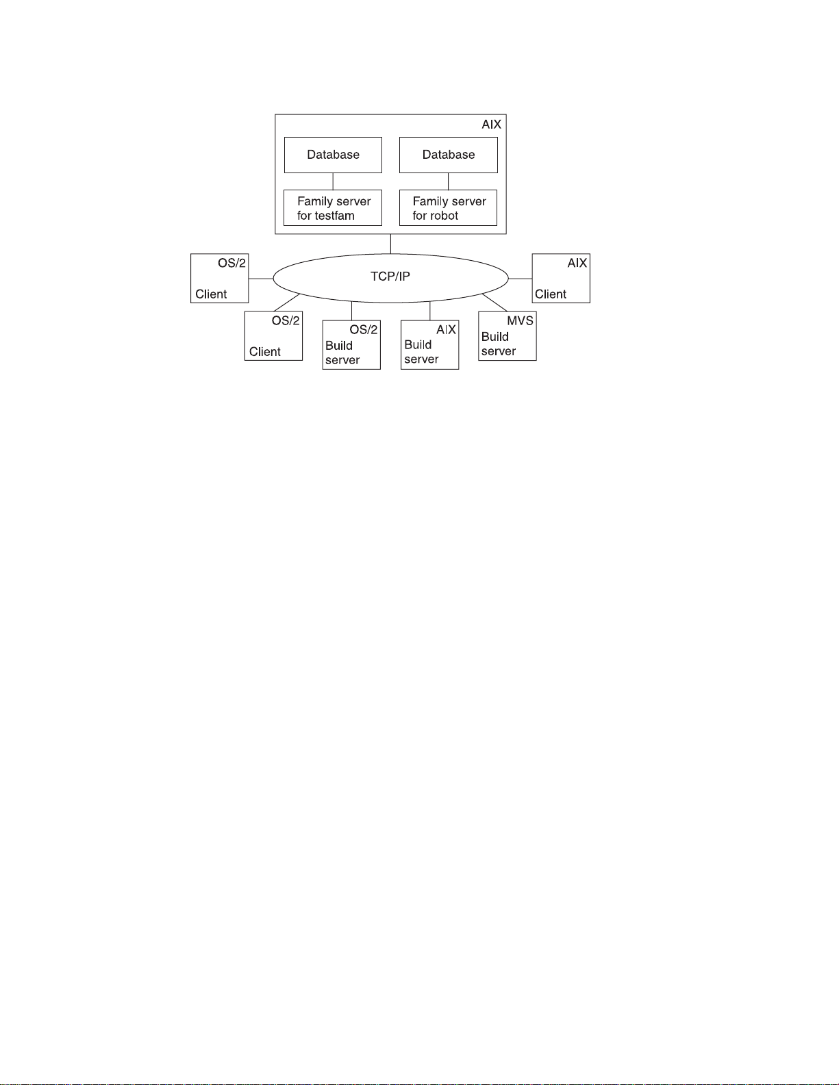
Figure 1. A sample TeamConnection client/server network
TeamConnection
Data stored in a family server’s database includes:
v Text objects, such as source code and product documentation
v Binary objects, such as compiled code
v Modeled objects that are stored in the information model by tools such as VisualAge
Generator
v Other TeamConnection objects that are metadata about the other objects
A TeamConnection
and parts stored on the database server.
TeamConnection database
TeamConnection is built on IBM’s DB2 Universal Database. Please refer to the DB2
documentation referenced in this document’s “Bibliography” on page 309 for detailed
information on DB2 database configuration, administration, and utilities.
Interfaces
TeamConnection provides the following interfaces that you can use to access data:
v A graphical user interface based on industry standards.
v A command line interface that lets you type TeamConnection commands from a
prompt or from within TeamConnection
v A web client that you access through your web browser.
family servers
client
gives team members access to the development information
control all data within the TeamConnection environment.
Chapter 1. An introduction to TeamConnection 5
Page 26

Families
You can use any interface to do your TeamConnection work, or you can switch among
them. This book usually gives instructions for using both interfaces.
For more information, see “Chapter 2. Getting familiar with the TeamConnection client
interfaces” on page 17.
A
family
represents a complete and self-contained collection of TeamConnection users
and development data. Data within a family is completely isolated from data in all other
families. One family cannot share data with another.
Refer to the
Users and host lists
Users are given access to the TeamConnection development data in a specific family
through their
access to the family. The superuser gives other users the
of
actions
might in turn be able to grant some equal or lesser level of authority to other users.
However, the ability to grant authority for some actions is reserved to the superuser.
There are no actions which the superuser cannot perform.
For host-based authentication, each user ID is associated with a
of client machine addresses from which the user can access TeamConnection when
using that ID.
A single user can access TeamConnection from multiple systems or logins. Likewise, a
single system login can act on behalf of multiple users. The set of authorized logins for
a TeamConnection user ID makes up the user’s host list.
It is also possible to authenticate users through the use of passwords, either in place of
host lists, or as an alternative form of authentication.
Refer to the
Parts
Administrator’s Guide
user IDs
on particular data. Depending on the authority granted to a user, that user
. Each family has at least one
Administrator’s Guide
for more information about families.
superuser
, who has privileged
authority
to perform some set
host list
for more information.
, which is a list
6 User’s Guide
TeamConnection
include text objects, binary objects, and modeled objects. These parts can be stored by
the user or the tool, or they can be generated from other parts, such as when a linker
generates an executable file. Parts can also be groupings of other TeamConnection
objects for building and distribution, or simply for convenient reference. Common part
actions include the following:
Create To store a part from your workstation on the server; from that time on,
TeamConnection keeps track of all changes made to the part. Or, to create a
part to use as a place holder to store the output of a build.
parts
are objects that users and tools store in TeamConnection. They
Page 27
Components
Check out
To get a copy of a part so that you can make changes to it.
Check in
To put the changed part back into TeamConnection.
Extract To get a copy of the part
TeamConnection.
Edit To change a part from within TeamConnection using a specified editor.
Build To construct an output part from parts that you have defined to
TeamConnection as input to the output part.
These are simplified definitions of part actions; there is more about the actions you can
perform against parts in “Chapter 3. The basics of using TeamConnection” on page 25.
The current version of each part is stored in the TeamConnection database, along with
previous versions of each part. You can return to previous versions if you need to.
without
making changes to the
current version
in
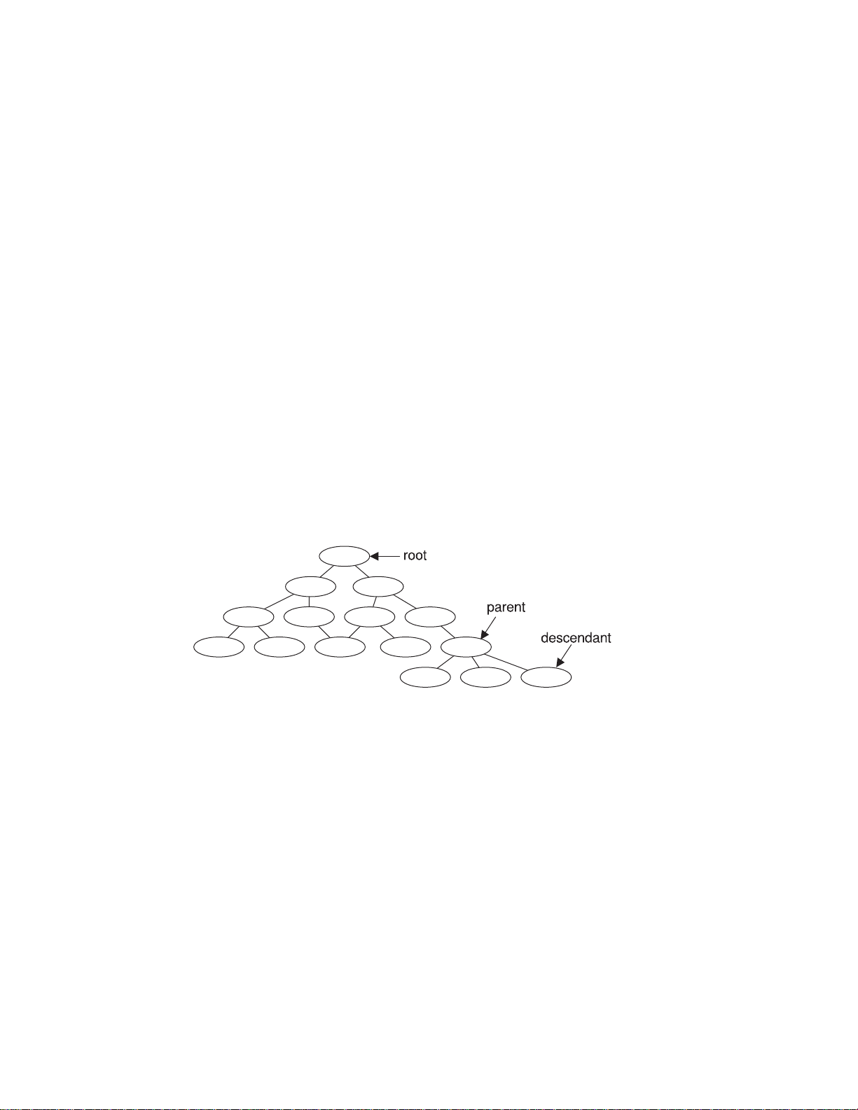
Within each family, development data is organized into groups called
component hierarchy of each family includes a single top component, called
descendants
child can have multiple parents.
The following figure depicts a component hierarchy.
Figure 2. Sample of a component hierarchy
TeamConnection uses components to organize development data, control access to the
data, and notify users when certain actions occur. Descendant components inherit
access and notification information from ancestor components. Information about the
components is stored in the database, including:
v The component’s position in its family hierarchy.
v The user who owns the component. The component
managing data related to it, including defects or features.
of that root. Each
child component
has at least one parent component; a
owner
components
root
is responsible for
. The
, and
Chapter 1. An introduction to TeamConnection 7
Page 28
Releases
v The users who have access to the component and the level of access each user
has. This information makes up the component’s
v The users who are to be notified about changes to the component. This set of users
is called the
process
v The
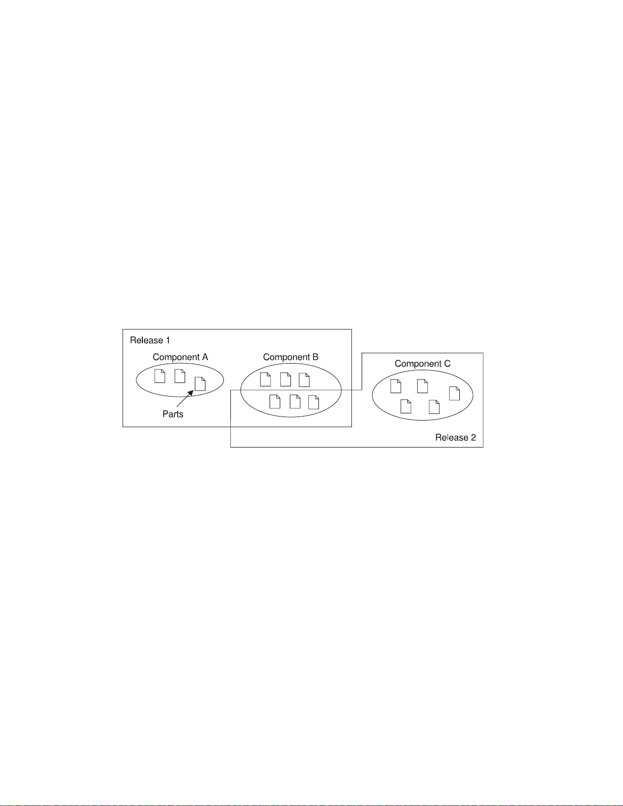
An application is likely to contain parts from more than one component. Because you
probably want to use some of the same parts in more than one application, or in more
than one version of an application, TeamConnection also groups parts into
release is a logical organization of all parts that are related to an application; that is, all
parts that must be built, tested, and distributed together. Each time a release is
changed, a new version of the release is created. Each version of the release points to
the correct version of each part in the release.
Each part in TeamConnection is managed by at least one component and contained in
at least one release. One release can contain parts from many components; a
component can span several releases. Figure 3 shows the relationships between parts,
the releases that contain them, and the components that manage them.
notification list
by which the component handles defects and features.
.
access list
.
releases
.A
Work areas
8 User’s Guide
Figure 3. Parts, releases, and components
Each time a new development cycle begins, you can define a separate release. Each
subsequent release of an application can share many of the same parts as its
predecessor. Thus maintenance of an older release can progress at the same time as
development of a newer one. Each release follows a process by which defects and
features are handled.
A release contains the latest ″official″ version of each of its parts. As users check parts
out of the releases, update them, and then check them back in, TeamConnection keeps
Page 29

track of all of these changes, even when more than one user updates the same part at
the same time. To make this possible, TeamConnection uses something called a
area
.
A work area is a logical temporary work space that enables you to isolate your work on
the parts in a release from the official versions of the parts. You can check parts out to
a work area, update them, and build them without affecting the official version of the
parts in the release. After you are certain that your changes work, you
work area with the release (or
you are using the driver subprocess). The integration makes the parts from your work
area the new official parts in the release.
You can do the following with work areas:
v Check out parts from a release
v Update any or all of the checked-out parts
v Get the latest copies of the parts in the release, including any changes integrated by
other users
v Get the latest copies of the parts in another work area
v
Freeze
instant in case you need to return to it later
v Build the parts in the work area
v Move all parts back into the release by integrating the work area
For more information, see “Using work areas” on page 28.
the work area, making a snapshot of the parts as they exist at a particular
commit
the driver that the work area is a member of, if
integrate
work
the
Drivers
A driver is a collector for work areas. You create drivers associated with specific
releases so that you can exercise greater control over which work areas are integrated
into the release and commit the changes from multiple work areas simultaneously.
When a work area is added to a driver, it is called a
can be a member of more than one driver. By making a work area part of a driver, you
associate the parts changed in relation to that work area with the specified driver.
These parts must be members of the release associated with the driver.
Drivers enable you to place the following controls over work area integrations:
v Define and monitor prerequisite and corequisite work areas to ensure that mutually
dependent changes are integrated in proper order.
v Monitor and resolve conflicting changes to the same part (if you use concurrent
development).
v Restrict access to driver members so that they can be changed only by users with
proper authority.
Chapter 1. An introduction to TeamConnection 9
driver member.
A single work area
Page 30

Defects and features
A defect is a record of a problem to be fixed. A feature is a record of a request for a
functional addition or enhancement. Both may be associated with a work area, and both
follow the processes defined for the component and release that are associated with
the work area. TeamConnection tracks both objects through their life cycles as
developers change and commit parts.
You can use defects and features to record problems and design changes for things
other than the products you are developing under TeamConnection control. For
example, you can use defects to record information about personnel problems,
hardware problems, or process problems. You can use features to record proposals for
process improvements and hardware design changes.
For more information, see “Working with defects and features” on page 38.
Processes
An application changes over time as developers add features or correct defects.
TeamConnection controls these changes according to the
your application’s components and releases. A process enforces a specific level of
control to part changes and ensures that actions occur in a specified order.
Two separate types of processes are defined: component processes, which can be
different for each component within a family, and release processes, which apply to all
activities associated with a given release. Component or release processes are built
from a number of lower-level processes, or
TeamConnection product.
subprocesses
processes
, that are included with the
you choose for
10 User’s Guide
A defect or feature written against a component moves through successive
during its life cycle. The TeamConnection actions that you can perform against it
depend on its current state. The component processes define these actions. You can
require users to do some, all, or none of the following for tracking defects and features:
dsrFeature
Design, size, and review changes to be made for features
verifyFeature
Verify that the features have been implemented correctly
dsrDefect
Design, size, and review fixes to be made for defects
verifyDefect
Verify that the fixes work
At the release level you can require some, all, or none of the following subprocesses:
track This subprocess is TeamConnection’s way of relating all part changes to a
specific defect or feature and a specific release. Each work area gathers all
states
Page 31

the parts modified for the specified defect or feature in one release and
records the status of the defect or feature. The work area moves through
successive states during its life cycle. The TeamConnection actions that you
can perform against a work area depend on its current state.
You must use the
subprocesses.
approval
This subprocess ensures that a designated
to incorporate changes into a particular release and electronically signs a
record. As soon as approval is given, the changes can be made.
fix This subprocess ensures that as users check in parts associated with a work
area, an action is taken to indicate that they have completed their portion.
When everyone is done, the owner of the
owner) can change the fix record to complete. The parts are then ready for
integration.
driver A
test The test subprocess guarantees that testing occurs prior to verifying that the
driver
is a collection of all the work areas that are to be integrated with each
other and with the unchanged parts in the release at a particular time. The
driver subprocess allows you to include these changes incrementally so that
their impact can be evaluated and verified before additional changes are
incorporated. Each work area that is included in a driver is called a
member
fix is correct within the release.
.
track subprocess
if you want to use any of the other release
approver
fix record
agrees with the decision
(usually the component
driver
Build
TeamConnection is shipped with several predefined processes. If these do not apply to
your organization, you can configure your own processes by defining different
combinations of subprocesses.
See “Chapter 4. The states of TeamConnection objects” on page 41 for an explanation
of TeamConnection states.
The TeamConnection build function automates the process of building individual parts
or entire applications, both in the work group LAN environment and on an enterprise
server. This function enables you to reliably and repeatedly build the same output from
the same inputs. You can also build different outputs from the same inputs for different
environments.
You start a build against an output part that has an associated
object that describes how to translate input parts to get the desired output, such as a
linker or compiler. An input part might have an associated parser, which determines the
dependencies for the input parts in a build.
The build function does the following:
Chapter 1. An introduction to TeamConnection 11
builder
. A builder is an
Page 32

Packaging
v Tracks build times of inputs and outputs so that it builds only those parts that are out
of date themselves or that have out of date dependents. You can also force a build
regardless of the build times.
v Enables you to spread the build over multiple machines running at the same time or
into multiple processes running on a single machine, such as on MVS.
For more information, see “Part 4. Using TeamConnection to build applications” on
page 127 .
Packaging
machines where they are to be used. TeamConnection includes two tools that you can
use to automate the electronic distribution of TeamConnection-managed software and
data:
Gather An automated data mover for server or file transfer-based distribution.
Tivoli Software Distribution
For more information, see “Part 5. Using TeamConnection to package products” on
page 199
Roles people play
Because TeamConnection is extremely flexible, no two projects are likely to use it in the
same way, and the jobs that people perform likewise vary. Still, TeamConnection tasks
can be grouped into the following general categories:
System administrator
is any of the steps necessary to distribute software and data onto the
A bridge utility that automates the installation and distribution of software or
data using Tivoli as the distribution vehicle.
Has
superuser
to the database management system. This administrator is responsible for the
following:
v Installing and maintaining the TeamConnection server
v Maintaining and backing up the database used by TeamConnection
access to the family server and database administration access
12 User’s Guide
Note: On UNIX systems, the system administrator must also have root access
to the host machine.
Family administrator
Has superuser access to the family server and database administration access
to the database management system. This administrator is responsible for the
following:
v Planning and configuring TeamConnection for one or more families
v Managing user access to one or more families
Page 33

v Maintaining one or more families
v Creating and updating configurable fields
v Configuring release and component processes for a family
v Creating and updating user exits
v Monitoring the user activity of a family
Build administrator
This administrator is responsible for the following:
v Setting up and maintaining build servers
v Planning for builds
v Creating builders and parsers
v Starting and stopping build servers
v Defining
v Monitoring build performance
v Creating driver members
v Committing and completing drivers
v Extracting releases
v Packaging and distributing applications
End user
End users, such as project leaders, programmers, and technical writers, use
one or more TeamConnection families to control and maintain application
development data.
pools
Chapter 1. An introduction to TeamConnection 13
Page 34

14 User’s Guide
Page 35

Part 2. Developing a product using TeamConnection
Chapter 2. Getting familiar with the TeamConnection client interfaces ...17
Using the GUI........................17
Starting the GUI ......................18
Stopping the GUI .....................19
Performing tasks with the GUI .................19
Using the Settings notebook ..................20
Online help information....................21
Using the command line interface .................21
Using the TeamConnection web client................22
Chapter 3. The basics of using TeamConnection ...........25
Laying the groundwork.....................25
Authority to perform tasks...................26
Finding objects within TeamConnection ...............27
Finding parts .......................27
Using work areas ......................28
Naming your work areas ...................29
Creating parts........................29
Naming your parts .....................30
Preparing to build your parts ..................30
Working with parts ......................31
Working in serial or concurrent development mode ..........31
Working with common parts ..................32
Getting parts from TeamConnection ...............33
Checking parts in to TeamConnection...............34
Finding different versions of TeamConnection objects ..........35
Versioning releases .....................35
Versioning work areas ....................36
Versioning drivers .....................37
Versioning parts ......................38
Working with defects and features .................38
Testing and verifying part changes .................39
Chapter 4. The states of TeamConnection objects...........41
Defects and features .....................41
The states of work areas ....................45
The states of drivers .....................47
Verification and test records ...................49
Chapter 5. Working with no component or release processes ......51
Working in serial development ..................51
Accepting a defect .....................52
Creating a work area ....................53
Checking out a part .....................54
Searching for a part.....................55
Checking in a part .....................58
© Copyright IBM Corp. 1992, 1995, 1996, 1997, 1998 15
Page 36

Verifying and testing part updates ................60
Extracting a part .....................62
Checking out the part one more time ..............63
Checking the part back in ..................64
Freezing the work area....................65
Refreshing the work area ...................66
Building the application ...................67
Integrating the work area ...................68
Closing a defect ......................69
Working in concurrent development ................70
Refreshing the work area from the driver..............71
Integrating the work area ...................72
Reconciling differences....................73
Chapter 6. Working with component and release processes .......77
Moving through design, size, and review ...............78
Changing defect ownership ...................79
Accepting a defect ......................80
Approving the fix.......................81
Checking out a part ......................82
Checking in the changes ....................83
Freezing the work area....................85
Building the application ...................86
Accepting fix records .....................87
Integrating changed parts into a release ...............88
Adding a driver member ...................88
Reconciling the differences ..................89
Returning the work area to the fix state .............89
Reactivating the fix record..................90
Refreshing the work area ..................90
Refreshing the driver ....................91
Building the driver .....................92
Restricting the driver ....................93
Integrating the parts.....................94
Completing the driver ....................95
Testing the built application ..................96
Using a configured process ...................97
Retrieving a past version of a part .................97
16 User’s Guide
This section is for anyone who uses the TeamConnection client to do daily work. The
information is meant for both the person who uses the command line interface and the
person who uses the GUI; instructions for both are provided.
All the tasks in this part are done from a client machine.
Before reading this section, you should be familiar with the TeamConnection
terminology and concepts presented in “Chapter 1. An introduction to TeamConnection”
on page 3.
Page 37

Chapter 2. Getting familiar with the TeamConnection client
interfaces
TeamConnection provides several interfaces that you can use to access data:
v A graphical user interface based on industry standards.
v A command line interface that lets you type TeamConnection commands from a
prompt or from within TeamConnection.
v A web client, that you access through your web browser.
You can use any of the interfaces to do all of your TeamConnection work, or you can
switch back and forth between the them. You might find that some tasks are easier to
do from the GUI or through the web, while others are easier to do from the command
line.
The examples throughout “Part 2. Developing a product using TeamConnection”on
page 15 give instructions for both GUI and command line interface usage.
This chapter helps you to begin using the TeamConnection client interfaces. It describes
the following:
v Using the GUI
– Starting and stopping the GUI
– Getting around in the GUI
– Using the Settings notebook
– Using the online help that is provided with TeamConnection
v Using the command line interface
v Using the web client
Before you can use TeamConnection, someone in your organization with superuser or
admin authority, such as your family administrator, must create for you a unique user ID
and a host list entry for the workstation where you installed the client.
Using the GUI
TeamConnection provides a GUI that you can use to do all of your TeamConnection
work. To use the GUI efficiently, set your default values in your Settings notebook to suit
your working environment, and then become familiar with the Tasks window and how
you can save time by adding your most common tasks to it.
Note: If available, use the Select Preference File window to specify your configuration
file for the TeamConnection GUI. This is the file that TeamConnection uses to
store and retrieve the information you have selected for the various GUI
windows. Preferences such as which view you are using for a window (for
example Details view on the Defects window), the column order for a window,
and the window size are saved in this file.
© Copyright IBM Corp. 1992, 1995, 1996, 1997, 1998 17
Page 38
If you are using AIX, HP_UX, or Solaris and are about to use the GUI for the first time,
you need to do the following tasks:
1. See
2. See
3. Copy the sample initial tasks list for the main GUI window by typing the following
Starting the GUI
You can start the TeamConnection client GUI in one of the following ways:
v Select the TeamConnection Client icon from the TeamConnection Group folder on
v Type teamcgui from a prompt.
The Tasks window appears.
Configure the environment variables in the .profile
the TeamConnection Clients manual.
Ensure that the TeamConnection client command is accessible
Started with the TeamConnection Clients manual.
command (this needs to be done only once):
cp $TC_HOME/nls/cfg/$LANG/teamcv3x.ini $HOME/.
chmod u+w $HOME/teamcv3x.ini
Where $TC_HOME is the location where the TeamConnection code was installed.
the desktop.
in the Getting Started with
in the Getting
18 User’s Guide
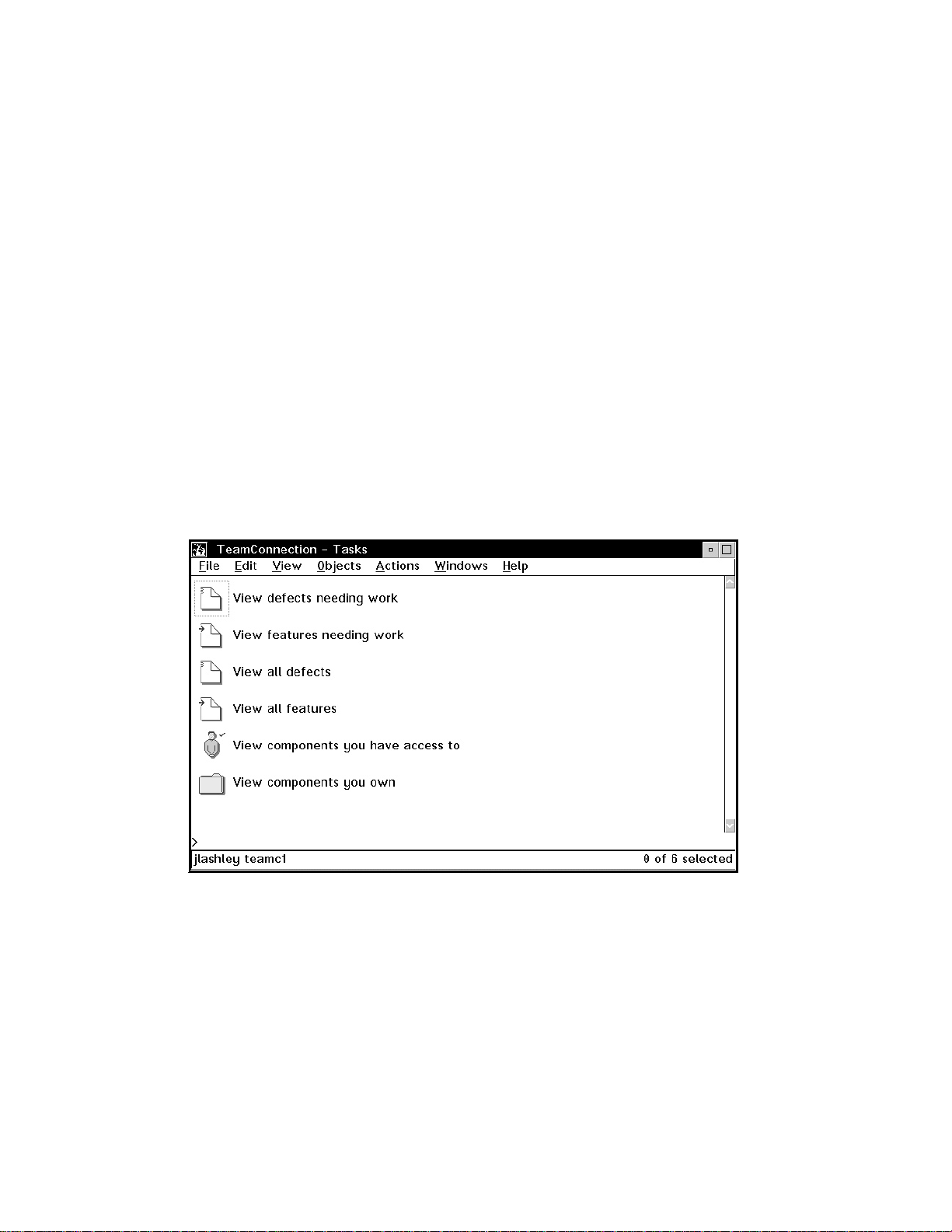
Figure 4. Tasks window
Page 39

Initially, a set of default tasks appears in your Tasks window. As you become more
familiar with TeamConnection and see what tasks you do most often, you can change,
delete from, and add new tasks to this list. To learn how to do this, select How do I
from the Help pull-down menu, and then select Update tasks on the Tasks window.
From the Tasks window, you can either select actions from the menu bar or select a
task.
Stopping the GUI
To stop the TeamConnection client GUI, do one of the following:
v Select Close from the System menu in the Tasks window.
v Select Exit from the File pull-down menu of a TeamConnection window.
Performing tasks with the GUI
There are several ways you can perform TeamConnection tasks with the GUI. You can:
v Select an action from the Actions pull-down menu and then select the object you
want to work with. For example, if you want to view a specific defect, select Defects
→ View from the Actions pull-down menu; then type the name of the defect in the
View Defects window.
This method is useful when you know the exact names of the objects you want to
work with.
v Select the type of object you want to work with, such as Defects, from the Objects
pull-down menu. A Filter window appears in which you can specify search criteria.
You then get a list of objects that match the search criteria. Online help provides
information about using the Filter window.
This method is useful when you do not know the exact name of the object you want
to work with, or you want to view a list of objects.
After you have a list of objects, and if you are going to use this list at other times,
you can keep the window open. Leave the window in the background as you do your
other work, or minimize it. This way, you can quickly retrieve the list when you want
to perform another action.
v Select a task from the Tasks window.
This method provides a fast path within the GUI. When you select a task,
TeamConnection performs the underlying query or command and then displays the
requested information.
v Select an object from an object window (such as the Parts, Defects, or Features
window) and then select an action to perform on the selected part from the Selected
menu. You can also display a pop-up menu listing valid actions for a specific object
by placing the mouse pointer over the object and pressing mouse button 2.
Chapter 2. Getting familiar with the TeamConnection client interfaces 19
Page 40

Using the Settings notebook
The TeamConnection GUI provides a Settings notebook in which you can set default
values for your working environment. To open the Settings notebook, select Settings
from the Windows pull-down menu. You can set the following values; for more
information about them, refer to the online help. The notebook has five pages.
Note: The environment variables you specify are relevant for the GUI only, not the
command line.
On the Environment
page:
On the Setup page:
On the GUI page:
v Family
v Release
v Component
v Work area
v Become user
v User ID
v Top
v Relative directory
v Working directory
v NLS path
v Log file
v Case
v Print command
v Compare command
v Edit command
v Verbose commands
v Auto refresh
v Multiple object windows
v Show query line
v Sort pre-defined list values
v Use small icons in icon views (not available in Windows or UNIX
clients)
v Use small icons in tree views (not available in Windows or UNIX
clients)
v Font for object windows (not available in Windows or UNIX
clients)
v Font for output windows (not available in Windows or UNIX
clients)
v Required field label color
v Modified field label color
20 User’s Guide
Page 41

On the Extract page:
On the Pool page:
Online help information
Online help information is available from anywhere in the TeamConnection GUI. Use
the online help when you need more information about a topic or task.
TeamConnection offers two types of help:
v General help
This is help for a specific window. General help provides an overview of the task and
describes the objects on the window, such as menu-bar items, icons, fields, and push
buttons. Do one of the following to access general help:
– Select Help from a menu bar.
– Select the Help push button.
– Press F1.
v How do I
This is where you find step-by-step instructions for doing a specific task. How you do
a task depends on the component or release process that is being followed, and this
help information takes that into consideration. To access this help, select How do I
from the Help pull-down menu. Double-click on one of the task items.
At the bottom of each Help window is a Diagram push button. Select this push button
to view a graphical process diagram. Step your way through the diagram to better
understand the processes that TeamConnection components and releases can follow.
The processes that your components and releases follow depend on how the
processes are configured for your organization. The defined processes determine the
actions that must occur before a defect or feature can move toward completion.
v Destination directory
v Read-only
v Expand keywords
v Pool
Using the command line interface
To use the command line interface effectively, you must be familiar with the actions that
you can perform using TeamConnection commands. A complete description of each
command, including examples for each, is available in the
To view the syntax of a TeamConnection command online, type the following at a
prompt:
teamc commandName
Where
commandName
is the name of the TeamConnection command.
Chapter 2. Getting familiar with the TeamConnection client interfaces 21
Commands Reference
Page 42

The
Quick Commands Reference
TeamConnection command.
You can also become familiar with the commands by looking at the contents of the log
file where TeamConnection stores the commands that are issued as you use the GUI.
This file is specified in the Log file field on the Setup page of the Settings notebook.
The default name is teamc.log; it is stored in the directory where the client is installed
(for AIX, HP-UX, and Solaris it is stored in the $HOME directory of the user), unless
you specify a different location in the Settings notebook.
You can type TeamConnection commands from a prompt within any directory; the
TeamConnection GUI does not need to be started. Or if you start the GUI, you can type
a command on the command line in the Tasks window (this command line is located at
the bottom of the window, just above the footer that indicates the user name and family
name).
Before you start to use the command line interface, you might want to set the most
used environment variables, such as TC_FAMILY or TC_COMPONENT. You are not
required to set these environment variables, but if you do not, you will need to specify
them in the command when required.
You set environment variables differently for different platforms:
v AIX, HP-UX, and Solaris users set environment variables in the .profile (sh, ksh
environment), .dtprofile (cde environment), or .cshrc (csh environment).
v OS/2 users set environment variables in the config.sys file or from a command line
prompt.
v Windows 95 and Windows NT users set environment variables in the Windows
Control Panel.
v Some environment variables are set in your config.sys file during installation.
You can override the value you set for an environment variable by using the
corresponding flag in the command. For example, you have the TC_FAMILY
environment variable set to robot, but you need a file from another family named octo,
so you issue the following command:
teamc part -extract hello.c -family octo -release 9501
is a booklet that lists the syntax of each
“Appendix A. Environment Variables” on page 227 provides a complete list of the
TeamConnection environment variables.
Using the TeamConnection web client
The TeamConnection Web Client provides family server connectivity and great deal of
the functionality provided by a standard TeamConnection client without the overhead
required by a standard client installation. Using a web browser, anyone in the
organization can access server data (provided the server is configured appropriately) by
addressing a machine and a port number. Although file input/output functions are not
22 User’s Guide
Page 43

currently available, most other familiar TeamConnection functions are available through
the Web client. If you want to disable the Web Client interface, you must set the
environment variable TC_WWWDISABLED before starting the family.
To begin using the TeamConnection web client you must point your web browser to the
correct URL. The syntax of the URL is:
your family
7890
. For example, if your server host name is
, the URL would look like: http://testfam:7890
http://host name of the server:port number of
testfam
and your port number is
When connecting to the Web client, you will be prompted for a user name and a
password. The browser will cache this user name and password until it is closed. The
user name is required, but the password may not be, depending on the authentication
level of the family and the host on which the browser is running.
If your organization authentication level is set for PASSWORD_ONLY, you must login
using a password to gain access. If your organization authentication level is
HOST_ONLY, you may be denied access to the web client because either the host
being used is not in the user’s host list, or the browser is not bypassing the proxy. You
may be able to gain access by:
v If the host being used is not in the user’s host list, you must add the host to the
user’s host list to gain access.
v If the browser is not bypassing the proxy, do one of the following:
– Temporarily disable the proxy when using the Web Client.
– Reconfigure the browser to bypass the proxy when connecting to the family
server.
– Use an autoproxy so the browser will automatically bypass the proxy when
connecting to the family server.
v Change the authentication level to HOST_OR_PASSWORD and login using a
password.
Using the web client is much like using the TeamConnection GUI. The following are
some differences you might find:
v Parts cannot be extracted, checked out or checked in with the web client.
v Releases, Drivers, and Workareas cannot be extracted with the web client.
v A filter for Corequisites does not exist in the TeamConnection GUI.
v For the FeatureModify action, the following are available with the TeamConnection
web client (but not the TeamConnection GUI):
– newName
– orginLogin.
v For the DriverMemberView action, the following are available with the
TeamConnection web client (but not the TeamConnection GUI):
– state
– defectName
– defectAbstract
– committedVersion.
Chapter 2. Getting familiar with the TeamConnection client interfaces 23
Page 44

v For the ChangeView action, the following are available with the TeamConnection web
client (but not the TeamConnection GUI):
– ChangeView
– workAreaState.
v For the PartBuild action, the following are available with the TeamConnection web
client (but not the TeamConnection GUI):
– cancel
– partType.
v The PartChildInfoView action does not exist in the TeamConnection GUI.
v For the PartDelete action, force is available for use with the TeamConnection web
client (but not the TeamConnection GUI).
v For the PartDisconnect action, parentType is available for use with the
TeamConnection web client (but not the TeamConnection GUI.)
v For the PartModify action, fileType is available for use with the TeamConnection web
client (but not the TeamConnection GUI).
v For the PartUnlock action, Source Directory is available in the TeamConnection GUI
but not in the TeamConnection web client.
v For the PartViewContents, Expand Keywords is available in the TeamConnection
GUI. In the TeamConnection web client, an option for turning keyword expansion on
and off is provided.
v For the UserView Filter action, the following are available with the TeamConnection
web client (but not the TeamConnection GUI):
– pswStatus
– pswModifyTime
– pswCreateTime.
24 User’s Guide
Page 45

Chapter 3. The basics of using TeamConnection
All users of TeamConnection perform a number of basic tasks, such as checking parts
out of TeamConnection and then back in, and testing and verifying part changes. Before
you start doing these tasks, you need to understand the basic concepts behind them;
that is what this chapter explains.
This chapter assumes that you have read “Chapter 1. An introduction to
TeamConnection” on page 3 and are familiar with the different objects, such as
components and releases. The other chapters in this part of the book define in more
detail how you perform the TeamConnection tasks.
Laying the groundwork
Someone has already created your family’s component structure, and those
components manage your parts and control access to the data. Your TeamConnection
family also contains releases. A release identifies a version of all the parts that
comprise an application at a given point in time. When you create a release, you
specify the component that will manage it. One component manages a release, but
many components can manage the individual parts associated with that release.
A single part can be associated with more than one release, but it is managed by one
component. When you create a part, you specify the release that you want to associate
with the part and the component that you want to manage it. At any time, you can link
the created part to other releases so that the part can be shared, or you can change its
managing component.
Before you start working with parts, you need to be familiar with your family’s
component structure. This will help you when trying to locate parts within
TeamConnection and when writing defects and features. You can do the following to
display your family’s component structure from the GUI:
1. Select Components → Components from the Objects pull-down menu on the Tasks
window. The Component Filter window appears.
2. Type the name of the component that is at the top of your component hierarchy in
the Component field, and select OK. Initially this component is called root. The
Components window appears, listing the component.
3. Verify that the component is displayed in tree view (a plus sign (+) appears before
the component name). If not, select Tree from the View pull-down menu.
4. Select Expand fully from the Selected pull-down menu.
© Copyright IBM Corp. 1992, 1995, 1996, 1997, 1998 25
Page 46

Figure 5. Components window
From a command prompt, you can issue the following command to view the component
structure.
teamc report -view -raw bCompView -where "name='root'"
Authority to perform tasks
As a TeamConnection user, you are automatically given the authority to perform some
basic tasks. You can:
v Open defects and features
v Add notes to existing defects and features
v Modify the information for your user ID
v Display information about any user ID
v
Search
You receive authority to perform additional actions when you become the owner of a
TeamConnection object, such as a component or a part, or when authority is explicitly
given to you by the component owners.
If you attempt an action that you do not have authority to do, TeamConnection tells you
so. When this happens, you can ask the component owner, the family administrator, or
a user with superuser authority to grant you the necessary authority.
for information within TeamConnection to create reports
26 User’s Guide
Page 47

Note: You can issue queries to generate reports of data from tables and views using
the -view action flag. If you do not specify selection criteria, such as the fields
and the search conditions you want to use, the report query selects all entries for
the table or view indicated that the user has authority to access. This command
does not show any objects in components that you are not authorized to access
“Appendix I. Authority and notification for TeamConnection actions” on page 277 lists the
types of authority you need in order to perform various TeamConnection actions.
Finding objects within TeamConnection
All TeamConnection objects are stored on a server in a database. To find one or more
of these objects within a family, do one of the following:
v Use the report command with the -view action flag from a command line or a
command line within TeamConnection.
Command usage is explained in the
v Use a Filter window in the GUI.
Online helps explain how to use the Filter windows.
For now, you need to understand that the database is case-sensitive. You need to refer
to and search for objects in the correct case. For example, if a component is stored in
the database as hand, you would not find it if you typed Hand or HAND. This is why it is
important that your organization sets a naming convention, and that everyone follows
that decision when creating objects. If you do not know what naming convention has
been established for your organization, talk to your family administrator.
Commands Reference
Finding parts
Note: It is recommended that you use all lowercase whenever possible.
There are three Filter windows that you can use to find parts within TeamConnection:
Note: Use the forward slash (/) when specifying path names, such as directory/file.txt.
The Intel convention of using the backward slash is not recognized in the Filter
window.
Parts Use when you want to limit your search to a particular context of a work area
or driver in a release, or a particular version of a release. This is generally the
view users will use most often.
If you specify only a release, TeamConnection lists the committed parts for that
release. However, if you want a list of all parts in a specified work area and
release, TeamConnection displays all the parts visible to the work area. This
includes parts that are committed to the release as well as changed parts that
are visible only to the work area.
Chapter 3. The basics of using TeamConnection 27
Page 48

BuildView
PartFull
Refer to the online help, in particular How do I, for more information on how to use the
Filter windows. Select How do I from the Help pull-down menu to access the
information.
Using work areas
A work area is a logical temporary work space that enables you to isolate your work on
the parts in a release from the official versions of the parts. You can check parts out to
a work area, update them, and build them without affecting the official version of the
parts in the release. You must create a work area before you can create, check out, or
check in parts. If your component’s process includes a design, size, review subprocess
for defects or features and the release follows a tracking subprocess, a work area is
automatically created when sizing records exist and the associated defect or feature is
accepted. TeamConnection associates these work areas with the appropriate defect or
feature.
Use when you want to search for information related to building your
application, such as viewing a build tree, or when you want to do build actions.
Use when you want to search for parts across releases, components, or work
areas. For example, you want a list of all the optics.c parts. Unlike the Parts
Filter, you can specify one or more release or work area names.
You can also use this filter to display only parts that have been changed in a
work area. For example, you check out robot.c to work area 310:1, and that is
the only part that you have changed. If you use the PartFull Filter to query for
all the parts in work area 310:1, only one record is returned.
You cannot use this filter to search for build information.
28 User’s Guide
The parts in a work area do not become available in the release until the work area is
integrated. Also, if your release follows a driver subprocess, parts that have been
changed do not become available in the release until the associated driver is
committed. However, users who have the authority to access the work area can view
and work with the parts in it.
You can save intermediate versions of the parts in your work area by
work area. Every time you freeze a work area, TeamConnection saves a revision level
of the work area. When you freeze work area 123:1, for example, a version called
123:2 is created. This version contains information about each part in the work area
and its current version at the time the work area was frozen. It may contain version 1 of
part optics.c, for example. If you freeze the work area again later, a new version called
123:3 is created with information about the versions of the parts in the work area when
it was frozen. This version may contain version 2 of part optics.c. Each of these work
area versions is saved in the database and you can retrieve the versions of the parts
they contain before you integrate the work area into the release. Therefore, you should
freeze a work area whenever there is a possibility that you will want to return to that
freezing
your
Page 49

version of the work area. For example, you might be adding a major feature to the
code, and you want to be able to return to something that works in case the application
no longer builds. When you integrate a work area or commit a driver, the work area is
frozen automatically.
Naming your work areas
When TeamConnection automatically creates a work area, the work area is given the
same name as the defect or feature it was created for plus the initial version number,
:1. When you create a work area, you can also give it the same name as the defect or
feature, or you could give it any other name. Where possible, we recommend that you
name it after a defect or feature, or relate the name to the change that is being made.
Here are some things you should know before you name a work area:
v Work area names must be unique within the context of a release.
v After you create a work area, you cannot delete it. You can, however, cancel the
work area in the following situations:
– No part changes were made.
– You undo the changes you made.
v With the proper authority, other users in your organization will be able to access your
work area and make changes to the parts. This means that you need to make it easy
for them to locate the work area. Following your local naming conventions will help.
v After the work area is integrated with the release, you cannot reuse the work area. If
the defect is still in the working state, you can create another work area with a
different name after the initial work area is integrated with the release.
Creating parts
A TeamConnection part is controlled by the TeamConnection server.A TeamConnection
part is uniquely identified by the
the release in which it is contained. You must specify both the release name and the
path name whenever you perform a TeamConnection action on a part. Multiple releases
can share the same part.
When you create a part, you do one of the following:
v Take an existing text or binary file that is on your workstation and place it into
TeamConnection.
v Create an empty part that has no content. Empty parts are used as place holders
until an application is built. For example, you can create a place holder for an
executable part that will be created by a build. See “Creating the build tree for the
application” on page 184 for an example of creating a place holder.
After you put a part under TeamConnection control, the official copy of the part resides
in the database. The copy on your workstation is changed to read-only mode. You can
then change the part by checking it out to your workstation or editing it within the GUI.
path name
of the part, the part
Chapter 3. The basics of using TeamConnection 29
type
, and the name of
Page 50

Use the online help facility if you need assistance when creating parts.
Naming your parts
If your organization has a naming convention, be sure to follow it when naming your
parts. When the naming convention is not followed, everybody in your organization can
have trouble locating parts. Part names created on the server are case-sensitive; they
must be retrieved using the same case in which they were created.
When you name TeamConnection parts, you can specify only the base name, such as
hand.c, or you can specify the directory path in addition to the base name, such as
robot\hand\hand.c. Specifying the path name as part of the name lets you have several
identical base name parts included in the same release, such as robot\hand\msg.h and
robot\optics\msg.h.
You can also have identical part names within the context of a release as long as their
part types are different, such as TCPart and vgdata.
Note: It is recommended that you use lowercase letters to name your parts.
A parts name may contain spaces provided it is enclosed in double quotation marks
during processing. For example:
teamc part -create "This is a long file name.txt"
The name with spaces will be shown as-is by the GUI (without the double quotes). If
the name has spaces and is not enclosed in double quotation marks, then you may get
an error message repeated many times, one for each ″token″ separated by spaces in
the long name.
Note: The base name may contain a maximum of 63 characters, not including the
double quotations. The path name, which includes the base name, may contain
a maximum of 195 characters, not including the double quotations.
Preparing to build your parts
If you are going to use the TeamConnection build function, you must provide certain
information about each part that participates in a build. You can provide this information
when you create the parts or wait until later. You can also change the information at any
time.
To associate a part with a build, you must specify the following information:
v The parent part that you want to associate the part with.
v The type of relationship the part has to the parent, such as:
Input The part will be used as input to building its parent. An example of an input
part is a C language source file, x.c, which is compiled to create its parent,
x.obj.
30 User’s Guide
Page 51

Output The part will be a generated output from the same build that creates its
Dependent
If you do not provide this information when you create the part, you can provide it
later using the
You can also specify the builder or parser that a part will use, as well as any build
parameters.
“Part 4. Using TeamConnection to build applications” on page 127 explains the build
function in more detail.
Working with parts
After the parts are created in TeamConnection, you will be working with these parts —
getting them to your workstation so you can change them and then getting them back in
to TeamConnection. This section gives a brief overview of these tasks. “Chapter 5.
Working with no component or release processes” on page 51 and “Chapter 6. Working
with component and release processes” on page 77 go into more detail about these and
other TeamConnection tasks.
parent part. In other words, both the parent part and this child part are
outputs when the parent part is built.
The part will be needed for the build operation of its parent to complete, but
it will not be passed directly to the builder. An example of this is an include
file.
connect
function.
Working in serial or concurrent development mode
A release is set up for either serial development or concurrent development mode.
Once the development mode is set you can change from serial mode to concurrent
mode, but not from concurrent mode to serial mode. In serial development, a part is
locked when a user checks it out, and no one else can update the part as long as it is
checked out. In concurrent development, more than one user can simultaneously have
the same part checked out.
In concurrent development, more than one user can check out and change the same
part. Prior to integrating their changes, each user should refresh their work area from
the driver in which they plan to put it. The first user will be able to integrate their work
area, complete fix records for tracking releases, with their release. When the next user
refreshes their work area, TeamConnection recognizes that the parts differ and notifies
them. It is up to this user to resolve the differences, using the TeamConnection merge
program, VisualAge TeamConnection VisualMerge Facility, or some other merge
program. If the user fails to refresh their work area from the driver, TeamConnection will
not notify them that the parts differ until they try to add the work area to the driver. They
will then have to put the fix records back in the fix state, reactivate the work area,
refresh the work area, reconcile the differences, refresh their work area again, and
reintegrate their work area before they can add their changes to the driver.
Chapter 3. The basics of using TeamConnection 31
Page 52

Before getting parts from TeamConnection, you might want to find out if the
development mode for the release is concurrent or serial. To determine the mode, view
the information about the specific release. To do this, select View from the Selected
pull-down menu on the Releases window.
Working with common parts
A
common
two or more work areas. For example, when an identical part is needed in two separate
releases, you can link the part from one release to the other (if you have the proper
authority). Both releases would then have a link to the current version of that part.
When a common part is checked out of a release, TeamConnection locks the current
version of the part in all releases if one of them uses serial development. When putting
the part back into the release, one of the following actions reflects the change in all
releases in which the part is common:
v You integrate the work area when the driver subprocess is not followed, or
v You commit the driver when the driver subprocess is followed.
You can break the common link if you make changes to a common part and you do not
want these changes reflected in other releases or work areas that link to the part. You
can break the common link when you check out, check in, rename, delete, re-create,
connect, or
can maintain the common link with some of the releases while breaking the link with
other releases. When a link is broken, the parts still share the same name, but the
information contained in the parts is different.
Parts can also be linked between two or more work areas in the same or different
releases, making the parts common to those work areas. For example, a user working
in one work area can link to the latest version of a part in another work area of the
same release (the part has yet to be integrated with the release). The part is then
common to the two work areas within the same release. If you want to maintain the
common link to all work areas, you must specify the names of the common work areas
when you check in, rename, delete, or re-create the parts. As with common parts in
releases, you can break the common link.
You can also link all the parts within a release to another release. This function is
especially helpful when development begins on a new release of a product, and you
want the parts in the new release to initially be the same as the parts in the current
release. As development of the two releases continues, the common link between the
parts can be broken to separate development of the new release from maintenance of
the current release.
For more information about how to link parts, refer to the
online help.
part is a part with identical content that is shared by two or more releases or
disconnect
parts. When a part is common to more than two releases, you
Commands Reference
and
32 User’s Guide
Page 53

Getting parts from TeamConnection
Checking out a part implies that you intend to modify it; extracting a part merely gives
you a copy of the part. Normally, when you extract a part, you do not plan to change
the current version in TeamConnection.
You must have the necessary authority to a component before you can check out or
extract parts from that component. You need
TeamConnection; you need
“Appendix I. Authority and notification for TeamConnection actions” on page 277 for a
listing of all the TeamConnection actions and their authority requirements.
Parts are checked out to work areas. The work area is where you store updated parts
and do builds without affecting the version of the parts in the release. When a part is
checked out of the release to the specified work area, TeamConnection locks the part in
the release if you are working in serial development. If you are working in concurrent
development, the part is never locked. TeamConnection also puts a copy of the part on
your workstation. It is here where you update the part. If a read-only copy of the part
exists on your workstation, the first character of its file extension changes as follows: It
becomes a ″$″ (dollar sign) for OS/2 and Windows platforms. It becomes a ″.″ (period)
for AIX, HP-UX, and Solaris platforms. This copy is a backup copy. If a backup copy
already exists, it is deleted. When you are finished updating the part, you check it back
in to the work area. A work area is optional when extracting a part.
The environment variables TC_BACKUP and TC_MODPERM may be set to change the
the backup and read-only options. TC_BACKUP controls whether or not backup files
are created. If this environment variable is set to off, backup files are not created.
TC_MODPERM controls whether or not the read-only attribute is set. The default for
this environment variable sets the read-only attribute on.
PartCheckOut
PartExtract
authority to check a part out. See
authority to extract a part from
When you extract a part, TeamConnection copies the part to your workstation, and the
part is not locked. In other words, other users can still check out the same version of
the part and make changes to it, even in serial development mode. By default,
TeamConnection sets the extracted part to read-only access. This is done to keep you
from inadvertently changing the part on your workstation when the part in
TeamConnection is not locked. You can, however, change this in the Settings window or
when you are extracting the part. When you do this, be aware that someone else can
change the official part in TeamConnection, making your workstation copy back level.
Where TeamConnection places a checked-out or extracted part on your workstation
depends on the following:
v Your workstation’s
v Whether you use the -relative flag on the command line or the Destination directory
field on the GUI
v Whether the TC_TOP environment variable is set
For more information about how these interact, refer to the part command examples in
the
Commands Reference
current working directory
Chapter 3. The basics of using TeamConnection 33
Page 54

When you want to make changes to a part, you can do one of the following:
v Check out one or more parts and edit the parts on your workstation. When you finish
making changes to the parts, you check them back in.
v Edit a part from within the TeamConnection GUI using a specified editor. When you
exit the editor, the Check In Parts window appears and you can check the part back
in to TeamConnection.
In either case, if you are working in concurrent development and someone else
changed a part while you had it checked out, you are asked to resolve the differences
when you try to integrate your work area.
Checking parts in to TeamConnection
After you have verified the accuracy of your part changes, you are ready to check them
in to TeamConnection. Any parts that you have checked out, you have the authority to
check back in.
As mentioned earlier, you check parts out to a work area so you can work on them.
Therefore, when you check in a part, you must specify the work area where that part is
checked out. In other words, you check the part back in to the same work area. When
the part is checked in, the copy on your workstation is flagged read-only. The
environment variable TC_MODPERM controls whether or not the read-only attribute is
set. The default for this environment variable sets the read-only attribute on.
At this time, the changed part is visible in only the named work area; it is not visible at
the release or to any other work area. This lets you test your changes by building the
version of the code that is in your work area.
34 User’s Guide
When you are satisfied with your changes, you can integrate the parts into the release
by integrating your work area. This action makes the work area visible to all the users
in the release.
If you are working in concurrent development mode, TeamConnection generates a
collision record
example, both you and Keith have hand.c checked out. Keith makes changes to the
part and then integrates the work area that contains that part. (Depending on the
process being followed, Keith might have to commit the work area rather than integrate
it.) Later, after making changes to hand.c, you attempt to integrate the work area that
contains the part. Because the part was already integrated by Keith, you are notified of
a collision and asked to refresh your work area. After the refresh, you can view the
collision record and decide how you want to resolve the conflicts. “Reconciling
differences” on page 73 explains in more detail how this works.
when a changed part conflicts with a previously committed part. For
Page 55

Finding different versions of TeamConnection objects
TeamConnection version control maintains different versions of the following objects:
v Releases
v Work areas (and driver members)
v Drivers
v Parts
When you want to find and retrieve previous versions of these objects, it is helpful to
know how TeamConnection creates and deletes previous versions of each object.
Some basics of TeamConnection versioning will help you understand how
TeamConnection identifies unique versions of objects:
v When you first create an object, the initial version name is the object name suffixed
with
:1
. When you create a new work area called
version is
myWorkArea:2, myWorkArea:3, myWorkArea:4, and so on. Versions of releases and
drivers are identified similarly: myRelease:1, myRelease:2, myRelease:3; myDriver:1,
myDriver:2, myDriver:3; and so on.
v Unique versions of parts are identified by association with a specific version of a
release, work area, or driver. Your TeamConnection family may have three different
versions of a part called
myRelease:2, one associated with work area myWorkArea:1, and one associated
with work area myWorkArea:2.
myWorkArea:1.
Subsequent versions are identified in numerical order:
myPart,
for example: one associated with release
myWorkArea,
for example, its
Versioning releases
TeamConnection creates new versions of releases whenever you do the following:
v Create a release
This is the initial version of a release and contains no parts. When you create
myRelease, for example, its version name is myRelease:1 and it contains no parts.
v Commit a work area to the release
Committing a work area to a new release creates a new version of the release and
adds the parts in the work area to the release. When you commit work area
myWorkArea:1, for example, to myRelease:1, TeamConnection creates a version of
myRelease called myRelease:2. It also associates the parts in myWorkArea:1 with
myRelease:2.
v Commit a driver to a release
Because drivers are simply collections of work areas, committing a driver to a
release has the same effect as committing a work area: TeamConnection creates a
new version of the release. When you commit myDriver:2 to myRelease:2, for
example, TeamConnection creates a version of myRelease called myRelease:3.
TeamConnection deletes versions of releases whenever you prune the release. Refer to
the
Administrator’s Guide
for an explanation of pruning.
Chapter 3. The basics of using TeamConnection 35
Page 56

Versioning work areas
TeamConnection creates new versions of work areas whenever you do the following:
v Create a work area
This is the initial version of a work area. When you create myWorkArea, for example,
its version name is myWorkArea:1.
v Refresh a work area
Refreshing a work area updates it with any new versions of parts that have been
integrated with the release. When a workarea is refreshed, two versions of the
workarea are created. One of the contents before the refresh and one with the
contents after the refresh.
v Freeze a work area
Freezing a work area is like taking a snapshot of the work area. It preserves the
parts as they are at a given point in time. If you create work area myWorkArea:1,
add three new parts to it — called part1, part2, and part3 — and then freeze it, your
family contains a work area called myWorkArea:2, with part1, part2, and part3. The
version name of each of these parts is myWorkArea:1. If you then alter part2 and
freeze the work area again, your family contains the following:
– myWorkArea:1, with nothing in it
– myWorkArea:2 contains part1, part2, and part3 at version myWorkArea:1
– myWorkArea:3 contains part1 and part3 at version myWorkArea:1, and part2 at
version myWorkArea:2
v Commit a work area
Committing a work area adds the parts in the latest version of the work area to the
release. It also does the following:
– Creates a new version of the release
– Creates new versions of the parts in the release
– Deletes any intermediate versions of the work area
36 User’s Guide
Using the previous example, if you commit myWorkArea:3 to myRelease:1, the
following happens:
– TeamConnection creates a new version of myRelease called myRelease:2.
– TeamConnection creates new versions of the parts in myRelease:2.
– TeamConnection deletes myWorkArea:1, myWorkArea:2, and myWorkArea:3.
TeamConnection deletes versions of work areas whenever you commit them to a
release. Once a work area has been committed, you can no longer use it for making
part changes and you cannot create a new work area with the same name.
Deleting work area versions is controlled by the autopruning option of the release
associated with the work area. By default, TeamConnection always deletes work area
versions on commit, but you can change this option. Refer to the
for an explanation of autopruning.
Administrator’s Guide
Page 57

Versioning drivers
TeamConnection creates new versions of drivers whenever you do the following:
v Create a driver
When you create a new driver, TeamConnection makes two versions of it:
myDriver:1, for example and myDriver:2.
v Add a work area (driver member) to a driver
If you add myWorkArea:1 to myDriver:2, for example, TeamConnection creates a
new version of myDriver called myDriver:3.
v Freeze a driver
Freezing a driver is like taking a snapshot of the driver. It preserves the parts as they
are when the driver is frozen. If you freeze myDriver:3, for example, TeamConnection
creates a new version called myDriver:4.
v Refresh a driver
Refreshing a driver updates the driver with all changes that have been made in all of
its driver members. Refreshing a driver actually creates two new versions of the
driver, as follows:
1. Freezes the driver (so that TeamConnection can have a point to roll back to if an
2. Updates the driver with any changes from the driver members
3. Freezes the driver again, thus preserving a copy of the updated driver.
If the current version of myDriver is myDriver:2, for example, and the parts in its
driver members have been changed, then TeamConnection does the following when
it refreshes the driver:
1. Freezes myDriver, creating myDriver:3.
2. Updates myDriver with changes from its driver members.
3. Freezes myDriver again, creating myDriver:4.
error occurs during the refresh operation).
The result of refreshing myDriver (version myDriver:2) is two new versions:
myDriver:3, containing a snapshot of the driver before the refresh, and myDriver:4,
containing a snapshot of the driver after the refresh.
TeamConnection deletes versions of drivers whenever you remove driver members or
commit a driver to a release.
v If you have a driver version myDriver:4 with driver members myWorkArea,
yourWorkArea, and ourWorkArea, and you remove myWorkArea, then
TeamConnection deletes driver versions myDriver:2, myDriver:3, and myDriver:4 and
creates a new driver version called myDriver:5 containing members yourWorkArea
and ourWorkArea. As a result, the family contains two versions of the driver,
myDriver:1 and myDriver:5.
v When you commit a driver to a release, all intermediate versions of the driver
(resulting from driver member add, driver freeze, driver refresh, or driver member
remove operations) are deleted.
Chapter 3. The basics of using TeamConnection 37
Page 58

Versioning parts
TeamConnection versions parts in association with other TeamConnection objects, such
as work areas. If, for example, you create part1 in myWorkArea:1, the current version of
part1 is myWorkArea:1. If part1 is in release myRelease:2 and work area
myWorkArea:2, then you can view the version of the part for either the release or the
work area. The version label for part1 in myRelease:2 is myRelease:2 and in
myWorkArea:2 is myWorkArea:2.
TeamConnection deletes part versions whenever it deletes versions of the object that
the part is associated with. In addition to versioning in association with other
TeamConnection objects, TeamConnection maintains versions of build output parts
(parts that are created as the result of a build, such as an .exe file or a .hlp file). When
you create a release, you can set the maximum number of versions of build output
parts to maintain. If you set this maximum to 10, for example, then TeamConnection
saves only 10 versions of build output parts and discards the oldest version each time a
new version is created.
Working with defects and features
Defects are used to report problem information; features are used to record information
about proposed design changes. After a defect or feature is opened, TeamConnection
tracks the progress of the defect or feature through various states. To what degree
defects and features are tracked depends on the processes followed by the release and
component to which they are assigned. The following describes actions that your
defined processes might require:
Analyzing defects and features
The owner is responsible for analyzing a defect or feature after it is opened.
The owner can then return it if it is not valid or feasible, reassign it to another
user or component, or accept it for resolution.
Designing the resolution
After a defect or feature has been accepted, the actual resolution needs to be
designed so that an informed evaluation can be made. This resolution needs
to be designed by users who are familiar with the product or area affected by
the defect or feature.
Identifying the required resources
Sizing records are created by the owner to identify the components and
releases that might be affected by the defect or feature. Each owner of a
component that is referenced in a sizing record needs to evaluate the impact
of the defect or feature on the parts managed by the component. If the defect
or feature requires changes to parts, the sizing record is accepted and sizing
information is added.
When sizing records exist and the associated defect or feature is accepted,
TeamConnection automatically creates a work area.
38 User’s Guide
Page 59

Reviewing the design and resource estimates
After the resolution has been designed and the resources have been identified,
the proposal needs to be reviewed. If the review indicates that work should
continue on the defect or feature, it is accepted.
Resolving defects and implementing features
Resolving one defect or implementing one feature in one release can involve
one or more users changing many parts. To change a part, a user must check
out the part, make the changes required to resolve the problem or implement
the design change, and check the part back in. If the release follows a tracking
process, all defects or features must be associated with a work area. Parts
that are checked out refer to the work areas that are monitoring the defect or
feature.
Resolving a defect or implementing a feature also involves integrating the
changed parts with changes made for other defects and features in that
release. All changed parts are eventually integrated with the unchanged parts
within the release.
Verifying the resolution of the defect or feature
The originator uses a verification record to acknowledge that the defect or
feature was satisfactorily resolved or not. Accepting a verification record
formally closes the defect or feature. Rejecting a verification returns the defect
or feature to working state.
“Chapter 4. The states of TeamConnection objects” on page 41 explains in more detail
the various states that different TeamConnection objects can go through depending on
the process that is being followed. A diagram in this chapter shows the flow of these
states. You might want to study this information before you start to work with defects
and features.
Testing and verifying part changes
You can use TeamConnection’s build function to build your program. Before you check
in updated parts, you will probably want to verify the accuracy of your changes.
The scenarios in “Chapter 5. Working with no component or release processes” on
page 51 and “Chapter 6. Working with component and release processes” on page 77
include information about testing and verifying part changes. “Part 4. Using
TeamConnection to build applications” on page 127 provides detailed information about
the build function.
Chapter 3. The basics of using TeamConnection 39
Page 60

40 User’s Guide
Page 61

Chapter 4. The states of TeamConnection objects
The actions that you can perform on certain TeamConnection objects are controlled by
two factors:
v The process followed by the component and by the release
v The current state of the object
Certain TeamConnection objects follow certain states through their life cycle. An
instance where an object might not follow all the possible states is when it moves
through the states defined in the subprocesses of the component and the release. The
following table briefly lists the component and release subprocesses. For more
information on component and release subprocesses, refer to the
Component subprocesses
v dsrDefect - Design, size, and review fixes to be made for defects
v verifyDefect - Verify that defect fixes work
v dsrFeature - Design, size, and review changes to be made for features
v verifyFeature - Verify that feature changes work
Release subprocesses
v track - Relate all part changes to a specific defect or feature and a specific release
v approval - Require all changes to be approved before incorporating them into a
release
v fix - Use fix records to ensure that all required changes are made
v driver - Use drivers to integrate changes into a release
v test - Require all changes to be tested before they are integrated into the release
This chapter explains the possible states of certain TeamConnection objects and how
objects are moved from one state to the next. It also explains how component and
release subprocesses affect the flow of states. For a diagram showing the flow of
states, refer to the poster
Staying on Track with TeamConnection Processes.
Administrator’s Guide
.
Defects and features
Use defects to report problem information; use features to record information about
proposed design changes. After you open defect or feature, TeamConnection tracks the
progress of the defect or feature through various states. Defects and features are
tracked according to the processes followed by the release and component that they
are assigned to. The possible states for defects and features are:
Open state
When you open a defect or feature, it is in the open state and you are
considered the originator.
You assign the defect or feature to a component. The owner of this component
becomes the feature or defect owner and is responsible for managing its
© Copyright IBM Corp. 1992, 1995, 1996, 1997, 1998 41
Page 62

resolution. The component you open a defect or feature against should be one
that manages the parts affected by the enhancement or problem. Use the
component descriptions and the structure of your family’s hierarchy to find the
most appropriate component. If you open a defect or feature in an
inappropriate component, the component owner can reassign it.
While the defect or feature owner is responsible for implementation, the
originator is responsible for verifying that the defect or feature is resolved
correctly.
Returned state
A defect or feature owner can return a defect or feature to its originator. You
can return a feature or defect from the open, design, size, or review state if
you decide that the defect or feature is not feasible or not valid. You can return
a defect or feature back to the working state only if it has no associated work
areas. If there are associated work areas, you must cancel or undo them
before you can return the defect or feature. When you return a defect or
feature, add your reason for returning it so that the originator and any other
users can evaluate why you believe it is not feasible or not valid.
Canceled state
A feature or defect in the open or returned state can be canceled only by its
originator or by a superuser. A canceled defect or feature remains inactive
unless it is reopened by the originator.
Design state
If the component to which a defect or feature is assigned includes the
dsrDefect or dsrFeature subprocess, you move defects or features in the open
or returned state to the design state.
In this state, the proposed change is designed, and a description of the design
change is entered. The owner must describe the design change before the
defect or feature can move to the next state.
If the release includes the fix subprocess, fix records are automatically created
when a defect or feature is designed.
Size state
Defects or features move to this state after the owner enters design
information.
In this state, users can create a
parts affected by the enhancement or problem. A sizing record identifies the
work that is required for and the resources affected by the defect or feature.
The owner of the component that is referenced in the sizing record is the
owner of the sizing record. The owner is responsible for entering information
about the amount of work that is required to implement the feature or resolve
the problem.
The sizing record owner can reject the sizing record if it does not affect the
specified component. After all sizing records are either accepted or rejected,
the defect or feature moves to the review state or returns to the design state if
more design information is needed.
sizing record
for each release that contains
42 User’s Guide
Page 63

Review state
Defects or features move to this state after they have been sized. In this state,
the design text and sizing records are reviewed to determine the feasibility of
the proposal. The owner can do one of the following:
v Accept the defect or feature if all design and sizing records are acceptable.
This moves the defect or feature to the working state.
v Return the defect or feature to the originator if all design and sizing records
are not acceptable. If necessary, the originator can reopen a defect or
feature.
v Move the defect or feature back to the design state if design modifications
are needed.
Working state
Defects or features move to this state when the owner accepts the defect or
feature when it is in the:
v Review state, if the component includes the dsrDefect or dsrFeature
subprocess
v Open state, if the component does not include the dsrDefect or dsrFeature
subprocess
When you accept a defect or feature, you accept the responsibility of resolving
it. A defect or feature might require changes in more than one release.
What happens after a defect or feature is accepted varies according to the
subprocesses in effect:
Component subprocesses
v dsrDefect or dsrFeature - TeamConnection creates a work area in the
approve state for each release identified in the accepted sizing records for
the defect or feature.
v verifyDefect or verifyFeature - TeamConnection creates verification
records in the notReady state.
Release subprocesses
v fix - TeamConnection creates fix records in the notReady state based on
the sizing records.
v approval - TeamConnection creates approval records for each user on the
release’s approver list.
If the component does not include the dsrDefect or dsrFeature subprocess,
then you must manually create a work area before you can check out or create
parts to address the defect or feature.
Verify state
Defects and features go through the verify state only if their component
includes the verifyDefect or verifyFeature subprocess. Defects and features are
automatically moved to this state when all work areas (there can be multiple
work areas for the defect or feature) for the release are integrated. If a release
is specified on the defect or feature when it was created, then the
Chapter 4. The states of TeamConnection objects 43
Page 64

defect/feature will only go to the verify state when all the workareas for the
release specified move to complete state.
Note: If you do not intend to fix that defect for the release specified, then you
must move the defect to verify state manually by doing a defect -verify.
This should be done by the originator of the defect.
When a defect or feature is accepted, TeamConnection creates a
record
v Accept the fix if the resolution was satisfactory
v Reject the fix if not satisfied with the resolution
v Abstain if unable to assess the resolution
Once all verification records have been accepted or abstained, the defect or
feature moves to the closed state. If a verification record is rejected, the defect
or feature returns to the working state. The defect or feature cannot be closed
until the verification records are accepted.
A defect or feature can have more than one verification record. For example, if
defect 123 is returned because it is a duplicate of defect 122, a second
verification record is created for defect 122. The originator of defect 123 is the
owner of the second verification record for defect 122. If the originator is the
same for both defects, only one verification record is created.
Note: For a discussion of verification records and test records, see
Closed state
The closed state is the final state of a defect or feature.
If the defect is associated with multiple work areas, the defect will remain in
the working state until all of the work areas are integrated.
If the component includes the verifyDefect or verifyFeature subprocess, the
defect or feature automatically moves to the closed state after all verification
records are in the accept or abstain state and all work areas are in the
complete state. If a verification record is rejected, the defect or feature moves
back to the working state. Otherwise, the defect or feature moves directly from
the working state to the closed state when the first work area moves to the
complete state.
You cannot re-open a defect or feature that is in the closed state. If the defect
or feature was not resolved correctly, you must open a new defect or feature to
address the necessary changes.
verification
. This record lets the originator:
“Verification and test records” on page 49.
44 User’s Guide
Page 65

The states of work areas
A work area is a storage area where you can work on the parts in a release without
affecting the ″official″ versions of those parts. A work area can be associated with a
specific defect or feature, but it does not have to be. These attributes can affect the
state of a workarea:
trackfixhold With the trackfixhold attribute and the fix subprocess, a workarea will
trackcommithold If an environment list exists for the release associated with the work areas,
tracktesthold With the tracktesthold attribute and the test subprocess, a workarea will
Approve state
When a work area is created, it goes to this state if the release includes the
approval subprocess. TeamConnection creates an approval record for each
user on the release’s
the changes in their approval record:
v Accept that work should continue
v Abstain if unable to assess if work should continue
v Reject if work should not continue
remain in the fix state rather than moving to the integrate state when the
final fix -complete command has been issued. A workarea -integrate
command must be issued to move the workarea into the integrate state.
the automatic transition to the test state can be disabled by including the
-trackcommithold attribute in the release process. A workarea -test
command must be issued to move the workarea into the test state.
remain in the test state rather than moving to the complete state when the
final test is marked. A workarea -complete command must be issued to
move the workarea into the complete state.
approver list
. Each approver indicates their evaluation of
Fix state
When all approval records are marked as abstain or accept, the work area
goes automatically to the fix state. If any approval record is marked as reject,
the state of the work area remains at approve. You can change rejected
approval records to accept or abstain.
If the release does not include the approval subprocess, work areas for the
release begin in the fix state.
While the work area is in this state, parts are checked out to the work area,
changes are made to these parts, and builds are done to verify the accuracy of
the changes.
If the release includes the fix subprocess, any fix records created for a defect
or feature move to the active state when a part change is associated with the
work area for the defect or feature. A fix record monitors the part changes
within a single component. Fix records provide a mechanism for reviewing all
part changes that apply to components before integrating those changes with
changes made for other defects and features.
Chapter 4. The states of TeamConnection objects 45
Page 66

How fix records are handled varies according to the subprocesses in effect:
Component subprocesses
v dsrDefect or dsrFeature - TeamConnection creates fix records for features
or defects when existing sizing records are accepted.
Release subprocesses
v fix - If a fix record does not already exist for the component,
TeamConnection creates one when a part managed by that component is
checked in to the database.
If neither of these subprocesses are in place and a defect or feature owner
needs to create a work area manually, he or she can create fix records at the
same time. Existing fix records go to the active state when a part is checked in
to the work area.
Fix records provide a way of ensuring that all necessary part changes within
the specified component have been made and are reviewed or inspected. The
fix record owner is responsible for this review. When the fix record owner is
satisfied that the part changes made within that component are complete and
ready for integration with other parts in the release, the owner marks the fix
record as complete. When all existing fix records for a work area are complete,
the work area automatically moves to the integrate state.
Integrate state
Work areas can be moved to the integrate state as follows. If the release
includes the fix and driver subprocesses, the work area automatically moves to
the integrate state when all fix records are complete. If all fix records are not
complete, you can force a work area to the integrate state, provided that no
part changes are associated with the work area. If the release does not include
the fix and driver subprocesses, you must move the work area to the integrate
state manually.
While a work area is in integrate state, you must add it to an existing driver as
a driver member if the release includes the driver subprocess. All work areas
in the integrate state do not have to be added to the same driver. The work
area stays in the integrate state until the driver in which it is a member is
committed.
You can move work areas from the integrate to the following states, according
the subprocesses in effect:
Release subprocesses
v driver - A work area moves to the commit state when the driver it is a
member of is committed, or to the restrict state when the driver is restricted.
You can also force a work area to the commit state, provided that no part
changes are associated with the work area.
v test - A work area moves to the test state so that test records can be
approved or rejected.
If the release does not include these subprocesses, you can manually
complete a work area in the integrate state.
46 User’s Guide
Page 67

Restrict state
Work areas can be moved to the restrict state only when the release includes
the driver subprocess. The work area moves automatically to the restrict state
when the driver to which it belongs is restricted. If a work area in this state is
removed from the driver, it returns to the integrate state. Otherwise, the work
area remains in the restrict state until the driver to which it belongs is
committed.
Commit state
Work areas can be moved to the commit state only when the release includes
the driver subprocess. The work area moves automatically to the commit state
when the driver to which it belongs is committed. At this point, all parts that
were changed in this release to resolve the feature or defect are committed.
The work area remains in the commit state until the driver to which it belongs
is completed.
Test state
Work areas can be moved to the test state only when the release includes the
test subprocess. When the associated driver moves to the complete state or
when a work area is committed without a driver, the work area moves to the
test state. The driver is then ready for formal testing in the specified
environments. Test records for the work area are created in the ready state
when the work area moves to the test state. The work area stays in the test
state until all test records are accepted, rejected, or abstained.
Complete state
The complete state is the final state of a work area; the work area can no
longer be used. If the test subprocess is not included in the release process,
the work area moves directly to this state when the associated driver is
completed or when the work area is explicitly integrated.
When a work area is completed, the feature or defect associated with that
work area automatically moves to the verify or complete state. The defect does
not leave the working state until the work area for that release is completed.
The states of drivers
Drivers monitor and implement the integration of part changes within a release. Those
part changes are included in a driver by adding the work areas containing the changed
parts to the driver as driver members.
Working state
Integrate state
The working state is the initial state of a driver. While the driver is in this state,
it is not associated with any work areas and, therefore, contains no part
changes.
If the release includes the driver subprocess, drivers can be explicitly created
at any time.
Each driver automatically moves to the integrate state when the first work area
Chapter 4. The states of TeamConnection objects 47
Page 68

is added to it as a driver member. If all work areas are removed from the
driver, the driver automatically returns to the working state.
Work areas can be added to drivers as driver members when the driver is in
the working, integrate, or restrict state and the work area is in the fix state.
Adding driver members to a driver in restrict state requires proper authority.
You can extract the driver when it is in the integrate state; however, only those
parts that were changed in reference to driver members are extracted. This is
referred to as extracting a
Restrict state
Before a driver is committed, you can move it to the restrict state. While a
driver is in this state, work areas in the integrate state can be created for or
deleted from the driver by only a superuser or an individual with the special
authority of memberCreateR or memberDeleteR. This allows a build
administrator to have better control over what is being built. The build
administrator can delete driver members that are causing build errors or add
driver members to fix build errors. You can then commit an error-free driver.
When a driver moves to the restrict state, all work areas that are included as
driver members also move to the restrict state.
Commit state
Committing a driver commits all work areas included as driver members and all
parts that were changed in reference to those work areas. TeamConnection
commits only a successfully built driver. Committing a driver changes it to the
commit state. You can, however, manually commit the driver. You can also
commit an unsuccessful driver by using the force option.
When a driver moves to the commit state, all work areas that are included as
driver members also move to the commit state. When a work area is in the
commit state, all part changes associated with the work area become the
″official″ versions of the parts in the release and are visible to all users of the
release.
A committed driver can be extracted as a full part tree as well as a delta part
tree. A full part tree is the part structure of all the parts within the release.
Complete state
The complete state is the final state of a driver. In this state, the driver is ready
for formal testing in the specified environments.
If the release includes the test subprocess, the work areas that are included as
driver members move to the test state. Any existing test records for the work
area move to the ready state when the work area moves to the test state. The
work area stays in the test state until all test records are accepted, rejected, or
abstained.
Test records are used to record the outcome of environment tests for changes
implemented in a driver. This record lets the owner:
v Accept the record if the test was satisfactory
v Reject the record if not satisfied with the test results
delta part tree
.
48 User’s Guide
Page 69

v Abstain if unable to assess the results
Once all test records have been accepted or abstained, the states of other
objects change as follows:
v Work areas - Go to complete state.
v Defects and features - Go to verify state if the component includes the
verifyDefect or verifyFeature subprocess; otherwise they go to the closed
state.
v Verification records - Go to ready state and are sent to the defect or
feature originators.
If the test subprocess is not configured, then work areas move to the complete
state and any defects or features move to the verify state.
If the component includes a verifyFeature or verifyDefect subprocess,
verification records move to the ready state and notification is sent to the
originators of any defects or features that were addressed in the completed
driver.
The commit and complete states of drivers differ as follows:
v When a driver is committed, all work areas are committed, but no changes
occur in the states of defects or features associated with the work areas.
v When a driver is completed, then the states of other associated objects
(such as test records, work areas, verification records, defects. and
features) change according to the other subprocesses in effect:
– test - Work areas go to the test state and test records are created in the
ready state for each environment in the release’s environment list.
– verify - Verification records go to the ready state.
If the release includes neither of these subprocesses, then the work area
goes to the complete state and all features and defects associated with the
work area are closed.
Verification and test records
If you use both the verify component subprocess (verifyDefect or verifyFeature) and the
test release subprocess, then TeamConnection creates both verification records for
features or defects and test records for each environment defined in the release’s
environment list. These records serve different purposes:
v Verification records provide a means of accepting or rejecting the product changes
made in response to defects or features and are thus specific in nature.
v Test records provide a means of accepting or rejecting the results of a build and are
more global in nature.
Chapter 4. The states of TeamConnection objects 49
Page 70

These records are handled by different people and enable you to monitor your
development progress in different ways. The sequence of creating and handling
verification and test records is as follows:
1. Verification records are created in the notReady state when a defect or feature is
accepted. This indicates that someone on the development team has begun
implementing the changes warranted by the defect or feature, but the changes are
not yet ready to be verified. A work area is also created for the part changes.
2. When a driver is committed all part changes associated with the driver members are
integrated into the release.
3. To create test records, the driver is completed. This action creates one test record
for each environment on the release’s environment list. The testers on your
development team use the test records to accept or reject the results of their tests
on the part changes.
4. After all test records have been accepted or abstained, the verification records are
moved to the ready state. This indicates that the part changes have been tested in
the context of the build and each individual defect or feature is ready to be accepted
or rejected by the person who opened it.
5. The defect or feature originator accepts or abstains the verification record to close
the defect or feature. The originator can also reject the verification record to move
the defect or feature back to working state.
50 User’s Guide
Page 71

Chapter 5. Working with no component or release processes
To illustrate how to work with objects in a release that does not follow a tracking
process or component processes, this chapter follows an example of a programming
team that is developing the control systems for a robot. They are working in a family
called robot.
Instructions for performing the task are given for both the graphical user interface (GUI)
and the command line interface (Command).
This chapter illustrates two scenarios: working in serial development and working in
concurrent development. Working in
a part, TeamConnection locks the part so that it cannot be updated by anyone else.
Compare this to
simultaneously update the same part.
The following table directs you to the scenario you need:
For this scenario, Go to this
Working in serial development 51
Working in concurrent development 70
concurrent development
Working in serial development
serial development
, in which more than one person can
means that after you check out
page.
Alex is one of the programmers working on the robot application within a release called
robot_control. The release does not follow a tracking process, and the release supports
serial development. Even though the release does not follow a tracking process, defects
are opened when problems are found.
This example assumes that the parts that Alex will work with have already been created
in the release, and the build tree has been established. The build tree shows the
hierarchy of objects that take part in the build of an application. It identifies parts as
inputs, outputs, and dependencies of a build. For more information about build trees,
see “Working with a build tree” on page 133 or “Creating the build tree for the
application” on page 184.
This example also assumes that the family named robot has been defined in the
TC_FAMILY environment variable. Because Alex accesses information in several
releases, he has not defined the release named robot_control. Therefore, he must
explicitly identify the release when performing TeamConnection actions, but not the
family.
A fellow team member, Carol, has discovered that the robot’s aperture is not working
correctly. To address this problem, she opens a defect. To fix the problem, Alex needs
© Copyright IBM Corp. 1992, 1995, 1996, 1997, 1998 51
Page 72

to make some modifications to the parts in this release. This fix will require the tasks
noted in the following table:
For information about this task, Go to this
Accepting the defect 52
Creating a work area 53
Checking out a part 54
Searching for a part 55
Checking in a part 58
Verifying and testing part updates 60
Freezing the work area 65
Refreshing the work area 66
Building the application 67
Integrating the work area 68
Closing the defect 69
Accepting a defect
Alex is notified via electronic mail that defect 310 has been opened against the robot
component. After some research, he agrees that there is a problem with the aperture of
the robot’s on-board camera, so he accepts the defect. Alex does one of the following:
page.
52 User’s Guide
GUI
From the GUI, he:
1. Selects Defects → Accept from the Actions pull-down menu on the Tasks window.
The Accept Defects window appears.
Note: The Accept Defects window in this example may be different than one you
may see based on your environment. Configurable fields may or may not be
shown depending on any configurable fields set by you or your administrator,
2. Types 310 in the Defects field and selects program_defect from the Answer list.
3. Selects OK.
Page 73
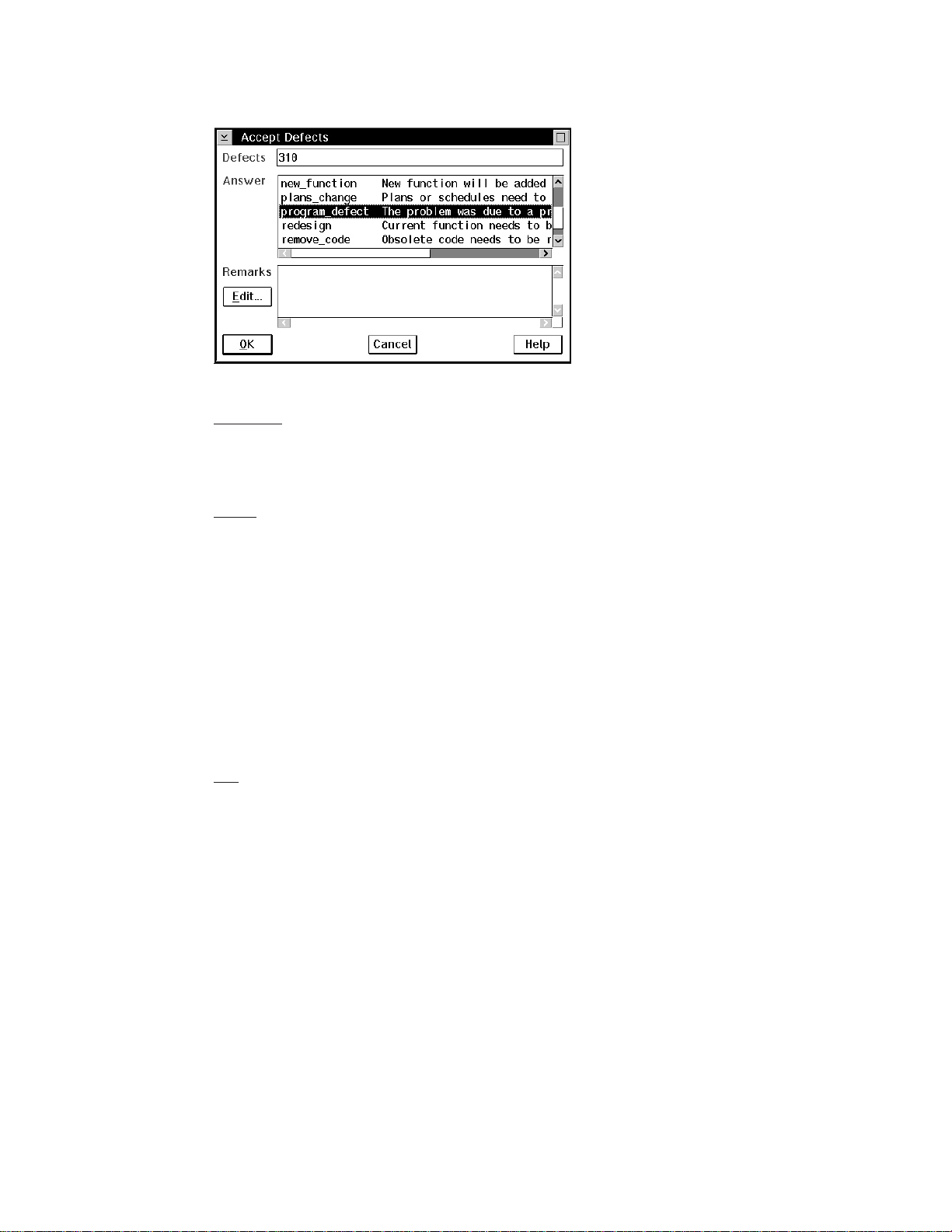
Figure 6. Accept Defects window
Command
From a command line, he issues the following command:
teamc defect -accept 310 -answer program_defect
Result
The defect goes to the working state.
Creating a work area
Because the component is not following a design, size, and review process, Alex needs
to manually create a work area in which to modify and build his parts. (If the component
follows a design, size, and review process, a work area is automatically created when
the defect moves to the working state, provided that sizing records have been accepted
for the defect.)
Before Alex checks out any parts, he creates a work area that will contain the latest
view of the parts in the release by doing one of the following:
GUI
From the GUI, he:
1. Selects Work areas → Create from the Actions pull-down menu on the Tasks
window.
2. Types 310 in the Work areas field and robot_control in the Releases field and
selects OK..
Chapter 5. Working with no component or release processes 53
Page 74

Note: 310 is the name of the defect that was opened for the problem, so this is
how Alex wants to identify the work area.
Figure 7. Create Work Areas window
Command
From a command line, he issues the following command:
teamc workarea -create -name 310 -release robot_control
Result
TeamConnection creates a work area named 310 associated with release robot_control.
The following parts are currently available in the latest view of release robot_control:
brain.c leg.c
brain.obj leg.obj
brain.exe foot.c
arm.c foot.obj
arm.obj optics.c
hand.c optics.obj
hand.obj
These parts are also visible in the work area 310 because the work area is associated
with the release upon creation, and it contains the latest view of the entire release.
Checking out a part
Alex wants to update a subroutine within optics.c, which controls the aperture of the
robot’s on-board camera. He checks the part out to start the modifications.
Because Alex knows the exact name of the part, he does one of the following:
GUI
54 User’s Guide
Page 75

From the GUI, he:
1. Selects Parts → Check out from the Actions pull-down menu on the Tasks window.
2. Types the following:
v optics.c in the Path names field
v robot_control in the Release field
v 310 in the Work area field
3. Selects OK.
Figure 8. Check Out Parts window
Command
From a command line, he issues the following command:
teamc part -checkout optics.c -release robot_control -workarea 310
Result
A copy of the part optics.c is checked out from TeamConnection and placed in the
directory specified on the Environment page of the Settings notebook of Alex’s
TeamConnection client. The part, optics.c, is locked. No other user can update the part
until Alex integrates his work area with the release.
Searching for a part
Because Alex knows exactly what part he wants to check out, he specifies the name of
the part. If he does not know the name, Alex can use the Parts Filter window or the
report command to search for the name. He can do one of the following:
GUI
From the GUI, he:
1. Selects Parts → Parts from the Objects pull-down menu on the Tasks window.
Chapter 5. Working with no component or release processes 55
Page 76

He does not select the PartFull choice because he wants to limit his search to a
particular release and work area. He uses PartFull when he wants to search for
parts across releases, components, or work areas.
2. Types the following in the Parts Filter window:
v robot_control in the Release field
v 310 in the Work area field
v % in the Base names field and selects like
3. Selects Save to Task List.
56 User’s Guide
Figure 9. Part Filter window
Alex does this because he realizes that he is going to use this query many times,
so he wants to add the query to the Tasks window.
4. Adds the necessary information to the Edit Task List window, and selects
Add/Change.
5. Closes the Edit Task List window. The Tasks window appears.
Page 77

Figure 10. Edit Task List window
6. Double-clicks on the task entry he just created. The Parts window appears.
Hereafter, to display the list of parts in his work area, he merely double-clicks on the
task entry.
7. Places the mouse pointer over the part name optics.c and presses mouse button 2
to display the pop-up menu.
8. Selects Check out. The Check Out Parts window appears with the required fields
pre-filled. If Alex provided directory information on the Environment page of the
Settings notebook, the Destination directory field is pre-filled also.
9. Selects OK to check out the part.
Command
From a command line, he issues the following command:
teamc report -view partView -where "baseName like '%.c'" -release robot_control
-workArea 310
Chapter 5. Working with no component or release processes 57
Page 78

This command returns a list of all the parts that match the query. After Alex determines
which part he wants to check out, he issues the following command:
teamc part -checkout optics.c -release robot_control -workarea 310
Result
A copy of the part optics.c is checked out from TeamConnection and placed in the
appropriate directory. The part optics.c is locked. No other user can update the part
until Alex integrates the work area with the release.
Checking in a part
Alex edits the part, making the modifications he thinks necessary. Now, he wants to test
the modifications. First, he checks the changed part back into his work area.
GUI
From the GUI, he:
1. Selects Parts → Check in from the Actions pull-down menu on the Tasks window.
2. Types the following in the Check In Parts window, and then selects OK:
v optics.c in the Path names field
v robot_control in the Release field
v 310 in the Work area field
58 User’s Guide
Page 79

Figure 11. Check In Parts window
Note: Alex follows these steps because he knows the exact name of the part that he is
checking in. If he does not know the name, or if he is checking in many parts, he
can instead do one of the following to display a list of parts:
v Select the entry on his Tasks window that displays the list of parts.
v Re-open the Parts window if it was previously minimized.
v Add an entry to his Tasks window that lists all of his checked-out parts.
He then selects the parts that he wants to check in.
Command
From a command line, he issues the following command:
teamc part -checkin optics.c -release robot_control -workarea 310
Result
At this point, it is important to note that the part is checked in to work area 310 and is
visible in work area 310 only. The change to optics.c is not visible at the release level
or to any other work area. Only the 310 work area contains the change, which is why
Alex must specify the work area on the check-out command. Because changes to parts
are isolated within work areas, the check-out command must specify which work area to
use so that the correct copy of the part is retrieved.
Chapter 5. Working with no component or release processes 59
Page 80

Thus, work area 310 contains the following parts:
brain.c leg.c
brain.obj leg.obj
brain.exe foot.c
arm.c foot.obj
arm.obj optics.c (modification 1)
hand.c optics.obj
hand.obj
Work area 310 continues to contain the unchanged parts from the requested release
view, but now the work area is overlaid with changes local to the work area — optics.c
in this case. Alex has his own copy of the application that he can modify without
impacting other developers. Alex has checked in optics.c; however, the modified part
remains locked until the work area is integrated with the release.
Verifying and testing part updates
Alex now requests a build of brain.exe, the high-level program for the robot control
application.
GUI
From the GUI, he:
1. Selects Parts → Build from the Actions pull-down menu. The Build Parts window
appears.
2. Types the following, and then selects OK to start the build:
v brain.exe in the Path name field
v robot_control in the Release field
v 310 in the Work area field
v normal in the Pool field
The Pool field tells TeamConnection which set of build agents will handle this build.
Alex got the name of the pool from his build administrator.
Alex could have selected brain.exe from a list of parts on the Parts window, and
then selected Build from the Selected pull-down menu. This action would have
placed some information in the fields, such as the path name and release name.
60 User’s Guide
Page 81

Figure 12. Build Parts window
Command
From a command line, he issues the following command:
teamc part -build brain.exe -release robot_control -workarea 310 -pool normal
Result
TeamConnection determines the parts that are needed for the build from the set of all
the part versions that are currently visible from work area 310. The following part
versions are selected for build:
brain.c leg.c
brain.obj leg.obj
brain.exe foot.c
arm.c foot.obj
arm.obj optics.c (modification 1)
hand.c optics.obj
hand.obj
After the build is complete, TeamConnection stores the resulting outputs of the build in
the work area 310. After the build, the work area contains these parts:
brain.c leg.c
brain.obj leg.obj
brain.exe (contains modification 1) foot.c
arm.c foot.obj
arm.obj optics.c (modification 1)
hand.c optics.obj (modification 1)
hand.obj
Chapter 5. Working with no component or release processes 61
Page 82
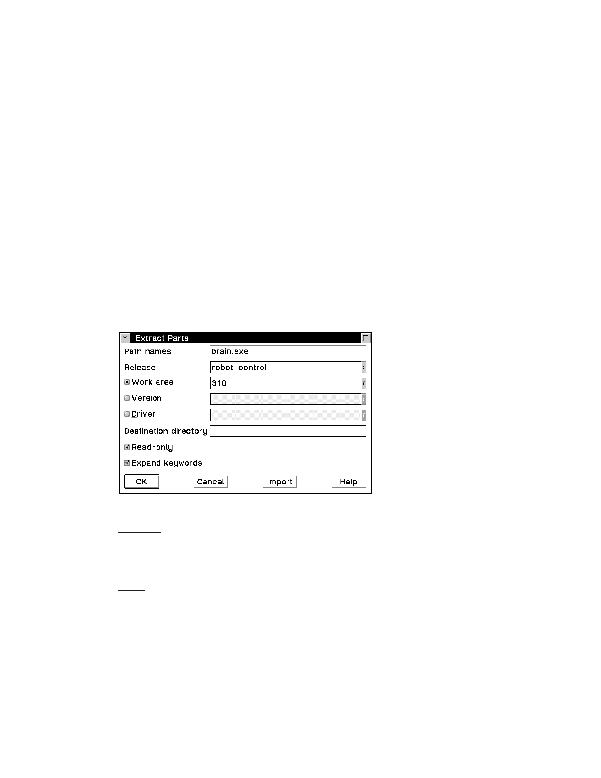
Note: For a detailed build example, see “Chapter 15. Building an application: an
example” on page 181.
Extracting a part
Next, Alex tests his modifications in the robot prototype in his office. He extracts the
executable part from the work area 310.
GUI
From the GUI, he:
1. Selects Parts → Extract from the Actions pull-down menu on the Tasks window.
2. Types the following in the Extract Parts window, and then selects OK:
v brain.exe in the Path names field
v robot_control in the Release field
v 310 in the Work area field
Alex does this because he wants to extract the .exe part that is in his work area.
If he leaves the Work area field blank, he gets the latest committed version of
the .exe part from the release.
62 User’s Guide
Figure 13. Extract Parts window
Command
From a command line, he issues the following command:
teamc part -extract brain.exe -release robot_control -workarea 310
Result
Page 83

This action places a copy of the part brain.exe in the current directory.
Checking out the part one more time
Alex then downloads brain.exe to his robot, runs his test, and determines that the
modification did not work: the robot slams into the wall. However, Alex thinks he knows
what the problem is, so he needs optics.c for further modifications. First, he checks out
the part.
GUI
From the GUI, he:
1. Does one of the following to display the Check Out Parts window:
v Selects Parts → Check out from the Actions pull-down menu on the Tasks
window.
v Selects the entry on his Tasks window that displays the list of parts, and then
selects the part.
v Re-opens the Parts window if it was minimized, and then selects the part.
2. When the Check Out Parts window appears, he types the necessary information
and selects OK.
Figure 14. Check Out Parts
Command
From a command line, he issues the following command:
teamc part -checkout optics.c -release robot_control -workarea 310
Result
A copy of the previously modified optics.c from work area 310 is checked out and
placed in the current directory.
Chapter 5. Working with no component or release processes 63
Page 84
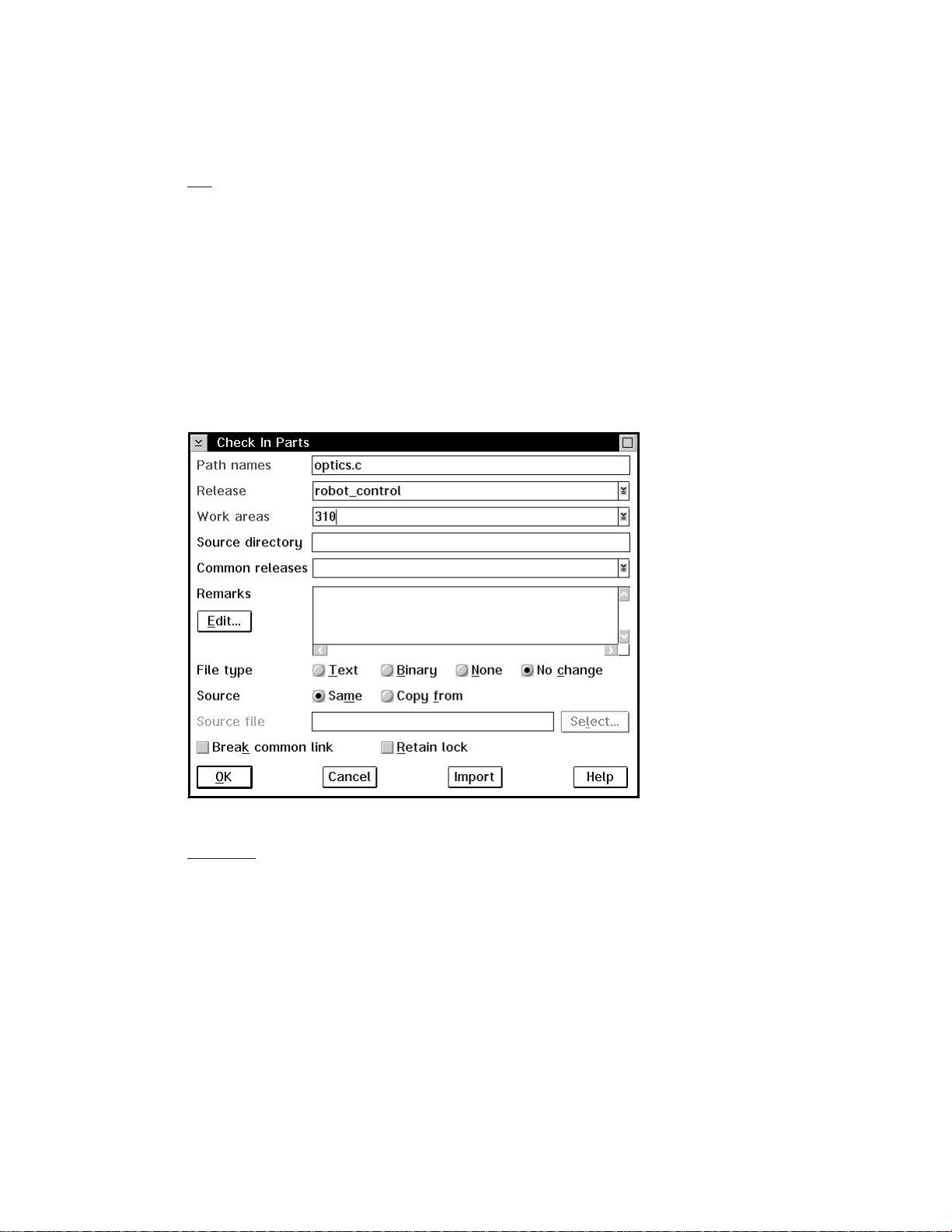
Checking the part back in
Alex makes his modification and checks the part in.
GUI
From the GUI, he:
1. Does one of the following to display the Check In Parts window:
v Selects Parts → Check in from the Actions pull-down menu on the Tasks window.
v Selects the entry on his Tasks window that displays all the parts he has checked
out, and then selects the part.
v Re-opens the Parts window if it was minimized, and then selects the part.
2. When the Check In Parts window appears, he types the necessary information and
selects OK.
64 User’s Guide
Figure 15. Check In Parts window
Command
From a command line, he issues the following command:
teamc part -checkin optics.c -release robot_control -workarea 310
Page 85
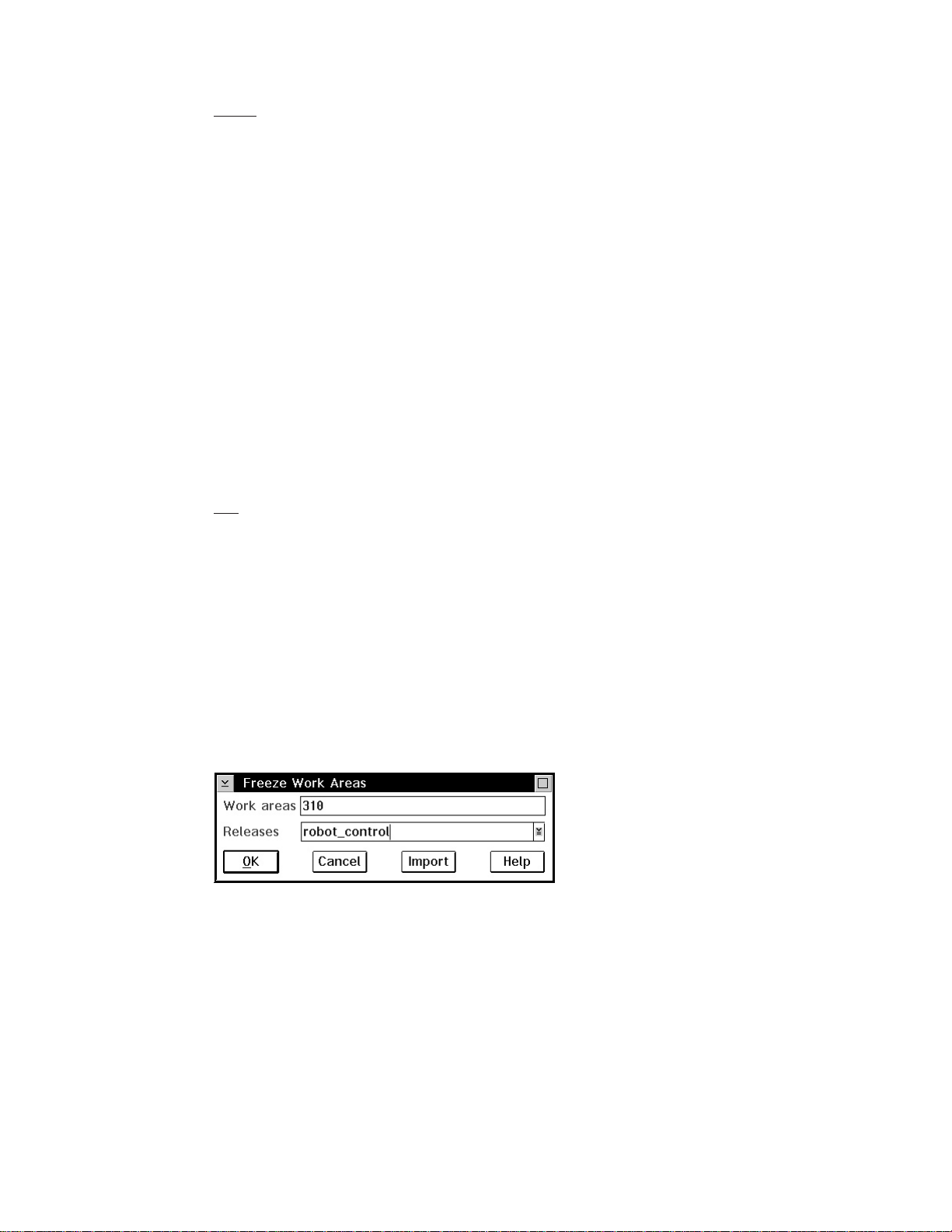
Result
Now the work area contains the following parts:
brain.c leg.c
brain.obj leg.obj
brain.exe (contains modification 1) foot.c
arm.c foot.obj
arm.obj optics.c (modification 2)
hand.c optics.obj (modification 1)
hand.obj
Because Alex did not specify that he wanted to save a copy of the work area by
freezing it, optics.c (modification 1) was overwritten.
Freezing the work area
Alex builds the application again, extracts the executable part, and runs his test. This
time, everything works, and the robot successfully finds its way to the snack machine
down the hall without hitting anything. Alex is very pleased, but he notices an unrelated
problem in the robot’s autofocus system. Before Alex begins repairing the autofocus
subroutine, he wants to save a copy of the application as it exists now in his work area.
So, Alex does one of the following to freeze the work area:
GUI
From the GUI, he:
1. Displays the Freeze Work Areas window in one of the following ways:
v Selects Work areas → Freeze on the Actions pull-down menu from the Tasks
window.
v Selects 310 from the list of work areas on the Work Areas window, then selects
Freeze from the Selected pull-down menu.
2. Types 310 in the Work areas field and robot_control in the Releases field if the
data is not already in the fields.
3. Selects OK.
Figure 16. Freeze Work Areas window
Chapter 5. Working with no component or release processes 65
Page 86

Command
From a command line, he issues the following command:
teamc workarea -freeze 310 -release robot_control
Result
The freeze command saves the work area 310. Thus, TeamConnection takes a
snapshot of the work area, with all its parts and their visible versions, and saves it. Alex
can come back to this stage of development in the work area if he wants. Note,
however, that a freeze action does not make the changes visible to the other people
working in the release, nor does it unlock the parts.
Refreshing the work area
Alex finally finishes his work on the robot’s optical systems after making three additional
attempts at modifying optics.c and rebuilding the application. Alex modified and rebuilt
the application a total of five times in the work area. Now, he wants to share his work
with the rest of the team. His work area currently contains the following parts:
brain.c leg.c
brain.obj leg.obj
brain.exe (contains modification 5) foot.c
arm.c foot.obj
arm.obj optics.c (modification 5)
hand.c optics.obj (modification 5)
hand.obj
66 User’s Guide
While Alex worked in his work area, other members of the team were working on their
own modifications. Some of these modifications have been integrated with the release,
so the copy of the release that Alex has is probably stale. If he were to integrate his
changes at this time with the release, he might cause the application to break.
Alex first refreshes his work area with parts from the release by doing one of the
following:
GUI
From the GUI, he:
1. Selects Work areas → Refresh from the Actions pull-down menu on the Tasks
window.
2. Types 310 in the Work areas field and robot_control in the Releases field.
Alex wants to refresh from the release, so he does not specify a source.
3. Selects OK.
Page 87
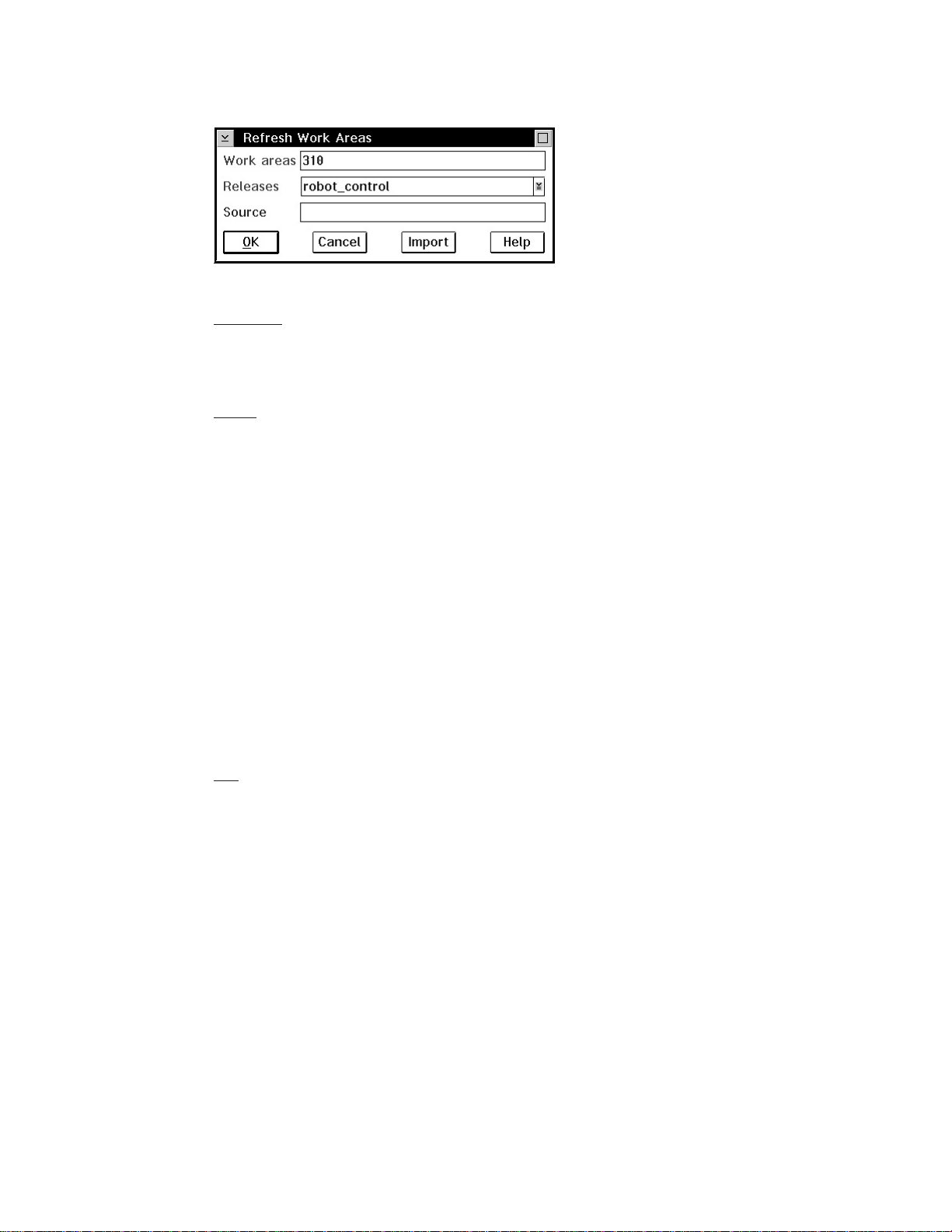
Figure 17. Refresh Work Areas window
Command
From a command line, he issues the following command:
teamc workarea -refresh 310 -release robot_control
Result
This action updates work area 310 with any changes from the release, and it also
freezes work area 310, if it is not already frozen. Now Alex’s work area contains the
following versions of parts:
brain.c (Jenny's modification) leg.c
brain.obj (from Alex's build after refresh) leg.obj
brain.exe (contains modification 5) foot.c
arm.c foot.obj
arm.obj optics.c (modification 5)
hand.c (Joy's and Ken's modification) optics.obj (modification 5)
hand.obj (from Alex's build after refresh)
None of the objects that Alex modified and none of the objects built as a result of Alex’s
modifications is overwritten by the refresh.
Building the application
Alex again builds the application brain.exe within his work area to determine whether
his changes integrate with Jenny’s, Joy’s, and Ken’s modifications.
GUI
Alex has a Parts window open with a list of all the parts that exist in work area 310. He
highlights the part brain.exe, and then does the following:
1. Selects Build from the Selected pull-down menu.
2. Types normal in the Pool field. The other required fields have the correct
information.
3. Selects OK to start the build.
Chapter 5. Working with no component or release processes 67
Page 88
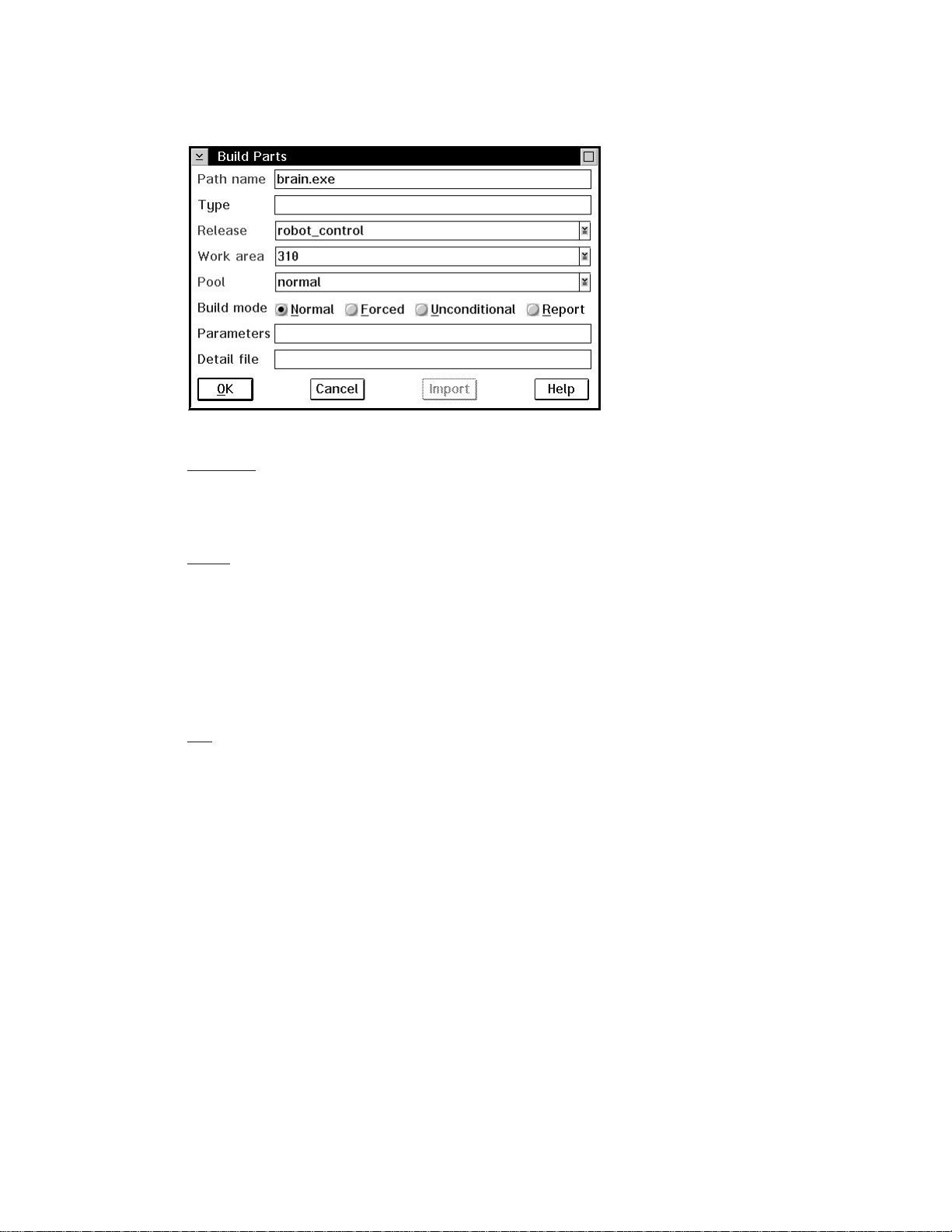
Figure 18. Build Parts window
Command
From a command line, he issues the following command:
teamc part -build brain.exe -release robot_control -workarea 310 -pool normal
Result
Fortunately, nothing breaks, so Alex is ready to integrate his changes with the release.
Integrating the work area
To integrate his changes with the release, Alex must integrate the work area he has
been using with the release. This will make the work area visible to all the users in the
release. He does one of the following:
GUI
From the GUI, he:
1. Selects Work areas → Integrate from the Actions pull-down menu on the Tasks
window. The Integrate Work Areas window appears.
2. Types 310 in the Work areas field and robot_control in the Releases field.
3. Selects OK.
68 User’s Guide
Page 89

Figure 19. Integrate Work Areas window
Command
From a command line, he issues the following command:
teamc workarea -integrate 310 -release robot_control
Result
TeamConnection first determines that Alex’s changes were built against the latest
version of the release. Then TeamConnection makes Alex’s changes visible at the
release level so that the other team members can see and use them. The following part
versions are now visible from the release:
brain.c (Jenny's modification)
brain.obj (from Jenny's build)
brain.exe (from Alex's build)
arm.c
arm.obj
hand.c (Joy's modification, Ken's modification)
hand.obj (from Ken's build)
leg.c
leg.obj
foot.c
foot.obj
optics.c (Alex's modification 5)
optics.obj (from Alex's build)
TeamConnection also makes a copy of the release before integrating Alex’s changes. If
something doesn’t work, the users or the administrator can go back to the release prior
to Alex’s integration. The part, optics.c, is now unlocked in the release. The work area
is now in the complete state and can no longer be used.
Closing a defect
Now that Alex is finished making changes to fix the problem reported in defect 310, he
is ready to close the defect. He does one of the following:
GUI
Chapter 5. Working with no component or release processes 69
Page 90

From the GUI, he:
1. Selects Defects → Verify from the Actions pull-down menu on the Tasks window.
The Verify Defects window appears.
2. Types 310 in the Defects field.
3. Selects OK.
Figure 20. Verify Defects window
Command
From a command line, he issues the following command:
teamc defect -verify 310 -release robot_control
Result
Because the component does not include the verifyDefect subprocess in its process,
the defect moves directly to the closed state.
Working in concurrent development
The previous section discussed working in a serial development environment. While
Alex had optics.c in his work area, no one else on the team could check out the part.
TeamConnection allows you to hold the part until you are sure that it integrates with the
rest of the application. Therefore, the lock is not released until the work area as a whole
is integrated with the release.
The scenario changes slightly for concurrent development. In this case, several users
can work on the same part at the same time. These users must reconcile their changes
as they integrate their work areas with the release.
70 User’s Guide
Page 91

The following tasks are required:
For information about this task, Go to this
Refreshing the work area from the driver 71
Integrating the work area 72
Resolving differences 73
Refreshing the work area from the driver
If Alex and Jenny are working on optics.c at the same time, they must resolve their part
differences at some point, because both want to make their changes visible to the
release. If Alex and Jenny were not required to do this before committing their work
areas, the last developer to commit would always overlay the other’s changes. For this
scenario, assume that Jenny finishes her changes first. The first thing she does is
refresh her work area.
GUI
From the GUI, she:
1. Selects Work areas → Refresh from the Actions pull-down menu on the Tasks
window.
2. Types 415 in the Work areas field.
3. Types robot_control in the Releases field. Jenny wants to refresh from the driver.
4. Types driver name in the Source field.
5. Selects OK.
page.
Figure 21. Refresh Work Areas window
Command
Chapter 5. Working with no component or release processes 71
Page 92

From a command line, she issues the following command:
teamc workarea -refresh 415 -release robot_control
Result
This command refreshes her work area with the latest view of the release. Her work
area now contains the following part versions:
brain.c (Jenny's modification 3)
brain.obj (Jenny's modification 3)
brain.exe (has Jenny's brain.c modification 3 and optics.c modification 4)
arm.c
arm.obj
hand.c (Joy's modification, Ken's modification)
hand.obj (Joy's modification, Ken's modification)
leg.c
leg.obj
foot.c
foot.obj
optics.c (Jenny's modification 4)
optics.obj (Jenny's modification 4)
Integrating the work area
The refresh shows Jenny only the parts integrated with the release. She does not see
Alex’s work because he has not integrated his work area yet. Jenny rebuilds the
application, tests it, and decides she is ready to integrate her changes. She does one of
the following:
72 User’s Guide
GUI
From the GUI, she:
1. Selects Records →Fix records →Complete from the Actions pull-down menu on the
Tasks window. The Complete Fix Records window appears.
2. Types 415 in the Work areas field, robot_control in the Releases field, and
robot_component in the Component field.
3. Selects OK.
Page 93

Figure 22. Integrate Work Areas window
Command
From a command line, she issues the following command:
teamc workarea -integrate 415 -release robot_control
Result
Because Jenny is up-to-date with the latest view of the driver, her changes are
integrated after TeamConnection preserves a copy of the previous version of the
release.
Reconciling differences
Later, Alex is ready to integrate his modifications. Alex issues a refresh command from
the driver, as Jenny did (see page 71 for instructions).
This time, Alex receives a message that collision records were generated, because both
he and Jenny have updated the same parts. At this time he does not know which parts
collided. TeamConnection refreshes work area 310 with the exception of the part
optics.c, which had the collision. Alex’s work area shows the following parts:
brain.c (Jenny's modification 3)
brain.obj (Jenny's modification 3)
brain.exe (Contains Alex's modification 5)
arm.c
arm.obj
hand.c (Joy's modification, Ken's modification)
hand.obj (Joy's modification, Ken's modification)
leg.c
leg.obj
foot.c
foot.obj
optics.c (Alex's modification 5)
optics.obj (Alex's modification 5)
Chapter 5. Working with no component or release processes 73
Page 94

Alex can use either the GUI or the command line to reconcile the differences. Four
steps are required from the command line:
1. Check out the latest uncommitted version.
2. Extract the latest committed version.
3. Run the merge program against the two parts.
4. Check in the resultant part.
However, on the GUI the reconcile action automatically does the preceding steps for
you, which can save you a considerable amount of work if several parts require
reconciliation.
GUI
From the GUI, he:
1. Selects Parts → Collision Records from the Objects pull-down menu. The Collision
Record Filter window appears.
2. Types 310 in the Work areas field and selects OK. The Collision Records window
appears with optics.c listed as the part having the collision.
3. Highlights the optics.c entry and selects Reconcile from the pop-up menu. The
Reconcile Collision Record window appears with the required information pre-filled.
Alex does not have to reconcile every part for which a collision record is created.
He can choose either his copy or the copy at the release rather than combining the
two. For example, if Alex wants to use his copy of optics.c without merging with the
copy at the release level, he selects the reject action (of course, he would not do
that without first talking with Jenny). If he wants to use the copy of optics.c at the
release level without merging any of his changes into the copy at the release level,
he selects the accept action.
4. Because Alex wants to combine the two sets of changes, he selects Merge to start
the TeamConnection merge program, or any merge program of his choice. Alex
merges the changes and then saves and exits from the merge program.
TeamConnection checks the resultant part back in as part of this merge step.
The online help provides information on how to use the merge program.
5. Selects OK from the Reconcile Collision Record window.
74 User’s Guide
Page 95

Figure 23. Reconcile Collision Record window
Command
From a command line, he does the following steps:
v Issues a report command to determine which parts are in conflict:
teamc report -view collisionView -workarea 310
This report tells him that optics.c is the part that collided and gives the
version ID
of the part that caused the collision. Alex makes note of the alternate
alternate
version ID, robot_control:2, because he needs to specify that in a later step.
v Extracts a copy of optics.c from the release:
teamc part -extract optics.c -release robot_control -relative d:\temp
By not specifying a work area on the part -extract command, Alex ensures that he
receives the last committed copy of the part at the release. Also, Alex specifies a
relative
path for the part extract. By specifying the relative directory, he prevents
TeamConnection from placing the part in his default directory, where he normally
works on checked-out parts. For more information about the -relative flag, refer to the
Commands Reference
v Checks out his copy of optics.c from his work area:
teamc part -checkout optics.c -release robot_control -workarea 310
Because he did not specify a relative path, this part is checked out to his working
directory d:\robot.
v Uses the merge program to reconcile the two copies of optics.c:
tcmerge d:\temp\optics.c d:\robot\optics.c -out
d:\robot\optics.c -prime d:\temp\optics.c
Chapter 5. Working with no component or release processes 75
Page 96

If Alex decides not to merge the two parts, but instead wants to use his copy of
optics.c, he uses the collision -reject command. Or, if he wants to use the copy of
optics.c at the release level, he uses the collision -accept command.
v Checks the resultant copy of optics.c into his work area and builds it against the rest
of the system.
v After he is satisfied with the reconciled changes, he lets TeamConnection know that
the previously discovered conflict is reconciled. Alex does this by completing the
collision record that TeamConnection created when Alex attempted to integrate his
copy of optics.c. He does the following:
teamc collision -reconcile -path optics.c -release robot_control
-workarea 310 -altversion robot_control:2
Result
Alex is now ready to make his changes visible to the release. He can use either the
GUI or the command line to integrate the work area.
He refreshes from the driver again. The integrate is permitted because a completed
collision record exists for the conflict between the two versions of optics.c. However, if
Ken or Joy had integrated a new version of optics.c while Alex was busy resolving the
last collision, Alex’s driver add would fail. He would have to repeat the collision
resolution process.
76 User’s Guide
Page 97

Chapter 6. Working with component and release processes
The previous chapter described how to work with parts when the release does not
follow a tracking process. This chapter describes how to work with parts when a
tracking process
defects.
When tracking is part of the process, users must associate any changes to their parts
with the defects or features active for the release. This association is made through a
work area. The work area is the object that ties a defect or feature with a specific
release. When checking out a part, the user must specify the work area with which the
modification is associated. For any release and defect or feature pair, there can be
multiple work area objects.
Aside from their association with a defect or feature, the work areas for a full-tracking
process environment are identical to those defined for working in a no-tracking process
environment. Work areas maintain a separate view for the user working on the
modifications associated with a defect or feature without affecting the release. This view
can be integrated with the release at some point. A work area is implicitly created when
a defect or feature is accepted if the managing component follows a design, size, and
review process for defects and features and if a sizing record is created. The work area
that TeamConnection creates is based on the sizing record and has the same name as
the defect or feature. If sizing records were not created, you must explicitly create the
work area.
As an example of how this all works, suppose that the robot project from the previous
chapter is entering system test. The administrator decides to turn on a full-tracking
process for the release, such as track_full. This process includes the track, approval,
fix, driver, and test subprocesses. The release follows concurrent development, and the
component follows a design, size, and review process for both defects and features.
is
followed and how to use component processes for features and
On a weekly basis the project leader, Carol, creates a driver. A
implements the integration of part changes within a release. These part changes are
included in a driver by adding the work areas referenced by the changed parts to the
driver as
One of the testers for the robot project discovers that the autofocus mechanism in the
robot’s eye fails when the robot is placed in front of striped wallpaper. The tester must
open a defect against the component optics, which is owned by Carol. Carol verifies
that the problem does exist, accepts the defect, and assigns it to Alex. This fix will
require the tasks noted in the following table:
For information about this task, Go to this
Changing the defect owner 79
Accepting the defect 80
© Copyright IBM Corp. 1992, 1995, 1996, 1997, 1998
driver members
.
driver
monitors and
page.
77
Page 98

For information about this task, Go to this
page.
Approving the fix 81
Checking out a part 82
Checking in the changes 83
Freezing the work area 85
Building the application 86
Accepting fix records 87
Adding a driver member 88
Returning the work area to the fix state 89
Reactivating the fix record 90
Refreshing the work area 90
Refreshing the driver 91
Building the driver 92
Restricting the driver 93
Integrating the parts 94
Completing the driver 95
Testing the built application 96
Moving through design, size, and review
Because the defect was created against a component that follows the design, size, and
review process for defects, Carol must move the defect through this process before the
defect can be accepted and parts can be checked out. As the names imply, the process
requires that the following be done:
v Design what needs to be done in order to resolve the problem. She must enter
design text before the defect can move to the size state.
v Size the amount of work that is required to resolve the problem. At this time, Carol
creates a sizing record and specifies robot_control as the release that contains the
parts that require changing. If parts in other releases require changing because of
the defect, a sizing record is created for each release. A sizing record assures that a
work area is created when the defect is accepted. It identifies the work that is
required for and the resources affected by the defect or feature. The owner of the
component that is referenced in the sizing record is the owner of the sizing record.
The owner is responsible for entering information about the amount of work that is
required to implement the feature or resolve the problem.
v Review all design text and sizing records and determine if work should continue on
the defect.
78 User’s Guide
Page 99
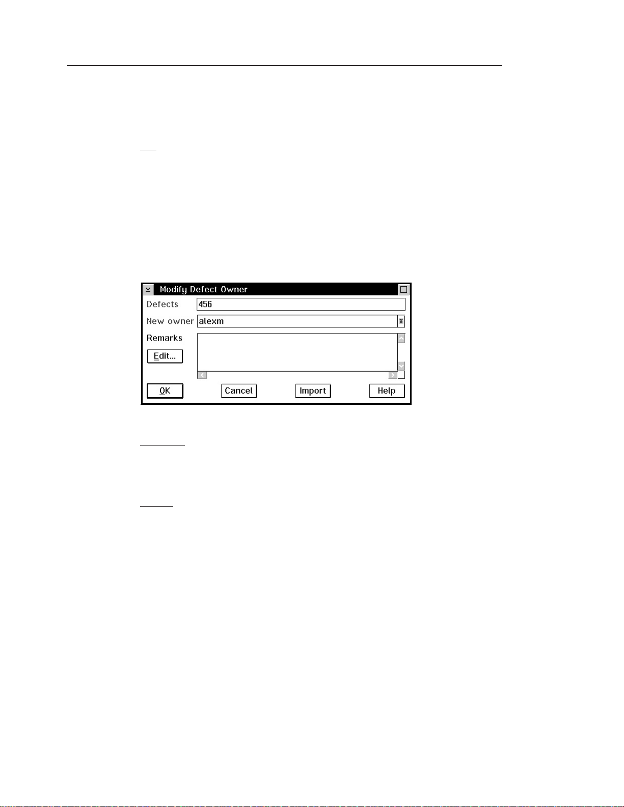
Changing defect ownership
Because Carol is the component owner, she is currently defined as the owner of defect
456. But the problem is in Alex’s code, so she wants him to own the defect. To reassign
ownership, she does one of the following:
GUI
From the GUI, she:
1. Selects Defects → Modify → Owner from the Actions pull-down menu on the Tasks
window. The Modify Defect Owner window appears.
2. Types 456 in the Defects field and types Alex’s user ID, alexm,intheNew owner
field.
3. Selects OK.
Figure 24. Modify Defect Owner window
Command
From a command line, she issues the following command:
teamc defect -assign 456 -owner alexm
Results
Alex is now the owner of defect 456. He is responsible for fixing the problem and
moving the defect through its various states.
Chapter 6. Working with component and release processes 79
Page 100

Accepting a defect
When you accept a defect or feature, you accept the responsibility of resolving it. A
defect or feature might require changes in more than one release. If the component
includes the design, size, and review process, these releases were identified during the
size state, and TeamConnection created a work area for each identified release. If the
component does not include the design, size, and review process, you will need to
create a work area manually.
When the first work area moves to the complete state, the defect or feature
automatically moves to the verify state or closed state.
Alex, now the owner of the defect, accepts the defect by doing one of the following:
GUI
From the GUI, he:
1. Selects Defects → Accept from the Actions pull-down menu on the Tasks window.
The Accept Defects window appears.
Note: The Accept Defects window in this example may be different than one you
2. Types 456 in the Defects field and selects program_defect from the Answer list.
3. Selects OK.
may see based on your environment. Configurable fields may or may not be
shown depending on any configurable fields set by you or your administrator,
80 User’s Guide
Figure 25. Accept Defects window
 Loading...