

Page 1
The
information
programmer
(Form
No.
information
RAMAC®305 REFERENCE SUMMARY
contained
and
operator.
A26-3502).
is
required.
in
this
It
is
Reference
summary
condensed
should
is
from
be
intended
the
made
IBM
to
as
that
an
aid
RAMAC
manual
for
305
the
more
Reference
when
experienced
more
complete
Manual
© 1957, 1958, 1959, 1960 by
International
RAMAC 305
Business
Machines
Corporation
Page 2
Systems
Summary
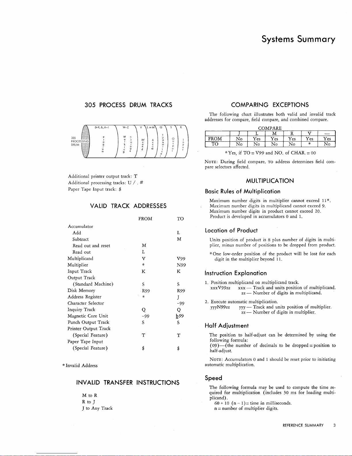
305
PROCESS
305
PROCES
DRUM
Additional printer
Additional processing tracks: U / . #
Paper Tape Input track: $
Accumulator
Add
Subtract
Read out and reset
Read out
Multiplicand
Multiplier
Input
Track
Output
Track
(Standard Machine)
Disk Memory
Address Register
Character Selector
Inquiry Track
Magnetic Core
Punch
Output
Printer
Output
(Special Feature)
Paper Tape
(Special Feature)
VALID
Unit
Track
Track
Input
output
TRACK
track: T
* Invalid Address
DRUM
TRACKS
ADDRESSES
FROM
M
L
V
*
K
S
R99
*
Q
-99
S
T
$
TO
L
M
V99
N99
K
S
R99
J
-99
Q
1299
S
T
$
COMPARING
The
following chart illustrates both valid and invalid track
addresses for compare, field compare, and combined compare.
* Yes, if
NOTE:
During
pare selectors affected.
TO
= V99 and
field compare,
MULTIPLICA
Basic
Rules
of
Multiplication
Maximum number digits in multiplier cannot exceed
Maximum number digits in multiplicand cannot exceed
Maximum number digits in product cannot exceed 20.
Product
is
developed in accumulators 0 and
Location
Units position of product
plier, minus number of positions to be dropped from product.
of
Product
EXCEPTIONS
NO.
of CHAR. = 00
TO
address determines field com-
TION
1.
is
8 plus number of digits in multi-
11
9.
* One low-order position of the product will be lost for each
digit in the multiplier beyond
Instruction Explanation
1.
Position multiplicand on multiplicand track.
xxxV99zz xxx - Track and units position of multiplicand.
2.
Execute automatic multiplication.
yyyN99zz
Half
Adjustment
The
position to half-adjust can be determined by using the
following formula:
(09)
-(
half -ad just.
NOTE:
automatic multiplication.
zz -Number
yyy
- Track and units position of multiplier.
zz -Number
the number of decimals to be dropped = position to
Accumulators 0 and 1 should be reset prior to initiating
11.
of digits in multiplicand.
of digits in multiplier.
*.
INVALID
M to R
R to J
TRANSFER
J to Any Track
INSTRUCTIONS
Speed
The
following formula may be used to compute the time re-
quired for multiplication (includes 30 ms for loading multi-
plicand).
60 +
10
(n
-
1)=
time
in
n
= number of multiplier digits.
milliseconds.
REFERENCE
SUMMARY
3
Page 3

AUTOMATIC DIVISION
Basic
Rules
of
Division
Maximum number digits in dividend cannot exceed 19.
Maximum number digits in divisor cannot exceed
Maximum number digits in quotient cannot exceed 19.
Maximum number digits' in divisor plus maximum number
digits in quotient cannot exceed
20.
9.
OPERATING
370 Printer Output
80 positions
60 positions
40 positions
20 positions
Punch Output
Card Feed Input
Typewriter Output
Automatic Typing
Manual Typing (average)
Tabulations (average)
Carriage Returns (average)
(29
(36.5
(50
(84
( 100
(125
SPEEDS
LPM)
LPM)
LPM)
LPM)
CPM
max.)
CPM max.)
100
200
300
1000
2050
ms/line
1640
ms/line
1200
ms/line
720
ms/line
600 ms/card
4so
ms/card
ms/
character
ms/
character
ms/tab
ms/
return
Location
Units position of quotient is in 119.
Location
Units position of remainder in L08 minus number of digits in
excess of
of digits in divisor.)
Instruction
1. Position dividend in accumulators 0 and
xxxLyyzzb5 xxx - Track and units position of dividend.
2.
Position divisor on multiplicand track.
xxxV99yy
3. Execute automatic division.
L09P99xx xx - Twice the number of digits in quotient.
Half
Increase the number
(3)
read quotient from position L18. Remainder is also positioned
one position to the left.
sion.)
NOTE:
mum whole number
figures.
of Quotient
of
Remainder
11.
(Number
Explanation
yy
zz -Number
xxx-
yy -Number
Adjustment
above, add 5 to
If
number
of digits in remainder equal number
1.
- Maximum whole number digits
tient plus 8. (Cannot exceed 19.) Maximum whole number digits in quotient is
maximum digits in dividend minus minimum digits in divisor plus one.
Track and units position of divisor.
added zeros.)
quotient exceeds
to right of divisor equal to number in
excess of
instruction.
of
of
of
digits, then additional digits are decimal
of digits in dividend.
of digits in divisor. (Including
If
number of digits of
11, zeros must be added
11
before execution
digits in quotient by one
119
after execution of instruction, and
(Do
not exceed basic rules
digits in quotient desired exceeds maxi-
in
instruction
in
of
of
quo-
this
divi-
Speed
The
following formula may be used to compute the
quired for division (includes
plus
30 ms for loading divisor).
100 + 20
n
(n -1)
= number
= time in milliseconds.
of
quotient digits.
30 ms for positioning dividend
time
re-
Disk
Storage
Seek time disk to disk:
SOo
ms/
Seek time track to track, same disk:
250
ms/max
Seek time record-to-record, same track:
50
ms
Transfer disk
so
ms/max.
Transfer drum to disk:
130 ms/max. 105 ms/avg. 80
Other Operating
Track-to-track transfer
Control panel test additional 20
Record advance additional 30
Skip-to-record additional
Addressing Address Register additional 20
Cycle Delay additional 30
NOTE:
tions which normally require
pleted in
Features of the RAMAC 305 are summarized below.
feature, the table indicates the number
standard machine, the units in which each optional addition may
be made and the maximum available capacity.
305
FEATURES
Character selectors
Distributors
Selectors 10
323
FEATURES
Co-Selectors
Pilot Selectors 0
Digit
Selector 1
Offset Stacker
DPBC
positions 20
FEATURES
370
Co-Selectors
Pilot Selectors
Skip Stops
*One 4S-position character selector standard.
**5-position
t2-position
Timing
max. 600
to
drum track:
ms/
175 ms/avg. 100 ms/min.
55
ms/avg. 30 ms/min.
Speeds
on
If
Program Exit Overlap
30 ms.
FEATURE
Standard
Standard Increment
Standard
avg. 400
drum
50
ms for execution may be com-
ms/
min.
ms/min.
is
installed, certain instruc-
SUMMARY
of
units included in the
Increment
3*
100
()
0
4**
0
6
3
20
,10
4**
5t
1
10
Increment
4**
5t
5
30
30
For
each
Maximum
6
120
40
Maximum
20**
lOt
2
1
80
Maximum
12**
lOt
11
ms
ms
ms
ms
ms
ms
4 IBM RAMAC
305
Page 4

DIGIT
NO
DIGIT
1
2
3
4
5
6
7
8
9
11
12
CONSOLE READING AID
ZONES
CHAR
0
x
•
•
• •
•
• •
•
•
•
•
•
• •
•
•
•
•
•
•
•
•
•
• •
•
•
•
X
•
•
•
•
•
•
•
•
•
•
•
•
•
•
•
•
•
•
•
•
0
-
&
0
A
J
/
1
B
K
S
2
c
L
T
3
D
M
U
4
E
N
V
5
F
0
W
6
G
p
X
7
H
Q
y
8
I
R
Z
9
$
#
I!
*
%
@
CONSOLE
The
Console
(
On
Left)
operator
decipher
instruction
easi
Iy. It should
following
I.
of
2.
3.
4.
In
the
following
and 4 lights
XOl248
..
Because
the
zone
lights
chart
should
condition.
X
and
0 in
followed
sented,
which
READING AID
Reading
is
designed
the
lights
more
be
manner:
Mentally
arrive
the
numeric
For
example:
1 2 4 8
0.00
.0.0
•••
oooe
Refer
to
the
digit
which
this
sum.
Find
the
proper
opposite
this
Follow
across
letter,
or
represented
example;
are
glowing:
~
6
numeric
opposite
be
checked
The
matching
this
example}
across
to
the
in
this
{left
special
Aid
to
help
binory
quickly
used in
at
the
lights
0
chart
for
corresponds
hand
zone
digit.
to
the
character
by
these
the
lights
total
the
digit 6 on
for a
zone
should
character
case
is
the
coded
and
the
sum
glowing.
the
column}
lights
number,
lights.
X,
6,
matching
pattern
then
repre-
the
to
0,
the
letter
the
READ,
The
the test lock
2,
The
the Test Lock
WRITE,
AND
ALTER
SUMMARY
following diagrams show the sequence of operations
On
or
Off.
Test
Lock
On
1st
~
2nd
~
3rd
I Write I
TesT
Lock
Off
1st
B
2nd
8
3rd
I Write I
TEST
following is a resume
ON
and
LOCK
with
it
to
On
From
To
Parity
From
Q
On
From
Q
Q
Q
Q
Q
To
From
To
[;J
[;J
FUNCTIONS
of
console keyboard operations
OFF.
with
with
Test Lock
Make disk file inquiries during processing
when
{an
be
F.
Make disk file inquiries
Make
drum
Make
track inquiries during processing
drum
track inquiries when
Alter a record in the disk storage file
Alter a
drum
track record
Read from
Correct parity errors
drum
track
________________________________________________
not processing
not
________________________________________
"M"
(clear
____________
________
________
processing
____
____________________
Yes
accumulators) Yes
ON
OFF
No
Yes
No
Yes
No
yes
No
Yes
No No
No
No
No
Yes
NOTE:
Dual
Access
Select
Hubs,
accept
only
RAMAC
RAMAC
during
an
NOTE: Any inquiries directed to the disk storage file
processing will be replied to only as provided for in the program.
CYCLE
exit
Cycles
cycle
CHART
Timing
Chart
Delay
DELAY
Regenerated
Impulses
Emit.Used
to
Return
Stored Prog
or
Select
Access
Arm
EXI
T
REFERENCE
to
during
SUMMARY
5
Page 5
Console
Operating
START-STOP
PROCEDURES
\
Starting the Machine After a
Power-Off
1.
Depress
sole
2. Depress
Hold
3.
and
4. Depress
by
5.
Place
of
6.
Place
reader
7.
If
Load
depress
Restarting the Same Job
To
restart
press
the
Starting or Stopping
To
Start:
1. Set
step.
Set
2.
operation-RUN,
3. Depress
4. Depress
To
Stop:
1.
Set
step.
2. Set
Inquiries-File
When
1.
The
The
2.
3.
Depress
4. Key
Inquiries-File
ITI0ff:
I.
Test
Control
2.
3.
Depress
Inquire
4.
5. Key
ITI0n:
I.
The
2.
The
3.
Depress
Condition
the
lights
the
the
punch
the
Ready
any
the
program.
the
operation.
the
hopper.
a
new
program
button.
the
the
reader
the
Program
the
Control
the
Program
the
Program
the
Control
Not
Test
machine
the
in
the
Lock
Selector
the
light
in
the
Test
Control
the
Power-on
have
printer
Control
Control
desired
If
reader
same
start
Program
key
turned
Start
light
the
key.
Selector switches
Selector switch to
SINGLE
Start.
Selector switches
Selector
at
on,
depress
Start
key.
key
down
is
on.
Impulse
Selector
data
is
job,
switch
or
program
to
be
loaded,
program
Start
key.
place
at
a Specific Program Step
OPERATION,
Set key.
switch
INQUIRIES
Information
Processing
Lock
must
be
must
desired
desired
Information During Processing
must
desired
comes
record
Lock
must
Selector switch
desired
off.
be
reset-depress
Format
five-digit address.
be
off.
switch
should
Format
key.
on
immediately.
address.
be
off.
Format
key.
Procedures
the
console.
until
buttons
is
already
cards
to
to
to
key.
be
should
After
the
Reset
cards
that
to
the
desired
load
depress
in
in
the
the
desired
the
desired
etc.
the
desired
CONTROL
Reset.
set
to
RUN.
be
set
cards
the
feed
to
key.
stop
are
the
machine,
STOP.
RUN.
the
con-
feeding
required
mode
in
the
Program
and
de-
program
mode
program
of
4.
When
the
IN
will
Delay
the
program
hub,
Inquiry
quiry
program
uous
When
5.
address.
Inquiries-Drum
When
Not
1.
The
Test
The
Control
2.
3. Depress
4.
Depress
Processing
Lock
the
the
ALTERATIONS
Altering Part
on
a Drum Track
I.
The
Test
Lock
2.
Depress
Select
3.
character
Depress
4.
Duplicate
5.
by
tion
6.
Type
7. Depress
completed.
8.
Depress
Depress
9.
tion
holding
to
to
the
type
be
the
the
proper
key.
the
the
down
changed.
new
the
the
any
reaches
the
Inquiry
stop.
(The
and
Exit
cycles.)
light
Cycle
turns
Information
may
be
either
Selector
Read
desired
switch
key
(read
character
TO
of
the Information
must
be
on.
Read
key.
track
by
Alter
key
to
on
the
track
information.
Clear
Write
desired
place
Q track.
information
the
DUP
key
after
key.
track
key.
key
the
step
light
will
lights
on,
on
or
is set
on
to
"Q")
key
on
DRUM
depressing
the
keyboard
on
Duplicate
all
alterations
except
which
turn
will
show
key
in
the
off.
RUN.
.
the
keyboard.
TRACKS
the
corresponding
the
typewriter
up
R.
tests
on
and
five-digit
in a condi-
to
the
have
Altering a Complete Drum Track
I.
The
Test
Lock
must
be
on.
2.
Clear
the
ing
this
3.
Depress
tion
Type
4.
5.
Depress
6.
Depress
Select
7.
character
Q track.
the
Read
order.
the
to
type
the
the
the
the
key.
TESTING
key,
Alter
on
desired
Clear
Write
desired
This
may
Space
to
place
Q track.
if
typing
by
depressing
be
bar,
the
key
the
information.
key
key.
track
PROCEDURES
accomplished
and
the
the
keyboard
less
than
100
the
corresponding
by
depress-
Clear
in a condi-
characters.
Testing Typewriter Control Panel Formats
1.
Inquiry
a.
b.
c.
d.
e.
format
Depress
Turn
Depress
Key
in
Depress
of
operation
the
the
the
the
the
Reset
selector
appropriate
desired
Program
on
the
key.
control
switch
Format
file address.
Start
key
typewriter
to
key (1,
one
time
control
FORMAT
2,
or
for
each
panel
program.
the
Inthe
contin-
track
posi-
been
key
TEST.
3) .
cycle
in
6 IBM RAMAC 305
Page 6

2.
Document-printing
a.
Reset
The
Turn
Depress
of
operation
the
test
the
the
b.
c.
d.
process
record
Selector
Program
on
format
must
the
Program Testing
Method I executes a program,
2
executes
stopping.
1.
2.
3.
4.
5.
6.
7.
NOTE:
during
write
File
several
program
The
Test
Lock
The
File
not
is
impossible
the
to
the
program
Interlock
be
plugged.
program
the
first
control
should
it
Turn
spond
place
Place
through a normal
After
the
gram,
TION.
When
will
If
it
and
corresponding
onto
light
processing
turn
the
the
Program
perform
the
operator
is necessary
then
type
Because
this
procedure,
the
disk
will
glow.
one
only
character
the
should
switch
to
destroy
selector
program
selector
load
program
Control
Start
program
wishes
to
out
the
File
each
storage,
Operation
unit.
be
on
Control
Start
typewriter
one
steps
or a complete
METHOD
be
1
off.
on
By
leaving
a file
switches
that
on
cards
in
load
unit
has
Selector
key is
step
to
examine a track
depress
desired
key.
Interlock
time
the
machine
may
the
switch
key
one
control
step
the
process
this
record.
is
CONTROL
the
machine,
routine.
stopped
switch
depressed,
at a time.
the
Keyboard
track
switch
the
program
be
resumed
typewriter
to
FORMAT
time
for
panel
at a time;
routine
control
switch
so
that
to
be
executed,
STOP.
on
the
to
SINGLE
by
depressing
is
not
jack-plugged
will
stop
track.
TEST.
each
cycle
program.
method
before
panel
unplugged,
they
corre-
and
proceed
first
OPERA-
the
machine
at
any
time,
Read
attempts
and
by
depress-
and
pro-
key,
the
the
to
ing
the
Check
next
Start.
Test
File
is
impossible
the
the
the
step
this
have
Because
this
onto
will
Reset
program
Start.
Reset
program
Lock
Interlock
not
be
the
program
to
the
control
processing
first
routine,
of
the
point,
been
This
may
Read
key
the
procedure,
the
disk
glow.
key,
to.
the
Program
1.
The
2.
The
should
it
3.
Turn
spond
place
4.
After
of
first
5.
At
that
order.
board
NOTE:
during
write
File
light
the
Check
the
next
Program
Track Clearing
Clearing a track
can
be
accomplished
1.
Turn
the
Test
2.
Depress
track.
tracks
propriate
To
reset
Read
The Q track
(e.g.,
track
character
the
accumulator
key,
setting
step,
should
switch
plugged.
to
destroy
selector
first
program
selector
second
the
operator
affected
be
accomplished
and
File
each
storage,
Operation
setting
step,
to
blanks
by
using
Lock
and
Space.
can
W)
the
depressing
METHOD
be
off.
on
By
leaving
a file
switches
on
unit
has
place
the
routine.
to
determine
selecting
Interlock
time
the
may
the
program
depressing
or
the
the
on.
This
now
by
depressing
key
(W
track,
program
Program
2
the
process
this
record.
that
is
to
CONTROL
stopped
program
can
investigate
by
the
proper
switch
the
program
machine
be
resumed
Program
accumulator
console
writes
be
used
in
this
depress
selector
Set,
control
switch
so
that
be
executed,
STOP.
on
the
selector
if
everything
depressing
track.
is
not
will
stop
by
selector
Set,
track
keyboard
blanks
to
blank
Write
case) .
Read
and
switches
and
then
panel
unplugged,
they
corre-
and
initial
step
on
the
the
tracks
is
the
Key-
jackplugged
attempts
and
the
depressing
switches
and
then
to
zero
as follows:
on
the
out
other
and
the
ap-
M.
in
to
to
Q
REFERENCE
SUMMARY
7
Page 7
Error Correction Procedures
PROCESSING
Parity
Console Indication:
Cause:
Restart
cycle,
the
Clock
Console Indication:
Cause:
Restart Procedure:
Check
1.
Processing
Parity
2.
Improper
PTOcedure:
1.
If
the
the
machine
on.
depressing
possible
and
2.
If
the
chine
Check
sary
tion
accumulator
data
used
necessary
struction
If
an
indication
To
correct
providing
following
a.
Depress
b.
Read
100
contains
c.
After
key.
page
d.
Type
e.
Depress
been
f.
Depress
Depress
g.
3.
If
the
will
Reset
a
read-in
tion
core
the
comparing
tion
sible,
step
tion
Error
I.
Processing
CLOCK
2.
Some
phase
1.
Make
NOTE:
light
character
parity
The
operator
because
the
records
parity
will
Reset
unless
is
involved.
is
retained
as
an
so
error
an
procedure
the
characters
the
This
and
any
completed.
parity
stop
and
has
occurred,
unit.
core
unit.
and
the
where
can
be
ligh t on.
a.
note
The
stops
on.
Check
stop
and
an
aid
to
that
persists
that
an
the
an
full
will
stop
the
the
program
check
with
Program
to
an
Depress
the
the
program
the
started
Stop
Stops
of
console
Stop
(Red
transfer
check
occurred
will
stop
may
Reset
no
information
in
the
check
occurred
with
the
Program
accumulator
If
read-out
has
been
in
the
to
reconstruction.
restart
the
the
accumulation
on a track
the
source
invalid
accumulator
may
Check
track
that
on
the
error,
it
track
cause
under
corrections
clear
write
key.
start.
occurred
the
TO
Start
accumulator
transferred
Check
It
may
accumulator
source
record.
should
accumulator
over
(Red
machine
of
the
program
may
character
Reset
key
CYCLE
be
timing
ERRORS
Stop
light
within
on
with
the
INSTRUCTION
attempt
and
then
machine
FROM
reset
will
has
the
Stop
has
have
on
the
CYCLE
Start
may
read-out
and
to
zero.
magnetic-core
program
to
data
is
occurring
operation
be
used:
key.
contains
track
are
be
automatically
been
typed,
typewriter
the
first
invalid
that
are
after
the
on
the
light
is
all
that
is
involved.
data
Reset
and
possible
data
However,
be
restarted
is
reset
again.
light
is
out
step
not
indicate
on)
.
the
processing
the
INSTRUCTION
the
transfer
Program
actually
not
FROM
light
be
all
and
reset
has
The
unit
It
will
at
some
can
be
track
transfer,
incorrect.
is
the
parity
typed,
depress
to
character.
required.
last
TO
cycle,
on.
Depressing
is
necessary
If
is
in
make
to
correct
with
the
if
at
and
on)
.
of
step.
involved.
the
CYCLE
Start.
transferred
been
CYCLE,
on.
Depressing
that
reset
occurred,
accumulator
and
normally
previous
built
on
not
and
if
underlined.
space
correction
the
an
the
an
the
core
this
some
the
error,
unit.
cycle,
light
again
This
affected.
the
ma-
is neces-
instruc-
can
up
again.
it
is
the
FROM
involved,
error.
the
track
the
alter
across
machine
Check
unless
accumula-
magnetic-
inquiry
error
informa-
is
not
pos-
previous
accumula-
until
by
is
the
be
be
in-
an
All
the
has
of
by
the
following
must
dicated
2.
Depress
3.
Investigate
and
written
4.
If
tions,
program
mulation
5.
Investigate
cuted
duplicated.
punch a card,
Set
6.
and
Start
7.
File
Check
include
preceding
either
it
to
the
press
the
program
and
the
Reset
the
in
the
or
both
may
where
can
the
insure
For
Program
program
program
Stop
Console Indication:
1.
Processing
File
2.
Check
Stops
light
Cause:
Record
just
data
on
NOTE:
and
will
the
process
on
every
Restart
1.
Depress
2.
Depress
3.
If
typing
that
the
re-entered
at
storage.
Feed
stored
drum.
Accumulator
always
panel
file
write
Procedure:
Check
Program
the
error
out
is
the
source
error
condition
on
an
instruction
Check
cause a File
persists,
the
Stop
Console Indication:
1.
Processing
2.
Feed
Check
Stops
light
Cause:
Misfeed
leave
should
Restart
1.
2.
3.
4.
5.
6.
Read
in
and
arrive
affect
Procedure:
Depress
Remove
Remove
Run
out
Process
Runout
Restart
by
card
failed
unit)
in
processed.
Depress
Check
the
only
Reader
the
any
the
placing
to
front
the
Stop
Console Indication:
1.
Processing
2.
Read
Stops
Check
step.
at
also
program
wrong
be
begin
etc.
are
operation.
Reset.
the
card
at
one
cards
jammed
remaining
feed
Reader
light
Therefore,
least
the
the
preceding
key,
not
TO
address
place.
of
these
necessary
the
accumulator
again.
program
that
information
example, a slide
Selector
set.
by
depressing
(Red
Stop
on.
on
disk
read-out
not
wired, a File
Start.
the
disk
storage
of
the
has
drum
that
will
(Red
Light
on.
reader. A check
each
feed
card
that
Stop.
from
cards
key.
the
last
from
of
the
remaining
Start
(Red
Stop
on.
step
on
step.
the
Check
track
step
to
steps
are
to
restart
steps
which
to
start
light
file
does
and
reset
Check
stop.
information
record
record
being
been
corrected,
track
and
transfer
on)
station.
has
not
the
feed
from
cards
by
three
the
feed
key
to
light
the
restart
which
Reset.
of
both
be
sure
accumulator
at a position
is
reset
are
will
not
operation,
at
the
Program
on)
.
not
agree
to
the
If
the
Check
can
and
the
transferred.
the
the
program
the
.
is
made
Therefore,
been
hopper.
the
feed.
depressing
cards
(two
hopper
cards
run
the
on)
.
procedure
the
error
the
error
data
was
and
the
to
be
re-exe-
be
lost
feed a card,
restart
Start.
with
file is
invalid
FILE
hubs
stop
will
be
retained
drum
data
can
restarted
record
to
as
the
any
processed.
the
cards
into
the
that
are
cards
in.
is
in-
step
not
opera-
in
the
accu-
or
point,
source
on
occur
by
track
After
be
disk
cards
jam
Non-
if
the
feed
to
be
8 IBM RAMAC
305
Page 8

Cause:
An
error
in
Restart
1.
Depress
2.
Remove
3.
Depress
NOTE:
of
4.
The
not
of
depress
reader.
reading
Procedure:
Reader
the
Non-Process
The
the
deck
last
three
processed;
the
remaining
the
cards
card
in
the
therefore,
Reader
or
Stop.
in
error
stacker,
cards
cards
recoding
from
Runout
to
Start
the
is
the
after
run
place
that
feed
are
Key
the
to
third
the
out
these
input
hopper.
clear
cards
of
to
to
run
the
card
the
three
be
processed.
Interlocked Track (Input or Output)
Console
Cause:
track
it
Restart
Indication:
1.
Processing
Interlock
2.
3. Select
Punch
Programming
before
has
called
Print
or
Procedure:
1.
Determine
cards
depress
2.
If
the
dition:
a.
Depress
interlocked
b.
Process
ure
Stops
light
light
for
or
Type)
has
the
last
for a transfer
Punch
operation
if
or
paper.
the
corresponding
interlock
the
through a normal
as
described
PRINTER
(Red
on.
interlock
.
called
for a transfer
feed
operation
to
is
the
interlock
If
so,
replenish
is
due
to
console
instruction.
Check
in
Console
Stop
light
device
the
output
completed.
is
due
input
an
input
Reset
track
Operating
ERRORS
on)
.
on
(Reader,
to
has
been
track
to
running
the
cards
or
output
or
output
key
investigation
card.
feed
from
the
are
run
machine
cards
in
cards
into
or
from
completed,
before
or
paper
Start
error
to
drop
Procedures.
station.
back
out.
were
front
Then
the
Printer,
the
or
the
last
out
of
and
key.
con-
out
the
proced-
a.
Try
2.
Repeat
NOTE:
Print
of
b.
If
track
c.
If
line
during
may
line
NOTE:
instances
A-N.
a.
At
for
sary.
b.
The
set
printing
the
the
the
may
have
typing.
Stop.
the
deltas,
Check
key
the
Switch.
If
the
Repeat
printer
switch
MLP.
error
appears
(see Console
document
be
crossed
future
use
to
be
Reprocessing
because
end
of
the
and
make
light
on
the
printer
line
must
Operating
is
for
out
of
the
redone
of
run,
manual
will
again
is
in
again,
internal
or
document.
either
will
file
updating.
examine
remain
is
depressed.
by
depressing
an
MLP
be
depressed
investigate
Procedures).
all
delta
by
not
be
the
corrections
on
operation,
for
the
purposes,
lines
disregarded
Other
practical
output
where
the
documents
documents
Check
reprocessing
until
the
each
output
the
in
Print
line
error
or
off-
most
neces-
Re-
the
Form Light
K
Console
Printer
Cause:
Restart
Indication:
1.
Processing
tion
(Red
2.
Interlock
3. Select
Printer
Indication:
Form
light
Botton
of
Procedure:
1. Successive
the
printer
the
last
2.
Insert
new
3.
Depress
stops
Stop
light
light
on.
last
form
depressions
to
print
form.
forms
the
printer
on
light
on.
is I
and
the
next
on)
on.
Y2
of
another
align
Start
transfer-to-Qutput
.
inches
from
the
printer
line
in
to
first
key.
print
Start
order
printing
key
to
stick.
will
complete
line.
instruc-
cause
Print Check Error (Parity or Print Setup Error)
Console
Printer
Cause:
Restart
Indication:
Depends
1. A
-N.
~2.
A
-Stop
a.
Processing
struction
b.
Interlock
c. Select
Indication:
1.
A-N.
a.
Check
b.
Delta
c.
Printer
2.
A-Stop.
a.
Check
b.
Delta
c.
Printing
3.
Stop:
1. A parity
output
2.
The
print
Procedure:
1.
A-Stop
on
Stop:
or
Stop.
Same
track
and
printer
No
Stop.
stops
(Red
light
Printer
light
printed
continues
light
printed
stops
as
error
to
stick
Stop.
control
console
on
Stop
on.
light
on.
in
the
on.
in
the
after
A-Stop,
was
sensed
the
may
Depress
panel
indication.
the
light
on.
left
to
print.
left
the
but
printer.
not
have
wiring.
next
transfer-to-output
on)
.
margin
margin
error
line
no
delta
during
the
been
Printer
of
the
of
the
is
is
printed.
transfer
set
Check
line
in
line
in
completed.
from
up
properly.
Reset
error.
error.
key.
in-
the
PUNCH
Punch-Parity Error Stop
Console
Punch
Cause:
cluding
check.
Restart
again.
cedures
Restart
Indication:
1.
Processing
tion
2.
Interlock
3. Select
Indication:
1.
Punch
Parity
2.
One
or
those
Procedures:
In
general,
If
may
Without
1.
Depress
2.
Read
track
will
3.
Depress
stops
(Red
Stop
light
Punch
stops
light
more
of
not
the
the
error
be
used.
the
the
output
are
typed,
be
automatically
Program
on
light
on.
light
on.
at
the
on.
the
100
being
operator
continues,
Clearing
380
Console
track.
and,
Start.
the
on)
end
positions
punched)
should
the
All
if
underlined.
ERRORS
next
transfer-to-output
.
of
the
punch
of
the
failed
try
either
of
Feed - Correct
Check
Reset
100
characters
the
track
contains
REFERENCE
cycle.
-output
to
to
punch
the
key.
track
pass
the
the
following
Later
on
the
an
SUMMARY
instruc-
parity
card
pro-
output
error,
(in-
it
9
Page 9

4.
Remove
finding
Reset
stacker
manually.
Correct
1.
Depress
Read
2.
3.
After
4.
Type
5.
Depress
completed.
6.
Depress
7.
Depress
8.
Remove
press
cards
9.
Remove
into
lO.
Place
input
first
output
programming
Punch
Console
1.
Processing
tion
Interlock
2.
3. Select
Punch
Feed
Cause:
Full
Restart
A.
Empty
I.
Place
stacker.
2.
Depress
B.
Feed
1.
Remove
2.
Depress
3.
Remove
will
this
4.
Replace
sary, a
5.
Depress
C.
Feed
I.
Remove
2.
Remove
the
cards
the
error
and
Start
is
the
the
Error,
then
the
380
the
output
the
full
track
any
corrections
the
Clear
the
Write
Program
the
cards
the
Punch
out
of
the
the
error
the
stacker.
the
last
deck
if
card
in
on a run-in
track
information
proceeds.
Feed-Check
Indication:
stops
(Red
Stop
light
Punch
light
Indication:
Check
light
stacker,
an
empty
Procedures:
Hopper
cards
in
the
Punch
Failure-Misfeed
cards
Start
key
the
be
card
Failure -to
last
repunched
is
retained
the
unpunched
gangpunch
the
Start
the
cards
any
damaged
from
the
card,
and
keys.
in
The
error,
card
Restart
Console
track.
has
been
that
key
after
key.
Start.
from
the
Check
Reset
machine
card,
which
correct
gangpunched
punched
is
Stop
on
the
next
light
on)
on.
on.
on.
hopper,
or
Full
Stacker.
the
hopper
Start
from
from
hopper.
to
clear
punched
because
on
the
master
key.
Feed
Into
from
cards
punch
depress
second
and
it
Check
Reset
typed,
depress
are
required.
the
last
323
Punch
key.
with
the
will
card
data
must
not
punched.)
punches
.
key.
cards
card
the
into a new
transfer-to-output
or a feed
or
remove
Hopper.
feed.
card.
The
the
information
output
in
the
precedes
Punch
Brush
hopper.
and
clear
stacker
the
punch
card
to
may
be
key.
the
correction
hopper,
Run
the
Start
key.
be
the
in
front
be
saved.
The
failure.
cards
last
punched
track.
hopper.
these
Station.
the
to
facilitate
Check
reach
corrected
Alter
has
been
and
remaining
second
of
(The
corrected
card
instruc-
from
concerning
If
neces-
cards.
feed.
the
key.
de-
card
the
and
the
card
3.
Remove
aged
because
on
4.
Replace
punch
5.
Depress
DPBC
Console
1.
Processing
tion
Interlock
2.
3. Select
Punch
DP & BC
the
card) . The
the
the
output
the
master
the
Error
Stop
Indication:
stops
(Red
Stop
light
Punch
Indication:
light.
information
Start
Cause:
Either a double-punch
has
occurred.
in
error
indicate
an
error
Restart
If
the
reconstruct
been
replaced
This
can
processing
In
some
the
output
cycle.
and
correct
If
the
must
be
Two
are:
No
Gangpunched
I.
Depress
2.
Depress
be
depressing
corrected
Gangpunched
1.
Remove
2.
Depress
3.
Depress
into
ually.
punched
4.
Place
master
with
When
has
passed
that
either
occurred
Procedures:
output
the
on
usually
drum
cases
it
data
Then
the
the
DPBC
cleared
methods
the
the
resumed.
Field
the
Check
the
the
stacker
The
on
the
gangpunch
the
Start
punching
output
the
be
tracks,
may
on a working
operator
card
stop
and
for
punch
the
manually.
second
last
last
punched
last
track.
cards
card
key.
on
light
on.
light
this
the
the
in a gangpunched
output
accomplished
be
manually.
was
the
restarting
Fields
punch
The
Start
Checked
cards
Reset.
Start
is
the
run-in.
correct
key.
card
punched
concerning
in
the
hopper.
precedes
the
next
on)
.
on.
or a blank-column
type
of
punch
brush
output
punching
is
at
because
or
fault,
the
track
by
checking
desirable
track
can
investigate
caused
operation
the
METHOD
Checked
Check
Reset
Start
key.
first
card
key is
the
METHOD
for
from
the
key
to
clear
in
error
card
and
is
not
card
information)
The
first
(this
may
card
will
be
this
card
If
these
transfer-to-output
error
with
by
I
for
to
necessary, a
cards.
is
signaled,
station.
is
incorrect,
field.
it
may
information
the
by
succeeding
investigating
the
printed
to
carry,
for
punch
in
one
additional
the
gangpunching,
restarted.
after a DPBC
DPBC
key.
Continuous
reach
the
card
in
error.
error
The
be
working
operation
2
DPBC
feed
hopper
the
feed.
error,
and
in
The
be
corrected
but
of
the
run
is
not
in
card
must
in
front
be
the
repunched
is
retained
instruc-
(or
the
error
necessary
in
error
the
document.
the
program,
the
stacker
It
must
and
stacker.
first
will
deck
the
cards
punched.
dam-
gang-
both)
card
can
or
that
to
has
record.
file
or
punch
track
feed
stop
will
after
be
card
man-
be
re-
(for
in
10
IBM RAMAC
305
Page 10

Control Panel Summary
EACH
under
SECTION
which
of the control panels is assigned a number
the
hubs are briefly described. Shaded areas indicate
special features.
Process Control Panel (Figure 1)
1.
Program
corresponding program exit occurs
is used to make tests on the control panel, and to transfer
program control to the first step
When
and
must
pulsing
When
lower exit hubs
hub
was impulsed last.
2.
Dual
Dual
Access operation.
to the SEL (select) hub, the access arms operate
sequence mode.
o
(zero)
Delay
or
CI
(control
switch.
Record Advances, Skip-To-Record, and R instructions until the
other
access
wired
to
function
DPIS
3.
hub
of
it
suspends the interlock
until the arm
address.
panel, it suspends the interlock for both systems; however, only
the system initiating the suspension can re-establish
by impulsing
tems, the
When
instruction causes a file check. A light on the console
system indicates
4.
ALC
plugged
and
the last card has passed the second reading
card reader
key, and feed
depresses the Start key, the last card selector transfers.
If
the ALC switch is plugged, the card reader
for one additional cycle before stopping.
cycle the last card selector transfers,
that
have been programmed utilizing the last card selector can be
completed.
ing
the
Inquire.
5.
jackplugged if manual inquiries to the disk records are to be
allowed
The
console to take control
not
countermand the stored program instructions.
interlock is
Exits. These hubs emit an impulse whenever the
in
an instruction.
of
one
of
these hubs emits, the program sequence is halted,
a new sequence
The
of
instructions.
be restarted by impulsing program advance
program entries.
Program Exit Split
of a group
is
installed, either the upper
will emit depending on which control
Access. These hubs provide control over the mode of
When
the C
(common)
With
the C
hub
or
1 hub may be impulsed from a Program Exit, Cycle
any
other
impulse originating on the 305 panel, except
impulses),
The
corresponding access
unit
hub
access
of
the
is impulsed.
unit
Process
the
other
PU
hub
either
as
a single access system using this unit.
(Dual
DPIS
is impulsed by either system
When
wired to the SEL hub, either the
and the
upper
unit
If·
(0
the C
or
Suspend).
hub
Interlock
that
prevents reading
system has moved from this same
is impulsed on one process control
hub is not wired
in
the automatic
hub
of
the Inquiry
will then accept all
hub
1)
is permanently
the system will then
When
in
Dual
System Control,
or
writing
the
the
DO hub.
DO
hub
on both process control panels must be impulsed.
a system impulses
when
(Automatic
(when
the cards have
If
PU
has been impulsed
PU,
it
cannot write in the file; a write
on
the interlock is suspended for that system.
Last
Card).
If
run
the ALC switch is
out
of
the card reader hopper,
brushes),
will
stop.
The
operator may depress the Reader Start
the
last cards to the stacker.
Just
after the operator
will
During
this additional
and
any last-card routines
The
cards may then be fed into the stacker by depress-
Reader Start key.
The
pair
of
during
processing.
IN-OUT
hubs form an interlock
hubs marked
of
the access arm
ON
form a switch that is
that
is wired to allow the
at
a time
when
The
wired
in
the program
at a point
where
the
impulse
or
by im-
or
ON
the
PU
a record
interlock
both sys-
of
each
not
the
feed cards
it
will
inquire
access arm
has completed its use
moved by the program, no harm will be done
of
the record.
If
the arm is about to be
if
moves the access arm to some other record to make an inquiry.
When
the record has been obtained
for
the operator, the stored
program resumes control and moves the arm to the next record
required.
A
program
from
sole
or
the
OUT
6.
to make inquiries to the disk records
typewriter may also be used as a secondary
dressing the
control panel (see item
the
OUT
is
delayed
hub
ITI
(Inquiry-Type
output
exit
wired
into
the
IN
hub
is
if
if
wired
no
inquiry
an
inquiry
to
initiate
Interlock).
has
is
the
hub
been
set
The
as
record to Q track and impulsing
33).
If
both
of
emerges
set
up
up.
The
next
impulse
program
typewriter may be used
described in item 5.
output
these uses occur in the
same program, the inquiry-type interlock must be jackplugged to
prevent an inquiry from taking place while the typewriter is under
program control.
7.
File
grams may be tested
disks.
When
to allow
writing
A write operation
J,
8.
Accumulator
Interlock.
the
on the disks may be performed
This interlock is provided so that
without
changing the information
a program has been checked out, this switch is wired
disk records to be changed. All operations except
with
will
cause a file check.
the interlock off.
Sign. Each accumulator has an associated
selector that shows its sign. By using a program exit impulse, a
test may be made to determine
at zero,
or
is negative.
Accumulator
9.
Overflow.
if
an accumulator is positive, stands
Whenever
an accumulator over-
flows (tries to accumulate a number beyond its capacity), a
is established between each
remain set
out
IN
dropped
of
up
until
by impulsing DO. A normal
hub and the corresponding
out
or
when no overflow has occurred.
Character
10.
Selectors
analyzing any character on a
analyzed is entered into this
(-99)
as
the
TO
address. Any character entered establishes test
paths between each
IN
hub
the
accumulator overflow selector is dropped
..
IN
hub
and its YES hub.
path
is established between the
NO
hubs
when
The
character selectors provide a way
drum
track.
unit
by an instruction
The
and the exit hubs corresponding to
the character entered.
Four
distinct
paths
are set
up
on the basic machine.
the paths are arranged so that a test impulse entered into
hub
emerges from
of
the character being tested.
into the
IN
the
specific letters, numbers, and special characters
blank).
The
the
hubs corresponding to the
In
hub
emerges from one
the fourth path, an impulse wired
of
the 48 exit hubs representing
test paths remain set up until another character is
addressed to the unit.
The
special feature X
analysis
for
the presence
no-X
or
and 0 no-O
absence
of
these bits
bit
selectors provide
in
sent to the character selector.
Blank
11.
struction causes
NO
condition.
during
selector
the
380 Console will be
ferred
Transmission.
the
If
the information transferred
the execution of the instruction is all zeros
will
transfer to a YES condition and the
and
the
light
will remain on until another instruction
A 6
in
the tenth position
Blank Transmission selector to reset to a
from
the core storage
turned
on.
The
selector will remain trans-
BLANK
a 6 is read.
the operator
immediately
at
the
con-
from
step.
The
printer
by ad-
TYPE
on the
new
pro-
on
the
path
These
paths
the selector is
position to be
with
hyphen
Three
of
the
IBM
IN
card code
(including
the character
of
an
in-
or
blanks, the
light
on
with
REFERENCE
SUMMARY
11
Page 11

T
: I I I I I I I I
c~~~~~~~~~~~
: ;
;~;
F 8
; ;
tIl
I I i I
;~;
; ;
;'~;
! ;
;~;
(T11J
; ;
r I I I I I I ! I i I
;:~;-~"':'
I':;
! !
I':;
! !
Iii
I:;
; ;
I i I
,
;:;
: I 101 I I 101 I I 101 I I 101 I I 101 I 101 I I 101 I I 101 I I 101 I
: I
I-I
I I
I-I
III
I-I
I I
I-I
AO/FLOW
LOIN
1
M
NO
N 9
P I I I
YES
Q
r
I 2
0 0 I
(bI
0---0-------0-0---0-------0--
G H I J K L M
0 0 0 0 0 0 0
N 0 P Q R S T
ooooooo~o--:---o:::Nt::D-'-'-<)()--"-<)
u v w x y z
0 0 0 0 0 0
'0·
I 2 3 4 5 6
0 0 0 0 0 0 0
I r l-I I I
12
()-'-=-(J
11
o-f!-o
o--!-o
o-!!:-o
4
Q---'--O
5
~
0--1-0
I-I
CHARACTER
o--!!!-o
12
0--.:-=-0
II
0
o---!-o
I I
o-!b..o
4
0--'-0
5
10
o-!-o
o-l-o o-l-o
I-I
SELECTORS
o--!!io
12
~
II
0--2-0
o.!ho
4
Q--'-O
5
o--!-o
o-I-o
I I
I-I
I I
I-I
I I
[~
1101 I
I-I
I
I 2 3 4 5 6 7 8 9
:
f!
: : :
~~!,:
AM
10
0 0 0 0 0 0 0
41_45-IN
::
1111111111
1
AQ
0 a 0 0 0 0 0 0 0 0 0 0 0 0 0 0 0 0 0 0 0 0 0 0 0 0 0 0 0 0 0 0 0 0 0 0 0 0 0 0
AR
10--0------0----
::
IillrTITI I I I I I 9rill
8M
10
II
12
13
14 15 16
17
18 19
20
21
22
23
24 25
26
27 28
29
30
31
32 33
: : : :
0ffiit0
26
OUT OUT
I
0------0--0----
OUT
'!~!m~'"r:
0 0 0 0 0
55-DISTRIBUTORS-65
GOO
: : :
'!
0 0 0
0tf1t0
: : : :
'f~
0 0 0 0 0 0 0 0 0 0 0 0 0 0
26
70-IN
111111111111111 111111111111
I
~
I I I I
I
0----0------0-0
1
0------0-0-----1
34
35
36
J,:
: : ! : I
37 38
39
40
B~
8R
Figure
12
IBM RAMAC
305
1.
305 Process Control Panel
Page 12

12. Last Card. This selector is used to control machine opera-
tion on the run-out. Normally, a path exists between each
and the
NO
hub beneath it.
When
the cards have
run
IN
hub
out of the
card reader hopper, and the last card has passed the second reading brushes,·
depress the Reader
After the
if
no more cards are to be entered, the operator may
Start key and feed the last cards to the stacker.
Start key has been depressed to initiate an additional
feed cycle, the last card selector transfers. The program control
may be wired through this selector to control the last card routine.
13. Compare. This selector stores the result of the last programmed comparison. A path
the
=
(equal)
hub beneath it whenever the two fields are exactly
equal, and between the
is
set up between each
IN
hubs and their
=I=-
(not
equal) hubs
IN
hub and
when the two fields fail to compare. These paths remain set up
until another programmed comparison is made.
14.
Field
allow,
with
one instruction, from one to ten fields on the track
specified by the
the fields of a track specified by the
may refer to a process drum track, a disk track,
Compare.
The
TO
address may specify any process drum track other than
the accumulator track. Neither the core
be used
as
the
TO
of the instruction to cause automatic field comparing.
The
field compare device is provided to
FROM
address to be individually compared
TO
address.
The
FROM
or
the core unit.
unit
nor the disk file may
with
address
address. A 2 code is placed in the tenth position
The
results
of a field comparison will be indicated in the ten selectors associated with the field compare device.
15. Communication. These hubs are connected to the cor-
respondingly numbered hubs of the communication section on
the printer, console
(TW),
and punch control panels, they allow
for signal communication between the machine units.
16. Start.
When
the first input card after any run-out except
non-process run-out has been read and checked, an impulse
emitted from this hub. This impulse is used
in
the same manner
as a Program Exit impulse to start the stored program at the desired instruction.
17.
CI
(Control
Impulse).
Two buttons are provided on the
operator's panel at the console to allow a control impulse to be
emitted on the control panel. This allows the operator to pick up
or
drop out selectors,
or
initiate other functions from the console.
These impulses are emitted from the correspondingly numbered
CI
hubs on the control panel.
18. Skip-To-Record.
When
one of the numbered hubs associated with Skip-To-Record is impulsed, the access arm remains on
the same disk and track,
so
that the units position of the disk address corresponds to the
but
the disk address register
is
advanced
number of the hub impulsed.
After the corresponding address has been
register, the
OUT
hub emits.
This
impulse
set
up in the address
is
wired to restart the
program. Normally, this device will be used in conjunction with
field compare.
19. Copy.
automatically transfers the contents of the
of
the program storage tracks.
instructions, this records instructions
hub
may be impulsed from the
When
an impulse that
Usually
20.
group
21.
When
the
copy
IN
hub is impulsed, the machine
If
the
input
190-197
START
hub.
the transfer to track I is completed, the
is
wired to start the stored program at any step.
it
is wired to start the program
Reset.
When
impulsed, this hub causes the corresponding
of
ten selectors to be dropped out.
Alteration.
A row of switches on the operator's panel at
at
input
track to track I
card is punched with
on
track
I.
The
OUT
hub emits
step 190.
IN
the console is provided to allow various changes to be made in
the program setup by changing the settings of the switches.
On
the control panel, these switches are wired in a manner similar to
selectors. Program exit impulses wired into the
from the
responding toggle switch
from the
may be used for control functions, such
of selectors.
from the
N
(normal)
T (transferred) hub if the toggle switch is transferred.
22.
Cycle Delay. These units provide a delayed impulse that
hub
of
the same vertical row
is
in
the normal position. They emerge
as
An
impulse wired into the cycle delay
OUT
hub thirty milliseconds later, where
IN
the pickup and dropout
IN
up or drop out selectors after the control impulse has ended.
Whenever Cycle Delay
vanced by the delayed
hubs may be located at
is
impulsed, programming must be ad-
OUT
impulse. Additional Cycle Delay
AF-AH,
6-20
if
Input
Analysis selectors
are not installed.
23. Analysis Selectors. These selectors analyze designated
input card columns for specific codes. Two
to each selector.
One
PU
hub
is
PU
hubs are connected
wired from the
Control Exit to be tested for the code; and the other hub
wired from the CARD CODE to be detected.
When
receive the same digit impulse, the selector transfers and remains
transferred until the next feed card instruction. A blank column
PU
can be detected by wiring both
TRACK
CONTROL
EXIT;
transmission of any card code causes the
hubs from the same
selector to transfer.
24.
Selectors. Latch-type selectors are furnished to provide for
storage and control of operations. Each selector position has a
COMMON,
connected to the
impulsing the
to the
Group
Selectors and Isolators are
is
address register one sector per impulse. This feature
NORMAL,
TRANSFERRED
D selectors may be added at BG-BR, 11-20 if
25.
Record Advance. These hubs advance the address in the
NORMAL
PICKUP
and
TRANSFERRED
hub until the selector
hub.
Then
the
hub until the
not
installed.
hub.
COMMON
DROPOUT
The
COMMON
is
hub is connected
hub
mainly to obtain additional sectors where a record is spread over
more than one sector.
dress in the address register
track.
When
the advance is completed, the
pulse that is wired to restart the program.
from sector 9 to sector
26.
Distributors.
When
the
IN
hubs are impulsed, the ad-
is
advanced one sector on the same
0, the olF hub emits instead of the
OUT
hubs emit an im-
When
the advance goes
Impulses that are used to initiate several
functions are wired through distributors that serve the same
function
impulse wired into the
associated
hubs,
that from the
as
or
from an
split wires
OUT
hubs,
OUT
but
IN
hub of a distributor
but
OUT
impulses cannot travel between
hub to the
hub
of
prevent possible back circuits.
is
available at the
IN
hub. Any impulse except
another distributor may be wired
through a distributor.
27.
Program
when the control is brought to the control panel
Advance.
The
stored program sequence is halted
as
impulse. To restart the program at the next higher step, the Program Exit impulse is wired to impulse Program Advance.
28.
Program
Entry.
When
the program control has been
brought to the control panel on a program exit, a new program
sequence may be started by impulsing the appropriate program
entries.
The
hundreds program entry is impulsed only when
sired to change program steps from steps below number
steps above
The
units hubs that correspond to the number
100,
or
vice versa.
new program step is set
up
by impulsing the tens and
of
the program step
desired. Distributors should be used.
Program Entry Isolation removes the common connections be-
tween the entry hubs, and internally connects a distributor in series
with
each hub. This eliminates the requirement for wiring a dis-
tributor
in
series
with
each entry hub.
hubs emerge
if
the cor-
hub emerges
it
may pick
Input
Track
both
PU
INPUT
hub
picked up
is
impulsed.
Input
Analysis
is
an electrical
it
is de-
100 to
is
hubs
is
by
used
OUT.
An
OUT
REFERENCE
SUMMARY
13
Page 13

29.
Feed
feed a card past each station.
Card. Impulsing these hubs causes the card reader to
The
card passing first reading is
automatically coded and recorded on one input track, while the
card passing second reading is checked against the recording on
the other input track that was recorded from that card on the
previous card-feed cycle.
has been checked, its input track
When
the card passing second reading
is
made available to the process-
ing unit.
30.
Print.
Impulsing these
hubs'
causes the printer to
print
from the output track. Format control on the printer determines
the arrangement of the printing.
31.
Stop.
When
stop.
If
the program
which impulses
the Program
these hubs are impulsed, the program will
is
STOP,
advanced with the same program exit
the program may be restarted by depressing
Start key.
32. Punch. Impulsing these hubs causes the 323 Punch to
punch from the output track.
Wiring
on the punch control panel
determines which columns are punched.
Type.
33.
to
print
on
the typewriter control panel determines the arrangement in
Impulsing these hubs causes the console typewriter
the information recorded on the Q track. Format control
which this information is typed.
34. Reset Stop. These hubs may be impulsed from a stored
program exit impulse
when
processing is to be halted. Impulsing these hubs resets the processing unit and places the machine
in an inquiry-only mode
made. Restart by depressing the Reader
of
operation
so
that inquiries may be
Start key with cards in
the hopper and the feed clear.
35. Isolators.
Two
IN
hubs and one
OUT
hub in each Isolator
permit two similar impulses to be combined without interaction
between the two sources.
to combine two Card Codes or two
The
OUT
hub then emits the two impulses in the sequence in which
they were received.
wired to the
IN
hub
in this manner decreases the reliability
36. Eliminators.
are used to prevent the writing
track.
The
Input
Track Control Exit is split-wired to the Card
The
IN
hubs of the Isolator are used
Input
Track Control Exits.
The
OUT
of
Four
hub of one Isolator should
another because connecting two Isolators
of
the
OUT
impulse.
Eliminators, with two entry hubs each,
of
a specific card code on the
not
input
be
Column Entry to be screened and to one hub of the Eliminator.
The
other hub
CARD CODE to be eliminated.
Card
37.
same sequence
card. These hubs must
wired to the same entry, they must be wired through an
38.
Input
the card column to be written
of
the Eliminator is then wired from the specific
Codes. These hubs emit card code impulses in the
as
the corresponding codes read from the input
not
Track
be split-wired; when two
Control
Exits. Each
in
a specific track location by an
of
these 100 hubs selects
or
more
ISOLATOR.
are
impulse wired to the corresponding Card Column Control Entry
hub. Any track position
Card
39.
Column
impulses from the
not
wired will be blank.
Control
Input
Entries. These 80 hubs receive
Track Control Exits to indicate to
which track position each card column will be sent. Any card
column not wired to an
send data to the
input
Printer Control Panel (Figure
1.
Print
print
Control
line. Each
hub
five
emits an impulse every time
the printer is positioned to
the
example,
Input
Track Control Exit will not
track.
2)
Exits. These hubs emit control impulses
print
hub
emits one impulse per line printed; for
the corresponding positions of
print
position
five
is being set up. These impulses are wired to initiate functions such
as zero suppression, X-elimination, etc.
2.
Distributors.
Impulses that are used to initiate several
functions are wired through distributors that serve the same
function
impulse wired into the
associated
hubs,
that from the
as
or
from an
split wires
OUT
hubs,
OUT
but
prevent possible back circuits.
IN
hub
but
OUT
hub
of a distributor is available at the
impulses cannot travel between
hub
to the
IN
of
another distributor may be wired
hub. Any impulse except
through a distributor.
3.
Analyzers.
track, and
by a control code, the
before the
When
PRINT
print
a record has been transferred to the output
on the process control panel has been impulsed
printer
prepares to
print
a line. However,
mechanism moves from the home position, the
output track may be analyzed.
By wiring from the
track position, the digit
output track will condition the analyzer
Exits will emit in IBM code.
1 exits emit for an A, etc.
position,
and
4.
BLANK
4.
MLP
(Multiple-Line
ACI
hubs
or
character in that position
The
If
ACI
will emit on each
Print).
of
an analyzer to an output
so
2 exit emits for a 2, the 12 and
is
not
print
The
that the Analyzer
wired to an output track
cycle except MLP 2, 3,
MLP function controls
the printing of multiple lines from a single output record.
START hub corresponding to the number
pulsed from an Analyzer Exit.
impulse at the beginning
sequence 1, 2,
(If
the special MLP Repeat feature is installed, the additional
MLP I hubs 5 through
3,
and 4,
8 emit
The
of
the corresponding MLP line,
up
to the number of lines desired.'
in
of
lines desired is im-
MLP I hubs then emit an
sequence for the corresponding
repeat lines.) These exit impulses can be wired to pick up Line
Program
print
hub
or
Co-selectors to control the format on the corresponding
line.
Print
MLP RPT. (Multiple-Line
Repeat). Impulsing the
serves to hold the 370 in MLP status after the initial
lines are printed, and initiates printing of the first repeat line.
The
OUT
(same time
wired to MLP
the analysis portion
MLP
operation, the MLP
IMPULSE
provided to allow format control
hub emits an impulse during the early analysis portion
as
Analyzer A and
START to select the number of additional
5.
Line
Program
Impulse.
of
START has been previously impulsed.
IMPULSE
B)
of the first repeat line, and is
This impulse is available during
the
print
cycle.
It
is,
however, inactive
During
hubs emit, and the
hubs are inactive.
6.
Line
Program
Selectors.
The'
line program selectors are
of
the information being printed
LINE
from the output track. Each selector has eleven positions; ten
these are grouped near the output track and an eleventh position
of
each selector is near the control section. Each position has a
COMMON
COMMON
five pickup hubs
the
TRANSFERRED
until the line is printed and drop out as the
hub, a
hub
COMMON
NORMAL
is
connected to the
is
hub
hub above it.
hub, and
five
TRANSFERRED
NORMAL
hub
until one
impulsed, usually from the MLP I hubs. Then
is connected to the correspondingly numbered
The
selectors remain transferred
print
to the home position.
7.
Skip-To. These hubs are impulsed from Analyzer Exits
or
from 305 control impulses wired through communication
channels to cause the tractor to feed the paper in the
as
the corresponding hole in the control tape.
In
the carriage control
tape, channels 1-6 stop the corresponding skips. Channel
the control tape causes an impulse to be emitted from the
(Overflow
first printing line on
hub)
that may be wired to advance the paper to the
the
following form.
An
OUT
of
the
The
in
IN
MLP
MLP
lines.
if
an MLP
PROGRAM
of
hubs. The
of
the
head returns
printer
to
12
in
OF
14
IBM RAMAC 305
Page 14
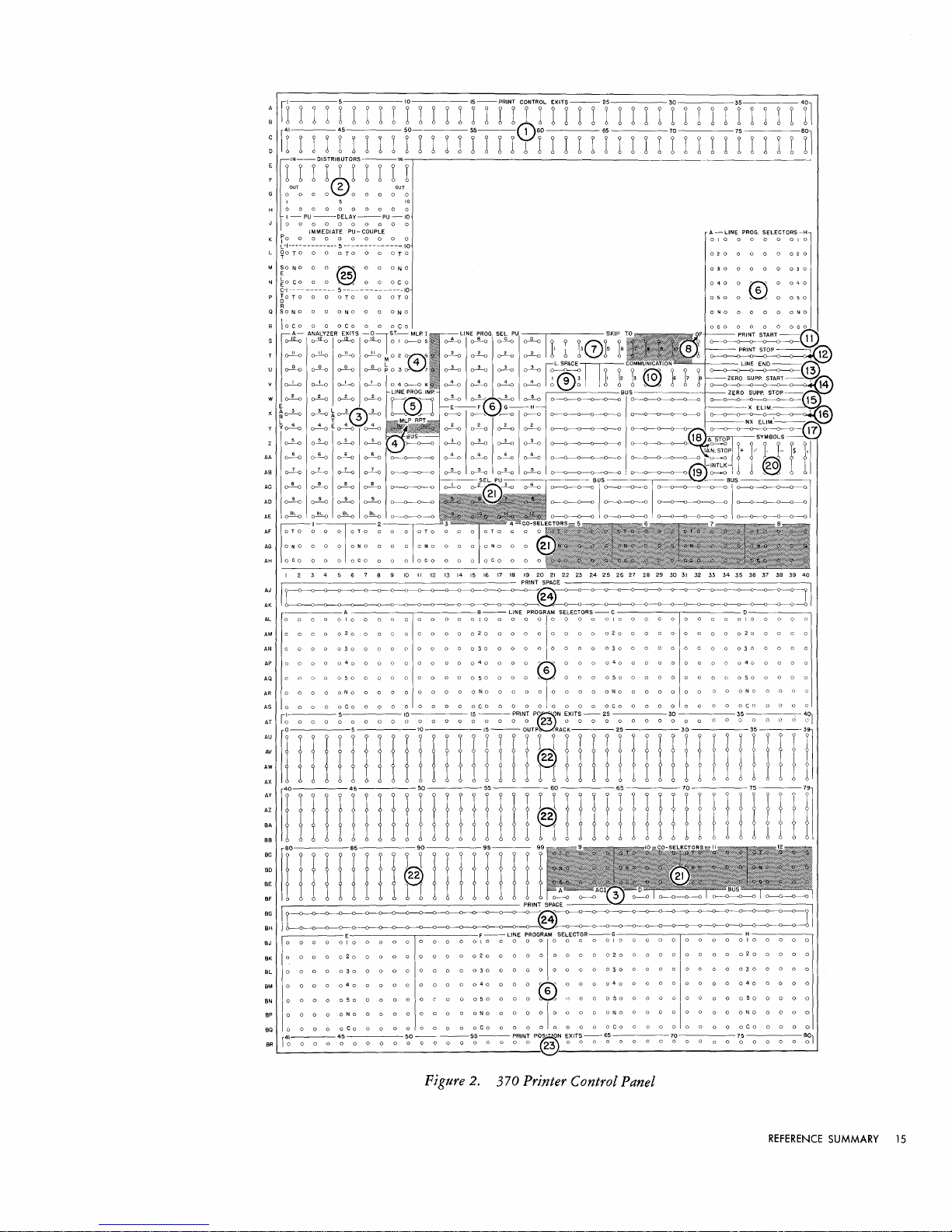
:
n-I
I-I
I I I I I I 1 1 1 1
:
[1-1
I-I
r r I I I r I I I I
:
~'NrT'Y®R'rTITTN
OUT
G
0000
I 5
H
0000000000
I-PU-DELAY-PU-IO
J
0000000000
K
10
L-i-------------5 --------------
L
~O
M
So
E 25
N
EO
C-I -----------
p
60TO
R
a
SONa
R
loco
S
o--R-o
T
~
u
~
:
~
!
E 5
X
~
o--!-o
y
~
~ ~ E ~
z
~ ~
AA
~ ~ ~
AS
~
2
00000
IMMEDIATE
0 0 0 0 0 0 0 0 0 0 I 0 0 0 0 0 0 I 0
TOO
NO
coo
A-
PU-
0 0
TOO
0 0
@~
0
~ ~
5
--------------10
0 0
aTa
0 0
DNa
0 a
DCa
ANALYZER EXITS
~
~
o-'!-o
0-"-0
0-!4
0-!4 0-!4
~
:::
~ ~ ~f3\~
\:)
~
0-2-0
o--!-o
I
OUT
10
COUPLE A - LINE
10
0 0
TOo
0 0 a N 0
0 0 0 C 0
0 0
aTa
0 0
0ND
0 0
oCo
-OlST.-MLPI
~
0 I
0----0
o-'!-o~02o-~
P 0 3
o-~7
~
D~'~E®~DG:
~
0-2-0
~
~
0-1-0
~
'I
-1
ri
ITf1tY
PROG.
o----Lo
:::®7
-F
~
o---!-o
0-2-0
o---±--o
o---E-o
SEL.
0----9-0
6
r-------o
o-!-o
o--Lo
~
o---E-o
El.
PU~---.------
5
~
~ ~ ~ ~
o-Lo o-Lo o-Lo o-Lo I
~
0---------0
~
0--2--0
o---±-o
o--i-o
IT
rTf
-I
I I I I I I r I I 1 I
PU
o---1L-o
I I I I
I . SKIP
I,
?
13f7\?5
Sf
IcL.S~ACE~
~
I I I
~I
:~
G-H
0-----0
~
o--l--D
o-i-o
0--2--0
~~~"~3_~
0-------0--0---
0---0---0--0---
0-----0--0-----
~
0-------0--0---
I I I I I I I I I
2 0 0 0 0 0 0 2 0
040
050
TO
I.
12
I ® I I 1
}_Oo,
_
o·~
_7
--+-,.
~~---O--O-O---O---O-~
0----0---------
~>--o--o-..-..I
o-~---o--<:r"J;~.
er--o---o----o--o--o
O---O---C~I
~---O--O---o---o--<>+I
o----<r--o---o---o--o-~r
3f
I I I I
'f
I I I I
PROG.
016"
0
~
SELECTORS-H
0
040
0
050
"11
rl
I 2 3 4 5 6 7 8 9
~-------
10
II
12 13 14 15 16
17
18
19
20
21
22
PRINTSPACE------------,
23
24
25
26
27
28
29
30
31
32 33
34
35 36
37 38 39
~~~~~~~~~§~~~~~~~~~
AL
0000
AM
0 0 0 0 0 2 0 0 0
AN
0 0 0 0 0 3 0 0 0 0
AP
0 0 0 0 0 4 0 0 0 0 0 0 0 0 0 0 4 0 0 0 0 r;:;'\ 0 0 0 0 4 0 0 0 0 0 0 0 0 0 0 4
AQ
0 0 0 0 0 5 0 0 0 0 0 0 0 0 0 0 5 0 0 0 0
AR
0 0 0 0 0 N 0 0 0 0 0 0 0 0 0 0 N 0 0 0 0 0 I 0 0 0 0 0 N 0 0 0 0 0 0 0 0 0 0 N 0 0 0 0 0
AS
0 0 0 0 0
I 5
AT
10
~
j
~:
1I1111111IlIliI
~
f!!
~---_---PRINTSPACE--'-"<----------,
::
I
,------E
BJ
0 0 0 0 0 I 0 0 0 0 0 0 0 0 0 0 I 0 0 0 0 0 I 0 0 0 0 0 I 0 0 0 0 0 0 0 0 0 0 I 0 0 0 0 0
8K
0 0 0 0 0 2 0 0 0 0 0 0 0 0 0 0 2 0 0 0 0 0 0 0 0 0 0 2 0 0 0 0 0 0 0 0 0 0 2 0 0 0 0 0
BL 0 0 0 0 0 3 0 0 0 0 0 0 0 0 0 0 3 0 0 0 0 0 0 0 0 0 0 3 0 0 0 0 0 0 0 0 0 0 3 0 0 0 0 0
BM
0 0 0 0 0 4 0 0 0 a 0 0 0 0 0 0
~
0 0 0 0
BP 0 0 a 0 0 N 0 0 0 a 0 0 a 0 0 0 N 0 0 0 0 0 I 0 0 0 0 0 N 0 0 0 0 0 0 0 0 0 0 N 0 0 0 0 0
00
0 0 0 0
BR
r~-o-o-o
010
a
00000000100000,0000010000000000100000
A
coO
(l
0 0 0 0 0 3 0 0 0 0 0 0 0 0 0 0 3 0 0 0 0 0 0 0 0 0 0 3 0 0 0 0 0
Coo
0 0 0 0 0 0 0 0
0 0 0 0 0 0 0 0 0 0 0 0 0 0 0 0 0 0 8 0 0 0 0 0 0 0 0 0 0 0 0 0 0 0 0 0 0 0
II
! j
!
Ii
050
oCo
4;
0 0 0 0
lO---15-PRINT
I!
II
! ! j
! ! I M I ! I
0 0 0 0 0
0 0 0 0 0 0 0 0
~o~-o
B-LlNE
0 0 0 0 2 0 0 0 0 0 0 0 0 0 0 2 0 0 0 0 0 0 0 0 0 0 2 0 0 0 0 0
coo
n-j
PROGRAM
$ELECTOR$-C
~
0 0 0 0 5 0 0 0 0 0 0 0 0
0 0 0 0 0 0 0 0
P~N
EXITS-25
!
r~"fmI
Coo
0 0 0 0 0 0 0 0
j!
30
n I ! I !
l~lllnl!lni
0;
IT)
COO
Coo
0 0 0
'(-!
II
0 0
(J
0 5 0 0 0 0 0
35
!!j'Jnn
nIn!
F-LiNE
40
coo
050
oCo
-0
5~-0
(§---o---o--o---o---<>---O--O-~-o--o--<)---O--O-~~
PROGRAM
SELECTOR-G
0 0 0
Tc\
0 0 0
0 0 0 0 0 0 0 0
-0
~RIN~
0 0 0 0 4 0 0 0 0 0 0 0 0 0 0
~
n 0 0
I I
~XIT;-o
050
0 0 0 0 0 0 0 0
oCo
0 0 0 0 0 0 0 0
6;
0 0 0 a 7;] a 0 a 0
H----,
40
050
oCo
7;
0 0 0 a
0 0 0 0
0 0 0 0
0 0 0 0
40
.
401
'I
8~1
Figure 2. 370 Printer Control Panel
REFERENCE
SUMMARY
15
Page 15

;c
»-
~
»-
()
w
o
U'1
,-
ANALYSIS
·1-
(])
"0
2
32
...
Carriage
Always Moves
this
far
CONTROL
PANEL
HUBS
>.
0
U
Z
0 2
4
6
8
10
12 14
16 18
20
Analyzer
Control
Impulse
(A)
A
*
-.
Analyzer
Control Impulse
(B)
A
*
....
Analyzer
Control
Impulse
(C)
A
*
..
-
Analyzer
Control
Impulse
(D)
A
*
•••
Pilot
Selector
Couple
Exit
A
:-
(Special
Feature)
MLP
Repeat
Out
Impulse
(
Special
Feature)
A 6
••
Analyzer
Exits
(A & B)
A 1
••
Analyzer
Exits ( C & D ) A
1
••
Line Program Impulse
A
2
1-.
Line
Space
1
A
I-~
Line
Space
2
A 3
I-
I-
Line
Space
3 A 4
I-~
I-
1-.
MLP
Impulse
A 2
I-~
OF
(overflow)
A
5
I-
..
..
r--
..
Print
Control
Exits
B
..
I--~ I--
Print Position Exits B
*
~
370
PRINTER
CONTROL
PANEL
ENTRIES
CONTROL PANEl
HUBS
Communication
Distributors
Line
End
Line Prog.
Sel.
Pickup
Line Prog.
Sel.
(Transfer)
Line Space
Common
Hubs
NX-Eliminate
Output
Track
Print
Space
Print
Start
Print
Stop
Selector
Pickup
Selector
(Transfer)
Skip-To
Symbols
X-Eliminate
Zero Supp.
Start
Zero Supp. Stop
ENTRY
DESCRIPTION
Accepts
whatever
is
entered.
Accepts
any
low level impulse.
Wire
from
any
print
control
exit.
Accepts
any
low level impulse.
Transfer
immediately;
drop
out
with
line end.
Will
accept
only
line space
1,2,
or
3.
Wire
from
any
print
control
exit.
Wire
from
ACI
or
print
position exit only.
Wire
from
any
print
position exit.
Wire
from
any
print
control
exit.
Wire
from
any
print
control
exit.
Accepts any low level impulse.
Transfer
immediately;
drop
out
with
line end.
Accepts
any
low level impulse.
Wire
from
any
print
control
exit.
Wire
from
any
print
control
exit.
Wire
from
any
print
control
exit.
Wire
from
any
print
control
exit.
22
r--
..
..
I--
P
RI
N T
•
32-Carriage
Under
Control
of
Print
Stop---{
24
26
28
30
0
I--
•
.:-
r--
-'
r--
•
r--
..
r--
-'
t--
..
I--
•
t--
..
r--
12
t--
13
t--
14
r-l
•
• • •
• •
I--
.-i
r--
..
I--
•
r--
..
t--
..
r-
•
r--
•
t--
•
t--
•
t--
•
t--
15t-
•
~
•
•
Machine Cycle Code:
A.
Emit
only
during
analysis
portion
of
cycle.
B.
Impulses
continue
for
all 80
print
positions.
Notes:
1.
Emit
if
Analyzer
Control
Impulse
hub
has been wired
to
an
output
track
position. (Blank emits
on
each
print
cycle except
MLP
2,
3,
and 4
if
ACI
is
not
wired
to
output.)
2.
If
MLP
START
has been impulsed,
LINE
PROGRAM
IMPULSE
is
inactive.
3.
To
select double spacing, selectors
must
be
transferred
in time
to
accept
the first impulse.
4.
To
select triple spacing, selectors
must
be
transferred
in time to
accept
the first impulse.
5.
Under
control
of
the
carriage.
High
Level Impulses.
6.
Emits on first repeat line.
Figure 3.. 370 Printer
Timing
Chart
Page 16

8.
OF
of
the carriage control tape, during the analysis portion of a
cycle, it causes an impulse to be emitted from these hubs.
(Overflow).
When
a hole is sensed in the
12
channel
print
The
impulse may be wired to cause the paper to be skipped to the
first line of the following form by impulsing one of the skip-to
hubs, and placing a hole in the control tape in that channel to
stop the tape at the
proper
place.
The
OF
impulse may also be
wired through communication channels to the processing control
panel, where it may pick
of the program to determine
Then
steps in the program can decide whether to complete the
form or start the following form.
to the next form,
the
processing
up
a selector that
if
unit
is
tested
in
the course
the overflow condition exists.
If
the
printing
is
to overflow
can, by control codes wired
through communication channels, control the overflow skip.
9. Line Space.
To
allow variable spacing, the space control
impulses are wired on the control panel. A jackplug may be
inserted between one
above it to cause single, double,
of
the numbered hubs and the space
or
triple spacing. Alternatively,
hub
the space control wiring may be selected to allow variable spacing.
10.
Communication.
ingly numbered hubs on the
signal communication between the processing
11.
Print
Start. These hubs are impulsed from
Exits to start printing at any desired column as the
moves across the paper.
will continue to
Print Stop.
times
format control.
In
in
this way, printing can be turned on and off several
the course of printing a line to give added flexibility in
The
each field to be printed
12.
Print
Stop. These hubs are impulsed from the
trol Exit of the
These hubs connect to the correspond-
305 Process Control Panel to allow
unit
and the printer.
Print
print
Once the printing is started, the machine
print
until printing is turned off by impulsing
Print
Control Exit for the first column of
is
wired to these hubs.
Print
first position not to be printed, to turn
Control
head
Con-
printing
off, if other information is to be printed later on the same line.
Impulsing these hubs causes printing to be suppressed until
Print
Start is impulsed.
13.
Line
End. These hubs are wired from the
Print
Control
Exit of the position after the last position to be printed on a
line to cause the printing to stop and the
the home position.
This
allows the length of the
print
head to return to
printing
line to
be controlled. Variable printing lengths are possible by wiring
Line End through selectors.
14.
Zero
Print
Control Exit of the high-order position of a field to
eliminate the
When
printing
these hubs have been impulsed, the
positions containing zeros until a significant digit
Suppression
encountered and
printed;
Start. These hubs are wired from the
of zeros to the left of significant digits.
print
unit
spaces over
(1-9)
then all zeros to the
right
of the sig-
nificant digit are printed.
Zero
15.
Suppression
Stop. Once Zero Suppression Start
has been impulsed, zero suppression will continue until a sig-
nificant digit
ended
(not
by
zero) is encountered and printed
impulsing these hubs from the
Print
or
until
it
Control Exit
of the first position not to be suppressed.
16.
X-Eliminate.
Negative numbers are recorded on the
output
track (as on all other processing tracks) by an X-bit over the
low-order position.
output track at 12N.
For
example, the amount 125 stands on the
The
X-eliminate and NX-eliminate hubs
allow the printer to read the X-punch or the digit punch from an
output
track position to separate the signed character into its sign
and digit components. These hubs are impulsed from
Print
Control Exits to cause only the digit portion of the character being
set up to be printed.
17.
NX-Eliminate.
Control Exits to allow only the sign portion
be printed
(item
These hubs are impulsed from the
16).
of
a character to
Print
18.
Ll
plugged, if a
(Delta).
Ll
in the left-hand margin opposite the line in error and the
When
print
the two hubs labeled
setup error occurs, the machine will
Ll
STOP
machine will stop.
When
machine will
the two hubs labeled
print a Ll,
Ll
but will
N.
STOP
not
stop when a
are jackplugged, the
error occurs.
If
neither
Ll
STOP
nor
Ll
N.
STOP
stop,
but a Ll
19.
will not be printed if a
INTLK
(Interlock).
before any printing operation can be initiated.
not operate
if
these hubs are left unplugged.
are plugged, the machine will
print
setup error occurs.
These hubs must be jackplugged
The
20. Symbols. These hubs are wired from the
Exits to cause the corresponding symbol to be printed. These
symbols may be selected through the line program selectors.
21. Co-selectors. These selectors may be used to supplement
the line program selectors. Each co-selector has
each position has a
COMMON, a NORMAL
Normally, a connection exists between the
NORMAL
nection
and the
ors may be picked
hub,
but
is
broken and a connection is made between the
TRANSFERRED
up
when the
PICKUP
hub is impulsed, this con-
hub
in the same vertical column. Co-select-
in
the same manner
five
and a
TRANSFERRED
COMMON
as
the line program
selectors, and they remain transferred for the entire
22.
Output
Track.
At
is
read in its entirety,
ing. This selection is made by wiring the
the output track position desired to the
corresponding to the
each printing position, the
but
only one character
printing
position where the character is to
is
selected for print-
hub
corresponding to
Print
print.
23.
Print
put
track
set
print
(item
up
to
print
position ten of the
Track position 10
Position
24.
Print
Space. All
the output track should be wired to these hubs.
the checking circuits that the
Exits. These hubs are wired from the out-
22)
to cause the corresponding positions to be
information on the output track. For example, to
output
track in
print
is
wired from
print
Print
positions that are not wired from
position 50,
Position Exit 50.
This
printer
is
not to
print
sponding column, and allows the checking circuits to detect any
position that was wired to
Pilot
25.
Selectors. These selectors may be used to control
printer functions based on
through communication channels,
is
IMMEDIATE
PICKUP:
pulsed from Analyzer A,
MLP
I Exits 1-4 (special feature MLP Repeat,
or a program Exit.
Print
is
on the process control panel, and normally should not be
used to impulse 370 functions directly - these functions should
be controlled by the
DELAY
PICKUP:
Accepts the same impulses
to transfer the selector for the following line,
Exception: the couple exit of another
program exit
is
used to impulse delay pickup, the selector trans-
print
and failed to set
up
Program Exit impulses received
or
from 370 impulses.
Selectors transfer immediately when im-
B, C,
or
D Exits, Space, Overflow,
MLP
(The
program exit used must also impulse
pilot
selector.)
as
immediate pickup
or
pilot
selector.
fers immediately on the first line after the program exit.
COUPLE
mediate pickup
Drop-out:
line,
may be dropped out manually
key. Depressing the
or
in the case
EXIT:
When
hub
The
the delay pickup hub is used, the im-
becomes a Couple Exit.
selectors normally drop out
of
MLP,
at
Printer Check Reset key does
at
the end of
by
the
depressing the Printer Reset
the end of the
last
MLP
the pilot selectors; they remain transferred and allow the selectors
to provide the same control for all
Print
Repeat lines.
are jack-
print
print
setup
printer will
Print
Control
positions, and
hub.
and the
COMMON
print
line.
output
track
Position Exit
Output
indicates to
in the corre-
correctly.
I exits
5-8),
lines,
if
MLP.
When
line. They
not
drop ·out
a
a
REFERENCE
SUMMARY
17
Page 17

Punch
Control Panel (Figure
1.
Output
Track.
These hubs emit the IBM codes
4)
of
the in-
formation on the output track. These exits may be wired to the
punch magnets to cause punching. This allows any
output
track positions to be punched into any of the 80 card
of
the 100
columns.
2.
Digit
series of impulses which are timed for punching the digits
Selector.
through 9.
If
digit selector becomes a digit emitter with a
at the
12
output
hub, an
track position is wired to the C hub, whatever digit or
character appears at that output track position will be made
able in
IBM
code at the numbered hubs of the digit selector.
3.
Sign Conversion.
by
a combination of X and a-bits. Also, sign control on negative
fields is maintained by carrying an
tion.
If
the low-order position of a field is zero and the field is
negative, a 12-hole would be punched
directly to a punch magnet.
The
or hub at the top of the panel emits a
the or
hub
is wired to the C hub beneath it, the
11
impulse available at the
Within
The
12
12
impulse available
11
hub, etc.
If
an
avail-
the system, the
12
holes are coded
X-bit over the low-order posi-
if
this position were wired
sign conversion hubs are provided
so that the 12-impulse available from the output track may be
converted to the
In
use, the low-order position
be negative is wired from the output track to an
the corresponding
emitted from this position of the output track, it
X/O.
Any other negative number is overpunched with
x/a
code desired for these positions.
of
any numerical field that may
OUT
hub to the punch magnet.
IN
hub and from
If
a 12-code is
is
punched
an
as
X.
Positive numbers pass through without conversion.
Column
4.
matically controlled to transfer between X and a time
is
punched.
Splits.
This
This
allows the
is
a la-position selector that
as
12
and X zones to be removed from
is
auto-
the card
columns and punched into other columns.
5. Co-selectors. As a special device,
5-position Co-selectors may be installed to allow changes in
ing format for different types of cards. Each selector is a
up
to
five
groups of four
punch-
five-
position selector with two common pickup hubs. Each position has
a C (common), N (normal) and a T (transferred) hub.
The
common hub is connected to the normal hub until the selector is
picked up
by
impulsing the pickup hub.
Then
the common
connected to the transferred hub.
When
the pickup is impulsed, the selector transfers immediately, and will remain transferred for the remainder of the punch
cycle.
The
Co-selector pickup hubs may be impulsed from any digit
impulse, Half-After-Zero,
the Punch Repeat
(0-5),
OUT
Pilot Selector
hubs; however, they should riot be im-
COUPLE,
or from
pulsed by a 305 Program Exit wired through a Communication
Channel. Co-selectors must be used
DET
CONTROL
wiring when controlling
ferent card formats, as well
OFF
switches.
Punch
6.
Magnets. These hubs are entries to the 80 punch
magnets that punch the correspondingly numbered columns
as
the DPBC
if
it
is necessary to select BC
DPBC
checking for dif-
STOP,
OFFSET,
and BC
of
the
card. These magnets are wired from the output track positions
that are to be punched.
7.
Punch
it
passes a set
tion that has been punched so that
Brushes.
On
of
the punch cycle after a card is punched,
80 reading brushes that read back the informa-
it
may be given the double-
punch blank-column check. These hubs are the exits for the read-
ing on this cycle.
The
information may also be gang-punched back
into the following card.
8.
DP
& BC
Det
Entry. These hubs may be wired from the
punch brushes to check individual columns for double punching
or
lack of punching. This is particularly valuable
in
numerical
fields, where every posltlOn must have one and only one hole.
If
the machine detects multiple punches
column wired,
do so.
The
it
will stop the machine
DPBC light on the punch
or
lack
of
if
the control
unit
is turned on to indicate
the reason the machine stopped.
9.
BC
Det
Entry
or
GP
Exit.
If
wired into
&
BC
DET
DP & BC
ENTRY
DET
ENTRY,
emerges from these hubs, from which it may be
the column being checked
the first impulse to enter the
wired to a punch magnet for gangpunching.
If
a column in which double punching is permissible
checked for blanks, these hubs are used
pulse to enter these hubs emerges from the
as
an entry.
DP & BC
hubs.
10. BC
Det
be done, the Blank Column
Control.
To
wired.
ENTRY
check a field for blank columns, wire the field to the
or
EXIT
of the
If
no checking for blank columns
OFF
switch (item 12) must be
DP & BC
If
anyone
field is to be checked,
wire it to the left-hand entry positions and, in the blank-column
detection control row, wire from the right-hand column
field to the last position in the row. Several fields can be entered
as one field for checking purposes.
11.
DPBC
Stop.
When
chine will stop
if
these hubs are jackplugged, the ma-
a DPBC error occurs. This switch may
selected if co-selectors are used.
12. BC
Off
(Blank
Column
Off).
These hubs must be jackplugged to turn the blank column detection feature off when no
punched columns are to be checked for blank columns.
13.
Offset.
When
is installed, the DPBC
error card rather than stop.
types of cards
the Offset Stacking Feature (special device)
Offset switch may be plugged to offset an
It
so
that
they may be easily distinguished from the
is also possible to offset different
main group of cards when removed from the stacker. This switch
may be selected; however, co-selectors must be used.
14.
INT
(Interlock).
Whenever the punch is to be used to
punch output cards for the processing unit, this control panel
switch must be jackplugged.
15.
is
Gangpunch.
plugged, the 323 Punch is removed from the control of the
processing
unit
When
this control panel switch is jack-
and may be used
as
an independent gangpunch.
16. Communication. These hubs are connected to the
spondingly numbered hubs labeled
PCH
on the process control
pane1.
Punch
IN
17.
(P
or
Repeat.
D),
When
an impulse is wired to Punch Repeat
one additional card will automatically be punched
from the same output track data.
If
selectors are used, two cards
obtained from the single
output
with
different formats can be
track.
Without
identical cards are punched.
When
Punch Control Panel will emit just
Punch Repeat has been impulsed, the
second card.
selectors
This
or
impulse may be wired to the D pickup
to co-selector pickups to control the punching for
prior
OUT
to punching time of the
the second card.
A program exit wired through a communication channel for
the purpose of impulsing punch repeat must be wired to the
(program exit) pickup. Also, the program exit that is wired to
punch repeat must be the same program exit that
PUNCH
on the Process Control Panel.
Digits or. couple exits used to impulse punch repeat must be
(digit)
directed to the D
case of the
impulsed, the
P pickup when the D pickup
OUT
pickup for correct operation. As in the
of
hub will emit just
punch repeat has been
prior
to punching time of
the second card.
a hole in any
is
wired
to
is
DP
is
to
first im-
ENTRY
is
of
the
be
to
The
DET
be
corre-
selectors, two
hub on the
of
pilot
is
wired to
P
18
IBM RAMAC 305
Page 18

o 5 10
1111111111111111111111
40
5 6 7 8 9 10 II
45
12 13
14
15 16
17
18 19
20
21
15
50
55
22
OUTPUT
60
1111111111111111111111
Y I I I I Y I 1 I I Y I I I I
9f
I
23
24
25 26
27
28
29
30
31
32
33
34
35
36
37
fY-ll-1
1 I 1 I I I I I 1 I I 1 I I I
-
SIGN
o
0:"1
3
o c "
-1
CONVERSION
---I N --Ir------------------------T
0 0 0 0 0
00000
b-l
q-l
OUT
-1
1-q-1
II--COLUMN
SPLlTS--12 -II
: : 0 0 0
COMMON
38
39
40
41
42
43
44
1-11r~]=!=
lIn::
~-~2::
:::
s~
~
E
CD
Lo---L
2 k
6 2 .....
:a
::~:::
......
:
o 0 0
000000
45
0 0
o 0 0 0 0
--0---0-----
-----------10-----------
r~---o--o--o--~--o--------o-I~--o--o-------
I~
r~--o---o----
o 0 0 0
50
I~
--0--0---0----
~#\:
~i:!8
~~8*-~
Figure
4.
323 Punch Control Panel
00000000
65
00000000
65
AC
AD
AE
AF
AG
AH
AJ
AK
70
70
o
75
o 0
75
o 0
o 0
80
More than one additional card can be punched
Punch Repeat
IN
on successive punch cycles.
tional punch cycles can be controlled by the use of
Punch Repeat will maintain its
restart procedures.
18.
Half-After-Zero
zero time
but
before one time.
(0.5).
so that only the digits 1-9 are punched,
and numerical punching
wired for
19.
Pilot
DPBC
Selectors.
tors may be installed
If
a program exit
of
detection.
Two
as
a special feature.
is
wired through a communication channel
for the purpose of impulsing a pilot selector, the program exit
must
be wired to the P
EXIT
result if a program exit is wired to any other selector pickup.
When
the P
EXIT
pickup
is
immediately and will remain transferred for the duration
associated punch
P
EXIT
pickup must be the same program exit that
PUNCH
on the Process Control Panel.
cycle.
The
by
The
proper
status during error
This
hub
It
may be used to transfer selectors
emits
or
to separate the zone
impulsing
number of addi-
pilot
selectors.
an
impulse after
alphabetic fields so that they can be
groups of
five
2-position pilot selec-
pickup. Improper operation will
impulsed, the selector will transfer
of
program exit that
is
wired to the
is
wired to
the
It
is
possible to impulse the P
pulse; however, if an
output
EXIT
pickup from a digit im-
error should occur, the selector will
remain transferred throughout a run-out and run-in procedure.
On
a run-out and run-in procedure the last punched card is
repunched on the run-in, and because the selector
would
be transferred during the repunching of the last punched card, operations
such as split column control would not function properly.
The
DELAY pickup may be wired from any digit impulse,
COUPLE,
pulsed
nel.
or
from the Punch Repeat
by
a program exit wired through a communication chan-
When
the DELAY pickup
OUT
hub.
It
is
impulsed, the selector will trans-
cannot be im-
fer one punch cycle later, and will remain transferred for one
cycle.
In
the event of an
output
error, selector control will be
automatically maintained.
Associated
selector is transferred by impulsing the P
gram exit, the
time for that card.
DELAY
prior
If
with
each
pilot
selector is a
COUPLE
pickup, the
hub will emit just
If
a selector is picked
COUPLE
exit will emit one cycle later just
to punching time.
it
is
desirable to expand the number
COUPLE
EXIT
pickup from a proprior
up
by impulsing the
of
available positions
REFERENCE
hub.
If
a
to punching
SUMMARY
pilot
19
Page 19

LOCATION
X,
1-40;
AA,I-4O
AH,43
W,
1-40;
Z,I-4O
A,
41-44
AG,43
AK,42
AJ,41-42
AK,43
AJ
, 43
A-D,I-4O; E-F, 1-20
AD,31-40
AC-AD,
41-44
T-U,
1-40
AH,
41-42
Co-Selector ( Transferred)
Selector
Repeat
Common
PU ( Delay)
PU ( Prog
IN ( Digit)
IN ( Prog
Digit
Pilot Selector
Pilot Selector
Pilot Selector ( Trans)
Punch
Punch Repeat
Exit)
Exit)
LOCATION
X,
1-40;
AA,I-40
W,
1-40;
Z,I-4O
AH,44
H,
31-40
G,
31-40
AC-AD,41-44
Q-Z,
41-44
S,
41-44
V,
1-40;
Y, 1-40
AG,44
AK,41
AK,44
AJ,44
AS,
31-40
AC
, 31-40
N-P,
1-40
AF-AG,42
AF-AG,41
11.0
0.0
1.0
2.0
3.0
4.0
5.0
6.0
7.0
8.0
Figure 5. 323 Punch
20
IBM RAMAC
30£;
Timing
Chart
Page 20

of a pilot selector, the
pickup.
The
co-selector will then function in the exact manner
as the pilot selector.
COUPLE
COUPLE
exit may be wired to a co-selector
may also be wired to the
DELAY
pickup of another pilot selector to cause it to transfer one cycle
later.
Typewriter Control Panel (Figure
1.
Column
Control
Exits.
When
6)
the typewriter is being used
for inquiries or for printing an auxiliary document, these hubs
seqeuentially emit impulses that coincide
corresponding position
of
the typewriter Q track. These impulses
with
the reading of the
control the format of the information being printed.
The
first Q track position to be read
Column Control Entry (item
is
13).
controlled by wiring the
Subsequently, the machine
reads succeeding positions until the control is transferred elsewhere.
This
arrangement allows the typewriter to type fields from
the typewriter track in any order.
If
at
any time the program
turned on, the column control exits stop emitting,
sequential position
is
is impulsed to transfer control to another position.
Program
ON
hubs are impulsed, column control
until Column Control
Delay
is
from the
impulsed, on the following cycle an impulse
CCD
hub, and then column control
unit
or the column control delay are
but
the same
held, unless the Column Control Entry
When
the
turned off
is
emitted
on
again
ON
is
impulsed.
When
Column Control
is
is
turned
automatically.
2.
Program
sequentially emit impulses when the typewriter
inquiries
Exits.
When
Program
or
for printing an auxiliary document. These impulses
On
is impulsed, these hubs
is
being used for
are used for typewriter control and to type constants, legends and
special characters
is
turned off
advances through steps
first turned on after the final dropout
Program Exit Ao will emit, followed by
Bl,
B2, etc.
by impulsing Program Entries (item
3.
Digit
not
on the typewriter track.
by
impulsing Column Control On, the program
0-4 in levels A-E.
The
program impulses may be started
Until
When
of
the program is
the previous operation,
AI,
A2, A3, A4,
at
12).
Selector.
It
is
sometimes desirable to know the con-
the program
another
point
BO,
tents of a certain typewriter track position so that format control
may be altered on the basis of the character coding.
PU
hub is impulsed from a Column Control
in
that position is analyzed and emitted
hubs labelled 12-9.
While
this
is
in
IBM code from the
taking place, the
EXIT,
When
the
the character
printing
the character is suppressed.
4.
CCD
Delay
is
impulsed, the
used for spacing
(Column
Control
or
other functions. Column control
Delay).
CCD
hubs emit an impulse that may be
When
Column Control
is
suspended
for the cycle on which these hubs emit. After one cycle, the
column control resumes from the step after the one on which the
control was impulsed (item
5.
Column
(item
either the X or
Split
24),
on the next cycle column control
NX-hub
(X-NX).
21).
When
will emit.
Column Split
is
The
suspended and
X-hub
is
impulsed
emits if the
character being analyzed by the column split device contained an
X-bit.
If
no X-bit was present, the
"0"
TR
(Zero
6.
Transfer).
ture is turned on by impulsing Zero Sup
read from the typewriter track
NX-hub
emits.
Whenever the zero transfer fea-
On,
(Item
22),
is
not printed,
but
a zero
an impulse is
emitted from these hubs. This impulse may be wired to Space
(Item
20) to maintain vertical column alignment.
7.
100
(Type
100).
Impulsing these hubs causes all 100 char-
acters to be typed from the typewriter track, in position sequence,
without format control.
8.
Format.
These hubs emit control impulses
when
sponding format key is depressed on the keyboard.
from these hubs may be used to set selectors to establish format
control for three different types
of
inquiries and to start the type-
writer control panel program.
9.
Type.
When
the
TYPE
control panel, the typewriter
be used to control format for lines typed
hubs are impulsed on the process
TYPE
hubs emit an impulse that may
out
under stored pro-
gram control and to start the typewriter control panel program.
10. Selectors.
Ten
2-position selectors
are.
provided to facilitate
format control. Normally a connection exists between each
and the N
this connection is broken and the C
above it.
hub
above it.
This
connection remains until the
When
an impulse is wired to the
hub
is connected to the T
DO
(dropout)
impulsed.
11.
Distributors.
Impulses that are used to initiate several
functions are wired through distributors that serve the same
function
pulse wired into the
associated
hubs,
from the
as
or
from an
OUT
split wires
OUT
hubs,
OUT
but
prevent possible back circuits. An im-
IN
hub
of a distributor is available
but
impulses cannot travel between
hub
to the
IN
hub. Any impulse except
hub of another distributor may be wired through
a distributor.
Program
12.
of a sequence of program impulses, one
hub are impulsed in the same manner that the
are impulsed on the process control panel.
turned on automatically
Entry
(Also
item
2).
To
LEVEL
by
impulsing Program Entry
establish the beginning
hub
PROGRAM
The
program
impulsing Program On.
13.
Column
sequence of column control (item
hub are impulsed in the same manner that the
Control
Entry.
To
establish the beginning of a
1),
one
TENS
PROGRAM
are impulsed on the process control panel. Column control is
turned on automatically by impulsing Column Control Entry
without impulsing Column Control
NOTE:
Column Control Entry must not be impulsed at the
On.
same time as Column Split.
14.
Type
Only.
When
exits
or
CCD, the corresponding characters are typed.
15.
Clear. Impulsing these hubs causes the typing to stop and
these hubs are impulsed from program
the carriage to return.
16.
of
Column
the typewriter to column control after program control has been
used,
if
Control
On.
These hubs are impulsed to restore
it is desired to restart from the track position after the
last position used previously. Column control is turned on automatically if a column control entry is made.
Program control
turned off.
17.
Program
writer
under program control. Column control is turned off. Pro-
gram control is turned
On.
These hubs are impulsed to place the type-
on
automatically
when
a program entry
is made.
18.
Carriage
Return.
Impulsing these hubs causes the type-
writer carriage to return to the left margin.
19.
Tabulate.
Impulsing these hubs causes the carriage to
tabulate to the next tab stop.
20. Space. Impulsing these hubs causes the typewriter to space
one space.
21.
Column
Control
Delay
(Item
4).
When
impulsed, column control is suspended for one cycle, during
which an impulse is emitted from the
CCD
hub
(item
control resumes control immediately after this cycle, continuing
from the column after the column that was wired to impulse
the delay.
the corre-
The
impulses
chub
PU
hub
hub
hub
at
the
OUT
that
and one
STEP
ENTRIES
unit
without
and one
UNITS
ENTRIES
these hubs are
4).
Column
is
is
is
REFERENCE
SUMMARY
21
Page 21

A
B
C
D
H.
2
BUS
4
COL
CTRL
~
: : :
~
0 0 M 0 2 0
15
;0:
I
~
: :
305
00
40
00
45
o 0 0 0 0
r-~----------~--~----SELECTORS----~~----------_~-,
8 9
10
II
EXITS_A_B-C-D-E~IGIT
~
t:::
~
0
:i:::
0
0
49
12 13
~
:::
~
0 2 0
0
:::
BUS
~;;q~~!
~)I
~~1'
I-COMMUN.-4
O('@')OO
5~78890
000000000
cr--o---o----<>
14
15
16
SELECTOR
~X
~
10
KVI~7g
BUS
17
18
19
20
21
COL.CTRL.EXITS
5~
: : :
6
6g
0 0 0 0
3
65
000:
i !
:?:
7 805 0 0 0 0
9
95
0 0 0 0 0 0
22
~
:
99
M
Q
T
U
v
w
x
Y
AA
AB
AC
AD
AE
AF
AG
AH
AJ
AK
I 2 3 4 5 6 8 10
:::
=
=:::
:::
: : : :
OCO
0000
r------------
o
IN
0 o o
------------------OUT---------------------
o
o
I
o
o
o o o
o o
o
5
o
~I~
o-----o-.!-o--o
~I==
~~
~TRL~
I
~
C @ 2
I I
=1=:::
:::
0
OCO
0
DISTRIBUTORS
IN
0 o 0 o
o
o
o
o
o
-,--------DISTRIBUTORS--------..
o
IN
----------OUT---------
o 0 0
21
o 0 0 0
~
TYt
B M X
o 0 0
o 0 Z
o 0 0
EPa
o 0 0 0
F
o
G
o
H 5 $
o
I
o
J
o
K V #
o 0 0
~
:~
:
:::
~I~
0
OCO
-------------~
IN
0 0
O~LY
S
o 0
4
5
o
6
o
8
o
o
9
o
o
*
o 0 0 0
o 0
o 0 0 0
o
25
o
o
10
®0
o 0 o o
0 0 0
E
N o Y 2
Q -
elf4\'
R~
o 0
0 0
T
o
u
o
BUS
=
0 0 : :
00
0 0 0
15
o
IN
0
o o 0 0
o
OeD)
o 0
o
BUS
=:::
:::
OOCO
o 0 0
IN
0
000
000
000
0
20
0
0
IN
0
Figure 6.
22.
Zero
impulsed,
be typed,
(item
function.
impulsed (item 23)
from the track. This arrangement allows the zeros in the
order position of fields to be suppressed. Zero Suppression
impulsed one position before
23.
the zero suppression feature off when
to the left
on by previous wiring.
24.
split device to analyze the character being typed for the presence
22
Suppression
if
a zero is read from the typewriter track
but
an impulse will be emitted from the 0
6)
which may be wired to cause spacing
The
printing
Zero
Suppression Off. These hubs are impulsed to turn
of
significant digits, and the feature has been turned
Column
IBM RAMAC 305
Split. Impulsing these hubs causes the column
On
(Also
item
of
zeros is resumed when the
or
when
a character other than zero
it
is to become active.
it
Zero Suppression
6).
When
is desired to
Off
occurs immediately.
this
it
will
TR
or
some other
OFF
print
380
Console Control Panel
or
hub
hub
is
high-
On
zeros
is
not
hubs
is
read
is
absence of an X-lSit.
matically suspended and the Column Split X or
emit.
Exit, the corresponding
numerical digit. Column
time
25.
wrl'ter
26.
writer to type through the red portion
27. Communication. These hubs connect to the correspond-
ingly numhered hubs labeled
allow signal communication between the processing
the console.
On
the next cycle, column control
When
Column Split
as
Column Control Entry.
Ribbon
Ribbon
Shift
to type through the black portion
Shift
is
impulsed from a Column Control
Q track character will type only
Split must not be impulsed at the same
Black. Impulsing this hub causes the type-
Red. Impulsing this hub causes the type-
TW
on the 305 Process Panel to
NX-hub
of
a two-color ribbon.
of
a two-color ribbon.
is
unit
auto-
will
as
and
a
Page 22

ALL
CONTROL
of
60 load units
(1)
(2)
PANEL
EXITS may be loaded to a maximum rating
with
the following exceptions:
305 - Distributors - 30 max.
- Inquiry
-
370
- Distributors -
-
Out
- 30 max.
Start - 30 max.
30
MLP
I Exit - 30 max.
max.
Load Rating Chart
(3)
380 - Distributors - 30 max.
To
insure
that
electrical limits are
can be made to the Load Rating Table shown in
the
individual load rating for each function associated
exit to be sure the maximum allowable load is
Also, be sure that each distributor exit is
not
being exceeded, reference
not
overloaded.
Figure
not
7.
Add
with
an
exceeded.
CONTROL
Accumulator
ENTRY
- 305 -
PANEL
HUB
Drop
Out
Accumulator Overflow
Accumulator Sign
Blank Transmission
Char Sel
Alpha
Char Sel Numeric
Comm Channel
Comm Channel
Compare
IN
IN
IN
IN
IN
(Print)
(Punch)
Cycle Delay
Distributors
* DPIS DO
* DPIS
PU
*
Dual
Access Sel
*
Dual
Access 0 and
Feed Card 3
Field Compare
Hundreds
Inquire
Last Card
IN
Program Entry
IN
IN
Print
Program Advance
* Program Exit Split DO 3
* Program Exit Split
Punch
Record Advance
Reset
Reset Stop
Selector
PU
Selector DO
Skip-To-Record
Stop
Tens Program Entry
Type
Units Program Entry
PU
IN
* Special Features
LOAD
RATING
3
IN
0+
0+
0+
0+
0+
0+
0+
0+
6
0+
6
6
0+
0+
0+
1
5
0+
5
2
3
3
5
3
3
3
3
6
1
5
2
CONTROL
BC
BC
ENTRY
-
Det
Det
PANEL
HUB
323-
Control
Entry
RATING
Column Splits
* Co-selector
Digit
DP
*
Pilot
*
Pilot
Punch
Punch Repeat
Sign Conversion
CONTROL
ENTRY
--
Selectors
& BC
Selectors
Selectors
Magnets
PANEL
HUB
370
PU
Det
-
Entry
(D)
(p)
IN
(P&D)
IN
RATING
Comm Channels
Co-selector
PU
Distributors
Line End 8
Lifle Prog. Sel.
PU
Line Space
*
MLP
RPT
MLP
MLP
MLP
MLP
NX
*
Pilot
*
Pilot
Output
IN
Start i
Start 2
Start 3
Start 4 6
Eliminate
Selector
Selector
PU
PU
(D)
(I)
Track
Units and Tens Entry.
LOAD
2
2 X Eliminate
0+
2
0+
3
2
3
10
2
2
Print
Space
Print
Start
Print
Stop 12
Skip to
Hubs
Symbols
Zero Supp Start 3
Zero Supp Stop 3
CONTROL
ENTRY
-
PANEL
HUB
380-
LOAD
RATING
Carriage Return
Clear
Col Ctrl Delay
LOAD
Col Ctrl Entry
Col Ctrl
On
Column Split
Comm Channel
0+
2
0+
3
8
3
2
3 Space
4
2
2
3
1
Digit
Selector
PU
Distributors
Program Entry
Program
On
Ribbon Shift B
Ribbon Shift R
Selector DO 3
Selector
PU
Tab
100
Type
Type Only
Zero Suppress
Zero Suppress
Off
On
NOTE:
When
a load rating
determined by
the
of
0+ is shown, the load is
final use
of
the function.
example, assume a panel impulse is wired to
cumulator overflow
Program Advance,
condition is
0+2=2.
IN,
and
For
overflow
YES is
The
YES,
NO
wired
load
rating
0+5+2+1=8.
is wired to
to type and
for the
2
3
12
2
2
2
2
2
2
4
0+
2
0+
2
2
2
2
3
8
2
2
4
2
3
For
ac-
NO
Figure
7.
Load Rating Chart
REFERENCE
SUMMARY
23
Page 23

lldIDdktr
International
Data
®
Business
Processing
Machines Corporation
Division,
112
East Post Road,
White
Plains,
New
York
Printed
in U.S.A.
G26-3540-0
 Loading...