

Page 1

BladeCenter QS22 Ty pe 0793
Problem Dete rminatio n and Service Guid e
Page 2

Page 3

BladeCenter QS22 Ty pe 0793
Problem Dete rminatio n and Service Guid e
Page 4

Note
Before using this information and the product it supports, read the general information in Appendix C, “Notices,” on page 127
and the Warranty and Support Information on the Documentation CD.
Fourth Edition (October 2008)
© Copyright International Business Machines Corporation 2006, 2008.
US Government Users Restricted Rights – Use, duplication or disclosure restricted by GSA ADP Schedule Contract
with IBM Corp.
Page 5

Contents
Safety . . . . . . . . . . . . . . . . . . . . . . . . . . . . vii
Chapter 1. Introduction . . . . . . . . . . . . . . . . . . . . . .1
Related documentation . . . . . . . . . . . . . . . . . . . . . .1
Notices and statements used in this document . . . . . . . . . . . . . .2
Features and specifications . . . . . . . . . . . . . . . . . . . . .2
Support for storage . . . . . . . . . . . . . . . . . . . . . . . .3
Turning on the blade server . . . . . . . . . . . . . . . . . . . . .4
Turning off the blade server . . . . . . . . . . . . . . . . . . . . .4
Blade server controls and LEDs . . . . . . . . . . . . . . . . . . .5
System board LEDs . . . . . . . . . . . . . . . . . . . . . . .6
System board internal and expansion card connectors . . . . . . . . . . .7
Chapter 2. Configuring the blade server . . . . . . . . . . . . . . .9
Communicating with the blade server . . . . . . . . . . . . . . . . .9
Using the Advanced Management Module . . . . . . . . . . . . . .9
Using the Web interface . . . . . . . . . . . . . . . . . . .10
Using the command-line interface . . . . . . . . . . . . . . . .10
Using Serial over LAN . . . . . . . . . . . . . . . . . . . . .10
Using the serial interface . . . . . . . . . . . . . . . . . . . .11
Using the SMS utility program . . . . . . . . . . . . . . . . . .11
Starting SMS . . . . . . . . . . . . . . . . . . . . . . .11
Viewing FRU information . . . . . . . . . . . . . . . . . . .12
Adding FRU information . . . . . . . . . . . . . . . . . .13
Updating the system and BMC firmware . . . . . . . . . . . . . . .15
Updating steps . . . . . . . . . . . . . . . . . . . . . . . .16
Determining current blade server firmware levels . . . . . . . . . . .16
Updating the BMC firmware . . . . . . . . . . . . . . . . . . .17
Using the BMC update package . . . . . . . . . . . . . . . .18
Using the Advanced Management Module . . . . . . . . . . . . .18
Installing the system firmware . . . . . . . . . . . . . . . . . .20
The firmware update package . . . . . . . . . . . . . . . . . .20
Using the package . . . . . . . . . . . . . . . . . . . . .21
Updating the system firmware automatically . . . . . . . . . . . .21
Installing the firmware manually . . . . . . . . . . . . . . . . . .21
Updating the system firmware images . . . . . . . . . . . . . . .22
Updating the optional expansion card firmware . . . . . . . . . . . . .23
Integrating the Gigabit Ethernet controller into the BladeCenter . . . . . . .23
Updating the Ethernet controller firmware . . . . . . . . . . . . . . .23
Using the update package . . . . . . . . . . . . . . . . . . . .24
Firmware update steps . . . . . . . . . . . . . . . . . . . . .24
Blade server Ethernet controller enumeration . . . . . . . . . . . . . .25
Chapter 3. Parts listing . . . . . . . . . . . . . . . . . . . . .27
Replaceable components . . . . . . . . . . . . . . . . . . . . .27
Consumable parts . . . . . . . . . . . . . . . . . . . . . . . .28
Chapter 4. Installing and removing replaceable units . . . . . . . . .29
Installation guidelines . . . . . . . . . . . . . . . . . . . . . .29
System reliability guidelines . . . . . . . . . . . . . . . . . . .30
Handling static-sensitive devices . . . . . . . . . . . . . . . . .30
Removing the blade server from the BladeCenter unit . . . . . . . . . .30
Opening and removing the blade server cover . . . . . . . . . . . . .31
© Copyright IBM Corp. 2006, 2008 iii
Page 6

Removing the BladeCenter PCI Express I/O Expansion Unit . . . . . . . .32
Removing the blade-server front bezel assembly . . . . . . . . . . . .33
Installing the optional modular flash drive . . . . . . . . . . . . . . .34
Removing the optional modular flash drive . . . . . . . . . . . . . . .35
Installing an optional high-speed expansion card . . . . . . . . . . . .36
Removing an optional high-speed expansion card . . . . . . . . . . . .38
Adding or changing system memory . . . . . . . . . . . . . . . . .39
Adding or changing I/O buffer DDR2 memory modules . . . . . . . . . .41
Replacing DIMM fillers . . . . . . . . . . . . . . . . . . . . . .42
Installing the optional SAS expansion card . . . . . . . . . . . . . . .43
Installing the BladeCenter PCI Express I/O Expansion Unit . . . . . . . .44
Replacing the system board base and planar . . . . . . . . . . . . . .45
Replacing the battery . . . . . . . . . . . . . . . . . . . . . .46
Replacing the retention clip for the modular flash drive . . . . . . . . . .48
Using the miscellaneous parts kit . . . . . . . . . . . . . . . . . .49
Replacing the ball studs . . . . . . . . . . . . . . . . . . . .50
Finishing the installation . . . . . . . . . . . . . . . . . . . . .50
Installing the front bezel assembly . . . . . . . . . . . . . . . . .51
Closing the blade server cover . . . . . . . . . . . . . . . . . .52
Input/output connectors and devices . . . . . . . . . . . . . . . . .53
Chapter 5. Diagnostics and troubleshooting . . . . . . . . . . . . .55
Prerequisites . . . . . . . . . . . . . . . . . . . . . . . . . .55
Basic checks . . . . . . . . . . . . . . . . . . . . . . . . .55
Finding troubleshooting information . . . . . . . . . . . . . . . . .56
Troubleshooting charts . . . . . . . . . . . . . . . . . . . . . .56
Problems indicated by the front panel LEDs . . . . . . . . . . . . .57
Problems indicated by the system board LEDs . . . . . . . . . . . .58
Power problems . . . . . . . . . . . . . . . . . . . . . . .62
Power throttling . . . . . . . . . . . . . . . . . . . . . . .62
Network connection problems . . . . . . . . . . . . . . . . . .62
Service processor problems . . . . . . . . . . . . . . . . . . .63
Software problems . . . . . . . . . . . . . . . . . . . . . .63
Recovering the system firmware code . . . . . . . . . . . . . . . .64
Checking the boot image . . . . . . . . . . . . . . . . . . . .64
Booting from the TEMP image . . . . . . . . . . . . . . . . . .64
Recovering the TEMP image from the PERM image . . . . . . . . . .64
Supported boot media . . . . . . . . . . . . . . . . . . . . . .65
Booting the system . . . . . . . . . . . . . . . . . . . . . . .65
Diagnostic programs and messages . . . . . . . . . . . . . . . . .67
Running diagnostics and preboot DSA . . . . . . . . . . . . . . .67
Diagnostic text messages . . . . . . . . . . . . . . . . . . . .68
Viewing the test log . . . . . . . . . . . . . . . . . . . . . .68
DSA error messages . . . . . . . . . . . . . . . . . . . . . .69
CPU test results . . . . . . . . . . . . . . . . . . . . . . .69
BMC test results . . . . . . . . . . . . . . . . . . . . . . .69
Memory tests . . . . . . . . . . . . . . . . . . . . . . . .75
System firmware startup messages . . . . . . . . . . . . . . . . .76
Checkpoints . . . . . . . . . . . . . . . . . . . . . . . . . .77
Boot errors and handling . . . . . . . . . . . . . . . . . . . . .77
Boot list . . . . . . . . . . . . . . . . . . . . . . . . . .77
System firmware update errors . . . . . . . . . . . . . . . . . .79
System memory errors . . . . . . . . . . . . . . . . . . . . .80
USB errors . . . . . . . . . . . . . . . . . . . . . . . . .83
Network boot errors . . . . . . . . . . . . . . . . . . . . . .84
SAS boot errors . . . . . . . . . . . . . . . . . . . . . . .86
iv BladeCenter QS22 Type 0793: Problem Determination and Service Guide
Page 7

I/O DIMM boot-time errors . . . . . . . . . . . . . . . . . . . .97
Other error messages . . . . . . . . . . . . . . . . . . . . .99
BMC firmware messages . . . . . . . . . . . . . . . . . . . . . 100
NMI error messages . . . . . . . . . . . . . . . . . . . . . 107
Problem reporting . . . . . . . . . . . . . . . . . . . . . . . 108
Problem description . . . . . . . . . . . . . . . . . . . . . . . 108
Solving undetermined problems . . . . . . . . . . . . . . . . . . 108
Calling IBM for service . . . . . . . . . . . . . . . . . . . . . 109
Appendix A. Using the SMS utility . . . . . . . . . . . . . . . . 111
Starting the SMS utility . . . . . . . . . . . . . . . . . . . . . 111
The SMS utility menu . . . . . . . . . . . . . . . . . . . . . . 111
Select Language . . . . . . . . . . . . . . . . . . . . . . .112
Setup Remote IPL (Initial Program Load) . . . . . . . . . . . . . .112
IP Parameters . . . . . . . . . . . . . . . . . . . . . . .113
Adapter Configuration . . . . . . . . . . . . . . . . . . . . .114
Ping Test . . . . . . . . . . . . . . . . . . . . . . . . . .115
Advanced Setup: DHCP . . . . . . . . . . . . . . . . . . . .115
Change SCSI Settings . . . . . . . . . . . . . . . . . . . . .115
Select Console . . . . . . . . . . . . . . . . . . . . . . .115
Select Boot Options . . . . . . . . . . . . . . . . . . . . . .116
Firmware Boot Side Options . . . . . . . . . . . . . . . . . .118
Progress Indicator History . . . . . . . . . . . . . . . . . . .118
FRU information . . . . . . . . . . . . . . . . . . . . . . .119
Adding FRU information . . . . . . . . . . . . . . . . . . . 120
SAS Settings . . . . . . . . . . . . . . . . . . . . . . . . 122
Appendix B. Getting help and technical assistance . . . . . . . . . . 125
Before you call . . . . . . . . . . . . . . . . . . . . . . . . 125
Using the documentation . . . . . . . . . . . . . . . . . . . . . 125
Getting help and information from the World Wide Web . . . . . . . . . 125
Software service and support . . . . . . . . . . . . . . . . . . . 126
Hardware service and support . . . . . . . . . . . . . . . . . . . 126
Appendix C. Notices . . . . . . . . . . . . . . . . . . . . . . 127
Trademarks . . . . . . . . . . . . . . . . . . . . . . . . . . 128
Important notes . . . . . . . . . . . . . . . . . . . . . . . . 128
Product recycling and disposal . . . . . . . . . . . . . . . . . . 129
Battery return program . . . . . . . . . . . . . . . . . . . . . 130
Electronic emission notices . . . . . . . . . . . . . . . . . . . . 132
Federal Communications Commission (FCC) statement . . . . . . . . 132
Industry Canada Class A emission compliance statement . . . . . . . . 132
Avis de conformité à la réglementation d’Industrie Canada . . . . . . . 132
Australia and New Zealand Class A statement . . . . . . . . . . . . 132
United Kingdom telecommunications safety requirement . . . . . . . . 132
Deutschsprachiger EU Hinweis: Hinweis für Geräte der Klasse A
EU-Richtlinie zur Elektromagnetischen Verträglichkeit . . . . . . . . 132
Deutschland: Einhaltung des Gesetzes über die elektromagnetische
Verträglichkeit von Geräten . . . . . . . . . . . . . . . . . 133
Zulassungsbescheinigung laut dem Deutschen Gesetz über die
elektromagnetische Verträglichkeit von Geräten (EMVG) (bzw. der EMC
EG Richtlinie 2004/108/EG) für Geräte der Klasse A . . . . . . . . 133
European Union EMC Directive conformance statement . . . . . . . . 133
Taiwanese Class A warning statement . . . . . . . . . . . . . . . 134
Japanese Voluntary Control Council for Interference (VCCI) statement 134
Korean Class A warning statement . . . . . . . . . . . . . . . . 134
Contents v
Page 8

Index . . . . . . . . . . . . . . . . . . . . . . . . . . . . 135
vi BladeCenter QS22 Type 0793: Problem Determination and Service Guide
Page 9
Safety
Before installing this product, read the Safety Information.
Antes de instalar este produto, leia as Informações de Segurança.
Pred instalací tohoto produktu si prectete prírucku bezpecnostních instrukcí.
Læs sikkerhedsforskrifterne, før du installerer dette produkt.
Lees voordat u dit product installeert eerst de veiligheidsvoorschriften.
Ennen kuin asennat tämän tuotteen, lue turvaohjeet kohdasta Safety Information.
Avant d’installer ce produit, lisez les consignes de sécurité.
Vor der Installation dieses Produkts die Sicherheitshinweise lesen.
Prima di installare questo prodotto, leggere le Informazioni sulla Sicurezza.
Les sikkerhetsinformasjonen (Safety Information) før du installerer dette produktet.
Antes de instalar este produto, leia as Informações sobre Segurança.
© Copyright IBM Corp. 2006, 2008 vii
Page 10

Antes de instalar este producto, lea la información de seguridad.
Läs säkerhetsinformationen innan du installerar den här produkten.
Guidelines for trained service technicians:
This section contains information for trained service technicians.
Inspecting for unsafe conditions:
Use the information in this section to help you identify potential unsafe conditions in
an IBM product that you are working on. Each IBM product, as it was designed and
manufactured, has required safety items to protect users and service technicians
from injury. The information in this section addresses only those items. Use good
judgment to identify potential unsafe conditions that might be caused by non-IBM
alterations or attachment of non-IBM features or options that are not addressed in
this section. If you identify an unsafe condition, you must determine how serious the
hazard is and whether you must correct the problem before you work on the
product.
Consider the following conditions and the safety hazards that they present:
v Electrical hazards, especially primary power.
v Primary voltage on the frame can cause serious or fatal electrical shock.
v Explosive hazards, such as a damaged CRT face or a bulging capacitor.
v Mechanical hazards, such as loose or missing hardware.
inspect the product for potential unsafe conditions, complete the following steps:
To
1. Make sure that the power is off and the power cord is disconnected.
2. Make sure that the exterior cover is not damaged, loose, or broken, and
observe any sharp edges.
3. Check the power cord:
v Make sure that the third-wire ground connector is in good condition. Use a
meter to measure third-wire ground continuity for 0.1 ohm or less between
the external ground pin and the frame ground.
v Make sure that the power cord is the correct type, as specified in the
documentation for your BladeCenter unit type.
v Make sure that the insulation is not frayed or worn.
Remove the cover.
4.
5. Check for any obvious non-IBM alterations. Use good judgment as to the safety
of any non-IBM alterations.
6. Check inside the blade server for any obvious unsafe conditions, such as metal
filings, contamination, water or other liquid, or signs of fire or smoke damage.
7. Check for worn, frayed, or pinched cables.
8. Make sure that the power-supply cover fasteners (screws or rivets) have not
been removed or tampered with.
Guidelines for servicing electrical equipment:
Observe the following guidelines when servicing electrical equipment:
v Check the area for electrical hazards such as moist floors, nongrounded power
extension cords, and missing safety grounds.
viii BladeCenter QS22 Type 0793: Problem Determination and Service Guide
Page 11

v Use only approved tools and test equipment. Some hand tools have handles that
are covered with a soft material that does not provide insulation from live
electrical current.
v Regularly inspect and maintain your electrical hand tools for safe operational
condition. Do not use worn or broken tools or testers.
v Do not touch the reflective surface of a dental mirror to a live electrical circuit.
The surface is conductive and can cause personal injury or equipment damage if
it touches a live electrical circuit.
v Some rubber floor mats contain small conductive fibers to decrease electrostatic
discharge. Do not use this type of mat to protect yourself from electrical shock.
v Do not work alone under hazardous conditions or near equipment that has
hazardous voltages.
v Locate the emergency power-off (EPO) switch, disconnecting switch, or electrical
outlet so that you can turn off the power quickly in the event of an electrical
accident.
v Disconnect all power before you perform a mechanical inspection, work near
power supplies, or remove or install main units.
v Before you work on the equipment, disconnect the power cord. If you cannot
disconnect the power cord, have the customer power-off the wall box that
supplies power to the equipment and lock the wall box in the off position.
v Never assume that power has been disconnected from a circuit. Check it to
make sure that it has been disconnected.
v If you have to work on equipment that has exposed electrical circuits, observe
the following precautions:
– Make sure that another person who is familiar with the power-off controls is
near you and is available to turn off the power if necessary.
– When you are working with powered-on electrical equipment, use only one
hand. Keep the other hand in your pocket or behind your back to avoid
creating a complete circuit that could cause an electrical shock.
– When using a tester, set the controls correctly and use the approved probe
leads and accessories for that tester.
– Stand on a suitable rubber mat to insulate you from grounds such as metal
floor strips and equipment frames.
Use extreme care when measuring high voltages.
v
v To ensure proper grounding of components such as power supplies, pumps,
blowers, fans, and motor generators, do not service these components outside of
their normal operating locations.
v If an electrical accident occurs, use caution, turn off the power, and send another
person to get medical aid.
Important:
All caution and danger statements in this documentation begin with a
number. This number is used to cross reference an English caution or
danger statement with translated versions of the caution or danger
statement in the IBM Safety Information book.
For example, if a caution statement begins with a number 1,
translations for that caution statement appear in the IBM Safety
Information book under statement 1.
Safety ix
Page 12

Be sure to read all caution and danger statements in this
documentation before performing the instructions. Read any additional
safety information that comes with the blade server or optional device
before you install the device.
x BladeCenter QS22 Type 0793: Problem Determination and Service Guide
Page 13

Statement 1:
DANGER
Electrical
current from power, telephone, and communication cables is
hazardous.
To avoid a shock hazard:
v Do not connect or disconnect any cables or perform installation,
maintenance, or reconfiguration of this product during an electrical
storm.
v Connect all power cords to a properly wired and grounded electrical
outlet.
v Connect to properly wired outlets any equipment that will be attached to
this product.
v When possible, use one hand only to connect or disconnect signal
cables.
v Never turn on any equipment when there is evidence of fire, water, or
structural damage.
v Disconnect the attached power cords, telecommunications systems,
networks, and modems before you open the device covers, unless
instructed otherwise in the installation and configuration procedures.
v Connect and disconnect cables as described in the following table when
installing, moving, or opening covers on this product or attached
devices.
To Connect: To Disconnect:
1. Turn everything OFF.
2. First, attach all cables to devices.
3. Attach signal cables to connectors.
4. Attach power cords to outlet.
1. Turn everything OFF.
2. First, remove power cords from outlet.
3. Remove signal cables from connectors.
4. Remove all cables from devices.
5. Turn device ON.
Safety xi
Page 14

Statement 2:
CAUTION:
When replacing the lithium battery, use only IBM Part Number 43W9859 or
03N2449 or an equivalent type battery recommended by the manufacturer. If
your system has a module containing a lithium battery, replace it only with
the same module type made by the same manufacturer. The battery contains
lithium and can explode if not properly used, handled, or disposed of.
Do not:
v Throw or immerse into water
v Heat to more than 100°C (212°F)
v Repair or disassemble
Dispose
of the battery as required by local ordinances or regulations.
xii BladeCenter QS22 Type 0793: Problem Determination and Service Guide
Page 15
Statement 3:
CAUTION:
When laser products (such as CD-ROMs, DVD drives, fiber optic devices, or
transmitters) are installed, note the following:
v Do not remove the covers. Removing the covers of the laser product could
result in exposure to hazardous laser radiation. There are no serviceable
parts inside the device.
v Use of controls or adjustments or performance of procedures other than
those specified herein might result in hazardous radiation exposure.
DANGER
laser products contain an embedded Class 3A or Class 3B laser
Some
diode. Note the following.
Laser radiation when open. Do not stare into the beam, do not view directly
with optical instruments, and avoid direct exposure to the beam.
Class 1 Laser Product
Laser Klasse 1
Laser Klass 1
Luokan 1 Laserlaite
Appareil A Laser de Classe 1
`
Safety xiii
Page 16
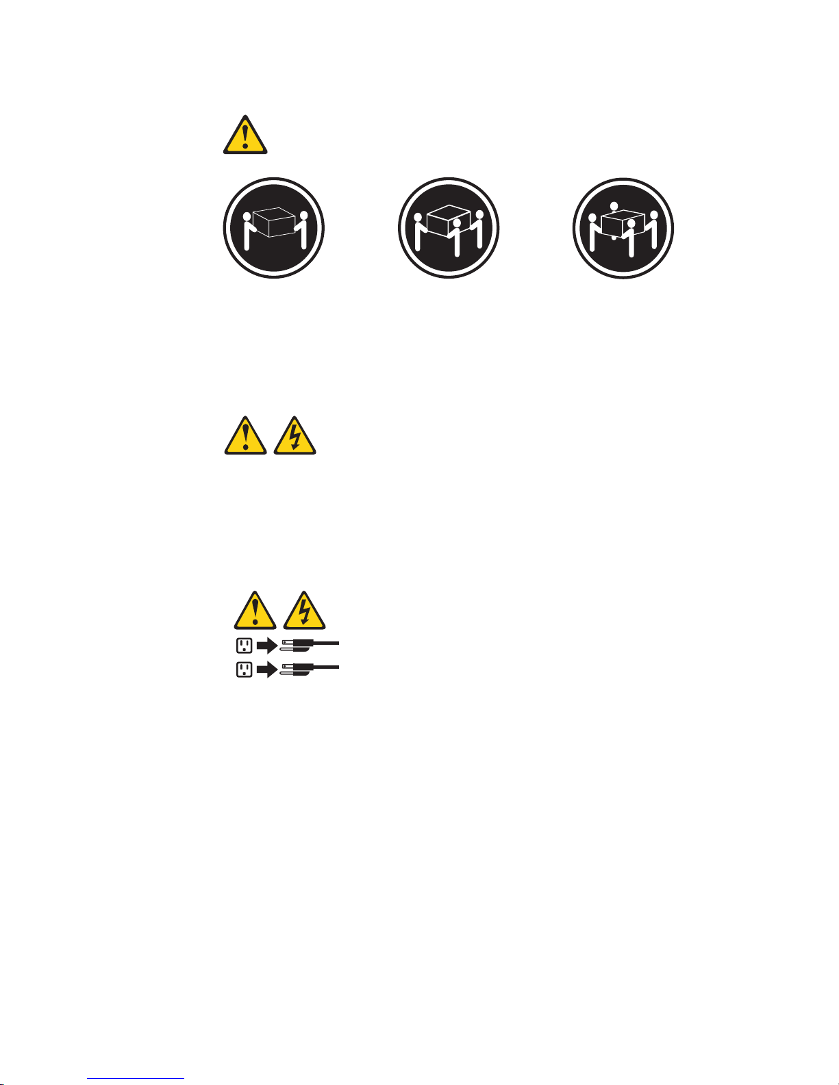
Statement 4:
≥ 18 kg (39.7 lb) ≥ 32 kg (70.5 lb) ≥ 55 kg (121.2 lb)
CAUTION:
Use safe practices when lifting.
Statement 5:
CAUTION:
The power control button on the device and the power switch on the power
supply do not turn off the electrical current supplied to the device. The device
also might have more than one power cord. To remove all electrical current
from the device, ensure that all power cords are disconnected from the power
source.
2
1
xiv BladeCenter QS22 Type 0793: Problem Determination and Service Guide
Page 17
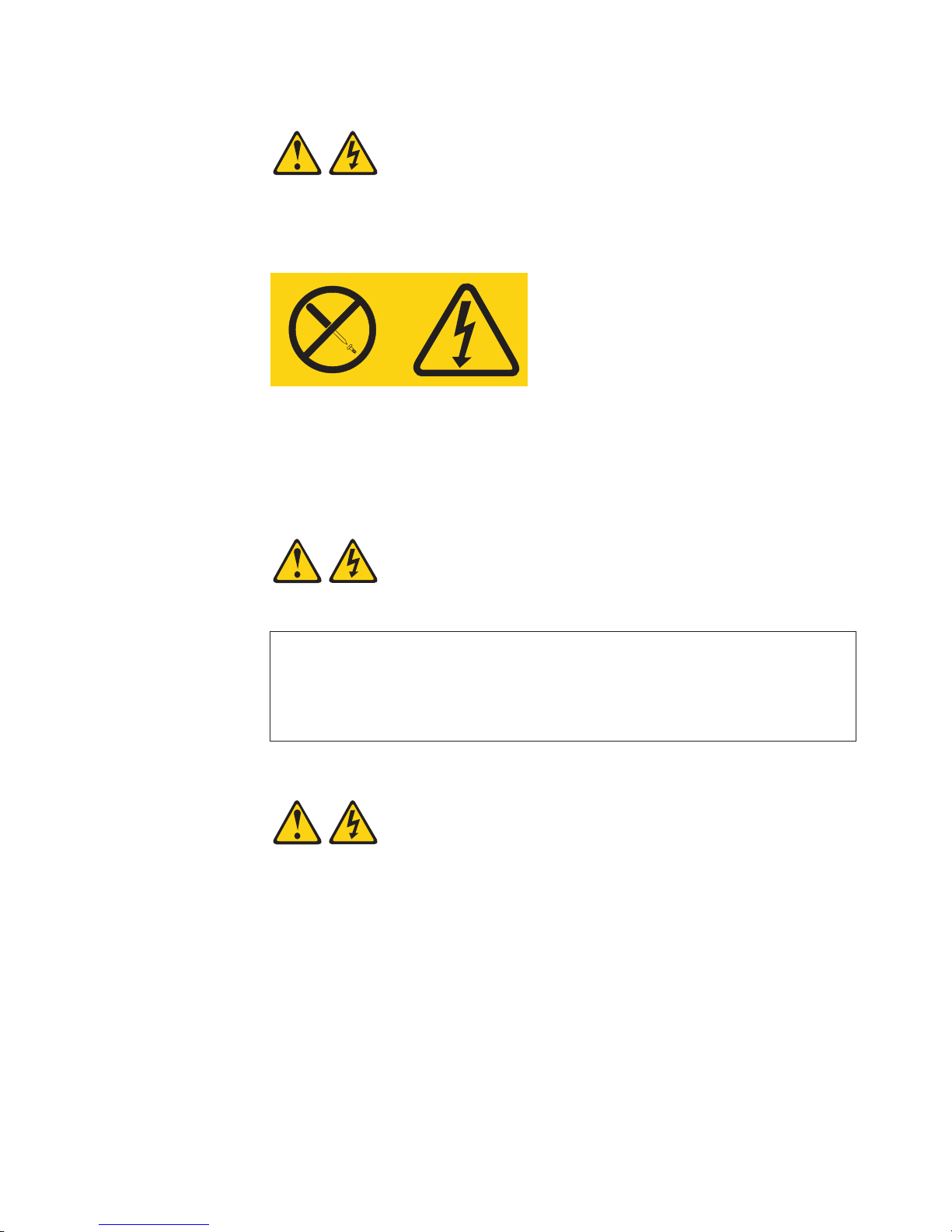
Statement 8:
CAUTION:
Never remove the cover on a power supply or any part that has the following
label attached.
Hazardous voltage, current, and energy levels are present inside any
component that has this label attached. There are no serviceable parts inside
these components. If you suspect a problem with one of these parts, contact
a service technician.
Statement 13:
DANGER
Overloading a branch circuit is potentially a fire hazard and a shock hazard
under certain conditions. To avoid these hazards, ensure that your system
electrical requirements do not exceed branch circuit protection
requirements. Refer to the information that is provided with your device for
electrical specifications.
Statement 21:
CAUTION:
Hazardous energy is present when the blade is connected to the power
source. Always replace the blade cover before installing the blade.
Safety xv
Page 18

WARNING: Handling the cord on this product or cords associated with accessories
sold with this product, will expose you to lead, a chemical known to the State of
California to cause cancer, and birth defects or other reproductive harm. Wash
hands after handling.
ADVERTENCIA: El contacto con el cable de este producto o con cables de
accesorios que se venden junto con este producto, pueden exponerle al plomo, un
elemento químico que en el estado de California de los Estados Unidos está
considerado como un causante de cancer y de defectos congénitos, además de
otros riesgos reproductivos. Lávese las manos después de usar el producto.
xvi BladeCenter QS22 Type 0793: Problem Determination and Service Guide
Page 19

Chapter 1. Introduction
This Problem Determination and Service Guide contains information to help you
solve problems that might occur when installing and using your IBM® BladeCenter®.
It describes the diagnostic tools that come with the BladeCenter QS22, error codes
and suggested actions. It also describes how to replace failing components.
Replaceable components are of three types:
v Tier 1 customer replaceable unit (CRU): Replacement of Tier 1 CRUs is your
responsibility. If IBM installs a Tier 1 CRU at your request, you will be charged for
the installation.
v Tier 2 CRU: You may install a Tier 2 CRU yourself or request IBM to install it, at
no additional charge, under the type of warranty service that is designated for
your server.
v Field replaceable unit (FRU): FRUs must be installed only by trained service
technicians.
information about the terms of the warranty and getting service and assistance,
For
see Warranty and Support Information.
The illustrations in this document might differ slightly from your hardware.
Note:
Related documentation
In addition to this document, the following documentation also comes with the
server:
v Installation and User’s Guide
This document is available in Portable Document Format (PDF) on the
Documentation CD. It contains general information about the blade server,
including how to install supported options and how to configure the blade server.
v Safety Information
This document is on the Documentation CD. It contains translated caution and
danger statements. Each caution and danger statement that appears in the
documentation has a number that you can use to locate the corresponding
statement in your language in the Safety Information document.
v Warranty and Support Information
This document is in PDF on the Documentation CD. It contains information about
the terms of the warranty and about service and assistance.
Depending
Documentation CD.
The blade server may have features that are not described in the documentation
that comes with the server. The documentation might be updated occasionally to
include information about those features, or technical updates might be available to
provide additional information that is not included in the blade server
documentation. The most recent versions of all BladeCenter documentation are at
http://www.ibm.com/support/us/en/.
on the server model, additional documentation might be included on the
In addition to the documentation in this library, be sure to review the planning and
installation documents for your BladeCenter hardware available at
http://www.ibm.com/support/us/en/.
© Copyright IBM Corp. 2006, 2008 1
Page 20

The IBM Software Development Kit for Multicore Acceleration documentation can be
downloaded from http://www.ibm.com/developerworks/power/cell/. This contains
information about how to install the operating system and how to program
applications for the blade server.
Updates may be available for this and other BladeCenter documents. You can
check for the most recent versions at http://www.ibm.com/support/us/en/ or on the
BladeCenter Information center at http://publib.boulder.ibm.com/infocenter/systems/.
Notices and statements used in this document
The caution and danger statements that appear in this document are also in the
multilingual Safety Information document, which is on the Documentation CD. Each
statement is numbered for reference to the corresponding statement in the Safety
Information document.
The following notices and statements are used in this document:
v Notes: These notices provide important tips, guidance, or advice.
v Important: These notices provide information or advice that might help you avoid
inconvenient or problem situations.
v Attention: These notices indicate potential damage to programs, devices, or
data. An attention notice is placed just before the instruction or situation in which
damage could occur.
v Caution: These statements indicate situations that can be potentially hazardous
to you. A caution statement is placed just before the description of a potentially
hazardous procedure step or situation.
v Danger: These statements indicate situations that can be potentially lethal or
extremely hazardous to you. A danger statement is placed just before the
description of a potentially lethal or extremely hazardous procedure step or
situation.
Features and specifications
The following table provides a summary of the features and specifications of the
BladeCenter QS22.
Through the BladeCenter Advanced Management Module, you can view the blade
server firmware code and other hardware configuration information.
The QS22 blade server is supported in the IBM BladeCenter H unit, the IBM
BladeCenter HT unit, and the IBM BladeCenter S (non RAID type only) unit.
Providing it is supported by the BladeCenter unit, you can install and operate any
other model of blade server in the same BladeCenter unit as a BladeCenter QS22.
Note: Power, cooling, removable-media drives, external ports, and advanced
system management are provided by the IBM BladeCenter unit. For more
information, see the Planning and Installation Guide for your BladeCenter
unit.
2 BladeCenter QS22 Type 0793: Problem Determination and Service Guide
Page 21

Table 1. Blade server features and specifications
Microprocessor:
Integrated functions:
Two IBM® PowerXCell™ 8i 64-bit
architecture processors w/VMX with 8
Synergistic Processor Units (SPU),
512 KB L2 cache, 256 KB on each
Synergistic Processing Engine (SPE)
v One dual-port 1 Gigabit Ethernet
controller
v Local service processor
v 2 IBM PowerXCell 8i companion
chips each providing a PCIe and
Memory: Minimum 4GB DDR2
memory. 2 GB per IBM PowerXCell 8i
processor. Maximum system memory
32 GB.
Supports 1 GB and 4 GB DDR2-800
VLP DIMMs. 2 GB DIMM support
depends on firmware level.
a single PCI-X interface
v RS-485 interface for
communication with BladeCenter
Management Module
v USB Controller
Supported
v Serial attached SCSI (SAS)
expansion card
v High-Speed InfiniBand Card,
IB-4x
v BladeCenter PCI Express I/O
Expansion Unit
v System memory 1 GB DDR2-800
VLP DIMM, total 4 GB per IBM
PowerXCell 8i processor
v System memory 2 GB DDR2-800
VLP DIMM, total 8 GB per IBM
PowerXCell 8i processor
v System memory 4 GB DDR2-800
VLP DIMM, total 16 GB per IBM
PowerXCell 8i processor
v I/O Buffer DIMM VLP DDR2 1GB,
total 1 GB per IBM PowerXCell 8i
companion chip
v 8 GB IBM Modular Solid State
Disk
v 8 GB Modular Flash Drive
Options:
Environment:
v Ambient temperature:
– Operating temperature: 10°C to
35°C (50°F to 95°F). Altitude: 0
to 2133 m (0 to 7000 ft)
v
Humidity:
– Operating temperature: 8% to
80%
Size:
v Height: 24.5 cm (9.7 inches)
v Depth: 44.6 cm (17.6 inches)
v Width: 2.9 cm (1.14 inches)
v Maximum weight: 5 kg (13.2 lb)
Electrical
input:
v Power provided to the blade server
by the BladeCenter unit: 12 V dc
Support for storage
The BladeCenter provides two options for storage:
SAS solution for storage
Onboard USB attached modular flash drive
SAS storage can be available through the following components: a SAS
Expansion Card attached to the blade server, one or two SAS connectivity
modules in the rear of the BladeCenter unit, and various options to attach
the IBM BladeCenter Boot Disk System to the SAS connectivity modules.
An optional SAS Expansion Card is available for the BladeCenter QS22.
If your QS22 blade server is installed in an IBM BladeCenter S unit, local
SAS drives of the BladeCenter S unit, if present, are also available as
storage.
This option provides a modular flash drive for system boot or local storage.
Chapter 1. Introduction 3
Page 22
Turning on the blade server
The QS22 blade server is hot-swappable and can be inserted into the BladeCenter
unit when the unit is already powered up. However, it can only be powered on by
one of the methods described in this section. While the blade server is powering up,
the power-on LED on the front of the server is lit. See “Blade server controls and
LEDs” on page 5 for the power-on LED states.
After you have installed the blade server into a powered up BladeCenter unit, wait
until the power on LED on the blade server flashes slowly before turning on the
blade server.
You can turn on the blade server in any of the following ways:
Using the power-control button
Providing local power control is enabled, you can press the power-control
button (see Figure 1) which is behind the control-panel door on the front of
the blade server. Local power control is enabled or disabled through the
Advanced Management Module Web interface.
Figure 1. Blade server power-control button
Using the BladeCenter Advanced Management Module
You can use the Advanced Management Module Web interface to turn on
the blade server remotely.
Using the Wake on LAN® feature:
If you want to use the Wake on LAN feature, you must enable it through the
operating system. Note that Wake on LAN does not operate if it has been
disabled through the Advanced Management Module.
In the event of a power failure the BladeCenter unit and then the blade server can
start automatically when power is restored. You must configure this through the
BladeCenter Advanced Management Module. See the BladeCenter Management
Module User's Guide for further information about this feature.
Turning off the blade server
When you turn off the blade server, it is still connected to power through the
BladeCenter unit and can continue to respond to requests from the service
processor, including remote requests to turn the blade server on. To remove all
power from the blade server, you must physically remove it from the BladeCenter
unit or power off the BladeCenter unit.
Power-on
LED
Power-control
button
4 BladeCenter QS22 Type 0793: Problem Determination and Service Guide
Page 23

To avoid loss of data, shut down the Linux® operating system before you turn off the
blade server. Shut down the operating system by entering the shutdown -h now
command at the command prompt or by choosing shutdown if you are using a
graphical user interface (GUI). See your operating system documentation for
additional information about shutting down the operating system.
If the BladeCenter unit has not been turned off, the blade server can be turned off
in any of the following ways:
Using the power-control button
Press the power-control button behind the control-panel door on the front
panel of the blade server. This starts an orderly shutdown of the operating
system if it has not been shut down already, providing your operating
system supports this feature, before turning off the blade server. If the
operating system stops functioning, pressing and holding the power-control
button for more than 4 seconds turns off the blade server.
Using the BladeCenter Advanced Management Module
You can use the Advanced Management Module Web interface to turn off
the blade server remotely. Yo u can also configure the Advanced
Management Module to turn off the blade server automatically if the system
is not operating correctly.
Note: After turning off the blade server, wait at least 5 seconds before turning it on
again.
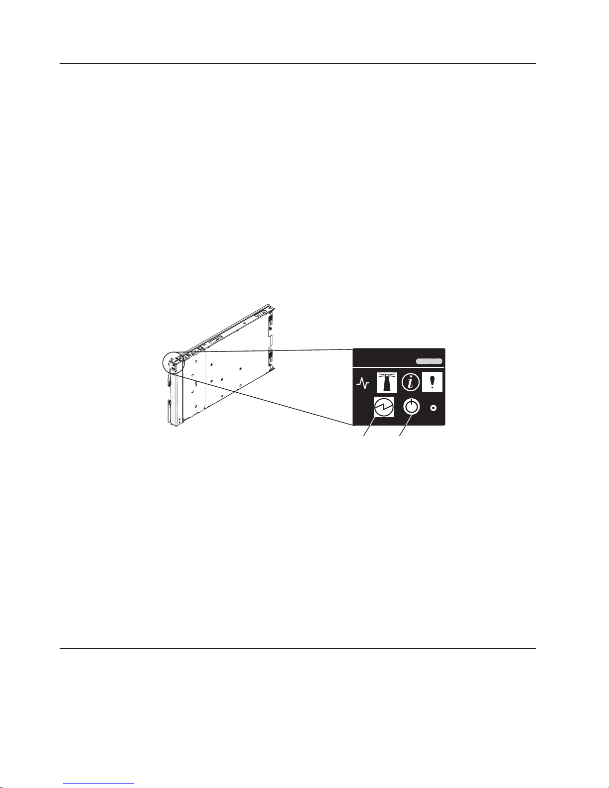
Blade server controls and LEDs
This section describes the controls and LEDs on the front panel of the blade server.
For further information about the LEDs and how they can be used to assist in
troubleshooting, see “Problems indicated by the front panel LEDs” on page 57.
Location
LED
Activity
LED
Information
LED
Power-on
LED
Media-tray
select button
Power-control
button
CD
Blade-error
LED
NMI
reset-button
Figure 2. Power-control button and LEDs
Note: The control panel door which normally covers the LEDs and power-control
button is omitted for reasons of clarity.
Activity LED:
This green LED lights when there is network activity.
Chapter 1. Introduction 5
Page 24

Location LED:
This blue LED is turned on remotely by the system administrator to assist in
locating the blade server. The location LED on the BladeCenter unit lights
at the same time.
Information LED:
This amber LED lights to indicate that information about a system event has
been placed in the Advanced Management Module Event Log. The
information LED remains on until turned off by Advanced Management
Module or through IBM Director Console.
Blade error LED:
This amber LED lights when a system error has occurred in the blade
server.
Power-control button:
Press this button to turn the blade server on or off. The power-control
button only has effect if local power control is enabled for the blade server.
Local power control is enabled and disabled through the BladeCenter
Advanced Management Module Web interface.
Media tray select button:
This button associates the shared BladeCenter unit media tray (DVD/CD
drive and USB ports) with the blade server. The LED on the button flashes
while the request is being processed, then lights when the ownership of the
media tray has been transferred to the blade server.
Power on LED:
reset button
NMI
The blade error LED, information LED, and location LED can be turned off through
the Advanced Management Module Web interface.
System board LEDs
The QS22 blade server has status LEDs on the system board to indicate the health
of various components. Some are within the light box while others are in different
locations. A lit LEDs indicates an error condition. Complete information about the
LEDs can be found in “Troubleshooting charts” on page 56.
It can take approximately 20 seconds for the operating system on the blade
server to recognize the media tray.
This green LED indicates the power status of the blade server as follows:
v Flashing rapidly - The service processor on the blade server is
communicating with the BladeCenter Advanced Management Module.
v Flashing slowly - The blade server has power but is not turned on.
v Lit continuously (steady) - The blade server has power and is turned on.
v Not lit. Either the BladeCenter unit is powered off, or a power failure has
occurred on the blade server or the BladeCenter unit.
If the operating system has been installed, pressing the button with a paper
clip or pin causes the operating system to call the Linux kernel debugger.
To find out what if any errors have occurred on the system board, you must:
1. Remove the blade server from the BladeCenter unit
2. Open the cover
3. Press the light path diagnostics switch
6 BladeCenter QS22 Type 0793: Problem Determination and Service Guide
Page 25
This lights any error LEDs that were turned on during processing. It also lights a
green LED to indicate the capacitor is charged and the light path diagnostics
system is operating.
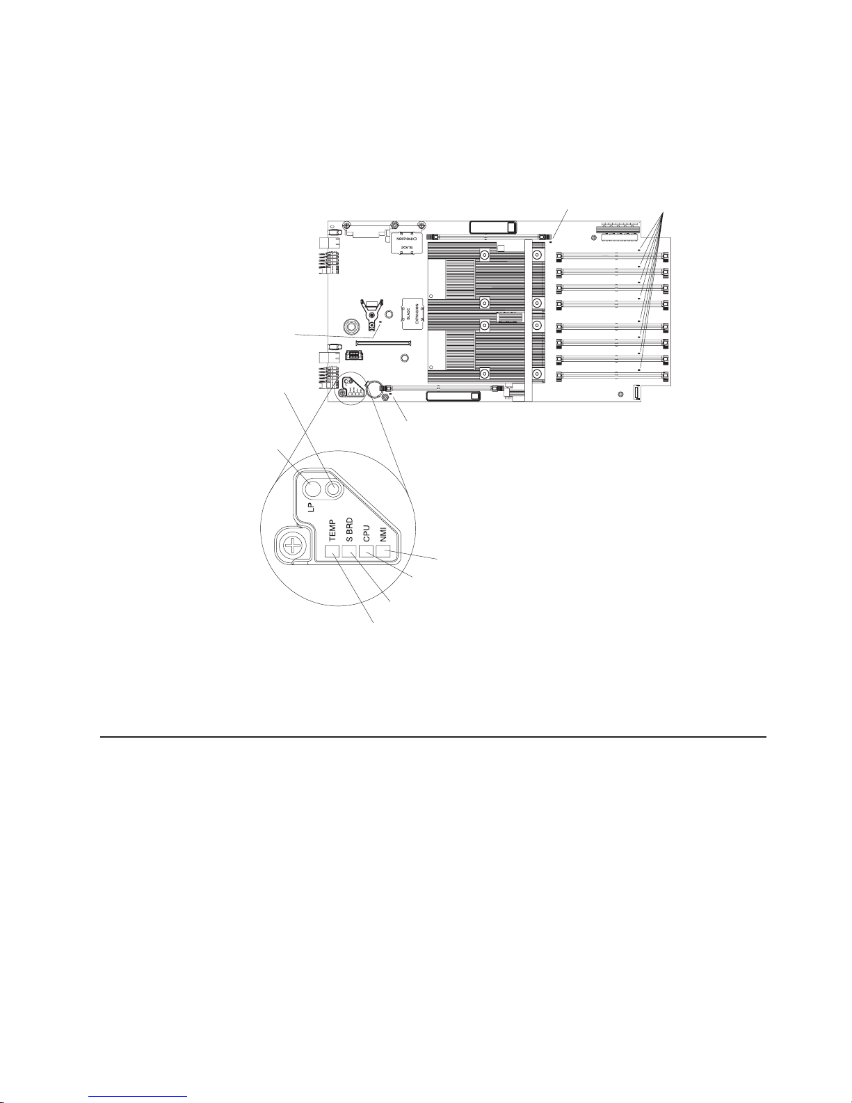
Figure 3 shows the location of the light path LEDs and the diagnostics switch.
Modular
flash drive
error LED
I/O buffer DIMM error LED
System memory DIMM
error LEDs
Light path
diagnosis
1
switch
Light path
diagnosis
I/O buffer DIMM error LED
LED
1
NMI error LED
CPU fail LED
System board LED
Temperature fault LED
Figure 3. System-board LEDs
Pressing the light path diagnostics switch lights the appropriate LED to indicate
where an error has occurred.
System board internal and expansion card connectors
The following illustration shows the location of the connectors for user-installable
options.
Chapter 1. Introduction 7
Page 26

PCIe high-speed
connector
Reserved
Flash drive connector
PCI-X expansion
connectors
IOBUF 2 DIMM slot
1
DIMM 8 slot
DIMM 7 slot
DIMM 6 slot
DIMM 5 slot
Battery
IOBUF 1 DIMM slot
DIMM 4 slot
DIMM 3 slot
DIMM 2 slot
DIMM 1 slot
Figure 4. Locations of the expansion option connectors on the system board
Control panel
connector
8 BladeCenter QS22 Type 0793: Problem Determination and Service Guide
Page 27

Chapter 2. Configuring the blade server
This chapter describes how to:
v Communicate with a blade server.
v Use System Management Services (SMS) to view and update the system
firmware revision number. This does not require the operating system to be
installed.
v Update the baseboard management controller (BMC) firmware using the update
package and the Advanced Management Module.
v Update the system firmware using the command-line utility.
v Configure the Ethernet Gigabit dual-port controller in preparation for a network
installation of the operating system.
You can update the BMC firmware through the Advanced Management
Note:
Module Web interface without booting the operating system. However, to
update the BMC using the update package or system firmware you must
boot the operating system first.
Communicating with the blade server
You do not have to boot the operating system before you can communicate with the
QS22 blade server. You can access it through:
Advanced Management Module
The Web-based management and configuration program. This is your main
access method to the blade server.
The command-line interface
See “Using the command-line interface” on page 10 for further information.
Serial over LAN (SOL)
This is similar to the serial interface, but allows you to connect to the blade
server over the network. See “Using Serial over LAN” on page 10 for further
information.
The serial interface
You can connect a PC or compatible terminal directly to the BladeCenter
unit. For BladeCenter H and BladeCenter HT you make this direct
connection using a special cable, for BladeCenter S you use a special
module. See “Using the serial interface” on page 11 for further information.
The BladeCenter unit Serial Breakout cable (or module for
Note:
BladeCenter S) is not supplied with the unit and must be ordered
separately.
System
Management Services (SMS)
The SMS utility allows you to view and update the VPD, change the boot
device and set network parameters. See “Using the SMS utility program” on
page 11 for further information.
Using the Advanced Management Module
The Advanced Management Module is the main means of administering the
BladeCenter system. Use the Advanced Management Module Web-based
management and configuration program to:
v Configure the BladeCenter unit
© Copyright IBM Corp. 2006, 2008 9
Page 28

v Update and configure BladeCenter components including the QS22 blade server
v Monitor the current system status
v Check the event log for system and other errors
Using the Web interface
Complete the following steps to start the Web-based management and configuration
program:
1. Open a Web browser. In the address or URL field, type the Internet protocol (IP)
address or host name that is assigned for the Management Module remote
connection. The default IP address is:
192.168.70.125
The Enter Network Password window opens.
2. Type your user name and password. Before you log in to the Advanced
Management Module for the first time, contact your system administrator
regarding whether your organization has assigned a user name and password
to you. Use the initial (default) user name and password the first time that you
log in to the Advanced Management Module. If you have an assigned user
name and password, use them for all subsequent logins. All login attempts are
documented in the event log.
The initial user ID and password for the Advanced Management Module are:
User ID
Password
Follow the instructions that appear on the screen. Be sure to set the timeout
3.
value that you want for your Web session.
BladeCenter management and configuration window opens.
The
For additional information, see the IBM BladeCenter Advanced Management
Module User's Guide.
Using the command-line interface
The IBM BladeCenter Advanced Management Module also provides a
command-line interface to provide direct access to BladeCenter management
functions. Yo u can use this as an alternative to using the BladeCenter Management
Module Web interface.
Through the command-line interface, you can issue commands to control the power
and configuration of the blade server and other components in the BladeCenter
unit. For information and instructions, see the IBM BladeCenter Management
Module Command-Line Interface Reference Guide.
Using Serial over LAN
To establish a Serial over LAN (SOL) connection to the blade server, you must
configure the SOL feature for the blade server and start an SOL session as
described in theIBM BladeCenter Serial over LAN Setup Guide. In addition, the
Advanced Management Module must be configured as described in the IBM
BladeCenter Management Module User’s Guide, and the BladeCenter unit must be
configured as described in the IBM BladeCenter Serial over LAN Setup Guide.
USERID (all capital letters)
PASSW0RD (note the number zero, not the letter O, in PASSW0RD)
10 BladeCenter QS22 Type 0793: Problem Determination and Service Guide
Page 29

Using the serial interface
Use the serial interface to:
v Observe firmware progress.
v Run the SMS Utility program
v Access the Linux terminal in order to configure Linux.
can connect a PC serially through the BladeCenter unit using a specific UART
You
cable. To connect to the serial console, plug the serial cable into the BladeCenter
unit and connect the other end to a serial device or computer with a serial port. For
more information, see the Installation and User's Guide for your BladeCenter unit.
Set the following parameters for the serial connection on the terminal client:
v 115200 baud
v 8 data bits
v No parity
v One stop bit
v No flow control
default, the blade server sends output over SOL and to the serial port on the
By
BladeCenter unit. However, the default for input is to use SOL. If you wish to use a
device connected to the serial port for input you must press any key on that device
while the blade server boots.
Using the SMS utility program
The Advanced Management Module is the main means of administering the
BladeCenter unit and the blade servers. However, another utility is provided which
in some cases can give more information than that displayed in the Advanced
Management Module. This is the System Management Services (SMS) utility
program.
The SMS utility program allows you to view and update the VPD, change the boot
list and set network parameters.
Starting SMS
Complete the following steps to start SMS:
1. Using a Telnet or SSH client, connect to the Advanced Management Module
external Ethernet interface IP address.
2. When prompted, enter a valid user ID and password. The default management
module user ID is USERID, and the default password is PASSW0RD, where the
0 is a zero.
Note: The user ID and password may have been changed. If so, check with the
system administrator for a valid id and password.
3. Power cycle the blade server and start an SOL console session by using the
power -cycle -c command.
For example, to power cycle and start an SOL remote text console with a blade
server that is in the first bay of the BladeCenter unit, issue the command:
power -cycle -c -T system:blade[1]
To open a console session with a blade that is already powered on, use the
command:
console -T system:blade[1]
Chapter 2. Configuring the blade server 11
Page 30

4. After approximately 30 seconds, you see a sequence of checkpoint codes
displayed on the console. These codes are generated by the Power On Self
Test (POST).
5. When the POST menu and indicators displays a screen similar to:
QS22 Firmware Starting
Check ROM = OK
Build Date = Jan 4 2008 11:31:29
FW Version = "QD-1.26.0-0"
Press "F1" to enter Boot Configuration (SMS)
Press "F2" to boot once from CD/DVD
Press F1 to display the SMS menu.
Viewing FRU information
The VPD on each blade server contains details about the machine type or model,
serial number and the universal unique ID.
Complete the following steps to see this information:
1. Start SMS by completing the steps in “Starting SMS” on page 11. The SMS
menu appears:
PowerPC Firmware
Version QD0123000
SLOF-SMS 1.1 (c) Copyright IBM Corp. 2007 All rights reserved.
--------------------------------------------------------------------------------
Main Menu
1. Select Language
2. Setup Remote IPL (Initial Program Load)
3. Change SCSI Settings
4. Select Console
5. Select Boot Options
6. Firmware Boot Side Options
7. Progress Indicator History
8. FRU Information
9. Change SAS Boot Device
--------------------------------------------------------------------------------
Navigation Keys:
X = eXit System Management Services
---------------------------------------------------------------------------
Type menu item number and press Enter or select Navigation key:
---------------------------------------------------------------------------
2. Type 8 to select FRU Information. A screen similar to the following appears:
12 BladeCenter QS22 Type 0793: Problem Determination and Service Guide
Page 31

PowerPC Firmware
Version QD0123000
SLOF-SMS 1.1 (c) Copyright IBM Corp. 2007 All rights reserved.
--------------------------------------------------------------------------------
FRU Information
Machine Type and Model: 079338x
Machine Serial Number: ABCDEFG
Universal Unique ID: 12345678-1234-1234-1234-123456789ABC
--------------------------------------------------------------------------------
Navigation Keys:
M = return to Main Menu
ESC key = return to previous screen X = eXit System Management Services
--------------------------------------------------------------------------------
Select Navigation key :
Note: You cannot change the FRU information from this screen, only view it.
Adding
FRU information: When you replace a FRU details are not recorded in
the VPD. Yo u must enter them manually through SMS.
When the system firmware detects an FRU replacement part during boot the
process stops to allow you to enter the machine type or model and serial number.
Boot does not continue until the information is provided.
To enter new FRU information, complete the following steps:
1. Using a Telnet or SSH client, connect to the Advanced Management Module
external Ethernet interface IP address.
2. When prompted, enter a valid user ID and password. The default management
module user ID is USERID, and the default password is PASSW0RD, where the
0 is a zero.
Note: The userid and password may have been changed. If so, check with the
system administrator for a valid user id and password.
3. Power cycle the blade and start an SOL console by using the power -cycle -c
command. See “Using the SMS utility program” on page 11 for further
information.
4. The following screen appears:
Chapter 2. Configuring the blade server 13
Page 32

PowerPC Firmware
Version QD0123000
SLOF-SMS 1.1 (c) Copyright IBM Corp. 2007 All rights reserved.
--------------------------------------------------------------------------------
Enter Type Model Number
(Must be 7 characters, only A-Z, a-z, 0-9 allowed. Press Esc to skip)
Enter Type Model Number :
Type the model number according to the instructions on the screen and press
Enter to continue.
5. You must confirm the model number:
PowerPC Firmware
Version QD0123000
SLOF-SMS 1.1 (c) Copyright IBM Corp. 2007 All rights reserved.
--------------------------------------------------------------------------------
Number entered is: 1234567
Accept number?
(Enter ’y’ or ’Y’ to accept or ’n’ or ’N’ to decline)
Select Navigation key :
Type y or Y and press Enter to confirm the number.
6. At the following screen, type the serial number:
14 BladeCenter QS22 Type 0793: Problem Determination and Service Guide
Page 33

PowerPC Firmware
Version QD0123000
SLOF-SMS 1.1 (c) Copyright IBM Corp. 2007 All rights reserved.
--------------------------------------------------------------------------------
Enter Serial Number
(Must be 7 characters, only A-Z, a-z, 0-9 allowed)
Enter Serial Number :
---------------------------------------------------------------------------------
Press Enter to continue.
7. You must now confirm the serial number:
PowerPC Firmware
Version QD0123000
SLOF-SMS 1.1 (c) Copyright IBM Corp. 2007 All rights reserved.
--------------------------------------------------------------------------------
Number entered is: ABCDEFG
Accept number?
(Enter ’y’ or ’Y’ to accept or ’n’ or ’N’ to decline)
Select Navigation key :
---------------------------------------------------------------------------------
Type y or Y and press Enter to confirm the number.
This completes the process and the blade server continues to boot as normal.
Updating the system and BMC firmware
The firmware consists of two distinct packages:
v A firmware package for the baseboard management controller (BMC). This is
referred to as the BMC firmware.
v A firmware package for the basic input/output system (BIOS) which runs on the
IBM PowerXCell 8i processor. This is referred to as system firmware.
Chapter 2. Configuring the blade server 15
Page 34

Note: The user and operating system interfaces of the system firmware are
based on the Open Firmware standard. Detailed system information is
provided through the Open Firmware device tree. You can use the client
interface and Run-Time Abstraction Services (RTAS) to run management
functions.
firmware
BMC
v Communicates with advanced management module
v Controls power on
v Initializes the board, including the IBM PowerXCell 8i processors and
clock chips
v Monitors the physical board environment
Updating steps
System
firmware
v Takes over when the BMC has successfully initialized the board
v Acts as the basic input/output system (BIOS)
v Includes boot-time diagnostics and power-on self test
v Prepares the system for the operating system boot
packages are delivered separately and do not follow the same versioning
The
scheme.
IBM periodically makes updates to both BMC and system firmware. These may be
downloaded from http://www.ibm.com/support/us/en/.
Note: To avoid problems and to maintain proper system performance, always make
sure that both the BMC firmware and the system firmware are at the same
level for all QS22 blade servers within the BladeCenter unit.
Complete the following steps to update the BMC and system firmware images:
1. Check the revision level of the firmware on the blade server and the level of the
updates on http://www.ibm.com/support/us/en/. If the level on the Web site is
higher than the version currently installed, continue with the updating steps.
2. Download the firmware updates.
3. Power off the blade server you wish to update.
4. Update the BMC firmware using the BMC update package or the Advanced
Management Module. See “Updating the BMC firmware” on page 17 for further
information.
5. Power on the blade server. This boots it with the new BMC firmware.
6. Update the system firmware image. See “Installing the system firmware” on
page 20 for further information.
7. The system reboots. This boots the blade server with the new system firmware.
8. Shut down the blade server.
There may be instances where you must update the BMC firmware before
Note:
updating the system firmware. Check the readme file that comes with each
firmware package for more information.
Determining current blade server firmware levels
Complete the following steps to view the current firmware code levels for both the
BMC and the system firmware:
16 BladeCenter QS22 Type 0793: Problem Determination and Service Guide
Page 35

1. To check the BMC firmware level, access and log on to the Advanced
Management Module Web interface as described in the Management Module
User's Guide.
2. From the Monitors menu section, select Firmware VPD:
The Blade Server Firmware Vital Product Data (VPD) window shows the build
identifier, release, and revision level of both the system firmware/BIOS and the
BMC firmware. In the example above, the system firmware or BIOS version is
QB01020000 and the BMC firmware is BLBT06b.
Compare this information to the firmware information provided at
http://www.ibm.com/support/us/en/. If the two match, then the blade server has the
latest firmware. If not, download the firmware package from the IBM Support Web
site. See “Updating the BMC firmware” or the IBM Support Web site for installation
instructions.
You can also view the system firmware level from within the operating system by
using the following command:
xxd /proc/device-tree/openprom/ibm,fw-vernum_encoded
Output is similar to:
0000000: 5142 3031 3031 3030 3000 00 QB0101000..
where QB0101000 is the system firmware version.
Note: The system firmware version displayed by the BladeCenter Advanced
Management Module might be different from the version displayed by your
operating system. Cross-reference information is given in the firmware
information at http://www.ibm.com/support/us/en/, and in the readme file
which comes with the firmware image.
Updating the BMC firmware
You can update the BMC firmware from the Linux prompt using the update package
or from the Advanced Management Module.
Chapter 2. Configuring the blade server 17
Page 36

Using the BMC update package
Complete the following steps to update the BMC firmware from the Linux command
prompt:
1. Check the README that comes with the BMC firmware as it contains specific
information about that particular firmware release.
2. Boot the blade server and the operating system.
3. Download the package from the IBM support site at http://www.ibm.com/support/
us/en/. The update package has a .sh extension.
4. Change to the directory where you have downloaded the package.
5. Run the package using the -s option.
6. Reboot the blade server.
Using the Advanced Management Module
Complete the following steps to update the BMC firmware:
1. Download the BMC firmware image file from http://www.ibm.com/support/us/en/
to a suitable location on a server that is accessible on the network.
2. Uncompress the .zip file. The BMC firmware image file name has the format
BLBT<version number>.zip.
3. Power off the blade you want to update.
4. Log in to the Advanced Management Module Web interface.
5. Click Firmware Update from the Blade Tasks submenu at the left of your
screen. The following screen appears:
6. Choose the blade you want to update (target) and browse to the firmware
image file.
7. Click on Update.
8. The validity of the image is checked, then the following screen appears:
18 BladeCenter QS22 Type 0793: Problem Determination and Service Guide
Page 37

Click Continue.
9. The next screen shows the firmware update progress:
When the update is finished, a confirmation message appears and an entry is
placed in the Advanced Management Module log.
10. Power up and boot the blade server.
Chapter 2. Configuring the blade server 19
Page 38

Note: QS22 firmware contains a proprietary implementation of Cell Broadband
Engine™ hardware initialization code.
Installing the system firmware
System firmware can only be installed after the operating system has booted. If the
operating system is not installed or cannot boot, then no upgrade or recovery is
possible. See the other sections of the manual Chapter 5, “Diagnostics and
troubleshooting,” on page 55 for further information about troubleshooting the QS22
blade server.
You can update the system firmware:
v Through IBM Director. See the IBM Director documentation on the IBM Director
CD for further information.
v Using the update package available from http://www.ibm.com/support/us/en/. See
“Updating the system firmware automatically” on page 21 for further information
on how to perform an update.
v Using the update_flash script available on supported Linux operating systems.
This requires the system firmware image file. See “The firmware update
package” for information about how to extract the file.
v Updating the firmware manually. See “Installing the firmware manually” on page
21 for further information.
all the above options Linux needs to have a current version of rtas_flash
For
device driver installed. This is normally installed with the operating system. If it is
not, see the installation guide for the Software Development Kit for Multicore
Acceleration for instructions about how to get this device driver and install it.
Note: You may have to update the BMC before updating the system firmware. See
the README file that comes with the package.
The firmware update package
You can now update firmware using the update packages available from
http://www.ibm.com/support/us/en/. These can be installed either through IBM
Director or by executing the .sh file contained in the package. This section
describes how to use the update package to install the firmware update or extract
the firmware image for manual installation.
To install the firmware package using IBM Director, see the documentation on the
IBM Director CD.
Note: The blade server must be configured and have a running Linux operating
system before the package can be extracted or installed.
The update package consists of 4 files:
v A file containing the change history for the QS22 system firmware. This has a
.chg extension.
v A file containing the update package. This has an .sh extension.
v A readme file for the update package. This contains specific installation and
configuration information.
v An XML file. This file is for use by IBM Systems Management tools, including
IBM Director Update Manager, UpdateXpress CD, and UpdateXpress System
Pack Installer.
20 BladeCenter QS22 Type 0793: Problem Determination and Service Guide
Page 39

Using the package
The package consists of an file with a .sh extension that runs from the Linux
prompt. It has a number of options. To see what options are available, run the
package without any options or with the -h switch:
# ./ibm_fw_bios_qb-1.9.1-2_linux-pq_cell.sh
In this example, ibm_fw_bios_qb-1.9.1-3_linux-pq_cell.sh is the name of the
firmware update package. The file name changes according to the version of the
firmware.
A screen similar to the following appears:
Usage:
-x /someDirectory - Extract the payload to <some directory>
-xr /someDirectory - Extract the payload plus PkgSdk files to <some directory>
-xd /dev/fd0 - Create a DOS bootable diskette - Internel floppy drive
-xd /dev/sda - Create a DOS bootable diskette - External USB floppy drive
-u - Perform update unattended
-h - Display this help screen
++debug - Display helpful debug information
Note:
All other command line arguments are passed to the
payload executable
The -xd options are not supported on the QS22 blade server.
The -x option
This enables to extract another executable file, in this example
ibm_fw_bios_qb-1.9.1-2.sh which in turn may be run to create the .bin file
required if you wish to update the firmware manually. See “Installing the
firmware manually” for further information.
The -u option
This performs an unattended and automatic update of the system firmware.
The blade server reboots automatically as part of the update process.
Updating the system firmware automatically
Complete the following steps to update the firmware automatically using the update
package:
1. Check the README before attempting to update the system firmware as it
contains specific information about the particular firmware release.
2. Download the update package from http://www.ibm.com/support/us/en/. The
update package has a .sh extension.
3. Change to the directory where you have downloaded the package.
4. Run the package with the -u option. Using the example from above, at the
command prompt enter:
./ibm_fw_bios_qb-1.9.1-2_linux-pq_cell.sh -u
5. Check the system firmware images to confirm the update has succeeded. See
“Determining current blade server firmware levels” on page 16 for instructions.
Installing the firmware manually
If you cannot update the firmware using the update_flash script, it is possible to
update the firmware manually. Yo u can use rtas_flash over /proc.
Complete the following steps to install the firmware manually:
1. Download the update package from http://www.ibm.com/support/us/en/.
Chapter 2. Configuring the blade server 21
Page 40

2. Extract the system firmware image package. At the command prompt enter:
./<update package> -x <target directory>
For example, to extract the image package ibm_fw_bios_qb-1.9.1-2.sh from
ibm_fw_bios_qb-1.9.1-2_linux-pq_cell.sh in the directory /temp/fwimage
enter:
./ibm_fw_bios_qb-1.9.1-2_linux-pq_cell.sh -x /temp/fwimage
If the directory does not exist the firmware package creates it.
3. Change to the directory containing the firmware image package.
4. Extract the firmware image. At the command prompt enter:
./<image package> -x
For example, to extract the image file QB-1.9.1-2-boot_rom.bin from
ibm_fw_bios_qb-1.9.1-2.sh enter:
./ibm_fw_bios_qb-1.9.1-2.sh -x
5. Ensure the rtas_flash driver is loaded. To do this, run lsmod.
6. If the module is not yet in the kernel, invoke the following to load it:
modprobe rtas_flash
7. To update your current firmware, copy the image file to /proc/ppc64/rtas/
firmware_update and reboot manually:
cp <image-file> /proc/ppc64/rtas/firmware_update
shutdown —r now
For example, to copy the image file cp QB-1.9.1-2-boot_rom.bin to
/proc/ppc64/rtas/firmware_update enter:
cp QB-1.9.1-2-boot_rom.bin /proc/ppc64/rtas/firmware_update
shutdown —r now
8. Once the system reboots, update the system firmware images. See “Updating
the system firmware images” for instructions.
Updating the system firmware images
Once the system firmware is updated, the QS22 blade server boots from the new
firmware. However, there are always two copies of the system firmware image on
the blade server:
TEMP This is the firmware image normally used in the boot process. When the
firmware is updated, it is the TEMP image that is replaced.
PERM This is a backup copy of the system firmware boot image. The blade server
only boots from this image if the TEMP image is corrupt. See “Recovering
the system firmware code” on page 64 for further information about how to
recover from a corrupt TEMP image.
you have updated the system firmware and booted the blade server, you
Once
should copy the TEMP image to the PERM image. This ensures that the PERM and
TEMP images are at the same revision level. The TEMP and PERM images should
always be at the same revision level.
There are two commands you can use to update an old image on PERM.
v From the Linux prompt issue the following command:
update_flash -c
22 BladeCenter QS22 Type 0793: Problem Determination and Service Guide
Page 41

Note: The script checks whether the board has booted from the TEMP image. If
not, the script does not complete.
v From the Linux prompt issue the following command:
echo 0 > /proc/rtas/manage_flash
For more information on booting from the TEMP or PERM images, see “Recovering
the system firmware code” on page 64.
Updating the optional expansion card firmware
If you have installed the SAS optional expansion card or a high-speed expansion
card, for example the InfiniBand card, you may have to update the firmware. See
the documentation that comes with the components for instructions about how to
update the firmware.
IBM periodically makes updates available for both SAS and high-speed expansion
cards. These may be downloaded from http://www.ibm.com/support/us/en/.
Integrating the Gigabit Ethernet controller into the BladeCenter
One dual-port Gigabit Ethernet controller is integrated on the blade server system
board. Each controller port provides a 1000-Mbps full-duplex interface connecting to
one of the Ethernet Switch Modules in I/O bays 1 and 2 of the BladeCenter unit,
which enables simultaneous transmission and reception of data on the Ethernet
local area network (LAN).
Each Ethernet-controller port on the system board is routed to a different switch
module in I/O bay 1 or bay 2. The routing from the Ethernet-controller port to the
I/O bay varies according to whether an Ethernet adapter is enabled and the
operating system that is installed. See “Blade server Ethernet controller
enumeration” on page 25 for information about how to determine the routing from
the Ethernet-controller ports to I/O bays for your blade server.
You do not have to set any jumpers or configure the controller for the blade server
operating system. However, you must install a device driver to enable the blade
server operating system to address the Ethernet-controller ports. For device drivers
and information about configuring your Ethernet controller ports, see the Ethernet
software documentation that comes with your blade server, or contact your IBM
marketing representative or authorized reseller. For updated information about
configuring the controllers, go to the Barcelona Computing Centre Web site at
http://www.bsc.es/projects/deepcomputing/linuxoncell/.
If your blade server contains a different type of optional Ethernet-compatible
Note:
switch module in I/O bay 1 than the switch modules that are mentioned in
this section, see the documentation that comes with the Ethernet switch
module that you are using.
Updating the Ethernet controller firmware
To update the Ethernet controller firmware, you must download an update package
from http://www.ibm.com/support/us/en/. This section describes how to use the
update package to install the firmware update.
The update package consists of four files:
Chapter 2. Configuring the blade server 23
Page 42

v A file containing the change history for the QS22 Ethernet Controller firmware.
This has a .chg extension.
v A file containing the update package. This has an .sh extension.
v A readme file for the update package. This contains specific installation and
configuration information.
v An XML file. This file is for use by IBM Systems Management tools, including
IBM Director Update Manager, UpdateXpress CD, and UpdateXpress System
Pack Installer.
Using the update package
The package consists of an file with a .sh extension that runs from the Linux
prompt. It has a number of options. To see what options are available, run the
package without any options or with the -h switch:
# ./brcm_fw_nic_2.0.3-e-1_rhel5_cell.sh
In the example shown above, brcm_fw_nic_2.0.3-e-1_rhel5_cell.sh is the name
of the firmware update package. The file name changes according to the version of
the firmware.
A screen similar to the following appears:
Usage:
-x /someDirectory - Extract the payload to <some directory>
-xr /someDirectory - Extract the payload plus PkgSdk files to <some directory>
-xd /dev/fd0 - Create a DOS bootable diskette - Internel floppy drive
-xd /dev/sda - Create a DOS bootable diskette - External USB floppy drive
-u - Perform update unattended
-h - Display this help screen
++debug - Display helpful debug information
The -xd and -x options are not supported on QS22.
The -u option performs an unattended and automatic update of the firmware. The
blade server reboots automatically as part of the update process.
Firmware update steps
Complete the following steps to update the firmware automatically:
1. Check the README before attempting to update the system firmware as it
contains specific information about the particular firmware release.
2. Download the update package from http://www.ibm.com/support/us/en/. The
update package has a .sh extension.
3. Change to the directory where you have downloaded the package.
4. Run the package with the -u option. Using the example from above, at the
command prompt enter:
./ brcm_fw_nic_2.0.3-e-1_rhel5_cell.sh -u
During the update process, messages similar to the following appear on the
console:
24 BladeCenter QS22 Type 0793: Problem Determination and Service Guide
Page 43

[root@c4b14 brcm-2.0.3-ppc]# ./ brcm_fw_nic_2.0.3-e-1_rhel5_cell.sh -u
IBM Ethernet Firmware Update Tool, Version 1.0.2
Warning. No Broadcom NetXtreme II adapters found.
ADAPTER MAC BOOT IPMI ASF PXE UMP
------------------- ---- ---- --- --- --001A640E030C (5704s) 3.21 2.20 NA NA NA
001A640E030D (5704s) NA NA NA NA NA
Updating Broadcom NetXtreme adapters.
Updating 001A640E030C using file 16A8bc.bin ---> Update successful
Updating 001A640E030C using file 16A8ipmi.bin ---> Update successful
Error! Firmware not detected on device 001A640E030D.
Warning. No Broadcom NetXtreme II adapters found.
ADAPTER MAC BOOT IPMI ASF PXE UMP
------------------- ---- ---- --- --- --001A640E030C (5704s) 3.38 2.47 NA NA NA
001A640E030D (5704s) NA NA NA NA NA
One or more errors occurred during the firmware update process. See /var
Note: The error message shown above is correct as it refers to an adapter not
available on QS22.
Blade server Ethernet controller enumeration
The enumeration of the Ethernet controller or controller ports in a blade server is
operating system dependent. Yo u can verify the Ethernet controller or controller port
designations that a blade server uses through your operating system settings.
The routing of an Ethernet controller or controller port to a particular BladeCenter
unit I/O bay depends on the type of Ethernet controller that is installed. You can
verify which Ethernet-controller port is routed to which I/O bay by using the
following test:
1. Install only one Ethernet switch module or pass-thru module, in I/O bay 1.
2. Make sure that the ports on the switch module or pass-thru module are enabled
(Switch Tasks → Management → Advanced Switch Management in the
BladeCenter Management Module Web interface).
3. Enable only one of the Ethernet-controller ports on the blade server. Note the
designation that the blade server operating system has for the controller port.
4. Ping an external computer on the network connected to the Ethernet switch
module. If you can ping the external computer, the Ethernet-controller port that
you enabled is associated with the switch module in I/O bay 1. The other
Ethernet-controller port in the blade server is associated with the switch module
in I/O bay 2.
Communications from optional I/O expansion cards are routed to I/O bays 3 and 4.
If you have installed an I/O expansion card on the blade server you can verify
which controller port on an expansion card is routed to which I/O bay by performing
the same test, using a controller on the expansion card and a compatible switch
module or pass-thru module in I/O bay 3 or 4.
Chapter 2. Configuring the blade server 25
Page 44

26 BladeCenter QS22 Type 0793: Problem Determination and Service Guide
Page 45

Chapter 3. Parts listing
This parts listing supports BladeCenter QS22 replaceable components. To check for
an updated parts list on the Web, do the following:
1. Go to http://www.ibm.com/support/us/en.
2. Under Find resources, select Upgrades, accessories and parts.
Replaceable components
Replaceable components are of three types:
v Tier 1 customer replaceable unit (CRU): Replacement of Tier 1 CRUs is your
responsibility. If IBM installs a Tier 1 CRU at your request, you will be charged for
the installation.
v Tier 2 CRU: You may install a Tier 2 CRU yourself or request IBM to install it, at
no additional charge, under the type of warranty service that is designated for
your server.
v Field replaceable unit (FRU): FRUs must be installed only by trained service
technicians.
information about the terms of the warranty and getting service and assistance,
For
see Warranty and Support Information.
The following table lists which replaceable components are available for the
BladeCenter QS22.
Description FRU No.
DIMM VLP 1 GB DDR2 system memory 46C0502
DIMM VLP 2 GB DDR2 system memory 46C0515
DIMM VLP 4 GB DDR2 system memory 46C0516
DIMM VLP 1 GB DDR2 I/O buffer memory only 46C0502
Cisco 4X Infiniband Expansion Card for IBM BladeCenter 32R1763
Front bezel assembly 43W9932
BladeCenter QS22 blade assembly, base and planar 60H3199
SAS expansion card 39Y9188
BladeCenter PCI Express I/O Expansion Unit 43W4390
Air baffle for I/O buffer DIMM connector 60H2962
Mounting tray for modular flash drive 42C0593
8 GB Modular Flash Drive 43W3932
8 GB IBM Modular Solid State Disk 60H4322
Miscellaneous Parts Kit 60H3473
Blade Cover and Warning Label 46C7201
System Service Label 60H3471
FRU List Label 60H3472
Tier 1 CRU
No.
Tier 2 CRU
No.
Part numbers can change and other options can become available. For the latest
information, check the IBM Web site at http://www.ibm.com/support/us/en/.
© Copyright IBM Corp. 2006, 2008 27
Page 46

Consumable parts
Consumable parts are not covered by the IBM Statement of Limited Warranty. The
following consumable parts are available for purchase from the retail store:
Description Part Number
3V lithium battery 43W9859
28 BladeCenter QS22 Type 0793: Problem Determination and Service Guide
Page 47

Chapter 4. Installing and removing replaceable units
This chapter provides instructions for installing or replacing units on the blade
server. Replaceable units are components, such as memory modules, and I/O
expansion cards. Some removal instructions are provided in case you need to
replace one replaceable unit with another.
You can replace the following items:
v Battery
v Front bezel assembly (control panel)
v Blade server cover
v Impedance air baffles
v Air baffle for I/O buffer DIMM connector
v Miscellaneous parts
can add, remove or replace the following optional items:
You
v Modular flash drive
v High-speed expansion card
v System memory DDR2 modules
v I/O buffer DDR2 memory modules
v SAS expansion card
v BladeCenter PCI Express I/O Expansion Unit
This chapter also details how to replace the system board. The system board is a
field replaceable unit (FRU): FRUs must be installed only by trained service
technicians.
Installation guidelines
Before you begin, read the following:
v Read the safety information beginning on page vii and the guidelines in “Handling
static-sensitive devices” on page 30. This information will help you work safely
with the blade server and components.
v You do not have to turn off the blade server or disconnect the BladeCenter unit
from power to install or replace any of the hot-swappable modules on the rear of
the BladeCenter unit.
v Before you remove a hot-swappable blade server from the BladeCenter unit, you
must shut down the operating system on it by typing the shutdown -h now
command or choosing the shut down option from your GUI. See “Turning off the
blade server” on page 4 for details. You do not have to shut down the
BladeCenter unit itself.
v Blue on a component indicates touch points, where you can grip the component
to remove it from or install it in the blade server or BladeCenter unit, open or
close a latch, and so on. An exception to this rule are the DIMM clips and the
battery clip that are also touch points but not colored blue.
v Orange on a component or an orange label on or near a component indicates
that the component can be hot-swapped. You can remove or install the
component while the blade server or BladeCenter unit is running providing the
blade server or BladeCenter unit and operating system support the
hot-swappable capability. Orange can also indicate touch points on
hot-swappable components. See the instructions for removing or installing a
© Copyright IBM Corp. 2006, 2008 29
Page 48

specific hot-swappable component for any additional procedures that you might
have to perform before you remove or install the component.
There are no hot-swappable components on the QS22 blade server. To
Note:
replace parts, you must turn off the blade server and remove it from the
BladeCenter unit.
System reliability guidelines
To help ensure proper cooling and system reliability, be sure that:
v The ventilation holes on the blade server are not blocked.
v Each of the blade bays on the front of the BladeCenter unit has a blade server or
blade filler installed. Do not operate the BladeCenter unit for more than 1 minute
without a blade server or blade filler installed in each blade bay.
v You have followed the reliability guidelines in the documentation that comes with
the BladeCenter unit.
Handling static-sensitive devices
Attention: Static electricity can damage electronic devices and your system. To
avoid damage, keep static-sensitive devices in their static-protective packages until
you are ready to install them.
To reduce the possibility of electrostatic discharge, observe the following
precautions:
v Limit your movement. Movement can cause static electricity to build up around
you.
v Handle the device carefully, holding it by its edges or its frame.
v Do not touch solder joints, pins, or exposed printed circuitry.
v Do not leave the device where others can handle and damage it.
v While the device is still in its static-protective package, touch it to an unpainted
metal part of the BladeCenter chassis for at least 2 seconds. This drains static
electricity from the package and from your body.
v Remove the device from its package and install it directly into the blade server or
BladeCenter unit without setting the device down. If it is necessary to set down
the device, put it back into its static-protective package. Do not place the device
on the blade server cover or on a metal surface.
v Take additional care when handling devices during cold weather. Heating reduces
indoor humidity and increases static electricity.
v Wear an electrostatic-discharge wrist strap, if one is available.
Removing the blade server from the BladeCenter unit
The blade server is a hot-swappable device, and the blade bays in the BladeCenter
unit are hot-swappable bays. Therefore, you can install or remove the blade server
without removing power from the BladeCenter unit. However, you must turn off the
blade server before removing it from the BladeCenter unit.
30 BladeCenter QS22 Type 0793: Problem Determination and Service Guide
Page 49

Attention:
v To maintain proper system cooling, do not operate the BladeCenter unit for more
than 1 minute without a blade server or blade fillers installed in each blade bay.
v Note the number of the bay that contains the blade server before you remove it.
You must reinstall the blade server in the same bay from which it was removed.
Reinstalling a blade server into a different bay than the one from which it was
removed could have unexpected consequences, such as incorrect reconfiguration
of the blade server. Some blade server configuration information and update
options are established according to bay number.
If you reinstall the blade server into a different bay, you might have to reconfigure
the blade server.
Releasehandles
open
Figure 5. Removing the blade server
Complete the following steps to remove the blade server:
1. Read the safety information beginning on page vii and “Installation guidelines”
on page 29.
2. If the blade server is operating, the power on LED is lit continuously (steady).
Before you remove a blade server from the BladeCenter unit, you must shut
down the operating system on it by typing the shutdown -h now command or
choosing the shut down option from your GUI. See “Turning off the blade
server” on page 4 for details. You do not have to shut down the BladeCenter
unit itself.
3. Open the two release levers as shown in Figure 5. The blade server moves out
of the bay approximately 0.6 cm (0.25 inch).
4. Pull the blade server out of the bay.
5. Place either a blade filler or a new blade server in the bay within 1 minute.
Opening and removing the blade server cover
You must open the blade server cover to access, install or remove any of the
replaceable items.
If a BladeCenter PCI Express I/O Expansion Unit has been installed on your blade
server, ignore this section and follow the instructions in “Removing the BladeCenter
PCI Express I/O Expansion Unit” on page 32 instead.
Chapter 4. Installing and removing replaceable units 31
Page 50

Cover pins
Cover release
Figure 6. Opening the blade server cover
Cover release
Complete the following steps to open the blade server cover:
1. Read the safety information beginning on page vii and “Installation guidelines”
on page 29.
2. If applicable, shut down the operating system, turn off the blade server, and
remove the blade server from the BladeCenter unit. See “Removing the blade
server from the BladeCenter unit” on page 30.
3. Carefully place the blade server on a flat, static-protective surface, with the
cover side up.
4. Press the blue blade cover release on each side of the blade server and lift the
outer cover open (see Figure 6).
5. If you want to remove the cover, carefully lift it from the cover pins and set it
aside (see Figure 6).
Statement 21:
CAUTION:
Hazardous energy is present when the blade server is connected to the power
source. Always replace the blade cover before installing the blade server.
Removing the BladeCenter PCI Express I/O Expansion Unit
You must remove BladeCenter PCI Express I/O Expansion Unit, if installed, to
access, install or remove any of the replaceable items.
32 BladeCenter QS22 Type 0793: Problem Determination and Service Guide
Page 51

Cover pins
Cover release
Cover release
Figure 7. Removing the expansion unit
Complete the following steps to remove BladeCenter PCI Express I/O Expansion
Unit:
1. Read the safety information beginning on page vii and “Installation guidelines”
on page 29.
2. Carefully place the blade server on a flat, static-protective surface, with the
expansion unit side facing up.
3. Press the blue blade cover release on each side of the blade server and lift the
expansion unit (see Figure 7).
4. To remove the expansion unit, carefully lift it from the cover pins and set it
aside.
Removing the blade-server front bezel assembly
Before you can add, remove, or replace system memory DIMM modules, replace a
defective system board assembly, or replace the blade server front bezel assembly,
you must first remove the blade server front bezel assembly.
Chapter 4. Installing and removing replaceable units 33
Page 52

Blade cover
Cover release
Bezel release
Cover release
Bezel release
Figure 8. Removing the front bezel assembly
Control-Panel
Cable
Bezel assembly
Control-Panel
Connector
Complete the following steps to remove the front bezel assembly:
1. Read the safety information beginning on page vii and “Installation guidelines”
on page 29.
2. If applicable, shut down the operating system, turn off the blade server, and
remove the blade server from the BladeCenter unit. See “Removing the blade
server from the BladeCenter unit” on page 30.
3. Open the blade server cover. See “Opening and removing the blade server
cover” on page 31.
4. Carefully disconnect the control panel cable from the control panel connector
(see Figure 8).
5. Press the front bezel release on both sides of the system board and pull the
front bezel assembly away from the blade server.
6. Store the front bezel assembly in a safe place.
Installing the optional modular flash drive
The modular flash drive connects to the flash drive connector on the system board
and provides non-volatile memory. This may be used, for example, for installing an
operating system.
Complete the following steps to install the modular flash drive:
1. Read the safety information beginning on page vii and “Installation guidelines”
on page 29.
2. If applicable, shut down the operating system, turn off the blade server, and
remove the blade server from the BladeCenter unit. See “Removing the blade
server from the BladeCenter unit” on page 30.
3. Open the blade server cover. See “Opening and removing the blade server
cover” on page 31.
34 BladeCenter QS22 Type 0793: Problem Determination and Service Guide
Page 53

4. Locate the flash drive retention clip and connector on the system board.
Ta b
Flash drive
Connector
Retention clip
Figure 9. Fitting the modular flash drive
5. Locate the connector on the back of the modular flash drive.
6. Carefully align the modular flash drive with the retention clip and connector on
the system board. Ensure the orientation of the connector on the modular flash
drive matches the connector on the system board.
7. Gently press the modular flash drive into position.
8. If applicable, reinstall the high-speed expansion card.
If you have other options to install or remove, do so now. Otherwise, go to
“Finishing the installation” on page 50.
Removing the optional modular flash drive
Complete the following steps to remove the modular flash drive:
1. Read the safety information beginning on page vii and “Installation guidelines”
on page 29.
2. If applicable, shut down the operating system, turn off the blade server, and
remove the blade server from the BladeCenter unit. See “Removing the blade
server from the BladeCenter unit” on page 30.
3. Open the blade server cover. See “Opening and removing the blade server
cover” on page 31.
4. Locate the modular flash drive on the system board. The modular flash drive
can be underneath a high-speed expansion card.
Chapter 4. Installing and removing replaceable units 35
Page 54

Ta b
Flash drive
Connector
Retention clip
Figure 10. Removing the modular flash drive
If the modular flash drive is blocked by a high-speed expansion card, you must
remove the high-speed expansion card before removing the modular flash drive.
See “Removing an optional high-speed expansion card” on page 38.
5. Locate the tab on the modular flash drive. See Figure 10.
6. Using the tab, carefully lift the modular flash drive away from the retention clip
and connector on the system board.
7. If applicable, reinstall the high-speed expansion card.
If you have other options to install or remove, do so now. Otherwise, go to
“Finishing the installation” on page 50.
Installing an optional high-speed expansion card
You can connect a high-speed expansion card, for example an InfiniBand card, to
the high-speed connector on the system board. Use the two expansion card locator
pins to assist with fitting the card. If your card has a ball socket, use the socket to
lock the card in place.
36 BladeCenter QS22 Type 0793: Problem Determination and Service Guide
Page 55
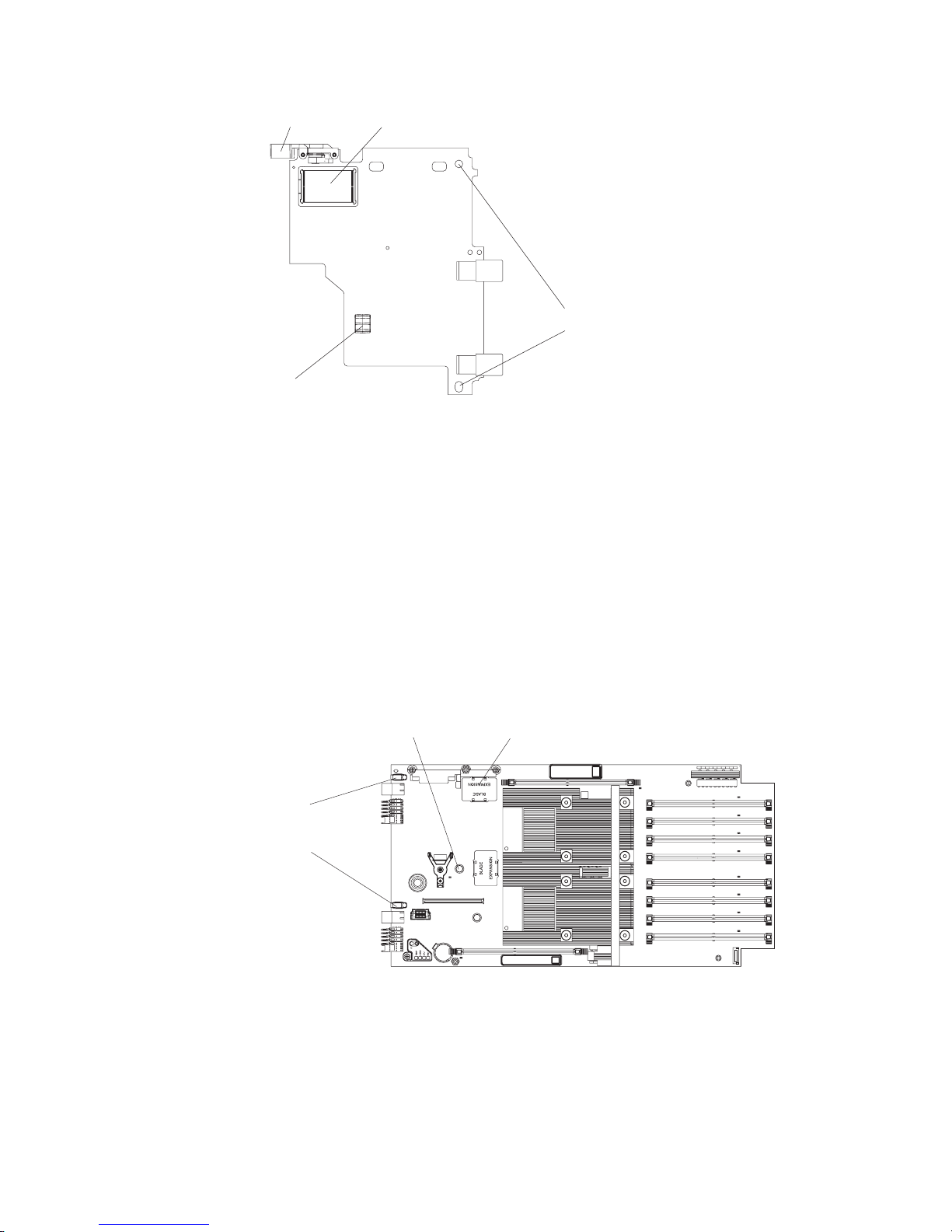
Locking clip
Connector
Locator pin holes
Ball socket
Figure 11 . High-speed expansion card reverse view
Complete the following steps to install the high-speed expansion card:
1. Read the safety information beginning on page vii and “Installation guidelines”
on page 29.
2. If applicable, shut down the operating system, turn off the blade server, and
remove the blade server from the BladeCenter unit. See “Removing the blade
server from the BladeCenter unit” on page 30.
3. Remove the blade server cover. See “Opening and removing the blade server
cover” on page 31.
4. If you also want to install a modular flash drive, do this before you proceed
with installing the high-speed expansion card. See “Installing the optional
modular flash drive” on page 34.
5. Locate the high-speed connector on the system board.
Ball stud
High-speed connector
Expansion card
standoffs
with locator pins
Figure 12. Expansion card connector, locator pins, and ball stud
6. Remove the connector cover.
7. Locate the expansion card locator pins on the standoffs at the back of the
system board.
8. Locate the connector and the ball socket on the high-speed expansion card.
1
Chapter 4. Installing and removing replaceable units 37
Page 56

9. Slide the locator pin holes on the expansion card over the locator pins. The
card rests on the locator pins.
Locator pin Locking clipExpansion card
Expansion
card
standoff
Expansion card
Expansion
connector
cover
Figure 13. Positioning the high-speed expansion card
10. Carefully press the expansion card into position. Be sure that the ball socket
on the card is over the corresponding ball stud on the main board. Use the
blue areas only to avoid damage to the card.
11. Check that the blue locking clip is horizontal and that there is no gap between
the card and the connector.
Attention: The connectors on the system board and the high-speed expansion
card are not designed for repeated removal or replacement of components. Avoid
removing the card once it is in position,
If you have other options to install or remove, do so now. Otherwise, go to
“Finishing the installation” on page 50.
Removing an optional high-speed expansion card
If you wish to remove an optional high-speed expansion card, complete the
following steps.
1. Read the safety information beginning on page vii and “Installation guidelines”
on page 29.
2. If applicable, shut down the operating system, turn off the blade server, and
remove the blade server from the BladeCenter unit. See “Removing the blade
server from the BladeCenter unit” on page 30.
3. Remove the blade server cover. See “Opening and removing the blade server
cover” on page 31.
4. Locate the high-speed expansion card on the system board.
5. Lift the locking clip to the vertical position until the card moves upward and
disengages from the connector.
6. If the card has a ball stud, hold the card at the handling area near the ball stud
and pull it upward until the ball stud disengages with the ball socket.
7. Lift the card off the locator pins and set it aside on a static-protective surface.
For diagrams see “Installing an optional high-speed expansion card” on page 36.
38 BladeCenter QS22 Type 0793: Problem Determination and Service Guide
Page 57

Adding or changing system memory
There are 8 DIMM slots for system memory. Each IBM PowerXCell 8i processor
has two memory channels and there are two DIMM slots per memory channel.
You can use VLP DDR2 1 GB, 2 GB, or 4 GB memory modules. The maximum
memory configuration has a 4 GB memory module in each DIMM slot which
provides 16 GB to each processor and 32 GB in total.
DIMM 8 slot
DIMM 7 slot
DIMM 6 slot
DIMM 5 slot
DIMM 4 slot
DIMM 3 slot
DIMM 2 slot
1
DIMM 1 slot
Processor 1 channel 1
Processor 1 channel 0
Processor 0 channel 1
Processor 0 channel 0
Figure 14. System memory DIMM slot locations
As shown in Figure 14, each processor has a channel 0 and a channel 1, with a
pair of DIMM slots for each channel. To use a channel, you must populate both
DIMM slots that belong to the channel.
All DIMM configuration listed in Table 2 are supported by the latest firmware level.
Table 2. Supported DIMM configurations
IBM PowerXCell 8i-0 IBM PowerXCell 8i-1
Channel 0 Channel 1 Channel 0 Channel 1
Slot 1 Slot 2 Slot 3 Slot 4 Slot 5 Slot 6 Slot 7 Slot 8
1 GB 1 GB 1 GB 1 GB
1 GB 1 GB 2 GB 2 GB
1 GB 1 GB 4 GB 4 GB
2 GB 2 GB 1 GB 1 GB
2 GB 2 GB 2 GB 2 GB
2 GB 2 GB 4 GB 4 GB
4 GB 4 GB 1 GB 1 GB
4 GB 4 GB 2 GB 2 GB
4 GB 4 GB 4 GB 4 GB
1 GB 1 GB 1 GB 1 GB 1 GB 1 GB 1 GB 1 GB
1 GB 1 GB 1 GB 1 GB 2 GB 2 GB 2 GB 2 GB
1 GB 1 GB 1 GB 1 GB 4 GB 4 GB 4 GB 4 GB
2 GB 2 GB 2 GB 2 GB 1 GB 1 GB 1 GB 1 GB
2 GB 2 GB 2 GB 2 GB 2 GB 2 GB 2 GB 2 GB
2 GB 2 GB 2 GB 2 GB 4 GB 4 GB 4 GB 4 GB
4 GB 4 GB 4 GB 4 GB 1 GB 1 GB 1 GB 1 GB
Chapter 4. Installing and removing replaceable units 39
Page 58

Table 2. Supported DIMM configurations (continued)
IBM PowerXCell 8i-0 IBM PowerXCell 8i-1
Channel 0 Channel 1 Channel 0 Channel 1
Slot 1 Slot 2 Slot 3 Slot 4 Slot 5 Slot 6 Slot 7 Slot 8
4 GB 4 GB 4 GB 4 GB 2 GB 2 GB 2 GB 2 GB
4 GB 4 GB 4 GB 4 GB 4 GB 4 GB 4 GB 4 GB
To change the system memory configuration, complete the following steps:
1. Read the safety information beginning on page vii and “Installation guidelines”
on page 29.
2. If applicable, shut down the operating system, turn off the blade server, and
remove the blade server from the BladeCenter unit. See “Removing the blade
server from the BladeCenter unit” on page 30.
3. Open the blade server cover. See “Opening and removing the blade server
cover” on page 31.
4. Remove the front bezel assembly. See “Removing the blade-server front bezel
assembly” on page 33 for details.
5. Locate the DIMM slots in which you want to insert the system memory modules.
See Table 2 on page 39 and Figure 14 on page 39 for guidance.
6. Remove any modules that are to be replaced or that have become redundant.
a. Open the retaining clips on either end of the DIMM slot. This lifts the DIMM
and disengages it from the slot.
b. Pull the DIMM out of the slot.
Insert the new DIMMs.
7.
a. Ensure that the retaining clips at both ends of the DIMM slot are in the open
position.
b. Place the DIMM in the slot, contact side down. Check the orientation of the
module. The locating pin in the slot must match the corresponding cut-out
on the module.
c. Carefully press the module into place until the retaining clips snap into
position. Make sure that the clips are locked properly.
Figure 15. DIMM retaining clips
Note: Unused system memory slots do not require DIMM fillers.
If you have other options to install or remove, do so now. Otherwise, go to
“Finishing the installation” on page 50.
40 BladeCenter QS22 Type 0793: Problem Determination and Service Guide
Page 59

Adding or changing I/O buffer DDR2 memory modules
This section describes how to add I/O buffer memory. For instructions on how to
add system memory see “Adding or changing system memory” on page 39.
Each IBM PowerXCell 8i companion chip has one DIMM slot for I/O buffer memory.
The QS22 blade server supports VLP DDR2 1 GB DIMMs. Yo u must add memory
as a pair of DIMMs, one for each IBM PowerXCell 8i companion chip.
Figure 16. I/O buffer DIMM slot location
To install I/O buffer memory, complete the following steps:
1. Read the safety information beginning on page vii and “Installation guidelines”
on page 29.
2. If applicable, shut down the operating system, turn off the blade server, and
remove the blade server from the BladeCenter unit. See “Removing the blade
server from the BladeCenter unit” on page 30.
3. Open the blade server cover. See “Opening and removing the blade server
cover” on page 31.
4. Locate the DIMM slots for the I/O buffer DDR2 memory modules.
There are two DIMM slots, one for each IBM PowerXCell 8i companion chip.
The slots are labelled IOBUF 1 and IOBUF 2. You must install a 1 GB DIMM for
both IBM PowerXCell 8i companion chips.
5. Remove the DIMM fillers from the slots. Retain the DIMM fillers. They are an
important part of the blade server cooling system and you need them if you ever
remove the I/O buffer DIMMs from the blade server.
6. If applicable, remove any modules that are to be replaced or that have become
redundant.
a. Open the retaining clips on either end of the DIMM slot. This lifts the DIMM
and disengages it from the slot.
b. Pull the DIMM out of the slot.
7. Place each DIMM in its slot, contact side down. Check the orientation of the
modules. The locating pin in each slot must match the corresponding cut-out on
the module.
8. Carefully press the modules into place until the retaining clips snap into place.
Make sure that the clips are locked properly.
Chapter 4. Installing and removing replaceable units 41
Page 60
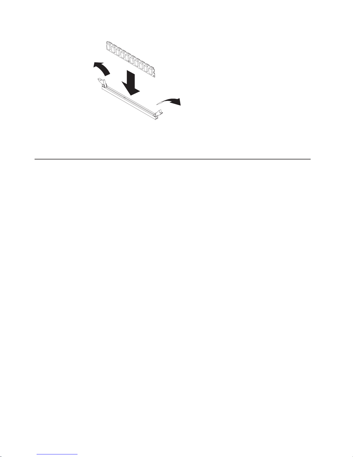
Figure 17. DIMM retaining clips
If you have other options to install or remove, do so now. Otherwise, go to
“Finishing the installation” on page 50.
Replacing DIMM fillers
For the QS22 cooling system to work properly there must be no empty I/O buffer
DIMM slots. The unused slots must be fitted with DIMM fillers. Replace faulty DIMM
fillers and, if you remove the I/O buffer memory modules, fit empty slots with DIMM
fillers.
Note: Unused system memory slots do not require DIMM fillers.
To install or replace DIMM fillers, complete the following steps:
1. Read the safety information beginning on page vii and “Installation guidelines”
on page 29.
2. If applicable, shut down the operating system, turn off the blade server, and
remove the blade server from the BladeCenter unit. See “Removing the blade
server from the BladeCenter unit” on page 30.
3. Open the blade server cover. See “Opening and removing the blade server
cover” on page 31.
4. Remove any faulty DIMM fillers.
a. Open the retaining clips on either end of the DIMM slot. This lifts the DIMM
filler and disengages it from the slot.
b. Pull the filler out of the slot.
5. If you wish to remove the I/O Buffer memory modules, remove them now. Be
sure to remove them both.
a. Open the retaining clips on either end of the DIMM slot. This lifts the DIMM
filler and disengages it from the slot.
b. Pull the module out of the slot.
Carefully press the DIMM filler into the empty I/O buffer DIMM slot until the
6.
retaining clips snap into position.
7. Repeat step 6 for the other I/O buffer slot.
you have other options to install or remove, do so now. Otherwise, go to
If
“Finishing the installation” on page 50.
42 BladeCenter QS22 Type 0793: Problem Determination and Service Guide
Page 61
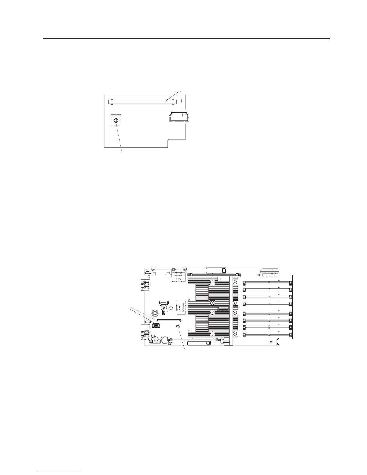
Installing the optional SAS expansion card
The QS22 blade server does not have any built-in disk storage. The SAS expansion
card allows you to use SAS attached storage. Use the blue handling areas to
handle the card.
Ball socket
Figure 18. SAS expansion card reverse side
Complete the following steps to install the SAS expansion card:
1. Read the safety information beginning on page vii and “Installation guidelines”
on page 29.
2. If applicable, shut down the operating system, turn off the blade server, and
remove the blade server from the BladeCenter unit. See “Removing the blade
server from the BladeCenter unit” on page 30.
3. Open the blade server cover. See “Opening and removing the blade server
cover” on page 31.
4. Locate the two SAS expansion card connectors and the ball stud on the system
board.
Connectors
Connectors
for SAS
expansion card
1
Ball stud
Figure 19. SAS expansion card connector and ball stud location
5. Locate the connectors and the ball socket on the SAS adapter card.
6. Align the connectors on the system board with the connectors on the SAS
adapter card.
Chapter 4. Installing and removing replaceable units 43
Page 62

Expansion
card
Figure 20. SAS expansion card location
7. Using the blue handling areas, carefully push the card down to insert it into the
connectors. Ensure that the ball stud on the system board engages with the ball
socket on the SAS expansion card.
you have other options to install or remove, do so now. Otherwise, go to
If
“Finishing the installation” on page 50.
Installing the BladeCenter PCI Express I/O Expansion Unit
Important:
v A BladeCenter QS22 with the BladeCenter PCI Express I/O Expansion Unit
installed takes up two contiguous slots in the BladeCenter chassis.
v You must remove any expansion card that uses the high-speed connector before
installing the expansion unit.
Cover pins
Cover release
Cover release
Figure 21. Installing the expansion unit
44 BladeCenter QS22 Type 0793: Problem Determination and Service Guide
Page 63

Complete the following steps to install the BladeCenter PCI Express I/O Expansion
Unit:
1. Read the safety information beginning on page vii and “Installation guidelines”
on page 29.
2. Remove the blade server cover and set it aside. See “Opening and removing
the blade server cover” on page 31 for further information.
3. Remove the connector cover or any optional card from the high-speed
connector. Figure 12 on page 37 shows the location of the high-speed
connector.
4. Lower the expansion unit so that the slots at the rear slide down onto the cover
pins at the rear of the blade server, as shown in Figure 21 on page 44.
5. Carefully close the expansion unit as shown in Figure 21 on page 44 until it
clicks into place.
Replacing the system board base and planar
Important
The system board is a field replaceable unit (FRU): FRUs must be installed
only by trained service technicians.
Figure 22. System board assembly
Complete the following steps to replace the system board base and planar:
1. Read the safety information beginning on page vii and “Installation guidelines”
on page 29.
2. If applicable, shut down the operating system, turn off the blade server, and
remove the blade server from the BladeCenter unit. See “Removing the blade
server from the BladeCenter unit” on page 30.
3. Remove the blade server cover. See “Opening and removing the blade server
cover” on page 31.
4. Remove the front bezel from the defective system board and set it aside. See
“Removing the blade-server front bezel assembly” on page 33 for detailed
instructions.
5. Remove the system memory modules and any optional components such as
I/O buffer memory modules or fillers, expansion cards or modular flash drive
from the defective system board and set them aside.
6. Note down the serial number of the defective system board. You need this
later to update the VPD information.
7. Install the system memory modules on the replacement system board. See
“Adding or changing system memory” on page 39.
Chapter 4. Installing and removing replaceable units 45
Page 64

8. Reinstall any options you removed from the defective system board on the
replacement system board, . See “Installing an optional high-speed expansion
card” on page 36, “Installing the optional SAS expansion card” on page 43,
“Installing the optional modular flash drive” on page 34 and “Adding or
changing I/O buffer DDR2 memory modules” on page 41 for detailed
instructions.
9. Reinstall the front bezel assembly on the replacement system board. See
“Installing the front bezel assembly” on page 51 for detailed instructions.
10. Replace and close the cover. See “Closing the blade server cover” on page 52
for details.
11. Reinstall the blade server in the BladeCenter unit.
12. Update the BMC, system and optional expansion card firmware as described
in Chapter 2, “Configuring the blade server,” on page 9.
13. Using SMS, update the VPD information by entering the serial number of the
defective system board. See “Adding FRU information” on page 13 for details.
14. Configure the replacement blade server to boot from the same device as the
original defective unit. See the QS22 Installation and User's Guide for details.
Providing the options on the new blade server are the same as on the
Note:
old you do not have to reinstall or reconfigure the operating system but
simply configure the boot options to boot from the boot device.
Replacing the battery
IBM has designed this product with your safety in mind. The lithium battery must be
handled correctly to avoid possible danger. If you replace the battery, you must
adhere to the following instructions.
Note: In the U. S., call 1-800-IBM-4333 for information about battery disposal.
If you replace the original lithium battery with a heavy-metal battery or a battery with
heavy-metal components, be aware of the following environmental consideration.
Batteries and accumulators that contain heavy metals must not be disposed of with
normal domestic waste. They will be taken back free of charge by the manufacturer,
distributor, or representative, to be recycled or disposed of in a proper manner.
To order replacement batteries, call 1-800-IBM-SERV within the United States, and
1-800-465-7999 or 1-800-465-6666 within Canada. Outside the U.S. and Canada,
call your IBM authorized reseller or IBM marketing representative.
Note: After you replace the battery, the blade server is automatically reconfigured.
However, you must reset the system date and time through the operating
system that you installed.
Statement 2:
46 BladeCenter QS22 Type 0793: Problem Determination and Service Guide
Page 65

CAUTION:
When replacing the lithium battery, use only IBM Part Number 43W9859 or
03N2449 or an equivalent type battery recommended by the manufacturer. If
your system has a module containing a lithium battery, replace it only with
the same module type made by the same manufacturer. The battery contains
lithium and can explode if not properly used, handled, or disposed of.
Do not:
v Throw or immerse into water
v Heat to more than 100°C (212°F)
v Repair or disassemble
Dispose
of the battery as required by local ordinances or regulations.
Note: See “Battery return program” on page 130 for more information about battery
disposal.
Complete the following steps to replace the battery:
1. Read the safety information beginning on page vii and “Installation guidelines”
on page 29.
2. Follow any special handling and installation instructions that come with the
battery.
3. If applicable, shut down the operating system, turn off the blade server, and
remove the blade server from the BladeCenter unit. See “Removing the blade
server from the BladeCenter unit” on page 30.
4. Remove the blade server cover. See “Opening and removing the blade server
cover” on page 31.
5. Locate the battery (Battery holder J12) on the system board.
1
Battery
Figure 23. Battery location
6. Remove the battery:
a. Use one finger to press the top of the battery clip away from the battery.
The battery pops up when released.
Chapter 4. Installing and removing replaceable units 47
Page 66

b. Use your thumb and index finger to lift the battery from the socket.
c. Dispose of the battery as required by local ordinances or regulations.
7. Insert the new battery:
a. Make sure the positive (+) side is facing upwards.
b. Tilt the battery so that you can insert it into the socket, under the battery
clip.
c. Press the battery down into the socket until it clicks into place. Make sure
the battery clip holds the battery securely.
8. Close the blade server cover and insert the blade server into the BladeCenter
unit (see “Closing the blade server cover” on page 52).
Statement 21:
CAUTION:
Hazardous energy is present when the blade server is connected to the
power source. Always replace the blade cover before installing the blade
server.
9. Turn on the blade server (see “Turning on the blade server” on page 4).
10. Reset the system date and time through the operating system that you
installed. For additional information, see your operating system documentation.
Replacing the retention clip for the modular flash drive
The retention clip supports the modular flash drive and should be replaced if
damaged.
To remove and replace the retention clip, complete the following steps:
1. Read the safety information beginning on page vii and “Installation guidelines”
on page 29.
2. If applicable, shut down the operating system, turn off the blade server, and
remove the blade server from the BladeCenter unit. See “Removing the blade
server from the BladeCenter unit” on page 30.
3. Remove the blade server cover. See “Opening and removing the blade server
cover” on page 31.
4. If applicable, carefully remove the modular flash drive from the retention clip.
5. Using a Philips head screwdriver pierce the label at the red circle corresponding
with the retention clip.
48 BladeCenter QS22 Type 0793: Problem Determination and Service Guide
Page 67

Retention clip screws
Ball stud screws
6. Carefully unscrew the retention clip and remove.
7. Position the replacement retention clip over the hole and screw into position,
taking care not to over-tighten as this might damage the system board.
8. If applicable, replace the modular flash drive.
9. Replace the cover and insert the blade server into the BladeCenter unit.
Using the miscellaneous parts kit
The miscellaneous parts kit contains replacement parts and screws to be used if
the original item is damaged. It contains the following items:
Kit, Miscellaneous Parts Quantity Part No
Alignment socket 4 26K6003
Cover for blade server expansion connector 4 28R3024
Pivot point blocks for expansion card support 4 31R2232
Ball stud for expansion card support 4 31R2233
Tray, expansion card support end bracket 2 31R2248
Alignment pin 2 39M6518
Screw, Plastite 4-20x6.35 8 39R9558
Screw, 3.5 x 6 Pan Head, Philips, Planar 6 26K5962
QS22 Planar Light box 2 43W9782
Impedance Air Baffle top, foam 2 43W9966
Impedance Air Baffle DIMM Sides 2 43W9958
Impedance Air Baffle DIMM Sides 2 43W9959
Impedance Air Baffle VRD heat sink, foam 2 43W9967
Impedance Air Baffle VRD heat sink, foam 2 43W9969
Chapter 4. Installing and removing replaceable units 49
Page 68

Kit, Miscellaneous Parts Quantity Part No
Impedance Air Baffle Processor HS, foam gasket 2 43W9968
Screw, Plastite 4-20x9.53 for flash drive memory tray 2 43W9973
To replace a support or bracket you need a Philips head screwdriver.
Replacing the ball studs
The ball studs help support the optional expansion cards and should be replaced if
damaged.
To remove and replace a ball stud, complete the following steps:
1. Read the safety information beginning on page vii and “Installation guidelines”
on page 29.
2. If applicable, shut down the operating system, turn off the blade server, and
remove the blade server from the BladeCenter unit. See “Removing the blade
server from the BladeCenter unit” on page 30.
3. Remove the blade server cover. See “Opening and removing the blade server
cover” on page 31.
4. Using a Philips head screwdriver pierce the label at the red circle corresponding
with the ball stud you wish to replace.
Retention clip screws
Ball stud screws
5. Carefully unscrew the ball stud and remove.
6. Position the replacement ball stud over the hole and screw into position, taking
care not to over-tighten as this might damage the system board.
7. Replace the cover and insert the blade server into the BladeCenter unit.
Finishing the installation
To complete the installation you must:
50 BladeCenter QS22 Type 0793: Problem Determination and Service Guide
Page 69

1. Reinstall the front bezel assembly on the blade server if removed. See
“Installing the front bezel assembly” for further information.
2. Ensure that the I/O buffer DIMM slots are occupied either by DIMMs or by
DIMM fillers. No DIMM fillers are needed for empty system memory DIMM slots.
3. Replace and close the blade server cover, unless you installed an optional
expansion unit that has its own cover. See “Closing the blade server cover” on
page 52 for further information.
Statement 21:
CAUTION:
Hazardous energy is present when the blade server is connected to the
power source. Always replace the blade cover before installing the blade
server.
4. Reinstall the blade server into the BladeCenter unit.
5. Turn on the blade server. See “Turning on the blade server” on page 4 for
further information.
6. If you have replaced the battery or the system board assembly, reset the
system date and time through the operating system that you installed. For
additional information, see your operating system documentation.
If you have just powered on the BladeCenter unit, wait until the power on
Note:
LED on the blade server flashes slowly before powering on the blade server.
Installing the front bezel assembly
Figure 24 on page 52 shows how to install the front bezel assembly on the blade
server.
Chapter 4. Installing and removing replaceable units 51
Page 70

Blade cover
Cover release
Bezel release
Cover release
Bezel release
Figure 24. Installing the front bezel assembly
Complete the following steps to install the blade server front bezel assembly:
1. Read the safety information beginning on page vii and “Installation guidelines”
on page 29.
2. Connect the control panel cable to the control panel connector on the system
board assembly.
3. Carefully slide the front bezel assembly onto the blade server, as shown in
Figure 24, until it clicks into place.
Make sure that you do not pinch any cables when you reinstall the front
Note:
bezel assembly.
Closing the blade server cover
Important: The blade server cannot be inserted into the BladeCenter unit until the
cover is installed and closed or an expansion unit is installed. Do not attempt to
override this protection.
Control-Panel
Cable
Bezel assembly
Control-Panel
Connector
Statement 21:
CAUTION:
Hazardous energy is present when the blade server is connected to the power
source. Always replace the blade cover before installing the blade server.
52 BladeCenter QS22 Type 0793: Problem Determination and Service Guide
Page 71

Cover pins
Cover release
Cover release
Figure 25. Closing the blade server cover
Complete the following steps to close the blade server cover:
1. Read the safety information beginning on page vii and “Installation guidelines”
on page 29.
2. If you removed the front bezel assembly, replace it now. See “Installing the front
bezel assembly” on page 51 for instructions.
3. Lower the cover so that the slots at the rear slide down onto the pins at the rear
of the blade server, as shown in Figure 25. Before closing the cover, make sure
that all components are installed and seated correctly and that you have not left
loose tools or parts inside the blade server.
4. Pivot the cover to the closed position as shown in Figure 25 until it clicks into
place.
Input/output connectors and devices
The BladeCenter unit contains the input/output connectors that are available to the
blade server. See the documentation that comes with the BladeCenter unit for
information about the input/output connectors.
Chapter 4. Installing and removing replaceable units 53
Page 72

54 BladeCenter QS22 Type 0793: Problem Determination and Service Guide
Page 73

Chapter 5. Diagnostics and troubleshooting
This chapter provides basic troubleshooting information to help you solve some
common problems that might occur while setting up your blade server.
A problem with the BladeCenter QS22 can relate either to the BladeCenter QS22 or
the BladeCenter unit.
A problem with the blade server exists if the BladeCenter unit contains more than
one blade server and only one of the blade servers has the symptom. If all of the
blade servers have the same symptom, then the problem relates to the BladeCenter
unit. For more information, see the Problem Determination and Service Guide for
your BladeCenter unit.
The BladeCenter QS22 blade server is supported in the IBM BladeCenter H unit,
the IBM BladeCenter HT unit, and the IBM BladeCenter S (non RAID type only)
unit.
You can put other blade server types that are supported in your BladeCenter unit in
the same unit as a BladeCenter QS22.
Prerequisites
Basic checks
Before you start problem determination or servicing, check that:
v The BladeCenter QS22 is inserted correctly into the BladeCenter unit.
v All components are connected correctly
v The BladeCenter QS22 has the latest firmware updates. These should include
updates for:
– The BMC
– The system firmware
– Gb Ethernet controller
– The SAS expansion card
– The high-speed expansion card (if installed)
v The components in your SAS environment have the latest firmware updates.
These include updates for:
– SAS Connectivity Modules (if installed)
– SAS Storage Modules (if installed into BladeCenter S chassis)
– IBM Boot Disk System (if attached)
If you install the blade server in the BladeCenter unit and the blade server does not
start, always perform the following basic checks before continuing with more
advanced troubleshooting:
v Make sure that the BladeCenter unit is correctly connected to a power source.
v Reseat the blade server in the BladeCenter unit.
v If the power on LED is flashing slowly, the blade server may be turned off. To
turn on the blade server, see “Turning on the blade server” on page 4 for further
information.
© Copyright IBM Corp. 2006, 2008 55
Page 74

v If you have just added a new optional device or component, make sure that it is
correctly installed and compatible with the blade server and its components. If
the device or component is not compatible, remove it from the blade server,
reinstall the blade server in the BladeCenter unit, and then restart the blade
server.
v Use Advanced Management Module to check that the blade server appears in
the list of blade servers available.
Finding troubleshooting information
Table 3 describes where to find troubleshooting information in this section.
Note: Many components, including the CPU and power supplies cannot be
exchanged in the field. The only replaceable parts are the optional SAS
expansion card, battery, front bezel assembly, system DIMM memory, I/O
buffer DIMM memory, modular flash drive and the optional InfiniBand card.
Table 3. Where to find troubleshooting information
Component Where to find information
SAS expansion card
Front bezel
High-speed InfiniBand expansion card
Modular flash drive
Memory Table 12 on page 80
LEDs
Power
Network connections
Service processor
Software problems
For troubleshooting information about other BladeCenter components, see the
appropriate Problem Determination and Service Guide, and other product-specific
documentation. See “Related documentation” on page 1 for additional information.
For the latest editions of the IBM BladeCenter documentation, go to
http://www.ibm.com/support/us/en/ on the World Wide Web.
Troubleshooting charts
The following tables list problem symptoms and suggested solutions. If you cannot
find the problem in the troubleshooting charts, or if carrying out the suggested steps
do not solve the problem, have the blade server serviced.
“Solving undetermined problems” on page
108
“Troubleshooting charts” on page 56
If you have problems with an adapter, monitor, keyboard, mouse, or power module,
see the Problem Determination and Service Guide for your BladeCenter unit for
more information.
If you have problems with an Ethernet switch module, I/O adapter, or other optional
device that can be installed in the BladeCenter unit, see the Problem Determination
and Service Guide or other documentation that comes with the device for more
information.
56 BladeCenter QS22 Type 0793: Problem Determination and Service Guide
Page 75

Problems indicated by the front panel LEDs
The state of the LEDs on the front of the blade can help in isolating problems.
The table below gives an explanation and a suggested action, if required, for each
Information
LED
Location
LED
Activity
LED
Power-on
LED
Media-tray
select button
Power-control
button
Blade-error
LED
NMI
reset-button
CD
Figure 26. Power-control button and LEDs
LED.
Table 4. Explanation of LEDs and their states
LED State Explanation Suggested action
Blade error LED yellow A system error has occurred on
the blade server.
Information LED yellow Information about a system
event has been placed in the
Advanced Management Module
Event Log. The information LED
remains on until turned off by
Advanced Management Module
or through IBM Director
Console.
Activity LED Green There is network activity. No action required. For further
Check the BladeCenter error
log, see “Problem reporting” on
page 108.
Check Advanced Management
Module to see what the
problem is. See the
BladeCenter Management
Module User's Guide for further
information about the error.
information about
troubleshooting networks, see
“Network connection problems”
on page 62.
Chapter 5. Diagnostics and troubleshooting 57
Page 76

Table 4. Explanation of LEDs and their states (continued)
LED State Explanation Suggested action
Power-on LED Flashing rapidly The service processor on the
No action required
blade server is communicating
with the BladeCenter
Management Module.
Flashing slowly The blade server has power but
Turn on if required
is not turned on.
Lit continuously (steady) The blade server has power
No action required
and is turned on.
Not lit. Blade server not powered.
1. Verify that the BladeCenter
unit provides 12V dc to the
blade server.
2. Reseat blade server.
3. Check if BladeCenter power
supplies numbers 3 and 4
are installed and powered.
If they are not, install and
power them or use slots
1-5.
4. Go to “Power problems” on
page 62
Problems indicated by the system board LEDs
The blade server must be removed from the BladeCenter unit and the cover
removed before you can use the light path LEDs for diagnostics. To activate the
light box and the other light path LEDs, press the light path diagnostics switch.
58 BladeCenter QS22 Type 0793: Problem Determination and Service Guide
Page 77

Modular
flash drive
error LED
Light path
diagnosis
switch
Light path
diagnosis
LED
I/O buffer DIMM error LED
System memory DIMM
error LEDs
1
I/O buffer DIMM error LED
1
NMI error LED
CPU fail LED
System board LED
Temperature fault LED
Figure 27. Light box and system board LEDs
The location of each LED on the system board is shown in the table below.
Table 5. System board LEDs
Board
LED Color
Status LEDs The status LEDs are listed
Heartbeat Green D16 Indicates the BMC is functional.
Alert Yellow D15 Indicates an error condition has
Ethernet 1 activity Green D12 Indicates on-board Ethernet 1 is
Ethernet 0 activity Green D11 Indicates on-board Ethernet 0 is
BE0_PLL_LOCK Green D8 Indicates the phased lock loop of
BE1_PLL_LOCK Green D13 Indicates the phased lock loop of
MM_SELECT_A Green D19 Indicates Advanced Management
MM_SELECT_B Green D18 Indicates Advanced Management
location Explanation Comments
for reasons of completeness
since they are for use by
IBM service only and are not
occurred on the system board.
normally visible. They are
not activated by the light
active and sending or receiving
path diagnostics switch.
packets.
active and sending or receiving
packets.
Cell BE-0 is working.
Cell BE-1 is working.
Module A is active.
Module B is active.
Chapter 5. Diagnostics and troubleshooting 59
Page 78

Table 5. System board LEDs (continued)
Board
LED Color
location Explanation Comments
Light path LEDs
DIMM at I/O BUF 1
error
DIMM at I/O BUF 2
error
Yellow DS9 There has been a failure in the I/O
DIMM module.
Yellow DS10
See Figure 27 on page 59 for the
location of each DIMM and its
associated LED.
System DIMM1 error Yellow DS1 There has been a failure in the
System DIMM2 error Yellow DS2
System DIMM3 error Yellow DS3
System DIMM4 error Yellow DS4
system DIMM module.
See Figure 27 on page 59 for the
location of each DIMM and its
associated LED.
System DIMM5 error Yellow DS1
System DIMM6 error Yellow DS6
System DIMM7 error Yellow DS7
System DIMM8 error Yellow DS8
Light box LEDs
Either remove or replace the
faulty DIMM. Note that if you
remove one I/O buffer DIMM
you must remove the other.
Reboot.
Either remove or replace the
faulty DIMM and reboot. See
“Adding or changing I/O
buffer DDR2 memory
modules” on page 41 for
supported memory
configurations.
60 BladeCenter QS22 Type 0793: Problem Determination and Service Guide
Page 79

Table 5. System board LEDs (continued)
Board
LED Color
location Explanation Comments
Temperature fault Yellow Light
box
The blade server has exceeded
the operational temperature range.
v Using the Advanced
Management Module,
check that the
BladeCenter unit cooling
system is operating
correctly.
v Replace any missing filler
blades in the BladeCenter
unit.
v Replace any missing
DIMM fillers in the
BladeCenter QS22 I/O
buffer DIMM slots.
v Check that other blade
servers are operating
within the recommended
temperature range.
v Replace the blade server,
power on and boot. Check
Advanced Management
Module for errors.
NMI error (NMI) Yellow The NMI pinhole reset on the front
panel has been pressed.
CPU fail Yellow One of the Cell BE processors has
failed.
System board Yellow A critical error has occurred in a
component on the system board.
Light path diagnostics Green Lights when the light path
diagnostics switch is pressed.
Indicates that the capacitor is
charged and the light path LEDs
can light to show any errors.
If
the problem persists,
contact your IBM service
representative as the system
board may need servicing.
Pressing the reset causes
the operating system to call
the system debugger.
Contact your IBM service
representative as the system
board needs replacement.
Contact your IBM service
representative as the system
board may need replacing.
If this LED does not light
then the light path LEDs
cannot function.
Reinstall the blade server in
the BladeCenter unit and
power on to recharge.
If this fails to resolve the
problem, there is a problem
with the system board and it
may need replacement.
Chapter 5. Diagnostics and troubleshooting 61
Page 80

Power problems
Power symptom Suggested action
The blade server does not
turn on.
1. Make sure that:
a. The power-on LED on the front of the BladeCenter unit is lit.
b. The LEDs on all the BladeCenter power modules are lit.
c. The power-on LED on the blade-server control panel is flashing slowly.
v The power-on LED only flashes rapidly while it is communicating with the
management module. If the power-on LED is flashing rapidly and continues
to do so for an unduly long time, the blade server is not communicating
with the management module. Power off, reseat the blade server and
reboot.
v If the power LED is off, either the blade bay is not receiving power, the
blade server is defective, the Advanced Management Module firmware is an
earlier version and does not support this function, or the LED information
panel is loose or defective.
d.
Local power control for the blade server is enabled. Check using the
Advanced Management Module Web interface. The blade server might have
been instructed through the Advanced Management Module to turn on.
If you have just installed a new option in the blade server, remove it, and restart
2.
the blade server. If the blade server now powers on, troubleshoot the option. See
the documentation that comes with the option for further information.
3. Try another blade server in the blade bay. If it works, you may need to have a
trained service technician replace the system blade assembly.
Power throttling
Be aware that the BladeCenter unit automatically reduces the BladeCenter QS22
processor speed if certain conditions are met. One such condition is temperature
thresholds being exceeded, for example, when the blade server is running in
acoustic mode. This throttling occurs independent of your power configuration. Full
processor speed is restored automatically when the conditions that have caused the
throttling have been resolved.
Network connection problems
Network connection
symptom Suggested action
One or more blade servers
are unable to communicate
with the network.
Make sure that:
v The switch modules for the network interface being used are installed in the
correct BladeCenter bays and are configured and operating correctly.
v The settings in the switch module are correct for the blade server (settings in the
switch module are blade server specific).
For
additional information, see:
v Chapter 2, “Configuring the blade server,” on page 9
v The Problem Determination and Service Guide for your BladeCenter unit
v Other product-specific documentation that comes with the switch module
For the latest editions of the IBM BladeCenter documentation, go to
Note:
http://www.ibm.com/support/us/en/.
If the problem remains, see “Solving undetermined problems” on page 108.
If all the blades cannot communicate with the network, check the network itself for
problems.
62 BladeCenter QS22 Type 0793: Problem Determination and Service Guide
Page 81

Service processor problems
Service processor symptom Suggested action
Service processor reports a
general monitor failure.
1. If the blade server is operating, shut down the operating system.
2. If the blade server was not turned off, press the power-control button (behind the
blade server control-panel door) to turn off the server.
3. Remove the blade server from the BladeCenter unit.
4. Wait 30 seconds and reinstall the blade server into the BladeCenter unit.
5. Restart the blade server.
If
the problem remains, see “Solving undetermined problems” on page 108
Software problems
Symptom Suggested action
You suspect a software
problem.
1. To determine whether the problem is caused by the software, make sure that:
v The blade server has at least the minimum memory that is needed to use the
software. For memory requirements, see the software documentation.
v The blade server has a supported DIMM configuration (see Table 2 on page
39).
v The software is designed to operate on the blade server.
v Other software works on the blade server.
v The software works on another server.
If you received any error messages when using the software, see the software
2.
documentation for a description of the messages and suggested solutions to the
problem.
3. Contact the software vendor.
Chapter 5. Diagnostics and troubleshooting 63
Page 82

Recovering the system firmware code
The system firmware is contained in two separate images in the flash memory of
the blade server: temporary and permanent. These images are referred to as TEMP
and PERM, respectively. The system normally starts from the TEMP image, and the
PERM image serves as a backup. If the TEMP image becomes damaged, such as
from a power failure during a firmware update, the system automatically starts from
the PERM image.
If the TEMP image is damaged, you can recover the TEMP image from the PERM
image. See “Recovering the TEMP image from the PERM image” for further
information.
Checking the boot image
To check whether the system has started from the PERM image, enter:
cat /proc/device-tree/openprom/ibm,fw-bank
A P is returned if the system has started from the PERM image.
Booting from the TEMP image
To initiate a boot from the TEMP image after the system has booted from the PERM
side, complete the following steps:
1. Turn off the blade server.
2. Restart the blade system management processor from the Advanced
Management Module.
3. Turn on the blade server.
If the temp side is corrupted the boot times out, and an automatic reboot
Note:
occurs after switching to the PERM side.
the blade server does not restart, you must replace the system board assembly.
If
Contact a service support representative for assistance.
Recovering the TEMP image from the PERM image
To recover the TEMP image from the PERM image, you must copy the PERM
image into the TEMP image. To perform the copy, complete the following steps:
1. Copy the perm image to the temp image. Using the Linux operating system,
type the following command:
update_flash -r
2. Shut down the blade server using the operating system.
3. Restart the blade system management processor from the management
module.
4. Turn on the blade server.
might need to update the firmware code to the latest version. See “Installing
You
the system firmware” on page 20 for more information on updating the firmware
code.
64 BladeCenter QS22 Type 0793: Problem Determination and Service Guide
Page 83

Supported boot media
The BladeCenter QS22 can boot from the operating system installation CDs or
DVDs to allow the operating system to be installed.
The BladeCenter QS22 can also boot from:
v The network
v Modular flash drive, if installed
v SAS storage, if attached
v Local BladeCenter unit SAS drives, if the blade server is installed into an IBM
BladeCenter S unit that provides local SAS drives
you wish to perform a standard Bootp/TFTP network boot, please note the
If
following restrictions:
v Only the built-in Gigabit Ethernet Controller of I/O Bridge is supported
v Only boot through the Ethernet switch on the top side of BladeCenter
v No fall back or configurable change to the bottom switch is possible
v In the Advanced Management Module you need to set boot list to Network
v There is no support for a router between the blade and TFTP server. Only local
TFTP is supported.
Advanced Management Module to configure the required boot mode. See IBM
Use
BladeCenter Management Module Installation Guide for more information.
Booting the system
This section provides an overview on how to interpret the console output of the host
firmware. The output is grouped into several parts, which are detailed below.
Note:
1. The first part of the boot process shows the system name and build date. You
see an error at this point if the firmware image is corrupted.
2. Memory initialization follows next. It can take several seconds to initialize the
system memory. The screen displays details of the size and the speed of
memory modules.
The firmware console output depends on the configuration of your system.
The examples below are indicative only and may not reflect the configuration
of your system
***************************************************************************
QS22 Firmware Starting
Check ROM = OK
Build Date = Jan 4 2008 11:31:29
FW Version = "QD-1.26.0-0"
Press "F1" to enter Boot Configuration (SMS)
Press "F2" to boot once from CD/DVD
DDR2 MEMORY INITIALIZATION
CPU0 DIMMs: DIMM1=1024MB DIMM2=1024MB DIMM3=n/a DIMM4=n/a
CPU0 timings: 800 MHz, CL=6, tRCD=6, tRP=6
CPU0 memory test: ok
CPU1 DIMMs: DIMM5=1024MB DIMM6=1024MB DIMM7=n/a DIMM8=n/a
CPU1 timings: 800 MHz, CL=6, tRCD=6, tRP=6
CPU1 memory test: ok
COMPLETE
Chapter 5. Diagnostics and troubleshooting 65
Page 84

3. The next screen displays system information. It shows revision information
about the chip set, SMP size, boot date/time, and the available memory.
SYSTEM INFORMATION
Processor = PowerXCell DD1.0 @ 3200 MHz
I/O Bridge = Cell BE companion chip DD3.x
Timebase = 26666 kHz (internal)
SMP Size = 2 (4 threads)
Boot-Date = 2008-01-16 11:25
Memory = 4096MB (CPU0: 2048MB, CPU1: 2048MB)
4. The next screens show the open firmware section of the boot process and
provide checkpoints and an overview which adapters are available in the
system. The details in the adapter list are not meaningful.
Note: The warning (!) Permanent Boot ROM is displayed if there is a problem
with the TEMP image and system firmware is running on from the PERM
image. Yo u should correct this problem as soon as possible. See
“Recovering the TEMP image from the PERM image” on page 64 for
further information.
OPEN FIRMWARE
Adapters on 000001460ec00000
00 0800 (D) : 14e4 16a8 network [ ethernet ]
00 0900 (D) : 14e4 16a8 network [ ethernet ]
Adapters on 000001a040000000
00 0000 (B) : 1014 032c pci
Adapters on 000001a240000000
00 0000 (B) : 1014 032c pci
IOBUF1 initializing... no DIMM.
Adapters on 000003460ec00000
00 0800 (D) : 1033 0035 usb-ohci ( NEC uPD720101 )
00 0900 (D) : 1033 0035 usb-ohci ( NEC uPD720101 )
00 0a00 (D) : 1033 00e0 usb-ehci*
Adapters on 000003a040000000
00 0000 (B) : 1014 032c pci
Adapters on 000003a240000000
00 0000 (B) : 1014 032c pci
IOBUF2 initializing... no DIMM.
SB0 Monitor started
SB1 Monitor started
Scan USB...
uDOC not present
Ready
Welcome to Open Firmware
Licensed Internal Code - Property of IBM
(c) Copyright IBM Corp. 2005, 2007 All Rights Reserved.
Cell/B.E. is a trademark of SONY Computer Entertainment Inc.
Type ’boot’ and press return to continue booting the system.
Type ’sms-start’ and press return to enter the configuration menu.
Type ’reset-all’ and press return to reboot the system.
disable nvram logging .. done
The Operating System now boots unless you have pressed F1 in which case the
SMS menu starts. See “Using the SMS utility program” on page 11 for further
information.
66 BladeCenter QS22 Type 0793: Problem Determination and Service Guide
Page 85

Diagnostic programs and messages
The Dynamic System Analysis (DSA) Preboot diagnostic programs are the primary
method of testing the major components of the server. DSA is a system information
collection and analysis tool that you can use to provide information IBM service and
support to aid in the diagnosis of the system problems. The DSA diagnostic
programs come on the IBM Dynamic System Analysis Preboot Diagnostic CD. Yo u
can download the CD from http://www.ibm.com/support/us/en if one did not come
with your server. As you run the diagnostic programs, text messages are displayed
on the screen and are saved in the test log. A diagnostic text message indicates
that a problem has been detected and indicates the action you should take as a
result of the text message.
The DSA diagnostic programs collect the following information about the following
aspects of the system:
v System configuration
v Network interfaces and settings
v Hardware inventory USB information
v IBM LightPath diagnostics status
v Service processor status and configuration
v Vital product data and system firmware information
v Drive Health Information
v LSI RAID & Controller configuration
DSA diagnostic programs can also provide diagnostics for the following system
The
components:
v Baseboard Management Controller
v Memory stress
v Open Firmware Memory Diagnostics
v CPU stress
Additionally,
DSA creates a merged log that includes events from all collected logs.
All collected information can be output as a compressed XML file that can be sent
to IBM Service. Additionally, you can view the information locally through a
generated text report file. Optionally, the generated HTML pages may be copied to
removable media and viewed from a web browser.
Running diagnostics and preboot DSA
To run the diagnostic programs, complete the following steps:
1. If the server is running, turn off the server and all attached devices.
2. Turn on all attached devices then turn on the server.
3. Ensure that external DSA bootable media is available as a boot device. For boot
device selection, system firmware will work through the boot path as specified in
the onboard planar VPD and try to establish communication with the specified
interfaces in sequential order. These boot devices include the USB attached
DVD (BladeCenter, media tray), the SAS storage if attached, Network attached
storage, and, if the blade server is installed into an IBM BladeCenter S unit that
provides local SAS drives, the local BladeCenter unit SAS drives
4. Press F2 to enter DSA when the POST menu displays the following screen:
Chapter 5. Diagnostics and troubleshooting 67
Page 86

***************************************************************************
QS22 Firmware Starting
Check ROM = OK
Build Date = Jan 4 2008 11:31:29
FW Version = "QD-1.26.0-0"
Press "F1" to enter Boot Configuration (SMS)
Press "F2" to boot once from CD/DVD
5. The command line interface prompt will then appear on the SOL connection.
The BladeCenter QS22 does not support the graphical user interface.
6. Follow the on screen directions to run preboot DSA. Diagnostics are run from
within preboot DSA.
you are using the CPU or Memory stress tests, call your IBM service
When
representative if you experience any system instability.
To determine what action you should take as a result of a diagnostic text message,
see “DSA error messages” on page 69.
Open firmware memory diagnostic results are output to the SOL connection. They
are also logged in NVRAM. All NVRAM logs (more than just OF diags) are collected
as part of the DSA merged log.
If the diagnostic programs do not detect any hardware errors but the problem
remains during normal server operations, a software error might be the cause. If
you suspect a software problem, see the information that comes with your software.
A single problem might cause more than one error message. When this happens,
correct the cause of the first error message. The other error messages usually will
not occur the next time you run the diagnostic programs.
If there are multiple error codes or light path diagnostics LEDs that indicate a
microprocessor error, the error might be in a microprocessor or in a microprocessor
socket. See Table 21 on page 100 for further information about diagnosing
microprocessor problems.
If the server stops during testing and you cannot continue, restart the server and try
running the diagnostic programs again.
Diagnostic text messages
Diagnostic text messages are displayed while the tests are running. A diagnostic
text message contains one of the following results:
v Passed: The test was completed without any errors
v Failed: The test detected an error
v Aborted: The test could not proceed because of the server configuration
Additional
information concerning test failures is available in the extended
diagnostic results for each test.
Viewing the test log
To view the test log when the tests are completed, issue the view command from
the DSA command line interface. DSA collections may also be transferred to an
external USB device using the copy command from the DSA command line
interface.
68 BladeCenter QS22 Type 0793: Problem Determination and Service Guide
Page 87

DSA error messages
The tables below describe the messages that the diagnostic programs might
generate and suggested actions to correct the detected problems. Follow the
suggested actions in the order given.
CPU test results
Table 6. CPU test results
Test Number Status
CPU
stress test
089-901xxx
089-802xxx
089-801xxx
Fail Test failure
Abort System resource
Abort Internal program
Extended
results Actions
1. If the system has stopped responding, turn off and restart
the system and then run the test again.
2. Make sure that the DSA Diagnostic code is at the latest
level. The latest level DSA Diagnostic code can be found
on the IBM Support Web site at http://www.ibm.com/
support/docview.wss?uid=psg1SERV-DSA/.
3. Run the test again.
availability error
4. Check system firmware level and upgrade if necessary.
The installed firmware level can be found in the DSA
Diagnostic Event Log within the Firmware/VPD section for
this component. The latest level firmware for this
component can be found on the IBM Support Web site
athttp://www.ibm.com/support/us/en/.
error
5. Run the test again.
6. If the system has stopped responding, turn off and restart
the system and then run the test again.
7. If the test continues to fail, refer to the other sections of
this chapter for diagnosis and corrective action.
BMC test results
Table 7. BMC test results
Test Number Status
I2C test 166-901-
xxx
Fail The BMC
Extended
results Actions
indicates a
failure in the
IPMB bus.
1. Turn off the system and disconnect it from power. The
system must be removed from AC power in order to reset
the BMC.
2. After 45 seconds, reconnect the system to power and turn
on the system.
3. Run the test again.
4. Make sure that the DSA Diagnostic code is at the latest
level. The latest level DSA Diagnostic code can be found
on the IBM Support Web site at http://www.ibm.com/
support/docview.wss?uid=psg1SERV-DSA/.
5. Check BMC firmware level and upgrade if necessary. The
installed firmware level can be found in the DSA Diagnostic
Event Log within the Firmware/VPD section for this
component. The latest level firmware for this component
can be found on the IBM Support Web site
athttp://www.ibm.com/support/us/en/.
6. Run the test again.
7. If the test continues to fail, refer to the other sections of
this chapter for diagnosis and corrective action.
Chapter 5. Diagnostics and troubleshooting 69
Page 88

Table 7. BMC test results (continued)
Test Number Status
166-902-
Fail The BMC
xxx
Extended
results Actions
indicates a
failure in the
memory card
bus.
1. Turn off the system and disconnect it from power. The
system must be removed from AC power in order to reset
the BMC.
2. After 45 seconds, reconnect the system to power and turn
on the system.
3. Run the test again.
4. Make sure that the DSA Diagnostic code is at the latest
level. The latest level DSA Diagnostic code can be found
on the IBM Support Web site at http://www.ibm.com/
support/docview.wss?uid=psg1SERV-DSA/.
5. Check BMC firmware level and upgrade if necessary. The
installed firmware level can be found in the DSA
Diagnostic Event Log within the Firmware/VPD section for
this component. The latest level firmware for this
component can be found on the IBM Support Web site
athttp://www.ibm.com/support/us/en/.
6. Run the test again.
7. If the reported memory size is the same as the installed
memory size, complete the following steps. Otherwise, go
to step 8.
a. Turn off the system and disconnect it from power.
b. Reseat all the system DIMMs within the system.
c. Reconnect the system to power and turn on the
d. Run the test again.
8. Turn off the system and disconnect it from power.
9. Remove all the system memory.
10. Install the minimum memory configuration for the system.
See Table 2 on page 39 for supported memory
configurations.
11. Reconnect the system to power and turn on the system.
12. Make sure that the reported memory size is the same as
the installed memory size.
13. Run the test again. If the memory passes the test, one of
the uninstalled memory cards or DIMMs is the failing
component.
14. Repeat steps 8 through to 13 as necessary, using
different memory cards and DIMMs, to isolate the failing
component. It is important to change only one element
each time in order to identify the specific cause of the
error.
15. Replace the failing memory card or DIMM.
system.
70 BladeCenter QS22 Type 0793: Problem Determination and Service Guide
Page 89

Table 7. BMC test results (continued)
Test Number Status
166-903-
Fail The BMC
xxx
Extended
results Actions
indicates a
failure in the
Ethernet
sideband bus.
1. Turn off the system and disconnect it from power. The
system must be removed from AC power in order to reset
the BMC.
2. After 45 seconds, reconnect the system to power and turn
on the system.
3. Run the test again.
4. Make sure that the DSA Diagnostic code is at the latest
level. The latest level DSA Diagnostic code can be found
on the IBM Support Web site at http://www.ibm.com/
support/docview.wss?uid=psg1SERV-DSA/.
5. Check BMC firmware level and upgrade if necessary. The
installed firmware level can be found in the DSA Diagnostic
Event Log within the Firmware/VPD section for this
component. The latest level firmware for this component
can be found on the IBM Support Web site
athttp://www.ibm.com/support/us/en/.
6. Check Ethernet device firmware level and upgrade if
necessary. The installed firmware level can be found in the
DSA Diagnostic Event Log within the Firmware/VPD
section for this component. The latest level firmware for
this component can be found on the IBM Support Web site
at http://www.ibm.com/support/us/en/ .
7. Run the test again.
8. If the test continues to fail, refer to the other sections of
this chapter for diagnosis and corrective action.
Chapter 5. Diagnostics and troubleshooting 71
Page 90

Table 7. BMC test results (continued)
Test Number Status
166-904-
Fail The BMC
xxx
166-905-
Fail The BMC
xxx
166-906-
Fail The BMC
xxx
166-907-
Fail The BMC
xxx
166-908-
Fail The BMC
xxx
166-910-
Fail The BMC
xxx
Extended
results Actions
indicates a
failure in the
main bus.
1. Turn off the system and disconnect it from power. The
system must be removed from AC power in order to reset
the BMC.
2. After 45 seconds, reconnect the system to power and turn
on the system.
indicates a
failure in the
pecos bus.
3. Run the test again.
4. Make sure that the DSA Diagnostic code is at the latest
level. The latest level DSA Diagnostic code can be found
on the IBM Support Web site at http://www.ibm.com/
indicates a
failure in the
BMC private
bus.
support/docview.wss?uid=psg1SERV-DSA/.
5. Check BMC firmware level and upgrade if necessary. The
installed firmware level can be found in the DSA Diagnostic
Event Log within the Firmware/VPD section for this
component. The latest level firmware for this component
indicates a
failure in the
power backplane
bus.
can be found on the IBM Support Web site at
http://www.ibm.com/support/us/en/.
6. Run the test again.
7. If the test continues to fail, refer to the other sections of
this chapter for diagnosis and corrective action.
indicates a
failure in the
microprocessor
bus.
indicates a
failure in the
PCIe and Light
path diagnostics
bus.
72 BladeCenter QS22 Type 0793: Problem Determination and Service Guide
Page 91

Table 8. BMC test results
Test Number Status
166-801-
Abort BMC I2C test
xxx BMC
166-802-
Abort BMC I2C test
xxx BMC
166-803-
Abort BMC I2C test
xxx BMC
166-804xxx
BMC
166-805-
Abort BMC I2C test
Abort BMC I2C test
xxx BMC
166-806-
Abort BMC I2C test
xxx BMC
166-807-
Abort BMC I2C test
xxx BMC
166-808-
Abort BMC I2C test
xxx BMC
166-809-
Abort BMC I2C test
xxx BMC
166-810-
Abort BMC I2C test
xxx BMC
166-811-
Abort BMC I2C test
xxx BMC
166-812-
Abort BMC I2C test
xxx BMC
Extended
results Actions
canceled: the
BMC returned
an incorrect
response length.
canceled: the
test cannot be
completed for an
unknown reason.
canceled: the
node is busy; try
later.
1. Turn off the system and disconnect it from power. The
system must be removed from AC power in order to reset
the BMC.
2. After 45 seconds, reconnect the system to power and turn
on the system.
3. Run the test again.
4. Make sure that the DSA Diagnostic code is at the latest
level. The latest level DSA Diagnostic code can be found
on the IBM Support Web site at http://www.ibm.com/
support/docview.wss?uid=psg1SERV-DSA/.
5. Check BMC firmware level and upgrade if necessary. The
installed firmware level can be found in the DSA Diagnostic
Event Log within the Firmware/VPD section for this
component. The latest level firmware for this component
can be found on the IBM Support Web site at
canceled: invalid
command.
http://www.ibm.com/support/us/en/.
6. Run the test again.
7. If the test continues to fail, refer to the other sections of this
canceled: invalid
chapter for diagnosis and corrective action.
command for the
given LUN.
canceled:
timeout while
processing the
command.
canceled: out of
space
canceled:
reservation
canceled or
invalid
reservation ID
canceled:
request data
was truncated.
canceled:
request data
length is invalid.
canceled:
request data
field length limit
is exceeded.
canceled: a
parameter is out
of range.
Chapter 5. Diagnostics and troubleshooting 73
Page 92

Table 8. BMC test results (continued)
Extended
Test Number Status
166-813-
Abort BMC I2C test
xxx BMC
results Actions
canceled: cannot
return the
number of
requested data
bytes.
166-814xxx BMC
Abort BMC I2C test
canceled:
requested
sensor, data, or
record is not
present.
166-814xxx BMC
Abort BMC I2C test
canceled: invalid
data field in the
request.
166-816xxx BMC
Abort BMC I2C test
canceled: the
command is
illegal for the
specified sensor
or record type
166-817xxx BMC
Abort BMC I2C test
canceled: a
command
response could
not be provided
166-818xxx BMC
Abort BMC I2C test
canceled: cannot
execute a
duplicated
request.
1. Turn off the system and disconnect it from power. The
system must be removed from AC power in order to reset
the BMC.
2. After 45 seconds, reconnect the system to power and turn
on the system.
3. Run the test again.
4. Make sure that the DSA Diagnostic code is at the latest
level. The latest level DSA Diagnostic code can be found
on the IBM Support Web site at http://www.ibm.com/
support/docview.wss?uid=psg1SERV-DSA/.
5. Check BMC firmware level and upgrade if necessary. The
installed firmware level can be found in the DSA Diagnostic
Event Log within the Firmware/VPD section for this
component. The latest level firmware for this component
can be found on the IBM Support Web site at
http://www.ibm.com/support/us/en/.
6. Run the test again.
7. If the test continues to fail, refer to the other sections of this
chapter for diagnosis and corrective action.
74 BladeCenter QS22 Type 0793: Problem Determination and Service Guide
Page 93

Table 8. BMC test results (continued)
Test Number Status
166-819-
Abort BMC I2C test
xxx BMC
166-820xxx
BMC
166-821-
Abort BMC I2C test
Abort BMC I2C test
xxx BMC
166-822-
Abort BMC I2C test
xxx BMC
166-823-
Abort BMC I2C test
xxx BMC
166-824-
Abort BMC I2C test
xxx BMC
166-000-
Pass
xxx
Extended
results Actions
canceled: a
command
response could
not be provided;
the SDR
repository is in
update mode.
canceled: a
command
response could
not be provided;
the device is in
firmware update
mode.
canceled: a
command
response could
not be provided;
BMC
initialization is in
progress
canceled: the
destination is
unavailable.
canceled: cannot
execute the
command;
insufficient
privilege level.
canceled: cannot
execute the
command.
Memory tests
Table 9. Memory test results
Test Number Status
Memory
stress
test
201-000xxx
Pass
Extended
results Actions
Chapter 5. Diagnostics and troubleshooting 75
Page 94

Table 9. Memory test results (continued)
Extended
Test Number Status
202-
Fail General error:
802-xx
results Actions
memory size is
insufficient to run
the test.
202-901-
Fail Test failure.
xxx
202-801xxx
202-000-
Abort Internal program
error.
Pass
xxx
1. Ensure all memory is enabled by checking Available
System Memory in the Resource Utilization section of the
DSA Diagnostic Event Log.
2. Make sure that the DSA Diagnostic code is at the latest
level. The latest level DSA Diagnostic code can be found on
the IBM Support Web site at http://www.ibm.com/support/
docview.wss?uid=psg1SERV-DSA/.
3. Run the test again.
4. Execute the standard DSA memory diagnostic to validate all
memory.
5. If the test continues to fail, refer to the other sections of this
chapter for diagnosis and corrective action.
1. Execute the standard DSA memory diagnostic to validate all
memory.
2. Make sure that the DSA Diagnostic code is at the latest
level. The latest level DSA Diagnostic code can be found on
the IBM Support Web site at http://www.ibm.com/support/
docview.wss?uid=psg1SERV-DSA/.
3. Turn off the system and disconnect it from power.
4. Reseat the DIMMs.
5. Reconnect the system to power and turn on the system.
6. Run the test again.
7. Execute the standard DSA memory diagnostic to validate all
memory.
8. If you cannot reproduce the problem, contact your IBM
technical-support representative.
1. Turn off and restart the system.
2. Make sure that the system firmware code and DSA code are
at the latest level.
3. Run the test again.
4. Turn off and restart the system if necessary to recover from
a hung state.
5. Run the memory diagnostic to identify the specific failing
DIMM.
6. If the test continues to fail, refer to the other sections of this
chapter for diagnosis and corrective action
System firmware startup messages
The system firmware displays the progress of the startup process on the serial
console from the time that ac power is connected to the system until the operating
system login prompt is displayed following a successful operating system startup.
If a serial console is not connected, you can use the Advanced Management
Module to monitor the logs and display informational and error messages.
76 BladeCenter QS22 Type 0793: Problem Determination and Service Guide
Page 95

If the firmware encounters an error during the startup process, a message
describing the error together with an error code is displayed on the serial console.
There are two types of error, where xxx represents the number of the error code:
Cxxx This is an internal checkpoint. If the system stops during the startup
process a checkpoint may be displayed.
Exxx This type of error means that there is a failure that does not allow
the firmware to continue the startup process. Check the error codes
in the section “Boot errors and handling” on page 77. If these do
not help resolve the problem, contact a service support
representative.
are cases where a message that is informational only is displayed on the
There
serial console.
Wxxx This is a warning message. The firmware allows the startup process
to continue, but indicates there maybe a problem. A warning
message can be combined with an error message to give more
complete information about an error.
complete list of possible messages is given in the section “Boot errors and
A
handling” on page 77.
Checkpoints
Checkpoints show the progress of the boot. Each checkpoint is overwritten by the
next as the boot process continues. If the boot process stops for any reason, a
checkpoint may be displayed. Take note of the checkpoint code and any message,
then attempt to reboot the blade server.
If the problem persists, contact your IBM service representative with details of the
checkpoint and any message associated with it.
Boot errors and handling
The following sections describe boot errors and actions you can take to resolve
these errors.
Boot list
The following table describes boot list errors.
Table 10. System firmware boot list errors
Code Message Description Action
E3400 It was not possible to boot from
any device specified in the VPD
The firmware found a valid VPD
but was not able to find bootable
code on any of the devices listed
in it.
Use Advanced Management
Module Web browser to specify at
least one device that contains
bootable code.
From the Advanced Management
Module Web interface, choose
BladeTasks>Configuration>Boot
Sequence.
Chapter 5. Diagnostics and troubleshooting 77
Page 96

Table 10. System firmware boot list errors (continued)
Code Message Description Action
E3401 Aborting boot, <details> Boot aborted due to error detected
by the low level code. The
<details> string provides the error
description.
Based on the <details> string you
may have to take an action on
faulty hardware or use the
Advanced Management Module to
correct the system configuration.
If the problem persists, contact
your IBM service representative.
E3402 Aborting boot, internal error. Boot aborted due to error detected
by the low level code.
The exact reason is unknown but
could be a firmware problem.
If the problem persists, contact
your IBM service representative.
E3403 Bad executable: <details> The file loaded from the boot
device is not a valid PPC
executable ELF file. The <details>
string provides more details about
Using the Advanced Management
Module correct the boot device
configuration. Select a valid boot
device and executable path
the file type.
E3404 Not a bootable device! The system cannot load an
executable file from this device.
Using the Advanced Management
Module correct the boot device
configuration. Select a valid boot
device and executable path.
E3405 No such device The specified boot device is
currently not present or not ready
for access.
Check the hardware device or use
the Advanced Management
Module to correct the system
configuration.
E3406 Client application returned an
error: <details>
The OS or a standalone
application returned an error code
to the system firmware. The
<details> string provides the error
description
E3407 Load failed Load or boot failed to load
requested file from the device.
This is informational message and
may be preceded by one or more
other error messages.
E3408 Failed to claim memory for the
executable
An attempt to load executable file
from the boot device failed due to
insufficient memory or firmware
problem.
If the problem persists, contact
your IBM service representative.
Based on the <details> string you
may have to take an action on
faulty hardware or use the
Advanced Management Module to
correct the system configuration. It
may be needed to perform the
firmware or OS upgrade to resolve
compatibility issues. If the problem
persists, contact your IBM service
representative.
Based on the preceding error
messages you may have to take
an action on faulty hardware or
use the Advanced Management
Module to correct the system
configuration
Verify that loaded file was indeed
the right executable intended to
boot this system. If not, using the
Advanced Management Module
correct the system configuration.
Otherwise, contact your IBM
service representative. Yo u may
need to add more memory to the
system or to perform the firmware
upgrade.
78 BladeCenter QS22 Type 0793: Problem Determination and Service Guide
Page 97

Table 10. System firmware boot list errors (continued)
Code Message Description Action
E3409 Unknown FORTH Word Internal code error, or compatibility
issue.
Contact your IBM service
representative. Yo u may need to
perform the firmware upgrade.
E3410 Boot list successfully read from
VPD but no useful information
received.
The firmware found a valid VPD
but was not able to find bootable
code on any of the devices listed
in it.
Use Advanced Management
Module Web browser to specify at
least one device that contains
bootable code.
From the Advanced Management
Module Web interface, choose
BladeTasks>Configuration>Boot
Sequence.
W3411 Client application returned. Loaded OS or standalone
application returned to firmware.
This may be a normal condition or
firmware could not detect any error
issued by the client application.
Booting from the boot-device list
will be interrupted at this stage
and no further attempts to boot
None needed. If boot (e.g. yaboot)
exited because of need to boot
from different device in the list,
either boot manually from the
firmware (ok) prompt or, using the
Advanced Management Module,
change the boot device order in
the system configuration.
from devices in the list will be
made.
E3420 Boot list could not be read from
VPD.
The firmware found an invalid
VPD. Possibly it has been
corrupted by the system software.
The VPD must be rewritten. Use
the Advanced Management
Module Web browser to specify at
least one device that contains
bootable code.
From the Advanced Management
Module Web interface, choose
BladeTasks>Configuration>Boot
Sequence.If the problem persists,
contact your IBM service
representative.
System firmware update errors
The following table describes system firmware errors that can occur if there have
been problems after an update.
Table 11 . System firmware boot errors
Code Message Description Action
E4000 (RTAS Flash) unknown flash chip
version
The flash update code does not
support the onboard boot ROM
flash chip.
Contact your IBM service
representative as the system
board may need replacing.
Chapter 5. Diagnostics and troubleshooting 79
Page 98

Table 11 . System firmware boot errors (continued)
Code Message Description Action
E4010 Platform check failed for image The firmware image does not
match the hardware platform.
Check the firmware image and
ensure you have the right image
for the BladeCenter QS22. See
“Using the SMS utility program” on
page 11.
If the image is incorrect, download
and install the correct image from
http://www.ibm.com/support/us/en/.
See “Updating the system and
BMC firmware” on page 15 for
further information.
E4020 (RTAS flash) image corrupted
(CRC)
Download the image again and
reapply the update.
The image for a system firmware
update is corrupted.
If this does not resolve the
problem, apply an image from a
different source.
System memory errors
The following table describes system memory initialization errors that can occur
during boot.
Table 12. DIMM boot errors
Code Message Description Action
E1100 Incompatible DIMM in slot x.
Disabling slots x and y.
Incompatible DIMM. DIMM does
not match technical requirements
Replace the DIMM with a
supported DIMM.
of the memory controller.
where
x is the slot containing the
incompatible DIMM and
Note: Both the offending DIMM
and its pair are disabled. System
DIMM must operate in pairs.
See Chapter 3, “Parts listing,” on
page 27 for details of supported
DIMMs.
y is the slot containing its pair.
W1110 Unsupported DIMM in slot x.
where
Unsupported DIMM. DIMM is
within technical requirements of
memory controller but is untested.
Replace the DIMM with a
supported DIMM.
See Chapter 3, “Parts listing,” on
x is the slot containing the
unsupported DIMM.
E1120 Unsupported plugging: No pair in
slots x and y. Disabling slots.
Plugging rule violation. No pair
plugged on a given channel.
page 27 for details of supported
DIMMs.
Check DIMM configuration. See
“Adding or changing system
memory” on page 39for details of
where
permitted configurations.
x and y form the pair of slots on a
given channel.
W1130 Unsupported plugging.
This message appears with one of
the following informational
Plugging sequence violation.
DIMMs are not plugged in
supported sequence
Check DIMM configuration. See
“Adding or changing system
memory” on page 39 details of
permitted configurations.
messages:
80 BladeCenter QS22 Type 0793: Problem Determination and Service Guide
Page 99

Table 12. DIMM boot errors (continued)
Code Message Description Action
No local memory on CPU1 No local memory on IBM
PowerXCell 8i processor 1. There
should be DIMMs on IBM
PowerXCell 8i processor 1, but
this is not the case.
No local memory on CPU2 No local memory on IBM
PowerXCell 8i processor 2. There
should be DIMMs on IBM
PowerXCell 8i processor 2, but
this is not the case.
Slots 1 and 2 should both have
DIMMs plugged
Either slot 1 or slot 2 has no
DIMMs plugged, but this should
not be the case.
Slots 5 and 6 should both have
DIMMs plugged
Either slot 5 or slot 6 has no
DIMMs plugged, but this should
not be the case.
Slots [3,7] and [4,8] should have
both DIMMs plugged
Slots 3,4,7,8 are not completely
plugged.
Slots 1,2,5,6 are plugged,
additional slots are plugged, but
not all of 3,4,7,8.
E1140 Slots x and y are plugged with
different DIMM types. Disabling
slots.
The type or the speed bin of the
two DIMMs on a given channel
differs.
Replace the DIMM with a
supported DIMM.
See Chapter 3, “Parts listing,” on
page 27 for details of supported
DIMMs.
E1150 DIMMs in slots x and y have
different amount of ranks. Disabling
DIMM rank count on channel
differs.
Replace the DIMMs with ones of
the same type.
slots a and b
The number of ranks of the two
DIMMs on a given channel differs.
See Chapter 3, “Parts listing,” on
page 27 for details of supported
DIMMs.
E1160 DIMMs on CPUx have different
types on channel 1 and 2.
DIMM types across channels
differ.
Replace the DIMMs with ones of
the same type.
Disabling slots a and b.
The type or speed bin of the
DIMMs on CH0 is different than
the type of the DIMMs on CH1.
See Chapter 3, “Parts listing,” on
page 27 for details of supported
DIMMs.
W1170 DIMMs on CPux have different
speed bins on channel 1 and 2.
W1180 DIMMs on CPux have different
rank count on channel 1 and 2.
Truncating slots a and b.
DIMM speed bins across channels
differs.
Speed bins on Chx are greater
than those on CHy
DIMM rank count across channels
differs
Chapter 5. Diagnostics and troubleshooting 81
Replace the DIMMs with ones of
the same type.
See Chapter 3, “Parts listing,” on
page 27 for details of supported
DIMMs.
Replace the DIMMs with ones of
the same type.
See Chapter 3, “Parts listing,” on
page 27 for details of supported
DIMMs.
Page 100

Table 12. DIMM boot errors (continued)
Code Message Description Action
E1200 Error during memtest.
Memory test failed
This message appears with one of
the following informational
messages:
Detected MIC SRAM parity error. MIC SRAM parity failed during
memtest.
MIC detected a parity error in an
internal buffer.
Detected MIC Data write error. MIC DERR during memtest
MIC received a DERR condition
from another on chip unit upon a
write request from that unit.
Detected single-bit ECC error
(recoverable) on DIMM x or DIMM
y.
A correctable error occurred
during memtest.
Replace the DIMM where the
error occurred with a supported
DIMM.
See Chapter 3, “Parts listing,” on
page 27* for details of supported
DIMMs.
Detected multi-bit ECC
uncorrectable error on DIMM x or
DIMM y.
An uncorrectable error occurred
during memtest
Replace the DIMM where the
error occurred with a supported
DIMM.
Stuck data bit on DIMM x. Stuck data bit during memtest.
Stuck address bit on DIMM x. Stuck address bit during memtest.
E1300 No memory available at address
zero. Aborting system boot.
One or more data lanes failed in
the stuck bit test.
One or more address lanes failed
in the stuck bit test.
No memory is assigned to
address 0. Due to error E1100 all
memory attached to CPU with
address zero must be disabled.
See Chapter 3, “Parts listing,” on
page 27 for details of supported
DIMMs.
Replace the DIMM where the
error occurred with a supported
DIMM.
See Chapter 3, “Parts listing,” on
page 27 for details of supported
DIMMs.
Replace the DIMM where the
error occurred with a supported
DIMM.
See Chapter 3, “Parts listing,” on
page 27 for details of supported
DIMMs.
Replace the DIMM where the
error occurred with a supported
DIMM.
See Chapter 3, “Parts listing,” on
page 27 for details of supported
DIMMs.
82 BladeCenter QS22 Type 0793: Problem Determination and Service Guide
 Loading...