

Page 1

BladeCenter QS21 Type 0792
Before installing the BladeCenter QS21
in a BladeCenter unit, complete the
following procedures:
Installation and
User’s Guide
Welcome.
Thank you for buying an
IBM blade server.
server features superior
performance, availability,
and scalability.
This
Installation and User’s Guide
contains information for setting up,
configuring, and using your
blade server.
Additionally, a service information
label is attached to each BladeCenter
unit and blade server. This label
provides a graphical summary of
many of the installation and service
activities that are associated with
each device.
Your blade
Install and configure the rack according
to the documentation that came with the rack.
Install the BladeCenter unit into the rack and
configure it, according to the documentation
that comes with the BladeCenter unit.
Supply input power to the BladeCenter unit.
Install the latest firmware in all BladeCenter
components.
Before you install the blade server into the
BladeCenter unit, install optional components
such as memory modules and expansion cards
in the blade server.
Install the blade server in the BladeCenter unit.
See Chapter 4 for more information.
Configure the blade server.
See Chapter 5 for more information.
Install the operating system.
See Chapter 6 for more information.
Install additional applications
according to the instructions that
come with the applications.
For more information about your
BladeCenter components and
features, you can view the
publications on the
Documentation
CD or download them from the
IBM Support Web site.
Go to
http://www.ibm.com/bladecenter/
The blade server is now
ready to use. Be sure to
register and profile your
blade server on the
IBM Support Web site.
Page 2

Server Support
Is the server working
correctly?
Ye s
No
Update the firmware to the
latest level.
Is the problem
solved?
Ye s
No
Register the server. Go to
http://www.ibm.com/support/mysupport/.
View information about IBM Support Line at
http://www.ibm.com/services/sl/products/
or view support telephone numbers at
http://www.ibm.com/planetwide/.
Check all cables for loose connections
and verify that all optional devices you
installed are on the ServerProven list at
http://www.ibm.com/servers/eserver/
serverproven/compat/us/.
Is the problem
solved?
Ye s
No
See the troubleshooting
information that comes with
the server to determine
the cause of the problem
and the action to take.
Ye s
Is the problem
solved?
View support telephone numbers at
http://www.ibm.com/planetwide/.
Hardware
No Software
Hardware or
software problem?
Page 3

BladeCenter QS21 Ty pe 0792
Installation an d User’s Guide
Page 4

Note
Before using this information and the product it supports, read the general information in Appendix C, “Notices,” on page 81
and the Warranty and Support Information document for your blade server type on the Documentation CD.
Fifth Edition (September 2008)
© Copyright International Business Machines Corporation 2006, 2008.
US Government Users Restricted Rights – Use, duplication or disclosure restricted by GSA ADP Schedule Contract
with IBM Corp.
Page 5

Contents
Safety . . . . . . . . . . . . . . . . . . . . . . . . . . . . vii
Chapter 1. Introduction . . . . . . . . . . . . . . . . . . . . . .1
The BladeCenter QS21 . . . . . . . . . . . . . . . . . . . . . .1
Features and specifications . . . . . . . . . . . . . . . . . . . . .1
Power configuration and power throttling . . . . . . . . . . . . . . .3
Boot support . . . . . . . . . . . . . . . . . . . . . . . . .3
Support for local storage . . . . . . . . . . . . . . . . . . . . .3
Major components of the blade server . . . . . . . . . . . . . . . . .3
Reliability, availability, and serviceability features . . . . . . . . . . . . .4
Registering your BladeCenter QS21 . . . . . . . . . . . . . . . . .5
Checking for software and firmware updates . . . . . . . . . . . . . .5
Notices and statements used in this document . . . . . . . . . . . . . .5
Using this book . . . . . . . . . . . . . . . . . . . . . . . . .6
Related documentation . . . . . . . . . . . . . . . . . . . . . .6
The Documentation CD . . . . . . . . . . . . . . . . . . . . . .7
Hardware and software requirements . . . . . . . . . . . . . . . .7
Using the Documentation Browser . . . . . . . . . . . . . . . . .8
Chapter 2. Blade server power, controls, and indicators . . . . . . . . .9
Turning on the blade server . . . . . . . . . . . . . . . . . . . . .9
Turning off the blade server . . . . . . . . . . . . . . . . . . . .10
Blade server controls and LEDs . . . . . . . . . . . . . . . . . . .11
System board LEDs . . . . . . . . . . . . . . . . . . . . . . .12
System board internal and expansion card connectors . . . . . . . . . .13
Chapter 3. Installing the blade server . . . . . . . . . . . . . . . .15
Installation guidelines . . . . . . . . . . . . . . . . . . . . . .15
Installing the BladeCenter QS21 . . . . . . . . . . . . . . . . . .15
Chapter 4. Installing and removing replaceable units . . . . . . . . .19
Installation guidelines . . . . . . . . . . . . . . . . . . . . . .19
System reliability guidelines . . . . . . . . . . . . . . . . . . .19
Handling static-sensitive devices . . . . . . . . . . . . . . . . .20
Removing the blade server from the BladeCenter unit . . . . . . . . . .21
Removing the blade server . . . . . . . . . . . . . . . . . . .21
Opening and removing the blade server cover . . . . . . . . . . . . .22
Removing the BladeCenter PCI Express I/O Expansion Unit . . . . . . . .22
Installing the optional InfiniBand card . . . . . . . . . . . . . . . . .23
Adding I/O DDR2 memory modules . . . . . . . . . . . . . . . . .26
Installing the SAS expansion card . . . . . . . . . . . . . . . . . .27
Installing the BladeCenter PCI Express I/O Expansion Unit . . . . . . . .29
Removing the blade-server front bezel assembly . . . . . . . . . . . .31
Replacing the battery . . . . . . . . . . . . . . . . . . . . . .31
Finishing the installation . . . . . . . . . . . . . . . . . . . . .34
Installing the front bezel assembly . . . . . . . . . . . . . . . . .34
Closing the blade server cover . . . . . . . . . . . . . . . . . .36
Input/output connectors and devices . . . . . . . . . . . . . . . . .36
Chapter 5. Configuring the blade server . . . . . . . . . . . . . . .37
Communicating with the blade server . . . . . . . . . . . . . . . .37
Using the Advanced Management Module . . . . . . . . . . . . . .37
Using the Web interface . . . . . . . . . . . . . . . . . . .38
© Copyright IBM Corp. 2006, 2008 iii
Page 6

Using the command-line interface . . . . . . . . . . . . . . . .38
Using Serial over LAN . . . . . . . . . . . . . . . . . . . . .38
Using the serial interface . . . . . . . . . . . . . . . . . . . .39
Using the SMS utility program . . . . . . . . . . . . . . . . . .39
Starting SMS . . . . . . . . . . . . . . . . . . . . . . .39
Viewing FRU information . . . . . . . . . . . . . . . . . . .40
Updating the system and BMC firmware . . . . . . . . . . . . . . .41
Updating steps . . . . . . . . . . . . . . . . . . . . . . . .42
Determining current blade server firmware levels . . . . . . . . . . .42
Updating the BMC firmware . . . . . . . . . . . . . . . . . . .43
Using the BMC update package . . . . . . . . . . . . . . . .44
Using the Advanced Management Module . . . . . . . . . . . . .44
Installing the system firmware . . . . . . . . . . . . . . . . . .46
The firmware update package . . . . . . . . . . . . . . . . . .47
Using the package . . . . . . . . . . . . . . . . . . . . .47
Updating the system firmware automatically . . . . . . . . . . . .48
Installing the firmware manually . . . . . . . . . . . . . . . . . .48
Updating the system firmware images . . . . . . . . . . . . . . .49
Updating the optional expansion card firmware . . . . . . . . . . . . .49
Integrating the Gigabit Ethernet controller into the BladeCenter . . . . . . .49
Updating the Ethernet controller firmware . . . . . . . . . . . . . . .50
Using the update package . . . . . . . . . . . . . . . . . . . .50
Firmware update steps . . . . . . . . . . . . . . . . . . . . .51
Blade server Ethernet controller enumeration . . . . . . . . . . . . . .52
Finishing the configuration . . . . . . . . . . . . . . . . . . . . .52
Chapter 6. Installing the operating system . . . . . . . . . . . . . .53
Preparing a boot device . . . . . . . . . . . . . . . . . . . . .53
Using a boot device on the network . . . . . . . . . . . . . . . .53
Configuring a SAS boot device . . . . . . . . . . . . . . . . . .54
Preparing the installation source . . . . . . . . . . . . . . . . . .56
Installing over the network . . . . . . . . . . . . . . . . . . . .56
Installing from the media tray . . . . . . . . . . . . . . . . . . .56
Installing using an ISO image . . . . . . . . . . . . . . . . . .56
Post installation configuration . . . . . . . . . . . . . . . . . . .56
Chapter 7. Solving problems . . . . . . . . . . . . . . . . . . .59
Prerequisites . . . . . . . . . . . . . . . . . . . . . . . . . .59
Basic checks . . . . . . . . . . . . . . . . . . . . . . . . .59
Troubleshooting charts . . . . . . . . . . . . . . . . . . . . . .60
Problems indicated by the front panel LEDs . . . . . . . . . . . . .60
Power problems . . . . . . . . . . . . . . . . . . . . . . .61
Power throttling . . . . . . . . . . . . . . . . . . . . . . .61
Network connection problems . . . . . . . . . . . . . . . . . .62
Service processor problems . . . . . . . . . . . . . . . . . . .62
Recovering the system firmware code . . . . . . . . . . . . . . . .63
Checking the boot image . . . . . . . . . . . . . . . . . . . .63
Booting from the TEMP image . . . . . . . . . . . . . . . . . .63
Recovering the TEMP image from the PERM image . . . . . . . . . .63
System firmware startup messages . . . . . . . . . . . . . . . . .63
Appendix A. Using the SMS utility . . . . . . . . . . . . . . . . .65
Starting the SMS utility . . . . . . . . . . . . . . . . . . . . . .65
The SMS utility menu . . . . . . . . . . . . . . . . . . . . . .65
Select Language . . . . . . . . . . . . . . . . . . . . . . .66
Setup Remote IPL (Initial Program Load) . . . . . . . . . . . . . .66
iv QS21 Installation and User’s Guide
Page 7

IP Parameters . . . . . . . . . . . . . . . . . . . . . . .67
Adapter Configuration . . . . . . . . . . . . . . . . . . . . .68
Ping Test . . . . . . . . . . . . . . . . . . . . . . . . . .69
Advanced Setup: DHCP . . . . . . . . . . . . . . . . . . . .69
Change SCSI Settings . . . . . . . . . . . . . . . . . . . . .69
Select Console . . . . . . . . . . . . . . . . . . . . . . . .69
Select Boot Options . . . . . . . . . . . . . . . . . . . . . .70
Firmware Boot Side Options . . . . . . . . . . . . . . . . . . .72
Progress Indicator History . . . . . . . . . . . . . . . . . . . .72
FRU information . . . . . . . . . . . . . . . . . . . . . . .73
Adding FRU information . . . . . . . . . . . . . . . . . . .74
SAS Settings . . . . . . . . . . . . . . . . . . . . . . . .76
Appendix B. Getting help and technical assistance . . . . . . . . . .79
Before you call . . . . . . . . . . . . . . . . . . . . . . . . .79
Using the documentation . . . . . . . . . . . . . . . . . . . . .79
Getting help and information from the World Wide Web . . . . . . . . . .79
Software service and support . . . . . . . . . . . . . . . . . . .80
Hardware service and support . . . . . . . . . . . . . . . . . . .80
Appendix C. Notices . . . . . . . . . . . . . . . . . . . . . .81
Trademarks . . . . . . . . . . . . . . . . . . . . . . . . . .82
Important notes . . . . . . . . . . . . . . . . . . . . . . . . .82
Product recycling and disposal . . . . . . . . . . . . . . . . . . .83
Battery return program . . . . . . . . . . . . . . . . . . . . . .84
Electronic emission notices . . . . . . . . . . . . . . . . . . . .85
Federal Communications Commission (FCC) statement . . . . . . . . .85
Industry Canada Class A emission compliance statement . . . . . . . .86
Avis de conformité à la réglementation d’Industrie Canada . . . . . . . .86
Australia and New Zealand Class A statement . . . . . . . . . . . .86
United Kingdom telecommunications safety requirement . . . . . . . . .86
Deutschsprachiger EU Hinweis: Hinweis für Geräte der Klasse A
EU-Richtlinie zur Elektromagnetischen Verträglichkeit . . . . . . . . .86
Deutschland: Einhaltung des Gesetzes über die elektromagnetische
Verträglichkeit von Geräten . . . . . . . . . . . . . . . . .86
Zulassungsbescheinigung laut dem Deutschen Gesetz über die
elektromagnetische Verträglichkeit von Geräten (EMVG) (bzw. der EMC
EG Richtlinie 2004/108/EG) für Geräte der Klasse A . . . . . . . .86
European Union EMC Directive conformance statement . . . . . . . . .87
Taiwanese Class A warning statement . . . . . . . . . . . . . . .87
Japanese Voluntary Control Council for Interference (VCCI) statement . . .88
Korean Class A warning statement . . . . . . . . . . . . . . . .88
Index . . . . . . . . . . . . . . . . . . . . . . . . . . . .89
Contents v
Page 8

vi QS21 Installation and User’s Guide
Page 9

Safety
Before installing this product, read the Safety Information.
Antes de instalar este produto, leia as Informações de Segurança.
Pred instalací tohoto produktu si prectete prírucku bezpecnostních instrukcí.
Læs sikkerhedsforskrifterne, før du installerer dette produkt.
Lees voordat u dit product installeert eerst de veiligheidsvoorschriften.
Ennen kuin asennat tämän tuotteen, lue turvaohjeet kohdasta Safety Information.
Avant d’installer ce produit, lisez les consignes de sécurité.
Vor der Installation dieses Produkts die Sicherheitshinweise lesen.
Prima di installare questo prodotto, leggere le Informazioni sulla Sicurezza.
Les sikkerhetsinformasjonen (Safety Information) før du installerer dette produktet.
Antes de instalar este produto, leia as Informações sobre Segurança.
© Copyright IBM Corp. 2006, 2008 vii
Page 10

Antes de instalar este producto, lea la información de seguridad.
Läs säkerhetsinformationen innan du installerar den här produkten.
Important:
All caution and danger statements in this documentation begin with a
number. This number is used to cross reference an English caution or
danger statement with translated versions of the caution or danger
statement in the IBM Safety Information book.
For example, if a caution statement begins with a number 1,
translations for that caution statement appear in the IBM Safety
Information book under statement 1.
Be sure to read all caution and danger statements in this
documentation before performing the instructions. Read any additional
safety information that comes with the blade server or optional device
before you install the device.
viii QS21 Installation and User’s Guide
Page 11

Statement 1:
DANGER
Electrical
current from power, telephone, and communication cables is
hazardous.
To avoid a shock hazard:
v Do not connect or disconnect any cables or perform installation,
maintenance, or reconfiguration of this product during an electrical
storm.
v Connect all power cords to a properly wired and grounded electrical
outlet.
v Connect to properly wired outlets any equipment that will be attached to
this product.
v When possible, use one hand only to connect or disconnect signal
cables.
v Never turn on any equipment when there is evidence of fire, water, or
structural damage.
v Disconnect the attached power cords, telecommunications systems,
networks, and modems before you open the device covers, unless
instructed otherwise in the installation and configuration procedures.
v Connect and disconnect cables as described in the following table when
installing, moving, or opening covers on this product or attached
devices.
To Connect: To Disconnect:
1. Turn everything OFF.
2. First, attach all cables to devices.
3. Attach signal cables to connectors.
4. Attach power cords to outlet.
1. Turn everything OFF.
2. First, remove power cords from outlet.
3. Remove signal cables from connectors.
4. Remove all cables from devices.
5. Turn device ON.
Safety ix
Page 12

Statement 2:
CAUTION:
When replacing the lithium battery, use only IBM Part Number 43W9859 or
03N2449 or an equivalent type battery recommended by the manufacturer. If
your system has a module containing a lithium battery, replace it only with
the same module type made by the same manufacturer. The battery contains
lithium and can explode if not properly used, handled, or disposed of.
Do not:
v Throw or immerse into water
v Heat to more than 100°C (212°F)
v Repair or disassemble
Dispose
of the battery as required by local ordinances or regulations.
x QS21 Installation and User’s Guide
Page 13

Statement 3:
CAUTION:
When laser products (such as CD-ROMs, DVD drives, fiber optic devices, or
transmitters) are installed, note the following:
v Do not remove the covers. Removing the covers of the laser product could
result in exposure to hazardous laser radiation. There are no serviceable
parts inside the device.
v Use of controls or adjustments or performance of procedures other than
those specified herein might result in hazardous radiation exposure.
DANGER
laser products contain an embedded Class 3A or Class 3B laser
Some
diode. Note the following.
Laser radiation when open. Do not stare into the beam, do not view directly
with optical instruments, and avoid direct exposure to the beam.
Class 1 Laser Product
Laser Klasse 1
Laser Klass 1
Luokan 1 Laserlaite
Appareil A Laser de Classe 1
`
Safety xi
Page 14
Statement 4:
≥ 18 kg (39.7 lb) ≥ 32 kg (70.5 lb) ≥ 55 kg (121.2 lb)
CAUTION:
Use safe practices when lifting.
Statement 5:
CAUTION:
The power control button on the device and the power switch on the power
supply do not turn off the electrical current supplied to the device. The device
also might have more than one power cord. To remove all electrical current
from the device, ensure that all power cords are disconnected from the power
source.
2
1
xii QS21 Installation and User’s Guide
Page 15

Statement 8:
CAUTION:
Never remove the cover on a power supply or any part that has the following
label attached.
Hazardous voltage, current, and energy levels are present inside any
component that has this label attached. There are no serviceable parts inside
these components. If you suspect a problem with one of these parts, contact
a service technician.
Statement 13:
DANGER
Overloading a branch circuit is potentially a fire hazard and a shock hazard
under certain conditions. To avoid these hazards, ensure that your system
electrical requirements do not exceed branch circuit protection
requirements. Refer to the information that is provided with your device for
electrical specifications.
Statement 21:
CAUTION:
Hazardous energy is present when the blade is connected to the power
source. Always replace the blade cover before installing the blade.
Safety xiii
Page 16

WARNING: Handling the cord on this product or cords associated with accessories
sold with this product, will expose you to lead, a chemical known to the State of
California to cause cancer, and birth defects or other reproductive harm. Wash
hands after handling.
ADVERTENCIA: El contacto con el cable de este producto o con cables de
accesorios que se venden junto con este producto, pueden exponerle al plomo, un
elemento químico que en el estado de California de los Estados Unidos está
considerado como un causante de cancer y de defectos congénitos, además de
otros riesgos reproductivos. Lávese las manos después de usar el producto.
xiv QS21 Installation and User’s Guide
Page 17

Chapter 1. Introduction
This chapter gives an overview of the features of the IBM® BladeCenter® QS21 and
what options are available.
The BladeCenter QS21
The high performance BladeCenter QS21 is based on the 64-bit Cell Broadband
Engine™ (Cell/B.E.) processor with a frequency of 3.2 GHz. Two processors are
supported per blade and are directly mounted on the blade planar board to provide
multiprocessing capability. Each processor includes 32/32 KB L1 (data/instruction)
and 512 KB L2 cache.
The Cell/B.E. implementation of the broadband processor architecture includes one
PowerPC® Processor Element (PPE) element and eight synergistic processing
elements (SPE). Each SPE includes one synergistic processing unit (SPU) with its
own local store (LS), and one dedicated memory flow controller (MFC), which has
an associated memory management unit (MMU) to hold and process memory
protection and access permission information. To facilitate data flow on-chip and
externally, the Cell/B.E. also implements the broadband engine bus and other I/O
structures. The memory subsystem on BladeCenter QS21 consists of 18 XDR
memory modules per Cell/B.E. chip, creating 1 GB of error checking and correction
(ECC) memory per Cell/B.E. chip. The system board therefore has a total of 2 GB
system memory.
There is a high speed RAMBUS interface to the processor, a PCI-X connector for
BladeCenter I/O extension cards, a 4x PCI-Express channel providing high speed
I/O, a 1 Gigabit Ethernet NIC, a UART and an external bus controller. Attached to
the external bus are a Flash EPROM device (8 Mbyte), 1 MB of battery-backed
NVRAM and battery-backed real-time clock (RTC).
The local service processor supports environmental monitoring, front panel, chip
initialization and the BladeCenter unit Advanced Management Module interface.
To ensure compatibility with existing blades, the BladeCenter QS21 provides two
midplane connectors. These connectors contain Gigabit Ethernet links, USB ports
(for support of BladeCenter unit media tray devices), power and a unit management
bus. The blade includes support for an optional InfiniBand expansion card and an
optional Serial Attached SCSI (SAS) card.
For more information about the processor itself, see http://www.ibm.com/
developerworks/power/cell.
Features and specifications
The BladeCenter QS21 is a high-density, high-performance multiprocessor server
system. It is based on the Cell Broadband Engine processor (Cell/B.E.) and
provides leading edge performance density with its single wide 2-way blade server.
© Copyright IBM Corp. 2006, 2008 1
Page 18

The BladeCenter QS21 conforms to the generic BladeCenter infrastructure and is
designed for operation with the high-speed interconnect in the following
BladeCenter units:
v BladeCenter H Type 8852
v BladeCenter HT Types 8740 and 8750 (enterprise environment only)
v BladeCenter S Types 7779 and 8886 (non RAID type only)
BladeCenter
QS21 support is only available for the BladeCenter units listed above.
Figure 1. BladeCenter QS21
The BladeCenter QS21 has the following major components:
v 2 Cell/B.E. processor chips (Cell/B.E.-0 and Cell/B.E.-1) operating at 3.2 GHz
v 2 GB XDR system memory with ECC, 1 GB per Cell/B.E. chip
v 2 Cell/B.E. companion chips, one per Cell/B.E. chip
v 2 x 16 lanes PCIe, 2 masters per Cell/B.E. companion chip
v 1 PCI-X bus per Cell/B.E. companion chip, running at 100 MHz
v Interface to optional DDR2 memory, for use as the I/O Buffer
v Onboard Dual Channel Gb-Ethernet controller BCM5704S
v Onboard USB controller NEC uPD720101
v 1 BladeCenter PCI-X expansion card connector
v 1 BladeCenter High-Speed connector for 2 x 8 PCIe buses
v 1 Special additional I/O expansion connector for 2 x 16 PCIe buses
v 4 DIMM slots (2 slots per Cell/B.E. companion chip) for optional I/O Buffer DDR2
VLP DIMMs
v Integrated Renesas 2166 Service processor (BMC, IPMI compliant code stack)
average maximum for power budgeting is 300 W for a QS21 blade server
The
without options.
2 QS21 Installation and User’s Guide
Page 19

Through the BladeCenter Advanced Management Module Web interface, you can
view the blade server firmware code and other hardware configuration information.
Note: Power, cooling, removable-media drives, external ports, and advanced
system management are provided by the IBM BladeCenter. For more
information, see the relevant BladeCenter guide.
Power configuration and power throttling
Each blade server is powered by two BladeCenter redundant power-supply
modules. By enforcing a power policy known as power domain oversubscription, the
BladeCenter unit can share the power load between two power modules to ensure
efficient power for each device in the BladeCenter unit. This policy is enforced when
the initial power is applied to the BladeCenter unit or when a blade server is
inserted into the BladeCenter unit. Yo u can configure and monitor the power
environment by using the management module.
For more information about configuring power, see the management-module
documentation.
Boot support
The BladeCenter QS21 can boot from:
v The optical drive of the BladeCenter unit media tray
v A SAS storage device, typically one or more hard disks attached to the
BladeCenter unit
v A storage device attached to the network
Support for local storage
The BladeCenter provides a SAS solution for local storage. This comprises a SAS
Expansion Card attached to the blade server, a SAS switch in the rear of the
chassis, and various options to attach storage to that integrated SAS switch. An
optional SAS Expansion Card is available for the BladeCenter QS21.
Storage can be attached via the external SAS host controller. The BladeCenter
QS21 supports the SAS drives of the IBM System Storage™ DS3200 and the IBM
System Storage EXP3000 expansion unit. Check the IBM BladeCenter support Web
site for details of supported SAS drives at http://www.ibm.com/systems/bladecenter/
support/.
Major components of the blade server
In order to see the components of the BladeCenter QS21 you must remove it from
the BladeCenter unit and remove the cover. Figure 2 on page 4 shows the major
components of the blade server.
Chapter 1. Introduction 3
Page 20
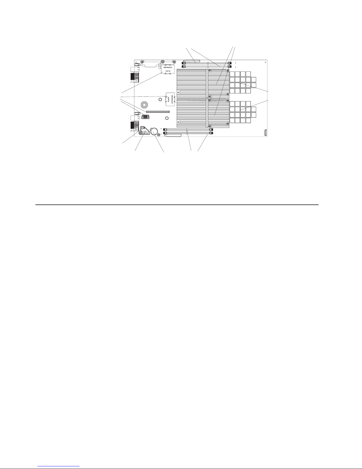
Expansion
option
connectors
Light path
diagnostics
switch
Light box
I/O buffer DIMM slots
1
Battery
Heat sinks
I/O buffer DIMM slots
Figure 2. BladeCenter components
Both Cell/B.E. processors and Cell/B.E. companion chips are underneath the heat
sinks and therefore not visible. The Cell/B.E. processors and the system XDR
memory are soldered onto the system board and are not removable.
Reliability, availability, and serviceability features
System XDR
memory
Three important features in server design are reliability, availability, and
serviceability (RAS). These RAS features are designed to help ensure that your
blade server is available when you want to use it; and, in the event of a failure, help
you easily diagnose and repair the failure with minimal inconvenience.
The following is a list of some of the RAS features that your blade server supports:
v Transparent CPU Hardware error recovery
v ECC for XDR and DDR2 memory
v PFA for CEs on the Cell/B.E. companion chip attached I/O Buffer DDR2 DIMMs
v Memory Scrubbing on XDR system memory
v XDR System memory failure isolation for memory errors to a single memory
interface (Cell/B.E.-0 or Cell/B.E.-1 attached)
v DDR2 I/O Buffer memory failure isolation to a single DIMM
v PCI Bus Parity
level features include:
Blade
v Degraded boot for both XDR and DDR2 memory errors. XDR memory errors
may create holes in the memory map.
v Automatic server recovery and restart:
– Automatic reboot after boot hangs (with switch of the boot flash to the backup
image)
– Automatic reboot after checkstop (without switch of the boot flash side)
Environmental monitors and alerts
v
v System VPD and VPD on all major electronic components
v Lightbox LEDs
v System Management Services (SMS) menu support
v Checkstop detection with data logging and automated reboot
BladeCenter unit supports the following features:
The
4 QS21 Installation and User’s Guide
Page 21

v Redundant power supplies
v Power Supply error detection
v Remote Power control
v System Event Logs through Advanced Management Module
v Redundant Blowers, switches, Advanced Management Modules
v Hotplug of all BladeCenter unit field replaceable units (FRUs) including blowers,
switches and power supplies
Registering your BladeCenter QS21
Record information about the blade server in the following table. You need this
information when you register the blade server with IBM. Yo u can register the blade
server at http://www.ibm.com/support/mysupport/.
Product name BladeCenter QS21
Machine type 0792
Model number _____________________________________________
Serial number _____________________________________________
The machine type, model number, and serial number are on the label that covers
the base of the blade server. The label is visible when the blade server is not in the
BladeCenter unit.
Checking for software and firmware updates
Occasionally, firmware and software updates become available. To check for
updates and download the latest device drivers, firmware updates or documents, go
to http://www.ibm.com/support/us/en/.
Notices and statements used in this document
The caution and danger statements that appear in this document are also in the
multilingual Safety Information document, which is on the IBM BladeCenter
Documentation CD. Each statement is numbered for reference to the corresponding
statement in the Safety Information document.
The following notices and statements are used in this document:
v Notes: These notices provide important tips, guidance, or advice.
v Important: These notices provide information or advice that might help you avoid
inconvenient or problem situations.
v Attention: These notices indicate potential damage to programs, devices, or
data. An attention notice is placed just before the instruction or situation in which
damage could occur.
v Caution: These statements indicate situations that can be potentially hazardous
to you. A caution statement is placed just before the description of a potentially
hazardous procedure step or situation.
v Danger: These statements indicate situations that can be potentially lethal or
extremely hazardous to you. A danger statement is placed just before the
description of a potentially lethal or extremely hazardous procedure step or
situation.
Chapter 1. Introduction 5
Page 22

Using this book
This Installation and User’s Guide provides information to help you:
v Set up the BladeCenter QS21
v Start and configure the BladeCenter QS21
v Install options
v Install the operating system
v Perform basic troubleshooting of the BladeCenter QS21
The illustrations in this document might differ slightly from the hardware.
Note:
Updates might be available for this document. Yo u can check for the most recent
version at http://www.ibm.com/support/us/en/.
Related documentation
In addition to this document, the following documentation also comes with the
server:
v Problem Determination and Service Guide
This document is in Portable Document Format (PDF) on the Documentation CD.
It contains information to help you solve problems yourself, and it contains
information for service technicians.
v Safety Information
This document is in Portable Document Format (PDF) on the Documentation CD.
It contains translated caution and danger statements. Each caution and danger
statement that appears in the documentation has a number that you can use to
locate the corresponding statement in your language in the Safety Information
document.
v Warranty and Support Information
This document is in PDF on the IBM Documentation CD. It contains information
about the terms of the warranty and about service and assistance.
v IBM Software Development Kit for Multicore Acceleration Version 3.0.0
Installation Guide
This document is in PDF and can be downloaded from http://www.ibm.com/
alphaworks/tech/cellsw/download. It contains information about how to install the
operating system and how to program applications for the blade server.
Depending
Documentation CD.
The blade server can have features that are not described in the documentation
that comes with the server. Additionally, the documentation might be updated
occasionally to include information about those features, or technical updates might
be available to provide additional information that is not included in the blade server
documentation on the CD. Yo u can check for the most recent versions of all
BladeCenter documentation at http://www.ibm.com/support/us/en/.
In addition to the documentation in this library, be sure to review the planning and
installation documents for your BladeCenter hardware available at
http://www.ibm.com/support/us/en/.
6 QS21 Installation and User’s Guide
on the server model, additional documentation might be included on the
Page 23

The Documentation CD
The Documentation CD contains documentation for the blade server in PDF and
includes the IBM Documentation Browser to help you find information quickly.
Hardware and software requirements
The Documentation CD requires the following minimum hardware and software:
v Microsoft® Windows® 2000, Windows XP or Red Hat Linux
v 100 MHz microprocessor
v 32 MB of RAM
v Adobe® Acrobat Reader 3.0 (or later) or xpdf, which comes with Linux operating
systems
Note: Acrobat Reader software is included on the CD, and you can install it
when you run the Documentation Browser.
®
Chapter 1. Introduction 7
Page 24

Using the Documentation Browser
Use the Documentation Browser to browse the contents of the CD, read brief
descriptions of the books, and view books using Adobe Acrobat Reader or xpdf.
The Documentation Browser automatically detects the regional settings in use in
your system and displays the books in the language for that region (if available). If
a book is not available in the language for that region, the English version is
displayed.
Use one of the following procedures to start the Documentation Browser:
v If Autostart is enabled, insert the CD into your CD or DVD drive. The
Documentation Browser starts automatically.
v If Autostart is disabled or is not enabled for all users:
– If you are using a Windows operating system, insert the CD into your CD or
DVD drive and click Start Run. In the Open field, type:
x:\win32.bat
where x is the drive letter of your CD drive, then click OK.
– If you are using a Linux operating system, insert the CD into your CD drive;
then, run the following command from the /mnt/cdrom directory:
sh runlinux.sh
The Available Topics list displays all the books for the blade server. Some books
might be in folders. A plus sign (+) indicates each folder or book that has additional
books under it. Click the plus sign to display the additional books.
When you select a book, a description of the book appears under Topic
Description. To select more than one book, press and hold the Ctrl key while you
select the books. Click View Book to view the selected book or books in Acrobat
Reader or xpdf. If you selected more than one book, all the selected books are
opened in Acrobat Reader or xpdf.
To search all the books, type a word or word string in the Search field and click
Search. The books in which the word or word string appears are listed in order of
the most occurrences. Click a book to view it, and press Crtl+F to use the Acrobat
search function or Alt+F to use the xpdf search function within the book.
Click Help for detailed information about using the Documentation Browser.
8 QS21 Installation and User’s Guide
Page 25

Chapter 2. Blade server power, controls, and indicators
This chapter describes the power features, how to turn on and turn off the blade
server, and what the controls and indicators mean. This chapter also identifies the
system board connectors.
Turning on the blade server
The BladeCenter QS21 is hot-swappable and can be inserted into the BladeCenter
unit when the unit is already powered up. However, it can only be powered on by
one of the methods described in this section. While the blade server is powering up,
the power-on LED on the front of the server is lit. See “Blade server controls and
LEDs” on page 11 for the power-on LED states.
After you have installed the BladeCenter QS21 into a powered up BladeCenter unit,
wait until the power on LED on the blade server flashes slowly before turning on the
blade server.
You can turn on the blade server in any of the following ways:
Using the power control button
You can press the power-control button Figure 3 which is behind the
control-panel door on the front of the blade server if local power control is
enabled for the blade server. Local power control is enabled and disabled
through the BladeCenter Management Module Web interface.
Figure 3. Blade server power button
Using the BladeCenter Advanced Management Module
Using the Wake on LAN® feature:
In the event of a power failure the BladeCenter unit and then the blade server can
start automatically when power is restored. Yo u must configure this through the
BladeCenter Advanced Management Module. See the BladeCenter Management
Module User's Guide for further information about this feature.
© Copyright IBM Corp. 2006, 2008 9
Power-control
button
You can use the BladeCenter Management Module Web interface to turn on
the blade server remotely.
If you want to use the Wake on LAN feature, the feature must be enabled in
the installed operating system and it must not have been disabled through
the Advanced Management Module.
Page 26

Turning off the blade server
When you turn off the blade server, it is still connected to power through the
BladeCenter unit and can continue to respond to requests from the service
processor, including remote requests to turn the blade server on. To remove all
power from the blade server, you must physically remove it from the BladeCenter
unit or power off the BladeCenter unit.
To avoid loss of data, shut down the Linux operating system before you turn off the
blade server. Shut down the operating system by entering the shutdown -h now
command at the command prompt or by choosing shutdown if you are using a
graphical user interface (GUI). See your operating system documentation for
additional information about shutting down the operating system.
If the BladeCenter unit has not been turned off, the blade server can be turned off
in any of the following ways:
Using the power control button
You can press the power control button behind the control-panel door on
the front panel of the blade server. This starts an orderly shutdown of the
operating system, providing your operating system supports this feature,
before turning off the BladeCenter QS21. If the operating system stops
functioning, pressing and holding the power control button for more than 4
seconds turns off the blade server.
Using the BladeCenter Advanced Management Module
You can use the Advanced Management Module Web interface to turn off
the blade server remotely. Yo u can also configure the Advanced
Management Module to turn off the blade server automatically if the system
is not operating correctly.
Note: After turning off the blade server, wait at least 5 seconds before turning it on
again.
10 QS21 Installation and User’s Guide
Page 27

Blade server controls and LEDs
This section describes the controls and LEDs on the front panel of the blade server.
For further information about the LEDs and how they can be used to assist in
troubleshooting, see Problem Determination and Service Guide.
Information
LED
Location
LED
Activity
LED
Power-on
LED
Media-tray
select button
Power-control
button
Blade-error
LED
NMI
reset-button
CD
Figure 4. Power-control button and LEDS
Note: The control panel door which normally covers the LEDs and power-control
button is omitted for reasons of clarity.
Activity LED:
This green LED lights when there is network activity.
Location LED:
This blue LED is turned on remotely by the system administrator to assist in
locating the blade server. The location LED on the BladeCenter unit lights
at the same time.
Information LED:
This amber LED lights to indicate that information about a system error has
been placed in the Advanced Management Module Event Log. The
information LED remains on until turned off by Advanced Management
Module or through IBM Director Console.
Blade error LED:
This amber LED lights when a system error has occurred in the blade
server.
Power control button:
Press this button to turn the blade server on or off. The power control
button only has effect if local power control is enabled for the blade server.
Local power control is enabled and disabled through the BladeCenter
Advanced Management Module Web interface.
Media tray select button:
This button associates the shared BladeCenter unit media tray (DVD/CD
drive and USB ports) with the blade server. The LED on the button flashes
while the request is being processed, then lights when the ownership of the
media tray has been transferred to the blade server.
It can take approximately 20 seconds for the operating system on the blade
server to recognize the media tray.
Chapter 2. Blade server power, controls, and indicators 11
Page 28

Power on LED:
reset button
NMI
Note: The blade error LED, information LED, and location LED can be turned off
System board LEDs
The BladeCenter QS21 has status LEDs on the system board to indicate the health
of various components. Some are within the light box while others are in different
location. A lit LEDs indicates an error condition. Complete information about the
LEDs can be found in the Problem Determination and Service Guide.
This green LED indicates the power status of the blade server as follows:
v Flashing rapidly - The service processor on the blade server is
communicating with the BladeCenter Advanced Management Module.
v Flashing slowly - The blade server has power but is not turned on.
v Lit continuously (steady) - The blade server has power and is turned on.
v Not lit. Either the BladeCenter unit is powered off, or a power failure has
occurred on the blade server or the BladeCenter unit.
If the operating system has been installed, pressing this with a paper clip or
pin causes the operating system to call the system debugger.
through the BladeCenter Management Module Web interface. For additional
information about errors, see “Problems indicated by the front panel LEDs”
on page 60.
To find out what if any errors have occurred on the system board, you must:
1. Remove the blade server from the BladeCenter unit
2. Open the cover
3. Press the light path diagnostics switch
lights any error LEDs that were turned on during processing. It also lights a
This
green LED to indicate the capacitor is charged and the light path diagnostics
system is operating.
Figure 5 on page 13 shows the location of the light path LEDs and the diagnostics
switch.
12 QS21 Installation and User’s Guide
Page 29
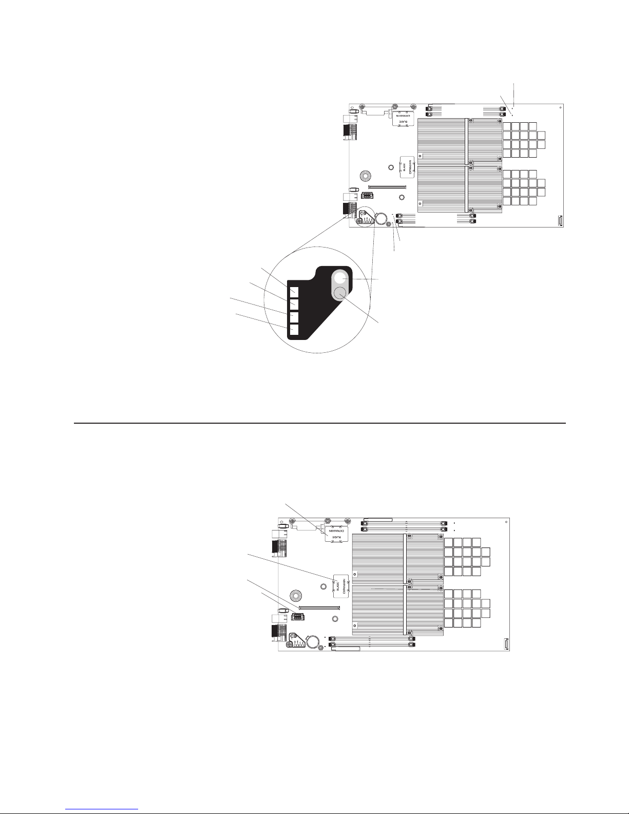
Temperature fault LED
System board LED
CPU fail LED
NMI error LED
TEMP
S BRD
CPU
NMI
LP
Light box
1
Error LED (JDIM )00
Light path
diagnostics
LED
Light path
diagnostics
switch
Error LED (JDIM10)
JDIM11 slot
JDIM10 slot
JDIM01 slot
JDIM00 slot
Error LED (JDIM01)
Error LED (JDIM11)
Figure 5. System-board LEDs
Pressing the light path diagnostics switch lights the LED(s) to indicate where an
error has occurred.
System board internal and expansion card connectors
The following illustration shows the location of the connectors for user-installable
options.
Connector at J201
Connector at J22
Connector at JFC_18
Connector at J200
1
Figure 6. Locations of the expansion option connectors on the system board
Chapter 2. Blade server power, controls, and indicators 13
Page 30

14 QS21 Installation and User’s Guide
Page 31

Chapter 3. Installing the blade server
If you have options to install in the blade server, you should install them now. See
Chapter 4, “Installing and removing replaceable units,” on page 19 and the
BladeCenter QS21 Problem Determination and Service Guide for further
information, then continue with the instructions in this chapter.
Installation guidelines
The BladeCenter QS21 is a hot-swappable device: you can install or remove the
blade server while the BladeCenter unit is running. Additionally, the BladeCenter
QS21 can operate alongside different blade servers in the same BladeCenter unit.
Attention: If you plan to remove a blade server and reinstall it, be sure to note
the number of the bay that contains the blade server before you remove it. Yo u
must reinstall the blade server in the same bay from which it was removed.
Reinstalling a blade server into a different bay than the one from which it was
removed could have unexpected consequences, such as incorrect reconfiguration of
the blade server. Some blade server configuration information and update options
are established according to bay number.
If you reinstall the blade server into a different bay, you might have to reconfigure
the blade server.
Statement 21:
CAUTION:
Hazardous energy is present when the blade server is connected to the power
source. Always replace the blade cover before installing the blade server.
For information about the design of the BladeCenter unit, including the hot-swap
blade bays, see the documentation that comes with the BladeCenter unit.
While you can install or remove the blade server without removing power from the
BladeCenter unit, you must turn off the blade server before removing it from the
BladeCenter unit.
The maximum number of blade servers that the BladeCenter unit supports varies by
the wattage of the power supplies that are installed in the BladeCenter unit. For
more information about determining the power requirements for the blade server,
see the IBM BladeCenter Power Module Upgrade Guidelines.
Installing the BladeCenter QS21
© Copyright IBM Corp. 2006, 2008 15
Page 32

Releasehandles
open
Figure 7. Inserting the blade server into the BladeCenter unit
Complete the following steps to install a blade server into the BladeCenter unit:
1. Read the safety information beginning on page vii and “Installation guidelines”
on page 19.
2. If you have not done so already, install any options. See Chapter 4, “Installing
and removing replaceable units,” on page 19 for further information.
3. Select the bay for the blade server.
4. If the bay that you selected contains filler blades, remove the filler blades.
When you remove filler blades from a blade bay in the BladeCenter unit do not
discard the filler blades. Yo u need the filler blades if you ever remove the
blade server.
For future use, store the filler blades in a static-protective environment.
To help ensure proper cooling, performance, and system reliability, do not
operate the BladeCenter unit for more than 1 minute without a blade server or
filler blades installed in each blade bay.
5. Make sure that the release levers on the blade server are in the open position
(perpendicular to the blade server).
6. Slide the blade server into the bay until it stops. The spring-loaded doors
further back in the bay that cover the bay opening move out of the way as you
insert the blade server.
7. Push the release levers on the front of the blade server to the closed position.
8. A set of user labels comes with the blade server. Use them to write identifying
information for each the blade server; then place the label on the BladeCenter
unit. See your BladeCenter unit documentation for the exact location.
Important: Do not place the label on the blade server or in any way block the
ventilation holes on the blade server.
9. Turn on the blade server by pressing the power-control button on the blade
server control panel. The power-on LED on the blade server changes from the
slowly-flashing state to a continuously lit (steady) state.
10. If this is the initial installation of the blade server install the operating system.
Use the installation instructions that come with the operating system. For more
information, see Chapter 6, “Installing the operating system,” on page 53.
11. Check http://www.ibm.com/support/us/en/ for any software or firmware updates.
12. Update the firmware or software if required.
Note: Yo u may be required to reboot the blade server.
16 QS21 Installation and User’s Guide
Page 33

Once you have installed the operating system and performed any required updates,
the blade server is ready for use. If you have not already done so, turn on the blade
server by pressing the power-control button on the blade server control panel. The
power on LED on the blade server changes from the slowly-flashing state to a
continuously lit (steady) state.
If you have other blade servers to install, you can do so now.
Chapter 3. Installing the blade server 17
Page 34

18 QS21 Installation and User’s Guide
Page 35

Chapter 4. Installing and removing replaceable units
This chapter provides instructions for replacing units on the blade server.
Replaceable units are components, such as memory modules, and I/O expansion
cards. Some removal instructions are provided in case you need to replace one
replaceable with another.
You can replace the following items:
v Battery
v Front bezel assembly (control panel)
v Blade server cover
can add or remove the following optional items:
You
v Cisco 4X Infiniband Expansion Card for IBM BladeCenter
v InfiniBand 4X DDR Expansion Card (CFFh)
v I/O buffer DDR2 memory modules
v SAS expansion card
v BladeCenter Expansion unit
If you wish to install the InfiniBand 4X DDR Expansion Card (CFFh) you
Note:
must install Red Hat Enterprise Linux 5.2 or higher.
Installation guidelines
Before you begin, read the following:
v Read the safety information beginning on page vii and the guidelines in “Handling
static-sensitive devices” on page 20. This information will help you work safely
with the blade server and components.
v You do not have to turn off the blade server or disconnect the BladeCenter unit
from power to install or replace any of the hot-swappable modules on the rear of
the BladeCenter unit.
v Before you remove a hot-swappable blade server from the BladeCenter unit, you
must shut down the operating system on it by typing the shutdown -h now
command or choosing the shut down option from your GUI. See “Turning off the
blade server” on page 10 for details. Yo u do not have to shut down the
BladeCenter unit itself.
v Blue on a component indicates touch points, where you can grip the component
to remove it from or install it in the blade server or BladeCenter unit, open or
close a latch, and so on.
v Orange on a component or an orange label on or near a component indicates
that the component can be hot-swapped. Yo u can remove or install the
component while the blade server or BladeCenter unit is running providing the
blade server or BladeCenter unit and operating system support the
hot-swappable capability. Orange can also indicate touch points on
hot-swappable components. See the instructions for removing or installing a
specific hot-swappable component for any additional procedures that you might
have to perform before you remove or install the component.
System reliability guidelines
To help ensure proper cooling and system reliability, make sure that:
v The ventilation holes on the blade server are not blocked.
© Copyright IBM Corp. 2006, 2008 19
Page 36

v Each of the blade bays on the front of the BladeCenter unit has a blade server or
filler blade installed. Do not operate the BladeCenter unit for more than 1 minute
without a blade server or filler blade installed in each blade bay.
v You have followed the reliability guidelines in the documentation that comes with
the BladeCenter unit.
Handling static-sensitive devices
Attention: Static electricity can damage electronic devices and your system. To
avoid damage, keep static-sensitive devices in their static-protective packages until
you are ready to install them.
To reduce the possibility of electrostatic discharge, observe the following
precautions:
v Limit your movement. Movement can cause static electricity to build up around
you.
v Handle the device carefully, holding it by its edges or its frame.
v Do not touch solder joints, pins, or exposed printed circuitry.
v Do not leave the device where others can handle and damage it.
v While the device is still in its static-protective package, touch it to an unpainted
metal part of the BladeCenter chassis for at least 2 seconds. This drains static
electricity from the package and from your body.
v Remove the device from its package and install it directly into the blade server or
BladeCenter unit without setting the device down. If it is necessary to set down
the device, put it back into its static-protective package. Do not place the device
on the blade server cover or on a metal surface.
v Take additional care when handling devices during cold weather. Heating reduces
indoor humidity and increases static electricity.
v Wear an electrostatic-discharge wrist strap, if one is available.
20 QS21 Installation and User’s Guide
Page 37

Removing the blade server from the BladeCenter unit
Attention:
v To maintain proper system cooling, do not operate the BladeCenter unit for more
than 1 minute without a blade server or filler blades installed in each blade bay.
v Note the number of the bay that contains the blade server before you remove it.
You must reinstall the blade server in the same bay from which it was removed.
Reinstalling a blade server into a different bay than the one from which it was
removed could have unexpected consequences, such as incorrect reconfiguration
of the blade server. Some blade server configuration information and update
options are established according to bay number.
If you reinstall the blade server into a different bay, you might have to reconfigure
the blade server.
Removing the blade server
The blade server is a hot-swappable device, and the blade bays in the BladeCenter
unit are hot-swappable bays. Therefore, you can install or remove the blade server
without removing power from the BladeCenter unit. However, you must turn off the
blade server before removing it from the BladeCenter unit.
Complete the following steps to remove the blade server:
Releasehandles
open
Figure 8. Removing the blade server
1. Read the safety information beginning on page vii and “Installation guidelines”
on page 19.
2. If the blade server is operating, the power on LED is lit continuously (steady).
Before you remove a blade server from the BladeCenter unit, you must shut
down the operating system on it by typing the shutdown -h now command or
choosing the shut down option from your GUI. See “Turning off the blade
server” on page 10 for details. Yo u do not have to shut down the BladeCenter
unit itself.
3. Open the two release levers as shown in the illustration. The blade server
moves out of the bay approximately 0.6 cm (0.25 inch).
4. Pull the blade server out of the bay.
5. Place either a filler blade or a new blade server in the bay within 1 minute.
Chapter 4. Installing and removing replaceable units 21
Page 38

Opening and removing the blade server cover
You must open the blade server cover to access, install or remove any of the
replaceable items except the front bezel assembly.
Cover pins
Cover release
Cover release
Figure 9. Opening the blade server cover
Complete the following steps to open the blade server cover:
1. Read the safety information beginning on page vii and “Installation guidelines”
on page 19.
2. Carefully place the blade server on a flat, static-protective surface, with the
cover side up.
3. Press the blue blade cover release on each side of the blade server and lift the
outer cover open (see Figure 9).
4. If you want to remove the cover, carefully lift it from the cover pins and set it
aside (see Figure 9).
Statement 21:
CAUTION:
Hazardous energy is present when the blade server is connected to the power
source. Always replace the blade cover before installing the blade server.
Removing the BladeCenter PCI Express I/O Expansion Unit
You must remove BladeCenter PCI Express I/O Expansion Unit, if installed, to
access, install or remove any of the replaceable items except the front bezel
assembly.
22 QS21 Installation and User’s Guide
Page 39

Cover pins
Cover release
Cover release
Figure 10. Removing the expansion unit
Complete the following steps to remove BladeCenter PCI Express I/O Expansion
Unit:
1. Read the safety information beginning on page vii and “Installation guidelines”
on page 19.
2. Carefully place the blade server on a flat, static-protective surface, with the
expansion unit side facing up.
3. Press the blue blade cover release on each side of the blade server and lift the
expansion unit (see Figure 10).
4. To remove the expansion unit, carefully lift it from the cover pins and set it
aside.
Statement 21:
CAUTION:
Hazardous energy is present when the blade server is connected to the power
source. Always replace the blade cover before installing the blade server.
Installing the optional InfiniBand card
The InfiniBand card connects to the high-speed connector on the system board
using the two expansion card locator pins to assist with fitting and locking in place.
Use the blue handling areas to handle the card, and, when it has been placed in
position, to lock it into place.
Note: If you wish to install the InfiniBand 4X DDR Expansion Card (CFFh) you
must install Red Hat Enterprise Linux 5.2 or higher.
Chapter 4. Installing and removing replaceable units 23
Page 40

Locking clip
Locator pin holes
Handling areas
Figure 11. InfiniBand card handling areas
Complete the following steps to install the InfiniBand card:
1. Shut down the BladeCenter QS21.
2. Remove the BladeCenter QS21 from BladeCenter unit.
3. Remove the top cover.
4. Locate the high-speed connector at location J200 on the system board.
Ball stud
High-speed connector
Expansion card
standoffs
with locator pins
1
Figure 12. Expansion card connector, locator pins, and ball stud
5. Remove the connector cover.
6. Locate the expansion card locator pins at the back of the system board.
7. Locate the connector and ball socket on the InfiniBand card.
24 QS21 Installation and User’s Guide
Page 41

Locking clip
Connector
Locator pin holes
Ball socket
Figure 13. InfiniBand card reverse view
8. Slide the InfiniBand card locator pin holes over the expansion card locator
pins. The card rests on the locator pins.
Locator pin
Expansion card
Expansion
connector
cover
Expansion
card
standoff
Figure 14. Positioning the InfiniBand card
9. Check that the ball socket on the card is over the corresponding ball stud on
the main board then carefully press the InfiniBand card into position. Use the
blue areas only to avoid damage to the card.
10. Check that the blue locking clip has locked into position.
11. If you do not want to install any other options, replace the cover and insert the
BladeCenter QS21 into the BladeCenter unit.
Attention: The connectors on the system board and the InfiniBand card are not
designed for repeated removal or replacement of components. Avoid removing the
InfiniBand card once it is in position,
Chapter 4. Installing and removing replaceable units 25
Page 42

Adding I/O DDR2 memory modules
This section describes how to add extra I/O DDR2 memory. There are two slots per
Cell/B.E. companion chip allowing up to 1 GB of memory for each Cell/B.E.
companion chip for I/O buffering.
DIMM
filler
DIMM filler
DIMM slot at JDIM11
DIMM slot at JDIM10
DIMM slot at JDIM00
DIMM slot at JDIM01
Figure 15. DIMM slot location
You must add memory as pairs of dual inline memory modules (DIMMs). Yo u may
fit one or more memory modules for each buffer, but each I/O buffer must use the
same type of memory module and have the same amount of memory. The minimum
amount of memory you can add is 512 MB per buffer, or one module per buffer. If
you fit a single pair of DIMMs you must use slots JDIM00 and JDIM11.
The BladeCenter QS21 supports VLP DDR2 512 MB DIMMs only.
The DIMMs are used as memory for the I/O buffers only. Yo u cannot
Note:
increase the size of system memory which is fixed at 1GB for each Cell/B.E.
processor.
To install extra I/O buffer memory, complete the following steps:
1. Shut down the BladeCenter QS21.
2. Remove the BladeCenter QS21 from the BladeCenter unit.
3. Open the top cover.
4. Locate the DIMM slots in which you want to insert the I/O DDR2 memory.
modules.
26 QS21 Installation and User’s Guide
Page 43

1
Slot at JDIM01
Slot at JDIM00
Slot at JDIM11
Slot at JDIM10
Figure 16. DIMM slot location
There are four DIMM slots, two for each Cell/B.E. companion chip. If this is the
first pair of DIMMs you are installing, use slots 00 and 11. Slots 00 and 11 are
the two outer slots as shown in Figure 16. For a second pair of DIMMs, use
the remaining slots 01 and 10.
5. Remove the DIMM fillers from the slots where you want to insert the DIMMs.
Retain the DIMM fillers. Yo u need them if you remove any DIMMs from the
blade server as they are an important part of the blade server cooling system.
6. Place the DIMM in the slot, contact side down. Check the orientation of the
module. The central locating pin in the slot should match the corresponding
cut-out on the module.
7. Carefully press the module into place until the retaining clips snap into
position. Make sure that the clips are locked properly.
Figure 17. DIMM retaining clips
8. Repeat steps 6 and 7 until you have installed all the optional DIMMs.
9. Ensure that all unused DIMM slots are fitted with DIMM fillers.
10. If you do not want to install any other options, replace the cover and insert the
BladeCenter QS21 into the BladeCenter unit.
Installing the SAS expansion card
The BladeCenter QS21 does not have any built-in disk storage. The SAS expansion
card allows you to connect storage to the BladeCenter QS21. Use the blue handling
areas to handle the card.
DIMM
Retaining clip
Chapter 4. Installing and removing replaceable units 27
Page 44

Handling areas
Figure 18. SAS expansion card handling areas
Complete the following steps to install the SAS expansion card:
1. Shut down the BladeCenter QS21.
2. Remove the BladeCenter QS21 from the BladeCenter unit.
3. Open the top cover.
4. Locate the two SAS expansion card connectors at locations J22 and JFC_18
and the ball stud on the system board.
Connectors
for SAS
expansion card
1
Ball stud
Figure 19. SAS expansion card connector and ball stud location
5. Locate the connectors and the ball socket on the SAS card.
Connectors
Ball socket
Figure 20. SAS expansion card reverse side
6. Align the connectors on the system board with the connector on the SAS card.
28 QS21 Installation and User’s Guide
Page 45

Expansion
card
Figure 21. SAS expansion card location
7. Using the blue handling areas, carefully push the card down to insert it into the
connectors. Ensure that the ball stud on the system board engages with the ball
socket on the SAS expansion card.
8. If you do not want to install any other options, replace the cover and insert the
BladeCenter QS21 into the BladeCenter unit.
Installing the BladeCenter PCI Express I/O Expansion Unit
Important:
v A BladeCenter QS21 with the BladeCenter PCI Express I/O Expansion Unit
installed takes up two contiguous slots in the BladeCenter chassis
v You must remove any expansion card using the high-speed connector before
installing the expansion unit.
Cover pins
Cover release
Figure 22. Installing the expansion unit
Cover release
Chapter 4. Installing and removing replaceable units 29
Page 46

Complete the following steps to install the BladeCenter PCI Express I/O Expansion
Unit:
1. Read the safety information beginning on page vii and “Installation guidelines”
on page 19.
2. Remove the blade server cover and set it aside. See “Opening and removing
the blade server cover” on page 22 for further information.
3. Remove the connector cover or any optional card from the high-speed
connector. Figure 12 on page 24 shows the location of the high-speed
connector.
4. Lower the expansion unit so that the slots at the rear slide down onto the cover
pins at the rear of the blade server, as shown in Figure 22 on page 29.
5. Carefully close the expansion unit as shown in Figure 22 on page 29 until it
clicks into place.
30 QS21 Installation and User’s Guide
Page 47

Removing the blade-server front bezel assembly
Before you can replace a defective system board assembly or blade server front
bezel assembly, you must first remove the blade server front bezel assembly.
Figure 23 shows how to remove the front bezel assembly from a blade server.
Blade Cover
Blade-Cover
Release
Bezel-Assembly
Release
Bezel-Assembly
Release
Figure 23. Removing the front bezel assembly
Complete the following steps to remove the front bezel assembly:
1. Read the safety information beginning on page vii and “Installation guidelines”
on page 19.
2. Open the blade server cover.
3. Carefully disconnect the control panel cable from the control panel connector.
4. Press the front bezel release on both sides of the system board and pull the
front bezel assembly away from the blade server.
5. Store the front bezel assembly in a safe place.
Replacing the battery
IBM has designed this product with your safety in mind. The lithium battery must be
handled correctly to avoid possible danger. If you replace the battery, you must
adhere to the following instructions.
Blade-Cover
Release
Control-Panel
Cable
Bezel
Control-Panel
Connector
Note: In the U. S., call 1-800-IBM-4333 for information about battery disposal.
If you replace the original lithium battery with a heavy-metal battery or a battery with
heavy-metal components, be aware of the following environmental consideration.
Batteries and accumulators that contain heavy metals must not be disposed of with
normal domestic waste. They will be taken back free of charge by the manufacturer,
distributor, or representative, to be recycled or disposed of in a proper manner.
Chapter 4. Installing and removing replaceable units 31
Page 48

To order replacement batteries, call 1-800-IBM-SERV within the United States, and
1-800-465-7999 or 1-800-465-6666 within Canada. Outside the U.S. and Canada,
call your IBM authorized reseller or IBM marketing representative.
Note: After you replace the battery, the blade server is automatically reconfigured.
However, you must reset the system date and time through the operating
system that you installed.
Statement 2:
CAUTION:
When replacing the lithium battery, use only IBM Part Number 43W9859 or
03N2449 or an equivalent type battery recommended by the manufacturer. If
your system has a module containing a lithium battery, replace it only with
the same module type made by the same manufacturer. The battery contains
lithium and can explode if not properly used, handled, or disposed of.
Do not:
v Throw or immerse into water
v Heat to more than 100°C (212°F)
v Repair or disassemble
Dispose
of the battery as required by local ordinances or regulations.
Note: See “Battery return program” on page 84 for more information about battery
disposal.
Complete the following steps to replace the battery:
1. Read the safety information beginning on page vii and “Installation guidelines”
on page 19.
2. Follow any special handling and installation instructions that come with the
battery.
3. If the blade server is operating, shut down the operating system by typing the
shutdown -h now command or by choosing shut down from the GUI. If the
blade server was not powered off, press the power control button (behind the
blade server control panel door) to turn off the blade server. See “Blade server
controls and LEDs” on page 11 for more information about the location of the
power control button.
4. Remove the blade server from the BladeCenter unit (see “Removing the blade
server from the BladeCenter unit” on page 21 for information).
5. Carefully place the blade server on a flat, static-protective surface.
6. Open the blade server cover (see “Opening and removing the blade server
cover” on page 22 for instructions).
7. Locate the battery (connector BH1) on the system board.
32 QS21 Installation and User’s Guide
Page 49

1
Battery
Figure 24. Battery location
8. Remove the battery:
a. Use one finger to press the top of the battery clip away from the battery.
The battery pops up when released.
b. Use your thumb and index finger to lift the battery from the socket.
c. Dispose of the battery as required by local ordinances or regulations.
9. Insert the new battery:
a. Tilt the battery so that you can insert it into the socket, under the battery
clip.
b. Press the battery down into the socket until it clicks into place. Make sure
the battery clip holds the battery securely.
Close the blade server cover (see “Closing the blade server cover” on page
10.
36).
Statement 21:
CAUTION:
Hazardous energy is present when the blade server is connected to the
power source. Always replace the blade cover before installing the blade
server.
11. Reinstall the blade server into the BladeCenter unit. See Chapter 3, “Installing
the blade server,” on page 15 for further information.
12. Turn on the blade server (see “Turning on the blade server” on page 9).
13. Reset the system date and time through the operating system that you
installed. For additional information, see your operating-system documentation.
Chapter 4. Installing and removing replaceable units 33
Page 50

Finishing the installation
To complete the installation you must:
1. Reinstall the front bezel assembly on the blade server if removed. See
“Installing the front bezel assembly” for further information.
2. Ensure there is a DIMM filler or a DIMM in each of the I/O buffer DIMM slots.
3. Replace and close the blade server cover. See “Closing the blade server cover”
on page 36 for further information.
Statement 21:
CAUTION:
Hazardous energy is present when the blade server is connected to the
power source. Always replace the blade cover before installing the blade
server.
4. Reinstall the blade server into the BladeCenter unit. See Chapter 3, “Installing
the blade server,” on page 15 for further information.
5. Turn on the blade server. See “Turning on the blade server” on page 9 for
further information.
6. If you have replaced the battery or the system board assembly, reset the
system date and time through the operating system that you installed. For
additional information, see your operating system documentation.
Note: If you have just powered on the BladeCenter unit, wait until the power on
LED on the blade server flashes slowly before powering on the blade server.
Installing the front bezel assembly
The following illustration shows how to reinstall the front bezel assembly on the
blade server.
34 QS21 Installation and User’s Guide
Page 51

Blade Cover
Blade-Cover
Release
Bezel-Assembly
Release
Blade-Cover
Release
Control-Panel
Cable
Bezel-Assembly
Release
Bezel
Control-Panel
Connector
Figure 25. Reinstalling the front bezel assembly
Complete the following steps to install the blade server front bezel assembly:
1. Read the safety information beginning on page vii and “Installation guidelines”
on page 19.
2. Connect the control panel cable to the control panel connector on the system
board assembly.
3. Carefully slide the front bezel assembly onto the blade server, as shown in
Figure 25, until it clicks into place.
Make sure that you do not pinch any cables when you reinstall the front
Note:
bezel assembly.
Chapter 4. Installing and removing replaceable units 35
Page 52

Closing the blade server cover
Important: The blade server cannot be inserted into the BladeCenter unit until the
cover is installed and closed. Do not attempt to override this protection.
Cover pins
Cover release
Cover release
Figure 26. Closing the blade server cover
Complete the following steps to close the blade server cover:
1. Read the safety information beginning on page vii and “Installation guidelines”
on page 19.
2. If you removed the front bezel assembly, replace it now. See “Installing the front
bezel assembly” on page 34 for instructions, and Figure 26.
3. Lower the cover so that the slots at the rear slide down onto the pins at the rear
of the blade server, as shown Figure 26. Before closing the cover, make sure
that all components are installed and seated correctly and that you have not left
loose tools or parts inside the blade server.
4. Carefully close the cover as shown in Figure 26 until it clicks into place.
Input/output connectors and devices
The BladeCenter unit contains the input/output connectors that are available to the
blade server. See the documentation that comes with the BladeCenter unit for
information about the input/output connectors.
36 QS21 Installation and User’s Guide
Page 53

Chapter 5. Configuring the blade server
This chapter describes how to:
v Communicate with a newly-installed blade server.
v Use System Management Services (SMS) to view and update the system
firmware revision number. This does not require the operating system to be
installed.
v Update the baseboard management controller (BMC) firmware using the
Advanced Management Module.
v Update the system firmware using the command-line utility.
v Configure the Ethernet gigabit controllers and in preparation for a network
installation of the operating system.
Yo u can update the BMC firmware through the Advanced Management
Note:
Module Web interface without booting the operating system. However, to
update the system firmware you must boot the operating system first. For
information about installing the operating system, see Chapter 6, “Installing
the operating system,” on page 53.
Communicating with the blade server
The operating system does not have to be booted before you can communicate
with the BladeCenter QS21. Yo u can access it through:
Advanced Management Module
The Web-based management and configuration program. This is your main
access method to the blade server.
The command-line interface
See “Using the command-line interface” on page 38 for further information.
Serial over LAN (SOL)
This is similar to the serial interface, but allows you to connect to the blade
server over the network. See “Using Serial over LAN” on page 38 for further
information.
The serial interface
You can connect a PC or compatible terminal directly to the BladeCenter H
or HT unit using a special cable. See “Using the serial interface” on page
39 for further information.
The BladeCenter H and HT Serial Breakout cables are not supplied
Note:
with the unit and must be ordered separately
System Management Services (SMS)
The SMS utility allows you to view and update the VPD, change the boot
device and set network parameters. See “Using the SMS utility program” on
page 39 for further information.
Using the Advanced Management Module
The Advanced Management Module is the main means of administering the
BladeCenter system. Use the Advanced Management Module Web-based
management and configuration program to:
v Configure the BladeCenter unit
v Update and configure BladeCenter components including the BladeCenter QS21
© Copyright IBM Corp. 2006, 2008 37
Page 54

v Monitor the current system status
v Check the event log for system and other errors
Using the Web interface
Complete the following steps to start the Web-based management and configuration
program:
1. Open a Web browser. In the address or URL field, type the Internet protocol (IP)
address or host name that is assigned for the Management Module remote
connection. The default IP address is:
192.168.70.125
The Enter Network Password window opens.
2. Type your user name and password. Before you log in to the Advanced
Management Module for the first time, contact your system administrator
regarding whether your organization has assigned a user name and password
to you. Use the initial (default) user name and password the first time that you
log in to the Advanced Management Module. If you have an assigned user
name and password, use them for all subsequent logins. All login attempts are
documented in the event log.
The initial user ID and password for the Advanced Management Module are:
User ID
USERID (all capital letters)
Password
3. Follow the instructions that appear on the screen. Be sure to set the timeout
value that you want for your Web session.
BladeCenter management and configuration window opens.
The
For additional information, see the IBM BladeCenter Advanced Management
Module User's Guide.
Using the command-line interface
The IBM BladeCenter Advanced Management Module also provides a
command-line interface to provide direct access to BladeCenter management
functions. You can use this as an alternative to using the BladeCenter Management
Module Web interface.
Through the command-line interface, you can issue commands to control the power
and configuration of the blade server and other components in the BladeCenter
unit. For information and instructions, see the IBM BladeCenter Management
Module Command-Line Interface Reference Guide.
Using Serial over LAN
To establish a Serial over LAN (SOL) connection to the blade server, you must
configure the SOL feature for the blade server and start an SOL session as
described in theIBM BladeCenter Serial over LAN Setup Guide. In addition, the
Advanced Management Module must be configured as described in the IBM
BladeCenter Management Module User’s Guide, and the BladeCenter unit must be
configured as described in the IBM BladeCenter Serial over LAN Setup Guide.
PASSW0RD (note the number zero, not the letter O, in PASSW0RD)
38 QS21 Installation and User’s Guide
Page 55

Using the serial interface
Use the serial interface to:
v Observe firmware progress.
v Access the Linux terminal in order to configure Linux.
can connect a PC serially through the BladeCenter unit using a specific UART
You
cable. To connect to the serial console, plug the serial cable into the BladeCenter
unit and connect the other end to a serial device or computer with a serial port. For
more information, see the documentation that comes with your BladeCenter unit.
Set the following parameters for the serial connection on the terminal client:
v 115200 baud
v 8 data bits
v No parity
v One stop bit
v No flow control
default, the blade server sends output over SOL and to the serial port on the
By
BladeCenter unit. However, the default for input is to use SOL. If you wish to use a
device connected to the serial port for input you must press any key on that device
while the blade server boots.
Using the SMS utility program
The Advanced Management Module is the main means of administering the
BladeCenter unit and the BladeCenter servers. However, another utility is provided
which in some cases can give more information than that displayed in the Advanced
Management Module. This is the System Management Services (SMS) utility
program.
The SMS utility program allows you to view and update the VPD, change the boot
list and set network parameters.
Starting SMS
Complete the following steps to start SMS:
1. Using a Telnet or SSH client, connect to the Advanced Management Module
external Ethernet interface IP address.
2. When prompted, enter a valid user ID and password. The default management
module user ID is USERID, and the default password is PASSW0RD, where the
0 is a zero.
Note: The user ID and password may have been changed. If so, check with the
system administrator for a valid id and password.
3. Power cycle the blade server and start an SOL console session by using the
power -cycle -c command.
For example, to power cycle and start an SOL remote text console with a blade
server that is in the first bay of the BladeCenter unit, issue the command:
power -cycle -c -T system:blade[1]
To open a console session with a blade server that is already powered on, use
the command:
console -T system:blade[1]
Chapter 5. Configuring the blade server 39
Page 56

4. After approximately 30 seconds, you see a sequence of checkpoint codes
displayed on the console. These codes are generated by the Power On Self
Test (POST).
5. When the POST menu and indicators displays a screen similar to:
QS21 Firmware Starting
Check ROM = OK
Build Date = Apr 24 2007 09:32:34
FW Version = "QB-1.6.0-0"
Press "F1" to enter Boot Configuration (SMS)
Initializing memory configuration...
MEMORY
Modules = Elpida 512MB, 3200 MHz
XDRlibrary = v0.32, Bin A/C, RevB, DualDD
Calibrate = Done
Test = Done
SYSTEM INFORMATION
Processor = Cell/B.E.(TM) DD3.2 @ 3200 MHz
I/O Bridge = Cell BE companion chip DD2.x
Timebase = 26666 kHz (internal)
SMP Size = 2 (4 threads)
Boot-Date = 2007-06-08 11:20
Memory = 2048MB (CPU0: 1024MB, CPU1: 1024MB)
Press F1 to display the SMS menu.
Viewing FRU information
The VPD on each blade server contains details about the machine type or model,
serial number and the universal unique ID.
Complete the following steps to see this information:
1. Start SMS by completing the above steps. The SMS menu appears:
PowerPC Firmware
Version HEAD
SLOF-SMS 1.6 (c) Copyright IBM Corp. 2000,2005,2007 All rights reserved.
--------------------------------------------------------------------------
Main Menu
1. Select Language
2. Setup Remote IPL (Initial Program Load)
3. Change SCSI Settings
4. Select Console
5. Select Boot Options
6. Firmware Boot Side Options
7. Progress Indicator History
8. FRU Information
9. Change SAS Boot Device
---------------------------------------------------------------------------
Navigation Keys:
X = eXit System Management Services
---------------------------------------------------------------------------
Type menu item number and press Enter or select Navigation key:
---------------------------------------------------------------------------
2. Type 8 to select FRU Information. A screen similar to the following appears:
40 QS21 Installation and User’s Guide
Page 57

PowerPC Firmware
Version HEAD
SLOF-SMS 1.6 (c) Copyright IBM Corp. 2000,2005,2007 All rights reserved.
--------------------------------------------------------------------------------
FRU Information
Machine Type and Model: 079232x
Machine Serial Number: ABCDEFG
Universal Unique ID: 12345678-1234-1234-1234-123456789ABC
--------------------------------------------------------------------------------
Navigation Keys:
M = return to Main Menu
ESC key = return to previous screen X = eXit System Management Services
--------------------------------------------------------------------------------
Select Navigation key :
Note: Yo u cannot change the FRU information from this screen, only view it.
Updating the system and BMC firmware
The firmware consists of two distinct packages:
v A firmware package for the baseboard management controller (BMC). This is
referred to as the BMC firmware.
v A firmware package for the basic input/output system (BIOS) which runs on the
Cell/B.E. processor. This is referred to as system firmware.
Note: The user and operating system interfaces of the system firmware are
based on the Open Firmware standard. Detailed system information is
provided through the Open Firmware device tree. Yo u can use the client
interface and Run-Time Abstraction Services (RTAS) to run management
functions.
firmware
BMC
v Communicates with advanced management module
v Controls power on
v Initializes the board, including the Cell/B.E. processors and clock chips
v Monitors the physical board environment
System firmware
v Takes over when the BMC has successfully initialized the board
v Acts as the basic input/output system (BIOS)
v Includes boot-time diagnostics and power-on self test
v Prepares the system for the operating system boot
packages are delivered separately and do not follow the same versioning
The
scheme.
IBM provides two basic update options for updating or ″flashing″ the firmware:
online and offline. The offline method requires you to use an alternate bootable
media to restart the server and perform the firmware update. For greater
Chapter 5. Configuring the blade server 41
Page 58

Updating steps
convenience and flexibility, IBM now also provides online updates that you can
install while the operating system is running. The online method allows you to run
the update at any time, with the flexibility to restart the server at a time when it is
most convenient to do so. As a best practice, use the online update packages to
perform all of your basic update functions
IBM periodically makes updates to both BMC and system firmware. These may be
downloaded from http://www.ibm.com/support/us/en/.
Note: To avoid problems and to maintain proper system performance, always make
sure that both the BMC firmware and the system firmware are at the same
level for all BladeCenter QS21 servers within the BladeCenter unit.
Complete the following steps to update the BMC and system firmware images:
1. Check the revision level of the firmware on the blade server and the level of the
updates on http://www.ibm.com/support/us/en/. If the level on the Web site is
higher than the version currently installed, continue with the updating steps.
2. Download the firmware updates.
3. Boot the operating system if it is not running already.
4. Update the BMC firmware using the update package or the Management
Module. See “Updating the BMC firmware” on page 43 for further information.
5. Restart the blade server. This boots the blade server with the new BMC
firmware.
6. Update the system firmware image. See “Installing the system firmware” on
page 46 for further information.
7. The system reboots. This boots the blade server with the new system firmware.
8. Shut down the blade server.
There may be instances where you must update the BMC firmware before
Note:
updating the system firmware. Check the readme file that comes with each
firmware package for more information.
Determining current blade server firmware levels
Complete the following steps to view the current firmware code levels for both the
BMC and the system firmware:
1. Access and log on to the Advanced Management Module Web interface as
described in the Management Module User's Guide.
2. From the Monitors menu section, select Firmware VPD:
42 QS21 Installation and User’s Guide
Page 59

The Blade Server Firmware Vital Product Data (VPD) window shows the build
identifier, release, and revision level of both the system firmware/BIOS and the
BMC firmware. In the example above, the system firmware or BIOS version is
QB01020000 and the BMC firmware is BNBT06b.
Compare this information to the firmware information provided at
http://www.ibm.com/support/us/en/. If the two match, then the blade server has the
latest firmware. If not, download the firmware package from the IBM Support Web
site. See “Updating the BMC firmware” or the IBM Support Web site for installation
instructions.
You can also view the firmware level from within the operating system by using the
following command:
xxd /proc/device-tree/openprom/ibm,fw-vernum_encoded
Output is similar to:
0000000: 5142 3031 3031 3030 3000 00 QB0101000..
where QB0101000 is the system firmware version.
Note: The system firmware version displayed by the BladeCenter Advanced
Management Module might be different from the version displayed by your
operating system. Cross-reference information is given in the firmware
information at http://www.ibm.com/support/us/en/, and in the readme file
which comes with the firmware image.
Updating the BMC firmware
You can update the BMC firmware from the Linux prompt using the update
package, if you have installed RHEL 5.2, or from Advanced Management Module.
Chapter 5. Configuring the blade server 43
Page 60

The Linux executable package allows you to run the firmware update without exiting
the Linux environment. In addition, when you run it with the -x (extract) option, the
package allows you to extract the Linux update files to a specified location.
Using the BMC update package
If you have not done so already you must install RHEL 5.2 or later before you can
update the BMC firmware from the Linux command prompt.
Complete the following steps to update the BMC firmware from the Linux command
prompt:
1. Check the README that comes with the BMC firmware as it contains specific
information about that particular firmware release.
2. Boot the blade server and the operating system.
3. Download the package from the IBM support site at http://www.ibm.com/support/
us/en/. The update package has a .sh extension.
4. Change to the directory where you have downloaded the package.
5. Run the package using the -s option.
6. Reboot the blade server.
Using the Advanced Management Module
Complete the following steps to update the BMC firmware:
1. Download the BMC firmware image file from http://www.ibm.com/support/us/en/
to a suitable location on a server that is accessible on the network. The BMC
firmware image file name has the format BNBT<version number>.pkt.
2. Power off the blade server you want to update.
3. Log in to the Advanced Management Module Web interface.
4. Click Firmware Update from the Blade Tasks submenu at the left of your
screen. The following screen appears:
44 QS21 Installation and User’s Guide
Page 61

5. Choose the blade server you want to update (target) and browse to the
firmware image file.
6. Click on Update.
7. The validity of the image is checked, then the following screen appears:
Chapter 5. Configuring the blade server 45
Page 62

Click Continue.
8. The next screen shows the firmware update progress:
When the update is finished, a confirmation message appears and an entry is
placed in the Advanced Management Module log.
9. Power up and boot the blade server.
BladeCenter QS21 firmware contains a proprietary implementation of
Note:
Cell/B.E. hardware initialization code.
Installing the system firmware
System firmware can only be installed after the operating system has booted. If the
operating system is not installed or cannot boot, then no upgrade or recovery is
possible. See the other sections of the manual Chapter 7, “Solving problems,” on
page 59 for further information about troubleshooting the BladeCenter QS21 blade
server.
You can update the system firmware:
v Through IBM Director. See the IBM Director documentation on the IBM Director
CD for further information.
v Using the update package available from http://www.ibm.com/support/us/en/. See
“Updating the system firmware automatically” on page 48 for further information
on how to perform an update.
v Using the update_flash script available on supported Linux operating systems.
This requires the system firmware image file. See “The firmware update
package” on page 47 for information about how to extract the file.
v Updating the firmware manually. See “Installing the firmware manually” on page
48 for further information.
46 QS21 Installation and User’s Guide
Page 63

For all the above options Linux needs to have a current version of rtas_flash
device driver installed. This is normally installed with the operating system. If it is
not, see the installation guide for the Software Development Kit for Multicore
Acceleration for instructions about how to get this device driver and install it.
Note: Yo u may have to update the BMC before updating the system firmware. See
the README file that comes with the package.
The firmware update package
You can update firmware using the update packages available from
http://www.ibm.com/support/us/en/. These can be installed either through IBM
Director or by executing the .sh file contained in the package. This section
describes how to use the update package to install the firmware update or extract
the firmware image for manual installation.
To install the firmware package using IBM Director, see the documentation on the
IBM Director CD.
Note: The blade server must be configured and have a running Linux operating
system before the package can be extracted or installed.
The update package consists of 4 files:
v A file containing the change history for the BladeCenter QS21 system firmware.
This has a .chg extension.
v A file containing the update package. This has an .sh extension.
v A readme file for the update package. This contains specific installation and
configuration information.
v An XML file. This file is for use by IBM Systems Management tools, including
IBM Director Update Manager, UpdateXpress CD, and UpdateXpress System
Pack Installer.
Using the package
The package consists of a file with a .sh extension that runs from the Linux prompt.
It has a number of options. To see what options are available, run the package
without any options or with the -h switch:
# ./ibm_fw_bios_qb-1.9.1-2_linux_cell.sh
In this example, ibm_fw_bios_qb-1.9.1-3_linux_cell.sh is the name of the
firmware update package. The file name changes according to the version of the
firmware.
A screen similar to the following appears:
Usage:
-x /someDirectory - Extract the payload to <some directory>
-xr /someDirectory - Extract the payload plus PkgSdk files to <some directory>
-xd /dev/fd0 - Create a DOS bootable diskette - Internel floppy drive
-xd /dev/sda - Create a DOS bootable diskette - External USB floppy drive
-u - Perform update unattended
-h - Display this help screen
++debug - Display helpful debug information
Note:
All other command line arguments are passed to the
payload executable
The -xd options are not supported on the BladeCenter QS21 blade server.
Chapter 5. Configuring the blade server 47
Page 64

The -x option
This enables to extract another executable file, in this example
ibm_fw_bios_qb-1.9.1-2.sh which in turn may be run to create the .bin file
required if you wish to update the firmware manually. See “Installing the
firmware manually” for further information.
The -u option
This performs an unattended and automatic update of the system firmware.
The blade server reboots automatically as part of the update process.
Updating the system firmware automatically
Complete the following steps to update the firmware automatically using the update
package:
1. Check the README before attempting to update the system firmware as it
contains specific information about the particular firmware release.
2. Download the update package from http://www.ibm.com/support/us/en/. The
update package has a .sh extension.
3. Change to the directory where you have downloaded the package.
4. Run the package with the -u option. Using the example from above, at the
command prompt enter:
./ibm_fw_bios_qb-1.9.1-2_linux_cell.sh -u
5. Check the system firmware images to confirm the update has succeeded. See
“Determining current blade server firmware levels” on page 42 for instructions.
Installing the firmware manually
If you cannot update the firmware using the update_flash script, it is possible to
update the firmware manually. Yo u can use rtas_flash over /proc.
Complete the following steps to install the firmware manually:
1. Download the update package from http://www.ibm.com/support/us/en/.
2. Extract the system firmware image package. At the command prompt enter:
./<update package> -x <target directory>
For example, to extract the image package ibm_fw_bios_qb-1.9.1-2.sh from
ibm_fw_bios_qb-1.9.1-2_linux_cell.sh in the directory /temp/fwimage enter:
./ibm_fw_bios_qb-1.9.1-2_linux_cell.sh -x /temp/fwimage
If the directory does not exist the firmware package creates it.
3. Change to the directory containing the firmware image package.
4. Extract the firmware image. At the command prompt enter:
./<image package> -x
For example, to extract the image file QB-1.9.1-2-boot_rom.bin from
ibm_fw_bios_qb-1.9.1-2.sh enter:
./ibm_fw_bios_qb-1.9.1-2.sh -x
5. Ensure the rtas_flash driver is loaded. To do this, run lsmod.
6. If the module is not yet in the kernel, invoke the following to load it:
modprobe rtas_flash
7. To update your current firmware, copy the image file to /proc/ppc64/rtas/
firmware_update and reboot manually:
cp <image-file> /proc/ppc64/rtas/firmware_update
shutdown —r now
48 QS21 Installation and User’s Guide
Page 65

For example, to copy the image file cp QB-1.9.1-2-boot_rom.bin to
/proc/ppc64/rtas/firmware_update enter:
cp QB-1.9.1-2-boot_rom.bin /proc/ppc64/rtas/firmware_update
shutdown —r now
8. Once the system reboots, update the system firmware images. See “Updating
the system firmware images” for instructions.
Updating the system firmware images
Once the system firmware is updated, the BladeCenter QS21 boots from the new
firmware. However, there are always two copies of the system firmware image on
the blade server:
TEMP This is the firmware image normally used in the boot process. When the
firmware is updated, it is the TEMP image that is replaced.
PERM This is a backup copy of the system firmware boot image. The blade server
only boots from this image if the TEMP image is corrupt. See “Recovering
the system firmware code” on page 63 for further information about how to
recover from a corrupt TEMP image.
you have updated the system firmware and booted the blade server, you
Once
should copy the TEMP image to the PERM image. This ensures that the PERM and
TEMP images are at the same revision level. The TEMP and PERM images should
always be at the same revision level.
There are two commands you can use to update an old image on PERM.
v From the Linux prompt issue the following command:
update_flash -c
Note: The script checks whether the board has booted from the TEMP image. If
not, the script does not complete.
v From the Linux prompt issue the following command:
echo 0 > /proc/rtas/manage_flash
For more information on booting from the TEMP or PERM images, see “Recovering
the system firmware code” on page 63.
Updating the optional expansion card firmware
If you have installed the SAS optional expansion card or the high-speed InfiniBand
expansion card you may have to update the firmware. See the documentation that
comes with the components for instructions about how to update the firmware.
IBM periodically makes updates available for both SAS and InfiniBand expansion
cards. These may be downloaded from http://www.ibm.com/support/us/en/.
Integrating the Gigabit Ethernet controller into the BladeCenter
One dual-port Gigabit Ethernet controller is integrated on the blade server system
board. Each controller port provides a 1000-Mbps full-duplex interface connecting to
one of the Ethernet Switch Modules in BladeCenter unit I/O bays 1 and 2 of the
BladeCenter H unit or the BladeCenter HT unit. These enable simultaneous
transmission and reception of data on the Ethernet local area network (LAN).
Chapter 5. Configuring the blade server 49
Page 66

Each Ethernet-controller port on the system board is routed to a different switch
module in I/O bay 1 or bay 2. The routing from the Ethernet-controller port to the
I/O bay varies according to whether an Ethernet adapter is enabled and the
operating system that is installed. See “Blade server Ethernet controller
enumeration” on page 52 for information about how to determine the routing from
the Ethernet-controller ports to I/O bays for your blade server.
You do not have to set any jumpers or configure the controller for the blade server
operating system. However, you must install a device driver to enable the blade
server operating system to address the Ethernet-controller ports. For device drivers
and information about configuring your Ethernet controller ports, see the Ethernet
software documentation that comes with your blade server, or contact your IBM
marketing representative or authorized reseller. For updated information about
configuring the controllers, go to the Barcelona Computing Centre Web site at
http://www.bsc.es/projects/deepcomputing/linuxoncell/.
If your blade server contains a different type of optional Ethernet-compatible
Note:
switch module in I/O bay 1 than the switch modules that are mentioned in
this section, see the documentation that comes with the Ethernet switch
module that you are using.
Updating the Ethernet controller firmware
To update the Ethernet controller firmware, you must download an update package
from http://www.ibm.com/support/us/en/. This section describes how to use the
update package to install the firmware update.
The update package consists of four files:
v A file containing the change history for the QS22 Ethernet Controller firmware.
This has a .chg extension.
v A file containing the update package. This has an .sh extension.
v A readme file for the update package. This contains specific installation and
configuration information.
v An XML file. This file is for use by IBM Systems Management tools, including
IBM Director Update Manager, UpdateXpress CD, and UpdateXpress System
Pack Installer.
Using the update package
The package consists of an file with a .sh extension that runs from the Linux
prompt. It has a number of options. To see what options are available, run the
package without any options or with the -h switch:
# ./brcm_fw_nic_2.0.3-e-1_rhel5_cell.sh
In the example shown above, brcm_fw_nic_2.0.3-e-1_rhel5_cell.sh is the name
of the firmware update package. The file name changes according to the version of
the firmware.
A screen similar to the following appears:
50 QS21 Installation and User’s Guide
Page 67

Usage:
-x /someDirectory - Extract the payload to <some directory>
-xr /someDirectory - Extract the payload plus PkgSdk files to <some directory>
-xd /dev/fd0 - Create a DOS bootable diskette - Internel floppy drive
-xd /dev/sda - Create a DOS bootable diskette - External USB floppy drive
-u - Perform update unattended
-h - Display this help screen
++debug - Display helpful debug information
The -xd and -x options are not supported on BladeCenter QS21.
The -u option performs an unattended and automatic update of the firmware. The
blade server reboots automatically as part of the update process.
Firmware update steps
Complete the following steps to update the firmware automatically:
1. Check the README before attempting to update the system firmware as it
contains specific information about the particular firmware release.
2. Download the update package from http://www.ibm.com/support/us/en/. The
update package has a .sh extension.
3. Change to the directory where you have downloaded the package.
4. Run the package with the -u option. Using the example from above, at the
command prompt enter:
./ brcm_fw_nic_2.0.3-e-1_rhel5_cell.sh -u
During the update process, messages similar to the following appear on the
console:
[root@c4b14 brcm-2.0.3-ppc]# ./ brcm_fw_nic_2.0.3-e-1_rhel5_cell.sh -u
IBM Ethernet Firmware Update Tool, Version 1.0.2
Warning. No Broadcom NetXtreme II adapters found.
ADAPTER MAC BOOT IPMI ASF PXE UMP
------------------- ---- ---- --- --- --001A640E030C (5704s) 3.21 2.20 NA NA NA
001A640E030D (5704s) NA NA NA NA NA
Updating Broadcom NetXtreme adapters.
Updating 001A640E030C using file 16A8bc.bin ---> Update successful
Updating 001A640E030C using file 16A8ipmi.bin ---> Update successful
Error! Firmware not detected on device 001A640E030D.
Warning. No Broadcom NetXtreme II adapters found.
ADAPTER MAC BOOT IPMI ASF PXE UMP
------------------- ---- ---- --- --- --001A640E030C (5704s) 3.38 2.47 NA NA NA
001A640E030D (5704s) NA NA NA NA NA
One or more errors occurred during the firmware update process. See /var
Note: The error message shown above is correct as it refers to an adapter not
available on BladeCenter QS21.
Chapter 5. Configuring the blade server 51
Page 68

Blade server Ethernet controller enumeration
The enumeration of the Ethernet controller or controller ports in a blade server is
operating system dependent. Yo u can verify the Ethernet controller or controller port
designations that a blade server uses through your operating system settings.
The routing of an Ethernet controller or controller port to a particular BladeCenter
unit I/O bay depends on the type of Ethernet expansion card that is installed. Yo u
can verify which Ethernet-controller port in this blade server is routed to which I/O
bay by using the following test:
1. Install only one Ethernet switch module or pass-thru module, in I/O bay 1.
2. Make sure that the ports on the switch module or pass-thru module are enabled
(Switch Tasks → Management → Advanced Switch Management in the
BladeCenter Management Module Web interface).
3. Enable only one of the Ethernet-controller ports on the blade server. Note the
designation that the blade server operating system has for the controller port.
4. Ping an external computer on the network connected to the Ethernet switch
module. If you can ping the external computer, the Ethernet-controller port that
you enabled is associated with the switch module in I/O bay 1. The other
Ethernet-controller port in the blade server is associated with the switch module
in I/O bay 2.
Communications from optional I/O expansion cards are routed to I/O bays 3 and 4.
If you have installed an I/O expansion card on the blade server you can verify
which controller port on an expansion card is routed to which I/O bay by performing
the same test, using a controller on the expansion card and a compatible switch
module or pass-thru module in I/O bay 3 or 4.
Finishing the configuration
You do not have to set any passwords to use the blade server. If you change the
battery or replace the system-board assembly, you must reset the date and time
through your operating system.
For information about setting up your network configuration for remote
management, see the IBM BladeCenter Planning and Installation Guide or the
Installation and User's Guide for your BladeCenter unit. Yo u can find this
documentation at http://www.ibm.com/support/us/en/.
52 QS21 Installation and User’s Guide
Page 69

Chapter 6. Installing the operating system
BladeCenter QS21 supports the following operating systems:
v Red Hat Enterprise Linux 5.1
v Red Hat Enterprise Linux 5.2
you download Linux distributions, ensure that you download the version
If
compatible with Cell/B.E.
Fedora (Fedora 7 and later) can be installed and supported from the Open Source
only. You can view the current support levels in the Information Center topic
Specified operating environments for Cell Broadband Engine solution.
For general information on installing Linux, see the installation instructions that
come with the distribution or are available at http://www.redhat.com/.
For additional instructions specific to your blade server, check for QS21
documentation on the BladeCenter support Web site at http://www.ibm.com/
systems/bladecenter/support/.
If you need to install Linux on numerous blade servers, consider using DIM
(Distributed Image Management for Linux Clusters). DIM is a sophisticated cluster
management system especially for large and very large number of nodes. For more
information on DIM see http://www.alphaworks.ibm.com/tech/dim/.
Note: IBM may add support for later versions of the operating systems or other
operating systems. You can check the IBM support Web site or the
Information Center topic Specified operating environments for Cell
Broadband Engine solution to see the currently supported operating systems
and levels.
Preparing a boot device
BladeCenter QS21 does not come with any onboard hard disks or other storage.
Instead, you must allocate storage to BladeCenter QS21 as a resource. You can
allocate:
v Networked storage
v SAS attached storage
A remote SAS storage must boot before BladeCenter QS21 attempts to boot
Note:
the operating system from it.
Using a boot device on the network
You cannot directly install Linux on a network device attached to BladeCenter
QS21. First you need to create an initial installation on a 64-bit POWER™ based
system with local storage. Yo u can then create multiple copies of the root file
system on an NFS server. To be able to boot a particular blade server from a copy,
adapt the instance specifics to the blade server and export the adapted copy for
NFS mounting.
Figure 27 on page 54 illustrates the main steps for creating a network installation
that BladeCenter QS21 can boot from.
© Copyright IBM Corp. 2006, 2008 53
Page 70

Install
Installation source
POWER-based system
Figure 27. Installation overview for NLS boot device
For details see the IBM Software Development Kit for Multicore Acceleration
Version 3.0.0 Installation Guide.
Note: Be aware that your BladeCenter QS21 has two Ethernet controllers and can
be connected to two Ethernet switches. As the blade center performs a
network boot from the controller that acquires the IP address, first make sure
that your Linux configuration supports this. If your Linux environment
requires a static IP address for a particular Ethernet port, you must set up
your DHCP environment accordingly.
Configuring a SAS boot device
If you have installed the optional SAS expansion card you can attach supported
local storage to it and configure the storage accordingly. See the documentation
that comes with the SAS expansion card for further information.
BladeCenter QS21 supports IBM System Storage DS3200 (DS3200) including the
IBM System Storage EXP3000 expansion option as SAS attached storage.
Copy
NFS server
Adapt and export
BladeCenter QS21
You must configure storage on your DS3200 storage system before you can use it
as a SAS boot device. Also configure any options, such as RAID arrays, before
installing the operating system. For the configuration you use a management station
that runs a Storage Manager. Use the Storage Manager for the operating system on
your management station:
Linux IBM System Storage DS3000 Storage Manager
Windows Simplicity Storage Manager
installation instructions, see the documentation that comes with your Storage
For
Manager.
The descriptions in this section are based on the System Storage DS3000 Storage
Manager. The Simplicity Storage Manager, might have a slightly different user
interface.
Figure 28 on page 55 shows a schematic setup with a network connection between
the workstation that runs the Storage Manager and the DS3200 storage system.
54 QS21 Installation and User’s Guide
Page 71

BladeCenter QS21
BladeCenter unit
SAS
card
Switch
SAS fabric
Network
Storage
Manager
DS3200
Management station
Figure 28. DS3200 setup for BladeCenter QS21
The SAS expansion card is attached to the PCI-X connector of the blade server.
One or two SAS cables connect the SAS switch at the rear of the BladeCenter unit
to the DS3200 storage system. Production environments, typically, have multiple
storage systems and a more complex SAS fabric, including two switches to provide
redundancy.
Perform the following steps to configure a boot device:
1. Start your Storage Manager. For details on steps 2 to 6 see the documentation
that comes with the Storage Manager.
2. Make the DS3200 storage system accessible to the Storage Manager by
performing a discovery.
3. Assign a name to the DS3200 storage system.
4. Make the storage system accessible to the blade server by configuring host
access for the blade server.
5. Create a logical drive and map it to the blade server. Note the logical unit
number (LUN) you assign when you map the new logical drive to the blade
server. You need this LUN when defining the logical drive as a boot device for
the blade server.
6. Find out the SAS address for the boot device.
a. Click the Summary tab.
b. Click Storage System Profile.
c. In the Storage Systems Profile notebook, click the Controllers tab.
d. Scroll to the information for host interface Sas.
e. The SAS address for the boot device is specified as the World-wide
identifier of the Sas host interface.
7. Configure the SAS drive as a boot device by performing the following steps
from an SMS session with your blade server:
a. Select Change SAS Boot Device on the SAS main menu.
b. Select Change SAS Boot Device Address on the SAS Settings menu.
c. Type the address of step 6e and press Enter.
d. Return to the SAS Settings menu.
e. Select Change SAS Boot Device LUN Id on the SAS Settings menu.
f. Type the LUN you assigned in step 5 and press Enter. Omit any colons that
were shown in the Storage Manager window to separate pairs of
hexadecimal digits.
are now ready to install the operating system.
You
Chapter 6. Installing the operating system 55
Page 72

Preparing the installation source
This section applies if you install the operating system directly on the blade server,
for example on SAS-attached storage. If you perform an initial installation on an
alternative POWER-based system, as suggested in “Using a boot device on the
network” on page 53, see the installation instructions for that system.
Before you install the operating system on the blade server, make sure that the
blade server is turned on. Yo u must first provide an SOL or make a direct serial
connection to the blade server before installing your operating system. If you have
not already done so, configure the SOL feature on the blade server to establish an
SOL connection and enable the SOL feature; then, start an SOL session. For
instructions, see the IBM BladeCenter Serial over LAN Setup Guide and the
BladeCenter Management Module Command-Line Interface Reference Guide. For
information about SOL commands, see the documentation for your operating
system.
You can install over the network, from the CD/DVD drive on the media tray, or from
an ISO image.
Installing over the network
To install over the network, the installation packages must be copied to a server
that the BladeCenter QS21 can access through the network. Yo u can also install
from a CD/DVD drive connected to a server that the BladeCenter QS21 can access
through the network.
If you plan to install the operating system through the Ethernet network, see:
v “Integrating the Gigabit Ethernet controller into the BladeCenter” on page 49
v “Blade server Ethernet controller enumeration” on page 52
v The documentation that comes with the Ethernet switch module that you are
using.
A network boot uses the DHCP, BOOTP, and TFTP protocols.
Note:
Installing from the media tray
The BladeCenter QS21 does not come with a built-in CD/DVD drive. Instead, you
must use the media tray on the BladeCenter unit.
To allocate the media tray to the blade server, press the media tray select button
which is on the front panel of the blade server. Alternatively, you can use the
Advanced Management Module to allocate the media tray to the blade server.
Installing using an ISO image
You can install an operating system from an ISO image of the installation media.
Use the Advanced Management Module to mount the ISO image on your blade
server. For details see IBM BladeCenter Management Module User’s Guide.
Post installation configuration
After you install the operating system on the blade server, you must install any
service packs or update packages that come with the operating system. For
additional information, see http://www.ibm.com/support/us/en/, the instructions that
come with your operating-system documentation and the service packs or update
56 QS21 Installation and User’s Guide
Page 73

packages. Some options have device drivers that you must install. See the
documentation that comes with the options for information about installing any
required device drivers.
If your operating system does not have the required device drivers, contact your
IBM marketing representative or authorized reseller, or see your operating system
documentation for additional information.
If you want to use the Wake on LAN feature, ensure that it is active. Yo u might
have to activate it with ethtool.
Chapter 6. Installing the operating system 57
Page 74

58 QS21 Installation and User’s Guide
Page 75

Chapter 7. Solving problems
This chapter provides basic troubleshooting information to help you solve some
common problems that might occur while setting up your blade server.
A problem with the BladeCenter QS21 can relate either to the BladeCenter QS21 or
the BladeCenter unit.
A problem with the blade server exists if the BladeCenter unit contains more than
one blade server and only one of the blade servers has the symptom. If all of the
blade servers have the same symptom, then the problem relates to the BladeCenter
unit. For more information, see the documentation that comes with your
BladeCenter unit.
The BladeCenter QS21 is supported in the BladeCenter H Type 8852 unit
Note:
and the BladeCenter HT Type 8740 and 8750 (enterprise environment only)
unit. However you can put other blade servers compatible with the
BladeCenter units in the same unit as a BladeCenter QS21.
Prerequisites
Basic checks
Before you start problem determination or servicing, check that:
v The BladeCenter QS21 is inserted correctly into the BladeCenter unit
v All components are connected correctly
v The BladeCenter QS21 has the latest firmware updates. These include:
– BMC
– System
– Gigabit Ethernet controller
– SAS expansion card (if installed)
– InfiniBand high-speed expansion card (if installed)
If you install the blade server in the BladeCenter unit and the blade server does not
start, always perform the following basic checks before continuing with more
advanced troubleshooting:
v Make sure that the BladeCenter unit is correctly connected to a power source.
v Reseat the blade server in the BladeCenter unit (see Chapter 3, “Installing the
blade server,” on page 15).
v If the power on LED is flashing slowly, the blade server may be turned off. To
turn on the blade server, see “Turning on the blade server” on page 9 for further
information.
v If you have just added a new optional device or component, make sure that it is
correctly installed and compatible with the blade server and its components. If
the device or component is not compatible, remove it from the blade server,
reinstall the blade server in the BladeCenter unit, and then restart the blade
server.
v Use Advanced Management Module to check that the blade server appears in
the list of blade servers available.
© Copyright IBM Corp. 2006, 2008 59
Page 76

Troubleshooting charts
The following tables list problem symptoms and suggested solutions. If you cannot
find the problem in the troubleshooting charts, or if carrying out the suggested steps
do not solve the problem, have the blade server serviced.
If you have problems with an adapter, monitor, keyboard, mouse, or power module,
see the Problem Determination and Service Guide that comes with your
BladeCenter unit for more information.
If you have problems with an Ethernet switch module, I/O adapter, or other optional
device that can be installed in the BladeCenter unit, see the Problem Determination
and Service Guide or other documentation that comes with the device for more
information.
Problems indicated by the front panel LEDs
The state of the LEDs on the front of the blade can help in isolating problems.
The table below gives an explanation and a suggested action, if required, for each
Information
LED
Location
LED
Activity
LED
Power-on
LED
Media-tray
select button
Power-control
button
Blade-error
LED
NMI
reset-button
CD
Figure 29. Power-control button and LEDS
LED.
Table 1. Explanation of LEDs and their states
LED State Explanation Suggested action
Blade error LED Amber A system error has occurred on
the blade server.
Information LED Amber Information about a system
error has been placed in the
Advanced Management Module
Event Log. The information LED
remains on until turned off by
Advanced Management Module
or through IBM Director
Console.
Check the BladeCenter error
log, see QS21 Problem
Determination and Service
Guide.
Check Advanced Management
Module to see what the
problem is. See the
BladeCenter Management
Module User's Guide for further
information about the error.
60 QS21 Installation and User’s Guide
Page 77

Table 1. Explanation of LEDs and their states (continued)
LED State Explanation Suggested action
Activity LED Green There is network activity. No action required. For further
information about
troubleshooting networks, see
“Network connection problems”
on page 62.
Power-on LED Flashing rapidly The service processor on the
No action required
blade server is communicating
with the BladeCenter
Management Module.
Flashing slowly The blade server has power but
Turn on if required
is not turned on.
Lit continuously (steady) The blade server has power
No action required
and is turned on.
Not lit. Blade server not powered.
1. Reseat blade server.
2. Check if BladeCenter power
supplies numbers 3 and 4
are installed and powered.
If they are not, install and
power them or use slots
1-5.
3. Go to “Power problems”
Power problems
Power symptom Suggested action
The blade server does not
turn on.
1. Make sure that:
a. The power-on LED on the front of the BladeCenter unit is lit.
b. The LEDs on all the BladeCenter power modules are lit.
c. The power-on LED on the blade-server control panel is flashing slowly.
v The power-on LED flashes rapidly for a short period to indicate it is
communicating with Advanced Management Module. If the power-on LED
to flash rapidly and continues to do so, the blade server is not
communicating with the management module; reseat the blade server and
reboot.
v If the power LED is off, either the blade bay is not receiving power, the
blade server is defective, the Advanced Management Module firmware is an
earlier version and does not support this function, or the LED information
panel is loose or defective.
d.
Local power control for the blade server is enabled. Check using the
Advanced Management Module Web interface. The blade server might have
been instructed through the Advanced Management Module to turn on.
If you have just installed a new option in the blade server, remove it, and restart
2.
the blade server. If the blade server now powers on, troubleshoot the option. See
the documentation that comes with the option for further information.
3. Try another blade server in the blade bay. If it works, you may need to have a
trained service technician replace the system blade assembly.
Power throttling
Be aware that the BladeCenter unit automatically reduces the BladeCenter QS21
processor speed if certain conditions are met. One such condition is temperature
thresholds being exceeded, for example, when the blade server is running in
Chapter 7. Solving problems 61
Page 78

acoustic mode. This throttling occurs independent of your power configuration. Full
processor speed is restored automatically when the conditions that have caused the
throttling have been resolved.
Network connection problems
Network connection
symptom Suggested action
One or more blade servers
are unable to communicate
with the network.
Make sure that:
v The switch modules for the network interface being used are installed in the
correct BladeCenter bays and are configured and operating correctly.
v The settings in the switch module are correct for the blade server (settings in the
switch module are blade server specific).
For
additional information, see:
v Chapter 5, “Configuring the blade server,” on page 37
v The Problem Determination and Service Guide that comes with your BladeCenter
unit
v Other product-specific documentation that comes with the switch module
For the latest editions of the IBM BladeCenter documentation, go to
Note:
http://www.ibm.com/support/us/en/.
If the problem remains, see QS21 Problem Determination and Service Guide.
If all the blades cannot communicate with the network, check the network itself for
problems.
Service processor problems
Service processor symptom Suggested action
Service processor reports a
general monitor failure.
1. If the blade server is operating, shut down the operating system.
2. If the blade server was not turned off, press the power-control button (behind the
blade server control-panel door) to turn off the server.
3. Remove the blade server from the BladeCenter unit.
4. Wait 30 seconds and reinstall the blade server into the BladeCenter unit.
5. Restart the blade server.
If
the problem remains, see QS21 Problem Determination and Service Guide
62 QS21 Installation and User’s Guide
Page 79

Recovering the system firmware code
The system firmware is contained in two separate images in the flash memory of
the blade server: temporary and permanent. These images are referred to as TEMP
and PERM, respectively. The system normally starts from the TEMP image, and the
PERM image serves as a backup. If the TEMP image becomes damaged, such as
from a power failure during a firmware update, the system automatically starts from
the PERM image.
If the TEMP image is damaged, you can recover the TEMP image from the PERM
image. See “Recovering the TEMP image from the PERM image” for further
information.
Checking the boot image
To check whether the system has started from the PERM image, enter:
cat /proc/device-tree/openprom/ibm,fw-bank
A P is returned if the system has started from the PERM image.
Booting from the TEMP image
To initiate a boot from the TEMP image after the system has booted from the PERM
side, complete the following steps:
1. Turn off the blade server.
2. Restart the blade system management processor from the Advanced
Management Module.
3. Turn on the blade server.
If the temp side is corrupted the boot times out, and an automatic reboot
Note:
occurs after switching to the PERM side.
the blade server does not restart, you must replace the system board assembly.
If
Contact a service support representative for assistance.
Recovering the TEMP image from the PERM image
To recover the TEMP image from the PERM image, you must copy the PERM
image into the TEMP image. To perform the copy, complete the following steps:
1. Copy the perm image to the temp image. Using the Linux operating system,
type the following command:
update_flash -r
2. Shut down the blade server using the operating system.
3. Restart the blade system management processor from the management
module.
4. Turn on the blade server.
might need to update the firmware code to the latest version. See “Updating
You
the system and BMC firmware” on page 41 for more information on updating the
firmware code.
System firmware startup messages
The system firmware displays the progress of the startup process on the serial
console from the time that ac power is connected to the system until the operating
system login prompt is displayed following a successful operating system startup.
Chapter 7. Solving problems 63
Page 80

If a serial console is not connected, you can use the Advanced Management
Module to monitor the logs and display informational and error messages.
If the firmware encounters an error during the startup process, a message
describing the error together with an error code is displayed on the serial console.
There are two types of error, where xxx represents the number of the error code:
Cxxx This is an internal checkpoint. If the system stops during the startup
process a checkpoint may be displayed.
Exxx This type of error means that there is a failure that does not allow
the firmware to continue the startup process. Check the error codes
in theQS21 Problem Determination and Service Guide. If these do
not help resolve the problem, contact a service support
representative.
are cases where a message that is informational only is displayed on the
There
serial console.
Wxxx This is a warning message. The firmware allows the startup process
to continue, but indicates there maybe a problem. A warning
message can be combined with an error message to give more
complete information about an error.
Descriptions
for each of the error codes are not included in this document. See the
Problem Determination and Service Guide for your blade server for further
information.
64 QS21 Installation and User’s Guide
Page 81

Appendix A. Using the SMS utility
Use the System Management Services (SMS) utility to perform a variety of
configuration tasks on the BladeCenter QS21 blade server.
Starting the SMS utility
Start the SMS utility to configure the blade server.
1. Establish an SOL session with the blade server. See the BladeCenter
Management Module Command-Line Interface Reference Guide or the
BladeCenter Serial-Over-LAN Setup Guide for more information.
2. Turn on or restart the blade server.
3. When the boot process starts, you see a screen similar to the following:
QS21 Firmware Starting
Check ROM = OK
Build Date = Apr 24 2007 09:32:34
FW Version = "QB-1.6.0-0"
Press "F1" to enter Boot Configuration (SMS)
Initializing memory configuration...
MEMORY
Modules = Elpida 512MB, 3200 MHz
XDRlibrary = v0.32, Bin A/C, RevB, DualDD
Calibrate = Done
Test = Done
SYSTEM INFORMATION
Processor = Cell/B.E.(TM) DD3.2 @ 3200 MHz
I/O Bridge = Cell BE companion chip DD2.x
Timebase = 26666 kHz (internal)
SMP Size = 2 (4 threads)
Boot-Date = 2007-06-08 11:20
Memory = 2048MB (CPU0: 1024MB, CPU1: 1024MB)
Press F1 to enter the SMS menu.
The SMS utility menu
Select SMS tasks from the SMS utility main menu. Choices on the SMS utility main
menu depend on the version of the firmware in the blade server. Some menu
choices might differ slightly from these descriptions.
PowerPC Firmware
Version HEAD
SLOF-SMS 1.6 (c) Copyright IBM Corp. 2000,2005,2007 All rights reserved.
--------------------------------------------------------------------------------
Main Menu
1. Select Language
2. Setup Remote IPL (Initial Program Load)
3. Change SCSI Settings
4. Select Console
5. Select Boot Options
6. Firmware Boot Side Options
7. Progress Indicator History
8. FRU Information
9. Change SAS Boot Device
© Copyright IBM Corp. 2006, 2008 65
Page 82

Change SCSI Settings
Select Console
Select Boot Options
Select Language
Select this choice to change the language that is used to display the SMS menus. A
screen similar to the following appears:
Select this choice to view and change the addresses of the SCSI controllers
that are attached to the blade server.
Select this choice to select the console on which the SMS menus are
displayed.
Select this choice to view and set various options regarding the installation
devices and boot devices.
If a device that you are trying to select (such as a USB CD drive in the
BladeCenter media tray) is not displayed in the Select Device Type menu,
select List all Devices and select the device from that menu.
PowerPC Firmware
Version HEAD
SLOF-SMS 1.6 (c) Copyright IBM Corp. 2000,2005,2007 All rights reserved.
--------------------------------------------------------------------------------
Select Language
1. ISO8859-1 English (United States) *
--------------------------------------------------------------------------------
Navigation Keys:
M = return to Main Menu N = Next page of list
ESC key = return to previous screen X = eXit System Management Services
--------------------------------------------------------------------------------
Type menu item number and press Enter or select Navigation key :
At present, English (United States) is the only available language.
Setup Remote IPL (Initial Program Load)
Select this to configure a network adapter for networks that use static IP addresses
or TFTP only. By default the BladeCenter QS21 uses DHCP, in which case no
changes should be made.
The screen is a similar to:
66 QS21 Installation and User’s Guide
Page 83

PowerPC Firmware
Version HEAD
SLOF-SMS 1.6 (c) Copyright IBM Corp. 2000,2005,2007 All rights reserved.
--------------------------------------------------------------------------------
NIC Adapters (NET)
1. /axon@10000000000/plb5/plb4/pcix@4000004600000000/ethernet@1
2. /axon@10000000000/plb5/plb4/pcix@4000004600000000/ethernet@1,1
--------------------------------------------------------------------------------
Navigation Keys:
M = return to Main Menu
ESC key = return to previous screen X = eXit System Management Services
--------------------------------------------------------------------------------
Type menu item number and press Enter or select Navigation key :
To view the Network Parameters screen type the number of the adapter you wish to
configure and press Enter. A screen similar to the following appears:
PowerPC Firmware
Version HEAD
SLOF-SMS 1.6 (c) Copyright IBM Corp. 2000,2005,2007 All rights reserved.
--------------------------------------------------------------------------------
Network Parameters
NET /axon@10000000000/plb5/plb4/pcix@4000004600000000/ethernet@1
1. IP Parameters
2. Adapter Configuration
3. Ping Test
4. Advanced Setup: DHCP
--------------------------------------------------------------------------------
Navigation Keys:
M = return to Main Menu
ESC key = return to previous screen X = eXit System Management Services
--------------------------------------------------------------------------------
Type menu item number and press Enter or select Navigation key :
Type the number of the menu item and press Enter.
IP Parameters
This allows you to configure IP for the network adapter to use static IP addresses or
TFTP. Yo u should not change these setting if you use DHCP, which is the default.
Appendix A. Using the SMS utility 67
Page 84

PowerPC Firmware
Version HEAD
SLOF-SMS 1.6 (c) Copyright IBM Corp. 2000,2005,2007 All rights reserved.
--------------------------------------------------------------------------------
IP Parameters
NET /axon@10000000000/plb5/plb4/pcix@4000004600000000/ethernet@1
1. Client IP Address [000.000.000.000]
2. Server IP Address [000.000.000.000]
3. Gateway IP Address [000.000.000.000]
4. Subnet Mask [255.255.255.000]
--------------------------------------------------------------------------------
Navigation Keys:
M = return to Main Menu
ESC key = return to previous screen X = eXit System Management Services
--------------------------------------------------------------------------------
Type menu item number and press Enter or select Navigation key :
Select an item from the list and enter the appropriate address and subnet mask.
Press Enter when you have finished each item. To save the information and return
to the Main Menu, press M. If you wish to cancel and return to the main menu,
press Esc.
Adapter Configuration
This allows you to set network parameters for the adapter.
PowerPC Firmware
Version HEAD
SLOF-SMS 1.6 (c) Copyright IBM Corp. 2000,2005,2007 All rights reserved.
--------------------------------------------------------------------------------
Adapter Configuration
NET /axon@10000000000/plb5/plb4/pcix@4000004600000000/ethernet@1
1. Speed, Duplex
2. Spanning Tree Enabled
3. Protocol
--------------------------------------------------------------------------------
Navigation Keys:
M = return to Main Menu
ESC key = return to previous screen X = eXit System Management Services
--------------------------------------------------------------------------------
Type menu item number and press Enter or select Navigation key :
Do not change these settings unless required by your network. The defaults are:
v Speed: detected automatically
v Spanning Tree Enabled: disabled
Only change this if your network uses the Spanning-Tree Protocol link
management protocol.
v Protocol: standard.
IEE 802.3 is the only other option.
68 QS21 Installation and User’s Guide
Page 85

Ping Test
This enables you to verify the static IP addresses you have set.
PowerPC Firmware
Version HEAD
SLOF-SMS 1.6 (c) Copyright IBM Corp. 2000,2005,2007 All rights reserved.
--------------------------------------------------------------------------------
Ping Test
NET /axon@10000000000/plb5/plb4/pcix@4000004600000000/ethernet@1
Speed, Duplex: auto, auto
Client IP Address [000.000.000.000]
Server IP Address [000.000.000.000]
Gateway IP Address [000.000.000.000]
Subnet Mask [255.255.255.000]
Protocol: Standard
Spanning Tree Enabled: No
Connector Type:
1. Execute Ping Test
--------------------------------------------------------------------------------
Navigation Keys:
M = return to Main Menu
ESC key = return to previous screen X = eXit System Management Services
--------------------------------------------------------------------------------
Type menu item number and press Enter or select Navigation key :
Type 1 to ping each IP address in turn.
Advanced Setup: DHCP
You do not need to use this option unless your network requires a specific block
size or filename.
PowerPC Firmware
Version HEAD
SLOF-SMS 1.6 (c) Copyright IBM Corp. 2000,2005,2007 All rights reserved.
--------------------------------------------------------------------------------
Advanced Setup: DHCP
NET /axon@10000000000/plb5/plb4/pcix@4000004600000000/ethernet@1
1. DHCP Retries: 255
2. TFTP Blocksize: 512
3. TFTP Retries: 5
4. TFTP Filename:
--------------------------------------------------------------------------------
Navigation Keys:
M = return to Main Menu
ESC key = return to previous screen X = eXit System Management Services
--------------------------------------------------------------------------------
Type menu item number and press Enter or select Navigation key :
Change SCSI Settings
At present the BladeCenter QS21 does not support SCSI so this option is not
available.
Select Console
You do not have to use this option as, by default, the current session is the active
session, and BladeCenter QS21 does not support more than one session.
Appendix A. Using the SMS utility 69
Page 86

PowerPC Firmware
Version HEAD
SLOF-SMS 1.6 (c) Copyright IBM Corp. 2000,2005,2007 All rights reserved.
--------------------------------------------------------------------------------
Select Console
To select this console as the active console press 0
--------------------------------------------------------------------------------
Navigation Keys:
M = return to Main Menu
ESC key = return to previous screen X = eXit System Management Services
--------------------------------------------------------------------------------
Type menu item number and press Enter or select Navigation key :
Select Boot Options
Use this screen to select the device from which to install the operating system, the
boot device and the boot device order. If you wish to install or boot from the
BladeCenter unit media tray, you must first allocate it to the blade server using the
Advanced Management Module.
PowerPC Firmware
Version HEAD
SLOF-SMS 1.6 (c) Copyright IBM Corp. 2000,2005,2007 All rights reserved.
--------------------------------------------------------------------------------
Multiboot
1. Select Install/Boot Device
2. Configure Boot Device Order
--------------------------------------------------------------------------------
Navigation Keys:
M = return to Main Menu
ESC key = return to previous screen X = eXit System Management Services
--------------------------------------------------------------------------------
Type menu item number and press Enter or select Navigation key :
Select Install/Boot Device
To select the installation or boot device, type 1 and press Enter. The
screen that appears is similar to the following:
70 QS21 Installation and User’s Guide
Page 87

PowerPC Firmware
Version HEAD
SLOF-SMS 1.6 (c) Copyright IBM Corp. 2000,2005,2007 All rights reserved.
--------------------------------------------------------------------------------
Select Device
Number Device Name
. NET /axon@10000000000/plb5/plb4/pcix@4000004600000000/ethernet@1
. CDROM .../plb5/plb4/pcix@4000004600000000/usb@1/hub@1/hub@2/cdrom@3
--------------------------------------------------------------------------------
Navigation Keys:
M = return to Main Menu
ESC key = return to previous screen X = eXit System Management Services
--------------------------------------------------------------------------------
Type menu item number and press Enter or select Navigation key :
Only available boot devices are displayed. If you wish to boot from the
CD/DVD drive in the media tray, first allocated it to the blade server using
the Advanced Management Module, as otherwise, it is not shown as an
available option.
Configure Boot Device Order
When booting the operating system, the blade server cycles through the
boot devices in list order until it finds a boot device. If it does not, an error
is generated and placed in the Advanced Management Module. Yo u may
only list boot devices if they are allocated or available to the blade server.
For example, to include the CD/DVD drive in the BladeCenter media tray in
the list, first been allocate it to the blade server using Advanced
Management Module. To select boot device order, type 2 and press Enter.
A screen similar to the following appears:
PowerPC Firmware
Version HEAD
SLOF-SMS 1.6 (c) Copyright IBM Corp. 2000,2005,2007 All rights reserved.
--------------------------------------------------------------------------------
Configure Boot Device Order
1. Select 1st Boot Device
2. Select 2nd Boot Device
3. Select 3rd Boot Device
4. Select 4th Boot Device
5. Display Current Setting
6. Restore Default Setting
--------------------------------------------------------------------------------
Navigation Keys:
M = return to Main Menu
ESC key = return to previous screen X = eXit System Management Services
--------------------------------------------------------------------------------
Type menu item number and press Enter or select Navigation key :
Appendix A. Using the SMS utility 71
Page 88

To set the boot device order, type the menu number according to the order
you want for a particular device. For example, to choose the first boot
device, type 1 and press Enter. A screen showing all the available boot
devices appears:
PowerPC Firmware
Version HEAD
SLOF-SMS 1.6 (c) Copyright IBM Corp. 2000,2005,2007 All rights reserved.
--------------------------------------------------------------------------------
Select Device
Number Position Device Name
1. Not Specified
2. 1 NET /axon@10000000000/plb5/plb4/pcix@4000004600000000/ethernet1
--------------------------------------------------------------------------------
Navigation Keys:
M = return to Main Menu
ESC key = return to previous screen X = eXit System Management Services
--------------------------------------------------------------------------------
Type menu item number and press Enter or select Navigation key :
The screen shows the current position in the list for the displayed boot
devices. To alter the position, choose a device, type the number and press
Enter. To save your selection, press M to return to the menu.
Firmware Boot Side Options
Normally the BladeCenter QS21 boots from the Temporary side and you should not
change this. However, there may be occasions, for example boot failure, where you
must change the setting.
PowerPC Firmware
Version HEAD
SLOF-SMS 1.6 (c) Copyright IBM Corp. 2000,2005,2007 All rights reserved.
--------------------------------------------------------------------------------
Firmware Boot Side Options Menu
Firmware Boot Side for next boot: Temporary
1. Permanent
2. Temporary
--------------------------------------------------------------------------------
Navigation Keys:
M = return to Main Menu
ESC key = return to previous screen X = eXit System Management Services
--------------------------------------------------------------------------------
Type menu item number and press Enter or select Navigation key :
Progress Indicator History
This shows the messages from the present and previous attempts to boot the
blade. It also shows messages from the last occasion the blade could not boot from
the Temporary side, if any.
72 QS21 Installation and User’s Guide
Page 89

PowerPC Firmware
Version HEAD
SLOF-SMS 1.6 (c) Copyright IBM Corp. 2000,2005,2007 All rights reserved.
--------------------------------------------------------------------------------
View Progress Indicator History
1. Current Boot Progress Indicator
2. Previous Boot Progress Indicator
3. Previous Failover Permanent Side Boot
--------------------------------------------------------------------------------
Navigation Keys:
M = return to Main Menu
ESC key = return to previous screen X = eXit System Management Services
--------------------------------------------------------------------------------
Type menu item number and press Enter or select Navigation key :
The screen below shows an example of a successful previous boot:
PowerPC Firmware
Version HEAD
SLOF-SMS 1.6 (c) Copyright IBM Corp. 2000,2005,2007 All rights reserved.
--------------------------------------------------------------------------------
Progress Indicator History
Creating common NVRAM partition
C0880
Could not find SAS partition in NVRAM - created.
Adapters on 000001460ec00000
00 0800 (D) : 14e4 16a8 network [ ethernet ]
00 0900 (D) : 14e4 16a8 network [ ethernet ]
Adapters on 000001a040000000
00 0000 (B) : 1014 032c pci
Adapters on 000001a240000000
00 0000 (B) : 1014 032c pci
--------------------------------------------------------------------------------
Navigation Keys:
M = return to Main Menu N = Next page of list
ESC key = return to previous screen X = eXit System Management Services
--------------------------------------------------------------------------------
Type menu item number and press Enter or select Navigation key :
Press N to scroll through the boot history. When you have finished, press Esc to
return to the menu.
FRU information
The VPD on each blade server contains details about the machine type or model,
serial number and the universal unique ID.
The screen is similar to the following:
Appendix A. Using the SMS utility 73
Page 90

PowerPC Firmware
Version HEAD
SLOF-SMS 1.6 (c) Copyright IBM Corp. 2000,2005,2007 All rights reserved.
--------------------------------------------------------------------------------
FRU Information
Machine Type and Model: 079338x
Machine Serial Number: ABCDEFG
Universal Unique ID: 12345678-1234-1234-1234-123456789ABC
--------------------------------------------------------------------------------
Navigation Keys:
M = return to Main Menu
ESC key = return to previous screen X = eXit System Management Services
--------------------------------------------------------------------------------
Select Navigation key :
Adding FRU information
When you replace a FRU details are not recorded in the VPD. Yo u must enter them
manually through SMS.
When the system firmware detects an FRU replacement part during boot the
process stops to allow you to enter the machine type or model and serial number.
Boot does not continue until the information is provided.
To enter new FRU information, complete the following steps:
1. Using a Telnet or SSH client, connect to the Advanced Management Module
external Ethernet interface IP address.
2. When prompted, enter a valid user ID and password. The default management
module user ID is USERID, and the default password is PASSW0RD, where the
0 is a zero.
Note: The userid and password may have been changed. If so, check with the
system administrator for a valid user id and password.
3. Power cycle the blade and start an SOL console by using the power -cycle -c
command. See “Using the SMS utility program” on page 39 for further
information.
4. The following screen appears:
74 QS21 Installation and User’s Guide
Page 91

PowerPC Firmware
Version HEAD
SLOF-SMS 1.6 (c) Copyright IBM Corp. 2000,2005,2007 All rights reserved.
--------------------------------------------------------------------------------
Enter Type Model Number
(Must be 7 characters, only A-Z, a-z, 0-9 allowed. Press Esc to skip)
Enter Type Model Number :
Type the model number according to the instructions on the screen and press
Enter to continue.
5. You must confirm the model number:
PowerPC Firmware
Version HEAD
SLOF-SMS 1.6 (c) Copyright IBM Corp. 2000,2005,2007 All rights reserved.
--------------------------------------------------------------------------------
Number entered is: 1234567
Accept number?
(Enter ’y’ or ’Y’ to accept or ’n’ or ’N’ to decline)
Select Navigation key :
Type y or Y and press Enter to confirm the number.
6. At the following screen, type the serial number:
Appendix A. Using the SMS utility 75
Page 92

PowerPC Firmware
Version HEAD
SLOF-SMS 1.6 (c) Copyright IBM Corp. 2000,2005,2007 All rights reserved.
--------------------------------------------------------------------------------
Enter Serial Number
(Must be 7 characters, only A-Z, a-z, 0-9 allowed)
Enter Serial Number :
---------------------------------------------------------------------------------
Press Enter to continue.
7. You must now confirm the serial number:
SAS Settings
PowerPC Firmware
Version HEAD
SLOF-SMS 1.6 (c) Copyright IBM Corp. 2000,2005,2007 All rights reserved.
--------------------------------------------------------------------------------
Number entered is: ABCDEFG
Accept number?
(Enter ’y’ or ’Y’ to accept or ’n’ or ’N’ to decline)
Select Navigation key :
---------------------------------------------------------------------------------
Type y or Y and press Enter to confirm the number.
Use this option to configure or change the SAS settings if you have installed the
IBM BladeCenter Boot Disk System.
Yo u must use this option when configuring an IBM BladeCenter Boot Disk
Note:
System for the first time.
76 QS21 Installation and User’s Guide
Page 93

PowerPC Firmware
Version HEAD
SLOF-SMS 1.6 (c) Copyright IBM Corp. 2000,2005,2007 All rights reserved.
--------------------------------------------------------------------------------
SAS Settings
1. Change SAS Boot Device Address
2. Change SAS Boot Device LUN Id
--------------------------------------------------------------------------------
Navigation Keys:
M = return to Main Menu
ESC key = return to previous screen X = eXit System Management Services
--------------------------------------------------------------------------------
Type menu item number and press Enter or select Navigation key :
Choose 1 to set or change the SAS Boot Device Address. A screen similar to the
following appears:
PowerPC Firmware
Version HEAD
SLOF-SMS 1.6 (c) Copyright IBM Corp. 2000,2005,2007 All rights reserved.
--------------------------------------------------------------------------------
Change SAS Boot Device Address
Current SAS Disk Address (Default = 0) : 0
--------------------------------------------------------------------------------
Navigation Keys:
M = return to Main Menu
ESC key = return to previous screen X = eXit System Management Services
--------------------------------------------------------------------------------
Type SAS Address in hexadecimal and press Enter or select navigation key:
The SAS address can be obtained from the Storage System Profile utility. See the
documentation that comes with your IBM BladeCenter Boot Disk System for more
information about the Storage System Profile utility.
Once you have typed the address, press Enter to add the address, then M to return
to the SAS Settings menu.
Choose 2 to set or change the SAS Boot Device LUN ID. A screen similar to the
following appears:
Appendix A. Using the SMS utility 77
Page 94

PowerPC Firmware
Version HEAD
SLOF-SMS 1.6 (c) Copyright IBM Corp. 2000,2005,2007 All rights reserved.
--------------------------------------------------------------------------------
Change SAS Boot Device LUN Id
Current SAS LUN Id (Default = 0) : 0
--------------------------------------------------------------------------------
Navigation Keys:
M = return to Main Menu
ESC key = return to previous screen X = eXit System Management Services
--------------------------------------------------------------------------------
Type new LUN Id in hexadecimal and press Enter or select navigation key:
The LUN Id can be obtained from the Storage System Profile utility. See the
documentation that comes with your IBM BladeCenter Boot Disk System for more
information about the Storage System Profile utility.
78 QS21 Installation and User’s Guide
Page 95

Appendix B. Getting help and technical assistance
If you need help, service, or technical assistance or just want more information
about IBM products, you will find a wide variety of sources available from IBM to
assist you. This appendix contains information about where to go for additional
information about IBM and IBM products, what to do if you experience a problem
with your BladeCenter product or optional device, and whom to call for service, if it
is necessary.
Before you call
Before you call, make sure that you have taken these steps to try to solve the
problem yourself:
v Check all cables to make sure that they are connected.
v Check the power switches to make sure that the system and any optional
devices are turned on.
v Use the troubleshooting information in your system documentation, and use the
diagnostic tools that come with your system. Information about diagnostic tools is
in the Hardware Maintenance Manual and Troubleshooting Guide or Problem
Determination and Service Guide on the IBM Documentation CD that comes with
your system.
v Go to http://www.ibm.com/systems/bladecenter/support/ to check for information
to help you solve the problem.
can solve many problems without outside assistance by following the
You
troubleshooting procedures that IBM provides in the online help or in the
documentation that is provided with your IBM product. The documentation that
comes with BladeCenter systems also describes the diagnostic tests that you can
perform. Most BladeCenter systems, operating systems, and programs come with
documentation that contains troubleshooting procedures and explanations of error
messages and error codes. If you suspect a software problem, see the
documentation for the software.
Using the documentation
Information about your IBM BladeCenter system and preinstalled software, if any, or
optional device is available in the documentation that comes with the product. That
documentation can include printed documents, online documents, readme files, and
help files. See the troubleshooting information in your system documentation for
instructions for using the diagnostic programs. The troubleshooting information or
the diagnostic programs might tell you that you need additional or updated device
drivers or other software. IBM maintains pages on the World Wide Web where you
can get the latest technical information and download device drivers and updates.
To access these pages, go to http://www.ibm.com/systems/bladecenter/support/ and
follow the instructions. Also, some documents are available through the IBM
Publications Center at http://www.ibm.com/shop/publications/order/.
Getting help and information from the World Wide Web
On the World Wide Web, the IBM Web site has up-to-date information about IBM
systems, optional devices, services, and support. The address for IBM BladeCenter
information is http://www.ibm.com/systems/bladecenter/.
© Copyright IBM Corp. 2006, 2008 79
Page 96

You can find service information for IBM systems and optional devices at
http://www.ibm.com/systems/support/.
Software service and support
Through IBM Support Line, you can get telephone assistance, for a fee, with usage,
configuration, and software problems with BladeCenter products. For information
about which products are supported by Support Line in your country or region, see
http://www.ibm.com/services/sl/products/.
For more information about Support Line and other IBM services, see
http://www.ibm.com/services/us/, or see http://www.ibm.com/planetwide/ for support
telephone numbers. In the U.S. and Canada, call 1-800-IBM-SERV
(1-800-426-7378).
Hardware service and support
You can receive hardware service through IBM Services or through your IBM
reseller, if your reseller is authorized by IBM to provide warranty service. See
http://www.ibm.com/planetwide/ for support telephone numbers, or in the U.S. and
Canada, call 1-800-IBM-SERV (1-800-426-7378).
In the U.S. and Canada, hardware service and support is available 24 hours a day,
7 days a week. In the U.K., these services are available Monday through Friday,
from 9 a.m. to 6 p.m.
80 QS21 Installation and User’s Guide
Page 97

Appendix C. Notices
This information was developed for products and services offered in the U.S.A.
IBM may not offer the products, services, or features discussed in this document in
other countries. Consult your local IBM representative for information on the
products and services currently available in your area. Any reference to an IBM
product, program, or service is not intended to state or imply that only that IBM
product, program, or service may be used. Any functionally equivalent product,
program, or service that does not infringe any IBM intellectual property right may be
used instead. However, it is the user’s responsibility to evaluate and verify the
operation of any non-IBM product, program, or service.
IBM may have patents or pending patent applications covering subject matter
described in this document. The furnishing of this document does not give you any
license to these patents. Yo u can send license inquiries, in writing, to:
IBM Director of Licensing
IBM Corporation
North Castle Drive
Armonk, NY 10504-1785
U.S.A.
INTERNATIONAL
BUSINESS MACHINES CORPORATION PROVIDES THIS
PUBLICATION “AS IS” WITHOUT WARRANTY OF ANY KIND, EITHER EXPRESS
OR IMPLIED, INCLUDING, BUT NOT LIMITED TO, THE IMPLIED WARRANTIES
OF NON-INFRINGEMENT, MERCHANTABILITY OR FITNESS FOR A
PARTICULAR PURPOSE. Some states do not allow disclaimer of express or
implied warranties in certain transactions, therefore, this statement may not apply to
you.
This information could include technical inaccuracies or typographical errors.
Changes are periodically made to the information herein; these changes will be
incorporated in new editions of the publication. IBM may make improvements and/or
changes in the product(s) and/or the program(s) described in this publication at any
time without notice.
Any references in this information to non-IBM Web sites are provided for
convenience only and do not in any manner serve as an endorsement of those
Web sites. The materials at those Web sites are not part of the materials for this
IBM product, and use of those Web sites is at your own risk.
IBM may use or distribute any of the information you supply in any way it believes
appropriate without incurring any obligation to you.
© Copyright IBM Corp. 2006, 2008 81
Page 98

Trademarks
IBM, the IBM logo, and ibm.com are trademarks or registered trademarks of
International Business Machines Corporation in the United States, other countries,
or both. These and other IBM trademarked terms are marked on their first
occurrence in this information with the appropriate symbol (® or ™), indicating US
registered or common law trademarks owned by IBM at the time this information
was published. Such trademarks may also be registered or common law trademarks
in other countries. A complete and current list of IBM trademarks is available on the
Web at http://www.ibm.com/legal/copytrade.shtml.
Adobe is a registered trademarks or trademarks of Adobe Systems Incorporated in
the United States, and/or other countries.
Cell Broadband Engine is a trademark of Sony Computer Entertainment, Inc. in the
United States, other countries, or both and is used under license therefrom.
Linux is a registered trademark of Linus Torvalds in the United States, other
countries, or both.
Microsoft and Windows are trademarks of Microsoft Corporation in the United
States, other countries, or both.
Important notes
Other company, product, or service names may be trademarks or service marks of
others.
Processor speed indicates the internal clock speed of the microprocessor; other
factors also affect application performance.
CD or DVD drive speed is the variable read rate. Actual speeds vary and are often
less than the possible maximum.
When referring to processor storage, real and virtual storage, or channel volume,
KB stands for 1024 bytes, MB stands for 1 048 576 bytes, and GB stands for
1 073 741 824 bytes.
When referring to hard disk drive capacity or communications volume, MB stands
for 1 000 000 bytes, and GB stands for 1 000 000 000 bytes. Total user-accessible
capacity can vary depending on operating environments.
Maximum internal hard disk drive capacities assume the replacement of any
standard hard disk drives and population of all hard disk drive bays with the largest
currently supported drives that are available from IBM.
Maximum memory might require replacement of the standard memory with an
optional memory module.
IBM makes no representation or warranties regarding non-IBM products and
services that are ServerProven®, including but not limited to the implied warranties
of merchantability and fitness for a particular purpose. These products are offered
and warranted solely by third parties.
IBM makes no representations or warranties with respect to non-IBM products.
Support (if any) for the non-IBM products is provided by the third party, not IBM.
82 QS21 Installation and User’s Guide
Page 99

Some software might differ from its retail version (if available) and might not include
user manuals or all program functionality.
Product recycling and disposal
This unit must be recycled or discarded according to applicable local and national
regulations. IBM encourages owners of information technology (IT) equipment to
responsibly recycle their equipment when it is no longer needed. IBM offers a
variety of product return programs and services in several countries to assist
equipment owners in recycling their IT products. Information on IBM product
recycling offerings can be found on IBM’s Internet site at http://www.ibm.com/ibm/
environment/products/index.shtml.
Esta unidad debe reciclarse o desecharse de acuerdo con lo establecido en la
normativa nacional o local aplicable. IBM recomienda a los propietarios de equipos
de tecnología de la información (TI) que reciclen responsablemente sus equipos
cuando éstos ya no les sean útiles. IBM dispone de una serie de programas y
servicios de devolución de productos en varios países, a fin de ayudar a los
propietarios de equipos a reciclar sus productos de TI. Se puede encontrar
información sobre las ofertas de reciclado de productos de IBM en el sitio web de
IBM http://www.ibm.com/ibm/environment/products/index.shtml.
Notice: This mark applies only to countries within the European Union (EU) and
Norway.
This appliance is labeled in accordance with European Directive 2002/96/EC
concerning waste electrical and electronic equipment (WEEE). The Directive
determines the framework for the return and recycling of used appliances as
applicable throughout the European Union. This label is applied to various products
to indicate that the product is not to be thrown away, but rather reclaimed upon end
of life per this Directive.
Remarque : Cette marque s’applique uniquement aux pays de l’Union Européenne
et à la Norvège.
L’etiquette du système respecte la Directive européenne 2002/96/EC en matière de
Déchets des Equipements Electriques et Electroniques (DEEE), qui détermine les
dispositions de retour et de recyclage applicables aux systèmes utilisés à travers
l’Union européenne. Conformément à la directive, ladite étiquette précise que le
produit sur lequel elle est apposée ne doit pas être jeté mais être récupéré en fin
de vie.
Appendix C. Notices 83
Page 100

In accordance with the European WEEE Directive, electrical and electronic
equipment (EEE) is to be collected separately and to be reused, recycled, or
recovered at end of life. Users of EEE with the WEEE marking per Annex IV of the
WEEE Directive, as shown above, must not dispose of end of life EEE as unsorted
municipal waste, but use the collection framework available to customers for the
return, recycling, and recovery of WEEE. Customer participation is important to
minimize any potential effects of EEE on the environment and human health due to
the potential presence of hazardous substances in EEE. For proper collection and
treatment, contact your local IBM representative.
Battery return program
This product may contain a sealed lead acid, nickel cadmium, nickel metal hydride,
lithium, or lithium ion battery. Consult your user manual or service manual for
specific battery information. The battery must be recycled or disposed of properly.
Recycling facilities may not be available in your area. For information on disposal of
batteries outside the United States, go to http://www.ibm.com/ibm/environment/
products/index.shtml or contact your local waste disposal facility.
In the United States, IBM has established a return process for reuse, recycling, or
proper disposal of used IBM sealed lead acid, nickel cadmium, nickel metal hydride,
and battery packs from IBM equipment. For information on proper disposal of these
batteries, contact IBM at 1-800-426-4333. Have the IBM part number listed on the
battery available prior to your call.
For Taiwan: Please recycle batteries.
For the European Union:
Notice: This mark applies only to countries within the European Union (EU).
Batteries or packaging for batteries are labeled in accordance with European
Directive 2006/66/EC concerning batteries and accumulators and waste batteries
and accumulators. The Directive determines the framework for the return and
recycling of used batteries and accumulators as applicable throughout the European
Union. This label is applied to various batteries to indicate that the battery is not to
be thrown away, but rather reclaimed upon end of life per this Directive.
84 QS21 Installation and User’s Guide
 Loading...