

Page 1

ERserver
pSeries 655
Installation Guide
SA38-0616-03
Page 2

Page 3

ER s e r v e r
pSeries 655
Installation Guide
SA38-0616-03
Page 4

Fourth Edition (February 2004)
Before using this information and the product it supports, read the information in “Safety Notices” on page vii,
Appendix B, “Environmental Notices,” on page 117, and Appendix C, “Notices,” on page 123.
A reader’s comment form is provided at the back of this publication. If the form has been removed, address
comments to Information Development, Department H6DS-905-6C006, 11501 Burnet Road, Austin, Texas
78758-3493. To send comments electronically, use this commercial internet address: aix6kpub@austin.ibm.com. Any
information that you supply may be used without incurring any obligation to you.
© Copyright International Business Machines Corporation, 2002, 2004. All rights reserved.
Note to U.S. Government Users -- Documentation related to restricted rights -- Use, duplication or disclosure is
subject to restrictions set forth is GSA ADP Schedule Contract with IBM Corp.
Page 5

Contents
Safety Notices . . . . . . . . . . . . . . . . . . . . . . . . . . . . . . . . . vii
Rack Safety Instructions . . . . . . . . . . . . . . . . . . . . . . . . . . . . . . vii
Electrical and Mechanical Safety . . . . . . . . . . . . . . . . . . . . . . . . . . . viii
Laser Safety Information . . . . . . . . . . . . . . . . . . . . . . . . . . . . . .x
Laser Compliance . . . . . . . . . . . . . . . . . . . . . . . . . . . . . . . .x
Data Integrity and Verification . . . . . . . . . . . . . . . . . . . . . . . . . . .xi
About This Book . . . . . . . . . . . . . . . . . . . . . . . . . . . . . . . . xiii
ISO 9000 . . . . . . . . . . . . . . . . . . . . . . . . . . . . . . . . . . . xiii
Highlighting . . . . . . . . . . . . . . . . . . . . . . . . . . . . . . . . . . xiii
Accessing Information . . . . . . . . . . . . . . . . . . . . . . . . . . . . . . . xiii
References to AIX Operating System . . . . . . . . . . . . . . . . . . . . . . . . . xiii
Related Publications . . . . . . . . . . . . . . . . . . . . . . . . . . . . . . . xiv
Trademarks . . . . . . . . . . . . . . . . . . . . . . . . . . . . . . . . . . xiv
Chapter 1. Reference Materials . . . . . . . . . . . . . . . . . . . . . . . . . . .1
Documentation Overview . . . . . . . . . . . . . . . . . . . . . . . . . . . . . .3
Chapter 2. Installing the pSeries 655 . . . . . . . . . . . . . . . . . . . . . . . . .7
Server handling and packaging information . . . . . . . . . . . . . . . . . . . . . . .7
Customer Responsibility for Site Preparation . . . . . . . . . . . . . . . . . . . . . . .7
Service Representative Responsibility for Installation . . . . . . . . . . . . . . . . . . . .8
Step 1. Observe Safety Notices During Installation . . . . . . . . . . . . . . . . . . . . .8
Step 2. Check the Prerequisites to Installing the System . . . . . . . . . . . . . . . . . .8
Weight Reduction . . . . . . . . . . . . . . . . . . . . . . . . . . . . . . . .9
Step 3. Unpack the System . . . . . . . . . . . . . . . . . . . . . . . . . . . . .10
Step 4. Check the Inventory . . . . . . . . . . . . . . . . . . . . . . . . . . . .10
Rack Inventory . . . . . . . . . . . . . . . . . . . . . . . . . . . . . . . .11
Hardware Management Console (If Not Installed) . . . . . . . . . . . . . . . . . . . .11
Tool Kits . . . . . . . . . . . . . . . . . . . . . . . . . . . . . . . . . . .11
Step 6. Position and Level the Rack . . . . . . . . . . . . . . . . . . . . . . . . .11
Step 7. Install Subsystems in the 7040-W42 Frame . . . . . . . . . . . . . . . . . . . .12
Step 8. Check the Cables . . . . . . . . . . . . . . . . . . . . . . . . . . . . .12
Step 9. Verify that the Unit Emergency Power Off (UEPO) Switch is in the Off Position . . . . . . .13
Computer Room Emergency Power Off (EPO) . . . . . . . . . . . . . . . . . . . . .13
Step 10. Check Power Outlets and Source . . . . . . . . . . . . . . . . . . . . . . .14
Step 11. Route and Connect Power Cords to the System . . . . . . . . . . . . . . . . . .16
Step 12. Install the Hardware Management Console (HMC) . . . . . . . . . . . . . . . . .17
Connect the HMC to the System . . . . . . . . . . . . . . . . . . . . . . . . . .17
Install and Configure an 8-Port Asynchronous Adapter . . . . . . . . . . . . . . . . . .24
Install and Configure an 128-Port Asynchronous Adapter . . . . . . . . . . . . . . . . .25
Step 13. Connect the External Modem . . . . . . . . . . . . . . . . . . . . . . . . .26
Step 14. Connect the Ethernet LAN Cable . . . . . . . . . . . . . . . . . . . . . . .26
Step 15. Connect the High Power Switch Cables . . . . . . . . . . . . . . . . . . . . .26
Step 16. Connect the Power Cords . . . . . . . . . . . . . . . . . . . . . . . . . .26
Step 17. Turn on the IBF Breaker (If Present) . . . . . . . . . . . . . . . . . . . . . .26
Step 18. Have the Customer Activate the Designated Circuit Breakers . . . . . . . . . . . . .27
Step 19. Power on the HMC . . . . . . . . . . . . . . . . . . . . . . . . . . . .27
Step 20. Verify HMC Code Level . . . . . . . . . . . . . . . . . . . . . . . . . . .27
Step 21. Set the Console’s Date and Time . . . . . . . . . . . . . . . . . . . . . . .28
Step 22. Verify Installation is Complete Using the HMC Interface . . . . . . . . . . . . . . .28
Step 23. Determine Firmware and Microcode Levels . . . . . . . . . . . . . . . . . . .28
iii
Page 6

Step 24. Installing the Operating System . . . . . . . . . . . . . . . . . . . . . . . .28
Step 25. Verify Basic Hardware and Operating System Operation . . . . . . . . . . . . . . .28
Step 26. Install the Rack Doors . . . . . . . . . . . . . . . . . . . . . . . . . . .28
Install the Rack Front Door . . . . . . . . . . . . . . . . . . . . . . . . . . . .29
Install the Rack Rear Door . . . . . . . . . . . . . . . . . . . . . . . . . . . .29
Step 27. Perform HMC Setup Tasks . . . . . . . . . . . . . . . . . . . . . . . . .30
Step 28. Complete System Records and Installation Procedure . . . . . . . . . . . . . . .30
Step 29. Return System Packing Materials . . . . . . . . . . . . . . . . . . . . . . .30
Chapter 3. Verifying the Hardware Operations . . . . . . . . . . . . . . . . . . . . .31
Online and Standalone Diagnostics Operating Considerations . . . . . . . . . . . . . . . .31
Identifying the Terminal Type to the Diagnostics . . . . . . . . . . . . . . . . . . . .31
Undefined Terminal Types . . . . . . . . . . . . . . . . . . . . . . . . . . . .32
Resetting the Terminal . . . . . . . . . . . . . . . . . . . . . . . . . . . . . .32
Running Online Diagnostics . . . . . . . . . . . . . . . . . . . . . . . . . . . .32
Online Diagnostics Modes of Operation . . . . . . . . . . . . . . . . . . . . . . . .32
Service Mode . . . . . . . . . . . . . . . . . . . . . . . . . . . . . . . . .32
Concurrent Mode . . . . . . . . . . . . . . . . . . . . . . . . . . . . . . .33
Maintenance Mode . . . . . . . . . . . . . . . . . . . . . . . . . . . . . . .33
Running Online Diagnostics in Service Mode . . . . . . . . . . . . . . . . . . . . . .34
Running the Online Diagnostics in Concurrent Mode . . . . . . . . . . . . . . . . . . .34
Running the Online Diagnostics in Maintenance Mode . . . . . . . . . . . . . . . . . . .34
Standalone Diagnostic Operation . . . . . . . . . . . . . . . . . . . . . . . . . . .35
Perform Slow Boot . . . . . . . . . . . . . . . . . . . . . . . . . . . . . . .35
Partitioned System Considerations for Standalone Diagnostics . . . . . . . . . . . . . . .35
Running Standalone Diagnostics from a Network Installation Management (NIM) Server . . . . .35
NIM Server Configuration . . . . . . . . . . . . . . . . . . . . . . . . . . . .36
Client Configuration and Booting Standalone Diagnostics from the NIM Server . . . . . . . . .36
Chapter 4. Installation and Removal Procedures . . . . . . . . . . . . . . . . . . . .39
Processor Subsystem . . . . . . . . . . . . . . . . . . . . . . . . . . . . . . .39
Powering the System On . . . . . . . . . . . . . . . . . . . . . . . . . . . . .39
Powering the System Off . . . . . . . . . . . . . . . . . . . . . . . . . . . . .40
Powering On the System Using the Service Processor . . . . . . . . . . . . . . . . . .41
Processor Subsystem Installation . . . . . . . . . . . . . . . . . . . . . . . . .41
Processor Subsystem Removal . . . . . . . . . . . . . . . . . . . . . . . . . .43
I/O Subsystems . . . . . . . . . . . . . . . . . . . . . . . . . . . . . . . . .45
I/O Subsystem Installation . . . . . . . . . . . . . . . . . . . . . . . . . . . .45
I/O Subsystem Removal . . . . . . . . . . . . . . . . . . . . . . . . . . . . .46
Integrated Battery Feature (IBF) . . . . . . . . . . . . . . . . . . . . . . . . . . .47
Integrated Battery Feature Installation . . . . . . . . . . . . . . . . . . . . . . . .47
Integrated Battery Feature Removal . . . . . . . . . . . . . . . . . . . . . . . . .48
PCI Adapters . . . . . . . . . . . . . . . . . . . . . . . . . . . . . . . . . .49
Removing a PCI Adapter Cassette . . . . . . . . . . . . . . . . . . . . . . . . .50
Replacing an Adapter in a PCI Adapter Cassette . . . . . . . . . . . . . . . . . . . .74
Short Adapter or Blank Filler Installation . . . . . . . . . . . . . . . . . . . . . . .78
Long Adapter Installation . . . . . . . . . . . . . . . . . . . . . . . . . . . . .95
Appendix A. Communications Statements . . . . . . . . . . . . . . . . . . . . . .113
Federal Communications Commission (FCC) Statement . . . . . . . . . . . . . . . . . .113
European Union (EU) Statement . . . . . . . . . . . . . . . . . . . . . . . . . .113
International Electrotechnical Commission (IEC) Statement . . . . . . . . . . . . . . . . .113
United Kingdom Telecommunications Safety Requirements . . . . . . . . . . . . . . . . .113
Avis de conformité aux normes du ministère des Communications du Canada . . . . . . . . . .114
Canadian Department of Communications Compliance Statement . . . . . . . . . . . . . .114
VCCI Statement . . . . . . . . . . . . . . . . . . . . . . . . . . . . . . . .114
iv Eserver pSeries 655 Installation Guide
Page 7

Electromagnetic Interference (EMI) Statement - Taiwan . . . . . . . . . . . . . . . . . .114
Radio Protection for Germany . . . . . . . . . . . . . . . . . . . . . . . . . . .114
Appendix B. Environmental Notices . . . . . . . . . . . . . . . . . . . . . . . .117
Product Recycling and Disposal . . . . . . . . . . . . . . . . . . . . . . . . . . .117
Environmental Design . . . . . . . . . . . . . . . . . . . . . . . . . . . . . . 121
Acoustical Noise Emissions . . . . . . . . . . . . . . . . . . . . . . . . . . . . 122
Declared Acoustical Noise Emissions . . . . . . . . . . . . . . . . . . . . . . . . . 122
Appendix C. Notices . . . . . . . . . . . . . . . . . . . . . . . . . . . . . . 123
Product Recycling and Disposal . . . . . . . . . . . . . . . . . . . . . . . . . . . 123
Battery Return Program . . . . . . . . . . . . . . . . . . . . . . . . . . . . . . 124
Appendix D. pSeries 655 Description and Overview . . . . . . . . . . . . . . . . . . 125
Processor Subsystem Description . . . . . . . . . . . . . . . . . . . . . . . . . . 125
Front View . . . . . . . . . . . . . . . . . . . . . . . . . . . . . . . . . 125
Rear View . . . . . . . . . . . . . . . . . . . . . . . . . . . . . . . . . . 126
Server Configurations . . . . . . . . . . . . . . . . . . . . . . . . . . . . . . 127
Typical Server Configuration . . . . . . . . . . . . . . . . . . . . . . . . . . . 127
Maximum I/O Subsystem and Processor Subsystem Configuration . . . . . . . . . . . . . 128
Subsystem Placement Rules . . . . . . . . . . . . . . . . . . . . . . . . . . . 130
System Cables . . . . . . . . . . . . . . . . . . . . . . . . . . . . . . . . 130
Multiple System Configurations . . . . . . . . . . . . . . . . . . . . . . . . . . . 130
Appendix E. System Records . . . . . . . . . . . . . . . . . . . . . . . . . . . 131
Identification Numbers . . . . . . . . . . . . . . . . . . . . . . . . . . . . . . 131
Location Codes for Server Configurations . . . . . . . . . . . . . . . . . . . . . . . 132
Device Records . . . . . . . . . . . . . . . . . . . . . . . . . . . . . . . . 134
Processor Subsystem Memory . . . . . . . . . . . . . . . . . . . . . . . . . . 134
PCI Adapter Slots . . . . . . . . . . . . . . . . . . . . . . . . . . . . . . . 135
Serial Ports . . . . . . . . . . . . . . . . . . . . . . . . . . . . . . . . . 136
Ethernet Ports . . . . . . . . . . . . . . . . . . . . . . . . . . . . . . . . 137
RIO Ports . . . . . . . . . . . . . . . . . . . . . . . . . . . . . . . . . . 138
DASD Devices . . . . . . . . . . . . . . . . . . . . . . . . . . . . . . . . . 139
Verify that All Hardware is Present . . . . . . . . . . . . . . . . . . . . . . . . . . 139
Appendix F. Securing the Rack . . . . . . . . . . . . . . . . . . . . . . . . . . 141
Position the Rack . . . . . . . . . . . . . . . . . . . . . . . . . . . . . . . . 141
Determine Your Next Step . . . . . . . . . . . . . . . . . . . . . . . . . . . . . 141
Install the Ruggedized Frame Kit . . . . . . . . . . . . . . . . . . . . . . . . . . 142
Attach the Rack to a Concrete (Non-Raised) Floor . . . . . . . . . . . . . . . . . . . . 144
Attach the Rack to a Low-Raised or High-Raised Floor . . . . . . . . . . . . . . . . . . 146
Cutting and Placement of Floor Panels . . . . . . . . . . . . . . . . . . . . . . . 146
Install Eyebolts and Frame . . . . . . . . . . . . . . . . . . . . . . . . . . . 147
Install the Weight Distribution Plate . . . . . . . . . . . . . . . . . . . . . . . . . 150
Install the Frame Ground Straps . . . . . . . . . . . . . . . . . . . . . . . . . . 152
Signal Integrity . . . . . . . . . . . . . . . . . . . . . . . . . . . . . . . . 152
Raised-Floor Environments . . . . . . . . . . . . . . . . . . . . . . . . . . . 152
Non-Raised Floor Environments . . . . . . . . . . . . . . . . . . . . . . . . . 154
Appendix G. Cabling Information . . . . . . . . . . . . . . . . . . . . . . . . . 155
Power Cabling . . . . . . . . . . . . . . . . . . . . . . . . . . . . . . . . . 155
Bulk Power Subsystem Connector Locations . . . . . . . . . . . . . . . . . . . . . 155
Rack Configuration Drawer Assignments . . . . . . . . . . . . . . . . . . . . . . 155
Power Cable Part Numbers . . . . . . . . . . . . . . . . . . . . . . . . . . . 156
RIO Cables . . . . . . . . . . . . . . . . . . . . . . . . . . . . . . . . . . 158
Contents v
Page 8

HMC to Processor Subsystem Cables . . . . . . . . . . . . . . . . . . . . . . . . 158
I/O Subsystem Cabling . . . . . . . . . . . . . . . . . . . . . . . . . . . . . . 159
Example of I/O Cabling to Processor Subsystem (Not Looped) . . . . . . . . . . . . . . 159
Example of I/O Cabling to Processor Subsystem (Looped) . . . . . . . . . . . . . . . . 160
Appendix H. LAN and Switch Cable Installation and Management Procedures . . . . . . . . 161
Cable Installation and Management . . . . . . . . . . . . . . . . . . . . . . . . . 161
Procedure Concepts . . . . . . . . . . . . . . . . . . . . . . . . . . . . . . 161
Cable Installation Procedure, Initial Setup . . . . . . . . . . . . . . . . . . . . . . 162
Cable Installation Procedure, Nodes on the Left Side of the Frame . . . . . . . . . . . . . 163
Cable Installation Procedure, Nodes on the Right Side of the Frame . . . . . . . . . . . . 166
Appendix I. Removing and Installing the Rack Top Frame . . . . . . . . . . . . . . . . 171
Required Tools . . . . . . . . . . . . . . . . . . . . . . . . . . . . . . . . . 172
Remove the Covers . . . . . . . . . . . . . . . . . . . . . . . . . . . . . . . 172
Side Cover Removal . . . . . . . . . . . . . . . . . . . . . . . . . . . . . . 173
Remove the Rack Top Frame for Clearance Through Doorways . . . . . . . . . . . . . . . 175
Prepare for Rack Top-Frame Installation for the Reduced-Height Option . . . . . . . . . . . . 180
Install the Rack Top Frame . . . . . . . . . . . . . . . . . . . . . . . . . . . . 182
Replace Covers . . . . . . . . . . . . . . . . . . . . . . . . . . . . . . . . 187
Index . . . . . . . . . . . . . . . . . . . . . . . . . . . . . . . . . . . . 189
vi Eserver pSeries 655 Installation Guide
Page 9

Safety Notices
A danger notice indicates the presence of a hazard that has the potential of causing death or serious
personal injury. Danger notices appear on the following pages:
v viii
v 7
v ix
v 26
v 125
A caution notice indicates the presence of a hazard that has the potential of causing moderate or minor
personal injury. Caution notices appear on the following pages:
v viii
v x
v 8
v 14
v 41
v 43
v 45
v 46
v 47
v 48
v 62
v 74
v 171
For a translation of the safety notices contained in this book, see the System Unit Safety Information.
Rack Safety Instructions
v Do not install this unit in a rack where the internal rack ambient temperatures will exceed 35 degrees C.
v Do not install this unit in a rack where the airflow is compromised. Any side, front or back of the unit
used for air flow through the unit must not be in direct contact with the rack.
v Care should be taken to ensure that a hazardous condition is not created due to uneven mechanical
loading when installing this unit in a rack. If the rack has a stabilizer it must be firmly attached before
installing or removing this unit.
v Consideration should be given to the connection of the equipment to the supply circuit so that
overloading of circuits does not compromise the supply wiring or overcurrent protection. To provide the
correct power connection to the rack, refer to the rating labels located on the equipment in the rack to
determine the total power requirement for the supply circuit.
v An electrical outlet that is not correctly wired could place hazardous voltage on the metal parts of the
system or the devices that attach to the system. It is the responsibility of the customer to ensure that
the outlet is correctly wired and grounded to prevent an electrical shock.
vii
Page 10

Electrical and Mechanical Safety
The following safety instructions appear throughout this document:
DANGER
electrical outlet that is not correctly wired could place hazardous voltage on metal parts of
An
the system or the devices that attach to the system. It is the responsibility of the customer to
ensure that the outlet is correctly wired and grounded to prevent an electrical shock.
Use one hand, when possible, to connect or disconnect signal cables to prevent a possible
shock from touching two surfaces with different electrical potentials.
During an electrical storm, do not connect cables for display stations, printers, telephones, or
station protectors for communications lines.
D06
CAUTION:
This unit weighs between 32 kg (70.5 pounds) and 55 kg (121.2 pounds). Three persons are
required to safely move it. Using less than three persons to move it can result in injury.
C05
CAUTION:
This product is equipped with a four-wire (three-phase and ground) power cable for the user’s
safety. Use this power cable with a properly grounded electrical outlet to avoid electrical shock.
C27
DANGER
system has redundant power supply capabilities, meaning that it has the ability to have two
This
power supplies running simultaneously in the same system unit. When instructed to disconnect
the power source, ensure that all power cables have been unplugged.
D07
DANGER
To prevent electrical shock hazard, disconnect all power cables from the electrical outlet before
relocating the system.
D01
CAUTION:
This unit has more than one power supply cord. Follow procedures for removal of power from the
system when directed.
C28
CAUTION:
Energy hazard, remove power before servicing.
C22
CAUTION:
Energy hazard, remove all jewelry before servicing.
C29
viii Eserver pSeries 655 Installation Guide
Page 11

CAUTION:
Do not touch the receptacle or the receptacle faceplate with anything other than your test probes
before you have met the requirements in step 8.
C02
CAUTION:
If the reading is other than infinity, do not proceed! Have the customer make necessary wiring
connections before continuing. Do not turn on the branch circuit CB until all the above steps are
satisfactorily completed.
C03
DANGER
During
an electrical storm, do not connect cables for display stations, printers, telephones, or
station protectors for communications lines.
D12
CAUTION:
This unit weighs between 18 kg (39.7 pounds) and 32 kg (70.5 pounds). Two persons are required
to safely move it. Using less than two persons to move it can result in injury.
C04
CAUTION:
Metal edges might be sharp.
C38
Preface ix
Page 12

Laser Safety Information
CAUTION:
This product may contain a CD-ROM, DVD-ROM, or laser module on a PCI card, which are class 1
laser products.
C30
Laser Compliance
All Lasers are certified in the U.S. to conform to the requirements of DHHS21 CFR Subchapter J for class
1 laser products. Outside the U.S., they are certified to be in compliance with the IEC 60825 as a class 1
laser product. Consult the label on each part for laser certification numbers and/or approval information.
CAUTION:
All IBM laser modules are designed so that there is never any human access to laser radiation
above a class 1 level during normal operation, user maintenance, or prescribed service conditions.
Data processing environments can contain equipment transmitting on system links with laser
modules that operate at greater than class 1 power levels. For this reason, never look into the end
of an optical fiber cable or open receptacle. Only trained service personnel should perform the
inspection or repair of optical fiber cable assemblies and receptacles.
C25, C26
x Eserver pSeries 655 Installation Guide
Page 13

Data Integrity and Verification
IBM computer systems contain mechanisms designed to reduce the possibility of undetected data corruption
or loss. This risk, however, cannot be eliminated. Users who experience unplanned outages, system failures,
power fluctuations or outages, or component failures must verify the accuracy of operations performed and
data saved or transmitted by the system at or near the time of the outage or failure. In addition, users must
establish procedures to ensure that there is independent data verification before relying on such data in
sensitive or critical operations. Users should periodically check the IBM support websites for updated
information and fixes applicable to the system and related software.
xi
Page 14

xii Eserver pSeries 655 Installation Guide
Page 15

About This Book
This book provides information about how to set up and cable the system, and how to install and remove:
v Processors
v I/O subsystems
v Integrated battery feature (IBF) units
v PCI adapters
ISO 9000
ISO 9000 registered quality systems were used in the development and manufacturing of this product.
Highlighting
The following highlighting conventions are used in this book:
Bold Identifies commands, subroutines, keywords, files, structures, directories, and other items
whose names are predefined by the system. Also identifies graphical objects such as buttons,
labels, and icons that the user selects.
Italics Identifies parameters whose actual names or values are to be supplied by the user.
Monospace Identifies examples of specific data values, examples of text similar to what you might see
displayed, examples of portions of program code similar to what you might write as a
programmer, messages from the system, or information you should actually type.
Accessing Information
IBM Eserver pSeries hardware publications are available online. To access the online hardware
publications, see the IBM Eserver pSeries and AIX Information Center at
http://publib16.boulder.ibm.com/pseries/index.htm. Click hardware documentation
Documentation for the AIX operating system is available at the IBM Eserver pSeries and AIX Information
Center at http://publib16.boulder.ibm.com/pseries/index.htm. Click AIX documentation. The AIX
Documentation CD contains the base set of publications for the operating system, including
system-management and end-user documentation.
References to AIX Operating System
This document may contain references to the AIX operating system. If you are using another operating
system, consult the appropriate documentation for that operating system.
This document may describe hardware features and functions. While the hardware supports them, the
realization of these features and functions depends upon support from the operating system. AIX provides
this support. If you are using another operating system, consult the appropriate documentation for that
operating system regarding support for those features and functions.
xiii
Page 16

Related Publications
The following publications provide related information:
v The System Unit Safety Information, order number SA23-2652, contains translations of safety
information used throughout this book.
v The IBM Hardware Management Console for pSeries Installation and Operations Guide, order number
SA38-0590, provides information to system administrators on how to install and use a Hardware
Management Console (HMC) to manage a system.
v The IBM Hardware Management Console for pSeries Maintenance Guide, order number SA38-0603,
provides information to the service representative for repairing the HMC.
v The Eserver pSeries 655 Service Guide, order number SA38-0618, contains reference information,
maintenance analysis procedures (MAPs), error codes, removal and replacement procedures, and a
parts catalog.
v The Eserver pSeries 655 User’s Guide, order number SA38-0617, contains information about how to
use the system, use diagnostics, use service aids, and verify system operations.
v The RS/6000 and Eserver Diagnostic Information for Multiple Bus Systems, order number SA38-0509,
contains diagnostic information, service request numbers (SRNs), and failing function codes (FFCs).
v The RS/6000 and Eserver Adapters, Devices and Cable Information for Multiple Bus Systems, order
number SA38-0516, contains information about adapters, devices, and cables for your server. This
manual is intended to supplement the service information found in the Diagnostic Information for
Multiple Bus Systems.
v The PCI Adapter Placement Reference, order number SA38-0538, contains information regarding slot
restrictions for adapters that can be used in this system.
v The Site and Hardware Planning Information, order number SA38-0508, contains information to help
you plan your installation.
v The 61D and 61R Upgrade Installation Guide, order number SA23-1281, contains information about
how to install additional I/O drawers in a rack.
v The AIX Installation Guide and Reference, order number SC23-4389, describes how to install the
operating system, to use a network server, and to install the operating system and run diagnostics on
systems connected to a network.
v The AIX Installation in a Partitioned Environment, order number SC23-4390, provides information about
installing AIX in a partitioned environment.
v The Eserver Cluster 1600 Hardware Planning, Installation, and Service Guide, order number
GA22-7863, provides information for planning, installation, and service for clustered system
environments.
Trademarks
The following terms are trademarks of International Business Machines Corporation in the United States,
other countries, or both:
v AIX
v AIX 5L
v ESCON
v Eserver
v IBM
v pSeries
v RS/6000
company, product, and service names may be trademarks or service marks of others.
Other
xiv Eserver pSeries 655 Installation Guide
Page 17

Chapter 1. Reference Materials
Note: This document may contain references to the AIX operating system. If you are using another
operating system, consult the appropriate documentation for that operating system.
This document may describe hardware features and functions. While the hardware supports them,
the implementation of these features and functions depends on support from the operating system.
AIX provides this support. If you are using another operating system, consult the appropriate
documentation for that operating system regarding support for those features and functions.
This chapter helps you get started with installing and configuring the Eserver pSeries environment. The
following information is included in the chapter:
v Eserver pSeries Roadmap
v Documentation Overview - Brief description of the printed and softcopy documentation shipped including
targeted audience
Eserver pSeries Roadmap helps you locate marketing, service, and customer task information. The
The
roadmap guides you through the tasks and the publications that document those tasks.
1
Page 18

Begin
Managed
by HMC
?
No
Yes
Marketing and Customer Tasks
Site and Hardware Planning Information
Planning for Partitioned-System Operations
Hardware Management Console
Installation and Operations Guide
Planning
Planning
Hardware
Installation
Planning for
Partitioned-System Operations
AIX Installation in a
Partitioned Environment
AIX Installation Guide
and Reference
Operating System Installation:
Getting Started
Installing/Configuring
the Operating System
Site and Hardware Planning Information
Installer Tasks
Hardware Installation Guide
Hardware Management Console
Installation and Operations Guide
Customer Tasks
Configuring
Partitions
Installing/Configuring
the Operating System
Installing/Configuring
Applications
AIX Installation in a Partitioned Environment
Application Documentation
AIX Documentation Library
Yes
Hardware
Installation
Is System
Using
Partitions
?
No
Configuring Full
System Partition
Using the System
The publications listed in this section are available online. To access the online books, visit our IBM
Eserver pSeries Information Center at http://publib16.boulder.ibm.com/pseries/index.htm.
2 Eserver pSeries 655 Installation Guide
Hardware User's Guide
AIX Documentation Library
Application Documentation
Page 19

Documentation Overview
This section provides descriptions and target audience information for the Eserver pSeries and AIX 5L
documentation libraries. Some of the documentation may only be available in softcopy form. Based on the
documentation content, the books are divided into the following categories: Planning, Installing and
Configuring, and Using the System.
Table 1. Planning
Documentation Title Description Audience Type
Site and Hardware Planning
Information
Planning for Partitioned-System
Operations
Hardware Management
Console for pSeries Installation
and Operations Guide
Contains information to help plan for site
preparation tasks, such as floor-planning,
electrical needs, air conditioning, and other
site-planning considerations.
Describes planning considerations for
partitioned systems, including information on
dynamic partitioning and Capacity Upgrade on
Demand.
Provides information on how to install,
configure, and use a Hardware Management
Console (HMC). Logical partition (LPAR) tasks,
such as configuring and managing partitions on
multiple host servers, are included.
Marketing, system
administrators
System
administrators
System
administrators
softcopy
printed and
softcopy
printed and
softcopy
Chapter 1. Reference Materials 3
Page 20

Table 2. Installing and Configuring
Documentation Title Description Audience Type
Hardware Installation Guide Provides information on how to install system
hardware, cable the system, and verify
System installer printed and
softcopy
operations.
Planning for Partitioned-System
Operations
Describes planning considerations for
partitioned systems, including information on
System
administrators
printed and
softcopy
dynamic partitioning and Capacity Upgrade on
Demand.
Hardware Management
Console for pSeries Installation
and Operations Guide
Provides information on how to install,
configure, and use a Hardware Management
Console (HMC). Logical partition (LPAR) tasks,
System
administrators
printed and
softcopy
such as configuring and managing partitions on
multiple host servers, are included.
AIX Installation in a Partitioned
Environment
AIX Operating System
Installation: Getting Started
Provides information on how to install the AIX
operating system in an LPAR environment.
Provides information on how to install and
configure the AIX operating system on a
System
administrators
System
administrators
printed and
softcopy
printed and
softcopy
standalone system using a CD-ROM device.
AIX 5L Installation Guide and
Reference
Provides information on installing the AIX 5L
operating system on standalone systems, as
System
administrators
printed and
softcopy
well as on client systems using the Network
Installation Management (NIM) interface.
PCI Adapter Placement
Reference
Outlines system-specific PCI adapter slot
placement and adapter support configurations.
System
administrators,
softcopy
service personnel
AIX 5L Release Notes Provides late-breaking information for a specific
AIX release.
AIX 5L Documentation CD AIX documentation library (system
management guides, user guides, application
System
administrators
System
administrators
printed and
softcopy
softcopy
programmer guides, commands and files
references, AIX man pages, and so on).
4 Eserver pSeries 655 Installation Guide
Page 21

Table 3. Using the System
Documentation Title Description Audience Type
Hardware Management
Console for pSeries Installation
and Operations Guide
Provides information on how to install, configure,
and use a Hardware Management Console
(HMC). Logical partition (LPAR) tasks, such as
System
administrators
printed and
softcopy
configuring and managing partitions on multiple
host servers, are included.
Hardware User’s Guide Provides using, problem determination, and
service processor information.
Diagnostic Information for
Multiple Bus Systems
Combines operating instructions for hardware
diagnostic programs with common MAPs and
System
administrators
printed and
softcopy
Service personnel printed and
softcopy
SRNs (Service Request Numbers).
PCI Adapter Placement
Reference
Outlines system-specific PCI adapter slot
placement and adapter support configurations.
System
administrators,
softcopy
service personnel
Hardware Management
Console for pSeries
Maintenance Guide
Adapters, Devices, and Cable
Information for Multiple Bus
Systems
System Unit Safety Information Contains the English version of safety notices, as
AIX 5L Documentation CD AIX documentation library (system management
Contains MAPs, removal and replacement, error
code, and parts information to help diagnose and
repair the system.
Provides information about adapters, devices, and
cables that are attached to or used within the
system.
well as translations of those safety notices into
other languages.
guides, user guides, application programmer
Service personnel printed and
softcopy
System
administrators
System
administrators,
printed and
softcopy
printed and
softcopy
service personnel
System
softcopy
administrators
guides, commands and files references, AIX man
pages, and so on).
Chapter 1. Reference Materials 5
Page 22

6 Eserver pSeries 655 Installation Guide
Page 23

Chapter 2. Installing the pSeries 655
DANGER
This system has redundant power supply capabilities, meaning that it has the ability to have two
power supplies running simultaneously in the same system unit. When instructed to disconnect
the power source, ensure that all power cables have been unplugged.
D07
Server handling and packaging information
This section applies to the following server machine types and models:
v pSeries 655
v pSeries 670
v pSeries 690
v 369/55
v 406/70
v 406/70
v 9118
v 9119
DANGER
Because
of the size and weight of this product, the installation, relocation, or discontinuance
packaging and unpackaging of this server must be performed by professional movers who are
trained to avoid the hazards associated with moving large heavy objects.
When the server is delivered to a customer location, the professional mover must unpack the server from
the shipping crate, move the server to the installation location, install any weight distribution plates, if
provided, and remove the shipping crate. The shipping crate is then returned to the shipper. Do not
remove the shipping bag from around the server for 48 hours, even if the server was shipped in a
climate-controlled truck. This action allows the server to acclimate to its environment. If the customer is not
ready for the professional mover to perform the installation, relocation, or discontinuance procedures, it
then becomes the customer’s responsibility to contact the professional mover, so that the professional
mover can return and complete the unpacking of the server. The customer is responsible for any additional
charges this might incur.
Before this server is relocated or discontinued, it must be properly packaged in the approved packing
material. This action ensures the safe handling and the protection of the server. The authorized service
provider is responsible for ordering the appropriate packing material. A list of appropriate packing material
is located at the following IBM internal Web site:
http://cssweb1.atlanta.ibm.com/ssrhomepage/packingsealing.html.
Relocation and discontinuance activity is usually billable, and the cost of the packing material must be
included in the contract.
Customer Responsibility for Site Preparation
Attention: Before installing the system, refer to the Site and Hardware Planning Information. Observe
the requirements in the Site and Hardware Planning Information relating to system weight, noise
emissions, power, and cooling.
7
Page 24

The customer is responsible for consulting with a qualified licensed structural engineer to determine if the
building concrete subfloor can withstand the floor loading specified in the Site and Hardware Planning
Information.
For detailed information about securing the rack at the installation site, refer to Appendix F, “Securing the
Rack,” on page 141.
Service Representative Responsibility for Installation
Service representatives should use the information presented in this chapter and Appendix D, “pSeries 655
Description and Overview,” on page 125 to become familiar with the pSeries 655 Model 651 processor
subsystem (machine type 7039) , referred to in this publication as the processor subsystem.
The procedures in this chapter describe how to:
v Set up the system
v Determine the system configuration and whether weight reduction is required. (See Appendix D,
“pSeries 655 Description and Overview,” on page 125 and “Weight Reduction” on page 9.)
v Connect and configure the Hardware Management Console (HMC) to the system(s) for use in the
installation procedures.
Step 1. Observe Safety Notices During Installation
CAUTION:
This unit weighs between 32 kg (70.5 pounds) and 55 kg (121.2 pounds). Three persons are
required to safely move it. Using less than three persons to move it can result in injury.
C05
CAUTION:
This product is equipped with a four-wire (three-phase and ground) power cable for the user’s
safety. Use this power cable with a properly grounded electrical outlet to avoid electrical shock.
C27
CAUTION:
This unit has more than one power supply cord. Follow procedures for removal of power from the
system when directed.
C28
CAUTION:
Energy hazard, remove all jewelry before servicing.
C29
Step 2. Check the Prerequisites to Installing the System
Before installing the system, ensure that the following have been completed:
v Rack doors (front and rear) are available
v Planning procedures outlined in Site and Hardware Planning Information have been reviewed and
implemented
Attention: If the system will weigh more than 1136 kg (2500 lbs.) at the installation location, the
weight distribution plate must be installed on the rack. For installation instructions for the weight plate,
refer to “Install the Weight Distribution Plate” on page 150.
8 Eserver pSeries 655 Installation Guide
Page 25

Weight Reduction
Certain system configurations may include a rack that weighs in excess of 1136 kg (2500 lbs.) (doors
removed) as shipped from manufacturing. Some elevators have a weight restriction that prevents lifting
these systems. To reduce the weight of affected systems to less than 1136 kg (2500 lbs.), service
personnel must remove the integrated battery features (IBFs) and some processor subsystems and I/O
subsystems installed in the system rack. This weight reduction is only required for these systems when the
installation process requires the rack to be reduced temporarily to less than 1136 kg (2500 lbs.).
For instructions on removing and replacing the components, see Chapter 4, “Installation and Removal
Procedures,” on page 39.
Configurations affected by this weight limitation consist of systems having the 7040 Model W42 frame with:
v Eight or more processor subsystems
v Three or more I/O subsystems
v Two or three IBFs
Recommended Order for Removing Components for Weight Reduction
The recommended order for removing components to reduce weight is as follows:
1. Remove all IBFs.
2. Remove processor subsystems or I/O subsystems, starting from the top position and working down the
rack.
Determine the Number of Components to Remove
Use the following tables to determine the number of IBFs or processor subsystems to remove to reduce
system weight to a maximum of 1136 kg (2500 lbs.).
Chapter 2. Installing the pSeries 655 9
Page 26

The following table lists the total weight for systems with the integrated battery feature and without doors.
Number of Processor Subsystems
1 2 3 4 5 6 7 8 9 10 11 12 13 14 15 16
I/O 0 587
1 689
2 845
3 1129
4 1397
(1292)
(1515)
642
(1412)
744
(1636)
(1859)
712
(1567)
814
(1790)
1027
(2260)
(2483)
879
(1934)
981
(2157)
1082
(2381)
1296
(2851)
(3074)
949
(2088)
1051
(2312)
1264
(2782)
1366
(3005)
1467
(3228)
1116
(2456)
1218
(2679)
1319
(2902)
1421
(3126)
1522
(3349)
1186
(2610)
1288
(2833)
1389
(3057)
1491
(3280)
N/A N/A
1241
(2731)
1343
(2954)
1444
(3177)
1546
(3401)
1311
(2885)
1413
(3108)
1514
(3331)
N/A N/A
1366
(3005)
1468
(3229)
1569
(3452)
1436
(3160)
1538
(3383)
N/A N/A
1491
(3280)
1593
(3504)
1561
(3434)
N/A N/A
1616
(3555)
N/A N/A
5 N/A N/A
Note: Each weight is shown in kilograms (kg), followed by weight in pounds (lbs) enclosed in parentheses.
The following table lists the total weight for systems without the integrated battery feature and without
doors.
1 2 3 4 5 6 7 8 9 10 11 12 13 14 15 16
I/O 0 499
1 600
2 756
3 952
(1097)
(1320)
553
(1218)
655
(1441)
(1664)
623
(1372)
725
(1595)
850
(1870)
(2094)
702
(1544)
803
(1768)
905
(1991)
1030
(2266)
4 1132
(2490)
5 1303
Note: Each weight is shown in kilograms (kg), followed by weight in pounds (lbs) enclosed in parentheses.
Number of Processor Subsystems
772
851
(1871)
952
(2094)
1054
(2318)
1155
(2541)
1257
(2764)
921
(2025)
1022
(2249)
1124
(2472)
1225
(2695)
1327
(2918)
(1698)
874
(1922)
999
(2197)
1100
(2420)
1202
(2644)
1358
(2867)
(2988)
975
(2146)
1077
(2369)
1178
(2593)
1280
(281)6
1381
(3039)
1045
(2300)
1147
(2523)
1248
(2747)
1350
(2970)
1100
(2421)
1202
(2644)
1303
(2867)
1405
(3091)
1170
(2575)
1272
(2798)
1373
(3021)
1225
(2696)
1327
(2919)
1428
(3142)
1295
(2850)
1397
(3073)
1350
(2970)
1404
(3090)
1420
(3124)
1475
(3245)
Step 3. Unpack the System
After the customer unpacks the system, the service representative should determine if weight reduction is
required before the customer moves the system to its installation site. If it is necessary to reduce the
system weight to a maximum 1136 kg (2500 lbs.), refer to “Weight Reduction” on page 9 to calculate the
number of subsystems to remove. Follow the recommended order for removing components.
After the system weight is reduced to less than 1136 kg (2500 lbs.), the customer should move the system
to its installation location, and proceed to “Step 4. Check the Inventory.”
Step 4. Check the Inventory
Use the packing lists for each ship group to verify that you have all the items shipped with the system.
Other tools that might be needed for installation, but not shipped with the system, include:
v Electronic Service Multimeter
v Lift Tool
v Service Vacuum
v Service Ladder
v Stepladder
10 Eserver pSeries 655 Installation Guide
Page 27

v Service Tool (used for performing service procedures on a processor subsystem)
with the customer that the following items are available. You will need them to complete this
Verify
installation.
v A floor plan, showing where to place each rack
v The items necessary for installing a modem, including the correct telephone jack, line cords, cables, and
a power source
These items are not necessary if there is an existing system that has an HMC managing the
Note:
system resources.
information on the HMC inventory, refer to the IBM Hardware Management Console for pSeries
For
Installation and Operations Guide.
Rack Inventory
v Front and rear door for the rack
v Two power cords
v Display(s) and keyboard for the Hardware Management Console for pSeries (if an existing HMC is not
already installed and available for the system being installed).
Hardware Management Console (If Not Installed)
v Hardware Management Console (HMC). One HMC is standard; a second HMC is optional.
v Power cords
v Display and keyboard
Asynchronous Adapters
v 8-port asynchronous adapters are required for the HMC. One adapter is required for each HMC being
installed. The 8-port asynchronous adapter connects the HMC to the Bulk Power Controllers (BPCs)
through its connector box.
v 128-port asynchronous adapters can be installed depending upon the system configuration and the
number of processor subsystems being installed. Numerous processor subsystems can be connected to
the HMCs through 128-port asynchronous adapters and RANs.
Tool Kits
The following tool kits are shipped with the system:
v Processor subsystem tools (part number 44P1461, MFI 00P4635)
v I/O subsystem tools (part number 44P2629, MFI 00P4652)
Ensure that these tools are placed in the rack toolbox located at the bottom front of the rack.
Step 6. Position and Level the Rack
To adjust the leveler feet on the rack, do the following:
1. Ensure the rack is positioned according to the customer plan.
2. Loosen the jam nut on each leveler foot by turning the nut counterclockwise (away from the bottom of
the rack).
3. Rotate each leveler foot downward until it contacts the surface on which the rack is placed.
4. Adjust the leveler feet downward as needed until the rack is level. When the rack is level, tighten the
jam nuts against the base by turning the nut clockwise (toward the bottom of the rack).
Chapter 2. Installing the pSeries 655 11
Page 28

1
2
3
1 Jam Nut
2 Leveler Foot
3 Rack Base (Front)
If the system weighs 1701 kg (3750 lb). the rack weight distribution plate must be installed. To secure the
rack to the floor and install the weight distribution plate, see Appendix F, “Securing the Rack,” on page
141.
Step 7. Install Subsystems in the 7040-W42 Frame
If subsystems were removed from the system rack to reduce weight to enable moving the rack to the
installation site, or if separate subsystem shipments were received, perform this step. System weight may
have been reduced because of either of the following conditions:
v Processor subsystems, I/O subsystems, integrated battery feature, and/or frame top extender were
shipped separately.
v Processor subsystems, I/O subsystems, integrated battery feature, and/or frame top extender were
removed to enable moving the system to its installation site.
proceed with installation or reinstallation of subsystems, do the following:
To
1. Install or reinstall all of the system subsystems as described in Chapter 4, “Installation and Removal
Procedures,” on page 39.
2. If the frame top extender was removed, reinstall the extender as described in Appendix I, “Removing
and Installing the Rack To p Frame,” on page 171.
Step 8. Check the Cables
Cables may loosen during shipping. Check for loose cables before continuing the installation. Reconnect
any cables that are loose or disconnected.
12 Eserver pSeries 655 Installation Guide
Page 29

Step 9. Verify that the Unit Emergency Power Off (UEPO) Switch is in
the Off Position
Note: UEPO refers to the red Unit Emergency Power Off switch located on the unit. EPO refers to the
computer room Emergency Power off.
The unit emergency power off (UEPO) switch is located on the front of the system rack. When the switch
is tripped, utility power is confined to the machine power compartment. All volatile data is lost.
Computer Room Emergency Power Off (EPO)
Attention: When the integrated battery feature (IBF) is installed and the room EPO is turned off, the
batteries engage and the system continues to run. It is possible to attach the computer room EPO system
to the machine UEPO. When this is done, turning off the room EPO disconnects all power from the power
cords and the IBF unit. In this event, all volatile data is lost.
To incorporate the IBF into the room EPO, a cable connection must be made to connect to the rear of the
system UEPO panel. The following diagrams illustrate how to make the connection.
A Side BPC
J00
J01
B Side BPC
UEPO Switch
I
O
Room EPO Cable
J02
Front
View
Switch in the
Active Position
This illustration shows the rear of the machine UEPO panel with the room EPO cable plugging into the
machine. The switch actuator located at the bottom of the UEPO must be switched to the ″active″ position.
After the switch actuator is moved to ″active″ and makes the cable connection possible, the room EPO
cable must be installed for the machine to power on.
The following illustration shows the AMP connector (part number 770019-1) needed to connect to the
system UEPO panel. For room EPO cables using wire sizes #20 AWG to #24 AWG, use AMP pins (part
number 770010-4).
Rear
View
Chapter 2. Installing the pSeries 655 13
Page 30

4
1
3
2
AMP Connector
Part Number - 770019-1
Contact Number
2 Pole Normally Closed Pushbutton
Step 10. Check Power Outlets and Source
CAUTION:
Do not touch the receptacle or the receptacle faceplate with anything other than your test probes
before you have met the requirements in step 8.
C02
To ensure that the customer has provided the correct power to the system, do the following:
1. This system is equipped to use 200-240 V/380-415 V/480 V ac, three-phase power. Check that the
correct power source is available.
2. Have the customer locate and turn off the branch circuit breaker and attach tag S229-0237, which
reads “Do Not Operate.”
Note: All measurements are made with the receptacle faceplate in the normally installed position.
3. Some receptacles are enclosed in metal housings. On receptacles of this type, perform the following
steps:
a. Check for less than 1 volt from the receptacle case to any grounded metal structure in the
building, such as a raised-floor metal structure, water pipe, building steel, or similar structure.
b. Check for less than 1 volt from receptacle ground pin to a grounded point in the building.
If the receptacle case or faceplate is painted, be sure the probe tip penetrates the paint and
Note:
makes good electrical contact with the metal.
4. Check the resistance from the ground pin of the receptacle to the receptacle case. Check resistance
from the ground pin to building ground. The reading should be less than 1.0 ohm, which indicates the
presence of a continuous grounding conductor.
If measured impedance is greater that 1 ohm and the test instrument used was a digital
Note:
multimeter, verify that the grounding impedance is correct by using an appropriately approved
ground-impedance tester.
5. If any of the checks made in substeps 2, 3, and 4 are not correct, ask the customer to remove the
power from the branch circuit and make the wiring corrections; then check the receptacle again.
6. Check for infinite resistance between the phase pins. This is a check for a wiring short.
CAUTION:
If the reading is other than infinity, do not proceed! Have the customer make necessary wiring
connections before continuing. Do not turn on the branch circuit CB until all the above steps
are satisfactorily completed.
C03
7. Have the customer remove tag S229-0237, which reads “Do Not Operate” and turn on the branch
circuit breaker.
14 Eserver pSeries 655 Installation Guide
Page 31

Note: If your power source does not have a standard receptacle, check for voltage using local
procedures.
Measure
for appropriate voltages between phases. If no voltage is present on the receptacle case or
grounded pin, the receptacle is safe to touch.
8. With an appropriate meter, verify that the voltage at the outlet is correct:
v For 200-240 V, the acceptable phase-phase voltage measurement range is 180 to 254 V.
v For 380-415 V, the acceptable phase-phase voltage measurement range is 342 to 440 V.
v For 480 V, the acceptable phase-phase voltage measurement range is 432 to 509 V.
9. Verify that the grounding impedance is correct by using the ECOS 1020, 1023, B7106, or an
appropriately approved ground impedance tester.
10. Have the customer turn off the branch circuit breaker and attach tag S229-0237, which reads “Do Not
Operate.”
Chapter 2. Installing the pSeries 655 15
Page 32
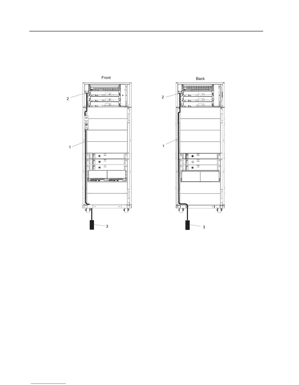
Step 11. Route and Connect Power Cords to the System
The rack system has two power cords, one located on the front and one on the rear of the rack. These
two power cords attach to each of the Bulk Power Assemblies (BPAs) at the front and at the rear of the
rack. The power cords are routed as shown in the following illustration.
The following illustration shows the power cord routing in the rack.
1 Power Cord
2 Cord Connection at BPA
3 Electrical Power Source Connection
Notes:
1. The front power cord is routed at the bottom of the rack to the rear of the rack, through the cable access hole in
the rack bottom extender, through the cutout in the floor tile, and connected to the electrical source.
2. The rear power cord is routed to the bottom of the rack, through the cable access hole in the rack bottom
extender, through the cutout in the floor tile, and connected to the electrical source.
16 Eserver pSeries 655 Installation Guide
Page 33

To route and connect the power cords, do the following:
1. Loosen or remove the cable retainers and filler plate located along the side and bottom of the frame.
To identify the use of the brackets, filler plates, and cable ties for the rack, refer to the following table.
Description Recommended Usage
Cable Retention Bracket Use in the base of the frame to retain cables leaving the frame. This
bracket is used for large diameter cables.
Cable Retention Bracket Use in the base of the frame to retain the cables leaving the frame. This
bracket is used for medium diameter cables.
Cable Retention Bracket Use in the base of the frame to retain the cables leaving the frame. This
bracket is used for small diameter cables.
Filler Plate (thin) Use in the base of the frame to cover the openings. Install in the base of
the frame after all of the cable retention brackets are installed.
Filler Plate (wide) Use in the base of the frame to cover openings. Install in the base of the
frame after all of the cable retention brackets are installed.
Soft Cable Ties (roll) Use to organize the cables leaving the frame.
2. On the front of the frame, loosen the screw on the brackets in the cable track on the left side only.
Remove the UEPO switch.
3. Remove the toolbox from the bottom of the frame.
4. Route the front power cord to the bottom of the rack, to the rear of the rack, through the cable access
hole in the rack bottom extender, through the cutout in the floor tile, and connect it to the electrical
source.
For more information about floor cutouts, refer to the Site and Hardware Planning Information.
Note:
5. Route the rear power cord to the bottom of the rack, through the cable access hole in the rack bottom
extender, through the cutout in the floor tile, and connected to the electrical source.
6. Route and secure the power cords in the frame channel, with the brackets from top to bottom.
7. Connect the plugs for the cords to the BPA.
8. Ensure that the dots are aligned on the cord plug and receptacle.
9. Replace the UEPO switch on the front of the frame.
10. Replace the toolbox in the bottom of the frame.
Step 12. Install the Hardware Management Console (HMC)
The Hardware Management Console (HMC) user interface provides the functions needed to control power
to the subsystems, manage the frame resources, and create and maintain multiple-partitioned
environments in the processor subsystems in the rack.
To install the HMC, follow the instructions described in IBM Hardware Management Console for pSeries
Installation and Operations Guide.
Connect the HMC to the System
1. Connect the RS422 serial cables from the 8-port asynchronous adapter connector box to the A side
and B side of the Bulk Power Controller (BPC). Refer to the following table for cable names and
connections.
Cable Name 8-Port Connector Box BPC Side and Connector
BPC A Serial Port 0 BPC A (J00B) for primary HMC
BPC B Serial Port 1 BPC B (J00A) for primary HMC
BPC A (J00A) for secondary (optional) HMC
BPC B (J00B) for secondary (optional) HMC
Chapter 2. Installing the pSeries 655 17
Page 34

Notes:
a. Two ports on the 8-port asynchronous adapter must be configured as RS422 ports and connected
to the BPCs in the rack. To configure these two ports as RS422 ports, refer to the IBM Hardware
Management Console for pSeries Installation and Operations Guide. Any remaining ports on the
8-port asynchronous adapter can used as RS232 connections to HMC ports on managed
processor subsystems.
b. The cable from the HMC should be plugged into connector J00B on the BPC. (If the cable is found
to be plugged into J00A it should be moved to J00B.) If a High Performance Switch is installed in
or connected to the system, the cable from the HMC must be connected to J00B or the HPS will
not operate correctly.
Connect the HMC serial cable to serial port HMC1 on the rear of the processor subsystem. For two
2.
HMCs, connect the redundant HMC into serial port HMC2 on the processor subsystem.
The use of the second serial port on the HMC is not recommended because this port defaults to be
used for the modem.
3. If you are connecting cables from the HMC to processor subsystems in the rack in more complicated
configurations, refer to “System Cabling” on page 22 to determine cable connections and routing.
If you are connecting HMC(s) to the system using an 8-port asynchronous adapter, go to “Install and
Configure an 8-Port Asynchronous Adapter” on page 24.
If you are connecting HMC(s) to the system using an 128-port asynchronous adapter, go to “Install and
Configure an 128-Port Asynchronous Adapter” on page 25.
The following illustration shows:
Note:
v A simplified configuration connecting a primary and secondary (optional) HMC to a processor
subsystem
v The location of the serial ports on the rear of the HMCs and the HMC connectors located on
the processor subsystem
v The connection of the 8-port adapters to the HMCs
v The connection of the 8-port adapters to the BPC (side A and side B) with an RS422 cable
18 Eserver pSeries 655 Installation Guide
Page 35

3
7
1
6
9
5
8
70
RS 422
to BPC A
to BPC B
2
3
4
7
8
0
RS 422
to BPC A
to BPC B
9
5
1 pSeries 655 Processor Subsystem (rear
6 HMC Connector 2 (connection for secondary HMC)
view of connection on one processor
subsystem)
2 HMC Connector 1 (connection for primary
7 Secondary HMC (optional)
HMC)
3 Power Plug to External Power Source
8 8-Port Asynchronous Adapter
(wall plug)
4 Primary HMC 9 Serial Port Reserved for Modem
5 Serial Port on HMC
If you are connecting only the primary HMC to the processor subsystem, connect only the cables for
the primary HMC as shown in the illustration.
Chapter 2. Installing the pSeries 655 19
Page 36

Connecting to a 128-Port Serial Adapter
The HMC, when shipped with a pSeries 655 frame, comes installed with a 128-port serial adapter. Use
converter RS232 to RS422 (part of feature code 8122 and 8123) when cabling the HMC to the BPC. Use
the following cable diagram as a reference, when cabling a system using the RS232 to RS422 converter.
HMC
128-Port
Adapter
RS232
RS232
RAN
RS232
16-Port
RS232
RS232
RS232
RS232
Converter
Converter
To System CEC
To System CEC
To System CEC
To System CEC
RS422
RS422
BPC A Side
BPC B Side
To configure a 128-port adapter enter the following: Go to the System Configuration menu and do the
following:
1. Open Configure Serial Adapter and enter 1 to select Configure Serial Adapter(s).
Notes:
a. All serial adapters in the system must be configured at the same time. When adding additional
adapters, the original adapters must also be reconfigured. If you do not reconfigure the original
adapters, its original definition will be lost.
b. This step configures the serial adapters. The ports used for RS-422 service on 8-port adapters will
get configured later. Ports on the 128-port adapters do not need to be configured for RS-422
service.
2. When prompted for the number of boards to install, enter the total number of 8-port and 128-port
adapters in the system.
3. When prompted for the board type, enter 16 (128-Port async PCI)
4. c. When prompted for the number of ports on the digiBoard, you will be presented with a list of
possible values.
a. Count the total number of Enhanced RANs you are attaching to the 128-Port async adapter and
multiply by 2.
b. Enter the selection number associated with the actual number of ports on the enhanced RANs.
When prompted to set Altpin, enter n (for no).
5.
6. If two 128-port adapters are installed, the utility repeats the question sequence. Use the listed answers
for each adapter.
Configuring
a 16-Port Ran: With 128-port adapters you also need to configure the RANs by entering the
following:
1. When prompted for the number of C/X cards, enter the total number of 128-port adapters installed in
the HMC.
2. When prompted for the number of C/CONs (RANs) connected to card 1 - line 1, enter the total number
of RANs on line 1.
3. When prompted for the wiring scheme used for card 1 - line 1, enter A
4. When prompted for the type of communication mode to use on line 1, enter 14
20 Eserver pSeries 655 Installation Guide
Page 37

5. When prompted for the number of ports supported on the C/CON (RAN), enter 16
6. When prompted for the number of C/CONs (RANs) connected to card 1 - line 2, enter the total number
of RANs on line 2.
7. Reboot the HMC to load the adapter device drivers.
Chapter 2. Installing the pSeries 655 21
Page 38

System Cabling
The following illustration shows the cabling of HMCs to the BPCs, 8-port connector boxes, and 16-port
RANs.
1
2
3
5
4
7
0
to BPC A
RS422
to BPC B
BPC
J00A
J00B
Power
(UPIC)
Ports
To DCAs
BPRs
RS232
6
To Processor
Subsystems
5
6
RS232
BPC
J00A
J00B
To Processor
Subsystems
Power
(UPIC)
Ports
To DCAs
BPRs
7
4
to BPC B
7
0
RS422
to BPC A
3
1 HMC 1 5 Bulk Power Assembly
2
2 128-Port Asynchronous Adapter 6 16-Port RAN
3 8-Port Asynchronous Adapter 7 HMC 2
4 8-Port Connector Box
The following illustration shows a comprehensive cable layout for a fully configured rack.
22 Eserver pSeries 655 Installation Guide
Page 39

HMC
8-Port
Adapter
128-Port
Adapter
Ethernet
Adapter
HMC
8-Port
Adapter
128-Port
Adapter
Ethernet
Adapter
8-Port Expansion Port
Outputs set to RS422
RS422 Cables
8-port
Exp
8-port
Exp
RS422 Cables
16-Port
RS232
RAN
16-Port
RS232
RAN
Bulk Power
Assembly
BPC
BPRs
Bulk Power
Assembly
BPC
BPRs
RS232 Cables
RS232 Cables
UPIC
Ports
UPIC
Ports
Processor Subsystem
DCA
SPCN
CSP
Processor Subsystem
DCA
SPCN
CSP
I/O Subsystem
DCA
DCA
AMD
Serial
AMD
Serial
Integrated Enet
Integrated Enet
AMD
Power
Switch
AMD
I/O Planar
Power
Switch
RIO
PCI Slots
RIO
PCI Slots
RIO
PCI Slots
RIO
PCI Slots
System Rack
Processor Subsystem
DCA
SPCN
CSP
AMD
Serial
Integrated Enet
RIO
PCI Slots
I/O Subsystem
DCA
AMD
I/O Planar
DCA
Power
Switch
AMD
RIO
PCI Slots
I/O Planar
Processor Subsystem
DCA
SPCN
CSP
AMD
Serial
Power
Switch
RIO
PCI Slots
RIO
Integrated Enet
PCI Slots
Up to 16 Processor Subsystems in one Rack
Processor Subsystem
DCA
SPCN
CSP
AMD
Serial
Integrated Enet
RIO
PCI Slots
Chapter 2. Installing the pSeries 655 23
Page 40

Install and Configure an 8-Port Asynchronous Adapter
To install and configure an 8-port asynchronous adapter, refer to the IBM Hardware Management Console
for pSeries Installation and Operations Guide.
To connect the cables from the processor subsystem to the 8-port asynchronous adapter, use the following
procedure.
Connect the Processor Subsystem to the 8-Port Asynchronous Adapter
At least one 8-port asynchronous adapter is required. Up to two 8-port asynchronous adapters can be
installed. The D-shell connector on the rear of the adapter attaches to the 8-port expansion cable. The
cable is approximately 0.9 m (3 ft.), and on the other end, has a slim box (21.6 cm (8-1/2 in.) x 7.6 cm (3
in.) x 3.8 cm (1-1/2 in.)) with 8 separate serial port connectors on it. The cable is labeled ISA 8-Port Cable.
Serial cables can be connected from any of the ports on the 8-port expansion cable to the HMC ports on
the managed systems.
If you are using a second, redundant HMC, connect cables from all of the processor subsystem’s HMC1
ports to the 8-port cable on one HMC, and connect all the processor subsystem’s HMC2 ports to the
8-port cable on the other HMC.
HMC to Processor Subsystem Cabling
The following illustration shows cabling for both the 8-port asynchronous adapter and 128-port
asynchronous adapter to the HMC and the processor subsystems. The top portion of the illustration shows
the 8-port adapter and the RS422 cable to support up to four system frames. For smaller system
configurations, the 8-port asynchronous adapter can be used for RS232 connections.
The bottom portion of the illustration shows the 128-port adapter and the RS232 cables to support up to
64 processor subsystems.
RS422 port pairs support up
to four frames
BPCs have 9-pin micro D-shell connectors
HMC
8-Port
Adapter
Port 1
Port 2
Connector matching
interposers
128-Port
Adapter
T
RS232 RAN (Remote Asynchronous Node)
- RS232 ports to support up to 64 Processor Subsystems
- Processor Subsystems have 9-pin D-shell female connectors
24 Eserver pSeries 655 Installation Guide
Page 41

Details for the RS232 cables are shown in the following illustration.
Standard 9-pin D-shell female to 9-pin D-shell male cable
To RAN unit
RJ 45
connector
on RAN
9-pin D-shell male connector
25-pin D-shell female connector
25-pin D-shell male connector
Not required for 8-port asynchronous adapter
RS232 Cable
9-pin D-shell connector
To HMC port on
Processor Subsystem
Details for the RS422 cables are shown in the following illustration.
Part number 44P2237 for 7.5 meters
Part number 44P2238 for 6.0 meters
25-pin D-shell female
connector
RS422 Cable
To BPC
9-pin mini-D-shell male
connector
Configure Ports on the 8-Port Asynchronous Adapter
The default configuration for ports on the 8-port asynchronous adapter is for RS232 ports. To use RS422
cables on the adapter, the adapter must be configured to accommodate them. For configuration
instructions, refer to the IBM Hardware Management Console for pSeries Installation and Operations
Guide.
Install and Configure an 128-Port Asynchronous Adapter
The 128-port asynchronous adapter is an option for the HMC. It must be configured by the service
representative when the HMC is installed. The 128-port asynchronous adapter software is installed in the
HMC base software-installation package.
This adapter provides the control function and connectors to attach eight 16-port remote asynchronous
nodes (RANs). When all eight RANs are attached, this combination provides 128 RS232 or RS422
communication ports.
Refer to the illustrations shown in “HMC to Processor Subsystem Cabling” on page 24 for cable
information. The bottom portion of the illustration shows the 128-port adapter and the RS232 cable pairs to
support up to 64 processors. There are 16 RS232 ports per RAN unit. Up to four RAN units can be
daisy-chained on one 128-port asynchronous adapter. The RAN unit has Ethernet (RJ45) connectors that
connect to the 25-pin D-shell male connector on the RS232 cable.
To install and configure the 128-port asynchronous adapter, refer to the IBM Hardware Management
Console for pSeries Maintenance Guide. Installation of the adapter requires:
v Connecting cables
v Setting the RAN node number
v Configuring the adapter
v Updating the device driver
Chapter 2. Installing the pSeries 655 25
Page 42

Connect an Additional 128-Port Asynchronous Adapter
An additional optional 128-port asynchronous adapter can be installed. The D-shell connectors on the rear
of the adapter attach to RANs. Serial cables can be connected from any of the ports on a RAN to the
HMC1 ports on the managed systems.
If you are using a second, redundant HMC, connect cables from all the processor subsystem HMC1 ports
to the RAN on one HMC, and connect all the processor subsystem HMC2 ports to the RANs on the other
HMC.
To install and configure an additional 128-port asynchronous adapter, refer to the IBM Hardware
Management Console for pSeries Maintenance Guide.
Step 13. Connect the External Modem
The external modem is used in conjunction with the HMC’s Service Agent and Call Home features. To
install the external modem, refer to the IBM Hardware Management Console for pSeries Installation and
Operations Guide.
Step 14. Connect the Ethernet LAN Cable
DANGER
During
station protectors for communications lines.
D12
an electrical storm, do not connect cables for display stations, printers, telephones, or
The customer is responsible for providing the Ethernet LAN cable. The Ethernet LAN cable is required
because each active partition reports errors to the HMC’s Service Focal Point application through the LAN
network. To connect the LAN cable, refer to the IBM Hardware Management Console for pSeries
Installation and Operations Guide.
Step 15. Connect the High Power Switch Cables
See Appendix H, “LAN and Switch Cable Installation and Management Procedures,” on page 161.
Step 16. Connect the Power Cords
1. Connect the HMC power cord into the power receptacle on the rear of the HMC.
2. Plug the power cords for the display, HMC, and modem (if applicable) into electrical outlets.
3. Plug in the power cords from the rack to the electrical power source.
Step 17. Turn on the IBF Breaker (If Present)
Turn on the Integrated Battery Feature (IBF) breaker.
26 Eserver pSeries 655 Installation Guide
Page 43

Step 18. Have the Customer Activate the Designated Circuit Breakers
Have the customer activate the designated circuit breakers by doing the following:
1. Ensure that the tag S229-0237, which reads “Do Not Operate,” has been removed.
2. Reset the circuit breaker.
The following steps should be performed only by the service representative.
Note:
3. Turn the UEPO switch to the ON position.
4. Verify that the LEDs on the bulk power enclosure are on. The labels on the LEDs are as follows:
v BPC - good
v BPD - good
v Power
v Complete
v Standby (flashes, then lights on solid)
v BPR enabled
v Power-in on processor subsystem(s)
Step 19. Power on the HMC
Attention: Ensure that all subsystems are correctly installed and cabled before performing this step.
To power on the HMC, refer to the IBM Hardware Management Console for pSeries Installation and
Operations Guide for instructions. Ensure that the I/O subsystems are correctly installed and cabled before
performing this step.
At HMC power on, the HMC performs an initialization to determine a frame’s managed systems and
resources.
Note: If either an 8-port or 128-port asynchronous adapter is installed, the adapters must be configured
before the HMC can inventory the managed systems. See “Configure Ports on the 8-Port
Asynchronous Adapter” on page 25 and “Install and Configure an 128-Port Asynchronous Adapter”
on page 25.
The rack (frame) may contain combinations of processor subsystems, I/O subsystems, and IBFs. For
details of this initialization, refer to ″Initializing a Frame’s Managed Systems and Resources″ in the IBM
Hardware Management Console for pSeries Installation and Operations Guide.
Step 20. Verify HMC Code Level
The customer is responsible for verifying that the required code level is installed on the HMC. To verify the
HMC code level, refer to the IBM Hardware Management Console for pSeries Installation and Operations
Guide for instructions.
1. Select Help on the HMC interface.
2. Select About Hardware Management Console. The code level installed on the HMC is displayed.
The code level must be Release 3.1.2 or later.
Note:
3. If the code level is not Release 3.1.2 or later, the customer should call their service representative for
instructions on how to obtain the required code level.
Chapter 2. Installing the pSeries 655 27
Page 44

Step 21. Set the Console’s Date and Time
At the initial installation of the HMC, the date and time must be set on the HMC. Instructions for setting the
date and time are contained in the IBM Hardware Management Console for pSeries Installation and
Operations Guide.
The battery-operated clock keeps the date and time for the HMC. Yo u may also need to set the console
date and time under the following circumstances:
v If the battery is replaced in the HMC
v If your system is physically moved to a different time zone
Step 22. Verify Installation is Complete Using the HMC Interface
Use the HMC basic system management tasks to verify that the installation is successful and complete.
The tasks may be used to power the system on or off, view managed systems properties, and other
functions. For detailed procedures on using the basic management tasks, refer to the IBM Hardware
Management Console for pSeries Installation and Operations Guide.
Step 23. Determine Firmware and Microcode Levels
Ensure that the latest firmware and microcode levels are installed on the system. The following firmware
and microcode should be brought to the latest level:
v System firmware
v Frame (power subsystem) firmware
v Integrated SCSI controller microcode
v Integrated Ethernet microcode
The integrated SCSI controller and integrated Ethernet microcode can only be verified after the
Note:
operating system is installed.
To determine the current level of firmware and microcode, and how to perform updates, go to Processor
Subsystem Firmware Updates in the Eserver pSeries 655 User’s Guide.
Step 24. Installing the Operating System
If an operating system has been preinstalled on your system, see the documentation provided with the
operating system.
If you are installing the AIX operating system at this time, AIX can be installed from a Network Installation
Management (NIM) server. For information about installing AIX from a NIM server, see the AIX Installation
Guide and Reference.
When installation of AIX is completed, return to this step.
Step 25. Verify Basic Hardware and Operating System Operation
Verify the basic hardware and operating system operation by running the online diagnostics in the service
mode as described in “Running Online Diagnostics in Service Mode” on page 34.
Step 26. Install the Rack Doors
This step describes how to install the doors on the system rack. For more information about the doors, see
“Step 2. Check the Prerequisites to Installing the System” on page 8.
28 Eserver pSeries 655 Installation Guide
Page 45

Install the Rack Front Door
To install the rack front door, refer to the illustration on page 29, and do the following:
Note: After installing the front and rear doors, it may be necessary to adjust the latch.
1. Position the door so that both the top and the bottom hinge pins partially engage the hinges.
2. Simultaneously slide the top and bottom hinge pins (1) on the front door into the top and bottom
hinges (2) on the rack.
3. Close the front door, and engage the latch on the left side of the door.
Install the Rack Rear Door
Note: There is no frame extender on the front of system rack. The rear of the rack has 4-inch deep
extenders at the top, bottom, left, and right.
To install the rack rear door, refer to the illustration on page 29, and do the following:
1. Position the door so that both the top and the bottom hinge pins partially engage the hinges.
2. Simultaneously slide the top and bottom hinge pins (1) on the rear door into the top and bottom hinges
(2) on the rack.
3. Close the rear door, and engage the latch on the left side of the door.
1 Hinge Pin (Typical Front and Rear Door) 3 Front Door
2 Rack Hinge (Typical Front and Rear Door) 4 Rear Door
Chapter 2. Installing the pSeries 655 29
Page 46

Step 27. Perform HMC Setup Tasks
Perform the following setup tasks on the HMC:
1. Configure the network for the HMC
2. Configure the Service Agent
3. Register the processor subsystems
To perform the setup tasks, refer to the IBM Hardware Management Console for pSeries Installation and
Operations Guide.
After the customer customizes the operating system and other software on the system, configure the
Service Focal Point application. Refer to the IBM Hardware Management Console for pSeries Installation
and Operations Guide for the procedures to configure the Service Focal Point application.
Step 28. Complete System Records and Installation Procedure
Update the “System Records” in Appendix E, “System Records,” on page 131 to reflect the configuration of
the system adapters and devices that are installed. After completing the records, deliver this book to the
system administrator.
Step 29. Return System Packing Materials
For instructions on returning the shipping crates, refer to the crate-unpacking instructions shipped with the
Model 651.
30 Eserver pSeries 655 Installation Guide
Page 47

Chapter 3. Verifying the Hardware Operations
Running diagnostics verifies system hardware operation. The diagnostics consist of online diagnostics and
standalone diagnostics.
The diagnostic procedures described in this chapter must be run for each processor subsystem
Note:
installed in a rack.
Attention: The AIX operating system must be installed in a partition in order to run online diagnostics on
that partition. If the AIX operating system is not installed, use the standalone diagnostic procedures.
Online diagnostics, when they are installed, reside with AIX in the file system. They can be booted:
v In single user mode (referred to as service mode)
v To run in maintenance mode (referred to as maintenance mode)
v To run concurrently with other applications (referred to as concurrent mode)
Standalone
diagnostics must be booted before they can be run. If booted, the diagnostics have no access
to the AIX error log or the AIX configuration data.
Online and Standalone Diagnostics Operating Considerations
Note: When possible, run online diagnostics in service mode. Online diagnostics perform additional
functions compared to standalone diagnostics. Running online diagnostics in service mode ensures
that the error state of the system that has been captured in NVRAM is available for your use in
analyzing the problem. The AIX error log and certain SMIT functions are only available when
diagnostics are run from the disk drive.
Consider the following items before using the diagnostics:
v Standalone diagnostics can run on systems configured for either a full (or single) system partition or a
multiple partitioned system. When running in a partitioned system, the device from which you are
booting standalone diagnostics must be made available to the partition dedicated to running standalone
diagnostics. This may require moving the device from the partition that currently contains the boot
device (for example, the network adapter connected to the Network Installation Management (NIM)
server that has a standalone diagnostic image) to the partition used to run standalone diagnostics. If
you move devices, reboot both partitions. For more information, see “Standalone Diagnostic Operation”
on page 35.
v When diagnostics are installed, the device support for some devices might not get installed. If this is the
case, that device does not display in the diagnostic test list when running disk-based diagnostics.
v When running diagnostics in a partitioned system, diagnostics function only with the resources that were
assigned to that partition. You must run diagnostics in the partition containing the resource that you
want to test.
Identifying the Terminal Type to the Diagnostics
When you run diagnostics, you must identify which type of terminal you are using. If the terminal type is
not known when the FUNCTION SELECTION menu is displayed, the diagnostics do not allow you to
continue until a terminal is selected from the DEFINE TERMINAL option menu. Choose the ″vt320″
selection when running diagnostics from an HMC.
31
Page 48

Undefined Terminal Types
If you specify an undefined terminal type from the DEFINE TERMINAL option menu, the menu prompts the
user to enter a valid terminal type. The menu redisplays until either a valid type is entered or you exit the
DEFINE TERMINAL option.
Resetting the Terminal
If you enter a terminal type that is valid (according to the DEFINE TERMINAL option menu) but is not the
correct type for the HMC virtual terminal window being used, you may be unable to read the screen, use
the function keys, or use the Enter key. Bypass these difficulties by pressing Ctrl-C to reset the terminal.
The screen display that results from this reset depends on the mode in which the system is being run:
v Online Normal or Maintenance Mode - The command prompt displays.
v Standalone Mode or Online Service Mode - The terminal type is reset to dumb, the Diagnostic Operating
Instruction panel displays, and you are required to go through the DEFINE TERMINAL process again.
Running Online Diagnostics
Consider the following when you run the online diagnostics from a server or a disk:
v The diagnostics cannot be loaded and run from a disk until the AIX operating system has been installed
and configured.
v The diagnostics cannot be loaded on a system (client) from a server if that system is not set up to boot
from a server over a network. When the system is set up to boot from a server, the diagnostics are run
in the same manner as they are from disk.
v On full system partitions, if the diagnostics are loaded from disk or a server, you must shut down the
AIX operating system before turning off the system unit to prevent possible damage to disk data. Do
this in either of the following ways:
– If the diagnostics were loaded in standalone mode, press the F3 key until DIAGNOSTIC OPERATING
INSTRUCTIONS displays. Then press the F3 key once again to shut down the AIX operating system.
– If the diagnostics were loaded in maintenance or concurrent mode, type the shutdown -F command.
Under some conditions, the system might stop, with instructions displayed on attached displays and
v
terminals. Follow the instructions to select a console display.
Online Diagnostics Modes of Operation
Note: When running online diagnostics on a partition in a partitioned system, diagnostics can be run only
on resources that are allocated to that partition.
The online diagnostics can be run in the following modes:
v Service Mode (see “Service Mode”). Refer to “Running Online Diagnostics in Service Mode” on page 34
for instructions on how to run the diagnostics in service mode.
v Concurrent Mode (see “Concurrent Mode” on page 33). Refer to “Running the Online Diagnostics in
Concurrent Mode” on page 34 for instructions on how to run the diagnostics in service mode.
v Maintenance Mode (see “Maintenance Mode” on page 33). Refer to “Running the Online Diagnostics in
Maintenance Mode” on page 34 for instructions on how to run the diagnostics in service mode.
Service Mode
Service mode provides the most complete checkout of the system resources. This mode also requires that
no other programs be running on the partition or system on a full system partition. All partitions or system
on a full system partition resources, except the SCSI adapter and the disk drives used for paging, can be
tested. However, note that the memory and processor are only tested during POST, and the results of the
POST tests are reported by diagnostics.
32 Eserver pSeries 655 Installation Guide
Page 49

Error-log analysis is done in service mode when you select the Problem Determination option on the
DIAGNOSTIC MODE SELECTION menu.
Concurrent Mode
Use concurrent mode to run online diagnostics on some of the system resources while the system is
running normal activity.
Because the system is running in normal operation, the following resources cannot be tested in concurrent
mode:
v SCSI adapters connected to paging devices
v Disk drive used for paging
v Some display adapters and graphics related devices
v Memory (tested during POST)
v Processor (tested during POST)
The following levels of testing exist in concurrent mode:
v The share-test level tests a resource while the resource is being shared by programs running in the
normal operation. This testing is mostly limited to normal commands that test for the presence of a
device or adapter.
v The sub-test level tests a portion of a resource while the remaining part of the resource is being used
in normal operation. For example, this test could test one port of a multiport device while the other ports
are being used in normal operation.
v The full-test level requires the device not be assigned to or used by any other operation. This level of
testing on a disk drive might require the use of the varyoff command. The diagnostics display menus to
allow you to vary off the needed resource.
Error-log
analysis is done in concurrent mode when you select the Problem Determination option on the
DIAGNOSTIC MODE SELECTION menu.
To run the online diagnostics in concurrent mode, you must be logged in to the AIX operating system and
have proper authority to issue the commands (if help is needed, see the system operator).
The diag command loads the diagnostic controller and displays the online diagnostic menus.
Maintenance Mode
Maintenance mode runs the online diagnostics using the customer’s version of the AIX operating system.
This mode requires that all activity on the partition running the AIX operating system be stopped so that
the online diagnostics have most of the resources available to check. All of the system resources, except
the SCSI adapters, memory, processor, and the disk drive used for paging, can be checked.
Error log analysis is done in maintenance mode when you select the Problem Determination option on
the DIAGNOSTIC MODE SELECTION menu.
Use the shutdown -m command to stop all activity on the AIX operating system and put the AIX operating
system into maintenance mode. The diag command is then used to invoke the diagnostic controller so you
can run the diagnostics. After the diagnostic controller is loaded, follow the normal diagnostic instructions.
Documentation for the AIX operating system is available from the IBM Eserver pSeries Information
Center at http://publib16.boulder.ibm.com/pseries/index.htm. Select AIX documentation. The AIX
Documentation CD contains the base set of publications for the operating system, including
system-management and end-user documentation.
Chapter 3. Verifying the Hardware Operations 33
Page 50

Running Online Diagnostics in Service Mode
To run the online diagnostics in service mode from the boot hard disk, do the following:
1. From the HMC, select the Partition Manager.
2. Right-click on the mouse and select Open Terminal Window.
3. From the Service Processor Menu on the VTERM, select Option 2 System Power Control.
4. Select option 6. Verify that the state changes to currently disabled. Disabling fast system boot
automatically enables slow boot.
5. Select Option 98 to exit the system power control menu.
6. Use the HMC to power on the managed system in a full system partition by selecting the managed
system in the Contents area.
7. Right-click or select the desired system in the Contents area. Next, on the menu, choose Selected.
8. Select Power On.
9. Select the Power on Diagnostic Stored Boot list option (refer to “Full System Management Tasks”
in the IBM Hardware Management Console for pSeries Installation and Operations Guide, for more
information on full system partitions).
10. Enter any passwords, if requested.
Note: If you are unable to load the diagnostics to the point when the DIAGNOSTIC OPERATING
INSTRUCTIONS display, go to “Running Standalone Diagnostics from a Network Installation
Management (NIM) Server” on page 35.
11. Complete the installation by going to “Step 26. Install the Rack Doors” on page 28.
Running the Online Diagnostics in Concurrent Mode
To run online diagnostics in concurrent mode, do the following:
1. Log in to the AIX operating system as root user or use CE Login.
2. Enter the diag command.
3. When the DIAGNOSTIC OPERATING INSTRUCTIONS display, follow the instructions to check out the
desired resources.
4. When testing is complete, use the F3 key to return to the DIAGNOSTIC OPERATING
INSTRUCTIONS. Press the F3 key again to return to the AIX operating system prompt. Be sure to
vary on any resource that you had varied to off.
5. Press Ctrl-D to log off from root user or CE Login.
6. Complete the installation by going to “Step 26. Install the Rack Doors” on page 28.
Running the Online Diagnostics in Maintenance Mode
To run the online diagnostics in maintenance mode, do the following:
1. Stop all programs running on the partition except the AIX operating system (if help is needed, see the
system operator).
2. Log in to the AIX operating system as root user or use CE Login.
3. Type the shutdown -m command.
4. When a message indicates the system is in maintenance mode, enter the diag command.
Note: It might be necessary to set TERM type again.
5. When DIAGNOSTIC OPERATING INSTRUCTIONS screen displays, follow the displayed instructions
to check out the desired resources.
6. When testing is complete, use the F3 key to return to DIAGNOSTIC OPERATING INSTRUCTIONS.
Press the F3 key again to return to the AIX operating system prompt.
34 Eserver pSeries 655 Installation Guide
Page 51

7. Press Ctrl-D to log off from root user or CE Login.
8. Complete the installation by going to “Step 26. Install the Rack Doors” on page 28.
Standalone Diagnostic Operation
Use standalone diagnostics to test the system when the online diagnostics are not installed and as a
method of testing the disk drives that cannot be tested by the online diagnostics.
Note: No error log analysis is done by the standalone diagnostics. The standalone diagnostics:
v Are resident on a Network Installation Management (NIM) server
v Provide a method to test the system when the online diagnostics are not installed or cannot be
loaded from the disk drive
v Allow testing of the disk drives and other resources that cannot be tested by the online
diagnostics
v Do not have access to the AIX configuration data
v Do not have access to the AIX error log
v Do not allow for running of error log analysis
Perform Slow Boot
To fully analyze all of the available information, perform the following steps before doing a hardware repair
or replacement:
1. Record the 8-character error code (and location code if present) displayed as the operator panel value
displayed on the HMC or that was reported by the customer.
2. Do a slow boot in service mode. This boot can be specified using the System Power Control Menu on
the Service Processor Main Menu. (A fast boot skips much of the built-in diagnostic testing.) A slow
boot may yield a new 8-character error code displayed as an operator panel value on the HMC and
new errors in the service processor error log. If a new error code is reported, use this code to continue
problem analysis. See “Running Online Diagnostics in Service Mode” on page 34.
Partitioned System Considerations for Standalone Diagnostics
To run standalone diagnostics on a full system partition, you must reboot the entire system. However, for a
partition in a partitioned system, you can boot standalone diagnostics either in a given partition or on the
entire system (which is the same procedure as a full system partition). For a partitioned system, before
running standalone diagnostics on a given partition, the user must move the device from the existing
location where standalone diagnostics is booted (the network adapter connected to the NIM server, in the
case of NIM boot of standalone diagnostics), to the partition that will run standalone diagnostics. Devices
in a partitioned system are moved on an I/O-slot basis.
Running Standalone Diagnostics from a Network Installation
Management (NIM) Server
A client system connected to a network with a NIM server can boot standalone diagnostics from the NIM
server if the client-specific settings on both the NIM server and client are correct.
Notes:
1. All operations to configure the NIM server require root user authority.
2. If you replace the network adapter in the client, the network adapter hardware address settings for the
client must be updated on the NIM server.
3. The Cstate for each standalone diagnostics client on the NIM server should be kept in the diagnostic
boot has been enabled state.
4. On the client partition, the NIM server network adapter can be put in the bootlist after the boot disk
drive. This allows the system to boot in standalone diagnostics from the NIM server if there is a
Chapter 3. Verifying the Hardware Operations 35
Page 52

problem booting from the disk drive. Another option is to use the Select Boot Options function in the
SMS menu to set up the network adapter that is connected to the NIM server for a one-time boot of
standalone diagnostics.
NIM Server Configuration
Refer to the “Advanced NIM Configuration Tasks” chapter of the AIX Installation Guide and Reference, for
information on doing the following:
v Registering a client on the NIM server
v Enabling a client to run diagnostics from the NIM server
verify that the client system is registered on the NIM server and the diagnostic boot is enabled, run the
To
command lsnim -a Cstate -Z ClientName from the command line on the NIM server. Refer to the
following table for system responses.
Note: The ClientName is the name of the system on which you want to run standalone diagnostics.
System Response Client Status
#name:Cstate:
ClientName:diagnostic
boot has been
enabled:
#name:Cstate:
ClientName:ready for a NIM operation:
or
#name:Cstate:
ClientName:BOS
installation has been
enabled:
0042-053 lsnim: there is no NIM object
named
"ClientName"
The client system is registered on the NIM server and
enabled to run diagnostics from the NIM server.
The client is registered on the NIM server but not enabled
to run diagnostics from the NIM server.
Note: If the client system is registered on the NIM server
but Cstate has not been set, no data will be returned.
The client is not registered on the NIM server.
Client Configuration and Booting Standalone Diagnostics from the NIM
Server
To run standalone diagnostics on a client from the NIM server, do the following:
1. Stop all programs including the AIX operating system (get help if needed).
2. If you are running standalone diagnostics in a full system partition, verify with the system administrator
and system users that the system unit can be shut down. Stop all programs, including the AIX
operating system. Refer to the AIX operating system documentation for shutdown command
information.
Verify with the system administrator and system users using that partition that all applications on that
partition must be stopped, and that the partition will be rebooted. Stop all programs on that partition,
including the operating system.
3. If you are in a full system partition, power on the system unit to run standalone diagnostics. In a
partitioned system, reboot the partition to run standalone diagnostics.
4. When the keyboard indicator is displayed (the word keyboard on an HMC virtual terminal window),
press the number 1 key on the keyboard to display the SMS menu.
5. Enter any requested passwords.
6. Select Setup Remote IPL (Initial Program Load).
7. Enter the client address, server address, gateway address (if applicable), and subnet mask.
8. If the NIM server is set up to allow pinging from the client system, use the ping utility in the RIPL utility
to verify that the client system can ping the NIM server. Under the ping utility, choose the network
adapter that provides the attachment to the NIM server to do the ping operation. If the ping returns
36 Eserver pSeries 655 Installation Guide
Page 53

with an OK prompt, the client is prepared to boot from the NIM server. If ping returns with a FAILED
prompt, the client cannot proceed with the NIM boot.
Note: If the ping fails, refer to the Boot Problems section of the Eserver pSeries 655 Service Guide
and follow the steps for network boot problems.
do a one-time boot of the network adapter attached to the NIM server network, do the following:
To
1. Exit to the SMS Main screen.
2. Select Select Boot Options.
3. Select Install or Boot a Device.
4. On the Select Device Type screen, select Network.
5. Set the network parameters for the adapter from which you want to boot.
6. Exit completely from SMS.
The system starts loading packets while doing a bootp from the network.
Follow the instructions on the screen to select the system console.
v If Diagnostics Operating Instructions Version x.x.x displays, standalone diagnostics have loaded
successfully.
v If the AIX login prompt displays, standalone diagnostics did not load. Check the following items:
– The network parameters on the client may be incorrect.
– Cstate on the NIM server may be incorrect.
– Network problems might be preventing you from connecting to the NIM server.
Verify the settings and the status of the network. If you continue to have problems, refer to the Boot
Problems section of the Eserver pSeries 655 Service Guide, and follow the steps for network boot
problems.
Chapter 3. Verifying the Hardware Operations 37
Page 54

38 Eserver pSeries 655 Installation Guide
Page 55

Chapter 4. Installation and Removal Procedures
This chapter describes how to install and remove processor subsystems, I/O subsystems, integrated
battery feature (IBF), and PCI adapters. If individual subsystems were shipped separately to a customer’s
site to reduce weight, use the procedures contained in this chapter to assemble the system rack with the
subsystems.
The procedures in this chapter can also be used to remove subsystems in order to reduce the weight of
the system so that it can be moved to the installation location at the customer’s site.
Processor Subsystem
Attention: Installing a processor subsystem requires the use of a lift tool. This procedure requires:
v The use of a lift tool (part number 09P2481) and lift-plate assembly tool (part number 11P4369).
v The lift tool wheels must be chocked to prevent it from moving during the operation. The rack must not
be on its casters. The leveling pads must be engaged to prevent the rack from moving during the
operation.
In the process of removing and installing processor subsystems for weight reduction, the outer
Note:
chassis (frame cage) is always left in place in the rack.
This section describes how to install and remove a processor subsystem.
Powering the System On
The Hardware Management Console is used to turn the power on to the processor subsystems through
the HMC user interface. For a detailed procedure, see ″Basic System Management Tasks″, located in the
IBM Hardware Management Console for pSeries Installation and Operations Guide.
Processor subsystems can be powered on after all of the following steps have been completed:
v All I/O drawer cables are connected
v Base system cables are connected (cables for rack power, bulk power subsystem, integrated battery
feature)
v All PCI cables to supported subsystems are connected
v The hardware management console (HMC) is connected
v Source power is connected and turned on to the system
The UEPO switch must be switched to on to restore power to the entire rack after performing
Note:
certain service operations. Removing power from an individual processor subsystem with the HMC
does not remove power from other processor subsystems or from the bulk power assembly in the
system rack.
After the required cables are installed, and the power cables are connected, examine the Power-In LED of
the processor subsystem DCA, and the Power-In LEDs of both DCAs of any attached I/O subsystem(s). If
any of the Power-In LEDs of the DCAs are off, for the system that you are trying to power on, push the
white Service Complete button on the UEPO panel. The action should restore power to the input of all
DCAs, and all Power-In LEDs should turn on. The HMC interface provides a power-on function to turn on
the power to the system. Progress indicators, also referred to as checkpoints, are visible on the operator
panel display on the HMC as the system power is turned on.
The base system and I/O subsystems are powered on through the system power control network (SPCN).
When power is applied, the Power-Out LED of the processor subsystem DCA and the Power-Out LEDs of
both DCAs of any attached I/O subsystem(s) turn on and stay on. This action indicates that power levels
are satisfactory in the subsystems.
39
Page 56

If any of the Power-Out LEDs on the subsystem DCAs do not turn on, perform the Initializing a Frame’s
Managed Systems and Resources task as described in ″Basic System Management Tasks″, located in
theIBM Hardware Management Console for pSeries Installation and Operations Guide. This action allows
all of the attached resources to be recognized by the power subsystem.
Powering the System Off
The HMC user interface provides a power-off function to turn off the power to individual processor
subsystem. For information about shutting down and powering off a processor subsystem, see ″Basic
System Management Tasks″, located in the IBM Hardware Management Console for pSeries Installation
and Operations Guide.
Note: Service operations can be performed to individual processor subsystems by powering off individual
processor subsystems mounted in a rack using the HMC. If you are servicing a system and you
need to remove power from the entire rack, follow all shutdown procedures and then switch off the
UEPO switch.
If you are servicing an individual I/O subsystem, refer to the information about deactivating a frame’s I/O
drawers, see ″Basic System Management Tasks″, located in the IBM Hardware Management Console for
pSeries Installation and Operations Guide to remove 350 V power from both of the I/O subsystem DCA
UPIC cable connections. Before deactivating, ensure that you shut down the operating system on all
partitions that are using the resources of the I/O subsystem being serviced.
After deactivating the I/O subsystem, both the Power-In LED and the Power-Out LED on the front of the
I/O subsystem DCAs should be off. If not, call service support.
If you are servicing an individual processor subsystem, refer to the information about deactivating a
managed system’s service processor, see ″Basic System Management Tasks″, located in the IBM
Hardware Management Console for pSeries Installation and Operations Guide to remove 350 V power
from the processor subsystem DCA UPIC cable connections. Before deactivating, ensure that you shut
down the operating system on all partitions that are running on the processor subsystem being serviced.
After deactivating the processor subsystem, both the Power-In LED and the Power-Out LED on the front of
the processor subsystem DCA should be off. If not, do not continue. Call service support.
Attention: If the system is operating in a full system partition under AIX, typing the shutdown command
causes the system to shut down and power off. The -F option shuts down the system without warning
system users. Check with the system administrator before using this command. If you cannot use this
method, you can power off the system by using the HMC.
Using the HMC to power off the system without shutting down AIX can cause unpredictable results in the
data files, and the next IPL will take longer to complete.
Stopping the System with an HMC Attached and AIX Installed
The HMC user interface provides a power-off function to turn off the power to the system. If the system is
logically partitioned, AIX in each partition may be stopped individually to make repairs. If the system power
must be turned off, all of the logical partitions must be stopped. AIX provides hot-swap procedures for
adapters and devices that support hot-swap removal and installation. You do not have to shut down a
partition that controls an adapter or device that supports hot-swap. Individual power components and fans
can be serviced with power on for power systems equipped with redundant power and cooling.
Check the removal and installation procedures before servicing the system. If the system is operating in a
full system partition under AIX, typing the shutdown command causes the system to shut down and
power off. The -F flag shuts down the system without warning system users. Check with the system
administrator before using this command. If you cannot use this method, you can power off the system by
using the appropriate command at the HMC.
40 Eserver pSeries 655 Installation Guide
Page 57

Attention: Using the HMC to power off the system can cause unpredictable results in the data files. The
next IPL will also take longer to complete if all applications in all partitions are not stopped first.
Stopping the System with an HMC Attached and Linux Installed
The HMC user interface provides a power-off function to turn off the power to the system. If the system is
logically partitioned, Linux in each partition may be stopped individually to make repairs. If the system
power must be turned off, all of the logical partitions must be stopped. Linux does not provide hot-swap
procedures for adapter and device removal and installation. Yo u must shut down all partitions, and the
system power must be turned off to service an adapter or device. Individual power components and fans
can be serviced with power on for power systems equipped with redundant power and cooling.
Check the removal and installation procedures before servicing this system. If the system is operating in a
full-system partition under Linux, typing the shutdown now -h command causes the system to shut down
and power off. Check with the system administrator before using this command. If you cannot use this
method, you can power off the system using the HMC.
Attention: Using the HMC to power off the system can cause unpredictable results in the data files. The
next IPL will also take longer to complete if all applications in all partitions are not stopped first.
Powering On the System Using the Service Processor
The system can be powered on using the System Power Control menu, which is a service processor
menu that is available to the privileged user.
Processor Subsystem Installation
CAUTION:
This unit weighs between 32 kg (70.5 pounds) and 55 kg (121.2 pounds). Three persons are
required to safely move it. Using less than three persons to move it can result in injury.
C05
Attention: Installing a processor subsystem requires the use of a lift tool. This procedure requires:
v The use of a lift tool (part number 09P2481) and lift-plate assembly tool (part number 11P4369).
v The lift tool wheels must be chocked to prevent it from moving during the operation. The rack must not
be on its casters. The leveling pads must be engaged to prevent the rack from moving during the
operation.
replace the processor subsystem into the rack, do the following:
To
1. Position the lift tool near the processor subsystem so it can be lifted onto the lift plate.
2. Install the wheel chocks, and engage the brake on the lift tool.
3. Adjust the sliding part of the lift plate so that it can be moved toward the rack when the lift tool is
positioned in front of the rack.
The sliding part of the lift plate can be positioned to move in two directions.
Note:
4. Pull the release buttons on the lift plate and slide the lift-plate tray to the maximum distance.
5. Position the processor subsystem onto the lift plate with the back edge of the processor subsystem at
the edge of the lift plate.
6. Tie the processor subsystem to the lift plate with tie-down straps.
7. At the front of the rack, ensure that the cover on the frame cage is lifted and locked in the open
position.
8. Move the lift tool into position in front of the rack with the edge of the lift plate approximately 17.8 cm
(7 in.) from the front of the rack. See the following illustration.
Chapter 4. Installation and Removal Procedures 41
Page 58

Top View of Lift Plate
with Processor Subsystem Loaded
for Installation into the Frame
1
2
3
Front View of Lift Tool Lift Plate
Holding a Processor Subsystem
1
4
3
4
Top View of Frame
with Processor Subsystem
Pushed into the Frame
1
2
5
1 Processor subsystem 4 Sliding Portion of Lift Plate
2 Back of Lift Tool 5 Frame Cage
3 ″L″-shaped Edge of Lift Plate
Note: The lift-tool extension arms are not attached to the rack for this system.
9. Raise the lift plate to the frame cage in which the processor subsystem is being installed.
The edge of the lift plate must be level with the edge of the frame cage.
Note:
10. Ensure that the front cover on the frame cage is raised and locked into the open position.
When sliding the processor subsystem into the chassis, lift the front cover to ensure that it
Note:
does not catch on the memory card or PCI adapter cassette handles.
11. Remove the tie-down straps, and slide the processor subsystem into the frame cage.
12. Remove the wheel chocks on the lift-tool casters, and disengage the lift-tool brake.
13. Move the lift tool from the front of the rack and lower the lift plate.
14. At the front of the rack, ensure that the front cover on the frame cage is lowered into the closed
position.
42 Eserver pSeries 655 Installation Guide
Page 59

15. At the rear of the rack, tighten the two knurled captive screws at the bottom of the chassis, to hold
the processor subsystem to the frame cage.
16. Route and connect all cables previously removed from the processor subsystem. These may include:
v Power cables to the DCA units on the front of the subsystem
v RIO cables at the rear of the subsystem
v PCI adapter cables at the rear of the subsystem
v Serial cables at the rear of the subsystem
v Ethernet cables at the rear of the subsystem
17. If additional service is not being performed, close the rack doors.
18. Repackage the lift tool.
Processor Subsystem Removal
CAUTION:
This unit weighs between 32 kg (70.5 pounds) and 55 kg (121.2 pounds). Three persons are
required to safely move it. Using less than three persons to move it can result in injury.
C05
Attention: Removing a processor subsystem for the rack requires the use of a lift tool. This procedure
requires:
v The use of a lift tool (part number 09P2481) and lift-plate assembly tool (part number 11P4369).
v The lift tool wheels must be chocked to prevent it from moving during the operation. The rack must not
be on its casters. The leveling pads must be engaged to prevent the rack from moving during the
operation.
remove the processor subsystem from the rack, do the following:
To
1. Ensure that power to the system is turned off.
2. Open the front and rear doors of the rack.
3. Prepare the lift tool for use as follows:
a. Unpack the lift tool and follow the assembly instructions included with the tool.
b. Inspect the tool for damage (do not perform the removal procedure with a damaged lift tool).
c. Read all safety instructions before performing this operation.
d. Replace the blue lift plate with the orange lift plate (part number 11P4369).
e. Orient the two round holes in the lift plate to the side of the lift tool that will be closest to the rack.
Label all cables and components, and record their locations at the front and the rear of the rack.
4.
5. Disconnect all cables on the processor subsystem. These may include:
v Power cables to the DCAs on the front of the subsystem
v RIO cables at the rear of the subsystem
v PCI adapter cables at the rear of the subsystem
v Serial cables at the rear of the subsystem
v Ethernet cables at the rear of the subsystem
At the rear of the rack, loosen the two knurled captive screws, at the bottom of the chassis, holding the
6.
processor subsystem to the frame cage.
The nuts are on captive screws and are not removed from the chassis when removing the
Note:
processor subsystem.
7. At the front of the rack, lift the front cover on the frame cage and lock it into the open position.
8. To remove the processor subsystem from the rack, use the lift tool, and do the following:
Chapter 4. Installation and Removal Procedures 43
Page 60

a. Position the lift tool at the front of the rack, about 17.8 cm (7 in.) from the front of the rack.
The lift-tool extension arms are not attached to the rack for this system.
Note:
b. Raise and align the lift plate so that it is level with the bottom of the processor subsystem. Ensure
that the edge of the lift plate is approximately 17.8 cm (7 in.) from the front of the rack, and with
the ″L″-shaped edge of the lift plate aligned with the side of the processor subsystem.
Note: The ″L″-shaped edge of the lift plate must be maintained flush against the side of the
processor subsystem as the processor subsystem is pushed onto the lift plate. If you are
removing a processor subsystem located on the left side of the rack (as you face the front
of the rack), the lift tool must be positioned in front of the rack and to the left so that the
″L″-shaped edge of the lift plate will align with the right side of the processor subsystem that
is being removed.
The following illustration shows the position of the lift tool for removing a processor subsystem on
the right side of the rack (facing the rack).
Top View of Frame
with Processor Subsystem
in the Frame Cage
1
3
Front View of Lift Tool Lift Plate
5
Top View of Lift Tool
with Processor Subsystem
Pushed onto the Lift Plate
2
2
4
4
6
1 Frame Cage (right side) 4 ″L″-shaped Edge of Lift Plate
2 Processor Subsystem 5 Sliding Portion of Lift Plate
3 Frame Cage 6 Rear of Lift Tool
c. Install wheel chocks on the lift-tool casters, and engage the lift-tool brake.
44 Eserver pSeries 655 Installation Guide
5
2
Page 61

d. Adjust the sliding part of the lift plate so that it can move forward and away from the rack.
The sliding part of the lift plate can be positioned to move in two directions.
Note:
e. Pull the release buttons on the lift plate and slide the lift-plate tray to the maximum distance away
from the rack.
f. Carefully slide the processor subsystem out of the frame cage until the front of the processor
subsystem is aligned with the edge of the lift-plate tray the is farthest from the rack.
g. Check to ensure that the rear of the processor subsystem and the PCI adapter release handles are
clear of the rack and frame cage.
h. Tie the processor subsystem to the lift plate with tie-down straps.
i. Check to ensure that you can safely lower the lift plate. If the processor subystem will clear the
frame cage and rack, lower the lift plate and release the lift-tool brake.
If you cannot safely lower the lift plate, do the following:
1) Remove the wheel chocks on the lift-tool casters, and disengage the lift-tool brake.
2) Move the lift tool away from the rack until you can safely lower the lift plate.
3) Install the wheel chocks, and engage the brake on the lift tool.
4) Lower the lift plate and release the lift-tool brake.
Remove the processor subsystem from the lift plate.
j.
If other processor subsystems are not being removed from the rack, repackage the lift tool.
9.
I/O Subsystems
This section describes how to install and remove I/O subsystems.
I/O Subsystem Installation
CAUTION:
This unit weighs between 32 kg (70.5 pounds) and 55 kg (121.2 pounds). Three persons are
required to safely move it. Using less than three persons to move it can result in injury.
C05
Attention: Installing an I/O subsystem in the rack requires the use of a lift tool. This procedure requires:
v The use of a lift tool (part number 09P2481) and lift-plate assembly tool (part number 11P4369).
v The lift tool wheels must be chocked to prevent it from moving during the operation. The rack must not
be on its casters. The leveling pads must be engaged to prevent the rack from moving during the
operation.
install an I/O subsystem in the rack, do the following:
To
1. Unpack the lift tool and follow the assembly instructions included with the tool.
2. Inspect the tool for damage (do not perform the installation procedure with a damaged lift tool).
3. Read all safety instructions before performing this operation.
4. Replace the blue lift plate with the orange lift plate (part number 11P4369).
5. Orient the two round holes in the lift plate to the side of the lift tool that will be closest to the frame.
6. Position the lift tool so that the I/O subsystem can be moved onto the lift plate.
7. Install the wheel chocks, and engage the brake on the lift tool.
8. Move the I/O subsystem onto the tool with the rear side toward the two holes of the lift plate. The
side with the handles is considered the front side.
Ensure that the I/O subsystem is in the center of the lift plate.
Note:
9. Remove the wheel chocks on the lift-tool casters, and disengage the lift-tool brake.
Chapter 4. Installation and Removal Procedures 45
Page 62

10. Position the lift tool as close as possible to the rack.
11. Install the wheel chocks, and engage the brake on the lift tool.
12. Raise the lift plate to a height so that it is just above the rails of the installation location. Release the
pins on the lift plate and fully extend the center portion of the plate toward the frame. Lock the lift
plate in place. Ensure that the lift tool is securely in place.
Notes:
a. The lift-tool extension arms are not attached to the rack for this system.
b. Ensure that the I/O subsystem is being installed in its original rack location.
13. Push the I/O subsystem into the frame. Adjust the height of the lift plate, as needed.
14. Remove the wheel chocks on the lift-tool casters, and disengage the lift-tool brake.
15. Lower the lift plate, and move the lift tool away from the rack.
16. Secure the I/O subsystem in the frame.
17. Connect the cables from the I/O subsystem to applicable processor subsystem(s). See Appendix G,
“Cabling Information,” on page 155.
18. If other subsystems are not being installed, repackage the lift tool.
I/O Subsystem Removal
CAUTION:
This unit weighs between 32 kg (70.5 pounds) and 55 kg (121.2 pounds). Three persons are
required to safely move it. Using less than three persons to move it can result in injury.
C05
Attention: Removal of an I/O subsystem from the rack requires the use of the lift tool. This procedure
requires:
v The use of a lift tool (part number 09P2481) and lift-plate assembly tool (part number 11P4369).
v The lift tool wheels must be chocked to prevent it from moving during the operation. The frame must not
be on its casters. The leveling pads must be engaged to prevent the frame from moving during the
operation.
remove an I/O subsystem from the rack, do the following:
To
1. Unpack the lift tool and follow assembly instructions included with the tool.
2. Inspect the tool for damage (do not perform the removal procedure with a damaged lift tool).
3. Read all safety instructions before performing this operation.
4. Replace the blue lift plate with the orange lift plate (part number 11P4369).
5. Orient the two round holes in the lift plate to the side of the lift tool that will be closest to the frame.
6. Open the rack doors and remove them from the rack.
7. Label all cables and components, and record their locations at the front and the rear of the rack.
8. Remove the screws that attach the I/O subsystem to the rack.
9. Position the lift tool at the front of the rack. Align the lift tool so that I/O subsystem chassis will not be
blocked (at the lip of the orange lift plate) from removal.
Note: The lift-tool extension arms are not attached to the rack for this system.
10. Install wheel chocks on the lift tool casters, and engage the lift-tool brake.
11. Raise the lift plate to a height so that the lift plate is just below the base of the I/O subsystem chassis
you are removing.
12. Pull and guide the I/O subsystem chassis onto the lift plate. The I/O subsystem chassis must be
removed far enough to clear the front face of the frame.
13. Lower the I/O subsystem to the bottom position of the lift tool.
46 Eserver pSeries 655 Installation Guide
Page 63

14. Remove the wheel chocks on the lift-tool casters, and release the lift-tool brake.
15. Move the lift tool with the I/O subsystem to a staging area, and move the I/O subsystem from the lift
plate.
16. Install the wheel chocks on the lift-tool casters, and engage the lift-tool brake.
17. Position the I/O subsystem on a sturdy and stable work surface.
18. If other subsystems are not being installed or removed, repackage the lift tool.
Integrated Battery Feature (IBF)
This section describes how to install and remove the integrated battery feature.
Integrated Battery Feature Installation
CAUTION:
This unit weighs between 32 kg (70.5 pounds) and 55 kg (121.2 pounds). Three persons are
required to safely move it. Using less than three persons to move it can result in injury.
C05
Attention: Installing an IBF in the rack requires the use of a lift tool. This procedure requires:
v The use of a lift tool (part number 09P2481) and lift-plate assembly tool (part number 11P4369).
v The lift tool wheels must be chocked to prevent it from moving during the operation. The rack must not
be on its casters. The leveling pads must be engaged to prevent the rack from moving during the
operation.
install an IBF, do the following:
To
1. Unpack the lift tool and follow assembly instructions included with the tool.
2. Inspect the tool for damage (do not perform the installation procedure with a damaged lift tool).
3. Read all safety instructions before performing this operation.
4. Replace the blue lift plate with the orange lift plate (part number 11P4369).
5. Orient the two round holes in the lift plate to the side of the lift tool that will be closest to the frame.
6. Position the lift tool so that the IBF can be moved onto the lift plate.
The lift-tool extension arms are not attached to the rack for this system.
Note:
7. Install the wheel chocks, and engage the brake on the lift tool.
8. Move the IBF onto the tool with the rear side toward the two holes of the lift plate. The side with the
handles is considered the front side.
Ensure that the IBF is in the center of the lift plate.
Note:
9. Remove the wheel chocks on the lift-tool casters, and disengage the lift-tool brake.
10. Position the lift tool as close as possible to the rack.
11. Install the wheel chocks, and engage the brake on the lift tool.
12. Raise the lift plate to a height so that the lift plate is just above the rails of the slot you are installing it
in.
Note: Ensure that the IBF is being installed in its original rack location.
13. Push the IBF into the frame. Adjust the height of the lift plate, as needed.
14. Lower the lift plate on the lift tool.
15. Fasten the IBF to the mounting rails, using the mounting screws.
16. Install the battery cable in the IBF cable connector.
Chapter 4. Installation and Removal Procedures 47
Page 64

17. Fasten the cable retaining clamp (closest to the cable’s connector) to the frame, using the retaining
clamp screw.
18. If other subsystems are not being installed, repackage the lift tool.
Integrated Battery Feature Removal
CAUTION:
This unit weighs between 32 kg (70.5 pounds) and 55 kg (121.2 pounds). Three persons are
required to safely move it. Using less than three persons to move it can result in injury.
C05
Attention: Removing an IBF the rack requires the use of a lift tool. This procedure requires:
v The use of a lift tool (part number 09P2481) and lift-plate assembly tool (part number 11P4369).
v The lift tool wheels must be chocked to prevent it from moving during the operation. The rack must not
be on its casters. The leveling pads must be engaged to prevent the rack from moving during the
operation.
remove an IBF, do the following:
To
1. Unpack the lift tool and follow assembly instructions included with the tool.
2. Inspect the tool for damage (do not perform the removal procedure with a damaged lift tool).
3. Read all safety instructions before performing this operation.
4. Replace the blue lift plate with the orange lift plate (part number 11P4369).
5. Orient the two round holes in the lift plate to the side of the lift tool that will be closest to the frame.
6. Locate the IBF to be removed.
7. Remove the battery cable from the front of the IBF, and remove the screw (closest to the connector)
holding the cable to the rack. This action allows the cable to move so the IBF can be removed.
8. Remove the two mounting screws from the top and bottom guide rails and retain for reuse.
9. Raise the lift plate to a height so that the lift plate is just below the base of the IBF you are removing.
10. Lock the lift plate in place.
11. Pull and guide the IBF onto the lift plate. The IBF must be removed far enough to clear the front face
of the rack. Retract the extender arms and the center portion of the lift plate.
Note: Ensure that the IBF is in the center of the lift plate.
12. Lower the IBF to the bottom position of the lift tool.
13. Remove the wheel chocks on the lift-tool casters, and release the lift-tool brake.
14. Move the lift tool with the IBF to a staging area.
15. Position the IBF on a sturdy and stable work surface.
16. If other subsystems are not being installed or removed, repackage the lift tool.
48 Eserver pSeries 655 Installation Guide
Page 65

PCI Adapters
Note: Linux does not support hot-plugging any hot-pluggable PCI adapters or devices. A system with
Linux installed on one or more partitions must be shut down and powered off before replacing any
PCI adapter or device assigned to a Linux partition. Follow the non-hot-pluggable adapter or device
procedures when replacing a PCI adapter or device in any partition with Linux installed.
Most PCI adapters can be removed and replaced, or installed in the system without turning off the power
to the entire system. These adapters are referred to as hot-pluggable PCI adapters. Some adapters are
not hot-pluggable and power must be removed from the system for adapter removal, replacement, or
installation. Though some adapters are not hot-pluggable, they must still be installed in the cassette.
Note: An adapter or an adapter blank filler must be installed into the PCI adapter cassette assembly
before it is reinstalled in a system unit or an I/O drawer.
Before you remove or replace an adapter, determine if the PCI adapter you are working with is
hot-pluggable. See the PCI Adapter Placement Reference, order number SA38-0538.
When assembling, inserting or removing a blindswap cassette, verify that the foam ″T-shaped″ EMC
gasket strip is firmly attached to the sheet metal bezel. This includes all applications where these gaskets
are used (for example, riser cards, blank fillers or any of the various cassette assemblies).
Visually inspect the top and bottom of the gasket strips insuring that they are firmly bonded to the sheet
metal. Look for any of the following:
v gaskets that are starting to unwrap
v gaskets lifting or peeling off of the sheet metal
v gaskets protruding from the sheet metal bezel when all cassettes, fillers, or risers are plugged into the
system.
Inspect both the gasket on the cassette or filler that was removed and the gasket visible in the PCI slot.
If a bad gasket is found on a cassette, then the entire cassette must be replaced with a new cassette and
gasket. If a bad gasket is found on a riser card, then the I/O Planar containing the riser card needs to be
replaced.
If you are removing a PCI adapter that is:
v Not hot-pluggable, go to “Removing a Non-Hot-Pluggable PCI Adapter” on page 55.
v Hot-pluggable, go to “Hot-Pluggable PCI Adapter” on page 56.
Chapter 4. Installation and Removal Procedures 49
Page 66

Removing a PCI Adapter Cassette
Attention: Perform this procedure only when you are instructed to by the removal and replacement
procedures in “Removing a Non-Hot-Pluggable PCI Adapter” on page 55 or “Hot-Pluggable PCI Adapter”
on page 56.
An adapter or a blank filler must be installed into the PCI adapter cassette before it is reinstalled in
Note:
a processor subsystem or an I/O subsystem.
The following illustration shows the PCI adapter cassette.
50 Eserver pSeries 655 Installation Guide
1 PCI Adapter Cassette
2 Handle-Release Lever Latch
3 Locking Bar
4 Handle Release Lever
5 Handle
6 PCI Adapter Tailstock Ta b
7 Adapter Cassette Pull Ta b
Page 67

To remove a PCI adapter cassette, do the following:
1. Determine which PCI adapter cassette you are removing.
2. Disconnect any cables that are connected to the PCI adapter.
3. Press the handle release lever, then push the handle to the down position. See the following
illustration.
1 Locking Bar
2 Handle Release Lever
3 Handle in the Down Position
4. Push in the locking bar until it clicks into the locked position. See the following illustration.
In this position, the locking bar locks the handle in the down position and prevents it from being
Note:
pulled up while the PCI adapter cassette is being removed.
Chapter 4. Installation and Removal Procedures 51
Page 68

1 Locking Bar
2 PCI Adapter Tailstock Ta b
3 Adapter Cassette Pull Ta b
5. Position your index finger under the handle and push up the adapter tailstock tab. Grasp the adapter
cassette pull tab with the other hand. Pull the PCI adapter cassette from the adapter slot by pulling on
the adapter cassette pull tab. Do not pull on the handle when removing the adapter cassette.
Notes:
a. Pulling on the handle may reengage the adapter connector, preventing the cassette from sliding
out.
b. Do not force the PCI adapter cassette out of the PCI adapter slot. The cassette will slide out
smoothly when this step is performed correctly.
c. Do not remove more than one adapter cassette at a time.
52 Eserver pSeries 655 Installation Guide
Page 69

Replacing a PCI Adapter Cassette
Attention: Perform this procedure only when you are instructed to from “Removing a Non-Hot-Pluggable
PCI Adapter” on page 55 or “Hot-Pluggable PCI Adapter” on page 56. Before you replace the PCI adapter
cassette, check the following:
v Before installing a PCI adapter cassette in the system, an adapter or blank filler must be installed in
each PCI adapter cassette and the top cover for the system must be installed.
v Check the adapter in the cassette that you are about to install, and make sure that the adapter is held
firmly on all four corners by the retaining arms and ratchet clips.
v Review the procedures beginning with “PCI Adapter or Blank Filler Removal from a
Snap-Assembly-Type Cassette” on page 62 to make sure that the adapter is correctly installed in the
cassette.
replace a PCI adapter cassette, do the following:
To
1. Depress the handle release lever located in the center of the PCI adapter cassette handle. Move the
handle down completely to the fully down position. See the following illustration.
1 Cassette Dovetail Rails
2 Handle-Release Lever Latch
3 Handle Release Lever
2. Push the top of the locking bar in until it clicks into the locked position.
Chapter 4. Installation and Removal Procedures 53
Page 70

Note: In this position, the locking bar locks the handle in the down position and prevents it from
being pulled up while the PCI adapter cassette is being removed.
3. Examine the PCI adapter slot opening carefully, and note the location of the dovetail rails and the
cassette guide rails. A flashlight can be used to enable you to see the dovetail rails and the cassette
guide rail slots, as shown in the following illustration.
1 Cassette Left Dovetail Rail 4 Cassette Bottom Guide Rail
2 Cassette Right Dovetail Rail 5 Side Guide Rail Slot on System Board
3 Cassette Side Guide Rail 6 Bottom Guide Rail Slot on System Board
4. Hold the PCI adapter cassette at the PCI adapter slot so that the PCI adapter cassette is
perpendicular to the slot and level with the slot opening.
5. Align the bottom edge of the PCI cassette cover with the PCI cassette guide rail on the system board
or I/O unit.
6. Slide the cassette partially into the guide.
Attention: If the cassette does not slide in smoothly, the cover might not have engaged the PCI
cassette guide rail. Carefully pull the adapter back out and start again.
7. As you slide the cassette into the slot, ensure that the dovetail rail on the top of the PCI adapter
cassette aligns with the mating slots on any cassettes that might be installed on the left and right
sides.
8. Push the cassette in until it is flush with any other installed cassettes.
54 Eserver pSeries 655 Installation Guide
Page 71

9. Visually check to ensure that the cassette is parallel with the cassettes to the left or right. If the
cassette is not parallel with the neighboring cassettes, the cassette dovetail rails might not be
correctly engaged. If the cassette is not correctly aligned, you might need to pull it out so you can see
the ends of the dovetail rails. If so, reinsert the cassette, ensuring that the dovetail rails engage on
both sides of the cassette.
If there are no other cassettes installed, it is not necessary to check the alignment of the
Note:
dovetail rails.
10. Depress the handle release latch. Lift the handle up until the handle-release lever clicks when it locks
into position.
Note: To aid you in seating the PCI adapter connector, it may be necessary to press down on the
adapter tailstock tab. The PCI adapter is completely installed into the PCI adapter slot when
the handle is in the fully raised position and the tailstock is seated into the slots located on the
system board.
Attention: Do not force the handle into the raised position.
Removing a Non-Hot-Pluggable PCI Adapter
To remove a non-hot-pluggable adapter, do the following:
1. Turn off power and remove the power from the system.
2. Determine the slot from which you are removing the adapter.
3. Refer to “Removing a PCI Adapter Cassette” on page 50. When you have completed the PCI adapter
cassette removal procedure, return here.
4. If you are installing another adapter in this slot, follow the instructions given in “Replacing a
Non-Hot-Pluggable PCI Adapter.” If you are not installing another adapter in this slot, install a blank
PCI adapter cassette into the slot. Refer to “Replacing a PCI Adapter Cassette” on page 53.
5. Connect power to the system and turn the power on.
Replacing a Non-Hot-Pluggable PCI Adapter
Replace the adapter using the following procedure:
Because the adapter you are installing is not hot-pluggable, shut down the system and remove
Note:
power before performing this procedure.
1. If you have just removed an adapter and you are replacing it in the system, use the procedures in “PCI
Adapter or Blank Filler Removal from a Snap-Assembly-Type Cassette” on page 62 to install the
replacement adapter into the PCI adapter cassette.
2. Go to “Replacing a PCI Adapter Cassette” on page 53 to replace the appropriate cassette in the PCI
slot, then return here.
3. Connect power to the system.
4. Return the system to normal operations.
5. Set the color slide to blue.
6. Ensure that the adapter is configured when the system completes the boot process.
Chapter 4. Installation and Removal Procedures 55
Page 72

Hot-Pluggable PCI Adapter
Before performing the following procedure, read “Safety Notices” on page vii.
Attention: The Linux operating system does not support these hot-plug procedures. Also, Linux does not
support hot-plugging any hot-pluggable PCI adapters. Systems with Linux installed on one or more
partitions must be shut down and powered off before replacing any PCI adapter assigned to a Linux
partition. Follow the non-hot-pluggable adapter procedures when replacing a PCI adapter in any partition
with Linux installed.
The following hot-plug procedures take you through removing and replacing hot-plug PCI adapters using
software that presents procedures on your display. The LEDs on a PCI adapter cassette are described in
either your installation guide or service guide.
Removing and Replacing a Hot-Pluggable PCI Adapter:
Notes:
1. Use this procedure only when you are replacing an adapter with an identical adapter. If you are
replacing an adapter with an adapter that is not identical to the adapter removed, go to “Removing and
Replacing a Hot-Pluggable PCI Adapter,” and then to “Installing a New Hot-Pluggable PCI Adapter” on
page 58.
2. When a system containing a defective adapter is booted, the system considers that the PCI slot is
empty, and adapter LEDs do not light. Under this condition, it is safe to remove the adapter from the
system at this time.
To replace an adapter, perform the following steps:
1. Determine the slot from which you are removing the adapter.
2. Ensure that any processes or applications that might use the adapter are stopped.
Note: Removing a hot-pluggable PCI adapter requires the system administrator to take the PCI
adapter offline before performing any PCI adapter hot-plug procedures. Before taking an
adapter offline, the devices attached to the adapter must be taken offline as well. This action
prevents a service representative or user from causing an unexpected outage for system
users.
For additional information about taking an adapter offline or removing it from the system
configuration, see the AIX System Management Guide: Operating System and Devices.
Documentation for the AIX operating system is available from the IBM Eserver pSeries
Information Center at http://publib16.boulder.ibm.com/pseries/index.htm. Select AIX
documentation. The AIX Documentation CD contains the base set of publications for the
operating system, including system-management and end-user documentation.
3. Log in as root user. If the system is a partitioned system, log in as root user on the partition that has
the adapter assigned to it.
4. At the command line, type smitty.
5. Select Devices.
6. Select PCI Hot Plug Manager.
7. Select Unconfigure a Device and press Enter.
8. Press F4 to display the Device Names menu.
9. From the menu, select the adapter you are removing.
10. If you are replacing the adapter, go to step 11 on page 57. If you are not replacing the adapter, do
the following:
a. Use the Tab key to answer NO to Keep Definition. Press Enter.
b. Go to step 12 on page 57.
56 Eserver pSeries 655 Installation Guide
Page 73

11. Answer YES to Keep Definition. Press Enter.
12. The ARE YOU SURE screen displays. Press Enter to verify the information. Successful
unconfiguration is indicated by the OK message displayed next to the Command field at the top of the
screen.
13. Press F3 to return to the PCI Hot-Plug Manager menu.
14. Select List PCI Hot-Plug Slots.
15. If the List PCI Hot-Plug Slots menu indicates that the slot is not empty, go to step 17.
16. If the List PCI Hot-Plug Slots menu indicates that the slot is empty, do the following:
a. Press F3 to cancel.
b. Select Add PCI Hot-Plug Adapter, and press Enter. The display screen indicates that the PCI
slot is empty.
c. On the display screen, select the indicated empty slot. Look at the adapter you intend to remove.
A slow blinking amber LED located next to the adapter on the PCI riser card indicates that the slot
has been identified. Press Enter. The adapter has been put into the action state.
d. Disconnect any cables that are connected to the adapter being removed.
e. Completely remove the hot-plug adapter from the slot. The LED goes off.
f. Go to step 21.
17. When you are instructed to remove the adapter from the adapter slot, disconnect any cables that are
connected to the adapter being removed, and then refer to “Removing a PCI Adapter Cassette” on
page 50.
18. Install the replacement adapter into the PCI adapter cassette. See “PCI Adapter or Blank Filler
Removal from a Snap-Assembly-Type Cassette” on page 62.
19. With the replaced adapter installed into the PCI adapter cassette, refer to “Replacing a PCI Adapter
Cassette” on page 53.
20. If you installed an adapter into the adapter cassette, connect the appropriate cables and devices to
the adapter connectors.
21. Continue to follow the screen instructions until you receive a message that the replacement is
successful. Successful replacement is indicated by the OK message displayed next to the Command
field at the top of the screen.
22. If you did not install an adapter into the adapter cassette, go to step 23. If you did install an adapter
into the adapter cassette, do the following:
a. Press the F3 key to return to the PCI Hot-Plug Manager menu.
b. Select Install/Configure Devices Added After IPL and press Enter. Then follow the instructions
on the screen. Successful replacement is indicated by the OK message displayed next to the
Command field at the top of the screen.
If you do not have other adapters to replace, continue with the next step.
23.
OR
you have other adapters to replace, press the F3 key to return to the PCI Hot-Plug Manager menu
If
and then return to step 14.
24. Press F10 to exit the Hot-Plug Manager.
If you have added, removed, or replaced any adapters, run the diag -a command. If the system
responds with a menu or prompt, follow the instructions to complete the device configuration.
Chapter 4. Installation and Removal Procedures 57
Page 74

Installing a New Hot-Pluggable PCI Adapter:
Note: Before installing a new adapter, ensure the device driver for the adapter is installed. Check with the
system administrator if the device driver is not already installed.
To install an adapter, perform the following steps:
1. Install the new adapter into a PCI adapter cassette. See “PCI Adapter or Blank Filler Removal from a
Snap-Assembly-Type Cassette” on page 62.
2. Log in as root user. If the system is a partitioned system, log in as root user on the partition that has
the adapter assigned to it.
3. At the command line, type smitty.
4. Select Devices.
5. Select PCI Hot Plug Manager.
6. From the PCI Hot-Plug Manager menu, select Add a PCI Hot-Plug Adapter and press Enter. The
Add a Hot-Plug Adapter window displays.
7. For adapter placement information, see the PCI Adapter Placement Reference, order number
SA38-0538. Select an empty PCI slot for the adapter.
8. Select the appropriate empty PCI slot from the ones listed on the screen, and press Enter.
9. Follow the instructions on the screen to install the adapter until the visual indicator (LED) for the
specified PCI slot is set to the Action state.
10. Install the new adapter in the adapter slot by performing the following:
a. Lower the black handle completely.
b. Push the locking bar until you hear a clicking sound.
c. Hold the assembly straight on and level with the slot.
d. Align the bottom edge of the PCI cassette cover with the PCI adapter guide rail on the I/O
backplane.
Note: If there is a cassette to the left of the one you are installing, align the ridge on the cover
with the ″tick″ in the notch of the neighboring cassette.
58 Eserver pSeries 655 Installation Guide
Page 75

e. Slide the cassette partially into the guide.
f. Ensure that the dovetail on the top track aligns with its mating component(s) on both sides.
1 I/O Subsystem 2 PCI Adapter Cassette
g. When the cassette is fully inserted, prepare to activate the handle by lowering the locking bar. Lift
the handle all the way up until you hear a click. The PCI adapter should be completely seated.
h. Set the color slide to the orange color indicating that the adapter in the cassette is hot-pluggable.
Connect the appropriate cables and devices to the adapter.
11.
12. Continue to follow the screen instructions until you receive a message that the installation is
successful. Successful installation is indicated by the OK message displayed next to the Command
field at the top of the screen.
13. Press the F3 key to return to the PCI Hot-Plug Manager menu.
14. Select Install/Configure Devices Added After IPL and press Enter. Then follow the instructions on
the screen. Successful installation is indicated by the OK message displayed next to the Command
field at the top of the screen.
15. If you do not have other adapters to install, continue with the next step.
OR
If you have other adapters to install, press the F3 key to return to the PCI Hot-Plug Manager menu
and then return to step 6 on page 58.
16. Press F10 to exit the Hot-Plug Manager.
If you have added, removed, or replaced any adapters, run the diag -a command. If the system
responds with a menu or prompt, follow the instructions to complete the device configuration.
PCI Hot-Plug Manager Access
Attention: The Linux operating system does not support these hot-plug procedures. Also, Linux does not
support hot-plugging any hot-pluggable PCI adapters. Systems with Linux installed on one or more
partitions must be shut down and powered off before replacing any PCI adapter assigned to a Linux
partition. Follow the non-hot-pluggable adapter procedures when replacing a PCI adapter in any partition
with Linux installed.
The installation instructions for hot-pluggable PCI adapters refer you to these procedures when it is
appropriate to perform them.
Note: A PCI adapter is only hot-pluggable if the PCI adapter supports hot-plug applications. See the PCI
Adapter Placement Reference, order number SA38-0538.
Chapter 4. Installation and Removal Procedures 59
Page 76

Accessing Hot-Plug Management Functions:
Note: Removing or installing a Hot-Pluggable PCI adapter requires the system administrator to take the
PCI adapter offline prior to performing the operation. Before taking an adapter offline, the devices
attached to the adapter must be taken offline as well. This action prevents a service representative
or user from causing an unexpected outage for system users.
For additional information about taking an adapter offline or removing it from the system
configuration, see the AIX System Management Guide: Operating System and Devices.
Documentation for the AIX operating system is available from the IBM Eserver pSeries Information
Center at http://publib16.boulder.ibm.com/pseries/index.htm. Select AIX documentation. The AIX
Documentation CD contains the base set of publications for the operating system, including
system-management and end-user documentation.
To access the hot-plug menus, do the following:
1. Log in as root user. If the system is a partitioned system, log in as root user on the partition that has
the adapter assigned to it.
2. At the command line, type smitty.
3. Select Devices.
4. Select PCI Hot Plug Manager and press Enter.
5. The PCI Hot-Plug Manager menu displays. Return to the procedure that directed you here. For a
description of the menu options, see below.
Hot-Plug Manager Menu: The following options are available from the PCI Hot Plug Manager menu:
PCI
Note: For information about the PCI slot LED states, refer to either your installation guide or service
guide.
List PCI Hot-Plug Slots
Provides a descriptive list of all slots that support PCI hot-plug capability. If the listing for a slot indicates it
holds an “Unknown” device, select the Install/Configure Devices Added after IPL to configure the
adapter in that slot.
Add a PCI Hot-Plug Adapter
Allows the user to add a new PCI hot-plug-capable adapter to the slot with the system turned on. You will
be asked to identify the PCI slot that you have selected prior to the actual operation. The selected PCI slot
will go into the Action state and finally into the On state.
Note: The system will indicate the slot holds an “Unknown” device until you perform the Install/Configure
Devices Added After IPL option to configure the adapter.
Replace/Remove a PCI Hot-Plug Adapter
Allows the user to remove an existing adapter, or replace an existing adapter with an identical one. For
this option to work, the adapter must be in the Defined state (see “Unconfigure a Device” option below).
You will be asked to identify the PCI slot prior to the actual operation. The selected PCI slot will go into the
Action state.
60 Eserver pSeries 655 Installation Guide
Page 77

Identify a PCI Hot-Plug Slot
Allows the user to identify a PCI slot. The selected PCI slot will go into the Identify state.
Unconfigure a Device
Allows the user to put an existing PCI adapter into the Defined state if the device is no longer in use.
This step must be completed successfully before starting any removal or replacement operation. If this
step fails, the customer must take action to release the device.
Configure a Defined Device
Allows a new PCI adapter to be configured into the system if software support is already available for the
adapter. The selected PCI slot will go into the On state.
Install/Configure Devices Added After IPL
The system attempts to configure any new devices and tries to find and install any required software from
a user-selected source.
The add, remove, and replace functions return information to the user indicating whether the operation
was successful. If additional instructions are provided on the screen, complete the recommended actions.
If the instructions do not resolve the problem, see the following:
v If the adapter is listed as Unknown, perform the Install/Configure Devices Added After IPL option to
configure the adapter.
v If you receive a warning indicating that needed device packages are not installed, the system
administrator must install the specified packages before you can configure or diagnose the adapter.
v If you receive a failure message indicating a hardware error, the problem might be either the adapter or
the PCI slot. Isolate the problem by retrying the operation in a different PCI slot, or trying a different
adapter in the slot. If you determine that you have failing hardware, call your service representative.
Chapter 4. Installation and Removal Procedures 61
Page 78

PCI Adapter or Blank Filler Removal from a Snap-Assembly-Type Cassette
CAUTION:
Metal edges might be sharp.
C38
Use this procedure when you are preparing to install or replace an adapter or an adapter blank filler in the
system unit or an I/O drawer.
Note: An adapter or an adapter blank filler must be installed into the PCI adapter cassette assembly
before it is reinstalled in a system unit or an I/O drawer.
Determine the slot of the system or I/O drawer in which you plan to install or remove an adapter, and refer
to the procedures for removing an adapter from the system. Before beginning this procedure, remove the
PCI adapter cassette assembly from the system unit or I/O drawer.
It may take approximately 30 to 40 minutes to perform this procedure the first time. This time
Note:
includes using the instructions in this guide and performing the steps. Thereafter, performing this
procedure usually takes approximately 10 minutes.
Before performing the following steps, familiarize yourself with the entire procedure.
To remove a PCI adapter or blank filler from a cassette assembly, do the following:
1. Place the PCI adapter cassette assembly on a flat work surface with the cover facing up, and the top
of the adapter facing you. See the following illustration.
1 Cover 3 To p of Cover
2 Handle
62 Eserver pSeries 655 Installation Guide
Page 79

2. Using two fingers, remove the bushing-lock pin from the bushing. The bushing-lock pin can be
removed by pulling it out of the bushing with your fingernails.
1 Bushing
2 Bushing-Lock Pin
1 Bushing-Lock Pin
Chapter 4. Installation and Removal Procedures 63
Page 80

3. Remove the bushing. The bushing can be removed by pulling it out of the PCI adapter cassette
assembly with your fingernails.
1 Bushing
4. Turn over the PCI adapter cassette assembly so that the top is facing away from you.
1 To p of Adapter
2 Handle
64 Eserver pSeries 655 Installation Guide
Page 81
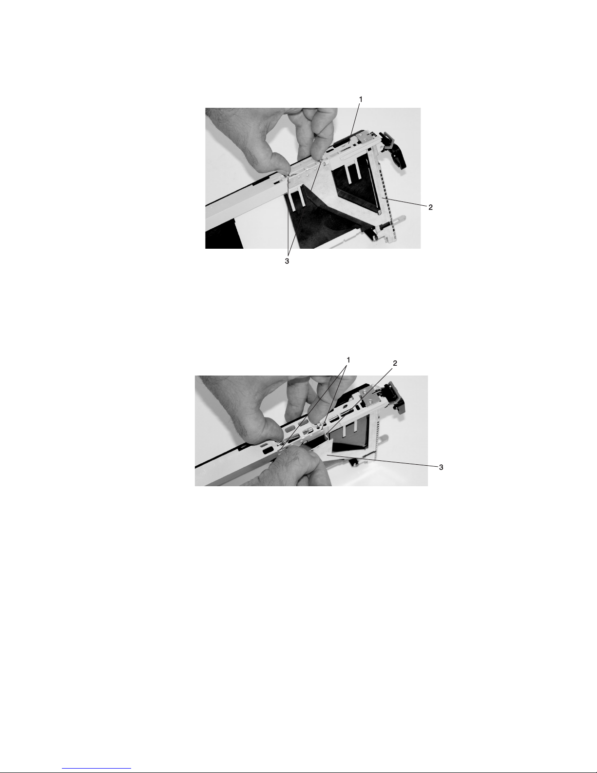
5. Remove the bezel, as follows:
a. Locate the plastic latch fingers in the top part of the cassette.
1 To p of Cassette
2 Bezel
3 Plastic Latch Fingers
b. Using one hand, pinch the plastic latch fingers, and with your other hand, carefully lift the top part
of the bezel extension out until the tabs clear the slots in the PCI adapter cassette assembly.
1 Slots
2 Ta b
3 Bezel Extension
Chapter 4. Installation and Removal Procedures 65
Page 82

c. While holding the bezel extension out, push the plastic cover latch out of the bezel hook, as shown
in the following illustration. This action allows the bezel to be removed.
1 Bezel Extension
2 Plastic Cover Latch in Bezel Hook
d. On the opposite side of the cassette (cover side), push the cover latch to release the bezel.
1 Cover Side
2 Cover Latch
66 Eserver pSeries 655 Installation Guide
Page 83

e. While holding the bezel extension out, carefully slide the bezel off. Yo u might have to work from
both sides to loosen the bezel assembly from the cassette assembly. When the bezel is free, slide
it completely off the cassette assembly, and set it aside.
1 Bezel Extension
2 Bezel
1 Bezel
Chapter 4. Installation and Removal Procedures 67
Page 84

6. Turn over the cassette so that the cover is facing up, as shown in the following illustration. Remove the
cover from the cassette as follows:
a. Slide the cover until it releases from the cassette assembly.
Attention: The cover might be tight and difficult to slide. If you grasp the left end (handle end) of
the cassette and the right end of the cover, you can use enough force to pull the cover off the PCI
adapter cassette assembly.
1 Left End of the Cassette
2 Cassette Cover
b. Lift the cover off the assembly, and set it aside.
c. Depress the handle release lever to unlock the locking bar. The locking bar is located on the
handle, ensure that the handle is pulled into the unlocked position. Raise the handle on the
cassette linkage assembly until it locks into the up position (the blank filler or adapter moves
downward).
1 Handle Release Lever
2 Locking Bar
68 Eserver pSeries 655 Installation Guide
Page 85

7. Remove the metal EMC shield from the top of the tailstock.
1 Metal EMC Shield
8. Remove the blank filler or adapter that is installed in the cassette linkage assembly.
If there is a blank filler in the cassette linkage assembly, as shipped from the manufacturer,
Note:
there are two adapter arms. One adapter arm is used with short adapters (short adapter arm)
and the other adapter arm is used with long adapters (long adapter arm).
If you are removing a short adapter or blank filler, see “Short Adapter or Blank Filler Removal” on page
70.
If you are removing a long adapter, see “Long Adapter Removal” on page 73.
Chapter 4. Installation and Removal Procedures 69
Page 86

Short Adapter or Blank Filler Removal: To remove a short adapter or blank filler, do the following:
1. Slide the long and short adapter arms away from the adapter or blank filler by doing the following:
a. Each adapter arm has a release tab that allows the arm to be moved away from the adapter or
blank filler in the cassette assembly. Use your fingernail to lift the tab, to allow each arm to be
moved away from the adapter or blank filler. Lift the release tab on the short adapter arm, and
push on the slotted tab to release the end of the blank filler.
If you plan to install a short adapter, leave the long adapter arm on the cassette linkage
Note:
assembly. If you plan to install a long adapter, remove both the long and short adapter arms
from the cassette linkage assembly in the next step.
b. Slide the long and short adapter arms away from the blank filler or adapter.
1 Long Adapter Arm
2 Release Ta b
3 Release Ta b
4 Short Adapter Arm
5 Slotted Ta b
Note: Some dual linkage PCI adapter cassettes might contain a middle-spacer arm to be used with
long adapter cards only. The middle-spacer arm and its installation can be seen in the following
illustration.
70 Eserver pSeries 655 Installation Guide
Page 87

1
2
3
4
2
5
1 Short PCI Adapter Card
2 Short Adapter Arm
3 Middle-Spacer Arm
4 Long Adapter Arm
5 Long PCI Adapter Card
Chapter 4. Installation and Removal Procedures 71
Page 88

2. Remove the adapter or blank filler from the cassette linkage assembly by rotating the bottom of the
tailstock out, as shown in the following illustration. Store the adapter or blank filler in a safe place.
1 Cassette Linkage Assembly
2 Bottom of Tailstock
3 Handle
3. The removal procedure for the PCI adapter cassette assembly is complete. To install a new adapter or
blank filler in the cassette, go to “Installing a New Hot-Pluggable PCI Adapter” on page 58.
72 Eserver pSeries 655 Installation Guide
Page 89

Long Adapter Removal: To remove a long adapter, do the following:
1. Each adapter arm has a release tab that allows the arm to be moved away from the adapter in the
cassette assembly. Use your fingernail to lift the tab, to allow the arm to be moved away from the
adapter. Lift the release tab on the long adapter arm, and slide it off the cassette linkage assembly.
1 Release Ta b
2. Remove the adapter from the cassette linkage assembly by rotating the bottom of the tailstock out, as
shown in the following illustration. Store the adapter in a safe place.
1 Cassette Linkage
3 Bottom of Tailstock
Assembly
2 Adapter 4 Handle
3. The removal procedure for the PCI adapter cassette assembly is complete. To install a new adapter or
blank filler in the cassette, go to “Installing a New Hot-Pluggable PCI Adapter” on page 58.
If you are going to install a short adapter card, and your cassette linkage has the middle-spacer
Note:
arm installed, remove the middle-spacer arm and install the short adapter arm, refer to page 1a
on page 70. The middle-spacer arm and long adapter arm can be stored on the cassette
linkage. See the illustration on page 71. To install a short adapter into a cassette see “Replacing
an Adapter in a PCI Adapter Cassette” on page 74.
Chapter 4. Installation and Removal Procedures 73
Page 90

Replacing an Adapter in a PCI Adapter Cassette
CAUTION:
Metal edges might be sharp.
C38
This procedure is performed when preparing to install a new adapter or a blank filler in the processor
subsystem or an I/O drawer. Familiarize yourself with the entire procedure before performing the following
steps.
1. Place the empty PCI Adapter Cassette Assembly linkage on a flat work surface in front of you. Position
the cassette so that the handle is in the raised (up) position, and on the left, with the top of the linkage
facing away from you.
Your PCI Adapter Cassette Assembly linkage might not have the short or long adapter retaining
Note:
arms or the middle-spacer arm installed if you removed them during the removal procedure. In
the following illustration, both arms are shown.
1 Handle
2 Cassette Linkage Assembly
3 Retaining Arms
4 Middle-Spacer Arm
74 Eserver pSeries 655 Installation Guide
Page 91

Note: If you are installing an adapter that is in the following list, use the additional brackets listed to
help when you seat the adapter during installation. There are unique brackets (1) for each
adapter type (2):
1
2
Feature Code Description Bracket Part
Number
2751 S/390 ESCON Channel PCI Adapter 31L8728
2969 Gigabit Ethernet-SX PCI Adapter 44P2676
2975 10/100/1000 Base-T Ethernet PCI Adapter 44P2676
4962 10/100 Mbps Ethernet PCI Adapter II 44P0321
5700 IBM Gigabit Ethernet-SX PCI-X Adapter 53P5450
5701 IBM 10/100/1000 Base-TX Ethernet PCI-X Adapter 53P5450
5706 IBM 2-Port 10/100/1000 Base-TX Ethernet PCI-X Adapter 53P5450
5707 IBM 2-Port Gigabit Ethernet-SX PCI-X Adapter 53P5450
6203 PCI Dual Channel Ultra3 SCSI Adapter 44P2661
6228 2 Gigabit Fibre Channel Adapter for 64-bit PCI Bus 44P2675
6239 2 Gigabit Fibre Channel PCI-X Adapter 44P3912
Chapter 4. Installation and Removal Procedures 75
Page 92

2. To determine if you are installing a long adapter or a short adapter, use the following steps. If you
know the length of your adapter, skip the following steps and proceed to step 3 on page 78.
a. Remove the adapter from its protective packaging and, if present, remove the plastic extension
handle from the end of the adapter.
b. Place the adapter or a blank filler over the cassette, with the upper-left corner aligned into the top
adapter-retaining clip.
1
2
5
4
1 To p Adapter-Retaining Clip 3 Adapter
3
2 Cassette Linkage Assembly 4 Bottom of Tailstock
5 Handle
76 Eserver pSeries 655 Installation Guide
Page 93

c. The cassette linkage assembly is marked to show long or short adapters similar to the adapter
shown in the following illustration. Check the right end of the adapter to determine if it is long
enough to fall into the long area of the cassette linkage assembly. Ensure that the corner on the
left end of the adapter is still aligned into the top adapter-retaining clip, and determine the length of
the adapter.
ARM
LONG
ARM
SHORT
1
2
1 To p Adapter-Retaining Clip
2 Long Adapter-Retaining Arm and Clip
Chapter 4. Installation and Removal Procedures 77
Page 94

3. Remove the adapter or blank filler and ensure that the handle is in the up position. If you need to
move the handle, ensure that the locking bar is pulled into the unlocked position, and then rotate the
adapter handle until the handle is in the up position (the cassette linkage assembly will extend down
beyond the cassette top).
If you are installing a short adapter or blank filler, go to “Short Adapter or Blank Filler Installation.” If
you are installing a long adapter, go to “Long Adapter Installation” on page 95.
1
1 Handle Release Lever
2
2 Lock
Short Adapter or Blank Filler Installation
To install a short adapter or blank filler, do the following:
1. Place the adapter or blank filler into the cassette so that the upper-left corner of the adapter engages
the adjustable top adapter-retaining clip as shown in the following illustration.
78 Eserver pSeries 655 Installation Guide
Page 95

1
4
2
3
1 Cassette Linkage Assembly
2 Bottom of Tailstock
3 Retaining Clip
4 Handle
Chapter 4. Installation and Removal Procedures 79
Page 96

2. Rotate the adapter so that the adapter engages the slot in the bottom adapter-retaining clip and the
top corner of the adapter is seated into the adjustable top adapter-retaining clip.
If the adapter is not a full-height adapter, you must slide the adjustable top adapter-retaining
Note:
clip downward until the lower edge of the adapter is seated into the slot on the bottom
adapter-retaining clip.
1
2
3
1 Adapter
2 Slot
3 Bottom Retaining Clip
80 Eserver pSeries 655 Installation Guide
Page 97

3. Slide the short adapter-retaining arm toward the adapter or blank filler on the cassette linkage rail.
If the short-adapter retaining arm has been removed from the cassette linkage rail, install the
short-adapter retaining arm and then slide the arm until it contacts the adapter or blank filler as
shown in the following illustration.
3
1
2
1 Short-adapter Retaining Arm
2 Adapter or Blank Filler
3 Cassette Linkage Rail
4. Ensure that the adjustable top retaining clip catches the corner of the adapter as shown in the
following illustration:
Chapter 4. Installation and Removal Procedures 81
Page 98

1
1 Short Adapter To p Retaining Clip
5. Use the lower short adapter arm clip to engage and hold the bottom of the adapter.
It might be necessary to apply pressure to engage and hold the bottom of the adapter.
Note:
1 Lower Short Adapter Arm Clip
1
82 Eserver pSeries 655 Installation Guide
Page 99

6. To hold the top of the adapter, slide down the adjustable top adapter-retaining clip on the retaining
arm. Ensure that the bottom edge of the adapter is held by the lower part of the adapter retaining
arm.
1 Adjustable To p Adapter-Retaining Clip
Chapter 4. Installation and Removal Procedures 83
Page 100

7. Press the lock on the handle, and rotate the adapter handle until it is in the down position (adapter or
blank filler moves up into the cassette assembly).
1
1 Handle Release Lever
2
2 Lock
Ensure that the right end of the cassette linkage rail moves up into the cassette linkage assembly as
shown in the following illustration:
1
8. Position the adapter and cassette assembly with the handle on the left (in the down position) and the
top facing away from you.
84 Eserver pSeries 655 Installation Guide
1 Right End of Cassette Linkage
 Loading...