

Page 1

ERserver
pSeries 650
Installation Guide
SA38-0610-03
Page 2

Page 3

ER s e r v e r
pSeries 650
Installation Guide
SA38-0610-03
Page 4

A
©
Fourth Edition (November 2003)
Before using this information and the product it supports, read the information in “Safety Notices” on page vii,
Appendix B, “Environmental Notices,” on page 127, and Appendix D, “Notices,” on page 135.
reader’s comment form is provided at the back of this publication. If the form has been removed, address
comments to Information Development, Department H6DS-905-6C006, 11501 Burnet Road, Austin, Texas
78758-3493. To send comments electronically, use this commercial internet address: aix6kpub@austin.ibm.com. Any
information that you supply may be used without incurring any obligation to you.
Copyright International Business Machines Corporation, 2002, 2003. All rights reserved.
Note to U.S. Government Users -- Documentation related to restricted rights -- Use, duplication or disclosure is
subject to restrictions set forth is GSA ADP Schedule Contract with IBM Corp.
Page 5

Contents
Safety Notices . . . . . . . . . . . . . . . . . . . . . . . . . . . . . . . . . vii
Rack Safety Instructions . . . . . . . . . . . . . . . . . . . . . . . . . . . . . . vii
Electrical and Mechanical Safety . . . . . . . . . . . . . . . . . . . . . . . . . . . vii
Laser Safety Information . . . . . . . . . . . . . . . . . . . . . . . . . . . . . .ix
Laser Compliance . . . . . . . . . . . . . . . . . . . . . . . . . . . . . . .ix
Data Integrity and Verification . . . . . . . . . . . . . . . . . . . . . . . . . . .xi
About This Book . . . . . . . . . . . . . . . . . . . . . . . . . . . . . . . . xiii
ISO 9000 . . . . . . . . . . . . . . . . . . . . . . . . . . . . . . . . . . . xiii
Highlighting . . . . . . . . . . . . . . . . . . . . . . . . . . . . . . . . . . xiii
Accessing Information . . . . . . . . . . . . . . . . . . . . . . . . . . . . . . . xiii
References to AIX Operating System . . . . . . . . . . . . . . . . . . . . . . . . . xiii
Related Publications . . . . . . . . . . . . . . . . . . . . . . . . . . . . . . . xiv
Ergonomic Information . . . . . . . . . . . . . . . . . . . . . . . . . . . . . . xiv
Trademarks . . . . . . . . . . . . . . . . . . . . . . . . . . . . . . . . . . xiv
Chapter 1. Reference Materials . . . . . . . . . . . . . . . . . . . . . . . . . . .1
Documentation Overview . . . . . . . . . . . . . . . . . . . . . . . . . . . . . .3
Chapter 2. Installing the pSeries 650 . . . . . . . . . . . . . . . . . . . . . . . . .7
pSeries 650 Overview . . . . . . . . . . . . . . . . . . . . . . . . . . . . . . .7
Before You Begin . . . . . . . . . . . . . . . . . . . . . . . . . . . . . . . . .8
Step 1. Check Your Inventory . . . . . . . . . . . . . . . . . . . . . . . . . . . .8
System Unit . . . . . . . . . . . . . . . . . . . . . . . . . . . . . . . . . .9
Step 2. Read the Safety Notices . . . . . . . . . . . . . . . . . . . . . . . . . . .10
Step 3. Attach the Mounting Hardware to the Rack Enclosure . . . . . . . . . . . . . . . .11
Rail Positioning Without a Template . . . . . . . . . . . . . . . . . . . . . . . . .14
Step 4. Install the System in the Rack Enclosure . . . . . . . . . . . . . . . . . . . . .15
Step 5. Are All of the Features Installed? . . . . . . . . . . . . . . . . . . . . . . . .16
Step 6. Position the Display . . . . . . . . . . . . . . . . . . . . . . . . . . . . .17
Step 7. Check Your Display or Console Type . . . . . . . . . . . . . . . . . . . . . .17
Step 8. Connecting to a Hardware Management Console (HMC) . . . . . . . . . . . . . . .17
Step 9. Attach the Display Cable Toroid . . . . . . . . . . . . . . . . . . . . . . . .18
Step 10. Connect the Graphics Display . . . . . . . . . . . . . . . . . . . . . . . .18
Step 11. Connect the Keyboard and Mouse (When Using a Graphics Display) . . . . . . . . . .19
Step 12. Connect the Serial and Parallel Devices . . . . . . . . . . . . . . . . . . . . .20
Step 13. Connect the Adapter Cables . . . . . . . . . . . . . . . . . . . . . . . . .21
Step 14. Connect Internal and External SCSI Devices . . . . . . . . . . . . . . . . . . .22
Step 15. Are You Using the Rack Indicator Feature? . . . . . . . . . . . . . . . . . . .24
Step 16. Are You Using an Ethernet Connection? . . . . . . . . . . . . . . . . . . . . .24
Step 17. Connect the Power Cords to the Server . . . . . . . . . . . . . . . . . . . . .25
Step 18. Route the Cables . . . . . . . . . . . . . . . . . . . . . . . . . . . . .26
Step 19. Connect the Power Cords . . . . . . . . . . . . . . . . . . . . . . . . . .27
Step 20. What is the Next Step? . . . . . . . . . . . . . . . . . . . . . . . . . . .28
Chapter 3. Verifying the Hardware Operation . . . . . . . . . . . . . . . . . . . . .29
Considerations Before Running This Procedure . . . . . . . . . . . . . . . . . . . . .29
Power Procedures . . . . . . . . . . . . . . . . . . . . . . . . . . . . . . .29
Using the HMC to Load the Online Diagnostics in Service Mode . . . . . . . . . . . . . . .32
Using the HMC to Load the Standalone Diagnostics from CD-ROM . . . . . . . . . . . . . .32
Loading the Online Diagnostics on a System without an HMC Attached . . . . . . . . . . . .33
Loading the Standalone Diagnostics on a System without an HMC Attached . . . . . . . . . . .33
iii
Page 6

On
iv
Running Standalone Diagnostics from a Network Installation Management (NIM) Server with an HMC
Attached to the System . . . . . . . . . . . . . . . . . . . . . . . . . . . . .33
NIM Server Configuration . . . . . . . . . . . . . . . . . . . . . . . . . . . .34
Client Configuration and Booting Standalone Diagnostics from the NIM Server . . . . . . . . .34
Running System Verification . . . . . . . . . . . . . . . . . . . . . . . . . . . .35
Performing Additional System Verification . . . . . . . . . . . . . . . . . . . . . . . .36
Stopping the Diagnostics . . . . . . . . . . . . . . . . . . . . . . . . . . . . . .36
Verify that the Latest Firmware and Adapter and Drive Microcode are Installed . . . . . . . . . .36
Verify that the Latest HMC Software is Installed . . . . . . . . . . . . . . . . . . . . .36
Access the System Documentation . . . . . . . . . . . . . . . . . . . . . . . . . .37
Accessing Hardware Documentation . . . . . . . . . . . . . . . . . . . . . . . .37
Accessing System Documentation . . . . . . . . . . . . . . . . . . . . . . . . .37
Verify Partition Standby and Full System Partition Power Options . . . . . . . . . . . . . . .37
Final Installation Tasks . . . . . . . . . . . . . . . . . . . . . . . . . . . . . .37
Complete System Records and Installation Procedure . . . . . . . . . . . . . . . . . .37
Configure the Network . . . . . . . . . . . . . . . . . . . . . . . . . . . . . .38
Chapter 4. Completing the Installation . . . . . . . . . . . . . . . . . . . . . . . .39
Step 1. Bezels and Doors . . . . . . . . . . . . . . . . . . . . . . . . . . . . .39
Step 2. Complete Installation Checklists . . . . . . . . . . . . . . . . . . . . . . . .39
TTY Terminal Console and the System is Not Partitioned . . . . . . . . . . . . . . . . .39
Graphics Terminal Console and the System is Not Partitioned . . . . . . . . . . . . . . .40
HMC-Managed System Using a Single Full System Partition . . . . . . . . . . . . . . .41
HMC-Managed System with Multiple Partitions . . . . . . . . . . . . . . . . . . . . .42
Chapter 5. Installing Options for the pSeries 650 . . . . . . . . . . . . . . . . . . . .43
Safety Considerations . . . . . . . . . . . . . . . . . . . . . . . . . . . . . . .43
Handling Static-Sensitive Devices . . . . . . . . . . . . . . . . . . . . . . . . . .44
Color Coded Indicators . . . . . . . . . . . . . . . . . . . . . . . . . . . . . .44
Stopping the System . . . . . . . . . . . . . . . . . . . . . . . . . . . . . . .45
Disk Drive Options . . . . . . . . . . . . . . . . . . . . . . . . . . . . . . . .46
Preinstallation Considerations for Disk Drives . . . . . . . . . . . . . . . . . . . . .46
Installing Hot-Plug SCSI Disk Drives . . . . . . . . . . . . . . . . . . . . . . . .47
Removing Hot-Plug SCSI Disk Drives . . . . . . . . . . . . . . . . . . . . . . . .49
Configuring and Deconfiguring SCSI Hot-Swap Disk Drives . . . . . . . . . . . . . . . .51
Installing Media Drives . . . . . . . . . . . . . . . . . . . . . . . . . . . . . .52
Installing a Drive in the Optional Media Position . . . . . . . . . . . . . . . . . . . .52
PCI Adapters . . . . . . . . . . . . . . . . . . . . . . . . . . . . . . . . . .54
Removing and Replacing a PCI Adapter Cassette . . . . . . . . . . . . . . . . . . .55
Non-Hot-Pluggable PCI Adapter Removal and Replacement . . . . . . . . . . . . . . . .60
Hot-Pluggable PCI Adapter . . . . . . . . . . . . . . . . . . . . . . . . . . . .61
PCI Adapter or Blank Filler Removal from a Cassette Assembly . . . . . . . . . . . . . .67
Replacing an Adapter in a PCI Adapter Cassette . . . . . . . . . . . . . . . . . . . .79
Short Adapter or Blank Filler Installation . . . . . . . . . . . . . . . . . . . . . . .84
Long Adapter Installation . . . . . . . . . . . . . . . . . . . . . . . . . . . . 100
Replacing a Hot-Pluggable PCI Adapter . . . . . . . . . . . . . . . . . . . . . . .116
Capacity Upgrade on Demand . . . . . . . . . . . . . . . . . . . . . . . . . . .118
Permanent Processors on Demand . . . . . . . . . . . . . . . . . . . . . . . .118
Permanent Memory on Demand . . . . . . . . . . . . . . . . . . . . . . . . .118
Demand On/Off Features . . . . . . . . . . . . . . . . . . . . . . . . . . .119
Trial Capacity on Demand . . . . . . . . . . . . . . . . . . . . . . . . . . . .119
Capacity Planning . . . . . . . . . . . . . . . . . . . . . . . . . . . . . . .119
Software Licenses and Processor on Demand . . . . . . . . . . . . . . . . . . . . 120
Activating Process for Capacity Upgrade on Demand Features . . . . . . . . . . . . . . 121
Appendix A. Communications Statements . . . . . . . . . . . . . . . . . . . . . . 123
Eserver pSeries 650 Installation Guide
Page 7

Federal Communications Commission (FCC) Statement . . . . . . . . . . . . . . . . . . 123
European Union (EU) Statement . . . . . . . . . . . . . . . . . . . . . . . . . . 123
International Electrotechnical Commission (IEC) Statement . . . . . . . . . . . . . . . . . 123
United Kingdom Telecommunications Safety Requirements . . . . . . . . . . . . . . . . . 123
Avis de conformité aux normes du ministère des Communications du Canada . . . . . . . . . 124
Canadian Department of Communications Compliance Statement . . . . . . . . . . . . . . 124
VCCI Statement . . . . . . . . . . . . . . . . . . . . . . . . . . . . . . . . 124
Electromagnetic Interference (EMI) Statement - Taiwan . . . . . . . . . . . . . . . . . . 124
Radio Protection for Germany . . . . . . . . . . . . . . . . . . . . . . . . . . . 124
Appendix B. Environmental Notices . . . . . . . . . . . . . . . . . . . . . . . . 127
Product Recycling and Disposal . . . . . . . . . . . . . . . . . . . . . . . . . . . 127
Environmental Design . . . . . . . . . . . . . . . . . . . . . . . . . . . . . . 131
Acoustical Noise Emissions . . . . . . . . . . . . . . . . . . . . . . . . . . . . 132
Declared Acoustical Noise Emissions . . . . . . . . . . . . . . . . . . . . . . . . . 132
Appendix C. Acoustical Noise Emissions . . . . . . . . . . . . . . . . . . . . . . 133
Declared Acoustical Noise Emissions . . . . . . . . . . . . . . . . . . . . . . . . . 133
Appendix D. Notices . . . . . . . . . . . . . . . . . . . . . . . . . . . . . . 135
Appendix E. Subsystem Positioning and Cabling . . . . . . . . . . . . . . . . . . . 137
SPCN Cabling . . . . . . . . . . . . . . . . . . . . . . . . . . . . . . . . . 137
One I/O Subsystem, Two I/O Subsystems . . . . . . . . . . . . . . . . . . . . . . 137
Four I/O Subsystems, Eight I/O Subsystems . . . . . . . . . . . . . . . . . . . . . 139
RIO Cabling . . . . . . . . . . . . . . . . . . . . . . . . . . . . . . . . . . 140
One I/O Subsystem or Two I/O Subsystems . . . . . . . . . . . . . . . . . . . . . 141
Three I/O Subsystems or Four I/O Subsystems . . . . . . . . . . . . . . . . . . . . 141
Eight I/O Subsystems with Two RIO Loops . . . . . . . . . . . . . . . . . . . . . 142
Hardware Management Console for pSeries (HMC) to the HMC Connector . . . . . . . . . . . 144
Optional 8-Port or 128-Port Async Adapters . . . . . . . . . . . . . . . . . . . . . 144
Appendix F. Service Processor Setup and Test . . . . . . . . . . . . . . . . . . . . 145
Service Processor Setup Checklist . . . . . . . . . . . . . . . . . . . . . . . . . . 145
Testing the Setup . . . . . . . . . . . . . . . . . . . . . . . . . . . . . . . . 146
Testing Call-In . . . . . . . . . . . . . . . . . . . . . . . . . . . . . . . . 146
Testing Call-Out . . . . . . . . . . . . . . . . . . . . . . . . . . . . . . . 147
Serial Port Configuration . . . . . . . . . . . . . . . . . . . . . . . . . . . . 147
Appendix G. Firmware Updates . . . . . . . . . . . . . . . . . . . . . . . . . . 149
General Information on System Firmware Updates . . . . . . . . . . . . . . . . . . . . 149
Determining the Level of Firmware on the System . . . . . . . . . . . . . . . . . . . . 150
System Firmware Update in AIX Using a Locally Available Image . . . . . . . . . . . . . . 151
Updating System Firmware From the Service Processor Menus . . . . . . . . . . . . . . . 152
Updating System Firmware from the AIX Service Aids . . . . . . . . . . . . . . . . . . 152
Updating System Firmware from a NIM Server . . . . . . . . . . . . . . . . . . . . . 152
Recovery Mode . . . . . . . . . . . . . . . . . . . . . . . . . . . . . . . . . 153
Updating System Firmware from the AIX Command Line . . . . . . . . . . . . . . . . . 153
Appendix H. System Records . . . . . . . . . . . . . . . . . . . . . . . . . . . 155
Record the Identification Numbers . . . . . . . . . . . . . . . . . . . . . . . . . . 155
Device Records . . . . . . . . . . . . . . . . . . . . . . . . . . . . . . . . 156
Index . . . . . . . . . . . . . . . . . . . . . . . . . . . . . . . . . . . . 167
Contents
v
Page 8

vi
Eserver pSeries 650 Installation Guide
Page 9

A
v
A
v
v ix v 10 v 15 v 67 v 79
v Do
v Do
v
v
v An
Safety Notices
danger notice indicates the presence of a hazard that has the potential of causing death or serious
personal injury. Danger notices appear on the following pages:
viii
caution notice indicates the presence of a hazard that has the potential of causing moderate or minor
personal injury. Caution notices appear on the following pages:
viii
For a translation of the safety notices contained in this book, see the System Unit Safety Information,
order number SA23-2652.
Rack Safety Instructions
not install this unit in a rack where the internal rack ambient temperatures will exceed 40 degrees C.
not install this unit in a rack where the air flow is compromised. Any side, front or back of the unit
used for air flow through the unit must not be in direct contact with the rack.
Care should be taken to ensure that a hazardous condition is not created due to uneven mechanical
loading when installing this unit in a rack. If the rack has a stabilizer it must be firmly attached before
installing or removing this unit.
Consideration should be given to the connection of the equipment to the supply circuit so that
overloading of circuits does not compromise the supply wiring or overcurrent protection. To provide the
correct power connection to the rack, refer to the rating labels located on the equipment in the rack to
determine the total power requirement for the supply circuit.
electrical outlet that is not correctly wired could place hazardous voltage on the metal parts of the
system or the devices that attach to the system. It is the responsibility of the customer to ensure that
the outlet is correctly wired and grounded to prevent an electrical shock.
Electrical and Mechanical Safety
Observe the following safety instructions anytime you are connecting or disconnecting devices attached to
the workstation.
vii
Page 10

or
DANGER
electrical outlet that is not correctly wired could place hazardous voltage on metal parts of
An
the system or the devices that attach to the system. It is the responsibility of the customer to
ensure that the outlet is correctly wired and grounded to prevent an electrical shock.
Before installing or removing signal cables, ensure that the power cables for the system unit
and all attached devices are unplugged.
When adding or removing any additional devices to or from the system, ensure that the power
cables for those devices are unplugged before the signal cables are connected. If possible,
disconnect all power cables from the existing system before you add a device.
Use one hand, when possible, to connect or disconnect signal cables to prevent a possible
shock from touching two surfaces with different electrical potentials.
During an electrical storm, do not connect cables for display stations, printers, telephones, or
station protectors for communications lines.
D05
DANGER
prevent electrical shock hazard, disconnect all power cables from the electrical outlet before
To
relocating the system.
D01
CAUTION:
This product is equipped with a three-wire power cable and plug for the user’s safety. Use this
power cable with a properly grounded electrical outlet to avoid electrical shock.
C01
CAUTION:
This unit has more than one power supply cord. To reduce the risk of electrical shock, disconnect
two power supply cords before servicing.
C21
CAUTION:
This unit weighs more than 55 kg (121.2 pounds). Material handling systems such as levers, slings,
lifts are required to safely move it. When this is not possible, specially trained persons or
services (such as riggers or movers) must be used.
C06
CAUTION:
Metal edges might be sharp.
C38
viii
Eserver pSeries 650 Installation Guide
Page 11

1
of an
Laser Safety Information
CAUTION:
This product may contain a CD-ROM, DVD-ROM, or laser module on a PCI card, which are class 1
laser products.
C30
Laser Compliance
All lasers are certified in the U.S. to conform to the requirements of DHHS 21 CFR Subchapter J for class
laser products. Outside the U.S., they are certified to be in compliance with the IEC 825 (first edition
1984) as a class 1 laser product. Consult the label on each part for laser certification numbers and
approval information.
CAUTION:
All IBM laser modules are designed so that there is never any human access to laser radiation
above a class 1 level during normal operation, user maintenance, or prescribed service conditions.
Data processing environments can contain equipment transmitting on system links with laser
modules that operate at greater than class 1 power levels. For this reason, never look into the end
optical fiber cable or open receptacle. Only trained service personnel should perform the
inspection or repair of optical fiber cable assemblies and receptacles.
C26
C25,
Preface
ix
Page 12

x
Eserver pSeries 650 Installation Guide
Page 13

or
Data Integrity and Verification
IBM computer systems contain mechanisms designed to reduce the possibility of undetected data corruption
loss. This risk, however, cannot be eliminated. Users who experience unplanned outages, system failures,
power fluctuations or outages, or component failures must verify the accuracy of operations performed and
data saved or transmitted by the system at or near the time of the outage or failure. In addition, users must
establish procedures to ensure that there is independent data verification before relying on such data in
sensitive or critical operations. Users should periodically check the IBM support websites for updated
information and fixes applicable to the system and related software.
xi
Page 14

xii
Eserver pSeries 650 Installation Guide
Page 15

v To
v To
About This Book
This book provides information on how to set up and cable the server, install and remove options, and
verify server operation.
ISO 9000
ISO 9000 registered quality systems were used in the development and manufacturing of this product.
Highlighting
The following highlighting conventions are used in this book:
Bold
Identifies commands, subroutines, keywords, files, structures, directories, and other items
whose names are predefined by the system. Also identifies graphical objects such as buttons,
labels, and icons that the user selects.
Italics
Monospace
Identifies parameters whose actual names or values are to be supplied by the user.
Identifies examples of specific data values, examples of text similar to what you might see
displayed, examples of portions of program code similar to what you might write as a
programmer, messages from the system, or information you should actually type.
Accessing Information
Documentation for the IBM Eserver pSeries is available online. Visit the IBM Eserver pSeries
Information Center at http://publib16.boulder.ibm.com/pseries/en_US/infocenter/base.
access the pSeries publications, click Hardware documentation.
view information about the accessibility features of Eserver pSeries hardware and the AIX operating
system, click AIX and pSeries accessibility.
References to AIX Operating System
This document may contain references to the AIX operating system. If you are using another operating
system, consult the appropriate documentation for that operating system.
This document may describe hardware features and functions. While the hardware supports them, the
realization of these features and functions depends upon support from the operating system. AIX provides
this support. If you are using another operating system, consult the appropriate documentation for that
operating system regarding support for those features and functions.
xiii
Page 16

v
v
v
v
v
v
v
v
v
v
v
v
v
v
Related Publications
The following publications provide related information:
The System Unit Safety Information, order number SA23-2652, contains translations of safety
information used throughout this book.
The IBM Hardware Management Console for pSeries Installation and Operations Guide, order number
SA38-0590, provides information to system administrators on how to install and use a Hardware
Management Console (HMC) to manage a system.
The Eserver pSeries 650 Service Guide, order number SA38-0612, contains reference information,
maintenance analysis procedures (MAPs), error codes, removal and replacement procedures, and a
parts catalog.
The Eserver pSeries 650 User’s Guide, order number SA38-0611, contains information on how to use
the system, use diagnostics, use service aids, and verify system operations.
The RS/6000 and Eserver Diagnostic Information for Multiple Bus Systems, order number SA38-0509,
contains diagnostic information, service request numbers (SRNs), and failing function codes (FFCs).
The RS/6000 and Eserver Adapters, Devices and Cable Information for Multiple Bus Systems, order
number SA38-0516, contains information about adapters, devices, and cables for your server. This
manual is intended to supplement the service information found in the Diagnostic Information for
Multiple Bus Systems.
The PCI Adapter Placement Reference, order number SA38-0538, contains information regarding slot
restrictions for adapters that can be used in this system.
The Site and Hardware Planning Information, order number SA38-0508, contains information to help
you plan your installation.
The Electronic Service Agent for pSeries and RS/6000 User’s Guide, order number LCD4-1060,
contains information on using the Electronic Service Agent.
Ergonomic Information
After you have set up your system, we encourage you to visit the Healthy Computing Web site. Good
ergonomic practice is important to get the most from your workstation and to avoid discomfort. This means
that the equipment and the workplace should be arranged to suit your individual needs and the kind of
work you do.
The Healthy Computing Web site gives ergonomic guidelines to help you understand the ergonomic
considerations that you should know when working at a computer workstation. The address is:
http://www.us.pc.ibm.com/healthycomputing
Trademarks
The following terms are trademarks of International Business Machines Corporation in the United States,
other countries, or both:
AIX
AIX 5L
Eserver
pSeries
RS/6000
company, product, and service names may be trademarks or service marks of others.
Other
xiv
Eserver pSeries 650 Installation Guide
Page 17

v
v
Chapter 1. Reference Materials
Note: This document may contain references to the AIX operating system. If you are using another
operating system, consult the appropriate documentation for that operating system.
This document may describe hardware features and functions. While the hardware supports them,
the implementation of these features and functions depends on support from the operating system.
AIX provides this support. If you are using another operating system, consult the appropriate
documentation for that operating system regarding support for those features and functions.
This chapter helps you get started with installing and configuring the Eserver pSeries environment. The
following information is included in the chapter:
Eserver pSeries Roadmap
Documentation Overview - Brief description of the printed and softcopy documentation shipped including
targeted audience
Eserver pSeries Roadmap helps you locate marketing, service, and customer task information. The
The
roadmap guides you through the tasks and the publications that document those tasks.
1
Page 18

2
Marketing and Customer Tasks
Begin
Managed
by HMC
?
Yes
No
Site and Hardware Planning Information
Planning for Partitioned-System Operations
Hardware Management Console
Installation and Operations Guide
Planning
Planning
Hardware
Installation
Planning for
Partitioned-System Operations
AIX Installation in a
Partitioned Environment
AIX Installation Guide
and Reference
Operating System Installation:
Getting Started
Installing/Configuring
the Operating System
Site and Hardware Planning Information
Installer Tasks
Hardware Installation Guide
Hardware Management Console
Installation and Operations Guide
Customer Tasks
Configuring
Partitions
Installing/Configuring
the Operating System
Installing/Configuring
Applications
AIX Installation in a Partitioned Environment
Application Documentation
AIX Documentation Library
Yes
Hardware
Installation
Is System
Using
Partitions
?
No
Configuring Full
System Partition
Using the System
The publications listed in this section are available online. To access the online books, visit our IBM
Eserver pSeries Information Center at http://publib16.boulder.ibm.com/pseries/en_US/infocenter/base.
Eserver pSeries 650 Installation Guide
Hardware User's Guide
AIX Documentation Library
Application Documentation
Page 19

Documentation Overview
This section provides descriptions and target audience information for the Eserver pSeries and AIX 5L
documentation libraries. Some of the documentation may only be available in softcopy form. Based on the
documentation content, the books are divided into the following categories: Planning, Installing and
Configuring, and Using the System.
Table 1. Planning
Documentation Title
Site and Hardware Planning
Information
Planning for Partitioned-System
Operations
Hardware Management
Console for pSeries Installation
and Operations Guide
Description
Contains information to help plan for site
preparation tasks, such as floor-planning,
electrical needs, air conditioning, and other
site-planning considerations.
Describes planning considerations for
partitioned systems, including information on
dynamic partitioning and Capacity Upgrade on
Demand.
Provides information on how to install,
configure, and use a Hardware Management
Console (HMC). Logical partition (LPAR) tasks,
such as configuring and managing partitions on
multiple host servers, are included.
Audience
Marketing, system
administrators
System
administrators
System
administrators
Type
softcopy
printed and
softcopy
printed and
softcopy
Chapter 1. Reference Materials
3
Page 20

4
Table 2. Installing and Configuring
Documentation Title
Hardware Installation Guide
Planning for Partitioned-System
Operations
Hardware Management
Console for pSeries Installation
and Operations Guide
AIX Installation in a Partitioned
Environment
AIX Operating System
Installation: Getting Started
AIX 5L Installation Guide and
Reference
PCI Adapter Placement
Reference
AIX 5L Release Notes
AIX 5L Documentation CD
Description
Provides information on how to install system
hardware, cable the system, and verify
operations.
Describes planning considerations for
partitioned systems, including information on
dynamic partitioning and Capacity Upgrade on
Demand.
Provides information on how to install,
configure, and use a Hardware Management
Console (HMC). Logical partition (LPAR) tasks,
such as configuring and managing partitions on
multiple host servers, are included.
Provides information on how to install the AIX
operating system in an LPAR environment.
Provides information on how to install and
configure the AIX operating system on a
standalone system using a CD-ROM device.
Provides information on installing the AIX 5L
operating system on standalone systems, as
well as on client systems using the Network
Installation Management (NIM) interface.
Outlines system-specific PCI adapter slot
placement and adapter support configurations.
Provides late-breaking information for a
specific AIX release.
AIX documentation library (system
management guides, user guides, application
programmer guides, commands and files
references, AIX man pages, and so on).
Audience
Type
System installer printed and
softcopy
System
administrators
System
administrators
System
administrators
System
administrators
System
administrators
System
printed and
softcopy
printed and
softcopy
printed and
softcopy
printed and
softcopy
printed and
softcopy
softcopy
administrators,
service personnel
System
administrators
System
printed and
softcopy
softcopy
administrators
Eserver pSeries 650 Installation Guide
Page 21

Table 3. Using the System
Documentation Title
Hardware Management
Console for pSeries Installation
and Operations Guide
Description
Provides information on how to install, configure,
and use a Hardware Management Console
(HMC). Logical partition (LPAR) tasks, such as
configuring and managing partitions on multiple
host servers, are included.
Hardware User’s Guide
Provides using, problem determination, and
service processor information.
Diagnostic Information for
Multiple Bus Systems
Combines operating instructions for hardware
diagnostic programs with common MAPs and
SRNs (Service Request Numbers).
PCI Adapter Placement
Reference
Hardware Management
Console for pSeries
Maintenance Guide
Adapters, Devices, and Cable
Information for Multiple Bus
Systems
Outlines system-specific PCI adapter slot
placement and adapter support configurations.
Contains MAPs, removal and replacement, error
code, and parts information to help diagnose and
repair the system.
Provides information about adapters, devices,
and cables that are attached to or used within the
system.
System Unit Safety Information Contains the English version of safety notices, as
well as translations of those safety notices into
other languages.
AIX 5L Documentation CD
AIX documentation library (system management
guides, user guides, application programmer
guides, commands and files references, AIX man
pages, and so on).
Audience
System
administrators
System
administrators
Type
printed and
softcopy
printed and
softcopy
Service personnel printed and
softcopy
System
softcopy
administrators,
service personnel
Service personnel printed and
softcopy
System
administrators
System
administrators,
printed and
softcopy
printed and
softcopy
service personnel
System
softcopy
administrators
Chapter 1. Reference Materials
5
Page 22

6
Eserver pSeries 650 Installation Guide
Page 23

v
v
is
Chapter 2. Installing the pSeries 650
Service representatives use the procedures in this chapter to set up your pSeries 650.
Note: This procedure explains how to attach the mounting hardware to the rack enclosure. If your pSeries
650 was preinstalled in the rack, perform the rack-installation procedures as described in the 7014
Model T00 Rack Installation and Service Guide, order number SA38-0577, then return here and
begin with “Step 5. Are All of the Features Installed?” on page 16.
pSeries 650 Overview
The pSeries 650 is a multiprocessor, multibus system packaged in one 7038 Model 6M2 system drawer
and up to eight I/O drawers. The processor subsystem drawer is 8 EIA units high and can be mounted in a
19-inch rack. The 7038 Model 6M2 system drawer houses the processors, memory, and a base set of I/O.
The I/O capacity of the system can be expanded by the addition of up to eight I/O subsystems.
The pSeries 650 system supports up to eight logical partitions. Processors, memory, and I/O within each
partition can be dynamically removed or added without the need to reboot the system. Logical partitioning
requires the use of a hardware management console (HMC) that is used to manage and monitor the
system resources as well as provide a service focal point.
Cables are used to connect the base system to the I/O subsystem drawers, including the following:
SPCN (System Power Control Network) cables.
RIO (Remote Input Output) cables.
Power
connected to the pSeries 650 through redundant power cords that attach to redundant type-7
power distribution buses (PDBs), which are installed in the rack.
7
Page 24

To
If
v
v
v
v
h
h
h
h
h
8
Before You Begin
ensure that all of the installation steps are complete, the installer should use the following installation
checklists during the installation process. The customer’s choice of system console options and partition
configurations determines which of the following checklists to use. At the appropriate points in the
installation steps, you will be referred to the applicable checklist.
Note:
the system you are installing will be managed by an HMC, and the HMC is not installed and
functional, see the IBM Hardware Management Console for pSeries Installation and Operations
Guide, order number SA38-0590, for instructions on installing the HMC. Install the HMC, then return
here and continue with this procedure.
“TTY Terminal Console and the System is Not Partitioned” on page 39
“Graphics Terminal Console and the System is Not Partitioned” on page 40
“HMC-Managed System Using a Single Full System Partition” on page 41
“HMC-Managed System with Multiple Partitions” on page 42
Step 1. Check Your Inventory
Use the packing lists for each ship group to verify that you have all the items shipped with the system.
hBooks, CD-ROM and Other Media
Power Cables (1 standard, 2 optional)
″About Your Machine″ Document
9-Pin to 25-Pin Serial Converters (2) (optional)
RJ48 to D-Shell Converter Cable (1)
Eserver pSeries 650 Installation Guide
ASCII Terminal or System Console Display
(optional)
Page 25

h
h
h 2
h
h
v 8
v 4 M5
v 16 M5
v
v
v
v
v 8
System Unit
7038 Model 6M2 system drawer
Rack Mounting Template
Rack-Mounting Kit Envelope contains:
system to rail M4 screws (item 1)
thumbscrews (item 2)
rack screws (item 3)
Left EIA plate (item 4)
Right EIA plate (item 5)
Right rear-mounting bracket (item 6)
Left rear-mounting bracket (item 7)
nut clips (item 8)
2
1
Rack Rails
3
4
5
6
Cable Management Arm
7
8
Use of a lift tool is required to install the system unit into a rack, for lift tool information contact your
service support.
Chapter 2. Installing the pSeries 650
9
Page 26

10
Step 2. Read the Safety Notices
Before continuing, read the following safety information. Do not plug any cables into the system unit,
adapters, or electrical outlets until you have reviewed this information. Make sure none of the power cords
are connected before continuing to the next step.
DANGER
An electrical outlet that is not correctly wired could place hazardous voltage on metal parts of
the system or the devices that attach to the system. It is the responsibility of the customer to
ensure that the outlet is correctly wired and grounded to prevent an electrical shock.
Before installing or removing signal cables, ensure that the power cables for the system unit
and all attached devices are unplugged.
When adding or removing any additional devices to or from the system, ensure that the power
cables for those devices are unplugged before the signal cables are connected. If possible,
disconnect all power cables from the existing system before you add a device.
Use one hand, when possible, to connect or disconnect signal cables to prevent a possible
shock from touching two surfaces with different electrical potentials.
During an electrical storm, do not connect cables for display stations, printers, telephones, or
station protectors for communications lines.
D05
CAUTION:
This product is equipped with a three-wire power cable and plug for the user’s safety. Use this
power cable with a properly grounded electrical outlet to avoid electrical shock.
C01
DANGER
prevent electrical shock hazard, disconnect all power cables from the electrical outlet before
To
relocating the system.
D01
Eserver pSeries 650 Installation Guide
Page 27

To
v
v 2
v
v
v
a.
b.
c.
1
5 M5
2
6 M5
3
7
4
8 M5
Step 3. Attach the Mounting Hardware to the Rack Enclosure
attach the mounting hardware, you will need the following items:
Rack-Mounting Template
Rack Rails
Cable Management Arm
Rack-Mounting Kit Envelope
Screwdriver or Nutdriver
1.
Install the slide-rails and the cable management arm on the mounting rails of the rack enclosure.
Note: If you do not have the rail template, go to “Rail Positioning Without a Template” on page 14.You
must align the rack slide rails correctly. Otherwise, the installation cannot be completed
successfully.
Position the template on the front rack-mounting rails, aligning the holes.
Install the nut clips (item 8 in the following illustration), using the locations shown on the template.
Install the EIA plates (items 4 and 7 in the following illustration), and attach them to the
rack-mounting rail with an M5 rack screw in the lower of the two nut clips.
1
2
8
7
6
3
5
4
Rack
Left Rail (from front)
Right Rail (from front)
Right EIA Plate (from front)
Screw for EIA Plates
Screw for Rails
Left EIA Plate (from front)
Nut Clip
Chapter 2. Installing the pSeries 650
11
Page 28

e.
in
1
5 M5
2
6 M5
3 M5
7
4
8 M5
f.
12
d.
Move the template to the rear rack-mounting rails, and position it at the same level as the front.
Using the locations shown on the template for the hold-down brackets, install the nut clips (item 8
the following illustration).
1
7
8
1
6
5
4
2
3
Right Rail (from rear)
Left Rail (from rear)
Screw for Rails
Cable Management Arm
Note: The left-mounting bracket is also the mounting bracket for the cable-management arm.
Install the mounting brackets using M5 screws and the mounted nut clips.
Eserver pSeries 650 Installation Guide
Screw for Cable Management Arm
Screws for Shipping Bracket
Left Side Shipping Bracket (from rear)
Nut Clip
Page 29

a.
in
b.
a.
b.
to
1
5 M5
2
6 M5
3 M5
7
4
8 M5
c.
2.
Attach the slide rails to the rack.
Insert the left slide rail so that the pin on the rear end of the slide rail engages the appropriate hole
the rear-mounting rail. Refer to the template for the alignment hole. The front end of the slide rail
has an L-shape channel in the front flange that fits over the pin on the EIA plate. Secure the front
and rear ends of each slide rail, using a total of eight M5 screws.
Perform the step above for the right slide rail.
Attach the cable-management arm to the left rear of the rack enclosure.
3.
Align the mounting bracket for the cable-management arm with the nut clips on the rear mounting
rail.
Insert two M5 by 16-mm screws to secure the mounting bracket (item 1 in the following illustration)
the rack.
1
7
8
1
6
5
4
2
3
Right Rail (from rear)
Left Rail (from rear)
Screw for Rails
Cable Management Arm
Attach the free end of the cable-management arm to the rear of the left slide rail, using a hitch pin.
Screw for Cable Management Arm
Screws for Shipping Bracket
Left Side Shipping Bracket (from rear)
Nut Clip
Chapter 2. Installing the pSeries 650
13
Page 30

If
1.
An
2.
3.
4.
1. If
2.
3.
14
Rail Positioning Without a Template
you do not have a rack-mounting template, do the following:
Determine where in the rack to place the system unit. The system unit you are about to install
measures 8 EIA units high. Make note of the EIA location number.
Note:
EIA unit on your rack consists of a grouping of three holes.
Facing the front of the rack and working from the right side, place a self-adhesive dot next to the top
hole of the bottom EIA unit.
Note: The self-adhesive dots are used to aid in identifying locations on the rack. If you no longer have
any of the dots, use some other form of marking tool to aid you in identifying hole locations (for
example, tape, a marker, or pencil).
Place another self-adhesive dot next to the top hole of the above EIA unit.
Note: If you are counting the holes, begin with the hole identified by the first dot and count up four
holes. Place the second dot next to the fourth hole.
Secure a nut clip to the rack four holes up from the top dot (bottom hole of the top EIA unit). The nut
clip aids in securing your system drawer to the rack while in transit.
Notes:
you are counting the holes, begin with the hole identified by the top dot and count up four holes.
Place the nut clip next to the fourth hole.
Whenever a populated rack is being moved, secure the system drawers with two retaining
thumbscrews threaded through the nut clips. This action secures the system front bezel and
system chassis to the rack.
When counting from the nut clip to the bottom dot, there is an 8-hole span.
Repeat this process for the left side of the rack.
5.
Eserver pSeries 650 Installation Guide
Page 31

1.
a.
b.
c.
d.
1 M4 by
Step 4. Install the System in the Rack Enclosure
CAUTION:
The stabilizer must be firmly attached to the bottom front of the rack to prevent the rack from
turning over when the drawers are pulled out of the rack. Do not pull out or install any drawer or
feature if the stabilizer is not attached to the rack.
C16
Attention:
When installing this unit in a rack, ensure that a hazardous condition is not created due to
uneven mechanical loading. If the rack has a stabilizer, the stabilizer must be firmly attached before
installing or removing this unit.
Attention: This procedure requires use of a lift tool.
Mount the server on the slide rails as follows.
Extend the slide rails fully from the rack until the slide rails lock.
Using a lift tool, lift the server and position it so that the rails align with the rack-rail holes.
Slide the server backward or forward as necessary until the rail holes align with the holes in the
side of the server.
Attach the rails to both sides of the server with M4 by 5-mm screws (Item 1 in the following figure).
5-mm Screws
1
Chapter 2. Installing the pSeries 650
15
Page 32

3.
1
4.
4U
If
16
2.
Press the safety latches on the slide rails, and slide the server about halfway into the rack enclosure.
Note: When the server is fully extended, safety latches on the slide rails lock into place. This action
prevents the server from being accidentally pulled out too far. To release the safety latches,
press the latches from inside the rack.
Slide the server fully into the rack enclosure until the slide latches on the front chassis brackets click
into place.
Note: To release the server, release the left and right slide latches, and pull the server forward.
1
1
Slide Latches
(Optional) For additional security, such as would be needed when transporting the rack, fasten the
server to the rack enclosure by inserting an M5 screw through the chassis bracket, mounting rail, and
cage nut on each side. Also, a thumbscrew can be used with the hold-down brackets on the rear of the
rack to secure the rear of the server.
Step 5. Are All of the Features Installed?
The 7311 Model D10 I/O Subsystem is a 19-inch rack-mountable expansion drawer that is designed to be
attached to the pSeries 650 system drawer. Two 7311 Model D10 drawers can fit side by side in a single
rack enclosure. If you are installing these I/O drawers, refer to the D10 Installation Guide, order
number SA23-1295, for more information.
The 7311 Model D20 I/O Subsystem is a 19-inch rack-mountable expansion drawer that also can be
attached to the pSeries 650 system drawer. A single 7311 Model D20 occupies a full 19″ 4U rack position.
you are installing these I/O drawers, refer to the D20 Installation Guide, order number SA23-1296, for
more information.
Eserver pSeries 650 Installation Guide
Page 33

If
If
If
If
If
To
1
2
3
If you have internal options that are not installed, install them now. Refer to Chapter 5, “Installing Options
for the pSeries 650,” on page 43, and then return here.
Step 6. Position the Display
your system will be connected to a graphics display or an ASCII terminal, position the display (or
terminal) at or near its final location. Place the display (or terminal) in a sturdy and stable location.
Step 7. Check Your Display or Console Type
you are using an ASCII terminal and keyboard as the console for this system, and do not have a
graphics display to connect, continue with “Step 12. Connect the Serial and Parallel Devices” on page 20.
you are using a graphics display with a keyboard and mouse, continue with “Step 9. Attach the Display
Cable Toroid” on page 18.
you are connecting to a Hardware Management Console (HMC), continue with “Step 8. Connecting to a
Hardware Management Console (HMC).”
Step 8. Connecting to a Hardware Management Console (HMC)
the HMC is not installed and functional, see the IBM Hardware Management Console for pSeries
Installation and Operations Guide, order number SA38-0590, for instructions on installing the HMC. Install
the HMC, then return here and continue with this step.
Note: Two HMC connectors, located on the rear of the pSeries 650 processor subsystem, are used to
connect the processor subsystem to the HMC. The connectors are labeled HMC1 and HMC2.
connect the first HMC to the pSeries 650 processor subsystem, connect a serial cable from a serial
port on the HMC to the HMC1 connector on the rear of the processor subsystem.
Note: If you have a second HMC to connect, connect a second serial cable from a serial port on the
second HMC to the HMC2 connector on the rear of the processor subsystem.
After connecting the HMC, go to “Step 12. Connect the Serial and Parallel Devices” on page 20.
(HMC) HSC Port 1
HMC
(HMC) HSC Port 2
Chapter 2. Installing the pSeries 650
17
Page 34

If
1
1.
2.
1
18
Step 9. Attach the Display Cable Toroid
the cable for your display came with a separate toroid, install the toroid using the installation instructions
included with the toroid.
Display Cable Toroid
Step 10. Connect the Graphics Display
Note: If you have an ASCII terminal, you must connect it to the serial connector S1 (item 1 in the
following illustration). If you are using an ASCII terminal as the console for this system, and do not
have a graphics display to connect, continue with “Step 12. Connect the Serial and Parallel
Devices” on page 20.
Connect the graphics display cable to the back of the display and to the graphics adapter connector. For
the locations of installed adapters, consult the ″About Your Machine″ document.
For more information about your display, refer to the documentation included with the display.
Notes:
The PCI graphics adapter might be installed in any of the PCI slots on the system unit.
Some displays require an additional cable.
Eserver pSeries 650 Installation Guide
Serial Connector S1
Page 35

If a
As
If you ordered a graphics display with your system unit, the graphics adapter has been set to use the
highest display resolution and refresh rate available for the display. If you want to attach another display to
your system unit or change the default display resolution or refresh rate, refer to the documentation for
your display and graphics adapter. For further information documentation is available online; see
“Accessing Information” on page xiii.
Step 11. Connect the Keyboard and Mouse (When Using a Graphics
Display)
wrist/palm rest was included with your keyboard and you want to attach it, refer to the installation
instructions included with the keyboard.
shown in the following illustration, connect the keyboard and mouse to the connectors on the rear of
the system unit.
Chapter 2. Installing the pSeries 650
19
Page 36

If
If
If
If
1
2
3
4
If
20
Step 12. Connect the Serial and Parallel Devices
you have a remote ASCII terminal, connect it through an external modem to serial connector S1, and
connect a local ASCII terminal to serial port 2 connector S2.
you have a local ASCII terminal or a single serial device, connect it to the serial connector S1.
you have additional serial devices to connect, you can connect additional serial devices to the two
remaining serial ports (S3 and S4) that are located at the rear of the system.
you have a parallel device (such as a printer), connect it to the parallel connector.
2
4
1
3
Serial Port 1 Connector
Serial Port 2 Connector
Serial Port 3 Connector
Serial Port 4 Connector
The following are examples of serial port usage. All of the serial ports are located on the rear of the
system.
Serial Port Number
Serial Port 1
Serial Port 2
Serial Port 3
Serial Port 4
Applicable Usage Examples
Service Agent, PDA system management applications (for example: handheld devices,
laptop systems), Service Processor menus
Service Processor menus, Service Agent, PDA system management applications
(interface cable required)
Service Processor menus, HACMP
HACMP, UPS, and modems
Note: Do not use serial port 1 to run HACMP or attach a UPS. If you are configuring your system to run
HACMP with a UPS attached, you must connect the HACMP cable to serial port 3 and the UPS
cable to serial port 4. Do not run a UPS connected to serial port 2.
you decide to disconnect HACMP, you must reset the service processor using the pinhole reset
switch before running another application. The service processor pinhole reset switch is located on
the operator panel.
Eserver pSeries 650 Installation Guide
Page 37

If
1
2
Step 13. Connect the Adapter Cables
you are using any optional adapters (such as token ring or 8-port EIA-232), connect the cables to the
appropriate adapter connectors in the PCI slots of your machine. For the locations of installed adapters,
consult the ″About Your Machine″ document.
1
2
PCI Slots
Optional Adapter Cables
Chapter 2. Installing the pSeries 650
21
Page 38

If
1. If
1
2
2.
3.
4. If
on
22
Step 14. Connect Internal and External SCSI Devices
Note: If your system was ordered with the split disk drive backplane feature, two SCSI cables are used to
connect two SCSI ports (either two SCSI adapters, or one integrated SCSI connector and one
external SCSI connector) to the SCSI passthrough cables (in the system PCI adapter slot 7). These
SCSI cables are shipped with systems that are ordered with the split disk drive backplane feature.
your system does not have the split disk drive backplane, skip step one of the following
procedure.
your system was ordered with the split disk drive backplane feature, use the two SCSI cables
shipped with the system to connect the installed SCSI adapters (or the integrated external SCSI
connector) to the SCSI pass through adapter cassette in PCI slot 7.
1
2
External SCSI Adapter
SCSI Cables to Internal SCSI Device
Connect the SCSI cable to the SCSI connector.
Connect the other end of the SCSI cable to the SCSI device.
this is the last device connected, connect the SCSI device terminator.
Note: The built-in SCSI interface is Ultra3 SCSI. When a cable is not attached to the SCSI connector
the system, the SCSI bus is automatically terminated.
Eserver pSeries 650 Installation Guide
Page 39

To
1
3
2
4
5.
set the SCSI device address, refer to the SCSI device documentation.
4
3
2
External SCSI Connector
SCSI Cable to SCSI Device
1
SCSI Terminator
SCSI Device
Chapter 2. Installing the pSeries 650
23
Page 40

1 1
If
To
1.
2.
1
2
24
Step 15. Are You Using the Rack Indicator Feature?
The rack indicator feature signals when a drawer installed in a rack has a failure. If you are unsure
whether you are using the rack indicator feature, ask your system administrator. If you are not using the
rack indicator feature, continue to “Step 16. Are You Using an Ethernet Connection?.”
Connect the rack indicator cable as shown in the following illustration.
Rack Indicator Cable
Step 16. Are You Using an Ethernet Connection?
you are unsure whether you are using an Ethernet connection, ask the system administrator. If you are
not using Ethernet or you have already connected your Ethernet to an adapter, continue to “Step 17.
Connect the Power Cords to the Server” on page 25.
connect the Ethernet cable, do the following:
Note: The twisted-pair connector is compatible with the IEEE 802.3 Ethernet network 10/100 Base T link.
Connect the twisted-pair cable to one of two RJ-45 connectors located on the rear of the system
drawer. For RJ-45 connector locations, see the following illustration.
The twisted-pair Ethernet cable is now installed. Continue with “Step 17. Connect the Power Cords to
the Server” on page 25.
1
2
Eserver pSeries 650 Installation Guide
RJ-45 Connector
Twisted-Pair Cable
Page 41

Step 17. Connect the Power Cords to the Server
DANGER
An electrical outlet that is not correctly wired could place hazardous voltage on metal parts of
the system or the devices that attach to the system. It is the responsibility of the customer to
ensure that the outlet is correctly wired and grounded to prevent an electrical shock.
Before installing or removing signal cables, ensure that the power cables for the system unit
and all attached devices are unplugged.
When adding or removing any additional devices to or from the system, ensure that the power
cables for those devices are unplugged before the signal cables are connected. If possible,
disconnect all power cables from the existing system before you add a device.
Use one hand, when possible, to connect or disconnect signal cables to prevent a possible
shock from touching two surfaces with different electrical potentials.
During an electrical storm, do not connect cables for display stations, printers, telephones, or
station protectors for communications lines.
D05
CAUTION:
This product is equipped with a three-wire power cable and plug for the user’s safety. Use this
power cable with a properly grounded electrical outlet to avoid electrical shock.
C01
Chapter 2. Installing the pSeries 650
25
Page 42

1.
2.
1
2
To
1.
2.
26
To connect the power cords to the server, do the following:
Plug the power cords into the power supply connectors.
Route the power cords through the cable-restraint bracket.
2
1
Power Cords
Power Supply Connectors
For more information about cabling, refer to Appendix E, “Subsystem Positioning and Cabling,” on page
137.
Step 18. Route the Cables
route the cables, do the following:
Route the mouse cable and keyboard cable through the cable-restraint bracket.
Route all cables through the cable-management arm, attaching the cables to the arm with the hook
and loop fastener strips. The wraps are provided for additional cable management.
Eserver pSeries 650 Installation Guide
Page 43

If
1
2
If
Step 19. Connect the Power Cords
Plug the power cords for the display, and attached devices into electrical outlets.
redundant power is required, ensure that there are at least two type-7 power distribution buses (PDBs)
installed in the rack. These PDBs must be connected to two separate ac power sources. To ensure
adequate power, the 7038 Model 6M2 must be connected to type-7 PDBs.
Note:
For information about connecting power cables to the PDUs in the rack, refer to the 7014 Model
T00 Rack Installation and Service Guide, order number SA38-0577, and Site and Hardware
Planning Information, order number SA38-0508.
Plug the power cords for the processor subsystem into the type-7 PDBs that supply power to the rack.
When the power cords are plugged into the PDBs, the operator panel displays OK, and the green power
LED (1) blinks. When this occurs, your system is in standby mode. The following illustration shows the
operator panel in standby mode.
1
2
1
OK
R
Green Power LED
Operator Panel Display
your system does not stop in standby mode, check all cables for good connection. If you cannot find a
problem, contact your service support for assistance.
Chapter 2. Installing the pSeries 650
27
Page 44

If
An
A
An
An
28
Step 20. What is the Next Step?
The next step in the installation procedure is to apply power to the system and verify that the system is
ready to be used for regular operations. The steps to verify the system vary depending on how the
customer has decided to manage the system. The system could be managed using an HMC or a
directly-connected console (such as a TTY terminal or a graphics display, keyboard, and mouse).
Determine the console configuration and operating system usage for the system that you are installing.
Then, using the following table, go to the appropriate checklist indicated.
your system console type and
power control is:
ASCII terminal is connected to a
serial port as the system console.
The power is controlled at the
operator panel.
graphics display, keyboard, and
mouse are connected as the system
console. The power is controlled at
the operator panel.
HMC is used to manage a full
system partition. The power is
controlled by the HMC.
HMC is used to manage multiple
logical partitions. The power is
controlled by the HMC.
And your system usage is:
The system is running one copy of
the operating system (no partitions).
The system is running one copy of
the operating system (no partitions).
The operating system is running in a
full system partition.
Multiple operating systems are
running in multiple logical partitions.
Then go to:
“TTY Terminal Console and the
System is Not Partitioned” on page
39.
“Graphics Terminal Console and the
System is Not Partitioned” on page
40.
“HMC-Managed System Using a
Single Full System Partition” on page
41.
“HMC-Managed System with Multiple
Partitions” on page 42.
Eserver pSeries 650 Installation Guide
Page 45

To
v If
v
v
If
v If
If
If an
NO If
If an
To
v
v
v
v
Chapter 3. Verifying the Hardware Operation
check the system for correct hardware operation, use the system verification procedure discussed in
this chapter.
Considerations Before Running This Procedure
These verification procedures use either online AIX diagnostics or standalone AIX diagnostics. Either the
online AIX diagnostics or the standalone AIX diagnostics must be available to perform this procedure.
Read the following before using this procedure:
this system unit is directly attached to another system unit or attached to a network, be sure
communications with the other systems are stopped.
This procedure requires use of all of the system resources. No other activity can be running on the
system while you are performing this procedure.
This procedure requires a Hardware Management Console for pSeries (HMC), a display attached to a
graphics adapter, or an ASCII terminal attached to the S1 or S2 port.
Note:
you use a virtual terminal on the HMC and you are asked to define the terminal type, the
virtual terminal is considered a VT320.
your system is set up to run in a partitioned configuration, this procedure runs the AIX online
diagnostics in service mode with the system booted to full system partition mode. For information about
full system partition mode, refer to “Full System Partition” on page 30.
the system have online AIX diagnostics preinstalled?
Does
YES
there is an HMC attached to the system, go to “Using the HMC to Load the Online
Diagnostics in Service Mode” on page 32.
HMC is not attached to the system, go to “Loading the Online Diagnostics on a
System without an HMC Attached” on page 33.
there is an HMC attached to the system, go to “Using the HMC to Load the Standalone
Diagnostics from CD-ROM” on page 32.
HMC is not attached to the system, go to “Loading the Standalone Diagnostics on a
System without an HMC Attached” on page 33.
Power Procedures
These power procedures are here for reference during the system verification tests. Do not perform any
power procedures until the verification procedures instruct you to do so.
You can power-on the pSeries 650 by using the Hardware Management Console or by using the power-on
button on the processor subsystem operator panel. If an HMC is connected to the system, the HMC
power-on method is the preferred method. Choose the appropriate power-on method for your system and
perform the procedures to power on (start) your system.
HMC Power-On Method
power on the managed system using the HMC, you must be a member of one of the following roles:
System Administrator
Advanced Operator
Operator
Service Representative
power on the managed system, do the following:
To
29
Page 46

In
2. In
3. In
4.
v
v
v
to
If
v
v
v
v
v
v
30
1.
the Navigation area, click the Partition Management icon.
the Contents area, select the managed system.
the menu, click Selected.
Select Power On.
You are asked to select a power-on mode from the following:
Partition Standby
Full System Partition
System Profile
The next section discusses each of these power-on modes.
Note:
You must power off your managed system to switch between using the full system partition and
using either logical or affinity partitions. You must also power off the system between using logical
partitions and affinity partitions.
Partition Standby:
The Partition Standby power-on option allows you to create and activate logical
partitions. When the Partition Standby power-on is completed, the operator panel on the managed system
displays LPAR..., indicating the managed system is ready for you to use the HMC to partition its
resources.
Note: The full system partition is listed as Not Available because the managed system was powered on
using the Partition Standby option.
System Partition:
Full
The full system partition power-on option allows you to use all of the system’s
resources on one operating system after the system has been powered on. This is the traditional
single-system method of using your system’s resources.
The physical operator panel on your managed system displays progress codes when you boot the system
this mode.
Power On Options:
you select the full system partition option, you can then select one of the following
profiles:
Power On Normal
This profile boots an operating system from the designated boot device.
Power On SMS
This profile is similar to Power On Diagnostic Stored Boot List Profile, except the system boots
using the default boot list that is stored in the system firmware.
Power On Diagnostic Stored Boot List
This profile causes the system to perform a service mode boot using the service mode boot list
saved on the managed system. If the system boots AIX from the disk drive and AIX diagnostics
are loaded on the disk drive, AIX boots to the diagnostics menu.
Using this profile to boot the system is the preferred way to run online diagnostics.
Power On Diagnostic Default Boot List
This profile boots to the System Management Services (SMS) menus. The SMS menus include:
Password Utilities
Display Error Log
Remote Initial Program Load Setup
SCSI Utilities
Select Console
MultiBoot
Eserver pSeries 650 Installation Guide
Page 47

v OK
On
To to
v
v
v
v
1.
2.
v
v
v
Select Language
Prompt
Power
Open Firmware OK Prompt
This profile is used only by service representatives to obtain additional debug information. When
this selection is enabled, the system boots to the open firmware prompt.
learn more about these power-on options, see the IBM Hardware Management Console for pSeries
To
Installation and Operations Guide.
System Profiles:
The System Profile option powers on the system according to a predefined set of
profiles.
Note: The profiles are activated in the order in which they are shown in the system profile.
Configuring
the Network Using the HMC:
complete the installation, the following configuration
tasks must be performed:
Configuring Inventory Scout Services
Configuring Service Agent
Collecting Vital Product Data (VPD)
Transmitting VPD
more information about performing these tasks, refer to the IBM Hardware Management Console for
For
pSeries Installation and Operations Guide.
Operator Panel Power-On Method
Perform the following steps to power on the processor subsystem and attached I/O subsystems using the
power button on the operator panel.
Open the rack door. Look for OK in the operator panel display, which indicates that the system is in
standby.
Press the power button on the operator panel.
power LED on the operator panel starts blinking at a fast rate. 9xxx checkpoints appear in the
The
operator panel display.
When the power-on sequence is complete, the following events have occurred:
The power LED on the system operator panel stops blinking and stays on.
The power LEDs on the I/O subsystem come on and stay on.
Chapter 3. Verifying the Hardware Operation
31
Page 48

To
1.
2.
3. In
4.
5.
6.
7.
8.
9.
to
To
1.
2.
3.
4. In
5.
6.
7.
8.
9.
Go to
32
Using the HMC to Load the Online Diagnostics in Service Mode
run the online diagnostics in service mode from the boot hard disk, do the following:
Select Server and Partition.
Select Partition Management.
For more information about full system partitions, refer to the IBM Hardware Management Console for
pSeries Installation and Operations Guide, order number SA38-0590.
the Contents area, select the icon that represents the 7038 Model 6M2. Right-click on the mouse,
and select Open Terminal Window.
From the Service Processor menu on the VTERM, select Option 2 System Power Control.
Select option 6. Verify that the state changes to currently disabled. Disabling fast system boot
automatically enables slow boot.
Select Option 98 to exit the system power control menu.
Use the HMC to power on the managed system in full system partition mode by selecting the
managed system in the Contents area.
Highlight the desired system by right-clicking on or selecting the system in the Contents area. On the
menu, choose Selected.
Select Power On.
10.
Select the Power on Diagnostics Stored Boot List option.
11.
Ensure that the media subsystem contains no media devices.
12.
Enter any passwords, if requested.
Note: If you are unable to load the diagnostics to the point when the DIAGNOSTIC OPERATING
INSTRUCTIONS display, go to “Using the HMC to Load the Standalone Diagnostics from
CD-ROM.”
“Running System Verification” on page 35.
Go
Using the HMC to Load the Standalone Diagnostics from CD-ROM
run the standalone diagnostics in service mode from CD-ROM, use the following steps:
Stop all programs, including the operating system (get help if needed).
Remove all tapes, diskettes, and CD-ROMs.
Power off the pSeries 650 (refer to the IBM Hardware Management Console for pSeries Installation
and Operations Guide, order number SA38-0590, for more information).
your desktop area, right-click on the mouse, and select Open Terminal Window.
From the service processor menu on the VTERM, select option 2, System Power Control Menu.
Select option 6. Verify that the state changes to currently disabled. Disabling fast system boot
automatically enables slow boot.
Select option 98 to exit the system power control menu.
Use the HMC to power on the managed server in full system partition mode. Select Power on
Diagnostic Default Boot List.
Insert the CD-ROM into the CD-ROM drive in the media bay in the pSeries 650 (not into the HMC
CD-ROM drive).
“Running System Verification” on page 35.
Note: If you are unable to load standalone diagnostics, call your support center for assistance.
Eserver pSeries 650 Installation Guide
Page 49

To
1.
2.
3.
4.
5.
6.
If
To
1.
2.
3.
4.
5.
6.
If
A
1.
2. If
3.
4. On
Loading the Online Diagnostics on a System without an HMC Attached
run the online diagnostics in service mode from the boot hard disk, do the following:
Stop all programs including the operating system (get help if needed).
Remove all tapes, diskettes, and CD-ROM discs.
Turn off the system unit power.
Turn on the system unit power.
After the keyboard POST indicator displays on the firmware console and before the last POST
indicator (speaker) displays, press the numeric 6 key on either the directly attached keyboard or the
ASCII terminal to indicate that a service mode boot should be initiated using the customized service
mode boot list.
Enter any requested password.
Note:
you are unable to load the diagnostics to the point when the DIAGNOSTIC OPERATING
INSTRUCTIONS display, call your support center for assistance.
Loading the Standalone Diagnostics on a System without an HMC
Attached
run the standalone diagnostics in service mode from the boot hard disk, do the following:
Note:
Online diagnostics are not available when the operating system is Linux.
Stop all programs including the operating system (get help if needed).
Remove all tapes, diskettes, and CD-ROM discs.
Turn off the system unit power.
Turn on the system unit power and immediately insert the diagnostic CD-ROM into the CD-ROM drive.
After the keyboard POST indicator displays on the firmware console and before the last POST
indicator (speaker) displays, press the numeric 5 key on either the directly attached keyboard or the
ASCII terminal to indicate that a service mode boot should be initiated using the default service mode
boot list.
Enter any requested password.
Note:
you are unable to load the diagnostics to the point when the DIAGNOSTIC OPERATING
INSTRUCTIONS display, call your support center for assistance.
Running Standalone Diagnostics from a Network Installation
Management (NIM) Server with an HMC Attached to the System
client system connected to a network with a Network Installation Management (NIM) server can boot
standalone diagnostics from the NIM server if the client-specific settings on both the NIM server and client
are correct.
Notes:
All operations to configure the NIM server require root user authority.
you replace the network adapter in the client, the network-adapter hardware-address settings for the
client must be updated on the NIM server.
The Cstate for each standalone diagnostics client on the NIM server should be kept in the diagnostic
boot has been enabled state.
the client system, the NIM server network adapter should be put in the bootlist after the boot disk
drive. This allows the system to boot in standalone diagnostics from the NIM server if there is a
Chapter 3. Verifying the Hardware Operation
33
Page 50

v
v
To
or
to
To
1.
2.
3. If
In a
4. If
5.
34
problem booting from the disk drive. For information about setting the bootlist, see the Multiboot
section under “SMS” in the client system’s service guide.
NIM Server Configuration
Refer to the “Advanced NIM Configuration Tasks” chapter of the AIX 5L Installation Guide and Reference,
order number SC23-4389, for information on doing the following:
Registering a client on the NIM server
Enabling a client to run diagnostics from the NIM server
Documentation for the AIX operating system is available from the IBM Eserver pSeries Information
Center at http://publib16.boulder.ibm.com/pseries/en_US/infocenter/base. Select AIX documentation. The
AIX Documentation CD contains the base set of publications for the operating system, including
system-management and end-user documentation.
verify that the client system is registered on the NIM server and the diagnostic boot is enabled, run the
lsnim -a Cstate -Z ClientName command from the command line on the NIM server. Refer to the
following table for system responses.
Note: The ClientName is the name of the system on which you want to run standalone diagnostics.
System Response
#name:Cstate:
ClientName:diagnostic
boot has been
enabled:
#name:Cstate:
ClientName:ready
for a NIM operation:
#name:Cstate:
ClientName:BOS
installation has been
enabled:
0042-053 lsnim: there is no NIM object
named "ClientName"
Client Status
The client system is registered on the NIM server and
enabled to run diagnostics from the NIM server.
The client is registered on the NIM server but not enabled
run diagnostics from the NIM server.
Note: If the client system is registered on the NIM server
but Cstate has not been set, no data will be returned.
The client is not registered on the NIM server.
Client Configuration and Booting Standalone Diagnostics from the NIM
Server
run standalone diagnostics on a client from the NIM server, do the following:
Remove any removable media (tape or CD-ROM disc).
Stop all programs including the operating system (get help if needed).
you are running standalone diagnostics in a full system partition, verify with the system administrator
and system users that the system unit can shut down. Stop all programs, including the operating
system. Refer to the operating system documentation for shutdown command information.
partitioned system, make the CD-ROM drive available to the partition used to run standalone
diagnostics (refer to the IBM Hardware Management Console for pSeries Installation and Operations
Guide for more information). Verify with the system administrator and system users using that partition
that all applications on that partition must be stopped, and that the partition will be rebooted. Stop all
programs on that partition, including the operating system.
you are in a full system partition, power on the system unit to run standalone diagnostics. In a
partitioned system, reboot the partition to run standalone diagnostics.
When the keyboard indicator is displayed (the word keyboard), press the number 1 key on the
keyboard to display the SMS menu.
Eserver pSeries 650 Installation Guide
Page 51

7.
8.
9. If
to
To do a
1.
2.
3.
4. On
5.
6.
v If
v If
–
–
–
1.
2. If
If
3.
4. To
To
v
v
To
6.
Enter any requested passwords.
Select Setup Remote IPL (Initial Program Load).
Enter the client address, server address, gateway address (if applicable), and subnet mask. Exit to the
Network Parameters screen.
the NIM server is set up to allow pinging from the client system, use the ping utility in the RIPL utility
verify that the client system can ping the NIM server. Under the ping utility, choose the network
adapter that provides the attachment to the NIM server to do the ping operation. If the ping returns
with an OK prompt, the client is prepared to boot from the NIM server. If ping returns with a FAILED
prompt, the client cannot proceed with the NIM boot.
one-time boot of the network adapter attached to the NIM server network, do the following:
Exit to the SMS Main screen.
Select Select Boot Options.
Select Install or Boot a Device.
the Select Device Type screen, select Network.
Set the network parameters for the adapter from which you want to boot.
Exit completely from SMS. The system starts loading packets while doing a bootp from the network.
Follow
the instructions on the screen to select the system console.
Diagnostics Operating Instructions Version x.x.x displays, standalone diagnostics have loaded
successfully.
the operating system login prompt displays, standalone diagnostics did not load. Check the following
items:
The network parameters on the client may be incorrect.
Cstate on the NIM server may be incorrect.
Network problems might be preventing you from connecting to the NIM server.
Running System Verification
When the Diagnostic Operating Instructions display, do the following to run system verification:
Press Enter.
the terminal type is requested, you must use the Initialize Terminal option on the Function Selection
menu to initialize the operating system before you can continue with the diagnostics.
Note:
Select the System Verification option on the Diagnostic Mode Selection menu.
Selection menu. Follow the instructions on the screen to complete the checkout procedure.
you use a virtual terminal on the HMC and you are asked to define the terminal type, the
virtual terminal is considered a VT320.
run a general checkout of all installed resources, select the All Resource option on the Diagnostic
check one particular resource, select that resource on the Diagnostic Selection menu.
checkout program ends with either of the following results:
The
The Testing Complete screen displays a message stating No trouble was found.
The A Problem Was Detected On (Time Stamp) menu displays, with either a service request number
(SRN) or an error code. Make a note of any codes displayed on the display or operator panel.
perform additional system verification, go to “Performing Additional System Verification” on page 36. To
exit diagnostics, go to “Stopping the Diagnostics” on page 36.
Chapter 3. Verifying the Hardware Operation
35
Page 52

To
1.
2. To
to
To
1. To
2. If
3.
to
If
v
v
If
1.
2.
3.
1.
2. Go to
at
36
Performing Additional System Verification
perform additional system verification, do the following:
Press Enter to return to the Diagnostic Selection menu.
check other resources, select the resource. When you have checked all of the resources you need
check, go to “Stopping the Diagnostics.”
Stopping the Diagnostics
stop the diagnostics, do the following:
exit the diagnostics, press the F3 key (from a defined terminal) or press 99 (from an undefined
terminal).
you changed any attributes on your terminal to run the diagnostics, change the settings back to
normal.
This completes the system verification.
the server passed all the diagnostic tests, the verification process is complete and your server is ready
If
use.
you received an error code, record the code and go to the Eserver pSeries 650 Service Guide.
Verify that the Latest Firmware and Adapter and Drive Microcode are
Installed
Use the procedures in this section to verify that the latest firmware and adapter microcode are installed on
the system. The firmware and microcode are available from either of the following sources:
Web site:
http://techsupport.services.ibm.com/server/mdownload2/download.html
From the Web site, follow the instructions for checking your system’s firmware level and for
downloading the latest level of code. Adapter and drive microcode packages are also available from this
Web site.
Current Object Repository (CORE):
you have access to CORE, do the following to access the firmware and microcode:
Access Current Object Repository (CORE).
Select CORE Product Family and eServer pSeries - RS/6000
Select CORE Machine Type and pSeries - RS/6000 - Microcode-System/Service
Verify that the Latest HMC Software is Installed
Use the following instructions to verify the software level of the HMC that is managing the system you just
installed.
Determine the level of the HMC software running on the HMC. If you don’t know the level of your
HMC’s software, refer to the section entitled “Updating the HMC Software” in the IBM Hardware
Management Console for pSeries Installation and Operations Guide, order number SA38-0590.
the following Web site for the latest HMC corrective service software:
http://techsupport.services.ibm.com/server/hmc/corrsrv.html. If the level of software on your HMC is not
the same level as the version on the Web, download and update the HMC software to the latest
level. Instructions for updating the HMC software can be found in the IBM Hardware Management
Console for pSeries Installation and Operations Guide, order number SA38-0590.
Eserver pSeries 650 Installation Guide
Page 53

If
v To
v To
If an
1. At
2. In
3. In
4.
v
v
v
In
6. If
7.
8. If
Access the System Documentation
you are installing this system and another person is the system administrator, deliver this book to the
system administrator when the installation is complete. Ensure that the system administrator reads the
following information and is aware of the options to access the documentation for the new system.
Accessing Hardware Documentation
Documentation for the IBM Eserver pSeries is available online. Visit the IBM Eserver pSeries
Information Center at http://publib16.boulder.ibm.com/pseries/en_US/infocenter/base.
access the pSeries publications, click Hardware documentation.
view information about the accessibility features of Eserver pSeries hardware and the AIX operating
system, click AIX and pSeries accessibility.
Accessing System Documentation
Documentation for the AIX operating system is available from the IBM Eserver pSeries Information
Center at http://publib16.boulder.ibm.com/pseries/en_US/infocenter/base. Select AIX documentation. The
AIX Documentation CD contains the base set of publications for the operating system, including
system-management and end-user documentation.
Verify Partition Standby and Full System Partition Power Options
HMC is attached, perform these procedures to verify that the system can be booted to
partition-standby and full-system partition modes. Perform this procedure just before you turn the system
over to the customer.
the HMC, in the Navigation area, click the Partition Management icon.
the Contents area, select the managed system.
the menu, click Selected.
Select Power On.
You are asked to select a power-on mode from the following:
Partition Standby
Full System Partition
System Profile
the Power On Options menu, select Partition Standby and click OK.
5.
the boot to Partition Standby is successful, LPAR will appear in the operator panel.
Reboot the system to Full System Partition.
the boot to Partition Standby and the boot to Full System Partition operations are not successful,
follow normal service procedures to correct the problem.
Final Installation Tasks
This section contains information on completing the installation of the 7038 Model 6M2.
Complete System Records and Installation Procedure
Update the “System Records” in Appendix H, “System Records,” on page 155 to reflect the configuration of
the system adapters and devices that are installed. After completing the records, deliver this book to the
system administrator. The system administrator can proceed with installing and configuring the operating
system.
Chapter 3. Verifying the Hardware Operation
37
Page 54

To
v
v
v
38
Configure the Network
configure the network, the following tasks must be performed:
Configuring Inventory Scout
Collecting Vital Product Data (VPD)
Configuring Service Agent
more information on performing these tasks, refer to the IBM Hardware Management Console for
For
pSeries Installation and Operations Guide.
Eserver pSeries 650 Installation Guide
Page 55

If
to
To
__ 1.
__ 2.
to
__ 3.
__ 4.
__ 5.
__ 6.
__ 7.
If an
If
v
v
If
__ 9. If
__ a.
__ b.
__ c.
__
Chapter 4. Completing the Installation
This chapter contains information on how to ensure that the installation is complete and you are ready to
turn the system over to the system administrator. Complete the steps described in this chapter after you
verify the hardware operation as described in Chapter 3, “Verifying the Hardware Operation,” on page 29.
Step 1. Bezels and Doors
you have not done so, install any remaining bezels and close the doors on the rack.
Step 2. Complete Installation Checklists
The installation instructions prompt you through the installation procedure. Use the checklist as you work
ensure that the installation process is complete.
Note:
The procedures referenced in this section might be optional on your system. Contact your service
support representative for more information.
TTY Terminal Console and the System is Not Partitioned
complete an installation when the TTY terminal is used for the system console, the installer must:
Locate the installed TTY terminal. Refer to “Step 7. Check Your Display or Console Type” on page
17.
Check the connection of the TTY terminal to the appropriate serial port on the system unit. Refer
“Step 12. Connect the Serial and Parallel Devices” on page 20.
Arrange the system console and attached devices so that they can be used comfortably. Refer to
“Step 6. Position the Display” on page 17.
Connect the power to the system. Refer to “Step 17. Connect the Power Cords to the Server” on
page 25.
Verify the system operation by completing the procedures in Chapter 3, “Verifying the Hardware
Operation,” on page 29.
Verify that the latest firmware and adapter/drive microcode code are installed. Refer to “Verify that
the Latest Firmware and Adapter and Drive Microcode are Installed” on page 36.
Ensure that the operating system is installed:
operating system has been preinstalled in your system, go to the next step.
you plan to install the operating system now, see the installation instructions provided with the
operating system.
The operating system can be installed from a CD (if a CD-ROM drive is installed). For this
method, the system must have a CD-ROM drive.
The operating system can be installed from a Network Installation Management (NIM) server.
For information about installing AIX from a NIM server, see the AIX 5L Installation Guide and
Reference, order number SC23-4389.
__ 8.
the system is not running, start the system. Refer to the procedures in “Operator Panel
Power-On Method” on page 31.
you want to set up your service processor, perform the following procedures:
Configure Inventory Scout Services and Service Agent.
Collect vital product data.
Transmit vital product data.
more information about performing these tasks, refer to user’s guide for your system.
For
10.
Leave this installation guide with the system administrator.
39
Page 56

To
__ 1.
or
__ 2.
of
on
__ 3.
__ 4.
__ 5.
__ 6.
__ 7.
If an
If
v
v
8. If
__ 9. If
__ a.
__ b.
__ c.
__
40
Graphics Terminal Console and the System is Not Partitioned
complete an installation when a graphics display, keyboard, and mouse are used for the system
console, the installer must:
Locate the installed graphics display, keyboard, and mouse. Refer to “Step 7. Check Your Display
Console Type” on page 17
Check the connection of the graphics display to the appropriate PCI adapter, and the connection
the keyboard and mouse to the system unit. Refer to “Step 10. Connect the Graphics Display”
page 18.
Arrange the system console and attached devices so that they can be used comfortably. Refer to
“Step 6. Position the Display” on page 17.
Connect the power to the system. Refer to “Step 17. Connect the Power Cords to the Server” on
page 25.
Verify the system operation by completing the procedures in Chapter 3, “Verifying the Hardware
Operation,” on page 29.
Verify that the latest firmware and adapter/drive microcode code are installed. Refer to “Verify that
the Latest Firmware and Adapter and Drive Microcode are Installed” on page 36.
Ensure that the operating system is installed:
operating system has been preinstalled in your system, go to the next step.
you plan to install the operating system now, see the installation instructions provided with the
operating system.
The operating system can be installed from a CD (if a CD-ROM drive is installed). For this
method, the system must have a CD-ROM drive.
The operating system can be installed from a Network Installation Management (NIM) server.
For information about installing AIX from a NIM server, see the AIX 5L Installation Guide and
Reference, order number SC23-4389.
__
the system is not running, start the system. Refer to the procedures in “Operator Panel
Power-On Method” on page 31.
you want to set up your service processor, perform the following procedures:
Configure Inventory Scout Services and Service Agent.
Collect vital product data.
Transmit vital product data.
more information about performing these tasks, refer to user’s guide for your system.
For
10.
Leave this installation guide with the system administrator.
Eserver pSeries 650 Installation Guide
Page 57

To
__ 1.
__ 2.
__ 3.
__ 4.
__ 5.
__ 6.
__ 7.
If an
If
v
v
8. If
__ 9.
__ a.
__ b.
__ c.
__
HMC-Managed System Using a Single Full System Partition
complete an installation when an HMC is used to manage a full system partition on a managed system,
the installer must:
Locate the installed HMC. If the HMC is not already installed, install it now. Refer to the IBM
Hardware Management Console for pSeries Installation and Operations Guide, order number
SA38-0590.
Arrange the HMC and attached devices so that they can be used comfortably. Refer to the IBM
Hardware Management Console for pSeries Installation and Operations Guide, order number
SA38-0590.
Ensure that the HMC is running. Refer to IBM Hardware Management Console for pSeries
Installation and Operations Guide, order number SA38-0590.
Connect the power to the system. Refer to “Step 17. Connect the Power Cords to the Server” on
page 25.
Verify the system operation by completing the procedures in Chapter 3, “Verifying the Hardware
Operation,” on page 29.
Verify that the latest firmware and adapter/drive microcode code are installed. Refer to “Verify that
the Latest Firmware and Adapter and Drive Microcode are Installed” on page 36.
Ensure that the operating system is installed:
operating system has been preinstalled in your system, go to the next step.
you plan to install the operating system now, see the installation instructions provided with the
operating system.
The operating system can be installed from a CD (if a CD-ROM drive is installed). For this
method, the system must have a CD-ROM drive.
The operating system can be installed from a Network Installation Management (NIM) server.
For information about installing AIX from a NIM server, see the AIX 5L Installation Guide and
Reference, order number SC23-4389.
__
the system is not running, start the system. refer to the IBM Hardware Management Console for
pSeries Installation and Operations Guide, order number SA38-0590 for procedures on starting the
system from the HMC.
Configure the network. Perform the following procedures:
Configure Inventory Scout Services and Service Agent.
Collect vital product data.
Transmit vital product data.
For more information about performing these tasks, refer to the IBM Hardware Management
Console for pSeries Installation and Operations Guide, order number SA38-0590.
10.
Leave this installation guide with the system administrator.
Chapter 4. Completing the Installation
41
Page 58

To
__ 1.
__ 2.
__ 3.
__ 4.
__ 5.
__ 6.
__ 7.
If an
If
v
v
8. If
__ 9.
__ a.
__ b.
__ c.
__
42
HMC-Managed System with Multiple Partitions
complete an installation when an HMC is used to manage a multi-partition system, the installer must:
Locate the installed HMC. If the HMC is not already installed, install it now. Refer to the IBM
Hardware Management Console for pSeries Installation and Operations Guide, order number
SA38-0590.
Arrange the HMC and attached devices so that they can be used comfortably. Refer to the IBM
Hardware Management Console for pSeries Installation and Operations Guide, order number
SA38-0590.
Ensure that the HMC is running. Refer to IBM Hardware Management Console for pSeries
Installation and Operations Guide, order number SA38-0590.
Connect the power to the system. Refer to “Step 17. Connect the Power Cords to the Server” on
page 25.
Verify the system operation by completing the procedures in Chapter 3, “Verifying the Hardware
Operation,” on page 29.
Verify that the latest firmware and adapter/drive microcode code are installed. Refer to “Verify that
the Latest Firmware and Adapter and Drive Microcode are Installed” on page 36.
Ensure that the operating system is installed:
operating system has been preinstalled in your system, go to the next step.
you plan to install the operating system now, see the installation instructions provided with the
operating system.
The operating system can be installed from a CD (if a CD-ROM drive is installed). For this
method, the system must have a CD-ROM drive.
The operating system can be installed from a Network Installation Management (NIM) server.
For information about installing AIX from a NIM server, see the AIX 5L Installation Guide and
Reference, order number SC23-4389.
__
the system is not running, start the system. refer to the IBM Hardware Management Console for
pSeries Installation and Operations Guide, order number SA38-0590 for procedures on starting the
system from the HMC.
Configure the network. Perform the following procedures:
Configure Inventory Scout Services and Service Agent.
Collect vital product data.
Transmit vital product data.
more information about performing these tasks, refer to the IBM Hardware Management
For
Console for pSeries Installation and Operations Guide, order number SA38-0590.
10.
Leave this installation guide with the system administrator.
Eserver pSeries 650 Installation Guide
Page 59

In
v
v
of
to
or
1.
2.
3. A
Chapter 5. Installing Options for the pSeries 650
This chapter provides instructions to help you add options to your system. In case you need to remove
one option to install another, some option removal instructions are provided. If you have several internal
options to install, these instructions enable you to add them all at one time.
Before performing any of the installation or removal procedures in this chapter, read the following safety
considerations.
Safety Considerations
Observe the following safety precautions anytime you work with this system unit.
the system you are about to set up or service:
The ac power interface connector is considered the main power disconnect device.
This system has redundant power supply capabilities, meaning that it has the capability of having two
power supplies running simultaneously in the same system unit. When you are instructed to disconnect
the power source, ensure that all power cords have been unplugged.
DANGER
electrical outlet that is not correctly wired could place hazardous voltage on metal parts
An
the system or the devices that attach to the system. It is the responsibility of the customer
ensure that the outlet is correctly wired and grounded to prevent an electrical shock.
Before installing or removing signal cables, ensure that the power cables for the system unit
and all attached devices are unplugged.
When adding or removing any additional devices to or from the system, ensure that the
power cables for those devices are unplugged before the signal cables are connected. If
possible, disconnect all power cables from the existing system before you add a device.
Use one hand, when possible, to connect or disconnect signal cables to prevent a possible
shock from touching two surfaces with different electrical potentials.
During an electrical storm, do not connect cables for display stations, printers, telephones,
station protectors for communications lines.
D05
CAUTION:
This product is equipped with a three-wire power cable and plug for the user’s safety. Use this
power cable with a properly grounded electrical outlet to avoid electrical shock.
C01
CAUTION:
This unit has more than one power supply cord. To reduce the risk of electrical shock,
disconnect two power supply cords before servicing.
C21
Notes:
This unit will have two power cords only if the redundant power supply feature is installed.
Servicing of the pSeries 650 is performed with the system in the rack and placed into the service
position. See the Eserver pSeries 650 Service Guide for more information on the service position for
the pSeries 650.
highlighted number in a procedure step refers to the numbered components found in the illustration
for that particular procedure.
43
Page 60

v If
v Do
v
v
v If
v
v
v
be
If a
44
Handling Static-Sensitive Devices
Attention: Electronic boards, diskette drives, and disk drives are sensitive to static electricity discharge.
These devices are wrapped in antistatic bags to prevent this damage.
Take the following precautions:
you have an antistatic wrist strap available, use it while handling the device.
not remove the device from the antistatic bag until you are ready to install the device in the system.
With the device still in its antistatic bag, touch it to a metal frame of the system.
Grasp cards and boards by the edges. Hold drives by the frame. Avoid touching the solder joints or
pins.
you need to lay the device down while it is out of the antistatic bag, lay it on the antistatic bag. Before
picking it up again, touch the antistatic bag and the metal frame of the system at the same time.
Handle the devices carefully to prevent permanent damage.
Color Coded Indicators
Some components in this system are color coded to indicate a location where an installation or removal
task is performed. When you are installing or removing components in this system, note that the handles
and latches are indicated using either blue or orange color. The colors indicate the following:
Orange designates a location for a component that can be installed or removed without powering off the
system. The system hardware and operating system must be enabled to allow these tasks. Also, there
might be preparatory steps that the user must perform before any installation or removal is attempted.
Blue indicates a touch point that is used in the installation or removal of a component. The power must
removed before you install or remove a part that has only a blue touch point.
Note:
component has both blue and orange indicators, the orange indicator takes precedence over
the blue indicator.
Eserver pSeries 650 Installation Guide
Page 61

Is an
Do
1.
2.
As
v OK
v
NO Do
1.
2.
3. At
v OK
v
Stopping the System
Attention: If you are installing a hot-pluggable component, do not stop the system.
HMC attached to the system?
YES
the following:
Ask the customer to shut down all active partitions.
Use the HMC power-off function to power off the system.
the system powers off, the power LED on the operator panel starts blinking at a fast
rate, and B0FF appears in the system operator panel display.
When the power-off sequence is complete, the system goes into standby mode, and the
following occurs:
displays on the operator panel.
The system’s operator panel power indicator LED blinks at a slow rate.
After the operating system is in standby mode, set the power switches of any attached
devices to off.
the following:
Ask the customer to stop all applications that are running on the system.
Log into the system as the root user.
the command line, type shutdown to stop the operating system.
Note: If Linux is running, enter the shutdown now -h command.
the system powers off, the power LED on the operator panel starts blinking at a fast
As
rate. B0FF appears in the operator panel display.
When the power-off sequence is complete, the system goes into standby mode and the
following occurs:
displays on the operator panel.
The system’s operator panel power indicator LED blinks at a slow rate.
After the operating system is in standby mode, set the power switches of any attached
devices to off.
Chapter 5. Installing Options
45
Page 62

on
1
2
v
v
v
46
Disk Drive Options
Attention: The Linux operating system does not support some hot-pluggable procedures. Also, Linux
does not support hot-plugging any hot-pluggable PCI adapters or devices. The system with Linux installed
one or more partitions must be shutdown and powered off before replacing any PCI adapter or device
assigned to a Linux partition. Please follow the non-hot-pluggable adapter or device procedures when
replacing a PCI adapter or device in any partition with Linux installed.
Your system can have up to four disk drives installed. The disk drives are mounted in carriers that allow
the disk drives to plug into the bay slots. When you install or remove disk drives, refer to the procedures in
this section.
Disk drives that are installed in the four-position bays are referred to as hot-pluggable disk drives.
The SCSI disk drive bays have light emitting diodes (LEDs) to identify the state of the disk drive slot (1)
shown in the following illustration. The disk drive carriers also have status lights (2), which are used to
determine if the drive is active.
Note: The SCSI disk may have an optional second LED. If so, the bottom one is not used.
1
2
LED Identifies
Disk drive slot status
Disk drive status
Status
Light is on when slot is active.
Light is on when drive is active.
Preinstallation Considerations for Disk Drives
Consider the following when installing disk drives into your system unit:
Use caution when you are handling all disk drives. Disk drives are more likely to be damaged during
installation and service than at any other time. A fall of as little as .25 inch, bumping, or rough handling
can all cause latent failures.
Media drives are particularly sensitive to electrostatic discharge. Follow all electrostatic handling
procedures prior to handling the media drive.
You must install the appropriate disk drive bay hardware before proceeding.
Eserver pSeries 650 Installation Guide
Page 63

on
A
1.
2.
1
2
Installing Hot-Plug SCSI Disk Drives
Attention: The Linux operating system does not support some hot-pluggable procedures. Also, Linux
does not support hot-plugging any hot-pluggable PCI adapters or devices. The system with Linux installed
one or more partitions must be shutdown and powered off before replacing any PCI adapter or device
assigned to a Linux partition. Please follow the non-hot-pluggable adapter or device procedures when
replacing a PCI adapter or device in any partition with Linux installed.
Note:
four-position disk drive bay is required for hot-plugging of disk drives.
Review the information in “Disk Drive Options” on page 46 before installing a disk drive. To install a disk
drive, do the following:
Determine the bay in which you are installing the new disk drive. Remove the cover from the bay.
Remove the disk drive from its protective packaging and open the drive latch handle.
2
1
Drive latch handle
Disk drive
Chapter 5. Installing Options
47
Page 64

1
2
4.
5.
6.
7. At
8.
9.
at
Go to
48
3.
Install the disk drive in the drive slot. Align the disk drive with the drive slot rails, and slide the disk
drive into the slot until it contacts the backplane at the rear of the drive bay. The drive should be
inserted far enough for the latch handle to engage the latch.
1
2
Disk drive bay
Disk drive
Push the disk drive lever up and to the rear to lock the disk drive.
Repeat steps 1 through 4 in “Installing Hot-Plug SCSI Disk Drives” on page 47 for all the drives that
you are installing in this bay. Then replace the cover on the bay.
Log in as root user.
the command line, type smitty.
Select Devices.
Select Install/Configure Devices Added After IPL and press Enter. Follow the instructions on the
screen. Successful configuration is indicated by the OK message displayed next to the Command field
the top of the screen.
10.
Press F10 to exit smitty.
11.
“Configuring and Deconfiguring SCSI Hot-Swap Disk Drives” on page 51 to configure the drive
for use with your operating system.
Eserver pSeries 650 Installation Guide
Page 65

1.
2.
3.
1
2
4.
5. At
6.
7.
Removing Hot-Plug SCSI Disk Drives
Review the information in “Disk Drive Options” on page 46 before removing a disk drive. To remove a disk
drive, do the following:
Back up the information from the disk drive to another drive.
Deconfigure the drive you are removing from the system. See “Deconfiguring Drives” on page 51.
Remove the disk drive bay cover from the disk drive bay.
1
3
2
Disk drive bay
Disk drive bay cover
Log in as root user.
the command line, type smitty.
Select System Storage Management (Physical and Logical Storage).
Select Removable Disk Management.
Chapter 5. Installing Options
49
Page 66

9.
1
2
50
8.
Select Remove a Disk.
Select the desired disk from the list on the screen and press Enter.
10.
Follow the instructions on the screen to remove the drive.
11.
When you are asked ″Are you sure?″ answer “Yes” and press Enter. The power LED on the drive that
you selected turns off.
12.
Remove the disk drive by pulling the disk drive lever toward you until it is completely open. Then
remove the disk drive from the slot. The LED on the top of the slot will turn off when the disk drive is
removed.
1
2
Disk drive bay
Disk drive
13.
Repeat steps 1 through 12 in “Removing Hot-Plug SCSI Disk Drives” on page 49 for all the drives
that you are removing from this bay. Then replace the cover on the bay.
14.
Press F10 to exit smitty.
Eserver pSeries 650 Installation Guide
Page 67

on
To
1.
2. At
3.
4.
5.
6.
7.
8.
9.
1.
2. At
3.
4.
5.
6.
7.
8.
9.
Configuring and Deconfiguring SCSI Hot-Swap Disk Drives
Attention: The Linux operating system does not support some hot-pluggable procedures. Also, Linux
does not support hot-plugging any hot-pluggable PCI adapters or devices. The system with Linux installed
one or more partitions must be shutdown and powered off before replacing any PCI adapter or device
assigned to a Linux partition. Please follow the non-hot-pluggable adapter or device procedures when
replacing a PCI adapter or device in any partition with Linux installed.
configure or deconfigure a drive, use the following procedures:
Configuring Drives
Log in as root user.
the command line, type smitty.
Select System Storage Management (Physical and Logical Storage) and press Enter.
Select Logical Volume Manager and press Enter.
Select Volume Groups and press Enter.
Select Set Characteristics of a Volume Group and press Enter.
Select Add a Physical Volume to a Volume Group.
Fill in the fields for the drive you are adding to the system. Press F4 for a list of selections.
Documentation for the AIX operating system is available from the IBM Eserver pSeries Information
Center at http://publib16.boulder.ibm.com/pseries/en_US/infocenter/base. Select AIX documentation.
The AIX Documentation CD contains the base set of publications for the operating system, including
system-management and end-user documentation.
Press F10 to exit smitty.
Deconfiguring Drives
Log in as root user.
the command line, type smitty.
Select System Storage Manager (Physical and Logical Storage) and press Enter.
Select Logical Volume Manager and press Enter.
Select Volume Groups and press Enter.
Select Set Characteristics of a Volume Group. and press Enter.
Select Remove a Physical Volume from a Volume Group.
Press F4 to list the available volume groups, then select the volume group name and press Enter.
Press F4 to select a physical volume and follow the instructions on the screen to select the physical
volume. Press Enter.
10.
Return to the procedure that directed you here.
Chapter 5. Installing Options
51
Page 68

on
of an
1. If
2. If
3.
1
2
4.
5.
6. If
7. If
8.
9. At
52
Installing Media Drives
This section helps you install media drives in the optional media position of the system.
Installing a Drive in the Optional Media Position
Attention: The Linux operating system does not support these hot-pluggable procedures. Also, Linux
does not support hot-plugging any hot-pluggable PCI adapters or devices. The system with Linux installed
one or more partitions must be shutdown and powered off before replacing any PCI adapter or device
assigned to a Linux partition. Follow the non-hot-pluggable adapter or device procedures when replacing a
PCI adapter or device in any partition with Linux installed.
Attention: Do not open the drive; no user adjustments or serviceable parts are inside.
CAUTION:
All IBM laser modules are designed so that there is never any human access to laser radiation
above a class 1 level during normal operation, user maintenance, or prescribed service conditions.
Data processing environments can contain equipment transmitting on system links with laser
modules that operate at greater than class 1 power levels. For this reason, never look into the end
optical fiber cable or open receptacle. Only trained service personnel should perform the
inspection or repair of optical fiber cable assemblies and receptacles.
C26
C25,
the system is running Linux only operating system, shut down the system as described in “Stopping
the System” on page 45.
the system is running Linux, unplug the system unit power cable from the electrical outlet.
Remove the media-bay blank cover bracket by pulling it straight out from the system unit.
2
1
Media-bay blank cover bracket
System unit
Ensure that the locking knobs are pulled to the out position, and install the drive in the system unit by
sliding it into the optional media bay until the locking knobs contact the frame of the system unit.
Push each locking knob until it locks into position.
you do not have other options to install, replace the system unit covers.
the system power is off, connect power to the system and turn on the power as described in “HMC
Power-On Method” on page 29.
Log on to the system as root user.
the command line, type smitty.
10.
Select Devices.
11.
Select Install/Configure Devices Added After IPL and press Enter. Successful configuration is
indicated by the OK message displayed next to the Command field at the top of the screen.
Eserver pSeries 650 Installation Guide
Page 69

12.
Press F3 to go back to the first menu and select System Storage Management (Physical and
Logical Storage) and press Enter.
13.
Select Logical Volume Manager and press Enter.
14.
Select Volume Groups and press Enter.
15.
Select Set Characteristics of a Volume Group and press Enter.
16.
Select Add a Physical Volume to a Volume Group.
17.
Press F3 to exit back to an AIX prompt.
Chapter 5. Installing Options
53
Page 70

to
If
v
v
54
PCI Adapters
Attention: The Linux operating system does not support some hot-pluggable procedures. Also, Linux
does not support hot-plugging any hot-pluggable PCI adapters or devices. A system with Linux installed on
one or more partitions must be shutdown and powered off before replacing any PCI adapter or device
assigned to a Linux partition. Follow the non-hot-pluggable adapter or device procedures when replacing a
PCI adapter or device in any partition with Linux installed.
Most PCI adapters can be removed and replaced, or installed in the system without turning off the power
the entire system. These adapters are referred to as hot-pluggable PCI adapters. Some adapters are
not hot-pluggable and power must be removed from the system for adapter removal, replacement, or
installation.
Note: An adapter or an adapter blank filler must be installed into the PCI adapter cassette assembly
before it is reinstalled in a system unit or an I/O drawer.
Before you remove or replace an adapter, determine if the PCI adapter you are working with is
hot-pluggable. See the PCI Adapter Placement Reference, order number SA38-0538.
you are installing or removing a PCI adapter that is:
Not hot-pluggable, go to “Non-Hot-Pluggable PCI Adapter Removal and Replacement” on page 60.
Hot-pluggable, go to “Hot-Pluggable PCI Adapter” on page 61.
Eserver pSeries 650 Installation Guide
Page 71

An
1
2
3
4
5
6
7
Removing and Replacing a PCI Adapter Cassette
Attention: Perform this procedure only when you are instructed to by the removal and replacement
procedures in “Non-Hot-Pluggable PCI Adapter Removal and Replacement” on page 60 or “Hot-Pluggable
PCI Adapter” on page 61.
Removing a PCI Adapter Cassette
Attention: Perform this procedure only when you are instructed to by the removal and replacement
procedures for a “Non-Hot-Pluggable PCI Adapter Removal and Replacement” on page 60 or
“Hot-Pluggable PCI Adapter” on page 61.
Note:
adapter or a blank filler must be installed into the PCI adapter cassette assembly before it is
reinstalled in a processor subsystem or an I/O subsystem.
PCI adapter cassettes and the PCI slots in which they are installed have features that are difficult to see.
Use of a flashlight is recommended when performing these procedures.
The following illustration shows the PCI adapter cassette.
PCI Adapter Cassette
Handle-Release Lever Latch
Locking Bar
Handle Release Lever
Handle
PCI Adapter Tailstock Ta b
Adapter Cassette Pull Ta b
Chapter 5. Installing Options
55
Page 72

1.
2.
3.
1
2
3
4.
In
56
To remove a PCI adapter cassette, do the following:
Determine which PCI adapter cassette you are removing.
Disconnect any cables that are connected to the PCI adapter.
Press the handle release lever, then push the handle to the down position. See the following
illustration.
Locking Bar
Handle Release Lever
Handle in the Down Position
Push in the locking bar until it clicks into the locked position. See the following illustration.
Note:
this position, the locking bar locks the handle in the down position and prevents it from being
pulled up while the PCI adapter cassette is being removed.
Eserver pSeries 650 Installation Guide
Page 73

2
3
5.
1.
2. Do
3. Do
1 Locking Bar
PCI Adapter Tailstock Ta b
Adapter Cassette Pull Ta b
Position your index finger under the handle and push up the adapter tailstock tab. Grasp the adapter
cassette pull tab with the other hand. Pull the PCI adapter cassette from the adapter slot by pulling on
the adapter cassette pull tab. Do not pull on the handle when removing the adapter cassette.
Notes:
Pulling on the handle may reengage the adapter connector, preventing the cassette from sliding
out.
not force the PCI adapter cassette out of the PCI adapter slot. The cassette will slide out
smoothly when this step is performed correctly.
not remove more than one adapter cassette at a time.
Chapter 5. Installing Options
57
Page 74

v
v
v
on
1.
1
2
3
2.
58
Replacing a PCI Adapter Cassette
Attention: Perform this procedure only when you are instructed to from “Non-Hot-Pluggable PCI Adapter
Removal and Replacement” on page 60 or “Hot-Pluggable PCI Adapter” on page 61. Before you replace
the PCI adapter cassette, check the following:
Before installing a PCI adapter cassette in the system, an adapter or blank filler must be installed in
each PCI adapter cassette and the top cover for the system must be installed.
Check the adapter in the cassette that you are about to install, and make sure that the adapter is held
firmly on all four corners by the retaining arms and ratchet clips.
Review the procedures beginning with “PCI Adapter or Blank Filler Removal from a Cassette Assembly”
page 67 to make sure that the adapter is correctly installed in the cassette.
replace a PCI adapter cassette, do the following:
To
Depress the handle release lever located in the center of the PCI adapter cassette handle. Move the
handle down completely to the fully down position. See the following illustration.
Cassette Dovetail Rails
Handle-Release Lever Latch
Handle Release Lever
Push the top of the locking bar in until it clicks into the locked position.
Note: In this position, the locking bar locks the handle in the down position and prevents it from
being pulled up while the PCI adapter cassette is being removed.
Eserver pSeries 650 Installation Guide
Page 75
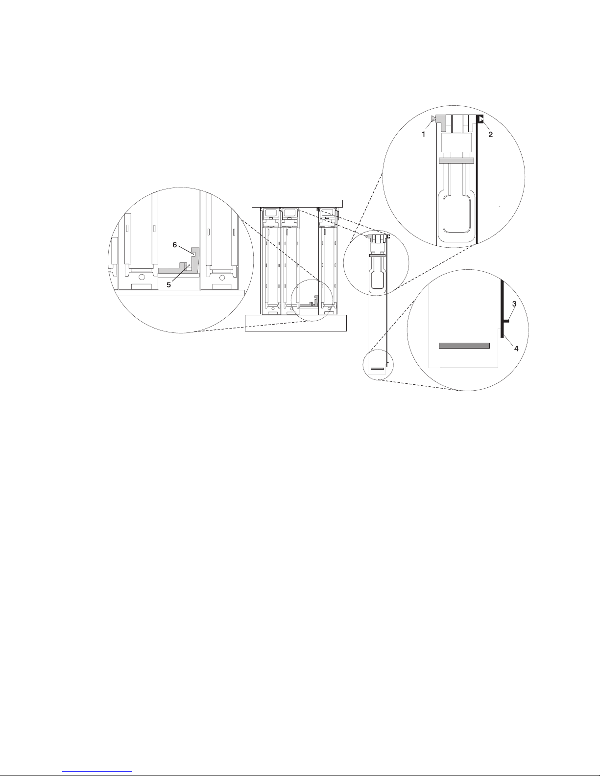
1
4
2
5
3
6
4.
5.
or
6.
7. As
8.
3.
Examine the PCI adapter slot opening carefully, and note the location of the dovetail rails and the
cassette guide rails. A flashlight can be used to enable you to see the dovetail rails and the cassette
guide rail slots, as shown in the following illustration.
Cassette Left Dovetail Rail
Cassette Right Dovetail Rail
Cassette Side Guide Rail
Cassette Bottom Guide Rail
Side Guide Rail Slot on System Board
Bottom Guide Rail Slot on System Board
Hold the PCI adapter cassette at the PCI adapter slot so that the PCI adapter cassette is
perpendicular to the slot and level with the slot opening.
Align the bottom edge of the PCI cassette cover with the PCI cassette guide rail on the system board
I/O unit.
Slide the cassette partially into the guide.
Attention: If the cassette does not slide in smoothly, the cover might not have engaged the PCI
cassette guide rail. Carefully pull the adapter back out and start again.
you slide the cassette into the slot, ensure that the dovetail rail on the top of the PCI adapter
cassette aligns with the mating slots on any cassettes that might be installed on the left and right
sides.
Push the cassette in until it is flush with any other installed cassettes.
Chapter 5. Installing Options
59
Page 76

If
To
1.
2.
3.
4. If
a
If
5.
6.
1. If
2. Go to
3.
4.
5.
60
9.
Visually check to ensure that the cassette is parallel with the cassettes to the left or right. If the
cassette is not parallel with the neighboring cassettes, the cassette dovetail rails might not be
correctly engaged. If the cassette is not correctly aligned, you might need to pull it out so you can see
the ends of the dovetail rails. If so, reinsert the cassette, ensuring that the dovetail rails engage on
both sides of the cassette.
Note:
there are no other cassettes installed, it is not necessary to check the alignment of the
dovetail rails.
10.
When the cassette is fully inserted, ensure that the lock bar is in the unlocked position (pulled out).
11.
Depress the handle release latch. Lift the handle up until the handle-release lever clicks when it locks
into position.
Note: To aid you in seating the PCI adapter connector, it may be necessary to press down on the
adapter tailstock tab. The PCI adapter is completely installed into the PCI adapter slot when
the handle is in the fully raised position and the tailstock is seated into the slots located on the
system board.
Attention: Do not force the handle into the raised position.
Non-Hot-Pluggable PCI Adapter Removal and Replacement
Because this procedure is done with the power turned off, ensure that the system is available to be shut
down.
Removing a Non-Hot-Pluggable PCI Adapter
remove a non-hot-pluggable adapter, do the following:
Turn off power and remove the power from the system as described in “Stopping the System” on page
45.
Determine the slot from which you are removing the adapter.
Refer to “Removing a PCI Adapter Cassette” on page 55. When you have completed the PCI adapter
cassette removal procedure, return here.
you are installing another adapter in this slot, follow the instructions given in “Installing or Replacing
Non-Hot-Pluggable PCI Adapter.”
you are not installing another adapter in this slot, install a blank filler in the cassette and then install
the cassette into the empty slot. For information about installing a blank filler in a cassette, see “Short
Adapter or Blank Filler Installation” on page 84.
Connect power to the system and turn on the power.
Return the system to normal operations.
Installing or Replacing a Non-Hot-Pluggable PCI Adapter
Install the adapter using the following procedure:
Note:
Because the adapter you are installing is not hot-pluggable, shut down the system and remove
power before performing this procedure.
you have just removed an adapter and you are replacing it in the system, use the procedures in “PCI
Adapter or Blank Filler Removal from a Cassette Assembly” on page 67 to install the replacement
adapter into the PCI adapter cassette, return here.
“Replacing a PCI Adapter Cassette” on page 58 to replace the appropriate cassette in the PCI
slot, then return here.
Set the color slide to blue.
Connect power to the system and turn on the power as described in “HMC Power-On Method” on
page 29.
Ensure that the adapter is configured when the system completes the boot process.
Eserver pSeries 650 Installation Guide
Page 77

a
To
1.
2.
3. At
4.
5.
6.
7.
8.
9.
Go to
at
If
OR If
If
Hot-Pluggable PCI Adapter
Use the following procedure to install hot-pluggable PCI adapters.
Note: If you are removing an adapter and replacing it with an adapter that is identical to the adapter that
was removed, use the procedure “Replacing a Hot-Pluggable PCI Adapter” on page 116.
Installing a New Hot-Pluggable PCI Adapter
Attention: The Linux operating system does not support these hot-plug procedures. Also, Linux does not
support hot-plugging any hot-pluggable PCI adapters or devices. Systems with Linux installed on one or
more partitions must be shutdown and powered off before replacing any PCI adapter or device assigned to
Linux partition. Follow the non-hot-pluggable adapter procedures when replacing a PCI adapter in any
partition with Linux installed.
Note:
Before installing a new adapter, ensure the device driver for the adapter is installed. See the
instructions that came with the new adapter.
install an adapter, perform the following steps:
Install the new adapter into a PCI adapter cassette. See “PCI Adapter or Blank Filler Removal from a
Cassette Assembly” on page 67.
Log in as root user, if the system is a partitioned system, log in as root user on the partition that has
the adapter assigned to it.
the command line, type smitty.
Select Devices.
Select PCI Hot Plug Manager.
From the PCI Hot-Plug Manager menu, select Add a PCI Hot-Plug Adapter and press Enter. The
Add a Hot-Plug Adapter window displays.
For adapter placement information, see the PCI Adapter Placement Reference, order number
SA38-0538. Select an empty PCI slot for the adapter.
Select the appropriate empty PCI slot from the ones listed on the screen, and press Enter.
Follow the instructions on the screen to install the adapter until the visual indicator (LED) for the
specified PCI slot is set to the Action state.
10.
“Replacing a PCI Adapter Cassette” on page 58 to install the cassette in the system. Then
return here.
11.
Connect the appropriate cables and devices to the adapter.
12.
Continue to follow the screen instructions until you receive a message that the installation is
successful. Successful installation is indicated by the OK message displayed next to the Command
field at the top of the screen.
13.
Press the F3 key to return to the PCI Hot-Plug Manager menu.
14.
Select Install/Configure Devices Added After IPL and press Enter. Follow the instructions on the
screen. Successful installation is indicated by the OK message displayed next to the Command field
the top of the screen.
15.
you do not have other adapters to install, continue with the next step.
you have other adapters to install, press the F3 key to return to the PCI Hot-Plug Manager menu
and then return to step 6.
16.
Press F10 to exit the Hot-Plug Manager.
you have added, removed, or replaced any adapters, run the diag -a command. If the system
responds with a menu or prompt, follow the instructions to complete the device configuration.
Chapter 5. Installing Options
61
Page 78

62
PCI Hot-Plug Manager Access
Attention: The Linux operating system does not support these hot-plug procedures. Also, Linux does not
support hot-plugging any hot-pluggable PCI adapters. Systems with Linux installed on one or more
partitions must be shut down and powered off before replacing any PCI adapter assigned to a Linux
partition. Follow the non-hot-pluggable adapter procedures when replacing a PCI adapter in any partition
with Linux installed.
The installation instructions for hot-pluggable PCI adapters refer you to these procedures when it is
appropriate to perform them.
Note: A PCI adapter is only hot-pluggable if the PCI adapter supports hot-plug applications. See the PCI
Adapter Placement Reference, order number SA38-0538.
Eserver pSeries 650 Installation Guide
Page 79

or
To
1.
2. At
3.
4.
5.
be
Accessing Hot-Plug Management Functions:
Note: Removing or installing a Hot-Pluggable PCI adapter requires the system administrator to take the
PCI adapter offline prior to performing the operation. Before taking an adapter offline, the devices
attached to the adapter must be taken offline as well. This action prevents a service representative
user from causing an unexpected outage for system users.
For additional information about taking an adapter offline or removing it from the system
configuration, see the AIX System Management Guide: Operating System and Devices.
Documentation for the AIX operating system is available from the IBM Eserver pSeries Information
Center at http://publib16.boulder.ibm.com/pseries/en_US/infocenter/base. Select AIX
documentation. The AIX Documentation CD contains the base set of publications for the operating
system, including system-management and end-user documentation.
access the hot-plug menus, do the following:
Log in as root user. If the system is a partitioned system, log in as root user on the partition that has
the adapter assigned to it.
the command line, type smitty.
Select Devices.
Select PCI Hot Plug Manager and press Enter.
The PCI Hot-Plug Manager menu displays. Return to the procedure that directed you here. For a
description of the menu options, see below.
Hot-Plug Manager Menu:
PCI
The following options are available from the PCI Hot Plug Manager menu:
Note: For information about the PCI slot LED states, refer to either your installation guide or service
guide.
List PCI Hot-Plug Slots
Provides a descriptive list of all slots that support PCI hot-plug capability. If the listing for a slot indicates it
holds an “Unknown” device, select the Install/Configure Devices Added after IPL to configure the
adapter in that slot.
Add a PCI Hot-Plug Adapter
Allows the user to add a new PCI hot-plug-capable adapter to the slot with the system turned on. You will
asked to identify the PCI slot that you have selected prior to the actual operation. The selected PCI slot
will go into the Action state and finally into the On state.
Note: The system will indicate the slot holds an “Unknown” device until you perform the Install/Configure
Devices Added After IPL option to configure the adapter.
Replace/Remove a PCI Hot-Plug Adapter
Allows the user to remove an existing adapter, or replace an existing adapter with an identical one. For
this option to work, the adapter must be in the Defined state (see “Unconfigure a Device” option below).
You will be asked to identify the PCI slot prior to the actual operation. The selected PCI slot will go into the
Action state.
Chapter 5. Installing Options
63
Page 80

a
If
v If
v If
v If
64
Identify a PCI Hot-Plug Slot
Allows the user to identify a PCI slot. The selected PCI slot will go into the Identify state.
Unconfigure a Device
Allows the user to put an existing PCI adapter into the Defined state if the device is no longer in use.
This step must be completed successfully before starting any removal or replacement operation. If this
step fails, the customer must take action to release the device.
Configure a Defined Device
Allows a new PCI adapter to be configured into the system if software support is already available for the
adapter. The selected PCI slot will go into the On state.
Install/Configure Devices Added After IPL
The system attempts to configure any new devices and tries to find and install any required software from
user-selected source.
The add, remove, and replace functions return information to the user indicating whether the operation
was successful. If additional instructions are provided on the screen, complete the recommended actions.
the instructions do not resolve the problem, see the following:
the adapter is listed as Unknown, perform the Install/Configure Devices Added After IPL option to
configure the adapter.
you receive a warning indicating that needed device packages are not installed, the system
administrator must install the specified packages before you can configure or diagnose the adapter.
you receive a failure message indicating a hardware error, the problem might be either the adapter or
the PCI slot. Isolate the problem by retrying the operation in a different PCI slot, or trying a different
adapter in the slot. If you determine that you have failing hardware, call your service representative.
Eserver pSeries 650 Installation Guide
Page 81

in
If
To
1.
2.
3.
4.
5. At
6.
7.
8.
9.
Removing a Hot-Pluggable PCI Adapter
Attention: The Linux operating system does not support these hot-plug procedures. Also, Linux does not
support hot-plugging any hot-pluggable PCI adapters. Systems with Linux installed on one or more
partitions must be shutdown and powered off before replacing any PCI adapter or device assigned to a
Linux partition. Follow the non-hot-pluggable adapter procedures when replacing a PCI adapter or device
any partition with Linux installed.
Note:
you are removing an adapter and replacing it with an adapter that is identical to the adapter that
was removed, use the procedure “Replacing a Hot-Pluggable PCI Adapter” on page 116.
remove an adapter, perform the following steps:
Open the door of the rack.
Determine the slot from which you are removing the adapter.
Ensure that any processes or applications that might use the adapter are stopped.
Note: Removing a hot-pluggable PCI adapter requires the system administrator to take the PCI
adapter offline before performing any PCI adapter hot-plug procedures. Before taking an
adapter offline, the devices attached to the adapter must also be taken offline. This action
prevents a service representative or user from causing an unexpected outage for system
users.
For additional information about taking an adapter offline or removing it from the system
configuration, see the AIX System Management Guide: Operating System and Devices.
Documentation for the AIX operating system is available from the IBM Eserver pSeries
Information Center at http://publib16.boulder.ibm.com/pseries/en_US/infocenter/base. Select
AIX documentation. The AIX Documentation CD contains the base set of publications for the
operating system, including system-management and end-user documentation.
Log in as root user, if the system is a partitioned system, log in as root user on the partition that has
the adapter assigned to it.
the command line, type smitty.
Select Devices.
Select PCI Hot Plug Manager.
Note:
For information about the Hot-Plug Manager, refer to “PCI Hot-Plug Manager Access” on page
62.
Select Unconfigure a Device and press Enter.
Press F4 to display the Device Names menu.
10.
From the menu, select the adapter you are removing.
11.
Use the Ta b key to answer NO to Keep Definition. Press Enter.
12.
The ARE YOU SURE screen displays. Press Enter to verify the information. Successful unconfigure is
indicated by the OK message displayed next to the Command field at the top of the screen.
13.
Press F3 to return to the PCI Hot-Plug Manager menu.
14.
Select Replace/Remove a PCI Hot-Plug Adapter and press Enter. The Replace/Remove a PCI
Hot-Plug Adapter menu displays.
15.
Move the cursor to select the adapter that you are removing and press Enter. (The description entry
displays as unknown).
16.
Press the Ta b key until the entry field displays the remove operation. Press Enter. Follow the
instructions that display on the screen until you are instructed to remove the adapter.
17.
When you are instructed to remove the adapter from the adapter slot, disconnect any cables that are
connected to the adapter being removed.
Chapter 5. Installing Options
65
Page 82

Go to
Go to
If
at
If
OR If
66
18.
“Removing a PCI Adapter Cassette” on page 55 to remove the appropriate cassette, then
return here.
19.
Install the replacement adapter in the PCI adapter cassette, see “PCI Adapter or Blank Filler Removal
from a Cassette Assembly” on page 67, then return here.
20.
“Replacing a PCI Adapter Cassette” on page 58 to install the cassette in the system. Then
return here.
21.
you are not installing another adapter in this slot, install the PCI adapter cassette with a blank filler
into the slot.
22.
Continue to follow the screen instructions until you receive a message that the adapter removal is
successful. Successful removal is indicated by the OK message displayed next to the Command field
the top of the screen.
23.
you do not have other adapters to remove, continue with the next step.
you have other adapters to remove, press the F3 key to return to the PCI Hot-Plug Manager menu
and then return to step 14 on page 65.
24.
Press F10 to exit the Hot-Plug Manager.
Eserver pSeries 650 Installation Guide
Page 83

to
It
To
1.
of
1
3
2
PCI Adapter or Blank Filler Removal from a Cassette Assembly
CAUTION:
Metal edges might be sharp.
C38
Use this procedure when you are preparing to install or replace an adapter or an adapter blank filler in the
system unit or an I/O drawer.
Note: An adapter or an adapter blank filler must be installed into the PCI adapter cassette assembly
before it is reinstalled in a system unit or an I/O drawer.
Determine the slot of the system or I/O drawer in which you plan to install or remove an adapter, and refer
the procedures for removing an adapter from the system. Remove the PCI adapter cassette assembly
from the system unit or I/O drawer before beginning this procedure.
Note:
may take approximately 30 to 40 minutes to perform this procedure the first time. This time
includes using the instructions in this guide and performing the steps. Thereafter, performing this
procedure usually takes approximately 10 minutes.
Before performing the following steps, familiarize yourself with the entire procedure.
remove a PCI adapter or blank filler from a cassette assembly, do the following:
Place the PCI adapter cassette assembly on a flat work surface with the cover facing up, and the top
the adapter facing you. See the following illustration.
Cover
Handle
To p of Cover
Chapter 5. Installing Options
67
Page 84

1
2
1
68
2.
Using two fingers, remove the bushing-lock pin from the bushing. The pin can be removed by pulling it
out of the bushing with your fingernails.
Bushing
Bushing-Lock Pin
Bushing-Lock Pin
Eserver pSeries 650 Installation Guide
Page 85
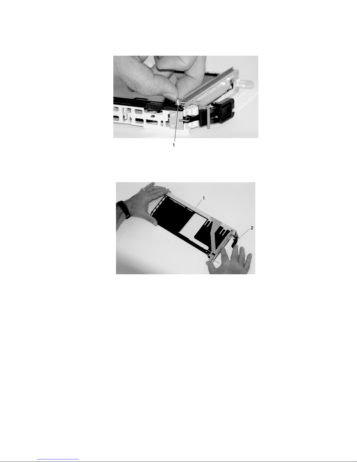
1
4.
1
2
3.
Remove the bushing. The bushing can be removed by pulling it out of the PCI adapter cassette
assembly with your fingernails.
Bushing
Turn over the PCI adapter cassette assembly so that the top is facing away from you.
To p of Adapter
Handle
Chapter 5. Installing Options
69
Page 86

a.
1
2
3
b.
of
1
2
3
70
5.
Remove the bezel, as follows:
Locate the plastic latch fingers in the top part of the cassette.
To p of Cassette
Bezel
Plastic Latch Fingers
Using one hand, pinch the plastic latch fingers, and with your other hand, carefully lift the top part
the bezel extension out until the tabs clear the slots in the PCI adapter cassette assembly.
Slots
Ta b
Bezel Extension
Eserver pSeries 650 Installation Guide
Page 87

in
1
2
d. On
1
2
c.
While holding the bezel extension out, push the plastic cover latch out of the bezel hook, as shown
the following illustration. This action allows the bezel to be removed.
Bezel Extension
Plastic Cover Latch in Bezel Hook
the opposite side of the cassette (cover side), push the cover latch to release the bezel.
Cover Side
Cover Latch
Chapter 5. Installing Options
71
Page 88

it
1
2
1
72
e.
While holding the bezel extension out, carefully slide the bezel off. You might have to work from
both sides to loosen the bezel assembly from the cassette assembly. When the bezel is free, slide
completely off the cassette assembly, and set it aside.
Bezel Extension
Bezel
Bezel
Eserver pSeries 650 Installation Guide
Page 89

a.
1
2
b.
c. By
1
2
6.
Turn over the cassette so that the cover is facing up, as shown in the following illustration. Remove the
cover from the cassette as follows:
Slide the cover until it releases from the cassette assembly.
Attention: The cover might be tight and difficult to slide. If you grasp the left end (handle end) of
the cassette and the right end of the cover, you can use enough force to pull the cover off the PCI
adapter cassette assembly.
Left End of the Cassette
Cassette Cover
Lift the cover off the assembly, and set it aside.
pulling on both sides of the locking bar, which is located on the handle, ensure that the locking
bar is pulled into the unlocked position. Raise the handle on the cassette linkage assembly until it
locks into the up position (the blank filler or adapter moves downward).
Handle
Locking Bar
Chapter 5. Installing Options
73
Page 90

1
8.
If
If
If
74
7.
Remove the metal EMC shield from the top of the tailstock.
Metal EMC Shield
Remove the blank filler or adapter that is installed in the cassette linkage assembly.
Note:
there is a blank filler in the cassette linkage assembly, as shipped from the manufacturer,
there are two adapter arms. One adapter arm is used with short adapters (short adapter arm)
and the other adapter arm is used with long adapters (long adapter arm).
you are removing a short adapter or blank filler, go to “Short Adapter or Blank Filler Removal” on
page 75.
you are removing a long adapter, go to “Long Adapter Removal” on page 78.
Eserver pSeries 650 Installation Guide
Page 91

To
1.
a.
If
b.
1
2
3
4
5
Short Adapter or Blank Filler Removal
remove a short adapter or blank filler, do the following:
Slide the long and short adapter arms away from the adapter or blank filler by doing the following:
Each adapter arm has a release tab that allows the arm to be moved away from the adapter or
blank filler in the cassette assembly. Use your fingernail to lift the tab, to allow each arm to be
moved away from the adapter or blank filler. Lift the release tab on the short adapter arm, and
push on the slotted tab to release the end of the blank filler.
Note:
you plan to install a short adapter, leave the long adapter arm on the cassette linkage
assembly. If you plan to install a long adapter, remove both the long and short adapter arms
from the cassette linkage assembly in the next step.
Slide the long and short adapter arms away from the blank filler or adapter.
Long Adapter Arm
Release Ta b
Release Ta b
Short Adapter Arm
Slotted Ta b
Note: Some dual linkage PCI adapter cassettes might contain a middle-spacer arm to be used with
long adapter cards only. The middle-spacer arm and its installation can be seen in the following
Chapter 5. Installing Options
75
Page 92

1
2
3
4
5
76
illustration.
1
2
3
4
3
5
Short PCI Adapter Card
Short Adapter Arm
Middle-Spacer Arm
Long Adapter Arm
Long PCI Adapter Card
Eserver pSeries 650 Installation Guide
Page 93

1
2
3
3.
2.
Remove the adapter or blank filler from the cassette linkage assembly by rotating the bottom of the
tailstock out, as shown in the following illustration. Store the adapter or blank filler in a safe place.
Cassette Linkage Assembly
Bottom of Tailstock
Handle
The PCI adapter cassette assembly removal procedure is complete. To install a new adapter or blank
filler in the cassette, go to “Installing a New Hot-Pluggable PCI Adapter” on page 61.
Chapter 5. Installing Options
77
Page 94

To
1.
1
2.
1
3
2
4
3.
78
Long Adapter Removal
remove a long adapter, do the following:
Each adapter arm has a release tab that allows the arm to be moved away from the adapter in the
cassette assembly. Use your fingernail to lift the tab, to allow the arm to be moved away from the
adapter. Lift the release tab on the long adapter arm, and slide it off the cassette linkage assembly.
Release Ta b
Remove the adapter from the cassette linkage assembly by rotating the bottom of the tailstock out, as
shown in the following illustration. Store the adapter in a safe place.
Cassette Linkage
Assembly
Adapter
Bottom of Tailstock
Handle
Note: If you are going to install a short adapter card, and your cassette linkage has the middle-spacer
arm installed, remove the middle-spacer arm and install the short adapter arm, refer to 1a on
page 75. The middle-spacer arm and long adapter arm can be stored on the cassette linkage.
See the illustration on page 76.
The PCI adapter cassette assembly removal procedure is complete. To install a new adapter or blank
filler in the cassette, go to “Replacing an Adapter in a PCI Adapter Cassette” on page 79.
Eserver pSeries 650 Installation Guide
Page 95

1.
1
2
3
4
Replacing an Adapter in a PCI Adapter Cassette
CAUTION:
Metal edges might be sharp.
C38
This procedure is performed when preparing to install a new adapter or a blank filler in the processor
subsystem or an I/O drawer. Familiarize yourself with the entire procedure before performing the following
steps.
Place the empty PCI Adapter Cassette Assembly linkage on a flat work surface in front of you. Position
the cassette so that the handle is in the raised (up) position, and on the left, with the top of the linkage
facing away from you.
Note:
Your PCI Adapter Cassette Assembly linkage might not have the short or long adapter retaining
arms or the middle-spacer arm installed if you removed them during the removal procedure.
Handle
Cassette Linkage Assembly
Retaining Arms
Middle-Spacer Arm
Chapter 5. Installing Options
79
Page 96

2
2
80
Note: If you are installing an adapter that is in the following list, use the additional brackets listed to
help when you seat the adapter during installation. There are unique brackets (1) for each
adapter type (2):
1
2
Feature Code
2751
2969
2975
4962
5700
5701
5706
5707
6203
6228
6239
Description
S/390 ESCON Channel PCI Adapter
Gigabit Ethernet-SX PCI Adapter
10/100/1000 Base-T Ethernet PCI Adapter
10/100 Mbps Ethernet PCI Adapter II
IBM Gigabit Ethernet-SX PCI-X Adapter
IBM 10/100/1000 Base-TX Ethernet PCI-X Adapter
IBM 2-Port 10/100/1000 Base-TX Ethernet PCI-X Adapter
IBM 2-Port Gigabit Ethernet-SX PCI-X Adapter
PCI Dual Channel Ultra3 SCSI Adapter
Gigabit Fibre Channel Adapter for 64-bit PCI Bus
Gigabit Fibre Channel PCI-X Adapter
Bracket Part
Number
31L8728
44P2676
44P2676
44P0321
53P5450
53P5450
53P5450
53P5450
44P2661
44P2675
44P2650
Eserver pSeries 650 Installation Guide
Page 97

To
a.
b.
1
3
2
4
5
2.
determine if you are installing a long adapter or a short adapter, use the following steps. If you
know the length of your adapter, skip the following steps and proceed to step 3 on page 83.
Remove the adapter from its protective packaging and, if present, remove the plastic extension
handle from the end of the adapter.
Place the adapter or a blank filler over the cassette with the upper left corner aligned into the top
adapter-retaining clip.
1
2
5
4
To p Adapter-Retaining Clip
Cassette Linkage Assembly
3
Adapter
Bottom of Tailstock
Handle
Chapter 5. Installing Options
81
Page 98

1
82
c.
The cassette linkage assembly is marked to show long or short adapters similar to the adapter
shown in the following illustration. Check the right end of the adapter to determine if it is long
enough to fall into the long area of the cassette linkage. Ensure that the corner on the left end of
the adapter is still aligned into the top adapter-retaining clip and determine the length of the
adapter.
ARM
LONG
ARM
SHORT
1
2
Eserver pSeries 650 Installation Guide
To p Adapter-Retaining Clip
Page 99

If
on
1
2
3.
Remove the adapter or blank filler and ensure that the handle is in the up position. If you need to
move the handle, ensure that the gray locking bar is pulled into the unlocked position, and then rotate
the adapter handle until the handle is in the up position (the cassette linkage will extend down beyond
the cassette top).
you are installing a short adapter or blank filler, proceed to “Short Adapter or Blank Filler Installation”
page 84. If you are installing a long adapter, go to “Long Adapter Installation” on page 100.
1
Handle Release Sever
Lock
2
Chapter 5. Installing Options
83
Page 100

To
1.
1
3
2
4
84
Short Adapter or Blank Filler Installation
install a short adapter or blank filler, use the following procedure.
Place the adapter or blank filler into the cassette so that the upper-left corner of the adapter engages
the adjustable top adapter-retaining clip as shown in the following illustration.
1
4
2
3
Cassette Linkage
Retaining Clip
Assembly
Bottom of Tailstock
Handle
Eserver pSeries 650 Installation Guide
 Loading...