

Page 1

Power Systems
RDX docking stations, power cable, and
removable disk drives for the 9009-41A,
9009-42A, or 9223-42H
IBM
Page 2

Note
Before using this information and the product it supports, read the information in “Safety notices” on
page v, “Notices” on page 87, the IBM Systems Safety Notices manual, G229-9054, and the IBM
Environmental Notices and User Guide, Z125–5823.
This edition applies to IBM® Power Systems servers that contain the POWER9™ processor and to all associated models.
©
Copyright International Business Machines Corporation 2018, 2019.
US Government Users Restricted Rights – Use, duplication or disclosure restricted by GSA ADP Schedule Contract with
IBM Corp.
Page 3

Contents
Safety notices........................................................................................................v
RDX docking stations, removable disk drives, and power cable...............................1
Installing an external RDX docking station in the 9009-41A, 9009-42A, or 9223-42H...........................1
Installing an internal RDX docking station..................................................................................................3
Preparing the system..............................................................................................................................3
Installing an internal RDX docking station.......................................................................................... 10
Preparing the system for operation..................................................................................................... 23
Removing and replacing an internal RDX docking station, power cable, and removable disk drive ......29
Removing and replacing an internal RDX docking station in the 9009-41A, 9009-42A, or
9223-42H........................................................................................................................................29
Internal RDX power cable.................................................................................................................... 54
Removing and replacing an internal RDX removable disk drive......................................................... 73
Managing RDX docking stations and removable disk drives.................................................................... 77
Internal RDX docking stations and removable disk drives................................................................. 77
External RDX docking stations and removable disk drives.................................................................81
Notices................................................................................................................87
Accessibility features for IBM Power Systems servers............................................................................ 88
Privacy policy considerations ................................................................................................................... 89
Trademarks................................................................................................................................................ 89
Electronic emission notices.......................................................................................................................89
Class A Notices.....................................................................................................................................90
Class B Notices.....................................................................................................................................93
Terms and conditions................................................................................................................................ 95
iii
Page 4

iv
Page 5

Safety notices
Safety notices may be printed throughout this guide:
• DANGER notices call attention to a situation that is potentially lethal or extremely hazardous to people.
• CAUTION notices call attention to a situation that is potentially hazardous to people because of some
existing condition.
• Attention notices call attention to the possibility of damage to a program, device, system, or data.
World Trade safety information
Several countries require the safety information contained in product publications to be presented in their
national languages. If this requirement applies to your country, safety information documentation is
included in the publications package (such as in printed documentation, on DVD, or as part of the product)
shipped with the product. The documentation contains the safety information in your national language
with references to the U.S. English source. Before using a U.S. English publication to install, operate, or
service this product, you must rst become familiar with the related safety information documentation.
You should also refer to the safety information documentation any time you do not clearly understand any
safety information in the U.S. English publications.
Replacement or additional copies of safety information documentation can be obtained by calling the IBM
Hotline at 1-800-300-8751.
German safety information
Das Produkt ist nicht für den Einsatz an Bildschirmarbeitsplätzen im Sinne § 2 der
Bildschirmarbeitsverordnung geeignet.
Laser safety information
IBM servers can use I/O cards or features that are ber-optic based and that utilize lasers or LEDs.
Laser compliance
IBM servers may be installed inside or outside of an IT equipment rack.
DANGER:
Electrical voltage and current from power, telephone, and communication cables are hazardous.
To avoid a shock hazard:
• If IBM supplied the power cord(s), connect power to this unit only with the IBM provided power
cord. Do not use the IBM provided power cord for any other product.
• Do not open or service any power supply assembly.
• Do not connect or disconnect any cables or perform installation, maintenance, or reconguration
of this product during an electrical storm.
• The product might be equipped with multiple power cords. To remove all hazardous voltages,
disconnect all power cords.
– For AC power, disconnect all power cords from their AC power source.
– For racks with a DC power distribution panel (PDP), disconnect the customer’s DC power
• When connecting power to the product ensure all power cables are properly connected.
When working on or around the system, observe the following precautions:
source to the PDP.
– For racks with AC power, connect all power cords to a properly wired and grounded electrical
outlet. Ensure that the outlet supplies proper voltage and phase rotation according to the
system rating plate.
©
Copyright IBM Corp. 2018, 2019 v
Page 6

– For racks with a DC power distribution panel (PDP), connect the customer’s DC power source
to the PDP. Ensure that the proper polarity is used when attaching the DC power and DC power
return wiring.
• Connect any equipment that will be attached to this product to properly wired outlets.
• When possible, use one hand only to connect or disconnect signal cables.
• Never turn on any equipment when there is evidence of re, water, or structural damage.
• Do not attempt to switch on power to the machine until all possible unsafe conditions are
corrected.
• Assume that an electrical safety hazard is present. Perform all continuity, grounding, and power
checks specied during the subsystem installation procedures to ensure that the machine meets
safety requirements.
• Do not continue with the inspection if any unsafe conditions are present.
• Before you open the device covers, unless instructed otherwise in the installation and
conguration procedures: Disconnect the attached AC power cords, turn off the applicable
circuit breakers located in the rack power distribution panel (PDP), and disconnect any
telecommunications systems, networks, and modems.
DANGER:
• Connect and disconnect cables as described in the following procedures when installing,
moving, or opening covers on this product or attached devices.
To Disconnect:
1. Turn off everything (unless instructed otherwise).
2. For AC power, remove the power cords from the outlets.
3. For racks with a DC power distribution panel (PDP), turn off the circuit breakers located in the
PDP and remove the power from the Customer's DC power source.
4. Remove the signal cables from the connectors.
5. Remove all cables from the devices.
To Connect:
1. Turn off everything (unless instructed otherwise).
2. Attach all cables to the devices.
3. Attach the signal cables to the connectors.
4. For AC power, attach the power cords to the outlets.
5. For racks with a DC power distribution panel (PDP), restore the power from the Customer's
DC power source and turn on the circuit breakers located in the PDP.
6. Turn on the devices.
Sharp edges, corners and joints may be present in and around the system. Use care when
handling equipment to avoid cuts, scrapes and pinching. (D005)
(R001 part 1 of 2):
DANGER:
• Heavy equipment–personal injury or equipment damage might result if mishandled.
• Always lower the leveling pads on the rack cabinet.
• Always install stabilizer brackets on the rack cabinet unless the earthquake option is to be
installed.
• To avoid hazardous conditions due to uneven mechanical loading, always install the heaviest
devices in the bottom of the rack cabinet. Always install servers and optional devices starting
from the bottom of the rack cabinet.
Observe the following precautions when working on or around your IT rack system:
vi Power Systems: RDX docking stations, power cable, and removable disk drives for the 9009-41A, 9009-42A,
or 9223-42H
Page 7

• Rack-mounted devices are not to be used as shelves or work spaces. Do not place objects on top
of rack-mounted devices. In addition, do not lean on rack mounted devices and do not use them
to stabilize your body position (for example, when working from a ladder).
• Each rack cabinet might have more than one power cord.
– For AC powered racks, be sure to disconnect all power cords in the rack cabinet when directed
to disconnect power during servicing.
– For racks with a DC power distribution panel (PDP), turn off the circuit breaker that controls
the power to the system unit(s), or disconnect the customer’s DC power source, when
directed to disconnect power during servicing.
• Connect all devices installed in a rack cabinet to power devices installed in the same rack
cabinet. Do not plug a power cord from a device installed in one rack cabinet into a power device
installed in a different rack cabinet.
• An electrical outlet that is not correctly wired could place hazardous voltage on the metal parts
of the system or the devices that attach to the system. It is the responsibility of the customer to
ensure that the outlet is correctly wired and grounded to prevent an electrical shock. (R001 part
1 of 2)
(R001 part 2 of 2):
CAUTION:
• Do not install a unit in a rack where the internal rack ambient temperatures will exceed the
manufacturer's recommended ambient temperature for all your rack-mounted devices.
• Do not install a unit in a rack where the air flow is compromised. Ensure that air flow is not
blocked or reduced on any side, front, or back of a unit used for air flow through the unit.
• Consideration should be given to the connection of the equipment to the supply circuit so that
overloading of the circuits does not compromise the supply wiring or overcurrent protection. To
provide the correct power connection to a rack, refer to the rating labels located on the
equipment in the rack to determine the total power requirement of the supply circuit.
• (For sliding drawers.) Do not pull out or install any drawer or feature if the rack stabilizer
brackets are not attached to the rack or if the rack is not bolted to the floor. Do not pull out more
than one drawer at a time. The rack might become unstable if you pull out more than one drawer
at a time.
• (For xed drawers.) This drawer is a xed drawer and must not be moved for servicing unless
specied by the manufacturer. Attempting to move the drawer partially or completely out of the
rack might cause the rack to become unstable or cause the drawer to fall out of the rack. (R001
part 2 of 2)
CAUTION:
stability during relocation. Follow these general guidelines whenever you relocate a populated
rack cabinet within a room or building.
• Reduce the weight of the rack cabinet by removing equipment starting at the top of the rack
cabinet. When possible, restore the rack cabinet to the conguration of the rack cabinet as you
received it. If this conguration is not known, you must observe the following precautions:
Removing components from the upper positions in the rack cabinet improves rack
Safety notices vii
Page 8

– Remove all devices in the 32U position (compliance ID RACK-001 or 22U (compliance ID
RR001) and above.
– Ensure that the heaviest devices are installed in the bottom of the rack cabinet.
– Ensure that there are little-to-no empty U-levels between devices installed in the rack cabinet
below the 32U (compliance ID RACK-001 or 22U (compliance ID RR001) level, unless the
received conguration specically allowed it.
• If the rack cabinet you are relocating is part of a suite of rack cabinets, detach the rack cabinet
from the suite.
• If the rack cabinet you are relocating was supplied with removable outriggers they must be
reinstalled before the cabinet is relocated.
• Inspect the route that you plan to take to eliminate potential hazards.
• Verify that the route that you choose can support the weight of the loaded rack cabinet. Refer to
the documentation that comes with your rack cabinet for the weight of a loaded rack cabinet.
• Verify that all door openings are at least 760 x 230 mm (30 x 80 in.).
• Ensure that all devices, shelves, drawers, doors, and cables are secure.
• Ensure that the four leveling pads are raised to their highest position.
• Ensure that there is no stabilizer bracket installed on the rack cabinet during movement.
• Do not use a ramp inclined at more than 10 degrees.
• When the rack cabinet is in the new location, complete the following steps:
– Lower the four leveling pads.
– Install stabilizer brackets on the rack cabinet or in an earthquake environment bolt the rack to
the floor.
– If you removed any devices from the rack cabinet, repopulate the rack cabinet from the
lowest position to the highest position.
• If a long-distance relocation is required, restore the rack cabinet to the conguration of the rack
cabinet as you received it. Pack the rack cabinet in the original packaging material, or equivalent.
Also lower the leveling pads to raise the casters off of the pallet and bolt the rack cabinet to the
pallet.
(L001)
(L002)
(R002)
DANGER:
this label attached. Do not open any cover or barrier that contains this label. (L001)
Hazardous voltage, current, or energy levels are present inside any component that has
viii
Power Systems: RDX docking stations, power cable, and removable disk drives for the 9009-41A,
9009-42A, or 9223-42H
Page 9

(L003)
or
or
DANGER: Rack-mounted devices are not to be used as shelves or work spaces. Do not place
objects on top of rack-mounted devices. In addition, do not lean on rack-mounted devices and do
not use them to stabilize your body position (for example, when working from a ladder). (L002)
or
or
Safety notices
ix
Page 10

(L007)
DANGER: Multiple power cords. The product might be equipped with multiple AC power cords or
multiple DC power cables. To remove all hazardous voltages, disconnect all power cords and
power cables. (L003)
CAUTION:
(L008)
CAUTION:
All lasers are certied in the U.S. to conform to the requirements of DHHS 21 CFR Subchapter J for class 1
laser products. Outside the U.S., they are certied to be in compliance with IEC 60825 as a class 1 laser
product. Consult the label on each part for laser certication numbers and approval information.
CAUTION:
ROM drive, DVD-RAM drive, or laser module, which are Class 1 laser products. Note the following
information:
• Do not remove the covers. Removing the covers of the laser product could result in exposure to
hazardous laser radiation. There are no serviceable parts inside the device.
• Use of the controls or adjustments or performance of procedures other than those specied
herein might result in hazardous radiation exposure.
A hot surface nearby. (L007)
Hazardous moving parts nearby. (L008)
This product might contain one or more of the following devices: CD-ROM drive, DVD-
(C026)
x Power Systems: RDX docking stations, power cable, and removable disk drives for the 9009-41A, 9009-42A,
or 9223-42H
Page 11

CAUTION: Data processing environments can contain equipment transmitting on system links
with laser modules that operate at greater than Class 1 power levels. For this reason, never look
into the end of an optical ber cable or open receptacle. Although shining light into one end and
looking into the other end of a disconnected optical ber to verify the continuity of optic bers may
not injure the eye, this procedure is potentially dangerous. Therefore, verifying the continuity of
optical bers by shining light into one end and looking at the other end is not recommended. To
verify continuity of a ber optic cable, use an optical light source and power meter. (C027)
CAUTION: This product contains a Class 1M laser. Do not view directly with optical instruments.
(C028)
CAUTION: Some laser products contain an embedded Class 3A or Class 3B laser diode. Note the
following information:
• Laser radiation when open.
• Do not stare into the beam, do not view directly with optical instruments, and avoid direct
exposure to the beam. (C030)
(C030)
CAUTION: The battery contains lithium. To avoid possible explosion, do not burn or charge the
battery.
Do Not:
• Throw or immerse into water
• Heat to more than 100 degrees C (212 degrees F)
• Repair or disassemble
Exchange only with the IBM-approved part. Recycle or discard the battery as instructed by local
regulations. In the United States, IBM has a process for the collection of this battery. For
information, call 1-800-426-4333. Have the IBM part number for the battery unit available when
you call. (C003)
CAUTION: Regarding IBM provided VENDOR LIFT TOOL:
• Operation of LIFT TOOL by authorized personnel only.
• LIFT TOOL intended for use to assist, lift, install, remove units (load) up into rack elevations. It is
not to be used loaded transporting over major ramps nor as a replacement for such designated
tools like pallet jacks, walkies, fork trucks and such related relocation practices. When this is not
practicable, specially trained persons or services must be used (for instance, riggers or movers).
• Read and completely understand the contents of LIFT TOOL operator's manual before using.
Failure to read, understand, obey safety rules, and follow instructions may result in property
damage and/or personal injury. If there are questions, contact the vendor's service and support.
Local paper manual must remain with machine in provided storage sleeve area. Latest revision
manual available on vendor's web site.
• Test verify stabilizer brake function before each use. Do not over-force moving or rolling the LIFT
TOOL with stabilizer brake engaged.
• Do not raise, lower or slide platform load shelf unless stabilizer (brake pedal jack) is fully
engaged. Keep stabilizer brake engaged when not in use or motion.
• Do not move LIFT TOOL while platform is raised, except for minor positioning.
• Do not exceed rated load capacity. See LOAD CAPACITY CHART regarding maximum loads at
center versus edge of extended platform.
• Only raise load if properly centered on platform. Do not place more than 200 lb (91 kg) on edge
of sliding platform shelf also considering the load's center of mass/gravity (CoG).
• Do not corner load the platforms, tilt riser, angled unit install wedge or other such accessory
options. Secure such platforms -- riser tilt, wedge, etc options to main lift shelf or forks in all four
(4x or all other provisioned mounting) locations with provided hardware only, prior to use. Load
objects are designed to slide on/off smooth platforms without appreciable force, so take care
Safety notices
xi
Page 12

not to push or lean. Keep riser tilt [adjustable angling platform] option flat at all times except for
nal minor angle adjustment when needed.
• Do not stand under overhanging load.
• Do not use on uneven surface, incline or decline (major ramps).
• Do not stack loads.
• Do not operate while under the influence of drugs or alcohol.
• Do not support ladder against LIFT TOOL (unless the specic allowance is provided for one
following qualied procedures for working at elevations with this TOOL).
• Tipping hazard. Do not push or lean against load with raised platform.
• Do not use as a personnel lifting platform or step. No riders.
• Do not stand on any part of lift. Not a step.
• Do not climb on mast.
• Do not operate a damaged or malfunctioning LIFT TOOL machine.
• Crush and pinch point hazard below platform. Only lower load in areas clear of personnel and
obstructions. Keep hands and feet clear during operation.
• No Forks. Never lift or move bare LIFT TOOL MACHINE with pallet truck, jack or fork lift.
• Mast extends higher than platform. Be aware of ceiling height, cable trays, sprinklers, lights, and
other overhead objects.
• Do not leave LIFT TOOL machine unattended with an elevated load.
• Watch and keep hands, ngers, and clothing clear when equipment is in motion.
• Turn Winch with hand power only. If winch handle cannot be cranked easily with one hand, it is
probably over-loaded. Do not continue to turn winch past top or bottom of platform travel.
Excessive unwinding will detach handle and damage cable. Always hold handle when lowering,
unwinding. Always assure self that winch is holding load before releasing winch handle.
• A winch accident could cause serious injury. Not for moving humans. Make certain clicking sound
is heard as the equipment is being raised. Be sure winch is locked in position before releasing
handle. Read instruction page before operating this winch. Never allow winch to unwind freely.
Freewheeling will cause uneven cable wrapping around winch drum, damage cable, and may
cause serious injury.
• This TOOL must be maintained correctly for IBM Service personnel to use it. IBM shall inspect
condition and verify maintenance history before operation. Personnel reserve the right not to use
TOOL if inadequate. (C048)
Power and cabling information for NEBS (Network Equipment-Building System) GR-1089-CORE
The following comments apply to the IBM servers that have been designated as conforming to NEBS
(Network Equipment-Building System) GR-1089-CORE:
The equipment is suitable for installation in the following:
• Network telecommunications facilities
• Locations where the NEC (National Electrical Code) applies
The intrabuilding ports of this equipment are suitable for connection to intrabuilding or unexposed wiring
or cabling only. The intrabuilding ports of this equipment must not be metallically connected to the
interfaces that connect to the OSP (outside plant) or its wiring. These interfaces are designed for use as
intrabuilding interfaces only (Type 2 or Type 4 ports as described in GR-1089-CORE) and require isolation
from the exposed OSP cabling. The addition of primary protectors is not sufcient protection to connect
these interfaces metallically to OSP wiring.
Note: All Ethernet cables must be shielded and grounded at both ends.
The ac-powered system does not require the use of an external surge protection device (SPD).
xii
Power Systems: RDX docking stations, power cable, and removable disk drives for the 9009-41A, 9009-42A,
or 9223-42H
Page 13

The dc-powered system employs an isolated DC return (DC-I) design. The DC battery return terminal shall
not be connected to the chassis or frame ground.
The dc-powered system is intended to be installed in a common bonding network (CBN) as described in
GR-1089-CORE.
Safety notices xiii
Page 14

xiv Power Systems: RDX docking stations, power cable, and removable disk drives for the 9009-41A,
9009-42A, or 9223-42H
Page 15

RDX docking stations, removable disk drives, and
power cable, for the 9009-41A, 9009-42A, or
9223-42H
Find information about removing and replacing internal RDX docking stations, removable disk drives, and
power cable in the IBM Power® System S914 (9009-41A), IBM Power System S924 (9009-42A), or IBM
Power System H924 (9223-42H) system.
Installing an external RDX docking station in the 9009-41A, 9009-42A, or 9223-42H
Find information about installing an external RDX docking station.
About this task
Keep in mind the following guidelines when you install the external RDX docking station:
• A rack shelf is not included with the external RDX docking station, feature code (FC) EUA4.
• The docking station can be rested on a flat surface in a rack or on a table top next to a rack.
• Ensure that the device is on a flat surface, is right side up, and is not likely to be bumped, dropped, or
otherwise damaged or jolted.
• If the docking station is placed by itself on a rack shelf, it has space on the sides of the device. No ller
panels are provided with the docking station.
• If the docking station is placed on a rack shelf, ensure that the docking station has sufcient air flow.
Also, ensure that it does not affect the air flow of the other systems in the rack.
• Do not block the fan on the rear of the docking station.
• The external RDX disk drive can be installed while the system is powered on and needs to be congured
following the installation.
To install the external docking station, complete the following steps:
Procedure
1. Attach the electrostatic discharge (ESD) wrist strap.
The ESD wrist strap must be connected to an unpainted metal surface until the service procedure is
completed, and if applicable, until the service access cover is replaced.
Attention:
• Attach an electrostatic discharge (ESD) wrist strap to the front ESD jack, to the rear ESD jack,
or to an unpainted metal surface of your hardware to prevent the electrostatic discharge from
damaging your hardware.
• When you use an ESD wrist strap, follow all electrical safety procedures. An ESD wrist strap is
used for static control. It does not increase or decrease your risk of receiving electric shock
when using or working on electrical equipment.
• If you do not have an ESD wrist strap, just prior to removing the product from ESD packaging
and installing or replacing hardware, touch an unpainted metal surface of the system for a
minimum of 5 seconds. If at any point in this service process you move away from the
system, it is important to again discharge yourself by touching an unpainted metal surface for
at least 5 seconds before you continue with the service process.
©
Copyright IBM Corp. 2018, 2019 1
Page 16

2. Place the external RDX docking station on a flat service. Use the previous guidelines when selecting a
location.
3. Attach one end of the external USB cable (F) to the rear of the external RDX docking station.
Figure 1. Attaching USB and power supply cables
4. Attach the other end of the external USB cable (F) to an external, integrated USB port or to the USB
ports on a four-port USB PCIe (Peripheral Component Interconnect Express) adapter.
5. Attach the power supply cord (E) to the rear of the external RDX docking station and plug it into a
power source. In addition to the external power supply cord, you can also use universal adapters as
needed.
6. After the external RDX docking station is powered on, insert the disk drive into it.
Note: A green indicator light appears when the disk drive is placed into the dock correctly.
7. Congure the removable disk drive by performing the following steps:
a) For the AIX® operating system, log in as root user.
b) At the command line, type cfgmgr and press Enter.
c) To verify that the system recognizes the device, enter lsdev -Cc usbms.
Note: The Linux operating system automatically congures the drive as a disk drive that has a name in
the format sdx, for example, sda, sdb, and sdc. To verify that the system recognizes the device, enter
lsusb. To nd the device that is associated with the USB disk drive, enter lsscsi.
8. Verify the installed part.
• If you replaced the part because of a service action, verify the installed part. For instructions, see
https://www.ibm.com/support/knowledgecenter/POWER9/p9ect/
pxect_verifyrepair.htm (www.ibm.com/support/knowledgecenter/POWER9/p9ect/
pxect_verifyrepair.htm).
• If you installed the part for any other reason, verify the installed part. For instructions, see https://
www.ibm.com/support/knowledgecenter/POWER9/p9haj/pxhaj_hsmverify.htm (www.ibm.com/
support/knowledgecenter/POWER9/p9haj/pxhaj_hsmverify.htm).
2
Power Systems: RDX docking stations, power cable, and removable disk drives for the 9009-41A, 9009-42A,
or 9223-42H
Page 17

Installing an internal RDX docking station in the 9009-41A, 9009-42A, or
9223-42H
Find information about installing an internal RDX docking station.
About this task
Note: Installing this feature is a customer task. You can complete this task yourself, or contact a service
provider to complete the task for you. You might be charged a fee by the service provider for this service.
If your system is managed by the Hardware Management Console (HMC), use the HMC to repair a part in
the system. For instructions, see Repairing a part by using the HMC (www.ibm.com/support/
knowledgecenter/POWER9/p9haj/p9haj_hmc_repair.htm).
If your system is not managed by an HMC, complete the steps in the following procedures to install an
internal RDX docking station.
Preparing the system to remove and replace an internal RDX docking station in the
9009-41A, 9009-42A, or 9223-42H
To prepare the system to install an internal RDX docking station, complete the steps in this procedure.
Procedure
1. Identify the part and the system that you are working on. For instructions, see Identifying a
part (www.ibm.com/support/knowledgecenter/POWER9/p9haj/sal.htm).
Use the blue identify LED on the enclosure to locate the system. Ensure that the serial number of the
system matches the serial number to be serviced.
2. Stop the system. For instructions, see Stopping a system (www.ibm.com/support/knowledgecenter/
POWER9/p9haj/crustopsys.htm).
3. Label and disconnect the power cords from the system unit.
See Figure 2 on page 4 or Figure 3 on page 5.
Notes:
• This system might be equipped with two or more power supplies. If the removing and replacing
procedures require the system power to be turned off, ensure that all the power sources to the
system are disconnected.
• The power cord (B) is fastened to the system with hook-and-loop fastener (A). If you are placing the
system in a service position after you disconnect the power cords, ensure that you unstrap the
fastener.
RDX docking stations, removable disk drives, and power cable, for the 9009-41A, 9009-42A, or 9223-42H
3
Page 18

Figure 2. Removing the power cords from a rack-mounted server
4
Power Systems: RDX docking stations, power cable, and removable disk drives for the 9009-41A, 9009-42A,
or 9223-42H
Page 19

Figure 3. Removing the power cords from a stand-alone server
(L003)
or
RDX docking stations, removable disk drives, and power cable, for the 9009-41A, 9009-42A, or 9223-42H
5
Page 20

or
or
or
6
Power Systems: RDX docking stations, power cable, and removable disk drives for the 9009-41A, 9009-42A,
or 9223-42H
Page 21

DANGER: Multiple power cords. The product might be equipped with multiple AC power cords
or multiple DC power cables. To remove all hazardous voltages, disconnect all power cords and
power cables. (L003)
4. For a rack-mounted system, open the side latches (A) and pull the latches to slide the system unit fully
into the service position until the slides click and hold the system unit securely. Ensure that the screws
inside the latches are not secured to the rack.
See the following gure.
Remove the hook-and-loop fasteners that secure the cable management arms. Ensure that the cable
management arms can move freely. Ensure that the cables at the rear of the system do not catch or
bind as you pull the system unit into the service position.
Do not pull out or install any drawer or feature if the rack stabilizer brackets are not attached to the
rack. Do not pull out more than one drawer at a time. The rack might become unstable if you pull out
more than one drawer at a time.
RDX docking stations, removable disk drives, and power cable, for the 9009-41A, 9009-42A, or 9223-42H
7
Page 22

Figure 4. Releasing the side latches
5. Attach the electrostatic discharge (ESD) wrist strap.
The ESD wrist strap must be connected to an unpainted metal surface until the service procedure is
completed, and if applicable, until the service access cover is replaced.
Attention:
• Attach an electrostatic discharge (ESD) wrist strap to the front ESD jack, to the rear ESD jack,
or to an unpainted metal surface of your hardware to prevent the electrostatic discharge from
damaging your hardware.
• When you use an ESD wrist strap, follow all electrical safety procedures. An ESD wrist strap is
used for static control. It does not increase or decrease your risk of receiving electric shock
when using or working on electrical equipment.
• If you do not have an ESD wrist strap, just prior to removing the product from ESD packaging
and installing or replacing hardware, touch an unpainted metal surface of the system for a
minimum of 5 seconds. If at any point in this service process you move away from the
system, it is important to again discharge yourself by touching an unpainted metal surface for
at least 5 seconds before you continue with the service process.
6. Remove the service access cover.
For a rack-mounted system, complete the following steps. Refer to Figure 5 on page 9.
8
Power Systems: RDX docking stations, power cable, and removable disk drives for the 9009-41A, 9009-42A,
or 9223-42H
Page 23

Attention: Operating the system without the service access cover on for more than 10 minutes
when the system power is turned on might damage the system components.
a. Release the service cover latch by pushing the release latch (A) in the direction shown.
b. Slide the cover (B) off the system unit. When the front of the service access cover clears the upper
frame ledge, lift the cover up and off the system unit.
Figure 5. Removing the service access cover from a rack-mounted system
For a stand-alone system, complete the following steps. Refer to Figure 6 on page 10.
Attention:
when the system power is turned on might damage the system components.
a. Release the latch by pushing the release latch (A) in the direction shown.
b. Slide the cover (B) off the system unit. When the front of the service access cover has cleared the
upper frame ledge, lift the cover up and off the system unit.
RDX docking stations, removable disk drives, and power cable, for the 9009-41A, 9009-42A, or 9223-42H
Operating the system without the service access cover on for more than 10 minutes
9
Page 24

Figure 6. Removing the service access cover
Installing an internal RDX docking station in the 9009-41A, 9009-42A, or 9223-42H
To install an internal RDX docking station, complete the steps in this procedure.
Procedure
1. Ensure that you have the electrostatic discharge (ESD) wrist strap on and that the ESD clip is plugged
into a ground jack or connected to an unpainted metal surface. If not, do so now.
2. For a stand-alone system, open the front door by inserting the front door key into the lock as shown
below. Twist the key to the left (counterclockwise) to unlock the door.Horizontal is locked; vertical is
unlocked..
10
Power Systems: RDX docking stations, power cable, and removable disk drives for the 9009-41A, 9009-42A,
or 9223-42H
Page 25

Figure 7. Unlocking the front door
3. For a rack-mounted system, lift the air baffle (A) straight up as shown in Figure 8 on page 12.
For a stand-alone system, remove the air baffle (A) straight out as shown in Figure 9 on page 13.
Place the air baffle upside down on a clean area so that the foam does not collect contaminants.
RDX docking stations, removable disk drives, and power cable, for the 9009-41A, 9009-42A, or 9223-42H
11
Page 26

Figure 8. Removing the air baffle from a rack-mounted system
12
Power Systems: RDX docking stations, power cable, and removable disk drives for the 9009-41A, 9009-42A,
or 9223-42H
Page 27

Figure 9. Removing the air baffle from a stand-alone system
4. Remove the rear ller as shown in Figure 10 on page 14.
RDX docking stations, removable disk drives, and power cable, for the 9009-41A, 9009-42A, or 9223-42H
13
Page 28

Figure 10. Removing the internal RDX docking station rear ller
5. Remove the direct-access storage device (DASD) llers as shown in Figure 11 on page 15.
14
Power Systems: RDX docking stations, power cable, and removable disk drives for the 9009-41A, 9009-42A,
or 9223-42H
Page 29

Figure 11. Removing the DASD llers
6. Slide the internal RDX docking station sleeve (A) into the system and secure it using a Phillips
screwdriver and two M 3.5 x 10 MPC (B) screws as shown in Figure 12 on page 16 or Figure 13 on
page 17.
RDX docking stations, removable disk drives, and power cable, for the 9009-41A, 9009-42A, or 9223-42H
15
Page 30

Figure 12. Installing the internal RDX docking station sleeve into a rack-mounted system
16
Power Systems: RDX docking stations, power cable, and removable disk drives for the 9009-41A, 9009-42A,
or 9223-42H
Page 31

Figure 13. Installing the internal RDX docking station sleeve into a stand-alone system
7. Remove the internal RDX docking station from the static-protective package.
8. Locate the RDX Air Block, part number 01GY504 in the FRU kit. Remove the adhesive protective
cover and apply the Air Block to the rear of the internal RDX docking station.
9. Align the internal RDX latch with the holes on the bottom of the internal RDX docking station.
10. Hold the internal RDX latch in place while sliding the internal RDX docking station into the system.
RDX docking stations, removable disk drives, and power cable, for the 9009-41A, 9009-42A, or 9223-42H
17
Page 32

11. Slide the internal RDX docking station into the system until it locks into place as shown in Figure 14
on page 18 or Figure 15 on page 19.
Figure 14. Replacing the internal RDX docking station from a rack-mounted system
18
Power Systems: RDX docking stations, power cable, and removable disk drives for the 9009-41A, 9009-42A,
or 9223-42H
Page 33

Figure 15. Replacing the internal RDX docking station in a stand-alone system
12. Connect the internal RDX docking station USB cable (B) to the rear of the new internal RDX docking
station. Proceed to connect the internal RDX docking station power cable (A) to the rear of the new
internal RDX docking station as shown in Figure 16 on page 20.
Ensure that the latch (C) on the RDX power cable is oriented upwards for a rack-mounted system;
and to the outside for a stand-alone system.
RDX docking stations, removable disk drives, and power cable, for the 9009-41A, 9009-42A, or 9223-42H
19
Page 34

Figure 16. Connecting the internal RDX docking station power and USB cables
13. For a rack-mounted system, replace the air baffle (A) straight down into the chassis as shown in
Figure 17 on page 21.
For a stand-alone system, replace the air baffle (A) straight into the side of the chassis as shown in
Figure 18 on page 22.
Ensure that the front flap tucks under the front chassis.
20
Power Systems: RDX docking stations, power cable, and removable disk drives for the 9009-41A, 9009-42A,
or 9223-42H
Page 35

Figure 17. Replacing the air baffle in a rack-mounted system
RDX docking stations, removable disk drives, and power cable, for the 9009-41A, 9009-42A, or 9223-42H
21
Page 36

Figure 18. Replacing the air baffle in a stand-alone system
14. For a stand-alone system, close the front door. Insert the front door key into the lock as shown in
Figure 19 on page 23. Twist the key to the right (clockwise) to lock the door. Horizontal is locked;
vertical is unlocked.
22
Power Systems: RDX docking stations, power cable, and removable disk drives for the 9009-41A, 9009-42A,
or 9223-42H
Page 37

Figure 19. Locking the front door
Preparing the system for operation after installing an internal RDX docking station in the
9009-41A, 9009-42A, or 9223-42H
To prepare the system for operation after installing an internal RDX docking station, complete the steps in
this procedure.
Procedure
1. Ensure that you have the electrostatic discharge (ESD) wrist strap on and that the ESD clip is plugged
into a ground jack or connected to an unpainted metal surface. If not, do so now.
2. Replace the service access cover.
For a rack-mounted system, complete the following steps. Refer to Figure 20 on page 24
a. Slide the cover (A) onto the system unit.
b. Close the release latch (B) by pushing it in the direction shown.
RDX docking stations, removable disk drives, and power cable, for the 9009-41A, 9009-42A, or 9223-42H
.
23
Page 38

Figure 20. Installing the service access cover
For a stand-alone system, complete the following steps. Refer to Figure 21 on page 25.
a. Slide the cover (B) on to the system unit as shown.
b. Close the latch release (A) by pushing it in the direction shown.
24
Power Systems: RDX docking stations, power cable, and removable disk drives for the 9009-41A, 9009-42A,
or 9223-42H
Page 39

Figure 21. Installing the service access cover
3. For a rack-mounted system, unlock the blue rail safety latches (A) as shown in Figure 22 on page 26
by pushing them inward.
Ensure that the cable management arms can move freely. Ensure that the cables at the rear of the unit
do not catch or bind as you push the unit into the operating position.
RDX docking stations, removable disk drives, and power cable, for the 9009-41A, 9009-42A, or 9223-42H
25
Page 40

Figure 22. Placing the system into the operating position
4. For a rack-mounted system, push the system unit (B) as shown in the previous gure back into the
rack until both release latches lock the system into position.
Secure the cable management arm with hook-and-loop fasteners around the back side of the cable
management arm, but not around the cables.
5. Using your labels, reconnect the power cords (A) to the system unit.
Fasten the power cords (A) to the system using the hook-and-loop fasteners (B) as shown in Figure 23
on page 27 or Figure 24 on page 28.
26
Power Systems: RDX docking stations, power cable, and removable disk drives for the 9009-41A, 9009-42A,
or 9223-42H
Page 41

Figure 23. Connecting the power cords to a rack-mounted system
RDX docking stations, removable disk drives, and power cable, for the 9009-41A, 9009-42A, or 9223-42H
27
Page 42

Figure 24. Connecting the power cords to a stand-alone system
6. Start the system. For instructions, see Starting a system (www.ibm.com/support/knowledgecenter/
POWER9/p9haj/crustartsys.htm).
7. Turn off the identify LED. For instructions, see Deactivating an identify LED (www.ibm.com/support/
knowledgecenter/POWER9/p9haj/p9haj_turn_off_identify_led.htm).
28
Power Systems: RDX docking stations, power cable, and removable disk drives for the 9009-41A, 9009-42A,
or 9223-42H
Page 43

Removing and replacing an internal RDX docking station, power cable, and
removable disk drive in the 9009-41A, 9009-42A, or 9223-42H
Find information about removing and replacing an internal RDX docking station, power cable, and
removable disk drive.
About this task
Note: Installing this feature is a customer task. You can complete this task yourself, or contact a service
provider to complete the task for you. You might be charged a fee by the service provider for this service.
If your system is managed by the Hardware Management Console (HMC), use the HMC to repair a part in
the system. For instructions, see Repairing a part by using the HMC (www.ibm.com/support/
knowledgecenter/POWER9/p9haj/p9haj_hmc_repair.htm).
If your system is not managed by an HMC, complete the steps in the following procedures to remove and
replace an internal RDX docking station and power cable.
Removing and replacing an internal RDX docking station in the 9009-41A, 9009-42A, or 9223-42H
Find information about replacing an internal RDX docking station.
About this task
Note: Installing this feature is a customer task. You can complete this task yourself, or contact a service
provider to complete the task for you. You might be charged a fee by the service provider for this service.
If your system is managed by the Hardware Management Console (HMC), use the HMC to repair a part in
the system. For instructions, see Repairing a part by using the HMC
knowledgecenter/POWER9/p9haj/p9haj_hmc_repair.htm).
If your system is not managed by an HMC, complete the steps in the following procedures to remove and
replace an internal RDX docking station.
Preparing the system to remove and replace an internal RDX docking station in the 9009-41A,
9009-42A, or 9223-42H
To prepare the system to remove and replace an internal RDX docking station, complete the steps in this
procedure.
Procedure
1. Identify the part and the system that you are working on. For instructions, see Identifying a
part (www.ibm.com/support/knowledgecenter/POWER9/p9haj/sal.htm).
Use the blue identify LED on the enclosure to locate the system. Ensure that the serial number of the
system matches the serial number to be serviced.
2. Stop the system. For instructions, see Stopping a system (www.ibm.com/support/knowledgecenter/
POWER9/p9haj/crustopsys.htm).
3. Label and disconnect the power cords from the system unit.
See Figure 25 on page 30 or Figure 26 on page 31.
Notes:
• This system might be equipped with two or more power supplies. If the removing and replacing
procedures require the system power to be turned off, ensure that all the power sources to the
system are disconnected.
• The power cord (B) is fastened to the system with hook-and-loop fastener (A). If you are placing the
system in a service position after you disconnect the power cords, ensure that you unstrap the
fastener.
(www.ibm.com/support/
RDX docking stations, removable disk drives, and power cable, for the 9009-41A, 9009-42A, or 9223-42H
29
Page 44
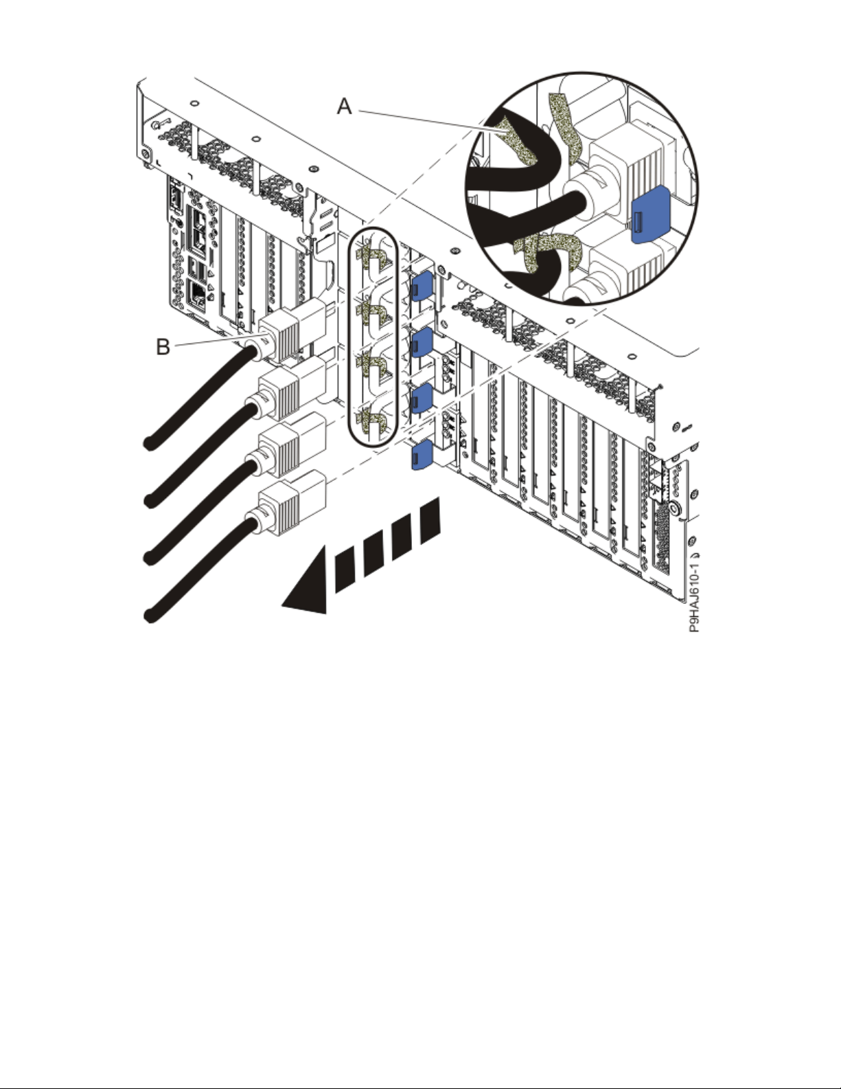
Figure 25. Removing the power cords from a rack-mounted server
30
Power Systems: RDX docking stations, power cable, and removable disk drives for the 9009-41A, 9009-42A,
or 9223-42H
Page 45

Figure 26. Removing the power cords from a stand-alone server
(L003)
or
RDX docking stations, removable disk drives, and power cable, for the 9009-41A, 9009-42A, or 9223-42H
31
Page 46

or
or
or
32
Power Systems: RDX docking stations, power cable, and removable disk drives for the 9009-41A, 9009-42A,
or 9223-42H
Page 47

DANGER: Multiple power cords. The product might be equipped with multiple AC power cords
or multiple DC power cables. To remove all hazardous voltages, disconnect all power cords and
power cables. (L003)
4. For a rack-mounted system, open the side latches (A) and pull the latches to slide the system unit fully
into the service position until the slides click and hold the system unit securely. Ensure that the screws
inside the latches are not secured to the rack.
See the following gure.
Remove the hook-and-loop fasteners that secure the cable management arms. Ensure that the cable
management arms can move freely. Ensure that the cables at the rear of the system do not catch or
bind as you pull the system unit into the service position.
Do not pull out or install any drawer or feature if the rack stabilizer brackets are not attached to the
rack. Do not pull out more than one drawer at a time. The rack might become unstable if you pull out
more than one drawer at a time.
RDX docking stations, removable disk drives, and power cable, for the 9009-41A, 9009-42A, or 9223-42H
33
Page 48

Figure 27. Releasing the side latches
5. Attach the electrostatic discharge (ESD) wrist strap.
The ESD wrist strap must be connected to an unpainted metal surface until the service procedure is
completed, and if applicable, until the service access cover is replaced.
Attention:
• Attach an electrostatic discharge (ESD) wrist strap to the front ESD jack, to the rear ESD jack,
or to an unpainted metal surface of your hardware to prevent the electrostatic discharge from
damaging your hardware.
• When you use an ESD wrist strap, follow all electrical safety procedures. An ESD wrist strap is
used for static control. It does not increase or decrease your risk of receiving electric shock
when using or working on electrical equipment.
• If you do not have an ESD wrist strap, just prior to removing the product from ESD packaging
and installing or replacing hardware, touch an unpainted metal surface of the system for a
minimum of 5 seconds. If at any point in this service process you move away from the
system, it is important to again discharge yourself by touching an unpainted metal surface for
at least 5 seconds before you continue with the service process.
6. Remove the service access cover.
For a rack-mounted system, complete the following steps. Refer to Figure 28 on page 35.
34
Power Systems: RDX docking stations, power cable, and removable disk drives for the 9009-41A, 9009-42A,
or 9223-42H
Page 49

Attention: Operating the system without the service access cover on for more than 10 minutes
when the system power is turned on might damage the system components.
a. Release the service cover latch by pushing the release latch (A) in the direction shown.
b. Slide the cover (B) off the system unit. When the front of the service access cover clears the upper
frame ledge, lift the cover up and off the system unit.
Figure 28. Removing the service access cover from a rack-mounted system
For a stand-alone system, complete the following steps. Refer to Figure 29 on page 36.
Attention:
when the system power is turned on might damage the system components.
a. Release the latch by pushing the release latch (A) in the direction shown.
b. Slide the cover (B) off the system unit. When the front of the service access cover has cleared the
upper frame ledge, lift the cover up and off the system unit.
RDX docking stations, removable disk drives, and power cable, for the 9009-41A, 9009-42A, or 9223-42H
Operating the system without the service access cover on for more than 10 minutes
35
Page 50

Figure 29. Removing the service access cover
Removing an internal RDX docking station in the 9009-41A, 9009-42A, or 9223-42H
To remove an internal RDX docking station in the system, complete the steps in this procedure.
Procedure
1. Ensure that you have the electrostatic discharge (ESD) wrist strap on and that the ESD clip is plugged
into a ground jack or connected to an unpainted metal surface. If not, do so now.
2. For a rack-mounted system, lift the air baffle (A) straight up as shown in Figure 30 on page 37.
For a stand-alone system, remove the air baffle (A) straight out as shown in Figure 31 on page 38.
Place the air baffle upside down on a clean area so that the foam does not collect contaminants.
36
Power Systems: RDX docking stations, power cable, and removable disk drives for the 9009-41A, 9009-42A,
or 9223-42H
Page 51

Figure 30. Removing the air baffle from a rack-mounted system
RDX docking stations, removable disk drives, and power cable, for the 9009-41A, 9009-42A, or 9223-42H
37
Page 52

Figure 31. Removing the air baffle from a stand-alone system
3. For a stand-alone system, open the front door by inserting the front door key into the lock as shown
below. Twist the key to the left (counterclockwise) to unlock the door.Horizontal is locked; vertical is
unlocked..
38
Power Systems: RDX docking stations, power cable, and removable disk drives for the 9009-41A, 9009-42A,
or 9223-42H
Page 53

Figure 32. Unlocking the front door
4. Disconnect the internal RDX docking station power and USB cable.
a) Disconnect the internal RDX docking station power cable (A) from the rear of the docking station as
shown in Figure 33 on page 40.
b) Disconnect the internal RDX docking station USB cable (B) from the rear of the docking station as
shown in Figure 33 on page 40.
RDX docking stations, removable disk drives, and power cable, for the 9009-41A, 9009-42A, or 9223-42H
39
Page 54

Figure 33. Disconnecting the internal RDX docking station power and USB cables
5. Remove the internal RDX docking station.
a) Push the blue tab on the internal RDX docking station latch upwards to release the internal RDX
docking station as shown in Figure 34 on page 41.
b) Gently slide the internal RDX docking station and its latch out from the system. Remove the internal
RDX docking station latch from the docking station in the direction of the arrow shown.
40
Power Systems: RDX docking stations, power cable, and removable disk drives for the 9009-41A, 9009-42A,
or 9223-42H
Page 55

Figure 34. Removing the internal RDX docking station from a rack-mounted system
RDX docking stations, removable disk drives, and power cable, for the 9009-41A, 9009-42A, or 9223-42H
41
Page 56

Figure 35. Removing the internal RDX docking station from a stand-alone system
Replacing an internal RDX docking station in the 9009-41A, 9009-42A, or 9223-42H
To replace an internal RDX docking station, complete the steps in this procedure.
Procedure
1. Ensure that you have the electrostatic discharge (ESD) wrist strap on and that the ESD clip is plugged
into a ground jack or connected to an unpainted metal surface. If not, do so now.
2. Remove the internal RDX docking station from the static-protective package.
3. Locate the RDX Air Block, part number 01GY504 in the FRU kit. Remove the adhesive protective cover
and apply the Air Block to the rear of the internal RDX docking station.
4. Align the internal RDX latch with the holes on the bottom of the internal RDX docking station.
5. Hold the internal RDX latch in place while sliding the internal RDX docking station into the system.
6. Slide the internal RDX docking station into the system until it locks into place as shown in Figure 36 on
page 43.
42
Power Systems: RDX docking stations, power cable, and removable disk drives for the 9009-41A, 9009-42A,
or 9223-42H
Page 57

Figure 36. Replacing the internal RDX docking station from a rack-mounted system
RDX docking stations, removable disk drives, and power cable, for the 9009-41A, 9009-42A, or 9223-42H
43
Page 58

Figure 37. Replacing the internal RDX docking station in a stand-alone system
7. Connect the internal RDX docking station USB cable (B) to the rear of the new internal RDX docking
station. Connect the internal RDX docking station power cable (A) to the rear of the new internal RDX
docking station as shown in Figure 38 on page 45.
If you reconnect the RDX power cable to the disk drive backplane, ensure that the latch (C) on the RDX
power cable is oriented upwards for a rack-mounted system; and to the outside for a stand-alone
system.
44
Power Systems: RDX docking stations, power cable, and removable disk drives for the 9009-41A, 9009-42A,
or 9223-42H
Page 59

Figure 38. Connecting the internal RDX docking station power and USB cables
8. For a rack-mounted system, replace the air baffle (A) straight down into the chassis as shown in Figure
39 on page 46.
For a stand-alone system, replace the air baffle (A) straight into the side of the chassis as shown in
Figure 40 on page 47.
Ensure that the front flap tucks under the front chassis.
RDX docking stations, removable disk drives, and power cable, for the 9009-41A, 9009-42A, or 9223-42H
45
Page 60

Figure 39. Replacing the air baffle in a rack-mounted system
46
Power Systems: RDX docking stations, power cable, and removable disk drives for the 9009-41A, 9009-42A,
or 9223-42H
Page 61

Figure 40. Replacing the air baffle in a stand-alone system
9. For a stand-alone system, close the front door. Insert the front door key into the lock as shown in
Figure 41 on page 48. Twist the key to the right (clockwise) to lock the door. Horizontal is locked;
vertical is unlocked.
RDX docking stations, removable disk drives, and power cable, for the 9009-41A, 9009-42A, or 9223-42H
47
Page 62

Figure 41. Locking the front door
Preparing the system for operation after removing and replacing an internal RDX docking station in
the 9009-41A, 9009-42A, or 9223-42H
To prepare the system for operation after removing and replacing an internal RDX docking station,
complete the steps in this procedure.
Procedure
1. Ensure that you have the electrostatic discharge (ESD) wrist strap on and that the ESD clip is plugged
into a ground jack or connected to an unpainted metal surface. If not, do so now.
2. Replace the service access cover.
For a rack-mounted system, complete the following steps. Refer to Figure 42 on page 49.
a. Slide the cover (A) onto the system unit.
b. Close the release latch (B) by pushing it in the direction shown.
48
Power Systems: RDX docking stations, power cable, and removable disk drives for the 9009-41A, 9009-42A,
or 9223-42H
Page 63

Figure 42. Installing the service access cover
For a stand-alone system, complete the following steps. Refer to Figure 43 on page 50.
a. Slide the cover (B) on to the system unit as shown.
b. Close the latch release (A) by pushing it in the direction shown.
RDX docking stations, removable disk drives, and power cable, for the 9009-41A, 9009-42A, or 9223-42H
49
Page 64
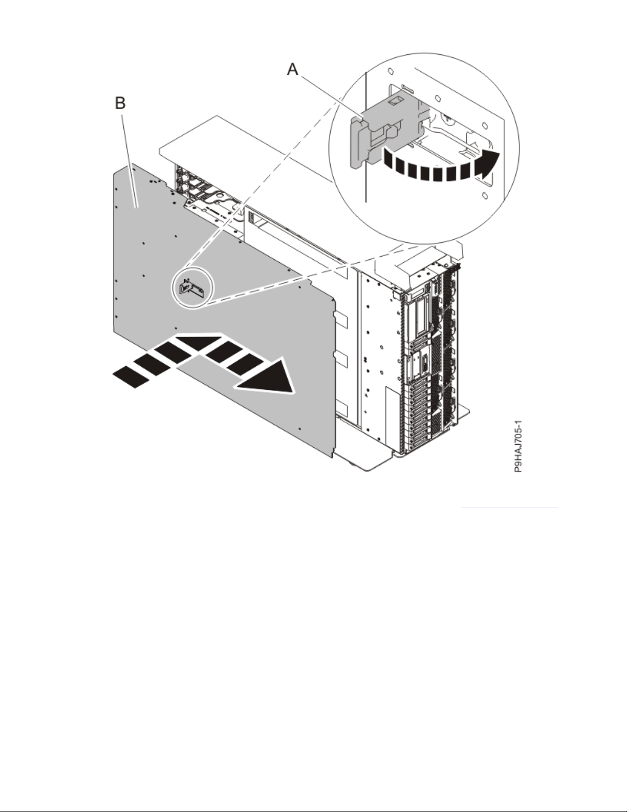
Figure 43. Installing the service access cover
3. For a rack-mounted system, unlock the blue rail safety latches (A) as shown in Figure 44 on page 51
by pushing them inward.
Ensure that the cable management arms can move freely. Ensure that the cables at the rear of the unit
do not catch or bind as you push the unit into the operating position.
50
Power Systems: RDX docking stations, power cable, and removable disk drives for the 9009-41A, 9009-42A,
or 9223-42H
Page 65

Figure 44. Placing the system into the operating position
4. For a rack-mounted system, push the system unit (B) as shown in the previous gure back into the
rack until both release latches lock the system into position.
Secure the cable management arm with hook-and-loop fasteners around the back side of the cable
management arm, but not around the cables.
5. Using your labels, reconnect the power cords (A) to the system unit.
Fasten the power cords (A) to the system using the hook-and-loop fasteners (B) as shown in Figure 45
on page 52 or Figure 46 on page 53.
RDX docking stations, removable disk drives, and power cable, for the 9009-41A, 9009-42A, or 9223-42H
51
Page 66

Figure 45. Connecting the power cords to a rack-mounted system
52
Power Systems: RDX docking stations, power cable, and removable disk drives for the 9009-41A, 9009-42A,
or 9223-42H
Page 67

Figure 46. Connecting the power cords to a stand-alone system
6. Start the system. For instructions, see Starting a system (www.ibm.com/support/knowledgecenter/
POWER9/p9haj/crustartsys.htm).
7. Turn off the identify LED. For instructions, see Deactivating an identify LED (www.ibm.com/support/
knowledgecenter/POWER9/p9haj/p9haj_turn_off_identify_led.htm).
RDX docking stations, removable disk drives, and power cable, for the 9009-41A, 9009-42A, or 9223-42H
53
Page 68

Removing and replacing an internal RDX power cable in the 9009-41A, 9009-42A, or
9223-42H
Find information about replacing an internal RDX power cable.
About this task
Note: Installing this feature is a customer task. You can complete this task yourself, or contact a service
provider to complete the task for you. You might be charged a fee by the service provider for this service.
If your system is managed by the Hardware Management Console (HMC), use the HMC to repair a part in
the system. For instructions, see Repairing a part by using the HMC
knowledgecenter/POWER9/p9haj/p9haj_hmc_repair.htm).
If your system is not managed by an HMC, complete the steps in the following procedures to remove and
replace an internal RDX power cable in the system.
Preparing the system to remove and replace an internal RDX power cable in the 9009-41A,
9009-42A, or 9223-42H
To prepare the system to remove and replace an internal RDX power cable, complete the steps in this
procedure.
Procedure
1. Identify the part and the system that you are working on. For instructions, see Identifying a
part (www.ibm.com/support/knowledgecenter/POWER9/p9haj/sal.htm).
Use the blue identify LED on the enclosure to locate the system. Ensure that the serial number of the
system matches the serial number to be serviced.
2. Stop the system. For instructions, see Stopping a system (www.ibm.com/support/knowledgecenter/
POWER9/p9haj/crustopsys.htm).
3. Label and disconnect the power cords from the system unit.
See Figure 47 on page 55 or Figure 48 on page 56.
(www.ibm.com/support/
Notes:
• This system might be equipped with two or more power supplies. If the removing and replacing
procedures require the system power to be turned off, ensure that all the power sources to the
system are disconnected.
• The power cord (B) is fastened to the system with hook-and-loop fastener (A). If you are placing the
system in a service position after you disconnect the power cords, ensure that you unstrap the
fastener.
54
Power Systems: RDX docking stations, power cable, and removable disk drives for the 9009-41A, 9009-42A,
or 9223-42H
Page 69

Figure 47. Removing the power cords from a rack-mounted server
RDX docking stations, removable disk drives, and power cable, for the 9009-41A, 9009-42A, or 9223-42H
55
Page 70

Figure 48. Removing the power cords from a stand-alone server
(L003)
or
56
Power Systems: RDX docking stations, power cable, and removable disk drives for the 9009-41A, 9009-42A,
or 9223-42H
Page 71

or
or
or
RDX docking stations, removable disk drives, and power cable, for the 9009-41A, 9009-42A, or 9223-42H
57
Page 72

DANGER: Multiple power cords. The product might be equipped with multiple AC power cords
or multiple DC power cables. To remove all hazardous voltages, disconnect all power cords and
power cables. (L003)
4. Attach the electrostatic discharge (ESD) wrist strap.
The ESD wrist strap must be connected to an unpainted metal surface until the service procedure is
completed, and if applicable, until the service access cover is replaced.
Attention:
• Attach an electrostatic discharge (ESD) wrist strap to the front ESD jack, to the rear ESD jack,
or to an unpainted metal surface of your hardware to prevent the electrostatic discharge from
damaging your hardware.
• When you use an ESD wrist strap, follow all electrical safety procedures. An ESD wrist strap is
used for static control. It does not increase or decrease your risk of receiving electric shock
when using or working on electrical equipment.
• If you do not have an ESD wrist strap, just prior to removing the product from ESD packaging
and installing or replacing hardware, touch an unpainted metal surface of the system for a
minimum of 5 seconds. If at any point in this service process you move away from the
system, it is important to again discharge yourself by touching an unpainted metal surface for
at least 5 seconds before you continue with the service process.
5. For a rack-mounted system, open the side latches (A) and pull the latches to slide the system unit fully
into the service position until the slides click and hold the system unit securely. Ensure that the screws
inside the latches are not secured to the rack.
See the following gure.
Remove the hook-and-loop fasteners that secure the cable management arms. Ensure that the cable
management arms can move freely. Ensure that the cables at the rear of the system do not catch or
bind as you pull the system unit into the service position.
Do not pull out or install any drawer or feature if the rack stabilizer brackets are not attached to the
rack. Do not pull out more than one drawer at a time. The rack might become unstable if you pull out
more than one drawer at a time.
58
Power Systems: RDX docking stations, power cable, and removable disk drives for the 9009-41A, 9009-42A,
or 9223-42H
Page 73

Figure 49. Releasing the side latches
6. Remove the service access cover.
For a rack-mounted system, complete the following steps. Refer to Figure 50 on page 60.
Attention:
when the system power is turned on might damage the system components.
a. Release the service cover latch by pushing the release latch (A) in the direction shown.
b. Slide the cover (B) off the system unit. When the front of the service access cover clears the upper
frame ledge, lift the cover up and off the system unit.
RDX docking stations, removable disk drives, and power cable, for the 9009-41A, 9009-42A, or 9223-42H
Operating the system without the service access cover on for more than 10 minutes
59
Page 74

Figure 50. Removing the service access cover from a rack-mounted system
For a stand-alone system, complete the following steps. Refer to Figure 51 on page 61.
Attention:
when the system power is turned on might damage the system components.
a. Release the latch by pushing the release latch (A) in the direction shown.
b. Slide the cover (B) off the system unit. When the front of the service access cover has cleared the
upper frame ledge, lift the cover up and off the system unit.
60
Power Systems: RDX docking stations, power cable, and removable disk drives for the 9009-41A, 9009-42A,
or 9223-42H
Operating the system without the service access cover on for more than 10 minutes
Page 75

Figure 51. Removing the service access cover
Removing an internal RDX power cable in the 9009-41A, 9009-42A, or 9223-42H
To remove an internal RDX power cable, complete the steps in this procedure.
Procedure
1. Ensure that you have the electrostatic discharge (ESD) wrist strap on and that the ESD clip is plugged
into a ground jack or connected to an unpainted metal surface. If not, do so now.
2. For a rack-mounted system, lift the air baffle (A) straight up as shown in Figure 52 on page 62.
For a stand-alone system, remove the air baffle (A) straight out as shown in Figure 53 on page 63.
Place the air baffle upside down on a clean area so that the foam does not collect contaminants.
RDX docking stations, removable disk drives, and power cable, for the 9009-41A, 9009-42A, or 9223-42H
61
Page 76

Figure 52. Removing the air baffle from a rack-mounted system
62
Power Systems: RDX docking stations, power cable, and removable disk drives for the 9009-41A, 9009-42A,
or 9223-42H
Page 77

Figure 53. Removing the air baffle from a stand-alone system
3. Disconnect the internal RDX power cable (B) from the disk drive backplane. Disconnect the other end
of the internal RDX power cable (A) from the internal RDX docking station as shown in Figure 54 on
page 64.
RDX docking stations, removable disk drives, and power cable, for the 9009-41A, 9009-42A, or 9223-42H
63
Page 78
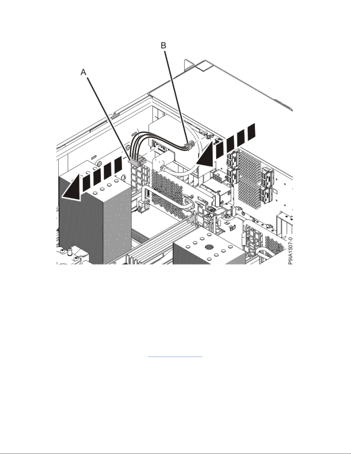
Figure 54. Disconnecting the internal RDX power cable
Replacing an internal RDX power cable in the 9009-41A, 9009-42A, or 9223-42H
To replace an internal RDX power cable, complete the steps in this procedure.
Procedure
1. Ensure that you have the electrostatic discharge (ESD) wrist strap on and that the ESD clip is plugged
into a ground jack or connected to an unpainted metal surface. If not, do so now.
2. Connect the internal RDX power cable (B) to the disk drive backplane. Ensure that the latch (C) on the
RDX power cable is oriented upwards for a rack-mounted system; and to the outside for a stand-alone
system. Connect the other end of the internal RDX power cable to the internal RDX docking station (A)
until it clicks into place as shown in Figure 55 on page 65.
64
Power Systems: RDX docking stations, power cable, and removable disk drives for the 9009-41A, 9009-42A,
or 9223-42H
Page 79

Figure 55. Connecting the internal RDX power cable
3. For a rack-mounted system, replace the air baffle (A) straight down into the chassis as shown in Figure
56 on page 66.
For a stand-alone system, replace the air baffle (A) straight into the side of the chassis as shown in
Figure 57 on page 67.
Ensure that the front flap tucks under the front chassis.
RDX docking stations, removable disk drives, and power cable, for the 9009-41A, 9009-42A, or 9223-42H
65
Page 80

Figure 56. Replacing the air baffle in a rack-mounted system
66
Power Systems: RDX docking stations, power cable, and removable disk drives for the 9009-41A, 9009-42A,
or 9223-42H
Page 81

Figure 57. Replacing the air baffle in a stand-alone system
Preparing the system for operation after removing and replacing an internal RDX power cable in the
9009-41A, 9009-42A, or 9223-42H
To prepare the system for operation after removing and replacing an internal RDX power cable, complete
the steps in this procedure.
Procedure
1. Ensure that you have the electrostatic discharge (ESD) wrist strap on and that the ESD clip is plugged
into a ground jack or connected to an unpainted metal surface. If not, do so now.
2. Replace the service access cover.
For a rack-mounted system, complete the following steps. Refer to Figure 58 on page 68.
a. Slide the cover (A) onto the system unit.
b. Close the release latch (B) by pushing it in the direction shown.
RDX docking stations, removable disk drives, and power cable, for the 9009-41A, 9009-42A, or 9223-42H
67
Page 82

Figure 58. Installing the service access cover
For a stand-alone system, complete the following steps. Refer to Figure 59 on page 69.
a. Slide the cover (B) on to the system unit as shown.
b. Close the latch release (A) by pushing it in the direction shown.
68
Power Systems: RDX docking stations, power cable, and removable disk drives for the 9009-41A, 9009-42A,
or 9223-42H
Page 83

Figure 59. Installing the service access cover
3. For a rack-mounted system, unlock the blue rail safety latches (A) as shown in Figure 60 on page 70
by pushing them inward.
Ensure that the cable management arms can move freely. Ensure that the cables at the rear of the unit
do not catch or bind as you push the unit into the operating position.
RDX docking stations, removable disk drives, and power cable, for the 9009-41A, 9009-42A, or 9223-42H
69
Page 84

Figure 60. Placing the system into the operating position
4. For a rack-mounted system, push the system unit (B) as shown in the previous gure back into the
rack until both release latches lock the system into position.
Secure the cable management arm with hook-and-loop fasteners around the back side of the cable
management arm, but not around the cables.
5. Using your labels, reconnect the power cords (A) to the system unit.
Fasten the power cords (A) to the system using the hook-and-loop fasteners (B) as shown in Figure 61
on page 71 or Figure 62 on page 72.
70
Power Systems: RDX docking stations, power cable, and removable disk drives for the 9009-41A, 9009-42A,
or 9223-42H
Page 85

Figure 61. Connecting the power cords to a rack-mounted system
RDX docking stations, removable disk drives, and power cable, for the 9009-41A, 9009-42A, or 9223-42H
71
Page 86

Figure 62. Connecting the power cords to a stand-alone system
6. Start the system. For instructions, see Starting a system (www.ibm.com/support/knowledgecenter/
POWER9/p9haj/crustartsys.htm).
7. Turn off the identify LED. For instructions, see Deactivating an identify LED (www.ibm.com/support/
knowledgecenter/POWER9/p9haj/p9haj_turn_off_identify_led.htm).
72
Power Systems: RDX docking stations, power cable, and removable disk drives for the 9009-41A, 9009-42A,
or 9223-42H
Page 87

Removing and replacing an internal RDX removable disk drive in the 9009-41A,
9009-42A, or 9223-42H
Find information about replacing an internal RDX removable disk drive.
About this task
Note: Installing this feature is a customer task. You can complete this task yourself, or contact a service
provider to complete the task for you. You might be charged a fee by the service provider for this service.
If your system is managed by the Hardware Management Console (HMC), use the HMC to repair a part in
the system. For instructions, see Repairing a part by using the HMC
knowledgecenter/POWER9/p9haj/p9haj_hmc_repair.htm).
If your system is not managed by an HMC, complete the steps in the following procedures to remove and
replace an internal RDX removable disk drive in the system.
Preparing the system to remove and replace the internal RDX removable disk drive in the 9009-41A,
9009-42A, or 9223-42H
To prepare the system to remove and replace the internal RDX removable disk drive, complete the steps
in this procedure.
Procedure
1. Identify the part and the system that you are working on. For instructions, see Identifying a
part (www.ibm.com/support/knowledgecenter/POWER9/p9haj/sal.htm).
Use the blue identify LED on the enclosure to locate the system. Ensure that the serial number of the
system matches the serial number to be serviced.
2. Review the RDX removable disk drive location. The RDX removable disk drive is located in the front of
the system.
(www.ibm.com/support/
RDX docking stations, removable disk drives, and power cable, for the 9009-41A, 9009-42A, or 9223-42H
73
Page 88

Figure 63. Location of the RDX removable disk drive
3. Ensure that the RDX removable disk drive is not being used for a backup or restore operation.
4. Attach the electrostatic discharge (ESD) wrist strap.
The ESD wrist strap must be connected to an unpainted metal surface until the service procedure is
completed, and if applicable, until the service access cover is replaced.
Attention:
• Attach an electrostatic discharge (ESD) wrist strap to the front ESD jack, to the rear ESD jack,
or to an unpainted metal surface of your hardware to prevent the electrostatic discharge from
damaging your hardware.
• When you use an ESD wrist strap, follow all electrical safety procedures. An ESD wrist strap is
used for static control. It does not increase or decrease your risk of receiving electric shock
when using or working on electrical equipment.
• If you do not have an ESD wrist strap, just prior to removing the product from ESD packaging
and installing or replacing hardware, touch an unpainted metal surface of the system for a
minimum of 5 seconds. If at any point in this service process you move away from the
system, it is important to again discharge yourself by touching an unpainted metal surface for
at least 5 seconds before you continue with the service process.
5. Remove the replacement RDX removable disk drive from the static-protective package and place it on
an ESD mat.
74
Power Systems: RDX docking stations, power cable, and removable disk drives for the 9009-41A, 9009-42A,
or 9223-42H
Page 89

Removing the internal RDX removable disk drive from the 9009-41A, 9009-42A, or 9223-42H
To remove the internal RDX removable disk drive, complete the steps in this procedure.
Procedure
1. Ensure that you have the electrostatic discharge (ESD) wrist strap on and that the ESD clip is plugged
into a ground jack or connected to an unpainted metal surface. If not, do so now.
2. On the system, verify that the LED of the internal RDX removable disk drive is on.
3. Press the internal RDX disk drive eject button that is shown in Figure 64 on page 75.
Figure 64. Front view of an internal RDX docking station and the removable disk drive
4. Wait for the eject button to stop flashing green and for the removable disk drive to be ejected.
5. Remove the RDX removable disk drive.
Note: If the RDX removable disk drive is stuck and does not eject, insert a large straightened paper
clip (or similar object) into the emergency eject hole.
RDX docking stations, removable disk drives, and power cable, for the 9009-41A, 9009-42A, or 9223-42H
75
Page 90

Replacing the internal RDX removable disk drive in the 9009-41A, 9009-42A, or 9223-42H
To replace the internal RDX removable disk drive, complete the steps in this procedure.
Procedure
1. Ensure that you have the electrostatic discharge (ESD) wrist strap on and that the ESD clip is plugged
into a ground jack or connected to an unpainted metal surface. If not, do so now.
2. Insert the internal RDX removable disk drive into the docking station as shown in Figure 65 on page
76.
Figure 65. Replacing the internal RDX removable disk drive
Preparing the system for operation after removing and replacing the internal RDX removable disk
drive in the 9009-41A, 9009-42A, or 9223-42H
To prepare the system for operation, complete the steps in this procedure.
Procedure
1. Ensure that you have the electrostatic discharge (ESD) wrist strap on and that the ESD clip is plugged
into a ground jack or connected to an unpainted metal surface. If not, do so now.
2. Verify the installed part.
• If you replaced the part because of a service action, verify the installed part. For instructions, see
https://www.ibm.com/support/knowledgecenter/POWER9/p9ect/
pxect_verifyrepair.htm (www.ibm.com/support/knowledgecenter/POWER9/p9ect/
pxect_verifyrepair.htm).
• If you installed the part for any other reason, verify the installed part. For instructions, see https://
www.ibm.com/support/knowledgecenter/POWER9/p9haj/pxhaj_hsmverify.htm (www.ibm.com/
support/knowledgecenter/POWER9/p9haj/pxhaj_hsmverify.htm).
76
Power Systems: RDX docking stations, power cable, and removable disk drives for the 9009-41A, 9009-42A,
or 9223-42H
Page 91

3. Turn off the identify LED. For instructions, see Deactivating an identify LED (www.ibm.com/support/
knowledgecenter/POWER9/p9haj/p9haj_turn_off_identify_led.htm).
Managing RDX docking stations and removable disk drives
Find information about how to use and manage RDX docking stations and removable disk drives.
Internal RDX docking stations and removable disk drives
Find information about the internal RDX docking station and its supported disk drives.
Description
The internal RDX docking station is available as an internal device. The disk drive is a back-up and restore
device that can be used as an alternative to tape drives. The removable disk drive is not a replacement for
regular disk drives and cannot be used as part of a disk array. Figure 66 on page 77 shows the front view
of the internal RDX docking station cartridge.
Figure 66. Front view of an internal RDX docking station and the removable disk drive
RDX docking stations, removable disk drives, and power cable, for the 9009-41A, 9009-42A, or 9223-42H
77
Page 92

Feature codes and part numbers
The internal RDX docking station includes a USB cable that is used to connect to an internal USB port.
Table 1 on page 78 provides the part numbers for the internal RDX docking station. Table 2 on page 78
provides the part numbers of its supported disk drives.
The internal RDX docking station provides the following parts:
Table 1. Internal RDX docking station parts
FRU Part number Description
46C2443 or
46C2444
02CL764 Y-cable with USB type A connector and USB type B connector for RDX
01GY348 RDX power cable
The supported disk drives in the internal RDX docking station are listed in the following table:
Table 2. Internal RDX docking station removable disk drives
Feature code Part number Description
1107 46C5379 500 GB Removable disk drive
EU01 46C2335 1 TB Removable disk drive
EU2T 46C2975 2 TB Removable disk drive
Purchasing extra removable disk drives
For best results, use only the removable disk drives that are listed in Table 2 on page 78.
The removable disk drives are a supply item that can be ordered as a feature code. To order in the United
States and Canada, call 1-888-IBM-MEDIA. To order drives in other locations, contact your local provider
of IBM storage products.
IBM service representatives will not be dispatched to service or replace the removable disk drives.
Internal RDX 3.5" USB 3.0 docking station (FC EU00)
Storing removable disk drives
Store removable disk drives in their protective containers, on a flat surface with the top side up. The
storage area must be clean and dry, must have normal room temperature, and must be away from any
magnetic elds. For best storage life, use the removable disk drives every six months.
Supported USB adapters and cables
Attention:
feature code. The docking station does not support attachment by using other USB cables, USB
hubs, add-on USB cables, or USB cable extenders.
The internal docking station must be connected to the internal, integrated USB port on the 9009-41A
system.
Specications
Interface
USB 3.0
Mksysb
Yes
Bootable
Yes (IBM i requires a hardware management console)
78
Power Systems: RDX docking stations, power cable, and removable disk drives for the 9009-41A, 9009-42A,
or 9223-42H
The internal RDX docking station supports the USB cable that is provided as part of the
Page 93
Environmental
Table 3. Operating conditions
USB Removable Disk Drive Operating conditions Non-operating conditions
Temperature 5°C - 55°C –40°C - 65°C
Relative humidity 8% - 90% non-condensing 5% - 95% non-condensing
Maximum wet bulb temperature 29.4°C non-condensing 40°C non-condensing
Maximum temperature gradient 20°C per hour 20°C per hour
Altitude –300 meters (–984.25 ft) to
3048 m (10,000 ft)
Operating system or partition requirements
If you are installing a new feature, ensure that you have the software that is required to support the new
feature and that you determine whether there are any prerequisites for this feature and attaching devices.
For information about the prerequisites, see the IBM Prerequisite website (www-912.ibm.com/e_dir/
eServerPrereq.nsf).
The media device is supported on the following versions of the operating systems:
• AIX
– AIX 7.1, or later.
– AIX 6.1
• Linux
– Red Hat Enterprise Linux Version 6, or later.
– SUSE Linux Enterprise Server 11, Service Pack 3, or later, with current maintenance updates
available from SUSE.
• IBM i
– IBM i Version 7.3, or later
– IBM i Version 7.2
– IBM i Version 7.1
–300 meters (–984.25 ft) to
12,192 m (40,000 ft)
Using the internal RDX removable disk drive for backup and restore
The disk drive is a back-up and restore device that can be used as an alternative to tape drives. The
removable disk drive is not a replacement for regular disk drives and cannot be used as part of a disk
array.
Note: If power is lost during a backup to the disk, the data can be compromised. Verify the data or rerun
the backup.
Using the disk drive with the AIX operating system
The AIX operating system names the drives as drive usbmsx, for example, usbms1, and usbms2. The AIX
operating system can also use the device as a raw device, for example, rusbms1 and rusbms2.
The AIX operating system uses the removable disk drive differently depending on the program that is
being used. The AIX command mksysb, builds a list of les to backup, creates a universal disk format
(UDF) le system, and puts a boot image and the root volume group on the removable disk drive. When
the mksysb process is complete, the removable disk drive can be used to boot the system. If you mount
the removable disk drive, you can display and copy les to and from the UDF le system on the removable
disk drive.
RDX docking stations, removable disk drives, and power cable, for the 9009-41A, 9009-42A, or 9223-42H
79
Page 94

The AIX commands, tar, backup, restore, dd, and cpio can write to the removable disk drive as a raw
device or non-raw device. You might get improved performance by using the device as a raw device.
See the AIX documentation for additional information.
Using the disk drive with the IBM i operating system
The IBM i operating system congures the drive as a removable media drive with a name in the format
RMSxx, for example, RMS01.
The drive and cartridge are used with optical commands and utilities (for example, WRKOPTVOL and
INZOPT), and reports media in the Optical File System (QOPT).
See the IBM i operating system documentation for information about using the IBM i commands: copy
and backup.
Using the disk drive with the Linux operating system
The Linux operating system congures the drive as a disk drive with a name in the format sdx, for
example, sda, sdb, and sdc.
See the Linux documentation for information about using the Linux commands: copy and backup.
Setting the write-protect switch
The removable disk drives have a red, write-protect tab that is located on the back of the drive. To writeprotect a drive, slide the write-protect tab toward the lock symbol. To disengage write protection, slide
the tab to the unlock symbol.
Using the emergency eject function
To normally eject a removable disk drive, press the eject button, wait for the eject button to stop flashing
green and for the removable disk drive to be ejected. If a drive is stuck and does not eject, the drive and
the dock need service. Complete the following steps to eject the cartridge:
1. Prepare the system for servicing by following the instructions at: “Preparing the system to remove and
replace an internal RDX docking station in the 9009-41A, 9009-42A, or 9223-42H” on page 29 (http://
www.ibm.com/support/knowledgecenter/POWER9/p9ia1/p9ia1_914_924_prereq.htm).
2. Insert a large straightened paper clip (or similar object) into the emergency eject hole.
Note: Do not insert the object in the hole at an angle. Keep the object straight and apply some force to
eject the drive.
3. When the drive has been ejected by the docking station, grasp the exposed sides of the drive and pull
the drive straight out.
4. Prepare the system for operation by following the instructions at: “Preparing the system for operation
after removing and replacing an internal RDX docking station in the 9009-41A, 9009-42A, or
9223-42H” on page 48 (http://www.ibm.com/support/knowledgecenter/POWER9/p9ia1/
p9ia1_914_924_postreq.htm).
Status lights
Find information about the power indicator and drive indicator status lights on the internal RDX docking
station.
Power indicator
The eject button is illuminated by a power indicator light. The following table describes the operation of
the power indicator.
80
Power Systems: RDX docking stations, power cable, and removable disk drives for the 9009-41A, 9009-42A,
or 9223-42H
Page 95

Table 4. Power indicator
Indicator status Meaning Description
Off No power Docking station does not have
power supply.
Steady green Ready Power is on and the docking
station is working correctly.
Flashing green Ejecting Cartridge is ejecting.
Flashing amber Fault Docking station has detected a
fault condition with the docking
station.
Removable disk drive indicator
The disk drive has an indicator light that displays the status of the drive. The following table describes the
operation of the drive indicator.
Table 5. Removable disk drive indicator
Indicator status Meaning Description
Off Not ready Drive is not inserted correctly or
the docking station has no power
supply.
Steady green Ready Drive is ready.
Flashing green Activity Drive is reading, writing, or
Flashing amber Fault Docking station has detected a
External RDX docking stations and removable disk drives
Find information about external USB docking stations and their supported disk drives.
Description
The external RDX docking station (FC EUA4) consists of a docking station, which holds a removable disk
drive. The external RDX docking station is available as an external device. The disk drive is a backup and
restore device that can be used as an alternative to tape drives. The removable disk drive is not a
replacement for regular disk drives and cannot be used as part of a disk array. Figure 67 on page 82 and
Figure 68 on page 82 show the front and rear views of the external USB docking station.
seeking.
fault condition with the cartridge.
RDX docking stations, removable disk drives, and power cable, for the 9009-41A, 9009-42A, or 9223-42H
81
Page 96

Figure 67. Front view of an external USB docking station and the removable disk drive cartridge
D
Write-protect switch
Figure 68. Rear view of an external RDX docking station and its cables
E
Power cable
F
USB cable
Feature codes and part numbers
The external USB docking stations use an external USB cable to connect to an external USB port. These
docking stations include a USB cable, an external power supply, and a power cord. Table 6 on page 83
provides the part numbers. Table 7 on page 83 provides the part numbers of the supported disk drives.
82
Power Systems: RDX docking stations, power cable, and removable disk drives for the 9009-41A, 9009-42A,
or 9223-42H
Page 97

Table 6. External USB docking station parts
FRU part number Description
01GY550 or
01GY551
01GY552 or
01GY553
05H5081 or
05H5080
39M5516 Power cord (1 meter (3.28 ft)) that connects the power supply to the rack power
The supported disk drives in the external RDX docking station (FC EUA4) are listed in the following table:
Table 7. External USB removable disk drives
Feature code Part number Description
1107 46C5379 500 GB Removable disk drive (FC EUA4)
EU01 46C2335 1 TB Removable disk drive (FC EUA4)
EU2T 46C2975 2 TB Removable disk drive (FC EUA4)
Purchasing extra removable disk drives
For best results, use only the removable disk drives that are listed in Table 7 on page 83.
External RDX USB 3.0 Dock (FC EUA4)
External power supply with power cord and universal plugs for all supported
geographies (FC EUA4)
External USB 3.0 cable (2.7 meters (8 ft 10 in))
distribution unit
The removable disk drives are a supply item that can be ordered as a feature code. To order in the United
States and Canada, call 1-888-IBM-MEDIA. To order drives in other locations, contact your local provider
of IBM storage products or see the Storage Media (http://www-03.ibm.com/systems/storage/media/)
website.
IBM service representatives will not be dispatched to service or replace the removable disk drives.
Storing removable disk drives
Store removable disk drives in their protective containers, on a flat surface with the top side up. The
storage area must be clean and dry, must have normal room temperature, and must be away from any
magnetic elds. For best storage life, use the removable disk drives every six months.
Supported USB adapters and cables
Attention:
The docking station does not support attachment by using other USB cables, USB hubs, add-on
USB cables, or USB cable extenders.
The external docking station can be connected to the external, integrated USB ports on POWER9
processor-based systems or can be connected to the USB ports on the PCIe2 LP 4-Port USB 3.0 adapter
(FC EC45) or PCIe2 4-Port USB 3.0 adapter (FC EC46). For more information on these adapters and
search on your feature code (FC). The FC in this le is a link to more information. See PCIe adapter
information by feature code (http://www.ibm.com/support/knowledgecenter/POWER9/p9hcd/
p9hcd_pcibyfeature.htm)
The docking station supports the USB cable that is provided as part of the feature code.
Specications
Interface
USB 3.0
RDX docking stations, removable disk drives, and power cable, for the 9009-41A, 9009-42A, or 9223-42H
83
Page 98

Mksysb
Yes
Bootable
Yes
Environmental
Table 8. Operating conditions
USB Removable Disk Drive Operating conditions Non-operating conditions
Temperature 5°C - 55°C –40°C - 65°C
Relative humidity 8% - 90% non-condensing 5% - 95% non-condensing
Maximum wet bulb temperature 29.4°C non-condensing 40°C non-condensing
Maximum temperature gradient 20°C per hour 20°C per hour
Altitude –300 meters (–984.25 ft) to
3048 m (10,000 ft)
Using the external RDX removable disk drive for backup and restore
The external RDX removable disk drive is a back up and restore device that can be used as an alternative
to tape drives. The removable disk drive is not a replacement for regular disk drives and cannot be used
as part of a disk array.
Note: If power is lost during a backup to the disk, the data can be compromised. Verify the data or rerun
the backup.
Using the disk drive with the AIX operating system
The AIX operating system names the drives as drive usbmsx, for example, usbms1, and usbms2. The AIX
operating system can also use the device as a raw device, for example, rusbms1 and rusbms2.
The AIX operating system uses the removable disk drive differently depending on the program that is
being used. The AIX command mksysb, builds a list of les to backup, creates a universal disk format
(UDF) le system, and puts a boot image and the root volume group on the removable disk drive. When
the mksysb process is complete, the removable disk drive can be used to boot the system. If you mount
the removable disk drive, you can display and copy les to and from the UDF le system on the removable
disk drive.
The AIX commands, tar, backup, restore, dd, and cpio can write to the removable disk drive as a raw
device or non-raw device. You might get improved performance by using the device as a raw device.
–300 meters (–984.25 ft) to
12,192 m (40,000 ft)
See the AIX documentation for additional information.
Using the disk drive with the IBM i operating system
The IBM i operating system congures the drive as a removable media drive with a name in the format
RMSxx, for example, RMS01.
The drive and cartridge are used with optical commands and utilities (for example, WRKOPTVOL and
INZOPT), and reports media in the Optical File System (QOPT).
See the IBM i operating system documentation for information about using the IBM i commands: copy
and backup.
Using the disk drive with the Linux operating system
The Linux operating system congures the drive as a disk drive with a name in the format sdx, for
example, sda, sdb, and sdc.
See the Linux documentation for information about using the Linux commands: copy and backup.
84
Power Systems: RDX docking stations, power cable, and removable disk drives for the 9009-41A, 9009-42A,
or 9223-42H
Page 99

Setting the write-protect switch
The removable disk drives have a red, write-protect tab that is located on the rear of the disk drive. To
write-protect a drive, slide the write-protect tab toward the lock symbol. To disengage write protection,
slide the tab to the unlock symbol.
Using the emergency eject function
To eject a removable disk drive, press the eject button. If a drive is stuck, complete the following steps:
1. Unplug the power cable from the device.
2. Insert a large straightened paper clip (or similar object) into the emergency eject hole.
Attention: Do not insert the object in the hole at an angle. Keep the object straight and apply
some force to eject the drive.
3. When the drive has been ejected by the docking station, grasp the exposed sides of the drive and pull
the drive straight out.
4. Reconnect the power cable for the docking station.
5. Restart your system to reset the docking station.
Status lights
Find information about the power indicator and drive indicator status lights on the external USB
removable disk drive.
Power indicator
The eject button is illuminated by a power indicator light. The following table describes the operation of
the power indicator.
Table 9. Power indicator status and description
Indicator status Meaning Description
Off No power
Steady green Ready
Flashing green Ejecting Cartridge is ejecting.
Flashing amber Fault Docking station has detected a
• FC EUA4: USB cable is not
connected. The power supply
may or may not be connected.
• FC EUA4: USB cable is
connected. The power supply
may or may not be connected.
If the power supply is
connected, the docking station
will work correctly. If the power
supply is not connected, the
docking station will not work
correctly.
fault condition with the docking
station.
External RDX removable disk drive indicator
The disk drive has an indicator light that displays the status of the drive. The following table describes the
operation of the drive indicator.
RDX docking stations, removable disk drives, and power cable, for the 9009-41A, 9009-42A, or 9223-42H
85
Page 100

Table 10. External USB removable disk drive indicator
Indicator status Meaning Description
Off Not ready Drive is not inserted correctly or
the docking station has no power
supply.
Steady green Ready Drive is ready.
Flashing green Activity Drive is reading, writing, or
seeking.
Flashing amber Fault Docking station has detected a
fault condition with the cartridge.
86 Power Systems: RDX docking stations, power cable, and removable disk drives for the 9009-41A, 9009-42A,
or 9223-42H
 Loading...