

Page 1

Power Systems
System backplane for the 9009-41A,
9009-42A, or 9223-42H
IBM
Page 2

Note
Before using this information and the product it supports, read the information in “Safety notices” on
page v, “Notices” on page 123, the IBM Systems Safety Notices manual, G229-9054, and the IBM
Environmental Notices and User Guide, Z125–5823.
This edition applies to IBM® Power Systems servers that contain the POWER9™ processor and to all associated models.
©
Copyright International Business Machines Corporation 2018, 2019.
US Government Users Restricted Rights – Use, duplication or disclosure restricted by GSA ADP Schedule Contract with
IBM Corp.
Page 3

Contents
Safety notices........................................................................................................v
System backplane................................................................................................. 1
Removing and replacing the system backplane......................................................................................... 1
Preparing the system..............................................................................................................................1
Removing the system backplane.........................................................................................................17
Replacing the system backplane......................................................................................................... 68
Preparing the system for operation...................................................................................................110
Notices..............................................................................................................123
Accessibility features for IBM Power Systems servers..........................................................................124
Privacy policy considerations .................................................................................................................125
Trademarks..............................................................................................................................................125
Electronic emission notices.....................................................................................................................125
Class A Notices...................................................................................................................................126
Class B Notices...................................................................................................................................129
Terms and conditions.............................................................................................................................. 131
iii
Page 4

iv
Page 5

Safety notices
Safety notices may be printed throughout this guide:
• DANGER notices call attention to a situation that is potentially lethal or extremely hazardous to people.
• CAUTION notices call attention to a situation that is potentially hazardous to people because of some
existing condition.
• Attention notices call attention to the possibility of damage to a program, device, system, or data.
World Trade safety information
Several countries require the safety information contained in product publications to be presented in their
national languages. If this requirement applies to your country, safety information documentation is
included in the publications package (such as in printed documentation, on DVD, or as part of the product)
shipped with the product. The documentation contains the safety information in your national language
with references to the U.S. English source. Before using a U.S. English publication to install, operate, or
service this product, you must rst become familiar with the related safety information documentation.
You should also refer to the safety information documentation any time you do not clearly understand any
safety information in the U.S. English publications.
Replacement or additional copies of safety information documentation can be obtained by calling the IBM
Hotline at 1-800-300-8751.
German safety information
Das Produkt ist nicht für den Einsatz an Bildschirmarbeitsplätzen im Sinne § 2 der
Bildschirmarbeitsverordnung geeignet.
Laser safety information
IBM servers can use I/O cards or features that are ber-optic based and that utilize lasers or LEDs.
Laser compliance
IBM servers may be installed inside or outside of an IT equipment rack.
DANGER:
Electrical voltage and current from power, telephone, and communication cables are hazardous.
To avoid a shock hazard:
• If IBM supplied the power cord(s), connect power to this unit only with the IBM provided power
cord. Do not use the IBM provided power cord for any other product.
• Do not open or service any power supply assembly.
• Do not connect or disconnect any cables or perform installation, maintenance, or reconguration
of this product during an electrical storm.
• The product might be equipped with multiple power cords. To remove all hazardous voltages,
disconnect all power cords.
– For AC power, disconnect all power cords from their AC power source.
– For racks with a DC power distribution panel (PDP), disconnect the customer’s DC power
• When connecting power to the product ensure all power cables are properly connected.
When working on or around the system, observe the following precautions:
source to the PDP.
– For racks with AC power, connect all power cords to a properly wired and grounded electrical
outlet. Ensure that the outlet supplies proper voltage and phase rotation according to the
system rating plate.
©
Copyright IBM Corp. 2018, 2019 v
Page 6

– For racks with a DC power distribution panel (PDP), connect the customer’s DC power source
to the PDP. Ensure that the proper polarity is used when attaching the DC power and DC power
return wiring.
• Connect any equipment that will be attached to this product to properly wired outlets.
• When possible, use one hand only to connect or disconnect signal cables.
• Never turn on any equipment when there is evidence of re, water, or structural damage.
• Do not attempt to switch on power to the machine until all possible unsafe conditions are
corrected.
• Assume that an electrical safety hazard is present. Perform all continuity, grounding, and power
checks specied during the subsystem installation procedures to ensure that the machine meets
safety requirements.
• Do not continue with the inspection if any unsafe conditions are present.
• Before you open the device covers, unless instructed otherwise in the installation and
conguration procedures: Disconnect the attached AC power cords, turn off the applicable
circuit breakers located in the rack power distribution panel (PDP), and disconnect any
telecommunications systems, networks, and modems.
DANGER:
• Connect and disconnect cables as described in the following procedures when installing,
moving, or opening covers on this product or attached devices.
To Disconnect:
1. Turn off everything (unless instructed otherwise).
2. For AC power, remove the power cords from the outlets.
3. For racks with a DC power distribution panel (PDP), turn off the circuit breakers located in the
PDP and remove the power from the Customer's DC power source.
4. Remove the signal cables from the connectors.
5. Remove all cables from the devices.
To Connect:
1. Turn off everything (unless instructed otherwise).
2. Attach all cables to the devices.
3. Attach the signal cables to the connectors.
4. For AC power, attach the power cords to the outlets.
5. For racks with a DC power distribution panel (PDP), restore the power from the Customer's
DC power source and turn on the circuit breakers located in the PDP.
6. Turn on the devices.
Sharp edges, corners and joints may be present in and around the system. Use care when
handling equipment to avoid cuts, scrapes and pinching. (D005)
(R001 part 1 of 2):
DANGER:
• Heavy equipment–personal injury or equipment damage might result if mishandled.
• Always lower the leveling pads on the rack cabinet.
• Always install stabilizer brackets on the rack cabinet unless the earthquake option is to be
installed.
• To avoid hazardous conditions due to uneven mechanical loading, always install the heaviest
devices in the bottom of the rack cabinet. Always install servers and optional devices starting
from the bottom of the rack cabinet.
Observe the following precautions when working on or around your IT rack system:
vi Power Systems: System backplane
Page 7

• Rack-mounted devices are not to be used as shelves or work spaces. Do not place objects on top
of rack-mounted devices. In addition, do not lean on rack mounted devices and do not use them
to stabilize your body position (for example, when working from a ladder).
• Each rack cabinet might have more than one power cord.
– For AC powered racks, be sure to disconnect all power cords in the rack cabinet when directed
to disconnect power during servicing.
– For racks with a DC power distribution panel (PDP), turn off the circuit breaker that controls
the power to the system unit(s), or disconnect the customer’s DC power source, when
directed to disconnect power during servicing.
• Connect all devices installed in a rack cabinet to power devices installed in the same rack
cabinet. Do not plug a power cord from a device installed in one rack cabinet into a power device
installed in a different rack cabinet.
• An electrical outlet that is not correctly wired could place hazardous voltage on the metal parts
of the system or the devices that attach to the system. It is the responsibility of the customer to
ensure that the outlet is correctly wired and grounded to prevent an electrical shock. (R001 part
1 of 2)
(R001 part 2 of 2):
CAUTION:
• Do not install a unit in a rack where the internal rack ambient temperatures will exceed the
manufacturer's recommended ambient temperature for all your rack-mounted devices.
• Do not install a unit in a rack where the air flow is compromised. Ensure that air flow is not
blocked or reduced on any side, front, or back of a unit used for air flow through the unit.
• Consideration should be given to the connection of the equipment to the supply circuit so that
overloading of the circuits does not compromise the supply wiring or overcurrent protection. To
provide the correct power connection to a rack, refer to the rating labels located on the
equipment in the rack to determine the total power requirement of the supply circuit.
• (For sliding drawers.) Do not pull out or install any drawer or feature if the rack stabilizer
brackets are not attached to the rack or if the rack is not bolted to the floor. Do not pull out more
than one drawer at a time. The rack might become unstable if you pull out more than one drawer
at a time.
• (For xed drawers.) This drawer is a xed drawer and must not be moved for servicing unless
specied by the manufacturer. Attempting to move the drawer partially or completely out of the
rack might cause the rack to become unstable or cause the drawer to fall out of the rack. (R001
part 2 of 2)
CAUTION:
stability during relocation. Follow these general guidelines whenever you relocate a populated
rack cabinet within a room or building.
• Reduce the weight of the rack cabinet by removing equipment starting at the top of the rack
cabinet. When possible, restore the rack cabinet to the conguration of the rack cabinet as you
received it. If this conguration is not known, you must observe the following precautions:
Removing components from the upper positions in the rack cabinet improves rack
Safety notices vii
Page 8

– Remove all devices in the 32U position (compliance ID RACK-001 or 22U (compliance ID
RR001) and above.
– Ensure that the heaviest devices are installed in the bottom of the rack cabinet.
– Ensure that there are little-to-no empty U-levels between devices installed in the rack cabinet
below the 32U (compliance ID RACK-001 or 22U (compliance ID RR001) level, unless the
received conguration specically allowed it.
• If the rack cabinet you are relocating is part of a suite of rack cabinets, detach the rack cabinet
from the suite.
• If the rack cabinet you are relocating was supplied with removable outriggers they must be
reinstalled before the cabinet is relocated.
• Inspect the route that you plan to take to eliminate potential hazards.
• Verify that the route that you choose can support the weight of the loaded rack cabinet. Refer to
the documentation that comes with your rack cabinet for the weight of a loaded rack cabinet.
• Verify that all door openings are at least 760 x 230 mm (30 x 80 in.).
• Ensure that all devices, shelves, drawers, doors, and cables are secure.
• Ensure that the four leveling pads are raised to their highest position.
• Ensure that there is no stabilizer bracket installed on the rack cabinet during movement.
• Do not use a ramp inclined at more than 10 degrees.
• When the rack cabinet is in the new location, complete the following steps:
– Lower the four leveling pads.
– Install stabilizer brackets on the rack cabinet or in an earthquake environment bolt the rack to
the floor.
– If you removed any devices from the rack cabinet, repopulate the rack cabinet from the
lowest position to the highest position.
• If a long-distance relocation is required, restore the rack cabinet to the conguration of the rack
cabinet as you received it. Pack the rack cabinet in the original packaging material, or equivalent.
Also lower the leveling pads to raise the casters off of the pallet and bolt the rack cabinet to the
pallet.
(L001)
(L002)
(R002)
DANGER:
this label attached. Do not open any cover or barrier that contains this label. (L001)
Hazardous voltage, current, or energy levels are present inside any component that has
viii
Power Systems: System backplane
Page 9

(L003)
or
or
DANGER: Rack-mounted devices are not to be used as shelves or work spaces. Do not place
objects on top of rack-mounted devices. In addition, do not lean on rack-mounted devices and do
not use them to stabilize your body position (for example, when working from a ladder). (L002)
or
or
Safety notices
ix
Page 10

(L007)
DANGER: Multiple power cords. The product might be equipped with multiple AC power cords or
multiple DC power cables. To remove all hazardous voltages, disconnect all power cords and
power cables. (L003)
CAUTION:
(L008)
CAUTION:
All lasers are certied in the U.S. to conform to the requirements of DHHS 21 CFR Subchapter J for class 1
laser products. Outside the U.S., they are certied to be in compliance with IEC 60825 as a class 1 laser
product. Consult the label on each part for laser certication numbers and approval information.
CAUTION:
ROM drive, DVD-RAM drive, or laser module, which are Class 1 laser products. Note the following
information:
• Do not remove the covers. Removing the covers of the laser product could result in exposure to
hazardous laser radiation. There are no serviceable parts inside the device.
• Use of the controls or adjustments or performance of procedures other than those specied
herein might result in hazardous radiation exposure.
A hot surface nearby. (L007)
Hazardous moving parts nearby. (L008)
This product might contain one or more of the following devices: CD-ROM drive, DVD-
(C026)
x Power Systems: System backplane
Page 11

CAUTION: Data processing environments can contain equipment transmitting on system links
with laser modules that operate at greater than Class 1 power levels. For this reason, never look
into the end of an optical ber cable or open receptacle. Although shining light into one end and
looking into the other end of a disconnected optical ber to verify the continuity of optic bers may
not injure the eye, this procedure is potentially dangerous. Therefore, verifying the continuity of
optical bers by shining light into one end and looking at the other end is not recommended. To
verify continuity of a ber optic cable, use an optical light source and power meter. (C027)
CAUTION: This product contains a Class 1M laser. Do not view directly with optical instruments.
(C028)
CAUTION: Some laser products contain an embedded Class 3A or Class 3B laser diode. Note the
following information:
• Laser radiation when open.
• Do not stare into the beam, do not view directly with optical instruments, and avoid direct
exposure to the beam. (C030)
(C030)
CAUTION: The battery contains lithium. To avoid possible explosion, do not burn or charge the
battery.
Do Not:
• Throw or immerse into water
• Heat to more than 100 degrees C (212 degrees F)
• Repair or disassemble
Exchange only with the IBM-approved part. Recycle or discard the battery as instructed by local
regulations. In the United States, IBM has a process for the collection of this battery. For
information, call 1-800-426-4333. Have the IBM part number for the battery unit available when
you call. (C003)
CAUTION: Regarding IBM provided VENDOR LIFT TOOL:
• Operation of LIFT TOOL by authorized personnel only.
• LIFT TOOL intended for use to assist, lift, install, remove units (load) up into rack elevations. It is
not to be used loaded transporting over major ramps nor as a replacement for such designated
tools like pallet jacks, walkies, fork trucks and such related relocation practices. When this is not
practicable, specially trained persons or services must be used (for instance, riggers or movers).
• Read and completely understand the contents of LIFT TOOL operator's manual before using.
Failure to read, understand, obey safety rules, and follow instructions may result in property
damage and/or personal injury. If there are questions, contact the vendor's service and support.
Local paper manual must remain with machine in provided storage sleeve area. Latest revision
manual available on vendor's web site.
• Test verify stabilizer brake function before each use. Do not over-force moving or rolling the LIFT
TOOL with stabilizer brake engaged.
• Do not raise, lower or slide platform load shelf unless stabilizer (brake pedal jack) is fully
engaged. Keep stabilizer brake engaged when not in use or motion.
• Do not move LIFT TOOL while platform is raised, except for minor positioning.
• Do not exceed rated load capacity. See LOAD CAPACITY CHART regarding maximum loads at
center versus edge of extended platform.
• Only raise load if properly centered on platform. Do not place more than 200 lb (91 kg) on edge
of sliding platform shelf also considering the load's center of mass/gravity (CoG).
• Do not corner load the platforms, tilt riser, angled unit install wedge or other such accessory
options. Secure such platforms -- riser tilt, wedge, etc options to main lift shelf or forks in all four
(4x or all other provisioned mounting) locations with provided hardware only, prior to use. Load
objects are designed to slide on/off smooth platforms without appreciable force, so take care
Safety notices
xi
Page 12

not to push or lean. Keep riser tilt [adjustable angling platform] option flat at all times except for
nal minor angle adjustment when needed.
• Do not stand under overhanging load.
• Do not use on uneven surface, incline or decline (major ramps).
• Do not stack loads.
• Do not operate while under the influence of drugs or alcohol.
• Do not support ladder against LIFT TOOL (unless the specic allowance is provided for one
following qualied procedures for working at elevations with this TOOL).
• Tipping hazard. Do not push or lean against load with raised platform.
• Do not use as a personnel lifting platform or step. No riders.
• Do not stand on any part of lift. Not a step.
• Do not climb on mast.
• Do not operate a damaged or malfunctioning LIFT TOOL machine.
• Crush and pinch point hazard below platform. Only lower load in areas clear of personnel and
obstructions. Keep hands and feet clear during operation.
• No Forks. Never lift or move bare LIFT TOOL MACHINE with pallet truck, jack or fork lift.
• Mast extends higher than platform. Be aware of ceiling height, cable trays, sprinklers, lights, and
other overhead objects.
• Do not leave LIFT TOOL machine unattended with an elevated load.
• Watch and keep hands, ngers, and clothing clear when equipment is in motion.
• Turn Winch with hand power only. If winch handle cannot be cranked easily with one hand, it is
probably over-loaded. Do not continue to turn winch past top or bottom of platform travel.
Excessive unwinding will detach handle and damage cable. Always hold handle when lowering,
unwinding. Always assure self that winch is holding load before releasing winch handle.
• A winch accident could cause serious injury. Not for moving humans. Make certain clicking sound
is heard as the equipment is being raised. Be sure winch is locked in position before releasing
handle. Read instruction page before operating this winch. Never allow winch to unwind freely.
Freewheeling will cause uneven cable wrapping around winch drum, damage cable, and may
cause serious injury.
• This TOOL must be maintained correctly for IBM Service personnel to use it. IBM shall inspect
condition and verify maintenance history before operation. Personnel reserve the right not to use
TOOL if inadequate. (C048)
Power and cabling information for NEBS (Network Equipment-Building System) GR-1089-CORE
The following comments apply to the IBM servers that have been designated as conforming to NEBS
(Network Equipment-Building System) GR-1089-CORE:
The equipment is suitable for installation in the following:
• Network telecommunications facilities
• Locations where the NEC (National Electrical Code) applies
The intrabuilding ports of this equipment are suitable for connection to intrabuilding or unexposed wiring
or cabling only. The intrabuilding ports of this equipment must not be metallically connected to the
interfaces that connect to the OSP (outside plant) or its wiring. These interfaces are designed for use as
intrabuilding interfaces only (Type 2 or Type 4 ports as described in GR-1089-CORE) and require isolation
from the exposed OSP cabling. The addition of primary protectors is not sufcient protection to connect
these interfaces metallically to OSP wiring.
Note: All Ethernet cables must be shielded and grounded at both ends.
The ac-powered system does not require the use of an external surge protection device (SPD).
xii
Power Systems: System backplane
Page 13

The dc-powered system employs an isolated DC return (DC-I) design. The DC battery return terminal shall
not be connected to the chassis or frame ground.
The dc-powered system is intended to be installed in a common bonding network (CBN) as described in
GR-1089-CORE.
Safety notices xiii
Page 14

xiv Power Systems: System backplane
Page 15

Removing and replacing the system backplane in the
9009-41A, 9009-42A, or 9223-42H
Find information about removing and replacing the system backplane in the 9009-41A, 9009-42A, or
9223-42H.
Removing and replacing the system backplane in the 9009-41A, 9009-42A,
or 9223-42H
Find information about removing and replacing the system backplane in the 9009-41A, 9009-42A, or
9223-42H.
If your system is managed by the Hardware Management Console (HMC), use the HMC to repair a part in
the system. For instructions, see Repairing a part by using the HMC (www.ibm.com/support/
knowledgecenter/POWER9/p9haj/p9haj_hmc_repair.htm).
If you do not have an HMC, use the following procedures to remove and replace the system backplane.
Note: Only an authorized service representative must remove or replace this part.
Preparing the system to remove and replace the system backplane
To prepare the system to remove and replace the system backplane, complete the steps in this
procedure.
About this task
Before you begin this procedure, ensure that you have authority to log in as an authorized service
provider. The authority levels are described in ASMI authority levels.
Procedure
1. Identify the part and the system that you are working on. For instructions, see Identifying a
part (www.ibm.com/support/knowledgecenter/POWER9/p9haj/sal.htm).
Use the blue identify LED on the enclosure to locate the system. Ensure that the serial number of the
system matches the serial number to be serviced.
2. Stop the system. For instructions, see Stopping a system (www.ibm.com/support/knowledgecenter/
POWER9/p9haj/crustopsys.htm).
3. Access the Advanced System Management Interface (ASMI).
For instructions, see Accessing the ASMI without an HMC (www.ibm.com/support/knowledgecenter/
POWER9/p9hby/connect_asmi.htm).
4. On the ASMI welcome panel, locate Service Processor: Primary (Location: UXXXX.YYY.ZZZZZZZ)
where XXXX.YYY represents the Feature Code/Sequence Number and ZZZZZZZ represents the
Enclosure serial number. Record the values for XXXX.YYY and ZZZZZZZ.
5. Check and record the System Enclosure Type and Feature Code. The enclosure serial number is a
seven-digit number that is printed on a bar-coded label on the system unit.
6. Attach the electrostatic discharge (ESD) wrist strap.
The ESD wrist strap must be connected to an unpainted metal surface until the service procedure is
completed, and if applicable, until the service access cover is replaced.
Attention:
• Attach an electrostatic discharge (ESD) wrist strap to the front ESD jack, to the rear ESD
jack, or to an unpainted metal surface of your hardware to prevent the electrostatic
discharge from damaging your hardware.
©
Copyright IBM Corp. 2018, 2019 1
Page 16

• When you use an ESD wrist strap, follow all electrical safety procedures. An ESD wrist strap
is used for static control. It does not increase or decrease your risk of receiving electric
shock when using or working on electrical equipment.
• If you do not have an ESD wrist strap, just prior to removing the product from ESD packaging
and installing or replacing hardware, touch an unpainted metal surface of the system for a
minimum of 5 seconds. If at any point in this service process you move away from the
system, it is important to again discharge yourself by touching an unpainted metal surface
for at least 5 seconds before you continue with the service process.
7. For rack-mounted systems, continue to the next step.
For stand-alone systems, the recommended service position for working with the system backplane
is to lay the system on its side. You do not need to lift the system. For instructions to place a standalone system in the service position, continue to step “17” on page 11.
CAUTION: This system requires two people to tip the system onto its side.
8. Open the cable management arm by completing the following steps:
a) Release the mounting bracket from the cable management arm assembly by pressing the
indentation (A) on the inner cable management arm tab.
The cable management arm releases from the outer mounting bracket in the direction shown.
Figure 1. Releasing the cable management arm
b) Swing the cable management arm away from the system.
2
Power Systems: System backplane
Page 17

In the image, the inner cable management arm tab is shown on the left side as you are facing the
system from the rear. However, the cable management arm can also be installed so that the inner
cable management arm tab is on the right side of the system.
CAUTION: To avoid causing damage to the arm, open the cable management arm just long
enough to complete these repairs.
9. Label and disconnect the power cords from the system unit.
See Figure 2 on page 3.
Notes:
• This system might be equipped with two or more power supplies. If the removing and replacing
procedures require the system power to be turned off, ensure that all the power sources to the
system are disconnected.
• The power cord (B) is fastened to the system with hook-and-loop fastener (A). If you are placing
the system in a service position after you disconnect the power cords, ensure that you unstrap the
fastener.
Figure 2. Removing the power cords
(L003)
Removing and replacing the system backplane in the 9009-41A, 9009-42A, or 9223-42H
3
Page 18

or
or
or
or
4
Power Systems: System backplane
Page 19

DANGER: Multiple power cords. The product might be equipped with multiple AC power cords
or multiple DC power cables. To remove all hazardous voltages, disconnect all power cords
and power cables. (L003)
10. Unseat each of the power supplies by pushing on the locking-tab and pulling the power supply out
enough so that the connector is disengaged.
11. Label, disconnect, and set aside all remaining rear cables that connect to the system.
12. Close the cable management arm by completing the following steps:
a) Swing the cable management arm towards the server.
b) Insert the inner cable management arm tab (A) into the outer mounting bracket (B) until it clicks
into place as shown. The inner mounting bracket (C) is not used on the left side.
Removing and replacing the system backplane in the 9009-41A, 9009-42A, or 9223-42H 5
Page 20

Figure 3. Closing the cable management arm
13. Disconnect the cable management arm from the system by pressing the inner cable management
arm tab (A) while lightly squeezing the inner and outer cable management arms together. Then,
secure the inner cable management arm to the outer cable management arm with a hook and loop
fastener. You should secure the inner and outer arms at the narrowest spot (G) between the basket
and the side of the arm that you just disconnected. See Figure 4 on page 7.
6
Power Systems: System backplane
Page 21

Figure 4. Cable management arm parts
14. Hold the indentations (A) on the front cover and pull it away from the system. See Figure 5 on page
8.
Removing and replacing the system backplane in the 9009-41A, 9009-42A, or 9223-42H
7
Page 22

Figure 5. Removing the front cover
15. Open the side latches (A) and pull the latches to slide the system unit fully into the service position,
until the slides click and hold the system unit securely. Ensure that the screws inside the latches are
not secured to the rack.
See Figure 6 on page 9.
Do not pull out or install any drawer or feature if the rack stabilizer brackets are not attached to the
rack. Do not pull out more than one drawer at a time. The rack might become unstable if you pull out
more than one drawer at a time.
8
Power Systems: System backplane
Page 23

Figure 6. Releasing the side latches
16. Remove the service access cover.
For a rack-mounted system, complete the following steps. Refer to Figure 7 on page 10.
Attention:
minutes when the system power is turned on might damage the system components.
a. Release the service cover latch by pushing the release latch (A) in the direction shown.
b. Slide the cover (B) off the system unit. When the front of the service access cover clears the upper
frame ledge, lift the cover up and off the system unit.
Removing and replacing the system backplane in the 9009-41A, 9009-42A, or 9223-42H
Operating the system without the service access cover on for more than 10
9
Page 24

Figure 7. Removing the service access cover from a rack-mounted system
For a stand-alone system, complete the following steps. Refer to Figure 8 on page 11.
Attention:
minutes when the system power is turned on might damage the system components.
a. Release the latch by pushing the release latch (A) in the direction shown.
b. Slide the cover (B) off the system unit. When the front of the service access cover has cleared the
upper frame ledge, lift the cover up and off the system unit.
10
Power Systems: System backplane
Operating the system without the service access cover on for more than 10
Page 25

Figure 8. Removing the service access cover
17. Complete the following steps to place a stand-alone system into the service position:
a) Label and remove all cables that connect to the system.
b) Remove the power supplies from the system to lighten the system.
Refer to Figure 9 on page 12.
Removing and replacing the system backplane in the 9009-41A, 9009-42A, or 9223-42H
11
Page 26

Figure 9. Removing the power supplies
1) Label the power cord, and then unstrap the hook-and-loop fastener (D) to release the power
cord (A) from the power supply handle. Retain the hook-and-loop fastener for future use.
2) Pull the power cord (A) out of the power supply (C) in the direction shown. Pull the power cord
connector; do not pull the cord itself.
3) To unseat the power supply from its position in the system, push the locking-tab (B) in the
direction shown.
4) Using the handle (E), pull the power supply (C) away from the system.
5) Repeat steps “17.b.i” on page 12 - “17.b.iv” on page 12 for each power supply.
c) Remove the side cover.
Refer to Figure 10 on page 13.
12
Power Systems: System backplane
Page 27

Figure 10. Removing the service access cover
1) Release the latch by pushing the release latch (A) in the direction shown.
2) Slide the cover (B) off the system unit. When the front of the service access cover has cleared
the upper frame ledge, lift the cover up and off the system unit.
d) Carefully tilt the stand-alone system from its vertical position to lay it in a horizontal position.
Position the system with the open service area up, and with a 3 cm (1.5") support (A) along its top
edge, as shown in Figure 11 on page 14.
The support (A) is used to prevent the plastic handle from being damaged.
Removing and replacing the system backplane in the 9009-41A, 9009-42A, or 9223-42H
13
Page 28

Figure 11. Tilting the stand-alone system to a horizontal position
18. Press and hold the push-button (A) on the trusted platform module card to activate the identify LED
for the faulty part as shown in the following gures.
Verify that the LED (B) is lit, which indicates that sufcient power exists for the identify LED. If the
LED (B) is not lit, use the location code to nd the physical location by using the service label.
14
Power Systems: System backplane
Page 29

Figure 12. Activating the identify LED for a rack mounted system
Removing and replacing the system backplane in the 9009-41A, 9009-42A, or 9223-42H
15
Page 30

Figure 13. Activating the identify LED for a stand-alone system
19. Look for the amber LED of the system backplane. See Figure 14 on page 17.
16
Power Systems: System backplane
Page 31

Figure 14. Service indicator LEDs
Removing the system backplane from the 9009-41A, 9009-42A, or 9223-42H
Follow these steps to remove the system backplane from a server to replace a failing part or as part of
another service procedure.
Procedure
1. Ensure that you have the electrostatic discharge (ESD) wrist strap on and that the ESD clip is plugged
into a ground jack or connected to an unpainted metal surface. If not, do so now.
2. For a rack-mounted system, lift the air baffle (A) straight up as shown in Figure 15 on page 18.
For a stand-alone system, remove the air baffle (A) straight out as shown in Figure 16 on page 19.
Place the air baffle upside down on a clean area so that the foam does not collect contaminants.
Removing and replacing the system backplane in the 9009-41A, 9009-42A, or 9223-42H
17
Page 32

Figure 15. Removing the air baffle from a rack-mounted system
18
Power Systems: System backplane
Page 33

Figure 16. Removing the air baffle from a stand-alone system
3. Remove the PCIe adapters:
a) Label and disconnect all external cables that are attached to the adapters.
b) Record the slot number and location of each adapter being removed. See the following gure.
Removing and replacing the system backplane in the 9009-41A, 9009-42A, or 9223-42H
19
Page 34

Figure 17. PCIe adapter slot locations in the 9009-41A, 9009-42A, or 9223-42H system
c) To set the adapter latch (A) at the target slot into the open position, rotate the latch (A) on the
rear of the system as shown.Figure 18 on page 21.
d) Carefully grasp the adapter (B) by its top edge or tailstock, and remove the adapter from the
slot.Figure 18 on page 21.
Attention:
remove this pin. It is required for correct alignment and seating.
A pin on the tailstock of the adapter resembles a removable screw. Do not
20 Power Systems: System backplane
Page 35

Figure 18. Removing a PCIe adapter from a 9009-41A, 9009-42A, or 9223-42H rack-mounted
system
e) Place the adapter on an appropriate ESD surface.
f) Repeat steps “3.a” on page 19 through “3.e” on page 21 for the remaining adapters.
4. Remove the rear USB cable:
a) While pressing the latch release on the connector, unplug the rear USB cable (A) from the system
backplane as shown in the following gure. The connector on the system backplane that has the
USB port symbol with an arrow that points to the rear of the system.
Removing and replacing the system backplane in the 9009-41A, 9009-42A, or 9223-42H
21
Page 36

Figure 19. Removing the rear USB cable
b) At the rear of the system, press on the tabs (B) in the direction that is shown in the previous gure
to release the rear USB cable (C).
c) Lift the rear USB cable out of the system.
d) Place the rear USB cable on an appropriate ESD surface.
5. Disconnect the front USB cable from the system backplane.
a) Pressing the latch release on the connector, disconnect the front USB cable (A) from the system
backplane as shown in the following gure. The connector on the system backplane that has the
USB port symbol with an arrow that points to the front of the system.
b) Unfasten the cable from the hook and loop fasteners that secure the cable to the right side of the
chassis.
c) Route the cable over the side of the system and out of the way to provide clearance for removing
the backplane.
22
Power Systems: System backplane
Page 37

Figure 20. Disconnecting the front USB cable and routing it over the side of the system
6. Remove the service processor card:
a) At the rear of the system, unlatch the PCI adapter retainer (A) for the service processor card as
shown in Figure 21 on page 24.
b) Pull the service processor card straight up from the slot by holding the two card holder brackets
(B) at the front and rear of the card as shown in the following gure.
Removing and replacing the system backplane in the 9009-41A, 9009-42A, or 9223-42H
23
Page 38

Figure 21. Removing the service processor card from slot P1-C1
c) Place the service processor card on an appropriate ESD surface.
7. Remove the vital product data (VPD) card:
a) Grasp the VPD card by the plastic housing as shown in the following gure.
b) Pull the VPD card out of its slot in location P1-C13 on the system backplane. See the following
gure.
24
Power Systems: System backplane
Page 39

Figure 22. Removing the VPD card
c) Place the VPD card on an appropriate ESD surface.
8. Remove the PCIe adapter dividers:
a) Place your nger on the top edge of the PCIe adapter divider (A) to hold the divider steady as
shown in the following gure.
Figure 23. Preparing to remove the PCIe adapter divider
Removing and replacing the system backplane in the 9009-41A, 9009-42A, or 9223-42H
25
Page 40

b) Press down on the retaining latch at the back edge of the divider (B) as shown in the following
gure.
26
Power Systems: System backplane
Page 41

Figure 24. Pressing the retaining latch on the PCIe divider
c) Slide the divider away from the system chassis and towards the inside of the system. When the
tab on the divider (C) clears the groove in the system backplane, lift the divider to remove it from
the system. See the following gure.
Removing and replacing the system backplane in the 9009-41A, 9009-42A, or 9223-42H
27
Page 42

Figure 25. Sliding the PCIe divider out of the system
d) Place the adapter divider in a clean area.
e) Repeat steps “8.a” on page 25 through “8.d” on page 28 for the remaining adapter dividers.
9. Remove the RAID adapter or adapters, if present. Otherwise, continue with step “10” on page 32.
a) Locate the RAID adapter you want to remove.
b) Identify and label the front SAS cable or cables that are connected to the adapter you want to
remove. Pay attention to the locations of the connectors where the cable or cables attach to the
disk drive backplane and the SAS RAID internal adapter.
Note: Depending on which SAS RAID adapter is installed in your system, one or two front SAS
cables are connected to the SAS RAID adapter. A rear SAS cable might also be connected to the
SAS RAID adapter.
c) Press the connector latch (A) and unplug the front SAS cable or cables that are connected to the
SAS RAID internal adapter from the disk drive backplane. Leave the other end of the cable or
cables plugged in to the SAS RAID internal adapter. See the following gure.
28
Power Systems: System backplane
Page 43

Figure 26. Unplugging the front SAS cables
d) If a rear SAS cable is attached to the SAS RAID adapter, label and disconnect the rear SAS cables
from the SAS RAID internal adapters in positions P1-C49 and P1-C50 by pressing the connector
latch and unplugging the cable. See the following gure.
Removing and replacing the system backplane in the 9009-41A, 9009-42A, or 9223-42H
29
Page 44

Figure 27. Disconnecting the rear SAS cables from the SAS RAID internal adapter
e) If a rear SAS cable is attached to the SAS RAID adapter, unlatch the PCI retainer (A) for the PCI
adapter slot P1-C6 at the rear of the system. Then, lift and remove the rear SAS cable adapter (B).
See the following gure.
Ensure that the rear SAS cable does not catch on any components while you are lifting the rear
SAS adapter out of the slot.
30
Power Systems: System backplane
Page 45

Figure 28. Removing the rear SAS cable adapter
f) Place the rear SAS cable and connector on an appropriate ESD surface.
g) Twist the screws (A) counterclockwise to release the SAS RAID adapter. Lift both the SAS RAID
adapter and the front SAS cable out of the slot. Ensure that the front SAS cable does not catch on
any components while you are lifting the SAS RAID adapter out of the slot.
See the following gure.
Removing and replacing the system backplane in the 9009-41A, 9009-42A, or 9223-42H
31
Page 46

Figure 29. Removing the SAS RAID adapter
h) Place the SAS RAID internal adapter on an appropriate ESD surface.
i) Repeat steps “9.a” on page 28 through “9.h” on page 32 for any additional SAS RAID adapters.
10. Remove the NVMe M.2 carrier card, if present. Otherwise, continue with step “11” on page 33.
a) Twist the screws (A) counterclockwise to release the NVMe M.2 carrier card.
b) Lift the NVMe M.2 carrier card out of the slot as shown in the following gure.
32
Power Systems: System backplane
Page 47

Figure 30. Removing the NVMe M.2 carrier card
c) Place the NVMe M.2 carrier card on an appropriate ESD surface.
11. Remove the internal RDX docking station, if present. Otherwise, continue with step “12” on page
35.
a) Disconnect the RDX power cable (A) from the back of the RDX docking station and route the cable
over the side of the system as shown in the following gure.
b) Disconnect the front USB cable (B) from the back of the RDX docking station and route the cable
over the side of the system as shown in the following gure.
Removing and replacing the system backplane in the 9009-41A, 9009-42A, or 9223-42H
33
Page 48

Figure 31. Routing the RDX power and USB cables over the side of the system
c) Push the blue tab on the internal RDX docking station latch upwards to release the internal RDX
docking station as shown in the following gure.
d) Gently slide the internal RDX docking station and its latch out from the system. Remove the
internal RDX docking station latch from the docking station in the direction of the arrow shown.
34
Power Systems: System backplane
Page 49

Figure 32. Removing the internal RDX docking station
e) Place the RDX docking station on an appropriate ESD surface.
12. Remove the ller for the RDX docking station, if present. Otherwise, continue with step “14” on page
38.
a) Push down on the clips (A) to unlock the ller from the chassis as shown in the following gure.
Removing and replacing the system backplane in the 9009-41A, 9009-42A, or 9223-42H
35
Page 50

Figure 33. Removing the RDX drive ller
b) Holding the clips, pivot the ller away from the disk drive backplane.
c) Lift the ller out of the system, and place it on an appropriate ESD surface.
13. Remove the front drives enough to prevent them from interfering with the removal of the system
backplane:
a) Unlatch a front drive by pushing the drive tab (A) to release the drive lever (B) as shown in the
following gures.
36
Power Systems: System backplane
Page 51

Figure 34. Partially removing the front drives from a base function or 12-drive expanded function
disk drive backplane
Removing and replacing the system backplane in the 9009-41A, 9009-42A, or 9223-42H
37
Page 52

Figure 35. Partially removing the front drives from an 18-drive expanded function disk drive
backplane
b) After the drive unlatches, unplug but do not remove the front drive from its slot. Using the drive
lever, pull the drive about 2.5 cm (1 in) from the system or far enough to prevent it from interfering
with the removal of the disk drive backplane.
c) Repeat “13.a” on page 36 through “13.b” on page 38 for the other front drives.
14. Remove the disk drive backplane:
• If you have a base function disk drive backplane, complete “14.a” on page 38 through “14.e” on
page 41.
• If you have a 12-drive expanded function disk drive backplane, complete “14.f” on page 41
through “14.j” on page 44.
• If you have an 18-drive expanded function disk drive backplane, complete “14.k” on page 44
through “14.o” on page 47.
a) Label and disconnect the signal cable (A) and the power cable (B) from the disk drive backplane
and system backplane as shown in the following gure. Unlatch the clips that secure the
connectors to the disk drive backplane.
38
Power Systems: System backplane
Page 53
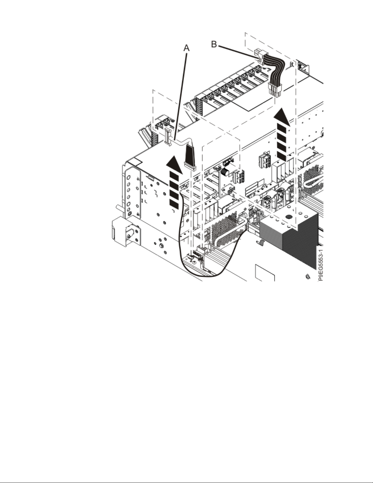
Figure 36. Disconnecting the signal cable and the power cable
b) Ensure that all cables are carefully positioned out of the way, such that the disk drive backplane
can be easily lifted and removed.
c) Carefully unscrew the captive thumbscrew (A) of the disk drive backplane until fully loose as
shown in the following gure. If needed, use a Phillips screwdriver to loosen the screws.
Removing and replacing the system backplane in the 9009-41A, 9009-42A, or 9223-42H
39
Page 54

Figure 37. Loosening the disk drive backplane screw
d) Using the thumbscrew (A) and the disk drive backplane holder (B), slide the disk drive backplane
to the side in the direction that is shown in the following gure, so that the disk drive backplane
clears the tabs in the chassis.
40
Power Systems: System backplane
Page 55

Figure 38. Removing the disk drive backplane
e) Lift the disk drive backplane out of the chassis and place the disk drive backplane on an
appropriate ESD surface.
f) Label and disconnect the signal cable (A) and the power cable (B) from the disk drive backplane
and system backplane as shown in the following gure. Unlatch the clips that secure the
connectors to the disk drive backplane.
Removing and replacing the system backplane in the 9009-41A, 9009-42A, or 9223-42H
41
Page 56

Figure 39. Disconnecting the signal cable and power cable
g) Ensure that all cables are carefully positioned out of the way, such that the disk drive backplane
can be easily lifted and removed.
h) Carefully unscrew the captive thumbscrew (A) of the disk drive backplane until fully loose as
shown in the following gure. If needed, use a Phillips screwdriver to loosen the screws.
42
Power Systems: System backplane
Page 57

Figure 40. Loosening the disk drive backplane screw
i) Using the thumbscrew (A) and the disk drive backplane holder (B), slide the disk drive backplane
to the side in the direction that is shown in the following gure, so that the backplane cutouts
clear the tabs in the chassis.
Removing and replacing the system backplane in the 9009-41A, 9009-42A, or 9223-42H
43
Page 58

Figure 41. Removing the disk drive backplane
j) Lift the disk drive backplane out of the chassis and place the disk drive backplane on an
appropriate ESD surface.
k) Label and disconnect the signal cable (A) and the power cable (B) from the disk drive backplane
and system backplane as shown in the following gure. Unlatch the clips that secure the
connectors to the disk drive backplane.
44
Power Systems: System backplane
Page 59

Figure 42. Disconnecting the signal cable and power cable
l) Ensure that all cables are carefully positioned out of the way, such that the disk drive backplane
can be easily lifted and removed.
m) Carefully unscrew the captive thumbscrews (A) and (B) of the disk drive backplane until fully
loose as shown in the following gure. If needed, use a Phillips screwdriver to loosen the screws.
Removing and replacing the system backplane in the 9009-41A, 9009-42A, or 9223-42H
45
Page 60

Figure 43. Loosening the disk drive backplane screws
n) Using the thumbscrews (A) and (B), slide the disk drive backplane to the side in the direction that
is shown in the following gure, so that the backplane cutouts clear the tabs in the chassis.
46
Power Systems: System backplane
Page 61

Figure 44. Removing the disk drive backplane
o) Lift the disk drive backplane out of the chassis and place the disk drive backplane on an
appropriate ESD surface.
15. Remove the fans enough to prevent them from interfering with the removal of the system backplane:
a) Put your thumb against the front of the latch, (A) as shown in the following gure, and put your
index nger against the rear of the latch.
b) Push against the latch with your thumb and pull out with your index nger. This action releases
the latch.
c) Rotate the handle in the direction shown in the following gure to unlock the fan from its slot.
d) After the fan unlatches, unplug but do not remove fan from its slot. Pull the fan out far enough to
prevent it from interfering with the removal of the system backplane. See the following gure.
e) Repeat “15.a” on page 47 through “15.d” on page 47 for the other fans.
Removing and replacing the system backplane in the 9009-41A, 9009-42A, or 9223-42H
47
Page 62

Figure 45. Removing a fan from the system
16. Disconnect the control panel cable from the system backplane:
a) Unplug the control panel cable from the system backplane as shown in the following gure. As
you face the chassis, the connector is in the left front corner. You can pull the cable from the
system backplane by using the cable cover near the plug.
48
Power Systems: System backplane
Page 63

Figure 46. Disconnecting the control panel cable from the system backplane for a rack-mounted
system
b) Route the cable over the side of the system and out of the way to provide clearance for removing
the backplane.
17. Disconnect the control panel display cable from the system backplane:
a) Unplug the control panel display cable from the system backplane as shown in the following
gure.
Removing and replacing the system backplane in the 9009-41A, 9009-42A, or 9223-42H
49
Page 64

Figure 47. Disconnecting the control panel display cable from the system backplane for a rackmounted system
b) Route the cable over the side of the system and out of the way to provide clearance for removing
the backplane.
18. Remove the heat sink from the system processor module:
a) Loosen the heat sink actuation screw by turning the supplied hex key counterclockwise (A).
Loosen the screw until it moves freely. See the following gure.
50
Power Systems: System backplane
Page 65
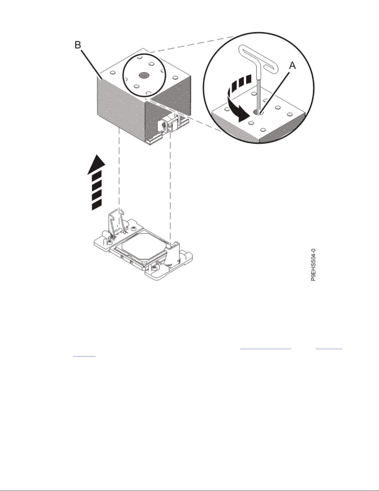
Figure 48. Removing the heat sink
b) Grip the heat sink (B) on opposing sides and remove the heat sink by lifting it upward. Set the heat
sink aside with the module side facing upward.
Note: If you plan to remove dust or debris from the heat sink, this operation must be performed in
another room that is greater than 7.6 m (24.9 ft) away from the work area.
c) Place the heat sink on an appropriate ESD surface.
d) If your system has a second system processor, repeat steps “18.a” on page 50 through “18.c” on
page 51 to remove the other heat sink.
19. Remove the thermal interface material (TIM) from the system processor module or modules:
a) If the system uses the gray-colored TIM: Using the tweezers, remove the gray-colored TIM from
the top of the processor and place it in a clean, dry area as shown in the following gure.
The system can use two types of TIMs. One TIM is silver-colored with trimmed corners and
typically adheres to the heat sink. The other TIM is dark gray with square corners and will lightly
adhere. The gray-colored TIM needs to be removed before the processor is removed.
Note: The gray-colored TIM can be removed using tweezers and reused, but it is best left on the
heat sink during servicing. Be careful not to damage the gray-colored TIM as it is very light and
porous.
Removing and replacing the system backplane in the 9009-41A, 9009-42A, or 9223-42H
51
Page 66

Figure 49. Removing the TIM from the system processor module
b) If your system has a second system processor, repeat step “19.a” on page 51 to remove the other
system processor module.
20. Remove the system processor module or modules:
a) Open the packaging of the system processor module tray. Remove the tray cover and set it aside.
Place the system processor module tray on a solid surface.
b) Ensure that the removal tool (A) is in the open position as shown in Figure 50 on page 53. The
middle pin (B) must be pushed down and blue tabs (C) must be turned inward.
52
Power Systems: System backplane
Page 67

Figure 50. Ensuring the removal tool is in the open position
c) Using the supplied removal tool, align the tool over the system processor module on the system
backplane as shown in the following gure. Lower the tool over the system processor module by
ensuring the two guide pins (A) are inserted into the alignment holes (B) on each side of the tool.
Ensure that the chamfered edge on the tool aligns with the chamfered edge of the processor (C).
Removing and replacing the system backplane in the 9009-41A, 9009-42A, or 9223-42H
53
Page 68

Figure 51. Lowering the removal tool onto the system processor module
d) With the removal tool sitting on top of the system processor module, push down on the pin (A)
slightly so that the blue tabs (B) snap outward and the jaws engage with the system processor
module as shown in the following gure. Make sure that both of the tool jaws are locked onto the
system processor module by pushing down on the tool.
Important: Do not press the blue release tabs until directed to do so later.
54
Power Systems: System backplane
Page 69

Figure 52. Locking the system processor module into the tool
e) Hold the outside of the tool and use it to lift the system processor module from the socket. Lift the
tool upward slowly to ensure that the jaws are fully engaged with the system processor module.
Ensure that the system processor module does not disengage and fall back into the socket of the
system processor module. If the system processor module falls back into the socket of system
processor module, the pins may be damaged. Place the system processor module on the system
processor module tray as shown in the following gure.
Removing and replacing the system backplane in the 9009-41A, 9009-42A, or 9223-42H
55
Page 70

Figure 53. Placing the tool on the system processor module tray
f) To release the system processor module, push the pin downward. Hold the pin down while
pushing the blue tabs inward. Ensure that the pin catches on the openings in the blue tabs, and
that the blue tabs are locked in a xed position. See the following gure.
Note: To prevent the system processor module from falling, pull up on the round lever before you
place the tool on the system processor module tray.
56
Power Systems: System backplane
Page 71

Figure 54. Releasing the system processor module from the tool
g) Place the cover on the system processor module tray.
h) If your system has a second system processor module, repeat steps “20.a” on page 52 through
“20.g” on page 57 to remove the other system processor module.
21. Place the socket dust covers in the system processor module sockets on the system backplane:
a) Lower the socket dust cover over the sockets on the system backplane and ensure that the holes
(B) on the socket dust cover align with the two guide pins (A) on the system backplane. Push
straight down until the latches (D) on the socket dust cover engage with the latches (C) on the
backplane. See the following gure.
Removing and replacing the system backplane in the 9009-41A, 9009-42A, or 9223-42H
57
Page 72

Figure 55. Placing the dust covers on the system processor module sockets on the system
backplane
b) If your system has a second system processor, repeat step “21.a” on page 57 to install the other
socket dust cover.
22. Remove the fan socket from the right side of the bulkhead on the system backplane:
a) Pull out the release pin (A) towards the front of the system. See the following gure.
58
Power Systems: System backplane
Page 73

Figure 56. Releasing the fan socket from the bulkhead
b) Slide the fan socket to the side to release it from the bulkhead. See the following gure.
Removing and replacing the system backplane in the 9009-41A, 9009-42A, or 9223-42H
59
Page 74

Figure 57. Removing the fan socket from the bulkhead
23. Remove the system backplane:
Notes:
• You might nd it helpful to use a magnetic screwdriver.
• Do not remove the silver Torx screws.
a) Using a Phillips screwdriver, unscrew and remove the screw that is underneath the fan socket.
b) Using a Phillips screwdriver, unscrew and remove the remaining three black screws (A) that
mount the backplane to the chassis. See the following gure.
60
Power Systems: System backplane
Page 75

Figure 58. System backplane screw locations
c) Using a Phillips screwdriver, unscrew and remove the two screws (B) that attach the backplane to
the power supply cage. See the following gure.
d) Using a Phillips screwdriver, unscrew and remove the four screws (C) that attach the backplane to
the sides of the system chassis. See the following gure.
e) Using a Phillips screwdriver, unscrew and remove the remaining four screws (D), which are
aligned vertically, that attach the backplane to the sides of the system chassis. See the following
gure.
f) After you remove the screws, place your ngers in positions (A) and (B) and slide the system
backplane slightly toward the front of the system as shown in the following gure.
Note: Slide the system backplane carefully. There is just enough space for the power connectors
to clear the flange on the power supply cage (C).
Figure 59. Preparing the system backplane for removal
Removing and replacing the system backplane in the 9009-41A, 9009-42A, or 9223-42H
61
Page 76

g) Grasp the system backplane by positions (A) and (B) on the front and middle metal bulkheads and
lift up until the pins disengage from the bottom of the chassis. See the following gure.
Figure 60. Grasping the system backplane and disengaging the pins
h) Tilt the system backplane so that the front end is high and the back end is low as you continue to
lift the system backplane out of the chassis. When the system backplane catches on the pins (A)
on the power supply cage, slide the system backplane forward until it clear the pins. Then, lift the
system backplane completely out of the system. See the following gure.
62
Power Systems: System backplane
Page 77

Figure 61. Lifting the system backplane out of the system
i) Place the system backplane on an appropriate ESD surface.
24. Replace the fan socket on the right side of the bulkhead on the system backplane you just removed:
a) Insert the socket tabs into the bulkhead.
b) Slide the socket to the side to fasten it to the bulkhead.
c) Ensure that the pin clicks into place to secure the socket to the bulkhead.
25. Set the new system backplane on the ESD surface next to the system backplane you just removed.
26. Remove the fan socket from the right side of the bulkhead on the new system backplane:
a) Pull out the release pin towards the front of the system.
b) Slide the fan socket to the side to release it from the bulkhead.
27. Transfer the memory modules and llers to the new system backplane:
a) Unlock a memory module or ller from its connector by pushing the locking tabs away from the
module in the direction that is shown in the following gure.
The lever action of the tabs pushes the memory module or ller out of the connector. If you nd it
difcult to open the tabs with your ngers, you may use the tips of ball point pens or the eraser
ends of pencils to open the tabs. The levers must be opened simultaneously, so that the memory
module lifts straight up.
Removing and replacing the system backplane in the 9009-41A, 9009-42A, or 9223-42H
63
Page 78

Figure 62. Removing a memory module or ller
b) Hold the memory module or ller by the edges and pull it out of the system. Note the location
from which you are removing the memory module.
c) Identify the corresponding location on the new system backplane and ensure that the locking tabs
are open. See the following gure.
64
Power Systems: System backplane
Page 79

Figure 63. Replacing a memory module or ller
d) Press the memory module or ller straight down, rmly into the slot, until the locking tabs lock
into place.
e) Repeat “27.a” on page 63 through “27.d” on page 65 for the remaining memory modules and
llers.
28. Install the vital product data card in the new system backplane:
a) Align the VPD card in its slot in location P1-C13 on the new system backplane as shown in the
following gure.
Removing and replacing the system backplane in the 9009-41A, 9009-42A, or 9223-42H
65
Page 80

Figure 64. Replacing the VPD card
b) Push the VPD card into place until it is fully seated in the new system backplane.
29. Install the trusted platform module card in the new system backplane:
a) Grasp the TPM card by the plastic housing as shown in the following gure.
b) Pull the TPM card out of its slot in location P1-C14 on the system backplane.
66
Power Systems: System backplane
Page 81

Figure 65. Removing the TPM card
c) Insert the TPM card into its slot in location P1-C14 on the new system backplane as shown in the
following gure.
Removing and replacing the system backplane in the 9009-41A, 9009-42A, or 9223-42H
67
Page 82
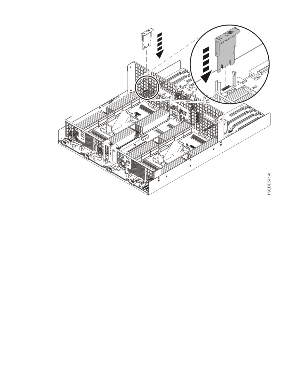
Figure 66. Replacing the TPM card
d) Push the TPM card into place until it is fully seated in the new system backplane.
Replacing the system backplane in the 9009-41A, 9009-42A, or 9223-42H
Follow these steps to replace the system backplane.
About this task
Procedure
1. Ensure that you have the electrostatic discharge (ESD) wrist strap on and that the ESD clip is plugged
into a ground jack or connected to an unpainted metal surface. If not, do so now.
2. Install the replacement system backplane.
a) Grasp the replacement system backplane by positions (A) and (B) on the front and middle metal
bulkheads and begin lowering the backplane into the chassis. As you lower the backplane, be
careful not to hit the pins (C) on the power supply cage. See the following image.
68
Power Systems: System backplane
Page 83

Figure 67. Grasping the system backplane and lowering it into the chassis
b) Tilt the backplane so that the front end is high and the back end is low as you continue to lower
the backplane into the chassis. When the system backplane catches on the pins (A) on the power
supply cage, lower the front end enough so that it clears the pins. See the following image.
Removing and replacing the system backplane in the 9009-41A, 9009-42A, or 9223-42H
69
Page 84

Figure 68. Tilting and lowering the system backplane into the chassis
c) Continue lowering the backplane into the chassis until the pins engage.
d) Place your ngers in positions (A) and (B) and slide the system backplane slightly toward the rear
of the system as shown in the following image.
Note: Slide the system backplane carefully. There is just enough space for the power connectors
to clear the flange on the power supply cage (C).
70
Power Systems: System backplane
Page 85

Figure 69. Sliding the backplane towards the rear of the system
e) Using a Phillips screwdriver, replace and screw in the four screws (D) that are vertically aligned
and that attach the backplane to the sides of the system chassis. See the following image.
Notes:
• You might nd it helpful to use a magnetic screwdriver.
• Do not remove the silver Torx screws.
Figure 70. System backplane screw locations
Removing and replacing the system backplane in the 9009-41A, 9009-42A, or 9223-42H
71
Page 86

f) Using a Phillips screwdriver, replace and screw in the four screws (C) that attach the backplane to
the sides of the system chassis. See the previous image.
g) Using a Phillips screwdriver, replace and screw in the two screws (B) that attach the backplane to
the power supply cage. See the previous image.
h) Using a Phillips screwdriver, replace and screw in the three black screws (A) that mount the
backplane to the chassis. See the previous image.
i) Using a Phillips screwdriver, replace and screw in the screw that is underneath the fan socket.
3. Replace the fan socket on the right side of the bulkhead on the new system backplane as shown in
the following images:
a) Insert the socket tabs into the bulkhead.
b) Slide the socket to the side to fasten it to the bulkhead.
c) Ensure that the pin (A) clicks into place to secure the socket to the bulkhead.
Figure 71. Replacing the socket in the bulkhead
72
Power Systems: System backplane
Page 87
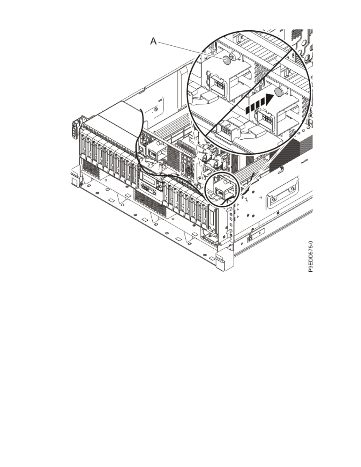
Figure 72. Fastening the fan socket to the bulkhead
4. Remove the socket dust covers from the system processor module sockets on the new system
backplane:
a) Grasp the latches on both sides of the socket dust cover and squeeze them inwards until the
latches release from the pins on the system backplane. See the following image.
b) Lift the socket dust cover straight up as shown in the following image. Set the dust cover aside.
Removing and replacing the system backplane in the 9009-41A, 9009-42A, or 9223-42H
73
Page 88
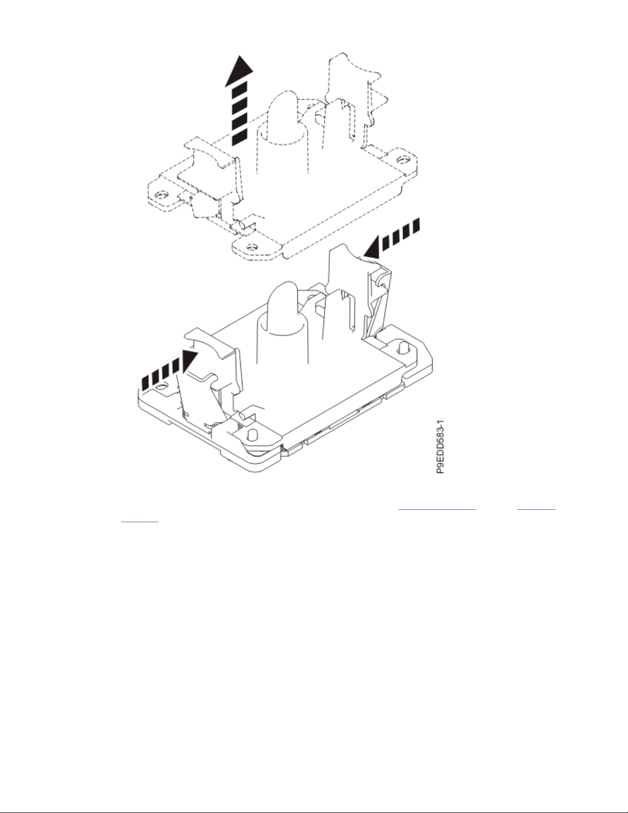
Figure 73. Removing the socket dust covers
c) If your system has a second system processor, repeat steps “4.a” on page 73 through “4.b” on
page 73 to remove the other socket dust cover.
5. Place the original system backplane on the packaging for the replacement system backplane FRU
and place it near the system with the replacement system backplane.
6. Install the system processor modules from the original system backplane in the new system
backplane:
a) If dust or debris is present on the system processor socket on the new system backplane, use the
supplied air pump to clean the socket before you install the new system processor. Blow small
bursts of air from the center toward the sides of the socket, as shown the following image.
74
Power Systems: System backplane
Page 89

Figure 74. Removing dust and debris from the system processor socket
b) If necessary, take the cover off of the system processor module tray.
c) Hold the sides of the tool with system processor module and carefully lift the tool out of the
system processor module tray.
d) Lower the tool and system processor module onto the socket. Align the beveled corner of the tool
with the beveled corner on the socket. Align the guide pins (A) with the alignment holes (B) on
each side of the tool. Use care to lower the tool evenly without tilting the tool.
Note: Do not attempt to slide the tool and the system processor module in any direction while the
system processor module is touching the socket. If the tool and the system processor module are
not aligned with the guide pins, lift the tool and the system processor module and reposition
them.
Removing and replacing the system backplane in the 9009-41A, 9009-42A, or 9223-42H
75
Page 90

Figure 75. Installing the system processor module
e) Open the latches that hold the system processor module in the supplied removal tool (A) as
shown in the following gure. Push down on the ring (B) while pressing in on the tabs (C).
76
Power Systems: System backplane
Page 91

Figure 76. Removing the system processor module tool
f) Lift the tool off the system processor module.
g) Repeat “6.a” on page 74 through “6.f” on page 77 for the other system processor module.
7. Replace the thermal interface material (TIM) and heat sinks.
a) Using the tweezers, move the old processor's TIM from the clean, dry surface and center it onto
the new system processor module.
The TIM has no preferred up side. The TIM can be placed on the processor and centered as shown
in the following gure.
Removing and replacing the system backplane in the 9009-41A, 9009-42A, or 9223-42H
77
Page 92

Figure 77. Moving the TIM onto the system processor module
b) Place the heat sink on the TIM as shown in the following gure.
78
Power Systems: System backplane
Page 93

Figure 78. Installing the heat sink on the TIM
c) Ensure that the heat sink load arms are engaged as shown by (A) in the following gure.
d) Tighten the center load screw clockwise by using the supplied hex key as shown by (B) in the
following gure until a rm stop is reached. If the heat sink moves noticeably, the load arms are
not engaged. Unscrew the center load screw and repeat this step again.
Removing and replacing the system backplane in the 9009-41A, 9009-42A, or 9223-42H
79
Page 94

Figure 79. Tightening the center load screw on the heat sink
e) If your system has a second system processor module, repeat steps “7.a” on page 77 through
“7.d” on page 79 to replace the other TIM and heat sink.
8. Reconnect the control panel display cable to the system backplane as shown in the following gure.
80
Power Systems: System backplane
Page 95

Figure 80. Connecting the control panel display cable to the system backplane for a rack-mounted
system
9. Reconnect the control panel cable to the system backplane as shown in the following gure.
Removing and replacing the system backplane in the 9009-41A, 9009-42A, or 9223-42H
81
Page 96

Figure 81. Connecting the control panel cable to the system backplane for a rack-mounted system
10. Replace the fans into their slots.
a) Using your hand to support the bottom of the fan, slide the fan into the system. See the following
gure.
b) Rotate the fan handle (A) in the direction shown, and then press the handle until the latch locks in
place. See the following gure.
c) Repeat “10.a” on page 82 through “10.b” on page 82 for the other fans.
82
Power Systems: System backplane
Page 97

Figure 82. Replacing a fan in the system
11. Replace the disk drive backplane.
• If you have a base function disk drive backplane, complete “11.a” on page 83 through “11.c” on
page 85.
• If you have a 12-drive expanded function disk drive backplane, complete “11.d” on page 86
through “11.f” on page 88.
• If you have an 18-drive expanded function disk drive backplane, complete “11.g” on page 89
through “11.i” on page 91.
a) The chassis has two alignment pins and several brackets (A) to secure the disk drive backplane.
Using the disk drive backplane touchpoint (B), thumbscrew (C), and alignment pins (A), insert the
disk drive backplane into the chassis as shown in the following gure.
Slide the disk drive backplane to the side in the direction that is shown so that the backplane
cutouts slide under tabs in the chassis.
Removing and replacing the system backplane in the 9009-41A, 9009-42A, or 9223-42H
83
Page 98

Figure 83. Replacing the disk drive backplane by using alignment pins
b) Carefully tighten the captive thumbscrew (C) to secure the disk drive backplane to the system
chassis as shown in the following gure.
84
Power Systems: System backplane
Page 99

Figure 84. Replacing the disk drive backplane
c) Reconnect the signal cable (A), and the power cable (B), to the disk drive backplane and system
backplane as shown in the following gure.
Push the connectors in until the latches click.
Removing and replacing the system backplane in the 9009-41A, 9009-42A, or 9223-42H
85
Page 100

Figure 85. Reconnecting the power cable and the signal cable to the disk drive backplane
d) The chassis has two alignment pins and several brackets (A) to secure the disk drive backplane.
Using the disk drive backplane touchpoint (B), thumbscrew (C) and alignment pins (A), insert the
disk drive backplane as shown in the following gure, while you ensure that the alignment pins t
through the holes in the disk drive backplane.
Slide the disk drive backplane to the side in the direction that is shown so that the backplane
cutouts slide under tabs in the chassis.
86
Power Systems: System backplane
 Loading...