

Page 1

Power Systems
Installing the IBM Power System S814
(8286-41A)
IBM
GI11-9904-06
Page 2

Page 3

Power Systems
Installing the IBM Power System S814
(8286-41A)
IBM
GI11-9904-06
Page 4

Note
Before using this information and the product it supports, read the information in “Safety notices” on page v, “Notices” on
page 47, the IBM Systems Safety Notices manual, G229-9054, and the IBM Environmental Notices and User Guide, Z125–5823.
This edition applies to IBM Power Systems™servers that contain the POWER8®processor and to all associated
models.
© Copyright IBM Corporation 2014, 2017.
US Government Users Restricted Rights – Use, duplication or disclosure restricted by GSA ADP Schedule Contract
with IBM Corp.
Page 5

Contents
Safety notices ................................. v
Installing the IBM Power System S814 (8286-41A).................. 1
Determining your server type ............................. 1
Installing a rack-based server .............................. 1
Prerequisite for installing the rack-mounted server...................... 1
Completing inventory for your server .......................... 2
Determining and marking the location in the rack ...................... 2
Attaching the mounting hardware to the rack ....................... 4
Installing the system into the rack ........................... 6
Installing the cable-management arm .......................... 7
Cabling the server and setting up a console........................ 11
Determining which console to use .......................... 12
Cabling the server with an ASCII terminal ...................... 12
Cabling the server to the HMC .......................... 13
Cabling the server and accessing Operations Console .................. 14
Cabling the server and accessing the IVM ...................... 19
Cabling the server with keyboard, video, and mouse .................. 20
Cabling the server and connecting expansion units ..................... 20
Completing the server setup............................. 21
Completing the server setup by using an HMC ..................... 21
Completing the server setup without using an HMC ................... 24
Setting up a preinstalled server ............................. 25
Prerequisite for installing the preinstalled server ...................... 25
Completing inventory for your preinstalled server ..................... 25
Removing the shipping bracket and connecting power cords and power distribution unit (PDU) for your
preinstalled server ................................ 26
Setting up a console ............................... 28
Determining which console to use .......................... 28
Cabling the server with an ASCII terminal ...................... 29
Cabling the server to the HMC .......................... 30
Cabling the server and accessing the IVM ...................... 31
Cabling the server with keyboard, video, and mouse .................. 32
Routing cables through the cable-management arm and connecting expansion units .......... 33
Completing the server setup............................. 33
Completing the server setup by using an HMC ..................... 33
Completing the server setup without using an HMC ................... 35
Installing a stand-alone server ............................. 36
Prerequisite for installing the stand-alone server ...................... 36
Moving the server to the installation site ........................ 37
Completing inventory for your stand-alone server ..................... 37
Cabling the server and setting up a console ....................... 37
Determining which console to use .......................... 37
Cabling the server with an ASCII terminal ...................... 38
Cabling the server to the HMC .......................... 39
Cabling the server and accessing the IVM ...................... 40
Cabling the server with keyboard, video, and mouse .................. 42
Cabling the server and connecting expansion units .................... 42
Completing the server setup............................. 42
Completing the server setup by using an HMC ..................... 42
Completing the server setup without using an HMC ................... 45
Notices ................................... 47
Accessibility features for IBM Power Systems servers ..................... 48
Privacy policy considerations ............................. 49
© Copyright IBM Corp. 2014, 2017 iii
Page 6

Trademarks ................................... 50
Electronic emission notices .............................. 50
Class A Notices ................................. 50
Class B Notices ................................. 54
Terms and conditions ................................ 57
iv Power Systems: Installing the IBM Power System S814 (8286-41A)
Page 7

Safety notices
Safety notices may be printed throughout this guide:
v DANGER notices call attention to a situation that is potentially lethal or extremely hazardous to
people.
v CAUTION notices call attention to a situation that is potentially hazardous to people because of some
existing condition.
v Attention notices call attention to the possibility of damage to a program, device, system, or data.
World Trade safety information
Several countries require the safety information contained in product publications to be presented in their
national languages. If this requirement applies to your country, safety information documentation is
included in the publications package (such as in printed documentation, on DVD, or as part of the
product) shipped with the product. The documentation contains the safety information in your national
language with references to the U.S. English source. Before using a U.S. English publication to install,
operate, or service this product, you must first become familiar with the related safety information
documentation. You should also refer to the safety information documentation any time you do not
clearly understand any safety information in the U.S. English publications.
Replacement or additional copies of safety information documentation can be obtained by calling the IBM
Hotline at 1-800-300-8751.
German safety information
Das Produkt ist nicht für den Einsatz an Bildschirmarbeitsplätzen im Sinne § 2 der
Bildschirmarbeitsverordnung geeignet.
Laser safety information
IBM®servers can use I/O cards or features that are fiber-optic based and that utilize lasers or LEDs.
Laser compliance
IBM servers may be installed inside or outside of an IT equipment rack.
DANGER: When working on or around the system, observe the following precautions:
Electrical voltage and current from power, telephone, and communication cables are hazardous. To avoid
a shock hazard:
v If IBM supplied the power cord(s), connect power to this unit only with the IBM provided power cord.
Do not use the IBM provided power cord for any other product.
v Do not open or service any power supply assembly.
v Do not connect or disconnect any cables or perform installation, maintenance, or reconfiguration of this
product during an electrical storm.
v The product might be equipped with multiple power cords. To remove all hazardous voltages,
disconnect all power cords.
– For AC power, disconnect all power cords from their AC power source.
– For racks with a DC power distribution panel (PDP), disconnect the customer’s DC power source to
the PDP.
v When connecting power to the product ensure all power cables are properly connected.
© Copyright IBM Corp. 2014, 2017 v
Page 8

– For racks with AC power, connect all power cords to a properly wired and grounded electrical
outlet. Ensure that the outlet supplies proper voltage and phase rotation according to the system
rating plate.
– For racks with a DC power distribution panel (PDP), connect the customer’s DC power source to
the PDP. Ensure that the proper polarity is used when attaching the DC power and DC power
return wiring.
v Connect any equipment that will be attached to this product to properly wired outlets.
v When possible, use one hand only to connect or disconnect signal cables.
v Never turn on any equipment when there is evidence of fire, water, or structural damage.
v Do not attempt to switch on power to the machine until all possible unsafe conditions are corrected.
v Assume that an electrical safety hazard is present. Perform all continuity, grounding, and power checks
specified during the subsystem installation procedures to ensure that the machine meets safety
requirements.
v Do not continue with the inspection if any unsafe conditions are present.
v Before you open the device covers, unless instructed otherwise in the installation and configuration
procedures: Disconnect the attached AC power cords, turn off the applicable circuit breakers located in
the rack power distribution panel (PDP), and disconnect any telecommunications systems, networks,
and modems.
DANGER:
v Connect and disconnect cables as described in the following procedures when installing, moving, or
opening covers on this product or attached devices.
To Disconnect:
1. Turn off everything (unless instructed otherwise).
2. For AC power, remove the power cords from the outlets.
3. For racks with a DC power distribution panel (PDP), turn off the circuit breakers located in the
PDP and remove the power from the Customer's DC power source.
4. Remove the signal cables from the connectors.
5. Remove all cables from the devices.
To Connect:
1. Turn off everything (unless instructed otherwise).
2. Attach all cables to the devices.
3. Attach the signal cables to the connectors.
4. For AC power, attach the power cords to the outlets.
5. For racks with a DC power distribution panel (PDP), restore the power from the Customer's DC
power source and turn on the circuit breakers located in the PDP.
6. Turn on the devices.
Sharp edges, corners and joints may be present in and around the system. Use care when handling
equipment to avoid cuts, scrapes and pinching. (D005)
(R001 part 1 of 2):
DANGER: Observe the following precautions when working on or around your IT rack system:
v Heavy equipment–personal injury or equipment damage might result if mishandled.
v Always lower the leveling pads on the rack cabinet.
v Always install stabilizer brackets on the rack cabinet.
v To avoid hazardous conditions due to uneven mechanical loading, always install the heaviest devices
in the bottom of the rack cabinet. Always install servers and optional devices starting from the bottom
of the rack cabinet.
v Rack-mounted devices are not to be used as shelves or work spaces. Do not place objects on top of
rack-mounted devices. In addition, do not lean on rack mounted devices and do not use them to
stabilize your body position (for example, when working from a ladder).
vi Power Systems: Installing the IBM Power System S814 (8286-41A)
Page 9

v Each rack cabinet might have more than one power cord.
– For AC powered racks, be sure to disconnect all power cords in the rack cabinet when directed to
disconnect power during servicing.
– For racks with a DC power distribution panel (PDP), turn off the circuit breaker that controls the
power to the system unit(s), or disconnect the customer’s DC power source, when directed to
disconnect power during servicing.
v Connect all devices installed in a rack cabinet to power devices installed in the same rack cabinet. Do
not plug a power cord from a device installed in one rack cabinet into a power device installed in a
different rack cabinet.
v An electrical outlet that is not correctly wired could place hazardous voltage on the metal parts of the
system or the devices that attach to the system. It is the responsibility of the customer to ensure that
the outlet is correctly wired and grounded to prevent an electrical shock.
(R001 part 2 of 2):
CAUTION:
v Do not install a unit in a rack where the internal rack ambient temperatures will exceed the
manufacturer's recommended ambient temperature for all your rack-mounted devices.
v Do not install a unit in a rack where the air flow is compromised. Ensure that air flow is not blocked
or reduced on any side, front, or back of a unit used for air flow through the unit.
v Consideration should be given to the connection of the equipment to the supply circuit so that
overloading of the circuits does not compromise the supply wiring or overcurrent protection. To
provide the correct power connection to a rack, refer to the rating labels located on the equipment in
the rack to determine the total power requirement of the supply circuit.
v (For sliding drawers.) Do not pull out or install any drawer or feature if the rack stabilizer brackets are
not attached to the rack. Do not pull out more than one drawer at a time. The rack might become
unstable if you pull out more than one drawer at a time.
v (For fixed drawers.) This drawer is a fixed drawer and must not be moved for servicing unless specified
by the manufacturer. Attempting to move the drawer partially or completely out of the rack might
cause the rack to become unstable or cause the drawer to fall out of the rack.
Safety notices vii
Page 10

CAUTION:
Removing components from the upper positions in the rack cabinet improves rack stability during
relocation. Follow these general guidelines whenever you relocate a populated rack cabinet within a
room or building.
v Reduce the weight of the rack cabinet by removing equipment starting at the top of the rack
cabinet. When possible, restore the rack cabinet to the configuration of the rack cabinet as you
received it. If this configuration is not known, you must observe the following precautions:
– Remove all devices in the 32U position (compliance ID RACK-001 or 22U (compliance ID RR001)
and above.
– Ensure that the heaviest devices are installed in the bottom of the rack cabinet.
– Ensure that there are little-to-no empty U-levels between devices installed in the rack cabinet
below the 32U (compliance ID RACK-001 or 22U (compliance ID RR001) level, unless the
received configuration specifically allowed it.
v If the rack cabinet you are relocating is part of a suite of rack cabinets, detach the rack cabinet from
the suite.
v If the rack cabinet you are relocating was supplied with removable outriggers they must be
reinstalled before the cabinet is relocated.
v Inspect the route that you plan to take to eliminate potential hazards.
v Verify that the route that you choose can support the weight of the loaded rack cabinet. Refer to the
documentation that comes with your rack cabinet for the weight of a loaded rack cabinet.
v Verify that all door openings are at least 760 x 230 mm (30 x 80 in.).
v Ensure that all devices, shelves, drawers, doors, and cables are secure.
v Ensure that the four leveling pads are raised to their highest position.
v Ensure that there is no stabilizer bracket installed on the rack cabinet during movement.
v Do not use a ramp inclined at more than 10 degrees.
v When the rack cabinet is in the new location, complete the following steps:
– Lower the four leveling pads.
– Install stabilizer brackets on the rack cabinet.
– If you removed any devices from the rack cabinet, repopulate the rack cabinet from the lowest
position to the highest position.
v If a long-distance relocation is required, restore the rack cabinet to the configuration of the rack
cabinet as you received it. Pack the rack cabinet in the original packaging material, or equivalent.
Also lower the leveling pads to raise the casters off of the pallet and bolt the rack cabinet to the
pallet.
(R002)
(L001)
DANGER: Hazardous voltage, current, or energy levels are present inside any component that has this
label attached. Do not open any cover or barrier that contains this label. (L001)
(L002)
viii Power Systems: Installing the IBM Power System S814 (8286-41A)
Page 11

DANGER: Rack-mounted devices are not to be used as shelves or work spaces. (L002)
1
2
!
1
2
1 2
3
4
(L003)
or
or
or
Safety notices ix
Page 12
1
2
3
4
or
DANGER: Multiple power cords. The product might be equipped with multiple AC power cords or
multiple DC power cables. To remove all hazardous voltages, disconnect all power cords and power
cables. (L003)
(L007)
CAUTION: A hot surface nearby. (L007)
(L008)
x Power Systems: Installing the IBM Power System S814 (8286-41A)
Page 13

CAUTION: Hazardous moving parts nearby. (L008)
All lasers are certified in the U.S. to conform to the requirements of DHHS 21 CFR Subchapter J for class
1 laser products. Outside the U.S., they are certified to be in compliance with IEC 60825 as a class 1 laser
product. Consult the label on each part for laser certification numbers and approval information.
CAUTION:
This product might contain one or more of the following devices: CD-ROM drive, DVD-ROM drive,
DVD-RAM drive, or laser module, which are Class 1 laser products. Note the following information:
v Do not remove the covers. Removing the covers of the laser product could result in exposure to
hazardous laser radiation. There are no serviceable parts inside the device.
v Use of the controls or adjustments or performance of procedures other than those specified herein
might result in hazardous radiation exposure.
(C026)
CAUTION:
Data processing environments can contain equipment transmitting on system links with laser modules
that operate at greater than Class 1 power levels. For this reason, never look into the end of an optical
fiber cable or open receptacle. Although shining light into one end and looking into the other end of
a disconnected optical fiber to verify the continuity of optic fibers many not injure the eye, this
procedure is potentially dangerous. Therefore, verifying the continuity of optical fibers by shining
light into one end and looking at the other end is not recommended. To verify continuity of a fiber
optic cable, use an optical light source and power meter. (C027)
CAUTION:
This product contains a Class 1M laser. Do not view directly with optical instruments. (C028)
CAUTION:
Some laser products contain an embedded Class 3A or Class 3B laser diode. Note the following
information: laser radiation when open. Do not stare into the beam, do not view directly with optical
instruments, and avoid direct exposure to the beam. (C030)
CAUTION:
The battery contains lithium. To avoid possible explosion, do not burn or charge the battery.
Do Not:
v ___ Throw or immerse into water
v ___ Heat to more than 100°C (212°F)
v ___ Repair or disassemble
Exchange only with the IBM-approved part. Recycle or discard the battery as instructed by local
regulations. In the United States, IBM has a process for the collection of this battery. For information,
call 1-800-426-4333. Have the IBM part number for the battery unit available when you call. (C003)
Safety notices xi
Page 14

CAUTION:
Regarding IBM provided VENDOR LIFT TOOL:
v Operation of LIFT TOOL by authorized personnel only.
v LIFT TOOL intended for use to assist, lift, install, remove units (load) up into rack elevations. It is
not to be used loaded transporting over major ramps nor as a replacement for such designated tools
like pallet jacks, walkies, fork trucks and such related relocation practices. When this is not
practicable, specially trained persons or services must be used (for instance, riggers or movers).
v Read and completely understand the contents of LIFT TOOL operator's manual before using.
Failure to read, understand, obey safety rules, and follow instructions may result in property
damage and/or personal injury. If there are questions, contact the vendor's service and support.
Local paper manual must remain with machine in provided storage sleeve area. Latest revision
manual available on vendor's web site.
v Test verify stabilizer brake function before each use. Do not over-force moving or rolling the LIFT
TOOL with stabilizer brake engaged.
v Do not move LIFT TOOL while platform is raised, except for minor positioning.
v Do not exceed rated load capacity. See LOAD CAPACITY CHART regarding maximum loads at
center versus edge of extended platform.
v Only raise load if properly centered on platform. Do not place more than 200 lb (91 kg) on edge of
sliding platform shelf also considering the load's center of mass/gravity (CoG).
v Do not corner load the platform tilt riser accessory option. Secure platform riser tilt option to main
shelf in all four (4x) locations with provided hardware only, prior to use. Load objects are designed
to slide on/off smooth platforms without appreciable force, so take care not to push or lean. Keep
riser tilt option flat at all times except for final minor adjustment when needed.
v Do not stand under overhanging load.
v Do not use on uneven surface, incline or decline (major ramps).
v Do not stack loads.
v Do not operate while under the influence of drugs or alcohol.
v Do not support ladder against LIFT TOOL.
v Tipping hazard. Do not push or lean against load with raised platform.
v Do not use as a personnel lifting platform or step. No riders.
v Do not stand on any part of lift. Not a step.
v Do not climb on mast.
v Do not operate a damaged or malfunctioning LIFT TOOL machine.
v Crush and pinch point hazard below platform. Only lower load in areas clear of personnel and
obstructions. Keep hands and feet clear during operation.
v No Forks. Never lift or move bare LIFT TOOL MACHINE with pallet truck, jack or fork lift.
v Mast extends higher than platform. Be aware of ceiling height, cable trays, sprinklers, lights, and
other overhead objects.
v Do not leave LIFT TOOL machine unattended with an elevated load.
v Watch and keep hands, fingers, and clothing clear when equipment is in motion.
v Turn Winch with hand power only. If winch handle cannot be cranked easily with one hand, it is
probably over-loaded. Do not continue to turn winch past top or bottom of platform travel.
Excessive unwinding will detach handle and damage cable. Always hold handle when lowering,
unwinding. Always assure self that winch is holding load before releasing winch handle.
v A winch accident could cause serious injury. Not for moving humans. Make certain clicking sound
is heard as the equipment is being raised. Be sure winch is locked in position before releasing
handle. Read instruction page before operating this winch. Never allow winch to unwind freely.
Freewheeling will cause uneven cable wrapping around winch drum, damage cable, and may cause
serious injury. (C048)
Power and cabling information for NEBS (Network Equipment-Building System)
GR-1089-CORE
The following comments apply to the IBM servers that have been designated as conforming to NEBS
(Network Equipment-Building System) GR-1089-CORE:
xii Power Systems: Installing the IBM Power System S814 (8286-41A)
Page 15

The equipment is suitable for installation in the following:
v Network telecommunications facilities
v Locations where the NEC (National Electrical Code) applies
The intrabuilding ports of this equipment are suitable for connection to intrabuilding or unexposed
wiring or cabling only. The intrabuilding ports of this equipment must not be metallically connected to the
interfaces that connect to the OSP (outside plant) or its wiring. These interfaces are designed for use as
intrabuilding interfaces only (Type 2 or Type 4 ports as described in GR-1089-CORE) and require isolation
from the exposed OSP cabling. The addition of primary protectors is not sufficient protection to connect
these interfaces metallically to OSP wiring.
Note: All Ethernet cables must be shielded and grounded at both ends.
The ac-powered system does not require the use of an external surge protection device (SPD).
The dc-powered system employs an isolated DC return (DC-I) design. The DC battery return terminal
shall not be connected to the chassis or frame ground.
The dc-powered system is intended to be installed in a common bonding network (CBN) as described in
GR-1089-CORE.
Safety notices xiii
Page 16

xiv Power Systems: Installing the IBM Power System S814 (8286-41A)
Page 17

Installing the IBM Power System S814 (8286-41A)
Use this information to learn about installing the IBM Power®System S814 (8286-41A).
Determining your server type
Determine whether you are installing a rack-mounted server, a server that arrived preinstalled in a rack,
or a stand-alone server.
Determine which type of server you are installing. For more information, see the following table.
Table 1. Determine the type of server you are installing and follow the instructions to find related information.
Server type Description Where to find related information
Rack-mounted Your system arrived without a rack,
and you need to install the system
into an existing rack.
Preinstalled Your system arrived preinstalled in a
rack.
Stand-alone Your system is a stand-alone, or
deskside system.
Installing a rack-based server
“Installing a rack-based server”
“Setting up a preinstalled server” on
page 25
“Installing a stand-alone server” on
page 36
Use this information to learn about installing a rack-based 8286-41A server.
Prerequisite for installing the rack-mounted server
Use the information to understand the prerequisites that are required for installing the server.
You might need to read the following documents before you install the server:
v The latest version of this document is maintained online. See Installing the IBM Power System S814
(8286-41A) (http://www.ibm.com/support/knowledgecenter/POWER8/p8eg1/p8eg1_roadmap.htm).
v To plan your server installation, see Planning for the system (http://www.ibm.com/support/
knowledgecenter/POWER8/p8had/p8had_8xx_kickoff.htm).
v If you are using a Hardware Management Console (HMC), see Obtaining and applying machine code
updates for the HMC with an Internet connection (http://www.ibm.com/support/knowledgecenter/
POWER8/p8hai/area3fixeshmc.htm).
Consider the following prerequisites before you install the server:
1. Ensure that you have the following items before you start your installation:
v Phillips screwdriver
v Flat-head screwdriver
v Rack with four units of space
Note: If you do not have a rack that is installed, install the rack. For instructions, see Racks and rack
features (http://www.ibm.com/support/knowledgecenter/POWER8/p8hbf/p8hbf_8xx_kickoff.htm).
2. Ensure that you have one of the following consoles:
v Hardware Management Console (HMC): Ensure that your HMC is at version 8 release 8.4.0 or later.
v Graphic monitor with keyboard and mouse.
© Copyright IBM Corp. 2014, 2017 1
Page 18

v Teletype (tty) monitor with keyboard.
Completing inventory for your server
Use this information to complete inventory for your server.
To complete the inventory, complete the following steps:
1. Verify that you received all the boxes you ordered.
2. Unpack the server components as needed.
3. Complete a parts inventory before you install each server component by following these steps:
a. Locate the inventory list for your server.
b. Ensure that you received all the parts that you ordered.
Note: Your order information is included with your product. You can also obtain order
information from your marketing representative or the IBM Business Partner.
If you have incorrect, missing, or damaged parts, consult any of the following resources:
v Your IBM reseller.
v IBM Rochester manufacturing automated information line at 1-800-300-8751 (United States only).
v The Directory of worldwide contacts website http://www.ibm.com/planetwide. Select your
location to view the service and support contact information.
Determining and marking the location in the rack
You might need to determine where to install the system unit into the rack.
To determine where to install the system unit into a rack, complete the following steps:
1. Read the Rack safety notices (http://www.ibm.com/support/knowledgecenter/POWER8/p8hbf/
racksafety.htm).
2. Determine where to place the system unit in the rack. As you plan for installing the system unit in a
rack, consider the following information:
v Organize larger and heavier units into the lower part of the rack.
v Plan to install units into the lower part of the rack first.
v Record the Electronic Industries Alliance (EIA) locations in your plan.
Note: This server is four EIA units high. An EIA unit is 44.45 mm (1.75 in.) in height. The rack
contains three mounting holes for each EIA unit of height. This system unit therefore, is 177.8 mm (7
in.) high and covers 12 mounting holes in the rack.
3. If necessary, remove the filler panels to allow access to the inside of the rack enclosure where you
plan to place the unit, as shown in For details, see Figure 1 on page 3.
2 Power Systems: Installing the IBM Power System S814 (8286-41A)
Page 19

Figure 1. Removing the filler panels
4. Determine to place the system in the rack. Record the EIA location.
Note: An EIA unit on your rack consists of a grouping of three holes.
5. Facing the front of the rack and working from the right side of the rack, use tape, a marker, or pencil
to mark the lowest two holes of the lowest EIA unit. Next, mark the lowest hole on the EIA unit
directly above this EIA unit.
6. Repeat step 5 for the corresponding holes located on the left side of the rack.
7. Go to the rear of the rack.
8. On the right side, find the EIA unit that corresponds to the bottom EIA unit marked on the front of
the rack.
9. Mark the bottom hole in the EIA unit and the top hole in the EIA unit.
10. Mark the corresponding holes on the left side of the rack.
Installing the IBM Power System S814 (8286-41A) 3
Page 20

Attaching the mounting hardware to the rack
You might need to attach the mounting hardware to the rack. Use the procedure to complete this task.
The information is intended to promote safety and reliable operation, and includes illustrations of the
related hardware components and shows how these components relate to each other.
Attention: To avoid rail failure and potential danger to yourself and to the unit, ensure that you have
the correct rails and fittings for your rack. If your rack has square support flange holes or screw-thread
support flange holes, ensure that the rails and fittings match the support flange holes that are used on
your rack. Do not install mismatched hardware by using washers or spacers. If you do not have the
correct rails and fittings for your rack, contact your IBM reseller.
To install the rack-mounting hardware into the rack, complete the following steps:
1. Each slide rail is marked with either an R (right) or an L (left), when you look from the front. Select
the left slide rail, bring it to the rear of the rack, and locate the selected EIA unit that was previously
marked.
2. Push up on the locking tab (1) on the front, and pull out the front latch (2) at the front of the rail.
Then, remove the screw from the rear of the rail (3). For details, see Figure 2.
Figure 2. Opening the front latch and removing the rear screw
3. Align the two pins located on the rear of the slide rail with the top and bottom holes within the
selected EIA unit that were previously marked. Pull the slide rail toward you to insert the two pins
into the rack holes (1), and lower the slide rail down (2) to engage the hook feature on the top pin.
For details, see Figure 3 on page 5. Ensure that the two pins protrude through the rack holes before
you proceed to the next step.
Note: The pin fixtures of the slide rails support either round-hole or square-hole rack models.
4 Power Systems: Installing the IBM Power System S814 (8286-41A)
Page 21
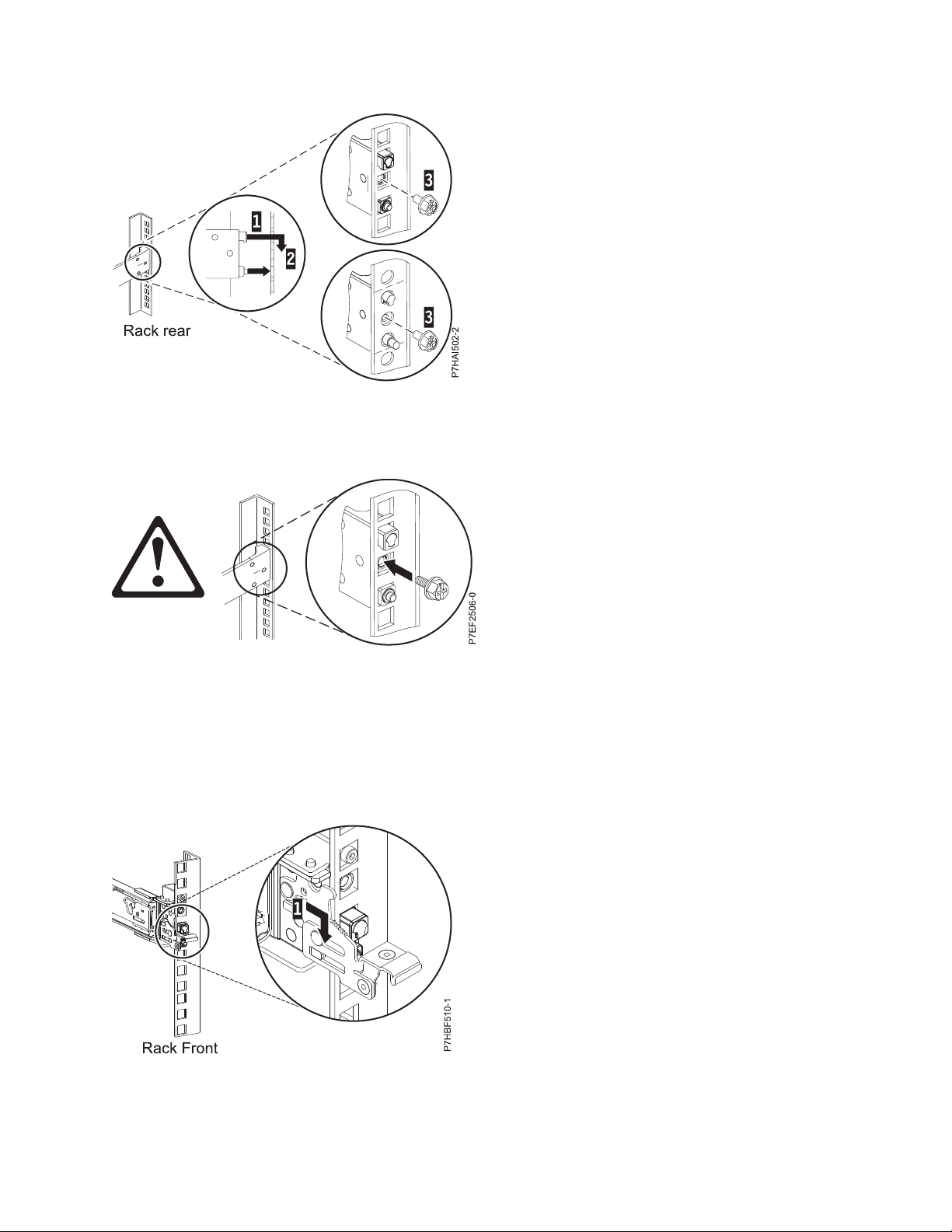
Figure 3. Aligning and engaging the pins into the holes in the rear of the rack
4. Reinstall the screw that was removed in step 2 on page 4, as shown in Figure 4.
Figure 4. Reinstalling the screw
5. Return to the front of the rack. Ensure that the latch is still open on the front of the slide rail. Refer to
step 2 on page 4.
6. Pull the slide rail forward and insert three pins on the front of the rail into the holes within the
selected EIA unit that were previously marked. Lower the slide rail down (1) to engage the hook
feature on the middle pin. For details, see Figure 5.
Figure 5. Pins that are seated on the front rail of the rack
Installing the IBM Power System S814 (8286-41A) 5
Page 22

7. While you pull the slide rail forward, ensure that all three pins protrude through the rack holes, then
push the front latch (2) all the way in. For details, see Figure 6.
Figure 6. Latch seated on the front rail of the rack
Note: If you must reposition the rail, release the front latch (2), and while you press the blue pin at
the bottom, push the rail up and toward the rear to release from the rack.
8. Repeat step 1 on page 4 through step 7 to install the right rail into the rack.
Installing the system into the rack
Use the procedure to install the system into the rack.
Attention:
v Attach an electrostatic discharge (ESD) wrist strap to the front ESD jack, to the rear ESD jack, or to an
unpainted metal surface of your hardware to prevent the electrostatic discharge from damaging your
hardware.
v When you use an ESD wrist strap, follow all electrical safety procedures. An ESD wrist strap is used
for static control. It does not increase or decrease your risk of receiving electric shock when using or
working on electrical equipment.
v If you do not have an ESD wrist strap, just prior to removing the product from ESD packaging and
installing or replacing hardware, touch an unpainted metal surface of the system for a minimum of 5
seconds.
CAUTION:
This system requires three people to install the system into the rack.
To install the system into the rack, complete the following steps:
1. Remove the shipping cover on the rear and the front of the system, if present.
2. Extend the slide rails forward (1) until they click twice into place. Carefully lift the server and tilt it
into position over the slide rails so that the rear nail heads (2) on the server line up with the rear slots
(3) on the slide rails. Slide the server down until the rear nail heads slip into the two rear slots. Then,
slowly lower the front of the server (4) until the other nail heads slip into the other slots on the slide
rails. Ensure that the front latch (5) slides over the nail heads.
6 Power Systems: Installing the IBM Power System S814 (8286-41A)
Page 23

1
3
4
2
5
P8EG1602-0
Figure 7. Extending slide rails and aligning server nail heads with the slots on the rail
2
P8EG1601-0
1
3. Lift the blue release latches (1) on the slide rails and push the server (2) all the way into the rack until
it clicks into place. For details, see Figure 8.
Figure 8. Release latches and server
Installing the cable-management arm
The cable-management arm is used to efficiently route cables so that you have proper access to the rear
of the system. Use the procedure to install the cable-management arm.
To install the cable-management arm, complete the following steps:
1. Ensure that you have the following parts.
Item Description
▌A▐ Support arm
▌B▐ Cable-management stop bracket
▌C▐ Mounting bracket
▌D▐ Cable-management arm
▌E▐ Extension bracket
Installing the IBM Power System S814 (8286-41A) 7
Page 24
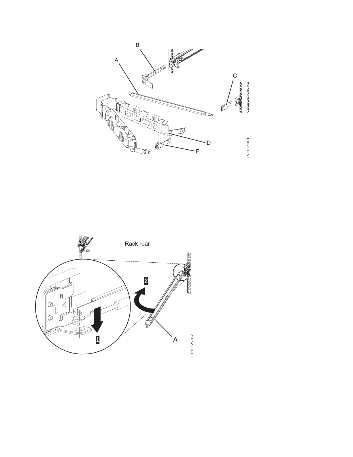
Figure 9. Relative positions of the cable-management arm parts before assembly
2. The cable-management arm can be installed on either side of the server. For this procedure, it is
illustrated that you are installing it on the right side, while you are facing the server from the rear.
Connect one end of the support arm (A) to the right slide rail (1) so that you can swing the other end
of the support arm toward the left side of the rack (2).
Note: The support arm (A) is labeled UP and DOWN. Ensure that the side labeled UP is facing
upward and to the right.
Figure 10. Connecting the support arm
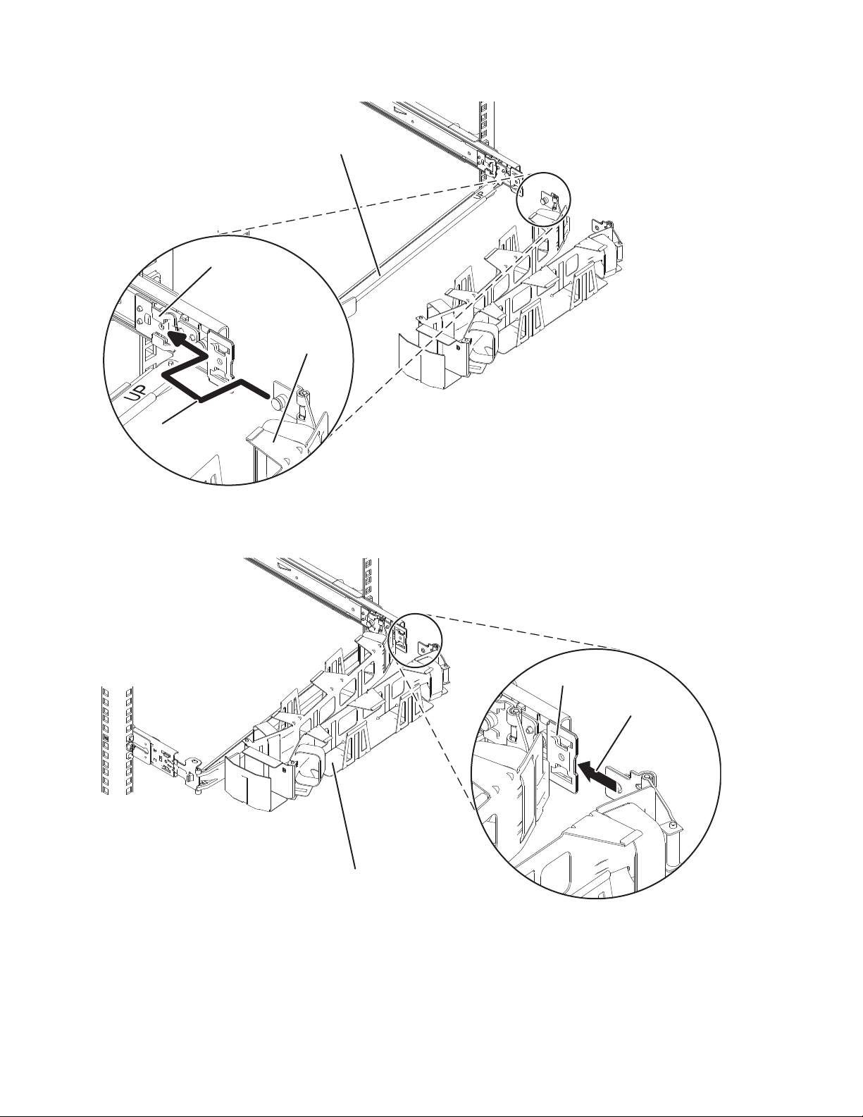
3. Locate the hole at the bottom inside corner of the L-shaped cable-management stop bracket (B).
Position the unattached end of the support arm so that the locking tab on the underside of its tip
aligns with the bracket hole. Insert the tab into the hole (1) and turn the bracket (2) to secure it to the
support arm. For details, see Figure 11 on page 9.
8 Power Systems: Installing the IBM Power System S814 (8286-41A)
Page 25

Figure 11. Securing the cable-management stop bracket to the support arm
4. Attach the cable-management stop bracket (B) to the slot on the inside of the left slide by sliding the
stop bracket (B) into the slide rail until the spring-loaded pin snaps into place. For details, see
Figure 12.
Figure 12. Extending the pin, and installing the bracket into the slide rail
5. Slide the extension bracket (E) into the right slide rail until the spring-loaded pin snaps into place. For
details, see Figure 13 on page 10.
Installing the IBM Power System S814 (8286-41A) 9
Page 26

Figure 13. Installing the extension bracket into the slide rail
6. Attach the cable-management stop bracket (B) to the slot on the inside of the left slide by sliding the
stop bracket (B) into the slide rail until the spring-loaded pin snaps into place. For details, see
Figure 14.
Figure 14. Installing the mounting bracket into the slide rail
7. Place the cable-management arm (D) on the support arm (A). Slide the first cable-management arm
tab into the slot on the mounting bracket (C). Push the tab until the spring-loaded latch snaps into
place. Slide the other cable-management arm tab into the extension bracket (E) on the outside of the
right slide rail (2). Push the tab until the spring-loaded latch snaps into place. For details, see
Figure 15 on page 11 and Figure 16 on page 11.
10 Power Systems: Installing the IBM Power System S814 (8286-41A)
Page 27
P7EF3502-2
1
D
A
C
Figure 15. Sliding the cable-management arm tab into the mounting bracket slot
P7EF3503-1
2
E
D
Figure 16. Sliding the other cable-management arm tab into the extension bracket
Cabling the server and setting up a console
Your console, monitor, or interface choices are guided by whether you create logical partitions, which
operating system you install in your primary partition, and whether you install a Virtual I/O Server
(VIOS) in one of your logical partitions.
Installing the IBM Power System S814 (8286-41A) 11
Page 28

Determining which console to use
Your console, monitor, or interface choices are guided by whether you create logical partitions, which
operating system you install in your primary partition, and whether you install a Virtual I/O Server
(VIOS) in one of your logical partitions.
Go to the instructions for the applicable console, interface, or terminal in the following table.
Table 2. Available console types
Cabling setup
Console type Operating system Logical partitions Cable required
ASCII terminal AIX®, Linux, or VIOS Yes for VIOS, no for
AIX and Linux
Hardware
Management Console
(HMC)
Operations Console IBM i Yes
Integrated
Virtualization
Manager for VIOS
Keyboard, video, and
mouse (KVM)
AIX, IBM i, Linux, or
VIOS
AIX, IBM i, or Linux Yes Serial cable “Cabling the server
Linux or VIOS Yes Monitor and USB
Yes Ethernet (or
Use your Operations
Console to manage
existing IBM i
partitions.
Serial cable equipped
with a null modem
cross-over cable)
Ethernet cable for
LAN connection
cables equipped with
KVM
instructions
“Cabling the server
with an ASCII
terminal”
“Cabling the server
to the HMC” on page
13.
“Cabling the server
and accessing
Operations Console”
on page 14
and accessing the
IVM” on page 19
“Cabling the server
with keyboard,
video, and mouse”
on page 20
Cabling the server with an ASCII terminal:
If you are not creating logical partitions, you can use an ASCII terminal to manage a server that is
running the AIX, Linux, or VIOS operating systems. From the ASCII terminal, you can access the
Advanced System Management Interface (ASMI) to complete more installation tasks.
The ASCII terminal is connected to the server through a serial link. The ASCII interface to the ASMI
provides a subset of the web interface functions. The ASCII terminal for the ASMI interface is available
only when the system is in the standby state. It is not available during the initial program load (IPL) or
run time.
Note: If you are using a serial connection to the ASMI terminal, you must use a conversion cable. This
cable (part number 46K5108) is used to convert the ASCII terminal 9-pin Dshell connector to an RJ45
serial port connector on the system. For information about the locations of the connectors on the system,
see Part locations and location codes (http://www.ibm.com/support/knowledgecenter/POWER8/p8ecs/
p8ecs_locations.htm).
To cable an ASCII terminal to the server, complete the following steps:
1. Using a serial cable that is equipped with a null modem, connect the ASCII terminal to the serial port
on the rear of the server.
2. Complete the following steps:
a. Plug the power cord into the power supply.
b. Plug the system power cords and the power cords for any other attached devices into the power
source.
12 Power Systems: Installing the IBM Power System S814 (8286-41A)
Page 29

c. If your system uses a power distribution unit (PDU), complete the following steps:
1) Connect the system power cords from the server and I/O drawers to the PDU with an IEC 320
type receptacle.
2) Attach the PDU input power cord and plug it into the power source.
3) If your system uses two PDUs for redundancy, complete the following steps:
v If your system has two power supplies, attach one power supply to each of the two PDUs.
v If your system has four power supplies, plug E1 and E2 to PDU A and E3 and E4 to PDU
B.
Note: Confirm that the system is in standby mode. The green power status indicator on the
front control panel is flashing, and the dc out indicator lights on the power supplies are
flashing. If none of the indicators are flashing, check the power cord connections.
3. Wait for the green light on the control panel to start flashing.
4. Ensure that your ASCII terminal is set to the following general attributes.
These attributes are the default settings for the diagnostic programs. Be sure that your terminal is set
according to these attributes before proceeding to the next step.
Table 3. Default settings for the diagnostic programs
3151 /11/31/41
General setup attributes
Line speed 19,200 19,200 19,200 Uses the 19,200 (bits per second) line
Word length (bits) 8 8 8 Selects 8 bits as a data word length
Parity No No No Does not add a parity bit and is used
Stop bit 1 1 1 Places a bit after a data word (byte).
settings
3151 /51/61
settings
3161 /64
settings Description
speed to communicate with the system
unit.
(byte).
together with the word length attribute
to form the 8–bit data word (byte).
5. Press a key on the ASCII terminal to allow the service processor to confirm the presence of the ASCII
terminal.
6. When the login display appears for the ASMI, enter admin for the user ID and password.
7. Change the default password when you are prompted.
8. Press Enter until the server information appears. You have completed the setup for an ASCII terminal,
and have started the ASMI.
9. Continue with “Completing the server setup” on page 21.
Cabling the server to the HMC:
The Hardware Management Console (HMC) controls managed systems, including the management of
logical partitions, the creation of a virtual environment, and the use of capacity on demand. Using service
applications, the HMC can also communicate with managed systems to detect, consolidate, and forward
information to IBM service for analysis.
If you have not installed and configured your HMC, do so now. For instructions, see Installation and
configuration scenarios (http://www.ibm.com/support/knowledgecenter/POWER8/p8hai/
basichmcinstallationandconfigurationtaskflow.htm).
To manage POWER8 processor-based servers, the HMC must be at version 8 release 8.4.0 or later. To
view the HMC version and release, complete the following steps:
1. In the navigation area, click Updates.
Installing the IBM Power System S814 (8286-41A) 13
Page 30
2. In the work area, view and record the information that appears in the HMC Code Level section,
including the HMC version, release, Service Pack, build level, and base versions.
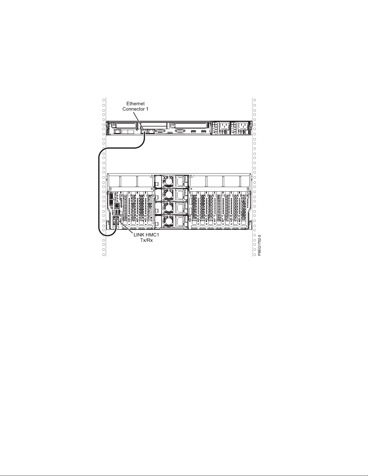
To cable the server to the HMC, complete the following steps:
1. If you want to directly attach your HMC to the managed system, connect Ethernet Connector 1 on
the HMC to the HMC1 port on the managed system. See Figure 17.
Figure 17. Attaching the HMC to the managed system
2. To learn how to connect an HMC to a private network so that it can manage more than one managed
system, see HMC network connections (http://www.ibm.com/support/knowledgecenter/POWER8/
p8hai/netconhmc.htm).
Notes:
v You can also have multiple systems that are attached to a switch that is then connected to the
HMC. For instructions, see HMC network connections (http://www.ibm.com/support/
knowledgecenter/POWER8/p8hai/netconhmc.htm).
v If you are using a switch, ensure that the speed in the switch is set to Autodetection. If the server
is directly attached to the HMC, ensure the Ethernet adapter speed on the HMC is set to
Autodetection. For information about how to set media speeds, see Setting the media speed
(http://www.ibm.com/support/knowledgecenter/POWER8/p8hai/lanmediaspeed.htm).
3. If you are connecting a second HMC to your managed server, connect it to the Ethernet port that is
labeled HMC2 on the managed server.
4. Continue with “Cabling the server and connecting expansion units” on page 20.
Cabling the server and accessing Operations Console:
You can use Operations Console to manage a server that is running the IBM i operating system whether
you have logical partitions or not. However, you must first use a different console to create the logical
partitions.
14 Power Systems: Installing the IBM Power System S814 (8286-41A)
Page 31

Operations Console is a component of IBM i Access for Windows. You can install the complete product or
select any of the console components - Operations Console support and the 5250 emulator support.
To cable the server and access the Operations Console, complete the following steps:
1. Ensure that your server is powered off.
2. Obtain a static IP address that is assigned to the LAN console adapter on the server for use by the
console, including information about the IP, subnet mask, and default gateway.
3. Select a unique host name and register the host name and the IP address in your site's Domain Name
System (DNS).
Note: This IP address is used by the Operations Console and different from the IP address that is
used to connect a normal Telnet session. The IP address must not be in use by another server. Ping
the IP address to verify that no other device is using the IP address.
To set up the Operations Console, complete the following steps:
1. Install IBM i Access for Windows and the latest service pack.
Note: For information about the list of Microsoft Windows operating systems that are supported for
Operations Console LAN, see IBM i Access (http://www-03.ibm.com/systems/i/software/access/
windows/supportedos.html).
a. Log on to the system as a local administrator.
b. Ensure that you install the latest IBM i Access service pack. The website to download the latest
service pack for IBM i Access can be found at IBM i Access (http://www-03.ibm.com/systems/
i/software/access/windows/casp.html).
2. Cable the PC to server. Plug a Cat 5e or Cat 6 (recommended) Ethernet cable from the PC directly
into a valid Ethernet adapter port. To determine the server adapter port that you must use, refer to
the following table:
Table 4. Server Operations Console LAN ports
Server Operations Console - LAN port Notes
8286-41A C6, C7, C8, C9, C10, C11 and C12
v Use local macro or console service
function (65+21) + Bn for card
selection.
v Slots C2-C5 do not exist on this
system.
v The slot number can be larger than
10. When the slot number is above
9, an alpha character is used. For
example, B1 B2 ... B8, B9, then
changes to BA, BB, and BC.
Installing the IBM Power System S814 (8286-41A) 15
Page 32

Table 5. Server Operations Console LAN ports
Server Operations Console - LAN port Notes
8286-42A C2, C3, C4, C5, C6, C7, C8, C9, C10,
C11, and C12
v Use local macro or console service
function (65+21) + Bn for card
selection.
v Slots C2-C5 do not exist on this
system.
v The slot number can be larger than
10. When the slot number is above
9, an alpha character is used. For
example, B1 B2 ... B8, B9, then
changes to BA, BB, and BC.
Note: Make the initial connection with the PC directly cabled to the server. The PC and server can
be recabled to the network after the initial connection is made. A cross-over cable is not needed. For
information, see Adapter requirements (http://www.ibm.com/support/knowledgecenter/POWER8/
p8hbx/hardwarereq_adapter.htm).
3. Configure the PC networking. To configure the PC networking, complete the following steps:
a. Disable any additional connections listed, except the local area connection.
b. Record current TCP/IP settings:
1) Access the adapter properties. Select Internet Protocol, then click Properties.
2) Record the current settings, including IP address, subnet mask, and gateway, if applicable.
c. Change the TCP/IP settings.
Note: Some versions of IBM i require that the gateway address respond to pings before the
console LAN adapter activates.
4. To configure the PC with the default gateway IP address complete the following steps:
a. Set the IP address to the opcon LAN adapter gateway.
b. Set the subnet mask to the opcon LAN adapter subnet.
c. Set the default gateway to the opcon LAN adapter primary router, or gateway address. This
address is the same address as the IP address.
5. To disable the PC firewall, complete the following steps.
Note: All PC firewalls must be disabled for the initial connection.
a. In the Windows control panel, click Firewall settings and disable the firewall.
b. In the Windows control panel, click Security center. Check for a firewall and, if present, disable
it.
c. Scan all tasks that are running on the PC for any other software firewalls and disable the firewall.
6. To configure the Operations Console on your system, complete the following steps:
a. Start Operations Console. To start the Operations Console, select Start > All Programs > IBM
iSeries > Access > Operations Console.
b. Start the Configuration Wizard. If the Operations Console is started for the first time, the
connection wizard starts automatically. If it does not start automatically, click Connection > New
Connection to manually start the wizard. Read the notifications, and click Next.
c. Select the local console on a network. Click Next.
d. Specify a service host name and IP address by completing the following types:
1) Enter a name for your session. The name must be one of the following names:
v A valid host name that was registered in the site Domain Name Service (DNS) for the
console IP address.
16 Power Systems: Installing the IBM Power System S814 (8286-41A)
Page 33

v A unique name that is not currently registered in the DNS for any other IP address.
2) If you are using IBM i V6R1, or later, press the Tab key. The Service TCP/IP Address field is
enabled.
3) Specify the service TCP/IP address. Enter the LAN console adapter IP address.
4) Click Next.
e. Specify the LAN console interface information.
1) In the Service TCP/IP Address field, type the IP address that you recorded.
2) In the Service Subnet Mask field, type the subnet mask that you recorded.
3) In the Service gateway address field, type the default gateway that you recorded.
4) The system serial number must match the tag on the server. It must be 7 characters long,
without a dash.
5) Set the Target partition to 1.
6) Click Next.
f. Specify the device ID. If you are prompted to specify a service tools device ID, enter QCONSOLE.
Click Next.
g. Click Next > Finish. Your session is now ready to connect. Double-click the session name to start
the connection.
7. Power on the server by completing the following steps:
a. Set the manual initial program load (IPL) by completing the following steps:
1) Locate the server's control panel. Look for the blue tab on the front of the server. Push it to
the side, and pull the control panel out slowly.
2) Press the Up arrow key until you see 02, and press Enter.
3) Press Enter again. A < (less than symbol) appears next to N.
4) Press the Up Arrow key. The N changes to an M.
5) Press Enter.
6) Press Enter twice. A 02 is displayed on the control panel.
b. After you have the server set to a manual IPL, push the white power button to power on the
server.
Note: You must watch the control panel while the system is trying to power on. During the IPL, the
system displays C6004031 indicating that it is searching for console. The system might take 20 - 30
minutes to complete this action. If A6005008 is displayed, this means that no console is available.
This might indicate that the system is not preinstalled with IBM i and you must set the console type
to LAN.
8. Perform this step if the system is not preinstalled with IBM i. For setting the console type to LAN,
complete the following steps:
a. Set the control panel to manual mode. If the system is in Normal mode (function 01 shows 01 B
N), select function 02 on the control panel and press Enter.
b. Enable control panel functions by completing the following steps:
1) Select function 25 on the control panel and press Enter. The return code must be 00.
2) Select function 26 on the control panel and press Enter.
Note: If you see a FF return code, go back to function 25 and press Enter, then return to
function 26 and press Enter.
c. Check your current setting(s). Use console service functions (65+21+11) to check the current
setting.
v A600 500A = No console defined
v A601 500A = Twinax console
Installing the IBM Power System S814 (8286-41A) 17
Page 34

v A602 500A = Direct cable console
v A603 500A = LAN console
v A604 500A = HMC console
If the system reference code (SRC) = A603500A, go to step 8e. For all others SRCs, continue with
the next step.
d. Set console type to LAN.
1) Use the 65+21+11 sequences until it returns A603500B. This indicates that the console type
will be changed to LAN.
2) Use the 21+11 sequences, if it returns A6C3500C. This indicates that settings have been saved
successfully. If not, repeat function 11 until it returns A6C3500C.
e. Clear the adapter configuration from the profile by completing the following steps:
1) Use the 65+21+11 sequences until it returns A6C3500B. This indicates that the adapter
configuration will be cleared.
2) Use the 21+11 sequences, if it returns A6C3500C. This indicates that settings have been saved
successfully. If not, repeat function 11 until it returns A6C3500C.
f. Enable and set the console adapter location. Select the console adapter location - external PCI
card.
1) Use the 65-21+11 sequences until it returns A6E2500B. Use the 21+11 sequence, if it returns
A6E2500C. This indicates that the add-on adapter has been enabled and the settings have been
saved successfully. If not, repeat function 11 until it returns A6E2500C.
2) Use the 65-21+11 sequences until it returns A6D1500B. Use the 21+11 sequence, if it returns
A6D1500C. This indicates that the internal embedded port has been disabled and the settings
have been saved successfully. If not, repeat function 11 until it returns A6D1500C.
3) Use the 65-21+11 sequences until it returns A6Bn500B. This indicates that the LAN Adapter
will be enabled in location Cn, where n= the location code of the Console adapter location.
Use the 21+11 sequence, if it returns A6Bn500C the settings have been saved successfully.
Table 6. Console settings and functions
Console Setting Function
E2 Enable add-on adapter (OPSCONSOLE ENBEXTLAN)
D1 Disable embedded port (OPSCONSOLE DISINTLAN)
Bn Enable LAN adapter in slot Cn (OPSCONSOLE
ENBLSLOT n)
Note: This setting requires that the embedded (internal)
LAN flag is turned off and the external flag is turned on.
Otherwise, you will not see this series.
Notes:
1) Use the earlier recorded slot number to determine which Bn function must be selected. For
example, if you are using the I/O adapter in slot C2, you can select console setting B2 to
configure the location of the adapter.
2) The Bn function might be displayed starting with the first number of the search order
numerically. For example, if the search order is C4,C3,C1, the Bn numbers might display 4
instead of a lower number. This function is not applicable to all models.
3) If A60x500D is displayed, function has timed out because the function has been entered
slowly. You have a minute to complete a 65-21-11 sequence. After you start, select the required
settings with no pauses.
9. Restart the console. Use the 65+21+11 sequences until the console displays A6A3500B. This indicates
that the console has been restarted. The system searches for a console resource based on the current
configuration (E1/E2, D1/D2, Bn) and the resource is activated. Use the 21+11 sequences. If the
18 Power Systems: Installing the IBM Power System S814 (8286-41A)
Page 35

console displays A6A3500C, a console search and activate operation has been requested. If the
console displays A6A3500C, repeat function 11 until the console displays A603500C.
10. Connect the console by completing the following steps:
a. Monitor the console status. After the status changes to Pending Authorization, the Service Tools
Sign-On window opens.
Note: The Service Tools Sign-On window might open behind the Operations Console window.
Resize or move the Operations Console window to locate the Service Tools Sign-On window.
b. Sign on to the Service Tools application. To sign on to the Service Tools application, enter
11111111 for the user ID and password.
c. Load the initial program and configure the system.
d. If your session does not connect, wait for the power-on process to stop on an attention or IPL
failure system reference code (SRC), such as A6005008 or B2xxxx. If the power-on stops at
A6005008, call your IBM service provider for assistance.
Note: You must configure and start an IBM i TCP interface on a second port (T2, T3, T4) before
moving the console. This action ensures that there is an alternative method to access the server.
Reset the PC to its original TCP/IP settings.
Note: The PC IP configuration must be reset before cabling the PC back to the network because the
PC is configured with the gateway IP address.
The PC and server console port (T1) can now be recabled to the network.
Continue with “Completing the server setup” on page 21.
Cabling the server and accessing the IVM:
When you install the Virtual I/O Server (VIOS) in an environment where no Hardware Management
Console (HMC) is present, the VIOS automatically creates a management partition whose interface is the
Integrated Virtualization Manager (IVM).
Note: If your system was ordered with IVM preloaded, you can install IBM i as a 'guest' of IVM.
To prepare for and install the VIOS and to enable the IVM, complete the following steps:
1. Using a serial cable that is equipped with a null modem, connect the ASCII terminal to the serial port
on the rear of the server.
2. Complete the following steps:
a. Verify that you have access to the Advanced System Management Interface (ASMI) by using the
web interface.
b. Verify that you have administrator or authorized service provider authority in ASMI.
c. Using the Web-based ASMI, change the following settings as appropriate for the type of partition
on which you are installing the Integrated Virtualization Manager:
For an AIX or Linux partition, complete the following steps to change the partition boot mode:
1) In the navigation area, expand Power/Restart Control.
2) Click Power On/Off System.
3) Select Boot to SMS menu in the AIX or Linux partition mode by boot field.
4) If you are installing the Integrated Virtualization Manager on an IBM System i®model, select
AIX or Linux in the Default partition environment field.
5) Click Save settings and power on.
d. Open a terminal session on the PC, using an application such as HyperTerminal, and wait for the
SMS menu to appear. Be sure that the line speed is set to 19,200 bits per second to communicate
with the system unit.
Installing the IBM Power System S814 (8286-41A) 19
Page 36

e. Using the Web-based ASMI, change the partition boot mode back so that the server loads the
operating environment during startup:
1) Expand Power/Restart Control.
2) Click Power On/Off System.
3) Select Continue to operating system in the AIX or Linux partition mode boot field.
4) Click Save settings.
3. Insert the Virtual I/O Server CD or DVD into the optical drive.
4. In SMS, select the CD or DVD as the boot device:
a. Select Select Boot Options, and press Enter.
b. Select Select Install/Boot Device, and press Enter.
c. Select CD/DVD, and press Enter.
d. Select the media type that corresponds to the optical device, and press Enter.
e. Select the device number that corresponds to the optical device, and press Enter.
f. Select Normal Boot, and confirm that you want to exit SMS.
5. Install the Virtual I/O Server:
a. Select the console, and press Enter.
b. Select a language for the BOS menus, and press Enter.
c. Select Start Install Now with Default Settings.
d. Select Continue with Install. The managed system restarts after the installation is complete, and
the login prompt is displayed on the ASCII terminal.
6. After you install the IVM, finish the installation by accepting the license agreement, checking for
updates, and configuring the TCP/IP connection.
7. Continue with “Cabling the server and connecting expansion units.”
Cabling the server with keyboard, video, and mouse:
Before you start the system, you might need to connect the keyboard, video, and mouse to the system, if
a graphics card is present.
To connect the keyboard, video, and mouse, complete the following steps:
1. Locate the graphics card and Universal Serial Bus (USB) ports at the rear of the system. You might
need a connector converter.
2. Connect the monitor cable to the graphics card.
3. Connect a keyboard and mouse to the blue USB 3.0 ports.
4. Power on the console.
5. Continue with “Cabling the server and connecting expansion units.”
Cabling the server and connecting expansion units
Learn how to cable the server and to connect expansion units.
To cable the server and to connect expansion units, complete the following steps:
1. Complete the following steps:
a. Plug the power cord into the power supply.
b. Plug the system power cords and the power cords for any other attached devices into the power
source.
c. If your system uses a power distribution unit (PDU), complete the following steps:
1) Connect the system power cords from the server and I/O drawers to the PDU with an IEC 320
type receptacle.
20 Power Systems: Installing the IBM Power System S814 (8286-41A)
Page 37

2) Attach the PDU input power cord and plug it into the power source.
A
P8HAJ652-0
3) If your system uses two PDUs for redundancy, complete the following steps:
v If your system has two power supplies, attach one power supply to each of the two PDUs.
v If your system has four power supplies, plug E1 and E2 to PDU A and E3 and E4 to PDU
B.
Note: Confirm that the system is in standby mode. The green power status indicator on the
front control panel is flashing, and the dc out indicator lights on the power supplies are
flashing. If none of the indicators are flashing, check the power cord connections.
2. For information about connecting enclosures and expansion units, see Enclosures and expansion units
(http://www.ibm.com/support/knowledgecenter/POWER8/p8ham/p8ham_kickoff.htm).
Completing the server setup
Learn about the tasks you must complete to set up your managed system.
Select from the following options:
v “Completing the server setup by using an HMC”
v “Completing the server setup without using an HMC” on page 24
Completing the server setup by using an HMC
Perform these tasks to complete the server setup by using a Hardware Management Console (HMC). You
can also begin to use virtualization to consolidate multiple workloads onto fewer systems to increase
server use, and to reduce cost.
To manage POWER8 processor-based systems, the HMC must be at version 8 release 8.1.0, or later.
To complete the server setup by using an HMC, complete the following steps:
1. Attach the server to the rack using the shipping screws (A) that were provided with your system.
2. Change the managed system passwords by completing the following steps:
Installing the IBM Power System S814 (8286-41A) 21
Page 38

If you are using an HMC Classic or HMC Enhanced interface, complete the following steps:
a. In the navigation area, select the managed system.
b. In the Tasks area, click Operations.
c. Click Change password. The Update Password window opens.
d. Type the required information and click OK.
If you are using an HMC Enhanced+ interface, complete the following steps:
a. In the navigation area, select the managed system and click the Users and Security icon, and then
select Users and Roles.
b. Click Change Password. The Update Password window opens.
c. Type the required information and click OK.
For more information about setting passwords for the managed system by using the HMC Classic or
HMC Enhanced interface, see Setting passwords for the managed system (http://www.ibm.com/
support/knowledgecenter/POWER8/p8hai/setpasswordsforthemanagedsystem.htm). For more
information about setting passwords for the managed system by using the HMC Enhanced interface,
see Setting passwords for the managed system (http://www.ibm.com/support/knowledgecenter/
POWER8/p8hai/p8hai_setpassword_enh.htm).
3. Update the time of day on the managed system by using the Advanced System Management Interface
(ASMI).
To access ASMI by using the HMC, choose one of the following navigation options depending on the
interface type of the HMC:
If you are using an HMC Classic or HMC Enhanced interface, complete the following steps:
a. In the navigation area, expand Systems Management > Servers.
b. In the contents area, select the managed system.
c. In the task area, expand Operations.
d. Click Launch Advanced System Management (ASM).
e. Log on to the ASMI by using the administrator user ID and password.
f. Select System Config > Time of Day.
g. Adjust the time of day.
h. Select Save Settings.
If you are using an HMC Enhanced+ interface, complete the following steps:
a. In the navigation area, click the Resources icon, and then select All Systems.
b. To view the actions for that server, select the server name of the required server.
c. In the navigation area, click System Actions > Operations > Launch Advanced System
Management (ASM).
d. Log on to the ASMI by using the administrator user ID and password.
e. Select System Config > Time of Day.
f. Adjust the time of day.
g. Select Save Settings.
4. Check the firmware level on the managed system.
Note: The following operation is not supported by using the HMC Enhanced+ interface. If you are
using the HMC Enhanced+ interface, log out of the HMC, and then log in to the HMC and select the
HMC Classic or HMC Enhanced interface option.
a. In the navigation area, click Updates.
b. In the contents area, select the required managed system.
c. Click Change Licensed Internal Code for the current release.
d. Select View system information and then click OK.
22 Power Systems: Installing the IBM Power System S814 (8286-41A)
Page 39

e. In the Specify LIC Repository window, select None - Display current values and then click OK.
f. Record the level that appears in the EC Number field and the Activated Level field. For example,
if the EC Number is 01EM310 and the Activated Level is 77, the firmware level is 01EM310_77.
5. Compare your installed firmware level with available firmware levels. If necessary, update your
firmware levels.
a. Compare your installed firmware level with available firmware levels. For more information, see
the Fix Central website Fix Central.
b. If necessary, update your managed system firmware levels. In the navigation area, select Updates.
c. In the contents area, select your managed system.
d. Click Change Licensed Internal Code for the current release.
6. To power on a managed system, choose one of the following navigation options depending on the
interface type of the HMC:
If you are using an HMC Classic or HMC Enhanced interface, complete the following steps:
a. In the navigation area, click Systems Management > Servers.
b. In the contents pane, select the required managed system.
c. Click Tasks > Operations > Power On.
Follow any additional on-screen instructions.
If you are using an HMC Enhanced+ interface, complete the following steps:
a. In the navigation area, click the Resources icon, and then select All Systems.
b. In the content pane, select the required managed system name.
c. In the navigation area, click System Actions > Operations > Power On.
Follow any additional on-screen instructions.
7. Create partitions using templates, if you logged in to the HMC by using the Enhanced or HMC
Enhanced+ login option.
v If you are creating new partitions, you can use the templates that are on your HMC. For more
information, see Accessing the template library (http://www.ibm.com/support/knowledgecenter/
POWER8/p8efc/p8efc_accessing_template_library.htm).
v If you have existing partitions on another system, you can capture those configurations, save it to
the template library and deploy the partition template. For more information, see Partition
templates (http://www.ibm.com/support/knowledgecenter/POWER8/p8efc/
p8efc_partition_template_concept.htm).
v If you want to use an existing template from another source, you can import that and use it. For
more information, see Importing a partition template (http://www.ibm.com/support/
knowledgecenter/POWER8/p8efc/p8efc_import_partition_template.htm).
If you are using system plans or you did not log in to the HMC by using the HMC Enhanced or
HMC Enhanced+ login option, you can create partitions or deploy system plans.
v For instructions about creating partitions, see Partitioning with the HMC (http://www.ibm.com/
support/knowledgecenter/POWER8/p8hat/p8hat_lparwithhmcp6.htm).
v For instructions about deploying system plans, see Deploying a system plan by using an HMC
(http://www.ibm.com/support/knowledgecenter/8286-41A/p8hc6/p8hc6_deploysysplanp6.htm).
8. Install an operating system and update the operating system.
v Install the AIX operating system. For instructions, see Installing AIX (http://www.ibm.com/
support/knowledgecenter/POWER8/p8hdx/p8hdx_installaix.htm).
v Install the Linux operating system. For instructions, see Installing Linux (http://www.ibm.com/
support/knowledgecenter/POWER8/p8hdx/p8hdx_installlinux.htm).
v Install the VIOS operating system. For instructions, see Installing VIOS (http://www.ibm.com/
support/knowledgecenter/POWER8/p8hch/p8hch_installvios.htm).
9. You have now completed the steps to install your server.
Installing the IBM Power System S814 (8286-41A) 23
Page 40

Completing the server setup without using an HMC
A
P8HAJ652-0
If you do not have an Hardware Management Console (HMC), use this procedure to complete the server
setup.
To complete the server setup without using a management console, complete the following steps:
1. Attach the server to the rack using the shipping screws (A) that were provided with your system.
2. To check the firmware level on the managed system and to update the time of day, complete the
following steps:
a. Access the Advanced System Management Interface (ASMI). For instructions, see Accessing the
ASMI without an HMC (http://www.ibm.com/support/knowledgecenter/POWER8/p8hby/
connect_asmi.htm).
b. On the ASMI Welcome pane, note the existing level of server firmware in the upper-right corner
under the copyright statement.
c. Update the time of day. In the navigation area, expand System Configuration.
d. Click Time of Day. The content pane displays a form that shows the current date (month, day,
and year) and time (hours, minutes, and seconds).
e. Change the date value, the time value, or both, and click Save settings.
3. To start a system, complete the following steps:
a. Open the front door of the managed system.
b. Press the power button on the control panel.
The power-on light begins to flash faster.
a. The system cooling fans are activated after approximately 30 seconds and begin to accelerate to
operating speed.
b. Progress indicators appear on the control panel display while the system is being started.
c. The power-on light on the control panel stops flashing and remains on, indicating that the system
is powered on.
For instructions, see Starting a system that is not managed by an HMC (http://www.ibm.com/
support/knowledgecenter/POWER8/p8haj/startsysnohmc.htm).
24 Power Systems: Installing the IBM Power System S814 (8286-41A)
Page 41

4. Install an operating system and update the operating system.
v Install the AIX operating system. For instructions, see Installing AIX (http://www.ibm.com/
support/knowledgecenter/POWER8/p8hdx/p8hdx_installaix.htm).
v Install the Linux operating system. For instructions, see Installing Linux (http://www.ibm.com/
support/knowledgecenter/POWER8/p8hdx/p8hdx_installlinux.htm).
v Install the VIOS operating system. For instructions, see Installing VIOS (http://www.ibm.com/
support/knowledgecenter/POWER8/p8hch/p8hch_installvios.htm).
5. If required, update the system firmware.
v For instructions to get firmware fixes through the AIX or Linux operating system, see Getting
server firmware fixes through AIX or Linux without a management console (http://www.ibm.com/
support/knowledgecenter/POWER8/p8ha5/fix_firm_no_hmc_aix.htm).
v If you are using VIOS, see Updating the Virtual I/O Server's firmware and device microcode with
an Internet connection (http://www.ibm.com/support/knowledgecenter/POWER8/p8ha5/
fix_virtual_firm_ivm.htm).
6. You have now completed the steps to install your server.
Setting up a preinstalled server
Learn how to set up a server that arrives preinstalled in a rack.
Prerequisite for installing the preinstalled server
Use the information to understand the prerequisites that are required for setting up the preinstalled
server.
You might need to read the following documents before you install the server:
v The latest version of this document is maintained online. See Installing the IBM Power System S814
(8286-41A) (http://www.ibm.com/support/knowledgecenter/POWER8/p8eg1/p8eg1_roadmap.htm).
v To plan your server installation, see Planning for the system (http://www.ibm.com/support/
knowledgecenter/POWER8/p8had/p8had_8xx_kickoff.htm).
v If you are using a Hardware Management Console (HMC), see Obtaining and applying machine code
updates for the HMC with an Internet connection (http://www.ibm.com/support/knowledgecenter/
POWER8/p8hai/area3fixeshmc.htm).
Consider the following prerequisites before you install the server:
1. Ensure that you have the following items before you start your installation:
v Phillips screwdriver
v Flat-head screwdriver
2. Ensure that you have one of the following consoles:
v Hardware Management Console (HMC): Ensure that your HMC is at version 8 release 8.4.0 or later.
v Graphic monitor with keyboard and mouse.
v Teletype (tty) monitor with keyboard.
Completing inventory for your preinstalled server
Use this information to complete inventory for your server.
To complete the inventory, complete the following steps:
1. Verify that you received all the boxes you ordered.
2. Unpack the server components as needed.
3. Complete a parts inventory before you install each server component by following these steps:
a. Locate the inventory list for your server.
Installing the IBM Power System S814 (8286-41A) 25
Page 42

b. Ensure that you received all the parts that you ordered.
Note: Your order information is included with your product. You can also obtain order
information from your marketing representative or the IBM Business Partner.
If you have incorrect, missing, or damaged parts, consult any of the following resources:
v Your IBM reseller.
v IBM Rochester manufacturing automated information line at 1-800-300-8751 (United States only).
v The Directory of worldwide contacts website http://www.ibm.com/planetwide. Select your
location to view the service and support contact information.
Removing the shipping bracket and connecting power cords and power distribution unit (PDU) for your preinstalled server
Before you set up a console, you must remove the shipping bracket and connect power cords.
Attention:
v Attach an electrostatic discharge (ESD) wrist strap to the front ESD jack, to the rear ESD jack, or to an
unpainted metal surface of your hardware to prevent the electrostatic discharge from damaging your
hardware.
v When you use an ESD wrist strap, follow all electrical safety procedures. An ESD wrist strap is used
for static control. It does not increase or decrease your risk of receiving electric shock when using or
working on electrical equipment.
v If you do not have an ESD wrist strap, just prior to removing the product from ESD packaging and
installing or replacing hardware, touch an unpainted metal surface of the system for a minimum of 5
seconds.
To remove the shipping bracket and connect power cords, do the following:
1. Remove the four screws that secure the shipping bracket to the chassis.
26 Power Systems: Installing the IBM Power System S814 (8286-41A)
Page 43

Figure 18. Removing the shipping bracket from the rear of the chassis
Store the shipping bracket if you want to move your system at a later date.
2. Cable the server.
a. Plug the top two power cords into the power supply and attach the cables to the handles on the
power supply with cable ties or hook-and-loop fasteners.
Installing the IBM Power System S814 (8286-41A) 27
Page 44

Figure 19. Plugging the power cords into the power supply and attaching cables to the power supply handles
b. Connect the system power cords from the server and I/O drawers to the PDU with an IEC 320
type receptacle.
c. Attach the PDU input power cord and plug it into the power source.
Setting up a console
Your console, monitor, or interface choices are guided by whether you create logical partitions, which
operating system you install in your primary partition, and whether you install a Virtual I/O Server
(VIOS) in one of your logical partitions.
Determining which console to use
Your console, monitor, or interface choices are guided by whether you create logical partitions, which
operating system you install in your primary partition, and whether you install a Virtual I/O Server
(VIOS) in one of your logical partitions.
Go to the instructions for the applicable console, interface, or terminal in the following table.
Table 7. Available console types
Cabling setup
Console type Operating system Logical partitions Cable required
ASCII terminal AIX, Linux, or VIOS Yes for VIOS, no for
AIX and Linux
Hardware
Management Console
(HMC)
AIX, IBM i, Linux, or
VIOS
Yes Ethernet (or
Serial cable equipped
with a null modem
cross-over cable)
instructions
“Cabling the server
with an ASCII
terminal” on page 12
“Cabling the server
to the HMC” on page
13.
28 Power Systems: Installing the IBM Power System S814 (8286-41A)
Page 45

Table 7. Available console types (continued)
Cabling setup
Console type Operating system Logical partitions Cable required
Operations Console IBM i Yes
Use your Operations
Console to manage
existing IBM i
partitions.
Integrated
Virtualization
Manager for VIOS
Keyboard, video, and
mouse (KVM)
AIX, IBM i, or Linux Yes Serial cable “Cabling the server
Linux or VIOS Yes Monitor and USB
Ethernet cable for
LAN connection
cables equipped with
KVM
instructions
“Cabling the server
and accessing
Operations Console”
on page 14
and accessing the
IVM” on page 19
“Cabling the server
with keyboard,
video, and mouse”
on page 20
Cabling the server with an ASCII terminal:
If you are not creating logical partitions, you can use an ASCII terminal to manage a server that is
running the AIX, Linux, or VIOS operating systems. From the ASCII terminal, you can access the
Advanced System Management Interface (ASMI) to complete more installation tasks.
The ASCII terminal is connected to the server through a serial link. The ASCII interface to the ASMI
provides a subset of the web interface functions. The ASCII terminal for the ASMI interface is available
only when the system is in the standby state. It is not available during the initial program load (IPL) or
run time.
Note: If you are using a serial connection to the ASMI terminal, you must use a conversion cable. This
cable (part number 46K5108) is used to convert the ASCII terminal 9-pin Dshell connector to an RJ45
serial port connector on the system. For information about the locations of the connectors on the system,
see Part locations and location codes (http://www.ibm.com/support/knowledgecenter/POWER8/p8ecs/
p8ecs_locations.htm).
To cable an ASCII terminal to the server, complete the following steps:
1. Using a serial cable that is equipped with a null modem, connect the ASCII terminal to the serial port
on the rear of the server.
2. Ensure that your ASCII terminal is set to the following general attributes.
These attributes are the default settings for the diagnostic programs. Be sure that your terminal is set
according to these attributes before proceeding to the next step.
Table 8. Default settings for the diagnostic programs
3151 /11/31/41
General setup attributes
Line speed 19,200 19,200 19,200 Uses the 19,200 (bits per second) line
Word length (bits) 8 8 8 Selects 8 bits as a data word length
Parity No No No Does not add a parity bit and is used
Stop bit 1 1 1 Places a bit after a data word (byte).
settings
3151 /51/61
settings
3161 /64
settings Description
speed to communicate with the system
unit.
(byte).
together with the word length attribute
to form the 8–bit data word (byte).
Installing the IBM Power System S814 (8286-41A) 29
Page 46

3. Press a key on the ASCII terminal to allow the service processor to confirm the presence of the ASCII
terminal.
4. When the login display appears for the ASMI, enter admin for the user ID and password.
5. Change the default password when you are prompted.
6. Press Enter until the server information appears. You have completed the setup for an ASCII terminal,
and have started the ASMI.
7. Continue with “Completing the server setup without using an HMC” on page 35.
Cabling the server to the HMC:
The Hardware Management Console (HMC) controls managed systems, including the management of
logical partitions, the creation of a virtual environment, and the use of capacity on demand. Using service
applications, the HMC can also communicate with managed systems to detect, consolidate, and forward
information to IBM service for analysis.
If you have not installed and configured your HMC, do so now. For instructions, see Installation and
configuration scenarios (http://www.ibm.com/support/knowledgecenter/POWER8/p8hai/
basichmcinstallationandconfigurationtaskflow.htm).
To manage POWER8 processor-based servers, the HMC must be at version 8 release 8.4.0 or later. To
view the HMC version and release, complete the following steps:
1. In the navigation area, click Updates.
2. In the work area, view and record the information that appears in the HMC Code Level section,
including the HMC version, release, Service Pack, build level, and base versions.
To cable the server to the HMC, complete the following steps:
1. If you want to directly attach your HMC to the managed system, connect Ethernet Connector 1 on
the HMC to the HMC1 port on the managed system..
30 Power Systems: Installing the IBM Power System S814 (8286-41A)
Page 47

Figure 20. Attaching the HMC to the managed system
2. To learn how to connect an HMC to a private network so that it can manage more than one managed
system, see HMC network connections (http://www.ibm.com/support/knowledgecenter/POWER8/
p8hai/netconhmc.htm).
Notes:
v You can also have multiple systems that are attached to a switch that is then connected to the
HMC. For instructions, see HMC network connections (http://www.ibm.com/support/
knowledgecenter/POWER8/p8hai/netconhmc.htm).
v If you are using a switch, ensure that the speed in the switch is set to Autodetection. If the server
is directly attached to the HMC, ensure the Ethernet adapter speed on the HMC is set to
Autodetection. For information about how to set media speeds, see Setting the media speed
(http://www.ibm.com/support/knowledgecenter/POWER8/p8hai/lanmediaspeed.htm).
3. If you are connecting a second HMC to your managed server, connect it to the Ethernet port that is
labeled HMC2 on the managed server.
4. Continue with “Routing cables through the cable-management arm and connecting expansion units”
on page 33.
Cabling the server and accessing the IVM:
When you install the Virtual I/O Server (VIOS) in an environment where no Hardware Management
Console (HMC) is present, the VIOS automatically creates a management partition whose interface is the
Integrated Virtualization Manager (IVM).
Note: If your system was ordered with IVM preloaded, you can install IBM i as a 'guest' of IVM.
To prepare for and install the VIOS and to enable the IVM, complete the following steps:
1. Using a serial cable that is equipped with a null modem, connect the ASCII terminal to the serial port
on the rear of the server.
Installing the IBM Power System S814 (8286-41A) 31
Page 48

2. Complete the following steps:
a. Verify that you have access to the Advanced System Management Interface (ASMI) by using the
web interface.
b. Verify that you have administrator or authorized service provider authority in ASMI.
c. Using the Web-based ASMI, change the following settings as appropriate for the type of partition
on which you are installing the Integrated Virtualization Manager:
For an AIX or Linux partition, complete the following steps to change the partition boot mode:
1) In the navigation area, expand Power/Restart Control.
2) Click Power On/Off System.
3) Select Boot to SMS menu in the AIX or Linux partition mode by boot field.
4) If you are installing the Integrated Virtualization Manager on an IBM System i model, select
AIX or Linux in the Default partition environment field.
5) Click Save settings and power on.
d. Open a terminal session on the PC, using an application such as HyperTerminal, and wait for the
SMS menu to appear. Be sure that the line speed is set to 19,200 bits per second to communicate
with the system unit.
e. Using the Web-based ASMI, change the partition boot mode back so that the server loads the
operating environment during startup:
1) Expand Power/Restart Control.
2) Click Power On/Off System.
3) Select Continue to operating system in the AIX or Linux partition mode boot field.
4) Click Save settings.
3. Insert the Virtual I/O Server CD or DVD into the optical drive.
4. In SMS, select the CD or DVD as the boot device:
a. Select Select Boot Options, and press Enter.
b. Select Select Install/Boot Device, and press Enter.
c. Select CD/DVD, and press Enter.
d. Select the media type that corresponds to the optical device, and press Enter.
e. Select the device number that corresponds to the optical device, and press Enter.
f. Select Normal Boot, and confirm that you want to exit SMS.
5. Install the Virtual I/O Server:
a. Select the console, and press Enter.
b. Select a language for the BOS menus, and press Enter.
c. Select Start Install Now with Default Settings.
d. Select Continue with Install. The managed system restarts after the installation is complete, and
the login prompt is displayed on the ASCII terminal.
6. After you install the IVM, finish the installation by accepting the license agreement, checking for
updates, and configuring the TCP/IP connection.
7. Continue with “Routing cables through the cable-management arm and connecting expansion units”
on page 33.
Cabling the server with keyboard, video, and mouse:
Before you start the system, you might need to connect the keyboard, video, and mouse to the system, if
a graphics card is present.
To connect the keyboard, video, and mouse, complete the following steps:
32 Power Systems: Installing the IBM Power System S814 (8286-41A)
Page 49

1. Locate the graphics card and Universal Serial Bus (USB) ports at the rear of the system. You might
need a connector converter.
2. Connect the monitor cable to the graphics card.
3. Connect a keyboard and mouse to the blue USB 3.0 ports.
4. Power on the console.
5. Continue with “Routing cables through the cable-management arm and connecting expansion units.”
Routing cables through the cable-management arm and connecting expansion units
Use this procedure to route cables through the cable-management arm and to connect expansion units.
To route cables through the cable-management arm and to connect expansion units, complete the
following steps:
1. Route the console cable through the cable management arm.
2. Connect expansion units that were shipped with the system. For more information, see the expansion
unit installation book that was shipped with the system. Complete the tasks associated with
connecting a preinstalled expansion unit or disk drive enclosure, then return to this document to
complete your server setup.
3. Continue with “Completing the server setup.”
Completing the server setup
Learn about the tasks you must complete to set up your managed system.
Select from the following options:
v “Completing the server setup by using an HMC”
v “Completing the server setup without using an HMC” on page 35
Completing the server setup by using an HMC
Perform these tasks to complete the server setup by using a Hardware Management Console (HMC). You
can also begin to use virtualization to consolidate multiple workloads onto fewer systems to increase
server use, and to reduce cost.
To manage POWER8 processor-based systems, the HMC must be at version 8 release 8.1.0, or later.
To complete the server setup by using an HMC, complete the following steps:
1. Change the managed system passwords by completing the following steps:
If you are using an HMC Classic or HMC Enhanced interface, complete the following steps:
a. In the navigation area, select the managed system.
b. In the Tasks area, click Operations.
c. Click Change password. The Update Password window opens.
d. Type the required information and click OK.
If you are using an HMC Enhanced+ interface, complete the following steps:
a. In the navigation area, select the managed system and click the Users and Security icon, and then
select Users and Roles.
b. Click Change Password. The Update Password window opens.
c. Type the required information and click OK.
For more information about setting passwords for the managed system by using the HMC Classic or
HMC Enhanced interface, see Setting passwords for the managed system (http://www.ibm.com/
Installing the IBM Power System S814 (8286-41A) 33
Page 50

support/knowledgecenter/POWER8/p8hai/setpasswordsforthemanagedsystem.htm). For more
information about setting passwords for the managed system by using the HMC Enhanced interface,
see Setting passwords for the managed system (http://www.ibm.com/support/knowledgecenter/
POWER8/p8hai/p8hai_setpassword_enh.htm).
2. Update the time of day on the managed system by using the Advanced System Management Interface
(ASMI).
To access ASMI by using the HMC, choose one of the following navigation options depending on the
interface type of the HMC:
If you are using an HMC Classic or HMC Enhanced interface, complete the following steps:
a. In the navigation area, expand Systems Management > Servers.
b. In the contents area, select the managed system.
c. In the task area, expand Operations.
d. Click Launch Advanced System Management (ASM).
e. Log on to the ASMI by using the administrator user ID and password.
f. Select System Config > Time of Day.
g. Adjust the time of day.
h. Select Save Settings.
If you are using an HMC Enhanced+ interface, complete the following steps:
a. In the navigation area, click the Resources icon, and then select All Systems.
b. To view the actions for that server, select the server name of the required server.
c. In the navigation area, click System Actions > Operations > Launch Advanced System
Management (ASM).
d. Log on to the ASMI by using the administrator user ID and password.
e. Select System Config > Time of Day.
f. Adjust the time of day.
g. Select Save Settings.
3. Check the firmware level on the managed system.
Note: The following operation is not supported by using the HMC Enhanced+ interface. If you are
using the HMC Enhanced+ interface, log out of the HMC, and then log in to the HMC and select the
HMC Classic or HMC Enhanced interface option.
a. In the navigation area, click Updates.
b. In the contents area, select the required managed system.
c. Click Change Licensed Internal Code for the current release.
d. Select View system information and then click OK.
e. In the Specify LIC Repository window, select None - Display current values and then click OK.
f. Record the level that appears in the EC Number field and the Activated Level field. For example,
if the EC Number is 01EM310 and the Activated Level is 77, the firmware level is 01EM310_77.
4. Compare your installed firmware level with available firmware levels. If necessary, update your
firmware levels.
a. Compare your installed firmware level with available firmware levels. For more information, see
the Fix Central website Fix Central.
b. If necessary, update your managed system firmware levels. In the navigation area, select Updates.
c. In the contents area, select your managed system.
d. Click Change Licensed Internal Code for the current release.
5. To power on a managed system, choose one of the following navigation options depending on the
interface type of the HMC:
If you are using an HMC Classic or HMC Enhanced interface, complete the following steps:
34 Power Systems: Installing the IBM Power System S814 (8286-41A)
Page 51

a. In the navigation area, click Systems Management > Servers.
b. In the contents pane, select the required managed system.
c. Click Tasks > Operations > Power On.
Follow any additional on-screen instructions.
If you are using an HMC Enhanced+ interface, complete the following steps:
a. In the navigation area, click the Resources icon, and then select All Systems.
b. In the content pane, select the required managed system name.
c. In the navigation area, click System Actions > Operations > Power On.
Follow any additional on-screen instructions.
6. Create partitions using templates, if you logged in to the HMC by using the Enhanced or HMC
Enhanced+ login option.
v If you are creating new partitions, you can use the templates that are on your HMC. For more
information, see Accessing the template library (http://www.ibm.com/support/knowledgecenter/
POWER8/p8efc/p8efc_accessing_template_library.htm).
v If you have existing partitions on another system, you can capture those configurations, save it to
the template library and deploy the partition template. For more information, see Partition
templates (http://www.ibm.com/support/knowledgecenter/POWER8/p8efc/
p8efc_partition_template_concept.htm).
v If you want to use an existing template from another source, you can import that and use it. For
more information, see Importing a partition template (http://www.ibm.com/support/
knowledgecenter/POWER8/p8efc/p8efc_import_partition_template.htm).
If you are using system plans or you did not log in to the HMC by using the HMC Enhanced or
HMC Enhanced+ login option, you can create partitions or deploy system plans.
v For instructions about creating partitions, see Partitioning with the HMC (http://www.ibm.com/
support/knowledgecenter/POWER8/p8hat/p8hat_lparwithhmcp6.htm).
v For instructions about deploying system plans, see Deploying a system plan by using an HMC
(http://www.ibm.com/support/knowledgecenter/8286-41A/p8hc6/p8hc6_deploysysplanp6.htm).
7. Install an operating system and update the operating system.
v Install the AIX operating system. For instructions, see Installing AIX (http://www.ibm.com/
support/knowledgecenter/POWER8/p8hdx/p8hdx_installaix.htm).
v Install the Linux operating system. For instructions, see Installing Linux (http://www.ibm.com/
support/knowledgecenter/POWER8/p8hdx/p8hdx_installlinux.htm).
v Install the VIOS operating system. For instructions, see Installing VIOS (http://www.ibm.com/
support/knowledgecenter/POWER8/p8hch/p8hch_installvios.htm).
8. You have now completed the steps to install your server.
Completing the server setup without using an HMC
If you do not have an Hardware Management Console (HMC), use this procedure to complete the server
setup.
To complete the server setup without using a management console, complete the following steps:
1. To check the firmware level on the managed system and to update the time of day, complete the
following steps:
a. Access the Advanced System Management Interface (ASMI). For instructions, see Accessing the
ASMI without an HMC (http://www.ibm.com/support/knowledgecenter/POWER8/p8hby/
connect_asmi.htm).
b. On the ASMI Welcome pane, note the existing level of server firmware in the upper-right corner
under the copyright statement.
c. Update the time of day. In the navigation area, expand System Configuration.
Installing the IBM Power System S814 (8286-41A) 35
Page 52

d. Click Time of Day. The content pane displays a form that shows the current date (month, day,
and year) and time (hours, minutes, and seconds).
e. Change the date value, the time value, or both, and click Save settings.
2. To start a system, complete the following steps:
a. Open the front door of the managed system.
b. Press the power button on the control panel.
The power-on light begins to flash faster.
a. The system cooling fans are activated after approximately 30 seconds and begin to accelerate to
operating speed.
b. Progress indicators appear on the control panel display while the system is being started.
c. The power-on light on the control panel stops flashing and remains on, indicating that the system
is powered on.
For instructions, see Starting a system that is not managed by an HMC (http://www.ibm.com/
support/knowledgecenter/POWER8/p8haj/startsysnohmc.htm).
3. Install an operating system and update the operating system.
v Install the AIX operating system. For instructions, see Installing AIX (http://www.ibm.com/
support/knowledgecenter/POWER8/p8hdx/p8hdx_installaix.htm).
v Install the Linux operating system. For instructions, see Installing Linux (http://www.ibm.com/
support/knowledgecenter/POWER8/p8hdx/p8hdx_installlinux.htm).
v Install the VIOS operating system. For instructions, see Installing VIOS (http://www.ibm.com/
support/knowledgecenter/POWER8/p8hch/p8hch_installvios.htm).
4. If required, update the system firmware.
v For instructions to get firmware fixes through the AIX or Linux operating system, see Getting
server firmware fixes through AIX or Linux without a management console (http://www.ibm.com/
support/knowledgecenter/POWER8/p8ha5/fix_firm_no_hmc_aix.htm).
v If you are using VIOS, see Updating the Virtual I/O Server's firmware and device microcode with
an Internet connection (http://www.ibm.com/support/knowledgecenter/POWER8/p8ha5/
fix_virtual_firm_ivm.htm).
5. You have now completed the steps to install your server.
Installing a stand-alone server
Use this information to learn about setting up a stand-alone server.
Prerequisite for installing the stand-alone server
Use the information to understand the prerequisites that are required for setting up the preinstalled
server.
You might need to read the following documents before you install the server:
v The latest version of this document is maintained online. See Installing the IBM Power System S824
(8286-42A) (http://www.ibm.com/support/knowledgecenter/POWER8/p8egg/p8egg_roadmap.htm).
v To plan your server installation, see Planning for the system (http://www.ibm.com/support/
knowledgecenter/POWER8/p8had/p8had_8xx_kickoff.htm).
v If you are using a Hardware Management Console (HMC), see Obtaining and applying machine code
updates for the HMC with an Internet connection (http://www.ibm.com/support/knowledgecenter/
POWER8/p8hai/area3fixeshmc.htm).
Consider the following prerequisites before you install the server:
1. Ensure that you have the following items before you start your installation:
v Phillips screwdriver
36 Power Systems: Installing the IBM Power System S814 (8286-41A)
Page 53

v Flat-head screwdriver
2. Ensure that you have one of the following consoles:
v Hardware Management Console (HMC): Ensure that your HMC is at version 8 release 8.4.0 or later.
v Graphic monitor with keyboard and mouse.
v Teletype (tty) monitor with keyboard.
Moving the server to the installation site
Move the stand-alone server to the installation site.
After you have unpacked your stand-alone server and have taken inventory, move the server to the
installation site.
Completing inventory for your stand-alone server
Use this information to complete inventory for your server.
To complete the inventory, complete the following steps:
1. Verify that you received all the boxes you ordered.
2. Unpack the server components as needed.
3. Complete a parts inventory before you install each server component by following these steps:
a. Locate the inventory list for your server.
b. Ensure that you received all the parts that you ordered.
Note: Your order information is included with your product. You can also obtain order
information from your marketing representative or the IBM Business Partner.
If you have incorrect, missing, or damaged parts, consult any of the following resources:
v Your IBM reseller.
v IBM Rochester manufacturing automated information line at 1-800-300-8751 (United States only).
v The Directory of worldwide contacts website http://www.ibm.com/planetwide. Select your
location to view the service and support contact information.
Cabling the server and setting up a console
Your console, monitor, or interface choices are guided by whether you create logical partitions, which
operating system you install in your primary partition, and whether you install a Virtual I/O Server
(VIOS) in one of your logical partitions.
Determining which console to use
Your console, monitor, or interface choices are guided by whether you create logical partitions, which
operating system you install in your primary partition, and whether you install a Virtual I/O Server
(VIOS) in one of your logical partitions.
Go to the instructions for the applicable console, interface, or terminal in the following table.
Table 9. Available console types
Cabling setup
Console type Operating system Logical partitions Cable required
ASCII terminal AIX, Linux, or VIOS Yes for VIOS, no for
AIX and Linux
Hardware
Management Console
(HMC)
AIX, IBM i, Linux, or
VIOS
Yes Ethernet (or
Serial cable equipped
with a null modem
cross-over cable)
instructions
“Cabling the server
with an ASCII
terminal” on page 12
“Cabling the server
to the HMC” on page
13.
Installing the IBM Power System S814 (8286-41A) 37
Page 54

Table 9. Available console types (continued)
Cabling setup
Console type Operating system Logical partitions Cable required
Operations Console IBM i Yes
Use your Operations
Console to manage
existing IBM i
partitions.
Integrated
Virtualization
Manager for VIOS
Keyboard, video, and
mouse (KVM)
AIX, IBM i, or Linux Yes Serial cable “Cabling the server
Linux or VIOS Yes Monitor and USB
Ethernet cable for
LAN connection
cables equipped with
KVM
instructions
“Cabling the server
and accessing
Operations Console”
on page 14
and accessing the
IVM” on page 19
“Cabling the server
with keyboard,
video, and mouse”
on page 20
Cabling the server with an ASCII terminal:
If you are not creating logical partitions, you can use an ASCII terminal to manage a server that is
running the AIX, Linux, or VIOS operating systems. From the ASCII terminal, you can access the
Advanced System Management Interface (ASMI) to complete more installation tasks.
The ASCII terminal is connected to the server through a serial link. The ASCII interface to the ASMI
provides a subset of the web interface functions. The ASCII terminal for the ASMI interface is available
only when the system is in the standby state. It is not available during the initial program load (IPL) or
run time.
Note: If you are using a serial connection to the ASMI terminal, you must use a conversion cable. This
cable (part number 46K5108) is used to convert the ASCII terminal 9-pin Dshell connector to an RJ45
serial port connector on the system. For information about the locations of the connectors on the system,
see Part locations and location codes (http://www.ibm.com/support/knowledgecenter/POWER8/p8ecs/
p8ecs_locations.htm).
To cable an ASCII terminal to the server, complete the following steps:
1. Using a serial cable that is equipped with a null modem, connect the ASCII terminal to the serial port
on the rear of the server.
2. Complete the following steps:
a. Plug the power cord into the power supply.
b. Plug the system power cords and the power cords for any other attached devices into the power
source.
c. If your system uses a power distribution unit (PDU), complete the following steps:
1) Connect the system power cords from the server and I/O drawers to the PDU with an IEC 320
type receptacle.
2) Attach the PDU input power cord and plug it into the power source.
3) If your system uses two PDUs for redundancy, complete the following steps:
v If your system has two power supplies, attach one power supply to each of the two PDUs.
v If your system has four power supplies, plug E1 and E2 to PDU A and E3 and E4 to PDU
B.
38 Power Systems: Installing the IBM Power System S814 (8286-41A)
Page 55

Note: Confirm that the system is in standby mode. The green power status indicator on the
front control panel is flashing, and the dc out indicator lights on the power supplies are
flashing. If none of the indicators are flashing, check the power cord connections.
3. Wait for the green light on the control panel to start flashing.
4. Ensure that your ASCII terminal is set to the following general attributes.
These attributes are the default settings for the diagnostic programs. Be sure that your terminal is set
according to these attributes before proceeding to the next step.
Table 10. Default settings for the diagnostic programs
3151 /11/31/41
General setup attributes
Line speed 19,200 19,200 19,200 Uses the 19,200 (bits per second) line
Word length (bits) 8 8 8 Selects 8 bits as a data word length
Parity No No No Does not add a parity bit and is used
Stop bit 1 1 1 Places a bit after a data word (byte).
settings
3151 /51/61
settings
3161 /64
settings Description
speed to communicate with the system
unit.
(byte).
together with the word length attribute
to form the 8–bit data word (byte).
5. Press a key on the ASCII terminal to allow the service processor to confirm the presence of the ASCII
terminal.
6. When the login display appears for the ASMI, enter admin for the user ID and password.
7. Change the default password when you are prompted.
8. Press Enter until the server information appears. You have completed the setup for an ASCII terminal,
and have started the ASMI.
9. Continue with “Completing the server setup without using an HMC” on page 45.
Cabling the server to the HMC:
The Hardware Management Console (HMC) controls managed systems, including the management of
logical partitions, the creation of a virtual environment, and the use of capacity on demand. Using service
applications, the HMC can also communicate with managed systems to detect, consolidate, and forward
information to IBM service for analysis.
If you have not installed and configured your HMC, do so now. For instructions, see Installation and
configuration scenarios (http://www.ibm.com/support/knowledgecenter/POWER8/p8hai/
basichmcinstallationandconfigurationtaskflow.htm).
To manage POWER8 processor-based servers, the HMC must be at version 8 release 8.4.0 or later. To
view the HMC version and release, complete the following steps:
1. In the navigation area, click Updates.
2. In the work area, view and record the information that appears in the HMC Code Level section,
including the HMC version, release, Service Pack, build level, and base versions.
To cable the server to the HMC, complete the following steps:
1. If you want to directly attach your HMC to the managed system, connect Ethernet Connector 1 on
the HMC to the HMC1 port on the managed system. See Figure 21 on page 40.
Installing the IBM Power System S814 (8286-41A) 39
Page 56

Figure 21. Attaching the HMC to the managed system
2. To learn how to connect an HMC to a private network so that it can manage more than one managed
system, see HMC network connections (http://www.ibm.com/support/knowledgecenter/POWER8/
p8hai/netconhmc.htm).
Notes:
v You can also have multiple systems that are attached to a switch that is then connected to the
HMC. For instructions, see HMC network connections (http://www.ibm.com/support/
knowledgecenter/POWER8/p8hai/netconhmc.htm).
v If you are using a switch, ensure that the speed in the switch is set to Autodetection. If the server
is directly attached to the HMC, ensure the Ethernet adapter speed on the HMC is set to
Autodetection. For information about how to set media speeds, see Setting the media speed
(http://www.ibm.com/support/knowledgecenter/POWER8/p8hai/lanmediaspeed.htm).
3. If you are connecting a second HMC to your managed server, connect it to the Ethernet port that is
labeled HMC2 on the managed server.
4. Continue with “Completing the server setup by using an HMC” on page 42.
Cabling the server and accessing the IVM:
When you install the Virtual I/O Server (VIOS) in an environment where no Hardware Management
Console (HMC) is present, the VIOS automatically creates a management partition whose interface is the
Integrated Virtualization Manager (IVM).
40 Power Systems: Installing the IBM Power System S814 (8286-41A)
Page 57

Note: If your system was ordered with IVM preloaded, you can install IBM i as a 'guest' of IVM.
To prepare for and install the VIOS and to enable the IVM, complete the following steps:
1. Connect a serial cable from a PC or ASCII terminal to a system port on the server. For details, see
“Cabling the server with an ASCII terminal” on page 38.
2. Complete the following steps:
a. Verify that you have access to the Advanced System Management Interface (ASMI) by using the
web interface.
b. Verify that you have administrator or authorized service provider authority in ASMI.
c. Using the Web-based ASMI, change the following settings as appropriate for the type of partition
on which you are installing the Integrated Virtualization Manager:
For an AIX or Linux partition, complete the following steps to change the partition boot mode:
1) In the navigation area, expand Power/Restart Control.
2) Click Power On/Off System.
3) Select Boot to SMS menu in the AIX or Linux partition mode by boot field.
4) If you are installing the Integrated Virtualization Manager on an IBM System i model, select
AIX or Linux in the Default partition environment field.
5) Click Save settings and power on.
d. Open a terminal session on the PC, using an application such as HyperTerminal, and wait for the
SMS menu to appear. Be sure that the line speed is set to 19,200 bits per second to communicate
with the system unit.
e. Using the Web-based ASMI, change the partition boot mode back so that the server loads the
operating environment during startup:
1) Expand Power/Restart Control.
2) Click Power On/Off System.
3) Select Continue to operating system in the AIX or Linux partition mode boot field.
4) Click Save settings.
3. Insert the Virtual I/O Server CD or DVD into the optical drive.
4. In SMS, select the CD or DVD as the boot device:
a. Select Select Boot Options, and press Enter.
b. Select Select Install/Boot Device, and press Enter.
c. Select CD/DVD, and press Enter.
d. Select the media type that corresponds to the optical device, and press Enter.
e. Select the device number that corresponds to the optical device, and press Enter.
f. Select Normal Boot, and confirm that you want to exit SMS.
5. Install the Virtual I/O Server:
a. Select the console, and press Enter.
b. Select a language for the BOS menus, and press Enter.
c. Select Start Install Now with Default Settings.
d. Select Continue with Install. The managed system restarts after the installation is complete, and
the login prompt is displayed on the ASCII terminal.
6. After you install the IVM, finish the installation by accepting the license agreement, checking for
updates, and configuring the TCP/IP connection.
7. Continue with “Cabling the server and connecting expansion units” on page 42.
Installing the IBM Power System S814 (8286-41A) 41
Page 58

Cabling the server with keyboard, video, and mouse:
Before you start the system, you might need to connect the keyboard, video, and mouse to the system, if
a graphics card is present.
To connect the keyboard, video, and mouse, complete the following steps:
1. Locate the graphics card and Universal Serial Bus (USB) ports at the rear of the system. You might
need a connector converter.
2. Connect the monitor cable to the graphics card.
3. Connect a keyboard and mouse to the blue USB 3.0 ports.
4. Power on the console.
5. Continue with “Cabling the server and connecting expansion units.”
Cabling the server and connecting expansion units
Learn how to cable the server and to connect expansion units.
To cable the server and to connect expansion units, complete the following steps:
1. Ensure that you have cabled and set up a console. For more information, see “Cabling the server and
setting up a console” on page 37.
2. Complete the following steps:
a. Plug the power cord into the power supply.
b. Plug the system power cords and the power cords for any other attached devices into the power
source.
c. If your system uses a power distribution unit (PDU), complete the following steps:
1) Connect the system power cords from the server and I/O drawers to the PDU with an IEC 320
type receptacle.
2) Attach the PDU input power cord and plug it into the power source.
3) If your system uses two PDUs for redundancy, complete the following steps:
v If your system has two power supplies, attach one power supply to each of the two PDUs.
v If your system has four power supplies, plug E1 and E2 to PDU A and E3 and E4 to PDU
B.
Note: Confirm that the system is in standby mode. The green power status indicator on the
front control panel is flashing, and the dc out indicator lights on the power supplies are
flashing. If none of the indicators are flashing, check the power cord connections.
3. For information about connecting enclosures and expansion units, see Enclosures and expansion units
(http://www.ibm.com/support/knowledgecenter/POWER8/p8ham/p8ham_kickoff.htm).
Completing the server setup
Learn about the tasks you must complete to set up your managed system.
Completing the server setup by using an HMC
Perform these tasks to complete the server setup by using a Hardware Management Console (HMC). You
can also begin to use virtualization to consolidate multiple workloads onto fewer systems to increase
server use, and to reduce cost.
To manage POWER8 processor-based systems, the HMC must be at version 8 release 8.1.0, or later.
To complete the server setup by using an HMC, complete the following steps:
1. Change the managed system passwords by completing the following steps:
If you are using an HMC Classic or HMC Enhanced interface, complete the following steps:
42 Power Systems: Installing the IBM Power System S814 (8286-41A)
Page 59

a. In the navigation area, select the managed system.
b. In the Tasks area, click Operations.
c. Click Change password. The Update Password window opens.
d. Type the required information and click OK.
If you are using an HMC Enhanced+ interface, complete the following steps:
a. In the navigation area, select the managed system and click the Users and Security icon, and then
select Users and Roles.
b. Click Change Password. The Update Password window opens.
c. Type the required information and click OK.
For more information about setting passwords for the managed system by using the HMC Classic or
HMC Enhanced interface, see Setting passwords for the managed system (http://www.ibm.com/
support/knowledgecenter/POWER8/p8hai/setpasswordsforthemanagedsystem.htm). For more
information about setting passwords for the managed system by using the HMC Enhanced interface,
see Setting passwords for the managed system (http://www.ibm.com/support/knowledgecenter/
POWER8/p8hai/p8hai_setpassword_enh.htm).
2. Update the time of day on the managed system by using the Advanced System Management Interface
(ASMI).
To access ASMI by using the HMC, choose one of the following navigation options depending on the
interface type of the HMC:
If you are using an HMC Classic or HMC Enhanced interface, complete the following steps:
a. In the navigation area, expand Systems Management > Servers.
b. In the contents area, select the managed system.
c. In the task area, expand Operations.
d. Click Launch Advanced System Management (ASM).
e. Log on to the ASMI by using the administrator user ID and password.
f. Select System Config > Time of Day.
g. Adjust the time of day.
h. Select Save Settings.
If you are using an HMC Enhanced+ interface, complete the following steps:
a. In the navigation area, click the Resources icon, and then select All Systems.
b. To view the actions for that server, select the server name of the required server.
c. In the navigation area, click System Actions > Operations > Launch Advanced System
Management (ASM).
d. Log on to the ASMI by using the administrator user ID and password.
e. Select System Config > Time of Day.
f. Adjust the time of day.
g. Select Save Settings.
3. Check the firmware level on the managed system.
Note: The following operation is not supported by using the HMC Enhanced+ interface. If you are
using the HMC Enhanced+ interface, log out of the HMC, and then log in to the HMC and select the
HMC Classic or HMC Enhanced interface option.
a. In the navigation area, click Updates.
b. In the contents area, select the required managed system.
c. Click Change Licensed Internal Code for the current release.
d. Select View system information and then click OK.
e. In the Specify LIC Repository window, select None - Display current values and then click OK.
Installing the IBM Power System S814 (8286-41A) 43
Page 60

f. Record the level that appears in the EC Number field and the Activated Level field. For example,
if the EC Number is 01EM310 and the Activated Level is 77, the firmware level is 01EM310_77.
4. Compare your installed firmware level with available firmware levels. If necessary, update your
firmware levels.
a. Compare your installed firmware level with available firmware levels. For more information, see
the Fix Central website Fix Central.
b. If necessary, update your managed system firmware levels. In the navigation area, select Updates.
c. In the contents area, select your managed system.
d. Click Change Licensed Internal Code for the current release.
5. To power on a managed system, choose one of the following navigation options depending on the
interface type of the HMC:
If you are using an HMC Classic or HMC Enhanced interface, complete the following steps:
a. In the navigation area, click Systems Management > Servers.
b. In the contents pane, select the required managed system.
c. Click Tasks > Operations > Power On.
Follow any additional on-screen instructions.
If you are using an HMC Enhanced+ interface, complete the following steps:
a. In the navigation area, click the Resources icon, and then select All Systems.
b. In the content pane, select the required managed system name.
c. In the navigation area, click System Actions > Operations > Power On.
Follow any additional on-screen instructions.
6. Create partitions using templates, if you logged in to the HMC by using the Enhanced or HMC
Enhanced+ login option.
v If you are creating new partitions, you can use the templates that are on your HMC. For more
information, see Accessing the template library (http://www.ibm.com/support/knowledgecenter/
POWER8/p8efc/p8efc_accessing_template_library.htm).
v If you have existing partitions on another system, you can capture those configurations, save it to
the template library and deploy the partition template. For more information, see Partition
templates (http://www.ibm.com/support/knowledgecenter/POWER8/p8efc/
p8efc_partition_template_concept.htm).
v If you want to use an existing template from another source, you can import that and use it. For
more information, see Importing a partition template (http://www.ibm.com/support/
knowledgecenter/POWER8/p8efc/p8efc_import_partition_template.htm).
If you are using system plans or you did not log in to the HMC by using the HMC Enhanced or
HMC Enhanced+ login option, you can create partitions or deploy system plans.
v For instructions about creating partitions, see Partitioning with the HMC (http://www.ibm.com/
support/knowledgecenter/POWER8/p8hat/p8hat_lparwithhmcp6.htm).
v For instructions about deploying system plans, see Deploying a system plan by using an HMC
(http://www.ibm.com/support/knowledgecenter/8286-41A/p8hc6/p8hc6_deploysysplanp6.htm).
7. Install an operating system and update the operating system.
v Install the AIX operating system. For instructions, see Installing AIX (http://www.ibm.com/
support/knowledgecenter/POWER8/p8hdx/p8hdx_installaix.htm).
v Install the Linux operating system. For instructions, see Installing Linux (http://www.ibm.com/
support/knowledgecenter/POWER8/p8hdx/p8hdx_installlinux.htm).
v Install the VIOS operating system. For instructions, see Installing VIOS (http://www.ibm.com/
support/knowledgecenter/POWER8/p8hch/p8hch_installvios.htm).
8. If you have a stand-alone server, install the front door, if necessary, by completing the following steps:
a. Hold the front door at an approximate 120 degree angle to the system as shown in the figure.
44 Power Systems: Installing the IBM Power System S814 (8286-41A)
Page 61

b. Follow the direction of the arrow as shown in the figure to attach the door.
c. Close the door.
Note: If you must remove the front door, complete the following steps:
a. Open the front door by grasping the door handle and pulling the door at approximately a 120
degree angle to the system.
b. Pull the door away from the cover.
9. You have now completed the steps to install your server.
Completing the server setup without using an HMC
If you do not have an Hardware Management Console (HMC), use this procedure to complete the server
setup.
To complete the server setup without using a management console, complete the following steps:
1. To check the firmware level on the managed system and to update the time of day, complete the
following steps:
a. Access the Advanced System Management Interface (ASMI). For instructions, see Accessing the
ASMI without an HMC (http://www.ibm.com/support/knowledgecenter/POWER8/p8hby/
connect_asmi.htm).
b. On the ASMI Welcome pane, note the existing level of server firmware in the upper-right corner
under the copyright statement.
c. Update the time of day. In the navigation area, expand System Configuration.
d. Click Time of Day. The content pane displays a form that shows the current date (month, day,
and year) and time (hours, minutes, and seconds).
e. Change the date value, the time value, or both, and click Save settings.
2. To start a system, complete the following steps:
a. Open the front door of the managed system.
b. Press the power button on the control panel.
The power-on light begins to flash faster.
a. The system cooling fans are activated after approximately 30 seconds and begin to accelerate to
operating speed.
b. Progress indicators appear on the control panel display while the system is being started.
c. The power-on light on the control panel stops flashing and remains on, indicating that the system
is powered on.
For instructions, see Starting a system that is not managed by an HMC (http://www.ibm.com/
support/knowledgecenter/POWER8/p8haj/startsysnohmc.htm).
3. Install an operating system and update the operating system.
v Install the AIX operating system. For instructions, see Installing AIX (http://www.ibm.com/
support/knowledgecenter/POWER8/p8hdx/p8hdx_installaix.htm).
v Install the Linux operating system. For instructions, see Installing Linux (http://www.ibm.com/
support/knowledgecenter/POWER8/p8hdx/p8hdx_installlinux.htm).
v Install the VIOS operating system. For instructions, see Installing VIOS (http://www.ibm.com/
support/knowledgecenter/POWER8/p8hch/p8hch_installvios.htm).
4. If required, update the system firmware.
v For instructions to get firmware fixes through the AIX or Linux operating system, see Getting
server firmware fixes through AIX or Linux without a management console (http://www.ibm.com/
support/knowledgecenter/POWER8/p8ha5/fix_firm_no_hmc_aix.htm).
v If you are using VIOS, see Updating the Virtual I/O Server's firmware and device microcode with
an Internet connection (http://www.ibm.com/support/knowledgecenter/POWER8/p8ha5/
fix_virtual_firm_ivm.htm).
Installing the IBM Power System S814 (8286-41A) 45
Page 62

5. If you have a stand-alone server, install the front door, if necessary, by completing the following steps:
a. Hold the front door at an approximate 120 degree angle to the system as shown in the figure.
b. Follow the direction of the arrow as shown in the figure to attach the door.
c. Close the door.
Note: If you must remove the front door, complete the following steps:
a. Open the front door by grasping the door handle and pulling the door at approximately a 120
degree angle to the system.
b. Pull the door away from the cover.
6. You have now completed the steps to install your server.
46 Power Systems: Installing the IBM Power System S814 (8286-41A)
Page 63

Notices
This information was developed for products and services offered in the US.
IBM may not offer the products, services, or features discussed in this document in other countries.
Consult your local IBM representative for information on the products and services currently available in
your area. Any reference to an IBM product, program, or service is not intended to state or imply that
only that IBM product, program, or service may be used. Any functionally equivalent product, program,
or service that does not infringe any IBM intellectual property right may be used instead. However, it is
the user's responsibility to evaluate and verify the operation of any non-IBM product, program, or
service.
IBM may have patents or pending patent applications covering subject matter described in this
document. The furnishing of this document does not grant you any license to these patents. You can send
license inquiries, in writing, to:
IBM Director of Licensing
IBM Corporation
North Castle Drive, MD-NC119
Armonk, NY 10504-1785
US
INTERNATIONAL BUSINESS MACHINES CORPORATION PROVIDES THIS PUBLICATION "AS IS"
WITHOUT WARRANTY OF ANY KIND, EITHER EXPRESS OR IMPLIED, INCLUDING, BUT NOT
LIMITED TO, THE IMPLIED WARRANTIES OF NON-INFRINGEMENT, MERCHANTABILITY OR
FITNESS FOR A PARTICULAR PURPOSE. Some jurisdictions do not allow disclaimer of express or
implied warranties in certain transactions, therefore, this statement may not apply to you.
This information could include technical inaccuracies or typographical errors. Changes are periodically
made to the information herein; these changes will be incorporated in new editions of the publication.
IBM may make improvements and/or changes in the product(s) and/or the program(s) described in this
publication at any time without notice.
Any references in this information to non-IBM websites are provided for convenience only and do not in
any manner serve as an endorsement of those websites. The materials at those websites are not part of
the materials for this IBM product and use of those websites is at your own risk.
IBM may use or distribute any of the information you provide in any way it believes appropriate without
incurring any obligation to you.
The performance data and client examples cited are presented for illustrative purposes only. Actual
performance results may vary depending on specific configurations and operating conditions.
Information concerning non-IBM products was obtained from the suppliers of those products, their
published announcements or other publicly available sources. IBM has not tested those products and
cannot confirm the accuracy of performance, compatibility or any other claims related to non-IBM
products. Questions on the capabilities of non-IBM products should be addressed to the suppliers of
those products.
Statements regarding IBM's future direction or intent are subject to change or withdrawal without notice,
and represent goals and objectives only.
© Copyright IBM Corp. 2014, 2017 47
Page 64

All IBM prices shown are IBM's suggested retail prices, are current and are subject to change without
notice. Dealer prices may vary.
This information is for planning purposes only. The information herein is subject to change before the
products described become available.
This information contains examples of data and reports used in daily business operations. To illustrate
them as completely as possible, the examples include the names of individuals, companies, brands, and
products. All of these names are fictitious and any similarity to actual people or business enterprises is
entirely coincidental.
If you are viewing this information in softcopy, the photographs and color illustrations may not appear.
The drawings and specifications contained herein shall not be reproduced in whole or in part without the
written permission of IBM.
IBM has prepared this information for use with the specific machines indicated. IBM makes no
representations that it is suitable for any other purpose.
IBM's computer systems contain mechanisms designed to reduce the possibility of undetected data
corruption or loss. This risk, however, cannot be eliminated. Users who experience unplanned outages,
system failures, power fluctuations or outages, or component failures must verify the accuracy of
operations performed and data saved or transmitted by the system at or near the time of the outage or
failure. In addition, users must establish procedures to ensure that there is independent data verification
before relying on such data in sensitive or critical operations. Users should periodically check IBM's
support websites for updated information and fixes applicable to the system and related software.
Homologation statement
This product may not be certified in your country for connection by any means whatsoever to interfaces
of public telecommunications networks. Further certification may be required by law prior to making any
such connection. Contact an IBM representative or reseller for any questions.
Accessibility features for IBM Power Systems servers
Accessibility features assist users who have a disability, such as restricted mobility or limited vision, to
use information technology content successfully.
Overview
The IBM Power Systems servers include the following major accessibility features:
v Keyboard-only operation
v Operations that use a screen reader
The IBM Power Systems servers use the latest W3C Standard, WAI-ARIA 1.0 (www.w3.org/TR/wai-aria/
), to ensure compliance with US Section 508 (www.access-board.gov/guidelines-and-standards/
communications-and-it/about-the-section-508-standards/section-508-standards) and Web Content
Accessibility Guidelines (WCAG) 2.0 (www.w3.org/TR/WCAG20/). To take advantage of accessibility
features, use the latest release of your screen reader and the latest web browser that is supported by the
IBM Power Systems servers.
The IBM Power Systems servers online product documentation in IBM Knowledge Center is enabled for
accessibility. The accessibility features of IBM Knowledge Center are described in the Accessibility section
of the IBM Knowledge Center help (www.ibm.com/support/knowledgecenter/doc/
kc_help.html#accessibility).
48 Power Systems: Installing the IBM Power System S814 (8286-41A)
Page 65

Keyboard navigation
This product uses standard navigation keys.
Interface information
The IBM Power Systems servers user interfaces do not have content that flashes 2 - 55 times per second.
The IBM Power Systems servers web user interface relies on cascading style sheets to render content
properly and to provide a usable experience. The application provides an equivalent way for low-vision
users to use system display settings, including high-contrast mode. You can control font size by using the
device or web browser settings.
The IBM Power Systems servers web user interface includes WAI-ARIA navigational landmarks that you
can use to quickly navigate to functional areas in the application.
Vendor software
The IBM Power Systems servers include certain vendor software that is not covered under the IBM
license agreement. IBM makes no representation about the accessibility features of these products. Contact
the vendor for accessibility information about its products.
Related accessibility information
In addition to standard IBM help desk and support websites, IBM has a TTY telephone service for use by
deaf or hard of hearing customers to access sales and support services:
TTY service
800-IBM-3383 (800-426-3383)
(within North America)
For more information about the commitment that IBM has to accessibility, see IBM Accessibility
(www.ibm.com/able).
Privacy policy considerations
IBM Software products, including software as a service solutions, (“Software Offerings”) may use cookies
or other technologies to collect product usage information, to help improve the end user experience, to
tailor interactions with the end user, or for other purposes. In many cases no personally identifiable
information is collected by the Software Offerings. Some of our Software Offerings can help enable you to
collect personally identifiable information. If this Software Offering uses cookies to collect personally
identifiable information, specific information about this offering’s use of cookies is set forth below.
This Software Offering does not use cookies or other technologies to collect personally identifiable
information.
If the configurations deployed for this Software Offering provide you as the customer the ability to collect
personally identifiable information from end users via cookies and other technologies, you should seek
your own legal advice about any laws applicable to such data collection, including any requirements for
notice and consent.
For more information about the use of various technologies, including cookies, for these purposes, see
IBM’s Privacy Policy at http://www.ibm.com/privacy and IBM’s Online Privacy Statement at
http://www.ibm.com/privacy/details the section entitled “Cookies, Web Beacons and Other
Technologies” and the “IBM Software Products and Software-as-a-Service Privacy Statement” at
http://www.ibm.com/software/info/product-privacy.
Notices 49
Page 66

Trademarks
IBM, the IBM logo, and ibm.com are trademarks or registered trademarks of International Business
Machines Corp., registered in many jurisdictions worldwide. Other product and service names might be
trademarks of IBM or other companies. A current list of IBM trademarks is available on the web at
Copyright and trademark information at www.ibm.com/legal/copytrade.shtml.
Linux is a registered trademark of Linus Torvalds in the United States, other countries, or both.
Microsoft, Windows, Windows NT, and the Windows logo are trademarks of Microsoft Corporation in the
United States, other countries, or both.
Electronic emission notices
When attaching a monitor to the equipment, you must use the designated monitor cable and any
interference suppression devices supplied with the monitor.
Class A Notices
The following Class A statements apply to the IBM servers that contain the POWER8 processor and its
features unless designated as electromagnetic compatibility (EMC) Class B in the feature information.
Federal Communications Commission (FCC) Statement
Note: This equipment has been tested and found to comply with the limits for a Class A digital device,
pursuant to Part 15 of the FCC Rules. These limits are designed to provide reasonable protection against
harmful interference when the equipment is operated in a commercial environment. This equipment
generates, uses, and can radiate radio frequency energy and, if not installed and used in accordance with
the instruction manual, may cause harmful interference to radio communications. Operation of this
equipment in a residential area is likely to cause harmful interference, in which case the user will be
required to correct the interference at his own expense.
Properly shielded and grounded cables and connectors must be used in order to meet FCC emission
limits. IBM is not responsible for any radio or television interference caused by using other than
recommended cables and connectors or by unauthorized changes or modifications to this equipment.
Unauthorized changes or modifications could void the user's authority to operate the equipment.
This device complies with Part 15 of the FCC rules. Operation is subject to the following two conditions:
(1) this device may not cause harmful interference, and (2) this device must accept any interference
received, including interference that may cause undesired operation.
Industry Canada Compliance Statement
CAN ICES-3 (A)/NMB-3(A)
European Community Compliance Statement
This product is in conformity with the protection requirements of EU Council Directive 2014/30/EU on
the approximation of the laws of the Member States relating to electromagnetic compatibility. IBM cannot
accept responsibility for any failure to satisfy the protection requirements resulting from a
non-recommended modification of the product, including the fitting of non-IBM option cards.
European Community contact:
IBM Deutschland GmbH
Technical Regulations, Abteilung M456
50 Power Systems: Installing the IBM Power System S814 (8286-41A)
Page 67

IBM-Allee 1, 71139 Ehningen, Germany
Tel: +49 800 225 5426
email: halloibm@de.ibm.com
Warning: This is a Class A product. In a domestic environment, this product may cause radio
interference, in which case the user may be required to take adequate measures.
VCCI Statement - Japan
The following is a summary of the VCCI Japanese statement in the box above:
This is a Class A product based on the standard of the VCCI Council. If this equipment is used in a
domestic environment, radio interference may occur, in which case, the user may be required to take
corrective actions.
Japan Electronics and Information Technology Industries Association Statement
This statement explains the Japan JIS C 61000-3-2 product wattage compliance.
This statement explains the Japan Electronics and Information Technology Industries Association (JEITA)
statement for products less than or equal to 20 A per phase.
This statement explains the JEITA statement for products greater than 20 A, single phase.
Notices 51
Page 68

This statement explains the JEITA statement for products greater than 20 A per phase, three-phase.
Electromagnetic Interference (EMI) Statement - People's Republic of China
Declaration: This is a Class A product. In a domestic environment this product may cause radio
interference in which case the user may need to perform practical action.
Electromagnetic Interference (EMI) Statement - Taiwan
The following is a summary of the EMI Taiwan statement above.
52 Power Systems: Installing the IBM Power System S814 (8286-41A)
Page 69

Warning: This is a Class A product. In a domestic environment this product may cause radio interference
in which case the user will be required to take adequate measures.
IBM Taiwan Contact Information:
Electromagnetic Interference (EMI) Statement - Korea
Germany Compliance Statement
Deutschsprachiger EU Hinweis: Hinweis für Geräte der Klasse A EU-Richtlinie zur
Elektromagnetischen Verträglichkeit
Dieses Produkt entspricht den Schutzanforderungen der EU-Richtlinie 2014/30/EU zur Angleichung der
Rechtsvorschriften über die elektromagnetische Verträglichkeit in den EU-Mitgliedsstaatenund hält die
Grenzwerte der EN 55022 / EN 55032 Klasse A ein.
Um dieses sicherzustellen, sind die Geräte wie in den Handbüchern beschrieben zu installieren und zu
betreiben. Des Weiteren dürfen auch nur von der IBM empfohlene Kabel angeschlossen werden. IBM
übernimmt keine Verantwortung für die Einhaltung der Schutzanforderungen, wenn das Produkt ohne
Zustimmung von IBM verändert bzw. wenn Erweiterungskomponenten von Fremdherstellern ohne
Empfehlung von IBM gesteckt/eingebaut werden.
EN 55022 / EN 55032 Klasse A Geräte müssen mit folgendem Warnhinweis versehen werden:
"Warnung: Dieses ist eine Einrichtung der Klasse A. Diese Einrichtung kann im Wohnbereich
Funk-Störungen verursachen; in diesem Fall kann vom Betreiber verlangt werden, angemessene
Maßnahmen zu ergreifen und dafür aufzukommen."
Deutschland: Einhaltung des Gesetzes über die elektromagnetische Verträglichkeit von Geräten
Dieses Produkt entspricht dem “Gesetz über die elektromagnetische Verträglichkeit von Geräten
(EMVG)“. Dies ist die Umsetzung der EU-Richtlinie 2014/30/EU in der Bundesrepublik Deutschland.
Zulassungsbescheinigung laut dem Deutschen Gesetz über die elektromagnetische Verträglichkeit von
Geräten (EMVG) (bzw. der EMC Richtlinie 2014/30/EU) für Geräte der Klasse A
Dieses Gerät ist berechtigt, in Übereinstimmung mit dem Deutschen EMVG das EG-Konformitätszeichen
- CE - zu führen.
Verantwortlich für die Einhaltung der EMV Vorschriften ist der Hersteller:
International Business Machines Corp.
New Orchard Road
Notices 53
Page 70

Armonk, New York 10504
Tel: 914-499-1900
Der verantwortliche Ansprechpartner des Herstellers in der EU ist:
IBM Deutschland GmbH
Technical Relations Europe, Abteilung M456
IBM-Allee 1, 71139 Ehningen, Germany
Tel: +49 (0) 800 225 5426
email: HalloIBM@de.ibm.com
Generelle Informationen:
Das Gerät erfüllt die Schutzanforderungen nach EN 55024 und EN 55022 / EN 55032 Klasse A.
Electromagnetic Interference (EMI) Statement - Russia
Class B Notices
The following Class B statements apply to features designated as electromagnetic compatibility (EMC)
Class B in the feature installation information.
Federal Communications Commission (FCC) Statement
This equipment has been tested and found to comply with the limits for a Class B digital device,
pursuant to Part 15 of the FCC Rules. These limits are designed to provide reasonable protection against
harmful interference in a residential installation.
This equipment generates, uses, and can radiate radio frequency energy and, if not installed and used in
accordance with the instructions, may cause harmful interference to radio communications. However,
there is no guarantee that interference will not occur in a particular installation.
If this equipment does cause harmful interference to radio or television reception, which can be
determined by turning the equipment off and on, the user is encouraged to try to correct the interference
by one or more of the following measures:
v Reorient or relocate the receiving antenna.
v Increase the separation between the equipment and receiver.
v Connect the equipment into an outlet on a circuit different from that to which the receiver is
connected.
v Consult an IBM-authorized dealer or service representative for help.
Properly shielded and grounded cables and connectors must be used in order to meet FCC emission
limits. Proper cables and connectors are available from IBM-authorized dealers. IBM is not responsible for
any radio or television interference caused by unauthorized changes or modifications to this equipment.
Unauthorized changes or modifications could void the user's authority to operate this equipment.
54 Power Systems: Installing the IBM Power System S814 (8286-41A)
Page 71

This device complies with Part 15 of the FCC rules. Operation is subject to the following two conditions:
(1) this device may not cause harmful interference, and (2) this device must accept any interference
received, including interference that may cause undesired operation.
Industry Canada Compliance Statement
CAN ICES-3 (B)/NMB-3(B)
European Community Compliance Statement
This product is in conformity with the protection requirements of EU Council Directive 2014/30/EU on
the approximation of the laws of the Member States relating to electromagnetic compatibility. IBM cannot
accept responsibility for any failure to satisfy the protection requirements resulting from a
non-recommended modification of the product, including the fitting of non-IBM option cards.
European Community contact:
IBM Deutschland GmbH
Technical Regulations, Abteilung M456
IBM-Allee 1, 71139 Ehningen, Germany
Tel: +49 800 225 5426
email: halloibm@de.ibm.com
VCCI Statement - Japan
Japan Electronics and Information Technology Industries Association Statement
This statement explains the Japan JIS C 61000-3-2 product wattage compliance.
This statement explains the Japan Electronics and Information Technology Industries Association (JEITA)
statement for products less than or equal to 20 A per phase.
This statement explains the JEITA statement for products greater than 20 A, single phase.
Notices 55
Page 72

This statement explains the JEITA statement for products greater than 20 A per phase, three-phase.
IBM Taiwan Contact Information
Germany Compliance Statement
Deutschsprachiger EU Hinweis: Hinweis für Geräte der Klasse B EU-Richtlinie zur
Elektromagnetischen Verträglichkeit
Dieses Produkt entspricht den Schutzanforderungen der EU-Richtlinie 2014/30/EU zur Angleichung der
Rechtsvorschriften über die elektromagnetische Verträglichkeit in den EU-Mitgliedsstaatenund hält die
Grenzwerte der EN 55022/ EN 55032 Klasse B ein.
Um dieses sicherzustellen, sind die Geräte wie in den Handbüchern beschrieben zu installieren und zu
betreiben. Des Weiteren dürfen auch nur von der IBM empfohlene Kabel angeschlossen werden. IBM
übernimmt keine Verantwortung für die Einhaltung der Schutzanforderungen, wenn das Produkt ohne
Zustimmung von IBM verändert bzw. wenn Erweiterungskomponenten von Fremdherstellern ohne
Empfehlung von IBM gesteckt/eingebaut werden.
Deutschland: Einhaltung des Gesetzes über die elektromagnetische Verträglichkeit von Geräten
56 Power Systems: Installing the IBM Power System S814 (8286-41A)
Page 73

Dieses Produkt entspricht dem “Gesetz über die elektromagnetische Verträglichkeit von Geräten
(EMVG)“. Dies ist die Umsetzung der EU-Richtlinie 2014/30/EU in der Bundesrepublik Deutschland.
Zulassungsbescheinigung laut dem Deutschen Gesetz über die elektromagnetische Verträglichkeit von
Geräten (EMVG) (bzw. der EMC Richtlinie 2014/30/EU) für Geräte der Klasse B
Dieses Gerät ist berechtigt, in Übereinstimmung mit dem Deutschen EMVG das EG-Konformitätszeichen
- CE - zu führen.
Verantwortlich für die Einhaltung der EMV Vorschriften ist der Hersteller:
International Business Machines Corp.
New Orchard Road
Armonk, New York 10504
Tel: 914-499-1900
Der verantwortliche Ansprechpartner des Herstellers in der EU ist:
IBM Deutschland GmbH
Technical Relations Europe, Abteilung M456
IBM-Allee 1, 71139 Ehningen, Germany
Tel: +49 (0) 800 225 5426
email: HalloIBM@de.ibm.com
Generelle Informationen:
Das Gerät erfüllt die Schutzanforderungen nach EN 55024 und EN 55022/ EN 55032 Klasse B.
Terms and conditions
Permissions for the use of these publications are granted subject to the following terms and conditions.
Applicability: These terms and conditions are in addition to any terms of use for the IBM website.
Personal Use: You may reproduce these publications for your personal, noncommercial use provided that
all proprietary notices are preserved. You may not distribute, display or make derivative works of these
publications, or any portion thereof, without the express consent of IBM.
Commercial Use: You may reproduce, distribute and display these publications solely within your
enterprise provided that all proprietary notices are preserved. You may not make derivative works of
these publications, or reproduce, distribute or display these publications or any portion thereof outside
your enterprise, without the express consent of IBM.
Rights: Except as expressly granted in this permission, no other permissions, licenses or rights are
granted, either express or implied, to the publications or any information, data, software or other
intellectual property contained therein.
IBM reserves the right to withdraw the permissions granted herein whenever, in its discretion, the use of
the publications is detrimental to its interest or, as determined by IBM, the above instructions are not
being properly followed.
You may not download, export or re-export this information except in full compliance with all applicable
laws and regulations, including all United States export laws and regulations.
IBM MAKES NO GUARANTEE ABOUT THE CONTENT OF THESE PUBLICATIONS. THE
PUBLICATIONS ARE PROVIDED "AS-IS" AND WITHOUT WARRANTY OF ANY KIND, EITHER
EXPRESSED OR IMPLIED, INCLUDING BUT NOT LIMITED TO IMPLIED WARRANTIES OF
MERCHANTABILITY, NON-INFRINGEMENT, AND FITNESS FOR A PARTICULAR PURPOSE.
Notices 57
Page 74

58 Power Systems: Installing the IBM Power System S814 (8286-41A)
Page 75

Page 76

IBM®
Part Number: 01LK522
Printed in USA
GI11-9904-06
(1P) P/N: 01LK522
 Loading...