

Page 1

Power Systems
5887 removal and replacement
procedures
IBM
Page 2

Page 3

Power Systems
5887 removal and replacement
procedures
IBM
Page 4

Note
Before using this information and the product it supports, read the information in “Safety notices” on page v, “Notices” on
page 11, the IBM Systems Safety Notices manual, G229-9054, and the IBM Environmental Notices and User Guide, Z125–5823.
This edition applies to IBM Power Systems™servers that contain the POWER7 processor and to all associated
models.
© Copyright IBM Corporation 2011, 2017.
US Government Users Restricted Rights – Use, duplication or disclosure restricted by GSA ADP Schedule Contract
with IBM Corp.
Page 5

Contents
Safety notices ................................. v
Removal and replacement procedures ...................... 1
Removing and installing a disk drive ........................... 3
Removing and installing an enclosure services manager ..................... 4
Removing and installing a midplane ........................... 5
Removing and installing a power supply .......................... 9
Notices ................................... 11
Trademarks ................................... 12
Electronic emission notices .............................. 12
Class A Notices ................................. 12
Class B Notices ................................. 16
Terms and conditions ................................ 19
© Copyright IBM Corp. 2011, 2017 iii
Page 6

iv
Page 7

Safety notices
Safety notices may be printed throughout this guide:
v DANGER notices call attention to a situation that is potentially lethal or extremely hazardous to
people.
v CAUTION notices call attention to a situation that is potentially hazardous to people because of some
existing condition.
v Attention notices call attention to the possibility of damage to a program, device, system, or data.
World Trade safety information
Several countries require the safety information contained in product publications to be presented in their
national languages. If this requirement applies to your country, safety information documentation is
included in the publications package (such as in printed documentation, on DVD, or as part of the
product) shipped with the product. The documentation contains the safety information in your national
language with references to the U.S. English source. Before using a U.S. English publication to install,
operate, or service this product, you must first become familiar with the related safety information
documentation. You should also refer to the safety information documentation any time you do not
clearly understand any safety information in the U.S. English publications.
Replacement or additional copies of safety information documentation can be obtained by calling the IBM
Hotline at 1-800-300-8751.
German safety information
Das Produkt ist nicht für den Einsatz an Bildschirmarbeitsplätzen im Sinne § 2 der
Bildschirmarbeitsverordnung geeignet.
Laser safety information
IBM®servers can use I/O cards or features that are fiber-optic based and that utilize lasers or LEDs.
Laser compliance
IBM servers may be installed inside or outside of an IT equipment rack.
© Copyright IBM Corp. 2011, 2017 v
Page 8

DANGER
When working on or around the system, observe the following precautions:
Electrical voltage and current from power, telephone, and communication cables are hazardous. To
avoid a shock hazard:
v Connect power to this unit only with the IBM provided power cord. Do not use the IBM
provided power cord for any other product.
v Do not open or service any power supply assembly.
v Do not connect or disconnect any cables or perform installation, maintenance, or reconfiguration
of this product during an electrical storm.
v The product might be equipped with multiple power cords. To remove all hazardous voltages,
disconnect all power cords.
v Connect all power cords to a properly wired and grounded electrical outlet. Ensure that the outlet
supplies proper voltage and phase rotation according to the system rating plate.
v Connect any equipment that will be attached to this product to properly wired outlets.
v When possible, use one hand only to connect or disconnect signal cables.
v Never turn on any equipment when there is evidence of fire, water, or structural damage.
v Disconnect the attached power cords, telecommunications systems, networks, and modems before
you open the device covers, unless instructed otherwise in the installation and configuration
procedures.
v Connect and disconnect cables as described in the following procedures when installing, moving,
or opening covers on this product or attached devices.
To Disconnect:
1. Turn off everything (unless instructed otherwise).
2. Remove the power cords from the outlets.
3. Remove the signal cables from the connectors.
4. Remove all cables from the devices.
To Connect:
1. Turn off everything (unless instructed otherwise).
2. Attach all cables to the devices.
3. Attach the signal cables to the connectors.
4. Attach the power cords to the outlets.
5. Turn on the devices.
(D005)
DANGER
vi
Page 9

Observe the following precautions when working on or around your IT rack system:
v Heavy equipment–personal injury or equipment damage might result if mishandled.
v Always lower the leveling pads on the rack cabinet.
v Always install stabilizer brackets on the rack cabinet.
v To avoid hazardous conditions due to uneven mechanical loading, always install the heaviest
devices in the bottom of the rack cabinet. Always install servers and optional devices starting
from the bottom of the rack cabinet.
v Rack-mounted devices are not to be used as shelves or work spaces. Do not place objects on top
of rack-mounted devices.
v Each rack cabinet might have more than one power cord. Be sure to disconnect all power cords in
the rack cabinet when directed to disconnect power during servicing.
v Connect all devices installed in a rack cabinet to power devices installed in the same rack
cabinet. Do not plug a power cord from a device installed in one rack cabinet into a power
device installed in a different rack cabinet.
v An electrical outlet that is not correctly wired could place hazardous voltage on the metal parts of
the system or the devices that attach to the system. It is the responsibility of the customer to
ensure that the outlet is correctly wired and grounded to prevent an electrical shock.
CAUTION
v Do not install a unit in a rack where the internal rack ambient temperatures will exceed the
manufacturer's recommended ambient temperature for all your rack-mounted devices.
v Do not install a unit in a rack where the air flow is compromised. Ensure that air flow is not
blocked or reduced on any side, front, or back of a unit used for air flow through the unit.
v Consideration should be given to the connection of the equipment to the supply circuit so that
overloading of the circuits does not compromise the supply wiring or overcurrent protection. To
provide the correct power connection to a rack, refer to the rating labels located on the
equipment in the rack to determine the total power requirement of the supply circuit.
v (For sliding drawers.) Do not pull out or install any drawer or feature if the rack stabilizer brackets
are not attached to the rack. Do not pull out more than one drawer at a time. The rack might
become unstable if you pull out more than one drawer at a time.
v (For fixed drawers.) This drawer is a fixed drawer and must not be moved for servicing unless
specified by the manufacturer. Attempting to move the drawer partially or completely out of the
rack might cause the rack to become unstable or cause the drawer to fall out of the rack.
(R001)
Safety notices vii
Page 10

CAUTION:
Removing components from the upper positions in the rack cabinet improves rack stability during
relocation. Follow these general guidelines whenever you relocate a populated rack cabinet within a
room or building:
v Reduce the weight of the rack cabinet by removing equipment starting at the top of the rack
cabinet. When possible, restore the rack cabinet to the configuration of the rack cabinet as you
received it. If this configuration is not known, you must observe the following precautions:
– Remove all devices in the 32U position and above.
– Ensure that the heaviest devices are installed in the bottom of the rack cabinet.
– Ensure that there are no empty U-levels between devices installed in the rack cabinet below the
32U level.
v If the rack cabinet you are relocating is part of a suite of rack cabinets, detach the rack cabinet from
the suite.
v Inspect the route that you plan to take to eliminate potential hazards.
v Verify that the route that you choose can support the weight of the loaded rack cabinet. Refer to the
documentation that comes with your rack cabinet for the weight of a loaded rack cabinet.
v Verify that all door openings are at least 760 x 230 mm (30 x 80 in.).
v Ensure that all devices, shelves, drawers, doors, and cables are secure.
v Ensure that the four leveling pads are raised to their highest position.
v Ensure that there is no stabilizer bracket installed on the rack cabinet during movement.
v Do not use a ramp inclined at more than 10 degrees.
v When the rack cabinet is in the new location, complete the following steps:
– Lower the four leveling pads.
– Install stabilizer brackets on the rack cabinet.
– If you removed any devices from the rack cabinet, repopulate the rack cabinet from the lowest
position to the highest position.
v If a long-distance relocation is required, restore the rack cabinet to the configuration of the rack
cabinet as you received it. Pack the rack cabinet in the original packaging material, or equivalent.
Also lower the leveling pads to raise the casters off of the pallet and bolt the rack cabinet to the
pallet.
(R002)
(L001)
(L002)
viii
Page 11

(L003)
or
All lasers are certified in the U.S. to conform to the requirements of DHHS 21 CFR Subchapter J for class
1 laser products. Outside the U.S., they are certified to be in compliance with IEC 60825 as a class 1 laser
product. Consult the label on each part for laser certification numbers and approval information.
CAUTION:
This product might contain one or more of the following devices: CD-ROM drive, DVD-ROM drive,
DVD-RAM drive, or laser module, which are Class 1 laser products. Note the following information:
v Do not remove the covers. Removing the covers of the laser product could result in exposure to
hazardous laser radiation. There are no serviceable parts inside the device.
v Use of the controls or adjustments or performance of procedures other than those specified herein
might result in hazardous radiation exposure.
(C026)
Safety notices ix
Page 12

CAUTION:
Data processing environments can contain equipment transmitting on system links with laser modules
that operate at greater than Class 1 power levels. For this reason, never look into the end of an optical
fiber cable or open receptacle. (C027)
CAUTION:
This product contains a Class 1M laser. Do not view directly with optical instruments. (C028)
CAUTION:
Some laser products contain an embedded Class 3A or Class 3B laser diode. Note the following
information: laser radiation when open. Do not stare into the beam, do not view directly with optical
instruments, and avoid direct exposure to the beam. (C030)
CAUTION:
The battery contains lithium. To avoid possible explosion, do not burn or charge the battery.
Do Not:
v ___ Throw or immerse into water
v ___ Heat to more than 100°C (212°F)
v ___ Repair or disassemble
Exchange only with the IBM-approved part. Recycle or discard the battery as instructed by local
regulations. In the United States, IBM has a process for the collection of this battery. For information,
call 1-800-426-4333. Have the IBM part number for the battery unit available when you call. (C003)
Power and cabling information for NEBS (Network Equipment-Building System)
GR-1089-CORE
The following comments apply to the IBM servers that have been designated as conforming to NEBS
(Network Equipment-Building System) GR-1089-CORE:
The equipment is suitable for installation in the following:
v Network telecommunications facilities
v Locations where the NEC (National Electrical Code) applies
The intrabuilding ports of this equipment are suitable for connection to intrabuilding or unexposed
wiring or cabling only. The intrabuilding ports of this equipment must not be metallically connected to the
interfaces that connect to the OSP (outside plant) or its wiring. These interfaces are designed for use as
intrabuilding interfaces only (Type 2 or Type 4 ports as described in GR-1089-CORE) and require isolation
from the exposed OSP cabling. The addition of primary protectors is not sufficient protection to connect
these interfaces metallically to OSP wiring.
Note: All Ethernet cables must be shielded and grounded at both ends.
The ac-powered system does not require the use of an external surge protection device (SPD).
The dc-powered system employs an isolated DC return (DC-I) design. The DC battery return terminal
shall not be connected to the chassis or frame ground.
x
Page 13

Removal and replacement procedures
Use the removal and replacement procedures when you repair, maintain, or exchange your system parts.
Before you begin a replacement, perform these tasks:
1. If you are performing a replacement procedure that might put your data at risk, ensure, if possible,
that you have a current backup of your system or logical partition (including operating systems,
licensed programs, and data).
2. Review the installation or replacement procedure for the feature or part.
3. Note the significance of color on your system.
Blue or terra-cotta on a part of the hardware indicates a touch point where you can grip the hardware
to remove it from or install it in the system, open or close a latch, and so on. Terra-cotta might also
indicate that the part can be removed and replaced with the system or logical partition power on.
4. Ensure that you have access to a Phillips screwdriver.
5. If parts are incorrect, missing, or visibly damaged, contact your service provider or next level of
support.
© Copyright IBM Corp. 2011, 2017 1
Page 14

DANGER
When working on or around the system, observe the following precautions:
Electrical voltage and current from power, telephone, and communication cables are hazardous. To
avoid a shock hazard:
v Connect power to this unit only with the IBM provided power cord. Do not use the IBM
provided power cord for any other product.
v Do not open or service any power supply assembly.
v Do not connect or disconnect any cables or perform installation, maintenance, or reconfiguration
of this product during an electrical storm.
v The product might be equipped with multiple power cords. To remove all hazardous voltages,
disconnect all power cords.
v Connect all power cords to a properly wired and grounded electrical outlet. Ensure that the outlet
supplies proper voltage and phase rotation according to the system rating plate.
v Connect any equipment that will be attached to this product to properly wired outlets.
v When possible, use one hand only to connect or disconnect signal cables.
v Never turn on any equipment when there is evidence of fire, water, or structural damage.
v Disconnect the attached power cords, telecommunications systems, networks, and modems before
you open the device covers, unless instructed otherwise in the installation and configuration
procedures.
v Connect and disconnect cables as described in the following procedures when installing, moving,
or opening covers on this product or attached devices.
To Disconnect:
1. Turn off everything (unless instructed otherwise).
2. Remove the power cords from the outlets.
3. Remove the signal cables from the connectors.
4. Remove all cables from the devices.
To Connect:
1. Turn off everything (unless instructed otherwise).
2. Attach all cables to the devices.
3. Attach the signal cables to the connectors.
4. Attach the power cords to the outlets.
5. Turn on the devices.
(D005)
Attention: Failure to follow the steps sequentially for field replaceable unit (FRU) removal or
installation might result in FRU or system damage.
Use the following precautions whenever you handle electronic components or cables:
v The electrostatic discharge (ESD) kit and the ESD wrist strap must be used when handling logic cards,
single chip modules (SCMs), multiple chip modules (MCMs), electronic boards, and disk drives.
v Keep all electronic components in the shipping container or envelope until you are ready to install
them.
v If you remove and reinstall an electronic component, temporarily place the component on an ESD pad
or blanket.
2
Page 15

Removing and installing a disk drive
You can service a disk drive concurrently.
Attention: Failure to follow the steps sequentially for this field replaceable unit (FRU) removal or
installation might result in damage to the FRU or system.
Use the following precautions whenever you handle electronic components or cables:
v Attach a wrist strap to an unpainted metal surface of your hardware to prevent electrostatic discharge
(ESD) from damaging your hardware.
v If you do not have a wrist strap, before removing the product from ESD packaging and installing or
replacing hardware, touch an unpainted metal surface of the system for a minimum of 5 seconds.
v Keep all electronic components in the shipping container or envelope until you are ready to install
them.
v If you remove and reinstall an electronic component, temporarily place the component on an ESD pad
or blanket, if available.
To remove a disk drive from the disk drive enclosure, complete the following steps:
1. Slide the orange release latch up gently to unlock the drive handle.
2. Grasp the handle and pull the drive partially out of the slot.
3. Grasp the front of the disk drive and pull it out from the slot, making sure that you support the
bottom of the disk drive.
Note: The concurrent maintenance light for the slot turns off when you remove the disk drive.
Figure 1. Removing a disk drive from the disk drive enclosure
To install a disk drive in the disk drive enclosure, complete the following steps:
1. With the handle in the unlocked position, support the bottom of the disk drive as you align it with
the guide rails in the disk drive enclosure.
Note: Do not hold the disk drive only by the handle.
Removal and replacement procedures 3
Page 16

2. Slide the disk drive into the disk drive enclosure until the drive stops.
3. Rotate the handle to the locked position.
Figure 2. Installing a disk drive in the disk drive enclosure
Removing and installing an enclosure services manager
You can remove and install an enclosure services manager (ESM) concurrently only when its amber fault
light is on solid.
Attention: Failure to follow the steps sequentially for this field replaceable unit (FRU) removal or
installation might result in damage to the FRU or system.
Use the following precautions whenever you handle electronic components or cables:
v Attach a wrist strap to an unpainted metal surface of your hardware to prevent electrostatic discharge
(ESD) from damaging your hardware.
v If you do not have a wrist strap, before removing the product from ESD packaging and installing or
replacing hardware, touch an unpainted metal surface of the system for a minimum of 5 seconds.
v Keep all electronic components in the shipping container or envelope until you are ready to install
them.
v If you remove and reinstall an electronic component, temporarily place the component on an ESD pad
or blanket, if available.
v During nonconcurrent replacement, do not combine the replacement of any ESM with the replacement
of the midplane unless there has been a power cycle of the disk drive enclosure with one new FRU at
a time. If multiple FRUs are replaced at the same time, the serial number is not preserved.
To remove and install an ESM, complete the following steps:
1. Determine whether the repair can continue concurrently. To continue the repair concurrently, the
following conditions must be true:
v A second ESM must already be installed.
v The amber fault light of the failing ESM must be solid on.
4
Page 17

2. If any of these conditions are not true, continue the repair only after powering off the unit containing
the FRU that is being repaired, and begin with The ESM will be serviced nonconcurrently.
Otherwise, continue with The ESM will be serviced concurrently.
v The ESM will be serviced concurrently.
Go to step 3.
v The ESM will be serviced nonconcurrently.
Power off the system or partition that is using the disk drive enclosure. Remove power from both
power supplies of the disk drive enclosure. Go to step 3.
3. Remove the ESM:
a. Disconnect the serial-attached SCSI (SAS) cable or cables from the ESM and mark each cable label
with its location.
Attention: Incorrect cable placement might result in data loss.
b. Open the two release levers.
c. Support both sides of the ESM while you slide it out of the enclosure.
Figure 3. Removing an ESM from the disk drive enclosure
4. Install the ESM:
a. Ensure that the release levers on the new ESM are in the open position.
b. Gently slide the ESM into the enclosure until the ESM stops.
c. Push the release levers to the closed position.
d. Reconnect the SAS cable or cables to the ESM using the location information marked on each cable
in step 3a.
Attention: Incorrect cable placement might result in data loss.
e. If this service action was a nonconcurrent repair, restore power to the power supplies of the disk
drive enclosure and power on the system or partition.
Note: To prevent loss of enclosure information, do not replace both ESMs at the same time with
the power off. To replace the second ESM nonconcurrently, restore power first. Then remove
power and replace the ESM.
Removing and installing a midplane
You can service the midplane nonconcurrently.
Attention: Failure to follow the steps sequentially for this field replaceable unit (FRU) removal or
installation might result in damage to the FRU or system.
Use the following precautions whenever you handle electronic components or cables:
Removal and replacement procedures 5
Page 18

v Attach a wrist strap to an unpainted metal surface of your hardware to prevent electrostatic discharge
(ESD) from damaging your hardware.
v If you do not have a wrist strap, before removing the product from ESD packaging and installing or
replacing hardware, touch an unpainted metal surface of the system for a minimum of 5 seconds.
v Keep all electronic components in the shipping container or envelope until you are ready to install
them.
v If you remove and reinstall an electronic component, temporarily place the component on an ESD pad
or blanket, if available.
v Replace only the midplane FRU in this procedure until power has been applied to the disk drive
enclosure with the new midplane installed. The original enclosure services managers (ESMs) must be
used in this procedure to preserve the serial number.
To remove and install a midplane, complete the following steps:
1. Remove power to the disk drive enclosure to service the midplane. Removing power to the disk
drive enclosure might require powering off the system or partition that is using the disk drive
enclosure. Remove power from both power supplies of the disk drive enclosure.
2. Carefully remove each disk drive and label it with the slot from which it was removed. See
“Removing and installing a disk drive” on page 3. After the midplane is replaced, the disk drives
must be inserted back into the same slots from which they were removed.
3. Remove the two power supplies. For instructions, see “Removing and installing a power supply” on
page 9.
4. Label and remove all SAS cables to the ESMs.
5. Remove both ESMs. For instructions, see “Removing and installing an enclosure services manager”
on page 4.
6. Remove the bezels and unscrew the drawer from the rack.
7. Remove the midplane assembly screws.
a. Remove the enclosure from the rack, turn it upside down, and place the enclosure on a flat
surface.
b. Using the correct size screwdriver, remove the two screws from the bottom of the enclosure.
Label these screws as to the location from which they are removed and place them aside.
c. Turn the enclosure top side up and place it on a flat surface. Remove the four beveled screws on
the right and left sides that secure the midplane assembly to the front of the enclosure. Label the
four screws with the location from which they are removed and place them aside.
d. Remove the four screws on the right and left sides of the enclosure that secure the midplane
assembly to the chassis. Label the four screws with the location from which they are removed
and place them aside.
6
Page 19

Figure 4. Removing the midplane assembly screws
8. Remove the midplane assembly.
a. Rotate the midplane assembly up about 45 degrees.
b. Lift the midplane assembly out of the enclosure.
Figure 5. Removing the midplane assembly
9. Remove the midplane.
a. Remove the six screws that attach the midplane to the midplane assembly.
b. Lift off the failed midplane.
Removal and replacement procedures 7
Page 20

Figure 6. Removing and installing the midplane
10. Install the midplane.
a. Align the six screw holes on the midplane with the six screw holes on the midplane assembly.
b. Secure the midplane to the midplane assembly with the six screws that you removed earlier in
this procedure.
11. Install the midplane assembly.
a. Grasp the midplane assembly with two hands and hold it at a 45 degree angle.
b. Insert the three tabs on the midplane assembly into the tab holes in the enclosure and rotate the
front of the assembly down.
Figure 7. Installing the midplane assembly
12. Install the midplane assembly screws.
a. Secure the midplane assembly to the chassis on both the right and left sides of the enclosure by
using the four screws that you removed earlier in step 7d.
b. Insert the four beveled screws that secure the midplane assembly to the front of the enclosure by
using the four screws that you removed earlier in step 7c.
c. Turn the enclosure upside down and insert the two screws on the bottom of the enclosure by
using the two screws that you removed in step 7b.
d. Turn the enclosure top side up and install the enclosure in the rack.
13. Screw the drawer into the rack and install bezels.
14. Install both of the original ESMs. For instructions, see “Removing and installing an enclosure
services manager” on page 4.
15. Install SAS cables to the ESMs.
16. Install both original power supplies. For instructions, see “Removing and installing a power supply”
on page 9.
8
Page 21

17. Install the disk drives making sure that each disk drive is inserted back into the same slot from
which it was removed. For instructions, see “Removing and installing a disk drive” on page 3.
18. Restore power to the power supplies of the disk drive enclosure and power on the system or
partition.
19. Check the LEDs to make sure that the enclosure is fully operational.
Removing and installing a power supply
You can remove and install a power supply concurrently or nonconcurrently.
Attention: Failure to follow the steps sequentially for this field replaceable unit (FRU) removal or
installation might result in damage to the FRU or system.
Use the following precautions whenever you handle electronic components or cables:
v Attach a wrist strap to an unpainted metal surface of your hardware to prevent electrostatic discharge
(ESD) from damaging your hardware.
v If you do not have a wrist strap, before removing the product from ESD packaging and installing or
replacing hardware, touch an unpainted metal surface of the system for a minimum of 5 seconds.
v Keep all electronic components in the shipping container or envelope until you are ready to install
them.
v If you remove and reinstall an electronic component, temporarily place the component on an ESD pad
or blanket, if available.
To remove and install a power supply, complete the following steps:
1. Determine whether the repair can continue concurrently. To continue the repair concurrently, the
following conditions must be true:
v A second power supply must already be installed.
v The second power supply LEDs must be set as follows:
– The dc power LED (green) is on solid.
– The fault LED (amber) is off.
– The ac power LED (green) is on solid.
Note: If you decide to remove and replace the failing power supply with the power on, the
procedure must be performed in less than 15 minutes to prevent overheating.
Figure 8. Rear view of power supply
2. If any of these conditions are not true, continue the repair only after powering off the unit containing
the FRU that is being repaired, and begin with The power supply will be serviced nonconcurrently.
Otherwise, continue with The power supply will be serviced concurrently.
v The power supply will be serviced concurrently.
Do not remove power from the working power supply during this procedure. Remove the
power-cable retention bracket. Label and remove the power cable from the power supply to be
removed. Go to step 3.
Removal and replacement procedures 9
Page 22
v The power supply will be serviced nonconcurrently.
Power off the system or partition that is using the disk drive enclosure. Remove the power-cable
retention brackets. Label and remove the power cables from the power supplies of the disk drive
enclosure. Go to step 3.
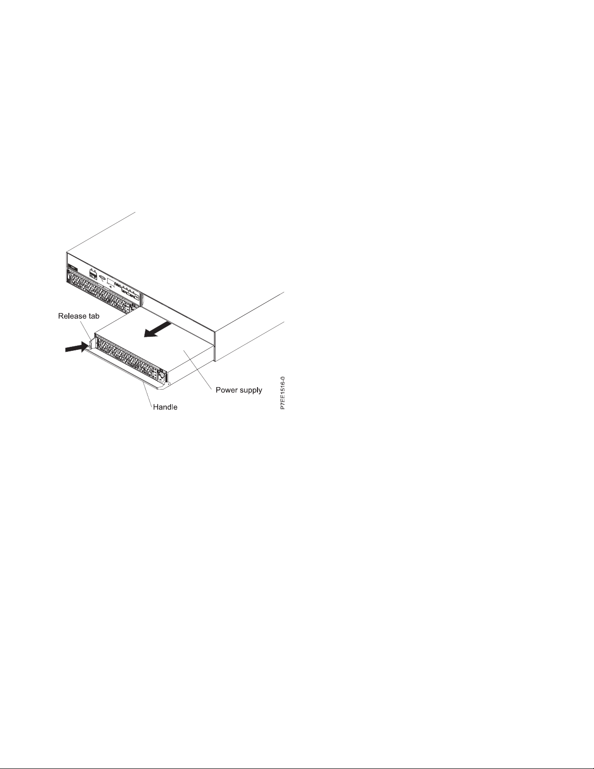
3. Remove the power supply:
Note: If you are removing the power supply with the power on, this operation must be performed
within 15 minutes to prevent overheating.
a. On the left side of the power supply, press the orange release tab to the right, just enough to
release the handle as you rotate the handle downward.
b. Using the handle, gently slide the power supply out of the enclosure, supporting the bottom.
Figure 9. Removing the power supply
4. Install the power supply:
a. Hold the replacement power supply so that the handle is fully extended downward.
b. Gently slide the power supply into the enclosure until it stops.
c. Rotate the handle upward into the closed position until it clicks.
d. Reconnect the power cable to the power supply. Install the power-cable retention bracket.
Note: After the power cord is reconnected, ensure that the ac and dc power (green) LEDs are lit
and that the fault (amber) LED is off.
e. If this service action was a nonconcurrent repair, reconnect the power cable to the other power
supply, install the power-cable retention bracket, and power on the system or partition.
10
Page 23

Notices
This information was developed for products and services offered in the U.S.A.
The manufacturer may not offer the products, services, or features discussed in this document in other
countries. Consult the manufacturer's representative for information on the products and services
currently available in your area. Any reference to the manufacturer's product, program, or service is not
intended to state or imply that only that product, program, or service may be used. Any functionally
equivalent product, program, or service that does not infringe any intellectual property right of the
manufacturer may be used instead. However, it is the user's responsibility to evaluate and verify the
operation of any product, program, or service.
The manufacturer may have patents or pending patent applications covering subject matter described in
this document. The furnishing of this document does not grant you any license to these patents. You can
send license inquiries, in writing, to the manufacturer.
The following paragraph does not apply to the United Kingdom or any other country where such
provisions are inconsistent with local law: THIS PUBLICATION IS PROVIDED “AS IS” WITHOUT
WARRANTY OF ANY KIND, EITHER EXPRESS OR IMPLIED, INCLUDING, BUT NOT LIMITED TO,
THE IMPLIED WARRANTIES OF NON-INFRINGEMENT, MERCHANTABILITY OR FITNESS FOR A
PARTICULAR PURPOSE. Some states do not allow disclaimer of express or implied warranties in certain
transactions, therefore, this statement may not apply to you.
This information could include technical inaccuracies or typographical errors. Changes are periodically
made to the information herein; these changes will be incorporated in new editions of the publication.
The manufacturer may make improvements and/or changes in the product(s) and/or the program(s)
described in this publication at any time without notice.
Any references in this information to websites not owned by the manufacturer are provided for
convenience only and do not in any manner serve as an endorsement of those websites. The materials at
those websites are not part of the materials for this product and use of those websites is at your own risk.
The manufacturer may use or distribute any of the information you supply in any way it believes
appropriate without incurring any obligation to you.
Any performance data contained herein was determined in a controlled environment. Therefore, the
results obtained in other operating environments may vary significantly. Some measurements may have
been made on development-level systems and there is no guarantee that these measurements will be the
same on generally available systems. Furthermore, some measurements may have been estimated through
extrapolation. Actual results may vary. Users of this document should verify the applicable data for their
specific environment.
Information concerning products not produced by this manufacturer was obtained from the suppliers of
those products, their published announcements or other publicly available sources. This manufacturer has
not tested those products and cannot confirm the accuracy of performance, compatibility or any other
claims related to products not produced by this manufacturer. Questions on the capabilities of products
not produced by this manufacturer should be addressed to the suppliers of those products.
All statements regarding the manufacturer's future direction or intent are subject to change or withdrawal
without notice, and represent goals and objectives only.
The manufacturer's prices shown are the manufacturer's suggested retail prices, are current and are
subject to change without notice. Dealer prices may vary.
© Copyright IBM Corp. 2011, 2017 11
Page 24

This information is for planning purposes only. The information herein is subject to change before the
products described become available.
This information contains examples of data and reports used in daily business operations. To illustrate
them as completely as possible, the examples include the names of individuals, companies, brands, and
products. All of these names are fictitious and any similarity to the names and addresses used by an
actual business enterprise is entirely coincidental.
If you are viewing this information in softcopy, the photographs and color illustrations may not appear.
The drawings and specifications contained herein shall not be reproduced in whole or in part without the
written permission of the manufacturer.
The manufacturer has prepared this information for use with the specific machines indicated. The
manufacturer makes no representations that it is suitable for any other purpose.
The manufacturer's computer systems contain mechanisms designed to reduce the possibility of
undetected data corruption or loss. This risk, however, cannot be eliminated. Users who experience
unplanned outages, system failures, power fluctuations or outages, or component failures must verify the
accuracy of operations performed and data saved or transmitted by the system at or near the time of the
outage or failure. In addition, users must establish procedures to ensure that there is independent data
verification before relying on such data in sensitive or critical operations. Users should periodically check
the manufacturer's support websites for updated information and fixes applicable to the system and
related software.
Homologation statement
This product may not be certified in your country for connection by any means whatsoever to interfaces
of public telecommunications networks. Further certification may be required by law prior to making any
such connection. Contact an IBM representative or reseller for any questions.
Trademarks
IBM, the IBM logo, and ibm.com are trademarks or registered trademarks of International Business
Machines Corp., registered in many jurisdictions worldwide. Other product and service names might be
trademarks of IBM or other companies. A current list of IBM trademarks is available on the Web at
Copyright and trademark information at www.ibm.com/legal/copytrade.shtml.
Electronic emission notices
When attaching a monitor to the equipment, you must use the designated monitor cable and any
interference suppression devices supplied with the monitor.
Class A Notices
The following Class A statements apply to the IBM servers that contain the POWER7®processor and its
features unless designated as electromagnetic compatibility (EMC) Class B in the feature information.
Federal Communications Commission (FCC) statement
Note: This equipment has been tested and found to comply with the limits for a Class A digital device,
pursuant to Part 15 of the FCC Rules. These limits are designed to provide reasonable protection against
harmful interference when the equipment is operated in a commercial environment. This equipment
generates, uses, and can radiate radio frequency energy and, if not installed and used in accordance with
the instruction manual, may cause harmful interference to radio communications. Operation of this
12
Page 25

equipment in a residential area is likely to cause harmful interference, in which case the user will be
required to correct the interference at his own expense.
Properly shielded and grounded cables and connectors must be used in order to meet FCC emission
limits. IBM is not responsible for any radio or television interference caused by using other than
recommended cables and connectors or by unauthorized changes or modifications to this equipment.
Unauthorized changes or modifications could void the user's authority to operate the equipment.
This device complies with Part 15 of the FCC rules. Operation is subject to the following two conditions:
(1) this device may not cause harmful interference, and (2) this device must accept any interference
received, including interference that may cause undesired operation.
Industry Canada Compliance Statement
This Class A digital apparatus complies with Canadian ICES-003.
Avis de conformité à la réglementation d'Industrie Canada
Cet appareil numérique de la classe A est conforme à la norme NMB-003 du Canada.
European Community Compliance Statement
This product is in conformity with the protection requirements of EU Council Directive 2004/108/EC on
the approximation of the laws of the Member States relating to electromagnetic compatibility. IBM cannot
accept responsibility for any failure to satisfy the protection requirements resulting from a
non-recommended modification of the product, including the fitting of non-IBM option cards.
This product has been tested and found to comply with the limits for Class A Information Technology
Equipment according to European Standard EN 55022. The limits for Class A equipment were derived for
commercial and industrial environments to provide reasonable protection against interference with
licensed communication equipment.
European Community contact:
IBM Deutschland GmbH
Technical Regulations, Department M372
IBM-Allee 1, 71139 Ehningen, Germany
Tele: +49 7032 15 2941
email: lugi@de.ibm.com
Warning: This is a Class A product. In a domestic environment, this product may cause radio
interference, in which case the user may be required to take adequate measures.
VCCI Statement - Japan
The following is a summary of the VCCI Japanese statement in the box above:
This is a Class A product based on the standard of the VCCI Council. If this equipment is used in a
domestic environment, radio interference may occur, in which case, the user may be required to take
corrective actions.
Notices 13
Page 26

Japanese Electronics and Information Technology Industries Association (JEITA)
Confirmed Harmonics Guideline (products less than or equal to 20 A per phase)
Japanese Electronics and Information Technology Industries Association (JEITA)
Confirmed Harmonics Guideline with Modifications (products greater than 20 A per
phase)
Electromagnetic Interference (EMI) Statement - People's Republic of China
Declaration: This is a Class A product. In a domestic environment this product may cause radio
interference in which case the user may need to perform practical action.
Electromagnetic Interference (EMI) Statement - Taiwan
The following is a summary of the EMI Taiwan statement above.
Warning: This is a Class A product. In a domestic environment this product may cause radio interference
in which case the user will be required to take adequate measures.
IBM Taiwan Contact Information:
14
Page 27

Electromagnetic Interference (EMI) Statement - Korea
Germany Compliance Statement
Deutschsprachiger EU Hinweis: Hinweis für Geräte der Klasse A EU-Richtlinie zur
Elektromagnetischen Verträglichkeit
Dieses Produkt entspricht den Schutzanforderungen der EU-Richtlinie 2004/108/EG zur Angleichung der
Rechtsvorschriften über die elektromagnetische Verträglichkeit in den EU-Mitgliedsstaaten und hält die
Grenzwerte der EN 55022 Klasse A ein.
Um dieses sicherzustellen, sind die Geräte wie in den Handbüchern beschrieben zu installieren und zu
betreiben. Des Weiteren dürfen auch nur von der IBM empfohlene Kabel angeschlossen werden. IBM
übernimmt keine Verantwortung für die Einhaltung der Schutzanforderungen, wenn das Produkt ohne
Zustimmung von IBM verändert bzw. wenn Erweiterungskomponenten von Fremdherstellern ohne
Empfehlung von IBM gesteckt/eingebaut werden.
EN 55022 Klasse A Geräte müssen mit folgendem Warnhinweis versehen werden:
"Warnung: Dieses ist eine Einrichtung der Klasse A. Diese Einrichtung kann im Wohnbereich
Funk-Störungen verursachen; in diesem Fall kann vom Betreiber verlangt werden, angemessene
Maßnahmen zu ergreifen und dafür aufzukommen."
Deutschland: Einhaltung des Gesetzes über die elektromagnetische Verträglichkeit von Geräten
Dieses Produkt entspricht dem “Gesetz über die elektromagnetische Verträglichkeit von Geräten
(EMVG)“. Dies ist die Umsetzung der EU-Richtlinie 2004/108/EG in der Bundesrepublik Deutschland.
Zulassungsbescheinigung laut dem Deutschen Gesetz über die elektromagnetische Verträglichkeit von
Geräten (EMVG) (bzw. der EMC EG Richtlinie 2004/108/EG) für Geräte der Klasse A
Dieses Gerät ist berechtigt, in Übereinstimmung mit dem Deutschen EMVG das EG-Konformitätszeichen
- CE - zu führen.
Notices 15
Page 28

Verantwortlich für die Einhaltung der EMV Vorschriften ist der Hersteller:
International Business Machines Corp.
New Orchard Road
Armonk, New York 10504
Tel: 914-499-1900
Der verantwortliche Ansprechpartner des Herstellers in der EU ist:
IBM Deutschland GmbH
Technical Regulations, Abteilung M372
IBM-Allee 1, 71139 Ehningen, Germany
Tel: +49 7032 15 2941
email: lugi@de.ibm.com
Generelle Informationen:
Das Gerät erfüllt die Schutzanforderungen nach EN 55024 und EN 55022 Klasse A.
Electromagnetic Interference (EMI) Statement - Russia
Class B Notices
The following Class B statements apply to features designated as electromagnetic compatibility (EMC)
Class B in the feature installation information.
Federal Communications Commission (FCC) statement
This equipment has been tested and found to comply with the limits for a Class B digital device,
pursuant to Part 15 of the FCC Rules. These limits are designed to provide reasonable protection against
harmful interference in a residential installation.
This equipment generates, uses, and can radiate radio frequency energy and, if not installed and used in
accordance with the instructions, may cause harmful interference to radio communications. However,
there is no guarantee that interference will not occur in a particular installation.
If this equipment does cause harmful interference to radio or television reception, which can be
determined by turning the equipment off and on, the user is encouraged to try to correct the interference
by one or more of the following measures:
v Reorient or relocate the receiving antenna.
v Increase the separation between the equipment and receiver.
v Connect the equipment into an outlet on a circuit different from that to which the receiver is
connected.
v Consult an IBM-authorized dealer or service representative for help.
Properly shielded and grounded cables and connectors must be used in order to meet FCC emission
limits. Proper cables and connectors are available from IBM-authorized dealers. IBM is not responsible for
16
Page 29

any radio or television interference caused by unauthorized changes or modifications to this equipment.
Unauthorized changes or modifications could void the user's authority to operate this equipment.
This device complies with Part 15 of the FCC rules. Operation is subject to the following two conditions:
(1) this device may not cause harmful interference, and (2) this device must accept any interference
received, including interference that may cause undesired operation.
Industry Canada Compliance Statement
This Class B digital apparatus complies with Canadian ICES-003.
Avis de conformité à la réglementation d'Industrie Canada
Cet appareil numérique de la classe B est conforme à la norme NMB-003 du Canada.
European Community Compliance Statement
This product is in conformity with the protection requirements of EU Council Directive 2004/108/EC on
the approximation of the laws of the Member States relating to electromagnetic compatibility. IBM cannot
accept responsibility for any failure to satisfy the protection requirements resulting from a
non-recommended modification of the product, including the fitting of non-IBM option cards.
This product has been tested and found to comply with the limits for Class B Information Technology
Equipment according to European Standard EN 55022. The limits for Class B equipment were derived for
typical residential environments to provide reasonable protection against interference with licensed
communication equipment.
European Community contact:
IBM Deutschland GmbH
Technical Regulations, Department M372
IBM-Allee 1, 71139 Ehningen, Germany
Tele: +49 7032 15 2941
email: lugi@de.ibm.com
VCCI Statement - Japan
Japanese Electronics and Information Technology Industries Association (JEITA)
Confirmed Harmonics Guideline (products less than or equal to 20 A per phase)
Notices 17
Page 30

Japanese Electronics and Information Technology Industries Association (JEITA)
Confirmed Harmonics Guideline with Modifications (products greater than 20 A per
phase)
IBM Taiwan Contact Information
Electromagnetic Interference (EMI) Statement - Korea
Germany Compliance Statement
Deutschsprachiger EU Hinweis: Hinweis für Geräte der Klasse B EU-Richtlinie zur
Elektromagnetischen Verträglichkeit
Dieses Produkt entspricht den Schutzanforderungen der EU-Richtlinie 2004/108/EG zur Angleichung der
Rechtsvorschriften über die elektromagnetische Verträglichkeit in den EU-Mitgliedsstaaten und hält die
Grenzwerte der EN 55022 Klasse B ein.
Um dieses sicherzustellen, sind die Geräte wie in den Handbüchern beschrieben zu installieren und zu
betreiben. Des Weiteren dürfen auch nur von der IBM empfohlene Kabel angeschlossen werden. IBM
übernimmt keine Verantwortung für die Einhaltung der Schutzanforderungen, wenn das Produkt ohne
Zustimmung von IBM verändert bzw. wenn Erweiterungskomponenten von Fremdherstellern ohne
Empfehlung von IBM gesteckt/eingebaut werden.
Deutschland: Einhaltung des Gesetzes über die elektromagnetische Verträglichkeit von Geräten
Dieses Produkt entspricht dem “Gesetz über die elektromagnetische Verträglichkeit von Geräten
(EMVG)“. Dies ist die Umsetzung der EU-Richtlinie 2004/108/EG in der Bundesrepublik Deutschland.
Zulassungsbescheinigung laut dem Deutschen Gesetz über die elektromagnetische Verträglichkeit von
Geräten (EMVG) (bzw. der EMC EG Richtlinie 2004/108/EG) für Geräte der Klasse B
18
Page 31

Dieses Gerät ist berechtigt, in Übereinstimmung mit dem Deutschen EMVG das EG-Konformitätszeichen
- CE - zu führen.
Verantwortlich für die Einhaltung der EMV Vorschriften ist der Hersteller:
International Business Machines Corp.
New Orchard Road
Armonk, New York 10504
Tel: 914-499-1900
Der verantwortliche Ansprechpartner des Herstellers in der EU ist:
IBM Deutschland GmbH
Technical Regulations, Abteilung M372
IBM-Allee 1, 71139 Ehningen, Germany
Tel: +49 7032 15 2941
email: lugi@de.ibm.com
Generelle Informationen:
Das Gerät erfüllt die Schutzanforderungen nach EN 55024 und EN 55022 Klasse B.
Terms and conditions
Permissions for the use of these publications are granted subject to the following terms and conditions.
Applicability: These terms and conditions are in addition to any terms of use for the IBM website.
Personal Use: You may reproduce these publications for your personal, noncommercial use provided that
all proprietary notices are preserved. You may not distribute, display or make derivative works of these
publications, or any portion thereof, without the express consent of IBM.
Commercial Use: You may reproduce, distribute and display these publications solely within your
enterprise provided that all proprietary notices are preserved. You may not make derivative works of
these publications, or reproduce, distribute or display these publications or any portion thereof outside
your enterprise, without the express consent of IBM.
Rights: Except as expressly granted in this permission, no other permissions, licenses or rights are
granted, either express or implied, to the Publications or any information, data, software or other
intellectual property contained therein.
IBM reserves the right to withdraw the permissions granted herein whenever, in its discretion, the use of
the publications is detrimental to its interest or, as determined by IBM, the above instructions are not
being properly followed.
You may not download, export or re-export this information except in full compliance with all applicable
laws and regulations, including all United States export laws and regulations.
IBM MAKES NO GUARANTEE ABOUT THE CONTENT OF THESE PUBLICATIONS. THE
PUBLICATIONS ARE PROVIDED "AS-IS" AND WITHOUT WARRANTY OF ANY KIND, EITHER
EXPRESSED OR IMPLIED, INCLUDING BUT NOT LIMITED TO IMPLIED WARRANTIES OF
MERCHANTABILITY, NON-INFRINGEMENT, AND FITNESS FOR A PARTICULAR PURPOSE.
Notices 19
Page 32

20
Page 33

Page 34

IBM®
Printed in USA
 Loading...