

Page 1

Power Systems
Servicing the 8335-GTW
IBM
Page 2

Note
Before using this information and the product it supports, read the information in “Safety notices” on
page v, “Notices” on page 221, the IBM Systems Safety Notices manual, G229-9054, and the IBM
Environmental Notices and User Guide, Z125–5823.
This edition applies to IBM® Power Systems servers that contain the POWER9™ processor and to all associated models.
©
Copyright International Business Machines Corporation 2018, 2019.
US Government Users Restricted Rights – Use, duplication or disclosure restricted by GSA ADP Schedule Contract with
IBM Corp.
Page 3

Contents
Safety notices........................................................................................................v
Removing and replacing parts in the 8335-GTW or 8335-GTX................................. 1
BMC card...................................................................................................................................................... 3
Removing the BMC card......................................................................................................................... 3
Replacing the BMC card......................................................................................................................... 4
Cold plates....................................................................................................................................................7
Removing the cold plates from the system........................................................................................... 7
Replacing the cold plates in the cold plate installation carrier...........................................................32
Replacing the cold plates in the system..............................................................................................45
Disk drive....................................................................................................................................................64
Removing a disk drive.......................................................................................................................... 65
Replacing a disk drive...........................................................................................................................67
Disk drive and fan card.............................................................................................................................. 68
Removing the disk drive and fan card..................................................................................................68
Replacing the disk drive and fan card..................................................................................................74
Disk and fan signal cable........................................................................................................................... 80
Removing the disk and fan signal cable.............................................................................................. 81
Replacing the disk and fan signal cable...............................................................................................83
Fans............................................................................................................................................................84
Removing a fan.....................................................................................................................................84
Replacing a fan..................................................................................................................................... 86
Fan power cable.........................................................................................................................................87
Removing the fan power cable............................................................................................................ 87
Replacing the fan power cable.............................................................................................................90
Graphics processing unit........................................................................................................................... 91
Removing the graphics processing unit from a water-cooled system............................................... 91
Replacing the graphics processing unit in a water-cooled system.................................................... 96
Memory modules..................................................................................................................................... 101
Removing and replacing memory modules.......................................................................................102
Memory plugging rules.......................................................................................................................107
PCIe adapters.......................................................................................................................................... 108
Removing a PCIe adapter.................................................................................................................. 108
Replacing a PCIe adapter.................................................................................................................. 109
Power supplies........................................................................................................................................ 110
Removing a power supply..................................................................................................................111
Replacing a power supply..................................................................................................................114
Power switch and cable...........................................................................................................................114
Removing the power switch and cable..............................................................................................115
Replacing the power switch and cable..............................................................................................119
System backplane................................................................................................................................... 123
Preparing to remove the system backplane......................................................................................123
Removing the system backplane.......................................................................................................124
Replacing the system backplane.......................................................................................................135
Preparing the system for operation after replacing the system backplane..................................... 149
System processor module.......................................................................................................................150
Removing a system processor module............................................................................................. 150
Replacing the system processor module.......................................................................................... 160
Upgrading system processor modules..............................................................................................172
Time-of-day battery.................................................................................................................................173
iii
Page 4

Water manifold........................................................................................................................................ 175
Preparing the system to remove and replace the water manifold................................................... 175
Removing the water manifold............................................................................................................179
Replacing the water manifold............................................................................................................183
Preparing the system for operation after replacing the water manifold.......................................... 187
Common procedures for servicing or installing features...................................... 191
Before you begin......................................................................................................................................191
Identifying the system that contains the part to replace.......................................................................195
System LEDs.......................................................................................................................................195
Identifying the system....................................................................................................................... 197
Preparing the system to remove and replace internal parts..................................................................198
Preparing the system for operation........................................................................................................ 202
Starting and stopping the system........................................................................................................... 204
Starting the system ........................................................................................................................... 204
Stopping the 8335-GTC, 8335-GTG, 8335-GTH, 8335-GTW, or 8335-GTX system...................... 205
Sensor status........................................................................................................................................... 205
Removing and replacing covers.............................................................................................................. 206
Removing the service access cover...................................................................................................206
Installing the service access cover....................................................................................................207
Removing the front cover...................................................................................................................208
Installing the front cover....................................................................................................................209
Service and operating positions..............................................................................................................209
Placing the system into the service position.....................................................................................209
Placing the system into the operating position.................................................................................211
Removing and replacing power cords.....................................................................................................214
Disconnecting power cords............................................................................................................... 214
Connecting power cords.................................................................................................................... 217
Notices..............................................................................................................221
Accessibility features for IBM Power Systems servers..........................................................................222
Privacy policy considerations .................................................................................................................223
Trademarks..............................................................................................................................................223
Electronic emission notices.....................................................................................................................224
Class A Notices...................................................................................................................................224
Class B Notices...................................................................................................................................227
Terms and conditions.............................................................................................................................. 230
iv
Page 5

Safety notices
Safety notices may be printed throughout this guide:
• DANGER notices call attention to a situation that is potentially lethal or extremely hazardous to people.
• CAUTION notices call attention to a situation that is potentially hazardous to people because of some
existing condition.
• Attention notices call attention to the possibility of damage to a program, device, system, or data.
World Trade safety information
Several countries require the safety information contained in product publications to be presented in their
national languages. If this requirement applies to your country, safety information documentation is
included in the publications package (such as in printed documentation, on DVD, or as part of the product)
shipped with the product. The documentation contains the safety information in your national language
with references to the U.S. English source. Before using a U.S. English publication to install, operate, or
service this product, you must rst become familiar with the related safety information documentation.
You should also refer to the safety information documentation any time you do not clearly understand any
safety information in the U.S. English publications.
Replacement or additional copies of safety information documentation can be obtained by calling the IBM
Hotline at 1-800-300-8751.
German safety information
Das Produkt ist nicht für den Einsatz an Bildschirmarbeitsplätzen im Sinne § 2 der
Bildschirmarbeitsverordnung geeignet.
Laser safety information
IBM servers can use I/O cards or features that are ber-optic based and that utilize lasers or LEDs.
Laser compliance
IBM servers may be installed inside or outside of an IT equipment rack.
DANGER:
Electrical voltage and current from power, telephone, and communication cables are hazardous.
To avoid a shock hazard:
• If IBM supplied the power cord(s), connect power to this unit only with the IBM provided power
cord. Do not use the IBM provided power cord for any other product.
• Do not open or service any power supply assembly.
• Do not connect or disconnect any cables or perform installation, maintenance, or reconguration
of this product during an electrical storm.
• The product might be equipped with multiple power cords. To remove all hazardous voltages,
disconnect all power cords.
– For AC power, disconnect all power cords from their AC power source.
– For racks with a DC power distribution panel (PDP), disconnect the customer’s DC power
• When connecting power to the product ensure all power cables are properly connected.
When working on or around the system, observe the following precautions:
source to the PDP.
– For racks with AC power, connect all power cords to a properly wired and grounded electrical
outlet. Ensure that the outlet supplies proper voltage and phase rotation according to the
system rating plate.
©
Copyright IBM Corp. 2018, 2019 v
Page 6

– For racks with a DC power distribution panel (PDP), connect the customer’s DC power source
to the PDP. Ensure that the proper polarity is used when attaching the DC power and DC power
return wiring.
• Connect any equipment that will be attached to this product to properly wired outlets.
• When possible, use one hand only to connect or disconnect signal cables.
• Never turn on any equipment when there is evidence of re, water, or structural damage.
• Do not attempt to switch on power to the machine until all possible unsafe conditions are
corrected.
• Assume that an electrical safety hazard is present. Perform all continuity, grounding, and power
checks specied during the subsystem installation procedures to ensure that the machine meets
safety requirements.
• Do not continue with the inspection if any unsafe conditions are present.
• Before you open the device covers, unless instructed otherwise in the installation and
conguration procedures: Disconnect the attached AC power cords, turn off the applicable
circuit breakers located in the rack power distribution panel (PDP), and disconnect any
telecommunications systems, networks, and modems.
DANGER:
• Connect and disconnect cables as described in the following procedures when installing,
moving, or opening covers on this product or attached devices.
To Disconnect:
1. Turn off everything (unless instructed otherwise).
2. For AC power, remove the power cords from the outlets.
3. For racks with a DC power distribution panel (PDP), turn off the circuit breakers located in the
PDP and remove the power from the Customer's DC power source.
4. Remove the signal cables from the connectors.
5. Remove all cables from the devices.
To Connect:
1. Turn off everything (unless instructed otherwise).
2. Attach all cables to the devices.
3. Attach the signal cables to the connectors.
4. For AC power, attach the power cords to the outlets.
5. For racks with a DC power distribution panel (PDP), restore the power from the Customer's
DC power source and turn on the circuit breakers located in the PDP.
6. Turn on the devices.
Sharp edges, corners and joints may be present in and around the system. Use care when
handling equipment to avoid cuts, scrapes and pinching. (D005)
(R001 part 1 of 2):
DANGER:
• Heavy equipment–personal injury or equipment damage might result if mishandled.
• Always lower the leveling pads on the rack cabinet.
• Always install stabilizer brackets on the rack cabinet unless the earthquake option is to be
installed.
• To avoid hazardous conditions due to uneven mechanical loading, always install the heaviest
devices in the bottom of the rack cabinet. Always install servers and optional devices starting
from the bottom of the rack cabinet.
Observe the following precautions when working on or around your IT rack system:
vi Power Systems: Servicing the 8335-GTW
Page 7

• Rack-mounted devices are not to be used as shelves or work spaces. Do not place objects on top
of rack-mounted devices. In addition, do not lean on rack mounted devices and do not use them
to stabilize your body position (for example, when working from a ladder).
• Stability hazard:
– The rack may tip over causing serious personal injury.
– Before extending the rack to the installation position, read the installation instructions.
– Do not put any load on the slide-rail mounted equipment mounted in the installation position.
– Do not leave the slide-rail mounted equipment in the installation position.
• Each rack cabinet might have more than one power cord.
– For AC powered racks, be sure to disconnect all power cords in the rack cabinet when directed
to disconnect power during servicing.
– For racks with a DC power distribution panel (PDP), turn off the circuit breaker that controls
the power to the system unit(s), or disconnect the customer’s DC power source, when
directed to disconnect power during servicing.
• Connect all devices installed in a rack cabinet to power devices installed in the same rack
cabinet. Do not plug a power cord from a device installed in one rack cabinet into a power device
installed in a different rack cabinet.
• An electrical outlet that is not correctly wired could place hazardous voltage on the metal parts
of the system or the devices that attach to the system. It is the responsibility of the customer to
ensure that the outlet is correctly wired and grounded to prevent an electrical shock. (R001 part
1 of 2)
(R001 part 2 of 2):
CAUTION:
• Do not install a unit in a rack where the internal rack ambient temperatures will exceed the
manufacturer's recommended ambient temperature for all your rack-mounted devices.
• Do not install a unit in a rack where the air flow is compromised. Ensure that air flow is not
blocked or reduced on any side, front, or back of a unit used for air flow through the unit.
• Consideration should be given to the connection of the equipment to the supply circuit so that
overloading of the circuits does not compromise the supply wiring or overcurrent protection. To
provide the correct power connection to a rack, refer to the rating labels located on the
equipment in the rack to determine the total power requirement of the supply circuit.
• (For sliding drawers.) Do not pull out or install any drawer or feature if the rack stabilizer
brackets are not attached to the rack or if the rack is not bolted to the floor. Do not pull out more
than one drawer at a time. The rack might become unstable if you pull out more than one drawer
at a time.
• (For xed drawers.) This drawer is a xed drawer and must not be moved for servicing unless
specied by the manufacturer. Attempting to move the drawer partially or completely out of the
rack might cause the rack to become unstable or cause the drawer to fall out of the rack. (R001
part 2 of 2)
Safety notices
vii
Page 8

CAUTION: Removing components from the upper positions in the rack cabinet improves rack
stability during relocation. Follow these general guidelines whenever you relocate a populated
rack cabinet within a room or building.
• Reduce the weight of the rack cabinet by removing equipment starting at the top of the rack
cabinet. When possible, restore the rack cabinet to the conguration of the rack cabinet as you
received it. If this conguration is not known, you must observe the following precautions:
– Remove all devices in the 32U position (compliance ID RACK-001 or 22U (compliance ID
RR001) and above.
– Ensure that the heaviest devices are installed in the bottom of the rack cabinet.
– Ensure that there are little-to-no empty U-levels between devices installed in the rack cabinet
below the 32U (compliance ID RACK-001 or 22U (compliance ID RR001) level, unless the
received conguration specically allowed it.
• If the rack cabinet you are relocating is part of a suite of rack cabinets, detach the rack cabinet
from the suite.
• If the rack cabinet you are relocating was supplied with removable outriggers they must be
reinstalled before the cabinet is relocated.
• Inspect the route that you plan to take to eliminate potential hazards.
• Verify that the route that you choose can support the weight of the loaded rack cabinet. Refer to
the documentation that comes with your rack cabinet for the weight of a loaded rack cabinet.
• Verify that all door openings are at least 760 x 230 mm (30 x 80 in.).
• Ensure that all devices, shelves, drawers, doors, and cables are secure.
• Ensure that the four leveling pads are raised to their highest position.
• Ensure that there is no stabilizer bracket installed on the rack cabinet during movement.
• Do not use a ramp inclined at more than 10 degrees.
• When the rack cabinet is in the new location, complete the following steps:
(L001)
(L002)
– Lower the four leveling pads.
– Install stabilizer brackets on the rack cabinet or in an earthquake environment bolt the rack to
the floor.
– If you removed any devices from the rack cabinet, repopulate the rack cabinet from the
lowest position to the highest position.
• If a long-distance relocation is required, restore the rack cabinet to the conguration of the rack
cabinet as you received it. Pack the rack cabinet in the original packaging material, or equivalent.
Also lower the leveling pads to raise the casters off of the pallet and bolt the rack cabinet to the
pallet.
(R002)
DANGER:
this label attached. Do not open any cover or barrier that contains this label. (L001)
Hazardous voltage, current, or energy levels are present inside any component that has
viii
Power Systems: Servicing the 8335-GTW
Page 9

(L003)
or
DANGER: Rack-mounted devices are not to be used as shelves or work spaces. Do not place
objects on top of rack-mounted devices. In addition, do not lean on rack-mounted devices and do
not use them to stabilize your body position (for example, when working from a ladder). Stability
hazard:
• The rack may tip over causing serious personal injury.
• Before extending the rack to the installation position, read the installation instructions.
• Do not put any load on the slide-rail mounted equipment mounted in the installation position.
• Do not leave the slide-rail mounted equipment in the installation position.
(L002)
or
or
Safety notices
ix
Page 10

or
DANGER: Multiple power cords. The product might be equipped with multiple AC power cords or
multiple DC power cables. To remove all hazardous voltages, disconnect all power cords and
power cables. (L003)
(L007)
CAUTION:
x Power Systems: Servicing the 8335-GTW
A hot surface nearby. (L007)
Page 11

(L008)
CAUTION: Hazardous moving parts nearby. (L008)
All lasers are certied in the U.S. to conform to the requirements of DHHS 21 CFR Subchapter J for class 1
laser products. Outside the U.S., they are certied to be in compliance with IEC 60825 as a class 1 laser
product. Consult the label on each part for laser certication numbers and approval information.
CAUTION: This product might contain one or more of the following devices: CD-ROM drive, DVDROM drive, DVD-RAM drive, or laser module, which are Class 1 laser products. Note the following
information:
• Do not remove the covers. Removing the covers of the laser product could result in exposure to
hazardous laser radiation. There are no serviceable parts inside the device.
• Use of the controls or adjustments or performance of procedures other than those specied
herein might result in hazardous radiation exposure.
(C026)
CAUTION: Data processing environments can contain equipment transmitting on system links
with laser modules that operate at greater than Class 1 power levels. For this reason, never look
into the end of an optical ber cable or open receptacle. Although shining light into one end and
looking into the other end of a disconnected optical ber to verify the continuity of optic bers may
not injure the eye, this procedure is potentially dangerous. Therefore, verifying the continuity of
optical bers by shining light into one end and looking at the other end is not recommended. To
verify continuity of a ber optic cable, use an optical light source and power meter. (C027)
CAUTION: This product contains a Class 1M laser. Do not view directly with optical instruments.
(C028)
CAUTION: Some laser products contain an embedded Class 3A or Class 3B laser diode. Note the
following information:
• Laser radiation when open.
• Do not stare into the beam, do not view directly with optical instruments, and avoid direct
exposure to the beam. (C030)
(C030)
CAUTION: The battery contains lithium. To avoid possible explosion, do not burn or charge the
battery.
Do Not:
• Throw or immerse into water
• Heat to more than 100 degrees C (212 degrees F)
• Repair or disassemble
Exchange only with the IBM-approved part. Recycle or discard the battery as instructed by local
regulations. In the United States, IBM has a process for the collection of this battery. For
information, call 1-800-426-4333. Have the IBM part number for the battery unit available when
you call. (C003)
CAUTION: Regarding IBM provided VENDOR LIFT TOOL:
• Operation of LIFT TOOL by authorized personnel only.
Safety notices xi
Page 12

• LIFT TOOL intended for use to assist, lift, install, remove units (load) up into rack elevations. It is
not to be used loaded transporting over major ramps nor as a replacement for such designated
tools like pallet jacks, walkies, fork trucks and such related relocation practices. When this is not
practicable, specially trained persons or services must be used (for instance, riggers or movers).
• Read and completely understand the contents of LIFT TOOL operator's manual before using.
Failure to read, understand, obey safety rules, and follow instructions may result in property
damage and/or personal injury. If there are questions, contact the vendor's service and support.
Local paper manual must remain with machine in provided storage sleeve area. Latest revision
manual available on vendor's web site.
• Test verify stabilizer brake function before each use. Do not over-force moving or rolling the LIFT
TOOL with stabilizer brake engaged.
• Do not raise, lower or slide platform load shelf unless stabilizer (brake pedal jack) is fully
engaged. Keep stabilizer brake engaged when not in use or motion.
• Do not move LIFT TOOL while platform is raised, except for minor positioning.
• Do not exceed rated load capacity. See LOAD CAPACITY CHART regarding maximum loads at
center versus edge of extended platform.
• Only raise load if properly centered on platform. Do not place more than 200 lb (91 kg) on edge
of sliding platform shelf also considering the load's center of mass/gravity (CoG).
• Do not corner load the platforms, tilt riser, angled unit install wedge or other such accessory
options. Secure such platforms -- riser tilt, wedge, etc options to main lift shelf or forks in all four
(4x or all other provisioned mounting) locations with provided hardware only, prior to use. Load
objects are designed to slide on/off smooth platforms without appreciable force, so take care
not to push or lean. Keep riser tilt [adjustable angling platform] option flat at all times except for
nal minor angle adjustment when needed.
• Do not stand under overhanging load.
• Do not use on uneven surface, incline or decline (major ramps).
• Do not stack loads.
• Do not operate while under the influence of drugs or alcohol.
• Do not support ladder against LIFT TOOL (unless the specic allowance is provided for one
following qualied procedures for working at elevations with this TOOL).
• Tipping hazard. Do not push or lean against load with raised platform.
• Do not use as a personnel lifting platform or step. No riders.
• Do not stand on any part of lift. Not a step.
• Do not climb on mast.
• Do not operate a damaged or malfunctioning LIFT TOOL machine.
• Crush and pinch point hazard below platform. Only lower load in areas clear of personnel and
obstructions. Keep hands and feet clear during operation.
• No Forks. Never lift or move bare LIFT TOOL MACHINE with pallet truck, jack or fork lift.
• Mast extends higher than platform. Be aware of ceiling height, cable trays, sprinklers, lights, and
other overhead objects.
• Do not leave LIFT TOOL machine unattended with an elevated load.
• Watch and keep hands, ngers, and clothing clear when equipment is in motion.
• Turn Winch with hand power only. If winch handle cannot be cranked easily with one hand, it is
probably over-loaded. Do not continue to turn winch past top or bottom of platform travel.
Excessive unwinding will detach handle and damage cable. Always hold handle when lowering,
unwinding. Always assure self that winch is holding load before releasing winch handle.
• A winch accident could cause serious injury. Not for moving humans. Make certain clicking sound
is heard as the equipment is being raised. Be sure winch is locked in position before releasing
handle. Read instruction page before operating this winch. Never allow winch to unwind freely.
xii
Power Systems: Servicing the 8335-GTW
Page 13

Freewheeling will cause uneven cable wrapping around winch drum, damage cable, and may
cause serious injury.
• This TOOL must be maintained correctly for IBM Service personnel to use it. IBM shall inspect
condition and verify maintenance history before operation. Personnel reserve the right not to use
TOOL if inadequate. (C048)
Power and cabling information for NEBS (Network Equipment-Building System) GR-1089-CORE
The following comments apply to the IBM servers that have been designated as conforming to NEBS
(Network Equipment-Building System) GR-1089-CORE:
The equipment is suitable for installation in the following:
• Network telecommunications facilities
• Locations where the NEC (National Electrical Code) applies
The intrabuilding ports of this equipment are suitable for connection to intrabuilding or unexposed wiring
or cabling only. The intrabuilding ports of this equipment must not be metallically connected to the
interfaces that connect to the OSP (outside plant) or its wiring. These interfaces are designed for use as
intrabuilding interfaces only (Type 2 or Type 4 ports as described in GR-1089-CORE) and require isolation
from the exposed OSP cabling. The addition of primary protectors is not sufcient protection to connect
these interfaces metallically to OSP wiring.
Note: All Ethernet cables must be shielded and grounded at both ends.
The ac-powered system does not require the use of an external surge protection device (SPD).
The dc-powered system employs an isolated DC return (DC-I) design. The DC battery return terminal shall
not be connected to the chassis or frame ground.
The dc-powered system is intended to be installed in a common bonding network (CBN) as described in
GR-1089-CORE.
Safety notices
xiii
Page 14

xiv Power Systems: Servicing the 8335-GTW
Page 15

Removing and replacing parts in the 8335-GTW or 8335-GTX
Use these procedures to remove and replace failing parts.
Note: See the International Information Bulletin for Customers - Installation of IBM Machines (http://
www.ibm.com/e-business/linkweb/publications/servlet/pbi.wss). This bulletin (Publication number
SC27-6601-00) provides a list of the key IBM system installation activities and those activities that might
be billable.
Before you begin a replacement, complete these tasks:
1. If you are completing a replacement procedure that might put your data at risk, ensure, if possible,
that you have a current backup of your system or logical partition (including operating systems,
licensed programs, and data).
2. Review the installation or replacement procedure for the feature or part.
3. Note the signicance of color on your system. The color blue on the part indicates a touch point.
4. Ensure that you have access to a medium, flat-blade screwdriver, and a Phillips screwdriver.
5. If parts are incorrect, missing, or visibly damaged, contact the provider of the part or your next level of
support.
DANGER:
Electrical voltage and current from power, telephone, and communication cables are hazardous.
To avoid a shock hazard:
• If IBM supplied the power cord(s), connect power to this unit only with the IBM provided power
cord. Do not use the IBM provided power cord for any other product.
• Do not open or service any power supply assembly.
• Do not connect or disconnect any cables or perform installation, maintenance, or reconguration
of this product during an electrical storm.
• The product might be equipped with multiple power cords. To remove all hazardous voltages,
disconnect all power cords.
– For AC power, disconnect all power cords from their AC power source.
– For racks with a DC power distribution panel (PDP), disconnect the customer’s DC power
• When connecting power to the product ensure all power cables are properly connected.
– For racks with AC power, connect all power cords to a properly wired and grounded electrical
– For racks with a DC power distribution panel (PDP), connect the customer’s DC power source
• Connect any equipment that will be attached to this product to properly wired outlets.
• When possible, use one hand only to connect or disconnect signal cables.
• Never turn on any equipment when there is evidence of re, water, or structural damage.
• Do not attempt to switch on power to the machine until all possible unsafe conditions are
corrected.
• Assume that an electrical safety hazard is present. Perform all continuity, grounding, and power
checks specied during the subsystem installation procedures to ensure that the machine meets
safety requirements.
When working on or around the system, observe the following precautions:
source to the PDP.
outlet. Ensure that the outlet supplies proper voltage and phase rotation according to the
system rating plate.
to the PDP. Ensure that the proper polarity is used when attaching the DC power and DC power
return wiring.
©
Copyright IBM Corp. 2018, 2019 1
Page 16

• Do not continue with the inspection if any unsafe conditions are present.
• Before you open the device covers, unless instructed otherwise in the installation and
conguration procedures: Disconnect the attached AC power cords, turn off the applicable
circuit breakers located in the rack power distribution panel (PDP), and disconnect any
telecommunications systems, networks, and modems.
DANGER:
• Connect and disconnect cables as described in the following procedures when installing,
moving, or opening covers on this product or attached devices.
To Disconnect:
1. Turn off everything (unless instructed otherwise).
2. For AC power, remove the power cords from the outlets.
3. For racks with a DC power distribution panel (PDP), turn off the circuit breakers located in the
PDP and remove the power from the Customer's DC power source.
4. Remove the signal cables from the connectors.
5. Remove all cables from the devices.
To Connect:
1. Turn off everything (unless instructed otherwise).
2. Attach all cables to the devices.
3. Attach the signal cables to the connectors.
4. For AC power, attach the power cords to the outlets.
5. For racks with a DC power distribution panel (PDP), restore the power from the Customer's
DC power source and turn on the circuit breakers located in the PDP.
6. Turn on the devices.
Sharp edges, corners and joints may be present in and around the system. Use care when
handling equipment to avoid cuts, scrapes and pinching. (D005)
Attention:
Failure to follow the step-by-step sequence for FRU removal or installation might result in FRU or
system damage.
For safety, airflow purposes and thermal performance, the service access cover must be installed
and fully seated before you power the system on.
For safety and airflow purposes and thermal performance, if you remove parts from the system,
you must ensure that PCIe tailstock llers are present.
Use the following precautions whenever you handle electronic components or cables.
• The electrostatic discharge (ESD) kit and the ESD wrist strap must be used when you handle
logic cards, single chip modules (SCM), multichip modules (MCM), electronic boards, and disk
drives.
• Keep all electronic components in the shipping container or envelope until you are ready to
install them.
• If you remove and then reinstall an electronic component, temporarily place the component on
an ESD pad or blanket.
2 Power Systems: Servicing the 8335-GTW
Page 17

Removing and replacing the BMC card in the 8335-GTC, 8335-GTG, 8335GTH, 8335-GTW, or 8335-GTX
Learn how to remove and replace the baseboard management card (BMC) in the IBM Power® System
AC922 (8335-GTC, 8335-GTG, and 8335-GTH) or IBM Power System AC922 (8335-GTW and 8335-GTX)
system.
Removing the BMC card from the 8335-GTC, 8335-GTG, 8335-GTH, 8335-GTW, or 8335GTX system
To remove a the baseboard management card (BMC), complete the steps in this procedure.
Before you begin
Record the network settings. For instructions, see Network settings
knowledgecenter/POWER9/p9eih/p9eih_openbmc_networksetting.htm).
Power off the system and place it in the service position. For instructions, see “Preparing the 8335-GTC,
8335-GTG, 8335-GTH, 8335-GTW, or 8335-GTX system to remove and replace internal parts” on page
198.
Procedure
1. Attach the electrostatic discharge (ESD) wrist strap.
The ESD wrist strap must be connected to an unpainted metal surface until the service procedure is
completed, and if applicable, until the service access cover is replaced.
Attention:
• Attach an electrostatic discharge (ESD) wrist strap to the front ESD jack, to the rear ESD jack,
or to an unpainted metal surface of your hardware to prevent the electrostatic discharge from
damaging your hardware.
• When you use an ESD wrist strap, follow all electrical safety procedures. An ESD wrist strap is
used for static control. It does not increase or decrease your risk of receiving electric shock
when using or working on electrical equipment.
• If you do not have an ESD wrist strap, just prior to removing the product from ESD packaging
and installing or replacing hardware, touch an unpainted metal surface of the system for a
minimum of 5 seconds. If at any point in this service process you move away from the
system, it is important to again discharge yourself by touching an unpainted metal surface for
at least 5 seconds before you continue with the service process.
2. If needed, label and remove the cables from the BMC card.
3. To remove the BMC card, follow these steps as shown in Figure 1 on page 4.
a) Remove the four screws that secure the rear of the card to the chassis at (A).
b) Slide the release latch at (B) away from the BMC card, then rotate the latch towards the front of the
system to release and lift the BMC card from the system backplane.
c) Using the blue tab at (C) and the handle (B), lift the BMC card out of the chassis.
(www.ibm.com/support/
Removing and replacing parts in the 8335-GTW or 8335-GTX
3
Page 18

Figure 1. Removing the BMC card
4. Place the BMC card on an ESD mat.
Replacing the BMC card in the 8335-GTC, 8335-GTG, 8335-GTH, 8335-GTW, or 8335-GTX
system
To replace a the baseboard management card (BMC), complete the steps in this procedure.
Procedure
1. Ensure that you have the electrostatic discharge (ESD) wrist strap on and that the ESD clip is plugged
into a ground jack or connected to an unpainted metal surface. If not, do so now.
2. Ensure that the release latch of the BMC card is opened to about a 60-degree angle .
3. Align the BMC card with the rear of the system.
Use the plastic guides at (A) and the alignment pin (B) shown in Figure 2 on page 5
card to the chassis.
to help align the
4
Power Systems: Servicing the 8335-GTW
Page 19

Figure 2. Aligning the BMC card in the chassis
4. Using the blue tab at (A) and the handle (B) as shown in Figure 3 on page 6, press the BMC card into
the connector on the system backplane.
Removing and replacing parts in the 8335-GTW or 8335-GTX
5
Page 20

Figure 3. Replacing the BMC card
5. Rotate the release latch (B) towards the rear of the system and snap the latch into the closed position
to fully seat the card.
6. Replace the four screws (C) to secure the BMC card to the rear of the chassis.
7. If needed, use your labels to replace the cables in the BMC card.
8. Apply the new MAC address label over the previous label, on the power supply housing of the chassis,
as shown in Figure 4 on page 7.
6
Power Systems: Servicing the 8335-GTW
Page 21

Figure 4. Applying the new MAC address label
What to do next
Prepare the system for operation. For instructions, see “Preparing the 8335-GTC, 8335-GTG, 8335-GTH,
8335-GTW, or 8335-GTX system for operation after you remove and replace internal parts” on page 202.
Removing and replacing the cold plates in the 8335-GTW or 8335-GTX
Learn how to remove and replace the cold plates in the system.
Removing the cold plates from the 8335-GTW or 8335-GTX system
To remove the cold plates, complete the steps in this procedure.
Before you begin
Power off the system and place it in the service position. For instructions, see “Preparing the 8335-GTC,
8335-GTG, 8335-GTH, 8335-GTW, or 8335-GTX system to remove and replace internal parts” on page
198.
As part of the cold plate replacement, the cold plates are removed from the system processor modules
and GPUs. Each module and GPU must have thermal interface material (TIM) between the module, the
Removing and replacing parts in the 8335-GTW or 8335-GTX
7
Page 22

GPU, and the cold plate. If the processor TIM is damaged, it must be replaced. GPU TIMs must always be
replaced. Ensure that you have spare TIMs available before proceeding.
Familiarize yourself with the cold plate installation carrier. You use the carrier to remove and replace the
cold plate assembly. The installation carrier is a metal frame that ts over the system.
• Each processor cold plate & GPU cold plate has a corresponding holder in the installation carrier.
• Each holder has holes and plastic latches to secure the pins on the top of each cold plate. Slide the
holder near to the top of the pins; the pins are narrower at the top.
• Each holder has a quarter turn screw that can be loosened to remove the holder from the carrier. This
helps when you need to install or remove the cold plate from the carrier.
• The holder also has alignment pins to help you replace the holder in the carrier.
• The carrier has hook-and-loop fasteners to hold the water pipes and hoses.
Procedure
1. Attach the electrostatic discharge (ESD) wrist strap.
The ESD wrist strap must be connected to an unpainted metal surface until the service procedure is
completed, and if applicable, until the service access cover is replaced.
Attention:
• Attach an electrostatic discharge (ESD) wrist strap to the front ESD jack, to the rear ESD
jack, or to an unpainted metal surface of your hardware to prevent the electrostatic
discharge from damaging your hardware.
• When you use an ESD wrist strap, follow all electrical safety procedures. An ESD wrist strap
is used for static control. It does not increase or decrease your risk of receiving electric
shock when using or working on electrical equipment.
• If you do not have an ESD wrist strap, just prior to removing the product from ESD packaging
and installing or replacing hardware, touch an unpainted metal surface of the system for a
minimum of 5 seconds. If at any point in this service process you move away from the
system, it is important to again discharge yourself by touching an unpainted metal surface
for at least 5 seconds before you continue with the service process.
2. Remove the air baffles
They lift straight up; you might need to maneuver them around the hoses.
(A), (B), and (C) as shown in Figure 5 on page 9.
8
Power Systems: Servicing the 8335-GTW
Page 23

Figure 5. Removing the air baffles
3. Remove the three screws (A) that secure the water hoses to the rear of the system as shown in
Figure 6 on page 10.
Removing and replacing parts in the 8335-GTW or 8335-GTX
9
Page 24

Figure 6. Removing the rear water hose screws
4. Remove the two screws that secure the pipes to the left side of the chassis as shown in Figure 7 on
page 11.
10
Power Systems: Servicing the 8335-GTW
Page 25

Figure 7. Removing the screws from the side water pipe bracket
5. Remove the two pipe holders (A) near the middle of the system as shown in Figure 8 on page 12.
Loosen the four screws (B) and lift the holders off the pipes.
Removing and replacing parts in the 8335-GTW or 8335-GTX
11
Page 26

Figure 8. Removing the pipe holders
6. Remove the two pipe holders (A) near the front of the system as shown in Figure 9 on page 13.
Loosen the four screws (B) and lift the holders from the pipes.
12
Power Systems: Servicing the 8335-GTW
Page 27

Figure 9. Removing the pipe holders
7. Loosen the screw (A) that secures the pipe junction (B) to the front of the system as shown in Figure
10 on page 14.
Removing and replacing parts in the 8335-GTW or 8335-GTX
13
Page 28

Figure 10. Loosen the front pipe screw
8. Pull the side pipes away and slightly forwards from the side of the system as shown in Figure 11 on
page 15.
14
Power Systems: Servicing the 8335-GTW
Page 29

Figure 11. Loosening the side pipes
9. Lift the pipes slightly out of the chassis. Rest the pipes against the side as shown in Figure 12 on page
16.
Removing and replacing parts in the 8335-GTW or 8335-GTX
15
Page 30

Figure 12. Lifting out the side pipes
10. For each GPU, loosen each of the cold plate retainer screws and swing each of the retainers open.
Attention:
to the GPU.
16 Power Systems: Servicing the 8335-GTW
Do not unscrew the four spring-loaded screws that attach the aluminum heat cover
Page 31

Figure 13. Open the cold plate retainer
11. With the cold plate installation carrier placed on a work table, open all the hook-and-loop fasteners
on the carrier as shown in Figure 14 on page 18.
Removing and replacing parts in the 8335-GTW or 8335-GTX
17
Page 32

Figure 14. Opening the hook-and-loop fasteners in the cold plate installation carrier
12. Remove all the holders from the cold plate installation carrier as shown in Figure 15 on page 19.
Unscrew the holders and place them on the work table.
18
Power Systems: Servicing the 8335-GTW
Page 33

Figure 15. Removing all the holders
13. Place the cold plate installation carrier over the system as shown in Figure 16 on page 20.
Ensure that the alignment pins in the carrier t into holes for the top cover.
Removing and replacing parts in the 8335-GTW or 8335-GTX
19
Page 34

Figure 16. Lowering the cold plate installation carrier onto the system
14. Fasten the two water hoses to the top of the cold plate installation carrier as shown in Figure 17 on
page 21.
20
Power Systems: Servicing the 8335-GTW
Page 35

Figure 17. Securing the hoses
15. At the rear of the system, lift and fasten the rear of the side pipe to the cold plate installation carrier
as shown in Figure 18 on page 22.
Removing and replacing parts in the 8335-GTW or 8335-GTX
21
Page 36

Figure 18. Securing the rear of the side pipe
16. At the front of the system, lift the side pipe up. Support it on the pins and fasten the front of the side
pipe to the cold plate installation carrier as shown in Figure 19 on page 23.
22
Power Systems: Servicing the 8335-GTW
Page 37

Figure 19. Securing the front of the side pipe
17. At the front of the system, lift the front pipe junction (A) up. Fasten the front pipe junction to the cold
plate installation carrier as shown in Figure 20 on page 24.
Removing and replacing parts in the 8335-GTW or 8335-GTX
23
Page 38

Figure 20. Securing the front pipe
18. Attach the GPU cold plate to the corresponding holder.
a) Ensure that the plastic latches are in the open position on the GPU cold plate holder as shown in
Figure 21 on page 25.
24
Power Systems: Servicing the 8335-GTW
Page 39

Figure 21. Opening the GPU holder latches
b) Insert the cold plate pins (A) into the holder as shown in Figure 22 on page 25.
Figure 22. Inserting the GPU cold plate pins into the holder
Removing and replacing parts in the 8335-GTW or 8335-GTX
25
Page 40

c) Slide both of the plastic latches (A) into the narrowest part of the pin as shown in Figure 23 on
page 26.
Figure 23. Securing the GPU cold plate pins
d) Repeat step “18” on page 24 for the other GPU cold plate.
19. Fasten each GPU cold plate holder to the cold plate installation carrier as shown in Figure 24 on page
27. Use the alignment pins (A) and tighten the screw (B) to secure the holder to the carrier.
26
Power Systems: Servicing the 8335-GTW
Page 41
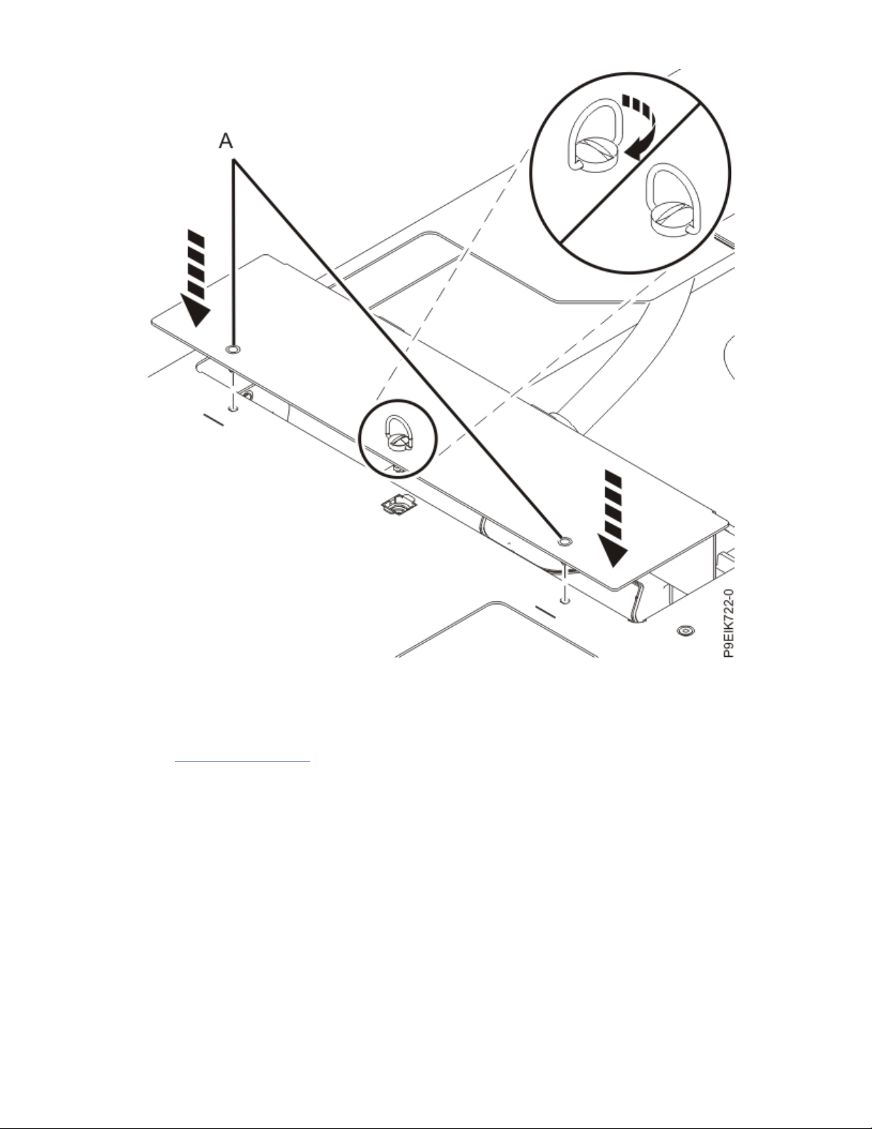
Figure 24. Placing the GPU holder back onto the carrier
20. Apply light pressure downward on the cold plate. Loosen the retainer screw of the system processor
module cold plate by turning the supplied hex key counterclockwise. Loosen the screw until it moves
freely.
See Figure 25 on page 28.
Removing and replacing parts in the 8335-GTW or 8335-GTX
27
Page 42

Figure 25. Loosening the cold plate retainer screw
21. Attach the processor cold plate to the holder by using the following steps:
a) On the processor cold plate holder, ensure that the plastic latches (B) are in the open position as
shown in Figure 26 on page 29, so that the holes (A) are exposed.
28
Power Systems: Servicing the 8335-GTW
Page 43

Figure 26. Opened holder latches
b) Lift the coldplate straight up from the processor. Insert the cold plate pins (A) into the holder as
shown in Figure 27 on page 30.
Removing and replacing parts in the 8335-GTW or 8335-GTX
29
Page 44
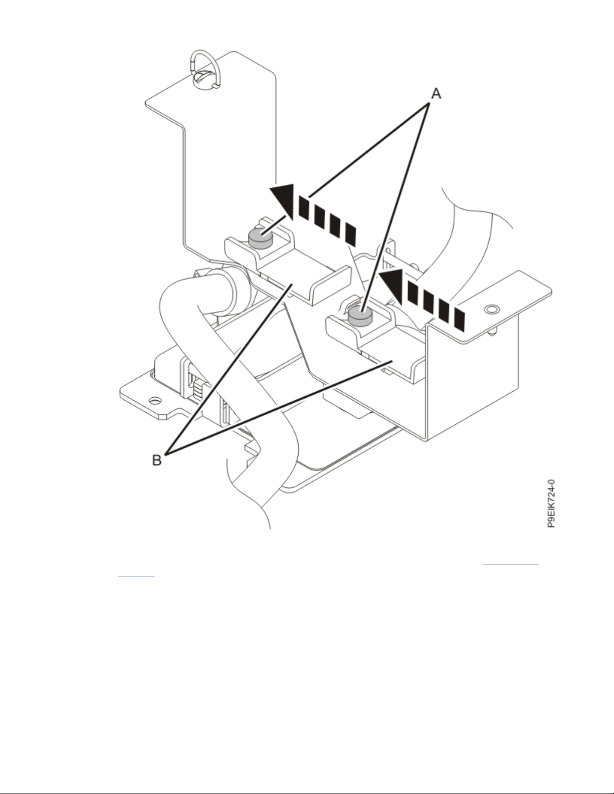
Figure 27. Inserting the cold plate pins into the holder
c) Slide both of the plastic latches (B) into the narrowest part of the pin as shown in Figure 27 on
page 30.
d) Fasten the processor cold plate holder to the cold plate installation carrier. Use the alignment pin
(A) and tighten the screw (B) to secure the holder to the carrier.
30
Power Systems: Servicing the 8335-GTW
Page 45

Figure 28. Placing the processor holder back onto the carrier
22. Repeat steps “20” on page 27 - “21” on page 28 for the other processor.
23. After all the cold plates are attached to the cold plate installation carrier, lift the carrier straight up
off the system as shown in Figure 29 on page 32.
If you lift at an angle, the carrier catches on the cold plate clips.
Removing and replacing parts in the 8335-GTW or 8335-GTX
31
Page 46

Figure 29. Lifting the cold plate installation carrier
24. To prevent the cold plates from being dented or damaged, place the cold plate installation carrier on
a flat work surface to ensure that the cold plates in the carrier remain suspended above the work
surface.
Replacing the cold plates in the 8335-GTW or 8335-GTX cold plate installation carrier
To replace the cold plates in the cold plate installation carrier, complete the steps in this procedure.
Before you begin
To replace a faulty cold plate or water hose, you rst need to complete the procedure: “Removing the
cold plates from the 8335-GTW or 8335-GTX system” on page 7
Procedure
1. On your work table, place the replacement cold plate assembly next to the cold plate installation
carrier.
2. Remove each processor cold plate from its holder.
a) Unscrew a processor cold plate holder from the cold plate installation carrier as shown in Figure
30 on page 33.
32
Power Systems: Servicing the 8335-GTW
Page 47

Figure 30. Removing the processor cold plate holder from the carrier
b) Support the cold plate from underneath and carefully slide both of the plastic latches (A) to free
the pins from the holder as shown in Figure 31 on page 34.
Removing and replacing parts in the 8335-GTW or 8335-GTX
33
Page 48

Figure 31. Removing the processor cold plate pins from the holder
c) Gently lower the cold plate to the work surface.
The cold plate is resting on the work table. Repeat step “2” on page 32 for each cold plate.
3. Remove each GPU cold plate from its holder.
a) Unscrew a GPU cold plate holder from the cold plate installation carrier as shown in Figure 32 on
page 35.
34
Power Systems: Servicing the 8335-GTW
Page 49

Figure 32. Removing the GPU cold plate holder from the carrier
b) Support the cold plate from underneath and carefully slide both of the plastic latches (A) to free
the pins from the holder as shown in Figure 33 on page 36.
Removing and replacing parts in the 8335-GTW or 8335-GTX
35
Page 50

Figure 33. Removing the GPU cold plate from the holder
c) Gently lower the cold plate to the work surface.
The cold plate is resting on the work table. Repeat step “3” on page 34 for each cold plate.
4. Unfasten all the hook-and-loop fasteners on the cold plate installation carrier.
Ensure that all the water pipes are released from the holder.
5. Lift the cold plate installation carrier off the faulty cold plate assembly, and place it over the
replacement cold plate assembly as shown in Figure 34 on page 37.
36
Power Systems: Servicing the 8335-GTW
Page 51

Figure 34. Moving the cold plate installation carrier over the replacement cold plate assembly
6. Fasten the two water hoses to the top of the cold plate installation carrier as shown in Figure 35 on
page 38.
Removing and replacing parts in the 8335-GTW or 8335-GTX
37
Page 52

Figure 35. Securing the hoses
7. At the rear of the system, lift and fasten the rear of the side pipe to the cold plate installation carrier
as shown in Figure 36 on page 39.
38
Power Systems: Servicing the 8335-GTW
Page 53

Figure 36. Securing the rear of the side pipe
8. At the front of the system, lift the side pipe up. Support it on the pins and fasten the front of the side
pipe to the cold plate installation carrier as shown in Figure 37 on page 40.
Removing and replacing parts in the 8335-GTW or 8335-GTX
39
Page 54

Figure 37. Securing the front of the side pipe
9. At the front of the system, lift the front pipe junction (A) up. Fasten the front pipe junction to the cold
plate installation carrier as shown in Figure 38 on page 41.
40
Power Systems: Servicing the 8335-GTW
Page 55

Figure 38. Securing the front pipe
10. Attach the processor cold plates to the holder.
a) Lift the coldplate straight up from the processor. Insert the cold plate pins (A) into the holder as
shown in Figure 39 on page 42.
Removing and replacing parts in the 8335-GTW or 8335-GTX
41
Page 56

Figure 39. Inserting the cold plate pins into the holder
b) Carefully slide both of the plastic latches (A) into the narrowest part of the pin.
c) Fasten the processor cold plate holder to the cold plate installation carrier. Use the alignment pin
(A) and tighten the screw (B) to secure the holder to the carrier.
42
Power Systems: Servicing the 8335-GTW
Page 57

Figure 40. Placing the processor holder back onto the carrier
d) Repeat step “10” on page 41 for each cold plate.
11. Attach the GPU cold plates to the holder.
a) Insert the cold plate pins (A) into the holder as shown in Figure 41 on page 44.
Removing and replacing parts in the 8335-GTW or 8335-GTX
43
Page 58

Figure 41. Inserting the GPU cold plate pins into the holder
b) Slide both of the plastic latches (A) into the narrowest part of the pin as shown in Figure 42 on
page 44.
Figure 42. Securing the GPU cold plate pins
c) Repeat step “11” on page 43 for each cold plate.
44
Power Systems: Servicing the 8335-GTW
Page 59

12. Fasten each GPU cold plate holder to the cold plate installation carrier as shown in Figure 43 on page
45. Use the alignment pins (A) and tighten the screw (B) to secure the holder to the carrier.
Figure 43. Placing the GPU holder back onto the carrier
What to do next
Next, complete the: “Replacing the cold plates in the 8335-GTW or 8335-GTX system” on page 45
procedure.
Replacing the cold plates in the 8335-GTW or 8335-GTX system
To replace the cold plates, complete the steps in this procedure.
Before you begin
Ensure that you have enough TIMs for the GPUs and processors. Check the replacement part kit.
• The GPU TIM part number is 00E5133 and must be replaced.
• The processor TIM part number is 45D7426 and can be reused.
Procedure
1. Ensure that you have the electrostatic discharge (ESD) wrist strap on and that the ESD clip is plugged
into a ground jack or connected to an unpainted metal surface. If not, do so now.
Removing and replacing parts in the 8335-GTW or 8335-GTX
45
Page 60

2. Ensure that each GPU clip is open as shown in Figure 44 on page 46.
Figure 44. Open the cold plate retainer
3. Check the TIM heat sink material.
• For each GPU, the TIM must be replaced.
• For each processor, inspect the TIM material for visible signs of damage. If you see folds, tears,
bends, or if you have doubts about the TIM, replace it.
46
Power Systems: Servicing the 8335-GTW
Page 61

Figure 45. Inspecting the thermal interface material
4. Lower the cold plate installation carrier straight down onto the system as shown in Figure 46 on page
48.
If you lower the carrier at an angle, the carrier catches on the cold plate clips.
Removing and replacing parts in the 8335-GTW or 8335-GTX 47
Page 62

Figure 46. Lowering the cold plate installation carrier onto the system
5. Replace the processor cold plates rst.
a) Unscrew a processor cold plate holder from the cold plate installation carrier as shown in Figure
47 on page 49.
48
Power Systems: Servicing the 8335-GTW
Page 63

Figure 47. Removing the processor cold plate holder from the carrier
b) Support the cold plate from underneath and carefully slide both of the plastic latches (A) to free
the pins from the holder as shown in Figure 48 on page 50.
Removing and replacing parts in the 8335-GTW or 8335-GTX
49
Page 64

Figure 48. Removing the processor cold plate pins from the holder
c) Check that the processor TIM is squarely placed on the processor.
d) Lower the cold plate onto the processor and TIM while carefully aligning the cold plate guide holes
with the pins on the processor socket.
Keep applying light pressure downward on the cold plate to ensure that the cold plate and the
processor do not move.
e) Maintain the downward pressure and tighten the cold plate retainer screw with the supplied hex
key to secure the cold plate to the processor module as shown in Figure 49 on page 51.
50
Power Systems: Servicing the 8335-GTW
Page 65

Figure 49. Tightening the cold plate retainer screw
Repeat step “5” on page 48 for the other processor.
6. Replace the GPU cold plates next.
a) Check that the new GPU TIMs are squarely placed on the GPUs as shown in Figure 50 on page
52.
Removing and replacing parts in the 8335-GTW or 8335-GTX
51
Page 66
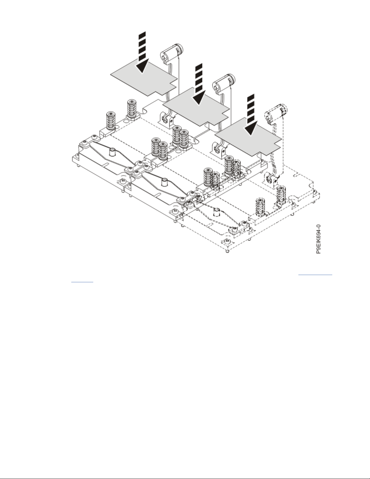
Figure 50. Installing GPU TIMs
b) Unscrew a GPU cold plate holder from the cold plate installation carrier as shown in Figure 51 on
page 53.
52
Power Systems: Servicing the 8335-GTW
Page 67

Figure 51. Removing the GPU cold plate holder from the carrier
c) Support the cold plate from underneath and carefully slide both of the plastic latches (A) to free
the pins from the holder as shown in Figure 52 on page 54.
Removing and replacing parts in the 8335-GTW or 8335-GTX
53
Page 68

Figure 52. Removing the GPU cold plate from the holder
d) Place the cold plate onto the GPUs.
e) Secure the middle GPU rst. Swing the retainer over the GPU and tighten the cold plate retainer
screw as shown in Figure 53 on page 55.
Repeat with the remaining clips until the GPU cold plate is secure.
54
Power Systems: Servicing the 8335-GTW
Page 69

Figure 53. Secure the cold plate retainer screw
Repeat step “6” on page 51 for the other GPU cold plate.
7. Unfasten all the hook-and-loop fasteners on the cold plate installation carrier as shown in Figure 54
on page 56.
Ensure that all the water pipes are released from the holder.
Removing and replacing parts in the 8335-GTW or 8335-GTX
55
Page 70

Figure 54. Unfastening the water hoses from the carrier
8. Lift the cold plate installation carrier straight up off the system as shown in Figure 55 on page 57.
56
Power Systems: Servicing the 8335-GTW
Page 71

Figure 55. Lifting the cold plate installation carrier
9. Replace the front pipe (B). Use the alignment pin (C) to position the front pipe. Tighten the screw (A)
that secures the pipe (B) to the front of the system as shown in Figure 56 on page 58.
Removing and replacing parts in the 8335-GTW or 8335-GTX
57
Page 72

Figure 56. Replacing the front pipe screw
10. Replace the two pipe holders (A) near the front of the system as shown in Figure 57 on page 59.
Place the pipes in the supports on the system backplane, place the holders over the supports and the
pipes, align the screw threads at (B), and tighten the four screws.
58
Power Systems: Servicing the 8335-GTW
Page 73

Figure 57. Replacing the front pipe holders
11. Replace the side pipes into the side of the chassis as shown in Figure 58 on page 60.
Ensure the rear of the pipe slides into its position. Ensure that the alignment pin at the front of the
side pipe is in the pipe junction.
Removing and replacing parts in the 8335-GTW or 8335-GTX
59
Page 74

Figure 58. Inserting the side pipes
12. Replace the two pipe holders (A) near the middle of the system as shown in Figure 59 on page 61.
Place the pipes in the supports on the system backplane, place the holders over the supports and the
pipes, align the screw threads at (B), and tighten the four screws.
60
Power Systems: Servicing the 8335-GTW
Page 75

Figure 59. Replacing the middle pipe holders
13. Replace the three screws (A) that secure the water hoses to the rear of the system as shown in Figure
60 on page 62.
Removing and replacing parts in the 8335-GTW or 8335-GTX
61
Page 76

Figure 60. Replacing the rear water hose screws
14. Replace the two screws that secure the pipes to the left side of the chassis as shown in Figure 61 on
page 63.
62
Power Systems: Servicing the 8335-GTW
Page 77

Figure 61. Replacing the screws for the side water pipe bracket
15. Replace the air baffles (A), (B), and (C) as shown in Figure 62 on page 64.
The baffles go straight down; you might need to maneuver them around the hoses.
Removing and replacing parts in the 8335-GTW or 8335-GTX
63
Page 78

Figure 62. Replacing the air baffles
16. Replace each cold plate holder in the cold plate installation carrier.
Use the alignment pins on the holder, and tighten each holder with its retaining screw. Close the
loops on all the hook and loop fasteners to ensure that they do not come loose from the cold plate
installation carrier.
What to do next
Prepare the system for operation. For instructions, see “Preparing the 8335-GTC, 8335-GTG, 8335-GTH,
8335-GTW, or 8335-GTX system for operation after you remove and replace internal parts” on page 202.
Removing and replacing a disk drive in the 8335-GTC, 8335-GTG, 8335-GTH,
8335-GTW, or 8335-GTX system
Learn how to remove and replace a disk drive in the IBM Power System AC922 (8335-GTC, 8335-GTG,
and 8335-GTH) or IBM Power System AC922 (8335-GTW and 8335-GTX) system.
About this task
The drive might be a hard disk drive (HDD) or a solid-state drive (SSD).
64
Power Systems: Servicing the 8335-GTW
Page 79

Removing a disk drive from the 8335-GTC, 8335-GTG, 8335-GTH, 8335-GTW, or 8335GTX system
To remove a disk drive, complete the steps in this procedure.
Procedure
1. Remove the front cover. For instructions, see “Removing the front cover from an 8335-GTC, 8335-
GTG, 8335-GTH, 8335-GTW, or 8335-GTX system” on page 208.
2. Attach the electrostatic discharge (ESD) wrist strap.
The ESD wrist strap must be connected to an unpainted metal surface until the service procedure is
completed, and if applicable, until the service access cover is replaced.
Attention:
• Attach an electrostatic discharge (ESD) wrist strap to the front ESD jack, to the rear ESD jack,
or to an unpainted metal surface of your hardware to prevent the electrostatic discharge from
damaging your hardware.
• When you use an ESD wrist strap, follow all electrical safety procedures. An ESD wrist strap is
used for static control. It does not increase or decrease your risk of receiving electric shock
when using or working on electrical equipment.
• If you do not have an ESD wrist strap, just prior to removing the product from ESD packaging
and installing or replacing hardware, touch an unpainted metal surface of the system for a
minimum of 5 seconds. If at any point in this service process you move away from the
system, it is important to again discharge yourself by touching an unpainted metal surface for
at least 5 seconds before you continue with the service process.
3. Locate the faulty drive. The amber drive LED is turned on when a drive has an issue.
If a drive's amber LED is lit, go to step “4” on page 66.
If a drive has an issue and if the amber LED is not lit, use the following procedure to locate the drive.
Run the following commands from an operating system command window.
a) Determine the drive that must be replaced as indicated by the operating system.
For example, the drive might be referenced as sda or sdb.
Attention:
The operating system is typically on sda. Do not remove this drive when the
system powered on unless the sda drive is part of a RAID conguration. If the drive that
contains the operating system needs to be removed, and that drive is not part of a RAID
array, you must rst power off the system before removing that drive.
b) Gather the physical serial number of the
identied drive by running the following hdparm
command, where sdX is the drive to replace:
hdparm –i /dev/sdX | grep –i serial
The hdparm command is in the hdparm package; install the package if you have not installed it
already.
apt-get install hdparm
Or:
yum install hdparm
c) Run the following command to identify the physical drive, where sdX is the drive to replace:
The command causes the green LED on the drive to flash.
dd if=/dev/sdX of =/dev/null
Removing and replacing parts in the 8335-GTW or 8335-GTX
65
Page 80

You can also use the optional usysident package to turn on or turn off the amber LED. Run the
following command to turn on the amber LED:
usysident -d sdX -s identify
Run the following command to turn off the amber LED:
usysident -d sdX -s normal
d) To prepare the drive for removal, disable it by running the following command, where sdX is the
drive to replace.
echo 0 >/sys/block/sdX/device/delete
e) Verify that you disabled the write operation on the drive by using the lsscsi command. When the
drive is disabled, the drive no longer appears in the output.
lsscsi
4. Unlock the drive bay handle (B) by pushing the handle release (A) up. The handle (B) snaps out
towards you. If the handle does not snap out all the way, the drive does not slide out of the system.
See Figure 63 on page 66.
Figure 63. Disk drive lock detail
66
Power Systems: Servicing the 8335-GTW
Page 81

5. Support the bottom of the disk drive as you slide it out of the system. Do not hold the disk drive by the
handle.
6. If you are removing more than one drive, repeat the steps in this procedure until all drives are
removed.
Replacing a disk drive in the 8335-GTC, 8335-GTG, 8335-GTH, 8335-GTW, or 8335-GTX
system
To replace a disk drive, complete the steps in this procedure.
Procedure
1. Ensure that you have the electrostatic discharge (ESD) wrist strap on and that the ESD clip is plugged
into a ground jack or connected to an unpainted metal surface. If not, do so now.
2. Hold the disk drive by the top and bottom edges as you position the disk drive, and insert it into the
disk drive slot.
Important: Ensure that the disk drive is fully seated and is all the way into the system.
3. Lock the disk drive bay handle (A) by pushing in the handle release.
See Figure 64 on page 67
.
Figure 64. Disk drive lock detail
4. Congure the installed disk drive for your environment.
Removing and replacing parts in the 8335-GTW or 8335-GTX
67
Page 82

After you insert the new disk drive, you must scan for the device. Choose one of the following options
depending on the operating system that you are using:
• Ubuntu Linux operating system:
Ubuntu can automatically detect storage devices. You may not need to rescan the disk drives;
proceed to verifying that the new disk drive is active.
To run the rescan-scsi-bus command in the Ubuntu Linux operating system, log in to the system
as the root user, and run the following command:
rescan-scsi-bus
The rescan-scsi-bus tool is available in the scsitools package; install the package by using the
following command:
sudo apt-get install scsitools
• Red Hat Enterprise Linux (RHEL): To run the rescan command in the RHEL operating system, log in
to the system as the root user, and run the command:
rescan-scsi-bus.sh -a
The rescan-scsi-bus tool is available in the sg3_utils package; install the package by using the
following command:
yum install sg3_utils
You may also want to refer to: Adding a Storage Device or Path
documentation/en-US/Red_Hat_Enterprise_Linux/7/html/Storage_Administration_Guide/
adding_storage-device-or-path.html)
Verify that the new drive is active by running the following command:
lsscsi
5. Load or restore data from your backup media.
(https://access.redhat.com/
Removing and replacing the disk drive and fan card in the 8335-GTW or
8335-GTX system
Learn how to remove and replace the disk drive and fan card in the system.
Removing the disk drive and fan card from the 8335-GTW or 8335-GTX system
To remove a disk drive and fan card, complete the steps in this procedure.
Before you begin
Power off the system and place it in the service position. For instructions, see “Preparing the 8335-GTC,
8335-GTG, 8335-GTH, 8335-GTW, or 8335-GTX system to remove and replace internal parts” on page
198.
Procedure
1. Attach the electrostatic discharge (ESD) wrist strap.
The ESD wrist strap must be connected to an unpainted metal surface until the service procedure is
completed, and if applicable, until the service access cover is replaced.
Attention:
68 Power Systems: Servicing the 8335-GTW
Page 83

• Attach an electrostatic discharge (ESD) wrist strap to the front ESD jack, to the rear ESD
jack, or to an unpainted metal surface of your hardware to prevent the electrostatic
discharge from damaging your hardware.
• When you use an ESD wrist strap, follow all electrical safety procedures. An ESD wrist strap
is used for static control. It does not increase or decrease your risk of receiving electric
shock when using or working on electrical equipment.
• If you do not have an ESD wrist strap, just prior to removing the product from ESD packaging
and installing or replacing hardware, touch an unpainted metal surface of the system for a
minimum of 5 seconds. If at any point in this service process you move away from the
system, it is important to again discharge yourself by touching an unpainted metal surface
for at least 5 seconds before you continue with the service process.
2. Label and remove the fan power cable from the disk drive and fan card.
For instructions, see “Removing the fan power cable from the 8335-GTC, 8335-GTG, 8335-GTH,
8335-GTW, or 8335-GTX system” on page 87.
3. Label and remove the disk drive fan signal cable from the disk drive and fan card.
For instructions, see “Removing the disk and fan signal cable from the 8335-GTC, 8335-GTG, 8335-
GTH, 8335-GTW, or 8335-GTX system” on page 81.
4. Unplug but do not remove the fans from their slots. Pull the fans out approximately 2.5 cm (1 in) to
prevent them from interfering with the removal of the disk drive and fan card.
For instructions, see “Removing a fan from the 8335-GTW or 8335-GTX system” on page 84
5. Remove the air baffles (A) and (B) as shown in Figure 65 on page 70.
Carefully move the baffles around the hoses.
.
Removing and replacing parts in the 8335-GTW or 8335-GTX
69
Page 84

Figure 65. Removing the memory air baffles
6. From the pipe bracket (A) near the front of the system as shown in Figure 66 on page 71, remove
the three screws (B) that secure the bracket to the system.
70
Power Systems: Servicing the 8335-GTW
Page 85

Figure 66. Removing the front pipe holder
7. From the water pipe at position (C), loosen the screw (D) as shown in Figure 66 on page 71.
8. Move the water pipe and holder away from the disk drive and fan card, toward the processor.
Removing and replacing parts in the 8335-GTW or 8335-GTX
71
Page 86
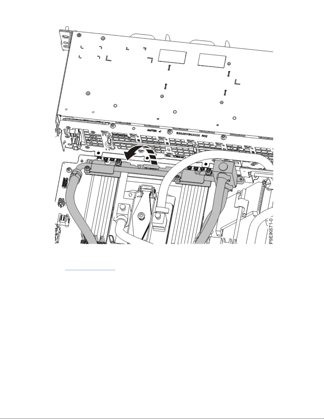
Figure 67. Moving the front pipe away
9. Remove ve screws (A) from the top of the disk drive and fan card.
See Figure 68 on page 73 for the screw locations.
72
Power Systems: Servicing the 8335-GTW
Page 87

Figure 68. Screw locations for the disk drive and fan card
a) Remove two screws (B) from the bottom of the disk drive and fan card.
b) Remove one screw (C) from each side of the disk drive and fan card.
10. The disk drive and fan card (A) is aligned in the system by using two pins (B). Pivot the disk drive and
fan card away from the fan housing around the pins; then, lift out the card.
Removing and replacing parts in the 8335-GTW or 8335-GTX
73
Page 88

Figure 69. Removing the disk drive and fan card
11. Place the disk drive and fan card on the table.
Replacing the disk drive and fan card in the 8335-GTW or 8335-GTX system
To replace a disk drive and fan card, complete the steps in this procedure.
Procedure
1. Ensure that you have the electrostatic discharge (ESD) wrist strap on and that the ESD clip is plugged
into a ground jack or connected to an unpainted metal surface. If not, do so now.
2. Remove the replacement disk drive and fan card from the protective plastic envelope.
3. Using the alignment pins (one on each side) (A) for the disk drive and fan card (B), lower and pivot the
card into place.
See Figure 70 on page 75.
Note: Both the front USB cable and the power switch cable (A) need to be located in the recessed
area (B) of the disk drive and fan card. If they are not located in that recessed area, they can be
pinched and damaged. See Figure 71 on page 76.
74
Power Systems: Servicing the 8335-GTW
Page 89

Figure 70. Inserting the disk drive and fan card
Removing and replacing parts in the 8335-GTW or 8335-GTX
75
Page 90

Figure 71. Routing the cables under the disk drive and fan card
4. Replace two screws (B) for the bottom of the disk drive and fan card.
Figure 72 on page 77 shows the screw locations.
76
Power Systems: Servicing the 8335-GTW
Page 91

Figure 72. Screw locations for the disk drive and fan card
a) Replace ve screws (A) at the top of the disk drive and fan card.
b) Replace one screw (C) in each side of the disk drive and fan card.
5. Replace the water pipe and holder as shown in Figure 73 on page 78.
Use the alignment pin (A) to align the front pipe assembly in the chassis.
Removing and replacing parts in the 8335-GTW or 8335-GTX
77
Page 92

Figure 73. Replacing the front pipe and holder
6. For the water pipe at position (C), tighten the screw (D) as shown in Figure 74 on page 79.
7. Replace the three screws (B) to secure the front water pipe bracket (A) as shown in Figure 74 on
page 79.
78
Power Systems: Servicing the 8335-GTW
Page 93

Figure 74. Replacing the front pipe holder
8. Replace the air baffles (A) and (B) as shown in Figure 75 on page 80.
Carefully move the baffles around the hoses.
Removing and replacing parts in the 8335-GTW or 8335-GTX
79
Page 94

Figure 75. Replacing the memory air baffles
9. Replace the fans.
For instructions, see “Replacing a fan in the 8335-GTW or 8335-GTX system” on page 86.
10. Using your label, plug the disk drive fan signal cable into the disk drive and fan card.
For instructions, see “Replacing the disk and fan signal cable in the 8335-GTC, 8335-GTG, 8335-
GTH, 8335-GTW, or 8335-GTX system” on page 83.
11. Using your label, plug the power cable into the disk drive and fan card.
For instructions, see “Replacing the fan power cable in the 8335-GTC, 8335-GTG, 8335-GTH, 8335-
GTW, or 8335-GTX system” on page 90.
What to do next
Prepare the system for operation. For instructions, see “Preparing the 8335-GTC, 8335-GTG, 8335-GTH,
8335-GTW, or 8335-GTX system for operation after you remove and replace internal parts” on page 202.
Removing and replacing the disk and fan signal cable in the 8335-GTC,
8335-GTG, 8335-GTH, 8335-GTW, or 8335-GTX
Learn how to remove and replace a disk and fan signal cable in the IBM Power System AC922 (8335-GTC,
8335-GTG, and 8335-GTH) or IBM Power System AC922 (8335-GTW and 8335-GTX) system.
80
Power Systems: Servicing the 8335-GTW
Page 95

Removing the disk and fan signal cable from the 8335-GTC, 8335-GTG, 8335-GTH, 8335GTW, or 8335-GTX system
To remove a disk and fan signal cable, complete the steps in this procedure.
Before you begin
Power off the system and place it in the service position. For instructions, see “Preparing the 8335-GTC,
8335-GTG, 8335-GTH, 8335-GTW, or 8335-GTX system to remove and replace internal parts” on page
198.
Procedure
1. Attach the electrostatic discharge (ESD) wrist strap.
The ESD wrist strap must be connected to an unpainted metal surface until the service procedure is
completed, and if applicable, until the service access cover is replaced.
Attention:
• Attach an electrostatic discharge (ESD) wrist strap to the front ESD jack, to the rear ESD jack,
or to an unpainted metal surface of your hardware to prevent the electrostatic discharge from
damaging your hardware.
• When you use an ESD wrist strap, follow all electrical safety procedures. An ESD wrist strap is
used for static control. It does not increase or decrease your risk of receiving electric shock
when using or working on electrical equipment.
• If you do not have an ESD wrist strap, just prior to removing the product from ESD packaging
and installing or replacing hardware, touch an unpainted metal surface of the system for a
minimum of 5 seconds. If at any point in this service process you move away from the
system, it is important to again discharge yourself by touching an unpainted metal surface for
at least 5 seconds before you continue with the service process.
2. Locate the disk and fan signal cable (A). It connects from the system backplane to the disk drive and
fan card, along the inside of the system.
See Figure 76 on page 82.
Removing and replacing parts in the 8335-GTW or 8335-GTX
81
Page 96

Figure 76. Location of the disk and fan signal cable and connectors
3. Release the cable from the retaining clip on the inside wall of the system.
4. Label and disconnect the disk and fan signal cable (A) from the disk drive and fan card (B) and from
the system backplane (C).
Using your thumb, press the release latch on the connector to remove a cable. See Figure 77 on page
83.
82
Power Systems: Servicing the 8335-GTW
Page 97

Figure 77. Removing the disk and fan signal cable
5. Place the cable on the table.
Replacing the disk and fan signal cable in the 8335-GTC, 8335-GTG, 8335-GTH, 8335GTW, or 8335-GTX system
To replace a disk and fan signal cable, complete the steps in this procedure.
Procedure
1. Ensure that you have the electrostatic discharge (ESD) wrist strap on and that the ESD clip is plugged
into a ground jack or connected to an unpainted metal surface. If not, do so now.
2. Using the labels, connect the disk and fan signal cable (A) to the disk drive and fan card (B) and to the
system backplane (C).
Ensure that the cable latch clip snaps into place on the connectors. See Figure 78 on page 84
.
Removing and replacing parts in the 8335-GTW or 8335-GTX
83
Page 98

Figure 78. Replacing the disk and fan signal cable
3. Secure the cable in the retaining clip on the inside wall of the system.
What to do next
Prepare the system for operation. For instructions, see “Preparing the 8335-GTC, 8335-GTG, 8335-GTH,
8335-GTW, or 8335-GTX system for operation after you remove and replace internal parts” on page 202.
Removing and replacing fans in the 8335-GTW or 8335-GTX system
Learn how to remove and replace the fans in the system.
Removing a fan from the 8335-GTW or 8335-GTX system
To remove a fan, complete the steps in this procedure.
About this task
Attention:
within 5 minutes to avoid a system shutdown.
Procedure
1. Attach the electrostatic discharge (ESD) wrist strap.
84
Power Systems: Servicing the 8335-GTW
If you are replacing a fan with the system power on, you must replace the failed fan
Page 99

The ESD wrist strap must be connected to an unpainted metal surface until the service procedure is
completed, and if applicable, until the service access cover is replaced.
Attention:
• Attach an electrostatic discharge (ESD) wrist strap to the front ESD jack, to the rear ESD jack,
or to an unpainted metal surface of your hardware to prevent the electrostatic discharge from
damaging your hardware.
• When you use an ESD wrist strap, follow all electrical safety procedures. An ESD wrist strap is
used for static control. It does not increase or decrease your risk of receiving electric shock
when using or working on electrical equipment.
• If you do not have an ESD wrist strap, just prior to removing the product from ESD packaging
and installing or replacing hardware, touch an unpainted metal surface of the system for a
minimum of 5 seconds. If at any point in this service process you move away from the
system, it is important to again discharge yourself by touching an unpainted metal surface for
at least 5 seconds before you continue with the service process.
2. To unseat the fan from its position in the system, press in the locking-tab (A) as shown in Figure 79 on
page 85.
Figure 79. Removing a fan from the system
Attention:
ller, if removed, must be replaced in the second position from the left.
Water-cooled systems have a fan ller in the second position from the left. The fan
Removing and replacing parts in the 8335-GTW or 8335-GTX 85
Page 100

3. While you hold onto the fan handle and use your hand to support the bottom of the fan, pull out the fan
from its slot.
Replacing a fan in the 8335-GTW or 8335-GTX system
To replace a fan, complete the steps in this procedure.
Procedure
1. Ensure that you have the electrostatic discharge (ESD) wrist strap on and that the ESD clip is plugged
into a ground jack or connected to an unpainted metal surface. If not, do so now.
2. Using your hand to support the bottom of the fan, align the fan (A) with the fan slot and slide it into the
system until the tab (A) locks in place as shown in Figure 80 on page 86.
Figure 80. Replacing a fan in the system
Attention:
ller, if removed, must be replaced in the second position from the left.
86 Power Systems: Servicing the 8335-GTW
Water-cooled systems have a fan ller in the second position from the left. The fan
 Loading...