

Page 1

Power Systems
Installing the IBM Power System
S821LC (8001-12C)
IBM
Page 2

Page 3

Power Systems
Installing the IBM Power System
S821LC (8001-12C)
IBM
Page 4

Note
Before using this information and the product it supports, read the information in “Safety notices” on page v, “Notices” on
page 103, the IBM Systems Safety Notices manual, G229-9054, and the IBM Environmental Notices and User Guide, Z125–5823.
This edition applies to IBM Power Systems™servers that contain the POWER8 processor and to all associated
models.
© Copyright IBM Corporation 2016, 2017.
US Government Users Restricted Rights – Use, duplication or disclosure restricted by GSA ADP Schedule Contract
with IBM Corp.
Page 5

Contents
Safety notices ............ v
Installing and configuring POWER8
processor-based systems and system
features ............... 1
Installing the IBM Power System S821LC (8001-12C)
system ................ 1
Prerequisites for installing the rack-mounted
8001-22C system ............ 1
Completing inventory for your system..... 1
Determining and marking the location in the rack
for the 8001-12C system ......... 2
Attaching the rails to the system chassis and to
the rack ............... 3
Installing the system into the rack and connecting
and routing power cables ......... 5
Completing server setup ......... 8
Installing drives in the 8001-12C system ..... 8
Drive installation details for the 8001-12C system 8
Installing a front drive in the 8001-12C system.. 10
Installing a drive on module in the 8001-12C
system ............... 14
Installing a graphics processing unit in the 8001-12C
system ................ 16
Installing memory in the 8001-12C system .... 19
Placement rules for memory in the 8001-12C or
8001-22C system............ 19
Installing memory in the 8001-12C system ... 20
Installing a PCIe adapter in the 8001-12C system .. 23
PCIe adapter placement rules and slot priorities
for the 8001-12C or 8005-12N system ..... 23
PCIe adapter information by feature type for the
8001-12C or 8005-12N .......... 31
12 Gb/s Eight-Port SAS Internal HBA Adapter
(Adapter FRU number: AOC-S3008L-L8e-P) . 32
PCIe3 x4 Intel x550 10GBase-T Converged
Network Adapter with Dual RJ45 Ports (FC
EKA0) .............. 34
Cavium (Qlogic) BCM57840 4-port SFP+ 10
Gb Ethernet Adapter PCIe3.0 x8 LP (FC
EKA1) .............. 35
Intel 82599ES Ethernet Converged Network
Adapter x520-DA2 Dual-port 10G/1G SFP+
PCIe2.0 x8 LP (FC EKA2) ........ 37
Intel 82575EB dual-port Gigabit Ethernet
Controller PCIe x4.0 LP (FC EKA3) .... 39
Broadcom (LSI) MegaRAID 9361-8i SAS3
Controller with 8 Internal Ports (1 GB Cache)
PCIe3.0 x8 LP with cables (FC EKAA and
EKEA) .............. 41
SMC AOC-K-S3008L-L8i 12 Gbps SAS3/RAID
0,1 and 10 PCIe3.0 x8 LP with cables (FC
EKAB and EKEB) .......... 43
Broadcom (LSI) 9300-8E SAS3 HBA PCIe3.0 x8
LP Adapter (FC EKAD and EKED) .... 45
PCIe3 x8 Dual-port Internal NVMe Host Bus
Adapter (FC EKAE and EKEE) ...... 47
Emulex LPE16002B-M6-O Dual-port 16 Gb
Fibre Channel Card PCIe3.0 x8 LP (FC EKAF) . 49
SMC quad-port NVMe Host Bus Adapter
(PEX9733) PCIe3.0 x8 LP with cables (FC
EKAG and EKEG) .......... 51
Broadcom (LSI) MegaRAID 9361-8i SAS3
Controller with 8 internal ports (2 GB Cache)
PCIe3.0 x8 with cables (FC EKAH and EKEH) . 53
NVIDIA Tesla K80 24 GB GPU Accelerator (FC
EKAJ) .............. 55
Mellanox MCX456A-ECAT ConnectX-4 VPI
EDR IB 100 Gb/s and 100 GbE Dual-port
QSFP28 PCIe3.0 x16 LP (FC EKAL) .... 57
Mellanox MCX415A-CCAT ConnectX-4 EN
100 GbE Single-port QSFP28 PCIe3.0 x16 LP
(FC EKAM) ............ 59
Qlogic QLE2562 Dual-port 8 Gb Fibre Channel
Adapter PCIe x8 LP (FC EKAP) ..... 61
Qlogic QLE2692OP Dual-port 16 Gb Fibre
Channel Adapter PCIe3 x8 LP (FC EKAQ) .. 63
Alpha-data CAPI Adapter: ADM-PCIe KU3
(FC EKAT)............. 65
Mellanox MCX4121A-ACAT ConnectX-4 Lx
EN 25GbE dual-port SFP28 PCIe3.0 x8 LP (FC
EKAU) .............. 67
NVIDIA Tesla P100 16GB PCIe3.0 x16
Dual-slot FHFL with cables (FC EKAZ) ... 69
Intel XL710 Ethernet Converged Network
Adapter Quad-port 10G/1G SFP+ PCIe3.0 x8
LP (FC EKFH) ........... 71
PCIe3 1.6 TB NVMe Flash Adapter (FC EKN2) 73
Installing a PCIe adapter in the 8001-12C system 75
Common procedures for servicing or installing
features in the 8001-12C or 8005-12N ...... 80
Before you begin ........... 80
Identifying the system that contains the part to
replace ............... 83
LEDs on the 8001-12C or 8005-12N system .. 83
Identifying the 8001-12C, 8001-22C, 8005-12N,
or 8005-22N that needs servicing ..... 85
Preparing the 8001-12C or 8005-12N system to
remove and replace internal parts ...... 85
Preparing the 8001-12C or 8005-12N system for
operation after you remove and replace internal
parts................ 87
Starting and stopping the 8001-12C, 8001-22C,
8005-12N, or 8005-22N.......... 88
Starting the 8001-12C, 8001-22C, 8005-12N, or
8005-22N system .......... 88
Stopping the 8001-12C, 8001-22C, 8005-12N, or
8005-22N system .......... 90
Drive commands for 8001-12C, 8001-22C,
8005-12N, or 8005-22N.......... 90
mvCLI commands .......... 90
© Copyright IBM Corp. 2016, 2017 iii
Page 6

StorCLI commands .......... 91
sas3ircu commands .......... 92
NVMe commands .......... 92
Sensor readings GUI display ....... 93
Removing and replacing a power supply in the
8001-12C, 8001-22C, 8005-12N, or 8005-22N ... 93
Removing a power supply from the 8001-12C,
8001-22C, 8005-12N, or 8005-22N ..... 93
Replacing a power supply in the 8001-12C,
8001-22C, 8005-12N, or 8005-22N ..... 95
Removing and replacing covers on an 8001-12C
or 8005-12N system........... 95
Removing the service access cover from an
8001-12C or 8005-12N system ...... 95
Installing the service access cover on an
8001-12C or 8005-12N system ...... 96
Service and operating positions for 8001-12C .. 97
Placing an 8001-12C system into the service
position ............. 97
Placing an 8001-12C system into the operating
position ............. 98
Power cords............. 100
Disconnecting the power cords from an
8001-12C, 8001-22C, 8005-12N, or 8005-22N
system ............. 100
Connecting the power cords to an 8001-12C,
8001-22C, 8005-12N, or 8005-22N system .. 100
Notices .............. 103
Accessibility features for IBM Power Systems
servers ............... 104
Privacy policy considerations ........ 105
Trademarks .............. 106
Electronic emission notices ......... 106
Class A Notices............ 106
Class B Notices ............ 110
Terms and conditions ........... 113
iv Power Systems: Installing the IBM Power System S821LC (8001-12C)
Page 7

Safety notices
Safety notices may be printed throughout this guide:
v DANGER notices call attention to a situation that is potentially lethal or extremely hazardous to
people.
v CAUTION notices call attention to a situation that is potentially hazardous to people because of some
existing condition.
v Attention notices call attention to the possibility of damage to a program, device, system, or data.
World Trade safety information
Several countries require the safety information contained in product publications to be presented in their
national languages. If this requirement applies to your country, safety information documentation is
included in the publications package (such as in printed documentation, on DVD, or as part of the
product) shipped with the product. The documentation contains the safety information in your national
language with references to the U.S. English source. Before using a U.S. English publication to install,
operate, or service this product, you must first become familiar with the related safety information
documentation. You should also refer to the safety information documentation any time you do not
clearly understand any safety information in the U.S. English publications.
Replacement or additional copies of safety information documentation can be obtained by calling the IBM
Hotline at 1-800-300-8751.
German safety information
Das Produkt ist nicht für den Einsatz an Bildschirmarbeitsplätzen im Sinne § 2 der
Bildschirmarbeitsverordnung geeignet.
Laser safety information
IBM®servers can use I/O cards or features that are fiber-optic based and that utilize lasers or LEDs.
Laser compliance
IBM servers may be installed inside or outside of an IT equipment rack.
DANGER: When working on or around the system, observe the following precautions:
Electrical voltage and current from power, telephone, and communication cables are hazardous. To avoid
a shock hazard:
v If IBM supplied the power cord(s), connect power to this unit only with the IBM provided power cord.
Do not use the IBM provided power cord for any other product.
v Do not open or service any power supply assembly.
v Do not connect or disconnect any cables or perform installation, maintenance, or reconfiguration of this
product during an electrical storm.
v The product might be equipped with multiple power cords. To remove all hazardous voltages,
disconnect all power cords.
– For AC power, disconnect all power cords from their AC power source.
– For racks with a DC power distribution panel (PDP), disconnect the customer’s DC power source to
the PDP.
v When connecting power to the product ensure all power cables are properly connected.
© Copyright IBM Corp. 2016, 2017 v
Page 8

– For racks with AC power, connect all power cords to a properly wired and grounded electrical
outlet. Ensure that the outlet supplies proper voltage and phase rotation according to the system
rating plate.
– For racks with a DC power distribution panel (PDP), connect the customer’s DC power source to
the PDP. Ensure that the proper polarity is used when attaching the DC power and DC power
return wiring.
v Connect any equipment that will be attached to this product to properly wired outlets.
v When possible, use one hand only to connect or disconnect signal cables.
v Never turn on any equipment when there is evidence of fire, water, or structural damage.
v Do not attempt to switch on power to the machine until all possible unsafe conditions are corrected.
v Assume that an electrical safety hazard is present. Perform all continuity, grounding, and power checks
specified during the subsystem installation procedures to ensure that the machine meets safety
requirements.
v Do not continue with the inspection if any unsafe conditions are present.
v Before you open the device covers, unless instructed otherwise in the installation and configuration
procedures: Disconnect the attached AC power cords, turn off the applicable circuit breakers located in
the rack power distribution panel (PDP), and disconnect any telecommunications systems, networks,
and modems.
DANGER:
v Connect and disconnect cables as described in the following procedures when installing, moving, or
opening covers on this product or attached devices.
To Disconnect:
1. Turn off everything (unless instructed otherwise).
2. For AC power, remove the power cords from the outlets.
3. For racks with a DC power distribution panel (PDP), turn off the circuit breakers located in the
PDP and remove the power from the Customer's DC power source.
4. Remove the signal cables from the connectors.
5. Remove all cables from the devices.
To Connect:
1. Turn off everything (unless instructed otherwise).
2. Attach all cables to the devices.
3. Attach the signal cables to the connectors.
4. For AC power, attach the power cords to the outlets.
5. For racks with a DC power distribution panel (PDP), restore the power from the Customer's DC
power source and turn on the circuit breakers located in the PDP.
6. Turn on the devices.
Sharp edges, corners and joints may be present in and around the system. Use care when handling
equipment to avoid cuts, scrapes and pinching. (D005)
(R001 part 1 of 2):
DANGER: Observe the following precautions when working on or around your IT rack system:
v Heavy equipment–personal injury or equipment damage might result if mishandled.
v Always lower the leveling pads on the rack cabinet.
v Always install stabilizer brackets on the rack cabinet.
v To avoid hazardous conditions due to uneven mechanical loading, always install the heaviest devices
in the bottom of the rack cabinet. Always install servers and optional devices starting from the bottom
of the rack cabinet.
v Rack-mounted devices are not to be used as shelves or work spaces. Do not place objects on top of
rack-mounted devices. In addition, do not lean on rack mounted devices and do not use them to
stabilize your body position (for example, when working from a ladder).
vi Power Systems: Installing the IBM Power System S821LC (8001-12C)
Page 9

v Each rack cabinet might have more than one power cord.
– For AC powered racks, be sure to disconnect all power cords in the rack cabinet when directed to
disconnect power during servicing.
– For racks with a DC power distribution panel (PDP), turn off the circuit breaker that controls the
power to the system unit(s), or disconnect the customer’s DC power source, when directed to
disconnect power during servicing.
v Connect all devices installed in a rack cabinet to power devices installed in the same rack cabinet. Do
not plug a power cord from a device installed in one rack cabinet into a power device installed in a
different rack cabinet.
v An electrical outlet that is not correctly wired could place hazardous voltage on the metal parts of the
system or the devices that attach to the system. It is the responsibility of the customer to ensure that
the outlet is correctly wired and grounded to prevent an electrical shock.
(R001 part 2 of 2):
CAUTION:
v Do not install a unit in a rack where the internal rack ambient temperatures will exceed the
manufacturer's recommended ambient temperature for all your rack-mounted devices.
v Do not install a unit in a rack where the air flow is compromised. Ensure that air flow is not blocked
or reduced on any side, front, or back of a unit used for air flow through the unit.
v Consideration should be given to the connection of the equipment to the supply circuit so that
overloading of the circuits does not compromise the supply wiring or overcurrent protection. To
provide the correct power connection to a rack, refer to the rating labels located on the equipment in
the rack to determine the total power requirement of the supply circuit.
v (For sliding drawers.) Do not pull out or install any drawer or feature if the rack stabilizer brackets are
not attached to the rack. Do not pull out more than one drawer at a time. The rack might become
unstable if you pull out more than one drawer at a time.
v (For fixed drawers.) This drawer is a fixed drawer and must not be moved for servicing unless specified
by the manufacturer. Attempting to move the drawer partially or completely out of the rack might
cause the rack to become unstable or cause the drawer to fall out of the rack.
Safety notices vii
Page 10

CAUTION:
Removing components from the upper positions in the rack cabinet improves rack stability during
relocation. Follow these general guidelines whenever you relocate a populated rack cabinet within a
room or building.
v Reduce the weight of the rack cabinet by removing equipment starting at the top of the rack
cabinet. When possible, restore the rack cabinet to the configuration of the rack cabinet as you
received it. If this configuration is not known, you must observe the following precautions:
– Remove all devices in the 32U position (compliance ID RACK-001 or 22U (compliance ID RR001)
and above.
– Ensure that the heaviest devices are installed in the bottom of the rack cabinet.
– Ensure that there are little-to-no empty U-levels between devices installed in the rack cabinet
below the 32U (compliance ID RACK-001 or 22U (compliance ID RR001) level, unless the
received configuration specifically allowed it.
v If the rack cabinet you are relocating is part of a suite of rack cabinets, detach the rack cabinet from
the suite.
v If the rack cabinet you are relocating was supplied with removable outriggers they must be
reinstalled before the cabinet is relocated.
v Inspect the route that you plan to take to eliminate potential hazards.
v Verify that the route that you choose can support the weight of the loaded rack cabinet. Refer to the
documentation that comes with your rack cabinet for the weight of a loaded rack cabinet.
v Verify that all door openings are at least 760 x 230 mm (30 x 80 in.).
v Ensure that all devices, shelves, drawers, doors, and cables are secure.
v Ensure that the four leveling pads are raised to their highest position.
v Ensure that there is no stabilizer bracket installed on the rack cabinet during movement.
v Do not use a ramp inclined at more than 10 degrees.
v When the rack cabinet is in the new location, complete the following steps:
– Lower the four leveling pads.
– Install stabilizer brackets on the rack cabinet.
– If you removed any devices from the rack cabinet, repopulate the rack cabinet from the lowest
position to the highest position.
v If a long-distance relocation is required, restore the rack cabinet to the configuration of the rack
cabinet as you received it. Pack the rack cabinet in the original packaging material, or equivalent.
Also lower the leveling pads to raise the casters off of the pallet and bolt the rack cabinet to the
pallet.
(R002)
(L001)
DANGER: Hazardous voltage, current, or energy levels are present inside any component that has this
label attached. Do not open any cover or barrier that contains this label. (L001)
(L002)
viii Power Systems: Installing the IBM Power System S821LC (8001-12C)
Page 11

DANGER: Rack-mounted devices are not to be used as shelves or work spaces. (L002)
1
2
!
1
2
1 2
3
4
(L003)
or
or
or
Safety notices ix
Page 12

1
2
3
4
or
DANGER: Multiple power cords. The product might be equipped with multiple AC power cords or
multiple DC power cables. To remove all hazardous voltages, disconnect all power cords and power
cables. (L003)
(L007)
CAUTION: A hot surface nearby. (L007)
(L008)
x Power Systems: Installing the IBM Power System S821LC (8001-12C)
Page 13

CAUTION: Hazardous moving parts nearby. (L008)
All lasers are certified in the U.S. to conform to the requirements of DHHS 21 CFR Subchapter J for class
1 laser products. Outside the U.S., they are certified to be in compliance with IEC 60825 as a class 1 laser
product. Consult the label on each part for laser certification numbers and approval information.
CAUTION:
This product might contain one or more of the following devices: CD-ROM drive, DVD-ROM drive,
DVD-RAM drive, or laser module, which are Class 1 laser products. Note the following information:
v Do not remove the covers. Removing the covers of the laser product could result in exposure to
hazardous laser radiation. There are no serviceable parts inside the device.
v Use of the controls or adjustments or performance of procedures other than those specified herein
might result in hazardous radiation exposure.
(C026)
CAUTION:
Data processing environments can contain equipment transmitting on system links with laser modules
that operate at greater than Class 1 power levels. For this reason, never look into the end of an optical
fiber cable or open receptacle. Although shining light into one end and looking into the other end of
a disconnected optical fiber to verify the continuity of optic fibers many not injure the eye, this
procedure is potentially dangerous. Therefore, verifying the continuity of optical fibers by shining
light into one end and looking at the other end is not recommended. To verify continuity of a fiber
optic cable, use an optical light source and power meter. (C027)
CAUTION:
This product contains a Class 1M laser. Do not view directly with optical instruments. (C028)
CAUTION:
Some laser products contain an embedded Class 3A or Class 3B laser diode. Note the following
information: laser radiation when open. Do not stare into the beam, do not view directly with optical
instruments, and avoid direct exposure to the beam. (C030)
CAUTION:
The battery contains lithium. To avoid possible explosion, do not burn or charge the battery.
Do Not:
v ___ Throw or immerse into water
v ___ Heat to more than 100°C (212°F)
v ___ Repair or disassemble
Exchange only with the IBM-approved part. Recycle or discard the battery as instructed by local
regulations. In the United States, IBM has a process for the collection of this battery. For information,
call 1-800-426-4333. Have the IBM part number for the battery unit available when you call. (C003)
Safety notices xi
Page 14

CAUTION:
Regarding IBM provided VENDOR LIFT TOOL:
v Operation of LIFT TOOL by authorized personnel only.
v LIFT TOOL intended for use to assist, lift, install, remove units (load) up into rack elevations. It is
not to be used loaded transporting over major ramps nor as a replacement for such designated tools
like pallet jacks, walkies, fork trucks and such related relocation practices. When this is not
practicable, specially trained persons or services must be used (for instance, riggers or movers).
v Read and completely understand the contents of LIFT TOOL operator's manual before using.
Failure to read, understand, obey safety rules, and follow instructions may result in property
damage and/or personal injury. If there are questions, contact the vendor's service and support.
Local paper manual must remain with machine in provided storage sleeve area. Latest revision
manual available on vendor's web site.
v Test verify stabilizer brake function before each use. Do not over-force moving or rolling the LIFT
TOOL with stabilizer brake engaged.
v Do not move LIFT TOOL while platform is raised, except for minor positioning.
v Do not exceed rated load capacity. See LOAD CAPACITY CHART regarding maximum loads at
center versus edge of extended platform.
v Only raise load if properly centered on platform. Do not place more than 200 lb (91 kg) on edge of
sliding platform shelf also considering the load's center of mass/gravity (CoG).
v Do not corner load the platform tilt riser accessory option. Secure platform riser tilt option to main
shelf in all four (4x) locations with provided hardware only, prior to use. Load objects are designed
to slide on/off smooth platforms without appreciable force, so take care not to push or lean. Keep
riser tilt option flat at all times except for final minor adjustment when needed.
v Do not stand under overhanging load.
v Do not use on uneven surface, incline or decline (major ramps).
v Do not stack loads.
v Do not operate while under the influence of drugs or alcohol.
v Do not support ladder against LIFT TOOL.
v Tipping hazard. Do not push or lean against load with raised platform.
v Do not use as a personnel lifting platform or step. No riders.
v Do not stand on any part of lift. Not a step.
v Do not climb on mast.
v Do not operate a damaged or malfunctioning LIFT TOOL machine.
v Crush and pinch point hazard below platform. Only lower load in areas clear of personnel and
obstructions. Keep hands and feet clear during operation.
v No Forks. Never lift or move bare LIFT TOOL MACHINE with pallet truck, jack or fork lift.
v Mast extends higher than platform. Be aware of ceiling height, cable trays, sprinklers, lights, and
other overhead objects.
v Do not leave LIFT TOOL machine unattended with an elevated load.
v Watch and keep hands, fingers, and clothing clear when equipment is in motion.
v Turn Winch with hand power only. If winch handle cannot be cranked easily with one hand, it is
probably over-loaded. Do not continue to turn winch past top or bottom of platform travel.
Excessive unwinding will detach handle and damage cable. Always hold handle when lowering,
unwinding. Always assure self that winch is holding load before releasing winch handle.
v A winch accident could cause serious injury. Not for moving humans. Make certain clicking sound
is heard as the equipment is being raised. Be sure winch is locked in position before releasing
handle. Read instruction page before operating this winch. Never allow winch to unwind freely.
Freewheeling will cause uneven cable wrapping around winch drum, damage cable, and may cause
serious injury. (C048)
Power and cabling information for NEBS (Network Equipment-Building System)
GR-1089-CORE
The following comments apply to the IBM servers that have been designated as conforming to NEBS
(Network Equipment-Building System) GR-1089-CORE:
xii Power Systems: Installing the IBM Power System S821LC (8001-12C)
Page 15

The equipment is suitable for installation in the following:
v Network telecommunications facilities
v Locations where the NEC (National Electrical Code) applies
The intrabuilding ports of this equipment are suitable for connection to intrabuilding or unexposed
wiring or cabling only. The intrabuilding ports of this equipment must not be metallically connected to the
interfaces that connect to the OSP (outside plant) or its wiring. These interfaces are designed for use as
intrabuilding interfaces only (Type 2 or Type 4 ports as described in GR-1089-CORE) and require isolation
from the exposed OSP cabling. The addition of primary protectors is not sufficient protection to connect
these interfaces metallically to OSP wiring.
Note: All Ethernet cables must be shielded and grounded at both ends.
The ac-powered system does not require the use of an external surge protection device (SPD).
The dc-powered system employs an isolated DC return (DC-I) design. The DC battery return terminal
shall not be connected to the chassis or frame ground.
The dc-powered system is intended to be installed in a common bonding network (CBN) as described in
GR-1089-CORE.
Safety notices xiii
Page 16

xiv Power Systems: Installing the IBM Power System S821LC (8001-12C)
Page 17

Installing and configuring POWER8 processor-based systems and system features
Use this information to install and configure POWER8®processor-based systems and to install
customer-installable hardware features. This information also provides removal and replacement
procedures for customer-replaceable hardware features, such as memory modules or fans.
Note: See the International Information Bulletin for Customers - Installation of IBM Machines
(Publication number: SC27-6601-00) that is available from the IBM Publications Center
(http://www-05.ibm.com/e-business/linkweb/publications/servlet/pbi.wss). This bulletin provides a list
of the key IBM system installation activities and a list of activities that might be billable.
Installing the IBM Power System S821LC (8001-12C) system
Learn how to install, cable, and set up your 8001-12C system.
Prerequisites for installing the rack-mounted 8001-22C system
Use the information to understand the prerequisites that are required for installing the system.
About this task
You might need to read the following documents before you install the server:
v The latest version of this document is maintained online, see Installing the IBM Power System
8001-22C (http://www.ibm.com/support/knowledgecenter/POWER8/p8eip/
p8eip_installsys_kickoff.htm).
v To plan your server installation, see Planning for the system (http://www.ibm.com/support/
knowledgecenter/POWER8/p8had/p8had_8xx_kickoff.htm).
Procedure
1. Ensure that you have the following items before starting your installation:
v Phillips screwdriver
v Flat-head screwdriver
v Box cutter
v Electrostatic discharge (ESD) wrist strap
v Rack with two Electronic Industries Association (EIA) units (2U) of space
Note: If you do not have a rack that is installed, install the rack. For instructions, see Racks and rack
features (http://www.ibm.com/support/knowledgecenter/POWER8/p8hbf/p8hbf_8xx_kickoff.htm).
2. If you have already installed a shelf into your rack and plan on installing the system onto the shelf,
an additional 1U of space above the system is required.
Completing inventory for your system
Use this information to complete inventory for your system.
Procedure
1. Verify that you received all the boxes you ordered.
2. Unpack the server components as needed.
3. Complete a parts inventory before you install each server component by following these steps:
© Copyright IBM Corp. 2016, 2017 1
Page 18

a. Locate the inventory list for your server.
b. Ensure that you received all the parts that you ordered.
Note: Your order information is included with your product. You can also obtain order
information from your marketing representative or the IBM Business Partner.
If you have incorrect, missing, or damaged parts, consult any of the following resources:
v Your IBM reseller.
v IBM Rochester manufacturing automated information line at 1-800-300-8751 (United States only).
v The Directory of worldwide contacts website http://www.ibm.com/planetwide. Select your
location to view the service and support contact information.
Determining and marking the location in the rack for the 8001-12C system
You might need to determine where to install the system unit into the rack.
Procedure
1. Read the Rack safety notices (http://www.ibm.com/support/knowledgecenter/POWER8/p8hbf/
racksafety.htm).
2. Determine where to place the system unit in the rack. As you plan for installing the system unit in a
rack, consider the following information:
v Organize larger and heavier units into the lower part of the rack.
v Plan to install units into the lower part of the rack first.
v Record the Electronic Industries Alliance (EIA) locations in your plan.
3. If necessary, remove the filler panels to allow access to the inside of the rack enclosure where you
plan to place the unit, as shown in Figure 1 on page 3.
2 Power Systems: Installing the IBM Power System S821LC (8001-12C)
Page 19

Figure 1. Removing the filler panels
4. Determine to place the system in the rack. Record the EIA location.
5. Facing the front of the rack and working from the right side, use tape, a marker, or pencil to mark
the lower hole of each EIA unit.
6. Repeat step 5 for the corresponding holes located on the left side of the rack.
7. Go to the rear of the rack.
8. On the right side, find the EIA unit that corresponds to the bottom EIA unit marked on the front of
the rack.
9. Mark the bottom EIA unit.
10. Mark the corresponding holes on the left side of the rack.
Attaching the rails to the system chassis and to the rack
You must install the rails onto the chassis and into the rack. Use this procedure to perform this task.
Installing and configuring the system 3
Page 20

About this task
Attention: To avoid rail failure and potential danger to yourself and to the unit, ensure that you have
the correct rails and fittings for your rack. If your rack has square support flange holes or screw-thread
support flange holes, ensure that the rails and fittings match the support flange holes that are used on
your rack. Do not install mismatched hardware by using washers or spacers. If you do not have the
correct rails and fittings for your rack, contact your IBM reseller.
Note: The system requires 1 EIA rack unit (1U) of space.
Ensure that you have the parts you need to install the rails. The following parts are included with the rail
kit:
v Slide rail screws, used to attach the two parts of each slide rail
v Slide rail rack screws, used to secure the rails to the rack
v Rails
v 10-32 x 0.25” screws, used to attach the rails to system chassis
Procedure
1. Remove the rail pieces from the packaging and put them on a work surface.
2. Connect the two parts of each rack slide rail. To connect the two parts of the rack slide rail, perform
the following tasks:
a. Identify the two pieces of the left rack slide rail. Align the short and long pieces (C). Ensure that
the rack rail pins are pointing in the same direction (A) and (D).
b. The shorter piece of the rack slide rail has a metal pin. Insert the pin into the hole in the longer
piece of the rack slide rail (B). Slide the shorter piece of the rack rail into the longer piece of the
rack rail.
c. Align the holes in the two pieces of the rack slide rails. Using a Philips-head screwdriver, attach
the two parts by loosely screwing two rail screws through the holes in the rack slide rail.
Note: Do not tighten the rack slide rail screws.
d. Repeat these steps for the right slide rail.
3. Attach the chassis rails to the system chassis. To attach the chassis rails to the system chassis, perform
the following tasks:
4 Power Systems: Installing the IBM Power System S821LC (8001-12C)
Page 21

a. On the left side of the system, align the metal tabs on the left side of the system chassis with the
square holes on the left chassis slide rail. Slide the chassis slide rail toward the front of the rack
until the chassis slide rail clicks into place.
b. Attach the system chassis slide rail to the system chassis by screwing in the two screws that were
supplied in the rail kit.
c. Repeat these steps for the right system chassis slide rail.
4. Install the rack slide rails into the rack.
a. Move to the front of the rack.
b. Select the left rack slide rail, and locate the EIA unit that you previously marked. Each slide rail is
also marked Back, to designate the rear of the rack. Ensure that you are holding the front end of
the rack slide rail.
c. Extend the rail from the front of the rack to the back of the rack and align the rack slide rail pins
with the holes in the rack flange that you previously marked.
d. Push the rack rail pins into the rear rack flange until the rear rack rail latch clicks into place.
e. Pull the front of the rack rail toward the front of the rack rail flange. Align the slide rail pins with
the holes in the rail flange and pull them until the rail latch clicks into place.
f. Using a screwdriver, Tighten the rail screws that you installed in step 2.
g. Repeat these steps for the right slide rail.
5. Secure the rails to the rack.
a. Move to the rear of the rack.
b. Slide each washer onto to each of the longer screws that is included with the rail kit.
c. Screw a screw and washer through the middle hole of each rail on each side of the rear of the
rack.
Installing the system into the rack and connecting and routing power cables
After you install the system onto the rails in the rack, connect and route power cables.
About this task
CAUTION:
The weight of this part or unit is between 18 and 32 kg (39.7 and 70.5 lb). It takes two persons to
safely lift this part or unit. (C009)
Procedure
1. Remove the protective plastic film from the top of the system chassis.
2. Move to the front of the rack.
3. Using two people, one on each side of the system, lift the system and align the system chassis rails
on each side of the chassis with the rack rails.
4. With each person supporting the weight of the system on each side, gently push the system into the
rack until you hear each rail click into place.
or
or
Installing and configuring the system 5
Page 22

5. Before releasing your hold on the system, ensure that the rails are engaged by sliding the system
forward into service lock position. Check that the rails are properly seated. If the rails are not fully
engaged, the system could drop.
6. Release the rail safety latches and push the system fully into the rack. The safety latches work in
opposite directions; the latch on one side moves up while the latch on the other side moves down.
Figure 2. Placing the system into the operating position
7. Secure the system to the rack by screwing a screw through the handles on each side of the system
chassis.
8. Plug the power cords into the power supplies.
6 Power Systems: Installing the IBM Power System S821LC (8001-12C)
Page 23

Figure 3. Plugging the power cords into the power supplies
9. Attach all cables to the rear of the server.
Figure 4. Rear ports
Table 1. Input and output ports
Identifier Description
1 USB 2.0 used for keyboard and mouse.
Certain USB drives might be too wide to fit properly into
the USB ports on the rear of the system. Test the fit your
USB drive before proceeding.
2 Ethernet Intelligent Platform Management Interface
(IPMI)
3 Serial IPMI
4 Video Graphics Array (VGA) used for monitor. Only the
1024 x 768 at 60 Hz VGA setting is supported. Only up
to a 3-meter cable is supported. Text based capability is
only supported at this time.
10. Plug the system power cords and the power cords for any other attached devices into the alternating
current (AC) power source.
11. Continue with “Completing server setup” on page 8.
Installing and configuring the system 7
Page 24

Completing server setup
Learn how to complete server setup.
Procedure
1. Connect your server to a VGA terminal and keyboard or a console. Only the 1024x768 at 60 Hz VGA
setting is supported. Only up to a 3 meter cable is supported.
2. Go to Getting fixes(http://www.ibm.com/support/knowledgecenter/POWER8/p8ei8/
p8ei8_fixes_kickoff.htm) and update the system firmware with the most recent level of firmware.
3. You can receive important technical information and updates for specific IBM Support tools and
resources by subscribing to receive updates. To subscribe to receive updates, complete the following
steps:
a. Go to the IBM Support Portal.
b. Log in by using your IBM ID and password and click Sign in.
c. Click Support notifications.
d. Click Browse for a product.
e. Select Power > Firmware, find your machine type and model and click Subscribe.
f. Exit the Browse for a product screen.
g. Click Delivery preferences to set email preferences and click Submit.
h. Click Edit to select the types of documentation updates that you want to receive and click Submit.
4. You can install the Linux operating system on bare metal systems, or on non-virtualized systems. For
these systems, the operating system runs directly on the Open Power Abstraction Layer (OPAL)
firmware. For more information about installing the Linux operating system on bare metal systems,
see Installing Linux on bare metal systems(http://www.ibm.com/support/knowledgecenter/
linuxonibm/liabw/liabwkickoff.htm).
Installing drives in the 8001-12C system
Learn how to install storage drives in the IBM Power®System S821LC (8001-12C) system.
About this task
You can install the following types of drives in the system:
v SATA drives connected to the SATA controller ports on the system backplane
v SAS drives connected to a SAS RAID adapter
v NVMe drives connected to an NVMe adapter
v 3.5-inch drives
v 2.5-inch drives by using an adapter
Drive installation details for the 8001-12C system
Find information about the drive installation options for the IBM Power System S821LC (8001-12C)
system.
SATA Drives
The 8001-12C system can support four SATA drives directly connected to the SATA ports and controller
on the system backplane. The SATA drives can be installed into the front drive bay locations. SATA drive
cables connect the disk drive backplane to the SATA sockets on the system backplane.
Use SATA cables to connect the SATA ports on the system backplane to the SATA ports on the disk drive
backplane.
8 Power Systems: Installing the IBM Power System S821LC (8001-12C)
Page 25

You can plug SATA drive on module (DOM) drives directly into the system backplane. Up to two SATA
DOM drives can be installed. Use the two orange SATA connectors.
SAS Drives
With system feature codes EKB1 or EKB2, and by using SATA/SAS RAID adapters, the 8001-12C system
can support up to four SATA/SAS drives. Adapter feature codes EKAA and EKAB each support up to
eight SAS drives, but the system is physically limited to four.
Use SAS cables to connect the SAS ports on the PCIe adapter cards to the SAS ports on the disk drive
backplane.
If you are installing a RAID adapter, see the adapter documentation for information on configuring the
drives.
As an example, consider this configuration:
v Feature code EKAA supporting four front-mounted SATA/SAS drives.
v Two SATA DOMs plugged into the system backplane.
NVMe Enabled System and Drives
When the system has one or more NVMe adapters, feature code EKAE, the system supports NVMe
drives. To support up to two NVMe drives, you need a feature code EKAE PCIe adapter. To support up
to four NVMe drives, you need two EKAE PCIe adapters. Figure 5 shows the adapter positions. The first
EKAE PCIe adapter needs to go in position 2 (UIO Slot1); the second needs to go in position 3 (PLX
Slot1).
Figure 5. 8001-12C PCIe adapter positions
The first two NVMe drives need to be plugged into drive locations 1 and 2 as shown in Figure 6. The
second two NVMe drives need to be plugged into drive locations 3 and 4.
NVMe drives are only supported on host operating systems; NVMe drives are not supported by guest
operating systems. On systems with RHEL 7.3 or later, or Ubuntu 16.04 or later, NVMe drives can be
used as bootable drives. Port 1 of the internal NVMe host bus adapter must be plugged into NVMe port
1 on the disk drive backplane.
Figure 6. NVMe drive locations
As an example, consider this configuration:
v Four NVMe front-mounted drives with two EKAE PCIe adapters.
v Two SATA DOMs plugged into the system backplane.
Installing and configuring the system 9
Page 26

Installing a front drive in the 8001-12C system
Follow these steps to install a front drive in the IBM Power System S821LC (8001-12C) system.
Before you begin
You can install SATA and SAS front drives with the system powered on and running.
When installing NVMe drives, the system needs to be powered down; for instructions, see “Stopping the
8001-12C, 8001-22C, 8005-12N, or 8005-22N system” on page 90.
Procedure
1. Attach the electrostatic discharge (ESD) wrist strap.
Attention:
v Attach an electrostatic discharge (ESD) wrist strap to the front ESD jack, to the rear ESD jack, or to
an unpainted metal surface of your hardware to prevent the electrostatic discharge from damaging
your hardware.
v When you use an ESD wrist strap, follow all electrical safety procedures. An ESD wrist strap is
used for static control. It does not increase or decrease your risk of receiving electric shock when
using or working on electrical equipment.
v If you do not have an ESD wrist strap, just prior to removing the product from ESD packaging
and installing or replacing hardware, touch an unpainted metal surface of the system for a
minimum of 5 seconds.
2. Unlock the drive bay handle (B) by pushing in the handle release (A) as shown in Figure 7. The
handle (B) snaps out towards you. If the handle does not snap out all the way, the drive does not
slide out of the system.
Figure 7. Removing a drive
3. If you are installing more than one drive, remove those drive trays.
10 Power Systems: Installing the IBM Power System S821LC (8001-12C)
Page 27

4. For 3.5-inch drives, remove the plastic filler from the carrier. For 2.5-inch drives in a 3.5-inch
opening, there is a 2.5-inch tool-less drive carrier.
5. Install a drive into the tray. Orient the drive such that the connectors are pointing to the rear of the
drive.
v A 3.5-inch drive fills the tray, as shown in Figure 8. Fasten the drive to the sides of the tray with
four screws (two screws on each side).
Figure 8. Mounting the 3.5-inch drive in the tray
v A 2.5-inch drive slides into the rear of the tool-less drive carrier.
a. Turn the tray upside down as shown in Figure 9 on page 12.
b. Open the retention spring (B) as shown in Figure 10 on page 12.
c. Place the 2.5-inch drive (A) into the tray, aligning the pins with the screw holes in the drive.
d. When the pins are aligned, close the retention spring, allowing the pins to secure the drive in
the tray.
e. Turn the tray right side up.
Installing and configuring the system 11
Page 28

Figure 9. Turning the 2.5-inch tray upside-down
Figure 10. Mounting the 2.5-inch drive in the tray
6. Support the drive by the bottom as you position the drive, and insert it into the drive slot.
Important: Ensure that the drive is fully seated and is all the way into the system.
7. Lock the drive bay handle (A) by pushing in the handle release as shown in Figure 11 on page 13.
12 Power Systems: Installing the IBM Power System S821LC (8001-12C)
Page 29

Figure 11. Disk drive lock detail
8. If you installed an NVMe drive, power the system back on. For instructions, see “Starting the
8001-12C, 8001-22C, 8005-12N, or 8005-22N system” on page 88.
9. Configure the installed drive for your environment.
After you insert the new drive, you need to rescan for the device.
Ubuntu Linux operating system
To run the rescan-scsi-bus command in the Ubuntu Linux operating system, log in to the
system as the root user, and run the following command:
rescan-scsi-bus
The rescan-scsi-bus tool is available in the scsitools package; install the package by using
the following command:
sudo apt-get install scsitools
Red Hat Enterprise Linux (RHEL) version 7.2
To run the rescan command in the REHL version 7.2 operating system, log in to the system
as the root user, and run the command:
rescan-scsi-bus.sh -a
The rescan-scsi-bus tool is available in the sg3_utils package; install the package by using
the following command:
yum install sg3_utils
You can also want to refer to: Adding a Storage Device or Path (https://access.redhat.com/
documentation/en-US/Red_Hat_Enterprise_Linux/7/html/Storage_Administration_Guide/
logical-unit-add-remove.html).
10. Load or restore data from your backup media.
Installing and configuring the system 13
Page 30

Installing a drive on module in the 8001-12C system
Learn how to install a drive on module (DOM) in the IBM Power System S821LC (8001-12C) system.
Before you begin
Power off the system and place it in the service position. For instructions, see “Preparing the 8001-12C or
8005-12N system to remove and replace internal parts” on page 85.
About this task
You can plug SATA drive on module (DOM) drives directly into the system backplane. Up to two SATA
DOM drives can be installed. Use the two orange SATA connectors.
Procedure
1. Attach the electrostatic discharge (ESD) wrist strap.
Attention:
v Attach an electrostatic discharge (ESD) wrist strap to the front ESD jack, to the rear ESD jack, or to
an unpainted metal surface of your hardware to prevent the electrostatic discharge from damaging
your hardware.
v When you use an ESD wrist strap, follow all electrical safety procedures. An ESD wrist strap is
used for static control. It does not increase or decrease your risk of receiving electric shock when
using or working on electrical equipment.
v If you do not have an ESD wrist strap, just prior to removing the product from ESD packaging and
installing or replacing hardware, touch an unpainted metal surface of the system for a minimum of
5 seconds.
2. Install the DOM into the system backplane, in positions (A), as shown in Figure 12 on page 15.
Depending on the DOM model, you may also have to plug in a small power cord for the DOM.
Ensure you plug the connectors in properly.
14 Power Systems: Installing the IBM Power System S821LC (8001-12C)
Page 31

Figure 12. Installing a DOM
3. Prepare the system for operation. For instructions, see “Preparing the 8001-12C or 8005-12N system
for operation after you remove and replace internal parts” on page 87.
4. Configure the installed drive for your environment.
After you insert the new drive, you need to rescan for the device.
Ubuntu Linux operating system
To run the rescan-scsi-bus command in the Ubuntu Linux operating system, log in to the
system as the root user, and run the following command:
rescan-scsi-bus
The rescan-scsi-bus tool is available in the scsitools package; install the package by using
the following command:
sudo apt-get install scsitools
Red Hat Enterprise Linux (RHEL) version 7.2
To run the rescan command in the REHL version 7.2 operating system, log in to the system as
the root user, and run the command:
rescan-scsi-bus.sh -a
The rescan-scsi-bus tool is available in the sg3_utils package; install the package by using the
following command:
yum install sg3_utils
You can also want to refer to: Adding a Storage Device or Path (https://access.redhat.com/
documentation/en-US/Red_Hat_Enterprise_Linux/7/html/Storage_Administration_Guide/
logical-unit-add-remove.html).
5. Load or restore data from your backup media.
Installing and configuring the system 15
Page 32

Installing a graphics processing unit in the 8001-12C system
Follow these steps to install a graphics processing unit in the IBM Power System S821LC (8001-12C)
system.
Before you begin
Power off the system and place it in the service position. For instructions, see “Preparing the 8001-12C or
8005-12N system to remove and replace internal parts” on page 85.
Procedure
1. Attach the electrostatic discharge (ESD) wrist strap.
Attention:
v Attach an electrostatic discharge (ESD) wrist strap to the front ESD jack, to the rear ESD jack, or to
an unpainted metal surface of your hardware to prevent the electrostatic discharge from damaging
your hardware.
v When you use an ESD wrist strap, follow all electrical safety procedures. An ESD wrist strap is
used for static control. It does not increase or decrease your risk of receiving electric shock when
using or working on electrical equipment.
v If you do not have an ESD wrist strap, just prior to removing the product from ESD packaging and
installing or replacing hardware, touch an unpainted metal surface of the system for a minimum of
5 seconds.
2. The GPU can share the PCIe riser card with other PCIe adapters. Label and remove any cables and
plugs that extend out of the adapters.
3. Remove the PCIe riser as shown in Figure 13.
a. Retract the retaining pins (A) so that the arrows on the tabs point to the system.
b. Lift the PCIe riser from the system.
Figure 13. Removing the PCIe riser
16 Power Systems: Installing the IBM Power System S821LC (8001-12C)
Page 33

4. Place the PCIe adapter riser on an ESD surface, with the riser up.
5. Plug the GPU (A) into the PCIe adapter riser (B) as shown in Figure 14. Secure the GPU tailstock with
one or two screws as needed.
Figure 14. Inserting the GPU into the riser
6. Place the PCIe adapter riser and the cards it contains into the system backplane as shown in Figure 15
on page 18.
a. Ensure that the PCIe holder release pins (B) are retracted, so the arrows point into the system.
b. Use the alignment pins (A) and slots to help you properly insert the riser cards and replace the
cover
c. Reset the retaining pins to secure the PCIe cage.
Installing and configuring the system 17
Page 34

Figure 15. Replacing the PCIe riser
7. Using your labels, replace any cables and plugs that you removed from the adapters.
8. Plug the GPU power cable into the system backplane as shown in Figure 16. Ensure that the cable
latch clip snaps into place on the connector.
Figure 16. Plugging the GPU power cable into the system backplane
18 Power Systems: Installing the IBM Power System S821LC (8001-12C)
Page 35

What to do next
Prepare the system for operation. For instructions, see “Preparing the 8001-12C or 8005-12N system for
operation after you remove and replace internal parts” on page 87.
Installing memory in the 8001-12C system
Learn how to install memory in the IBM Power System S821LC (8001-12C) system.
Placement rules for memory in the 8001-12C or 8001-22C system
Learn about the configurations and rules that apply to adding memory to the IBM Power System S821LC
(8001-12C) or the IBM Power System S822LC for Big Data (8001-22C) system.
Table 2 lists the supported memory DIMM feature codes and Table 3 shows the allowable memory
capacity points for the 8001-12C or 8001-22C system.
v Mixing of memory feature codes is not allowed.
v Mixing of memory from different manufacturers is not allowed.
v You must add four memory DIMMs at a time.
v The memory DIMMs need to be added in a sequence. Use Table 4 and Figure 17 on page 20 to
determine the memory placement.
Table 2. Memory DIMM feature codes
Supported feature codes (FC) Size
EMM0 4 GB Memory DDR4 ISRDIMM
EMM1 8 GB Memory DDR4 ISRDIMM
EMM2 16 GB Memory DDR4 ISRDIMM
EMM3 32 GB Memory DDR4 ISRDIMM
Table 3. Memory configuration as a function of the number of DIMMs. You read this table by selecting the individual
DIMM size row in the leftmost column, then move to the right and select the columns for the memory capacity. The
value that is listed is the quantity of the memory feature code that can be ordered, which corresponds to the DIMM
size in the leftmost column.
DIMM
Size DIMMs DIMMs DIMMs DIMMs DIMMs DIMMs DIMMs DIMMs DIMMs DIMMs
Total
Memory 16 GB 32 GB 48 GB 64 GB 96 GB 128 GB 192 GB 256 GB 384 GB 512 GB
4 GB 4
(default)
8 GB 4 8 12 16
16 GB 4 8 12 16
32 GB 4 8 12 16
Table 4. Memory plugging sequence
Slot Location DIMM Quantity Plugging Sequence
P1M1 A and B, P1M2 A and B 4 1
P2M1 A and B, P2M2 A and B 4 2
P1M1 C and D, P1M2 C and D 4 3
P2M1 C and D, P2M2 C and D 4 4
8 12 16
Installing and configuring the system 19
Page 36

Figure 17. Memory slot locations and plugging sequence
Installing memory in the 8001-12C system
Learn how to install memory in the IBM Power System S821LC (8001-12C) system.
Before you begin
Power off the system and place it in the service position. For instructions, see “Preparing the 8001-12C or
8005-12N system to remove and replace internal parts” on page 85.
Procedure
1. Attach the electrostatic discharge (ESD) wrist strap.
Attention:
v Attach an electrostatic discharge (ESD) wrist strap to the front ESD jack, to the rear ESD jack, or to
an unpainted metal surface of your hardware to prevent the electrostatic discharge from damaging
your hardware.
v When you use an ESD wrist strap, follow all electrical safety procedures. An ESD wrist strap is
used for static control. It does not increase or decrease your risk of receiving electric shock when
using or working on electrical equipment.
v If you do not have an ESD wrist strap, just prior to removing the product from ESD packaging and
installing or replacing hardware, touch an unpainted metal surface of the system for a minimum of
5 seconds.
2. Determine the slot in which you want to install the memory. See “Placement rules for memory in the
8001-12C or 8001-22C system” on page 19 to understand the plugging rules and to ensure that you
plug the memory into the system in the correct sequence.
3. Depending on the memory location, you might need to remove the system processor air baffles.
Carefully unsnap and lift the processor air baffle from the system.
20 Power Systems: Installing the IBM Power System S821LC (8001-12C)
Page 37

Figure 18. Removing the processor air baffle
4. Push the DIMM locking tabs away from the socket.
5. Insert the memory DIMM.
a. Grasp the memory DIMM along its edges and align it with the slot on the system backplane.
Attention: Memory is keyed to prevent it from being installed incorrectly. Note the location of
the key tab within the memory connector before you attempt to install it.
b. Press firmly on each side of the memory DIMM until the locking tab locks in place with an
audible click.
Installing and configuring the system 21
Page 38

Figure 19. Inserting the memory DIMM
6. If you removed the system processor air baffle, replace it. Insert the edge of the baffle into the fan
support. Then, carefully press the baffle down into place.
Figure 20. Installing the processor air baffle
22 Power Systems: Installing the IBM Power System S821LC (8001-12C)
Page 39

What to do next
Prepare the system for operation. For instructions, see “Preparing the 8001-12C or 8005-12N system for
operation after you remove and replace internal parts” on page 87.
Installing a PCIe adapter in the 8001-12C system
Learn how to install Peripheral Component Interconnect Express (PCIe) adapters in the IBM Power
System S821LC (8001-12C) system.
About this task
You can install full-length, half-length or short (low-profile) PCIe adapters in the system. If you need to
change the tail-stock of the PCIe adapter from one size to another, so that the adapter fits properly in the
socket, see Removing and replacing the tailstock on a PCIe adapter.
The features listed in Table 5 are electromagnetic compatibility (EMC) Class B features. See the Class B
Notices in the Hardware Notices section.
Table 5. Electromagnetic compatibility (EMC) Class B features
Feature Description
EKAA Broadcom (LSI) MegaRAID 9361-8i SAS3 Controller with 8 Internal Ports (1 GB Cache)
PCIe3.0 x8 LP with cables (Adapter FRU number: AOC-K-9361-8IS-IB001 and
AOC-K-9361-8IB-IB001)
EKAJ NVIDIA Tesla K80 24 GB GPU Accelerator (Adapter FRU number: AOC-KIT-NVK80-
IB001)
EKA3 Intel 82575EB dual-port Gigabit Ethernet Controller PCIe x4.0 LP (Adapter FRU
number: AOC-SG-I2)
EKAT Alpha-data CAPI Adapter: ADM-PCIe KU3 (Adapter FRU Number: ADM-PCIE-KU3)
PCIe adapter placement rules and slot priorities for the 8001-12C or 8005-12N system
Find information about the placement rules and slot priorities for the Peripheral Component Interconnect
Express (PCIe) adapters that are supported for the IBM Power System S821LC (8001-12C) or the IBM
CS821 (8005-12N).
PCIe slot descriptions
The 8001-12C and 8005-12N systems provide PCIe generation 3 slots. Full-length, half-length, or short
(low-profile) adapters can be installed. Figure 21 on page 24 shows the rear view of the system with the
PCIe adapter slots. Table 6 on page 24 lists the PCIe adapter slot locations and details for the 8001-12C or
8005-12N system.
Important: The only two adapters that are currently supported on the 8005-12N are FC EKFH and
AOC-S3008L-L8e-P.
Installing and configuring the system 23
Page 40

Figure 21. Rear view of an 8001-12C or 8005-12N system with PCIe slots indicated
Table 6. PCIe slot locations and descriptions for the 8001-12C or 8005-12N system
Coherent Accelerator
PCI host bridge
Slot Description
1 (UIO Network) 4-ports 10 networking
card, x8
2 (UIO Slot1) PCIe3 x16 Processor Module 1,
3 (PLX Slot1) PCIe3 x8 Processor Module 1,
4 (WIO Slot1) PCIe3 x16 Processor Module 2,
5 (WIO Slot2) PCIe3 x16 Processor Module 2,
(PHB) Adapter size
Processor Module 1,
PHB0
PHB0
PHB0
PHB1
PHB1
Riser No
Half-height,
half-length, internal
Half-height,
half-length
Full-height,
full-length
Full-height,
full-length
Processor Interface
(CAPI)
Yes
No
Yes
Yes
PCIe adapter placement rules
Use this information to select slots for installing PCIe adapters in the 8001-12C or 8005-12N system.
Table 7 provides information about the adapters, the slot priorities in the system they are supported on,
and the maximum number of adapters that can be installed in the supported system. You can click the
link that appears in the feature code column for more technical information specific to the PCIe adapter.
Table 7. PCIe adapters supported in the 8001-12C or 8005-12N system
8001-12C (slot
Feature code Description
EKA0 PCIe3 x4 Intel x550 10GBase-T
Converged Network Adapter
with Dual RJ45 Ports (Adapter
FRU number: AOC-STGS-I2T)
v PCIe2.1 x8
v Short, low-profile
v Direct Cache Access (DCA)
to avoid cache misses
v TCP/UDP Segmentation
Offload
v OS support: Linux
operating systems
priority)
3, 4, 5 NA 3
8005-12N (slot
priority)
Maximum number
of adapters
supported
24 Power Systems: Installing the IBM Power System S821LC (8001-12C)
Page 41

Table 7. PCIe adapters supported in the 8001-12C or 8005-12N system (continued)
Feature code Description
EKA1 Cavium (Qlogic) BCM57840
8001-12C (slot
priority)
3, 4, 5 NA 3
8005-12N (slot
priority)
4-port SFP+ 10 Gb Ethernet
Adapter PCIe3.0 x8 LP
(Adapter FRU number:
AOC-STG-B4S)
v PCIe3 x8
v Short, low-profile
v TCP Offload Engine (TOE)
v VMDq and PC-SIG SR-IOV
for Virtualized
Environments
v OS support: Linux
operating systems
EKA2 Intel 82599ES Ethernet
3, 4, 5 NA 3
Converged Network Adapter
x520-DA2 Dual-port 10G/1G
SFP+ PCIe2.0 x8 LP (Adapter
FRU number: AOC-STGN-I2S)
v PCIe2 x8
v Short, low-profile
v Dual and single SFP+
Connectors
v Load Balancing on Multiple
CPUs
v OS support: Linux
operating systems
EKA3 Intel 82575EB dual-port
3, 4, 5 NA 3
Gigabit Ethernet Controller
PCIe x4.0 LP (Adapter FRU
number: AOC-SG-I2)
v PCIe2 x4
v Short, low-profile
v Intel I/O Acceleration
Technology
v Low-latency interrupts
v OS support: Linux
operating systems
Maximum number
of adapters
supported
Installing and configuring the system 25
Page 42

Table 7. PCIe adapters supported in the 8001-12C or 8005-12N system (continued)
Feature code Description
EKAA Broadcom (LSI) MegaRAID
9361-8i SAS3 Controller with 8
Internal Ports (1 GB Cache)
PCIe3.0 x8 LP with cables
(Adapter FRU number:
AOC-K-9361-8IS-IB001 and
AOC-K-9361-8IB-IB001)
v PCIe3 x8
v Short, low-profile
v Supports 1.5, 3.0, 6.0 and 12
Gb/s SAS and SATA data
transfer rates
v Supports RAID 0, 1, 5, 6, 10,
50, 60
v OS support: Linux
operating systems
EKAB SMC AOC-K-S3008L-L8i 12
Gbps SAS3/RAID 0,1 and 10
PCIe3.0 x8 LP with cables
(Adapter FRU number:
AOC-K-S3008L-L8iS-IB001 and
AOC-K-S3008L-L8iB-IB001)
v PCIe3 x8
v Short, low-profile
v Supports 3.0, 6.0 and 12
Gb/s SAS and SATA data
transfer rates
v Supports MegaRAID
Storage Manager Software
v OS support: Linux
operating systems
EKAD Broadcom (LSI) 9300-8E SAS3
HBA PCIe3.0 x8 LP Adapter
(Adapter FRU number:
AOC-SAS3-9300-8E)
v PCIe3 x8
v Short, low-profile
v Supports 122 devices (HBA
only)
v Port independent
auto-negotiation
v OS support: Linux
operating systems
8001-12C (slot
priority)
2, 3 NA 1
2, 3, 4, 5 NA 1
4, 5 NA 3
8005-12N (slot
priority)
Maximum number
of adapters
supported
26 Power Systems: Installing the IBM Power System S821LC (8001-12C)
Page 43

Table 7. PCIe adapters supported in the 8001-12C or 8005-12N system (continued)
Feature code Description
EKAE PCIe3 x8 Dual-port Internal
8001-12C (slot
priority)
2, 3, 4, 5 NA 2
8005-12N (slot
priority)
NVMe Host Bus Adapter
(Adapter FRU number:
AOC-K-SLG3-2E4S-IB001 and
AOC-K-SLG3-2E4B-IB001)
v PCIe3 x8
v Short, low-profile
v Supports two physical
NVMe Devices
v Four internal lanes per port
with 3.2 GB/s per port
v OS support: Linux
operating systems
EKAF Emulex LPE16002B-M6-O
3, 4, 5 NA 3
Dual-port 16 Gb Fibre Channel
Card PCIe3.0 x8 LP (Adapter
FRU number:
AOC-LPE16002B-M6-Of)
v PCIe3 x8
v Short, low-profile
v Auto-negotiation
v LDAP support
v OS support: Linux
operating systems
EKAG PCIe3 x8 Quad-port Internal
3, 4, 5 NA 3
Host Bus Adapter (Adapter
FRU number:
AOC-K-SLG3-4E2PS)
v PCIe3 x8
v Short, low-profile
v Supports four physical
NVMe Devices
v OS support: Linux
operating systems
Maximum number
of adapters
supported
Installing and configuring the system 27
Page 44

Table 7. PCIe adapters supported in the 8001-12C or 8005-12N system (continued)
Feature code Description
EKAH Broadcom (LSI) MegaRAID
9361-8i SAS3 Controller with 8
internal ports (2 GB Cache)
PCIe3.0 x8 with
cables(Adapter FRU number:
AOC-K-9361-8I2S-IB001 and
AOC-K-9361-8I2B-IB001)
v PCIe3 x8
v Short, low-profile
v Supports 1.5, 3.0, 6.0 and 12
Gb/s SAS and SATA data
transfer rates
v Supports RAID 0, 1, 5, 6, 10,
50, 60
v OS support: Linux
operating systems
EKAJ NVIDIA Tesla K80 24 GB GPU
Accelerator (Adapter FRU
number: AOC-KIT-NVK80IB001)
v PCIe3 x16
v Double-wide, with
full-height tailstock
v Dynamic parallelism
v Hyper-Q and system
monitoring
v OS support: Linux
operating systems
EKAL Mellanox MCX456A-ECAT
ConnectX-4 VPI EDR IB 100
Gb/s and 100 GbE Dual-port
QSFP28 PCIe3.0 x16 LP
(Adapter FRU number:
AOC-MCX456A-ECAT-IB001)
v PCIe3 x16
v Short, with full-height
tailstock
v Virtual Protocol
Interconnect (VPI)
v OS support: Linux
operating systems
8001-12C (slot
priority)
2, 3 NA 1
4-5 NA 1
4, 5 NA 2
8005-12N (slot
priority)
Maximum number
of adapters
supported
28 Power Systems: Installing the IBM Power System S821LC (8001-12C)
Page 45

Table 7. PCIe adapters supported in the 8001-12C or 8005-12N system (continued)
Feature code Description
EKAM Mellanox MCX415A-CCAT
8001-12C (slot
priority)
4, 5 NA 2
8005-12N (slot
priority)
ConnectX-4 EN 100 GbE
Single-port QSFP28 PCIe3.0
x16 LP (Adapter FRU number:
AOC-MCX415A-CCAT-IB001)
v PCIe3 x16
v Short, with full-height
tailstock
v POWER8®CAPI support
v OS support: Linux
operating systems
EKAP Qlogic QLE2562 Dual-port 8
3, 4, 5 NA 3
Gb Fibre Channel Adapter
PCIe x8 LP (Adapter FRU
number: AOC-QLE2562)
v PCIe2 x8
v Short, low-profile
v Auto-negotiation
v StarPower technology
v OS support: Linux
operating systems
EKAQ Qlogic QLE2692OP Dual-port
3, 4, 5 NA 3
16 Gb Fibre Channel Adapter
PCIe3 x8 LP (Adapter FRU
number: AOC-QLE2692OPIB001)
v PCIe2 x8
v Short, low-profile
v Auto-negotiation
v StarPower technology
v OS support: Linux
operating systems
EKAT Alpha-data CAPI Adapter:
4 NA 1
ADM-PCIe KU3 (Adapter FRU
Number: ADM-PCIE-KU3)
v PCIe3 x16
v Short, low-profile
v 1 GB of BPI x16
configuration flash
v Dual QSFP cages for
high-speed optical
communication including 10
and 40-Gigabit Ethernet
v OS support: Linux
operating systems
Maximum number
of adapters
supported
Installing and configuring the system 29
Page 46

Table 7. PCIe adapters supported in the 8001-12C or 8005-12N system (continued)
Feature code Description
EKAU Mellanox MCX4121A-ACAT
ConnectX-4 Lx EN 25GbE
dual-port SFP28 PCIe3.0 x8 LP
(Adapter FRU number:
AOC-MCX4121A-ACAT-IB001)
v PCIe3 x8
v Short, with full-height
tailstock
v POWER8®CAPI support
v End-to-end QoS and
congestion control
v OS support: Linux
operating systems
EKAZ NVIDIA Tesla P100 16GB
PCIe3.0 x16 Dual-slot FHFL
with cables (Adapter FRU
number: AOC-KIT-NVTP100IB001)
v PCIe3 x16
v Double-wide, with
full-height tailstock
v Pascal Architecture
v NVLink
v Kepler GPU Architecture
v OS support: Linux
operating systems
EKFH Intel XL710 Ethernet
Converged Network Adapter
Quad-port 10G/1G SFP+
PCIe3.0 x8 LP (Adapter FRU
number: AOC-STG-I4S)
v Quad SFP+ Connectors
v Small Packet Performance
v Network Virtualization
Offloads including VXLAN
and NVGRE
EKN2 PCIe3 1.6 TB NVMe Flash
Adapter (Adapter FRU
number: HDS-AVMHUSPR3216AHP301)
v PCIe3 x4
v Short, low-profile
v 1.6 TB of low latency flash
memory
v OS support: Linux
operating systems
8001-12C (slot
priority)
3, 4, 5 NA 3
4-5 NA 1
3, 4, 5 4 1
2, 3, 4, 5 NA 4
8005-12N (slot
priority)
Maximum number
of adapters
supported
30 Power Systems: Installing the IBM Power System S821LC (8001-12C)
Page 47

Table 7. PCIe adapters supported in the 8001-12C or 8005-12N system (continued)
Maximum number
Feature code Description
AOC-S3008L-L8e-P 12 Gb/s Eight-Port SAS
Internal HBA Adapter
(Adapter FRU number:
AOC-S3008L-L8e-P)
v PCIe3 x8
v Short, low-profile
v OS support: Linux
operating systems
8001-12C (slot
priority)
NA 2 1
8005-12N (slot
priority)
of adapters
supported
PCIe adapter information by feature type for the 8001-12C or 8005-12N
Find information about the Peripheral Component Interconnect Express (PCIe) adapters that are
supported for the IBM Power System S821LC (8001-12C) or the IBM CS821 (8005-12N).
The table shows the available adapters by feature code (FC), description, adapter FRU number, and
provides a link to more details for each adapter.
Important:
v This document does not replace the latest sales and marketing publications and tools that document
supported features.
v If you are installing a new feature, ensure that you have the software and utilities that are required to
support the new feature and determine whether you must install any adapter firmware updates. The
latest version of adapter firmware and utilities can be downloaded from Fix Central(http://
www.ibm.com/support/fixcentral/).
v For more information regarding PCIe adapter identification and I/O firmware levels for each adapter,
see the IBM Power 8001-12C and 8001-22C I/O Firmware (https://www.ibm.com/developerworks/
community/wikis/home?lang=en_us#!/wiki/W51a7ffcf4dfd_4b40_9d82_446ebc23c550/page/IBM
%20Power%208001-12C%20and%208001-22C%20IO%20Firmware) topic on the Linux on POWER
community wiki.
v The only two adapters that are currently supported on the 8005-12N are FC EKFH and
AOC-S3008L-L8e-P.
®
Table 8. PCIe adapters supported in the 8001-12C or 8005-12N system
Feature code Description
EKA0 PCIe3 x4 Intel x550 10GBase-T Converged Network Adapter with Dual RJ45 Ports (Adapter
FRU number: AOC-STGS-I2T)
EKA1 Cavium (Qlogic) BCM57840 4-port SFP+ 10 Gb Ethernet Adapter PCIe3.0 x8 LP (Adapter FRU
number: AOC-STG-B4S)
EKA2 Intel 82599ES Ethernet Converged Network Adapter x520-DA2 Dual-port 10G/1G SFP+ PCIe2.0
x8 LP (Adapter FRU number: AOC-STGN-I2S)
EKA3 Intel 82575EB dual-port Gigabit Ethernet Controller PCIe x4.0 LP (Adapter FRU number:
AOC-SG-I2)
EKAA Broadcom (LSI) MegaRAID 9361-8i SAS3 Controller with 8 Internal Ports (1 GB Cache) PCIe3.0
x8 LP with cables (Adapter FRU number: AOC-K-9361-8IS-IB001)
EKAB SMC AOC-K-S3008L-L8i 12 Gbps SAS3/RAID 0,1 and 10 PCIe3.0 x8 LP with cables (Adapter
FRU number: AOC-K-S3008L-L8iS-IB001)
EKAD Broadcom (LSI) 9300-8E SAS3 HBA PCIe3.0 x8 LP Adapter (Adapter FRU number:
AOC-SAS3-9300-8E)
Installing and configuring the system 31
Page 48

Table 8. PCIe adapters supported in the 8001-12C or 8005-12N system (continued)
Feature code Description
EKAE PCIe3 x8 Dual-port Internal NVMe Host Bus Adapter (Adapter FRU number:
AOC-K-SLG3-2E4S-IB001)
EKAF Emulex LPE16002B-M6-O Dual-port 16 Gb Fibre Channel Card PCIe3.0 x8 LP (Adapter FRU
number: AOC-LPE16002B-M6-Of)
EKAG SMC quad-port NVMe Host Bus Adapter (PEX9733) PCIe3.0 x8 LP with cables (Adapter FRU
number: AOC-K-SLG3-4E2PS)
EKAH SMC AOC-K-S3008L-L8i 12 Gbps SAS3/RAID 0,1 and 10 PCIe3.0 x8 LP with cables (Adapter
FRU number: AOC-K-9361-8I2S-IB001)
EKAJ NVIDIA Tesla K80 24 GB GPU Accelerator (Adapter FRU number: AOC-KIT-NVK80-IB001)
EKAL Mellanox MCX456A-ECAT ConnectX-4 VPI EDR IB 100 Gb/s and 100 GbE Dual-port QSFP28
PCIe3.0 x16 LP (Adapter FRU number: AOC-MCX456A-ECAT-IB001)
EKAM Mellanox MCX415A-CCAT ConnectX-4 EN 100 GbE Single-port QSFP28 PCIe3.0 x16 LP
(Adapter FRU number: AOC-MCX415A-CCAT-IB001)
EKAP Qlogic QLE2562 Dual-port 8 Gb Fibre Channel Adapter PCIe x8 LP (Adapter FRU number:
AOC-QLE2562)
EKAQ Qlogic QLE2692OP Dual-port 16 Gb Fibre Channel Adapter PCIe3 x8 LP (Adapter FRU number:
AOC-QLE2692OP-IB001)
EKAT Alpha-data CAPI Adapter: ADM-PCIe KU3 (Adapter FRU Number: ADM-PCIE-KU3)
EKAU Mellanox MCX4121A-ACAT ConnectX-4 Lx EN 25GbE dual-port SFP28 PCIe3.0 x8 LP (Adapter
FRU number: AOC-MCX4121A-ACAT-IB001)
EKAZ NVIDIA Tesla P100 16GB PCIe3.0 x16 Dual-slot FHFL with cables (Adapter FRU number:
AOC-KIT-NVTP100-IB001)
1
EKFH
EKN2 PCIe3 1.6 TB NVMe Flash Adapter (Adapter FRU number: HDS-AVM-HUSPR3216AHP301)
AOC-S3008L-L8e-
2
P
1
This adapter is supported on the 8001-12C and 8005-12N.
2
This adapter is only supported on the 8005-12N.
Intel XL710 Ethernet Converged Network Adapter Quad-port 10G/1G SFP+ PCIe3.0 x8 LP
(Adapter FRU number: AOC-STG-I4S)
Note: This adapter must go in WIO Slot1 in the 8005-12N system.
12 Gb/s Eight-Port SAS Internal HBA Adapter (Adapter FRU number: AOC-S3008L-L8e-P)
Note: This adapter must go in UIO Slot1 in the 8005-12N system.
12 Gb/s Eight-Port SAS Internal HBA Adapter (Adapter FRU number:
AOC-S3008L-L8e-P)
Learn about the specifications and operating system requirements for the 12 Gb/s Eight-Port SAS Internal
HBA Adapter .
Overview
The 12 Gb/s Eight-Port SAS Internal HBA Adapter is a PCI Express Gen-3 (PCIe3) x8 adapter. The
adapter can be used in either an x8 or x16 PCIe slot in the system. The adapter expands virtualization
beyond the server level to the network level and combines with hardware optimizations and offloads. It
features 8 internal SAS connectors for high-performance storage connectivity. The adapter uses a
Broadcom 3008 I/O processor with Fusion-MPT (Message Passing Technology) for optimum performance
and a PCI Express host interface for increased bandwidth. The 12 Gb/s Eight-Port SAS Internal HBA
Adapter supports 122 devices as a HBA in IT mode.
32 Power Systems: Installing the IBM Power System S821LC (8001-12C)
Page 49

Figure 22. 12 Gb/s Eight-Port SAS Internal HBA Adapter
Specifications
Item Description
Adapter FRU number
AOC-S3008L-L8e-P (Designed to comply with RoHS requirement)
I/O bus architecture
PCIe3 x8
Slot requirement
For details about slot priorities and placement rules, see PCIe adapter placement rules and slot
priorities (http://www.ibm.com/support/knowledgecenter/POWER8/p8eab/
p8eab_mtm_pciplacement.htm) and select the system you are working on.
Supported Systems
POWER8 processor-based systems
Voltage
3.3 V, 12 V
Form factor
Short, low-profile
Attributes provided
Supports 3.0, 6.0 and 12 Gb/s SAS and SATA data transfer rates
Port-independent auto-negotiation
Supports SSP, SMP, STP and SATA protocols
Automatically negotiates PCIe (1.x, 2.x and 3.x) link widths
Operating system or partition requirements
If you are installing a new feature, ensure that you have the software that is required to support the new
feature and that you determine whether any prerequisites must be met for this feature and attaching
devices. To check for operating system and partition requirements, see one of the following links:
Installing and configuring the system 33
Page 50

v The latest version of enabling libraries and utilities may be downloaded from Fix Central.
(http://www.ibm.com/support/fixcentral/)
v IBM Prerequisite website (www-912.ibm.com/e_dir/eServerPrereq.nsf)
v IBM SSIC (System Storage Interoperation Center) (http://www-03.ibm.com/systems/support/storage/
ssic/interoperability.wss)
v The latest version of the device driver or iprutils can be downloaded from the IBM Service and
Productivity Tools website. (http://www14.software.ibm.com/webapp/set2/sas/f/lopdiags/
home.html)
v For support details, see the Linux Alert website. (www14.software.ibm.com/webapp/set2/sas/f/
lopdiags/info/LinuxAlerts.html)
PCIe3 x4 Intel x550 10GBase-T Converged Network Adapter with Dual RJ45 Ports (FC EKA0)
Learn about the specifications and operating system requirements for feature code (FC) EKA0 adapters.
Overview
The PCIe3 x4 Intel x550 10GBase-T Converged Network Adapter with Dual RJ45 Ports is a PCI Express
(PCIe) generation 2.1 (Gen2) x8 adapter. The adapter can be used in either a x8 or x16 PCIe slot in the
system. The adapter has an auto-negotiation feature between 1 GbE and 10 GbE that offers compatibility
with earlier versions for a smooth transition to 10 GbE.
Figure 23. PCIe3 x4 Intel x550 10GBase-T Converged Network Adapter with Dual RJ45 Ports
Specifications
Item Description
34 Power Systems: Installing the IBM Power System S821LC (8001-12C)
Page 51

Adapter FRU number
AOC-STGS-I2T (Designed to comply with RoHS requirement)
I/O bus architecture
PCIe2.1 x8
Slot requirement
For details about slot priorities and placement rules, see PCIe adapter placement rules and slot
priorities (http://www.ibm.com/support/knowledgecenter/POWER8/p8eab/
p8eab_mtm_pciplacement.htm) and select the system you are working on.
Supported Systems
POWER8®processor-based systems
v 8001-12C and 8001-22C
Voltage
12 V
Form factor
Short, low-profile
Maximum number
For details about the maximum number of adapters that are supported, see PCIe adapter
placement rules and slot priorities (http://www.ibm.com/support/knowledgecenter/POWER8/
p8eab/p8eab_mtm_pciplacement.htm) and select the system you are working on.
Attributes provided
Direct Cache Access (DCA) to avoid cache misses
TCP/UDP Segmentation Offload
Support for Virtual Machine Device Queues (VMDq and Next-generation VMDq)
Preboot eXecuation Environment (PXE) support
Cables
RJ-45 Category-6 up to 55 M
Operating system or partition requirements
If you are installing a new feature, ensure that you have the software that is required to support the new
feature and that you determine whether any prerequisites must be met for this feature and attaching
devices. To check for the prerequisites, see IBM Prerequisite website (www-912.ibm.com/e_dir/
eServerPrereq.nsf).
The adapter is supported on the following versions of the operating systems:
v Linux
– Red Hat Enterprise Linux 7.2, little-endian, for Power, or later
– Ubuntu 16.04.1, or later
– Ubuntu 14.04.5, or later
– For support details, see the Linux Alert website (www14.software.ibm.com/webapp/set2/sas/f/
lopdiags/info/LinuxAlerts.html).
– The latest version of the device driver or iprutils can be downloaded from the IBM Service and
Productivity Tools website(http://www14.software.ibm.com/webapp/set2/sas/f/lopdiags/
home.html).
– The latest version of enabling libraries and utilities may be downloaded from Fix
Central(http://www.ibm.com/support/fixcentral/).
Cavium (Qlogic) BCM57840 4-port SFP+ 10 Gb Ethernet Adapter PCIe3.0 x8 LP (FC EKA1)
Learn about the specifications and operating system requirements for feature code (FC) EKA1 adapters.
Installing and configuring the system 35
Page 52

Overview
The Cavium (Qlogic) BCM57840 4-port SFP+ 10 Gb Ethernet Adapter PCIe3.0 x8 LP is a PCI Express
(PCIe) generation 3 (Gen3) x8 adapter. The adapter can be used in either a x8 or x16 PCIe slot in the
system. The adapter offers a broad selection of networking features including TCP offload, support for
PXE boot and virtualized environments (VMDq and PC-SIG SRIOV), and Energy Efficient Ethernet (IEEE
802.3az).
Figure 24. Cavium (Qlogic) BCM57840 4-port SFP+ 10 Gb Ethernet Adapter PCIe3.0 x8 LP
Specifications
Item Description
Adapter FRU number
AOC-STG-B4S (Designed to comply with RoHS requirement)
I/O bus architecture
PCIe3 x8
Slot requirement
For details about slot priorities and placement rules, see PCIe adapter placement rules and slot
priorities (http://www.ibm.com/support/knowledgecenter/POWER8/p8eab/
p8eab_mtm_pciplacement.htm) and select the system you are working on.
Supported Systems
POWER8®processor-based systems
v 8001-12C and 8001-22C
Voltage
12 V
Form factor
Short, low-profile
Maximum number
For details about the maximum number of adapters that are supported, see PCIe adapter
placement rules and slot priorities (http://www.ibm.com/support/knowledgecenter/POWER8/
p8eab/p8eab_mtm_pciplacement.htm) and select the system you are working on.
36 Power Systems: Installing the IBM Power System S821LC (8001-12C)
Page 53

Attributes provided
External PHY support
TCP Offload Engine (TOE)
IPv6 acceleration
SR-IOV with up to 64 Virtual Functions (VFs) for Guest Operating Systems (GOS) per port
Cables
LC-LC fiber-optic cables (with required optional transceivers)
Operating system or partition requirements
If you are installing a new feature, ensure that you have the software that is required to support the new
feature and that you determine whether any prerequisites must be met for this feature and attaching
devices. To check for the prerequisites, see IBM Prerequisite website (www-912.ibm.com/e_dir/
eServerPrereq.nsf).
The adapter is supported on the following versions of the operating systems:
v Linux
– Red Hat Enterprise Linux 7.2, little-endian, for Power, or later
– Ubuntu 16.04.1, or later
– Ubuntu 14.04.5, or later
– For support details, see the Linux Alert website (www14.software.ibm.com/webapp/set2/sas/f/
lopdiags/info/LinuxAlerts.html).
– The latest version of the device driver or iprutils can be downloaded from the IBM Service and
Productivity Tools website(http://www14.software.ibm.com/webapp/set2/sas/f/lopdiags/
home.html).
– The latest version of enabling libraries and utilities may be downloaded from Fix
Central(http://www.ibm.com/support/fixcentral/).
Intel 82599ES Ethernet Converged Network Adapter x520-DA2 Dual-port 10G/1G SFP+ PCIe2.0 x8 LP (FC EKA2)
Learn about the specifications and operating system requirements for feature code (FC) EKA2 adapters.
Overview
The Intel 82599ES Ethernet Converged Network Adapter x520-DA2 Dual-port 10G/1G SFP+ PCIe2.0 x8
LP is a PCI Express (PCIe) generation 2 (Gen2) x8 adapter. The adapter can be used in either a x8 or x16
PCIe slot in the system. The adapter offers a broad selection of features including iSCSI remote boot
support, load balancing on multiple CPUs, and Fibre Channel over Ethernet (FCoE) support.
Installing and configuring the system 37
Page 54

Figure 25. Intel 82599ES Ethernet Converged Network Adapter x520-DA2 Dual-port 10G/1G SFP+ PCIe2.0 x8 LP
Specifications
Item Description
Adapter FRU number
AOC-STGN-I2S (Designed to comply with RoHS requirement)
I/O bus architecture
PCIe2 x8
Slot requirement
For details about slot priorities and placement rules, see PCIe adapter placement rules and slot
priorities (http://www.ibm.com/support/knowledgecenter/POWER8/p8eab/
p8eab_mtm_pciplacement.htm) and select the system you are working on.
Note: For more transceiver and cable options, visit the Supermicro Store.(https://store.supermicro.com)
Supported Systems
POWER8®processor-based systems
v 8001-12C and 8001-22C
Voltage
3.3V, 12 V
Form factor
Short, low-profile
Maximum number
For details about the maximum number of adapters that are supported, see PCIe adapter
placement rules and slot priorities (http://www.ibm.com/support/knowledgecenter/POWER8/
p8eab/p8eab_mtm_pciplacement.htm) and select the system you are working on.
Attributes provided
Preboot eXecution Environment (PXE) support
Direct Cache Access (DCA) to avoid cache misses
IPv6 offloading
VMDq, Next-generation VMDq (64 queues per port) and PC-SIG SR-IOV implementation
Transceivers and cables
FC EKC0: 3 M 10 Gb SFP+ SR Cable Fiber Active Optical Cable (AOC)
FC EKC1: 3 M 10 Gb SFP+ Copper Passive
38 Power Systems: Installing the IBM Power System S821LC (8001-12C)
Page 55

FC EKC2: 10/1 Gb SFP+ SR Optical Transceiver
Operating system or partition requirements
If you are installing a new feature, ensure that you have the software that is required to support the new
feature and that you determine whether any prerequisites must be met for this feature and attaching
devices. To check for the prerequisites, see IBM Prerequisite website (www-912.ibm.com/e_dir/
eServerPrereq.nsf).
The adapter is supported on the following versions of the operating systems:
v Linux
– Red Hat Enterprise Linux 7.2, little-endian, for Power, or later
– Ubuntu 16.04.1, or later
– Ubuntu 14.04.5, or later
– For support details, see the Linux Alert website (www14.software.ibm.com/webapp/set2/sas/f/
lopdiags/info/LinuxAlerts.html).
– The latest version of enabling libraries and utilities may be downloaded from Fix
Central(http://www.ibm.com/support/fixcentral/).
Intel 82575EB dual-port Gigabit Ethernet Controller PCIe x4.0 LP (FC EKA3)
Learn about the specifications and operating system requirements for feature code (FC) EKA3 adapters.
Overview
The Intel 82575EB dual-port Gigabit Ethernet Controller PCIe x4.0 LP is a PCI Express (PCIe) generation 2
(Gen2) x4 adapter. The adapter can be used in either a x8 or x16 PCIe slot in the system. The adapter
offers a high-performing PCIe 10/100/1000 Ethernet connection. It also improves flexibility and
performance in a virtualized environment in multi-core systems by lowering interrupt overhead and
providing sorted multiple data queue paths.
Installing and configuring the system 39
Page 56

Figure 26. Intel 82575EB dual-port Gigabit Ethernet Controller PCIe x4.0 LP
Specifications
Item Description
Adapter FRU number
AOC-SG-I2 (Designed to comply with RoHS requirement)
I/O bus architecture
PCIe2 x4
Slot requirement
For details about slot priorities and placement rules, see PCIe adapter placement rules and slot
priorities (http://www.ibm.com/support/knowledgecenter/POWER8/p8eab/
p8eab_mtm_pciplacement.htm) and select the system you are working on.
Supported Systems
POWER8®processor-based systems
v 8001-12C and 8001-22C
Voltage
12 V
Form factor
Short, low-profile
Maximum number
For details about the maximum number of adapters that are supported, see PCIe adapter
placement rules and slot priorities (http://www.ibm.com/support/knowledgecenter/POWER8/
p8eab/p8eab_mtm_pciplacement.htm) and select the system you are working on.
Attributes provided
Preboot eXecution Environment (PXE) support
Intel I/O Acceleration Technology (I/O AT)
Direct Cache Access (DCA)
Low-latency interrupts
Cables
Supported cable length is more than 100 meters
40 Power Systems: Installing the IBM Power System S821LC (8001-12C)
Page 57

Operating system or partition requirements
If you are installing a new feature, ensure that you have the software that is required to support the new
feature and that you determine whether any prerequisites must be met for this feature and attaching
devices. To check for the prerequisites, see IBM Prerequisite website (www-912.ibm.com/e_dir/
eServerPrereq.nsf).
The adapter is supported on the following versions of the operating systems:
v Linux
– Red Hat Enterprise Linux 7.2, little-endian, for Power, or later
– Ubuntu 16.04.1, or later
– Ubuntu 14.04.5, or later
– For support details, see the Linux Alert website (www14.software.ibm.com/webapp/set2/sas/f/
lopdiags/info/LinuxAlerts.html).
– The latest version of the device driver or iprutils can be downloaded from the IBM Service and
Productivity Tools website(http://www14.software.ibm.com/webapp/set2/sas/f/lopdiags/
home.html).
– The latest version of enabling libraries and utilities may be downloaded from Fix
Central(http://www.ibm.com/support/fixcentral/).
Broadcom (LSI) MegaRAID 9361-8i SAS3 Controller with 8 Internal Ports (1 GB Cache) PCIe3.0 x8 LP with cables (FC EKAA and EKEA)
Learn about the specifications and operating system requirements for feature code (FC) EKAA and EKEA
adapters.
Overview
FC EKAA and EKEA are both the same adapter with different feature codes. FC EKAE is only supported
on 8001-12C and does not include cables. FC EKEA, alternatively, is only supported on 8001-22C and
includes cables.
The Broadcom (LSI) MegaRAID 9361-8i SAS3 Controller with 8 Internal Ports (1 GB Cache) PCIe3.0 x8 LP
with cables is a PCI Express (PCIe) generation 3 (Gen3) x8 adapter. The adapter can be used in either a x8
or x16 PCIe slot in the system. The adapter features 8 internal SAS connectors for high-performance
storage connectivity. This Redundant Array of Independent Disks (RAID) adapter is built on the LSI
Logic SAS IC and MegaRAID technology. It also supports high capacity storage applications using
high-performance RAID architecture, including hardware RAID 5 and 6.
Important: The Broadcom (LSI) MegaRAID 9361-8i SAS3 Controller with 8 Internal Ports (1 GB Cache)
PCIe3.0 x8 LP with cables must be configured with a RAID partition or JBOD (Just a Bunch of Disks)
mode.
Installing and configuring the system 41
Page 58

Figure 27. Broadcom (LSI) MegaRAID 9361-8i SAS3 Controller with 8 Internal Ports (1 GB Cache) PCIe3.0 x8 LP with
cables
Specifications
Item Description
Adapter FRU number
FC EKAA: AOC-K-9361-8IS-IB001 (Designed to comply with RoHS requirement)
FC EKEA: AOC-K-9361-8IB-IB001 (Designed to comply with RoHS requirement)
I/O bus architecture
PCIe3 x8
Slot requirement
For details about slot priorities and placement rules, see PCIe adapter placement rules and slot
priorities (http://www.ibm.com/support/knowledgecenter/POWER8/p8eab/
p8eab_mtm_pciplacement.htm) and select the system you are working on.
Supported Systems
POWER8®processor-based systems
v 8001-12C and 8001-22C
Voltage
12 V
Form factor
Short, low-profile
Maximum number
For details about the maximum number of adapters that are supported, see PCIe adapter
placement rules and slot priorities (http://www.ibm.com/support/knowledgecenter/POWER8/
p8eab/p8eab_mtm_pciplacement.htm) and select the system you are working on.
Attributes provided
Port independent auto-negotiation
Automatically negotiates PCIe link widths
Supports 1.5, 3.0, 6.0 and 12 Gb/s SAS and SATA data transfer rates
42 Power Systems: Installing the IBM Power System S821LC (8001-12C)
Page 59

Advanced array configuration and management utilities
Cables
Attach any necessary cables to the add-on card.
Set JBOD mode on the adapter
Before you set up the adapter in JBOD mode, download the LSI Storage Command Line Tool (storcli64)
RAID utility from Fix Central.
To set up the adapter in JBOD mode, complete the following steps:
1. Boot the system to the Petitboot main menu.
2. Copy the storcli64 RAID utility to Petitboot by using mount from the shell:
-t nfs -n -o nolock <LCB IP>:<path to storcli64> /mnt
3. Set the adapter up in JBOD mode.
4. Show the controller summary:
storcli64 /c0 show
Operating system or partition requirements
If you are installing a new feature, ensure that you have the software that is required to support the new
feature and that you determine whether any prerequisites must be met for this feature and attaching
devices. To check for the prerequisites, see IBM Prerequisite website (www-912.ibm.com/e_dir/
eServerPrereq.nsf).
The adapter is supported on the following versions of the operating systems:
v Linux
– Red Hat Enterprise Linux 7.2, little-endian, for Power, or later
– Ubuntu 16.04.1, or later
– Ubuntu 14.04.5, or later
– For support details, see the Linux Alert website (www14.software.ibm.com/webapp/set2/sas/f/
lopdiags/info/LinuxAlerts.html).
– The latest version of the device driver or iprutils can be downloaded from the IBM Service and
Productivity Tools website(http://www14.software.ibm.com/webapp/set2/sas/f/lopdiags/
home.html).
– The latest version of enabling libraries and utilities may be downloaded from Fix
Central(http://www.ibm.com/support/fixcentral/).
SMC AOC-K-S3008L-L8i 12 Gbps SAS3/RAID 0,1 and 10 PCIe3.0 x8 LP with cables (FC EKAB and EKEB)
Learn about the specifications and operating system requirements for feature code (FC) EKAB and EKEB
adapters.
Overview
FC EKAB and EKEB are both the same adapter with different feature codes. FC EKAB is only supported
on 8001-12C and does not include cables. FC EKEB, alternatively, is only supported on 8001-22C and
includes cables.
The SMC AOC-K-S3008L-L8i 12 Gbps SAS3/RAID 0,1 and 10 PCIe3.0 x8 LP with cables is a PCI Express
(PCIe) generation 3 (Gen3) x8 adapter. The adapter can be placed in either a x8 or x16 PCIe slot in the
system. The 12 Gb/s 8-Port SAS Internal RAID Adapter features 8 internal SAS connectors for
high-performance storage connectivity.
Installing and configuring the system 43
Page 60

Figure 28. SMC AOC-K-S3008L-L8i 12 Gbps SAS3/RAID 0,1 and 10 PCIe3.0 x8 LP with cables
Specifications
Item Description
Adapter FRU number
FC EKAB: AOC-K-S3008L-L8iS-IB001 (Designed to comply with RoHS requirement)
FC EKEB: AOC-K-S3008L-L8iB-IB001 (Designed to comply with RoHS requirement)
I/O bus architecture
PCIe3 x8
Slot requirement
For details about slot priorities and placement rules, see PCIe adapter placement rules and slot
priorities (http://www.ibm.com/support/knowledgecenter/POWER8/p8eab/
p8eab_mtm_pciplacement.htm) and select the system you are working on.
Supported Systems
POWER8®processor-based systems
v 8001-12C and 8001-22C
Voltage
12 V
Form factor
Short, low-profile
Maximum number
For details about the maximum number of adapters that are supported, see PCIe adapter
placement rules and slot priorities (http://www.ibm.com/support/knowledgecenter/POWER8/
p8eab/p8eab_mtm_pciplacement.htm) and select the system you are working on.
Attributes provided
Port independent auto-negotiation
Supports MegaRAID Storage Manager software
Supports 3.0, 6.0 and 12 Gb/s SAS and SATA data transfer rates
Supports SSP, SMP, STP and SATA protocols
Cables
Attach any necessary cables to the add-on card
44 Power Systems: Installing the IBM Power System S821LC (8001-12C)
Page 61

Operating system or partition requirements
If you are installing a new feature, ensure that you have the software that is required to support the new
feature and that you determine whether any prerequisites must be met for this feature and attaching
devices. To check for the prerequisites, see IBM Prerequisite website (www-912.ibm.com/e_dir/
eServerPrereq.nsf).
The adapter is supported on the following versions of the operating systems:
Important: For a list of known Linux OS issues that may affect this adapter, see the IBM Power LC
readme (https://ibm.biz/BdrgTZ).
v Linux
– Red Hat Enterprise Linux 7.2, little-endian, for Power, or later
– Ubuntu 16.04.1, or later
– Ubuntu 14.04.5, or later
– For support details, see the Linux Alert website (www14.software.ibm.com/webapp/set2/sas/f/
lopdiags/info/LinuxAlerts.html).
– The latest version of the device driver or iprutils can be downloaded from the IBM Service and
Productivity Tools website(http://www14.software.ibm.com/webapp/set2/sas/f/lopdiags/
home.html).
– The latest version of enabling libraries and utilities may be downloaded from Fix
Central(http://www.ibm.com/support/fixcentral/).
Broadcom (LSI) 9300-8E SAS3 HBA PCIe3.0 x8 LP Adapter (FC EKAD and EKED)
Learn about the specifications and operating system requirements for feature code (FC) EKAD and EKED
adapters.
Overview
The Broadcom (LSI) 9300-8E SAS3 HBA PCIe3.0 x8 LP Adapter is a PCI Express (PCIe) generation 3
(Gen3) x8 adapter. The adapter can be used in either a x8 or x16 PCIe slot in the system. The adapter has
two external mini-SAS high-density (HD) x4 connectors for high-performance storage connectivity.
Installing and configuring the system 45
Page 62

Figure 29. Broadcom (LSI) 9300-8E SAS3 HBA PCIe3.0 x8 LP Adapter
Specifications
Item Description
Adapter FRU number
AOC-SAS3-9300-8E (Designed to comply with RoHS requirement)
I/O bus architecture
PCIe3 x8
Slot requirement
For details about slot priorities and placement rules, see PCIe adapter placement rules and slot
priorities (http://www.ibm.com/support/knowledgecenter/POWER8/p8eab/
p8eab_mtm_pciplacement.htm) and select the system you are working on.
Supported Systems
POWER8®processor-based systems
v 8001-12C and 8001-22C
Voltage
3.3V, 12 V
Form factor
Short, low-profile
Maximum number
For details about the maximum number of adapters that are supported, see PCIe adapter
placement rules and slot priorities (http://www.ibm.com/support/knowledgecenter/POWER8/
p8eab/p8eab_mtm_pciplacement.htm) and select the system you are working on.
Attributes provided
Port independent auto-negotiation
Supports 122 devices (HBA only)
Power management support
Supports 3.0 Gb/s, 6.0 Gb/s and 12 Gb/s SAS and SATA data transfer rates
46 Power Systems: Installing the IBM Power System S821LC (8001-12C)
Page 63

Cables
Attach any necessary cables to the add-on card.
Operating system or partition requirements
If you are installing a new feature, ensure that you have the software that is required to support the new
feature and that you determine whether any prerequisites must be met for this feature and attaching
devices. To check for the prerequisites, see IBM Prerequisite website (www-912.ibm.com/e_dir/
eServerPrereq.nsf).
The adapter is supported on the following versions of the operating systems:
v Linux
– Red Hat Enterprise Linux 7.2, little-endian, for Power, or later
– Ubuntu 16.04.1, or later
– Ubuntu 14.04.5, or later
– For support details, see the Linux Alert website (www14.software.ibm.com/webapp/set2/sas/f/
lopdiags/info/LinuxAlerts.html).
– The latest version of the device driver or iprutils can be downloaded from the IBM Service and
Productivity Tools website(http://www14.software.ibm.com/webapp/set2/sas/f/lopdiags/
home.html).
– The latest version of enabling libraries and utilities may be downloaded from Fix
Central(http://www.ibm.com/support/fixcentral/).
PCIe3 x8 Dual-port Internal NVMe Host Bus Adapter (FC EKAE and EKEE)
Learn about the specifications and operating system requirements for feature code (FC) EKAE and EKEE
adapters.
Overview
FC EKAE and EKEE are both the same adapter with different feature codes. FC EKAE is only supported
on 8001-12C and does not include cables. FC EKEE, alternatively, is only supported on 8001-22C and
includes cables.
The PCIe3 x8 Dual-port Internal NVMe Host Bus Adapter is a PCI Express (PCIe) generation 3 (Gen3) x8
adapter. The adapter can be used in either a x8 or x16 PCIe slot in the system. The adapter features two
internal NVMe connectors (SFF 8643) for high-performance storage connectivity. This HBA card is built
on the PLX PE8718 PCIe switch IC technology and proven NVMe technology.
Installing and configuring the system 47
Page 64
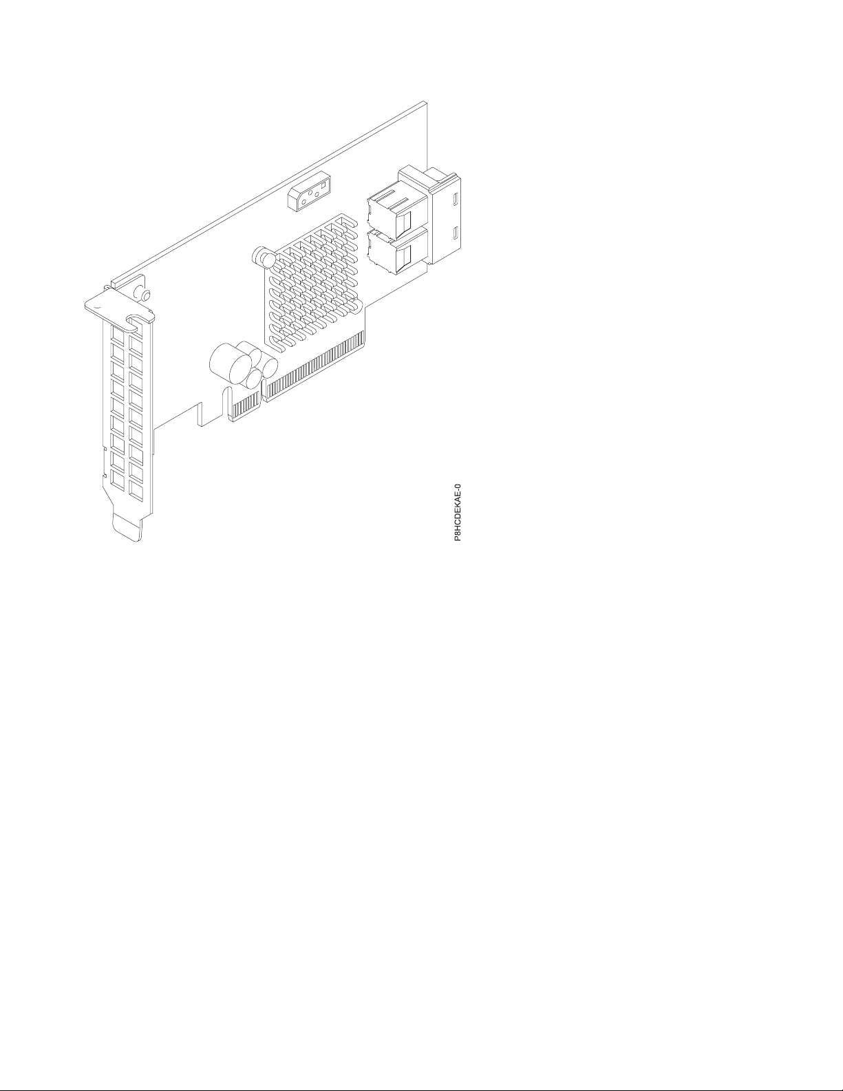
Figure 30. PCIe3 x8 Dual-port Internal NVMe Host Bus Adapter
Specifications
Item Description
Adapter FRU number
FC EKAE: AOC-K-SLG3-2E4S-IB001 (Designed to comply with RoHS requirement)
FC EKEE: AOC-K-SLG3-2E4B-IB001 (Designed to comply with RoHS requirement)
I/O bus architecture
PCIe3 x8
Slot requirement
For details about slot priorities and placement rules, see PCIe adapter placement rules and slot
priorities (http://www.ibm.com/support/knowledgecenter/POWER8/p8eab/
p8eab_mtm_pciplacement.htm) and select the system you are working on.
Supported Systems
POWER8®processor-based systems
Voltage
3.3 V, 12 V
Form factor
Short, low-profile
Maximum number
For details about the maximum number of adapters that are supported, see PCIe adapter
placement rules and slot priorities (http://www.ibm.com/support/knowledgecenter/POWER8/
p8eab/p8eab_mtm_pciplacement.htm) and select the system you are working on.
Attributes provided
Four internal lanes per port and 32 Gb/s per port (PCIe3 speed)
Supports two physical NVMe devices
48 Power Systems: Installing the IBM Power System S821LC (8001-12C)
Page 65

Pure host bus adapter (HBA)
Cables
Attach any necessary cables to the add-on card.
Operating system or partition requirements
If you are installing a new feature, ensure that you have the software that is required to support the new
feature and that you determine whether any prerequisites must be met for this feature and attaching
devices. To check for the prerequisites, see IBM Prerequisite website (www-912.ibm.com/e_dir/
eServerPrereq.nsf).
The adapter is supported on the following versions of the operating systems:
Important: For a list of known Linux OS issues that may affect this adapter, see the IBM Power LC
readme (https://ibm.biz/BdrgTZ).
v Linux
– Red Hat Enterprise Linux 7.2, little-endian, for Power, or later
– Ubuntu 16.04.1, or later
– Ubuntu 14.04.5, or later
– For support details, see the Linux Alert website (www14.software.ibm.com/webapp/set2/sas/f/
lopdiags/info/LinuxAlerts.html).
– The latest version of the device driver or iprutils can be downloaded from the IBM Service and
Productivity Tools website(http://www14.software.ibm.com/webapp/set2/sas/f/lopdiags/
home.html).
– The latest version of enabling libraries and utilities may be downloaded from Fix
Central(http://www.ibm.com/support/fixcentral/).
Emulex LPE16002B-M6-O Dual-port 16 Gb Fibre Channel Card PCIe3.0 x8 LP (FC EKAF)
Learn about the specifications and operating system requirements for feature code (FC) EKAF adapters.
Overview
The Emulex LPE16002B-M6-O Dual-port 16 Gb Fibre Channel Card PCIe3.0 x8 LP is a PCI Express (PCIe)
generation 3 (Gen3) x8 adapter. The adapter can be used in either a x8 or x16 PCIe slot in the system. The
adapter features auto-negotiation, LDAP support and has a data transfer rate of 14.025 Gb/s.
Installing and configuring the system 49
Page 66
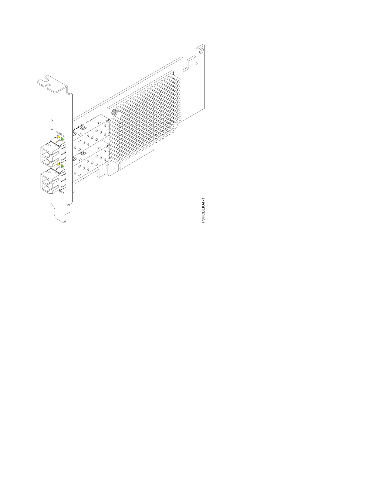
Figure 31. Emulex LPE16002B-M6-O Dual-port 16 Gb Fibre Channel Card PCIe3.0 x8 LP
Specifications
Item Description
Adapter FRU number
AOC-LPE16002B-M6-Of (Designed to comply with RoHS requirement)
I/O bus architecture
PCIe3 x8
Slot requirement
For details about slot priorities and placement rules, see PCIe adapter placement rules and slot
priorities (http://www.ibm.com/support/knowledgecenter/POWER8/p8eab/
p8eab_mtm_pciplacement.htm) and select the system you are working on.
Supported Systems
POWER8®processor-based systems
v 8001-12C and 8001-22C
Voltage
3.3 V, 12 V
Form factor
Short, low-profile
Maximum number
For details about the maximum number of adapters that are supported, see PCIe adapter
placement rules and slot priorities (http://www.ibm.com/support/knowledgecenter/POWER8/
p8eab/p8eab_mtm_pciplacement.htm) and select the system you are working on.
Attributes provided
Auto-negotiation
LDAP support
Data transfer rate of 14.025 Gb/s
Cables
Attach any necessary cables to the add-on card.
50 Power Systems: Installing the IBM Power System S821LC (8001-12C)
Page 67

Operating system or partition requirements
If you are installing a new feature, ensure that you have the software that is required to support the new
feature and that you determine whether any prerequisites must be met for this feature and attaching
devices. To check for the prerequisites, see IBM Prerequisite website (www-912.ibm.com/e_dir/
eServerPrereq.nsf).
The adapter is supported on the following versions of the operating systems:
Important: For a list of known Linux OS issues that may affect this adapter, see the IBM Power LC
readme (https://ibm.biz/BdrgTZ).
v Linux
– Red Hat Enterprise Linux 7.3, little-endian, for Power, or later
– Ubuntu 16.04.1, or later
– Ubuntu 14.04.5, or later
– For support details, see the Linux Alert website (www14.software.ibm.com/webapp/set2/sas/f/
lopdiags/info/LinuxAlerts.html).
– The latest version of the device driver or iprutils can be downloaded from the IBM Service and
Productivity Tools website(http://www14.software.ibm.com/webapp/set2/sas/f/lopdiags/
home.html).
– The latest version of enabling libraries and utilities may be downloaded from Fix
Central(http://www.ibm.com/support/fixcentral/).
SMC quad-port NVMe Host Bus Adapter (PEX9733) PCIe3.0 x8 LP with cables (FC EKAG and EKEG)
Learn about the specifications and operating system requirements for feature code (FC) EKAG and EKEG
adapters.
Overview
FC EKAG and EKEG are both the same adapter with different feature codes. FC EKAG is supported only
on the 8001-12C and does not include cables. FC EKEG, alternatively, is supported only on the 8001-22C
and includes cables.
The SMC quad-port NVMe Host Bus Adapter (PEX9733) PCIe3.0 x8 LP with cables is a PCI Express
(PCIe) generation 3 (Gen3) x8 adapter. The adapter can be used in either a x8 or x16 PCIe slot in the
system. The adapter features four internal NVMe connectors for high-performance storage connectivity.
This host bus adapter (HBA) card is built on the PLX PE8718 PCIe switch IC technology and proven
NVMe technology.
Installing and configuring the system 51
Page 68

Figure 32. SMC quad-port NVMe Host Bus Adapter (PEX9733) PCIe3.0 x8 LP with cables
Specifications
Item Description
Adapter FRU number
FC EKAG: AOC-K-SLG3-4E2PS (Designed to comply with RoHS requirement)
FC EKEG: AOC-K-SLG3-4E2PB-IB001 (Designed to comply with RoHS requirement)
I/O bus architecture
PCIe3 x8
Slot requirement
For details about slot priorities and placement rules, see PCIe adapter placement rules and slot
priorities (http://www.ibm.com/support/knowledgecenter/POWER8/p8eab/
p8eab_mtm_pciplacement.htm) and select the system you are working on.
Supported Systems
POWER8®processor-based systems
v 8001-12C and 8001-22C
Voltage
3.3 V, 12 V
Form factor
Short, low-profile
Maximum number
For details about the maximum number of adapters that are supported, see PCIe adapter
placement rules and slot priorities (http://www.ibm.com/support/knowledgecenter/POWER8/
p8eab/p8eab_mtm_pciplacement.htm) and select the system you are working on.
Attributes provided
Supports four physical NVMe devices
52 Power Systems: Installing the IBM Power System S821LC (8001-12C)
Page 69

Pure host bus adapter (HBA)
Supports 3.0 Gb/s, 6.0 Gb/s, and 12 Gb/s SAS and SATA data transfer rates
Cables
Attach any necessary cables to the add-on card.
Operating system or partition requirements
If you are installing a new feature, ensure that you have the software that is required to support the new
feature and that you determine whether any prerequisites must be met for this feature and attaching
devices. To check for the prerequisites, see IBM Prerequisite website (www-912.ibm.com/e_dir/
eServerPrereq.nsf).
The adapter is supported on the following versions of the operating systems:
Important: For a list of known Linux OS issues that may affect this adapter, see the IBM Power LC
readme (https://ibm.biz/BdrgTZ).
v Linux
– Red Hat Enterprise Linux 7.3, little-endian, for Power, or later
– Ubuntu 16.04.1, or later
– Ubuntu 14.04.5, or later
– For support details, see the Linux Alert website (www14.software.ibm.com/webapp/set2/sas/f/
lopdiags/info/LinuxAlerts.html).
– The latest version of the device driver or iprutils can be downloaded from the IBM Service and
Productivity Tools website(http://www14.software.ibm.com/webapp/set2/sas/f/lopdiags/
home.html).
– The latest version of enabling libraries and utilities may be downloaded from Fix
Central(http://www.ibm.com/support/fixcentral/).
Broadcom (LSI) MegaRAID 9361-8i SAS3 Controller with 8 internal ports (2 GB Cache) PCIe3.0 x8 with cables (FC EKAH and EKEH)
Learn about the specifications and operating system requirements for feature code (FC) EKAH and EKEH
adapters.
Overview
FC EKAH and EKEH are both the same adapter with different feature codes. FC EKAH is only supported
on 8001-12C and does not include cables. FC EKEH, alternatively, is only supported on 8001-22C and
includes cables.
The Broadcom (LSI) MegaRAID 9361-8i SAS3 Controller with 8 internal ports (2 GB Cache) PCIe3.0 x8
with cables is a PCI Express (PCIe) generation 3 (Gen3) x8 adapter. The adapter can be used in either a x8
or x16 PCIe slot in the system. TThe adapter features 8 internal SAS connectors for high-performance
storage connectivity. This Redundant Array of Independent Disks (RAID) adapter is built on the LSI
Logic SAS IC and MegaRAID technology. It also supports high capacity storage applications using
high-performance RAID architecture, including hardware RAID 5 and 6.
Important: RAID mode is the adapter default and needs to be configured by the customer before drives
are shown to the OS for install. The adapter can be set up in JBOD (Just a Bunch of Disks) mode.
Installing and configuring the system 53
Page 70

Figure 33. Broadcom (LSI) MegaRAID 9361-8i SAS3 Controller with 8 internal ports (2 GB Cache) PCIe3.0 x8 with
cables
Specifications
Item Description
Adapter FRU number
FC EKAH: AOC-K-9361-8I2S-IB001 (Designed to comply with RoHS requirement)
FC EKEH: AOC-K-9361-8I2B-IB001 (Designed to comply with RoHS requirement)
I/O bus architecture
PCIe3 x8
Slot requirement
For details about slot priorities and placement rules, see PCIe adapter placement rules and slot
priorities (http://www.ibm.com/support/knowledgecenter/POWER8/p8eab/
p8eab_mtm_pciplacement.htm) and select the system you are working on.
Supported Systems
POWER8 processor-based systems
v 8001-12C and 8001-22C
Voltage
3.3 V, 12 V
Form factor
Short, low-profile
Maximum number
For details about the maximum number of adapters that are supported, see PCIe adapter
placement rules and slot priorities (http://www.ibm.com/support/knowledgecenter/POWER8/
p8eab/p8eab_mtm_pciplacement.htm) and select the system you are working on.
Attributes provided
Port independent auto-negotiation
54 Power Systems: Installing the IBM Power System S821LC (8001-12C)
Page 71

Automatically negotiates PCIe link widths
Supports 1.5, 3.0, 6.0 and 12 Gb/s SAS and SATA data transfer rates
Advanced array configuration and management utilities
Cables
Attach any necessary cables to the add-on card.
SAS-3 Integrated RAID Configuration Utility (SAS3IRCU) User Guide
Before you set up the adapter in JBOD mode, you must have the SAS-3 Integrated RAID Configuration
Utility (SAS3IRCU) installed. For more information about SAS3IRCU, see the SAS-3 Integrated RAID
Configuration Utility (SAS3IRCU) User Guide.
Operating system or partition requirements
If you are installing a new feature, ensure that you have the software that is required to support the new
feature and that you determine whether any prerequisites must be met for this feature and attaching
devices. To check for the prerequisites, see IBM Prerequisite website (www-912.ibm.com/e_dir/
eServerPrereq.nsf).
The adapter is supported on the following versions of the operating systems:
Important: For a list of known Linux OS issues that may affect this adapter, see the IBM Power LC
readme (https://ibm.biz/BdrgTZ).
v Linux
– Red Hat Enterprise Linux 7.2, little-endian, for Power, or later
– Ubuntu 16.04.1, or later
– Ubuntu 14.04.5, or later
– For support details, see the Linux Alert website (www14.software.ibm.com/webapp/set2/sas/f/
lopdiags/info/LinuxAlerts.html).
– The latest version of the device driver or iprutils can be downloaded from the IBM Service and
Productivity Tools website(http://www14.software.ibm.com/webapp/set2/sas/f/lopdiags/
home.html).
– The latest version of enabling libraries and utilities may be downloaded from Fix
Central(http://www.ibm.com/support/fixcentral/).
NVIDIA Tesla K80 24 GB GPU Accelerator (FC EKAJ)
Learn about the specifications and operating system requirements for the feature code (FC) EKAJ adapter.
Overview
The NVIDIA Tesla K80 24 GB GPU Accelerator is a PCI Express (PCIe) generation 3 (Gen3) x16 adapter.
The adapter has a double-wide, full-height form-factor and takes up two x16 PCIe slots in the system.
The NVIDIA Tesla K80 24GB GPU Accelerator is designed for demanding computational tasks, combining
24 GB of memory with fast memory bandwidth and compute performance for single and double
precision workloads. It is equipped with the latest NVIDIA GPU Boost technology and monitors GPU
usage to maximize throughput and outperform CPUs by up to 10x.
Installing and configuring the system 55
Page 72

Figure 34. NVIDIA Tesla K80 24 GB GPU Accelerator
Specifications
Item Description
Adapter FRU number
AOC-KIT-NVK80-IB001 (Designed to comply with RoHS requirement)
I/O bus architecture
PCIe3 x16
Slot requirement
For details about slot priorities and placement rules, see PCIe adapter placement rules and slot
priorities (http://www.ibm.com/support/knowledgecenter/POWER8/p8eab/
p8eab_mtm_pciplacement.htm) and select the system you are working on.
Supported Systems
POWER8 processor-based systems
v 8001-12C and 8001-22C
Voltage
12 V
Form factor
Double-wide, full-height
Maximum number
For details about the maximum number of adapters that are supported, see PCIe adapter
placement rules and slot priorities (http://www.ibm.com/support/knowledgecenter/POWER8/
p8eab/p8eab_mtm_pciplacement.htm) and select the system you are working on.
Attributes
Dynamic Parallelism
Error Correcting Codes (ECC) Memory
Kepler GPU Architecture
Hyper-Q
Cables
Attach any necessary cables to the add-on card
56 Power Systems: Installing the IBM Power System S821LC (8001-12C)
Page 73

Operating system or partition requirements
If you are installing a new feature, ensure that you have the software that is required to support the new
feature and that you determine whether any prerequisites must be met for this feature and attaching
devices. To check for the prerequisites, see IBM Prerequisite website (www-912.ibm.com/e_dir/
eServerPrereq.nsf).
The adapter is supported on the following versions of the operating systems:
Important: For a list of known Linux OS issues that may affect this adapter, see the IBM Power LC
readme (https://ibm.biz/BdrgTZ).
v Linux
– Ubuntu 16.04.1, or later
– Ubuntu 14.04.5, or later
– For support details, see the Linux Alert website (www14.software.ibm.com/webapp/set2/sas/f/
lopdiags/info/LinuxAlerts.html).
– The latest version of the device driver or iprutils can be downloaded from the IBM Service and
Productivity Tools website(http://www14.software.ibm.com/webapp/set2/sas/f/lopdiags/
home.html).
– The latest version of enabling libraries and utilities may be downloaded from Fix
Central(http://www.ibm.com/support/fixcentral/).
Mellanox MCX456A-ECAT ConnectX-4 VPI EDR IB 100 Gb/s and 100 GbE Dual-port QSFP28 PCIe3.0 x16 LP (FC EKAL)
Learn about the specifications and operating system requirements for feature code (FC) EKAL adapters.
Overview
The Mellanox MCX456A-ECAT ConnectX-4 VPI EDR IB 100 Gb/s and 100 GbE Dual-port QSFP28
PCIe3.0 x16 LP is a PCI Express (PCIe) generation 3 (Gen3) x16 adapter. The adapter can be used in
either a x8 or x16 PCIe slot in the system. The adapter supports EDR 100 Gb/s InfiniBand and 100 Gb/s
Ethernet connectivity. It also provides flexible solutions for high-performance, Web 2.0, cloud, data
analytics, database, and storage platforms.
Installing and configuring the system 57
Page 74

Figure 35. Mellanox MCX456A-ECAT ConnectX-4 VPI EDR IB 100 Gb/s and 100 GbE Dual-port QSFP28 PCIe3.0 x16
LP
Specifications
Item Description
Adapter FRU number
AOC-MCX456A-ECAT-IB001 (Designed to comply with RoHS requirement)
I/O bus architecture
PCIe3 x16
Slot requirement
For details about slot priorities and placement rules, see PCIe adapter placement rules and slot
priorities (http://www.ibm.com/support/knowledgecenter/POWER8/p8eab/
p8eab_mtm_pciplacement.htm) and select the system you are working on.
Supported Systems
POWER8®processor-based systems
v 8001-12C and 8001-22C
Voltage
12 V
Form factor
Short, with full-height tailstock
Maximum number
For details about the maximum number of adapters that are supported, see PCIe adapter
placement rules and slot priorities (http://www.ibm.com/support/knowledgecenter/POWER8/
p8eab/p8eab_mtm_pciplacement.htm) and select the system you are working on.
Attributes provided
EDR 100 Gb/s InfiniBand or 100 Gb/s Ethernet per port
Supports 2 physical NVMe Devices
58 Power Systems: Installing the IBM Power System S821LC (8001-12C)
Page 75

Single and dual-port options available
Hardware-based I/O virtualization
Cables
Mellanox LinkX 10, 25, 40, 50 and 100Gb/s Direct Attach Copper cables (DACs), Copper Splitter
cables, Active Optical Cables (AOCs) and Transceivers. For information regarding Mellanox
LinkX cables and Transceivers, see LinkX™InfiniBand Direct Attach Copper Cables(http://
www.mellanox.com/products/interconnect/infiniband-copper-cables.php)
Operating system or partition requirements
If you are installing a new feature, ensure that you have the software that is required to support the new
feature and that you determine whether any prerequisites must be met for this feature and attaching
devices. To check for the prerequisites, see IBM Prerequisite website (www-912.ibm.com/e_dir/
eServerPrereq.nsf).
The adapter is supported on the following versions of the operating systems:
v Linux
– Red Hat Enterprise Linux 7.2, little-endian, for Power, or later
– Ubuntu 16.04.1, or later
– Ubuntu 14.04.5, or later
– For support details, see the Linux Alert website (www14.software.ibm.com/webapp/set2/sas/f/
lopdiags/info/LinuxAlerts.html).
– The latest version of the device driver or iprutils can be downloaded from the IBM Service and
Productivity Tools website(http://www14.software.ibm.com/webapp/set2/sas/f/lopdiags/
home.html).
– The latest version of enabling libraries and utilities may be downloaded from Fix
Central(http://www.ibm.com/support/fixcentral/).
Mellanox MCX415A-CCAT ConnectX-4 EN 100 GbE Single-port QSFP28 PCIe3.0 x16 LP (FC EKAM)
Learn about the specifications and operating system requirements for feature code (FC) EKAM adapters.
Overview
The Mellanox MCX415A-CCAT ConnectX-4 EN 100 GbE Single-port QSFP28 PCIe3.0 x16 LP is a PCI
Express (PCIe) generation 3 (Gen3) x16 adapter. The adapter can be used in either a x8 or x16 PCIe slot in
the system. The adapter supports 100 Gb/s Ethernet per port and provides flexible solutions for
high-performance, Web 2.0, cloud, data analytics, database, and storage platforms.
Installing and configuring the system 59
Page 76

Figure 36. Mellanox MCX415A-CCAT ConnectX-4 EN 100 GbE Single-port QSFP28 PCIe3.0 x16 LP
Specifications
Item Description
Adapter FRU number
AOC-MCX415A-CCAT-IB001 (Designed to comply with RoHS requirement)
I/O bus architecture
PCIe3 x16
Slot requirement
For details about slot priorities and placement rules, see PCIe adapter placement rules and slot
priorities (http://www.ibm.com/support/knowledgecenter/POWER8/p8eab/
p8eab_mtm_pciplacement.htm) and select the system you are working on.
Supported Systems
POWER8®processor-based systems
v 8001-12C and 8001-22C
Voltage
12 V
Form factor
Short, with full-height tailstock
Maximum number
For details about the maximum number of adapters that are supported, see PCIe adapter
placement rules and slot priorities (http://www.ibm.com/support/knowledgecenter/POWER8/
p8eab/p8eab_mtm_pciplacement.htm) and select the system you are working on.
Attributes provided
100 Gb/s Ethernet per port
Supports two physical NVMe devices
Single and dual-port options available
60 Power Systems: Installing the IBM Power System S821LC (8001-12C)
Page 77

Hardware-based I/O virtualization
Cables
Mellanox LinkX 10, 25, 40, 50 and 100 Gb/s Direct Attach Copper cables (DACs), Copper Splitter
cables, Active Optical Cables (AOCs), and Transceivers. For information regarding Mellanox
LinkX cables and Transceivers, see LinkX™InfiniBand Direct Attach Copper Cables(http://
www.mellanox.com/products/interconnect/infiniband-copper-cables.php)
Operating system or partition requirements
If you are installing a new feature, ensure that you have the software that is required to support the new
feature and that you determine whether any prerequisites must be met for this feature and attaching
devices. To check for the prerequisites, see IBM Prerequisite website (www-912.ibm.com/e_dir/
eServerPrereq.nsf).
The adapter is supported on the following versions of the operating systems:
Important: For a list of known Linux OS issues that may affect this adapter, see the IBM Power LC
readme (https://ibm.biz/BdrgTZ).
v Linux
– Red Hat Enterprise Linux 7.2, little-endian, for Power, or later
– Ubuntu 16.04.1, or later
– Ubuntu 14.04.5, or later
– For support details, see the Linux Alert website (www14.software.ibm.com/webapp/set2/sas/f/
lopdiags/info/LinuxAlerts.html).
– The latest version of the device driver or iprutils can be downloaded from the IBM Service and
Productivity Tools website(http://www14.software.ibm.com/webapp/set2/sas/f/lopdiags/
home.html).
– The latest version of enabling libraries and utilities may be downloaded from Fix
Central(http://www.ibm.com/support/fixcentral/).
Qlogic QLE2562 Dual-port 8 Gb Fibre Channel Adapter PCIe x8 LP (FC EKAP)
Learn about the specifications and operating system requirements for feature code (FC) EKAP adapters.
Overview
The Qlogic QLE2562 Dual-port 8 Gb Fibre Channel Adapter PCIe x8 LP is a PCI Express (PCIe)
generation 2 (Gen2) x8 adapter. The adapter can be used in either a x8 or x16 PCIe slot in the system. The
adapter offers dual-channel performance, auto-negotiation and StarPower technology.
Installing and configuring the system 61
Page 78

Figure 37. Qlogic QLE2562 Dual-port 8 Gb Fibre Channel Adapter PCIe x8 LP
Specifications
Item Description
Adapter FRU number
AOC-QLE2562 (Designed to comply with RoHS requirement)
I/O bus architecture
PCIe2 x8
Slot requirement
For details about slot priorities and placement rules, see PCIe adapter placement rules and slot
priorities (http://www.ibm.com/support/knowledgecenter/POWER8/p8eab/
p8eab_mtm_pciplacement.htm) and select the system you are working on.
Supported Systems
POWER8®processor-based systems
v 8001-12C and 8001-22C
Voltage
12 V
Form factor
Short, low-profile
Maximum number
For details about the maximum number of adapters that are supported, see PCIe adapter
placement rules and slot priorities (http://www.ibm.com/support/knowledgecenter/POWER8/
p8eab/p8eab_mtm_pciplacement.htm) and select the system you are working on.
Attributes provided
StarPower technology
Auto-negotiation
Quality of Service (QoS)
62 Power Systems: Installing the IBM Power System S821LC (8001-12C)
Page 79

Cables
Attach any necessary cables to the add-on card.
Operating system or partition requirements
If you are installing a new feature, ensure that you have the software that is required to support the new
feature and that you determine whether any prerequisites must be met for this feature and attaching
devices. To check for the prerequisites, see IBM Prerequisite website (www-912.ibm.com/e_dir/
eServerPrereq.nsf).
The adapter is supported on the following versions of the operating systems:
Important: For a list of known Linux OS issues that may affect this adapter, see the IBM Power LC
readme (https://ibm.biz/BdrgTZ).
v Linux
– Red Hat Enterprise Linux 7.2, little-endian, for Power, or later
– Ubuntu 16.04.1, or later
– Ubuntu 14.04.5, or later
– For support details, see the Linux Alert website (www14.software.ibm.com/webapp/set2/sas/f/
lopdiags/info/LinuxAlerts.html).
– The latest version of the device driver or iprutils can be downloaded from the IBM Service and
Productivity Tools website(http://www14.software.ibm.com/webapp/set2/sas/f/lopdiags/
home.html).
– The latest version of enabling libraries and utilities may be downloaded from Fix
Central(http://www.ibm.com/support/fixcentral/).
Qlogic QLE2692OP Dual-port 16 Gb Fibre Channel Adapter PCIe3 x8 LP (FC EKAQ)
Learn about the specifications and operating system requirements for feature code (FC) EKAQ adapters.
Overview
The Qlogic QLE2692OP Dual-port 16 Gb Fibre Channel Adapter PCIe3 x8 LP is a PCI Express (PCIe)
generation 3 (Gen3) x8 adapter. The adapter can be used in either a x8 or x16 PCIe slot in the system. The
adapter provides advanced storage networking features capable of supporting demanding virtualized and
private cloud environments. The Standard Low-profile QLogic 16 Gb Fibre Channel Card can also deliver
up to 1.3 million IOPS (Input/Output Operations per Second) fuel high performance in all-flash arrays
(AFAs) and high-density virtualized environments.
Installing and configuring the system 63
Page 80

Figure 38. Qlogic QLE2692OP Dual-port 16 Gb Fibre Channel Adapter PCIe3 x8 LP
Specifications
Item Description
Adapter FRU number
AOC-QLE2692OP-IB001 (Designed to comply with RoHS requirement)
I/O bus architecture
PCIe3 x8
Slot requirement
For details about slot priorities and placement rules, see PCIe adapter placement rules and slot
priorities (http://www.ibm.com/support/knowledgecenter/POWER8/p8eab/
p8eab_mtm_pciplacement.htm) and select the system you are working on.
Supported Systems
POWER8®processor-based systems
v 8001-12C and 8001-22C
Voltage
12 V
Form factor
Short, low-profile
Maximum number
For details about the maximum number of adapters that are supported, see PCIe adapter
placement rules and slot priorities (http://www.ibm.com/support/knowledgecenter/POWER8/
p8eab/p8eab_mtm_pciplacement.htm) and select the system you are working on.
Attributes provided
Up to 1.3 million IOPS fuel high performance in AFAs and high density virtualized environments
Enhanced reliability, diagnostics, and accelerated deployment powered by QLogic StarFusion
technology
64 Power Systems: Installing the IBM Power System S821LC (8001-12C)
Page 81

Port isolation design offers deterministic and scalable performance on each port
Cables
Attach any necessary cables to the add-on card.
Operating system or partition requirements
If you are installing a new feature, ensure that you have the software that is required to support the new
feature and that you determine whether any prerequisites must be met for this feature and attaching
devices. To check for the prerequisites, see IBM Prerequisite website (www-912.ibm.com/e_dir/
eServerPrereq.nsf).
The adapter is supported on the following versions of the operating systems:
Important: For a list of known Linux OS issues that may affect this adapter, see the IBM Power LC
readme (https://ibm.biz/BdrgTZ).
v Linux
– Red Hat Enterprise Linux 7.2, little-endian, for Power, or later
– Ubuntu 16.04.1, or later
– Ubuntu 14.04.5, or later
– For support details, see the Linux Alert website (www14.software.ibm.com/webapp/set2/sas/f/
lopdiags/info/LinuxAlerts.html).
– The latest version of the device driver or iprutils can be downloaded from the IBM Service and
Productivity Tools website(http://www14.software.ibm.com/webapp/set2/sas/f/lopdiags/
home.html).
– The latest version of enabling libraries and utilities may be downloaded from Fix
Central(http://www.ibm.com/support/fixcentral/).
Alpha-data CAPI Adapter: ADM-PCIe KU3 (FC EKAT)
Learn about the specifications and operating system requirements for feature code (FC) EKAT adapters.
Overview
The Alpha-data CAPI Adapter: ADM-PCIe KU3 is a PCI Express (PCIe) generation 3 (Gen3) x16 adapter.
The adapter can be used in either a x8 or x16 PCIe slot in the system. The adapter features two
independent channels of DDR3 memory capable of 1600 mega transfers per second (MT/s), SATA
connections, and high-speed I/O through dual quad small form-factor pluggable (QSFP) ports. It
supports up to 40G Ethernet or 4x10G Ethernet links and offers voltage, temperature, current control and
monitoring.
Installing and configuring the system 65
Page 82

Figure 39. Alpha-data CAPI Adapter: ADM-PCIe KU3
Specifications
Item Description
Adapter FRU number
ADM-PCIE-KU3 (Designed to comply with RoHS requirement)
I/O bus architecture
PCIe3 x16
Slot requirement
For details about slot priorities and placement rules, see PCIe adapter placement rules and slot
priorities (http://www.ibm.com/support/knowledgecenter/POWER8/p8eab/
p8eab_mtm_pciplacement.htm) and select the system you are working on.
Supported Systems
POWER8®processor-based systems
v 8001-12C and 8001-22C
Voltage
12 V
Form factor
Short, low-profile
Maximum number
For details about the maximum number of adapters that are supported, see PCIe adapter
placement rules and slot priorities (http://www.ibm.com/support/knowledgecenter/POWER8/
p8eab/p8eab_mtm_pciplacement.htm) and select the system you are working on.
Attributes provided
Dual QSFP cages for high-speed optical communication including 10 and 40 Gigabit Ethernet
Dual SATA Interfaces
1 GB of BPI x16 configuration flash
66 Power Systems: Installing the IBM Power System S821LC (8001-12C)
Page 83

Cables
Attach any necessary cables to the add-on card.
Operating system or partition requirements
If you are installing a new feature, ensure that you have the software that is required to support the new
feature and that you determine whether any prerequisites must be met for this feature and attaching
devices. To check for the prerequisites, see IBM Prerequisite website (www-912.ibm.com/e_dir/
eServerPrereq.nsf).
The adapter is supported on the following versions of the operating systems:
Important: For a list of known Linux OS issues that may affect this adapter, see the IBM Power LC
readme (https://ibm.biz/BdrgTZ).
v Linux
– Red Hat Enterprise Linux 7.2, little-endian, for Power, or later
– Ubuntu 16.04.1, or later
– Ubuntu 14.04.5, or later
– For support details, see the Linux Alert website (www14.software.ibm.com/webapp/set2/sas/f/
lopdiags/info/LinuxAlerts.html).
– The latest version of the device driver or iprutils can be downloaded from the IBM Service and
Productivity Tools website(http://www14.software.ibm.com/webapp/set2/sas/f/lopdiags/
home.html).
– The latest version of enabling libraries and utilities may be downloaded from Fix
Central(http://www.ibm.com/support/fixcentral/).
References
Please note that the Alpha-data CAPI Adapter: ADM-PCIe KU3 (FC EKAT) is hardware only. The adapter
development toolkit and services are available on the Alpha-Data®website. For more information, consult
the following references:
v IBM®CAPI information:
– POWER8®Coherent Accelerator Processor Interface (CAPI) (http://www.ibm.biz/powercapi)
v Alpha-Data®CAPI PCIe adapter information:
– Coherent Accelerator Processor Interface (CAPI) for POWER8®(http://www.alpha-data.com/dcp/
capi.php)
– ADM-PCIE-KU3 Summary and Features (http://www.alpha-data.com/dcp/
products.php?product=adm-pcie-ku3)
Mellanox MCX4121A-ACAT ConnectX-4 Lx EN 25GbE dual-port SFP28 PCIe3.0 x8 LP (FC EKAU)
Learn about the specifications and operating system requirements for feature code (FC) EKAU adapters.
Overview
The Mellanox MCX4121A-ACAT ConnectX-4 Lx EN 25GbE dual-port SFP28 PCIe3.0 x8 LP is a PCI
Express (PCIe) generation 3 (Gen3) x8 adapter. The adapter can be used in either a x8 or x16 PCIe slot in
the system. The adapter provides a combination of 1, 10, 25, 40, and 50 GbE bandwidth, sub-microsecond
latency and a 75 million packets per second message rate. It includes native hardware support for remote
direct memory access (RDMA) over converged Ethernet (RoCE), Ethernet stateless offload engines,
overlay networks, and GPU Direct®Technology.
Installing and configuring the system 67
Page 84

Figure 40. Mellanox MCX4121A-ACAT ConnectX-4 Lx EN 25GbE dual-port SFP28 PCIe3.0 x8 LP
Specifications
Item Description
Adapter FRU number
AOC-MCX4121A-ACAT-IB001 (Designed to comply with RoHS requirement)
I/O bus architecture
PCIe3 x8
Slot requirement
For details about slot priorities and placement rules, see PCIe adapter placement rules and slot
priorities (http://www.ibm.com/support/knowledgecenter/POWER8/p8eab/
p8eab_mtm_pciplacement.htm) and select the system you are working on.
Supported Systems
POWER8®processor-based systems
v 8001-12C and 8001-22C
Voltage
12 V
Form factor
Short, with full-height tailstock
Maximum number
For details about the maximum number of adapters that are supported, see PCIe adapter
placement rules and slot priorities (http://www.ibm.com/support/knowledgecenter/POWER8/
p8eab/p8eab_mtm_pciplacement.htm) and select the system you are working on.
Attributes provided
Low latency RDMA over Converged Ethernet
Connectivity to up-to 4 independent hosts
Hardware-based I/O virtualization
68 Power Systems: Installing the IBM Power System S821LC (8001-12C)
Page 85

Cables
Mellanox LinkX 10 Gb/s, 25 Gb/s, 40 Gb/s, 50 Gb/s and 100 Gb/s Direct Attach Copper cables
(DACs), Copper Splitter cables, Active Optical Cables (AOCs) and Transceivers. For information
regarding Mellanox LinkX cables and Transceivers, see LinkX™InfiniBand Direct Attach Copper
Cables. (http://www.mellanox.com/products/interconnect/infiniband-copper-cables.php)
Operating system or partition requirements
If you are installing a new feature, ensure that you have the software that is required to support the new
feature and that you determine whether any prerequisites must be met for this feature and attaching
devices. To check for the prerequisites, see IBM Prerequisite website (www-912.ibm.com/e_dir/
eServerPrereq.nsf).
The adapter is supported on the following versions of the operating systems:
Important: For a list of known Linux OS issues that may affect this adapter, see the IBM Power LC
readme. (https://ibm.biz/BdrgTZ)
v Linux
– Red Hat Enterprise Linux 7.2, little-endian, for Power, or later
– Ubuntu 16.04.1, or later
– Ubuntu 14.04.5, or later
– For support details, see the Linux Alert website (www14.software.ibm.com/webapp/set2/sas/f/
lopdiags/info/LinuxAlerts.html).
– The latest version of Mellanox OFED can be downloaded from Mellanox. (http://
www.mellanox.com)
NVIDIA Tesla P100 16GB PCIe3.0 x16 Dual-slot FHFL with cables (FC EKAZ)
Learn about the specifications and operating system requirements for the feature code (FC) EKAZ
adapter.
Overview
The NVIDIA Tesla P100 16GB PCIe3.0 x16 Dual-slot FHFL with cables is a PCI Express (PCIe) generation
3 (Gen3) x16 adapter. The adapter has a double-wide, full-height form-factor and takes up two x16 PCIe
slots in the system. The NVIDIA Tesla P100 16 GB GPU Accelerator can deliver up to 18.7 teraflops
(TFLOPS) of half-precision and is capable of 720 GB/s of memory bandwidth. The accelerator is ideal for
high-performance-computing (HPC) and hyperscale workloads.
Installing and configuring the system 69
Page 86

Figure 41. NVIDIA Tesla P100 16GB PCIe3.0 x16 Dual-slot FHFL with cables
Specifications
Item Description
Adapter FRU number
AOC-KIT-NVTP100-IB001 (Designed to comply with RoHS requirement)
I/O bus architecture
PCIe3 x16
Slot requirement
For details about slot priorities and placement rules, see PCIe adapter placement rules and slot
priorities (http://www.ibm.com/support/knowledgecenter/POWER8/p8eab/
p8eab_mtm_pciplacement.htm) and select the system you are working on.
Supported Systems
POWER8®processor-based systems
v 8001-12C and 8001-22C
Voltage
3.3 V, 12 V
Form factor
Double-wide, full-height
Maximum number
For details about the maximum number of adapters that are supported, see PCIe adapter
placement rules and slot priorities (http://www.ibm.com/support/knowledgecenter/POWER8/
p8eab/p8eab_mtm_pciplacement.htm) and select the system you are working on.
Attributes
Pascal Architecture
NVLink
Kepler GPU Architecture
Page Migration Engine
Cables
Attach any necessary cables to the add-on card
70 Power Systems: Installing the IBM Power System S821LC (8001-12C)
Page 87

Operating system or partition requirements
If you are installing a new feature, ensure that you have the software that is required to support the new
feature and that you determine whether any prerequisites must be met for this feature and attaching
devices. To check for the prerequisites, see IBM Prerequisite website (www-912.ibm.com/e_dir/
eServerPrereq.nsf).
The adapter is supported on the following versions of the operating systems:
Important: For a list of known Linux OS issues that may affect this adapter, see the IBM Power LC
readme (https://ibm.biz/BdrgTZ).
v Linux
– Red Hat Enterprise Linux 7.3, little-endian, for Power, or later
– Ubuntu 16.04.1, or later
– For support details, see the Linux Alert website (www14.software.ibm.com/webapp/set2/sas/f/
lopdiags/info/LinuxAlerts.html).
– The latest version of the device driver or iprutils can be downloaded from the IBM Service and
Productivity Tools website(http://www14.software.ibm.com/webapp/set2/sas/f/lopdiags/
home.html).
– The latest version of enabling libraries and utilities may be downloaded from Fix
Central(http://www.ibm.com/support/fixcentral/).
Intel XL710 Ethernet Converged Network Adapter Quad-port 10G/1G SFP+ PCIe3.0 x8 LP (FC EKFH)
Learn about the specifications and operating system requirements for the feature code (FC) EKFH
adapter.
Overview
The Intel XL710 Ethernet Converged Network Adapter Quad-port 10G/1G SFP+ PCIe3.0 x8 LP is a PCI
Express (PCIe) x8 adapter. The adapter can be used in either an x4, x8 or x16 PCIe slot in the system. The
adapter expands virtualization beyond the server level to the network level and combines with hardware
optimizations and offloads. It provides unmatched features for virtualization, flexibility for LAN and
SAN networks, and reliable performance.
Installing and configuring the system 71
Page 88

Figure 42. Intel XL710 Ethernet Converged Network Adapter Quad-port 10G/1G SFP+ PCIe3.0 x8 LP
Specifications
Item Description
Adapter FRU number
AOC-STG-I4S (Designed to comply with RoHS requirement)
I/O bus architecture
PCIe x8
Slot requirement
For details about slot priorities and placement rules, see PCIe adapter placement rules and slot
priorities (http://www.ibm.com/support/knowledgecenter/POWER8/p8eab/
p8eab_mtm_pciplacement.htm) and select the system you are working on.
Supported Systems
POWER8 processor-based systems
Voltage
3.3 V, 12 V
Form factor
Short, low-profile
Attributes provided
Quad SFP+ Connectors
Small Packet Performance
Network Virtualization Offloads including VXLAN and NVGRE
Unified networking providing a single with support
Transceivers and cables
Supported cable length is more than 100 M
72 Power Systems: Installing the IBM Power System S821LC (8001-12C)
Page 89

Operating system or partition requirements
If you are installing a new feature, ensure that you have the software that is required to support the new
feature and that you determine whether any prerequisites must be met for this feature and attaching
devices. To check for operating system and partition requirements, see one of the following links:
v The latest version of enabling libraries and utilities may be downloaded from Fix Central.
(http://www.ibm.com/support/fixcentral/)
v IBM Prerequisite website (www-912.ibm.com/e_dir/eServerPrereq.nsf)
v IBM SSIC (System Storage Interoperation Center) (http://www-03.ibm.com/systems/support/storage/
ssic/interoperability.wss)
v The latest version of the device driver or iprutils can be downloaded from the IBM Service and
Productivity Tools website. (http://www14.software.ibm.com/webapp/set2/sas/f/lopdiags/
home.html)
v For support details, see the Linux Alert website. (www14.software.ibm.com/webapp/set2/sas/f/
lopdiags/info/LinuxAlerts.html)
PCIe3 1.6 TB NVMe Flash Adapter (FC EKN2)
Learn about the specifications and operating system requirements for feature code (FC) EKN2 adapters.
Overview
See FC EKN3 for an adapter with more capacity.
The PCIe3 1.6 TB NVMe Flash Adapter is a PCI Express (PCIe) generation 3 (Gen3) x4 adapter. The
adapter can be used in either a x8 or x16 PCIe (Gen3) slot in the system and uses Non-Volatile Memory
Express (NVMe). NVMe is a high performance software interface that can read/write flash memory.
Compared to a SAS or SATA SSD, the NVMe Flash adapter provides more read/write input/output
operations per second (IOPS) and larger throughput (GB/sec). The NVMe Flash Adapter is read intensive
and is not designed for high write intensive workloads. At about 8,760 to 17,000 TB of writes to the
adapter, it will be at its maximum projected write capability. The nature of the workload has a great
impact on the maximum write capacity. If a high percentage of more sequentially oriented writes is used
instead of random writes, the maximum write capacity will be closer to the larger value in the range. In
the case of a high percentage of random writes, the maximum will be closer to the smaller value in the
range. Writes past the adapter's maximum write capacity will continue to work for some period of time,
but much more slowly. A Predictive Failure Analysis message will indicate that it is time to replace the
adapter if enabled by the system administrator. After the warranty period, if the maximum write
capability is achieved, the adapter's replacement is not covered under IBM maintenance. This adapter has
protection against single Flash channel failures. To prevent the entire adapter from failing, software RAID
should be used. For high value applications where the content in the adapter must be protected,
additional NVMe Flash adapters with OS mirroring or software Redundant Array of Independent Disks
(RAID) are recommended. This adapter is not supported in the PCIe Gen3 I/O drawer.
Important: Before removing a NVMe Flash adapter, ensure that all data on the adapter or the array that
contains the adapter is backed up. Restore the data after the adapter is replaced.
Installing and configuring the system 73
Page 90

Figure 43. PCIe3 1.6 TB NVMe Flash Adapter
Important: The micro USB connector visible through the adapter tailstock has no function and cannot be
used. Do not insert a cable of any kind into this port.
Specifications
Item Description
Adapter FRU number
HDS-AVM-HUSPR3216AHP301 (Designed to comply with RoHS requirement)
I/O bus architecture
PCIe3 x4
Slot requirement
For details about slot priorities and placement rules, see PCIe adapter placement rules and slot
priorities (http://www.ibm.com/support/knowledgecenter/POWER8/p8eab/
p8eab_mtm_pciplacement.htm) and select the system you are working on.
Supported Systems
POWER8®processor-based systems
v 8001-12C and 8001-22C
Voltage
12 V
Form factor
Short, low-profile
Maximum number
For details about the maximum number of adapters that are supported, see PCIe adapter
placement rules and slot priorities (http://www.ibm.com/support/knowledgecenter/POWER8/
p8eab/p8eab_mtm_pciplacement.htm) and select the system you are working on.
Attributes provided
1.6 TB of low latency flash memory
Non-Volatile write buffer
74 Power Systems: Installing the IBM Power System S821LC (8001-12C)
Page 91

Hot plug capable
NVMe Flash adapter maximum write capability
Determine whether the NVMe Flash adapter maximum write capability is depleted by completing the
following steps:
1. Type the following command at the Linux command line and press Enter: nvme smart-log
/dev/nvmeX, where nvmeX is the resource name of the NVMe Flash adapter.
2. If the critical_warning field is 1 (bit 0 is set) and the percentage_used field is 90% or greater, replace
the NVMe Flash adapter.
Note: The replacement of depleted NVMe Flash adapters is covered during the system warranty period.
After the warranty period has expired, the cost that is incurred for the replacement of depleted NVMe
Flash adapters is not covered under maintenance contracts, and is the responsibility of the customer.
Service tools for Linux on Power servers
To obtain the utility to update firmware, format storage, and complete other service tasks, complete the
following steps:
1. Go to Service and productivity tools and follow the instructions to download service tools.
2. Install the NVMe management command line interface (CLI).
v For Red Hat Enterprise Linux (RHEL), type yum install nvme-cli.
v For SUSE Linux Enterprise Server (SLES), type zypper install nvme-cli.
3. For more information about using the NVMe CLI, see the README file.
Operating system or partition requirements
If you are installing a new feature, ensure that you have the software that is required to support the new
feature and that you determine whether any prerequisites must be met for this feature and attaching
devices. To check for the prerequisites, see IBM Prerequisite website (www-912.ibm.com/e_dir/
eServerPrereq.nsf).
The adapter is supported on the following versions of the operating systems:
Important: For a list of known Linux OS issues that may affect this adapter, see the IBM Power LC
readme (https://ibm.biz/BdrgTZ).
v Linux
– Red Hat Enterprise Linux 7.2, little-endian, for Power, or later
– Ubuntu 16.04.1, or later
– Ubuntu 14.04.5, or later
– For support details, see the Linux Alert website (www14.software.ibm.com/webapp/set2/sas/f/
lopdiags/info/LinuxAlerts.html).
– The latest version of the device driver or iprutils can be downloaded from the IBM Service and
Productivity Tools website(http://www14.software.ibm.com/webapp/set2/sas/f/lopdiags/
home.html).
– The latest version of enabling libraries and utilities may be downloaded from Fix
Central(http://www.ibm.com/support/fixcentral/).
Installing a PCIe adapter in the 8001-12C system
Complete the steps in this procedure to install a PCIe adapter in the IBM Power System S821LC
(8001-12C) system.
Installing and configuring the system 75
Page 92

Before you begin
Power off the system and place it in the service position. For instructions, see “Preparing the 8001-12C or
8005-12N system to remove and replace internal parts” on page 85.
About this task
See “PCIe adapter placement rules and slot priorities for the 8001-12C or 8005-12N system” on page 23
for information and capabilities of the PCIe slots.
Attention: For safety and airflow purposes, if you remove parts from the system, you must ensure that:
v PCIe tail-stock fillers are present
v System processor airflow baffles are present.
Procedure
1. Attach the electrostatic discharge (ESD) wrist strap.
Attention:
v Attach an electrostatic discharge (ESD) wrist strap to the front ESD jack, to the rear ESD jack, or to
an unpainted metal surface of your hardware to prevent the electrostatic discharge from damaging
your hardware.
v When you use an ESD wrist strap, follow all electrical safety procedures. An ESD wrist strap is
used for static control. It does not increase or decrease your risk of receiving electric shock when
using or working on electrical equipment.
v If you do not have an ESD wrist strap, just prior to removing the product from ESD packaging and
installing or replacing hardware, touch an unpainted metal surface of the system for a minimum of
5 seconds.
2. An adapter can share a PCIe riser card with other adapters. Label and remove any cables and plugs
that extend out of the adapters. See Figure 44.
Figure 44. 8001-12C PCIe adapter positions
Position Step
2 (UIO Slot1) 3
3, 4, 5 (PLX Slot1, WIO Slot1, WIO Slot2) 4
3. If you are working with a PCIe adapter in position 2, do the following:
a. Remove the standard tailstock from the adapter.
b. If you are inserting a storage drive adapter, connect the signal cables to the adapter before
inserting the adapter. See “Drive installation details for the 8001-12C system” on page 8 for cabling
information.
c. If needed, install a support bracket for the PCIe adapter to the system backplane. Also install a
special support tailstock to the PCIe adapter.
d. Insert the adapter into the PCIe riser.
e. If you installed the support bracket for the PCIe adapter, fasten the special support tailstock to
that bracket.
4. If the PCIe adapter to install is in positions 3, 4, or 5, you must remove the PCIe cage and riser.
76 Power Systems: Installing the IBM Power System S821LC (8001-12C)
Page 93

a. If the riser contains a GPU, remove the power cable (A) from the system backplane as shown in
Figure 45. Using your thumb, press the release latch on the connector to remove the cable.
Figure 45. Unplugging the GPU power cable
b. Remove the PCIe riser as shown in Figure 46 on page 78.
1) Retract the retaining pins (A) so that the arrows on the tabs point to the system.
2) Lift the PCIe riser from the system.
Installing and configuring the system 77
Page 94

Figure 46. Removing the PCIe riser
c. Place the PCIe riser upside down on an ESD surface.
d. Remove the screw and the tail-stock filler for that position.
e. If you are inserting a storage drive adapter, connect the signal cables to the adapter before
inserting the adapter. See “Drive installation details for the 8001-12C system” on page 8 for cabling
information.
NVMe drives are only supported on host operating systems; NVMe drives are not supported by
guest operating systems. On systems with RHEL 7.3 or later, or Ubuntu 16.04 or later, NVMe
drives can be used as bootable drives. Port 1 of the internal NVMe host bus adapter must be
plugged into NVMe port 1 on the disk drive backplane.
f. Insert the adapter (A) into the riser (B) as shown in Figure 47, aligning it properly and inserting it
fully into the slot. Secure the adapter tail-stock with 1 or 2 screws as needed.
Figure 47. Inserting an adapter into position 3 of the riser
78 Power Systems: Installing the IBM Power System S821LC (8001-12C)
Page 95

Figure 48. Inserting an adapter into position 4 or 5 of the riser
g. Place the PCIe adapter riser and the cards it contains into the system backplane as shown in
Figure 49.
1) Ensure that the PCIe holder release pins (B) are retracted, so the arrows point into the system.
2) Use the alignment pins (A) and slots to help you properly insert the riser cards and replace the
cover
3) Reset the retaining pins to secure the PCIe cage.
Figure 49. Replacing the PCIe riser
h. If the riser contains a GPU, replace the power cable (A) into the system backplane.
Installing and configuring the system 79
Page 96

Figure 50. Plugging the GPU power cable
What to do next
Prepare the system for operation. For instructions, see “Preparing the 8001-12C or 8005-12N system for
operation after you remove and replace internal parts” on page 87.
Common procedures for servicing or installing features in the 8001-12C or 8005-12N
Learn about the common procedures related to installing, removing, and replacing features in the IBM
Power System S821LC (8001-12C) system.
Before you begin
Observe these precautions when you are installing, removing, or replacing features and parts.
About this task
These precautions are intended to create a safe environment to service your system and do not provide
steps for servicing your system. The installation, removal, and replacement procedures provide the
step-by-step processes that are required to service your system.
DANGER: When working on or around the system, observe the following precautions:
Electrical voltage and current from power, telephone, and communication cables are hazardous. To avoid
a shock hazard:
v If IBM supplied the power cord(s), connect power to this unit only with the IBM provided power cord.
Do not use the IBM provided power cord for any other product.
v Do not open or service any power supply assembly.
v Do not connect or disconnect any cables or perform installation, maintenance, or reconfiguration of this
product during an electrical storm.
80 Power Systems: Installing the IBM Power System S821LC (8001-12C)
Page 97

v The product might be equipped with multiple power cords. To remove all hazardous voltages,
disconnect all power cords.
– For AC power, disconnect all power cords from their AC power source.
– For racks with a DC power distribution panel (PDP), disconnect the customer’s DC power source to
the PDP.
v When connecting power to the product ensure all power cables are properly connected.
– For racks with AC power, connect all power cords to a properly wired and grounded electrical
outlet. Ensure that the outlet supplies proper voltage and phase rotation according to the system
rating plate.
– For racks with a DC power distribution panel (PDP), connect the customer’s DC power source to
the PDP. Ensure that the proper polarity is used when attaching the DC power and DC power
return wiring.
v Connect any equipment that will be attached to this product to properly wired outlets.
v When possible, use one hand only to connect or disconnect signal cables.
v Never turn on any equipment when there is evidence of fire, water, or structural damage.
v Do not attempt to switch on power to the machine until all possible unsafe conditions are corrected.
v Assume that an electrical safety hazard is present. Perform all continuity, grounding, and power checks
specified during the subsystem installation procedures to ensure that the machine meets safety
requirements.
v Do not continue with the inspection if any unsafe conditions are present.
v Before you open the device covers, unless instructed otherwise in the installation and configuration
procedures: Disconnect the attached AC power cords, turn off the applicable circuit breakers located in
the rack power distribution panel (PDP), and disconnect any telecommunications systems, networks,
and modems.
DANGER:
v Connect and disconnect cables as described in the following procedures when installing, moving, or
opening covers on this product or attached devices.
To Disconnect:
1. Turn off everything (unless instructed otherwise).
2. For AC power, remove the power cords from the outlets.
3. For racks with a DC power distribution panel (PDP), turn off the circuit breakers located in the
PDP and remove the power from the Customer's DC power source.
4. Remove the signal cables from the connectors.
5. Remove all cables from the devices.
To Connect:
1. Turn off everything (unless instructed otherwise).
2. Attach all cables to the devices.
3. Attach the signal cables to the connectors.
4. For AC power, attach the power cords to the outlets.
5. For racks with a DC power distribution panel (PDP), restore the power from the Customer's DC
power source and turn on the circuit breakers located in the PDP.
6. Turn on the devices.
Sharp edges, corners and joints may be present in and around the system. Use care when handling
equipment to avoid cuts, scrapes and pinching. (D005)
(R001 part 1 of 2):
DANGER: Observe the following precautions when working on or around your IT rack system:
v Heavy equipment–personal injury or equipment damage might result if mishandled.
v Always lower the leveling pads on the rack cabinet.
v Always install stabilizer brackets on the rack cabinet.
Installing and configuring the system 81
Page 98

v To avoid hazardous conditions due to uneven mechanical loading, always install the heaviest devices
in the bottom of the rack cabinet. Always install servers and optional devices starting from the bottom
of the rack cabinet.
v Rack-mounted devices are not to be used as shelves or work spaces. Do not place objects on top of
rack-mounted devices. In addition, do not lean on rack mounted devices and do not use them to
stabilize your body position (for example, when working from a ladder).
v Each rack cabinet might have more than one power cord.
– For AC powered racks, be sure to disconnect all power cords in the rack cabinet when directed to
disconnect power during servicing.
– For racks with a DC power distribution panel (PDP), turn off the circuit breaker that controls the
power to the system unit(s), or disconnect the customer’s DC power source, when directed to
disconnect power during servicing.
v Connect all devices installed in a rack cabinet to power devices installed in the same rack cabinet. Do
not plug a power cord from a device installed in one rack cabinet into a power device installed in a
different rack cabinet.
v An electrical outlet that is not correctly wired could place hazardous voltage on the metal parts of the
system or the devices that attach to the system. It is the responsibility of the customer to ensure that
the outlet is correctly wired and grounded to prevent an electrical shock.
(R001 part 2 of 2):
CAUTION:
v Do not install a unit in a rack where the internal rack ambient temperatures will exceed the
manufacturer's recommended ambient temperature for all your rack-mounted devices.
v Do not install a unit in a rack where the air flow is compromised. Ensure that air flow is not blocked
or reduced on any side, front, or back of a unit used for air flow through the unit.
v Consideration should be given to the connection of the equipment to the supply circuit so that
overloading of the circuits does not compromise the supply wiring or overcurrent protection. To
provide the correct power connection to a rack, refer to the rating labels located on the equipment in
the rack to determine the total power requirement of the supply circuit.
v (For sliding drawers.) Do not pull out or install any drawer or feature if the rack stabilizer brackets are
not attached to the rack. Do not pull out more than one drawer at a time. The rack might become
unstable if you pull out more than one drawer at a time.
v (For fixed drawers.) This drawer is a fixed drawer and must not be moved for servicing unless specified
by the manufacturer. Attempting to move the drawer partially or completely out of the rack might
cause the rack to become unstable or cause the drawer to fall out of the rack.
82 Power Systems: Installing the IBM Power System S821LC (8001-12C)
Page 99

Procedure
1. If you are installing a new feature, ensure that you have the software that is required to support the
new feature. See IBM Prerequisite.
2. If you are installing or replacing something that might put your data at risk, ensure, wherever
possible, that you have a current backup of your system or logical partition (including operating
systems, licensed programs, and data).
3. Review the installation or replacement procedure for the feature or part.
4. Note the significance of color on your system.
Blue or terra-cotta on a part of the hardware indicates a touch point where you can grip the hardware
to remove it from or install it in the system, or open or close a latch. Terra-cotta might also indicate
that the part can be removed and replaced with the system or logical partition powered on.
5. Ensure that you have access to a medium flat-blade screwdriver, a Phillips screwdriver, and a pair of
scissors.
6. If parts are incorrect, missing, or visibly damaged, do the following steps:
v If you are replacing a part, contact the provider of your parts or next level of support.
v If you are installing a feature, contact one of the following service organizations:
– The provider of your parts or next level of support.
– In the United States, the IBM Rochester Manufacturing Automated Information Line (R-MAIL) at
1-800-300-8751.
In countries and regions outside of the United States, use the following website to locate your service
and support telephone numbers:
http://www.ibm.com/planetwide
7. If you encounter difficulties during the installation, contact your service provider, your IBM reseller,
or your next level of support.
8. For thermal performance, ensure that the top cover is on when the system is running.
9. If you are installing new hardware in a logical partition, you need to understand and plan for the
implications of partitioning your system. For information, see Logical Partitioning.
Identifying the system that contains the part to replace
Learn how to determine which system has the part you want to replace.
LEDs on the 8001-12C or 8005-12N system
Use this information as a guide to the LEDs on the IBM Power System S821LC (8001-12C) or the IBM
CS821 (8005-12N) system.
The LEDs indicate various system status. If the part does not have a problem indicator LED, you can use
a troubleshooting program such as impitool to identify the issue.
The front LEDs are shown in Figure 51 on page 84.
v The green LED (6) indicates the power status.
v The identify LED (2) can indicate the following states:
– Solid blue indicates that the local UID button was pressed.
– Flashing blue indicates that a remote UID command was run.
– Solid red indicates that the system is overheated.
– Flashing red at 1 Hz indicates that a fan failed.
– Flashing red at 0.25 Hz indicates that a power supply failed.
v The amber LED (5) flashes when there is SATA drive activity, for SATA drives directly attached to the
system backplane.
Installing and configuring the system 83
Page 100

v The network activity LEDs (3) and (4) flash when there is network activity on the feature EKA6 four
port network card.
Figure 51. LEDs on the front of the system
LEDs are also located on the rear of the system; see Figure 52.
The identify LED is at (2). Turn it on by using a system identify command or by pressing the UID button.
Figure 52. LEDs on the rear of the system
Drive LEDs can indicate the following states:
v Blue activity LED can indicate the following states:
– When there is no activity, the LED is off for SATA drives; on for SAS drives.
– Flashing blue indicates activity
v Red status LED can indicate the following states. The status LED does not work when SATA drives are
directly attached to the system backplane.
– Steady red indicates that the drive failed
– Flashing red at 4 Hz identifies the drive
84 Power Systems: Installing the IBM Power System S821LC (8001-12C)
 Loading...