

IBM Power System 8247-21L, Power System 8284-22A, Power System 5148-21L, Power System 8247-22L, Power System 8284-21A User Manual
Page 1

Power Systems
Disk drives or solid-state drives for the
5148-21L, 5148-22L, 8247-21L,
8247-22L, 8284-21A, or 8284-22A
IBM
Page 2

Page 3

Power Systems
Disk drives or solid-state drives for the
5148-21L, 5148-22L, 8247-21L,
8247-22L, 8284-21A, or 8284-22A
IBM
Page 4

Note
Before using this information and the product it supports, read the information in “Safety notices” on page vii, “Notices”
on page 173, the IBM Systems Safety Notices manual, G229-9054, and the IBM Environmental Notices and User Guide,
Z125–5823.
This edition applies to IBM Power Systems servers that contain the POWER8 processor and to all associated
models.
© Copyright IBM Corporation 2014, 2017.
US Government Users Restricted Rights – Use, duplication or disclosure restricted by GSA ADP Schedule Contract
with IBM Corp.
Page 5

Contents
Safety notices ................................ vii
Disk drives or solid-state drives for the 5148-21L, 5148-22L, 8247-21L, 8247-22L,
8284-21A, or 8284-22A ............................. 1
Installing a disk drive or solid-state drive in the 5148-21L, 5148-22L, 8247-21L, 8247-22L, 8284-21A, or 8284-22A .. 1
Installing a disk drive or solid-state drive in the 5148-21L, 5148-22L, 8247-21L, 8247-22L, 8284-21A, or 8284-22A
system with the power turned off ........................... 1
Installing a disk drive in the 5148-21L, 5148-22L, 8247-21L, 8247-22L, 8284-21A, or 8284-22A system with the
power turned off ................................ 1
Preparing the 5148-21L, 5148-22L, 8247-21L, 8247-22L, 8284-21A, or 8284-22A system to install a disk drive
with the power turned off ............................ 2
Installing a disk drive in the 5148-21L, 5148-22L, 8247-21L, 8247-22L, 8284-21A, or 8284-22A system with
the power turned off ............................. 5
Preparing the 5148-21L, 5148-22L, 8247-21L, 8247-22L, 8284-21A, or 8284-22A system for operation after
installing a disk drive with the power turned off .................... 7
Installing a solid-state drive in the expanded function 5148-21L, 5148-22L, 8247-21L, 8247-22L, 8284-21A, or
8284-22A system with the power turned off ....................... 7
Preparing the expanded function 5148-21L, 5148-22L, 8247-21L, 8247-22L, 8284-21A, or 8284-22A system to
install a solid-state drive with the power turned off ................... 8
Installing a solid-state drive in the expanded function 5148-21L, 5148-22L, 8247-21L, 8247-22L, 8284-21A,
or 8284-22A system with the power turned off..................... 10
Preparing the expanded function 5148-21L, 5148-22L, 8247-21L, 8247-22L, 8284-21A, or 8284-22A system
for operation after installing a solid-state drive with the power turned off ........... 12
Installing a disk drive or solid-state drive in the 8284-21A or 8284-22A system with the power turned on in
AIX ..................................... 13
Preparing the 8284-21A or 8284-22A system to install a disk drive or solid-state drive with the power turned
on in AIX .................................. 14
Installing a disk drive or solid-state drive in the 8284-21A or 8284-22A system with the power turned on in
AIX .................................... 16
Preparing the 8284-21A or 8284-22A system for operation after installing a disk drive or solid-state drive
with the power turned on in AIX .......................... 20
Installing a disk drive or solid-state drive in the 8284-21A or 8284-22A system with the power turned on in
IBM i .................................... 21
Preparing the 8284-21A or 8284-22A system to install a disk drive or solid-state drive with the power turned
on in IBM i ................................. 22
Installing a disk drive or solid-state drive in the 8284-21A or 8284-22A system with the power turned on in
IBM i ................................... 24
Preparing the 8284-21A or 8284-22A system for operation after installing a drive with the power turned on
in IBM i .................................. 28
Installing a disk drive or solid-state drive in the 5148-21L, 5148-22L, 8247-21L, 8247-22L, 8284-21A, or 8284-22A
system with the power turned on in Linux ........................ 29
Preparing the 5148-21L, 5148-22L, 8247-21L, 8247-22L, 8284-21A, or 8284-22A system to install a disk drive
or solid-state drive with the power turned on in Linux ................... 30
Installing a disk drive or solid-state drive in the 5148-21L, 5148-22L, 8247-21L, 8247-22L, 8284-21A, or
8284-22A system with the power turned on in Linux ................... 32
Preparing the 5148-21L, 5148-22L, 8247-21L, 8247-22L, 8284-21A, or 8284-22A system for operation after
installing a disk drive or solid-state drive with the power turned on in Linux ........... 36
Removing and replacing a disk drive or solid-state drive in the 5148-21L, 5148-22L, 8247-21L, 8247-22L, 8284-21A,
or 8284-22A ................................... 38
Removing and replacing a disk drive or solid-state drive in the 5148-21L, 5148-22L, 8247-21L, 8247-22L,
8284-21A, or 8284-22A with the system power turned off ................... 38
Preparing the 5148-21L, 5148-22L, 8247-21L, 8247-22L, 8284-21A, or 8284-22A system to remove and replace
a disk drive or solid-state drive with the power turned off ................. 39
Removing a disk drive or solid-state drive from the 5148-21L, 5148-22L, 8247-21L, 8247-22L, 8284-21A, or
8284-22A system with the power turned off ...................... 42
© Copyright IBM Corp. 2014, 2017 iii
Page 6

Replacing a disk drive or solid-state drive in the 5148-21L, 5148-22L, 8247-21L, 8247-22L, 8284-21A, or
8284-22A system with the power turned off ...................... 45
Preparing the 5148-21L, 5148-22L, 8247-21L, 8247-22L, 8284-21A, or 8284-22A system for operation after
removing and replacing a drive with the power turned off ................. 47
Removing and replacing a disk drive or solid-state drive in the 8284-21A or 8284-22A system with the power
turned on in AIX ................................ 49
Preparing the 8284-21A or 8284-22A system to remove and replace a disk drive or solid-state drive with the
power turned on in AIX ............................. 49
Removing a disk drive or solid-state drive from the 8284-21A or 8284-22A system with the power turned on
in AIX ................................... 51
Replacing a disk drive or solid-state drive in the 8284-21A or 8284-22A system with the power turned on in
AIX .................................... 54
Preparing the 8284-21A or 8284-22A system for operation after replacing a drive with the power turned on
in AIX ................................... 57
Removing and replacing a disk drive or solid-state drive in the 8284-21A or 8284-22A system with the power
turned on in IBM i ................................ 58
Preparing the 8284-21A or 8284-22A system to remove and replace a disk drive or solid-state drive with the
power turned on in IBM i ............................ 59
Removing a disk drive or solid-state drive from the 8284-21A or 8284-22A system with the power turned on
in IBM i .................................. 63
Replacing a disk drive or solid-state drive in the 8284-21A or 8284-22A system with the power turned on in
IBM i ................................... 66
Preparing the 8284-21A or 8284-22A system for operation after removing and replacing a drive with the
power turned on in IBM i ............................ 70
Removing and replacing a disk drive or solid-state drive by using the hot-spare function in the 8284-21A
or 8284-22A system with the power turned on in IBM i ................... 71
Preparing the 8284-21A or 8284-22A system to remove and replace a disk drive or solid-state drive by using
the hot-spare function with the power turned on in IBM i .................. 72
Removing a hot-spare disk drive or solid-state drive from the 8284-21A or 8284-22A system with the power
turned on in IBM i ............................... 75
Replacing a hot-spare disk drive or solid-state drive in the 8284-21A or 8284-22A system with the power
turned on in IBM i ............................... 78
Preparing the 8284-21A or 8284-22A system for operation after removing and replacing a hot-spare drive
with the power turned on in IBM i ......................... 82
Removing and replacing a disk drive or solid-state drive in the 5148-21L, 5148-22L, 8247-21L, 8247-22L,
8284-21A, or 8284-22A with the power turned on in Linux................... 84
Preparing the 5148-21L, 5148-22L, 8247-21L, 8247-22L, 8284-21A, or 8284-22A system to remove and replace
a disk drive or solid-state drive with the power turned on in Linux .............. 84
Removing a disk drive or solid-state drive from the 5148-21L, 5148-22L, 8247-21L, 8247-22L, 8284-21A, or
8284-22A system with the power turned on in Linux ................... 88
Replacing a disk drive or solid-state drive in the 5148-21L, 5148-22L, 8247-21L, 8247-22L, 8284-21A, or
8284-22A system with the power turned on in Linux ................... 91
Preparing the 5148-21L, 5148-22L, 8247-21L, 8247-22L, 8284-21A, or 8284-22A system for operation after
removing and replacing a drive with the power turned on in Linux .............. 95
Related procedures for installing, removing, and replacing disk drives or solid-state drives......... 97
Internal disk drive sharing on an 5148-21L, 5148-22L, 8247-21L, 8247-22L, 8284-21A, or 8284-22A system ... 97
Removing and installing a disk drive filler ........................ 97
Removing a disk drive filler from the 5148-21L, 5148-22L, 8247-21L, 8247-22L, 8284-21A, or 8284-22A ... 97
Installing a disk drive filler in the 5148-21L, 5148-22L, 8247-21L, 8247-22L, 8284-21A, or 8284-22A .... 99
Disk drive or solid-state drive locations and service indicators ................. 101
Disk drive locations and service indicators for the 5148-21L, 5148-22L, 8247-21L, 8247-22L, 8284-21A, or
8284-22A system ............................... 101
Disk drive locations and service indicators for the 5887 disk drive enclosure ........... 101
Disk drive locations and service indicators for the ESLL and ESLS storage enclosures ........ 103
Solid-state drive configuration rules .......................... 104
Mainstream solid-state drives ............................ 108
Using the AIX fuel gauge command ......................... 110
Using the IBM i fuel gauge tool .......................... 111
Using the Linux fuel gauge command ........................ 112
Preparing the system to remove a disk drive or solid-state drive ................ 113
Preparing the system to remove a disk drive or solid-state drive in AIX ............. 113
iv Disk drives or solid-state drives
Page 7

Preparing the system to remove a disk drive or solid-state drive from a system or logical partition
controlled by IBM i .............................. 113
Preparing the system to remove a disk drive or solid-state drive in Linux ............ 114
Configuring a disk drive or solid-state drive ....................... 114
Configuring a disk drive or solid-state drive for use in an AIX system or AIX logical partition ..... 114
Configuring a disk drive or solid-state drive for use in an IBM i system or IBM i logical partition .... 115
Configuring a disk drive or solid-state drive on a load source adapter for hot-spare protection by using the
IBM i operating system ............................. 117
Configuring a disk drive or solid-state drive for use in an Linux system or Linux logical partition .... 118
Determining the disk drive or solid-state drive protection status in the IBM i operating system ...... 118
Rebuilding data on a replacement disk drive or solid-state drive ................ 119
Rebuilding data on a replacement disk drive or solid-state drive in a system or logical partition running
the AIX operating system ............................ 119
Rebuilding data on a replacement disk drive or solid-state drive in a system or logical partition running
the IBM i operating system ............................ 120
Rebuilding data on a replacement disk drive or solid-state drive in a system or logical partition that is
running the Linux operating system ......................... 121
Rebuilding data by using the iprconfig command ................... 121
Common procedures for installing, removing and replacing disk drives or solid-state
drives.................................... 123
Before you begin ................................. 123
Identifying a part ................................. 126
Identifying the enclosure or server that contains the part ................... 126
Enabling enclosure or server indicators with the ASMI .................. 126
Control panel LEDs .............................. 126
Activating an identify LED for an enclosure or server by using the HMC ............ 127
Finding the part location code and LED support status ................... 128
Identifying a part by using the operating system or VIOS .................. 129
Identifying a part in an AIX system or logical partition .................. 129
Finding the location code for a part in an AIX system or logical partition ........... 129
Activating the indicator light for a part by using AIX diagnostics .............. 130
Identifying a part in an IBM i system or logical partition .................. 130
Finding the location code and activating the indicator light for a part by using the IBM i operating
system ................................. 130
Identifying a part in a Linux system or logical partition .................. 131
Finding the location code of a part in a Linux system or logical partition ........... 131
Activating the indicator light for a part by using the Linux operating system .......... 131
Identifying a part in a VIOS system or logical partition .................. 131
Finding the location code of a part in a VIOS system or logical partition ........... 131
Activating the indicator light for a part by using the VIOS tools .............. 132
Identifying a part by using the ASMI ......................... 132
Activating the identify LED by using the ASMI when you know the location code ......... 132
Activating the identify LED by using the ASMI when you do not know the location code....... 133
Identifying a part by using the HMC ......................... 133
Stopping a system or logical partition .......................... 134
Stopping a system that is not managed by an HMC .................... 134
Stopping a system by using the control panel ..................... 134
Stopping a system by using the ASMI ........................ 135
Stopping a system by using the HMC ......................... 135
Stopping a system by using the HMC Classic or HMC Enhanced interface ............ 135
Stopping a system by using the HMC Enhanced + Tech Preview (Pre-GA) or HMC Enhanced+ interface 136
Stopping an IBM PowerKVM system ......................... 136
Starting the system or logical partition .......................... 136
Starting a system that is not managed by an HMC ..................... 137
Starting a system by using the control panel ...................... 137
Starting a system by using the ASMI ........................ 138
Starting a system or logical partition by using the HMC ................... 138
Starting a system or logical partition by using the HMC Classic or HMC Enhanced interface...... 138
Starting a system or logical partition by using the HMC Enhanced + Tech Preview (Pre-GA) or HMC
Enhanced+ interface .............................. 139
Contents v
Page 8

Starting an IBM PowerKVM system .......................... 139
Installing or replacing a part with an HMC ........................ 140
Installing a part by using the HMC .......................... 140
Removing a part by using the HMC.......................... 141
Repairing a part by using the HMC .......................... 141
Power cords................................... 142
Disconnecting the power cords from the system ...................... 142
Connecting the power cords to the system........................ 145
Removing and replacing covers on the 5148-21L, 5148-22L, 8247-21L, 8247-22L, 8247-42L, 8284-21A, 8284-22A,
8286-41A, or 8286-42A system ............................. 148
Removing the front cover ............................. 148
Removing the front cover from a rack-mounted 5148-21L, 5148-22L, 8247-21L, 8247-22L, 8284-21A, or
8284-22A system ............................... 148
Removing the front cover from a rack-mounted 8247-42L, 8286-41A, or 8286-42A system ....... 148
Removing the front cover from a stand-alone 8286-41A system ................ 149
Removing the side cover from a stand-alone 8286-41A system with an internal RDX docking station ... 150
Installing the front cover ............................. 153
Installing the front cover on a rack-mounted 5148-21L, 5148-22L, 8247-21L, 8247-22L, 8284-21A, or 8284-22A
system .................................. 153
Installing the front cover on a rack-mounted 8247-42L, 8286-41A, or 8286-42A system ........ 154
Installing the front cover and front door on a stand-alone 8286-41A system............ 155
Installing the side cover on a stand-alone 8286-41A system with an internal RDX docking station .... 156
Removing the service access cover from a 5148-21L, 5148-22L, 8247-21L, 8247-22L, 8247-42L, 8284-21A,
8284-22A, 8286-41A, or 8286-42A system ........................ 159
Removing the service access cover from a rack-mounted 5148-21L, 5148-22L, 8247-21L, 8247-22L, 8247-42L,
8284-21A, 8284-22A, 8286-41A, or 8286-42A system .................... 159
Removing the service access cover from a stand-alone 8286-41A system ............. 160
Installing the service access cover on a 5148-21L, 5148-22L, 8247-21L, 8247-22L, 8247-42L, 8284-21A, 8284-22A,
8286-41A, or 8286-42A system ............................ 161
Installing the service access cover on a rack-mounted 5148-21L, 5148-22L, 8247-21L, 8247-22L, 8247-42L,
8284-21A, 8284-22A, 8286-41A, or 8286-42A system .................... 161
Installing the service access cover on a stand-alone 8286-41A system .............. 162
Air baffle................................... 163
Opening the air baffle on an 8247-42L, 8286-41A, or 8286-42A system ............. 163
Closing the air baffle on an 8247-42L, 8286-41A, or 8286-42A system .............. 164
Removing the air baffle from an 8247-42L, 8286-41A, or 8286-42A system ............ 165
Replacing the air baffle on an 8247-42L, 8286-41A, or 8286-42A system ............. 166
Deactivating an identify LED ............................. 167
Deactivating a system attention LED by using the operating system or VIOS tools .......... 167
Deactivating the indicator light for a part by using AIX diagnostics .............. 167
Deactivating the indicator light by using the IBM i operating system .............. 168
Deactivating the indicator light by using the Linux operating system.............. 168
Deactivating the indicator light for a part by using the VIOS tools .............. 168
Deactivating a system attention LED by using the ASMI ................... 169
Deactivating the identify LED by using the ASMI when you know the location code ........ 169
Deactivating the identify LED by using the ASMI when you do not know the location code ...... 169
Deactivating a check log indicator (system information indicator) by using the ASMI ........ 170
Deactivating LEDs by using the HMC ......................... 170
Deactivating a system attention LED or partition LED by using the HMC ............ 170
Deactivating an identify LED for a FRU by using the HMC ................. 171
Deactivating an identify LED for an enclosure by using the HMC ............... 171
Notices ................................... 173
Accessibility features for IBM Power Systems servers ..................... 174
Privacy policy considerations ............................. 175
Trademarks ................................... 176
Electronic emission notices .............................. 176
Class A Notices................................. 176
Class B Notices ................................. 180
Terms and conditions................................ 183
vi Disk drives or solid-state drives
Page 9

Safety notices
Safety notices may be printed throughout this guide:
v DANGER notices call attention to a situation that is potentially lethal or extremely hazardous to
people.
v CAUTION notices call attention to a situation that is potentially hazardous to people because of some
existing condition.
v Attention notices call attention to the possibility of damage to a program, device, system, or data.
World Trade safety information
Several countries require the safety information contained in product publications to be presented in their
national languages. If this requirement applies to your country, safety information documentation is
included in the publications package (such as in printed documentation, on DVD, or as part of the
product) shipped with the product. The documentation contains the safety information in your national
language with references to the U.S. English source. Before using a U.S. English publication to install,
operate, or service this product, you must first become familiar with the related safety information
documentation. You should also refer to the safety information documentation any time you do not
clearly understand any safety information in the U.S. English publications.
Replacement or additional copies of safety information documentation can be obtained by calling the IBM
Hotline at 1-800-300-8751.
German safety information
Das Produkt ist nicht für den Einsatz an Bildschirmarbeitsplätzen im Sinne § 2 der
Bildschirmarbeitsverordnung geeignet.
Laser safety information
IBM®servers can use I/O cards or features that are fiber-optic based and that utilize lasers or LEDs.
Laser compliance
IBM servers may be installed inside or outside of an IT equipment rack.
DANGER: When working on or around the system, observe the following precautions:
Electrical voltage and current from power, telephone, and communication cables are hazardous. To avoid
a shock hazard:
v If IBM supplied the power cord(s), connect power to this unit only with the IBM provided power cord.
Do not use the IBM provided power cord for any other product.
v Do not open or service any power supply assembly.
v Do not connect or disconnect any cables or perform installation, maintenance, or reconfiguration of this
product during an electrical storm.
v The product might be equipped with multiple power cords. To remove all hazardous voltages,
disconnect all power cords.
– For AC power, disconnect all power cords from their AC power source.
– For racks with a DC power distribution panel (PDP), disconnect the customer’s DC power source to
the PDP.
v When connecting power to the product ensure all power cables are properly connected.
© Copyright IBM Corp. 2014, 2017 vii
Page 10

– For racks with AC power, connect all power cords to a properly wired and grounded electrical
outlet. Ensure that the outlet supplies proper voltage and phase rotation according to the system
rating plate.
– For racks with a DC power distribution panel (PDP), connect the customer’s DC power source to
the PDP. Ensure that the proper polarity is used when attaching the DC power and DC power
return wiring.
v Connect any equipment that will be attached to this product to properly wired outlets.
v When possible, use one hand only to connect or disconnect signal cables.
v Never turn on any equipment when there is evidence of fire, water, or structural damage.
v Do not attempt to switch on power to the machine until all possible unsafe conditions are corrected.
v Assume that an electrical safety hazard is present. Perform all continuity, grounding, and power checks
specified during the subsystem installation procedures to ensure that the machine meets safety
requirements.
v Do not continue with the inspection if any unsafe conditions are present.
v Before you open the device covers, unless instructed otherwise in the installation and configuration
procedures: Disconnect the attached AC power cords, turn off the applicable circuit breakers located in
the rack power distribution panel (PDP), and disconnect any telecommunications systems, networks,
and modems.
DANGER:
v Connect and disconnect cables as described in the following procedures when installing, moving, or
opening covers on this product or attached devices.
To Disconnect:
1. Turn off everything (unless instructed otherwise).
2. For AC power, remove the power cords from the outlets.
3. For racks with a DC power distribution panel (PDP), turn off the circuit breakers located in the
PDP and remove the power from the Customer's DC power source.
4. Remove the signal cables from the connectors.
5. Remove all cables from the devices.
To Connect:
1. Turn off everything (unless instructed otherwise).
2. Attach all cables to the devices.
3. Attach the signal cables to the connectors.
4. For AC power, attach the power cords to the outlets.
5. For racks with a DC power distribution panel (PDP), restore the power from the Customer's DC
power source and turn on the circuit breakers located in the PDP.
6. Turn on the devices.
Sharp edges, corners and joints may be present in and around the system. Use care when handling
equipment to avoid cuts, scrapes and pinching. (D005)
(R001 part 1 of 2):
DANGER: Observe the following precautions when working on or around your IT rack system:
v Heavy equipment–personal injury or equipment damage might result if mishandled.
v Always lower the leveling pads on the rack cabinet.
v Always install stabilizer brackets on the rack cabinet.
v To avoid hazardous conditions due to uneven mechanical loading, always install the heaviest devices
in the bottom of the rack cabinet. Always install servers and optional devices starting from the bottom
of the rack cabinet.
v Rack-mounted devices are not to be used as shelves or work spaces. Do not place objects on top of
rack-mounted devices. In addition, do not lean on rack mounted devices and do not use them to
stabilize your body position (for example, when working from a ladder).
viii Disk drives or solid-state drives
Page 11

v Each rack cabinet might have more than one power cord.
– For AC powered racks, be sure to disconnect all power cords in the rack cabinet when directed to
disconnect power during servicing.
– For racks with a DC power distribution panel (PDP), turn off the circuit breaker that controls the
power to the system unit(s), or disconnect the customer’s DC power source, when directed to
disconnect power during servicing.
v Connect all devices installed in a rack cabinet to power devices installed in the same rack cabinet. Do
not plug a power cord from a device installed in one rack cabinet into a power device installed in a
different rack cabinet.
v An electrical outlet that is not correctly wired could place hazardous voltage on the metal parts of the
system or the devices that attach to the system. It is the responsibility of the customer to ensure that
the outlet is correctly wired and grounded to prevent an electrical shock.
(R001 part 2 of 2):
CAUTION:
v Do not install a unit in a rack where the internal rack ambient temperatures will exceed the
manufacturer's recommended ambient temperature for all your rack-mounted devices.
v Do not install a unit in a rack where the air flow is compromised. Ensure that air flow is not blocked
or reduced on any side, front, or back of a unit used for air flow through the unit.
v Consideration should be given to the connection of the equipment to the supply circuit so that
overloading of the circuits does not compromise the supply wiring or overcurrent protection. To
provide the correct power connection to a rack, refer to the rating labels located on the equipment in
the rack to determine the total power requirement of the supply circuit.
v (For sliding drawers.) Do not pull out or install any drawer or feature if the rack stabilizer brackets are
not attached to the rack. Do not pull out more than one drawer at a time. The rack might become
unstable if you pull out more than one drawer at a time.
v (For fixed drawers.) This drawer is a fixed drawer and must not be moved for servicing unless specified
by the manufacturer. Attempting to move the drawer partially or completely out of the rack might
cause the rack to become unstable or cause the drawer to fall out of the rack.
Safety notices ix
Page 12

CAUTION:
Removing components from the upper positions in the rack cabinet improves rack stability during
relocation. Follow these general guidelines whenever you relocate a populated rack cabinet within a
room or building.
v Reduce the weight of the rack cabinet by removing equipment starting at the top of the rack
cabinet. When possible, restore the rack cabinet to the configuration of the rack cabinet as you
received it. If this configuration is not known, you must observe the following precautions:
– Remove all devices in the 32U position (compliance ID RACK-001 or 22U (compliance ID RR001)
and above.
– Ensure that the heaviest devices are installed in the bottom of the rack cabinet.
– Ensure that there are little-to-no empty U-levels between devices installed in the rack cabinet
below the 32U (compliance ID RACK-001 or 22U (compliance ID RR001) level, unless the
received configuration specifically allowed it.
v If the rack cabinet you are relocating is part of a suite of rack cabinets, detach the rack cabinet from
the suite.
v If the rack cabinet you are relocating was supplied with removable outriggers they must be
reinstalled before the cabinet is relocated.
v Inspect the route that you plan to take to eliminate potential hazards.
v Verify that the route that you choose can support the weight of the loaded rack cabinet. Refer to the
documentation that comes with your rack cabinet for the weight of a loaded rack cabinet.
v Verify that all door openings are at least 760 x 230 mm (30 x 80 in.).
v Ensure that all devices, shelves, drawers, doors, and cables are secure.
v Ensure that the four leveling pads are raised to their highest position.
v Ensure that there is no stabilizer bracket installed on the rack cabinet during movement.
v Do not use a ramp inclined at more than 10 degrees.
v When the rack cabinet is in the new location, complete the following steps:
– Lower the four leveling pads.
– Install stabilizer brackets on the rack cabinet.
– If you removed any devices from the rack cabinet, repopulate the rack cabinet from the lowest
position to the highest position.
v If a long-distance relocation is required, restore the rack cabinet to the configuration of the rack
cabinet as you received it. Pack the rack cabinet in the original packaging material, or equivalent.
Also lower the leveling pads to raise the casters off of the pallet and bolt the rack cabinet to the
pallet.
(R002)
(L001)
DANGER: Hazardous voltage, current, or energy levels are present inside any component that has this
label attached. Do not open any cover or barrier that contains this label. (L001)
(L002)
x Disk drives or solid-state drives
Page 13

DANGER: Rack-mounted devices are not to be used as shelves or work spaces. (L002)
1
2
!
1
2
1 2
3
4
(L003)
or
or
or
Safety notices xi
Page 14

1
2
3
4
or
DANGER: Multiple power cords. The product might be equipped with multiple AC power cords or
multiple DC power cables. To remove all hazardous voltages, disconnect all power cords and power
cables. (L003)
(L007)
CAUTION: A hot surface nearby. (L007)
(L008)
xii Disk drives or solid-state drives
Page 15

CAUTION: Hazardous moving parts nearby. (L008)
All lasers are certified in the U.S. to conform to the requirements of DHHS 21 CFR Subchapter J for class
1 laser products. Outside the U.S., they are certified to be in compliance with IEC 60825 as a class 1 laser
product. Consult the label on each part for laser certification numbers and approval information.
CAUTION:
This product might contain one or more of the following devices: CD-ROM drive, DVD-ROM drive,
DVD-RAM drive, or laser module, which are Class 1 laser products. Note the following information:
v Do not remove the covers. Removing the covers of the laser product could result in exposure to
hazardous laser radiation. There are no serviceable parts inside the device.
v Use of the controls or adjustments or performance of procedures other than those specified herein
might result in hazardous radiation exposure.
(C026)
CAUTION:
Data processing environments can contain equipment transmitting on system links with laser modules
that operate at greater than Class 1 power levels. For this reason, never look into the end of an optical
fiber cable or open receptacle. Although shining light into one end and looking into the other end of
a disconnected optical fiber to verify the continuity of optic fibers many not injure the eye, this
procedure is potentially dangerous. Therefore, verifying the continuity of optical fibers by shining
light into one end and looking at the other end is not recommended. To verify continuity of a fiber
optic cable, use an optical light source and power meter. (C027)
CAUTION:
This product contains a Class 1M laser. Do not view directly with optical instruments. (C028)
CAUTION:
Some laser products contain an embedded Class 3A or Class 3B laser diode. Note the following
information: laser radiation when open. Do not stare into the beam, do not view directly with optical
instruments, and avoid direct exposure to the beam. (C030)
CAUTION:
The battery contains lithium. To avoid possible explosion, do not burn or charge the battery.
Do Not:
v ___ Throw or immerse into water
v ___ Heat to more than 100°C (212°F)
v ___ Repair or disassemble
Exchange only with the IBM-approved part. Recycle or discard the battery as instructed by local
regulations. In the United States, IBM has a process for the collection of this battery. For information,
call 1-800-426-4333. Have the IBM part number for the battery unit available when you call. (C003)
Safety notices xiii
Page 16

CAUTION:
Regarding IBM provided VENDOR LIFT TOOL:
v Operation of LIFT TOOL by authorized personnel only.
v LIFT TOOL intended for use to assist, lift, install, remove units (load) up into rack elevations. It is
not to be used loaded transporting over major ramps nor as a replacement for such designated tools
like pallet jacks, walkies, fork trucks and such related relocation practices. When this is not
practicable, specially trained persons or services must be used (for instance, riggers or movers).
v Read and completely understand the contents of LIFT TOOL operator's manual before using.
Failure to read, understand, obey safety rules, and follow instructions may result in property
damage and/or personal injury. If there are questions, contact the vendor's service and support.
Local paper manual must remain with machine in provided storage sleeve area. Latest revision
manual available on vendor's web site.
v Test verify stabilizer brake function before each use. Do not over-force moving or rolling the LIFT
TOOL with stabilizer brake engaged.
v Do not move LIFT TOOL while platform is raised, except for minor positioning.
v Do not exceed rated load capacity. See LOAD CAPACITY CHART regarding maximum loads at
center versus edge of extended platform.
v Only raise load if properly centered on platform. Do not place more than 200 lb (91 kg) on edge of
sliding platform shelf also considering the load's center of mass/gravity (CoG).
v Do not corner load the platform tilt riser accessory option. Secure platform riser tilt option to main
shelf in all four (4x) locations with provided hardware only, prior to use. Load objects are designed
to slide on/off smooth platforms without appreciable force, so take care not to push or lean. Keep
riser tilt option flat at all times except for final minor adjustment when needed.
v Do not stand under overhanging load.
v Do not use on uneven surface, incline or decline (major ramps).
v Do not stack loads.
v Do not operate while under the influence of drugs or alcohol.
v Do not support ladder against LIFT TOOL.
v Tipping hazard. Do not push or lean against load with raised platform.
v Do not use as a personnel lifting platform or step. No riders.
v Do not stand on any part of lift. Not a step.
v Do not climb on mast.
v Do not operate a damaged or malfunctioning LIFT TOOL machine.
v Crush and pinch point hazard below platform. Only lower load in areas clear of personnel and
obstructions. Keep hands and feet clear during operation.
v No Forks. Never lift or move bare LIFT TOOL MACHINE with pallet truck, jack or fork lift.
v Mast extends higher than platform. Be aware of ceiling height, cable trays, sprinklers, lights, and
other overhead objects.
v Do not leave LIFT TOOL machine unattended with an elevated load.
v Watch and keep hands, fingers, and clothing clear when equipment is in motion.
v Turn Winch with hand power only. If winch handle cannot be cranked easily with one hand, it is
probably over-loaded. Do not continue to turn winch past top or bottom of platform travel.
Excessive unwinding will detach handle and damage cable. Always hold handle when lowering,
unwinding. Always assure self that winch is holding load before releasing winch handle.
v A winch accident could cause serious injury. Not for moving humans. Make certain clicking sound
is heard as the equipment is being raised. Be sure winch is locked in position before releasing
handle. Read instruction page before operating this winch. Never allow winch to unwind freely.
Freewheeling will cause uneven cable wrapping around winch drum, damage cable, and may cause
serious injury. (C048)
Power and cabling information for NEBS (Network Equipment-Building System)
GR-1089-CORE
The following comments apply to the IBM servers that have been designated as conforming to NEBS
(Network Equipment-Building System) GR-1089-CORE:
xiv Disk drives or solid-state drives
Page 17

The equipment is suitable for installation in the following:
v Network telecommunications facilities
v Locations where the NEC (National Electrical Code) applies
The intrabuilding ports of this equipment are suitable for connection to intrabuilding or unexposed
wiring or cabling only. The intrabuilding ports of this equipment must not be metallically connected to the
interfaces that connect to the OSP (outside plant) or its wiring. These interfaces are designed for use as
intrabuilding interfaces only (Type 2 or Type 4 ports as described in GR-1089-CORE) and require isolation
from the exposed OSP cabling. The addition of primary protectors is not sufficient protection to connect
these interfaces metallically to OSP wiring.
Note: All Ethernet cables must be shielded and grounded at both ends.
The ac-powered system does not require the use of an external surge protection device (SPD).
The dc-powered system employs an isolated DC return (DC-I) design. The DC battery return terminal
shall not be connected to the chassis or frame ground.
The dc-powered system is intended to be installed in a common bonding network (CBN) as described in
GR-1089-CORE.
Safety notices xv
Page 18

xvi Disk drives or solid-state drives
Page 19

Disk drives or solid-state drives for the 5148-21L, 5148-22L, 8247-21L, 8247-22L, 8284-21A, or 8284-22A
Learn how to install, remove, and replace disk drives or solid-state drives (SSDs) for the IBM Elastic
Storage Server Management Server (5148-21L), IBM Elastic Storage Server Data Server (5148-22L), IBM
Power®System S812L (8247-21L), IBM Power System S822L (8247-22L), IBM Power System S812
(8284-21A), and the IBM Power System S822 (8284-22A) servers and for the supported drive enclosures or
expansion units.
If you are installing, removing, or replacing mainstream SSDs, it is not supported to mix mainstream
drives with enterprise drives in disk arrays. Also, you will need to monitor the amount of life that is
remaining in the mainstream drives. For more information about these drives, see “Mainstream
solid-state drives” on page 108.
Installing a disk drive or solid-state drive in the 5148-21L, 5148-22L, 8247-21L, 8247-22L, 8284-21A, or 8284-22A
Find information about installing a serial-attached SCSI (SAS) disk drive or a solid-state drive (SSD) in
the system.
If you are installing a disk drive or solid-state drive in a 5887 disk drive enclosure or 5147-024, ESLL, or
ESLS storage enclosure, see Installing a disk drive or solid-state drive in the 5887 disk drive
enclosure(http://www.ibm.com/support/knowledgecenter/POWER8/p8hal/
p8hal_5887_install_kickoff.htm) or Installing a disk drive or solid-state drive in the 5147-024, ESLL, or
ESLS storage enclosure(http://www.ibm.com/support/knowledgecenter/POWER8/p8hal/
p8hal_eslx_install_kickoff.htm).
Installing a disk drive or solid-state drive in the 5148-21L, 5148-22L, 8247-21L, 8247-22L, 8284-21A, or 8284-22A system with the power turned off
Find information about installing a disk drive or solid-state drive (SSD) in a system, with the system
power turned off.
Installing a disk drive in the 5148-21L, 5148-22L, 8247-21L, 8247-22L, 8284-21A, or 8284-22A system with the power turned off
Learn how to install a disk drive in a system with the system power turned off.
Before you install a feature, ensure that the software that is required to support the feature is installed on
your system. For information about software prerequisites, see the IBM Prerequisite website
(http://www-912.ibm.com/e_dir/eServerPrereq.nsf). If the required software is not installed, see the
following websites to download it, and then install it before you continue:
v To download system firmware updates, software updates, and fix packs, see the Fix Central website
(http://www.ibm.com/support/fixcentral/).
v To download Hardware Management Console (HMC) updates and fixes, see the Hardware
Management Console Support and downloads website (www14.software.ibm.com/webapp/set2/sas/
f/hmcl/home.html).
To install a disk drive in a system, complete the following steps:
1. “Preparing the 5148-21L, 5148-22L, 8247-21L, 8247-22L, 8284-21A, or 8284-22A system to install a disk
drive with the power turned off” on page 2.
© Copyright IBM Corp. 2014, 2017 1
Page 20

2. “Installing a disk drive in the 5148-21L, 5148-22L, 8247-21L, 8247-22L, 8284-21A, or 8284-22A system
P2-D12
P2-D11
P2-D10
P2-D9
P2-D8
P2-D7
P2-D6
P2-D5
P2-D4
P2-D3
P2-D2
P2-D1
P8HAL508-0
with the power turned off” on page 5.
3. “Preparing the 5148-21L, 5148-22L, 8247-21L, 8247-22L, 8284-21A, or 8284-22A system for operation
after installing a disk drive with the power turned off” on page 7.
Note: Installing this feature is a customer task. You can complete this task yourself, or contact a service
provider to complete the task for you. You might be charged a fee by the service provider for this service.
Preparing the 5148-21L, 5148-22L, 8247-21L, 8247-22L, 8284-21A, or 8284-22A system to install a disk
drive with the power turned off:
Learn about the steps you must complete before you install a disk drive in the system with the system
power turned off.
To prepare the system to install a disk drive, complete the following steps:
1. Ensure that the software that is required to support the feature is installed on your system. For
information about software prerequisites, see the IBM Prerequisite website (http://www-
912.ibm.com/e_dir/eServerPrereq.nsf). If the required system firmware, software, or fix packs are not
installed on your system, go to the Fix Central website (http://www.ibm.com/support/fixcentral/) to
download and install them before you continue.
2. Determine the slot in which you want to install a disk drive or an SSD. The disk drive and SSD slots
are in the front of a system. More SSD slots are also available in an expanded function system.
Figure 1 and Figure 2 on page 3 show the disk drive and solid-state drive locations and service
indicators. Service indicators are located above the latch handle on the disk drives.
Figure 1. Disk drive and service indicator locations for a base function system
2 Disk drives or solid-state drives
Page 21

1
2
P2-D14
P2-D12
P2-D10
P2-D13
P2-D11
P2-D9
P2-D8
P2-D7
P2-D6
P2-D5
P2-D4
P2-D3
P2-D2
P2-D1
P8HAL509-1
Figure 2. Disk drive, solid-state drive, and service indicator locations for an expanded function system
Note: When you have drive slots available in a system, enclosure, or expansion unit, fill the slot
positions in the system first. However, you can choose a different disk drive or solid-state drive
placement that depends on your data protection strategy.
3. Record the position (an available empty slot) where the new disk drive must be installed. For
example, the next available disk drive or SSD slot might be P2-D3.
4. Stop the system or logical partition. For instructions, see “Stopping a system or logical partition” on
page 134.
5. Open the rack rear door.
6. Attach the electrostatic discharge (ESD) wrist strap. The ESD wrist strap must be connected to an
unpainted metal surface until the service procedure is completed, and if applicable, until the service
access cover is replaced.
Attention:
v Attach an electrostatic discharge (ESD) wrist strap to the front ESD jack, to the rear ESD jack, or to
an unpainted metal surface of your hardware to prevent the electrostatic discharge from damaging
your hardware.
v When you use an ESD wrist strap, follow all electrical safety procedures. An ESD wrist strap is
used for static control. It does not increase or decrease your risk of receiving electric shock when
using or working on electrical equipment.
v If you do not have an ESD wrist strap, just prior to removing the product from ESD packaging and
installing or replacing hardware, touch an unpainted metal surface of the system for a minimum of
5 seconds. If at any point in this service process you move away from the system, it is important to
once again discharge yourself by touching an unpainted metal surface for at least 5 seconds before
you continue with the service process.
7. Disconnect the power source from the system by unplugging the system. For instructions, see
“Disconnecting the power cords from the system” on page 142.
Note: The system might be equipped with redundant power supply. Before you continue with this
procedure, ensure that all power to your system is disconnected.
(L003)
or
Disk drives or solid-state drives 3
Page 22

!
1
2
or
1 2
3
4
1
2
3
4
or
or
DANGER: Multiple power cords. The product might be equipped with multiple AC power cords or
multiple DC power cables. To remove all hazardous voltages, disconnect all power cords and power
cables. (L003)
8. Find the package that contains the new drive.
4 Disk drives or solid-state drives
Page 23

Attention: Drives are fragile. Handle with care.
9. Remove the drive from the static-protective package and place it on an ESD mat.
Installing a disk drive in the 5148-21L, 5148-22L, 8247-21L, 8247-22L, 8284-21A, or 8284-22A system with
the power turned off:
Learn how to install a disk drive in a system, with the system power turned off.
To install a disk drive in a system, complete the following steps:
1. Ensure that you have the electrostatic discharge (ESD) wrist strap on and that the ESD clip is
connected to an unpainted metal surface. If not, do so now.
2. If the slot you want to use contains a drive filler, remove the drive filler from the slot.
To remove a filler from a base function system, complete the following steps:
a. Push the lock (A) on the handle of the filler in the direction that is shown in Figure 3.
b. Hold the handle and pull out the filler from the slot.
Figure 3. Removing a disk drive filler from a base function system
For instructions to remove a filler from other systems, see “Removing a disk drive filler from the
5148-21L, 5148-22L, 8247-21L, 8247-22L, 8284-21A, or 8284-22A” on page 97.
3. Unlock the drive bay handle (A) by pressing it and pulling it out toward you. If the handle is not all
the way out, the drive does not slide into the system. See Figure 4 on page 6 and Figure 5 on page 6.
4. Hold the drive by the top and bottom edges as you position the drive, and insert it into the drive slot.
5. Slide the drive all the way into the system, and push the drive bay handle (A) in until it locks, as
shown in Figure 4 on page 6 and Figure 5 on page 6.
Important: Ensure that the drive is fully seated and is all the way into the system.
Disk drives or solid-state drives 5
Page 24

P8HAL503-0
A
Figure 4. Installing a disk drive in a base function 5148-21L, 5148-22L, 8247-21L, 8247-22L, 8284-21A, or 8284-22A
P8HAL505-1
A
system
Figure 5. Installing a disk drive in an expanded function 5148-21L, 5148-22L, 8247-21L, 8247-22L, 8284-21A, or
8284-22A system
6 Disk drives or solid-state drives
Page 25

6. If you are installing more than one drive, repeat the steps in this procedure until all drives are
installed.
Preparing the 5148-21L, 5148-22L, 8247-21L, 8247-22L, 8284-21A, or 8284-22A system for operation after
installing a disk drive with the power turned off:
Learn to prepare the system for operation after you install a disk drive in the system with the system
power turned off.
To prepare the system for operation, complete the following steps:
1. Ensure that you have the electrostatic discharge (ESD) wrist strap on and that the ESD clip is
connected to an unpainted metal surface. If not, do so now.
2. Reconnect the power cords to the system. For instructions, see “Connecting the power cords to the
system” on page 145.
3. Start the system or logical partition. For instructions, see “Starting the system or logical partition” on
page 136.
4. On the front of the system, verify that the power LED is ON (green) for the installed or replaced
drive.
5. To configure the newly installed disk drive or solid-state drive, see the following procedures for the
applicable operating system that controls the disk drive or solid-state drive:
v “Configuring a disk drive or solid-state drive for use in an AIX system or AIX logical partition” on
page 114.
v “Configuring a disk drive or solid-state drive for use in an IBM i system or IBM i logical partition”
on page 115.
v “Configuring a disk drive or solid-state drive for use in an Linux system or Linux logical partition”
on page 118.
Installing a solid-state drive in the expanded function 5148-21L, 5148-22L, 8247-21L, 8247-22L, 8284-21A, or 8284-22A system with the power turned off
Learn how to install a solid-state drive (SSD) in a system with the system power turned off.
Before you install a feature, ensure that the software that is required to support the feature is installed on
your system. For information about software prerequisites, see the IBM Prerequisite website
(http://www-912.ibm.com/e_dir/eServerPrereq.nsf). If the required software is not installed, see the
following websites to download it, and then install it before you continue:
v To download system firmware updates, software updates, and fix packs, see the Fix Central website
(http://www.ibm.com/support/fixcentral/).
v To download Hardware Management Console (HMC) updates and fixes, see the Hardware
Management Console Support and downloads website (www14.software.ibm.com/webapp/set2/sas/
f/hmcl/home.html).
To install a solid-state drive in a system, complete the following steps:
1. “Preparing the expanded function 5148-21L, 5148-22L, 8247-21L, 8247-22L, 8284-21A, or 8284-22A
system to install a solid-state drive with the power turned off” on page 8.
2. “Installing a solid-state drive in the expanded function 5148-21L, 5148-22L, 8247-21L, 8247-22L,
8284-21A, or 8284-22A system with the power turned off” on page 10.
3. “Preparing the expanded function 5148-21L, 5148-22L, 8247-21L, 8247-22L, 8284-21A, or 8284-22A
system for operation after installing a solid-state drive with the power turned off” on page 12.
Note: Installing this feature is a customer task. You can complete this task yourself, or contact a service
provider to complete the task for you. You might be charged a fee by the service provider for this service.
Disk drives or solid-state drives 7
Page 26

Preparing the expanded function 5148-21L, 5148-22L, 8247-21L, 8247-22L, 8284-21A, or 8284-22A system
P2-D14
P2-D12
P2-D10
P2-D13
P2-D11
P2-D9
P2-D8
P2-D7
P2-D6
P2-D5
P2-D4
P2-D3
P2-D2
P2-D1
P8HAL509-1
to install a solid-state drive with the power turned off:
Learn about the steps you must complete before you install a solid-state drive (SSD) in the system with
the system power turned off.
Review the SSD configuration rules and then return here. For information, see “Solid-state drive
configuration rules” on page 104.
To prepare the system to install a disk drive or solid-state drive, complete the following steps:
1. Ensure that the software that is required to support the feature is installed on your system. For
information about software prerequisites, see the IBM Prerequisite website (http://www-
912.ibm.com/e_dir/eServerPrereq.nsf). If the required system firmware, software, or fix packs are not
installed on your system, go to the Fix Central website (http://www.ibm.com/support/fixcentral/) to
download and install them before you continue.
2. Determine the slot in which you want to install an SSD. The disk drive and SSD slots are in the front
of a system. More SSD slots are also available in an expanded function system.
Figure 6 shows the disk drive and solid-state drive locations and service indicators for an expanded
function system. Service indicators are located above the latch handle on the disk drives.
Figure 6. Disk drive, solid-state drive, and service indicator locations for an expanded function system
Note: When you have drive slots available in a system, enclosure, or expansion unit, fill the slot
positions in the system first. However, you can choose a different disk drive or solid-state drive
placement that depends on your data protection strategy.
3. Record the position (an available empty slot) where the new SSD must be installed. For example, the
next available disk drive or SSD slot might be P2-D13.
4. Stop the system or logical partition. For instructions, see “Stopping a system or logical partition” on
page 134.
5. Open the rack rear door.
6. Attach the electrostatic discharge (ESD) wrist strap. The ESD wrist strap must be connected to an
unpainted metal surface until the service procedure is completed, and if applicable, until the service
access cover is replaced.
8 Disk drives or solid-state drives
Page 27

Attention:
1
2
!
1
2
1 2
3
4
v Attach an electrostatic discharge (ESD) wrist strap to the front ESD jack, to the rear ESD jack, or to
an unpainted metal surface of your hardware to prevent the electrostatic discharge from damaging
your hardware.
v When you use an ESD wrist strap, follow all electrical safety procedures. An ESD wrist strap is
used for static control. It does not increase or decrease your risk of receiving electric shock when
using or working on electrical equipment.
v If you do not have an ESD wrist strap, just prior to removing the product from ESD packaging and
installing or replacing hardware, touch an unpainted metal surface of the system for a minimum of
5 seconds. If at any point in this service process you move away from the system, it is important to
once again discharge yourself by touching an unpainted metal surface for at least 5 seconds before
you continue with the service process.
7. Disconnect the power source from the system by unplugging the system. For instructions, see
“Disconnecting the power cords from the system” on page 142.
Note: The system might be equipped with redundant power supply. Before you continue with this
procedure, ensure that all power to your system is disconnected.
(L003)
or
or
or
Disk drives or solid-state drives 9
Page 28

1
2
3
4
or
DANGER: Multiple power cords. The product might be equipped with multiple AC power cords or
multiple DC power cables. To remove all hazardous voltages, disconnect all power cords and power
cables. (L003)
8. Find the package that contains the new drive.
Attention: Drives are fragile. Handle with care.
9. Remove the drive from the static-protective package and place it on an ESD mat.
Installing a solid-state drive in the expanded function 5148-21L, 5148-22L, 8247-21L, 8247-22L, 8284-21A,
or 8284-22A system with the power turned off:
Learn how to install a solid-state drive (SSD) in a system with the system power turned off.
To install a solid-state drive in a system, complete the following steps:
1. Ensure that you have the electrostatic discharge (ESD) wrist strap on and that the ESD clip is
connected to an unpainted metal surface. If not, do so now.
2. Remove the front cover to access the SSD. For instructions to remove the front cover from an
expanded function system, see “Removing the front cover from a rack-mounted 5148-21L, 5148-22L,
8247-21L, 8247-22L, 8284-21A, or 8284-22A system” on page 148.
3. To access the SSD slots, remove the perforated plate (B) covering the SSD cage as shown in Figure 7
on page 11.
10 Disk drives or solid-state drives
Page 29

P8HAL516-2
B
Figure 7. Removing the SSD cage cover to access the SSD slots in an expanded function system
4. With the SSD drive bay handle (A) in the unlocked position, pull the lever outward to gain access to
the guide rails in the SSD slot. Support the bottom of the SSD as you align it with the guide rails in
the SSD slot. See Figure 8 on page 12.
Note: Support the drive by holding the drive by its sides.
5. Slide the SSD into the system until the drive stops, and then lock the SSD by rotating the bay handle
(A) in the direction shown. See Figure 8 on page 12.
Important: When you install an SSD, ensure that the SSD is fully seated and is all the way into the
system.
Disk drives or solid-state drives 11
Page 30

P8HAL507-2
A
Figure 8. Installing an SSD in an expanded function 5148-21L, 5148-22L, 8247-21L, 8247-22L, 8284-21A, or
8284-22A system
6. If you are installing more than one drive, repeat the steps in this procedure until all drives are
installed.
Preparing the expanded function 5148-21L, 5148-22L, 8247-21L, 8247-22L, 8284-21A, or 8284-22A system
for operation after installing a solid-state drive with the power turned off:
Learn to prepare the system for operation after you install a solid-state drive (SSD) in the system, with
the system power turned off.
To prepare the system for operation, complete the following steps:
1. Ensure that you have the electrostatic discharge (ESD) wrist strap on and that the ESD clip is
connected to an unpainted metal surface. If not, do so now.
2. Reconnect the power cords to the system. For instructions, see “Connecting the power cords to the
system” on page 145.
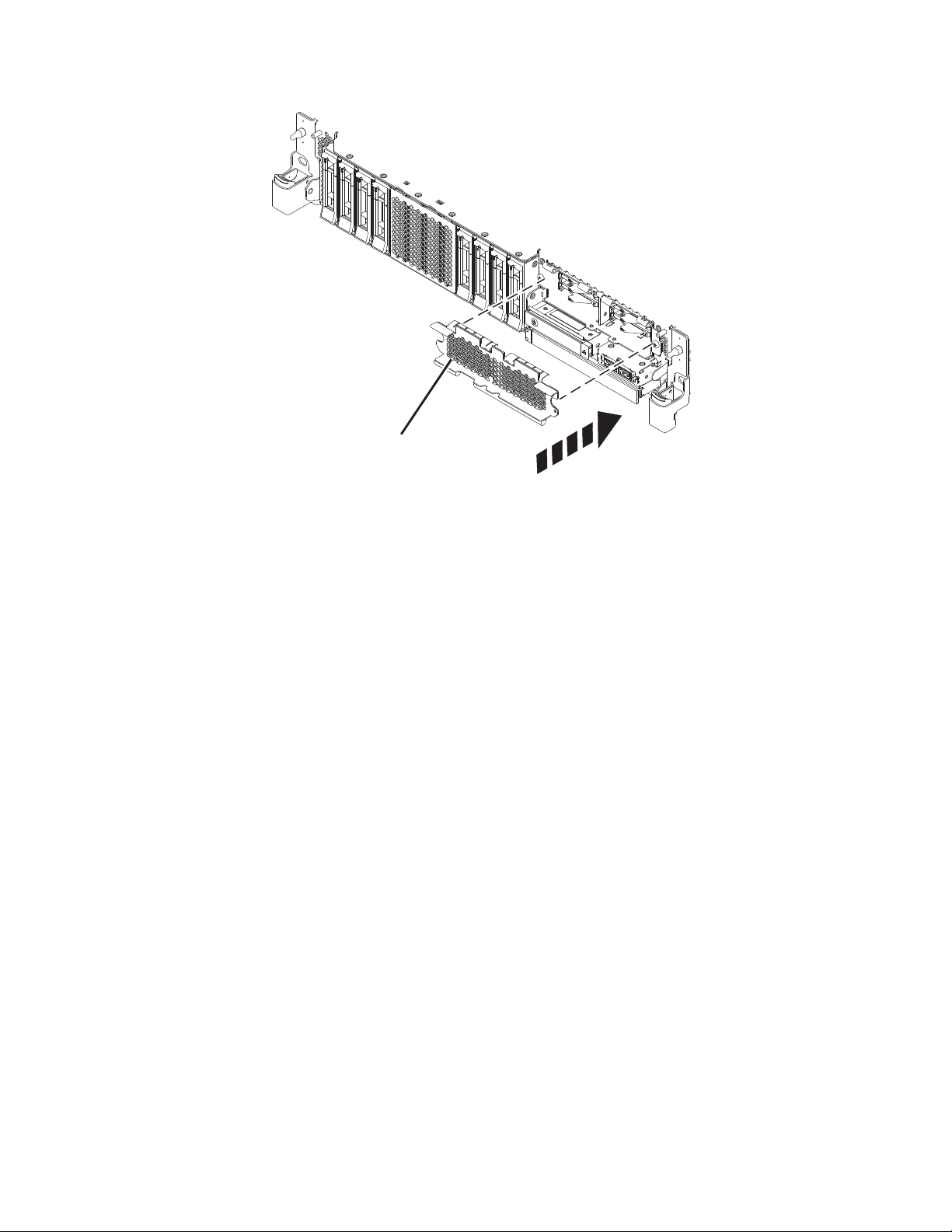
3. If applicable, cover the SSD cage with the perforated plate (A) as shown in Figure 9 on page 13.
12 Disk drives or solid-state drives
Page 31
A
P8HAL517-2
Figure 9. Covering the SSD cage in an expanded function system
4. If applicable, replace the front cover. For instructions to replace the front cover on an expanded
function system, see “Installing the front cover on a rack-mounted 5148-21L, 5148-22L, 8247-21L,
8247-22L, 8284-21A, or 8284-22A system” on page 153.
5. Start the system or logical partition. For instructions, see “Starting the system or logical partition” on
page 136.
6. On the front of the system, verify that the power LED is ON (green) for the installed or replaced
drive.
7. To configure the newly installed disk drive or solid-state drive, see the following procedures for the
applicable operating system that controls the disk drive or solid-state drive:
v “Configuring a disk drive or solid-state drive for use in an AIX system or AIX logical partition” on
page 114.
v “Configuring a disk drive or solid-state drive for use in an IBM i system or IBM i logical partition”
on page 115.
v “Configuring a disk drive or solid-state drive for use in an Linux system or Linux logical partition”
on page 118.
Installing a disk drive or solid-state drive in the 8284-21A or 8284-22A system with the power turned on in AIX
Learn how to install a disk drive or solid-state drive (SSD) in a system with the AIX®operating system or
AIX logical partition that controls the drive location powered on.
Before you install a feature, ensure that the software that is required to support the feature is installed on
your system. For information about software prerequisites, see the IBM Prerequisite website
(http://www-912.ibm.com/e_dir/eServerPrereq.nsf). If the required software is not installed, see the
following websites to download it, and then install it before you continue:
v To download system firmware updates, software updates, and fix packs, see the Fix Central website
(http://www.ibm.com/support/fixcentral/).
Disk drives or solid-state drives 13
Page 32

v To download Hardware Management Console (HMC) updates and fixes, see the Hardware
P2-D12
P2-D11
P2-D10
P2-D9
P2-D8
P2-D7
P2-D6
P2-D5
P2-D4
P2-D3
P2-D2
P2-D1
P8HAL508-0
Management Console Support and downloads website (www14.software.ibm.com/webapp/set2/sas/
f/hmcl/home.html).
To install a disk drive or solid-state drive in a system, complete the following steps:
1. “Preparing the 8284-21A or 8284-22A system to install a disk drive or solid-state drive with the power
turned on in AIX.”
2. “Installing a disk drive or solid-state drive in the 8284-21A or 8284-22A system with the power turned
on in AIX” on page 16.
3. “Preparing the 8284-21A or 8284-22A system for operation after installing a disk drive or solid-state
drive with the power turned on in AIX” on page 20.
Note: Installing this feature is a customer task. You can complete this task yourself, or contact a service
provider to complete the task for you. You might be charged a fee by the service provider for this service.
Preparing the 8284-21A or 8284-22A system to install a disk drive or solid-state drive with the power turned on in AIX
Learn about the steps you must complete before you install a disk drive or solid-state drive (SSD) in a
system with the AIX operating system or AIX logical partition that controls the drive location powered
on.
If you are installing SSDs, review the configuration rules and then return here. For details, see
“Solid-state drive configuration rules” on page 104.
To prepare the system to install a disk drive or solid-state drive, complete the following steps:
1. Ensure that the software that is required to support the feature is installed on your system. For
information about software prerequisites, see the IBM Prerequisite website (http://www-
912.ibm.com/e_dir/eServerPrereq.nsf). If the required system firmware, software, or fix packs are not
installed on your system, go to the Fix Central website (http://www.ibm.com/support/fixcentral/) to
download and install them before you continue.
2. Determine the slot in which you want to install a disk drive or an SSD. The disk drive and SSD slots
are in the front of a system. More SSD slots are also available in an expanded function system.
Figure 10 and Figure 11 on page 15 show the disk drive and solid-state drive locations and service
indicators. Service indicators are located above the latch handle on the disk drives.
Figure 10. Disk drive and service indicator locations for a base function system
14 Disk drives or solid-state drives
Page 33

P2-D14
P2-D12
P2-D10
P2-D13
P2-D11
P2-D9
P2-D8
P2-D7
P2-D6
P2-D5
P2-D4
P2-D3
P2-D2
P2-D1
P8HAL509-1
Figure 11. Disk drive, solid-state drive, and service indicator locations for an expanded function system
Note: When you have drive slots available in a system, enclosure, or expansion unit, fill the slot
positions in the system first. However, you can choose a different disk drive or solid-state drive
placement that depends on your data protection strategy.
3. To identify the available slot by using the diagnostic command, complete the following steps:
a. Log in as root user.
b. At the command line, type diag and then press Enter.
c. On the Diagnostic Operating Instructions display, press Enter to continue.
d. On the Function Selection display, select Task Selection.
e. Select RAID Array Manager.
f. Select IBM SAS Disk Array Manager.
g. Select Diagnostics and Recovery Options.
h. Select SCSI and SCSI RAID Hot Plug Manager.
i. Select Attach a Device to a SCSI Hot Swap Enclosure Device. A list of empty slots in the SCSI hot
swap enclosure device is shown.
4. Record the position (an available empty slot) where the new disk drive must be installed. For
example, the next available disk drive or SSD slot might be P2-D3.
5. Find the package that contains the new drive.
Attention: Drives are fragile. Handle with care.
6. Attach the electrostatic discharge (ESD) wrist strap. The ESD wrist strap must be connected to an
unpainted metal surface until the service procedure is completed, and if applicable, until the service
access cover is replaced.
Attention:
v Attach an electrostatic discharge (ESD) wrist strap to the front ESD jack, to the rear ESD jack, or to
an unpainted metal surface of your hardware to prevent the electrostatic discharge from damaging
your hardware.
v When you use an ESD wrist strap, follow all electrical safety procedures. An ESD wrist strap is
used for static control. It does not increase or decrease your risk of receiving electric shock when
using or working on electrical equipment.
v If you do not have an ESD wrist strap, just prior to removing the product from ESD packaging and
installing or replacing hardware, touch an unpainted metal surface of the system for a minimum of
5 seconds. If at any point in this service process you move away from the system, it is important to
once again discharge yourself by touching an unpainted metal surface for at least 5 seconds before
you continue with the service process.
7. Remove the drive from the static-protective package and place it on an ESD mat.
Disk drives or solid-state drives 15
Page 34

Installing a disk drive or solid-state drive in the 8284-21A or 8284-22A system with the power turned on in AIX
Learn how to install a disk drive or solid-state drive (SSD) in a system with the AIX operating system or
AIX logical partition that controls the drive location powered on.
To install a disk drive or solid-state drive in a system, complete the following steps:
1. Ensure that you have the electrostatic discharge (ESD) wrist strap on and that the ESD clip is
connected to an unpainted metal surface. If not, do so now.
2. Choose from the following options:
v If you are installing a disk drive in a system, continue with step 3.
v If you are installing an solid-state drive in an expanded function system, continue with step 12 on
page 18.
3. If the slot you want to use contains a drive filler, remove the drive filler from the slot.
To remove a filler from a base function system, complete the following steps:
a. Push the lock (A) on the handle of the filler in the direction that is shown in Figure 12.
b. Hold the handle and pull out the filler from the slot.
Figure 12. Removing a disk drive filler from a base function system
For instructions to remove a filler from other systems, see “Removing a disk drive filler from the
5148-21L, 5148-22L, 8247-21L, 8247-22L, 8284-21A, or 8284-22A” on page 97.
4. Unlock the drive bay handle (A) by pressing it and pulling it out toward you. If the handle is not all
the way out, the drive does not slide into the system. See Figure 13 on page 17 and Figure 14 on
page 18.
5. Hold the drive by the top and bottom edges as you position the drive, and insert it into the drive
slot.
6. Slide the drive halfway into the system.
16 Disk drives or solid-state drives
Page 35

7. On the console, select the drive that you want to install and then press Enter.
P8HAL503-0
A
8. When the identify LED turns on solid, slide the drive all the way into the system, and push the
drive carrier handle (A) in until it locks, as shown in the following figure. Figure 13 and Figure 14 on
page 18.
Important: Ensure that the drive is fully seated and is all the way into the system.
Figure 13. Installing a disk drive in a base function system
Disk drives or solid-state drives 17
Page 36

P8HAL505-1
A
Figure 14. Installing a disk drive in an expanded function system
9. On the console, press Enter to indicate that you installed the drive.
10. If you are installing more than one drive, repeat the steps in this procedure until all drives are
installed.
11. Proceed to the procedure for preparing the system for operation. For instructions, see “Preparing the
8284-21A or 8284-22A system for operation after installing a disk drive or solid-state drive with the
power turned on in AIX” on page 20.
12. To install an SSD in an expanded function system, continue with the next step.
13. Remove the front cover to access the SSD. For instructions to remove the front cover from an
expanded function system, see “Removing the front cover from a rack-mounted 5148-21L, 5148-22L,
8247-21L, 8247-22L, 8284-21A, or 8284-22A system” on page 148.
14. To access the SSD slots, remove the perforated plate (B) covering the SSD cage as shown in Figure 15
on page 19.
18 Disk drives or solid-state drives
Page 37

P8HAL516-2
B
Figure 15. Removing the SSD cage cover to access the SSD slots in an expanded function system
15. With the SSD drive bay handle (A) in the unlocked position, pull the lever outward to gain access to
the guide rails in the SSD slot. Support the bottom of the SSD as you align it with the guide rails in
the SSD slot. See Figure 16 on page 20.
Note: Support the drive by holding the drive by its sides.
16. Slide the drive halfway into the system.
17. On the console, select the drive that you want to install and then press Enter.
18. When the identify LED turns on solid, slide the drive all the way into the system until the drive
stops.
19. Lock the drive by rotating the bay handle (A) in the direction that is shown in Figure 16 on page 20.
Important: When you install an SSD, ensure that the SSD is fully seated and is all the way into the
system.
Disk drives or solid-state drives 19
Page 38

P8HAL507-2
A
Figure 16. Installing an SSD in an expanded function system
20. On the console, press Enter to indicate that you installed the drive.
21. If you are installing more than one drive, repeat the steps in this procedure until all drives are
installed.
Preparing the 8284-21A or 8284-22A system for operation after installing a disk drive or solid-state drive with the power turned on in AIX
Learn to prepare the system for operation after you install a disk drive or solid-state drive (SSD) in the
system with the AIX operating system or AIX logical partition that controls the drive location powered
on.
To prepare the system for operation, complete the following steps:
1. Ensure that you have the electrostatic discharge (ESD) wrist strap on and that the ESD clip is
connected to an unpainted metal surface. If not, do so now.
2. On the front of the system, verify that the power LED is ON (green) for the installed or replaced
drive.
3. If applicable, cover the SSD cage with the perforated plate (A) as shown in Figure 17 on page 21.
20 Disk drives or solid-state drives
Page 39

A
P8HAL517-2
Figure 17. Covering the SSD cage in an expanded function system
4. If applicable, replace the front cover. For instructions to replace the front cover on an expanded
function system, see “Installing the front cover on a rack-mounted 5148-21L, 5148-22L, 8247-21L,
8247-22L, 8284-21A, or 8284-22A system” on page 153.
5. To configure the newly installed disk drive or solid-state drive, see “Configuring a disk drive or
solid-state drive for use in an AIX system or AIX logical partition” on page 114.
Installing a disk drive or solid-state drive in the 8284-21A or 8284-22A system with the power turned on in IBM i
Learn how to install a disk drive or solid-state drive (SSD) in a system with the IBM i operating system
or IBM i logical partition that controls the drive location powered on.
Before you install a feature, ensure that the software that is required to support the feature is installed on
your system. For information about software prerequisites, see the IBM Prerequisite website
(http://www-912.ibm.com/e_dir/eServerPrereq.nsf). If the required software is not installed, see the
following websites to download it, and then install it before you continue:
v To download system firmware updates, software updates, and fix packs, see the Fix Central website
(http://www.ibm.com/support/fixcentral/).
v To download Hardware Management Console (HMC) updates and fixes, see the Hardware
Management Console Support and downloads website (www14.software.ibm.com/webapp/set2/sas/
f/hmcl/home.html).
To install a disk drive or solid-state drive in a system, complete the following steps:
1. “Preparing the 8284-21A or 8284-22A system to install a disk drive or solid-state drive with the power
turned on in IBM i” on page 22.
2. “Installing a disk drive or solid-state drive in the 8284-21A or 8284-22A system with the power turned
on in IBM i” on page 24.
3. “Preparing the 8284-21A or 8284-22A system for operation after installing a drive with the power
turned on in IBM i” on page 28.
Disk drives or solid-state drives 21
Page 40

Note: Installing this feature is a customer task. You can complete this task yourself, or contact a service
P2-D12
P2-D11
P2-D10
P2-D9
P2-D8
P2-D7
P2-D6
P2-D5
P2-D4
P2-D3
P2-D2
P2-D1
P8HAL508-0
P2-D14
P2-D12
P2-D10
P2-D13
P2-D11
P2-D9
P2-D8
P2-D7
P2-D6
P2-D5
P2-D4
P2-D3
P2-D2
P2-D1
P8HAL509-1
provider to complete the task for you. You might be charged a fee by the service provider for this service.
Preparing the 8284-21A or 8284-22A system to install a disk drive or solid-state drive with the power turned on in IBM i
Learn about the steps you must complete before you install a disk drive or solid-state drive (SSD) in a
system with the IBM i operating system or IBM i logical partition that controls the drive location
powered on.
If you are installing SSDs, review the configuration rules and then return here. For details, see
“Solid-state drive configuration rules” on page 104.
To prepare the system to install a disk drive or solid-state drive, complete the following steps:
1. Ensure that the software that is required to support the feature is installed on your system. For
information about software prerequisites, see the IBM Prerequisite website (http://www-
912.ibm.com/e_dir/eServerPrereq.nsf). If the required system firmware, software, or fix packs are not
installed on your system, go to the Fix Central website (http://www.ibm.com/support/fixcentral/) to
download and install them before you continue.
2. Determine the slot in which you want to install a disk drive or an SSD. The disk drive and SSD slots
are in the front of a system. More SSD slots are also available in an expanded function system.
Figure 18 and Figure 19 show the disk drive and solid-state drive locations and service indicators.
Service indicators are located above the latch handle on the disk drives.
Figure 18. Disk drive and service indicator locations for a base function system
Figure 19. Disk drive, solid-state drive, and service indicator locations for an expanded function system
22 Disk drives or solid-state drives
Page 41
Note: When you have drive slots available in a system, enclosure, or expansion unit, fill the slot
positions in the system first. However, you can choose a different disk drive or solid-state drive
placement that depends on your data protection strategy.
3. Record the physical location where the new disk drive or solid-state drive can be installed.
a. The physical location has the following form: U787A.001.AAAXXXX-P2-D3 where P2-D3 is the
position of the disk drive or solid-state drive in the system, drive enclosure, or an expansion unit.
Find the U787A.001.AAAXXXX location information from the control panel display on the system,
drive enclosure, or an expansion unit.
b. In this example, U787A.001.AAAXXXX-P2-D3, U787A.001 comes from the feature code (FC) on the
label, AAAXXXX comes from the last 7 digits of the sequence number (SN or SEQ) on the label,
and P2-D3 is the slot where you are installing the disk drive or solid-state drive.
c. If you cannot find the location information from the control panel, find the feature code (FC) and
sequence number (SN or SEQ) on the label that is shown on the front of the system, drive
enclosure, or an expansion unit, as shown in Figure 20. In the example, U5074.001.AAAXXXX-DB3-
D32, you would install a disk drive or solid-state drive in the expansion unit with type 5074,
model 001, sequence number AAAXXXX, and disk drive or solid-state drive position DB3–D32.
Figure 20. Example of a system or an expansion unit label
4. To identify the available slot by using the Hardware Service Manager (HSM), complete the following
steps:
a. Sign on to service level authority.
b. Type strsst in the command line of the IBM i session and then press Enter.
c. Type your service tools user ID and service tools password in the Start Service Tools Sign On
display, and then press Enter.
Note: The service tools password is case-sensitive.
d. Select Start a service tool from the System Service Tools (SST) display, and then press Enter.
e. Select Hardware service manager from the Start a Service Tool display, and then press Enter.
f. If the slot you want to use contains a disk drive filler, remove the disk drive filler.
g. Select Device Concurrent Maintenance from the Hardware Service Manager display, and then
press Enter.
The Device Concurrent Maintenance is displayed, as shown in the following figure.
Disk drives or solid-state drives 23
Page 42

Device Concurrent Maintenance
Type the choices, then press Enter.
Specify either physical location or resource name.
Physical location:
U787A.001.1234567-P3-D4
Specify action as 1=Remove device 2=Install device
Enter a time value between 00 and 19.
F3=Exit F5=Refresh F12=Cancel
Figure 21. Example Device Concurrent Maintenance display
or
Device resource name:
Action to be performed . . . . . . . .: 2
Time delay needed in minutes . . . . .: 01
h. In the Specify either physical location or resource name field, type the physical location that you
previously recorded in this procedure.
i. Select 2 (Install device) for the Action to be completed.
j. Set the time delay in minutes. For example, for one minute enter: 01.
Note: You can set an appropriate time delay of 01 - 19 minutes to allow adequate time to access
the disk drive or solid-state drive.
k. Do not press Enter yet, first complete installing the disk drive or solid-state drive in the system,
drive enclosure, or an expansion unit.
5. Find the package that contains the new drive.
Attention: Drives are fragile. Handle with care.
6. Attach the electrostatic discharge (ESD) wrist strap. The ESD wrist strap must be connected to an
unpainted metal surface until the service procedure is completed, and if applicable, until the service
access cover is replaced.
Attention:
v Attach an electrostatic discharge (ESD) wrist strap to the front ESD jack, to the rear ESD jack, or to
an unpainted metal surface of your hardware to prevent the electrostatic discharge from damaging
your hardware.
v When you use an ESD wrist strap, follow all electrical safety procedures. An ESD wrist strap is
used for static control. It does not increase or decrease your risk of receiving electric shock when
using or working on electrical equipment.
v If you do not have an ESD wrist strap, just prior to removing the product from ESD packaging and
installing or replacing hardware, touch an unpainted metal surface of the system for a minimum of
5 seconds. If at any point in this service process you move away from the system, it is important to
once again discharge yourself by touching an unpainted metal surface for at least 5 seconds before
you continue with the service process.
7. Remove the drive from the static-protective package and place it on an ESD mat.
Installing a disk drive or solid-state drive in the 8284-21A or 8284-22A system with the power turned on in IBM i
Learn how to install a disk drive or solid-state drive (SSD) in a system with the IBM i operating system
or IBM i logical partition that controls the drive location powered on.
To install a disk drive or solid-state drive in a system, complete the following steps:
1. Ensure that you have the electrostatic discharge (ESD) wrist strap on and that the ESD clip is
connected to an unpainted metal surface. If not, do so now.
2. Choose from the following options:
24 Disk drives or solid-state drives
Page 43
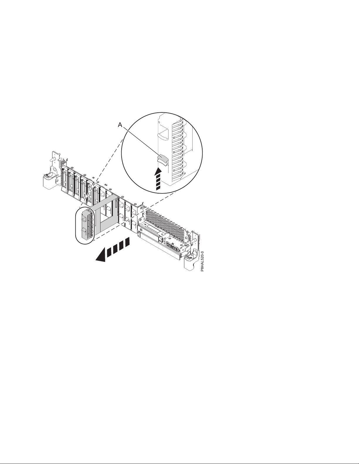
v If you are installing a disk drive in a system, continue with step 3.
v If you are installing an solid-state drive in an expanded function system, continue with step 13 on
page 27.
3. If the slot you want to use contains a drive filler, remove the drive filler from the slot.
To remove a filler from a base function system, complete the following steps:
a. Push the lock (A) on the handle of the filler in the direction that is shown in Figure 22.
b. Hold the handle and pull out the filler from the slot.
Figure 22. Removing a disk drive filler from a base function system
For instructions to remove a filler from other systems, see “Removing a disk drive filler from the
5148-21L, 5148-22L, 8247-21L, 8247-22L, 8284-21A, or 8284-22A” on page 97.
4. Unlock the drive bay handle (A) by pressing it and pulling it out toward you. If the handle is not all
the way out, the drive does not slide into the system. See Figure 23 on page 26 and Figure 24 on
page 26.
5. Hold the drive by the top and bottom edges as you position the drive, and insert it into the drive
slot.
6. Slide the drive halfway into the system.
7. In the HSM display, select the drive that you want to install or replace.
8. Press Enter on the console.
Important: When you press Enter, after your selected time delay, the service indicator light comes
on (solid) for 18 seconds. You then have 18 seconds to slide the drive all the way in and then lock it
in place by pushing in the drive handle. You can set an appropriate time delay of 01 - 19 minutes to
allow adequate time to access the disk drive or solid-state drive.
9. When the identify LED turns on solid, slide the drive all the way into the system, and push in the
drive handle (A) until it locks, as shown in Figure 23 on page 26 and Figure 24 on page 26.
Disk drives or solid-state drives 25
Page 44

Important: Ensure that the drive is fully seated and is all the way into the system.
P8HAL503-0
A
P8HAL505-1
A
Figure 23. Installing a disk drive in a base function system
Figure 24. Installing a disk drive in an expanded function system
10. On the console, press Enter to indicate that you installed the drive.
26 Disk drives or solid-state drives
Page 45

11. If you are installing more than one drive, repeat the steps in this procedure until all drives are
P8HAL516-2
B
installed.
12. Proceed to the procedure for preparing the system for operation. For instructions, see “Preparing the
8284-21A or 8284-22A system for operation after installing a drive with the power turned on in IBM
i” on page 28.
13. To install an SSD in an expanded function 8284-21A or 8284-22A system, continue with the next step.
14. Remove the front cover to access the SSD. For instructions to remove the front cover from an
expanded function system, see “Removing the front cover from a rack-mounted 5148-21L, 5148-22L,
8247-21L, 8247-22L, 8284-21A, or 8284-22A system” on page 148.
15. To access the SSD slots, remove the perforated plate (B) covering the SSD cage as shown in
Figure 25.
Figure 25. Removing the SSD cage cover to access the SSD slots in an expanded function system
16. With the SSD drive bay handle (A) in the unlocked position, pull the lever outward to gain access to
the guide rails in the SSD slot. Support the bottom of the SSD as you align it with the guide rails in
the SSD slot. See Figure 26 on page 28.
Note: Support the drive by holding the drive by its sides.
17. Slide the drive halfway into the system.
18. In the HSM display, select the drive that you want to install or replace.
19. Press Enter on the console.
Important: When you press Enter, after your selected time delay, the service indicator light comes
on (solid) for 18 seconds. You then have 18 seconds to slide the drive all the way in and then lock it
in place by pushing in the drive handle. You can set an appropriate time delay of 01 - 19 minutes to
allow adequate time to access the disk drive or solid-state drive.
20. When the identify LED turns on solid, slide the drive all the way into the system until the drive
stops.
21. Lock the drive by rotating the bay handle (A) in the direction that is shown in Figure 26 on page 28.
Disk drives or solid-state drives 27
Page 46

Important: When you install an SSD, ensure that the SSD is fully seated and is all the way into the
P8HAL507-2
A
system.
Figure 26. Installing an SSD in an expanded function system
22. On the console, press Enter to indicate that you installed the drive.
23. If you are installing more than one drive, repeat the steps in this procedure until all drives are
installed.
Preparing the 8284-21A or 8284-22A system for operation after installing a drive with the power turned on in IBM i
Learn to prepare the system for operation after you install a disk drive or solid-state drive (SSD) in the
system with the IBM i operating system or IBM i logical partition that controls the drive location
powered on.
To prepare the system for operation, complete the following steps:
1. Return to the console and wait until the Concurrent Maintenance Results display is shown, and then
press Enter.
2. When the HSM display is shown, press F12 twice and then press Enter.
3. Ensure that you have the electrostatic discharge (ESD) wrist strap on and that the ESD clip is
connected to an unpainted metal surface. If not, do so now.
4. On the front of the system, verify that the power LED is ON (green) for the installed or replaced
drive.
5. If applicable, cover the SSD cage with the perforated plate (A) as shown in Figure 27 on page 29.
28 Disk drives or solid-state drives
Page 47

A
P8HAL517-2
Figure 27. Covering the SSD cage in an expanded function system
6. If applicable, replace the front cover. For instructions to replace the front cover on an expanded
function system, see “Installing the front cover on a rack-mounted 5148-21L, 5148-22L, 8247-21L,
8247-22L, 8284-21A, or 8284-22A system” on page 153.
7. To configure the newly installed disk drive or solid-state drive, see “Configuring a disk drive or
solid-state drive for use in an IBM i system or IBM i logical partition” on page 115.
Installing a disk drive or solid-state drive in the 5148-21L, 5148-22L, 8247-21L, 8247-22L, 8284-21A, or 8284-22A system with the power turned on in Linux
Learn how to install a disk drive or solid-state drive (SSD) in a system, drive enclosure, or an expansion
unit, in the Linux system or an Linux logical partition with the power turned on.
Before you install a feature, ensure that the software that is required to support the feature is installed on
your system. For information about software prerequisites, see the IBM Prerequisite website
(http://www-912.ibm.com/e_dir/eServerPrereq.nsf). If the required software is not installed, see the
following websites to download it, and then install it before you continue:
v To download system firmware updates, software updates, and fix packs, see the Fix Central website
(http://www.ibm.com/support/fixcentral/).
v To download Hardware Management Console (HMC) updates and fixes, see the Hardware
Management Console Support and downloads website (www14.software.ibm.com/webapp/set2/sas/
f/hmcl/home.html).
To install a disk drive or solid-state drive in a system, complete the following steps:
1. “Preparing the 5148-21L, 5148-22L, 8247-21L, 8247-22L, 8284-21A, or 8284-22A system to install a disk
drive or solid-state drive with the power turned on in Linux” on page 30.
2. “Installing a disk drive or solid-state drive in the 5148-21L, 5148-22L, 8247-21L, 8247-22L, 8284-21A, or
8284-22A system with the power turned on in Linux” on page 32.
Disk drives or solid-state drives 29
Page 48
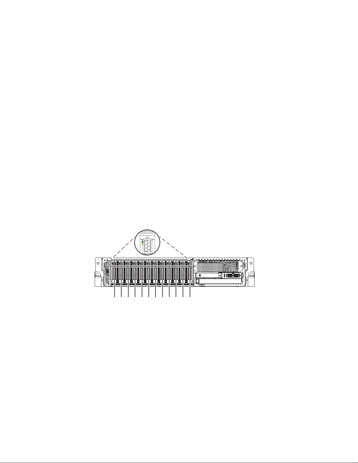
3. “Preparing the 5148-21L, 5148-22L, 8247-21L, 8247-22L, 8284-21A, or 8284-22A system for operation
P2-D12
P2-D11
P2-D10
P2-D9
P2-D8
P2-D7
P2-D6
P2-D5
P2-D4
P2-D3
P2-D2
P2-D1
P8HAL508-0
after installing a disk drive or solid-state drive with the power turned on in Linux” on page 36.
Note: Installing this feature is a customer task. You can complete this task yourself, or contact a service
provider to complete the task for you. You might be charged a fee by the service provider for this service.
Preparing the 5148-21L, 5148-22L, 8247-21L, 8247-22L, 8284-21A, or 8284-22A system to install a disk drive or solid-state drive with the power turned on in Linux
Learn about the steps you must complete before you install a disk drive or solid-state drive (SSD) in a
system with the Linux operating system or Linux logical partition that controls the drive location
powered on.
If you are installing SSDs, review the configuration rules and then return here. For details, see
“Solid-state drive configuration rules” on page 104.
To prepare the system to install a disk drive or solid-state drive, complete the following steps:
1. Ensure that the software that is required to support the feature is installed on your system. For
information about software prerequisites, see the IBM Prerequisite website (http://www-
912.ibm.com/e_dir/eServerPrereq.nsf). If the required system firmware, software, or fix packs are not
installed on your system, go to the Fix Central website (http://www.ibm.com/support/fixcentral/) to
download and install them before you continue.
2. Determine the slot in which you want to install a disk drive or an SSD. The disk drive and SSD slots
are in the front of a system. More SSD slots are also available in an expanded function system.
Figure 28 and Figure 29 on page 31 show the disk drive and solid-state drive locations and service
indicators. Service indicators are located above the latch handle on the disk drives.
Figure 28. Disk drive and service indicator locations for a base function system
30 Disk drives or solid-state drives
Page 49

P2-D14
P2-D12
P2-D10
P2-D13
P2-D11
P2-D9
P2-D8
P2-D7
P2-D6
P2-D5
P2-D4
P2-D3
P2-D2
P2-D1
P8HAL509-1
Figure 29. Disk drive, solid-state drive, and service indicator locations for an expanded function system
Note: When you have drive slots available in a system, enclosure, or expansion unit, fill the slot
positions in the system first. However, you can choose a different disk drive or solid-state drive
placement that depends on your data protection strategy.
3. To identify the available slot by using the iprconfig command, complete the following steps:
a. Log in as root user.
b. Type iprconfig on the command line of the Linux session, and then press Enter. The IBM Power
RAID Configuration Utility display is shown.
c. Select Work with disk unit recovery from the IBM Power RAID Configuration Utility display, and
then press Enter.
d. Select Concurrent add device from the Work with Disk Unit Recovery display, and then press
Enter.
A Concurrent Device Add display, similar to Figure 30, is shown.
Concurrent Device Add
Choose a single location for add operations
1=Select
OPT Name PCI/SCSI Location Description Status
--- ------ -------------------------- ------------------------- ----------------U5887.001.Z065075-P1-D1 Empty
U5887.001.Z065075-P1-D6 Empty
U5887.001.Z065075-P1-D7 Empty
U5887.001.Z065075-P1-D8 Empty
U5887.001.Z065075-P1-D9 Empty
e=Exit q=Cancel t=Toggle
Figure 30. Example Concurrent Device Add display
e. Type t if you want to toggle through different location code representations.
f. Type 1 next to the location into which you want to install the disk drive or solid-state drive and
press Enter. The Verify Device Concurrent Add display is shown and the service indicator flashes
for the selected slot.
g. Do not press Enter again. Follow the rest of the procedure to complete installing the drive.
4. Record the position (an available empty slot) where the new disk drive must be installed. For
example, the next available disk drive or SSD slot might be P2-D3.
5. Find the package that contains the new drive.
Attention: Drives are fragile. Handle with care.
Disk drives or solid-state drives 31
Page 50

6. Attach the electrostatic discharge (ESD) wrist strap. The ESD wrist strap must be connected to an
unpainted metal surface until the service procedure is completed, and if applicable, until the service
access cover is replaced.
Attention:
v Attach an electrostatic discharge (ESD) wrist strap to the front ESD jack, to the rear ESD jack, or to
an unpainted metal surface of your hardware to prevent the electrostatic discharge from damaging
your hardware.
v When you use an ESD wrist strap, follow all electrical safety procedures. An ESD wrist strap is
used for static control. It does not increase or decrease your risk of receiving electric shock when
using or working on electrical equipment.
v If you do not have an ESD wrist strap, just prior to removing the product from ESD packaging and
installing or replacing hardware, touch an unpainted metal surface of the system for a minimum of
5 seconds. If at any point in this service process you move away from the system, it is important to
once again discharge yourself by touching an unpainted metal surface for at least 5 seconds before
you continue with the service process.
7. Remove the drive from the static-protective package and place it on an ESD mat.
Installing a disk drive or solid-state drive in the 5148-21L, 5148-22L, 8247-21L, 8247-22L, 8284-21A, or 8284-22A system with the power turned on in Linux
Learn how to install a disk drive or solid-state drive (SSD) in a system with the Linux operating system
or Linux logical partition that controls the drive location powered on.
To install a disk drive or solid-state drive in a system, complete the following steps:
1. Ensure that you have the electrostatic discharge (ESD) wrist strap on and that the ESD clip is
connected to an unpainted metal surface. If not, do so now.
2. Choose from the following options:
v If you are installing a disk drive in a system, continue with step 3.
v If you are installing an solid-state drive in an expanded function system, continue with step 12 on
page 35.
3. If the slot you want to use contains a drive filler, remove the drive filler from the slot.
To remove a filler from a base function system, complete the following steps:
a. Push the lock (A) on the handle of the filler in the direction that is shown in Figure 31 on page
33.
b. Hold the handle and pull out the filler from the slot.
32 Disk drives or solid-state drives
Page 51

Figure 31. Removing a disk drive filler from a base function system
For instructions to remove a filler from other systems, see “Removing a disk drive filler from the
5148-21L, 5148-22L, 8247-21L, 8247-22L, 8284-21A, or 8284-22A” on page 97.
4. Unlock the drive bay handle (A) by pressing it and pulling it out toward you. If the handle is not all
the way out, the drive does not slide into the system. See Figure 32 on page 34 and Figure 33 on
page 34.
5. Hold the drive by the top and bottom edges as you position the drive, and insert it into the drive
slot.
6. Slide the drive halfway into the system.
7. Return to the console, and then press Enter. In the Verify Device Concurrent Add display, verify that
the selected slot is the slot in which you want to install the drive.
8. When the identify LED flashes for the selected slot, slide the drive all the way into the slot, and
push the drive bay handle (A) in until it locks, as shown in Figure 32 on page 34 and Figure 33 on
page 34.
Important: Ensure that the drive is fully seated and is all the way into the system.
Disk drives or solid-state drives 33
Page 52

P8HAL503-0
A
Figure 32. Installing a disk drive in a base function system
P8HAL505-1
A
Figure 33. Installing a disk drive in an expanded function system
9. On the console, press Enter to indicate that you installed the drive.
34 Disk drives or solid-state drives
Page 53
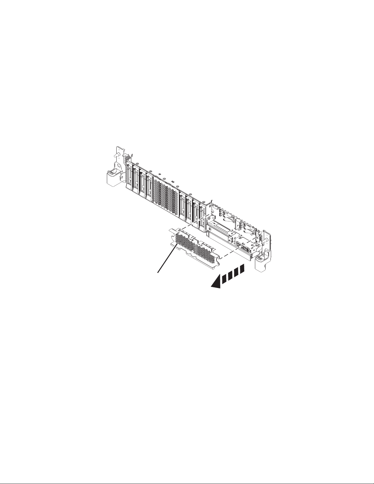
10. If you are installing more than one drive, repeat the steps in this procedure until all drives are
P8HAL516-2
B
installed.
11. Proceed to the procedure for preparing the system for operation. For instructions, see “Preparing the
5148-21L, 5148-22L, 8247-21L, 8247-22L, 8284-21A, or 8284-22A system for operation after installing a
disk drive or solid-state drive with the power turned on in Linux” on page 36.
12. To install an SSD in an expanded function 5148-21L, 5148-22L, 8247-21L, 8247-22L, 8284-21A, or
8284-22A system, continue with the next step.
13. Remove the front cover to access the SSD. For instructions to remove the front cover from an
expanded function system, see “Removing the front cover from a rack-mounted 5148-21L, 5148-22L,
8247-21L, 8247-22L, 8284-21A, or 8284-22A system” on page 148.
14. To access the SSD slots, remove the perforated plate (B) covering the SSD cage as shown in
Figure 34.
Figure 34. Removing the SSD cage cover to access the SSD slots in an expanded function system
15. With the SSD drive bay handle (A) in the unlocked position, pull the lever outward to gain access to
the guide rails in the SSD slot. Support the bottom of the SSD as you align it with the guide rails in
the SSD slot. See Figure 35 on page 36.
Note: Support the drive by holding the drive by its sides.
16. Slide the drive halfway into the system.
17. Return to the console, and then press Enter. In the Verify Device Concurrent Add display, verify that
the selected slot is the slot in which you want to install the drive.
18. When the identify LED flashes for the selected slot, slide the drive all the way into the slot until the
drive stops.
19. Lock the drive by rotating the bay handle (A) in the direction that is shown in Figure 35 on page 36.
Important: When you install an SSD, ensure that the SSD is fully seated and is all the way into the
system.
Disk drives or solid-state drives 35
Page 54

P8HAL507-2
A
Figure 35. Installing an SSD in an expanded function system
20. On the console, press Enter to indicate that you installed the drive.
21. If you are installing more than one drive, repeat the steps in this procedure until all drives are
installed.
Preparing the 5148-21L, 5148-22L, 8247-21L, 8247-22L, 8284-21A, or 8284-22A system for operation after installing a disk drive or solid-state drive with the power turned on in Linux
Learn to prepare the system for operation after you install a disk drive or solid-state drive (SSD) in the
system with the Linux operating system or Linux logical partition that controls the drive location
powered on.
To prepare the system for operation, complete the following steps:
1. Press Enter on the Complete Device Concurrent Add display to indicate that the disk drive or
solid-state drive is installed. The service indicator stops flashing and turns off for that drive slot.
2. Ensure that you have the electrostatic discharge (ESD) wrist strap on and that the ESD clip is
connected to an unpainted metal surface. If not, do so now.
3. On the front of the system, verify that the power LED is ON (green) for the installed or replaced
drive.
4. If applicable, cover the SSD cage with the perforated plate (A) as shown in Figure 36 on page 37.
36 Disk drives or solid-state drives
Page 55

A
P8HAL517-2
Figure 36. Covering the SSD cage in an expanded function system
5. If applicable, replace the front cover. For instructions to replace the front cover on an expanded
function system, see “Installing the front cover on a rack-mounted 5148-21L, 5148-22L, 8247-21L,
8247-22L, 8284-21A, or 8284-22A system” on page 153.
6. To verify that the new disk drive or solid-state drive is operational, complete the following steps:
a. Log in as root user.
b. Type iprconfig on the command line of the Linux session and press Enter. The IBM Power RAID
Configuration Utility display is shown.
c. Select Display hardware status. The Display Hardware Status display is shown, similar to the
following figure.
Disk drives or solid-state drives 37
Page 56

Display Hardware Status
Type option, press Enter.
1=Display hardware resource information details
OPT Name PCI/SCSI Location Description Status
--- ------ -------------------------- ------------------------- ----------------
e=Exit q=Cancel r=Refresh t=Toggle f=PageDn b=PageUp
Figure 37. Example Display Hardware Status
0000:01:00.0/0: PCI-E SAS RAID Adapter Operational
0000:01:00.0/0:0:0:0 Advanced Function SSD Active
0000:01:00.0/0:0:1:0 Advanced Function SSD Active
0000:01:00.0/0:0:2:0 Advanced Function SSD Active
0000:01:00.0/0:0:3:0 Advanced Function SSD Active
0000:01:00.0/0:0:4:0 Advanced Function SSD Active
0000:01:00.0/0:0:5:0 Advanced Function SSD Active
0000:01:00.0/0:0:6:0 Advanced Function SSD Active
0000:01:00.0/0:0:8:0 Enclosure Active
0000:01:00.0/0:0:9:0 Enclosure Active
0001:01:00.0/1: PCI-E SAS RAID Adapter Operational
0001:01:00.0/1:0:3:0 Advanced Function SSD Remote
0001:01:00.0/1:0:4:0 Advanced Function SSD Remote
0001:01:00.0/1:0:5:0 Advanced Function SSD Remote
More...
d. Verify that the disk drive or solid-state drive that you installed is shown on this display.
7. To configure the newly installed disk drive or solid-state drive, see “Configuring a disk drive or
solid-state drive for use in an Linux system or Linux logical partition” on page 118.
Removing and replacing a disk drive or solid-state drive in the 5148-21L, 5148-22L, 8247-21L, 8247-22L, 8284-21A, or 8284-22A
Find information about removing and replacing a serial-attached SCSI (SAS) disk drive or a solid-state
drive (SSD) in a system.
If you are removing and replacing a disk drive or solid-state drive in a 5887 disk drive enclosure or
5147-024, ESLL, or ESLS storage enclosure, see Removing and replacing a disk drive or solid-state drive
in the 5887 disk drive enclosure(http://www.ibm.com/support/knowledgecenter/POWER8/p8hal/
p8hal_5887_rnr_kickoff.htm) or Removing and replacing a disk drive or solid-state drive in the 5147-024,
ESLL, or ESLS storage enclosure storage enclosure(http://www.ibm.com/support/knowledgecenter/
POWER8/p8hal/p8hal_eslx_rnr_kickoff.htm).
Removing and replacing a disk drive or solid-state drive in the 5148-21L, 5148-22L, 8247-21L, 8247-22L, 8284-21A, or 8284-22A with the system power turned off
Learn how to remove and replace a disk drive or solid-state drive (SSD) in a system with the system
power turned off.
To remove and replace a disk drive or solid-state drive in a system, complete the following steps:
1. “Preparing the 5148-21L, 5148-22L, 8247-21L, 8247-22L, 8284-21A, or 8284-22A system to remove and
replace a disk drive or solid-state drive with the power turned off” on page 39.
2. “Removing a disk drive or solid-state drive from the 5148-21L, 5148-22L, 8247-21L, 8247-22L,
8284-21A, or 8284-22A system with the power turned off” on page 42.
3. “Replacing a disk drive or solid-state drive in the 5148-21L, 5148-22L, 8247-21L, 8247-22L, 8284-21A,
or 8284-22A system with the power turned off” on page 45.
4. “Preparing the 5148-21L, 5148-22L, 8247-21L, 8247-22L, 8284-21A, or 8284-22A system for operation
after removing and replacing a drive with the power turned off” on page 47.
38 Disk drives or solid-state drives
Page 57

Note: Removing or replacing this feature is a customer task. You can complete this task yourself, or
P2-D12
P2-D11
P2-D10
P2-D9
P2-D8
P2-D7
P2-D6
P2-D5
P2-D4
P2-D3
P2-D2
P2-D1
P8HAL508-0
contact a service provider to complete the task for you. You might be charged a fee by the service
provider for this service.
Preparing the 5148-21L, 5148-22L, 8247-21L, 8247-22L, 8284-21A, or 8284-22A system to remove and replace a disk drive or solid-state drive with the power turned off
Learn about the steps you must complete before you remove and replace a disk drive or solid-state drive
(SSD) in the system with the system power turned off.
To prepare the system to remove and replace a disk drive or solid-state drive, complete the following
steps:
1. Prepare to remove the disk drive or solid-state drive from the system, drive enclosure, or expansion
unit by using one of the following procedures depending on the operating system that controls the
drive location:
v If the system or logical partition that controls the disk drive or solid-state drive location is running
the AIX operating system, see “Preparing the system to remove a disk drive or solid-state drive in
AIX” on page 113.
v If the system or logical partition that controls the disk drive or solid-state drive location is running
the IBM i operating system, see “Preparing the system to remove a disk drive or solid-state drive
from a system or logical partition controlled by IBM i” on page 113.
v If the system or logical partition that controls the disk drive or solid-state drive location is running
the Linux operating system, see “Preparing the system to remove a disk drive or solid-state drive in
Linux” on page 114.
2. Identify the part and the system that you want to service. The disk drive and SSD slots are in the
front of a system. More SSD slots are also available in an expanded function system.
Figure 38 and Figure 39 on page 40 show the disk drive and solid-state drive locations and service
indicators. Service indicators are located above the latch handle on the disk drives.
Figure 38. Disk drive and service indicator locations for a base function system
Disk drives or solid-state drives 39
Page 58
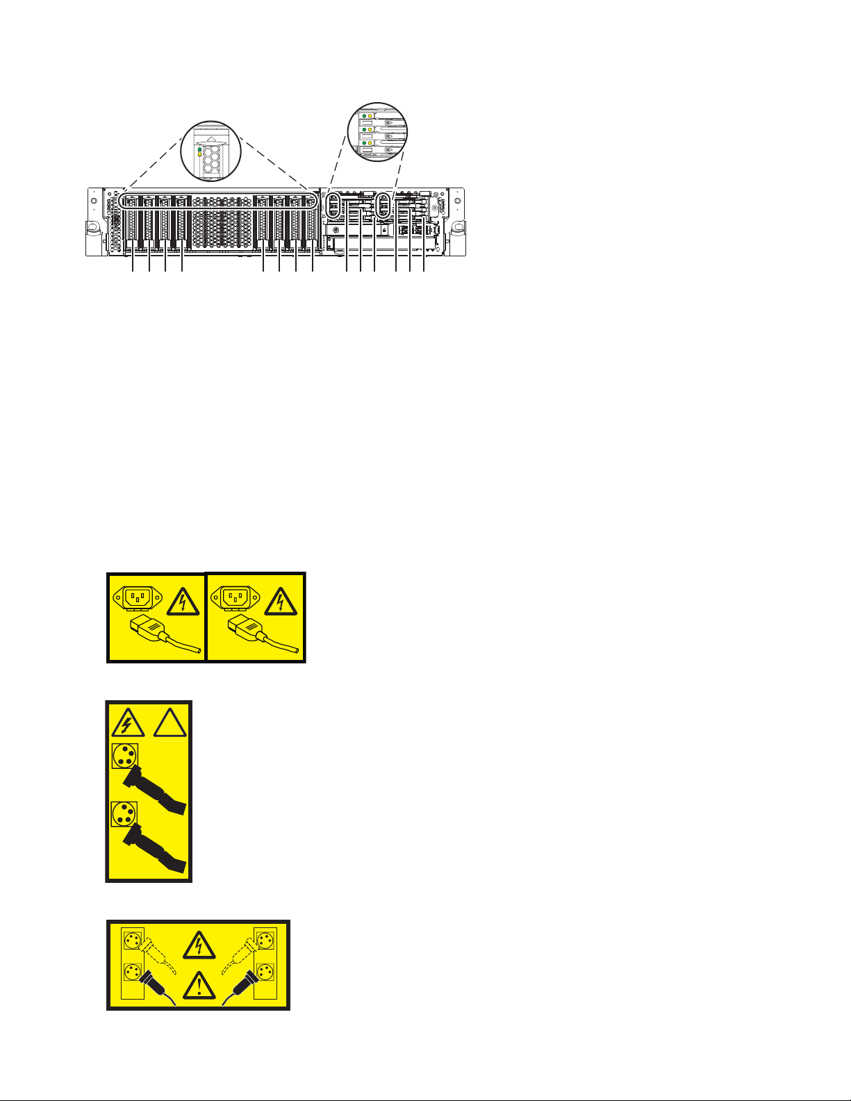
1
2
!
1
2
1 2
3
4
P2-D14
P2-D12
P2-D10
P2-D13
P2-D11
P2-D9
P2-D8
P2-D7
P2-D6
P2-D5
P2-D4
P2-D3
P2-D2
P2-D1
P8HAL509-1
Figure 39. Disk drive, solid-state drive, and service indicator locations for an expanded function system
3. Identify the disk drive or solid-state drive to be removed and record the location information. For
instructions, see “Identifying a part” on page 126.
4. Stop the system or logical partition. For instructions, see “Stopping a system or logical partition” on
page 134.
5. Open the rack rear door.
6. Disconnect the power source from the system by unplugging the system. For instructions, see
“Disconnecting the power cords from the system” on page 142.
Note: The system might be equipped with redundant power supply. Before you continue with this
procedure, ensure that all power to your system is disconnected.
(L003)
or
or
40 Disk drives or solid-state drives
Page 59
or
1
2
3
4
or
DANGER: Multiple power cords. The product might be equipped with multiple AC power cords or
multiple DC power cables. To remove all hazardous voltages, disconnect all power cords and power
cables. (L003)
7. Find the package that contains the new drive.
Attention: Drives are fragile. Handle with care.
8. Attach the electrostatic discharge (ESD) wrist strap. The ESD wrist strap must be connected to an
unpainted metal surface until the service procedure is completed, and if applicable, until the service
access cover is replaced.
Attention:
v Attach an electrostatic discharge (ESD) wrist strap to the front ESD jack, to the rear ESD jack, or to
an unpainted metal surface of your hardware to prevent the electrostatic discharge from damaging
your hardware.
v When you use an ESD wrist strap, follow all electrical safety procedures. An ESD wrist strap is
used for static control. It does not increase or decrease your risk of receiving electric shock when
using or working on electrical equipment.
v If you do not have an ESD wrist strap, just prior to removing the product from ESD packaging and
installing or replacing hardware, touch an unpainted metal surface of the system for a minimum of
5 seconds. If at any point in this service process you move away from the system, it is important to
once again discharge yourself by touching an unpainted metal surface for at least 5 seconds before
you continue with the service process.
9. Remove the drive from the static-protective package and place it on an ESD mat.
Disk drives or solid-state drives 41
Page 60

Removing a disk drive or solid-state drive from the 5148-21L, 5148-22L, 8247-21L,
A
B
P8HAL502-0
8247-22L, 8284-21A, or 8284-22A system with the power turned off
Find information about removing a disk drive or solid-state drive (SSD) from a system with the system
power turned off.
To remove a disk drive or solid-state drive from a system, complete the following steps:
1. Ensure that you have the electrostatic discharge (ESD) wrist strap on and that the ESD clip is
connected to an unpainted metal surface. If not, do so now.
2. Choose from the following options:
v If you are removing a disk drive from a system, continue with step 3.
v If you are removing a solid-state drive from an expanded function system, continue with step 8 on
page 43.
3. Unlock the drive handle (B) by pressing the handle latch (A) and pulling it out toward you, as
shown in Figure 40 and Figure 41 on page 43. If the handle is not all the way out, the solid-state
drive cannot slide out of the system.
Figure 40. Removing a disk drive from a base function system
42 Disk drives or solid-state drives
Page 61

A
B
P8HAL504-1
Figure 41. Removing a disk drive from an expanded function system
4. Support the bottom of the drive as you slide it out of the system. Hold the drive by its sides.
5. If you are removing more than one drive, repeat the steps in this procedure until all drives are
removed.
6. If you are not installing a replacement drive, install a filler in the empty slot to ensure proper air
flow for cooling. For instructions, see“Installing a disk drive filler in the 5148-21L, 5148-22L,
8247-21L, 8247-22L, 8284-21A, or 8284-22A” on page 99.
7. Proceed to the procedure for replacing a disk drive. See “Replacing a disk drive or solid-state drive
in the 5148-21L, 5148-22L, 8247-21L, 8247-22L, 8284-21A, or 8284-22A system with the power turned
off” on page 45.
8. To remove an SSD in an expanded function system, continue with the next step.
9. Remove the front cover to access the SSD. For instructions to remove the front cover from an
expanded function system, see “Removing the front cover from a rack-mounted 5148-21L, 5148-22L,
8247-21L, 8247-22L, 8284-21A, or 8284-22A system” on page 148.
10. To access the SSD slots, remove the perforated plate (B) covering the SSD cage as shown in Figure 42
on page 44.
Disk drives or solid-state drives 43
Page 62
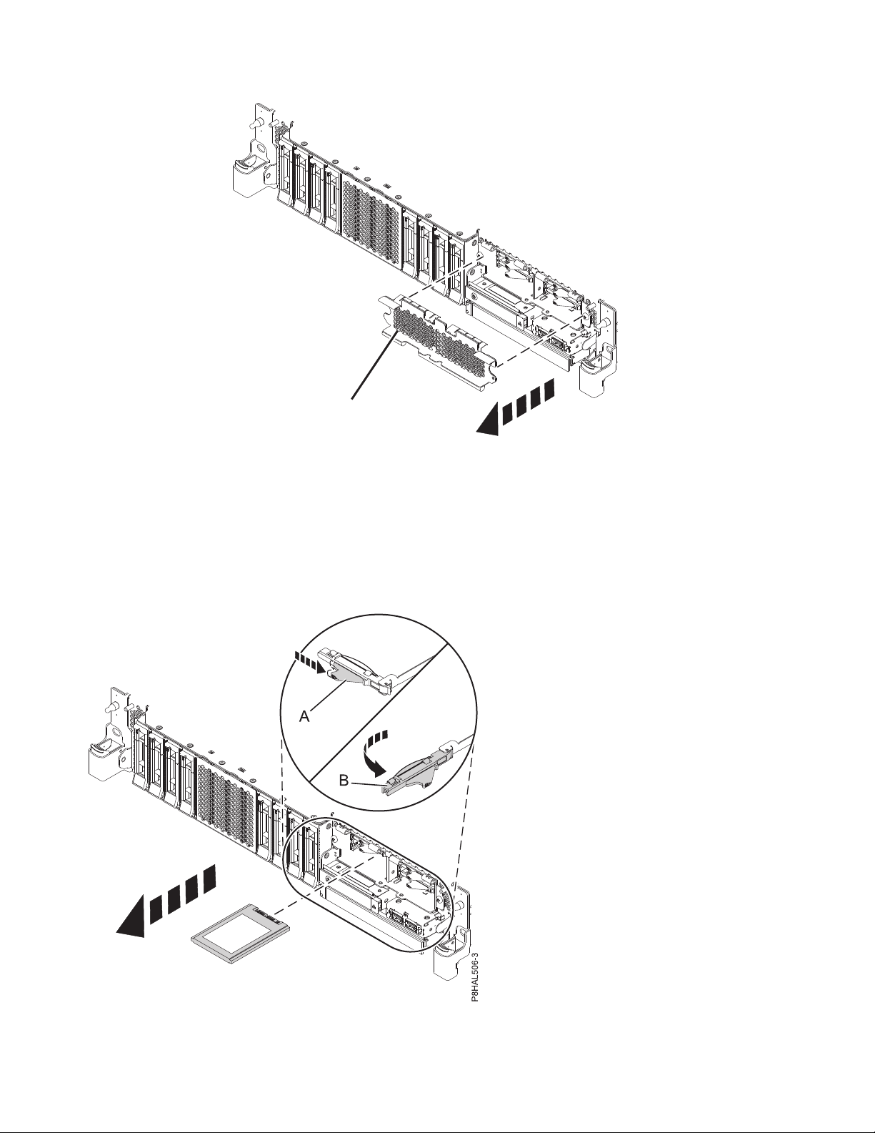
P8HAL516-2
B
Figure 42. Removing the SSD cage cover to access the SSD slots in an expanded function system
11. Unlock the drive bay handle (B) by pushing the handle latch (A) in the direction that is shown and
pulling the drive handle (B) out toward you, as shown in Figure 43. If the handle is not all the way
out, the solid-state drive cannot slide out of the system.
Figure 43. Removing an SSD from an expanded function system
44 Disk drives or solid-state drives
Page 63

12. Support the bottom of the drive as you slide it out of the system. Hold the drive by its sides.
P8HAL503-0
A
13. If you are not installing a replacement drive immediately, lock the drive bay handle (B) by rotating it
inwards toward the system.
14. If you are removing more than one drive, repeat the steps in this procedure until all drives are
removed.
Replacing a disk drive or solid-state drive in the 5148-21L, 5148-22L, 8247-21L, 8247-22L, 8284-21A, or 8284-22A system with the power turned off
Find information about replacing a disk drive or solid-state drive (SSD) in a system with the system
power turned off.
To replace a disk drive or solid-state drive in a system, complete the following steps:
1. Ensure that you have the electrostatic discharge (ESD) wrist strap on and that the ESD clip is
connected to an unpainted metal surface. If not, do so now.
2. Choose from the following options:
v If you are replacing a disk drive in a system, continue with step 3.
v If you are replacing an SSD in an expanded function system, continue with step 8 on page 46.
3. Unlock the drive bay handle (A) by pressing it and pulling it out toward you. If the handle is not all
the way out, the drive does not slide into the system. See Figure 44 and Figure 45 on page 46.
4. Hold the drive by the top and bottom edges as you position the drive, and insert it into the drive
slot.
5. Slide the drive all the way into the system, and push the drive bay handle (A) in until it locks, as
shown in Figure 44 and Figure 45 on page 46.
Important: Ensure that the drive is fully seated and is all the way into the system.
Figure 44. Replacing a disk drive in a base function system
Disk drives or solid-state drives 45
Page 64
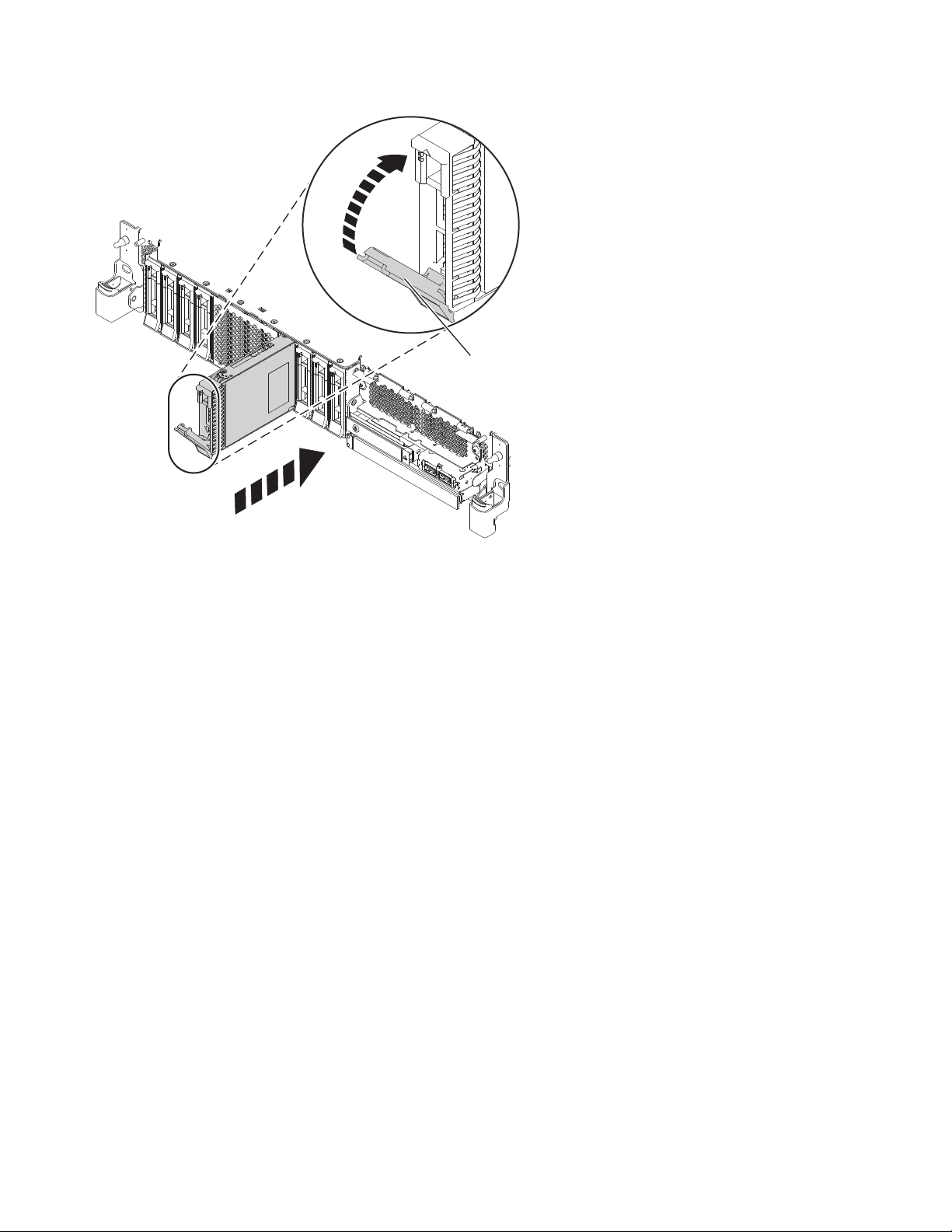
P8HAL505-1
A
Figure 45. Replacing a disk drive in an expanded function system
6. If you are installing more than one drive, repeat the steps in this procedure until all drives are
installed.
7. Proceed to the procedure for preparing the system for operation. For instructions, see “Preparing the
5148-21L, 5148-22L, 8247-21L, 8247-22L, 8284-21A, or 8284-22A system for operation after removing
and replacing a drive with the power turned off” on page 47.
8. If you are replacing an SSD in an expanded function system, continue with the next step.
9. With the SSD drive bay handle (A) in the unlocked position, pull the lever outward to gain access to
the guide rails in the SSD slot. Support the bottom of the SSD as you align it with the guide rails in
the SSD slot. See Figure 46 on page 47.
Note: Support the drive by holding the drive by its sides.
10. Slide the SSD into the system until the drive stops, and then lock the SSD by rotating the bay handle
(A) in the direction shown.
Important: When you install an SSD, ensure that the SSD is fully seated and is all the way into the
system.
46 Disk drives or solid-state drives
Page 65

P8HAL507-2
A
Figure 46. Replacing an SSD in an expanded function system
11. Lock the drive by rotating the bay handle (A) in the direction that is shown in Figure 46.
12. If you are installing more than one drive, repeat the steps in this procedure until all drives are
installed.
Preparing the 5148-21L, 5148-22L, 8247-21L, 8247-22L, 8284-21A, or 8284-22A system for operation after removing and replacing a drive with the power turned off
Learn to prepare the system for operation after you replace a disk drive or solid-state drive (SSD) in the
system with the system power turned off.
To prepare the system for operation, complete the following steps:
1. Ensure that you have the electrostatic discharge (ESD) wrist strap on and that the ESD clip is
connected to an unpainted metal surface. If not, do so now.
2. Reconnect the power cords to the system. For instructions, see “Connecting the power cords to the
system” on page 145.
3. If applicable, cover the SSD cage with the perforated plate (A) as shown in Figure 47 on page 48.
Disk drives or solid-state drives 47
Page 66
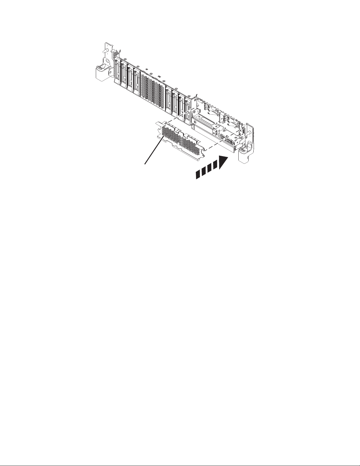
A
P8HAL517-2
Figure 47. Covering the SSD cage in an expanded function system
4. If applicable, replace the front cover. For instructions to replace the front cover on an expanded
function system, see “Installing the front cover on a rack-mounted 5148-21L, 5148-22L, 8247-21L,
8247-22L, 8284-21A, or 8284-22A system” on page 153.
5. Start the system or logical partition. For instructions, see “Starting the system or logical partition” on
page 136.
6. If you replaced a drive and have not verified the drive yet, verify that the power LED is ON (green)
and the amber fault LED is OFF (not lit) for the replaced drive on the front of the system.
7. To configure the newly installed disk drive or solid-state drive, see the following procedures for the
applicable operating system that controls the disk drive or solid-state drive:
v “Configuring a disk drive or solid-state drive for use in an AIX system or AIX logical partition” on
page 114.
v “Configuring a disk drive or solid-state drive for use in an IBM i system or IBM i logical partition”
on page 115.
v “Configuring a disk drive or solid-state drive for use in an Linux system or Linux logical partition”
on page 118.
8. To rebuild the data on the replacement disk drive or solid-state drive, or to recover from a failed or
missing array, see the following procedures for the applicable operating system that controls the drive:
v “Rebuilding data on a replacement disk drive or solid-state drive in a system or logical partition
running the AIX operating system” on page 119.
v “Rebuilding data on a replacement disk drive or solid-state drive in a system or logical partition
running the IBM i operating system” on page 120.
v “Rebuilding data on a replacement disk drive or solid-state drive in a system or logical partition
that is running the Linux operating system” on page 121.
48 Disk drives or solid-state drives
Page 67

Removing and replacing a disk drive or solid-state drive in the 8284-21A or 8284-22A system with the power turned on in AIX
Learn how to remove and replace a disk drive or solid-state drive (SSD) in a system with the AIX
operating system or AIX logical partition that controls the drive location powered on.
To remove and replace a disk drive or solid-state drive in a system, complete the following steps:
1. “Preparing the 8284-21A or 8284-22A system to remove and replace a disk drive or solid-state drive
with the power turned on in AIX.”
2. “Removing a disk drive or solid-state drive from the 8284-21A or 8284-22A system with the power
turned on in AIX” on page 51.
3. “Replacing a disk drive or solid-state drive in the 8284-21A or 8284-22A system with the power
turned on in AIX” on page 54.
4. “Preparing the 8284-21A or 8284-22A system for operation after replacing a drive with the power
turned on in AIX” on page 57.
Note: Removing or replacing this feature is a customer task. You can complete this task yourself, or
contact a service provider to complete the task for you. You might be charged a fee by the service
provider for this service.
Preparing the 8284-21A or 8284-22A system to remove and replace a disk drive or solid-state drive with the power turned on in AIX
Learn about the steps you must complete before you remove and replace a disk drive or solid-state drive
(SSD) in a system with the AIX operating system or AIX logical partition that controls the drive location
powered on.
If the drive that you are removing is in the root volume group (rootvg) and it is not protected by either
Redundant Array of Independent Disks (RAID) or mirroring, or to use the powered-off procedure, go to
“Removing a disk drive or solid-state drive from the 5148-21L, 5148-22L, 8247-21L, 8247-22L, 8284-21A, or
8284-22A system with the power turned off” on page 42.
To prepare the system to remove and replace a disk drive or solid-state drive, complete the following
steps:
1. Before you remove a drive from a system that is controlled by the AIX operating system, ensure that
all data on that drive or the array that contains the drive is backed up and removed from the drive.
v If the drive that is being replaced is protected by Raid-5, Raid-6, or Raid-10 and the array will
remain functional with the drive removed, it is not necessary to back up or remove data.
v If the drive you are removing is mirrored, you will need to break the mirror before you remove the
drive. Contact your system administrator for assistance.
v If the drives are just a bunch of disks (JBOD) or a Raid array that will not remain functional when
the drive is removed (that is, Raid-0), ensure that the disks are in the defined state by completing
the following steps:
a. Remove data access methods from the JBOD or failing array (that is, file systems, databases, and
so on).
b. Delete the array.
c. Unconfigure the JBOD.
2. If you are removing a solid-state device that is on a PCIe RAID and SSD SAS adapter, go to Replacing
an SSD module on the PCIe RAID and SSD SAS adapter and complete that procedure.
3. Identify the part and the system that you want to service. The disk drive and SSD slots are in the
front of a system. More SSD slots are also available in an expanded function system.
Figure 48 on page 50 and Figure 49 on page 50 show the disk drive and solid-state drive locations and
service indicators. Service indicators are located above the latch handle on the disk drives.
Disk drives or solid-state drives 49
Page 68

P2-D12
P2-D11
P2-D10
P2-D9
P2-D8
P2-D7
P2-D6
P2-D5
P2-D4
P2-D3
P2-D2
P2-D1
P8HAL508-0
Figure 48. Disk drive and service indicator locations for a base function system
P2-D14
P2-D12
P2-D10
P2-D13
P2-D11
P2-D9
P2-D8
P2-D7
P2-D6
P2-D5
P2-D4
P2-D3
P2-D2
P2-D1
P8HAL509-1
Figure 49. Disk drive, solid-state drive, and service indicator locations for an expanded function system
4. Find the package that contains the new drive.
Attention: Drives are fragile. Handle with care.
5. Attach the electrostatic discharge (ESD) wrist strap. The ESD wrist strap must be connected to an
unpainted metal surface until the service procedure is completed, and if applicable, until the service
access cover is replaced.
Attention:
v Attach an electrostatic discharge (ESD) wrist strap to the front ESD jack, to the rear ESD jack, or to
an unpainted metal surface of your hardware to prevent the electrostatic discharge from damaging
your hardware.
v When you use an ESD wrist strap, follow all electrical safety procedures. An ESD wrist strap is
used for static control. It does not increase or decrease your risk of receiving electric shock when
using or working on electrical equipment.
v If you do not have an ESD wrist strap, just prior to removing the product from ESD packaging and
installing or replacing hardware, touch an unpainted metal surface of the system for a minimum of
5 seconds. If at any point in this service process you move away from the system, it is important to
once again discharge yourself by touching an unpainted metal surface for at least 5 seconds before
you continue with the service process.
6. Remove the drive from the static-protective package and place it on an ESD mat.
7. To identify the drive by using the diagnostic command before you remove a disk drive or solid-state
drive, complete the following steps:
a. Log in as root user.
50 Disk drives or solid-state drives
Page 69

b. At the command line, type diag and then press Enter.
c. On the Diagnostic Operating Instructions display, press Enter to continue.
d. On the Function Selection display, select Task Selection.
e. Select RAID Array Manager.
f. Select IBM SAS Disk Array Manager.
g. Select Diagnostics and Recovery Options.
h. Select SCSI and SCSI RAID Hot Plug Manager.
i. To identify the location of the drive to be removed, select Identify a Device Attached to an SCSI
Hot Swap Enclosure Device.
j. Choose the slot corresponding to the drive, and then press Enter.
Notes: If the device is in use and cannot be removed, complete the following actions:
v Verify that all users of the device have been removed and that the device can be unconfigured.
v If the device is in a Raid array that will go to a failed state when you remove the drive, the
array must be deleted first. See Deleting a disk array(http://www.ibm.com/support/
knowledgecenter/POWER8/p8ebj/sasdeletingasasdiskarray.htm).
v If the drive you are removing is mirrored, you will need to break the mirror before you remove
the drive. Contact your system administrator for assistance.
k. Verify that the identify LED for that slot is flashing rapidly, and record the location of the slot.
l. Press Enter to stop the LED from flashing and continue.
m. To prepare to remove the drive, press F3 to return to the SCSI and SCSI RAID Hot Plug Manager
display.
n. Select Replace/Remove a Device Attached to an SCSI Hot Swap Enclosure Device.
8. On the console, select the drive that you want to remove, and then press Enter.
Note: When you press Enter, the identify LED stops flashing and is ON (solid).
Removing a disk drive or solid-state drive from the 8284-21A or 8284-22A system with the power turned on in AIX
Find information about removing a disk drive or solid-state drive (SSD) from a system with the AIX
operating system or AIX logical partition that controls the drive location powered on.
To remove a disk drive or solid-state drive from a system, complete the following steps:
1. Ensure that you have the electrostatic discharge (ESD) wrist strap on and that the ESD clip is
connected to an unpainted metal surface. If not, do so now.
2. Choose from the following options:
v If you are removing a disk drive in a system, continue with step 3.
v If you are removing a solid-state drive in an expanded function system, continue with step 9 on
page 53.
3. When the identify LED turns on solid, unlock the drive bay handle (B) by pressing the handle latch
(A) and pulling it out toward you, as shown in Figure 50 on page 52 and Figure 51 on page 52. If the
handle is not all the way out, the solid-state drive cannot slide out of the system.
Disk drives or solid-state drives 51
Page 70
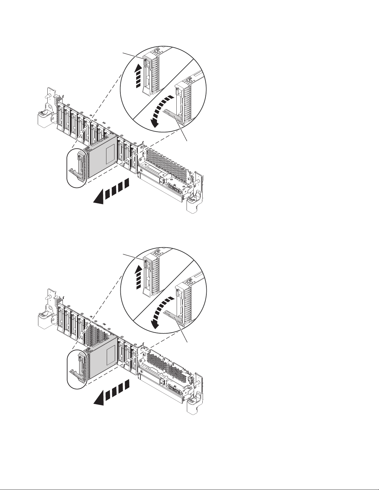
A
B
P8HAL502-0
Figure 50. Removing a disk drive from a base function system
A
B
P8HAL504-1
Figure 51. Removing a disk drive from an expanded function system
4. Support the bottom of the drive as you slide it out of the system. Hold the drive by its sides.
5. Press Enter on the console to indicate that you removed the drive. The identify LED turns off.
52 Disk drives or solid-state drives
Page 71

6. If you are removing more than one drive, repeat the steps in this procedure until all drives are
P8HAL516-2
B
removed.
7. If you are not installing a replacement drive, install a filler in the empty slot to ensure proper air
flow for cooling. For instructions, see“Installing a disk drive filler in the 5148-21L, 5148-22L,
8247-21L, 8247-22L, 8284-21A, or 8284-22A” on page 99.
8. If you are installing a replacement drive as a replacement for the failed disk drive or solid-state
drive, go to “Replacing a disk drive or solid-state drive in the 8284-21A or 8284-22A system with the
power turned on in AIX” on page 54.
9. If you are removing an SSD in an expanded function system, continue with the next step.
10. Remove the front cover to access the SSD. For instructions to remove the front cover from an
expanded function system, see “Removing the front cover from a rack-mounted 5148-21L, 5148-22L,
8247-21L, 8247-22L, 8284-21A, or 8284-22A system” on page 148.
11. To access the SSD slots, remove the perforated plate (B) covering the SSD cage as shown in
Figure 52.
Figure 52. Removing the SSD cage cover to access the SSD slots in an expanded function system
12. When the identify LED turns on solid, unlock the drive bay handle (B) by pushing the handle latch
(A) in the direction that is shown and pulling the drive bay handle (B) out toward you, as shown in
Figure 53 on page 54. If the handle is not all the way out, the solid-state drive cannot slide out of the
system.
Disk drives or solid-state drives 53
Page 72

Figure 53. Removing an SSD from an expanded function system
13. Support the bottom of the drive as you slide it out of the system. Hold the drive by its sides.
14. Press Enter on the console to indicate that you removed the drive. The identify LED turns off.
15. If you are not installing a replacement drive immediately, lock the drive bay handle (B) by rotating it
inwards toward the system.
16. If you are removing more than one drive, repeat the steps in this procedure until all drives are
removed.
Replacing a disk drive or solid-state drive in the 8284-21A or 8284-22A system with the power turned on in AIX
Find information about replacing a disk drive or solid-state drive (SSD) in a system with the AIX
operating system or AIX logical partition that controls the drive location powered on.
To replace a disk drive or solid-state drive in a system, complete the following steps:
1. Ensure that you have the electrostatic discharge (ESD) wrist strap on and that the ESD clip is
connected to an unpainted metal surface. If not, do so now.
2. Choose from the following options:
v If you are replacing a disk drive in a system, continue with step 3.
v If you are replacing a solid-state drive in an expanded function system, continue with step 11 on
page 56.
3. Unlock the drive bay handle (A) by pressing it and pulling it out toward you. If the handle is not all
the way out, the drive does not slide into the system. See Figure 54 on page 55 and Figure 55 on
page 56.
4. Hold the drive by the top and bottom edges as you position the drive, and insert it into the drive
slot.
5. Slide the drive halfway into the system.
6. On the console, select the drive that you want to install and then press Enter.
54 Disk drives or solid-state drives
Page 73

7. When the identify LED turns on solid, slide the drive all the way into the system, and push the
P8HAL503-0
A
drive carrier handle (A) in until it locks, as shown in the following figure. Figure 54 and Figure 55 on
page 56.
Important: Ensure that the drive is fully seated and is all the way into the system.
Figure 54. Replacing a disk drive in a base function system
Disk drives or solid-state drives 55
Page 74

P8HAL505-1
A
Figure 55. Replacing a disk drive in an expanded function system
8. On the console, press Enter to indicate that you installed the drive.
9. If you are replacing more than one drive, repeat the steps in this procedure until all drives are
replaced.
10. Proceed to the procedure for preparing the system for operation. For instructions, see “Preparing the
8284-21A or 8284-22A system for operation after replacing a drive with the power turned on in AIX”
on page 57.
11. If you are replacing a solid-state drive in an expanded function system, continue with the next step.
12. With the SSD drive bay handle (A) in the unlocked position, pull the lever outward to gain access to
the guide rails in the SSD slot. Support the bottom of the SSD as you align it with the guide rails in
the SSD slot. See Figure 56 on page 57.
Note: Support the drive by holding the drive by its sides.
13. Slide the drive halfway into the system.
14. On the console, select the drive that you want to install and then press Enter.
15. When the identify LED turns on solid, slide the drive all the way into the system until the drive
stops.
16. Lock the drive by rotating the bay handle (A) in the direction that is shown in Figure 56 on page 57.
Important: When you install an SSD, ensure that the SSD is fully seated and is all the way into the
system.
56 Disk drives or solid-state drives
Page 75
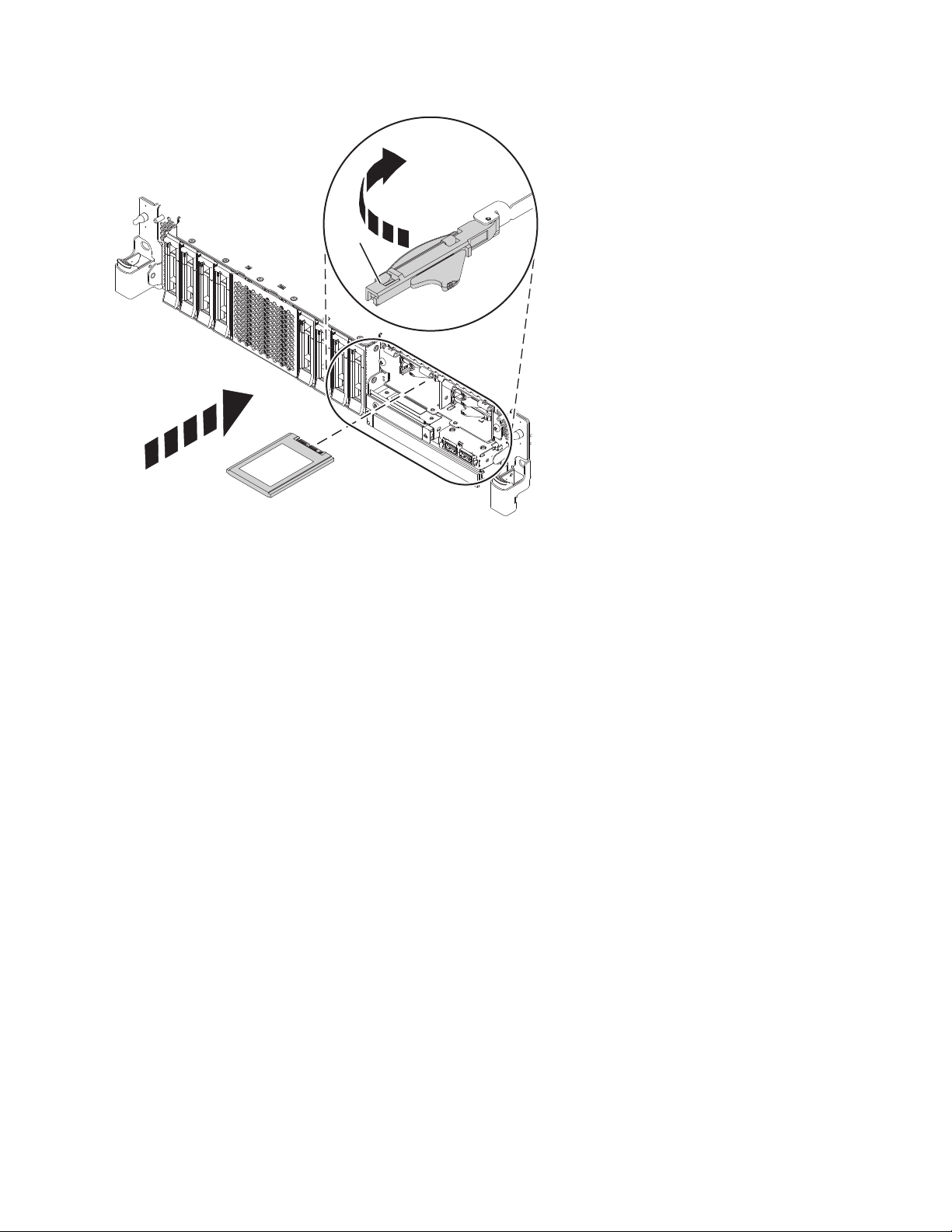
P8HAL507-2
A
Figure 56. Replacing an SSD in an expanded function system
17. On the console, press Enter to indicate that you installed the drive.
18. If you are installing more than one drive, repeat the steps in this procedure until all drives are
installed.
Preparing the 8284-21A or 8284-22A system for operation after replacing a drive with the power turned on in AIX
Learn to prepare the system for operation after you replace a disk drive or solid-state drive (SSD) in a
system with the AIX operating system or AIX logical partition that controls the drive location powered
on.
To prepare the system for operation, complete the following steps:
1. Ensure that you have the electrostatic discharge (ESD) wrist strap on and that the ESD clip is
connected to an unpainted metal surface. If not, do so now.
2. If you replaced a drive and have not verified the drive yet, verify that the power LED is ON (green)
and the amber fault LED is OFF (not lit) for the replaced drive on the front of the system.
3. If applicable, cover the SSD cage with the perforated plate (A) as shown in Figure 57 on page 58.
Disk drives or solid-state drives 57
Page 76

A
P8HAL517-2
Figure 57. Covering the SSD cage in an expanded function system
4. If applicable, replace the front cover. For instructions to replace the front cover on an expanded
function system, see “Installing the front cover on a rack-mounted 5148-21L, 5148-22L, 8247-21L,
8247-22L, 8284-21A, or 8284-22A system” on page 153.
5. To configure the newly installed disk drive or solid-state drive, see “Configuring a disk drive or
solid-state drive for use in an AIX system or AIX logical partition” on page 114.
6. To rebuild the data on the replacement disk drive or solid-state drive, see “Rebuilding data on a
replacement disk drive or solid-state drive in a system or logical partition running the AIX operating
system” on page 119.
Removing and replacing a disk drive or solid-state drive in the 8284-21A or 8284-22A system with the power turned on in IBM i
Learn how to remove and replace a disk drive or solid-state drive (SSD) in a system with the IBM i
operating system or IBM i logical partition that controls the drive location powered on.
To remove and replace a disk drive or solid-state drive in a system, complete the following steps:
1. “Preparing the 8284-21A or 8284-22A system to remove and replace a disk drive or solid-state drive
with the power turned on in IBM i” on page 59.
2. “Removing a disk drive or solid-state drive from the 8284-21A or 8284-22A system with the power
turned on in IBM i” on page 63.
3. “Replacing a disk drive or solid-state drive in the 8284-21A or 8284-22A system with the power
turned on in IBM i” on page 66.
4. “Preparing the 8284-21A or 8284-22A system for operation after removing and replacing a drive with
the power turned on in IBM i” on page 70.
Note: Removing or replacing this feature is a customer task. You can complete this task yourself, or
contact a service provider to complete the task for you. You might be charged a fee by the service
provider for this service.
58 Disk drives or solid-state drives
Page 77

Preparing the 8284-21A or 8284-22A system to remove and replace a disk drive or solid-state drive with the power turned on in IBM i
Learn about the steps you must complete before you remove and replace a disk drive or solid-state drive
(SSD) in a system with the IBM i operating system or IBM i logical partition that controls the drive
location powered on.
If the drive that you are removing is in the root volume group (rootvg) and it is not protected by either
Redundant Array of Independent Disks (RAID) or mirroring, or to use the powered-off procedure, go to
“Removing a disk drive or solid-state drive from the 5148-21L, 5148-22L, 8247-21L, 8247-22L, 8284-21A, or
8284-22A system with the power turned off” on page 42.
To prepare the system to remove and replace a disk drive or solid-state drive, complete the following
steps:
1. Determine the protection status of the disk drive or solid-state drive that you are replacing. For
instructions, see “Determining the disk drive or solid-state drive protection status in the IBM i
operating system” on page 118.
2. Before you remove a disk drive or solid-state drive, ensure that you back up all the data from the
drive or from the array that the drive is a part of. Then, move the data from the drive that you want
to remove. For instructions, choose one of the following options:
v If you are moving and removing disk units, go to IBM i Knowledge Center(http://www-
01.ibm.com/support/knowledgecenter/ssw_ibm_i/welcome) and then select Systems
management > Disk management > Disk pools > Managing disk pools > Moving or removing a
disk unit from a disk pool.
v If you are recovering the system, go to IBM i Knowledge Center(http://www-01.ibm.com/
support/knowledgecenter/ssw_ibm_i/welcome) and select the version of IBM i that you are
using. Then, select Systems management > Backup and recovery > Recovering your system.
3. Find the package that contains the new drive.
Attention: Drives are fragile. Handle with care.
4. Attach the electrostatic discharge (ESD) wrist strap. The ESD wrist strap must be connected to an
unpainted metal surface until the service procedure is completed, and if applicable, until the service
access cover is replaced.
Attention:
v Attach an electrostatic discharge (ESD) wrist strap to the front ESD jack, to the rear ESD jack, or to
an unpainted metal surface of your hardware to prevent the electrostatic discharge from damaging
your hardware.
v When you use an ESD wrist strap, follow all electrical safety procedures. An ESD wrist strap is
used for static control. It does not increase or decrease your risk of receiving electric shock when
using or working on electrical equipment.
v If you do not have an ESD wrist strap, just prior to removing the product from ESD packaging
and installing or replacing hardware, touch an unpainted metal surface of the system for a
minimum of 5 seconds. If at any point in this service process you move away from the system, it
is important to once again discharge yourself by touching an unpainted metal surface for at least 5
seconds before you continue with the service process.
5. Remove the drive from the static-protective package and place it on an ESD mat.
6. If you are removing a solid-state device that is on a PCIe RAID and SSD SAS adapter, go to
Replacing an SSD module on the PCIe RAID and SSD SAS adapter and complete that procedure.
7. Verify that the disk drive or solid-state drive you are replacing is suspended before you continue
with this procedure. For mirrored disk drives in an IBM i system or an IBM i logical partition,
complete the following steps to verify that the disk drive or solid-state drive you are removing is
suspended:
a. Sign on with service level authority.
b. Type strsst on the command line of the IBM i session and then press Enter.
Disk drives or solid-state drives 59
Page 78

c. Type your service tools user ID and service tools password in the Start Service Tools Sign On
P2-D12
P2-D11
P2-D10
P2-D9
P2-D8
P2-D7
P2-D6
P2-D5
P2-D4
P2-D3
P2-D2
P2-D1
P8HAL508-0
display. Press Enter.
Note: The service tools password is case-sensitive.
d. Select Work with disk units from the System Service Tools (SST) display, and then press Enter.
e. Select Display Disk Configuration from the Work with Disk Units display, and then press Enter.
f. Select Display Disk Configuration Status from the Display Disk Configuration display, and then
press Enter.
g. Does the disk drive or solid-state drive that is mirrored to the drive that you are replacing (same
drive number) have a status of Active?
v No: The replacement must be completed by a service provider.
v Yes: Does the disk drive or solid-state drive that you are replacing have a status of Suspended?
– Yes: Continue with the next step.
– No: Follow these steps to suspend mirrored protection on the disk drive or solid-state drive
that you are replacing:
1) Press F3 from the Display Disk Configuration display to return to the Work with Disk
Units display.
2) Select Work with Disk Unit Recovery from the Work with Disk Units display, and then
press Enter.
3) Select Suspend mirrored protection from the Work with Disk Unit Recovery display,
and then press Enter.
4) Select the option to suspend the disk drive or solid-state drive that you are replacing
from the Suspend Mirrored Protection display, and then press Enter.
h. Press F3 repeatedly to exit System Service Tools and return to the main menu.
8. Identify the part and the system that you want to service. The disk drive and SSD slots are in the
front of a system. More SSD slots are also available in an expanded function system.
Figure 58 and Figure 59 on page 61 show the disk drive and solid-state drive locations and service
indicators. Service indicators are located above the latch handle on the disk drives.
Figure 58. Disk drive and service indicator locations for a base function system
60 Disk drives or solid-state drives
Page 79
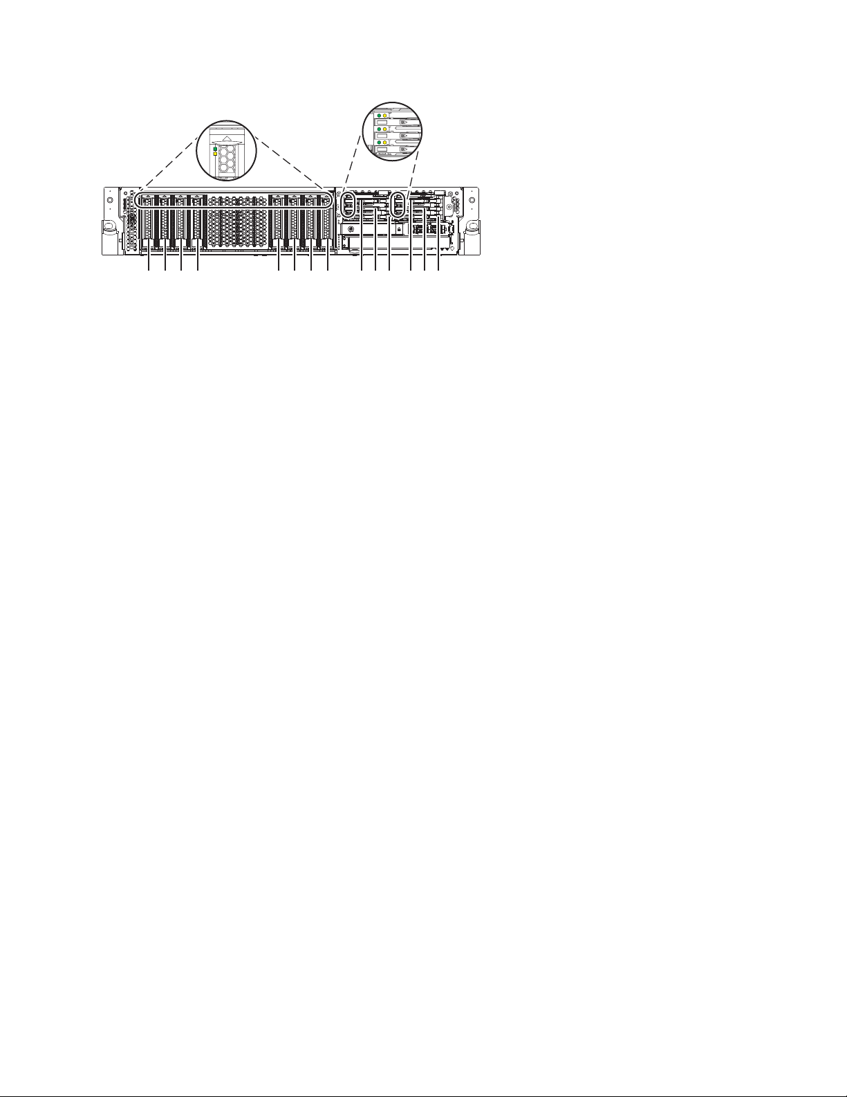
P2-D14
P2-D12
P2-D10
P2-D13
P2-D11
P2-D9
P2-D8
P2-D7
P2-D6
P2-D5
P2-D4
P2-D3
P2-D2
P2-D1
P8HAL509-1
Figure 59. Disk drive, solid-state drive, and service indicator locations for an expanded function system
9. Locate the disk drive or solid-state drive to be replaced and record the location information. Then,
use the location information to activate the identify light for that drive. For instructions, see “Finding
the location code and activating the indicator light for a part by using the IBM i operating system”
on page 130.
10. Determine whether the disk drive or solid-state drive to be removed is a non-configured drive by
completing the following steps:
a. Type strsst on the command line of the IBM i session, and then press Enter.
b. Type your service tools user ID and service tools password, and then press Enter.
c. Select Work with disk units, and then press Enter.
d. Select Display Disk Configuration, and then press Enter.
e. Select Display non-configured units, and then press Enter.
11. Is the failed drive listed as a non-configured drive in the display?
v No: Continue to step 14.
v Yes: Continue to step 12.
12. Determine whether the disk drive or solid-state drive to be removed was replaced by a hot-spare
drive when it failed by completing the following steps:
a. Go to the service action log. For instructions to access the service action log, see “Finding the
location code and activating the indicator light for a part by using the IBM i operating system”
on page 130.
b. Determine whether an xxxx9031 error was logged close to the same time as the original disk
failure. This error indicates that the data to the hot-spare drive was automatically rebuilt.
c. Determine whether an error was logged for the field-replaceable unit (FRU) by using concurrent
maintenance. If yes, continue with the next step.
13. Did you find the service action log entry that is related to this problem?
v No: Exit the service action log and go to step 15.
v Yes: Continue with the next step.
14. Within the service action log, select the concurrent maintenance option. This option displays the
drive location on the concurrent maintenance display. Go to step 17 on page 62.
15. From the Hardware Service Manager, navigate to Select Device Concurrent Maintenance option.
Press Enter. The Device Concurrent Maintenance display is shown, as shown in the Figure 60 on
page 62.
Disk drives or solid-state drives 61
Page 80

Device Concurrent Maintenance
Type the choices, then press Enter.
Specify either physical location or resource name.
Physical location:
U787A.001.1234567-P3-D4
Specify action as 1=Remove device 2=Install device
Enter a time value between 00 and 19.
F3=Exit F5=Refresh F12=Cancel
Figure 60. Example Device Concurrent Maintenance display
or
Device resource name:
Action to be performed . . . . . . . .: 1
Time delay needed in minutes . . . . .: 01
16. If the physical location does not show in the Device Concurrent Maintenance display, type the
physical location where you are replacing the disk drive or solid-state drive as shown in the
following example:
The physical location has the following form: U787A.001.AAAXXXX-P3-D4 where P3-D4 is the position
of the disk drive or solid-state drive in the system unit or an expansion unit. You can get the
U787A.001.AAAXXXX location information from the control panel display on the system unit or
expansion unit.
If you cannot get the information from the control panel, find the feature code (FC) and sequence
number (SN or SEQ) on the label that is on the front of the system unit or an expansion unit as
shown in the following figure.
Figure 61. Example system or expansion unit label
In this example, U787A.001.AAAXXXX-P3-D4, U787A.001 comes from the feature code (FC) on the label,
AAAXXXX comes from the last 7 digits of the sequence number (SN or SEQ) on the label, and
P3–D4 is the slot where you are replacing the disk drive or solid-state drive.
In the example, U5074.001.AAAXXXX-DB3-D32, you would replace a disk drive or solid-state drive in
the expansion unit with type 5074, model 001, sequence number AAAXXXX, and disk drive or
solid-state drive position DB3–D32.
17. Select 1 (Remove device) for the action to be completed.
18. Set the time delay in minutes. For example, for one minute enter: 01
Note: You can set an appropriate time delay of 01 - 19 minutes to allow adequate time to access the
disk drive or solid-state drive.
Important: Do not press Enter now.
19. Locate the service indicator that corresponds to the position of the drive that you are removing from
a system, drive enclosure, or an expansion unit. For details on locations of the service indicators, see
step 8 on page 60.
62 Disk drives or solid-state drives
Page 81
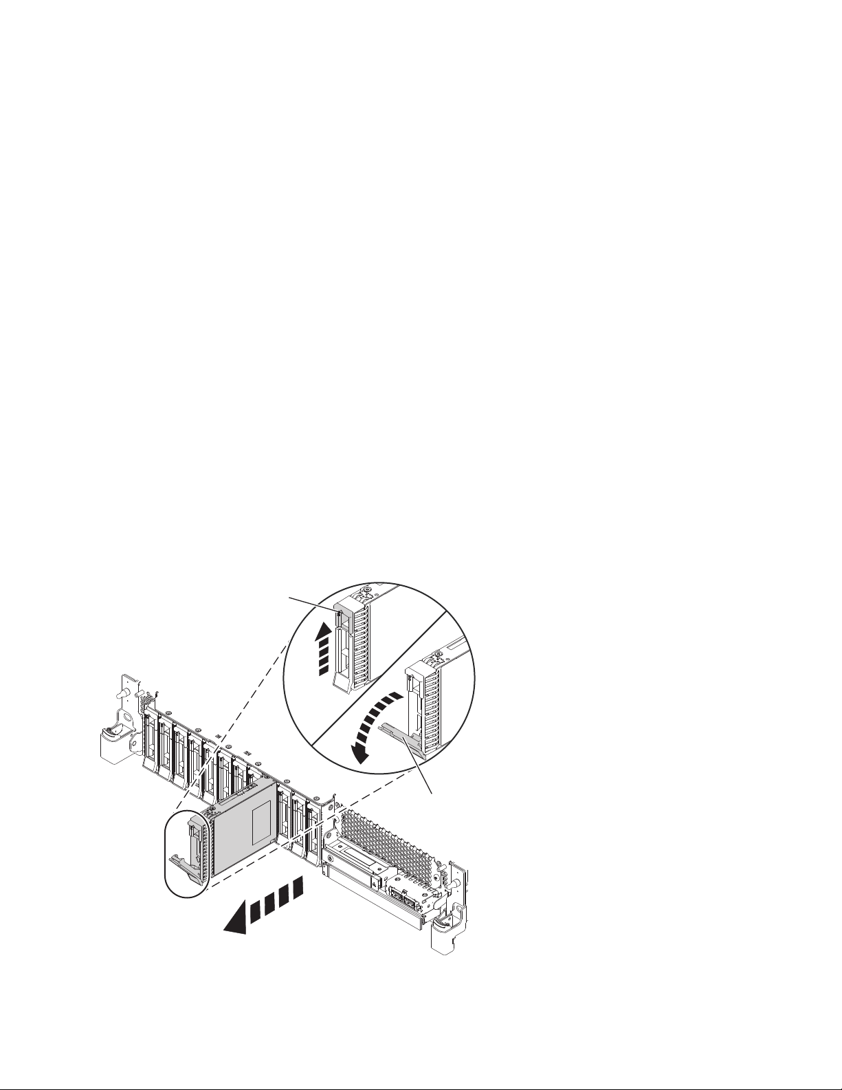
Removing a disk drive or solid-state drive from the 8284-21A or 8284-22A system
A
B
P8HAL502-0
with the power turned on in IBM i
Find information about removing a disk drive or solid-state drive (SSD) from a system with the IBM i
operating system or IBM i logical partition that controls the drive location powered on.
To remove a disk drive or solid-state drive from a system, complete the following steps:
1. Ensure that you have the electrostatic discharge (ESD) wrist strap on and that the ESD clip is
connected to an unpainted metal surface. If not, do so now.
2. Choose from the following options:
v If you are removing a disk drive in a system, continue with step 3.
v If you are removing a solid-state drive in an expanded function system, continue with step 10 on
page 64.
3. On the console, select the drive that you want to remove, and then press Enter.
Important:
v When you press Enter, after your selected time delay, the service indicator light comes on (solid)
for 18 seconds. You then have 18 seconds to unlock and remove the drive. You can set an
appropriate time delay of 01 - 19 minutes to allow adequate time to access the disk drive or
solid-state drive.
v If the service indicator light was already turned on due to a failed device, you will not see a
change in the service indicator light until after the first 18 seconds. You will need to wait until the
service indicator light goes off and then turns back on (solid). You will have two cycles of the light
turning on (solid) to unlock and remove the drive.
4. When the identify LED turns on solid, unlock the drive bay handle (B) by pressing the handle latch
(A) and pulling it out toward you, as shown in Figure 62 and Figure 63 on page 64. If the handle is
not all the way out, the solid-state drive cannot slide out of the system.
Figure 62. Removing a disk drive from a base function system
Disk drives or solid-state drives 63
Page 82

A
B
P8HAL504-1
Figure 63. Removing a disk drive from an expanded function system
5. Support the bottom of the drive as you slide it out of the system. Hold the drive by its sides.
6. Press Enter on the console to indicate that you removed the drive. The identify LED turns off.
7. If you are removing more than one drive, repeat the steps in this procedure until all drives are
removed.
8. If you are not installing a replacement drive, install a filler in the empty slot to ensure proper air
flow for cooling. For instructions, see“Installing a disk drive filler in the 5148-21L, 5148-22L,
8247-21L, 8247-22L, 8284-21A, or 8284-22A” on page 99.
9. If you are installing a replacement drive as a replacement for the failed disk drive or solid-state
drive, go to “Replacing a disk drive or solid-state drive in the 8284-21A or 8284-22A system with the
power turned on in IBM i” on page 66.
10. To remove a solid-state drive in an expanded function system, continue with the next step.
11. Remove the front cover to access the SSD. For instructions to remove the front cover from an
expanded function system, see “Removing the front cover from a rack-mounted 5148-21L, 5148-22L,
8247-21L, 8247-22L, 8284-21A, or 8284-22A system” on page 148.
12. To access the SSD slots, remove the perforated plate (B) covering the SSD cage as shown in Figure 64
on page 65.
64 Disk drives or solid-state drives
Page 83

P8HAL516-2
B
Figure 64. Removing the SSD cage cover to access the SSD slots in an expanded function system
13. On the console, select the drive that you want to remove, and then press Enter.
Important:
v When you press Enter, after your selected time delay, the service indicator light comes on (solid)
for 18 seconds. You then have 18 seconds to unlock and remove the drive. You can set an
appropriate time delay of 01 - 19 minutes to allow adequate time to access the disk drive or
solid-state drive.
v If the service indicator light was already turned on due to a failed device, you will not see a
change in the service indicator light until after the first 18 seconds. You will need to wait until the
service indicator light goes off and then turns back on (solid). You will have two cycles of the light
turning on (solid) to unlock and remove the drive.
14. When the identify LED turns on solid, unlock the drive bay handle (B) by pushing the handle latch
(A) in the direction that is shown and pulling the drive bay handle (B) out toward you, as shown in
Figure 65 on page 66. If the handle is not all the way out, the solid-state drive cannot slide out of the
system.
Disk drives or solid-state drives 65
Page 84

Figure 65. Removing an SSD from an expanded function system
15. Support the bottom of the drive as you slide it out of the system. Hold the drive by its sides.
16. Press Enter on the console to indicate that you removed the drive. The identify LED turns off.
17. If you are not installing a replacement drive immediately, lock the drive bay handle (B) by rotating it
inwards toward the system.
18. If you are removing more than one drive, repeat the steps in this procedure until all drives are
removed.
Replacing a disk drive or solid-state drive in the 8284-21A or 8284-22A system with the power turned on in IBM i
Find information about replacing a disk drive or solid-state drive (SSD) in a system with the IBM i
operating system or IBM i logical partition that controls the drive location powered on.
To replace a disk drive or solid-state drive in a system, complete the following steps:
1. Ensure that you have the electrostatic discharge (ESD) wrist strap on and that the ESD clip is
connected to an unpainted metal surface. If not, do so now.
2. Choose from the following options:
v If you are replacing a disk drive in a system, continue with step 3.
v If you are replacing a solid-state drive in an expanded function system, continue with step 13 on
page 69.
3. Return to the console and complete the following steps. Wait until the Concurrent Maintenance
Results display is shown.
a. Press F12.
b. The physical locations that you entered while you removed the disk drive or solid-state drive
might still show on the display. If not, retype the physical location where you want to install the
new disk drive or solid-state drive.
66 Disk drives or solid-state drives
Page 85

v In the example, U787A.001.1234567-P3-D4, you would install a disk drive in the system unit
with type 9406, Model 520, sequence number 1234567, and disk drive or solid-state drive
position P3–D4.
v In the example, U5074.001.1234567-DB3-D32, you would install a disk drive or solid-state drive
in the expansion unit with type 5074, model 001, sequence number 1234567, and disk drive or
solid-state drive position DB3–D32.
c. Select 2 (Install device) for the Action to be completed.
d. Set the time delay. For example, for one minute: 01.
Note: You can set an appropriate time delay of 01 - 19 minutes to allow adequate time to access
the disk drive or solid-state drive.
Important: Do not press Enter yet.
4. Unlock the drive bay handle (A) by pressing it and pulling it out toward you. If the handle is not all
the way out, the drive does not slide into the system. See Figure 66 on page 68 and Figure 67 on
page 68.
5. Hold the drive by the top and bottom edges as you position the drive, and insert it into the drive
slot.
6. Slide the drive halfway into the system.
7. In the HSM display, select the drive that you want to install or replace.
8. Press Enter on the console.
Important: When you press Enter, after your selected time delay, the service indicator light comes
on (solid) for 18 seconds. You then have 18 seconds to slide the drive all the way in and then lock it
in place by pushing in the drive handle. You can set an appropriate time delay of 01 - 19 minutes to
allow adequate time to access the disk drive or solid-state drive.
9. When the identify LED turns on solid, slide the drive all the way into the system, and push in the
drive handle (A) until it locks, as shown in Figure 66 on page 68 and Figure 67 on page 68.
Important: Ensure that the drive is fully seated and is all the way into the system.
Disk drives or solid-state drives 67
Page 86

P8HAL503-0
A
Figure 66. Replacing a disk drive in a base function system
P8HAL505-1
A
Figure 67. Replacing a disk drive in an expanded function system
10. On the console, press Enter to indicate that you installed the drive.
68 Disk drives or solid-state drives
Page 87

11. If you are replacing more than one drive, repeat the steps in this procedure until all drives are
replaced.
12. Proceed to the procedure for preparing the system for operation. For instructions, see “Preparing the
8284-21A or 8284-22A system for operation after removing and replacing a drive with the power
turned on in IBM i” on page 70.
13. To replace an SSD in an expanded function system, continue with the next step.
14. Return to the console and complete the following steps. Wait until the Concurrent Maintenance
Results display is shown.
a. Press F12.
b. The physical locations that you entered while you removed the disk drive or solid-state drive
might still show on the display. If not, retype the physical location where you want to install the
new disk drive or solid-state drive.
v In the example, U787A.001.1234567-P3-D4, you would install a disk drive in the system unit
with type 9406, Model 520, sequence number 1234567, and disk drive or solid-state drive
position P3–D4.
v In the example, U5074.001.1234567-DB3-D32, you would install a disk drive or solid-state drive
in the expansion unit with type 5074, model 001, sequence number 1234567, and disk drive or
solid-state drive position DB3–D32.
c. Select 2 (Install device) for the Action to be completed.
d. Set the time delay. For example, for one minute: 01.
Note: You can set an appropriate time delay of 01 - 19 minutes to allow adequate time to access
the disk drive or solid-state drive.
Important: Do not press Enter yet.
15. With the SSD drive bay handle (A) in the unlocked position, pull the lever outward to gain access to
the guide rails in the SSD slot. Support the bottom of the SSD as you align it with the guide rails in
the SSD slot. See Figure 68 on page 70.
Note: Support the drive by holding the drive by its sides.
16. Slide the drive halfway into the system.
17. In the HSM display, select the drive that you want to install or replace.
18. Press Enter on the console.
Important: When you press Enter, after your selected time delay, the service indicator light comes
on (solid) for 18 seconds. You then have 18 seconds to slide the drive all the way in and then lock it
in place by pushing in the drive handle. You can set an appropriate time delay of 01 - 19 minutes to
allow adequate time to access the disk drive or solid-state drive.
19. When the identify LED turns on solid, slide the drive all the way into the system until the drive
stops.
20. Lock the drive by rotating the bay handle (A) in the direction that is shown in Figure 68 on page 70.
Important: When you install an SSD, ensure that the SSD is fully seated and is all the way into the
system.
Disk drives or solid-state drives 69
Page 88

P8HAL507-2
A
Figure 68. Replacing an SSD in an expanded function system
21. On the console, press Enter to indicate that you installed the drive.
22. If you are replacing more than one drive, repeat the steps in this procedure until all drives are
replaced.
Preparing the 8284-21A or 8284-22A system for operation after removing and replacing a drive with the power turned on in IBM i
Learn to prepare the system for operation after you replace a disk drive or solid-state drive (SSD) in a
system with the IBM i operating system or IBM i logical partition that controls the drive location
powered on.
To prepare the system for operation, complete the following steps:
1. Ensure that you have the electrostatic discharge (ESD) wrist strap on and that the ESD clip is
connected to an unpainted metal surface. If not, do so now.
2. If you replaced a drive and have not verified the drive yet, verify that the power LED is ON (green)
and the amber fault LED is OFF (not lit) for the replaced drive on the front of the system.
3. If applicable, cover the SSD cage with the perforated plate (A) as shown in Figure 69 on page 71.
70 Disk drives or solid-state drives
Page 89

A
P8HAL517-2
Figure 69. Covering the SSD cage in an expanded function system
4. If applicable, replace the front cover. For instructions to replace the front cover on an expanded
function system, see “Installing the front cover on a rack-mounted 5148-21L, 5148-22L, 8247-21L,
8247-22L, 8284-21A, or 8284-22A system” on page 153.
5. Return to the console and wait until the Concurrent Maintenance Results display is shown, and then
press Enter.
6. If you return to the Service Action Log display, exit the service action log.
7. When the Hardware Service Manager (HSM) display is shown, press F3.
8. To configure the newly installed disk drive or solid-state drive, see “Configuring a disk drive or
solid-state drive for use in an IBM i system or IBM i logical partition” on page 115.
9. To rebuild the data on the replacement disk drive or solid-state drive, see “Rebuilding data on a
replacement disk drive or solid-state drive in a system or logical partition running the IBM i
operating system” on page 120.
Removing and replacing a disk drive or solid-state drive by using the hot-spare function in the 8284-21A or 8284-22A system with the power turned on in IBM i
Learn how to remove and replace a disk drive or solid-state drive (SSD) by using the hot-spare function
in a system with the IBM i operating system or an IBM i logical partition that controls the drive location
powered on.
To remove and replace a disk drive or solid-state drive in a system, complete the following steps:
1. “Preparing the 8284-21A or 8284-22A system to remove and replace a disk drive or solid-state drive
by using the hot-spare function with the power turned on in IBM i” on page 72.
2. “Removing a hot-spare disk drive or solid-state drive from the 8284-21A or 8284-22A system with the
power turned on in IBM i” on page 75.
3. “Replacing a hot-spare disk drive or solid-state drive in the 8284-21A or 8284-22A system with the
power turned on in IBM i” on page 78.
Disk drives or solid-state drives 71
Page 90
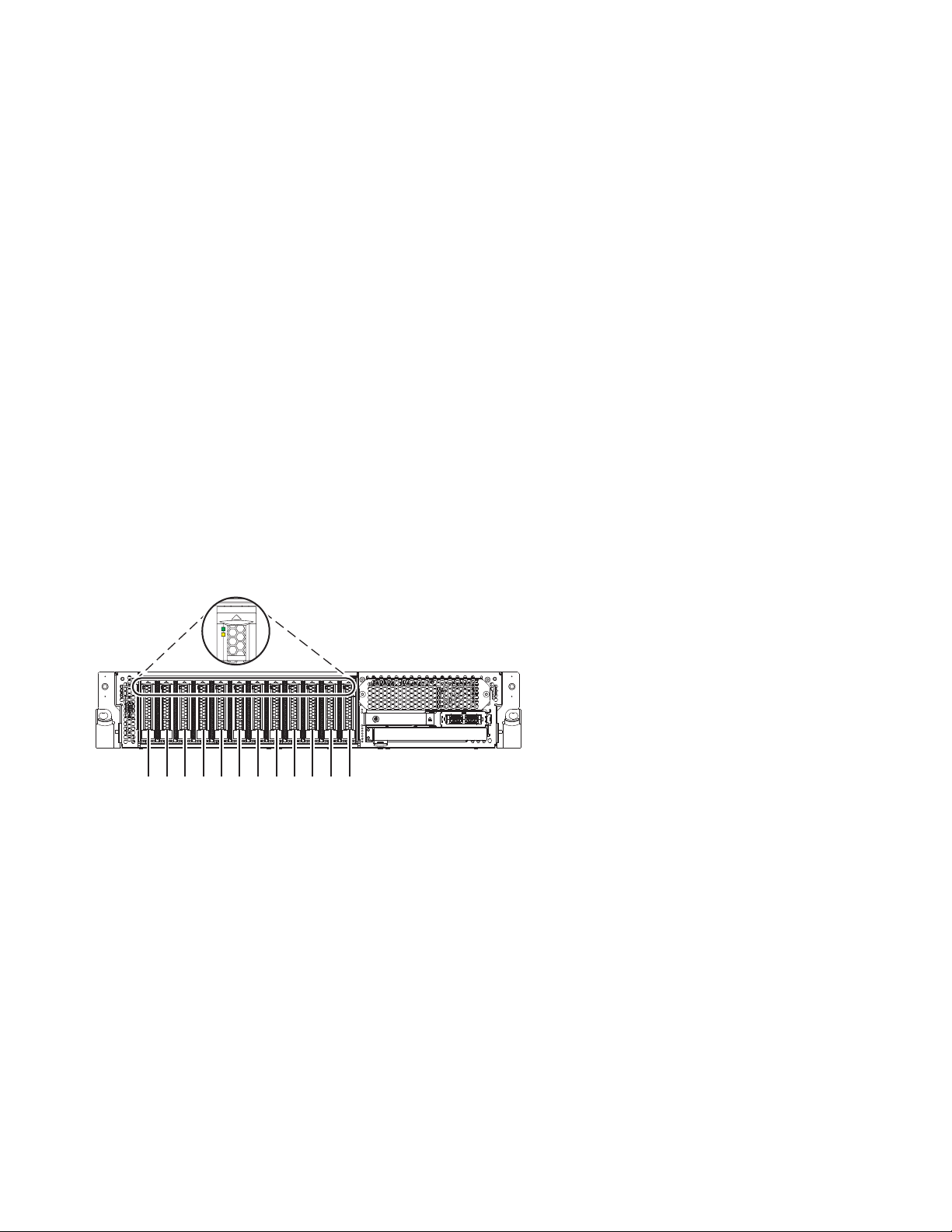
4. “Preparing the 8284-21A or 8284-22A system for operation after removing and replacing a hot-spare
P2-D12
P2-D11
P2-D10
P2-D9
P2-D8
P2-D7
P2-D6
P2-D5
P2-D4
P2-D3
P2-D2
P2-D1
P8HAL508-0
drive with the power turned on in IBM i” on page 82.
Note: Removing or replacing this feature is a customer task. You can complete this task yourself, or
contact a service provider to complete the task for you. You might be charged a fee by the service
provider for this service.
Preparing the 8284-21A or 8284-22A system to remove and replace a disk drive or solid-state drive by using the hot-spare function with the power turned on in IBM i
Learn about the steps you must complete before you remove and replace a disk drive or solid-state drive
(SSD) by using the hot-spare function in a system with the IBM i operating system or IBM i logical
partition that controls the drive location powered on.
To prepare the system to remove and replace a disk drive or solid-state drive, complete the following
steps:
1. Determine the protection status of the disk drive or solid-state drive that you are replacing. For
instructions, see “Determining the disk drive or solid-state drive protection status in the IBM i
operating system” on page 118.
2. If you are removing a solid-state device that is on a PCIe RAID and SSD SAS adapter, go to
Replacing an SSD module on the PCIe RAID and SSD SAS adapter and complete that procedure.
3. Identify the part and the system that you want to service. The disk drive and SSD slots are in the
front of a system. More SSD slots are also available in an expanded function system.
Figure 70 and Figure 71 on page 73 show the disk drive and solid-state drive locations and service
indicators. Service indicators are located above the latch handle on the disk drives.
Figure 70. Disk drive and service indicator locations for a base function system
72 Disk drives or solid-state drives
Page 91

P2-D14
P2-D12
P2-D10
P2-D13
P2-D11
P2-D9
P2-D8
P2-D7
P2-D6
P2-D5
P2-D4
P2-D3
P2-D2
P2-D1
P8HAL509-1
Figure 71. Disk drive, solid-state drive, and service indicator locations for an expanded function system
4. Locate the disk drive or solid-state drive to be replaced and record the location information. Then,
use the location information to activate the identify light for that drive. For instructions, see “Finding
the location code and activating the indicator light for a part by using the IBM i operating system”
on page 130.
5. Determine whether the disk drive or solid-state drive to be removed is a non-configured drive by
completing the following steps:
a. Type strsst on the command line of the IBM i session, and then press Enter.
b. Type your service tools user ID and service tools password, and then press Enter.
c. Select Work with disk units, and then press Enter.
d. Select Display Disk Configuration, and then press Enter.
e. Select Display non-configured units, and then press Enter.
6. Is the failed drive listed as a non-configured drive in the display?
v No: Continue to “Removing and replacing a disk drive or solid-state drive in the 8284-21A
or 8284-22A system with the power turned on in IBM i” on page 58.
v Yes: Determine if the disk drive to be removed was replaced by a hot spare when it failed. A
xxxx9031 error logged close to the same time of the original disk failure indicates the automatic
Rebuild of the data to a hot-spare device, then go on to the next step.
7. Is the disk drive to be removed controlled by the load source adapter?
v No: Go to step 10.
v Yes: Go to the next step.
8. Is the disk drive to be removed located in a valid load source position?
v No: Go to “Configuring a disk drive or solid-state drive on a load source adapter for hot-spare
protection by using the IBM i operating system” on page 117.
v Yes: Go to step 10.
9. Choose the concurrent maintenance option. This option shows the disk drive location on the
concurrent maintenance display. Go to step 12 on page 74.
10. From the Hardware Service Manager, navigate to Select Device Concurrent Maintenance option.
Press Enter. The Device Concurrent Maintenance display is shown, as shown in the Figure 72 on
page 74.
Disk drives or solid-state drives 73
Page 92

Device Concurrent Maintenance
Type the choices, then press Enter.
Specify either physical location or resource name.
Physical location:
U787A.001.1234567-P3-D4
Specify action as 1=Remove device 2=Install device
Enter a time value between 00 and 19.
F3=Exit F5=Refresh F12=Cancel
Figure 72. Example Device Concurrent Maintenance display
or
Device resource name:
Action to be performed . . . . . . . .: 1
Time delay needed in minutes . . . . .: 01
11. If the physical location does not show in the Device Concurrent Maintenance display, type the
physical location where you are replacing the disk drive or solid-state drive as shown in the
following example:
The physical location has the following form: U787A.001.AAAXXXX-P3-D4 where P3-D4 is the position
of the disk drive or solid-state drive in the system unit or an expansion unit. You can get the
U787A.001.AAAXXXX location information from the control panel display on the system unit or
expansion unit.
If you cannot get the information from the control panel, find the feature code (FC) and sequence
number (SN or SEQ) on the label that is on the front of the system unit or an expansion unit as
shown in the following figure.
Figure 73. Example system or expansion unit label
In this example, U787A.001.AAAXXXX-P3-D4, U787A.001 comes from the feature code (FC) on the label,
AAAXXXX comes from the last 7 digits of the sequence number (SN or SEQ) on the label, and
P3–D4 is the slot where you are replacing the disk drive or solid-state drive.
In the example, U5074.001.AAAXXXX-DB3-D32, you would replace a disk drive or solid-state drive in
the expansion unit with type 5074, model 001, sequence number AAAXXXX, and disk drive or
solid-state drive position DB3–D32.
12. Select 1 (Remove device) for the action to be completed.
13. Set the time delay in minutes. For example, for one minute enter: 01
Note: You can set an appropriate time delay of 01 - 19 minutes to allow adequate time to access the
disk drive or solid-state drive.
Important: Do not press Enter now.
14. Find the package that contains the new drive.
Attention: Drives are fragile. Handle with care.
15. Attach the electrostatic discharge (ESD) wrist strap. The ESD wrist strap must be connected to an
unpainted metal surface until the service procedure is completed, and if applicable, until the service
access cover is replaced.
74 Disk drives or solid-state drives
Page 93

Attention:
v Attach an electrostatic discharge (ESD) wrist strap to the front ESD jack, to the rear ESD jack, or to
an unpainted metal surface of your hardware to prevent the electrostatic discharge from damaging
your hardware.
v When you use an ESD wrist strap, follow all electrical safety procedures. An ESD wrist strap is
used for static control. It does not increase or decrease your risk of receiving electric shock when
using or working on electrical equipment.
v If you do not have an ESD wrist strap, just prior to removing the product from ESD packaging
and installing or replacing hardware, touch an unpainted metal surface of the system for a
minimum of 5 seconds. If at any point in this service process you move away from the system, it
is important to once again discharge yourself by touching an unpainted metal surface for at least 5
seconds before you continue with the service process.
16. Remove the drive from the static-protective package and place it on an ESD mat.
Removing a hot-spare disk drive or solid-state drive from the 8284-21A or 8284-22A system with the power turned on in IBM i
Find information about removing a hot-spare disk drive or solid-state drive (SSD) from a system with the
IBM i operating system or IBM i logical partition that controls the drive location powered on.
To remove a disk drive or solid-state drive from a system, complete the following steps:
1. Ensure that you have the electrostatic discharge (ESD) wrist strap on and that the ESD clip is
connected to an unpainted metal surface. If not, do so now.
2. Choose from the following options:
v If you are removing a disk drive in a system, continue with step 3.
v If you are removing a solid-state drive in an expanded function system, continue with step 11 on
page 77.
3. On the console, select the drive that you want to remove, and then press Enter.
Important:
v When you press Enter, after your selected time delay, the service indicator light comes on (solid)
for 18 seconds. You then have 18 seconds to unlock and remove the drive. You can set an
appropriate time delay of 01 - 19 minutes to allow adequate time to access the disk drive or
solid-state drive.
v If the service indicator light was already turned on due to a failed device, you will not see a
change in the service indicator light until after the first 18 seconds. You will need to wait until the
service indicator light goes off and then turns back on (solid). You will have two cycles of the light
turning on (solid) to unlock and remove the drive.
4. Ensure that you have the electrostatic discharge (ESD) wrist strap attached. If not, attach it now.
5. When the identify LED turns on solid, unlock the drive bay handle (B) by pressing the handle latch
(A) and pulling it out toward you, as shown in Figure 74 on page 76 and Figure 75 on page 76. If the
handle is not all the way out, the solid-state drive cannot slide out of the system.
Disk drives or solid-state drives 75
Page 94

A
B
P8HAL502-0
Figure 74. Removing a disk drive from a base function system
A
B
P8HAL504-1
Figure 75. Removing a disk drive from an expanded function system
6. Support the bottom of the drive as you slide it out of the system. Hold the drive by its sides.
7. Press Enter on the console to indicate that you removed the drive. The identify LED turns off.
76 Disk drives or solid-state drives
Page 95
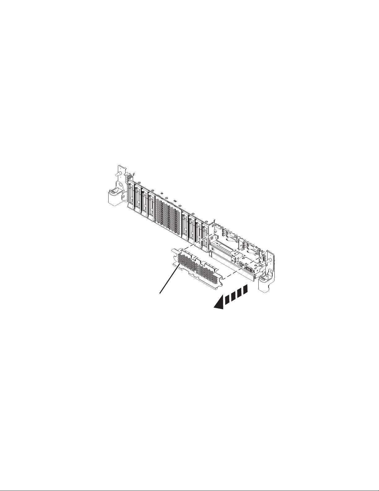
8. If you are removing more than one drive, repeat the steps in this procedure until all drives are
P8HAL516-2
B
removed.
9. If you are not installing a replacement drive, install a filler in the empty slot to ensure proper air
flow for cooling. For instructions, see“Installing a disk drive filler in the 5148-21L, 5148-22L,
8247-21L, 8247-22L, 8284-21A, or 8284-22A” on page 99.
10. If you are installing a replacement drive as a replacement for the failed disk drive or solid-state
drive, go to “Replacing a hot-spare disk drive or solid-state drive in the 8284-21A or 8284-22A
system with the power turned on in IBM i” on page 78.
11. To remove an SSD in an expanded function system, continue with the next step.
12. Remove the front cover to access the SSD. For instructions to remove the front cover from an
expanded function system, see “Removing the front cover from a rack-mounted 5148-21L, 5148-22L,
8247-21L, 8247-22L, 8284-21A, or 8284-22A system” on page 148.
13. To access the SSD slots, remove the perforated plate (B) covering the SSD cage as shown in
Figure 76.
Figure 76. Removing the SSD cage cover to access the SSD slots in an expanded function system
14. On the console, select the drive that you want to remove, and then press Enter.
Important:
v When you press Enter, after your selected time delay, the service indicator light comes on (solid)
for 18 seconds. You then have 18 seconds to unlock and remove the drive. You can set an
appropriate time delay of 01 - 19 minutes to allow adequate time to access the disk drive or
solid-state drive.
v If the service indicator light was already turned on due to a failed device, you will not see a
change in the service indicator light until after the first 18 seconds. You will need to wait until the
service indicator light goes off and then turns back on (solid). You will have two cycles of the light
turning on (solid) to unlock and remove the drive.
15. When the identify LED turns on solid, unlock the drive bay handle (B) by pushing the handle latch
(A) in the direction that is shown and pulling the drive bay handle (B) out toward you, as shown in
Disk drives or solid-state drives 77
Page 96

Figure 77. If the handle is not all the way out, the solid-state drive cannot slide out of the system.
Figure 77. Removing an SSD from an expanded function system
16. Support the bottom of the drive as you slide it out of the system. Hold the drive by its sides.
17. Press Enter on the console to indicate that you removed the drive. The identify LED turns off.
18. If you are not installing a replacement drive immediately, lock the drive bay handle (B) by rotating it
inwards toward the system.
19. If you are removing more than one drive, repeat the steps in this procedure until all drives are
removed.
Replacing a hot-spare disk drive or solid-state drive in the 8284-21A or 8284-22A system with the power turned on in IBM i
Find information about replacing a hot-spare disk drive or solid-state drive (SSD) in a system with the
IBM i operating system or IBM i logical partition that controls the drive location powered on.
To replace a disk drive or solid-state drive in a system, complete the following steps:
1. Ensure that you have the electrostatic discharge (ESD) wrist strap on and that the ESD clip is
connected to an unpainted metal surface. If not, do so now.
2. Choose from the following options:
v If you are replacing a disk drive in a system, continue with step 3.
v If you are replacing a solid-state drive in an expanded function system, continue with step 13 on
page 81.
3. Return to the console and complete the following steps. Wait until the Concurrent Maintenance
Results display is shown.
a. Press F12.
78 Disk drives or solid-state drives
Page 97

b. The physical locations that you entered while you removed the disk drive or solid-state drive
might still show on the display. If not, retype the physical location where you want to install the
new disk drive or solid-state drive.
v In the example, U787A.001.1234567-P3-D4, you would install a disk drive in the system unit
with type 9406, Model 520, sequence number 1234567, and disk drive or solid-state drive
position P3–D4.
v In the example, U5074.001.1234567-DB3-D32, you would install a disk drive or solid-state drive
in the expansion unit with type 5074, model 001, sequence number 1234567, and disk drive or
solid-state drive position DB3–D32.
c. Select 2 (Install device) for the Action to be completed.
d. Set the time delay. For example, for one minute: 01.
Note: You can set an appropriate time delay of 01 - 19 minutes to allow adequate time to access
the disk drive or solid-state drive.
Important: Do not press Enter yet.
4. Unlock the drive bay handle (A) by pressing it and pulling it out toward you. If the handle is not all
the way out, the drive does not slide into the system. See Figure 78 on page 80 and Figure 79 on
page 80.
5. Hold the drive by the top and bottom edges as you position the drive, and insert it into the drive
slot.
6. Slide the drive halfway into the system.
7. In the HSM display, select the drive that you want to install or replace.
8. Press Enter on the console.
Important: When you press Enter, after your selected time delay, the service indicator light comes
on (solid) for 18 seconds. You then have 18 seconds to slide the drive all the way in and then lock it
in place by pushing in the drive handle. You can set an appropriate time delay of 01 - 19 minutes to
allow adequate time to access the disk drive or solid-state drive.
9. When the identify LED turns on solid, slide the drive all the way into the system, and push in the
drive handle (A) until it locks, as shown in Figure 78 on page 80 and Figure 79 on page 80.
Important: Ensure that the drive is fully seated and is all the way into the system.
Disk drives or solid-state drives 79
Page 98

P8HAL503-0
A
Figure 78. Replacing a disk drive in a base function system
P8HAL505-1
A
Figure 79. Replacing a disk drive in an expanded function system
10. On the console, press Enter to indicate that you installed the drive.
80 Disk drives or solid-state drives
Page 99

11. If you are replacing more than one drive, repeat the steps in this procedure until all drives are
replaced.
12. Proceed to the procedure for preparing the system for operation. For instructions, see “Preparing the
8284-21A or 8284-22A system for operation after removing and replacing a hot-spare drive with the
power turned on in IBM i” on page 82.
13. To replace an SSD in an expanded function system, continue with the next step.
14. Return to the console and complete the following steps. Wait until the Concurrent Maintenance
Results display is shown.
a. Press F12.
b. The physical locations that you entered while you removed the disk drive or solid-state drive
might still show on the display. If not, retype the physical location where you want to install the
new disk drive or solid-state drive.
v In the example, U787A.001.1234567-P3-D4, you would install a disk drive in the system unit
with type 9406, Model 520, sequence number 1234567, and disk drive or solid-state drive
position P3–D4.
v In the example, U5074.001.1234567-DB3-D32, you would install a disk drive or solid-state drive
in the expansion unit with type 5074, model 001, sequence number 1234567, and disk drive or
solid-state drive position DB3–D32.
c. Select 2 (Install device) for the Action to be completed.
d. Set the time delay. For example, for one minute: 01.
Note: You can set an appropriate time delay of 01 - 19 minutes to allow adequate time to access
the disk drive or solid-state drive.
Important: Do not press Enter yet.
15. With the SSD drive bay handle (A) in the unlocked position, pull the lever outward to gain access to
the guide rails in the SSD slot. Support the bottom of the SSD as you align it with the guide rails in
the SSD slot. See Figure 80 on page 82.
Note: Support the drive by holding the drive by its sides.
16. Slide the drive halfway into the system.
17. In the HSM display, select the drive that you want to install or replace.
18. Press Enter on the console.
Important: When you press Enter, after your selected time delay, the service indicator light comes
on (solid) for 18 seconds. You then have 18 seconds to slide the drive all the way in and then lock it
in place by pushing in the drive handle. You can set an appropriate time delay of 01 - 19 minutes to
allow adequate time to access the disk drive or solid-state drive.
19. When the identify LED turns on solid, slide the drive all the way into the system until the drive
stops.
20. Lock the drive by rotating the bay handle (A) in the direction that is shown in Figure 80 on page 82.
Important: When you install an SSD, ensure that the SSD is fully seated and is all the way into the
system.
Disk drives or solid-state drives 81
Page 100
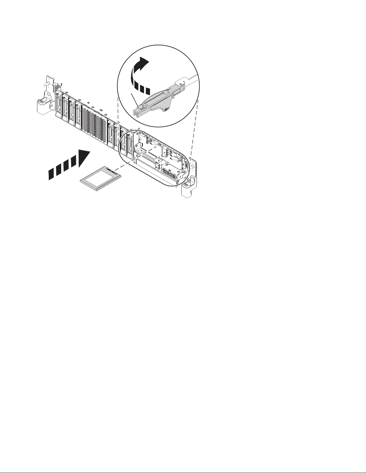
P8HAL507-2
A
Figure 80. Replacing an SSD in an expanded function system
21. On the console, press Enter to indicate that you installed the drive.
22. If you are replacing more than one drive, repeat the steps in this procedure until all drives are
replaced.
Preparing the 8284-21A or 8284-22A system for operation after removing and replacing a hot-spare drive with the power turned on in IBM i
Learn to prepare the system for operation after you replace a hot-spare disk drive or solid-state drive
(SSD) in a system with the IBM i operating system or IBM i logical partition that controls the drive
location powered on.
To prepare the system for operation, complete the following steps:
1. Return to the console and wait until the Concurrent Maintenance Results display is shown, and
press Enter if you used the concurrent maintenance process, otherwise continue with the next step.
2. If you return to the HSM, exit the HSM.
3. Select Work with disk units from the Start System Service Tools display and complete the following
steps:
a. Select Non-configured disk units from the Work with Disk Units display, and press Enter.
b. Is the new disk unit displayed with a status of non-configured?
Note: It might take several minutes for the new drive to display.
v No: Contact your next level of support.
v Yes: Continue with the next step.
c. Press F3 to return to the Work with Disk Units display.
d. Select Work with disk unit recovery from the Work with Disk Units display, and press Enter.
e. Select Disk unit problem recovery procedure, and press Enter.
f. Select Initialize and format disk unit, and press Enter.
g. Select the new disk and press Enter.
82 Disk drives or solid-state drives
 Loading...