

Page 1

Power Systems
Installing the IBM Power 750
(8408-E8D)
and IBM PowerLinux 7R4 (8248-L4T)
GI11-9890-01
Page 2

Page 3

Power Systems
Installing the IBM Power 750
(8408-E8D)
and IBM PowerLinux 7R4 (8248-L4T)
GI11-9890-01
Page 4

Note
Before using this information and the product it supports, read the information in “Safety notices” on page v, “Notices” on
page 43, the IBM Systems Safety Notices manual, G229-9054, and the IBM Environmental Notices and User Guide, Z125–5823.
This edition applies to IBM Power Systems servers that contain the POWER7 processor and to all associated
models.
© Copyright IBM Corporation 2013.
US Government Users Restricted Rights – Use, duplication or disclosure restricted by GSA ADP Schedule Contract
with IBM Corp.
Page 5

Contents
Safety notices .................................v
Installing the IBM Power 750 (8408-E8D) and IBM PowerLinux 7R4 (8248-L4T) .....1
What's new in Installing the IBM Power 750 (8408-E8D) and IBM PowerLinux 7R4 (8248-L4T) ........1
Prerequisite for installing the IBM Power 750 (8408-E8D) and IBM PowerLinux 7R4 (8248-L4T) ........1
Before you begin ..................................2
Installation overview ................................2
Installing the server into a rack .........................3
Attaching the mounting hardware to the rack ........................3
Removing the power supply shipping bracket and the shipping covers................5
Removing the system processor assembly..........................6
Installing the chassis lift handles.............................8
Installing the IBM Power 750 (8408-E8D) and IBM PowerLinux 7R4 (8248-L4T) system into the rack ......9
Replacing the system processor assembly .........................14
Installing the cable-management bracket..........................16
Connecting the expansion units and disk drives .......................16
Model IBM Power 750 (8408-E8D) and IBM PowerLinux 7R4 (8248-L4T) PCI adapters ..........17
Cabling the server and setting up the console...................19
Cabling the server with an ASCII terminal .........................19
Cabling the server to the Hardware Management Console ....................21
Cabling the server and accessing the Integrated Virtualization Manager ...............22
Cabling the server and accessing Operations Console .....................23
Connecting the monitor, keyboard, and mouse to the system ...................25
Connecting the power cables to the system .........................25
Completing the server setup ..........................27
Completing the server setup by using Hardware Management Console ...............27
Completing the server without using a management console ...................29
Reference information .............................31
Installing rack-mounted and factory-racked servers ......................31
Installing the rack-mounted server...........................31
Installing the factory-racked server ..........................32
Supporting information for setting up consoles .......................36
Accessing the ASMI by using a web browser .......................36
Setting the IP address on your PC or notebook ......................38
Windows XP and Windows 2000 ..........................38
Windows Vista ................................38
Windows 7 .................................39
Correcting an IP address ..............................39
Common system attention LEDs and system reference codes ...................40
Best practices for integrating cable and system placement ....................41
Notices ...................................43
Trademarks ...................................44
Electronic emission notices ..............................44
Class A Notices .................................44
Class B Notices .................................48
Terms and conditions ................................51
© Copyright IBM Corp. 2013 iii
Page 6

iv Power Systems: Installing the IBM Power 750 (8408-E8D) and IBM PowerLinux 7R4 (8248-L4T)
Page 7

Safety notices
Safety notices may be printed throughout this guide:
v DANGER notices call attention to a situation that is potentially lethal or extremely hazardous to
people.
v CAUTION notices call attention to a situation that is potentially hazardous to people because of some
existing condition.
v Attention notices call attention to the possibility of damage to a program, device, system, or data.
World Trade safety information
Several countries require the safety information contained in product publications to be presented in their
national languages. If this requirement applies to your country, safety information documentation is
included in the publications package (such as in printed documentation, on DVD, or as part of the
product) shipped with the product. The documentation contains the safety information in your national
language with references to the U.S. English source. Before using a U.S. English publication to install,
operate, or service this product, you must first become familiar with the related safety information
documentation. You should also refer to the safety information documentation any time you do not
clearly understand any safety information in the U.S. English publications.
Replacement or additional copies of safety information documentation can be obtained by calling the IBM
Hotline at 1-800-300-8751.
German safety information
Das Produkt ist nicht für den Einsatz an Bildschirmarbeitsplätzen im Sinne§2der
Bildschirmarbeitsverordnung geeignet.
Laser safety information
IBM®servers can use I/O cards or features that are fiber-optic based and that utilize lasers or LEDs.
Laser compliance
IBM servers may be installed inside or outside of an IT equipment rack.
© Copyright IBM Corp. 2013 v
Page 8

DANGER
When working on or around the system, observe the following precautions:
Electrical voltage and current from power, telephone, and communication cables are hazardous. To
avoid a shock hazard:
v Connect power to this unit only with the IBM provided power cord. Do not use the IBM
provided power cord for any other product.
v Do not open or service any power supply assembly.
v Do not connect or disconnect any cables or perform installation, maintenance, or reconfiguration
of this product during an electrical storm.
v The product might be equipped with multiple power cords. To remove all hazardous voltages,
disconnect all power cords.
v Connect all power cords to a properly wired and grounded electrical outlet. Ensure that the outlet
supplies proper voltage and phase rotation according to the system rating plate.
v Connect any equipment that will be attached to this product to properly wired outlets.
v When possible, use one hand only to connect or disconnect signal cables.
v Never turn on any equipment when there is evidence of fire, water, or structural damage.
v Disconnect the attached power cords, telecommunications systems, networks, and modems before
you open the device covers, unless instructed otherwise in the installation and configuration
procedures.
v Connect and disconnect cables as described in the following procedures when installing, moving,
or opening covers on this product or attached devices.
To Disconnect:
1. Turn off everything (unless instructed otherwise).
2. Remove the power cords from the outlets.
3. Remove the signal cables from the connectors.
4. Remove all cables from the devices.
To Connect:
1. Turn off everything (unless instructed otherwise).
2. Attach all cables to the devices.
3. Attach the signal cables to the connectors.
4. Attach the power cords to the outlets.
5. Turn on the devices.
(D005)
DANGER
vi Power Systems: Installing the IBM Power 750 (8408-E8D) and IBM PowerLinux 7R4 (8248-L4T)
Page 9

Observe the following precautions when working on or around your IT rack system:
v Heavy equipment–personal injury or equipment damage might result if mishandled.
v Always lower the leveling pads on the rack cabinet.
v Always install stabilizer brackets on the rack cabinet.
v To avoid hazardous conditions due to uneven mechanical loading, always install the heaviest
devices in the bottom of the rack cabinet. Always install servers and optional devices starting
from the bottom of the rack cabinet.
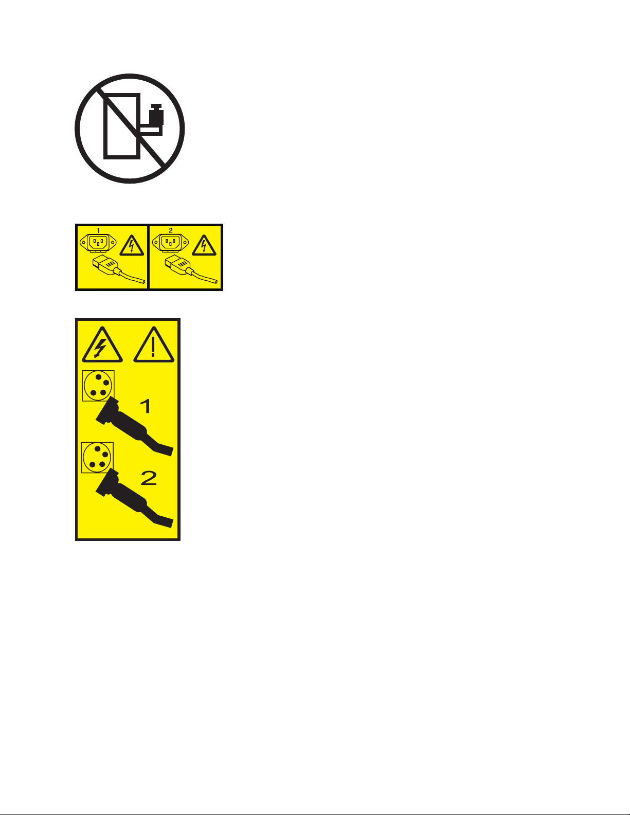
v Rack-mounted devices are not to be used as shelves or work spaces. Do not place objects on top
of rack-mounted devices.
v Each rack cabinet might have more than one power cord. Be sure to disconnect all power cords in
the rack cabinet when directed to disconnect power during servicing.
v Connect all devices installed in a rack cabinet to power devices installed in the same rack
cabinet. Do not plug a power cord from a device installed in one rack cabinet into a power
device installed in a different rack cabinet.
v An electrical outlet that is not correctly wired could place hazardous voltage on the metal parts of
the system or the devices that attach to the system. It is the responsibility of the customer to
ensure that the outlet is correctly wired and grounded to prevent an electrical shock.
CAUTION
v Do not install a unit in a rack where the internal rack ambient temperatures will exceed the
manufacturer's recommended ambient temperature for all your rack-mounted devices.
v Do not install a unit in a rack where the air flow is compromised. Ensure that air flow is not
blocked or reduced on any side, front, or back of a unit used for air flow through the unit.
v Consideration should be given to the connection of the equipment to the supply circuit so that
overloading of the circuits does not compromise the supply wiring or overcurrent protection. To
provide the correct power connection to a rack, refer to the rating labels located on the
equipment in the rack to determine the total power requirement of the supply circuit.
v (For sliding drawers.) Do not pull out or install any drawer or feature if the rack stabilizer brackets
are not attached to the rack. Do not pull out more than one drawer at a time. The rack might
become unstable if you pull out more than one drawer at a time.
v (For fixed drawers.) This drawer is a fixed drawer and must not be moved for servicing unless
specified by the manufacturer. Attempting to move the drawer partially or completely out of the
rack might cause the rack to become unstable or cause the drawer to fall out of the rack.
(R001)
Safety notices vii
Page 10

CAUTION:
Removing components from the upper positions in the rack cabinet improves rack stability during
relocation. Follow these general guidelines whenever you relocate a populated rack cabinet within a
room or building:
v Reduce the weight of the rack cabinet by removing equipment starting at the top of the rack
cabinet. When possible, restore the rack cabinet to the configuration of the rack cabinet as you
received it. If this configuration is not known, you must observe the following precautions:
– Remove all devices in the 32U position and above.
– Ensure that the heaviest devices are installed in the bottom of the rack cabinet.
– Ensure that there are no empty U-levels between devices installed in the rack cabinet below the
32U level.
v If the rack cabinet you are relocating is part of a suite of rack cabinets, detach the rack cabinet from
the suite.
v Inspect the route that you plan to take to eliminate potential hazards.
v Verify that the route that you choose can support the weight of the loaded rack cabinet. Refer to the
documentation that comes with your rack cabinet for the weight of a loaded rack cabinet.
v Verify that all door openings are at least 760 x 230 mm (30 x 80 in.).
v Ensure that all devices, shelves, drawers, doors, and cables are secure.
v Ensure that the four leveling pads are raised to their highest position.
v Ensure that there is no stabilizer bracket installed on the rack cabinet during movement.
v Do not use a ramp inclined at more than 10 degrees.
v When the rack cabinet is in the new location, complete the following steps:
– Lower the four leveling pads.
– Install stabilizer brackets on the rack cabinet.
– If you removed any devices from the rack cabinet, repopulate the rack cabinet from the lowest
position to the highest position.
v If a long-distance relocation is required, restore the rack cabinet to the configuration of the rack
cabinet as you received it. Pack the rack cabinet in the original packaging material, or equivalent.
Also lower the leveling pads to raise the casters off of the pallet and bolt the rack cabinet to the
pallet.
(R002)
(L001)
(L002)
viii Power Systems: Installing the IBM Power 750 (8408-E8D) and IBM PowerLinux 7R4 (8248-L4T)
Page 11
(L003)
or
All lasers are certified in the U.S. to conform to the requirements of DHHS 21 CFR Subchapter J for class
1 laser products. Outside the U.S., they are certified to be in compliance with IEC 60825 as a class 1 laser
product. Consult the label on each part for laser certification numbers and approval information.
CAUTION:
This product might contain one or more of the following devices: CD-ROM drive, DVD-ROM drive,
DVD-RAM drive, or laser module, which are Class 1 laser products. Note the following information:
v Do not remove the covers. Removing the covers of the laser product could result in exposure to
hazardous laser radiation. There are no serviceable parts inside the device.
v Use of the controls or adjustments or performance of procedures other than those specified herein
might result in hazardous radiation exposure.
(C026)
Safety notices ix
Page 12

CAUTION:
Data processing environments can contain equipment transmitting on system links with laser modules
that operate at greater than Class 1 power levels. For this reason, never look into the end of an optical
fiber cable or open receptacle. (C027)
CAUTION:
This product contains a Class 1M laser. Do not view directly with optical instruments. (C028)
CAUTION:
Some laser products contain an embedded Class 3A or Class 3B laser diode. Note the following
information: laser radiation when open. Do not stare into the beam, do not view directly with optical
instruments, and avoid direct exposure to the beam. (C030)
CAUTION:
The battery contains lithium. To avoid possible explosion, do not burn or charge the battery.
Do Not:
v ___ Throw or immerse into water
v ___ Heat to more than 100°C (212°F)
v ___ Repair or disassemble
Exchange only with the IBM-approved part. Recycle or discard the battery as instructed by local
regulations. In the United States, IBM has a process for the collection of this battery. For information,
call 1-800-426-4333. Have the IBM part number for the battery unit available when you call. (C003)
Power and cabling information for NEBS (Network Equipment-Building System)
GR-1089-CORE
The following comments apply to the IBM servers that have been designated as conforming to NEBS
(Network Equipment-Building System) GR-1089-CORE:
The equipment is suitable for installation in the following:
v Network telecommunications facilities
v Locations where the NEC (National Electrical Code) applies
The intrabuilding ports of this equipment are suitable for connection to intrabuilding or unexposed
wiring or cabling only. The intrabuilding ports of this equipment must not be metallically connected to the
interfaces that connect to the OSP (outside plant) or its wiring. These interfaces are designed for use as
intrabuilding interfaces only (Type 2 or Type 4 ports as described in GR-1089-CORE) and require isolation
from the exposed OSP cabling. The addition of primary protectors is not sufficient protection to connect
these interfaces metallically to OSP wiring.
Note: All Ethernet cables must be shielded and grounded at both ends.
The ac-powered system does not require the use of an external surge protection device (SPD).
The dc-powered system employs an isolated DC return (DC-I) design. The DC battery return terminal
shall not be connected to the chassis or frame ground.
x Power Systems: Installing the IBM Power 750 (8408-E8D) and IBM PowerLinux 7R4 (8248-L4T)
Page 13

Installing the IBM Power 750 (8408-E8D) and IBM PowerLinux 7R4 (8248-L4T)
Follow the steps outlined in this topic collection for installing your IBM Power®750 (8408-E8D) and IBM
PowerLinux
You might need to read the following documents before you begin to install the server:
v The latest version of this document is maintained online. See Overview (http://
publib.boulder.ibm.com/infocenter/systems/scope/hw/topic/p7eey/p7eeyroadmap.htm).
v To plan your server installation, see .Planning for the system (http://publib.boulder.ibm.com/
infocenter/systems/scope/hw/topic/p7had/p7had_kickoff_75x_76x).
v If you are using a Hardware Management Console (HMC), see Obtaining and applying machine code
updates for the HMC with an Internet connection (http://publib.boulder.ibm.com/infocenter/systems/
scope/hw/topic/p7hai/area3fixeshmc.htm).
™
7R4 (8248-L4T) system.
What's new in Installing the IBM Power 750 (8408-E8D) and IBM PowerLinux 7R4 (8248-L4T)
Read about new or significantly changed information in Installing the IBM Power 750 (8408-E8D) and
IBM PowerLinux 7R4 (8248-L4T) since the previous update of this topic collection.
November 2013
The following updates have been made to the content:
v Added installation information for the IBM PowerLinux 7R4 (8248-L4T) system.
v Added information for the left and right rear tie-down brackets.
v Miscellaneous changes were made to this topic collection.
Prerequisite for installing the IBM Power 750 (8408-E8D) and IBM PowerLinux 7R4 (8248-L4T)
Use the information in this section to understand the prerequisites required for installing the IBM Power
750 (8408-E8D) and IBM PowerLinux 7R4 (8248-L4T) systems.
Ensure that you have the following items before starting your installation:
v Philips screwdriver
v Flat-head screwdriver
v Hex wrench
v Box cutter
v Rack with 5U (5 Electronic Industries Association units) of space: If you do not have a rack installed,
see Installing the rack (http://publib.boulder.ibm.com/infocenter/systems/scope/hw/topic/p7hbf/
installrack.htm).
You also need one of the following consoles:
v Hardware Management Console (HMC) Version 7 Release 7.7 or later
v Graphics monitor with keyboard and mouse
v Teletype (TTY) monitor with keyboard
© Copyright IBM Corp. 2013 1
Page 14

Before you begin
Understand the requirements for installing the server into a rack.
If your system comes preinstalled in a rack, complete the steps in “Installing the factory-racked server”
on page 32.
Before you begin installing a rack-mounted server, complete the following:
1. Verify that you have received all the boxes that you ordered.
2. Before removing the system from the box, move the system box to a location where you have access
to all four sides of the box.
3. Unpack the server components as needed, starting with the box that contains the rack rails.
4. Complete a parts inventory before installing each server component by following these steps:
a. Locate the inventory list for your server.
b. Ensure that you have received all the parts that you ordered.
Note: Your order information is included with your product. You can also obtain order
information from your marketing representative or the IBM Business Partner.
If you have incorrect, missing, or damaged parts, consult any of the following resources:
v Your IBM reseller.
v IBM Rochester manufacturing automated information line at 1-800-300-8751 (United States only).
v Directory of worldwide contacts (http://www.ibm.com/planetwide). Select your location to view
the service and support contact information.
Installation overview
Learn about installing the server into a rack by using the slide rail and cable-management arm options.
To install the server into a rack, complete the following tasks:
1. “Installing the server into a rack” on page 3.
2. “Cabling the server and setting up the console” on page 19.
3. “Completing the server setup” on page 27.
2 Power Systems: Installing the IBM Power 750 (8408-E8D) and IBM PowerLinux 7R4 (8248-L4T)
Page 15
Installing the server into a rack
With the rack installed, you must remove the processor assembly from the chassis, install the chassis into
the rack, replace the processor assembly, and set up the cable-management bracket.
Attaching the mounting hardware to the rack
You might need to determine where to install the system in the rack, and install the mounting hardware.
Use this procedure to perform this task.
Note: The system requires 5 EIA rack units (5U) of space.
If present, use the rack-mount template to determine and mark the location, and to attach the mounting
hardware to the rack.
To install the rails into the rack without a rack-mount template, complete the following steps:
1. Select the appropriate EIA location unit number for the rails. Each EIA location contains three (3)
holes for mounting hardware. For the purpose of these instructions, each EIA set of holes are
identified as a, b, and c, from the top of each EIA unit to the bottom of each EIA unit.
2. Rotate the locking clamps downward at each end of both rails, to the open position.
Figure 1. Opening the rail clamps
Note: The rails are marked with an L, to designate the left rail, and an R, to designate the right rail.
3. Install nut clips (A) onto the front EIA support flanges, at the appropriate locations. The nut clips are
used to secure the system to the rack.
4. At the rack front, align the bottom of the right rail with the bottom hole (c) of the EIA unit selected,
in both the front of the rack and the rear of the rack. The locator pins (B) fit into holes (b) and (c)of
© Copyright IBM Corp. 2013 3
Page 16
the EIA location directly above the lowest EIA unit used, on both the front and the back of the rack.
Figure 2. Front of rack rail alignment and nut clip locations
5. Rotate the hinged rail latch upward to hold the rail in place against the front EIA support flange.
6. Repeat steps 1 through 5 for the left rail.
7. Secure both rails to the front EIA support flange using two M5 x 16mm screws (C).
8. At the rear of the rack, rotate the hinged rail latch upward to hold each rail in place against the rear
EIA support flange.
4 Power Systems: Installing the IBM Power 750 (8408-E8D) and IBM PowerLinux 7R4 (8248-L4T)
Page 17
Figure 3. Rear of rack rail alignment and nut clip locations
9. Secure both rails to the rear EIA support flanges using four M5 x 16mm screws (C).
Removing the power supply shipping bracket and the shipping covers
If you haven't already done so, remove the front and rear shipping covers and the rear shipping bracket
before you remove the processor assembly and install the system chassis.
1. Remove the screws that attach the front shipping cover (A) to the system chassis, and remove the
front shipping cover.
2. At the rear of the system, remove the power supply retaining bracket (B) and then remove the rear
shipping cover (C) from the chassis.
Installing the server into a rack 5
Page 18
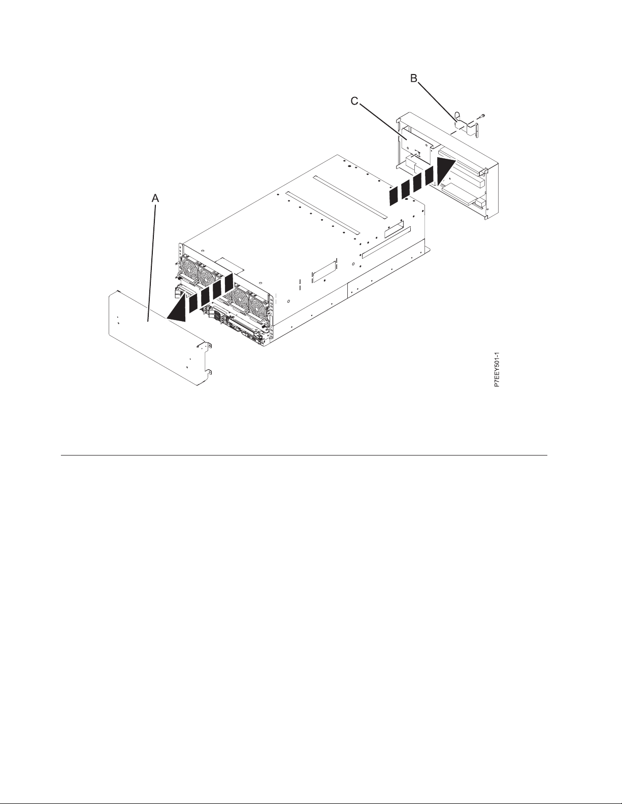
Figure 4. Removing the shipping covers
3. Push the power supplies back into the system, ensuring that they are fully seated and latched. Store
the shipping hardware for future use.
Removing the system processor assembly
If you haven't already done so, you must remove the system processor assembly before you install the
IBM Power 750 (8408-E8D) and IBM PowerLinux 7R4 (8248-L4T).
CAUTION:
The system processor assembly requires two people to remove from the system.
Attention: The system processor assembly weighs 45 lbs. Use caution when you are sliding the system
processor assembly out of the enclosure.
1. Prepare to remove the system processor assembly:
a. Using a slotted screwdriver, loosen both the captive screws (A), if present.
b. Rotate the handles (B) in the direction that is shown until they stop.
c. Hold and pull both the handles and begin sliding the system processor assembly out of the
enclosure until the slide release buttons on each side of the processor assembly lock into place.
6 Power Systems: Installing the IBM Power 750 (8408-E8D) and IBM PowerLinux 7R4 (8248-L4T)
Page 19
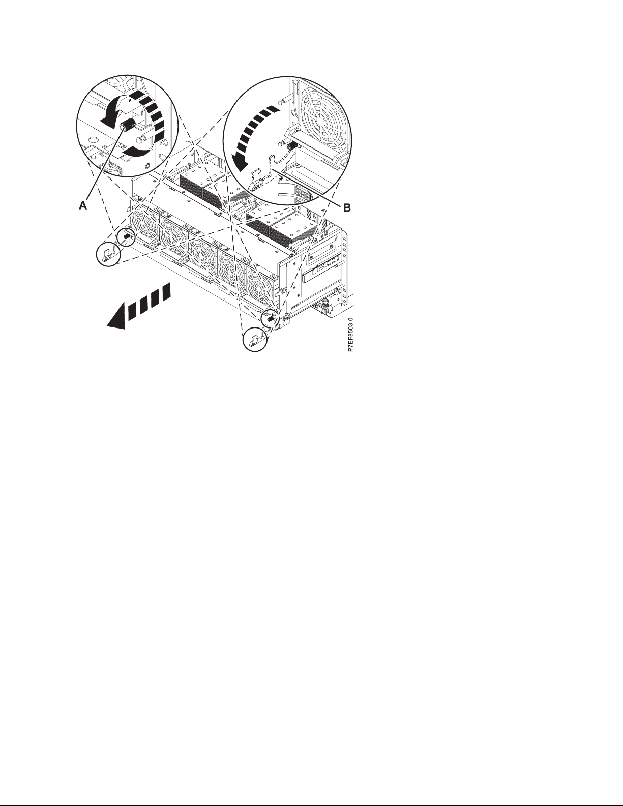
Figure 5. Preparing to remove the system processor assembly
2. Remove the system processor assembly.
a. Slide the card release tabs (C) toward the rear of the system.
3. With two people, one on each side of the assembly, lift the system processor assembly off of the rails
by using both handles on each side. Then move the assembly horizontally away from the rack to clear
the rails.
Installing the server into a rack 7
Page 20
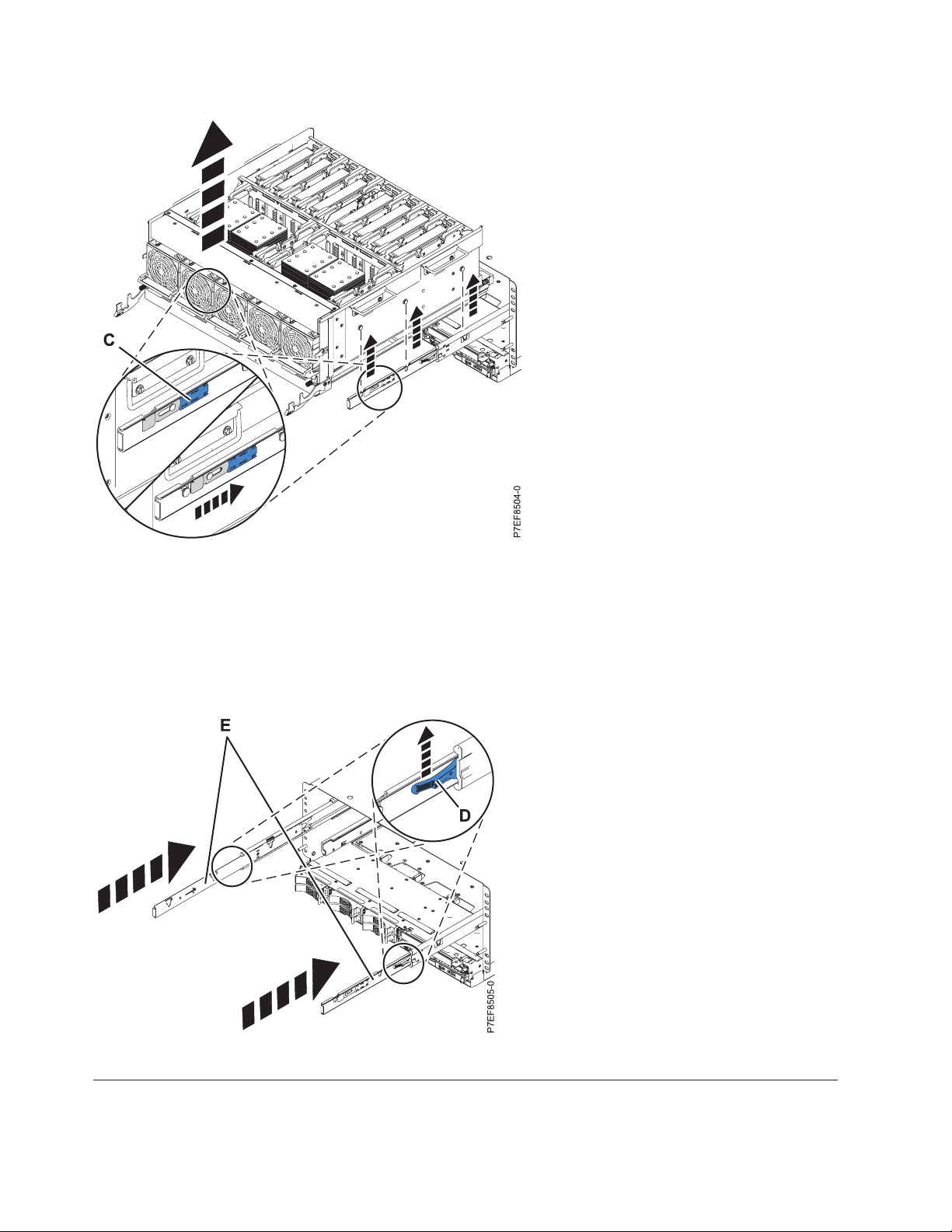
Figure 6. Removing system processor assembly
4. Place the system processor assembly on an ESD surface.
5. Push in the system processor assembly rails:
a. Lift the slide release buttons (one on each side) to unlock the rails (D).
b. Push both the rails (E) back into the enclosure.
Figure 7. Push in the system processor assembly rails
Installing the chassis lift handles
Install the removable system lift handles onto each side of the system chassis.
8 Power Systems: Installing the IBM Power 750 (8408-E8D) and IBM PowerLinux 7R4 (8248-L4T)
Page 21

1. Insert the removable handles into the slots on either side of the system chassis.
Figure 8. Inserting the removable handles
2. Lift the handles so that they slide into the grooves and lock into place.
Installing the IBM Power 750 (8408-E8D) and IBM PowerLinux 7R4 (8248-L4T) system into the rack
Use the procedure in this section to install the IBM Power 750 (8408-E8D) and IBM PowerLinux 7R4
(8248-L4T) systems into the rack. The information provided is intended to promote safety and reliable
operation.
CAUTION:
This system requires three people to install the system into the rack.
To install the 8408-E8D and 8248-L4T into the rack, complete the following steps:
1. Position one person in front of the system (1), one person on the left side of the system (2) and one
person on the right side of the system (3).
Installing the server into a rack 9
Page 22

Figure 9. Lifting the system by the lift handles
2. Using all six handles, do the following:
a. Lift the system.
b. Tilt the system into position over the rack rails.
c. Carefully lower the system until the rear of the system rests on the rails.
10 Power Systems: Installing the IBM Power 750 (8408-E8D) and IBM PowerLinux 7R4 (8248-L4T)
Page 23

Figure 10. Positioning the system so that it rests on the rack rails
3. While the rear of the system is resting on the rails, have the two people on either side of the system
support the weight of the system from the bottom of the chassis.
4. While the two people on either side are supporting the weight of the system, have the person in front
of the system remove the lift handles, as shown in the following figure.
Installing the server into a rack 11
Page 24

Figure 11. Removing the lift handles
5. Push the system all the way into the rack.
6. Install the screws (A) to secure the system to the rack.
Figure 12. Pushing the system into the rack
12 Power Systems: Installing the IBM Power 750 (8408-E8D) and IBM PowerLinux 7R4 (8248-L4T)
Page 25

7. Move to the rear of the system, and,attach the left and right tie-down brackets (A) with four M5 x
16mm screws (two on each bracket), as shown in the following figure. The tie-down brackets ensure
that the chassis is securely fastened to the rack.
Figure 13. Attaching the left and right tie-down brackets
Figure 14. Installed left and right tie-down brackets
Installing the server into a rack 13
Page 26

8. Continue with “Replacing the system processor assembly.”
Replacing the system processor assembly
Replace the system processor assembly after you have installed the system onto the rails.
CAUTION:
The system processor assembly requires two people to install into the system.
1. Slide both the rails out of the enclosure (A) until the slide release buttons (one on each side) lock into
place.
Figure 15. Sliding out the system processor assembly rails
2. Install the system processor assembly:
a. With the rails extended and locked in position, and two people (one person on each side of the
system processor assembly), lift the system processor assembly by using both handles on each
side.
b. Position the system outside of the slide rails so that with the three pins on either side of the
processor assembly are slightly above the rails.
c. Carefully move the system horizontally toward the rack, until the three pins on each side are over
their respective slots on the rails.
d. With the system processor assembly secured on the rails, lift the slide release buttons (one on each
side) to unlock the rails (B).
e. By using the lower handles, slide the system processor assembly completely into the enclosure.
14 Power Systems: Installing the IBM Power 750 (8408-E8D) and IBM PowerLinux 7R4 (8248-L4T)
Page 27

Figure 16. Installing the system processor assembly
3. Complete installing system processor assembly:
a. Ensure that the handles (C) are in the unlocked position.
b. Rotate the handles (C) up and push them toward the enclosure until they lock into place.
c. Tighten both of the captive screws (D), if present.
Note: Do not overtighten the captive screws.
Figure 17. Complete installing system processor assembly
Installing the server into a rack 15
Page 28

Installing the cable-management bracket
Use the cable management bracket if you intend to provide extensive organization for the cables and
cords connecting to the system.
Note: The following situations might prevent the installation of the cable-management bracket:
v The cable management bracket cannot be installed in rack model (7014-S25) due to insufficient
clearance space between the bracket shelf and door.
v The cable management bracket cannot be installed with features that require the same physical space,
such as the earthquake kit.
v The cable management bracket might not be able to be installed in racks that contain additional
customer hardware.
The cable management bracket is designed for installation in standard 482.6 cm (19 inch) rack cabinets.
However, the use of other rack designs, or of additional rack features, or of additional customer
hardware might prevent the installation of the cable management bracket.
1. At the rear of the rack, hold the cable management bracket so that its mounting flanges align with
holes in the system chassis.
2. Tighten the two thumbscrews to attach the cable management bracket to the system chassis.
Figure 18. Installing the cable management bracket
Connecting the expansion units and disk drives
Use this information to learn about connecting and configuring expansion units and disk drives to system
units.
1. For information about connecting expansion units, see Enclosures and expansion units
(http://publib.boulder.ibm.com/infocenter/systems/scope/hw/topic/p7ham/expansionunit.htm).
2. For information about connecting the disk drive unit, see Disk drives (http://
publib.boulder.ibm.com/infocenter/systems/scope/hw/topic/p7hal/p7halkickoff.htm).
16 Power Systems: Installing the IBM Power 750 (8408-E8D) and IBM PowerLinux 7R4 (8248-L4T)
Page 29

Model IBM Power 750 (8408-E8D) and IBM PowerLinux 7R4 (8248-L4T) PCI adapters
You can remove, replace, or install PCI adapters in the IBM Power 750 (8408-E8D) and IBM PowerLinux
7R4 (8248-L4T) systems.
If you are installing a new adapter, see PCI adapter placement (http://publib.boulder.ibm.com/
infocenter/systems/scope/hw/topic/p7hak/p7hak_pciadapters_front_75x_76x.htm) for slot placement
information.
Important: If you are installing a new feature, ensure that you have the software required to support the
new feature and determine whether there are any existing PTF prerequisites to install. To do this, use the
IBM Prerequisite website at http://www-912.ibm.com/e_dir/eServerPrereq.nsf.
Installing the server into a rack 17
Page 30

18 Power Systems: Installing the IBM Power 750 (8408-E8D) and IBM PowerLinux 7R4 (8248-L4T)
Page 31

Cabling the server and setting up the console
Your console, monitor, or interface choices are guided by whether you create logical partitions, which
operating system you install in your primary partition, and whether you install a Virtual I/O Server
(VIOS) in one of your logical partitions.
Note: If you ordered your system or expansion unit preinstalled into a rack, you must remove the
shipping bracket that is on the left side of the rear of the system or expansion unit before you cable it.
Go to the instructions for the applicable console, interface, or terminal in the following table.
Note: After you have cabled your system to a console, connect the power cables to the system. For more
information, see “Connecting the power cables to the system” on page 25.
Table 1. Available console types
Cabling and setup
Console type Operating system Logical partitions Cable required
®
ASCII terminal AIX
Hardware
Management Console
Integrated
Virtualization
Manager for VIOS
Operations Console IBM i Yes
Keyboard, video, and
mouse (KVM)
, Linux, or VIOS Yes for VIOS, no for
AIX and Linux
AIX, IBM i, Linux, or
VIOS
AIX, IBM i, and
Linux
Yes Ethernet (or crossover
Yes Ethernet cable for
Use your Operations
Console to manage
existing IBM i
partitions.
Yes Monitor and USB
Serial cable equipped
with a null modem
cable)
network connection
Ethernet cable for
LAN connection
cables equipped with
KVM
instructions
“Cabling the server
with an ASCII
terminal”
“Cabling the server to
the Hardware
Management
Console” on page 21
“Cabling the server
and accessing the
Integrated
Virtualization
Manager” on page 22
“Cabling the server
and accessing
Operations Console”
on page 23
“Connecting the
monitor, keyboard,
and mouse to the
system” on page 25
Cabling the server with an ASCII terminal
If you are not creating logical partitions, you can use an ASCII terminal to manage a server that is
running the AIX, Linux, or VIOS operating systems. From the ASCII terminal, you can access the
Advanced System Management Interface (ASMI) to perform additional installation tasks.
The ASCII terminal is connected to the server through a serial link. The ASCII interface to the ASMI
provides a subset of the web interface functions. The ASCII terminal is available only when the system is
in the standby state. It is not available during the initial program load (IPL) or run time.
© Copyright IBM Corp. 2013 19
Page 32

If you have previously connected the server to an HMC, you must use the HMC to switch the server
firmware from being managed by the HMC to being a stand-alone server. This switch enables the native
serial ports on the server, and allows you to use the serial ports to connect to the ASCII terminal. Follow
these steps to perform this task:
1. Power off the server using the HMC.
a. Select Systems Management > Servers.
b. Select the server. Ensure that you are selecting the server and not the partition.
c. Select Operations > Power Off.
2. Access ASM to reset the server to its factory default settings.
a. Select Operations > Launch Advanced System Management.
b. Login using the User ID admin.
Note: The default password for the admin User ID is admin.
c. Expand System Service Aids and select Factory Configuration.
d. Select Reset all settings and then select Continue.
3. In the HMC navigation area, select Connections > Reset or Remove Connections > Remove
Connection.
4. Click OK.
To cable an ASCII terminal to the server, complete the following steps:
1. Using a serial cable that is equipped with a null modem, connect the ASCII terminal to system
connector 1 (P2-C8-T7) on the rear of the server.
2. Ensure that your ASCII terminal is set to the following general attributes.
These attributes are the default settings for the diagnostic programs. Be sure that your terminal is set
according to these attributes before proceeding to the next step.
Table 2. Default settings for the diagnostic programs
3151 /11/31/41
General setup attributes
Line speed 19,200 19,200 19,200 Uses the 19,200 (bits per second) line
Word length (bits) 8 8 8 Selects 8 bits as a data word length
Parity No No No Does not add a parity bit and is used
Stop bit 1 1 1 Places a bit after a data word (byte).
settings
3151 /51/61
settings
3161 /64
settings Description
speed to communicate with the system
unit.
(byte).
together with the word length attribute
to form the 8–bit data word (byte).
3. Connect the power cord from the server to a power source.
4. Wait for the green light on the control panel to start flashing.
5. Press a key on the ASCII terminal to allow the service processor to confirm the presence of the ASCII
terminal.
6. When the login display appears for the ASMI, enter admin for the user ID and password.
7. Change the default password when you are prompted.
You have completed the setup for an ASCII terminal, and have started the ASMI.
8. Continue with “Completing the server without using a management console” on page 29.
20 Power Systems: Installing the IBM Power 750 (8408-E8D) and IBM PowerLinux 7R4 (8248-L4T)
Page 33

Cabling the server to the Hardware Management Console
The Hardware Management Console (HMC) controls managed systems, including the management of
logical partitions and the use of capacity on demand. Using service applications, the HMC communicates
with managed systems to detect, consolidate, and forward information to IBM service for analysis.
If you have not already done so, install and configure your HMC. For instructions about installing and
configuring the HMC, see Installation and configuration scenarios (http://publib.boulder.ibm.com/
infocenter/systems/scope/hw/topic/p7hai/basichmcinstallationandconfigurationtaskflow.htm).
®
To manage POWER7
HMC version and release, complete the following steps:
1. In the navigation area, click Updates.
2. In the work area, view and record the information that appears in the HMC Code Level section,
including the HMC version, release, maintenance level, build level, and base versions.
To cable the server to the HMC, complete the following steps:
1. If you want to directly attach your HMC to the managed system, connect Ethernet Connector 1 on
the HMC to the HMC1 port on the managed system. See the following figure.
processor-based servers, the HMC must be at Version 7.7.0, or later. To view the
To learn more about connecting an HMC to a private network so that it can manage more than one
managed system, see HMC network connections (http://publib.boulder.ibm.com/infocenter/systems/
scope/hw/topic/p7hai/netconhmc.htm).
Note:
v You can also have multiple systems attached to a switch that is then connected to the HMC.
v If you are using a switch, ensure that the speed in the switch is set to auto/auto. If the server is
directly attached to the HMC, ensure the HMC's Ethernet adapter speed is set to auto/auto. For
more information about setting media speeds, see Setting the media speed (http://
publib.boulder.ibm.com/infocenter/systems/scope/hw/topic/p7hai/lanmediaspeed.htm).
Cabling the server and setting up the console 21
Page 34

2. If you are connecting a second HMC to your managed server, connect to the Ethernet port that is
labeled HMC2 on the managed server.
3. Complete your server setup. For instructions, see “Completing the server setup by using Hardware
Management Console” on page 27.
Cabling the server and accessing the Integrated Virtualization Manager
When you install the Virtual I/O Server (VIOS) in an environment where no Hardware Management
Console (HMC) is present, the VIOS automatically creates a management partition whose interface is the
Integrated Virtualization Manager (IVM).
To prepare for and install the VIOS and enable the IVM, complete the following steps:
1. Connect a serial cable from a PC or ASCII terminal to a system port on the server. For details, see
“Cabling the server with an ASCII terminal” on page 19.
2. Complete the following steps:
a. Verify that you have access to the Advanced System Management Interface (ASMI) using the web
interface. For details, see “Accessing the ASMI by using a web browser” on page 36.
b. Verify that you have administrator or authorized service provider authority in ASMI.
c. Using the Web-based ASMI, change the following settings as appropriate for the type of partition
on which you are installing the Integrated Virtualization Manager:
For an AIX or Linux partition, complete the following steps to change the partition boot mode:
1) In the navigation area, expand Power/Restart Control.
2) Click Power On/Off System.
3) Select Boot to SMS menu in the AIX or Linux partition mode by boot field.
®
4) If you are installing the Integrated Virtualization Manager on an IBM System i
AIX or Linux in the Default partition environment field.
5) Click Save settings and power on.
d. Open a terminal session on the PC, using an application such as HyperTerminal, and wait for the
SMS menu to appear. Be sure that the line speed is set to 19,200 bits per second to communicate
with the system unit.
e. Using the Web-based ASMI, change the partition boot mode back so that the server loads the
operating environment during startup:
1) Expand Power/Restart Control.
2) Click Power On/Off System.
3) Select Continue to operating system in the AIX or Linux partition mode boot field.
4) Click Save settings.
3. Insert the Virtual I/O Server CD or DVD into the optical drive.
4. In SMS, select the CD or DVD as the boot device:
a. Select Select Boot Options, and press Enter.
b. Select Select Install/Boot Device, and press Enter.
c. Select CD/DVD, and press Enter.
d. Select the media type that corresponds to the optical device, and press Enter.
e. Select the device number that corresponds to the optical device, and press Enter.
f. Select Normal Boot, and confirm that you want to exit SMS.
5. Install the Virtual I/O Server:
a. Select the console, and press Enter.
b. Select a language for the BOS menus, and press Enter.
c. Select Start Install Now with Default Settings.
model, select
22 Power Systems: Installing the IBM Power 750 (8408-E8D) and IBM PowerLinux 7R4 (8248-L4T)
Page 35

d. Select Continue with Install. The managed system restarts after the installation is complete, and
the login prompt is displayed on the ASCII terminal.
6. After you install the IVM, finish the installation by accepting the license agreement, checking for
updates, and configuring the TCP/IP connection.
Cabling the server and accessing Operations Console
You can use Operations Console to manage a server that is running the IBM i operating system whether
you have logical partitions or not. However, you must first use an alternative tool to create the logical
partitions.
Operations Console is a component of IBM i Access for Windows. You can install the complete product or
select only the two console components, which are the Operations Console support and the 5250
emulator support.
To prepare to cable the server and access the Operations Console, complete the following steps:
1. Ensure that your server is powered off.
2. Obtain a static IP address that will be assigned to the server's LAN console adapter for use by the
console, including information about the IP, subnet mask, and default gateway.
3. Select a unique host name and register the host name and the IP address in your site's Domain Name
System (DNS).
Note: This IP address is for use by Operations Console and different from the IP address that is used
to connect a normal Telnet session. The IP address must not be in use by another server. Ping the IP
address to verify that no other device is using the IP address.
To learn more about setting up Operations Console, complete the following steps:
1. Install IBM i Access for Windows and the latest service pack.
Note: The list of Microsoft Windows operating systems supported for Operations Console LAN is
documented at the following Web address: IBM i Access (http://www-03.ibm.com/systems/i/
software/access/windows/supportedos.html).
a. Sign on to the PC by using the local administrator account.
b. Ensure that you have installed a full version of IBM i Access with the latest service pack. The Web
site to download the latest service pack for IBM i Access can be found at IBM i Access
(http://www-03.ibm.com/systems/i/software/access/windows/casp.html).
2. Connect an Ethernet cable from the PC or notebook to the Ethernet port labeled HMC1 on the back of
the managed system. If HMC1 is occupied, connect an Ethernet cable from the PC or notebook to the
Ethernet port labeled HMC2 on the rear of the managed system.
Note: Make the initial connection with the PC directly cabled to the server. The PC and server can be
recabled to the network after the initial connection is made. A cross-over cable is not needed.
3. Configure the PC networking. To configure the PC networking, complete the following steps:
a. Disable any additional adapters. Disable any additional adapters listed, leaving only the local area
connection.
b. Record current TCP/IP settings:
1) Access the adapter properties. Select Internet Protocol, then click Properties .
2) Record the current settings, including IP address, subnet mask, and gateway, if applicable.
3) Tape this information on the console PC as a reminder to reset it before reconnecting to the
network.
c. Change the TCP/IP settings.
Cabling the server and setting up the console 23
Page 36

Note: Some versions of IBM i require that the gateway address respond to pings before the
console LAN adapter activates. Configure the PC with the default gateway IP address by doing
the following:
1) Set the IP address to the opcon LAN adapter gateway.
2) Set the subnet mask to the opcon LAN adapter subnet.
3) Set the default gateway to the opcon LAN adapter primary router, or gateway address. This
address is the same address as the IP address.
4. Disable the PC firewall.
Note: All PC firewalls must be disabled for the initial connection.
To disable the PC firewall, complete the following steps:
a. In the Windows control panel, click Firewall settings and disable the firewall.
b. In the Windows control panel, click Security center. Check for a firewall and, if present, disable it.
c. Scan all tasks running on the PC for any other software firewalls and disable the firewall.
5. Configure Operations Console on your PC:
a. Start Operations Console. To start the Operations Console, select Start > All Programs > IBM
iSeries > Access > Operations Console.
b. Launch the Configuration Wizard. If this is the first time Operations Console is started, the
connection wizard starts automatically. If it does not start automatically, click Connection > New
Connection to manually start the wizard. Read the notifications, and click Next.
c. Select the local console on a network. Click Next.
d. Specify a service host name and IP address by doing the following types:
1) Give your session a name. The name should be one of the following:
v A valid host name that was registered in the site DNS for the console IP address
v A unique name you create that is not currently registered in the DNS for any other IP
address.
For IBM i V5R4 and earlier only: The service tool console IP address can be specified as the
name.
2) If you are using IBM i V5R4, set the target partition to 1. If you are using IBM i V6R1 and
later, press the Tab key. The Service TCP/IP Address field is enabled.
3) IBM i V6R1 and later: Specify the service TCP/IP address. Enter the LAN console adapter IP
address.
4) Click Next.
e. Specify the LAN console interface information.
1) In the Service TCP/IP Address field, type the IP address that you recorded.
2) In the Service Subnet Mask field, type the subnet mask that you recorded.
3) In the Service gateway address field, type the default gateway that you recorded.
4) The system serial number must match the tag on the server. It should be 7 characters long,
without a dash.
5) Set the Target partition to 1.
6) Click Next.
f. Specify the device ID. If you are prompted to specify a service tools device ID, enter QCONSOLE.
Click Next.
g. If you are using a version that is earlier than V6R1, create an access password.
Note: Be sure to record this case-sensitive password because it must be entered each time the
console connection is opened.
h. Click Next > Finish. Your session is now ready to connect. Double-click the session name to start
the connection.
24 Power Systems: Installing the IBM Power 750 (8408-E8D) and IBM PowerLinux 7R4 (8248-L4T)
Page 37

6. Power on the server by completing the following steps:
a. Set the manual IPL by completing the following steps:
1) Locate the server's control panel. Look for the blue tab on the front of the server. Push it to the
side, and pull the control panel out slowly.
2) Press the Up arrow key until you see 02, and press Enter.
3) Press Enter again, and you will see a Less Than symbol (<) move to the N.
4) Press the Up Arrow key. The N changes to an M.
5) Press Enter.
6) Press Enter twice. 02 is displayed on the control panel.
b. After you have the server set to a manual IPL, push the white power button to power on the
server.
7. Connect the console by completing the following steps:
a. Monitor the console status. After the status changes to Pending Authorization, the Service Tools
Sign-On window opens.
Note: The Service Tools Sign-On window might open behind the Operations Console window.
Resize or move the Operations Console window to locate the Service Tools Sign-On window.
b. Sign on to the Service Tools application. To sign on to the Service Tools application, enter 11111111
for the user ID and password.
c. IPL and configure the system.
d. If your session does not connect, wait for the power-on process to stop on an attention or IPL
failure system reference code (SRC), such as A6005008 or B2xxxx. If the power on stops at
A6005008, leave the server in this state and call your IBM service provider for assistance.
Note: You should configure and start an IBM i TCP interface on a second port (T2, T3, T4) prior to
moving the console. This action ensures there is an alternate method to access the server.
Use the information in step 3b to reset the PC to its original TCP/IP settings.
Note: The PC IP configuration must be reset prior to cabling the PC back to the network, because the
PC is configured with the gateway IP address.
The PC and server console port (T1) can now be recabled to the network.
Connecting the monitor, keyboard, and mouse to the system
You might need to connect the monitor, keyboard, and mouse to the system.
To connect a monitor, mouse, and keyboard, perform the following steps:
1. Locate the graphics adapter at the rear of the server.
2. Connect a keyboard and mouse to the USB ports.
3. Connect a standard monitor to the adapter to use the console.
Note: Ensure that you have a video card installed in your system.
4. Power on the console.
5. Connect the power cables for the server and wait for the green light on the operator panel to start
flashing. For instructions, see “Connecting the power cables to the system.”
6. Install an operating system and update the operating system, if required.
Connecting the power cables to the system
You might need to connect power cables to the system. Use this procedure to perform this task.
Cabling the server and setting up the console 25
Page 38

Note: Cable the system and set up a console, interface, or terminal. To cable the system, see “Cabling the
server and setting up the console” on page 19.
To connect power cables to the system, complete the following steps:
1. While facing the rear of the system unit, route the system power cord through the cable retention
bracket.
Note: You might need to pull the power supply out slightly to route the cable though the retention
bracket. After you route the cable through the retention bracket, reseat the power supply.
2. Plug the power cord into the power supply.
Note: This system is equipped with two power supplies. If you want to configure the system with
redundant power supplies, you must connect each power cable to its own power source.
3. Plug the system power cords and the power cords for any other attached devices into the alternating
current (ac) power source.
Note: Confirm that the system is in standby mode. The green power status indicator on the front
control panel is flashing slowly, and the dc out indicator lights on the power supplies are flashing. If
none of the indicators are flashing, check the power cord connections. For detailed information, see
“Common system attention LEDs and system reference codes” on page 40.
26 Power Systems: Installing the IBM Power 750 (8408-E8D) and IBM PowerLinux 7R4 (8248-L4T)
Page 39

Completing the server setup
Learn more about the tasks that you must perform to complete your managed system installation.
If you have an HMC, use it to perform the following tasks:
1. Update the time of day on the managed system by using the Advanced System Management Interface
(ASMI).
2. Check the firmware level on the managed system.
3. If required, update the managed system firmware levels.
4. Confirm that the system is in standby mode. The green power status indicator on the front control
panel is flashing slowly, and the DC Out indicator lights on the power supplies are flashing. If none
of the indicators are flashing, check the power cord connections.
5. Power on the managed system.
6. Create partitions or deploy an imported system plan.
7. Install an operating system, if it is not already installed.
For more detailed information about these tasks, see “Completing the server setup by using Hardware
Management Console.”
If you do not have an HMC, perform the following tasks:
1. Check the firmware level on the managed system and update the time of day by using the ASMI.
2. Confirm that the system is in standby mode. The green power status indicator on the front control
panel is flashing slowly, and the DC Out indicator lights on the power supplies are flashing. If none
of the indicators are flashing, check the power cord connections.
3. Power on the managed system.
4. Install and update an operating system (if it is not already installed).
5. Update system firmware, if required.
For detailed instructions about how to perform these tasks, see “Completing the server without using a
management console” on page 29.
Completing the server setup by using Hardware Management Console
You must perform these tasks to complete the server setup by using a Hardware Management Console
(HMC).
To manage POWER7 processor-based systems, the HMC must be at Version 7.7.0, or later.
To complete the server setup by using an HMC, complete the following steps:
1. Plug in the power cords. For more information, see “Connecting the power cables to the system” on
page 25.
2. Confirm that the system is in standby mode. The green power status indicator on the front control
panel is flashing slowly, and the DC Out indicator lights on the power supplies are flashing. If none
of the indicators are flashing, check the power cord connections. For more information, see “Common
system attention LEDs and system reference codes” on page 40.
3. Change the managed system passwords by completing the following steps:
a. In the navigation area, expand Systems Management > Servers.
b. In the content area, select the managed system.
© Copyright IBM Corp. 2013 27
Page 40

c. In the operations area, click Update passwords.
Note: If the server is managed by a second HMC, ensure that you also update the password on
the second HMC.
4. Update the time of day on the managed system by using the Advanced System Management Interface
(ASMI).
To set up and access the ASMI, complete the following steps:
a. In the navigation area, expand Systems Management > Servers.
b. In the content area, select the managed system.
c. In the task area, expand Operations.
d. Click Launch Advanced System Management (ASM).
To change the time of day by using the ASMI, complete the following steps:
a. On the ASMI Welcome pane, type your admin user ID and password, and click Log In.
b. In the navigation area, expand System Configuration.
c. Click Time of Day. The right pane displays a form that shows the current date (month, day, and
year) and time (hours, minutes, and seconds).
d. Change the date value, the time value, or both, and click Save settings.
5. Check the firmware level on the managed system.
To check the firmware level on the managed system, in the navigation area, click Updates. Firmware
information is displayed in the contents area.
6. Compare your installed firmware level with available firmware levels. If required, update your
firmware levels:
a. Compare your installed firmware level with available firmware levels. For more information, see
the Fix Central website (http://www.ibm.com/support/fixcentral/).
b. If required, update your managed system firmware levels. In the navigation area, click Updates.
c. In the contents area, select your managed system.
d. Click Change Licensed Internal Code for the current release.
7. Power on your managed system by using the correct power-on parameters. To power-on your
managed system by using the HMC, complete the following steps:
a. View your managed system's properties and verify that the logical partition Start policy is set to
User-Initiated. To verify that the logical partition start policy is set to User-Initiated, complete the
following steps:
1) In the navigation area, expand Systems Management > Servers.
2) In the content area, select the managed system.
3) In the tasks area, click Properties.
4) Click the Power On Parameters tab.
5) Ensure that the Partition start policy field is set to User-Initiated.
b. Power on the managed system. To power on the managed system, complete the following steps:
1) In the navigation area, expand Systems Management > Servers.
2) In the content area, select the managed system.
3) Click Operations > Power On.
4) Select the Normal power-on option, and click OK.
8. Create partitions or deploy an imported system plan:
v For instructions about creating partitions, see Partitioning with the HMC (http://
publib.boulder.ibm.com/infocenter/systems/scope/hw/topic/p7hat/iphbllparwithhmcp6.htm).
v For instructions about deploying system plans, see Deploying a system plan by using an HMC
(http://publib.boulder.ibm.com/infocenter/systems/scope/hw/topic/p7hc6/
iphc6deploysysplanp6.htm).
28 Power Systems: Installing the IBM Power 750 (8408-E8D) and IBM PowerLinux 7R4 (8248-L4T)
Page 41

9. Install an operating system and update the operating system:
v For instructions to install the AIX operating system, see Installing AIX (http://
publib.boulder.ibm.com/infocenter/systems/scope/hw/topic/ipha8/iphayinstallaix.htm).
v For instructions to install IBM i, seeInstalling IBM i (http://publib.boulder.ibm.com/infocenter/
systems/scope/hw/topic/ipha8/iphaxinstallos400.htm).
v For instructions to install the Linux operating system, see Installing Linux on Power Systems
servers (http://publib.boulder.ibm.com/infocenter/lnxinfo/v3r0m0/topic/liaae/
lcon_Installing_Linux_on_System_p5.htm).
v For instructions to install the VIOS operating system, see Installing VIOS (http://
publib.boulder.ibm.com/infocenter/systems/scope/hw/topic/p7hch/iphchinstallvios.htm).
Completing the server without using a management console
You must perform these tasks to complete the server setup if you do not have a Hardware Management
Console (HMC).
1. Plug in the power cords. For instructions, see “Connecting the power cables to the system” on page
25.
2. Confirm that the system is in standby mode. The green power status indicator on the front control
panel is flashing slowly, and the DC Out indicator lights on the power supplies are flashing. If none
of the indicator lights are flashing, check the power cord connections. For more information, see
“Common system attention LEDs and system reference codes” on page 40.
3. To check the firmware level on the managed system and to update the time of day, complete the
following steps:
a. Access the Advanced System Management Interface (ASMI). For instructions, see Accessing the
ASMI without an management console (http://publib.boulder.ibm.com/infocenter/systems/
scope/hw/topic/p7hby/connect_asmi.htm).
b. On the ASMI Welcome pane, note the existing level of server firmware in the upper-right corner
under the copyright statement.
c. Update the time of day. In the navigation area, expand System Configuration.
d. Click Time of Day. The right pane displays a form that shows the current date (month, day, and
year) and time (hours, minutes, and seconds).
e. Change the date value, the time value, or both, and click Save settings.
4. Connect your disk drives and PCI adapters, if applicable. For more information, see Disk drives
(http://publib.boulder.ibm.com/infocenter/systems/scope/hw/topic/p7hal/
p7halkickoff_75x_76x.htm) and PCI adapters (http://publib.boulder.ibm.com/infocenter/systems/
scope/hw/topic/p7hak/p7hak_pciadapters_front.htm).
5. To start a system that is not managed by an HMC or ASMI, complete the following steps:
a. Open the front door of the managed system.
b. Press the power button on the control panel. For instructions, see Power on (http://
publib.boulder.ibm.com/infocenter/systems/scope/hw/topic/p7hby/poweronoff.htm).
6. Install an operating system and update the operating system, if required.
For instructions to install the Virtual I/O Server (VIOS) operating system, see Installing VIOS
(http://publib.boulder.ibm.com/infocenter/systems/scope/hw/topic/p7hch/iphchinstallvios.htm).
7. Update the system firmware, if required.
v For instructions to get firmware fixes through the AIX or Linux operating system, see Getting
server firmware fixes through AIX or Linux without a management console (http://
publib.boulder.ibm.com/infocenter/systems/scope/hw/topic/p7ha5/fix_firm_no_hmc_aix.htm).
v If you are using VIOS, see Updating the Virtual I/O Server's firmware and device microcode with
an Internet connection (http://publib.boulder.ibm.com/infocenter/systems/scope/hw/topic/
p7ha5/fix_virtual_firm_ivm.htm).
Completing the server setup 29
Page 42

30 Power Systems: Installing the IBM Power 750 (8408-E8D) and IBM PowerLinux 7R4 (8248-L4T)
Page 43

Reference information
Use this information to learn more about the tasks associated with a system installation.
Installing rack-mounted and factory-racked servers
Use this information to learn about installing rack-mounted and factory-racked servers.
Note: The screws included in the shipment are used to secure the drawer to the rack. Use these screws if
you are moving the rack and drawer to another location, or if you are in an area prone to vibrations or
earthquakes.
Installing the rack-mounted server
You might need to install a rack-mounted server. Use this procedure to perform this task.
To install the rack-mounted server, complete the following high-level tasks:
Table 3. Tasks to install the server into a rack
Task Where to find associated information
Check the prerequisites. For more information, see “Prerequisite for installing the
IBM Power 750 (8408-E8D) and IBM PowerLinux 7R4
(8248-L4T)” on page 1.
Perform the inventory. For more information, see “Before you begin” on page 2.
Verify that you have a rack. You must first have a rack installed. If you do not have a
rack installed, see Installing the rack
(http://publib.boulder.ibm.com/infocenter/systems/
scope/hw/topic/p7hbf/installrack.htm).
Determine where you are going to install the rails and
mark the location.
Remove the system processor assembly. To remove the system processor assembly, see
Install the chassis lift handles. To install the chassis lift handles, see “Installing the
Attach the mounting hardware to the rack. Use the rack mount template included with your
Install the system into the rack. To install the system into the rack, see “Installing the
Replace the processor assembly. To replace the processor assembly, see “Replacing the
Install the cable management bracket. To install the cable management bracket, see “Installing
To determine and mark the location, see “Attaching the
mounting hardware to the rack” on page 3.
“Removing the system processor assembly” on page 6.
chassis lift handles” on page 8.
shipment.
IBM Power 750 (8408-E8D) and IBM PowerLinux 7R4
(8248-L4T) system into the rack” on page 9.
system processor assembly” on page 14.
the cable-management bracket” on page 16.
© Copyright IBM Corp. 2013 31
Page 44

Table 3. Tasks to install the server into a rack (continued)
Task Where to find associated information
Connect your expansion unit, disk drives, and PCI
adapters, if applicable.
Notes:
v Consult your project manager or read the system plans
before moving or installing any disk drives and PCI
adapters.
v Do not power on your system. You will be instructed
to power on the system when you set up the console.
Cable the mouse, keyboard, and monitor, if required. For instructions, see “Connecting the monitor, keyboard,
Cable the system and set up a console, interface, or
terminal.
Connect the power cables to the system and apply
power.
Complete the server setup. For instructions, see “Completing the server setup” on
For more information, see Enclosures and expansion
units (http://publib.boulder.ibm.com/infocenter/
systems/scope/hw/topic/p7ham/expansionunit.htm),
Disk drives (http://publib.boulder.ibm.com/infocenter/
systems/scope/hw/topic/p7hal/
p7halkickoff_75x_76x.htm), and .http://
publib.boulder.ibm.com/infocenter/systems/scope/hw/
topic/p7hak/p7570pci_75x_76x.htm (http://
publib.boulder.ibm.com/infocenter/systems/scope/hw/
topic/p7hak/p7570pci_75x_76x.htm).
and mouse to the system” on page 25.
For instructions, see “Cabling the server and setting up
the console” on page 19.
For instructions, see “Connecting the power cables to the
system” on page 25.
page 27.
Installing the factory-racked server
You might need to install the factory-racked server. Use this procedure to perform this task.
To install a server that is already in a factory-installed rack, complete the following high-level tasks:
Table 4. Tasks to install factory-racked server
Task Where to find associated information
Check the
prerequisites.
Perform the
inventory.
For more information, see “Prerequisite for installing the IBM Power 750 (8408-E8D) and IBM
PowerLinux 7R4 (8248-L4T)” on page 1.
For more information, see “Before you begin” on page 2.
32 Power Systems: Installing the IBM Power 750 (8408-E8D) and IBM PowerLinux 7R4 (8248-L4T)
Page 45

Table 4. Tasks to install factory-racked server (continued)
Task Where to find associated information
Remove the
orange shipping
covers on the
front of the
system.
Remove the
shipping
brackets on the
rear of the
system.
P7EEY508-0
Figure 19. Remove the shipping cover on the front of the system
Figure 20. Remove the power supply shipping bracket
Reference information 33
Page 46

Table 4. Tasks to install factory-racked server (continued)
Task Where to find associated information
Remove the
shipping
brackets on the
rear of the
system.
Remove the
shipping
brackets on the
rear of the
system.
Figure 21. Remove the shipping bracket
Figure 22. Remove the shipping bracket
34 Power Systems: Installing the IBM Power 750 (8408-E8D) and IBM PowerLinux 7R4 (8248-L4T)
Page 47

Table 4. Tasks to install factory-racked server (continued)
Task Where to find associated information
Remove the
shipping
brackets on the
rear of the
system.
Install the cable
management
bracket.
Figure 23. Remove the shipping bracket
Note: Ensure that you fully seat the server power supplies after removing the rear shipping
bracket.
To install the cable management bracket, see “Installing the cable-management bracket” on page
16.
Reference information 35
Page 48

Table 4. Tasks to install factory-racked server (continued)
Task Where to find associated information
Connect your
expansion unit,
disk drives, and
PCI adapters, if
applicable.
Notes:
v Consult your
project
manager or
read the
system plans
before
moving or
installing any
disk drives
and PCI
adapters.
v Do not power
on your
system. You
will be
instructed to
power on the
system when
you set up
the console.
Cable the
system and set
up a console,
interface, or
terminal.
Connect the
power cables to
the system and
apply power.
Complete the
server setup.
For more information, see Enclosures and expansion units (http://publib.boulder.ibm.com/
infocenter/systems/scope/hw/topic/p7ham/expansionunit.htm), Disk drives
(http://publib.boulder.ibm.com/infocenter/systems/scope/hw/topic/p7hal/
p7halkickoff_75x_76x.htm), and .http://publib.boulder.ibm.com/infocenter/systems/scope/hw/
topic/p7hak/p7570pci_75x_76x.htm (http://publib.boulder.ibm.com/infocenter/systems/scope/
hw/topic/p7hak/p7570pci_75x_76x.htm).
For instructions, see “Cabling the server and setting up the console” on page 19.
For instructions, see “Connecting the power cables to the system” on page 25.
For instructions, see “Completing the server setup” on page 27.
Supporting information for setting up consoles
Use this information if you need to access the Advanced System Management Interface by using a web
browser if you need to set IP addresses on your notebook, or if you need to troubleshoot a connection.
Accessing the ASMI by using a web browser
If your system is not managed by a Hardware Management Console (HMC), you can connect a PC or
notebook to the server to access the Advanced System Management Interface (ASMI). You need to
configure the Web browser address on the PC or notebook to match the manufacturing default address
on the server.
To set up the Web browser for direct or remote access to the ASMI, complete the following steps:
1. If the server is not powered on, perform the following steps:
a. Connect your power cord or cords to the server.
36 Power Systems: Installing the IBM Power 750 (8408-E8D) and IBM PowerLinux 7R4 (8248-L4T)
Page 49

b. Plug the power cord or cords into the power source.
c. Wait for the control panel to display 01. A series of progress codes are shown before 01 appears.
Notes:
v The system is powered on if the light on the control panel is green.
v To view the control panel, press the blue switch to the left, then pull out the control panel all
the way, and then pull it down.
Important: Do not connect an Ethernet cable to either the HMC1 port or the HMC2 port until you are
directed to do so later in this procedure.
2. Select a PC or notebook that has Netscape 9.0.0.4, Microsoft Internet Explorer 7.0, Opera 9.24, or
Mozilla Firefox 2.0.0.11 to connect to your server.
Note: If the PC or notebook on which you are viewing this document does not have two Ethernet
connections, another PC or notebook needs to be connected to your server to access the ASMI.
If you do not plan to connect your server to your network, this PC or notebook is your ASMI console.
If you plan to connect your server to your network, this PC or notebook temporarily connects directly
to the server for setup purposes only. After setup, you can use any PC or notebook on your network
that is running Netscape 9.0.0.4, Microsoft Internet Explorer 7.0, Opera 9.24, or Mozilla Firefox 2.0.0.11
as your ASMI console.
Note: Complete the following steps to disable the TLS 1.0 option in Microsoft Internet Explorer to
access the ASMI using Microsoft Internet Explorer 7.0 running on Windows XP:
a. From the Tools menu in Microsoft Internet Explorer, select Internet Options.
b. From the Internet Options window, click the Advanced tab.
c. Clear the Use TLS 1.0 check box (in the Security category) and click OK.
3. Connect an Ethernet cable from the PC or notebook to the Ethernet port labeled HMC1 on the back of
the managed system. If HMC1 is occupied, connect an Ethernet cable from the PC or notebook to the
Ethernet port labeled HMC2 on the rear of the managed system.
Important: If you attach an Ethernet cable to the service processor before the system reaches power
off standby, the IP address shown in Table 5 might not be valid. For details, see “Correcting an IP
address” on page 39.
4. Use Table 5 to help you determine and record the information needed to set the IP address of the
service processor on the PC or notebook. The Ethernet interface on the PC or notebook needs to be
configured within the same subnet mask as the service processor so that they can communicate with
each other. For example, if you connected your PC or notebook to HMC1, the IP address for your PC
or notebook could be 169.254.2.140 and the subnet mask would be 255.255.255.0. Set the gateway IP
address to the same IP address as the PC or notebook
Table 5. Network configuration information for the service processor in a POWER7 processor-based system
POWER7
processor-based
systems Server connector Subnet mask
Service processorAHMC1 255.255.255.0 169.254.2.147 169.254.2.140
HMC2 255.255.255.0 169.254.3.147 169.254.3.140
Service processor
B (if installed)
HMC1 255.255.255.0 169.254.2.146 169.254.2.140
HMC2 255.255.255.0 169.254.3.146 169.254.3.140
IP address of the
service processor
Example of an IP
address for your PC or
notebook
5. Set the IP address on your PC or notebook by using the values from the table. For details, see “Setting
the IP address on your PC or notebook” on page 38.
6. To access the ASMI by using a web browser, complete the following steps:
Reference information 37
Page 50

a. Use Table 5 on page 37 to determine the IP address of the service processor Ethernet port that
your PC or notebook is connected to.
b. Type the IP address in the Address field on the Web browser of your PC or notebook and press
Enter. For example, if you connected your PC or notebook to HMC1, type https://169.254.2.147
in the Web browser on your PC or notebook.
Note: It might take up to 2 minutes for the ASMI login display to be shown in the Web browser after
the Ethernet cable is plugged into the service processor in step 3 on page 37. During this time, if you
use control panel function 30 to view the IP addresses on the service processor, incomplete or
inaccurate data is shown.
7. When the Login display appears, enter admin for the user ID and password.
8. Change the default password when prompted.
9. Choose from the following options:
v If you do not plan to connect your PC or notebook to your network, this ends this procedure. You
can now perform tasks such as changing the time of day or changing the altitude setting.
v If you plan to connect your PC or notebook to your network, see Accessing the ASMI without an
HMC (http://publib.boulder.ibm.com/infocenter/systems/scope/hw/topic/p7hby/
connect_asmi.htm).
Setting the IP address on your PC or notebook
To access the ASMI through a web browser, you first need to set the IP address on a PC or notebook. The
following procedures describe setting the IP address on a PC or notebook running the Linux operating
system and the Microsoft Windows XP, 2000, and Vista operating systems.
You will need the information that you recorded in step 4 on page 37 in the “Accessing the ASMI by
using a web browser” on page 36 topic to complete the following procedure.
Windows XP and Windows 2000
To set the IP address within Windows XP and Windows 2000, complete the following steps:
1. Click Start > Control Panel.
2. On the control panel, double-click Network Connections.
3. Right-click Local Area Connection.
4. Click Properties.
5. Select Internet Protocol (TCP/IP), and then click Properties.
Attention: Record the current settings before making any changes. Use this information to restore
these settings if you disconnect the PC or notebook after setting up the ASMI web interface.
Note: If Internet Protocol (TCP/IP) is not shown in the list, complete the following steps:
a. Click Install.
b. Click Protocol, and then click Add.
c. Click Internet Protocol (TCP/IP).
d. Click OK to return to the Local Area Connection Properties window.
6. Click Use the Following IP Address.
7. Complete the IP address, Subnet mask, and Default gateway fields by using the values you recorded
in the “Accessing the ASMI by using a web browser” on page 36.
8. Click OK on the Local Area Connection Properties window. It is not necessary to restart your PC.
Windows Vista
To set the IP address within Windows Vista, complete the following steps:
1. Click Start > Control Panel.
38 Power Systems: Installing the IBM Power 750 (8408-E8D) and IBM PowerLinux 7R4 (8248-L4T)
Page 51

2. Ensure Classic View is selected.
3. Click Network and Sharing Center.
4. Click View status in the Public network area.
5. Click Properties.
6. If the Security window is shown, click Continue.
7. Highlight Internet Protocol Version 4 and click Properties.
8. Select Use the following IP address.
9. Complete the IP address, Subnet mask, and Default gateway fields by using the values you
recorded in the “Accessing the ASMI by using a web browser” on page 36.
10. Click OK > Close > Close.
Windows 7
To set the IP address within Windows 7, complete the following steps:
1. Click Start > Control Panel > Network and Internet > Network and Sharing Center.
2. Click Change adapter settings to choose your network adapter.
3. Right-click the adapter and choose Properties to open up the properties window.
4. Select Internet Protocol Version 4(TCP/IPv4), and then click Properties.
Attention: Record the current settings before making any changes. Use this information to restore
these settings if you disconnect the PC or notebook after setting up the ASMI web interface.
5. Select Use the Following IP Address.
6. Complete the IP address, Subnet mask, and Default gateway fields by using the values you recorded
in “Accessing the ASMI by using a web browser” on page 36 topic.
7. In the Local Area Connection Properties window, click OK. It is not necessary to restart your PC.
Correcting an IP address
If you attach an Ethernet cable to the service processor before the system reaches power off standby, the
IP address shown in the service processor network configuration table might not be valid.
If a cable is attached and not connected to anything, nothing happens. The address could potentially
change if an Ethernet cable that is attached to a network is connected to that port and if the system is
turned on. If you are unable to access the ASMI by using a network connection, complete one of the
following tasks:
v Attach an ASCII terminal to the service processor by using a serial cable. For details, see “Cabling the
server with an ASCII terminal” on page 19.
v Determine the current IP address. For more information about determining the current service
processor IP address, see Function 30: Service processor IP address and port location
(http://publib.boulder.ibm.com/infocenter/systems/scope/hw/topic/p7hb5/func30.htm).
v Move the reset toggle switches on the service processor from their current position to the opposite
position. To perform this task, you must remove and replace the service processor. For details, contact
your next level of support.
Reference information 39
Page 52

Common system attention LEDs and system reference codes
Find LED and system reference code (SRC) information for recovering recover from common installation
problems.
The following table describes LED status behaviors and describes the meaning of each behavior.
Table 6. Common installation system attention LEDs
Front power
status LED
(green) ac in (green) dc out (green) Fault (yellow) Description
On On On Off Power is being supplied to the system
and the system is powered on.
Flashing On Flashing Off Power is being supplied to the system.
Flashing Off Flashing Off Power is not being supplied to one of
the power supplies, but power is being
supplied to the second power supply,
and the system is in standby mode.
On Off Flashing Off Power is not being supplied to one of
the power supplies, but power is being
supplied to the second power supply,
and the system is powered on.
Off Off Off Off Power is not being supplied to either
power supply.
Flashing On Off or flashing On Power is being applied, but the power
supply is not functioning properly and
the system is in standby mode.
On On Off or flashing On Power is being applied, but the power
supply is not functioning properly and
the system is powered on.
Flashing On On On 110 volts are being applied. This system
requires 220 volts.
The following table describes SRCs that you might encounter during installation.
Table 7. Common installation SRCs
SRC Error description Recovery steps
1000xxx
1100xxx
509Axxx
509Dxxx
50A4xxx
50ADxxx
50B1xxx
11002613 Your power voltages do not
ac input and power supply
connections
match
1. Verify that power cords are plugged in correctly in
the following locations:
v Drawer
v Power distribution unit (PDU), if applicable
v Battery backup unit (BBU), if applicable
v Input source power receptacle
2. Verify that the power supplies are seated and latched
into position.
Ensure that you are using the correct power voltage.
Refer to your server's specifications to learn more about
the power voltage that your server requires.
40 Power Systems: Installing the IBM Power 750 (8408-E8D) and IBM PowerLinux 7R4 (8248-L4T)
Page 53

Table 7. Common installation SRCs (continued)
SRC Error description Recovery steps
Starts with 27xxx,
28xx, 57xxx
and ends with
xxxx3120, xxxx3121
B1A38B24 Network configuration Ensure that you have entered the correct IP address.
Fibre Channel port failure These errors are often caused by ports that are not used.
Every port must have a cable or wrap plug installed.
Whenever a cable is not installed, ensure that a wrap
plug is installed for each unused port. Wrap plugs are
shipped automatically when a Fibre Channel feature
code is ordered.
Best practices for integrating cable and system placement
These guidelines ensure that your system and its cables have optimal clearance for maintenance and
other operations. The guidelines also provide guidance in correctly cabling your system and using the
appropriate cables.
The following guidelines provide cabling information for installing, migrating, relocating, or upgrading
your system:
v Position drawers in racks to allow enough space, where possible, for cable routing on the bottom and
top of the rack, and between drawers.
v Shorter drawers should not be placed between longer drawers in the rack (for example, placing a
19-inch drawer between two 24-inch drawers).
v When a specific cable plugging sequence is required, for example, for concurrent maintenance
(symmetric multiprocessing cables), label the cables appropriately and note the sequence order.
v To facilitate cable routing, install cables in the following order:
1. System power control network (SPCN) cables
2. Power cables
3. Communications (serial attached SCSI, InfiniBand, remote input/output, and peripheral component
interconnect express) cables
Note: Install and route the communications cables, starting with the smallest diameter first and
then progressing to the largest diameter. This applies to installing them into the cable management
arm and retaining them to the rack, brackets, and other features that may be provided for cable
management.
v Install and route the communications cables, starting with smallest diameter first and then progressing
to the largest diameter.
v Use the innermost cable-management bridge lances for SPCN cables.
v Use the middle cable-management bridge lances for power and communications cables.
v The outermost row of cable-management bridge lances are available for use when routing cables.
v Use the cable raceways on the sides of the rack to manage excess SPCN and power cables.
v There are four cable-management bridge lances on the top of the rack. Use these bridge lances to route
the cables from one side of the rack to the other, by routing to the top of the rack, where possible. This
routing helps to avoid having a cable bundle that blocks the cable exit opening at the bottom of the
rack.
v Use the cable management brackets provided with the system to maintain concurrent maintenance
routing.
v Maintain a minimum bend diameter of 101.6 mm (4 in.) for communications (SAS, IB, RIO, and PCIe)
cables.
v Maintain a minimum bend diameter of 50.8 mm (2 in.) for power cables.
v Maintain a minimum bend diameter of 25.4 mm (1 in.) for SPCN cables.
Reference information 41
Page 54

v Use the shortest-length cable available for each point-to-point connection.
v If cables have to be routed across the rear of a drawer, leave enough slack to reduce the tension on the
cables for maintenance of the drawer.
v When routing cables, leave enough slack around the power connection on the power distribution unit
(PDU) so that the wall-to-PDU line cord can be attached to the PDU.
v Use hook-and-loop fasteners where necessary.
Figure 24. Cable management bridge lances
Figure 25. Cable bend radius
Related information:
POWER7 770/780 Cabling guide
42 Power Systems: Installing the IBM Power 750 (8408-E8D) and IBM PowerLinux 7R4 (8248-L4T)
Page 55

Notices
This information was developed for products and services offered in the U.S.A.
The manufacturer may not offer the products, services, or features discussed in this document in other
countries. Consult the manufacturer's representative for information on the products and services
currently available in your area. Any reference to the manufacturer's product, program, or service is not
intended to state or imply that only that product, program, or service may be used. Any functionally
equivalent product, program, or service that does not infringe any intellectual property right of the
manufacturer may be used instead. However, it is the user's responsibility to evaluate and verify the
operation of any product, program, or service.
The manufacturer may have patents or pending patent applications covering subject matter described in
this document. The furnishing of this document does not grant you any license to these patents. You can
send license inquiries, in writing, to the manufacturer.
The following paragraph does not apply to the United Kingdom or any other country where such
provisions are inconsistent with local law: THIS PUBLICATION IS PROVIDED “AS IS” WITHOUT
WARRANTY OF ANY KIND, EITHER EXPRESS OR IMPLIED, INCLUDING, BUT NOT LIMITED TO,
THE IMPLIED WARRANTIES OF NON-INFRINGEMENT, MERCHANTABILITY OR FITNESS FOR A
PARTICULAR PURPOSE. Some states do not allow disclaimer of express or implied warranties in certain
transactions, therefore, this statement may not apply to you.
This information could include technical inaccuracies or typographical errors. Changes are periodically
made to the information herein; these changes will be incorporated in new editions of the publication.
The manufacturer may make improvements and/or changes in the product(s) and/or the program(s)
described in this publication at any time without notice.
Any references in this information to websites not owned by the manufacturer are provided for
convenience only and do not in any manner serve as an endorsement of those websites. The materials at
those websites are not part of the materials for this product and use of those websites is at your own risk.
The manufacturer may use or distribute any of the information you supply in any way it believes
appropriate without incurring any obligation to you.
Any performance data contained herein was determined in a controlled environment. Therefore, the
results obtained in other operating environments may vary significantly. Some measurements may have
been made on development-level systems and there is no guarantee that these measurements will be the
same on generally available systems. Furthermore, some measurements may have been estimated through
extrapolation. Actual results may vary. Users of this document should verify the applicable data for their
specific environment.
Information concerning products not produced by this manufacturer was obtained from the suppliers of
those products, their published announcements or other publicly available sources. This manufacturer has
not tested those products and cannot confirm the accuracy of performance, compatibility or any other
claims related to products not produced by this manufacturer. Questions on the capabilities of products
not produced by this manufacturer should be addressed to the suppliers of those products.
All statements regarding the manufacturer's future direction or intent are subject to change or withdrawal
without notice, and represent goals and objectives only.
The manufacturer's prices shown are the manufacturer's suggested retail prices, are current and are
subject to change without notice. Dealer prices may vary.
© Copyright IBM Corp. 2013 43
Page 56

This information is for planning purposes only. The information herein is subject to change before the
products described become available.
This information contains examples of data and reports used in daily business operations. To illustrate
them as completely as possible, the examples include the names of individuals, companies, brands, and
products. All of these names are fictitious and any similarity to the names and addresses used by an
actual business enterprise is entirely coincidental.
If you are viewing this information in softcopy, the photographs and color illustrations may not appear.
The drawings and specifications contained herein shall not be reproduced in whole or in part without the
written permission of the manufacturer.
The manufacturer has prepared this information for use with the specific machines indicated. The
manufacturer makes no representations that it is suitable for any other purpose.
The manufacturer's computer systems contain mechanisms designed to reduce the possibility of
undetected data corruption or loss. This risk, however, cannot be eliminated. Users who experience
unplanned outages, system failures, power fluctuations or outages, or component failures must verify the
accuracy of operations performed and data saved or transmitted by the system at or near the time of the
outage or failure. In addition, users must establish procedures to ensure that there is independent data
verification before relying on such data in sensitive or critical operations. Users should periodically check
the manufacturer's support websites for updated information and fixes applicable to the system and
related software.
Homologation statement
This product may not be certified in your country for connection by any means whatsoever to interfaces
of public telecommunications networks. Further certification may be required by law prior to making any
such connection. Contact an IBM representative or reseller for any questions.
Trademarks
IBM, the IBM logo, and ibm.com are trademarks or registered trademarks of International Business
Machines Corp., registered in many jurisdictions worldwide. Other product and service names might be
trademarks of IBM or other companies. A current list of IBM trademarks is available on the web at
Copyright and trademark information at www.ibm.com/legal/copytrade.shtml.
INFINIBAND, InfiniBand Trade Association, and the INFINIBAND design marks are trademarks and/or
service marks of the INFINIBAND Trade Association.
Linux is a registered trademark of Linus Torvalds in the United States, other countries, or both.
Microsoft and Windows are trademarks of Microsoft Corporation in the United States, other countries, or
both.
Electronic emission notices
When attaching a monitor to the equipment, you must use the designated monitor cable and any
interference suppression devices supplied with the monitor.
Class A Notices
The following Class A statements apply to the IBM servers that contain the POWER7 processor and its
features unless designated as electromagnetic compatibility (EMC) Class B in the feature information.
44 Power Systems: Installing the IBM Power 750 (8408-E8D) and IBM PowerLinux 7R4 (8248-L4T)
Page 57

Federal Communications Commission (FCC) statement
Note: This equipment has been tested and found to comply with the limits for a Class A digital device,
pursuant to Part 15 of the FCC Rules. These limits are designed to provide reasonable protection against
harmful interference when the equipment is operated in a commercial environment. This equipment
generates, uses, and can radiate radio frequency energy and, if not installed and used in accordance with
the instruction manual, may cause harmful interference to radio communications. Operation of this
equipment in a residential area is likely to cause harmful interference, in which case the user will be
required to correct the interference at his own expense.
Properly shielded and grounded cables and connectors must be used in order to meet FCC emission
limits. IBM is not responsible for any radio or television interference caused by using other than
recommended cables and connectors or by unauthorized changes or modifications to this equipment.
Unauthorized changes or modifications could void the user's authority to operate the equipment.
This device complies with Part 15 of the FCC rules. Operation is subject to the following two conditions:
(1) this device may not cause harmful interference, and (2) this device must accept any interference
received, including interference that may cause undesired operation.
Industry Canada Compliance Statement
This Class A digital apparatus complies with Canadian ICES-003.
Avis de conformité à la réglementation d'Industrie Canada
Cet appareil numérique de la classe A est conforme à la norme NMB-003 du Canada.
European Community Compliance Statement
This product is in conformity with the protection requirements of EU Council Directive 2004/108/EC on
the approximation of the laws of the Member States relating to electromagnetic compatibility. IBM cannot
accept responsibility for any failure to satisfy the protection requirements resulting from a
non-recommended modification of the product, including the fitting of non-IBM option cards.
This product has been tested and found to comply with the limits for Class A Information Technology
Equipment according to European Standard EN 55022. The limits for Class A equipment were derived for
commercial and industrial environments to provide reasonable protection against interference with
licensed communication equipment.
European Community contact:
IBM Deutschland GmbH
Technical Regulations, Department M372
IBM-Allee 1, 71139 Ehningen, Germany
Tele: +49 7032 15 2941
email: lugi@de.ibm.com
Warning: This is a Class A product. In a domestic environment, this product may cause radio
interference, in which case the user may be required to take adequate measures.
Notices 45
Page 58

VCCI Statement - Japan
The following is a summary of the VCCI Japanese statement in the box above:
This is a Class A product based on the standard of the VCCI Council. If this equipment is used in a
domestic environment, radio interference may occur, in which case, the user may be required to take
corrective actions.
Japanese Electronics and Information Technology Industries Association (JEITA)
Confirmed Harmonics Guideline (products less than or equal to 20 A per phase)
Japanese Electronics and Information Technology Industries Association (JEITA)
Confirmed Harmonics Guideline with Modifications (products greater than 20 A per
phase)
Electromagnetic Interference (EMI) Statement - People's Republic of China
Declaration: This is a Class A product. In a domestic environment this product may cause radio
interference in which case the user may need to perform practical action.
46 Power Systems: Installing the IBM Power 750 (8408-E8D) and IBM PowerLinux 7R4 (8248-L4T)
Page 59

Electromagnetic Interference (EMI) Statement - Taiwan
The following is a summary of the EMI Taiwan statement above.
Warning: This is a Class A product. In a domestic environment this product may cause radio interference
in which case the user will be required to take adequate measures.
IBM Taiwan Contact Information:
Electromagnetic Interference (EMI) Statement - Korea
Germany Compliance Statement
Deutschsprachiger EU Hinweis: Hinweis für Geräte der Klasse A EU-Richtlinie zur
Elektromagnetischen Verträglichkeit
Dieses Produkt entspricht den Schutzanforderungen der EU-Richtlinie 2004/108/EG zur Angleichung der
Rechtsvorschriften über die elektromagnetische Verträglichkeit in den EU-Mitgliedsstaaten und hält die
Grenzwerte der EN 55022 Klasse A ein.
Um dieses sicherzustellen, sind die Geräte wie in den Handbüchern beschrieben zu installieren und zu
betreiben. Des Weiteren dürfen auch nur von der IBM empfohlene Kabel angeschlossen werden. IBM
übernimmt keine Verantwortung für die Einhaltung der Schutzanforderungen, wenn das Produkt ohne
Zustimmung von IBM verändert bzw. wenn Erweiterungskomponenten von Fremdherstellern ohne
Empfehlung von IBM gesteckt/eingebaut werden.
Notices 47
Page 60

EN 55022 Klasse A Geräte müssen mit folgendem Warnhinweis versehen werden:
"Warnung: Dieses ist eine Einrichtung der Klasse A. Diese Einrichtung kann im Wohnbereich
Funk-Störungen verursachen; in diesem Fall kann vom Betreiber verlangt werden, angemessene
Maßnahmen zu ergreifen und dafür aufzukommen."
Deutschland: Einhaltung des Gesetzes über die elektromagnetische Verträglichkeit von Geräten
Dieses Produkt entspricht dem “Gesetz über die elektromagnetische Verträglichkeit von Geräten
(EMVG)“. Dies ist die Umsetzung der EU-Richtlinie 2004/108/EG in der Bundesrepublik Deutschland.
Zulassungsbescheinigung laut dem Deutschen Gesetz über die elektromagnetische Verträglichkeit von
Geräten (EMVG) (bzw. der EMC EG Richtlinie 2004/108/EG) für Geräte der Klasse A
Dieses Gerät ist berechtigt, in Übereinstimmung mit dem Deutschen EMVG das EG-Konformitätszeichen
- CE - zu führen.
Verantwortlich für die Einhaltung der EMV Vorschriften ist der Hersteller:
International Business Machines Corp.
New Orchard Road
Armonk, New York 10504
Tel: 914-499-1900
Der verantwortliche Ansprechpartner des Herstellers in der EU ist:
IBM Deutschland GmbH
Technical Regulations, Abteilung M372
IBM-Allee 1, 71139 Ehningen, Germany
Tel: +49 7032 15 2941
email: lugi@de.ibm.com
Generelle Informationen:
Das Gerät erfüllt die Schutzanforderungen nach EN 55024 und EN 55022 Klasse A.
Electromagnetic Interference (EMI) Statement - Russia
Class B Notices
The following Class B statements apply to features designated as electromagnetic compatibility (EMC)
Class B in the feature installation information.
Federal Communications Commission (FCC) statement
This equipment has been tested and found to comply with the limits for a Class B digital device,
pursuant to Part 15 of the FCC Rules. These limits are designed to provide reasonable protection against
harmful interference in a residential installation.
48 Power Systems: Installing the IBM Power 750 (8408-E8D) and IBM PowerLinux 7R4 (8248-L4T)
Page 61

This equipment generates, uses, and can radiate radio frequency energy and, if not installed and used in
accordance with the instructions, may cause harmful interference to radio communications. However,
there is no guarantee that interference will not occur in a particular installation.
If this equipment does cause harmful interference to radio or television reception, which can be
determined by turning the equipment off and on, the user is encouraged to try to correct the interference
by one or more of the following measures:
v Reorient or relocate the receiving antenna.
v Increase the separation between the equipment and receiver.
v Connect the equipment into an outlet on a circuit different from that to which the receiver is
connected.
v Consult an IBM-authorized dealer or service representative for help.
Properly shielded and grounded cables and connectors must be used in order to meet FCC emission
limits. Proper cables and connectors are available from IBM-authorized dealers. IBM is not responsible for
any radio or television interference caused by unauthorized changes or modifications to this equipment.
Unauthorized changes or modifications could void the user's authority to operate this equipment.
This device complies with Part 15 of the FCC rules. Operation is subject to the following two conditions:
(1) this device may not cause harmful interference, and (2) this device must accept any interference
received, including interference that may cause undesired operation.
Industry Canada Compliance Statement
This Class B digital apparatus complies with Canadian ICES-003.
Avis de conformité à la réglementation d'Industrie Canada
Cet appareil numérique de la classe B est conforme à la norme NMB-003 du Canada.
European Community Compliance Statement
This product is in conformity with the protection requirements of EU Council Directive 2004/108/EC on
the approximation of the laws of the Member States relating to electromagnetic compatibility. IBM cannot
accept responsibility for any failure to satisfy the protection requirements resulting from a
non-recommended modification of the product, including the fitting of non-IBM option cards.
This product has been tested and found to comply with the limits for Class B Information Technology
Equipment according to European Standard EN 55022. The limits for Class B equipment were derived for
typical residential environments to provide reasonable protection against interference with licensed
communication equipment.
European Community contact:
IBM Deutschland GmbH
Technical Regulations, Department M372
IBM-Allee 1, 71139 Ehningen, Germany
Tele: +49 7032 15 2941
email: lugi@de.ibm.com
Notices 49
Page 62
VCCI Statement - Japan
Japanese Electronics and Information Technology Industries Association (JEITA)
Confirmed Harmonics Guideline (products less than or equal to 20 A per phase)
Japanese Electronics and Information Technology Industries Association (JEITA)
Confirmed Harmonics Guideline with Modifications (products greater than 20 A per
phase)
IBM Taiwan Contact Information
Electromagnetic Interference (EMI) Statement - Korea
Germany Compliance Statement
Deutschsprachiger EU Hinweis: Hinweis für Geräte der Klasse B EU-Richtlinie zur
Elektromagnetischen Verträglichkeit
50 Power Systems: Installing the IBM Power 750 (8408-E8D) and IBM PowerLinux 7R4 (8248-L4T)
Page 63

Dieses Produkt entspricht den Schutzanforderungen der EU-Richtlinie 2004/108/EG zur Angleichung der
Rechtsvorschriften über die elektromagnetische Verträglichkeit in den EU-Mitgliedsstaaten und hält die
Grenzwerte der EN 55022 Klasse B ein.
Um dieses sicherzustellen, sind die Geräte wie in den Handbüchern beschrieben zu installieren und zu
betreiben. Des Weiteren dürfen auch nur von der IBM empfohlene Kabel angeschlossen werden. IBM
übernimmt keine Verantwortung für die Einhaltung der Schutzanforderungen, wenn das Produkt ohne
Zustimmung von IBM verändert bzw. wenn Erweiterungskomponenten von Fremdherstellern ohne
Empfehlung von IBM gesteckt/eingebaut werden.
Deutschland: Einhaltung des Gesetzes über die elektromagnetische Verträglichkeit von Geräten
Dieses Produkt entspricht dem “Gesetz über die elektromagnetische Verträglichkeit von Geräten
(EMVG)“. Dies ist die Umsetzung der EU-Richtlinie 2004/108/EG in der Bundesrepublik Deutschland.
Zulassungsbescheinigung laut dem Deutschen Gesetz über die elektromagnetische Verträglichkeit von
Geräten (EMVG) (bzw. der EMC EG Richtlinie 2004/108/EG) für Geräte der Klasse B
Dieses Gerät ist berechtigt, in Übereinstimmung mit dem Deutschen EMVG das EG-Konformitätszeichen
- CE - zu führen.
Verantwortlich für die Einhaltung der EMV Vorschriften ist der Hersteller:
International Business Machines Corp.
New Orchard Road
Armonk, New York 10504
Tel: 914-499-1900
Der verantwortliche Ansprechpartner des Herstellers in der EU ist:
IBM Deutschland GmbH
Technical Regulations, Abteilung M372
IBM-Allee 1, 71139 Ehningen, Germany
Tel: +49 7032 15 2941
email: lugi@de.ibm.com
Generelle Informationen:
Das Gerät erfüllt die Schutzanforderungen nach EN 55024 und EN 55022 Klasse B.
Terms and conditions
Permissions for the use of these publications are granted subject to the following terms and conditions.
Applicability: These terms and conditions are in addition to any terms of use for the IBM website.
Personal Use: You may reproduce these publications for your personal, noncommercial use provided that
all proprietary notices are preserved. You may not distribute, display or make derivative works of these
publications, or any portion thereof, without the express consent of IBM.
Commercial Use: You may reproduce, distribute and display these publications solely within your
enterprise provided that all proprietary notices are preserved. You may not make derivative works of
these publications, or reproduce, distribute or display these publications or any portion thereof outside
your enterprise, without the express consent of IBM.
Rights: Except as expressly granted in this permission, no other permissions, licenses or rights are
granted, either express or implied, to the Publications or any information, data, software or other
intellectual property contained therein.
Notices 51
Page 64

IBM reserves the right to withdraw the permissions granted herein whenever, in its discretion, the use of
the publications is detrimental to its interest or, as determined by IBM, the above instructions are not
being properly followed.
You may not download, export or re-export this information except in full compliance with all applicable
laws and regulations, including all United States export laws and regulations.
IBM MAKES NO GUARANTEE ABOUT THE CONTENT OF THESE PUBLICATIONS. THE
PUBLICATIONS ARE PROVIDED "AS-IS" AND WITHOUT WARRANTY OF ANY KIND, EITHER
EXPRESSED OR IMPLIED, INCLUDING BUT NOT LIMITED TO IMPLIED WARRANTIES OF
MERCHANTABILITY, NON-INFRINGEMENT, AND FITNESS FOR A PARTICULAR PURPOSE.
52 Power Systems: Installing the IBM Power 750 (8408-E8D) and IBM PowerLinux 7R4 (8248-L4T)
Page 65

Page 66

Part Number: 00L5075
Printed in USA
GI11-9890-01
(1P) P/N: 00L5075
 Loading...