

Page 1

Front cover
IBM Power 750 and 760
Technical Overview and
Introduction
Features the 8408-E8D and 9109-RMD based
on the latest POWER7+ processor technology
Discusses the dual chip module
architecture
Describes the enhanced I/O
subsystem
James Cruickshank
Sorin Hanganu
Volker Haug
Stephen Lutz
John T Schmidt
Marco Vallone
ibm.com/redbooks
Redpaper
Page 2

Page 3

International Technical Support Organization
IBM Power 750 and 760 Technical Overview and
Introduction
May 2013
REDP-4985-00
Page 4

Note: Before using this information and the product it supports, read the information in “Notices” on
page vii.
First Edition (May 2013)
This edition applies to the IBM Power 750 (8408-E8D) and Power 760 (9109-RMD) Power Systems servers.
© Copyright International Business Machines Corporation 2013. All rights reserved.
Note to U.S. Government Users Restricted Rights -- Use, duplication or disclosure restricted by GSA ADP Schedule
Contract with IBM Corp.
Page 5

Contents
Notices . . . . . . . . . . . . . . . . . . . . . . . . . . . . . . . . . . . . . . . . . . . . . . . . . . . . . . . . . . . . . . . . . vii
Trademarks . . . . . . . . . . . . . . . . . . . . . . . . . . . . . . . . . . . . . . . . . . . . . . . . . . . . . . . . . . . . . viii
Preface . . . . . . . . . . . . . . . . . . . . . . . . . . . . . . . . . . . . . . . . . . . . . . . . . . . . . . . . . . . . . . . . . ix
Authors . . . . . . . . . . . . . . . . . . . . . . . . . . . . . . . . . . . . . . . . . . . . . . . . . . . . . . . . . . . . . . . . . .x
Now you can become a published author, too! . . . . . . . . . . . . . . . . . . . . . . . . . . . . . . . . . . . xi
Comments welcome. . . . . . . . . . . . . . . . . . . . . . . . . . . . . . . . . . . . . . . . . . . . . . . . . . . . . . . . xi
Stay connected to IBM Redbooks . . . . . . . . . . . . . . . . . . . . . . . . . . . . . . . . . . . . . . . . . . . . . xii
Chapter 1. General description . . . . . . . . . . . . . . . . . . . . . . . . . . . . . . . . . . . . . . . . . . . . . 1
1.1 Systems overview . . . . . . . . . . . . . . . . . . . . . . . . . . . . . . . . . . . . . . . . . . . . . . . . . . . . . . 2
1.1.1 IBM Power 750 Express server. . . . . . . . . . . . . . . . . . . . . . . . . . . . . . . . . . . . . . . . 2
1.1.2 IBM Power 760 server . . . . . . . . . . . . . . . . . . . . . . . . . . . . . . . . . . . . . . . . . . . . . . 3
1.2 Operating environment . . . . . . . . . . . . . . . . . . . . . . . . . . . . . . . . . . . . . . . . . . . . . . . . . . 5
1.3 IBM Systems Energy Estimator . . . . . . . . . . . . . . . . . . . . . . . . . . . . . . . . . . . . . . . . . . . 6
1.4 Physical package . . . . . . . . . . . . . . . . . . . . . . . . . . . . . . . . . . . . . . . . . . . . . . . . . . . . . . 6
1.5 System features . . . . . . . . . . . . . . . . . . . . . . . . . . . . . . . . . . . . . . . . . . . . . . . . . . . . . . . 7
1.5.1 Power 750 Express system features. . . . . . . . . . . . . . . . . . . . . . . . . . . . . . . . . . . . 7
1.5.2 Power 760 system features . . . . . . . . . . . . . . . . . . . . . . . . . . . . . . . . . . . . . . . . . . 8
1.5.3 Minimum features . . . . . . . . . . . . . . . . . . . . . . . . . . . . . . . . . . . . . . . . . . . . . . . . . 10
1.5.4 Power supply features . . . . . . . . . . . . . . . . . . . . . . . . . . . . . . . . . . . . . . . . . . . . . 13
1.5.5 Processor card features . . . . . . . . . . . . . . . . . . . . . . . . . . . . . . . . . . . . . . . . . . . . 13
1.5.6 Memory features . . . . . . . . . . . . . . . . . . . . . . . . . . . . . . . . . . . . . . . . . . . . . . . . . . 16
1.6 Disk and media features . . . . . . . . . . . . . . . . . . . . . . . . . . . . . . . . . . . . . . . . . . . . . . . . 18
1.7 I/O drawers . . . . . . . . . . . . . . . . . . . . . . . . . . . . . . . . . . . . . . . . . . . . . . . . . . . . . . . . . . 21
1.7.1 12X I/O Drawer PCIe . . . . . . . . . . . . . . . . . . . . . . . . . . . . . . . . . . . . . . . . . . . . . . 21
1.7.2 EXP30 Ultra SSD I/O drawer . . . . . . . . . . . . . . . . . . . . . . . . . . . . . . . . . . . . . . . . 22
1.7.3 EXP24S SFF Gen2-bay drawer . . . . . . . . . . . . . . . . . . . . . . . . . . . . . . . . . . . . . . 22
1.7.4 EXP12S SAS drawer . . . . . . . . . . . . . . . . . . . . . . . . . . . . . . . . . . . . . . . . . . . . . . 23
1.7.5 I/O drawers and usable PCI slots . . . . . . . . . . . . . . . . . . . . . . . . . . . . . . . . . . . . . 23
1.8 Comparison between models . . . . . . . . . . . . . . . . . . . . . . . . . . . . . . . . . . . . . . . . . . . . 24
1.9 Build to order . . . . . . . . . . . . . . . . . . . . . . . . . . . . . . . . . . . . . . . . . . . . . . . . . . . . . . . . . 26
1.10 IBM editions . . . . . . . . . . . . . . . . . . . . . . . . . . . . . . . . . . . . . . . . . . . . . . . . . . . . . . . . 26
1.11 Model upgrades . . . . . . . . . . . . . . . . . . . . . . . . . . . . . . . . . . . . . . . . . . . . . . . . . . . . . 26
1.12 Server and virtualization management . . . . . . . . . . . . . . . . . . . . . . . . . . . . . . . . . . . . 27
1.13 System racks. . . . . . . . . . . . . . . . . . . . . . . . . . . . . . . . . . . . . . . . . . . . . . . . . . . . . . . . 28
1.13.1 IBM 7014 Model T00 rack . . . . . . . . . . . . . . . . . . . . . . . . . . . . . . . . . . . . . . . . . . 29
1.13.2 IBM 7014 Model T42 rack . . . . . . . . . . . . . . . . . . . . . . . . . . . . . . . . . . . . . . . . . . 30
1.13.3 Feature code 0551 rack . . . . . . . . . . . . . . . . . . . . . . . . . . . . . . . . . . . . . . . . . . . 32
1.13.4 Feature code 0553 rack . . . . . . . . . . . . . . . . . . . . . . . . . . . . . . . . . . . . . . . . . . . 32
1.13.5 The AC power distribution unit and rack content . . . . . . . . . . . . . . . . . . . . . . . . 32
1.13.6 Useful rack additions. . . . . . . . . . . . . . . . . . . . . . . . . . . . . . . . . . . . . . . . . . . . . . 34
1.13.7 OEM rack . . . . . . . . . . . . . . . . . . . . . . . . . . . . . . . . . . . . . . . . . . . . . . . . . . . . . . 40
Chapter 2. Architecture and technical overview . . . . . . . . . . . . . . . . . . . . . . . . . . . . . . 43
2.1 The IBM POWER7+ processor . . . . . . . . . . . . . . . . . . . . . . . . . . . . . . . . . . . . . . . . . . . 45
2.1.1 POWER7+ processor overview . . . . . . . . . . . . . . . . . . . . . . . . . . . . . . . . . . . . . . 46
2.1.2 POWER7+ processor core . . . . . . . . . . . . . . . . . . . . . . . . . . . . . . . . . . . . . . . . . . 47
2.1.3 Simultaneous multithreading. . . . . . . . . . . . . . . . . . . . . . . . . . . . . . . . . . . . . . . . . 47
© Copyright IBM Corp. 2013. All rights reserved. iii
Page 6

2.1.4 Memory access . . . . . . . . . . . . . . . . . . . . . . . . . . . . . . . . . . . . . . . . . . . . . . . . . . . 48
2.1.5 On-chip L3 cache innovation and Intelligent Cache . . . . . . . . . . . . . . . . . . . . . . . 49
2.1.6 POWER7+ processor and Intelligent Energy . . . . . . . . . . . . . . . . . . . . . . . . . . . . 51
2.1.7 Comparison of the POWER7+, POWER7, and POWER6 processors . . . . . . . . . 51
2.2 POWER7+ processor card . . . . . . . . . . . . . . . . . . . . . . . . . . . . . . . . . . . . . . . . . . . . . . 51
2.2.1 Overview . . . . . . . . . . . . . . . . . . . . . . . . . . . . . . . . . . . . . . . . . . . . . . . . . . . . . . . . 52
2.2.2 Processor interconnects . . . . . . . . . . . . . . . . . . . . . . . . . . . . . . . . . . . . . . . . . . . . 52
2.3 Memory subsystem . . . . . . . . . . . . . . . . . . . . . . . . . . . . . . . . . . . . . . . . . . . . . . . . . . . . 54
2.3.1 Registered DIMM . . . . . . . . . . . . . . . . . . . . . . . . . . . . . . . . . . . . . . . . . . . . . . . . . 54
2.3.2 Memory placement rules. . . . . . . . . . . . . . . . . . . . . . . . . . . . . . . . . . . . . . . . . . . . 54
2.3.3 Memory bandwidth . . . . . . . . . . . . . . . . . . . . . . . . . . . . . . . . . . . . . . . . . . . . . . . . 60
2.4 Capacity on Demand. . . . . . . . . . . . . . . . . . . . . . . . . . . . . . . . . . . . . . . . . . . . . . . . . . . 61
2.4.1 Capacity Upgrade on Demand . . . . . . . . . . . . . . . . . . . . . . . . . . . . . . . . . . . . . . . 61
2.4.2 Capacity Backup offering (applies only to IBM i). . . . . . . . . . . . . . . . . . . . . . . . . . 61
2.4.3 Software licensing and CoD . . . . . . . . . . . . . . . . . . . . . . . . . . . . . . . . . . . . . . . . . 62
2.5 System bus . . . . . . . . . . . . . . . . . . . . . . . . . . . . . . . . . . . . . . . . . . . . . . . . . . . . . . . . . . 62
2.5.1 I/O buses and GX++ card . . . . . . . . . . . . . . . . . . . . . . . . . . . . . . . . . . . . . . . . . . . 62
2.6 Internal I/O subsystem . . . . . . . . . . . . . . . . . . . . . . . . . . . . . . . . . . . . . . . . . . . . . . . . . 63
2.6.1 Blind swap cassettes . . . . . . . . . . . . . . . . . . . . . . . . . . . . . . . . . . . . . . . . . . . . . . 64
2.6.2 Integrated multifunction card. . . . . . . . . . . . . . . . . . . . . . . . . . . . . . . . . . . . . . . . . 64
2.7 PCI adapters . . . . . . . . . . . . . . . . . . . . . . . . . . . . . . . . . . . . . . . . . . . . . . . . . . . . . . . . . 65
2.7.1 PCI Express . . . . . . . . . . . . . . . . . . . . . . . . . . . . . . . . . . . . . . . . . . . . . . . . . . . . . 65
2.7.2 PCI-X adapters . . . . . . . . . . . . . . . . . . . . . . . . . . . . . . . . . . . . . . . . . . . . . . . . . . . 66
2.7.3 IBM i IOP adapters . . . . . . . . . . . . . . . . . . . . . . . . . . . . . . . . . . . . . . . . . . . . . . . . 66
2.7.4 PCIe adapter form factors. . . . . . . . . . . . . . . . . . . . . . . . . . . . . . . . . . . . . . . . . . . 66
2.7.5 LAN adapters . . . . . . . . . . . . . . . . . . . . . . . . . . . . . . . . . . . . . . . . . . . . . . . . . . . . 68
2.7.6 Graphics accelerator adapters . . . . . . . . . . . . . . . . . . . . . . . . . . . . . . . . . . . . . . . 70
2.7.7 SCSI and SAS adapters . . . . . . . . . . . . . . . . . . . . . . . . . . . . . . . . . . . . . . . . . . . . 70
2.7.8 iSCSI adapters . . . . . . . . . . . . . . . . . . . . . . . . . . . . . . . . . . . . . . . . . . . . . . . . . . . 70
2.7.9 Fibre Channel adapters . . . . . . . . . . . . . . . . . . . . . . . . . . . . . . . . . . . . . . . . . . . . 71
2.7.10 Fibre Channel over Ethernet. . . . . . . . . . . . . . . . . . . . . . . . . . . . . . . . . . . . . . . . 71
2.7.11 InfiniBand host channel adapter . . . . . . . . . . . . . . . . . . . . . . . . . . . . . . . . . . . . . 72
2.7.12 Asynchronous and USB adapters. . . . . . . . . . . . . . . . . . . . . . . . . . . . . . . . . . . . 73
2.7.13 Cryptographic coprocessor . . . . . . . . . . . . . . . . . . . . . . . . . . . . . . . . . . . . . . . . . 73
2.8 Internal Storage. . . . . . . . . . . . . . . . . . . . . . . . . . . . . . . . . . . . . . . . . . . . . . . . . . . . . . . 74
2.8.1 Dual split backplane mode . . . . . . . . . . . . . . . . . . . . . . . . . . . . . . . . . . . . . . . . . . 77
2.8.2 Triple split backplane mode . . . . . . . . . . . . . . . . . . . . . . . . . . . . . . . . . . . . . . . . . 77
2.8.3 Dual storage I/O Adapter (IOA) configurations . . . . . . . . . . . . . . . . . . . . . . . . . . . 78
2.8.4 DVD . . . . . . . . . . . . . . . . . . . . . . . . . . . . . . . . . . . . . . . . . . . . . . . . . . . . . . . . . . . 79
2.9 External I/O subsystems . . . . . . . . . . . . . . . . . . . . . . . . . . . . . . . . . . . . . . . . . . . . . . . . 80
2.9.1 PCI-DDR 12X expansion drawer . . . . . . . . . . . . . . . . . . . . . . . . . . . . . . . . . . . . . 80
2.9.2 12X I/O Drawer PCIe . . . . . . . . . . . . . . . . . . . . . . . . . . . . . . . . . . . . . . . . . . . . . . 80
2.9.3 12X I/O Drawer PCIe configuration and cabling rules. . . . . . . . . . . . . . . . . . . . . . 82
2.10 External disk subsystems . . . . . . . . . . . . . . . . . . . . . . . . . . . . . . . . . . . . . . . . . . . . . . 86
2.10.1 EXP30 Ultra SSD I/O drawer . . . . . . . . . . . . . . . . . . . . . . . . . . . . . . . . . . . . . . . 86
2.10.2 EXP24S SFF Gen2-bay drawer . . . . . . . . . . . . . . . . . . . . . . . . . . . . . . . . . . . . . 91
2.10.3 EXP12S SAS expansion drawer. . . . . . . . . . . . . . . . . . . . . . . . . . . . . . . . . . . . . 93
2.10.4 TotalStorage EXP24 disk drawer and tower . . . . . . . . . . . . . . . . . . . . . . . . . . . . 93
2.10.5 IBM 7031 TotalStorage EXP24. . . . . . . . . . . . . . . . . . . . . . . . . . . . . . . . . . . . . . 93
2.10.6 IBM System Storage . . . . . . . . . . . . . . . . . . . . . . . . . . . . . . . . . . . . . . . . . . . . . . 94
2.11 Hardware Management Console . . . . . . . . . . . . . . . . . . . . . . . . . . . . . . . . . . . . . . . . 95
2.11.1 HMC connectivity to the POWER7+ processor-based systems . . . . . . . . . . . . . 97
2.11.2 High availability HMC configuration . . . . . . . . . . . . . . . . . . . . . . . . . . . . . . . . . . 99
iv IBM Power 750 and 760 Technical Overview and Introduction
Page 7

2.12 Operating system support . . . . . . . . . . . . . . . . . . . . . . . . . . . . . . . . . . . . . . . . . . . . . 100
2.12.1 IBM AIX operating system . . . . . . . . . . . . . . . . . . . . . . . . . . . . . . . . . . . . . . . . 101
2.12.2 IBM i operating system . . . . . . . . . . . . . . . . . . . . . . . . . . . . . . . . . . . . . . . . . . . 102
2.12.3 Linux operating system . . . . . . . . . . . . . . . . . . . . . . . . . . . . . . . . . . . . . . . . . . . 102
2.12.4 Virtual I/O Server . . . . . . . . . . . . . . . . . . . . . . . . . . . . . . . . . . . . . . . . . . . . . . . 103
2.12.5 Java versions that are supported . . . . . . . . . . . . . . . . . . . . . . . . . . . . . . . . . . . 103
2.12.6 Boosting performance and productivity with IBM compilers . . . . . . . . . . . . . . . 103
2.13 Energy management . . . . . . . . . . . . . . . . . . . . . . . . . . . . . . . . . . . . . . . . . . . . . . . . . 105
2.13.1 IBM EnergyScale technology . . . . . . . . . . . . . . . . . . . . . . . . . . . . . . . . . . . . . . 105
2.13.2 Thermal power management device card. . . . . . . . . . . . . . . . . . . . . . . . . . . . . 110
2.13.3 Energy consumption estimation . . . . . . . . . . . . . . . . . . . . . . . . . . . . . . . . . . . . 110
Chapter 3. Virtualization. . . . . . . . . . . . . . . . . . . . . . . . . . . . . . . . . . . . . . . . . . . . . . . . . 111
3.1 POWER Hypervisor . . . . . . . . . . . . . . . . . . . . . . . . . . . . . . . . . . . . . . . . . . . . . . . . . . 112
3.2 POWER processor modes . . . . . . . . . . . . . . . . . . . . . . . . . . . . . . . . . . . . . . . . . . . . . 115
3.3 Active Memory Expansion. . . . . . . . . . . . . . . . . . . . . . . . . . . . . . . . . . . . . . . . . . . . . . 117
3.4 PowerVM. . . . . . . . . . . . . . . . . . . . . . . . . . . . . . . . . . . . . . . . . . . . . . . . . . . . . . . . . . . 122
3.4.1 PowerVM editions . . . . . . . . . . . . . . . . . . . . . . . . . . . . . . . . . . . . . . . . . . . . . . . . 122
3.4.2 Logical partitions . . . . . . . . . . . . . . . . . . . . . . . . . . . . . . . . . . . . . . . . . . . . . . . . . 122
3.4.3 Multiple shared processor pools . . . . . . . . . . . . . . . . . . . . . . . . . . . . . . . . . . . . . 126
3.4.4 Virtual I/O Server . . . . . . . . . . . . . . . . . . . . . . . . . . . . . . . . . . . . . . . . . . . . . . . . 130
3.4.5 PowerVM Live Partition Mobility . . . . . . . . . . . . . . . . . . . . . . . . . . . . . . . . . . . . . 136
3.4.6 Active Memory Sharing . . . . . . . . . . . . . . . . . . . . . . . . . . . . . . . . . . . . . . . . . . . . 138
3.4.7 Active Memory Deduplication . . . . . . . . . . . . . . . . . . . . . . . . . . . . . . . . . . . . . . . 139
3.4.8 Dynamic Platform Optimizer . . . . . . . . . . . . . . . . . . . . . . . . . . . . . . . . . . . . . . . . 142
3.4.9 Dynamic System Optimizer. . . . . . . . . . . . . . . . . . . . . . . . . . . . . . . . . . . . . . . . . 143
3.4.10 Operating system support for PowerVM . . . . . . . . . . . . . . . . . . . . . . . . . . . . . . 143
3.4.11 Linux support . . . . . . . . . . . . . . . . . . . . . . . . . . . . . . . . . . . . . . . . . . . . . . . . . . 144
3.5 System Planning Tool . . . . . . . . . . . . . . . . . . . . . . . . . . . . . . . . . . . . . . . . . . . . . . . . . 146
3.6 New PowerVM Version 2.2.2 features . . . . . . . . . . . . . . . . . . . . . . . . . . . . . . . . . . . . 147
Chapter 4. Continuous availability and manageability . . . . . . . . . . . . . . . . . . . . . . . . 149
4.1 Reliability. . . . . . . . . . . . . . . . . . . . . . . . . . . . . . . . . . . . . . . . . . . . . . . . . . . . . . . . . . . 150
4.1.1 Designed for reliability. . . . . . . . . . . . . . . . . . . . . . . . . . . . . . . . . . . . . . . . . . . . . 150
4.1.2 Placement of components . . . . . . . . . . . . . . . . . . . . . . . . . . . . . . . . . . . . . . . . . 151
4.1.3 Redundant components and concurrent repair. . . . . . . . . . . . . . . . . . . . . . . . . . 151
4.2 Availability . . . . . . . . . . . . . . . . . . . . . . . . . . . . . . . . . . . . . . . . . . . . . . . . . . . . . . . . . . 151
4.2.1 Partition availability priority . . . . . . . . . . . . . . . . . . . . . . . . . . . . . . . . . . . . . . . . . 152
4.2.2 General detection and deallocation of failing components . . . . . . . . . . . . . . . . . 152
4.2.3 Memory protection . . . . . . . . . . . . . . . . . . . . . . . . . . . . . . . . . . . . . . . . . . . . . . . 154
4.2.4 Cache protection . . . . . . . . . . . . . . . . . . . . . . . . . . . . . . . . . . . . . . . . . . . . . . . . . 156
4.2.5 Special Uncorrectable Error handling . . . . . . . . . . . . . . . . . . . . . . . . . . . . . . . . . 156
4.2.6 PCI Enhanced Error Handling. . . . . . . . . . . . . . . . . . . . . . . . . . . . . . . . . . . . . . . 157
4.3 Serviceability . . . . . . . . . . . . . . . . . . . . . . . . . . . . . . . . . . . . . . . . . . . . . . . . . . . . . . . . 158
4.3.1 Detecting . . . . . . . . . . . . . . . . . . . . . . . . . . . . . . . . . . . . . . . . . . . . . . . . . . . . . . . 159
4.3.2 Diagnosing . . . . . . . . . . . . . . . . . . . . . . . . . . . . . . . . . . . . . . . . . . . . . . . . . . . . . 164
4.3.3 Reporting . . . . . . . . . . . . . . . . . . . . . . . . . . . . . . . . . . . . . . . . . . . . . . . . . . . . . . 165
4.3.4 Notifying . . . . . . . . . . . . . . . . . . . . . . . . . . . . . . . . . . . . . . . . . . . . . . . . . . . . . . . 167
4.3.5 Locating and servicing . . . . . . . . . . . . . . . . . . . . . . . . . . . . . . . . . . . . . . . . . . . . 168
4.4 Manageability . . . . . . . . . . . . . . . . . . . . . . . . . . . . . . . . . . . . . . . . . . . . . . . . . . . . . . . 171
4.4.1 Service user interfaces . . . . . . . . . . . . . . . . . . . . . . . . . . . . . . . . . . . . . . . . . . . . 171
4.4.2 IBM Power Systems firmware maintenance . . . . . . . . . . . . . . . . . . . . . . . . . . . . 176
4.4.3 Concurrent firmware update improvements with POWER7+ . . . . . . . . . . . . . . . 178
Contents v
Page 8

4.4.4 Electronic Services and Electronic Service Agent . . . . . . . . . . . . . . . . . . . . . . . 179
4.5 POWER7+ RAS features . . . . . . . . . . . . . . . . . . . . . . . . . . . . . . . . . . . . . . . . . . . . . . 180
4.6 Power-On Reset Engine . . . . . . . . . . . . . . . . . . . . . . . . . . . . . . . . . . . . . . . . . . . . . . . 181
4.7 Operating system support for RAS features . . . . . . . . . . . . . . . . . . . . . . . . . . . . . . . . 181
Related publications . . . . . . . . . . . . . . . . . . . . . . . . . . . . . . . . . . . . . . . . . . . . . . . . . . . . 185
IBM Redbooks . . . . . . . . . . . . . . . . . . . . . . . . . . . . . . . . . . . . . . . . . . . . . . . . . . . . . . . . . . 185
Other publications . . . . . . . . . . . . . . . . . . . . . . . . . . . . . . . . . . . . . . . . . . . . . . . . . . . . . . . 186
Online resources . . . . . . . . . . . . . . . . . . . . . . . . . . . . . . . . . . . . . . . . . . . . . . . . . . . . . . . . 187
Help from IBM . . . . . . . . . . . . . . . . . . . . . . . . . . . . . . . . . . . . . . . . . . . . . . . . . . . . . . . . . . 187
vi IBM Power 750 and 760 Technical Overview and Introduction
Page 9

Notices
This information was developed for products and services offered in the U.S.A.
IBM may not offer the products, services, or features discussed in this document in other countries. Consult
your local IBM representative for information on the products and services currently available in your area. Any
reference to an IBM product, program, or service is not intended to state or imply that only that IBM product,
program, or service may be used. Any functionally equivalent product, program, or service that does not
infringe any IBM intellectual property right may be used instead. However, it is the user's responsibility to
evaluate and verify the operation of any non-IBM product, program, or service.
IBM may have patents or pending patent applications covering subject matter described in this document. The
furnishing of this document does not grant you any license to these patents. You can send license inquiries, in
writing, to:
IBM Director of Licensing, IBM Corporation, North Castle Drive, Armonk, NY 10504-1785 U.S.A.
The following paragraph does not apply to the United Kingdom or any other country where such
provisions are inconsistent with local law: INTERNATIONAL BUSINESS MACHINES CORPORATION
PROVIDES THIS PUBLICATION "AS IS" WITHOUT WARRANTY OF ANY KIND, EITHER EXPRESS OR
IMPLIED, INCLUDING, BUT NOT LIMITED TO, THE IMPLIED WARRANTIES OF NON-INFRINGEMENT,
MERCHANTABILITY OR FITNESS FOR A PARTICULAR PURPOSE. Some states do not allow disclaimer of
express or implied warranties in certain transactions, therefore, this statement may not apply to you.
This information could include technical inaccuracies or typographical errors. Changes are periodically made
to the information herein; these changes will be incorporated in new editions of the publication. IBM may make
improvements and/or changes in the product(s) and/or the program(s) described in this publication at any time
without notice.
Any references in this information to non-IBM websites are provided for convenience only and do not in any
manner serve as an endorsement of those websites. The materials at those websites are not part of the
materials for this IBM product and use of those websites is at your own risk.
IBM may use or distribute any of the information you supply in any way it believes appropriate without incurring
any obligation to you.
Any performance data contained herein was determined in a controlled environment. Therefore, the results
obtained in other operating environments may vary significantly. Some measurements may have been made
on development-level systems and there is no guarantee that these measurements will be the same on
generally available systems. Furthermore, some measurements may have been estimated through
extrapolation. Actual results may vary. Users of this document should verify the applicable data for their
specific environment.
Information concerning non-IBM products was obtained from the suppliers of those products, their published
announcements or other publicly available sources. IBM has not tested those products and cannot confirm the
accuracy of performance, compatibility or any other claims related to non-IBM products. Questions on the
capabilities of non-IBM products should be addressed to the suppliers of those products.
This information contains examples of data and reports used in daily business operations. To illustrate them
as completely as possible, the examples include the names of individuals, companies, brands, and products.
All of these names are fictitious and any similarity to the names and addresses used by an actual business
enterprise is entirely coincidental.
COPYRIGHT LICENSE:
This information contains sample application programs in source language, which illustrate programming
techniques on various operating platforms. You may copy, modify, and distribute these sample programs in
any form without payment to IBM, for the purposes of developing, using, marketing or distributing application
programs conforming to the application programming interface for the operating platform for which the sample
programs are written. These examples have not been thoroughly tested under all conditions. IBM, therefore,
cannot guarantee or imply reliability, serviceability, or function of these programs.
© Copyright IBM Corp. 2013. All rights reserved. vii
Page 10

Trademarks
IBM, the IBM logo, and ibm.com are trademarks or registered trademarks of International Business Machines
Corporation in the United States, other countries, or both. These and other IBM trademarked terms are
marked on their first occurrence in this information with the appropriate symbol (® or ™), indicating US
registered or common law trademarks owned by IBM at the time this information was published. Such
trademarks may also be registered or common law trademarks in other countries. A current list of IBM
trademarks is available on the Web at http://www.ibm.com/legal/copytrade.shtml
The following terms are trademarks of the International Business Machines Corporation in the United States,
other countries, or both:
Active Memory™
AIX®
AS/400®
BladeCenter®
DS8000®
Dynamic Infrastructure®
Electronic Service Agent™
EnergyScale™
Focal Point™
IBM®
IBM Flex System™
IBM Systems Director Active Energy
Manager™
Micro-Partitioning®
POWER®
POWER Hypervisor™
Power Systems™
Power Systems Software™
POWER6®
POWER6+™
POWER7®
POWER7+™
PowerHA®
PowerPC®
PowerVM®
pSeries®
PureFlex™
Rational®
Rational Team Concert™
Real-time Compression™
Redbooks®
Redpaper™
Redpapers™
Redbooks (logo) ®
RS/6000®
Storwize®
System p®
System Storage®
System x®
System z®
Tivoli®
XIV®
The following terms are trademarks of other companies:
Intel, Intel Xeon, Intel logo, Intel Inside logo, and Intel Centrino logo are trademarks or registered trademarks
of Intel Corporation or its subsidiaries in the United States and other countries.
ITIL is a registered trademark, and a registered community trademark of The Minister for the Cabinet Office,
and is registered in the U.S. Patent and Trademark Office.
Linux is a trademark of Linus Torvalds in the United States, other countries, or both.
LTO, Ultrium, the LTO Logo and the Ultrium logo are trademarks of HP, IBM Corp. and Quantum in the U.S.
and other countries.
Microsoft, and the Windows logo are trademarks of Microsoft Corporation in the United States, other
countries, or both.
Java, and all Java-based trademarks and logos are trademarks or registered trademarks of Oracle and/or its
affiliates.
UNIX is a registered trademark of The Open Group in the United States and other countries.
Other company, product, or service names may be trademarks or service marks of others.
viii IBM Power 750 and 760 Technical Overview and Introduction
Page 11

Preface
This IBM® Redpaper™ publication is a comprehensive guide covering the IBM Power 750
(8408-E8D) and Power 760 (9109-RMD) servers that support IBM AIX®, IBM i, and Linux
operating systems. The goal of this paper is to introduce the major innovative Power 750 and
Power 760 offerings and their prominent functions:
The IBM POWER7+™ processor, available at frequencies of 3.1 GHz, 3.4 GHz, 3.5 GHz,
The larger IBM POWER7+ Level 3 cache provides greater bandwidth, capacity, and
The newly introduced POWER7+ dual chip module (DCM).
New 10 GBaseT options for the Integrated Multifunction Card that provides two USB ports,
New IBM PowerVM® V2.2.2 features, such as 20 LPARs per core.
The improved IBM Active Memory™ Expansion technology that provides more usable
IBM EnergyScale™ technology that provides features such as power trending,
Improved reliability, serviceability, and availability.
and 4.0 GHz.
reliability.
one serial port, and four Ethernet connectors for a processor enclosure and does not
require a PCI slot.
memory than is physically installed in the system.
power-saving, capping of power, and thermal measurement.
Dynamic Platform Optimizer.
High-performance SSD drawer.
This publication is for professionals who want to acquire a better understanding of IBM Power
Systems™ products. The intended audience includes the following roles:
Clients
Sales and marketing professionals
Technical support professionals
IBM Business Partners
Independent software vendors
This paper expands the current set of IBM Power Systems documentation by providing a
desktop reference that offers a detailed technical description of the Power 750 and Power 760
systems.
This paper does not replace the latest marketing materials and configuration tools. It is
intended as an additional source of information that, together with existing sources, can be
used to enhance your knowledge of IBM server solutions.
© Copyright IBM Corp. 2013. All rights reserved. ix
Page 12

Authors
This paper was produced by a team of specialists from around the world working at the
International Technical Support Organization, Poughkeepsie Center.
James Cruickshank works in the Power Systems Client Technical Specialist team for IBM in
the UK. He holds an Honors degree in Mathematics from the University of Leeds. James has
over 11 years of experience working with IBM pSeries®, IBM System p® and Power Systems
products and is a member of the EMEA Power Champions team. James supports customers
in the financial services sector in the UK.
Sorin Hanganu is an Accredited Product Services professional. He has eight years of
experience working on Power Systems and IBM i products. He is an IBM Certified Solution
Expert for IBM Dynamic Infrastructure® and also a IBM Certified Systems Expert for Power
Systems, AIX, PowerVM virtualization, ITIL and ITSM. Sorin works as a System Services
Representative for IBM in Bucharest, Romania.
Volker Haug is an Open Group Certified IT Specialist within IBM Germany supporting Power
Systems clients and Business Partners as a Client Technical Specialist. He holds a diploma
degree in Business Management from the University of Applied Studies in Stuttgart. His
career includes more than 25 years of experience with Power Systems, AIX, and PowerVM
virtualization; he has written several IBM Redbooks® publications about Power Systems and
PowerVM. Volker is an IBM POWER7® Champion and a member of the German Technical
Expert Council, an affiliate of the IBM Academy of Technology.
Stephen Lutz is a Certified Senior Technical Sales Professional for Power Systems working
for IBM Germany. He holds a degree in Commercial Information Technology from the
University of Applied Science Karlsruhe, Germany. He is POWER7 champion and has 14
years experience in AIX, Linux, virtualization, and Power Systems and its predecessors,
providing pre-sales technical support to clients, Business Partners, and IBM sales
representatives all over Germany. Stephen is also an expert in IBM Systems Director, its
plug-ins, and IBM SmartCloud® Entry with a focus on Power Systems and AIX.
John T Schmidt is an Accredited IT Specialist for IBM and has twelve years experience with
IBM and Power Systems. He has a degree in Electrical Engineering from the University of
Missouri - Rolla and an MBA from Washington University in St. Louis. In addition to
contributing to eight other Power Systems IBM Redpapers™ publications, in 2010, he
completed an assignment with the IBM Corporate Service Corps in Hyderabad, India. He is
currently working in the United States as a pre-sales Field Technical Sales Specialist for
Power Systems in Boston, MA.
Marco Vallone is a certified IT Specialist at IBM Italy. He joined IBM in 1989 starting in the
Power Systems production plant (Santa Palomba) as a product engineer and afterwords he
worked for the ITS AIX support and delivery service center. For the last eight years of his
career, he has worked as IT Solution Architect in the ITS Solution Design Compentence
Center of Excellence in Rome, where he mainly designs infrastructure solutions on distributed
environments with a special focus on Power System solution.
The project that produced this publication was managed by:
Scott Vetter
Executive Project Manager, PMP
x IBM Power 750 and 760 Technical Overview and Introduction
Page 13

Thanks to the following people for their contributions to this project:
Larry L. Amy, Ron Arroyo, Hsien-I Chang, Carlo Costantini, Kirk Dietzman,
Gary Elliott, Michael S. Floyd, James Hermes, Pete Heyrman, John Hilburn,
Roberto Huerta de la Torre, Dan Hurlimann, Roxette Johnson, Sabine Jordan,
Kevin Kehne, Robert Lowden, Jia Lei Ma, Hilary Melville, Hans Mozes,
Thoi Nguyen, Mark Olson, Pat O’Rourke, Jan Palmer, Velma Pavlasek,
Dave Randall, Robb Romans, Todd Rosedahl, Jeff Stuecheli, Madeline Vega
IBM
Udo Sachs
SVA Germany
Louis Bellanger
Bull
Simon Higgins
FIL Investment Management Limited
Tam ikia B arrow
International Technical Support Organization, Poughkeepsie Center
Now you can become a published author, too!
Here’s an opportunity to spotlight your skills, grow your career, and become a published
author—all at the same time! Join an ITSO residency project and help write a book in your
area of expertise, while honing your experience using leading-edge technologies. Your efforts
will help to increase product acceptance and customer satisfaction, as you expand your
network of technical contacts and relationships. Residencies run from two to six weeks in
length, and you can participate either in person or as a remote resident working from your
home base.
Find out more about the residency program, browse the residency index, and apply online at:
ibm.com/redbooks/residencies.html
Comments welcome
Your comments are important to us!
We want our papers to be as helpful as possible. Send us your comments about this paper or
other IBM Redbooks® publications in one of the following ways:
Use the online Contact us review Redbooks form found at:
ibm.com/redbooks
Send your comments in an email to:
redbooks@us.ibm.com
Mail your comments to:
IBM Corporation, International Technical Support Organization
Dept. HYTD Mail Station P099
2455 South Road
Poughkeepsie, NY 12601-5400
Preface xi
Page 14

Stay connected to IBM Redbooks
Find us on Facebook:
http://www.facebook.com/IBMRedbooks
Follow us on Twitter:
http://twitter.com/ibmredbooks
Look for us on LinkedIn:
http://www.linkedin.com/groups?home=&gid=2130806
Explore new Redbooks publications, residencies, and workshops with the IBM Redbooks
weekly newsletter:
https://www.redbooks.ibm.com/Redbooks.nsf/subscribe?OpenForm
Stay current on recent Redbooks publications with RSS Feeds:
http://www.redbooks.ibm.com/rss.html
xii IBM Power 750 and 760 Technical Overview and Introduction
Page 15

Chapter 1. General description
1
The IBM Power 750 Express server (8408-E8D) and IBM Power 760 server (9109-RMD) use
the latest POWER7+ processor technology that is designed to deliver unprecedented
performance, scalability, reliability, and manageability for demanding commercial workloads.
The IBM Power 750 Express server and the Power 760 server deliver the outstanding
performance of the POWER7+ processor. The performance, capacity, energy efficiency, and
virtualization capabilities of the Power 750 or Power 760 make it an ideal consolidation,
database or multi-application server. As a consolidation or highly virtualized multi-application
server, the Power 750 Express and the Power 760 servers offer tremendous configuration
flexibility to meet the most demanding capacity and growth requirements. Use the full
capability of the system by leveraging industrial-strength PowerVM virtualization for AIX,
IBM i, and Linux. PowerVM offers the capability to dynamically adjust system resources
based on workload demands so that each partition gets the resources it needs. Active
Memory Expansion is a technology, introduced with POWER7, that enables the effective
maximum memory capacity to be much larger than the true physical memory. The POWER7+
processor includes built-in accelerators that increase the efficiency of the compression and
decompression process, allowing greater levels of expansion up to 125%. This can enable a
partition to do significantly more work or enable a server to run more partitions with the same
physical amount of memory.
The Power 750 and Power 760 servers are 5U 19-inch rack-based systems. The Power 750
offers configurations of up to 32 POWER7+ cores and 1 TB of memory. The Power 760 offers
configurations of up to 48 POWER7+ cores and 2 TB of memory. Both are able to contain
internal I/O and also connections to additional drawers for external I/O. These systems
contain a single processor planar board with up to four pluggable processor modules. The
processor modules have eight installed cores (8404-E8D) or 12 installed cores (9109-RMD).
The POWER7+ module, built with 32 nm technology, dramatically increases the number of
circuits available, supporting a larger L3 cache (80 MB: 2.5 times greater than its POWER7
predecessor), and new performance acceleration features for Active Memory Expansion and
hardware-based data encryption. Power servers using this new module will be able to achieve
higher frequencies within the same power envelope and improved performance per core
when compared to POWER7 based offerings.
© Copyright IBM Corp. 2013. All rights reserved. 1
Page 16

1.1 Systems overview
Power 760 (front views)
Power 750 Express (front views)
Detailed information about the Power 750 Express server and Power 760 systems is within
the following sections. Figure 1-1 shows the front view of the Power 750 and Power 760.
Figure 1-1 Front view of the Power 750 Express and Power 760
1.1.1 IBM Power 750 Express server
The Power 750 Express server (8408-E8D) supports up to four POWER7+ processor dual
chip modules (DCMs). Each of the four processor DCMs is an 8-core DCM packaged with
2 x 4-core chips. All 8-core processor DCMs are either 3.5 or 4.0 GHz mounted on a
dedicated card. The Power 750 is in a 19-inch rack-mount, 5U (EIA units) drawer
configuration. Each POWER7+ processor DCM is a 64-bit, 8-core processor packaged on a
dedicated card with a maximum of 16 DDR3 DIMMs, 10 MB of L3 cache per core, and
256 KB of L2 cache per core. A Power 750 Express server can be populated with one, two,
three, or four DCMs providing 8, 16, 24, or 32 cores. All the cores are active.
The Power 750 Express server supports a maximum of 64 DDR3 DIMM slots, 16 per 8-core
DCM. Memory features (two DIMMs per memory feature) supported are 8, 16, and 32 GB
and run at a speed of 1066 MHz. A system with four DCMs installed has a maximum memory
of 1024 GB. The optional Active Memory Expansion feature enables the effective maximum
memory capacity to be much larger than the true physical memory. Innovative compression
and decompression of memory content using a new hardware accelerator can allow memory
expansion up to 125% for AIX partitions. A server with a maximum of 1024 GB can effectively
be expanded in excess of more than 2 TB. This can enhance virtualization and server
consolidation by allowing more partitions or running more work with the same physical
amount of memory.
The Power 750 Express server delivers great I/O expandability. In addition to the six PCIe
Gen2 slots in the system unit, up to four 12X-attached I/O drawers (FC 5802 or FC 5877),
2 IBM Power 750 and 760 Technical Overview and Introduction
Page 17

add up to 40 PCIe Gen1 slots. This set of PCIe slots can provide extensive connectivity to
LANs, switches, SANs, asynchronous devices, SAS storage, tape storage, and more. For
example, more than 64 TB of SAS disk storage is supported.
The Power 750 Express system unit includes six small form factor (SFF) SAS bays. This
offers up to 5.4 TB HDD capacity or up to 3.6 TB SSD capacity. All SAS disks and SSDs are
2.5-inch SFF and hot swappable. The six SAS SFF bays can be split into two sets of three
bays for additional configuration flexibility using just the integrated SAS adapters.
Two new SSD packages offer ordering convenience and price savings for a new server order.
Each 6-pack SSD feature (FC ESR2 or FC ESR4) for the EXP30 Ultra SSD I/O Drawer can
provide up to 140,000 I/O operations per second (IOPS) in just one-fifth of a 1U drawer. The
4-pack SSD features (FC ESRA, FC ESRB, FC ESRC, and FC ESRD) can provide up to
90,000 IOPS. The 6-pack or 4-pack SSD must be ordered with the server, not as a later
miscellaneous equipment specification (MES) order.
Other integrated features include the following items:
Enhanced I/O bandwidth with PCIe Gen2 slots compared to the PCIe Gen1 and PCI-X
slots of the POWER7-based Power 750 (8233-E8B)
Enhanced I/O redundancy and flexibility with two new, integrated POWER7 I/O controllers
One hot-plug, slim-line SATA media bay (optional)
Choice of Integrated Multifunction Card options (maximum one per system):
– Dual 10 Gb Copper + Dual 1 Gb Ethernet (FC 1768)
– Dual 10 Gb Optical + Dual 1 Gb Ethernet (FC 1769)
– Dual 10 Gb Copper + Dual 1/10 Gb (RJ45) Ethernet (FC EN10)
– Dual 10 Gb Optical + Dual 1/10 Gb (RJ45) Ethernet (FC EN11)
One serial port on the Integrated Multifunction Card: two USB ports per each Integrated
Multifunction Card plus another USB port (maximum three usable USB ports per system)
Service processor
EnergyScale technology
Two SPCN ports and two Hardware Management Console (HMC) ports (HMC is optional)
Redundant and hot-swap AC power supplies
Redundant and hot-swap cooling
4-pack and 6-pack SSD features that can be ordered with a new server
1.1.2 IBM Power 760 server
The IBM Power 760 server (9109-RMD) supports up to four POWER7+ processor DCMs and
is in a 5U (EIA units) drawer configuration. Each of the four processor DCMs is a 0/12-core
Capacity Upgrade on Demand (CUoD) DCM packaged with 2 x 6-core chips. All 0/12-core
CUoD processor DCMs are 64-bit, either 3.1 GHz or 3.4 GHz mounted on a dedicated card
with a maximum of 16 DDR3 DIMMs, 10 MB of L3 cache per core, and 256 KB of L2 cache
per core. A fully populated Power 760 server with four DCMs has a minimum of eight cores
activated and up to a maximum of 48 cores with a CUoD granularity of one core.
Note: 0/12-core means 0-core through 12-core. For example, 16 slots per 0 to 12 core
DCM is indicated as 16 per 0/12-core.
Chapter 1. General description 3
Page 18

The Power 760 server supports a maximum of 64 DDR3 DIMM slots, 16 per 0/12-core
processor DCM. Memory features (two memory DIMMs per feature) supported are 8, 16, 32,
and 64 GB and run at a speed of 1066 MHz. A system with four DCMs installed has a
maximum memory of 2048 GB. Also, the optional Active Memory Expansion can enable the
effective maximum memory capacity to be much larger than the true physical memory.
Innovative compression and decompression of memory content using processor cycles can
enable memory expansion up to 125% for AIX partitions. A server with a maximum of
2048 GB can effectively be expanded to greater than 4 TB. This can enhance virtualization
and server consolidation by allowing more partitions or running more work with the same
physical amount of memory.
The Power 760 server offers great I/O expandability. In addition to the six PCIe Gen2 slots in
the system unit, up to four 12X-attached I/O drawers (FC 5802 or FC 5877) add up to 40 PCIe
Gen1 slots. This set of PCI slots can deliver extensive connectivity to LANs, switches, SANs,
asynchronous devices, SAS storage, tape storage, and more. For example, more than 64 TB
of SAS disk storage is supported.
The Power 760 server includes six SFF SAS bays. This offers up to 5.4 TB HDD capacity or
up to 3.6 TB SSD capacity. All SAS disks and SSDs are 2.5-inch SFF and hot swappable. The
six SAS or SSD bays can be split into two sets of three bays for additional configuration
flexibility using just the integrated SAS adapters.
Two new SSD packages offer ordering convenience and price savings for a new server order.
Each 6-pack SSD feature (FC ESR2 or FC ESR4) for the EXP30 Ultra SSD I/O Drawer can
provide up to 140,000 I/O operations per second (IOPS) in just one-fifth of a 1U drawer. The
4-pack SSD feature (FC ESRA, FC ESRB, FC ESRC, and FC ESRD) can provide up to
90,000 IOPS. A 6-pack or 4-pack SSD must be ordered with the server, not as a later MES
order.
Other integrated features include:
Enhanced I/O bandwidth with PCIe Gen2 slots compared to the PCIe Gen1 and PCI-X
slots of the POWER7-based Power 750
Enhanced I/O redundancy and flexibility with two new, integrated POWER7 I/O controllers
One hot-plug, slim-line SATA media bay per enclosure (optional)
Choice of Integrated Multifunction Card options (maximum one per system):
– Dual 10 Gb Copper + Dual 1 Gb Ethernet (FC 1768)
– Dual 10 Gb Optical + Dual 1 Gb Ethernet (FC 1769)
– Dual 10 Gb Copper + Dual 1/10 Gb (RJ45) Ethernet (FC EN10)
– Dual 10 Gb Optical + Dual 1/10 Gb (RJ45) Ethernet (FC EN11)
One serial port on the Integrated Multifunction Card
Two USB ports on the Integrated Multifunction Card plus another USB port on the base
system unit
Service processor
EnergyScale technology
Two SPCN ports and two hardware management console (HMC) ports (HMC is optional)
Redundant and hot-swap AC power supplies
Redundant and hot-swap cooling
4-pack and 6-pack SSD features that can be ordered with a new server
4 IBM Power 750 and 760 Technical Overview and Introduction
Page 19

1.2 Operating environment
Table 1-1 lists the operating environment specifications for the servers.
Table 1-1 Operating environment for Power 750 Express and Power 760
Description Operating Non-operating
Temperature 5 - 35 degrees C
(41 - 95 degrees F)
Relative humidity 20 - 80% 8 - 80%
Maximum dew point 29 degrees C
(84 degrees F)
Operating voltage 200 - 240 V AC Not applicable
Operating frequency 50 - 60 ± 3 Hz Not applicable
Power consumption Power 750:
2400 watts maximum (system unit
with 32 cores installed)
Power 760:
2400 watts maximum (system unit
with 48 cores active)
Power source loading Power 750:
2.45 kVA maximum (system unit
with 32 cores installed)
Power 760:
2.45 kVA maximum (system unit
with 48 cores active)
Thermal output Power 750:
8,189 BTU/hr maximum (system
unit with 32 cores installed)
Power 760:
8,189 BTU/hr maximum (system
unit with 48 cores active)
5 - 45 degrees C
(41 - 113 degrees F)
28 degrees C
(82 degrees F)
Not applicable
Not applicable
Not applicable
Maximum altitude 3048 m
Noise level for system unit Power 750 (system unit with 32 installed cores):
Not applicable
(10,000 ft)
7.1 bels (operating or idle)
6.6 bels (operating or idle) with acoustic rack doors
Power 760 (system unit with 48 active cores):
7.1 bels (operating or idle)
6.6 bels (operating or idle) with acoustic rack doors
Chapter 1. General description 5
Page 20

1.3 IBM Systems Energy Estimator
Integrated Multifunction Card
PCIe Gen2
slots
GX++
slots
Power
Supplies
HMC
portsUSB port
SPCN
ports
USB ports
VPD
card
External SAS
port
Ethernet
ports
Serial port
The IBM Systems Energy Estimator is a web-based tool for estimating power requirements
for IBM Power Systems. You can use this tool to estimate typical power requirements (watts)
for a specific system configuration under normal operating conditions:
http://www-912.ibm.com/see/EnergyEstimator/
1.4 Physical package
Table 1-2 lists the physical dimensions of an individual system unit. Both servers are available
only in a rack-mounted form factor and each can take five EIA units (5U) of rack space.
Table 1-2 Physical dimensions of a Power 750 Express and Power 760 server
Dimension Power 750 (Model 8408-E8D) Power 760 (Model 9109-RMD)
Width 447 mm (17.6 in) 447 mm (17.6 in)
Depth 858 mm (33.8 in) 858 mm (33.8 in)
Height 217 mm (8.56 in), 5U (EIA units) 217 mm (8.56 in), 5U (EIA units)
Weight 70.3 kg (155 lb) 70.3 kg (155 lb)
Figure 1-2 shows the rear view of the Power 750 Express and Power 760.
Figure 1-2 Rear view of the Power 750 Express and Power 760
6 IBM Power 750 and 760 Technical Overview and Introduction
Page 21

1.5 System features
This section describes the features available on the Power 750 and Power 760 systems.
1.5.1 Power 750 Express system features
The following features are available on the Power 750 Express:
A 5U 19-inch rack-mount system enclosure
One to four 8-core DCMs:
– 8-core (2 x 4-core) 3.5 GHz processor DCM (FC EPT8)
– 8-core (2 x 4-core) 4.0 GHz processor DCM (FC EPT7)
Additional processor considerations:
Each system must have a minimum of one processor DCM (eight cores).
There is a maximum of four DCMs per system (32 cores).
If you have more than one processor DCM in one server, then all processor DCM
features must be identical: All 3.5 GHz processor DCMs (FC EPT8) or all 4.0 GHz
processor DCMs (FC EPT7).
All the cores must be activated using FC EPTC, FC EPTD, FC EPTE or FC EPTF.
A minimum of 8 GB per core is required to use FC EPTC or FC EPTD zero-priced
1-core activation features.
POWER7+ DDR3 Memory DIMMs (two per feature):
– 8 GB (2 x 4 GB), 1066 MHz (FC EM08)
– 16 GB (2 x 8 GB), 1066 MHz (FC EM4B)
– 32 GB (2 x 16 GB), 1066 MHz (FC EM4C)
Active Memory Expansion with POWER7+ hardware accelerator (FC 4792)
Six hot-swappable, 2.5-inch, small form factor, SAS disks or SSD bays per system
One hot-plug, slim-line, SATA media bay per system
Redundant hot-swap 1,925 Watts AC power supplies
Choice of Integrated Multifunction Card options (maximum one per system):
– Dual 10 Gb Copper and Dual 1 Gb Ethernet (FC 1768)
– Dual 10 Gb Optical and Dual 1 Gb Ethernet (FC 1769)
– Dual 10 Gb Copper and Dual 1/10 Gb (RJ45) Ethernet (FC EN10)
– Dual 10 Gb Optical and Dual 1/10 Gb (RJ45) Ethernet (FC EN11)
One serial port on the Integrated Multifunction Card
Two USB ports on the Integrated Multifunction Card plus another USB port on the base
system unit
DASD and Media backplane with 6 x 2.5-inch HDD or SSD (FC EPTS):
– One to six SFF SAS DASD or SSDs (mixing allowed)
– Two integrated SAS controllers to run SAS bays
– One slim bay for a DVD-RAM (required)
– One integrated SATA controller to run the DVD-RAM
Two HMC ports
Chapter 1. General description 7
Page 22

Eight I/O expansion slots per system
– Six Gen2 PCIe 8x slots plus two GX++ slots
PowerVM (optional)
– IBM Micro-Partitioning®
– Virtual I/O Server (VIOS)
– Automated CPU and memory reconfiguration support for dedicated and shared
processor logical partition groups (dynamic LPAR)
– PowerVM Live Partition Migration (requires PowerVM Enterprise Edition)
12X I/O drawer with PCIe slots for 16-core or larger Power 750 systems:
– Up to four PCIe I/O drawers (FC 5802 or FC 5877)
Disk or SSD-only I/O drawers:
– Up to two EXP30 Ultra SSD I/O drawers (FC EDR1) with integrated, high-performance
SAS controllers
– Up to 51 EXP24S SFF SAS I/O drawers (FC 5887) on SAS PCIe controllers (optionally
one of the 51 drawers can be attached to the external SAS port of the system unit)
– Up to 27 EXP12S 3.5-inch SAS I/O drawers (FC 5886) on SAS PCIe controllers
(supported but not orderable)
1.5.2 Power 760 system features
The following features are available on the Power 760:
A 5U 19-inch rack-mount system enclosure
One to four 0/12-core CUoD processor DCMs:
– 0/12-core (2 x 6-core) 3.1 GHz processor DCM (FC EPT5)
– 0/12-core (2 x 6-core) 3.4 GHz processor DCM (FC EPT6)
Additional processor considerations:
Each system must have a minimum of one processor DCM (12 cores).
There is a maximum of four DCMs per system (48 cores).
If you have more than one processor DCM in one server, then all processor DCM
features must be identical: All 3.1 GHz processor DCMs (FC EPT5) or all 3.4 GHz
processor DCMs (FC EPT6).
Each system must have a minimum of eight processor activations (FC EPTA or
FC EPTB).
All processor DCMs are placed on a mandatory processor and memory backplane
(FC EPT1).
POWER7+ DDR3 Memory DIMMs (two per feature):
– 8 GB (2 x 4 GB), 1066 MHz (FC EM08)
– 16 GB (2 x 8 GB), 1066 MHz (FC EM4B)
– 32 GB (2 x 16 GB), 1066 MHz (FC EM4C)
– 64 GB (2 x 32 GB), 1066 MHz (FC EM4D)
Active Memory Expansion with POWER7+ hardware accelerator (FC 4792)
Six hot-swappable, 2.5-inch, small form-factor SAS disks or SSD bays per system
8 IBM Power 750 and 760 Technical Overview and Introduction
Page 23

One hot-plug, slim-line SATA media bay per system
Redundant hot-swap 1,925 Watts AC power supplies
Choice of Integrated Multifunction Card options (maximum one per system):
– Dual 10 Gb Copper and Dual 1 Gb Ethernet (FC 1768)
– Dual 10 Gb Optical and Dual 1 Gb Ethernet (FC 1769)
– Dual 10 Gb Optical and Dual 1/10 Gb (RJ45) Ethernet (FC EN11)
– Dual 10 Gb Copper and Dual 1/10 Gb (RJ45) Ethernet (FC EN10)
One serial port on the Integrated Multifunction Card
Two USB ports on the Integrated Multifunction Card plus another USB port on the base
system unit
DASD and Media Backplane with 6 x 2.5-inch DASD or SSD (FC EPTS):
– One to six SFF SAS DASD or SSDs (mixing allowed)
– Two integrated SAS controllers to run the SAS bays
– One slim bay for a DVD-RAM (required)
– One integrated SATA controller to run the DVD-RAM
Eight I/O expansion slots per system
– Six Gen2 PCIe 8x slots plus two GX++ slots
Two HMC ports
Permanent Processor CUoD
PowerVM (optional)
– Micro-Partitioning
– Virtual I/O Server (VIOS)
– Automated CPU and memory reconfiguration support for dedicated and shared
processor logical partition (LPAR) groups
– PowerVM Live Partition Mobility (requires PowerVM Enterprise Edition)
12X I/O drawers with PCIe slots for 24-core or larger Power 760:
– Up to four PCIe I/O drawers (FC 5802 or FC 5877)
Disk-only I/O drawers
– Up to two EXP30 Ultra SSD I/O drawers with integrated, high performance, SAS
controllers (FC EDR1)
– Up to 51 EXP24S SFF SAS I/O drawers (FC 5887) on SAS PCIe controller (optionally
one of the 51 drawers can be attached to the external SAS port of the system unit)
– Up to 27 EXP12S 3.5-inch SAS I/O drawers (FC 5886) on SAS PCIe controllers
Chapter 1. General description 9
Page 24

1.5.3 Minimum features
Each system has a minimum feature set to be valid. Table 1-3 shows the minimum system
configuration for a Power 750.
Table 1-3 Minimum features for Power 750 Express system
Power 750 minimum
features
One system enclosure (5U) The base machine includes the bezels for the rack. No feature
Notes
code is required.
One service processor (FC EPTR)
Processor and memory backplane (FC EPT1)
One DASD backplane (FC EPTS)
Two power cords rated at 200-240 V and 10 A
Two AC power supply (FC 5532)
One Integrated Multifunction Card chosen from:
– Quad Ethernet 2 x 1 GB and 2 x 10 GB Optical (FC 1769)
– Quad Ethernet 2 x 1 GB and 2 x 10 GB Copper (FC 1768)
– Dual 10 Gb Copper + Dual 1/10 Gb (RJ45) Ethernet
(FC EN10)
– Dual 10 Gb Optical + Dual 1/10 Gb (RJ45) Ethernet
(FC EN11)
One primary operating
system
One processor card 8-core, 3.5 GHz processor card DCM (FC EPT8)
Eight processor activations For processor card FC EPT7, one of the following items:
32 GB minimum DDR3
memory. A minimum of two
identical features from:
For AIX and Linux:
One disk drive
AIX (FC 2146)
IBM i (FC 2145)
Linux (FC 2147)
8-core, 4.0 GHz processor card DCM (FC EPT7)
8 X (FC EPTE)
4 X (FC EPTC) plus 4 x (FC EPTE)
For processor card FC EPT8, one of the following items:
8 X (FC EPTF)
4 X (FC EPTD) plus 4 x (FC EPTF)
8 GB (4 X 8 GB), 1066 MHz (FC EM08)
16 GB (2 X 8 GB), 1066 MHz (FC EM4B)
32 GB (2 X 16 GB), 1066 MHz (FC EM4C)
900 GB 10K RPM SAS SFF Disk Drive (FC 1751)
900 GB 10K RPM SAS SFF-2 Disk Drive (FC 1752)
600 GB 10K RPM SAS SFF Disk Drive (FC 1790)
600 GB 10K RPM SAS SFF-2 Disk Drive (FC 1964)
300 GB 15K RPM SAS SFF Disk Drive (FC 1880)
300 GB 15K RPM SAS SFF-2 Disk Drive (FC 1953)
300 GB 10K RPM SFF SAS Disk Drive (FC 1885)
300 GB 10K RPM SAS SFF-2 Disk Drive (FC 1925)
146 GB 15K RPM SFF SAS Disk Drive (FC 1886)
146 GB 15K RPM SAS SFF-2 Disk Drive (FC 1917)
If SAN boot (FC 0837) is selected then no disk drive is required
10 IBM Power 750 and 760 Technical Overview and Introduction
Page 25

Power 750 minimum
features
Notes
For IBM i:
Two disk drives
856 GB 10K RPM SAS SFF Disk Drive (FC 1737)
856 GB 10K RPM SAS SFF-2 Disk Drive (FC 1738)
571 GB 10K RPM SAS SFF Disk Drive (FC 1916)
571 GB 10K RPM SAS SFF-2 Disk Drive (FC 1962)
283 GB 15K RPM SAS SFF Disk Drive (FC 1879)
283 GB 15K RPM SAS SFF-2 Disk Drive (FC 1948)
283 GB 10K RPM SFF SAS Disk Drive (FC 1911)
283 GB 10K RPM SAS SFF-2 Disk Drive (FC 1956)
139 GB 15K RPM SFF SAS Disk Drive (FC 1888)
139 GB 15K RPM SAS SFF-2 Disk Drive (FC 1947)
If SAN boot (FC 0837) is selected then no disk drive is required
One Language Group
FC 9300 or FC 97xx Language Group Specify
Specify
One removable media
SATA Slimline DVD-RAM Drive (FC 5771)
device
One HMC HMC is optional
Considerations:
The no-charge processor core activations, FC EPTC and FC EPTD, have a minimum
prerequisite of 8 GB memory per core before they can be ordered. That is, a miniumum of 64 GB
of active memory per DCM is a prerequisite before ordering the no-charge processor core
activations. When either FC EPTC or FC EPTD are ordered, 50% of the DCM processor core
activations can be no-charge FC EPTC or FC EPTD and at 50% must be priced FC EPTE or
FC EPTF.
The Ethernet ports and serial port of the Integrated Multifunction Card is not natively supported
by IBM i and thus cannot be used for IBM i LAN console support. The FC 5899 4-port Ethernet
adapter is usually used with this function or an optional HMC can be used for IBM i console
functions.
If IBM i native support is required, choose an Ethernet card:
– 2-Port 10/100/1000 Base-TX Ethernet PCI Express Adapter (FC 5767)
– 2-Port Gigabit Ethernet-SX PCI Express Adapter (FC 5768)
– 10 Gigabit Ethernet-LR PCI Express Adapter (FC 5772)
– PCIe2 4-Port 1 Gb Ethernet Adapter (FC 5899)
Table 1-4 shows the minimum system configuration for a Power 760 system.
Table 1-4 Minimum features for Power 760 system
Power 760 minimum
features
One system enclosure (5U) The base machine includes the bezels for the rack. No feature
Notes
code is required.
One service processor (FC EPTR)
Processor and Memory Backplane (FC EPT1)
One DASD Backplane (FC EPTS)
Two Power Cords rated at 200-240 V and 10 A
Two AC Power Supply (FC 5532)
One Integrated Multifunction Card chosen from:
– Quad Ethernet 2 x 1 GB and 2 x 10 GB Optical (FC 1769)
– Quad Ethernet 2 x 1 GB and 2 x 10 GB Copper (FC 1768)
– Dual 10 Gb Copper + Dual 1/10 Gb (RJ45) Ethernet
(FC EN10)
– Dual 10 Gb Optical + Dual 1/10 Gb (RJ45) Ethernet
(FC EN11)
Chapter 1. General description 11
Page 26

Power 760 minimum
features
Notes
One primary operating
system
AIX (FC 2146)
IBM i (FC 2145)
Linux (FC 2147)
One processor card 0/12-core, 3.1 GHz POWER7+ processor card (FC EPT5)
0/12-core, 3.4 GHz POWER7+ processor card (FC EPT6)
Eight processor activations 0/12-core, 3.1 GHz POWER7+ processor card (FC EPT5)
requires a minimum of eight FC EPTA
0/12-core, 3.4 GHz POWER7+ processor card (FC EPT6)
requires a minimum of eight FC EPTB
32 GB minimum DDR3
memory. A minimum of two
identical features from:
8 GB (4 x 8 GB), 1066 MHz (FC EM08)
16 GB (2 x 8 GB), 1066 MHz (FC EM4B)
32 GB (2 x 16 GB), 1066 MHz (FC EM4C)
64 GB (2 x 32 GB), 1066 MHz (FC EM4D)
For AIX and Linux:
One disk drive
900 GB 10K RPM SAS SFF Disk Drive (FC 1751)
900 GB 10K RPM SAS SFF-2 Disk Drive (FC 1752)
600 GB 10K RPM SAS SFF Disk Drive (FC 1790)
600 GB 10K RPM SAS SFF-2 Disk Drive (FC 1964)
300 GB 15K RPM SAS SFF Disk Drive (FC 1880)
300 GB 15K RPM SAS SFF-2 Disk Drive (FC 1953)
300 GB 10K RPM SFF SAS Disk Drive (FC 1885)
300 GB 10K RPM SAS SFF-2 Disk Drive (FC 1925)
146 GB 15K RPM SFF SAS Disk Drive (FC 1886)
146 GB 15K RPM SAS SFF-2 Disk Drive (FC 1917)
If SAN boot (FC 0837) is selected then no disk drive is required
For IBM i:
Two disk drives
856 GB 10K RPM SAS SFF Disk Drive (FC 1737)
856 GB 10K RPM SAS SFF-2 Disk Drive (FC 1738)
571 GB 10K RPM SAS SFF Disk Drive (FC 1916)
571 GB 10K RPM SAS SFF-2 Disk Drive (FC 1962)
283 GB 15K RPM SAS SFF Disk Drive (FC 1879)
283 GB 15K RPM SAS SFF-2 Disk Drive (FC 1948)
283 GB 10K RPM SFF SAS Disk Drive (FC 1911)
283 GB 10K RPM SAS SFF-2 Disk Drive (FC 1956)
139 GB 15K RPM SFF SAS Disk Drive (FC 1888)
139 GB 15K RPM SAS SFF-2 Disk Drive (FC 1947)
If SAN boot (FC 0837) is selected then no disk drive is required
One Language Group
FC 9300 or FC 97xx Language Group Specify
Specify
One HMC Required for the Power 760
Considerations:
The Ethernet ports and serial port of the Integrated Multifunction Card is not natively supported
by IBM i and thus cannot be used for IBM i LAN console support. The FC 5899 4-port Ethernet
adapter is usually used with this function or an optional HMC can be used for IBM i console
functions.
If IBM i inative support is required, choose an Ethernet card:
– 2-Port 10/100/1000 Base-TX Ethernet PCI Express Adapter (FC 5767)
– 2-Port Gigabit Ethernet-SX PCI Express Adapter (FC 5768)
– 10 Gigabit Ethernet-LR PCI Express Adapter (FC 5772)
– PCIe2 4-Port 1 Gb Ethernet Adapter (FC 5899)
12 IBM Power 750 and 760 Technical Overview and Introduction
Page 27

1.5.4 Power supply features
Two system AC power supplies (FC 5532) are required for each system enclosure. The
second power supply provides redundant power for enhanced system availability. To provide
full redundancy, the two power supplies must be connected to separate power distribution
units (PDUs).
The system will continue to function with one working power supply. A failed power supply can
be hot-swapped but must remain in the system until the replacement power supply is
available for exchange.
The Power 750 and the Power 760 require 200-240 V AC for all configurations.
1.5.5 Processor card features
The Power 750 and Power 760 systems contain a processor planar board (FC EPT1) that has
the following sockets:
Four processor sockets
Eight memory riser sockets (two per processor module) with eight DIMM sockets per riser
Five power regulator sockets (one regulator socket is preinstalled on the planar)
The processor planar is populated with one, two, three, or four processor modules. The
processor modules can be installed in field but must be installed by an IBM customer
engineer.
The Power 750 has two types of processor cards:
FC EPT8 offering 8-core POWER7+ processor card at 3.5 GHz
FC EPT7 offering 8-core POWER7+ processor card at 4.0 GHz
The Power 760 has two types of processor cards:
FC EPT5 offering 12-core POWER7+ processor card at 3.1 GHz
FC EPT6 offering 12-core POWER7+ processor card at 3.4 GHz
Chapter 1. General description 13
Page 28

Figure 1-3 shows the top view of the Power 750 and Power 760 system with four DCMs
PCIe slot #1
PCIe slot #3
PCIe slot #2
PCIe slot #4
PCIe slot #5
PCIe slot #6
Memory Riser #1
Memory Riser #2
Memory Riser #3
Memory Riser #4
Memory Riser #5
Memory Riser #6
Memory Riser #7
Memory Riser #8
Regulator #5
TPMD Slot
Regulator #1
Regulator #2
Regulator #3
Regulator #4
DCM1
DCM0
DCM4
DCM3
Fans
installed.
Figure 1-3 View of the Power 750 and Power 760 with four DCMs installed
The Power 750 server does not support Capacity Upgrade on Demand for processors, and
must come fully activated.
The Power 760 supports Capacity Upgrade On Demand for processors only. A minimum of
eight processor activations are required per system. Additional processor activations may be
purchased with the initial configuration or at a later time. More information about Capacity
Upgrade on Demand is in 2.4.1, “Capacity Upgrade on Demand” on page 61.
14 IBM Power 750 and 760 Technical Overview and Introduction
Page 29

Summary of processor features
Table 1-5 summarizes the processor feature codes for the Power 750 Express server. Cells
marked N/A indicate bulk ordering codes and Custom Card Identification Number (CCIN) are
not applicable. A blank CCIN cell indicates CCIN not available.
Table 1-5 Summary of processor features for the Power 750 Express server
Feature
code
EPT1 2B61 Processor & Memory Backplane + Base Memory VRM + Clock
EPT8 54A1 3.5 GHz, 8-core POWER7+ Processor DCM (2x4-core) AIX, IBM i,
EPT7 4.0 GHz, 8-core POWER7+ Processor DCM (2x4-core) AIX, IBM i,
EPTC N/A 1-core activation of FC EPT7 (No charge) AIX, IBM i,
EPTD N/A 1-core activation of FC EPT8 (No charge) AIX, IBM i,
EPTE N/A 1-core activation of FC EPT7 AIX, IBM i,
EPTF N/A 1-core activation of FC EPT8 AIX, IBM i,
EPTR 2B67 Service processor AIX, IBM i,
CCIN Description OS
support
AIX, IBM i,
Card
Linux
Linux
Linux
Linux
Linux
Linux
Linux
Linux
Table 1-6 summarizes the processor feature codes for the Power 760.
Table 1-6 Summary of processor features for the Power 760
Feature
code
EPT1 2B61 Processor & Memory Backplane + Base Memory VRM + Clock
EPT5 3.1 GHz, Proc DCM, 0/12-core POWER7+ (2x6-core) AIX, IBM i,
EPT6 3.4 GHz, Proc DCM, 0/12-core POWER7+ (2x6-core) AIX, IBM i,
EPTA N/A 1-core activation of FC EPT5 AIX, IBM i,
EPTB N/A 1-core activation of FC EPT6 AIX, IBM i,
EPTR 2B67 Service processor AIX, IBM i,
CCIN Description OS
support
AIX, IBM i,
Card
Linux
Linux
Linux
Linux
Linux
Linux
Chapter 1. General description 15
Page 30

1.5.6 Memory features
DCM
MC: Memory Controller
BC: Memory Buffer
Memory Riser Card #2
DDR3 RDIMM Slot 2
DDR3 RDIMM Slot 1
DDR3 RDIMM Slot 8
DDR3 RDIMM Slot 7
DDR3 RDIMM Slot 4
DDR3 RDIMM Slot 3
DDR3 RDIMM Slot 6
DDR3 RDIMM Slot 5
BC-B
BC-A
POWER 7+
Chip 1
MC1
Channel D
MC1
Channel C
POWER 7+
Chip 0
MC0
Channel B
MC0
Channel A
Memory Riser Card #1
DDR3 RDIMM Slot 2
DDR3 RDIMM Slot 1
DDR3 RDIMM Slot 8
DDR3 RDIMM Slot 7
DDR3 RDIMM Slot 4
DDR3 RDIMM Slot 3
DDR3 RDIMM Slot 6
DDR3 RDIMM Slot 5
BC-B
BC-A
In POWER7+ systems, DDR3 memory is used throughout. There are four capacity memory
features, each has two DIMMs: 8 GB, 16 GB, 32 GB, or 64 GB. The Power 760 supports all
four memory features. The Power 750 does not support the 64 GB feature.
The POWER7+ DDR3 memory has been redesigned to provide greater bandwidth and
capacity. The 16, 32 and 64 GB DIMMs use 4 GB DRAMs. This enables operating at a higher
data rate for large memory configurations. All memory cards have eight memory DIMM slots
running at speeds of 1066 MHz and must be populated with POWER7+ DDR3 Memory
DIMMs. Each DCM supports two memory riser cards.
The DIMMs are plugged into memory riser cards (FC EM01) located on the processor and
memory backplane (FC EPT1). Each riser card has eight DIMM slots.
Figure 1-4 outlines the general connectivity of a POWER7+ DCM and DDR3 memory DIMMs.
The figure shows the eight memory channels (four per DCM).
Figure 1-4 Outline of POWER7+ processor connectivity to DDR3 DIMMs in Power 750 and Power 760
16 IBM Power 750 and 760 Technical Overview and Introduction
Page 31
Table 1-7 gives the maximum and minimum memory configurations for Power 750 and
Power 760 with different number of DCMs installed.
Table 1-7 Maximum and minimum memory configurations of the Power 750 and Power 760
DCMs in
system
1 16 32 GB 256 GB 32 GB 512 GB
2 32 32 GB 512 GB 32 GB 1024 GB
3 48 48 GB 768 GB 48 GB 1536 GB
4 64 64GB 1024GB 64GB 2048GB
DIMM slots Power 750 memory Power 760 memory
Minimum Maximum Minimum Maximum
Additional memory configuration rules:
Different system memory feature codes may be mixed on each of the two memory riser
cards servicing each DCM.
Each riser card must have at least one memory feature code (two identical DIMMs).
Table 1-8 details the memory features available in the Power 750 and Power 760.
Table 1-8 Summary of memory features available on Power 750 and Power 760
Feature
code
EM01 2C1C Memory Riser Card 2 8
CCIN Description Min
a
Max
a
EM08 8 GB (2 x 4 GB) Memory DIMMs, 1066 MHz, 2 GB DDR3
DRAM
EM4B 31FA 16 GB (2 x 8 GB) Memory DIMMs, 1066 MHz, 4 GB DDR3
DRAM
EM4C 32 GB (2 x 16 GB) Memory DIMMs, 1066 MHz, 4 GB DDR3
DRAM
EM4D 64 GB (2 x 32 GB) Memory DIMMs, 1066 MHz, 4 GB DDR3
DRAM
a. Minimum and maximum
032
032
032
032
A memory riser card can have two, four, six, or eight DIMMs ordered by one, two, three, or
four memory features. All the memory features can be the same in the riser card, or two
different size memory features can be used in the same riser card. If using two different sized
memory features, valid configurations are as follows:
Four DIMMs total: one memory feature plus one different memory feature
Six DIMMs total: two memory features plus one different memory feature
Eight DIMMs total: two memory features plus two different memory features
Invalid configurations using more than one memory size feature are as follows:
More than two sizes of memory features. For example: 8 GB plus 16 GB plus 32 GB on
one riser.
Three of one memory features plus one of another memory feature. Use two sets of two
features instead if installing eight DIMMs.
Chapter 1. General description 17
Page 32

Different memory feature codes can be mixed on each of the two memory riser cards
associated with each DCM. Likewise, riser cards on multiple processor DCMs can have the
same or different memory features.
For better performance, two guidelines are important:
Be sure that the quantity of DIMMs are evenly distributed across each of the riser cards.
Be sure that the total quantity of GB on each riser card is balanced as evenly as possible.
Where possible, avoid having one riser card with more than twice the gigabytes of another
riser card on the server.
These are general performance guidelines, not mandatory configuration rules. The first
guideline is typically more significant than the second guideline.
The eight DIMM slots in a riser card are labeled C1, C2, C3, C4, C5, C6, C7, and C8. DIMM
placement rules are as follows:
The DIMMs in C1 and C3 must be identical. Similarly the DIMMs in C2 and C4 must be
identical and C5 and C7 must be identical and C6 and C8 must be identical.
The four DIMMs, if present in C1, C2, C3, and C4, must be identical in a riser card. The
four DIMMs, if present in C5, C6, C7, and C8, must be identical in a riser card.
Plans for future memory upgrades should be taken into account when deciding which
memory feature size to use at the time of initial system order.
1.6 Disk and media features
The Power 750 and the Power 760 system unit includes six SFF SAS bays. This offers up to
5.4 TB HDD capacity or up to 3.6 TB SSD capacity. All SAS disks and SSD drives are
2.5-inch SFF and hot swappable. The six SAS SFF bays can be split into two sets of three
bays for additional configuration flexibility using just the integrated SAS adapters.
Table 1-9 shows the available disk drive feature codes that each bay can contain.
Table 1-9 Disk drive feature code description
Feature
code
1886 146 GB 15K RPM SFF SAS Disk Drive AIX, Linux
1917 146 GB 15K RPM SAS SFF-2 Disk Drive AIX, Linux
1775 177 GB SFF SSD with eMLC AIX, Linux
1793 177 GB SFF-2 SSD with eMLC AIX, Linux
1995 177 GB SSD Module with eMLC AIX, Linux
1885 300 GB 10K RPM SFF SAS Disk Drive AIX, Linux
1925 300 GB 10K RPM SAS SFF-2 Disk Drive AIX, Linux
1880 169C 300 GB 15K RPM SAS SFF Disk Drive AIX, Linux
CCIN Description OS
support
1953 300 GB 15K RPM SAS SFF-2 Disk Drive AIX, Linux
ES02 387 GB 1.8 inch SAS SSD for AIX and Linux with eMLC AIX, Linux
ES0A 387 GB SFF SSD with eMLC AIX, Linux
18 IBM Power 750 and 760 Technical Overview and Introduction
Page 33

Feature
code
ES0C 387 GB SFF-2 SSD eMLC AIX, Linux
1790 600 GB 10K RPM SAS SFF Disk Drive AIX, Linux
1964 600 GB 10K RPM SAS SFF-2 Disk Drive AIX, Linux
1751 900 GB 10K RPM SAS SFF Disk Drive AIX, Linux
1752 900 GB 10K RPM SAS SFF-2 Disk Drive AIX, Linux
1888 198C 139 GB 15K RPM SFF SAS Disk Drive IBM i
1947 19B0 139 GB 15K RPM SAS SFF-2 Disk Drive IBM i
1787 58B3 177 GB SFF SSD with eMLC IBM i
1794 58B4 177 GB SFF-2 SSD with eMLC IBM i
1996 58B2 177 GB SSD Module with eMLC IBM i
1911 198D 283 GB 10K RPM SFF SAS Disk Drive IBM i
1956 19B7 283 GB 10K RPM SAS SFF-2 Disk Drive IBM i
1879 283 GB 15K RPM SAS SFF Disk Drive IBM i
1948 19B1 283 GB 15K RPM SAS SFF-2 Disk Drive IBM i
CCIN Description OS
support
ES0B 387 GB SFF SSD eMLC IBM i
ES0D 387 GB SFF-2 SSD eMLC IBM i
1916 19A3 571 GB 10K RPM SAS SFF Disk Drive IBM i
1962 19B3 571 GB 10K RPM SAS SFF-2 Disk Drive IBM i
1737 19A4 856 GB 10K RPM SAS SFF Disk Drive IBM i
1738 19B4 856 GB 10K RPM SAS SFF-2 Disk Drive IBM i
Certain HDD and SSD features are available for order in large quantities. Table 1-10 lists the
disk drives available in a quantity of 150.
Table 1-10 Available disk drives in quantity of 150
Feature
code
1818 Quantity 150 of FC 1964 (600 GB 10K RPM SAS SFF-2 Disk Drive) AIX, Linux
1866 Quantity 150 of FC 1917 (146 GB 15K RPM SAS SFF-2 Disk Drive) AIX, Linux
1869 Quantity 150 of FC 1925 (300 GB 10K RPM SAS SFF-2 Disk Drive) AIX, Linux
1887 Quantity 150 of FC 1793 (177 GB SAS SSD) AIX, Linux
1928 Quantity 150 of FC 1880 (300 GB 15K RPM SAS SFF Disk Drive) AIX, Linux
Description OS
support
1929 Quantity 150 of FC 1953 (300 GB 15K RPM SAS SFF-2 Disk Drive) AIX, Linux
7547 Quantity 150 of FC 1885 (300 GB 10K RPM SFF SAS Disk Drive) AIX, Linux
7548 Quantity 150 of FC 1886 (146 GB 15K RPM SFF SAS Disk Drive) AIX, Linux
7550 Quantity 150 of FC 1790 (600 GB 10K RPM SAS SFF Disk Drive) AIX, Linux
Chapter 1. General description 19
Page 34

Feature
code
EQ0A Quantity 150 of FC ES0A (387 GB SAS SFF SSD) AIX, Linux
EQ0C Quantity 150 of FC ES0C (387 GB SAS SFF SSD) AIX, Linux
EQ51 Quantity 150 of FC 1751 (900 GB SFF disk) AIX, Linux
EQ52 Quantity 150 of FC 1752 (900 GB SFF-2 disk) AIX, Linux
7578 Quantity 150 of FC 1775 (177 GB SAS SFF SSD) AIX, Linux
1958 Quantity 150 of FC 1794 (177 GB SAS SSD) IBM i
7582 Quantity 150 of FC 1787 (177 GB SAS SFF SSD) IBM i
EQ0B Quantity 150 of FC ES0B (387GB SAS SFF SSD) IBM i
EQ0D Quantity 150 of FC ES0D (387GB SAS SFF SSD) IBM i
EQ37 Quantity 150 of FC 1737 (856 GB SFF-2 disk) IBM i
EQ37 Quantity 150 of FC 1737 (856 GB 10K RPM SAS SFF-1 Disk Drive) IBM i
EQ38 Quantity 150 of FC 1738 (856 GB SFF-2 disk) IBM i
EQ38 Quantity 150 of FC 1738 (856 GB 10K RPM SAS SFF-2 Disk Drive) IBM i
1817 Quantity 150 of FC 1962 (571 GB 10K RPM SAS SFF-2 Disk Drive) IBM i
Description OS
support
1844 Quantity 150 of FC 1956 (283 GB 10K RPM SAS SFF-2 Disk Drive) IBM i
1868 Quantity 150 of FC 1947 (139 GB 15K RPM SAS SFF-2 Disk Drive) IBM i
1926 Quantity 150 of FC 1879 (283 GB 15K RPM SAS SFF Disk Drive) IBM i
1927 Quantity 150 of FC 1948 (283 GB 15K RPM SAS SFF-2 Disk Drive) IBM i
7544 Quantity 150 of FC 1888 (139 GB 15K RPM SFF SAS Disk Drive) IBM i
7557 Quantity 150 of FC 1911(283 GB 10K RPM SFF SAS Disk Drive) IBM i
7566 Quantity 150 of FC 1916 (571 GB 10K RPM SAS SFF Disk Drive) IBM i
A device capable of reading a DVD must be in the system or attached to the system. It must
be available to perform operating system installation, maintenance, problem determination,
and service actions such as maintaining system firmware and I/O microcode at their latest
levels. Alternatively for AIX, a network with an AIX NIM server configured to perform these
functions can be used. For IBM i, its network installation capability can be used to avoid
multiple DVDs on a server.
The Power 750 and the Power 760 can support one DVD drive in the system unit. Other DVD
drives can be attached externally to the system unit.
System boot and load source is supported using HDDs or SSDs located in the system unit,
located in an I/O drawer such as an FC EDR1 an EXP30 Ultra SSD I/O Drawer, FC 5887
EXP24S drawer, FC 5886 EXP12S drawer, an FC 5802 12X I/O drawer, or a PCIe RAID and
SSD SAS Adapter. For AIX or VIOS boot drives, a network attached using LAN adapters can
also be used. System boot and load source can also be done from a SAN.
20 IBM Power 750 and 760 Technical Overview and Introduction
Page 35

The minimum system configuration requires at least one SAS HDD or SSD in the system for
AIX, Linux, or VIOS and two drives for IBM i. However, if using a Fibre Channel attached SAN
indicated by FC 0837, an HDD or SSD is not required. Attachment to the SAN using a Fibre
Channel over Ethernet connection is also supported.
The Power 750 and the Power 760 supports both 3.5-inch and 2.5-inch SAS DASD hard disk
drives (HDD). The 2.5-inch (SFF) HDD can either be mounted in the system unit or in the
EXP24S SFF Gen2-bay Drawer (FC 5887) or in an 12X I/O Drawer (FC 5802). The 3.5-inch
hard disk drives can be attached to the Power 750 and Power 760 servers, but must be
located in an EXP12S I/O drawer (FC 5886).
1.7 I/O drawers
The Power 750 and the Power 760 servers support the following 12X attached I/O drawers,
providing extensive capability to expand the overall server expandability and connectivity:
FC 5802 provides PCIe slots and SFF SAS disk slots
FC 5877 provides PCIe slots only
Disk-only I/O drawers are also supported, providing large storage capacity and multiple
partition support:
EXP30 Ultra SSD I/O drawer (FC EDR1)
EXP24S SFF Gen2-bay drawer (FC 5887) for high-density storage holds SAS Hard Disk
drives.
EXP12S (FC 5886) drawer holds a 3.5-inch SAS disk or SSD.
A suggestion is that any attached I/O drawers be located in the same rack as the Power 750
Express or the Power 760 server for ease of service, but they can be installed in separate
racks if the application or other rack content requires it.
Requirement: Two or more processor DCMs are required in order to attach a FC 5802,
FC 5877, or FC EDR1.
1.7.1 12X I/O Drawer PCIe
The FC 5802 and FC 5877 expansion units are 19-inch, rack-mountable, I/O expansion
drawers that are designed to be attached to the system by using 12X double data rate (DDR)
cables. The expansion units can accommodate ten generation-3 cassettes. These cassettes
can be installed and removed without removing the drawer from the rack.
A maximum of two FC 5802 drawers can be placed on the same 12X loop. FC 5877 is the
same as FC 5802, except it does not support disk bays. FC 5877 can be on the same loop as
FC 5802. FC 5877 cannot be upgraded to FC 5802.
The I/O drawer has the following attributes:
18 SAS hot-swap SFF disk bays (only FC 5802)
10 PCIe based I/O adapter slots (blind swap)
Redundant hot-swappable power and cooling units
Chapter 1. General description 21
Page 36

Figure 1-5 shows the front view of the FC 5802 12X I/O drawer.
Figure 1-5 The front view of the FC 5802 I/O drawer
1.7.2 EXP30 Ultra SSD I/O drawer
The enhanced EXP30 Ultra SSD I/O Drawer (FC EDR1) provides the IBM Power 750 and
Power 760 up to 30 solid-state drives (SSD) in only 1U of rack space. The drawer provides up
to 480,000 IOPS and up to 11.6 TB of capacity for AIX or Linux clients. Plus, up to 48
additional hard disk drives (HDDs) can be directly attached to the Ultra Drawer (still without
using any PCIe slots) providing up to 43.2 TB additional capacity in only 4U additional rack
space for AIX clients. This ultra-dense SSD option is similar to the Ultra Drawer (FC 5888),
which remains available to the Power 710, 720, 730, and 740. The EXP30 attaches to the
Power 750 or Power 760 server with a GX++ adapter, FC 1914.
Figure 1-6 shows the EXP30 I/O drawer.
Figure 1-6 EXP30 Ultra SSD I/O Drawer
1.7.3 EXP24S SFF Gen2-bay drawer
The EXP24S SFF Gen2-bay Drawer (FC 5887) is an expansion drawer that supports up to
24 2.5-inch hot-swap SFF SAS HDDs in 2U of 19-inch rack space. The EXP24S bays are
controlled by SAS adapters or controllers attached to the I/O drawer by SAS X or Y cables.
The SFF bays of the EXP24S are different from the SFF bays of the POWER7 and
POWER7+ system units or 12X PCIe I/O drawers (FC 5802). The EXP24S uses Gen2 or
SFF-2 SAS drives that physically do not fit in the Gen1 or SFF-1 bays of the POWER7 and
POWER7+ system unit or 12X PCIe I/O Drawers.
22 IBM Power 750 and 760 Technical Overview and Introduction
Page 37

Figure 1-7 shows the EXP24S I/O drawer.
Figure 1-7 EXP24S SFF Gen2-bay Drawer (FC 5887) front view
1.7.4 EXP12S SAS drawer
The EXP12S SAS drawer (FC 5886) is a 2 EIA drawer and mounts in a 19-inch rack. The
drawer can hold either SAS disk drives or SSD. The EXP12S SAS drawer has 12 3.5-inch
SAS disk bays with redundant data paths to each bay. The SAS disk drives or SSD drives that
are contained in the EXP12S are controlled by one or two PCIe SAS adapters that are
connected to the EXP12S with SAS cables.
Support: The EXP12S drawer (FC 5886) is supported on the Power 750 and Power 760
servers, but no longer orderable.
Figure 1-8 shows the EXP12S I/O drawer.
Figure 1-8 EXP12S SAS Drawers rear view
1.7.5 I/O drawers and usable PCI slots
The I/O drawer model types can be intermixed on a single server within the appropriate I/O
loop. Depending on the system configuration, the maximum number of I/O drawers that is
supported differs.
The Power 750 and Power 760 servers deliver great I/O expandability. In addition to the six
PCIe Gen2 slots in the system unit, up to four 12X-attached I/O drawers (FC 5802 or
FC 5877), add up to forty PCIe Gen1 slots. This set of PCIe slots can provide extensive
connectivity to LANs, switches, SANs, asynchronous devices, SAS storage, tape storage, and
more. For example, more than 64 TB of SAS disk storage is supported.
Chapter 1. General description 23
Page 38
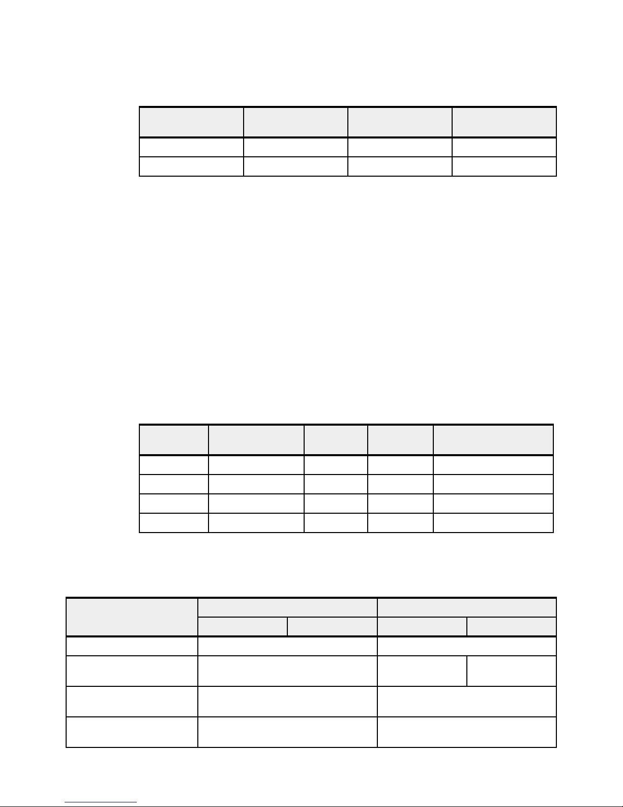
Table 1-11 summarizes the maximum number of supported disk-only I/O drawers.
Table 1-11 Maximum number of disk only I/O drawers supported
Server Maximum FC EDR1
drawers
Power 750 2 51 27
Power 760 2 51 27
1.8 Comparison between models
The Power 750 contains either one, two, three, or four 8-core 3.5 GHz or 8-core 4.0 GHz
POWER7+ DCMs within the system unit.
The Power 760 contains either one, two, three or four 0/12-core 3.1 GHz or 0/12-core
3.4 GHz POWER7+ DCMs within the system unit.
On both systems each processor core has access to 256 KB of L2 cache and 10 MB of L3
cache. Each processor on a DCM connects to eight DDR3 memory DIMM slots; a total of
16 DIMM slots per DCM. Each memory module is a 1066 MHz DIMM, and are delivered in
pairs. Memory features contain two memory DIMMs per feature code, with features ranging
from 8 GB to 64 GB per feature code.
Table 1-12 summarizes the processor core options and frequencies, and matches them to the
L3 cache sizes for the Power 750 and Power 760.
Maximum FC 5887
drawers
Maximum FC 5886
drawers
Table 1-12 Summary of processor core counts, core frequencies, and L3 cache sizes
System Cores per
POWER7+ DCM
Power 750 8 3.5 80 MB 32
Power 750 8 4.0 80 MB 32
Power 760 12 3.1 120 MB 48
Power 760 12 3.4 120 MB 48
a. The total L3 cache available on the POWER7+ DCM, maintaining 10 MB per processor core
Frequency
(GHz)
L3 cache
per DCM
System maximum
a
(cores)
Table 1-13 compares the Power 750 and Power 760 systems.
Table 1-13 Comparison between models
Power 750 (8408-E8D) Power 760 (9109-RMD)
Component
Allowable n-core systems 8-core, 16-core, 24-core, 32-core 12-core, 24-core, 36-core, 48-core
CUoD base processor
activations
Orderable processor speeds 8-core DCM (2 x 4 core): 3.5 GHz
Minimum Maximum Minimum Maximum
All processors are activated 8 cores 48 cores
0/12-core DCM (2 x 6 core): 3.1 GHz
8-core DCM (2 x 4 core): 4.0 GHz
0/12-core DCM (2 x 6 core): 3.4 GHz
Processor planar - 4 module
per 8 memory risers, 5 VRM
1 x FC EPT1 1 x FC EPT1
24 IBM Power 750 and 760 Technical Overview and Introduction
Page 39

Component
Power 750 (8408-E8D) Power 760 (9109-RMD)
Minimum Maximum Minimum Maximum
Processor card feature codes 1 x FC EPT7
1 x FC EPT8
Processor activation and
enablement feature codes
Processor deactivation
8 x FC EPTE
8 x FC EPTF
0 x FC 2319 31 x FC 2319 N/A N/A
4 x FC EPT7
4 x FC EPT8
32 x FC EPTE
32 x FC EPTF
1 x FC EPT5
1 x FC EPT6
8 x FC EPTA
8 x FC EPTB
4 x FC EPT5
4 x FC EPT6
48 x FC EPTA
48 x FC EPTB
feature codes
Flexible service processors
1111
(FSPs)
Total memory 32GB 1TB 32GB 2TB
CUoD memory size offerings
No CUoD memory; all memory is active No CUoD memory; all memory is active
(GB)
Memory cards 2 x FC EM01 riser
card
(2 per populated
DCM)
DIMMs / memory feature
code
With 1 DCM:
32 GB
(2 x FC EM4B
or
4 x FC EM08)
With 2 DCMs:
32 GB
(4 x FC EM08)
With 3 DCMs:
48 GB
(6 x FC EM08)
With 4 DCMs:
64 GB
(8 x FC EM08)
8 x FC EM01 riser
card
(2 per populated
DCM)
64 (16 per DCM)
from the list of:
FC EM08
FC EM4B
FC EM4C
2 x FC EM01 riser
card
(2 per populated
DCM)
With 1 DCM:
32 GB
(2 x FC EM4B
or
4 x FC EM08)
With 2 DCMs:
32 GB
(4 x FC EM08)
With 3 DCMs:
48 GB
(6 x FC EM08)
With 4 DCMs:
64 GB
(8 x FC EM08)
8 x FC EM01 riser
card
(2 per populated
DCM)
64 (16 per DCM)
from the list of:
FC EM08
FC EM4B
FC EM4C
FC EM4D
Number of FC 5802 or
0404
FC 5877 I/O drawers
System PCIe slots 6 46 6 46
Optical drive0101
Internal tape SAS or SCSI ----
Internal SAS drives 0606
SAS drives in attached
drawers
With FC 5802: 0
With FC 5887: 0
With FC EDR1: 0
With FC 5802:
4x18=72
With FC 5887:
51 x 24=1224
With FC EDR1:
2x30=60
With FC 5802: 0
With FC 5887: 0
With FC EDR1: 0
With FC 5802:
4x18=72
With FC 5887:
51 x 24 = 1224
With FC EDR1:
2x30=60
Chapter 1. General description 25
Page 40

1.9 Build to order
You can perform a build-to-order or a la carte configuration using the IBM configurator for
e-business (e-config), where you specify each configuration feature that you want on the
system.
This method is the only configuration method for the IBM Power 750 and Power 760 servers.
1.10 IBM editions
IBM edition offerings are not available for the IBM Power 750 and Power 760 servers.
However, the Power 750 offers no-charge processor core activations with FC EPTC and
FC EPTD. To qualify, a system must have a minimum prerequisite of 8 GB active memory per
core before they can be ordered. That is, a minimum of 64 GB of active memory per dual chip
module (DCM) is a prerequisite before ordering the no-charge processor core activations.
When either FC EPTC or FC EPTD are ordered, 50% of the DCM processor core activations
can be no-charge FC EPTC or FC EPTD and at least 50% must be priced FC EPTE or
FC EPTF.
On a new server order this 8 GB per core minimum applies to the entire server so that the
no-charge activation features can be ordered. For an MES order, the 8 GB per core rule is
also applied to the entire Power 750 server configuration, not just the new MES order. If the
GB per core Power 750 configuration is lower than 8 GB per core, then the no-charge
activations cannot be ordered and all activations must be the full price. If the server previously
had not qualified for the no-charge activations and a MES order is placed with enough
memory to meet the 8 GB per core minimum on the entire server (original plus MES), then a
maximum of 50% of the cores’ activation features on that MES order can be no-charge. If the
server previously had a great deal of memory and little or no memory was ordered with a new
processor DCM MES order, then no-charge activations can still be used on 50% of the MES
core activations while the system 8 GB per core minimum is still satisfied.
1.11 Model upgrades
The Power 750 and Power 760 are new serial number servers. There are no upgrades from
IBM POWER6®, IBM POWER6+™, or POWER7 servers into the Power 750 or Power 760
which retains the same serial number.
However, excluding RIO/HSL attached drawers and excluding 12X PCI-X I/O drawers
(FC 5796) and their PCI-X adapters, much of the I/O from the POWER6, POWER6+, or
POWER7 servers can be reused on the POWER7+ based Power 750 Express and
Power 760. However, Power 750 Express and Power 760 servers that have only one
processor DCM do not have the ability to attach 12X PCIe I/O drawers (FC 5802 or FC 5877)
and only have six PCIe slots available. Two or more DCMs are required to support either one
or two 12X I/O loops with two available GX++ slots. Thus two DCMs (16-core for the
Power 750 and 24-core for the Power 760) or higher configurations with two loops provide
more I/O migration flexibility.
26 IBM Power 750 and 760 Technical Overview and Introduction
Page 41

Other key points beyond I/O drawers are summarized in the following list:
All SAS disk drives supported on the POWER6, POWER6+, and POWER7 rack and tower
servers are supported. However, SCSI disk drives are not supported.
Quarter-Inch Cartridge (QIC) tape drives are not supported. Many newer, faster,
larger-capacity replacement options are available.
IBM i IOPs are not supported, which impacts any older PCI adapters that require an IOP.
This can impact older I/O devices such as some tape libraries or optical drive libraries or
any HVD SCSI device. It means twinax displays or printers cannot be attached except
using an OEM protocol converter. It means SDLC-attached devices that use a LAN or
WAN adapter are not supported. SNA applications still can run when encapsulated inside
TCP/IP, but the physical device attachment cannot be SNA. It means the earlier Fibre
Channel and SCSI controllers that depended upon an IOP being present are not
supported.
IBM i considerations: Without serial number upgrades, 5250 Enterprise Enablements are
not transferable from older servers and are a new purchase on the Power 760.
1.12 Server and virtualization management
This section discusses the supported management interfaces for the servers.
The Hardware Management Console (HMC) is optional for managing the IBM Power 750 and
required for managing Power 760. It has a set of functions that are necessary to manage
the system:
Creating and maintaining a multiple partition environment
Displaying a virtual operating system session terminal for each partition
Displaying a virtual operator panel of contents for each partition
Detecting, reporting, and storing changes in hardware conditions
Powering managed systems on and off
Acting as a service focal point for service representatives to determine an appropriate
service strategy
The IBM Power 750 is supported by the Integrated Virtualization Manager (IVM) and an HMC.
For the Power 750, there are two service strategies for non-HMC systems:
Full system partition: A single partition owns all the server resources and only one
operating system may be installed.
Partitioned system: In this configuration, the system can have more than one partition and
can be running more than one operating system. In this environment, partitions are
managed by the Integrated Virtualization Manager (IVM), which includes some of the
functions offered by the HMC.
The Power 760 requires the usage of an HMC.
In 2012, IBM announced a new HMC model, machine type 7042-CR7. Hardware features on
the CR7 model include a second disk drive (FC 1998) for RAID 1 data mirroring, and the
option of a redundant power supply. At the time of writing, the latest version of HMC code was
V7R7.7.0 (SP1). This code level also includes the new LPAR function support, which allows
the HMC to manage more LPARs per processor core. A core can now be partitioned in up to
20 LPARs (0.05 of a core).
Chapter 1. General description 27
Page 42

Several HMC models are supported to manage POWER7+ based systems. The model
7042-CR7 is the only HMC available for ordering at the time of writing, but you can also use
one of the withdrawn models listed in Table 1-14.
Table 1-14 HMC models supporting POWER7+ processor technology-based servers
Type-model Availability Description
7310-C05 Withdrawn IBM 7310 Model C05 Desktop Hardware Management Console
7310-C06 Withdrawn IBM 7310 Model C06 Deskside Hardware Management Console
7042-C06 Withdrawn IBM 7042 Model C06 Deskside Hardware Management Console
7042-C07 Withdrawn IBM 7042 Model C07 Deskside Hardware Management Console
7042-C08 Withdrawn IBM 7042 Model C08 Deskside Hardware Management Console
7310-CR3 Withdrawn IBM 7310 Model CR3 Rack-Mounted Hardware Management Console
7042-CR4 Withdrawn IBM 7042 Model CR4 Rack-Mounted Hardware Management Console
7042-CR5 Withdrawn IBM 7042 Model CR5 Rack-Mounted Hardware Management Console
7042-CR6 Withdrawn IBM 7042 Model CR6 Rack mounted Hardware Management Console
7042-CR7 Available IBM 7042 Model CR7 Rack mounted Hardware Management Console
At the time of writing, base Licensed Machine Code V7R7.7.0 (SP1), or later, is required in
order to support the Power 750 (8408-E8D) and Power 760 (9109-RMD).
The HMC V7R7.7.0 (SP1) contains the following features:
Support for managing IBM Power 750 and Power 760
Support for PowerVM functions such as new HMC GUI interface for VIOS install
Improved transition from IVM to HMC management
Ability to update the user's password in Kerberos from the HMC for clients utilizing remote
HMC
Fix Central: You can download or order the latest HMC code from the Fix Central website:
http://www.ibm.com/support/fixcentral
Existing HMC models 7310 can be upgraded to Licensed Machine Code Version 7 to support
environments that might include POWER5, POWER5+, POWER6, POWER6+, POWER7 and
POWER7+ processor-based servers. Licensed Machine Code Version 6 (FC 0961) is not
available for 7042 HMC models.
When IBM Systems Director is used to manage an HMC, or if the HMC manages more than
254 partitions, the HMC must have a minimum of 3 GB RAM and must be a rack-mount CR3
model or later, or deskside C06 model or later.
1.13 System racks
The Power 750 (8408-E8D), Power 760 (9109-RMD), and their I/O drawers are designed to
mount in the 7014-T00, 7014-T42, 7014-B42, feature 0551, and feature 0553 racks. These
are built to the 19-inch EIA standard. When ordering a new Power 750 or Power 760 system,
you can order the appropriate 7014 rack model with the system hardware on the same initial
order. IBM also makes the racks available as features of the 8408-E8D or 9109-RMD when
28 IBM Power 750 and 760 Technical Overview and Introduction
Page 43

you order additional I/O drawer hardware for an existing system (MES order). Use the rack
FC 0551 and FC 0553 if you want IBM to integrate the newly ordered I/O drawer in a 19-inch
rack before shipping the MES order.
The 8408-E8D and 9109-RMD have the following rack requirements:
The Power 750 Express and Power 760 can be ordered without a rack.
The Power 750 Express and Power 760 consist of one system enclosure that requires 5U
of vertical rack space.
The 36 EIA unit (1.8 meter) rack (FC 0551) and the 42 EIA unit (2.0 meter) rack (FC 0553)
are available on MES upgrade orders only. For initial system orders, the racks should be
ordered as machine type 7014-T00 or 7014-T42.
When a Power 750 Express or Power 760 server is installed in a 7014-T00 or 7014-T42
rack that has no front door, you must order a Thin Profile Front Trim Kit for the rack. The
required trim kit for the 7014-T00 rack is FC 6263. The required trim kit for the 7014-T42
rack is FC 6272.
Acoustic door features are available with the 7014-T00 (FC 0551) and 7014-T42
(FC 0553) racks to meet the lower acoustic levels identified in the physical specifications
section. You can order the acoustic door feature on new 7014-T00 (FC 0551), 7014-T42
(FC 0553) racks, or for the 7014-T00 (FC 0551) or 7014-T42 (FC 0553) racks that you
already own.
A Power 750 Express or Power 760 door (FC ERG7) is available on the 7014-T42 rack.
If a system is to be installed in a rack or cabinet that is not from IBM, it must meet
requirements.
Responsibility: The client is responsible for ensuring that the installation of the drawer in
the preferred rack or cabinet results in a configuration that is stable, serviceable, safe, and
compatible with the drawer requirements for power, cooling, cable management, weight,
and rail security.
1.13.1 IBM 7014 Model T00 rack
The 1.8-meter (71-inch) model T00 is compatible with past and present IBM Power Systems
servers. The features of the T00 rack are as follows:
It has 36U (EIA units) of usable space.
It has optional removable side panels.
It has optional side-to-side mounting hardware for joining multiple racks.
It has increased power distribution and weight capacity.
It supports both AC and DC configurations.
Up to four power distribution units (PDUs) can be mounted in the PDU bays (see
Figure 1-10 on page 33), but others can fit inside the rack. See 1.13.5, “The AC power
distribution unit and rack content” on page 32.
Chapter 1. General description 29
Page 44

For the T00 rack, three door options are available:
– Front Door for 1.8 m Rack (FC 6068)
This feature provides an attractive black full height rack door. The door is steel, with a
perforated flat front surface. The perforation pattern extends from the bottom to the top
of the door to enhance ventilation and provide some visibility into the rack.
OEM front door: This door is also available as an OEM front door (FC 6101).
– 1.8 m Rack Acoustic Door (FC 6248)
This feature provides a front and rear rack door designed to reduce acoustic sound
levels in a general business environment.
– 1.8 m Rack Trim Kit (FC 6263)
If no front door should used in the rack, this feature provides a decorative trim kit for the
front.
Ruggedized Rack Feature
For enhanced rigidity and stability of the rack, the optional Ruggedized Rack Feature
(FC 6080) provides additional hardware that reinforces the rack and anchors it to the floor.
This hardware is designed primarily for use in locations where earthquakes are a concern.
The feature includes a large steel brace or truss that bolts into the rear of the rack.
It is hinged on the left side so it can swing out of the way for easy access to the rack
drawers when necessary. The Ruggedized Rack Feature also includes hardware for
bolting the rack to a concrete floor or a similar surface, and bolt-in steel filler panels for any
unoccupied spaces in the rack.
Weights are as follows:
– T00 base empty rack: 244 kg (535 lb)
– T00 full rack: 816 kg (1795 lb)
– Maximum weight of drawers is 572 kg (1260 lb)
– Maximum weight of drawers in a zone 4 earthquake environment is 490 kg (1080 lb),
which equates to 13.6 kg (30 lb) per EIA
Important: If additional weight is added to the top of the rack, for example add feature
code 6117, the 490 kg (1080 lb) must be reduced by the weight of the addition. As an
example, feature code 6117 weighs approximately 45 kg (100 lb) so the new maximum
weight of drawers that the rack can support in a zone 4 earthquake environment is 445 kg
(980 lb). In the zone 4 earthquake environment the rack should be configured starting with
the heavier drawers at the bottom of the rack.
1.13.2 IBM 7014 Model T42 rack
The 2.0-meter (79.3-inch) Model T42 addresses the client requirement for a tall enclosure to
house the maximum amount of equipment in the smallest possible floor space. The following
features are for the model T42 rack (which differ from the model T00):
The T42 rack has 42U (EIA units) of usable space (6U of additional space).
The model T42 supports AC power only.
30 IBM Power 750 and 760 Technical Overview and Introduction
Page 45

Weights are as follows:
Trim kit
(no front door)
FC 6272
Plain front door
FC 6069
Acoustic doors
(front and rear)
FC 6249
Optional
front door
FC ERG7
780 logo
front door
FC 6250
– T42 base empty rack: 261 kg (575 lb)
– T42 full rack: 930 kg (2045 lb)
For the T42 rack, various door options are available as shown in Figure 1-9.
Figure 1-9 Door options for the T42 rack
The 2.0 m Rack Trim Kit (FC 6272) is used, if no front door is used in the rack.
The Front Door for a 2.0 m Rack (FC 6069) is made of steel, with a perforated flat front
The 2.0 m Rack Acoustic Door feature (FC 6249) consists of a front and rear door to
The High-End Appearance Front Door (FC 6250) provides a front rack door with a field
The FC ERG7 provides an attractive black full height rack door. The door is steel, with a
surface. The perforation pattern extends from the bottom to the top of the door to enhance
ventilation and provide some visibility into the rack. This door is non acoustic and has a
depth of about 25 mm (1 in).
OEM front door: This door is also available as an OEM front door (FC 6084).
reduce noise by about 6 dB(A). It has a depth of about 191 mm (7.5 in).
installed Power 780 logo designed to be used when the rack will contain a Power 780
system. The door is not acoustic and has a depth of about 90 mm (3.5 in).
High end: For the High-End Appearance Front Door (FC 6250) the High-End
Appearance Side Covers (FC 6238) should be used to make the rack appear as a
high-end server (but in a 19-inch rack format instead of a 24-inch rack).
perforated flat front surface. The perforation pattern extends from the bottom to the top of
the door to enhance ventilation and provide some visibility into the rack. The door is non
acoustic and has a depth of about 134 mm (5.3 in).
Chapter 1. General description 31
Page 46

Rear Door Heat Exchanger
To lead away more heat a special door, called a Rear Door Heat Exchanger (FC 6858), is
available. This door replaces the standard rear door on the rack. Copper tubes are attached
to the rear door to circulate chilled water, which is provided by the customer. The chilled water
removes heat from the exhaust air being blown through the servers and attachments mounted
in the rack. The water lines in the door attach to the customer-supplied secondary water loop
using industry standard quick couplings.
For details about planning for the installation of the IBM Rear Door Heat Exchanger, see the
following website:
http://pic.dhe.ibm.com/infocenter/powersys/v3r1m5/index.jsp?topic=/iphad_p5/iphade
xchangeroverview.html
1.13.3 Feature code 0551 rack
The 1.8-meter rack (FC 0551) is a 36U (EIA units) rack. The rack that is delivered as FC 0551
is the same rack delivered when you order the 7014-T00 rack. The included features might
differ. Several features that are delivered as part of the 7014-T00 must be ordered separately
with the FC 0551.
1.13.4 Feature code 0553 rack
The 2.0-meter rack (FC 0553) is a 42U (EIA units) rack. The rack that is delivered as FC 0553
is the same rack delivered when you order the 7014-T42 or B42 rack. The included features
might differ. Several features that are delivered as part of the 7014-T42 or B42 must be
ordered separately with the FC 0553.
1.13.5 The AC power distribution unit and rack content
For rack models T00 and T42, 12-outlet PDUs are available. These include the AC power
distribution units FC 9188 and FC 7188 and the AC Intelligent PDU+ FC 5889 and FC 7109.
The Intelligent PDU+ (FC 5889 and FC 7109) is identical to FC 9188 and FC 7188 PDUs but
are equipped with one Ethernet port, one console serial port, and one RS232 serial port for
power monitoring.
The PDUs have 12 client-usable IEC 320-C13 outlets. There are six groups of two outlets, fed
by six circuit breakers. Each outlet is rated up to 10 amps, but each group of two outlets is fed
from one 15 amp circuit breaker.
32 IBM Power 750 and 760 Technical Overview and Introduction
Page 47

Four PDUs can be mounted vertically in the back of the T00 and T42 racks. Figure 1-10
Rack Rear View
43
21
Circuit breaker reset
Status LED
shows placement of the four vertically mounted PDUs. In the rear of the rack, two additional
PDUs can be installed horizontally in the T00 rack and three in the T42 rack. The four vertical
mounting locations will be filled first in the T00 and T42 racks. Mounting PDUs horizontally
consumes 1U per PDU and reduces the space available for other racked components. When
mounting PDUs horizontally, the best approach is to use fillers in the EIA units that are
occupied by these PDUs to facilitate proper air-flow and ventilation in the rack.
Figure 1-10 PDU placement and PDU view
The PDU receives power through a UTG0247 power-line connector. Each PDU requires one
PDU-to-wall power cord. Various power cord features are available for various countries and
applications by varying the PDU-to-wall power cord, which must be ordered separately. Each
power cord provides the unique design characteristics for the specific power requirements. To
match new power requirements and save previous investments, these power cords can be
requested with an initial order of the rack or with a later upgrade of the rack features.
Chapter 1. General description 33
Page 48

Table 1-15 shows the available wall power cord options for the PDU and iPDU features, which
must be ordered separately.
Table 1-15 Power wall cord options for the PDU and iPDU features
Feature
code
6653 IEC 309,
6489 IEC309
6654 NEMA L6-30 200-208, 240 1 24 Amps US, Canada, LA, Japan
6655 RS 3750DP
6656 IEC 309,
6657 PDL 230-240 1 24 Amps Australia, New Zealand
6658 Korean plug 220 1 24 Amps North and South Korea
6492 IEC 309,
6491 IEC 309,
Wall plug Rated
voltage (Vac)
230 3 16 Amps Internationally available
3P+N+G, 16A
230 3 24 Amps EMEA
3P+N+G, 32A
200-208, 240 1 24 Amps US, Canada, LA, Japan
(watertight)
230 1 24 Amps EMEA
P+N+G, 32A
200-208, 240 1 48 Amps US, Canada, LA, Japan
2P+G, 60A
230 1 48 Amps EMEA
P+N+G, 63A
Phase Rated
amperage
Geography
Notes: Ensure that the appropriate power cord feature is configured to support the power
being supplied. Based on the power cord that is used, the PDU can supply from 4.8 kVA to
19.2 kVA. The power of all the drawers plugged into the PDU must not exceed the power
cord limitation.
The Universal PDUs are compatible with previous models.
To better enable electrical redundancy, each server has two power supplies that must be
connected to separate PDUs, which are not included in the base order. For maximum
availability, the best way is to connect power cords from the same system to two separate
PDUs in the rack, and to connect each PDU to independent power sources.
For detailed power requirements and power cord details, see the Planning for power section
in the IBM Power Systems Hardware Information Center website:
http://pic.dhe.ibm.com/infocenter/powersys/v3r1m5/topic/p7had/p7hadrpower.htm
1.13.6 Useful rack additions
This section highlights several solutions for IBM Power Systems rack-based systems.
IBM System Storage 7214 Tape and DVD Enclosure
The IBM System Storage® 7214 Tape and DVD Enclosure (Model 1U2) is designed to mount
in one EIA unit of a standard IBM Power Systems 19-inch rack and can be configured with
one or two tape drives, or either one or two Slim DVD-RAM or DVD-ROM drives in the bay on
the right side.
34 IBM Power 750 and 760 Technical Overview and Introduction
Page 49

Table 1-16 shows the supported tape or DVD drives for IBM Power servers in the 7214-1U2.
Table 1-16 Supported feature codes for 7214-1U2
Feature code Description Status
1400 DAT72 36 GB Tape Drive Available
1401 DAT160 80 GB Tape Drive Available
1402 DAT320 160 GB SAS Tape Drive Withdrawn
1420 DVD-RAM SAS Optical Drive Available
1421 DVD-ROM Optical Drive Withdrawn
1423 DVD-ROM Optical Drive Available
1404 LTO Ultrium 4 Half-High 800 GB Tape Drive Available
Support: The IBM System Storage 7214-1U2 Tape and DVD Enclosure is no longer
orderable. Although the drawer is supported to be attached to a Power 750 or Power 760
server.
IBM System Storage 7216 Multi-Media Enclosure
The IBM System Storage 7216 Multi-Media Enclosure (Model 1U2) is designed to attach to
the Power 750 and the Power 760 through a USB port on the server or through a PCIe SAS
adapter. The 7216 has two bays to accommodate external tape, removable disk drive, or
DVD-RAM drive options.
Table 1-17 shows the supported tape, RDX, or DVD drives for IBM Power servers in the
7216-1U2:
Table 1-17 Supported feature codes for 7216-1U2
Feature code Description Status
5619 DAT160 80 GB SAS Tape Drive Available
EU16 DAT160 80 GB USB Tape Drive Available
1402 DAT320 160 GB SAS Tape Drive Withdrawn
5673 DAT320 160 GB USB Tape Drive Withdrawn
1420 DVD-RAM SAS Optical Drive Withdrawn
8247 LTO Ultrium 5 Half-High 1.5 TB SAS Tape Drive Withdrawn
1103 RDX Removable Disk Drive Docking Station Withdrawn
Support: The IBM System Storage 7216-1U2 Multi-Media Enclosure is no longer
orderable. Although the drawer is supported to be attached to a Power 750 or Power 760
server.
Chapter 1. General description 35
Page 50

To attach a 7216 Multi-Media Enclosure to the Power 750 and Power 760, consider the
following cabling procedures:
Attachment by an SAS adapter
A PCIe Dual-X4 SAS adapter (FC 5901) or a PCIe LP Dual-x4-port SAS Adapter 3 Gb
(FC 5278) must be installed in the Power 750 and Power 760 server to attach to a 7216
Model 1U2 Multi-Media Storage Enclosure. Attaching a 7216 to a Power 750 and
Power 760 through the integrated SAS adapter is not supported.
For each SAS tape drive and DVD-RAM drive feature installed in the 7216, the appropriate
external SAS cable will be included.
An optional Quad External SAS cable is available by specifying (FC 5544) with each 7216
order. The Quad External Cable allows up to four 7216 SAS tape or DVD-RAM features to
attach to a single System SAS adapter.
Up to two 7216 storage enclosure SAS features can be attached per PCIe Dual-x4 SAS
adapter (FC 5901) or the PCIe LP Dual-x4-port SAS Adapter 3 Gb (FC 5278).
Attachment by a USB adapter
The Removable RDX HDD Docking Station features on 7216 only support the USB cable
that is provided as part of the feature code. Additional USB hubs, add-on USB cables, or
USB cable extenders are not supported.
For each RDX Docking Station feature installed in the 7216, the appropriate external USB
cable will be included. The 7216 RDX Docking Station feature can be connected to the
external, integrated USB ports on the Power 750 and Power 760 or to the USB ports on
4-Port USB PCI Express Adapter (FC 2728).
The 7216 DAT320 USB tape drive or RDX Docking Station features can be connected to
the external, integrated USB ports on the Power 750 and Power 760.
The two drive slots of the 7216 enclosure can hold the following drive combinations:
One tape drive (DAT160 SAS or LTO Ultrium 5 Half-High SAS) with second bay empty
Two tape drives (DAT160 SAS or LTO Ultrium 5 Half-High SAS) in any combination
One tape drive (DAT160 SAS or LTO Ultrium 5 Half-High SAS) and one DVD-RAM SAS
drive sled with one or two DVD-RAM SAS drives
Up to four DVD-RAM drives
One tape drive (DAT160 SAS or LTO Ultrium 5 Half-High SAS) in one bay, and one RDX
Removable HDD Docking Station in the other drive bay
One RDX Removable HDD Docking Station and one DVD-RAM SAS drive sled with one
or two DVD-RAM SAS drives in the bay on the right
Two RDX Removable HDD Docking Stations
36 IBM Power 750 and 760 Technical Overview and Introduction
Page 51

Figure 1-11 shows the 7216 Multi-Media Enclosure.
Figure 1-11
7216-1U2 Multi-Media Enclosure
In general, the 7216-1U2 is supported by the AIX, IBM i, and Linux operating systems. IBM i,
from Version 7.1, now fully supports the internal 5.25 inch RDX SATA removable HDD
docking station, including boot support (no VIOS support). This support provides a fast,
robust, high-performance alternative to tape backup and restore devices.
IBM System Storage 7226 Model 1U3 Multi-Media Enclosure
IBM System Storage 7226 Model 1U3 Multi-Media Enclosure can accommodate up to two
tape drives, two RDX removable disk drive docking stations, or up to four DVD RAM drives.
The 7226 offers SAS, USB, and FC electronic interface drive options.
The 7226 Storage Enclosure delivers external tape, removable disk drive, and DVD-RAM
drive options that allow data transfer within similar system archival storage and retrieval
technologies installed in existing IT facilities. The 7226 offers an expansive list of drive feature
options.
Chapter 1. General description 37
Page 52

Table 1-18 shows the supported options for IBM Power servers in the 7226-1U3:
Table 1-18 Supported feature codes for 7226-1U3
Feature code Description Status
5619 DAT160 SAS Tape Drive Available
EU16 DAT160 USB Tape Drive Available
1420 DVD-RAM SAS Optical Drive Available
5762 DVD-RAM USB Optical Drive Available
8248 LTO Ultrium 5 Half High Fibre Drive Available
8247 LTO Ultrium 5 Half High SAS Drive Available
8348 LTO Ultrium 6 Half High Fibre Drive Available
EU11 LTO Ultrium 6 Half High SAS Drive Available
1103 RDX 2.0 Removable Disk Docking Station Withdrawn
EU03 RDX 3.0 Removable Disk Docking Station Available
Option descriptions are as follows:
DAT160 80 GB Tape Drives: With SAS or USB interface options and a data transfer rate of
up to 24 MBps, the DAT160 drive is read-write compatible with DAT160, DAT72, and DDS4
data cartridges.
LTO Ultrium 5 Half-High 1.5 TB SAS and FC Tape Drive: With a data transfer rate up to
280 MBps, the LTO Ultrium 5 drive is read-write compatible with LTO Ultrium 5 and LTO
Ultrium 4 data cartridges, and read-only compatible with Ultrium 3 data cartridges. Using
data compression, a LTO-5 cartridge is capable to store up to 3 TB of data.
LTO Ultrium 6 Half-High 2.5 TB SAS and FC Tape Drive: With a data transfer rate up to
160 MBps, the LTO Ultrium 6 drive is read-write compatible with LTO Ultrium 5 and LTO
Ultrium 4 data cartridges. Using data compression, a LTO-6 cartridge is capable to store
up to 6.25 TB of data.
DVD-RAM: 9.4 GB SAS Slim Optical Drive with SAS and USB interface option is
compatible with most standard DVD disks.
RDX removable disk drives: The RDX USB docking station is compatible with most RDX
removable disk drive cartridges when used in the same operating system. The 7226 offers
the following RDX removable drive capacity options:
– 320 GB (FC EU08)
– 500 GB (FC 1107)
–1.0TB (FC EU01)
–1.5TB (FC EU15)
Removable RDX drives are in a rugged cartridge that inserts in a RDX removable (USB) disk
docking station (FC 1103 or FC EU03). RDX drives are compatible with docking stations
installed internally in IBM POWER6, POWER6+, POWER7, and POWER7+ servers.
Media used in the 7226 DAT160 SAS and USB tape drive features are compatible with
DAT160 tape drives installed internally in IBM POWER6, POWER6+, POWER7, and
POWER7+ servers, and in IBM BladeCenter® systems.
38 IBM Power 750 and 760 Technical Overview and Introduction
Page 53

Media used in LTO Ultrium 5 Half-High 1.5 TB tape drives are compatible with Half High LTO5
tape drives installed in the IBM TS2250 and TS2350 external tape drives, IBM LTO5 tape
libraries, and Half High LTO5 tape drives installed internally in IBM POWER6, POWER6+,
POWER7, and POWER7+ servers.
Figure 1-12 shows the 7226 Multi-Media Enclosure.
Figure 1-12 FC 7226 Multi-Media Enclosure
The 7226 offers customer replaceable unit (CRU) maintenance service to help make
installation or replacement of new drives efficient. Other 7226 components are also designed
for CRU maintenance.
The IBM System Storage 7226 Multi-Media Enclosure is compatible with most IBM POWER6,
POWER6+, POWER7, and POWER7+ systems, and also with the IBM BladeCenter models
(PS700, PS701, PS702, PS703, and PS704) that offer current level AIX, IBM i, and Linux
operating systems.
The IBM i operating system does not support 7226 USB devices.
For a complete list of host software versions and release levels that support the 7226, see the
following System Storage Interoperation Center (SSIC) website:
http://www.ibm.com/systems/support/storage/config/ssic/index.jsp
Flat panel display options
The IBM 7316 Model TF3 is a rack-mountable flat panel console kit consisting of a 17-inch
337.9 mm x 270.3 mm flat panel color monitor, rack keyboard tray, IBM Travel Keyboard,
support for IBM keyboard, video, and mouse (KVM) switches, and language support. The IBM
7316-TF3 Flat Panel Console Kit offers the following features:
Slim, sleek, lightweight monitor design that occupies only 1U (1.75 inches) in a 19-inch
standard rack
A 17-inch, flat panel TFT monitor with truly accurate images and virtually no distortion
The ability to mount the IBM Travel Keyboard in the 7316-TF3 rack keyboard tray
Support for IBM keyboard, video, and mouse (KVM) switches that provide control of as
many as 128 servers, and support of both USB and PS/2 server-side keyboard and mouse
connections
Chapter 1. General description 39
Page 54

1.13.7 OEM rack
571mm (22.50 in.)
Drawer Rail
Mounting
Flanges
Back, No Door
494mm (19.45 in.)
Front, No Door
203mm (8.0 in.)
719mm (28.31 in.)
51mm (2.01 in.)
451mm (17.76 in.)
494mm (19.45 in.)
The system can be installed in a suitable OEM rack, if the rack conforms to the EIA-310-D
standard for 19-inch racks. This standard is published by the Electrical Industries Alliance. For
detailed information see the IBM Power Systems Hardware Information Center:
http://publib.boulder.ibm.com/infocenter/systems/scope/hw/index.jsp
The key points mentioned are as follows:
The front rack opening must be 451 mm wide ± 0.75 mm (17.75 in. ± 0.03 in.), and the
rail-mounting holes must be 465 mm ± 0.8 mm (18.3 in. ± 0.03 in.) apart on center
(horizontal width between the vertical columns of holes on the two front-mounting flanges
and on the two rear-mounting flanges). Figure 1-13 shows a top view showing the
specification dimensions.
40 IBM Power 750 and 760 Technical Overview and Introduction
Figure 1-13 Top view of non-IBM rack specification dimensions
Page 55

The vertical distance between the mounting holes must consist of sets of three holes
Hole Diameter =
7.1 +/- 0.1mm
Rack Mounting Holes Center-to-Center
Rack Front Opening
450 +/- 0.75mm
465 +/- 0.8mm
EIA Hole Spacing
6.75mm min
15.9mm
15.9mm
12.7mm
15.9mm
15.9mm
12.7mm
6.75mm min
15.9mm
15.9mm
12.7mm
15.9mm
15.9mm
12.7mm
Top Front of Rack
Top Front of Rack
spaced (from bottom to top) 15.9 mm (0.625 in.), 15.9 mm (0.625 in.), and 12.67 mm
(0.5 in.) on center, making each three-hole set of vertical hole spacing 44.45 mm (1.75 in.)
apart on center. Rail-mounting holes must be 7.1 mm ± 0.1 mm (0.28 in. ± 0.004 in.) in
diameter. Figure 1-14 shows the top front specification dimensions.
Figure 1-14 Rack specification dimensions, top front view
Chapter 1. General description 41
Page 56

42 IBM Power 750 and 760 Technical Overview and Introduction
Page 57

Chapter 2. Architecture and technical
2
overview
The IBM Power 750 offers a 4-socket system enclosure populated with dual chip modules
(DCMs). Each DCM has two 4-core POWER7+ processors.
The IBM Power 760 offers a 4-socket system enclosure, also populated with DCMs. Each
DCM has two 6-core POWER7+ processors.
This chapter provides an overview of the system architecture and its major components. The
bandwidths numbers that are provided are theoretical maximums used for reference.
The speeds shown are at an individual component level. Multiple components and application
implementation are key to achieving the best performance.
Always do the performance sizing at the application workload environment level and evaluate
performance by using real-world performance measurements and production workloads.
© Copyright IBM Corp. 2013. All rights reserved. 43
Page 58
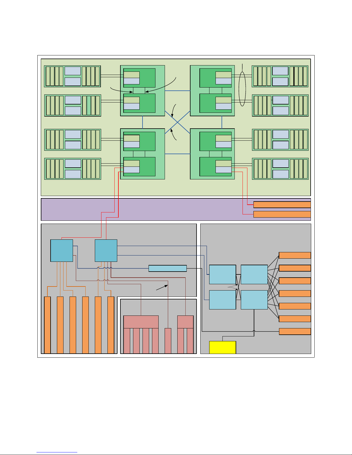
DASD BackplaneI/O Backplane
Multifunction Card
CPU card
DCM0
P7+
xz
Memory
Controller
GX++
P7+
Memory
Controller
GX++
DCM1
P7+
xz
Memory
Controller
GX++
P7+
Memory
Controller
GX++
DCM2
P7+
x
z
Memory
Controller
GX++
P7+
Memory
Controller
GX++
DCM3
P7+
xz
Memory
Controller
GX++
P7+
Memory
Controller
GX++
AB Buses
DIMM
Buffer
Buffer
Midplane
PCIe Gen 2 8x Slot 1
P7IOC
(A)
PCIe Gen 2 8x Slot 2
PCIe Gen 2 8x Slot 3
PCIe Gen 2 8x Slot 4
PCIe Gen 2 8x Slot 5
PCIe Gen 2 8x Slot 6
P7IOC
(B)
GX++ Slot 1
GX++ Slot 2
Ethernet
Ethernet
Ethernet
Ethernet
Ethernet
Controller
Serial
USB
USB
USB
Cont
Hard Disk 1
Hard Disk 2
Hard Disk 3
Hard Disk 4
Hard Disk 5
Hard Disk 6
OpticalOptical
Int. SAS Cnt.
DIMM
DIMM
DIMM
DIMM
DIMM
DIMM
DIMM
DIMM
Buffer
Buffer
DIMM
DIMM
DIMM
DIMM
DIMM
DIMM
DIMM
DIMM
Buffer
Buffer
DIMM
DIMM
DIMM
DIMM
DIMM
DIMM
DIMM
DIMM
Buffer
Buffer
DIMM
DIMM
DIMM
DIMM
DIMM
DIMM
DIMM
DIMM
Buffer
Buffer
DIMM
DIMM
DIMM
DIMM
DIMM
DIMM
DIMM
DIMM
Buffer
Buffer
DIMM
DIMM
DIMM
DIMM
DIMM
DIMM
DIMM
DIMM
Buffer
Buffer
DIMM
DIMM
DIMM
DIMM
DIMM
DIMM
DIMM
DIMM
Buffer
Buffer
DIMM
DIMM
DIMM
DIMM
DIMM
DIMM
DIMM
SAS Port
Expander
SAS Port
Expander
Integrated
SAS
Controller
Integrated
SAS
Controller
External
SAS Port
68.2 GB/s
19.7 GB/s19.7 GB/s
19.7 GB/s19.7 GB/s
39.4 GB/s
39.4 GB/s
39.4 GB/s 39.4 GB/s
39.4 GB/s
39.4 GB/s
48.3 GB/s
48.3 GB/s
6 GB/s
PCIe Gen2 8x
PCIe Gen2 8x
PCIe Gen1 1x
PCIe Gen2 8x
PCIe Gen1 1x
PCIe Gen2 1x
Figure 2-1 shows the logical system diagram of the Power 750 and Power 760.
Figure 2-1 IBM Power 750 and Power 760 logical system diagram
44 IBM Power 750 and 760 Technical Overview and Introduction
Page 59

2.1 The IBM POWER7+ processor
The IBM POWER7+ processor represents a leap forward in technology achievement and
associated computing capability. The multi-core architecture of the POWER7+ processor has
been matched with innovation across a wide range of related technologies to deliver leading
throughput, efficiency, scalability, and reliability, availability, and serviceability (RAS).
Note: This section provides a general description of the POWER7+ processor chip that
applies to Power Systems servers in general. The Power 750 and Power 760 servers use
two 4- or 6-core chips packaged in a DCM.
Although the processor is an important component in delivering outstanding servers, many
elements and facilities must be balanced on a server to deliver maximum throughput. As with
previous generations of systems based on IBM POWER® processors, the design philosophy
for POWER7+ processor-based systems is one of system-wide balance in which the
POWER7+ processor plays an important role.
IBM uses innovative technologies to achieve required levels of throughput and bandwidth.
Areas of innovation for the POWER7+ processor and POWER7+ processor-based systems
include (but are not limited to) the following items:
On-chip L3 cache implemented in embedded dynamic random access memory (eDRAM)
Cache hierarchy and component innovation
Advances in memory subsystem
Advances in off-chip signaling
Advances in I/O card throughput and latency
Advances in RAS features such as power-on reset and L3 cache dynamic column repair
The superscalar POWER7+ processor design also provides a variety of other capabilities:
Binary compatibility with the prior generation of POWER processors
Support for PowerVM virtualization capabilities, including PowerVM Live Partition Mobility
to and from POWER6, POWER6+, and POWER7 processor-based systems
Figure 2-2 on page 46 shows the POWER7+ processor die layout, with the major areas
identified:
Processor cores
L2 cache
L3 cache and chip interconnection
Simultaneous multiprocessing links
Memory controllers.
I/O links
Chapter 2. Architecture and technical overview 45
Page 60

Figure 2-2 POWER7+ processor die with key areas indicated
2.1.1 POWER7+ processor overview
The POWER7+ processor chip is fabricated with IBM 32 nm Silicon-On-Insulator (SOI)
technology using copper interconnects, and implements an on-chip L3 cache using eDRAM.
The POWER7+ processor chip is 567 mm
to eight processor cores are on the chip, each with 12 execution units, 256 KB of L2 cache
per core, and up to 80 MB of shared on-chip L3 cache per chip.
For memory access, the POWER7+ processor includes a double data rate 3 (DDR3) memory
controller with four memory channels.
Table 2-1 summarizes the technology characteristics of the POWER7+ processor.
Table 2-1 Summary of POWER7+ processor technology
Technology POWER7+ processor
Die size 567 mm
Fabrication technology 32 nm lithography
Processor cores 3, 4, 6, or 8
46 IBM Power 750 and 760 Technical Overview and Introduction
2
and has 2.1 billion components (transistors). Up
2
Copper interconnect
Silicon-on-Insulator
eDRAM
Page 61

Technology POWER7+ processor
Maximum execution threads (core/chip) 4/32
Maximum L2 cache (core/chip) 256 KB/2 MB
Maximum On-chip L3 cache (core/chip) 10 MB/80 MB
DDR3 memory controllers 1
SMP design-point 32 sockets with IBM POWER7+ processors
Compatibility With prior generation of POWER processor
2.1.2 POWER7+ processor core
Each POWER7+ processor core implements aggressive out-of-order (OoO) instruction
execution to drive high efficiency in the use of available execution paths. The POWER7+
processor has an Instruction Sequence Unit that is capable of dispatching up to six
instructions per cycle to a set of queues. Up to eight instructions per cycle can be issued to
the instruction execution units. The POWER7+ processor has a set of 12 execution units:
Two fixed point units
Two load store units
Four double precision floating point units
One vector unit
One branch unit
One condition register unit
One decimal floating point unit
The following caches are tightly coupled to each POWER7+ processor core:
Instruction cache: 32 KB
Data cache: 32 KB
L2 cache: 256 KB, implemented in fast SRAM
2.1.3 Simultaneous multithreading
POWER7+ processors support SMT1, SMT2, and SMT4 modes to enable up to four
instruction threads to execute simultaneously in each POWER7+ processor core. The
processor supports the following instruction thread execution modes:
SMT1: Single instruction execution thread per core
SMT2: Two instruction execution threads per core
SMT4: Four instruction execution threads per core
SMT4 mode enables the POWER7+ processor to maximize the throughput of the processor
core by offering an increase in processor-core efficiency. SMT4 mode is the latest step in an
evolution of multithreading technologies introduced by IBM.
Chapter 2. Architecture and technical overview 47
Page 62
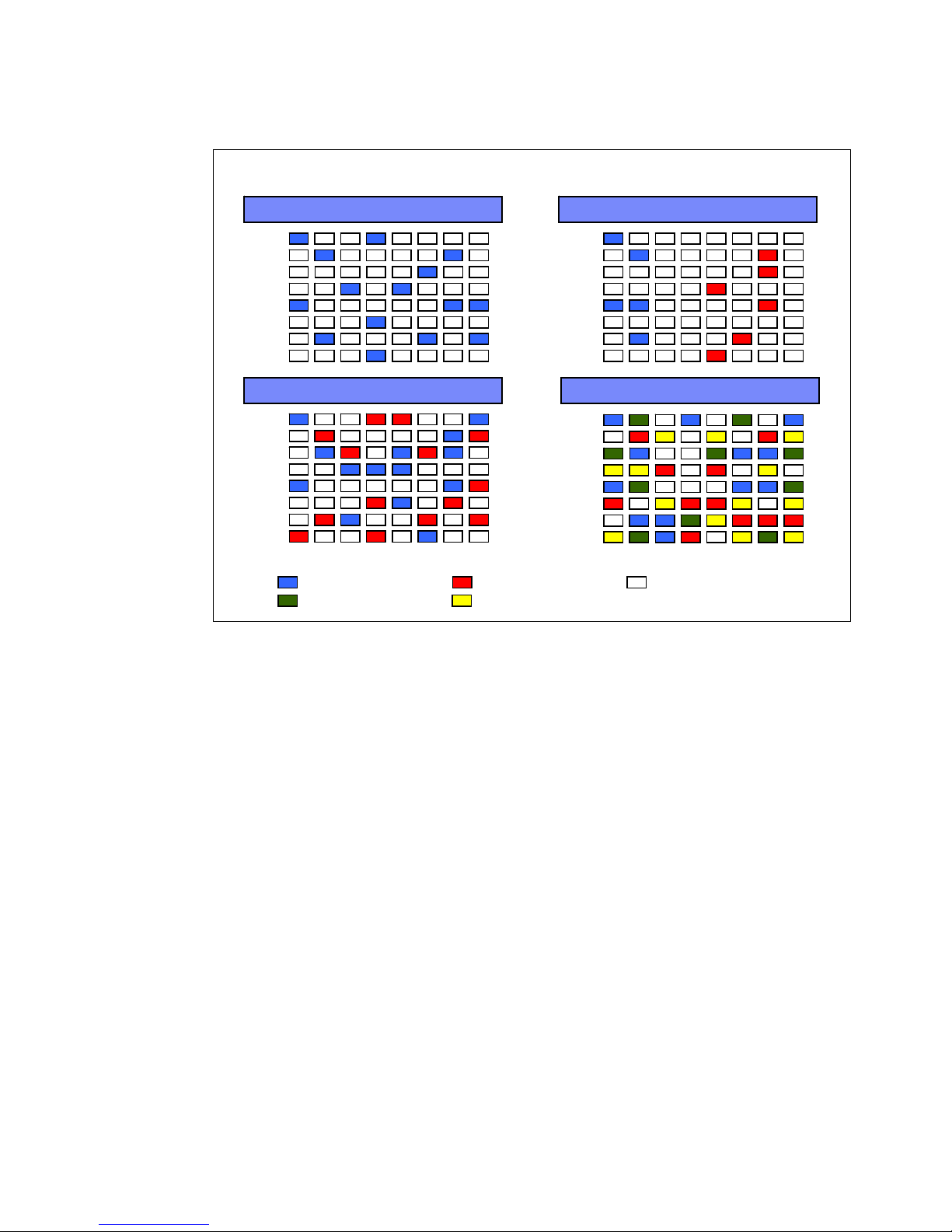
Figure 2-3 shows the evolution of simultaneous multithreading in the industry.
2004 2-way SMT
FX0
FX1
FP0
FP1
LS0
LS1
BRX
CRL
FX0
FX1
FP0
FP1
LS0
LS1
BRX
CRL
1995 Single thread out of order
FX0
FX1
FP0
FP1
LS0
LS1
BRX
CRL
1997 Hardware multi-thread
FX0
FX1
FP0
FP1
LS0
LS1
BRX
CRL
2010 4-way SMT
Thread 1 ExecutingThread 0 Executing
Thread 3 ExecutingThread 2 Executing
No Thread Executing
Multi-threading evolution
Figure 2-3 Evolution of simultaneous multithreading
The various SMT modes offered by the POWER7+ processor allow flexibility, enabling users
to select the threading technology that meets an aggregation of objectives such as
performance, throughput, energy use, and workload enablement.
Intelligent Threads
The POWER7+ processor features Intelligent Threads that can vary based on the workload
2.1.4 Memory access
48 IBM Power 750 and 760 Technical Overview and Introduction
demand. The system either automatically selects (or the system administrator can manually
select) whether a workload benefits from dedicating as much capability as possible to a
single thread of work, or if the workload benefits more from having capability spread across
two or four threads of work. With more threads, the POWER7+ processor can deliver more
total capacity as more tasks are accomplished in parallel. With fewer threads, those
workloads that need fast individual tasks can get the performance that they need for
maximum benefit.
Each POWER7+ processor chip has one memory controller that uses two memory channels.
Each memory channel operates at 1066 MHz connects to four DIMMs.
In the Power 750 server, each channel can address up to 64 GB. Thus, the Power 750 is
capable of addressing up to 1 TB of total memory.
In the Power 760 server, each channel can address up to 128 GB. Thus, the Power 760 is
capable of addressing up to 2 TB of total memory.
Page 63
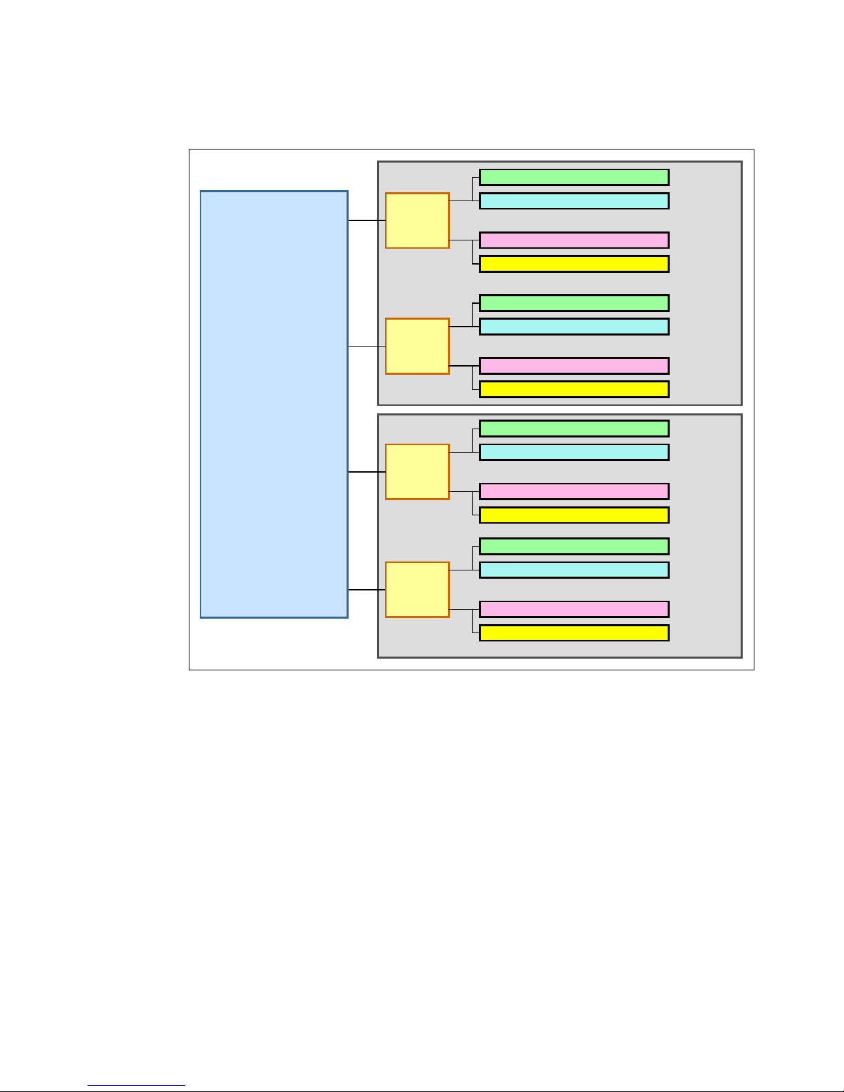
Figure 2-4 gives a simple overview of the POWER7+ processor memory access structure in
Buffer
Port A
Port B
DDR3 RDIMM Slot 7
DDR3 RDIMM Slot 8
DDR3 RDIMM Slot 1
DDR3 RDIMM Slot 2
Buffer
Port A
Port B
DDR3 RDIMM Slot 5
DDR3 RDIMM Slot 6
DDR3 RDIMM Slot 3
DDR3 RDIMM Slot 4
Buffer
Port A
Port B
DDR3 RDIMM Slot 5
DDR3 RDIMM Slot 6
DDR3 RDIMM Slot 3
DDR3 RDIMM Slot 4
Buffer
Port A
Port B
DDR3 RDIMM Slot 7
DDR3 RDIMM Slot 8
DDR3 RDIMM Slot 1
DDR3 RDIMM Slot 2
P3-Cn-C7
P3-Cn-C8
P3-Cn-C1
P3-Cn-C2
P3-Cn-C5
P3-Cn-C6
P3-Cn-C3
P3-Cn-C4
P3-Cn-C7
P3-Cn-C8
P3-Cn-C1
P3-Cn-C2
P3-Cn-C5
P3-Cn-C6
P3-Cn-C3
P3-Cn-C4
POWER7+
DCM
P7+ Chip1
Channel D
P7+ Chip1
Channel C
P7+ Chip0
Channel B
P7+ Chip0
Channel A
the Power 750 and Power 760 systems.
Figure 2-4 Overview of POWER7+ memory access structure
2.1.5 On-chip L3 cache innovation and Intelligent Cache
A breakthrough in material engineering and microprocessor fabrication enabled IBM to
implement the L3 cache in eDRAM and place it on the POWER7+ processor die. L3 cache is
critical to a balanced design, as is the ability to provide good signaling between the L3 cache
and other elements of the hierarchy, such as the L2 cache or SMP interconnect.
The on-chip L3 cache is organized into separate areas with differing latency characteristics.
Each processor core is associated with a fast local region of L3 cache (FLR-L3) but also has
access to other L3 cache regions as shared L3 cache. Additionally, each core can negotiate
to use the FLR-L3 cache associated with another core, depending on reference patterns.
Data can also be cloned to be stored in more than one core’s FLR-L3 cache, again depending
on reference patterns. This
to optimize the access to L3 cache lines and minimize overall cache latencies.
Intelligent Cache management enables the POWER7+ processor
Chapter 2. Architecture and technical overview 49
Page 64

Figure 2-5 shows the FLR-L3 cache regions for each of the cores on the POWER7+
Core Core Core Core
Core
L2 Cache
Core
L2 Cache
Core
L2 Cache
Core
L2 Cache
Mem Ctrl Mem Ctrl
L3 Cache and Chip Interconnect
Local SMP Links
Local SMP Links
Local SMP Links
Remote SMP + I/O Links
Remote SMP + I/O Links
Remote SMP + I/O Links
Fast local L3
Cache Region
Fast local L3
Cache Region
Fast local L3
Cache Region
Fast local L3
Cache Region
L2 Cache L2 Cache L2 Cache L2 Cache
Fast local L3
Cache Region
Fast local L3
Cache Region
Fast local L3
Cache Region
Fast local L3
Cache Region
processor die.
Figure 2-5 Fast local regions of L3 cache on the POWER7+ processor
The innovation of using eDRAM on the POWER7+ processor die is significant for
several reasons:
Latency improvement
A six-to-one latency improvement occurs by moving the L3 cache on-chip compared to L3
accesses on an external (on-ceramic) ASIC.
Bandwidth improvement
A 2x bandwidth improvement occurs with on-chip interconnect. Frequency and bus sizes
are increased to and from each core.
No off-chip driver or receivers
Removing drivers or receivers from the L3 access path lowers interface requirements,
conserves energy, and lowers latency.
Small physical footprint
The performance of eDRAM when implemented on-chip is similar to conventional SRAM
but requires far less physical space. IBM on-chip eDRAM uses only a third of the
components used in conventional SRAM, which has a minimum of six transistors to
implement a 1-bit memory cell.
Low energy consumption
The on-chip eDRAM uses only 20% of the standby power of SRAM.
50 IBM Power 750 and 760 Technical Overview and Introduction
Page 65
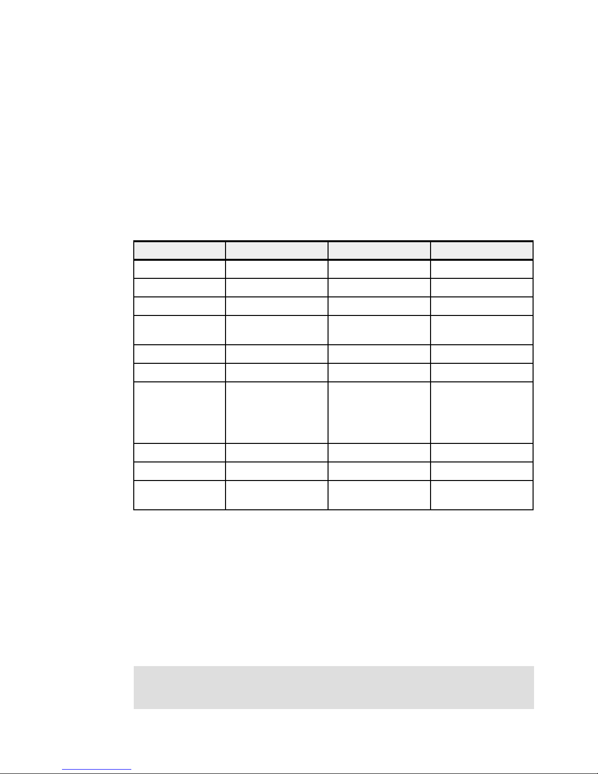
2.1.6 POWER7+ processor and Intelligent Energy
Energy consumption is an important area of focus for the design of the POWER7+ processor,
which includes Intelligent Energy features that help to dynamically optimize energy usage and
performance so that the best possible balance is maintained. Intelligent Energy features, such
as EnergyScale, work with IBM Systems Director Active Energy Manager™ to dynamically
optimize processor speed based on thermal conditions and system utilization.
2.1.7 Comparison of the POWER7+, POWER7, and POWER6 processors
Table 2-2 shows comparable characteristics between the generations of POWER7+,
POWER7, and POWER6 processors.
Table 2-2 Comparison of technology for the POWER7+ processor and the prior generation
Characteristic POWER7+ POWER7 POWER6
Technology
Die size
Maximum cores
Maximum SMT
threads per core
Maximum frequency
L2 Cache
L3 Cache
Memory support
I/O bus
Enhanced cache
mode (TurboCore)
a. Only supported on the Power 795.
32 nm 45 nm 65 nm
567 mm
882
4 threads 4 threads 2 threads
4.3 GHz 4.25 GHz 5.0 GHz
256 KB per core 256 KB per core 4 MB per core
10 MB of FLR-L3 cache
per core with each core
having access to the full
80 MB of L3 cache,
on-chip eDRAM
DDR3 DDR3 DDR2
Two GX++ Two GX++ One GX++
No Yes
2
567 mm
4 MB or 8 MB of FLR-L3
cache per core with each
core having access to
the full 32 MB of L3
cache, on-chip eDRAM
2
a
341 mm
32 MB off-chip eDRAM
ASIC
No
2
2.2 POWER7+ processor card
The POWER7+ processors in the Power 750 and Power 760 are packaged as dual chip
modules (DCMs). Each DCM consists of two POWER7+ processors. DCMs installed in a
Power 750 server consist of two 4-core chips. DCMs installed in the Power 760 server consist
of two 6-core chips.
The Power 750 and Power 760 can host one, two, three, or four DCMs. Each DCM can
address 16 DDR3 memory DIMM slots.
Note: All POWER7+ processors in the system must be the same frequency and have the
same number of processor cores. POWER7+ processor types cannot be mixed within a
system.
Chapter 2. Architecture and technical overview 51
Page 66

2.2.1 Overview
I/O Connectors
Regulator #1
Regulator #4
Memory Riser #3
Memory Riser #4
Memory Riser #1
Memory Riser #2
Memory Riser #7
Memory Riser #8
Memory Riser #5
Memory Riser #6
TPMD Slot
Regulator #3
Regulator #2
Pwr
Connector
Regulator #5
DCM0
DCM2
DCM3
DCM1
Front
Midplane
Figure 2-6 illustrates the major components of the Power 750 and Power 760 CPU card.
Figure 2-6 IBM Power 750 and Power 760 CPU board
2.2.2 Processor interconnects
This section describes the processor to memory architectural differences between IBM
POWER7 technology-based IBM Power 750 (8233-E8B) and the IBM POWER7+
technology-based Power 750 (8408-E8D) and Power 760 (9109-RMD) servers.
Historically new server models within a model family (such as Power 710) have carried
forward a similar, though enhanced, memory and I/O architecture of their previous model.
However, this case is not the same for POWER7+ Power 750 and Power 760. With these new
server models, changes to the bus architecture might require additional performance
considerations for partitions that need processor and memory resources that span multiple
processor sockets.
Similar to its previous POWER7 version, the POWER7+ technology-based Power 750 design
still provides 32 cores across four processor sockets, but the system design delivers a new
architecture. The Power 750 (8404-E8D) and Power 760 systems introduce a two-tier
interconnect architecture for a 4-socket system design. With this implementation, the socket
and node are logically the same. For the Power 770, the system enclosure and the node are
logically the same. For the Power 795, the book and node are logically the same. One tier is
for intra-node communication, and the second tier is for inter-node communication. This
two-tier interconnect enables more cores and greater throughput.
52 IBM Power 750 and 760 Technical Overview and Introduction
Page 67

The previous POWER7 technology-based Power 750 (8233-E8B) uses a single node design.
P7 P7
P7 P7
WW
Y
Y
Z
Node
Node
Node
Node
Node
P7
P7
P7
P7
P7
P7
P7
P7
AB Buses
It was available as a 4-socket system with one POWER7 chip per socket and W-Y-Z buses
between sockets, as shown in Figure 2-7. A 6-core or 8-core POWER7 chip was orderable.
Figure 2-7 Intra-node buses
The POWER7+ technology-based Power 750 (8408-E8D) and Power 760 use a multiple
node design, with two POWER7+ chips per socket delivered in a dual chip module package
(DCM). The Power 750 (8408-E8D) can be ordered with a 4-core chip and the Power 760 can
be ordered with a 6-core chip. The two POWER7+ chips within the DCM communicate using
the Y-Z bus architecture that was previously deployed between sockets in the POWER7
technology-based Power 750 (8233-E8B). However, communications between DCMs, from
socket to socket, use AB buses as illustrated in Figure 2-8.
Figure 2-8 Inter-node buses
From a topology standpoint, the new Power 750 (8408-E8D) and Power 760 (9109-RMD)
systems are similar to the 4-CEC enclosure Power 770 and Power 780 systems. In this case,
the interconnects between chips in a DCM of a Power 750 (8408-E8D) and Power 760
(9109-RMD) server are similar to the interconnects that are used between sockets in a single
Power 770 or Power 780 system enclosure. Similarly, the interconnects between DCMs in the
four sockets of the Power 750 (8408-E8D) and Power 760 (9109-RMD) system are similar to
the interconnects that are used between the system enclosures of a Power 770 or Power 780.
This architecture provides the best bandwidth and lowest latency between the chips within a
DCM or socket (node) and a lower bandwidth and higher latency between DCMs or sockets
(nodes). Therefore, when configuring workloads that span the DCM or socket (node)
boundaries within a Power 750 (8408-E8D) and Power 760 (9109-RMD), the same
Chapter 2. Architecture and technical overview 53
Page 68

considerations should be taken into account as when deploying workloads that span multiple
system enclosures on a Power 770 or Power 780 server to achieve optimum performance.
For more information, see the “Architecture of the IBM POWER7+ Technology-based
IBM Power 750 and IBM Power 760” technote:
http://www.redbooks.ibm.com/Redbooks.nsf/RedbookAbstracts/tips0972.html?Open
2.3 Memory subsystem
The Power 750 and Power 760 servers are a four-socket systems supporting four POWER7+
DCM processor modules. Each DCM processor module activates two memory riser cards
with eight DDR3 DIMM slots for each card. The server supports a maximum of 64 DDR3
DIMM slots using all 16 riser cards and all DCM modules.
The DIMM cards are 30 mm high, industry standard DDR3 Registered DIMMs. Memory
features (two memory DIMMs per feature) supported in the Power 750 are 4 GB, 8 GB, and
16 GB. The Power 760 additionally supports the 32 GB DIMMs. All DIMMs run at a speeds of
1066 MHz. The maximum memory supported using all DIMM slots is 1 TB for the Power 750
and 2 TB for the Power 760.
2.3.1 Registered DIMM
Industry standard DDR3 Registered DIMM (RDIMM) technology is used to increase reliability,
speed, and density of memory subsystems by putting a register between the DIMM modules
and the memory controller. This register is also referred to as a buffer.
2.3.2 Memory placement rules
The following memory options are orderable for the Power 750 system:
8 GB (2 x 4 GB) Memory DIMMs, 1066 MHz (FC EM08)
16 GB (2 x 8 GB) Memory DIMMs, 1066 MHz (FC EM4B, CCIN 31FA)
32 GB (2 x 16 GB) Memory DIMMs, 1066 MHz (FC EM4C)
The following memory options are orderable for the Power 760 system:
8 GB (2 x 4 GB) Memory DIMMs, 1066 MHz (FC EM08)
16 GB (2 x 8 GB) Memory DIMMs, 1066 MHz (FC EM4B, CCIN 31FA)
32 GB (2 x 16 GB) Memory DIMMs, 1066 MHz (FC EM4C)
64 GB (2 x 32 GB) Memory DIMMs, 1066 MHz (FC EM4D)
The minimum DDR3 memory capacity for the Power 750 and Power 760 systems is 32 GB of
installed memory for systems using one or two DCMs, 48 GB for three DCMs and 64 GB for
four DCMs. Although a single DCM system with two memory riser cards using the smallest
4 GB DIMMs can have a minimum of 16 GB (2 riser cards x 2 DIMMs with 4 GB = 16 GB), the
minimum memory is 32 GB. See Table 2-3.
Table 2-3 Maximum memory of the Power 750 and Power 760 system
Number of DCMs Power 750 Power 760
One DCM 256 GB 512 GB
Two DCMs 512 GB 1024 GB
54 IBM Power 750 and 760 Technical Overview and Introduction
Page 69

Number of DCMs Power 750 Power 760
DCM
MC: Memory Controller
BC: Memory Buffer
Memory Riser Card #2
DDR3 RDIMM Slot 2
DDR3 RDIMM Slot 1
DDR3 RDIMM Slot 8
DDR3 RDIMM Slot 7
DDR3 RDIMM Slot 4
DDR3 RDIMM Slot 3
DDR3 RDIMM Slot 6
DDR3 RDIMM Slot 5
BC-B
BC-A
POWER 7+
Chip 1
MC1
Channel D
MC1
Channel C
POWER 7+
Chip 0
MC0
Channel B
MC0
Channel A
Memory Riser Card #1
DDR3 RDIMM Slot 2
DDR3 RDIMM Slot 1
DDR3 RDIMM Slot 8
DDR3 RDIMM Slot 7
DDR3 RDIMM Slot 4
DDR3 RDIMM Slot 3
DDR3 RDIMM Slot 6
DDR3 RDIMM Slot 5
BC-B
BC-A
Three DCMs 768 GB 1536 GB
Four DCMs 1024 GB 2048 GB
Each riser card in the system must be populated with at least one pair of DIMMs.
No memory CoD: The Power 750 and Power 760 systems do not support capacity on
demand (CoD) for memory.
Figure 2-9 shows the physical memory DIMM topology for Power 750 and Power 760
connected to one DCM.
Figure 2-9 Physical memory DIMM topology for a Power 750 and Power 760 DCM
Chapter 2. Architecture and technical overview 55
Page 70

Figure 2-10 shows the memory location codes and how the memory riser cards are divided in
Memory Riser Card
Quad A
Quad B
Buffe r B
Sl ot #1 – P 3- C n-C 1
Sl ot #2 – P 3- C n-C 2
Sl ot #3 – P 3- C n-C 3
Sl ot #4 – P 3- C n-C 4
Sl ot #5 – P 3- C n-C 5
Sl ot #6 – P 3- C n-C 6
Sl ot #7 – P 3- C n-C 7
Sl ot #8 – P 3- C n-C 8
Bu f f e r A
quads, each quad being attached to a memory buffer.
Figure 2-10 Memory Riser Card for Power 750 and Power 760 Systems
A POWER7+ DCM uses one memory controller from each processor core (MC0 and MC1)
with two channels from memory controller 0 (channels A and B) and two channels from
memory controller 1 (channels C and D) for a total of four memory channels per DCM. Two
channels are attached to one memory riser card, with one channel to each buffer chip. The
two remaining memory channels from the POWER7+ DCM module attach to the second
memory riser card. Four DDR3 DIMMs will attach to each buffer chip with a total of 16 per
DCM and a maximum of 64 per system.
Memory placement rules
The memory-placement rules are as follows:
Each DCM requires two memory riser cards.
Each riser card must be populated at least with one pair of DIMMs.
The DIMMs of a DIMM-pair as listed in the tables (Table 2-4 on page 57 through Table 2-7
on page 59), must have the same size.
Each DIMM within a DIMM quad area (C1, C2, C3, and C4 or C5, C6, C7, and C8) must
be identical, although memory DIMMs in C1, C2, C3, and C4 might be separate feature
codes than those used in C5, C6, C7, and C8. A quad does not have to filled before
putting another pair of DIMMs into another quad.
For optimal performance, memory should be evenly spread across the memory riser
cards.
FC EM4D (64 GB - 2 x 32 GB DIMMs) is available only in the Power 760 and not
supported in the Power 750.
Third-party memory: Although the system uses industry standard DIMMs, third-party
memory is not supported.
56 IBM Power 750 and 760 Technical Overview and Introduction
Page 71
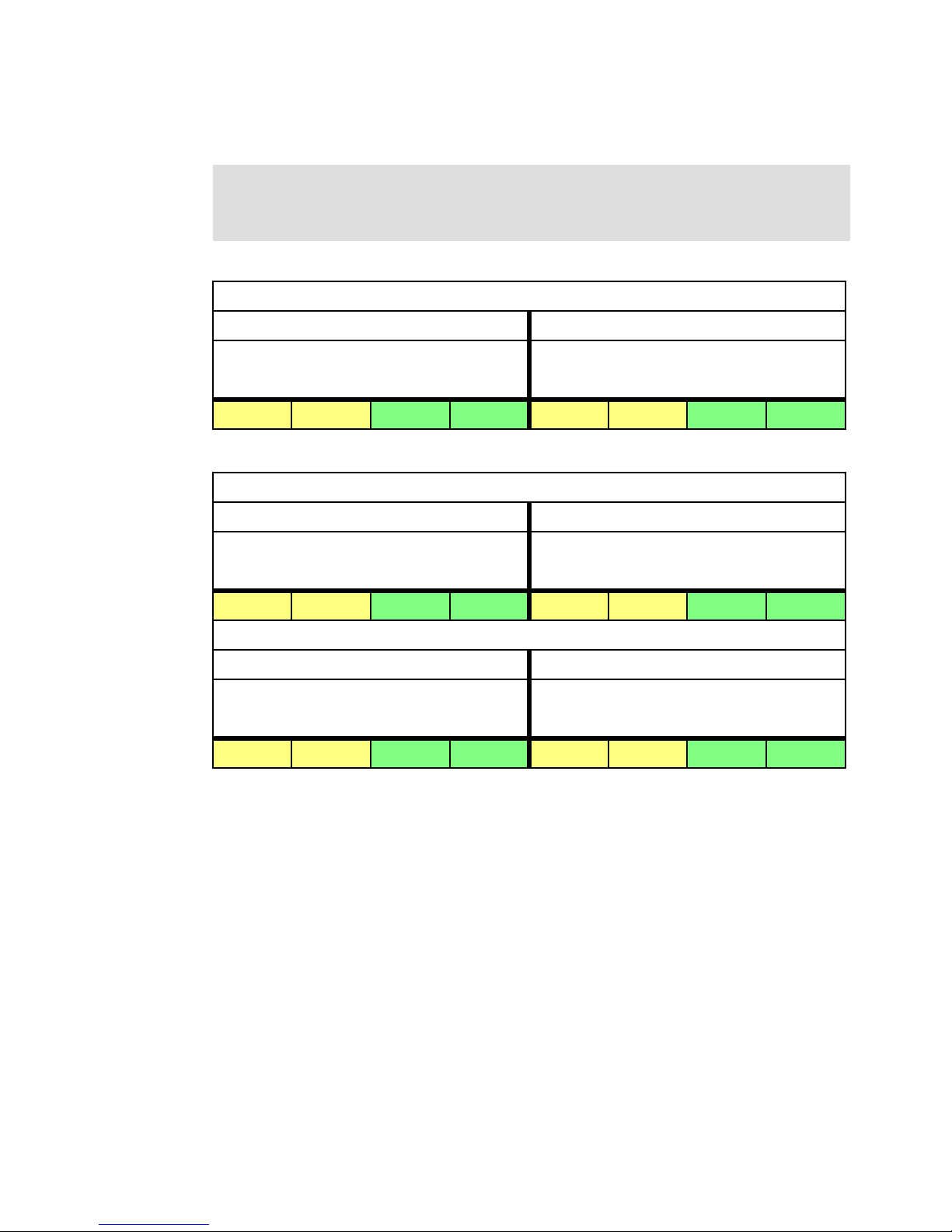
The following tables (Table 2-4 through Table 2-7 on page 59) show the plugging orders for
various DCM configurations.
Table information:
1 = first pair, 2 = second pair, 3 = third pair, 4 = fourth pair, and so on.
DIMMs in each colored area must be identical
Table 2-4 Memory plug order for a system with one DCM
DCM 0 / P3-C12
MC1 / Riser card 1 / P3-C1 MC0 / Riser card 2 / P3-C2
Pair of DIMM slots Pair of DIMM slots
C1/C3 C2/C4 C5/C7 C6/C8 C1/C3 C2/C4 C5/C7 C6/C8
1 5 7 3 2 6 8 4
Table 2-5 Memory plug order for a system with two DCMs
DCM 0 / P3-C12
MC1 / Riser card 1 / P3-C1 MC0 / Riser card 2 / P3-C2
Pair of DIMM slots Pair of DIMM slots
C1/C3 C2/C4 C5/C7 C6/C8 C1/C3 C2/C4 C5/C7 C6/C8
1 9 13 5 2 10 14 6
DCM 1 / P3-C17
MC1 / Riser card 1 / P3-C8 MC0 / Riser card 1 / P3-C9
Pair of DIMM slots Pair of DIMM slots
C1/C3 C2/C4 C5/C7 C6/C8 C1/C3 C2/C4 C5/C7 C6/C8
3 11 15 7 4 12 16 8
Chapter 2. Architecture and technical overview 57
Page 72

Table 2-6 Memory plug order for a system with three DCMs
DCM 0 / P3-C12
MC1 / Riser card 1 / P3-C1 MC0 / Riser card 2 / P3-C2
Pair of DIMM slots Pair of DIMM slots
C1/C3 C2/C4 C5/C7 C6/C8 C1/C3 C2/C4 C5/C7 C6/C8
1 13 19 7 2 14 20 8
DCM 1 / P3-C17
MC1 / Riser card 1 / P3-C8 MC0 / Riser card 1 / P3-C9
Pair of DIMM slots Pair of DIMM slots
C1/C3 C2/C4 C5/C7 C6/C8 C1/C3 C2/C4 C5/C7 C6/C8
3 15 21 9 4 16 22 10
DCM 2 / P3-C16
MC1 / Riser card 1 / P3-C6 MC0 / Riser card 1 / P3-C7
Pair of DIMM slots Pair of DIMM slots
C1/C3 C2/C4 C5/C7 C6/C8 C1/C3 C2/C4 C5/C7 C6/C8
5 17 23 11 6 18 24 12
58 IBM Power 750 and 760 Technical Overview and Introduction
Page 73

Table 2-7 Memory plug order for a system with four DCMs
DCM 0 / P3-C12
MC1 / Riser card 1 / P3-C1 MC0 / Riser card 2 / P3-C2
Pair of DIMM slots Pair of DIMM slots
C1/C3 C2/C4 C5/C7 C6/C8 C1/C3 C2/C4 C5/C7 C6/C8
1 17 25 9 2 18 26 10
DCM 1 / P3-C17
MC1 / Riser card 1 / P3-C8 MC0 / Riser card 1 / P3-C9
Pair of DIMM slots Pair of DIMM slots
C1/C3 C2/C4 C5/C7 C6/C8 C1/C3 C2/C4 C5/C7 C6/C8
3 19 27 11 4 20 28 12
DCM 2 / P3-C16
MC1 / Riser card 1 / P3-C6 MC0 / Riser card 1 / P3-C7
Pair of DIMM slots Pair of DIMM slots
C1/C3 C2/C4 C5/C7 C6/C8 C1/C3 C2/C4 C5/C7 C6/C8
5 21 29 13 6 22 30 14
DCM 3 / P3-C13
MC1 / Riser card 1 / P3-C3 MC0 / Riser card 1 / P3-C4
Pair of DIMM slots Pair of DIMM slots
C1/C3 C2/C4 C5/C7 C6/C8 C1/C3 C2/C4 C5/C7 C6/C8
7 23 31 15 8 24 32 16
Chapter 2. Architecture and technical overview 59
Page 74
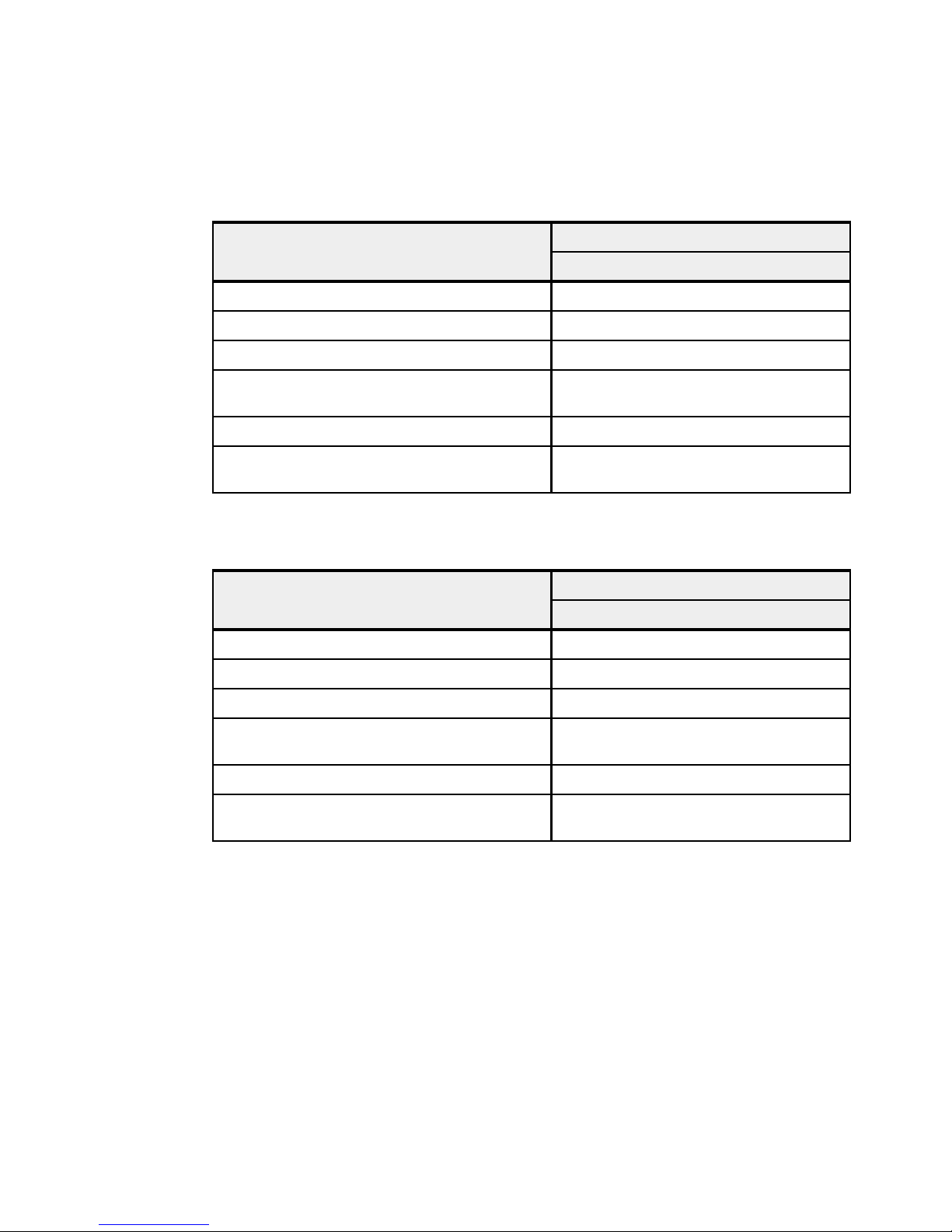
2.3.3 Memory bandwidth
POWER7+ has exceptional cache, memory, and interconnect bandwidths. Table 2-8 shows
the maximum bandwidth estimate for the Power 750 system running at 4.06 GHz.
Table 2-8 Power 750 processor and memory bandwidth estimates
Memory Power 750
L1 (data) cache 194.880 GBps
L2 cache 194.880 GBps
L3 cache 129.920 GBps
4.060 GHz processor card
Chip to chip in DCM (XZ bus)
4 DCMs
DCM to DCM (AB bus) 236.544 GBps
System memory
4 DCMs
96.768 GBps
387.072 GBps
68.224 GBps
272.896 GBps
Table 2-9 shows the maximum bandwidth estimate for a Power 760 running at 3.416 GHz.
Table 2-9 Power 760 processor and memory bandwidth estimates
Memory Power 760
3.416 GHz processor card
L1 (data) cache 163.968 GBps
L2 cache 163.968 GBps
L3 cache 109.312 GBps
Chip to chip in DCM (XZ bus)
4 DCMs
DCM to DCM (AB bus) 236.544 GBps
System memory
4 DCMs
96.768 GBps
387.072 GBps
68.224 GBps
272.896 GBps
The bandwidth figures for the caches are calculated as follows:
L1 cache: In one clock cycle, two 16-byte load operations and one 16-byte store operation
can be accomplished. Using an 4.060 GHz processor card the formula is as follows:
(2 * 16 B + 1 * 16 B) * 4.060 GHz = 194.88 GBps
L2 cache: In one clock cycle, one 32-byte load operation and one 16-byte store operation
can be accomplished. Using an 4.060 GHz processor card the formula is as follows:
(1 * 32 B + 1 * 16 B) * 4.060 GHz = 194.88 GBps
L3 cache: One 32-byte load operation and one 32-byte store operation can be
accomplished at half-clock speed. Using an 4.060 GHz processor card, the formula is as
follows:
(1 * 32 B + 1 * 32 B) * (4.060 GHz / 2) = 129.92 GBps
60 IBM Power 750 and 760 Technical Overview and Introduction
Page 75

Memory: Each of the two memory controllers uses two ports with 8 bytes that connect to a
buffer chip. Each buffer chip connects to four DIMMs running at 1066 MHz, with two
DIMMs being active at a given point in time. See Figure 2-9 on page 55 for reference. The
bandwidth formula is calculated as follows:
2 memory controller * 2 ports * 8 bytes * 2 DIMMs * 1066 MHz = 68.224 GBps.
2.4 Capacity on Demand
The Power 750 offers Capacity Backup (CBU) for IBM i only. No other Capacity on Demand
(CoD) offerings are available.
The Power 760 server offers Capacity Upgrade on Demand (CUoD) for processors to help
meet changing processor requirements in an on-demand environment, by using resources
that are installed on the system but that are not activated.
No other processor CoD options: Processor Elastic (On/Off) CoD or Utility CoD or Trial
CoD is not provided. Also memory CoD is not available for Power 750 and Power 760.
Capacity Backup for IBM i is also available for Power 760.
For more information about Capacity on Demand, see the following web page:
http://www.ibm.com/services/econfig/announce/index.htm
2.4.1 Capacity Upgrade on Demand
With the Capacity Upgrade on Demand (CUoD) offering for the Power 760 system, you can
purchase additional permanent processor capacity and dynamically activate them when
needed, without requiring you to restart your server or interrupt your business.
The Power 760 systems requires a minimum of eight cores being activated. For further
activations, the following feature codes can be used to activate additional cores:
FC EPT5: one additional core for 3.1 GHz processors
FC EPT6: one additional core for 3.4 GHz processors
2.4.2 Capacity Backup offering (applies only to IBM i)
The Power 750 and Power 760 systems Capacity Backup (CBU) designation can help meet
your requirements for a second system to use for backup, high availability, and disaster
recovery. It enables you to temporarily transfer IBM i processor license entitlements and 5250
Enterprise Enablement entitlements purchased for a primary machine to a secondary
CBU-designated system. Temporarily transferring these resources instead of purchasing
them for your secondary system may result in significant savings. Processor activations
cannot be transferred.
The CBU specify FC 0444 is available only as part of a new server purchase. Certain system
prerequisites must be met, and system registration and approval are required before the CBU
specify feature can be applied on a new server.
For information about registration and other details, visit the following location:
http://www.ibm.com/systems/power/hardware/cbu
Chapter 2. Architecture and technical overview 61
Page 76

2.4.3 Software licensing and CoD
For software licensing considerations with the various CoD offerings, see the most recent
revision of the Power Systems Capacity on Demand User’s Guide:
http://www.ibm.com/systems/power/hardware/cod
2.5 System bus
This section provides additional information related to the internal buses.
2.5.1 I/O buses and GX++ card
Each Power 750 Express server (8408-E8D) and each Power 760 server (9109-RMD)
supports up to four POWER7+ processor dual chip modules (DCMs). For the Power 750
Express server, each of the four processor DCMs is an 8-core DCM packaged with two 4-core
chips. All 8-core processor DCMs are either 3.5 or 4.0 GHz mounted on a dedicated card with
a granularity of one DCM. For the Power 760 server, each of the four processor DCMs is a
0/12-core CUoD DCM packaged with two 6-core chips. All 0/12-core CUoD processor DCMs
are either 3.1 GHz or 3.4 GHz mounted on a dedicated card with a granularity of one DCM.
In the Power 750 Express server, each POWER7+ processor DCM is a 64-bit, 8-core
processor packaged on a dedicated card with a maximum of 64 DDR3 DIMMs, 10 MB of L3
cache per core, and 256 KB of L2 cache per core. A Power 750 Express server can be
populated with one, two, three, or four DCMs providing 8, 16, 24, or 32 cores. All the cores are
active.
In the Power 760, each POWER7+ processor DCM is a 64-bit, 0/12-core CUoD processor,
packaged on a dedicated card with a maximum of 64 DDR3 DIMMs, 10 MB of L3 cache per
core, and 256 KB of L2 cache per core. A Power 760 server can be populated with one, two,
three, or four DCMs providing 12, 24, 36, or 48 cores. A fully populated Power 760 server with
four DCMs has a minimum of eight cores activated and up to a maximum of 48 cores with a
CUoD granularity of one core.
Each Power 750 Express or Power 760 server provides a total of four GX++ buses available
for I/O connectivity and expansion. Two 4-byte GX++ buses off the DCM0 socket are routed
through the midplane to the I/O backplane and drive two P7IOC chips. The two remaining
GX++ buses are routed off of DCM1 socket to the Midplane and feed GX++ adapter slots.
Therefore, a minimum of two processor cards must be installed to enable two GX++ adapter
slots. These GX++ adapter slots are not hot-pluggable and do not share space with any of the
PCIe slots. Table 2-10 on page 63 shows the I/O bandwidth for available processors cards.
The frequency for these buses are asynchronous to the CPU core clock and therefore will
always be constant regardless of CPU core frequency.
62 IBM Power 750 and 760 Technical Overview and Introduction
Page 77
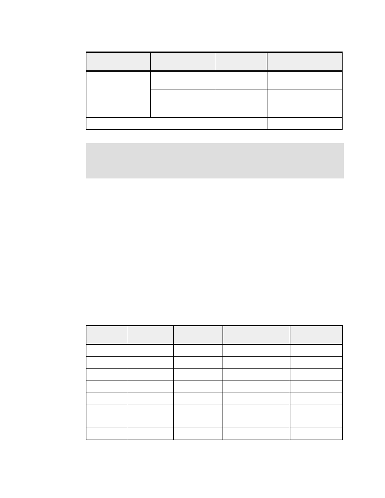
Table 2-10 External GX++ I/O bandwidth
Processor card Slot description Frequency GX++ Bandwidth
(maximum theoretical)
Power 760
3.416 GHz
3.136 GHz
Power 750
4.060 GHz
3.500 GHz
Total (External I/O) 40 GBps
CPU Socket 1(DCM1)
GX bus 1
CPU Socket 1(DCM1)
GX bus 0
Bandwidth: Technically, all the other interfaces, such as daughter card, asynchronous
port, DVD, USB, and the PCI Express slots are connected to two other internal GX++ ports
through two P7IOC chipsets. So, theoretically, if all the ports, devices, and PCIe slots are
considered, the total I/O bandwidth for a system is 80 GBps.
2.6 Internal I/O subsystem
The internal I/O subsystem resides on the I/O planar, which supports six PCIe slots. All PCIe
slots are hot-pluggable and enabled with Enhanced Error Handling (EEH). In the unlikely
event of a problem, EEH-enabled adapters respond to a special data packet that is generated
from the affected PCIe slot hardware by calling system firmware, which examines the affected
bus, allows the device driver to reset it, and continues without a system reboot. For more
information about RAS on the I/O buses, see Chapter 4, “Continuous availability and
manageability” on page 149.
2.5 GHz 20 GBps
2.5 GHz 20 GBps
The I/O backplane contains two I/O controllers for enhanced I/O redundancy and flexibility.
PCIe slots 1 - 4 are connected to I/O controller A. The I/O controller B connects to PCIe slots
5 - 6, the multifunction card, and to the DVD-RAM drive.
Table 2-11 lists the slot configuration of the Power 750 and Power 760.
Table 2-11 Slot configuration of the Power 750 and Power 760
Slot
number
Slot 1 PCIe Gen2 x8 P2-C1 P7IOC A PCIe PHB5 Full length
Slot 2 PCIe Gen2 x8 P2-C2 P7IOC A PCIe PHB4 Full length
Slot 3 PCIe Gen2 x8 P2-C3 P7IOC A PCIe PHB3 Full length
Slot 4 PCIe Gen2 x8 P2-C4 P7IOC A PCIe PHB2 Full length
Slot 5 PCIe Gen2 x8 P2-C5 P7IOC B PCIe PHB5 Full length
Slot 6 PCIe Gen2 x8 P2-C6 P7IOC B PCIe PHB4 Full length
Slot 7 GX++ P1-C2 - -
Slot 8 GX++ P1-C3 - -
Description Location
code
PCI host bridge
(PHB)
Maximum card
size
Chapter 2. Architecture and technical overview 63
Page 78

Tip: For information about hot-plug procedures, visit the Customer Information Center:
http://pic.dhe.ibm.com/infocenter/powersys/v3r1m5/topic/p7hbm/p7hbm.pdf
2.6.1 Blind swap cassettes
The Power 750 and Power 760 uses fourth-generation blind swap cassettes to manage the
installation and removal of adapters. This mechanism requires an interposer card that allows
the PCIe adapters to plug in vertically to the system, allows more airflow through the cassette,
and provides more room under the PCIe cards to accommodate the GX++ multifunctional
host bridge chip heat-sink height. Cassettes can be installed and removed without removing
the Power 750 and Power 760 server from the rack.
2.6.2 Integrated multifunction card
Each Power 750 and Power 760 server is equipped with an integrated multifunction card. This
card provides two USB ports, one serial port, and four Ethernet connectors for the system
and does not require a PCIe slot. All connectors are on the rear bulkhead of the system; one
integrated multifunction card can be placed in an individual system.
The serial port connector is a standard 9-pin male D-shell, and it supports the RS232
interface. If the server is managed by an HMC, this serial port is always controlled by the
operating system, and therefore is available in any system configuration. It is driven by the
integrated PLX Serial chip, and it supports any serial device that has an operating system
device driver. The FSP virtual console will be on the HMC.
Requirement: The Power 750 can be managed either by IVM or an HMC. The Power 760
requires management by an HMC.
When ordering a Power 750 or Power 760, you may select a integrated multifunction card
from the following options:
1 Gb Ethernet (RJ45) and 10 Gb copper SFP+
This card (FC 1768, CCIN 2BF3) provides four Ethernet connections: Two 1 Gb (RJ45) and
two 10 Gb Small Form-factor Pluggable+ (SFP+) active copper twinax. The RJ45 ports
support up to 100 m cabling distance using Cat 5e cable. The 10 Gb copper SFP+ twinax
ports support up to 5 m cabling distances and active copper twinax cables are available in
length of 1 m (FC EN01), 3 m (FC EN02), or 5 m (FC EN03).
Hint: The SFP+ twinax copper is not IBM AS/400® 5250 twinax or CX4 or 10 GBASE-T.
1 Gb Ethernet (RJ45) and 10 Gb SR optical
This card (FC 1769, CCIN 2BF4) provides four Ethernet connections: Two 1 Gb (RJ45) and
two 10 Gb (Small Form-factor Pluggable + (SFP+) SR optical). The RJ45 ports support up to
100 m cabling distance using Cat 5e cable. The optical ports only support the 850 Nm optic
cable (multi mode cable) and support up to 300 m cabling distances.
10 Gb Ethernet (RJ45) and 10 Gb copper twinax
This card (FC EN10, CCIN 2C4C) provides four Ethernet connections: Two RJ45 ports
(10 Gb/1 Gb/100 Mb) and two active copper twinax ports (10 Gb). The two RJ45 ports default
to auto negotiate the highest speed either 10 Gb (10 GBaseT), 1 Gb (1000 BaseT), or
64 IBM Power 750 and 760 Technical Overview and Introduction
Page 79

100 Mb (100 BaseT) full duplex. Each RJ45 port's configuration is independent of the other.
The RJ45 ports use 4-pair Cat 6A cabling for distances of up to 100 meters. CAT5 cabling is
not supported.
The two 10 Gb copper twinax ports are SFP+ and the transceivers are included. The ports
support up to 5 m cabling distances and active copper twinax cables are available in length of
1 m (FC EN01), 3 m (FC EN02), or 5 m (FC EN03). Active cables differ from passive cables.
The Converged Ethernet Network Adapter (CNA) capability on these two copper SFP+ twinax
ports support both Ethernet NIC and Fibre Channel over Ethernet (FCoE) workload
simultaneously.
Considerations: Consider the following information:
The SFP+ twinax copper is not AS/400 5250 twinax or CX4.
A FCoE switch is required for any FCoE traffic.
IBM i supports Ethernet NIC through VIOS, but does not support the use of FCoE data
(with or without VIOS) through this adapter.
10 Gb Ethernet (RJ45) and 10 Gb SR optical
This card (FC EN11, CCIN 2C4D) provides four Ethernet connections: Two RJ45 ports
(10 Gb/1 Gb/100 Mb) and two SR fiber optical ports (10 Gb).
The two 10 Gb SR optical ports (10 GBase-SR) are SFP+ and include the transceivers. The
ports have LC Duplex type connectors and utilize shortwave laser optics and MMF-850nm
fiber cabling. With 62.5 micron OM1, up to 33 meter length fiber cables are supported. With
50 micron OM2, up to 82 meter fiber cable lengths are supported. With 50 micron OM3 or
OM4, up to 300 meter fiber cable lengths are supported.
The two RJ45 ports default to auto-negotiate the highest speed either 10 Gb (10 GBaseT),
1 Gb (1000 BaseT) or 100 Mb (100 BaseT). Each RJ45 port's configuration is independent of
the other. The RJ45 ports use 4-pair Cat 6A cabling for distances of up to 100 meters. CAT5
cabling is not supported.
2.7 PCI adapters
This section covers the types and functions of the PCI adapters supported by IBM Power 750
and Power 760 systems.
2.7.1 PCI Express
Peripheral Component Interconnect Express (PCIe) uses a serial interface and allows for
point-to-point interconnections between devices (using a directly wired interface between
these connection points). A single PCIe serial link is a dual-simplex connection that uses two
pairs of wires, one pair for transmit and one pair for receive, and can transmit only one bit per
cycle. These two pairs of wires are called a
such configurations, the connection is labelled as x1, x2, x8, x12, x16, or x32, where the
number is effectively the number of lanes.
Two generations of PCIe interfaces are supported in Power 750 and Power 760 models:
Gen1: Capable of transmitting at the extremely high speed of 2.5 Gbps, which gives a
capacity of a peak bandwidth of 2 GBps simplex on an 8-lane interface
lane. A PCIe link can consist of multiple lanes. In
Chapter 2. Architecture and technical overview 65
Page 80

Gen2: Double the speed of the Gen1 interface, which gives a capacity of a peak
bandwidth of 4 GBps on an 8-lane interface
PCIe Gen1 slots support Gen1 adapter cards and also most of the Gen2 adapters. In this
case, when a Gen2 adapter is used in a Gen1 slot, the adapter operates at PCIe Gen1
speed. PCIe Gen2 slots support both Gen1 and Gen2 adapters. In this case, when a Gen1
card is installed into a Gen2 slot, it operates at PCIe Gen1 speed with a slight performance
enhancement. When a Gen2 adapter is installed into a Gen2 slot, it operates at the full PCIe
Gen2 speed.
The IBM Power 750 and Power 760 server is equipped with six PCIe 8x Gen2 slots.
2.7.2 PCI-X adapters
The Power 750 and Power 760 systems do not support PCI-X adapters. Neither in internal
slots nor in a PCI-X DDR 12X I/O Drawer (FC 5796).
2.7.3 IBM i IOP adapters
IBM i IOP adapters are not supported with the Power 750 and Power 760, which has the
following results:
Existing PCI adapters that require an IOP are affected
Existing I/O devices are affected, such as certain tape libraries or optical drive libraries, or
any HVD SCSI device
Twinaxial displays or printers cannot be attached except through an OEM protocol converter
SDLC-attached devices using a LAN or WAN adapter are not supported
SNA applications still can run when encapsulated inside TCP/IP, but the physical device
attachment cannot be SNA
Earlier Fibre Channel and SCSI controllers that depended upon an IOP being present are
not supported
Before adding or rearranging adapters, use the System Planning Tool to validate the new
adapter configuration. See the IBM System Planning Tool website:
http://www.ibm.com/systems/support/tools/systemplanningtool/
If you are installing a new feature, ensure that you have the software that is required to
support the new feature, and determine whether there are any existing PTF prerequisites to
install. See the following website for prerequisite information:
https://www-912.ibm.com/e_dir/eServerPreReq.nsf
2.7.4 PCIe adapter form factors
IBM POWER7 and POWER7+ processor-based servers are able to support two form factors
of PCIe adapters:
PCIe low-profile (LP) cards, which are used on the Power 710 and Power 730 PCIe slots.
Low profile adapters are also supported in the PCIe riser card slots of the Power 720 and
Power 740 servers.
66 IBM Power 750 and 760 Technical Overview and Introduction
Page 81

PCIe full-height and full-high cards, which are plugged into the following servers slots:
Low Profile PCIe Slots
Power 710 / 730
Power 720 / 740
- PCIe riser card
Low Profile Full Height Full High
Full High PCIe Slots
Power 720 / 740 / 750 / 760 / 770 / 780 / 795
12X PCIe I/O Drawer
- FC 5802 / FC 5877 for 19-inch rack
- FC 5803 / FC 5873 for 24-inch rack
– Power 720 and Power 740 (within the base system, five PCIe half-length slots
are supported.)
–Power750
–Power755
–Power760
–Power770
–Power780
–Power795
– PCIe slots of external I/O drawers, such as FC 5802 and FC 5877
Low-profile PCIe adapter cards are supported only in low-profile PCIe slots, and full-height
and full-high cards are supported only in full-high slots.
Figure 2-11 lists the PCIe adapter form factors.
Figure 2-11 PCIe adapter form factors
Many of the full-height card features are also available in low-profile format. For example, the
PCIe RAID and SSD SAS Adapter 3 Gb is available as a low-profile adapter or as a full-height
adapter, each one having a different feature code. As expected, they have equivalent
functional characteristics.
Table 2-12 is a list of low-profile adapter cards and their equivalents in full height.
Table 2-12 Equivalent adapter cards
Low profile Adapter description Full height
Feature
code
2053 57CD PCIe RAID and SSD SAS Adapter 3 Gb 2054 or
5269 5269 PCIe POWER GXT145 Graphics Accelerator 5748 5748
5270 2B3B 10 Gb FCoE PCIe Dual Port adapter 5708 2B3B
5271 5271 4-Port 10/100/1000 Base-TX PCI-Express adapter 5717 5271
CCIN Feature
CCIN
code
57CD
2055
Chapter 2. Architecture and technical overview 67
Page 82
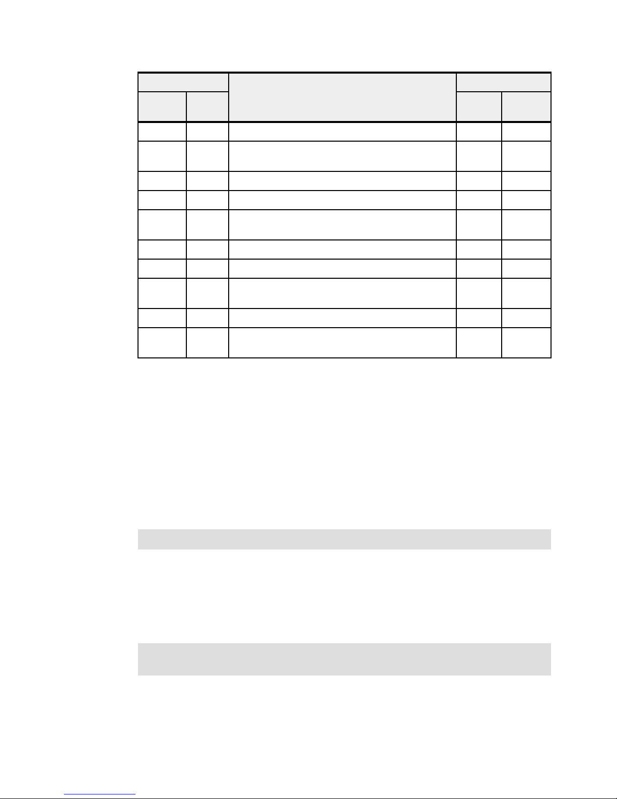
Low profile Adapter description Full height
Feature
code
5272 5272 10 Gigabit Ethernet-CX4 PCI Express adapter 5732 5732
5273 577D 8 Gigabit PCI Express Dual Port Fibre Channel
5274 5768 2-Port Gigabit Ethernet-SX PCI Express adapter 5768 5768
5275 5275 10 Gb ENet Fibre RNIC PCIe 8x adapter 5769 5275
5276 5774 4 Gigabit PCI Express Dual Port Fibre Channel
5277 57D2 4-Port Sync EIA-232 PCIe adapter 5785 57D2
5278 57B3 SAS Controller PCIe 8x adapter 5901 57B3
5280 2B44 PCIe2 LP 4-Port 10 Gb Ethernet &1 Gb Ethernet
EN0B 577F PCIe2 16 Gb 2-Port Fibre Channel adapter EN0A 577F
EN0J 2B93 PCIe2 4-Port (10 Gb FCOE & 1 Gb Ethernet)
CCIN Feature
code
5735 577D
adapter
5774 5774
adapter
5744 2B44
SR&RJ45 adapter
EN0H 2B93
SR&RJ45 adapter
CCIN
Before adding or rearranging adapters, use the System Planning Tool to validate the new
adapter configuration. See the IBM System Planning Tool website:
http://www.ibm.com/systems/support/tools/systemplanningtool/
If you are installing a new feature, ensure that you have the required software to support the
new feature and determine whether there are any existing update prerequisites to install. To
do this, see the following website for prerequisite information:
https://www-912.ibm.com/e_dir/eServerPreReq.nsf
Several of the following sections discuss the supported adapters and provide tables of
orderable feature numbers. The tables indicate operating system support (AIX, IBM i, and
Linux) for each of the adapters.
Note: Power 750 and Power 760 servers support only PCIe full-height and full-high cards.
2.7.5 LAN adapters
To connect a Power 750 and Power 760 to a local area network (LAN), use the integrated
multifunction card, or a dedicated adapter. For more information about the integrated
multifunction card, see 2.6.2, “Integrated multifunction card” on page 64.
Hint: The integrated multifunction card can be shared by LPARs that use VIOS, so each
LPAR is able to access it without a dedicated network card.
Other LAN adapters are supported in the PCIe slots of the system unit or in an I/O drawer that
are attached to the system by using a PCIe slot. Table 2-13 on page 69 lists the additional
LAN adapters that are available for the Power 750 and Power 760 servers.
68 IBM Power 750 and 760 Technical Overview and Introduction
Page 83

Table 2-13 Available LAN adapters
Feature
CCIN Adapter description Slot Size OS support
code
5287 5287 2-port 10 Gb Ethernet SR PCIe adapter PCIe Full height AIX, Linux
5288 5288 2-Port 10 Gb Ethernet SFP+ Copper
PCIe Full height AIX, Linux
adapter
5708 2B3B 2-Port 10 Gb NIC/FCoE adapter PCIe Full height AIX, Linux
5717 5271 4-Port 10/100/1000 Base-TX PCI
PCIe Full height AIX, Linux
Express adapter
5732 5732 10 Gigabit Ethernet-CX4 PCI Express
PCIe Full height AIX, Linux
adapter
5744 2B44 PCIe2 4-Port 10 Gb Ethernet &
PCIe Full height Linux
1 Gb Ethernet SR RJ45 adapter
5745 2B43 PCIe2 4-Port 10 Gb Ethernet &
PCIe Full height Linux
1 Gb Ethernet SFP+ Copper & RJ45
adapter
5767 5767 2-Port 10/100/1000 Base-TX Ethernet
PCI Express adapter
5768 5768 2-Port Gigabit Ethernet-SX PCI
Express adapter
5769 5769 10 Gigabit Ethernet-SR PCI Express
PCIe Full height AIX, IBM i,
Linux
PCIe Full height AIX, IBM i,
Linux
PCIe Full height AIX, Linux
adapter
5772 576E 10 Gigabit Ethernet-LR PCI Express
adapter
PCIe Full height AIX, IBM i,
Linux
5899 576F 4-Port 1 Gb Ethernet adapter PCIe Full height AIX, IBM i,
Linux
EC28 EC27 PCIe2 2-Port 10 Gb Ethernet ROCE
PCIe Full height AIX, Linux
SFP+ adapter
EC30 EC29 PCIe2 2-Port 10 Gb Ethernet ROCE SR
PCIe Full height AIX, Linux
adapter
EN0H 2B93 PCIe2 4-port (10 Gb FCoE & 1 Gb
Ethernet) SR & RJ45 adapter
PCIe Full height AIX, IBM i,
Linux
Chapter 2. Architecture and technical overview 69
Page 84

2.7.6 Graphics accelerator adapters
The IBM Power 750 and Power 760 support up to eight of the FC 5748 cards, as shown in
Table 2-14. They can be configured to operate in either 8-bit or 24-bit color modes. These
adapters support both analog and digital monitors. The total number of graphics accelerator
adapters in any one partition may not exceed four.
Table 2-14 Available graphics accelerator adapters
Feature
code
CCIN Adapter description Slot Size OS
support
5748 5748 POWER GXT145 PCI Express
2.7.7 SCSI and SAS adapters
The Power 750 and Power 760 do not support SCSI adapters and SCSI disks. SAS adapters
are supported and Table 2-15 lists the available SAS adapters.
Table 2-15 Available SCSI and SAS adapters
Feature
code
2055 57CD PCIe RAID and SSD SAS adapter 3 Gb
5805 574E PCIe 380 MB Cache Dual - x4 3 Gb
5901 57B3 PCIe Dual-x4 SAS adapter PCIe Full height AIX, IBM i,
5903
5913
CCIN Adapter description Slot Size OS
with Blind Swap Cassette
SAS RAID adapter
a
574E PCIe 380 MB Cache Dual - x4 3 Gb
SAS RAID adapter
a
57B5 PCIe2 1.8 GB Cache RAID SAS
adapter Tri-Port 6 Gb
Graphics Accelerator
PCIe Full height AIX,
Linux
support
PCIe Full height AIX, IBM i,
Linux
PCIe Full height AIX IBM i,
Linux
Linux
PCIe Full height AIX, IBM i,
Linux
PCIe Full height AIX, IBM i,
Linux
ESA1 57B4 PCIe2 RAID SAS adapter Dual-Port
a. A pair of adapters is required to provide mirrored write-cache data and adapter redundancy.
2.7.8 iSCSI adapters
The Power 750 and Power 760 do not support iSCSI adapters. However, AIX, IBM i and Linux
provide software iSCSI support through available Ethernet adapters. Table 2-16 lists the
available adapters for operating system iSCSI support.
Table 2-16 Available iSCSI adapters
Feature
code
5899 576F PCIe2 4-Port 1 Gb Ethernet adapter PCIe Full Height AIX, IBM i,
EN0H 2B93 PCIe2 4-Port (10 Gb FCOE &
70 IBM Power 750 and 760 Technical Overview and Introduction
CCIN Adapter description Slot Size OS
6Gb
1 Gb Ethernet) SR & RJ45 adapter
PCIe Full height AIX, IBM i,
Linux
support
Linux
PCIe Full height AIX, IBM i,
Linux
Page 85
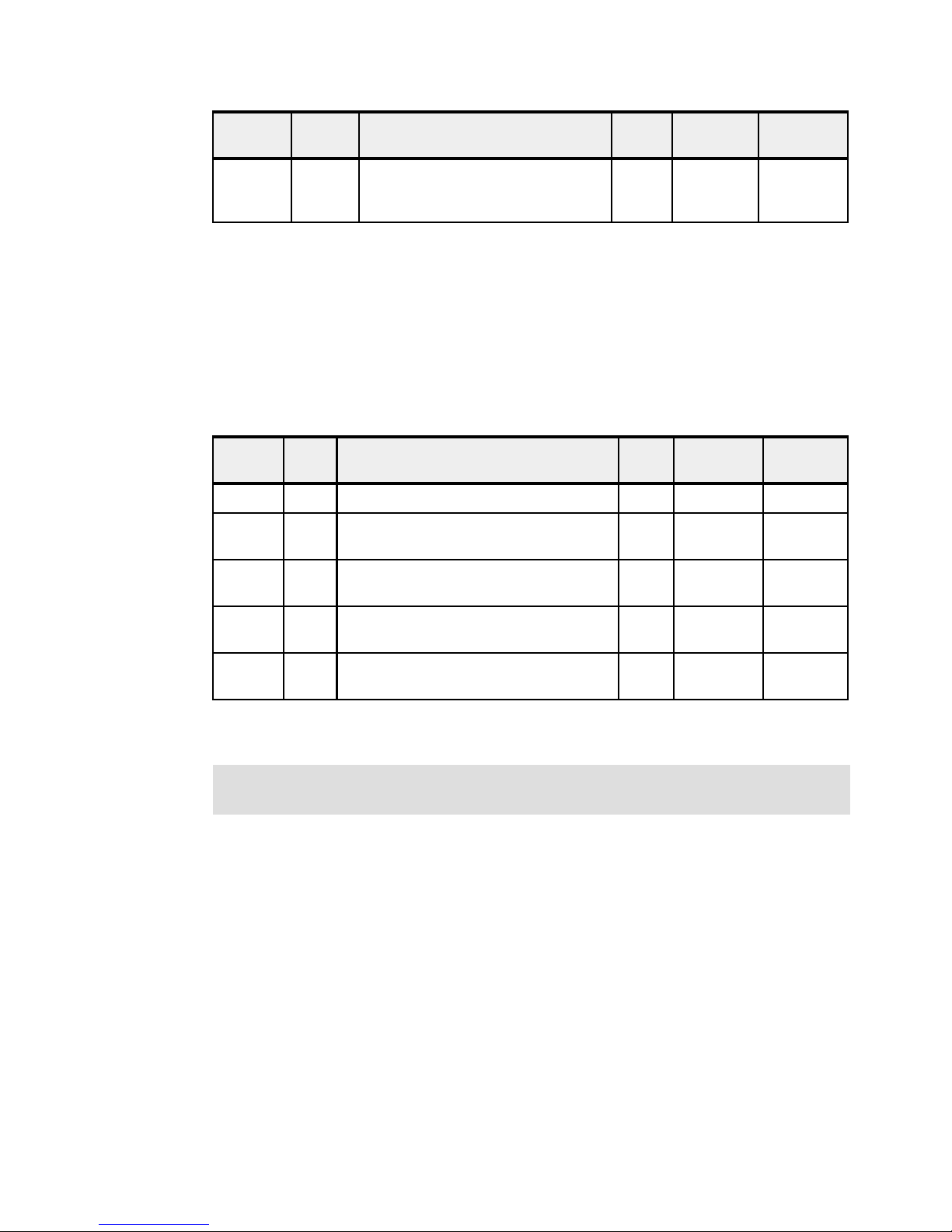
Feature
code
CCIN Adapter description Slot Size OS
support
EN10 2C4C Integrated Multifunction Card with
2.7.9 Fibre Channel adapters
The IBM Power 750 and Power 760 servers support direct or SAN connection to devices that
use Fibre Channel adapters. Table 2-17 summarizes the available Fibre Channel adapters.
All of these adapters have LC connectors. If you attach a device or switch with an SC type
fiber connector, an LC-SC 50 Micron Fiber Converter Cable (FC 2456) or an LC-SC 62.5
Micron Fiber Converter Cable (FC 2459) is required.
Table 2-17 Available Fibre Channel adapters
Feature
code
5729
5735 577D 8 Gigabit PCI Express Dual Port Fibre
5773
5774 2B44 4 Gigabit PCI Express Dual Port Fibre
CCIN Adapter description Slot Size OS
a
2B53 PCIe2 8 Gb 4-Port Fibre Channel adapter PCIe Full height AIX, Linux
Channel adapter
b
5773 4 Gigabit PCI Express Single Port Fibre
Channel adapter
Channel adapter
-- n/a
10 Gb Ethernet RJ45 & Copper
Twinax
support
PCIe Full height AIX, IBM i,
Linux
PCIe Full height AIX, Linux
PCIe Shor t AIX, IBM i,
Linux
EN0A 577F PCIe2 16 Gb 2-Port Fibre Channel adapter PCIe Full height AIX, IBM i,
a. A Gen2 PCIe slot is required to provide the bandwidth for all four ports to operate at full speed.
b. Adapter is supported, but no longer orderable.
Note: The usage of NPIV through the Virtual I/O server requires a NPIV capable Fibre
Channel adapter such as the FC 5729, FC 5735, and FC EN0A.
2.7.10 Fibre Channel over Ethernet
Fibre Channel over Ethernet (FCoE) allows for the convergence of Fibre Channel and
Ethernet traffic onto a single adapter and converged fabric.
Figure 2-12 on page 72 compares an existing Fibre Channel and network connection, and a
FCoE connection.
Linux
Chapter 2. Architecture and technical overview 71
Page 86

Figure 2-12 Comparison between existing Fibre Channel and network connection and FCoE connection
Ethernet
and Fibre
Channel
Cables
Ethernet
Cable
Fibre Channel
Cable
FC Switch
Ethernet Switch
CEC or I/O Drawer
Ethernet
CEC or I/O Drawer
FC
Rack
Fibre Channel (FC)
Device or FC Switch
Ethernet
Cables
Ethernet
Cable
Fibre Channel
Cable
FCoE Switch
CEC or I/O Drawer
Rack
Fibre Channel (FC)
Device or FC Switch
FCoE
Ethernet Device/
Switch
Ethernet Device/
Switch or FCoE
Device/Switch
Table 2-18 lists the available Fibre Channel over Ethernet adapter. It is a high-performance
Converged Network Adapter (CNA) using SR optics. Each port can provide network interface
card (NIC) traffic and Fibre Channel functions simultaneously. NPIV support is available, but
requires VIOS for all operating systems.
Table 2-18 Available FCoE adapter
Feature
code
5708 2B3B 10 Gb FCoE PCIe Dual Port adapter PCIe Full height AIX, Linux
CCIN Adapter description Slot Size OS support
EN0H 2B93 PCIe2 4-Port (10 Gb FCOE & 1 Gb
Ethernet) SR & RJ45 adapter
For more information about FCoE, see An Introduction to Fibre Channel over Ethernet, and
Fibre Channel over Convergence Enhanced Ethernet, REDP-4493.
2.7.11 InfiniBand host channel adapter
The InfiniBand architecture (IBA) is an industry-standard architecture for server I/O and
inter-server communication. It was developed by the InfiniBand Trade Association (IBTA) to
provide the levels of reliability, availability, performance, and scalability necessary for present
and future server systems with levels significantly better than can be achieved by using
bus-oriented I/O structures.
InfiniBand (IB) is an open set of interconnect standards and specifications. The main
IB specification is published by the InfiniBand Trade Association and is available at the
following location:
http://www.infinibandta.org/
InfiniBand is based on a switched fabric architecture of serial point-to-point links, where these
IB links can be connected to either host channel adapters (HCAs), used primarily in servers,
or to target channel adapters (TCAs), used primarily in storage subsystems.
The InfiniBand physical connection consists of multiple byte lanes. Each individual byte lane
is a four-wire, 2.5, 5.0, or 10.0 Gbps bidirectional connection. Combinations of link width and
byte-lane speed allow for overall link speeds from 2.5 Gbps to 120 Gbps. The architecture
72 IBM Power 750 and 760 Technical Overview and Introduction
PCIe Full height AIX, IBM i,
Linux
Page 87

defines a layered hardware protocol, and also a software layer to manage initialization and
the communication between devices. Each link can support multiple transport services for
reliability and multiple prioritized virtual communication channels.
For more information about InfiniBand, read HPC Clusters Using InfiniBand on IBM Power
Systems Servers, SG24-7767.
Table 2-19 lists the available InfiniBand adapters.
Table 2-19 Available InfiniBand adapters
Feature
code
CCIN Adapter description Slot Size OS
support
1808 2BC3 GX++ 12X DDR adapter, Dual-port GX++ Standard
5285 58E2 2-Port 4X IB QDR adapter 40 Gb PCIe Full
GX++ 12X DDR adapter (FC 1808) plugs into the system backplane (GX++ slot). There are
two GX++ slots in each Power 750 and Power 760 system unit. By attaching a 12X to 4X
converter cable (FC 1828), an IB switch can be attached.
The PCIe Gen2 2-port 4X InfiniBand QDR adapter (FC 5285) provides high speed
connectivity with other servers or IB switches. Each port can achieve a maximum of 40 Gb
assuming no other system or switch bottlenecks are present.
2.7.12 Asynchronous and USB adapters
Asynchronous PCIe adapters provide connection of asynchronous EIA-232 or RS-422
devices. Table 2-20 lists the available asynchronous and USB adapters.
Table 2-20 Available asynchronous adapters
Feature
code
2728 57D1 4-port USB PCIe adapter PCIe Full height AIX, Linux
CCIN Adapter description Slot Size OS
size
height
AIX, IBM i,
Linux
AIX, Linux
support
5289 57D4 2-port Async EIA-232 PCIe
5785 57D2 4-port Asynchronous EIA-232
Notice: IBM PowerHA® releases no longer support heartbeats over serial connections.
2.7.13 Cryptographic coprocessor
The cryptographic coprocessor cards provide both cryptographic coprocessor and
cryptographic accelerator functions in a single card.
The IBM PCIe Cryptographic Coprocessor adapter has the following features:
Integrated Dual processors that operate in parallel for higher reliability
Supports IBM Common Cryptographic Architecture or PKCS#11 standard
Ability to configure adapter as coprocessor or accelerator
PCIe Full height AIX, Linux
adapter, 2-Port RJ45 Async
PCIe Full height AIX, Linux
PCIe adapter
Chapter 2. Architecture and technical overview 73
Page 88
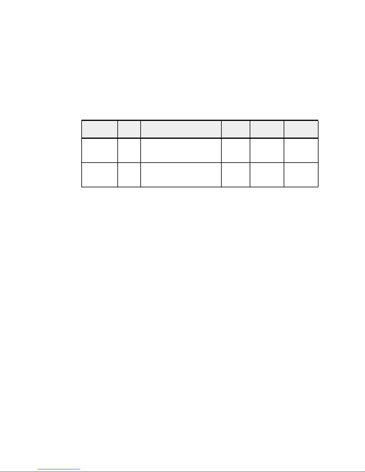
Support for smart card applications using Europay, MasterCard and Visa
Cryptographic key generation and random number generation
PIN processing - generation, verification, translation
Encrypt and Decrypt using AES and DES keys
See the following website for the latest firmware and software updates:
http://www.ibm.com/security/cryptocards/
Table 2-21 lists the cryptographic adapter that is available for the server.
Table 2-21 Available cryptographic adapters
Feature
code
4808 4765 PCIe Crypto Coprocessor with
4809 4765 PCIe Crypto Coprocessor with
CCIN Adapter description Slot Size OS
2.8 Internal Storage
Serial-attached SCSI (SAS) drives the Power 750 and Power 760 internal disk subsystem.
SAS provides enhancements over parallel SCSI with its point-to-point high frequency
connections. SAS physical links are a set of four wires used as two differential signal pairs.
One differential signal transmits in one direction. The other differential signal transmits in the
opposite direction. Data can be transmitted in both directions simultaneously.
The Power 750 and Power 760 have an extremely flexible and powerful backplane for
supporting hard disk drives (HDD) or solid-state drives (SSD). The six small form factor (SFF)
bays can be configured in three ways to match your business needs. Two integrated SAS
controllers can be optionally augmented with a 175 MB Cache RAID - Dual IOA Enablement
Card (Figure 2-13 on page 76). These two controllers provide redundancy and additional
flexibility. The optional 175 MB Cache RAID - Dual IOA Enablement Card enables dual
175 MB write cache and provides dual batteries for protection of that write cache.
support
PCIe Full height AIX, IBM i
GEN3 Blindswap Cassette
4765-001
PCIe Full height AIX, IBM i
GEN4 Blindswap Cassette
4765-001
There are two PCIe integrated SAS controllers under the POWER7 I/O chip and also the SAS
controller that is directly connected to the DVD media bay (Figure 2-13 on page 76).
Power 750 and Power 760 supports various internal storage configurations:
Dual split backplane mode: The backplane is configured as two sets of three bays (3/3).
Triple split backplane mode: The backplane is configured as three sets of two bays (2/2/2).
Dual storage IOA configuration using internal disk drives (Dual RAID of internal drives
only): The backplane is configured as one set of six bays.
Dual storage IOA configuration using internal disk drives and external enclosure (dual
RAID of internal drives and external drives).
Configuration options can vary depending on the controller options and the operating system
that is selected. The controllers for the dual split backplane configurations are always the two
embedded controllers. But if the triple split backplane configuration is used, the two integrated
SAS controllers run the first two sets of bays and require a SAS adapter (FC 5901) located in
74 IBM Power 750 and 760 Technical Overview and Introduction
Page 89

a PCIe slot in a system enclosure. This adapter controls the third set of bays. By having three
controllers, you can have three sets of boot drives supporting three partitions.
Rules: The following SSD or HDD configuration rules apply:
You can mix SSD and HDD drives when configured as one set of six bays.
If you want to have both SSDs and HDDs within a dual split configuration, you must use
the same type of drive within each set of three. You cannot mix SSDs and HDDs within
a subset of three bays.
If you want to have both SSDs and HDDs within a triple split configuration, you must
use the same type of drive within each set of two. You cannot mix SSDs and HDDs
within a subset of two bays. The FC 5901 PCIe SAS adapter that controls the remaining
two bays in a triple split configuration does not support SSDs.
You can configure the two embedded controllers together as a pair for higher redundancy or
you can configure them separately. If you configure them separately, they can be owned by
separate partitions or they can be treated independently within the same partition. If
configured as a pair, they provide controller redundancy and can automatically switch over to
the other controller if one has problems. Also, if configured as a pair, both can be active at the
same time (active/active) assuming that two or more arrays are configured, providing
additional performance capability and also redundancy. The pair controls all six small form
factor (SFF) bays and both see all six drives. The dual split (3/3) and triple split (2/2/2)
configurations are not used with the paired controllers. RAID 0 and RAID 10 are supported,
and you can also mirror two sets of controller or drives using the operating system.
Adding the optional 175 MB Cache RAID - Dual IOA Enablement Card (FC 5662) causes the
pair of embedded controllers to be configured as dual controllers, accessing all six SAS drive
bays. With this feature, you can get controller redundancy, additional RAID protection options,
and additional I/O performance. RAID 5 (a minimum of three drives is required) and RAID 6 (a
minimum of four drives is required) are available when configured as dual controllers with one
set of six bays. The Dual IOA Enablement Card (FC 5662) plugs in to the disk or media
backplane and enables a 175 MB write cache on each of the two embedded RAID adapters
by providing two rechargeable batteries with associated charger circuitry.
The write cache can provide additional I/O performance for attached disk or solid-state drives,
particularly for RAID 5 and RAID 6. The write-cache contents are mirrored for redundancy
between the two RAID adapters, resulting in an effective write cache size of 175 MB. The
batteries provide power to maintain both copies of write-cache information in the event that
power is lost.
Without the Dual IOA Enablement Card, each controller can access only two or three SAS
drive bays.
Another expansion option is a SAS expansion port (FC 1819). The SAS expansion port can
add more SAS bays to the six bays in the system unit. A DASD expansion drawer (FC 5887)
is attached using a SAS port on the rear of the processor drawer, and its two SAS bays are
run by the pair of embedded controllers. The pair of embedded controllers is now running 30
SAS bays (six SFF bays in the system unit and 24 SFF bays in the drawer). The disk drawer
is attached to the SAS port with a SAS YI cable, and the embedded controllers are connected
to the port using a FC 1819 cable assembly. In this 30-bay configuration, all drives must be
HDDs. An FC 5886 SAS disk drawer can similarly be configured in place of the FC 5887
drawer.
IBM i supports configurations that use one set of six bays but does not support logically
splitting the backplane into dual or triple split. Thus, the Dual IOA Enablement card (FC 5662)
Chapter 2. Architecture and technical overview 75
Page 90
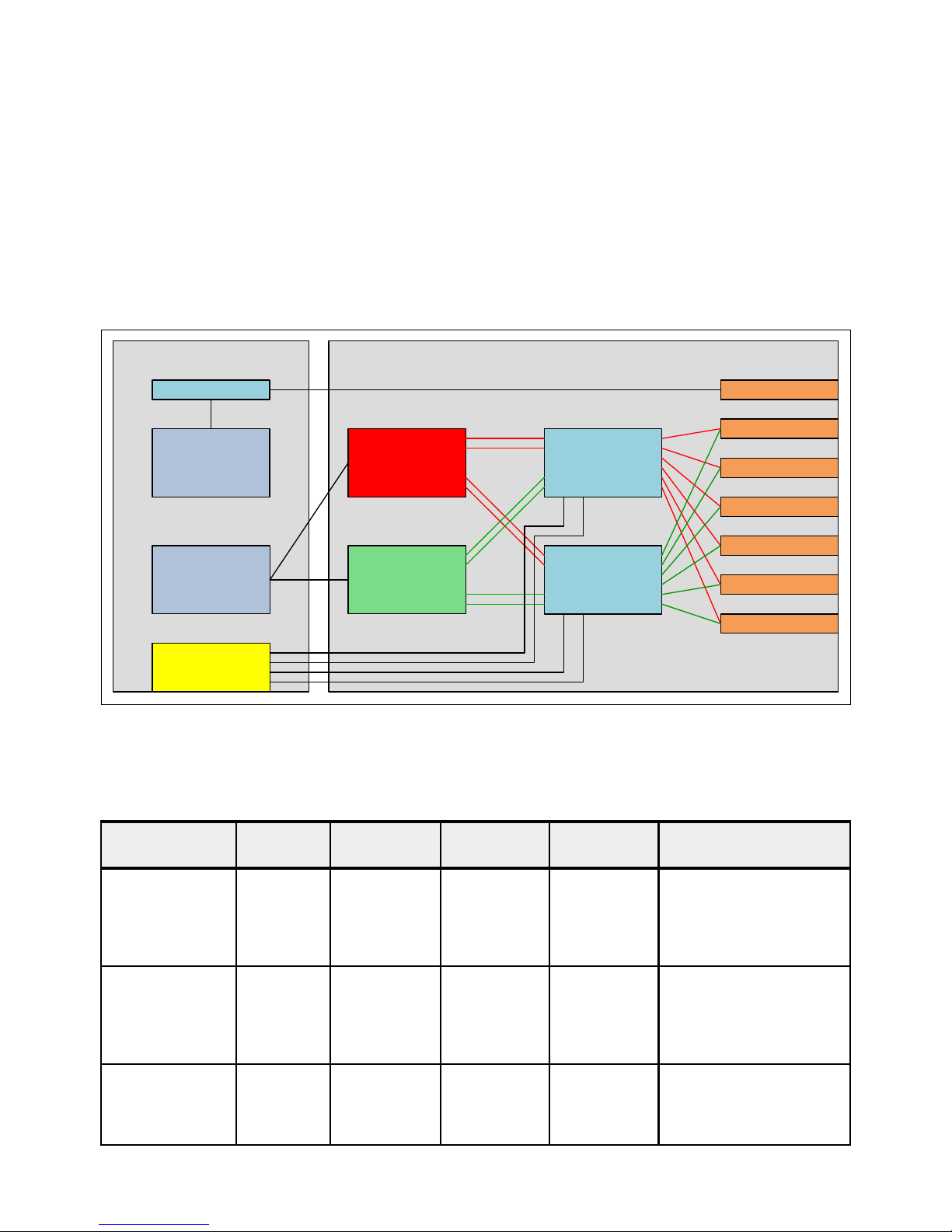
is required if IBM i is to access any of the SAS bays in that processor enclosure. AIX and
I/O Planar DASD Backplane
Hard Disk 2
Hard Disk 3
SAS Port
Expander
Hard Disk 4
Hard Disk 5
Hard Disk 6
SAS Port
Expander
OpticalOpticalInt. SAS Cnt.
Hard Disk 1
Integrated
SAS
Controller
Integrated
SAS
Controller
External SAS Port
P7IOC
P7IOC
Linux support configurations using two sets of three bays (3/3) or three sets of two bays
(2/2/2) without the dual IOA enablement card. With FC 5662, they support dual controllers
running one set of six bays.
The system backplane also includes a third embedded controller for running the DVD-RAM
drive in the system enclosure. Because the controller is independent from the two other SAS
disk or SSD controllers, it allows the DVD to be switched between multiple partitions without
affecting the assignment of disks or SSDs in the system enclosure.
Figure 2-13 shows the internal SAS topology overview.
Figure 2-13 Internal SAS topology overview
Table 2-22 summarizes the internal storage combination and the feature codes that are
required for any combination.
Table 2-22 SAS configurations summary
SAS subsystem
configuration
Two-way split
backplane
Three-way split
backplane
FC 5662
CCIN 2BC2
No None None N/A IBM i does not support this
No Dual x4 SAS
Dual storage IOA
with internal disk
Yes None None N/A Internal SAS port cable
76 IBM Power 750 and 760 Technical Overview and Introduction
External SAS
components
adapter
(FC 5901
CCIN 57B3)
SAS port
cables
Internal SAS
port (FC 1815)
SAS cable for
three-way split
backplane
SAS cables Notes
combination.
Connecting to an external
disk enclosure is not
supported.
AI cable
(FC 3679) Adapter to
internal drive
(1 meter)
IBM i does not support this
combination.
(FC 1815) cannot be used
with this or high availability
RAID configuration.
Page 91

SAS subsystem
I/O Planar DASD Backplane
Hard Disk 2
Hard Disk 3
SAS Port
Expander
Hard Disk 4
Hard Disk 5
Hard Disk 6
SAS Port
Expander
OpticalOpticalInt. SAS Cnt.
Hard Disk 1
Integrated
SAS
Controller
Integrated
SAS
Controller
External SAS Port
P7IOC
P7IOC
Hard Disk 1 Hard Disk 2 Hard Disk 3
Hard Disk 4 Hard Disk 5 Hard Disk 6
Front View
configuration
FC 5662
CCIN 2BC2
External SAS
components
SAS port
cables
SAS cables Notes
Dual storage IOA
with internal disk
and external disk
enclosure
Yes Requires an
external disk
drawer:
FC 5887 or
FC 5886
2.8.1 Dual split backplane mode
Dual split backplane mode offers two sets of three disks and is the standard configuration.
One set can be connected to an external SAS PCIe adapter if FC 1819 is selected.
Figure 2-14 shows how the six disk bays are shared with the dual split backplane mode.
Although solid-state drives (SSDs) are supported with a dual split backplane configuration,
mixing SSDs and hard disk drives HDDs in the same split domain is not supported. Also,
mirroring SSDs with HDDs is not possible.
Internal SAS
port (FC 1819)
SAS cable
assembly for
connecting to
an external
SAS drive
enclosure
FC 3686 or
FC 3687
1 meter cable is FC 3686.
3 meter cable is FC 3687.
Figure 2-14 Dual split backplane overview
2.8.2 Triple split backplane mode
an internal SAS Cable (FC 1815), a SAS cable (FC 3679), and a SAS controller, such as SAS
adapter FC 5901. Figure 2-15 on page 78 shows how the six disk bays are shared with the
The triple split backplane mode offers three sets of two disk drives each. This mode requires
Chapter 2. Architecture and technical overview 77
Page 92

triple split backplane mode. The PCI adapter that drives two of the six disks can be located in
I/O Planar DASD Backplane
Hard Disk 2
Hard Disk 3
SAS Port
Expander
Hard Disk 4
Hard Disk 5
Hard Disk 6
SAS Port
Expander
OpticalOpticalInt. SAS Cnt.
Hard Disk 1
Integrated
SAS
Controller
Integrated
SAS
Controller
External SAS Port
P7IOC
P7IOC
Hard Disk 1 Hard Disk 2 Hard Disk 3
Hard Disk 4 Hard Disk 5 Hard Disk 6
Front View
SAS Adapter
the same Power 750 or Power 760 system enclosure or in an external I/O drawer.
Figure 2-15 Triple split backplane overview
Although SSDs are supported with a triple split backplane configuration, mixing SSDs
and HDDs in the same split domain is not supported. Also, mirroring SSDs with HDDs is
not possible.
2.8.3 Dual storage I/O Adapter (IOA) configurations
The dual storage IOA (FC 1819) configurations are available with either internal or external
disk drives from another I/O drawer. SSDs are not supported with this mode.
If FC 1819 is selected, a SAS cable FC 3686 or FC 3687 to support RAID with internal and
external drives is necessary (Figure 2-16 on page 79). If this IOA is not selected for the
enclosure, the RAID supports only internal enclosure disks.
This configuration increases availability by using dual storage IOA or high availability (HA) to
connect multiple adapters to a common set of internal disk drives. It also increases the
performance of RAID arrays. The following rules apply to this configuration:
This configuration uses the 175 MB Cache RAID - Dual IOA Enablement Card (FC 5662).
Using the dual IOA enablement card, the two embedded adapters can connect to each
The disk drives are required to be in RAID arrays.
other and to all six disk drives, and also the 12 disk drives in an external disk drive
enclosure, if one is used.
78 IBM Power 750 and 760 Technical Overview and Introduction
There are no separate SAS cables required to connect the two embedded SAS RAID
adapters to each other. The connection is contained within the backplane.
Page 93
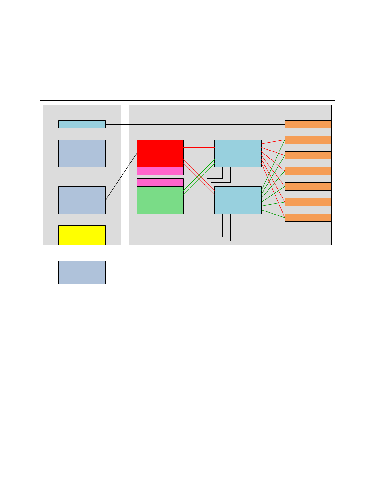
RAID 0, 10, 5, and 6 support up to six drives.
I/O Planar DASD Backplane
Hard Disk 2
Hard Disk 3
SAS Port
Expander
Hard Disk 4
Hard Disk 5
Hard Disk 6
SAS Port
Expander
OpticalOpticalInt. SAS Cnt.
Hard Disk 1
Integrated
SAS
Controller
Integrated
SAS
Controller
External SAS Port
P7IOC
P7IOC
External Disk
Drawer
Battery
Battery
SSDs and HDDs can be used, but can never be mixed in the same disk enclosure.
To connect to the external storage, you need to connect to the FC 5887 disk drive
enclosure.
Figure 2-16 shows the topology of the RAID mode.
Figure 2-16 RAID mode with external disk drawer option
2.8.4 DVD
The DVD media bay is directly connected to the integrated SAS controller on the I/O
backplane and has a specific chip (VSES) for controlling the DVD LED and power. The VSES
appears as a separate device to the device driver and operating systems (Figure 2-13 on
page 76).
Because the integrated SAS controller is independent from the two SAS disk or SSD
controllers, it allows the DVD to be switched between multiple partitions without affecting
the assignment of disks or SSDs in the system enclosure.
Chapter 2. Architecture and technical overview 79
Page 94
2.9 External I/O subsystems
The Power 750 and Power 760 server support the attachment of I/O drawers. Any
combination of the following two I/O drawers can be attached to the system unit, providing
extensive capability to expand the overall server.
12X I/O Drawer PCIe, small form factor (SFF) disk (FC 5802)
12X I/O Drawer PCIe, No Disk (FC 5877)
Two GX++ slots are enabled in a system unit if two or more processor DCMs are installed. An
optional GX++ 12X DDR Adapter, Dual-port (FC 1808) is available, which is installed in a
GX++ adapter slot and enables the attachment of a 12X loop, which runs at DDR speed.
Table 2-23 provides an overview of all the supported I/O drawers.
Table 2-23 I/O drawer capabilities
Feature
code
Disk drive bays PCI slots Requirements for
Power 750 and Power 760
5802 18 SAS hot-swap disk
drive bays
5877 None 10 PCIe GX++ adapter card
2.9.1 PCI-DDR 12X expansion drawer
The PCI-DDR 12X Expansion Drawer (FC 5796) is not supported with the Power 750 and
Power 760 server.
2.9.2 12X I/O Drawer PCIe
The 12X I/O Drawer PCIe, SFF disk (FC 5802) is a 19-inch I/O and storage drawer. It
provides a 4U (EIA units) drawer containing 10 PCIe-based I/O adapter slots and 18 SAS
hot-swap small form factor (SFF) disk bays, which can be used for either disk drives or SSD
drives. Using 900 GB disk drives, each I/O drawer provides up to 16.2 TB of storage. The
adapter slots within the I/O drawer use Gen3 blind swap cassettes and support hot-plugging
of adapter cards. The 12X I/O Drawer PCIe, No Disk (FC 5877) is the same as FC 5802
except that it does not support any disk bays.
A maximum of two 12X I/O Drawer PCIe, SFF disk drawers can be placed on the same 12X
loop. Within the same loop FC 5877 and FC 5802 can be mixed. An upgrade from a diskless
FC 5877 to FC 5802 with disk bays is not available.
10 PCIe GX++ adapter card
(FC 1808 CCIN 2BC3)
(FC 1808 CCIN 2BC3)
A minimum configuration of two 12X DDR cables, two AC power cables, and two SPCN
cables is required to ensure proper redundancy. The drawer attaches to the system unit with a
12X adapter in a GX++ slot through 12X DDR cables that are available in the following
various cable lengths:
0.6 meters 12X DDR Cable (FC 1861)
1.5 meters 12X DDR Cable (FC 1862)
3.0 meters 12X DDR Cable (FC 1865)
8.0 meters 12X DDR Cable (FC 1864)
Unsupported: The 12X SDR cables are not supported.
80 IBM Power 750 and 760 Technical Overview and Introduction
Page 95
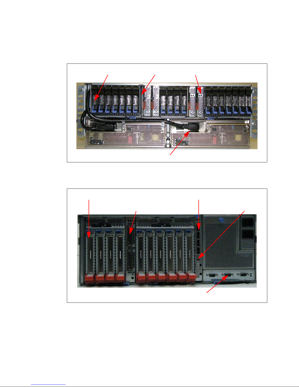
The physical dimensions of the drawer measure 444.5 mm (17.5 in.) wide by 177.8 mm
Disk drives Service card Port cards
Power cables
10 PCIe cards X2 SAS connectors
12X connectors Mode switch
SPCN connectors
(7.0 in.) high by 711.2 mm (28.0 in.) deep for use in a 19-inch rack.
Figure 2-17 shows the front view of the 12X I/O Drawer PCIe (FC 5802).
Figure 2-17 Front view of the 12X I/O Drawer PCIe
Figure 2-18 shows the rear view of the 12X I/O Drawer PCIe (FC 5802).
Figure 2-18 Rear view of the 12X I/O Drawer PCIe
Chapter 2. Architecture and technical overview 81
Page 96
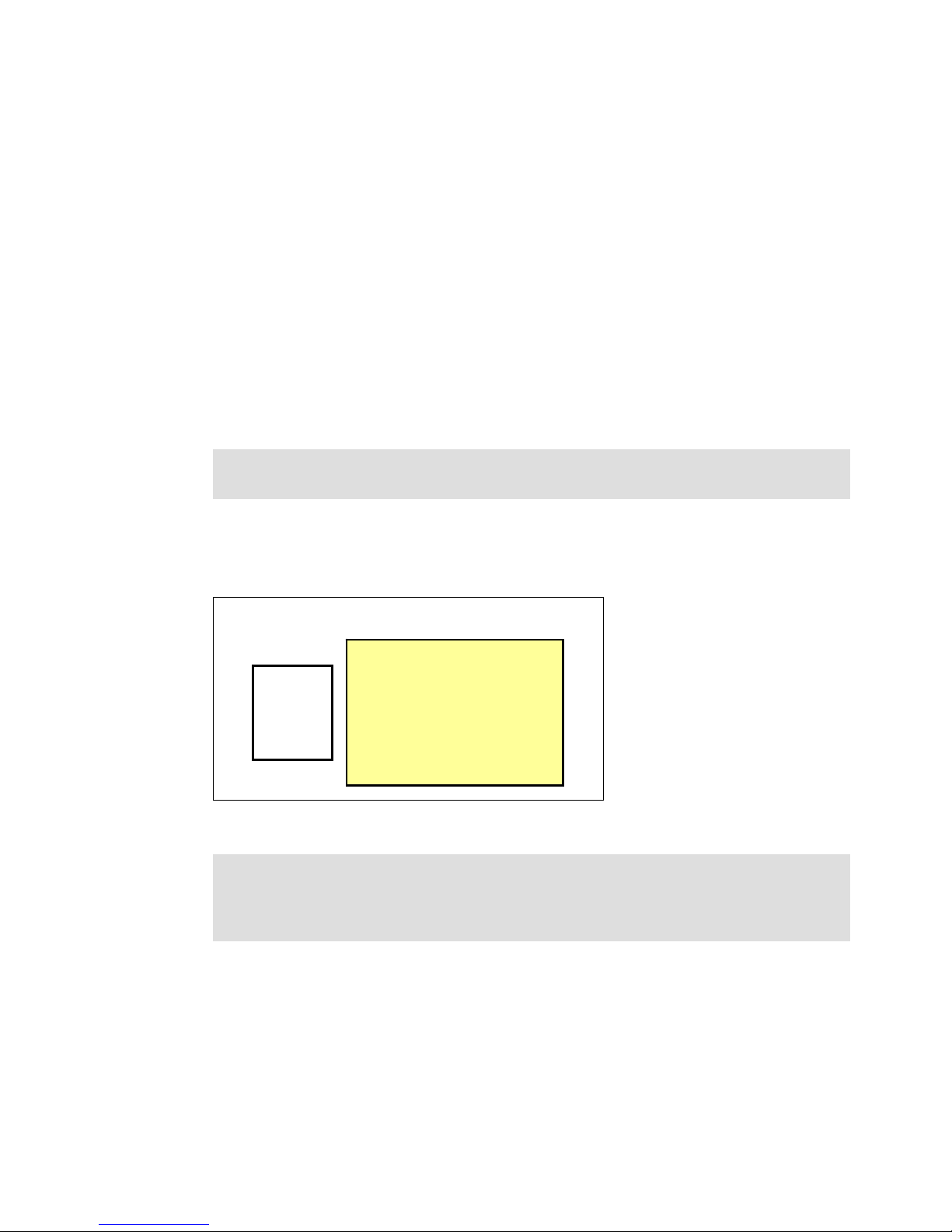
2.9.3 12X I/O Drawer PCIe configuration and cabling rules
MODE
SWITCH
1
2
4
FC 5802 12X I/O Drawer
AIX/Linux
One set: 18 bays
Two sets: 9 + 9 bays
Four sets: 5 + 4 + 5 + 4 bays
IBM i
Two sets: 9 + 9 bays
PCIe 12X I/O Drawer SFF Drive Bays
The following sections offer details about the disk drive configuration, 12X loop and SPCN
cabling rules.
Configuring the disk drive subsystem of the FC 5802 drawer
The 12X I/O Drawer PCIe, SFF disk (FC 5802) can hold up to 18 disk drives. The disks in this
enclosure can be organized in various configurations depending on the operating system
used, the type of SAS adapter card, and the position of the mode switch.
Each disk bay set can be attached to its own controller or adapter. The 12X I/O Drawer PCIe
has four SAS connections to drive bays. It connects to PCIe SAS adapters or controllers on
the host systems.
Disk drive bays in the 12X I/O drawer PCIe can be configured as one, two, or four sets. This
way allows for partitioning of disk bays. Disk bay partitioning configuration can be done with
the physical mode switch on the I/O drawer.
Remember: A mode change, using the physical mode switch, requires power cycling of
the I/O drawer.
Figure 2-19 indicates the mode switch in the rear view of the FC 5802 I/O drawer and shows
the configuration rules of disk bay partitioning in the PCIe 12X I/O drawer. There is no specific
feature code for mode switch setting.
Figure 2-19 Disk bay partitioning configuration in 12X I/O Drawer PCI (FC 5802)
Tools and CSP: The IBM System Planning Tool supports disk bay partitioning. Also, the
IBM configuration tool accepts this configuration from IBM System Planning Tool and
passes it through IBM manufacturing using the Customer Specified Placement (CSP)
option.
82 IBM Power 750 and 760 Technical Overview and Introduction
Page 97
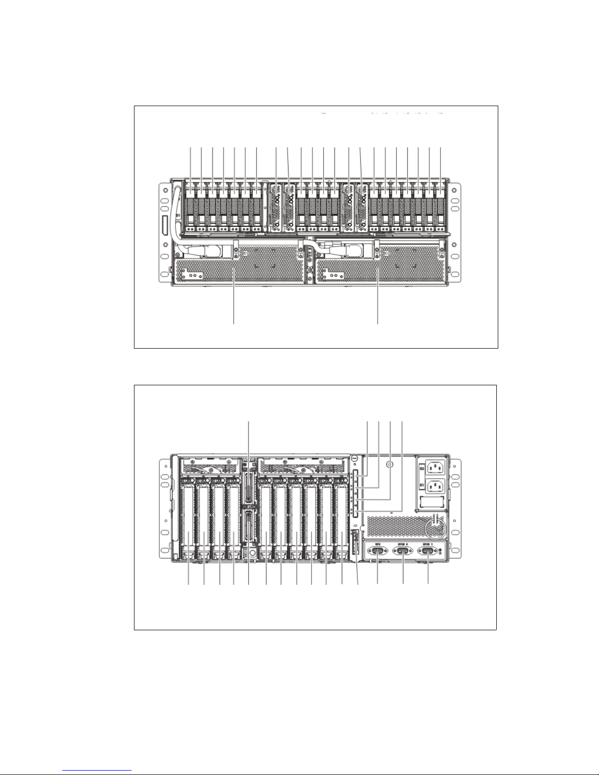
The location codes for the front and rear views of the FC 5802 I/O drawer are provided in
P3-D1
P3-D2
P3-D3
P3-D4
P3-D5
P3-D6
P3-D7
P3-C1
P3-C2
P3-D8
P3-D9
P3-D10
P3-D11
P3-C3
P3-C4
P3-D12
P3-D13
P3-D14
P3-D15
P3-D16
P3-D17
P3-D18
E1
E2
ARECW500-0
P1-C1
P1-C2
P1-C3
P1-C4
P1-T2
P1-C5
P1-C6
P1-C7
P1-C8
P1-C9
P1-C10
P4-T5
P2-T1
P2-T2
P2-T3
ARECW501-0
P4-T1
P4-T2
P4-T3
P4-T4
P1-T1
Figure 2-20 and Figure 2-21.
Figure 2-20 FC 5802 I/O drawer from view location codes
Figure 2-21 FC 5802 I/O drawer rear view location codes
Chapter 2. Architecture and technical overview 83
Page 98

Table 2-24 lists the SAS ports associated to the disk bays with the mode selector switch 4.
PCIe
750
760
750
760
PCIe
PCIe
PCIe
750
760
PCIe
PCIe
PCIe
One PCIe I/O Drawer
Two PCIe I/O Drawers
Three PCIe I/O Drawer
Four PCIe I/O Drawer
750
760
PCIe
PCIe
PCIe
Table 2-24 SAS connection mappings using mode switch 4
SAS connector location code Mappings Number of bays
P4-T1 P3-D1 to P3-D5 5 bays
P4-T2 P3-D6 to P3-D9 4 bays
P4-T3 P3-D10 to P3-D14 5 bays
P4-T4 P3-D15 to P3-D18 4 bays
For more detailed information about cabling and other switch modes, see the Power Systems
Enclosures and expansion units documentation:
http://pic.dhe.ibm.com/infocenter/powersys/v3r1m5/topic/ipham/ipham.pdf
General rule for the 12X I/O drawer configuration
To optimize performance and distribute workload, use as many multiple GX++ buses as
possible. Figure 2-22 shows several examples of a 12X I/O drawer configuration for the
Power 750 and Power 760 servers:
Figure 2-22 12X IO Drawer configuration
12X I/O Drawer PCIe loop
The I/O drawers are connected to the adapters in the Power 750 and Power 760 system
unit with data transfer cables such as the 12X DDR cables for the FC 5802 and FC 5877
I/O drawers.
The first 12X I/O drawer that is attached in any I/O drawer loop requires two data transfer
cables. Each additional drawer, up to the maximum allowed in the loop, requires one
additional data transfer cable. Consider the following information:
84 IBM Power 750 and 760 Technical Overview and Introduction
A 12X I/O loop starts at a system unit adapter port 0 and attaches to port 0 of an I/O
drawer.
The I/O drawer attaches from port 1 of the current unit to port 0 of the next I/O drawer.
Port 1 of the last I/O drawer on the 12X I/O loop connects to port 1 of the system unit
adapter to complete the loop.
Page 99
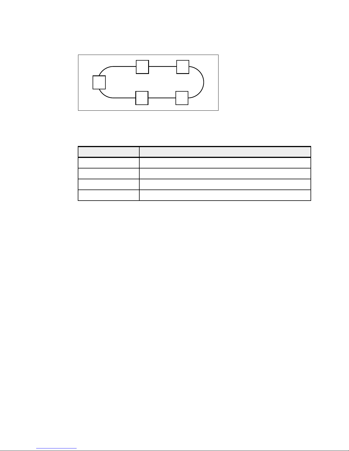
Figure 2-23 shows typical 12X I/O loop port connections.
I/O I/O
10
I/O
10
I/O
10
I/O
10
C
0
1
Figure 2-23 Typical 12X I/O loop port connections
Table 2-25 shows various 12X cables to satisfy the various length requirements.
Table 2-25 12X connection cables
Feature code Description
1861 0.6 meter 12X DDR cable
1862 1.5 meter 12X DDR cable
1865 3.0 meter 12X DDR cable
1864 8.0 meter 12X DDR cable
12X I/O Drawer PCIe SPCN cabling
System power control network (SPCN) is used to control and monitor the status of power and
cooling within the I/O drawer.
SPCN cables connect all AC powered expansion units. Figure 2-24 on page 86 shows an
example for a Power 750 or Power 760 connecting to four I/O drawers. Other connections
options are available.
1. Start at SPCN 0 (T4) of the system unit to J15 (T1) of the first expansion unit.
2. Cable all units from J16 (T2) of the previous unit to J15 (T1) of the next unit.
3. To complete the cabling loop, connect J16 (T2) from the final expansion unit, to the
SPCN 1 (T5) in the system unit.
4. Ensure that a complete loop exists from the system unit, through all attached expansions
and back to the system unit.
Chapter 2. Architecture and technical overview 85
Page 100

Figure 2-24 12X I/O Drawer PCIe SPCN cabling
SPCN Connections I/O Units
I/O
Expansion
Unit
I/O
Expansion
Unit
I/O
Expansion
Unit
I/O
Expansion
Unit
*J15(T1)
*J16(T2)
P1-C1-T4 (SPCN0)
750/760 system unit
P1-C1-T5 (SPCN1)
*J15(T1)
*J16(T2)
*J15(T1)
*J16(T2)
*J15(T1)
*J16(T2)
Various SPCN cables are available. Table 2-26 shows the available SPCN cables options to
satisfy various length requirements.
Table 2-26 SPCN cables
Feature code Description
a
6001
6006 Power Control Cable (SPCN) - 3 meter
a
6008
6007 Power Control Cable (SPCN) - 15 meter
a
6029
a. Supported, but no longer orderable
Power Control Cable (SPCN) - 2 meter
Power Control Cable (SPCN) - 6 meter
Power Control Cable (SPCN) - 30 meter
2.10 External disk subsystems
This section describes the following external disk subsystems that can be attached to the
Power 750 and Power 760:
EXP30 Ultra SSD I/O drawer (FC EDR1, CCIN 57C3)
EXP24S SFF Gen2-bay drawer for high-density storage (FC 5887)
EXP12S SAS expansion drawer (FC 5886)
IBM System Storage
2.10.1 EXP30 Ultra SSD I/O drawer
The EXP30 Ultra SSD I/O drawer (FC EDR1, CCIN 57C3) is a 1U high I/O drawer, providing
30 hot-swap SSD bays and a pair of integrated large write caches, high-performance SAS
controllers without using any PCIe slots on the POWER7+ server. The two high-performance,
86 IBM Power 750 and 760 Technical Overview and Introduction
 Loading...