

Page 1

Front cover
IBM Power 595
Technical Overview and Introduction
PowerVM virtualization technology
including Live Partition Mobility
World-class performance and
flexibility
Mainframe-inspired
continuous availability
ibm.com/redbooks
Charlie Cler
Carlo Costantini
Redpaper
Page 2

Page 3

International Technical Support Organization
IBM Power 595 Technical Overview and Introduction
August 2008
REDP-4440-00
Page 4

Note: Before using this information and the product it supports, read the information in “Notices” on
page vii.
First Edition (August 2008)
This edition applies to the IBM Power Systems 595 (9119-FHA), IBMs most powerful Power Systems offering.
© Copyright International Business Machines Corporation 2008. All rights reserved.
Note to U.S. Government Users Restricted Rights -- Use, duplication or disclosure restricted by GSA ADP Schedule
Contract with IBM Corp.
Page 5

Contents
Notices . . . . . . . . . . . . . . . . . . . . . . . . . . . . . . . . . . . . . . . . . . . . . . . . . . . . . . . . . . . . . . . . . vii
Trademarks . . . . . . . . . . . . . . . . . . . . . . . . . . . . . . . . . . . . . . . . . . . . . . . . . . . . . . . . . . . . . viii
Preface . . . . . . . . . . . . . . . . . . . . . . . . . . . . . . . . . . . . . . . . . . . . . . . . . . . . . . . . . . . . . . . . . ix
The team that wrote this paper . . . . . . . . . . . . . . . . . . . . . . . . . . . . . . . . . . . . . . . . . . . . . . . ix
Become a published author . . . . . . . . . . . . . . . . . . . . . . . . . . . . . . . . . . . . . . . . . . . . . . . . . . .x
Comments welcome. . . . . . . . . . . . . . . . . . . . . . . . . . . . . . . . . . . . . . . . . . . . . . . . . . . . . . . . .x
Chapter 1. General description . . . . . . . . . . . . . . . . . . . . . . . . . . . . . . . . . . . . . . . . . . . . . 1
1.1 Model overview and attributes . . . . . . . . . . . . . . . . . . . . . . . . . . . . . . . . . . . . . . . . . . . . 2
1.2 Installation planning . . . . . . . . . . . . . . . . . . . . . . . . . . . . . . . . . . . . . . . . . . . . . . . . . . . . 4
1.2.1 Physical specifications . . . . . . . . . . . . . . . . . . . . . . . . . . . . . . . . . . . . . . . . . . . . . . 4
1.2.2 Service clearances . . . . . . . . . . . . . . . . . . . . . . . . . . . . . . . . . . . . . . . . . . . . . . . . . 5
1.2.3 Operating environment . . . . . . . . . . . . . . . . . . . . . . . . . . . . . . . . . . . . . . . . . . . . . . 6
1.2.4 Power requirements . . . . . . . . . . . . . . . . . . . . . . . . . . . . . . . . . . . . . . . . . . . . . . . . 7
1.3 Minimum configuration requirements . . . . . . . . . . . . . . . . . . . . . . . . . . . . . . . . . . . . . . . 9
1.3.1 Minimum required processor card features. . . . . . . . . . . . . . . . . . . . . . . . . . . . . . 11
1.3.2 Memory features . . . . . . . . . . . . . . . . . . . . . . . . . . . . . . . . . . . . . . . . . . . . . . . . . . 12
1.3.3 System disks and media features . . . . . . . . . . . . . . . . . . . . . . . . . . . . . . . . . . . . . 12
1.3.4 I/O Drawers attachment (attaching using RIO-2 or 12x I/O loop adapters) . . . . . 15
1.3.5 IBM i, AIX, Linux for Power I/O considerations . . . . . . . . . . . . . . . . . . . . . . . . . . . 16
1.3.6 Hardware Management Console models . . . . . . . . . . . . . . . . . . . . . . . . . . . . . . . 17
1.3.7 Model conversion . . . . . . . . . . . . . . . . . . . . . . . . . . . . . . . . . . . . . . . . . . . . . . . . . 18
1.4 Racks power and cooling . . . . . . . . . . . . . . . . . . . . . . . . . . . . . . . . . . . . . . . . . . . . . . . 29
1.4.1 Door kit . . . . . . . . . . . . . . . . . . . . . . . . . . . . . . . . . . . . . . . . . . . . . . . . . . . . . . . . . 30
1.4.2 Rear door heat exchanger . . . . . . . . . . . . . . . . . . . . . . . . . . . . . . . . . . . . . . . . . . 31
1.4.3 Power subsystem . . . . . . . . . . . . . . . . . . . . . . . . . . . . . . . . . . . . . . . . . . . . . . . . . 31
1.5 Operating system support . . . . . . . . . . . . . . . . . . . . . . . . . . . . . . . . . . . . . . . . . . . . . . . 32
1.5.1 IBM AIX 5.3 . . . . . . . . . . . . . . . . . . . . . . . . . . . . . . . . . . . . . . . . . . . . . . . . . . . . . . 33
1.5.2 IBM AIX V6.1 . . . . . . . . . . . . . . . . . . . . . . . . . . . . . . . . . . . . . . . . . . . . . . . . . . . . 33
1.5.3 IBM i 5.4 (formerly IBM i5/OS V5R4) . . . . . . . . . . . . . . . . . . . . . . . . . . . . . . . . . . 34
1.5.4 IBM i 6.1 . . . . . . . . . . . . . . . . . . . . . . . . . . . . . . . . . . . . . . . . . . . . . . . . . . . . . . . . 35
1.5.5 Linux for Power Systems summary. . . . . . . . . . . . . . . . . . . . . . . . . . . . . . . . . . . . 35
Chapter 2. Architectural and technical overview . . . . . . . . . . . . . . . . . . . . . . . . . . . . . . 37
2.1 System design. . . . . . . . . . . . . . . . . . . . . . . . . . . . . . . . . . . . . . . . . . . . . . . . . . . . . . . . 38
2.1.1 Design highlights. . . . . . . . . . . . . . . . . . . . . . . . . . . . . . . . . . . . . . . . . . . . . . . . . . 38
2.1.2 Center electronic complex (CEC) . . . . . . . . . . . . . . . . . . . . . . . . . . . . . . . . . . . . . 40
2.1.3 CEC midplane . . . . . . . . . . . . . . . . . . . . . . . . . . . . . . . . . . . . . . . . . . . . . . . . . . . . 42
2.1.4 System control structure (SCS). . . . . . . . . . . . . . . . . . . . . . . . . . . . . . . . . . . . . . . 43
2.1.5 System controller (SC) card . . . . . . . . . . . . . . . . . . . . . . . . . . . . . . . . . . . . . . . . . 47
2.1.6 System VPD cards . . . . . . . . . . . . . . . . . . . . . . . . . . . . . . . . . . . . . . . . . . . . . . . . 48
2.1.7 Oscillator card . . . . . . . . . . . . . . . . . . . . . . . . . . . . . . . . . . . . . . . . . . . . . . . . . . . . 49
2.1.8 Node controller card . . . . . . . . . . . . . . . . . . . . . . . . . . . . . . . . . . . . . . . . . . . . . . . 49
2.1.9 DC converter assembly (DCA) . . . . . . . . . . . . . . . . . . . . . . . . . . . . . . . . . . . . . . . 50
2.2 System buses . . . . . . . . . . . . . . . . . . . . . . . . . . . . . . . . . . . . . . . . . . . . . . . . . . . . . . . . 51
2.2.1 System interconnects . . . . . . . . . . . . . . . . . . . . . . . . . . . . . . . . . . . . . . . . . . . . . . 51
2.2.2 I/O subsystem . . . . . . . . . . . . . . . . . . . . . . . . . . . . . . . . . . . . . . . . . . . . . . . . . . . . 55
2.3 Bulk power assembly . . . . . . . . . . . . . . . . . . . . . . . . . . . . . . . . . . . . . . . . . . . . . . . . . . 57
© Copyright IBM Corp. 2008. All rights reserved. iii
Page 6

2.3.1 Bulk power hub (BPH) . . . . . . . . . . . . . . . . . . . . . . . . . . . . . . . . . . . . . . . . . . . . . 58
2.3.2 Bulk power controller (BPC) . . . . . . . . . . . . . . . . . . . . . . . . . . . . . . . . . . . . . . . . . 60
2.3.3 Bulk power distribution (BPD) . . . . . . . . . . . . . . . . . . . . . . . . . . . . . . . . . . . . . . . . 60
2.3.4 Bulk power regulators (BPR). . . . . . . . . . . . . . . . . . . . . . . . . . . . . . . . . . . . . . . . . 61
2.3.5 Bulk power fan (BPF) . . . . . . . . . . . . . . . . . . . . . . . . . . . . . . . . . . . . . . . . . . . . . . 62
2.3.6 Integrated battery feature (IBF). . . . . . . . . . . . . . . . . . . . . . . . . . . . . . . . . . . . . . . 63
2.3.7 POWER6 EnergyScale . . . . . . . . . . . . . . . . . . . . . . . . . . . . . . . . . . . . . . . . . . . . . 63
2.4 System cooling . . . . . . . . . . . . . . . . . . . . . . . . . . . . . . . . . . . . . . . . . . . . . . . . . . . . . . . 69
2.5 Light strips . . . . . . . . . . . . . . . . . . . . . . . . . . . . . . . . . . . . . . . . . . . . . . . . . . . . . . . . . . . 69
2.6 Processor books . . . . . . . . . . . . . . . . . . . . . . . . . . . . . . . . . . . . . . . . . . . . . . . . . . . . . . 70
2.6.1 POWER6 processor . . . . . . . . . . . . . . . . . . . . . . . . . . . . . . . . . . . . . . . . . . . . . . . 73
2.6.2 Decimal floating point . . . . . . . . . . . . . . . . . . . . . . . . . . . . . . . . . . . . . . . . . . . . . . 76
2.6.3 AltiVec and Single Instruction, Multiple Data . . . . . . . . . . . . . . . . . . . . . . . . . . . . 77
2.7 Memory subsystem . . . . . . . . . . . . . . . . . . . . . . . . . . . . . . . . . . . . . . . . . . . . . . . . . . . . 78
2.7.1 Memory bandwidth . . . . . . . . . . . . . . . . . . . . . . . . . . . . . . . . . . . . . . . . . . . . . . . . 79
2.7.2 Available memory features . . . . . . . . . . . . . . . . . . . . . . . . . . . . . . . . . . . . . . . . . . 80
2.7.3 Memory configuration and placement . . . . . . . . . . . . . . . . . . . . . . . . . . . . . . . . . . 81
2.8 Internal I/O subsystem . . . . . . . . . . . . . . . . . . . . . . . . . . . . . . . . . . . . . . . . . . . . . . . . . 82
2.8.1 Connection technology . . . . . . . . . . . . . . . . . . . . . . . . . . . . . . . . . . . . . . . . . . . . . 83
2.8.2 Internal I/O drawers . . . . . . . . . . . . . . . . . . . . . . . . . . . . . . . . . . . . . . . . . . . . . . . 84
2.8.3 Internal I/O drawer attachment . . . . . . . . . . . . . . . . . . . . . . . . . . . . . . . . . . . . . . . 88
2.8.4 Single loop (full-drawer) cabling . . . . . . . . . . . . . . . . . . . . . . . . . . . . . . . . . . . . . . 89
2.8.5 Dual looped (half-drawer) cabling . . . . . . . . . . . . . . . . . . . . . . . . . . . . . . . . . . . . . 90
2.8.6 I/O drawer to I/O hub cabling sequence . . . . . . . . . . . . . . . . . . . . . . . . . . . . . . . . 90
2.9 PCI adapter support . . . . . . . . . . . . . . . . . . . . . . . . . . . . . . . . . . . . . . . . . . . . . . . . . . . 92
2.9.1 LAN adapters . . . . . . . . . . . . . . . . . . . . . . . . . . . . . . . . . . . . . . . . . . . . . . . . . . . . 93
2.9.2 SCSI adapters. . . . . . . . . . . . . . . . . . . . . . . . . . . . . . . . . . . . . . . . . . . . . . . . . . . . 93
2.9.3 iSCSI . . . . . . . . . . . . . . . . . . . . . . . . . . . . . . . . . . . . . . . . . . . . . . . . . . . . . . . . . . . 94
2.9.4 SAS adapters . . . . . . . . . . . . . . . . . . . . . . . . . . . . . . . . . . . . . . . . . . . . . . . . . . . . 94
2.9.5 Fibre Channel adapters . . . . . . . . . . . . . . . . . . . . . . . . . . . . . . . . . . . . . . . . . . . . 95
2.9.6 Asynchronous, WAN, and modem adapters . . . . . . . . . . . . . . . . . . . . . . . . . . . . . 95
2.9.7 PCI-X Cryptographic Coprocessor . . . . . . . . . . . . . . . . . . . . . . . . . . . . . . . . . . . . 96
2.9.8 IOP adapter. . . . . . . . . . . . . . . . . . . . . . . . . . . . . . . . . . . . . . . . . . . . . . . . . . . . . . 97
2.9.9 RIO-2 PCI adapter . . . . . . . . . . . . . . . . . . . . . . . . . . . . . . . . . . . . . . . . . . . . . . . . 97
2.9.10 USB and graphics adapters . . . . . . . . . . . . . . . . . . . . . . . . . . . . . . . . . . . . . . . . 97
2.10 Internal storage . . . . . . . . . . . . . . . . . . . . . . . . . . . . . . . . . . . . . . . . . . . . . . . . . . . . . . 97
2.11 Media drawers. . . . . . . . . . . . . . . . . . . . . . . . . . . . . . . . . . . . . . . . . . . . . . . . . . . . . . . 98
2.11.1 Media drawer, 19-inch (7214-1U2) . . . . . . . . . . . . . . . . . . . . . . . . . . . . . . . . . . . 99
2.11.2 DVD/Tape SAS External Storage Unit (#5720). . . . . . . . . . . . . . . . . . . . . . . . . . 99
2.12 External I/O enclosures . . . . . . . . . . . . . . . . . . . . . . . . . . . . . . . . . . . . . . . . . . . . . . . 100
2.12.1 TotalStorage EXP24 Disk Dwr (#5786). . . . . . . . . . . . . . . . . . . . . . . . . . . . . . . 100
2.12.2 PCI Expansion Drawer (#5790) . . . . . . . . . . . . . . . . . . . . . . . . . . . . . . . . . . . . 100
2.12.3 EXP 12S Expansion Drawer (#5886) . . . . . . . . . . . . . . . . . . . . . . . . . . . . . . . . 100
2.13 Hardware Management Console (HMC) . . . . . . . . . . . . . . . . . . . . . . . . . . . . . . . . . . 101
2.13.1 Determining the HMC serial number. . . . . . . . . . . . . . . . . . . . . . . . . . . . . . . . . 102
2.14 Advanced System Management Interface . . . . . . . . . . . . . . . . . . . . . . . . . . . . . . . . 103
2.14.1 Accessing the ASMI using a Web browser . . . . . . . . . . . . . . . . . . . . . . . . . . . . 103
2.14.2 Accessing the ASMI using an ASCII console . . . . . . . . . . . . . . . . . . . . . . . . . . 104
2.14.3 Accessing the ASMI using an HMC . . . . . . . . . . . . . . . . . . . . . . . . . . . . . . . . . 104
2.14.4 Server firmware. . . . . . . . . . . . . . . . . . . . . . . . . . . . . . . . . . . . . . . . . . . . . . . . . 105
Chapter 3. Virtualization . . . . . . . . . . . . . . . . . . . . . . . . . . . . . . . . . . . . . . . . . . . . . . . . . 109
3.1 Virtualization feature support . . . . . . . . . . . . . . . . . . . . . . . . . . . . . . . . . . . . . . . . . . . 109
iv IBM Power 595 Technical Overview and Introduction
Page 7

3.2 PowerVM and PowerVM editions . . . . . . . . . . . . . . . . . . . . . . . . . . . . . . . . . . . . . . . . 110
3.3 Capacity on Demand. . . . . . . . . . . . . . . . . . . . . . . . . . . . . . . . . . . . . . . . . . . . . . . . . . 111
3.3.1 Permanent activation . . . . . . . . . . . . . . . . . . . . . . . . . . . . . . . . . . . . . . . . . . . . . 112
3.3.2 On/Off CoD . . . . . . . . . . . . . . . . . . . . . . . . . . . . . . . . . . . . . . . . . . . . . . . . . . . . . 113
3.3.3 Utility CoD . . . . . . . . . . . . . . . . . . . . . . . . . . . . . . . . . . . . . . . . . . . . . . . . . . . . . . 114
3.3.4 Trial CoD . . . . . . . . . . . . . . . . . . . . . . . . . . . . . . . . . . . . . . . . . . . . . . . . . . . . . . . 114
3.3.5 Capacity Backup . . . . . . . . . . . . . . . . . . . . . . . . . . . . . . . . . . . . . . . . . . . . . . . . . 114
3.4 POWER Hypervisor . . . . . . . . . . . . . . . . . . . . . . . . . . . . . . . . . . . . . . . . . . . . . . . . . . 115
3.5 Logical partitioning . . . . . . . . . . . . . . . . . . . . . . . . . . . . . . . . . . . . . . . . . . . . . . . . . . . 116
3.5.1 Dynamic logical partitions . . . . . . . . . . . . . . . . . . . . . . . . . . . . . . . . . . . . . . . . . . 117
3.5.2 Shared processor pool partitions . . . . . . . . . . . . . . . . . . . . . . . . . . . . . . . . . . . . 117
3.5.3 Shared dedicated capacity . . . . . . . . . . . . . . . . . . . . . . . . . . . . . . . . . . . . . . . . . 118
3.5.4 Multiple shared processor pools . . . . . . . . . . . . . . . . . . . . . . . . . . . . . . . . . . . . . 118
3.6 Virtual Ethernet . . . . . . . . . . . . . . . . . . . . . . . . . . . . . . . . . . . . . . . . . . . . . . . . . . . . . . 119
3.7 Virtual I/O Server. . . . . . . . . . . . . . . . . . . . . . . . . . . . . . . . . . . . . . . . . . . . . . . . . . . . . 120
3.7.1 Virtual SCSI . . . . . . . . . . . . . . . . . . . . . . . . . . . . . . . . . . . . . . . . . . . . . . . . . . . . 121
3.7.2 Shared Ethernet Adapter . . . . . . . . . . . . . . . . . . . . . . . . . . . . . . . . . . . . . . . . . . 122
3.8 PowerVM Lx86 . . . . . . . . . . . . . . . . . . . . . . . . . . . . . . . . . . . . . . . . . . . . . . . . . . . . . . 124
3.9 PowerVM Live Partition Mobility . . . . . . . . . . . . . . . . . . . . . . . . . . . . . . . . . . . . . . . . . 125
3.10 AIX 6 workload partitions . . . . . . . . . . . . . . . . . . . . . . . . . . . . . . . . . . . . . . . . . . . . . 127
3.11 System Planning Tool . . . . . . . . . . . . . . . . . . . . . . . . . . . . . . . . . . . . . . . . . . . . . . . . 128
Chapter 4. Continuous availability and manageability . . . . . . . . . . . . . . . . . . . . . . . . 131
4.1 Reliability. . . . . . . . . . . . . . . . . . . . . . . . . . . . . . . . . . . . . . . . . . . . . . . . . . . . . . . . . . . 132
4.1.1 Designed for reliability. . . . . . . . . . . . . . . . . . . . . . . . . . . . . . . . . . . . . . . . . . . . . 132
4.1.2 Placement of components . . . . . . . . . . . . . . . . . . . . . . . . . . . . . . . . . . . . . . . . . 133
4.1.3 Continuous field monitoring . . . . . . . . . . . . . . . . . . . . . . . . . . . . . . . . . . . . . . . . 133
4.2 Availability . . . . . . . . . . . . . . . . . . . . . . . . . . . . . . . . . . . . . . . . . . . . . . . . . . . . . . . . . . 134
4.2.1 Detecting and deallocating failing components. . . . . . . . . . . . . . . . . . . . . . . . . . 134
4.2.2 Special uncorrectable error handling . . . . . . . . . . . . . . . . . . . . . . . . . . . . . . . . . 141
4.2.3 Cache protection mechanisms . . . . . . . . . . . . . . . . . . . . . . . . . . . . . . . . . . . . . . 142
4.2.4 The input output subsystem . . . . . . . . . . . . . . . . . . . . . . . . . . . . . . . . . . . . . . . . 143
4.2.5 Redundant components and concurrent repair update. . . . . . . . . . . . . . . . . . . . 145
4.2.6 Availability in a partitioned environment . . . . . . . . . . . . . . . . . . . . . . . . . . . . . . . 148
4.2.7 Operating system availability . . . . . . . . . . . . . . . . . . . . . . . . . . . . . . . . . . . . . . . 149
4.3 Serviceability . . . . . . . . . . . . . . . . . . . . . . . . . . . . . . . . . . . . . . . . . . . . . . . . . . . . . . . . 150
4.3.1 Service environments . . . . . . . . . . . . . . . . . . . . . . . . . . . . . . . . . . . . . . . . . . . . . 151
4.3.2 Service processor . . . . . . . . . . . . . . . . . . . . . . . . . . . . . . . . . . . . . . . . . . . . . . . . 151
4.3.3 Detecting errors . . . . . . . . . . . . . . . . . . . . . . . . . . . . . . . . . . . . . . . . . . . . . . . . . 152
4.3.4 Diagnosing problems . . . . . . . . . . . . . . . . . . . . . . . . . . . . . . . . . . . . . . . . . . . . . 154
4.3.5 Reporting problems . . . . . . . . . . . . . . . . . . . . . . . . . . . . . . . . . . . . . . . . . . . . . . . 155
4.3.6 Notifying the appropriate contacts . . . . . . . . . . . . . . . . . . . . . . . . . . . . . . . . . . . 157
4.3.7 Locating and repairing the problem . . . . . . . . . . . . . . . . . . . . . . . . . . . . . . . . . . 158
4.4 Operating system support for RAS features . . . . . . . . . . . . . . . . . . . . . . . . . . . . . . . . 160
4.5 Manageability . . . . . . . . . . . . . . . . . . . . . . . . . . . . . . . . . . . . . . . . . . . . . . . . . . . . . . . 162
4.5.1 Service processor . . . . . . . . . . . . . . . . . . . . . . . . . . . . . . . . . . . . . . . . . . . . . . . . 162
4.5.2 System diagnostics . . . . . . . . . . . . . . . . . . . . . . . . . . . . . . . . . . . . . . . . . . . . . . . 163
4.5.3 Electronic Service Agent . . . . . . . . . . . . . . . . . . . . . . . . . . . . . . . . . . . . . . . . . . . 163
4.5.4 Manage serviceable events with the HMC . . . . . . . . . . . . . . . . . . . . . . . . . . . . . 165
4.5.5 Hardware user interfaces . . . . . . . . . . . . . . . . . . . . . . . . . . . . . . . . . . . . . . . . . . 165
4.5.6 IBM System p firmware maintenance . . . . . . . . . . . . . . . . . . . . . . . . . . . . . . . . . 166
4.5.7 Management Edition for AIX . . . . . . . . . . . . . . . . . . . . . . . . . . . . . . . . . . . . . . . . 168
4.5.8 IBM Director . . . . . . . . . . . . . . . . . . . . . . . . . . . . . . . . . . . . . . . . . . . . . . . . . . . . 168
Contents v
Page 8

4.6 Cluster solution . . . . . . . . . . . . . . . . . . . . . . . . . . . . . . . . . . . . . . . . . . . . . . . . . . . . . . 169
Related publications . . . . . . . . . . . . . . . . . . . . . . . . . . . . . . . . . . . . . . . . . . . . . . . . . . . . 171
IBM Redbooks . . . . . . . . . . . . . . . . . . . . . . . . . . . . . . . . . . . . . . . . . . . . . . . . . . . . . . . . . . 171
Other publications . . . . . . . . . . . . . . . . . . . . . . . . . . . . . . . . . . . . . . . . . . . . . . . . . . . . . . . 171
Online resources . . . . . . . . . . . . . . . . . . . . . . . . . . . . . . . . . . . . . . . . . . . . . . . . . . . . . . . . 172
How to get Redbooks . . . . . . . . . . . . . . . . . . . . . . . . . . . . . . . . . . . . . . . . . . . . . . . . . . . . . 173
Help from IBM . . . . . . . . . . . . . . . . . . . . . . . . . . . . . . . . . . . . . . . . . . . . . . . . . . . . . . . . . . 173
vi IBM Power 595 Technical Overview and Introduction
Page 9

Notices
This information was developed for products and services offered in the U.S.A.
IBM may not offer the products, services, or features discussed in this document in other countries. Consult
your local IBM representative for information on the products and services currently available in your area. Any
reference to an IBM product, program, or service is not intended to state or imply that only that IBM product,
program, or service may be used. Any functionally equivalent product, program, or service that does not
infringe any IBM intellectual property right may be used instead. However, it is the user's responsibility to
evaluate and verify the operation of any non-IBM product, program, or service.
IBM may have patents or pending patent applications covering subject matter described in this document. The
furnishing of this document does not give you any license to these patents. You can send license inquiries, in
writing, to:
IBM Director of Licensing, IBM Corporation, North Castle Drive, Armonk, NY 10504-1785 U.S.A.
The following paragraph does not apply to the United Kingdom or any other country where such
provisions are inconsistent with local law: INTERNATIONAL BUSINESS MACHINES CORPORATION
PROVIDES THIS PUBLICATION "AS IS" WITHOUT WARRANTY OF ANY KIND, EITHER EXPRESS OR
IMPLIED, INCLUDING, BUT NOT LIMITED TO, THE IMPLIED WARRANTIES OF NON-INFRINGEMENT,
MERCHANTABILITY OR FITNESS FOR A PARTICULAR PURPOSE. Some states do not allow disclaimer of
express or implied warranties in certain transactions, therefore, this statement may not apply to you.
This information could include technical inaccuracies or typographical errors. Changes are periodically made
to the information herein; these changes will be incorporated in new editions of the publication. IBM may make
improvements and/or changes in the product(s) and/or the program(s) described in this publication at any time
without notice.
Any references in this information to non-IBM Web sites are provided for convenience only and do not in any
manner serve as an endorsement of those Web sites. The materials at those Web sites are not part of the
materials for this IBM product and use of those Web sites is at your own risk.
IBM may use or distribute any of the information you supply in any way it believes appropriate without incurring
any obligation to you.
Information concerning non-IBM products was obtained from the suppliers of those products, their published
announcements or other publicly available sources. IBM has not tested those products and cannot confirm the
accuracy of performance, compatibility or any other claims related to non-IBM products. Questions on the
capabilities of non-IBM products should be addressed to the suppliers of those products.
This information contains examples of data and reports used in daily business operations. To illustrate them
as completely as possible, the examples include the names of individuals, companies, brands, and products.
All of these names are fictitious and any similarity to the names and addresses used by an actual business
enterprise is entirely coincidental.
COPYRIGHT LICENSE:
This information contains sample application programs in source language, which illustrate programming
techniques on various operating platforms. You may copy, modify, and distribute these sample programs in
any form without payment to IBM, for the purposes of developing, using, marketing or distributing application
programs conforming to the application programming interface for the operating platform for which the sample
programs are written. These examples have not been thoroughly tested under all conditions. IBM, therefore,
cannot guarantee or imply reliability, serviceability, or function of these programs.
© Copyright IBM Corp. 2008. All rights reserved. vii
Page 10

Trademarks
IBM, the IBM logo, and ibm.com are trademarks or registered trademarks of International Business Machines
Corporation in the United States, other countries, or both. These and other IBM trademarked terms are
marked on their first occurrence in this information with the appropriate symbol (® or ™), indicating US
registered or common law trademarks owned by IBM at the time this information was published. Such
trademarks may also be registered or common law trademarks in other countries. A current list of IBM
trademarks is available on the Web at http://www.ibm.com/legal/copytrade.shtml
The following terms are trademarks of the International Business Machines Corporation in the United States,
other countries, or both:
1350™
AIX 5L™
AIX®
BladeCenter®
Chipkill™
DB2®
DS8000™
Electronic Service Agent™
EnergyScale™
eServer™
HACMP™
i5/OS®
IBM®
iSeries®
Micro-Partitioning™
OpenPower®
OS/400®
POWER™
Power Architecture®
POWER Hypervisor™
POWER4™
POWER5™
POWER5+™
POWER6™
PowerHA™
PowerPC®
PowerVM™
Predictive Failure Analysis®
pSeries®
Rational®
Redbooks®
Redbooks (logo) ®
RS/6000®
System i™
System i5™
System p™
System p5™
System Storage™
System x™
System z™
Tivoli®
TotalStorage®
WebSphere®
Workload Partitions Manager™
z/OS®
The following terms are trademarks of other companies:
AMD, the AMD Arrow logo, and combinations thereof, are trademarks of Advanced Micro Devices, Inc.
Novell, SUSE, the Novell logo, and the N logo are registered trademarks of Novell, Inc. in the United States
and other countries.
ABAP, SAP NetWeaver, SAP, and SAP logos are trademarks or registered trademarks of SAP AG in Germany
and in several other countries.
Java, JVM, Power Management, Ultra, and all Java-based trademarks are trademarks of Sun Microsystems,
Inc. in the United States, other countries, or both.
Internet Explorer, Microsoft, and the Windows logo are trademarks of Microsoft Corporation in the United
States, other countries, or both.
Intel, Intel logo, Intel Inside logo, and Intel Centrino logo are trademarks or registered trademarks of Intel
Corporation or its subsidiaries in the United States, other countries, or both.
UNIX is a registered trademark of The Open Group in the United States and other countries.
Linux is a trademark of Linus Torvalds in the United States, other countries, or both.
Other company, product, or service names may be trademarks or service marks of others.
viii IBM Power 595 Technical Overview and Introduction
Page 11

Preface
This IBM® Redpaper is a comprehensive guide describing the IBM Power 595 (9119-FHA)
enterprise-class IBM Power Systems server. The goal of this paper is to introduce several
technical aspects of this innovative server. The major hardware offerings and prominent
functions include:
The POWER6™ processor available at frequencies of 4.2 and 5.0 GHz
Specialized POWER6 DDR2 memory that provides improved bandwidth, capacity, and
Support for AIX®, IBM i, and Linux® for Power operating systems.
EnergyScale™ technology that provides features such as power trending, power-saving,
PowerVM™ virtualization
Mainframe levels of continuous availability.
This Redpaper is intended for professionals who want to acquire a better understanding of
Power Systems products, including:
Clients
Sales and marketing professionals
Technical support professionals
reliability
thermal measurement, and processor napping.
IBM Business Partners
Independent software vendors
This Redpaper expands the current set of IBM Power Systems documentation by providing a
desktop reference that offers a detailed technical description of the 595 system.
This Redpaper does not replace the latest marketing materials, tools, and other IBM
publications available, for example, at the IBM Systems Hardware Information Center
http://publib.boulder.ibm.com/infocenter/systems/scope/hw/index.jsp. It is intended as
an additional source of information that, together with existing sources, can be used to
enhance your knowledge of IBM server solutions.
The team that wrote this paper
This paper was produced by a team of specialists from around the world working at the
International Technical Support Organization, Austin Center.
Charlie Cler is an Executive IT Specialist for IBM in the United States. He has worked with
IBM Power Systems and related server technology for over 18 years. Charlie’s primary areas
of expertise include Power Systems processor virtualization and server consolidation. He
holds a masters degree in Mechanical Engineering from Purdue University with specialization
in robotics and computer graphics.
Carlo Costantini is a Certified IT Specialist for IBM and has over 30 years of experience with
IBM and IBM Business Partners. He currently works in Italy Power Systems Platforms as
Presales Field Technical Sales Support for IBM Sales Representatives and IBM Business
© Copyright IBM Corp. 2008. All rights reserved. ix
Page 12

Partners. Carlo has broad marketing experience and his current major areas of focus are
competition, sales, and technical sales support. He is a certified specialist for Power Systems
servers. He holds a masters degree in Electronic Engineering from Rome University.
The project manager that organized the production of this material was:
Scott Vetter, (PMP) is a Certified Executive Project Manager at the International Technical
Support Organization, Austin Center. He has enjoyed 23 years of rich and diverse experience
working for IBM in a variety of challenging roles. His latest efforts are directed at providing
world-class Power Systems Redbooks®, whitepapers, and workshop collateral.
Thanks to the following people for their contributions to this project:
Terry Brennan, Tim Damron, George Gaylord, Dan Henderson, Tenley Jackson,
Warren McCracken, Patrick O’Rourke, Paul Robertson, Todd Rosedahl, Scott Smylie,
Randy Swanberg, Doug Szerdi, Dave Williams
IBM Austin
Mark Applegate
Avnet
Become a published author
Join us for a two- to six-week residency program! Help write a book dealing with specific
products or solutions, while getting hands-on experience with leading-edge technologies. You
will have the opportunity to team with IBM technical professionals, Business Partners, and
Clients.
Your efforts will help increase product acceptance and client satisfaction. As a bonus, you will
develop a network of contacts in IBM development labs, and increase your productivity and
marketability.
Find out more about the residency program, browse the residency index, and apply online at:
ibm.com/redbooks/residencies.html
Comments welcome
Your comments are important to us!
We want our papers to be as helpful as possible. Send us your comments about this paper or
other IBM Redbooks in one of the following ways:
Use the online Contact us review Redbooks form found at:
ibm.com/redbooks
Send your comments in an e-mail to:
redbooks@us.ibm.com
Mail your comments to:
IBM Corporation, International Technical Support Organization
Dept. HYTD Mail Station P099
2455 South Road
Poughkeepsie, NY 12601-5400
x IBM Power 595 Technical Overview and Introduction
Page 13

Chapter 1. General description
IBM System i™ and IBM System p™ platforms are unifying the value of their servers into a
single and powerful lineup of IBM Power Systems servers based on POWER6-processor
technology with support for the IBM i operating system (formerly known as i5/OS®), IBM AIX,
and Linux for Power operating systems. This new single portfolio of Power Systems servers
offers industry-leading technology, continued IBM innovation, and the flexibility to deploy the
operating system that your business requires.
This publication provides overview and introductory-level technical information for the
POWER6-based IBM Power 595 server with Machine Type and Model (MTM) 9119-FHA.
1
The IBM Power 595 server is designed to help enterprises deploy the most cost-effective and
flexible IT infrastructure, while achieving the best application performance and increasing the
speed of deployment of new applications and services. As the most powerful member of the
IBM Power Systems family, the Power 595 server is engineered to deliver exceptional
performance, massive scalability and energy-efficient processing for a full range of complex,
mission-critical applications with the most demanding computing requirements.
Equipped with ultra-high frequency IBM POWER6 processors in up to 64-core, symmetric
multiprocessing (SMP) configurations, the Power 595 server is designed to scale rapidly and
seamlessly to address the changing needs of today's data centers. With advanced PowerVM
virtualization, EnergyScale technology, and Capacity on Demand (CoD) options, the
Power 595 is ready to help businesses take control of their IT infrastructure and confidently
consolidate multiple UNIX®-based, IBM i, and Linux application workloads onto a single
system.
© Copyright IBM Corp. 2008. All rights reserved. 1
Page 14

1.1 Model overview and attributes
The Power 595 server (9119-FHA) offers an expandable, high-end enterprise solution for
managing the computing requirements to enable your business to become an On Demand
Business. The Power 595 is an 8- to 64-core SMP system packaged in a 20U (EIA-unit) tall
central electronics complex (CEC) cage. The CEC is 50 inches tall, and housed in a 24-inch
wide rack. Up to 4 TB of memory are supported on the Power 595 server.
The Power 595 (9119-FHA) server consists of the following major components:
A 42U-tall, 24-inch system rack that houses the CEC, Bulk Power Assemblies (BPA) that
are located at the top of the rack, and I/O drawers that are located at the bottom of the
rack. A redundant power subsystem is standard. Battery backup is an optional feature.
CEC features include:
– A 20U-tall CEC housing that features the system backplane cooling fans, system
electronic components, and mounting slots for up to eight processor books.
– One to eight POWER6 processor books. Each processor book contains eight,
dual-threaded SMP cores that are packaged on four multi-chip modules (MCMs). Each
MCM contains one dual-core POWER6 processor supported by 4 MB of on-chip L2
cache (per core) and 32 MB of shared L3 cache. Each processor book also provides:
• Thirty-two DDR2 memory DIMM slots
• Support for up to four GX based I/O hub adapter cards (RIO-2 or 12x) for
connection to system I/O drawers
• Two Node Controller (NC) service processors (primary and redundant)
One or two optional Powered Expansion Racks, each with 32U of rack space for up to
eight, 4U I/O Expansion Drawers. Redundant Bulk Power Assemblies (BPA) are located at
the top of the Powered Expansion Rack. Optional battery backup capability is available.
Each Powered Expansion Rack supports one 42U bolt-on, nonpowered Expansion Rack
for support of additional I/O drawers.
One or two nonpowered Expansion Racks, each supporting up to seven 4U I/O Expansion
Drawers.
One to 30 I/O Expansion Drawers (maximum of 12 RIO-2), each containing 20 PCI-X slots
and 16 hot-swap SCSI-3 disk bays.
In addition to the 24 inch rack-mountable I/O drawers, also available are standard, 2
meters high, 19 inch I/O racks for mounting both SCSI and SAS disk drawers. Each disk
drawer is individually powered by redundant, 220 V power supplies. The disk drawers can
be configured for either RAID or non-RAID disk storage. A maximum of 40 SCSI drawers
(each with 24 disks), and 185 SAS drawers (each with 12 disks), can be mounted in
19-inch racks. The maximum number of disks available in 19 inch racks is 960 hot-swap
SCSI disks (288 TB) and 2,220 hot-swap SAS disks (666 TB).
Note: In this publication, the main rack containing the CEC is referred to as the system
. Other IBM documents might use the terms CEC rack or Primary system rack to refer
rack
to this rack.
Table 1-1 on page 3 lists the major attributes of the Power 595 (9119-FHA) server.
2 IBM Power 595 Technical Overview and Introduction
Page 15

Table 1-1 Attributes of the 9119-FHA
Attribute 9119-FHA
SMP processor configurations 8- to 64 core POWER6 using 8-core processor books
8-core processor books Up to 8
POWER6 processor clock rate 4.2 GHz Standard or 5.0 GHz Turbo
L2 cache 4 MB per core
L3 cache 32 MB per POWER6 processor (shared by two cores)
RAM (memory) 16, 24, or 32 DIMMs configured per processor book
Up to 4 TB of 400 MHz DDR2
Up to 1 TB of 533 MHz DDR2
Up to 512 GB of 667 MHz DDR2
Processor packaging MCM
Maximum memory configuration 4 TB
Rack space 42U 24-inch custom rack
I/O drawers 24": 1 - 30
19" I/O drawers 0 - 96
Internal disk bays 16 maximum per 24" I/O drawer
Internal disk storage Up to 4.8 TB per 24" I/O drawer
64-bit PCI-X Adapter slots #5791 RIO-2 drawer:
20 PCI-X (133 MHz), 240 per system
#5797 or #5798 drawer:
14 PCI-X 2.0 (266 MHz), 6 PCI-X (133 MHz), 600 per system
I/O ports 4 GX+ adapter ports per processor book, 32 per system
POWER™ Hypervisor LPAR, Dynamic LPAR, Virtual LAN
PowerVM Standard Edition
(optional)
Micro-Partitioning™ with up to 10 micro-partitions per
processor (254 maximum); Multiple shared processor pools;
Virtual I/O Server; Shared Dedicated Capacity; PowerVM Lx86
PowerVM Enterprise Edition
PowerVM Standard Edition plus Live Partition Mobility
(optional)
Capacity on Demand configurations 8 to 64 processor cores in increments of one (using one to
eight processor books); 4.2 or 5.0 GHz POWER6 processor
a
cores.
Capacity on Demand (CoD)
features (optional)
Processor CoD (in increments of one processor), Memory
CoD (in increments of 1 GB), On/Off Processor CoD, On/Off
Memory CoD, Trial CoD, Utility CoD
High availability software PowerHA™ family
Chapter 1. General description 3
Page 16

Attribute 9119-FHA
RAS features Processor Instruction Retry
Alternate Processor Recovery
Selective dynamic firmware updates
IBM Chipkill™ ECC, bit-steering memory
ECC L2 cache, L3 cache
Redundant service processors with automatic failover
Redundant system clocks with dynamic failover
Hot-swappable disk bays
Hot-plug/blind-swap PCI-X slots
Hot-add I/O drawers
Hot-plug power supplies and cooling fans
Dynamic Processor Deallocation
Dynamic deallocation of logical partitions and PCI bus slots
Extended error handling on PCI-X slots
Redundant power supplies and cooling fans
Redundant battery backup (optional)
Operating systems AIX V5.3 or later
IBM i V5.4 or later
SUSE® Linux Enterprise Server 10 for POWER SP2 or later
Red Hat Enterprise Linux 4.7 and 5.2 for POWER or later
a. Minimum requirements include a single 8-core book with three cores active, and for every
8-core book, three cores must be active.
1.2 Installation planning
Complete installation instructions are shipped with each server. The Power 595 server must
be installed in a raised floor environment. Comprehensive planning information is available at
this address:
http://publib.boulder.ibm.com/infocenter/eserver/v1r3s/index.jsp
1.2.1 Physical specifications
The key specifications, such as dimensions and weights, are described in this section.
Table 1-2 lists the major Power 595 server dimensions.
Table 1-2 Power 595 server dimensions
Dimension Rack only Rack with
Height 201.4 cm
(79.3 in)
Width 74.9 cm
(29.5 in)
Depth 127.3 cm
(50.1 in)
a. Rack with slim line and side doors, one or two frames
b. Rack with slim line front door and rear door heat exchanger (RDHX), system rack only
side doors
201.4 cm
(79.3 in)
77.5 cm
(30.5 in)
Slim line Acoustic
1 Frame 2 Frames 1 Frame 2 Frames
201.4 cm
(79.3 in)
77.5 cm
(30.5 in)
148.6 cm
(58.5 in)
152.1 cm
(61.3 in)
a
b
201.4 cm
(79.3 in)
156.7 cm
(61.7 in)
201.4 cm
(79.3 in)
77.5 cm
(30.5 in)
180.6 cm
(71.1 in)
201.4 cm
(79.3 in)
156.7 cm
(61.7 in)
180.6 cm
(71.1 in)
4 IBM Power 595 Technical Overview and Introduction
Page 17

Table 1-3 lists the Power 595 server full system weights without the covers.
Table 1-3 Power 595 server full system weights (no covers)
Frame With integrated battery
backup
A Frame (system rack) 1542 kg (3400 lb) 1451 kg (3200 lb)
A Frame (powered expansion rack) 1452 kg (3200 lb) 1361 kg (3000 lb)
Z Frame (bolt-on expansion rack) N/A 1157 kg (2559 lb)
Without integrated battery
backup
Table 1-4 lists the Power 595 cover weights.
Table 1-4 Power 595 cover weights
Covers Weight
Side covers pair 50 kg (110 lb)
Slim Line doors, single 15 kg (33 lb)
Acoustic doors, single (Expansion frame) 25 kg (56 lb)
Acoustic doors, single (System rack) 20 Kg (46 lb)
Table 1-5 lists the Power 595 shipping crate dimensions.
Table 1-5 Power 595 shipping crate dimensions
Dimension Weight
Height 231 cm (91 in)
Width 94 cm (37 in)
Depth 162 cm (63.5 in)
Weight Varies by configuration. Max 1724 kg (3800 lb)
1.2.2 Service clearances
Several possible rack configurations are available for Power 595 systems. Figure 1-1 on
page 6 shows the service clearances for a two-rack configuration with acoustical doors.
Note: The Power 595 server must be installed in a raised floor environment.
Chapter 1. General description 5
Page 18

Figure 1-1 Service clearances for a two-rack system configuration with acoustic doors
Service clearances for other configurations can be found at:
http://publib.boulder.ibm.com/infocenter/eserver/v1r3s/index.jsp?topic=/iphad/serv
iceclearance.htm
Important: If the Power 595 server must pass through a doorway opening less than 2.02
meters (79.5 inches), you should order the compact handling option (#7960) which, ships
the rack in two parts.
1.2.3 Operating environment
Table 1-6 lists the operating environment specifications for the Power 595 server.
Table 1-6 Power 595 server operating environment specifications
Description Range
Recommended operating temperature
(8-core, 16-core, and 32-core configurations)
Recommended operating temperature
(48-core and 64-core configurations)
Relative humidity 20% to 80%
10 degrees to 32 degrees C
(50 degrees to 89.6 degrees F)
10 degrees to 28 degrees C
(50 degrees to 82.4 degrees F)
a
a
6 IBM Power 595 Technical Overview and Introduction
Page 19

Description Range
Maximum wet bulb 23 degrees C (73 degrees F) (operating)
Sound power Declared A-weighted sound power level, per
Sound pressure Declared A-weighted one-meter sound
a. The maximum temperatures of 32°C (90°F) and 28°C (82°F) are linearly derated above 1295
m (4250 ft).
1.2.4 Power requirements
All Power 595 configurations are designed with a fully redundant power system. To take full
advantage of the power subsystem redundancy and reliability features, each of the two power
cords should be connected to different distribution panels.
Table 1-7 lists the electrical and thermal characteristics for the Power 595 server.
Table 1-7 Power 595 electrical and thermal characteristics
Description Range
ISO 9296: 9.2 bels (with slim line doors)
Declared A-weighted sound power level, per
ISO 9296: 8.2 bels (with acoustical doors)
pressure level, per ISO 9296: 79 decibels (with
slim line doors)
Declared A-weighted one-meter sound
pressure level, per ISO 9296: 69 decibels (with
acoustical doors)
Operating voltages 3-phase V ac at 50/60 Hz): 200 to 240 V;
380 to 415 V; 480 V
Rated current (A per phase): 48 A or 63
A or 80 A; 34 A or 43 A; 24 A or 34 A
Power consumption: 27,500 watts
(maximum for full CEC, three I/O
drawers)
Power source loading: 27.7 kVA
Thermal output: 27,500 joules/sec
(93,840 Btu/hr) maximum
Inrush current 134
Power Factor 0.99
Operating frequency 50/60 plus or minus 0.5 Hz
Maximum Power (Fully configured 4.2 GHz system) 23.3 KW
Maximum Power (Fully configured 5.0 GHz system) 28.3 KW
Maximum thermal output (4.2 GHz processor) 74.4 KBTU/hr
Maximum thermal output (5.0 GHz processor) 83.6 KBTU/hr
Table 1-8 on page 8 lists the electrical characteristics for 4.2 GHz and 5.0 GHz Power 595
servers, and the Powered Expansion Rack (U.S., Canada, and Japan).
Chapter 1. General description 7
Page 20

Table 1-8 Electrical characteristics (U.S., Canada, and Japan)
Description US, Canada, Japan US high voltage
Voltage and
Frequency
4.2 GHz Server
System Rating 48 A 63 A 24 A 24 A
Plug rating 60 A 100 A 30 A 30 A
Recommended
circuit breaker
rating
Cord size 6 AWG 6 AWG 8 AWG 8 AWG
Recommended
receptacle
5.0 GHz Server
System Rating 48 A 63 A 24 A 34 A
Plug rating 60 A 100 A 30 A 60 A
Recommend
circuit breaker
rating
Cord size 6 AWG 4 AWG 8 AWG 6 AWG
200-240 V at 50-60 Hz 480 V at 50-60 Hz
60 A80 A30 A30 A
IEC60309, 60 A,
type 460R9W
60 A 100 A 30 A 60 A
IEC60309, 100 A,
type 4100R9W
IEC60309, 30 A,
type 430R7W
IEC60309, 30 A,
type 430R7W
Recommended
receptacle
Powered Expansion Rack
System rating 48 A 63 A 24 A 24 A
Plug rating 60 A 100 A 30 A 30 A
Recommend
circuit breaker
rating
Cord size 6 AWG 6 AWG 8 AWG 8 AWG
Recommended
receptacle
IEC60309, 60 A,
type 460R9W
60 A80 A30 A30 A
IEC60309, 60 A,
type 460R9W
IEC60309, 100 A,
type 4100R9W
IEC60309, 100 A,
type 4100R9W
IEC60309, 30 A,
type 430R7W
IEC60309, 30 A,
type 430R7W
IEC60309, 30 A,
type 430R7W
IEC60309, 30 A,
type 430R7W
Table 1-9 lists the electrical characteristics for 4.2 GHz and 5.0 GHz Power 595 servers, and
the Powered Expansion Rack (World Trade).
Table 1-9 Electrical characteristics (World Trade)
Description Worl d Tra d e
Voltage and
frequency
4.2 GHz server
200-240 V at 50-60 Hz 380/415 V at 50-60 Hz
System rating 48 A 63 A 34 A 34 A
Plug rating no plug no plug no plug no plug
8 IBM Power 595 Technical Overview and Introduction
Page 21

Description Worl d Tra d e
Recommend
circuit breaker
rating
Cord size 6 AWG 6 AWG 8 AWG 8 AWG
Recommended
receptacle
5.0 GHz server
System rating 48 A 80 A 34 A 43 A
Plug rating no plug no plug no plug no plug
Recommend
circuit breaker
rating
Cord size 6 AWG 4 AWG 8 AWG 6 AWG
Recommended
receptacle
Powered Expansion Rack
System rating
Powered I/O
Rack
60 A80 A40 A40 A
Not specified
Electrician
installed
60 A 100 A 40 A 63 A
Not specified
Electrician
installed
48 A63 A34 A34 A
Not specified
Electrician
installed
Not specified
Electrician
installed
Not specified
Electrician
installed
Not specified
Electrician
installed
Not specified
Electrician
installed
Not specified
Electrician
installed
Plug rating no plug no plug no plug no plug
Recommend
circuit breaker
rating
Cord size 6 AWG 6 AWG 8 AWG 8 AWG
Recommended
receptacle
60 A80 A40 A40 A
Not specified
Electrician
installed
Not specified
Electrician
installed
1.3 Minimum configuration requirements
This section discusses the minimum configuration requirements for the Power 595. Also
provided are the appropriate feature codes for each system component. The IBM
configuration tool also identifies the feature code for each component in your system
configuration. Table 1-10 on page 10 identifies the required components for a minimum
9119-FHA configuration.
Note: Throughout this chapter, all feature codes are referenced as #xxxx, where xxxx is
the appropriate feature code number of the particular item.
Not specified
Electrician
installed
Not specified
Electrician
installed
Chapter 1. General description 9
Page 22

Table 1-10 Power 595 minimum system configuration
Quantity Component description Feature code
1 Power 595 9119-FHA
1 8-core, POWER6 processor book 0-core active #4694
3 1-core, processor activations 3 x #4754
4 Four identical memory features (0/4 GB or larger) —
16 1 GB memory activations (16x #5680) #5680
1 Power Cable Group, first processor book #6961
4 Bulk power regulators #6333
2 Power distribution assemblies #6334
2 Line cords, selected depending on country and
voltage
1 Pair of doors (front/back), either slim line or acoustic —
1 Universal lift tool/shelf/stool and adapter #3759 and #3761
1 Language - specify one #93xx (country dependent)
1 HMC (7042-COx/CRx) attached with Ethernet cables —
1 RIO I/O Loop Adapter #1814
or 1 12X I/O Loop Adapter #1816
1 One I/O drawer providing PCI slots attached to the
I/O loop
or 1 As an alternative when the 12X I/O Drawer (#5798)
becomes available, located at A05 in the system rack
2 Enhanced 12X I/O Cable 2.5 M #1831
1 Enhanced 12X I/O Cable, 0.6 m (#1829) #1829
—
#5791 (AIX, Linux)
#5790 (IBM i)
#5798
Prior to the availability of 12X Expansion Drawers (#5797 or #5798), new server shipments
will use an RIO I/O Expansion Drawer model dependent on the primary operating system
selected. When 12x Expansion Drawers become available, they become the default, base I/O
Expansion Drawer for all operating systems.
If AIX or Linux for Power operating system is specified as the primary operating system, see
Table 1-11 for a list of the minimum, required features:
Table 1-11 Minimum required features when AIX or Linux for Power is the primary operating system
Quantity Component description Feature code
1 Primary Operating System Indicator for AIX or Linux
for Power
1 PCI-X 2.0 SAS Adapter (#5912 or #5900) or PCI LAN
Adapter for attachment of a device to read CD media
or attachment to a NIM server
2 15,000 RPM, 146.8 GB, SCSI Disk Drives #3279
10 IBM Power 595 Technical Overview and Introduction
#2146
#2147
#5912 (#5900 is supported)
Page 23

Quantity Component description Feature code
1 RIO-2 I/O drawer located at location U5 in the system
rack prior to the availability of #5798
2 RIO-2 I/O bus cables, 2.5 m #3168
1 Remote I/O Cable, 0.6 m #7924
1 UPIC Cable Group, BPD1 to I/O Drawer at position
U5 in the system rack
#5791
#6942
If IBM i is specified as the primary operating system, refer to Table 1-12, which lists the
minimum required features.
Table 1-12 Minimum required features when IBM i is the primary operating system
Quantity Component description Feature code
1 Primary operating system indicator for IBM i #2145
1 System console specify —
1 SAN Load Source Specify: Requires Fibre Channel
Adapter
or 1 Internal Load Source Specify: Requires disk
controller and minimum of two disk drives
1 PCI-X 2.0 SAS Adapter for attachment of a DVD drive #5912
1 PCI 2-Line WAN Adapter with Modem #6833
For example, #5749
For example, #5782, two #4327
1 RIO-attached PCI Expansion Drawer (prior to feature
5798 availability)
— Rack space in a Dual I/O Unit Enclosure #7307, #7311
1 RIO-2 Bus Adapter #6438
2 RIO-2 I/O Bus Cables, 8 m #3170
2 Power cords #6459
2 Power Control Cable, 6 m SPCN #6008
1 Media Drawer, 19-inch (prior to feature 5798/5720
availability).
One DVD drive
Power cords
SAS cable for attachment to #5912 SAS adapter
or 1 595 Media Drawer, 24-inch with #5798 availability #5720
1 19-inch rack to hold the #5790 and 7214-1U2 —
1 PDU for power in 19-inch rack For example, #7188
1.3.1 Minimum required processor card features
The minimum configuration requirement for the Power 595 server is one 4.2 GHz 8-core
processor book and three processor core activations, or two 5.0 GHz 8-core processor books
and six processor core activations. For a description of available processor features and their
associated feature codes, refer to 2.6, “Processor books” on page 70.
#5790
#7214-1U2
#5756
For example, #6671
For example, #3684
Chapter 1. General description 11
Page 24

1.3.2 Memory features
The Power 595 utilizes DDR2 DRAM memory cards. Each processor book provides 32
memory card slots for a maximum of 256 memory cards per server. The minimum system
memory is 16 GB of active memory per processor book.
The Power 595 has the following minimum and maximum configurable memory resource
allocation requirements:
Utilizes DDR2 DRAM memory cards.
Requires a minimum of 16 GB of configurable system memory.
Each processor book provides 32 memory card slots for a maximum of 256 memory cards
per server. The minimum system memory is 16 GB of active memory per processor book.
Supports a maximum of 4 TB DDR2 memory.
Memory must be configured with a minimum of four identical memory features per
processor book, excluding feature #5697 (4 DDR2 DIMMs per feature). Feature #5697,
0/64 GB memory must be installed with 8 identical features.
Different memory features cannot be mixed within a processor book. For example, in a
4.2 GHz processor book (#4694), four 0/4 GB (#5693) features, 100% activated DIMMs
are required to satisfy the minimum active system memory of 16 GBs. For two 4.2 GHz or
5.0 GHz processor books (#4694 or #4695), four 0/4 GB (#5693) features, 100% activated
in each processor book is required to satisfy the minimum active system memory of
32 GBs. If 0/8 GB (#5694) features are used, then the same minimum system memory
requirements can be satisfied with 50% of the DIMMs activated.
Each processor book has four dual-core MCMs, each of which are serviced by one or two
memory features (4 DIMMs per feature). DDR2 memory features must be installed in
increments of one per MCM (4 DIMM cards per memory feature), evenly distributing
memory throughout the processor books installed. Incremental memory for each
processor book must be added in identical feature pairs (8 DIMMs). As a result, each
processor book will contain either four, six, or eight identical memory features (two per
MCM), which equals a maximum of 32 DDR2 memory DIMM cards.
Memory features #5694, #5695, and #5696 must be 50% activated as a minimum at the
time of order with either feature #5680 or #5681.
Features #5693 (0/4 GB) and #5697 (0/64 GB) must be 100% activated with either feature
#5680 or #5681 at the time of purchase.
Memory can be activated in increments of 1 GB.
All bulk order memory features #8201, #8202, #8203, #8204, and #8205 must be
activated 100% at the time of order with feature #5681.
Maximum system memory is 4096 GB and 64 memory features (eight features per
processor book or 256 DDR2 DIMMs per system). DDR1 memory is not supported.
For a list of available memory features refer to Table 2-15 on page 80.
1.3.3 System disks and media features
This topic focuses on the I/O device support within the system unit. The Power 595 servers
have internal hot-swappable drives supported in I/O drawers. I/O drawers can be allocated in
24-inch or 19-inch rack (IBM i application only). Specific client requirements can be satisfied
with several external disk options supported by the Power 595 server.
12 IBM Power 595 Technical Overview and Introduction
Page 25

For further information about IBM disk storage systems, including withdrawn products, visit:
http://www.ibm.com/servers/storage/disk/
Note: External I/O drawers 7311-D11, 7311-D20, and 7314-G30 are not supported on the
Power 595 servers.
The Power 595 has the following minimum and maximum configurable I/O device allocation
requirements:
The 595 utilizes 4U-tall remote I/O drawers for directly attached PCI or PCI-X adapters
and SCSI disk capabilities. Each I/O drawer is divided into two separate halves. Each half
contains 10 blind-swap PCI-X slots for a total of 20 PCI slots and up to 16 hot-swap disk
bays per drawer.
When an AIX operating system is specified as the primary operating system, a minimum
of one I/O drawer (#5791) per system is required in the 5U location within the system rack.
When an IBM i operating system is specified as the primary operating system, a minimum
of one PCI-X Expansion Drawer (#5790) per system is required in a 19-inch expansion
rack. A RIO-2 Remote I/O Loop Adapter (#6438) is required to communicate with the 595
CEC RIO-G Adapter (#1814).
When the 12X I/O drawers (#5797. #5798) is available, the above minimum requirement
will be replaced by one feature #5797 or #5798 per system in the 5U location within the
system rack. All I/O drawer feature #5791, #5797, or #5798 contain 20 PCI-X slots and 16
disk bays.
Note: The 12X I/O drawer (#5798) attaches only to the central electronics complex
using 12X cables. The 12X I/O drawer (#5797) comes with a repeater card installed.
The repeater card is designed to strengthen signal strength over the longer cables used
with the Power Expansion Rack (#6954 or #5792) and nonpowered, bolt-on Expansion
Rack (#6983 or #8691). Features #5797 and #5798 will not be supported in p5-595
migrated Expansion Rack.
7040-61D I/O drawers are supported with the 9119-FHA.
A maximum of 12-feature #5791 (or #5807), 5794 (specified as #5808), or 30-feature
#5797 I/O drawers can be connected to a 595 server. The total quantity of features
(#5791+#5797+#5798+#5807+#5808) must be less than or equal to 30.
One single-wide, blind-swap cassette (equivalent to those in #4599) is provided in each
PCI or PCI-X slot of the I/O drawer. Cassettes not containing an adapter will be shipped
with a
dummy card installed to help ensure proper environmental characteristics for the
drawer. If additional single-wide, blind-swap cassettes are needed, feature #4599 should
be ordered.
All 10 PCI-X slots on each I/O drawer planar are capable of supporting either 64-bit or
32-bit PCI or PCI-X adapters. Each I/O drawer planar provides 10 PCI-X slots capable of
supporting 3.3-V signaling PCI or PCI-X adapters operating at speeds up to 133 MHz.
Each I/O drawer planar incorporates two integrated Ultra3 SCSI adapters for direct
attachment of the two 4-pack hot-swap backplanes in that half of the drawer. These
adapters do not support external SCSI device attachments. Each half of the I/O drawer is
powered separately.
For IBM i applications, if additional external communication and storage devices are
required, a 19-inch, 42U high non-powered Expansion Rack can be ordered as feature
#0553. Feature #0553 (IBM i) is equivalent to the 7014-T42 rack, which is supported for
use with a 9119-FHA server.
Chapter 1. General description 13
Page 26

For IBM i applications, a maximum of 96 RIO-2 drawers or 30 12X I/O drawers can be
attached to the 595, depending on the server and attachment configuration.The IBM i
supported #0595, #0588, #5094/#5294, #5096/#5296 and #5790 all provide PCI slots and
are supported when migrated to the Power 595. Up to six I/O drawers/towers per RIO loop
are supported. Prior to the 24" 12X drawer's availability, the feature #5790 is also
supported for new orders.
The #5786 EXP24 SCSI Disk Drawer and the #5886 EXP 12S SAS Disk Drawer are 19"
drawers which are supported on the Power 595.
For a list of the available Power 595 Expansion Drawers, refer to 2.8.2, “Internal I/O drawers”
on page 84.
Note: Also supported for use with the 9119-FHA are items available from a model
conversion (all IBM i supported, and AIX and Linux are not supported):
7014-T00 and feature 0551 (36U, 1.8 meters)
7014-S11 and feature 0551 (11U high)
7014-S25 and feature 0551 (25U high)
In addition to the above supported racks, the following expansion drawers and towers
are also supported:
– PCI-X Expansion Tower/Unit (#5094) (IBM i)
– PCI-X Expansion Tower (no disk) (#5096, #5088 - no longer available (IBM i)
– 1.8 m I/O Tower (#5294)
– 1.8 m I/O Tower (no disk) (#5296)
– PCI-X Tower Unit in Rack (#0595)
– PCI Expansion Drawer (#5790)
There is no limit on the number of 7014 racks allowed.
Table 1-13 lists the Power 595 hard disk drive features available for I/O drawers.
Table 1-13 IBM Power 595 hard disk drive feature codes and descriptions
Feature code Description Support
AIX
#3646 73 GB 15K RPM SAS Disk Drive 9 — 9
#3647 146 GB 15K RPM SAS Disk Drive 9 — 9
#3648 300 GB 15K RPM SAS Disk Drive 9 — 9
#3676 69.7 GB 15K RPM SAS Disk Drive — 9 —
#3677 139.5 GB 15K RPM SAS Disk Drive — 9 —
#3678 283.7 GB 15K RPM SAS Disk Drive — 9 —
IBM i
Linux
#3279 146.8 GB 15K RPM Ultra320 SCSI Disk Drive Assembly 9 — 9
#4328 141.12 GB 15K RPM Disk Unit — 9 —
14 IBM Power 595 Technical Overview and Introduction
Page 27

The Power 595 server must have access to a device capable of reading CD/DVD media or to
a NIM server. The recommended devices for reading CD/DVD media is the Power 595 media
drawer (#5720), or and external DVD device (7214-1U2, or 7212-103). Ensure there is a SAS
adapter available for the connection.
If an AIX or Linux for Power operating system is specified as the primary operating system, a
NIM server can be used. The recommended NIM server connection is a PCI based Ethernet
LAN adapter plugged in one of the system I/O drawers.
If an AIX or Linux for Power operating system is specified as the primary operating system, a
minimum of two internal SCSI hard disks is required per 595 server. It is recommended that
these disks be used as mirrored boot devices. These disks should be mounted in the first I/O
drawer whenever possible. This configuration provides service personnel the maximum
amount of diagnostic information if the system encounters any errors during in the boot
sequence. Boot support is also available from local SCSI and Fibre Channel adapters, or
from networks via Ethernet or token-ring adapters.
Placement of the operating systems disks in the first I/O drawer allows the operating system
to boot even if other I/O drawers are found offline during boot. If the boot source other than
internal disk is configured, the supporting adapter should also be in the first I/O drawer.
Table 1-14 lists the available Power 595 media drawer features.
Table 1-14 IBM Power 595 media drawer features
Feature code Description Support
AIX
IBM i
Linux
#0274 Media Drawer, 19-inch 99—
#4633 DVD RAM — 9 —
#5619 80/160 GB DAT160 SAS Tape Drive 9 — 9
#5689 DAT160 Data Cartridge 9 — 9
#5746 Half High 800 GB/1.6 TB LTO4 SAS Tape Drive 9 — 9
#5747 IBM LTO Ultrium 4 800 GB Data Cartridge 9 — 9
#5756 IDE Slimline DVD ROM Drive 999
#5757 IBM 4.7 GB IDE Slimline DVD RAM Drive 999
1.3.4 I/O Drawers attachment (attaching using RIO-2 or 12x I/O loop adapters)
Existing System i and System p model configurations have a set of I/O enclosures that have
been supported on RIO-2 (HSL-2) loops for a number of years.
Most continue to be supported on POWER6 models. This section highlights the newer I/O
enclosures that are supported by the POWER6 models that are actively marketed on new
orders. See 2.8, “Internal I/O subsystem” on page 82 for additional information about
supported I/O hardware.
System I/O drawers are always connected using RIO-2 loops or 12X HCA loops to the GX
I/O hub adapters located on the front of the processor books. Drawer connections are
always made in loops to help protect against a single point-of-failure resulting from an
open, missing, or disconnected cable.
Chapter 1. General description 15
Page 28

Systems with non-looped configurations could experience degraded performance and
serviceability.
RIO-2 loop connections operate bidirectional at 1 GBps (2 GBps aggregate). RIO-2 loops
connect to the system CEC using RIO-2 loop attachment adapters (#1814). Each adapter
has two ports and can support one RIO-2 loop. Up to four of the adapters can be installed
in each 8-core processor book.
12X HCA loop connections operate bidirectional at 3 GBps (6 GBps aggregate). 12X
loops connect to the system CEC using 12X HCA loop attachment adapters (#1816). For
AIX applications up to 12 RIO-2 drawers or 30 12X I/O drawers can be attached to the
595, depending on the server and attachment configuration.
The total quantity of features #5791+#5797+#5798+#5807+#5808 must be less than or
equal to 30.
Slot plugging rules are complex, and depend on the number of processor books present.
Generally, the guidelines are:
Slots are populated from the top down.
#1816 adapters are placed first and #1814 are placed second.
A maximum of 32 GX adapters per server are allowed.
Refer to 2.8.1, “Connection technology” on page 83 for a list of available GX adapter types
and their feature numbers.
I/O drawers can be connected to the CEC in either single-loop or dual-loop mode. In some
situations, dual-loop mode might be recommended because it provides the maximum
bandwidth between the I/O drawer and the CEC. Single-loop mode connects an entire I/O
drawer to the CEC through one loop (two ports). The two I/O planars in the I/O drawer are
connected with a short jumper cable. Single-loop connection requires one loop (two ports)
per I/O drawer.
Dual-loop mode connects each I/O planar in the drawer to the CEC separately. Each I/O
planar is connected to the CEC through a separate loop. Dual-loop connection requires two
loops (four ports) per I/O drawer.
Refer to Table 2-22 on page 89 for information about the number of single-looped and doublelooped I/O drawers that can be connected to a 595 server based on the number of processor
books installed.
Note: On initial Power 595 server orders, IBM manufacturing places dual-loop connected
I/O drawers as the lowest numerically designated drawers followed by any single-looped
I/O drawers.
1.3.5 IBM i, AIX, Linux for Power I/O considerations
As we indicated previously, some operating system-specific requirements, and current
System i and System p client environments dictate differences, which are documented where
appropriate in this publication.
Examples of unique AIX I/O features include graphic adapters, specific WAN/LAN adapters,
SAS disk/tape controllers, iSCSI adapters, and specific Fibre Channel adapters.
Examples of unique IBM i I/O features include the #5094/#5294/#5088/#0588/#0595 I/O
drawers/towers (I/O enclosures), I/O Processors (IOPs), IOP-based PCI adapter cards, very
16 IBM Power 595 Technical Overview and Introduction
Page 29

large write cache disk controllers, specific Fibre Channel adapters, iSCSI adapters, and
specific WAN/LAN adapters.
System i hardware technologies and the IBM i operating system (OS/400®, i5/OS, and so
forth) have a long history of supporting I/O adapters (IOAs, also commonly referred to as
controllers) that also required a controlling I/O Processor (IOP) card. A single IOP might
support multiple IOAs. The IOP card originally had a faster processor technology than its
attached IOAs. Thus, microcode was placed in the IOP to deliver the fastest possible
performance expected by clients.
IOAs introduced over the last two to three years (since the time of writing), have very fast
processors and do not require a supporting IOP. Among the System i community, these
adapters are sometimes referred to as
Sometimes, these IOAs are also referred to as a
not run with an IOP. These are sometimes referred to as an
not run with an IOP).
AIX or Linux client partitions hosted by an IBM i partition are independent of any unique IBM i
I/O hardware requirements.
For new system orders, IOP-less IOAs are what AIX or Linux users consider as the normal
I/O environment. New orders for IBM i, AIX, and Linux operating systems should specify the
smart or IOP-less IOAs.
However, many System i technology clients who are considering moving to the POWER6
models should determine how to handle any existing IOP-IOA configurations they might have.
Older technology IOAs and IOPs should be replaced or I/O enclosures supporting IOPs
should be used.
smart IOAs that can operate with or without an IOP.
dual mode IOA. There are also IOAs that do
IOP-less IOA (or one that does
The POWER6 system unit does not support IOPs and thus IOAs that require an IOP are not
supported. IOPs can be used in supported I/O enclosures attached to the system by using a
RIO-2 loop connection. RIO-2 is the System p technology term used in this publication to also
represent the I/O loop technology typically referred to as HSL-2 by System i clients.
Later in this publication, we discuss the PCI technologies that can be placed within the
processor enclosure. For complete PCI card placement guidance in a POWER6
configuration, including the system unit and I/O enclosures attached to loops, refer to the
documents available at the IBM Systems Hardware Information Center at the following
location (the documents are in the Power Systems information category):
http://publib.boulder.ibm.com/infocenter/systems/scope/hw/index.jsp
PCI placement information for the Power 595 server can be found in the Power Systems PCI
Adapter Placement Guide for Machine Type 820x and 91xx, SA76-0090.
1.3.6 Hardware Management Console models
Each Power 595 server must be connected to an Hardware Management Console (HMC) for
system control, LPAR, Capacity on Demand, and service functions. It is highly recommended
that each 595 server is connected to two HMCs for redundancy. The Power 595 is connected
to the HMC through Ethernet connections to the front and rear Bulk Power Hub (BPH) in the
CEC Bulk Power Assembly.
Several HMC models are available for POWER6-based systems at the time of writing. See
2.13, “Hardware Management Console (HMC)” on page 101 for details about specific HMC
models. HMCs are preloaded with the required Licensed Machine Code Version 7 (#0962) to
support POWER6 systems, in addition to POWER5™ and POWER5+™ systems.
Chapter 1. General description 17
Page 30

Existing HMC models 7310 can be upgraded to Licensed Machine Code Version 7 to support
environments that can include POWER5, POWER5+, and POWER6 processor-based
servers. Version 7 is not available for the 7315 HMCs. Licensed Machine Code Version 6
(#0961) is not available for 7042 HMCs, and Licensed Machine Code Version 7 (#0962) is not
available on new 7310 HMC orders.
1.3.7 Model conversion
Clients with installed p5-590, p5-595, i5-595, and i5-570 servers can increase their computing
power by ordering a model conversion to the 595 server. Table 1-15 lists the available model
conversions.
Table 1-15 Available model conversions
From type-model To type-model
9119 590 9119 FHA
9119 595 9119 FHA
9406 570 9119 FHA
9406 595 9119 FHA
Due to the size and complex nature of the miscellaneous equipment specification (MES)
model upgrades into the Power 595 server, a two-step MES process is required. The two
MESs are configured in a single eConfig session (the ordering tool used by sales and
technical professionals) and contained within the same eConfig Proposed Report. These
MESs are processed in sequence.
The initial MES is a Record Purpose Only (RPO) activity that positions the inventory record
and conceptually redefines the installed product with Power Systems feature nomenclature.
This MES contains a series of RPO feature additions and removals within the installed
machine type and model, and adds specify code #0396. This RPO MES serves several
purposes. It keeps your maintenance billing whole throughout the upgrade process, reduces
the number of feature conversions on the normal MES, and reduces the overall size of the
normal MES. This RPO MES should be stored in a separate eConfig file for reference prior to
order forward.
The second MES is a normal machine/model upgrade MES from 9406/9119 to 9119-FHA
with all the appropriate model/feature conversions and subject to the usual scheduling,
manufacturing, and installation rules and processes. Care must be taken that both MESs are
processed completely through installation prior to configuration/placement of any subsequent
MES orders.
Note: In the event that the RPO MES is reported as installed and the normal MES is
cancelled, a sales representative must submit an additional RPO MES reversing the
transactions of the initial RPO MES to return your inventory record to its original state.
Failure to do so prevents future MES activity for your machine and could corrupt your
maintenance billing. The saved eConfig Proposed Report can be used as the basis for
configuring this reversal RPO MES.
18 IBM Power 595 Technical Overview and Introduction
Page 31

Ordering a model conversion provides:
Change in model designation from p5-590, p5-595, i5-595, and i5-570 to 595 (9119-FHA)
Power 595 labels with the same serial number as the existing server
Any model-specific system documentation that ships with a new 595 server
Each model conversion order also requires feature conversions to:
Update machine configuration records.
Ship system components as necessary.
The model conversion requires an order of a set of feature conversions.
The existing components, which are replaced during a model or feature conversion,
become the property of IBM and must be returned.
In general, feature conversions are always implemented on a quantity-of-one for
quantity-of-one basis. However, this is not true for 16-core processor books.
Each p590, p595, or i595, 16-core processor book conversion to the Power 595 server
actually results in two, 8-core 595 processor books. The duplicate 8-core book is
implemented by using eConfig in a unique two-step, MES order process as part of a
model conversion described in section1.3.7, “Model conversion” on page 18.
Excluding p590, p595, and i595 processor books, single existing features might not be
converted to multiple new features. Also, multiple existing features might not be converted
to a single new feature.
DDR1 memory is not supported.
DDR2 memory card (#7814) 9119-590, 9119-595, 4 GB, 533 MHz is not supported.
Migrated DDR2 memory cards from p590, p595 and i595 donor servers are supported in a
595 server. These are the #4501, #4502, and #4503 memory features.
If migrating DDR2 memory, each migrated DDR2 memory feature requires an interposer
feature. Each memory size (0/8, 0/16, and 0/32 GB) has its own individual interposer: one
feature 5605 per 0/8 GB feature, one feature 5611 per 0/16 GB feature, and one feature
#5584 per 0/32 GB feature. Each interposer feature is comprised of four interposer cards.
DDR2 migrated memory features must be migrated in pairs. Four interposers are required
for each migrated DDR2 feature (4 DIMMs/feature). Interposer cards must be used in
increments of two within the same processor book.
Each Power 595 processor book can contain a maximum of 32 interposer cards. Within a
server, individual processor books can contain memory different from that contained in
another processor book. However, within a processor book, all memory must be
comprised of identical memory features. This means that, within a 595 processor book,
migrated interposer memory cannot be mixed with 595 memory features, even if they are
the same size. Within a 595 server, it is recommended that mixed memory should not be
different by more than 2x in size. That is, a mix of 8 GB and 16 GB features is acceptable,
but a mix of 4 GB and 16 GB is not recommended within a server
When migrated, the Powered Expansion Rack (#5792) and non-powered Bolt-on
Expansion Rack (#8691) are available as expansion racks. When you order features
#5792 and #8691 with battery backup, both primary (#6200) and redundant (#6201)
battery backup units can be ordered.
At the time of writing, a conversion of a 9119-590 or 595 to a 9119-FHA requires the
purchase of a new 24 inch I/O drawer.
Chapter 1. General description 19
Page 32

Feature codes for model conversions
The following tables list, for every model conversion, the feature codes involved (processor,
memory, RIO adapters, racks, memory, Capacity on Demand, and others).
From type-model 9119-590
Table 1-16 details newly announced features to support an upgrade process.
Table 1-16 Feature conversions for 9119-590 to 9119-FHA
Description Feature code
Model Upgrade Carry-Over Indicator for
converted #4643 with DCA
Migrated Bolt-on rack #5881
Migrated Self-Powered rack #5882
1 GB Carry-Over Activation #5883
256 GB Carry-Over Activation #5884
Base 1 GB DDR2 Memory Act #8494
Base 256 GB DDR2 Memory Act #8495
#5809
For lists of features involved in the 9119-590 to 9119-FHA model conversion, see Table 1-17
(processor) and Table 1-18 (adapter).
Table 1-17 Feature conversions for 9119-590 to 9119-FHA processor
From feature code To feature code
#7981 - 16-core POWER5 Standard CUoD
Processor Book, 0-core Active
#8967 - 16-core POWER5+ 2.1 GHz Standard
CUoD Processor Book, 0-core Active
#1630 - Transition Feature from 9119-590-7981
to 9119-FHA-4694/4695
#1633 - Transition Feature from 9119-590-8967
to 9119-FHA-4694/4695
#7667 - Activation, #8967
#7704 CoD Processor Book,
One Processor
#7925 - Activation, #7981 or
#7730 CoD Processor Book,
One Processor
#7667 - Activation, #8967
#7704 CUoD Processor Book,
One Processor
#7925 - Activation, #7981 or
#7730 CUoD Processor Book,
One Processor
Table 1-18 Feature conversions for 9119-590 to 9119-FHA adapters
From feature code To feature code
#7818 - Remote I/O-2 (RIO-2) Loop Adapter, Two
Por t
20 IBM Power 595 Technical Overview and Introduction
#4754 - Processor Activation #4754
#4754 - Processor Activation #4754
#4755 - Processor Activation #4755
#4755 - Processor Activation #4755
#1814 - Remote I/O-2 (RIO-2) Loop Adapter, Two
Por t
Page 33

From feature code To feature code
#7820 - GX Dual-port 12x HCA #1816 - GX Dual-port 12x HCA
Table 1-19, Table 1-20, and Table 1-21 list features involved in the 9119-590 to 9119-FHA
model conversion (rack-related, the specify-codes, and memory).
Table 1-19 Feature conversions for 9119-590 to 9119-FHA rack-related
From feature code To feature code
#5794 - I/O Drawer, 20 Slots, 8 Disk Bays #5797 - 12X I/O Drawer PCI-X, with repeater
#5794 - I/O Drawer, 20 Slots, 8 Disk Bays #5798 - 12X I/O Drawer PCI-X, no repeater
Table 1-20 Feature conversions for 9119-590 to 9119-FHA specify codes feature
From feature code To feature code
#4643 - 7040-61D I/O Drawer Attachment
Indicator
Table 1-21 Feature conversions for 9119-590 to 9119-FHA memory
From feature code To feature code
#7669 - 1 GB Memory Activation for #4500,
#4501, #4502 and #4503 Memory Cards
#7970 - 1 GB Activation #7816
& #7835 Memory Features
#8471 - 1 GB Base Memory Activations for
#4500, #4501, #4502 and #4503
#7280 - 256 GB Memory Activations for #4500,
#4501, #4502 and #4503 Memory Cards
#8472 - 256 GB Base Memory Activations for
#4500, #4501, #4502 and #4503
Memory Cards
#8493 - 256 GB Memory Activations for #8151,
#8153 and #8200 Memory Packages
#4500 - 0/4 GB 533 MHz DDR2 CoD Memory
Card
#5809 - Model Upgrade Carry-Over Indicator for
converted #4643 with DCA
#5680 - Activation of 1 GB DDR2 POWER6
Memory
#5680 - Activation of 1 GB DDR2 POWER6
Memory
#5680 - Activation of 1 GB DDR2 POWER6
Memory
#5681 - Activation of 256 GB DDR2 POWER6
Memory
#5681 - Activation of 256 GB DDR2 POWER6
Memory
#5681 - Activation of 256 GB DDR2 POWER6
Memory
#5693 - 0/4 GB DDR2 Memory (4X1 GB)
DIMMS- 667 MHz- POWER6 CoD Memory
#7814 - 4 GB DDR2 Memory Card, 533 MHz #5693 - 0/4 GB DDR2 Memory (4X1 GB)
#7816 - 4 GB CUoD Memory Card 2 GB Active,
DDR1
#4500 - 0/4 GB 533 MHz DDR2 CoD Memory
Card
#4501 - 0/8 GB 533 MHz DDR2 CoD Memory
Card
DIMMS- 667 MHz- POWER6 CoD Memory
#5693 - 0/4 GB DDR2 Memory (4X1 GB)
DIMMS- 667 MHz-POWER6 CoD Memory
#5694 - 0/8 GB DDR2 Memory (4X2 GB)
DIMMS- 667 MHz-POWER6 CoD Memory
#5694 - 0/8 GB DDR2 Memory (4X2 GB)
DIMMS- 667 MHz-POWER6 CoD Memory
Chapter 1. General description 21
Page 34

From feature code To feature code
#7814 - 4 GB DDR2 Memory Card, 533 MHz #5694 - 0/8 GB DDR2 Memory (4X2 GB)
DIMMS- 667 MHz- POWER6 CoD Memory
#7816 - 4 GB CUoD Memory Card 2 GB Active,
DDR1
#7835 - 8 GB CUoD Memory Card 4 GB Active,
DDR1
#4501 - 0/8 GB 533 MHz DDR2 CoD Memory
Card
#4502 - 0/16 GB 533 MHz DDR2 CoD Memory
Card
#7828 - 16 GB DDR1 Memory Card, 266 MHz #5695 - 0/16 GB DDR2 Memory (4X4 GB)
#7835 - 8 GB CUoD Memory Card 4 GB Active,
DDR1
#4502 - 0/16 GB 533 MHz DDR2 CoD Memory
Card
#4503 - 0/32 GB 400 MHz DDR2 CoD Memory
Card
#7828 - 16 GB DDR1 Memory Card, 266 MHz #5696 - 0/32 GB DDR2 Memory (4X8 GB)
#7829 - 32 GB DDR1 Memory Card, 200 MHz #5696 - 0/32 GB DDR2 Memory (4X8 GB)
#5694 - 0/8 GB DDR2 Memory (4X2 GB)
DIMMS- 667 MHz-POWER6 CoD Memory
#5694 - 0/8 GB DDR2 Memory (4X2 GB)
DIMMS- 667 MHz-POWER6 CoD Memory
#5695 - 0/16 GB DDR2 Memory (4X4 GB)
DIMMS- 533 MHz-POWER6 CoD Memory
#5695 - 0/16 GB DDR2 Memory (4X4 GB)
DIMMS- 533 MHz-POWER6 CoD Memory
DIMMS- 533 MHz-POWER6 CoD Memory
#5695 - 0/16 GB DDR2 Memory (4X4 GB)
DIMMS- 533 MHz-POWER6 CoD Memory
#5696 - 0/32 GB DDR2 Memory (4X8 GB)
DIMMS- 400 MHz-POWER6 CoD Memory
#5696 - 0/32 GB DDR2 Memory (4X8 GB)
DIMMS- 400 MHz-POWER6 CoD Memory
DIMMS- 400 MHz-POWER6 CoD Memory
DIMMS- 400 MHz-POWER6 CoD Memory
#4503 - 0/32 GB 400 MHz DDR2 CoD Memory
Card
#7829 - 32 GB DDR1 Memory Card, 200 MHz #5697 - 0/64 GB DDR2 Memory(4X16 GB)
#8195 - 256 GB DDR1 Memory32 X 8 GB) #8201 - 0/256 GB 533 MHz DDR2 Memory
#8153 - 0/256 GB 533 MHz DDR2 Memory
Package
#8151 - 0/512 GB 533 MHz DDR2 Memory
Package
#8197 - 512 GB DDR1 Memory (32 X 16 GB
Cards)
#8198 - 512 GB DDR1 Memory(16 X 32 GB
Cards)
#8200 - 512 GB DDR2 Memory (16 X 32 GB
Cards)
#5697 - 0/64 GB DDR2 Memory(4X16 GB)
DIMMS, 400 MHz, POWER6 CoD Memory
DIMMS, 400 MHz, POWER6 CoD Memory
Package (32x#5694)
#8202 - 0/256 GB 533 MHz DDR2 Memory
Package (16x#5695)
#8203 - 0/512 GB 533 MHz DDR2 Memory
Package (32x#5695)
#8203 - 0/512 GB 533 MHz DDR2 Memory
Package (32x#5695)
#8204 - 0/512 GB 400 MHz DDR2 Memory
Package (16x#5696)
#8204 - 0/512 GB 400 MHz DDR2 Memory
Package (16x#5696)
From type-model 9119-595
Table 1-22 on page 23, Table 1-23 on page 23, and Table 1-24 on page 23 list features in a
9119-595 to 9119-FHA model conversion.
22 IBM Power 595 Technical Overview and Introduction
Page 35

Table 1-22 Processor feature conversions for 9119-595 to 9119-FHA
From feature code To feature code
#7988 - 16-core POWER5 Standard CoD
Processor Book, 0-core Active
#7813 - 16-core POWER5 Turbo CoD Processor
Book, 0-core Active
#8970 - 16-core POWER5+ 2.1 GHz Standard
CoD Processor Book, 0-core Active
#8968 - 16-core POWER5+ 2.3 GHz Turbo CoD
Processor Book, 0-core Active
#8969 - New 16-core POWER5 Turbo CoD
Processor Book, 0-core Active
#7668 - Activation, #8968 or #7705 CoD
Processor Book, One Processor
#7693 - Activation, #8970 or #7587 CoD
Processor Book, One Processor
#7815 - Activation #7813, #7731, #7586, or
#8969 CoD Processor Books, One Processor
#7990 - Activation, #7988 or #7732 CoD
Processor Book, One Processor
#7668 - Activation, #8968 or #7705 CoD
Processor Book, One Processor
#1631 - Transition Feature from 9119-595 #7988
to 9119-FHA #4694/#4695
#1632 - Transition Feature from 9119-595 #7813
to 9119-FHA #4694/#4695
#1634 - Transition Feature from 9119-595 #8970
to 9119-FHA #4694/#4695
#1635 - Transition Feature from 9119-595 #8968
to 9119-FHA #4694/#4695
#1636 - Transition Feature from 9119-595 #8969
to 9119-FHA #4694/#4695
#4754 - Processor Activation #4754
#4754 - Processor Activation #4754
#4754 - Processor Activation #4754
#4754 - Processor Activation #4754
#4755 - Processor Activation #4755
#7693 - Activation, #8970 or #7587 CoD
Processor Book, One Processor
#7815 - Activation #7813, #7731, #7586, or
#8969 CoD Processor Books, One Processor
#7990 - Activation, #7988 or #7732 CoD
Processor Book, One Processor
Table 1-23 Adapter feature conversions for 9119-595 to 9119-FHA
From feature code To feature code
#7818 - Remote I/O-2 (RIO-2) Loop Adapter, Two
Por t
#7820 - GX Dual-port 12x HCA #1816 - GX Dual-port 12x HCA
#4755 - Processor Activation #4755
#4755 - Processor Activation #4755
#4755 - Processor Activation #4755
#1814 - Remote I/O-2 (RIO-2) Loop Adapter, Two
Por t
Note: Table 1-24 lists just one feature because all other features are the same as in
Ta bl e 1 - 2 1.
Table 1-24 Additional memory feature conversions for 9119-595 to 9119-FHA
From Feature Code To Feature Code
#7799 - 256 1 GB Memory Activations for #7835
Memory Cards
#5681 - Activation of 256 GB DDR2 POWER6
Memory
Chapter 1. General description 23
Page 36

Table 1-25 and Table 1-26 list features involved in the 9119-595 to 9119-FHA model
conversion (rack-related, specify codes).
Table 1-25 Feature conversions for 9119-595 to 9119-FHA rack-related
From feature code To feature code
#5794 - I/O Drawer, 20 Slots, 8 Disk Bays #5797 - 12X I/O Drawer PCI-X, with repeater
#5794 - I/O Drawer, 20 Slots, 8 Disk Bays #5798 - 12X I/O Drawer PCI-X, no repeater
Table 1-26 Feature conversions for 9119-595 to 9119-FHA specify codes
From feature code To feature code
#4643 - 7040-61D I/O Drawer Attachment
Indicator
#5809 - Model Upgrade Carry-Over Indicator for
converted #4643 with DCA
Conversion within 9119-FHA
Table 1-27, Table 1-28, and Table 1-29 list features involved in model conversion within
9119-FHA.
Table 1-27 Feature conversions for 9119-FHA adapters (within 9119-FHA)
From feature code To feature code
#1814 - Remote I/O-2 (RIO-2) Loop Adapter, Two
Por t
#5778 - PCI-X EXP24 Ctl - 1.5 GB No IOP #5780 - PCI-X EXP24 Ctl-1.5 GB No IOP
#5778 - PCI-X EXP24 Ctl - 1.5 GB No IOP #5782 - PCI-X EXP24 Ctl-1.5 GB No IOP
Table 1-28 Processor feature conversions for 9119-FHA (within 9119-FHA)
From feature code To feature code
#4694 - 0/8-core POWER6 4.2 GHz CoD, 0-core
Active Processor Book
#4754 - Processor Activation #4754 #4755 - Processor Activation #4755
#1816 - GX Dual-port 12x HCA
#4695 - 0/8-core POWER6 5.0 GHz CoD, 0-core
Active Processor Book
Table 1-29 I/O drawer feature conversions for 9119-FHA
From feature code To feature code
#5791 - I/O Drawer, 20 Slots, 16 Disk Bays #5797 - 12X I/O Drawer PCI-X, with repeater
#5791 - I/O Drawer, 20 Slots, 16 Disk Bays #5798 - 12X I/O Drawer PCI-X, no repeater
From type-model 9406-570
Table 1-30, Table 1-31 on page 25, Table 1-32 on page 25, Table 1-32 on page 25, and
Table 1-33 on page 26 list the feature codes in a 9406-570 to 9119 FHA model conversion.
Table 1-30 Processor feature conversions for 9406-570 to 9119-FHA processor
From feature code To feature code
#7618 - 570 One Processor Activation #4754 - Processor Activation #4754
#7738 - 570 Base Processor Activation #4754 - Processor Activation #4754
24 IBM Power 595 Technical Overview and Introduction
Page 37

From feature code To feature code
#7618 - 570 One Processor Activation #4755 - Processor Activation #4755
#7738 - 570 Base Processor Activation #4755 - Processor Activation #4755
#7260 - 570 Enterprise Enablement #4995 - Single #5250 Enterprise Enablement
#7577 - 570 Enterprise Enablement #4995 - Single #5250 Enterprise Enablement
#9286 - Base Enterprise Enablement #4995 - Single #5250 Enterprise Enablement
#9299 - Base 5250 Enterprise Enable #4995 - Single #5250 Enterprise Enablement
#7597 - 570 Full Enterprise Enable #4996 - Full #5250 Enterprise Enablement
#9298 - Full 5250 Enterprise Enable #4996 - Full #5250 Enterprise Enablement
#7897 - 570 CUoD Processor Activation #4754 - Processor Activation #4754
#8452 - 570 One Processor Activation #4754 - Processor Activation #4754
#7897 - 570 CUoD Processor Activation #4755 - Processor Activation #4755
#8452 - 570 One Processor Activation #4755 - Processor Activation #4755
Table 1-31 Administrative feature conversions for 9406-570 to 9119-FHA
From feature code To feature code
#1654 - 2.2 GHz Processor #4694 - 0/8-core POWER6 4.2 GHz CoD, 0-core
Active Processor Book
#1655 - 2.2 GHz Processor #4694 - 0/8-core POWER6 4.2 GHz CoD, 0-core
Active Processor Book
#1656 - 2.2 GHz Processor #4694 - 0/8-core POWER6 4.2 GHz CoD, 0-core
Active Processor Book
#1654 - 2.2 GHz Processor #4695 - 0/8-core POWER6 5.0 GHz CoD, 0-core
Active Processor Book
#1655 - 2.2 GHz Processor #4695 - 0/8-core POWER6 5.0 GHz CoD, 0-core
Active Processor Book
#1656 - 2.2 GHz Processor #4695 - 0/8-core POWER6 5.0 GHz CoD, 0-core
Active Processor Book
Table 1-32 Capacity on Demand feature conversions for 9406-570 to 9119-FHA
From feature code To feature code
#7950 - 570 1 GB CoD Memory Activation #5680 - Activation of 1 GB DDR2 POWER6
Memory
#8470 - 570 Base 1 GB Memory Activation #5680 - Activation of 1 GB DDR2 POWER6
Memory
#7663 - 570 1 GB Memory Activation #5680 - Activation of 1 GB DDR2 POWER6
Memory
Chapter 1. General description 25
Page 38

Table 1-33 Memory feature conversions for 9406-570 to 9119-FHA
From feature code To feature code
#4452 - 2 GB DDR-1 Main Storage #5693 - 0/4 GB DDR2 Memory (4X1 GB)
DIMMS-667 MHz- POWER6 CoD Memory
#4453 - 4 GB DDR Main Storage #5693 - 0/4 GB DDR2 Memory (4X1 GB)
DIMMS-667 MHz- POWER6 CoD Memory
#4490 - 4 GB DDR-1 Main Storage #5693 - 0/4 GB DDR2 Memory (4X1 GB)
DIMMS-667 MHz- POWER6 CoD Memory
#4453 - 4 GB DDR Main Storage #5694 - 0/8 GB DDR2 Memory (4X2 GB)
DIMMS-667 MHz- POWER6 CoD Memory
#4454 - 8 GB DDR-1 Main Storage #5694 - 0/8 GB DDR2 Memory (4X2 GB)
DIMMS-667 MHz- POWER6 CoD Memory
#4490 - 4 GB DDR-1 Main Storage #5694 - 0/8 GB DDR2 Memory (4X2 GB)
DIMMS-667 MHz- POWER6 CoD Memory
#7890 - 4/8 GB DDR-1 Main Storage #5694 - 0/8 GB DDR2 Memory (4X2 GB)
DIMMS-667 MHz- POWER6 CoD Memory
#4454 - 8 GB DDR-1 Main Storage #5695 - 0/16 GB DDR2 Memory (4X4 GB)
DIMMS- 533 MHz-POWER6 CoD Memory
#4491 - 16 GB DDR-1 Main Storage #5695 - 0/16 GB DDR2 Memory (4X4 GB)
DIMMS- 533 MHz-POWER6 CoD Memory
#4494 - 16 GB DDR-1 Main Storage #5695 - 0/16 GB DDR2 Memory (4X4 GB)
DIMMS- 533 MHz-POWER6 CoD Memory
#7890 - 4/8 GB DDR-1 Main Storage #5695 - 0/16 GB DDR2 Memory (4X4 GB)
DIMMS- 533 MHz-POWER6 CoD Memory
#4491 - 16 GB DDR-1 Main Storage #5696 - 0/32 GB DDR2 Memory (4X8 GB)
DIMMS- 400 MHz-POWER6 CoD Memory
#4492 - 32 GB DDR-1 Main Storage #5696 - 0/32 GB DDR2 Memory (4X8 GB)
DIMMS- 400 MHz-POWER6 CoD Memory
#4494 - 16 GB DDR-1 Main Storage #5696 - 0/32 GB DDR2 Memory (4X8 GB)
DIMMS- 400 MHz-POWER6 CoD Memory
#4492 - 32 GB DDR-1 Main Storage #5697 - 0/64 GB DDR2 Memory(4X16 GB)
DIMMS, 400 MHz, POWER6 CoD Memory
#7892 - 2 GB DDR2 Main Storage #5693 - 0/4 GB DDR2 Memory (4X1 GB)
DIMMS- 667 MHz-POWER6 CoD Memory
#7893 - 4 GB DDR2 Main Storage #5693 - 0/4 GB DDR2 Memory (4X1 GB)
DIMMS- 667 MHz-POWER6 CoD Memory
#4495 - 4/8 GB DDR2 Main Storage #5694 - 0/8 GB DDR2 Memory (4X2 GB)
DIMMS- 667 MHz-POWER6 CoD Memory
#7893 - 4 GB DDR2 Main Storage #5694 - 0/8 GB DDR2 Memory (4X2 GB)
DIMMS- 667 MHz-POWER6 CoD Memory
#7894 - 8 GB DDR2 Main Storage #5694 - 0/8 GB DDR2 Memory (4X2 GB)
#4495 - 4/8 GB DDR2 Main Storage #5695 - 0/16 GB DDR2 Memory (4X4 GB)
26 IBM Power 595 Technical Overview and Introduction
DIMMS- 667 MHz-POWER6 CoD Memory
DIMMS- 533 MHz-POWER6 CoD Memory
Page 39

From feature code To feature code
#4496 - 8/16 GB DDR2 Main Storage #5695 - 0/16 GB DDR2 Memory (4X4 GB)
DIMMS- 533 MHz-POWER6 CoD Memory
#4497 - 16 GB DDR2 Main Storage #5695 - 0/16 GB DDR2 Memory (4X4GB)
DIMMS- 533 MHz-POWER6 CoD Memory
#4499 - 16 GB DDR2 Main Storage #5695 - 0/16 GB DDR2 Memory (4X4 GB)
DIMMS- 533 MHz-POWER6 CoD Memory
#7894 - 8 GB DDR2 Main Storage #5695 - 0/16 GB DDR2 Memory (4X4 GB)
DIMMS- 533 MHz-POWER6 CoD Memory
#4496 - 8/16 GB DDR2 Main Storage #5696 - 0/32 GB DDR2 Memory (4X8 GB)
DIMMS- 400 MHz-POWER6 CoD Memory
#4497 - 16 GB DDR2 Main Storage #5696 - 0/32 GB DDR2 Memory (4X8 GB)
DIMMS- 400 MHz-POWER6 CoD Memory
#4498 - 32 GB DDR2 Main Storage #5696 - 0/32 GB DDR2 Memory (4X8 GB)
DIMMS- 400 MHz-POWER6 CoD Memory
#4499 - 16 GB DDR2 Main Storage #5696 - 0/32 GB DDR2 Memory (4X8 GB)
DIMMS- 400 MHz-POWER6 CoD Memory
#4498 - 32 GB DDR2 Main Storage #5697 - 0/64 GB DDR2 Memory(4X16 GB)
DIMMS, 400 MHz, POWER6 CoD Memory
From type-model 9406-595
Table 1-34, Table 1-35 on page 28, Table 1-36 on page 28, Table 1-37 on page 28, Table 1-38
on page 29, and Table 1-39 on page 29 list the feature codes involved in 9406-595 to
9119-FHA model conversion.
Table 1-34 Feature conversions for 9406-595 processor features
From feature code To feature code
#7668 - 595 One Processor Activation #4754 - Processor Activation #4754
#7815 - 595 One Processor Activation #4754 - Processor Activation #4754
#7925 - 595 One Processor Activation #4754 - Processor Activation #4754
#7668 - 595 One Processor Activation #4755 - Processor Activation FC4755
#7815 - 595 One Processor Activation #4755 - Processor Activation FC4755
#7925 - 595 One Processor Activation #4755 - Processor Activation FC4755
#7261 - 595 Enterprise Enablement #4995 - Single #5250 Enterprise Enablement
#7579 - 595 Enterprise Enablement #4995 - Single #5250 Enterprise Enablement
#9286 - Base Enterprise Enablement #4995 - Single #5250 Enterprise Enablement
#9299 - Base 5250 Enterprise Enable #4995 - Single #5250 Enterprise Enablement
#7259 - 595 Full Enterprise Enable #4996 - Full #5250 Enterprise Enablement
#7598 - 595 Full Enterprise Enable #4996 - Full #5250 Enterprise Enablement
#9298 - Full 5250 Enterprise Enable #4996 - Full #5250 Enterprise Enablement
Chapter 1. General description 27
Page 40

Table 1-35 Feature conversions for 9406-595 adapters
From feature code To feature code
#7818 - HSL-2/RIO-G 2-Ports Copper #1814 - Remote I/O-2 (RIO-2) Loop Adapter, Two
Por t
Table 1-36 Feature conversions for 9406-595 to 9119-FHA Capacity on Demand
From feature code To feature code
#7669 - 1 GB DDR2 Memory Activation #5680 - Activation of 1 GB DDR2 POWER6
Memory
#7280 - 256 GB DDR2 Memory Activation #5681 - Activation of 256 GB DDR2 POWER6
Memory
#7970 - 595 1 GB CUoD Memory Activation #5680 - Activation of 1 GB DDR2 POWER6
Memory
#8460 - 595 Base 1 GB Memory Activation #5680 - Activation of 1 GB DDR2 POWER6
Memory
#7663 - 595 256 GB Memory Activation #5681 - Activation of 256 GB DDR2 POWER6
Memory
Table 1-37 Feature conversions for 9406-595 to 9119-FHA memory features
From feature code To feature code
#4500 - 0/4 GB DDR2 Main Storage #5693 - 0/4 GB DDR2 Memory (4X1 GB)
DIMMS- 667 MHz-POWER6 CoD Memory
#4500 - 0/4 GB DDR2 Main Storage #5694 - 0/8 GB DDR2 Memory (4X2 GB)
DIMMS- 667 MHz-POWER6 CoD Memory
#4501 - 0/8 GB DDR2 Main Storage #5694 - 0/8 GB DDR2 Memory (4X2 GB)
DIMMS- 667 MHz-POWER6 CoD Memory
#4501 - 0/8 GB DDR2 Main Storage #5695 - 0/16 GB DDR2 Memory (4X4 GB)
DIMMS- 533 MHz- POWER6 CoD Memory
#4502 - 0/16 GB DDR2 Main
Storage
#4502 - 0/16 GB DDR2 Main
Storage
#4503 - 0/32 GB DDR2 Main
Storage
#4503 - 0/32 GB DDR2 Main
Storage
#5695 - 0/16 GB DDR2 Memory (4X4 GB)
DIMMS- 533 MHz-POWER6 CoD Memory
#5696 - 0/32 GB DDR2 Memory (4X8 GB)
DIMMS- 400 MHz-POWER6 CoD Memory
#5696 - 0/32 GB DDR2 Memory(4X8 GB)
DIMMS- 400 MHz-POWER6 CoD Memory
#5697 - 0/64 GB DDR2 Memory(4X16 GB)
DIMMS, 400 MHz, POWER6 CoD Memory
#7816 - 2/4 GB CUoD Main Storage #5693 - 0/4 GB DDR2 Memory (4X1 GB)
DIMMS-667 MHz- POWER6 CoD Memory
#7816 - 2/4 GB CUoD Main Storage #5694 - 0/8 GB DDR2 Memory (4X2 GB)
DIMMS- 667 MHz- POWER6 CoD Memory
#7835 - 4/8 GB CUoD Main Storage #5694 - 0/8 GB DDR2 Memory (4X2 GB)
#7828 - 16 GB Main Storage #5695 - 0/16 GB DDR2 Memory (4X4 GB)
28 IBM Power 595 Technical Overview and Introduction
DIMMS- 667 MHz- POWER6 CoD Memory
DIMMS- 533 MHz-POWER6 CoD Memory
Page 41

From feature code To feature code
#7835 - 4/8 GB CUoD Main Storage #5695 - 0/16 GB DDR2 Memory (4X4 GB)
DIMMS- 533 MHz-POWER6 CoD Memory
#7828 - 16 GB Main Storage #5696 - 0/32 GB DDR2 Memory (4X8 GB)
DIMMS- 400 MHz-POWER6 CoD Memory
#7829 - 32 GB Main Storage #5696 - 0/32 GB DDR2 Memory (4X8 GB)
DIMMS- 400 MHz-POWER6 CoD Memory
#7829 - 32 GB Main Storage #5697 - 0/64 GB DDR2 Memory(4X16 GB)
DIMMS, 400 MHz, POWER6 CoD Memory
Table 1-38 Feature conversions for 9406-595 to 9119-FHA miscellaneous
From feature code To feature code
#8195 - 256 GB Main Storage (32x8) #8201 - 0/256 GB 533 MHz DDR2 Memory
Package (32x#5694)
#8197 - 512 GB Main Storage (32x16) #8203 - 0/512 GB 533 MHz DDR2 Memory
Package (32x#5695)
#8198 - 512 GB Main Storage (16x32) #8204 - 0/512 GB 400 MHz DDR2 Memory
Package (16x#5696)
Table 1-39 Feature conversions for 9406-595to 9119-FHA specify codes
From feature code To feature code
#4643 - 7040-61D I/O Drawer Attachment
Indicator
1.4 Racks power and cooling
A Power 595 system uses racks to house its components:
The 24-inch rack system rack includes an integrated power subsystem called the Bulk
Power Assemblies (BPA) that is located at the top of the rack on both the front and rear
sides. The system rack provides a total of 42U of rack-mounting space and also houses
the CEC and its components.
A powered Expansion Rack (#6954) is available for larger system configurations that
require additional 24-inch I/O Expansion Drawers beyond the three (without battery
backup) that are available in the system rack. It provides an identical redundant power
subsystem as that available in the system rack. The PCI Expansion Drawers (#5797,
#5791, and #5792) can be used with rack feature 6954. The 12X PCI drawer #5798 is
supported only in the system rack.
An nonpowered Expansion Rack (#6953) is available if additional 24-inch rack space is
required. To install the Expansion Rack feature, the side cover of the powered Expansion
Rack is removed, the Expansion Rack (#6953) is bolted to the side, and the side cover is
placed on the exposed side of the Expansion Rack (#6953). Power for components in the
Expansion Rack is provided from the bulk power assemblies in the powered Expansion
Rack.
#5809 - Model Upgrade Carry-Over Indicator for
converted #4643 with DCA
Chapter 1. General description 29
Page 42

Note: One nonpowered Expansion Rack can be attached to each Powered Expansion
rack. The nonpowered Expansion Rack (#6953) cannot be attached to the 595 system
rack.
Additional requirements are as follows:
The 12X I/O drawer (#5797) can be used for additional I/O capacity in the 595 system rack
and both of the 595 Expansion Racks (#6953 and #6954). The 12X I/O drawer (#5798)
can only be used in the system rack.
The 9119-590/595 PCI Expansion Drawers (#5791 and #5794) can be used with the 595
system rack and Expansion Racks (#6953 and #6954).
Although not available for new orders, the 9119-595 powered Expansion Rack (#5792)
can also be used for additional 24-inch I/O drawer expansion. The powered Expansion
Rack (#5792) only supports the RIO-2 I/O Drawers (#5791 and #5794). It does not
support the 12X I/O Drawers (#5797 nor #5798). When the 9119-595 powered Expansion
Rack (#5792) is used, the nonpowered Expansion Rack (#8691) can be used for
additional I/O expansion. The feature 8691 rack is bolted onto the powered Expansion
Rack (#5792).
The 9119-595 Expansion Racks (#5792) do not support additional I/O expansion using
the 12X PCI Drawers (#5797 and #5798).
The 9119-595 Expansion Racks (#5792 and #8691) only support the RIO-2 I/O Drawers
(#5791 and #5794).
All 24-inch, 595 racks and expansion feature racks must have door assemblies installed.
Door kits containing front and rear doors are available in either slimline, acoustic, rear heat
exchanger, or acoustic rear heat exchanger styles.
Additional disk expansion for IBM i partitions is available in a 42U high, 19-inch Expansion
Rack (#0553). Both the feature #5786 SCSI (4U) and feature #5886 SAS drawers can be
mounted in this rack. Also available is the PCI-X Expansion Drawer (#5790). A maximum of
four I/O bus adapters (#1814) are available in each CEC processor book for the PCI-X
Expansion Drawer (#5790). The Expansion Drawer (#5790) must include a #6438, dual-port
RIO-G adapter which is placed into a PCI slot.
1.4.1 Door kit
The slimline door kit provides a smaller footprint alternative to the acoustical doors for those
clients who might be more concerned with floor space than noise levels. The doors are
slimmer because they do not contain acoustical treatment to attenuate the noise.
The acoustical door kit provides specially designed front and rear acoustical doors that
greatly reduce the noise emissions from the system and thereby lower the noise levels in the
data center. The doors include acoustically absorptive foam and unique air inlet and exhaust
ducts to attenuate the noise. This is the default door option.
The non-acoustical front door and rear door heat exchanger kit provides additional cooling to
reduce environmental cooling requirements for the 595 server installation. This feature
provides a smaller footprint alternative to the acoustical doors along with a Rear Door Heat
Exchanger for those clients who might be more concerned with floor space than noise levels
and also want to reduce the environmental cooling requirements for the 595 server.
Note: The height of the system rack or Expansion Rack features (42U) might require
special handling when shipping by air or when moving under a low doorway.
30 IBM Power 595 Technical Overview and Introduction
Page 43

The acoustical front door and rear door heat exchanger kit provides both additional cooling
and acoustical noise reduction for use where a quieter environment is desired along with
additional environmental cooling. This feature provides a specially designed front acoustical
door and an acoustical attachment to the Rear Door Heat Exchanger door that reduce the
noise emissions from the system and thereby lower the noise levels in the data center.
Acoustically absorptive foam and unique air inlet and exhaust ducts are employed to
attenuate the noise.
Note: Many of our clients prefer the reduction of ambient noise through the use of the
acoustic door kit.
1.4.2 Rear door heat exchanger
The Power 595 systems support the rear door heat exchanger (#6859) similar to the one
used in POWER5 based 590/595 powered system racks. The rear door heat exchanger is a
water-cooled device that mounts on IBM 24-inch racks. By circulating cooled water in sealed
tubes, the heat exchanger cools air that has been heated and exhausted by devices inside
the rack. This cooling action occurs before the air leaves the rack unit, thus limiting the level of
heat emitted into the room. The heat exchanger can remove up to 15 kW (approximately
50,000 BTU/hr) of heat from the air exiting the back of a fully populated rack. This allows a
data center room to be more fully populated without increasing the room's cooling
requirements. The rear door heat exchanger is an optional feature.
1.4.3 Power subsystem
The Power 595 uses redundant power throughout its design. The power subsystem in the
system rack is capable of supporting 595 servers configured with one to eight processor
books, a media drawer, and up to three I/O drawers.
The system rack and powered Expansion Rack always incorporate two bulk power
Assemblies (BPA) for redundancy. These provide 350 V dc power for devices located in those
racks and associated nonpowered Expansion Racks. These bulk power assemblies are
mounted in front and rear positions and occupy the top 8U of the rack. To help provide
optimum system availability, these bulk power assemblies should be powered from separate
power sources with separate line cords.
Redundant Bulk Power Regulators (BPR #6333) interface to the bulk power assemblies to
help ensure proper power is supplied to the system components. Bulk power regulators are
always installed in pairs in the front and rear bulk power assemblies to provide redundancy.
The number of bulk power regulators required is configuration-dependent based on the
number of processor MCMs and I/O drawers installed.
A Bulk Power Hub (BPH) is contained in each of the two BPAs. Each BPH contains 24
redundant Ethernet ports. The following items are connected to the BPH:
Two (redundant) System Controller service processors (SC),
One HMC (an additional connection port is provided for a redundant HMC)
Bulk Power Controllers
Two (redundant) Node Controller (NC) service processors for each processor book
The 595 power subsystem implements redundant bulk power assemblies (BPA), Bulk Power
Regulators (BPR, #6333), Power controllers, Power distribution assemblies, dc power
converters, and associated cabling. Power for the 595 CEC is supplied from dc bulk power
Chapter 1. General description 31
Page 44

assemblies in the system rack. The bulk power is converted to the power levels required for
the CEC using dc to dc power converters (DCAs).
Additional Power Regulators (#6186) are used with the p5 Powered Expansion Rack (#5792),
when needed. Redundant Bulk Power Distribution (BPD) Assemblies (#6334) provide
additional power connections to support the system cooling fans dc power converters
contained in the CEC and the I/O drawers. Ten connector locations are provided by each
power distribution assembly. Additional BPD Assemblies (#7837) are provided with the p5
Powered Expansion Rack (#5792), when needed.
An optional Integrated Battery Backup feature (IBF) is available. The battery backup feature is
designed to protect against power line disturbances and provide sufficient, redundant power
to allow an orderly system shutdown in the event of a power failure. Each IBF unit occupies
both front and rear positions in the rack. The front position provides primary battery backup;
the rear positions provides redundant battery backup. These units are directly attached to the
system bulk power regulators. Each IBF is 2U high and will be located in the front and rear of
all powered racks (system and Powered Expansion). The IBF units displace an I/O drawer at
location U9 in each of these racks.
1.5 Operating system support
The Power 595 supports the following levels of IBM AIX, IBM i, and Linux operating systems:
AIX 5.3 with the 5300-06 Technology Level and Service Pack 7, or later
AIX 5.3 with the 5300-07 Technology Level and Service Pack 4, or later
AIX 5.3 with the 5300-08 Technology Level, or later
AIX 6.1 with the 6100-00 Technology Level and Service Pack 5, or later
AIX 6.1 with the 6100-01 Technology Level, or later
IBM i 5.4 (formerly known as i5/OS V5R4), or later
IBM i 6.1 (formerly known as i5/OS V6R1), or later
Novell® SUSE Linux Enterprise Server 10 Service Pack 2 for POWER, or later
Red Hat Enterprise Linux 4.7 for POWER, or later
Red Hat Enterprise Linux 5.2 for POWER, or later
Note: Planned availability for IBM i is September 9, 2008. Planned availability for SUSE
Linux Enterprise Server 10 for POWER and Red Hat Enterprise Linux for POWER is
October 24, 2008.
For the IBM i operating system, a console choice must be specified which can be one of the
following:
Operations console attached via Ethernet port (LAN console) or WAN port (
Hardware Management Console (HMC)
IBM periodically releases fixes, group fixes and cumulative fix packages for IBM AIX and IBM
i operating systems. These packages can be ordered on CD-ROM or downloaded from:
ops console)
http://www.ibm.com/eserver/support/fixes/fixcentral
Select a product (hardware) family. For the 595 server, select Power.
32 IBM Power 595 Technical Overview and Introduction
Page 45

A sequence of selection fields is available with each entry you select. Selection fields include
an operating system (for example IBM i, AIX, Linux) and other software categories that
include microcode, firmware, and others. For most options you must select a release level.
The Fix Central Web site provides information about how to obtain the software using the
media (for example, the CD-ROM).
You can also use the Fix Central Web site to search for and download individual operating
system fixes licensed program fixes, and additional information.
Part of the fix processing includes Fix Central dialoguing with your IBM i or AIX operating
system to identify fixes already installed, and whether additional fixes are required.
1.5.1 IBM AIX 5.3
When installing AIX 5L™ 5.3 on the 595 server, the following minimum requirements must be
met:
AIX 5.3 with the 5300-06 Technology Level and Service Pack 7, or later
AIX 5.3 with the 5300-07 Technology Level and Service Pack 4, or later
AIX 5.3 with the 5300-08 Technology Level, or later
IBM periodically releases maintenance packages (service packs or technology levels) for the
AIX 5L operating system. These packages can be ordered on CD-ROM or downloaded from:
http://www.ibm.com/eserver/support/fixes/fixcentral/main/pseries/aix
The Fix Central Web site also provides information about how to obtain the software via the
media (for example, the CD-ROM).
You can also get individual operating system fixes and information about obtaining AIX 5L
service at this site. From AIX 5L V5.3 the Service Update Management Assistant (SUMA),
which helps the administrator to automate the task of checking and downloading operating
system downloads, is part of the base operating system. For more information about the suma
command, refer to:
http://publib.boulder.ibm.com/infocenter/pseries/v5r3/index.jsp?topic=/com.ibm.aix
.cmds/doc/aixcmds5/suma.htm
AIX 5L is supported on the System p servers in partitions with dedicated processors (LPARs),
and shared-processor partitions (SPLARs). When combined with one of the PowerVM
features, AIX 5L Version 5.3 or later can make use of all the existing and new virtualization
features such as micro-partitioning technology, virtual I/O, virtual LAN, and PowerVM Live
Partition Mobility.
1.5.2 IBM AIX V6.1
IBM AIX 6.1 is the most recent version of AIX and includes significant new capabilities for
virtualization, security features, continuous availability features, and manageability. The
system must meet the following minimum requirements before you install AIX 6.1 on the 595
server:
AIX 6.1 with the 6100-00 Technology Level and Service Pack 5, or later
AIX 6.1 with the 6100-01 Technology Level, or later
Chapter 1. General description 33
Page 46

AIX V6.1 features include support for:
PowerVM AIX 6 Workload Partitions (WPAR) - software based virtualization
Live Application Mobility - with the IBM PowerVM AIX 6 Workload Partitions Manager™ for
AIX (5765-WPM)
64-bit Kernel for higher scalability and performance
Dynamic logical partitioning and Micro-Partitioning support
Support for Multiple Shared-Processor Pools
Trusted AIX - MultiLevel, compartmentalized security
Integrated Role Based Access Control
Encrypting JFS2 file system
Kernel exploitation of POWER6 Storage Keys for greater reliability
Robust journaled file system and Logical Volume Manager (LVM) software including
integrated file system snapshot
Tools for managing the systems environment:
– System Management Interface Tool (SMIT)
– IBM Systems Director Console for AIX
1.5.3 IBM i 5.4 (formerly IBM i5/OS V5R4)
IBM i 5.4 contains a wide range of medium to small enhancements and new functions built on
top of IBM i’s integrated work management, performance management, database (DB2® for
i5/OS), security, backup and recovery functions and System i Navigator graphical interface to
these functions. When installing IBM i 5.4 on the 595 server, the following minimum
requirements must be met:
IBM i 5.4 (formerly known as i5/OS V5R4), or later
IBM i 5.4 enhancements include:
Support of POWER6 processor technology models
Support of large write cache disk controllers (IOAs)
Expanded support of IOAs that do not require IOPs
More flexible back up and recovery options and extended support in local remote
journaling and cross-site mirroring and clustering
Expanded DB2 and SQL functions and graphical management
IBM Control Language (CL) extensions
Initial release support of IBM Technology for Java™ 32-bit JVM™
Support for IBM Express Runtime Web Environments for i5/OS, which contains a wide
range of capabilities intended to help someone new to or just beginning to use the Web
get started and running in a Web application serving environment.
Expanded handling of 5250 workstation applications running in a Web environment via the
WebFacing and HATS components
Licensed program enhancements include Backup Recovery and Media Services, and
application development enhancements including RPG, COBOL, and C/C++.
Note: IBM i 5.4 has a planned availability date of September 9, 2008.
34 IBM Power 595 Technical Overview and Introduction
Page 47

1.5.4 IBM i 6.1
Before you install IBM i 6.1 on the 595 server, your system must meet the following minimum
requirements:
IBM i 6.1 (formerly known as i5/OS V6R1), or later
As with previous releases, 6.1 builds on top of the IBM i integrated capabilities with
enhancement primarily in the following areas:
IBM i security, including greatly expanded data encryption/decryption and network
Support for the IBM PCI-X (#5749) and PCIe Fibre Channel (#5774) IOP-less adapters
Expanded base save/restore, journaling and clustering support
New IBM high availability products that take advantage of the expanded 6.1 save/restore,
System i PowerHA for i (formerly known as High Availability Solutions Manager (HASM))
Logical partitioning extensions including support of multiple shared processor pools and
intrusion detection
and a new performance improved code path for attached IBM System Storage™
DS8000™ configurations
journaling and clustering support
and IBM iCluster for i
IBM i 6.1 as a client partition to another 6.1 server partition or a server IBM Virtual I/O
Server partition. The VIOS partition can be on a POWER6 server or a POWER6 IBM
Blade JS22 or JS12.
Expanded DB2 and SQL functions, graphical management of the database, and generally
improved performance
Integrated Web application server and Web Services server (for those getting started with
Web services
Integrated browser-based IBM Systems Director Navigator for i5/OS that includes a new
Investigate Performance Data graphically function
Initial release support of IBM Technology for Java 64-bit JVM
RPG COBOL, and C/C++ enhancements as well as new packaging of the application
development tools: the WebSphere® Development Studio and Rational® Developer suite
of tools
Note: IBM i 6.1 has a planned availability date of September 9, 2008.
1.5.5 Linux for Power Systems summary
Linux is an open source operating system that runs on numerous platforms from embedded
systems to mainframe computers. It provides a UNIX-like implementation across many
computer architectures.
The supported versions of Linux for Power systems include the following brands to be run in
partitions:
Novell SUSE Linux Enterprise Server 10 Service Pack 2 for POWER, or later
Red Hat Enterprise Linux 4.7 for POWER, or later
Red Hat Enterprise Linux 5.2 for POWER, or later
Chapter 1. General description 35
Page 48

The PowerVM features are supported in Version 2.6.9 and above of the Linux kernel. The
commercially available latest distributions from Red Hat Enterprise (RHEL AS 5) and Novell
SUSE Linux (SLES 10) support the IBM System p 64-bit architectures and are based on this
2.6 kernel series.
Clients who want to configure Linux partitions in virtualized System p systems should
consider the following:
Not all devices and features supported by the AIX operating system are supported in
logical partitions running the Linux operating system.
Linux operating system licenses are ordered separately from the hardware. Clients can
acquire Linux operating system licenses from IBM, to be included with their 595 server or
from other Linux distributors.
For information about the features and external devices supported by Linux refer to:
http://www-03.ibm.com/systems/p/os/linux/index.html
For information about SUSE Linux Enterprise Server 10, refer to:
http://www.novell.com/products/server
For information about Red Hat Enterprise Linux Advanced Server 5, refer to:
http://www.redhat.com/rhel/features
Supported virtualization features
SLES 10, RHEL AS 4.5 and RHEL AS 5 support the following virtualization features:
Virtual SCSI, including for the boot device
Shared-processor partitions and virtual processors, capped and uncapped
Dedicated-processor partitions
Dynamic reconfiguration of processors
Virtual Ethernet, including connections through the Shared Ethernet Adapter in the Virtual
I/O Server to a physical Ethernet connection
Simultaneous multithreading
SLES 10, RHEL AS 4.5, and RHEL AS 5 do not support the following:
Dynamic reconfiguration of memory
Dynamic reconfiguration of I/O slot
Note: SUSE Linux Enterprise Server 10 for POWER, or later, and Red Hat Linux operating
system support has a planned availability date of October 24, 2008. IBM only supports the
Linux systems of clients with a SupportLine contract covering Linux. Otherwise, contact the
Linux distributor for support.
36 IBM Power 595 Technical Overview and Introduction
Page 49

Chapter 2. Architectural and technical
overview
This chapter discusses the overall system architecture and technical aspects of the Power
595 server. The 595 is based on a modular design, where all components are mounted in
24-inch racks. Figure 2-1 represents the processor book architecture. The following sections
describe the major components of this diagram. The bandwidths provided throughout this
section are theoretical maximums provided for reference. We always recommend that you
obtain real-world performance measurements using production workloads.
2
L
L
L
L
L
L
L
L
L
L
L
3
3
3
c
c
c
c
c
c
c
c
c
c
c
c
L
L
L
o
o
o
o
o
o
o
o
o
o
o
o
c
c
c
c
c
c
c
c
c
c
c
c
3
3
3
r
r
r
r
r
r
r
r
r
r
r
r
3
3
3
3
o
o
o
o
o
o
o
o
o
o
o
o
e
e
e
e
e
e
e
e
e
e
e
e
r
r
r
r
r
r
r
r
r
r
r
r
3
3
3
3
e
e
e
e
e
e
e
e
e
e
e
e
L
L
L
L
3
3
3
3
L
L
L
L
3
3
3
3
L
L
L
L
L
L
L
L
L
L
L
3
3
3
c
c
c
c
c
c
c
c
c
c
c
c
L
L
L
o
o
o
o
o
o
o
o
o
o
o
o
c
c
c
c
c
c
c
c
c
c
c
c
3
3
3
r
r
r
r
r
r
r
r
r
r
r
r
3
3
3
3
o
o
o
o
o
o
o
o
o
o
o
o
e
e
e
e
e
e
e
e
e
e
e
e
r
r
r
r
r
r
r
r
r
r
r
r
3
3
3
3
e
e
e
e
e
e
e
e
e
e
e
e
L
L
L
L
3
3
3
3
L
L
L
L
3
3
3
3
L
L
L
L
L
L
L
L
L
L
L
3
3
3
c
c
c
c
c
c
c
c
c
c
c
c
L
L
L
o
o
o
o
o
o
o
o
o
o
o
o
c
c
c
c
c
c
c
c
c
c
c
c
3
3
3
r
r
r
r
r
r
r
r
r
r
r
r
3
3
3
3
o
o
o
o
o
o
o
o
o
o
o
o
e
e
e
e
e
e
e
e
e
e
e
e
r
r
r
r
r
r
r
r
r
r
r
r
3
3
3
3
e
e
e
e
e
e
e
e
e
e
e
e
L
L
L
L
3
3
3
3
L
L
L
L
3
3
3
3
L
L
L
L
L
L
L
L
L
L
L
3
3
3
c
c
c
c
c
c
c
c
c
c
c
c
L
L
L
o
o
o
o
o
o
o
o
o
o
o
o
c
c
c
c
c
c
c
c
c
c
c
c
3
3
3
r
r
r
r
r
r
r
r
r
r
r
r
3
3
3
3
o
o
o
o
o
o
o
o
o
o
o
o
e
e
e
e
e
e
e
e
e
e
e
e
r
r
r
r
r
r
r
r
r
r
r
r
3
3
3
3
e
e
e
e
e
e
e
e
e
e
e
e
L
L
L
L
3
3
3
3
L
L
L
L
3
3
3
3
L
L
L
L
L
L
L
L
c
c
c
c
c
c
c
c
c
c
3
3
3
3
L
L
L
L
L
L
L
L
o
o
o
o
o
o
o
o
o
o
c
c
c
c
c
c
c
c
c
c
3
3
3
3
3
3
3
3
r
r
r
r
r
r
r
r
r
r
o
o
o
o
o
o
o
o
o
o
e
e
e
e
e
e
e
e
e
e
3
3
3
3
r
r
r
r
r
r
r
r
r
r
e
e
e
e
e
e
e
e
e
e
L
L
L
L
3
3
3
3
L
L
L
L
3
3
3
3
L
L
L
L
L
L
L
L
c
c
c
c
c
c
c
c
c
c
3
3
3
3
L
L
L
L
L
L
L
L
o
o
o
o
o
o
o
o
o
o
c
c
c
c
c
c
c
c
c
c
3
3
3
3
3
3
3
3
r
r
r
r
r
r
r
r
r
r
o
o
o
o
o
o
o
o
o
o
e
e
e
e
e
e
e
e
e
e
3
3
3
3
r
r
r
r
r
r
r
r
r
r
e
e
e
e
e
e
e
e
e
e
L
L
L
L
3
3
3
3
L
L
L
L
3
3
3
3
L
L
L
L
L
L
L
L
3
3
3
3
c
c
c
c
c
c
c
c
c
c
L
L
L
L
L
L
L
L
o
o
o
o
o
o
o
o
o
o
c
c
c
c
c
c
c
c
c
c
3
3
3
3
3
3
3
3
r
r
r
r
r
r
r
r
r
r
o
o
o
o
o
o
o
o
o
o
3
3
3
3
e
e
e
e
e
e
e
e
e
e
r
r
r
r
r
r
r
r
r
r
e
e
e
e
e
e
e
e
e
e
L
L
L
L
3
3
3
3
L
L
L
L
3
3
3
3
L
L
L
L
L
L
L
L
c
c
c
c
c
c
c
c
c
c
3
3
3
3
L
L
L
L
L
L
L
L
o
o
o
o
o
o
o
o
o
o
c
c
c
c
c
c
c
c
c
c
3
3
3
3
3
3
3
3
r
r
r
r
r
r
r
r
r
r
o
o
o
o
o
o
o
o
o
o
3
3
3
3
e
e
e
e
e
e
e
e
e
e
r
r
r
r
r
r
r
r
r
r
e
e
e
e
e
e
e
e
e
e
L
L
L
L
3
3
3
3
L
L
L
L
3
3
3
3
L
L
L
L
L
L
L
L
L
L
L
3
3
3
c
c
c
c
c
c
c
c
c
c
c
c
L
L
L
o
o
o
o
o
o
o
o
o
o
o
o
c
c
c
c
c
c
c
c
c
c
c
c
3
3
3
r
r
r
r
r
r
r
r
r
r
r
r
3
3
3
3
o
o
o
o
o
o
o
o
o
o
o
o
e
e
e
e
e
e
e
e
e
e
e
e
r
r
r
r
r
r
r
r
r
r
r
r
3
3
3
3
e
e
e
e
e
e
e
e
e
e
e
e
L
L
L
L
3
3
3
3
L
L
L
L
3
3
3
3
L
L
L
L
L
L
L
L
L
L
L
3
3
3
c
c
c
c
c
c
c
c
c
c
c
c
L
L
L
o
o
o
o
o
o
o
o
o
o
o
o
c
c
c
c
c
c
c
c
c
c
c
c
3
3
3
r
r
r
r
r
r
r
r
r
r
r
r
3
3
3
3
o
o
o
o
o
o
o
o
o
o
o
o
e
e
e
e
e
e
e
e
e
e
e
e
r
r
r
r
r
r
r
r
r
r
r
r
3
3
3
3
e
e
e
e
e
e
e
e
e
e
e
e
L
L
L
L
3
3
3
3
L
L
L
L
3
3
3
3
L
L
L
L
L
L
L
L
L
L
L
3
3
3
c
c
c
c
c
c
c
c
c
c
c
c
L
L
L
o
o
o
o
o
o
o
o
o
o
o
o
c
c
c
c
c
c
c
c
c
c
c
c
3
3
3
r
r
r
r
r
r
r
r
r
r
r
r
3
3
3
3
o
o
o
o
o
o
o
o
o
o
o
o
e
e
e
e
e
e
e
e
e
e
e
e
r
r
r
r
r
r
r
r
r
r
r
r
3
3
3
3
e
e
e
e
e
e
e
e
e
e
e
e
L
L
L
L
3
3
3
3
L
L
L
L
3
3
3
3
L
L
L
L
L
L
L
L
L
L
L
3
3
3
c
c
c
c
c
c
c
c
c
c
c
c
L
L
L
o
o
o
o
o
o
o
o
o
o
o
o
c
c
c
c
c
c
c
c
c
c
c
c
3
3
3
r
r
r
r
r
r
r
r
r
r
r
r
3
3
3
3
o
o
o
o
o
o
o
o
o
o
o
o
e
e
e
e
e
e
e
e
e
e
e
e
r
r
r
r
r
r
r
r
r
r
r
r
3
3
3
3
e
e
e
e
e
e
e
e
e
e
e
e
L
L
L
L
3
3
3
3
L
L
L
L
3
3
3
3
L
L
L
L
L
L
L
L
c
c
c
c
c
c
c
c
c
c
3
3
3
3
L
L
L
L
L
L
L
L
o
o
o
o
o
o
o
o
o
o
c
c
c
c
c
c
c
c
c
c
3
3
3
3
3
3
3
3
r
r
r
r
r
r
r
r
r
r
o
o
o
o
o
o
o
o
o
o
e
e
e
e
e
e
e
e
e
e
3
3
3
3
r
r
r
r
r
r
r
r
r
r
e
e
e
e
e
e
e
e
e
e
L
L
L
L
3
3
3
3
L
L
L
L
3
3
3
3
L
L
L
L
L
L
L
L
c
c
c
c
c
c
c
c
c
c
3
3
3
3
L
L
L
L
L
L
L
L
o
o
o
o
o
o
o
o
o
o
c
c
c
c
c
c
c
c
c
c
3
3
3
3
3
3
3
3
r
r
r
r
r
r
r
r
r
r
o
o
o
o
o
o
o
o
o
o
e
e
e
e
e
e
e
e
e
e
3
3
3
3
r
r
r
r
r
r
r
r
r
r
e
e
e
e
e
e
e
e
e
e
L
L
L
L
3
3
3
3
L
L
L
L
3
3
3
3
L
L
L
L
L
L
L
L
3
3
3
3
c
c
c
c
c
c
c
c
c
c
L
L
L
L
L
L
L
L
o
o
o
o
o
o
o
o
o
o
c
c
c
c
c
c
c
c
c
c
3
3
3
3
3
3
3
3
r
r
r
r
r
r
r
r
r
r
o
o
o
o
o
o
o
o
o
o
3
3
3
3
e
e
e
e
e
e
e
e
e
e
r
r
r
r
r
r
r
r
r
r
e
e
e
e
e
e
e
e
e
e
L
L
L
L
3
3
3
3
L
L
L
L
3
3
3
3
L
L
L
L
L
L
L
L
c
c
c
c
c
c
c
c
c
c
3
3
3
3
L
L
L
L
L
L
L
L
o
o
o
o
o
o
o
o
o
o
c
c
c
c
c
c
c
c
c
c
3
3
3
3
3
3
3
3
r
r
r
r
r
r
r
r
r
r
o
o
o
o
o
o
o
o
o
o
3
3
3
3
e
e
e
e
e
e
e
e
e
e
r
r
r
r
r
r
r
r
r
r
e
e
e
e
e
e
e
e
e
e
L
L
L
L
3
3
3
3
L
L
L
L
3
3
3
3
L
L
L
L
L
L
L
L
L
L
L
3
3
3
c
c
c
c
c
c
c
c
c
c
c
c
L
L
L
o
o
o
o
o
o
o
o
o
o
o
o
c
c
c
c
c
c
c
c
c
c
c
c
3
3
3
r
r
r
r
r
r
r
r
r
r
r
r
3
3
3
3
o
o
o
o
o
o
o
o
o
o
o
o
e
e
e
e
e
e
e
e
e
e
e
e
r
r
r
r
r
r
r
r
r
r
r
r
3
3
3
3
e
e
e
e
e
e
e
e
e
e
e
e
L
L
L
L
3
3
3
3
L
L
L
L
3
3
3
3
L
L
L
L
L
L
L
L
L
L
L
3
3
3
c
c
c
c
c
c
c
c
c
c
c
c
L
L
L
o
o
o
o
o
o
o
o
o
o
o
o
c
c
c
c
c
c
c
c
c
c
c
c
3
3
3
r
r
r
r
r
r
r
r
r
r
r
r
3
3
3
3
o
o
o
o
o
o
o
o
o
o
o
o
e
e
e
e
e
e
e
e
e
e
e
e
r
r
r
r
r
r
r
r
r
r
r
r
3
3
3
3
e
e
e
e
e
e
e
e
e
e
e
e
L
L
L
L
3
3
3
3
L
L
L
L
3
3
3
3
L
L
L
L
L
L
L
L
L
L
L
3
3
3
c
c
c
c
c
c
c
c
c
c
c
c
L
L
L
o
o
o
o
o
o
o
o
o
o
o
o
c
c
c
c
c
c
c
c
c
c
c
c
3
3
3
r
r
r
r
r
r
r
r
r
r
r
r
3
3
3
3
o
o
o
o
o
o
o
o
o
o
o
o
e
e
e
e
e
e
e
e
e
e
e
e
r
r
r
r
r
r
r
r
r
r
r
r
3
3
3
3
e
e
e
e
e
e
e
e
e
e
e
e
L
L
L
L
3
3
3
3
L
L
L
L
3
3
3
3
L
L
L
L
L
L
L
L
L
L
L
3
3
3
c
c
c
c
c
c
c
c
c
c
c
c
L
L
L
o
o
o
o
o
o
o
o
o
o
o
o
c
c
c
c
c
c
c
c
c
c
c
c
3
3
3
r
r
r
r
r
r
r
r
r
r
r
r
3
3
3
3
o
o
o
o
o
o
o
o
o
o
o
o
e
e
e
e
e
e
e
e
e
e
e
e
r
r
r
r
r
r
r
r
r
r
r
r
3
3
3
3
e
e
e
e
e
e
e
e
e
e
e
e
L
L
L
L
3
3
3
3
L
L
L
L
3
3
3
3
L
L
L
L
L
L
L
L
c
c
c
c
c
c
c
c
c
c
3
3
3
3
L
L
L
L
L
L
L
L
o
o
o
o
o
o
o
o
o
o
c
c
c
c
c
c
c
c
c
c
3
3
3
3
3
3
3
3
r
r
r
r
r
r
r
r
r
r
o
o
o
o
o
o
o
o
o
o
e
e
e
e
e
e
e
e
e
e
3
3
3
3
r
r
r
r
r
r
r
r
r
r
e
e
e
e
e
e
e
e
e
e
L
L
L
L
3
3
3
3
L
L
L
L
3
3
3
3
L
L
L
L
L
L
L
L
c
c
c
c
c
c
c
c
c
c
3
3
3
3
L
L
L
L
L
L
L
L
o
o
o
o
o
o
o
o
o
o
c
c
c
c
c
c
c
c
c
c
3
3
3
3
3
3
3
3
r
r
r
r
r
r
r
r
r
r
o
o
o
o
o
o
o
o
o
o
e
e
e
e
e
e
e
e
e
e
3
3
3
3
r
r
r
r
r
r
r
r
r
r
e
e
e
e
e
e
e
e
e
e
L
L
L
L
3
3
3
3
L
L
L
L
3
3
3
3
L
L
L
L
L
L
L
L
3
3
3
3
c
c
c
c
c
c
c
c
c
c
L
L
L
L
L
L
L
L
o
o
o
o
o
o
o
o
o
o
c
c
c
c
c
c
c
c
c
c
3
3
3
3
3
3
3
3
r
r
r
r
r
r
r
r
r
r
o
o
o
o
o
o
o
o
o
o
3
3
3
3
e
e
e
e
e
e
e
e
e
e
r
r
r
r
r
r
r
r
r
r
e
e
e
e
e
e
e
e
e
e
L
L
L
L
3
3
3
3
L
L
L
L
3
3
3
3
L
L
L
L
L
L
L
L
c
c
c
c
c
c
c
c
c
c
3
3
3
3
L
L
L
L
L
L
L
L
o
o
o
o
o
o
o
o
o
o
c
c
c
c
c
c
c
c
c
c
3
3
3
3
3
3
3
3
r
r
r
r
r
r
r
r
r
r
o
o
o
o
o
o
o
o
o
o
3
3
3
3
e
e
e
e
e
e
e
e
e
e
r
r
r
r
r
r
r
r
r
r
e
e
e
e
e
e
e
e
e
e
L
L
L
L
3
3
3
3
L
L
L
L
3
3
3
3
L
L
L
L
L
L
L
L
L
L
L
3
3
3
c
c
c
c
c
c
c
c
c
c
c
c
L
L
L
o
o
o
o
o
o
o
o
o
o
o
o
c
c
c
c
c
c
c
c
c
c
c
c
3
3
3
r
r
r
r
r
r
r
r
r
r
r
r
3
3
3
3
o
o
o
o
o
o
o
o
o
o
o
o
e
e
e
e
e
e
e
e
e
e
e
e
r
r
r
r
r
r
r
r
r
r
r
r
3
3
3
3
e
e
e
e
e
e
e
e
e
e
e
e
L
L
L
L
3
3
3
3
L
L
L
L
3
3
3
3
L
L
L
L
L
L
L
L
L
L
L
3
3
3
c
c
c
c
c
c
c
c
c
c
c
c
L
L
L
o
o
o
o
o
o
o
o
o
o
o
o
c
c
c
c
c
c
c
c
c
c
c
c
3
3
3
r
r
r
r
r
r
r
r
r
r
r
r
3
3
3
3
o
o
o
o
o
o
o
o
o
o
o
o
e
e
e
e
e
e
e
e
e
e
e
e
r
r
r
r
r
r
r
r
r
r
r
r
3
3
3
3
e
e
e
e
e
e
e
e
e
e
e
e
L
L
L
L
3
3
3
3
L
L
L
L
3
3
3
3
L
L
L
L
L
L
L
L
L
L
L
3
3
3
c
c
c
c
c
c
c
c
c
c
c
c
L
L
L
o
o
o
o
o
o
o
o
o
o
o
o
c
c
c
c
c
c
c
c
c
c
c
c
3
3
3
r
r
r
r
r
r
r
r
r
r
r
r
3
3
3
3
o
o
o
o
o
o
o
o
o
o
o
o
e
e
e
e
e
e
e
e
e
e
e
e
r
r
r
r
r
r
r
r
r
r
r
r
3
3
3
3
e
e
e
e
e
e
e
e
e
e
e
e
L
L
L
L
3
3
3
3
L
L
L
L
3
3
3
3
L
L
L
L
L
L
L
L
L
L
L
3
3
3
c
c
c
c
c
c
c
c
c
c
c
c
L
L
L
o
o
o
o
o
o
o
o
o
o
o
o
c
c
c
c
c
c
c
c
c
c
c
c
3
3
3
r
r
r
r
r
r
r
r
r
r
r
r
3
3
3
3
o
o
o
o
o
o
o
o
o
o
o
o
e
e
e
e
e
e
e
e
e
e
e
e
r
r
r
r
r
r
r
r
r
r
r
r
3
3
3
3
e
e
e
e
e
e
e
e
e
e
e
e
L
L
L
L
3
3
3
3
L
L
L
L
3
3
3
3
L
L
L
L
L
L
L
L
c
c
c
c
c
c
c
c
c
c
3
3
3
3
L
L
L
L
L
L
L
L
o
o
o
o
o
o
o
o
o
o
c
c
c
c
c
c
c
c
c
c
3
3
3
3
3
3
3
3
r
r
r
r
r
r
r
r
r
r
o
o
o
o
o
o
o
o
o
o
e
e
e
e
e
e
e
e
e
e
3
3
3
3
r
r
r
r
r
r
r
r
r
r
e
e
e
e
e
e
e
e
e
e
L
L
L
L
3
3
3
3
L
L
L
L
3
3
3
3
L
L
L
L
L
L
L
L
c
c
c
c
c
c
c
c
c
c
3
3
3
3
L
L
L
L
L
L
L
L
o
o
o
o
o
o
o
o
o
o
c
c
c
c
c
c
c
c
c
c
3
3
3
3
3
3
3
3
r
r
r
r
r
r
r
r
r
r
o
o
o
o
o
o
o
o
o
o
e
e
e
e
e
e
e
e
e
e
3
3
3
3
r
r
r
r
r
r
r
r
r
r
e
e
e
e
e
e
e
e
e
e
L
L
L
L
3
3
3
3
L
L
L
L
3
3
3
3
L
L
L
L
L
L
L
L
3
3
3
3
c
c
c
c
c
c
c
c
c
c
L
L
L
L
L
L
L
L
o
o
o
o
o
o
o
o
o
o
c
c
c
c
c
c
c
c
c
c
3
3
3
3
3
3
3
3
r
r
r
r
r
r
r
r
r
r
o
o
o
o
o
o
o
o
o
o
3
3
3
3
e
e
e
e
e
e
e
e
e
e
r
r
r
r
r
r
r
r
r
r
e
e
e
e
e
e
e
e
e
e
L
L
L
L
3
3
3
3
L
L
L
L
3
3
3
3
L
L
L
L
L
L
L
L
c
c
c
c
c
c
c
c
c
c
3
3
3
3
L
L
L
L
L
L
L
L
o
o
o
o
o
o
o
o
o
o
c
c
c
c
c
c
c
c
c
c
3
3
3
3
3
3
3
3
r
r
r
r
r
r
r
r
r
r
o
o
o
o
o
o
o
o
o
o
3
3
3
3
e
e
e
e
e
e
e
e
e
e
r
r
r
r
r
r
r
r
r
r
e
e
e
e
e
e
e
e
e
e
L
L
L
L
3
3
3
3
L
L
L
L
3
3
3
3
Figure 2-1 IBM Power 595 processor book architecture
© Copyright IBM Corp. 2008. All rights reserved. 37
Page 50

2.1 System design
The IBM Power 595 Enterprise Class structure is the result of the continuous evolution of 595
through pSeries®. Its structure and design have been continuously improved, adding more
capacity, performance, functionality, and connectivity, while considering the balanced system
approach for memory sizes, internal bandwidth, processing capacity, and connectivity. The
objective of the 595 system structure and design is to offer a flexible and robust infrastructure
to accommodate a wide range of operating systems and applications, either traditional or
based on WebSphere, Java, and Linux for integration and deployment in heterogeneous
business solutions. The Power 595 is based on a modular design, in which all components
are mounted in 24-inch racks. Inside this rack, all the server components are placed in
specific positions. This design and mechanical organization offer advantages in optimization
of floor space usage.
2.1.1 Design highlights
The IBM Power 595 (9119-FHA) is a high-end POWER6 processor-based symmetric
multiprocessing (SMP) system. To avoid any possible confusion with earlier POWER5 model
595 systems, we will hereafter refer to the current system as the Power 595. The Power 595 is
based on a modular design, where all components are mounted in 24-inch racks. Inside this
rack, all the server components are placed in specific positions. This design and mechanical
organization offer advantages in optimization of floor space usage.
Conceptually, the Power 595 is similar to the IBM eServer™ p5 595 and i5 595, which use
POWER5 technology, and can be configured in one (primary) or multiple racks (primary plus
expansions). The primary Power 595 frame is a 42U, 24-inch based primary rack, containing
major subsystems, which as shown in Figure 2-2 on page 39, from top to bottom, include:
A 42U-tall, 24-inch system rack (primary) houses the major subsystems.
A redundant power subsystem housed in the Bulk Power Assemblies (BPA's) located in
front and rear at the top 8U of the system rack, has optional battery backup capability.
A 20U-tall Central Electronics Complex (CEC) houses the system backplane cooling fans
and system electronic components.
One to eight, 8-core, POWER6 based processor books are mounted in the CEC. Each
processor book incorporates 32 memory dual in-line memory module (DIMM) slots.
Integrated battery feature (IBF) for backup is optional.
Media drawer is optional.
One to 30 I/O drawers each contains 20 PCI-X slots and 16 hot-swap SCSI-3 disk bays.
In addition, depending on the configuration, it is possible to have:
One or two powered expansion racks, each with 32U worth of rack space for up to eight
4U I/O drawers. Each powered expansion rack supports a 42U bolt-on, nonpowered
expansion rack for mounting additional I/O drawers as supported by the 595 I/O expansion
rules.
One to two nonpowered expansion racks, each supporting up to seven I/O drawers, 4Us
high.
Note: Nonpowered expansion racks must be attached to a powered expansion rack.
Maximum configuration can be up to five racks: One primary rack, two powered expansion
racks, and two nonpowered expansion racks
38 IBM Power 595 Technical Overview and Introduction
Page 51

Figure 2-2 details primary rack major subsystems.
Bulk Po wer Assembly
Bulk Po wer Assembly
Bulk Po wer Assembly
Bulk Po wer Assembly
Bulk Po wer Assembly
Bulk Po wer Assembly
Bulk Power
Bulk Power
Hub
Hub
(BPH)
(BPH)
Dual Clocks
Dual Clocks
Midplane
Midplane
System
System
Controller
Controller
(SC)
(SC)
IO
IO
Drawers
Drawers
Node
Node
Node
Node
Node
Node
Node
Node
Node
Node
Node
Node
Bulk Power Hub
Bulk Power Hub
Bulk Power Hub
Bulk Power Hub
Bulk Power Hub
Bulk Power Hub
Media Drawer
Media Drawer
Media Drawer
Media Drawer
Media Drawer
Media Drawer
Light St rips
Light St rips
Light St rips
Light St rips
Light St rips
Light St rips
Node
Node
Node
Node
Node
Node
Midplane
Midplane
Midplane
Midplane
Midplane
Midplane
Node
Node
Node
Node
Node
Node
IO Node
IO Node
IO Node
IO Node
IO Node
IO Node
IO Node
IO Node
IO Node
IO Node
IO Node
IO Node
IO Node
IO Node
IO Node
IO Node
IO Node
IO Node
Node
Node
Node
Node
Node
Node
Node
Node
Node
Node
Node
Node
Node
Node
Node
Node
Node
Node
Node
Node
Node
Node
Node
Node
Bulk Power
Bulk Power
Assembly
Assembly
(BPA)
(BPA)
Dual Node
Dual Node
Controller
Controller
(NC)
(NC)
Nodes
Nodes
Figure 2-2 Power 595 front view
Figure 2-3 on page 40 shows the four air-moving devices at the rear of the Power 595.
Figure 2-25 on page 69 shows the air flow.
Chapter 2. Architectural and technical overview 39
Page 52

Air Moving
Air Moving
Device - 1
Device - 1
(AMD)
(AMD)
Air Moving
Air Moving
Device - 3
Device - 3
(AMD)
(AMD)
Rear View
Rear View
Bulk Power
Bulk Power
Assembly
Assembly
(BPA)
(BPA)
Air Moving
Air Moving
Device-2
Device-2
(AMD)
(AMD)
Air Moving
Air Moving
Device - 4
Device - 4
(AMD)
(AMD)
IO
IO
Drawers
Drawers
Motor Drive
Assembly
MDA
Figure 2-3 Power 595 rear view
2.1.2 Center electronic complex (CEC)
The Power 595 CEC is a 20U tall, 24-inch rack-mounted device. It houses the system
processors, memory, redundant system service processors, I/O drawer connection capability,
and associated components. The CEC is installed directly below the power subsystem.
The CEC features a packaging concept based on books. The books contain processors
memory, and connectors to I/O drawers and other servers. These books will hereafter be
referred to as
mounted in the primary rack.
Each Processor book assembly contains many components, some of which include:
The processor book planar provides support for four multichip modules (MCM), 32
memory DIMM slots, a connector to the mid-plane, four I/O adapter connectors, two node
controller connectors, and one VPD card connector.
A node power distribution planar provides support for all DCA connectors, memory, and air
temperature sensors.
processor books. The processor books are located in the CEC, which is
Air Moving
Device-
(AMD)
40 IBM Power 595 Technical Overview and Introduction
Page 53

The processor book VPD card holds the VPD card and SVPD (CoD) for processor book
information. Routes sense and control signals pass between the DCAs and processor
book planar (DIMM LED Control). The VPS card plugs into processor book planar and the
node power distribution planar
Two Distributed Converter Assemblies (DCAs) located at the back of each processor
book.
Four RIO-2 or 12x I/O hub adapter slots (two wide and two narrow) are located at the front
of the processor book.
Two embedded Node Controller service processor cards (NC) are located in the front of
the processor book. The node controller cards communicate to the HMC via the Bulk
Power Hub (BPH) and are connected to both front and rear Ethernet ports on the BPH.
The layout of a processor book and its components is shown in Figure 2-4.
Node power distribution planar
Node power distribution planar
2x NC
2x NC
4x GX adapters
4x GX adapters
8xDIMM
8xDIMM
Internode
Internode
connectors
connectors
2x DCA
2x DCA
4x MCMs 24 xDIMM
4x MCMs 24 xDIMM
SVPD Card
SVPD Card
4 xLGA
4 xLGA
Air Flow Sensor
Air Flow Sensor
Figure 2-4 processor book cards layout
Processor book placement
Up to eight processor books can reside in the CEC cage. The processor books slide into the
mid-plane card, which is located in the middle of the CEC cage. Support is provided for up to
four books on top and four books on the bottom of the mid-plane. The processor books are
installed in a specific sequence as listed in Table 2-1 on page 42.
Two oscillator (system clock) cards are also connected to the mid-plane. One oscillator card
operates as the primary and the other as a backup. In case the primary oscillator would fail,
the backup card detects the failure and continues to provide the clock signal so that no outage
occurs due to an oscillator failure.
Chapter 2. Architectural and technical overview 41
Page 54

Table 2-1 Processor book installation sequence
Plug sequence PU book Location code Orientation
1Book 1 Un-P9 Bottom
2Book 2 Un-P5 Top
3Book 3 Un-P6 Bottom
4Book 4 Un-P2 Top
5Book 5 Un-P7 Bottom
6Book 6 Un-P8 Bottom
7Book 7 Un-P3 Top
8Book 8 Un-P4 Top
Figure 2-5 details the processor book installation sequence.
Figure 2-5 Processor Book layout
2.1.3 CEC midplane
The POWER6 595 CEC midplane holds the processor books in an ingenious way: four attach
to the top of the midplane and four to the bottom. A Node Actualization Mechanism (NAM)
raises or lowers processing unit (PU) Books into position. After a processor book is aligned
correctly and fully seated, the Node Locking Mechanism (NLM) secures the book in place.
The midplane assembly contains:
Eight processor node slots (4 Upper / 4 Lower)
Node P2
Node P2
Node P2
Node P2
Node P2
Node P2
4
4
4
4
4
4
4
4
Node P6
Node P6
Node P6
Node P6
Node P6
Node P6
3
3
3
3
3
3
3
3
Node P3
Node P3
Node P3
Node P3
Node P3
Node P3
7
7
7
7
7
7
7
7
Node P7
Node P7
Node P7
Node P7
Node P7
Node P7
5
5
5
5
5
5
5
5
Midplane
Midplane
Midplane
Midplane
Node P4
Node P4
Node P4
Node P4
Node P4
Node P4
8
8
8
8
8
8
8
8
Node P8
Node P8
Node P8
Node P8
Node P8
Node P8
6
6
6
6
6
6
6
6
Node P5
Node P5
Node P5
Node P5
Node P5
Node P5
2
2
2
2
2
2
2
2
Node P9
Node P9
Node P9
Node P9
Node P9
Node P9
1
1
1
1
1
1
1
1
Two system controllers (SC)
One VPD-card, which contains the CEC cage VPD information
One VPD-anchor (SVPD) card, which contains the anchor point VPD data. Dual
Smartchips
Figure 2-6 on page 43 shows the CEC midplane layout.
42 IBM Power 595 Technical Overview and Introduction
Page 55

Top View
Top View
Top View
Top View
Processor Book
Processor Book
Processor Book
Processor Book
Connectors (4x)
Connectors (4x)
Connectors (4x)
Connectors (4x)
System controller
System controller
System controller
System controller
cards (2x)
cards (2x)
cards (2x)
cards (2x)
Oscillator OSC
Oscillator OSC
Oscillator OSC
cards (2x)
cards (2x)
cards (2x)
Oscillators (OSC) cardsOscillators (OSC) cards
SC = System Controller
Processor Book
Processor Book
Processor Book
Connectors (4x)
Connectors (4x)
Connectors (4x)
CEC VPD
CEC VPD
CEC VPD
Card
Card
Card
Figure 2-6 CEC midplane
Table 2-2 lists the CEC midplane component locations codes.
Table 2-2 CEC location codes
Location code Component
Bottom View
Bottom View
Bottom View
System VPD
System VPD
System VPD
SmartChip
SmartChip
SmartChip
Card
Card
Card
U
n-P1 CEC Midplane
n-P1-C1 System VPD anchor card
U
U
n-P1-C2 CEC System Controller SC card 0
U
n-P1-C3 CEC Oscillator card 0
n-P1-C4 CEC Oscillator card 1
U
U
n-P1-C5 System Controller SC card 1
2.1.4 System control structure (SCS)
The Power 595 has the ability to run multiple different operating systems on a single server.
Therefore, a single instance of an operating system is no longer in full control of the
underlying hardware. As a result, a system control task running on an operating system that
does not have exclusive control of the server hardware can no longer perform operations that
were previously possible. For example, what would happen if a control task, in the course of
recovering from an I/O error, were to decide to reset the disk subsystem? Data integrity might
no longer be guaranteed for applications running on another operating system on the same
hardware.
As a solution, system-control operations for large systems must be moved away from the
resident operating systems and be integrated into the server at levels where full control over
the server remains possible. System control is therefore increasingly delegated to a set of
other helpers in the system outside the scope of the operating systems. This method of host
operating system-independent system management is often referred to as
control, or out-of-band system management.
out-of-band
Chapter 2. Architectural and technical overview 43
Page 56

The term system control structure (SCS) describes an area within the scope of hardware
platform management. It addresses the lower levels of platform management, for example the
levels that directly deal with accessing and controlling the server hardware. The SCS
implementation is also called the
out-of band service subsystem.
The SCS can be seen as key infrastructure for delivering mainframe RAS characteristics (for
example CoD support functions, on-chip array sparing) and error detection, isolation, and
reporting functions (Instant failure detection, Isolation of failed parts, continued system
operation, deferred maintenance, Call-home providing detailed problem analysis, pointing to
FRU to be replaced. The SCS provides system initialization and error reporting and facilitates
service. Embedded service processor-based control cards reside in the CEC cage
(redundant System Controllers-SC), node (redundant Node Controllers-NC), and in the BPC.
Figure 2-7 shows a high-level view of a Power 595, together with its associated control
structure. The system depicted to the right is composed of CEC with many processor books
and I/O drawers.
BPH
Node -1 NC
BPC
BPC
SC
ML3
HM C
ML4
SC
ML3
Node -1 NC
ML2
ML2
Node -2 NC
Node -2 NC
ML2
ML2
Node -3 NC
Node -3 NC
ML2
ML2
Node -4 NC
Node -4 NC
ML2
ML2
Node -5 NC
Node -5 NC
ML2
ML2
Node -6 NC
Node -6 NC
ML2
ML2
Node -7 NC
Node -7 NC
ML2
ML2
Node -8 NC
Node -8 NC
ML2
ML2
Subsystem
Control ler
(SP)
Subsystem
Control ler
(SP)
Serial link FSI
FSI
CFAM
Impl ement ed on
System chip
CFAM-S
FRU S upport Inter faces
•JTAG
•UART
•I2C
•GPIO
ML1
PSI
FSI
PSI
FSI
uchip
I/ O chip
ML1
SC
NC
System
Figure 2-7 System Control Structure (SCS) architecture
The System Controllers’s scope is to manage one system consisting of one or more
subsystems such as processor books (called
subsystem.
In addition to the functional structure, Figure 2-7 also shows a system-control infrastructure
that is orthogonal to the functional structure.
To support management of a truly modular server hardware environment, the management
model must have similar modular characteristics, with pluggable, standardized interfaces. his
44 IBM Power 595 Technical Overview and Introduction
nodes), I/O drawers and the power control
Page 57

required the development of a rigorously modular management architecture, which organizes
the management model in the following ways:
Groups together the management of closely related subsets of hardware elements and
logical resources.
Divides the management into multiple layers, with operations of increasing breadth and
scope.
Implements the management layering concepts consistently throughout the distributed
control structures of the system (rather than viewing management as something that is
added on top of the control structures).
Establishes durable interfaces, open interfaces within and between the layers
The Figure 2-7 on page 44 also shows that SCS is divided into management domains or
management levels, as follows:
Management Level 1 domain (ML1): This layer refers to hardware logic and chips present
on the circuit boards (actuators and sensors used to perform node-control operations.
Management Level 2 domain (ML2): This is management of a single subsystem (for
example processor book) or node instance within a system.The ML2 layer controls the
devices of such a subsystem through device interfaces (for example, FSI, PSI) other than
network services. The devices are physical entities attached to the node. Controlling a
node has the following considerations:
– Is limited to strict intra-node scope.
– Is not aware of anything about the existence of a neighbor node.
– Is required to maintain steady-state operation of the node.
– Does not maintain persistent state information.
Management Level 3 domain (ML3): Platform management of a single system instance,
comprises all functions within a system scope. Logical unit is responsible for a system and
controlling all ML2s through network interfaces; acts as state aggregation point for the
super-set of the individual ML2 controller states. Managing a system (local to the system)
requires the following considerations:
– Controls a system.
– Is the service focal point for the system being controlled.
– Aggregates multiple nodes to form a system.
– Exports manageability to management consoles.
– Implements the firewall between corporate intranet and private service network.
– Facilitates persistency for:
• Firmware code loads.
• Configuration data.
• Capturing of error data.
Management Level 4 domain (ML4): Set of functions that can manage multiple systems;
can be located apart from the system to be controlled. (HMC level)
The Power System HMC implements ML4 functionalities.
The relationship between the ML2 layer (NC) and ML3 layer (SC) is such that the ML3 layer’s
function set controls a system, which consists of one or more ML2 layers. The ML3 layer’s
function set exists once per system, while there is one ML2 layer instantiation per node. The
ML2 layer operates under the guidance of the ML3 layer, for example, the ML3 layer is the
Chapter 2. Architectural and technical overview 45
Page 58

manager and ML2 layer is the agent or the manageable unit. ML3 layer functions submit
transactions that are executed by the ML2 layer.
The System Controllers’s scope is, as reported before, to manage one system consisting of
one or more subsystems such as processor books (called
nodes), I/O drawers and the power
control subsystem. The system control structure (SCS) is implemented with complete
redundancy. This includes the service processors, interfaces and VPD and smart chip
modules.
The SC communicates exclusively via TCP/IP over Ethernet through the Bulk Power Hub
(BPH), is implemented as a service processor embedded controller. Upstream it
communicates with the HMC, downstream it communicates with the processor book
subsystem controllers called Node Controllers (NC). The NC is also implemented as a
service processor embedded controller.
Each processor book cage contains two embedded controllers called Node Controllers
(NCs), which interface with all of the logic in the corresponding book. Two NCs are used for
each processor book to avoid any single point of failure. The controllers operate in master and
subordinate configuration. At any given time, one controller performs the master role while the
other controller operates in standby mode, ready to take over the master's responsibilities if
the master fails. Node controller boot over the network from System Controller.
Referring again to Figure 2-7 on page 44, in addition to its intra-cage control scope, the NC
interfaces with a higher-level system-control entity as the system controller (SC). The SC
operates in the ML3 domain of the system and is the point of system aggregation for the
multiple processor books. The SCS provides system initialization and error reporting and
facilitates service. The design goal for the Power systems function split is that every Node
Controller (ML2 controller) controls its node as self-contained as possible, such as initializes
all HW components within the node in an autonomic way.
The SC (ML3 controller) is then responsible for all system-wide tasks, including NC node
management, and the communication with HMC and hypervisor. This design approach yields
maximum parallelism of node specific functions and optimizes performance of critical system
functions, such as system IPL and system dump, while minimizing external impacts to HMC
and hypervisor.
Further to the right in Figure 2-7 on page 44, the downstream fan-out into the sensors and
effectors is shown. A serial link, the FRU Support interface (FSI), is used to reach the
endpoint controls.
The endpoints are called Common FRU Access Macro (CFAM). CFAMs are integrated in the
microprocessors and all I/O ASICs. CFAMs support a variety of control interfaces such as
JTAG, UART, I2C, and GPIO.
Also what it shown is a link called the Processor Support Interface (PSI). This interface is new
in Power Systems. It is used for high-speed communication between the service subsystem
and the host firmware subsystem. Each CEC node has 4 PSI links associated with it, one
from each processor chip.
The BPH is a VLAN capable switch, that is part of the BPA. All SCs and NCs and the HMC
plug into that switch. The VLAN capability allows a single physical wire to act as separate
virtual LAN connections. The SC and BPC will make use of this functionality.
The switch is controlled (programmed) by the BPC firmware.
46 IBM Power 595 Technical Overview and Introduction
Page 59

2.1.5 System controller (SC) card
Two service processor cards are on the CEC midplane. These cards are referred to as
system controllers (SC). Figure 2-8 shows a system controller.
Figure 2-8 System controller card
The SC card provides connectors for:
Two Ethernet ports (J3, J4)
Two Lightstrips port - one for the front lightstrip (J1) and one for the rear lightstrip (J2)
One System Power Control Network (SPCN) port (J5)
SPCN Control network
The System Power Control Network (SPCN) control software and the system controller
software run on the embedded system controller service processor (SC).
SPCN is a serial communication network that interconnects the operating system and power
components of all IBM Power Systems.It provides the ability to report power failures in
connected components directly to the operating system.It plays a vital role in system VPD
along with helping map logical to physical relationships.SPCN also provides selective
operating system control of power to support concurrent system upgrade and repair.
The SCs implement an SPCN serial link. A 9-pin D-shell connector on each SC implements
each half of the SPCN serial loop. A switch on each SC allows the SC in control to access its
own 9-pin D-shell and the 9-pin D-shell on the other SC.
Each service processor inside SC provides an SPCN port and is used to control the power of
the attached I/O subsystems.
The SPCN ports are RS485 serial interface and uses standard RS485 9-pin female connector
(DB9).
Figure 2-9 on page 48 details the SPCN control network.
Chapter 2. Architectural and technical overview 47
Page 60

Figure 2-9 SPCN control network
2.1.6 System VPD cards
Two types of Vital Product Data (VPD) cards are available: VPD and smartchip VPD (SVPD).
VPD for all field replaceable unit (FRUs) are stored in Serial EPROM (SEEPROM). VPD
SEEPROM modules are provided on daughter cards on the midplane (see Figure 2-6 on
page 43) and on a VPD daughter card part of processor book assembly, Both are redundant.
Both SEEPROMs on the midplane daughter card will be accessible from both SC cards. Both
SEEPROMs on the processor book card will be accessible from both Node Controller cards.
VPD daughter cards on midplane and processor book planar are not FRUs and are not
replaced if one SEEPROM module fails.
SVPD functions are provided on daughter cards on the midplane (see Figure 2-6 on page 43)
and on a VPD card part of the processor book assembly; both are redundant. These SVPD
cards are available for Capacity Upgrade on Demand (CUoD) functions. The midplane SVPD
daughter card also serves as the anchor point for system VPD collection. SVPD function on
both the midplane board and the processor book board will be redundant. Both SVPD
functions on the midplane board must be accessible from both SC cards. Both SVPD
functions on the processor book planar board must be accessible from both NC cards. Note
that individual SVPD cards are not implemented for each processor module but just at
processor book level. MCM level SVPD is not necessary for the following reasons:
All four processors in a book are always populated (CoD).
All processors within a system must run at the same speed (dictated by the slowest
module) and that speed can be securely stored in the anchor card or book SVPD
modules.
The MCM serial number is stored in the SEEPROMs on the MCM.
Figure 2-6 on page 43 shows the VPD cards location in midplane.
48 IBM Power 595 Technical Overview and Introduction
Page 61

2.1.7 Oscillator card
Two (redundant) oscillator cards are on the CEC midplane. These oscillator cards are
sometimes referred to as
system. Although the card is actively redundant, only one is active at a time. In the event of a
clock failure, the system dynamically switches to the redundant oscillator card. System clocks
are initialized based on data in the PU Book VPD. Both oscillators must be initialized so that
the standby oscillator can dynamically switch if the primary oscillator fails.
The system oscillators support spread spectrum for reduction of radiated noise. Firmware
must ensure that spread spectrum is enabled in the oscillator. A system oscillator card is
shown in Figure 2-10.
Figure 2-10 Oscillator card
clock cards. An oscillator card provides clock signals to the entire
2.1.8 Node controller card
Two embedded node controller (NC) service processor cards are on every processor book.
They plug on the processor book planar.
The NC card provides connectors for two Ethernet ports (J01, J02) to BPH.
An NC card is shown in Figure 2-11.
Figure 2-11 Node Controller card
There is a full duplex serial link between each node controller NC and each DCA within a
processor book. This link is intended primarily for the relaying of BPC-ip address and MTMS
information to the System Power Control Network (SPCN), but can be used for other
purposes. The DCA asynchronously forwards this information to the NC without command
input from SPCN.
Chapter 2. Architectural and technical overview 49
Page 62

2.1.9 DC converter assembly (DCA)
For the CEC, dc power is generated by redundant, concurrently maintainable dc to dc
converter assemblies (DCAs). The DCAs convert main isolated 350VDC to voltage levels
appropriate for the processors, memory and CEC contained I/O hub cards. Industry standard
dc-dc voltage regulator module (VRM) technology is used.
The DCA does not support multiple core voltage domains per processor. The processor book
planar is wired to support a core voltage/nest domain and a cache array voltage domain for
each of the four MCMs. A common I/O voltage domain is shared among all CEC logic.
Figure 2-12 shows the DCA assembly on the processor book.
Note: A special tool is required to install and remove the DCA (worm-screw mechanism).
DC to DC Converter Assemblies
DC to DC Converter Assemblies
(DCA) 2x
(DCA) 2x
Figure 2-12 DC converter assembly (DCA)
When both DCAs are operational, adequate power is available for all operating conditions.
For some technical workloads, the processors can draw more current than a single DCA can
supply. In the event of a DCA failure, the remaining operational DCA can supply the needed
current for only a brief period before overheating. To prevent overheating when load is
excessive, the remaining DCA (through processor services) can reduce the processor load by
throttling processors or reducing processor clock frequency. Consider the following notes:
Reducing processor clock frequency must be done by the system controller and can take
a long time to accomplish. Throttling can be accomplished much more quickly.
The DCA uses an I2C connection to each processor to accomplish throttling within 10 ms.
Throttling causes the processors to slow down instruction dispatch to reduce power draw.
Throttling can affect performance significantly (by approximately 90% or more).
To regain performance after throttling, the system controller slows down the system clocks
and reduces core voltage, and then unthrottles the processor or processors. This is
effective because slowing the processor clocks and reducing voltage is in turn much more
effective at reducing load than throttling. After a failing DCA is replaced, the system clocks
are returned to normal if needed.
50 IBM Power 595 Technical Overview and Introduction
Page 63

2.2 System buses
The POWER6 processor interfaces can be divided into three categories:
SMP interconnect: These interfaces connect the POWER6 processors to each other.
These links form a coherent
network. The links are multiplexed—the same wires are time-sliced among address, data,
and control information.
Local interconnect: Local interfaces communicate the memory structures associated with
a specific POWER6 technology-based chip.
External interconnect: Interfaces provide for communication with I/O devices outside the
central system.
This section discusses the SMP and external interconnects.
2.2.1 System interconnects
The Power 595 uses point-to-point SMP fabric interfaces between processor node books.
Each processor book holds a processor node consisting of four dual-core processors
designated S, T, U and V.
The bus topology is no longer ring-based as in POWER5, but rather a multi-tier,
fully-connected topology in order to reduce latency, increase redundancy, and improve
concurrent maintenance. Reliability is improved with error correcting code (ECC) on the
external I/Os, and ECC and parity on the internal chip wires.
fabric for system requests in addition to a data routing
Books are interconnected by a point-to-point connection topology, allowing every book to
communicate with every other book. Data transfer never has to go through another books
read cache to address the requested data or control information. Inter-book communication
takes place at the Level 2 (L2) cache.
The POWER6 fabric bus controller (FBC) is the framework for creating a cache-coherent
multiprocessor system. The FBC provides all of the interfaces, buffering, and sequencing of
address and data operations within the storage subsystem. The FBC is integrated on the
POWER6 processor. The POWER6 processor has five fabric ports that can be used to
connect to other POWER6 processors.
Three for intranode bus interconnections. They are designated as X, Y, and Z and are
used to fully connect the POWER6 processor on a node.
Two for internode bus connections. They are designated as A and B ports and are used to
fully-connect nodes in multi-node systems.
Physically, the fabric bus is an 8-, 4-, or 2-byte wide, split-transaction, multiplexed address.
For Power 595 the bus is 8 bytes and operates at half the processor core frequency
From a fabric perspective, a node (processor book node) is one to four processors fully
connected with XYZ busses. AB busses are used to connect various fabric nodes together.
The one to four processor on a node work together to broadcast address requests to other
nodes in the system. Each node can have up to 8 AB links (two for processor, four processor
per node). Figure 2-13 on page 52 illustrates the internode bus interconnections.
Chapter 2. Architectural and technical overview 51
Page 64

L3
L3
L3
L3L3L3
L3
L3
L3
L3
L3
L3
L3
L3
A B
A B
core
core
core
core
core
core
core
core
core
core
core
core
core
core
core
core
core
core
core
core
core
core
core
core
X
X
A B
A B
core
core
core
core
core
core
core
core
core
core
core
core
core
core
core
core
core
core
core
core
L3
L3
L3
L3
L3
L3L3L3
L3
L3
L3
L3
L3
L3
L3
L3
L3
L3
L3
L3
L3
L3
L3
L3
Z
Z
Y
Y
L3
L3
L3
L3L3L3
L3
L3
L3
L3
L3
L3
L3
L3
L3
L3
L3
L3
L3
L3
L3
L3
Figure 2-13 FBC bus connections
The topologies that are illustrated in Figure 2-14 on page 54 are described in Table 2-3.
Table 2-3 Topologies of POWER5 and POWER6
System Description
core
core
core
core
core
core
core
core
core
core
core
core
core
core
core
core
core
core
core
core
core
core
core
core
core
core
core
core
core
core
core
core
core
core
A BA B
A BA B
core
core
core
core
core
core
core
core
core
core
L3
L3
L3
L3
L3
L3
L3
L3
L3
L3
L3
L3
L3
L3L3L3
L3
L3
L3
L3
L3
L3
L3
L3
L3
L3
L3
L3
L3
L3
L3
L3
(a) POWER5 The topology of a POWER5 processor-based system consists of a first-level
(a) POWER6 The POWER6 processor first-level nodal structure is composed of up to four
52 IBM Power 595 Technical Overview and Introduction
nodal structure containing up to four POWER5 processors. Coherence links
are fully connected so that each chip is directly connected to all of the other
chips in the node. Data links form clockwise and counterclockwise rings that
connect all of the chips in the node. All of the processor chips within a node
are designed to be packaged in the same multichip module.
POWER6 processors. Relying on the traffic reduction afforded by the
innovations in the coherence protocol to reduce packaging overhead,
coherence and data traffic share the same physical links by using a
time-division-multiplexing (TDM) approach. With this approach, the system
can be configured either with 67% of the link bandwidth allocated for data
and 33% for coherence or with 50% for data and 50% for coherence. Within
a node, the shared links are fully connected such that each chip is directly
connected to all of the other chips in the node.
Page 65

System Description
(b) POWER5 A POWER5 processor-based system can interconnect up to eight nodes
with a parallel ring topology. With this approach, both coherence and data
links are organized such that each chip within a node is connected to a
corresponding chip in every node by a unidirectional ring. For a system with
four processor s per node, four parallel rings pass through every node. The
POWER5 chip also provides additional data links between nodes in order
to reduce the latency and increase the bandwidth for moving data within a
system.
While the ring-based topology is ideal for facilitating a
nonblocking-broadcast coherence-transport mechanism, it involves every
node in the operation of all the other nodes. This makes it more complicated
to provide isolation capabilities, which are ideal for dynamic maintenance
activities and virtualization.
(b) POWER6 For POWER6 processor-based systems, the topology was changed to
address dynamic maintenance and virtualization activities. Instead of using
parallel rings, POWER6 process-based systems can connect up to eight
nodes with a fully connected topology, in which each node is directly
connected to every other node. This provides optimized isolation because
any two nodes can interact without involving any other nodes. Also, system
latencies do not increase as a system grows from two to eight nodes, yet
aggregate system bandwidth increases faster than system size.
Of the five 8-byte off-chip SMP interfaces on the POWER6 chip (which
operate at half the processor frequency), the remaining two are dedicated
(A, B - Intranode) to interconnecting the second-level system structure.
Therefore, with a four-processor node, eight such links are available for
direct node-to-node connections. Seven of the eight are used to connect a
given node to the seven other nodes in an eight-node 64-core system. The
five off-chip SMP interfaces on the POWER6 chip protect both coherence
and data with SECDED ECCs.
With both the POWER5 and the POWER6 processor approaches, large systems are
constructed by aggregating multiple nodes.
Chapter 2. Architectural and technical overview 53
Page 66

Figure 2-14 POWER5 and POWER6 processor (a) first-level nodal topology and (b) second-level
system topology.
Figure 2-15 on page 55 illustrates the potential for a large, robust, 64-core system that uses
8-byte SMP interconnect links, both L3 data ports to maximize L3 bandwidth, and all eight
memory channels per chip.
54 IBM Power 595 Technical Overview and Introduction
Page 67

Figure 2-15 Power 595 64 core
2.2.2 I/O subsystem
The Power 595 utilizes remote I/O drawers for directly attached PCI or PCI-X adapters and
disk capabilities.The 595 supports I/O DASD and media drawers through Remote I/O (RIO),
High Speed Loop (HSL), and 12x Host Channel Adapters (HCA) located in the front of the
processor books. These are collectively referred to as
Note: RIO and HSL describe the same I/O loop technology. RIO is terminology from
System p and HSL is terminology from System i.
Two types of GX adapter cards are supported in the 595 servers:
Remote I/O-2 (RIO-2) dual port Loop Adapter (#1814)
GX dual port 12x HCA adapter (#1816)
Drawer connections are always made in loops to help protect against a single point-of-failure
resulting from an open, missing, or disconnected cable. Systems with non-looped
configurations could experience degraded performance and serviceability.
RIO-2 loop connections operate bidirectional at 1 GBps (2 GBps aggregate). RIO-2 loops
connect to the system CEC using RIO-2 loop attachment adapters (#1814). Each adapter has
two ports and can support one RIO-2 loop. A maximum of four adapters can be installed in
each 8-core processor book.
GX adapters.
The 12x loop connections operate bidirectional at 3 GBps (6 GBps aggregate). 12x loops
connect to the system CEC using 12x loop attachment adapters (#1816). Each adapter has
two ports and can support one 12x loop.
Chapter 2. Architectural and technical overview 55
Page 68

A maximum of four adapters can be installed in each 8-core processor book: two wide and
two narrow. Beginning with the adapter slot closest to Node Controller 0, the slots alternate
narrow-wide-narrow-wide. GX slots T and U are narrow; S and V are wide.
Figure 2-16 details the GX adapter layout for a two-processor book.
Node
Controllers
GX
I/O Hub
Adapters
GX
I/O Hub
Adapters
Upper Node
Upper Node
Upper Node
(Node Controller 1)
(Node Controller 1)
(Node Controller 0)
(Node Controller 0)
I/O Hub Slot GX - T
I/O Hub Slot GX - T
I/O Hub Slot GX - S
I/O Hub Slot GX - S
I/O Hub Slot GX - U
I/O Hub Slot GX - U
I/O Hub Slot GX - V
I/O Hub Slot GX - V
Mid-plane
Mid-plane
I/O Hub Slot GX - V
I/O Hub Slot GX - V
I/O Hub Slot GX - U
I/O Hub Slot GX - U
I/O Hub Slot GX - S
I/O Hub Slot GX - S
I/O Hub Slot GX - T
I/O Hub Slot GX - T
(Node Controller 0)
(Node Controller 0)
(Node Controller 1)
Node
Controllers
Lower Node
Wide GX Slots
GX-V
GX-S
(Node Controller 1)
Lower Node
Narrow GX Slots
GX-U
GX-T
Figure 2-16 GX adapter placement
For I/O hub plugging rules, see section 2.8, “Internal I/O subsystem” on page 82.
Figure 2-17 on page 57 shows the cabling order when connecting I/O drawers to the I/O
hubs. The numbers on the left show the sequence in which the I/O hubs are selected for
cabling to the drawers. The designation on the left indicates the drawer location that the
cables will run to. “A’ indicates system rack. P-A indicates a powered expansion rack (not
shown), and P-Z indicates a nonpowered expansion rack attached to a powered expansion
rack. The numbers at the right indicate the rack location for the bottom edge of the drawer.
For example, A-01 is the drawer in the system rack, located at U1 (first I/O drawer) and A-09
is the drawer in the system rack, located at U9 (third I/O drawer).
56 IBM Power 595 Technical Overview and Introduction
Page 69

Figure 2-17 Plugging order
Upper
Upper
Narrow Slot
Narrow Slot
Bottom
Bottom
Narrow Slot
Narrow Slot
Plug Order: n
Plug Order: n
Destination: A0n
Destination: A0n
Standard Double
Standard Double
barrel mode
barrel mode
4 A05
4 A05
4 A05
4 A05
Upper Wide Slot
Upper Wide Slot
Upper Wide Slot
Upper Wide Slot
2 A01
2 A01
2 A012 A01
3 A05
3 A05
3 A05
3 A05
Bottom Wide Slot
Bottom Wide Slot
Bottom Wide Slot
Bottom Wide Slot
1 A01
1 A01
1 A011 A01
Node P9
Node P9
Node P9
2.3 Bulk power assembly
The Power 595 system employs a universal front-end power system. It can accept nominal ac
inputs from 200 V to 480 V at 50 or 60 Hz and converts this to a main isolated 350 V dc
nominal bulk power. The Bulk Power Assembly (BPA) holds the bulk power components.
The primary system rack and powered Expansion Rack always incorporate two bulk power
assemblies for redundancy. These provide 350 V dc power for devices located in those racks
and associated nonpowered Expansion Racks. These bulk power assemblies are mounted in
front and rear positions and occupy the top 8U of the rack. To help provide optimum system
availability, the bulk power assemblies should be powered from separate power sources with
separate line cords.
The Power 595 has both primary and redundant Bulk Power Assemblies (BPAs). The BPAs
provide the prime power conversion and dc distribution for devices located in the POWER6
595 CEC rack. They are comprised of the following individual components, all of which
support concurrent maintenance and require no special tools:
Table 2-4 BPA components
Component Definition
Bulk power controller (BPC) Is the BPA's main power and CEC controller.
Bulk power distributor (BPD) Distributes 350 V dc to FRUs in the system frame, including the
Air Moving Devices and Distributed Converter Assemblies. A
BPA has either one or two BPDs.
Bulk power enclosure (BPE) Is the metal enclosure containing the BPA components.
Chapter 2. Architectural and technical overview 57
Page 70

Component Definition
Bulk power fan (BPF) Cools the BPA components.
Bulk power hub (BPH) Is a 24 port 10/100 Ethernet switch.
Bulk power regulator (BPR) Is the main front-end power supply. A BPA has up to four BPRs,
each capable of supplying 8 KW of 350 V dc power.
These components are shown in Figure 2-18.
BPA = Bulk Power Assembly ( front )
BPA = Bulk Power Assembly ( front )
BPR = Bulk Power
BPR = Bulk Power
Regulator
Regulator
BPC = Bulk Power
BPC = Bulk Power
Controller
Controller
BPD = Bulk Power Distributor BPH = Bulk Power Hub
BPD = Bulk Power Distributor BPH = Bulk Power Hub
Figure 2-18 Bulk power assembly
The power subsystem in the primary system rack is capable of supporting Power 595 servers
with one to eight processor books installed, a media drawer, and up to three I/O drawers. The
nonpowered expansion rack can only be attached to powered expansion racks. Attachment of
nonpowered expansion racks to the system rack is not supported. The number of BPR and
BPD assemblies can vary, depending on the number of processor books, I/O drawers, and
battery backup features installed along with the final rack configuration.
2.3.1 Bulk power hub (BPH)
A 24-port 10/100 Ethernet switch serves as the 595 BPH. A BPH is contained in each of the
redundant bulk power assemblies located in the front and rear at the top the CEC rack. The
BPH provides the network connections for the system control structure (SCS), which in turn
provide system initialization and error reporting, and facilitate service operations. The system
controllers, the processor book node controllers and BPC use the BPH to communicate to the
Hardware Management Console.
Bulk power hubs are shown in Figure 2-19 on page 59.
58 IBM Power 595 Technical Overview and Introduction
Page 71

l
B
P
C
BPH – Side A
NCN
C
P4
NCN
C
P3
BPH – Side B
NCN
P8
N
NCN
NCN
NCN
3
C
C
P7
C
P2
C
P6
NCN
C
P5
C
P9
HM C
J01 J02 J03 J04 J05 J06 J07 J08 J09 J10 J11 J12 J13 J1 4 J15 J24J16 J17 J18 J19 J20 J21 J22 J23
B
SCS
P
C
C
J01 J02 J03 J04 J05 J06 J07 J08 J09 J10 J11 J12 J13 J1 4 J15 J24J16 J17 J18 J19 J20 J21 J22 J23
HM C
Figure 2-19 Bulk power hubs (BPH)
Table 2-5 list the BPH location codes.
Table 2-5 Bulk power hub (BPH) location codes
Location code Component Location code Component
Un-Px-C4 BPH (front or rear) Un-Px-C4-J13 Processor book 6 (node P8) node
controller 0
Un-Px-C4-J01 Hardware Management Console Un-Px-C4-J14 Processor book 6 (node P8) node
controller 1
Un-Px-C4-J02 Service mobile computer Un-Px-C4-J15 Processor book 5 (node P7) node
controller 0
Un-Px-C4-J03 Open Un-Px-C4-J16 Processor book 5 (node P7) node
controller 1
Un-Px-C4-J04 Corresponding BPH in powered I/O
rack
Un-Px-C4-J05 System controller 0 (in CEC
midplane)
Un-Px-C4-J06 System controller 1 (in CEC
midplane)
Un-Px-C4-J17 Processor book 4 (node P2) node
controller 0
Un-Px-C4-J18 Processor book 4 (node P2) node
controller 1
Un-Px-C4-J19 Processor book 3 (node P6) node
controller 0
Un-Px-C4-J07 Front BPC Un-Px-C4-J20 Processor book 3 (node P6) node
controller 1
Un-Px-C4-J08 Rear BPC Un-Px-C4-J21 Processor book 2 (node P5) node
controller 0
Un-Px
-C4-J09 Processor book 8 (node P4) node
controller 0
Un-Px-C4-J10 Processor book 8 (node P4) node
controller 1
Un-Px-C4-J11 Processor book 7 (node P3) node
controller 0
Un-Px-C4-J22 Processor book 2 (node P5) node
controller 1
Un-Px-C4-J23 Processor book 1 (node P9) node
controller 0
Un-Px-C4-J24 Processor book 1 (node P9) node
controller 1
Un-Px-C4-J12 Processor book 7 (node P3) node
controller 1
——
Chapter 2. Architectural and technical overview 59
Page 72

2.3.2 Bulk power controller (BPC)
One BPC, shown in Figure 2-20, is located in each BPA. The BPC provides the base power
connections for the internal power cables. Eight power connectors are provided for attaching
system components. In addition, the BPC contains a service processor card that provides
service processor functions within the power subsystem.
Figure 2-20 Bulk power controller (BPC)
Table 2-6 lists the BPC component location codes.
Table 2-6 Bulk power controller (BPC) component location codes
Location code Component Location code Component
Un-Px-C1 BPC (front or rear) Un-Px-C1-J06 BPF
Un-Px-C1-J01 BPC Cross Communication Un-Px-C1-J07 BPC Cross Power
Un-Px-C1-J02 Ethernet to BPH Un-Px-C1-J08 Not used
Un-Px-C1-J03 Ethernet to BPH Un-Px-C1-J09 Not used
Un-Px-C1-J04 UEPO Panel Un-Px-C1-J10 MDA 1 and MDA 3 (one Y cable
powers two MDAs)
Un-Px-C1-J05 Not used Un-Px-C1-J11 MDA 2 and MDA 4 (one Y cable
powers two MDAs)
2.3.3 Bulk power distribution (BPD)
Redundant BPD assemblies provide additional power connections to support the system
cooling fans, dc power converters contained in the CEC, and the I/O drawers. Each power
distribution assembly provides ten power connections. Two additional BPD assemblies are
provided with each Powered Expansion Rack.
Figure 2-21 details the BPD assembly.
Figure 2-21 Bulk power distribution (BPD) assembly
Table 2-7 on page 61 lists the BPD component location codes.
60 IBM Power 595 Technical Overview and Introduction
Page 73

Table 2-7 Bulk power distribution (BPD) assembly component location codes
Location code Component Location code Component
Un-Px-C2 BPD 1
(front or rear)
Un-Px-C2-J01 I/O Drawer 1, DCA 2 Un-Px-C3-J01 I/O Drawer 4, DCA 2
Un-Px-C2-J02 I/O Drawer 1, DCA 1 Un-Px-C3-J02 I/O Drawer 4, DCA 1
Un-Px-C2-J03 I/O Drawer 2, DCA 2 Un-Px-C3-J03 I/O Drawer 5, DCA 2
Un-Px-C2-J04 I/O Drawer 2, DCA 1 Un-Px-C3-J04 I/O Drawer 5, DCA 1
Un-Px-C2-J05 I/O Drawer 3, DCA 2 Un-Px-C3-J05 I/O Drawer 6, DCA 2
Un-Px-C2-J06 I/O Drawer 3, DCA 1 Un-Px-C3-J06 I/O Drawer 6, DCA 1
Un-Px-C2-J07 Processor book 2 (node P5) Un-Px-C3-J07 Processor book 8 (node P4) or I/O
Un-Px-C2-J08 Processor book 1 (node P9) Un-Px-C3-J08 Processor book 7 (node P3) or I/O
Un-Px-C2-J09 Processor book 4 (node P2) Un-Px-C3-J09 Processor book 6 (node P8) or I/O
Un-Px-C2-J10 Processor book 3 (node P6) U
Un-Px-C3 BPD 2
Drawer 7
Drawer 8
Drawer 9
n-Px-C3-J10 Processor book 5 (node P7) or I/O
Drawer 10
2.3.4 Bulk power regulators (BPR)
The redundant BPRs interface to the bulk power assemblies to help ensure proper power is
supplied to the system components. Figure 2-22 on page 62 shows four BPR assemblies.
The BPRs are always installed in pairs in the front and rear bulk power assemblies to provide
redundancy. One to four BPRs are installed in each BPA. A BPR is capable of supplying 8 KW
of 350 VDC power. The number of bulk power regulators required is configuration dependent,
based on the number of processor MCMs and I/O drawers installed. Figure 2-22 on page 62
details the BPR assembly.
Chapter 2. Architectural and technical overview 61
Page 74

Figure 2-22 Bulk power regulator (BPR) assemblies
Table 2-8 lists the BPR component location codes.
Table 2-8 Bulk power regulator (BPR) component location codes
Location code Component Location code Component
Un-Px-E1 BPR 4 (front or rear) Un-Px-E3 BPR 2 (front or rear)
Un-Px-E1-J01 Not used Un-Px-E3-J01 Integrated Battery feature
Un-Px-E2 BPR 3 (front or rear) Un-Px-E4 BPR 1 (front or rear)
Un-Px-E2-J01 Not used Un-Px-E4-J01 Integrated Battery feature
2.3.5 Bulk power fan (BPF)
Each bulk power assembly has a BPF for cooling the components of the bulk power
enclosure. The bulk power fan is powered via the universal power input cable (UPIC)
connected to connector J06 on the BPC. The BPF is shown in Figure 2-23 on page 63.
connector
connector
62 IBM Power 595 Technical Overview and Introduction
Page 75

Fastener
Fastener
Figure 2-23 Bulk power fan (BPF)
2.3.6 Integrated battery feature (IBF)
An optional integrated battery feature (IBF) is available for the Power 595 server. The battery
backup units are designed to protect against power line disturbances and provide sufficient,
redundant power to allow an orderly system shutdown in the event of a power failure. The
battery backup units attach to the system BPRs.
Each IBF is 2U high and IBF units will be located in each configured rack: CEC, Powered
Expansion Rack, and nonpowered bolt-on rack. When ordered, the IBFs will displace the
media drawer or an I/O drawer. In the CEC rack, two positions, U9 and U11 (located below
the processor books) will each be occupied by redundant battery backup units. When
positions U9 and U11 are occupied by battery backup units they replace one I/O drawer
position. When ordered, each unit provides both primary and redundant backup power and
occupy 2U of rack space. Each unit occupies both front and rear positions in the rack. The
front rack positions provide primary battery backup of the power subsystem; the rear rack
positions provide redundant battery backup. The media drawer is not available when the
battery backup feature is ordered. In the Powered Expansion Rack (#6494), two battery
backup units are located in locations 9 and 11, displacing one I/O drawer. As in the CEC rack,
these battery backup units provide both primary and redundant battery backup of the power
subsystem.
Baffle
Baffle
Plate
Plate
2.3.7 POWER6 EnergyScale
With increasing processor speed and density, denser system packaging, and other
technology advances, system power and heat have become important design considerations.
IBM has developed the EnergyScale architecture, a system-level power management
implementation for POWER6 processor-based machines. The EnergyScale architecture uses
the basic power control facilities of the POWER6 chip, together with additional board-level
Chapter 2. Architectural and technical overview 63
Page 76

hardware, firmware, and systems software, to provide a complete power and thermal
management solution. IBM has a comprehensive strategy for data center energy
management:
Reduce power at the system level where
per core
envelope.
Manage power at the data center level through IBM Director Active Energy Manager.
Automate energy management policies such as:
– Energy monitoring and management through Active Energy Manager and EnergyScale
– Thermal and power measurement
– Power capping
– Dynamic power management and savings
– Performance-aware power management
Often, significant runtime variability occurs in the power consumption and temperature
because of natural fluctuations in system utilization and type of workloads being run.
Power management designs often use a worst-case conservation approach because servers
have fixed power and cooling budgets (for example, a 100 W processor socket in a
rack-mounted system). With this approach, the frequency or throughput of the chips must be
fixed to a point well below their capability, sacrificing sizable amounts of performance, even
when a non-peak workload is running or the thermal environment is favorable. Chips, in turn,
are forced to operate at significantly below their runtime capabilities because of a cascade of
effects. The net results include:
Power supplies are significantly over-provisioned.
. POWER6-based systems provide more watt per core within the same power
work per watt is the important metric, not watts
Data centers are provisioned for power that cannot be used.
Higher costs with minimal benefit occur in most environments.
Building adaptability into the server is the key to avoiding conservative design points in order
to accommodate variability and to take further advantage of flexibility in power and
performance requirements. A design in which operational parameters are dictated by runtime
component, workload, environmental conditions, and by your current power versus
performance requirement is less conservative and more readily adjusted to your requirements
at any given time.
The IBM POWER6 processor is designed exactly with this goal in mind (high degree of
adaptability), enabling feedback-driven control of power and associated performance for
robust adaptability to a wide range of conditions and requirements. Explicit focus was placed
on developing each of the key elements for such an infrastructure: sensors, actuators, and
communications for control.
As a result, POWER6 microprocessor-based systems provide an array of capabilities for:
Monitoring power consumption and environmental and workload characteristics
Controlling a variety of mechanisms in order to realize the desired power and performance
trade-offs (such as the highest power reduction for a given performance loss)
Enabling higher performance and greater energy efficiency by providing more options to
the system designer to dynamically tune it to the exact requirements of the server
64 IBM Power 595 Technical Overview and Introduction
Page 77

EnergyScale is an infrastructure that enables:
Real-time measurements feedback to address variability and unpredictability of
parameters such as power, temperature, activity, and performance
Mechanisms for regulating system activity, component operating levels, and environmental
controls such as processor, memory system, fan control and disk power, and a dedicated
control structure with mechanisms for interactions with OS, hypervisor, and applications.
Interaction and integration that provides:
– Policy-guided power management to support user-directed policies and operation
modes
– Critical event and comprehensive usage information
– Support integration into larger scope system management frameworks
Design principles
The EnergyScale architecture is based on design principles that are used not only in
POWER6 processor-based servers but also in the IBM BladeCenter® and IBM System x™
product lines. These principles are the result of fundamental research on system-level power
management performed by the IBM Research Division, primarily in the Austin Research
Laboratory. The major design principles are as follows:
Implementation is primarily an out-of-band power management scheme. EnergyScale
utilizes one or more dedicated adapters (thermal power management devices (TPMD)) or
one or more service processors to execute the management logic. EnergyScale
communicates primarily with both in-system (service processor) and off-system (for
example, Active Energy Manager) entities.
Implementation is measurement-based, that is it continuously takes measurements of
voltage and current to calculate the amount of power drawn. It uses temperature sensors
to measure heat, and uses performance counters to determine the characteristics of
workloads. EnergyScale directly measures voltage, current, and temperature to determine
the characteristics of workloads (for example sensors and critical path monitors).
Implementation uses real-time measurement and control. When running out-of-band, the
EnergyScale implementation relies on real-time measurement and control to ensure that
the system meets the specified power and temperature goals. Timings are honored down
to the single-millisecond range.
System-level Power Management™ is used. EnergyScale considers a holistic view of
power consumption. Most other solutions focus largely or exclusively on the system
processor.
Multiple methods are available to control power and thermal characteristics of a system, it
allows sensing and allows for acting on system parameters to achieve control. The
EnergyScale implementation uses multiple actuators to alter the power consumption and
heat dissipation of the processors and the memory in the system.
The architecture contains features that ensure safe, continued operation of the system
during adverse power or thermal conditions, and in certain cases in which the
EnergyScale implementation itself fails.
The user has indirect control over Power Management behavior by using configurable
policies, similar to existing offerings from other product offerings (Active Energy Manager).
Figure 2-24 on page 66 show the POWER6 power management architecture.
Chapter 2. Architectural and technical overview 65
Page 78

Figure 2-24 Power management architecture
EnergyScale functions
The IBM EnergyScale functions, and hardware and software requirements are described in
the following list:
Power trending EnergyScale provides continuous power usage data collection
(monitoring). This enables the administrators with the information to
predict power consumption across their infrastructure and to react to
business and processing needs. For example, an administrator could
adjust server consumption to reduce electrical costs. To collect power
data for the 520, having additional hardware is unnecessary because
EnergyScale collects the information internally.
Power saver mode This mode reduces the voltage and frequency by a fixed percentage.
This percentage is predetermined to be within a safe operating limit
and is not user-configurable. Under current implementation, this is a
14% frequency drop. When CPU utilization is low, power saver mode
has no impact on performance. Power saver mode can reduce the
processor usage up to a 30%. Power saver mode is not supported
during boot or reboot although it is a persistent condition that will be
sustained after the boot when the system starts executing
instructions. Power saver is only supported with 4.0 GHz processors
and faster.
Power capping This enforces a user-specified limit on power usage. Power capping
is not a power saving mechanism. It enforces power caps by actually
throttling the one or more processors in the system, degrading
performance significantly. The idea of a power cap is to set
66 IBM Power 595 Technical Overview and Introduction
Page 79

something that should never be reached but frees up margined
power in the data center. The
power that is allocated to a server during its installation in a data
center. It is based on the server environmental specifications that
usually are never reached. Server specifications are always based on
maximum configurations and worst case scenarios.
Processor core nap The IBM POWER6 processor uses a low-power mode called
stops processor execution when there is no work to do on that
processor core (both threads are idle). Nap mode allows the
hardware to clock-off most of the circuits inside the processor core.
Reducing active power consumption by turning off the clocks allows
the temperature to fall, which further reduces leakage (static) power
of the circuits causing a cumulative effect. Unlicensed cores are kept
in core nap until they are licensed and return to core nap whenever
they are unlicensed again.
EnergyScale for I/O IBM POWER6 processor-based systems automatically power off
pluggable, PCI adapter slots that are empty or not being used, saving
approximately 14 watts per slot. System firmware automatically
scans all pluggable PCI slots at regular intervals looking for slots that
meet the criteria of not being in use, and then powers them off. This
support is available for all POWER6 processor-based servers, and
the expansion units that they support. Note that it applies to hot
pluggable PCI slots only.
Oversubscription protection
In systems with dual or redundant power supplies, additional
performance can be obtained by using the combined supply
capabilities of all supplies. However, if one of the supplies fails, the
power management immediately switches to normal or reduced
levels of operation to avoid oversubscribing the functioning power
subsystem. This can also allow less-expensive servers to be built for
a higher (common-case) performance requirement while maintaining
the reliability, availability, and serviceability (RAS) redundancy feature
expected of IBM servers.
margined power is the amount of extra
nap that
System implementations
Although the basic design of the EnergyScale architecture is similar for all of the POWER6
processor-based systems, some differences on system implementations exist.
The Power 595 is the largest POWER6 processor-based server. These servers contain
multiple boards, and the designs of their predecessor in the POWER5 product line already
contain power measurement features. Such machines pose a significant challenge because
of their scale and the additional complexity imposed by their hardware designs. The design
approach for extending the EnergyScale architecture to them involves three changes:
The EnergyScale architecture uses the existing power measurement function provided by
the BPCs used in the power supplies.
Rather than adding a TPMD card to each board, the design uses existing microcontrollers
that are already embedded in the power distribution subsystem (inside DCA assembly).
This allows real-time control on each board.
System-wide changes, such as to the frequency and the reporting of system-wide
measurements, use non-real-time implementations running on a service processor.
Although this limits the responsiveness of the power management system, this allows it to
scale to the scope needed to control a very large machine.
Chapter 2. Architectural and technical overview 67
Page 80

The Power 595 uses the existing MDC microcontroller found on each DCA to perform the
TPMD's functions and executes the firmware that run there. It uses communication between
the two MDCs on each processor book and the embedded node controller service processor
(NC) to measure the book-level power. The power is sensed by using the VRMs. To collect
the power consumption for the entire 595 server, the embedded node controller service
processor must pass each measurement to the embedded system controller service
processor for summation. Data collection is through the Ethernet connection (BPH). Voltage
and frequency adjustment for power save mode is always implemented by the service
processor because the system controller service processor have access to the redundant
clocks of the Power 595.
Table 2-9 indicates which functions the Power 595 supports.
Table 2-9 Functions available
Server model Power
trending
Power 575/595
(>= 4.0 GHz)
99 — 999
Power
saver
mode
Power
capping
Processor
core nap
I/O Oversub-
scription
Table 2-10 lists power saver mode frequency drops.
Table 2-10 Power saver mode frequency table
Power saver mode frequency table Frequency drop Estimated processor
power saved
5.0 GHz 595 20% 25-35%
4.2 GHz 595 without GX Dual Port RIO-2 Attach 14% 20-30%
4.2 GHz 595 with GX Dual Port RIO-2 Attach 5% 5-10%
Note: Required minimum firmware and software levels:
EM330; Active Energy Manager 3.1, IBM Director 5.20.2
HMC V7 R320.0 - However, it is recommended that HMC code level is equal to or
higher than firmware for additional feature support.
EnergyScale offers the following value proposals:
Finer data center control and management
Enables detailed power and temperature measurement data for trending and analysis,
configurable power and thermal limits, the reduction or elimination of over-provisioning
found in many data centers, and reduction or avoidance of costly capital construction in
new and existing data centers.
Enhanced availability
Enables continuous system operation, enhanced reliability, and better performance under
faulty power and thermal conditions. It allows you to better react to key component failure
such as power supply and cooling faults, thus lowering operating costs, and enables you
to configure power and thermal caps (where enabled).
Improved performance at lower costs
Enables you to dynamically maintain the power and temperature within prescribed limits,
reduce your cost by simplifying the facilities needed for power and cooling,
68 IBM Power 595 Technical Overview and Introduction
Page 81

Consistent power management for all Power System offerings from BladeCenter to Power
595.
2.4 System cooling
CEC cooling is provided by up to four air-moving devices (high-pressure, high-flow blowers)
that mount to a plenum on the rear of the CEC cage (refer to Figure 2-3 on page 40). Air is
drawn through all plugged nodes in parallel. In a hot room or under certain fault conditions,
blower speed can increase to maintain sufficient cooling. Figure 2-25 shows air flow through
the CEC.
Air Movement Device
Air Movement Device
AMDs (4x )
AMDs (4x )
w
w
o
o
l
l
F
F
r
r
i
i
A
A
Figure 2-25 CEC internal air flow
Four motor drive assemblies (MDAs) mount on the four air moving devices (AMD™), as
follows. A light strip LED identifies AMD and MDA.
MDA 1 & 3 are powered by a Y-cable from the BPC – Connector J10.
MDA 2 & 4 are powered by a Y-cable from the BPC – Connector J11.
Table 2-11 details the blower population
Table 2-11 Books
Processor book quantity AMD
1 or 2 processor books A1 and A3
3 or more processor books A1, A2, A3, A4
2.5 Light strips
The Power 595 server uses a front and back light strip for service. The front and rear light
strips each have redundant control modules that can receive input from either System
Controller (SC).
PLENUM
PLENUM
Chapter 2. Architectural and technical overview 69
Page 82

To identify FRUs within a node (MCMs, DIMMs, hub cards, or node controllers), both the FRU
LED (within the node, or on the light strip) and the node LED (on the light strip) must be on.
The front light strip is shown in Figure 2-26.
Figure 2-26 Front light strips
To identify card FRUs, both the node book LED and the card FRU LED must be on. The rear
light strip is shown in Figure 2-27.
Figure 2-27 Rear light strip
To identify DCAs, both the node book LED and the DCA LED must be on.
2.6 Processor books
The 595 server can be configured with one to eight POWER6, 4.2 GHz or 5.0 GHz, 8-core
processor books. All processor books installed in a 595 server must operate at the same
speed. Figure 2-28 on page 71 shows the Power 595 processor book architecture.
70 IBM Power 595 Technical Overview and Introduction
Page 83

GX Adapter
GX+/GX++/GX' BUS
4 byte write (53 bits total)
4 byte read (53 bits total)
1 byte write (X4)
2 byte read (X4)
full bfrd DIMM
full bfrd DIMM
full bfrd DIMM
full bfrd DIMM
full bfrd DIMM
full bfrd DIMM
full bfrd DIMM
1 byte write (X4)
2 byte read (X4)
full bfrd DIMM
GX+/GX++/GX' BUS
4 byte write (53 bits total)
4 byte read (53 bits total)
1 byte write
2 byte read
full bfrd DIMM
49 bits
(X4)
106 bits
FSI fanout
FSI fanout
Node Controller
(SP)
Node Controller
(SP)
Interplane
Slot
10/100 Ethernet to Cage Controllers
Inter-node
Fabric Busses
GX AdapterGX Adapter
full bfrd DIMM
full bfrd DIMM
8 bytes each direction (180 bi ts)
Mem Ctrl 0Mem Ctrl 1
POWER6
dual core
4 MB
L2
4 MB
MCM T
8 byte write
8 byte read
L3
16 MB
16 bit cmd/addr
L3 Dir
& Ctrl 2
I2C
SEEPROM
512 KB
I2C
SEEPROM
8 byte write
8 byte read
16 bit cmd/addr
& Ctrl 1
VPD /SVPD
card
512 KB
L3
16 MB
MCM to MCM
intra-node
pnt to pnt
Fabric Busses.
8 bytes each
direction (180
bits) (x3)
L2
L3 Dir
16 MB
16 MB
EI3
P0
P1
P2
P3
EI3
P0
P1
P2
P3
MCM S
8 byte write
& Ctrl 2
L3 Dir
8 byte read
L3
SEEPROM
512 KB
SEEPROM
512 KB
L3
16 bit cmd/addr
I2C
I2C
8 byte write
8 byte read
16 bit cmd/addr
& Ctrl 1
4 MB
L2
POWER6
dual core
4 MB
L2
L3 Dir
Mem Ctrl 0 Mem Ctrl 1
32 Double or Single High DIMM sites
EI3
P0
P1
P2
P3
EI3
P0
P1
P2
P3
full bfrd DIMM
full bfrd DIMM
full bfrd DIMM
full bfrd DIMM
full bfrd DIMM
full bfrd DIMM
GX Adapter
full bfrd DIMM
full bfrd DIMM
49 bits
(X4)
106 bits
full bfrd DIMM
EI3
full bfrd DIMM
full bfrd DIMM
full bfrd DIMM
full bfrd DIMM
full bfrd DIMM
full bfrd DIMM
EI3
Mem Ctrl 0Mem Ctrl 1
POWER6
dual core
4 MB
L2
4 MB
MCM V
16 byte write
16 byte read
L3 Dir
& Ctrl 2
L2
L3 Dir
& Ctrl 1
L3
16 MB
30 bit addr
I2C
SEEPROM
512 KB
I2C
SEEPROM
512 KB
16 byte write
16 byte read
L3
16 MB
30 bit addr
Inter-node
Fabric Busses 8
bytes each direction
(180 bits) (X8)
L3
16 MB
SEEPROM
SEEPROM
L3
16 MB
512 KB
512 KB
MCM U
8 byte write
8 byte read
16 bit cmd/addr
I2C
I2C
8 byte write
8 byte read
16 bit cmd/addr
& Ctrl 2
& Ctrl 1
L3 Dir
4 MB
L2
POWER6
dual core
4 MB
L2
L3 Dir
EI3
Mem Ctrl 0 Mem Ctrl 1
P0
P1
P2
P3
P0
P1
P2
P3
Figure 2-28 IBM Power 595 processor book architecture
The available processor books are listed in Table 2-12.
Table 2-12 Available processor books
Feature code Description
#4694 0/8-core POWER6 4.2 GHz CoD 0-core Active Processor Book
full bfrd DIMM
full bfrd DIMM
EI3
full bfrd DIMM
full bfrd DIMM
full bfrd DIMM
full bfrd DIMM
Chapter 2. Architectural and technical overview 71
Page 84

Feature code Description
#4695 0/8-core POWER6 5.0 GHz CoD 0-core Active Processor Book
Note: The minimum configuration requirement is one 4.2 GHz processor book with three
processor activations, or two 5.0 GHz processor books with six processor activations.
Several methods for activating CoD POWER6 processors are available. Table 2-13 lists the
CoD processor activation features and corresponding CoD modes. Additional information
about the CoD modes are provided in section 3.3, “Capacity on Demand” on page 111.
Table 2-13 CoD processor activation features
Feature
code
#4754 Processor activation for processor book #4694 Permanent 999
#4755 Processor activation for processor book #4695 Permanent 999
#7971 On/Off Processor Enablement On/Off, Utility 999
#7234 On/Off Processor CoD Billing, 1 Proc-Day, for #4694 On/Off 9 – 9
#7244 On/Off Processor CoD Billing, 1 Proc-Day, for #4695 On/Off 9 – 9
Description CoD Mode Support
AIX
IBM i
Linux
#5945 On/Off Processor CoD Billing, 1 Proc-Day, for #4694,
IBM i
#5946 On/Off Processor CoD Billing, 1 Proc-Day, for #4695,
IBM i
#5941 100 Processor Minutes for #4694 Utility 9 – 9
#5942 100 Processor Minutes for #4695 Utility 9 – 9
#5943 100 Processor Minutes for #4694, IBM i Utility – 9 –
#5944 100 Processor Minutes for #4694, IBM i Utility – 9 –
On/Off – 9 –
On/Off – 9 –
Each 8-core book contains four dual-threaded 64-bit SMP POWER6 processors chips
packaged in four MCMs as shown in Figure 2-29 on page 73. The processor book also
provides 32 DIMM slots for DDR2 memory DIMMs and four GX bus slots for remote I/O hubs
cards (RIO-2 and 12x) that are used to connect system I/O drawers.
72 IBM Power 595 Technical Overview and Introduction
Page 85

DCAs (2x)
MCMs (4x)
MCMs (4x)
DCAs (2x)
Memory DIMM Slots
Memory DIMM Slots
(24x)
(24x)
Memory DIMM Slots
Memory DIMM Slots
(8x)
Node Controller
Node Controller
FSP1 Cards (2x)
FSP1 Cards (2x)
Narrow GX I/O
Narrow GX I/O
Cards (2x)
Cards (2x)
Wide GX I/O Cards (2x)
Wide GX I/O Cards (2x)
Figure 2-29 Power 595 processor book (shown in upper placement orientation)
(8x)
Note: All eight processor books are identical. They are simply inverted when plugged into
the bottom side of the mid-plane.
Each MCM, shown in Figure 2-30, contains one dual-core POWER6 processor chip and two
L3 cache chips.
Figure 2-30 Multi-Chip Module (MCM)
The POWER6 processor chip provides 4 MB of on-board, private L2 cache per core. A total of
32 MB L3 cache is shared by the two cores.
2.6.1 POWER6 processor
The POWER6 processor capitalizes on all of the enhancements brought by the POWER5
processor. The POWER6 processor implemented in the Power 595 server includes additional
POWER6
POWER6
POWER6
POWER6
L3
L3
L3
L3
L3
L3
L3
L3
Chapter 2. Architectural and technical overview 73
Page 86

features that are not implemented in the POWER6 processors within other Power Systems
and System p servers. These features include:
Dual, integrated L3 cache controllers
Dual, integrated memory controllers
Two additional (of the many) enhancements to the POWER6 processor include the ability to
perform processor instruction retry and alternate processor recovery. This significantly
reduces exposure to both hard (logic) and soft (transient) errors in the processor core.
Processor instruction retry
Soft failures in the processor core are transient errors. When an error is encountered in
the core, the POWER6 processor automatically retries the instruction. If the source of the
error was truly transient, the instruction will succeed and the system will continue as
before. On predecessor IBM systems, this error would have caused a checkstop.
Alternate processor retry
Hard failures are more challenging to recover from, being true logical errors that are
replicated each time the instruction is repeated. Retrying the instruction does not help in
this situation because the instruction will continue to fail. Systems with POWER6
processors introduce the ability to extract the failing instruction from the faulty core and
retry it elsewhere in the system, after which the failing core is dynamically deconfigured
and called out for replacement. The entire process is transparent to the partition owning
the failing instruction. Systems with POWER6 processors are designed to avoid what
would have been a full system outage.
Other enhancements include:
POWER6 single processor checkstopping
Typically, a processor checkstop would result in a system checkstop. A new feature in the
595 server is the ability to contain most processor checkstops to the partition that was
using the processor at the time. This significantly reduces the probability of any one
processor affecting total system availability.
POWER6 cache availability
In the event that an uncorrectable error occurs in L2 or L3 cache, the system is able to
dynamically remove the offending line of cache without requiring a reboot. In addition,
POWER6 utilizes an L1/L2 cache design and a write-through cache policy on all levels,
helping to ensure that data is written to main memory as soon as possible.
While L2 and L3 cache are physically associated with each processor module or chip, all
cache is coherent. A coherent cache is one in which hardware largely hides, from the
software, the fact that cache exists. This coherency management requires control traffic
both within and between multiple chips. It also often means that data is copied (or moved)
from the contents of cache of one core to the cache of another core. For example, if a core
of chip one incurs a cache miss on some data access and the data happens to still reside
in the cache of a core on chip two, the system finds the needed data and transfers it
across the inter-chip fabric to the core on chip one. This is done without going through
memory to transfer the data.
Figure 2-31 on page 75 shows a high-level view of the POWER6 processor. L1 Data and L1
Instruction caches are within the POWER6 core.
74 IBM Power 595 Technical Overview and Introduction
Page 87

Chi p
Chi p
Chi p
to Chip
to Chip
to Chip
L3
L3
L3
L3
L3
L3
Ct rl
Ct rl
Ct rl
Alti
Alti
Alti
Vec
Vec
Vec
P6
P6
P6
Core
Core
Core
4 MB
4 MB
4 MB
L2
L2
L2
Fabric Bus
Fabric Bus
Controller
Controller
P6
P6
P6
Core
Core
Core
4 MB
4 MB
4 MB
L2
L2
L2
Alti
Alti
Alti
Vec
Vec
Vec
Ct rl
Ct rl
Ct rl
L3
L3
L3
L3
L3
L3
Chi p
Chi p
Chi p
to Chip
to Chip
to Chip
Cnt rl
Cnt rl
Memo ry
Memo ry
Memo ry+
Memo ry+
Figure 2-31 POWER6 processor
The CMOS 11S0 lithography technology in the POWER6 processor uses a 65 nm fabrication
process, which enables:
Performance gains through faster clock rates from up to 5.0 GHz
Physical size of 341 mm
The POWER6 processor consumes less power and requires less cooling. Thus, you can use
the POWER6 processor in servers where previously you could only use lower frequency
chips due to cooling restrictions.
The 64-bit implementation of the POWER6 design provides the following additional
enhancements:
Compatibility of 64-bit architecture
– Binary compatibility for all POWER and PowerPC® application code level
– Support of partition migration
GX++ Bus Cntrl
GX++ Bus Cntrl
GX++ Bridge
GX++ Bridge
Cnt rl
Cnt rl
Memo ry
Memo ry
Memo ry+
Memo ry+
– Support big and little endian
– Support of four page sizes: 4 KB, 64 KB, 16 MB, and 16 GB
High frequency optimization
– Designed to operate at maximum speed of 5 GHz
Superscalar core organization
– Simultaneous multithreading: two threads
In-order dispatch of five operations (through a single thread) or seven operations (using
Simultaneous Multithreading) to nine execution units:
– Two load or store operations
– Two fixed-point register-register operations
Chapter 2. Architectural and technical overview 75
Page 88

– Two floating-point operations
– One branch operation
The POWER6 processor implements the 64-bit IBM Power Architecture® technology. Each
POWER6 chip incorporates two ultrahigh dual-threaded Simultaneous Multithreading
processor cores, a private 4 MB level 2 cache (L2) for each processor, integrated memory
controller and data interconnect switch and support logic for dynamic power management,
dynamic configuration and recovery, and system monitoring.
2.6.2 Decimal floating point
This section describes the behavior of the POWER6 hardware decimal floating-point
processor, the supported data types, formats, and classes, and the usage of registers.
The decimal floating-point (DFP) processor shares the 32 floating-point registers (FPRs) and
the floating-point status and control register (FPSCR) with the binary floating-point (BFP)
processor. However, the interpretation of data formats in the FPRs, and the meaning of some
control and status bits in the FPSCR are different between the DFP and BFP processors.
The DFP processor supports three DFP data formats:
DFP32 (single precision): 4 bytes, 7 digits precision, -95/+96 exponent
DFP64 (double precision): 8 bytes, 16 digits precision, -383/+384 exponent
DFP128 (quad precision): 16 bytes, 34 digits precision, -6143/+6144 exponent
Most operations are performed on the DFP64 or DFP128 format directly. Support for DFP32
is limited to conversion to and from DFP64. For some operations, the DFP processor also
supports operands in other data types, including signed or unsigned binary fixed-point data,
and signed or unsigned decimal data.
DFP instructions that perform arithmetic, compare, test, quantum-adjustment, conversion,
and format operations on operands held in FPRs or FPR pairs are:
Arithmetic instructions Perform addition, subtraction, multiplication, and division
operations.
Compare instructions Perform a comparison operation on the numerical value of two
DFP operands.
Test instructions Test the data class, the data group, the exponent, or the
number of significant digits of a DFP operand.
Quantum-adjustment instructions
Convert a DFP number to a result in the form that has the
designated exponent, which can be explicitly or implicitly
specified.
Conversion instructions Perform conversion between different data formats or data
types.
Format instructions Facilitate composing or decomposing a DFP operand.
Enabling applications running on POWER6 systems to take advantage of the hardware
decimal floating point support depends on the programming language release level used by
the application and the operating system in which the application is running.
76 IBM Power 595 Technical Overview and Introduction
Page 89

Examples are discussed in the following list:
Java applications: Applications running IBM Technology for Java 6.0 32-bit and 64-bit JVM
automatically take advantage of the hardware assist during the initial just in time (JIT)
processing. Applications running under IBM i require release level 6.1. Java 5.0 does not
use DCP.
C and C++ applications: For the C and C++ compilers running under AIX and Linux for
Power, as of v9.0, DFP support through the POWER6 hardware instructions is available.
Software emulation is supported on all other POWER architectures.
Running under IBM i 6.1, support for DFP has been added to the IBM i 6.1 ILE C compiler.
If a C program that uses DFP data is compiled on POWER 6 hardware, hardware DFP
instructions is generated; otherwise, software emulation is used.
IBM i support for DFP in the ILE C++ compiler is planned for a future release.
For your information, C and C++ on z/OS®, as of V1R9, use hardware DFP support where
the run time code detects hardware analogous to POWER 6.
IBM i ILE RPG and COBOL: These languages do not use decimal floating point. The
normal zoned decimal or packed decimal instructions receive
merely by running under IBM i 6.1 on POWER6.
IBM i 6.1 supports decimal floating point data, for example, in DB2 for i5/OS tables. If the
RPG or COBOL compiler encounters a decimal float variable in an externally-described
file or data structure, it will ignore the variable and issue an identifying information
message.
normal performance gains
Some applications, such those available from SAP®, that run on POWER6-based
systems, can provide specific ways to take advantage of decimal floating point.
For example, the SAP NetWeaver® 7.10 ABAP™ kernel introduces a new SAP ABAP
data type called
floating point computations. The decimal floating point (DFP) support by SAP NetWeaver
leverages the built-in DFP feature of POWER6 processors. This allows for simplified
ABAP-coding while increasing numeric accuracy and with a potential for significant
performance improvements.
DECFLOAT to enable more accurate and consistent results from decimal
2.6.3 AltiVec and Single Instruction, Multiple Data
IBM semiconductor’s advanced Single Instruction, Multiple Data (SIMD) technology based on
the AltiVec instruction set is designed to enable exceptional general-purpose processing
power for high-performance POWER processors. This leading-edge technology is engineered
to support high-bandwidth data processing and algorithmic-intensive computations, all in a
single-chip solution
With its computing power, AltiVec technology also enables high-performance POWER
processors to address markets and applications in which performance must be balanced with
power consumption, system cost and peripheral integration.
The AltiVec technology is a well known environment for software developers who want to add
efficiency and speed to their applications. A 128-bit vector execution unit was added to the
architecture. This engine operates concurrently with the existing integer and floating-point
units and enables highly parallel operations, up to 16 operations in a single clock cycle. By
leveraging AltiVec technology, developers can optimize applications to deliver acceleration in
performance-driven, high-bandwidth computing.
The AltiVec technology is not comparable to the IBM POWER6 processor implementation,
using the simultaneous multithreading functionality.
Chapter 2. Architectural and technical overview 77
Page 90

2.7 Memory subsystem
The Power 595 server uses fully buffered, Double Data Rate (DDR2) DRAM memory DIMMs.
The DIMM modules are X8 organized (8 data bits per module). Support is provided for
migrated X4 DIMM modules. Memory DIMMs are available in the following capacities: 1 GB, 2
GB, 4 GB, 8 GB, and 16 GB. Each orderable memory feature (memory unit) provides four
DIMMs.
The memory subsystem provides the following levels of reliability, availability, and
serviceability (RAS):
ECC, single-bit correction, double-bit detection
Chip kill correction
Dynamic bit steering
Memory scrubbing
Page deallocation (AIX only)
Dynamic I/O bit line repair for bit line between the memory controller and synchronous
memory interface chip (SMI) and between SMI chips. The SMI chips connect the memory
controllers to memory DIMMs.
ECC on DRAM addressing provided by SMI chip
Service processor interface
Each of the four dual-core POWER6 processors within a processor book has two memory
controllers as shown in Figure 2-32 on page 79. Each memory controller is connected to a
memory unit. The memory controllers use an elastic interface to the memory DIMMs that runs
at four times the memory speed.
Note: One memory unit for each POWER6 processor must be populated at initial order
(four units per installed processor book).
78 IBM Power 595 Technical Overview and Introduction
Page 91

Figure 2-32 Memory system logical view
Each processor book supports a total of eight memory units (32 DIMMS or eight memory
features). A fully configured Power 595 server with eight processor books supports up to 64
memory units (256 DIMMs). Using memory features that are based on 64 GB DIMMs, the
resulting maximum memory configuration is four TB.
Note: One memory unit is equal to an orderable memory feature. One memory unit
contains four memory DIMMs.
2.7.1 Memory bandwidth
The Power 595 memory subsystem consists of L1, L2, and L3 caches along with the main
memory. The bandwidths for these memory components is shown in Table 2-14
Table 2-14 Memory bandwidth
Description Bus size Bandwidth
L1 (data) 2 x 8 bytes 80 GBps
L2 2 x 32 bytes 160 GBps
L3 4 x 8 bytes 80 GBps (per 2-core MCM)
2.56 TBps (per 64-core system)
Main memory 4 x 1 byte (write)
4 x 2 bytes (read)
42.7 GBps (per 2-core MCM)
1.33 TBps (per 64-core system)
Chapter 2. Architectural and technical overview 79
Page 92
2.7.2 Available memory features
The available memory features (4 DIMM units) for the 595 server are shown in Table 2-15.
Table 2-15 Available memory features
Feature
code
#5693 0/4 GB DDR2 Memory (4X1 GB) 667 100% 256 GB
#5694 0/8 GB DDR2 Memory (4X2 GB) 667 50% 512 GB
#5695 0/16 GB DDR2 Memory (4X4 GB) 533 50% 1024 GB
#5696 0/32 GB DDR2 Memory (4X8 GB) 400 50% 2048 GB
a
#5697
#8201 0/256 GB 533 MHz DDR2 Memory Package (32 x #5694) 667 100% 512 GB
#8202 0/256 GB 533 MHz DDR2 Memory Package (16 x #5695) 533 100% 1024 GB
#8203 0/512 GB 533 MHz DDR2 Memory Package (3 x #5695) 533 100% 1024 GB
#8204 0/512 GB 400 MHz DDR2 Memory Package (16 x #5696) 400 100% 2048 GB
c
#8205
a. Memory feature #5697, which uses 16 GB memory DIMMs, has a planned availability date of November 21, 2008.
b. The 16 GB DIMMS are only available with the 5.0 GHz processor option.
c. Memory feature #8205, which uses 16 GB memory DIMMs, has a planned availability date of November 21, 2008.
Description Speed
(MHz)
0/64 GB DDR2 Memory(4X16 GB)
0/2 TB 400 MHz DDR2 Memory Package (32x #5697)
b
1
400 100% 4096 GB
400 100% 4096 GB
Minimum
activation
Maximum
system
memory
All memory features for the 595 server are shipped with zero activations. A minimum
percentage of memory must be activated for each memory feature ordered.
For permanent memory activations, choose the desired quantity of memory activation
features from Table 2-16 that corresponds to the amount of memory that you would like to
permanently activate.
Table 2-16 Permanent memory activation features
Feature code Description
#5680 Activation of 1 GB DDR2 POWER6 memory
#5681 Activation of 256 GB DDR2 POWER6 memory
Memory can also be temporarily activated using the feature codes provided in Table 2-17. For
additional discussion on CoD options, see Chapter 3, CoD Options.
Table 2-17 CoD memory activation features
Feature code Description
#5691 On/Off, 1 GB-1Day, memory billing POWER6 memory
#7973 On/Off Memory Enablement
80 IBM Power 595 Technical Overview and Introduction
Page 93

2.7.3 Memory configuration and placement
Each processor book features four MCMs. The layout of the MCMs and their corresponding
memory units (a unit is a memory feature, or 4 DIMMs) is shown in Figure 2-33.
C1
Memory unit 8
Memory unit 8
Memory unit 4
Memory unit 4
Memory unit 7
Memory unit 7
Memory unit 3
Memory unit 3
Memory unit 6
Memory unit 6
Memory unit 2
Memory unit 2
DCA 1
DCA 1
DCA 2
DCA 2
Figure 2-33 Processor book with MCM and memory locations
C1
C4
C4
C5
C5
C8
C8
C9
C9
C12
C12
C13
C13
C16
C16
C17
C17
C20
C20
C21
C21
C24
C24
C25 C27
C25 C27
MCM-U MCM-V
MCM-U MCM-V
C26
C26
MCM-T MCM-S
MCM-T MCM-S
C29
C29
C32
C32
C33
C33
C36
C36
Memory unit 5
Memory unit 5
Memory unit 1
Memory unit 1
C28
C28
GX-V
GX-V
GX-U
GX-U
GX-S
GX-S
GX-T
GX-T
FSP 0
FSP 0
FSP 1
FSP 1
Table 2-18 shows the sequence in which the memory DIMMs are populated within the
processor book. Memory units one through four must be populated on every processor book.
Memory units five through eight are populated in pairs (5 and 6, 7 and 8) and do not have to
be uniformly populated across the installed processor books. For example, on a system with
three processor books, it is acceptable to have memory units 5 and 6 populated on just one of
the processor books.
Table 2-18 Memory DIMM installation sequence
Installation sequence Memory unit MCM
1 C33-C36 MCM-S (C28)
2 C21-C24 MCM-T (C26)
3 C13-C16 MCM-V (C27)
4 C5-C8 MCM-U (C25)
5 C29-C32 MCM-S (C28)
6 C17-C20 MCM-T(C26)
7 C9-C12 MCM-V (C27)
8 C1-C4 MCM-U (C25)
Within a 595 server, individual processor books can contain memory different from that
contained in another processor book. However, within a processor book, all memory must be
comprised using identical memory features.
For balanced memory performance within a 595 server, it is recommended that mixed
memory should not be different by more than 2x in size. That is, a mix of 8 GB and 16 GB
features is acceptable, but a mix of 4 GB and 16 GB is not recommended within a server.
Chapter 2. Architectural and technical overview 81
Page 94
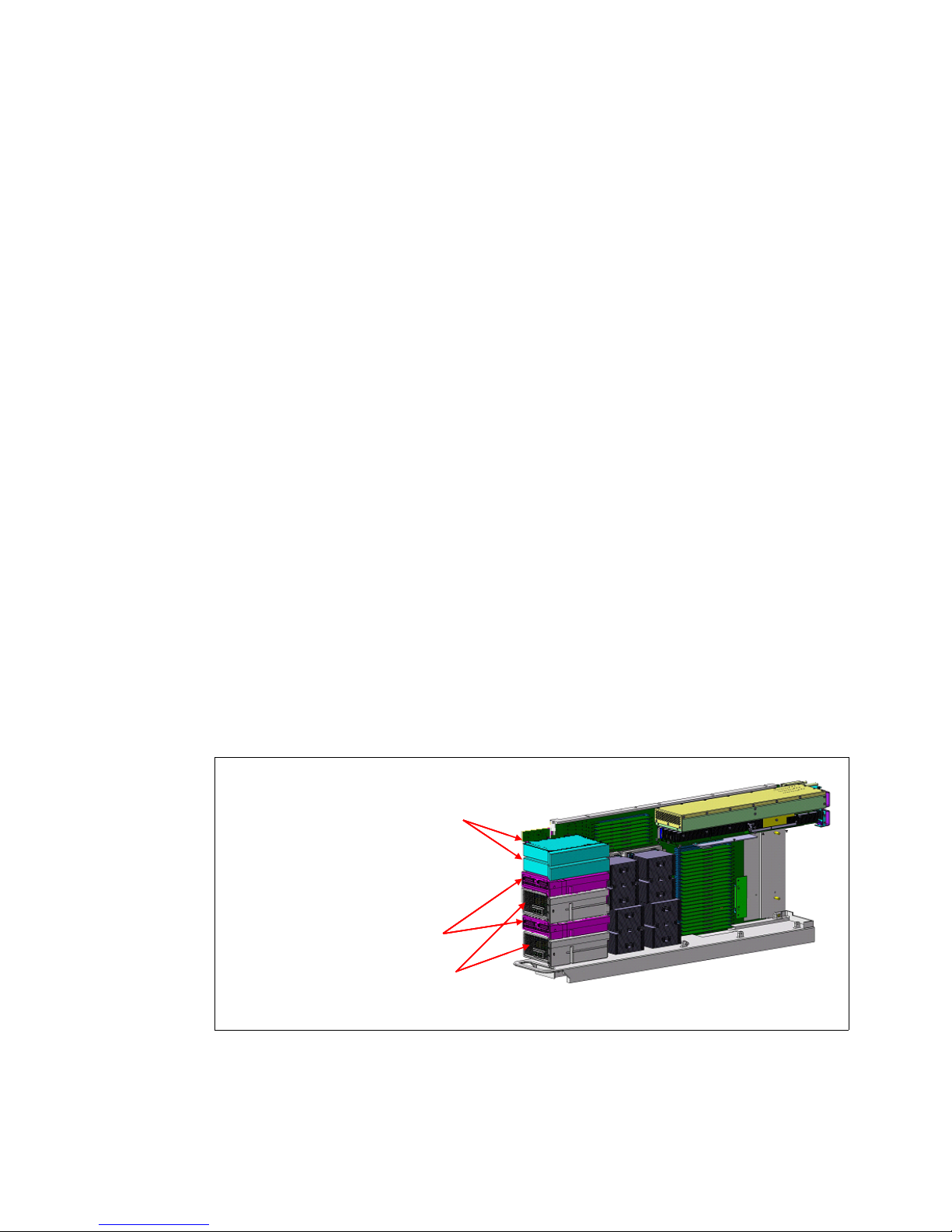
When multiple DIMM sizes are ordered, smaller DIMM sizes are placed in the fewest
processor books possible, while insuring that the quantity of remaining larger DIMMs are
adequate to populate at least one feature code per MCM module. The largest DIMM size is
spread out among all remaining processor books. This tends to balance the memory
throughout the system.
For memory upgrades, DIMMs are added first to those books with fewer DIMMs until all books
have the same number of DIMMs. Any remaining memory is then distributed round robin
amongst all books having that size DIMM.
The following memory configuration and placement rules apply to the 595 server:
At initial order, each installed processor book must have a minimum of:
– Four memory units installed (50% populated). The memory units must use the same
DIMM size within the processor book. Different DIMM sizes can be used within the 595
server. For 16 GB DIMMs, memory units must be installed in groups of eight.
– 16 GB of memory activated
Memory upgrades can be added in groups of two units (16 GB DIMMs must be added in
groups of eight units), as follows:
– For memory upgrades, you are not required to add memory to all processor books.
– You must maintain the same DIMM sizes within a processor book when adding
memory.
Processors books are 50% (initial), 75%, or 100% populated. Put another way, each
processor book will have either, four, six, or eight memory units installed.
2.8 Internal I/O subsystem
Each processor book on the 595 server provides four GX busses for the attachment of GX
bus adapters. A fully configured 595 server with eight processor books supports up to 32 GX
bus adapters. The GX bus adapter locations are shown in Figure 2-34.
Node Controllers
Node Controllers
GX bus adapters (narrow)
GX bus adapters (narrow)
GX bus adapters (wide)
GX bus adapters (wide)
Figure 2-34 GX bus adapters
The processor book provides two narrow and two wide GX bus adapter slots. Narrow
adapters fit into both narrow and wide GX bus slots.
Processor Book
Processor Book
82 IBM Power 595 Technical Overview and Introduction
Page 95

2.8.1 Connection technology
RIO-2 and 12x connectivity is provided using GX bus adapter based, remote I/O hubs. These
remote I/O hubs are listed in Table 2-19.
Table 2-19 Remote I/O hubs
Feature Description Form
factor
#1814 Remote I/O-2 (RIO-2) Loop Adapter, Two Port narrow 5791 9 — 9
#1816 GX Dual-Port 12x HCA narrow 5797, 5798 999
Attach to
drawer(s)
Support
AIX
IBM i
Linux
Each I/O hub provides two ports that are used to connect internal 24-inch I/O drawers to the
CEC.
The RIO-2 I/O hubs are currently available and the 12x I/O hubs have a planned-availability
date of November 21, 2008.
I/O hub adapter plugging rules
The I/O hubs are evenly distributed across the installed processor books. The installation
order follows the processor book plugging sequence listed in table Table 2-1 on page 42 with
the following order of priority:
1. Bottom narrow slots are across all processor nodes.
2. Upper narrow slots are across all processor nodes.
3. Bottom wide slots are across all processor nodes.
4. Upper wide slots are across all processor nodes.
This information (bottom and upper notation) is applicable regardless of the orientation of the
processor books (upper or lower). For example, bottom means bottom whether you are
plugging into a processor book installed in an upper or lower location.
Important: When your Power 595 server is manufactured, the I/O hubs are evenly
distributed across the installed processor books. I/O connections will then be distributed
across these installed I/O hubs. If you add more I/O hubs during an upgrade, install them
so that the end result is an even balance across all new and existing processor books.
Therefore, the cabling relationship between the I/O hubs and drawers can vary with each
Power 595 server. We suggest that you document these connections to assist with system
layout and maintenance. I/O hubs cards can be hot-added. Concurrent re-balancing of I/O
hub cards is not supported.
An example of the I/O hub installation sequence for a fully configured system with eight
processor books and 32 I/O hubs is shown in Figure 2-35 on page 84.
Chapter 2. Architectural and technical overview 83
Page 96

Node P2
Node P2
Node P2
Node P2
Plug seq. 4
Plug seq. 4
Plug seq. 4
Plug seq. 4
Node P3
Node P3
Node P3
Node P3
Plug seq. 7
Plug seq. 7
Plug seq. 7
Plug seq. 7
Node P4
Node P4
Node P4
Node P4
Plug seq. 8
Plug seq. 8
Plug seq. 8
Plug seq. 8
Node P5
Node P5
Node P5
Node P5
Plug seq. 2
Plug seq. 2
Plug seq. 2
Plug seq. 2
Figure 2-35 I/O hub installation sequence
2.8.2 Internal I/O drawers
12
12
12
12
28
28
28
28
4
4
4
4
20
20
20
20
27
27
27
11
11
11
11
19
19
19
3
3
3
3
Plug seq. 3
Plug seq. 3
Plug seq. 3
Node P6
Node P6
Node P6
Narrow
Narrow
Narrow
Narrow
Wide
Wide
Wide
Wide
Narrow
Narrow
Narrow
Narrow
Wide
Wide
Wide
Wide
Wide
Wide
Wide27Wide
Narrow
Narrow
Narrow
Narrow
Wide
Wide
Wide19Wide
Narrow
Narrow
Narrow
Narrow
15
15
15
15
Narrow
Narrow
Narrow
Narrow
31
31
31
31
7
7
7
7
Narrow
Narrow
Narrow
Narrow
23
23
23
23
Mid-plane
Mid-plane
29
29
29
13
13
13
13
Narrow
Narrow
Narrow
Narrow
21
21
21
5
5
5
5
Narrow
Narrow
Narrow
Narrow
Plug seq. 5
Plug seq. 5
Plug seq. 5
Node P7
Node P7
Node P7
Wide
Wide
Wide
Wide
Wide
Wide
Wide
Wide
Wide
Wide
Wide29Wide
Wide
Wide
Wide21Wide
16
16
16
16
Narrow
Narrow
Narrow
Narrow
32
32
32
32
8
8
8
8
Narrow
Narrow
Narrow
Narrow
24
24
24
24
30
30
30
14
14
14
14
Narrow
Narrow
Narrow
Narrow
22
22
22
6
6
6
6
Narrow
Narrow
Narrow
Narrow
Plug seq. 6
Plug seq. 6
Plug seq. 6
Node P8
Node P8
Node P8
Wide
Wide
Wide
Wide
Wide
Wide
Wide
Wide
Wide
Wide
Wide30Wide
Wide
Wide
Wide22Wide
10
10
10
10
Narrow
Narrow
Narrow
Narrow
26
26
26
26
2
2
2
2
Narrow
Narrow
Narrow
Narrow
18
18
18
18
25
25
25
9
9
9
9
Narrow
Narrow
Narrow
Narrow
17
17
17
1
1
1
1
Narrow
Narrow
Narrow
Narrow
Plug seq. 1
Plug seq. 1
Plug seq. 1
Node P9
Node P9
Node P9
Wide
Wide
Wide
Wide
Wide
Wide
Wide
Wide
Wide
Wide
Wide25Wide
Wide
Wide
Wide17Wide
The internal I/O drawers (24 inches) provide storage and I/O connectivity for the 595 server.
The available internal I/O drawers are listed in Table 2-20
Table 2-20 Internal I/O drawers
Feature Description Connection
Support
Adapter
AIX
IBM i
#5791 I/O drawer, 20 slots, 16 disk bays 1814 9 — 9
#5797 12x I/O drawer, 20 slots, 16 disk bays, with repeater 1816 999
#5798 12x I/O drawer, 20 slots, 16 disk bays, no repeater 1816 999
I/O drawers #5791 and #5797 (with repeater) are supported in the system (CEC) rack,
powered expansion racks, and nonpowered expansion racks. I/O drawer #5798 (without
repeater) is only supported in the system rack.
Note: I/O drawers #5797 and #5798 have a planned availability date of November 21,
2008.
Linux
84 IBM Power 595 Technical Overview and Introduction
Page 97

Figure 2-36 shows the components of an internal I/O drawer. The I/O riser cards provide
RIO-2 or 12x ports that are connected via cables to the I/O hubs located in the processor
books within the CEC.
PCI-X card in blind-swap hot plug cassette (2-20)
RIO-2 riser
RIO-2 riser
I/O riser
I/O riser
card (2)
card (2)
card (2)
card (2)
PCI-X card in blind-swap hot plug cassette (2-20)
Planar board (2)
Planar board (2)
Chassis with 1 midplane board
Chassis with 1 midplane board
Blower (4)
Blower (4)
DASD 4-pack (2 or 4)
DCA (2)
DCA (2)
DASD 4-pack (2 or 4)
(20)
(20)
(4)
(4)
Figure 2-36 I/O drawer internal view
Each I/O drawer is divided into two halves. Each half contains 10 blind-swap adapter slots
(3.3 V) and two Ultra3 SCSI 4-pack backplanes for a total of 20 adapter slots and 16 hot-swap
disk bays per drawer. The internal SCSI backplanes provide support for the internal drives
and do not have an external SCSI connector. Each half of the I/O drawer is powered
separately.
Additional I/O drawer configuration requirements:
A blind-swap hot-plug cassette is provided in each PCI-X slot of the I/O drawer. Cassettes
not containing an adapter are shipped with a plastic filler card installed to help ensure
proper environmental characteristics for the drawer. Additional blind-swap hot-plug
cassettes can be ordered: #4599, PCI blind-swap cassette kit.
All 10 adapter slots on each I/O drawer planar are capable of supporting either 64-bit or
32-bit 3.3 V based adapters.
For maximum throughout, use two I/O hubs per adapter drawer (one I/O hub per 10 slot
planar). This is also known as double-barrel cabling configuration (dual loop). Single-loop
configuration is supported for configurations with a large number of internal I/O drawers.
Table 2-21 compares features of the RIO-2 and 12x based internal I/O drawers.
Table 2-21 Internal I/O drawer feature comparison
Feature or Function #5791 drawer #5797, #5798 drawers
Connection technology RIO-2 12x
Bandwidth per connection port
(4 ports per drawe)r
PCI-X (133 MHz) slots 10 per planar (20 total) 3 per planar (6 total)
1.7 GBps sustained
2 GBps peak
Chapter 2. Architectural and technical overview 85
5 GBps sustained
6 GBps peak
Page 98

Feature or Function #5791 drawer #5797, #5798 drawers
PCI-X 2.0 (266 MHz) slots none 7 per planar (14 total)
Ultra3 SCSI busses 2 per planar (4 total) 2 per planar (4 total)
SCSI disk bays 8 per planar (16 total) 8 per planar (16 total)
Maximum drawers per system 12 30 (#5797)
3 (#5798)
30 (#5797 and #5798)
RIO-2 based internal I/O drawer (#5791)
The 5791 internal I/O drawer uses RIO-2 connectivity to the CEC. All 20 slots are PCI-X
based. An internal diagram of the #5791 internal I/O drawer is shown in Figure 2-37.
RIO-2 1.7 GB/s
RIO-2 1.7 GB/s
Sustained. 2 GB/s pk
Sustained. 2 GB/s pk
RIO-2 1.7 GB/s
RIO-2 1.7 GB/s
Sustained. 2 GB/s pk
Sustained. 2 GB/s pk
Figure 2-37 #5791 internal I/O Expansion Drawer (RIO-2)
12x based internal I/O drawers (#5797 and #5798)
The #5797 and #5798 internal I/O drawers use 12x connectivity to the CEC. Each I/O drawer
provides a total of 14 PCI-X 2.0 (266 MHz) slots and 6 PCI-X (133 MHz) slots. An internal
diagram of the #5797 and #5798 internal I/O drawers is shown in Figure 2-38 on page 87.
86 IBM Power 595 Technical Overview and Introduction
RIO-2 1.7 GB/s
RIO-2 1.7 GB/s
Sustained. 2 GB/s pk
Sustained. 2 GB/s pk
RIO-2 1.7 GB/s
RIO-2 1.7 GB/s
Sustained. 2 GB/s pk
Sustained. 2 GB/s pk
Page 99

12X IB, 5 GB/s
12X IB, 5 GB/s
12X IB, 5 GB/s
Sustained. 6 GB/s pk
Sustained. 6 GB/s pk
12X IB, 5 GB/s
12X IB, 5 GB/s
Sustained. 6 GB/s pk
Sustained. 6 GB/s pk
12X IB, 5 GB/s
Sustained. 6 GB/s pk
Sustained. 6 GB/s pk
12X IB, 5 GB/s
12X IB, 5 GB/s
Sustained. 6 GB/s pk
Sustained. 6 GB/s pk
Figure 2-38 #5797 and #5798 internal I/O drawers (12x)
The Power 595 server supports up to 30 expansion drawers (maximum of 12 for RIO-2).
Figure 2-39 on page 88 shows the drawer installation sequence when the integrated battery
feature (IBF) is not installed. If the IBF is installed, the battery backup units will be located
where I/O drawer
#2 would have been located. Subsequent drawer numbering with IBF is
shown in parenthesis.
Chapter 2. Architectural and technical overview 87
Page 100

Non-powered
Non-powered
expansion rack #1
expansion rack #1
I/O Drawer #17 (16)
I/O Drawer #17 (16)
I/O Drawer #17 (16)
I/O Drawer #16 (15)
I/O Drawer #16 (15)
I/O Drawer #16 (15)
I/O Drawer #15 (14)
I/O Drawer #15 (14)
I/O Drawer #15 (14)
I/O Drawer #14 (13)
I/O Drawer #14 (13)
I/O Drawer #14 (13)
I/O Drawer #13 (12)
I/O Drawer #13 (12)
I/O Drawer #13 (12)
I/O Drawer #12 (11)
I/O Drawer #12 (11)
I/O Drawer #12 (11)
I/O Drawer #11 (10)
I/O Drawer #11 (10)
I/O Drawer #11 (10)
Powered
Powered
Powered
expansion rack #1
expansion rack #1
expansion rack #1
Bulk power
Bulk power
Bulk power
I/O Drawer #10 (9)
I/O Drawer #10 (9)
I/O Drawer #10 (9)
I/O Drawer #10 (9)
I/O Drawer #9 (8)
I/O Drawer #9 (8)
I/O Drawer #9 (8)
I/O Drawer #9 (8)
I/O Drawer #8 (7)
I/O Drawer #8 (7)
I/O Drawer #8 (7)
I/O Drawer #8 (7)
I/O Drawer #7 (6)
I/O Drawer #7 (6)
I/O Drawer #7 (6)
I/O Drawer #7 (6)
I/O Drawer #6 (5)
I/O Drawer #6 (5)
I/O Drawer #6 (5)
I/O Drawer #6 (5)
I/O Drawer #5 (4)
I/O Drawer #5 (4)
I/O Drawer #5 (4)
I/O Drawer #5 (4)
I/O Drawer #4 (3)
I/O Drawer #4 (3)
I/O Drawer #4 (3)
I/O Drawer #4 (3)
System rack
System rack
System rack
Bulk power
Bulk power
Bulk power
Media Drawer
Media Drawer
Media Drawer
Light Strip
Light Strip
Light Strip
Upper
Upper
Upper
Processor
Processor
Processor
Books
Books
Books
Mid-plane
Mid-plane
Mid-plane
Lower
Lower
Lower
Processor
Processor
Processor
Books
Books
Books
I/O Drawer #2 (IBF)
I/O Drawer #2 (IBF)
I/O Drawer #2 (IBF)
I/O Drawer #1 (1)
I/O Drawer #1 (1)
I/O Drawer #1 (1)
I/O Drawer #3 (2)
I/O Drawer #3 (2)
I/O Drawer #3 (2)
Figure 2-39 Power 595 I/O Expansion Drawer locations
Non-powered
Non-powered
Non-powered
Expansion rack #2
Expansion rack #2
Expansion rack #2
I/O Drawer #30 (29)
I/O Drawer #30 (29)
I/O Drawer #30 (29)
I/O Drawer #29 (28)
I/O Drawer #29 (28)
I/O Drawer #29 (28)
I/O Drawer #28 (27)
I/O Drawer #28 (27)
I/O Drawer #28 (27)
I/O Drawer #27 (26)
I/O Drawer #27 (26)
I/O Drawer #27 (26)
I/O Drawer #26 (25)
I/O Drawer #26 (25)
I/O Drawer #26 (25)
I/O Drawer #25 (24)
I/O Drawer #25 (24)
I/O Drawer #25 (24)
I/O Drawer #24 (23)
I/O Drawer #24 (23)
I/O Drawer #24 (23)
Powered
Powered
Powered
Expansion rack #2
Expansion rack #2
Expansion rack #2
Bulk power
Bulk power
Bulk power
I/O Drawer #23 (22)
I/O Drawer #23 (22)
I/O Drawer #23 (22)
I/O Drawer #22 (21)
I/O Drawer #22 (21)
I/O Drawer #22 (21)
I/O Drawer #21 (20)
I/O Drawer #21 (20)
I/O Drawer #21 (20)
I/O Drawer #20 (19)
I/O Drawer #20 (19)
I/O Drawer #20 (19)
I/O Drawer #19 (18)
I/O Drawer #19 (18)
I/O Drawer #19 (18)
I/O Drawer #18 (17)
I/O Drawer #18 (17)
I/O Drawer #18 (17)
I/O Drawer #17 (16)
I/O Drawer #17 (16)
I/O Drawer #17 (16)
2.8.3 Internal I/O drawer attachment
The internal I/O drawers are connected to the 595 server CEC using RIO-2 or 12x technology.
Drawer connections are made in loops to help protect against errors resulting from an open,
missing, or disconnected cable. If a fault is detected, the system can reduce the speed on a
cable, or disable part of the loop to maintain system availability.
Each RIO-2 or 12x I/O attachment adapter (I/O hub) has two ports and can support one loop.
A maximum of one internal I/O drawer can be attached to each loop. Up to four I/O hub
attachment adapters can be installed in each 8-core processor book. Up to 12 RIO-2 or 30
12x I/O drawers are supported per 595 server.
I/O drawers can be connected to the CEC in either single-loop or dual-loop mode:
Single-loop (Figure 2-40 on page 89) mode connects an entire I/O drawer to the CEC
using one RIO-2 or 12x loop. In this configuration, the two I/O planars in the I/O drawer are
connected together using a short cable. Single-loop connection requires one RIO-2 Loop
Attachment Adapter (#1814) or GX Dual-Port 12x (#1816) per I/O drawer.
Dual-loop (Figure 2-41 on page 90) mode connects each of the two I/O planars (within the
I/O drawer) to the CEC on separate loops. Dual-loop connection requires two I/O hub
attachment adapters (#1814 or #1816) per connected I/O drawer. With a dual-loop
configurations, the overall I/O bandwidth per drawer is higher.
Note: Use dual-loop mode whenever possible to provide the maximum bandwidth between
the I/O drawer and the CEC.
Table 2-22 on page 89 lists the number of single-looped and double-looped I/O drawers that
can be connected to a 595 server based on the number of processor books installed.
88 IBM Power 595 Technical Overview and Introduction
 Loading...