

Page 1

User’s Manual
PG-FP3
Flash Memory Programmer
Document No. U13502EJ2V0UM00 (2nd edition)
Date Published July 1999 J CP(K)
1998
1991©
Printed in Japan
Page 2

[MEMO]
2
User's Manual U13502EJ2V0UM00
Page 3

SUMMARY OF CONTENTS
CHAPTER 1 GENERAL .....................................................................................................................................................17
CHAPTER 2 CONFIGURATION.........................................................................................................................................19
CHAPTER 3 STARTING AND STOPPING ........................................................................................................................27
CHAPTER 4 BASIC OPERATING PROCEDURE..............................................................................................................37
CHAPTER 5 COMMAND REFERENCE.............................................................................................................................45
CHAPTER 6 STAND-ALONE FUNCTION .........................................................................................................................67
CHAPTER 7 HARDWARE SPECIFICATIONS...................................................................................................................69
CHAPTER 8 ERROR MESSAGES AND REMEDIAL ACTIONS .......................................................................................87
APPENDIX A NOTES ON DESIGNING A TARGET............................................................................................................91
APPENDIX B REVISION HISTORY.....................................................................................................................................93
User's Manual U13502EJ2V0UM00
3
Page 4

EEPROM is a trademark of NEC Corporation.
PC/AT is a trademark of International Business Machines Corporation.
Windows and Windows NT are either registered trademarks or trademarks of Microsoft Corporation in the United
States and/or other countries.
Pentium is a trademark of Intel Corporation in the United States.
4
User's Manual U13502EJ2V0UM00
Page 5

• The information in this document is subject to change without notice. Before using this document,
please confirm that this is the latest version.
• No part of this document may be copied or reproduced in any form or by any means without the prior written
consent of NEC Corporation. NEC Corporation assumes no responsibility for any errors which may appear in
this document.
• NEC Corporation does not assume any liability for infringement of patents, copyrights or other intellectual
property rights of third parties by or arising from use of a device described herein or any other liability arising
from use of such device. No license, either express, implied or otherwise, is granted under any patents,
copyrights or other intellectual property rights of NEC Corporation or of others.
• Descriptions of circuits, software, and other related information in this document are provided for illustrative
purposes in semiconductor product operation and application examples. The incorporation of these circuits,
software, and information in the design of the customer's equipment shall be done under the full responsibility
of the customer. NEC Corporation assumes no responsibility for any losses incurred by the customer or third
parties arising from the use of these circuits, software, and information.
M7A 98. 8
User's Manual U13502EJ2V0UM00
5
Page 6

Regional Information
Some information contained in this document may vary from country to country. Before using any NEC
product in your application, pIease contact the NEC office in your country to obtain a list of authorized
representatives and distributors. They will verify:
•
Device availability
•
Ordering information
•
Product release schedule
•
Availability of related technical literature
•
Development environment specifications (for example, specifications for third-party tools and
components, host computers, power plugs, AC supply voltages, and so forth)
•
Network requirements
In addition, trademarks, registered trademarks, export restrictions, and other legal issues may also vary
from country to country.
NEC Electronics Inc. (U.S.)
Santa Clara, California
Tel: 408-588-6000
800-366-9782
Fax: 408-588-6130
800-729-9288
NEC Electronics (Germany) GmbH
Duesseldorf, Germany
Tel: 0211-65 03 02
Fax: 0211-65 03 490
NEC Electronics (UK) Ltd.
Milton Keynes, UK
Tel: 01908-691-133
Fax: 01908-670-290
NEC Electronics Italiana s.r.l.
Milano, Italy
Tel: 02-66 75 41
Fax: 02-66 75 42 99
NEC Electronics (Germany) GmbH
Benelux Office
Eindhoven, The Netherlands
Tel: 040-2445845
Fax: 040-2444580
NEC Electronics (France) S.A.
Velizy-Villacoublay, France
Tel: 01-30-67 58 00
Fax: 01-30-67 58 99
NEC Electronics (France) S.A.
Spain Office
Madrid, Spain
Tel: 91-504-2787
Fax: 91-504-2860
NEC Electronics (Germany) GmbH
Scandinavia Office
Taeby, Sweden
Tel: 08-63 80 820
Fax: 08-63 80 388
NEC Electronics Hong Kong Ltd.
Hong Kong
Tel: 2886-9318
Fax: 2886-9022/9044
NEC Electronics Hong Kong Ltd.
Seoul Branch
Seoul, Korea
Tel: 02-528-0303
Fax: 02-528-4411
NEC Electronics Singapore Pte. Ltd.
United Square, Singapore 1130
Tel: 65-253-8311
Fax: 65-250-3583
NEC Electronics Taiwan Ltd.
Taipei, Taiwan
Tel: 02-2719-2377
Fax: 02-2719-5951
NEC do Brasil S.A.
Electron Devices Division
Rodovia Presidente Dutra, Km 214
07210-902-Guarulhos-SP Brasil
Tel: 55-11-6465-6810
Fax: 55-11-6465-6829
J99.1
6
User's Manual U13502EJ2V0UM00
Page 7

Major Revisions in This Edition
Page Description
p.18
p.19
p.20
p.20
p.28
p.30
p.36
p.46
p.50
p.58
p.59
p.61
p.62
p.62
p.65
p.72
p.73
p.77
p.91
p.92
p.93
p.41 in the
first edition
p.46 in the
first edition
p.53 in the
first edition
p.75 in the
first edition
The setting of the baud rate and the c apacity for downloading the user program in
changed.
Figure 2-1
Figure 2-2
The description of EXPANSION CONNECTOR has been deleted from
A description in
A description in
A description has been added to "Option setting" in
A description has been added to
A description in
A description in
A description in
A description in
A description in
A description in
A description in
A description in "Support ed ROM specifications" in
A description has been deleted from
The setting of the baud rate in
Figure A-1
Figure A-2
Appendix B
Section 5.3.2
Section 5.3.7
Section 5.4.6
Section 7.5
has been changed.
has been changed.
Section 3.1
Section 3.2
Section 5.2.2
Section 5.3.2
Section 5.3.3
Section 5.3.4
Section 5.3.5
Section 5.3.6
Section 5.4.3
has been changed.
has been changed.
has been added.
has been deleted.
has been deleted.
has been deleted.
has been deleted.
has been changed.
has been changed.
Section 3.3
Section 5.1.2
has been changed.
has been changed.
has been changed.
has been changed.
has been changed and Caution has been added to
has been changed.
has been changed.
Section 7.3
Table 7-4
.
Section 7.2
.
has been changed.
Section 2.2
.
has been changed.
Table 1-1
.
Section 5.3.5
have been
.
The mark shows major revised points.
User's Manual U13502EJ2V0UM00
7
Page 8

[MEMO]
8
User's Manual U13502EJ2V0UM00
Page 9

PREFACE
Readers of This Manual
Purpose
Organization
How to Read This Manual
This manual is intended for user engineers who use the PG-FP3 to design and develop
systems with an NEC microcontroller with flash memory.
The PG-FP3 enables programs in the NEC microcontroller with flash memory to be
erased, written, or verified with the microcontroller mounted on a user-designed printed
TM
circuit board through simple operations on a Windows
screen.
This manual contains the basic PG-FP3 specifications and explains how to use the
PG-FP3.
This manual contains the following chapters:
General, Configuration, Starting and Stopping, Basic Operating Procedure, Command
Reference, Stand-alone Function, Hardware Specifications, and Error Messages and
Remedial Actions
To understand the basic specifications and operation of the PG-FP3, read this manual
in the order given in the table of contents. Be sure to read
Chapter 3
, which contains
important information on operating the PG-FP3.
It is assumed that the readers of this manual have a basic knowledge of electricity,
logic circuits, and microcontrollers. It is also assumed that, especially in the
description of applications, they have sufficient knowledge of Windows. For
information on using Windows 95 and Windows NTTM and for the related terminology,
refer to the appropriate Windows manual.
Legend Note
Caution
Remark
Numeric notation : Binary..............
: Explanation of the item so marked
: Important information
: Supplementary explanation
××××
Decimal ...........
Hexadecimal....0
User's Manual U13502EJ2V0UM00
××××
××××
or
H or
××××
××××
B
H
9
Page 10

Terminology
PG-FP3 ................................... Flash memory programmer
FLASHPRO3 ........................... Windows application name of PG-FP3
Target ...................................... NEC microcontroller with flash memory or user board
on which such a microcontroller is mounted
Printer interface (IEEE 1284) ... Parallel interface specified by IEEE 1284-1994. Used
by the PG-FP3 as one of the host interfaces.
FA adapter ............................... Adapter board used to write programs to an NEC
microcontroller with flash memory
The FA adapter board is a product of Naito Densei Machida Mfg. Co., Ltd.
Note
Note
<Telephone number>
Naito Densei Machida Mfg. Co., Ltd.: 044-822-3813
10
User's Manual U13502EJ2V0UM00
Page 11

CONTENTS
CHAPTER 1 GENERAL .............................................................................................................................17
CHAPTER 2 CONFIGURATION.................................................................................................................19
2.1 PRODUCT ORGANIZATION.........................................................................................................................19
2.2 NAMES AND FUNCTIONS OF PARTS.........................................................................................................20
2.3 CONNECTIONS OF PARTS..........................................................................................................................22
CHAPTER 3 STARTING AND STOPPING................................................................................................27
3.1 INSTALLING THE APPLICATION.................................................................................................................27
3.2 STARTING THE APPLICATION....................................................................................................................30
3.3 INITIALIZATION AND NOTES ON CORRECT USE.....................................................................................33
3.4 TERMINATING THE APPLICATION.............................................................................................................36
CHAPTER 4 BASIC OPERATING PROCEDURE .....................................................................................37
CHAPTER 5 COMMAND REFERENCE.....................................................................................................45
5.1 File.................................................................................................................................................................45
5.1.1 Load File.............................................................................................................................................45
5.1.2 Save File.............................................................................................................................................46
5.1.3 Load Type...........................................................................................................................................47
5.1.4 Save Type ..........................................................................................................................................48
5.1.5 Exit......................................................................................................................................................48
5.2 Setting...........................................................................................................................................................49
5.2.1 Device.................................................................................................................................................49
5.2.2 Type....................................................................................................................................................50
5.2.3 Voltage ...............................................................................................................................................54
5.2.4 Option.................................................................................................................................................55
5.2.5 Reset..................................................................................................................................................55
5.2.6 Connection Port..................................................................................................................................56
5.3 Procedure......................................................................................................................................................57
5.3.1 Download HEX...................................................................................................................................57
5.3.2 Erase..................................................................................................................................................58
5.3.3 Program..............................................................................................................................................59
5.3.4 Verify ..................................................................................................................................................61
5.3.5 E.P.V. .................................................................................................................................................62
5.3.6 Chip set/Block set/Area set ................................................................................................................62
5.4 Other..............................................................................................................................................................64
5.4.1 Signature............................................................................................................................................64
5.4.2 Status .................................................................................................................................................64
5.4.3 Dump HEX..........................................................................................................................................65
5.4.4 Supply Status .....................................................................................................................................66
5.4.5 PROM Load........................................................................................................................................66
5.5 Help................................................................................................................................................................66
User's Manual U13502EJ2V0UM00
11
Page 12

CHAPTER 6 STAND-ALONE FUNCTION .................................................................................................67
6.1 FUNCTION.....................................................................................................................................................67
6.2 OPERATION ..................................................................................................................................................68
CHAPTER 7 HARDWARE SPECIFICATIONS...........................................................................................69
7.1 PRODUCT CONFIGURATION AND OPERATING ENVIRONMENT.............................................................69
7.2 MASTER ROM SOCKET SPECIFICATIONS ................................................................................................70
7.3 HOST INTERFACE........................................................................................................................................73
7.3.1 Printer Interface Specifications...........................................................................................................73
7.3.2 RS-232C Interface Specifications .......................................................................................................77
7.4 TARGET INTERFACE SPECIFICATIONS ....................................................................................................80
7.4.1 Interface Specifications.......................................................................................................................81
7.4.2 Equivalent Circuit and Load Condition................................................................................................84
CHAPTER 8 ERROR MESSAGES AND REMEDIAL ACTIONS...............................................................87
APPENDIX A NOTES ON DESIGNING A TARGET ..................................................................................91
APPENDIX B REVISION HISTORY............................................................................................................93
12
User's Manual U13502EJ2V0UM00
Page 13

LIST OF FIGURES
Figure No. Title Page
2-1. PG-FP3 System Organization ...........................................................................................................................19
2-2. PG-FP3 Parts and Names.................................................................................................................................20
3-1. FLASHPRO3 Screens.......................................................................................................................................32
3-2. Parameter File Setting Dialog Box.....................................................................................................................33
3-3. TYPE Setting Dialog Box (When the Parameter File Is Loaded).......................................................................34
3-4. TYPE Setting Dialog Box (When the Parameter File Is Not Loaded)................................................................34
4-1. Communication Error Dialog Box ......................................................................................................................38
5-1. File Format Select Dialog Box...........................................................................................................................46
5-2. Mode Screens....................................................................................................................................................63
5-3. Editor Screen.....................................................................................................................................................65
7-1. Pin Configuration (Top View).............................................................................................................................72
7-2. Communication Error Dialog Box ......................................................................................................................77
A-1. Interface Circuit Example for a UART................................................................................................................91
A-2. Interface Circuit Example for SIO......................................................................................................................92
User's Manual U13502EJ2V0UM00
13
Page 14

LIST OF TABLES
Table No. Title Page
1-1. Function Specifications......................................................................................................................................18
2-1. Items in the PG-FP3 Shipping Carton................................................................................................................19
7-1. Product Configuration and Operating Environment...........................................................................................69
7-2. Pin List...............................................................................................................................................................72
7-3. Printer Interface Specifications..........................................................................................................................73
7-4. RS-232C Interface Specifications......................................................................................................................77
7-5. Withstand Voltage of Each Interface Signal.......................................................................................................80
14
User's Manual U13502EJ2V0UM00
Page 15

LIST OF PHOTOGRAPHS
Photo No. Title Page
2-1. Connections (Host, PG-FP3, and Target)..........................................................................................................22
2-2. Connecting the Printer Interface Cable (I/F SELECT Switch Set to PRINTER I/F Position) .............................23
2-3. Connecting RS-232C (I/F SELECT Switch Set to RS-232C Position)...............................................................23
2-4. Connecting the AC Adapter...............................................................................................................................24
2-5. Connecting Target Cable to PG-FP3 <1>..........................................................................................................24
2-6. Connecting Target Cable to User Target...........................................................................................................25
2-7. Connecting Target Cable to PG-FP3 <2>..........................................................................................................25
2-8. Connecting Target Cable to FA Adapter............................................................................................................26
2-9. Directly Connecting FA Adapter to PG-FP3 ......................................................................................................26
3-1. Starting the PG-FP3 ..........................................................................................................................................30
4-1. Connection of Host, PG-FP3, and Target..........................................................................................................37
6-1. Selecting the Command Mode ..........................................................................................................................68
7-1. Mounting the Master ROM.................................................................................................................................70
7-2. Mounting the PROM in the Master ROM Socket...............................................................................................71
7-3. Executing the [PROM Load] Command.............................................................................................................71
User's Manual U13502EJ2V0UM00
15
Page 16

[MEMO]
16
User's Manual U13502EJ2V0UM00
Page 17

CHAPTER 1 GENERAL
The PG-FP3 is a tool for erasing, writing, and verifying programs for an NEC single-chip microcontroller with flash
memory on a user board or FA adapter board.
♦♦♦♦
Features
Supports all NEC microcontrollers with flash memory (as of February 1999)
•
Easy to use in stand-alone mode (with PG-FP3 only) or on Windows 95 or Windows NT using a dedicated
•
application (PG-FP3)
Compact, portable design the size of a sheet of A5 paper
•
Has a printer interface (parallel interface) in addition to the standard RS-232C interface. Downloads user
•
programs quickl y.
Note
Supports high-capacity microcontrollers
•
memory of 2 Mbytes
that are expected to be available in the future as well as flash
Support of microcontrollers developed in the future may require PG-FP3 firmware and application
Note
upgrades.
User's Manual U13502EJ2V0UM00
17
Page 18

CHAPTER 1 GENERAL
♦♦♦♦
Function specifications
Table 1-1. Function Specifications
Item Specification
Host interface
Target interface
Supply voltage
Note 2
Note 3
Supply voltage input Target VDD supply voltage input: 1.8 to 5.5 V, current consumption: 100 mA max.
CPU clock supply A 16-, 8-, 4-, or 2-MHz clock can be selected as the target CPU clock.
Master ROM A PROM (CMOS, 32-pin) to which the user program is written can be inserted in the
Stand-alone Programming with only the PG-FP3.
RS-232C: D-SUB 25-pin, 9600, 19200, 38400, or 57600 bps
Printer interface
Note 1
: Half-pitch 36-pin conforming to IEEE 1284-1994
(Supports compatible mode and ECP mode.)
The interface can be selected with the I/F SELECT switch.
Connector: D-SUB 9-pin (receptacle)
DD
Level conversion: Within target V
input range (1.8 to 5.5 V)
Protection function: Overvoltage input protection circuit (guaranteed range: 15 V max.)
Supported interface: 3-wi re, 3-wire + handshake (Max. SCK: 2.0 MHz)
Pseudo 3-wire (Max. SCK: 2.0 MHz)
UART (Max. bps: 76800 bps)
IIC (Max. SCK: 50 kHz)
Target VPP supply voltage: 2.7 to 10.3 V, max.: 200 mA
DD
Target V
supply voltage: 1.8 to 6.0 V, max.: 200 mA
Whether power is supplied from the PG-FP3 or from the user target can be selected
DD
with the TARGET V
An overcurrent protection circuit is provided for both V
switch.
PP
and VDD.
The on-board target clock can be also used depending on the application settings.
(PG-FP3-side interface: CMOS level output)
master ROM socket to allow the user program to be downloaded (max.: 500 kbytes).
Functions such as E.P.V., ERASE, PROGRAM, VERIFY, and LOAD can be selected and
executed with the MODE Key.
Notes 1.
18
Only supported for Windows 95.
The maximum communication rate of the interface varies depending on the device used and the
2.
environment.
DD
is supplied to the target system to supply power to the device to which a program is to be written.
V
3.
The power is not enough to operate the target system of the user. Use the power supply on the target
for on-board program writing.
User's Manual U13502EJ2V0UM00
Page 19
CHAPTER 2 CONFIGURATION
2.1 PRODUCT ORGANIZATION
The system configuration of the PG-FP3 is illustrated below.
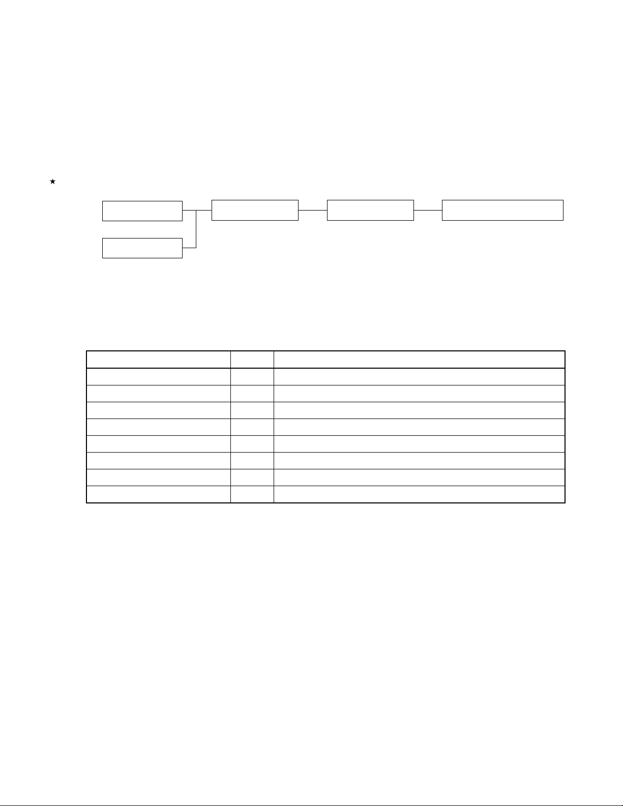
Figure 2-1. PG-FP3 System Organization
User target
FA adapter
Note
Note
The FA adapter is a product of Naito Densei Machida Mfg. Co., Ltd.
PG-FP3 Host machine Application (FLASHPRO3)
The PG-FP3 shipping carton contains the following items:
Table 2-1. Items in the PG-FP3 Shipping Carton
Item Qty Remarks
PG-FP3 1 PG-FP3
Floppy disk 1 Application software
AC adapter 1 Power supply
Printer cable 2 One for a PC-9800 and one for PC/ATTM or compatible machine
Target cable 2 Type 1 (IC clip) and Type 2 (connector)
User's Manual 1 This manual
Packing list 1 Packing list for this product
Warranty 1
The PG-FP3 is shipped with the above accessories. Make sure that all accessories have been provided by
checking the contents of the box against the above table when you unpack the box. If any part or accessory is missing
or is damaged, notify NEC.
To use RS-232C as the host interface, you will need a commercially available RS-232C straight cable.
User's Manual U13502EJ2V0UM00
19
Page 20
CHAPTER 2 CONFIGURATION
2.2 NAMES AND FUNCTIONS OF P ARTS
Parts and their names are illustrated bel o w.
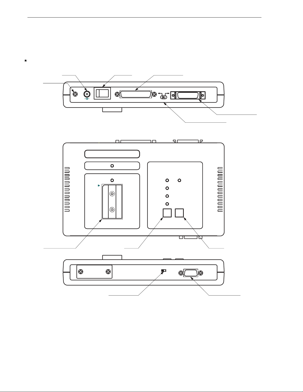
Figure 2-2. PG-FP3 Parts and Names
FG TERMI
N
AL
DC JACK
POWER SWITCH
FG
-+
OFF
+
V*IN
9
ON
232
C
-
RS-232-C CONNECTOR
RS-
T
ELE
I/F*S
C
P
RI
NTE
R*I /F
HOST I/F SELE
PRIN
C
TSWITCH
TER I/F CONNE
C
TOR
POWER
ACCESS
E
R
A
E
S
A
M
R
P
R
O
G
R
O
R
R
E
VERIFY
LOAD
E
N
R
E
T
EN
E
TER K
Y
D
D
V
T
I
N
T
E
R
A
T
G
TARGET I/F CONNECTOR
SOCKET OF MASTER ROM
MASTER
ROM
R
EAD ONLY
ODE KEY
M
T
RGET VDD SWITCH
A
MODE
A
T
R
E
G
T
O
U
The following explains the functions of the PG-FP3 parts:
FG TERMINAL
•
The FG terminal is a ground terminal on the PG-FP3. If necessary, ground the terminal using the FG cable
supplied as an accessory.
20
User's Manual U13502EJ2V0UM00
Page 21

CHAPTER 2 CONFIGURATION
DC JACK
•
This is the power supply input jack of the PG-FP3. To supply power to the PG-FP3, use the AC adapter supplied
as an accessory.
POWER SWITCH
•
This switch turns power to the PG-FP3 on or off. Before turning power on, make sure that all required parts are
connected correctly.
RS-232C CONNECTOR
•
This connector is used when RS-232C is used as the host interface. Use a commercially available 25-pin
straight cable to connect the host machine and the PG-FP3.
PRINTER I/F CONNECTOR
•
This connector is used when the printer interface cable supplied as an accessory is used as the host interface.
Connect the host machine and the PG-FP3 with the printer cable. Use only the supplied cable. Another cable
may cause the PG-FP3 to malfunction or to be damaged.
HOST I/F SELECT SWITCH
•
This switch selects whether an RS-232C or the printer interface cable is used as the interface with the host
machine. Select an interface before turning on power to the PG-FP3. The selected interface cannot be changed
after power has been turned on.
SOCKET OF MASTER ROM
•
The master ROM socket is used when a user program is downloaded to the PG-FP3 from a source other than
the host machine. A commercially available EPROM can be used as the master ROM. The user program can
be downloaded from an application or in stand-alone mode.
MODE KEY
•
This key is used to select a command mode when the PG-FP3 is used in stand-alone mode. Each time this key
is pressed, the command mode changes.
ENTER KEY
•
This key is used to execute a command selected by the mode key when the PG-FP3 is in stand-alone mode.
Select the command to be executed with the mode key, and press the ENTER key once to execute the
command.
DD
TARGET V
•
SWITCH
This switch selects whether VDD is supplied from the PG-FP3 or from the target board. Usually, VDD is supplied
from the target board.
DD
Supply V
from the PG-FP3 (TARGET VDD: OUT) only when a writing adapter, such as the FA adapter
used.
TARGET I/F CONNECTOR
•
This connector connects the PG-FP3 and the target board. Use the target interface cable supplied as an
accessory to make the connection.
Note
, is
The FA adapter is a product of Naito Densei Machida Mfg. Co., Ltd.
Note
User's Manual U13502EJ2V0UM00
21
Page 22
CHAPTER 2 CONFIGURATION
2.3 CONNECTIONS OF PARTS
This section explains how to connect the various parts of the PG-FP3.
The PG-FP3 can be used in two ways. It can be connected to a host machine and controlled by application
software or it can be used in stand-alone mode without being connected to a host machine. When using the PG-FP3
without being connected to the host machine (i.e., in stand-alone mode), you may skip the description on connection
with the host machine.
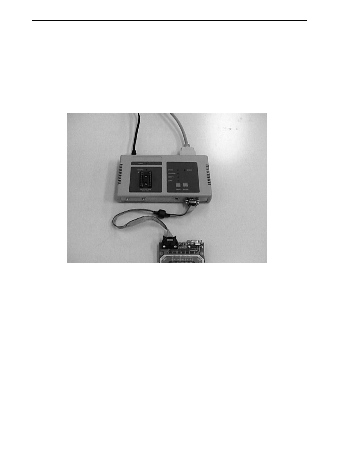
Photo 2-1. Connections (Host, PG-FP3, and Target)
Remark
22
When the PG-FP3 is used in stand-alone mode, interfacing with the target must be specified in advance.
To do so, select the device to be used and the communication mode using the application software on
the host machine. The setting information is recorded in the PG-FP3. In stand-alone mode, the PG-FP3
interfaces with the target based on this information.
User's Manual U13502EJ2V0UM00
Page 23
CHAPTER 2 CONFIGURATION
[Connecting a host machine]
Connection of the host interface cable is illustrated below. Select the host interface before turning on power to
the PG-FP3. The selected host interface cannot be changed after power has been turned on.
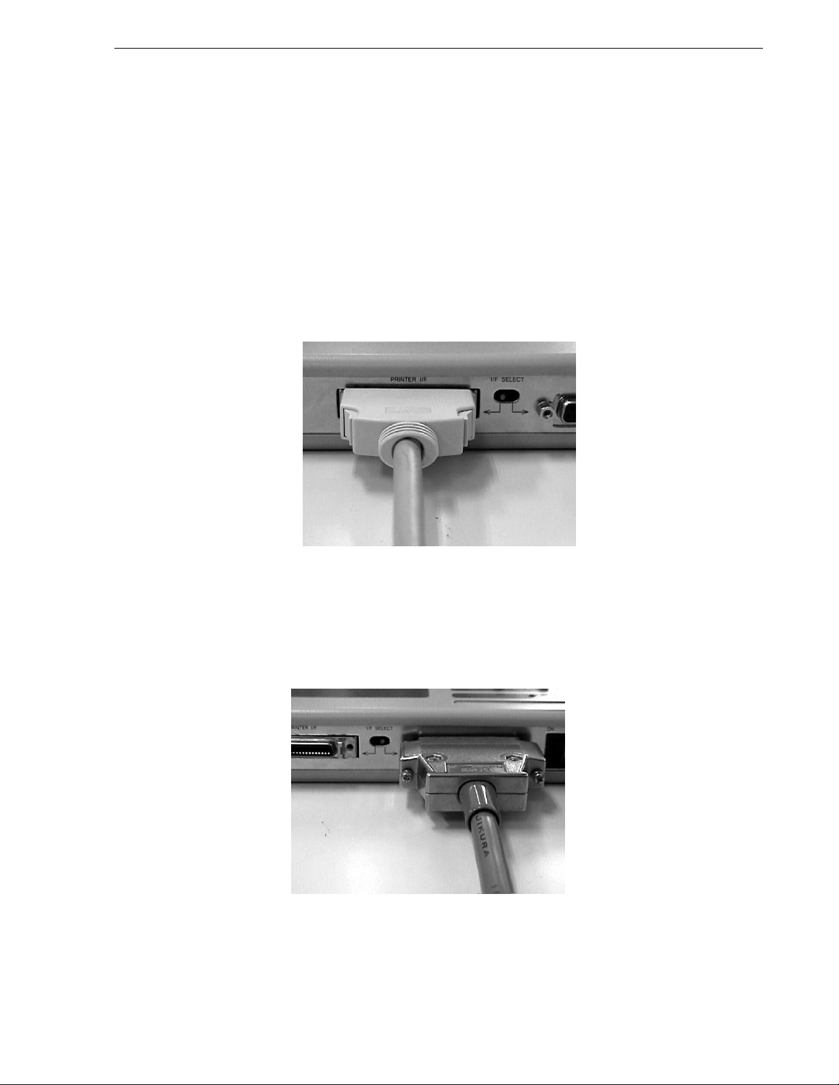
Connecting the printer interface cable
•
Set the interface select switch to the printer interface position. Connect the host machine with the printer
interface cable supplied as an accessory. Use the appropriate interface cable for the type of host machine (PC9800 or PC/AT).
The printer interface cable cannot be used unless the host machine supports bidirectional parallel
communication. Before using this cable, therefore, confirm that the host machine supports bidirectional
communication, compatible mode, and ECP mode.
Photo 2-2. Connecting the Printer Interface Cable (I/F SELECT Switch Set to PRINTER I/F Position)
Connecting the RS-232C interface
•
Set the interface select switch to the RS-232C position, and connect the appropriate RS-232C straight cable to
the RS-232C connector.
Photo 2-3. Connecting RS-232C (I/F SELECT Switch Set to RS-232C Position)
User's Manual U13502EJ2V0UM00
23
Page 24
CHAPTER 2 CONFIGURATION
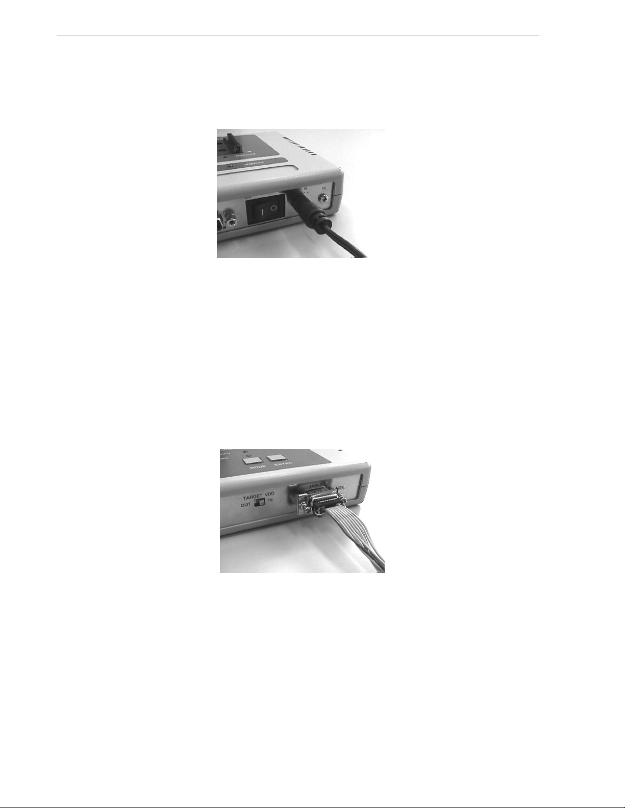
[Connecting the power supply]
With the power switch off, connect the AC adapter supplied as an accessory to the DC jack.
Photo 2-4. Connecting the AC Adapter
[Connecting the target]
Use the target cable supplied as an accessory to connect the target. Whether you use a Type 1 or Type 2 cable
depends on the specifications of the target. If the FA adapter
Note
is used, either use a Type 2 cable, or directly
connect the target to the PG-FP3.
Note
The FA adapter is a product of Naito Densei Machida Mfg. Co., Ltd.
When using a user target
•
Confirm that the target V
DD
switch is set to the IN position and then connect one end of the target cable to the
PG-FP3.
Photo 2-5. Connecting Target Cable to PG-FP3 <1>
Connect the other end of the target cable to the user target (in the example below, an IC clip is used).
24
User's Manual U13502EJ2V0UM00
Page 25
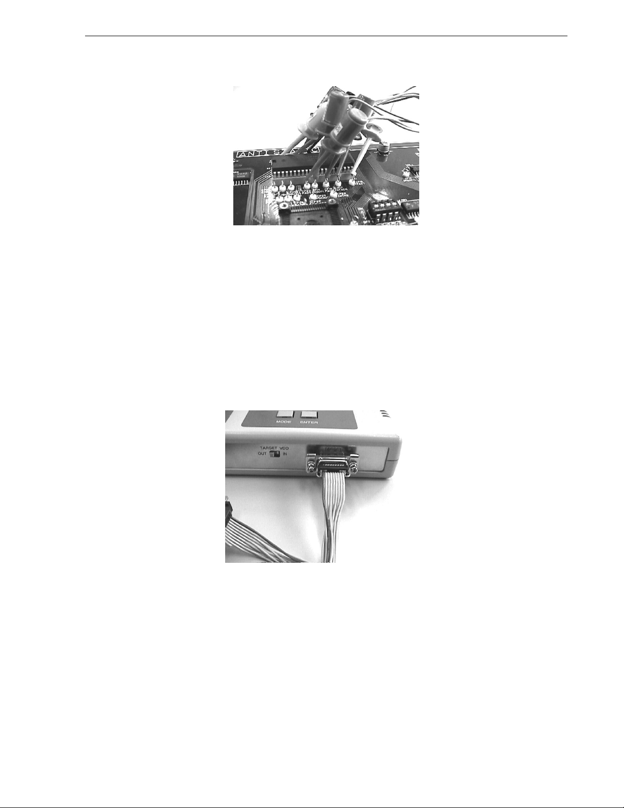
CHAPTER 2 CONFIGURATION
Photo 2-6. Connecting Target Cable to User Target
For the details of interface signal connections, see
When using the FA adapter
•
DD
Make sure that the target V
select switch is set to the OUT position. Connect one end of the Type 2 cable to
Section 7.4
and the manual for the device.
the PG-FP3, and the other end of the cable to the mating connector of the FA adapter. Alternatively, directly
connect the D-SUB connector of the FA adapter to the target interface connector of the PG-FP3.
The FA adapter has a D-SUB connector and a connector supporting the Ty pe 2 cable. Connect the FA adapter
in either of the ways described above. For the wiring of the FA adapter, refer to the FA adapter manual or the
manual for the device.
Photo 2-7. Connecting Target Cable to PG-FP3 <2>
User's Manual U13502EJ2V0UM00
25
Page 26

CHAPTER 2 CONFIGURATION
Photo 2-8. Connecting Target Cable to FA Adapter
The following is an example of directly connecting the FA adapter to the PG-FP3:
Photo 2-9. Directly Connecting FA Adapter to PG-FP3
26
User's Manual U13502EJ2V0UM00
Page 27
CHAPTER 3 STARTING AND STOPPING
This chapter explains how to install, start, and terminate the application. It also contains information on initialization
and on use of the application. Be sure to read this chapter, since it provides very important information about using
the PG-FP3. Unless the information in this chapter is not understood and followed, the PG-FP3 may not operate
correctly.
3.1 INSTALLING THE APPLICATION
This section explains how to install the application program.
Caution Because the program file is stored in compressed form on the floppy disk, it cannot be used
simply by copying the files on the disk to the hard disk. Be sure to install the program correctly
by using the setup program.
Starting the host machine
•
Turn on power to the personal computer, and start Windows 95 or Windows NT.
Host machine: PC-9801 or PC-9821
IBM PC/AT compatible
CPU: Pe ntiu m
RAM: 32 Mbytes or more is recommended.
TM
(100 MHz or higher is recommended.)
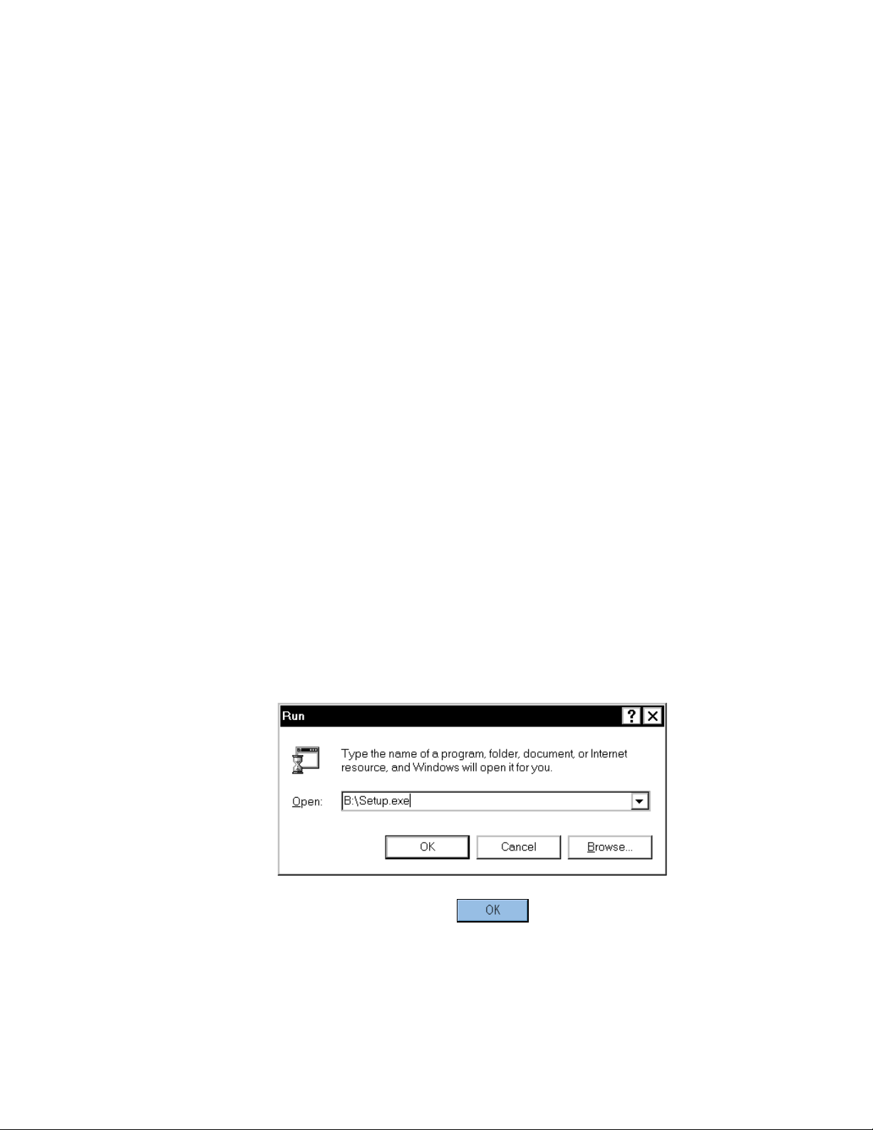
Starting the setup program
•
Select [Run] from the Start menu.
Enter the name of the drive for which [SETUP DISK] has been set and the file name SETUP.EXE in the [Open]
text box in the [Run] dialog box.
Example
When Disk 1 inserted in drive B
After entering the drive name and file name, click the button.
User's Manual U13502EJ2V0UM00
27
Page 28

CHAPTER 3 STARTING AND STOPPING
Starting installation
•
When SETUP.EXE star ts, follow the instructions by the setup program until the setting screen for the installation
directory is displayed. To stop installation partway, click the [Cancel] button.
Specify the installation directory in [Destination Directory] in the Choose Destination Location screen. Then,
click the
Example
Specifying the [\Program Files\Flashpro3] path of drive C
button.
To start the installation, click the [Next] button. When the installation ends, a confirmation message appears as
shown below. Click the [OK] button.
Now, the installation is completed. An English help file is installed as standard. To use a Japanese help file,
copy the flashpro.hlp file from Disk 2 into the installation directory. Note that the English help file is overwritten.
28
User's Manual U13502EJ2V0UM00
Page 29

CHAPTER 3 STARTING AND STOPPING
Uninstalling the program
•
To uninstall the PG-FP3 application, execute [Add/Remove Programs] in [Control Panel], and select
[FLASHPRO3].
Uninstallation will start, and the files copied during installation will be deleted.
Caution Uninstallation erases all installed components. If FLASHPRO3 is required after uninstallation,
reinstall it.
Installing the parameter file
•
The PG-FP3 loads information about the target device as a parameter file and makes the necessary settings for
interfacing.
Caution The PG-FP3 will not operate correctly unless the parameter file of the device to which
programs are to be written has been installed. Be sure to obtain and install the parameter file
when using PG-FP3.
Using Explorer or a similar means, copy the parameter file (XXXXXXX.PRC) to the same location where
FLASHPRO3 has been installed. Unless the file is copied to the same location, FLASHPRO3 will not correctly
recognize the parameter file.
User's Manual U13502EJ2V0UM00
29
Page 30

CHAPTER 3 STARTING AND STOPPING
3.2 STARTING THE APPLICATION
This section explains how to start the application program.
Connection of each unit and applying power
•
For connection of each unit, see
After completing connections, turn on power to the PG-FP3. When the PG-FP3 is operating normally, the
POWER LED lights, the LED on the side of the MODE key blinks, and then the Erase, Program, and Verify LED
indicators light.
Section 2.3
.
Photo 3-1. Starting the PG-FP3
If any of the LEDs mentioned above does not light, the PG-FP3 has probably malfunctioned. If this occurs,
notify NEC.
Starting FLASHPRO3
•
Either select FLASHPRO3 from the Start menu or, if a shortcut has been created, double-click the shortcut to
start FLASHPRO3. If FLASHPRO3 starts correctly, the following screen is displayed.
30
User's Manual U13502EJ2V0UM00
Page 31

CHAPTER 3 STARTING AND STOPPING
If FLASHPRO3 does not start correctly
•
FLASHPRO3 will not start correctly if the communication settings are wrong or if installation has not been
performed correctly.
When FLASHPRO3 starts, connection with the PG-FP3 is checked. If communication is not being performed
normally, the following dialog is displayed.
This dialog is displayed because:
1. The cables are not correctly connected.
Correctly connect the cables. Especially, connect the RS-232C cable correctly because it is a straight
cable.
2. The selected interface is wrong.
Check to see if the setting of the I/F SELECT switch matches the interface used.
3. Setting of Connection Port is wrong.
If the setting of the Port is different from the Port actually being used for the host, set the correct port.
4. A wrong communication rate is set.
The PG-FP3 operates at a communication (baud) rate of 9600 bps on starting if the RS-232C interface is
selected. If a wrong baud rate is set, correct the setting.
There is also a possibility that the communication settings for the RS-232C port are wrong. Also check the
RS-232C port. The correct communication setting is Data: 8 bits, Stop bit: 2 bits, Parity: None, Flow control:
None.
5. Other cases
If all the above are okay but FLASHPRO3 will still not start, either FLASHPRO3 is not correctly installed or
the PG-FP3 is damaged. If FLASHPRO3 will not start after it is installed again, notify NEC.
User's Manual U13502EJ2V0UM00
31
Page 32

CHAPTER 3 STARTING AND STOPPING
FLASHPRO3 screen
•
The FLASHPRO3 screen consists of three subscreens. The operation screen contains command execution
buttons in the for m of a flowchart so that you can perform a series of operations by referring to the flowchart.
The log window screen shows the command flow between the FLASHPRO3 and PG-FP3, the status, and the
progress of command execution. The TYPE screen displays the current TYPE settings, allowing you to check
the current settings without having to open the TYPE setting window.
Figure 3-1. FLASHPRO3 Screens
(a) Operation Screen
(b) Log Window Screen
(c) TYPE Screen
32
User's Manual U13502EJ2V0UM00
Page 33

CHAPTER 3 STARTING AND STOPPING
3.3 INITIALIZATION AND NOTES ON CORRECT USE
Before a target can be accessed with FLASHPRO3, several settings must be perfor med for FLASHPRO3. If these
settings are not done correctly, communication may not be executed correctly or the target may be damaged.
Loading parameter file
•
The parameter file is loaded with the [Setting..Device] command. If the file is not loaded when FLASHPRO3
starts, settings for the target will not be correctly performed. Consequently, communication may fail or the target
may be damaged.
Figure 3-2. Parameter File Setting Dialog Box
When this dialog box is opened, enter the parameter file name in response to Device file name:. Alternatively,
click the button to the right to the text box to display a list of parameter files. Select one and click the [OK]
button. The selected parameter file will be loaded.
User's Manual U13502EJ2V0UM00
33
Page 34

CHAPTER 3 STARTING AND STOPPING
TYPE setting
•
The TYPE setting dialog box is used to set information necessary for communication with the target. Default
information is set when the parameter file is loaded. To change the default setting, either execute the
[Setting..Type] command, or click the [TYPE] button on the screen.
The TYPE setting dialog box below is displayed.
Figure 3-3. TYPE Setting Dialog Box (When the Parameter File Is Loaded)
If the device definition file has not been loaded, the TYPE setting dialog box below is displayed. In this case,
load the file, and then perform TYPE setting.
Figure 3-4. TYPE Setting Dialog Box (When the Parameter File Is Not Loaded)
34
User's Manual U13502EJ2V0UM00
Page 35

CHAPTER 3 STARTING AND STOPPING
In the TYPE setting dialog box, device-specific information is automatically set when the parameter file has been
loaded, and the text box is grayed out. The parameters that can be changed by the user in this dialog box are as
follows:
1. COMM PORT
Selects the communication mode with the target. The communication modes that can be selected depend
on the device. For details, refer to the manual for the device.
The communication rate can be also changed. The communication rate also depends on the function and
the device operating clock. For details, refer to the manual for the device.
2. ROM TYPE
TM
Usually, only FLASH is set. If the device used has an on-chip EEPROM
, however, the internal data of the
EEPROM can be read to the PG-FP3 by selecting EEPROM.
3. CPU CLOCK
Selects the CPU operating clock. When the FA adapter is used, select In Flashpro to choose a clock from
Flashpro Clock. When the user target board is used, select On target board and enter the clock frequency
of the target board in the text box.
Some devices have a multiply circuit. In this case, enter a multiple for Multiple Rate.
Voltage setting
•
Set the operating voltage of the target. When the [Setting..Voltage] command is executed, the following dialog
box opens.
PP
This dialog box is used to set the operating voltage of the target and the V
voltage. If the parameter file has
been loaded, the default voltages are set automatically. Because some devices allow you to select an operating
voltage, set the voltage according to target conditions.
User's Manual U13502EJ2V0UM00
35
Page 36

CHAPTER 3 STARTING AND STOPPING
Option setting
•
The Options dialog box is used for detailed setting of the target and is displayed when the [Setting..Option]
command is executed.
This dialog box is used to set the erase time, write time, and convergence time. These parameters are
automatically set to the default values when the parameter file is loaded.
The new values become valid only when the check box is checked before the [Setting..Option] command is
executed.
Do not change these parameter settings unless it is necessary. Changing any of these parameters may damage
the device.
Because the above settings are necessary for correct interfacing with the target, be sure to perform them when
starting FLASHPRO3. The infor mation set is recorded in the PG-FP3 and is used to interface with the target
when the PG-FP3 is used in stand-alone mode. Any setting that is changed can be saved with the [File..Type
Save] command. To perform setting again, use the [File..Load] command.
Caution Load the parameter file each time FLASHPRO3 is started, even though the file was loaded the
previous time FLASHPRO3 was used. The PG-FP3 updates its settings to prevent a wrong
target from being selected by reloading the parameter file each time FLASHPRO3 has been
started. This is done because the target may be damaged if it is accessed with wrong setting
of the parameter file.
3.4 TERMINATING THE APPLICATION
To terminate the application, execute the [File..Exit] command.
After terminating the application, turn off power to the PG-FP3.
Caution The target may be damaged if power to the PG-FP3 is turned off or if the target is disconnected
while a command is being executed. To end operation of the PG-FP3 while a command is being
executed, execute the [Procedure..Cancel] command to cancel the current processing, then
terminate the application and turn off power to the PG-FP3.
36
User's Manual U13502EJ2V0UM00
Page 37

CHAPTER 4 BASIC OPERATING PROCEDURE
This chapter explains the basic operating procedure, using as an example the µPD78F4216 used as the target.
Specifically, this chapter discusses how to start the system and how to write a program to the target by executing the
E.P.V. command. For the other commands and their usage, see
Chapter 5
[Operating conditions in this example]
The operating conditions for the example used in this chapter are as follows:
HOST I/F : PRINTER I/F
Target :
PD78F4216 (with FA adapter)
µ
Interface : UART 9600 bps
Clock In Flashpro 16 MHz
Mode CHIP
DD
5.0 V
V
PP
10.0 V
V
Command : E.P.V.
(1) Starting the system
.
Connect the PG-FP3 and host.
•
Confirm that the interface select switch is set to the printer interface position.
Connect the PG-FP3 and target (FA adapter).
•
DD
Confirm that the target V
switch is set to the OUT position.
Photo 4-1. Connection of Host, PG-FP3, and Target
User's Manual U13502EJ2V0UM00
37
Page 38

CHAPTER 4 BASIC OPERATING PROCEDURE
Turn on power to the PG-FP3.
•
Confirm that the LED on the PG-FP3 is blinking.
Start FLASHPRO3.
•
If the communication error dialog box opens at this time, check the [Connection Port] setting and
change if necessary.
The example below assumes that the PG-FP3 is connected to LPT1.
Figure 4-1. Communication Error Dialog Box
Open the setting dialog box by clicking [Connection Port].
Change the setting for Connection Port from COM1 to LPT1.
After changing the setting, click the [OK] button.
The error dialog box will be displayed again. Execute [Retry] for reconnection.
38
User's Manual U13502EJ2V0UM00
Page 39

CHAPTER 4 BASIC OPERATING PROCEDURE
When FLASHPRO3 has been started correctly, the following screen is displayed.
User's Manual U13502EJ2V0UM00
39
Page 40

CHAPTER 4 BASIC OPERATING PROCEDURE
(2) Loading the parameter file
Select [Device] from the [Setting] pull-down menu. The dialog box for loading a parameter file will open.
Enter 78F4216.PRC in the box for Device file name: and click the [OK] button.
When the parameter file is read, the PG-FP3 is reset for synchronization, then the parameters are read.
Consequently, immediately after the parameter file is loaded, the initial status is restored, and the CHIP
mode is selected.
The Dump HEX command, Program command, Verify command, and E.P.V. command are dimmed.
Those commands are disabled until a user program is downloaded.
The screen appearing immediately after the parameter file is loaded is as shown below:
40
User's Manual U13502EJ2V0UM00
Page 41

CHAPTER 4 BASIC OPERATING PROCEDURE
(3) TYPE setting
Open the TYPE setting window by selecting [Type] from the [Setting] pull-down menu, or by clicking the
button on the operation screen.
When the window is open, set COMM Port to UART CH-0, and UART bps to 9600 bps. Then click the
[OK] button to accept TYPE setting.
When TYPE setting has been performed, the FLASHPRO3 screen is displayed as follows:
User's Manual U13502EJ2V0UM00
41
Page 42

CHAPTER 4 BASIC OPERATING PROCEDURE
(4) Downloading a user program
Open the dialog box by either selecting [Load File] from the [File] pull-down menu or clicking the
button on the operation screen. Select a HEX file to be downloaded, and load the file into
FLASHPRO3. When the file has been loaded, the FLASHPRO3 screen is displayed as follows:
Next, download the file to the PG-FP3 by either selecting [Download HEX] from the [Procedure] pulldown menu or clicking the
button on the operation screen.
After the file has been downloaded, the FLASHPRO3 screen is displayed as follows:
42
User's Manual U13502EJ2V0UM00
Page 43

CHAPTER 4 BASIC OPERATING PROCEDURE
(5) Executing the E.P.V. command
The E.P.V. command can be executed by selecting [E.P.V.] from the [Procedure] pull-down menu, or by
clicking the
button on the operation screen.
While the E.P.V. command is executed, the progress of execution is displayed in the log window, and a
PG-FP3 LED blinks.
Lighting of LEDs The Erase, Program, and Verify LEDs light, and the LED for the phase under
ex ecut ion blinks.
Erase
Blinks while the program is being erased
Ο ←
Program Ο ← Blinks during programming
Verify
Blinks while the program is being verified
Ο ←
Normal completion of the E.P.V. processing is indicated by the message Ver ify OK!, which is displayed in
the log window.
(6) Verify check
Next, the program is verified independently. This is done by comparing the data stored in the PG-FP3
with the data of the target.
Verification can be executed by either selecting [Verify] from the [Procedure] pull-down menu or clicking
the
button on the operation screen. While verification continues, its progress is displayed
in the log window. In addition, the Verify LED on the PG-FP3 blinks, indicating that the command is
being executed. If verification is completed normally, the message Verify OK! is displayed in the log
window.
(7) Terminating the system
To terminate FLASHPRO3, select [Exit] from the [File] pull-down menu. After terminating FLASHPRO3,
turn off power to the PG-FP3.
This completes the series of operations.
User's Manual U13502EJ2V0UM00
43
Page 44

[MEMO]
44
User's Manual U13502EJ2V0UM00
Page 45

CHAPTER 5 COMMAND REFERENCE
This chapter explains each command. A command can be selected from the pull-down menu on the menu bar or
by clicking the corresponding button on the screen.
5.1 File
When [File] is clicked, the pull-down menu shown below is displayed. This menu lists mostly the commands that
are used to manipulate files.
5.1.1 Load File
The [Load File] command loads the user program into FLASHPRO3. The loaded program can be displayed and
edited with the [Edit] command. Execute the [Load File] command by selecting it from the pull-down menu or by
pressing the
Select the file to be loaded, and click the [Open] button.
button on the screen. When this command has been executed, the window below opens.
Two types of files can be loaded: Intel expansion HEX and Motorola S format files. An Intel expansion HEX file is
recognized as xxxxxx.HEX. A Motorola S format file is recognized as xxxxxx.PRO.
User's Manual U13502EJ2V0UM00
45
Page 46

CHAPTER 5 COMMAND REFERENCE
5.1.2 Save File
The [Save File] command saves the user program loaded into FLASHPRO3 or uploaded from the PG-FP3 to a file.
Execute this command by selecting it from the pull-down menu or by pressing the
button. When
this command has been executed, the window below opens. Enter the name of the file to be saved, and click the
[Save] butto n.
Two types of files can be saved: Intel expansion HEX and Motorola S format files. An Intel expansion HEX file is
recognized as xxxxxx.HEX. A Motorola S format file is recognized as xxxxxx.PRO. For selection of a file format, the
following dialog box is displayed when the [Save File] command has been executed. Click the button corresponding to
the type of file to be saved.
The file format cannot be converted in the file format select dialog box.
Figure 5-1. File Format Select Dialog Box
46
User's Manual U13502EJ2V0UM00
Page 47

CHAPTER 5 COMMAND REFERENCE
5.1.3 Load Type
The [Load Type] command reloads the file (xxxxxx.TYP) in which the information set with [Setting] has been saved
when resetting is required. When the Type File is loaded again, the previously used environment is restored.
Execute the [Load Type] command by clicking [Load Type] on the [File] pull-down menu. When this command has
been executed, the window below opens. Select the Type File to be loaded, and click the [Open] button.
The following information is reset when Type File is reloaded:
Parameter defi nit ion information
•
TYPE setting information
•
Voltage setting information
•
Option setting information
•
User's Manual U13502EJ2V0UM00
47
Page 48

CHAPTER 5 COMMAND REFERENCE
5.1.4 Save Type
The [Save Type] command saves information set with [Setting] to a file (xxxxxx.TYP), so that the information can be
reloaded when resetting is required. When Type File is saved, the previously used environment can be restored at any
time.
Execute the [Save Type] command by clicking [Save Type] on the [File] pull-down menu. When this command has
been executed, the window below opens. Enter the name of the file to be saved and click the [Save] button.
The following information is saved when Type File is saved:
Parameter defi nit ion information
•
TYPE setting information
•
Voltage setting information
•
Option setting information
•
5.1.5 Exit
The [Exit] command terminates FLASHPRO3. Execute this command by clicking [Exit] on the [File] pull-down
menu. You can also terminate FLASHPRO3 by clicking the [×] button on the right of the task bar.
48
User's Manual U13502EJ2V0UM00
Page 49

CHAPTER 5 COMMAND REFERENCE
5.2 Setting
When [Setting] is clicked, the pull-down menu shown below is displayed. This menu lists the commands that are
used to set the FLASHPRO3 operating environment (such as setting of the target interface).
5.2.1 Device
The [Device] command loads information such as information specific to the target device and communication
settings into FLASHPRO3 and the PG-FP3. The information on each target device is supplied to the user in the form
of a parameter file (xxxxxx.PRC). Loading this file automatically sets each parameter. Execute this command by
clicking [Device] on the [Setting] pull-down menu.
When this command is executed, the dialog box below opens. Enter the name of the parameter file for the target to
be used, or select an appropriate parameter file by clicking the button to the right of the text box, and then click the
[OK] button. This completes the setting of the parameters.
Remarks 1.
The information in the parameter file sets infor mation important for interfacing with the target. On
starting FLASHPRO3, therefore, be sure to load the parameter file with [Device].
The parameter file will not be recognized unless it is installed in the same directory as FLASHPRO3.
2.
Install the file correctly b y seeing
If Type information is saved with [Save Type], parameter definition information is also set by loading
3.
Section 3.1
.
Type File with [Load Type]. It is therefore not necessary to load the parameter file again with [Device].
User's Manual U13502EJ2V0UM00
49
Page 50

CHAPTER 5 COMMAND REFERENCE
5.2.2 Type
The [Type] command sets the mode of communication with the target and operating clock. Because the
communication mode and operating clock differ depending on the device used, refer to the manual for the device for
details. Execute the [Type] command by clicking [Type] on the [Setting] pull-down menu or by clicking the
button on the screen.
When this command is executed, the TYPE setting window below opens. After the parameter file has been loaded,
the default values for the information specific to the device is grayed out, and the appropriate default values for the
device are automatically set for the other items. To change a default value, change the contents of the corresponding
item and click the [OK] button. The setting will be changed.
The following describes each parameter in the figure above.
Selecting the device type (DEVICE TYPE)
•
The device type is determined by the information in the parameter file.
Selecting the internal ROM format for the target microcontroller (FLASH, EEPROM)
•
A ROM type cannot be selected for a microcontroller that does not have EEPROM in the parameter definition
information. If a ROM type can be selected, select either of the following ROM types:
FLASH FLASH memory
•
EEPROM EEPROM
•
When FLASH memory is used, the memory cannot be correctly written to unless it has been erased.
The erase command cannot be executed when an EERPOM is used.
Entering the start address (START ADDRESS)
•
The start address is determined by the parameter definition infor mation. It is automatically set in the Block and
Area modes.
50
User's Manual U13502EJ2V0UM00
Page 51

CHAPTER 5 COMMAND REFERENCE
Entering the end address (END ADDRESS)
•
The end address is determined by the parameter definition information. It is automatically set in the Block and
Area modes.
Remark
The end address range that can be specified with the PG-FP3 is 2 Mbytes (1FFFFFH). This is a
hardware specification.
Selective input of serial port (COMM PORT)
•
Select the mode of communication between the PG-FP3 and target device from the modes listed below.
Some of the following communication modes cannot be used with some devices. Select one of the
communication modes listed in the manual for the device. The channel number of some devices starts with ch-
1. In this case, ch-0 is equivalent to ch-1 of the device.
Parameter on screen Description
SIO ch-0 SIO (3-wire clocked communication port) channel 0
•
SIO ch-1 SIO (3-wire clocked communication port) channel 1
•
SIO ch-2 SIO (3-wire clocked communication port) channel 2
•
SIO ch-3 + handshake SIO (3-wire clocked communication port with handshaking)
•
2
I2C ch-0 I
•
I2C ch-1 I
•
I2C ch-2 I
•
I2C ch-3 I
•
UART ch-0 (Async.) UART (asynchronous communication port) channel 0
•
UART ch-1 (Async.) UART (asynchronous communication port) channel 1
•
UART ch-2 (Async.) UART (asynchronous communication port) channel 2
•
UART ch-3 (Async.) UART (asynchronous communication port) channel 3
•
Port A (Pseudo-3 wired) Port (pseudo 3-wire) A
•
Port B (Pseudo-3 wired) Port (pseudo 3-wire) B
•
Port C (Pseudo-3 wired) Port (pseudo 3-wire) C
•
C channel 0
2
C channel 1
2
C channel 2
2
C channel 3
Entering a communication rate for the UART (UART BPS)
•
Select a communication rate from the following if UART is selected for the serial port.
4800 bps
•
9600 bps
•
19200 bps
•
31250 bps
•
38400 bps
•
76800 bps
•
Caution If the targ et CPU clock is slow, use a slow communication rate. If the communication rate is
too fast, communication may not be performed correctly (for details, refer to the target device
specifications).
User's Manual U13502EJ2V0UM00
51
Page 52

CHAPTER 5 COMMAND REFERENCE
Entering a clock frequency in 3-wire or pseudo 3-wire mode (SIO CLOCK)
•
If 3-wire or pseudo 3-wire mode is selected with the serial port, enter a communication rate as a decimal
number. The valid range for communication rates is from 100 Hz to 2.0000 MHz. Be sure to enter the unit also.
Up to six digits can be entered.
Example
100 Hz = 0.1 kHz = 0.0001 MHz
1 MHz = 1000 kHz (1000000 Hz is not recognized because it has 7 digits.)
Caution Generally, high-speed communication cannot be performed in pseudo 3-wire mode. Check the
operation at several hundred Hz and then increase the communication frequency within the
range at which correct operation can be performed. The reason is that it takes a long time to
write or verify programs at a low communication rate.
Some devices do not operate even at the communication rates that can be set for the PG-FP3.
Check the specifications of the device.
Entering a slave address for IIC (SIO CLOCK)
•
If IIC is selected for the serial port, enter a slave address as a hexadecimal number. The valid range is 8 to 77H.
Do not, however, enter the unit. This slave address can take any value within the range, but must not overlap
with the slave address of other devices on IIC.
Entering RAM SIZE
•
This value sets the packet size for communication with the target device and is determined by the parameter
definition information.
Entering the CPU clock source (CPU CLOCK)
•
Selects whether the clock for the target microcontroller is supplied from the PG-FP3.
On target board.......Uses the clock of the target system.
•
The clock is not supplied from the PG-FP3. Open the CLK pin of the target connector.
In Flashpro..............Supplies the clock of the PG-FP3 to the target.
•
Connect the CLK pin of the target connector to the CLK pin of the target microcontroller.
For details of connection, refer to the manual for the device.
Entering the clock frequency of the target system (Target board clock)
•
If [On target board] has been selected when a CPU clock source is being entered, enter a frequency as a
decimal number. The valid range is 1 to 99.999 MHz. Be sure to enter the unit also. Although up to six digits
can be entered, only the first three digits are used.
Example
4.19 MHz = 4190 kHz (4190000 Hz is not recognized because it has seven digits.)
If entered, 3.14159 MHz is recognized as 3.14 MHz.
52
User's Manual U13502EJ2V0UM00
Page 53

CHAPTER 5 COMMAND REFERENCE
Selecting a transmission clock frequency from the PG-FP3 (Flashpro clock)
•
If [In Flashpro] has been selected when a CPU clock source is being entered, select the clock the PG-FP3
transmits from the frequencies listed below. Different devices provide different operating frequency ranges for
the target microcontroller. Select the correct frequency by referring to the manual for the device.
16.0 MHz
•
8.0 MHz
•
4.0 MHz
•
2.0 MHz
•
Caution When the set frequency is changed, execute the [Other-Status] command to check the
contents displayed in the log window.
Setting a multiple for the operating clock (Multiple Rate)
•
If the target has a multiplier circuit and operation will be performed in multiple mode, enter a multiple. Usually,
this parameter is set to 01.00. To operate in multiple mode, enter a multiple.
Example
BLOCK range setting
•
To operate in ×5 mode Enter 05.00.
In block mode, set a range of blocks. In this mode, the [Block/Area] button at the right of the TYPE setting
screen becomes active. When this button is clicked, the dialog box shown below opens. Enter the block range
to be used and click the [OK] button. The block range will be set.
Block: Number of device blocks
(automatically set)
Block Number: Selected blocks
(set by user)
For example, if the block range is specified as 0 to 2 for erasure, Block 0, Block 1, and Block 2 are erased. To
specify only one block, enter the same value as the start block and end block.
Caution To set a block, you must set BLOCK mode by clicking the CHIP/BLOCK/AREA button in the
FLASHPRO3 window or by executing [set block].
For information on changing the mode, see Section 5.3.6.
User's Manual U13502EJ2V0UM00
53
Page 54

CHAPTER 5 COMMAND REFERENCE
AREA setting range
•
In area mode, set an area range. In this mode, the [Block/Area] button at the right of the TYPE setting screen
becomes active. When this button is clicked, the dialog box below opens. Enter the area range to be used and
click the [OK] button. The area range will be set.
Area: Number of device areas
(automatically set)
Area Number: Selected areas
(set by user)
For example, if the area range is specified as 0 to 2 for erasure, Area 0, Area 1, and Area 2 are erased. To
specify only one area, enter the same value as the start area and end area.
Caution To set an area, you must set AREA mode by clicking the CHIP/BLOCK/AREA button in the
FLASHPRO3 window or by executing [set Area].
For information on changing the mode, see Section 5.3.6.
5.2.3 Voltage
DD
[Voltage] sets the voltage at which the target operates. V
and VPP voltages differ depending on the device. The
VDD and VPP voltages are automatically set by loading the parameter file. However, some devices have two supply
voltages, and in this case, the default voltage is automatically set. Change this voltage value, if necessary, depending
on the operating conditions. For information on changing the voltage value, refer to the manual for the device.
When [Voltage...] is selected from [Setting...] on the menu bar, the dialog box below opens. Enter a voltage and
click the [OK] button. The entered voltage will be set.
Setting range
DD
voltage 1.8 to 6.0 V
V
VPP voltage 2.7 to 10.3 V
54
User's Manual U13502EJ2V0UM00
Page 55

CHAPTER 5 COMMAND REFERENCE
5.2.4 Option
[Option] sets detailed conditions for each device, such as erase time, write time, and convergence time. These
conditions are set to the default values when the parameter file is loaded. Unless otherwise specified, use the default
values. If incorrect values are specified, the service life of the device may be shortened or the device may be
damaged.
Click [Options...] on the [Setting] pull-down menu. The dialog box below will open. Change the parameter setting in
this dialog box and click the [OK] button. The setting will be changed.
Erase time: Sets the erase time for the device.
If 0 second is set, erasure processing is not performed.
Write time: Sets the write time for the device.
Convergence time: Sets the time of the function that prevents excessive erasing of the device.
5.2.5 Reset
[Reset] restarts the PG-FP3 system. The PG-FP3 must be restarted if you want to check the firmware version, or if
the system has failed.
Execute this command by selecting [Reset] from the [Setting] pull-down menu. If the PG-FP3 is restarted correctly,
an LED on the PG-FP3 blinks and then LEDs Erase, Program, and Verify light. The firmware version is then displayed
in the log window at the lower left of the screen.
User's Manual U13502EJ2V0UM00
55
Page 56

CHAPTER 5 COMMAND REFERENCE
5.2.6 Connection Port
The [Connection Por t] command sets a port for communication with the PG-FP3. This command is used to change
the baud rate or communication port of the host when RS-232C is used.
Click [Connection Port] on the [Setting] pull-down menu to execute this command. When the command is
executed, the following dialog box opens, allowing you to set a communication port.
If the printer interface was selected when the PG-FP3 started, the communication port setting must be LPTx. A
box for setting a baud rate is displayed in the dialog box, but a setting in this box is ignored.
If a wrong port was specified when FLASHPRO3 started, the error dialog box below is displayed. If this dialog box
is displayed, check the communication setting, and correct as necessary.
When [Connection Port...] in the dialog box is clicked, a dialog box for port setting opens.
56
User's Manual U13502EJ2V0UM00
Page 57

CHAPTER 5 COMMAND REFERENCE
5.3 Procedure
When [Procedure] is clicked, the pull-down menu shown below is displayed. This menu lists commands that
manipulate the target by erasing, programming, or verifying the target.
5.3.1 Download HEX
[Download HEX] downloads the user program loaded into FLASHPRO3 with [Load File] to the PG-FP3. The
progress of downloading is displayed in the log window. While downloading is in progress, the Load LED of the PGFP3 blinks.
Execute this command by selecting [Download HEX] from the [Procedure] pull-down menu or by clicking the
button on the operation screen.
When the user program has been completely downloaded, the buttons such as [Program] and [Verify], which could
not be executed at startup, become active and are ready to be executed.
User's Manual U13502EJ2V0UM00
57
Page 58

CHAPTER 5 COMMAND REFERENCE
5.3.2 Erase
[Erase] erases the flash memory. Use this command to keep the device with the flash memory erased. To program
the flash memory erased by this command, use the [Program] command. A device that has been just delivered to you
is blank and can be programmed without having to be erased.
Execute this command by selecting [Erase] from the [Procedure] pull-down menu or by clicking the
button on the operation screen.
While the device is being erased, the progress of erasure is displayed in the log window, and the Erase LED of the
PG-FP3 blinks.
Caution The typical erase time is set by the device definition information. Do not change the value set as
the erase time except in special circumstances, since the device may be damaged if it is
changed. If the target device is erased repeatedly, further erasing may become difficult, and a
longer erase time may be required.
During erasure, the following messages are displayed in the log window (they are displayed every second if there is
a wait time of second or longer).
NP18 Erase setting xxS
NP1E Erase setting OK
NP30 ROM Erasing now... xxS
If erasure is completed normally
•
NP0E ROM Erase... OK.
In Block mode, this message is displayed.
NP1C ROM Erase... OK. BLOCK x
In Area mode, this message is displayed.
NP1C ROM Erase… OK AREA x
If erasure is not successful
•
ER13 ROM Erase... Failed.
In Block mode, this message is displayed.
ER1C ROM Erase.. Failed. BLOCK x
In Area mode, this message is displayed.
ER5C ROM Erase… Failed. AREA
58
User's Manual U13502EJ2V0UM00
Page 59

CHAPTER 5 COMMAND REFERENCE
5.3.3 Program
The [Program] command writes the data sent from the writer into the flash memory. Then, the command verifies
whether the write level is secured. Use this command when writing a delivered device for the first time or when writing
a microcontroller kept with its flash memory erased. To execute [Program], be sure to download the user program to
the PG-FP3. Unless a program is downloaded, the [Program] command cannot be executed.
Execute this command by selecting [Program] from the [Procedure] pull-down menu or by clicking the
button on the operation screen.
While a program is being written, the progress is displayed in the log window, and the Program LED on the PG-FP3
blinks.
Caution The address range in which a program can be written differs depending on the currently set
mode (Chip, Block, or Area) and the setting conditions.
While a program is being written, the following messages are displayed in the log window.
NP17 Programming 10%
NP17 Programming 20%
:
NP17 Programming 100%
Caution If the write time is too short, this message may not be displayed.
If the result of writing is OK, the following message is displayed.
•
NP12 Program..OK.
If an error occurs during writing, this message is displayed (the error message displayed depends on the
•
condition).
ER14 Program.. Failed at xxxxxH
ER15 Cannot Program
When the device has been correctly written to, the data is verified.
User's Manual U13502EJ2V0UM00
59
Page 60

CHAPTER 5 COMMAND REFERENCE
The verification is made in either of the following two methods. The PG-FP3 automatically executes the
verification in the method that matches the target device.
<1>
Re-sends the written data from the PG-FP3 and verifies the data written in the flash memory against the
re-sent data.
NP13 Verifying 010 %
NP13 Verifying 020 %
NP13 Verifying 030 %
NP13 Verifying 040 %
NP13 Verifying 050 %
NP13 Verifying 060 %
NP13 Verifying 070 %
NP13 Verifying 080 %
NP13 Verifying 090 %
NP13 Verifying 100 %
NP14 Verify..OK
<2>
Reads the data programmed in the flash memory, changing the read level, and verifies the data.
NP13 V erifying 01s
NP13 V erifying 02s
NP13 V erifying 03s
:
NP14 Verify..OK
If the result of verification is OK, the program has been written correctly.
60
User's Manual U13502EJ2V0UM00
Page 61

CHAPTER 5 COMMAND REFERENCE
5.3.4 Verify
The [Verify] command sends the written data from the PG-FP3 and verifies the data written in the flash memory
against the sent data.
This command does not check the write level. Use this command to check whether data communication between
the PG-FP3 and the microcontroller with flash memory has been normally performed.
Execute this command by selecting [Ver ify] from the [Procedure] pull-down menu or by clicking the
button on the operation screen.
All the data loaded into the memory of the PG-FP3 is verified against the data of the target device. If an area is
specified, the data is verified in area units.
This command is usually used to check to see if data has been correctly written after programming.
While verification is being executed, the progress is displayed in the log window, and the Verify LED on the PG-FP3
blinks.
The following messages are displayed in the log window during verification.
NP13 V erifying 10%
NP13 V erifying 20%
:
NP13 V erifying 100%
Caution If the verify time is too short, the above message may not be displayed.
If the result of verification is OK
•
NP14 Verify... OK.
In Block mode, this message is displayed.
NP1D Verify... OK. BLOCK x
In Area mode, this message is displayed.
NP1D Verify… OK. AREA x
If verification fails
•
ER16 Verify.. Failed at xxxxxxH
ER17 Verify error.
In Block mode, this message is displayed.
ER16 Verify.. Failed at xxxxxxH
ER1D Verify error. BLOCK x
In Area mode, this message is displayed.
ER16 Verify… Failed at xxxxxxH
ER5D Verify error.. AREA x
(The error message displayed depends on the condition.)
User's Manual U13502EJ2V0UM00
61
Page 62

CHAPTER 5 COMMAND REFERENCE
5.3.5 E.P.V.
The [E.P.V.] command makes a blank check. If the result is OK, the [Program] command is executed. If the check
finds an error, the [Erase] command and [Program] command are executed in that order.
When writing a delivered device for a second or subsequent time, use this command.
If the user does not know whether the device has been erased, use this command to write the device.
Execute this command by selecting [E.P.V.] from the [Procedure] pull-down menu or by clicking the
button on the operation screen.
While the command is being executed, the progress is displayed in the log window. At the same time, the Erase,
Program, and Verify LEDs on the PG-FP3 light and the LED corresponding the command currently being executed
blinks.
The display in the log window is the same as that for each individual command.
The address range during command execution depends on the currently set mode (Chip, Block, or Area) and the
range setting condition. In CHIP mode, all space on the target is erased, programmed, or verified. In BLOCK and
AREA modes, only the specified address range is erased, programmed, or verified. When executing [E.P.V.] in a mode
other than CHIP, therefore, you must specify an address range.
Caution Avoid using this command for the device erased by the [Erase] command. The blank check level
of the [E.P.V.] command is the same as that of the [Erase] command. Even if the device has been
erased, the blank check by this command would detect an error, owing to voltage fluctuations in
operation. If this occurs, the device would be erased again.
5.3.6 Chip set/Block set/Area set
[Chip set/Block set/Area set] selects an operating mode. The display for the command changes depending on the
condition of the current mode.
Some devices do not have segment modes such as BLOCK and AREA, or only have one or the other of the
modes. Any mode not available to the device is not displayed.
The following explanation assumes that a device with all of the modes (CHIP, BLOCK, and AREA) is being used.
Execution of a command is always started in CHIP mode, and the mode changes as follows each time a command
has been ex ec uted .
CHIP → BLOCK → AREA → CHIP
…
At the same time, the command display and the button display on the operation screen change.
Before executing the Chip set/Block set/Area set command, load the parameter file. Before executing the
command, check that the target device is connected. When the command is executed, the application addresses the
device according to the parameter file information and device signature information.
If the parameter file is not loaded or if the target device is not connected, correct addressing may not be performed,
resulting in a malfunction.
Execute this command to change the mode by selecting [Chip set/Block set/Area set] from the [Procedure] pulldown menu or by clicking the
, , or button on the operation screen.
62
User's Manual U13502EJ2V0UM00
Page 63

CHAPTER 5 COMMAND REFERENCE
Figure 5-2. Mode Screens
(a) Block Mode Screen
(b) Area Mode Screen
User's Manual U13502EJ2V0UM00
63
Page 64

CHAPTER 5 COMMAND REFERENCE
5.4 Other
When [Other] is clicked, the pull-down menu shown below is displayed. This menu mostly lists ancillary function
commands.
5.4.1 Signature
The [Signature] command reads the signature information of the target device.
Execute this command by selecting [Signature] from the [Other] pull-down menu. When it is executed, the
signature information is displayed in the log window as shown at the right.
The figure shown below shows an example of executing a
NP26 *** SIGNATURE ***
PD75F4264 command.
µ
Vendor code = 10H
ID code = 7FH
Electrical Inf. = 41H
Last Address = 000FFFH
Device name = D75F4264
NP2D Signature END
5.4.2 Status
[Status] displays the TYPE information currently set for the PG-FP3 in the log window. This command is used to
check if the current PG-FP3 settings are correct or if the current settings are set for the PG-FP3.
Execute this command by selecting [Status] from the [Other] pull-down menu.
The following information is displayed in the log window:
Device Type
•
ROM Type
•
Start Address
•
End Address
•
RAM Size
•
Multiple Rate
•
Select Port
•
SIO Clock/UART bps
•
Flashpro Clock/Ta rget Clock
•
64
User's Manual U13502EJ2V0UM00
Page 65

CHAPTER 5 COMMAND REFERENCE
5.4.3 Dump HEX
[Dump HEX] uploads the user program stored on the PG-FP3 to FLASHPRO3 (host side). The uploaded data can
be checked by using the [Edit] command.
Execute this command by selecting [Dump HEX] from the [Other] pull-down menu or by clicking the
button on the operation screen. When this command is executed, the following dialog box opens, and the addresses
to which the program is to be uploaded can be specified.
About [Edit]
•
[Edit] is used to check the data loaded into or uploaded to FLASHPRO3. The displayed data can be also
edited.
Execute this command by clicking the
button on the operation screen.
When the command is executed, the following window opens and data can be listed or edited.
Figure 5-3. Editor Screen
User's Manual U13502EJ2V0UM00
65
Page 66

CHAPTER 5 COMMAND REFERENCE
5.4.4 Supply Status
The [Supply Status] command checks the status of the target power supply (V
DD
). When this command is
executed, the status of the target is displayed in the log window.
Execute this command by selecting [Supply Status] from the [Other] pull-down menu.
Use this command to check the status of the target when the target power supply is used, as when data is written
on-board.
5.4.5 PROM Load
[PROM Load] downloads data from the master ROM mounted in the master ROM socket of the PG-FP3. Usually,
the master ROM is a function that allows you to download the user program when only the PG-FP3 is used. However,
data can be also downloaded by using the master ROM from FLASHPRO3.
Execute this command by selecting [PROM Load] from the [Other] pull-down menu or by clicking the
button on the operation screen.
It is assumed that a general EPROM is used as the master ROM. For details on the master ROM socket, see
Section 7.3
. The master ROM command reads the signature of the mounted ROM before the master ROM is
downloaded in order to check if the ROM is usable or if the ROM is correctly mounted. If the ROM on the master ROM
socket is not supported by the PG-FP3, the dialog box below is displayed. If this happens, replace the ROM with the
one supported by the PG-FP3.
While the master ROM is being accessed, the ACCESS LED lights. Do not remove the ROM while this LED is lit.
5.5 Help
When [Help] is clicked, the pull-down menu shown below is displayed. This menu lists the commands that open the
help file or check the version of FLASHPRO3.
The functions of these commands are as follows:
Contents................................. Displa ys the table of contents of the help file.
•
Search for Help on keyword...Searches for information based on a keyword.
•
How to Use Help.................... Displays information of using the help file.
•
About Flashpro3..................... Displays the version information for FLASHPRO3.
•
66
User's Manual U13502EJ2V0UM00
Page 67

CHAPTER 6 STAND-ALONE FUNCTION
The stand-alone function erases, programs, or verifies data with the PG-FP3 alone, without the use of a host. This
function is used on a production line when the application system is mass-produced, or used to upgrade a customer’s
version.
6.1 FUNCTION
The commands that can be executed in stand-alone mode are as follows:
Program command
•
Erase command
•
Verify command
•
E.P.V. command
•
PROM Load command
•
These commands are selected with the PG-FP3 MODE KEY. The command currently selected can be identified by
an LED on the PG-FP3. Execute the selected command by pressing the ENTER key. The command is set in the
command mode specified by [E.P.V.] when the PG-FP3 is star ted. The command mode changes as follows each time
the MODE key has been pressed:
E.P.V. → Erase → Program → Verify → PROM Load → E.P.V.
While a command is being executed, the LED corresponding to the command blinks.
Caution Loading the parameter file and setting the TYPE in stand-alone mode must be performed in
advance by the host via FLASHPRO3. The information set using FLASHPRO3 is used as the
target setting information recorded in the PG-FP3 in stand-alone mode.
…
User's Manual U13502EJ2V0UM00
67
Page 68

CHAPTER 6 STAND-ALONE FUNCTION
6.2 OPERATION
The PG-FP3 can execute the E.P.V., ERASE, PROGRAM, VERIFY, and PROM Load commands in the stand-alone
mode. For processing and using the commands, see
In standalone mode, it is not necessary to connect to a host. However, a parameter file must be loaded from the
host and TYPE setting must be performed by the host in advance.
Selecting the command mode
•
When power is turned on, E.P.V. mode is set. The mode changes as follows each time the MODE key is
pressed:
Chapter 5
.
E.P.V. → ERASE → PROGRAM → VERIFY → LOAD → E.P.V.
Photo 6-1. Selecting the Command Mode
E.P.V. command mode
ERASE command mode
…
VERIFY command mode
PROM LOAD command mode
PROGRAM command mode
Executing a command
•
To execute the currently selected command, press the ENTER key. While the command is being executed, an
LED indicating the mode blinks.
68
User's Manual U13502EJ2V0UM00
Page 69

CHAPTER 7 HARDWARE SPECIFICATIONS
7.1 PRODUCT CONFIGURATION AND OPERATING ENVIRONMENT
Table 7-1. Product Configuration and Operating Environment
Item Specification
Power supply
Power consumption Maximum value: Approx. 15 W
Dimensions 205 × 117 × 32 mm (excluding projections)
Weight 470 g (main unit only)
Operating environment Temperature: 0°C to +40°C
Storage environment Temperature: -5°C to +45°C
Do not use any power supply other than the AC adapter supplied as an accessory.
Note
Note
9.0 V, 2.0 A (AC adapter input, plug: 5.5 DIA, center: "+")
Humidity: 35% to 85% (without condensation)
Humidity: 10% to 90% (without condensation)
User's Manual U13502EJ2V0UM00
69
Page 70

CHAPTER 7 HARDWARE SPECIFICATIONS
7.2 MASTER ROM SOCKET SPECIFICATIONS
Usage
•
Mount the master ROM, which downloads the user program, in the 32-pin socket on the top of the PG-FP3.
Photo 7-1. Mounting the Master ROM
Mount the PROM to which a program has been written in the master ROM socket and execute from the
FLASHPRO3 the command that downloads data from the master ROM. The data can be also downloaded from
the master ROM by pressing the MODE key on the PG-FP3 to set LOAD MODE (the LOAD LED lights) and then
pressing the ENTER key.
[Operation from the FLASHPRO3]
Either click the [PROM Load] button on the screen, or execute the [PROM Load] command from [Procedure].
70
User's Manual U13502EJ2V0UM00
Page 71

CHAPTER 7 HARDWARE SPECIFICATIONS
[Operation from PG-FP3]
Mount the PROM in the master ROM socket of the PG-FP3.
Photo 7-2. Mounting the PROM in the Master ROM Socket
Press the MODE key. Make sure that only the Load LED lights (Load mode).
In Load mode, press the ENTER key. The [PROM Load] command will be executed.
Photo 7-3. Executing the [PROM Load] Command
While the master ROM is being accessed, the ACCESS LED lights. Do not remove the PROM from the master
ROM while this LED is lit; otherwise, the PG-FP3 and PROM may be damaged.
If an error message is displayed while the [PROM Load] command is being executed, read the message, and
take corrective measures by seeing
Chapter 8
. Only the ERROR LED lights if the PG-FP3 is used in standalone mode. Check for any damage, and check the mounting direction and the type of the PROM in the case.
For a usable PROM, see "Supported ROM specifications" on the next page.
User's Manual U13502EJ2V0UM00
71
Page 72

CHAPTER 7 HARDWARE SPECIFICATIONS
Supported ROM specifications
•
Only an EPROM with 32 or fewer pins and the pin configuration shown below can be used as the master ROM.
When the master ROM is accessed, the signature of the PROM is read to check whether the PROM is
supported. If the signature cannot be correctly read, replace the PROM with a compatible PROM of another
make.
An attempt to download a program from the master ROM socket by using a product other than a PROM and a jig
may damage the ROM socket. Never make such an attempt.
The following is pin configuration.
Figure 7-1. Pin Configuration (Top View)
A19
A16
A15
A12
A7
A6
A5
A4
A3
A2
A1
A0
D0
D1
D2
V
SS
CC
V
A18
A17
A14
A13
A8
A9
A11
_OE
A10
_CE
D7
D6
D5
D4
D3
Table 7-2. Pin List
Pin Signal name Pin Signal name Pin Signal name Pin Signal name
Note
A19
1
2 A16 10 A2 18 D4 26 A9
3 A15 11 A1 19 D5 27 A8
4 A12 12 A0 20 D6 28 A13
5 A7 13D0 21D7 29A14
6 A6 14D1 22_CE 30A17
7 A5 15D2 23A10 31
8A4 16VSS (GND) 24 _OE 32 V
9 A3 17D3 25A11
Note
A18
CC
72
The pin list shown in Table 7-2 is for a 1-Mbyte model. A19 and A18 of the 512-Kbyte and 256-Kbyte
Note
models are NC.
User's Manual U13502EJ2V0UM00
Page 73

CHAPTER 7 HARDWARE SPECIFICATIONS
7.3 HOST INTERFACE
There are two types of host interfaces: the RS-232C interface and the printer interface.
Select either using the I/F SELECT switch. When the PG-FP3 is started, the software identifies the switch setting.
Note that once an interface has been selected, it cannot be changed until power is turned off and then back on again.
7.3.1 Printer Interface Specifications
The printer interface uses the parallel port provided on most personal computers as standard. Some parallel ports,
however, do not support bidirectional communication and ECP mode. To find out whether a port supports bidirectional
communication and ECP mode, consult the manufacturer of the personal computer. The printer interface
specifications, which conform to IEEE 1284-1994, are as follows:
Table 7-3. Printer Interface Specifications
Item Specification
Interface connector Half-pitch 36-pin (receptacle) standard: 10236-52A2J L, manufacturer: 3M
Operating mode
Electrical characteristics
Compatible mode, ECP mode supported
Data signal 74LS24× or equivalent
Pull-up resistor: 1.2 kΩ, damping resistor: 33
Input control signal 74LS24× or equivalent
Pull-up resistor: 1.2 k
Output control signal 74LS24× or equivalent
Damping resistor: 33
Note
Ω
Ω
Ω
If communication settings are not correctly performed, the Connection Port error dialog box may open. If this
happens, check if the Connection Port setting is correct.
The specifications of the interface connector and specifications of the interface cable are given on the next page.
Be sure to use a host computer that supports ECP mode.
Note
User's Manual U13502EJ2V0UM00
73
Page 74

[Pin layout]
CHAPTER 7 HARDWARE SPECIFICATIONS
Pin IN/OUT Compatible mode ECP mode
1 OUT Busy PeriphAck
2 OUT Select Xflag
3 OUT Nack PeriphClk
4 OUT Nfault nPeriphRequest
5 OUT PError nAckReverse
6 IN/OUT Data 1 (Least Significant Bit)
7 IN/OUT Data 2
8 IN/OUT Data 3
9 IN/OUT Data 4
10 IN/OUT Data 5
11 IN/OUT Data 6
12 IN/OUT Data 7
13 IN/OUT Data 8 (Most Significant Bit)
14 IN Ninit nReverseRequest
15 IN Nstobe HostClk
16 IN NselectIn IEEE1284 active
17 IN NautoFd HostAck
18 IN Host Logic High
19
20
21
22
23
24
25
26
27
28
29
30
31
32
33
34
35
36 OUT Peripheral Logic High
−
−
−
−
−
−
−
−
−
−
−
−
−
−
−
−
−
Signal Ground (Busy)
Signal Ground (Select)
Signal Ground (nAck)
Signal Ground (nFault)
Signal Ground (PError)
Signal Ground (Data1)
Signal Ground (Data2)
Signal Ground (Data3)
Signal Ground (Data4)
Signal Ground (Data5)
Signal Ground (Data6)
Signal Ground (Data7)
Signal Ground (Data8)
Signal Ground (nInit)
Signal Ground (nStrobe)
Signal Ground (nSelectIn)
Signal Ground (nAutoFd)
74
User's Manual U13502EJ2V0UM00
Page 75

CHAPTER 7 HARDWARE SPECIFICATIONS
[Cable specifications]
Item Specification Connection Recommended cable
PC/AT or compatible
machine, PC98-NX
cable
PG-FP3 side connector
: Half-pitch 36-pin (plug)
Host side connector
: D-SUB 25-pin (plug)
D-SUB Half pitch
Plug 25-pin P l ug 36-pin
1 --- 15
2 --- 6
3 --- 7
4 --- 8
5 --- 9
6 --- 10
7 --- 11
8 --- 12
9 --- 13
10 --- 3
11 --- 1
12 --- 5
13 --- 2
14 --- 17
15 --- 4
16 --- 14
17 --- 16
18 --- 33
19 --- 24, 25
20 --- 26, 27
21 --- 28, 29
22 --- 30, 31
23 --- 19, 22
24 --- 20, 21, 23
25 --- 32, 34, 35
Short --- 18, 36
Accessory
IEEE1284 cable
PC/AT
User's Manual U13502EJ2V0UM00
75
Page 76

CHAPTER 7 HARDWARE SPECIFICATIONS
Item Specification Connection Recommended cable
PC-9800 cable PG-FP3 side connector
: Half-pitch 36-pin (plug)
Host side connector
: Half-pitch 36-pin (plug)
Plug 36-pin Plug 36-pin
1 --- 1
2 --- 2
3 --- 3
4 --- 4
5 --- 5
6 --- 6
7 --- 7
8 --- 8
9 --- 9
10 --- 10
11 --- 11
12 --- 12
13 --- 13
14 --- 14
15 --- 15
16 --- 16
17 --- 17
18 --- 18
19 --- 19
20 --- 20
21 --- 21
22 --- 22
23 --- 23
24 --- 24
25 --- 25
26 --- 26
27 --- 27
28 --- 28
29 --- 29
30 --- 30
31 --- 31
32 --- 32
33 --- 33
34 --- 34
35 --- 35
36 --- 36
Accessory
IEEE1284 cable
PC-98
76
User's Manual U13502EJ2V0UM00
Page 77

CHAPTER 7 HARDWARE SPECIFICATIONS
7.3.2 RS-232C Interface Specifications
The specifications of the RS-232C interface are as follows:
Table 7-4. RS-232C Interface Specifications
Item Specification
Interface connector D-SUB 25-pin (receptacle) standard: RDEF-9S-LNA, m anufacturer:
Hirose
Connection Connected to host with straight cable
Baud rate 9600, 19200, 38400, or 57600 bps
Communication
settings
Data: 8 bits
Stop bit: 2 bits
Parity bit: None
Flow control: None
If the RS-232C interface is selected when the PG-FP3 starts, the default baud rate of 9600 bps is set. Unless the
baud rate of the application is also 9600 bps on startup, the PG-FP3 cannot connect to the host, possibly causing the
Connection Port error dialog box to open. If this happens, correct the setting.
Figure 7-2. Communication Error Dialog Box
If communication is not performed correctly, the Connection Port and communication settings are probably wrong.
Check the settings. For information on performing communication settings, refer to the Windows manual.
The interface connector specifications and interface cable specifications are given on the next page.
User's Manual U13502EJ2V0UM00
77
Page 78

[Pin layout]
Pin Signal name IN/O UT Specification
1GND
2 RxD IN Serial data input
3 TxD OUT Serial data output
4 CS IN Data control signal input
5 RS OUT Data control signal output
6 DSR OUT Data control signal output (not used)
7GND
8 DCD OUT Data control signal output (not used)
9NC
10 NC
11 NC
12 NC
13 NC
14 NC
15 NC
16 NC
17 NC
18 NC
19 NC
20 DTR IN Data control signal input (not used)
21 NC
22 NC
23 NC
24 NC
25 NC
CHAPTER 7 HARDWARE SPECIFICATIONS
−
−
−
−
−
−
−
−
−
−
−
−
−
−
−
−
−
−
Common signal line
Common signal line
78
User's Manual U13502EJ2V0UM00
Page 79

[Cable specifications]
Item Specification Connection
CHAPTER 7 HARDWARE SPECIFICATIONS
PC/AT or compatible
machine, PC98-NX cable
PC-9800 cable
PG-FP3 side connector
: D-SUB 25-pin (plug)
Host side connector
: D-SUB 9-pin (receptacle)
Connection : Strai ght
PG-FP3 side connector
: D-SUB 25-pin (plug)
Host side connector
: D-SUB 25-pin (plug)
Connection : Strai ght
D-SUB D-SUB
25-pin 9-pin
−
2
3
4
5
6
7
8
20
22
D-SUB D-SUB
25-pin 9-pin
1
2
3
4
5
6
7
8
20
22
3
−
2
−
7
−
8
−
6
−
5
−
1
−
4
−
9
−
1
−
2
−
3
−
4
−
5
−
6
−
7
−
8
−
20
−
22
User's Manual U13502EJ2V0UM00
79
Page 80

CHAPTER 7 HARDWARE SPECIFICATIONS
7.4 TARGET INTERFACE SPECIFICATIONS
The target interface has signals such as GND, SI, SO, SCK, CLK, _RESET, VDD, VPP, and HS. These signals are
used to connect the target. For the information on the required signal lines, refer to the user's manual for each device.
The PG-FP3 comes with two types of cables that can be used to connect the target. Use of these cables is
recommended.
The target interface is provided with a protection circuit that protects the PG-FP3 from damage due to input of an
overvoltage from an external source. This protection circuit disconnects from the target a signal line that may cause
damage if a signal line with a voltage higher than the rated voltage is connected to the interface by mistake. The
circuit also informs the user of the abnormal condition. If an abnormal condition is detected, check whether the
interface is correctly connected and whether the target is normal. The overvoltage level each signal line of the
interface can withstand is shown below. If a voltage exceeding this level is applied to a signal line, the PG-FP3 may be
damaged.
Table 7-5. Withstand Voltage of Each Interface Signal
Signal name Specificat i on
SI, SO, SCK, CLK
_RESET, V
PP
V
DD
Normal maximum level: 5.0 V
Voltage level when an abnormal condition is detected:
6.0 to 15.0 V
Normal maximum voltage level: 10.0 V
Voltage level when an abnormal condition is detected:
11.0 to 15.0 V
80
User's Manual U13502EJ2V0UM00
Page 81

CHAPTER 7 HARDWARE SPECIFICATIONS
7.4.1 Interface Specifications
Use the target interface connector to interface with the target.
Bear in mind the following points when connecting the target and designing the target board.
Supply voltage and operating clock of target
•
Basically, supply the power and operating clock to the microcontroller from the target board when programming
its flash memory. Power can be also supplied from the PG-FP3, but
entire target cannot be supplied
. In addition, the frequency of the clock that can be supplied from the PG-FP3
a current high enough to operate the
is limited to 16, 8, 4, and 2 MHz.
When supplying power and a clock from the PG-FP3, use a dedicated writing adapter such as the FA adapter
The level of each interface signal is conver ted in the PG-FP3 at the operating voltage (VDD). Therefore, even
DD
when the power supply (V
) on the user target is used, connect the VDD line to the target. With a device using
two supply voltages and requiring interface signals of different levels, output either of the voltage levels from the
PG-FP3, and convert the level of the signal with the different signal level on the target.
Signal conflict
•
If an output from another device is connected to the serial interface pin and reset pin, a signal conflict or
malfunction may occur. If this occurs, either isolate the connection with the other device, or make the output
from the other device high impedance. Exercise care so that the target is not inadvertently reset during
programming.
Connection of serial port
•
When programming flash memory using a UART or SIO, match the input/output of the SI and SO signals when
connecting the SI (RxD) and SO (TxD) signals of the PG-FP3 to the SI (RxD) and SO (TxD) of the target.
Note
.
PG-FP3 side Microcont rol l er side
SI (RxD)
SO (TxD)
← →
← →
SO (TxD)
SI (RxD)
When interfacing with IIC, the SI pin of the PG-FP3 serves as a SD (serial data) line. Therefore, connect the
SCK and SI pin.
The FA adapter is a product of Naito Densei Machida Mfg. Co., Ltd.
Note
User's Manual U13502EJ2V0UM00
81
Page 82

CHAPTER 7 HARDWARE SPECIFICATIONS
PG-FP3 pins not wired
•
Keep in mind the following points:
Open the CLK signal of the PG-FP3 to supply a clock to the microcontroller from the target.
•
Open the SCK signal when using a UART.
•
Open the SO signal when using IIC.
•
Open the HS signal when
•
not using
SIO + handshaking.
The pin configuration of the target interface connector and specifications of the interface cable are given below.
[Pin configuration]
Pin Signal name IN/OUT Specification
1GND
2 SI (RxD) IN/OUT Serial data I/O (3-wire, UART, II C)
3 SO (TxD) OUT Serial data output (3-wire, UART)
4 SCK OUT Serial clock output in 3-wire, IIC mode
5 CLK OUT Clock output to target (Select 16, 8, 4, or 2 MHz.)
6 _RESET OUT RES ET signal out put t o target (Low: RESET ON)
7V
8V
DD
PP
9 HS OUT Handshaking signal output of 3-wire + handshaking communication
−
Common signal
IN/OUT VDD input/output to target (Select I/O with sel ect switch.)
OUT VPP output to target
82
User's Manual U13502EJ2V0UM00
Page 83

CHAPTER 7 HARDWARE SPECIFICATIONS
[Cable specifications]
Two types of target interface cables (IC clip type (TYPE 1) and connector type (TYPE 2)) are supplied. Use the
appropriate cable for the situation.
If the supplied cables cannot be used because of the specifications of the target and the user prepares a cable,
keep the cable length to within 40 cm and use materials with frequency characteristics equivalent to those of the
supplied cables.
Note, however, that an error may occur during communication and operation may not be performed correctly if a
cable other than those supplied is used because communication rate is too high for the communication setting.
The following are the specifications for each cable.
Item Specification Connection Remarks
TYPE 1 PG-FP3 side connector:
D-SUB 9-pin (plug)
Standard: FDE-9P (05)
Manufacturer: Hirose
Target side connector:
IC clip (9 pcs)
TYPE 2 PG-FP3 side connector:
D-SUB 9-pin (plug)
Standard: FDE-9P (05)
Manufacturer: Hirose
Target side connector:
FAS connector
10-pin (receptacle)
Standard: FAS-1001-2101
Manufacturer:
Yamaichi Electri c
D-SUB IC clip
Plug 9-pin (9 pc s)
1 --- GND (black)
2 --- SI (yellow)
3 --- SO (blue)
4 --- SCK (white)
5 --- CLK (green)
6 --- _RESET (green)
DD
7 --- V
8 --- V
9 --- HS (green)
D-SUB FAS connector
Plug 9-pin Recept acl e 10-pi n
1 --- 1
2 --- 2
3 --- 3
4 --- 4
5 --- 5
6 --- 6
7 --- 7
8 --- 8
9 --- 9
(red)
PP
(green)
10 (Open)
mark
6
7
8
9
10
(When viewed from socket)
Pin configuration of FAS
connector
1
2
3
4
5
User's Manual U13502EJ2V0UM00
83
Page 84

CHAPTER 7 HARDWARE SPECIFICATIONS
7.4.2 Equivalent Circuit and Load Condition
The interface equivalent circuit between the PG-FP3 and the target and the load condition that must be satisfied by
the target are as follows:
SI I/O pin
•
DD
V
SO and RESET output pins
•
CLK output pin
•
Comparator
74LS07
74LS07
V
DD
V
470 Ω
DD
V
470 Ω
200 Ω
DD
100 pF
200 Ω
SO and _RESET
SI
84
CLK
200 Ω
AC equivalent BUFF
User's Manual U13502EJ2V0UM00
Page 85

SCK I/O pin
•
CHAPTER 7 HARDWARE SPECIFICATIONS
DD
V
HS input pin
•
Target load condition
•
Comparator
74LS07
Comparator
DD
V
470 Ω
DD
V
DD
V
470 Ω
200 Ω
DD
V
200 Ω
SCK
HS
SI, SO, _RESET
SCK, CLK
100 pF max.
CLK: 100 pF max., SCK: 470 pF max.
User's Manual U13502EJ2V0UM00
2.4 kΩ min.
85
Page 86

[MEMO]
86
User's Manual U13502EJ2V0UM00
Page 87

CHAPTER 8 ERROR MESSAGES AND REMEDIAL ACTIONS
Error No. Message Cause/action
Cause Input of wrong commandER01 Illegal command.
Action Enter the correct command.
Cause Input of wrong parameter during command inputER02 Illegal parameter.
Action Enter the correct parameter.
Cause Incorrect interfacing with host machineER03 Host is closed .
Action Check the connection between the PG-FP3 and the host.
Cause An attempt was made to read flash memory.ER04 Flash memory cannot read.
Action Flash memory cannot be read.
Cause PG-FP3 system errorER05 SYSTEM error.
Action The PG-FP3 may be damaged.
Cause Intel HEX format cannot be recognized.ER06 Intel HEX format error.
Action Check to see if the file is in Intel HEX format, and reload the file.
Cause A checksum error was detected during loading.ER07 Check sum error
Action Load the file again.
Cause Initialization with the target microcontrol l er cannot be m ade.ER08 Target initialize error.
Action Check to see if the target device was correctly set with the TYPE
command.
Cause The set target microcontroller has no signature.ER09 Target no SIGNATURE.
Action
Cause The set target microcontroller has no EEPROM.ER0A No EEPROM.
Action Check to see if the target device was correctly set with TYPE
Cause The target microcontroller is not normal.ER0B Target return error.
Action Communication with the target device is not normal.
Cause An error was detected during communication with the target device.ER0C Target status no return.
Action Check the connection with the target device again.
Cause Execution has been forcibly terminated with the Start/St op switch.ER0D SW STOP!!
Action Redo the processing from the beginning.
Cause An illegal character was detected in the displayed character stri ng.ER0E No character.
Action Turn off power to the PG-FP3 and then back on again.
Cause The set target device is not divided into blocks.ER0F This DEVICE is NO BLOCK
Action Block manipulation commands cannot be used if a microcontroller
Cause The size of the EEPROM exceeds 64 Kbytes.ER10 EEPROM size over flow.
Action Check the Start/End address in the TYPE setting.
Check to see if the target device was correctly set with TYPE
setting.
setting (cannot be read).
Check to see if the correct communication rate was set with the
TYPE command.
that is not divided into blocks was selected with the TYPE
command.
User's Manual U13502EJ2V0UM00
87
Page 88

CHAPTER 8 ERROR MESSAGES AND REMEDIAL ACTIONS
Error No. Message Cause/action
Cause An incorrect ECC address was entered.ER11 ECC address error.
Action Check the entered ECC address and reexecute.
Cause The target microcontroller is not blank.ER12 Blank check.. Failed
Action Erase the target microcontroller with the Erase command.
Cause The target microcontroller cannot be erased.ER13 ROM Erase.. Failed
Action The microcontroller may be damaged.
Cause A write error was detected at address XXXXXXH.ER14 Program.. Failed at XXXXXXH
Action
Cause An error was detected during writing.ER15 Cannot program.
Action
Cause A verify error was detected at address XXXXXXH.ER16 Verify.. Failed at XXXXXXH
Action Erase the device with the Erase command and execute writing
Cause An error was detected during verification.ER17 Verify error.
Action
Cause Excessive erasing was detected.ER18 Erase Verify error.
Action The microcontroller may be damaged.
Cause Excessive erasing was detected.ER19 Device error.
Action The microcontroller may be damaged.
Cause IIC communication errorER1A SLAVE ADDRESS ERROR
Action Check the connection with the target system.
Cause The specified block is not blank.ER1B Blank check.. Failed BLOCK xx
Action Erase the specified block with the Erase command.
Cause The specified block cannot be erased.ER1C ROM Erase.. Failed BLOCK xx
Action The specified block may be damaged.
Cause A verify error was detected in the specified block.ER1D Verify error BLOCK xx
Action Erase the block with the Erase command, and re-execute writing.
Cause Excessive erasing was detected in the specified block.ER1E Device error BLOCK xx
Action The microcontroller may be damaged.
Cause A pre-write error was detected in the specified block.ER1F Erase setting error. BLOCK
Action The microcontroller may be damaged.
Cause The TYPE settings cannot be saved to the PG-FP3.ER20 Cannot save TYP.
Action
Cause The master ROM mounted in the socket is not supported.ER21 PROM different type.
Action Replace the master ROM with the one supported by the PG-FP3.
Cause An abnormal condition was detected in the PG-FP3 memory.ER22 System flash error.
Action
Cause The memory in the PG-FP3 cannot be accessed.ER23 Flash time out error.
Action
Erase the device with the Erase command and execute writing
again.
Erase the device with the Erase command and execute writing
again.
again.
Erase the device with the Erase command and execute writing
again.
The internal flash memory in the PG-FP3 may have been
destroyed.
The internal flash memory in the PG-FP3 may have been
destroyed.
The internal flash memory in the PG-FP3 may have been
destroyed.
88
User's Manual U13502EJ2V0UM00
Page 89

CHAPTER 8 ERROR MESSAGES AND REMEDIAL ACTIONS
Error No. Message Cause/action
Cause The data stored in flash memory cannot be read.ER24 Cannot get TYPE data.
Action The internal flash memory in the PG-FP3 may have been
destroyed.
ER26 Over run error.
ER27 Framing error.
ER28 Parity error.
operation
ER32 Cannot execute when ECC set.
(1 bit)
(9 bit)
(ACK)
Cause An overrun error was detected during communication with the host
machine.
Action Check the connection environment with the host machine.
Cause A framing error was detected during communication with the host
machine.
Action Check the connection environment with the host machine.
Cause A parity error was detected during communication with the host
machine.
Action Check the connection environment with the host machine.
Cause The block set with TYPE setting does not exist.ER30 Illegal select BLOCK !
Action Check the block information in the TYPE settings.
Cause The E.P.V. command was executed in the BLOCK mode.ER31 EPV is not supported BLOCK
Action The version of the PG-FP3 terminal software does not match.
Cause An attempt was made to perform batch processing with a device
with ECC memory.
Action Batch processing cannot be performed with a device with ECC
memory.
Cause An ECC memory address was not entered.ER33 ECC BLOCK address unknown.
Action An ECC memory address was not entered correctly.
Cause A value exceeding the range was specified.ER34 Unpacked BCD format error.
Action The version of the PG-FP3 terminal software does not match.
Cause IIC communication errorER35 Cannot get SLAVE address.
Action Check the wiring and other devices on IIC.
Cause IIC communication errorER36 Cannot get SLAVE address.
Action Check the wiring and other devices on IIC.
Cause IIC communication errorER37 Cannot get SLAVE address.
Action Check the target microcontroller.
Cause IIC communication errorER38 IIC WRITE error. (1 bit)
Action Check the wiring and other devices on IIC.
Cause IIC communication errorER39 IIC WRITE error. (9 bit)
Action Check the wiring and other devices on IIC.
Cause IIC communication errorER3A IIC WRITE error. (ACK)
Action Check the target microcontroller.
Cause IIC communication errorER3B IIC READ error. (1 bit)
Action Check the wiring and other devices on IIC.
Cause IIC communication errorER3C IIC READ error. (9 bit)
Action Check the wiring and other devices on IIC.
User's Manual U13502EJ2V0UM00
89
Page 90

CHAPTER 8 ERROR MESSAGES AND REMEDIAL ACTIONS
Error No. Message Cause/action
Cause IIC communication errorER3D IIC READ error. (ACK)
Action Check the target microcontroller.
Cause The area set with TYPE setting does not exist.ER3E Illegal select AREA.
Action Check the area information in the TYPE settings.
ER40 CPU RAM error.
Cause An abnormal condition was detected in the internal RAM of the PG-
FP3.
Action The PG-FP3 may be damaged.
ER41 Expansion RAM error.
Cause
An abnormal condition was detected in the expansion RAM of the
PG-FP3.
Action The PG-FP3 may be damaged.
Cause The POWER SELECT switch is VDD OUT but USER VDD is supplied.ER42 Illegal SW Target ON.
DD
) from the target when the POWER
DD
OUT.
ER43 Illegal SW Target OFF.
Action Do not supply power (V
SELECT switch is V
Cause The POWER SELECT switch is USER VDD but USER VDD is not
supplied.
Action Supply power (V
switch is USER V
DD
) from the target when the POWER SELECT
DD
.
Cause The target system is not connected.ER44 Target is closed.
Action Check the connection of the target system.
Cause The SCK pin does not go high.ER45 IIC SCLK is Low level.
Action Check the SCK pin of the target system.
Cause An excess VPP current was detected.ER50 VPP OUT CURRENT error.
Action Check the V
PP
pin of the target system.
Cause An excess VDD current was detected.ER51 VDD OUT CURRENT error.
Action Check the V
DD
pin of the target system.
Cause An excess VCC (+5 V) current was detected.ER52 VCC (+5V) CURRENT error.
Action The PG-FP3 may be damaged.
Cause An excess EPROM VPP current was detected.ER53 EP ROM VPP CURRE NT error.
Action Check the master PROM. Alternatively, Flashpro3 may be
damaged.
Cause The target system voltage is abnormal.ER54 User VDD error.
Action Check the voltage of the target system.
Cause The specified area is not blank.ER5B Blank check.. Failed AREA
Action Erase the specified area with the Erase command.
Cause The specified area cannot be erased.ER5C ROM Erase.. Failed AREA
Action The specified area may be damaged.
Cause A verify error was detected in the specified area.ER5D Verify error. AREA
Action Erase the area with the Erase command, and reexecute writing.
Cause Excessive erasing was detected in the specified area.ER5E Device error. AREA
Action The microcontroller may be damaged.
Cause A pre-write error was detected in the specified area.ER5F Erase setting error. AREA
Action The microcontroller may be damaged.
90
User's Manual U13502EJ2V0UM00
Page 91

APPENDIX A NOTES ON DESIGNING A TARGET
Design a board using a flash microcontroller if you want to study the possibility of on-board writing.
Pin processing
•
The target may have pins that require special processing when the mode is changed from normal operating
mode to flash memory programming mode, or pins that go to high-impedance during programming. In a mode
in which the operation of the microcontroller is stopped by pin processing, the programming operation cannot be
performed. Therefore, be sure to read the manual for the device before creating the target.
Interface circuit for the PG-FP3
•
Interface circuit examples for a UART (asynchronous communication port) and SIO (3-wire clocked port) are
DD
given below. Because the PG-FP3 senses the voltage on the target even when V
be sure to connect the VDD pin. For information on pin processing of the device, be sure to refer to the manual
for the device used.
Figure A-1. Interface Circuit Example for a UART
V
CC
R
10K
10
CON
6
RESET
7
V
DD
8
V
PP
9
HS
NC
FAP-1008#2
V
CC
GND
SCK
CLK
R
10K
SO
1
2
SI
3
4
5
V
CCVCC
R
10KR10K
V
IC
X1
TxD
RxD
PP
V
X2
RESET
CC
V
DD
V
SS
Microcontroller
is not supplied to the target,
C
Y
C
JUMPER
User reset circuit
User's Manual U13502EJ2V0UM00
91
Page 92

V
CC
R
10K
CON
6
RESET
7
V
DD
8
V
PP
9
HS
10
NC
FAP-1008#2
V
CC
APPENDIX A NOTES ON DESIGNING A TARGET
Figure A-2. Interface Circuit Example for SIO
V
GND
SCK
CLK
R
10K
SO
CCVCC
R
1
2
SI
3
4
5
10KR10K
V
CC
IC
SO
SI
SCK
PP
V
RESET
V
DD
V
SS
Microcontroller
C
X1
Y
C
X2
JUMPER
User reset circuit
92
User's Manual U13502EJ2V0UM00
Page 93

APPENDIX B REVISION HISTORY
The revision history of this manual is listed below. The applicable chapter column indicates the chapters in the
corresp onding edition.
Edition Description Applicable chapter
Second edition
The setting of the baud rate in the RS-232C interface specifications and the capacity for
downloading the user program have been changed.
The PG-FP3 system organization has been changed.
A description of EXPANSION CONNECTOR has been deleted from the description of
parts.
A description of installing has been changed. Chapter 3
A description of the Erase command has been added.
A description of the Program command has been added.
A description of the Verify command has been added.
Caution has been added to the description of the E.P.V. command.
A description of the Blank Check command has been deleted from the first edition.
A description of the Read command has been deleted from the first edition.
A description of the Cancel command has been deleted from the first edition.
The setting of the baud rate in the RS-232C interface specifications has been changed.
The description of the expansion interface specific ati ons has been del eted f rom the first
edition.
Chapter 1
Chapter 2
Chapter 5
Chapter 7
User's Manual U13502EJ2V0UM00
93
Page 94

[MEMO]
94
User's Manual U13502EJ2V0UM00
Page 95

Facsimile Message
From:
Name
Company
Tel. FAX
Address
Although NEC has taken all possible steps
to ensure that the documentation supplied
to our customers is complete, bug free
and up-to-date, we readily accept that
errors may occur. Despite all the care and
precautions we've taken, you may
encounter problems in the documentation.
Please complete this form whenever
you'd like to report errors or suggest
improvements to us.
Thank you for your kind support.
North America
NEC Electronics Inc.
Corporate Communications Dept.
Fax: 1-800-729-9288
1-408-588-6130
Europe
NEC Electronics (Europe) GmbH
Technical Documentation Dept.
Fax: +49-211-6503-274
South America
NEC do Brasil S.A.
Fax: +55-11-6465-6829
Hong Kong, Philippines, Oceania
NEC Electronics Hong Kong Ltd.
Fax: +852-2886-9022/9044
Korea
NEC Electronics Hong Kong Ltd.
Seoul Branch
Fax: 02-528-4411
Taiwan
NEC Electronics Taiwan Ltd.
Fax: 02-2719-5951
Asian Nations except Philippines
NEC Electronics Singapore Pte. Ltd.
Fax: +65-250-3583
Japan
NEC Semiconductor Technical Hotline
Fax: 044-548-7900
I would like to report the following error/make the following suggestion:
Document title:
Document number: Page number:
If possible, please fax the referenced page or drawing.
Excellent Good Acceptable PoorDocument Rating
Clarity
Technical Accuracy
Organization
CS 99.1
 Loading...