

Page 1

PC Server 704
User's Handbook
IBM
Page 2

Note
Before using this information and the product it supports, be sure to read the general
information under Appendix B, “Notices” on page 295. Also read the general information
under “Product Warranties and Notices” in the User's Reference.
Third Edition (March 1997)
The following paragraph does not apply to the United Kingdom or any country where such provisions are
inconsistent with local law: INTERNATIONAL BUSINESS MACHINES CORPORATION PROVIDES THIS
PUBLICATION “AS IS” WITHOUT WARRANTY OF ANY KIND, EITHER EXPRESS OR IMPLIED,
INCLUDING, BUT NOT LIMITED TO, THE IMPLIED WARRANTIES OF MERCHANTABILITY OR FITNESS
FOR A PARTICULAR PURPOSE. Some states do not allow disclaimer of express or implied warranties in
certain transactions, therefore, this statement may not apply to you.
This publication could include technical inaccuracies or typographical errors. Changes are periodically made
to the information herein; these changes will be incorporated in new editions of the publication. IBM may
make improvements and/or changes in the product(s) and/or the program(s) described in this publication at
any time.
This publication was developed for products and services offered in the United States of America. IBM may
not offer the products, services, or features discussed in this document in other countries, and the information
is subject to change without notice. Consult your local IBM representative for information on the products,
services, and features available in your area.
Requests for technical information about IBM products should be made to your IBM reseller or IBM marketing
representative.
Copyright International Business Machines Corporation 1997. All rights reserved.
Note to U.S. Government Users — Documentation related to restricted rights — Use, duplication or disclosure
is subject to restrictions set forth in GSA ADP Schedule Contract with IBM Corp.
Page 3

Contents
Safety Information . . . . . . . . . . . . . . . . . . . . . . . . . . . vii
Laser Compliance Statement ..................... viii
Lithium Battery Notice ......................... ix
About This Book ............................ xi
How This Book is Organized ..................... xi
Notices Used in This Book ...................... xiii
Related Publications . . . . . . . . . . . . . . . . . . . . . . . . . . xiv
Welcome and Thank You ....................... xv
Chapter 1. Introducing the PC Server 704 ............. 1
Features at a Glance ........................... 3
Getting Help on the World Wide Web ............... 4
IBM PC Server Startup Support .................... 4
About ServerGuide . . . . . . . . . . . . . . . . . . . . . . . . . . . 5
Server Controls . . . . . . . . . . . . . . . . . . . . . . . . . . . . . . 6
Status Indicators . . . . . . . . . . . . . . . . . . . . . . . . . . . . . 8
Expansion Slots and Input/Output Connectors .......... 10
Padlock Loops and Power Supplies ................. 12
Expansion Bays . . . . . . . . . . . . . . . . . . . . . . . . . . . . . 14
Moving the Server ............................ 16
Before You Begin ............................ 17
Starting the Server ............................ 18
Using the CD-ROM Drive ....................... 21
Installing an Operating System .................... 23
Arranging Your Workspace ...................... 24
Comfort . . . . . . . . . . . . . . . . . . . . . . . . . . . . . . . . 24
Glare and Lighting .......................... 25
Air Circulation . . . . . . . . . . . . . . . . . . . . . . . . . . . . 25
Electrical Outlets and Cable Lengths ............... 26
Installation Checklist . . . . . . . . . . . . . . . . . . . . . . . . . . 27
Chapter 2. Configuring Your Server ................ 29
Configuration Overview . . . . . . . . . . . . . . . . . . . . . . . . 30
Using the Setup Program ....................... 31
Changing Settings . . . . . . . . . . . . . . . . . . . . . . . . . . 31
Starting the Setup Program ..................... 32
Recording and Restoring Default Settings ............ 33
Disabling the Diskette Drive .................... 34
Copyright IBM Corp. 1997 iii
Page 4

Using the System Configuration Utility Program ......... 35
Backing Up the SCU Program Diskette .............. 36
Starting the System Configuration Utility Program ...... 37
Defining Security . . . . . . . . . . . . . . . . . . . . . . . . . . . . 42
Administrative Password . . . . . . . . . . . . . . . . . . . . . . 44
User Password . . . . . . . . . . . . . . . . . . . . . . . . . . . . 45
Setting the Drive-Startup Sequence ................ 46
Secure Mode . . . . . . . . . . . . . . . . . . . . . . . . . . . . . 47
Configuring EISA, ISA, and PCI Adapters ............. 48
Configuring ISA or EISA Features and Options ........ 49
Configuration Conflicts . . . . . . . . . . . . . . . . . . . . . . . . . 51
Resolving Hardware Configuration Conflicts .......... 52
Resolving Software Configuration Conflicts ........... 53
Using the SCSISelect Utility Program ................ 54
Starting the SCSISelect Utility Program ............. 54
SCSISelect Utility Main Menu ................... 55
SCSISelect Utility Bus:Device Options Menu .......... 55
Chapter 3. Installing Options . . . . . . . . . . . . . . . . . . . . 61
Before You Begin ............................ 62
Electrical Safety . . . . . . . . . . . . . . . . . . . . . . . . . . . . . 63
Handling Static-Sensitive Devices .................. 65
Preparing to Install Options ...................... 66
Removing the Side Covers ..................... 69
Removing the Top Cover ...................... 71
Installing a Microprocessor ...................... 74
Removing a Microprocessor ...................... 91
Installing Memory-Module Kits ................... 101
Removing Memory-Module Kits .................. 113
Installing Video Memory ....................... 121
Replacing the Real-Time Clock ................... 127
Installing Adapters . . . . . . . . . . . . . . . . . . . . . . . . . . 135
Considerations . . . . . . . . . . . . . . . . . . . . . . . . . . . 137
Installation Procedure . . . . . . . . . . . . . . . . . . . . . . . 138
Removing Adapters . . . . . . . . . . . . . . . . . . . . . . . . . . 143
Installing Internal Drives ....................... 148
Internal Drive Bays ........................ 149
SCSI Drives . . . . . . . . . . . . . . . . . . . . . . . . . . . . . 151
Preinstallation Steps (All Bays) ................. 155
Installing a 5.25-inch Removable-Media Drive ........ 157
iv PC Server 704 User's Handbook
Page 5

Installing a Drive in a Hot-Swap Bay .............. 166
Removing Internal Drives ...................... 173
Removing a 5.25-Inch Removable-Media Drive ........ 174
Removing a Hot-Swap Drive ................... 181
Installing Hot-Swap Power Supplies ................ 188
Removing Hot-Swap Power Supplies ............... 192
Security Procedures . . . . . . . . . . . . . . . . . . . . . . . . . . 196
Completing the Installation ..................... 197
Installing the Top Cover ..................... 197
Installing the Side Covers ..................... 199
Connecting External Options .................... 203
Connecting External SCSI Devices ............... 203
Chapter 4. Solving Problems . . . . . . . . . . . . . . . . . . . 209
Getting Started . . . . . . . . . . . . . . . . . . . . . . . . . . . . . 210
Overview of the Diagnostic Tools ................. 210
Power-On Self-Test (POST) .................... 211
POST Beep Codes ......................... 211
Test Programs . . . . . . . . . . . . . . . . . . . . . . . . . . . . 212
Error Messages . . . . . . . . . . . . . . . . . . . . . . . . . . . 213
Troubleshooting Charts . . . . . . . . . . . . . . . . . . . . . . 214
Option Diskettes . . . . . . . . . . . . . . . . . . . . . . . . . . 214
About the Test Programs ....................... 214
The Main Menu of the Diagnostic Diskette .......... 215
Program Navigation . . . . . . . . . . . . . . . . . . . . . . . . 216
IntruderAlert . . . . . . . . . . . . . . . . . . . . . . . . . . . . 220
Starting the Test Programs ...................... 220
Using the Module Tests ...................... 222
Changing Selected Tests in Test Groups ............ 223
Creating Test Scripts ........................ 223
Test Options . . . . . . . . . . . . . . . . . . . . . . . . . . . . . 224
POST Error Message Table ...................... 227
SCSI Messages . . . . . . . . . . . . . . . . . . . . . . . . . . . . . 238
Beep Codes . . . . . . . . . . . . . . . . . . . . . . . . . . . . . . . 239
Troubleshooting . . . . . . . . . . . . . . . . . . . . . . . . . . . . 240
Troubleshooting Network Adapters .............. 248
Identifying Problems through Status Indicators ....... 250
Checking the System for Damage ................. 253
After Dropping It .......................... 253
After Spilling Liquid on It .................... 254
Contents v
Page 6

Installing Additional Test Programs ................ 255
Using the Utility Programs ..................... 257
Formatting Diskettes . . . . . . . . . . . . . . . . . . . . . . . . 257
Using the File Editor ........................ 257
Chapter 5. Getting Help, Service, and Information ...... 261
Before You Call for Service ..................... 262
Getting Customer Support and Service .............. 263
Using Electronic Support Services ................ 263
Using the World Wide Web ................... 264
Getting Information by Fax .................... 265
Getting Help by Telephone .................... 265
Getting Help Around the World ................ 266
Purchasing Additional Services ................... 267
Enhanced PC Support Line .................... 267
900-Number Operating System and Hardware Support Line 267
Network and Server Support Line ............... 268
Ordering Support Line Services ................. 268
Warranty and Repair Services .................. 269
Ordering Publications . . . . . . . . . . . . . . . . . . . . . . . . . 270
Appendix A. Server Records . . . . . . . . . . . . . . . . . . . . 271
Record the Identification Numbers ................. 271
Installed Device Records ....................... 272
The System Board ........................... 280
Changing Jumper and Switch Settings ............... 281
Changing a Jumper Setting .................... 282
Setting System-Board Configuration Jumpers ......... 284
Setting System-Board Configuration Switches ......... 291
Appendix B. Notices . . . . . . . . . . . . . . . . . . . . . . . . . 295
Trademarks . . . . . . . . . . . . . . . . . . . . . . . . . . . . . . . 295
Important Notes . . . . . . . . . . . . . . . . . . . . . . . . . . . . 296
Index . . . . . . . . . . . . . . . . . . . . . . . . . . . . . . . . . . 299
vi PC Server 704 User's Handbook
Page 7
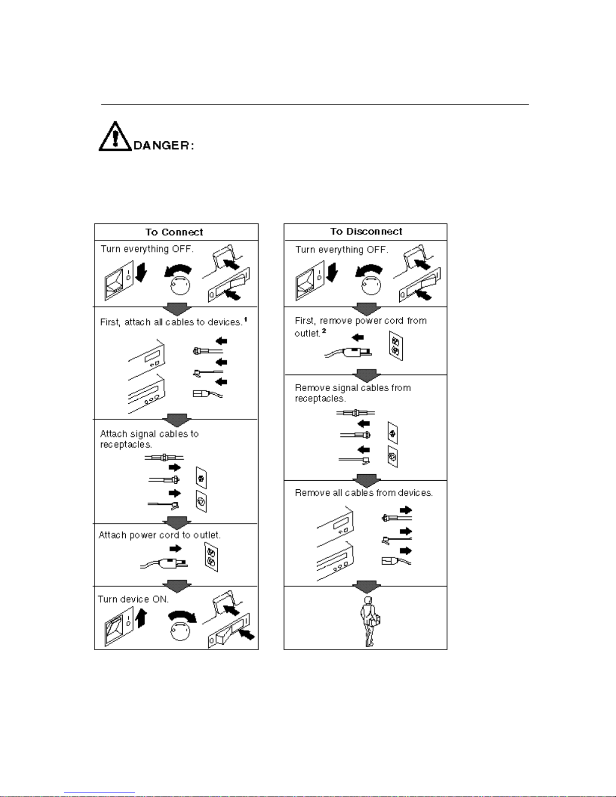
Safety Information
Electrical current from power, telephone, and communication cables is hazardous.
To avoid shock hazard, connect and disconnect cables as shown below when
installing, moving or opening the covers of this product or attached devices. The
power cord must be used with a properly grounded outlet.
1
In the U.K., by law, the power cord must be
2
In the U.K., by law, the telephone cable must
disconnected after the telephone line cable. be connected after the power cord.
Page 8
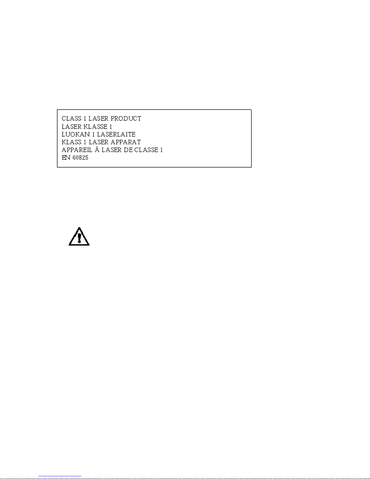
Laser Compliance Statement
5
The CD-ROM drive is a laser product. The drive has a label that
identifies its classification. The label, located on the drive, is
shown below.
The CD-ROM drive is certified in the U.S. to conform to the
requirements of the Department of Health and Human Services 21
Code of Federal Regulations (DHHS 21 CFR) Subchapter J for
Class 1 laser products. Elsewhere, the drive is certified to conform
to the requirements of EN 60825.
CAUTION:
Do not open the drive; no user adjustments or serviceable
parts are inside.
Class 1 laser products are not considered to be hazardous. The
CD-ROM drive has an internal Class 1 gallium-arsenide laser that
is nominally 0.14 milliwatts at 765 to 815 nanometers wavelength.
Page 9

Lithium Battery Notice
The real-time clock contains a lithium battery.
8
CAUTION:
Danger of explosion if battery is incorrectly replaced.
When replacing the battery, use only an equivalent type battery
recommended by the manufacturer. The battery contains lithium and can
explode if not properly used, handled, or disposed of.
Do not:
− − Throw or immerse into water
− − Heat to more than 100° C (212° F)
− − Repair or disassemble
Dispose of the battery as required by local ordinances or regulations.
ATTENTION
Danger d'explosion en cas de remplacement incorrect de la batterie.
Remplacer uniquement par une batterie d'un type équivalent recommandé
par le fabricant. La batterie contient du lithium et peut exploser en cas de
mauvaise utilisation, de mauvaise manipulation ou de mise au rebut
inappropriée.
Ne pas :
− Lancer ou plonger dans l'eau
− Chauffer à plus de 100° C (212° F)
− Réparer ou désassembler
Mettre au rebut les batteries usagées conformément aux règlements
locaux.
Note:
Please call 1-800-IBM-4333 for information on battery disposal.
Page 10

About This Book
This book provides the instructions for completing your installation;
installing and removing server options; and configuring, modifying,
and troubleshooting your server. This book also provides
information to help you solve some of the simpler problems that
might occur. If you have not yet set up your server, refer to the
Setup sheet for instructions on cabling the server. Refer to the User's
Reference for more detailed information about the server's features.
If your server came with a RAID adapter installed, refer to the
RAID adapter documentation for instructions for configuring your
disk arrays.
How This Book is Organized
Chapter 1, “Introducing the PC Server 704,” introduces and
describes the PC Server 704. This chapter also includes an overview
of the server's features and components. In addition, this chapter
contains instructions for starting the server and using the CD-ROM
drive. Also included are instructions for installing operating
systems and completing your installation.
Chapter 2, “Configuring Your Server,” contains instructions for
configuring your server. Also included are instructions for using
various utility programs.
Chapter 3, “Installing Options,” contains step-by-step instructions
for installing and removing hardware options, such as
memory-module kits, adapters, and internal drives. Instructions for
connecting external options are also included in this chapter.
Chapter 4, “Solving Problems,” contains information to help you
solve simple problems that you might encounter with your server.
This chapter includes an overview of diagnostic tools, instructions
for testing the server, lists of error messages, and troubleshooting
charts. This chapter also contains information about checking the
server for damage, and resolving configuration conflicts.
Chapter 5, “Getting Help, Service, and Information,” contains
information to help you solve more complex problems that you
might encounter with your server. This chapter provides
instructions on how to obtain service and technical assistance for
Copyright IBM Corp. 1997 xi
Page 11

About This Book
your PC Server 704 and other IBM products that you might plan to
use. This chapter also contains information about other
publications, products, warranties, and services that IBM offers.
Also included are fax numbers, toll-free telephone numbers, and
access information for electronic bulletin boards, online services, and
the World Wide Web.
Appendix A, “Server Records,” provides a section to record and
update important information about your server, including the serial
number, key number, and device records (which contain
configuration information). Whenever you add options to your
server, be sure to update the information in this appendix.
Appendix B, “Notices,” contains product notices and trademarks.
If you find a term that you are not familiar with, refer to the
glossary located in the back of the User's Reference.
xii PC Server 704 User's Handbook
Page 12

About This Book
Notices Used in This Book
This book contains information notices that relate to a specific topic.
The Attention and Caution notices also appear in a multilingual
safety booklet. Each notice is numbered for easy reference to the
corresponding notices in the safety booklet. The notice definitions
are as follows:
Notes
These notices provide important tips, guidance, or advice.
Attention
These notices indicate possible damage to programs, devices, or
data. An attention notice appears just before the instruction or
situation in which damage could occur.
Caution
These notices indicate situations that potentially can be
hazardous to you. A caution notice appears just before the
instruction or situation that could be hazardous.
About This Book xiii
Page 13

About This Book
Related Publications
In addition to this handbook, the following publications are
included with your server:
The Setup sheet contains the instructions for cabling your server.
The User's Reference contains detailed information about the
advanced features of your server.
The SCSI Software User's Guide describes the factors that you
might want to consider before installing small computer system
interface (SCSI) hardware and SCSI-related software in your
server. This book also contains information about SCSI device
drivers and describes the SCSI utility programs that you can use
to configure the SCSI devices that you attach to the SCSI
controllers on the system board.
The PC Server Service and Support pamphlet contains important
information and phone numbers to call for different types of
support for your PC Server.
PC Server 704 Safety Information is a multilingual safety booklet.
The PCI RAID adapter support package comes with disk-array
models. The documentation provided in the package contains
information about the PCI RAID adapter and provides
instructions for configuring models that come with a disk-array
controller. These instructions include step-by-step procedures
for the tasks necessary to configure, add, change, and delete one
or more disk arrays.
The IBM PC Server Hardware Maintenance Manual Supplement is
available for purchase. It contains error codes, advanced diagnostic
procedures, and a parts catalog for most models. This manual is
intended for trained service technicians. (Diagnostic Diskettes are
not included.)
Additional publications are available for purchase from IBM. For a
list of publications available in your country:
In the U.S., Canada, and Puerto Rico, call 1-800-879-2755.
In other countries, contact your IBM reseller or IBM marketing
representative.
xiv PC Server 704 User's Handbook
Page 14

Welcome and Thank You
We appreciate your decision to purchase an IBM PC Server 704.
Your server offers speed, power, expandability, and compatibility
with various existing network operating systems and application
programs.
The PC Server 704 also comes with IBM PC Server Startup Support,
which provides coverage during the first 90 days after installation.
IBM PC Server Startup Support is available to PC Server customers
at no additional charge. This comprehensive program enhances
IBM's support for setup, installation, configuration, and problem
determination. It provides assistance for popular network operating
systems and network adapters from IBM and other vendors. If you
need assistance, call IBM at 1-800-772-2227 in the U.S. and Puerto
Rico, or call IBM at 1-800-565-3344 in Canada. In all other countries,
contact the IBM support organization that services your area, your
IBM marketing representative, or your IBM reseller.
Copyright IBM Corp. 1997 xv
Page 15

Chapter 1. Introducing the PC Server 704
Your IBM PC Server 704 offers multiple (up to four) Intel
Pentium Pro microprocessor capability, so that you can take
advantage of symmetric multiprocessing (SMP) technology. You
can maximize the benefits of this technology, provided that you
have an SMP-capable operating system installed in your server.
For the latest information about SMP operating systems supported
by your PC Server 704:
In the U.S. and Puerto Rico, call 1-800-772-2227.
In Canada, call 1-800-565-3344.
In all other countries, contact the IBM support organization that
services your area, your IBM marketing representative, or your
IBM reseller.
Your server also has a built-in peripheral component interconnect
(PCI) advanced bus. This bus and the Pentium Pro microprocessors
combine to create a high-performance local area network (LAN)
server platform to handle heavy file-server applications or moderate
database applications. All models have two embedded UltraSCSI
controllers and offer super video graphics array (SVGA) graphics.
As an open-architecture, industry-standard system, the PC Server
704 has been tested for compatibility with numerous IBM and
non-IBM adapters and devices. Rugged dependability is achieved
by incorporating various quality standards and design points.
Your PC Server 704 comes with a full three-year, on-site limited
warranty, plus IBM PC Server Startup Support. Some PC Server 704
models also come with IBM ServerGuide.
Refer to the Setup sheet for instructions for setting up and cabling
your server.
This chapter contains an overview of the server features and
components. In addition, this chapter describes how to start the
server and use the CD-ROM drive. It also describes the
ServerGuide package and how to complete your installation.
Copyright IBM Corp. 1997 1
Page 16

This User's Handbook also describes how to configure and use the
server, and how to install and remove options. The troubleshooting
information will help you solve some of the simpler problems that
might occur. Appendix A, “Server Records” on page 271 provides
a section for you to record all the important information about your
server.
Refer to the User's Reference for more detailed information about the
server features. That book also includes a glossary, warranty
information, and other important notices.
Refer to the SCSI Software User's Guide, or if you have a RAID
adapter installed, to the documentation provided with the RAID
adapter, for information about SCSI device drivers and the utility
programs that you can use to configure the devices that you install.
This chapter contains:
Features at a Glance
........................... 3
Getting Help on the World Wide Web ............... 4
IBM PC Server Startup Support .................... 4
About ServerGuide . . . . . . . . . . . . . . . . . . . . . . . . . . . 5
Server Controls . . . . . . . . . . . . . . . . . . . . . . . . . . . . . . 6
Status Indicators . . . . . . . . . . . . . . . . . . . . . . . . . . . . . 8
Expansion Slots and Input/Output Connectors .......... 10
Padlock Loops and Power Supplies ................. 12
Expansion Bays . . . . . . . . . . . . . . . . . . . . . . . . . . . . . 14
Moving the Server ............................ 16
Before You Begin ............................ 17
Starting the Server ............................ 18
Using the CD-ROM Drive ....................... 21
Installing an Operating System .................... 23
Arranging Your Workspace ...................... 24
Comfort . . . . . . . . . . . . . . . . . . . . . . . . . . . . . . . . 24
Glare and Lighting .......................... 25
Air Circulation . . . . . . . . . . . . . . . . . . . . . . . . . . . . 25
Electrical Outlets and Cable Lengths ............... 26
Installation Checklist . . . . . . . . . . . . . . . . . . . . . . . . . . 27
2 PC Server 704 User's Handbook
Page 17

Features at a Glance
The features in your server vary according to the model that you purchased. The following is a
summary of the features that are available with the PC Server 704.
Microprocessors
Intel Pentium Pro with:
– Level-1 cache, 16 KB
– Level-2 cache, 512 KB
Expandable to four Pentium Pro
microprocessors
Memory
256 MB of system memory,
expandable to 2 GB
Industry standard, 60 ns, parity
Sixteen memory sockets
Two-way and four-way
interleaved
Error correcting code support
Diskette Drive
Standard: One 3.5-inch, 1.44 MB
CD-ROM Drive:
Standard: IDE CD-ROM Drive
Keyboard
Standard: 101-key or 102-key
Mouse
Standard: IBM Mouse
Upgradable POST and BIOS
Flash ROMs on the system board
Information Panel
Two 16-character lines
LCD display of status information
Expansion Slots and Bays
Ten expansion slots:
– Six 32-bit PCI slots
– Four 32-bit EISA/ISA slots
Seventeen expansion bays:
– Twelve hot-swap hard disk
drive bays
– Four removable-media drive
bays
– One dedicated, 3.5-inch
diskette drive bay
Video
SVGA controller
Video memory, 512 KB,
expandable to 1 MB
Compatibility:
– Color graphics adapter (CGA)
– Enhanced graphics adapter
(EGA)
– Video graphics array (VGA)
– Hercules graphics
Hard Disk Drives
Number of drives and drive
capacities
*
are model dependent
Can support up to 12 hot-swap
hard disk drives
Security Features
Door lock
Padlock loops
Integrated Functions
LED usability support
SVGA video connector
Two serial connectors
Parallel connector
Mouse connector
Keyboard connector
Battery-backed clock and
time/date calendar
Two UltraSCSI connectors
Hot Swap Power Supplies
Two or three 420-watt supplies
standard with:
– Automatic range voltage
selection (115–230 V ac)
– Built-in overload and surge
protection
For redundant power on
two-supply models, an optional
420-watt supply with:
– Automatic range voltage
selection
– Built-in overload and surge
protection
SCSI Controller
Two built-in bus-master UltraSCSI
controllers (all models)
PCI RAID adapter (disk-array
models only)
*
When referring to hard disk drive capacity, MB stands for 1 000 000 bytes and GB stands for 1 000 000 000 bytes. Total
user-accessible capacity may vary depending on operating environments.
Chapter 1. Introducing the PC Server 704
3
Page 18

Getting Help on the World Wide Web
You can access the latest information about product compatibility
and configuration on the World Wide Web. This information is
updated as new PC Server products are announced. The following
is a sample of the information available at
http://www.pc.ibm.com/servers/ on the World Wide Web.
Current updates to device drivers, flash BIOS, and other code.
A listing of products that have been tested for compatibility
with IBM PC Servers.
Certification and compatibility information about Network
operating systems (NOS) and operating systems (OS).
For additional information, service, or assistance, see Chapter 5,
“Getting Help, Service, and Information” on page 261.
IBM PC Server Startup Support
The IBM PC Server Startup Support program provides
comprehensive telephone assistance 24 hours a day, 7 days a week,
during the first 90 days after installation of your server at no
additional charge.*IBM gives you direct access to trained specialists
who can help you set up, install, and configure your server.
Help is available for IBM and non-IBM network operating systems,
network interface adapters, and other optional peripherals. To
receive a list of the network products supported by the IBM PC
Server Startup Support program, call the IBM PC Company
Automated Fax System at 1-800-426-3395 in the U.S., or call
1-800-465-3299 in Canada, and ask for document number 16125. For
more information about this program, or for help with the
installation of your server:
In the U.S. and Puerto Rico, call IBM at 1-800-772-2227.
In Canada, call IBM at 1-800-565-3344.
*
Response time will vary depending on the number and nature of calls received.
4 PC Server 704 User's Handbook
Page 19

About ServerGuide
In all other countries, contact your IBM reseller or IBM
marketing representative.
Note: For additional information, service, or assistance, see
Chapter 5, “Getting Help, Service, and Information” on
page 261.
About ServerGuide
The PC Server 704 comes with the IBM ServerGuide package, which
contains CDs that you can use to install your operating system.
Depending upon the ServerGuide version that came with your
server, your operating system might be installed automatically, or
ServerGuide might provide an assisted operating-system installation.
Refer to the information provided with your ServerGuide package
for more information.
Chapter 1. Introducing the PC Server 704 5
Page 20

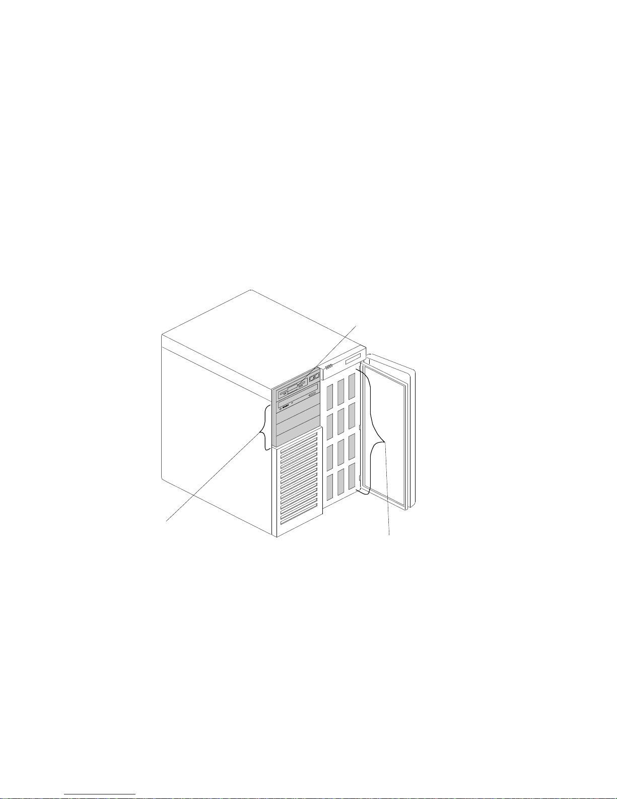
Server Controls
The most commonly used controls on the front of the server appear
in the following illustration.
Door
Lock
Diskette Eject
Button
Power On/Off
Button
Reset
Button
CD-ROM Eject
Button
6 PC Server 704 User's Handbook
Page 21

Door Lock: You can lock the door on your server to deter
tampering with the internal components.
Power On/Off Button: Press this convex button to manually
turn the server on or off.
Reset Button: Press this concave button to reset the system and
run the power-on self-test (POST).
Diskette-Eject Button: Press this button to remove a diskette
from the drive.
CD-ROM Eject Button: Press this button to eject the CD-ROM
tray from its drive so that you can insert or remove a CD.
Chapter 1. Introducing the PC Server 704 7
Page 22
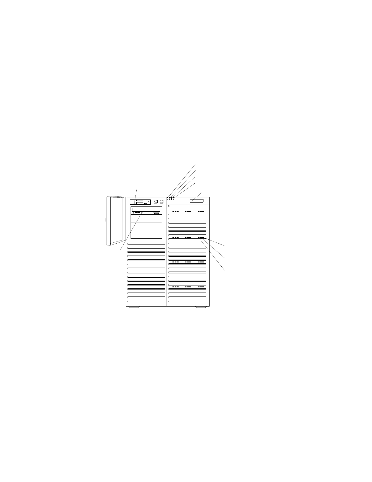
Status Indicators
The most commonly used status indicators on the front of the server
appear in the following illustration.
Diskette In-Use
Light
Power On Light
Power Failure Light
Cooling Failure Light
Drive Failure Light
Information Panel
Hard Disk
Power-On
Hard Disk
In-Use
Hard Disk
Fault
CD-ROM
In-Use
Light
8 PC Server 704 User's Handbook
Page 23

CD-ROM Drive In-Use Light: This light indicates CD-ROM
drive activity. When this light is green, power is being applied
to the drive. When this light is amber, the drive is being
accessed (read from or written to).
Diskette Drive In-Use Light: This green light indicates
diskette-drive activity.
Power-On Light: This green light indicates that the power-on
button is in the on position.
Power-Failure Light: This amber light indicates there is no
alternating current (AC) present.
Cooling-Failure Light: This amber light indicates a fan failure.
Drive-Failure Light: This amber light indicates a drive failure.
Information Panel: System monitoring information will appear
on this liquid crystal display (LCD) if you install a
system-management program and enable the information panel
using the System Configuration Utility (SCU) program.
Hard Disk Status Lights: Each of the 12 hot-swap drive bays
has a set of three status lights. These status lights indicate the
following:
Hard Disk Fault Light: When lit continuously, this amber
light indicates a faulty hard disk drive.
Hard Disk In-Use Light: When flashing, this green light
indicates that the server is writing to or reading from the
hard disk. However, on disk-array models, this light is
operating-system dependent.
Hard Disk Power-On Light: When lit continuously, this
green light indicates that a drive is installed and power is
present.
Chapter 1. Introducing the PC Server 704 9
Page 24
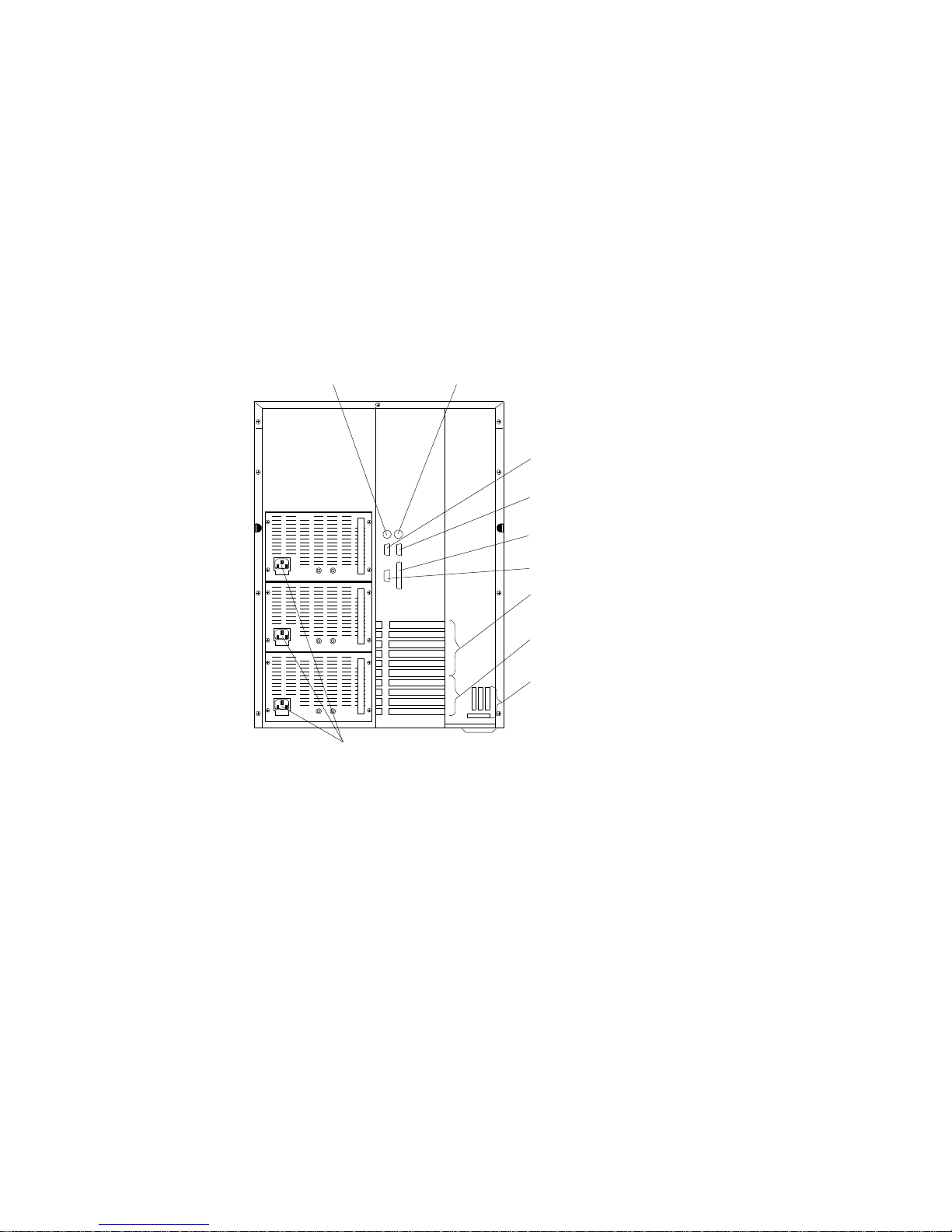
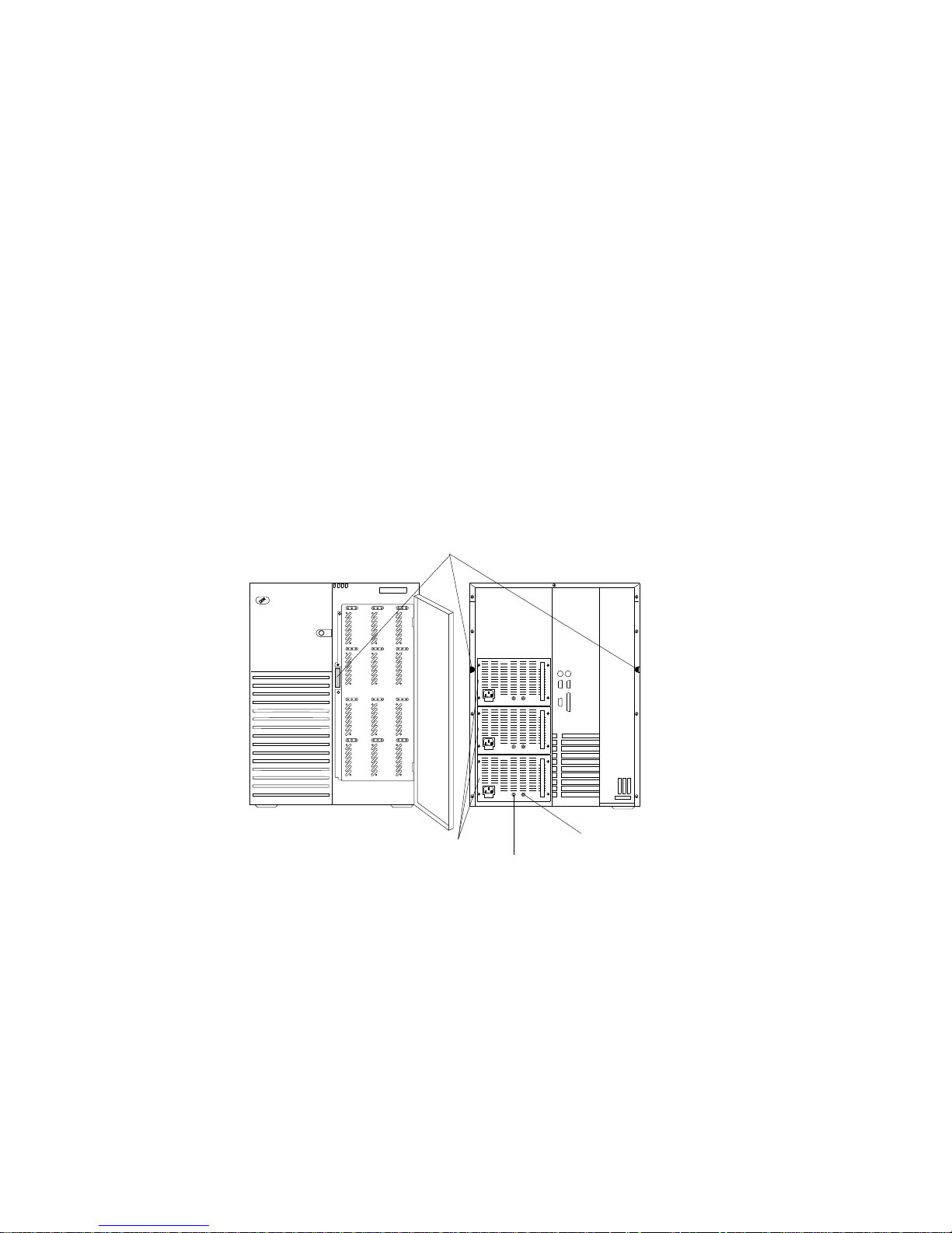
Expansion Slots and Input/Output Connectors
Expansion Slots and Input/Output Connectors
The following illustration shows the expansion slots and the
input/output connectors (ports) on the rear of the server.
Keyboard Connector
Mouse Connector
Serial Connector
(Com 2)
Serial Connector
(Com 1)
Video Connector
Parallel Connector
PCI Expansion
Slots
EISA Expansion
Slots
Power Connectors
External SCSI
Connector
Knockouts
10 PC Server 704 User's Handbook
Page 25

Expansion Slots and Input/Output Connectors
Keyboard Connector: The cable from your keyboard connects
here.
Mouse Connector: This is where the mouse cable connects to
the server. This port sometimes is called an auxiliary-device or
pointing-device port.
Serial Connectors: Your server has two, 9-pin serial connectors
(COM1 and COM2). The serial signal cable for a modem or
other serial device usually connects here. If you are using a
25-pin signal cable, you need a 9-pin-to-25-pin adapter cable.
Video Connector: The monitor signal cable attaches to this
15-pin connector.
Parallel Connector: This is where the signal cable for a parallel
printer or other parallel device connects to your server.
Expansion Slots: The PC Server 704 has four extended industry
standard architecture (EISA) expansion slots and six peripheral
component interconnect (PCI) expansion slots. You can install
PCI or EISA adapters to provide communication, specialized
graphics, and sound. Many adapters provide bus-master
capabilities, which enable the adapters to perform operations
without interrupting the system microprocessors.
The four EISA expansion slots are available for future
expansion. Disk-array models come with a PCI RAID adapter
installed as a standard feature. The remaining four or five PCI
expansion slots are available for future expansion.
External SCSI Connector Knockouts: An optional external SCSI
cable can be attached to an internal SCSI connector by using one
of these knockouts.
Power Connectors: The system power cords connect here.
Note: To see these and other connector locations on the system
board, refer to the system-board layout in “The System
Board” on page 280.
Chapter 1. Introducing the PC Server 704 11
Page 26
Padlock Loops and Power Supplies
The following illustration shows the power supply bays and
padlock loops on your PC Server 704.
Notes:
1. See “Installing Hot-Swap Power Supplies” on page 188 for
instructions for installing a power supply.
2. Some PC Server 704 models come with three power supplies
preinstalled.
Power Supplies
Power Good Light
Current Good Light
Padlock Loops
12 PC Server 704 User's Handbook
Page 27
Padlock Loops: The two side cover padlock loops enable you to
insert padlocks (not provided) to secure the side covers to the
system unit.
The electro-magnetic interference (EMI) panel on the front of the
server also has a padlock loop. You can insert a small padlock
(not included) through this loop to secure the EMI panel to the
system unit and help prevent unauthorized access to the hard
disk drives in the hot-swap bays.
Hot Swap Power Supplies: All PC Server 704 models support
three hot-swap power supplies. Some models are shipped with
two power supplies installed and some models are shipped with
three power supplies installed. In a three-supply system, the
third power supply provides redundant power.
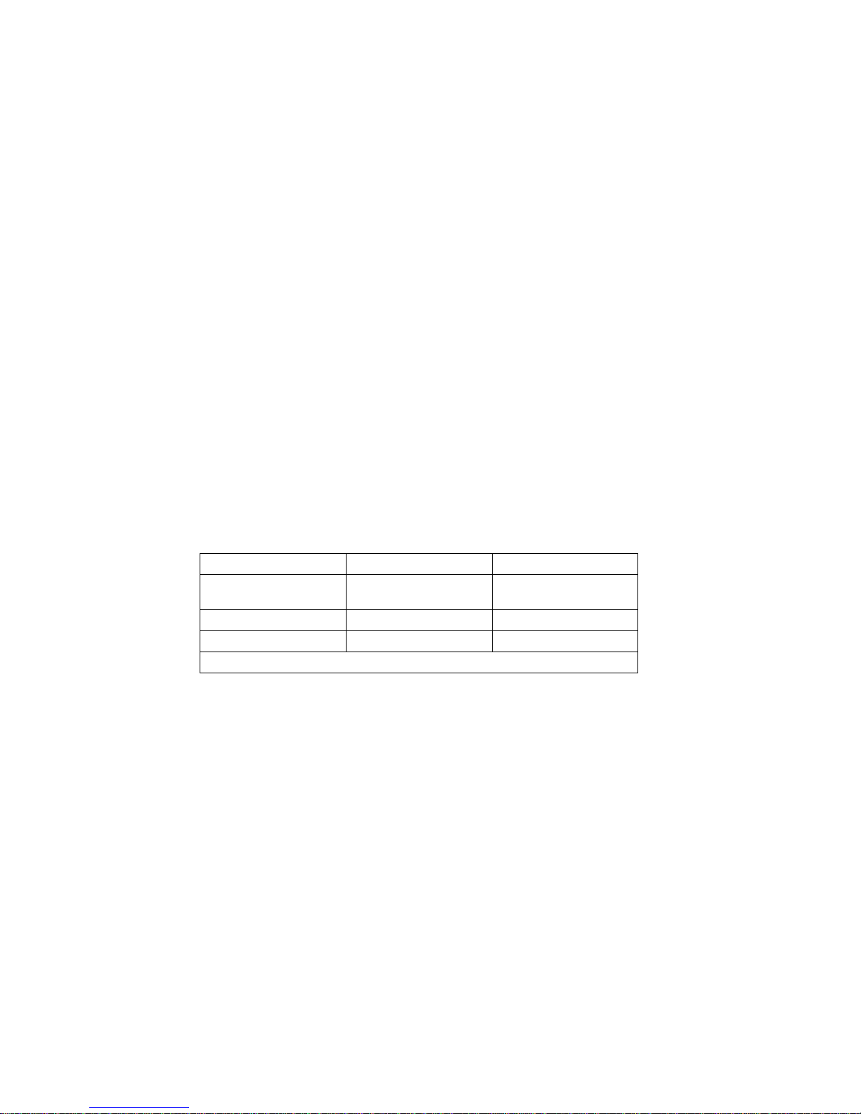
Power-Good Light and Current-Good Light: These green lights
provide status information about the power supply, as follows:
Power-Good Light (PS) Current-Good Light (I) Description
On On Power supply on and
OK
Off Off or On Power supply failure
On Off Current limit
Note: To ensure that the power supply is operational, both lights must be on.
Chapter 1. Introducing the PC Server 704 13
Page 28
Expansion Bays
The following illustration shows the location of the expansion bays
in your server. For installation instructions and information on the
types of drives that you can install in these bays, see Chapter 3,
“Installing Options” on page 61.
Removable Media
Bays
Hot Swap Bays
Diskette Drive Bay
14 PC Server 704 User's Handbook
Page 29

Diskette Drive Bay: This dedicated bay contains a 3.5-inch,
1.44 MB diskette drive, which comes standard in all PC Server
704 models. This drive uses 1 MB and 2 MB diskettes. For
optimum use, format 1 MB diskettes to 720 KB and format
2 MB diskettes to 1.44 MB.
Removable-Media Drive Bays: Your PC Server 704 has four
drive bays for removable-media devices such as tape-backup
drives, compact disc read-only memory (CD-ROM) drives,
optical drives, or additional diskette drives. One of these drive
bays contains a CD-ROM drive, which comes standard in all PC
Server 704 models. For information about inserting CDs and
using the CD-ROM drive, see “Using the CD-ROM Drive” on
page 21.
Hot-Swap Bays: The hot-swap drive bays support up to 12
UltraSCSI hard disk drives. The number of preinstalled drives
and their capacities vary by model. The hot-swap feature
enables you to remove and replace hard disk drives without
turning off the server.
Chapter 1. Introducing the PC Server 704 15
Page 30
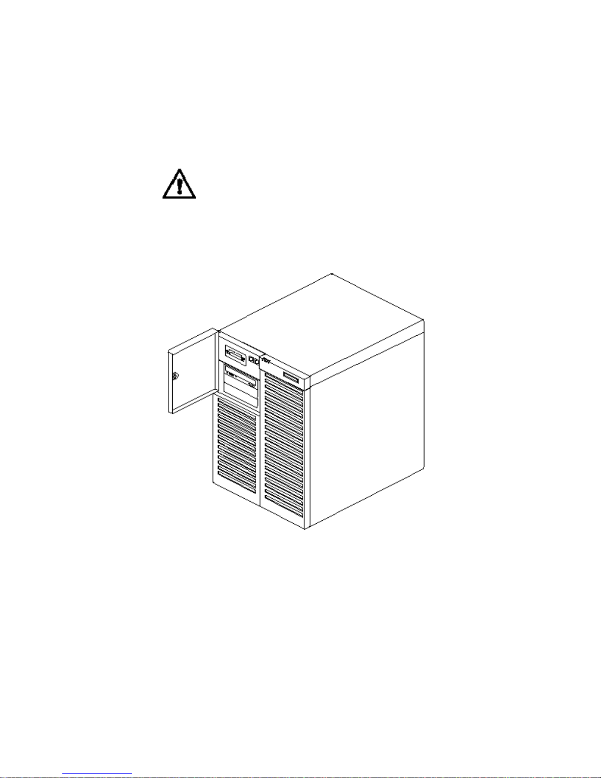
Moving the Server
Moving the Server
6
CAUTION:
Due to the weight of the server, do not attempt to lift the
server by yourself. To avoid possible injury while moving or
lifting the server, ask another person to help you.
PC Server 704 User's Handbook
Page 31

Before You Begin
If you have not already done so, unpack your server. If you are not
installing any optional hardware now, connect the cables and power
cords. Follow the instructions on the Setup sheet that comes with
your server. After you complete these tasks, return here for further
instructions.
Make sure you have an adequate number of properly grounded
electrical outlets for your server, monitor, and any other options
that you intend to install.
Place your server in a location that is dry. Rain or spilled
liquids might damage your server.
Leave about 127 mm (5 in.) of space around the front and rear
of your server to allow the server's cooling system to work
properly.
Have a supply of 1 MB and 2 MB, 3.5-inch diskettes available.
You will need these diskettes later, when you install your
operating system and backup your configuration and all
important data.
Chapter 1. Introducing the PC Server 704 17
Page 32

Starting the Server
Starting the Server
1. Turn on your monitor and adjust the Brightness and Contrast
controls to the approximate midpoint.
You can readjust these controls and the monitor location for
personal viewing comfort after you turn on your server.
Note: The locations of the Power Switch and the Brightness and
Contrast controls on your monitor might be different
from those shown above.
2. Adjust the keyboard feet and position the keyboard for personal
typing comfort.
18 PC Server 704 User's Handbook
Page 33

Starting the Server
3. Locate the keys; then, unlock and open the door. If the diskette drive
contains packing material or a diskette, remove it from the drive.
4. If you installed any external devices, such as printers, plotters, or modems,
turn them on now.
5. Turn on the server.
To turn on the server, press the Power On/Off button. The Power-on light comes
on. The power-on self-test (POST) begins.
3
CAUTION:
The convex On/Off button on the front of the server does
not turn off the electrical current supplied to the server.
To remove all electrical current from the server, you must
unplug all server and power supply power cords from the
wall outlets
.
Page 34

Starting the Server
6. Check your monitor. The screen displays the IBM logo and a
number that represents the amount of available server memory.
The server beeps once to indicate that it is working properly.
Notes:
If you hear more than one beep, or no beep, check to
see if an error message appears. If no operating
system is installed, the system prompts you to insert
a startable diskette. Refer to “Installing an Operating
System” on page 23 and to the information provided
with your ServerGuide package and with your
operating system for more information. If an error
message appears, or if your screen is blank, see
Chapter 4, “Solving Problems” on page 209.
If your server stops running during testing or normal
operation, call for service. Describe the problem to
the service technician.
20 PC Server 704 User's Handbook
Page 35

Using the CD-ROM Drive
An IDE CD-ROM drive is a standard feature on all PC Server 704
models. To use the CD-ROM drive:
1. Have the CD ready.
2. Press the CD-ROM tray-release button.
CD-ROM
In-Use Light
CD-ROM
Tray
Manual Tray
Release Opening
Tray Load and
Eject Button
Note: If the CD-ROM tray does not extend out, insert the end
of a paper clip into the manual tray-release opening and
gently pull the tray open.
Chapter 1. Introducing the PC Server 704 21
Page 36

3. Locate the tabs in the corners of the tray.
4. With the label information facing up, center and place the CD
on the tray.
5. Press the Tray Load and Eject button to move the CD-ROM tray
back into the drive.
22 PC Server 704 User's Handbook
Page 37

Installing an Operating System
Installing an Operating System
The operating system that you select allows you to optimize some of
the features in your server. Your server offers multi-processor
capability so that you can take advantage of SMP technology. You
can maximize the benefits of this technology, provided that you
have an SMP-capable operating system installed in your server.
For the latest information about SMP-capable operating systems
supported by your PC Server 704:
In the U.S. and Puerto Rico, call 1-800-772-2227.
In Canada, call 1-800-565-3344.
In all other countries, contact your IBM reseller or IBM
marketing representative.
If your server came with a RAID adapter preinstalled, logical drives,
except the startup drive, can be any size. However, the startup
drive must be less than 2046 MB if you use the high-performance
file system (HPFS), or 1024 MB if you use the file-allocation table
(FAT). This applies to all operating systems.
Refer to the information that came with your ServerGuide package
for instructions on installing your operating system.
Chapter 1. Introducing the PC Server 704 23
Page 38

Arranging Your Workspace
Arranging Your Workspace
To get the most from your server, arrange both the equipment you
use and your work area to suit your needs and the kind of work
you do. Your comfort is of foremost importance, but light sources,
air circulation, and the location of electrical outlets also can affect
the way you arrange your workspace.
Comfort
Although no single working position is ideal for everyone, here are
a few guidelines to help you find a position that suits you best.
Sitting in the same position for a long time can cause fatigue. A
good chair can make a big difference. The backrest and seat should
adjust independently and provide good support. The seat should
have a curved front to relieve pressure on the thighs. Adjust the
seat so that your thighs are parallel to the floor and your feet are
either flat on the floor or on a footrest.
When using the keyboard, keep your forearms parallel to the floor
and your wrists in a neutral, comfortable position. Try to keep a
light touch on the keyboard and your hands and fingers relaxed.
You can change the angle of the keyboard for maximum comfort by
adjusting the position of the keyboard feet.
Viewing Distance
Lower
Back
Support
Seat
Height
Adjust the monitor so the top of the screen is at, or slightly below,
eye level. Place the monitor at a comfortable viewing distance,
24 PC Server 704 User's Handbook
Page 39

Arranging Your Workspace
usually 51 to 61 cm (20 to 24 in.), and position it so you can view it
without having to twist your body. Also position other equipment
you use regularly, such as the telephone or a mouse, within easy
reach.
Glare and Lighting
Position the monitor to minimize glare and reflections from
overhead lights, windows, and other light sources. Even reflected
light from shiny surfaces can cause annoying reflections on your
monitor screen. Place the monitor at right angles to windows and
other light sources, when possible. Reduce overhead lighting, if
necessary, by turning off lights or using lower wattage bulbs. If you
install the monitor near a window, use curtains or blinds to block
the sunlight. You might have to adjust the Brightness and Contrast
controls on the monitor as the room lighting changes throughout the
day.
Where it is impossible to avoid reflections or to adjust the lighting,
an antiglare filter placed over the screen might be helpful.
However, these filters might affect the clarity of the image on the
screen; try them only after you have exhausted other methods of
reducing glare.
Dust buildup compounds problems associated with glare.
Remember to clean your monitor screen periodically using a soft
cloth moistened with a nonabrasive liquid glass cleaner.
Air Circulation
Your server and monitor produce heat. Your server has one or
more fans that pull in fresh air and force out hot air. The monitor
lets hot air escape through vents. Blocking the air vents can cause
overheating, which might result in a malfunction or damage. Place
the server and monitor so that nothing blocks the air vents; usually,
127 mm (5 in.) of air space is sufficient. Also, make sure the vented
air is not blowing on someone else.
Chapter 1. Introducing the PC Server 704 25
Page 40

Arranging Your Workspace
Electrical Outlets and Cable Lengths
The location of electrical outlets and the length of power cords and
cables that connect to the monitor, printer, and other devices might
determine the final placement of your server.
When arranging your workspace:
Avoid the use of extension cords. When possible, plug the
server power cord directly into an electrical outlet.
Keep power cords and cables neatly routed away from
walkways and other areas where they might get kicked
accidentally.
For more information about power cords, refer to the User's
Reference.
26 PC Server 704 User's Handbook
Page 41

Installation Checklist
Installation Checklist
Important
Be sure to maintain at least 127 mm (5 in.) of space at the rear of
the server to allow the server's cooling system to work properly.
Blocking the air vents can cause overheating, which might result
in a malfunction or permanent damage.
Your server hardware is set up, and you are ready to learn about
your server. The order in which you do these tasks is up to you.
Use the following checklist as a guide.
Ø Learn about your server and the system utility programs
Your server comes with utility programs to help you
configure your server and troubleshoot problems. See
Chapter 2, “Configuring Your Server” on page 29 for
information about configuring your server and using these
utility programs. See Chapter 4, “Solving Problems” on
page 209 for details about troubleshooting. If your server
came with a RAID adapter preinstalled, read and become
familiar with your RAID adapter documentation.
Ø Record your identification numbers
Your server has important identification information that you
will need if you have it serviced. Appendix A, “Server
Records” on page 271 shows where to find these numbers,
and provides space to record and retain information.
Ø Install options
If you have options to install, you might want to complete
these installations now. See Chapter 3, “Installing Options”
on page 61 for step-by-step installation instructions.
Chapter 1. Introducing the PC Server 704 27
Page 42

Installation Checklist
Ø Complete setting up your PC Server 704
If you need to set the date, time, passwords or drive-startup
sequences, or do other system setup tasks, use the procedures
in Chapter 2, “Configuring Your Server” on page 29.
Ø Install device drivers
If you install your operating system without using
ServerGuide, be sure to install the SCSI, RAID adapter, and
network-adapter device drivers. If you use ServerGuide to
install your operating system, verify that the appropriate
device drivers are installed correctly. These device drivers are
on the diskettes that come with your server.
These diskettes contain README files to help you install
device drivers and complete your installation. Be sure to
review the README files before you install the device drivers.
Ø Install option files
Some options that you install might come with a diskette that
contains device drivers, configuration files, or test programs.
To install these files (after your operating system is installed),
follow the instructions that come with the diskettes.
Ø Install application programs
To install application programs, follow the instructions
supplied with each application program.
Ø Review your User's Reference
The User's Reference contains information about the hardware
and software features and expansion capabilities of your
server. It also contains information about the
microprocessors, memory, data-storage devices, video
subsystems, input and output (I/O) ports, SCSI subsystem,
and security. The User's Reference also includes a glossary
and your product warranty information.
28 PC Server 704 User's Handbook
Page 43

Chapter 2. Configuring Your Server
This chapter provides information about the configuration and
utility programs that come with your server, as well as instructions
that tell you when and how to use them.
This chapter contains:
Configuration Overview
. . . . . . . . . . . . . . . . . . . . . . . . 30
Using the Setup Program ....................... 31
Changing Settings . . . . . . . . . . . . . . . . . . . . . . . . . . 31
Starting the Setup Program ..................... 32
Recording and Restoring Default Settings ............ 33
Disabling the Diskette Drive .................... 34
Using the System Configuration Utility Program ......... 35
Backing Up the SCU Program Diskette .............. 36
Starting the System Configuration Utility Program ...... 37
Defining Security . . . . . . . . . . . . . . . . . . . . . . . . . . . . 42
Administrative Password . . . . . . . . . . . . . . . . . . . . . . 44
User Password . . . . . . . . . . . . . . . . . . . . . . . . . . . . 45
Setting the Drive-Startup Sequence ................ 46
Secure Mode . . . . . . . . . . . . . . . . . . . . . . . . . . . . . 47
Configuring EISA, ISA, and PCI Adapters ............. 48
Configuring ISA or EISA Features and Options ........ 49
Configuration Conflicts . . . . . . . . . . . . . . . . . . . . . . . . . 51
Resolving Hardware Configuration Conflicts .......... 52
Resolving Software Configuration Conflicts ........... 53
Using the SCSISelect Utility Program ................ 54
Starting the SCSISelect Utility Program ............. 54
SCSISelect Utility Main Menu ................... 55
SCSISelect Utility Bus:Device Options Menu .......... 55
Copyright IBM Corp. 1997 29
Page 44

Configuration
Configuration Overview
You play a key role in how your server allocates resources to
organize and interconnect hardware devices and software programs.
This allocation process is referred to as configuration. The steps
required to configure your server depend on the number and
variety of devices and programs that you install.
Your server has the flexibility and power to support several types of
adapters. This flexibility lets you choose from among thousands of
adapters and devices that comply with any of the following
standards:
Peripheral Component Interconnect (PCI)
Extended Industry Standard Architecture (EISA)
Industry Standard Architecture (ISA)
Small Computer System Interface (SCSI)
In general, the greater the number and variety of hardware devices
and software programs you install in your server, the more you will
have to interact with your server and your devices to correctly
configure your system.
Several hardware configuration utility programs come with your
server. Use the built-in Setup program to define the system date
and time, and control access to the diskette drive.
The System Configuration Utility (SCU) program is your main tool
to configure the system. Use it to define most configuration
settings. The values that you enter in the System Configuration
Utility program override the entries in the Setup program.
See “Using the SCSISelect Utility Program” on page 54 and the SCSI
Software User's Guide for information on using the SCSI utility
programs to configure the SCSI devices that you attach to the SCSI
controllers on the system board.
Configuration switches and jumpers reside on the system board.
The switches enable you to define some configuration settings.
30 PC Server 704 User's Handbook
Page 45

Setup Program
If your server came with a RAID adapter preinstalled, refer to the
RAID adapter documentation for configuration information.
Using the Setup Program
The Setup program stores configuration values in nonvolatile
random-access memory (NVRAM) and in the battery-backed
memory of the real-time clock. Entries that you make in the System
Configuration Utility program overwrite the entries made in the
Setup program.
You perform much of the system configuration through the System
Configuration Utility program, not the Setup program. Because the
System Configuration Utility program resides on diskette, you must
enable the diskette drive before using the System Configuration
Utility. After configuring the system, you might prefer to secure it
against casual or unauthorized access by running the Setup program
to disable the diskette drive.
In most cases, the server operates using the default settings, and
you need to change the settings only to resolve configuration
conflicts or to enable or change device function (for example,
defining diskette drive types).
Review this section and the information that came with the device
before making changes. Also, record the current settings (see
“Recording and Restoring Default Settings” on page 33) before
making any changes.
Changing Settings
You can advance through the screens by pressing the Page Up
(PgUp) or Page Down (PgDn) key. Use the Up Arrow (↑) or Down
Arrow (↓) key to advance through the items on the screen. Change
selections by first advancing to the item that you want to change;
then, use the plus key (+) or minus key (−) to make the change.
Online Help information is available on the right side of the screen
for each selection. To access menu-bar selections within the Setup
program, use the Right Arrow (→) or Left Arrow (←) key.
Chapter 2. Configuring Your Server 31
Page 46

Setup Program
The Setup program consists of the following menu bar selections:
Main: Select this choice to set the System Time and Date. This
menu also allows you to view or change configuration settings for
diskette drives.
Advanced: This choice allows you to view the settings of integrated
peripherals, and identify the type and speed of the processors.
Security: Select this choice to set passwords.
Help: General help information is available by pressing F1.
Starting the Setup Program
To access the Setup program:
1. Remove all diskettes from the server.
2. Turn on the server and watch the screen. Be ready to act
quickly.
3. Immediately after the system initialization procedure begins and
before the IBM logo screen appears, the system prompts you to
Press <F1> if you want to run SETUP. As soon as you see that
prompt, press F1. If the Setup program screen does not appear,
restart your system and try again.
Note: If a configuration error occurs, a prompt appears before
the operating system starts (see “Configuration Conflicts”
on page 51).
4. If you have set a user or administrative password, the system
prompts you to enter it. If you have set both passwords, enter
either one.
5. Follow the instructions on the screen to view or change the
configuration.
You must correctly exit from the Setup program to save the
configuration information.
6. Press Esc or move the cursor to the Exit option on the menu
bar.
7. Select Exit from the menu bar.
32 PC Server 704 User's Handbook
Page 47

Setup Program
8. Select Exit Saving Changes.
Recording and Restoring Default Settings
If you have a printer attached to your server, you can use the Print
Screen key to print the configuration settings. The default settings
are helpful when you install additional options, or if the system
requires service. Also, record the new settings each time that you
make changes. Be sure to record the current configuration settings
in “Installed Device Records” on page 272. You can restore default
settings by using the Setup program.
To restore default settings:
1. Turn on the server.
2. Press F1 to enter the Setup program.
3. Select Exit from the menu bar.
4. Select Load Setup Defaults.
Chapter 2. Configuring Your Server 33
Page 48

Setup Program
Disabling the Diskette Drive
After configuring the system, you might prefer to secure the system
against casual or unauthorized access by running the Setup program
to disable the diskette drive. This is especially useful in securing
the System Configuration Utility program, which is provided on
diskette. You can disable the diskette drive through the Setup
program:
1. Turn on the server.
2. Press F1 to enter the Setup program.
3. Select Main from the menu bar.
4. Select Floppy Options.
5. Select the drive that you want to disable.
6. Press Esc or move the cursor to the Exit option on the menu
bar.
7. Select Exit from the menu bar.
8. Select Exit Saving Changes.
34 PC Server 704 User's Handbook
Page 49

System Configuration Utility
Using the System Configuration Utility Program
The System Configuration Utility program provides a convenient
method to configure various system settings. This program
automatically configures system adapters and maintains system
parameters. Because the System Configuration Utility program
assigns system resources, conflicts between adapters are less likely
to occur. In most cases, the server operates with the configuration
default settings.
If a conflict does occur, see “Configuration Conflicts” on page 51.
You must use the System Configuration Utility program anytime
you want to change resource allocations, such as:
Adding, deleting, or moving ISA or EISA devices
Resolving conflicts
Maintaining security functions
The System Configuration Utility program automatically configures
PCI devices, Plug and Play devices, and system memory.
Each time that you use the System Configuration Utility program to
configure your server, the configuration information is saved to the
nonvolatile random-access memory (NVRAM) and in a backup file
(with an extension of .CMS). Only devices that you install and
configure correctly appear on the System Configuration Utility
program screens.
Review this section and the information included with the devices
you are adding before making changes. Also, record the current
settings (see “Recording the SCU Program Settings” on page 41)
before making any changes. The values you enter using the System
Configuration Utility program override the entries in the Setup
program.
Chapter 2. Configuring Your Server 35
Page 50

System Configuration Utility
A screen similar to the following appears when you start the SCU
program.
à
@
ð
SYSTEM CONFIGURATION UTILITY, Release x.xx
Step 1: About System Configuration
Step 2: Add and Remove Boards
Step 3: Change Configuration Settings
Step 4: Save Configuration
Step 5: View Switch/Jumper Settings
Step 6: Exit
[Select=ENTER] [Exit=Esc] [Help=F1] [Utilities=F9]
á
ñ
In most cases, the server will operate using the default settings, and
you need to change the settings only to resolve configuration
conflicts or to enable or change device function (for example, define
the drive startup sequence).
Use the following commands to navigate through the screens and
make selections:
Action Press Key
Change between
major menus
← or →
Highlight an item ↑ or ↓
Select an item Enter
End activity
without changing
configuration
Esc
Get help F1
Backing Up the SCU Program Diskette
Use an operating-system command, such as the DOS DISKCOPY
command, to make a complete backup copy of the System
Configuration Utility program diskette. Using the backup copy can
36 PC Server 704 User's Handbook
Page 51

System Configuration Utility
prevent damage to the original diskette. Your operating-system
documentation provides information on backing up diskettes.
Starting the System Configuration Utility Program
To access the System Configuration Utility program:
1. Insert the backup copy of the System Configuration Utility
program diskette into the diskette drive.
2. Turn on the system. Or, if the system is turned on, press
Ctrl+Alt+Del.
Or, at the DOS prompt for drive A, type SCU and press Enter.
The system begins the power-on self-test (POST). If you have
set a user password, the system prompts you to enter it.
Notes:
a. If a user password is set, you must enter it to access
the System Configuration Utility program. If you
have set user and administrative passwords, you can
enter either one.
b. If a configuration error occurs, a prompt appears
before the operating system starts (see “Configuration
Conflicts” on page 51).
3. Press Enter when the SCU title screen appears.
4. Follow the instructions on the Main Menu screen to view or
change the configuration. The remainder of this chapter
explains the menu selections. Refer to “Utilities” on page 41 for
information on the SCU utilities accessible from this screen.
Step 1: About System Configuration
Select About System Configuration for an overview of the program.
You can select from a menu for specific information about each
function.
You can also press F1 for on-line Help information while
performing a configuration function.
Chapter 2. Configuring Your Server 37
Page 52

System Configuration Utility
Step 2: Add and Remove Boards
Select Add and Remove Boards to add, remove, or move any
adapter. The System Configuration Utility program automatically
detects and adds most adapters. This step provides a list of all
correctly configured devices. You can press F6 to add ISA devices
to the configuration.
The server requires configuration files to correctly configure ISA and
EISA adapters. You must copy the configuration file, which has a
file-name extension of .CFG, from the device option diskette to the
System Configuration Utility program diskette before installing the
device in the server.
If you have set an administrative password, the system prompts you
to enter it.
Note: If the administrative password entry prompt appears, you
must enter it to access this selection.
If you have not set an administrative password, the system prompts
you to set one. You can press Esc to continue using the System
Configuration Utility program without setting an administrative
password.
38 PC Server 704 User's Handbook
Page 53

System Configuration Utility
Step 3: Change Configuration Settings
After adding adapters, select this choice to change the configuration,
if necessary. If you change a setting in this step, you might need to
change a switch or jumper setting on the system board or on a
device. See the tables in “Installed Device Records” on page 272 for
a listing of the settings and default values.
All settings will remain in the default position if you do not use this
selection to change the configuration.
If you have set an administrative password and you have not used
the Add and Remove Boards choice during this session, the system
prompts you to enter your password.
Note: If the administrative password entry prompt appears, you
must enter the password to access this selection.
If you have not set an administrative password, the system prompts
you to set one. You can press Esc to continue using the System
Configuration Utility program without setting an administrative
password.
Advanced Options: Press F9 to display the Advanced Options
Menu screen. This screen provides options to display configuration
data. You can select the following choices:
Option Description
Global Resource Map Lists allocated resources.
Board Details Provides details on the adapter highlighted on the
Change Configuration Settings screen.
System Details Displays configuration data on the entire system and
its present state of configuration.
Physical Board ID Lists the identifiers of adapters physically installed in
the system.
Chapter 2. Configuring Your Server 39
Page 54

System Configuration Utility
Step 4: Save Configuration
This choice saves the configuration settings to nonvolatile
random-access memory (NVRAM) and in a backup file (with an
extension of .CMS).
Note: Be certain you want to save this configuration data, because
once you select this choice, the save process begins
immediately.
If you have set an administrative password and you have not used
the Add and Remove Boards, or Change Configuration Settings
choices during this session, the system prompts you to enter it.
Note: If the administrative password entry prompt appears, you
must enter your password to access this selection.
If you have not set an administrative password, the system prompts
you to set one. You can press Esc to continue using the System
Configuration Utility program without setting an administrative
password.
Step 5: Switch/Jumper Settings
Select View Switch/Jumper Settings to display the current settings
of switches and jumpers on any adapter that is switch or jumper
configurable.
40 PC Server 704 User's Handbook
Page 55

System Configuration Utility
Utilities
The Utilities choice controls some aspects of how the system
generates configuration data. For example, the System
Configuration Utility program can prompt the user to manually add
boards. Press F9 from the Main Menu screen to access the Utilities
screen.
Press the space bar to select an option. Refer to the following table
for information on the choices on this menu.
Options Description
Remote Mode Configure a server other than the server that you are using.
Advanced/Dealer
Mode
Maintain settings not typically set by an average user.
Force New
Configuration
Generate all new configuration data for PCI devices. If not
selected, the system uses the existing configuration settings.
Load CFG Files
Manually from
Directory List
Prompt the user to add boards manually.
Ignore ID
Mismatches
Select to have the System Configuration Utility program
load configuration data for all adapters, even adapters
physically present during the last configuration but not
now present.
Step 6: Exit
This choice exits the System Configuration Utility. If you have
changed configuration settings, you can optionally press F10 to
restart the system so that the new settings take effect. Otherwise,
press Enter to exit the System Configuration Utility program.
Recording the SCU Program Settings
Record the default configuration settings on a separate sheet then
store the sheet in a safe place for future reference. If you have a
printer attached to your server, you can use the Print Screen key to
print these settings. The settings are helpful when you install
additional options, or if the system requires service. Also, record
the new settings each time you make changes. Be sure to record the
current configuration settings in the tables in “Installed Device
Records” on page 272.
Chapter 2. Configuring Your Server 41
Page 56

Security
Defining Security
To control access to your server, you can implement several of the
security measures described in your User's Reference, including
password protection.
Password Overview
Two types of passwords are available with the PC Server 704.
These are the administrative and user passwords. You can set both
passwords using the Setup program and the System Configuration
Utility program.
Note: Table 7 on page 273 provides the default values for all
security-related data fields.
Enter Password appears on the screen to prompt you. (The
passwords do not appear on the screen as you type them.) If you
enter the wrong password, Enter Password appears again. After
three incorrect attempts, you must turn off the server and start
again.
Note: You can use any combination of up to seven characters (A–Z,
a–z, and 0–9) for your passwords. For additional security,
the user and administrative passwords should not be the
same. Keep a record of your password in a secure place.
The following table summarizes the levels of security with the
different levels of password protection.
42 PC Server 704 User's Handbook
Page 57

Security
You might prefer to set the administrative password in the Setup
program before you configure the system. This will help secure
your configuration data by restricting access to some System
Configuration Utility program functions. See “Administrative
Password” on page 44 for instructions for setting the administrative
password.
Type of Password Results
No password set No password required to start system.
No password required to access the System
Configuration Utility program and Setup
program.
User can access all System Configuration Utility
program functions.
Secure mode is not functional.
User password only User must enter password to complete the
system startup.
Password required to access the System
Configuration Utility program, Setup program,
and disable secure mode.
User can access all System Configuration Utility
program functions.
Administrative
password only
No password required to start system.
Password required to access Setup program.
User can access the System Configuration Utility
program, but password is required to access
sensitive SCU functions.
Secure mode is not operational.
Administrative and user
passwords
User must enter either password to complete the
system startup.
User must enter either password to access
System Configuration Utility program, or Setup
program.
Administrative password required to access
sensitive SCU functions.
User password required to disable secure mode.
Chapter 2. Configuring Your Server 43
Page 58

Security
Administrative Password
If you have set an administrative password, you must enter it to use
System Configuration Utility functions that allow you to change
configuration data. Before you set an administrative password, you
might want to first set your drive-startup sequence, as described in
“Setting the Drive-Startup Sequence” on page 46.
If an administrative password is set and then forgotten, you can
clear the password from memory using a system board
configuration switch. Refer to “Clearing All Passwords (Switch
S6A1-2)” on page 293 for more information.
To set an administrative password in the Setup program:
1. Start the Setup program.
2. Select Set Administrative Password from the Security Menu
screen.
The Set Administrative Password screen appears.
3. Type a password in the Enter New Password data field.
Note: To remove an administrative password, press Enter when
the Enter New Password data field is blank.
4. Press Enter.
The cursor moves to the Confirm New Password data field.
5. To verify that you typed the correct password, type the
password in the Confirm New Password data field. If you did
not type the correct password, you must re-enter the password
in the Enter New Password data field. Return to step 3.
6. If you typed the correct password, press Enter to save it.
Note: To change an existing administrative password, follow steps 1
through 6.
The password becomes effective immediately after you save it.
44 PC Server 704 User's Handbook
Page 59

Security
User Password
You do not need to set a user password, but a user password helps
to protect the information that you store in your server. It allows
you to enable secure mode and write-protect the boot sector of a
hard disk drive. Write-protecting the boot sector is a form of virus
protection.
If a user password is set and then forgotten, you can clear the
password from memory using a system-board configuration switch.
Refer to “Clearing All Passwords (Switch S6A1-2)” on page 293 for
more information.
To set a user password in the Setup program:
1. Start the Setup program.
2. Select Set User Password on the Security Menu screen.
The Set User Password screen appears.
3. Type the password in the Enter New Password data field.
4. Press Enter.
The cursor moves to the Confirm New Password data field.
5. To verify that you typed the new password correctly, type the
password in the Confirm New Password data field. If you did
not type the correct password, you must re-enter the password
in the Enter New Password data field. Return to step 3.
6. If you typed the correct password, press Enter to save it.
Note: To change an existing user password, follow steps 1
through 6.
The password becomes effective immediately after you save it.
Chapter 2. Configuring Your Server 45
Page 60

Security
Setting the Drive-Startup Sequence
The drive startup sequence allows you to control the startup
sequence of the drives in your server. Each time you turn on the
server, it checks the drives as it looks for the operating system. The
order in which the system checks the drives is the drive-startup
sequence.
In most cases, you do not need to change the default drive-startup
sequence. However, you might want to do so if you are working
with multiple operating systems, or diskette drives of different sizes.
The default drive-startup sequence first checks the primary diskette
drive for a self-starting (bootable) diskette. If one is present, the
operating system or program is loaded from the diskette. If not, the
system then checks the primary hard disk drive for an operating
system. If one is present, it loads the operating system from that
hard disk drive.
If you start the system from a diskette, the drive that contains the
diskette becomes drive A, regardless of the defined sequence, and
the first hard disk drive that you select in the startup sequence
becomes drive C.
If you elect to switch the startup sequence of the diskette drives, use
the Floppy Options selection in the System Configuration Utility
program Main Menu screen.
To change the startup sequence:
1. Start the System Configuration Utility program.
2. Select Peripheral Configuration Group.
3. Scroll through the settings and locate the Boot Subsystem
Group; then, follow the instructions on the screen.
46 PC Server 704 User's Handbook
Page 61

Security
Secure Mode
Secure mode secures the system against unauthorized use. Secure
mode inhibits keyboard and mouse input, and disables the power
switch and reset button. Secure mode takes effect when the
keyboard and mouse remain inactive for an amount of time that you
determine. You can gain access to the system only after you enter
the correct user password.
Note: You must set a user password before you can enable secure
mode.
Refer to the following table for information on the options available
for the secure mode.
Options Description
Hot Key Option Specifies a set of keyboard commands that will place the
system immediately into secure mode.
Lockout Timer Specifies a keyboard and mouse inactivity time-out period
of 1 to 128 minutes (in one minute increments). If the timer
is enabled, and no keyboard or mouse activity occurs for
the specified period, keyboard and mouse input is
inhibited.
Secure Boot
Mode
When this option is enabled, it disables the keyboard and
mouse after POST completes and the operating system has
loaded.
Enter the user password to unlock the keyboard and
mouse.
Video Blanking Specifies whether secure mode will cause the monitor to
blank out.
Floppy Writes Specifies whether writing to a diskette is enabled or
disabled when the system is in secure mode.
Chapter 2. Configuring Your Server 47
Page 62

Configuring EISA, ISA, and PCI Adapters
Configuring EISA, ISA, and PCI Adapters
Before installing a new device or program, read the documentation
that came with it. Reading the instructions helps you to determine
the steps required for installation and configuration. The following
list provides a preview of the actions that might be required to
configure your server.
Note: During POST, your server automatically configures ISA Plug
and Play, EISA, and PCI devices.
Run the System Configuration Utility program when you first set up
and configure your system, if you have added or removed any
hardware options, or if you receive an error message instructing you
to do so.
1. Start the System Configuration Utility program and:
a. Record the current configuration settings.
b. Install configuration files (.CFG).
See “Starting the System Configuration Utility Program” on
page 37 and “Recording the SCU Program Settings” on page 41
for information about starting the system configuration utility
program and recording current configuration setting.
Instructions on installing configuration files are also included in
“Starting the System Configuration Utility Program” on
page 37. If the .CFG files did not come with the adapter, see
“Configuration Files” on page 49.
2. Set jumpers or switches on the system board.
See “Changing Jumper and Switch Settings” on page 281.
3. Set jumpers or switches on the device.
See the instructions that came with the adapter.
4. Install the adapter in the server.
See “Installing Adapters” on page 135.
5. Install software programs.
See the installation instructions that came with the software.
48 PC Server 704 User's Handbook
Page 63

ISA/EISA Configuration
6. Resolve configuration conflicts.
See “Configuration Conflicts” on page 51.
Configuring ISA or EISA Features and Options
Some ISA and most EISA devices come with option diskettes. These
diskettes can contain any or all of the following types of
information:
Configuration files (.CFG)
Diagnostic files
Device drivers
Sample applications (mini-applications)
Configuration Files
The server requires a configuration file to configure the server for
ISA or EISA adapters. You must copy this configuration file, which
has a file-name extension of .CFG, from the device option diskette to
the System Configuration Utility program diskette before installing
the device in the server.
The configuration file reserves the system resources that the adapter
needs to function properly. Some ISA adapters come with a
diskette that contains the .CFG file for the adapter. If you want to
install ISA adapters that did not come with their own .CFG files, use
the System Configuration Utility program to create a unique .CFG
file for each adapter.
Note: The unique .CFG files are slot sensitive. That is, they should
not be used to configure identical adapters in multiple
systems unless you install the adapters in the same expansion
slots within each system.
Chapter 2. Configuring Your Server 49
Page 64

ISA/EISA Configuration
To create a unique .CFG file for an ISA adapter:
1. At the System Configuration Utility program Main Menu screen,
select Add and Remove Boards.
2. Press F6 (Define ISA).
3. At the ISA Definition screen, type in the adapter manufacturer
and description (for example, IBM Token Ring).
Refer to the adapter documentation for information about
specific configuration parameters, such as interrupt request
levels (IRQs) or direct memory access (DMA) channels, that are
required for the adapter. Then, follow the instructions on the
screen to enter the appropriate parameters.
4. After you type in all of the appropriate parameters, press F10 to
save the data.
5. At the Main Menu screen, select Save Configuration.
Note: PCI devices do not require .CFG files.
Diagnostic Files
The Diagnostic program that comes with your server is the primary
method of testing the server. Some optional devices and adapters
come with option-specific diagnostic files. These files provide a
more specialized test of the option. “About the Test Programs” on
page 214 provides additional information about installing and using
diagnostic files. Refer to the documentation that came with the
option for information about installing and running option-specific
diagnostics.
Device Drivers
Device drivers are programs designed to support a specific type of
hardware device. They provide instructions that enable the server
to interact with the device, or to take advantage of a device's special
features. The device driver might ship with the operating system,
the application program, or on an option diskette. Not all devices
require device drivers. Refer to the documentation that came with
the option for additional information.
50 PC Server 704 User's Handbook
Page 65

Configuration Conflicts
Sample Applications
Some optional devices provide small applications or sampler files.
These applications demonstrate the capabilities of the device and
serve as software examples for programming the device. Refer to
the documentation that came with the option for additional
information.
Configuration Conflicts
The resources used by your server consist of IRQs, DMA channels,
I/O ports (for example, serial and parallel), and memory. This
information is useful when a resource configuration conflict occurs.
Conflicts in the configuration occur if:
An installed device requires the same resource as another
device. (For example, if you install an ISA network adapter and
an EISA network adapter, both requesting IRQ 5, you can
configure only one of the adapters.)
A device resource is changed (for example, changing jumper
settings).
A device function is changed (for example, assigning COM 1 to
two different serial ports).
An installed software program requires the same resource as a
hardware device (for example, a device driver that uses the
address required by the SVGA video controller).
The steps required to resolve a configuration error depends on the
number and variety of hardware devices and software programs
that you install. If a hardware configuration error is detected, a
configuration error message appears after the server completes POST,
but before the operating system starts. You can bypass the error or
start one of the configuration utility programs. Press Esc to bypass
the error and load the operating system. Press F1 to start the Setup
program. To start the SCU program, insert the diskette in the
diskette drive and press F1. If the System Configuration Utility
program resides on a hard disk drive, type SCU from a DOS prompt
for the appropriate drive.
Chapter 2. Configuring Your Server 51
Page 66

Configuration Conflicts
The Setup program and the System Configuration Utility program
only configure the system hardware. These programs do not
consider the requirements of the operating system or the application
programs. See “Resolving Software Configuration Conflicts” on
page 53 for additional information.
Resolving Hardware Configuration Conflicts
Use the following information to help resolve hardware
configuration conflicts:
1. Run the System Configuration Utility program to view and
change the resources that are used by the system board
functions. Record the current settings before making any
changes. (See “Starting the System Configuration Utility
Program” on page 37 for instructions.)
2. Determine which adapter or device is causing the error. Use the
Change Configuration Settings selection in the System
Configuration Utility program to update system configuration
information (.CFG) files. (See “Step 3: Change Configuration
Settings” on page 39 for instructions.)
3. Change configuration resource allocations. Use the Change
Configuration Settings selection in the System Configuration
Utility program to view or change system-board resource
allocations. (See “Step 3: Change Configuration Settings” on
page 39 for instructions.)
4. Change adapter jumpers or switches. Jumpers and switches
define the system resources that a device can use. If the settings
are incorrect or set to use a resource that cannot be shared, a
conflict occurs and the device remains deactivated. Use the
Switch/Jumper Settings selection in the System Configuration
Utility program to verify switches (see “Step 5: Switch/Jumper
Settings” on page 40). If a change is required, see “Changing
Jumper and Switch Settings” on page 281. In addition, read the
documentation that came with the device.
5. Change system board jumpers or switches. If a change is
required, see “Setting System-Board Configuration Switches” on
page 291.
52 PC Server 704 User's Handbook
Page 67

Configuration Conflicts
6. Remove the device or adapter. Some configurations are not
supported (for example, you cannot operate the server with two
ISA SVGA adapters installed). If you must remove an adapter,
see “Removing Adapters” on page 143.
Resolving Software Configuration Conflicts
The memory-address space and IRQs used by some hardware
options might conflict with addresses defined for use through
application programs.
If there is a conflict, one or more of the following conditions might
exist:
The system cannot load the operating system.
The system does not work.
An application program does not operate, or it returns an error.
Screen messages indicate a conflict exists.
You can resolve conflicts by changing either the software or the
hardware configuration.
Note: Use the Change Configuration Settings selection in the
System Configuration Utility program to view the addresses
used by the system board functions and adapters. (See “Step
3: Change Configuration Settings” on page 39 for
instructions.)
Changing the Software Configuration
If a device driver is causing a memory-address conflict, refer to your
operating-system documentation or the documentation supplied
with the device drivers.
Chapter 2. Configuring Your Server 53
Page 68

SCSISelect Utility Program
Using the SCSISelect Utility Program
Note: For disk-array models, use the Configuration diskettes that
came with the RAID adapter to view or change SCSI settings
for attached devices.
The SCSI controllers have built-in menu-driven configuration utility
programs that allow you to view and change SCSI settings.
You can use the SCSISelect Utility programs to:
Change the default values
Verify and change configuration conflicts
Format a new SCSI hard disk
This section gives an overview of the SCSISelect Utility program.
Refer to the SCSI Software User's Guide for more information.
Starting the SCSISelect Utility Program
You can access this program when you start the server. During
system startup, the IBM PC Server screen appears briefly and then
disappears. The following prompt is displayed:
<<< Press <CTRL><A> for SCSISelect Utility! >>>
Press Ctrl+A when you see this prompt.
Use the Up Arrow (↑) or Down Arrow (↓) key to move the
highlight bar to the various menu choices. Press Esc to return to the
previous menu. Also, you can press F5 to switch between color and
monochrome modes (if your monitor permits). To change the
current settings of the items displayed in the menus, follow the
directions on the screen.
54 PC Server 704 User's Handbook
Page 69

SCSISelect Utility Program
SCSISelect Utility Main Menu
This menu allows you to select the SCSI channel (A or B) on which
you want to configure or view devices. Refer to the following table
for a description of the choices on this menu.
Option Description
Bus:0Bh Select this option to configure the SCSI devices on
SCSI Channel A.
Bus:0Ch Select this option to configure the SCSI devices on
SCSI Channel B.
SCSISelect Utility Bus:Device Options Menu
To view or change the SCSI controller settings, select
Configure/View Host Adapter Settings. Refer to “Configure/View
Host Adapter Settings” on page 56 for information about the
Configuration menu.
To see the IDs assigned to each SCSI device or to format a drive
connected to one of the built-in SCSI controllers, select SCSI Disk
Utilities. Refer to “SCSI Disk Utilities” on page 58 for information
about the SCSI disk utilities.
Refer to the following table for information on the choices on this
menu.
Option Description
Configure/View Host
Adapter Settings
Select this option to display the Configuration
menu.
SCSI Disk Utilities Select this option to display the SCSI Disk Utilities
menu.
Chapter 2. Configuring Your Server 55
Page 70

SCSISelect Utility Program
Configure/View Host Adapter Settings
To view or change the SCSI controller settings, select
Configure/View Host Adapter Settings from the Bus:Device
Options menu and follow the directions on the screen. Refer to the
following table for a description of the choices on this menu.
56 PC Server 704 User's Handbook
Page 71

SCSISelect Utility Program
Option Description
SCSI Bus Interface Definitions
Host Adapter SCSI ID Changes the SCSI ID of the SCSI controller
from its default value of 7.
SCSI Parity Checking Enables or disables parity checking on the
SCSI controller. The default value is
Enabled.
Host Adapter SCSI Termination Configures SCSI controller termination.
The default value is Low ON/High ON.
Additional Options
Boot Device Options Displays the Boot Device Configuration
menu, which allows you to select a Boot
Target ID and a Boot LUN Number.
The default boot device is at SCSI ID 0
with logical unit number (LUN) 0. To
specify a different boot device, choose a
different SCSI ID (0–7 for 8-bit adapters or
0–15 for 16-bit adapters).
If the boot device has multiple logical
units, also specify the boot LUN. It can be
0–7 for 8-bit or 16-bit.
If you disable Multiple LUN Support in
the Advanced Configuration menu,
specifying a number for Boot LUN
Number has no effect.
SCSI Device Configuration Displays the Configuration menu to allow
you to configure SCSI device parameters.
Before you can make updates, you must
know the ID of the device whose
parameters you want to configure.
Advanced Configuration Options Displays the Advanced Configuration
Options menu from which you can enable
or disable options such as BIOS Support
for Bootable CD-ROM, BIOS Support for
Int13 Extensions, Support for UltraSCSI
Speed, and Multiple LUN Support.
Chapter 2. Configuring Your Server 57
Page 72

SCSISelect Utility Program
SCSI Disk Utilities
To see the IDs assigned to each SCSI device or to format a drive
connected to one of the built-in SCSI controllers, select SCSI Disk
Utilities from the Bus:Device Options menu.
To use the utility program, select a drive from the list. Read the
screens carefully before making a selection.
Using the Low-Level Format Program
If your server did not come with a RAID adapter preinstalled, you
can format your hard disks using the Low-Level Format feature of the
SCSISelect Utility program.
Depending on the hard disk capacity, the Low-Level Format
program could take up to two hours.
Note: If your server came with a RAID adapter preinstalled, refer to
the RAID adapter documentation for instructions to format
your hard disk drives.
When To Use the Low-Level Format Program
Use the Low-Level Format program:
When you are installing software that requires a low-level
format
When you get recurring messages from the diagnostic tests
directing you to run the Low-Level Format program on the hard
disk
As a last resort before replacing a failing hard disk drive
Note: For information about backing up all of your files, see your
operating-system documentation.
Starting the Low-Level Format Program
20 Attention: The low-level format programs provided with
your server erase all data from your hard disk drive. Before
you run a low-level format program, be sure to back up your
data.
58 PC Server 704 User's Handbook
Page 73

SCSISelect Utility Program
Note: Refer to the RAID adapter documentation for instructions for
performing a low-level format on a hard disk drive attached
to the PCI RAID adapter.
1. If the hard disk is working, make a backup copy of all the files
and programs on the hard disk.
2. Select SCSI Disk Utilities.
3. Select the disk drive that you want to format; then, press Enter.
4. Select Format disk; then, follow the instructions on the screen.
Note: Hard disks normally contain more tracks than their stated
capacity (to allow for defective tracks). A message
appears on the screen if the defect limit is reached. If this
happens, have the system serviced.
5. To install an operating system, refer to the information provided
with your ServerGuide package and with your operating
system.
Chapter 2. Configuring Your Server 59
Page 74

Chapter 3. Installing Options
This chapter provides instructions to help you add options to your
server. Some option-removal instructions are provided, in case you
need to remove one option to install another. If you have several
internal options to install, these instructions enable you to add them
all at one time.
This chapter contains:
Before You Begin
............................ 62
Electrical Safety . . . . . . . . . . . . . . . . . . . . . . . . . . . . . 63
Handling Static-Sensitive Devices .................. 65
Preparing to Install Options ...................... 66
Removing the Side Covers ..................... 69
Removing the Top Cover ...................... 71
Installing a Microprocessor ...................... 74
Removing a Microprocessor ...................... 91
Installing Memory-Module Kits ................... 101
Removing Memory-Module Kits .................. 113
Installing Video Memory ....................... 121
Replacing the Real-Time Clock ................... 127
Installing Adapters . . . . . . . . . . . . . . . . . . . . . . . . . . 135
Considerations . . . . . . . . . . . . . . . . . . . . . . . . . . . 137
Installation Procedure . . . . . . . . . . . . . . . . . . . . . . . 138
Removing Adapters . . . . . . . . . . . . . . . . . . . . . . . . . . 143
Installing Internal Drives ....................... 148
Internal Drive Bays ........................ 149
SCSI Drives . . . . . . . . . . . . . . . . . . . . . . . . . . . . . 151
Preinstallation Steps (All Bays) ................. 155
Installing a 5.25-inch Removable-Media Drive ........ 157
Installing a Drive in a Hot-Swap Bay .............. 166
Removing Internal Drives ...................... 173
Removing a 5.25-Inch Removable-Media Drive ........ 174
Removing a Hot-Swap Drive ................... 181
Installing Hot-Swap Power Supplies ................ 188
Removing Hot-Swap Power Supplies ............... 192
Security Procedures . . . . . . . . . . . . . . . . . . . . . . . . . . 196
Completing the Installation ..................... 197
Installing the Top Cover ..................... 197
Installing the Side Covers ..................... 199
Connecting External Options .................... 203
Connecting External SCSI Devices ............... 203
Copyright IBM Corp. 1997 61
Page 75

Before You Begin
Note: You do not need to turn the server off to install hot-swap
power supplies and hot-swap drives.
If your server came with a RAID adapter preinstalled, you must
configure your disk arrays after you install hard disk drives, as
described in “Installing Internal Drives” on page 148. In this
case, follow the instructions in the RAID adapter documentation
after installing the drives. Return here to install your remaining
options, if applicable. See Chapter 2, “Configuring Your
Server” on page 29 for additional details about configuration,
and a description of your server utility programs.
Become familiar with the safety and handling guidelines
specified under “Safety Information” on page vii, “Electrical
Safety” on page 63 (or your safety booklet), and “Handling
Static-Sensitive Devices” on page 65. These guidelines will help
you work safely while working with your server or options.
In addition, you will need the following items:
– Antistatic wrist strap
– Standard-tip screwdriver with .375- to .500-inch by .04-inch
thick blade
– Phillips screwdriver with a #1 bit
– Phillips screwdriver with a #2 bit
62 PC Server 704 User's Handbook
Page 76

Electrical Safety
Electrical Safety
For your safety, always do the following before removing the cover:
1. Turn off the server and any attached devices, such as printers, monitors,
and external drives.
2. If you are in the United Kingdom and have a modem or fax machine
attached to your server, you must disconnect the telephone line from the
server before unplugging any power cords (also known as power
cables). When reassembling your server, you must reconnect the
telephone line after you plug in the power cords.
3. Unplug all the power cords from electrical outlets.
4. Disconnect all communication cables from external receptacles.
5. Disconnect all cables and power cords from the back of the server.
Note:
Reconnect the cables or power cords only after you reassemble the
server and put the covers back on.
4
CAUTION:
Never remove the cover on a power supply. Hazardous voltage,
current, and energy levels are present inside the power supplies.
There are no serviceable parts inside the power supplies. If you
suspect a problem with a power supply, contact an IBM service
technician.
Page 77

Electrical Safety
11 Attention: For proper cooling and airflow, always install the
chassis side and top covers before you turn on the server. If
you operate the server without installing these covers, server
components might become damaged.
13 Attention: For proper cooling and airflow, always install the
internal support panel for the processor and memory boards
before you install the chassis side and top covers and turn on
the server. If you operate the server without installing this
support panel, server components might become damaged.
15 Attention:
a. When you install adapters, processor boards, or
memory boards in the server, be sure that they are
completely and correctly seated in the system-board
connectors before you apply power. Incomplete insertion
might cause damage to the system board or the adapters
that you are installing.
b. Make sure you orient the processor board correctly
before pressing it into its connector. Failure to do so
could damage the processor board or the connector on
the system board.
Note: Be sure to select the correct connector on the system board
when you are installing the processor and memory boards.
64 PC Server 704 User's Handbook
Page 78

Handling Static-Sensitive Devices
Handling Static-Sensitive Devices
10 Attention:
Electrostatic discharge (ESD) can damage hard disk drives,
printed circuit boards, memory modules, and other server
components. When you handle these static-sensitive
components, observe the following precautions to avoid
component damage:
a. When you handle static-sensitive components, work at
an ESD protected workstation. If an ESD protected
workstation is not available, wear a static-protective wrist
strap attached to any unpainted metal surface on your
server.
b. Handle static-sensitive components only by their edges.
Never touch any exposed circuitry. After you remove
them from their static-protective wrappers or from the
server, place them component-side up on a grounded,
static-free surface.
c. Limit your movement. Movement can cause static
electricity to build up around you.
d. When you are installing a new option, touch the
static-protective package containing the option to a metal
expansion-slot screw or other unpainted metal surface on
the server for at least 2 seconds. This reduces static
electricity from the package and from your body.
Do not open the static-protective package that contains
the option until you are instructed to do so. Whenever
possible, remove the option from its static-protective
wrapper; then, install the option directly into the server
without setting the option down.
e. Do not slide a static-sensitive option over any surface
or set the option down on a metal surface.
Chapter 3. Installing Options 65
Page 79

Preparing to Install Options
Preparing to Install Options
Before you begin:
Be sure you have read “Electrical Safety” on page 63 and
“Handling Static-Sensitive Devices” on page 65 (or your safety
booklet).
Note: You do not need to turn the server off to install hot-swap
power supplies and hot-swap drives.
1. Unlock and open the door.
66 PC Server 704 User's Handbook
Page 80

Preparing to Install Options
2.
Remove all media (diskettes, CDs, optical discs, or tapes) from the
drives; then, turn off the server and all attached options.
3
CAUTION:
The convex On/Off button on the front of the server does not
turn off the electrical current supplied to the server. To remove
all electrical current from the server, you must unplug all
server and power supply power cords from the wall outlets.
3.
If you have a modem or fax machine attached to the server, disconnect
the telephone line from the wall outlet.
Page 81

Preparing to Install Options
4.
Unplug all power cords (cables) from electrical outlets.
Note the locations of the following; then, disconnect them from the
back of the server:
• Power cords
• Monitor cable
• Keyboard cable
• Any other cables and cords
2
CAUTION:
Electrical current from power, telephone, and
communication cables can be hazardous. To avoid personal
injury or equipment damage, disconnect the attached
power cords, telecommunications systems, networks, and
modems before you open the server covers.
Page 82

Removing the Side Covers
Removing the Side Covers
Before you begin:
Be sure you have:
Read “Electrical Safety” on page 63 and “Handling
Static-Sensitive Devices” on page 65 (or your safety booklet).
Turned off peripheral devices (see “Preparing to Install
Options” on page 66).
You must remove both side covers before you can remove the top
cover.
To remove either of the server side covers, do the following steps:
1. Unlock and remove any padlock .2/ on the side cover.
2. Remove the three screws .1/ from the back edge of the side
cover. Save the screws to reuse when you reinstall the cover.
Chapter 3. Installing Options 69
Page 83

Removing the Side Covers
3. Grip the two built-in handles at the back edge of the cover.
12 Attention: Do not damage or displace the
electromagnetic interference (EMI) gaskets mounted on
the cover. Replace any damaged gaskets, or your server
might not meet EMI requirements.
4. Pull firmly and evenly with both hands to slide the cover
toward the back. The cover stops after about an inch.
5. Pull the cover out from the server toward you, to disengage the
bottom and top rows of tabs from the notches in the chassis.
6. Set the cover aside.
11 Attention: For proper cooling and airflow, always
replace the top and side covers before turning on the
server. Operating the server with the covers removed
might damage server components.
70 PC Server 704 User's Handbook
Page 84

Removing the Top Cover
Removing the Top Cover
Before you begin:
Be sure you have:
Read “Electrical Safety” on page 63 and “Handling
Static-Sensitive Devices” on page 65 (or your safety booklet).
Turned off peripheral devices (see “Preparing to Install
Options” on page 66).
Removed both of the side covers (see “Removing the Side
Covers” on page 69).
To remove the server top cover, do the following steps:
1. Remove the three retaining screws from the back edge of the top
cover. Save the screws to reuse when you reinstall the cover.
12 Attention: Do not damage or displace the
electromagnetic interference (EMI) gaskets mounted on
the cover. Replace any damaged gaskets, or your server
might not meet EMI requirements.
Chapter 3. Installing Options 71
Page 85

Removing the Top Cover
2. Lift the back of the cover up very slightly (to about a 20-degree
angle). Avoid dislodging the EMI clips.
20 angle
or less
°
3. Slide the cover back and up from the chassis.
4. Set the cover aside.
72 PC Server 704 User's Handbook
Page 86

Removing the Top Cover
What to do next?
Installing a microprocessor? — Go to “Installing a
Microprocessor” on page 74.
Removing a microprocessor? — Go to “Removing a
Microprocessor” on page 91.
Installing memory-module kits? — Go to “Installing
Memory-Module Kits” on page 101.
Removing memory-module kits? — Go to “Removing
Memory-Module Kits” on page 113.
Installing video memory? — Go to “Installing Video Memory”
on page 121.
Replacing the real-time clock? — Go to “Replacing the
Real-Time Clock” on page 127.
Installing an adapter? — Go to “Installing Adapters” on
page 135.
Removing an adapter? — Go to “Removing Adapters” on
page 143.
Installing an internal drive? — Go to “Installing Internal Drives”
on page 148.
Removing an internal drive? — Go to “Removing Internal
Drives” on page 173.
Installing a power supply? — Go to “Installing Hot-Swap Power
Supplies” on page 188.
Removing a power supply? — Go to “Removing Hot-Swap
Power Supplies” on page 192.
Installing or removing a security feature? — Go to “Security
Procedures” on page 196.
Installing an external option? — Go to “Connecting External
Options” on page 203.
Chapter 3. Installing Options 73
Page 87

Installing a Microprocessor
Installing a Microprocessor
Your server comes with two processor boards. Some models come
with one microprocessor on each processor board. Other models
come with one microprocessor on one processor board. Your server
supports a maximum of four microprocessors. The system board
contains two processor-board connectors: one is primary; the other
is secondary. You must maintain a processor board in each
connector.
1
2
3
.1/ System board
.2/ Connector for secondary processor board
.3/ Connector for primary processor board
The two smaller illustrations on the right show the two
microprocessor sockets on the processor board. The top right
illustration shows a microprocessor in the bottom (shaded) socket.
The bottom right illustration shows a microprocessor in both sockets
(shaded areas).
Your PC Server 704 can operate as an SMP server. With SMP,
certain operating systems and application programs can distribute
the processing load between the microprocessors. This enhances
performance for applications, such as database transactions, graphics
or computer-aided design (CAD) programs, and modeling or
simulation programs.
74 PC Server 704 User's Handbook
Page 88

Installing a Microprocessor
Before you begin:
Be sure you have:
Read “Electrical Safety” on page 63 and “Handling
Static-Sensitive Devices” on page 65 (or your safety booklet).
Obtained the Processor Upgrade Option Kit.
Obtained an SMP-capable operating system. Refer to
“Getting Customer Support and Service” on page 263 for
instructions on how to obtain the latest information about
SMP operating systems supported by your server.
Before installing a new microprocessor, read thoroughly the
information provided with your microprocessor. You might
need to update the basic input/output code (BIOS) for your
system. Refer to “Getting Customer Support and Service”
on page 263 for information on obtaining the latest flash
BIOS.
Located the documentation that comes with your server and
operating system.
Removed the left side cover (see “Removing the Side
Covers” on page 69).
Notes:
1. The illustrations in this section might differ slightly from your
hardware.
2. For the latest information about SMP operating systems
supported by your PC Server 704:
In the U.S. and Puerto Rico, call 1-800-772-2227.
In Canada, call 1-800-565-3344.
In all other countries, contact the IBM support organization
that services your area, your IBM marketing representative,
or your IBM reseller.
3. To order additional microprocessor options, contact your IBM
reseller or IBM marketing representative.
Chapter 3. Installing Options 75
Page 89

Installing a Microprocessor
4. To avoid damage and ensure proper server operation when you
install a new or additional microprocessor, use the same speed
and voltage requirements as those of the currently installed
microprocessor. Microprocessor internal and external clock
frequencies must be identical.
17 Attention:
a. To avoid damaging the microprocessor during
installation, make sure that the socket latch is fully
opened to the vertical position before you insert the
microprocessor.
b. The microprocessor heat sink clips are under tension.
Be careful when installing or removing the
microprocessor assembly. Do not let the clips scrape
against the processor board, sockets, or other
components.
c. Reduce the risk of electrostatic discharge (ESD)
damage to the microprocessor and server boards by
following the instructions in Notice Number 10.
7b
CAUTION:
If your server has been operating, the heat sinks on the
installed microprocessors will be hot. You can avoid
getting a burn while removing an existing microprocessor
or installing an additional one, if you let the components
cool for 10 minutes before continuing with the procedures
described in this section.
Note: Do not touch or bend the exposed pins on a microprocessor.
Page 90

Installing a Microprocessor
An example microprocessor/heat-sink assembly might contain the
following components:
1
2
3
4
5
6
7
8
.1/ Heat sink retention clips (two)
.2/ Heat sink
.3/ Thermal grease
.4/ Microprocessor
.5/ Pin 1 location
.6/ Lower processor socket, with lever (latch) in open position
.7/ Upper processor socket, empty, with lever in closed, locked
position
.8/ Completed microprocessor/heat-sink assembly
You will work with these components while performing the steps in
this section.
Chapter 3. Installing Options 77
Page 91

Installing a Microprocessor
If you want to add a second microprocessor to a processor board,
you must first remove that processor board from its connector on
the system board. To install a microprocessor, do the following
steps:
1. Remove the board-support panel:
a. Remove the four screws .2/ from the board-support panel
.1/. Save the screws for later use.
1
2
b. Open the board-support panel.
c. Remove the board-support panel by pulling the back edge
away from the three slots at the back of the chassis.
d. Store the panel until you are ready to reinstall it.
78 PC Server 704 User's Handbook
Page 92

Installing a Microprocessor
2. Select the processor board that you will remove. Locate the
appropriate processor-board connector (.2/ or .4/) on the
system board .1/. The primary processor-board connector is
located at .2/. The secondary processor-board connector is
located at .4/.
1
2
3
4
3. Disconnect the processor board .3/ from the system board by
rotating the processor-board corner handles outward to a
90-degree angle from the processor board.
4. Grasp the processor-board corner handles and carefully slide the
processor board out of the slot.
Note: Avoid touching the components and gold-edge
connectors on the processor board.
5. Place the processor board on a flat, static-protective surface.
Chapter 3. Installing Options 79
Page 93

Installing a Microprocessor
6. Locate the primary and secondary microprocessor sockets on the
processor boards, as shown in the following illustration. Your
server comes with a microprocessor preinstalled in the primary
socket. Therefore, you will install the new microprocessor in the
secondary socket (also known as an upgrade socket).
Note: Both microprocessors on a processor board must have the
same speed to ensure proper server operation.
1
2
3
4
5
6
7
8
.1/ Heat sink retention clips (two)
.2/ Heat sink
.3/ Thermal grease
.4/ Microprocessor
.5/ Pin 1 location
.6/ Lower processor socket, with lever (latch) in open
position
.7/ Upper processor socket, empty, with lever in closed,
locked position
.8/ Completed microprocessor/heat-sink assembly
7. While you are handling boards and microprocessors, place them
on a grounded, static-protective or conductive-foam surface.
8. Lift the lever on the secondary socket. Verify that the socket
lever is completely opened to the vertical position.
80 PC Server 704 User's Handbook
Page 94

Installing a Microprocessor
9. Remove the microprocessor from the static-protective bag,
without touching or bending the pins. Place it pin-side down
on a grounded, static-protective or conductive-foam surface.
10. Open the thermal grease packet. Place the contents of the
packet on top of the microprocessor.
11. Spread the grease evenly over the surface of the microprocessor.
Ensure that the grease does not extend beyond the
microprocessor edges.
12. Discard the empty thermal grease packet.
13. Align the heat sink above the microprocessor.
14. Place the flat side of the heat sink on the layer of grease that
covers the microprocessor.
Note: When you move the microprocessor/heat sink assembly
to the socket on the processor board, hold the assembly
by the sides.
15. Center the microprocessor/heat sink assembly over the socket.
16. Carefully lower the microprocessor/heat sink assembly into the
socket. Ensure that the pins on the microprocessor/heat sink
assembly align with the holes in the socket. Do not bend the
pins.
Note: Do not force the pins into the socket. If you feel any
resistance, remove the microprocessor/heat sink assembly
and check the orientation and alignment.
Chapter 3. Installing Options 81
Page 95

Installing a Microprocessor
17. Move the lever forward and downward until it snaps into the
fully closed (locked) position.
18. Install two heat-sink clips to hold the microprocessor/heat sink
assembly in the socket:
a. Each heat-sink clip has a rounded edge .1/ and a flat edge
.2/. Position the two heat-sink clips straight across the heat
sink so that the flat edges .2/ at the ends of the clips face
each other.
82 PC Server 704 User's Handbook
Page 96

Installing a Microprocessor
b. The following illustration shows the microprocessor/heat
sink assembly, completely attached, except for one end of
one clip. The socket .1/ contains the microprocessor .3/.
An installation tool .4/ is being used to press the remaining
end of one clip over the heat sink .2/.
Chapter 3. Installing Options 83
Page 97

Installing a Microprocessor
Connect each end of each clip to the matching tab (flange)
on the socket. Then, press the clips down until they are
secure on both sides of the socket.
84 PC Server 704 User's Handbook
Page 98

Installing a Microprocessor
19. Reinstall the processor board .3/ in the server:
a. Locate the appropriate processor-board connector (.2/ or
.4/) on the system board .1/. Install the first processor
board in the primary connector .2/. Install the second
processor board in the secondary connector .4/.
1
2
3
4
Chapter 3. Installing Options 85
Page 99

Installing a Microprocessor
b. Grasp the processor board by the corners with the handles.
Insert the primary processor board, component-side down.
86 PC Server 704 User's Handbook
Page 100

Installing a Microprocessor
Insert the secondary processor board, component-side up.
c. Slide the processor board into the appropriate slot guides on
the system board.
d. Press the processor board carefully but firmly into the
system-board connector.
e. Rotate the processor-board handles to the closed position,
until the handles are aligned with the front edge of the
processor board.
15 Attention:
a. When you install adapters, processor boards, or
memory boards in the server, be sure that they are
completely and correctly seated in the system-board
connectors before you apply power. Incomplete
insertion might cause damage to the system board or
the adapters that you are installing.
b. Make sure you orient the processor board correctly
before pressing it into its connector. Failure to do so
Chapter 3. Installing Options 87
 Loading...