

Page 1

PC Server 330
IBM
User's Handbook
Page 2

Note
Before using this information and the product it supports, be sure to read the general
information under Appendix D, “Notices” on page 343. Also read the general information
under “Product Warranties and Notices” in the User's Reference.
First Edition (September 1996)
The following paragraph does not apply to the United Kingdom or any country where such provisions are
inconsistent with local law: INTERNATIONAL BUSINESS MACHINES CORPORATION PROVIDES THIS
PUBLICATION “AS IS” WITHOUT WARRANTY OF ANY KIND, EITHER EXPRESS OR IMPLIED,
INCLUDING, BUT NOT LIMITED TO, THE IMPLIED WARRANTIES OF MERCHANTABILITY OR FITNESS
FOR A PARTICULAR PURPOSE. Some states do not allow disclaimer of express or implied warranties in
certain transactions, therefore, this statement may not apply to you.
This publication could include technical inaccuracies or typographical errors. Changes are periodically made
to the information herein; these changes will be incorporated in new editions of the publication. IBM may
make improvements and/or changes in the product(s) and/or the program(s) described in this publication at
any time.
It is possible that this publication may contain reference to, or information about, IBM products (machines and
programs), programming, or services that are not announced in your country. Such references or information
must not be construed to mean that IBM intends to announce such IBM products, programming, or services in
your country.
Requests for technical information about IBM products should be made to your IBM reseller or IBM marketing
representative.
Copyright International Business Machines Corporation 1996. All rights reserved.
Note to U.S. Government Users — Documentation related to restricted rights — Use, duplication or disclosure
is subject to restrictions set forth in GSA ADP Schedule Contract with IBM Corp.
Page 3

Contents
Safety Information . . . . . . . . . . . . . . . . . . . . . . . . . . . vii
Laser Compliance Statement ...................... ix
About This Book ............................ xi
How This Book is Organized ..................... xi
Notices Used in This Book ....................... xii
Related Publications . . . . . . . . . . . . . . . . . . . . . . . . . . xiii
Welcome and Thank You ...................... xiv
Chapter 1. Getting Started with PC Server 330 ......... 1
Features at a Glance ........................... 3
Controls and Indicators ......................... 4
Input/Output Connectors . . . . . . . . . . . . . . . . . . . . . . . 9
Expansion Bays . . . . . . . . . . . . . . . . . . . . . . . . . . . . . 11
Arranging Your Workspace ...................... 14
Getting Help on the World Wide Web ............... 16
IBM PC Server Startup Support .................... 17
Chapter 2. Configuring Your Disk Arrays ............ 19
Before You Begin ............................ 20
Installing Your Software ........................ 20
Configuring Your Disk Arrays .................... 25
Maintaining Your Disk Arrays .................... 54
Chapter 3. Configuring Your Server ................ 87
Configuration Overview . . . . . . . . . . . . . . . . . . . . . . . . 89
The Configuration/Setup Utility ................... 91
Using the Configuration/Setup Utility Main Menu ........ 92
Configuring Options ......................... 104
Using the EISA Configuration Diskette .............. 105
Configuring EISA, ISA, and PCI Adapters ............ 108
Resolving Configuration Conflicts ................. 112
Configuring the Ethernet Controller ................ 115
Using the SCSISelect Utility Program ............... 116
Saving Configuration Settings .................... 119
Chapter 4. Installing Options . . . . . . . . . . . . . . . . . . . 121
Before You Begin ........................... 123
Electrical Safety . . . . . . . . . . . . . . . . . . . . . . . . . . . . 124
Handling Static-Sensitive Devices ................. 125
Copyright IBM Corp. 1996 iii
Page 4

Preparing to Add Options ...................... 126
Installing Video Memory ....................... 132
Working with Adapters ....................... 133
Working with Memory-Module Kits ................ 142
Installing Internal Drives ....................... 149
Working with Microprocessor Upgrades ............. 202
Installing the External SCSI Cable Connector ........... 211
Adding Security Options ....................... 215
Completing the Installation ..................... 218
Connecting External Options .................... 222
Updating the Server Configuration ................. 225
Chapter 5. Solving Problems . . . . . . . . . . . . . . . . . . . 227
Getting Started . . . . . . . . . . . . . . . . . . . . . . . . . . . . . 229
Diagnostic Tools Overview ..................... 229
About the Test Programs ....................... 233
Option Diskettes . . . . . . . . . . . . . . . . . . . . . . . . . . . . 246
Error Messages . . . . . . . . . . . . . . . . . . . . . . . . . . . . . 246
SCSI Messages . . . . . . . . . . . . . . . . . . . . . . . . . . . . . 257
Ethernet Controller Messages .................... 258
ServeRAID Adapter Messages .................... 282
Troubleshooting . . . . . . . . . . . . . . . . . . . . . . . . . . . . 288
Beep Codes . . . . . . . . . . . . . . . . . . . . . . . . . . . . . . . 299
Checking the System for Damage ................. 303
Installing Additional Test Programs ................ 305
Using the Utility Programs ..................... 308
Resolving Configuration Conflicts ................. 310
Chapter 6. Getting Help, Service, and Information ...... 313
Before You Call for Service ..................... 313
Using the HelpWare Support Family ............... 313
Purchasing Additional HelpWare Services ............ 317
Ordering Publications . . . . . . . . . . . . . . . . . . . . . . . . . 320
Appendix A. Jumpers . . . . . . . . . . . . . . . . . . . . . . . . 321
Changing Jumper Positions ..................... 321
System Board Jumpers ........................ 324
Processor Board Jumpers ....................... 328
Appendix B. Server Records . . . . . . . . . . . . . . . . . . . . 331
iv PC Server 330 User's Handbook
Page 5

Record the Identification Numbers ................. 331
Installed Device Records ....................... 332
Appendix C. Ethernet Cable Specifications ........... 339
10BASE-T Cables . . . . . . . . . . . . . . . . . . . . . . . . . . . 339
AUI Cable . . . . . . . . . . . . . . . . . . . . . . . . . . . . . . . . 341
Appendix D. Notices . . . . . . . . . . . . . . . . . . . . . . . . 343
Trademarks . . . . . . . . . . . . . . . . . . . . . . . . . . . . . . . 343
Index . . . . . . . . . . . . . . . . . . . . . . . . . . . . . . . . . . 345
Contents v
Page 6

vi PC Server 330 User's Handbook
Page 7

Safety Information
Turn everything OFF.
Attach signal cables to
receptacles.
First, remove power cord from
outlet.
To Disconnect
Turn device ON.
DANGER:
Turn everything OFF.
To Connect
Remove signal cables from
receptacles.
Remove all cables from devices.
Attach power cord to outlet.
First, attach all cables to devices.
In the U.K., by law, the power
cord must be disconnected after the
telephone line cable.
2
In the U.K., by law, the telephone
cable must be connected after the
power cord.
12
1
Electrical current from power, telephone, and communication
cables is hazardous. To avoid shock hazard, connect and
disconnect cables as shown below when installing, moving or
opening the covers of this product or attached devices. The
power cord must be used with a properly grounded outlet.
Copyright IBM Corp. 1995 vii
Page 8

DANGER:
Le courant électrique provenant des câbles d’alimentation,
télephoniques et de transmission peut présenter un danger.
Pour éviter tout risque de choc électrique, connectez et
déconnectez ces câbles comme indiqué ci- dessous lorsque
vous installez ou déplacez ce matériel ou les unités connectées,
ou que vous soulevez un carter.*
Pour connecter
Mettez tout hors tension.
Pour deconnecter
Mettez tout hors tension.
Connectez d’abord tous les câbles
sur les unités.
Connectez les câbles de signaux
sur les prises murales.
Branchez le cordon d’alimentation
sur la prise murale.
Mettez l’unité sous tension.
Débranchez d’abord le cordon
d’alimentation de la prise murale.
Déconnectez les câbles de signaux
des prises murales.
Déconnectez tous les câbles
de unités.
*Le cordon d’alimentation doit être
branché sur un socle de prise de
courant correctement mis à la terre.
viii PC Server 330 User's Handbook
Page 9

Laser Compliance Statement
Some IBM Personal Computer models are equipped from the factory
with a CD-ROM drive. CD-ROM drives are also sold separately as
options. The CD-ROM drive is a laser product. The CD-ROM drive
is certified in the U.S. to conform to the requirements of the
Department of Health and Human Services 21 Code of Federal
Regulations (DHHS 21 CFR) Subchapter J for Class 1 laser products.
Elsewhere, the drive is certified to conform to the requirements of
the International Electrotechnical Commission (IEC) 825 and
CENELEC EN 60 825 for Class 1 laser products.
When a CD-ROM drive is installed, note the following.
CAUTION:
Use of controls or adjustments or performance of procedures other
than those specified herein might result in hazardous radiation
exposure.
Opening the CD-ROM drive could result in exposure to hazardous
laser radiation. There are no serviceable parts inside the CD-ROM
drive. Do not open.
Some CD-ROM drives contain an embedded Class 3A or Class 3B
laser diode. Note the following.
DANGER
Laser radiation when open. Do not stare into the beam,
do not view directly with optical instruments, and avoid
direct exposure to the beam.
Safety Information ix
Page 10

x PC Server 330 User's Handbook
Page 11

About This Book
This book provides instructions on how to configure your PC Server
330 and how to install and remove options. This book also provides
information to help you solve many simple problems that might
occur. If you have not yet set up your server, refer to the Setup and
Installation sheet for detailed information on unpacking the server,
attaching cables, and installing the operating system. Refer to the
User's Reference for more detailed information on the features of the
server.
How This Book is Organized
Chapter 1, “Getting Started with PC Server 330,” provides a general
introduction to using your server.
Chapter 2, “Configuring Your Disk Arrays,” provides information
about configuring models that come with a disk-array adapter. This
chapter provides step-by-step instructions to perform the tasks
necessary to configure, add, change, or delete one or more disk
arrays.
Chapter 3, “Configuring Your Server,” describes how to use the
Configuration/Setup utility program to configure your server. This
chapter also provides instructions for using various utility programs.
Chapter 4, “Installing Options,” contains instructions for installing
and removing options, such as memory, adapters, and internal
drives. Instructions for connecting external options are also
included in this chapter.
Chapter 5, “Solving Problems,” includes an overview of the
diagnostic tools, instructions for testing the server, lists of error
messages, and troubleshooting charts. The chapter also contains
information about checking the server for damage, and resolving
configuration conflicts.
Chapter 6, “Getting Help, Service, and Information,” provides
instructions on how to obtain service and technical assistance for
your PC Server 330 and other IBM products that you might plan to
use. This chapter also contains information about other
publications, products, warranties, and services that IBM offers.
Copyright IBM Corp. 1996 xi
Page 12

Notices Used in This Book
Also included are fax numbers, toll-free telephone numbers, and
access information for electronic bulletin boards, online services, and
the World Wide Web.
Appendix A, “Jumpers,” describes jumper locations and settings
and contains instructions for changing jumpers.
Appendix B, “Server Records,” provides a section to record and
update important information about your server, including serial
numbers, key number, and device records. Whenever you add
options to your server, be sure to update the information in this
appendix.
Appendix C, “Ethernet Cable Specifications,” provides a description
of the cables that you can use to connect the server to an Ethernet,
IEEE Standard 802.3 network.
Appendix D, “Notices,” contains product notices and trademarks.
An index follows the appendixes.
Notices Used in This Book
This book contains notices to highlight information or provide safety
information:
Notes
These notices provide important tips, guidance, or advice.
Attention
These notices indicate possible damage to programs, devices, or
data. An attention notice is placed just before the instruction or
situation in which damage could occur.
Caution
These notices indicate situations that can be potentially
hazardous to you. A caution notice is placed just before
descriptions of potentially hazardous procedure steps or
situations.
xii PC Server 330 User's Handbook
Page 13

Related Publications
Related Publications
The following publications come with your PC Server 330:
The PC Server 330 Setup and Installation sheet contains
information about setting up your server.
The PC Server 330 User's Reference contains detailed information
about the advanced features of your server.
The PC Server Service and Support pamphlet contains important
information and phone numbers to call for different types of
support for your PC Server.
The ServerGuide documentation describes the advantages of IBM
ServerGuide and describes how to use the ServerGuide software.
The IBM PC Servers Hardware Maintenance Manual Supplement is
available for purchase. It contains a parts catalog, error codes, and
advanced diagnostic procedures. This manual is intended for
trained service technicians. (Diagnostic diskettes are not included.)
The following pertain to the server’s Ethernet Controller.
IBM LAN Technical Reference IEEE 802.2 and NETBIOS API,
SC30-3587
IBM Transmission Control Protocol/Internet Protocol Version 2.1 for
DOS: Programmer’s Reference, SC31-7046
IBM LAN Server Command and Utilities, S10H-9686
Guide to LAN Server Books, S10H-9688
DOS LAN Services and User’s Guide, S10H-9684
Additional publications are available for purchase from IBM. For a
list of publications available in your country:
In the U.S. and Puerto Rico, call 1-800-426-7282.
In Canada, call 1-800-465-1234.
In other countries, contact the IBM support organization that
services your area, your IBM marketing representative, or your
IBM reseller.
About This Book xiii
Page 14

Welcome and Thank You
Welcome and Thank You
We appreciate your decision to purchase an IBM PC Server 330.
Your server offers speed, power, expandability, and compatibility.
Your server comes with the ServerGuide package, which contains a
number of CDs. These CDs contain operating systems, application
programs, utility programs, online documentation, and more. Refer
to the ServerGuide documentation for more information.
You can access the World Wide Web for updates to flash BIOS and
the latest information about product compatibility and
configuration. You can also link to other locations for additional
information. IBM gives you direct access to trained specialists who
can help you set up, install, and configure your server.
The PC Server 330 comes with a limited three-year on-site warranty.
In addition, IBM's PC Server Startup Support provides coverage to
PC Server customers during the first 90 days after installation at no
additional charge.
1
This comprehensive program enhances IBM's support for setup,
installation, configuration, and problem determination. It provides
assistance for popular network operating systems and network
adapters from IBM and non-IBM vendors. In the U.S., call IBM at
1-800-772-2227, or in Canada, call 1-800-565-3344 if you need
assistance.
In all other countries, contact the IBM support organization that
services your area, your IBM marketing representative, or your IBM
reseller.
1
Response time will vary depending on the number and nature of calls received.
xiv PC Server 330 User's Handbook
Page 15

Chapter 1. Getting Started with PC Server 330
Your PC Server 330 combines powerful microprocessor performance,
large data-storage capacity, and improved system expandability.
This server is designed by IBM to support the demands of today's
network environment for smaller workgroups. Incorporating the
extended industry standard architecture (EISA) and the peripheral
component interconnect (PCI) bus architectures, your server
provides compatibility with a wide range of existing hardware and
software.
As an open-architecture, industry-standard system, the PC Server
330 has been tested for compatibility with numerous IBM and
non-IBM adapters and devices. Rugged dependability is achieved
by incorporating various quality standards and design points, such
as stringent IBM systems assurance testing.
Refer to the User's Reference for more detailed information on the
server features. That book also includes a glossary, warranty
information, and other important notices.
Refer to the Setup and Installation sheet for instructions for setting up
your server. Be sure to read the publications that come with the
IBM ServerGuide package before you set up your server.
This chapter contains an overview of the server features and
components.
CAUTION:
To avoid possible injury while moving or lifting the server, ask
another person to help you.
This chapter contains:
Features at a Glance
Controls and Indicators ......................... 4
PC Server 330 Controls (Non-Hot-Swap Server) ........ 4
PC Server 330 Controls (Hot-Swap Server) ........... 5
Operator Panel Status Indicators ................. 7
Input/Output Connectors . . . . . . . . . . . . . . . . . . . . . . . 9
........................... 3
Copyright IBM Corp. 1996 1
Page 16

Expansion Bays . . . . . . . . . . . . . . . . . . . . . . . . . . . . . 11
Expansion Bays (Non-Hot Swap Server) ............. 11
Expansion Bays (Hot-Swap Server) ................ 12
Arranging Your Workspace ...................... 14
Comfort . . . . . . . . . . . . . . . . . . . . . . . . . . . . . . . . 14
Glare and Lighting .......................... 15
Air Circulation . . . . . . . . . . . . . . . . . . . . . . . . . . . . 15
Electrical Outlets and Cable Lengths ............... 16
Getting Help on the World Wide Web ............... 16
IBM PC Server Startup Support .................... 17
2 PC Server 330 User's Handbook
Page 17

Features at a Glance
The following table summarizes the features of the PC Server 330.
Features at a Glance
Microprocessor
Pentium Pro microprocessor
16 KB of level-1 cache
256 KB of level-2 cache (min.)
Clock rate varies by model
Memory
Standard: 32 MB (min.),
expandable to 512 MB
60 ns, buffered Extended Data Out
(EDO), Error Correcting Code (ECC)
Four dual inline memory-module
sockets
Diskette Drives
Up to two drives supported
Standard: One 3.5-inch, 1.44 MB
Optional (internal):
– 3.5-inch, 1.44 MB
– 3.5-inch, 2.88 MB
Hard Disk Drives
Non-hot swap servers support up to
six not-hot swap hard disk drives.
Hot-swap servers support up to
seven hard disk drives, six of them
hot-swappable.
CD-ROM Drive
Standard: SCSI
Keyboard and Auxiliary Device
(some models)
Keyboard
Mouse
Expansion Slots
Up to nine adapters can be installed.
One dedicated PCI slot
Four shared PCI/EISA slots
Four dedicated EISA slots
Expansion Bays
Six 5.25-inch drive bays
(non-hot-swap server)
One 5.25-inch and six hot-swap
drive bays (hot-swap server)
Three 3.5-inch drive bays
The number of bays available for
expansion varies by model.
Upgradable POST and BIOS
POST/BIOS upgrades (when
available) can update EEPROM on
the system board
Security Features
Bolt-down capability
Door lock
LogicLock security enabled
Power-on and administrator
passwords
Selectable drive-startup
Security-error indicator
Integrated Functions
Two serial ports
One infrared port
One parallel port
Mouse port
Keyboard port
16-bit UltraSCSI controller
– One external connector (16-bit)
– One internal connector (16-bit)
Ethernet Controller
– 10BASE-T port
– AUI port
Video controller port compatible
with:
– Super video graphics array
(SVGA)
– Video graphics adapter (VGA)
– Color graphics adapter (CGA)
– 1 MB video memory
Power Supply
350 W (110–220 V ac)
Built-in overload and surge
protection
Automatic restart after a momentary
loss of power
Chapter 1. Getting Started with PC Server 330 3
Page 18

Controls and Indicators
Controls and Indicators
The most commonly used controls and indicators are on the front of
your server.
PC Server 330 Controls (Non-Hot-Swap Server)
CD-ROM Drive
In-Use Light
Diskette Eject
Button
Diskette Drive
In-Use Light
CD-ROM Eject Button
Power-On Light
Power Switch
4 PC Server 330 User's Handbook
Page 19

Controls and Indicators
PC Server 330 Controls (Hot-Swap Server)
CD-ROM Drive
In-Use Light
Diskette Eject
Button
Diskette Drive
In-Use Light
CD-ROM Eject Button
Power-On Light
Power Switch
Chapter 1. Getting Started with PC Server 330 5
Page 20

Controls and Indicators
CD-ROM Eject Button: Push this button to release the CD
from the CD-ROM drive.
Power-On Light: This green LED lights when you turn on
your server by pressing the power switch, and when the
server powers on in the Unattended mode.
Power Switch: Use this switch to turn your server on
manually, or return the server to Standby mode. The
automatic restart feature, which enables the server to restart
following a momentary power loss, means that the server is
never completely turned off. Do not set the server to the
Standby mode if any of the drive In-Use lights are on. This
might damage the information stored on a hard disk or
diskette.
You can configure the server to start at a specified date and
time, or when it receives a signal from either serial port. (For
more information on setting Unattended startup, see
“Alarm/Wakeup Settings” on page 96.)
To toggle the server:
To the Attended mode from the Standby mode, press and
release the power switch.
Attended mode to the Standby mode, press the power
switch in slowly just until the power-on light goes out,
and then immediately release the switch.
Diskette-Drive In-Use Light: This light comes on when the
drive is accessing a diskette.
Diskette Eject Button: Push this button to release a diskette
from the drive.
CD-ROM Drive In-Use Light: This light comes on when the
CD-ROM drive is accessed.
6 PC Server 330 User's Handbook
Page 21

Controls and Indicators
Operator Panel Status Indicators
Power-On
POST Activity
Primary Microprocessor
Ethernet Transmit
Ethernet Link Status
Activity
T
1
Unattended Power-On
SCSI Hard Disk Drive
2
Secondary Microprocessor
Activity
Ethernet Receive
Security
Unattended Power-On Indicator: This green LED lights
when the server powers on in the Unattended mode.
SCSI Hard Drive In-Use Indicator: This amber LED lights
when your server is accessing a SCSI device. If this light
remains illuminated, this might indicate that either the SCSI
bus or the system microprocessor has stopped.
Secondary Microprocessor In-Use Indicator: This amber
2
LED blinks to show the activity of a microprocessor installed
in the secondary microprocessor socket. The LED lights
during POST to indicate the presence of the microprocessor.
When you install a secondary microprocessor, it becomes the
startup microprocessor.
Ethernet Receive Indicator: This amber LED shows reception
activity on the network.
Chapter 1. Getting Started with PC Server 330 7
Page 22

Controls and Indicators
Security Indicator: When tamper-detection software is
installed and enabled, this amber LED shows that a security
hardware or software error occurred.
Ethernet Link Status Indicator: This green LED shows an
active link connection on the 10BASE-T interface.
Ethernet Transmit Indicator: This amber LED shows
transmission activity on the network.
Primary Microprocessor Activity Indicator: This amber LED
1
blinks to indicate the activity of the microprocessor; it also
comes on during POST.
POST Activity Indicator: This amber LED lights while the
T
power-on self test (POST) and the configuration utility
programs are running. If this LED remains illuminated,
either a POST error has occurred, or the system
microprocessor has stopped.
Power-On Indicator: This green LED lights when you turn
on your server by pressing the power switch, and when the
server powers on in the Unattended mode.
8 PC Server 330 User's Handbook
Page 23

Input/Output Connectors
Input/Output Connectors
SCSI Knockout
Power
Connector
Ethernet
Connectors
Keyboard
Connector
Mouse
Connector
Monitor
Connector
Parallel Connector
Serial Connectors
Infrared Connector
Expansion Slots
SCSI Knockout: Remove this knockout panel to install the
SCSI external connector cable. For more information, see
“Installing the External SCSI Cable Connector” on page 211.
Parallel Connector: A signal cable for a parallel device, such
as a printer, connects here.
Serial Connectors: Serial signal cables for modems or other
serial devices connect here to the two 9-pin serial connectors,
port A and port B. Serial port B shares a port assignment
with the infrared port. See “Devices and I/O Ports” on
page 94 for port assignment information.
Infrared Connector: An infrared (IR) transceiver module
option can connect here. See “Devices and I/O Ports” on
page 94 for port assignment information.
Chapter 1. Getting Started with PC Server 330 9
Page 24

Input/Output Connectors
Expansion Slots: When you install an adapter into an
expansion slot, you would remove the external expansion slot
cover for any external connectors on the adapter.
Monitor Connector: The monitor signal cable connects here.
Mouse Connector: The mouse cable connects here. This
connector is sometimes called the auxiliary-device port.
Keyboard Connector: The keyboard cable connects here.
Ethernet Connectors: There are two Ethernet connectors: A
DB-15 and an RJ-45. The DB-15 attachment unit interface
(AUI) connector is for attachment of external 10BASE2,
10BASE5, or 10BASE-F medium attachment unit (MAU). The
RJ-45 connector is for attachment to the integrated 10BASE-T
(twisted-pair) transceiver. If your server comes with an
Ethernet interface cable, you must attach it to the RJ-45
connector on the server, and the cable on the 10BASE-T
device.
For more information about cables, see “Ethernet Controller
Messages” on page 258.
Power Connector: The server power cable connects here.
Note: For pin assignments and other details about these connectors,
see the User's Reference.
10 PC Server 330 User's Handbook
Page 25

Expansion Bays
Expansion Bays
The server has the following expansion bays available.
Expansion Bays (Non-Hot Swap Server)
Open Bays
CD-ROM Drive
3.5-Inch
Diskette Drive
Open Bays
Power
On/Off Switch
Chapter 1. Getting Started with PC Server 330 11
Page 26

Expansion Bays
Expansion Bays (Hot-Swap Server)
Hot Swap Bays
CD-ROM Drive
3.5-Inch
Diskette Drive
Open Bays
Power
On/Off Switch
12 PC Server 330 User's Handbook
Page 27

Expansion Bays
Open Bays: Your server's design accommodates 3.5-inch or
5.25-inch devices, such as hard disk, tape, and rewritable optical
disk drives. The number and capacities of the hard disk drives
varies by model.
For information on the supported types of drives and their
installation, see “Installing Internal Drives” on page 149.
CD-ROM Drive: Your server comes with a SCSI CD-ROM
drive.
Diskette Drive: The 3.5-inch, 1.44 MB (MB is
approximately1 000 000 bytes) diskette drive uses 1 MB
(unformatted) or 2 MB (unformatted) diskettes.
Note: See the User's Reference for additional information about the
SCSI subsystem and SCSI hard disk drives.
Chapter 1. Getting Started with PC Server 330 13
Page 28

Arranging Your Workspace
Arranging Your Workspace
To get the most from your server, arrange both the equipment you
use and your work area to suit your needs and the kind of work
you do. Your comfort is of foremost importance, but light sources,
air circulation, and the location of electrical outlets also can affect
the way you arrange your workspace.
Comfort
Although no single working position is ideal for everyone, here are
a few guidelines to help you find a position that suits you best.
Sitting in the same position for a long time can cause fatigue. A
good chair can make a big difference. The backrest and seat should
adjust independently and provide good support. The seat should
have a curved front to relieve pressure on the thighs. Adjust the
seat so that your thighs are parallel to the floor and your feet are
either flat on the floor or on a footrest.
When using the keyboard, keep your forearms parallel to the floor
and your wrists in a neutral, comfortable position. Try to keep a
light touch on the keyboard and your hands and fingers relaxed.
You can change the angle of the keyboard for maximum comfort by
adjusting the position of the keyboard feet.
Viewing Distance
Lower
Back
Support
Seat
Height
Adjust the monitor so the top of the screen is at, or slightly below,
eye level. Place the monitor at a comfortable viewing distance,
14 PC Server 330 User's Handbook
Page 29

Arranging Your Workspace
usually 51 to 61 cm (20 to 24 in.), and position it so you can view it
without having to twist your body. Also position other equipment
you use regularly, such as the telephone or a mouse, within easy
reach.
Glare and Lighting
Position the monitor to minimize glare and reflections from
overhead lights, windows, and other light sources. Even reflected
light from shiny surfaces can cause annoying reflections on your
monitor screen. Place the monitor at right angles to windows and
other light sources, when possible. Reduce overhead lighting, if
necessary, by turning off lights or using lower wattage bulbs. If you
install the monitor near a window, use curtains or blinds to block
the sunlight. You might have to adjust the Brightness and Contrast
controls on the monitor as the room lighting changes throughout the
day.
Where it is impossible to avoid reflections or to adjust the lighting,
an antiglare filter placed over the screen might be helpful.
However, these filters might affect the clarity of the image on the
screen; try them only after you have exhausted other methods of
reducing glare.
Dust buildup compounds problems associated with glare.
Remember to clean your monitor screen periodically using a soft
cloth moistened with a nonabrasive liquid glass cleaner.
Air Circulation
Your server and monitor produce heat. Your server has one or
more fans that pull in fresh air and force out hot air. The monitor
lets hot air escape through vents. Blocking the air vents can cause
overheating, which might result in a malfunction or damage. Place
the server and monitor so that nothing blocks the air vents; usually,
51 mm (2 in.) of air space is sufficient. Also, make sure the vented
air is not blowing on someone else.
Chapter 1. Getting Started with PC Server 330 15
Page 30

Getting Help on the World Wide Web
Electrical Outlets and Cable Lengths
The location of electrical outlets and the length of power cords and
cables that connect to the monitor, printer, and other devices might
determine the final placement of your server.
When arranging your workspace:
Avoid the use of extension cords. When possible, plug the
server power cord directly into an electrical outlet.
Keep power cords and cables neatly routed away from
walkways and other areas where they might get kicked
accidentally.
For more information about power cords, refer to the User's
Reference.
Getting Help on the World Wide Web
You can access the latest information about product compatibility
and configuration on the World Wide Web. This information is
updated as new PC Server products are announced.
The following is a sample of the information available at
http://www.pc.ibm.com/servers/ on the World Wide Web.
Current updates to device drivers, flash BIOS, and other
software.
A listing of products that have been tested for compatibility
with IBM PC Servers.
Certification and compatibility information about network
operating systems (NOS) and operating systems (OS).
For additional information, service, or assistance, see Chapter 6,
“Getting Help, Service, and Information” on page 313.
16 PC Server 330 User's Handbook
Page 31

IBM PC Server Startup Support
The IBM PC Server Startup Support program provides
comprehensive telephone assistance 24 hours a day, 7 days a week,
during the first 90 days after installation of your server at no
additional charge. IBM gives you direct access to trained specialists
who can help you set up, install, and configure your server.
Help is available for IBM and non-IBM network operating systems,
network interface adapters, and other optional peripherals. To
receive a list of the network products supported by the IBM PC
Server Startup Support program, call the IBM PC Company
Automated Fax System at 1-800-426-3395 in the U.S., or call
1-800-465-3299 in Canada, and ask for document number 16125.
For more information about this program, or for help with the
installation of your server:
In the U.S., call IBM at 1-800-772-2227.
In Canada, call IBM at 1-800-565-3344.
*
In all other countries, contact the IBM support organization that
services your area, your IBM marketing representative, or your
IBM reseller.
Note: For additional information, service, or assistance, see
Chapter 6, “Getting Help, Service, and Information” on
page 313.
*
Response time will vary depending on the number and nature of calls received.
Chapter 1. Getting Started with PC Server 330
17
Page 32

18 PC Server 330 User's Handbook
Page 33

Chapter 2. Configuring Your Disk Arrays
The information in this chapter applies only to models that have an
IBM PC ServeRAID Adapter installed. This chapter provides
step-by-step procedures to perform the tasks necessary to configure,
add, change, or delete one or more disk arrays. In addition, this
chapter outlines procedures for some of the more common
disk-array configuration and maintenance tasks.
After you complete the instructions in this chapter, you must install
an operating system. Follow the instructions in your operating
system-documentation to install your operating system.
This chapter contains:
Before You Begin
Installing Your Software ........................ 20
Installing Your Operating System ................. 21
Administration and Monitoring Utility Programs ....... 22
Device Drivers . . . . . . . . . . . . . . . . . . . . . . . . . . . . 25
Configuring Your Disk Arrays .................... 25
Starting the Configuration Program ................ 25
ServeRAID Configuration Information .............. 29
Using the Configuration Program ................. 36
Viewing the Configuration ..................... 37
Creating/Deleting Disk Arrays .................. 38
Maintaining Your Disk Arrays .................... 54
Setting Device States ......................... 54
Results of a Hard Disk Drive Failure ............... 56
Logical and Hard Disk Drive Status Indications ........ 57
Replacing a Faulty Drive ...................... 58
Rebuilding a Logical Drive ..................... 61
Displaying Drive Information ................... 62
Additional Disk-Array Tasks .................... 63
Using the ServeRAID Adapter Mini-Configuration Program . 81
............................ 20
Copyright IBM Corp. 1996 19
Page 34

Before You Begin
Familiarize yourself with the information contained in this
chapter and the RAID (redundant array of independent disks)
information in the User's Reference.
Verify the disk-array configuration. The hard disk drives in
your disk-array model come configured as one logical drive.
– To view the disk-array configuration, go to “Viewing the
Configuration” on page 37.
– To create a disk array, go to “Creating a Disk Array” on
page 40.
Backup the disk-array configuration. See “Backing Up Your
Disk-Array Configuration” on page 64.
After you configure the disk array, you can complete setup by
installing your operating system (from the ServerGuide compact
disc that comes with your server or from the diskettes that come
with your operating system). Before you install an operating
system, refer to the README file in Start Here on the ServerGuide
Main CD.
Installing Your Software
The ServeRAID adapter can be used with several operating systems.
With OS/2, Novell NetWare, Microsoft Windows NT 3.51, and SCO
OpenServer 5.0, you can run the administration programs to
monitor the drive status. The Device Driver/Administration and
Monitoring diskette contains files that must be installed when you use
OS/2, Novell NetWare, Microsoft Windows NT 3.51, and SCO
OpenServer 5.0. Be sure to read the README file on the Device
Driver/Administration and Monitoring diskette for the appropriate
installation instructions for each program.
IBM and other manufacturers of operating systems, network
programs, and application programs periodically make software
updates available. These updates provide enhancements and
corrections. To ensure that the software you install functions
properly, contact the manufacturers to obtain the most current
updates.
20 PC Server 330 User's Handbook
Page 35

If you intend to install an IBM operating system or network
program, such as OS/2 for SMP, you can obtain the most current
software updates from the IBM OS/2 Technical Support Center.
These software updates are called ServicePaks or corrective-service
diskettes (CSDs). In the U.S. or Canada, you can call the IBM OS/2
Technical Support Center at 1-800-992-4777.
For the latest information about hardware device drivers and SMP
operating systems supported by your ServeRAID adapter:
In the U.S., call IBM at 1-800-772-2227.
In Canada, call 1-800-565-3344.
In all other countries, contact the IBM support organization that
services your area, your IBM marketing representative, or your
IBM reseller.
Installing Your Operating System
For installation instructions for installing OS/2, Novell NetWare,
Microsoft Windows NT, SCO OpenServer 5.0, and DOS, refer to the
README files on the IBM PC ServeRAID Device Driver,
Administration and Monitoring Diskette.
For all other operating systems, use the installation instructions that
come with the operating system.
Chapter 2. Configuring Your Disk Arrays 21
Page 36

Administration and Monitoring Utility Programs
The IBM PC ServeRAID Device Driver, Administration and
Monitoring Diskette contains RAID administration and monitoring
programs for several operating systems that your ServeRAID
adapter supports. You can monitor your ServeRAID adapter in the
local and remote mode by using these programs. The following is
an example of a IBM PC ServeRAID Administration and Monitoring
Program screen. Your screen might look different.
OptionsHelp
Adapter1 LogDrv0
Adapter2
Adapter3
Adapter4
Adapter5
Adapter6
Adapter7
Adapter8
TueFeb2715:49:471996
Adapter1:rebuildcompleted
TueFeb2715:46:111996
Adapter1:rebuildstarted
TueFeb2715:45:081996
Adapter1:deaddrivedetected
Channel=3,Bay=6
Thisisthehelpwindowforthisapplication.Helpisgivenhereasthemousepointerpassesover
objectsinthisapplication.
IBMPCServerRaidAdministratorandMonitor
CHANNEL2CHANNEL1
LogDrv1
LogDrv2
LogDrv3
LogDrv4
LogDrv5
LogDrv6
LogDrv7
Initiator
SBY
Initiator
CHANNEL3
ONL
ONL
ONL
ONL
HSP
ONL
Initiator
A
A
B
B
B
22 PC Server 330 User's Handbook
Page 37

Monitoring Status of the Adapter in the Local System
You can view the configuration or monitor the ServeRAID adapter
in the local system by using the Administration and Monitoring
Utility. This utility supports the following operating systems.
OS/2
Novell NetWare
Windows NT
Because the monitoring programs reside on top of your operating
system, you can perform tasks such as the following from your
active operating system Desktop:
Select the adapter that you want to monitor
View information about the states of drives connected to the
adapter and change the drive state
Replace a defunct hard disk drive
Refer to the README file on the IBM PC ServeRAID Device Driver,
Administration and Monitoring Diskette for instructions on how to
install and use these monitoring programs.
Chapter 2. Configuring Your Disk Arrays 23
Page 38

Monitoring Status of the Adapter in a Remote System
The ServeRAID adapter can be remotely monitored using the
Client/Server environment which is supported by using TCP/IP.
The Server part of the Client/Server environment runs on the
system containing the adapter and is supported by the following
operating systems.
Novell NetWare
Windows NT
OS/2
SCO OpenServer
The Client part of the Client/Server environment runs in the
following Windows environments:
Windows NT Server Version 3.51
Windows NT Workstation Version 3.51
Windows 95
The Client program includes many of the functions contained in the
IBM PC ServeRAID configuration program, such as, adding or
removing capacity dynamically when creating or deleting an array.
You can start the Administration and Monitoring program from
your active operating system Desktop.
This monitoring program allows you to view the ServeRAID
configuration and associated devices, reassign a drive to replace a
defunct drive, create a logical drive, create an array, and delete an
array.
24 PC Server 330 User's Handbook
Page 39

In addition, in an array that contains only one logical drive, and the
total number of logical drives in all arrays is less than eight, you can
change the logical drive RAID level from level 0 to level 5 (or level
5 to level 0). The logical drive is not accessible during the
conversion process. Make sure that you backup your data before
initializing a RAID conversion process.
Note: In the event of a power loss or a hard disk drive failure, the
data in the logical drive undergoing the RAID conversion can
be lost.
Refer to the README file on the IBM PC ServeRAID Device Driver,
Administration and Monitoring Diskette for instructions on how to
install and use this monitoring utility program.
Device Drivers
Device drivers are programs designed to support a specific type of
hardware device. They provide instructions that enable the server
to interact with the device, or to take advantage of a device's special
feature. The ServeRAID adapter requires the installation of device
drivers.
Configuring Your Disk Arrays
The ServeRAID configuration program allows you to view the
current disk-array configuration, change or delete existing arrays,
create and initialize new disk arrays, and perform many other
disk-array tasks.
You must configure your disk-arrays before you install your
operating system. Once your disk-arrays are configured, you must
run the Administration and Monitoring program appropriate for
your operating system to receive messages and warnings regarding
the status of the logical and physical hard disk drives.
Starting the Configuration Program
1. To start the ServeRAID configuration program, insert the
ServeRAID Adapter Configuration Diskette into the primary
Chapter 2. Configuring Your Disk Arrays 25
Page 40

diskette drive and turn on the system. If the system is already
turned on, press Ctrl+Alt+Del.
Each time your system starts, the ServeRAID adapter performs a
power-on self-test (POST). The POST checks the configuration
information on the adapter and on the configured hard disk
drives.
If POST does not detect changes in the adapter
configuration or an adapter hardware problem, continue
with step 2 on page 27.
If POST detects changes in the adapter configuration or
detects an adapter hardware problem, error messages
appear on the screen. Refer to “ServeRAID Adapter POST
and Setup Messages” on page 282, then return here and
continue with step 2 on page 27.
26 PC Server 330 User's Handbook
Page 41

2. If you have more than one ServeRAID adapter installed in your
system, the following screen appears. You can install a
maximum of three ServeRAID adapters in your system and you
must configure each adapter separately.
IBM PC ServeRAID Adapter Disk Array Configuration Utility Ver. 1.XX
Select Adapter
1. Help
2. ServeRAID Adapter 1
3. ServeRAID Adapter 2
4. Exit
Multiple IBM ServeRAID Adapter found in the system. Select a choice using the Up
Arrow()andDownArrow()keysandpressEnter.
Note: The version number on your screen might be different.
To select an adapter, use the Up Arrow (↑) key and Down
Arrow (↓) key to highlight your choice and then press Enter.
The Main Menu appears.
Chapter 2. Configuring Your Disk Arrays 27
Page 42

3. If you have only one ServeRAID adapter installed in your
server, the Main Menu appears.
IBM PC ServeRAID Adapter Disk Array Configuration Ver. 1.XX
Adapter Number: 1 Bus Number: 0 Host ID = Null Config
Main Menu
1. Help
2. View Configuration
3. Create/Delete Array/Log Drive
4. Initialize/Synchronize Log Drive
5. Rebuild Device Management
6. Advanced Functions
7. Exit
SelectachoiceusingtheUpArrow()andDownArrow()keysandpressEnter.
Press Esc to return to previous menu.
28 PC Server 330 User's Handbook
Page 43

ServeRAID Configuration Information
The Main Menu offers the following choices.
IBM PC ServeRAID Adapter Disk Array Configuration Ver. 1.XX
Adapter Number: 1 Bus Number: 0 Host ID = Null Config
Main Menu
1. Help
2. View Configuration
3. Create/Delete Array/Log Drive
4. Initialize/Synchronize Log Drive
5. Rebuild Device Management
6. Advanced Functions
7. Exit
SelectachoiceusingtheUpArrow()andDownArrow()keysandpressEnter.
Press Esc to return to previous menu.
Select Help for an online explanation about the choices on the
screen.
Select View Configuration to see the existing disk-array
configuration information.
Select Create/Delete Array/Log Drive to select the drives for an
array that you want to create or delete. This choice also allows
you to define and delete logical drives, and define and undefine
hot-spare drives.
Note: You can define a maximum of eight arrays and eight
logical drives per adapter.
Select Initialize/Synchronize Log Drive after creating an array:
– Initialize Logical Drive: You must select this choice to set
the logical drive to a predetermined value. Any data
existing on the drive is overwritten with zeros.
You can choose to initialize more than one logical drive at a
time. You can interrupt the initialization process at any
time by pressing the Esc key. Then, you can either restart
Chapter 2. Configuring Your Disk Arrays 29
Page 44

the initialization process by pressing the Enter key or you
can end the process by pressing the Esc key again.
– Synchronize Logical Drive: You must select this choice to
recompute and rewrite the parity data on the selected drive
for RAID level 5 before storing data. This selection does not
alter data on the drive. After synchronization starts, it
cannot be interrupted until the operation is complete.
Note: It is good practice to synchronize logical drives with
RAID levels 1 and 5 weekly.
Select Rebuild/Device Management to rebuild logical drives.
When you replace a defunct drive in a critical (CRT) logical
drive, the data is rebuilt on the new physical drive before the
state of the logical drive is changed to OKY. The rebuild
operation is supported only for RAID levels 1 and 5. You also
can use this option to define or redefine the state of a physical
drive, display drive information, and clear the device-error table.
Select Advanced Functions to change the write policy (the way
data is written to the drive), to save your configuration
information to a diskette, to restore your configuration from a
diskette, or to change ServeRAID adapter parameters. This
choice also allows you to run the RAID subsystems diagnostics,
initialize the adapter configuration, reset the configuration
values to the factory defaults, and synchronize the primary and
backup copies of the adapter configuration information.
Select Exit to leave the Main Menu.
30 PC Server 330 User's Handbook
Page 45

ServeRAID Configuration Program Screens and States
When you use the IBM ServeRAID configuration program, different
screens appear. The following is a compilation of many of the IBM
ServeRAID Adapter Disk Array Configuration screens and an
explanation of the areas labeled in the screen.
12
IBM PC ServeRAID Adapter Disk Array Configuration Ver. 1.XX
Adapter Number: 1 Bus Number: 0 Host ID = Null Config
Enter Size
of Logical
Drive,(MB)
:3840
Array
ID
Size(MB)
A
5760
B
5760
C
3840
D
5760
Enter a value greater than 2 and less than the default value shown or 32X1024
whichever is lesser, and press Enter. ESC to quit.
4
Create/Delete Array
1. Help
2. Delete Disk Array
3. Create Disk Array
4. Define Logical Drive
5. Delete Logical Drive
Log
Size
RAID
Date
Drv
(MB)
Level
Created
1500
1500
1005
1500
3510
1500
1170
RAID-5
RAID-0
RAID-1
RAID-5
RAID-0
RAID-0
RAID-1
03/24/94
03/24/94
03/24/94
03/24/94
03/24/94
03/24/94
03/24/94
A0
A1
A2
B0
B1
C0
C1
5
Ch 1 Ch 2 Ch 3
Array
Bay
1
2
3
4
5
6
7
Status
8
9
OKY
10
OKY
11
OKY
12
OFL
13
OFL
14
OKY
15
OKY
WRT
Pol
WT
WT
WT
WT
WT
WB
WT
ONL
ONL
ONL
ONL
ONL
ONL
RDY
RBL
1
A
2
A
3
A
4
A
5
A
6
A
7
8
9
10
B
11
12
13
14
15
3
Ch 2Ch 1
ArrayArray
BayBay
1
B
ONL
ONL
ONL
ONL
DDD
HSP
DHS
ONL
ONL
ONL
ONL
ONL
ONL
B
B
B
B
D
D
D
D
D
D
2
3
4
5
6
7
8
9
10
11
12
13
14
15
ONL
ONL
ONL
ONL
ONL
ONL
CDR
SHS
TAP
6
1. This area displays pop-ups that apply to the current menu. For
example, you can use this pop-up window to select the logical
drive size by entering the size in megabytes or to accept the
default value shown. Another pop-up that appears in this area
allows you to select the RAID level you want to assign to the
logical drive you are defining. When you need to confirm an
action, the Confirm pop-up window also appears in this area.
C
C
C
C
C
C
2. You can select any of the choices that appear on the menu.
3. The Bay/Array selection list shows 15 bays for each of the
adapter's three channels. For each bay that contains a drive, the
Chapter 2. Configuring Your Disk Arrays 31
Page 46

list indicates the physical drive state and the array in which the
drive is grouped. For example, in the illustration, the drive in
Channel 2, Bay 1 has a drive state of ONL (online) and is a part
of Array B. Selections are made from this list to determine
which bays (hard disk drives) are in your arrays.
Notes:
a. The Bay/Array area on the screen does not reflect the
physical configuration of the server. In your server, you
have one “bank” of hot-swap drive bays, bank C. The
default numbering for the hot-swap drive bays is numbered
1 through 6 (from top to bottom). Refer to “Installing
Internal Drives” on page 149. for the physical location of
the hard disk drives.
b. The internal drives in your server come connected to
Internal Channel 3 of the ServeRAID adapter.
To attach external devices to your server, you can use the
External Channel 1 connector. You can also attach external
devices to a separately purchased cable, and then connect
the cable from the Internal Channel 2 connector on the
adapter and out the back of your server, either through the
knockout panel or by removing an expansion slot cover.
c. The Bay Number corresponds to the SCSI ID of the device
plus 1.
4. The Array list indicates the array ID and the size (in megabytes)
of the array. When a drive is being rebuilt, this area and the
Logical Drive list area show the progression of the rebuild
process.
5. The Logical Drive list identifies the logical drive installed (for
example, A1), including the size of the logical drive, the RAID
level assigned to the logical drive, the date the logical drive was
created, the status of the logical drive, and its write policy.
Note: Logical drives are numbered 0 through 7 in ascending
order from top to bottom. They are position dependent,
for example, logical drive 3 will always display on the
fourth line (B0) even if logical drives 0, 1, and 2 are
deleted.
32 PC Server 330 User's Handbook
Page 47

6. The information area tells you the action you can perform on
this screen or pop-up.
Logical Drive States
The state of a logical drive is determined by the state of its physical
drives. Replacing a defunct drive with a good drive changes the
state of the logical drive from offline (OFL) to critical (CRT) or good
(OKY). When you replace a physical defunct drive in a critical
(CRT) logical drive, the data is rebuilt on the new physical drive
before the state of the logical drive is changed to OKY.
State Meaning
CRT A logical drive that is defined as RAID level 1 or 5
contains a defunct physical drive. A critical (CRT) logical
drive is accessible despite a physical drive failure.
FRE The drive is not defined.
LDM The logical drive is undergoing a RAID level change. This
state is available only in the remote system of the
Administration and Monitoring program.
OKY The drive is in a good functional state.
OFL The logical drive is offline and not accessible. This state
occurs if one or more physical drives in a nonredundant
logical drive (RAID level 0) is defunct. This state also
occurs when two or more physical drives in a redundant
logical drive (RAID levels 1 and 5) are defunct.
SYS Reserved state used by the ServeRAID adapter.
Note: If the logical drive is critical, you must replace and rebuild
the defunct drive.
Physical Device States
The Bay/Array selection list defines the physical devices connected
to each channel as follows:
State Meaning
CDR A CD-ROM drive is installed.
Chapter 2. Configuring Your Disk Arrays 33
Page 48

DDD A drive in the Online (ONL) or Rebuild (RBL) state has
become defunct; it does not respond to commands, which
means that the adapter cannot communicate properly with
the drive.
A hard disk drive in the DDD state does not necessarily
mean that the drive needs to be replaced. In order to
determine if the drive should be replaced, you should do
the following:
1. Check to ensure that all cables connected to the
backplane and to the hard disk drive are connected
properly. Also, check to ensure all cable inside the
server are connected properly.
2. Make sure tha the hot-swap drive trays are seated
properly in the drive bay.
If the hard disk drive still does not function after you
have performed these steps, replace the drive.
DHS A hot-Spare or standby hot-spare drive enters the Defunct
Hot-spare (DHS) state if it fails to respond to the adapter
commands.
EMP No device is present in the bay. This state is represented
with dashes (– – –) on the ServeRAID configuration
screen, or a blank space on the Administration and
Monitor screen.
HSP A hot-spare drive is a hard disk drive that is defined for
automatic use when a similar drive fails. The drive
capacity of the replacement HSP drive must be equal to or
greater than the capacity of the drive being replaced. You
must have at least four hard disk drives if you want a hot
spare and RAID level 5.
ONL The drive is online and part of an array.
RBL The drive is being rebuilt. A physical hard drive can
enter the RBL state if:
A good working drive replaces a defunct (DDD) drive
that is part of the critical (CRT) logical drive. At the
end of a successful rebuild, the state of the physical
34 PC Server 330 User's Handbook
Page 49

drive becomes online (ONL), and the state of the
corresponding logical drives changes to OKY.
The HSP or SHS drive is added to the array and the
state changes from HSP or SHS to RBL. At the same
time, the DDD drive is removed from the array and
its state changes to DHS from DDD. The ServeRAID
adapter will then automatically reconstruct data in the
RBL drive. The state of the corresponding logical
drive remains in CRT (if RAID level 1 or 5) or OFL (if
RAID level 0) during the rebuild process. When the
rebuild completes successfully, the device state
changes from RBL to ONL and the logical drive state
changes from CRT to OKY.
A Ready (RDY) or Standby (SBY) drive replaces a
defunct (DDD) drive that is part of the critical (CRT)
logical drive. The state of the RDY or SBY drive
becomes RBL. When the rebuild completes
successfully, the state changes to ONL. The DDD
drive is removed from the logical drive and becomes
DHS.
For more information on rebuilding a drive, refer to
“Important Information for Rebuilding a Logical Drive”
on page 60.
RDY A ready drive is recognized by the adapter and is
available for definition. A RDY drive becomes EMP when
the drive is physically removed from the bay.
SBY A standby drive is a hard disk drive that has been spun
down by the adapter. Devices such as tape drives and
CD-ROM drives are also considered to be in a Standby
state.
SHS A standby hot-spare is a hot-spare drive that has been
spun down by the adapter. If a drive becomes defunct
and no suitable hot-spare drive is available, a standby
hot-spare of the appropriate size spins up, and enters the
RBL state. You must have at least four hard disk drives,
if you want a standby hot-spare and RAID level 5.
TAP A tape drive is installed.
Chapter 2. Configuring Your Disk Arrays 35
Page 50

Using the Configuration Program
The information in the remainder of this chapter explains how to
use the configuration program. The information is divided into
sections matching the selections on the Main Menu.
To make a selection from the Main Menu, press the number of the
item or use the Up arrow (↑) key and Down arrow (↓) key to
highlight the item, and then press Enter. Also, you can press the
Esc key to return to the previous menu, the previous work area of a
screen, or all the way back to the Main Menu.
For an explanation about the choices on the screen, you can select
Help from any menu.
36 PC Server 330 User's Handbook
Page 51

Viewing the Configuration
Before creating or changing a disk array, you can look at the current
configuration.
To view the current disk-array configuration:
1. Start the ServeRAID configuration program (refer to “Starting
the Configuration Program” on page 25).
2. Select View Configuration and press Enter. The current
disk-array configuration information appears on the screen.
IBM PC ServeRAID Adapter Disk Array Configuration Ver. 1.XX
Adapter Number: 1 Bus Number: 0 Host ID = Null Config
View Configuration
Array
Log
Size
RAID
Date
ID Size
Drv
(MB)
A4300
B4300
C4300
Press Esc to return to main menu. Select array using cursor keys and press Enter
to view the stripe order.
Level
AO
500
RAID-0
BO
500
RAID-0
CO
500
RAID-0
Created
12/12/95
12/12/95
12/12/95
Status
OKY WT
OFL WT
OKY WT
Ch 1 Ch 2 Ch 3
Array
Bay
1
2
3
4
5
6
7
8
9
10
11
12
13
14
15
ONL
ONL
ONL
ONL
ONL
ONL
RDY
RBL
1
A
2
A
3
A
4
A
5
A
6
A
7
8
9
B
10
11
12
13
14
15
ONL ONL
ONL ONL
ONL ONL
ONL
DDD
HSP
DHS
Ch 2Ch 1
ArrayArray
BayBay
1
B
B
B
B
B
C
2
C
3
C
4
ONL
C
5
ONL
C
6
C
ONL
7
CDR
8
9
SHS
10
TAP
11
12
13
14
15
3. Press Enter to see the stripe order in the Bay/Array selection
list. In the above example, data for the A array is striped across
Channel 1, from bay 1, then bay 2, and so on, through bay 6.
4. Press any key to return to the View Configuration screen.
5. Press Esc to return to the Main Menu.
Chapter 2. Configuring Your Disk Arrays 37
Page 52

Creating/Deleting Disk Arrays
This section contains the common tasks for configuring disk arrays.
Procedures to complete these tasks are in this section as follows:
“Creating a Disk Array” on page 40.
“Defining Logical Drives” on page 41.
“Defining a Hot-Spare Drive” on page 47.
“Deleting a Disk Array” on page 49.
“Deleting a Logical Drive” on page 51.
“Redefining Space in an Array” on page 52.
“Setting Device States” on page 54.
You can create disk arrays from your existing drives, and define and
delete logical drives. Later, you can add storage capacity to your
server without disturbing existing data by installing additional hard
disk drives and creating additional arrays. You can use the remote
mode of Administration and Monitoring program or the ServeRAID
configuration program to create a disk array.
Using the remote mode of the Administration and Monitoring
program, you can add a logical drive to an existing array, if the
array has free space to create the logical drive. You can also create
a new array to add additional logical drives. By adding additional
logical drives, you can dynamically add capacity to your server, if
your operating system supports it. Refer to the README file on the
Device Driver/Administration and Monitoring diskette for instructions
on using the Administration and Monitoring program.
Understanding Logical Drives
It is helpful to understand how the system manages logical drives
and how many you can define.
When you create an array, you are combining several hard disk
drives into one storage area. The array then can be used as a single
logical drive or can be subdivided into several logical drives. A
logical drive of a disk array can be any size you choose within the
size limitations of the array. Each ServeRAID adapter supports up
to eight independent arrays and a total of eight logical drives.
38 PC Server 330 User's Handbook
Page 53

Each array can be formed from a maximum of 8 or 16 drives. An
array can span all channels.
Note: When the strip unit size is 8 K or 16 K, the maximum
number of physical drives in an array is 16. When the strip
unit size is 32 K or 64 K, the maximum number of physical
drives in an array is eight.
Understanding Hard Disk Drive Capacities
It is important to understand the implications of hard disk drive
capacities and how they influence the way you create disk arrays.
Although the drives in the disk array can be of different capacities
(for example 1 GB or 2 GB), they are treated in the disk array
configuration as if they all have the same capacity, that is, the
capacity of the smallest disk drive. Therefore, if you have four
drives of 1 GB, 1 GB, 1 GB, and 2 GB grouped in one disk array, the
total capacity of the array is 1 GB times 4, or 4 GB (instead of the 5
GB physically available).
Notes:
1. With RAID level 0, the total capacity of the array without
protection would be 4 GB. With RAID level 1 protection, the
usable data capacity would be 2 GB. With RAID level 5
protection, the usable data capacity would be 3 GB.
2. When referring to hard-disk-drive capacity, GB means
1 000 000 000 bytes; total user-accessible capacity may vary
depending on operating environment.
Chapter 2. Configuring Your Disk Arrays 39
Page 54

Creating a Disk Array
To create a disk array:
1. Start the ServeRAID configuration program (refer to “Starting
the Configuration Program” on page 25).
Note: If you want to create an array using hard disk drives in
an existing array, refer to “Redefining Space in an Array”
on page 52.
2. Select Create/Delete Array/Log Drive from the Main Menu and
press Enter.
3. Select Create Disk Array from the Create/Delete Array menu.
The cursor will be active in the Bay/Array selection list.
IBM PC ServeRAID Adapter Disk Array Configuration Ver. 1.XX
Adapter Number: 1 Bus Number: 0 Host ID = Null Config
Create/Delete Array
1. Help
2. Delete Disk Array
3. Create Disk Array
4. Define Logical Drive
5. Define/Undefine Hot-spare Drive
6. Delete Logical Drive
7. Exit
SelectachoiceusingtheUpArrow()andDownArrow()keysandpressEnter.
Press Esc to return to previous menu.
Ch 1 Ch 2 Ch 3
Array
Bay
1
2
3
4
5
6
7
8
9
10
11
12
13
14
15
ONL
ONL
ONL
ONL
ONL
ONL
RDY
RBL
1
A
2
A
3
A
4
A
5
A
6
A
7
8
9
B
10
11
12
13
14
15
ONL ONL
ONL ONL
ONL ONL
ONL
DDD
HSP
DHS
Ch 2Ch 1
ArrayArray
BayBay
1
B
2
B
3
B
4
B
5
B
6
7
8
9
10
11
12
13
14
15
ONL
ONL
ONL
CDR
SHS
TAP
C
C
C
C
C
C
4. Select each drive you want to include in the array by using the
Up Arrow (↑) key or the Down Arrow (↓) key to highlight the
drive and then press Enter. As you select each drive, the state
of that drive will change from RDY (Ready) to ONL (Online).
40 PC Server 330 User's Handbook
Page 55

5. When you have selected all the drives you want to include in
the array, press Esc. The cursor will become active in the menu.
Note: When the stripe unit size is 8 K or 16 K, the maximum
number of drives in an array is 16. When the stripe unit
size is 32 K or 64 K, the maximum number of drives in
an array is eight.
6. If you have drives you did not use in the array and you want to
create another array, you can do one of the following:
Define the logical drive or drives for that array; then create
another array and its logical drives. Refer to “Defining
Logical Drives.”
Create another array now by repeating steps 2 through 5 in
this procedure; then define logical drives for all arrays.
Note: You must define at least one logical drive for each
array created before you can exit from the ServeRAID
configuration program.
7. If you change your mind after selecting the drives for an array,
you can delete the array (by selecting Delete Disk Array from
the Create/Delete Array menu) and then begin again.
Defining Logical Drives
You cannot leave the ServeRAID configuration program until you
define the logical drives for any created arrays.
To define a logical drive:
1. Start the ServeRAID configuration program (refer to “Starting
the Configuration Program” on page 25).
Chapter 2. Configuring Your Disk Arrays 41
Page 56

2. Select Define Logical Drive from the Create/Delete Array menu
and press Enter. The following screen appears; the cursor is
active in the Bay/Array selection list.
IBM PC ServeRAID Adapter Disk Array Configuration Ver. 1.XX
Adapter Number: 1 Bus Number: 0 Host ID = Null Config
Create/Delete Array
1. Help
2. Delete Disk Array
3. Create Disk Array
4. Define Logical Drive
5. Define/Undefine Hot-spare Drive
6. Delete Logical Drive
7. Exit
SelectachoiceusingtheUpArrow()andDownArrow()keysandpressEnter.
Press Esc to return to previous menu.
Ch 1 Ch 2 Ch 3
Array
Bay
1
2
3
4
5
6
7
8
9
10
11
12
13
14
15
ONL
ONL
ONL
ONL
ONL
ONL
RDY
RBL
1
A
2
A
3
A
4
A
5
A
6
A
7
8
9
B
10
11
12
13
14
15
ONL ONL
ONL ONL
ONL ONL
ONL
DDD
HSP
DHS
Ch 2Ch 1
ArrayArray
BayBay
1
B
2
B
3
B
4
B
5
B
6
7
8
9
10
11
12
13
14
15
ONL
ONL
ONL
CDR
SHS
TAP
C
C
C
C
C
C
3. Use the Up Arrow (↑) key or the Down Arrow (↓) key to
highlight the array you want to define; then press Enter. The
Select RAID Level pop-up window appears, and the cursor is
active in the window.
4. Select a RAID level from the pop-up window and press Enter.
Notes:
a. The system automatically assigns RAID level 0 to any
logical drives defined in an array containing only one hard
disk drive. When this is the case, the Select RAID Level
pop-up window will not appear.
b. If you have two hard disk drives in the array, the Select
RAID Level pop-up window appears, but RAID level 5 is
not selectable. You need at least three hard disk drives in
an array to assign RAID level 5 to one of the logical drives.
c. You can define more than one logical drive for your array.
The maximum number of logical drives you can define is
eight. If you plan to change RAID levels using the remote
mode of the Administration and Monitoring program, the
42 PC Server 330 User's Handbook
Page 57

maximum number of logical drives you can define is seven.
The RAID conversion procedure requires one free logical
drive.
d. The maximum number of physical drives in an array is
eight or 16, depending on the stripe unit size. When the
stripe unit size is 8 K or 16 K, the maximum number of
drives in an array is 16. When the stripe unit size is 32 K or
64 K, the maximum number of drives in an array is eight.
5. Use the Up Arrow (↑) key or the Down Arrow (↓) key to
highlight the RAID level you want to assign to the logical
drives, then press Enter.
Note: The RAID level you assign to a logical drive can
influence the space needed for that drive, therefore; you
must assign a RAID level before you enter the size of the
logical drive.
IBM PC ServeRAID Adapter Disk Array Configuration Ver. 1.XX
Adapter Number: 1 Bus Number: 0 Host ID = Null Config
Enter Size
of Logical
Drive,(MB)
:3840
Array
ID
Size(MB)
A
5760
B
5760
C
3840
D
5760
Enter a value greater than 2 and less than the default value shown or 32X1024
whichever is lesser, and press Enter. ESC to quit.
Create/Delete Array
1. Help
2. Delete Disk Array
3. Create Disk Array
4. Define Logical Drive
5. Define/Undefine Hot-spare Drive
6. Delete Logical Drive
Log
Size
RAID
Level
RAID-5
RAID-0
RAID-1
RAID-5
RAID-0
RAID-0
RAID-1
Date
Created
03/24/94
03/24/94
03/24/94
03/24/94
03/24/94
03/24/94
03/24/94
Drv
A0
A1
A2
B0
B1
C0
C1
(MB)
1500
1500
1005
1500
3510
1500
1170
Ch 1 Ch 2 Ch 3
Array
Bay
Status
OKY
OKY
OKY
OFL
OFL
OKY
OKY
1
2
3
4
5
6
WRT
7
Pol
8
9
WT
10
WT
11
WT
12
WT
13
WT
14
WB
15
WT
ONL
ONL
ONL
ONL
ONL
ONL
RDY
RBL
1
A
ONL
2
A
ONL
3
A
ONL
4
A
ONL
5
A
DDD
6
A
HSP
7
DHS
8
9
ONL
10
ONL
B
11
ONL
12
ONL
13
ONL
14
ONL
15
Ch 2Ch 1
ArrayArray
BayBay
1
B
B
B
B
B
D
D
D
D
D
D
C
ONL
2
C
ONL
3
C
ONL
4
ONL
C
5
ONL
C
6
C
ONL
7
CDR
8
9
SHS
10
TAP
11
12
13
14
15
The Logical Drive list contains the drive ID and the size (the
total number of MB in the array) of the array, the size of each
logical drive, the RAID level you assign to that logical drive,
and the date that you created the logical drive.
The status of the logical drive also is shown. OKY means that
the drive is in a good functional state. CRT means that you
must replace the defunct hard disk drive and rebuild the drive.
Chapter 2. Configuring Your Disk Arrays 43
Page 58

(You will receive a message telling you the drive is in a CRT
state if you are running the Administration and Monitoring
program.) OFL means that the logical drive is unrecoverable;
the data in that drive is lost.
If this is the first logical drive to be defined, the Logical Drive
Size pop-up window shows the amount of space in the array
that is available for additional logical drives.
If other logical drives have been defined, the Allocation Table
appears, showing the logical drive sizes already created, and the
amount of free space available.
6. Type the size, in megabytes, that you want for the logical drive;
then press Enter. The Confirm pop-up window appears asking
you to confirm your action.
The information about the new logical drive appears in the
Logical Drive list.
Note: The size appearing in the Logical Drive list might be
different from the size you typed. The size of a logical
drive is determined by a number of factors, but basically
the size must be divisible by the number of data drives in
the array.
Consider the following scenarios:
Scenario 1
The array consists of three 1 GB drives. You assign RAID level
0 (which uses all the drives in the array with no parity storage),
and type 1ððð MB. The number in the Size (MB) field will show
999, which is the number closest to and lower than 1000 that is
divisible by 3.
Scenario 2:
The array consists of three 1 GB drives. You assign RAID level
1, which provides a disk mirroring that stripes data across all
drives in the array. Because the data is mirrored, the capacity of
the logical drive is 50 percent of the physical capacity of the
hard disk drives grouped in the array. Type 1ððð MB; the
number in the Size (MB) field will be 999. The physical capacity
used is 2000 MB, twice that of the logical drive size. The
44 PC Server 330 User's Handbook
Page 59

number that is closest to or lower than 2000 and divisible by 3 is
1998. The logical drive size is 999, which is 50% of the physical
capacity.
Scenario 3
The array consists of three 1 GB drives and you assign RAID
level 5. Data is striped across all three drives in the array, but
the space equivalent to that of one drive is used for redundant
storage. Therefore, if you type 1ððð MB, the number in the Size
(MB) field remains 1000 because it is divisible by 2 (drives),
which is the space available for data.
If you do not use the entire array for this logical drive, you can
create another by assigning either the same or a different RAID
level for an additional logical drive. You can have as many as
eight logical drives among eight disk arrays.
7. To define more logical drives, repeat steps 1 through 6 of this
procedure.
8. To leave this screen, select Exit or press Esc.
9. To ensure that your server operates correctly, you must select
Initialize Logical Drive for proper operation. This sets the
drive to a predetermined state. The initialization process
overwrites any data on the drive with zeros.
a. Select Initialize/Synchronize Log Drive from the Main
Menu, then select Initialize Logical Drive.
b. Select the logical drives you want to initialize from the
Logical Drive list by pressing the Spacebar (the selected
drives will appear highlighted). To start the initialization,
press Enter. The Confirm pop-up window appears, asking
you to confirm your action.
Attention: If you select Yes in the Confirm pop-up
window, information in the logical drive will be overwritten
with zeros.
Chapter 2. Configuring Your Disk Arrays 45
Page 60

c. Select Yes to confirm that you want to initialize the logical
drive.
The initialization process begins. You can see its progress in
the Pct. Int. (percent initialized) column of the Logical Drive
list.
d. To stop the initialization at any time, press Esc. Then, press
Esc again to return to the previous menu, or press Enter to
continue initializing the drive.
e. If you defined the drive as RAID level 5, you must
synchronize the drive before storing data.
f. Select Initialize/Synchronize Log Drive from the Main
Menu; then, select Synchronize Logical Drive.
Note: Once synchronization starts, it cannot be interrupted
until the operation is complete.
Your logical drives are now created and ready for use.
10. To back up the disk-array configuration to diskette, you will
need a 3.5-inch, formatted diskette. To back up the disk array
configuration:
a. Select Advanced Functions from the Main Menu.
b. Select Backup config. to diskette.
Follow the instructions on the screen. A pop-up window
shows the default file name of CONFIG. You can change
the file name by typing over the default. The Backup
program will assign a file-name extension of .ips.
46 PC Server 330 User's Handbook
Page 61

Defining a Hot-Spare Drive
You can use the Administration and Monitoring program or the
ServeRAID configuration program to define a hot-spare drive. By
using the Administration and Monitoring program from your active
operating system Desktop, you do not have to restart the server.
Refer to the README file on the Administration and Monitoring
program. for instructions for your operating system.
You can define a hot-spare drive from the Create/Delete Array/Log
Drive menu or the Rebuild/Device Management menu (refer to
“Setting Device States” on page 54).
To define a drive as a hot-spare drive from the Create/Delete
Array/Log Drive menu:
1. Start the server using the ServeRAID configuration program
(refer to “Configuring Your Disk Arrays” on page 25).
2. Select Create/Delete Array/Log Drive from the Main Menu.
The following screen appears.
IBM PC ServeRAID Adapter Disk Array Configuration Ver. 1.XX
Adapter Number: 1 Bus Number: 0 Host ID = Null Config
Create/Delete Array
1. Help
2. Delete Disk Array
3. Create Disk Array
4. Define Logical Drive
5. Define/Undefine Hot-spare Drive
6. Delete Logical Drive
7. Exit
SelectachoiceusingtheUpArrow()andDownArrow()keysandpressEnter.
Press Esc to return to previous menu.
Ch 1 Ch 2 Ch 3
Array
Bay
1
2
3
4
5
6
7
8
9
10
11
12
13
14
15
ONL
ONL
ONL
ONL
ONL
ONL
RDY
RBL
1
A
2
A
3
A
4
A
5
A
6
A
7
8
9
B
10
11
12
13
14
15
ONL ONL
ONL ONL
ONL ONL
ONL
DDD
HSP
DHS
Ch 2Ch 1
ArrayArray
BayBay
1
B
2
B
3
B
4
B
5
B
6
7
8
9
10
11
12
13
14
15
ONL
ONL
ONL
CDR
SHS
TAP
C
C
C
C
C
C
Chapter 2. Configuring Your Disk Arrays 47
Page 62

3. Select Define/Undefine Hot-spare Drive. The cursor will
become active in the Bay/Array selection list.
4. Use the Up Arrow (↑) key or the Down Arrow (↓) key to
highlight the RDY (Ready) drive you want to define as the hot
spare; then press Enter. The RDY state changes to HSP (Hot
Spare). You can press Enter again to toggle between the HSP
and RDY state.
5. Press Esc when you have finished. The cursor will become
active in the Create/Delete Array/Log Drive menu.
6. If you want to create a disk array, go to “Creating a Disk
Array” on page 40.
7. If you are finished, select Exit or press Esc.
8. Back up the disk-array configuration information to diskette.
Refer to “Backing Up Your Disk-Array Configuration” on
page 64 for instructions.
48 PC Server 330 User's Handbook
Page 63
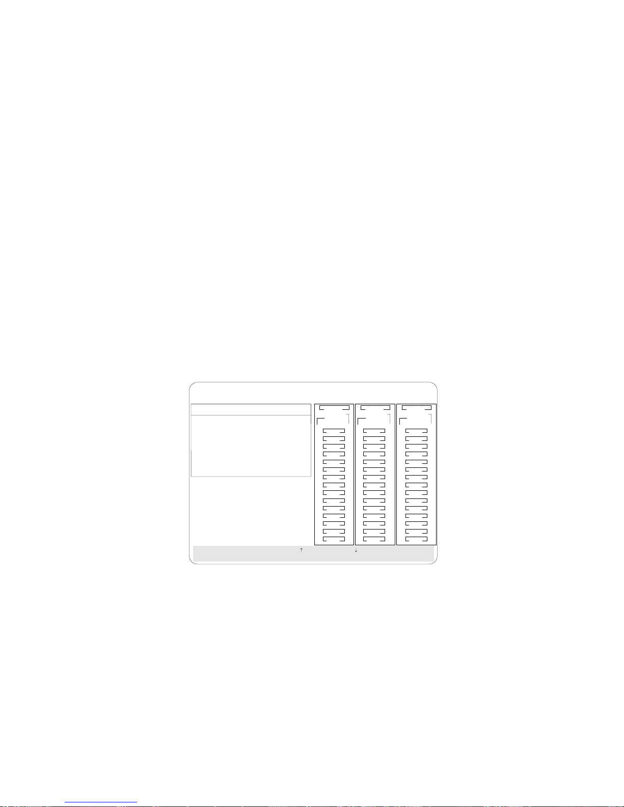
Deleting a Disk Array
Attention: All data and programs in the array are lost during this
procedure. Before proceeding, back up any data and programs that
you want to save.
To delete a disk array:
1. Start the ServeRAID configuration program (refer to “Starting
the Configuration Program” on page 25).
2. Select Create/Delete Array/Log Drive from the Main Menu and
press Enter. The following screen appears.
IBM PC ServeRAID Adapter Disk Array Configuration Ver. 1.XX
Adapter Number: 1 Bus Number: 0 Host ID = Null Config
Create/Delete Array
1. Help
2. Delete Disk Array
3. Create Disk Array
4. Define Logical Drive
5. Define/Undefine Hot-spare Drive
6. Delete Logical Drive
7. Exit
SelectachoiceusingtheUpArrow()andDownArrow()keysandpressEnter.
Press Esc to return to previous menu.
Ch 1 Ch 2 Ch 3
Array
Bay
1
2
3
4
5
6
7
8
9
10
11
12
13
14
15
ONL
ONL
ONL
ONL
ONL
ONL
RDY
RBL
1
A
2
A
3
A
4
A
5
A
6
A
7
8
9
B
10
11
12
13
14
15
ONL ONL
ONL ONL
ONL ONL
ONL
DDD
HSP
DHS
Ch 2Ch 1
ArrayArray
BayBay
1
B
2
B
3
B
4
B
5
B
6
7
8
9
10
11
12
13
14
15
ONL
ONL
ONL
CDR
SHS
TAP
C
C
C
C
C
C
3. Select Delete Disk Array from the Create/Delete Array menu
and press Enter. The cursor will be active in the Array list.
4. Review the Date Created column; then press the Up Arrow (↑)
key or the Down Arrow (↓) key to highlight the array you want
to delete.
5. Press Del. The Confirm pop-up window appears.
Attention: All the data and programs in the array will be lost
during this procedure.
6. Select Yes to delete the array. Select No if you do not want to
delete the array.
Chapter 2. Configuring Your Disk Arrays 49
Page 64

If a defunct drive is still in a bay, the status shows a Defunct
Hot-Spare (DHS). You can select Rebuild/Device Management,
then reset the drive state by selecting Set Device State (refer to
“Setting Device States” on page 54 for more information). If the
drive is good, set the drive state to Hot-Spare (HSP); then, select the
drive again and set the drive to Ready (RDY). If the drive is
defective, replace it with a good drive; then, set the new drive state
to Ready (RDY).
Note: In some operating systems, deleting an array and its
associated logical drives might change the drive letters
assigned to the existing drives.
50 PC Server 330 User's Handbook
Page 65

Deleting a Logical Drive
Attention: All the data and programs in the array are lost during
this procedure. Before proceeding, back up any data and programs
that you want to save.
To delete a logical drive:
1. Start the ServeRAID configuration program (refer to “Starting
the Configuration Program” on page 25).
2. Select Create/Delete Array/Log Drive from the Main Menu and
press Enter. The following screen appears; the cursor is active
in the Array list.
IBM PC ServeRAID Adapter Disk Array Configuration Ver. 1.XX
Adapter Number: 1 Bus Number: 0 Host ID = Null Config
Create/Delete Array
1. Help
2. Delete Disk Array
3. Create Disk Array
4. Define Logical Drive
5. Define/Undefine Hot-spare Drive
6. Delete Logical Drive
7. Exit
SelectachoiceusingtheUpArrow()andDownArrow()keysandpressEnter.
Press Esc to return to previous menu.
Ch 1 Ch 2 Ch 3
Array
Bay
1
2
3
4
5
6
7
8
9
10
11
12
13
14
15
ONL
ONL
ONL
ONL
ONL
ONL
RDY
RBL
1
A
2
A
3
A
4
A
5
A
6
A
7
8
9
B
10
11
12
13
14
15
ONL ONL
ONL ONL
ONL ONL
ONL
DDD
HSP
DHS
Ch 2Ch 1
ArrayArray
BayBay
1
B
2
B
3
B
4
B
5
B
6
7
8
9
10
11
12
13
14
15
ONL
ONL
ONL
CDR
SHS
TAP
C
C
C
C
C
C
3. Select Delete Logical Drive from the Create/Delete Array menu
and press Enter.
4. Use the Up Arrow (↑) key or the Down Arrow (↓) key to
highlight the array you want to delete; then press Del to delete
it.
The Confirm pop-up window appears asking you to confirm
your action.
Attention: All the data and programs in the array are lost
during this procedure.
Chapter 2. Configuring Your Disk Arrays 51
Page 66

5. Select Yes to delete the logical drive. Select No to keep the
logical drive.
6. Select Exit or Esc to return to the Main Menu.
Note: In some operating systems, deleting an array and associated
logical drives might change the drive letters assigned to the
existing drives.
Redefining Space in an Array
You can redefine space in a disk array in a number of ways. For
example, you can combine a number of small logical drives to create
a larger one, or you can redefine the existing logical drive into
several smaller drives. Also, you can install additional hard disk
drives and create a larger logical drive than was possible with the
existing storage capacity.
One method to redefine space in an array is to change the RAID
level assigned to a logical drive. For example, if you assigned RAID
level 1 to a logical drive and then decided you needed the capacity
offered with RAID level 5, you can use this procedure to replace the
existing logical drive with a logical drive assigned the new RAID
level.
To redefine the space in a disk array, first you must delete the
existing array.
Attention: In all cases, when you delete an array, all the data and
programs in the array are lost.
Note: You will need a blank 3.5-inch formatted diskette to back up
the configuration file, as described in this procedure.
1. Back up all data and programs in the array.
Note: Back up the data before you delete the existing array.
You might want to use a high-speed back up device, such
as a tape drive, to back up large amounts of data.
2. If needed, install additional hard disk drives. Refer to
“Understanding Hard Disk Drive Capacities” on page 39 for
information about drive sizes.
52 PC Server 330 User's Handbook
Page 67

3. Start the ServeRAID configuration program (refer to “Starting
the Configuration Program” on page 25).
4. To delete the existing array:
a. Select Create/Delete Array/Log Drive from the Main Menu.
b. Select Delete Disk Array. The cursor will be active in the
Bay/Array selection list.
c. Select the array that you want to delete.
d. Press Del. The Confirm pop-up window appears.
Attention: All the data in the array is lost during this
procedure. Be sure to back up all data and programs that
you want to save.
e. Select Yes to delete the array. Select No if you do not want
to delete the array.
Note: To use the hard disks from the existing array when
creating a new array, you must confirm the deletion
of the existing array. After you make your selection,
the Confirm pop-up window disappears, and the
cursor becomes active in the menu.
5. If you want to define a hot-spare drive, refer to “Setting Device
States” on page 54 for step-by-step instructions.
6. To create a new disk array and define logical drives, refer to
“Creating a Disk Array” on page 40 for instructions.
7. After you have established the new array and logical drive or
drives, select Initialize/Synchronize Log Drive from the Main
Menu; then, select Initialize Logical Drive to prepare the drives
in the array to receive data. This sets the drive to a
predetermined state. Any data existing in the drive is
overwritten with zeros.
8. If you defined the drive as RAID level 5, you must synchronize
the drive before storing data. Select Initialize/Synchronize Log
Drive from the Main Menu; then, select Synchronize Logical
Drive.
Note: After synchronization starts, you cannot interrupt it until
the operation is complete.
Chapter 2. Configuring Your Disk Arrays 53
Page 68

9. When the synchronization process completes, insert a blank
3.5-inch formatted diskette in the primary diskette drive and
select Advanced Functions from the Main Menu; then, select
Backup config. to diskette. Follow the instructions on the
screen.
10. Exit the ServeRAID configuration program by pressing Esc or
selecting Exit from the Main Menu. A Confirm pop-up window
appears asking you to confirm your action.
11. Reinstall your operating system and device drivers, then restore
your data and programs.
Maintaining Your Disk Arrays
This section contains procedures for defining the state of a hard disk
drive, information about the status indicators for logical and hard
disk drives, and instructions for replacing defunct drives. It also
contains procedures for displaying drive information and erasing
the device error table. This section provides information about the
status indicators for logical and hard disk drives, and the results of
a hard disk drive failure. It also contains procedures for defining
the state of a hard disk drive and replacing defunct drives.
Setting Device States
To define the state of a physical hard disk drive attached to the
ServeRAID adapter, you can use the Administration and Monitoring
program or the ServeRAID configuration program. By using the
Administration and Monitoring program from your active operating
system Desktop, you do not have to restart the server. Refer to the
README file for instructions on using the Administration and
Monitoring program for your operating system.
To define the state of a drive:
1. Start the ServeRAID configuration program (refer to “Starting
the Configuration Program” on page 25).
2. Select Rebuild/Device Management from the Main Menu. The
following screen appears.
54 PC Server 330 User's Handbook
Page 69

IBM PC ServeRAID Adapter Disk Array Configuration Ver. 1.XX
Adapter Number: 1 Bus Number: 0 Host ID = Null Config
Rebuild/Device Management
1. Help
2. Set Device State
3. Rebuild Logical Drive
4. Display Drive Information
5. Erase Device Error Table
6. Exit
Select the state to change the drive and press Enter.
Drive States
1. EMP
2. SBY
3. DHS
4. SHS
5. DDD
6. RDY
7. HSP
8. ONL
9. RBL
Ch 1 Ch 2 Ch 3
Array
Bay
1
ONL
2
ONL
3
ONL
4
ONL
5
ONL
6
ONL
7
RDY
8
9
RBL
10
11
12
13
14
15
1
A
2
A
3
A
4
A
5
A
6
A
7
8
9
B
10
11
12
13
14
15
ONL ONL
ONL ONL
ONL ONL
ONL
DDD
HSP
DHS
Ch 2Ch 1
ArrayArray
BayBay
1
B
B
B
B
B
C
2
C
3
C
4
ONL
C
5
ONL
C
6
C
ONL
7
CDR
8
9
SHS
10
TAP
11
12
13
14
15
3. Select Set Device State. The cursor becomes active in the
Bay/Array selection list.
4. Use the Up Arrow (↑) key or the Down Arrow (↓) key to
highlight the appropriate drive; then, press Enter. The Drive
States pop-up window appears, listing all hard disk drive states.
The following table shows the device states and the alternate
states valid for each state.
Device States Alternate States
EMP RDY SBY
SBY RDY EMP HSP SHS
DHS EMP HSP SHS
SHS HSP DHS
DDD ONL RBL
RDY EMP HSP SHS SBY
HSP RDY SHS DHS
ONL DDD
RBL DDD ONL
Note: Setting a DDD drive that is part of a CRT logical drive to
ONL without performing a Rebuild operation might
result in loss of data.
5. Highlight the appropriate drive state and press Enter. The new
state displays.
Chapter 2. Configuring Your Disk Arrays 55
Page 70

The numbers shown on the left in the Bay/Array selection list
area in the previous figure are the bay numbers. Refer to
“ServeRAID Configuration Program Screens and States” on
page 31 for an explanation of the bay numbers.
6. If you want to create a disk array, go to “Creating a Disk
Array” on page 40.
7. If you are finished, select Exit or press Esc.
8. Back up the disk-array configuration information to diskette.
Refer to “Backing Up Your Disk-Array Configuration” on
page 64 for instructions.
Results of a Hard Disk Drive Failure
Depending on the circumstances, a drive failure can result in several
possible situations.
Scenario 1:
Only one hard disk drive fails.
A hot-spare drive is defined that is the same size as the failed
drive.
The hot spare will take over immediately.
Note: Any logical drives with RAID level 0 are blocked during the
Rebuild process and remain blocked until the rebuild process
completes. The ServeRAID configuration program unblocks
all drives at the end of the rebuild operation.
All data in logical drives assigned RAID level 0 will be lost.
56 PC Server 330 User's Handbook
Page 71

Scenario 2:
Only one hard disk drive fails.
A hot-spare drive is not defined or is smaller than the failed
drive.
The logical drives in the array are assigned RAID levels 0, 1,
and 5, or a combination of these three levels.
All data in logical drives assigned RAID level 0 will be lost. In this
array, the logical drives that are assigned RAID level 1 or 5 will be
in Critical (CRT) state. The logical drives assigned RAID level 0 will
be in the Offline (OFL) state.
Scenario 3:
If more than one drive in an array fails, all the data is lost in all of
the logical drives of the array. For this reason, it is important that
you replace and rebuild a DDD drive as soon as possible.
Logical and Hard Disk Drive Status Indications
The status of the hard disk drive determines the status of the logical
drives in the array in which the hard disk is grouped.
A single hard disk drive failure, (indicated by a DDD state in
the Bay/Array selection list), generates a CRT state for the
array's logical drives that are assigned levels 1 and 5. Data in
logical drives with a CRT state is not lost, but you must replace
the failing hard disk drive promptly and perform a Rebuild
operation. If two hard disk drives fail, all of the data in the
array is lost.
After you install a new hard disk drive, the Rebuild process
changes the drive state from DDD to RBL, if the array contains a
CRT logical drive. After the Rebuild process completes, the
hard disk drive state changes from RBL to ONL.
A multiple hard disk drive failure causes logical drives in that
array to have an OFL state. This means that data is lost in all
the logical drives in that array, regardless of which RAID level
is assigned.
Chapter 2. Configuring Your Disk Arrays 57
Page 72

Replacing a Faulty Drive
If you are not using or installing a SCSI-2 Fast Hot Swap Drive Tray
III or a SCSI-2 Fast/Wide Hot Swap Drive Tray III, check your
manufacturers instructions for specific details for detecting a failing
hard disk drive.
Note: The LEDs on the SCSI-2 Fast Hot Swap Drive Tray III or the
SCSI-2 Fast/Wide Hot Swap Drive Tray III provide
information about the status of the drive.
Locked
Position
Amber
Light
Green
Light
Power-Off
Switch
58 PC Server 330 User's Handbook
Page 73

The following table summarizes the LED states and their meanings.
Green Amber Description
On Off Drive tray is powered on. The hard disk drive
is inactive; do not remove the drive.
Blinking Off The hard disk drive is inactive. The hot-swap
drive can be removed safely.
On On or
Blinking
Off Off The drive is defective, or no power is being
The hard disk drive is in use; do not remove
the drive.
supplied to the drive. The hot-swap drive can
be removed safely.
Check the drive for damage. If the drive is not damaged, check the
position of the drive. If it is not inserted correctly, reposition the
drive. Verify that the drive is positioned correctly.
If you are using one of the Administration and Monitoring
programs provided with your ServeRAID adapter, you can use it to
identify the defunct drive and designate a drive to replace the
defunct drive without restarting the server. Refer to the README
file on the Device Driver/Administration and Monitoring diskette for
instructions for your operating system.
Do the following steps to replace a faulty drive using the
ServeRAID configuration program:
1. Start the ServeRAID configuration program (refer to “Starting
the Configuration Program” on page 25).
If the drive failed while the system was powered down, a
message appears the next time you turn on the system.
2. Physically replace the drive or assign a hot-spare or other
appropriate drive as a replacement.
Attention: Removing the wrong hard disk drive can cause loss
of all data in the array.
3. If you are assigning a hot-spare or another appropriate drive to
replace the defunct drive, go to “Important Information for
Rebuilding a Logical Drive.”
Chapter 2. Configuring Your Disk Arrays 59
Page 74

4. If you are physically replacing the hard disk drive, refer to your
manufacturers installation instructions.
Important Information for Rebuilding a Logical Drive
Review this section before you rebuild a logical drive.
If the logical drive is critical, you must rebuild the defunct hard
disk drive.
Data in a logical drive assigned or defined RAID level 0 is lost
during a rebuild. If you backed up your data before the drive
failed, you can restore the data to the new drive.
If a physical hard disk drive being rebuilt is part of a logical
drive defined as RAID level 0, 1 or 5, any RAID level 0 drive is
blocked to external access during the rebuild.
– If you initiated the rebuild through the Administration and
Monitoring program, you must unblock the RAID level 0
drive when the rebuild is complete.
– If you initiated the rebuild through the ServeRAID
configuration program and the rebuild was interrupted,
drives with RAID Level 0 can be unblocked by restarting
the server.
Only one rebuild operation can take place at a time.
The hard disk drive being rebuilt must be the same size or
larger than the failed drive.
If multiple hot-spare drives are available, the adapter searches
all bays on each Channel for a hot-spare drive of the
appropriate size; the first one found enters the Rebuild state.
An automatic hot-spare rebuild will take place if:
– The physical drive that failed is part of a RAID level 1 or 5
logical drive.
– A HSP or SHP drive is available the moment the drive fails
and no rebuild, synchronization, or RAID level change
operation is in progress.
Under the following circumstances, a Rebuild operation can be
completed quickly:
60 PC Server 330 User's Handbook
Page 75

– The defunct (DDD) drive was not defective.
– The drive is in the same bay.
– No write operations or configuration changes have occurred
that require rebuilding data in that drive.
Rebuilding a Logical Drive
If you are using one of the Administration Monitoring programs
provided with your ServeRAID adapter, you can identify the
defunct drive and designate a drive to replace the defunct drive
without restarting the server. Refer to the README file on the
Device Driver/Administration and Monitoring diskette for instructions
on your operating system.
To replace a faulty drive using the ServeRAID configuration
program:
1. Start the ServeRAID configuration program (refer to “Starting
the Configuration Program” on page 25).
2. Select Rebuild/Device Management from the Main Menu.
3. Select Rebuild Drive from the Rebuild/Device Management
menu. The cursor becomes active in the Bay/Array list.
4. Select the replacement drive that you want to use for the rebuild
operation. A Confirm pop-up window appears.
Select Same Location if you physically replaced a hard disk
drive in the same bay.
Select New Location to assign a hard disk drive in a new
location. The ServeRAID adapter will prompt you to select
the drive that you want.
Information and status messages about each stage of the rebuild
process appear on the screen.
5. When the rebuild process completes, press Esc to return to the
Main Menu. The new configuration is saved.
6. Back up the new configuration to diskette (refer to “Backing Up
Your Disk-Array Configuration” on page 64).
7. Select Exit to leave the ServeRAID configuration program.
Chapter 2. Configuring Your Disk Arrays 61
Page 76

8. Remove the diskette and press Ctrl+Alt+Del to restart the
system.
Displaying Drive Information
To see the manufacturer or vendor ID, capacity, type of errors that
occurred, and other information about each of the hard disk drives
attached to the ServeRAID adapter, you can use the Administration
and Monitoring program or the ServeRAID configuration program.
When you use the Administration and Monitoring program from
your active operating system Desktop, you do not have to restart
the server. Refer to the README file for instructions on using the
Administration and Monitoring program for your operating system.
To obtain drive information, do the following:
1. Start the ServeRAID configuration program (refer to “Starting
the Configuration Program” on page 25).
2. Select Rebuild/Device Management from the Main Menu.
3. Select Display Drive Information from the Rebuild/Device
Management menu. The cursor becomes active in the
Bay/Array selection list.
4. Use the Up Arrow (↑) key or the Down Arrow (↓) key to
highlight each of the drives shown in the Bay/Array selection
list. As a drive is highlighted, the drive information appears.
IBM PC ServeRAID Adapter Disk Array Configuration Ver. 1.XX
Adapter Number: 1 Bus Number: 0 Host ID = Null Config
Drive Information
Vendor ID : IBM
Model : 0664N1H 5 500003
Version : 3404
Capacity : 1920 MB
Soft Error : 0
Hard Error : 0
Parity Error : 0
Misc Error : 0
SelectdriveusingtheUpArrow()andDownArrow()keys,pressEsctoreturn
to the previous menu.
Ch 1 Ch 2 Ch 3
Array
Bay
1
2
3
4
5
6
7
8
9
10
11
12
13
14
15
ONL
ONL
ONL
ONL
ONL
ONL
RDY
RBL
1
A
2
A
3
A
4
A
5
A
6
A
7
8
9
B
10
11
12
13
14
15
ONL ONL
ONL ONL
ONL ONL
ONL
DDD
HSP
DHS
Ch 2Ch 1
ArrayArray
BayBay
1
B
2
B
3
B
4
B
5
B
6
7
8
9
10
11
12
13
14
15
ONL
ONL
ONL
TAP
SHS
C
C
C
C
C
C
62 PC Server 330 User's Handbook
Page 77

The Device Error Table, located in the adapter's NVRAM,
collects statistics on the number and type of errors that occurred
on all hard disk drives attached to the ServeRAID adapter.
Soft Error displays the number of SCSI Check Condition
status messages returned from the drive (except Unit
Attention) since the Device Error Table was last cleared.
Hard Error displays the number of SCSI I/O processor
errors that occurred on the drive since the Device Error
Table was last cleared. It also indicates if the drive
exceeded the Predictive Failure Analysis (PFA) threshold.
Note: If the drive exceeded the PFA threshold, the hard
disk reports a change in the operating conditions.
Continue with operation and call for service within 24
hours. For RAID level 0, back up your logical drives.
Parity Error displays the number of parity errors that
occurred on the SCSI bus since the Device Error Table was
last cleared.
Misc Error displays the number of other errors (such as
selection timeout, unexpected bus free, or SCSI phase error)
that occurred on the drive since the Device Error Table was
last cleared.
5. Press Esc to return to the previous menu.
Note: The status of the hard disk drive determines the status of the
logical drives in the array in which the hard disk drive is
grouped.
After correcting a problem with the disk array, you might want to
clear the Device Error Table so that you can identify any subsequent
errors quickly. Select Erase Device Error Table from the
Rebuild/Device Management menu and press Enter to clear the
table.
Additional Disk-Array Tasks
This section contains procedures for performing additional, less
common, disk-array tasks. You can select and of the following:
Back up configuration to diskette
Chapter 2. Configuring Your Disk Arrays 63
Page 78

Restore configuration to diskette
Change the write policy
Change the RAID parameters
Run Subsystem diagnostic test
Format a drive
Reset the adapter configuration
Configuration Synchronization
Display/Change the ServeRAID adapter parameters
Attention: Notices appear throughout this section to alert you
about potential loss of data. Similar warning messages appear on
the screens for these procedures. Read these warnings carefully
before answering yes to the confirmations requested by the
ServeRAID configuration program.
Backing Up Your Disk-Array Configuration
The ServeRAID adapter maintains a record of the disk-array
configuration information in its nonvolatile RAM (NVRAM) and
electrically erasable programmable read-only memory (EEPROM)
module. The disk-array configuration is vital information. To protect
this information, back up the information to diskette as soon as you
have completed your tasks. You need a blank, 3.5-inch formatted
diskette.
To back up the disk-array configuration information to diskette:
1. Label a blank diskette “Disk Array Configuration Backup” and
date it.
2. Start the ServeRAID configuration program (refer to “Starting
the Configuration Program” on page 25).
3. Select Advanced Functions from the Main Menu and press
Enter.
4. Select Backup config. to diskette and press Enter.
5. Remove the ServeRAID configuration diskette from the drive
and insert the blank diskette.
6. Follow the instructions on the screen.
64 PC Server 330 User's Handbook
Page 79

Restoring the Disk-Array Configuration
To restore the disk-array configuration information in the
ServeRAID adapter, use the ServeRAID Adapter Configuration
Diskette and an up-to-date Disk Array Configuration Backup
diskette.
Note: Because dynamic changes in the configuration of your disk
array occur due to hot-spare drive replacement or other drive
maintenance activity, the configuration backup information
on the diskette might be different from that stored in the
adapter. Therefore, it is important that you back up the
disk-array configuration information frequently, to keep the
backup information on the diskette current.
Chapter 2. Configuring Your Disk Arrays 65
Page 80

To restore the ServeRAID configuration information:
1. Start the ServeRAID configuration program (refer to “Starting
the Configuration Program” on page 25).
2. Select Advanced Functions from the Main Menu and press
Enter.
3. Select Restore config. from diskette and press Enter.
4. Enter the file name of the backed-up configuration in the box at
the bottom of the screen and press Enter.
5. The Confirm pop-up window appears.
6. Select Yes to restore the configuration information. Select No to
return to the previous menu.
7. Press Esc to return to the Main Menu.
Changing the Write Policy
When you configure a logical drive, the ServeRAID adapter sets the
write policy to write-through (WT) mode, where the completion
status is sent after the data is written to the hard disk drive. Under
certain workloads, you can improve performance by changing this
write policy to write-back (WB) mode, where the completion status is
sent after the data is copied to cache memory, but before the data is
actually written to the storage device.
Although you might gain performance with write-back mode, it
creates a greater risk of losing data due to a power failure. This is
because the system gets a completion status message when the data
reaches cache memory, but before data is actually written to the hard
disk drive.
If you change the write policy to write-back, wait at least 10 seconds
after your last operation before you turn off your system. It takes
that long for the system to move the data from the cache memory to
the storage device. Failure to follow this practice can result in lost
data.
66 PC Server 330 User's Handbook
Page 81
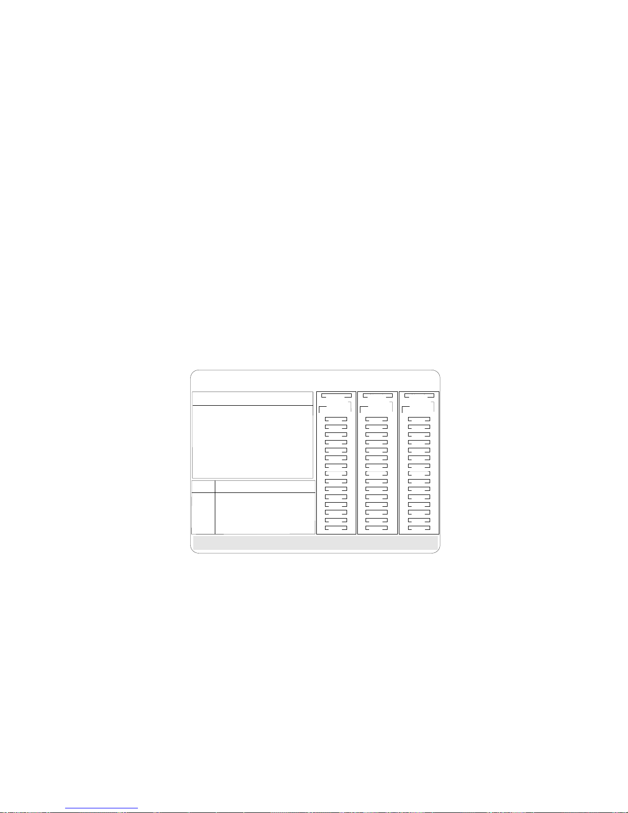
To change the write policy:
1. Start the ServeRAID configuration program (refer to “Starting
the Configuration Program” on page 25).
2. Select Advanced Functions from the Main Menu.
3. Select Change Write Policy from the Advanced Functions menu.
The cursor will be active in the Logical Drive list.
4. Select the logical drive whose write policy you want to change.
A screen similar to the following appears:
IBM PC ServeRAID Adapter Disk Array Configuration Ver. 1.XX
Adapter Number: 1 Bus Number: 0 Host ID = Null Config
1.Help
2.Backupconfig.toDiskette
3.Restoreconfig.fromDiskette
4.ChangeWritePolicy
5.ChangeRAIDParameters
6.IBMRAIDSubsystemDiagnostics
7.Init/View/SynchronizeConfig
8.Display/ChangeAdapterParams
9.Exit
Array
ID Size
A4300
B4300
C4300
Advanced Functions
Log
RAID
Level
RAID-0
RAID-1
RAID-1
Date
Created
12/13/95
12/13/95
12/13/95
Status
OKY WT
OKY WT
OKY WT
Size
Drv
(MB)
AO
100
A1
500
A1
500
Select logical drive and press Enter to toggle the write policy.
Ch 1 Ch 2 Ch 3
Array
Bay
Wrt
Pol
1
2
3
4
5
6
7
8
9
10
11
12
13
14
15
ONL
ONL
ONL
ONL
ONL
ONL
RDY
RBL
1
A
2
A
3
A
4
A
5
A
6
A
7
8
9
B
10
11
12
13
14
15
ONL ONL
ONL ONL
ONL ONL
ONL
DDD
HSP
DHS
Ch 2Ch 1
ArrayArray
BayBay
1
B
B
B
B
B
C
2
C
3
C
4
ONL
C
5
ONL
C
6
ONL
C
7
8
9
SHS
10
TAP
11
12
13
14
15
Note: Your information might be different from that shown in
this screen.
The Logical Drive list contains the logical drive ID, the size in
megabytes of each logical drive, the RAID level you assigned to
that logical drive, and the date you created it.
The status of the logical drive is also shown. OKY means that
no problem conditions are associated with the drive; CRT
means that you must replace the hard disk drive and rebuild the
logical drive. (You will have received a message telling you
what has happened to the drive.) OFL means that the logical
drive is unrecoverable; the data in that drive is lost.
Chapter 2. Configuring Your Disk Arrays 67
Page 82

5. Locate the Wrt pol field in the Logical Drive list.
The write policy is shown as either write-through (WT), which
is the default setting, or write-back (WB).
6. Select the logical drive whose write policy you want to change.
Attention: If you change the write policy to WB, wait at least
10 seconds after your last operation before you turn off your
system. It takes that long for the system to move the data from
the cache memory to the storage device. Failure to follow this
practice can result in lost data.
7. Press Enter to change the write policy.
Notice that WT changes to WB. You can press Enter to toggle
between WT and WB.
8. Press Esc. The Confirm pop-up window appears asking you to
confirm your action.
9. Select Yes to save the changes. Select No to return the setting to
its original state.
10. Back up the disk-array configuration information to diskette.
Refer to “Backing Up Your Disk-Array Configuration” on
page 64 for more information.
68 PC Server 330 User's Handbook
Page 83

Changing the RAID Parameters
You can change the RAID parameters using the advanced functions.
To change the RAID parameters:
1. Start the ServeRAID configuration program (refer to “Starting
the Configuration Program” on page 25).
2. Select Advanced Functions from the Main Menu and press
Enter.
3. Select Change RAID parameters and press Enter. The
following screen appears.
IBM PC ServeRAID Adapter Disk Array Configuration Ver. 1.XX
Adapter Number: 1 Bus Number: 0 Host ID = Null Config
Advanced Functions
1. Help
2. Backup config. to Diskette
3. Restore config. from Diskette
4. Change Write Policy
5. Change RAID Parameters
6. IBM RAID Subsystem Diagnostics
7. Init/View/Synchronize Config
8. Display/Change Adapter Params
9. Exit
Stripe
Unit Size
1. 8K
2. 16K
3. 32K
4. 64K
Select a choice using the Up Arrow, ( ) Down Arrow, ( ) Left Arrow ( )
andRightArrow()keys.
Press Enter to change parameter. Press Esc to return to main menu.
Rebuild
Priority
8K
1. Medium
2. High
3. Low
High
Unattended
Off
1. On
2. Off
1. On
2. Off
Ch 1 Ch 2 Ch 3
Array
Bay
Read
Ahead
On
1
2
3
4
5
6
7
8
9
10
11
12
13
14
15
ONL
ONL
ONL
ONL
ONL
ONL
RDY
RBL
1
A
2
A
3
A
4
A
5
A
6
A
7
8
9
B
10
11
12
13
14
15
ONL ONL
ONL ONL
ONL ONL
ONL
DDD
HSP
DHS
Ch 2Ch 1
ArrayArray
BayBay
1
B
2
B
3
B
4
B
5
B
6
7
8
9
10
11
12
13
14
15
ONL
ONL
ONL
TAP
SHS
C
C
C
C
C
C
The default settings are:
Stripe Unit Size — 8 K
Attention: After the stripe-unit size is chosen and data is
stored in the logical drives, the stripe-unit size cannot be
changed without destroying data in the logical drives.
The stripe-unit size is the amount of data written on a given
disk before writing on the next disk. To maximize the
overall performance, choose the stripe-unit size such that the
stripe-unit size is close to the size of the system I/O request.
The default is set to 8 K data bytes. You can set the
stripe-unit size to 8 K, 16 K, 32 K, or 64 K.
Chapter 2. Configuring Your Disk Arrays 69
Page 84

– When the stripe-unit size is set to 8 K or 16 K, the
maximum number of drives in an array is 16.
– When the stripe-unit size is set to 32 K or 64 K, the
maximum number of drives in an array is eight.
Rebuild Priority – High
Rebuild priority can be set to high, medium, or low. When
the rebuild request is set to high, the rebuild I/O request
gets high priority in the execution order.
When the rebuild request is set to medium in a heavily
loaded system, the medium-priority rebuild can reduce the
disk rebuild time at the expense of degraded handling of
I/O requests.
When the rebuild priority is set to low in a moderate to
heavily loaded system, low rebuild priority will increase the
disk rebuild time but provides better system performance.
Note: You can change the rebuild priority without affecting
data in the logical drives.
Unattended Mode – Off
You can enable the adapter to accept changes in the
configuration without user input. Unattended mode is
useful when the server operates remotely.
When Unattended Mode is Off, the program waits for user
input.
When Unattended Mode is set to On and the hard disk
drive is found in a location other than the one defined in the
adapter configuration, the program pauses briefly for user
input, then, rearranges the configuration information to
correct the logical drive configuration. Unattended mode
also clears any blocked drives.
70 PC Server 330 User's Handbook
Page 85

Read Ahead — On
Normally, the ServeRAID adapter transfers data from disk
to its local cache in steps of stripe-unit size. This provides
excellent overall performance when workloads tend to be
sequential. However, if the workload is random and system
I/O requests are smaller than the stripe-unit size, reading
ahead to the end of the stripe unit will result in lower
performance.
When read-ahead is set to Off, the size of data transfer from
the disk to local cache is equal to the system I/O request
size, and no read-ahead to the end of the stripe unit is
performed.
Notes:
a. You can change the read-ahead setting without destroying
data in a logical drive.
b. When you save the configuration information on a diskette,
the RAID parameters are saved also.
Chapter 2. Configuring Your Disk Arrays 71
Page 86

Unattended Mode of Operation
You can enable the adapter to accept changes in the configuration
without user input. When this mode is enabled (refer to
“Display/Change the ServeRAID Adapter Parameters” on page 79
for information), the adapter pauses briefly to permit a user to
override the default action; then the adapter makes the necessary
changes. Unattended mode, also clears any blocked drives. This
mode is useful when the server operates remotely.
The adapter “chooses” an action that is equivalent to pressing one
of the function keys in the following order.
F5: The server continues the startup operation after identifying the
drive that is defunct. For example, a HSP drive failed to respond
during POST. Startup continues without the HSP drive; its drive
state will display as DHS.
F6: When a drive has been removed from the server, for example,
for maintenance or security, and was returned, but in a different
bay, the adapter adjusts the configuration to the drive's new
location.
F7: An adapter with stored configuration information that does not
match that of the configured drives present, import the
configuration information from the drives. Refer to “ServeRAID
Adapter Messages” on page 282 for more information.
72 PC Server 330 User's Handbook
Page 87

RAID Subsystem Diagnostic Tests
The ServeRAID Subsystem Diagnostic program provides several
utility programs that you can use to test the ServeRAID adapter and
the devices connected to it.
To run the RAID diagnostic utility programs, do the following:
1. Start the ServeRAID configuration program (refer to “Starting
the Configuration Program” on page 25).
2. Select Advanced Functions from the Main Menu.
3. Select IBM RAID Subsystem Diagnostic.
4. Select the diagnostic test that you want to run and press Enter.
Run Adapter Self-Test runs diagnostic tests on the
ServeRAID adapter.
Note: Restart your server after the self-test is complete.
SCSI Device Self-Test runs diagnostic tests on the SCSI
devices attached to the ServeRAID adapter.
Drive Media Test verifies that all sectors on the hard disk
drive can be accessed. The drive must be in the RDY or
HSP state.
Format Drive performs a low-level format on a hard disk
drive. For more information, see “Formatting Drives” on
page 74.
5. Follow the instructions on the screen.
Chapter 2. Configuring Your Disk Arrays 73
Page 88

Formatting Drives
You can perform a low-level format on drives with Ready (RDY)
Empty (EMP), Standby (SBY), Standby Hot-Spare (SHS), or
Hot-Spare (HSP) states.
Note: The Format Drive choice on the IBM ServeRAID Subsystems
Diagnostics menu provides a low-level format. If you install
a new hard disk drive that requires a standard format, use
the Format command provided by your operating system.
To perform a low-level format:
1. Start the ServeRAID configuration program (refer to “Starting
the Configuration Program” on page 25).
2. Select Advanced Functions from the Main Menu and press
Enter.
3. Select IBM RAID Subsystem Diagnostics from the Advanced
Functions menu.
Attention: A low-level format erases all data and programs
from the hard disk drive. Before proceeding, back up any data
and programs that you want to save.
4. Select Format Drive and press Enter.
You can perform a low-level format on more than one drive at a
time.
Note: If formatting is interrupted, the state of the drive being
formatted might appear as Empty (EMP) on the ServeRAID
configuration screen in the Bay/Array selection list. Select
the drive and format it again.
74 PC Server 330 User's Handbook
Page 89

Resetting the Adapter Configuration
The RAID configuration information stored in the adapter's NVRAM
is critical to the reliable operation of the disk array. Therefore, to
protect the integrity of the configuration information, the
configuration information is also stored in the adapter EEPROM and
on each hard disk drive in a RBL or ONL state defined in the
adapter NVRAM configuration. Each time the configuration
information is changed, all corresponding copies are updated.
During POST, if the configuration information in the adapter's
NVRAM, EEPROM, or configured hard disk drives does not match,
an error message appears. (Refer to “ServeRAID Adapter POST and
Setup Messages” on page 282 for more information.)
The Init/View Synchronize Configuration menu enables you to view
or reset parameters.
IBM PC ServeRAID Adapter Disk Array Configuration Ver. 1.XX
Adapter Number: 1 Bus Number: 0 Host ID = Null Config
Init/View/Synchronize Config
1. Help
2. Initialize Configuration
3. View NVRAM Configuration
4. View EEPROM Configuration
5. View Hard Drive Configuration
6. View Change List
7. Exit
Select a choice using the Up Arrow ( ) and D own Arrow ( ) keys and press Enter.
Press Esc to return to previous menu.
Initialize Configuration allows you to restore the factory
default settings and resets all functional, connected hard disk
devices to the RDY state.
View NVRAM Configuration displays the current configuration
settings for the adapter's NVRAM.
View EEPROM Configuration displays the current
configuration settings for the adapter's EEPROM.
Chapter 2. Configuring Your Disk Arrays 75
Page 90

View Hard Drive Configuration displays the configuration
settings for the selected hard disk drive that is in the ONL or
RBL state.
View Change List allows you to view the device state
configuration changes that the ServeRAID adapter reported
since the last time the server was powered on or restarted.
– View Power-on Change List displays the device state
changes of any hard disk drives that changed since the last
time the server was powered on or restarted.
– View Wrong SCSI ID List provides a list of hard disk
drives that were found at a different SCSI ID location since
the last time the server was powered on or restarted.
– View Unidentified Drive List provides a list of hard disk
drives that have an identifier that does not match the stored
configuration information.
The identifier consists of both the configuration host ID and
a time stamp. You can define the host ID (for example, a
host ID can be the serial number of the server) as any string
up to 12 characters. (Refer to “Display/Change the
ServeRAID Adapter Parameters” on page 79 for more
information.)
To initialize, reset, or view the adapter configuration:
1. Start the ServeRAID configuration program (refer to “Starting
the Configuration Program” on page 25).
2. Select Advanced Functions from the Main Menu and press
Enter.
3. Select Init/View Synchronize Config.
4. Select your choice from the menu and press Enter.
5. Follow the instructions on the screen.
76 PC Server 330 User's Handbook
Page 91
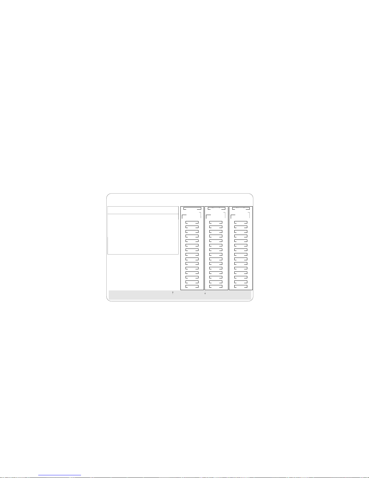
Configuration Synchronization
When the configuration information in the adapter's NVRAM,
EEPROM, and hard disk drives does not match, you can select one
source and copy the selected configuration information to the other
locations. This menu provides options to synchronize this
configuration information.
IBM PC ServeRAID Adapter Disk Array Configuration Ver. 1.XX
Adapter Number: 1 Bus Number: 0 Host ID = Null Config
Init/View/Synchronize Config
1. Help
2. Initialize Configuration
3. View NVRAM Configuration
4. View EEPROM Configuration
5. View Hard Drive Configuration
6. View Change List
7. Configuration Synchronization
8. Exit
SelectachoiceusingtheUpArrow()andDownArrow()keysandpressEnter.
Press Esc to return to previous menu.
Ch 1 Ch 2 Ch 3
Array
Bay
1
2
3
4
5
6
7
8
9
10
11
12
13
14
15
ONL
ONL
ONL
ONL
ONL
ONL
RDY
RBL
1
A
ONL
ONL
2
A
ONL
3
A
ONL
4
A
ONL
5
DDD
A
6
A
HSP
7
DHS
8
9
B
10
11
12
13
14
15
Ch 2Ch 1
ArrayArray
BayBay
1
B
2
B
3
B
4
B
5
B
6
7
8
9
10
11
12
13
14
15
ONL
ONL
ONL
ONL
ONL
ONL
CDR
SHS
TAP
C
C
C
C
C
C
Note: If you get a message stating that you have a recoverable
configuration error, it indicates that you have one of the
following:
Valid NVRAM, invalid FLASH
Valid FLASH, invalid NVRAM
Both the NVRAM and FLASH are valid, but they do not
match.
You can view the individual configurations to determine if
they are valid and then select the one you want to use.
If you get a message that states that you have an
unrecoverable configuration error, it indicates that you do not
have a valid configuration and that you must initialize the
configuration before proceeding any further.
Chapter 2. Configuring Your Disk Arrays 77
Page 92

EEPROM as Source copies configuration information from the
adapter's EEPROM to NVRAM and to all configured hard disk
drives that are in a RBL or ONL state and are defined in the
adapter EEPROM configuration.
NVRAM as Source copies configuration information from
NVRAM to the adapter's EEPROM and to all configured hard
disk drives that are in a RBL or ONL state and are defined in
the NVRAM configuration.
NVRAM and POCL as Source updates information from the
power-on change list (drive state changes at power-on time)
with the information in NVRAM. This information is then
copied to the adapter's EEPROM and to all configured hard disk
drives that are in a RBL or ONL state and are defined in the
NVRAM configuration.
Hard Disk Drive as Source retrieves configuration information
from a hard disk drive. The configuration information is then
copied to the adapter's NVRAM and EEPROM.
Identified HDD as Source updates the adapter's configuration
information with stored configuration information on a hard
disk drive that matches the identifiers stored in the NVRAM.
The updated configuration information is then copied to
NVRAM, the adapter's EEPROM, and the configured hard disk
drives in an array.
Specific HDD as Source retrieves the configuration information
with stored configuration information on the hard disk drive
that you select. The updated configuration information is then
copied to NVRAM, the adapter's EEPROM, and configured hard
disk drives.
78 PC Server 330 User's Handbook
Page 93
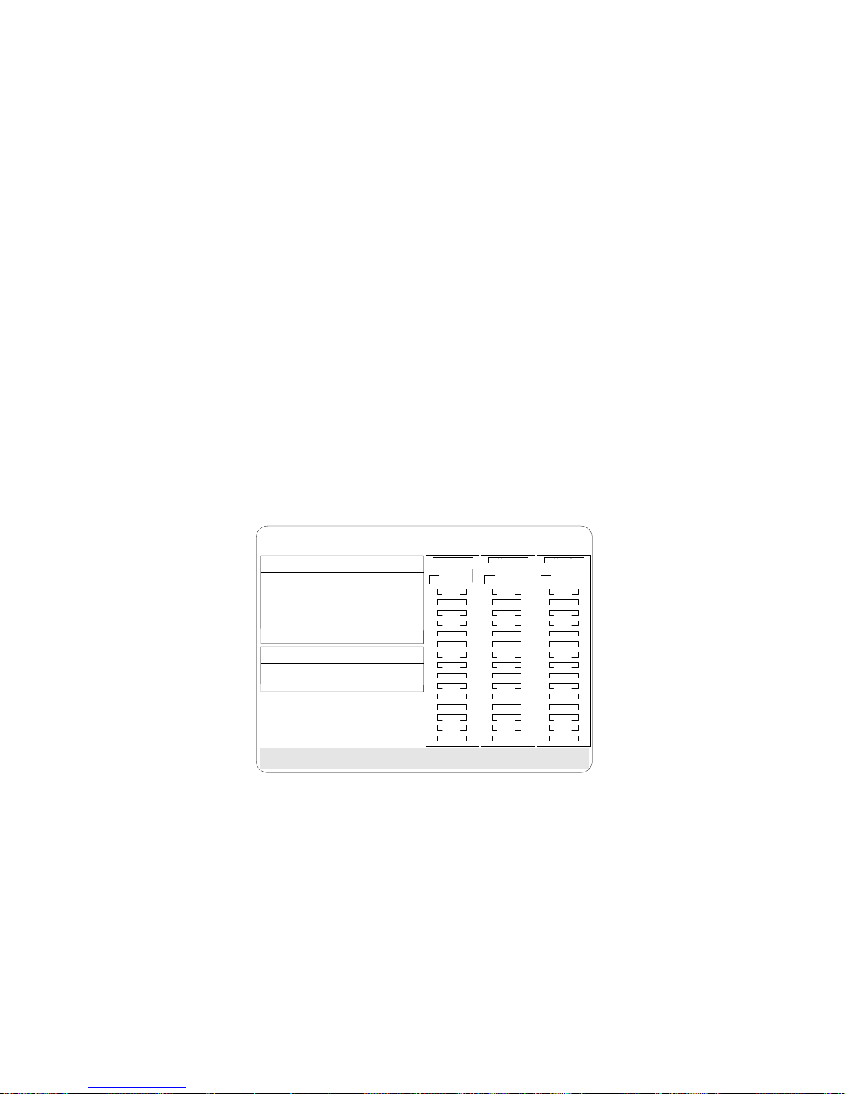
Display/Change the ServeRAID Adapter Parameters
The Display/Change Adapter Parameter menu allows you to view
and change the ServeRAID adapter parameters.
To display or change the adapter parameters:
1. Start the ServeRAID configuration program (refer to “Starting
the Configuration Program” on page 25).
2. Select Advanced Functions from the Main Menu.
3. Select Display/Change Adapter Params and press Enter. The
following screen appears.
IBM PC ServeRAID Adapter Disk Array Configuration Ver. 1.XX
Adapter Number: 1 Bus Number: 0 Host ID = Null Config
Display/Change Adapter Parameter
1. Help
2. Display Adapter Status
3. Change Adapter Host/SCSI ID
4. Set BIOS Compatability Mapping
5. Set Channel => Bank Mapping
6. Exit
Set BIOS Compatability Mapping
1. Extended BIOS Mapping (8GB)
2. Limited BIOS Mapping (2GB)
Select option for which to set BIOS compatability bit.
Ch 1 Ch 2 Ch 3
Array
Bay
1
ONL
2
ONL
3
ONL
4
ONL
5
ONL
6
ONL
7
RDY
8
9
RBL
10
11
12
13
14
15
1
A
ONL
2
A
ONL
3
A
ONL
4
A
ONL
5
DDD
A
6
A
HSP
7
DHS
8
9
B
10
11
12
13
14
15
Ch 2Ch 1
ArrayArray
BayBay
1
B
2
B
3
B
4
B
5
B
6
7
8
9
10
11
12
13
14
15
ONL
ONL
ONL
ONL
ONL
ONL
TAP
SHS
C
C
C
C
C
C
Display/Adapter Status allows you to view the status of the
adapter.
Change Adapter Host/SCSI ID allows you to change the
adapter SCSI ID and the SCSI transfer rate. You can change
the default setting from 10 MHz to a maximum of 20 MHz,
if you have SCSI-3 Ultra Fast/Wide drives (Ultra SCSI). If
the transfer rate is set to 20 MHz with Ultra SCSI drives, the
SCSI bus in the ServeRAID adapter can provide up to 40
MB per second data rate. You can also define the host
configuration ID as any 12 characters. In addition, you can
change the number of drives in a group that will startup
Chapter 2. Configuring Your Disk Arrays 79
Page 94

simultaneously, and set the start-up delay in seconds
between groups of drives.
Set BIOS Compatibility Mapping allows you to set the
BIOS mapping to 2 GB or 8 GB. The factory default is set to
8 GB.
Set Channel - Bank Mapping allows you to specify which
DASD bank is connected to each of the internal Channels on
the ServeRAID adapter. This mapping is critical for the
correct operation of the Administration and Monitoring
program, which uses the settings to identify drives, control
power to specific drives, and operate the SCSI LEDs.
In the PC Server 330, the default mapping is set to Channel 3,
sometimes referred to as Bank C.
ChannelBankMapping
LowIDHigh
ID
CH1
CH2
CH3
:E :
:D :
:C :
80 PC Server 330 User's Handbook
Page 95

Using the ServeRAID Adapter Mini-Configuration
Program
Using the Mini-Configuration program is a quick way to display the
adapter settings and to perform a limited set of the configuration
functions without using the ServeRAID Adapter Configuration
diskette.
To access the ServeRAID Adapter Mini-Configuration program:
1. Turn on the server; if the system is turned on, press
Ctrl+Alt+Del.
2. Press Ctrl+I immediately when the following
Mini-Configuration prompt screen appears.
IBM PC ServeRAID Adapter Disk Array Mini-Configuration Utility Ver. 1.XX
IBM PC ServeRAID Adapter BIOS
Copyright IBM Corp. 1995, 1996
Ver: 1.XX MM/DD/YY
Press <Ctrl+I> for Mini-Config Utility
Initializing Adapter Number 1
N logical drives are installed
NonDisk SCSI Devices Found : CDROM : N
Please wait Starting Drives . .
Tape : N R/W Optical : N Other : N
3. Press Enter.
Note: If you have more than one ServeRAID adapter installed,
you will get an adapter selection screen; otherwise, the
Main Menu appears.
Chapter 2. Configuring Your Disk Arrays 81
Page 96

4. Select your choice from the next menu, then press Enter.
IBM PC ServeRAID Controller Disk Array Mini-Configuration Ver. 1.XX
Main Menu
View Adapter Status
View Configuration
Advanced Functions
Exit
SelectthechoiceusingtheUpArrow()&DownArrow()keys,thenpressEnter.
The Main Menu offers the following choices:
View Adapter Status displays the current status of the
ServeRAID adapter. (Refer to “Viewing the Adapter
Status.”)
View Configuration displays the current configuration
information for the ServeRAID adapter. (Refer to “Viewing
the Configuration” on page 84.)
Advanced Functions resets the adapter, initializes the
configuration, and imports the configuration from drives.
(Refer to “Using the Advanced Configuration Functions” on
page 85.)
5. Select a menu item (press the number of the item or use the Up
Arrow (↑) key or Down Arrow (↓) key to highlight the item),
then press Enter.
6. Follow the instructions on the screen.
7. Select Exit to leave the Main Menu.
Viewing the Adapter Status
The View Adapter Status allows you to view the status of the
adapter's disk array.
82 PC Server 330 User's Handbook
Page 97

IBM PC ServeRAID Adapter Disk Array Mini-Configuration Utility Ver. 1.XX
View Adapter Status
No: 1 Bus: 0 Slot: 14
Hdwr:ISPR=OxEFIOBCS=OxO9ESC=OxOO
Unattended:OffReadAhead:On
CompMode:On
BootBk:"95352"CodeBk"cfaca2"
RebuildRate:High
No.ofDDDDrv.:0
No.ofOFLDrv.:0
No.ofCRTLogDrv.:0
Cfg.Updates:16FlashPgms.:524
LogicalDrivewithBad/BlockedStripe
BadStripe:None
BlockedDrive:None
Press any key to continue
Ch 1 Ch 2 Ch 3
Array
Bay
1
2
3
4
5
6
7
8
9
10
11
12
13
14
15
RDY
RDY
RDY
RDY
RDY
RDY
1
RDY
2
RDY
3
RDY
4
RDY
5
RDY
6
RDY
7
8
9
10
11
12
13
14
15
Ch 2Ch 1
ArrayArray
BayBay
1
2
3
4
5
6
7
CDR
8
9
10
11
12
13
14
15
The menu contains the following fields:
Unattended displays the on/off state of Unattended Mode.
Boot Block Version displays the current version number of the
Boot Block.
Code Block Version displays the current version number of the
microcode loaded on the adapter.
Rebuild Rate displays the speed of the rebuild. (Refer to
“Changing the RAID Parameters” on page 69.)
No. of DDD Drv. displays the number of defunct drives.
No. of OFL Drv. displays the number of offline logical drives.
No. of CRT Drv. displays the number of critical logical drives.
Cfg. Updates displays the number of times that the
configuration has been updated.
Chapter 2. Configuring Your Disk Arrays 83
Page 98

Flash Pgms displays the number of times that the microcode
EEPROM has been updated.
Logical Drive with Bad Stripe/Blocked Drive identifies any
logical drive that has bad stripes, as well as logical drives that
are in the blocked state.
Viewing the Configuration
The View Configuration choice allows you to view the number and
size of logical drives installed. It also displays the RAID level,
current state, stripe-unit size, write policy, read-ahead status, and
the date the logical drive was created.
IBM PC ServeRAID Adapter Disk Array Mini-Configuration Ver. 1.XX
View Adapter Configuration Information
No: 1 Bus: 0 Slot: 14
Logical
Logical
Drive
Drive
0
1
2
3
4
5
6
7
Size RAID Current Stripe Wrt Read Date Created
(MB) Level State Size Pol Ahead mm/dd/xx
100
100
100
100
100
200
300
5
5
5
5
5
1
99
5
1
Press any key to continue
OKY
OKY
OKY
OKY
OKY
OKY
OKY
OKY
WT
8K
WT
8K
WT
8K
WB
8K
WB
8K
WT
8K
WT
8K
WT
8K
01/18/96
NO
01/18/96
NO
01/18/96
NO
01/18/96
NO
01/18/96
NO
01/18/96
NO
01/18/96
NO
01/18/96
NO
84 PC Server 330 User's Handbook
Page 99

Using the Advanced Configuration Functions
The Advanced Functions choice allows you to reset the ServeRAID
adapter, initialize the configuration, and import the configuration
from drives.
IBM PC ServeRAID Adapter Disk Array Mini-Configuration Ver. 1.XX
Advanced Functions
Reset Adapters
Initialize Configuration
Import Configuration from Drive(s)
Exit
Select a choice using the Up and Down Arrow keys, then press Enter.
Reset Adapters resets the adapter.
Attention: The following choices may result in loss of data due
to changes in the configuration.
Initialize Configuration resets the adapter configuration values
to the factory defaults and sets all functional hard disk drive
states to RDY.
Import Configuration from Drive(s) reads the configuration
from the drives and copies it to NVRAM and the adapter's
EEPROM module.
Chapter 2. Configuring Your Disk Arrays 85
Page 100

86 PC Server 330 User's Handbook
 Loading...