

Page 1

Network Management Card
User’ s Guide
Page 2

Page 3

Network Management Card
User’ s Guide
Page 4

Note: Before using this information and the product it supports, read the general information in Appendix C, “Notices,” on page 89.
Second Edition (June 2012)
© Copyright IBM Corporation 2010, 2012.
US Government Users Restricted Rights – Use, duplication or disclosure restricted by GSA ADP Schedule Contract
with IBM Corp.
Page 5

Safety
Before installing this product, read the Safety Information.
Antes de instalar este produto, leia as Informações de Segurança.
Læs sikkerhedsforskrifterne, før du installerer dette produkt.
Lees voordat u dit product installeert eerst de veiligheidsvoorschriften.
Ennen kuin asennat tämän tuotteen, lue turvaohjeet kohdasta Safety Information.
Avant d'installer ce produit, lisez les consignes de sécurité.
Vor der Installation dieses Produkts die Sicherheitshinweise lesen.
Prima di installare questo prodotto, leggere le Informazioni sulla Sicurezza.
Les sikkerhetsinformasjonen (Safety Information) før du installerer dette produktet.
Antes de instalar este produto, leia as Informações sobre Segurança.
Antes de instalar este producto, lea la información de seguridad.
Läs säkerhetsinformationen innan du installerar den här produkten.
© Copyright IBM Corp. 2010, 2012 iii
Page 6

Important:
Each caution and danger statement in this document is labeled with a
number. This number is used to cross reference an English-language
caution or danger statement with translated versions of the caution or
danger statement in the Safety Information document.
For example, if a caution statement is labeled “Statement 1,”
translations for that caution statement are in the Safety Information
document under “Statement 1.”
Be sure to read all caution and danger statements in this document
before you perform the procedures. Read any additional safety
information that comes with the server or optional device before you
install the device.
iv Network Management Card : User’s Guide
Page 7

Statement 1:
DANGER
Electrical current from power, telephone, and communication cables is
hazardous.
To avoid a shock hazard:
v Do not connect or disconnect any cables or perform installation,
maintenance, or reconfiguration of this product during an electrical
storm.
v Connect all power cords to a properly wired and grounded electrical
outlet.
v Connect to properly wired outlets any equipment that will be attached to
this product.
v When possible, use one hand only to connect or disconnect signal
cables.
v Never turn on any equipment when there is evidence of fire, water, or
structural damage.
v Disconnect the attached power cords, telecommunications systems,
networks, and modems before you open the device covers, unless
instructed otherwise in the installation and configuration procedures.
v Connect and disconnect cables as described in the following table when
installing, moving, or opening covers on this product or attached
devices.
To Connect: To Disconnect:
1. Turn everything OFF.
2. First, attach all cables to devices.
3. Attach signal cables to connectors.
4. Attach power cords to outlet.
5. Turn device ON.
1. Turn everything OFF.
2. First, remove power cords from outlet.
3. Remove signal cables from connectors.
4. Remove all cables from devices.
Safety v
Page 8

vi Network Management Card : User’s Guide
Page 9

Contents
Safety ............................iii
Chapter 1. Introduction ......................1
Features............................1
Notices and statements in this document................2
Specifications ..........................3
Network ............................3
IBM Environmental Monitoring Probe .................4
Management Information Base (MIB) compatibility ............4
Chapter 2. Installing and configuring the network management card ....5
Installation checklist .......................5
Handling static-sensitive devices ...................5
LEDs and connectors .......................6
Network management card default parameters .............7
Installing the network management card in the UPS............9
Configuring the network management card...............11
Using the serial configuration menus .................16
Chapter 3. Using the network management card web interface ......19
Starting the web interface .....................19
Online help ..........................19
Optimizing the performance of your web browser ............20
UPS properties .........................20
UPS control ..........................28
UPS weekly schedule programming .................30
Shutdown parameters ......................31
Measurements .........................33
Event log ...........................34
System log ..........................35
Notification ..........................35
Sending text messages ......................38
Network settings ........................38
System settings ........................41
Notified applications .......................42
Access control .........................43
SNMP setting .........................44
Date and time .........................46
Updating firmware ........................47
Chapter 4. Using the Telnet, SSH, and CLI ..............49
Overview ...........................49
Session constraints .......................49
Available settings ........................49
Starting and ending a session ...................50
Using the Menu interface .....................50
Using the command-line interface ..................52
Chapter 5. Connecting and configuring an IBM Environmental Monitoring
Probe (optional) .......................61
Environmental monitoring probe features ...............61
Connecting an environmental monitoring probe to the network management
card ............................62
© Copyright IBM Corp. 2010, 2012 vii
Page 10

Environment status .......................64
Environment settings.......................65
Event log ...........................67
Chapter 6. Shutdown criteria and sequence .............69
Shutdown criteria managed by the network management card .......69
Load segments .........................70
Shutdown sequences detail ....................71
Appendix A. Uninterruptible power supply alarms, events, and MIB objects 75
Table of alarms .........................75
Table of events .........................76
Table of system alarms ......................78
MIB objects ..........................79
Appendix B. Getting help and technical assistance ..........85
Before you call .........................85
Using the documentation .....................86
Getting help and information from the World Wide Web ..........86
How to send Dynamic System Analysis data to IBM ...........86
Creating a personalized support web page...............86
Software service and support ...................86
Hardware service and support ...................87
IBM Taiwan product service ....................87
Appendix C. Notices ......................89
Trademarks ..........................89
Important notes.........................90
Particulate contamination .....................91
Documentation format ......................91
Telecommunication regulatory statement ...............92
Electronic emission notices ....................92
Index ............................97
viii Network Management Card : User’s Guide
Page 11

Chapter 1. Introduction
The IBM®Network Management Card works with the IBM UPS Manager software
to monitor, manage, and protect uninterruptible power supplies through standard
web pages, a Network Time Protocol (NTP) server, and Secure Sockets Layer
(SSL) security protocol. The network management card can support up to five
connected browsers at one time, or three browsers with the SSL protocol.
You can install the network management card in an IBM uninterruptible power
supply (UPS) that has a communication bay, and you can install it while the UPS is
online, maintaining the highest system availability. You can configure the network
management card by using any of the following methods:
v Web browser
v Local serial link (network parameters)
v BOOTP/DHCP (network parameters)
v Terminal over network (Telnet), Secure Shell (SSH), or command-line interface
(CLI)
If firmware and documentation updates are available, you can download them from
the IBM web site. The network management card might have features that are not
described in the documentation that comes with the UPS, and the documentation
might be updated occasionally to include information about those features, or
technical updates might be available to provide additional information that is not
included in the network management card documentation. To check for updates, go
to http://www.ibm.com/supportportal/.
Features
Note: Changes are made periodically to the IBM website. Procedures for locating
firmware and documentation might vary slightly from what is described in this
document.
The network management card has the following features:
v Simultaneous shutdown of protected servers
v Configuration of automatic email messages in response to UPS alarms and to
transmit periodic reports
v Control of UPS on/off switching with a web browser
v Adjustment and control of load segments through the HTML interface, including
sequential starting of the installation and optimization of backup time by shutting
down non-priority systems
v Automatic date and time adjustment through an NTP server
v Protection by encrypted password
v Protection by secure SSL connection
v SNMP v1/v3 for supervision Dual Stack IP v4/IP v6
v Log storage in the nonvolatile memory
v Online help (English only)
v Card firmware update through the network
v Fast Ethernet 10/100 MB compatibility with auto-negotiation on the RJ-45
connector
v Recording of events and measurements in the card log
© Copyright IBM Corp. 2010, 2012 1
Page 12

v Humidity/temperature/dry contact sensor (optional)
v Easy installation (can be installed while the UPS is online, maintaining the
highest system availability)
v Compatibility with the Internet Engineering Task Force (IETF) Management
Information Base (MIB) and the Power MIB (see “MIB objects” on page 79)
v Available languages:
– English
– French
– Spanish
– German
– Simplified Chinese
– Japanese
– Russian
– Korean
– Traditional Chinese
– Italian
– Portuguese
Notices and statements in this document
The caution and danger statements in this document are also in the multilingual
Safety Information document, which is on the IBM Documentation CD. Each
statement is numbered for reference to the corresponding statement in the Safety
Information document.
The following notices and statements are used in this document:
v Note: These notices provide important tips, guidance, or advice.
v Important: These notices provide information or advice that might help you avoid
inconvenient or problem situations.
v Attention: These notices indicate potential damage to programs, devices, or
data. An attention notice is placed just before the instruction or situation in which
damage could occur.
v Caution: These statements indicate situations that can be potentially hazardous
to you. A caution statement is placed just before the description of a potentially
hazardous procedure step or situation.
v Danger: These statements indicate situations that can be potentially lethal or
extremely hazardous to you. A danger statement is placed just before the
description of a potentially lethal or extremely hazardous procedure step or
situation.
2 Network Management Card : User’s Guide
Page 13

Specifications
Network
The network management card specifications are shown in the following table.
Table 1. Network management card specifications
Specification Description
Dimensions 132 x 66 x 42 mm (5.2 x 2.6 x 1.6 in.)
Weight 70 g (0.15 lb)
Storage temperature -10°C to 70°C (14°F to 158°F)
Operating temperature 0°C to 40°C (32°F to 104°F)
Ambient humidity 90% RH max without condensation
The Ethernet connector has fast Ethernet 10/100 Mb compatibility with
auto-negotiation. It is compatible with 1 Gb networks in 100 Mb mode.
Table 2. Network management card ports used
Protocol Port
BOOTP/DHCP UDP 68, 67
HTML TCP 80
SSL TCP 443
IBM UPS Manager shutdown software TCP 5000 (connected mode)
UDP 4679, 4680 (broadcast mode)
SMTP 25
NTP 123
SNMP V1 and V3 161
TRAP SNMP 162
Telnet 23
SSH 22
Chapter 1. Introduction 3
Page 14

IBM Environmental Monitoring Probe
The IBM Environmental Monitoring Probe (purchased separately) is a connectivity
device that enables you to remotely monitor the temperature, humidity, and status
of two contact devices through a standard web browser, providing greater power
management control and flexible monitoring. The environmental monitoring probe is
connected to the network management card.
For more information about the environmental monitoring probe, see Chapter 5,
“Connecting and configuring an IBM Environmental Monitoring Probe (optional),” on
page 61.
Management Information Base (MIB) compatibility
The network management card is compatible with the following Management
Information Bases (MIBs):
v MIB II (RFC 1213)
v Internet Engineering Task Force (IETF) Standard UPS MIB (RFC 1628)
v EATON Powerware MIB (PowerMIB)
For more information about MIBs, see “MIB objects” on page 79.
4 Network Management Card : User’s Guide
Page 15

Chapter 2. Installing and configuring the network
management card
This chapter describes how to install the network management card in an
uninterruptible power supply (UPS) and how to configure the card to use the web
interface.
Installation checklist
Before you install the network management card, make sure that you have the
following items:
v Network management card
v Serial communication cable for configuration (comes with the network
management card)
v Ethernet cable (purchased separately)
v Phillips screwdriver (purchased separately)
Handling static-sensitive devices
Attention: Static electricity can damage the UPS and other electronic devices. To
avoid damage, keep static-sensitive devices in their static-protective packages until
you are ready to install them.
To reduce the possibility of damage from electrostatic discharge, observe the
following precautions:
v Limit your movement. Movement can cause static electricity to build up around
you.
v The use of a grounding system is recommended. For example, wear an
electrostatic-discharge wrist strap, if one is available.
v Handle the device carefully, holding it by its edges or its frame.
v Do not touch solder joints, pins, or exposed circuitry.
v Do not leave the device where others can handle and damage it.
v While the device is still in its static-protective package, touch it to an unpainted
metal surface on the outside of the UPS for at least 2 seconds. This drains static
electricity from the package and from your body.
© Copyright IBM Corp. 2010, 2012 5
Page 16
v Remove the device from its package and install it directly into the UPS without
setting down the device. If it is necessary to set down the device, put it back into
its static-protective package. Do not place the device on the UPS cover or on a
metal surface.
v Take additional care when handling devices during cold weather. Heating reduces
indoor humidity and increases static electricity.
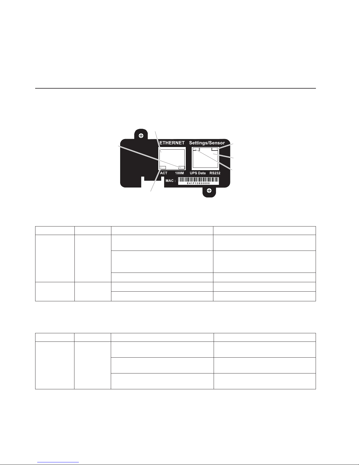
LEDs and connectors
The network management card LEDs and connectors are shown in the following
illustration.
Ethernet
connector
100M LED
(amber)
ACT LED
(green)
RS-232 LED
(amber)
Settings/Sensor
connector
UPS data
LED (green)
The Ethernet connector LEDs are described in the following table.
Table 3. Ethernet connector LEDs
LED Color Activity Description
ACT Green Off The network management card is not
connected to the network.
On The network management card is
connected to the network, but there is no
activity.
Flashing The port is sending and receiving data.
100 M Amber Off The port is operating at 10 Mbps.
On The port is operating at 100 Mbps.
The settings/sensor connector LEDs are described in the following table.
Table 4. Settings/sensor connector LEDs
LED Color Activity Description
UPS data Green Off The network management card is
On The network management card is
Flashing Communication with the UPS is
6 Network Management Card : User’s Guide
starting.
communicating with the UPS.
established (normal operation).
Page 17

Table 4. Settings/sensor connector LEDs (continued)
LED Color Activity Description
RS-232 Amber Off The Configuration menu is activated.
On The Configuration menu is not activated
(normal operation).
Flashing
(only if an optional environmental
monitoring probe is connected to the
network management card)
Communication with the environmental
monitoring probe is established (normal
operation).
Network management card default parameters
The following table is a summary of the user-configurable settings for the network
management card. The default parameters and available choices are listed. For
more information, see Chapter 3, “Using the network management card web
interface,” on page 19.
Table 5. Network management card default parameters
Function Parameter Default value Available choices
Network IP address 192.168.1.2 Network IP address
Subnet mask 255.255.0.0 Network IP address
Gateway address 0.0.0.0 Network IP address
BOOTP/DHCP Enabled Enabled / Disabled
IPv6 enabled Disabled Enabled / Disabled
IPv6 auto config enabled Disabled Enabled / Disabled
Firmware upload Enabled Enabled / Disabled
SMTP server smtpserver 49 characters maximum
System UPS Contact Computer Room Manager 49 characters maximum
UPS Location Computer Room 31 characters maximum
History log interval (sec.) 60 10 to 99999 sec.
Environment log interval
(sec.)
Default Language English English / French / Spanish /
UPS Custom Name UPS 31 characters maximum
Log Delimiter Tab Comma / Tab
Notified application table Empty Not applicable
Access control User name USERID 10 characters maximum
Password passw0rd 10 characters maximum
Telnet access enabled Enabled Enabled / Disabled
Telnet security enabled Disabled Enabled / Disabled
Console interface Menu Command-line interface /
300 10 to 99999 sec.
German / Italian / Chinese
Traditional / Chinese
Simplified / Japanese /
Russian / Korean /
Portuguese
Menu
Chapter 2. Installing and configuring the network management card 7
Page 18

Table 5. Network management card default parameters (continued)
Function Parameter Default value Available choices
SNMP Community name read public 32 characters maximum
Trap port 162 Not configurable
SNMP Version V1&V3 Disabled / V1 / V3 / V1&V3
Read-Only User readuser 1 character minimum, 32
characters maximum
Read-Only Security Level Authentication None / Authentication /
Authentication&Privacy
Read-Only Password readuser 8 characters minimum, 24
characters maximum
Read-Write User writeuser 1 character minimum, 32
characters maximum
Read-Write Security Level Authentication&Privacy None / Authentication /
Authentication&Privacy
Read-Write Password writeuser 8 characters minimum, 24
characters maximum
Notification Username notifuser 8 characters minimum, 24
characters maximum
Date and time Date and time adjustment Synchronize with an NTP
server
NTP server ntpserver 49 characters maximum
Serial link Speed 9600 baud Not configurable
Data bits 8 Not configurable
Stop bits 1 Not configurable
Parity without Not configurable
Flow control without Not configurable
Synchronize with an NTP
server / Synchronize
manually
8 Network Management Card : User’s Guide
Page 19
Installing the network management card in the UPS
You can install the IBM Network Management Card in an IBM UPS that has a
communication bay. You do not have to turn off the UPS or disconnect the load.
To install the network management card, complete the following steps:
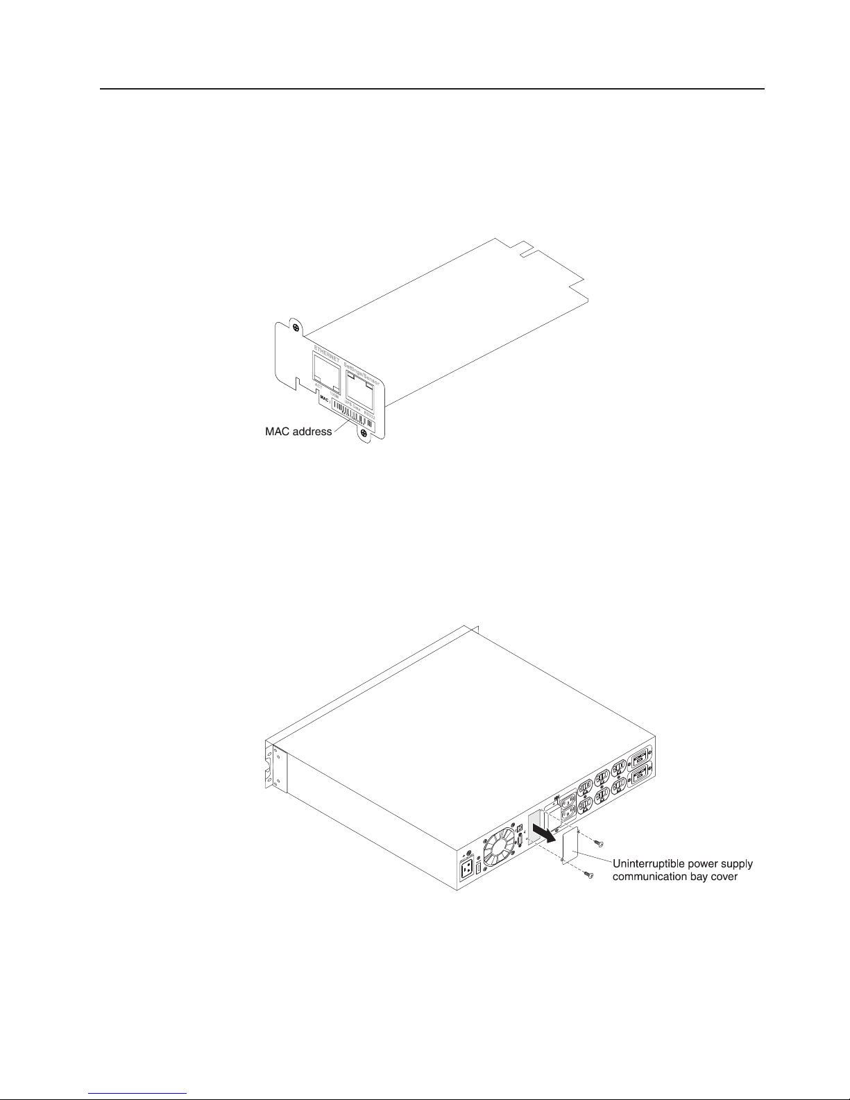
1. Record the network management card MAC address for future reference. The
MAC address is on the label on the front of the network management card.
2. Remove the two screws from the UPS communication bay cover and remove
the cover. For the location of the bay for your model, see the Installation and
Maintenance Guide that comes with the UPS.
Notes:
a. The UPS can remain online while you install the network management card.
b. The orientation of the communication bay on your UPS model might be
different from what is shown in the following illustration. You might have to
rotate the network management card to install it.
Chapter 2. Installing and configuring the network management card 9
Page 20
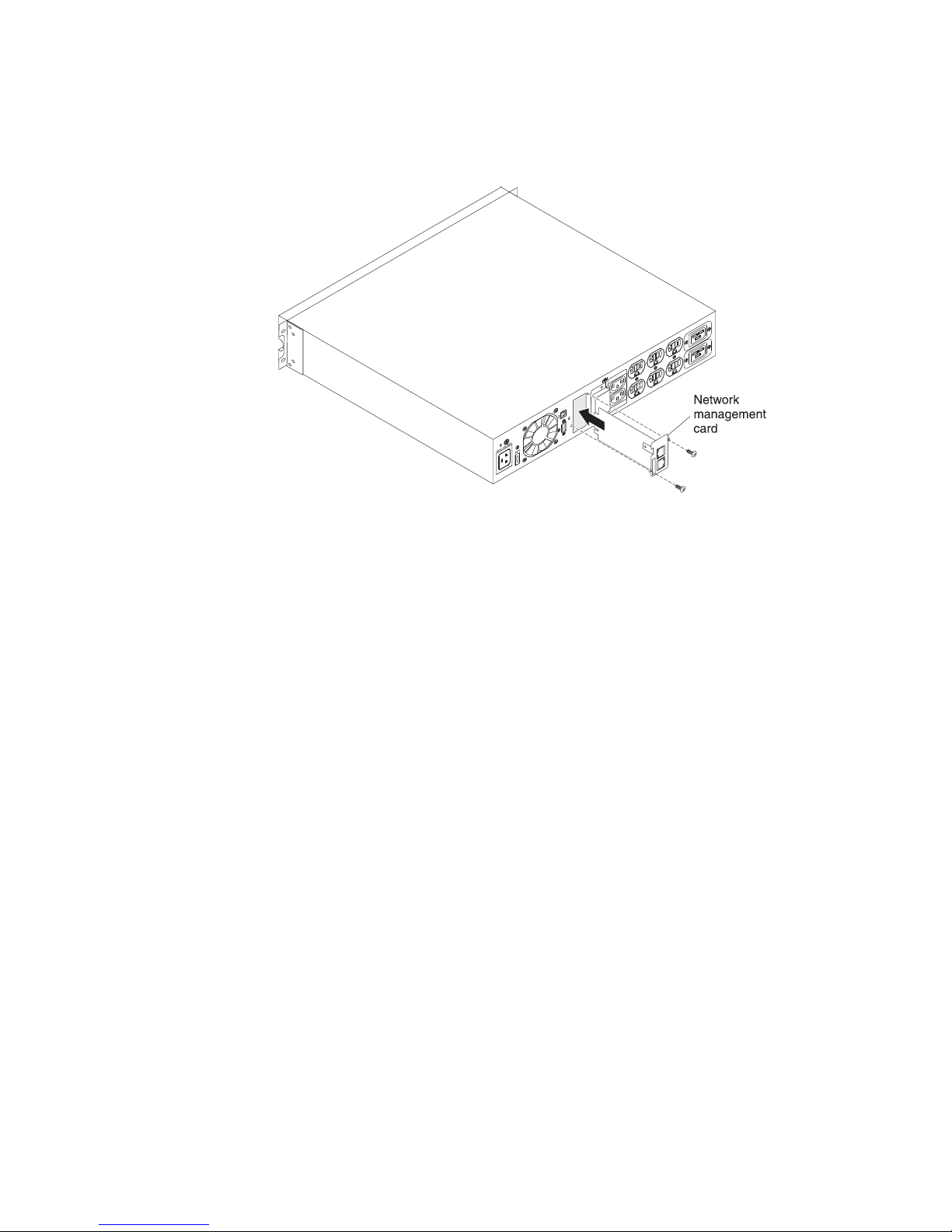
3. Carefully slide the network management card into the bay and align the screw
holes on the network management card with the screw holes on the UPS
communication bay. Secure the network management card to the UPS with the
screws that you removed in step 2 on page 9.
10 Network Management Card : User’s Guide
Page 21
Configuring the network management card
To configure the network management card, complete the following steps:
1. Make sure that the UPS is turned on.
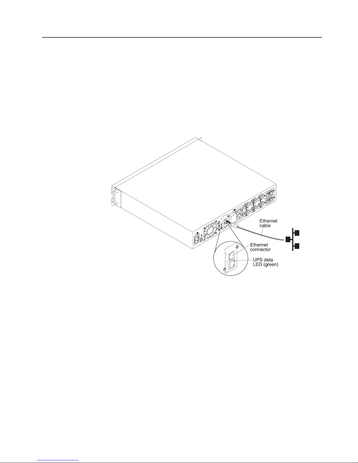
2. (Optional) For advanced configuration through a web interface and to use the
network management card on a network, connect an Ethernet cable (purchased
separately) to the Ethernet connector on the network management card and to
your network. Wait approximately 2 minutes until the UPS data LED flashes
regularly, indicating normal operation. (See “LEDs and connectors” on page 6.)
Note: You will be able to set the network management card parameters through
the settings/sensor connector even if the network management card is
not connected to the network.
Chapter 2. Installing and configuring the network management card 11
Page 22

3. Connect the RJ-45 end of the serial communication cable (which comes with
the network management card) to the settings/sensor connector on the network
management card.
Note: Make sure there is a physical RS-232 DB-9 port on the computer that
you are connecting to the UPS. Do not use RS-232 to USB converter
cables.
4. Connect the other end of the serial communication cable to the serial (COM)
connector on a computer.
5. On the computer, start a terminal emulation program, such as HyperTerminal.
Select the following settings and click OK:
v Bits per second: 9600
v Data bits: 8
v Stop bits: 1
v Parity: None
v Flow control: None
v Locally reproduce the characters entered option: Disabled
12 Network Management Card : User’s Guide
Page 23

6. After the initialization process is completed, type USERID (all uppercase) at the
prompt. The network management card main menu is displayed.
__________________________________________________
IBM NETWORK MANAGEMENT CARD :
__________________________________________________
1 : Reset
2 : Network configuration
3 : Set Login Password to Default
4 : Return to Default Configuration
0 : Exit
__________________________________________________
7. To configure the network settings, go to one of the following sections:
v “Configuring the network settings with a DHCPv4 or DHCPv6 server (default)”
v “Configuring the network settings without a DHCPv4 or DHCPv6 server” on
page 14
For more information about the serial communication cable and the serial
configuration menus, see “Using the serial configuration menus” on page 16.
Configuring the network settings with a DHCPv4 or DHCPv6 server
(default)
If your network is connected to a DHCPv4 or DHCPv6 server, the network
management card automatically collects the IP parameters.
Note: If the network management card is not connected to the network, it
continuously attempts to make a connection. After the connection is
established, the LEDs indicate the status (see “LEDs and connectors” on
page 6).
To configure the network settings, complete the following steps:
1. From the main menu, press 2 (Network configuration). The following menu is
displayed.
----------------------------------------------------------------------------Network settings
----------------------------------------------------------------------------1 : Read Network settings
2 : Modify Network settings
3 : Set Ethernet speed
0 : Exit
-----------------------------------------------------------------------------
2. Press 1 (Read Network settings). The network management card displays the
following settings that are supplied by the server. Record the IP address.
Network configuration :
MAC address : 00:20:85:FD:1C:07
Mode : Static IP
IP address : 166.99.21.94
Subnet mask : 255.255.248.0
Gateway 166.99.17.1
Link Local IPv6 address : FE80::220:85FF:FEFD:4210 /64
Global IPv6 address : 2001:720:410:100A:220:85FF:FEFD:4210 /64
Global IPv6 address : 1789:720:410:100A:220:85FF:FEFD:4210 /64
Chapter 2. Installing and configuring the network management card
13
Page 24

Note: The IPv6 parameters are read-only.
3. Press 0 twice to exit.
4. Disconnect the serial communication cable from the settings/sensor connector
and the computer.
To use the web interface to configure other network management card settings, see
Chapter 3, “Using the network management card web interface,” on page 19.
Configuring the network settings without a DHCPv4 or DHCPv6 server
If your network is not connected to a DHCPv4 or DHCPv6 server, you must
configure the network management card manually. To set the network configuration,
complete the following steps:
1. From the main menu, press 2 (Network configuration). The following menu is
displayed.
Note: You cannot configure the IPv6 address through the serial connection.
The IPv6 address is provided by the network management card or by the
IPv6 DHCP server (if an IPv6 DHCP server is available on the network).
To enable the IPv6 feature and configure IPv6 settings, see “Network
settings” on page 38.
----------------------------------------------------------------------------Network settings
----------------------------------------------------------------------------1 : Read Network settings
2 : Modify Network settings
3 : Set Ethernet speed
0 : Exit
-----------------------------------------------------------------------------
2. Press 2 (Modify Network settings).
3. Follow the instructions that are displayed on the screen and enter the static IP
parameters. After you are finished entering the parameters, wait until the
message Done is displayed, indicating that the IP parameters are saved.
----------------------------------------------------------------------------Network settings
----------------------------------------------------------------------------1 : Read Network settings
2 : Modify Network settings
3 : Set Ethernet speed
0 : Exit
----------------------------------------------------------------------------For each of the following questions, you can press <Return> to select the
value shown in braces, or you can enter a new value.
Should this target obtain IP settings from the network?[N] N
Static IP address [166.99.21.94]? 166.99.21.21
Static IP address is 166.99.21.21
Subnet Mask IP address [255.255.248.0]? 255.255.255.0
Subnet Mask IP address is 255.255.255.0
Gateway address IP address [166.99.17.1]? 166.99.17.1
Gateway address IP address is 166.99.17.1
Wait until your new configuration is saved ...
Reset the card to take into account the new configuration.
4. Press 0 to exit.
5. Press 1 to reset the network management card.
6. Press 2 to restart the network management card with the new IP parameters.
7. Disconnect the serial communication cable from the settings/sensor connector
and the computer.
14 Network Management Card : User’s Guide
Page 25

To use the web interface to configure other network management card settings, see
Chapter 3, “Using the network management card web interface,” on page 19.
Chapter 2. Installing and configuring the network management card 15
Page 26
Using the serial configuration menus
This section describes the serial communication cable and the serial configuration
menus that you can use to configure the network management card.
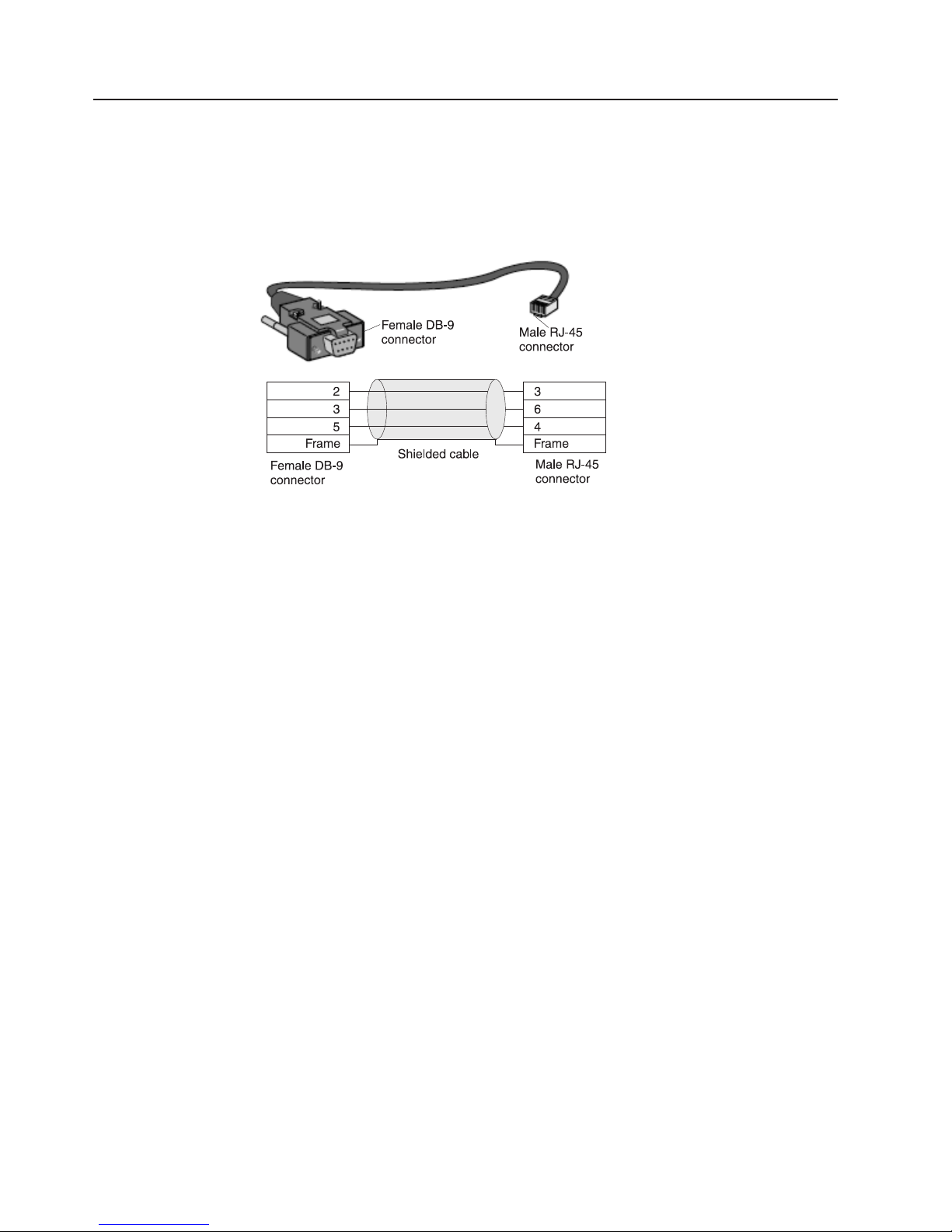
Serial cable pinout
The following illustration shows the serial communication cable and pinout.
Serial configuration menus
To access the serial configuration menus, complete the following steps. For more
detailed information, see Chapter 2, “Installing and configuring the network
management card,” on page 5.
1. Connect the RJ-45 end of the serial communication cable (which comes with
the network management card) to the settings/sensor connector on the network
management card.
2. Connect the other end of the serial communication cable to the serial (COM)
connector on a computer.
3. Start a terminal emulation program, such as HyperTerminal. Select the following
settings and click OK:
v Bits per second: 9600
v Data bits: 8
v Stop bits: 1
v Parity: None
v Flow control: None
v Locally reproduce the characters entered option: Disabled
16 Network Management Card : User’s Guide
Page 27

4. Make sure that the UPS is turned on. After the initialization process is
completed, type USERID at the prompt. The network management card main
menu is displayed.
__________________________________________________
IBM NETWORK MANAGEMENT CARD :
__________________________________________________
1 : Reset
2 : Network configuration
3 : Set Login Password to Default
4 : Return to Default Configuration
0 : Exit
__________________________________________________
1 : Reset
Two options are available for resetting the network management card:
v Hardware Reset: Select this option to reset the hardware. This is equivalent to
restarting the electrical power supply.
v Restart application: Select this option to restart only the application.
----------------------------------------------------------------------------Reset
----------------------------------------------------------------------------1 : Hardware Reset
2 : Restart application
0 : Exit
-----------------------------------------------------------------------------
2 : Network configuration
Select this option to display additional options for network settings.
----------------------------------------------------------------------------Network settings
----------------------------------------------------------------------------1 : Read Network settings
2 : Modify Network settings
3 : Set Ethernet speed
0 : Exit
-----------------------------------------------------------------------------
Three options are available for the network settings:
v Read Network settings: Select this option to view the IPv4 or IPv6 network
settings.
Network configuration :
MAC address : 00:20:85:FD:1C:07
Mode : Static IP
IP address : 166.99.18.129
Subnet mask : 255.255.248.0
Gateway : 166.99.17.1
Link Local IPv6 address : FE80::220:85FF:FEFD:4210 /64
Global IPv6 address : 2001:720:410:100A:220:85FF:FEFD:4210 /64
Global IPv6 address : 1789:720:410:100A:220:85FF:FEFD:4210 /64
Chapter 2. Installing and configuring the network management card
17
Page 28
v Modify Network settings: Select this option to modify existing network
parameters. Restart the network management card to activate the new
parameters. In DHCP mode, the network management card can receive the
following parameters according to the DHCP server settings:
– IP address
– Subnet mask
– Gateway address
Note: You cannot configure the IPv6 address through the serial connection. The
IPv6 address is provided by the network management card or by the IPv6
router (if an IPv6 router is available on the network). To enable the IPv6
feature and configure IPv6 settings, see “Network settings” on page 38.
For each of the following questions, you can press <Return> to select the
value shown in braces, or you can enter a new value.
Should this target obtain IP settings from the network?[N]
Static IP address [166.99.18.129]?
Subnet Mask IP address [255.255.248.0]?
Gateway address IP address [166.99.17.1]?
Wait during your new configuration is saved ...
Reset the card to take into account the new configuration.
v Set Ethernet speed: Select this option to change the network speed. Restart the
network management card to activate the new parameters.
Set the Ethernet speed : [1 : Automatic,2:10MBit]
1
New Ethernet speed : Automatic
Wait during the new setting is saved ...
Reset the card to take into account the new configuration.
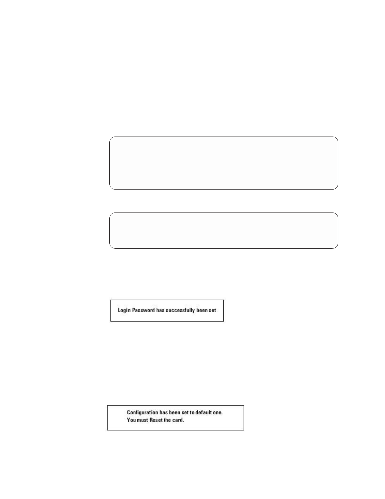
3 : Set Login Password to Default
Select this option to return the password to the default (passw0rd). Wait until the
confirmation message is displayed.
After the confirmation message is displayed, you can access the network
management card by using the web interface with the default password, but you
must restart the network management card to save the new password.
4 : Return to Default Configuration
Select this option to restore the parameters to the default configuration (see
“Network management card default parameters” on page 7). Wait until the
confirmation message is displayed. Restart the card to save the default parameters.
18 Network Management Card : User’s Guide
Page 29
Chapter 3. Using the network management card web interface
This chapter describes how to use the network management card web interface.
Note: Before you can access the network management card and use the web
interface, the Ethernet cable must be connected (see step 2 on page 11).
Starting the web interface
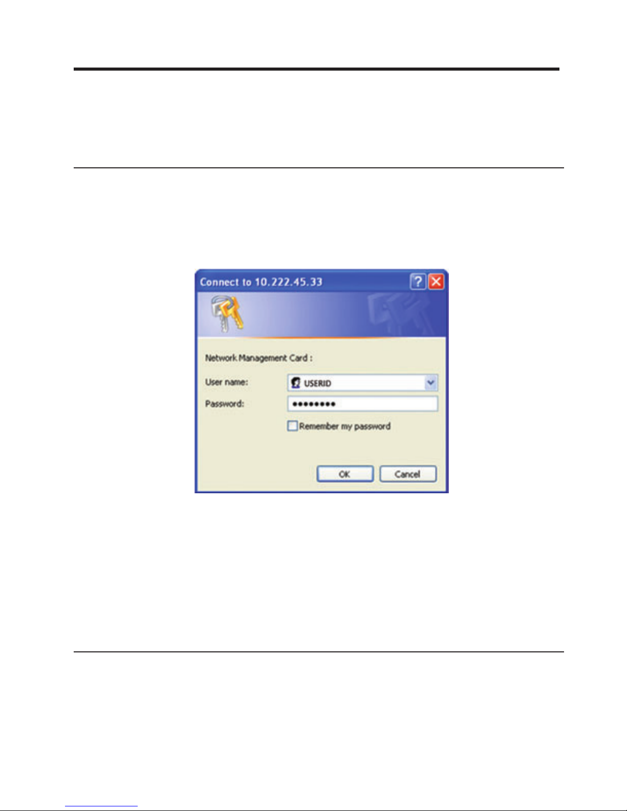
To start the web interface, complete the following steps:
1. Open a web browser from a computer and enter the IP address of the network
management card in the address field.
2. In the “Connect to” window, in the User name field, type USERID (all uppercase).
In the Password field, type passw0rd (all lowercase with a zero, not O).
Both the user name and password fields accept up to 10 characters. After 5
minutes have elapsed, or if the browser is closed and reopened, you must
reenter the user name and password. An error in either field results in rejection
of the requested action (such as save, page access, or card restart). After three
unsuccessful login attempts, you must restart the browser. Both the user name
and password fields are encrypted with an MD5 type algorithm, ensuring total
security. See “3 : Set Login Password to Default” on page 18 to reset the
password.
3. Click OK. The uninterruptible power supply (UPS) Properties page, which is the
home page, is displayed. The UPS Properties page features are described in
“UPS properties” on page 20.
Online help
Online contextual help in English is available through the Help link in the top-right
corner of each page. The navigation menu of the online help is identical to that of
the network management card web pages. The Help page always opens in a new
window.
© Copyright IBM Corp. 2010, 2012 19
Page 30
Optimizing the performance of your web browser
To view status changes on the UPS in real time, configure the web browser so that
it automatically refreshes all the objects on the current page.
To optimize the web browser performance if you are using Internet Explorer,
complete the following steps:
1. Click Tools > Internet Options > General > Temporary Internet files >
Settings.
2. Select Every visit to the page.
3. Click OK to close the Settings window, and then click OK again to close the
Internet Options window.
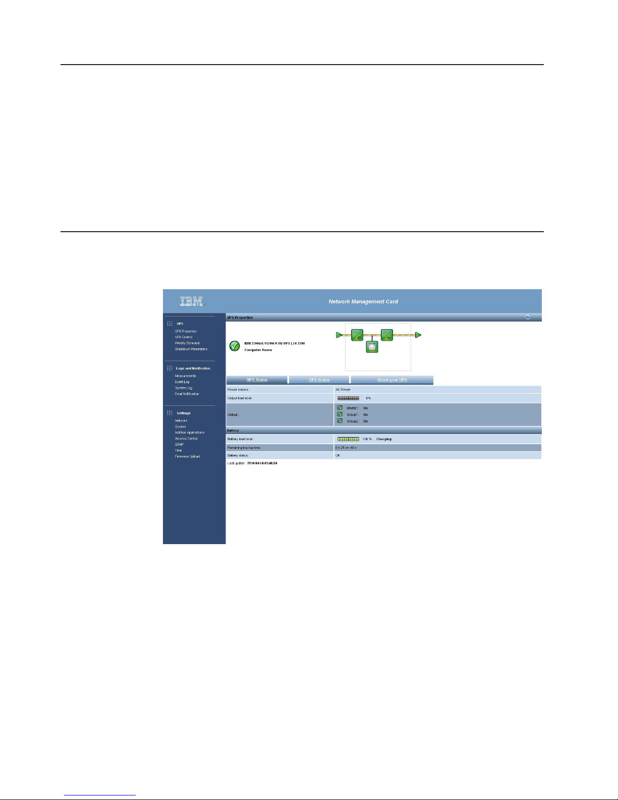
UPS properties
Essential information about the UPS status is available on the UPS Properties page
(see the following illustration), which refreshes automatically every 10 seconds.
The UPS Properties page shows an image and generic name of the UPS. You can
customize the UPS name, and replace the default location Computer Room to
name the location of your system (see “System settings” on page 41). An animated
diagram is displayed for online uninterruptible power supplies that shows an
overview of the current UPS operating mode.
20 Network Management Card : User’s Guide
Page 31

UPS measurements detail
Place the cursor over an element in the diagram to display the UPS measurement
detail (see the following illustration). These measurements are available for Normal
mode, Battery mode, and Bypass mode. The available measurements depend on
the UPS model.
UPS status icons
The UPS status icons are shown in the following table.
Table 6. UPS status icons
Icon Description
Operating mode diagrams
The operating mode diagrams provide a global overview of the UPS current
operating mode. The diagrams are available for all online uninterruptible power
supplies. The operating mode diagrams are shown in the following table.
Table 7. Operating mode diagrams
Operating mode Diagram
UPS with automatic bypass
Normal operation.
Alarm present. This icon links directly to the alarm page.
Loss of communication with the UPS.
Chapter 3. Using the network management card web interface 21
Page 32

Table 7. Operating mode diagrams (continued)
Operating mode Diagram
UPS without automatic bypass
Note: If communication with the UPS is not available, all the elements of the
diagram are gray.
The elements of the operating mode diagrams are shown in the following tables.
Table 8. AC normal input
Icon Color Description
Green In tolerance
Gray Out of tolerance
Table 9. AC normal flow
Icon Color Description
Yellow AC to dc converter powered
by ac normal
Gray AC to dc converter not
powered by ac normal
Table 10. AC to dc converter
Icon Color Description
Green Powered
Gray Not powered
Red Internal failure
22 Network Management Card : User’s Guide
Page 33

Table 11. Battery
Icon Color Description
Green Remaining capacity > 50%
Orange Remaining capacity < 50%
Red Battery to be checked
(battery test result)
Low battery when UPS is on
battery
Table 12. Battery output flow
Icon Color Description
Yellow DC to ac converter powered
by battery
Gray DC to ac converter not
powered by battery
Table 13. DC to ac converter input flow
Icon Color Description
Yellow Energy flow present
Gray No energy flow
Table 14. DC to ac converter
Icon Color Description
Green Powered
Gray Not powered
Red Internal failure
Chapter 3. Using the network management card web interface 23
Page 34

Table 15. DC to ac converter output
Icon Color Description
Yellow Energy flow present
Gray No energy flow
Table 16. AC bypass input
Icon Color Description
Green In tolerance
Red Out of tolerance
Table 17. AC automatic bypass flow
Icon Color Description
Yellow Energy flow present
Gray No energy flow
Table 18. AC automatic bypass status
Icon Color Description
Green Powered
Gray Not powered
Red Internal failure
Table 19. AC manual bypass flow
Icon Color Description
Yellow Energy flow present
Gray No energy flow
24 Network Management Card : User’s Guide
Page 35

Table 20. AC manual bypass status
Icon Color Description
Green / gray Open
Red / yellow Closed
Table 21. AC output flow
Icon Color Description
Yellow Energy flow present
Gray No energy flow
Table 22. AC output
Icon Color Description
Green Load protected
Red Load not protected
UPS Properties tabs
Select one of the three tabs to view specific information about the UPS. The tabs
are under the operating mode diagram on the UPS Properties page. The following
table is a summary of the information that is provided in each view, and the
following sections describe each view.
Table 23. UPS properties tabs
Tab Description
UPS Status (Default view) Provides essential information about the power
UPS Alarm Displays a list of current alarms
About your UPS Provides information about the model and firmware version of the
UPS Status
The UPS Status view displays the following basic information about power and
output:
v Power source: Indicates whether the power comes from the utility power or from
the UPS battery
v Output load level: Indicates the power percentage that is used at the UPS
output
v Output: Indicates whether the UPS outputs are protected
– Master (UPS): Indicates whether the UPS main output is protected
– Group1 and Group2: Indicates whether the controlled load segments (if
available) are powered (see the following table)
status of the UPS
UPS and the network management card
Chapter 3. Using the network management card web interface 25
Page 36

Table 24. UPS output status
Element Description
Receptacle powered
(green)
Receptacle not powered or not protected
(red)
v Battery charge level: Remaining battery charge (in percent). The battery modes
are as follows:
– Fault: The battery is faulty.
– No battery: No battery is found.
– Charging: The utility power is present, and the battery charge is in progress.
– Discharging: The UPS is operating from the battery.
– Floating: The battery is at the optimal charge level.
– Resting: The battery is not charging.
Note: The battery has reached the end of the floating mode time period and
has stopped charging to extend the life of the battery. The battery
slowly discharges until the minimum charge level is reached. When the
minimum charge level is reached, the battery returns to Charging
mode.
– Charger disabled: The battery charger is off.
v Remaining backup time: An estimate of the maximum backup time that remains
for the battery before the UPS shuts down.
v Battery status: The result of the last automatic battery test that was run by the
UPS. The possible values are as follows:
– OK: The test was completed correctly.
– NOK: The battery must be checked.
– Deactivated: The automatic battery test is not validated on the UPS.
UPS Alarm
Click UPS Alarm on the UPS Properties page to display the list of current alarms.
Table 25 on page 27 lists the alarm severity levels. For the managed UPS and
system alarms, see Table 39 on page 75 and Table 41 on page 78.
26 Network Management Card : User’s Guide
Page 37

The alarm severity levels are shown in the following table.
Table 25. Alarm severity levels
Icon Severity level
Critical
Red
Warning
Yellow
Unknown
Gray
About your UPS
Click About your UPS to view the information about the UPS and the network
management card.
Chapter 3. Using the network management card web interface 27
Page 38

UPS control
Note: The UPS configuration might prevent the shutdown and restart commands
from running correctly. For more information, see the Installation and
Maintenance Guide that comes with the UPS.
Click UPS Control from the menu to display the UPS Control page.
Use the UPS Control page to enable triggering of startup and shutdown sequences
for the UPS main output and load segments (by default, named Master, Group1,
and Group2).
28 Network Management Card : User’s Guide
Page 39

The status of each output is indicated by an Off icon (red) or an On icon (green).
The shutdown sequences allow time for the registered servers to shut down without
losing data (see “Shutdown parameters” on page 31).
The main output has priority over the load segments. Shutdown of the main output
causes the load segments to shut down. Load segments can be started only if the
master output is on.
In the Control column, select one of the following commands for each output, and
click Execute to initiate the selected commands:
Safe power down
Immediately start a sequence to turn off output power. The supplied
systems are shut down, and the output power is turned off.
Safe power down & reboot
Immediately start a sequence to turn off and then restore output power. The
supplied systems are shut down, and the output power is turned off. Then,
the restart sequence is initiated at the end of the time delay that you
specified in the Toggle Duration parameter. The output status is updated.
Immediate On
Immediately start a sequence to turn on output power and start the supplied
systems.
Delayed, safe power down
After the number of seconds that you specified in the Off Delay parameter,
start a sequence to turn off output power. The supplied systems are shut
down during the shutdown sequence, and the output power is turned off.
Delayed, safe power down & reboot
After the number of seconds that you specified in the Off Delay parameter,
start a sequence to turn off and then restore output power. The supplied
systems are shut down, and the output power is turned off. Then, the
restart sequence is initiated at the end of the time delay that you specified
in the Toggle Duration parameter. The output status is updated.
Delayed On
After the number of seconds that you specified in the On Delay parameter,
start a sequence to turn on output power and start the supplied systems.
In the Off Delay column, specify the value that is used by the Delayed, safe power
down and Delayed, safe power down & reboot commands to allow time for the
registered servers to shut down without losing data (see “Shutdown parameters” on
page 31).
In the Toggle Duration column, specify the value that is used by the Safe power
down & reboot and Delayed, safe power down and reboot commands.
In the On Delay column, specify the value that is used by the Delayed On
command.
Click Save to save the Off Delay, Toggle Duration, and On Delay parameters.
Note: For security, you must click Save and enter the administrator login and
password to save modifications or run commands. The default login is
USERID (all uppercase), and the password is passw0rd (all lowercase with a
zero, not the letter O).
Chapter 3. Using the network management card web interface 29
Page 40

UPS weekly schedule programming
Note: The UPS configuration might prevent the shutdown and restart commands
from running correctly. For more information, see the Installation and
Maintenance Guide that comes with the UPS.
Click Weekly Schedule from the menu to set up the timing of specific weekly
actions.
You can use the weekly schedule to optimize power consumption or program a
restart of the protected equipment at a set time.
In a shutdown sequence, the IBM UPS Manager software is notified to make sure
that each device is shut down correctly before the UPS output is turned off. You can
program up to seven UPS shutdown sequences in one week, with a minimum
shutdown delay of 30 minutes.
The on/off sequences are valid only if the network management card time is set
correctly.
Note: For security, you must click Save and enter the administrator login and
password to save modifications or run commands. The default login is
USERID (all uppercase), and the password is passw0rd (all lowercase with a
zero, not the letter O).
30 Network Management Card : User’s Guide
Page 41

Shutdown parameters
Click Shutdown Parameters from the menu to view and configure UPS parameters
for operating in battery mode and restoring power.
UPS shutdown
Click Show advanced parameters to display additional parameters for adjusting
specific thresholds related to the percentage of remaining battery charge level.
You can customize the name of the main output and load segments in the Output
column (the maximum is 20 characters).
Priority is given to the main output; therefore, the network management card cannot
supply power to the load segments when the main output power is off.
Note: For security, you must click Save and enter the administrator login and
password to save modifications or run commands. The default login is
USERID (all uppercase), and the password is passw0rd (all lowercase with a
zero, not the letter O).
Note: The first criterion encountered triggers the shutdown sequence. For more
information, see Chapter 6, “Shutdown criteria and sequence,” on page 69.
To program the criteria for starting the shutdown sequence, set the following
parameters in the first row of the table on the Shutdown Parameters page:
v Shutdown if Remaining time under: The minimum remaining backup time, in
seconds, that triggers a shutdown sequence. Valid values are 0 to 99999. The
default is 180.
v Shutdown if Capacity under: The minimum remaining battery capacity level (in
percent) that triggers a shutdown sequence. The value cannot be less than 30%.
If the value is set below 30%, it is automatically changed to 30%. The value
cannot be less than the value that is configured in the UPS itself.
Chapter 3. Using the network management card web interface 31
Page 42

v Shutdown after: The operating time, in minutes, that users have after a switch
to backup before starting the shutdown sequence. Valid values are 0 to 99999.
There is no default value.
v Shutdown duration: The time (in seconds) that is required for a complete
shutdown of the systems when a switch to backup time is long enough to trigger
a shutdown sequence. It is calculated automatically at the maximum of Shutdown
duration of subscribed clients, but it can be modified with the Advanced
parameters. The default is 120.
Load segments shutdown
Note: Some uninterruptible power supplies do not support the load segments
control feature.
To manage receptacle load shedding in the event of electric power failure, set the
following parameters in the load segment rows on the Shutdown Parameters page:
v Switch Off after: The amount of time (in seconds) during which the load
segment is supplied from the moment of utility power failure. Valid values are 0
to 99999. The default is 65535. This value includes the load segment shutdown
duration.
v Switch Off if Capacity under: The minimum remaining battery capacity level (in
percent) that triggers a load segment shutdown sequence. The default is 0.
v Shutdown duration: The time (in seconds) that is required for a complete
shutdown of the systems that are supplied by the load segment when a load
segment shutdown sequence starts.
v Switch On after: The period between the main output startup and the startup of
the relevant programmable load segment; therefore, load segment startup can be
delayed in relation to the main output. Valid values are 0 to 99999. The default
for Load segment 1 is 0 and the default for Load segment 2 is 1. Some
uninterruptible power supplies do not support this parameter.
Note: For security, you must click Save and enter the administrator login and
password to save modifications or run commands. The default login is
USERID (all uppercase), and the password is passw0rd (all lowercase with a
zero, not the letter O).
32 Network Management Card : User’s Guide
Page 43

Measurements
Click Measurements from the menu to view the measurements for the UPS.
Note: The following illustration shows the measurements for a single-phase UPS.
The following measurements are saved and time stamped:
v AC Normal
– Voltage: The utility voltage that supplies the UPS
– Frequency: The utility frequency that supplies the UPS
v AC Output
– Voltage: The UPS output voltage
– Frequency: The UPS output frequency
– Power (kVA): The UPS output power
– Load level (%): The percentage of the load at the UPS output
v Battery
– Capacity (%): The available charge in the battery (in percent)
– Remaining time (mn): An estimate of the remaining backup time (in minutes)
The save frequency of these values (60 seconds by default) is defined on the
System page (see “System settings” on page 41). Approximately 435 time stamps
can be stored on the network management card. When this threshold is reached,
the oldest time stamp is deleted when a new one occurs.
Click Save Log to open or save all saved values in comma separated values (CSV)
format (compatible with Microsoft Excel type spreadsheets).
Click Clear Log to delete all records. Enter your user name and password to
validate this action.
Chapter 3. Using the network management card web interface 33
Page 44

Event log
Click Event Log from the menu to view logged events.
The network management card can save up to 435 events. When this threshold is
reached, the oldest event is deleted when a new one occurs.
Click Save Log to save values in comma separated values (CSV) format.
Click Clear Log to delete all records. Enter your user name and password to
validate this action.
For a list of managed alarms, see Table 39 on page 75 and Table 41 on page 78.
34 Network Management Card : User’s Guide
Page 45

System log
Click System Log from the menu to view system events.
The network management card can save up to 435 events. When this threshold is
reached, the oldest event is deleted when a new one occurs.
Click Save Log to save values in comma separated values (CSV) format.
Click Clear Log to delete all records. Enter your user name and password to
validate this action.
For a list of managed alarms, see Table 39 on page 75 and Table 41 on page 78.
Notification
The email notification and email message settings are described in this section.
Email notification
The network management card can redirect UPS alarms to an email server to
distribute information to the applicable recipients. The format of these email
messages is compatible with mobile telephone transfer systems that use the short
message service (SMS) standard for text messaging.
Click Email Notification from the menu to configure email recipients.
Chapter 3. Using the network management card web interface 35
Page 46

On the Email Notification page, you can configure up to four recipients in the
Recipient list to receive email messages that are initiated by the network
management card. Each recipient receives an email message according to specific
trigger events, which you can select from the right side of the page. The network
management card log also indicates email transmission errors.
Set the following parameters for each recipient:
v Recipient: Specify the email address of the person or department that is to
receive the email. The limit is 99 characters. The default is
recipientn@domain.com.
v Attached files: Select the files (Measurements, Event Log, and System Log) that
you want to be attached to the email message. Data is sent in CSV format.
v Periodic report: In addition to the email messages that are sent when events
occur, you can schedule periodic email messages with the logs attached to be
sent to the recipient at specified intervals. To configure periodic email messages,
specify the day and time of the first transmission and the frequency of
subsequent transmissions. After the first transmission, the day and time of the
next transmission is displayed.
v Email Message Settings: Click this link to display the Email Message Settings
page (see “Email message settings” on page 37).
v Network Settings: Click this link to display the Network Settings page (see
“Network settings” on page 38).
v Test: Use this to send an email message to the recipient immediately. Use this
method to check email transmission, particularly to check access to the SMTP
server that is configured on the Network Settings page (see “Network settings”
on page 38). A transmission report is added to the system log. The event label in
the subject and text of the message is replaced with a test label. If you make any
modifications to the page, you must save them before you use the Test function.
v Save: Save your settings.
The right side of the page shows the events that can require notification. By default,
only main events, such as battery operation and a few of the UPS alarms, are
36 Network Management Card : User’s Guide
Page 47

accessible. If you click Show/Hide Events, all the events are displayed or hidden.
By default, only two events are selected for notification: UPS Off sequence in
progress and UPS alarms. You can click other events to select them, and you
restore the default selections by clicking Set Default.
Note: For security, you must click Save and enter the administrator login and
password to save modifications or run commands. The default login is
USERID (all uppercase), and the password is passw0rd (all lowercase with a
zero, not the letter O).
Email message settings
Use the Email Message Settings page to customize the content of email messages
that are initiated by the network management card (see “Email notification” on page
35).
All email message recipients have the following common settings:
v Sender: The source of the message. This field allows free text. However,
depending on the SMTP server configuration, the server might verify that the
domain name in the sender address exists and that the user in the sender
address belongs to that domain. The limit is 59 characters. The default is
ups@domain.com.
v Subject: The subject of the email message. Enter text and select from the
following optional check boxes to build the message subject:
– UPS Name is the name of the UPS.
– UPS Location is the geographic location of the UPS (see “System Settings”
on page 52).
– Event message is the event that generated the email message.
v Message text: Type your message in this field. The limit is 255 characters.
As shown in the following figure, the body of the email message contains the
following items:
– Message text
– The date and time of the event, as saved in the log
Chapter 3. Using the network management card web interface 37
Page 48

– The URL of the network management card, enabling a direct link with the
network management card to be established
– Attachments, as configured for the email recipients
– The subject text
Sending text messages
The network management card can redirect UPS alarms to an email server. The
format of these email messages is compatible with mobile telephone email/SMS
transfer systems that are used by Internet service providers (ISPs). The format that
is to be used depends on the service provider.
Network settings
Click Network from the menu to configure the network parameters of the network
management card and authorize the remote upgrade of the embedded system.
Note: If you are not already logged on, you are prompted to enter your user name
and password before you access the Network Settings page.
You can configure the following network management card network settings:
v BootP/DHCP: Select Enabled to authorize configuration of network parameters
with the BOOTP/DHCP server when the network management card is started.
38 Network Management Card : User’s Guide
Page 49

Mode of card operation with server: After each startup, the network management
card makes five attempts to recover the network parameters. If it receives no
response from the server, the card starts with the last saved parameters from the
most recent start. These parameters are shown on the page. The default value
for this parameter is Enabled.
Notes:
1. If the host name is not used, the IP address that is supplied by the DHCP
server must be assigned through Static DHCP Assignment to maintain the
connection with the clients on the stations that are to be protected.
2. During the first connection, if the DHCP query is not successful, the network
management card starts with the following IP configuration:
IP address: 192.168.1.2
Subnet mask: 255.255.255.0
Gateway address: 0.0.0.0
v IP address: The IP address of the network management card (for example,
166.99.224.70).
v Subnet Mask: The mask of the subnetwork of the network (for example,
255.255.255.0).
v Gateway Address: The IP address of the gateway to access the stations that
are outside the network management card subnet (for example, 166.99.224.1).
v Hostname: The host name of the network management card. This is the first
part of the fully qualified domain name that is used by the Domain Name System
(DNS). Because the network management card does not support the NetBIOS
protocol, the host name is sent to the DNS only if the DHCP server sends the
host name with the new IP address. This mechanism is described in the update
of the DNS protocol RFC 2136.
v Domain Name: The domain to which the network management card belongs.
The domain name is the part of the fully qualified domain name that follows the
host name and is used by the DNS. The default fully qualified domain name is
ups.domain.com.
v IPv6 Enabled: Select this check box to enable Internet Protocol version 6 (IPv6)
features.
Note: IPv6 is described in the Internet standard RFC 2460.
v IPv6 Auto Config Enabled: Select this check box to have the network
management card or the IPv6 router (if an IPv6 router is available on the
network) automatically generate the following IPv6 parameters:
– Local IPv6 address
– Prefix length
The IPv6 Gateway field becomes unavailable and remains blank.
v IPv6 Address 1: If IPv6 Auto Config Enabled is selected, the first IPv6 address
is displayed.
If IPv6 Auto Config Enabled is not selected, the IPv6 address of the network
management card is entered in one of the following formats:
– [::1:0:0 ; 1FFF:FFFF:FFFF:FFFF:FFFF:FFFF:FFFF:FFFF] for a range of
prefixes [4-128]
– [2000:: ; FEFF:FFFF:FFFF:FFFF:FFFF:FFFF:FFFF:FFFF] for a prefix of 64
v Prefix length: The addressing prefix that is used to route external traffic for a
network.
If IPv6 Auto Config Enabled is selected, the IPv6 network prefix is displayed.
Chapter 3. Using the network management card web interface 39
Page 50

If IPv6 Auto Config Enabled is not selected, you can enter the IPv6 network
prefix in the following format:
– [4-128] for an IP address 1:
[::1:0:0 ; 1FFF:FFFF:FFFF:FFFF:FFFF:FFFF:FFFF:FFFF]
– 64 for an IP address 1:
[2000:: ; FEFF:FFFF:FFFF:FFFF:FFFF:FFFF:FFFF:FFFF]
v IPv6 Gateway: If IPv6 Auto Config Enabled is selected, the IPv6 Gateway field
is not available.
If IPv6 Auto Config Enabled is not selected, you can enter the name of the IPv6
gateway.
v IPv6 Local Address: The IPv6 local address is generated from the network
management card MAC address and is displayed in this field.
v IPv6 Address 2: If IPv6 Auto Config Enabled is selected, the second IPv6
address is provided by the DHCP server (for example,
1876:720:410:100A:1111:2222:33:4444) and cannot be changed.
If IPv6 Auto Config Enabled is not selected, the IPv6 Address 2 field is not
available.
v Firmware Upload: Select Enabled to authorize remote updating of the network
management card embedded software. The default is Enabled.
v Primary DNS Server (IPv4 or IPv6): The IP address of the main DNS server
that ensures conversion of the domain name to an IP address.
v Secondary DNS Server: The IP address of the secondary DNS server that
ensures conversion of the domain name to an IP address if the primary DNS
server is not available.
v SMTP Server (for Email Notification): The name or IP address of the local
server to which the network management card connects to send email
messages. You can enter a host + domain name (DNS resolution) or an IP
address.
The default is smtpserver. The network management card uses the standard
port (25) for sending email messages.
v SMTP server authentication: If you select this check box, enter the SMTP
server user name and password.
Note: For security, you must click Save and enter the administrator login and
password to save modifications or run commands. The default login is
USERID (all uppercase), and the password is passw0rd (all lowercase with a
zero, not the letter O).
Restart the network management card after any changes to these parameters (see
“System settings” on page 41).
40 Network Management Card : User’s Guide
Page 51

System settings
Click System from the menu to customize the information that is displayed on the
UPS Properties page (see “UPS properties” on page 20).
You can configure the following network management card system settings:
v UPS Contact: Enter the name of the person who is responsible for UPS
administration at the IT network level or the person who is responsible for
electrical maintenance. This field is not displayed on any other web page. The
limit is 49 characters. The default is Computer Room Manager.
v UPS Location: Enter a description of the physical location of the UPS in your
installation (for example, Computer Room E1-C066). This text is displayed on the
home page. The limit is 31 characters. The default is Computer Room.
v UPS Custom Name: An alias personalization of the UPS name. The limit is 31
characters. The default is UPS.
v Default Language: Select one of the available languages (English, French,
Spanish, German, Simplified Chinese, Japanese, Russian, Korean, or Traditional
Chinese) to enable initialization of the browser language at the network
management card connection. To change the language of the web interface
pages, restart your browser after you change this setting.
v History log interval (sec): Enter the length of time (in seconds) that the
measurement history log is saved. Valid values are 5 to 99999. The default is 60.
v Environment log interval (sec): Enter the length of time (in seconds) that the
temperature and humidity measurement log is saved. Valid values are 60 to
99999. The default is 300.
Note: The Environment log interval parameter is displayed only if an optional
environmental monitoring probe is installed.
v Log Delimiter: Select the delimiter that is used in the log saved file. The default
is Ta b .
v Save: Save any changes that you have made on the System Settings page.
Chapter 3. Using the network management card web interface 41
Page 52

v Reset Communication: Perform a remote restart of the network management
card without modifying the configuration. This action is required for any changes
that you have made on the Network Settings page.
v Factory Reset: Restore all the network management card parameters to their
default settings.
v Keep TCP/IP parameters: Select this check box to maintain the IP address,
subnet mask, gateway, and BOOTP/DHCP value.
Note: For security, you must click Save and enter the administrator login and
Notified applications
Use the Notified Applications page to modify a network management system (NMS)
that is set to receive notifications from the network management card or to add up
to three NMSs to the notified applications.
To modify or add a new NMS, complete the following steps:
1. Select Notified Applications from the menu. The Notified Applications page is
displayed.
password to save modifications or run commands. The default login is
USERID (all uppercase), and the password is passw0rd (all lowercase with a
zero, not the letter O).
2. Click Modify NMS or Add NMS to open a new window in which you can modify
or enter SNMP trap receiver information (application name, host name or IP
address, protocol, trap community, and MIB filter).
42 Network Management Card : User’s Guide
Page 53

Access control
Click Access Control from the menu to configure the different parameters to allow
secure access to the card.
Notes:
1. If you are not already logged on, you are prompted to enter your user name and
password before you access the Access Control page.
2. Restart the network management card to activate any configuration changes.
For more information, see “System settings” on page 41.
On the Access Control page, you can configure the following access control
settings:
Chapter 3. Using the network management card web interface 43
Page 54

v Enter New Manager Login: This text field (limited to 10 characters) enables
secure access and modification of pages. The default is USERID (all uppercase).
v Enter New Password: This text field (limited to 10 characters) enables secure
access to Configuration menu pages. The default is passw0rd (all lowercase with
a zero, not the letter O).
v Confirm New Password: Reenter the new password.
v Security mode: Select the authentication method for page access. The following
security modes are available:
– Authentication for configuration: Only the configuration pages are protected
by a user name and password.
– Full authentication: All pages are protected by a user name and password.
– SSL and full authentication: All pages are protected by a user name and
password and are accessible only in SSL.
When SSL and full authentication is selected, access to the web interface is
made in secure mode (https). Connections with network shutdown modules stay
in standard mode (secure TCP).
SSL security implementation:
– SSL version 3.0
– TLS version 1.0
– Method: TLS_RSA_WITH_512_MD5
– Auth: RSA
– Key exchange: RSA
– Encryption: RCA_512
– Digest: MD5
v Save: Save your settings.
v Telnet Access Enabled: Select this field to allow access to the configuration
parameters through a Telnet, SSH, or command-line interface connection.
v Telnet Security Enabled: Select this field to set SSH security (secure access).
Deselect this field to allow unsecure access.
v Console Interface: Select the interface that you want to use to view the
configuration parameters during a Telnet, SSH, or command-line interface
connection. The following console interfaces are available:
– Menu: The parameters are grouped into predefined menus.
– CLI: The parameters are accessible independently of each other using the
command-line interface.
The interface setting applies to the TCP/IP connection and the Telnet and SSH
protocols.
SNMP setting
Click SNMP from the menu to enable configuration of the SNMP security
parameters.
Note: If you are not already logged on, you are prompted to enter your user name
and password before you access the SNMP Settings page.
44 Network Management Card : User’s Guide
Page 55

You can configure the following information:
v SNMP Version: Select the SNMP protocol version (Disabled, V1, or V3) that is
supported by the network management card.
v Community Read-Only: The SNMPv1 read community name that identifies a
subgroup that is attached to a network manager or a logical entity. The network
management card and the clients must share the same community name to
communicate.
v SNMP Write: Select Enabled to enable the SNMP write function.
v Community Write: This field is available only if the SNMP write function is
enabled. This is the SNMPv1 write community name that identifies a subgroup
that is attached to a network manager or a logical entity. The network
management card and the clients must share the same community name to
communicate.
v Read-Only User: The user name of the user in the SNMPv3 version who is
authorized only to read SNMP variables.
v Read-Only Security Level: Select one of the following security levels:
– No Auth No Priv: The user must not use authentication and privacy to
access SNMP variables.
– Auth No Priv: The user must use authentication and not privacy to access
SNMP variables.
– Auth Priv: The user must use authentication and privacy to access SNMP
variables.
v Read Only Password: Enter a new password for the Read-Only User. The
password must be between 8 and 24 characters and use only letters, numbers,
and <>&@#%_=:;,./?|$*() symbols.
v Read-Write User: The user name of the user in the SNMPv3 version who is
authorized to read and write SNMP variables.
v Read-Write Security Level: Select one of the following security levels:
– No Auth No Priv: The user must not use authentication and privacy to
access SNMP variables.
Chapter 3. Using the network management card web interface 45
Page 56

Date and time
– Auth No Priv: The user must use authentication and not privacy to access
SNMP variables.
– Auth Priv: The user must use authentication and privacy to access SNMP
variables.
v Read-Write Password: Enter a new password for the Read-Write User. The
password must be between 8 and 24 characters and use only letters, numbers,
and <>&@#%_=:;,./?|$*() symbols.
v Notification Username: Enter the username field that is sent in SNMPV3
notifications. This field must be defined in the applications that receive the
notifications.
v Save: Save your settings.
Click Time from the menu to manually set the network management card date and
time or to set the date and time to synchronize with the NTP server.
To set the date and time, complete the following steps:
1. Click Time from the menu to open the Setting Time page.
2. To manually set the date and time, select Set manually, enter the values in the
Date and Time fields, and click Save. The maximum drift is ±2 minutes per
month.
3. To synchronize the time with the Network Time Protocol (NTP) server, select
Synchronize with NTP server. Selecting this option enables a connection with
a time server, which is available either on the company internal network or on
the web. This server communicates the GMT.
v Enter the IP address or host name of the time server.
v Select the time zone for your geographic area from the list.
v Click Save to connect with the server and set the date and time.
The time is updated every 5 hours to prevent any time drift. After two attempts,
if the NTP server is not accessible, the network management card changes to
manual mode. The network management card uses the NTP (UDP 123 port).
46 Network Management Card : User’s Guide
Page 57

Notes:
1. After startup, if the network management card is in manual mode, or if no NTP
2. If the network management card is installed in an UPS that supports time
Updating firmware
To update the network management card firmware, complete the following steps.
Note: During the upgrade process, the network management card does not monitor
1. Go to http://www.ibm.com/systems/support/ and download the new firmware
2. Click Firmware Upload to open the Firmware Upload page.
The firewall must be set to transmit queries outside the intranet. No error
message is generated if the time server contact fails.
server was reached, the card initializes at 00:00 01/01/1970.
stamping, the network management card time is automatically synchronized with
that of the UPS.
the UPS status.
version to your computer.
3. Click Browse and select the firmware update file.
Chapter 3. Using the network management card web interface 47
Page 58

4. Click Upload.
Note: The upload can take up to 5 minutes. Do not interrupt the operation until the
firmware upload is successful and the following screen is displayed.
48 Network Management Card : User’s Guide
Page 59

Chapter 4. Using the Telnet, SSH, and CLI
This chapter describes how to use the Telnet, Secure Shell (SSH), and
command-line interface (CLI) to access the IBM Network Management Card.
Note: You cannot configure email recipients through Telnet, SSH, or CLI.
Overview
Telnet is a terminal emulation protocol that you can use to access and configure the
parameters for the network management card. Telnet is not a secure protocol, but
when it is used with Secure Shell (SSH) the connection is secure.
You can configure the connection to use one of the following interfaces:
v A Menu interface that groups the configuration parameters in pre-defined menus
for easy navigation
v A command-line interface (CLI) that enables direct access to the individual
configuration parameters
Telnet access to the network management card is enabled by default, with SSH
security enabled and the Menu interface selected.
Session constraints
Up to five sessions with the network management card can be open at one time.
Each open session must have the same protocol configuration. The available
protocol configurations are shown in the following table.
Table 26. Available session protocol configurations
Security Interface Comments
Telnet Menu
Telnet CLI
SSH Menu Default setting
SSH CLI
Available settings
Most configuration parameters that are available through the web interface are also
available through the Telnet, SSH, or command-line interface:
v For a detailed explanation of each parameter, default, and possible values, see
v For a quick reference of default parameters, see Table 5 on page 7.
Note: You cannot configure email recipients through Telnet, SSH, or CLI.
Depending on the current configuration of the network management card, some
parameters are not available. Table 2 lists the type of each parameter or message
coded by color.
Chapter 3, “Using the network management card web interface,” on page 19.
© Copyright IBM Corp. 2010, 2012 49
Page 60

Table 27. Color codes
Parameter or message Color
Read-write or write-only parameter Light green
Read-only parameter Yellow
Warning message Green
Error message Light red
Starting and ending a session
To start a session, complete the following steps:
1. Open a terminal emulator or other session manager such as PuTTY.
2. At the prompt, type telnet IPaddress, where IPaddress is the IP address of the
network management card.
If the connection is successful, the server responds with connected to
IPaddress and a welcome message.
3. At the Login and Password prompts, enter your user name and password. If the
login is successful, the configured interface displays either Menu (the main
menu) or CLI (the #> prompt).
If you want to use the Menu interface, see “Using the Menu interface.”
If you want to use the command-line interface, see “Using the command-line
interface” on page 52.
To end a session in either the Menu interface or the command-line interface, enter
quit at any time.
Using the Menu interface
The Menu interface is available with the Telnet and SSH protocols and is in English
only.
Menu structure
The Menu interface groups the configuration parameters into the same menus and
submenus that are available through the web interface (for details about the
parameters, see “Available settings” on page 49. Table 28 on page 51 shows the
parameters arranged in the Menu interface tree.
Using the menus
To use the menus, type the number of the menu item that you want to run and then
press Enter. For example, in the following sample menu screen, to access the Trap
Receiver 2 parameters you type 2 and press Enter. To return to the previous menu
from any screen, type 0 and press Enter.
50 Network Management Card : User’s Guide
Page 61

The following illustration shows a sample menu screen.
------------------------------------------------------------NETWORK MANAGEMENT CARD
Trap receiver
------------------------------------------------------------1 : Receiver 1
2 : Receiver 2
3 : Receiver 3
0 : Exit
To close the session from any menu screen, enter quit.
The following table provides an overview of the menu tree for the Menu interface.
Table 28. Menu interface main menu tree
Main menu item Submenu Submenu Description
Reset Resets the network
management card
Network settings MAC address, IP address,
and other parameters
SMTP menu Host name and other
parameters
SNMP menu Version and other
parameters
Trap receivers Receiver 1
Receiver 2
Receiver 3
Host name, protocol, and
other parameters for each
receiver
System settings Uninterruptible power
supply (UPS) contact, UPS
location, and other
parameters
Shutdown settings Outlet 1 (main or master)
Outlet 2
Name and other parameters
for each outlet
Outlet 3
Access control Login, password, and other
parameters
Date and time Date, hour, and other
parameters
Environment Sensor name, Temperature,
Thresholds and identifiers Configures the optional
Humidity, and Inputs
Set login password to
default
Default configuration Resets all parameters to
Configures the network
parameters and authorizes
remote upgrades.
Configures the SMTP
server.
Configures the SNMP
versions v1 and v3.
Lists the stations receiving
traps and configures the
traps. Maximum of three.
Customizes information on
the UPS Properties pages.
Defines the UPS behavior
during a shutdown.
Configures secure access
to the network management
card.
Sets the date and time.
environmental monitoring
probe.
Resets the login and
password to the defaults.
their defaults and restarts
the network management
card.
Chapter 4. Using the Telnet, SSH, and CLI 51
Page 62

Using the command-line interface
The command-line interface enables direct access to the individual configuration
parameters.
Usage guidelines
Type a command at the prompt and press Enter. A recognized command is
processed; otherwise a warning message is returned.
Blank characters are not allowed in commands, except inside strings.
Enclose strings in double quotation marks (“”). For example, name a server My
Server by sending the string “My Server” as part of the command.
General commands
Use the general commands in the following table to open, close, and control
sessions.
Table 29. General commands
help or ? Display help about a specific command.
Syntax help [command] or [command] ?
Example #> help getNetwork or #> getNetwork ?
setEcho Hide, or not, all characters. If hidden, each character entered is replaced by an asterisk (*).
Syntax setEcho [option]
Options ON | OFF
Example #> setEcho ON
quit Close a current CLI session.
Syntax quit
Example #> quit
reset Reset the software.
Syntax reset
Example #> reset
version Get information about the software version.
Syntax version
Example #> version
defaultPass Return to the default login and password.
Syntax defaultPass
Example #> defaultPass
52 Network Management Card : User’s Guide
Page 63

Table 29. General commands (continued)
defaultConf Return to the default configuration.
Syntax defaultConf
Example #> defaultConf
Chapter 4. Using the Telnet, SSH, and CLI 53
Page 64

Network commands
Use the network commands in the following table to administer network parameters
and authorizations.
Table 30. Network commands
getNetwork Read a network setting.
Syntax getNetwork [option1] [option2]
Options DHCP | IPAddress | IPMask | IPGateway | HostName | DomainName | IPv6Enable | IPv6AutoConf |
IPv6Address1 | PrefixLength | IPv6DefaultGateway | IPv6LocalAddress | IPv6Address2 | PrimaryDNS
| SecondaryDNS | FirmwareUpgrade
Example #> getNetwork IPAddress
setNetwork Modify a network setting.
Syntax setNetwork [option1=xxxx] [option2=yyyy]
Options DHCP =0|1 (0=No, 1=Yes)
IPAddress = “xxx.xxx.xxx.xxx” (See Note 1)
IPMask = “xxx.xxx.xxx.xxx” (See Note 1)
IPGateway = “xxx.xxx.xxx.xxx” (See Note 1)
HostName = “xx..xx”
DomainName = “xx..xx”
IPv6Enable=0|1 (0=No, 1=Yes)
IPv6AutoConf=0|1 (0=No, 1=Yes) (See Note 2)
IPv6Address1 = “” (See Note 3)
PrefixLength = xx (See Note 3)
IPv6DefaultGateway [= ] (See Note 3)
PrimaryDNS = “xx..xx”
SecondaryDNS = “xx..xx”
FirmwareUpgrade=0|1 (0=No, 1=Yes)
Example #> setNetwork IPAddress=”166.99.18.129” IPMask=”255.255.248.0”
Comments Note 1: Setting is write-enabled depending on “DHCP” status.
Note 2: Setting is write-enabled depending on “IPv6Enable” status.
Note 3: Setting is write-enabled depending on “IPv6AutoConf” status.
getSMTP Read an SMTP setting.
Syntax getSMTP [option1] [option2]
Options HostName | Authentication | Login | Password
Example #> getSMTP HostName
Comments For Password, each character is replaced with an asterisk (*).
setSMTP Modify an SMTP setting.
Syntax setSMTP [option1=xxxx] [option2=yyyy]
54 Network Management Card : User’s Guide
Page 65

Table 30. Network commands (continued)
Options HostName = “xx..xx”
Authentication=0|1 (0=No, 1=Yes)
Login = “xx..xx” (See Note 1)
Password = “**..**” (See Notes 1, 2)
Example #> setSMTP HostName = “Smtp Server”
Comments Note 1: Setting is write-enabled depending on “Authentication” status.
Note 2: Remember to set echo off.
getSNMP Read an SNMP setting.
Syntax getSNMP [option1] [option2]
Options snmpVersion | ReadCommunityName | WriteCommunitySecurityLevel | WriteCommunityName | User |
UserSecurityLevel | UserPassword | Admin | AdminSecurityLevel | AdminPassword |
NotificationUserName | FirmwareUpgrade
Example #> getSNMP User
Comments For UserPassword and AdminPassword, each character is replaced with an asterisk (*).
setSNMP Modify an SNMP setting.
Syntax getSNMP [option1] [option2]
Options snmpVersion = Disabled | V1 | V3 | V1V3
ReadCommunityName = “xx..xx” (See Note 1)
WriteCommunitySecurityLevel=0|2 (0=No, 2=Yes)
WriteCommunityName = “xx..xx” (See Notes 1, 2)
User = “xx..xx” (See Note 1)
UserSecurityLevel=1|2|3(1=No Auth, 2=Auth NoPriv,
(See Note 1)
3=Auth Priv)
UserPassword = “xx..xx” (See Notes 1, 3, 5, 6)
Admin = “xx..xx” (See Note 1)
AdminSecurityLevel=1|2|3(1=No Auth, 2=Auth NoPriv,
(See Note 1)
3=Auth Priv)
AdminPassword = “xx..xx” (See Notes 1, 4, 5, 6)
NotificationUserName = “xx..xx”
FirmwareUpgrade=0|1 (0=No, 1=Yes)
Example #> setSNMP User = “readuser”
Comments Note 1: Setting is write-enabled depending on “snmpVersion” status.
Note 2: Setting is write-enabled depending on “WriteCommunitySecurityLevel” status.
Note 3: Setting is write-enabled depending on “UserSecurityLevel” status.
Note 4: Setting is write-enabled depending on “AdminSecurityLevel” status.
Note 5: Remember to set echo off.
Note 6: Minimum length is 8 characters.
Chapter 4. Using the Telnet, SSH, and CLI 55
Page 66

Trap receiver commands
Use the trap receiver commands in the following table to configure the stations
receiving traps. The maximum number of trap receivers is three.
Table 31. Trap receiver commands
getTrap Read a trap receiver setting.
Syntax getTrap N [option1] [option2]
Options for
N=0|1|2
Example #> getTrap 1 HostName Name
setTrap Modify a trap receiver setting.
Syntax setTrap N [option1] [option2]
Options for
N=0|1|2
Example #> setTrap 0 Name=”My application”
Comments Note 1:
HostName | Name | TrapCommunity | TrapSnmpVersion | TrapSelectedMibs
HostName = “xx..xx”
Name = “xx..xx”
TrapCommunity = “xx..xx”
TrapSnmpVersion = Disabled | V1 | V3 | V1V3
TrapSelectedMibs=0|1|2|3|4|5|6|7 (See Note 1)
bit0 = 1: MIB Pulsar enabled
bit1 = 1: Power MIB enabled
bit2 = 1: MIB IETF enabled
System commands
Use the system commands in the following table to customize the information about
the UPS.
Table 32. System commands
getSystem Read a system setting.
Syntax getSystem [option1] [option2]
Options Contact | Location | upsCustomName | Language
Example #> getSystem Location
setSystem Modify a system setting.
Syntax setSystem [option1] [option2]
Options Contact = “xx..xx”
Location = “xx..xx”
upsCustomName = “xx..xx”
Language = AUTO | FRE | ENG | SPA | GER | ITA | CHI | JPN | KOR |
CZI | RUS
Example #> setSystem Location=”my office”
getHistSyst Read a history system setting.
Syntax getHistSyst [option]
Options Interval
Example #> getHistSyst Interval
56 Network Management Card : User’s Guide
Page 67

Table 32. System commands (continued)
setHistSyst Modify a history system setting.
Syntax setHistSyst [option]
Options Interval = xx (10 to 2147483647 in seconds)
Example #> setHistSyst Interval=12
getEnvSyst Read an environment system setting.
Syntax getEnvSyst [option1] [option2]
Options Interval | Delimiter
Example #> getEnvSyst Delimiter
setEnvSyst Modify an environment system setting.
Syntax setEnvSyst [option1] [option2]
Options Interval = xx (10 to 2147483647 in seconds)
Delimiter = Comma | Tab
Example #> setEnvSyst Delimiter=Comma
Shutdown commands
Use the shutdown commands in the following table to define the UPS behavior
during a shutdown.
Table 33. Shutdown commands
getShutdown Read a shutdown setting.
Syntax getShutdown N [option1] [option2]
Options for
N=1|2|3
Example #> getShutdown 1 ShutdownDuration
setShutdown Modify a shutdown setting.
Syntax setShutdown N [option1] [option2]
Options for
N=1|2|3
Options for N=1:
iName | RunTimeToEmptyLimit | RemainingCapacityLimit | ShutdownTimerSelected |
ShutdownTimer | ShutdownDuration | RestartLevel
Options for N=2 or 3:
iName | ShutdownTimer | RemainingCapacityLimit | ShutdownDuration | StartupTimer
Options for N=1:
iName = “xx..xx”
RunTimeToEmptyLimit = xx (0 to 99999 in seconds)
RemainingCapacityLimit = xx (0 to100 in seconds)
ShutdownTimerSelected=0|1 (0=No, 1=Yes)
ShutdownTimer = xx (0 to 5999940/60 in minutes)
ShutdownDuration = xx (120 to 9999 in seconds)
RestartLevel = xx (0 to 100%)
Options for N=2 or N=3:
iName = “xx..xx”
ShutdownTimer = xx (99 to 99999 in seconds)
RemainingCapacityLimit = xx (0 to 100 in seconds)
ShutdownDuration = xx (120 to 9999 in seconds)
StartupTimer = xx (0 to 65535 in seconds)
Chapter 4. Using the Telnet, SSH, and CLI 57
Page 68

Table 33. Shutdown commands (continued)
Example #> setShutdown 1 ShutdownDuration=120
Access control commands
Use the access control commands in the following table to configure secure access
to the network management card.
Table 34. Access control commands
getAccess Read an access control setting.
Syntax getAccess [option1] [option2]
Options Login | Password | Security
Example #> getAcess Login
Comments For Password, each character is replaced with an asterisk (*).
setAccess Modify an access control setting.
Syntax setAccess [option1] [option2]
Options Login = “xx..xx”
Password = “**..**” (See Note 1)
Security=1|2|3(1=configuration pages, 2=full authorization, 3=full authorization and SSL)
Example #> setAccess Security=3
Comments Note 1: Remember to set echo off.
getTelnet Read a Telnet setting.
Syntax getTelnet [option1] [option2]
Options Access | Security | Console
Example #> getTelnet Security
setTelnet Modify a Telnet setting.
Syntax setTelnet [option1] [option2]
Options Access=0|1 (0=Disabled, 1=Enabled)
Security=0|1 (0=No, 1=Yes with SSH)
Console = CLI | Menu
Example #> setTelnet Security=0
Date and time commands
Use the date and time commands in the following table to set the date and time
parameters for the network management card.
Table 35. Date and time commands
getDate Read a date and time setting.
Syntax getDate [option1] [option2]
Options Date | Time | TimeSync | TimeNtp | TimeZone | TimeDaylight
Example #> getDate timeSync
setDate Modify a date and time setting.
58 Network Management Card : User’s Guide
Page 69

Table 35. Date and time commands (continued)
Syntax setDate [option1] [option2]
Options Date = yyyy/mm/dd (See Note 1)
Time = hh:mm:ss (See Note 1)
TimeSync = MANUAL | AUTO | NTP
TimeNtp = “xx..xx”
TimeZone = +/-hh:mm (See Note 2)
TimeDaylight=0|1 (0=No, 1=Yes)
Example #> getDate timeSync=MANUAL
Comments Note 1: Setting is write-enabled depending on “TimeSync” status.
Note 2: Setting resolves to the nearest half hour. For example, sending +02:36 results in +02:30, and
sending +02:46 results in +03:00.
Environment commands
Use the environment commands in the following table to configure the optional
environmental monitoring probe.
Table 36. Environment commands
getEnv Read an environment setting.
Syntax getEnv [option]
Options Name
Example #> getEnv Name
setEnv Modify an environment setting.
Syntax setEnv [option]
Options Name = “xx..xx”
Example #> setEnv Name=”sensor”
getTemp Read a temperature setting.
Syntax getTemp [option1] [option2]
Options Unit | HighThreshold | LowThreshold | Hysteresis | Offset | HighNotify | LowNotify | HighShutdown |
LowShutdown
Example #> getTemp Unit
setTemp Modify a temperature setting.
Syntax setTemp [option1] [option2]
Options Unit=C|K
HighThreshold = xx
LowThreshold = xx
Hysteresis = xx (0 to 5)
Offset = xx (-5 to 5)
HighNotify=0|1 (0=No, 1=Yes)
LowNotify=0|1 (0=No, 1=Yes)
HighShutdown=0|1 (0=No, 1=Yes) (See Note 1)
LowShutdown=0|1 (0=No, 1=Yes) (See Note 1)
Example #> setTemp Unit=C
Comments Note 1: Setting is write-enabled only if the notification is enabled.
Chapter 4. Using the Telnet, SSH, and CLI 59
Page 70

Table 36. Environment commands (continued)
getHum Read a humidity setting.
Syntax getHum [option1] [option2]
Options HighThreshold | LowThreshold | Hysteresis | Offset | HighNotify | LowNotify | HighShutdown |
LowShutdown
Example #> getHum Offset
setHum Modify a humidity setting.
Syntax setHum [option1] [option2]
Options HighThreshold = xx
LowThreshold = xx
Hysteresis = xx (0 to 5)
Offset = xx (-5 to 5)
HighNotify=0|1 (0=No, 1=Yes)
LowNotify=0|1(0=No, 1=Yes)
HighShutdown=0|1 (0=No, 1=Yes) (See Note 1)
LowShutdown=0|1 (0=No, 1=Yes) (See Note 1)
Example #> setHum HighNotify=0
Comments Note 1: Setting is write-enabled only if the notification is enabled.
getInput1 or
getInput2
Syntax getInput1 [option1] [option2]
Options iName |
Example #> getInput1 iName
setInput1 or
setInput2
Syntax setInput1 [option1] [option2]
Options iName = “xx..xx”
Example #> setInput1 State[0].Description=“Door open” State[0].Notify=1
Comments Note 1: Setting is write-enabled only if the notification is enabled.
Read an input setting.
State[0].Description | State[0].Notify | State[0].Shutdown |
State[1].Description | State[1].Notify | State[1].Shutdown
Modify an input setting.
State[0].Description = “xx..xx”
State[0].Notify=0|1 (0=No, 1=Yes)
State[0].Shutdown=0|1 (0=No, 1=Yes)
State[1].Description = “xx..xx”
State[1].Notify=0|1 (0=No, 1=Yes) (See Note 1)
State[1].Shutdown=0|1 (0=No, 1=Yes) (See Note 1)
60 Network Management Card : User’s Guide
Page 71

Chapter 5. Connecting and configuring an IBM Environmental
Monitoring Probe (optional)
The IBM Environmental Monitoring Probe (purchased separately) is a connectivity
device that you can use to remotely monitor the temperature, humidity, and status
of two contact devices through a standard web browser, providing greater power
management control and flexible monitoring.
When the environmental monitoring probe is connected to the settings/sensor
connector on the network management card, temperature and humidity readings
are automatically displayed in the web interface. To access the readings, you must
run a web browser and connect to the network management card IP address.
Evironmental
monitoring
probe
RJ-45
connector
The environmental monitoring probe option comes with the following items:
v Environmental monitoring probe
v Screws
v Hook-and-loop fasteners
v Tie wrap
v Ethernet cable
You can install the device anywhere on the rack cabinet. To attach the
environmental monitoring probe, use the hook-and-loop fasteners or mount the
probe on the screw. The environmental monitoring probe has a universal slot on the
back that makes it easy to mount on the screw and in any direction.
Environmental monitoring probe features
The environmental monitoring probe has the following features:
v Temperature measurement from 0°C to 70°C with ±1°C accuracy.
v Humidity measurement from 0% to 100% with ±6% accuracy.
v Minimum/maximum time stamped function for temperature and humidity.
v Choice of temperature readings in Celsius or Fahrenheit.
v High and low thresholds, hysteresis and offset adjustable through the web
interface.
v Possibility of notification of status changes by email, SMS, or SNMP trap. SMS
notification requires the use of a vendor-acquired application that converts emails
to SMS.
v Position detection of two dry contacts (maximum sensor-to-contact distance
is 20 m).
© Copyright IBM Corp. 2010, 2012 61
Page 72

v Name and status of each configurable contact.
v Recording of events and measurements in the card log.
v Possibility of shutting down the installation if a threshold is exceeded or on the
opening or closing of a dry contact.
v Connection to the network management card with straight Category 5 Ethernet
cables (maximum sensor-to-card distance is 20 m).
Connecting an environmental monitoring probe to the network
management card
To connect the environmental monitoring probe to the network management card,
complete the following steps:
1. If applicable, connect external contact inputs to the screw terminals on the
environmental monitoring probe.
Pin 1
Environmental
monitoring probe
screw terminals
Note: External contact device 1 is connected between pins 1 and 2. Device 2 is
connected between pins 3 and 4 (as labeled to show device 1 and 2).
External contact devices can be normally open or normally closed.
Table 37. Environmental monitoring probe screw terminal pin assignment
Normally
open/normally
Pin number Description
1 Contact 1 return Normally closed
2 Contact 1 signal input Normally open
3 Contact 2 return Normally closed
4 Contact 2 signal input Normally open
closed
62 Network Management Card : User’s Guide
Page 73

2. Connect the Category 5 Ethernet cable that comes with the environmental
monitoring probe to the settings/sensor connector on the network management
card and to the RJ-45 connector on the environmental monitoring probe.
Note: If the cable is not long enough for your configuration, you can use a
cable that is 20 m (65.6 ft) or less.
3. Make sure that the uninterruptible power supply (UPS) has a network
connection, the power cord is connected, and the power to the UPS is turned
on. The environmental monitoring probe is automatically recognized by the
UPS.
4. Start a web browser and connect to the network management card IP address.
After the environmental monitoring probe is connected to the network management
card, an Environment menu option is available on the main menu. The
Environment menu has the following elements:
v Status
v Settings
v Log
Note: To switch the settings/sensor connector to the configuration mode,
disconnect the cable and reset the network management card.
Chapter 5. Connecting and configuring an IBM Environmental Monitoring Probe (optional) 63
Page 74

Environment status
Click Status to display the Environment Status page.
For both the temperature and humidity measurements, a graduated gauge provides
the following functions:
v The cursor indicates the current value.
v Two red zones to the left and right represent the high and low thresholds that
you can set on the Environment Settings page.
v You can set an alarm to notify you if the measured value enters one of the red
zones (see the Notification parameter on the Environment Settings page).
v Time stamped minimum and maximum temperatures show the extreme values
that have been recorded since the last time you clicked Reset Min/Max. A thin
dotted line shows their positions on the gauge.
v You can force the minimum and maximum values to the current value at any time
by clicking Reset Min/Max.
v The environmental monitoring probe is factory-calibrated, but you can apply an
offset to adjust the measurement by clicking Calibrate.
v Input #1 and Input #2 show the positions of the two contacts that are acquired
by the environmental monitoring probe. The positions are displayed with the
parameters entered on the Environment Settings page.
v The last status change of each contact is time stamped.
The Internet browser updates the Environment Status page every 10 seconds.
64 Network Management Card : User’s Guide
Page 75

Environment settings
Click Settings to display the Environment Settings page.
The environment sensor measures temperature and humidity and reports the status
of the two contacts (which are used for doors, alarms, or a generator unit).
The temperature and humidity thresholds can be adjusted and can trigger
notification and correct shutdown of the protected system.
The sensor name is the function name that is assigned to the sensor. Usually it
describes the location of the sensor.
To enable a notification to be triggered when a status change occurs, select the
applicable check box in the Notification column. The following functions are
activated for each selected event:
v Display in the list of current alarms
v Listing in the UPS log
v SNMP trap generation
v Notification by email (if the environmental monitoring probe notification option is
enabled on the Email Notification page)
To enable a system shutdown to be triggered when a notification is triggered, select
the applicable check box in the System Shutdown column. A system shutdown
cannot be enabled if the corresponding notification is not enabled.
Note: For security, you must click Save and enter the administrator login and
password to save modifications or run commands. The default login is
USERID (all uppercase), and the password is passw0rd (all lowercase with a
zero, not the letter O).
Chapter 5. Connecting and configuring an IBM Environmental Monitoring Probe (optional) 65
Page 76

Temperature
Humidity
v Temperature: Select the temperature unit (°C or °F).
v High threshold: If this value is exceeded, a notification is sent if the
corresponding notification checkbox is selected on the Environment Settings
page. The default is 40°C (104°F).
v Low threshold: If this value is exceeded, a notification is sent if the
corresponding notification checkbox is selected on the Environment Settings
page. The default is 5°C (41°F).
v Hysteresis: Specify a value to prevent multiple notifications if the temperature
fluctuates around a threshold. The default is 2°C (36°F).
The high alarm is not displayed if the value drops below the high threshold hysteresis value.
The low alarm is not displayed if the value rises above the low threshold +
hysteresis value.
v High threshold: If this value is exceeded, a notification is sent if the
corresponding notification checkbox is selected on the Environment Settings
page. The default is 90%.
v Low threshold: If this value is exceeded, a notification is sent if the
corresponding notification checkbox is selected on the Environment Settings
page. The default is 5%.
v Hysteresis: Specify a value to prevent multiple notifications if the humidity
fluctuates around a threshold. The default is 5%.
The high alarm is not displayed if the value drops below the high threshold hysteresis value.
The low alarm is not displayed if the value rises above the low threshold +
hysteresis value.
External contacts
v Input #1 and Input #2: Enter an identifier that corresponds to the acquired
v when closed and when open: Enter names that are associated with the two
For the list of messages, see Table 39 on page 75.
contact (for example, rack door, air conditioning, or generator unit). The limit is
28 characters.
contact positions (for example, Open and Closed for a door and On and Off for a
generator).
66 Network Management Card : User’s Guide
Page 77

Event log
Click Log to display the Environment Data Log page.
The temperature and humidity environment sensor measurements are recorded at
an interval that you specify in the Environment log interval (sec) field on the
System Settings page. The default is 300 seconds.
Each measurement is dated and stored in the log of the network management card.
The size of the log files is limited by a time indexing system.
Click Save Log to save the log on your computer at any time, in a CSV format file.
Click Clear Log to clear the files in the network management card and reset the
log.
Chapter 5. Connecting and configuring an IBM Environmental Monitoring Probe (optional) 67
Page 78

68 Network Management Card : User’s Guide
Page 79

Chapter 6. Shutdown criteria and sequence
This chapter describes the shutdown criteria that are managed by the network
management card, the shutdown sequence, and load segments.
Note: If you are using IBM UPS Manager as the power management software,
keep the shutdown criteria in the network management card at the default
settings, which enables IBM UPS Manager to program the settings correctly.
Shutdown criteria managed by the network management card
During an extended power failure, three criteria can cause the server shutdown
sequence to be initiated. If multiple criteria are selected, the first criterion that is
encountered triggers the shutdown sequence.
At the end of the shutdown sequence, when all servers are shut down, the
uninterruptible power supply (UPS) itself might shut down to avoid unnecessary
discharge of the batteries, depending on the configuration.
The shutdown criteria and sequence are shown in the following illustration and are
described in Table 38 on page 70.
Note: See “Shutdown parameters” on page 31 to configure the shutdown
parameters.
© Copyright IBM Corp. 2010, 2012 69
Page 80

Table 38. Shutdown criteria
Criterion Description
Backup time before shutdown starts (using the Shutdown
parameter)
Shutdown when the battery level is low (using the
Shutdown If Capacity Under parameter)
Shutdown when backup time is less than specified (using
the Shutdown If Remaining Time Under parameter)
When the UPS switches to battery power, the network
management card starts the shutdown timer countdown
and starts the system shutdown sequence at the end of
the countdown. You must select this value carefully to
allow users time to complete their tasks and disconnect,
without exceeding battery backup time.
Note: The IBM UPS Manager software uses parameters
that can interfere with this shutdown configuration. If you
use this criterion to initiate a shutdown sequence, an
automatic restart when power is restored is not
guaranteed. For more information, see the documentation
that comes with the IBM UPS Manager software.
When the network management card detects that the
remaining backup time percentage is less than the
configured level, the shutdown sequence is started. The
default is 20%.
Note: The UPS has an equivalent parameter. The
network management card does not accept values less
than what is configured in the UPS. See the UPS
documentation.
When the network management card detects that the
percentage of remaining backup time is less than the set
value, the shutdown sequence is started.
Load segments
Some UPS models are equipped with load segments. Load segments are sets of
receptacles that can be controlled through the network management card, providing
an orderly shutdown and startup of your equipment. Load segments are dependent
on the main output of the UPS. Shutdown of the main output causes shutdown of
the load segments. For the locations of the load segments, see the Installation and
Maintenance Guide that comes with the UPS.
70 Network Management Card : User’s Guide
Page 81

Shutdown sequences detail
This section describes the individual shutdown sequences in detail.
Shutdown initiated by the shutdown timer
After a user-defined backup time period (configured on the Shutdown Parameters
page), the shutdown of all servers is initiated, followed by the UPS shutdown
(depending on its configuration). The UPS restarts when utility power is restored
(depending on its configuration).
The network management card tracks the shutdown times required by the
configured equipment connected to the UPS. To protect all connected equipment,
the network management card uses the maximum required shutdown time for the
Shutdown Duration parameter.
Chapter 6. Shutdown criteria and sequence 71
Page 82

Shutdown initiated by low battery
When the Low battery power message is displayed, the UPS is turned off after
allowing for the specified shutdown delay.
The Low battery power message is displayed if either of the two following criteria is
reached:
v Low battery level
v Low battery delay
72 Network Management Card : User’s Guide
Page 83

Power restoration before the end of the shutdown duration
If power is restored before the end of the shutdown duration specified by the
Shutdown Duration parameter, the UPS is shut off after the shutdown duration for a
time equal to the forced reboot delay (10 seconds).
Chapter 6. Shutdown criteria and sequence 73
Page 84

74 Network Management Card : User’s Guide
Page 85

Appendix A. Uninterruptible power supply alarms, events, and
MIB objects
This chapter describes the uninterruptible power supply (UPS) alarms, events, and
MIB objects.
Table of alarms
The following table lists the time-dated alarms for the UPS.
Table 39. UPS time-dated alarms
Alarm on Alarm off
Battery fuse blown Battery fuse OK
No battery Battery present
Battery temperature fault Battery temperature OK
Battery charger fault Battery charger OK
Battery fault Battery OK
MAX charger voltage fault Charger voltage OK
MIN charger voltage fault Charger voltage OK
Charger temperature fault Charger temperature OK
Rectifier fault Rectifier OK
Chopper fault Chopper OK
Normal ac frequency out of tolerance Normal ac frequency OK
Normal ac fuses blown Normal ac fuses OK
Normal ac module fault Normal ac module OK
Normal ac voltage out of tolerance Normal ac voltage OK
Normal ac NOK Normal ac OK
Site wiring fault Site wiring OK
Bypass ac frequency out of tolerance Bypass ac frequency OK
Bypass ac phase out of tolerance Bypass ac phase OK
Bypass ac voltage out of tolerance Bypass ac voltage OK
Automatic bypass fault Automatic bypass OK
Automatic bypass overload Automatic bypass load OK
Automatic bypass overtemperature Automatic bypass temperature OK
Automatic bypass thermal overload Automatic bypass load OK
Automatic bypass switch (Q4S) open Automatic bypass switch (Q4S) closed
Normal ac switch (Q1) open Normal ac switch (Q1) closed
Battery switch (QF1) open Battery switch (QF1) closed
Manual bypass switch (Q3BP) closed Manual bypass switch (Q3BP) open
UPS on manual bypass
Output switch (Q5N) open Output switch (Q5N) closed
Single wave load fault Load OK
Negative DC bus too high Negative DC bus OK
© Copyright IBM Corp. 2010, 2012 75
Page 86

Table 39. UPS time-dated alarms (continued)
Alarm on Alarm off
Positive DC bus too high Positive DC bus OK
Negative DC bus too low Negative DC bus OK
Positive DC bus too low Positive DC bus OK
Inverter limitation Inverter end of limitation
Inverter fuses blown Input fuses OK
Inverter fault Inverter OK
Inverter overload Inverter load OK
Inverter overtemperature Inverter temperature OK
Inverter short circuit Inverter OK
Inverter thermal overload Inverter load OK
Load not protected; on automatic bypass Load protected; return from bypass
Load short circuit Load OK
Load not powered Load powered
Protection lost Protection OK
Emergency button on Emergency button off
Fan fault Fan OK
Redundancy lost Redundancy OK
Low battery Battery OK
UPS communication failed UPS communication restored
UPS data base not available UPS data base OK
UPS on battery UPS on normal AC
UPS internal fault UPS OK
UPS overload UPS returns to normal load
UPS overtemperature UPS temperature OK
Imminent UPS shutoff UPS OK
sensor_name: Temperature is above high threshold xx°C sensor_name: Temperature is in normal range
sensor_name: Humidity is above high threshold xx% sensor_name: Humidity is in normal range
sensor_name: Temperature is below low threshold xx°C sensor_name: Temperature is in normal range
sensor_name: Humidity is below low threshold xx% sensor_name: Humidity is in normal range
Table of events
The following table lists the UPS events.
Table 40. UPS events
Alarm on Alarm off
Battery fuse blown Battery fuse OK
Battery temperature fault Battery temperature OK
No battery Battery present
Battery charger fault Battery charger OK
Charger temperature fault Charger temperature OK
76 Network Management Card : User’s Guide
Page 87

Table 40. UPS events (continued)
Alarm on Alarm off
Maximum charger voltage fault Charger voltage OK
Minimum charger voltage fault Charger voltage OK
End of warranty LCM message OK
End of battery life LCM message OK
End of life of the wearing parts LCM message OK
Outlet 1 open Outlet 1 closed
Outlet 2 open Outlet 2 closed
Chopper fault Chopper OK
Normal ac switch (Q1) open Normal ac switch (Q1) closed
Normal ac frequency out of tolerance Normal ac frequency OK
Normal ac fuses blown Normal ac fuses OK
Normal ac module fault Normal ac module OK
Normal ac voltage out of tolerance Normal ac voltage OK
Site wiring fault Site wiring OK
Automatic bypass switch (Q4S) open Automatic bypass switch (Q4S) closed
Bypass ac frequency out of tolerance Bypass ac frequency OK
Automatic bypass fault Automatic bypass OK
Automatic bypass overload Automatic bypass load OK
Automatic bypass overtemperature Automatic bypass temperature OK
Bypass ac phase out of tolerance Bypass ac phase OK
Automatic bypass thermal overload Automatic bypass load OK
Load not protected - on automatic bypass Load protected - return from bypass
Bypass ac voltage out of tolerance Bypass ac voltage OK
Battery switch (QF1) open Battery switch (QF1) closed
Manual bypass switch (Q3BP) closed Manual bypass switch (Q3BP) open
UPS on manual bypass
Inverter limitation Inverter end of limitation
Inverter fuses blown Input fuses OK
Inverter fault Inverter OK
Inverter overload Inverter load OK
Inverter overtemperature Inverter temperature OK
Inverter short circuit Inverter OK
Inverter thermal overload Inverter load OK
Output switch (Q5N) closed Single wave load fault load OK
Load short circuit Load OK
Single wave load fault Load OK
Negative dc bus too high Negative dc bus OK
Positive dc bus too high Positive dc bus OK
Rectifier fault Rectifier OK
Negative dc bus too low Negative dc bus OK
Appendix A. Uninterruptible power supply alarms, events, and MIB objects 77
Page 88

Table 40. UPS events (continued)
Alarm on Alarm off
Positive dc bus too low Positive dc bus OK
Protection lost Protection OK
Redundancy lost Redundancy OK
Normal ac NOK Normal ac OK
Low battery Battery OK
UPS communication failed UPS communication restored
UPS database not available UPS database OK
UPS on battery UPS on normal ac
Emergency button on Emergency button off
Fan fault Fan OK
Load not powered Load powered
UPS internal fault UPS OK
Battery fault Battery OK
UPS overload UPS returns to normal load
UPS overtemperature UPS temperature OK Imminent UPS shutoff UPS OK
Imminent UPS shutoff UPS OK
sensor_name: Temperature is above high threshold xx°C sensor_name: Temperature is in normal range
sensor_name: Humidity is above high threshold xx% sensor_name: Humidity is in normal range
sensor_name: Temperature is below low threshold xx°C sensor_name: Temperature is in normal range
sensor_name: Humidity is below low threshold xx% sensor_name: Humidity is in normal range
Table of system alarms
The following table lists the system alarms.
Table 41. System alarms
Network Management Card startup
Send test mail SUCCESS
Send test mail ERROR
Send mail to recipient ERROR
sensor_name Communication failure
sensor_name Communication restored
Firmware upgraded
Connected NSM list Full, last connection refused
sendTrap()-> Unable to resolve hostname hostname
SNMP Send Trap # num failure to hostname
Time changed by user with yyyy/mm/dd hh:mm:ss
Time synchronized by NSM or EPM with yyyy/mm/dd hh:mm:ss
78 Network Management Card : User’s Guide
Page 89

MIB objects
The following sections describe the Management Information Base (MIB) files that
are available with the network management card. A MIB is an information repository
on a device in a communication network. Network management software uses the
MIB of a device to manage the device. Every manageable device on a network has
a MIB that consists of one or more files that list information about the device.
Use the facilities that are provided by your Simple Network Management Protocol
(SNMP) management software to access the individual MIB objects. The objects
define the available information about the UPS.
You can configure a device so that it generates a trap if a certain condition occurs,
such as an alarm clearing. The trap is sent to the management workstation to
inform it of the occurrence.
IETF MIB
The network management card implements the full IETF standard UPS MIB (RFC
1628), including the IETF alarm table. The IETF traps are supported. For a
description of the MIB, see http://tools.ietf.org. The UPS MIB access path is
1.3.6.1.2.1.33.
Eaton Powerware MIB
The network management card implements the full Eaton Powerware MIB
(PowerMIB), including alarm tables. The Eaton traps are sent. The Eaton
Powerware MIB access path is 1.3.6.1.4.1.534. Table 42 is an abbreviated list of
objects from the Powerware MIB. For the UPS output/load segment controls
objects, the MIB description, and to download the MIB and network management
card firmware updates, go to http://www.ibm.com/supportportal/.
Table 42. Eaton Powerware MIB objects
MIB object SNMP format Add.path
xupsIdentManufacturer String {1.1.0}
xupsIdentModel String {1.2.0}
xupsIdentSoftwareVersion String {1.3.0}
xupsIdentOemCode Integer {1.4.0}
xupsBatTimeRemaining Seconds {2.1.0}
xupsBatVoltage Volts dc {2.2.0}
xupsBatCurrent Amps dc {2.3.0}
xupsBatCapacity Percent {2.4.0}
xupsBatteryAbmStatus Integer {2.5.0}
xupsBatteryLastReplacedDate String {2.6.0}
xupsInputFrequency 0.1 hertz {3.1.0}
xupsInputLineBads Integer {3.2.0}
xupsInputNumPhases Integer {3.3.0}
xupsInputTable {3.4.0}
xupsInputPhase Integer {3.4.1.1.x}
Appendix A. Uninterruptible power supply alarms, events, and MIB objects 79
Page 90

Table 42. Eaton Powerware MIB objects (continued)
MIB object SNMP format Add.path
xupsInputVoltage RMS volts {3.4.1.2.x}
xupsInputCurrent RMS amps {3.4.1.3.x}
xupsInputWatts Watts {3.4.1.4.x}
xupsInputSource Integer {3.5.0}
xupsOutputLoad Percent {4.1.0}
xupsOutputFrequency 0.1 hertz {4.2.0}
xupsOutputNumPhases Integer {4.3.0}
xupsOutputTable {4.4.0}
xupsOutputPhase Integer {4.4.1.1.x}
xupsOutputVoltage RMS volts {4.4.1.2.x}
xupsOutputCurrent RMS amps {4.4.1.3.x}
xupsOutputWatts Watts {4.4.1.4.x}
xupsOutputSource Integer {4.5.0}
xupsBypassFrequency 0.1 hertz {5.1.0}
xupsBypassNumPhases Integer {5.2.0}
xupsBypassTable {5.3.0}
xupsBypassPhase
(IBM 6000 VA and 11000 VA UPS models only)
xupsBypassVoltage
(IBM 6000 VA and 11000 VA UPS models only)
Integer {5.3.1.1.x}
RMS volts {5.3.1.2.x}
xupsEnvAmbientLowerLimit Degrees C {6.2.0}
xupsEnvAmbientUpperLimit Degrees C {6.3.0}
xupsEnvRemoteTemp¹ Degrees C {6.5.0}
xupsEnvRemoteHumidity¹ Percent {6.6.0}
xupsEnvNumContacts ¹ Integer {6.7.0}
xupsContactSenseTable Table {6.8.0}
xupsContactIndex¹ Integer {6.8.1.1.1}
xupsContactIndex¹ Integer {6.8.1.1.2}
xupsContactType¹ Integer {6.8.1.2.1}
xupsContactType¹ Integer {6.8.1.2.2}
xupsContactState¹ Integer {6.8.1.3.1}
xupsContactState¹ Integer {6.8.1.3.2}
xupsContactDescr¹ String {6.8.1.4.1}
xupsContactDescr¹ String {6.8.1.4.2}
xupsEnvRemoteTempLowerLimit¹ Degrees C {6.9.0}
xupsEnvRemoteTempUpperLimit¹ Degrees C {6.10.0}
xupsEnvRemoteHumidityLowerLimit¹ Percent {6.11.0}
80 Network Management Card : User’s Guide
Page 91

Table 42. Eaton Powerware MIB objects (continued)
MIB object SNMP format Add.path
xupsEnvRemoteHumidityUpperLimit¹ Percent {6.12.0}
xupsAlarmTable Table {7.2.0}
xupsAlarmID {7.2.1.1.x}
xupsAlarmDescr {7.2.1.2.x}
xupsAlarmTime {7.2.1.3.x}
xupsOnBattery {7.3.0}
xupsLowBattery {7.4.0}
xupsUtilityPowerRestored {7.5.0}
xupsReturnFromLowBattery {7.6.0}
upsOutputOverload {7.7.0}
xupsInternalFailure {7.8.0}
xupsBatteryDischarged {7.9.0}
xupsInverterFailure {7.10.0}
xupsOnBypass {7.11.0}
xupsBypassNotAvailable {7.12.0}
xupsOutputOff {7.13.0}
xupsInputFailure {7.14.0}
xupsBuildingAlarm {7.15.0}
xupsShutdownImminent {7.16.0}
xupsOnInverter {7.17.0}
xupsAlarmNum Events {7.18.0}
xupsAlarmEventID {7.19.1.1}
xupsAlarmEventDateAndTime {7.19.1.2}
xupsAlarmEventKind {7.19.1.3}
xupsAlarmEventDescr {7.19.1.4}
xupsAlarmEventMsg {7.19.1.5}
xupsBreakerOpen {7.20.0}
xupsAlarmBatteryBad {7.23.0}
xupsOutputOffAsRequested {7.24.0}
xupsDiagnosticTestFailed {7.25.0}
xupsCommunicationsLost {7.26.0]
xupsUpsShutdownPending {7.27.0}
xupsAlarmTestInProgress {7.28.0}
xupsAmbientTempBad {7.29.0}
xupsLossOfRedundancy {7.30.0}
xupsAlarmTempBad {7.31.0}
xupsAlarmChargerFailed {7.32.0}
Appendix A. Uninterruptible power supply alarms, events, and MIB objects 81
Page 92

Table 42. Eaton Powerware MIB objects (continued)
MIB object SNMP format Add.path
xupsAlarmFanFailure {7.33.0}
xupsAlarmFuseFailure {7.34.0}
xupsPowerSwitchBad {7.35.0}
xupsModuleFailure {7.36.0}
xupsOnAlternatePowerSource {7.37.0}
xupsAltPowerNotAvailable {7.38.0}
xupsNoticeCondition {7.39.0}
xupsRemoteTempBad {7.40.0}
xupsRemoteHumidityBad {7.41.0}
xupsAlarmOutputBad {7.42.0}
xupsAlarmAwaitingPower {7.43.0}
xupsOnMaintenanceBypass {7.44.0}
xupsTestBatteryStatus Integer {8.2.0}
xupsControlOutputOffDelay Integer {9.1.0}
xupsControlOutputOnDelay Integer {9.2.0}
xupsControlOutputOffTrapDelay Integer {9.3.0}
xupsControlOutputOnTrapDelay Integer {9.4.0}
xupsControltoBypassDelay Integer {9.5.0}
xupsLoadShedsecondswith Restart Integer {9.6.0}
xupsConfigOutputVoltage RMS volts {10.1.0}
xupsConfigInputVoltage RMS volts {10.2.0}
xupsConfigOutputWatts Watts {10.3.0}
xupsConfigOutputFreq 0.1 hertz {10.4.0}
xupsConfigDateAndTime String {10.5.0}
xupsConfigLowOutputVoltageLimit RMS volts {10.6.0}
xupsConfigHighOutputVoltageLimit RMS volts {10.7.0}
xupsConfigInstallDate String {10.8.0}
xupsMaxTrapLevel Integer {11.1.0}
xupsTrapType Integer {11.2.0}
xupsTrapmessage String {11.3.0}
xupsNumberofcontrolledreceptacles Integer {12.1.0}
xupsFirstreceptacle Integer {12.2.1.1.1}
xupsSecondreceptacle Integer {12.2.1.1.2}
xupsFirstreceptaclestatus Integer {12.2.1.2.1}
xupsSecondreceptaclestatus Integer {12.2.1.2.2}
82 Network Management Card : User’s Guide
Page 93

Table 42. Eaton Powerware MIB objects (continued)
MIB object SNMP format Add.path
xupsFirstreceptacleoffdelay Integer {12.2.1.3.1}
xupsSecondreceptacleoffdelay Integer {12.2.1.3.2}
xupsFirstreceptacleondelay Integer {12.2.1.4.1}
xupsSecondreceptacleondelay Integer {12.2.1.4.2}
xupsFirstreceptacleAutoOffdelay Integer {12.2.1.5.1}
xupsSecondreceptacleAutoOffdelay Integer {12.2.1.5.2}
xupsFirstreceptacleAutoondelay Integer {12.2.1.6.1}
xupsSecondreceptacleAutoondelay Integer {12.2.1.6.2}
xupsFirstreceptacleShedsecswithRestart Integer {12.2.1.7.1}
xupsSecondreceptacleShedsecswithRestart Integer {12.2.1.7.2}
xupsTopologyType Integer {13.1.0}
xupsTopoMachineCode Integer {13.2.0}
xupsTopoUnitNumber Integer {13.3.0}
¹This MIB object is available only if the optional environmental monitoring probe is installed.
Appendix A. Uninterruptible power supply alarms, events, and MIB objects 83
Page 94

84 Network Management Card : User’s Guide
Page 95

Appendix B. Getting help and technical assistance
If you need help, service, or technical assistance or just want more information
about IBM products, you will find a wide variety of sources available from IBM to
assist you. Use this information to obtain additional information about IBM and IBM
products, determine what to do if you experience a problem with your IBM system
or optional device, and determine whom to call for service, if it is necessary.
Before you call
Before you call, make sure that you have taken these steps to try to solve the
problem yourself:
v Check all cables to make sure that they are connected.
v Check the power switches to make sure that the system and any optional
devices are turned on.
v Check for updated firmware and operating-system device drivers for your IBM
product. The IBM Warranty terms and conditions state that you, the owner of the
IBM product, are responsible for maintaining and updating all software and
firmware for the product (unless it is covered by an additional maintenance
contract). Your IBM service technician will request that you upgrade your
software and firmware if the problem has a documented solution within a
software upgrade.
v If you have installed new hardware or software in your environment, check
http://www.ibm.com/systems/info/x86servers/serverproven/compat/us/ to make
sure that the hardware and software is supported by your IBM product.
v Go to http://www.ibm.com/supportportal/ to check for information to help you
solve the problem.
v Gather the following information to provide to IBM Support. This data will help
IBM Support quickly provide a solution to your problem and ensure that you
receive the level of service for which you might have contracted.
– Hardware and Software Maintenance agreement contract numbers, if
applicable
– Machine type number (IBM 4-digit machine identifier)
– Model number
– Serial number
– Current system UEFI and firmware levels
– Other pertinent information such as error messages and logs
v Go to http://www.ibm.com/support/entry/portal/Open_service_request/ to submit
an Electronic Service Request. Submitting an Electronic Service Request will
start the process of determining a solution to your problem by making the
pertinent information available to IBM Support quickly and efficiently. IBM service
technicians can start working on your solution as soon as you have completed
and submitted an Electronic Service Request.
You can solve many problems without outside assistance by following the
troubleshooting procedures that IBM provides in the online help or in the
documentation that is provided with your IBM product. The documentation that
comes with IBM systems also describes the diagnostic tests that you can perform.
Most systems, operating systems, and programs come with documentation that
© Copyright IBM Corp. 2010, 2012 85
Page 96

contains troubleshooting procedures and explanations of error messages and error
codes. If you suspect a software problem, see the documentation for the operating
system or program.
Using the documentation
Information about your IBM system and preinstalled software, if any, or optional
device is available in the documentation that comes with the product. That
documentation can include printed documents, online documents, readme files, and
help files. See the troubleshooting information in your system documentation for
instructions for using the diagnostic programs. The troubleshooting information or
the diagnostic programs might tell you that you need additional or updated device
drivers or other software. IBM maintains pages on the World Wide Web where you
can get the latest technical information and download device drivers and updates.
To access these pages, go to http://www.ibm.com/supportportal/. Also, some
documents are available through the IBM Publications Center at
http://www.ibm.com/shop/publications/order/.
Getting help and information from the World Wide Web
On the World Wide Web, up-to-date information about IBM systems, optional
devices, services, and support is available at http://www.ibm.com/supportportal/.
The address for IBM System x
address for IBM BladeCenter®information is http://www.ibm.com/systems/
bladecenter/. The address for IBM IntelliStation®information is
http://www.ibm.com/systems/intellistation/.
®
information is http://www.ibm.com/systems/x/. The
How to send Dynamic System Analysis data to IBM
Use the IBM Enhanced Customer Data Repository to send diagnostic data to IBM.
Before you send diagnostic data to IBM, read the terms of use at
http://www.ibm.com/de/support/ecurep/terms.html.
You can use any of the following methods to send diagnostic data to IBM:
v Standard upload: http://www.ibm.com/de/support/ecurep/send_http.html
v Standard upload with the system serial number: http://www.ecurep.ibm.com/
app/upload_hw
v Secure upload: http://www.ibm.com/de/support/ecurep/send_http.html#secure
v Secure upload with the system serial number: https://www.ecurep.ibm.com/
app/upload_hw
Creating a personalized support web page
At http://www.ibm.com/support/mynotifications/, you can create a personalized
support web page by identifying IBM products that are of interest to you. From this
personalized page, you can subscribe to weekly email notifications about new
technical documents, search for information and downloads, and access various
administrative services.
Software service and support
Through IBM Support Line, you can get telephone assistance, for a fee, with usage,
configuration, and software problems with your IBM products. For information about
which products are supported by Support Line in your country or region, see
http://www.ibm.com/services/supline/products/.
86 Network Management Card : User’s Guide
Page 97

For more information about Support Line and other IBM services, see
http://www.ibm.com/services/, or see http://www.ibm.com/planetwide/ for support
telephone numbers. In the U.S. and Canada, call 1-800-IBM-SERV
(1-800-426-7378).
Hardware service and support
You can receive hardware service through your IBM reseller or IBM Services. To
locate a reseller authorized by IBM to provide warranty service, go to
http://www.ibm.com/partnerworld/ and click Find Business Partners on the right
side of the page. For IBM support telephone numbers, see http://www.ibm.com/
planetwide/. In the U.S. and Canada, call 1-800-IBM-SERV (1-800-426-7378).
In the U.S. and Canada, hardware service and support is available 24 hours a day,
7 days a week. In the U.K., these services are available Monday through Friday,
from 9 a.m. to 6 p.m.
IBM Taiwan product service
IBM Taiwan product service contact information:
IBM Taiwan Corporation
3F, No 7, Song Ren Rd.
Taipei, Taiwan
Telephone: 0800-016-888
Appendix B. Getting help and technical assistance 87
Page 98

88 Network Management Card : User’s Guide
Page 99

Appendix C. Notices
This information was developed for products and services offered in the U.S.A.
IBM may not offer the products, services, or features discussed in this document in
other countries. Consult your local IBM representative for information on the
products and services currently available in your area. Any reference to an IBM
product, program, or service is not intended to state or imply that only that IBM
product, program, or service may be used. Any functionally equivalent product,
program, or service that does not infringe any IBM intellectual property right may be
used instead. However, it is the user's responsibility to evaluate and verify the
operation of any non-IBM product, program, or service.
IBM may have patents or pending patent applications covering subject matter
described in this document. The furnishing of this document does not give you any
license to these patents. You can send license inquiries, in writing, to:
IBM Director of Licensing
IBM Corporation
North Castle Drive
Armonk, NY 10504-1785
U.S.A.
INTERNATIONAL BUSINESS MACHINES CORPORATION PROVIDES THIS
PUBLICATION “AS IS” WITHOUT WARRANTY OF ANY KIND, EITHER EXPRESS
OR IMPLIED, INCLUDING, BUT NOT LIMITED TO, THE IMPLIED WARRANTIES
OF NON-INFRINGEMENT, MERCHANTABILITY OR FITNESS FOR A
PARTICULAR PURPOSE. Some states do not allow disclaimer of express or
implied warranties in certain transactions, therefore, this statement may not apply to
you.
Trademarks
This information could include technical inaccuracies or typographical errors.
Changes are periodically made to the information herein; these changes will be
incorporated in new editions of the publication. IBM may make improvements and/or
changes in the product(s) and/or the program(s) described in this publication at any
time without notice.
Any references in this information to non-IBM websites are provided for
convenience only and do not in any manner serve as an endorsement of those
websites. The materials at those websites are not part of the materials for this IBM
product, and use of those websites is at your own risk.
IBM may use or distribute any of the information you supply in any way it believes
appropriate without incurring any obligation to you.
IBM, the IBM logo, and ibm.com are trademarks of International Business Machines
Corp., registered in many jurisdictions worldwide. Other product and service names
might be trademarks of IBM or other companies. A current list of IBM trademarks is
available on the web at “Copyright and trademark information” at
http://www.ibm.com/legal/copytrade.shtml.
Adobe and PostScript are either registered trademarks or trademarks of Adobe
Systems Incorporated in the United States and/or other countries.
© Copyright IBM Corp. 2010, 2012 89
Page 100

Important notes
Cell Broadband Engine is a trademark of Sony Computer Entertainment, Inc., in the
United States, other countries, or both and is used under license therefrom.
Intel, Intel Xeon, Itanium, and Pentium are trademarks or registered trademarks of
Intel Corporation or its subsidiaries in the United States and other countries.
Java and all Java-based trademarks and logos are trademarks or registered
trademarks of Oracle and/or its affiliates.
Linux is a registered trademark of Linus Torvalds in the United States, other
countries, or both.
Microsoft, Windows, and Windows NT are trademarks of Microsoft Corporation in
the United States, other countries, or both.
UNIX is a registered trademark of The Open Group in the United States and other
countries.
Processor speed indicates the internal clock speed of the microprocessor; other
factors also affect application performance.
CD or DVD drive speed is the variable read rate. Actual speeds vary and are often
less than the possible maximum.
When referring to processor storage, real and virtual storage, or channel volume,
KB stands for 1024 bytes, MB stands for 1,048,576 bytes, and GB stands for
1,073,741,824 bytes.
When referring to hard disk drive capacity or communications volume, MB stands
for 1,000,000 bytes, and GB stands for 1,000,000,000 bytes. Total user-accessible
capacity can vary depending on operating environments.
Maximum internal hard disk drive capacities assume the replacement of any
standard hard disk drives and population of all hard disk drive bays with the largest
currently supported drives that are available from IBM.
Maximum memory might require replacement of the standard memory with an
optional memory module.
IBM makes no representation or warranties regarding non-IBM products and
services that are ServerProven
®
, including but not limited to the implied warranties
of merchantability and fitness for a particular purpose. These products are offered
and warranted solely by third parties.
IBM makes no representations or warranties with respect to non-IBM products.
Support (if any) for the non-IBM products is provided by the third party, not IBM.
Some software might differ from its retail version (if available) and might not include
user manuals or all program functionality.
90 Network Management Card : User’s Guide
 Loading...