

Page 1

IBM
Hardw are Maintenance Man ual
Types 6826, 8317, 8318, and 8319
Page 2

Page 3

IBM
Hardw are Maintenance Man ual
Types 6826, 8317, 8318, and 8319
Page 4

Note: Before using this information and the product it supports, be sure to read the
general information under “Notices” on page 143.
Second Edition (December 2002)
INTERNATIONAL BUSINESS MACHINES CORPORATION PROVIDES THIS PUBLICATION ″AS IS″ WITHOUT
ANY WARRANTY OF ANY KIND, EITHER EXPRESS OR IMPLIED, INCLUDING, BUT NOT LIMITED TO, THE
LIMITED WARRANTIES OF MERCHANTABILITY OR FITNESS FOR A PARTICULAR PURPOSE. Some
jurisdictions do not allow disclaimers or express or implied warranties in certain transactions; therefore, this
statement may not apply to you.
This publication could include technical inaccuracies or typographical errors. Changes are periodically made to the
information herein; these changes will be incorporated in new editions of the publication. IBM may make
improvements or changes in the products or the programs described in this publication at any time.
Requests for technical information about IBM products should be made to your IBM Authorized Dealer or your
IBM Marketing Representative.
© Copyright International Business Machines Corporation 2001. All rights reserved.
US Government Users Restricted Rights – Use, duplication or disclosure restricted by GSA ADP Schedule Contract
with IBM Corp.
Page 5

Contents
Chapter 1. About this manual .....1
Important Safety Information .........1
Chapter 2. General Checkout......3
Chapter 3. General information .....5
Features ................5
Specifications ..............7
Available options .............8
Chapter 4. Diagnostics........9
IBM Setup Utility program .........9
Product Recovery Program menu .......11
Diagnostics ..............12
Diagnostics program download.......12
Navigating through the diagnostics programs . . 12
Running diagnostics tests.........12
Test selection .............12
Test results .............13
Fixed disk advanced test (FDAT) ......13
Quick and Full erase - hard drive ......15
Viewing the test log ..........16
Chapter 5. Installing Options .....17
Installing external options .........17
Locating controls and connectors on the front of
the computer .............17
Locating connectors on the rear of the computer 18
Obtaining device drivers .........18
Removing the cover ..........19
Removing the bezel ..........20
Locating components ..........21
Accessing system board components and drives 22
Identifying parts on the system board ....23
Installing memory ...........24
Installing PCI adapters .........25
Installing a drive in the disk drive tray ....26
Installing a cable lock ..........28
Changing the battery ..........29
Erasing a lost or forgotten password (clearing
CMOS) ...............30
Replacing the cover and connecting the cables. . 30
Chapter 6. FRU Removals ......33
Removing the retention bar and PCI riser card . . 33
Replacing a microprocessor .........33
System board..............34
Power supply .............34
Chapter 7. Symptom-to-FRU Index . . . 37
Hard disk drive boot error .........37
Power Supply Errors ...........37
Diagnostic error codes ...........39
Beep symptoms .............57
No-beep symptoms............59
POST error codes ............60
Miscellaneous error messages ........75
Undetermined problems ..........77
Chapter 8. Parts listing........79
Chapter 9. Additional Service
Information ............103
Security features ............103
Passwords .............103
Vital product data ...........104
Desktop Management Interface (DMI) ....104
Alert on LAN ............104
BIOS levels ..............104
Flash (BIOS/VPD) update procedure .....105
Flash recovery boot block jumper.......105
Power management ...........107
Automatic configuration and power interface
(ACPI) BIOS.............107
Advanced Power Management ......107
Automatic Hardware Power Management
features ..............107
Automatic Power-On features .......107
Chapter 10. Related service
information ............109
Safety information............109
General safety ............109
Electrical safety............110
Safety inspection guide .........111
Handling electrostatic discharge-sensitive
devices ..............112
Grounding requirements.........113
Safety notices (multi-lingual translations) . . . 113
Send us your comments! .........142
Problem determination tips.........143
Notices ...............143
Trademarks ..............144
© Copyright IBM Corp. 2001 iii
Page 6

iv Hardware Maintenance Manual
Page 7
Chapter 1. About this manual
This manual contains service and reference information for IBM®computer Types
6826, 8317, 8318, and 8319.
This manual is divided into product service sections and a related service section,
as follows:
v The product service sections include procedures for isolating problems to a FRU,
a Symptom-to-FRU Index, additional service information and an illustrated parts
catalog.
v The related service section includes safety notices and safety information, and
problem determination tips.
Note:
This manual is intended for trained servicers who are familiar with IBM Personal
Computer products. Use this manual along with advanced diagnostic tests to troubleshoot
problems effectively.
Before servicing an IBM product, be sure to review the “Safety information” on page 109.
Important Safety Information
Be sure to read all caution and danger statements in this book before performing
any of the instructions.
Prenez connaissance de toutes les consignes de type Attention et Danger avant de
procéder aux opérations décrites par les instructions.
Lesen Sie alle Sicherheitshinweise, bevor Sie eine Anweisung ausführen.
Accertarsi di leggere tutti gli avvisi di attenzione e di pericolo prima di effettuare
qualsiasi operazione.
© Copyright IBM Corp. 2001 1
Page 8
Leia todas as instruções de cuidado e perigo antes de executar qualquer operação.
Lea atentamente todas las declaraciones de precaución y peligro ante de llevar a
cabo cualquier operación.
2 Hardware Maintenance Manual
Page 9

Chapter 2. General Checkout
This general checkout procedure is for Type 6826, 8317, 8318, and 8319 computers.
Attention:
The drives in the computer you are servicing might have been rearranged or the drive
startup sequence changed. Be extremely careful during write operations such as copying,
saving or formatting. Data or programs can be overwritten if you select an incorrect drive.
Diagnostic error messages appear when a test program finds a problem with a
hardware option. For the test programs to properly determine if a test Passed, Failed
or Aborted, the test programs check the error-return code at test completion. See
“Diagnostics” on page 12.
General error messages appear if a problem or conflict is found by an application
program, the operating system, or both. For an explanation of these messages, refer
to the information supplied with that software package.
Notes:
v Type 6826, 8317, 8318, and 8319 computers default to come up quiet (no beep and no
memory count and checkpoint code display) when no errors are detected by POST.
v To enable beep and memory count and checkpoint code display when a successful POST
occurs, do the following:
1. Select Start Options in the Configuration/Setup Utility program (see “IBM Setup
Utility program” on page 9).
2. Set Power-On Self-Test to Enhanced.
v Before replacing any FRUs, ensure that the latest level of BIOS is installed on the system.
A down-level BIOS might cause false errors and unnecessary replacement of the system
board. For more information on how to determine and obtain the latest level BIOS, see
“BIOS levels” on page 104.
v If multiple error codes are displayed, diagnose the first error code displayed.
v If the computer hangs with a POST error, go to ″Symptom-to-FRU Index″ on page 37.
v If the computer hangs and no error is displayed, go to “Undetermined problems” on
page 77.
v If an installed device is not recognized by the diagnostics program, that device might be
defective.
001
1. Power-off the computer and all external devices.
2. Check all cables and power cords.
3. Make sure the system board is seated properly.
4. Set all display controls to the middle position.
5. Power-on all external devices.
6. Power-on the computer.
7. Check for the following response:
v Readable instructions or the Main Menu.
DID YOU RECEIVE THE CORRECT RESPONSE?
© Copyright IBM Corp. 2001 3
Page 10

If NO, continue to 002.
If YES, proceed to 003.
002
If the Power Management feature is enabled, do the following:
1. Start the Configuration/Setup Utility program (see “IBM Setup Utility
program” on page 9)
2. Select Power Management from the Configuration/Setup Utility program
menu.
3. Select APM.
4. Be sure APM BIOS Mode is set to Disabled. If it is not, press Left Arrow (})or
Right Arrow (Æ) to change the setting.
5. Select Automatic Hardware Power Management.
6. Set Automatic Hardware Power Management to Disabled.
7. If the problem persists, continue to 003.
003
Run the Diagnostic programs. If necessary, refer to “Diagnostics” on page 12.
v If you receive an error, replace the part that the diagnostic program calls out or
go to ″Symptom-to-FRU Index″ on page 37.
v If the test stops and you cannot continue, replace the last device tested.
4 Hardware Maintenance Manual
Page 11

Chapter 3. General information
This IBM®computer incorporates many of the latest advances in computer
technology and can be upgraded as needs change.
Adding hardware options to a computer is an easy way to increase its capabilities.
Instructions for installing external and internal options are included in this
publication. When adding an option, use these instructions along with the
instructions that come with the option.
Features
This section provides an overview of the computer features and preinstalled
software.
Microprocessor
®
v Intel
v Intel Pentium
Memory
Support for two dual inline memory modules (DIMMs)
Internal drives
v 3.5-inch, 1.44 MB diskette drive (some models)
v Hard disk drive
v EIDE CD-ROM, DVD, or CD-RW optical drive (some models)
Celeron™with 128 KB of internal L2 cache memory (some models)
®
4 with 512 KB of internal L2 cache memory and Intel NetBurst
micro-architecture (some models)
™
Video subsystem
An integrated graphics controller for a Video Graphics Array (VGA) monitor
Audio subsystem
Integrated Soundmax with SPX
v Microphone and headphone connectors on the front panel
v Line in, line out, and microphone connectors on the rear panel
Connectivity
v 10/100 Mbps integrated Intel Ethernet controller that supports the Wake on
v 10/1000 Mbps integrated Intel Ethernet controller that supports the Wake on
LAN
LAN
®
feature (some models)
®
feature (some models)
v PCI modem (some models)
System management features
v Remote Program Load (RPL) and Dynamic Host Configuration Protocol (DHCP)
v Wake on LAN
v Wake on Ring (in the IBM Setup Utility program, this feature is called Serial Port
Ring Detect for an external modem and Modem Ring Detect for an internal PCI
modem)
© Copyright IBM Corp. 2001 5
Page 12

v Remote Administration
v Automatic power-on startup
v System Management (SM) BIOS and SM software
v Ability to store POST hardware test results
Input/output features
v 25-pin, Extended Capabilities Port (ECP)/Extended Parallel Port (EPP)
v Two 9-pin serial connectors
v Six 4-pin, USB connectors (four on front panel and two on rear panel)
®
v PS/2
mouse connector
v PS/2 keyboard connector
v Ethernet connector
v VGA Monitor connector
v Three audio connectors (line in, line out, and microphone) on rear panel
v Two audio connectors (microphone and headphone) on front panel
Expansion
v Two 32-bit peripheral component interconnect (PCI) adapter slots
v Two DIMM sockets
Power
v 200 W power supply with manual voltage selection switch
v Automatic 50/60 Hz input frequency switching
v Advanced Power Management support
v Advanced Configuration and Power Interface (ACPI) support
Security features
v User and administrator passwords
v Support for the addition of a cable (Kennsington) lock
v Padlock loop for securing the cover
v Startup sequence control
v Startup without diskette drive, keyboard, or mouse
v Unattended start mode
v Diskette and hard disk I/O control
v Serial and parallel port I/O control
v Security profile by device
IBM preinstalled software
Your computer comes with preinstalled software. An operating system, device
drivers to support built-in features, and other support programs are included.
Operating systems (preinstalled) (varies by model)
Note: Not all countries or regions will have these operating systems.
®
v Microsoft
Windows®XP Home
v Microsoft Windows XP Professional
v Microsoft Windows 2000
6 Hardware Maintenance Manual
Page 13

Specifications
This section lists the specifications for the computer.
Dimensions
Width: 12.2 inches (309 mm)
Height: 3.3 inches (84 mm)
Depth: 13.6 inches (345 mm)
Weight
Minimum configuration as shipped: 7.4 kg (16.2 lbs)
Environment
Air temperature:
Operating: 10° to 35°C (50° to 95°F)
Non-operating: 10° to 60°C (50° to 140°F)
Humidity:
Operating: 8% to 80%
Non-operating: 8% to 90%
Transit: 8% to 90%
Electrical input
Input voltage:
Low range:
Minimum: 90 V ac
Maximum: 137 V ac
Input frequency range: 57–63 Hz
Voltage switch setting: 115 V ac
High range:
Minimum: 180 V ac
Maximum: 265 V ac
Input frequency range: 47–53 Hz
Voltage switch setting: 230 V ac
Input kilovolt-amperes (kVA) (approximate) 0.25 kVA
Heat output (approximate) in British thermal units (Btu)
per hour:
Minimum configuration: 257 Btu/hr (75 watts)
Maximum configuration: 463 Btu/hr (135 watts)
Airflow
Approximately 0.23 cubic meters per minute
Acoustical noise-emission values
Note: In this computer, fan speed is controlled by
temperature, configuration, and software. Actual
noise-emission values might be different from the stated
values depending on the speed of the fan.
Average sound-pressure levels:
At operator position - 0.5 meters:
Idle: 33 dBA
Operating: 38 dBA
At bystander position - 1 meter:
Idle: 31 dBA
Operating: 37 dBA
Declared (upper limit) sound-power levels:
Idle: 4.6 bels
Operating: 5.0 bels
Note: These levels were measured in controlled
acoustical environments according to the procedures
specified by the American National Standards
Institute (ANSI) S12.10 and ISO 7779 and are reported
in accordance with ISO 9296. Actual sound-pressure
levels in a given location might exceed the average
values stated because of room reflections and other
nearby noise sources. The declared sound-power
levels indicate an upper limit, below which a large
number of computers will operate.
Chapter 3. General information 7
Page 14

Available options
The following are some available options:
v External options
v Internal options
For the latest information about available options, see the following World Wide
Web pages:
v http://www.pc.ibm.com/us/accessories/
v http://www.pc.ibm.com/ww/accessories/
Information may also be obtained by calling the following telephone numbers:
v Within the United States, call 1-800-IBM-2YOU (1-800-426-2968), your IBM
v Within Canada, call 1-800-565-3344 or 1-800-IBM-4YOU.
v Outside the United States and Canada, contact your IBM reseller or IBM
– Parallel port devices, such as printers and external drives
– Serial port devices, such as external modems and digital cameras
– Audio devices, such as external speakers for the sound system
– USB devices, such as printers, joysticks, and scanners
– Security device, such as a cable lock
– Monitors
– System memory, called dual inline memory modules (DIMMs)
– Peripheral component interconnect (PCI) adapters
– CD-ROM, DVD, or CD-RW drive, hard disk drive, diskette drive, and other
removable media drives
reseller, or IBM marketing representative.
marketing representative.
8 Hardware Maintenance Manual
Page 15

Chapter 4. Diagnostics
The following tools are available to help identify and resolve hardware-related
problems.
v Setup Utility program
v Power-On Self-Test (POST)
– POST Beep Codes
– Error Code Format
v Diagnostics program
v Recovery utility
– Factory Contents
– Partial recovery
v Repair utility
IBM Setup Utility program
The IBM Setup Utility program is stored in the electrically erasable programmable
read-only memory (EEPROM) of your computer. The IBM Setup Utility program is
used to view and change the configuration settings of your computer, regardless of
which operating system you are using. However, the operating-system settings
might override any similar settings in the IBM Setup Utility program.
To start the IBM Setup Utility program, do the following:
1. If the computer is already on when you start this procedure, shut down the
operating system and turn off the computer.
2. Turn on the computer and look for the following prompt on the logo screen:
(To interrupt normal startup, press Enter)
Press Enter when you see the prompt. The Startup Interrupt Menu is displayed.
3. Press F1 to start the IBM Setup Utility.
Note: If a user password is set, you must type the password to continue. If an
administrator password has been set, you cannot make any changes to
configuration using the IBM Setup Utility program until you type your
administrator password. See “Passwords” on page 103 for more
information.
The IBM Setup Utility might start automatically when POST detects that hardware
has been removed or new hardware has been installed in your computer. A sample
© Copyright IBM Corp. 2001 9
Page 16
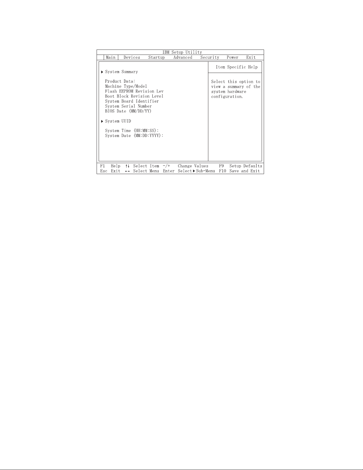
of the first IBM Setup Utility screen is shown here.
831941x
28KT10AUS
2810A
IBM
1234567
02/22/02
[13:34:25]
[02/22/2002]
The IBM Setup Utility program menu lists items that identify system configuration
topics.
When working with the IBM Setup Utility program menu, you must use the
keyboard. The keys used to perform various tasks are displayed at the bottom of
each screen.
When you finish viewing or changing settings, press Esc to return to the IBM
Setup Utility program menu (you might have to press Esc several times). If you
want to save the new settings, select Save Settings before you exit. Otherwise,
your changes will not be saved.
10 Hardware Maintenance Manual
Page 17

Product Recovery Program menu
Type 6826, 8317, 8318, and 8319 machines have recovery and diagnostics programs
on a separate hard drive partition. The Enhanced Diagnostics diskette is not
shipped with the machine. To download the Diagnostics program, see “Diagnostics
program download” on page 12.
At startup, the machine displays the following prompt:
To start the Product Recovery Program, press F11
Attention: Make sure all data is backed up to avoid loss when the Product
Recovery program is used.
After depressing F11, you are given the following options.
v Factory Contents
This utility reformats the hard drive and restores all original files.
v System utilities
1. Repair (Windows NT 4.0 and 2000 Only)
This runs the Windows NT 4.0 emergency repair utility.
2. Run Diagnostics
Runs the IBM Enhanced Diagnostic Program.
3. Create a Diagnostics Diskette
Creates a bootable diagnostic diskette.
4. System Information
Displays information about your computer configuration and allows the user
to gather system information that would be needed during a Help Center
call.
5. Create Recovery/Repair Diskette (Disk to Disk Solution Only)
Creates a startable diskette to restore access to the IBM Product Recovery
program on the hard disk.
6. Recovery CD
In the event of a Hard Disk Drive failure, a Recovery CD can be used to
restore the Hard Disk Drive to the original factory preset. Be sure to use the
Recovery CD FRU list to obtain the proper recovery CD for the computer
model you are servicing.
Chapter 4. Diagnostics 11
Page 18

Diagnostics
Diagnostics program download
Navigating through the diagnostics programs
The Diagnostics program uses a full range of diagnostic utilities to determine the
operating condition of the computer’s hardware components.
For a complete list of error codes and messages, see ″Symptom-to-FRU Index″ on
page 37.
To download the Diagnostics program, do the following:
v Go to http://www.pc.ibm.com/support/us/.
v Search for the machine Type and model in the ″Quick path to a product″ box on
the left.
v Select Downloadable Files from the optoins on the left.
v Select Diagnostic from the ″Downloadable files by category″ pull down menu.
Use the cursor movement keys to navigate within the menus.
v The Enter key is used to select a menu item.
v The Esc key is used to back up to the previous menu.
v For online help select F1.
Running diagnostics tests
There are four ways to run the diagnostic tests.
1. Using the cursor movement keys, highlight Run Normal Test or Run Quick
Test from the Diagnostics menu and then press Enter.
This will automatically run a pre-defined group of tests from each test category.
Run Normal Test runs a more extensive set of tests than does Run Quick Test
and takes longer to execute.
2. Press F5 to automatically run all selected tests in all categories. See ″Test
Selection″.
3. From within a test category, press Ctrl-Enter to automatically run only the
selected tests in that category. See ″Test Selection″.
4. Using the cursor movement keys, highlight a single test within a test category,
then press Enter. This will run only that test.
Press Esc at any time to stop the testing process.
Test results, (N/A, PASSED, FAILED, ABORTED), are displayed in the field beside
the test description and in the test log. See “Viewing the test log” on page 16.
Test selection
To select one or more tests, use the following procedure.
1. Open the corresponding test category.
2. Using the cursor movement keys, highlight the desired test.
3. Press the space bar.
A selected test is marked by >>. Pressing the space bar again de-selects a test
and removes the chevron.
4. Repeat steps 2 and 3 above to select all desired tests.
12 Hardware Maintenance Manual
Page 19

Test results
Diagnostics test results will produce the following error code format:
Function
Code
v Function Code:
Represents the feature or function within the PC.
v Failure Type:
Represents the type of error encountered.
v DeviceID:
Contains the component’s unit-ID which corresponds to either a fixed disk
drive, removable media drive, serial or parallel port, processor, specific RIMM,
or a device on the PCI bus.
v Date:
Contains the date on which the diagnostic test was run. The date is retrieved
from CMOS and displayed using the YYYYMMDD format.
v ChkDigits:
Contains a 2-digit check-digit value to ensure the following:
– Diagnostics were run on the specified date.
– Diagnostics were run on the specified IBM computer.
– The diagnostic error code is recorded correctly.
v Text:
Description of the error.
Failure Type DeviceID Date ChkDigits Text
Note: See “Diagnostic error codes” on page 39 for error code listings.
Fixed disk advanced test (FDAT)
PC-Doctor’s (PCDR) Fixed-Disk Advanced Test module (FDAT) is a full-featured
highly configurable fixed-disk test suite. The configurable capabilities of FDAT
allow users to enable or disable specific tests, enable or disable testing features,
control the test log detail, alter testing parameters, etc. FDAT will test for and
report most commonly found errors on a fixed-disk drive and is able to test up to
128 SCSI and 4 IDE drives (up to 132 total drives). Drive information is gathered
through FDAT’s enumeration of available devices and user specific configuration
parameters located in the FDAT.INI. FDAT uses information supplied by these
features to indicate specifically what devices are available for test, what tests are
available for the device, device properties, etc. Modify the FDAT.INI file in PC
Doctor for DOS to change testing parameters
FDAT consists of the following subtests and features.
Fixed-Disk Tests:
v Seek Tests: - checks the physical operation of the drive head.
– Linear Seek
– Random Seek
– Min-Max Seek
– Butterfly Seek
v Verify Tests: - checks the integrity of the data present on the media.
– Linear Verify
Chapter 4. Diagnostics 13
Page 20

– Random Verify
v Surface Scan Tests: - checks the drive media for defects.
– Surface Scan (Linear)
– Surface Scan (Aggressive) - this is disabled for normal customer use.
– Surface Scan (Random)
v SMART: - checks the SMART functionality for drives that support SMART.
– Start SMART Self-Test
– Get SMART test results
Other Test Features:
v Write-Splice Repair - detects and corrects Error Correction Code errors during
Verify tests.
v Auto Spin Down - a gradual spin down of the drive platters to avoid damaging
the media.
v Manufacturer Log - an in-depth manufacturer supported log of errors on the
drive.
Multitasking:
To allow simultaneous testing of multiple hard drives whenever possible, the
FDAT module is written as a set of multitasking functions. Each drive under test
can run the same test or run a different test at the same time. Each subtest is
written to handle a single test pass and all test variables are kept track of in a
structure unique for each drive . However, when testing IDE drives, FDAT will not
perform simultaneous testing of IDE drives that are attached to the same IDE
cable. For example, if FDAT is testing four IDE drives on a PC, it will perform
simultaneous testing on drives 1 and 3 first (master drives), then perform tests on
2 and 4 (slave drives). FDAT will also perform simultaneous testing on a master
and slave that are on separate IDE cables, but will not perform simultaneous tests
on a master and slave on the same IDE cable. This generally increases the amount
of time needed to test multiple IDE drives. Another limitation of FDAT’S
multitasking capability is the use of Ultra DMA (UDMA). Only one drive at a time
can access the UDMA channel and the UDMA channel buffer must be kept high in
order to maintain a speed advantage over other data transfer modes. In order to
use the UDMA channel during testing, users must disable the multitasking feature.
Destructive vs non-destructive testing:
Most of the tests found in FDAT are non-destructive. This means that PCDR will
preserve any data that is present on the tested media prior to beginning any
destructive operations (i.e. write operations). However, users can run certain tests
in destructive mode (i.e. surface scan tests). Destructive tests will speed up testing
because FDAT does not preserve the data on the media prior to the test beginning.
Unlike non-destructive tests, any data present on the media prior to the test
beginning is lost. FDAT allows for enabling or disabling destructive tests, as well
as specifying a range of destructive and non-destructive sectors on the tested drive.
This is done through the configuration of the FDAT.INI .If destructive and
non-destructive ranges somehow overlap, then the overlapped area is considered
non-destructive. For example, if users specify both destructive and non-destructive
ranges as the same, then the entire drive is tested as non-destructive.
14 Hardware Maintenance Manual
Page 21

Quick and Full erase - hard drive
The Diagnostics program offers two hard drive format utilities:
v Quick Erase Hard Drive
v Full Erase Hard Drive
The Quick Erase Hard Drive provides a DOS utility that performs the following
steps.
v Destroys the Master Boot Record (MBR) on the hard drive.
v Destroys all copies of the FAT Table on all partitions (both the master and
backup).
v Destroys the partition table.
v Provides messages that warn the user that this is a non-recoverable process.
Chapter 4. Diagnostics 15
Page 22

The Full Erase Hard Drive provides a DOS utility that performs the following
steps.
v Performs all the steps in Quick Erase.
v Provides a DOS utility that writes random data to all sectors of the hard drive.
v Provide an estimate of time to completion along with a visual representation of
completion status.
v Provides messages that warn the user about non-recoverable process.
Important: Make sure that all data is backed up before using the Quick or Full Erase
functions.
To select the Quick Erase or Full Erase Hard Drive utility, use the following
procedure.
1. Select the UTILITY option on the toolbar and press Enter.
2. Select either the QUICK ERASE or FULL ERASE HARD DISK option and
follow the instructions.
Viewing the test log
Errors reported by the diagnostic test will be displayed by the program as a failed
test.
To view details of a failure or to view a list of test results, use the following
procedure from any test category screen.
v Press F3 to activate the log file.
v Press F3 again to save the file to diskette or F2 to print the file.
16 Hardware Maintenance Manual
Page 23
Chapter 5. Installing Options
This section contains information on adding or replacing customer options.
Installing external options
This section shows the various external connectors on the computer to which
external options may be attached. When adding an external option, use the
information in this section to identify the required connector, and then use the
instructions that come with the option to make the connection and install any
software or device drivers that are required for the option.
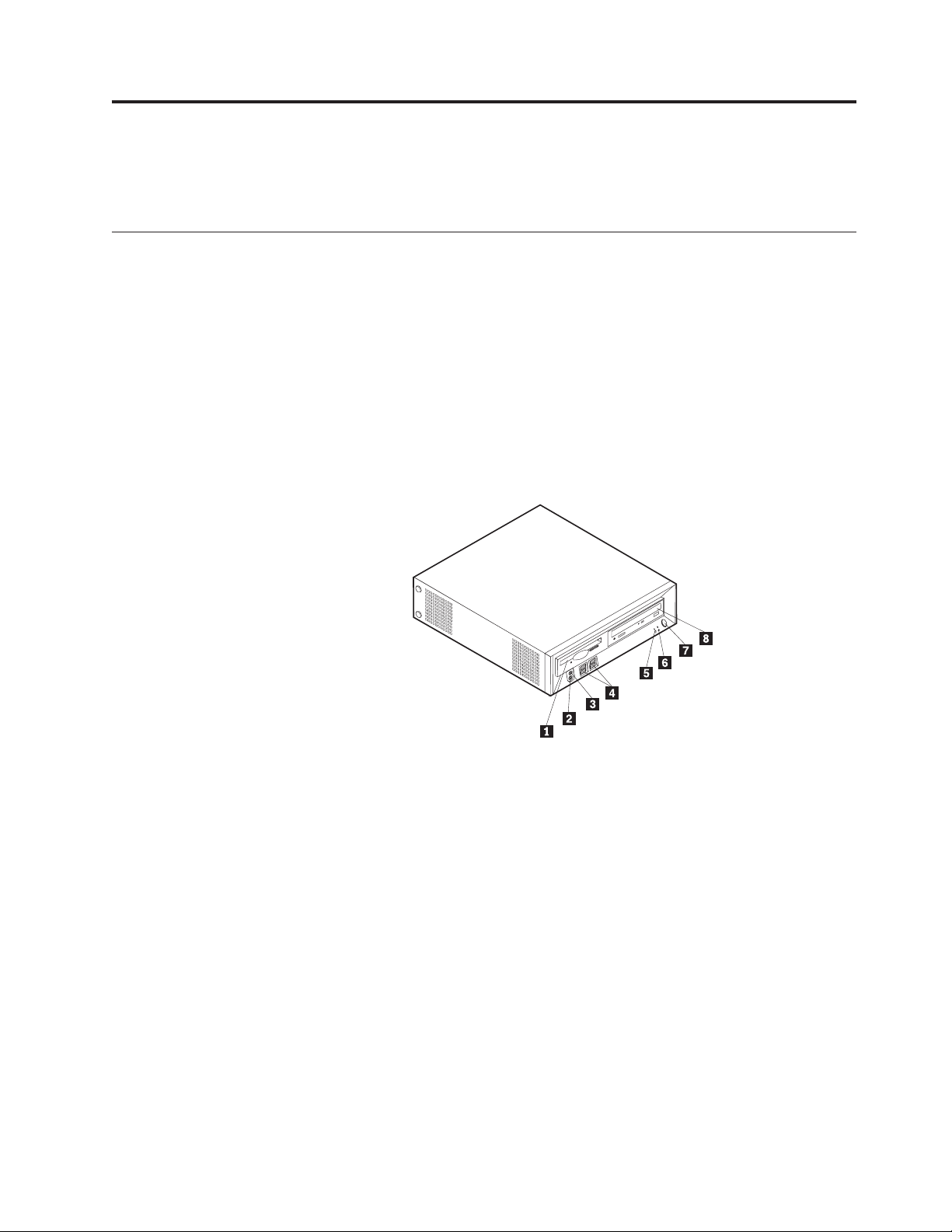
Locating controls and connectors on the front of the computer
The following illustration shows locations of the controls and connectors on the
front of the computer.
1 Diskette drive 5 Hard disk drive activity indicator
2 Headphone connector 6 Power-on indicator
3 Microphone connector 7 Power button
4 USB connectors (4) 8 CD or DVD drive
© Copyright IBM Corp. 2001 17
Page 24
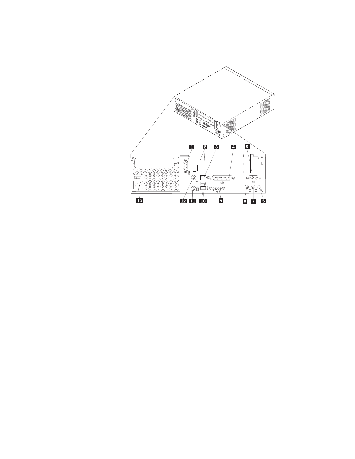
Locating connectors on the rear of the computer
The following illustration shows locations of connectors on the rear of the
computer.
1 Serial connector 8 Audio line-out connector
2 PCI adapter slots 9 VGA monitor connector
3 Ethernet connector 10 USB connectors (2)
4 Parallel connector 11 PS/2 keyboard connector
5 Serial connector 12 PS/2 mouse connector
6 Microphone connector 13 Power cord connector
7 Audio line-in connector
Note: Some connectors on the rear of your computer are color-coded to help
determine where to connect the cables.
Obtaining device drivers
Device drivers for operating systems that are not preinstalled may be obtained at
http://www.ibm.com/pc/support/ on the World Wide Web. Installation
instructions are provided in README files with the device-driver files.
18 Hardware Maintenance Manual
Page 25
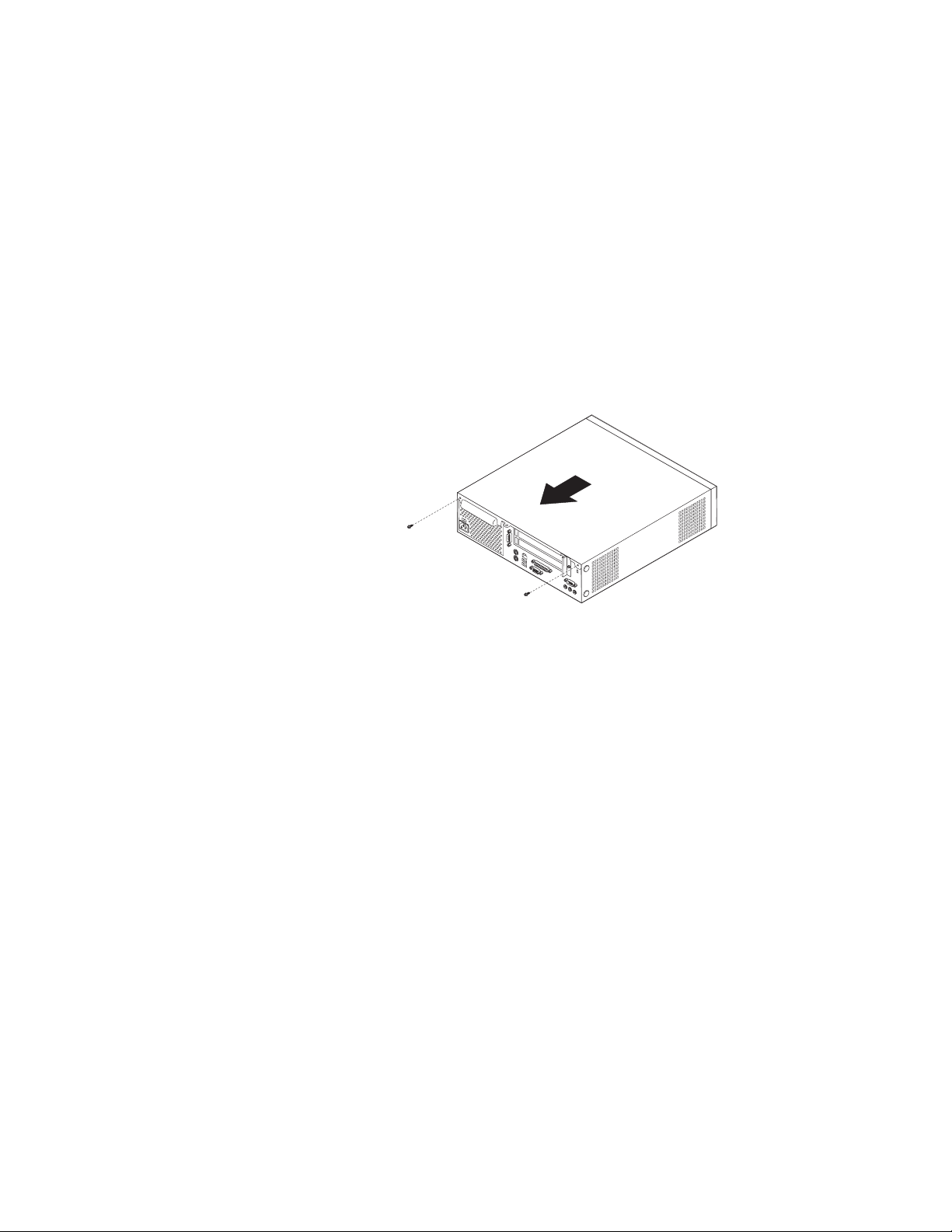
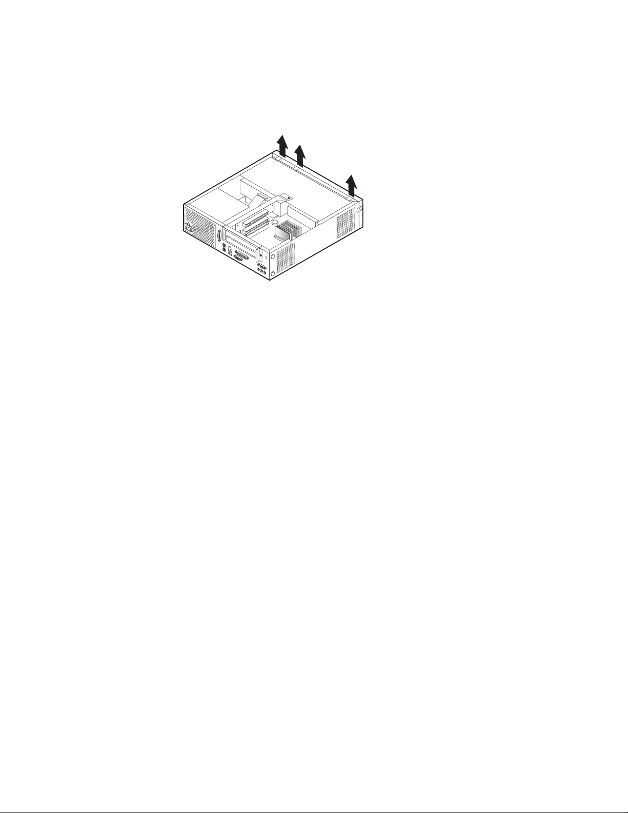
Removing the cover
To remove the cover:
1. Shut down the operating system, remove any media (diskettes, CDs, or tapes)
from the drives, and turn off all attached devices and the computer.
2. Unplug all power cords from electrical outlets.
3. Disconnect all cables attached to the computer. This includes power cords,
input/output (I/O) cables, and any other cables that are connected to the
computer.
4. Remove the floor stand, if attached.
5. Remove the padlock or cable lock if installed.
6. Remove the two thumbscrews that secure the cover at the rear of the system
unit.
7. Using the handle provided at the rear, pull the cover to the rear and lift it off.
Chapter 5. Installing Options 19
Page 26
Removing the bezel
To remove the bezel:
1. Remove the cover. See “Removing the cover” on page 19.
2. Lift the three tabs holding the bezel in place and pull forward and off.
20 Hardware Maintenance Manual
Page 27
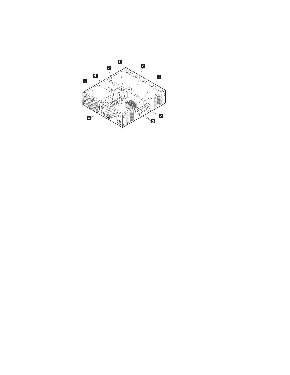
Locating components
The following illustration will help you locate the various components in the
computer.
1 Diskette drive 6 Hard disk drive
2 System board 7 CD or DVD drive
3 DIMM connectors 8 Battery
4 PCI riser 9 Disk drive tray
5 Power supply
Chapter 5. Installing Options 21
Page 28
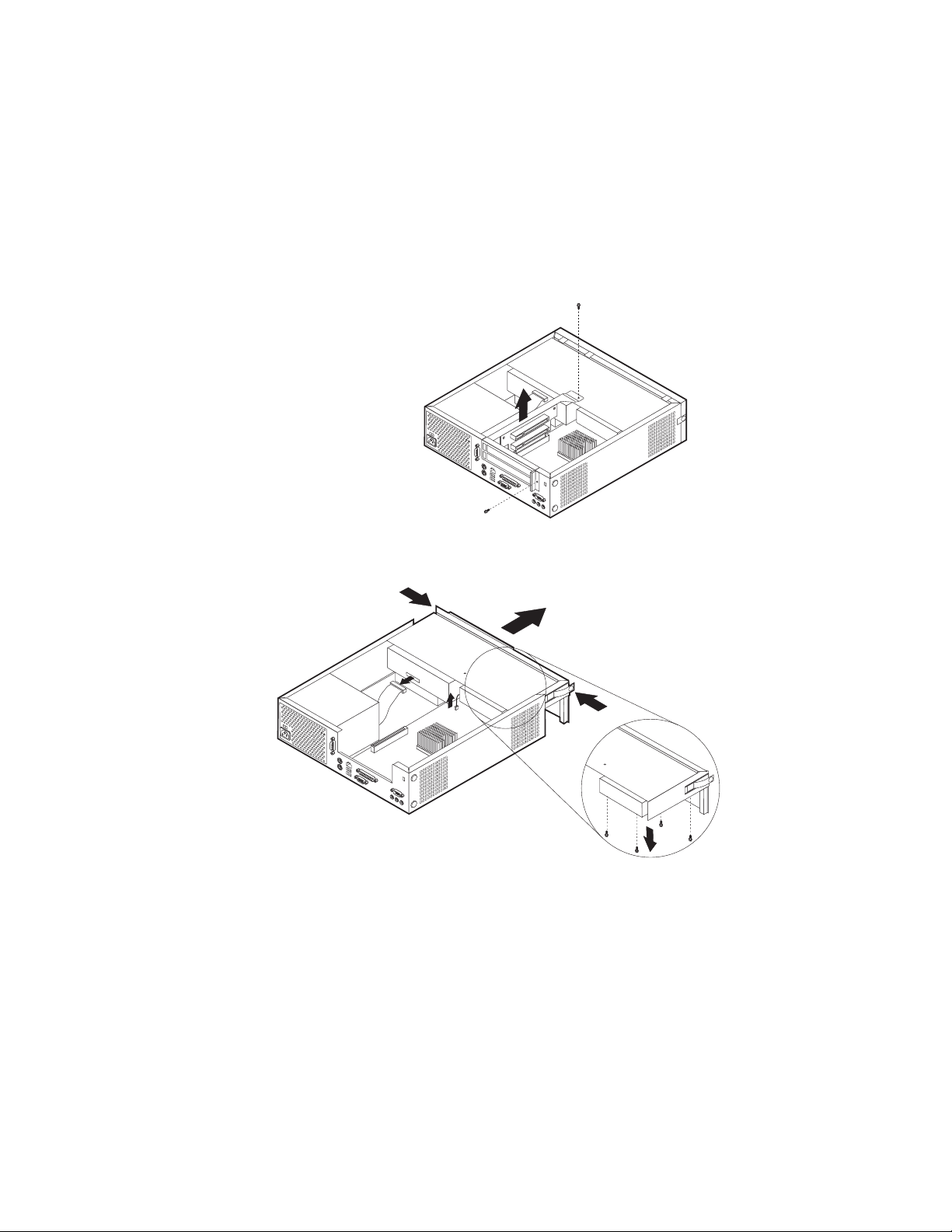
Accessing system board components and drives
To access some components on the system board such as memory, the battery, and
the Clear CMOS/BIOS recovery jumper, it may be necessary to slide the diskette
and CD drive tray outward to the front of the computer.
To access system board components or drives:
1. Turn off the computer.
2. Remove the cover. See “Removing the cover” on page 19.
3. Remove the screw securing the drive tray to the riser card support.
4. Press in on the drive tray buttons at each side as shown, and slide tray forward
to access drives.
Notes:
a. It may be necessary to disconnect some cables attached to the drives to
b. Make sure you note the location of any cables that you disconnect from the
5. Slide the drive tray to the front just far enough to access the necessary system
board component.
6. If any PCI adapters are installed, remove the PCI riser and adapter cards. Do
not remove any adapters from the riser card.
22 Hardware Maintenance Manual
allow the drive tray to slide out far enough to access some system board
components. To remove the drive tray completely, disconnect all the cables
attached to the diskette and CD drives.
drives.
Page 29
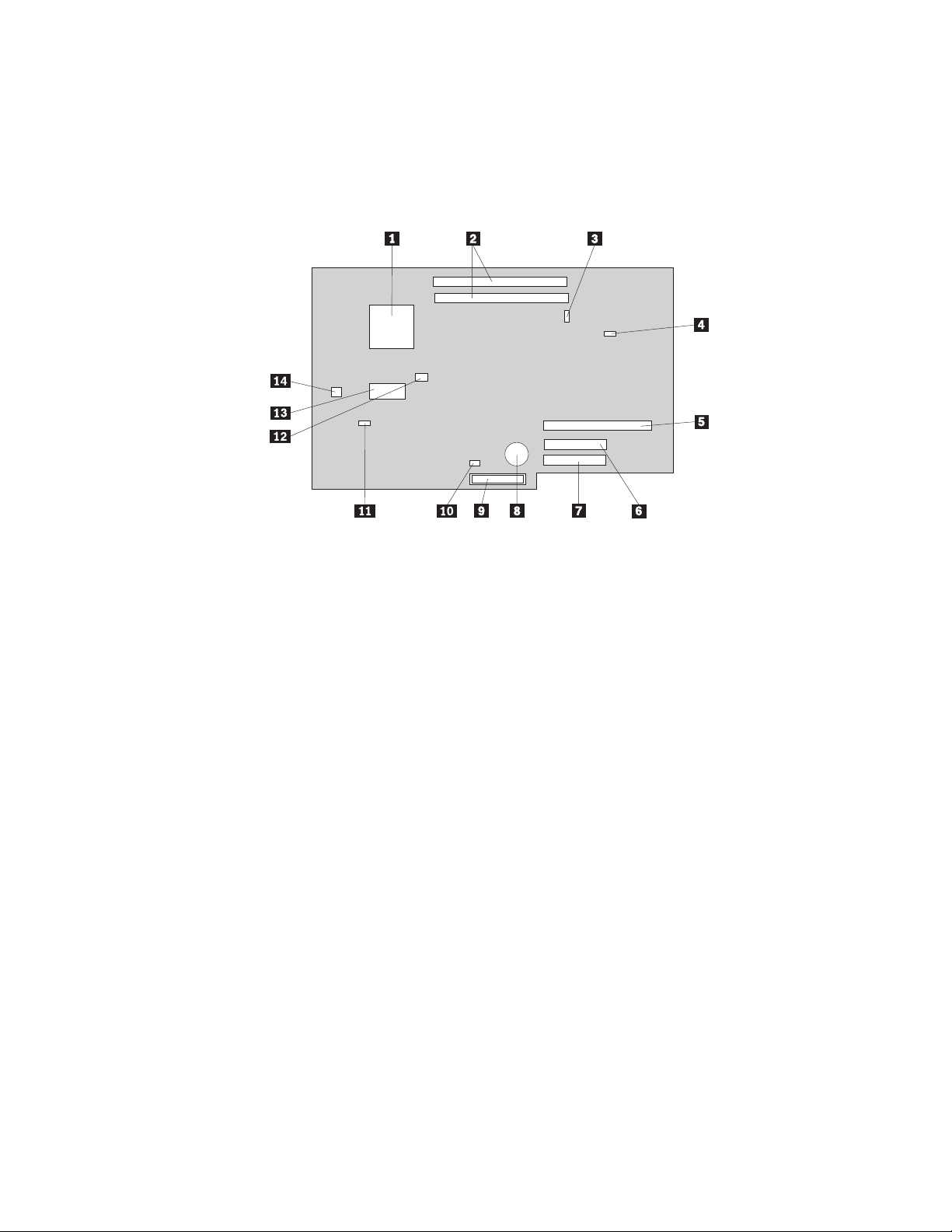
Identifying parts on the system board
The system board (sometimes called the planar or motherboard) is the main circuit
board in the computer. It provides basic computer functions and supports a variety
of devices that are IBM-installed or that can be installed later.
The following illustration shows the locations of parts on the system board.
1 Microprocessor 8 Battery
2 DIMM connectors 9 Diskette drive connector
3 Front panel connector 10 Clear CMOS/BIOS recovery jumper
4 CD audio connector 11 System fan connector
5 PCI riser connector 12 Microprocessor fan connector
6 Secondary IDE connector 13 Main power
7 Primary IDE connector 14 Microprocessor power connector
Chapter 5. Installing Options 23
Page 30
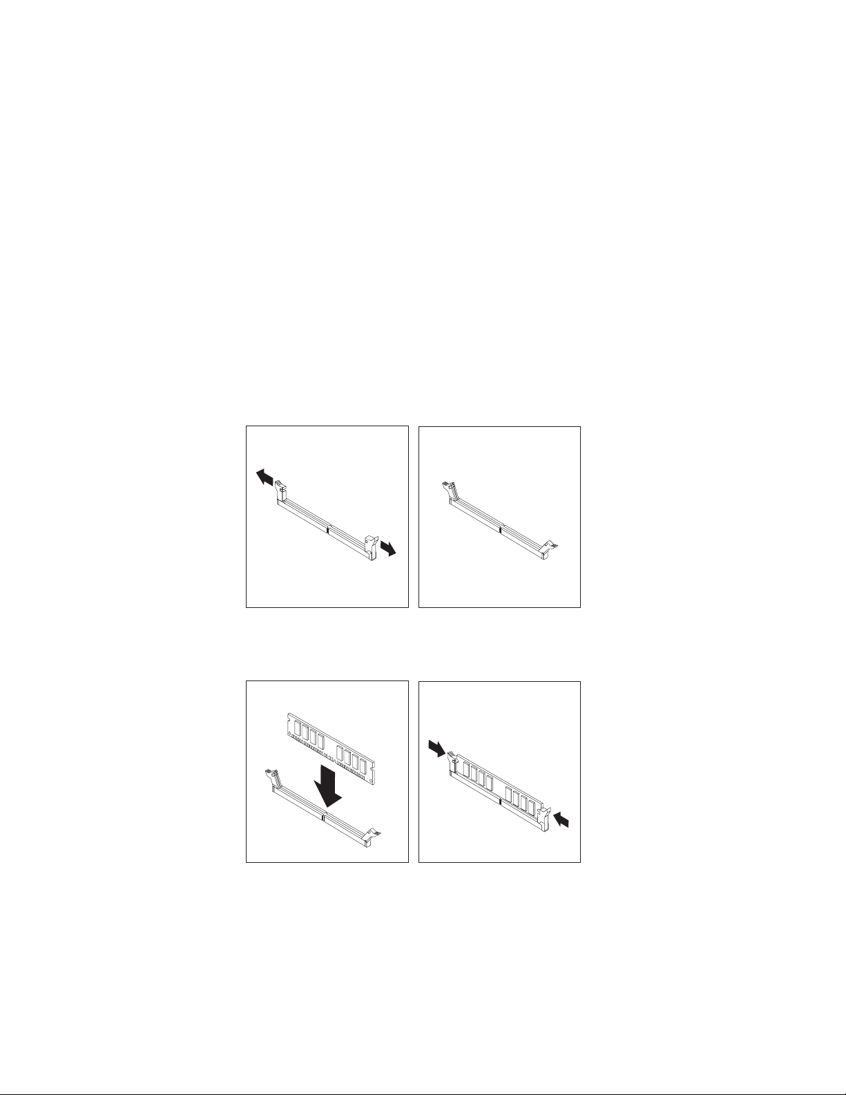
Installing memory
Type 6826, 8317, 8318, and 8319 computers have two connectors for installing dual
inline memory modules (DIMMs) that provide up to a maximum of 2 GB of
system memory.
When installing memory, the following rules apply:
v Use 2.5 V, 184-pin, double data rate synchronous dynamic random access
memory (DDR SDRAM), non-ECC DIMMs.
v Use 128 MB, 256 MB, 512 MB, or 1 GB DIMMs in any combination.
Note: Only DDR SDRAM DIMMs can be used.
To install DIMMs:
1. Access the system board. See “Accessing system board components and drives”
on page 22.
2. Locate the DIMM connectors. See “Identifying parts on the system board” on
page 23.
3. Open the retaining clips.
4. Make sure the notch in the DIMM aligns with the tab on the connector. Push or
insert the memory module straight down into the connector until the retaining
clips close.
5. Slide the CD and diskette drive tray back into position and reconnect any
cables that were disconnected. Insert the holding screw.
Note: Be sure to align the drive tray properly on the drive tray tracks,
otherwise the drive tray will not sit properly, nor will the cover attach
properly.
6. Replace the PCI riser and adapters if it was removed.
24 Hardware Maintenance Manual
Page 31

7. Replace the cover. See “Replacing the cover and connecting the cables” on
page 30.
Installing PCI adapters
This section provides information and instructions for installing and removing PCI
adapters. The computer has a riser card with two PCI expansion slots.
To install a PCI adapter:
1. Remove the cover. See “Removing the cover” on page 19.
2. Remove the PCI riser and adapters that are already installed.
3. Remove the adapter-slot-cover latch and the slot cover for the appropriate
expansion slot.
4. Remove the adapter from its static-protective package
5. Install the adapter into the appropriate slot on the PCI riser.
6. Replace the adapter-slot-cover latch.
7. Install the PCI riser and adapters.
8. Replace the cover. See “Replacing the cover and connecting the cables” on
page 30.
What to do next:
v To work with another option, go to the appropriate section.
v To complete the installation, go to “Replacing the cover and connecting the
cables” on page 30.
Chapter 5. Installing Options 25
Page 32

Installing a drive in the disk drive tray
This section provides information and instructions for installing and removing
internal drives.
Drives that are available for Type 6826, 8317, 8318, and 8319 computers are:
v Hard disk drives
v Tape drives
v CD drives or DVD drives
v Diskette and other removable media drives
When installing an internal drive, it is important to note what type and size of
drive that you can install in each bay. Also, it is important to correctly connect the
internal drive cables to the installed drive.
To install a drive in the disk drive tray, follow these steps.
1. Remove the cover. See “Removing the cover” on page 19.
2. Remove the bezel. See “Removing the bezel” on page 20.
3. Remove the disk drive tray. See “Accessing system board components and
drives” on page 22 and “Locating components” on page 21.
4. Install the drive into the bay. Align the screw holes, and insert the four screws.
26 Hardware Maintenance Manual
Page 33

5. Reinstall the disk drive tray. Go to “Connecting a diskette drive” on page 28 or
“Connecting an IDE CD drive”.
Note: Be sure to connect the system fan cable before sliding the disk drive tray
back in.
6. Replace the bezel and cover.
Replacing the hard disk drive
To replace the hard disk drive, follow these steps.
1. Remove the cover. See “Removing the cover” on page 19.
2. Remove the disk drive tray. See “Accessing system board components and
drives” on page 22.
3. Disconnect the signal and power cables from the existing hard disk drive and
remove the drive. Do not disconnect the signal cable from the system board.
4. Insert the hard drive into the hard disk cage and secure with 4 screws.
5. Slide the hard disk cage into its slot and make sure the plastic retaining clip is
secure. Connect the signal and power cables to the drive.
6. Reinstall the disk drive tray and connect the signal and power cables for the
diskette and CD drives.
What to do next:
v To work with another option, go to the appropriate section.
v To complete the installation, go to “Replacing the cover and connecting the
cables” on page 30.
Connecting an IDE CD drive
1. Locate the signal cable that came with your computer or with the new drive.
2. Locate the secondary IDE connector on the system board. See “Identifying parts
on the system board” on page 23.
3. Connect one end of the signal cable to the drive and the other to the secondary
IDE connector on the system board.
4. If you have a CD-ROM drive audio cable, connect it to the drive and the
system board. For the location of the CD audio connector, see “Identifying
parts on the system board” on page 23.
Chapter 5. Installing Options 27
Page 34

What to do next:
v To work with another option, go to the appropriate section.
v To complete the installation, go to “Replacing the cover and connecting the
cables” on page 30.
Connecting a diskette drive
1. Locate the cable that came with your computer or with the new drive.
2. Locate the diskette drive connector on the system board. See “Identifying parts
on the system board” on page 23.
3. Connect one end of the signal cable to the drive and the other to the diskette
drive connector on the system board.
Note: Make sure the twisted end of the cable is plugged into the drive.
What to do next:
v To work with another option, go to the appropriate section.
v To complete the installation, go to “Replacing the cover and connecting the
cables” on page 30.
Installing a cable lock
To help to protect against theft, an optional cable lock can be installed to secure the
computer to a desk, table, or other fixture. This type of cable lock also
automatically locks the computer cover to the chassis. The cable-lock latch on the
computer accommodates the same type of cable lock used with many laptop
computers. Cable Locks can be ordered directly from IBM. For more information,
see Finding options from IBM in Access IBM.
28 Hardware Maintenance Manual
Page 35

See the following illustration for cable lock installation.
®
Changing the battery
Type 6826, 8317, 8318, 8319 computers have a special type of memory that
maintains the date, time, and settings for built-in features, such as parallel-port
assignments (configuration). A battery keeps this information active when the
computer is turned off.
The battery normally requires no charging or maintenance throughout its life;
however, no battery lasts forever. If the battery fails, the date, time, and
configuration information (including passwords) are lost. An error message is
displayed when you turn on the computer.
Refer to “Safety information” on page 109 for information about replacing and
disposing of the battery.
To change the battery:
1. Refer to “Identifying parts on the system board” on page 23 and locate the
battery.
2. Remove the PCI riser and any cables that impede access to the battery.
3. Remove the old battery.
Chapter 5. Installing Options 29
Page 36

4. Install the new battery.
5. Reconnect any cables that were disconnected. Slide the drive tray back into the
computer, making sure both side tabs lock.
6. Install the PCI riser and adapters if removed.
7. Replace the cover, and connect the cables. See “Replacing the cover and
connecting the cables”.
Note: When the computer is turned on for the first time after battery
replacement, an error message might be displayed. This is normal after
replacing the battery.
8. Turn on the computer and all attached devices.
9. Use the IBM Setup Utility program to set the date and time and any
passwords.
Erasing a lost or forgotten password (clearing CMOS)
This section applies to lost or forgotten passwords. For more information about
lost or forgotten passwords, go to Access IBM.
To erase a forgotten password:
1. Refer to “Accessing system board components and drives” on page 22.
2. Locate the Clear CMOS/BIOS recovery jumper on the system board. See
“Identifying parts on the system board” on page 23.
3. Move the jumper from the standard position (pins 1 and 2, closest to the
battery) to the maintenance or configure position (pins 2 and 3, farthest from
the battery).
4. Slide both drive trays back into the computer and secure with the holding
screws. Reconnect any cables that were disconnected.
5. Install the PCI riser and adapters.
6. Replace the cover, and connect the power cable. See “Replacing the cover and
connecting the cables”.
7. Restart the computer, leave it on for approximately 10 seconds, and then turn
off the computer.
8. Repeat step 1.
9. Move the jumper back to the standard (pins 1 and 2).
10. Reassemble the computer and replace the cover. See “Replacing the cover and
connecting the cables”.
Replacing the cover and connecting the cables
After working with options, reinstall any removed parts, replace the cover, and
reconnect cables, including telephone lines and power cords. Also, depending on
the option that is installed, you might need to confirm the updated information in
the IBM Setup Utility program.
To replace the cover and connect cables to your computer:
30 Hardware Maintenance Manual
Page 37

1. Ensure that all components have been reassembled correctly and that no tools
or loose screws are left inside your computer.
2. Clear any cables that might impede the replacement of the cover.
3. Place the cover over the computer and slide it to the rear until it is fully closed.
Secure the cover with the two thumbscrews.
4. If your computer is being placed in the vertical position, attach the floor stand.
Attention: To prevent overheating and possible component damage, always
attach the floor stand when placing the computer in the vertical position.
5. Reconnect the external cables and power cords to the computer. See “Locating
connectors on the rear of the computer” on page 18.
6. To update the configuration, see “IBM Setup Utility program” on page 9.
Chapter 5. Installing Options 31
Page 38

32 Hardware Maintenance Manual
Page 39

Chapter 6. FRU Removals
These removals are to be done by trained service technicians only.
Important: Before you install or remove any option, read “Safety information” on
page 109. These precautions and guidelines will help you work safely.
Removing the retention bar and PCI riser card
To remove the retention bar and riser card, do the following:
1. Turn off the computer and peripheral devices and disconnect all external cables
and power cords; then, remove the cover. See “Removing the cover” on
page 19.
2. Disconnect all riser card cables and wires.
3. Remove the screws securing the retention bar and PCI riser card.
4. Lift the riser card out.
Replacing a microprocessor
To replace a microprocessor in any of the machine types, do the following:
1. Turn off the computer and peripheral devices and disconnect all external cables
and power cords; then, remove the cover. See “Removing the cover” on
page 19.
2. Remove the drive tray. See “Installing a drive in the disk drive tray” on
page 26.
3. Remove the retention bar and riser card. See “Removing the retention bar and
PCI riser card”.
© Copyright IBM Corp. 2001 33
Page 40

System board
4. Unscrew the fansink from the system board and carefully lift it off. The
processor will come with it, attached to the bottom by thermal grease.
5. To remove the fansink from the processor, remove the assembly from the
system board, and twist the processor to break the seal formed by the thermal
grease and remove.
To remove the system board, do the following:
1. Turn off the computer and peripheral devices and disconnect all external cables
and power cords; then, remove the cover. See “Removing the cover” on
page 19.
2. Remove the retention bar and riser card. See “Removing the retention bar and
PCI riser card” on page 33.
3. Remove the drive tray. See “Installing a drive in the disk drive tray” on
page 26.
4. Disconnect all wires connected to the system board.
5. Remove the fansink and processor. See “Replacing a microprocessor” on
page 33.
6. Remove the 4 screws that attach the system board to the chassis.
7. Lift out the system board.
Power supply
To remove the power supply, do the following:
1. Turn off the computer and peripheral devices and disconnect all external cables
and power cords; then, remove the cover. See “Removing the cover” on
page 19.
34 Hardware Maintenance Manual
Page 41

2. Remove the drive tray. See “Installing a drive in the disk drive tray” on
page 26.
3. Remove the hard disk drive. See “Replacing the hard disk drive” on page 27.
4. Disconnect all power supply wires.
5. Remove the system board. See“System board” on page 34.
6. Remove the screws holding the power supply.
7. Lift out the power supply.
Chapter 6. FRU Removals 35
Page 42

36 Hardware Maintenance Manual
Page 43

Chapter 7. Symptom-to-FRU Index
The Symptom-to-FRU index lists error symptoms and possible causes. The most
likely cause is listed first. Always begin with ″General Checkout″ on page 3. This
index can also be used to help you decide which FRUs to have available when
servicing a computer. If you are unable to correct the problem using this index, go
to “Undetermined problems” on page 77.
Notes:
v If you have both an error message and an incorrect audio response, diagnose the error
message first.
v If you cannot run the diagnostic tests or you get a diagnostic error code when running a
test, but did receive a POST error message, diagnose the POST error message first.
v If you did not receive any error message, look for a description of your error symptoms
in the first part of this index.
v Check the hard disk drive jumper settings before you replace a hard disk drive.
Hard disk drive boot error
A hard disk drive boot error (error codes 1962 and I999030X) can have the
following causes.
Error FRU/Action
The start-up drive is not in the boot
sequence in configuration.
No operating system installed on the boot
drive.
The boot sector on the start-up drive is
corrupted.
The drive is defective. Replace the hard disk drive.
Check the configuration and ensure the
start-up drive is in the boot sequence.
Install an operating system on the boot
drive.
The drive must be formatted, do the
following:
1. Attempt to access and recover (back-up)
the failing hard disk drive.
2. Using the operating systems programs,
format the hard disk drive.
Power Supply Errors
If the power-on indicator is not on, the power supply fan is not running, or the
computer will not power-off, use the following procedures.
Check/Verify FRU/Action
Check the following for proper installation.
v Power Cord
v On/Off Switch connector
v On/Off Switch Power Supply connector
v System Board Power Supply connectors
v Microprocessor(s) connection
Check the power-on switch for continuity. Power Cord
© Copyright IBM Corp. 2001 37
Reseat
Page 44

Check/Verify FRU/Action
Check the power-on switch for continuity. Power-on Switch
38 Hardware Maintenance Manual
Page 45

Diagnostic error codes
Refer to the following diagnostic error codes when using the diagnostic tests. See
″Diagnostics″ on page 9 for the specific type for information about the Diagnostic
programs.
In the following index, X can represent any number.
Diagnostic Error Code FRU/Action
000-000-XXX
BIOS Test Passed
000-002-XXX
BIOS Timeout
000-024-XXX
BIOS Addressing test failure
000-025-XXX
BIOS Checksum Value error
000-026-XXX
FLASH data error
000-027-XXX
BIOS Configuration/Setup error
000-034-XXX
BIOS Buffer Allocation failure
000-035-XXX
BIOS Reset Condition detected
000-036-XXX
BIOS Register error
000-038-XXX
BIOS Extension failure
000-039-XXX
BIOS DMI data error
000-195-XXX
BIOS Test aborted by user
000-196-XXX
BIOS test halt, error threshold exceeded
1. No action
1. Flash the system
2. System board
1. Flash the system
2. System board
1. Flash the system
2. Boot block
3. System board
1. Flash the system
2. Boot block
3. System board
1. Run Setup
2. Flash the system
3. Boot block
4. System board
1. Reboot the system
2. Flash the system
3. Run memory test
4. System board
1. Flash the system
2. System board
1. Flash the system
2. Boot block
3. System board
1. Flash the system
2. Adapter card
3. System board
1. Flash the system
2. System board
1. Information
2. Re-start the test, if necessary
1. Press F3 to review the log file
2. Re-start the test to reset the log file
Chapter 7. Symptom-to-FRU Index 39
Page 46

Diagnostic Error Code FRU/Action
000-197-XXX
BIOS test warning
000-198-XXX
BIOS test aborted
000-199-XXX
BIOS test failed, cause unknown
000-250-XXX
BIOS APM failure
000-270-XXX
BIOS ACPI failure
001-000-XXX
System Test Passed
001-00X-XXX
System Error
001-01X-XXX
System Error
001-024-XXX
System Addressing test failure
001-025-XXX
System Checksum Value error
001-026-XXX
System FLASH data error
001-027-XXX
System Configuration/Setup error
001-032-XXX
System Device Controller failure
001-034-XXX
System Device Buffer Allocation failure
001-035-XXX
System Device Reset condition detected
001-036-XXX
System Register error
1. Make sure the component that is called
out is connected and/or enabled
2. Re-run test
3. Component that is called out in warning
statement
4. Component under test
1. If a component is called out, make sure
it is connected and/or enabled
2. Flash the system and re-test
3. Go to the ″Undetermined problems″
section
1. Go to the ″Undetermined problems″
section
2. Flash the system and re-test
3. Replace component under function test
1. Flash the system
2. System board
1. Flash the system
2. System board
1. No action
1. System board
1. System board
1. System board
1. Flash the system
2. System board
1. Flash the system
2. System board
1. Run Setup
2. Flash the system
3. System board
1. System board
1. Reboot the system
2. Flash the system
3. Run memory test
4. System board
1. System board
1. System board
40 Hardware Maintenance Manual
Page 47

Diagnostic Error Code FRU/Action
001-038-XXX
System Extension failure
001-039-XXX
System DMI data structure error
001-040-XXX
System IRQ failure
001-041-XXX
System DMA failure
001-195-XXX
System Test aborted by user
001-196-XXX
System test halt, error threshold exceeded
001-197-XXX
System test warning
1. Adapter card
2. System board
1. Flash the system
2. System board
1. Power-off/on system and re-test
2. System board
1. Power-off/on system and re-test
2. System board
1. Information
2. Re-start the test, if necessary
1. Press F3 to review the log file
2. Re-start the test to reset the log file
1. Make sure the component that is called
out is connected and/or enabled
2. Re-run test
3. Component that is called out in warning
statement
4. Component under test
001-198-XXX
System test aborted
1. If a component is called out, make sure
it is connected and/or enabled
2. Flash the system and re-test
3. Go to the ″Undetermined problems″
section
001-199-XXX
System test failed, cause unknown
1. Go to the ″Undetermined problems″
section
2. Flash the system and re-test
3. Replace component under function test
001-250-XXX
System ECC error
001-254-XXX
001-255-XXX
1. System board
1. System board
001-256-XXX
001-257-XXX
System DMA error
001-260-XXX
001-264-XXX
1. System board
System IRQ error
001-268-XXX
System IRQ1 failure
001-269-XXX
System IRQ2 failure
001-270-XXX
System IRQ3 failure
1. Device on IRQ1
2. System board
1. Device on IRQ2
2. System board
1. Device on IRQ3
2. System board
Chapter 7. Symptom-to-FRU Index 41
Page 48

Diagnostic Error Code FRU/Action
001-271-XXX
System IRQ4 failure
001-272-XXX
System IRQ5 failure
001-273-XXX
System IRQ6
(diskette drive) failure
001-274-XXX
System IRQ7 failure
001-275-XXX
System IRQ8 failure
001-276-XXX
System IRQ9 failure
001-277-XXX
System IRQ10 failure
001-278-XXX
System IRQ11 failure
001-279-XXX
System IRQ12 failure
001-280-XXX
System IRQ13 failure
001-281-XXX
System IRQ14
(hard disk drive) failure
001-282-XXX
System IRQ15 failure
001-286-XXX
001-287-XXX
001-288-XXX
System Timer failure
001-292-XXX
System CMOS
RAM error
001-293-XXX
System CMOS Battery
001-298-XXX
System RTC date/time update failure
001-299-XXX
System RTC periodic interrupt failure
001-300-XXX
System RTC Alarm failure
1. Device on IRQ4
2. System board
1. Device on IRQ5
2. System board
1. Diskette Cable
2. Diskette drive
3. System board
1. Device on IRQ7
2. System board
1. Device on IRQ8
2. System board
1. Device on IRQ9
2. System board
1. Device on IRQ10
2. System board
1. Device on IRQ11
2. System board
1. Device on IRQ12
2. System board
1. Device on IRQ13
2. System board
1. Hard disk drive cable
2. Hard disk drive
3. System board
1. Device on IRQ15
2. System board
1. System board
1. Run Setup and re-test
2. System board
1. Battery
2. System board
1. Flash the system
2. System board
1. System board
1. System board
42 Hardware Maintenance Manual
Page 49

Diagnostic Error Code FRU/Action
001-301-XXX
System RTC Century byte error
005-000-XXX
Video Test Passed
005-00X-XXX
Video error
005-010-XXX
005-011-XXX
005-012-XXX
1. Flash the system
2. System board
1. No action
1. Video card, if installed
2. System board
1. Video card, if installed
2. System board
005-013-XXX
Video Signal failure
005-016-XXX
Video Simple Pattern
test failure
1. Video Ram
2. Video card, if installed
3. System board
005-024-XXX
Video Addressing test failure
005-025-XXX
Video Checksum Value error
005-027-XXX
Video Configuration/Setup error
1. Video card, if installed
2. System board
1. Video card, if installed
2. System board
1. Run Setup
2. Video drivers update
3. Video card, if installed
4. System board
005-031-XXX
Video Device Cable failure
1. Video cable
2. Monitor
3. Video card, if installed
4. System board
005-032-XXX
Video Device Controller failure
005-036-XXX
Video Register error
005-038-XXX
System BIOS extension failure
005-040-XXX
Video IRQ failure
005-195-XXX
Video Test aborted by user
005-196-XXX
Video test halt, error threshold exceeded
1. Video card, if installed
2. System board
1. Video card, if installed
2. System board
1. Video card, if installed
2. System board
1. Video card, if installed
2. System board
1. Information
2. Re-start the test, if necessary
1. Press F3 to review the log file
2. Re-start the test to reset the log file
Chapter 7. Symptom-to-FRU Index 43
Page 50

Diagnostic Error Code FRU/Action
005-197-XXX
Video test warning
005-198-XXX
Video test aborted
005-199-XXX
Video test failed, cause unknown
005-2XX-XXX
005-3XX-XXX
Video subsystem error
006-000-XXX
Diskette interface Test Passed
006-0XX-XXX
Diskette interface error
006-195-XXX
Diskette interface Test aborted by user
006-196-XXX
Diskette interface test halt, error threshold
exceeded
006-197-XXX
Diskette interface test warning
006-198-XXX
Diskette interface test aborted
006-199-XXX
Diskette interface test failed, cause unknown
006-25X-XXX
Diskette interface Error
1. Make sure the component that is called
out is connected and/or enabled
2. Re-run test
3. Component that is called out in warning
statement
4. Component under test
1. If a component is called out, make sure
it is connected and/or enabled
2. Flash the system and re-test
3. Go to the ″Undetermined problems″
section
1. Go to the ″Undetermined problems″
section
2. Flash the system and re-test
3. Replace component under function test
1. Video card, if installed
2. System board
1. No action
1. Diskette drive Cable
2. Diskette drive
3. System board
1. Information
2. Re-start the test, if necessary
1. Press F3 to review the log file
2. Re-start the test to reset the log file
1. If a component is called out, make sure
it is connected and/or enabled
2. Re-run test
3. Component that is called out in warning
statement
4. Component under test
1. If a component is called out, make sure
it is connected and/or enabled
2. Flash the system and re-test
3. Go to the ″Undetermined problems″
section
1. Go to the ″Undetermined problems″
section
2. Flash the system and re-test
3. Replace component under function test
1. Diskette drive cable
2. Diskette drive
3. System board
44 Hardware Maintenance Manual
Page 51

Diagnostic Error Code FRU/Action
011-000-XXX
Serial port Interface Test Passed
011-001-XXX
Serial port Presence
1. No action
1. Remove external serial device, if
present
2. Run setup, enable port
3. System board
011-002-XXX
011-003-XXX
1. System board
Serial port Timeout/Parity error
011-013-XXX
011-014-XXX
1. System board
Serial port Control Signal/Loopback test
failure
011-015-XXX
Serial port External Loopback failure
1. Wrap plug
Note: Ensure the wrap plug is removed
after testing is completed. Otherwise, the
system may not shut down properly.
2. System board
011-027-XXX
Serial port Configuration/Setup error
1. Run Setup, enable port
2. Flash the system
3. System board
011-03X-XXX
011-04X-XXX
1. System board
Serial port failure
011-195-XXX
Serial port Test aborted by user
011-196-XXX
Serial port test halt, error threshold exceeded
011-197-XXX
Serial port test warning
1. Information
2. Re-start the test, if necessary
1. Press F3 to review the log file
2. Re-start the test to reset the log file
1. Make sure the component that is called
out is connected and/or enabled
2. Re-run test
3. Component that is called out in warning
statement
4. Component under test
011-198-XXX
Serial port test aborted
1. If a component is called out, make sure
it is connected and/or enabled
2. Flash the system and re-test
3. Go to the ″Undetermined problems″
section
011-199-XXX
Serial port test failed, cause unknown
1. Go to the ″Undetermined problems″
section
2. Flash the system and re-test
3. Replace component under function test
011-2XX-XXX
Serial port signal failure
1. External serial device
2. System board
Chapter 7. Symptom-to-FRU Index 45
Page 52

Diagnostic Error Code FRU/Action
014-000-XXX
Parallel port Interface Test Passed
014-001-XXX
Parallel port Presence
014-002-XXX
014-003-XXX
Parallel port Timeout/Parity error
014-013-XXX
014-014-XXX
Parallel port Control Signal/Loopback test
failure
014-015-XXX
Parallel port External Loopback failure
014-027-XXX
Parallel port Configuration/Setup error
014-03X-XXX
014-04X-XXX
Parallel port failure
014-195-XXX
Parallel port Test aborted by user
014-196-XXX
Parallel port test halt, error threshold
exceeded
014-197-XXX
Parallel port test warning
014-198-XXX
Parallel port test aborted
014-199-XXX
Parallel port test failed, cause unknown
014-2XX-XXX
014-3XX-XXX
Parallel port failure
015-000-XXX
USB port Interface Test Passed
1. No action
1. Remove external parallel device, if
present
2. Run setup, enable port
3. System board
1. System board
1. System board
1. Wrap plug
2. System board
1. Run Setup, enable port
2. Flash the system
3. System board
1. System board
1. Information
2. Re-start the test, if necessary
1. Press F3 to review the log file
2. Re-start the test to reset the log file
1. Make sure the component that is called
out is connected and/or enabled
2. Re-run test
3. Component that is called out in warning
statement
4. Component under test
1. If a component is called out, make sure
it is connected and/or enabled
2. Flash the system and re-test
3. Go to the ″Undetermined problems″
section
1. Go to the ″Undetermined problems″
section
2. Flash the system and re-test
3. Replace component under function test
1. External parallel device
2. System board
1. No action
46 Hardware Maintenance Manual
Page 53

Diagnostic Error Code FRU/Action
015-001-XXX
USB port Presence
015-002-XXX
USB port Timeout
015-015-XXX
USB port External Loopback failure
015-027-XXX
USB port Configuration/Setup error
015-032-XXX
USB port Device Controller failure
015-034-XXX
USB port buffer
allocation failure
1. Remove USB device(s) and re-test
2. System board
1. Remove USB device(s) and re-test
2. System board
1. Remove USB device(s) and re-test
2. System board
1. Flash the system
2. System board
1. System board
1. Reboot the system
2. Flash the system
3. Run memory test
4. System board
015-035-XXX
USB port Reset condition detected
015-036-XXX
USB port Register error
015-040-XXX
USB port IRQ failure
1. Remove USB device(s) and re-test
2. System board
1. System board
1. Run setup and check for conflicts
2. Flash the system
3. System board
015-195-XXX
USB port Test aborted by user
015-196-XXX
USB port test halt, error threshold exceeded
015-197-XXX
USB port test warning
1. Information
2. Re-start the test, if necessary
1. Press F3 to review the log file
2. Re-start the test to reset the log file
1. Make sure the component that is called
out is connected and/or enabled
2. Re-run test
3. Component that is called out in warning
statement
4. Component under test
015-198-XXX
USB port test aborted
1. If a component is called out, make sure
it is connected and/or enabled
2. Flash the system and re-test
3. Go to the ″Undetermined problems″
section
015-199-XXX
USB port test failed, cause unknown
1. Go to the ″Undetermined problems″
section
2. Flash the system and re-test
3. Replace component under function test
018-000-XXX
PCI Card Test Passed
1. No action
Chapter 7. Symptom-to-FRU Index 47
Page 54

Diagnostic Error Code FRU/Action
018-0XX-XXX
PCI Card Failure
018-195-XXX
PCI Card Test aborted by user
018-196-XXX
PCI Card test halt, error threshold exceeded
018-197-XXX
PCI Card test warning
018-198-XXX
PCI Card test aborted
018-199-XXX
PCI Card test failed, cause unknown
018-250-XXX
PCI Card Services error
020-000-XXX
PCI Interface Test Passed
020-0XX-XXX
PCI Interface error
020-195-XXX
PCI Test aborted by user
020-196-XXX
PCI test halt, error threshold exceeded
020-197-XXX
PCI test warning
1. Riser card, if installed
2. System board
1. PCI card
2. Information
3. Re-start the test, if necessary
1. Press F3 to review the log file
2. Re-start the test to reset the log file
1. Make sure the component that is called
out is connected and/or enabled
2. Re-run test
3. Component that is called out in warning
statement
4. Component under test
1. Make sure the component that is called
out is connected and/or enabled
2. Flash the system and re-test
3. Go to the ″Undetermined problems″
section
1. Go to the ″Undetermined problems″
section
2. Flash the system and re-test
3. Replace component under function test
1. PCI card
2. Riser card, if installed
3. System board
1. No action
1. PCI card
2. Riser card, if installed
3. System board
1. Information
2. Re-start the test, if necessary
1. Press F3 to review the log file
2. Re-start the test to reset the log file
1. Make sure the component that is called
out is connected and/or enabled
2. Re-run test
3. Component that is called out in warning
statement
4. Component under test
48 Hardware Maintenance Manual
Page 55

Diagnostic Error Code FRU/Action
020-198-XXX
PCI test aborted
1. If a component is called out, make sure
it is connected and/or enabled
2. Flash the system and re-test
3. Go to the ″Undetermined problems″
section
020-199-XXX
PCI test failed, cause unknown
1. Go to the ″Undetermined problems″
section
2. Flash the system and re-test
3. Replace component under function test
020-262-XXX
PCI system error
1. PCI card
2. Riser card, if installed
3. System board
025-000-XXX
IDE interface Test Passed
025-00X-XXX
025-01X-XXX
IDE interface failure
1. No action
1. IDE signal cable
2. Check power supply
3. IDE device
4. System board
025-027-XXX
IDE interface Configuration/Setup error
1. IDE signal cable
2. Flash the system
3. IDE device
4. System board
025-02X-XXX
025-03X-XXX
025-04X-XXX
IDE Interface failure
1. IDE signal cable
2. Check power supply
3. IDE device
4. System board
025-195-XXX
IDE interface Test aborted by user
025-196-XXX
IDE interface test halt, error threshold
exceeded
025-197-XXX
IDE interface test warning
1. Information
2. Re-start the test, if necessary
1. Press F3 to review the log file
2. Re-start the test to reset the log file
1. Make sure the component that is called
out is connected and/or enabled
2. Re-run test
3. Component that is called out in warning
statement
4. Component under test
025-198-XXX
IDE interface test aborted
1. If a component is called out, make sure
it is connected and/or enabled
2. Flash the system and re-test
3. Go to the ″Undetermined problems″
section
Chapter 7. Symptom-to-FRU Index 49
Page 56

Diagnostic Error Code FRU/Action
025-199-XXX
IDE interface test failed, cause unknown
030-000-XXX
SCSI interface Test Passed
030-00X-XXX
030-01X-XXX
SCSI interface failure
030-027-XXX
SCSI interface Configuration/Setup error
030-03X-XXX
030-04X-XXX
SCSI interface error
030-195-XXX
SCSI interface Test aborted by user
030-196-XXX
SCSI interface test halt, error threshold
exceeded
030-197-XXX
SCSI interface test warning
030-198-XXX
SCSI interface test aborted
030-199-XXX
SCSI interface test failed, cause unknown
035-000-XXX
RAID interface Test Passed
1. Go to the ″Undetermined problems″
section
2. Flash the system and re-test
3. Replace component under function test
1. No action
1. SCSI signal cable
2. Check power supply
3. SCSI device
4. SCSI adapter card, if installed
5. System board
1. SCSI signal cable
2. Flash the system
3. SCSI device
4. SCSI adapter card, if installed
5. System board
1. SCSI signal cable
2. Check power supply
3. SCSI device
4. SCSI adapter card, if installed
5. installed System board
1. Information
2. Re-start the test, if necessary
1. Press F3 to review the log file
2. Re-start the test to reset the log file
1. Make sure the component that is called
out is connected and/or enabled
2. Re-run test
3. Component that is called out in warning
statement
4. Component under test
1. If a component is called out, make sure
it is connected and/or enabled
2. Flash the system and re-test
3. Go to the ″Undetermined problems″
section
1. Go to the ″Undetermined problems″
section
2. Flash the system and re-test
3. Replace component under function test
1. No action
50 Hardware Maintenance Manual
Page 57

Diagnostic Error Code FRU/Action
035-0XX-XXX
RAID interface Failure
1. RAID signal cable
2. RAID device
3. RAID adapter card, if installed
4. System board
035-195-XXX
RAID interface Test aborted by user
035-196-XXX
RAID interface test halt, error threshold
exceeded
035-197-XXX
RAID interface test warning
1. Information
2. Re-start the test, if necessary
1. Press F3 to review the log file
2. Re-start the test to reset the log file
1. Make sure the component that is called
out is connected and/or enabled
2. Re-run test
3. Component that is called out in warning
statement
4. Component under test
035-198-XXX
RAID interface test aborted
1. If a component is called out, make sure
it is connected and/or enabled
2. Flash the system and re-test
3. Go to the ″Undetermined problems″
section
035-199-XXX
RAID interface test failed, cause unknown
1. Go to the ″Undetermined problems″
section
2. Flash the system and re-test
3. Replace component under function test
071-000-XXX
Audio port Interface Test Passed
071-00X-XXX
071-01X-XXX
071-02X-XXX
Audio port error
071-03X-XXX
Audio port failure
1. No action
1. Run Setup
2. Flash the system
3. System board
1. Speakers
2. Microphone
3. Audio card, if installed
4. System board
071-04X-XXX
Audio port failure
1. Run Setup
2. Audio card, if installed
3. System board
071-195-XXX
Audio port Test aborted by user
071-196-XXX
Audio port test halt, error threshold
exceeded
1. Information
2. Re-start the test, if necessary
1. Press F3 to review the log file
2. Re-start the test to reset the log file
Chapter 7. Symptom-to-FRU Index 51
Page 58

Diagnostic Error Code FRU/Action
071-197-XXX
Audio port test warning
071-198-XXX
Audio port test aborted
071-199-XXX
Audio port test failed, cause unknown
071-25X-XXX
Audio port failure
080-000-XXX
Game Port interface Test Passed
080-XXX-XXX
Game Port interface Error
080-195-XXX
Game Port interface Test aborted by user
080-196-XXX
Game Port interface test halt, error threshold
exceeded
080-197-XXX
Game Port interface test warning
080-198-XXX
Game Port interface test aborted
080-199-XXX
Game Port interface test failed, cause
unknown
086-000-XXX
Mouse Port interface Test Passed
086-001-XXX
Mouse Port interface Presence
1. Make sure the component that is called
out is connected and/or enabled
2. Re-run test
3. Component that is called out in warning
statement
4. Component under test
1. If a component is called out, make sure
it is connected and/or enabled
2. Flash the system and re-test
3. Go to the ″Undetermined problems″
section
1. Go to the ″Undetermined problems″
section
2. Flash the system and re-test
3. Replace component under function test
1. Speakers
2. Audio card, if installed
3. System board
1. No action
1. Remove the game port device and
re-test the system
1. Information
2. Re-start the test, if necessary
1. Press F3 to review the log file
2. Re-start the test to reset the log file
1. Make sure the component that is called
out is connected and/or enabled
2. Re-run test
3. Component that is called out in warning
statement
4. Component under test
1. If a component is called out, make sure
it is connected and/or enabled
2. Flash the system and re-test
3. Go to the ″Undetermined problems″
section
1. Go to the ″Undetermined problems″
section
2. Flash the system and re-test
3. Replace component under function test
1. No action
1. Mouse
2. System board
52 Hardware Maintenance Manual
Page 59

Diagnostic Error Code FRU/Action
086-032-XXX
Mouse Port interface Device controller
failure
086-035-XXX
Mouse Port interface Reset
086-040-XXX
Mouse Port interface IRQ failure
1. Mouse
2. System board
1. Mouse
2. System board
1. Run Setup
2. Mouse
3. System board
086-195-XXX
Mouse Port interface Test aborted by user
086-196-XXX
Mouse Port interface test halt, error
threshold exceeded
086-197-XXX
Mouse Port interface test warning
1. Information
2. Re-start the test, if necessary
1. Press F3 to review the log file
2. Re-start the test to reset the log file
1. Make sure the component that is called
out is connected and/or enabled
2. Re-run test
3. Component that is called out in warning
statement
4. Component under test
086-198-XXX
Mouse Port interface test aborted
1. If a component is called out, make sure it
is connected and/or enabled
2. Flash the system and re-test
3. Go to the ″Undetermined problems″
section
086-199-XXX
Mouse Port interface test failed, cause
unknown
1. Go to the ″Undetermined problems″
section
2. Flash the system and re-test
3. Replace component under function test
089-000-XXX
Microprocessor Test Passed
089-XXX-XXX
Microprocessor failure
089-195-XXX
Microprocessor Test aborted by user
089-196-XXX
Microprocessor test halt, error threshold
exceeded
089-197-XXX
Microprocessor test warning
1. No action
1. Microprocessor(s)
2. System board
1. Information
2. Re-start the test, if necessary
1. Press F3 to review the log file
2. Re-start the test to reset the log file
1. Make sure the component that is called
out is connected and/or enabled
2. Re-run test
3. Component that is called out in warning
statement
4. Component under test
089-198-XXX
Microprocessor test aborted
1. Flash the system and re-test
2. Go to the ″Undetermined problems″
section
Chapter 7. Symptom-to-FRU Index 53
Page 60

Diagnostic Error Code FRU/Action
089-199-XXX
Microprocessor test failed, cause unknown
170-000-XXX
Voltage Sensor(s) Test Passed
170-0XX-XXX
Voltage Sensor(s) failure
170-195-XXX
Voltage Sensor(s) Test aborted by user
170-196-XXX
Voltage Sensor(s) test halt, error threshold
exceeded
170-197-XXX
Voltage Sensor(s) test warning
170-198-XXX
Voltage Sensor(s) test aborted
170-199-XXX
Voltage Sensor(s) test failed, cause unknown
170-250-XXX
170-251-XXX
Voltage Sensor(s) Voltage limit error
170-254-XXX
Voltage Sensor(s) Voltage Regulator Module
error
175-000-XXX
Thermal Sensor(s) Test Passed
175-0XX-XXX
Thermal Sensor(s) failure
175-195-XXX
Thermal Sensor(s) Test aborted by user
175-196-XXX
Thermal Sensor(s) test halt, error threshold
exceeded
1. If a component is called out, make sure
it is connected and/or enabled
2. Go to the ″Undetermined problems″
section
3. Flash the system and re-test
4. Replace component under function test
1. No action
1. Flash system
2. System board
1. Information
2. Re-start the test, if necessary
1. Press F3 to review the log file
2. Re-start the test to reset the log file
1. Make sure the component that is called
out is connected and/or enabled
2. Re-run test
3. Component that is called out in warning
statement
4. Component under test
1. If a component is called out, make sure
it is connected and/or enabled
2. Flash the system and re-test
3. Go to the ″Undetermined problems″
section
1. Go to the ″Undetermined problems″
section
2. Flash the system and re-test
3. Replace component under function test
1. Power supply
2. System board
1. Voltage Regulator Module (VRM)
2. Microprocessor
3. System board
1. No action
1. Flash system
2. System board
1. Information
2. Re-start the test, if necessary
1. Press F3 to review the log file
2. Re-start the test to reset the log file
54 Hardware Maintenance Manual
Page 61

Diagnostic Error Code FRU/Action
175-197-XXX
Thermal Sensor(s) test warning
1. Make sure the component that is called
out is connected and/or enabled
2. Re-run test
3. Component that is called out in warning
statement
4. Component under test
175-198-XXX
Thermal Sensor(s) test aborted
1. If a component is called out, make sure
it is connected and/or enabled
2. Flash the system and re-test
3. Go to ″Undetermined problems″ section
175-199-XXX
Thermal Sensor(s) test failed, cause
unknown
1. Go to the ″Undetermined problems″
section
2. Flash the system and re-test
3. Replace component under function test
175-250-XXX
175-251-XXX
Thermal Sensor(s) limit error
1. Check fans
2. Check Power supply
3. Microprocessor
4. System board
185-000-XXX
Asset Security Test Passed
185-XXX-XXX
Asset Security failure
185-278-XXX
Asset Security Chassis Intrusion
1. No action
1. Flash system
2. System board
1. Assure Asset Security Enabled
2. C2 Cover Switch
3. System board
201-000-XXX
System Memory Test Passed
201-XXX-XXX
System Memory error
1. No action
1. Replace the memory module called out
by the test
2. System board
202-000-XXX
System Cache Test Passed
202-XXX-XXX
System Cache error
1. No action
1. Cache, if removable
2. System board
3. Microprocessor
206-000-XXX
Diskette Drive Test Passed
206-XXX-XXX
Diskette Drive error
1. No action
1. Diskette Drive Cable
2. Check power supply voltages
3. Diskette drive
4. System board
215-000-XXX
CD-ROM Drive Test Passed
1. No action
Chapter 7. Symptom-to-FRU Index 55
Page 62

Diagnostic Error Code FRU/Action
215-XXX-XXX
CD-ROM Drive error
217-000-XXX
Hard Disk Drive Test Passed
217-25X-XXX
217-26X-XXX
Hard Disk Drive (IDE) error
217-28X-XXX
217-29X-XXX
Hard Disk Drive (SCSI) error
220-000-XXX
Hi-Capacity Cartridge Drive Test Passed
220-XXX-XXX
Hi-Capacity Cartridge Drive error
301-XXX-XXX
Keyboard error
301-000-XXX
Keyboard Test Passed
302-000-XXX
Mouse Test Passed
302-XXX-XXX
Mouse error
303-000-XXX
Joystick Test Passed
303-XXX-XXX
Joystick error
305-000-XXX
Monitor DDC Test Passed
305-250-XXX
Monitor DDC self test failure
415-000-XXX
Modem Test Passed
415-XXX-XXX
Modem error
1. CD-ROM Drive Cable
2. Check power supply voltages
3. CD-ROM drive
4. System board
1. No action
1. Hard Disk Drive Cable
2. Check power supply voltages
3. Hard Disk drive (IDE)
4. System board
1. Hard Disk Drive Cable
2. Check power supply voltages
3. Hard Disk drive (SCSI)
4. SCSI adapter card
5. System board
1. No action
1. Remove the Hi-Capacity Cartridge
Drive and re-test the system
1. Keyboard
2. Check and test mouse
3. System board
1. No action
1. No action
1. Mouse
2. Check and test Keyboard
3. System board
1. No action
1. Remove the Joystick and re-test the
system
1. No action
1. Run Setup to enable DDC
2. Cable
3. Monitor
4. Video card
5. System board
1. No action
1. Remove the Modem and re-test the
system
56 Hardware Maintenance Manual
Page 63

Beep symptoms
Beep symptoms are short tones or a series of short tones separated by pauses
(intervals without sound). See the following examples.
Beeps Description
1-2-X
4 Four continuous beeps
v One beep
v A pause (or break)
v Two beeps
v A pause (or break)
v Any number of breaks
Use the following table to diagnose beep symptoms.
Beep Symptom FRU/Action
1-1-3
CMOS read-write error
1-2-2-3
ROM BIOS check error
1-2-1
Programmable Interval Timer failed
1-2-2 DMA Initialization failed
1-2-3 DMA page register write/read failed
1-2-4 RAM refresh verification failed
1-3-3-1 1st 64K RAM test failed
1-3-2 1st 64K RAM parity test failed
2-2-3-1
Interrupt vector loading test failed
2-1-1 Secondary DMA register failed
2-1-2
Primary DMA register failed
2-1-3 Primary interrupt mask register failed
2-1-4 Secondary interrupt mask register
failed
2-2-1 Interrupt vector loading failed
1-3-1-3 Keyboard controller failed
2-2-3
CMOS power failure and checksum checks
failed
1. Run Setup
2. System Board
1. System Board
1. System Board
1. System Board
1. System Board
1. DIMM
2. System Board
1. DIMM
2. System Board
1. DIMM
2. Processor
3. System Board
1. System Board
1. System Board
1. System Board
1. System Board
1. System Board
1. System Board
1. System Board
2. Keyboard
1. Battery
2. System Board
Chapter 7. Symptom-to-FRU Index 57
Page 64

Beep Symptom FRU/Action
2-2-4 CMOS configuration info validation
failed
2-3-1 Screen initialization failed
2-3-2 Screen memory failed
2-3-3 Screen retrace failed
1-2 Search for video ROM failed
All other beep code sequences
Continuous beep
Repeating short beeps
1. Battery
2. System Board
1. Jumper on J28
2. System Board
1. System Board
1. System Board
1. System Board
1. System Board
1. System Board
1. Keyboard stuck key
2. Keyboard Cable
3. System Board
58 Hardware Maintenance Manual
Page 65

No-beep symptoms
Symptom/Error FRU/Action
No beep during POST but computer works
correctly.
No beep during POST.
1. System Board
1. See “Undetermined problems” on page
77.
2. System Board
3. Memory Module
4. Any Adapter or Device
5. Riser Card
6. Power Cord
7. Power Supply
Chapter 7. Symptom-to-FRU Index 59
Page 66

POST error codes
Each time you power-on the system, it performs a series of tests that check the
operation of the system and some options. This series of tests is called the
Power-On Self-Test,orPOST. POST does the following operations.
v Checks some basic system-board operations
v Checks the memory operation
v Starts the video operation
v Verifies that the diskette drive is working
v Verifies that the hard disk drive is working
If the POST finishes without detecting any problems, a single beep sounds and the
first screen of the operating system or application program appears.
Note:
Type 6826, 8317, 8318, and 8319 computers default to come up quiet (no beep and no
memory count and checkpoint code display) when no errors are detected by POST.
To enable beep and memory count and checkpoint code display when a successful POST
occurs, do the following:
1. Select Start Options in the Configuration/Setup Utility program (see “IBM Setup
2. Set Power-On Self-Test to Enhanced.
Utility program” on page 9).
If the POST detects a problem, an error message appears on the screen. A single
problem can cause several error messages to appear. When you correct the cause of
the first error message, the other error messages probably will not appear on the
screen the next time you turn on the system.
In the following index, X can represent any number.
POST Error Code FRU/Action
000
SCSI Adapter not enabled
02X
08X
Check SCSI terminator installation.
101
System board interrupt failure
102
System board timer error
106
110
System board memory parity error
1. Verify adapter device and Bus Master
fields are enabled in PCI configuration
program. See documentation shipped
with computer.
1. SCSI Adapter
1. SCSI Cable
2. SCSI Terminator
3. SCSI Device
4. SCSI Adapter
1. System Board
1. System Board
1. System Board
1. Memory Module
2. System Board
60 Hardware Maintenance Manual
Page 67

POST Error Code FRU/Action
111
I/O channel parity error
1. Reseat adapters
2. Any adapter
3. Riser card
4. System Board
114
Adapter ROM error
1. Adapter Memory
2. System Board
3. Riser card
129
Internal cache test error
1. Processor
2. L2 Cache Memory
3. System Board
135 Fan failure
1. Fan
2. System board
151
System board failure
161
Bad CMOS battery
1. System Board
1. Run Setup
2. CMOS Backup Battery (see “Safety
information” on page 109)
3. System Board
162
Configuration mismatch
1. Run Setup and verify Configuration
2. Had a device been added, removed,
changed location? If not, suspect that
device.
3. Power-on external devices first, then
power-on computer
4. CMOS Backup Battery (see “Safety
information” on page 109)
System Board
5. System Board
163
Date and Time Incorrect
1. Time and Date Set
2. CMOS Backup Battery (see “Safety
information” on page 109)
3. System Board
164
Memory Size Error
1. Run Setup. Check System Summary
menu for memory size change. (See
“IBM Setup Utility program” on
page 9.)
2. Run the Extended Memory Diagnostic
tests
166
Boot Block Check Sum Error
1. Run Flash Recovery using Boot Block.
See “Flash recovery boot block jumper”
on page 105.
2. System Board
167
No Processor BIOS Update Found
1. Run Setup. Check Stepping level for
the BIOS level needed, then perform
the flash update.
2. Processor
Chapter 7. Symptom-to-FRU Index 61
Page 68

POST Error Code FRU/Action
168
Alert on LAN error
17X, 18X
175 Primary Copy of Secure Data is
damaged
176 The System has been tampered with
177
Corrupted Administrator Password
178
179 Boot Integrity Services Segment Error
183
184
Asset Control Antenna not detected
185
Corrupted boot sequence
186 Security Hardware Control Logic Error
187
189
1XX
Not listed above
201, 20X
Memory data error
225
229
External cache test error
262
POST detected a base memory or extended
memory type error
301 Keyboard Error
1. Run Setup. Check to see that Ethernet
and Alert on LAN are enabled.
2. System Board
1. C2 Security
1. Run Configuration. See “IBM Setup
Utility program” on page 9.
2. System Board
1. Covers were removed from the
computer
1. System Board
1. System Board
1. System Board
1. Enter the administrator password
1. Make sure Asset Care and Asset ID are
enabled in Configuration/Setup
2. RFID Antenna
3. System Board
1. Set configuration and reinstall the boot
sequence
1. System Board
1. Clear Administration password
2. System Board
1. More than three password attempts
were made to access the computer
1. System Board
1. Run Enhanced Diagnostics Memory
Test
2. Memory Module
3. System Board
1. Unsupported Memory
1. L2 Cache Memory
2. System Board
1. Run Setup. Check System Summary
menu for memory. (See “IBM Setup
Utility program” on page 9.)
2. Run the Extended Memory Diagnostic
tests.
1. Keyboard
2. Keyboard Cable
3. System Board
62 Hardware Maintenance Manual
Page 69

POST Error Code FRU/Action
303
With an 8603 error
1. Mouse
2. Keyboard
3. Keyboard Cable
4. System Board
303
With no 8603 error
1. Keyboard
2. Keyboard Cable
3. System Board
3XX
Not listed above
1. Keyboard
2. Keyboard Cable
3. System Board
5XX
1. Video Adapter (if installed)
2. System Board
601
1. Diskette Drive A
2. Diskette Drive Cable
3. System Board
4. Riser card
602
1. Bad Diskette?
2. Verify Diskette and retry
604
And able to run diagnostics
1. Run Setup and verify diskette
configuration settings
2. Diskette Drive A/B
3. Diskette Drive Cable
4. System Board
5. Riser card
605
POST cannot unlock the diskette drive
1. Diskette Drive
2. Diskette Drive Cable
3. System Board
4. Riser card
662 Configuration Change has occured
1. Diskette drive configuration error or
wrong diskette drive type; run Setup
Configuration
6XX
Not listed above
1. Diskette Drive
2. System Board
3. Riser card
4. External Drive Adapter
5. Diskette Drive Cable
6. Power Supply
762
Math coprocessor configuration error
1. Run Setup
2. Processor
3. System Board
7XX
Not listed above
1. Processor
2. System Board
Chapter 7. Symptom-to-FRU Index 63
Page 70

POST Error Code FRU/Action
962
Parallel port configuration error
1. Run Configuration
2. Parallel Adapter (if installed)
3. System Board
9XX
1. Printer
2. System Board
1047
107X
Check SCSI terminator installation
1. 16-Bit AT
1. Check SCSI terminator installation
2. SCSI Cable
3. SCSI Terminator
4. SCSI Device
5. SCSI Adapter
1101
Serial connector error, possible system board
1. Run Enhanced Diagnostics
failure
1101, 1102, 1106, 1108, 1109
1. System Board
2. Any Serial Device
1107
1. Communications Cable
2. System Board
1102
Card selected feedback error
1103
Port fails register check
1106
Serial option cannot be turned off
1107
1. Run Enhanced Diagnostics
1. Run Enhanced Diagnostics
2. System Board
1. Run Enhanced Diagnostics
2. System Board
1. Serial Device Cable
2. System Board
1110
Register test failed
1116
Interrupt error
1117
Failed baud rate test
1162
Serial port configuration error
1. Run Enhanced Diagnostics
2. System Board
1. Run Enhanced Diagnostics
1. Run Enhanced Diagnostics
1. Run Configuration
2. Serial Adapter
(if installed)
3. System Board
11XX
Not listed above
1201
1. System Board
1. System Board
2. Any Serial Device
1202, 1206, 1208, 1209, 12XX
1. Dual Async Adapter/A
2. System Board
3. Any Serial Device
™
Fast SCSI Adapter
64 Hardware Maintenance Manual
Page 71

POST Error Code FRU/Action
1207
1. Communications Cable
2. Dual Async Adapter/A
13XX
1402
1. Game Adapter
Information only
Printer not ready
1403
Information only
No paper error, or interrupt failure
1404
System board timeout failure
1405
Parallel adapter error
1406
Presence test error
14XX
Not listed above. Check printer before
replacing system board
15XX
1692
Boot sequence error
16XX
1762
Hard disk drive configuration error
1780 (Disk Drive 0)
1781 (Disk Drive 1)
1782 (Disk Drive 2)
1783 (Disk Drive 3)
1. Run Enhanced Diagnostics
1. Run Enhanced Diagnostics
1. Run Enhanced Diagnostics
1. Printer
2. System Board
1. SDLC Adapter
1. Run FDISK to ensure at least one active
partition is set active
1. 36/38 Workstation Adapter
1. Run Configuration. (See “IBM Setup
Utility program” on page 9.)
1. Hard Disk Drive
2. System Board
3. Riser card
4. Hard Disk Cable
5. Power Supply
1800 PCI/PnP Error! No Hardware Interrupt
Available
1. Run Setup and verify PCI/ISA
configuration settings.
2. If necessary, set ISA adapters to Not
available to allow PCI adapters to
properly configure.
3. Remove any suspect ISA adapters.
4. Rerun diagnostics.
5. PCI Adapter
1801 PCI/PnP Error! No Space Available to
Shadow ROM
1. Run Setup and verify PCI/ISA
configuration settings.
2. If necessary, set ISA adapters to Not
available to allow PCI adapters to
properly configure.
3. Remove any suspect ISA adapters.
4. Rerun diagnostics.
5. PCI Adapter
Chapter 7. Symptom-to-FRU Index 65
Page 72

POST Error Code FRU/Action
1802 PCI/PnP Error! Not Enough I/O Space
Available
1803 PCI/PnP Error! Not Enough Memory
Space Available
1804 PCI/PnP Error! Not Enough Real
Memory Space Available
1805 PCI/PnP Error! Adapter ROM
Checksum Error
180X, 188X
PCI configuration or resource error
1962
No operating system found
209X
20XX
Not listed above
1. Run Setup and verify PCI/ISA
configuration settings.
2. If necessary, set ISA adapters to Not
available to allow PCI adapters to
properly configure.
3. Remove any suspect ISA adapters.
4. Rerun diagnostics.
5. PCI Adapter
1. Run Setup and verify PCI/ISA
configuration settings.
2. If necessary, set ISA adapters to Not
available to allow PCI adapters to
properly configure.
3. Remove any suspect ISA adapters.
4. Rerun diagnostics.
5. PCI Adapter
1. Run Setup and verify PCI/ISA
configuration settings.
2. If necessary, set ISA adapters to Not
available to allow PCI adapters to
properly configure.
3. Remove any suspect ISA adapters.
4. Rerun diagnostics.
5. PCI Adapter
1. Run Setup and verify PCI/ISA
configuration settings.
2. If necessary, set ISA adapters to Not
available to allow PCI adapters to
properly configure.
3. Remove any suspect ISA adapters.
4. Rerun diagnostics.
5. PCI Adapter
1. Run Setup and verify PCI/ISA
configuration settings.
2. If necessary, set ISA adapters to Not
available to allow PCI adapters to
properly configure.
3. Remove any suspect ISA adapters.
4. Rerun diagnostics.
5. PCI Adapter
1. Press F1 to repeat boot sequence.
1. Diskette Drive
2. Diskette Cable
1. BSC Adapter
66 Hardware Maintenance Manual
Page 73

POST Error Code FRU/Action
21XX
1. SCSI Device
2. 16-bit AT Fast SCSU adapter
3. Alternate BSC adapter
2401, 2402
If screen colors change
2401, 2402
If screen colors are OK
2409
2410
1. Display
1. System Board
2. Display
1. Display
1. System Board
2. Display
2462
Video memory configuration error
1. Check cable connections
2. Run Setup and verify video
configuration settings
3. Video Memory Modules
4. Video Adapter (if installed)
5. System Board
4611, 4630
1. Multiport/2 Interface Board
2. Multiport/2 Adapter
4612, 4613, 4640, 4641
1. Memory Module Package
2. Multiport/2 Adapter
4650
46XX
Not listed above
1. Multiport/2 Interface Cable
1. Multiport/2 Adapter
2. Multiport/2 Interface
Board
3. Memory Module
5600
5962
An IDE device (other than hard drive)
configuration error
1. Financial System Controller Adapter
1. Run Configuration
2. CD-ROM Drive
3. CD-ROM Adapter
4. Zip or other ATAPI device
5. System Board
6. Riser card
62XX
1. 1st Store Loop Adapter
2. Adapter Cable
63XX
1. 2nd Store Loop Adapter
2. Adapter Cable
64XX
71XX
74XX
1. Network Adapter
1. Voice Adapter
1. Video Adapter
(if installed)
76XX
1. Page Printer Adapter
Chapter 7. Symptom-to-FRU Index 67
Page 74

POST Error Code FRU/Action
78XX
79XX
80XX
84XX
8601, 8602
8603, 8604 Pointing Device Error
86XX
Not listed above
89XX
91XX
96XX
10101, 10102, 10104, 10105, 10106, 10107,
10108, 10109, 10111,
10112, 10113, 10114,
10115, 10116
10103, 10110, 101171
10117
Not listed above
10118
10119
10120
1. High Speed Adapter
1. 3117 Adapter
1. PCMCIA Adapter
1. Speech Adapter
2. Speech Control Assembly.
1. Pointing Device (Mouse)
2. System Board
1. System Board
2. Pointing Device
(Mouse)
1. Mouse
2. System Board
1. PC Music Adapter
2. MIDI Adapter Unit
1. Optical Drive
2. Adapter
1. SCSI Adapter
2. Any SCSI Device
3. System Board
4. Riser card
1. Have customer verify correct operating
system device drivers are installed and
operational.
2. Modem
1. System Board
2. Data/Fax Modem
3. Riser card
1. Check system speaker
2. Check PSTN cable
3. External DAA
(if installed)
4. Modem
1. Run Diagnostics and verify the correct
operation of the modem slot
2. Modem
1. Diagnostics detected a non-IBM modem
2. Modem
1. Check PSTN Cable
2. External DAA
(if installed)
3. Modem
68 Hardware Maintenance Manual
Page 75

POST Error Code FRU/Action
10132, 10133, 10134,
10135, 10136, 10137,
1. Modem
10138, 10139, 10140,
10141, 10142, 10143,
10144, 10145, 10146,
10147, 10148, 10149,
10150, 10151, 10152
10153
1. Data/Fax Modem
2. System Board
3. Riser card
101XX
Not listed above
1. Modem Adapter/A
2. Data/Fax Modem
3. System Board
4. Riser card
10450, 10451, 10490,
10491, 10492, 10499
Read/write error
1. Run Enhanced Diagnostics
2. Hard Disk Drive
3. System Board
4. Riser card
10452
Seek test error
10453
1. Run Enhanced Diagnostics
Information only
Wrong drive type?
10454
Sector buffer test error
10455, 10456
Controller error
10459
1. Run Enhanced Diagnostics
1. Run Enhanced Diagnostics
Information only
Drive diagnostic command error
10461
Drive format error
10462
Controller seek error
10464
Hard Drive read error
10467
Drive non-fatal seek error
10468
Drive fatal seek error
10469
Drive soft error count exceeded
10470, 10471, 10472
Controller wrap error
10473
1. Run Enhanced Diagnostics
1. Run Enhanced Diagnostics
1. Run Enhanced Diagnostics
1. Run Enhanced Diagnostics
1. Run Enhanced Diagnostics
1. Run Enhanced Diagnostics
1. Run Enhanced Diagnostics
Information only
Corrupt data. Low level format might be
required
Chapter 7. Symptom-to-FRU Index 69
Page 76

POST Error Code FRU/Action
10480
10481
ESDI drive D seek error
10482
Drive select acknowledgement bad
106X1
10635
10651, 10660
106XX
Not listed above
107XX
109XX
Check the adapter cables
1. Hard Disk Drive (ESDI)
2. Drive Cable
3. System Board
1. Run Enhanced Diagnostics
1. Run Enhanced Diagnostics
1. Check Configuration
2. Ethernet Adapter
1. Power-off computer, wait ten seconds
then power-on the computer
2. Ethernet Adapter
1. Check Cables
2. Ethernet Adapter
1. Ethernet Adapter
1. 5.25-inch External
Diskette Drive
2. 5.25-inch Diskette
Drive Adapter/A
1. ActionMedia
Adapter/A
2. System Board
3. Riser card
112XX
This adapter does not have cache
119XX
121XX
136XX
137XX
141XX
1. SCSI Adapter
2. Any SCSI Device
3. System Board
4. Riser card
1. 3119 Adapter
1. Modem Adapter
2. Any Serial Device
3. System Board
4. Riser card
1. ISDN Primary Rate Adapter
2. System Board
3. Riser card
1. System Board
1. Realtime Interface Coprocessor
Portmaster
Adapter/A
70 Hardware Maintenance Manual
Page 77

POST Error Code FRU/Action
143XX
1. Japanese Display Adapter
2. System Board
3. Riser card
14710, 14711
1. System Board Video Adapter
2. Adapter Video Memory
148XX
14901, 14902,
1491X, 14922
1. Video Adapter
1. Video Adapter
(if installed)
2. System Board
3. Riser card
4. Display (any type)
14932
1. External Display
2. Video Adapter
161XX
164XX
1. FaxConcentrator Adapter
1. 120 MB Internal Tape Drive
2. Diskette Cable
3. System Board
4. Riser card
16500
1. 6157 Tape Attachment
2. Adapter
16520, 16540
1. 6157 Streaming Tape Drive
2. 6157 Tape Attachment Adapter
166XX, 167XX
1. Token Ring Adapter
2. System Board
3. Riser card
18001 to 18029
1. Wizard Adapter
2. Wizard Adapter Memory
18031 to 18039
185XXXX
1. Wizard Adapter Cable
1. DBCS Japanese Display Adapter/A
2. System Board
3. Riser card
20001 to 20003
1. Image Adapter/A
Image-I Adapter/A
2. Memory Module DRAM, VRAM
20004
1. Memory Module DRAM, VRAM
2. Image Adapter/A
Image-I Adapter/A
20005 to 20010
1. Image Adapter/A
Image-I Adapter/A
2. Memory Module DRAM, VRAM
Chapter 7. Symptom-to-FRU Index 71
Page 78

POST Error Code FRU/Action
200XX
Not listed above
20101 to 20103
20104
20105 to 20110
Image Adapter/A
Memory Test failure indicated by graphic of
adapter
206XX
208XX
Verify there are no duplicate SCSI ID
settings on the same bus.
210XXXX
Internal bus, size unknown
210XXX1
External bus, size unknown
Tape Drive amber LED remains on
Tape Drive green ″in use″ LED fails to come
on
Tape automatically ejected from drive
SCSI ID on rotary switch does not match
SCSI ID set in configuration. Verify drive
switches inside cover are set to zero
Tape sticks or breaks in drive.
Verify that the tapes used meet ANSI
standard X3B5
1. Image Adapter/A
2. Image-I Adapter/A
3. Memory Module DRAM, VRAM
4. System Board
5. Riser card
1. Printer/Scanner Option
2. Image Adapter/A
3. Memory Module DRAM, VRAM
1. Memory Module DRAM, VRAM
2. Printer/Scanner Option
3. Image Adapter/A
1. Printer/Scanner Option
2. Image Adapter/A
3. Memory Module DRAM, VRAM
1. Replace memory module (shown in
graphic)
1. SCSI-2 Adapter
2. Any SCSI Device
3. System Board
4. Riser card
1. Any SCSI Device
1. SCSI Hard Disk Drive
2. SCSI Adapter or System Board
3. SCSI Cable
4. SCSI ID Switch (on some models)
1. Tape Drive
2. SCSI Cable (internal)
3. SCSI Adapter or System Board
1. Tape Drive
2. SCSI Adapter or System Board
3. SCSI Cable (internal)
4. SCSI Cable (external)
1. Tape Cassette
Drive
1. Rotary Switch Circuit Board
2. Circuit Board Cable
3. Tape Drive
1. Tape Cassette
72 Hardware Maintenance Manual
Page 79

POST Error Code FRU/Action
212XX
1. SCSI Printer
2. Printer Cable
213XX
214XX
215XXXC, 215XXXD, 215XXXE, 215XXXU
If an external device, and power-on LED is
off, check external voltages
1. SCSI Processor
1. WORM Drive
1. CD-ROM Drive I
2. CD-ROM Drive II
Enhanced CD-ROM Drive II
Any CD-ROM Drive
3. SCSI Cable
4. SCSI Adapter or System Board
216XX
217XX
If an external device, and power-on LED is
off, check external voltages
1. Scanner
1. Rewritable Optical Drive
2. SCSI Adapter or System Board
3. SCSI Cable
218XX
Check for multi CD tray or jukebox
219XX
24201Y0, 24210Y0
Be sure wrap plug is attached
1. Changer
1. SCSI Communications Device
1. ISDN/2 Adapter
2. ISDN/2 Wrap Plug
3. ISDN/2 Communications Cable
273XX
1. 1 Mbps Micro Channel
2. Infrared LAN Adapter
27501, 27503, 27506, 27507
1. ServerGuard Adapter
2. System Board
3. Riser card
27502, 27504, 27510, 27511, 27533, 27534,
27536, 27537
27509
1. ServerGuard Adapter
1. Remove redundant adapters, run Auto
Configuration program, then retest.
27512
1. WMSELF.DGS diagnostics file is
missing
2. WMSELF.DGS diagnostics file is incorrect
27535
1. 3V Lithium Backup Battery
2. ServerGuard Adapter
27554
1. Internal Temperature out of range
2. ServerGuard Adapter
27555, 27556
1. ServerGuard Adapter
2. Power Supply
27557
1. 7.2V NiCad Main Battery Pack
2. ServerGuard Adapter
Chapter 7. Symptom-to-FRU Index 73
Page 80

POST Error Code FRU/Action
27558, 27559, 27560, 27561
27562
27563, 27564
275XX
27801 to 27879
27880 to 27889
999030X
Hard disk reset failure
1. PCMCIA Type II Modem
2. ServerGuard Adapter
1. External Power Control not connected
2. External Power Control
3. ServerGuard Adapter
1. External Power Control
2. ServerGuard Adapter
1. Update Diagnostic Software
1. Personal Dictation System
2. Adapter
3. System Board
1. External FRU
(Speaker, Microphone)
1. Possible hard disk drive problem; see
“Hard disk drive boot error” on page
37.
74 Hardware Maintenance Manual
Page 81

Miscellaneous error messages
Message/Symptom FRU/Action
CMOS Backup Battery inaccurate
Changing colors
Computer will not power-off. See “Power
Supply Errors” on page 37.
Computer will not RPL from server
Computer will not Wake On LAN (if
applicable)
Dead computer. See “Power Supply Errors”
on page 37.
Diskette drive in-use light remains on or
does not light when drive is active.
Flashing cursor with an otherwise blank
display.
Incorrect memory size during POST
1. CMOS Backup Battery (see “Safety
information” on page 109)
2. System Board
1. Display
1. Power Switch
2. System Board
3. Riser card
1. Ensure that network is in startup
sequence as first device or first device
after diskette
2. Ensure that network adapter is enabled
for RPL
3. Network adapter (Advise network
administrator of new MAC address)
1. Check power supply and signal cable
connections to network adapter
2. Ensure that the operating system settings
are set to enable Wake on LAN
3. Ensure Wake On LAN feature is enabled
in Setup/Configuration (see “IBM Setup
Utility program” on page 9)
4. Ensure network administrator is using
correct MAC address
5. Ensure no interrupt or I/O address
conflicts
6. Network adapter (advise network
administrator of new MAC address)
1. Power Supply
2. System Board
3. Riser card
1. Diskette Drive
2. System Board
3. Diskette Drive Cable
4. Riser card
1. System Board
2. Primary Hard Disk Drive
3. Hard Disk Drive Cable
4. Riser card
1. Run the Memory tests
2. Memory Module
3. System Board
Chapter 7. Symptom-to-FRU Index 75
Page 82

Message/Symptom FRU/Action
″Insert a Diskette″ icon appears with a
known-good diagnostics diskette in the first
3.5-inch diskette drive.
Intensity or color varies from left to right of
characters and color bars
No power or fan not running
Non-system disk or disk error-type message
with a known-good diagnostic diskette.
Other display symptoms not listed above
(including blank or illegible display)
Power-on indicator or hard disk drive in-use
light not on, but computer works correctly
Printer problems
Program loads from the hard disk with a
known-good diagnostics diskette in the first
3.5-inch diskette drive
RPL computer cannot access programs from
its own hard disk.
RPL computer does not RPL from server
Serial or parallel port device failure (system
board port)
Serial or parallel port device failure (adapter
port)
Some or all keys on the keyboard do not
work
1. System Board
2. Diskette Drive Cable
3. Riser card
4. Network Adapter
1. Display
2. System Board
1. See “Power Supply Errors” on page 37.
1. Diskette Drive
2. System Board
3. Diskette Drive Cable
4. Riser card
1. Display
2. System Board
1. Power Supply
2. System Board
3. LED Cables
1. Printer
1. Run Setup
2. Diskette Drive
3. Diskette Drive Cable
4. System Board
5. Riser card
6. Power Supply
1. Hard disk drive
1. Check startup sequence
2. Check the network adapter LED status
1. External Device Self-Test OK?
2. External Device
3. Cable
4. System Board
1. External Device Self-Test OK?
2. External Device
3. Cable
4. Alternate Adapter
5. System Board
1. Keyboard
2. Keyboard Cable
3. System Board
76 Hardware Maintenance Manual
Page 83

Undetermined problems
Check the power supply voltages (see “Power Supply Errors” on page 37). If the
voltages are correct, return here and continue with the following steps.
1. Power-off the computer.
2. Remove or disconnect the following components (if installed) one at a time.
a. Non-IBM devices
b. External devices (modem, printer, or mouse)
c. Any adapters
d. Riser card
e. Memory modules
f. Extended video memory
g. External Cache
h. External Cache RAM
i. Hard disk drive
j. Diskette drive
3. Power-on the computer to re-test the system.
4. Repeat steps 1 through 3 until you find the failing device or adapter.
If all devices and adapters have been removed, and the problem continues, replace
the system board (see “System board” on page 34).
Chapter 7. Symptom-to-FRU Index 77
Page 84

78 Hardware Maintenance Manual
Page 85

Chapter 8. Parts listing
This section lists the replaceable FRUs for Machine Types 6826, 8317, 8318, and
8319.
12
1
11
10
3
9
8
7
5
6
2
4
Item # Machine Type 6826 FRU# CRU?
1 Top cover, black (all models) 49P3692 Y
2 Front bezel, black (all models) 49P3693 Y
3 CD-ROM Drive 48X - Black (models 11M 11J 12J 13J 14J
33P3203 Y
22M 31M 31J 32J 33J 34M 34J 39B 41M 42M 41J 42J 23J
24J 25J 26M A1E A1J A2J A3J A4J A5M 51J 52J 53J 54J
55M 43J 44J 45B 46M 61M 22E 22J)
3 CD-ROM Drive 48X - Black (models 11M 11J 12J 13J 14J
33P3207 Y
22M 31M 31J 32J 33J 34M 34J 39B 41M 42M 41J 42J 23J
24J 25J 26M A1E A1J A2J A3J A4J A5M 51J 52J 53J 54J
55M 43J 44J 45B 46M 61M 22E 22J)
© Copyright IBM Corp. 2001 79
Page 86

Item # Machine Type 6826 FRU# CRU?
3 CD-ROM Drive 48X - Black (models 11M 11J 12J 13J 14J
22M 31M 31J 32J 33J 34M 34J 39B 41M 42M 41J 42J 23J
24J 25J 26M A1E A1J A2J A3J A4J A5M 51J 52J 53J 54J
55M 43J 44J 45B 46M 61M 22E 22J)
3 CD-ROM Drive 48X - Black (models 11M 11J 12J 13J 14J
22M 31M 31J 32J 33J 34M 34J 39B 41M 42M 41J 42J 23J
24J 25J 26M A1E A1J A2J A3J A4J A5M 51J 52J 53J 54J
55M 43J 44J 45B 46M 61M 22E 22J)
3 DVD-ROM 16X/48X - Black 33P3259 Y
3 DVD-ROM 16X/48X - Black 33P3281 Y
3 DVD-ROM 16X/48X - Black 33P3277 Y
3 40X12X40X CD-RW - Black (models 15J 16J 35J 36J 37J
38J 17J)
3 40X12X40X CD-RW - Black (models 15J 16J 35J 36J 37J
38J 17J)
3 48X24X48X CD-RW - Black (models 27J 28J 29J 2AJ 2BJ
A6J A7J A8J A9J AAJ 56E 56J 57J 58J 59J 47E 47J 48J 49J
4AJ)
3 48X24X48X CD-RW - Black (models 27J 28J 29J 2AJ 2BJ
A6J A7J A8J A9J AAJ 56E 56J 57J 58J 59J 47E 47J 48J 49J
4AJ)
4 FDD 3.5″ 1.44 MB (models 111M 22M 31M 34M 39B
41M 42M 26M A5M 55M 45B 46M 61M)
4 FDD 3.5″ 1.44 MB (models 11J 12J 13J 14J 15J 16J 31J
32J 33J 34J 35J 36J 37J 38J 17J CAJ CBJ CCJ CDJ CEJ
CFJ CGJ 41J 42J 23J 24J 25J 27J 28J 29J 2AJ 2BJ A1E A1J
A2J A3J A4J A6J A7J A8J A9J AAJ 51J 52J 53J 54J 56E
56J 57J 58J 59J 43J 44J 47E 47J 48J 49J 4AJ CHJ CJJ CKJ
CLJ 22E 22J)
5 HDD 40 GB EIDE (models 11M 11J 12J 13J 14J 15J 16J
22M 31M 31J 32J 33J 34M 34J 35J 36J 37J 38J 39B 17J
41M 42M 41J 42J 23J 24J 25J 26M 27J 28J 29J 2AJ 2BJ
A1E A1J A2J A3J A4J A5M A6J A7J A8J A9J AAJ 51J 52J
53J 54J 55M 56E 56J 57J 58J 59J 43J 44J 45B 46M 47E 47J
48J 49J 4AJ 61M 22E 22J)
6 Chassis (all models) 49P3697 Y
7 200W Power Supply (all models) 49P3689 N
8 Riser card assembly (all models) 49P3699 Y
9 Memory 128MB SDRAM (models 11M 11J 12J 13J 14J
15J 22M 31M 31J 32J 33J 34M 34J 35J 36J 37J 38J 39B
41M 42M 17J CAJ CBJ CCJ CDJ CEJ CFJ CGJ 41J 42J
23J 24J 25J 27J 28J 29J 2AJ A1E A1J A2J A3J A4J A6J A7J
A8J A9J 51J 52J 53J 54J 56E 56J 57J 58J 59J 43J 44J 45B
47E 47J 48J 49J 4AJ 22E 22J)
9 Memory 256MB SDRAM (model 16J 26M 2BJ A5M AAJ
55M 46M 61M CHJ CJJ CKJ CLJ)
33P3211 Y
33P3215 Y
33P3269 Y
33P3273 Y
33P3293 Y
33P3289 Y
76H4091 Y
06P5291 Y
19K1568 Y
33L3303 Y
33L3305 Y
80 Hardware Maintenance Manual
Page 87

Item # Machine Type 6826 FRU# CRU?
10 Planar w/10/100 E-net (models 11M 11J 12J 13J 14J 15J
03R0329 N
16J 22M 31M 31J 32J 33J 34M 34J 35J 36J 37J 38J 39B 17J
41M 42M CAJ CBJ CCJ CDJ CEJ CFJ CGJ 41J 42J 23J
24J 25J 26M 27J 28J 29J 2AJ 2BJ A1E A1J A2J A3J A4J
A5M A6J A7J A8J A9J AAJ 51J 52J 53J 54J 55M 56E 56J
57J 58J 59J 43J 44J 45B 46M 47E 47J 48J 49J 4AJ 61M
CHJ CJJ CKJ CLJ 22E 22J)
10 Planar, w/gigabit E-net 03R0331 N
11 Processor P4 1.7 GHz (models 11M 11J 12J 13J 14J 15J
49P3677 N
16J 17J CAJ)
11 Processor P4 1.8 GHz (models 22M CBJ 23J 24J 25J 26M
49P3679 N
27J 28J 29J 2AJ 2BJ 22E 22J)
11 Processor P4 1.8 GHz (models 31M 31J 32J 33J 34M 34J
49P3683 N
35J 36J 37J 38J 39B CCJ)
11 Processor P4 2.0 GHz (models CDJ 51J 52J 53J 54J 55M
49P3684 N
56E 56J 57J 58J 59J)
11 Processor P4 2.0 GHz (models A1E A1J A2J A3J A4J
74P1605 N
A5M A6J A7J A8J A9J AAJ CHJ)
11 Processor P4 2.1 GHz 74P1607 N
11 Processor P4 2.2 GHz 74P1609 N
11 Processor P4 2.26 GHz (models CEJ CKJ) 49P3685 N
11 Processor P4 2.4 GHz (models 41M 42M CFJ 41J 42J 43J
49P3686 N
44J 45B 46M 47E 47J 48J 49J 4AJ)
11 Processor P4 2.53 GHz (models CGJ 61M) 49P3775 N
11 Processor P4 2.66 GHz 74P1611 N
11 Processor P4 2.8 GHz (model CLJ) 74P1613 N
12 Fan sink (all models) 49P3687 N
Cable, HDD, ATA100 (all models) 49P3703 Y
Cable, CD-ROM (all models) 49P3704 Y
Cable, FDD (all models) 49P3705 Y
Cable, serial assembly (all models) 49P3707 Y
Cable, power/LED (all models) 49P3708 Y
Fan duct (all models) 49P3700 Y
Feet (all models) 49P3702 Y
Front bay assembly (all models) 49P3695 Y
HDD tray (all models) 49P3698 Y
Mouse, PS/2 2-button (black) (models 11M 11J 12J 13J
24P0383 Y
14J 15J 16J 22M 31M 31J 32J 33J 34M 34J 35J 36J 37J 38J
17J 41M 42M CAJ CBJ CCJ CDJ CEJ CFJ CGJ 41J 42J
23J 24J 25J 26M 27J 28J 29J 2AJ 2BJ A1E A1J A2J A3J
A4J A5M A6J A7J A8J A9J AAJ 51J 52J 53J 54J 55M 56E
56J 57J 58J 59J 43J 44J 46M 47E 47J 48J 49J 4AJ 61M
CHJ CJJ CKJ CLJ 22E 22J)
Mouse, scrollpoint III (black) (model 39B 45B) 24P0485 Y
PCI modem card (soft) (models 16J 39B) 22P7943 Y
Speakers, infinity active T1 (black) (model 16J 2BJ AAJ) 25P4726 Y
Chapter 8. Parts listing 81
Page 88

Item # Machine Type 6826 FRU# CRU?
Speaker Power brick - US, CE, CF, LA, Taiwan 10K2587 Y
Speaker Power brick - Japan (models 16J 2BJ AAJ) 10K2593 Y
System fan (all models) 49P3694 Y
System screw kit (all models) 49P3696 Y
Vertical stand (all models) 49P3701 Y
Recovery CDs Win2K FRU# CRU?
US/UK/AP/TH Win2000 Recovery CD (models 34M
42M)
FR/CF Win2000 Recovery CD 71P6425 Y
GR Win2000 Recovery CD 71P6413 Y
IT Win2000 Recovery CD 71P6433 Y
BR Win2000 Recovery CD 71P6445 Y
SP/LA Win2000 Recovery CD 71P6421 Y
DK Win2000 Recovery CD 71P6417 Y
NL Win2000 Recovery CD 71P6441 Y
AE Win2000 Recovery CD 71P6465 Y
SV Win2000 Recovery CD 71P6409 Y
HE Win2000 Recovery CD 71P6453 Y
FI Win2000 Recovery CD 71P6429 Y
NO Win2000 Recovery CD 71P6437 Y
PL Win2000 Recovery CD 71P6457 Y
PO Win2000 Recovery CD 71P6449 Y
RU Win2000 Recovery CD 71P6477 Y
HU Win2000 Recovery CD 71P6473 Y
CZ Win2000 Recovery CD 71P6461 Y
TR Win2000 Recovery CD 71P6469 Y
GK Win2000 Recovery CD 71P6481 Y
Japanese Win2000 Recovery CD (models 14J 15J 34J 38J
42J 25J 2AJ A4J A9J 54J 59J 4AJ)
Simplified Chinese Win2000 Recovery CD 62P8983 Y
Taiwan Traditional Chinese Win2000 Recovery CD 62P8984 Y
Hong Kong traditional Chinese Win2000 Recovery CD 62P8985 Y
71P6405 Y
71P5962 Y
82 Hardware Maintenance Manual
Recovery CDs Win XP- Home FRU# CRU?
US/UK/AP/TH Win XP-Home Recovery CD 71P6565 Y
FR/CF Win XP-Home Recovery CD 71P6585 Y
GR Win XP-Home Recovery CD 71P6573 Y
IT Win XP-Home Recovery CD 71P6593 Y
BR Win XP-Home Recovery CD 71P6605 Y
SP/LA Win XP-Home Recovery CD 71P6581 Y
Page 89

Recovery CDs Win XP- Home FRU# CRU?
DK Win XP-Home Recovery CD 71P6577 Y
NL Win XP-Home Recovery CD 71P6601 Y
AE Win XP-Home Recovery CD 71P6625 Y
SV Win XP-Home Recovery CD 71P6569 Y
HE Win XP-Home Recovery CD 71P6613 Y
FI Win XP-Home Recovery CD 71P6589 Y
NO Win XP-Home Recovery CD 71P6597 Y
PL Win XP-Home Recovery CD 71P6617 Y
PO Win XP-Home Recovery CD 71P6609 Y
RU Win XP-Home Recovery CD 71P6637 Y
HU Win XP-Home Recovery CD 71P6633 Y
CZ Win XP-Home Recovery CD 71P6621 Y
TR Win XP-Home Recovery CD 71P6629 Y
GK Win XP-Home Recovery CD 71P6641 Y
Japanese Win XP-Home Recovery CD (models 12J 13J
71P6066 Y
16J 32J 33J 36J 37J 23J 24J 28J 29J 2BJ A2J A3J A7J A8J
AAJ 52J 53J 57J 58J 43J 44J 48J 49J)
Simplified Chinese Win XP-Home Recovery CD 71P6084 Y
Taiwan TC WinXP-Home Recovery CD 71P6087 Y
Hong Kong TC Win XP-Home Recovery CD (model
71P6090 Y
39B 45B)
Recovery CDs Win XP- Pro FRU# CRU?
US/UK/AP/TH Win XP-Pro Recovery CD (models
71P6485 Y
11M 22M 31M 41M 26M A1E A5M 55M 56E 46M 47E
61M 22E)
FR/CF Win XP-Pro Recovery CD 71P6505 Y
GR Win XP-Pro Recovery CD 71P6493 Y
IT Win XP-Pro Recovery CD 71P6513 Y
BR Win XP-Pro Recovery CD 71P6525 Y
SP/LA Win XP-Pro Recovery CD 71P6501 Y
DK Win XP-Pro Recovery CD 71P6497 Y
NL Win XP-Pro Recovery CD 71P6521 Y
AE Win XP-Pro Recovery CD 71P6545 Y
SV Win XP-Pro Recovery CD 71P6489 Y
HE Win XP-Pro Recovery CD 71P6533 Y
FI Win XP-Pro Recovery CD 71P6509 Y
NO Win XP-Pro Recovery CD 71P6517 Y
PL Win XP-Pro Recovery CD 71P6537 Y
PO Win XP-Pro Recovery CD 71P6529 Y
RU Win XP-Pro Recovery CD 71P6557 Y
HU Win XP-Pro Recovery CD 71P6553 Y
Chapter 8. Parts listing 83
Page 90

Recovery CDs Win XP- Pro FRU# CRU?
CZ Win XP-Pro Recovery CD 71P6541 Y
TR Win XP-Pro Recovery CD 71P6549 Y
GK Win XP-Pro Recovery CD 71P6561 Y
Japanese Win XP-Pro Recovery CD (models 11J 31J 35J
17J 41J 27J A1J A6J 51J 56J 47J 22J)
Simplified Chinese Win XP-Pro Recovery CD 71P6093 Y
Taiwan TC Win Xp-Pro Recovery CD 71P6096 Y
Hong Kong TC Win XP-Pro Recovery CD 71P6099 Y
Keyboards (Standard PS/2 Black) FRU# CRU?
US English (models 11M 22M 31M 34M 41M 42M
26M A1E A5M 55M 56E 46M 47E 61M 22E)
Arabic 32P5101 Y
Belgian/French 32P5102 Y
Belgian/UK 32P5103 Y
Bulgarian 32P5104 Y
Chinese/US 32P5105 Y
Czech 32P5106 Y
Danish 32P5107 Y
Dutch 32P5108 Y
French 32P5109 Y
French Canadian 32P5110 Y
French Canadian 32P5111 Y
German 32P5112 Y
Greek 32P5113 Y
Hebrew 32P5114 Y
Hungarian 32P5115 Y
Iceland 32P5116 Y
Italian 32P5117 Y
Japanese (models 11J 12J 13J 14J 15J 16J 31J 32J 33J
34J 35J 36J 37J 38J 17J CAJ CBJ CCJ CDJ CEJ CFJ CGJ
41J 42J 23J 24J 25J 27J 28J 29J 2AJ 2BJ A1J A2J A3J
A4J A6J A7J A8J A9J AAJ 51J 52J 53J 54J 56J 57J 58J
59J 43J 44J 47J 48J 49J 4AJ CHJ CJJ CKJ CLJ 22J)
Korean 32P5119 Y
LA Spanish 32P5120 Y
Norwegian 32P5121 Y
Polish 32P5122 Y
Portuguese 32P5123 Y
Romanian 32P5124 Y
Russian 32P5125 Y
Russian/Cy 32P5126 Y
71P5958 Y
32P5100 Y
32P5118 Y
84 Hardware Maintenance Manual
Page 91

Keyboards (Standard PS/2 Black) FRU# CRU?
Serbian/Cyrillic 32P5127 Y
Slovak 32P5128 Y
Spanish 32P5129 Y
Swedish/Finn 32P5130 Y
Swiss F/G 32P5131 Y
Thailand 32P5132 Y
Turkish 32P5133 Y
Turkish 32P5134 Y
UK English 32P5135 Y
US International 32P5136 Y
Yugoslav/Latin 32P5137 Y
Brazil/Portuguese 32P5138 Y
Keyboards RAK III Lite FRU# CRU?
US English 19K1910 Y
Arabic 19K1911 Y
Belgian/French 19K1912 Y
Belgian/UK 19K1913 Y
Brazil/Portuguese 19K1948 Y
Bulgarian 19K1914 Y
Chinese/US (model 39B 45B) 19K1915 Y
Czech 19K1916 Y
Danish 19K1917 Y
Dutch 19K1918 Y
French 19K1919 Y
French Canadian 19K1920 Y
French Canadian 19K1921 Y
German 19K1922 Y
Greek 19K1923 Y
Hebrew 19K1924 Y
Hungarian 19K1925 Y
Iceland 19K1926 Y
Italian 19K1927 Y
Japanese 19K1928 Y
LA Spanish 19K1930 Y
Norwegian 19K1931 Y
Polish 19K1932 Y
Portuguese 19K1933 Y
Romanian 19K1934 Y
Russian 19K1935 Y
Russian/Cy 19K1936 Y
Chapter 8. Parts listing 85
Page 92

Keyboards RAK III Lite FRU# CRU?
Serbian/Cyrillic 19K1937 Y
Slovak 19K1938 Y
Spanish 19K1939 Y
Swedish/Finn 19K1940 Y
Swiss F/G 19K1941 Y
Thailand 19K1942 Y
Turkish 19K1943 Y
Turkish 19K1944 Y
UK English 19K1945 Y
US International 19K1946 Y
Yugoslav/Latin 19K1947 Y
Japanese 19K1908 Y
Power Cords FRU# CRU?
Line Cord (models 11M 22M 31M 34M 41M 42M 26M
A5M 55M 46M 61M)
Line Cord 13F9939 Y
Line Cord 13F9978 Y
Line Cord 14F0032 Y
Line Cord 13F9996 Y
Line Cord 14F0068 Y
Line Cord 36L8879 Y
Line Cord (models 11J 12J 13J 14J 15J 16J 31J 32J 33J
34J 35J 36J 37J 38J 17J CAJ CBJ CCJ CDJ CEJ CFJ CGJ
41J 42J 23J 24J 25J 27J 28J 29J 2AJ 2BJ A1E A1J A2J
A3J A4J A6J A7J A8J A9J AAJ 51J 52J 53J 54J 56E 56J
57J 58J 59J 43J 44J 47E 47J 48J 49J 4AJ CHJ CJJ CKJ
CLJ 22E 22J)
Line Cord (model 39B 45B) 02K0545 Y
Line Cord 14F0086 Y
Line Cord 14F0014 Y
Line Cord 14F0050 Y
6952301 Y
1838576 Y
Item # Machine Type 8317 FRU# CRU?
1 Top cover, black (all models) 49P3692 Y
2 Front bezel, black (all models) 49P3693 Y
3 CD-ROM Drive 48X - Black (models 22G 23U 23S 23P
3 CD-ROM Drive 48X - Black (models 22G 23U 23S 23P
3 CD-ROM Drive 48X - Black (models 22G 23U 23S 23P
3 CD-ROM Drive 48X - Black (models 22G 23U 23S 23P
86 Hardware Maintenance Manual
33P3203 Y
23Y 24U 24S 24P 24Y 71G 31U 31S 31P 31Y 32G)
33P3207 Y
23Y 24U 24S 24P 24Y 71G 31U 31S 31P 31Y 32G)
33P3211 Y
23Y 24U 24S 24P 24Y 71G 31U 31S 31P 31Y 32G)
33P3215 Y
23Y 24U 24S 24P 24Y 71G 31U 31S 31P 31Y 32G)
Page 93

Item # Machine Type 8317 FRU# CRU?
3 DVD-ROM 16X/48X - Black 33P3259 Y
3 DVD-ROM 16X/48X - Black 33P3281 Y
3 DVD-ROM 16X/48X - Black 33P3277 Y
3 40X12X40X CD-RW - Black 33P3269 Y
3 40X12X40X CD-RW - Black 33P3273 Y
3 48X24X48X CD-RW - Black 33P3293 Y
3 48X24X48X CD-RW - Black 33P3289 Y
4 FDD 3.5″ 1.44 MB (model 22G 23U 23S 23P 23Y 71G
76H4091 Y
31U 31S 31P 31Y 32G)
4 FDD 3.5″ 1.44 MB 06P5291 Y
5 HDD 40 GB EIDE (models 22G 23U 23S 23P 23Y 24U
19K1568 Y
24S 24P 24Y 71G 31U 31S 31P 31Y 32G)
6 Chassis (all models) 49P3697 Y
7 200W Power Supply (all models) 49P3689 N
8 Riser card assembly (all models) 49P3699 Y
9 Memory 128MB SDRAM (models 22G 24U 24S 24P 24Y
33L3303 Y
71G 32G)
9 Memory 256MB SDRAM (models 23U 23S 23P 23Y 31U
33L3305 Y
31S 31P 31Y)
10 Planar w/ 10/100 ethernet (models 11M 11J 12J 13J 14J
03R0329 N
15J 16J 22M 31M 31J 32J 33J 34M 34J 35J 36J 37J 38J 39B
17J 41M 42M)
10 Planar w/ gigabit ethernet 03R0331 N
11 Processor P4 1.7 GHz 49P3677 N
11 Processor P4 1.8 GHz (models 22G 23U 23S 23P 23Y
49P3679 N
24U 24S 24P 24Y 71G)
11 Processor P4 1.8 GHz 49P3683 N
11 Processor P4 2.0 GHz (models 31U 31S 31P 31Y 32G) 49P3684 N
11 Processor P4 2.0GHz 74P1605 N
11 Processor P4 2.1 GHz 74P1607 N
11 Processor P4 2.2 GHz 74P1609 N
11 Processor P4 2.26 GHz 49P3685 N
11 Processor P4 2.4 GHz 49P3686 N
11 Processor P4 2.53 GHz 49P3775 N
11 Processor P4 2.66 GHz 74P1611 N
11 Processor P4 2.8 GHz 74P1613 N
12 Fan sink (all models) 49P3687 N
System fan (all models) 49P3694 Y
Front bay assembly (all models) 49P3695 Y
System screw kit (all models) 49P3696 Y
HDD tray (all models) 49P3698 Y
Fan duct (all models) 49P3700 Y
Vertical stand (all models) 49P3701 Y
Chapter 8. Parts listing 87
Page 94

Item # Machine Type 8317 FRU# CRU?
Feet (all models) 49P3702 Y
Cable, HDD, ATA100 (all models) 49P3703 Y
Cable, CD-ROM (all models) 49P3704 Y
Cable, FDD (all models) 49P3705 Y
Cable, serial assembly (all models) 49P3707 Y
Cable, power/LED (all models) 49P3708 Y
Mouse, PS/2 2-button (black) (models 22G 23U 23S 23P
23Y 24U 24S 24P 24Y 71G 31U 31S 31P 31Y 32G)
Mouse, scrollpoint III (black) 24P0485 Y
Recovery CDs Win XP- Pro FRU# CRU?
US/UK/AP/TH Win XP-Pro Recovery CD (models
22G 23U 24U 71G 31U 32G)
FR/CF Win XP-Pro Recovery CD (models 22G 71G
32G)
GR Win XP-Pro Recovery CD (models 22G 71G 32G) 71P6493 Y
IT Win XP-Pro Recovery CD (models 22G 71G 32G) 71P6513 Y
BR Win XP-Pro Recovery CD (models 23P 24P 31P) 71P6525 Y
SP/LA Win XP-Pro Recovery CD (models 22G 23S 23Y
24S 24Y 71G 31S 31Y 32G)
DK Win XP-Pro Recovery CD (models 22G 71G 32G) 71P6497 Y
NL Win XP-Pro Recovery CD (models 22G 71G 32G) 71P6521 Y
AE Win XP-Pro Recovery CD (models 22G 71G 32G) 71P6545 Y
SV Win XP-Pro Recovery CD (models 22G 71G 32G) 71P6489 Y
HE Win XP-Pro Recovery CD (models 22G 71G 32G) 71P6533 Y
FI Win XP-Pro Recovery CD (models 22G 71G 32G) 71P6509 Y
NO Win XP-Pro Recovery CD (models 22G 71G 32G) 71P6517 Y
PL Win XP-Pro Recovery CD (models 22G 71G 32G) 71P6537 Y
PO Win XP-Pro Recovery CD (models 22G 71G 32G) 71P6529 Y
RU Win XP-Pro Recovery CD (models 22G 71G 32G) 71P6557 Y
HU Win XP-Pro Recovery CD (models 22G 71G 32G) 71P6553 Y
CZ Win XP-Pro Recovery CD (models 22G 71G 32G) 71P6541 Y
TR Win XP-Pro Recovery CD (models 22G 71G 32G) 71P6549 Y
GK Win XP-Pro Recovery CD (models 22G 71G 32G) 71P6561 Y
Japanese Win XP-Pro Recovery CD 71P5958 Y
Simplified Chinese Win XP-Pro Recovery CD 71P6093 Y
Taiwan TC Win Xp-Pro Recovery CD 71P6096 Y
Hong Kong TC Win XP-Pro Recovery CD 71P6099 Y
24P0383 Y
71P6485 Y
71P6505 Y
71P6501 Y
88 Hardware Maintenance Manual
Keyboards (PS/2 Fullwidth ID Black) FRU# CRU?
US English (models 22G 23U 24U 71G 31U 32G) 32P5100 Y
Arabic (model 22G 71G 32G) 32P5101 Y
Page 95

Keyboards (PS/2 Fullwidth ID Black) FRU# CRU?
Belgian/French (model 22G 71G 32G) 32P5102 Y
Belgian/UK (model 22G 71G 32G) 32P5103 Y
Bulgarian (model 22G 71G 32G) 32P5104 Y
Chinese/US 32P5105 Y
Czech (model 22G 71G 32G) 32P5106 Y
Danish (model 22G 71G 32G) 32P5107 Y
Dutch (model 22G 71G 32G) 32P5108 Y
French (model 22G 71G 32G) 32P5109 Y
French Canadian 32P5110 Y
French Canadian 32P5111 Y
German (model 22G 71G 32G) 32P5112 Y
Greek (model 22G 71G 32G) 32P5113 Y
Hebrew (model 22G 71G 32G) 32P5114 Y
Hungarian (model 22G 71G 32G) 32P5115 Y
Iceland (model 22G 71G 32G) 32P5116 Y
Italian (model 22G 71G 32G) 32P5117 Y
Japanese 32P5118 Y
Korean 32P5119 Y
LA Spanish (models 23S 23Y 24S 24Y 31S 31Y) 32P5120 Y
Norwegian (model 22G 71G 32G) 32P5121 Y
Polish (model 22G 71G 32G) 32P5122 Y
Portuguese (model 22G 71G 32G) 32P5123 Y
Romanian (model 22G 71G 32G) 32P5124 Y
Russian (model 22G 71G 32G) 32P5125 Y
Russian/Cy (model 22G 71G 32G) 32P5126 Y
Serbian/Cyrillic (model 22G 71G 32G) 32P5127 Y
Slovak (model 22G 71G 32G) 32P5128 Y
Spanish (model 22G 71G 32G) 32P5129 Y
Swedish/Finn (model 22G 71G 32G) 32P5130 Y
Swiss F/G (model 22G 71G 32G) 32P5131 Y
Thailand 32P5132 Y
Turkish (model 22G 71G 32G) 32P5133 Y
Turkish (model 22G 71G 32G) 32P5134 Y
UK English (model 22G 71G 32G) 32P5135 Y
US International (model 22G 71G 32G) 32P5136 Y
Yugoslav/Latin (model 22G 71G 32G) 32P5137 Y
Brazil/Portuguese (models 23P 24P 31P) 32P5138 Y
Power Cords FRU# CRU?
Line Cord (models 22G 23U 23S 23P 24U 24S 24P 71G
6952301 Y
31U 31S 31P 32G)
Chapter 8. Parts listing 89
Page 96

Power Cords FRU# CRU?
Line Cord 13F9939 Y
Line Cord (model 22G 71G 32G) 13F9978 Y
Line Cord (model 22G 71G 32G) 14F0032 Y
Line Cord (model 22G 71G 32G) 13F9996 Y
Line Cord (model 22G 23S 23P 23Y 24S 24P 24Y 71G
31S 31P 31Y 32G)
Line Cord (models 23Y 24Y 31Y) 36L8879 Y
Line Cord 1838576 Y
Line Cord 02K0545 Y
Line Cord (model 22G 71G 32G) 14F0086 Y
Line Cord (model 22G 71G 32G) 14F0014 Y
Line Cord (model 22G 71G 32G) 14F0050 Y
Item # Machine Type 8318 FRU# CRU?
1 Top cover, black (all models) 49P3692 Y
2 Front bezel, black (all models) 49P3693 Y
3 CD-ROM Drive 48X - Black (models 31U 31F 31S 31P
31D 31Y 31G 31A 31T 31C 31B 31V 31H 31J 31M)
3 CD-ROM Drive 48X - Black (models 31U 31F 31S 31P
31D 31Y 31G 31A 31T 31C 31B 31V 31H 31J 31M)
3 CD-ROM Drive 48X - Black (models 31U 31F 31S 31P
31D 31Y 31G 31A 31T 31C 31B 31V 31H 31J 31M)
3 CD-ROM Drive 48X - Black (models 31U 31F 31S 31P
31D 31Y 31G 31A 31T 31C 31B 31V 31H 31J 31M)
3 DVD-ROM 16X/48X - Black 33P3259 Y
3 DVD-ROM 16X/48X - Black 33P3281 Y
3 DVD-ROM 16X/48X - Black 33P3277 Y
3 40X12X40X CD-RW - Black 33P3269 Y
3 40X12X40X CD-RW - Black 33P3273 Y
4 FDD 3.5″ 1.44 MB (models 31U 31F 31S 31P 31D 31Y
31G 31A 31T 31C 31B 31V 31H 31M)
4 FDD 3.5″ 1.44 MB (model 31J) 06P5291 Y
5 HDD 40 GB EIDE (models 31U 31F 31S 31P 31D 31Y
31G 31A 31T 31C 31B 31V 31H 31J 31M)
6 Chassis (all models) 49P3697 Y
7 200W Power Supply (all models) 49P3689 N
8 Riser card assembly (all models) 49P3699 Y
9 Memory 128MB SDRAM 33L3303 Y
9 Memory 256MB SDRAM (models 31U 31F 31S 31P 31D
31Y 31G 31A 31T 31C 31B 31V 31H 31J 31M)
10 Planar w/ 10/100 ethernet 03R0329 N
10 Planar w/ gigabit ethernet (models 31U 31F 31S 31P
31D 31Y 31G 31A 31T 31C 31B 31V 31H 31J 31M)
14F0068 Y
33P3203 Y
33P3207 Y
33P3211 Y
33P3215 Y
76H4091 Y
19K1568 Y
33L3305 Y
03R0331 N
90 Hardware Maintenance Manual
Page 97

Item # Machine Type 8318 FRU# CRU?
11 Processor P4 1.7 GHz 49P3677 N
11 Processor P4 1.8 GHz 49P3679 N
11 Processor P4 1.8 GHz 49P3683 N
11 Processor P4 2.0 GHz 49P3684 N
11 Processor P4 2.0GHz 74P1605 N
11 Processor P4 2.1 GHz 74P1607 N
11 Processor P4 2.2 GHz 74P1609 N
11 Processor P4 2.26 GHz 49P3685 N
11 Processor P4 2.4 GHz (models 31U 31F 31S 31P 31D
49P3686 N
31Y 31G 31A 31T 31C 31B 31V 31H 31J 31M)
11 Processor P4 2.53 GHz 49P3775 N
11 Processor P4 2.66 GHz 74P1611 N
11 Processor P4 2.8 GHz 74P1613 N
12 Fan sink (all models) 49P3687 N
System fan (all models) 49P3694 Y
Front bay assembly (all models) 49P3695 Y
System screw kit (all models) 49P3696 Y
HDD tray (all models) 49P3698 Y
Fan duct (all models) 49P3700 Y
Vertical stand (all models) 49P3701 Y
Feet (all models) 49P3702 Y
Cable, HDD, ATA100 (all models) 49P3703 Y
Cable, CD-ROM (all models) 49P3704 Y
Cable, FDD (all models) 49P3705 Y
Cable, serial assembly (all models) 49P3707 Y
Cable, power/LED (all models) 49P3708 Y
Mouse, PS/2 2-button (black) (models 31U 31F 31S 31P
24P0383 Y
31D 31Y 31G 31A 31T 31C 31B 31V 31H 31J 31M)
Mouse, scrollpoint III (black) 24P0485 Y
Recovery CDs Win XP- Pro FRU# CRU?
US/UK/AP/TH Win XP-Pro Recovery CD (models
71P6485 Y
31U 31G 31A 31T 31H 31M 31M)
FR/CF Win XP-Pro Recovery CD (models 31F 31G) 71P6505 Y
GR Win XP-Pro Recovery CD (model 31G) 71P6493 Y
IT Win XP-Pro Recovery CD (model 31G) 71P6513 Y
BR Win XP-Pro Recovery CD (model 31P) 71P6525 Y
SP/LA Win XP-Pro Recovery CD (models 31S 31D 31Y
71P6501 Y
31G)
DK Win XP-Pro Recovery CD (model 31G) 71P6497 Y
NL Win XP-Pro Recovery CD (model 31G) 71P6521 Y
AE Win XP-Pro Recovery CD (model 31G) 71P6545 Y
Chapter 8. Parts listing 91
Page 98

Recovery CDs Win XP- Pro FRU# CRU?
SV Win XP-Pro Recovery CD (model 31G) 71P6489 Y
HE Win XP-Pro Recovery CD (model 31G) 71P6533 Y
FI Win XP-Pro Recovery CD (model 31G) 71P6509 Y
NO Win XP-Pro Recovery CD (model 31G) 71P6517 Y
PL Win XP-Pro Recovery CD (model 31G) 71P6537 Y
PO Win XP-Pro Recovery CD (model 31G) 71P6529 Y
RU Win XP-Pro Recovery CD (model 31G) 71P6557 Y
HU Win XP-Pro Recovery CD (model 31G) 71P6553 Y
CZ Win XP-Pro Recovery CD (model 31G) 71P6541 Y
TR Win XP-Pro Recovery CD (model 31G) 71P6549 Y
GK Win XP-Pro Recovery CD (model 31G) 71P6561 Y
Japanese Win XP-Pro Recovery CD (model 31J) 71P5958 Y
Simplified Chinese Win XP-Pro Recovery CD (model
31C)
Taiwan TC Win Xp-Pro Recovery CD (model 31V) 71P6096 Y
Hong Kong TC Win XP-Pro Recovery CD (model 31B) 71P6099 Y
Keyboards (PS/2 Fullwidth ID Black) FRU# CRU?
US English (models 31U 31G 31A 31C 31H 31M) 32P5100 Y
Arabic (model 31G) 32P5101 Y
Belgian/French (model 31G) 32P5102 Y
Belgian/UK (model 31G) 32P5103 Y
Bulgarian (model 31G) 32P5104 Y
Chinese/US (models 31B 31V) 32P5105 Y
Czech (model 31G) 32P5106 Y
Danish (model 31G) 32P5107 Y
Dutch (model 31G) 32P5108 Y
French (model 31G) 32P5109 Y
French Canadian (model 31F) 32P5110 Y
French Canadian (model 31F) 32P5111 Y
German (model 31G) 32P5112 Y
Greek (model 31G) 32P5113 Y
Hebrew (model 31G) 32P5114 Y
Hungarian (model 31G) 32P5115 Y
Iceland (model 31G) 32P5116 Y
Italian (model 31G) 32P5117 Y
Japanese (model 31J) 32P5118 Y
Korean 32P5119 Y
LA Spanish (models 31S 31D 31Y) 32P5120 Y
Norwegian (model 31G) 32P5121 Y
Polish (model 31G) 32P5122 Y
71P6093 Y
92 Hardware Maintenance Manual
Page 99

Keyboards (PS/2 Fullwidth ID Black) FRU# CRU?
Portuguese (model 31G) 32P5123 Y
Romanian (model 31G) 32P5124 Y
Russian (model 31G) 32P5125 Y
Russian/Cy (model 31G) 32P5126 Y
Serbian/Cyrillic (model 31G) 32P5127 Y
Slovak (model 31G) 32P5128 Y
Spanish (model 31G) 32P5129 Y
Swedish/Finn (model 31G) 32P5130 Y
Swiss F/G (model 31G) 32P5131 Y
Thailand (model 31T) 32P5132 Y
Turkish (model 31G) 32P5133 Y
Turkish (model 31G) 32P5134 Y
UK English (model 31G) 32P5135 Y
US International (model 31G) 32P5136 Y
Yugoslav/Latin (model 31G) 32P5137 Y
Brazil/Portuguese (model 31P) 32P5138 Y
Power Cords FRU# CRU?
Line Cord (models 31U 31F 31S 31P 31D 31G 31A 31T
6952301 Y
31V 31M 31M)
Line Cord (model 31A 31M) 13F9939 Y
Line Cord (model 31G 31A 31M) 13F9978 Y
Line Cord (model 31G 31A 31H 31M) 14F0032 Y
Line Cord (model 31G) 13F9996 Y
Line Cord (model 31S 31P 31D 31Y 31G) 14F0068 Y
Line Cord (model 31Y) 36L8879 Y
Line Cord (model 31J) 1838576 Y
Line Cord (models 31C 31B 31H) 02K0545 Y
Line Cord (model 31G) 14F0086 Y
Line Cord (model 31G 31A 31M) 14F0014 Y
Line Cord (model 31G) 14F0050 Y
Item # Machine Type 8319 FRU# CRU?
1 Top cover, black (all models) 49P3692 Y
2 Front bezel, black (all models) 49P3693 Y
3 CD-ROM Drive 48X - Black (models 11U 11F 11G 11M
33P3203 Y
12U 12F 13C 21U 21F 21G 21M 22U 22F 23A 23C 23B
23V 23H 24C 24B 24H 31U 31F 31M 41U 41F 41G 71G
72G 74G 32M 41S 41P 41D 41Y 41M 41A 41C 41B 41V
41H 41J 44G 51U 51F 51G 75G 25G 45G 51C 1AA 1AT
46U 46S 46P 46Y 47A 47T 47B 47H 53B 53H 54M 61U
61S 61P 61Y 62U 62F 62S 62P 62Y 62C 63M 64A 64T
81U 81F 81S 81P 81Y 81G 81V 82C 82V 78G 79G)
Chapter 8. Parts listing 93
Page 100

Item # Machine Type 8319 FRU# CRU?
3 CD-ROM Drive 48X - Black (models 11U 11F 11G 11M
12U 12F 13C 21U 21F 21G 21M 22U 22F 23A 23C 23B
23V 23H 24C 24B 24H 31U 31F 31M 41U 41F 41G 71G
72G 74G 32M 41S 41P 41D 41Y 41M 41A 41C 41B 41V
41H 41J 44G 51U 51F 51G 75G 25G 45G 51C 1AA 1AT
46U 46S 46P 46Y 47A 47T 47B 47H 53B 53H 54M 61U
61S 61P 61Y 62U 62F 62S 62P 62Y 62C 63M 64A 64T
81U 81F 81S 81P 81Y 81G 81V 82C 82V 78G 79G)
3 DVD-ROM 16X/48X - Black (models 43U 43F 52U 52F
65U 65F 65S 65P 65Y 83U 83F 83S 83P 83Y 84C)
3 DVD-ROM 16X/48X - Black (models 43U 43F 52U 52F
65U 65F 65S 65P 65Y 83U 83F 83S 83P 83Y 84C)
3 DVD-ROM 16X/48X - Black (models 43U 43F 52U 52F
65U 65F 65S 65P 65Y 83U 83F 83S 83P 83Y 84C)
3 40X12X40X CD-RW - Black 33P3269 Y
3 40X12X40X CD-RW - Black 33P3273 Y
3 48X24X48X CD-RW - Black 33P3293 Y
3 48X24X48X CD-RW - Black 33P3289 Y
3 32x10x40x16x Combo Drive - Black (models 48U 48S
48P 48Y)
4 FDD 3.5″ 1.44 MB (models 11U 11F 11G 11M 12U 12F
13C 21U 21F 21G 21M 22U 22F 23A 23C 23B 23V 23H
24C 24B 24H 31U 31F 31M 41U 41F 41G 43U 43F 71G
72G 74G CTO CAU CBU CCU CDU 32M 41S 41P 41D
41Y 41M 41A 41C 41B 41V 41H 44G 51U 51F 51G 52U
52F 75G CEU 25G 45G 51C 1AA 1AT 46U 46S 46P 46Y
47A 47T 47B 47H 48U 48S 48P 48Y 53B 53H 54M 61U
61S 61P 61Y 62U 62F 62S 62P 62Y 62C 63M 64A 64T
65U 65F 65S 65P 65Y 81U 81F 81S 81P 81Y 81G 81V
82C 82V 83U 83F 83S 83P 83Y 84C 78G 79G CFU CGU)
4 FDD 3.5″ 1.44 MB (model 41J) 06P5291 Y
33P3207 Y
33P3211 Y
33P3215 Y
33P3259 Y
33P3281 Y
33P3277 Y
33P3251 Y
76H4091 Y
94 Hardware Maintenance Manual
 Loading...