

Page 1

IBM Netfinity Servers
IBM Netfinity 8500R - Type 8681
Models 4RY, 4RG, 5RY
5RG, 6RY, 6RG
Hardware Maintenance Manual
September 1999
We Want Your Comments!
(Please see page 277)
S37L-5123-00
Page 2

Page 3

IBM Netfinity Servers
IBM Netfinity 8500R - Type 8681
Models 4RY, 4RG, 5RY
5RG, 6RY, 6RG
Hardware Maintenance Manual
September 1999
We Want Your Comments!
(Please see page 277)
S37L-5123-00
IBM
Page 4

Note
Before using this information and the product it
supports, be sure to read the general information
under “Notices” on page 281.
First Edition (September 1999)
The following paragraph does not apply to the United
Kingdom or any country where such provisions are
inconsistent with local law: INTERNATIONAL
BUSINESS MACHINES CORPORATION PROVIDES THIS
PUBLICATION “AS IS” WITHOUT WARRANTY OF ANY
KIND, EITHER EXPRESS OR IMPLIED, INCLUDING, BUT
NOT LIMITED TO, THE IMPLIED WARRANTIES OF
MERCHANTABILITY OR FITNESS FOR A PARTICULAR
PURPOSE. Some states do not allow disclaimer of
express or implied warranties in certain transactions,
therefore, this statement may not apply to you.
This publication could include technical inaccuracies or
typographical errors. Changes are periodically made to
the information herein; these changes will be incorporated
in new editions of the publication. IBM may make
improvements and/or changes in the product(s) and/or the
program(s) described in this publication at any time.
This publication was developed for products and services
offered in the United States of America. IBM may not offer
the products, services, or features discussed in this
document in other countries, and the information is subject
to change without notice. Consult your local IBM
representative for information on the products, services,
and features available in your area.
Requests for technical information about IBM products
should be made to your IBM reseller or IBM marketing
representative.
Copyright International Business Machines
Corporation 1998, 1999. All rights reserved.
Note to U.S. Government users–Documentation related to
Restricted rights–Use, duplication, or disclosure is subject
to restrictions set forth in GSA ADP Schedule Contract
with IBM Corp.
ii Netfinity Server HMM
Page 5
About this manual
This manual contains diagnostic information, a
Symptom-to-FRU Index, service information, error codes,
error messages, and configuration information for the
Netfinity 8500R - Type 8681.
Important
This manual is intended for trained servicers who are
familiar with IBM PC Server products.
Important safety information
Be sure to read all caution and danger statements in this
book before performing any of the instructions.
Leia todas as instruções de cuidado e perigo antes de
executar qualquer operação.
Prenez connaissance de toutes les consignes de type
Attention et
Danger avant de procéder aux opérations décrites par les
instructions.
Lesen Sie alle Sicherheitshinweise, bevor Sie eine
Anweisung ausführen.
iii
Page 6

Accertarsi di leggere tutti gli avvisi di attenzione e di
pericolo prima di effettuare qualsiasi operazione.
Lea atentamente todas las declaraciones de precaución y
peligro ante
de llevar a cabo cualquier operación.
Online support
Use the World Wide Web (WWW) to download Diagnostic,
BIOS Flash, and Device Driver files.
File download address is:
http://www.ibm.com/pc/files.html
IBM online addresses:
The HMM manuals online address is:
http://www.ibm.com/pc/us/cdt/hmm.html
The IBM Support Page is:
http://www.ibm.com/support/
The IBM Home Page is:
http://www.ibm.com/pc/
iv Netfinity Server HMM
Page 7

Contents
About this manual ................. iii
Important safety information .......... iii
Online support . . . . . . . . . . . . . . . . . iv
Netfinity 8500R - Type 8681 ........... 1
General checkout . . . . . . . . . . . . . . . . . 5
Diagnostics . . . . . . . . . . . . . . . . . . . . 8
Features . . . . . . . . . . . . . . . . . . . . . 15
Configuring the server ............... 18
Specifications . . . . . . . . . . . . . . . . . . . 40
Locations . . . . . . . . . . . . . . . . . . . . . 42
Symptom-to-FRU index . . . . . . . . . . . . . 166
Undetermined problems . . . . . . . . . . . . . 211
Parts listing (Netfinity 8500R - Type 8681) .... 229
Related service information .......... 239
Safety information . . . . . . . . . . . . . . . . 240
Send us your comments! ............ 277
Problem determination tips ........... 278
Phone numbers, U.S. and Canada ........ 279
Notices . . . . . . . . . . . . . . . . . . . . . 281
Trademarks . . . . . . . . . . . . . . . . . . 281
Copyright IBM Corp. 1999 v
Page 8

vi Netfinity Server HMM
Page 9

Netfinity 8500R - Type 8681
General checkout . . . . . . . . . . . . . . . . . 5
Diagnostics . . . . . . . . . . . . . . . . . . . . 8
Diagnostic programs . . . . . . . . . . . . 8
Power-on self-test (POST) ......... 8
POST beep codes ............. 9
Error messages . . . . . . . . . . . . . . 9
POST error messages ........... 9
System-monitoring messages . . . . . . . . 9
Diagnostic error messages ......... 10
Software-Generated error messages ..... 10
POST error log ................ 10
System error log ................ 10
Option diskettes . . . . . . . . . . . . . . . . 10
Diagnostic programs . . . . . . . . . . . . . . 10
Running the diagnostic programs ...... 11
Starting the diagnostic programs ....... 12
Using the Online Manual .......... 13
Viewing the test log .............. 14
Features . . . . . . . . . . . . . . . . . . . . . 15
Configuring the server ............... 18
Accessing server programs ........... 19
Configuration overview . . . . . . . . . . . . . 19
The Configuration/Setup Utility program ..... 20
Using the Configuration/Setup Utility main menu . 21
System summary . . . . . . . . . . . . . . 23
System information . . . . . . . . . . . . . 23
Product data . . . . . . . . . . . . . . 23
System card data ............ 23
Devices and I/O ports ............ 23
Date and time ............... 24
System security . . . . . . . . . . . . . . 24
Using the power-on password menu . . . 25
Using the administrator password menu . 27
Start options . . . . . . . . . . . . . . . . 28
Advanced setup . . . . . . . . . . . . . . 28
Processor serial number access ..... 29
Modify front panel text .......... 29
PCI slot/device information ........ 30
Cache control . . . . . . . . . . . . . . 30
Memory settings . . . . . . . . . . . . . 31
Processor settings . . . . . . . . . . . . 31
MPS version control ........... 32
Error logs . . . . . . . . . . . . . . . . . 32
POST error log ............. 32
System error log ............ 32
Save settings . . . . . . . . . . . . . . . . 32
Restore settings . . . . . . . . . . . . . . 32
Load default settings ............ 32
Exit setup . . . . . . . . . . . . . . . . . 32
Using the System Partition ........... 33
Configuring options . . . . . . . . . . . . . . 33
Copyright IBM Corp. 1999 1
Page 10

Resolving configuration conflicts ........ 34
Resolving hardware configuration conflicts . . 34
Resolving software configuration conflicts . . 35
Using the SCSISelect Utility program ...... 36
Starting the SCSISelect Utility program . . . 36
SCSISelect Utility program choices ..... 36
Configure/view host adapter settings . . . 36
SCSI disk utilities ............ 37
Performing a low-level disk format .... 38
When to use the low-level format program 38
Starting the low-level format program . . . 38
Specifications . . . . . . . . . . . . . . . . . . . 40
Locations . . . . . . . . . . . . . . . . . . . . . 42
Adapters . . . . . . . . . . . . . . . . . . . 43
PCI slot LED descriptions .......... 44
Adapter considerations . . . . . . . . . . . 45
Configuring adapters . . . . . . . . . . . . 46
Advanced System Management PCI adapter . . 47
Advanced System Management PCI Adapter
component locations . . . . . . . . . . . 48
Battery replacement . . . . . . . . . . . . . . 49
Before you begin to install optional hardware . . 52
Lifting the server .............. 53
CD-ROM drive removal ............ 55
Completing the installation ........... 56
Installing the top cover ........... 56
Installing the front bezel ........... 58
Reconfiguring the server and updating server
records . . . . . . . . . . . . . . . . . . 59
Controls and indicators ............. 60
DIMM and memory board installation ...... 63
Diskette drive removal ............. 69
External options . . . . . . . . . . . . . . . . 70
Connecting external SCSI devices ...... 70
Cabling requirements . . . . . . . . . . 70
Setting SCSI IDs for external devices . . . 70
Installing external devices ........ 70
Input/Output port connectors ........ 71
Serial port . . . . . . . . . . . . . . . 71
Parallel port . . . . . . . . . . . . . . . 72
Video port . . . . . . . . . . . . . . . 73
Keyboard and auxiliary-device ports . . . 73
Wide Ultra-2 SCSI (LVD) ports ...... 74
Universal Serial Bus ports ........ 76
Advanced System Management PCI Adapter
10/100 Mbps Ethernet port ....... 76
Advanced System Management dual serial
port . . . . . . . . . . . . . . . . . . 77
Advanced System Management Interconnect
port . . . . . . . . . . . . . . . . . . 77
Front panel . . . . . . . . . . . . . . . . . . 79
Hot-swap Power supplies ........... 80
Hot-swap fan installation/removal ........ 83
Hot-plug PCI adapter installation ........ 84
2 Netfinity Server HMM
Page 11

Installing a non-hot-plug PCI adapter .... 89
Verifying compatibility between network
adapters and device drivers ........ 89
Cabling internal hard disk drives to a ServeRAID
adapter (optional) . . . . . . . . . . . . . 90
Hot-swap power supply installation/removal . . . 92
Installing the server in and removing the server
from the rack enclosure ............ 96
Installing the server in the rack enclosure . . 97
Preparing the rack enclosure ....... 97
Installing the server .......... 102
Removing the server from the rack enclosure 107
Internal drives installation .......... 110
Internal drive bays ............ 111
Hard disk drives ............. 112
SCSI IDs . . . . . . . . . . . . . . . . . 112
Termination . . . . . . . . . . . . . . . 113
Preinstallation steps . . . . . . . . . . . 113
Installing or replacing a drive ....... 113
I/O board component locations ........ 116
I/O board removal .............. 117
VRM latch releases ............ 119
I/O function card component locations ..... 120
I/O function card jumpers ......... 121
Input/output connectors and expansion slots . . 122
Jumper settings . . . . . . . . . . . . . . . 125
Two-pin jumper blocks .......... 125
Three-Pin jumper blocks ......... 126
LED card removal .............. 129
Memory board component locations ...... 130
Midplane removal . . . . . . . . . . . . . . 132
Power control card removal ......... 133
Preparing to install options .......... 134
Removing the top cover .......... 136
Removing the front bezel ......... 137
Removing the memory-access panel .... 138
Processor-controller board component locations 140
Processor-controller board jumpers ...... 141
Processor-daughterboard component locations 143
Processor fan replacement .......... 144
Replacing an I/O fan ........... 145
Processor housing assembly ......... 146
Removing the processor housing assembly 149
Installing or replacing a processor ..... 151
Installing or replacing a processor
daughterboard . . . . . . . . . . . . . 153
Installing an optional processor
daughterboard and cache coherency filter
cards . . . . . . . . . . . . . . . . 155
Replacing the standard processor
daughterboard . . . . . . . . . . . . 156
Reinstalling the processor housing assembly 159
SCSI backplane component locations ..... 160
SCSI backplane removal ........... 161
Netfinity 8500R - Type 8681 3
Page 12

System reliability considerations ....... 162
Understanding the Netfinity 8500R server design 163
I/O board . . . . . . . . . . . . . . . . 163
I/O function card ............. 163
Midplane . . . . . . . . . . . . . . . . . 164
Processor controller board ........ 164
Processor daughterboard . . . . . . . . . 164
Memory board . . . . . . . . . . . . . . 164
Working inside a server with power on .... 165
Symptom-to-FRU index . . . . . . . . . . . . . 166
Beep symptoms . . . . . . . . . . . . . . . 167
No beep symptoms ............. 172
Power supply LED errors ........... 173
AC LED on/DC LED off .......... 174
Power control card LED ........... 176
Server component fault indicators ....... 182
Diagnostic error codes ............ 183
Other error symptoms ............ 190
POST error codes .............. 194
DASD LEDs for hardfiles running in a RAID
environment . . . . . . . . . . . . . . . . 206
SCSI errors . . . . . . . . . . . . . . . . . 206
SM BUS error (3-3-2) ............ 208
Undetermined problems . . . . . . . . . . . . . 211
System management codes ......... 222
System Management Interrupt (SMI) Handler . 227
Parts listing (Netfinity 8500R - Type 8681) .... 229
System . . . . . . . . . . . . . . . . . . . 230
Processor Housing Assembly ....... 232
I/O Housing Assembly .......... 234
Keyboards (101/102 Key) .......... 236
Power cords . . . . . . . . . . . . . . . . . 238
4 Netfinity Server HMM
Page 13

General checkout
The server diagnostic programs are stored in flash RAM
on the I/O function card. These programs are the primary
method of testing the major components of the server.
You can also use them to test some external devices.
Also, if you cannot determine whether a problem is caused
by the hardware or by the software, you can run the
diagnostic programs to confirm that the hardware is
working properly.
When you run the diagnostic programs, a single problem
might cause several error messages. When this occurs,
work to correct the cause of the first error message. After
the cause of the first error message is corrected, the other
error messages might not occur the next time you run the
test.
Note
Some error conditions will generate error messages
that are displayed in the front panel video fluorescent
display (VFD). Some of these messages will
automatically be cleared once the problem is
corrected. Others will need to be cleared manually.
To ensure you have correctly identified the failing FRU
during your diagnosis, manually clear any messages
from the front panel display using the scroll and enter
buttons on the right side of the front panel after you
have replaced any FRU(s). This can be done with the
system in the Standby mode before power up. Then,
once you reboot the system, if a problem still exists
which normally generates a message on the front
panel, the new message generated will alert you to
the continued or new error condition.
A failed system might be part of a shared DASD cluster
(two or more systems sharing the same external storage
device(s)). Prior to running diagnostics, verify that the
failing system is not part of a shared DASD cluster.
A system might be part of a cluster if:
The customer identifies the system as part of a
cluster.
One or more external storage units are attached to
the system and at least one of the attached storage
units is additionally attached to another system or
unidentifiable source.
One or more systems are located near the failing
system.
If the failing system is suspect to be part of a shared
DASD cluster, all diagnostic tests can be run except
diagnostic tests which tests the storage unit (DASD
residing in the storage unit) or the storage adapter
attached to the storage unit.
Netfinity 8500R - Type 8681
5
Page 14

Notes
1. If you hear beep codes, see “Beep symptoms” on
page 167.
2. If you hear beep code 1-3-1, see "1st 1MB RAM
test failed" (Beep code 1-3-1) in “Beep
symptoms” on page 167.
3. If you hear beep code 3-3-2, see "SM Bus error"
(Beep code 3-3-2) in “Beep symptoms” on
page 167.
4. If you do not hear beep codes, and have no
other error indications but the system will not
boot or will not power off, see “No beep
symptoms” on page 172.
5. If you have SCSI errors posted on the monitor,
see “SCSI errors” on page 206.
6. If you have symptoms relating to fans, CD-ROM,
diskette drive, SCSI devices, or monitor, see
“Other error symptoms” on page 190.
7. If you do not have two LED's lit on each power
supply, see “Power supply LED errors” on
page 173.
8. If you have a power fault message in the system
error log, see “Power control card LED” on
page 176.
9. If you have server component fault indicator
LEDs lit, see “Server component fault indicators”
on page 182.
10. If you have a flashing attention light and error
messages posted in the front panel, see “System
management codes” on page 222.
11. If you have run diagnostics which generated
diagnostic error codes, see “Diagnostic error
codes” on page 183.
12. If you have a SMI error posted in the front panel,
see “System Management Interrupt (SMI)
Handler” on page 227.
13. If your system is hung, will not boot, or exhibits
symptoms other than those above, see
“Undetermined problems” on page 211.
14. For systems that are part of a shared DASD
cluster, run one test at a time in looped mode.
Do not run all tests in looped mode, as this could
enable the DASD diagnostic tests.
15. If multiple error codes are displayed, diagnose
the first error code displayed.
16. If there are multiple errors logged in the system
error log, diagnose the errors in the order they
were posted according to the date/time stamp.
17. If you have intermittent problems, check the
system error log; see, “System error log” on
page 32.
18. If you need safety information, see “Safety
information” on page 240.
(CONTINUED)
6 Netfinity Server HMM
Page 15

001
IS THE SYSTEM PART OF A CLUSTER?
Yes No
002
Go to Step 004.
003
Schedule maintenance with the customer. Shut down all
failing systems related to the cluster. Run storage test.
004
– Power-off the computer and all external devices.
– Check all cables and power cords.
– Set all display controls to the middle position.
– Power-on all external devices.
– Power-on the computer.
– Check the front panel system error LED; if blinking,
check the error message on the front panel and see
“System management codes” on page 222.
– Attempt to boot to the Configuration/Setup utility and
check the system error log. If an error was recorded by
the system, see “Symptom-to-FRU index” on page 166.
If this is not possible, connect to the System
Management Adapter and access the system error log
remotely.
– Attempt to boot the system and start the Diagnostic
programs. See “Running the diagnostic programs” on
page 11. If the diagnostics will not load, record the
symptoms you observe and go to “Symptom-to-FRU
index” on page 166.
If the diagnostics completed successfully and you
still suspect a problem, go to “Undetermined
problems” on page 211.
Netfinity 8500R - Type 8681 7
Page 16

Diagnostics
Server problems can be caused by hardware, software, or
a user error. An example of a user error is pressing the
wrong key on the keyboard.
The following tools are available to help identify and
resolve hardware-related problems:
Diagnostic programs
Power-on self-test (POST)
POST beep codes
Error messages
System error log
Option diskettes
Diagnostic programs: The Diagnostics Utility
program contains several server diagnostic programs.
These diagnostic programs are stored on electrically
erasable programmable read-only memory (EEPROM).
These programs are the primary method of testing the
major components of your server and some external
devices.
Also, if you cannot determine whether a problem is caused
by the hardware or by the software, you can run the
diagnostic programs to confirm that the hardware is
working properly.
Note
When you run the diagnostic programs, a single
problem might cause several error messages. When
this occurs, work to correct the cause of the first error
message. After the cause of the first error message is
corrected, the other error messages might not occur
the next time that you run the test.
Power-on self-test (POST): When you turn on
the server, it performs a series of tests to check the
operation of server components and some of the options
installed in the server. This series of tests is called the
power-on self-test or POST.
POST does the following:
Checks the operation of some basic I/O function card,
processor daughterboard, and I/O board operations
Checks the memory
Compares the current server configuration with the
stored server configuration information
Configures PCI adapters
Starts the video operation
Verifies that drives (such as the diskette, CD-ROM,
and hard disk drives) are connected properly
8 Netfinity Server HMM
Page 17

If you have a power-on password or administrator
password set, you must type the password and press
Enter before POST will continue.
While the memory is being tested, the amount of available
memory appears on the screen. These numbers advance
as the server progresses through POST and the final
number that appears on the screen represents the total
amount of memory available. If POST finishes without
detecting any problems, a single beep sounds and the first
screen of your operating system or application program
appears.
If POST detects a problem, more than one beep sounds,
or an error message appears on your screen.
Note
A single problem might cause several error messages.
When this occurs, work to correct the cause of the first
error message. After the cause of the first error
message is corrected, the other error messages
usually will not occur the next time you run the test.
POST beep codes: POST generates beep codes to
indicate successful completion or the detection of a
problem.
One beep indicates the successful completion of
POST.
No beep indicates that a unrecoverable error occurred
during POST.
More than one beep indicates that POST detected a
problem. For more information, see “Beep
symptoms” on page 167.
Error messages: Error messages indicate that a
problem exists; they are not intended to be used to identify
a failing part. Troubleshooting and servicing of complex
problems indicated by error messages should be
performed by trained service personnel.
Hardware error messages that occur can be text, numeric,
or both. Messages generated by your software generally
are text messages, but they also can be numeric.
POST error messages: POST error messages
occur during startup when POST finds a problem with the
hardware or detects a change in the hardware
configuration. For more information, see “Viewing the test
log” on page 14.
System-monitoring messages:
System-monitoring messages occur as the Advanced
System Management PCI Adapter monitors critical system
functions.
Netfinity 8500R - Type 8681
9
Page 18

DIAGNOSTIC PROGRAMS
Diagnostic error messages: Diagnostic error
messages occur when a diagnostic test finds a problem
with the server hardware. These error messages are
alphanumeric and they are saved in the test log. For more
information, see “Viewing the test log” on page 14.
Software-Generated error messages: These
messages occur if a problem or conflict is found by an
application program, the operating system, or both.
Messages are generally text messages, but they also can
be numeric. For information on these error messages,
refer to the documentation that comes with your software.
POST error log
The POST error log contains a maximum of three error
and warning messages issued during POST and all system
status messages from the Advanced System Management
PCI Adapter (service processor). See “POST error log” on
page 32 for information on how to view the POST error
log.
System error log
The system error log contains all error and warning
messages issued during POST, all system status
messages from the Advanced System Management PCI
Adapter (service processor), and all error messages issued
during diagnostic testing. See “System error log” on
page 32 for information on how to view the system error
log.
Option diskettes
An optional device or adapter can come with an Option
Diskette. Option Diskettes usually contain option-specific
diagnostic test programs or configuration files.
If your optional device or adapter comes with an Option
Diskette, follow the instructions that come with the option.
Different instructions apply depending on whether or not
the Option Diskette is startable.
Diagnostic programs
This section includes useful information on running the
diagnostic programs. These programs are designed to test
the IBM Netfinity 8500R server. If you want to test a
non-IBM product, refer to the information that comes with
that product.
10 Netfinity Server HMM
Page 19

DIAGNOSTIC PROGRAMS
Notes
1. When you run the diagnostic programs, a single
problem might cause several error messages.
When this occurs, work to correct the cause of
the first error message. After the cause of the
first error message is corrected, the other error
messages usually will not appear the next time
that you run the test.
2. You can also run the diagnostic programs
remotely with the Advanced System Management
PCI Adapter in conjunction with the Advanced
System Management service capabilities of
Netfinity Manager, a terminal program, or a Web
browser. Refer to the “Advanced System
Management Information” section of this
Library
for more information.
Server
Running the diagnostic programs: While you
are running the diagnostic programs, pressing F1 displays
help information. Pressing F1 from within a help screen
provides a help index from which you can select different
categories. Pressing Esc closes the Help window and
returns to running the diagnostic programs.
Netfinity 8500R - Type 8681
11
Page 20

Notes
1. To run the diagnostic programs, you must start
the server with the highest level password.
That is, if you enter the power-on password and
an administrator password is set, you cannot run
the programs. You can only view the error
messages in the Test Log.
You must enter the administrator password to run
the diagnostic programs.
2. If the server stops during testing and you cannot
continue, restart the server and try running the
diagnostic programs again. If the problem
persists, have the system serviced.
3. If the diagnostic tests do not find a problem, but
the problem persists during normal operations,
see “Undetermined problems” on page 211 and
look for the problem symptom.
4. You might have to install a wrap connector on
your active parallel or serial port to obtain
accurate test results for these ports. If you do
not have a wrap connector, contact your IBM
reseller or IBM marketing representative.
5. You might need a scratch diskette to obtain
accurate test results when testing the diskette
drive.
6. The keyboard and mouse (pointing device) tests
assume that a keyboard and mouse are attached
to the server.
DIAGNOSTIC PROGRAMS
Starting the diagnostic programs: To start the
diagnostic programs:
1. Ensure that there is no diskette in the diskette drive.
If the diskette drive contains a diskette, remove it.
2. Turn on the server and watch for the IBM logo
screen. If the server is turned on already, shut down
your operating system and restart the server.
3. After you start the server, several prompts appear on
the IBM logo screen. When the prompt Press F2 for
Diagnostics appears, press F2.
If a power-on password or administrator password is
set, the server prompts you for it. Type in the
appropriate password; then, press Enter.
The Diagnostics Utility program window appears.
After you start the Diagnostics Utility program, the
following menu headings will appear at the top of the
screen:
Extended
Basic
Utility
Hardware Info
Quit
12 Netfinity Server HMM
Page 21

DIAGNOSTIC PROGRAMS
a. Use the cursor control keys (arrow keys) to scroll
across the menu headings.
b. Press Enter to view the selections under the
main headings.
c. Use the Up Arrow (↑) and Down Arrow (↓) keys
to scroll down to the test that you want to run,
and press Enter.
Note
If you select Run Normal Test or Run Quick
Test from the Extended test menu, omit
steps 4 and 5.
d. Select the test components that you want to run.
e. Use these keys to tailor your selection:
Space = Select a test component
F1 = Help
F2 = Options (a pop-up window appears)
F3 = Test log
F5 = Run all tests
F10 = Deselect all
Esc = Exit
Enter = Run highlighted tests
CTRL+Enter = Run tests in view
4. Select either Extended or Basic from the top of the
screen.
5. Select the test that you want to run from the list that
appears; then, follow the instructions on the screen.
When the tests have completed, you can view the
Test Log by selecting Utility from the top of the
screen.
Also, you can view server configuration information
(such as system configuration, memory contents,
interrupt request (IRQ) use, direct memory access
(DMA) use, device drivers, and so on) by selecting
Hardware Info from the top of the screen.
6. When you are finished running the tests or viewing
information in the Diagnostics Utility program, select
Quit from the top of the screen.
If the hardware checks out OK, but the problem persists
during normal server operations, a software error might be
the cause. If you suspect a software problem, refer to the
information that comes with the software package.
Using the Online Manual: To obtain detailed
descriptions of the available tests, press F1 twice to gain
access to the Diagnostics Utility program
The
Online Manual
The error messages that the diagnostic tests generate
The menu structure and options
The function keys
Netfinity 8500R - Type 8681
also describes:
Online Manual
.
13
Page 22

In addition, the
terms.
Online Manual
contains a glossary of
Viewing the test log
If you are already running the diagnostic programs,
continue with step 1 in this procedure. If you have not run
the diagnostic programs, follow the instructions in “Starting
the diagnostic programs” on page 12; then, return here.
To view the Test Log:
1. Select Utility from the top of the screen.
2. Select View Test Log from the list that appears; then,
follow the instructions on the screen.
14 Netfinity Server HMM
Page 23

Features
The following list summarizes the features of the Netfinity
8500R - Type 8681.
Processors
Intel
Expandable to eight 550 MHz Pentium III Xeon
100 MHz Front Side Bus (FSB)
16 KB of level-1 cache memory
512 KB, 1 MB, or 2 MB of level-2 cache with error
Upgradable processor speeds when available
Memory
One memory board standard
Expandable to 16 GB
100 MHz, PC100, registered synchronous dynamic
Support for 128 MB, 256 MB, and 512 MB DIMMs
Support for a second memory board (optional)
Diskette drive
Supports one diskette drive
Standard: One 3.5-inch, 1.44 MB
Hard disk drives
Two half-high, 3.5-inch drive bays
Supports up to two internal hard disk drives
CD-ROM drive
Standard: Integrated drive electronics (IDE)
Expansion-slot connectors
12 available PCI slot connectors
Standard: I/O integrated function card
Standard: Advanced System Management PCI
Upgradable features
Advanced System Management PCI adapter
Diagnostics upgrades (when available)
Pentium III Xeon processor with Streaming
SIMD Extensions
processors
checking and correction (ECC) memory integrated
into processor
– Sixteen 168-pin, dual inline memory-module
(DIMM) connectors
– Supports up to 8 GB
random-access memory (SDRAM) with ECC
– Eight 64-bit, 33 MHz, hot-plug PCI slot
connectors
– Four 64-bit, 66 MHz, hot-plug PCI slot
connectors
adapter
upgrades (when available)
Netfinity 8500R - Type 8681
15
Page 24

POST/BIOS upgrades (when available) to update
electrically erasable programmable read-only memory
(EEPROM) on the I/O integrated function card
Security features
Chassis-intrusion detector (tower option only)
Power-on and administrator passwords
Security-error indicator (tower option only)
Selectable drive-startup sequence
Cover lock (tower option only)
Unattended start mode
SCSI features
Wide Ultra-2 SCSI (LVD) controller
1
– One external connector
– One internal connector
Two bays available for internal SCSI hard disk drives
Power supplies
Three - 750 watt power supplies standard
Redundant power available
Hot-swap capable
Auto-sensing function
Built-in overload and surge protection
Automatic restart after a loss of power
Predictive Failure Analysis (PFA) alerts
Fans
Power supplies
Memory
Hard disk drives
Processors
Integrated functions
Voltage regulators for processors
Two serial ports
Two Universal Serial Bus (USB) ports
One parallel port
Mouse port
Keyboard port
Video port
Wake on LAN capability
Alert on LAN capability
Advanced System Management PCI adapter
– Full-duplex 10/100 Mbps Ethernet controller for
system management use
– Advanced System Management Interconnect
port
– Two serial ports
ServeRAID adapter support
Built-in programmable read-only memory (PROM)
based diagnostics
16 Netfinity Server HMM
Page 25

1
LVD = low-voltage differential
Netfinity 8500R - Type 8681 17
Page 26

Configuring the server
The following information is for the Configuration/Setup
Utility program that comes with the server. In addition, this
chapter provides information on the System Partition and
the SCSISelect Utility program.
The Configuration/Setup Utility program is part of the IBM
Netfinity
with the server. Using these programs, you can set the
system date and time, define input and output device
parameters, and define system security.
This section contains:
Basic Input/Output System (BIOS
Note
The illustrations in this chapter might differ slightly
from your hardware.
“Accessing server programs” on page 19.
“Configuration overview” on page 19.
“The Configuration/Setup Utility program” on page 20.
“Using the Configuration/Setup Utility main menu” on
page 21.
“Using the System Partition” on page 33.
“Configuring options” on page 33.
“Resolving configuration conflicts” on page 34.
“Using the SCSISelect Utility program” on page 36.
) that comes
18 Netfinity Server HMM
Page 27
Accessing server programs
After you start the server, several prompts appear on the
IBM logo screen.
To access the Configuration/Setup Utility program,
press F1 when the prompt Press F1 for
Configuration/Setup appears. See “The
Configuration/Setup Utility program” on page 20 and
“Using the Configuration/Setup Utility main menu” on
page 21 for additional information.
To access the Diagnostic Utility program, press F2
when the prompt Press F2 for Diagnostics appears.
For information on running the diagnostics programs,
see “Diagnostic programs” on page 10.
To access the utility programs in the System Partition,
press Alt+F1 when the prompt Press Alt+F1 for
System Partition Boot appears. See “Using the
System Partition” on page 33 for additional
information.
The IBM logo screen is similar to the following illustration.
Note
The screen might look slightly different, depending on
the BIOS version that comes with the server, and the
hardware configuration.
IBM Netfinity BIOS - Copyright IBM Corporation© 1999
SMP system 4 processor(s):
BSP is processor A1 and APs are A2, A3, A4.
Pentium III Xeon ™ 550MHz
Press F1 for Configuration/Setup
Press F2 for Diagnostics
Press ALT-F1 for System Partition Boot
>> Build ID - MMKT16AUS, BIOS Revision 1 <<
Configuration overview
You play a key role in how the server allocates resources
to organize and interconnect hardware devices and
software programs. This allocation process is referred to
as
configuration.
server depend on the number and types of devices and
programs that you install.
The server supports PCI adapters and SCSI devices.
Because of this flexibility, you can choose from among
many adapters and devices.
In general, the greater the number and variety of hardware
devices and software programs that you install in the
Netfinity 8500R - Type 8681 19
The steps required to configure the
Page 28

server, the more you will have to interact with the server
and the devices to correctly configure the system.
The server comes with the following hardware
configuration programs:
Configuration/Setup Utility
With the built-in Configuration/Setup Utility program,
you can configure I/O functions, such as serial and
parallel port assignments; change interrupt request
(IRQ) settings; and change the startup sequence for
drives that you install. You also can use this program
to set passwords for starting up the server and
accessing the Configuration/Setup Utility program.
SCSISelect Utility
With the built-in SCSISelect Utility program, you can
configure the SCSI devices that you attach to the
SCSI controller. You can use SCSISelect to change
default values, resolve configuration conflicts, and
perform a low-level format on a SCSI hard disk drive.
Before installing a new device or program, read the
documentation that comes with it. Reading the instructions
helps you to determine the steps required for installation
and configuration. The following actions are typically, but
not always, required to configure the server.
1. Run the Configuration/Setup Utility program and
record the current configuration settings.
2. Set jumpers or switches on server components. See
“Jumper settings” on page 125 and “I/O function card
jumpers” on page 121.
3. Set jumpers or switches on the device. See the
device installation instructions.
4. Install the device in the server. See “Preparing to
install options” on page 134.
5. Install software programs. See the installation
instructions that come with the software.
6. Resolve configuration conflicts. See “Resolving
configuration conflicts” on page 34.
The Configuration/Setup Utility program
For most configurations, the server will operate using the
default system settings. You need to change the settings
only to resolve configuration conflicts or to enable or
change device functions (for example, defining diskette
types, and so on).
When you want or need to change the default settings, the
Configuration/Setup Utility program provides a convenient
way to display and change the settings.
After you run and exit from the Configuration/Setup Utility
program, configuration information is stored in electrically
erasable programmable read-only memory (EEPROM).
20 Netfinity Server HMM
Page 29

While the server is off, the configuration information
remains available for the next system startup.
Always run the Configuration/Setup Utility program if you
add, remove, or relocate any hardware option, or if you
receive an error message instructing you to do so. Review
this chapter and the information that comes with the option
before making changes. Also, record the current settings
before making any changes.
Attention
Maintaining a record of the configuration information is
especially important if you need to move the Clear
CMOS register contents jumper, which erases all
configuration information (see “I/O function card
jumpers” on page 121 for details).
To start the Configuration/Setup Utility program:
1. Ensure that there is no diskette in the diskette drive.
If the diskette drive contains a diskette, remove it.
2. Turn on the server and watch for the IBM logo
screen.
If the server is turned on already, shut down the
operating system and restart the server.
3. After you start the server, several prompts appear on
the IBM logo screen. When the prompt Press F1 for
Configuration/Setup appears, press F1.
The Configuration/Setup Utility main menu appears.
For information on the menu, see “Using the
Configuration/Setup Utility main menu.”
Note
If you enter the power-on password and an
administrator (supervisor-level) password is also
set, a limited version of the menu appears. To
see the full menu, you must restart the server
and enter the administrator password when you
are prompted to enter a password. See “System
security” on page 24 for additional information.
Using the Configuration/Setup Utility
main menu
From the Configuration/Setup Utility main menu, you can
select settings that you want to change. The
Configuration/Setup Utility main menu is similar to the
following screen.
Note
The choices on some menus might differ slightly,
depending on the BIOS version that comes with the
server.
Netfinity 8500R - Type 8681 21
Page 30

IBM Netfinity Setup - Copyright IBM Corporation© 1999
Configuration/Setup Utility
•
System Summary
System Information
•
Devices and I/O Ports
•
Date and Time
•
System Security
•
Start Options
•
Advanced Setup
•
Error Logs
•
Save Settings
Restore Settings
Load Default Settings
Exit Setup
<F1> Help < > < > Move
<Esc> Exit <Enter> Select
↑↓
Pressing F1 displays Help information for a selected menu
item.
To change configuration settings:
1. Use the Up Arrow (↑) or Down Arrow (↓) key to
highlight the menu item for the configuration setting
that you want to change; then, press Enter.
2. Use the Up Arrow (↑) or Down Arrow (↓) key to
choose the appropriate setting for the selected menu
item; then, press Enter.
3. Repeat steps 1 through step 2 for each setting that
you want to change. Press Esc to return to the
Configuration/Setup Utility main menu.
4. After making changes, you can select:
Save Settings to save the selected changes.
Restore Settings to delete the changes and
restore the previous settings.
Load Default Settings to cancel the changes
and restore the factory settings.
Note
The Configuration/Setup Utility main menu
selections do not save settings, restore settings,
or load default settings for the PCI Slot/Device
Information choice. To save settings, or restore
settings for the PCI Slot/Device Information
choice, you
must
use the menu selections
available from the PCI Slot/Device Information
choice.
5. To exit from the Configuration/Setup Utility main
menu, select Exit Setup. If you made any changes
and did not save them with the Save Settings choice,
the system prompts you to save or discard the
changes when you attempt to exit from the
Configuration/Setup Utility main menu.
22 Netfinity Server HMM
Page 31

System summary: Select this choice to display
configuration information, including the type and speed of
the processors and amount of memory.
Changes that you make to configuration settings appear on
this summary screen. You cannot edit the fields.
The System Summary choice appears on the full
Configuration/Setup Utility main menu and on the limited
Configuration/Setup Utility main menu.
System information: Select this choice to display
information on the Netfinity 8500R server. Changes that
you make on other menus might appear on this summary
screen. You cannot edit any fields. The System
Information choice appears only on the full
Configuration/Setup Utility main menu.
Product data:
information, such as the machine type and model, the
system serial number, and the revision level or issue date
of the BIOS stored on the flash EEPROM.
System card data:
product data (VPD) for some Netfinity 8500R server
components.
Select this choice to view system
Select this choice to view vital
Devices and I/O ports: Software recognizes ports
through their port assignments. Each port must have a
unique port assignment. The Configuration/Setup Utility
program normally handles this, but you might have special
hardware or software that requires you to change these
assignments.
Select the Devices and I/O Ports choice to view or
change the assignments for devices and input/output ports.
You can add serial ports by installing a serial adapter in an
expansion slot. See the documentation that comes with
the serial adapter for information on port assignments.
You can configure the parallel port as
so that data can be both read from and written to a device.
In bidirectional mode, the server supports Extended
Capabilities Port (ECP) and Enhanced Parallel Port (EPP).
To display or change the assignments for devices, the
serial ports, or parallel port:
1. Select Devices and I/O Ports.
2. Select a device or port; use the Left Arrow (←) or
Right Arrow (→) key to advance through the settings.
The Devices and I/O Ports choice appears only on
the full Configuration/Setup Utility main menu.
bidirectional
; that is,
Netfinity 8500R - Type 8681
23
Page 32

Notes
1. When you configure the parallel port as
bidirectional, use an Institute of Electrical and
Electronics Engineers (IEEE) 1284-compliant
cable. The maximum length of the cable must
not exceed 3 meters (9.8 feet).
2. If you install a Universal Serial Bus (USB)
keyboard that has a mouse port, the USB
keyboard emulates a mouse and you will not be
able to disable the mouse settings in the
Configuration/Setup Utility program.
3. Check the operating system documentation to
see if the operating system supports USB
devices.
4. If the operating system supports USB devices,
the USB is configured automatically.
Date and time: Select this choice to set the system
date and time.
The system time is in a 24-hour format:
hour:minute:second.
The system date is in the standard format for your country.
For example, in the United States, the format is
MM/DD/YYYY (Month/Day/Year).
Select Date and Time; then, use the Left Arrow (←) or
Right Arrow (→) key to advance through each data field.
Type the new information; the system saves the
information as you type it.
The Date and Time choice appears only on the full
Configuration/Setup Utility main menu.
System security: To control access to the
information in the server databases, you can implement
two levels of password protection. Implementing these
security measures helps you to ensure the integrity of the
data and programs that are stored in the server.
After you set a power-on password, you can enable the
unattended-start mode. This locks the keyboard and
mouse, but allows the system to start the operating
system. The keyboard and mouse remain locked until you
enter the correct password.
The System Security choice appears only on the full
Configuration/Setup Utility main menu.
After you set a power-on or administrator password, you
must enter the password when you turn on the server.
(The passwords do not appear on the screen as you type
them.)
24 Netfinity Server HMM
Page 33

Type of Password Results
No password set No password is required to start the system.
Power-on password
only
Administrator
password only
Administrator
power-on password
and
You can access all choices on the
Configuration/Setup Utility main menu.
No security features are enabled.
Intrusion cable (tower configuration only) will
not sense any cover removal.
You must enter the password to complete
the system startup.
You can access all choices on the
Configuration/Setup Utility main menu.
You must enter the password to complete
the system startup.
The Administrator password provides
access to all choices on the
Configuration/Setup Utility main menu.
If you need to run the flash update program
and the administrator password has been
set, you must enter the administrator
password when you run the flash update
program.
You must enter this password to enable
system security feature.
Intrusion detection (tower configuration only)
will sense cover removal.
You can enter either password to complete the
system startup.
The administrator password provides
access to all choices on the
Configuration/Setup Utility main menu. You
can set, change, or delete both the
administrator and power-on passwords, and
allow a power-on password to be changed
by the user.
The power-on password provides access to
a limited set of choices on the
Configuration/Setup Utility main menu. This
limited access might include changing or
deleting the power-on password.
If you forget the power-on password, and
the administrator password has been set,
use the administrator password at the
power-on password prompt; then, start the
Configuration/Setup Utility program and
change the power-on password.
If you need to run the flash update program
and the administrator password has been
set, you must enter the administrator
password when you run the flash update
program.
You must enter the administrator password
to enable system security feature.
Intrusion detection (tower configuration only)
will sense cover removal.
Using the power-on password menu:
When a
power-on password is set, you must enter a password
each time that you start the system.
When a power-on password is set, POST does not
complete until you enter the password. If you forget the
power-on password, you can regain access to the server
through one of the following methods:
If an administrator password has been set, enter the
administrator password at the power-on prompt. (If
Netfinity 8500R - Type 8681 25
Page 34

necessary, see “Using the administrator password
menu” on page 27 for details.) Start the
Configuration/Setup Utility program and change the
power-on password as previously described in this
section (see steps 1 through 4).
You can change the position of the Password
override jumper, as described in “Jumper settings” on
page 125.
You can remove the battery and then install the
battery. See “Battery replacement” on page 49.
To set a power-on password:
1. Select Power-on Password from the System
Security menu; then, press Enter.
The Power-on Password menu appears.
2. Type the password in the Enter Power-on Password
data field.
You can use any combination of up to seven
characters (A–Z, a–z, and 0–9) for your power-on
password. Keep a record of your password in a
secure place.
3. Move the cursor to the Enter Power-on Password
Again data field and type the password again.
Note
A message appears if the two passwords do not
match. If this happens, press Esc to cancel the
request and return to the System Security menu.
4. Select Change Power-on Password to save the new
password; then, press Enter.
To delete a power-on password:
1. Select Power-on Password from the System
Security menu; then, press Enter.
The Power-on Password menu appears.
2. Select Delete Power-on Password; then, press
Enter.
3. A confirmation window appears. Press Enter to
delete the power-on password. Press Esc to cancel
the request and return to the System Security menu.
To allow the system to start in unattended-start mode
when a power-on password is set:
1. Select Power-on Password from the System
Security menu; then, press Enter.
The Power-on Password screen appears.
2. Select Allow for unattended boot with password.
Press the Left Arrow (←) key or Right Arrow (→) key
to toggle the entry to On.
26 Netfinity Server HMM
Page 35

Note
The Allow for unattended boot with password
data field must be set to On for the system to
support locally or remotely scheduled system
shutdowns or restarts in unattended-start mode.
Using the administrator password menu:
administrator password (sometimes called a
supervisor-level password) controls access to some
features of the server, including the Configuration/Setup
Utility program.
Attention:
If an administrator password is set and then forgotten,
it cannot be overridden or removed. You must contact
your IBM service technician.
To set an administrator password:
1. Select Administrator Password from the System
Security menu: then, press Enter.
The Administrator Password menu appears.
2. Type the password in the Enter Administrator
Password data field.
A password can contain any combination of up to
seven alphanumeric characters (A–Z, a–z, and 0–9).
Keep a record of your password in a secure place.
3. Move the cursor to the Enter Administrator
Password Again data field and type the password
again.
Note
A message appears if the two passwords do not
match. If this happens, press Esc to cancel the
request and return to the System Security menu.
The
4. Select Change Administrator Password to save the
new password; then, press Enter. The password
becomes effective immediately.
To delete an administrator password:
1. Select Administrator Password from the System
Security menu; then, press Enter.
The Administrator Password menu appears.
2. Select Delete Administrator Password; then, press
Enter.
3. A confirmation window appears. Press Enter to
delete the administrator password. Press Esc to
return to the System Security menu.
To enable a user to change the power-on password:
1. Select Administrator Password from the System
Security menu; then, press Enter.
Netfinity 8500R - Type 8681
27
Page 36

The Administrator Password screen appears.
2. Select Power-on password changeable by user.
Press the Left Arrow (←) or Right Arrow (→) key to
toggle the entry to Yes.
When this choice is enabled, System Security appears on
the limited Configuration/Setup Utility main menu. The
System Security menu contains the Power-on Password
choice.
Note
If you need to run the flash update program and the
administrator password has been set, you must enter
the administrator password when you run the flash
update program.
Start options: Start options take effect when you
start the server.
You can select keyboard operating characteristics, such as
the keyboard speed. You also can specify whether the
keyboard number lock starts on or off. You also can
enable the server to run without a diskette drive or a
monitor.
The server uses a startup sequence to determine the
device from which the operating system loads. For
example, you can define a startup sequence that checks
for a startable diskette in the diskette drive, then checks
the hard disk drive in bay 1, and then checks a network
adapter.
Attention
If the CD-ROM drive contains a startable CD, you
must remove the CD if you want to use a startup
sequence that begins with a startable diskette.
You can enable a virus-detection test that checks for
changes in the master boot record at startup. You also
can choose to run POST in the enhanced mode or the
quick mode.
Select Start Options; then, use the Left Arrow (←) or
Right Arrow (→) key to advance through each data field.
The Start Options choice appears only on the full
Configuration/Setup Utility main menu.
Advanced setup: Select Advanced Setup to
change values for advanced hardware features, such as
cache control, PCI configuration, and processor serial
number access.
A warning message displays above the choices on this
menu, to alert you that the system might malfunction if
28 Netfinity Server HMM
Page 37

these options are configured incorrectly. Follow the
instructions on the screen carefully.
Use the Left Arrow (←) or Right Arrow (→) key to scroll
through each data field after you select one of the setup
options.
The Advanced Setup choice appears only on the full
Configuration/Setup Utility main menu.
Processor serial number access:
choice to enable or disable the processor serial-number
security feature. This feature has a variety of uses.
Review the information that comes with the processor to
determine the best use for your organization. In addition,
you can check the following Web site for details on the
processor serial number access feature:
http://www.intel.com
The default value is Disabled. To change this value,
select Processor Serial Number Access from the
Advanced Setup menu; then, use the Up Arrow (↑) or
Down Arrow (↓) key to highlight the Processor Serial
Number Access choice. Use the Left Arrow (←) or Right
Arrow (→) key to select Enabled. Enabling the processor
serial number access feature changes the server
configuration. Therefore, after you enable this feature,
save the new configuration information in the
Configuration/Setup Utility program. Start the
Configuration/Setup Utility program and select Save
Settings. See “Using the Configuration/Setup Utility main
menu” on page 21 for more information. You must shut
down and restart the server to implement this change.
When you restart the server, the system displays a
message indicating that the configuration has changed.
Modify front panel text:
the text that appears on the server front panel. For an
illustration of the front panel, see “Front panel” on
page 79.
To delete text, backspace to the left; then, press the Del or
Delete key.
The default value is IBM Netfinity 8500R. To change this
value, select Modify Front Panel Text from the Advanced
Setup menu; then, use the Up Arrow (↑) or Down Arrow
(↓) key to highlight the Modify Front Panel Text choice.
When the Modify Front Panel Text menu appears, use
the Up Arrow (↑) or Down Arrow (↓) key to highlight one of
the following choices:
Select this choice to modify
Select this
Netfinity 8500R - Type 8681
29
Page 38

First line of text
Currently, the
You may change this value to one with a maximum of
16 characters. You may use any valid combination of
alphanumeric characters.
Second line of text
Currently, the
You may change this value to one with a maximum of
16 characters. You may use any valid combination of
alphanumeric characters.
Save front panel text changes
Select this choice if you want to save the changes
that you made to the front-panel text.
Set front panel text to default
Select this choice if you want to change the
front-panel text to its default value of IBM Netfinity
8500R.
First line of text
Second line of text
value is IBM Netfinity.
value is 8500R.
PCI slot/device information:
view and identify system resources used by PCI devices.
PCI devices automatically communicate with the server
configuration information. This usually results in automatic
configuration of a PCI device. If a conflict does occur, see
“Resolving configuration conflicts” on page 34.
Use the Up Arrow (↑) or Down Arrow (↓) key to highlight
the assignment that you want to change and press Enter.
Use the Left Arrow (←) or Right Arrow (→) key to select
from the list of available choices. An asterisk (*) indicates
that more than one device shares a slot. After making
changes, you can select:
Save Settings to save the selected changes.
Restore Settings to delete the changes and restore
the previous settings.
Note
You can use the menu selections to save settings or
restore settings for the PCI Slot/Device Information
choice only. The Configuration/Setup Utility main
menu selections save settings, restore settings, or
load default settings for all other choices, but not the
PCI Slot/Device Information choice.
The server uses a rotational interrupt technique to
configure PCI devices. Because of this technique, you can
install a variety of PCI devices that currently do not support
sharing of PCI interrupts (IRQs). Multiple-function PCI
devices use more than one interrupt.
Select this choice to
Cache control:
the processor cache. In addition, you can define the
processor cache type as write-back (WB) or write-through
Select this choice to enable or disable
30 Netfinity Server HMM
Page 39

(WT). Selecting write-back mode will provide the
maximum system performance.
The default values are Write back and Enabled. For
proper server operation, do not change the values in this
field.
Note
You cannot enable or disable the cache for individual
processors.
Memory settings:
disable or enable a dual inline memory module (DIMM)
slot.
If you replaced a defective DIMM, you must manually
enable the DIMM slot in the Configuration/Setup
Utility program. In this case, the system does not
automatically access the Configuration/Setup Utility
program to enable the DIMM slot.
If a memory error is detected during POST or
memory configuration, the server can automatically
disable the failing DIMM slot and continue operating
with reduced memory capacity. If this occurs, you
must manually enable the DIMM slot after the
problem is corrected.
You can diagnose to just one DIMM.
To manually enable a DIMM slot:
1. Select Memory Settings from the Advanced Setup
menu.
2. Use the Up Arrow (↑) or Down Arrow (↓) key to
highlight the DIMM slot that you want to enable.
3. Use the Left Arrow (←) or Right Arrow (→) key to
select Enable.
For additional information on DIMMs, see “DIMM and
memory board installation” on page 63.
Processor settings:
enable a processor slot.
If you replaced a defective processor, you must
manually enable the processor slot in the
Configuration/Setup Utility program. In this case, the
system does not automatically access the
Configuration/Setup Utility program to enable the
processor slot.
If a processor error is detected during POST or
runtime, the server can automatically disable the
failing processors and restart the system to
reconfigure without the defective processors. If this
occurs, you must manually enable the processor slots
after the problem is corrected.
To manually enable a processor slot:
Select this choice to manually
Select this choice to manually
Netfinity 8500R - Type 8681
31
Page 40

1. Select Processor Settings from the Advanced Setup
menu.
2. Use the Up Arrow (↑) or Down Arrow (↓) key to
highlight the processor slot that you want to enable.
3. Use the Left Arrow (←) or Right Arrow (→) key to
select Enable.
For additional information on processors, see “Processor
housing assembly” on page 146.
MPS version control:
identify the multiprocessor specification (MPS) level. The
default value is 1.4. Refer to the documentation that
comes with the operating system for more information.
Select this choice to view and
Error logs: Select Error Logs to choose to view
either the POST error log or the system error log.
POST error log:
three error codes and messages that the system
generated during POST. You can clear the error log by
selecting Clear error logs.
System error log:
the system error log. The system error log contains all the
system, error, and warning messages that the system has
generated. You can use the Up Arrow (↑) or Down Arrow
(↓) keys to move between pages in the system error log.
Select POST Error Log to view up to
Select System Error Log to view
Save settings: After you make configuration
changes, review them to be sure that they contain the
correct information. If the information is correct, select
Save Settings to save the selected changes.
Restore settings: After you make configuration
changes, review them to be sure that they contain the
correct information. If the information is incorrect, or if you
do not want to save these changes, select Restore
Settings to delete the changes and restore the previous
settings.
Load default settings: If you make configuration
changes and then decide that you want to use default
values instead, select Load Default Settings to cancel the
changes and restore the factory settings.
Exit setup: To exit from the Configuration/Setup Utility
main menu, select Exit Setup. If you made changes and
did not save them with the Save Settings choice, the
system prompts you to either save the changes or exit
without saving the changes. Follow the instructions on the
menu.
32 Netfinity Server HMM
Page 41

Using the System Partition
The IBM ServerGuide program creates a 50 MB logical
partition on the default hard disk drive. This partition is
known as the System Partition. On some Netfinity server
models, the System Partition provides server-specific utility
programs, such as the Service Processor DOS Utility
Program. The System Partition Main Menu displays the
programs available for the server model. The System
Partition is a recent enhancement for the Netfinity server
products.
Notes
1. Not all server models support running utility
programs from the System Partition. For a
current list of the supported Netfinity servers,
start the
click Learn about ServerGuide.
2. You can only install the System Partition from the
Netfinity Setup and Installation
You may choose to use the System Partition for various
utility program functions.
To access the System Partition:
1. Ensure that there is no diskette in the diskette drive.
If the diskette drive contains a diskette, remove it.
2. Turn on the server and watch for the IBM logo
screen.
If the server is turned on already, shut down the
operating system and restart the server.
3. After you start the server, several prompts appear on
the IBM logo screen. To access the System Partition
Main Menu, press Alt+F1 when the prompt Press
Alt+F1 for System Partition Boot appears. The
System Partition Main Menu appears.
For a complete list and description of the utility programs
that the server supports through the System Partition, see
the System Partition Main Menu.
To exit from the System Partition Main Menu, follow the
instructions on the menu.
For additional information on the ServerGuide program,
refer to the “ServerGuide and Netfinity Manager
Information” section of this
Netfinity Setup and Installation
CD.
Server Library
CD, and
.
Configuring options
Before installing a new device or program, read the
documentation that comes with it. Reading the instructions
helps you to determine the steps that are required for
installation and configuration. The following list provides a
preview of the actions that might be required to configure
the server.
Netfinity 8500R - Type 8681
33
Page 42

1. Run the Configuration/Setup Utility program and
record the current configuration settings. See “The
Configuration/Setup Utility program” on page 20.
2. Set jumpers or switches on the server components.
See “Jumper settings” on page 125 and “I/O function
card jumpers” on page 121.
3. Set jumpers or switches on the device. See the
instructions that come with the adapter.
4. Install the adapter in the server. See “Adapters” on
page 43.
5. Install software programs. See the installation
instructions that come with the software.
6. Resolve configuration conflicts. See “Resolving
configuration conflicts.”
Resolving configuration conflicts
The resources used by the server consist of interrupt
requests, direct memory access (DMA), I/O ports
addresses, and memory. This information is useful when a
resource configuration conflict occurs.
Conflicts in the configuration occur if:
A device is installed that requires the same resource
as another device. (For example, a conflict occurs
when two adapters try to write to the same address
space.)
A device resource is changed (for example, changing
jumper settings).
A device function is changed (for example, assigning
COM1
to two serial ports).
A software program is installed that requires the same
resource as a hardware device.
The steps required to resolve a configuration error are
determined by the number and variety of hardware devices
and software programs that you install. If a hardware
configuration error is detected, a
message appears after the server completes POST and
before the operating system is loaded. You can bypass
the error by pressing Esc while the error message is
displayed.
The Configuration/Setup Utility program configures the
system hardware and PCI IRQs. The program does not
consider the requirements of the operating system or the
application programs. See “Resolving software
configuration conflicts” on page 35 for additional
information.
configuration error
Resolving hardware configuration
conflicts: Use the following information to help resolve
hardware configuration conflicts:
1. Run the Configuration/Setup Utility program to view
and change resources used by the system functions
34 Netfinity Server HMM
Page 43

and the installed options. Record the current settings
before making any changes. (See “The
Configuration/Setup Utility program” on page 20 for
instructions.)
2. Determine which adapter or device is causing the
conflict. (See “Symptom-to-FRU index” on page 166
for instructions.)
3. Change adapter jumpers or switches. Some devices
use jumpers and switches to define the system
resources that the devices need. If the settings are
incorrect or set to use a resource that cannot be
shared, a conflict occurs and the device will remain
deactivated by the configuration program.
4. Change system jumpers or switches. See “Jumper
settings” on page 125.
5. Remove the device or adapter. Some configurations
are not supported. If you must remove an adapter,
see “Adapters” on page 43.
Resolving software configuration conflicts:
The memory-address space and IRQs used by some
hardware options might conflict with addresses defined for
use through application programs or the expanded memory
specification (EMS). (EMS is used only with DOS.)
If a conflict exists, one or more of the following conditions
might exist:
The system cannot load the operating system.
The system does not work.
An application program does not operate, or it returns
an error.
Screen messages indicate a conflict exists.
To resolve conflicts, you can change the software or
hardware configuration.
Note
Start the Configuration/Setup Utility program to view
the addresses used by the server functions. (See
“The Configuration/Setup Utility program” on page 20
for instructions.)
The best way to resolve memory-address conflicts is to
change the addresses used by the application program or
the device driver. You can use the Configuration/Setup
Utility program to change addresses.
If a device driver is causing a memory-address conflict,
refer to the operating-system documentation or the
documentation that comes with the device drivers.
Netfinity 8500R - Type 8681
35
Page 44

Using the SCSISelect Utility program
Note
If the server has a redundant array of independent
disks (RAID) adapter installed, use the configuration
method that comes with the RAID adapter to view or
change SCSI settings for attached devices.
The server comes with a menu-driven configuration utility,
called SCSISelect, that allows you to view and change
SCSI settings.
You can use the SCSISelect Utility program to:
View and change the default SCSI IDs
Verify and change configuration conflicts
Perform a low-level format on a SCSI hard disk
Starting the SCSISelect Utility program:
You can access this program when you start the server.
The SCSISelect prompt appears after the IBM logo
appears. Press Ctrl+A immediately after the SCSISelect
prompt appears:
<<< Press <CTRL><A> for SCSISelect Utility! >>>
Use the Up Arrow (↑) or Down Arrow (↓) key to move the
highlight bar to the various menu choices. Press Esc to
return to the previous menu. Also, you can press the F5
key to switch between color and monochrome modes (if
the monitor permits). To change the settings of the
displayed items, follow the directions on the screen. Then,
press Enter.
SCSISelect Utility program choices: The
following choices appear on the SCSISelect Utility program
menu:
Configure/View Host Adapter Settings
SCSI Disk Utilities
Configure/view host adapter settings:
change the SCSI controller settings, select
Configure/View Host Adapter Settings and follow the
directions on the screen.
Note
On the SCSISelect Utility program menu, the SCSI
controller is referred to as the
This menu has the following choices:
Host Adapter SCSI ID The default SCSI ID of the
SCSI controller is 7. Do not change this value.
SCSI Parity Checking The default value is
Do not change this value.
Host Adapter
36 Netfinity Server HMM
To view or
.
Enabled
.
Page 45

Host Adapter SCSI Termination The default value is
Automatic
Boot Device Configuration Select this choice to
configure startable device parameters. Before you
can make updates, you must know the ID of the
device whose parameters you want to configure.
SCSI Device Configuration Select this choice to
configure SCSI device parameters. Before you can
make updates, you must know the ID of the device
whose parameters you want to configure.
Advanced Configuration Options Select this choice to
view or change the settings for advanced
configuration options. These options include enabling
support for large hard disk drives and support for
drives with UltraSCSI speed.
BIOS Information The BIOS information appears on
the Configure/View Host Adapter Settings main
menu screen. The BIOS information is displayed in a
pop-up window, below the selectable menu items.
This window contains:
1. Interrupt (IRQ) Channel
2. I/O Port Address
These values vary according to the current BIOS
settings for the server; however, you cannot change
the settings for the BIOS information.
To reset the SCSI controller defaults, press F6; then,
follow the directions on the screen.
. Do not change this value.
Note
For external SCSI tape drives, set Send Start
Unit Command to Off for that SCSI ID. This
ensures proper server operation. When the
Maximum Sync Transfer Rate is set to 40.0,
this value represents the transfer rate for
UltraSCSI devices. When the Maximum Sync
Transfer Rate is set to 20.0, this value
represents the transfer rate for Fast SCSI
devices.
SCSI disk utilities:
to each SCSI device or to format a SCSI device, select
SCSI Disk Utilities from the SCSISelect Utility program
menu.
To use the utility, select a drive from the list. Read the
screens carefully before making a selection.
Netfinity 8500R - Type 8681
To see the IDs that are assigned
37
Page 46

Note
If the following screen appears, you might have
pressed Ctrl+A before the selected drives were ready.
Restart the server and watch for the SCSISelect
messages as each drive spins up. After the drive that
you want to view or format spins up, press Ctrl+A.
à ð
Unexpected SCSI Command Failure
Target SCSI ID: 4
SCSI CDB Sent: ð3 ðð ðð ðð ðE ðð ð7 ðð ð2 ðð
Host Adapter Status: ððh - No host adapter error
Target Status: ð2h - Check condition
Sense Key: ð2h - Not ready
+Sense Code: ð4h
+Sense Code Qualifier: ð2h
Press 'Esc' to continue.
á
ñ
Performing a low-level disk format:
the
Format Disk
feature of the SCSISelect Utility program
You can use
to perform a low-level format on a hard disk drive.
The amount of processing time that the low-level format
program requires will vary according to the hard disk drive
capacity.
When to use the low-level format program:
Use
the Low-Level Format program:
When you are installing software that requires a
low-level format
When you get recurring messages from the diagnostic
tests directing you to run the Low-Level Format
program on the hard disk drive
As a last resort before replacing a failing hard disk
drive
Note
For information on backing up all of your files, see the
operating-system documentation.
Starting the low-level format program
Attention
The low-level format program erases
programs.
all
data and
38 Netfinity Server HMM
Page 47

Note
If the server has a RAID adapter installed, refer to the
RAID adapter documentation for instructions for
performing a low-level format on a hard disk drive
attached to the PCI RAID adapter.
1. If the hard disk is working, make a backup copy of all
the files and programs on the hard disk drive
2. Select Format Disk; then, follow the instructions on
the screen.
Note
Hard disks normally contain more tracks than
their stated capacity (to allow for defective
tracks). A message appears on the screen if the
defect limit is reached. If this happens, have the
system serviced.
3. To install an operating system after the hard disk
drive is formatted, follow the instructions in the
“ServerGuide and Netfinity Manager Information”
section of this
Server Library
.
Netfinity 8500R - Type 8681
39
Page 48

Specifications
Specifications for the Netfinity 8500R server.
Size
Depth: 747 mm (29.4 in.)
Height: 356 mm (14 in.) (8 U)
Width: 440 mm (17.3 in.)
Weight
Unpacked, minimum configuration:
67 kg (147 lb.)
Unpacked, maximum configuration:
77.5 kg (170 lb.)
Electrical input
Sine-wave input (50± or 60± Hz) is required
Input voltage
– Low range
- Minimum: 90 V AC
- Maximum: 137 V AC
– High range
- Minimum: 180 V AC
- Maximum: 265 V AC
– Input kilovolt-amperes (KVA) approximately
- Minimum configuration as shipped: 0.5
KVA
- Maximum configuration: 2.1 KVA
Environment
Air temperature
– System on: 10° to 35° C (50° to 95° F)
Altitude: 0 to 914 m (3000 ft.)
– System on: 10° to 32° C (50° to 89.6° F)
Altitude: 0 to 2133 m (7000 ft.)
– System off: 10° to 43° C (50° to 110° F)
Humidity
– System on:
8% to 80%; maximum wet-bulb 23° C (73.4° F)
– System off:
8% to 80%; maximum wet-bulb 27° C (80.6° F)
Electrostatic discharge
Tested to 20 KV
Immunity
Verified to comply with
EN 50082-2
40 Netfinity Server HMM
Page 49

Acoustical noise emission values
Declared (upper limit) sound power levels
Netfinity 8500R server (rack server)
– 6.1 bels operating
– 6.1 bels idle
Netfinity 8500R server (tower option)
– 6.2 bels operating
– 6.2 bels idle
Mean value of the A-weighted sound pressure levels at
the bystander (1 meter) position
Netfinity 8500R server (rack server)
– 45.0 dB operating
– 45.0 dB idle
Netfinity 8500R server (tower option)
– 43.5 dB operating
– 43.0 dB idle
Heat output
Approximate heat output
in British thermal units (Btu) per hour:
– Minimum configuration: 1700 Btu/hr.
– Maximum configuration: 7000 Btu/hr.
Safety standards
UL 1950, Third Edition
CSA C22.2 No. 950-95
EN 60950 and countries deviations
IEC 950
NOM-019
Notes
1. These levels are measured in controlled
acoustical environments according to ISO 7779,
and are reported in accordance with ISO 9296.
The declared sound power levels indicate an
upper limit, below which a large portion of
machines operate.
2. These values apply to a random sample of
machines.
3. There is no impulsive noise, and there are no
prominent tones.
4. For additional information on the Netfinity 8500R
server (tower option), refer to
IBM Netfinity
Rack-to-Tower Conversion Kit Installation
Instructions
.
Netfinity 8500R - Type 8681 41
Page 50

Locations
The following information supports the Netfinity 8500R Type 8681 server.
“Adapters” on page 43.
“Advanced System Management PCI adapter” on
page 47.
“Battery replacement” on page 49.
“Before you begin to install optional hardware” on
page 52.
“CD-ROM drive removal” on page 55.
“Completing the installation” on page 56.
“Controls and indicators” on page 60.
“DIMM and memory board installation” on page 63.
“Diskette drive removal” on page 69.
“External options” on page 70.
“Front panel” on page 79.
“Hot-swap Power supplies” on page 80.
“Hot-swap fan installation/removal” on page 83.
“Hot-plug PCI adapter installation” on page 84.
“Hot-swap power supply installation/removal” on
page 92.
“Installing the server in and removing the server from
the rack enclosure” on page 96.
“Internal drives installation” on page 110.
“I/O board component locations” on page 116.
“I/O board removal” on page 117.
“I/O function card component locations” on page 120.
“Input/output connectors and expansion slots” on
page 122.
“Jumper settings” on page 125.
“LED card removal” on page 129.
“Memory board component locations” on page 130.
“Midplane removal” on page 132.
“Power control card removal” on page 133.
“Preparing to install options” on page 134.
“Processor-controller board component locations” on
page 140.
“Processor-controller board jumpers” on page 141.
“Processor-daughterboard component locations” on
page 143.
“Processor fan replacement” on page 144.
“Processor housing assembly” on page 146.
“SCSI backplane component locations” on page 160.
“SCSI backplane removal” on page 161.
“System reliability considerations” on page 162.
“Understanding the Netfinity 8500R server design” on
page 163.
“Working inside a server with power on” on page 165.
42 Netfinity Server HMM
Page 51

Adapters
You can add adapters to extend the capabilities and power
of the server.
You add the adapters to the expansion connectors, called
slots, on the I/O board of the server. All slots are PCI
expansion slots. The server supports up to 12 adapters in
the PCI slots. There are two additional dedicated slots for
the I/O function card and the Advanced System
Management PCI adapter.
You can install a new PCI adapter or replace an existing
PCI adapter with the same type of adapter without turning
the server power off and restarting the system. These
slots are called
referred to as hot-plug PCI slots.
A PCI adapter comes with built-in identification and
configuration specifications (set in memory on the device)
that provide installation information to the server during
startup. This information is read by the input/output (I/O)
bus and interpreted by the server BIOS. The BIOS
routines automatically configure the adapter around the
resources already in use by other devices.
The server comes with a video controller. This video
controller is an integrated component on the I/O function
card. The integrated video controller has super video
graphics array (SVGA) technology.
hot-pluggable
PCI slots. They are also
Netfinity 8500R - Type 8681
43
Page 52

The following illustration shows the location of the
expansion slots and other components referred to in these
steps.
.1/ Midplane connector
.2/ I/O function card slot
.3/ Voltage regulator module (VRM) connectors
.4/ Advanced System Management PCI adapter slot
.5/ USB 1 and USB 2 port connectors
.6/ PCI switch card connector
.7/ Hot-plug, 64-bit, PCI slots 10–12 (bus A, 33 MHz)
.8/ Hot-plug, 64-bit, PCI slots 8–9 (bus B, 66 MHz)
.9/ Hot-plug, 64-bit, PCI slots 6–7 (bus C, 66 MHz)
.1ð/ Hot-plug, 64-bit, PCI slots 1–5 (bus D, 33 MHz)
.11/ Hot-plug external attention/fail LED for PCI slot
(green blink = attention, amber = defective PCI
adapter)
.12/ Hot-plug internal attention/fail LED for PCI slot
(green blink = attention, amber = defective PCI
adapter)
.13/ Hot-plug power LED for PCI slot (green solid,
on)
PCI slot LED descriptions: Each PCI slot has
two lights associated with it — one Attention/Fail light and
one Power On light.
Power On Light: This light is on when the PCI slot
is active and has power. Do not add or remove an
adapter from the PCI slot when the Power On light is
on. When this light is off, the PCI slot is inactive and
has no power applied. You can install or remove an
adapter when the Power On light is off. Refer to the
operating-system documentation to determine if the
operating system supports hot-plug PCI adapters.
Attention/Fail Lights: These are bi-color lights.
When an Attention/Fail light flashes green, it indicates
the PCI Hot-Plug Attention function. The meaning of
44 Netfinity Server HMM
Page 53

the Attention light is defined by the operating system.
Refer to the operating-system documentation to
determine if the operating system supports hot-plug
PCI adapters and, if so, what the Attention light
indicates. When this light is solid amber, it indicates
a failure on the PCI adapter installed in the slot.
Adapter considerations: Before you continue with
the adapter-installation procedure:
Review and follow the instructions that come with the
adapter and the operating system in addition to the
instructions given in this chapter. If you need to
change the switch or jumper settings on the adapter,
follow the instructions that come with the adapter
documentation.
Manual assignment of interrupts is never required
with operating systems that use the Advanced
Programmable Interrupt Controller (APIC) interrupt
structure. Although you can manually assign
interrupts through the Configuration/Setup utility
program, most adapters designed for PCI slots are
auto-configuring. If the required resources are
available, the BIOS software automatically configures
an adapter around the resources already in use by
other devices. The default setting is generally the
most appropriate. If you choose to manually assign
interrupts, be sure that these interrupts do not conflict
with existing values. If a conflict does occur, see
“Resolving configuration conflicts” on page 34.
For a list of compatible RAID adapters, and
installation requirements, refer to
http://www.ibm.com/pc/us/compat/ on the World
Wide Web. If you install a RAID adapter, configure
the adapter using the RAID adapter documentation.
The I/O function card slot can support only the I/O
function card. It is not an expansion slot.
The Advanced System Management PCI adapter slot
can support only the Advanced System Management
PCI Adapter. It is not an expansion slot.
Attention
You must have the Advanced System
Management PCI Adapter installed for proper
operation of the server and to use the
system-management functions that the adapter
provides. See “Understanding the Netfinity
8500R server design” on page 163 for more
information about the Advanced System
Management PCI Adapter.
The integrated video controller is not removable. If you
want to disable this controller and use a video adapter
instead, you can install a video adapter in an expansion
Netfinity 8500R - Type 8681 45
Page 54

slot. If you want a monitor to be the startup monitor, install
a video adapter in slot 10, 11, or 12. When you install a
PCI video adapter in one of these slots, the server BIOS
automatically disables the integrated video controller.
Table 1 contains information on the requirements for the
PCI adapter slots and PCI buses in the server.
Table 1. PCI adapter information
Bus Slots Speed PCI slot
A 10–12 33 MHz 5.0 V
B 8–9 66 MHz 3.3 V
C 6–7 66 MHz 3.3 V
D 1–5 33 MHz 5.0 V
Notes:
1. All expansion slots are hot-plug, 64-bit, PCI slots.
2. You can install:
a. A full-length or half-length, 32-bit or 64-bit, 5 V or Universal,
hot-plug or non-hot-plug PCI adapter in slots 1–5 or 10–12.
66 MHz PCI adapters plugged into these slots will operate at
33 MHz.
b. A full-length or half-length, 32-bit or 64-bit, 3.3 V or Universal,
hot-plug or non-hot-plug PCI adapter in slots 6–7 and 8–9. A
33 MHz PCI adapter installed in one of these slots limits a 66
MHz PCI adapter installed on the same bus to 33 MHz.
3. To optimize performance, spread the installation of high-speed
adapters, such as 66 MHz Ethernet adapters, between the two 66
MHz PCI buses.
keying
Configuring adapters: PCI devices automatically
communicate with the server configuration information.
This usually results in automatic configuration of a PCI
device. From the Configuration/Setup utility program, you
can select available resources for the adapter that you are
installing. If a conflict does occur, see “Resolving
configuration conflicts” on page 34.
Refer to the documentation that comes with the adapter for
information about required system resources. Then, make
the appropriate jumper or switch settings on the adapter.
46 Netfinity Server HMM
Page 55

Advanced System Management PCI
adapter
With a Advanced System Management PCI adapter, in
conjunction with Netfinity Manager, you can locally and
remotely configure and monitor many features of the
server.
Attention
The server must have the Advanced System
Management PCI Adapter installed for proper server
operation and to use the system-management
functions that the adapter provides.
The Advanced System Management PCI Adapter contains
the connectors for the 10/100 Mbps Ethernet port, dual
serial port, Advanced System Management Interconnect
bus, Personal Computer Memory Card International
Association (PCMCIA) token-ring, and the I/O function
card.
For more information:
See “Adapters” on page 43 for an overview.
See “External options” on page 70 for a detailed
description of the connectors.
See “Advanced System Management PCI Adapter
component locations” on page 48 for a layout that
shows the component locations.
Refer to the “Advanced System Management
Information” section of this
installation, startup, and operating instructions.
Server Library
for
Netfinity 8500R - Type 8681 47
Page 56

Advanced System Management PCI Adapter
component locations: The following simplified
layout of the Advanced System Management PCI Adapter
identifies the components.
.1/ 10/100 Mbps Ethernet port connector (J8)
.2/ Dual serial port connector (J11)
.3/ Advanced System Management Interconnect (RS
485) bus connector (J16)
.4/ External power supply connector (12 V DC jack
J19, not used)
.5/ PCMIA token ring connector (J2)
.6/ Power on LED (CR2 bottom)
.7/ Processor error LED (CR2 top)
.8/ Ethernet activity LED (CR3 bottom)
.9/ Ethernet link LED (CR3 top)
.1ð/ I/O function card connector
.11/ Reserved J9
48 Netfinity Server HMM
Page 57

Battery replacement
IBM has designed this product with your safety in mind.
The lithium battery must be handled correctly to avoid
possible danger. If you replace the battery, you must
adhere to the following instructions.
Caution
When replacing the lithium battery, use only IBM Part
Number 33F8354 or an equivalent type battery
recommended by the manufacturer. If your system
has a module containing a lithium battery, replace it
only with the same module type made by the same
manufacturer. The battery contains lithium and can
explode if not properly used, handled, or disposed of.
Do not:
Throw or immerse into water
Heat to more than 100°C (212°F)
Repair or disassemble
Dispose of the battery as required by local ordinances
or regulations.
In the U.S., please call 1-800-IBM-4333 for information on
battery disposal. To order replacement batteries, call
1-800-388-7080 within the United States, and
1-800-465-7999 or 1-800-465-6666 within Canada. Outside
the U.S. and Canada, call your IBM reseller or IBM
marketing representative.
Before you begin, be sure you have:
Read “Safety information” on page 240 and
“Handling electrostatic discharge-sensitive
devices” on page 244.
Follow any special handling and installation
instructions supplied with the replacement
battery.
After you replace the battery, you must reconfigure your
server and reset the system date and time.
To replace the battery:
1. Turn off the server and peripheral devices, and
disconnect all external cables and power cords (see
“Preparing to install options” on page 134); then,
remove the top cover (see “Removing the top cover”
on page 136).
2. Remove the I/O function card from the server:
a. Refer to the following illustration while you
perform the steps in this procedure.
Netfinity 8500R - Type 8681
49
Page 58

b. Disconnect all cables .1/ from the I/O function
card .2/. Note carefully where each cable is
connected before you remove it. See “I/O
function card component locations” on page 120
for the connector locations on the I/O function
card.
c. Remove the two screws .4/ located on the metal
connector plate inside the server.
d. Remove the I/O function card retention bracket
.3/ on the right side of the card by pulling out
the fastener on the bracket.
e. Carefully grasp the I/O function card by its top
edge and pull the I/O function card out of the
server.
f. Place the I/O function card connector-side up on
a flat, static-protective surface.
3. Locate the battery on the I/O function card (see “I/O
function card component locations” on page 120).
4. Remove the battery:
a. Use one finger to lift the battery clip over the
battery.
b. Use one finger to slightly slide the battery toward
the rear of the I/O function card. The spring
mechanism behind the battery will push it out
toward you as you slide it forward.
c. Use your thumb and index finger to pull the
battery from under the battery clip.
d. Ensure that the battery clip is touching the base
of the battery socket by pressing gently on the
clip.
5. Insert the new battery:
a. Tilt the battery so that you can insert it into the
front of the socket, under the battery clip.
50 Netfinity Server HMM
Page 59

b. As you slide it under the battery clip, press the
battery down into the socket.
6. Install the I/O function card:
a. Refer to the illustration in step 2a on page 49
while you perform the steps in this procedure.
b. Carefully grasp the I/O function card by its top
edge, and insert the tabs on the bottom edge of
the metal connector plate in the matching
openings on the server back panel.
c. Align the I/O function card with the guide on the
opposite end of the adapter and the slot on the
I/O board.
d. Press the I/O function card
firmly
into the slot.
Attention
When you install the I/O function card in the
server, be sure that it is completely and
correctly seated. Incomplete insertion might
cause damage to server components.
e. Reinstall the I/O function card retention bracket
that you removed in step 2d on page 50 by
pressing in the fastener on the bracket.
f. Insert the two screws that you removed in step
2c on page 50.
g. Connect the cables that you disconnected in
step 2b on page 50. See “I/O function card
component locations” on page 120 for the
connector locations on the I/O function card.
7. Reinstall the top cover and complete the installation
(see “Completing the installation” on page 56).
Note
You will have to wait approximately 20 seconds
after you plug the power cord of your server into
an electrical outlet for the Power Control button
to become active.
8. Start the Configuration/Setup utility program and reset
configuration parameters as needed.
To reset the system date and time, continue with
“Date and time” on page 24.
To reset the power-on password, continue with
“Using the power-on password menu” on
page 25.
To reconfigure your server, follow the
instructions given in “The Configuration/Setup
Utility program” on page 20 (all models).
Netfinity 8500R - Type 8681 51
Page 60

Before you begin to install optional
hardware
Before you install any optional hardware in the server,
thoroughly review the information in this section. Also,
review the power supply requirements described in
“Hot-swap power supply installation/removal” on page 92.
If you upgrade the server by installing a RAID
adapter, you must configure the disk arrays after you
install hard disk drives, as described in “Internal
drives installation” on page 110. Follow the
instructions in the RAID adapter documentation after
installing the drives. Then, return here to install the
remaining options, if applicable. See “Configuring the
server” on page 18 for additional details about
configuration and for a description of the server utility
programs.
You do not need to turn off the server to install or
replace hot-swap power supplies, hot-swap fans,
hot-swap drives, or hot-plug PCI adapters.
Hot-swap
–
certain components, such as power supplies,
fans, and hard disk drives, without turning off the
server, provided that the server contains
hardware and an operating system that support
the installation or removal of these components.
These components are known as
components, and more commonly referred to as
hot-swap
–
Hot-plug
certain components without turning off the
server, after you perform an intervening action,
provided that the server contains hardware and
an operating system that support the installation
or removal of these components. For example,
before you can install or remove hot-plug PCI
adapters, you must enable or disable the
hot-plug PCI slots that contain or will contain
these adapters. To do this, you must perform
the operating-system-defined procedures for
enabling or disabling the affected hot-plug PCI
slots. Failure to do so might cause the system
to lock up. Refer to the operating-system
documentation for additional information.
Hot-plug
hot-pluggable
The orange color on components and labels in the
server indicates hot-swap or hot-plug components.
This means that you can install or remove the
component while the system is running, provided that
the system is configured to support this function. For
complete details about installing or removing a
hot-swap or hot-plug component, see the information
provided in this chapter.
means that you can install or remove
hot-swappable
components.
means that you can install or remove
components are also known as
components.
52 Netfinity Server HMM
Page 61

The blue color on components or labels indicates
touch points where a component can be gripped, a
latch moved, and so on.
For a list of supported options for the Netfinity 8500R
server, refer to http://www.ibm.com/pc/us/compat/ on
the World Wide Web.
Several types of connectors, such as those designed
for adapters, processors, DIMMs, and other
components, contain keys (dividers) to ensure that
these components can only be installed in the correct
position.
Note
The illustrations in this chapter might differ slightly
from the hardware.
Before you begin installing options, be sure to do the
following:
Become familiar with the safety and handling
guidelines specified in the
Safety Information
booklet,
and the requirements specified under “Safety
information” on page 240 and “Working inside a
server with power on” on page 165. These
guidelines will help you work safely while working with
the server or options.
Read the information in “System reliability
considerations” on page 162.
Make sure that you have an adequate number of
properly grounded electrical outlets for the server,
monitor, and any other options that you intend to
install.
Place the server in a location that is dry. Rain or
spilled liquids might damage the server.
Leave sufficient space around the server to allow the
server cooling system to work properly. Refer to the
server rack documentation, for example,
9308 Enterprise Rack Planning Guide
IBM Netfinity
, for additional
information.
Back up all important data before you make changes
to disk drives.
Have a small, flat-blade screwdriver available.
Lifting the server
k18 kg (37 lbs) k32 kg (70.5 lbs) k55 kg (121.2 lbs)
Netfinity 8500R - Type 8681 53
Page 62

Caution
Use safe practices when lifting.
54 Netfinity Server HMM
Page 63

CD-ROM drive removal
Notes
1. Read “Safety information” on page 240.
2. See “Preparing to install options” on page 134
before removing or installing options.
To remove the CD-ROM drive:
1. Remove the front bezel. See “Removing the front
bezel” on page 137 for instructions.
2. Disconnect all cables.
3. Squeeze latches .1/ in to remove the CD-ROM drive
.2/.
4. Reverse the procedure to install a CD-ROM drive.
Netfinity 8500R - Type 8681
55
Page 64

Completing the installation
Depending on the options that you have installed, you
must reinstall the top cover and the front bezel to complete
the installation. You must also reconnect all the cables
that you disconnected in “Preparing to install options” on
page 134, and, after installing certain options, you must
run the Configuration/Setup utility program. Follow the
instructions in this section.
Installing the top cover
Notes
1. The top cover is in place during normal
operation. If the server is on, do not leave the
top cover off for more than 30 minutes at a time.
2. If necessary, see “Input/output connectors and
expansion slots” on page 122 for connector
locations.
To install the server top cover:
1. Before installing the top cover, check that all cables,
adapters, and other components are installed and
seated correctly and that you have not left tools or
loose parts inside the server.
2. Place the cover-release latch .1/ in the open (up)
position.
3. Insert the bottom tabs of the cover .2/ in the
matching slots in the server chassis.
4. Close the cover-release latch to pull the cover forward
and lock the cover in place.
56 Netfinity Server HMM
Page 65

Danger
Overloading an electrical circuit breaker is
potentially a fire hazard and a shock hazard
under certain conditions. To avoid these
hazards, adhere to the instructions in the
following statements:
1. If you are connecting to a 100–127 V AC
power source, connect each power cord to a
separate branch circuit.
2. If you are connecting to a 200–240 V AC
power source and the branch circuit breaker
rating is:
a. 13 amps or less, connect each power
cord to a separate branch circuit.
b. 14 amps to 19 amps, do not connect
more than two power cords to the
same branch circuit.
c. 20 amps or greater, you may connect
up to three power cords to the same
branch circuit.
.
5. If you disconnected any cables or cords from the
back of the server, reconnect the cables; then, plug
the power cords into properly grounded electrical
outlets.
Netfinity 8500R - Type 8681 57
Page 66

Installing the front bezel: To install the front
bezel:
1. Insert the bottom tabs of the bezel in the matching
slots in the server chassis.
2. Press in the tab on the bezel; then, pivot the top of
the bezel until the latches .1/ snap into place. This
places the bezel in the locked position.
58 Netfinity Server HMM
Page 67

Reconfiguring the server and updating
server records: When you start the server for the
first time after you add or remove an internal option or an
external SCSI device, you might see a message telling you
that the configuration has changed.
Device drivers Some options have device drivers that
you need to install. Refer to the documentation that
comes with the option for information about installing
any required device drivers.
DIMMs If you replaced a defective DIMM, you must
manually enable the DIMM slot in the
Configuration/Setup utility program. In this case, the
system does not automatically access the
Configuration/Setup utility program to enable the
DIMM slot. See “Memory settings” on page 31 for
additional information.
Processors The Netfinity 8500R server comes with at
least one processor installed on the standard
processor daughterboard. If you have installed one
or more additional processors, the server can now
operate as an SMP server. Therefore, you might
need to upgrade the operating system. Refer to the
operating-system documentation for additional
information.
If you replaced a defective processor, you must
manually enable the processor slot in the
Configuration/Setup utility program. In this case, the
system does not automatically access the
Configuration/Setup utility program to enable the
processor slot. See “Processor settings” on page 31
for additional information.
Reconfiguring the server Run the Configuration/Setup
utility program to save the new configuration
information. See “Configuring the server” on
page 18.
Updating server records Record your updated device
and configuration information.
Netfinity 8500R - Type 8681 59
Page 68

Controls and indicators
The most commonly used controls and status indicators
are on the front of the server. See “Using the SCSISelect
Utility program” on page 36 for additional information.
.1/ Front panel: The lights and messages on this
panel give status information for the server. See
“Front panel” on page 79 for more information.
.2/ Scroll button: Press this button to select an action
to perform on a system-monitoring message; then,
press the Enter button to perform the action. You
can select:
Keep to retain the message on the front panel
and enable the system error light to continue
to flash
Remind to retain the message on the front
panel and enable the system error light to flash
slowly
Clear to clear the message from the front
panel and enable the system error light to stop
flashing
.3/ Enter button: Press this button to perform an
action on system-monitoring messages that appear
on the front panel.
.4/ CD-ROM drive in-use light: When this light is on,
the CD-ROM drive is being accessed.
.5/ CD-ROM eject/load button: Press this button to
eject or retract the CD-ROM tray so that you can
insert or remove a CD.
60 Netfinity Server HMM
Page 69

.6/ Hard disk status light: This light only operates in
a ServeRAID environment. Each of the hot-swap
drives has a Hard Disk Drive Status light. When
the amber light for a hard disk drive is on
continuously, the drive has failed. When the light
flashes slowly (one flash per second), the drive is
being rebuilt. When the light flashes rapidly (three
flashes per second), the ServeRAID controller is
identifying the drive.
.7/ Hard disk in-use light: Each hot-swap hard disk
drive has a Hard Disk In-Use light. When the green
light for a hard disk drive is on, the drive is being
accessed.
.8/ Diskette-eject button: Press this button to eject a
diskette from the drive.
.9/ Diskette drive in-use light: When this light is lit,
the diskette drive is being accessed.
.1ð/ Power control button: Press this button to
manually turn the server on or off.
Caution
The Power Control button on the front of the
server does not turn off the electrical current
supplied to the server. The server also might
have more than one power cord. To remove
all electrical current from the server, ensure
that all power cords are disconnected from the
power source.
1
2
3
The server can be activated in several ways:
You can turn the server on by pressing the
Power Control button on the front of the
server.
The server can also be powered on by the
Advanced System Management PCI Adapter,
Wake on LAN, Wake on Real-Time Clock
Alarm, or Wake on Ring.
Netfinity 8500R - Type 8681
61
Page 70

Note
To enable the wakeup features, you must
install the appropriate software and hardware in
the server. For complete details, refer to the
documentation that comes with the Ethernet
adapter.
The server can be deactivated as follows:
Pressing the Power Control button causes an
immediate shutdown of the server, and places
the server in standby mode. This feature can
be used if the operating system hangs.
Note
After turning off the server, wait at least
five seconds before pressing the Power
Control button to power on the server
again.
Disconnecting all of the server power cords
from the electrical outlet will shut off all power
to the server.
Note
Wait for the system to stop running.
Watch for the System Power light on the
front panel to stop flashing or illuminating.
The server can also be powered off by the
Advanced System Management PCI Adapter.
.11/ Reset button: Press this button to reset the
system and run the power-on self-test (POST).
62 Netfinity Server HMM
Page 71

DIMM and memory board installation
You can increase the amount of memory in the server by
installing additional
The server uses 100 MHz, 168-pin, PC100 registered
synchronous dynamic random-access memory (SDRAM),
industry-standard DIMMs with error checking and
correction (ECC). You can add extra DIMMs or replace
existing DIMMs. The illustration 66 shows how DIMMs are
installed.
dual inline memory modules (DIMMs)
.
Netfinity 8500R - Type 8681 63
Page 72

Notes
1. You can install an optional memory board that
contains an additional 16 DIMM connectors and
supports cache-line interleaving. To obtain an
optional memory board, contact an IBM reseller
or IBM marketing representative.
2. The connector identifiers on both the standard
and the optional memory boards are J1–J16. To
distinguish the two memory boards, use the
labels provided on the processor housing
assembly. These labels refer to the connector
identifiers as A1–A16 on the standard memory
board (A), and B1–B16 on the optional memory
board (B).
3. The server comes with a system label on the
server cover. The numbers located to the right of
the memory boards on the system label do not
indicate DIMM connector identifiers. These
numbers indicate the DIMMs; for example, .1/
means the first DIMM that you install, .9/ means
the ninth DIMM that you install, and so on.
4.
Cache-line interleaving
can only occur if two
memory boards are installed in the server. This
process allows the two memory boards to share
a common address range, with one memory
board responding to even-numbered cache lines,
and the other memory board responding to
odd-numbered cache lines. This configuration
has the highest performance because it allows
the two SDRAM arrays to be used in a balanced
fashion, reducing access conflicts.
5. Installing or removing DIMMs changes the server
configuration. Therefore, after installing or
removing a DIMM, save the new configuration
information in the Configuration/Setup utility
program. See “Using the Configuration/Setup
Utility main menu” on page 21 for more
information.
6. If you replaced a defective DIMM, you must
manually enable the DIMM slot in the
Configuration/Setup utility program. In this case,
the system does not automatically access the
Configuration/Setup utility program to enable the
DIMM slot. See “Memory settings” on page 31
for additional information.
7. See “Memory board component locations” on
page 130 for a layout of the memory board.
64 Netfinity Server HMM
Page 73

Table 2 shows the memory installation requirements for
the server.
Table 2. Memory installation requirements
DIMM sizes 128 MB, 256 MB, 512 MB
DIMM population order for a
single board configuration —
standard memory board (A)
DIMM population order for a dual
board configuration — standard
memory board (A) and optional
memory board (B)
Notes:
1. The 100 MHz DIMMs support the registered mode of operation.
2. Install DIMMs with a maximum height of 4.32 cm (1.7 inches).
3. The server comes with one standard (preinstalled) memory board
(A), and one or more DIMMs installed on this memory board. You
can install an optional memory board (B). Both the standard
memory board (A) and the optional memory board (B) contain 16
DIMM connectors (J1–J16).
4. When you install DIMMs in both the standard memory board (A)
and the optional memory board (B), you must install them in
matching pairs with the same part number, in the same slot on
each memory board; for example, J1/J1, J5/J5, J9/J9, and so on.
A1, A5, A9, A13, A3, A7, A11,
A15, A2, A6, A10, A14, A4, A8,
A12, A16
A1/B1, A5/B5, A9/B9, A13/B13,
A3/B3, A7/B7, A11/B11,
A15/B15, A2/B2, A6/B6,
A10/B10, A14/B14, A4/B4,
A8/B8, A12/B12, A16/B16
Table 3 shows the available memory configurations.
Table 3. Memory expansion
DIMM size 16 Connectors
128 MB 2 GB 4 GB
256 MB 4 GB 8 GB
512 MB 8 GB 16 GB
(1 Board)
32 Connectors
(2 Boards)
Netfinity 8500R - Type 8681 65
Page 74

Refer to the following illustration while you perform the
steps in this procedure.
Note
The illustrations in this section might differ slightly from
your hardware.
.1/ Latches
.2/ Retaining clips
.3/ DIMM
Before you begin:
Read “Safety information” on page 240.
Read the documentation that comes with your
option.
To install a DIMM:
1. Run the shutdown procedure for the operating
system. Turn off the server and peripheral devices;
then, remove the front bezel (see “Removing the front
bezel” on page 137) and the memory-access panel
(see “Removing the memory-access panel” on
page 138).
2. If you are not installing an optional memory board,
continue with step 3.
If you are installing an optional memory board, touch
the static-protective package containing the memory
board to any unpainted metal surface on the server.
Then, remove the memory board from the package.
Continue with step 4 on page 67.
3. Remove the memory board from the server:
a. Pull both latches .1/ simultaneously so that they
fully extend from the memory board.
b. Grasp the two latches and pull the memory
board from the server.
66 Netfinity Server HMM
Page 75

c. Place the memory board connector-side up on a
flat, static-protective surface.
4. Touch the static-protective package containing the
DIMM to any unpainted metal surface on the server.
Then, remove the DIMM from the package.
Netfinity 8500R - Type 8681 67
Page 76

Attention
To avoid breaking the retaining clips or damaging
the DIMM connectors, handle the clips gently.
5. Install the DIMM:
a. Turn the DIMM .3/ so that the keys align
correctly with the connector.
b. Align the keyed DIMM .3/, and press on both
sides of the DIMM as you insert it into the
connector. Be sure to press the DIMM straight
into the connector.
Note
If a gap exists between the DIMM and the
retaining clips, the DIMM has not been
properly installed. Open the retaining clips
and remove the DIMM; then, reinsert the
DIMM.
c. Make sure that the retaining clips .2/ are in the
closed position.
d. Repeat these steps for each DIMM that you
install.
6. Reinstall the memory board:
a. Insert the memory board into the guides and
gently press the memory board into the
connector. When you install the memory board
in the server, be sure that it is correctly seated in
the connector before you apply force to close the
latches.
b. Push the latches .1/ until they close and lock in
place.
Attention
To ensure proper EMC containment and
cooling for the server, reinstall the
memory-access panel before turning on the
server.
c. Reinstall the memory-access panel:
1) Ensure that the memory-access panel is
fully seated in the appropriate location.
2) Press in the two plastic fasteners on the
memory-access panel to secure it into
place.
d. Reinstall the front bezel (see “Installing the front
bezel” on page 58).
7. If you have other options to install or remove, do so
now; otherwise, continue with “Completing the
installation” on page 56.
68 Netfinity Server HMM
Page 77

Diskette drive removal
Note
1. Read “Safety information” on page 240.
2. See “Preparing to install options” on page 134
before removing or installing options.
To remove a diskette drive:
1. Remove the front bezel. See “Removing the front
bezel” on page 137 for instructions.
2. Disconnect all cables.
3. Squeeze latch .1/on bottom of drive inward to
release the diskette drive .2/.
4. Pull diskette drive out of the server chassis.
5. Reverse the procedure to install a diskette drive.
Netfinity 8500R - Type 8681
69
Page 78

External options
Before you begin:
Read “Safety information” on page 240.
Read the documentation that comes with the
options.
Connecting external SCSI devices: The
server comes with one external SCSI port so that you can
connect external SCSI devices.
You can also attach a SCSI storage expansion enclosure
to the server.
Cabling requirements:
SCSI devices, you must order additional SCSI cables.
These cables must have the proper connectors for the
SCSI external connector and the external devices. To
select and order the correct cables for use with external
devices, contact the IBM reseller or IBM marketing
representative.
Refer to the information that comes with the adapter to
determine the number of internal and external connectors,
channels, and SCSI devices that the adapter supports.
For information about the maximum length of SCSI cable
between the terminated ends of the cable, see the
following ANSI SCSI Standards:
X3.131-1986 (SCSI)
X3.131-1994 (SCSI-2)
X3T10/1071D
X3T10/1142D (Ultra-2 SCSI)
X3.302:1998 (Ultra-2 SCSI)
Adhering to these standards ensures that the server
operates properly.
Setting SCSI IDs for external devices:
device that is connected to a SCSI controller must have a
unique SCSI ID, so that the SCSI controller can identify
the devices and ensure that different devices do not
attempt to transfer data at the same time. SCSI devices
that are connected to different SCSI controllers can have
duplicate SCSI IDs. Refer to “SCSI IDs” on page 112 and
to the instructions that come with the SCSI devices for
more information about setting a SCSI ID.
If you plan to install external
Each SCSI
Installing external devices:
device:
1. Run the shutdown procedure for the operating
system. Turn off the server and all attached devices.
2. Follow the instructions that come with the option to
prepare it for installation and to connect it to the
server.
To attach an external
70 Netfinity Server HMM
Page 79

Input/Output port connectors: The input/output
(I/O) port connectors are for attaching external devices,
such as printers, keyboards, and displays, to the server.
The I/O port connectors on the server include:
Two serial-port connectors
One parallel-port connector
One video-port connector
One keyboard-port connector
One auxiliary-device-port connector
One external Wide Ultra-2 SCSI (LVD) port connector
Two USB-port connectors
One 10/100 Mbps Ethernet port connector on the
Advanced System Management PCI Adapter
One dual serial-port connector on the Advanced
System Management PCI Adapter
One Advanced System Management Interconnect
port connector
Refer to the illustration in “Input/output connectors and
expansion slots” on page 122 for the locations of the
connectors.
Serial port:
(Refer to “Input/output connectors and expansion slots” on
page 122 for the locations of the connectors.) These ports
are used to communicate with printers, plotters, external
modems, scanners, and auxiliary terminals. You can also
use these ports to transfer data between computers.
Serial ports transfer data one bit at a time, using direct
memory access (DMA). DMA is a method of transferring
data between I/O devices and system memory without
intervention by the system processor.
Serial ports can transfer data
means that they can transmit any number of characters at
any time, with no restriction on the duration of the pauses
between characters.
The serial ports can transmit and receive data and
commands at rates of from 300 bits per second up to
345600 bits per second. To use a serial port at 345 600
bits per second, you need a shielded serial cable. For
information about this cable, contact your IBM marketing
representative or your IBM authorized reseller.
Each serial port has a 9-pin, male D-shell connector on the
back of the server. The pin-number assignments of this
connector conform to the industry standard.
The server comes with two serial ports.
1
asynchronously
5
, which
69
Netfinity 8500R - Type 8681 71
Page 80

The following table shows the pin-number assignments for
the serial-port connectors.
Table 4. Serial port pin-number assignments
Pin Signal Pin Signal
1 Data carrier detect 6 Data set ready
2 Receive data 7 Request to send
3 Transmit data 8 Clear to send
4 Data terminal ready 9 Ring indicator
5 Signal ground
When you turn on the server, the POST routine assigns
the serial ports to specific communication port addresses.
Some application programs use only certain ports, and
some modems are designed for use only at certain
communication port addresses. You might need to use the
Configuration/Setup utility program to change
communication port address assignments to resolve
conflicts.
Parallel port:
The parallel port usually is used to
communicate with printers, and transfers data one byte at
a time using DMA. The parallel port has a 25-pin, female
D-shell connector on the back of the server. (Refer to
“Input/output connectors and expansion slots” on page 122
for the location of the connector.)
13
25
1
14
The following table shows the pin-number assignments for
the parallel-port connector.
Table 5. Parallel port pin-number assignments
Pin Signal Pin Signal
1 STROBE 14 -AUTO FEED XT
2 Data 0 15 -ERROR
3 Data 1 16 -INIT
4 Data 2 17 -SLCT IN
5 Data 3 18 Ground
6 Data 4 19 Ground
7 Data 5 20 Ground
8 Data 6 21 Ground
9 Data 7 22 Ground
10 -ACK 23 Ground
11 BUSY 24 Ground
12 PE (paper end) 25 Ground
13 SLCT (select)
When you turn on the server, the POST routine assigns
the parallel port a specific port address. You can change
72 Netfinity Server HMM
Page 81

the parallel-port assignment by using the
Configuration/Setup utility program.
Video port:
The I/O function card in the server has one
SVGA video port. This port is used to attach a video
monitor. The video port has a 15-pin analog connector on
the back of the server. (Refer to “Input/output connectors
and expansion slots” on page 122 for the location of the
connector.)
5
1
610
1115
The following table shows the pin-number assignments for
the video connector.
Table 6. Video port pin-number assignments
Pin Signal
1 Red
2 Green or monochrome
3 Blue
4 Not connected
5 Ground
6 Ground
7 Ground
8 Ground
9 Not connected
10 Ground
11 Not connected
12 Not connected
13 Horizontal synchronization (Hsync)
14 Vertical synchronization (Vsync)
15 Not connected
The integrated video controller has 4 MB of video memory.
The integrated video controller supports the following
screen resolutions:
640 × 480 pels with up to 16,000,000 colors
800 × 600 pels with up to 16,000,000 colors
1024 × 768 pels with up to 16,000,000 colors
1152 × 864 pels with up to 16,000,000 colors
1280 × 1024 pels with up to 64,000 colors
1600 × 1200 pels with up to 64,000 colors
Keyboard and auxiliary-device ports:
The I/O
function card has one keyboard port and one
auxiliary-device port that supports a mouse or other
pointing device. (Refer to “Input/output connectors and
expansion slots” on page 122 for the locations of the
connectors.)
Netfinity 8500R - Type 8681 73
Page 82

6
4
2
5
3
1
The following table shows the pin-number assignments for
the connectors used by the keyboard and auxiliary-device
ports.
Table 7. Keyboard and auxiliary-device port
pin-number assignments
Pin Signal
1 Data
2 Not connected
3 Ground
4 +5 V DC
5 Clock
6 Not connected
Wide Ultra-2 SCSI (LVD) ports:
The server has two
Wide Ultra-2 SCSI (LVD) bus-master controllers on the I/O
function card; one supports internal devices and the other
is connected to an external connector for support of
external devices. Each controller supports up to 15 SCSI
devices. You can use the 68-pin SCSI connectors for
these controllers to expand the capabilities of the server by
attaching different types of SCSI devices, such as drives or
printers.
Table 8 on page 75 shows the pin-number assignments
for the 68-pin SCSI connectors.
74 Netfinity Server HMM
Page 83

Table 8. 68-Pin SCSI port pin-number assignments
Pin Signal Pin Signal
1 +DB12 35 -DB12
2 +DB13 36 -DB13
3 +DB14 37 -DB14
4 +DB15 38 -DB15
5 +DBP1 39 -DBP1
6 +DB0 40 -DB0
7 +DB1 41 -DB1
8 +DB2 42 -DB2
9 +DB3 43 -DB3
10 +DB4 44 -DB4
11 +DB5 45 -DB5
12 +DB6 46 -DB6
13 +DB7 47 -DB7
14 +DBP 48 -DBP
15 Ground 49 Ground
16 Ground 50 -Cable Detect
17 Termpwr 51 Termpwr
18 Termpwr 52 Termpwr
19 Ground 53 Reserved
20 Ground 54 Ground
21 +ATN 55 -ATN
22 Ground 56 Ground
23 +BSY 57 -BSY
24 +ACK 58 -ACK
25 +RST 59 -RST
26 +MSG 60 -MSG
27 +SEL 61 -SEL
28 +C/D 62 -C/D
29 +REQ 63 -REQ
30 +I/O 64 -I/O
31 +DB8 65 -DB8
32 +DB9 66 -DB9
33 +DB10 67 -DB10
34 +DB11 68 -DB11
Netfinity 8500R - Type 8681 75
Page 84

Universal Serial Bus ports:
The I/O board in the
server contains two Universal Serial Bus (USB) ports.
Each USB port has an external connector on the rear on
the server for attaching devices that previously used serial,
parallel, keyboard, mouse, and game ports.
USB is an emerging serial interface standard for telephony
and multimedia devices. USB technology uses Plug and
Play to determine what device is attached to the
connector. Each USB device is accessed by a unique
USB address
. A device called a hub is used to convert
the USB port into multiple attachment points. A hub has
multiple ports where devices can be attached. USB
provides 12 megabits-per-second (Mbps) data transfer rate
with a maximum of 63 devices and a maximum signal
distance of 5 meters (16 ft.) per data segment.
Note
If more than one USB device is to be attached, the
device must be connected to a hub.
Table 9 shows the pin-number assignments for the USB
connectors.
Table 9. USB connector pin-number assignments
Pin Signal
1 VCC
2 −Data
3 +Data
4 Ground
Advanced System Management PCI Adapter
10/100 Mbps Ethernet port:
Management PCI Adapter contains a 10/100 Mbps
Ethernet controller. The Ethernet controller has an
external RJ-45 connector that is used with Category 3, 4,
or 5 unshielded twisted-pair (UTP) cable. The connector
enables the Advanced System Management PCI Adapter
to attach to an Ethernet network for remote
communication.
Notes
1. The Advanced System Management PCI Adapter
10/100 Mbps Ethernet port cannot be accessed
from the network operating system. The
connector is dedicated to connecting the
Advanced System Management PCI Adapter to
an Ethernet network through a service-processor
interface, such as Netfinity Manager.
2. The 100BASE-TX Fast Ethernet standard
requires that the cabling in the network is
Category 5 or higher.
The Advanced System
76 Netfinity Server HMM
Page 85
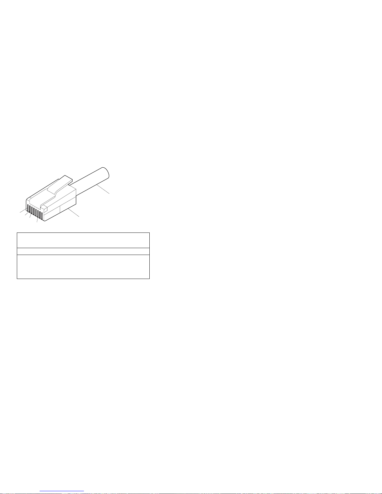
Table 10 on page 77 shows the pin-number assignments
for the RJ-45 connector. These assignments apply to both
10BASE-T and 100BASE-TX devices.
10BASE-T or 100 BASE-TX
UTP Cable
1
Pins
2
3
6
RJ-45 Modular Plug Connector
Table 10. 10/100 Mbps Ethernet connector
pin-number assignments
Pin Signal Pin Signal
1 Transmit data+ 5 Reserved
2 Transmit data− 6 Receive data−
3 Receive data+ 7 Reserved
4 Reserved 8 Reserved
Advanced System Management dual serial port:
The Advanced System Management PCI Adapter contains
a dual serial port. The port has an external connector that
can be used to attach to a Y-cable that is shipped with the
server. The serial connectors on the Y-cable and the
pin-number assignments are the same as for the system
serial ports. This Y-cable can be used to attach to a
modem that is dedicated to communication with the
Advanced System Management PCI Adapter.
You can obtain a listing of compatible modems and related
information by accessing the following address:
http://www.ibm.com/pc/us/compat/ on the World Wide Web.
Advanced System Management Interconnect
port:
The Advanced System Management PCI Adapter
contains an Advanced System Management Interconnect
port. The port has an external connector that must be
attached to an optional Y-cable that provides for chaining
other compatible service processors for remote access.
To obtain an optional Y-cable, contact an IBM reseller or
IBM marketing representative.
The following table shows the pin-number assignments for
the connectors used by the Advanced System
Management Interconnect bus port.
Netfinity 8500R - Type 8681 77
Page 86

Table 11. Advanced System Management
Interconnect bus connector pin-number assignments
Pin Signal
1 Term power
2 + Input
3 − Input
4 + Output
5 − Output
6 Ground
78 Netfinity Server HMM
Page 87

Front panel
The front panel on the front of the server contains status
lights and system messages.
.1/ Information message panel: System monitor
information appears on this display. The Advanced
System Management PCI Adapter monitors system
functions and generates the messages.
When the server is in standby mode (the system
power supply is turned off and AC current is
present), the information message panel can
display system monitor information.
.2/ System error light: This amber light is on when a
system error occurs. Information about the
condition displays on the information message
panel.
.3/ SCSI hard disk drive in-use light: This green
light is on when there is activity on a hard disk
drive.
Attention: If the System Power Light is off, it does
not mean there is no electrical current present in
the server. To remove all electrical current from the
server, you must unplug the server power cords.
.4/ System Power Light: When this green light is on,
system power is present in the server. When this
light flashes, the server is in standby mode (AC
current is present). When this light is off, it
indicates either power supply failure or an AC
power failure, or the power cords have been
disconnected.
Netfinity 8500R - Type 8681
79
Page 88

Hot-swap Power supplies
The server comes with three hot-swap power supplies.
The power supplies can provide up to 550 watts each at
110 V AC input power, and 750 watts each at 220 V AC
input power.
Danger
Overloading an electrical circuit breaker is potentially a
fire hazard and a shock hazard under certain
conditions. To avoid these hazards, adhere to the
instructions in the following statements.
1. If you are connecting to a 100–127 V AC power
source, connect each power cord to a separate
branch circuit.
2. If you are connecting to a 200–240 V AC power
source and the branch circuit breaker rating is:
a. 13 amps or less, connect each power cord
to a separate branch circuit.
b. 14 amps to 19 amps, do not connect more
than two power cords to the same branch
circuit.
c. 20 amps or greater, you may connect up to
three power cords to the same branch
circuit.
In addition to the power supplies, the server comes with
three 220 V AC power cords, and three 110 V AC power
cords (U.S. only). Be sure to select the appropriate power
cord voltage for the server environment. All three power
cords must have the same voltage.
If you connect the three:
220 V AC power cords to the power supplies, the
three power supplies support redundancy and
hot-swap capability.
110 V AC power cords to the power supplies, the
three power supplies do not support redundancy if the
system configuration exceeds any of these conditions:
– More than six processors
– More than 24 memory DIMMs
– More than eight PCI adapters
For servers with redundant power, the loss of a single
power supply will not affect the server operation. Replace
a power supply that has failed as soon as convenient to
help maintain the redundant power and cooling capability.
When a power supply has failed and the Power Good light
is on, the DC power LED on the power supply is off. See
“Power supply LED errors” on page 173 for more
information on the DC power LEDs. See “Hot-swap power
80 Netfinity Server HMM
Page 89

supply installation/removal” on page 92 for complete
details on the power supplies.
Attention
To ensure proper server operation, be sure to connect
all three 220 V AC power cords or all three 110 V AC
power cords to the power supplies.
Notes
1. The server also comes with three 220 V AC
power cords for connection to the server rack
power distribution unit (PDU). Refer to
IBM
Netfinity Rack Power Distribution Unit (PDU)
Installation Instructions
for additional information
on installing a PDU. See “Installing the server in
and removing the server from the rack enclosure”
on page 96 for additional information on installing
a server rack.
2. Power cords vary by country. For complete
details about power cords for use in your country
or region, refer to “Power cords” in the “Legal
Information” section of this
Server Library
or see
http://www.ibm.com/pc/support on the World
Wide Web.
The following illustration shows the power supplies in the
server. The server might differ slightly from this illustration.
.1/ Power supplies: See “Hot-swap power supply
installation/removal” on page 92 for information on
power supply requirements and for instructions on
installing additional power supplies.
Netfinity 8500R - Type 8681
81
Page 90

.2/ AC and DC power lights: These lights provide
status information about the power supplies. These
adjacent lights are located on the power supplies;
the ac power light is located closest to the power
supply connector. During normal operation, both
the AC and DC power lights are on. For any other
combination of lights, see “Power supply LED
errors” on page 173.
.3/ Power supply connectors: The three system
power cords connect here. For additional details on
power cords, refer to the information at the
beginning of this section.
82 Netfinity Server HMM
Page 91

Hot-swap fan installation/removal
The server comes with three hot-swap processor fans
(labeled and numbered 1, 2, and 3) in the front of the
processor housing assembly at the front of the server, and
three hot-swap I/O fans (labeled and numbered 4, 5, and
6) behind the hot-swap drive bays. Each fan has an LED;
the fan LEDs are amber in color. A fan LED is lit only
when the fan needs replacement.
Notes
1. The illustrations in this section might differ slightly
from your hardware.
2. You do not need to turn off the power to the
server to replace a fan.
3. Replace a fan that has failed as soon as
convenient to maintain the redundant cooling
capability.
4. The top cover is in place during normal
operation. If the server is on, do not leave the
top cover off for more than 30 minutes at a time.
To replace a hot-swap fan:
To replace a processor fan, continue with “Processor
fan replacement” on page 144.
To replace an I/O fan, continue with “Replacing an I/O
fan” on page 145.
Netfinity 8500R - Type 8681
83
Page 92

Hot-plug PCI adapter installation
This section gives the procedure for installing a hot-plug
PCI adapter. If you want to remove a hot-plug adapter,
reverse the steps. If the operating system supports
hot-plug PCI adapters, you can replace a failing hot-plug
PCI adapter with a new adapter of the same type without
turning off power to the server.
Notes
1. You do not need to turn off the server to install or
remove a hot-plug PCI adapter.
2. When you install an adapter, be sure that the
gold-edge connectors on the adapter match the
connectors in the PCI slot.
Before you begin:
Read “Safety information” on page 240. and
“Working inside a server with power on” on
page 165.
Read the documentation that comes with the
adapter for any special requirements or
restrictions.
Read the documentation that comes with the
operating system.
The orange color on components and labels in
the server indicates hot-swap or hot-plug
components. This means that you can install or
remove the component while the system is
running, provided that the system is configured to
support this function. For complete details about
installing or removing a hot-swap or hot-plug
component, see the information provided in this
chapter.
The blue color on components or labels indicates
touch points where a component can be gripped,
a latch moved, and so on.
Attention:
Do not remove a hot-plug adapter before performing
the operating-system-defined procedure for disabling
the hot-plug PCI slot that contains the adapter.
Failure to do so might cause the system to lock up.
Refer to the operating system documentation.
84 Netfinity Server HMM
Page 93

Refer to the following illustrations while you perform the
steps in this procedure.
Note
The illustrations in this section might differ slightly from
your hardware.
.1/ Tab
.2/ Adapter retention latch
.3/ Expansion-slot cover
.4/ Adapter retention cover
To install a hot-plug PCI adapter:
1. If you have not already done so, remove the top
cover (see “Removing the top cover” on page 136).
Attention
If the server is on, do not leave the top cover off
for more than 30 minutes at a time.
2. Determine which expansion slot you will use for the
adapter.
Note
Check the instructions that come with the adapter
for any requirements or restrictions.
3. Disable the PCI slot from the operating system.
Make sure that the Power On light for the PCI slot is
off. See step 12 on page 87 for the Power On light
location. (Refer to the documentation that comes with
the operating system for information about disabling a
hot-plug PCI slot.)
Netfinity 8500R - Type 8681
85
Page 94

4. Remove the expansion-slot cover .3/:
a. Rotate the adapter retention latch .2/ to the
open (unlocked) position.
b. Lift the tab .1/ at the top of the expansion-slot
cover to the open (unlocked) position.
c. Remove the expansion-slot cover .3/ from the
server. Store it in a safe place for future use.
Attention
Expansion-slot covers must be installed on
all vacant slots. This maintains the
electromagnetic-emissions characteristics of
the system and ensures proper cooling of
system components.
5. If you are installing a full-length adapter, open the
adapter retention cover .4/.
a. Press outward on the adapter retention assembly
where indicated by the arrow.
b. Continue pressing on the assembly as described
in step 5a, and lift the adapter retention
cover .4/.
6. Refer to the documentation that comes with the
adapter for any cabling instructions. It might be
easier for you to route any internal cables before you
install the adapter.
7. Touch the static-protective package containing the
adapter to any unpainted metal surface on the server.
Then, remove the adapter from the static-protective
package.
Note
Avoid touching the components and gold-edge
connectors on the adapter.
8. Place the adapter, component-side up, on a flat,
static-protective surface.
9. Set any jumpers or switches as described by the
adapter manufacturer.
Refer to the following illustrations while you perform
the following steps.
86 Netfinity Server HMM
Page 95

.1/ Tab
.2/ Adapter retention latch
.3/ Adapter
.4/ Adapter retention cover
10. Install the adapter:
a. Carefully grasp the adapter .3/ by its top edge
or upper corners, and align it with the expansion
slot on the I/O board.
Attention
When you install an adapter in the server,
be sure that it is completely and correctly
seated in the connector. Incomplete
insertion might cause damage to server
components or the adapter.
b. Press the adapter
firmly
into the expansion slot.
c. If you are installing a full-length adapter, close
the adapter retention cover .4/.
d. Lower the tab .1/ over the adapter. Rotate the
adapter retention latch .2/ until it snaps in place
(the locked position).
11. If you have not already done so, connect any cables
to the adapter.
12. Enable the PCI slot from the operating system. Make
sure that the Power On light .5/ for the PCI slot is
on.
Attention
If the installed adapter is not supported by the
hot-plug capability of the operating system, shut
down and restart the server.
Netfinity 8500R - Type 8681 87
Page 96

13. If you have other options to install or remove, do so
now; otherwise, continue with “Completing the
installation” on page 56.
88 Netfinity Server HMM
Page 97

Installing a non-hot-plug PCI adapter: This
section gives the procedures for installing a non-hot-plug
adapter. If you want to remove a non-hot-plug adapter,
reverse the steps.
Before you begin:
Read “Safety information” on page 240.
Read the documentation that comes with the
adapter for any special requirements or
restrictions.
The orange color on components and labels in
the server indicates hot-swap or hot-plug
components. This means that you can install or
remove the component while the system is
running, provided that the system is configured to
support this function. For complete details about
installing or removing a hot-swap or hot-plug
component, see the information provided in this
chapter.
The blue color on components or labels indicates
touch points where a component can be gripped,
a latch moved, and so on.
Refer to the illustrations in “Hot-plug PCI adapter
installation” on page 84 while you perform the steps in this
procedure.
To install a non-hot-plug PCI adapter:
1. Run the shutdown procedure for the operating
system. Turn off the server and peripheral devices;
and disconnect all external cables and power cords
(see “Preparing to install options” on page 134); then,
remove the top cover (see “Removing the top cover”
on page 136).
2. Determine which expansion slot you will use for the
adapter.
Note
Check the instructions that come with the adapter
for any requirements or restrictions.
3. Perform step 4 on page 86 through step 11 on
page 87, and step 13 on page 88.
Verifying compatibility between network
adapters and device drivers: The server
supports several types of network adapters. If you are
having trouble with the installation or operation of a
network adapter or network operating system, ensure that
the network-adapter device driver supports multiple
processors. Refer to the network-adapter documentation
for additional information about adapter compatibility
requirements.
Netfinity 8500R - Type 8681
89
Page 98

Cabling internal hard disk drives to a
ServeRAID adapter (optional): You can install
an optional ServeRAID adapter in the server to enable you
to configure the internal hot-swap hard disk drives into disk
arrays. To do this, you must disconnect the cable from the
integrated SCSI controller on the I/O function card, and
connect the cable to a ServeRAID adapter. To cable a
ServeRAID adapter to the internal hard disk drives in the
server, or to make this adapter a startup device, you must
install the ServeRAID adapter in PCI slot 10, 11, or 12.
Refer to the ServeRAID adapter option documentation for
complete instructions on installing a ServeRAID adapter in
the server.
The following procedure describes the cable routing that is
necessary when you install the ServeRAID adapter. Refer
to the following illustration while you perform the steps in
this procedure.
Notes
1. It might be easier for you to route the cable
before you install the adapter.
2. You do not have to remove the I/O function card
or the screws on the I/O function card to connect
the internal SCSI cable to a ServeRAID adapter.
.1/ Standard internal SCSI cable location for
connection to internal SCSI port B
.2/ Internal SCSI port B
.3/ New internal SCSI cable location for connection
to ServeRAID adapter
1. Disconnect the internal SCSI cable .1/ from internal
SCSI port B .2/ on the I/O function card.
2. Change the setting of the three-pin, SCSI B detect
jumper (identifier J19) on the I/O function card from
pins 1 and 2 to pins 2 and 3. This prevents the
server from displaying a non-applicable error
message, Cable not present.
90 Netfinity Server HMM
Page 99

1 2 3
Note
For additional information on changing jumper
settings, see “Jumper settings” on page 125.
For the jumper location, see the illustration of the
I/O function card in “I/O function card component
locations” on page 120.
3. The SCSI cable comes with two standard folds.
Unfold the SCSI cable at the fold that is closer to the
connector on the end of the cable. If necessary, refer
to the illustration at the beginning of this procedure.
4. Install the ServeRAID adapter in PCI slot 10, 11, or
12.
5. Connect the internal SCSI port B end of the SCSI
cable to the appropriate channel on the ServeRAID
adapter .3/. Refer to the ServeRAID adapter option
documentation for instructions on installing a
ServeRAID adapter in the server and connecting the
SCSI cable to the ServeRAID adapter.
Netfinity 8500R - Type 8681
91
Page 100

Hot-swap power supply
installation/removal
Danger
Overloading an electrical circuit breaker is potentially a
fire hazard and a shock hazard under certain
conditions. To avoid these hazards, adhere to the
instructions in the following statements.
1. If you are connecting to a 100–127 V AC power
source, connect each power cord to a separate
branch circuit.
2. If you are connecting to a 200–240 V AC power
source and the branch circuit breaker rating is:
a. 13 amps or less, connect each power cord
to a separate branch circuit.
b. 14 amps to 19 amps, do not connect more
than two power cords to the same branch
circuit.
c. 20 amps or greater, you may connect up to
three power cords to the same branch
circuit.
The server comes with three power supplies, three 220 V
AC power cords, and three 110 V AC power cords (U.S.
only). Be sure to select the appropriate power cord
voltage for the server environment. All three power cords
must have the same voltage.
If you connect the three:
220 V AC power cords to the power supplies, the
three power supplies support redundancy and
hot-swap capability.
110 V AC power cords to the power supplies, the
three power supplies do not support redundancy if the
system configuration exceeds any of these conditions:
– More than six processors
– More than 24 memory DIMMs
– More than eight PCI adapters
For servers with redundant power, the loss of a single
power supply will not affect the server operation. Replace
a power supply that has failed as soon as convenient to
help maintain the redundant power and cooling capability.
When the AC power LED is on, the DC power LED is on,
and the System Power light on the operator panel is on,
the power supply has failed. See “Hot-swap Power
supplies” on page 80 for the location of the DC power
LEDs. See “Power supply LED errors” on page 173 for
more information on the DC power LEDs.
92 Netfinity Server HMM
 Loading...