

Page 1

IBM
Hardware Maintenance Manual
Netfinity 7600 – Type 8665
Models 1RY, 2RY
Page 2

Page 3

IBM
Hardware Maintenance Manual
Netfinity 7600 – Type 8665
Models 1RY, 2RY
Page 4

Note
Before using this information and the product it supports, be sure to read the general information under
“Notices” on page 280.
Second Edition (September 2000)
The following paragraph does not apply to the United Kingdom or to any country where such provisions
are inconsistent with local law: INTERNATIONAL BUSINESS MACHINES CORPORATION
PROVIDE S TH IS PU BLIC ATION "AS IS" WIT H O UT WARRANTY OF AN Y KIND , EI THER EXPRES S
OR IMPLIED, INCLUDING, BUT NOT LIMITED TO, THE IMPLIED WARRANTIES OF
MERCHANTABILITY OR FITNES S FOR A PARTICULAR PURPO SE . Som e stat e s do not all ow
disclaimer of express or implied warranties in certain transactions, ther efore, this statement may not
apply to you.
This publication could include technical inaccuracies or typographical errors. Changes are periodically
made to the information herein; these changes will be incorporated in new editions of the publication.
IBM may make improvements and/or changes in the product(s) and/or the program(s) described in this
publication at any time.
This publication was developed for products and services offered in the United States of America. IBM
may not offer the products, services, or features discussed in this document in other countries, and the
information is subject to change without notice. Consult your local IBM representative for information
on the products, services, and featur es available in your area.
Requests for technical information about IBM products should be made to your IBM reseller or IBM
marketing representative.
Netfinit y 7600 – Type 8665
Sept 2000
© Copyright Int ernational Business Machines Corporation 1999, 2000. All rights reserved.
US Government Users Restricted Rights – Use, duplication or disclosure restricted by GSA ADP Schedule Contract with
IBM Corp.
Page 5

© Copyright IBM Corp. 1999, 2000 iii
About this manual
This manual contains dia gnost ic infor mat io n, a Symp tom -to- FR U index , servic e
information, error codes, error messages, and configuration information for the
Netfinity 7600 – Type 8665.
Important: This manual is intended for trained servicers who are familiar with IBM
PC Server products.
Important safety information
Be sure to read all caution and danger statements in this book befor e performing any
of the instructions.
Leia todas as instruções de cuidado e perigo antes de executar qualquer operação.
Prenez connaissance de toutes les consignes de type Attention et
Danger avant de procéde r aux opérations décrites par les instructions.
Page 6

iv Hardware M aintenance Manual: Netfinity 7600 – Type 866 5 Mo dels 1RY, 2RY
Lesen Sie alle Sicherheitshinweise, bevor Sie eine Anweisung ausführen.
Accertarsi di leggere tutti gli avvisi di attenzione e di pericolo prima di effettuare
qualsiasi operazi on e.
Lea atentamente todas las decl araciones de pr ecau ción y peligro ante de llevar a cabo
cualquier operación.
Online support
Use the World Wide Web (WWW) to downlo ad Diagnostic, BIOS Flash, a nd Device
Driver files.
File download address is:
http://www.us.pc.ibm.com/files.html
IBM online addresses
The H M M manu a l s online addres s i s:
http://www.us.pc.ibm.com/cdt/hmm.html
The IBM PC Company Support Page is:
http://www.us.pc.ibm.com/support/index.html
The IBM PC Compa ny Home Page is:
http://www.pc.ibm.com
Page 7

© Copyright IBM Corp. 1999, 2000 v
Contents
About this manual . . . . . . . . . . . . . . . . . . . iii
Important safety information . . . . . . . . . . . . . . . . . . . . . . iii
Online support. . . . . . . . . . . . . . . . . . . . . . . . . . . . . . . . . . . iv
IBM online addresses . . . . . . . . . . . . . . . . . . . . . . . . . . iv
General checkout. . . . . . . . . . . . . . . . . . . . . 1
General information. . . . . . . . . . . . . . . . . . . 3
Features and specifications . . . . . . . . . . . . . . . . . . . . . . . . 3
Server features . . . . . . . . . . . . . . . . . . . . . . . . . . . . . . . . . . . 5
Reliability, availability, and serviceability . . . . . . . . . . . . 6
Controls and indicators . . . . . . . . . . . . . . . . . . . . . . . . . . . 7
Information LED panel. . . . . . . . . . . . . . . . . . . . . . . . . . . . 9
Diagnostics . . . . . . . . . . . . . . . . . . . . . . . . 11
Diagnostic tools overview . . . . . . . . . . . . . . . . . . . . . . . . 11
POST . . . . . . . . . . . . . . . . . . . . . . . . . . . . . . . . . . . . . . . . . . 12
POST beep codes . . . . . . . . . . . . . . . . . . . . . . . . . . . . . 12
POST error messages. . . . . . . . . . . . . . . . . . . . . . . . . . 12
Event/error logs. . . . . . . . . . . . . . . . . . . . . . . . . . . . . . 12
Small computer system interface messages . . . . . . . . . 12
Solving ServeRAID problems . . . . . . . . . . . . . . . . . . . . . 13
ServeRAID controller messages. . . . . . . . . . . . . . . . . 13
ServeRAID startup messages . . . . . . . . . . . . . . . . 13
ServeRA ID ISPR, BCS, and ECS POST e r ror codes.
18
Rebuilding a defunct drive . . . . . . . . . . . . . . . . . . . . . 22
Steps for recov ering from defunct drives . . . . . . 23
Rebuilding a hot-swap drive . . . . . . . . . . . . . . . . 23
Recovering from an incomplete format of a ph ysi cal
drive . . . . . . . . . . . . . . . . . . . . . . . . . . . . . . . . . . . . . . . . . . 23
Recovering from a failure in a failover-environment 24
Replacing a non-hot-plug controller in a failover pair.
24
Diagnostic programs and error messages . . . . . . . . . . . 24
Text messages . . . . . . . . . . . . . . . . . . . . . . . . . . . . . . . . 25
Starting the diagnostic programs . . . . . . . . . . . . . . . 25
Viewing the test log . . . . . . . . . . . . . . . . . . . . . . . . . . . 26
Diagnostic error message tables . . . . . . . . . . . . . . . . 27
Light path diagnostics . . . . . . . . . . . . . . . . . . . . . . . . . . . 27
Power supply LEDs . . . . . . . . . . . . . . . . . . . . . . . . . . . 27
Diagnostic panel LEDs. . . . . . . . . . . . . . . . . . . . . . 28
Light path diagnostics . . . . . . . . . . . . . . . . . . . . . . 29
Power checkout . . . . . . . . . . . . . . . . . . . . . . . . . . . . . . . . . 31
Temperature checkout . . . . . . . . . . . . . . . . . . . . . . . . . . . 31
Recovering BIOS . . . . . . . . . . . . . . . . . . . . . . . . . . . . . . . . 32
Replacing the battery . . . . . . . . . . . . . . . . . . . . . . . . . . . . 32
Diagnosing errors . . . . . . . . . . . . . . . . . . . . . . . . . . . . . . . 34
Troubleshooting the Ethernet controller. . . . . . . . . . 34
Network connection problems . . . . . . . . . . . . . . . 34
Ethernet controller troublesho oting cha rt. . . . . . 35
Ethernet controller messages . . . . . . . . . . . . . . . . . . . 36
Novell NetW are o r IntraNetWare server ODI driver
messages . . . . . . . . . . . . . . . . . . . . . . . . . . . . . . . . . 37
NDIS 4.0 (Windows NT) d r iver mess ages . . . . . 39
UNIX messages . . . . . . . . . . . . . . . . . . . . . . . . . . . . 39
Configuring the server . . . . . . . . . . . . . . . 43
Using the Configuration/Setup Utility program . . . . . 43
Starting the Configuration/Setup Utility program 43
Choices available from the Configuration/Setup main
menu . . . . . . . . . . . . . . . . . . . . . . . . . . . . . . . . . . . . . . . . . . 44
Using passwords . . . . . . . . . . . . . . . . . . . . . . . . . . . . . 48
Power-on password . . . . . . . . . . . . . . . . . . . . . . . . 48
Administrator password . . . . . . . . . . . . . . . . . . . . 48
Using the SCSISelect utility program . . . . . . . . . . . . . . . 49
Starting the SCSISelect utility program . . . . . . . . . . 49
Choices available from the SCSISelect menu . . . . . 50
Installing options. . . . . . . . . . . . . . . . . . . . 53
Major components of the Netfinity 7600 . . . . . . . . . . . . 53
Component locations . . . . . . . . . . . . . . . . . . . . . . . . . . . . 54
I/O board component locations. . . . . . . . . . . . . . . . . 54
Processor board component locations. . . . . . . . . . . . 55
Processor board LEDs . . . . . . . . . . . . . . . . . . . . . . 55
Processor board connectors . . . . . . . . . . . . . . . . . . 56
Processor board jumpers . . . . . . . . . . . . . . . . . . . . 57
Memory board component locations . . . . . . . . . . . . 58
Memory board connectors. . . . . . . . . . . . . . . . . . . 58
Memory board LED locations . . . . . . . . . . . . . . . . 60
Before you begin . . . . . . . . . . . . . . . . . . . . . . . . . . . . . . . . 60
Working inside the server with the power on . . . . . 61
Removing the server top cover and bezel . . . . . . . . . . . 61
Removing the top cover . . . . . . . . . . . . . . . . . . . . . . . 62
Removing the media-bay bezel . . . . . . . . . . . . . . . . . 62
Removing the front trim bezel . . . . . . . . . . . . . . . . . . 63
Working with adapters . . . . . . . . . . . . . . . . . . . . . . . . . . . 63
Adapter considerations . . . . . . . . . . . . . . . . . . . . . . . . 64
Installing a hot-plug adapter . . . . . . . . . . . . . . . . . . . 64
Installing internal drives. . . . . . . . . . . . . . . . . . . . . . . . . . 66
Internal drive bays . . . . . . . . . . . . . . . . . . . . . . . . . . . . 67
Installing a hot-swap hard disk drive. . . . . . . . . . . . 68
Installing a 5.25-inch removable-media drive . . . . . 70
Installing memory-module kits. . . . . . . . . . . . . . . . . . . . 71
Installing a microprocessor kit. . . . . . . . . . . . . . . . . . . . . 73
Installing a hot-swap power supply. . . . . . . . . . . . . . . . 76
Replacing a hot-swap fan . . . . . . . . . . . . . . . . . . . . . . . . . 78
Completing the installation . . . . . . . . . . . . . . . . . . . . . . . 79
Installing the front trim bezel. . . . . . . . . . . . . . . . . . . 79
Installing the media-bay bezel . . . . . . . . . . . . . . . . . . 79
Installing the top cover . . . . . . . . . . . . . . . . . . . . . . . . 80
Reconfiguring the server . . . . . . . . . . . . . . . . . . . . . . . 81
Connecting external options . . . . . . . . . . . . . . . . . . . . . . 81
Input/output ports . . . . . . . . . . . . . . . . . . . . . . . . . . . . . . 81
Parallel port. . . . . . . . . . . . . . . . . . . . . . . . . . . . . . . . . . 82
Viewing or changing the parallel-port assignments
82
Parallel port connector . . . . . . . . . . . . . . . . . . . . . . 83
Video port . . . . . . . . . . . . . . . . . . . . . . . . . . . . . . . . . . . 83
Keyboard port. . . . . . . . . . . . . . . . . . . . . . . . . . . . . . . . 84
Auxiliary-device (pointing device) port . . . . . . . . . . 85
Ultra2 SCSI ports . . . . . . . . . . . . . . . . . . . . . . . . . . . . . 85
SCSI cabling requirements. . . . . . . . . . . . . . . . . . . 86
Setting SCSI IDs . . . . . . . . . . . . . . . . . . . . . . . . . . . 86
SCSI connector pin-number assignments . . . . . . 86
Serial ports. . . . . . . . . . . . . . . . . . . . . . . . . . . . . . . . . . . 87
Viewing or changing the serial-port assignments 87
Serial-port connectors. . . . . . . . . . . . . . . . . . . . . . . 88
Universal Serial Bus ports. . . . . . . . . . . . . . . . . . . . . . 88
USB cables and hubs. . . . . . . . . . . . . . . . . . . . . . . . 88
USB-port connectors. . . . . . . . . . . . . . . . . . . . . . . . 89
Ethernet port . . . . . . . . . . . . . . . . . . . . . . . . . . . . . . . . 89
Page 8

vi Hardware Maintenance Man ual: Netfinity 7600 – Type 866 5 Models 1RY, 2RY
Configuring the Ethernet controller. . . . . . . . . . . 89
Failover for redundant Ethernet. . . . . . . . . . . . . . 89
Ethernet port connector . . . . . . . . . . . . . . . . . . . . . 92
Advanced System Management ports . . . . . . . . . . . 92
Cabling the server . . . . . . . . . . . . . . . . . . . . . . . . . . . . . . . 93
Installing the server in a rack. . . . . . . . . . . . . . . . . . . . . . 93
Netfinity Manager. . . . . . . . . . . . . . . . . . . . 95
Managing your IBM Netfinity server with Netfinity
Manager . . . . . . . . . . . . . . . . . . . . . . . . . . . . . . . . . . . . . . . 96
Netfinity Manager documentation . . . . . . . . . . . . . . . . . 96
Netfinity Manager system requirements. . . . . . . . . . . . 96
Netfinity Manager for OS/2 system requir ement s. 96
Netfinity Manager for Windows 95 and Windows 98
system requirements. . . . . . . . . . . . . . . . . . . . . . . . . . . . . 97
Netfinity Manager for W indows NT system
requirements . . . . . . . . . . . . . . . . . . . . . . . . . . . . . . . . . . . 97
Starting the Netfinity Manager installation program . 98
Netfinity Manager database support . . . . . . . . . . . . . . 105
DB2 database support . . . . . . . . . . . . . . . . . . . . . . . . 105
System requirements . . . . . . . . . . . . . . . . . . . . . . 105
Installing and configuring the database . . . . . . 105
Activating the database . . . . . . . . . . . . . . . . . . . . 106
Granting and revoking database privileges . . . 107
Deleting the database. . . . . . . . . . . . . . . . . . . . . . 109
Lotus Notes database support . . . . . . . . . . . . . . . . . 109
System requirements . . . . . . . . . . . . . . . . . . . . . . 109
Installing the database. . . . . . . . . . . . . . . . . . . . . 110
Browsing the Netfinity Manager Lotus Notes
database . . . . . . . . . . . . . . . . . . . . . . . . . . . . . . . . . . 111
ODBC database support . . . . . . . . . . . . . . . . . . . . . . . 111
System requirements . . . . . . . . . . . . . . . . . . . . . . . 111
ODBC database configuration . . . . . . . . . . . . . . 112
Creating the Netfinity Manager tables . . . . . . . 112
Supported and certified databases. . . . . . . . . . . 114
Starting Netfinity Manager . . . . . . . . . . . . . . . . . . . . . . 115
Netfinity Manager Service Manager. . . . . . . . . . . . 116
Netfinity Manager service descriptions . . . . . . . . . 117
Advanced System Management. . . . . . . . . . . . . 118
Alert Manager . . . . . . . . . . . . . . . . . . . . . . . . . . . . 118
Alert on LAN configuration . . . . . . . . . . . . . . . . 118
Capacity Management . . . . . . . . . . . . . . . . . . . . . 118
Cluster Manager . . . . . . . . . . . . . . . . . . . . . . . . . . 118
Critical File Monitor . . . . . . . . . . . . . . . . . . . . . . . 118
DMI Browser . . . . . . . . . . . . . . . . . . . . . . . . . . . . . 119
ECC Memory Setup . . . . . . . . . . . . . . . . . . . . . . . 119
Event Scheduler . . . . . . . . . . . . . . . . . . . . . . . . . . 119
File Transfer . . . . . . . . . . . . . . . . . . . . . . . . . . . . . . 119
Power-On Error Detect . . . . . . . . . . . . . . . . . . . . 119
Predictive Failure Analysis . . . . . . . . . . . . . . . . . 119
Process Manager. . . . . . . . . . . . . . . . . . . . . . . . . . 119
RAID Manager . . . . . . . . . . . . . . . . . . . . . . . . . . . 119
Remote Session . . . . . . . . . . . . . . . . . . . . . . . . . . . 120
Remote System Manager . . . . . . . . . . . . . . . . . . . 120
Remote Workstation Control . . . . . . . . . . . . . . . 120
Screen View . . . . . . . . . . . . . . . . . . . . . . . . . . . . . . 120
Security Manager . . . . . . . . . . . . . . . . . . . . . . . . . 120
Serial Connection Control . . . . . . . . . . . . . . . . . . 120
Service Configuration Manager . . . . . . . . . . . . . 120
Software Inventory. . . . . . . . . . . . . . . . . . . . . . . . 121
System Diagnostics Manager . . . . . . . . . . . . . . . 121
System Information Tool . . . . . . . . . . . . . . . . . . . 121
System Monitor. . . . . . . . . . . . . . . . . . . . . . . . . . . 121
System Partition Access. . . . . . . . . . . . . . . . . . . . 121
System Profile . . . . . . . . . . . . . . . . . . . . . . . . . . . . 121
Update Connector Manager . . . . . . . . . . . . . . . . 121
Web Manager Configuration . . . . . . . . . . . . . . . 122
Delaying Netfinit y Mana ger startup on OS/2 systems
122
Getting more information about Netfinity Manager . 122
Installation options . . . . . . . . . . . . . . . . . . . . . . . . . . . . . 123
Automated installation . . . . . . . . . . . . . . . . . . . . . . . 123
Customized installation . . . . . . . . . . . . . . . . . . . . . . 125
FRU information (service only) . . . . . . . 127
Diagnostic switch card . . . . . . . . . . . . . . . . . . . . . . . . . . 127
Disconnecting the shuttle . . . . . . . . . . . . . . . . . . . . . . . . 128
Front LED card assembly . . . . . . . . . . . . . . . . . . . . . . . . 128
I/O Legacy board . . . . . . . . . . . . . . . . . . . . . . . . . . . . . . 129
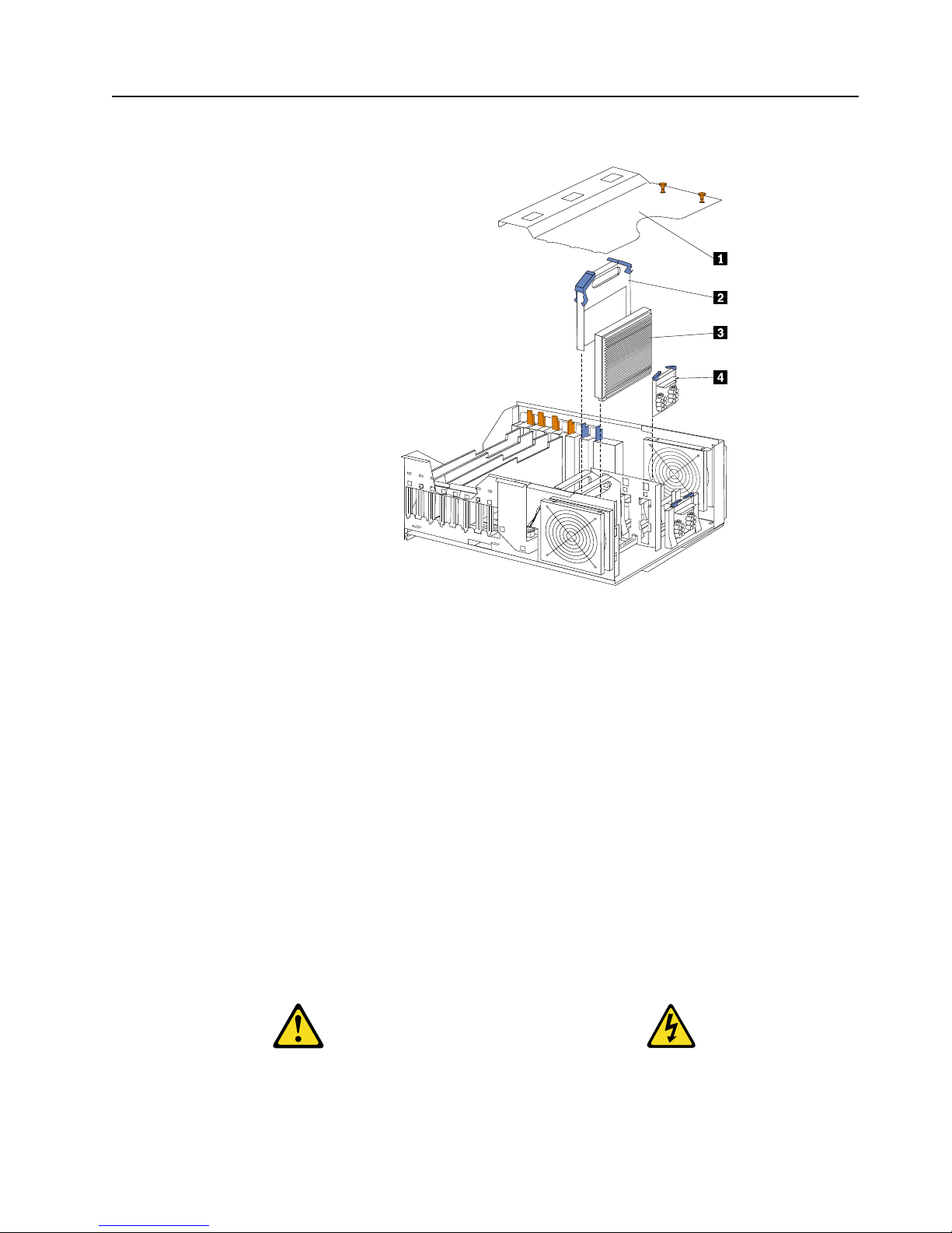
Memory card removal. . . . . . . . . . . . . . . . . . . . . . . . . . . 130
PCI switch card . . . . . . . . . . . . . . . . . . . . . . . . . . . . . . . . 132
Power backplane assembly . . . . . . . . . . . . . . . . . . . . . . 132
Processor/PCI backplane . . . . . . . . . . . . . . . . . . . . . . . . 133
Removing the shuttle . . . . . . . . . . . . . . . . . . . . . . . . . . . 135
SCSI backplane assembly . . . . . . . . . . . . . . . . . . . . . . . . 135
SCSI daughter card . . . . . . . . . . . . . . . . . . . . . . . . . . . . . 136
Installing and configuring ServeRAID
controllers . . . . . . . . . . . . . . . . . . . . . . . 139
Feature s and connector locati ons of ServeRAID-4H
controller. . . . . . . . . . . . . . . . . . . . . . . . . . . . . . . . . . . . . . 139
Controller features . . . . . . . . . . . . . . . . . . . . . . . . . . . 139
Connector locations . . . . . . . . . . . . . . . . . . . . . . . . . . 139
SCSI channel connectors . . . . . . . . . . . . . . . . . . . 140
Feature s and connector locati ons of ServeRAID-4L
controller. . . . . . . . . . . . . . . . . . . . . . . . . . . . . . . . . . . . . . 141
Controller features . . . . . . . . . . . . . . . . . . . . . . . . . . . 141
Connector locations . . . . . . . . . . . . . . . . . . . . . . . . . . 141
SCSI channel connector . . . . . . . . . . . . . . . . . . . . 141
Feature s and connector locati ons of ServeRAID-4M
controller. . . . . . . . . . . . . . . . . . . . . . . . . . . . . . . . . . . . . . 143
Controller features . . . . . . . . . . . . . . . . . . . . . . . . . . . 143
Connector locations . . . . . . . . . . . . . . . . . . . . . . . . . . 143
SCSI channel connectors . . . . . . . . . . . . . . . . . . . 143
Using a ServeRAID-4x controller in a server with Hot-
plug PCI features . . . . . . . . . . . . . . . . . . . . . . . . . . . . . . . 145
Using Windows NT 4.0 wi th Hot-plug PCI features . .
145
Step 1: Installing and cabling a ServeRAID controller 146
Installing the ServeRAID controller . . . . . . . . . . . . 146
Connecting external devices. . . . . . . . . . . . . . . . . . . 150
Step 2: Updating BIOS and firmware code . . . . . . . . . 151
Step 3: Configuring ServeRAID controllers. . . . . . . . . 151
Using the ServeRAID Manager program . . . . . . . . 152
Using Configuration mode . . . . . . . . . . . . . . . . . 154
Using Information mode . . . . . . . . . . . . . . . . . . . 162
Obtaining ServeRAID updates . . . . . . . . . . . . . . . . . . . 162
Downloadable files from the World Wide Web. . . 163
ServeRAID device driver order on Windows 2000 and
Windows NT 4.0 . . . . . . . . . . . . . . . . . . . . . . . . . . . . . . . 164
Using utility programs . . . . . . . . . . . . . . . . . . . . . . . . . . 165
Using the ServeRAID Mini-Configuration program . .
165
Viewing the controller status. . . . . . . . . . . . . . . . 166
Viewing the configuration. . . . . . . . . . . . . . . . . . 166
Using the advanced configuration functions . . 166
Using th e IPS SE N D co m m a nd- l i ne pro g ra m. . . . . 168
Server roll-out functions . . . . . . . . . . . . . . . . . . . 168
Error-recovery functions . . . . . . . . . . . . . . . . . . . 169
Problem-isolation and debug functions . . . . . . 170
RAID Configuration functions . . . . . . . . . . . . . . 173
Using the IPSMON command-line program (NetWare
only). . . . . . . . . . . . . . . . . . . . . . . . . . . . . . . . . . . . . . . . . . 173
Page 9

Contents vii
Introduction to IBM ServeRAID cluster solution . . . . 175
Monitoring and updating an IBM Serv eRAID cluster
solution . . . . . . . . . . . . . . . . . . . . . . . . . . . . . . . . . . . . . . . 176
Checking the ownership of a physical drive . . . . . . . . 177
Adding logical drives to a cluster . . . . . . . . . . . . . . . . . 177
Validating a cluster . . . . . . . . . . . . . . . . . . . . . . . . . . . . . 178
Viewing merge group numbers and other cluster
information . . . . . . . . . . . . . . . . . . . . . . . . . . . . . . . . . . . . 180
POST (ISPR) error codes and procedures. . . . . . . . . . . 180
ServeRAID-4 Controller error codes/messages . . . . . 180
POST (ISPR) error codes . . . . . . . . . . . . . . . . . . . . . . . . . 182
POST (ISPR) error procedures . . . . . . . . . . . . . . . . . . . . 182
Recovery procedures for defunct (DDD) drives . . . . . 184
Drive replacement (reb uilding a defunct drive) . . . . . 184
Steps for recovering from defunct drives . . . . . . . . . . . 185
Rebuilding a hot-swap drive . . . . . . . . . . . . . . . . . . . . . 185
Recovering from an incomplete format of a physical drive
185
Recovering from a failure in a failover-environment. 186
Replacing a non-hot-plug controller in a failover pair 186
Guidelines for the rebuild operation. . . . . . . . . . . . . . . 186
General information about the rebuild operation. . . . 186
Automatically rebuilding the defunct drive . . . . . . . . 187
Software and physical replacement . . . . . . . . . . . . . 187
Using ServeRAID Manager to determine the correct
order to software replace . . . . . . . . . . . . . . . . . . . . . . . . 187
Using and understan d in g the Serv eR AID Mo nito r Log
188
Recovery from ServeRAID controller failure. . . . . . . . 189
Recovery procedures . . . . . . . . . . . . . . . . . . . . . . . . . . . . 189
Recovery procedures for one defunct drive . . . . . . 190
More than one defunct (DDD) drive, all logical driv es
in critical or OK state. . . . . . . . . . . . . . . . . . . . . . . . . . . . 190
More than one defunct (DDD) drive and one or more
arrays offline . . . . . . . . . . . . . . . . . . . . . . . . . . . . . . . . . . . 190
Channel record table . . . . . . . . . . . . . . . . . . . . . . . . . . . . 191
Reference information. . . . . . . . . . . . . . . . . . . . . . . . . . . 192
Understanding RAID technology . . . . . . . . . . . . . . 192
Stripe-unit size. . . . . . . . . . . . . . . . . . . . . . . . . . . . 193
Supported RAID levels. . . . . . . . . . . . . . . . . . . . . 193
Drive state descriptions . . . . . . . . . . . . . . . . . . . . 202
Acronyms, terms, and definitions . . . . . . . . . . . . . . 210
Symptom-to-FRU index. . . . . . . . . . . . . . 215
Beep symptoms . . . . . . . . . . . . . . . . . . . . . . . . . . . . . . . . 215
No beep symptoms . . . . . . . . . . . . . . . . . . . . . . . . . . . . . 218
Diagnostic panel LEDs . . . . . . . . . . . . . . . . . . . . . . . . . . 218
Diagnostic error codes. . . . . . . . . . . . . . . . . . . . . . . . . . . 220
Error symptoms . . . . . . . . . . . . . . . . . . . . . . . . . . . . . . . . 225
Power supply LED errors . . . . . . . . . . . . . . . . . . . . . . . . 225
POST error codes . . . . . . . . . . . . . . . . . . . . . . . . . . . . . . . 226
ServeRAID POST (ISPR) error codes. . . . . . . . . . . . . . . 232
ServeRAID POST (ISPR) error procedures . . . . . . . 232
ServeRAID. . . . . . . . . . . . . . . . . . . . . . . . . . . . . . . . . . . . . 234
SCSI error codes . . . . . . . . . . . . . . . . . . . . . . . . . . . . . . . . 236
Temperature error messages. . . . . . . . . . . . . . . . . . . . . . 236
Fan error messages. . . . . . . . . . . . . . . . . . . . . . . . . . . . . . 237
Power error messages . . . . . . . . . . . . . . . . . . . . . . . . . . . 237
System shutdown. . . . . . . . . . . . . . . . . . . . . . . . . . . . . . . 238
Power related system shutdown . . . . . . . . . . . . . . . 238
Temperature related system shutdown . . . . . . . . . . 239
DASD checkout . . . . . . . . . . . . . . . . . . . . . . . . . . . . . . . . 239
Host Built-In Self Test (BIST) checkout . . . . . . . . . . . . . 239
I2C bus fault messages . . . . . . . . . . . . . . . . . . . . . . . . . . 239
Undetermined problems. . . . . . . . . . . . . . . . . . . . . . . . . 241
Parts listing (Type 8665) . . . . . . . . . . . . . 243
Part A . . . . . . . . . . . . . . . . . . . . . . . . . . . . . . . . . . . . . . . . . 243
System. . . . . . . . . . . . . . . . . . . . . . . . . . . . . . . . . . . . . . 243
Part B . . . . . . . . . . . . . . . . . . . . . . . . . . . . . . . . . . . . . . . . . 244
System . . . . . . . . . . . . . . . . . . . . . . . . . . . . . . . . . . . . . . . . 245
Keyboards . . . . . . . . . . . . . . . . . . . . . . . . . . . . . . . . . . . . . 246
Power cords. . . . . . . . . . . . . . . . . . . . . . . . . . . . . . . . . . . . 247
Related service information . . . . . . . . . . 249
Safety information . . . . . . . . . . . . . . . . . . . . . . . . . . . . . . 249
General safety . . . . . . . . . . . . . . . . . . . . . . . . . . . . . . . 249
Electrical safety . . . . . . . . . . . . . . . . . . . . . . . . . . . . . . 250
Safety inspection guide . . . . . . . . . . . . . . . . . . . . . . . 251
Handling electrostatic dischar ge-sensitive devices 252
Grounding requirements . . . . . . . . . . . . . . . . . . . . . . 253
Safety notices (multi-lingual translations) . . . . . . . 253
Send us your comments! . . . . . . . . . . . . . . . . . . . . . . . . . 279
Problem determination tips . . . . . . . . . . . . . . . . . . . . . . 280
Notices . . . . . . . . . . . . . . . . . . . . . . . . . . . . . . . . . . . . . . . . 280
Trademarks . . . . . . . . . . . . . . . . . . . . . . . . . . . . . . . . . . . . 281
Page 10

viii Hardware Maintenance Manual: Netfinity 7600 – Type 8665 Models 1RY, 2RY
Page 11

© Copyright IBM Corp. 1999, 2000 1
General checkout
The server diagnostic prog rams are stored in upgradable read-only memory (ROM)
on the system board. These programs are the primary method of testing the major
components of the server: The system board, Ethernet controller, video controller,
RAM, keyboard, mouse (pointing device), diskette drive, serial ports, hard drives,
and parallel port. You can also use them to test some external devices. See
“Diagnostic programs and error messages” on page 24.
Also, if you cannot determine whether a problem is caused by the hardware or by the
softw a re, you ca n run the diagnostic programs t o confirm that the hard wa re is
working properly.
When you run the diagnostic programs, a single problem might cause several error
messages. When this occurs, work to correct the cause of the first error message.
After the cause of the first error message is corrected, the other error messages might
not occur the next time you run the test.
A failed system might be par t of a shared DASD cluster (two or mor e systems s haring
the same external storage device(s)) . Prior to running diagnostics, verify that the
failing system is not part of a shared DASD cluster.
A system might be part of a cluster if:
• The customer identifies the system as part of a cluster.
• One or more external storage units are attached to the system and at least one of
the attached storage units is additionally attached to another system or
unidentifiable source.
• One or more sy stems are loca te d near the failing system.
If the failing system is suspected to be part of a shared DASD cluster, all diagnostic
tests can be run except diagnostic tests which test the storage unit (DASD residing in
the storage unit) or the storage adapter attached to the storage unit.
Notes:
1. For systems that are part of a shared DASD cluster, run one test at a time in
looped mode. Do not run all tests in looped mode, as this could enable the DASD
diagnostic tests.
2. If mult iple er ror codes are displaye d, diagno se the firs t error code disp laye d.
3. If the computer hangs with a POST error , go to the “Chapter . Symptom-to-FRU
index,” on page 215.
4. If the computer hangs and no error is displayed, go to “Undetermined problems”
on page 241.
5. Power supply problems, see “Chapter . Symptom-to-FRU index,” on page 215.
6. Safety information, see “Safety information” on page 249.
7. For intermittent problems, check the error log; see “PO ST erro r me s s ages” on
page 12.
1. IS THE SYSTEM PART OF A CLUSTER?
Page 12

2 Hardware Maintenance Manual: Netfinity 7600 – Type 8665 Models 1RY, 2RY
YES. Schedule mai ntenance with the custome r. Shut down all systems related to the
cluster. Run storage test.
NO. Go to step 2.
2. THE SYSTEM IS NOT PART OF A CLUSTER.
• Power-off the computer and all external devices.
• Chec k al l cabl e s and po wer cords .
• Set all display controls to the middle position.
• Power-o n all ext e rna l devices.
• Power-on the computer.
• Record any POST error messages displayed on the screen. If an error is
displayed, look up the first error in the “POST error codes” on page 226.
• Check the information LED panel System Error LED; if on, see “Diagnostic
panel LEDs” on page 218.
• Check the System Error Log. If an error was recorded by the system, see
“Chapter . Symptom-to-FRU index ,” on page 215.
• Start the Diagnostic Programs. See “Diagnostic p rograms and error
messages” on page 24.
• Check for th e following responses:
a. One beep.
b. Readable instructions or the Main Menu.
3. DID YOU RECEIVE BOTH OF THE CORRECT RESPONSES?
NO. Find the failure symptom in “Chapter . Symptom-to-FRU index,” on page 215.
YES. Run the Diagnostic Programs. If necessary, refer to “Diagnostic programs and
error messages” on page 24.
If you receive an error, go to “Chap te r . Sy m p to m-to- F R U in de x,” on page 215.
If the diagnostics completed successfully and you still suspect a problem, see
“Undetermined problems” on page 241.
Page 13

© Copyright IBM Corp. 1999, 2000 3
General information
The IBM® Netfinity® 7600 server is a high-performance server with the capability of
microprocessor upgrade to a symmet ric mult iprocessing (SMP) server. It is ideally
suited for networking environments that require superior microprocessor
performance, efficient memory management, flexibility , and large amounts of reliable
data storage.
Performance, ease of use, reliability, and expansion capabilities were key
considerations during the design of the server . These design features make it possible
for you to customize the system hardware to meet your needs today, while providing
flexible expansion cap ab ilitie s for the future.
The IBM Netfinity 7600 server comes with a three-year limi ted warranty and 90-Day
IBM St art Up Su p p ort. If you h av e ac ce ss to the World Wide Web, you can ob ta i n u p to-date information about the server model and other IBM server products at the
following World Wide Web address: http://www .ibm.com/pc/us/netfinity/
Features and specifications
The following provides a summary of the features and specifications for the Netfinity
7600 server.
• Microprocessor:
— Intel® Pentium®III Xeon™
— 32 KB of level-1 cache
— 1 MB of Level-2 cache (min.)
— Expandable to four microprocessors
• Memory:
— Maximum: 16GB
— Type: ECC, SDRAM, Registered DIMMs
— Slots: 4- way interleave d, 16 slots
• Drives standard:
— Diskette: 1.44 MB
— CD-ROM: 40X IDE
• Expa nsion bays:
— Hot-swap: 10 slim high or 7 half high
— Non-hot-swap: Two 5.25-inch
• PCI expansion slots:
— Four 33 MHz 64-bit
— Two 66 MHz 64-bit
• Hot-swap power s upplies:
250 W (115-230 V ac)
— Minimum: Three
— Maximum: Four
• Redundant cooling:
— Four hot-swap fan assemblies
• Video:
Page 14

4 Hardware Maintenance Manual: Netfinity 7600 – Type 8665 Models 1RY, 2RY
— S3 video controller
— Compatible with SVGA and VGA
— 4 MB video me mory
• Size
— Height: 356 mm (14 in.)
— Depth: 650 mm (25.6 in.)
— Width: 440 mm (17.3 in.)
— Weight: 34.4 kg (76 lb.) to 61 kg (134 lb.) depending upon configuration
• Integrated functions:
— Netfinity Advanced System Management processor
— Dual Ultra-2 (LV D) SCSI controller, one external port, one internal port
— One 10BASE-T/100BASE-TX AMD Ethernet controller
— Three serial ports (one reserved for system management)
— Two RS 485 ports
— One parallel port
— Two unive rsal serial bus ports
— Keyboard port
— Mouse port
— Video port
• RAID technology
— IBM ServeRAID controller (three channels)
• Acoustical noise emissions:
— Sound power, idling: 6.3 bel maximum
— Sound power, operating: 6.3 bel maximum
— Sound pressure, operating: 48 dBa maximum
• Environment:
— Air temperature:
– Server on: 10º to 35º C (50º to 95º F). Altitude: 0 to 914 m (3000 ft.)
– Server on: 10º to 32º C (50º to 89.6º F). Altitude: 914 m (3000 ft.) to 2133 m
(7000 ft.)
– Server off: 10º to 43º C (50º to 110 º F). Maximum altitude: 2133 m (7000 ft.)
— Humidit y :
– Server on: 8% to 80%
– Server off: 8% to 80%
• Heat output:
Approximate heat output in British Thermal Units (BTU) per hour
— Minimum configuration:1023.9 BTU
— Maximum configuration: 2764.6 BTU
• Electrical input:
— Sine-wave input (50-60 Hz) required
— Input voltage low range:
– Minimum: 90 V ac
– Maximum: 137 V ac
— Input voltage high range:
– Minimum: 180 V ac
– Maximum: 265 V ac
— Input kilovolt-amperes (kVA) approximately:
Page 15

General information 5
– Minimum: 0.08 kVA
– Maximum: 0.52 kVA
Server features
The unique design of the server takes advantage of advancements in symmetric
multiprocessing (SMP), data storage, and memory protection. The server combines:
• Impressive performance using an innovative approach to SMP
The server supports up to four Pentium III Xeon microprocessors. The server
comes with one microprocessor installed; you can install additional
microprocessor s to enhance performance and provide SMP capability.
• Integrated disk-array subsystem
Although many operating systems provide software fault tolerance through
mirroring, IBM provides hardware fault tolerance through the redundant array of
independent disks (RAID) controller. The IBM ServeRAID™ controller is a
standard feature. It provides three channels and supports RAID levels 0, 1, 1E, 5,
and 5E.
• Large data-storage an d hot- swa p cap ab ilitie s
All models of the server support up to 10 slim-high or 7 half high hot-swap hard
disk drives . Th is hot-swap feature enables you to remove and replace hard disk
drives without turni ng off the server.
• Hot-plug PCI adapter capabilities
The server ha s f our hot-plug slots for PCI adapters. With operating system
support, you can replace failing hot-plug PCI adapters without turning off the
server. If the hot-add feature is supported by the operating system and the PCI
adapter, you can also add PCI adapters in these slots without turning off the
server.
• Redundant cooling and power capabilities
The redundant cooling and hot-swap capabilities of the fans in the server enable
continued operation if one of the fans fails, because you can replace a failing fan
without turning off the server.
The server comes standard with three 250-watt power supplies, which support
redundancy for a typical configuration. You can install one additional power
supply.
• Large system memory
The memory bus in the server supports up to 16 GB of system memory. The
memory controller provides error correcting code (ECC) support for up to 16
industry-sta ndard, 3. 3 V, 168-pin, 8-byte, register ed, dual inlin e memory modules
(DIMMs). The memory controller also provides Chipkill™ memory protection.
Chipkill memory protect ion is a technolo gy that protects the syste m from
component fa ilure on a DIMM.
• System-management capabilities
The serve r comes with a Netfinity Advanced System Management Processor.
This processor, in conjunction with the Netfinity Manager software provided on
the ServerGuide CDs, enables you to manage the functions of the server locally
and remotely. The Netfinity Advanced System Management Processor also
provides system monitoring, event recording, and dial-out alert capability.
Page 16

6 Hardware Maintenance Manual: Netfinity 7600 – Type 8665 Models 1RY, 2RY
Note: The Netfinity Advanced System Management Processor is sometimes
referred to as the service processor.
Refer to “Chapt er . Netfinity Manager,” on page 95 for more information.
• Integrated network environment support
The server comes with an Ethernet controller. This Ethernet controller has an
interface for connecting to 10-Mbps or 100-Mbps networks. The server
automatically sel e cts between 10BASE-T and 100BASE-TX. The controller
provides full-duplex (FDX) capability, which enables simultaneous transmission
and reception of data on the Ethernet local area network (LAN).
• Redundant network-interface card
The addition of an optional, redundant network interface card (NIC) provides a
failover capability to a redundant Ethernet connection. If a problem occurs with
the primary Ethernet connection, all Ethernet traffic associ ated with thi s primary
connection is automatically switched to the redundant NIC. This switching
occurs without data loss and without user intervention.
• IBM ServerGuide CDs
The ServerGuide CDs included with the Netfinity server provide programs to
help you set up the server and install the network operating system (NOS). The
ServerGuide program detects the hardware options that are installed, and
provides the correct configuration pr ogram and device drivers. In addition, the
ServerGuide CDs include a variety of application programs for the server.
Reliability, availability, and serviceability
Three of the most importan t featu res in server des ign a re reliability, availability, and
serviceability (RAS). These factors help to ensure the integrity of the data stored on
the server; that the server is available when you want to use it; and that should a
failure occur, you can easily diagnose and repair the failure with minimal
inconvenience.
The following is an abbreviated list of the RAS features that the server supports.
• Menu-driven setup, syste m configu ration, RA ID configurat io n, and diagno s tic
programs
• Power-on self-test (POST)
• Integrated
• Predictive Failure Analysis™ alerts
• Remote system problem-determination support
• Power and temperature monitoring
• Power-supply redundancy monitoring
• Fault-resistant startup
• Hot-swap drive bays
• Support for hot-plug PCI adapters
• Error code s and me s s ag e s
• System error logging
• Upgradable BIOS, diagnostics, and code
• Automatic restart aft e r a p owe r failur e
• Parity che ck ing on the SCSI bus and the PCI b us
• Err or corre cting code ( ECC) memory
• Chipkill™ memory protection
• Redundant hot-swap power supplies and fans
• Redundant Ethe rn et capa bilit ies (with op tional ad ap ter )
• Vit al Product Data (VPD) on processors, processor board, I/O board, power
supplies, hard disk backplane, power backplane and VRMs.
• Information and diagnostic LED panels
Page 17
General information 7
Controls and indic ato rs
The following illustration shows the controls and indicators on the server .
1 Hard-disk drive status light: Each of the hot-swap drives has a status light.
When this amber light is on continuously, the drive has failed. When the light
flashes slowly (one flash per sec ond) , the driv e is being rebuilt. When the
light flashes rapidly (three flashes per second) the controller is identifying the
drive.
2 Hard-disk activity light: Each of the hot-s wap driv es has a hard-disk activity
light. When this green light is flashing, the drive is being accessed.
3 CD-ROM eject/load button: Press this button to eject or retract the CD-ROM
tray.
4 CD-ROM drive in-use light: When this light is on, the CD -RO M dr ive is
being acce s s ed.
5 Diskette-eject button: Press this button to eject a diskette f rom the drive .
6 Diskette drive in-use light: When this light is on, the diskette drive is being
accessed.
7 Reset button: Press thi s bu t to n to res e t th e se rver and run the power-on se l f-
test (POST).
8 Power control button: Press this button to manually turn on or off the server.
CAUTION:
Page 18

8 Hardware Maintenance Manual: Netfinity 7600 – Type 8665 Models 1RY, 2RY
The power control button on the device and/or the power switch on the
power supply do not turn off the electrical current supplied to the device.
The device also might have more than one power cord. To remove all
electrical current from the device, ensure that all power cords are
disconnected from the power source.
You can start the server in several ways:
• You can turn on the server by pressing the Power Control button on the
front of the server.
Note: After you plug the power cords of your server into electrical
outlets, wait 20 seconds before press ing the Power Control button.
During this time the system-ma nage m ent processor is initializin g
and the Power Control button does not respond.
• If the server is turned on, a power failure occurs, and unattended- start
mode is enabled in the Configuration/Setup utility program, the server
will start automatically when power is restored.
• If AC power is present, the server is off, and the wake-up feature is
enabled in the Configuration/Setup utility program, the wake-up feature
will turn on the server at the set time.
• If AC power is present, the server is off, and ring signal detect is enabled
in the Configuration/ Setup u tility program, you can turn on the server
by telephone input.
• The Netfinity Advanced System Management Processor also can turn on
the server.
You can turn off the server in several ways:
• You can turn off the server by pressing the Power Control button on the
front of the server. Pressing the Power Control button starts an orderly
shutdown of the operating system, if this feature is supported by your
operating system, and places the server in standby mode.
Note: After turning off the server, wait at least 5 se conds before pressing
the Power Control button to power the server on again.
• Y ou can press and hold the Power Control button for more than 4 seconds
to cause an immediate shutdown of the server and place the server in
standby mode. You can use this feature if the operating system stalls.
• You can disconnect the server power cords from the electrical outlets to
shut off all power to the server.
Note: Wait about 15 seconds after disconnecting th e p ower cords for
your syst e m to stop running. Watch for the System Powe r light on
the operator information panel to stop blinking.
1
2
3
Page 19
General information 9
9 Informati on LED pa ne l: The lights on this panel give status information for
the server. See “Information LED panel”.
Informatio n LED panel
The following illustration shows the status lights on the Information LED panel.
1 System power light: When this green light is on, power is present in the
server. When this light flashes, the server is in standby mode (the system
power supply is turned off and ac current is present). When this light is off,
the power subsystem, the ac power, or a light has failed.
Attention: If the system power light is off, it does not mean there is no
electrical current present in the ser ver. The light might be burned
out. To remove all electrical current from the server, you must
unplug the server power cords from the electrica l outlets or from
the uninterruptible power device.
2 POST-complete light: This green light is on when the power-on self-test
(POST) completes without any errors.
3 Hard disk drive activity light: This green light flickers when there is activity
on a hard disk drive.
4 Information light: When this amber l ight is on, the server power supplies are
nonredundant or some other noncritical event has occurred. The event is
recorded in the Event log. See “Choices avail able from the
Configuration/S etup main menu” on page 44. A light on the diagnostic
panel may also be on; see “Diagnostic panel LEDs” on page 28.
5 System error light: This amber light is on when a system error occurs. A light
on the diagnostics LED panel will also be on to further isolate the error. (For
more information, see “Diagnostic panel LEDs” on page 28.)
S
M
I
N
M
I
P
C
IA
P
C
I
B
P
S
3
P
S
4
S
P
OV
E
R
S
P
E
C
M
E
M
N
O
N
R
E
D
FA
N
T
E
M
P
V
R
M
C
P
U
DA
S
D
1
P
S
2
P
S
1
P
C
I
C
Page 20

10 Hardware Maintenance Manual: Netfinity 7600 – Type 8665 Models 1RY, 2RY
6 Ethernet transmit/receive activity light: When this green light is on, there is
activity between the server from the network.
7 Ethernet-link status light: When this green light is on, there is an active
connection on the Ethernet port.
8 Ethernet speed 100 Mbps: When this green light is on, the Ethernet speed is
100 Mbps. When the light is off, the Ethernet speed is 10 Mbps.
9 Processor activity lights : One or more of these green lights are on when there
is microprocessor activity. The number of lights that are on indicates the
number of microprocessors with activity.
Page 21

© Copyright IBM Corp. 1999, 2000 11
Diagnostics
Diagnostic tools overview . . . . . . . . . . . . . . . . . . . . 11
POST . . . . . . . . . . . . . . . . . . . . . . . . . . . . . . . . . . . . . . 12
POST beep codes. . . . . . . . . . . . . . . . . . . . . . . . . . . . 12
POST error messages . . . . . . . . . . . . . . . . . . . . . . . . 12
Event/error logs . . . . . . . . . . . . . . . . . . . . . . . . . . . . 12
Small computer system interface messages . . . . . 12
Solving ServeRAID problems . . . . . . . . . . . . . . . . . 13
ServeRAID controller messages . . . . . . . . . . . . . . . 13
Rebuilding a defunct drive . . . . . . . . . . . . . . . . . . . 22
Recovering from an incomplete format of a physical
drive . . . . . . . . . . . . . . . . . . . . . . . . . . . . . . . . . . . . . . 23
Recovering from a failure in a failover-environment
24
Replacing a non-hot-plug controller in a failover
pair. . . . . . . . . . . . . . . . . . . . . . . . . . . . . . . . . . . . . . . . 24
Diagnost ic programs and error messages. . . . . . . 24
T e xt messages . . . . . . . . . . . . . . . . . . . . . . . . . . . . . . 25
Starting the diagnostic programs. . . . . . . . . . . . . . 25
Viewing the test log . . . . . . . . . . . . . . . . . . . . . . . . . 26
Diagnostic error message tables. . . . . . . . . . . . . . . 27
Light path diagnostics . . . . . . . . . . . . . . . . . . . . . . . 27
Power supply LEDs . . . . . . . . . . . . . . . . . . . . . . . . . 27
Power checkout . . . . . . . . . . . . . . . . . . . . . . . . . . . . 31
T emperature checkout . . . . . . . . . . . . . . . . . . . . . . . 31
Recovering BIOS. . . . . . . . . . . . . . . . . . . . . . . . . . . . 32
Replacing the battery . . . . . . . . . . . . . . . . . . . . . . . . 32
Diagnosing errors . . . . . . . . . . . . . . . . . . . . . . . . . . . 34
T roubleshooting the Ethernet controller . . . . . . . . 34
Ethernet controller messages . . . . . . . . . . . . . . . . . 36
This section provides basic troubleshooting information to help you resolve some
common pr oblems that might occur wi th the server.
If you cannot locate and correct the problem using the information in this sec tion,
refer to “Chapter . Symptom-to-FRU index,” on page 215 for more informati on .
Diagnostic tools overview
The following tools are available to help you identify and resolve hardware-related
problems:
• POST beep cod es, error m ess ag es, and e rror logs
The power-on self-test (POST) generates beep codes and messages to indicate
successful test completion or the det e ction of a probl e m. See “POST” on page 12
for more information.
• Diagnostic programs and error messages
The server diagnostic programs are stored in upgradable read-only memory
(ROM) on the system board. These programs are the primary method of testing
the major components of the server. See “Diagn o st ic programs and erro r
messages” on page 24 for more information.
• Light path diagnostics
Your server has light-emitting diodes (LEDs) to help you identify problems with
server components. These LEDs are part of the light-path diagnostics that are
built into the server. By following the path of lights, you can quickly identify the
type of system error that occurred. See “Light path diag nostics” on page 27 for
more information.
• Error symptoms
These charts list problem symptoms, along with suggested steps to correct the
problems. See the “Diagnosing errors” on page 34 for more information.
Page 22

12 Hardware Maintenance Manual: Netfinity 7600 – Type 8665 Models 1RY, 2RY
POST
When you turn on the server, it performs a series of tests to check the operation of
server components an d some of the options installed in th e se rver. This series of te sts
is called the power-on self-test or POST.
If POST finishes without detec ting any pr oblems, a sin gle beep sounds, the f irst sc reen
of the operating system or application progr am appears, and the System POST
Complete (OK) light is illuminated on the operator information panel.
If POST detects a problem, more than one beep sounds and an error message appears
on the screen. See “POST beep codes” and “POST error messages” for mo re
information.
Notes:
1.If you have a pow e r-on password or ad ministrato r password set, you must type the
password and press Enter, when prompted, before POST will continue.
2.A single problem might c ause several error messages. When this occurs, work to
correct the cause of the fir st e rror message. After you correct the cause of the first
error message, the other error messages usually will not occur the next time you
run the te s t .
POST beep codes
POST generates beep codes to indicate successful completion or the detection of a
problem.
• One beep indicates the successful completion of POST.
• More than one beep indicates that POST detected a problem. For more
information, see “Beep symptoms” on page 215.
POST error messages
POST error messages occur during startup when POST finds a problem with the
hardware or detects a change in the hardware configuration. For a list of POST
errors, se e “POST error codes” on page 226.
Event/error logs
The POST error log contains the three most recent error codes and messages that the
system generated during POST. The System Event/Error Log contains all error
messages issued during POST and all sy stem status messages from the Netf inity
Advanced System Managem ent Processor.
To view the contents of the error logs, start the Configuration/Setup Utility program;
then, se l e c t Ev ent/Error Logs from the main menu.
Small computer system interface messages
If you receive a SCSI error message, see “SCSI error codes” on page 236.
Note: If the server does not have a har d disk drive, ig nore any message that indicates
that the BIOS is not installed.
You will get these messages only when running the SCSISelect Utility.
Page 23

Diagnostics 13
Solving ServeRAID problems
This section describes the ServeRAID text and numeric messages that might appear
during startup. This section also includes some basic information about rebuilding a
defunct drive .
In addition to the information provided in this section, you might want to use the
ServeRAID IPSSEND program to help isolate ServeRAID problems.
ServeRAID controller messages
This section lists the ServeRAID messages that might appear during system startup.
The ServeRAID cont roller s provide a Device Ev en t Log that collect s statist ics on the
number and types o f events that occur on a selected physical drive. After correct ing a
problem with the array, clear the log so that you can identify any subsequent errors
quickly. For information about clearing the event log, see "eraseevent" on page 170.
All physical drives contain unique identifiers, such as the drive serial number and
manufacturer. During configuration, the ServeRAID controller stores this
information.
ServeRAID startup messages
During power-on self-test (POST), the ServeRAID controller compares the stored
configuration informa tion to the configu ration that is actually present. If a
discrepancy exists, one or more status messages appear after POST completes, but
before the operating system loads.
Notes:
1.When the ServeRAID controller requires your input, a list of function keys will
appear below the message.
2.Where the Action information tells you to start the IBM ServeRAID configuration
program, insert the IBM ServeRAID Support CD into the CD-ROM drive; then,
restart the server. The Action column also provides general information about
the message.
3.Where SID or ch appears in these messages, sid is the SCSI ID for the device, and ch
is the channel to which the device is atta ched .
4.Where m or n appears in these messages, a number will appear in the actual
message.
Following are messages associated with the ServeRAID subsystem in alphabetical
order.
A new drive was instal led.
Explanation: When the ServeRAID controller detect s a new drive that is not part of the current configuration, the
following message appears:
x new ready drives found
where x is the number of ready drives found.
Action: This is an information message. No action is requir ed.
Page 24

14 Hardware Maintenance Manual: Netfinity 7600 – Type 8665 Models 1RY, 2RY
Auto rearran ge.
Explanation: Auto rearrange is enabled or disabled.
Action: This is an information message. No action is requir ed.
Battery-Backup Write Cache Not Responding
Explanation: BIOS co de detected a bad or failed battery-backup write cache.
Action: Press F9 to remove the battery-backup write cache from the configuration, or press F10 to exit withou t chang e .
Battery-Backup Write Cache Replacement
Explanation: The ServeRAID controller detects that the battery-backup write cache is defective.
Action: Press F8 if you replaced the battery-backup write cache, or press F10 if you have not replaced the battery-
backup wri t e ca ch e .
Page 25

Diagnostics 15
Configured dri ves are missing.
Explanation: When the ServeRAID controller detects t hat a pr eviously config ured drive is missing, the following
message appears:
x online drives not responding
where x is the number of drives not responding. Example of a possible message: Onli ne Drive on Channel 3 SCSI ID 3
is not responding.
Action: Press one of the following keys:
F2 – Detailed description. Press this key for a detailed description of the problem, such as the example message ab ove.
F4 – Retry. Press this key after correcting a problem. For example, press F4 after you turn on the external storage
enclosure that contains the physical drive.
F5 – Change the configuration and set the drives to defunct. Press th is key to acc ept the new state that the Serve RAID
controller will assign to the drive. For example, the ServeRAID controller will assign the drive a state of defunct or
empty. You can also press F5 when you must remove a drive. RAID level-1 and RAID level-5 logical drives are
present, and performance in a degraded mode is acceptable. The ServeRAID controller will assign the drive a state of
defunct, but the server c an complete startup. However, the array will remain in critical mode and the potential for data
loss will exist until you replace and rebuild the defunct drive. To prevent the loss of data, replace and rebuild the
defunct drive in a timel y manner.
Note: A physical drive in the defunct state does not necessarily mean that you need to replace the drive. Before yo u
replace the drive, ensure that:
1. All cables are connected properly to the backplane and to the physical drive. Also, ensure that all cables
inside the server are connected properly.
2. The hot-swap drive trays are seated properly in the drive bay.
3. Try rebuilding the drive if you have not already done so. See “Rebuilding a defunct drive” on page 22 for
more information.
After you perform these steps, if the physical drive does not function properly, replace the drive.
F10 – Continue booting without changing the configuration. Press this key to continue without change to the
configuration.
Page 26

16 Hardware Maintenance Manual: Netfinity 7600 – Type 8665 Models 1RY, 2RY
Configured drives are not in the configured location.
Explanation: When t he ServeRAID controller detects that a previously configured drive is present, but t he drive is in a
new location, the following message appears:
x online drive has been rearranged
where x is the number of drives that have been rearranged. Examples of possible messages are: Online Drive on
Channel 3 SCSI ID 4 moved to Channel 3 SCSI ID 3
Online Drive on Channel 3 SCSI ID 3 moved to Channel 3 SCSI ID 4
Action: Press one of the following keys: F2 – Detailed description. Press this key for a detailed description of the
problem, such as the example messages above. F4 – Retry . Press this key after correcting a problem. For example, press
F4 after you move the physical drive to its previously assigned location . F5 – Change the configuration and set the drive
to defunct. Press this key to accept the new state that the ServeRAID controller will assign to the drive. For example,
the ServeRAID controller will assign the drive a state of defunct or empty.
Note: A physical drive in the defunct state does not necessarily mean that you need to replace the drive. Before you
replace the drive, ensure that:
1. All cables are connected properly to the backplane and to the physical drive. Also, ensure that all cables
inside the server are connected properly.
2. The hot-swap drive trays are seated properly in the drive bay.
3. If you have not already attempted to rebuild the drive, try rebuilding it. See “Rebuilding a defunct drive”
on page 22 for more information.
After you perform these steps, if the physical drive does not function properly, replace the drive. F6 – Cha n ge the
configuration and accept the rearrangement. Press this key to modify the configuration to match the current drive
location. You might remove the hot-swap drives from the server for security or maintenance reasons. If you replace
the drives but install them in different drive bays, you can press F6 to accept the new locations, and the ServeRAID
controller will update the configuration. F10 – Con tinu e star tu p w ith ou t chan gi n g the con f igu rat io n. Press thi s key to
continue without change to the configuration.
Controller is not responding to commands. No logical dr ives are installed.
Explanation: The ServeRAID controller is not operational.
Action: Run the IBM ServeRAID Supp ort CD and reseat the adapte r. If the problem persists , repla c e the adap te r.
Error: Cannot disable thi s controller BIOS.
Explanation: The ServeRAI D controller was unable to prevent an extra copy of its BIOS code from being stored on the
server . This condition occurs when the server contains multiple ServeRAID contro llers.
Action: This is an information message. No action is requir ed.
Page 27

Diagnostics 17
Installati on stopped.
Explanation: The server cannot access the ServeRAID controller.
Action: This is a follow-on message t o a preceding message. Follow the Action instructio ns for the preceding message
to resolve the problem.
New controller installed in a configured server or drives are imported.
Explanation: When the ServeRAID controller det ect s t hat the identifiers of the drives do not match the controller
configuration information, the following message appears: x online drive(s) found with mismatch configuration
Examples of possible messages: Configuration mismatch Channel 1 SCSI ID 0 with Host ID Configuration mismatch
Channel 2 SCSI ID 0 with Host ID
Action: Press one of the following keys: F2 – Detailed description. Press this key for a detailed description of the
problem, such as the example messages above. F4 – Retry. Press this key after correcting the prob lem. For example,
press F4 after you move the physical drive to its previously assigned location, or after you install the original physical
drives back in the server. F5 – Change the config ura tion and set th e dri ve to defu nct . Press this key to acc ept th e new
state that the ServeRAID controller will assign to the drive. For example, t he ServeRAID controller will assi gn the drive
a state of de fu n ct or em pty. Note: A physical drive in the defunct state does not necessarily mean that you need to
replace the drive. Before you replace the drive, ensure that:
1. All cables are connected properly to the backplane or pro cessor or I/O board, and to the physical drive. Also,
ensure that all cables inside the server are connected properly.
2. The hot-swap drive trays are seated properly in the drive bay.
3. If you have not already attempted to rebuild the drive, try rebuilding it. See “Rebuilding a defunct dri ve” on page
22 for more informa tion.
After you perform these steps, if the physical drive does not function properly, replace the drive. F7 – Import
configuration information from drive. Press this key to restart the server. Press this key to import the configuration
information from the drive and to update the configuration information for the ServeRAID controller. This choice is
useful when you replace the ServeRAID controller in an existing S erveRAID subsystem. You also might press F7 if you
replace a whole set of drives with drives that were configured in another server with a ServeRAID controller. When
you install drives in a server that has no logical drives defined, the F7 choice will not appear. The ServeRAID controller
does not contain any logical drives in its factory configuration. Therefore, F7 will not appear. In this case, do the
following:
1. Restart the server and press Ctrl+I to enter the Mini-Configuration program (see “Using the ServeRAID MiniConfiguration program” on page 16 5).
2. Select Advanced Functions.
3. Select Copy the Configuration from Drives to the Controller and follow the instructions on the screen.
Page 28

18 Hardware Maintenance Manual: Netfinity 7600 – Type 8665 Models 1RY, 2RY
ServeRAID ISPR, BCS, and ECS POST error
codes
After the ServeRAID POST completes, register information appears on the screen in
hexadecimal format, as follows:
Hardware: ISPR=aaaa BCS=bb ECS=cc
ISPR displays the four-digit Interrupt Status Report Register code, BCS displays the
Basic Confi guration Statu s Register code , and ECS display s the Exte nded
Configuration Status Register code.
Recoverable configuration error.
Explanation: The configuration data stor ed in NVRAM does not match the configuration data stor ed in the EEPROM.
Action:
1. Press Ctrl+I to access the ServeRAID Mini-Configurat i on menu.
2. Select Advanced Functions from the Main Menu.
3. Select Copy the Configuration from Drives to the Controller.
Unrecoverable configuration error.
Explanation: The configuration data stor ed in NVRAM does not match the configuration data stor ed in the EEPROM.
Action:
1. Press Ctrl+I to access the ServeRAID Mini-Configurat i on menu.
2. Select Advanced Functions from the Main Menu.
3. Select Restore to the Factory Default Setti ngs.
WARNING: n log ical drive s are critical; n logical d rives are offline.
Explanation: One or more physical drives have failed.
Action: Replace the defunct drives as soon as possible to prevent data loss.
Your server has an error due to a Blocked Logical Drive.
Explanation: One or more logical drives are blocked. A blocked logical drive cannot be accessed.
Action: Press F4 to unblock the logical drive, or press F5 to continue without unblocking.
Page 29

Diagnostics 19
For example:
Controller 1 Slot 5, Status:Not responding properly - Error Code=0B0
Controller 2 Slot 4, Logical Drive=0, Other=0, Firmware=2.88.10, Status=Ok
Controller 3 Slot 3, Logical Drive=0, Other=0, Firmware=3.60.13, Status=Ok
Controller 4 Slot 2, Logical Drive=1, Other=1, Firmware=1.00.09, Status=Ok
If no errors occur:
ISPR (aaaa) = EF10
BCS (bb) = 0F or 09
ECS (cc) = 00
If an error occurs, refe r to: “ServeRAID POST (ISPR) error codes” on page 232 fo r the
ISPR error codes and “Basic an d Extend ed Conf iguration Status Registe r Codes” for
the BCS a nd ECS error codes.
Basic and Extended Configuration Status Register Codes:
BCS ECS Explanation and possible recovery action
Code not in
table
Code not in
table
Explanation: The ServeRAID controller is not functioning properly.
Action: Replace the adapter or the I/ O bo ard with integrat e d controller.
00 01 Explanation: I nvalid flash configuration.
Action: Start the IBM ServeRAID Supp ort CD and follo w the inst ruct ions that appear
on the screen.
00 02 Explanation: Invalid NVRAM configuration.
Action: Start the IBM ServeRAID Supp ort CD and follo w the inst ruct ions that appear
on the screen.
00 03 Explanation: Invalid flash and NVRAM configuration.
Action: Start the IBM ServeRAID Supp ort CD and follo w the inst ruct ions that appear
on the screen.
01 08 Explanation: No configuration was found in drives, or o nline/rebuil d drives are not
responding.
Action: Pres s F4, F5, F7, or F10.
01 18 Explanation: No configuration was found in drives, or online/rebuild and hot-
spare/standby hot-spare driv e s are not responding.
Action: Pres s F4, F5, F7, or F10.
01 28 Explanation: No configuration was found in drives, or online/rebuild and
ready/standby drives are not responding.
Action: Press F4, F5, F7, or F10.
01 38 Explanation: No configuration was found in drives, or online/rebuild, hot-
spare/standby hot-spare, and ready/standby drives are not responding.
Action: Pres s F4, F5, F7, or F10.
01 48 Explanation: No configuration was found in drives, or o nline/rebuil d drives are not
responding and unidentif ied driv es w ere found.
Action: Pres s F4, F5, F7, or F10.
Page 30

20 Hardware Maintenance Manual: Netfinity 7600 – Type 8665 Models 1RY, 2RY
01 58 Explanation: No configuration was found in drives, or online/rebuild and hot-
spare/standby hot-spare drives ar e no t r esponding and unidentified drives were
found.
Action: Pres s F4, F5, F7, or F10.
01 68 Explanation: No configuration was found in drives, or online/rebuild and
ready/standby drives are not r esponding and unidentified drives were found.
Action: Press F4, F5, F7, or F10.
01 78 Explanation: No configuration was found in drives, or online/rebuild, hot-
spare/standby hot-spare, and ready/standby drives are not responding and
unidentified drives were found.
Action: Pres s F4, F5, F7, or F10.
03 88 Explanation: A drive was imported from another system and it has valid
configuration, and online/rebuild drives are not r esponding.
Action: Pres s F4, F5, F7, or F10.
03 98 Explanation: A drive was imported from another system and it has valid
configuration, and online/r e build and hot spare /standby hot-spare drives ar e not
responding.
Action: Pres s F4, F5, F7, or F10.
03 A8 Explanation: A drive was imported from another system and it has valid
configuration, and online/rebuild and ready/ st andby drives are not responding.
Action: Pres s F4, F5, F7, or F10.
03 B8 Explanation: A drive was imported from another system and it has valid
configuration, and online/rebuild, hot-spare/standby hot-spare, and
ready/standby drives are not responding.
Action: Press F4, F5, F7, or F10.
03 C8 Explanation: A drive was imported from another system and it has valid
configuration, and online/rebuild drives are not responding and unidentified
drives were found.
Action: Press F4, F5, F7, or F10.
03 D8 Explanation: A drive was imported from another system and it has valid
configuration, and online/rebuild and hot-spare/standby hot-spare drives are not
responding and unidentif ied driv es w ere found.
Action: Pres s F4, F5, F7, or F10.
03 E8 Explanation: A drive was imported from another system and it has valid
configuration, and online/rebuild and ready/standby drives are not responding
and unidentified drives were found.
Action: Pres s F4, F5, F7, or F10.
03 F8 Explanation: A drive was imported from another system and it has valid
configuration, and online/rebuild, hot-spare/standby hot-spare, and
ready/standby drives are not r esponding and unidentified drives were found.
Action: Press F4, F5, F7, or F10.
BCS ECS Explanation and possible recovery action
Page 31

Diagnostics 21
07 08 Explanation: Online/rebuild drives are not resp ondi ng.
Action: Press F4, F5, or F10.
07 0C Explanation: Online/rebuild drives ar e not responding, and a drive was found at
the incorrect SCSI ID.
Action: Press F4, F5, F6, or F10.
07 18 Explanation: Online/rebuild and hot-spare/standby hot-spare drives are not
responding.
Action: Press F4, F5, or F10.
07 1C Explanation: Onl i ne /rebuild and hot s pare/standby hot -spare drives are not
responding, and a drive was found at t he incorrect SCSI ID.
Action: Pres s F4, F5, F6, or F10.
07 28 Explanation: Online/rebuild and ready/stand by drives ar e not responding.
Action: Press F4, F5, or F10.
07 2C Explanation: Online/rebuild and ready/standby drives are not responding, and a
drive was found at the incorrect SCSI ID.
Action: Pres s F4, F5, F6, or F10.
07 38 Explanation: Online/rebuild, ready/standby, and hot-spare/standby hot-spare
drives are not responding.
Action: Press F4, F5, or F10.
07 3C Explanation: Online/rebuild, ready/standby, and hot-spare/standby hot-sp are
drives are not responding, and a drive was found at the incorrect SCSI ID.
Action: Pres s F4, F5, F6, or F10.
07 48 Explanation: Online/rebuild drives are not responding, and unidentified drives
were found.
Action: Pr ess F4, F5, or F10.
07 4C Explanation: Online/rebuild drives are not responding, and a drive was found at
the incorrect SCSI ID, and unidentified drives were found.
Action: Pres s F4, F5, F6, or F10.
07 58 Explanation: Online/rebuild and hot spare/standby hot-spare drives are not
responding, and unidentified drives were foun d.
Action: Press F4, F5, or F10.
07 5C Explanation: Online/rebuild and hot s pare/standby hot -spare drives are not
responding, a drive was found at the incorrect SCSI ID, and unidentified drives
were found.
Action: Pres s F4, F5, F6, or F10.
07 68 Explanation: Online/rebuild and ready/st andby drives are not responding, and
unidentified drives were found.
Action: Press F4, F5, or F10.
BCS ECS Explanation and possible recovery action
Page 32

22 Hardware Maintenance Manual: Netfinity 7600 – Type 8665 Models 1RY, 2RY
Rebuil ding a defunct drive
A physical drive is defunct when there is a loss of communication between the
controller and the physical drive. This can be caused by any of the following:
• An improperly connected cable, physical drive, or controller
• A loss of power to a drive
• A defective cable, backplane, physical drive or controller
In each case, the communication problem needs to be resolved, and then a rebuild
operation is required to reconstruc t the dat a for the devic e in its disk array. The
ServeRAID controllers can reconstruc t RAID level- 1 and RAID leve l-5 logical dr ives ,
but they cannot reconstruct dat a stored in RAID level-0 logical dr ives .
07 6C Explanation: Online/rebuild and re ady/standby drives are not responding, a drive
was found at the incorrect SCSI ID, and unidentified drives were found.
Action: Pres s F4, F5, F6, or F10.
07 78 Explanation: Online/rebuild, ready/standby, and hot-spare/standby hot-spare
drives are not responding, and unidentified drives wer e found.
Action: Press F4, F5, or F10.
07 7C Explanation: Online/rebuild, ready/standby, and hot-spare/standby hot-sp are
drives are not responding, a drive was found at the incorrect SCSI ID, and
unidentified drives were found.
Action: Press F4, F5, F6, or F10.
09 00 Explanation: No error occurred.
Action: No action is required.
09 10 Explanation: Hot-spare/standby hot-spar e dri v e s are not responding.
Action: Pr ess F4, F5, or F10.
09 20 Explanation: Ready/standby dri v e s are not responding.
Action: Press F4, F5, or F10.
09 30 Explanation: Hot-spare/standby hot-spar e and ready/standb y dri ves are not
responding.
Action: Press F4, F5, or F10.
0F 00 Explanation: No error occurred.
Action: No action is required.
0F 10 Explanation: Hot-spare/standby hot-spare drives are not responding.
Action: Press F4, F5, or F10.
0F 20 Explanation: R e ady/standby drives are not responding.
Action: Pr ess F4, F5, or F10.
0F 30 Explanation: H ot -spare/standby hot-spare and ready/standby driv e s are not
responding.
Action: Press F4, F5, or F10.
BCS ECS Explanation and possible recovery action
Page 33

Diagnostics 23
To prevent data-integrity problems, the ServeRAID contro ller s set s the RAID level-0
logical drives to blocked during a rebuild operation. After the rebuild operation
completes, you can unblock the RAID level-0 logical drives, and access them once
again. Remember, however, that the logical drive might contain damaged data.
Steps for recovering from defunct drives
If the defunct drives are part of an array, do the following:
• If more than one physical drive in an array is defunct, replace DDD drives and
restore from backup.
• If a rebuild operation is in progress, wait until the rebuild is complete.
• If a rebuild is not in progress and only one physical drive in the array is defunct,
replace the drive.
Rebuilding a hot-swap drive
A hot-swap rebuild r efers to a rebuild operation that is st arted by the ServeRAID
controller when it detects that a drive that is part of a RAID-I or RAID-J array and in
the defunct state has been removed and reinserted on the SCSI backplane. The
reinsertion of the physical drive, whether it is the same drive or a new drive, will
trigger the ServeRAID controller to start the rebuild operation. During the rebuild
operation, the drive being rebuilt is in the rebuild state, and the logical drive remains
critical until the rebuild operation has been successfully completed.
On IBM servers, when a hot-spare drive is available, the rebuild operation will begin
automatically without the requirement to replace the failed drive.
To start a hot-swap rebuild, do the following:
1. Without removing the drive com ple tely, gently remove the physical drive from
the server, using the handle of the hot-swap tray. If necessary, refer to the
documentation that comes with your server on removing a physical dr i ve.
2. Wait 20 seconds to allow the physical drive to completely spin down.
Note: When power is removed from a hot-swap drive, the drive immediately
parks the heads, locks the actuator in the "landing zone", and begins
spinning down. However, the spinning down of the disk might require up
to 20 seconds after powe r is remove d. Do not move the drive while it is
spinning down. Moving the drive while it is spinning down may damage
the drive.
3. Gently replace into the server the physical drive that you r emoved. Make sur e the
drive is completel y insta lled in the bac kpla ne co nnec tor.
Recovering from an incomplete format of a physical
drive
During formatting of a physical drive, if the format process is stopped by a system
reset, system shut down, power outage, or by some other means, the physical drive
becomes inoperable .
To enable the physical drive to communicate with the ServeRAID controller again, do
the following:
1. Note the channel of the ServeRAID controller to which the physical drive is
connected.
2. Note the SCSI ID of the physical drive.
Page 34

24 Hardware Maintenance Manual: Netfinity 7600 – Type 8665 Models 1RY, 2RY
3. Use ipssend forma t to restart the format of the physical drive. The syntax is:
ipssend format controller channel sid
where:
• controller is the ServeRAID controller number (1–12)
• channel is the channel number for the devic e (1, 2, or 3)
• sid is the SCSI ID for the device (0–15)
After the format is complete, the ServeRAID controller will be able to recognize
the drive again.
Recovering from a failure in a failover-environment
In a failover environment, when the ServeRAID device driver is unable to send a
command to the primary controller and the primary controller does not respond to a
reset command, the device driver attempts to failover to the secondary controller.
Note: Loose cables or defective physical drives will not cause a failover to occur.
Replac ing a non-hot-plug controller in a failover pair
If a failed controller is not in a hot-plug PCI slot, do the following to replace it:
1. Shutdown the server.
2. Replace the failed controller.
3. Reconf igure the new controller.
Notes:
1.Be sure the firmware level of the new controller is the same as the controller you are
replacing. Be sure to use the same controller name, partner name, and SCSI
initiator ID for the controller you are replacing.
2.For detailed instructions, refer to the Hardware Maintenance Manual for the
ServeRAID controller being serviced.
If the failed controller is in a hot-plug slot, refer to the documentation that comes with
the server for instructions for replacing the controller.
Diagnostic programs and error messages
The server diagnostic prog rams are stored in upgradable read-only memory (ROM)
on the system board. These programs are the primary method of testing the major
components of the server.
Diagnostic error messages indicate that a problem exists; they ar e not inten ded to be
used to identify a failing part. Troubleshooting and servicing of complex problems
that are indicated by error messages should be performed by trained service
personnel.
Somet i m e s th e f i rs t e rro r to occur causes add i tional erro rs . In this cas e, th e se r ve r
displays more than one error message. Always follow the suggested action
instructions for the first error message that appears.
The following sections contain the error codes that might appear in the detailed test
log and summary log when running the diagnostic programs.
The error code format is as follows:
Page 35

Diagnostics 25
fff-ttt-iii-date-cc-text message
where:
fff is the thre e -digit functi on code that indicates the function being
tested when the error occurred. For example, function c od e 089 is for
the microprocessor.
ttt is the thre e -digit failure code that indicates the exact test failu re that
was encou ntered.
iii is the thr e e-digit device ID.
date is the date that the diagnostic test was run and the error recorded.
cc is the check digit that is used to verify the validity of the information.
text message is the diagnostic message that indicates the reason for the problem.
Text messages
The diagnostic text message format is as follows:
Function Name: Result (test specific string)
where:
Func tion Name
is the name of the function being tested when the error occurred. This
corresponds to the function code (fff) given in the previous list.
Result can be one of the fo llowing:
Passed This result occurs when the diagnosti c te st completes without any
errors.
Failed This result occurs when the diag n ostic test discovers an err o r.
User Aborted
This result occurs when you stop the diagnostic test before it is
complete.
Not Applicable
This result occurs when you specify a diagnosti c test for a device that
is not present.
Aborted This result occurs when the test could not proceed because of the
system configuration.
Warning This result occurs when a possible problem is reported during the
diagnosti c test, such as whe n a device that is to be tested is not
installed.
Te st Spe c i fic St ri ng
This is additional information th at you can use to an alyz e the problem.
Starting the diagnostic programs
You can press F1 while running the diagnostic programs to obtain Help information.
You also can press F1 from within a help screen to obtain online do cumentation f rom
which you can select different categories. To exit Help and return to where you left
off, press Esc.
To start the di agnostic programs:
1. Tur n on the server and watch the screen.
Page 36

26 Hardware Maintenance Manual: Netfinity 7600 – Type 8665 Models 1RY, 2RY
Note: To run the diagnosti c pr ogra ms, you must st art the ser ver with the highest
level password that is set. Th at is, if an administrator password is se t, you
must enter the administrator password, not the power-on password, to
run the diagnostic programs.
2. When the message F2 for Diagnostics appears, press F2.
3. Type in the appro priate password when prompted; then, press Enter.
4. Select either Extended or Basic from the top of the screen.
5. When the Diagnostic Programs screen appears, select the test you want to run
from the list that appears; then, follow the instructi ons on the screen.
Notes:
a.If the server stops during testing and you cannot continue, restart the server and
try running the diagnostic programs again. If the problem persists, flash
server with the latest diag nostics code and r u n the test again.
b.The keyboard and mouse (pointing device) tests assume that a keyboard and
mouse are attached to the server.
c.If you run the diagnostic programs with no mouse attached to the ser ver, you
will not be able to navigate between test categories using the Next Cat and
Prev Catbuttons. All other functions provided by mouse-selectable buttons
are also available using the function keys.
d.You can run th e USB interface test and the U SB external loopback test only i f
there are no USB devices attached.
e.Y ou can view server configuration information (such as system configuration,
memory contents, interrupt request (IRQ) use, direct memory access (DMA)
use, device drivers, and so on) by selecting Hardware Info from the top of the
screen.
When the tests have completed, you can view the Test Log by selectin g Utility from
the top of the screen.
If the hardware checks out OK but the problem persists during normal server
operations, a software error might be the cause. If you suspect a software problem,
refer to the information that comes with the software package.
Viewing the test log
The test log will not contain any information until after the diagnostic program has
run.
Note: If you already are running the diagnostic programs, begin with step 3.
To view the test log:
1. Tur n on the server and watch the screen.
If the server is on, shut down the operating system and restart the server.
2. When the message F2 for Diagnostics appears, press F2.
If a power-on passw ord or administrator p a ssword is set, the ser ver prompts y ou
for it. Type in the appropriate password; then, pr ess Ente r.
3. When the Diagnostic Programs screen appears, select Utility from the top of the
screen.
4. Select View Test Log from the list that appears; then, follow the instructions on
the screen.
The system maintains the test-log data while the server is powered on. When you
turn off the power to the server, the test log is cleared.
Page 37
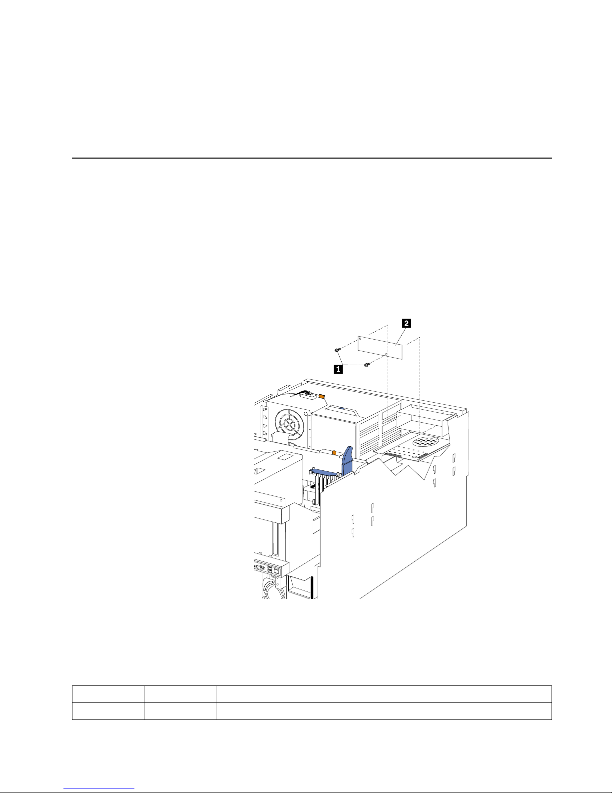
Diagnostics 27
Diagno st ic er ror mess ag e tab le s
For descriptions of the error messages that might appear when you run the diagnostic
programs, see “Diagnost ic error codes” on page 220. If diagnostic error messages
appear that are not listed in those tables, make sure that the server has the latest levels
of BIOS, Advance d System Managemen t P rocessor, ServeRAID, and diagnostics
microcode installed.
Light path diagnostics
The serv e r has LEDs to help you identify problems wit h some server components.
These LEDs are part of the light path diagnostics built into the server. By following
the path of lights you can quickly identify the type of system error that occurred.
Power supply LEDs
The AC and DC power LEDs on the power supply provide status information about
the power supply. See “Installing a hot-swap power supply” on page 76 for the
location of these LEDs. See “Power checkout” on page 31 for more information on
power problems.
1 AC power light
2 DC power light
The following table describes the AC and DC power LEDs.
AC power LED DC power LED Description and act ion
On On The power supply is on and operating correctly.
S
M
I
N
M
I
P
C
I
A
P
C
I
B
P
S
3
P
S
4
S
P
OV
E
R
S
P
E
C
M
E
M
N
O
N
R
E
D
FA
N
T
E
M
P
V
R
M
C
P
U
DA
S
D
1
P
S
2
P
S
1
P
C
I
C
Page 38

28 Hardware Maintenance Manual: Netfinity 7600 – Type 8665 Models 1RY, 2RY
Diagnostic panel LEDs
The following illustration shows the LEDs on the diagnostics panel inside the server.
See Table 1 on page 30 for information on identifying problems using these LEDs.
On Off There is a dc power problem.
Possible causes:
1. The server is not turned on (the power LED is blinking on the front of the
server).
Action: Press the power-control button to start the server.
2. The power supply has failed.
Action: Replace the power supply.
Off Off There is an ac power problem.
Possible causes:
1. There is no ac power to the power supply.
Actions: Verify that:
• The electrical cord is properly connected to the server.
• The electrical outlet functions properly.
2. The power supply has failed.
Action: Replace the power supply.
AC power LED DC power LED Description and act ion
Page 39
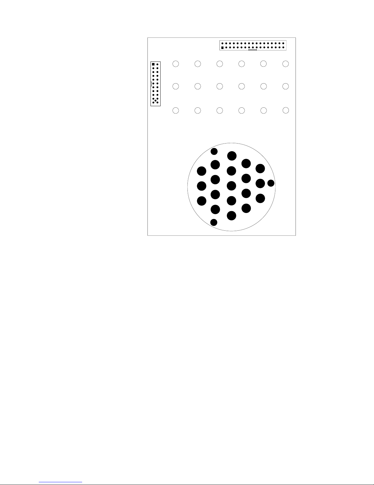
Diagnostics 29
Light path diagnostics
You can use the light path diagnostics built into the server to quickly identify the type
of system error that occurred. Your server is designed so that LEDs remain
illuminated when the server shuts down, as long as the power supplies are operating
properly. This feature helps you to isolate the problem if an error causes the server to
shut down.
If the system error LED (on the information LED panel) is not lit and no diagnostics
panel LEDs are lit, it means that the light path diagnostics have not detected a system
error.
If the system error LED (on the information LED panel) is lit, it means that a system
error was detected. Check to see which of the LEDs on the diagnostics panel inside
the server are lit and refer to the following table:
SMI
NMI
PCIA PCIB
PS3
PS4
SP
OVER
SPEC
MEM
NON
RED
FAN TEMPVRM
CPU
DASD1
PS2
PS1
PCIC
Page 40

30 Hardware Maintenance Manual: Netfinity 7600 – Type 8665 Models 1RY, 2RY
Table 1. Light path diagnostics.
LED Cause Action
None The system error log is 75% or more full; a PFA alert was logged; or a failure occurred
on the I 2C bus.
Check the system error log and correct any problems. See “Cho ice s a v ailab le from the Co nf igura tion/S etu p
main menu” on pag e 44 for information about clearing the error log. Disconnecting the server from a ll power
sources for at least 20 seconds will turn off the system error LED.
SMI A systems management event occurred. Restart the server.
NMI A nonmaskable interrupt occurred. The PCIA, PCIB, or PCIC LED will probably also
be on.
1. If the PCIA, PCIB, or PCIC LED is not on, restart the server.
If the problem persists, tr y to determ ine the failing adapter by removing o ne adapter at a time and restarting the
server after eac h ad apter is re m ov ed.
SP The service processor has failed. 1. Run service processor diagnostics.
2. Repl ace Legacy I/O board.
PCIA A n error occurre d on PCI bus A. An adapte r in PCI slot 1 or 2, or the processo r board
caused the error.
1. Check the error log for additional information.
2. If you cannot corr ect th e problem from the informatio n in the error log, try to determ ine the failing
adapter by r emoving one ad apter at a tim e from PCI bus A (PCI sl o ts 1–2) and restarting the serv er after
each ada pter i s rem oved.
PCIB An error occurred on PCI bus B. An adapter in PCI slot 3, 4, 5, or 6 or the processor
board caused the error.
1. Check the error log for additional information.
2. If you cannot corr ect th e problem from the informatio n in the error log, try to determ ine the failing
adapter b y removing one ad apter at a time from PCI bus B (PCI slots 3–6) an d res tart i n g the ser ve r after
each ada pter i s rem oved.
PCIC An error occurred on PCI bus C. An error on the processor or I/O board caused the
problem.
Check the error log for add ition al i nform ation. If the error log indicates a proble m wi th the integ ra te d SC S I
controller, the Ethernet controller or video controller, see “Starting the diagnostic programs” on page 25.
DASD A hot-swap hard disk drive has failed on SCSI channel B. 1. If the TEMP LED is also on, take the actions listed for that LED.
2. If the amber status LED on one of the hot-swap hard disk drives is on, replace the drive.
MEM A me m ory er ror o cc urred. 1. C heck th e DIM M erro r LE Ds on th e me m or y board.
2. Replace the DIMM indicated by the l it DIMM error LEDs.
CPU One of the microprocessors has failed or a microprocessor is installed in the wrong
connector.
1. Ch e c k th e m ic roproce s s or e rro r LEDs on the memo ry board. If a m icroproce s s or error LED is o n fo r a
microp roc essor co n n e c to r that h as a te rm inato r c ard instal led in s te a d of a micro p rocesso r, the
microprocessors are not installed in the correct order. See “Installing a microprocessor kit” on page 73
for inf orm at io n abou t th e cor re ct order for ins ta llin g m i cropr oc e s s ors and VRMs . Otherw ise, co n tinue
with the next step.
2. Turn off the s e rv er, reseat the mic roproce s so r indicat ed by the lit m icropro ce s s or error LE D, a n d re s ta rt
the server.
3. If the problem persi sts, replace the microprocess or.
VRM One of the voltage regulator modules on the processor board has failed. 1. Check the VRM error LEDs on the processor board.
2. Turn off t he s e rv e r, reseat th e VRM i nd ic ated by the l it VRM erro r LED, an d restart the s e rv er.
3. If the problem pe rsi sts , replace the VRM .
FAN O ne of the fan assemblies has failed or is operating too slowly.
Note: A failing fan can also cause the TEMP and DASD LEDs to be on.
The LED on the failing fan assembly will be lit. Replace the fan assembly.
TEMP The system temperature has exceeded the maximum rating. 1. Check to see if a fan has failed. If it has, replace the fan.
2. Make sure the room tempe r atur e is not too high. (See “Features and specifications” on page 3.)
If the problem persists, see “Temperature checkout” on page 31.
NON RED Server drawing too much power to operate in a redundant power mode. System can continue to operate in a nonredundant power mode. To operate in a red undant m ode , add a power
supply or remove most recently installed options.
OVER SPEC The server is drawing more power than the power supplies are rated for. Either add a power supply or remove a device from the serv er.
PS1 The first power supply has failed. Replace the first power supply.
PS2 The second power supply has failed. Replace the second power supply.
PS3 T h e third p o w er sup p ly has f a iled. Repl a ce the thi rd pow e r s u p p ly.
Page 41

Diagnostics 31
Power checkout
Power problems can b e difficu lt to trou bleshoot. For instance, a short circui t can exist
anywhere on any of the power distributio n busses. Usually a short circuit will cause
the power su b s ystem to shut d own because of an overcurrent condition.
A general procedure for troubleshooting power problems is as follows:
1. Power off the s y ste m and disconnect the AC cord(s).
2. Check for loose cables in the power subsystem. Also check for short circuits, for
instance if there is a loose screw causing a short circuit on a circuit board.
3. Remove adapters and disconnect the cables and pow er co nnectors to all internal
and external devices until system is at minimum configuration required for
power on (see "Minimum operating requirements" on page 225).
4. Reconnect the AC cord and power on the system. If the system powers up
successfully, replace adapters and devices one at a time until the problem is
isolated. If system does not power up from minimal configuration, replace FRUs
of minimal configuration one at a time until the problem is isolated.
To use this method it is important to know the minimum configuration required for a
system to power up (see page 225). For specific problems, see “Power erro r
messages” on page 237.
Temperature checkout
Proper cooling of the system is important for proper operation and system reliability.
For a typical Netfinity server, you should make sure:
• Each of the drive bays has either a drive or a filler panel installed
• Each of the power supply bays has either a power supply or a filler panel installed
• The top cover is in place during normal operation
• There is at l east 50 mm (2 inches) of ventilated space at the sides of t he se rv er and
100 mm (4 inches) at the rear of the server
• The top cover is removed for no longer than 30 minutes while the server is
operating
• The processor housing cover covering the proc essor and memory area is r emoved
for no longer that ten minutes while the server is operating
• A removed hot-swap drive is replaced within two minutes of removal
• Cables for optional adapters are routed according to the instructions provided
with the adapters (ensure that cables are not restricting air flow)
• The fans are operati ng correctly and the air flow is good
• A failed fan is replaced within 48 hours
In addition, ensure that the environmental specifications for the system are met. See
“Features and specifications” on page 3.
For more information on specific temperature error messages, see “Temperature err or
messages” on page 236.
PS4 The fourth power supply ha s failed. Replace the fourth power supply.
Table 1. Light path diagnostics.
LED Cause Action
Page 42

32 Hardware Maintenance Manual: Netfinity 7600 – Type 8665 Models 1RY, 2RY
Recovering BIOS
If the BIOS code in the server has become corrupted, such as from a power failure
during a flash update, you can recover the BIOS using the recovery boot block and a
BIOS flash diskette.
Note: You can obtain a BIOS flash diskette from one of the following sources:
• Use the ServerGuide program to make a BIOS flash diskette.
• Download a BIOS flash diskette from the World Wide Web. Go to
http://www.pc. ibm.com/support/, select IBM Server Supp o rt, and make
the selections for the server .
The flash memory of the se rver consis ts of a pri mary page and a backup page. The J56
jumper controls which page is used to start th e server. If the BIOS in the primary page
is corrupted, you can use the backup page to start the server; then boot the BIOS Flash
Diskette to restore the BIOS to the primary page.
To recover the BIOS:
1. Tur n off the server and peripheral devices and disconnect all external cables and
power cords; then, remove the cover.
2. Locate jumper J56 on the processor board (see “Pro cessor board jumpers” on page
57).
3. Move J56 to pins 1 and 2 to enable secondary boot block page.
4. Insert the BIOS flash diskette into the diskette drive.
5. Restart the server.
6. The system begins the power-on self-test (POST). Select 1 – Update POST/BIOS
from the menu that contains various flash (update) options.
7. When you are asked if you would like to move the current POST/BIOS image to
the backup ROM location, type N.
Attention: Typing Y will copy the corrupted BIOS into the seconda ry page.
8. When you are asked if you would like to save the current code to a diskette, select
N.
9. You will be asked to choose which language you wish to use. Select your
language (0-7) and press Enter to accept your choice. You will be prompted to
remove the diskette and press Enter to restart the system. Remove the flash
diskette from the diskette drive.
Attention: Do not press Enter to reboot the system at this time.
10. Power-off the server.
1 1. Move jumper J56 back to pins 2 and 3 to return to normal startup mode.
12. Restart the server. The system should start up normally.
Replacing the battery
IBM has designed th is prod u ct with yo u r safety i n mind. The lithi u m b attery m ust be
handled correctly to avoid possible danger. If you replace the battery, you must
adhere to the following instructions.
CAUTION:
When replacing the battery, use only IBM Part Number 33F8354 or an equivalent
type battery recommended by the manufacturer. If your system has a module
containing a lithium battery, replace it only with the same module type made by
Page 43

Diagnostics 33
the same manufacturer. The battery contains lithium and can explode if not
properly used, handled, or disposed of.
Do not:
• Throw or immerse into water
• Heat to more than 100°C (212°F)
• Repair or disassemble
Dispose of the battery as required by local ordinances or regulations.
Note: In the U. S., call 1-800-IBM-4333 for information about battery disposal.
If you replace the original lithium battery with a heavy-metal batter y or a battery with
heavy-metal components, be aware of the following environmental consideration.
Batteries and accumulators that contain heavy metals must not be disposed of with
normal domestic waste. They will be taken back free of charge by the manufacturer,
distributor, or representative, to be recycled or disposed of in a proper manner.
Note: After you replace the battery, you must reconfigure your server and reset the
system date a nd time.
To replace the battery:
1. Read the information in “Before you begin” on page 60.
2. Follow any special handling and installation instructions supplied with the
battery.
3. Turn off the ser ver and all attached devi ces and disconnect al l external cables and
power cords (see “Safety information” on page 249); then remove the top cover.
4. Locate the battery on the processor board (see “Processor bo ard component
locations” on page 55).
5. Remove adapters as necessary so you can access th e battery. (See “Working with
adapters” on page 63.)
6. Lift and remove the plastic dividers by pres sin g the latches on the top ends of the
dividers toward the dividers and lifting the dividers from the server.
7. Remove the batte ry :
a. Use one finger to lift the battery clip over the battery.
b. Use one finger to slightly slide the battery toward the rear of the server. The
spring mechanism behind the battery will push it out toward you as you slide
it forward.
c. Use your thumb and index finger to pull the battery from under the battery
clip.
d. Ensure that the battery clip is touching the base of the battery socket by
pressing gently on the clip.
8. Insert the new battery:
Page 44

34 Hardware Maintenance Manual: Netfinity 7600 – Type 8665 Models 1RY, 2RY
a. Tilt the battery so that you can insert it into the front of the socket, under the
battery clip.
b. As you slide it under the battery clip, press the battery down into the socket.
9. Reinstall any adapter s th at y ou removed.
10. Insert the plastic dividers into the divider guides.
11. Reins ta l l th e to p co ve r.
Note: You must wait approximately 20 seconds after you plug the power cord of
your server into an electrical outlet before the power control button
becomes active.
12. Start the Configuration/Setup Utility program and set configuration parameters
as needed. Refer to “Using the Configuration/Setup Utility program” on page 43.
Diagnosing errors
To find solutions to problems that have definite symptoms, see “Error sympt o ms ” on
page 225.
If you cannot find the problem there, go to “Starting the diagnost ic programs” on
page 25 to test the se rver.
If you ha ve jus t ad de d new soft ware or a n ew opt ion and the se rver i s not wo rkin g, d o
the following before using the error symptoms table:
• Remove the software or dev ice that you just added.
• Run the diagnostic tests to determine if the serve r is running correctly.
• Reinstall the new softwa re or new device.
Troubleshooting the Ethernet controller
This section provides troubleshooting information for problems that might occur with
the 10/100 Mbps Ethernet controller.
Network connection problems
If the Ethernet cont roller cannot connec t to the network, check the following:
• Make sure that the cable is installed correctly.
The network cable must be sec urely att a ched at all connections. If the cable is
attached but the problem persists, try a different cable.
If you set the Ethernet contr oll er to operate at 100 Mbps, you must use Cate gory 5
cabling.
Page 45

Diagnostics 35
If you directly connect two workstations (without a hub), or if you are not using a
hub with X ports, use a crossover cable.
Note: To determine whether a hub has an X port, check the port label. If the label
contains an X, the hub has an X port.
• Determine if the hub supports auto-negotiation. If not, try configuring the
integrated Ethernet controller manually to match the speed and duplex mode of
the hub.
• Check the Ethernet controller lights on the operator information panel.
These lights indicate whether a problem exists with the connector, cable, or hub.
— The Ethernet Link Status light illuminates when the Ethernet controller
receives a LINK pulse from the hub. If the light is off, there might be a
defective connector or cable, or a problem with the hub.
— The Ethernet Transmit/Receive Activity light illum inat e s when the Ethe rnet
controller sends or receives data over the Ethernet Network. If the Ethernet
Transmit/Receive Activity light is off, make sur e that the hub and network
are operating and that the correct device drivers are loaded.
— The Ethernet Speed 100 Mbps light illuminates when the Ethernet controller
LAN speed is 100 Mbps.
• Make sure that you are using the correct device drivers, supplied with the server.
• Check for operating system-specific causes for the problem.
• Make sure that the device drivers on the client and server are using the same
protocol.
• Test the Ethernet controller.
How you test the Ethernet controll er depends on which operating system you are
using (see the Ethernet controller device driver README file).
Ethernet controller troubleshooting chart
You can use the following troubleshooting chart to fi nd sol u ti ons to 10/100 Mbps
Ethernet controller problems that have definite symptoms.
Table 2. Ethernet troubleshooting chart.
Ethernet controller problem Suggested Action
The server stops running
when loading device drivers.
The PCI BIOS interrupt settings are incorrect.
Check the following:
• Determine if the interrupt (IRQ) setting assigned to the Ethernet controller is also
assigned to another device in the Configuration/Setup Utility program.
Although interrupt sharing is allowed for PCI devices, some devices do not
function well when they share an interrupt with a dissimilar PCI device. Try
changing the IRQ assigned to the Ethernet controller or the other device. For
example, for NetWare Versions 3 and 4 it is recommended that disk controllers not
share interrupts with LAN controllers.
• Make sure that you are using the most recent device driver available from the
World Wide Web.
• Run the network diagnostic program.
Page 46

36 Hardware Maintenance Manual: Netfinity 7600 – Type 8665 Models 1RY, 2RY
Ether net controller m essages
The integrated Ethernet controller might display messages from the following device
drivers:
Ethernet Link Status light
does not light.
Check the following:
• M a ke sure th at the hub is tu rned on.
• Check all connections at the Ethernet controller and the hub.
• Check the cable. A crossover cable is required u nless the hub has an X designation.
• U se another port on the hub.
• If the hub does not support auto-negotiation, manually configure the Ethernet
controller to match the hub.
• If you manually configured the duplex mode, make sure that you also manually
configure the speed.
• Run diagnostics on the LEDs.
The Ethernet Transmit/
Receive Activity light do es
not light.
Check the following:
Note: The Ethernet Transmit/Receive Activity LED illuminates only when data is
sent to or by this Ethernet controller.
• Make sure that you have loaded the network device drivers.
• The network might be idle. Try sending data from this workstation.
• Run diagnostics on the LEDs.
• T h e fu nc ti o n of thi s LE D can be ch a n ged by de vice driv er lo ad paramete r s. If
necessary, remove any LED parameter settings when you load the device drivers.
Data is incorrect or sporadic. Check the following:
• Make sure tha t you are using Category 5 cabling when operating the server at 100
Mbps.
• Make sure that the cables do not run close to noise-inducing sources like
fluorescent lights.
The Ethernet controller
stopped working when
another adapter was added
to the server.
Check the following:
• Make sure that the cable is connected to the Ethernet controller.
• Make sure that the PCI system BIOS is current.
• Reseat the adapter.
• Determine if the interrupt (IRQ) setting assigned to the Ethernet ada pter is also
assigned to another device in the Configuration/Setup Utility program.
Although interrupt sharing is allowed for PCI devices, some devices do not
function well when they share an interrupt with a dissimilar PCI device. Try
changing the IRQ assigned to the Ethernet adapter or the other device.
The Ethernet controller
stopped work ing without
apparent cause.
Check the following:
• Run diagnostics for the Ethernet controller.
• Try a different connector on the hub.
• Reinstall the device drivers. Refer to the operating-system documentation and to
the ServerGuide information.
Table 2. Ethernet troubleshooting chart.
Ethernet controller problem Suggested Action
Page 47

Diagnostics 37
• Novell™ NetWare™ or IntraNetWare Server ODI
• NDIS Adapter for level 4.0 (Windows NT)
• SCO™ UNIX LLI
Novell NetWare or IntraNetWare server ODI
driver messages
This section provides explanations of the error messages for the Novell NetWare or
IntraNetWare server ODI driver, and suggested actions to resolve each problem.
Table 3. Novell NetWare or IntraNetWare ODI driver messages for the Ethernet controller.
PCNTNW-NW-026 The MSM is unable to parse a required custom keyword.
Explanation: The user entered an incorrect parameter keyword. Action: Reload the driver
using the correct keyword.
PCNTNW-NW-054 The adapter did not respond to the initiali zation command.
Explanation: The adapter did not respond when the driver tried to initialize it. Action:
Verify that the Ethernet controller is enabled. If the Ethernet controller is enabled, go to
“Starting the diagnostic programs” on page 25 to run the diagnostic programs.
PCNTNW-NW-058 The adapter did not respond to the initiali zation command.
Explanation: The interrupt request (IRQ) setting might not be valid or the EEPROM
information might be incorrect. Action: Make sure the IRQ settings are correct in the
Configuration/Setup Utility program. for information on setting the interrupt requests. If
the IRQ settings are correct, go to “Starting the diagno st ic progra m s” on page 25 to run the
diagnostic programs.
PCNTNW-NW-066 The cabl e m ight be disconnected from th e adapter.
Explanation: The cable might be disconnected from the server Ethernet port. Action: Verify
that a cable is connected to the Ethernet port.
PCNTNW-NW-071 The matching virtual adapter could not be found.
Explanation: You tried to load another instance of the driver with a different I/O address.
This new adap ter could not be fou n d. Action: Verify th at you in s talled an IBM Net f in i ty
10/100 Fault Tolerant Adapter and make sure that the adapter is s eated correctly. If the
adapter is seated correctly, go to “Starting the diagnostic programs” on page 25 to run the
diagnostic programs.
PCNTNW-NW-072 A resour ce tag is unavailable.
Explanation: The driver tried to allocate some resources that were not availa ble. Action:
Add more memory, or free some memory resources in the server. Then, restart the server.
PCNTNW-NW-073 Unable to allocate memory
Explanation: The driver failed to allocate the memory needed for normal opera tion. Action:
Add more memory, or free some memory resources in the server. Then, restart the server.
Page 48

38 Hardware Maintenance Manual: Netfinity 7600 – Type 8665 Models 1RY, 2RY
PCNTNW-NW-074 The hard wa re interrupt cannot be se t.
Explanation: An attempt was made to initialize a given hardware interrupt. The attempt was
not successful. Action: Verify that the Ethernet controller is enabled. If the Ethernet
controller is enabled, go to “Starting the diagnosti c programs” on page 25 to run the
diagnostic programs.
If you have an Etherne t ada pt e r i nstalled, make sure that the adapter does not share an IRQ
with any other device.
PCNTNW-NW-075 The Multiple Link Interface Driver (MLID) cannot be register ed w ith the Link Support
Layer (LSL).
Explanation: An error occurred while the driver was trying to register with the LSL. Action:
Check the version of the NetWare or IntraNetWare Operating System. Make sure that this
driver is correct for the version of NetWare or IntraNetWare that you are using. Restart the
server.
PCNTNW-NW-079 The Multiple Link Interface Driver (MLID) did not initialize MSMTx Free Count.
Explanation: The MSMTx Free Count is not initialized correctly. Action: Restart the server. If
the problem per s is ts, go to “Starting the diagnost i c programs” on page 25 to run the
diagnostic programs.
PCNTNW-NW-086 The driver parameter block is too small.
Explanation: The driver parameter block is too small.Action: Restart the server. If the
problem persists, go to “Starting the diagnostic programs” on page 25 to run the diagnostic
programs.
PCNTNW-NW-087 The media parameter block is too small.
Explanation: The driver media parameter block is too small.Action: Restart the server. If the
problem persists, go to “Starting the diagnostic programs” on page 25 to run the diagnostic
programs.
PCNTNW-NW-091 The hardw are configurat i on conflicts.
Explanation: You tried to load a new frame type for the existing controller. The hardware
assumptions made in doing so are incorrect. This error can also occur if you try to specify a
mode (such as, r e dundancy) that con fli cts with another specified mode. Action: Make sure
that your hardware configuration matches the software settings.
PCNTNW-NW-126 The group bit in the node address override was clear ed.
Explanation: The IEEE address has a group bit that indicates that an address belongs to a
group of stations. This bit is used only as a destination address; it cannot be used as a source
address. You tried to enter a source address with this bit set. The driver cleared the group bit
of the source address. Action: None necessary, message is for information only.
PCNTNW-NW-127 The local bit in the node address override was set.
Explanation: The local bit in the IEEE address format indicates that the addresses are being
managed locally. If you use the node address override capabilities of this driver to enter a
new address, the local bit must be set. You entered an address without the local bit set. The
driver has set the local bit. Action: None necessary, message is for information only.
PCNTNW-NW-164 The dev i ce was not fou nd.
Explanation: The driver cannot find an Ethernet controller in the server. Action: Verify that
the Ethernet controller is enabled. If the Ethernet controller is enabled, go to “Starting the
diagnostic programs” on page 25 to run the diagnostic programs.
Table 3. Novell NetWare or IntraNetWare ODI driver messages for the Ethernet controller.
Page 49

Diagnostics 39
NDIS 4.0 (Windows NT) driver messages
This section contains the error messages for the NDIS 4.0 drivers. The explanation
and recommended action are included with each message.
UNIX messages
This section provides descriptions of the Ethernet error messages for the SCO UNIX
LLI driver, and suggested actions to resolve each problem.
PCNTNW-NW-165 The device was not found at IOADDRESS.
Explanation: The Ethernet controller cannot be found at th e I/O address
specified.Action:The Ethernet contr oller does not require a parameter for the I/O address.
Remove the I/O address parameter.
PCNTNW-NW-167 PCI scan specified, device not found.
Explanation: The driver cannot locate the Ethernet controller on the PCI bus. Action: Verify
that the Ethernet controller is enabled. If the pro blem per sist s, go to “Starti ng th e diagnos t ic
programs” on page 25 to run the diagnostic programs.
PCNTNW-NW-180 The DMA parameter is not necessary for PCI device.
Explanation: The Ethernet controller does not require a DMA setting.Action: None
necessary, message is for information only.
Table 4. NDIS (Windows NT) driver messages for the Ethernet controller.
PermaNet™ Server: No Secondary Adapter Found. Groupi ng Mode is disabled.
Explanation: The failover option requires an adapter that is compatible with the device
driver of the Ethernet controller on the system board. No such adapter was found.
Action: Make sure the correct adapter is installed.
PermaNet Server: Problem Occurs on the Primary Adapter. Switching over to the Secondary Adapter.
Explanation: The syst em detected a pro blem with the primary Ethernet connec tion and
has transferred al l network traffi c to the secondary Ethernet cont roller. Action:
Identify the cause of the failure on the primary Ethernet connection. Restoring the
operational state of the primary connection will cause the network traffic to
automati ca l ly tran sf er to th e prim a ry Ethe rnet co n trolle r.
PermaNet Server: Switching back to Primary Adapter.
Explanation: The primary Ethernet connection is now operating corr ectly. Network
traffic will automatically transfer to the primary Ethernet controller. Action: None
needed, message is for information only.
Table 3. Novell NetWare or IntraNetWare ODI driver messages for the Ethernet controller.
Page 50

40 Hardware Maintenance Manual: Netfinity 7600 – Type 8665 Models 1RY, 2RY
Table 5. UNIX LLI driver messages for the Ethernet controller.
pnt0-2 PCI search specified, PCI device not found!
Explanation: The driver cannot locate the Ethernet controller on the PCI bus. Action:
• Run the NETCONFIG program to search for another Ethernet controller
• Verify that the Ethernet controller is enabled. If the Ethernet controller is enabled, run the
diagnostic programs.
pnt0-6 Cannot allocate memory for the adapter dur ing an interrupt. Please check the Streams
parameters.
Explanation: On a SunSoft Solaris system, thi s message indicates that the system is out of
Streams memory blocks. Action: Use the CRASH utility to increase the number of Streams
memory blocks. Modify the interrupt request (IRQ) settings in the Configuration/Setup Utility
program, or run the NETCONFIG program to match the hardware settings.
pnt0-7 Cannot allocate memory for the adapter dur ing reset. Please chec k the Streams parameters.
Explanation: The system is out of Streams memory blocks. Action: Use the CRASH utility to
increase the number of Streams memory blocks.
pnt0-11 Device not found!
Explanation: The driv e r canno t fi nd an Ether n e t control l er. Action: Verify that the Ethernet
controller is enabled. If the Ethernet controller is enabled, run the diagnostic programs.
pnt0-12 Device failed checksum test!
Explanation: The driv e r canno t fi nd an Ether n e t control l er. Action: Verify that the Ethernet
controller is enabled. If the Ethernet controller is enabled, run the diagnostic programs.
pnt0-13 add_intr_handler failed! Interrupts already enabled.
Explanation: The interrupt request (IRQ) that was sp ecif ied, or the IRQ that was found, conflicts
with other devices in the server. Action: Modify the hardware settings.
pnt0-14 Cannot locate hardware.
Explanation: The SunSoft Solaris driver cannot fin d any Ethernet cont roller. Action: Verify
that the Ethernet controller is enabled. If the Ethernet controller is enabled, run the diagnostic
programs.
pnt0-15 No more devices to open.
Explanation: The SunSoft Solaris driver cannot fin d any more Et hernet co nt rollers. Action:
Verify that additional IBM Netfinity 10/100 Fault Tolerant Adapters are present or replace the
Ethernet adapter that fails to r espond. If the problem persists, run the diagnost ic pr ograms.
pnt0-17 Device fault...Reset initiated!
Explanation: The SunSoft Solaris driver has been reset due to a device fault. Action: Verify that
additional IBM Netfinity 10/100 Fault Tolerant Adapters are present or replace the Ethernet
adapter that fails to respond. If the problem persists, run the diagnostic programs.
pnt0-19 IRQ found for PCnet hardware does not match space.c (or pnt.conf)!
Explanation: This is a warning message referri ng to th e interru pt reques t (IR Q) that the Sun So ft
Solaris driver found in the system. Action: Ignore this message if you are sure that this is what
you want to do. Otherwise, run the NETCONFIG program to match the hardware settings
Page 51

Diagnostics 41
pnt0-20 add_intr_handle r fai led! Unknown interrupt type.
Explanation: The interrupt request (IRQ) that was sp ecif ied, or the IRQ that was found, conflicts
with other devices in the server. Action:
• Modify the hardware settings.
• Run the NETCONFIG program to search for another Ethernet controller.
pnt0-21 add_intr_handler failed! Out of range interrupt number.
Explanation: The interrupt request (IRQ) that was sp ecif ied, or the IRQ that was found, conflicts
with other devices in the server. Action:
• Modify the hardware settings.
• Run the NETCONFIG program to search for another Ethernet controller.
pnt0-22 add_intr_handler failed! Out of range IPL.
Explanation: The interrupt request (IRQ) that was sp ecif ied, or the IRQ that was found, conflicts
with other devices in the server. Action: Modify the hardware settings. Run the NETCONFIG
program to search for another Et hernet controller.
pnt0-23 add_intr_handler failed! Vector already occupied.
Explanation: The interrupt request (IRQ) that was sp ecif ied, or the IRQ that was found, conflicts
with other devices in the server. Action: Modify the hardw are setti ngs.
pnt0-24 add_intr_handler failed! Vector already shared at different IPL.
Explanation: The interrupt request (IRQ) that was sp ecif ied, or the IRQ that was found, conflicts
with other devices in the server. Action:
• Modify the hardware settings.
• Run the NETCONFIG program to search for another Ethernet controller.
pnt0-26 The DMA number is not necessary for PCI device.
Explanation: The IBM Netfinity 10/100 Fault Tolerant Adapter does not require a DMA setting.
Action: Edit the SPACE.C file to delete the DMA parameter.
pnt0-29 The IRQ number is already in use.
Explanation: The specified I/O address is already in use. Action: Run the NETCONFIG
program to modify the hardware settings.
pnt0-31 I/O address is not necessary for the PCI device.
Explanation: The I/O address specified is not required. Action: Remove the assigned I/O
address specified for the Ethernet controller.
Table 5. UNIX LLI driver messages for the Ethernet controller.
Page 52

42 Hardware Maintenance Manual: Netfinity 7600 – Type 8665 Models 1RY, 2RY
Page 53

© Copyright IBM Corp. 1999, 2000 43
Configuring the server
The following configuration programs ar e pro vided with the server:
• Configuration/Setup Utility
This program is part of the basic input/output system (BIOS) code that comes with
the server. You can use this program to configure serial and parallel port
assignments, change interrupt request (IRQ) settings, change the drive startup
sequence, set the date and time, and set passwords. See “Using the
Configuration/ Se tup Ut ility program ” for more information.
• SCSISelect Utility
With the built-in SCSISelect Utility program, you can configure the devices
attached to the integrated SCSI controller. See “Us ing the SCSI Sele ct utili ty
program” on page 49 for more information.
• ServeRAID programs
The ServeRAID programs come with the optional ServeRAID adapters and with
server models that have a ServeRAID adapter preinstalled. If the server has a
ServeRAID adapter installed, you must use the ServeRAID Configuration
program to define and configure the disk-array subsystem before you ins tall th e
operating sy stem. See “Chapter . Installing and configuring ServeRAID
controllers,” on page 139 for more detailed information.
• ServerGuide CDs
The ServerGuide CDs include softw are setup a nd ins talla ti on to ols spec if ically
designed for IBM Netfinity servers. You can use these CDs during the initial
installation of the server to configure the server hardware and simplify the
network oper ating system inst allation. The ServerGuide CDs also contai n a
collection of application programs, which you can install after the server is up and
running.
Using the Configuration/Setup Utility program
This section provides the instructions needed to start the Configuration/Setup Utility
program and descriptions of the menu choices available.
Starting the Configuration/ Setup Utility program
To start the Configuration/Setup Utility program:
1. Tur n on the server and watch the monitor screen.
2. When the message Press F1 for Configuration/Setup appears, press F1.
Note: If yo u have set both levels of passwords (u se r and administrator), you
must enter the administrator password to access the full
Configuration/Setup menu.
3. Follo w the instructions that appear on the screen.
Page 54

44 Hardware Maintenance Manual: Netfinity 7600 – Type 8665 Models 1RY, 2RY
Choices available from the Configuration/Setup main
menu
From the Configuration/S etup Ut ility main menu, you can select settings that you
want to change. The Configuration/Setup Utility main menu is similar to the
following:
Notes:
1.You can press F1 to display Help information for a selected menu item.
2.The choices on some menus m i ght differ slightly, depending on the BIOS version i n
the server.
Descriptions of the choi ce s available f rom the main menu are as follows:
• System Summary
Select this choice to display configuration information. This includes the type and
speed of the microprocess ors and the amount of memory installed.
Changes that you make to configuration settings appear on this summary screen.
You cannot edit the fields.
This choice appears on both the full and limited Configuration/Setup Utility
menus.
• System Information
Select this choice to display information about the server . Changes that you make
on other menus might appear on this summary screen. Y ou cannot edit any
fields. The System Information choice appears only on the full
Configuration/Setup Utility main menu.
— Product Data
Select this choice to view sys tem informa tio n, such as the mac hine typ e and
model, the server serial number, and the revision level or issue date of the
BIOS stored in the flash electronically erasable programmable ROM
(EEPROM).
— System Card Data
IBM Netfinity Setup - © IBM Corporation 1998
<F1> Help < > < > Move
<Esc> Exit <Enter> Select
↑↓
•
•
•
•
•
•
•
•
System Summary
System Information
Devices and I/O Ports
Date and Time
System Security
Start Options
Advanced Setup
Error Logs
Save Settings
Restore Settings
Load Default Settings
Exit Setup
Configuration/Setup Utility
Page 55

Configuring the server 45
Select this choice to view vital product data (VPD) for some server
components.
• Devices and I/O Port s
Select t his choic e to v ie w or chan ge th e as sig nmen ts fo r de vice s and input /out put
ports. This choice appears only on the full Configuration/Setup Utility main
menu.
• Date and Time
Select this choice to set the system date and ti me and to change the system time
sent to the Advanced System Management Pr ocessor (service pro cessor) w hen the
server is started. This choice appears only on the full Configuration/Setup Utility
main menu.
The system time is in a 24-hour format: hour:minute:second.
You can set a time delta to be added or su b tracted from the system ti me that is
sent to the service processor (Advanced System Management Processor) each
time the server is started. Use the number keys to enter the hours and minutes
and + or − to add or subtract from the system time. If you want the system cl ock
time to be the same as the Advanced System Management Processor clock time,
leave the value set at its default of 0.
• System Security
Select t his ch o ice t o set pass words or a syst em ow ner’s name. This choice appears
only on the full Configuration/Setup Utility main menu.
You can implement two levels of password protection:
— Power-on Password
Select thi s choice to set or ch ange a power-on pa ssword. See “Using
passwords” on page 48 for more info rmation.
— Administrat or Password
Select thi s choice to set or chan ge an administrator password.
Attention:
If an admini strator password is set and the n forgotten, it cannot be
overridden or removed. You must replace the I/O Legacy board.
The administrator passwor d provides access to all choices on the
Configuration/Setup Utility main menu. You can set, change, or delete both
the administrator and power-on passwords, and allow a power-on p assword
to be changed by the user.
See“Using passwords” on page 48 for more information.
— System Owner’s Name
Select this choice to specify a system owner’s name, which will display during
POST. You can remove or change the name only from the System Security
menu. You can use any combination of u p t o 1 6 characters for the system
owner’s name.
• Start Options
Page 56

46 Hardware Maintenance Manual: Netfinity 7600 – Type 8665 Models 1RY, 2RY
Select this choice to view or change the start options. This choice appears only on
the full Configuration/Setup Utility main menu. Start options take effect when
you sta r t the ser ve r.
You can select keyboard operating characteristics, such as the keyboard speed.
You also can specify wh e ther the keyboard number loc k starts on or off. You also
can enable th e se rver to run with out a diskette dri ve, monitor, or keyboard.
The server uses a startup sequence to determine the device from which the
operating system loads. For example, you can define a startup sequence that
checks for a startable diskette in the diskette drive, then checks the hard disk
drive in bay 1, and then checks a network adapter.
You also can select which PCI SCSI adapter is given boot precedence. The first
drive that is attached to the selected adapter will be assigned drive number 80L
and the operating system will st art from that drive. The defaul t f or boot
precedence is Disabled. The range of choices depends upon the number of PCI
SCSI adapters installed in the server.
You can enable a virus-detection test that checks for change s in the master boot
record at startup. You also can choose to run POST in the enhanced mode or the
quick mode.
• Advanced Setup
Select this choice to change values for advanced hardware features, such as cache
control, and PCI configuration. This choice appears only on the full
Configuration/Setup Utility main menu.
A warning message appears above the choices on this menu to alert you that the
system might malfunction if these options are configured incorrectly. Follow the
instructions on the screen carefully.
— Processor Serial Number Access
Select this choice to i de ntify if the micropr ocessor serial number in the
microprocessor is readable.
— Core Chipset Control
Select this choice to modify settings that control features of the core chip set.
Attention: Changes here must only be made by a n IBM au thorized servi ce
representative.
— Cache Control
Select this choice to enable or disable th e microprocessor cache. In addition,
you can define the microprocessor cache type as write-back (WB) or writethrough (WT). Selecting write-back mode will provide the maximum system
performance.
— PCI Slot/Devic e Inf orm at ion
Select this choice to view and identify system resources used by PCI devices.
PCI devices automatically communicate with the server configuration
information. This usually results in automatic configuration of a PCI device.
Page 57

Configuring the server 47
Attention: You must use the menu selections to save custom settings f o r the
PCI Slot/Dev ice Information choice. The save , restore an d load default
settings choices on the main menu of the Conf igu rati on /Se tup Utilit y do not
save the PCI Slot/Device Information settings.
After mak ing changes, select:
– Save and exit the PCI Utility to save the changes and return to the
Advanced Setup choice.
– Exit the PCI Utility without saving changes to ignore the change s,
restore the previous settings, and return to the Advanced Setup choice.
PCI Device Cont rol allows you to enable or disable the integrated SCSI,
video, and Et hernet controllers. You can also enable or disab le PCI slots from
this m en u .
– The default setting is Enable for all the controllers and PCI slots. If you
select Disable, the system will not configure the disabled device and the
operati ng system will not see the device. ( Th is is equivale nt to
unplugging the device.)
– If the on-board SCSI contro lle r is disabled and no ot her controller and
mass storage device are installed, operating system startup cannot occur.
– If the video controller is disabled and no video adapter is installed, the
server will have no video capability. However, turning the server off and
on three ti mes without completing POST resu lts in a default startup that
enables video again .
• Memory Settings
Select this choice to manually disable or enable a bank of memory.
If a memory error is detected during POST or memory configuration, the server
can automatically disable the failing memory bank and continue operating with
redu ced memory cap a city. If this occurs, you must ma nually enable the memory
bank after the problem is corrected. Select Memory Settings from the Advanced
Setup menu, use the arrow keys to highlight the bank that you want to enable;
then, use the arrow keys to select Enable.
• System Service Processor Settings
Select this choice to enable or disable power supply redundancy monitoring.
• Event/Error Logs
Select this choice to view or clear error logs.
— Select Clear error logs to clear the error or event log.
— Select POST Error Log to view the three most recent error codes and
messages that the system generated during POST.
— Select System Eve nt/Er ror Log to view the system event/error log. The
system event/error log contains all the system error and warning messages
that the system has generated. You can use the arrow keys to move between
pages in the system event/error log.
• Save Settings
Select thi s choice to save th e cu stomized settin gs.
• Restore Settings
Page 58

48 Hardware Maintenance Manual: Netfinity 7600 – Type 8665 Models 1RY, 2RY
Select this choice to delete the changes and restore the previous settings.
• Load Default Settings
Select this choice to cancel the changes and restore the factory settings.
• Exit Setup
If you have made any changes, the program will prompt you to save the changes
or exit wit hout saving the chan ges.
Using passwords
The System Security choice appears only on the full Configuration/Setup Utility
menu. After you select this choice, you can implement two levels of protection:
power-on p a ssword and administrator passw ord.
Power-on password
After you set a power-on password, you can enable the unattended-start mode. This
locks the keyboard and mouse, but allows the server to start the operating system.
The keyboard and mouse remain locked until you enter the correct password.
You can use any combination of up to seven characters (A–Z, a–z, and 0–9) for the
power-on password. Keep a record of the password in a secure place. If you forget
the power -on password , y ou can regain access to the server through one of the
following methods:
• If an administrator password is set, enter the administrator password at the
power-on prompt . Start the Configuration/Set u p Uti lity program and change th e
power-on password.
• Change the p osition of the password override switch a s described in “Setting the
password override switch:”.
• Remove the battery and then install the battery.
Setting the password override switch:: When a power-on password is set, POST
does not complete until you enter the password. If you forget the power-on pas sword,
you can reg a in access to the server throu g h either of the f ollowing methods:
• Enter the administrator password at the power-on prompt, if an administrator
password has been set. Start the Configuration/ Setup Utility program and
change the power-on password. See “Power-on password”
• Change the position of the jumper on J48 to bypass t he power- on password check.
You can then start the Configuration/Setup Utility program and change the
power-on password. See “Processor board comp onent locations” on page 55 for
the location of J 48.
Administrator passw ord
Select this choice to set an administrator password. The administrator password
provides access to all choices on the Configuration/Setup Utility main menu. Y ou can
set, change , or delete both the administrator and power-on passwords, and allow a
power-on password to be changed by the user.
Attention: If an administrator password is set and then forgotten, it cannot be
overridden or removed. You must replace the I/O Legacy board.
The following table provides a summary of the password features.
Page 59

Configuring the server 49
Using the SCSIS ele ct ut ilit y prog ram
SCSISelect is a built-in, menu-driven configuration utility program that you can use
to:
• View the default SCSI IDs
• Locate and correct configuration conflicts
• Perform a low-level format on a SCSI hard disk
The following sectio ns provide the inst ructio ns need ed to star t the SCSISe lec t Utility
and descriptions of the menu choices available.
Note: If the server has a RAID adapter installed, use the configuration method
supplied with the RAID adapter to view or change SCSI settings for RAID
attached devices.
Starting the SCSISelect utility program
To start the SCSISelect utility program:
1. Tu rn on the server.
2. When the <<< Press <CTRL><A> for SCSISelect™ Utility! >>> prompt appears,
press Ctrl+A.
Note: If an administrator password has been set, a prom pt appears asking you to
enter the password to start the SCSISelect Utility program.
3. When prompted, select either channel A (external) or channel B (internal).
4. Use the arrow keys to select a choice fro m the menu.
• Press Esc to return to the previous menu.
• Pres s the F5 key to switch between color and monochrome modes (if the
monitor permits).
5. Follow the instructions on the screen to change the settings of the selected items;
then, press Enter.
Table 6. Power-on and administrator password features.
Type of password Results
Power-on password • E n ter the pa ss wor d to com ple te th e syste m sta rtu p.
• All choices are available on the Configuration/Setup Utility main menu.
Administrator password • No password is required to start the system.
• Enter the password to access the Configuration/Setup Utility program.
• All choices are available on the Configuration/Setup Utility main menu.
Administrator and power-on
password
• You can enter either password to complete the system startup .
• The administrator password provides access to all choices on the
Configuration/Setup Utility main menu. You can set, change, or delete both the
administrator and powe r-on passwords, and allow a power-on pa ss w ord to be
changed by the user .
• The power-on password provides ac cess to a limited set of choices on the
Configuration/Setup Utility main menu. This limited access might include
changing or deleting the powe r-on password.
Page 60

50 Hardware Maintenance Manual: Netfinity 7600 – Type 8665 Models 1RY, 2RY
Choices available from the SC SISelect menu
The following choices appear on the SCSISelect Utility menu:
• Configure/View Host Adapter Settings
Select this choice to view or change the SCSI controller settings. To reset the SCSI
controller to its default values, pres s F6; then, follow the instructions that appear
on the screen.
You can view or change the following controller settings:
— Host Adapter SCSI ID
Select this choice to view the SCSI controller ID, normally 7.
— SCSI Pa rity Checking
Select this choice to view the assigned value of Enabled.
— Host Adapter SCSI Termination
Select this choice to view the assigned value of Automatic.
— Boot Device Options
Select this choice to configure startable device parameters. Before you can
make updates, you must know the ID of the device whose parameters you
want to con f igure.
— SCSI Device Configuration
Select this choice to configure SCSI device parameters. Before you can make
updates , you must know the ID of the de vice whose par ameters you want to
configure.
Note: The Maximum Sync Transfer Rat e repr esents t he transfer rat e for Ultra
SCSI devices.
– The transfer rate for Ultra-3 SCSI LVD devices is 160.0
– The transfer rate for Ultra-2 SCSI LVD devices is 80.0
– The transfer rate for Fast SCSI devices is 20.0
— Advanced Configuration Options
Select this choice to view or change the settings for advanced configuration
options. These options include enabling supp ort for large hard disk drives
and support for drives with UltraSCSI speeds.
• SCSI Disk Utilities
Select this choice to view the SCSI IDs that are assigned to each device or to
format a SCSI device.
To use th e utilit y program, selec t a driv e from the list. Read the screens carefully
before making a selection.
Note: If you press Ctrl+A before the selected drives are ready, an Unexpected
SCSI Command Failure screen might appear. Restart the server and watch
the SCSISelect messages as each drive spins up. After the drive that you
want to view or format spins up, press Ctrl+A.
Page 61

Configuring the server 51
• Format Disk
Attention: The Low-Level Format program erases all data and programs.
Select this choice to perform a low-level format on a hard disk drive. Depending
on the hard disk drive capacity, the Low-Level Format program could take up to
two hours.
Use the Low-Level Format program:
— When you are installing software that requires a low-level format
— When you get recurring messages from the diagnostic tests directing you to
run the Low-Level Format program on the hard disk drive
— As a last resort before replacing a failing hard disk drive
Note: If the server has a PCI RAID adapter installed, refer to the RAID adapter
documentation for instructions for performing low-level formats on hard
disk drives at ta ched to th e a dapter.
To start the Low-Level Format program:
1. If the hard disk is working, make a backup copy of all the files and programs
on the hard disk drive. (See the operating system information for
instructions.)
2. Select Format Disk; then, follow the instructions on the screen.
Unexpected SCSI Command Failure
Target SCSI ID: 4
SCSI CDB Sent: 03 00 00 00 0E 00 07 00 02 00
Host Adapter Status: 00h - No host adapter error
Target Status: 02h - Check condition
Sense Key: 02h - Not ready
+Sense Code: 04h
+Sense Code Qualifier: 02h
Press ’Esc’ to continue.
Page 62

52 Hardware Maintenance Manual: Netfinity 7600 – Type 8665 Models 1RY, 2RY
Note: Hard disks normall y contain more tracks than their stated capacit y (to
allow for defective tracks). A message appears on the screen if the
defect limit is reached. If this happens, replace the hard disk drive.
Page 63

© Copyright IBM Corp. 1999, 2000 53
Installing options
This chapter provides instruc tions to help you add optio ns to the server.
Note: The illustrat io ns in this book are similar to the serve r; deta ils might vary.
Major components of the Netfinity 7600
The orange color on comp one nt s and lab els in your ser ver iden tifie s hot -swa p or hotplug components. This means that you can install or remove the components while
the system is running, provided that your system is configured to support this
function. For complete inform ation a bou t installin g or removing a hot-swap or hotplug component, see the information provided in the detailed procedures in this
document.
The blue color on com po nen ts an d lab els ind icat es touch point s w here a compo nen t
can be gripped, a latch moved, and so on.
1 Hot-swap drive
2 Power supply
3 Fan assembly
4 Filler panel
5 Removable-media drive
Page 64
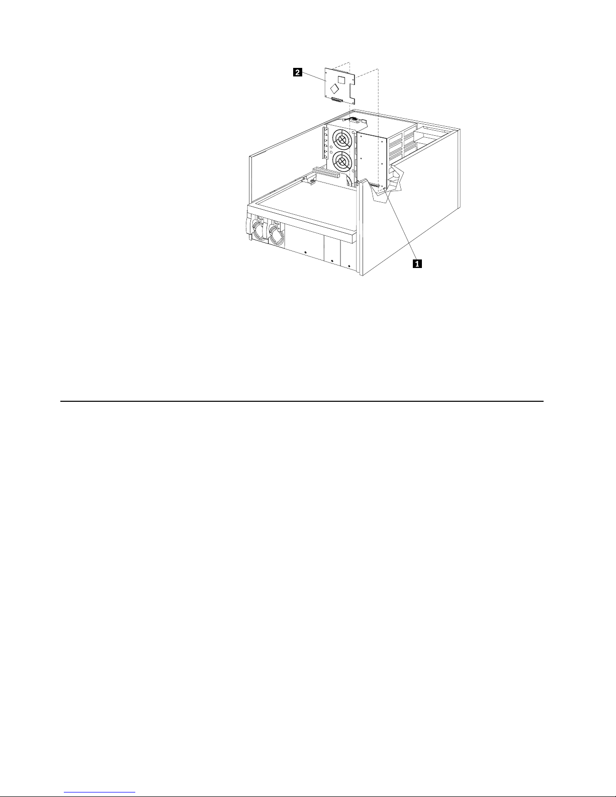
54 Hardware Maintenance Manual: Netfinity 7600 – Type 8665 Models 1RY, 2RY
1 Memory board
2 Memory module
3 Microp rocessor te rminator card
4 Voltage regulator module
5 I/O board
6 Shuttle
Component locations
This section provides illustrations of the I/O board, processor board, and memory
board c omp onent locati ons.
I/O board component locations
The follow ing i llus trati on sh ows the loc atio n of the in put /out put (I /O) con nect or s on
the I/O board.
Note: The illustrations in this document might differ slightly from your hardware.
Page 65
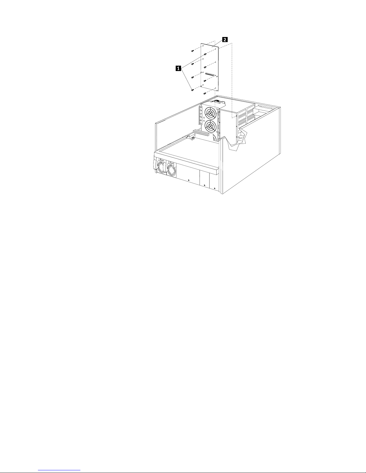
Installing options 55
1 Power backplane connector
2 Processor board connector
3 Ethernet port connector (J14)
4 USB 1 and USB 2 port connectors (J31)
5 Video port connector (J2)
6 Mouse connector (J30)
7 Keyboard connector (J32)
8 SCSI external connector (J21)
9 Parallel port connector (J33)
10 ASM Interconnect connec tor (J10)
11 Serial port B connector (J15)
12 Serial port A connector (J16)
13 Management port connector (J18)
Processor board component locations
The following illustration shows the location of the LEDs, connectors, and jumpers on
the processor board.
Processor board LEDs
The following illustration shows the location of the LEDs.
Page 66
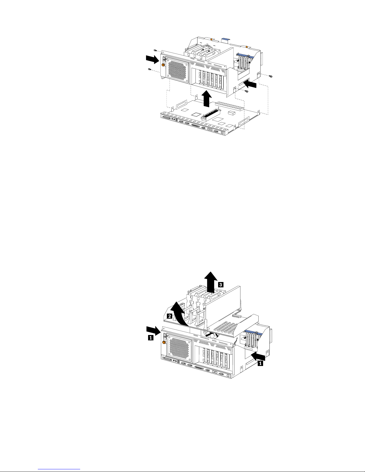
56 Hardware Maintenance Manual: Netfinity 7600 – Type 8665 Models 1RY, 2RY
1 Microp rocessor 1 error LED (CR9)
2 Microp rocessor 2 error LED (CR3)
3 Microp rocessor 3 error LED (CR8)
4 Microp rocessor 4 error LED (CR4)
5 Battery
6 PCI
7 VRM 4 error LED (CR10)
8 VRM 3 error LED (CR5)
9 VRM 2 error LED (CR7)
10 VRM 1 error LED (CR6)
Processor board connectors
The following illustrat io n show s the connectors.
1 Microp rocessor 1 con nector
2 Microp rocessor 2 con nector
3 Microp rocessor 3 con nector
4 Microp rocessor 4 con nector
5 Memory board connector
Page 67
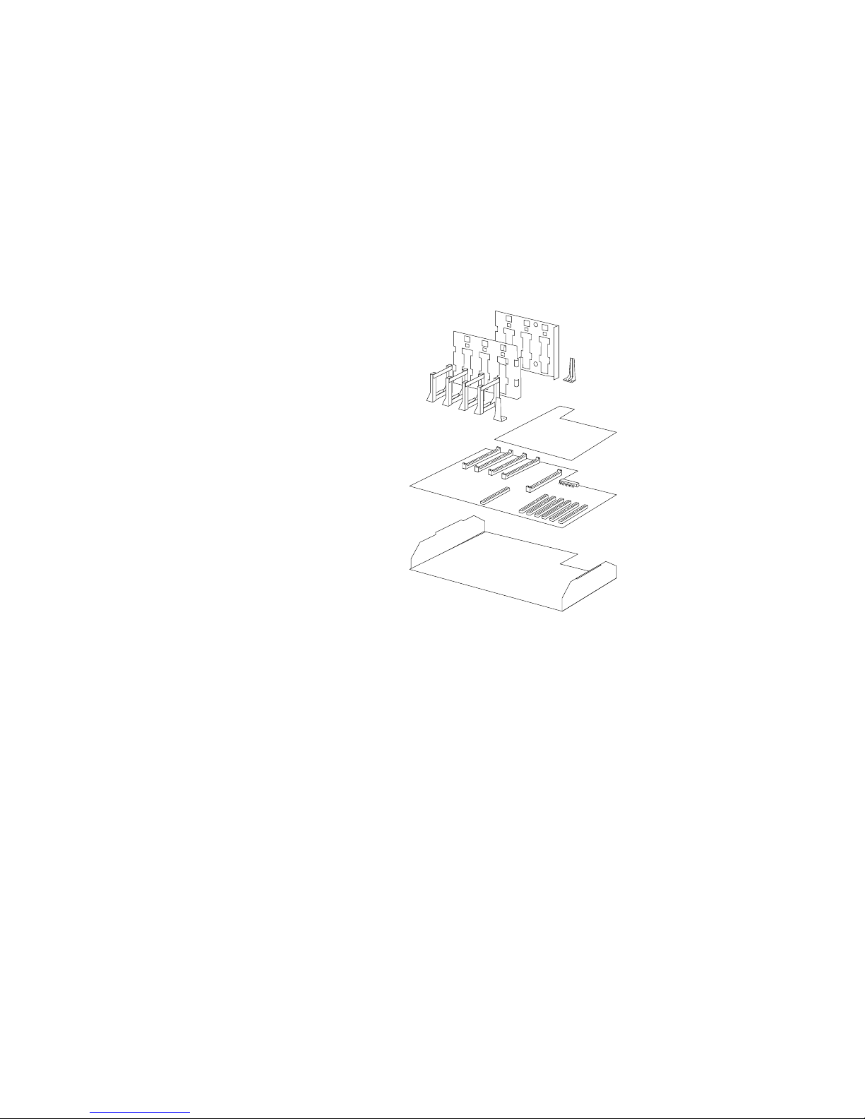
Installing options 57
6 Battery
7 PCI slots 3-6 (on PCI bus B)
8 PCI slots 1-2 (on PCI bus A)
9 VRM 4 connector
10 VRM 3 connector
11 VRM 2 connector
12 VRM 1 connector
Processor board jumpers
The followin g illust rat io n show s the jump er s .
1 Jumper block (J8) (Reserved)
2 Jumper block (J9) (Reserved)
3 Jumper block (J10-J16)
4 Flash ROM page-swap jumper block (J56)
5 Power-on password override jumper block (J48)
6 Battery
7 Power-on control jumper block (J23)
8 3.3 V standby power for slot 2 (J20)
9 3.3 V standby power for slot 1 (J47)
10 Advanced System Management Processor reset jumper block (J59)
Page 68
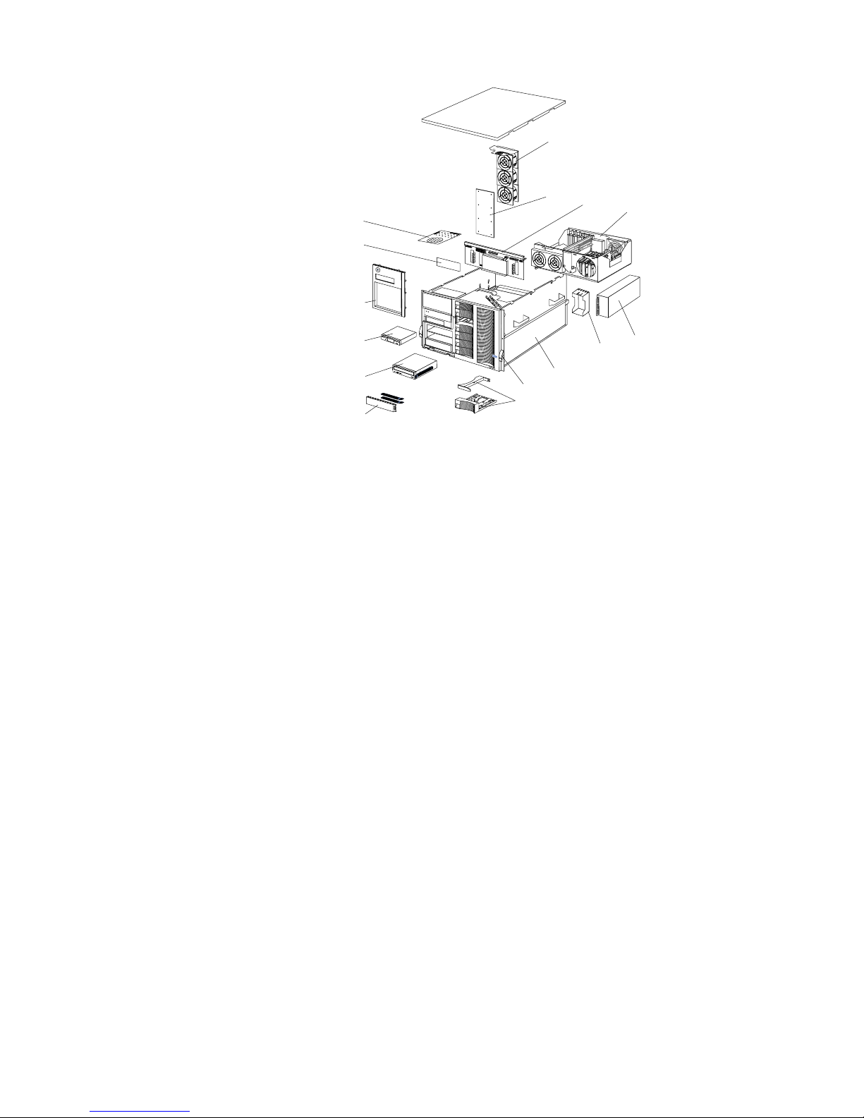
58 Hardware Maintenance Manual: Netfinity 7600 – Type 8665 Models 1RY, 2RY
1 Microp rocessor core-frequency-selection jumper block (J 13-J16)
2 Reserved (J10)
3 Reserved (J12)
4 Reserved (J11)
Memory board component locations
The illustrations in this section show certain locations on the memory board.
Memory board connectors
The follow ing ill ust ra tion shows the locat ion of th e DIMM conn ec tors on the memory
board.
S
M
I
N
M
I
P
C
I
A
P
C
I
B
P
S
3
P
S
4
S
P
OV
E
R
S
P
E
C
M
E
M
N
O
N
R
E
D
FA
N
T
E
M
P
V
R
M
C
P
UDA
S
D
1
P
S
2
P
S
1
P
C
I
C
1
2
3
4
A
5
6
7
8
9
10
11
12
13
14
Page 69
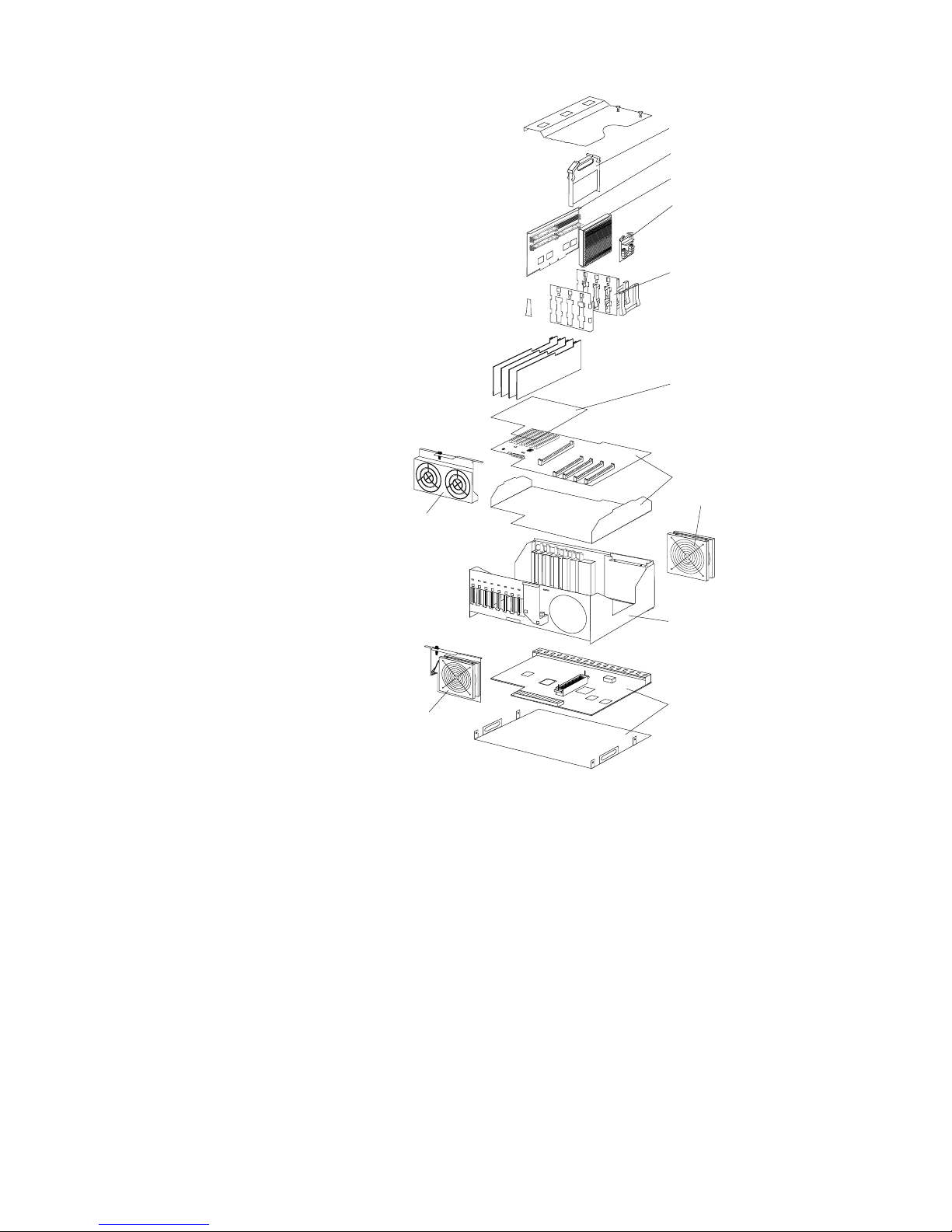
Installing options 59
1 Connector 1 (J1)
2 Connector 2 (J2)
3 Connector 3 (J3)
4 Connector 4 (J4)
5 Connector 5 (J5)
6 Connector 6 (J6)
7 Connector 7 (J7)
8 Connector 8 (J8)
9 Connector 9 (J9)
10 Conne ctor 10 (J10)
11 Connector 11 (J11)
12 Conne ctor 12 (J12)
13 Conne ctor 13 (J13)
1
2
3
4
5
6
7
8
9
10
11
12
Page 70
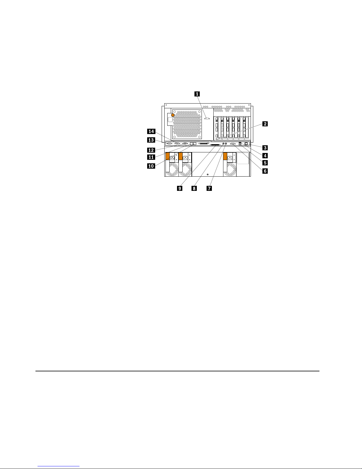
60 Hardware Maintenance Manual: Netfinity 7600 – Type 8665 Models 1RY, 2RY
14 Conne ctor 14 (J14)
15 Conne ctor 15 (J15)
16 Conne ctor 16 (J16)
Memory board LED locations
The following illustration shows the location of the error LEDs on the memory board.
1 DIMM 1 error LED (CR4)
2 DIMM 2 error LED (CR5)
3 DIMM 3 error LED (CR2)
4 DIMM 4 error LED (CR1)
5 DIMM 9 error LED (CR13)
6 DIMM 10 error LED (CR12)
7 DIMM 11 error LED (CR15)
8 DIMM 12 error LED (CR16)
9 DIMM 13 error LED (CR11)
10 DIMM 14 error LED (CR14)
11 DIMM 15 error LED (CR10)
12 DIMM 16error LED (CR9)
13 Processor board connector
14 DIMM 8 error LED (CR8)
15 DIMM 7 error LED (CR7)
16 DIMM 6 error LED (CR3)
17 DIMM 5 error LED (CR6)
Before yo u begin
Before you begin to inst all options in the server, read the following in f ormation:
• Become familiar with the safety and handling guidelines provided in “Safety
information” on page 249, and “Handling electrostatic discharge-sensitive
devices” on page 252. These guidelines will help you work safely while working
with the server or options.
Page 71

Installing options 61
• You do not need to turn off the server to install or replace hot-swap power
supplies, hot-swap drives, hot-swap fans, or hot-plug PCI adapters.
• The orange color on comp o nent s and la bels in the serve r ident ifie s hot-swap or
hot-plug components. This means tha t you can install or remove the component
while the system is running, provided that the system is configured to support
this fu n ct i o n .
• The blue color on components and labels identifies touch points where you can
grip a compon e nt, move a latch, and so on.
• Make sure that you have an adequate number of properly grounded electrical
outlets for the server, monitor, and any other options that you intend to install.
• Back up all important data before you make changes to disk drives.
• For a lis t of su p p o rted op tions fo r the Ne tf inity 7 60 0 , refer to
http://www.ibm.com/pc/us/c ompat on the World Wide Web.
Working inside the server with the power on
The server is designed with features that make it highly available. These features are
hot-add and hot-plug devices. Hot-plug devices allow you to replace the device
without turning off the server. Hot-add devices allow you to add an identical device
without turning off the server. In the past you would need to turn off the server and
disconnect power to perform these operations. With the hot-plug features, you can
remove the top cover of the server with the power on.
The server supports hot plug, hot add, and hot swap devices and is designed to
operate safely while turned on wit h the top cover removed. The server i s d esigne d to
protect you and the server. Follow these guidelines when you work inside a server
that i s turned o n :
• Avoid loose-fittin g clothing on your forearms. Button long-slee ve d shirts before
working inside the server; do not wear cuff links while you are working inside the
server.
• Do not allow your necktie to hang inside the server.
• Remove jewe lry, such as bracelets, necklaces, rings, and loos e -fitting wr ist
watches.
• Remove items from your shirt pocket (such as pens or pencils) that could fall into
the server as you lean over it.
• Take care to avoid dropping any metallic objects, such as paper clips, hair pins, or
screws, i nt o the serv e r.
Removing the server top cover and bezel
Before you begin:
• Read “Safety information” on page 249.
• Review the information in “Before you begin” on page 60.
Page 72
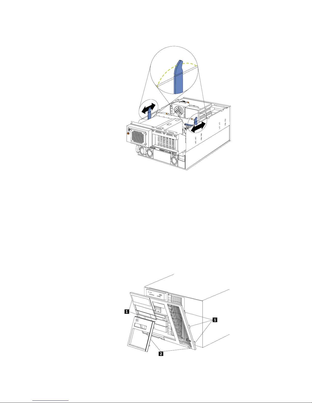
62 Hardware Maintenance Manual: Netfinity 7600 – Type 8665 Models 1RY, 2RY
Removing the top cover
1 Top cover
2 Captive screws
To remove the server top cover:
1. Loosen the two thumbscrews on the back edge of the top cover.
2. Slide the top cover slightly toward the rear of the server. Lift the cover off the
server and set the cover aside.
Attention: For proper cooling and airflow, replace the top cover before turning
on the server. Operating the server for extended periods of time
(over 3 0 m in utes) wit h the to p co ve r remo ved mig h t da m a g e se rv e r
components.
Removing the media-bay bezel
1 Media-bay bezel
Page 73
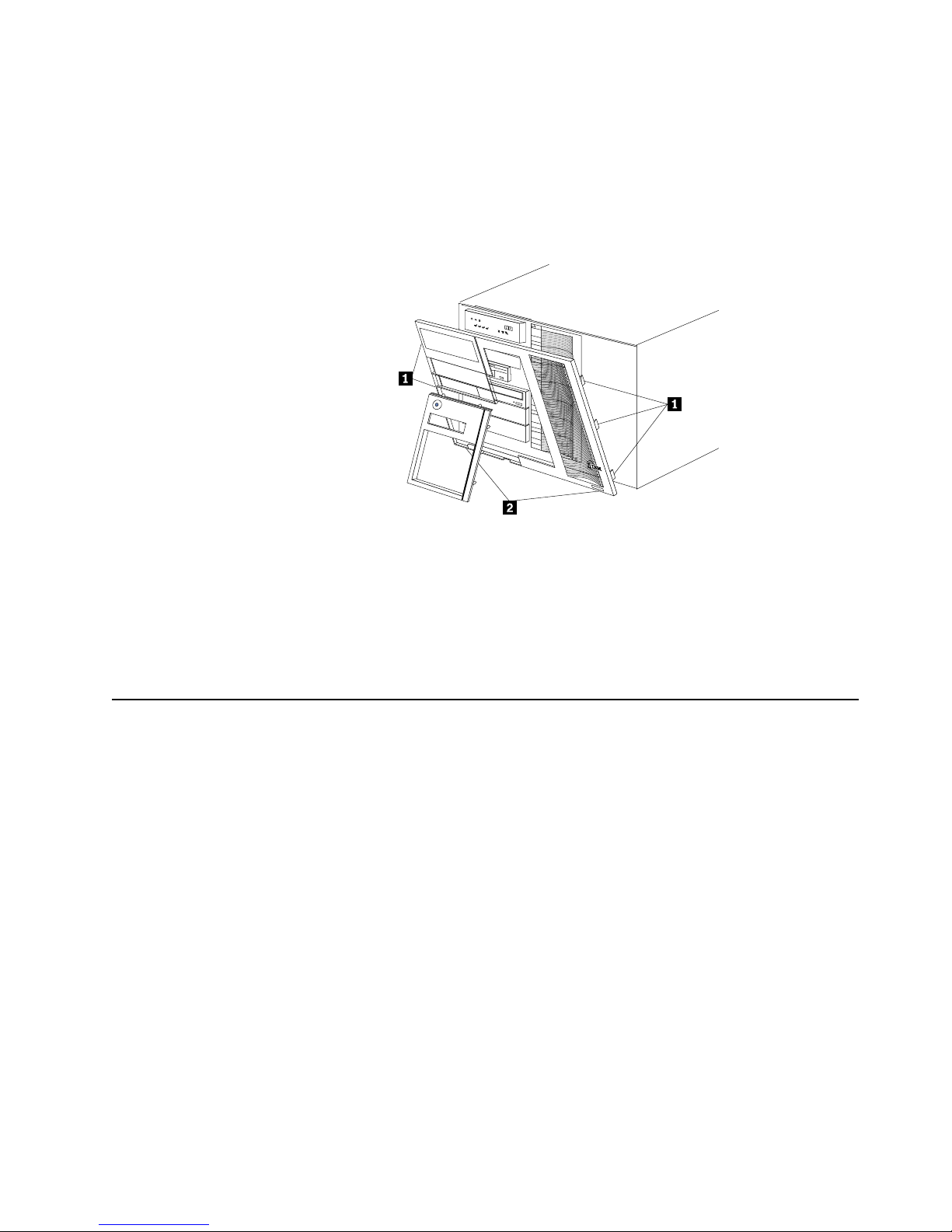
Installing options 63
To remove the media-bay bezel:
1. Release the two tabs at the bottom edge of the media-bay bezel and pull the
bottom of the bezel slightly away from the server.
2. Pull the media- bay b ez el dow n to r e lease t h e two tabs at th e to p edge o f th e beze l.
Store the bezel in a safe place.
Removing the front trim bezel
1 Side tabs
2 Bottom tabs
1. Release the three tabs on the right side of the front trim bezel and release the two
tabs on the l e f t side of th e b e ze l.
2. Gently separate the bezel partly from the server.
3. Release the two bottom tabs on the bezel and lift the bezel away from the server.
Working with adapters
You can install up to six PCI adapters in the expansion connectors on the processor
board. All six of the slots are peripheral component interconnect (PCI) expansion
slots.
The server comes with an integrated super vid e o gr ap hics array (SVGA) video
controller, which is not removable. If you want to disable this controller and use a
video adapter instead, you can install a video adapter in an expansion slot. When you
install a PCI video adapter, the server BIOS automatically disables the integrated
video controller.
Note: Video adapters are supported in all six PCI slots.
The following illustration shows the location of the 64-bit PCI expansion slots on the
processor board.
Note: The illustrations in this book might differ slightly from your hardware.
Page 74

64 Hardware Maintenance Manual: Netfinity 7600 – Type 8665 Models 1RY, 2RY
1 Non-hot-plug PCI slots 1-2 (on PCI bus A) (3.3 volt)
2 Hot-p lu g P CI slots 3-6 ( on P CI bus B)
3 Power LEDs for hot-plug slots
4 Internal Attention LEDs for hot-plug slots
5 External Attention LEDs for hot-plug slots
Adapter considerations
Before you continue wi th the adapter- installation procedure:
• Review the documentation that comes with the adapter and follow those
instructions in addition to the instructions given in thi s chapter. If you need to
change the switch or jumper settings on the adapter, follow the instructions that
come with th e adapter docum e ntation.
• Slots 3 through 6 support 5.0V, 3.3V, and universal PCI adapters.
Note: Universal PCI adapters support both 3.3V and 5.0V operation.
• Slots 1 and 2 support 3.3 V and univers al non-h ot-swap PCI adapters only.
• The server uses a rotational interrupt technique to configure PCI adapters.
Because of this techni que, you can install a variety of PCI adapters that currently
do not support sharing of PCI interrupts.
• The system scans PCI slots 1 through 6 to assign syste m resources; then the
system starts (boots) the PCI devices in the following order: processor board
devices, slo ts 1 and 2, and then slots 3 through 6.
• The performance of the PCI adapters depends on the types of adapters in the
system.
Installing a hot-plug adapter
Refer to the following illustration to install a hot-plug PCI adapter.
Note: The illustrat ions in this book may be slightly different from your server.
Before you begin:
• Read “Safety information” on page 249.
Page 75
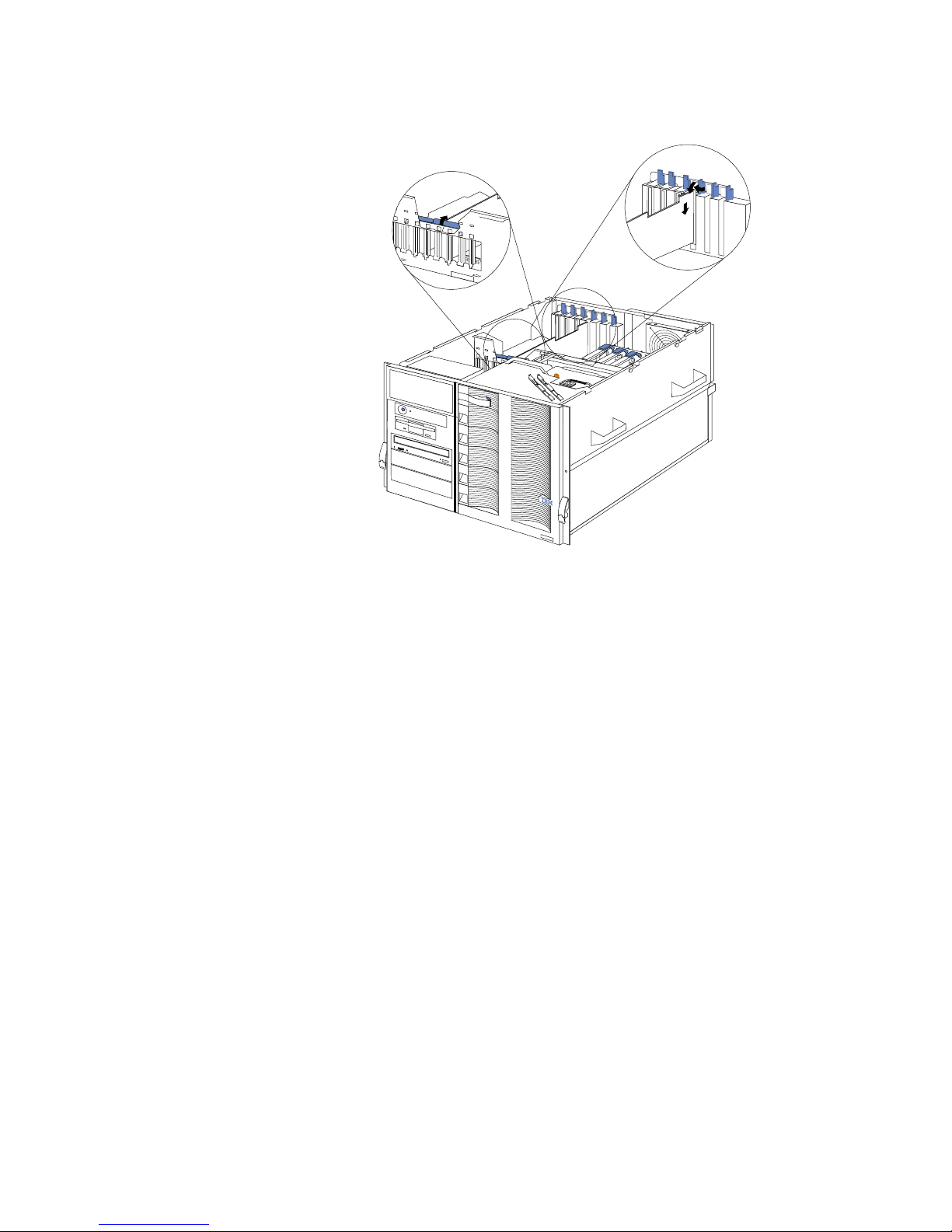
Installing options 65
• Review the information in “Before you begin” on page 60.
• Read the documentation that comes with the option.
1 Adapter retention latch
2 Tab
3 Adapter retention latch
4 Adapter
To install a hot-plug PCI adapter:
Attention: Do not remove a hot-plug adapter before performing the operating-
system-defined procedure for disabling the hot-plug PCI slot that
contains the adapter. Failure to do so might cause the system to lock up.
Refer to the operating system documentation.
1. Review the information in “Before you begin” on page 60.
2. Remove the top cove r.
3. Determ ine whi ch expa nsio n slot you will use for the adapter.
Note: You can install hot-plug PCI adapters in PCI slots 3-6 only.
4. Disable the selected PCI slot from the operating system. (Refer to the
documentation that comes with the operating system for information about
disabling a hot-plug PCI sl ot.) Disabli ng the PCI slot turn s off the power light for
that PCI slot.
Attention: Make sure the power light for the hot-plug PCI slot is off before you
continue with the next step.
5. Remove the expansion-slot cover:
a. Rotate the adapter retention latch counterclockwise.
b. Lift the tab covering the top of the expansion-slot cover and then remove the
expansion-slot cover from the server. Store it in a safe place for future use.
c. Press on the rear latch and lift the rear retainer clip.
Page 76

66 Hardware Maintenance Manual: Netfinity 7600 – Type 8665 Models 1RY, 2RY
Attention: You must install expansi on-slot co vers on all empty slots. This
maintains the electromagnetic emissions characteristics of the
system and ensures proper cooling of system components.
6. Refer to the docume ntation that comes with the adapter for any cabling
instructions. It might be easier for you to route any cables before you install the
adapter.
7. Remove the adapter from the static-protective package.
Attention: Av oid touching the components and gold-edge connectors on the
adapter. If you need to put down the adapter, place the adapter,
component-side up, on a flat, static-protective sur f ace.
8. Install the adapter:
a. Carefully grasp the adapter by its top edge or upper corners, and align it with
the expansion slot on the processor board.
b. Press the adapter firmly into the expansion slot.
Attention: When you install an adapte r in the server, be sure that it is
complet ely and correc tly seated in th e processor -board connector.
Incomplete insertion might cause damage to the processor board
or the adapter.
c. Lower the tab over the top corner of the adapter. Rotate the adapter retention
latch clockwise until it snaps into place.
d. Lower the rear retainer clip over the top of the adapter until it snaps into
place.
9. Connect any needed cables to the adapter.
10. Enable the PCI slot from the operating system. (Refer to the documentation that
comes with the operating system for information about enabling a hot-plug PCI
slot.) Make sure that the power light for the hot-plug PCI slot is on.
11. If you have other options to install or remove, do so now; other wise, go
to“Comp let ing the ins tallat io n” on page 79.
Installing internal drives
If you add different types of drives, the system can read multiple types of media and
store more data. Several types of drives ar e availabl e, such as:
• Diskette
• Hard disk
• CD-ROM
• Tape
Internal drives are installed in bays. Your server comes with one 3.5-inch, 1.44 MB
diskette dr ive an d one IDE CD-ROM dr ive.
Page 77

Installing options 67
1 3.5 inch diskette drive
2 CD-ROM drive
3 Media bays 1 and 2
4 Hot-swap hard disk
Your server contains hardware that enables you to replace a failed hard disk drive
without turning off the server. Therefore, you have the advantage of continuing to
operate the system while a hard disk drive is removed or installed. These drives are
known as hot-swap drives.
Each hot-swap drive has two indicator lights on the front of the server. If the amber
hard-disk status light for a drive is lit continuously, that individual drive is faulty and
needs to be replaced. When the hard-disk status light indicates a drive fault, you can
replace a hot-swap drive without turning off the server.
Each hot-swap driv e that you plan to ins tall must be mount ed in a hot-s w ap-d rive
tray. The drive must have a single connector a ttachment (SCA) co nn ector. Hot-swapdrive trays come with hot-swap drives.
Internal drive bays
Internal drives are installed in bays.
• Your server comes with one CD-ROM drive and one 3.5-inch, 1.44 MB diskette
drive.
• The left front bays support 5.25-inch, half-high, removable-media drives. Any
two adjacent 5.25-inch, half-high bays can be converted to a single full-high bay.
Note: The server EMI integrity and cooling are both protected by having the left
front bays covered or occupied. When you install a drive, save the filler
panel from the bay, in case you later remove the drive and do not replace it
with anothe r.
• Y ou cannot install hard disk drives in the left front bays. You can install hot-swap
hard disk drives only in the hot-swap hard disk d rive bays on the ri ght fron t side
of the server.
Page 78

68 Hardware Maintenance Manual: Netfinity 7600 – Type 8665 Models 1RY, 2RY
• If you are installing a device with a 50-pin connector in one of the left front bays,
you will need a 68-to-50-pin converter (option number 32G3925).
• Your server su pports ten 1-inch (26 mm) slim-high or se ven 1.6-inch (42 mm) half high, 3.5-inch hot-swap hard disk drives in the hot-swap bays.
• The hot-swap b a ys connect to a hard disk drive backplane. The backplane is a
printed circuit board behind the bays.
Some drives have a special interface called small computer system interface, or SCSI.
Using this interface, you can attach multiple drives to a single SCSI controller.
Notes:
1.Any information abo u t SCSI drives also applies to other SCSI devices, such as
scanners and printers .
2.If you plan to install both internal and external SCSI devices, you must follow the
instructions in “Connecting external options” on page 81, in addition to the
instructions in this section.
A 16-bit (wide) low voltage differential (LVD) SCSI cable connects the hard disk drive
backplane to the ServeRaid adapter located in a PCI slot on the processor board. An
additional 16-b it, two - drop SCSI cable comes with the ser ver. It is located in the
bottom of the server media bay and is restrained with a cable clamp.
If you want to install SCSI devices in the removable media bays:
1. Locate the internal SCSI connector on the power backplane.
2. Use the 16-bit two-d rop SCSI cable located in the bottom of the se rver media bay.
3. Connect the SCSI device(s) in the r e movable media ba y to the internal SCSI
connector on the power backplane.
Installing a hot-swap hard disk drive
Refer to the following illustration when installing a hot-swap drive.
Before you begin:
• Read “Safety information” on page 249.
• Review the information in “Before you begin” on page 60.
• Read the documentation that comes with the option.
Page 79

Installing options 69
Note: You do not have to turn off the server to install hot-swap drives in these bays.
To ins tall a drive in a hot-sw ap bay:
1. Review the information in “Before you begin” on page 60.
2. Remo ve the filler panel from one of the empty hot-swap ba ys by insertin g your
finger into the depression at the left side of the filler panel and pulling it away
from th e se rver.
Attention: To maintain proper system cooling, do not operate the server for
more than 10 minutes without either a drive or a filler panel installed
for each bay.
3. Install the hard disk drive in the hot-swap bay:
a. If there is a small gap above or below the drive, separate the slim filler from
the filler panel, and insert it in the gap.
Note: A drive placement guide is located on the inside edge of the bezel. The
drive placement guide indicates the placement for slim-high and half-
high drives. The guide also shows the SCSI ID assigned to the drive.
b. Ensure the tray handle is open (that is, perpendicular to the drive).
c. Align the drive assembly with the guide rails in the bay.
d. Gently push the drive assembly into the bay until the drive stops.
e. Push the tray handle to the closed (locked) position.
f. Check the hard disk dr ive status indicators to verify that the hard disk drive
is operating properly.
If the amber hard-disk status light for a drive is lit continuously, that
individual drive is faulty and needs to be replaced. If the green hard-disk
activity light is flashing, the drive is being ac cess ed.
Note: Because the server has a RAID controller installed, you must configure the
disk arrays after installing hard disk drives. Refer to “Chapter . Installing
and configuring ServeRAID controllers,” on page 139 for information.
Slim filler
Filler panel
Drive tray handle
(in open position)
Page 80
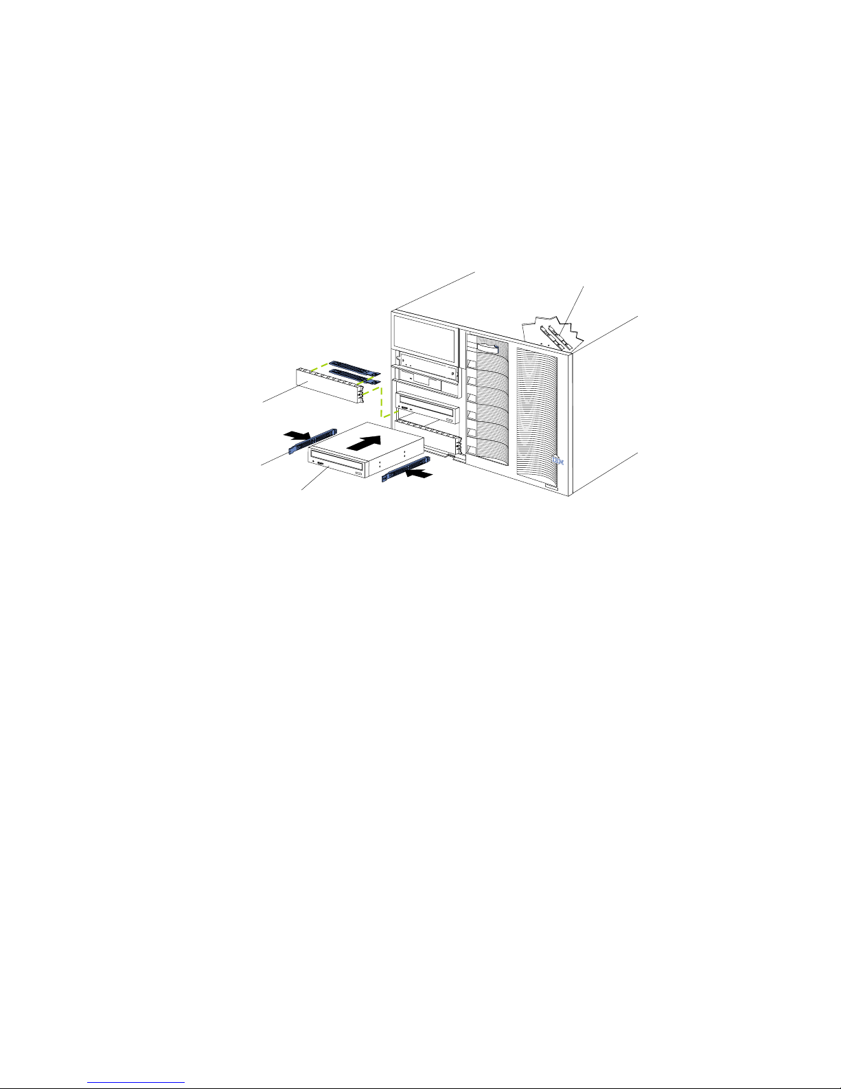
70 Hardware Maintenance Manual: Netfinity 7600 – Type 8665 Models 1RY, 2RY
Installing a 5.25-inch removable-media drive
Refer to the following illustrations when installing a 5.25-inch removable media drive.
Before you begin:
• Read “Safety information” on page 249.
• Review the information in “Before you begin” on page 60.
• Read the documentation that comes with the option.
Choose the bay in which you want to install the drive. Also, check the instructions
that come with the drive to see if you need to set any switches or jumpers on the
drive.
To install a removable-media drive in one of the left front bays:
1. Review the information in“Before you begin” on page 60.
2. Turn off the server and all attach ed devi ces. Disconnect all external cables and
remove the top cover.
3. Remove the media-bay bezel.
4. Remove the filler panel from the bay opening. Keep the filler panel nearby.
Note: The server EMI integrity and cooling are both protected by having the left
front bays covered or occupied. When you install a drive, save the filler
panel from the bay, in case you later remove the drive and do not replace it
with anothe r.
5. Touch the stati c-p rotective bag containing the drive to any unpai nted metal
surface on the server; then, remove the drive from the bag and place it on a staticprotective surface.
6. Remove the snap-on slide rails from the filler panel and snap the rails on the
drive. Store the filler panel for later use.
Note: Slide rails for installing a tape drive are attached with screws. Use the
screws to attach the rails to the side of the tape drive.
7. Align the slide rails on the drive with the guide rails in the bay; then, slide the
drive into the bay until it snaps into place.
Note: If you are installing a tape drive, use the screws that are shi pped next to
the tape drive rails to attach the tape drive to the front of the chassis.
8. Disconnect the shuttle (see “Disconnecting the shuttle” on page 128).
Drive
Slide rails
Filler panel with
EMI sheild
Slide rails for
use with a tape drive
Page 81

Installing options 71
9. If you are installing a SCSI device, go to step 10.. If you are installing an IDE
device, go to step 11..
10. Install the two-drop SCSI cable:
a. Locate the two-drop SCSI cable. The tw o- drop SCSI cable is located in the
bottom of the server between the open bays and the power supply area. It is
folded and restrained with a cable clamp.
b. Connect one of the conn e ctors on the two-drop SCSI cabl e to the back of the
drive. Go to step 12..
c. Connect the other end of the two-drop SCSI cable to the SCSI connector on
the power backplane.
d. Go to step 12..
11. To install an IDE device, such as a CD-ROM or a DVD-ROM, use the two-drop
IDE cable that comes with the option.
a. Remove the cab le th at connects the CD-ROM to the IDE connector on the
power backplane.
b. Using the two-drop cable that came with the IDE option, connect the CD-
ROM and IDE device you are installing to the IDE connector on the power
backplane.
c. Set the j u mpe r on the b a ck of the new IDE opti o n as se co n dary.
12. Connect a power cable to the back of the drive. Power cables for removablemedia drives come installed in the server. The connectors are keyed and can be
inserted only one way.
13. If you are installing another 5.25-inch drive, do so now. Otherwise, continue with
step 14..
14. Connect the shuttle.
a. Slide the shuttle back into the server
b. Disengage the retaining levers from the notches on the chassis.
c. Move the retain i n g lev e rs to ward the fron t of th e se r ve r.
d. Secure the retaining levers in the horizonta l position.
15. If you have other opt ions to install or remove, do so now ; otherwise, go to
“Completing the installation” on page 79.
Installing memory-module kits
Before you continue with the memory-installation procedure, review the following:
• Review the information in “Before you begin” on page 60.
• All the DIMMs installed in each set must be the same size and speed, but all the
sets do not have to contain DIMMs of the same size and speed.
• The memory board contains 1 6 DIMM connectors and supports 4-way memory
interleaving.
• Install only 3.3 V, 168-pin, 8-byte, re g i stered DIMMs. Only 100 MHz, 72-bit,
registered, synchronous, error correcting code (ECC), SDRAM configuration
DIMM memory is supported for the 128 MB, 256 MB, 512 MB and 1 GB (when
available) DIMMs.
• If you install 4 GB of memory, some of the me mory is rese rved for system
resources. The amount reser ved for system reso urces depends on the
configuration of the server.
Page 82

72 Hardware Maintenance Manual: Netfinity 7600 – Type 8665 Models 1RY, 2RY
• If you install 16 GB of memory, the Configuration/Setup Utility will display the
memory that is usable by the network operating system. This amount of memory
might differ from the amount of memory you ha ve installed.
• Installing or removing DIMMs chang es the configur ation inf orm ati on in the
server. Therefore, after installing or removing a DIMM, you must save the new
configuration inform ati on in the Config urati on/ Setup Ut ilit y program. Refer to
“Using the Configura tion/ S etup Utilit y program ” on page 43 for more
information.
• Install the DIMMs in the order provided in Table 7.
• For the l o ca tions of th e D I M M conne ctors, se e “Memory board component
locations” on page 58.
Refer to the following illustration when installing memory.
Table 7. DIMM installation order.
Set of 4 DIMMs Install DIMMs in these connectors:
First set (shipped as standard) J1, J5, J9, J13
2nd set J2, J6, J10, J 14
3rd set J3, J7, J11, J15
4th set J4, J8, J12, J16
Pop rivets
Processor housing
cover
DIMM
Memory board
Page 83

Installing options 73
To ins tall a memo r y mo dule:
Before you begin:
• Read “Safety information” on page 249.
• Read the documentati on that comes wi th your option.
1. Review “Before you begin” on page 60.
2. Turn off the server and all attached devices. Disconnect external cables and
power cords and remove the top cover.
3. Pull up the two pop rivets on the processor housing cover and remove the cover
from the processor housing.
4. Remove the memory board assembly:
a. Lift up on the memory board assembly and remove it from the server .
b. Place the memory board assembly on a static-protective surface, such as the
static-protective package in which the option came.
5. Locate the DIMM con nectors on the memory board. De te rmine the DIMM
connectors into which you will install the DIMMs. (See the notes at the beginning
of this procedure.)
6. Touch the static-protective package containing the DIMM option to any
unpainted metal surface on t he server. Then, remove the DIMM from the package.
Note: To avoid breaking the retaining clips or damaging the DIMM connectors,
handle the clips gently.
7. To install the DIMMs, repeat the following steps for each DIMM that you install.
a. Turn the DIMM so that the pins align correctly with the DIMM connector.
b. Insert the DIMM by pressing the DIMM straight into the connector. Be sure
that the retaining clips snap into the closed position.
8. Install the memory board ass e mbl y :
a. Hold the memory board assembly and align it over the memory boar d
connector.
b. Insert the memor y board assemb ly into the con nector.
9. Install the processor housing cover and push the two pop rivets down to secure
the cover.
10. If you have other opt ions to install or remove, do so now ; otherwise, go to
“Completing the installation” on page 79.
Installing a microprocessor kit
The serve r comes with one microprocessor installed on the proc essor board. If you
install an additional microprocessor kit, the server can operate as a symmetric
multiprocessing (S MP) se rver. With SMP, certain operating systems and application
programs can distribute the proce s sing load among the microprocessors.
Table 8. Microprocessor core frequency selection.
Microprocessor speed (MHz) – Core/Bus
fraction
Jumper
J13 J14 J15 J16
550 – 5.5 Pins 1 and 2 Pins 2 and 3 Pins 2 and 3 Pins 2 and 3
700 – 7.0 Pins 2 and 3 Pins 1 and 2 Pins 1 and 2 Pins 2 and 3
750 – 7.5 Pins 2 and 3 Pins 2 and 3 Pins 1 and 2 Pins 2 and 3
Page 84

74 Hardware Maintenance Manual: Netfinity 7600 – Type 8665 Models 1RY, 2RY
Notes:
1. Thoroughly review the documentation that comes with the microprocessor, so
that you can determine whether you need to update the server basic
input/output system (BIOS) code. The latest level of BIOS code for the server is
availa b le th ro u gh the World Wide Web. Go to
http:/ /www.pc.ibm.com/support/, select IBM S ervers, an d ma ke the selections
for your server.
2. Obtain an SMP-capable operating system (optional). For a list of supported
operating systems, see http://www.ibm.com/pc/ us/compat/ on the World
Wide Web.
Attention: To avoid damage and ensure proper server operation when you
install a new or an additional microprocessor, use micropr ocessors that have the
same cache size an d type, and the same clo ck speed. Micropr oces sor i n ternal and
external clock frequencies must be identical.
3. To order addi tional microprocessor options, contact your IBM r e seller or IBM
marketing representative.
4. If you replace the microprocessor in the server with a microprocessor that
operates at a different speed, be sure to set the microprocessor core-frequencyselection jumpers correctly. See T abl e 8 on page 73.
5. Y our server come s standard wi th one microprocessor installed. The
microprocessor is installed in microprocessor connector J2 and is the startup
(boot) processor. A micropr ocessor installed in microprocessor connector J3 is
processor 2; a microprocessor installed in micr oprocess or connector J 4 is
processor 3; a microprocessor installed in micr oprocess or connector J 5 is
processor 4. If more than one microprocessor is installed, the highest numbered
processor is the one the server will start from. The lower numbered
microprocessor s ar e used as application processors.
The following table and the label on the inside of the top cover of the server show the
order in which additional microprocessors and voltage regulator modu les (VRMs)
must be installed.
800 – 8.0 Pins 2 and 3 Pins 1 and 2 Pins 2 and 3 Pins 1 and 2
Table 9. Microprocessor and VRM installation order.
Note: "T" indicates an installed terminator card; "X" indicates an instal led microprocessor or VRM. A terminator card
must be installed in each microprocessor connector that does not contain a microprocessor.
One microprocessor installed
Microprocessor connectors VRM connectors
J2 (P1) J3 (P2) J4 (P3) J5 (P4) J37 (VRM 1)J38 (VRM 2) J39 (VRM 3)J41 (VRM 4)
X TTT X
T w o micr oprocessors installed
Microprocessor connectors VRM connectors
J2 (P1) J3 (P2) J4 (P3) J5 (P4) J37 (VRM 1)J38 (VRM 2) J39 (VRM 3)J41 (VRM 4)
Table 8. Microprocessor core frequency selection.
Microprocessor speed (MHz) – Core/Bus
fraction
Jumper
J13 J14 J15 J16
Page 85

Installing options 75
To install an additional microprocessor kit:
1. Review “Before you begin” on page 60.
2. Turn off the server and all attached devi ces. Disconnect all external cables and
power cords and remove the top cover.
3. Pull up the two pop rivets on the processor housing cover and remove the cover
from the processor housing.
4. Det ermine the slots wh ere you will install the microp rocesso r and VRM .
5. Remove the terminator card from the micr op rocessor connector.
6. Install the micropr oce ssor:
XXTT X X
Thre e m i croprocessors in s t a l l e d
Microprocessor connectors VRM connectors
J2 (P1) J3 (P2) J4 (P3) J5 (P4) J37 (VRM 1)J38 (VRM 2) J39 (VRM 3)J41 (VRM 4)
XXXT X X X
Four microprocessors installed
Microprocessor connectors VRM connectors
J2 (P1) J3 (P2) J4 (P3) J5 (P4) J37 (VRM 1)J38 (VRM 2) J39 (VRM 3)J41 (VRM 4)
XXXXXXXX
Table 9. Microprocessor and VRM installation order.
Microprocessor 2
Connector (J3)
Microprocessor 1
Connector (J2)
Microprocessor 3
Connector (J4)
Microprocessor 4
Connector (J5)
Battery
VRM 1 Connector
VRM 4 Connector
VRM 3 Connector
Reserved (J8 and J9)
VRM 2 Connector
Memory board
Connector
PCI Slot 1 and 2
(on PCI bus A)
PCI Slot 3-6
(on PCI bus B)
Page 86
76 Hardware Maintenance Manual: Netfinity 7600 – Type 8665 Models 1RY, 2RY
a. T ouch the s tat ic-pro tecti ve package c ontain ing th e new micr opro cess or to a ny
unpainted metal surface on the se rver; then, remove the microprocessor from
the package.
b. Hold the microprocessor by the open latches, and center the microprocessor
over the microprocessor connector.
Attention: Make sure the microprocessor is oriented and aligned correctly
before you try to close the latches.
c. Carefully close the latches to seat the microprocessor in the connec tor.
d. Store the terminator card in a safe place in the static -protective package that
the new microprocessor comes in; you will need to install it agai n if you ever
remove the microprocessor.
7. Install the voltage regulator module (VRM):
a. Center the VRM over the connector. Make sure that the VRM is oriented and
aligned correctly.
Note: If you remove t he micropr ocessor later, rememb er to insta ll the
terminator card in the appropriate microprocessor connector and to
remove the VRM for that micropr ocessor.
b. Carefully cl ose the latches to seat the VRM in the connector.
8. Install the processor housing cover and push down on the two pop rivets.
9. If you have other opt ions to install or remove, do so now; otherwise, go to
“Completing the installation” on page 79.
Installing a hot-swap power supp ly
CAUTION:
Never remove the cover on a power supply or any part that has the following label
attached.
Hazardous voltage, curren t, an d ener gy levels are present inside any component
that has this label a ttached. There are no s ervice able parts in side thes e components.
If you suspect a problem with one of these parts, contact a service technician.
Before you continue with the power supply-installation procedure, review the
following.
Notes:
1. During normal operation, each power supply bay must have either a power
supply or filler panel installed for proper cooling.
2. Before you install a power supply in the right-most power supply bay, you must
disconnect the cable-management arm. You can connect the cable-management
arm after installing the power supply.
Page 87
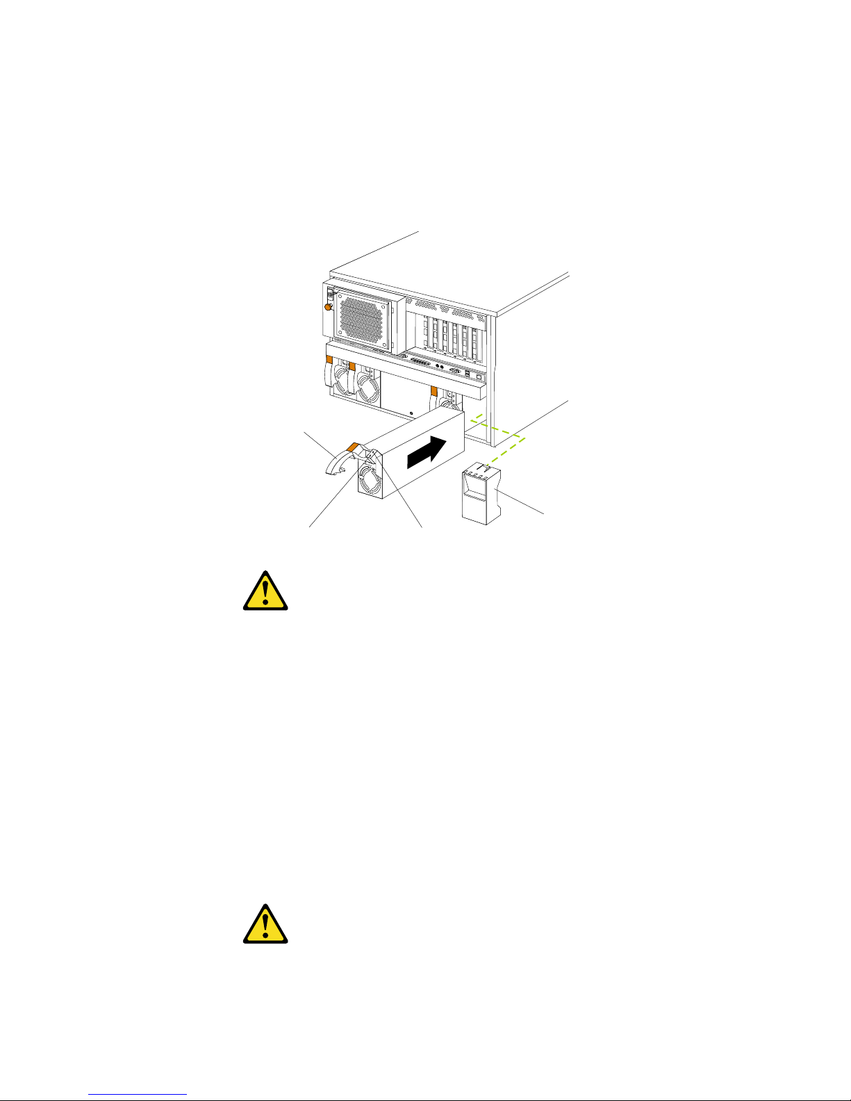
Installing options 77
Before you begin:
• Read “Safety information” on page 249.
• Review the information in “Before you begin” on page 60.
• Read the documentation that comes with the option.
Refer to the following illustration to install a hot-swap power supply.
CAUTION:
If you install a strain-relief bracket option over the end of the power cord that is
connected to the device, you must connect the other end of the power cord to an
easily accessible power source.
To install an additional power supply:
1. Review “Before you begin” on page 60.
2. Remove the filler panel.
3. Place the handle on the power supply in the open position.
4. Slide the power supply into the chassis and close the handle.
5. Plug one end of the power cord into the power supply; then, plug the other end of
the cord into a properly grounded electrical outlet.
6. Verify that the DC Power light and the AC Power light on the power supply are
lit, indicating that the power supply is operating properly.
CAUTION:
AC power lightDC power light
Handle
Filler panel
Page 88
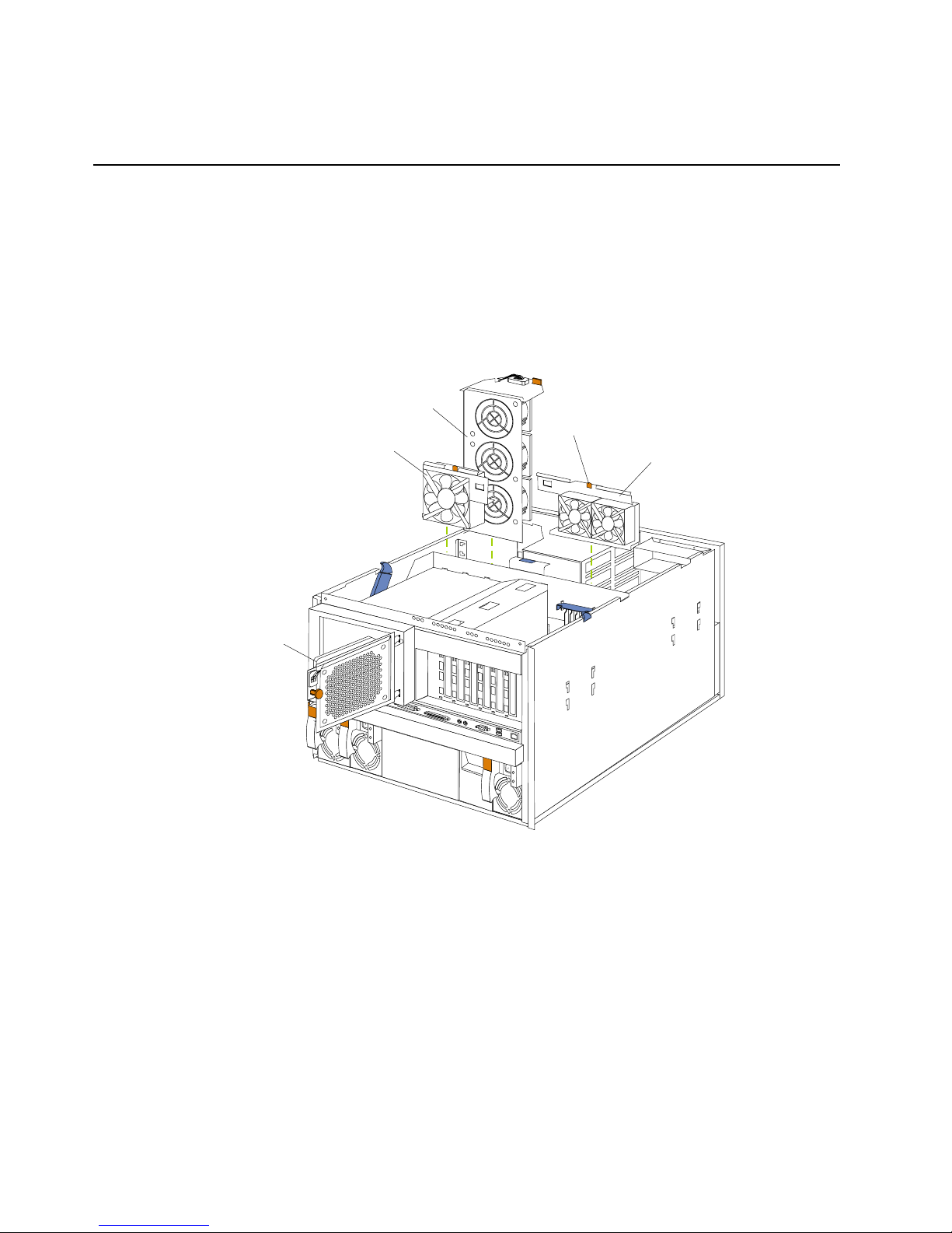
78 Hardware Maintenance Manual: Netfinity 7600 – Type 8665 Models 1RY, 2RY
If you install a strain-relief bracket option over the end of the power cord that is
connected to the device, you must connect the other end of the power cord to an
easily accessible power source.
Replacing a hot-swap fan
Before you begin:
• Read “Safety information” on page 249.
• Review the information in “Before you begin” on page 60.
• Read the documentation that comes with the option.
Refer to the f o llowing illu stration to replace a hot - swap fan.
To replace a hot-swap fan assembly:
1. Review the information in “Before you begin” on page 60.
2. If you are replacing fan assembly 1, 2, or 3:
a. Remove the top cove r.
Attention: To ensure proper system cooling, keep the cover removed for no
more than 30 minutes during this procedure.
b. Press the fan release latch and lift the fan assem b ly ou t of the server.
c. Slide the replacement fan assembly into the server. The latch will snap into
place and secure the fan in the server.
d. Replace the top cover
3. If you are replacing fan assembly 4:
Hot-swap fan
assembly 3
Hot-swap fan
assembly 4
Hot-swap fan
assembly 1
Hot-swap fan
assembly 2
Latch
Page 89
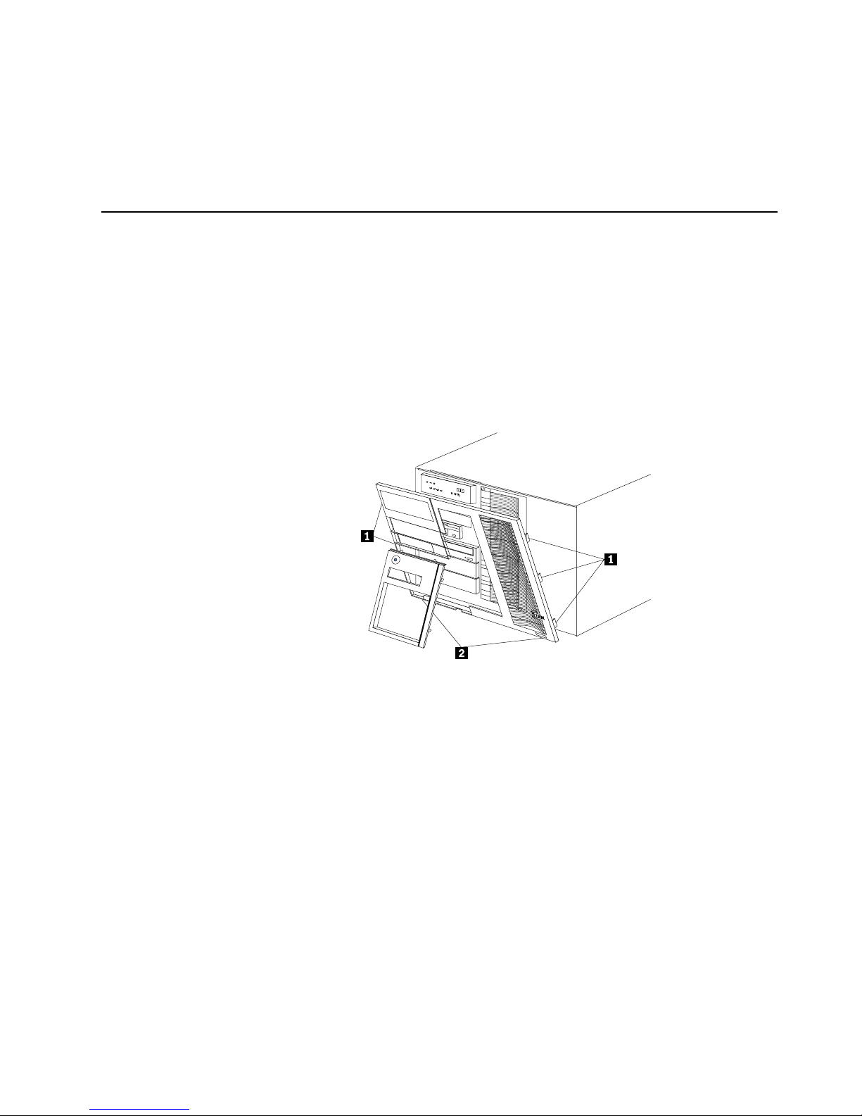
Installing options 79
a. Pull out on the orange pop rivet on the rear fan bracket; then, lift the fan
assembly up and ou t of th e h in ge cuto u t s.
b. Slide the replacement fan assembly into the server. (Make sure the fan
assembly f its corre ctly into the hinge cutouts on the rear of the shuttle.)
c. When you have the fan assembly pr operly seated, push on the pop rivet until
it clicks into place.
Completin g th e ins tal lat i on
To com p lete the installa tio n, you must reinstall the front trim bezel, reinstall the
media bay bezel, reinstall the top cover, rec onnect all the cables that you disconnected,
and for certain options, run the Configuration/Setup Utility program. Follow the
instructions in this section.
Attention: For proper cooling and air fl ow, install the top cover befor e turning on the
server. Operating the server for extended periods of time (over 30
minutes) with the top cover removed might damage server components.
Installing the front trim bezel
1 Side tabs
2 Bottom tabs
1. Align the two bot tom tabs with the notches on the bottom front of the server.
2. Align the side ta b s with the notches on the sides of the server.
3. Gently press the bezel into place.
Insta lling the media-bay bezel
Refer to the following illustration to install the media-bay bezel.
Page 90

80 Hardware Maintenance Manual: Netfinity 7600 – Type 8665 Models 1RY, 2RY
To ins tall the me dia- bay beze l:
1. Insert the tw o ta b s on th e top of the media - b a y be z e l i n to the ma tchi ng holes on
the server chassis.
2. Push the botto m of t he media -bay bezel to ward the se rver u ntil the t wo t abs at th e
bottom of the be zel sna p in to pl a c e .
Installing the top cover
To install the server top cover:
1. Before installing the cover, check that all cables, adapter s, and other components
are installed and seated correctly and that you have not left loose tools or parts
inside the server.
2. Lower the cover with the rear edge of the cover about 25 mm (1 inch) back from
the rear edge of the server.
3. S l ide the cove r forw a rd.
4. Tighten the two captive screws on the back edge of the cover.
Media-bay bezel
Captive screws
Top cover
Page 91

Installing options 81
5. If you disconnected any cables from the back of the server , reconnect the cables;
then, plug the power cords into properly grounded electrical outlets.
Note: If necessary, see “Cabling the server” on page 93 for connector locations.
Reconf i g ur in g th e ser ver
When you start th e ser ver for t he fi rst ti me after you add or r emov e an inte rnal optio n
or an external SCSI device, you might see a message telling you that the configuration
has changed. Run the Configuration/Setup Utility program to save the new
configuration informa ti on. See “Chapt e r . Co nf igu r ing the server,” on page 43.
Some options have device drivers that you need to install. Refer to the documentation
that comes with the option for information about installing any required device
drivers.
If you have installed a new microprocessor, you might want to upgrade the operating
syste m to support sy mmetri c mu l t i p roc e ss i n g ( S M P ) .
Run the Configuration/Setup Utility program to save the new configuration
information. See “Chap t er . Co nf igu r ing the ser ve r,” on page 43.
If you have installed or removed a hard disk drive, refer to “Ch apter . Installin g and
configuring ServeRAID controllers,” on page 139 for information about reconfiguri n g
the disk arrays.
Connecting external options
Review the information in “Before you begin” on page 60. Also, read the
docume ntation that co m e s with the o p tio n s .
To attach a n external device:
1. Turn off the server and all attach ed devices.
2. Follow the instructions that come with the option to prepare it for installation and
to conn ect it to the se rver.
Input/output ports
This section provides information about the input/output (I/O) ports on the rear of
the server. These ports include the following:
• One parallel port
• One video port
• One keyboard port
• One auxiliary-device port (mouse)
• One dual-channel Ultra-2 SCSI port
• Two serial ports
• Two Universal Se rial bus (USB) ports
• One Ethernet port
• Three communication ports dedicated to the Netfinity Advanced System
Management processor
Refer to the following illustration for the location of input and output connectors.
Page 92

82 Hardware Maintenance Manual: Netfinity 7600 – Type 8665 Models 1RY, 2RY
Parallel port
The server has one parallel port. This port supports three standard Institute of
Electrical an d Elec tr onics Engi neers (IEEE) 128 4 mo des of operati on: Sta ndar d Par alle l
Port (SPP), Enhanced Parallel Port (EPP), and Extended Capability Port (ECP).
Viewing or changing the parallel-port
assignments
You can use the built-in Configuration/Setup Utility program to configure the
parallel port as bidirectional; that is, so that data can be both read from and written to
a device. In bidirectional mode, the server supports the ECP and EPP modes.
To view or change the parallel-port assignment:
1. Restart the server and watch the monitor screen.
2. When the message Press F1 for Configuration/Setup appears, press F1.
Note: The Devices and I/O Ports choice appears only on the full configuration
menu. If you set two levels of passwords , y o u must enter the
administrator pas swo rd to access the full configur a tion men u.
3. From the main menu, select Devices and I/O Ports; then, press Enter.
4. Select the parallel port; then, use the arrow keys to advance through the settings
available.
Note: When you configure the parallel port as bidirectional, use an IEEE 1284-
compli a nt cable. The ma ximum length of the cable mu st not exceed 3
meter s ( 9 .8 fe e t ).
5. Select Save Settings; then, select Exit Setup to exit from the Configuration/Setup
Utility main menu.
Ethernet
USB1
USB2
Video
Mouse
Keyboard
Ultra2 SCSI
ASM Interconnect
port B
ASM Interconnect
port A
Serial A
Serial B
System management
Parallel
Advanced Systems
Management Interconnect knockout
Page 93

Installing options 83
Parallel port connec tor
The following table shows the pin-number assignments for the 25-pin, female D-shell
parallel-port connector on the rear of the server.
Video port
Your server comes with an integrated super video graphic s arr ay (SVGA ) video
controller. This controller is not removable, but you can disable it by installing a PCI
video adapter.
Table 10. Parallel-port connector pin-number assignments.
Pin I /O SPP/ECP Signal EPP Signal
1 O -STROBE -WRITE
2 I/O Data 0 Data 0
3 I/O Data 1 Data 1
4 I/O Data 2 Data 2
5 I/O Data 3 Data 3
6 I/O Data 4 Data 4
7 I/O Data 5 Data 5
8 I/O Data 6 Data 6
9 I/O Data 7 Data 7
10 I -ACK -ACK
11 I BUSY -WAIT
12 I PE (paper en d) PE (paper end)
13 I SLCT (select) SLCT (select)
14 O -AUTO FD (feed) -AUTO FD
15 I -ERROR -ERROR
16 O -INIT -INIT
17 O -SLCT IN -SLCT IN
18 — Ground Ground
19 — Ground Ground
20 — Ground Ground
21 — Ground Ground
22 — Ground Ground
23 — Ground Ground
24 — Ground Ground
25 — Ground Ground
13
1
25
14
Page 94

84 Hardware Maintenance Manual: Netfinity 7600 – Type 8665 Models 1RY, 2RY
Note: If you install a PCI video adapter, the server BIOS will automatically disable
the integrated video controller.
The follo wing table shows the pin - number assignme n ts f or the 15-pin analog vi deo
connector on the rear of the server.
Keyboard port
There is one keyboard port connect or on the rear of t he se rver.
Note: If you attach a standard (n on-USB) keyboard to the keyboard con nector, the
USB ports and devices will be disabled during the power-on self-test (POST).
The following table shows the pin-number assignments for the keyboard connector
on the rear of the server.
Table 11. Video-port connector pin-number assignments.
Pin Signal
1Red
2 Green or monochrome
3Blue
4Monitor ID bit 2
5Ground
6Ground
7Ground
8Ground
9+5 V dc
10 Ground
11 Mon itor ID bit 0
12 DDC SDA
13 Horizontal synchronization (Hsynch)
14 Vertical synchronization (Vsynch)
15 DDC SCL
1
5
1115
6
4
2
1
3
5
Page 95

Installing options 85
Auxiliary-device (pointing device) port
The I/O board has one auxiliary-device port that supports a mouse or other pointing
device.
The following table shows the pin-number assignments for the auxiliary-device
connector on the rear of the server.
Ultra2 SCSI ports
The server comes with an IBM ServeRAID controller. This controller provides three
independent SCSI channels. A 16-bit (wide) LVD SCSI cable connects the hard disk
drive backplane to one channel of the RAID controller. Two 68-pin SCSI connectors
for two additional channels are on th e rear of the server. Refer to “Chapter . Installing
and configuring Serve RAID co ntrollers,” on page 139.
The server has a dual-channel Ultra-2 small computer system interface (SCSI)
controller. This controller supports two independent SCSI channels: one exter nal and
one internal. Each of these channels supports up to 15 SCSI devices. You can use the
external LVD SCSI channel connector, on the rear of the server, to connect different
types of SCSI devices, such as drives or printers.
Table 12. Keyboard connector pin-number assignments .
Pin I/O Signal
1I/O Data
2N/A Reserved
3N/A Ground
4N/A +5 V dc
5 I/O Keyboard clock
6N/A Reserved
Table 13. Auxiliary-device connector pin-number assignments .
Pin Signal
1Data
2Not connected
3Ground
4+5 V dc
5Clock
6Not connected
6
4
2
1
3
5
Page 96

86 Hardware Maintenance Manual: Netfinity 7600 – Type 8665 Models 1RY, 2RY
SCSI cabling requirements
If you plan to attach external SCSI devices, you must or der additional SCSI cables. To
select and o rd er th e correct ca bl es fo r u se with exte rna l devices, co n t a ct you r IB M
reseller or IBM marketing representative.
For information about the maximum length of SCSI cable between the terminated
ends of the cable, refer to the ANSI SCSI standards. Adhering to these standa rds will
help ensure that the server operates properly.
Setting SCSI IDs
Each SCSI device connected to a SCSI co ntroller must have a unique SCSI ID. This ID
enables the SCSI controller to identif y the device and ensure that different devices on
the same SCSI channel do not atte mp t to transfer da ta simultaneou sly. SCSI devices
that are connected to different SCSI channels can have duplicate SCSI IDs.
The hot-swap-drive backplane controls the SCSI IDs for the internal hot-swap drive
bays. However, when you attach SCSI devices to the external SCSI connector, you
must set a unique ID for the device. Refer to the information that is provided with the
device for instructions to set its SCSI ID.
SCSI connector pin-number assignments
The following table shows the pin-number assignments for the 68-pin SCSI
connectors.
Table 14. 68-pin SCSI connector pin-number assignments.
Pin Signal Pin Signal
1 +Data 12 35 -Data 12
2 +Data 13 36 -Data 13
3 +Data 14 37 -Data 14
4 +Data 15 38 -Data 15
5 +Data P1 39 -Data P1
6 +Data 0 40 -Data 0
7 +Data1 41 -Dat a 1
8 +Data 2 42 -Data 2
9 +Data 3 43 -Data 3
10 + D ata 4 44 -Data 4
11 +D ata 5 45 -Da t a 5
12 + D ata 6 46 -Data 6
13 + D ata 7 47 -Data 7
14 + D ata P 48 -Data P
15 Ground 49 Ground
34
1
68
35
Page 97

Installing options 87
Serial ports
The server has two standard serial ports: Serial port A and Serial port B. The
operating system can use and share both serial ports; however, the integrated
Netfinity Advanced System Management Processor can use an d share onl y Serial port
A.
Some application programs r equire specific ports, and some modems function
properly only at certain communication port addresses. You might need to use the
Configuration/Setup Utility program to change communication port address
assignments to prevent or resolve address conflicts.
Viewing o r chan gin g th e se rial- port assig nmen ts
To view or chang e the serial-port assignments:
1. Restart the server and watch the monitor screen.
2. When the message Press F1 for Configuration/Setup appears, press F1.
3. From the main menu, select Devices and I/O Ports; then, press Enter.
Note: The Devices and I/O Ports choice appears only on the full configuration
menu. If you set two levels of passwords , y o u must enter the
administrator pas swo rd to access the full configur a tion men u.
16 DIFFSENS 50 Ground
17 Term power 51 Term power
18 Term power 52 Term power
19 Reserved 53 Reserved
20 Ground 54 Ground
21 +Attention 55 -Attention
22 Ground 56 Ground
23 +Busy 57 -Busy
24 +Acknowledge 58 -Acknowledge
25 +Reset 59 -Reset
26 +Message 60 -Message
27 +Select 61 -Select
28 +Control/Data 62 -Control/Data
29 +Request 63 -Request
30 +Input/Output 64 -Input/Output
31 + D ata 8 65 -Data 8
32 + D ata 9 66 -Data9
33 +Data 10 67 -Data 10
34 +Data 11 68 -Data 11
Table 14. 68-pin SCSI connector pin-number assignments.
Pin Signal Pin Signal
Page 98

88 Hardware Maintenance Manual: Netfinity 7600 – Type 8665 Models 1RY, 2RY
4. Select the serial port; then, use the arrow keys to advance through the settings
available.
5. Select Save Settings; then, select Exit Setup to exit from the Configuration/Setup
Utility main menu.
Serial-port connectors
The following table shows the pin-number assignments for the 9-pin, male D-shell
serial-port connectors on the rear of the server. These pin-number assignments
conform to the industry stan dard.
Universal Serial Bus ports
The server has two Universal Serial Bus (USB) ports that configure automatically.
USB is an emerging serial interface standard for te lephony and multimedia devic es. It
uses Plug and Play technology to determine the type of device attached to the
connector.
Notes:
1.If you attach a standard (non-USB) keyboard to the keyboard connector, the USB
ports and devices will be disabled during the power-on self-test (POST).
2.If you install a USB keyboard that has a mouse port, the USB keyboa rd emulates a
mouse and you will not be able to disable the mouse settings in the
Configuration/ Se tup Ut ility program .
3.Check to make sure your NOS supports USB devices.
USB cables and hubs
You need a 4-pin cable to connect devices to USB 1 or USB 2. If you plan to attach
more than two USB devices t o the machine, you mu st u se a hub to connect the
devices. The hub provides mu ltiple co nn e ctors for attac hing additional external US B
devices with a maximum of 127 external devices.
USB technology provides up to 12 megabits-per-second (Mbps) speed with a
maximum of 127 external devic e s and a maximum sign al distance of five meters (16
ft.) per segment.
Table 15. Serial-port connectors pin-number assignments.
Pin Signal Pin Signal
1 Data carri e r de tect 6 Data set ready
2 Receive data 7 Request to send
3 T ransmit data 8 Clear to send
4 Data terminal ready 9 Ring indicato r
5 Signal ground
1
5
69
Page 99

Installing options 89
USB-port connectors
Each USB port has an external connector on the rear of the server for attaching USB
compatible dev ices .
The following table shows the pin-number assignments for the USB-port connectors
on the rear of the server.
Ethernet port
Your server comes with an integrated Ethernet controller. This controller provides an
interface for connecting to 10-Mbps or 100-Mbps networks and provides full-duplex
(FDX) capability, which enables simultaneous transmission and reception of data on
the Ethernet local area network (LAN).
To access the Ethernet port, connect a Category 3, 4 or 5 unshielded twisted-pair
(UTP) cable to the RJ-45 connector on the rear of the server.
Note: The 100BASE-TX Fast Ethernet standard re q u ires that the cabling in the
network be Category 5 or higher.
Configuring the Ethernet controller
When you connect the server to the network, the Ethernet controller automatically
detects the data-transfer rate (10Mbps or 100Mbps) on the network and then sets the
controller to operate at the appropriate rate. That is, the Ethernet controller will
adjust to th e network data rate, whether the data rate is stand a rd Ethernet ( 10BASET), Fast Ethernet (100BASE-TX), half duplex (HDX), or full duplex (FDX). The
controller supports half-duplex (HDX) and full-duplex (FDX) modes at both speeds.
The Ethernet controller is a PCI Plug and Play device. You do not need to set any
jumpers or configure the controller for the operating system before you use the
Ethernet controller . However, you must install a device driver to enable the operating
system to address the Ethernet controll er. The device drivers are provide d on the
ServerGuide CDs.
Failover for redundant Ethernet
The IBM Netfinity 10/ 100 Fa ult Tolerant Adapter is an optional redundant netw ork
interface card (NIC adapter) that you can install in the server. If you install this NIC
adapter and connect it to the same logical LAN segment as the primary Ethernet
controller, you can configure the server to support a failover function. You can
configure either the integrated Ethernet controller or the NIC adapter as the primary
Ethernet controller. In failover mod e, if the primar y Etherne t controlle r detects a link
failure, all Ethernet traffic associated with it is switched to the redundant (secondary)
controller. This switching occurs without any user intervention. When the primary
link is restored to an operational state, the Ethernet traffic switches back to the
primary Ethernet controller. The switch back to the primary Ethernet controller can be
automatic or manually controlled, depending on the setup and operating system.
Table 16. USB-port connector pin-number assignments.
Pin Signal
1VCC
2-Data
3+Data
4Ground
Page 100

90 Hardware Maintenance Manual: Netfinity 7600 – Type 8665 Models 1RY, 2RY
Note that only one controller in the redundant pair is active at any given time. For
example, if the primary Ethernet controller is active, then the secondary Ethernet
controller cannot be used for any other network operation.
Note: The operating system determines the maximum number of IBM Netfinity
10/100 Fault Tolerant Adapters that you can install in the server. See the
documentation tha t comes with the adapter for more information .
Considerations when combining failover and hot-plug
func tions: If the operating system supports hot-plug PCI adapters and the optional
redundant NIC adapter is installed in a hot-plug PCI slot, you can replace the NIC
adapte r without po wering off the server — even if it is the primary Ethernet
controller. Disconnecting the Ethernet cable from the primary Ethernet controller will
cause th e Et hern et traf f ic t o s witc h auto mati cal ly to th e sec ond ary E ther ne t con tr ol ler.
This can be very useful if a faulty adapter causes a network problem, or if you want to
upgrade the primary adapter hardware.
Note: If you hot replace the primary adapter while the Ethernet traffic is being
handled by the secondary Et her net cont roller, the traffic does not
automatically switch back to the primary adapter when the primary adapter
comes bac k online. See “Configuring for failover”.
Configuring for failover: The failover feature currently is supported by OS/2™,
Windows NT Server, and IntraNetWare. The setup required for each operating
system follows.
Windows NT Server: IBM offers hot-plug support for Windows NT Server Version 4.0.
Failover can work in conjunction with hot-plug support or independently. If you are
not using hot-plug support, go to “Windows NT Se rv e r f ailove r se t u p ” on page 91.
Windows NT Server hot-plug setup: IBM Netfinit y Ho t Plug PCI for Windows NT
Server 4.0 package is available for download from the IBM Web site at:
http://www.pc.ibm.com/support
Enter the brand type of Server, click on D ownloadable files and look for Hot Plug.
The IBM Netfinity Hot Plug PCI for Windows NT Server 4.0 package uses the Intel
Desktop Management Interface (DMI) to control hot-plug support for the Ethernet
controllers. The Ethernet controller in the computer is DMI compliant. Download
and install the following software in the order listed:
1. IBM Netfini ty PCI Hot plug for Windows NT 4.0 Failover DM I Agent
2. IBM Netfinity PCI Hot Plug for Windows NT 4.0 Sol u tion
3. IBM Netfinity 10/100 Fault Tolerant Adapter device drivers
Note: The order of installation is important. You must install the IBM Netfinity Hot
Plug for Windows NT Server 4.0 package before you install the IBM Netfin ity
10/100 Fault Tolerant Adapter driver. If you install the adapter device driver
before the PCI Hot Plug Solution package, the adapter device driver will not
recognize the hot-plug code. This happens because the adapter device driver
only checks the NT registry for the Hot Plug pack ag e during ins tallat ion. If
the PCI Hot Plug Solution package is added after the adapter device driver is
installed, the adapter must be removed and added again in order for it to
detect the P CI Ho t-Plu g So l u t ion code .
To ins tall the IBM Netfin ity PCI Hotp lug for Windows NT 4.0 Failover DMI Agent :
1. Download the IBM Netfinity PCI Hotplug for Windows NT 4.0 Failover DMI
Agent DMI Agent file from the Netfinity Support web page and extract the files
onto a diskett e .
2. Insert the diskette into the diskette drive.
3. From the Start menu, select the Run opt ion.
 Loading...