

Page 1

IBM
IBM® Netfinity® 7600
User’s Reference
SC19-K080-90
Page 2

Page 3

IBM
IBM® Netfinity® 7600
User’s Reference
SC19-K080-90
Page 4

NOTE
Before using this information and the product it supports, be sure to read the general information in
“Appendix A. Product warranties and notices,” on page 161.
First Edition (March 2000)
© COPYRIGHT INTERNATIONAL BUSINESS MACHINES CORPORATION, 2000. All rights reserved.
Note to U.S. Government Users — Documentation related to restricted rights — Use, duplication or disclosure is subject
to restrictions se t forth in GSA ADP Schedule Contract with IBM Corp.
Page 5

iii
Contents
Safety . . . . . . . . . . . . . . . . . . . . . . . . . . . . . v
Chapter 1.Introducing the IBM Netfinity
7600. . . . . . . . . . . . . . . . . . . . . . . . . . . . . . . 1
Server specifications . . . . . . . . . . . . . . . . . . . . . . . . . . . . . . 2
Notices used in this book. . . . . . . . . . . . . . . . . . . . . . . . . . 3
Server features. . . . . . . . . . . . . . . . . . . . . . . . . . . . . . . . . . . 3
Reliability, availability, and serviceability . . . . . . . . . . . . 4
Controls and indicators . . . . . . . . . . . . . . . . . . . . . . . . . . . 5
Information LED panel. . . . . . . . . . . . . . . . . . . . . . . . . . . . 8
Chapter 2.Arranging your workspace . . . 11
Comfort. . . . . . . . . . . . . . . . . . . . . . . . . . . . . . . . . . . . . . . . 11
Glare and lighting . . . . . . . . . . . . . . . . . . . . . . . . . . . . 11
Air circulation. . . . . . . . . . . . . . . . . . . . . . . . . . . . . . . . 11
Electrical outlets and cable lengths. . . . . . . . . . . . . . 12
Chapter 3. Configuring your server . . . . . 13
Using the Configuration/Setup Utility program. . . . . 13
Starting the Configuration/Setup Utility program 13
Choices available from the Configuration/Setup main
menu . . . . . . . . . . . . . . . . . . . . . . . . . . . . . . . . . . . . . . . . . . 14
Using passwords . . . . . . . . . . . . . . . . . . . . . . . . . . . . . 17
Power-on password . . . . . . . . . . . . . . . . . . . . . . . . 17
Administrator password . . . . . . . . . . . . . . . . . . . . 18
Using the SCSISelect utility program. . . . . . . . . . . . . . . 19
Starting the SCSISelect utility program . . . . . . . . . . 20
Choices available from the SCSISelect menu . . . . . 20
Chapter 4.Introducing ServerGuide. . . . . 23
ServerGuide provides the following to make setup easier
23
Features at a glance. . . . . . . . . . . . . . . . . . . . . . . . . . . . . . 24
Setup and Configuration overview . . . . . . . . . . . . . . . . 25
System Partition. . . . . . . . . . . . . . . . . . . . . . . . . . . . . . 25
Network operating system (NOS) installation overview .
26
Setting up multiple servers . . . . . . . . . . . . . . . . . . . . . . . 26
Installing your NOS without ServerGuide . . . . . . . . . . 26
Additional programs included with ServerGuide. . . . 27
NOS updates. . . . . . . . . . . . . . . . . . . . . . . . . . . . . . . . . 27
Applications . . . . . . . . . . . . . . . . . . . . . . . . . . . . . . . . . 27
Installing applications. . . . . . . . . . . . . . . . . . . . . . . . . 27
Error symptoms. . . . . . . . . . . . . . . . . . . . . . . . . . . . . . . . . 27
Chapter 5.Using Netfinity Manager . . . . . 29
Managing your IBM Netfinity server with Netfinity
Manager . . . . . . . . . . . . . . . . . . . . . . . . . . . . . . . . . . . . . . . 29
Netfinity Manager documentation. . . . . . . . . . . . . . . . . 30
Netfinity Manager system requirements. . . . . . . . . . . . 30
Netfinity Manager for OS/2 system requirements. 30
Netfinity Manager for Windows 95 and Windows 98
system requirements. . . . . . . . . . . . . . . . . . . . . . . . . . . . . 31
Netfinity Manager for Windows NT system
requirements . . . . . . . . . . . . . . . . . . . . . . . . . . . . . . . . . . . 31
Starting the Netfinity Manager installation program . 32
Netfinity Manager database support. . . . . . . . . . . . . . . 38
DB2 database support. . . . . . . . . . . . . . . . . . . . . . . . . 39
System requirements . . . . . . . . . . . . . . . . . . . . . . . 39
Installing and configuring the database . . . . . . . 39
Activating the database . . . . . . . . . . . . . . . . . . . . . 40
Granting and revoking database privileges . . . . 40
Deleting the database. . . . . . . . . . . . . . . . . . . . . . . 42
Lotus Notes database support . . . . . . . . . . . . . . . . . . 43
System requirements . . . . . . . . . . . . . . . . . . . . . . . 43
Installing the database . . . . . . . . . . . . . . . . . . . . . . 43
Browsing th e Netfinity Manager Lotus No tes
database . . . . . . . . . . . . . . . . . . . . . . . . . . . . . . . . . . 44
ODBC database support . . . . . . . . . . . . . . . . . . . . . . . 44
System requirements . . . . . . . . . . . . . . . . . . . . . . . 44
ODBC database configuration . . . . . . . . . . . . . . . 45
Creating the Netfinity Manager tables . . . . . . . . 46
Supported and certified databases. . . . . . . . . . . . 47
Starting Netfinity Manager . . . . . . . . . . . . . . . . . . . . . . . 48
Netfinity Manager Service Manager. . . . . . . . . . . . . 49
Netfinity Manager service descriptions . . . . . . . . . . 50
Advanced System Management. . . . . . . . . . . . . . 51
Alert Manager . . . . . . . . . . . . . . . . . . . . . . . . . . . . . 51
Alert on LAN configuration . . . . . . . . . . . . . . . . . 51
Capacity Management . . . . . . . . . . . . . . . . . . . . . . 51
Cluster Manager . . . . . . . . . . . . . . . . . . . . . . . . . . . 51
Critical File Monitor . . . . . . . . . . . . . . . . . . . . . . . . 51
DMI Browser . . . . . . . . . . . . . . . . . . . . . . . . . . . . . . 52
ECC Memory Setup . . . . . . . . . . . . . . . . . . . . . . . . 52
Event Scheduler. . . . . . . . . . . . . . . . . . . . . . . . . . . . 52
File Transfer . . . . . . . . . . . . . . . . . . . . . . . . . . . . . . . 52
Power-On Error Detect. . . . . . . . . . . . . . . . . . . . . . 52
Predictive Failure Analysis . . . . . . . . . . . . . . . . . . 52
Process Manager . . . . . . . . . . . . . . . . . . . . . . . . . . . 52
RAID Manager . . . . . . . . . . . . . . . . . . . . . . . . . . . . 52
Remote Session . . . . . . . . . . . . . . . . . . . . . . . . . . . . 53
Remote System Manager. . . . . . . . . . . . . . . . . . . . 53
Remote Workstation Control. . . . . . . . . . . . . . . . . 53
Screen View . . . . . . . . . . . . . . . . . . . . . . . . . . . . . . . 53
Security Manager . . . . . . . . . . . . . . . . . . . . . . . . . . 53
Serial Connection Control . . . . . . . . . . . . . . . . . . . 53
Service Configuration Manager . . . . . . . . . . . . . . 53
Software Inventory . . . . . . . . . . . . . . . . . . . . . . . . . 54
System Diagnostics Manager . . . . . . . . . . . . . . . . 54
System Information Tool . . . . . . . . . . . . . . . . . . . . 54
System Monitor. . . . . . . . . . . . . . . . . . . . . . . . . . . . 54
System Partition Access. . . . . . . . . . . . . . . . . . . . . 54
System Profile . . . . . . . . . . . . . . . . . . . . . . . . . . . . . 54
Update Connector Manager . . . . . . . . . . . . . . . . . 54
Web Manager Configuration. . . . . . . . . . . . . . . . . 55
Delaying Netfinity Manager startup on OS/2 systems
55
Getting more information about Netfinity Manager . . 55
Installation options . . . . . . . . . . . . . . . . . . . . . . . . . . . . . . 56
Automated installation . . . . . . . . . . . . . . . . . . . . . . . . 56
Customized installation . . . . . . . . . . . . . . . . . . . . . . . 58
Chapter 6.Installing options. . . . . . . . . . . 61
Major components of the Netfinity 7600 server . . . . . . 61
Component locations . . . . . . . . . . . . . . . . . . . . . . . . . . . . 63
I/O board component locations. . . . . . . . . . . . . . . . . 63
Processor board component locations. . . . . . . . . . . . 64
Processor board LEDs . . . . . . . . . . . . . . . . . . . . . . 64
Processor board connectors. . . . . . . . . . . . . . . . . . 65
Processor board jumpers . . . . . . . . . . . . . . . . . . . . 66
Memory board component locations . . . . . . . . . . . . 67
Page 6

iv IBM Netfinity 7600 User’s Reference
Before you begin . . . . . . . . . . . . . . . . . . . . . . . . . . . . . . . . 68
System reliability considerations. . . . . . . . . . . . . . . . 68
Working inside the server with the power on . . . . . 68
Handling static-sensitive devices . . . . . . . . . . . . . . . 69
Safety information statements . . . . . . . . . . . . . . . . . . 69
Removing the server top cover and bezel. . . . . . . . . . . 71
Removing the top cover . . . . . . . . . . . . . . . . . . . . . . . 71
Removing the media-bay bezel . . . . . . . . . . . . . . . . . 72
Working with adapters. . . . . . . . . . . . . . . . . . . . . . . . . . . 72
Adapter considerations. . . . . . . . . . . . . . . . . . . . . . . . 73
Installing a hot-plug adapter . . . . . . . . . . . . . . . . . . . 74
Installing internal drives . . . . . . . . . . . . . . . . . . . . . . . . . 75
Internal drive bays. . . . . . . . . . . . . . . . . . . . . . . . . . . . 76
Installing a hot-swap hard disk drive. . . . . . . . . . . . 77
Installing a 5.25-inch removable-media drive . . . . . 78
Installing memory-module kits. . . . . . . . . . . . . . . . . . . . 80
Installing a microprocessor kit . . . . . . . . . . . . . . . . . . . . 83
Installing a hot-swap power supply. . . . . . . . . . . . . . . . 87
Replacing a hot-swap fan. . . . . . . . . . . . . . . . . . . . . . . . . 89
Completing the installation . . . . . . . . . . . . . . . . . . . . . . . 90
Installing the media-bay bezel. . . . . . . . . . . . . . . . . . 90
Installing the top cover . . . . . . . . . . . . . . . . . . . . . . . . 91
Reconfiguring the server. . . . . . . . . . . . . . . . . . . . . . . 91
Connecting external options . . . . . . . . . . . . . . . . . . . . . . 92
Input/Output ports . . . . . . . . . . . . . . . . . . . . . . . . . . . . . 92
Parallel port. . . . . . . . . . . . . . . . . . . . . . . . . . . . . . . . . . 93
Viewing or changing the parallel-port assignments
93
Parallel port connector. . . . . . . . . . . . . . . . . . . . . . 94
Video port . . . . . . . . . . . . . . . . . . . . . . . . . . . . . . . . . . . 95
Keyboard port. . . . . . . . . . . . . . . . . . . . . . . . . . . . . . . . 95
Auxiliary-device (pointing device) port. . . . . . . . . . 96
Ultra2 SCSI ports . . . . . . . . . . . . . . . . . . . . . . . . . . . . . 96
SCSI cabling requirements . . . . . . . . . . . . . . . . . . 97
Setting SCSI IDs . . . . . . . . . . . . . . . . . . . . . . . . . . . 97
SCSI connector pin-number assignments. . . . . . 97
Serial ports . . . . . . . . . . . . . . . . . . . . . . . . . . . . . . . . . . 98
Viewing or changing the serial-port assignments 98
Serial-port connectors . . . . . . . . . . . . . . . . . . . . . . 99
Universal Serial Bus ports. . . . . . . . . . . . . . . . . . . . . . 99
USB cables and hubs . . . . . . . . . . . . . . . . . . . . . . . 99
USB-port connectors. . . . . . . . . . . . . . . . . . . . . . . . 99
Ethernet port . . . . . . . . . . . . . . . . . . . . . . . . . . . . . . . 100
Configuring the Ethernet controller. . . . . . . . . . 100
Failover for redundant Ethernet. . . . . . . . . . . . . 100
Ethernet port connector. . . . . . . . . . . . . . . . . . . . 103
Advanced System Management ports . . . . . . . . . . 103
Cabling the server . . . . . . . . . . . . . . . . . . . . . . . . . . . . . . 104
Installing the server in a rack. . . . . . . . . . . . . . . . . . . . . 105
Chapter 7.Solving problems. . . . . . . . . . 107
Diagnostic tools overview . . . . . . . . . . . . . . . . . . . . . . . 107
POST . . . . . . . . . . . . . . . . . . . . . . . . . . . . . . . . . . . . . . . . . 109
POST beep code descriptions. . . . . . . . . . . . . . . . . . 109
POST beep codes . . . . . . . . . . . . . . . . . . . . . . . . . . . . . 111
POST error messages. . . . . . . . . . . . . . . . . . . . . . . . . 112
Event/error logs. . . . . . . . . . . . . . . . . . . . . . . . . . . . . 121
Small computer system interface messages . . . . . . . . 121
Diagnostic programs and error messages . . . . . . . . . . 122
Text messages. . . . . . . . . . . . . . . . . . . . . . . . . . . . . . . 123
Starting the diagnostic programs . . . . . . . . . . . . . . 123
Viewing the test log. . . . . . . . . . . . . . . . . . . . . . . . . . 124
Diagnostic error message tables . . . . . . . . . . . . . . . 124
Recovering BIOS . . . . . . . . . . . . . . . . . . . . . . . . . . . . . . . 132
Identifying problems using status LEDs . . . . . . . . . . . 132
Power supply LEDs. . . . . . . . . . . . . . . . . . . . . . . . . . 133
Diagnostic panel LEDs. . . . . . . . . . . . . . . . . . . . . 134
Light path diagnostics . . . . . . . . . . . . . . . . . . . . . 135
Noncritical light path diagnostics . . . . . . . . . . . . . . 138
Troubleshooting charts . . . . . . . . . . . . . . . . . . . . . . . . . . 138
Troubleshooting the Ethernet controller. . . . . . . . . 143
Network connection problems . . . . . . . . . . . . . . 143
Ethernet controller troubleshooting chart. . . . . 144
Ethernet controller messages . . . . . . . . . . . . . . . . . . 145
Novell NetWare or IntraNetWare server OD I driv er
messages. . . . . . . . . . . . . . . . . . . . . . . . . . . . . . . . . 145
NDIS 4.0 (Windows NT) driver messages. . . . . 147
UNIX messages. . . . . . . . . . . . . . . . . . . . . . . . . . . 148
Replacing the battery . . . . . . . . . . . . . . . . . . . . . . . . . . . 151
Getting help, service, and information. . . . . . . . . . . . . 153
Service support. . . . . . . . . . . . . . . . . . . . . . . . . . . . . . 154
Before you call for service. . . . . . . . . . . . . . . . . . . . . 154
Getting customer support and service . . . . . . . . . . 155
Using the World Wide Web . . . . . . . . . . . . . . . . . 155
Using electronic support services. . . . . . . . . . . . 155
Getting information by fax . . . . . . . . . . . . . . . . . 156
Getting help online . . . . . . . . . . . . . . . . . . . . . . . . 156
Getting help by telephone . . . . . . . . . . . . . . . . . . 156
Getting help around the world. . . . . . . . . . . . . . 157
Purchasing additional services. . . . . . . . . . . . . . . . . 158
Enhanced PC support line. . . . . . . . . . . . . . . . . . 158
900-number operating system and hardware
support line . . . . . . . . . . . . . . . . . . . . . . . . . . . . . . 158
Network and server support line. . . . . . . . . . . . 158
Ordering support line services . . . . . . . . . . . . . . 159
Warranty and repair services . . . . . . . . . . . . . . . 159
Ordering publications . . . . . . . . . . . . . . . . . . . . . . . . 159
Appendix A. Product warranties and
notices . . . . . . . . . . . . . . . . . . . . . . . . . . 161
Warranty Statements. . . . . . . . . . . . . . . . . . . . . . . . . . . . 161
IBM Statement of Limited Warranty for United States,
Puerto Rico, and Canada (Part 1 - General Terms) 161
IBM Statement of Warranty Worldwide except
Canada, Puerto Rico, Turkey, United States (Part 1 –
General Terms) . . . . . . . . . . . . . . . . . . . . . . . . . . . . . . 164
Part 2 - Worldwide Country-Unique Terms . . . . . . 166
Notices. . . . . . . . . . . . . . . . . . . . . . . . . . . . . . . . . . . . . . . . 170
Edition Notice . . . . . . . . . . . . . . . . . . . . . . . . . . . . . . . 170
Year 2000 readiness and instructions. . . . . . . . . . . . 171
Trademarks . . . . . . . . . . . . . . . . . . . . . . . . . . . . . . . . . 171
Important notes . . . . . . . . . . . . . . . . . . . . . . . . . . . . . 172
Electronic emission notices . . . . . . . . . . . . . . . . . . . . . . 172
Federal Communications Commission (FCC)
Statement. . . . . . . . . . . . . . . . . . . . . . . . . . . . . . . . . . . 172
Industry Canada Class A emission compliance
statement . . . . . . . . . . . . . . . . . . . . . . . . . . . . . . . . . . . 173
Australia and New Zealand Class A statement. . . 173
United Kingdom telecommunications safety
requirement. . . . . . . . . . . . . . . . . . . . . . . . . . . . . . . . . 173
European community directive conformance
statement . . . . . . . . . . . . . . . . . . . . . . . . . . . . . . . . . . . 173
Taiwan electrical emission statement . . . . . . . . . . . 174
Japanese Voluntary Control Council for Interference
(VCCI) statement . . . . . . . . . . . . . . . . . . . . . . . . . . . . 174
Power cords . . . . . . . . . . . . . . . . . . . . . . . . . . . . . . . . . . . 174
Index . . . . . . . . . . . . . . . . . . . . . . . . . . . . . 177
Page 7

© Copyright IBM Corp. 2000 v
Safety
Before installing this product, read the Safety Information book .
Antes de instalar este produto, leia o Manual de Informações sobre Segurança.
Læs hæftet med sikkerhedsforskrifter, før du installerer dette produkt.
Lue Safety Information -kirjanen, ennen kuin asennat tämän tuotteen.
Avant de procéder à l'installation de ce produit, lisez le manuel Safety Information.
Vor Beginn der Installation die Broschüre mit Sicherheitshinweisen lesen.
Prima di installare questo prodotto, leggere l'opuscolo contenente le informazioni
sulla sicurezza.
Pred instalací tohoto produktu si prectete prírucku bezpecnostních instrukcí.
Przed zainstalowaniem tego produktu należy przeczytać broszurę Informacje Dotyczące
Bezpieczeństwa.
Page 8

vi IBM® Netfinity® 7600 User’s Reference
Lees voordat u dit product installeert eerst het boekje met veiligheidsvoorschriften.
Les heftet om sikkerhetsinformasjon (Safety Information) før du installerer dette
produktet.
Antes de instalar este produto, leia o folheto Informações sobr e Segurança.
Antes de instalar este producto, lea la Información de Seguridad.
Läs säkerhetsinformationen innan du installerar den här produkten.
Перед установкой продукта прочтите брошюру по технике безопасности
(Safety Information).
Pred inštaláciou tohto produktu si pre ítajte Informa nú brožúrku o bezpe nosti.
Preden namestite ta izdelek, preberite knjižico Varnostne informacije.
Installálás el tt olvassa el a Biztonsági el írások kézikönyvét !
Page 9

vii
Statement 1
Danger
Electrical current from power, telephone, and communication cables is
hazardous.
To avoid a shock hazard:
• Do not connect or disconnect any cables or perform installation,
maintenance, or reconfiguration of this product during an electrical storm.
• Connect all power cords to a properly wired and grounded electrical outlet.
• Connect to properly wired outlets any equipment that will be attached to
this product.
• When possible, use one hand only to connect or disconnect signal cables.
• Never turn on any equipment wh en there is evidence of fire, water, or
structural damage.
• Disconnect the attached power cords, telecommunications systems,
networks, and modems before you open the device covers, unless
instructed otherwise in the installation and configuration procedures.
• Connect and disconnect cables as described in the following table when
installing, moving, or opening covers on this product or attached devices.
To conn ect:
1. Turn everything OFF.
2. First, attach all cables to devices.
3. Attach signal cables to connectors.
4. Attach power cords to outlet.
5. Turn device ON.
To disconnect:
1. Turn everything OFF.
2. First, remove power cords from
outlet.
3. Remove signal cables from
connectors.
4. Remove all cables from device s.
Page 10

viii IBM® Netfinity® 7600 User’s Reference
Statement 2
CAUTION:
When replacing the lithium battery, use only IBM Part Number 33F8354 or an
equivalent type battery r ecommended by the manufactur er . If your system has a
module containing a lithium battery, replace it only with the same module type
made by the same manufacturer. The battery contains lithium and can explode
if not properly used, handled, or disposed of.
Do not:
• Throw or immerse into water.
• Heat to more than 100 C (212 F)
• Repair or disassemble
Dispose of the battery as required by local ordinances or regulations.
Statement 3
CAUTION:
When laser products (such as CD-ROMs, DVD drives, fiber optic devices, or
transmitters) are installed, note the following:
• Do not remove the covers. Removing the cov ers of t he l aser prod uct co uld
result in exposure to hazardous laser radiation. There are no serviceable
parts inside the device.
• Use of controls or adjustments or performance of procedures other than
those specified herein might result in hazardous radiation exposure.
Danger
Some laser products contain an embedded Class 3A or Class 3B laser diode. Note
the following. Laser radiation when open. Do not stare into the beam, do not view
directly with optical instruments, and avoid direct exposure to the beam.
Page 11

ix
Statement 4
≥18 kg (37 lbs) ≥32 kg (70.5 lbs) ≥55 kg (121.2 lbs)
CAUTION:
Use safe practices when lifting.
Page 12

x IBM® Netfinity® 7600 User’s Reference
Statement 5
CAUTION:
The power control button on the device and the power supply do not turn off
the electrical current supplied to the device. The device also might have more
than one power cord. To remove all electrical current from the device, ensure
that all power cords are disconnected from the power source.
1
2
3
Page 13

© Copyright IBM Corp. 2000 1
Chapter 1. Introducing the IBM Netfinity 7600
Your IBM® Netfinity® 7600 server is a high-performance server with the capability of
microprocessor upgrade to a symmetric multiprocessing (SMP) server. It is ideally
suited for networking environments that require superior microprocessor
performance, efficient memory management, flexibility , and lar ge amounts of reliable
data storage.
Performance, ease of use, reliability, and expansion capabilities were key
considerations during the design of your server. These design features make it
possible for you to customize the system hardware to meet your needs today, while
providing flexible expansion capabilities for the future.
Your IBM Netfinity 7600 server comes with a thr ee-year limited warranty and 90-Day
IBM Start Up Support. If you have access to the World Wide Web, you can obtain upto-date information about your server mo d el and other IBM server products at the
following World Wide Web address:
http://www.ibm.com/pc/us/netfinity/
Page 14

2 IBM® Netfinity® 7600 User’s Reference
Server specifications
The following table provides a summary of the fea tures and specifications for your
Netfinity 7600 server.
Microprocessor:
• Intel® Pentium®III Xeon™
• 32 KB of level-1 cache
• 1 MB of level-2 cache (min)
• Expandable to four
microprocessors
Memory:
• Maximum: 16 GB
• Type: ECC, SDRAM,
Registered DIMMs
• Slots: 4-way interleaved, 16
slots
Drives standard:
• Diskette: 1.44 MB
• CD-ROM: 40X IDE
Expansion bays:
• Hot-swap: 10 slim-high or 7
half high
• Non-hot-swap: Two 5.25inch
PCI expansion slots:
• Four 33 MHz 64-bit
• Two 66 MHz 64-bit
Hot-swap power supplies:
250 Watt (115-230 V ac)
• Minimum: Three
• Maximum: Four
Redundant cooling:
• Four hot-swap fan
assemblies
Video:
• S3 video controller
• Compatible wit h SVGA and
VGA
• 4 MB video memory
Size
• Height: 356 mm (14 in.) (8U)
• Depth: 650 mm (25.6 in.)
• Width: 440 mm (17.3 in.)
• Weight: 34.4 kg (76 lb.) to 61
kg (134 lb.) depending upon
configuration
Integrated functions:
• Netfinity Advanced System
Management processor
• IBM ServeRAID controller
(three channels)
• Dual Ultra2 (LVD) SCSI
controller, one external
port, one internal port
• One 10BASE-T/100BASETX AMD Ethernet contr o l l e r
• Two serial ports
• One parallel port
• Two universal serial bus
ports
• Keyboard port
• Mouse port
• Video port
Acoustical noise emissions:
• Sound power, idling: 6.3 bel
maximum
• Sound power, operating: 6.3
bel maximum
• Sound pressure, operating:
48 dBa maximum
Environment:
• Air temperature:
— Server on: 10º to 35º C
(50º to 95º F). Altitude: 0
to 914 m (3000 ft.)
— Server on: 10º to 32º C
(50º to 89.6º F). Altitude:
914 m (3000 ft.) to 2133
m (7000 ft.)
— Server off: 10º to 43º C
(50º to 110º F).
Maximum altitu de: 2133
m (7000 ft.)
• Humidity:
— Server on: 8% to 80%
— Server off: 8% to 80%
Heat output:
Approximate heat output in
British Thermal Units (BTU) per
hour
• Minimum configuration:
1023.9 BTU
• Maximum configuration:
2764.6 BTU
Electrical input:
• Sine-wave input (50-60 Hz)
required
• Input voltage low range:
— Minimum: 90 V ac
— Maximum: 137 V ac
• Input voltage high range:
— Minimum: 180 V ac
— Maximum: 265 V ac
• Input kilovolt-amperes
(kVA) approximately:
— Minimum: 0.08 kVA
— Maximum: 0.52 kVA
Table 1. Features and specifications
Page 15

Chapter 1. Introducing the IBM Netfinity 7600 3
Notices used in this book
This information product contains notices that relate to a specific topic. The Caution
and Danger notices also appear in the multilingual safety booklet that came with your
Netfinity product. Each notice is numbered for easy reference to the corresponding
notices in the safety booklet.
The notice definitions are as follows:
• Notes: These notices provide important tips, guidance, or advice.
• Attention: These notices indicate possible damage to programs, devices, or data.
An attention notice is placed just before the instruction or situation in which
damage could occur.
• Caution: These notices indicate situations that can be potentially ha zardous to
you. A caution notice is placed just before descriptions of potentially hazardous
procedure steps or situations.
• Danger: These notices indicate situations that can be potentially lethal or
extremely hazardous to you. A danger notice is placed just before descriptions of
potentially lethal or extremely hazardous procedure steps or situations.
Server features
The unique design of your server takes advantage of advancements in symmetric
multiprocessing (SMP), data storage, and memory protection. Your server combines:
• Impressive performance using an innovative approach to SMP
Your server supports up to four Pentium III Xeon microprocessors. Your server
comes with one microprocessor installed; you can install additional
microprocessors to enhance performance and provide SMP capability.
• Integrated disk-array subsystem
Although many operating sys tems provide so f tware fault tolerance through
mirroring, IBM provides hardware fault tolerance through the redundant array
of independent disks (RAID) controller. The IBM ServeRAID™ controller is a
standard feature. It pr ovides thr ee channels an d supports RAID levels 0, 1, 1 E, 5,
and 5E.
• Large data-storage and hot-swap capabilit ies
All models of the server support up to 10 slim-high or 7 half high hot-swap hard
disk drives. This hot-swap feat ure enables you to remove and replace hard disk
drives without turning off the server.
• Hot-plug PCI adapter capabilities
Your server has four hot-plug slots for PCI adapters. With operating system
support, you can replace failing hot-plug PCI adapters without turning off the
server. If the hot-add feature is supported by your operating system and the PCI
adapter, you can also add PCI adapters in these slo ts without turning off the
server.
• Redundant cooling and powe r capabilities
The redundant cooling and hot-swap capabi lities of the fans in your server
enable continued operation if one of the fans fails, because you can replace a
failing fan without turning off the server.
The server comes standard with three 250-watt power supplies, which support
redundancy for a typical configuration. You can install one additional power
supply.
Page 16

4 IBM® Netfinity® 7600 User’s Reference
• Large system memory
The memory bus in your server supports up to 16 GB of system memory. The
memory controller provides error correcting code (ECC) support for up to 16
industry-standard, 3.3 V, 168-pin, 8-byte, registered, dual inline memory
modules (DIMMs). The memory controller also provides Chipkill™ memory
protection. Chipkill memory protection is a technology that protects the system
from component failure on a DIMM.
• System-management capabilities
Your server comes with a Netfinity Advanced System Management Processor.
This processor , in conjunction with the Netfinity Manager software provided on
your ServerGuide CDs, enables you to manage the functions of the server locally
and remotely. The Netfinity Advanced System Management Processor also
provides system monitoring, event recording, and dial-out alert capability.
Note: The Netfinity Advanced System Managem e nt Processor is sometimes
referred to as the service processor.
Refer to “Chapter 5. Using Netfinity Manager,” on page 29 and “Advanced
System Manageme nt ports” on page 103 for more information.
• Integrated network environment support
Your server comes with an Ethernet controller. This Ethernet controller has an
interface for connecting to 10-Mbps or 100-Mbps networks. The server
automatically selects between 10BASE- T and 100BASE-TX. The controller
provides full-duplex (FDX) capability, which enables simultaneous transmission
and reception of data on the Ethernet local area network (LAN).
• Redundant network-interface card
The addition of an optional, redundant network interface card (NIC) provides a
failover capability to a redundant Ethernet connection. If a problem occurs with
the primary Ethernet connection, all Ethernet traf fic associated with this primary
connection is automatically switched to the redundant NIC. This switching
occurs without data loss and without user intervention.
• IBM ServerGuide CDs
The ServerGuide CDs included with your Netfinity server provide programs to
help you set up your server and install the network operating system (NOS).
The ServerGuide program detects the hardware options that are installed, and
provides the correct configuration pr ograms a nd device drivers. In addition, the
ServerGuide CDs include a variety of application programs for your server.
For more information about the ServerGuide CDs, see “Chapter 4. Intro du cin g
ServerGuide,” on page 23.
Reliability, availability, and serviceability
Three of the most important features in server design are reliability, availability, and
serviceability (RAS). These factors help to ensure the integrity of the data stored on
your server; that your server is available when you want to use it; and that should a
failure occur, you can easily diagnose and repair the failure with minimal
inconvenience.
The following is an abbreviated list of the RAS features that your server supports.
• Menu-driven setup, system configura tion, RAID configuration, and diagnostic
programs
• Power-on self-test (POST)
• Integrated Netfinity Advanced System Management Processor
• Predictive Failure Analysis™ alerts
• Remote system problem-determination support
Page 17

Chapter 1. Introducing the IBM Netfinity 7600 5
• Power and temperature monitoring
• Power-supply redundancy monitoring
• Fault-resistant startup
• Hot-swap drive bays
• Support for hot-plug PCI adapters
• Error codes and messages
• System error logging
• Upgradable BIOS, diagnostics, and Netfinity Advanced System Management
Processor code
• Automatic restart after a power failure
• Parity checking on the SCSI bus and the PCI bus
• Error correcting code (ECC) memory
• Chip kill memory protection
• Redundant hot-swap power supplies and fans
• Redundant Ethernet capabilities (with optional adapter)
• Vital Product Data (VPD) on processors, processor board, I/O board, power
supplies, hard disk backplane, power backplane and VRMs.
• Information and diagnostic LED panels
• Customer support center 24 hours per day 7 days a week
1
Controls and indicators
The following illustration shows the controls and indicators on the server.
Hard-disk drive status light: Each of the hot-swap drives has a status light.
When this amber light is on continuously, the drive has failed. When the light
flashes slowly (one flash per secon d), the d r ive is being rebuilt. When the light
flashes rapidly (three flashes per second), the controller is identifying the drive.
1.Service availability will vary by country. Response time will vary depending on the number and nature of incoming calls.
Information LED panel
Power-control button
Reset button
Diskette drive in-use light
Diskette-eject button
CD-ROM eject/load button
CD-ROM drive in-use light
Hard-disk
activity light
Hard-disk
status light
Page 18

6 IBM® Netfinity® 7600 User’s Reference
Hard-disk activity light: Each of the hot-swap drives has a hard-disk activity
light. When this green light is flashing, the drive is being access ed.
CD-ROM eject/load button: Press this button to eject or retract the CD-ROM
tray.
CD-ROM drive in-use light: When this light is on, the CD-ROM drive is being
accessed.
Diskette-eject button: Press this button to eject a diskette from the drive.
Diskette drive in-use light: When this light is on, the diskette drive is being
accessed.
Reset button: Press this button to reset the server and run the power-on self-test
(POST).
Power control button: Press this button to manually turn on or off the server.
Page 19

Chapter 1. Introducing the IBM Netfinity 7600 7
You can start the server in several ways:
— You can turn on the server by pressing the Power Control button on the
front of the server.
Note: After you plug the power cords of your server into electrical outlets,
wait 20 seconds before pressing the Power Control button. During
this time, the system-management processor is initializing and the
Power Control button does not respond.
— If the server is turned on, a power failure occurs, and unattended-start mode
is enabled in the Configuration/Setup utility program, the server will start
automatically when power is restored.
— If AC power is present, the server is off, and the wake-up feature is enabled
in the Configuration/Setup utility program, the wake-up feature will turn
on the server at the set time.
— If AC power is present, the server is off, and ring-signal detect is enabled in
the Configuration/Setup utility program, you can turn on the server by
telephone input.
— The Netfinity Advanced System Management Processor also can turn on the
server.
You can turn off the server in several ways:
— You can turn off the server by pressing the Power Control button on the
front of the server. Pressing the Power Control button starts an orderly
shutdown of the operating system, if this fea ture is supported by your
operating system, and places the server in standby mode.
Note: After turning off the server, wait at least 5 seconds before pressing
the Power Control button to power the server on again.
— Y ou can press and hold the Power Control button for more than 4 seconds to
cause an immediate shutdown of the server and place the server in standby
mode. You can use this feature if the operating system st alls.
Statement 5
CAUTION:
The power control button on the device and the power supply do not turn off
the electrical current supplied to the device. The device also might have more
than one power cord. To remove all electrical current from the device, ensure
that all power cords are disconnected from the power source.
1
2
3
Page 20

8 IBM® Netfinity® 7600 User’s Reference
— Y ou can disconnect the server power cords from the electrical outlets to shut
off all power to the server.
Note: Wait about 15 seconds after disconnecting the power cords for your
system to stop running. Watch for the System Power light on the
operator information panel to stop blinkin g.
Information LED panel: The lights on this panel give status information for
your server. See “Information LED panel”.
Information LED panel
The following illustration shows the status lights on the Information LED panel.
System power light: When this green light is on, power is present in the server.
When this light flashes, the server is in standby mode (the system power supply
is turned off and ac current is present). When this light is off, the power
subsystem, the ac power, or a light has failed.
Attention: If the system power light is off, it does not mean there is no electrical
current present in the server. The light might be burned out. To remove all
electrical current from the server, you must unplug the server power cords from
the electrical outlets or from the uninterruptible power device.
POST-complete light: This green light is on when the power-on self-test (POST)
completes without any errors.
Hard disk drive activity light: This green light flickers when there is activity on
a hard disk drive.
Processor activity lights: One or more of these green lights are on when there is
microprocessor activity. The number of lights that are on indicates the number of
microprocessors with activity .
Information light: When this amber light is on, the server power supplies are
nonredundant or some other noncritical event has occurred. The event is
recorded in the Event log. See “Choices available from the Configuration/Setup
main menu” on page 14 for instructions on viewing the Event log.
Ethernet transmit/receive activ it y light: When this green light is on, there is
activity between the server and the network.
100
MB
LINK
OK
TX
RX
OK
1 2 3 4
POST-complete
System power
Hard disk drive
activity
Processor
activity
Ethernet speed Ethernet-link
status
Ethernet
transmit/receive
activity
Information
System error
Page 21

Chapter 1. Introducing the IBM Netfinity 7600 9
System error light: This amber light is on when a system err or occurs. A light on
the diagnostics LED panel will also be on to further isola te the error. (For more
information, see “Diagnostic panel LEDs” on page 134.)
Ethernet-link status light: When this green light is on, there is an active
connection on the Ethernet port.
Ethernet speed 100 Mbps: When this green light is on, the Ethernet speed is
100 Mbps. When the light is off, the Ethernet speed is 10 Mbps.
Page 22

10 IBM® Netfinity® 7600 User’s Reference
Page 23

© Copyright IBM Corp. 2000 11
Chapter 2. Arranging your workspace
To get the most from your server, arrange both the equipment you use and your work
area to suit your needs and the kind of work you do. Your comfort is of foremost
importance, but light sources, air circulation, and the location of electrical outlets also
can affect the way you arrange your workspace.
Comfort
Although no single working position is ideal for everyone, here are a few guidelines
to help you find a position tha t suits you best.
Sitting in the same position for a long time can cause fatigue. A good chair can make a
big difference. The backrest and seat should adjust independently and provide good
support. The seat should have a curved front to relieve pressure on the thighs. Adjust
the seat so that your thighs are parallel to the floor and your feet are either flat on the
floor or on a footrest.
When using the keyboard, keep your for earms parallel to the floor and your wrists in
a neutral, comfortable position. Try to keep a light touch on the keyboard and your
hands and fingers relaxed. You can change the angle of the keyboard for maximum
comfort by adjusting the position of the keyboard feet.
Adjust the monitor so the top of the screen is at, or slightly below, eye level. Place the
monitor at a comfortable viewing distance, usually 51 to 61 cm (20 to 24 in.), and
position it so you can view it without having to twist your body. Also position other
equipment you use regularly, such as the telephone or a mouse, within easy reach.
Glare and lighting
Position the monitor to minimize glare and reflections from overhead lights,
windows, and other light sources. Even reflected light from shiny surfaces can cause
annoying reflections on your monitor screen. Place the monitor at right angles to
windows and other light sources, when possi ble. Red uce overhead lighting, if
necessary, by turning off lights or using lower wattage bulbs. If you insta ll the
monitor near a window, use curt ains or blinds to block the sunlight. You might have
to adjust the Brightness and Contrast controls on the mon itor as the room lighting
changes throughout the day.
Where it is impossible to avoid reflections or to adjust the lighting, an antiglare filter
placed over the screen might be helpful. However, these filters might affect the clarity
of the image on the screen; try them only after you have tried all other methods of
reducing glare.
Dust buildup compounds problems that are associated with glare. Remember to clean
your monitor screen periodically using a soft cloth that is moistened with a
nonabrasive liquid glass cleaner.
Air circulation
Your server and monitor produce heat. Your server has one or more fans that pull in
fresh air and force out hot air . The monitor lets hot air escape through vents. Blocking
the air vents can cause overheating, which might result in a malfunction or dama ge.
Page 24

12 IBM® Netfinity® 7600 User’s Reference
Place the server and monitor so that nothing blocks the air vents; usually, 15 cm (6
inches) of air space is sufficient. Also, make sure that the vented air is not blowing on
someone else.
Electrical outlets and cable lengths
The location of electrical outlets and the length of power cords and cables that connect
to the monitor, printer, and other devices might determine the final placement of your
server.
When arranging your workspace:
• Avoid the use of extension cords. When possible, plug the server power cords
directly into electrical outlets.
• Keep power cords and cables neatly routed away from walkways and other
areas where they might get kicked accidentally.
For more information about power cords, see “Power cords” on page 174.
Page 25

© Copyright IBM Corp. 2000 13
Chapter 3. Configuring your server
The following configuration programs are provided with your server:
• Configuration/Setup Utility
This pro gra m is par t of th e basic input/output system (BIOS) code that comes with
your server. You can use this program to configure serial and parallel port
assignments, change interrupt request (IRQ) settings, change the drive startup
sequence, set the date and time, and set passwords. See “Using the
Configuration/Setup Utility program” for more information.
• SCSISelect Utility
With the built-in SCSISelect Utility program, you can configure the devices
attached to the integrated SCSI controller. See “Using the SCSISelect utility
program” on page 19 for more information.
• ServerGuide CDs
The ServerGuide CDs include software setup and installation tools specifically
designed for IBM Netfinity servers. You can use these CDs during the initial
installation of your server to configure the server hardware and simplify your
network operating system installation. The ServerGuide CDs also contain a
collection of application programs, which you can install after your server is up
and running. See “Chapter 4. Introducing ServerGuide,” on page 23 for more
detailed in formation.
• ServeRAID programs
The ServeRAID programs come with the optional ServeRAID adapters and with
server models that have a ServeRAID adapter preinstalled. If your server has a
ServeRAID adapter installed, you must use the RAID Configuration program to
define and configure your disk-array subsystem before you install your operating
system. See the ServeRAID topic provided on this CD for more detailed
information.
Using the Configuration/Setup Utility program
This section provides the instructions needed to start the Configuration/Setup Utility
program and descriptions of the menu choices available.
Starting the Configuration/Setup Utility program
To start the Configuration/Setup Utility program:
1. Turn on the server and watch the monitor screen.
2. When the message Press F1 for Configuration/Setup appears, press F1.
Note: If you have set both levels of passwords (user and administrator), you
must enter the administrator password to access the full
Configuration/Setup menu.
3. Follow the instructions that appear on the screen.
Page 26

14 IBM® Netfinity® 7600 User’s Reference
Choices available from the Configuration/Setup main
menu
From the Configuration/Setup Utility main menu, you can select settings that you
want to change. The Configuration/Setup U tility main menu is similar to the
following:
Notes:
1. You can press F1 to display Help information for a selected menu item.
2. The choices on some menus might differ slightly, depending on the BIOS version
in your server.
Descriptions of the choices available from the main menu are as follows:
• System Summary
Select this choice to display configuration information. This includes the type
and speed of the microprocessors and the amount of memory installed.
Changes that you make to configuration settings appear on this summary
screen. You cannot edit the fields.
This choice appears on both the full and limited Configuration/Setup Utility
menus.
• System Information
Select this choice to display informat ion about your server. Changes that you
make on other menus might appear on this summary screen. You cannot edit
any fields. The System Information choice a ppears only on the full
Configuration/Setup Utility ma in menu.
— Product Data
Select this choice to view system information, such as the machine type and
model, the server serial number, and the revision level or issue date of the
BIOS stored in the flash electronically erasable programmable ROM
(EEPROM).
IBM Netfinity Setup - © IBM Corporation 1998
<F1> Help < > < > Move
<Esc> Exit <Enter> Select
↑↓
•
•
•
•
•
•
•
•
System Summary
System Information
Devices and I/O Ports
Date and Time
System Security
Start Options
Advanced Setup
Error Logs
Save Settings
Restore Settings
Load Default Settings
Exit Setup
Configuration/Setup Utility
Page 27

Chapter 3. Configurin g your server 15
— System Card Data
Select this choice to view vital product data (VPD) for some server
components.
• Devices and I/O Ports
Select this choice to view or change the assignments for devices and
input/output ports. This choice appears only on the full Configuration/Setup
Utility main menu.
• Date and Time
Select this choice to set the system date and time and to change the system time
sent to the Advanced System Management Processor (service processor) when
the server is started. This choice appears only on the full Configuration/Setup
Utility main menu.
The system time is in a 24-hour format: hour:minute:second.
You can set a time delta to be added or subtracted from the system time that is
sent to the service processor (Advanced Syste m Management Processor) each
time the server is started. Use the number keys to enter the hours and minutes
and + or
− to add or subtract from the system time. If you want the system clock
time to be the same as the Advanced System Management Processor clock time,
leave the value set at its default of 0.
• System Security
Select this choice t o set passwords or a system owner’s name. This choice
appears only on the full Configuratio n/Setup Utility main menu.
You can implement two levels of password protection:
— Power-on Password
Select this choice to set or change a power-on password. See “Using
passwords” on page 17 for more information.
— Administrator Password
Select this choice to set or change an administrator password.
Attention: If an administrator password is set and then forgotten, it cannot
be overridden or removed. You must replace the processor board.
The administrator password provides access to all choices on the
Configuration/Setup Utility main menu. You can set, change, or delete both
the administrator and power-on passwords, and allow a power-on
password to be changed by the user.
See“Using passwords” on page 17 for more information.
— System Owner’s Name
Select this choice to specify a system owner’s name, which will display
during POST. You can remove or change the name only from the System
Security menu. You can use any combination of up to 16 characters for the
system owner’s name.
• Start Options
Select this choice to view or change the start options. This choice appears only
on the full Configuration/Setup Utility main menu. Start options take effect
when you start your server.
You can select keyboard operating characteristics, such as the keyboard speed.
Y ou also can specify whether the keyboard number lock starts on or off. Y ou also
can enable the server to run without a diskette drive, monitor, or keyboard.
Page 28

16 IBM® Netfinity® 7600 User’s Reference
The server uses a startup sequence to determine the device from which the
operating system loads. For example, you can defin e a star tup sequence that
checks for a startable diskette in the diskette drive, then checks the hard disk
drive in bay 1, and then checks a network adapter.
You also can select which PCI SCSI adapter is given boot precedence. The first
drive that is attached to the selected adapter will be assigned drive number 80L
and the operating system will start from that drive. The default for boot
precedence is Disabled. The range of choices depends upon the number of PCI
SCSI adapters installed in the server.
You can enable a virus-detection test that checks for changes in the master boot
record at startup. You also can choose to run POST in the enhanced mode or the
quick mode.
• Advanced Setup
Select this choice to change values for advanced hardware features, such as
cache control, and PCI configuration. This choi ce appears only on the full
Configuration/Setup Utility main menu.
A warning message appears above the choices on this menu to alert you that the
system might malfunction if these options ar e configured incorr ectly. Follow the
instructions on the screen carefully.
— Processor Serial Number Access
Select this choice to identify if the microprocessor serial number in the
microprocessor is readable.
— Core Chipset Control
Select this choice to modify settings that control features of the core ch ip set.
Attention: Do not make changes here unless directed to do so by an IBM
authorized service representative.
— Cache Control
Select this choice to enable or disable the microprocessor cache. In addition,
you can define the microprocessor cache type as write-back (WB) or writethrough (WT). Selecting write-back mode will provide the maximum system
performance.
— PCI Slot/Device Information
Select this choice to view and identify system resources used by PCI devices.
PCI devices automatically communicate with the server confi guration
information. This usually results in automatic configuration of a PCI device.
Attention: You must use the menu selections to save custom settings for the
PCI Slot/Device Information choice. The save, restore and load default
settings choices on the main menu of the Configuration/Setup Utility do not
save the PCI Slot/Device Information settings.
After making changes, select:
– Save and exit the PCI Utility to save the changes and return to the
Advanced Setup choice.
– Exit the PCI Utility withou t saving changes to ignore the changes,
restore the previous settings, and return to the Advanced Setup choice.
PCI Device Control allows you to enable or disable the integrated SCSI,
video, and Ethernet controllers. You can also enable or disable PCI slots
from this menu.
– The default setting is Enable for all the controllers and PCI slots. If you
select Disable, the system will not configure the disabled device and the
operating system will not see the device. (This is equivalent to
unplugging the device.)
Page 29

Chapter 3. Configurin g your server 17
– If the on-board SCSI controller is disabled and no other controller and
mass storage device are installed, operating system startup cannot
occur.
– If the video controller is disabled and no video adapter is installed, the
server will have no video capability . However , turning the server off and
on three times without completing POST results in a default startup that
enables video again.
— Memory Settings
Select this choice to manually disable or enable a bank of memory.
If a memory error is detected during POST or memory configuration, the
server can automatically disable the fa iling memory bank and continue
operating with reduced memory capacity. If this occurs, you must manually
enable the memory bank after the problem is corrected. Select Memory
Settings from the Advanced Setup menu, use the arrow keys to highlight
the bank that you want to enable; then, use the arrow keys to select Enable.
• System Service Processor Settings
Select this choice to enable or disable power supply redundancy monitoring.
• Event/Error Logs
Select this choice to view or clear error logs.
— Select Clear error logs to clear the error or event log.
— Select POST Error Log to view the three most recent error codes and
messages that the system generated during POST.
— Select System Event/Error Log to view the system event/error log. The
system event/error log contains all the system error and warning messages
that the system has generated. You can use the arrow keys to move between
pages in the system event/error log.
• Save Settings
Select this choice to save your customized settings.
• Restore Settings
Select this choice to delete your changes and restore the previous settings.
• Load Default Settings
Select this choice to cancel your changes and restore the factory settings.
• Exit Setup
If you have made any changes, the program will prompt you to save the changes
or exit without saving the changes.
Using passwords
The System Security choice appears only on the full Configuration/Setup Utility
menu. After you select this choice, you can implement two levels of protection:
power-on password and administrator password.
Power-on password
After you set a power-on password, you can enable the unattended-start mode. This
locks the keyboard and mouse, but allows the server to start the operating system.
The keyboard and mouse remain locked until you enter the correct password.
You can use any combination of up to seven characters (A –Z, a–z, and 0–9) for your
power-on password. Keep a record of your password in a secure place. If you forget
Page 30

18 IBM® Netfinity® 7600 User’s Reference
the power-on password, you can regain access to the server through one of the
following methods:
• If an administrator password is set, enter the administrator password at the
power-on prompt. Start the Configuration/Setup Utility program and change
the power-on password.
• Change the position of the password override switch as described in “Setting the
password override switch”.
• Remove the battery and then install the battery.
Setting the password override switch: When a power-on password is set, POST does
not complete until you enter the password. If you forget the power-on password, you
can regain access to the server through either of the following methods:
• Enter the administrator password at the power-on prompt, if an administrator
password has been set. Start the Configuration/S e tup Utility program and
change the power-on password.
• Change the position of the jumper on J48 to bypass the power-on password
check. You can then start the Configuration/Setup Utility program and change
the power-on password.
The following illustration the location of J48.
Administrator password
Select this choice to set an administrator password. The administrator password
provides access to all choices on the Configuration/Setup Utility main menu. You can
set, change, or delete both the administrator and power-on passwords, and allow a
power-on password to be changed by the user.
Power-on
password override
jumper block (J48)
Page 31

Chapter 3. Configurin g your server 19
Attention: If an administrator password is set and then forgotten, it cannot be
overridden or removed. You must replace the processor board.
The following table provides a summary of the password features.
Using the SCSISelect utility program
SCSISelect is a built-in, menu-driven configuration utility program that you can use
to:
• View the default SCSI IDs
• Locate and correct configuration conflicts
• Perform a low-level format on a SCSI hard disk
The following sections provide the instructions needed to star t the S C SISelect Utility
and descriptions of the menu choices available.
Note: If your server has a RAID adapter installed, use the configuration method
supplied with the RAID adapter to view or change SCSI settings for attached
devices.
Type of password Results
Power-on password • Enter the password to complete the system startup.
• All choices are available on the Configuration/Setup
Utility main menu.
Administrator
password
• No password is required to start the system.
• Enter the password to access the
Configuration/Setup Utility program.
• All choices are available on the Configuration/Setup
Utility main menu.
Administrator and
power-on password
• You can enter either password to complete the
system startup.
• The administrator password provides access to all
choices on the Configuration/S etup Utility main
menu. You can set, change, or delete both the
administrator and power-on passwords, and allow a
power-on password to be changed by the user.
• The power-on password provides access to a limited
set of choices on the Configuration/Setup Utility
main menu. This limited access might includ e
changing or deleting the power-on password.
Table 2. Power-on and administrator password features
Page 32

20 IBM® Netfinity® 7600 User’s Reference
Starting the SCSISelect utility program
To start the SCSISelect utility program:
1. Turn on the server.
2. When the <<< Press <CTRL><A> for SCSISelect™ Utility! >>> prompt appears,
press Ctrl+A.
Note: If an administrator password has been set, a prompt appears asking you
to enter the password to start the SCSISelect Utility program.
3. When prompted, select either channel A or channel B.
4. Use the arrow keys to select a choice from the menu.
• Press Esc to return to the previous menu.
• Press the F5 key to switch between color and monochrome modes (if your
monitor permits).
5. Follow the instructions on the screen to change the settings of the selected items;
then, press Enter.
Choices available from the SCSISelect menu
The following choices appear on the SC SISe lect Utility menu:
• Configure/View Host Adapter Settings
Select this choice to view or change the SCSI controller settings. T o r eset the SCSI
controller to its default values, press F6; then, follow the instructions that appear
on the screen.
You can view or change the following controller settings:
— Host Adapter SCSI ID
Select this choice to view the SCSI controller ID, normally 7.
— SCSI Parity Checking
Select this choice to view the assigned value of Enabled.
— Host Adapter SCSI Termination
Select this choice to view the assigned value of Automatic.
— Boot Device Options
Select this choice to configure startable device parameters. Before you can
make updates, you must know the ID of the device whose parameters you
want to configure.
— SCSI Device Configuration
Select this choice to configure SCSI device parameters. Before you can make
updates, you must know the ID of the device whose parameters you want to
configure.
Note: The Maximum Sync Transfer Rate represents the transfer rate for
Ultra SCSI devices.
– The transfer rate for Ultra-3 SCSI LVD devices is 160.0
– The transfer rate for Ultra-2 SCSI LVD devices is 80.0
– The transfer rate for Fast SCSI devices is 20.0
Page 33

Chapter 3. Configurin g your server 21
— Advanced Configuration Options
Select this choice to view or change the settings for advanced configuration
options. These options include enabling support for large hard disk drives
and support for drives with UltraSCSI speeds.
• SCSI Disk Utilities
Select this choice to view the SCSI IDs that are assigned to each device or to
format a SCSI device.
To use the utility program, select a drive from the list. Read the screens carefully
before making a selection.
Note: If you press Ctrl+A before the selected drives are ready, an Unexpected
SCSI Command Failure screen might appear. Restart the server and
watch the SCSISelect messages as each drive spins up. After the drive
that you want to view or format spins up, press Ctrl+A.
• Format Disk
Attention: The Low-Level Format program erases all data and programs.
Select this choice to perform a low-level format on a hard disk drive. Depending
on the hard disk drive capacity, the Low-Level Format program could take up to
two hours.
Use the Low-Level Format program:
— When you are installing software that requires a low-level format
— When you get recurring messages from the diagnostic tests directing you to
run the Low-Level Format program on the hard disk drive
— As a last resort before replacing a failing hard disk drive
Note: If your server has a PCI RAID adapter installed, refer to the RAID
adapter documentation for instructions for performing low-level
formats on hard disk drives attached to the adapter.
To start the Low-Level Format program:
1. If the hard disk is working, make a backup copy of all the files and programs
on the hard disk drive. (See your operating system information for
instructions.)
2. Select Format Disk; then, follow the instructions on the screen.
Note: Hard disks normally contain more tracks than their stated capacity
(to allow for defective tracks). A message appears on the screen if
the defect limit is reached. If this happens, replace the hard disk
drive.
Page 34

22 IBM® Netfinity® 7600 User’s Reference
Page 35

© Copyright IBM Corp. 2000 23
Chapter 4. Introducing ServerGuide
The ServerGuide CDs include easy-to-use server software setup and installation tools,
specifically designed for IBM Netfinity servers. The ServerGuide Netfinity S e tup and
Installation program detects the server model and hardware options installed and
uses the information during setup to configure hardware. You can simplify Network
operating system (NOS) installations because S erverGuide provides updated device
drivers, and in some cases, installs them automatically.
If there is a newer version of ServerGuide available, you can purchase an update
package. For details, see the Software Coupon form that comes with your Netfinity
Server Library, or visit our Web site at: http://www.ibm.com/pc/coupon
ServerGuide provides the following to make setup easier
• Simple to use GUI interface with online help provided.
• Diskette-free setup; configuration programs displayed are based on detected
hardware options.
• Netfinity Performanc e Optimizer program easily tunes your server for your specific
environment.
• System BIOS update program; updates the BIOS level directly from the CD.
• Correct device drivers are provided based on the server model and hardware
detected.
• NOS partition size and file system type are selectable du ri ng setup.
• Popular network operating system (NOS) updates provided on the ServerGuide
Operating System U pd ates CD. No need to download and install diskettes.
• Includes Administrator tools such as Diskette Factory.
• Powerful application programs are provided at no additional charge.
Page 36

24 IBM® Netfinity® 7600 User’s Reference
Features at a glance
Summary of ServerGuide features:
Note: Exact features and functions can vary with the release of ServerGuide. To
learn more about the release you that have, start the Netfinity Setup and
Installation CD and view the online overview.
Netfinity Setup and Installation
CD
Note: Requires a supported
Netfinity server with an
enabled startable
(bootable) CD-ROM
drive. Not all features are
supported on all models.
• Sets system date and time.
• Detects the ServeRAID
adapter or controller and
runs the ServeRAID
configuration program.
Updates the licensed
internal code (firmware)
level without creating
diskettes.
• Checks the system BIOS
level to see if a later level is
available from the CD. Can
update BIOS without
creating diskettes.
• Updates firmware for
Advanced System
Management adapters and
controllers.
• Provides the Netfinity
Performance Optimizer
program to easily tune your
server for your environment.
• Creates a system partition on
the default drive. You can
run server-specific utility
programs after setup.
• Detects installed hardware
options and provides
updated device drivers for
most adapters and devices.
Netfinity Setup and Installation
CD (Con’d.)
• Diskette-free installation
available fro Windows 2000,
Windows NT, and NetWare.
• Provides a "Replicated"
installation path for multiple
Windows 2000, Windows
NT Server 4.0, and W indows
Enterprise Edition
installations.
• Includes an online README
file with links to tips for
your particular hardware
and NOS installation.
Note: Installation requires your
NOS CD.
Diskette Factory
• With a few mouse-clicks,
you can create diagnostic,
device driver, adapter, and
other diskettes for IBM
Netfinity servers.
• Includes a vast library of
fully-tested device drivers.
• The Diskett e Factory CD links
you to the Web to check for
the latest diskette images
(requires Windows and an
Internet connection.)
• Search function helps locate
diskettes by title or
keywords.
Operating System Updates CD
• Provides current updates
from the software developer
for supported network
operating systems.
• Installs directly from CD; no
diskettes are required.
Netfinity Applications CD
• Installs powerful
applications.
• Activation keys are not
required.
• Diskettes are not required,
installs applications directly
from CD.
TechConnect CD
The TechConnect CD is now
included with your server. View
or print server documentation.
Topics can include:
• Netfinity server manuals
• Technical publications
• Software integration guides
(IBM Redbooks)
• Industry topics
• Marketing bro c hures
Note: No-cost subscription
service is available; visit:
www.ibm.com/pc/techconnect
Page 37

Chapter 4. Introducing S e rv er G u id e 25
System Partition
Setup and Configuration overview
When you use the Netfinity Setup and Installation CD, you do not need setup diskettes.
You can configure any supported IBM Netfinity server model. The setup program
detects the server model, and displays only the ServeRAID or system configuration
programs you need, all in a wizard interface.
The following is a brief explanation of a typical hardware configuration from
ServerGuide:
Note: Exact features and functions can vary with the release of ServerGuide.
• When you start the Netfinity Setup and Installat ion CD, you are prompted for
your language, country, and keyboard layout. (This information is stored and
later passed on to the network operating system (NOS) installation program.)
• ServerGuide presents choices for running the configuration programs. For
example:
— The Express path runs the required programs for your server, based on the
hardware detected.
— The Custom path displays all programs available for your server, and you
decide which programs to run.
Note: The following programs are optional if you select the Custom path. You
can run any or all programs.
• The Set Date and Time feature is provided so you do not have to go into setup
(F1) to access these settings.
• ServerGuide checks the server BIOS and microcode (firmware) levels for
supported options, then checks the CD for a newer level. (CD content can be
newer than the hardware.) ServerGuide can flash update the BIOS level.
• The ServeRAID configuration program starts, leading you through the entire
configuration process.
• Before the setup program completes, ServerGuide creates a system partition on
the default drive.
• The Netfinity Performance Optimizer program easily tunes your server for your
specific environment.
• ServerGuide displays a confirmation record, so you know when you have
completed all the required programs. Next, you are ready to install your NOS.
Notes:
1. Plug and Play adapters configure automatically. Legacy or non-IBM adapters
might require switch settings, additional device drivers, and installation after
installing the NOS. See the documentation that comes with the adapter.
2. Diagnostics for your server are either in Read-Only Memory (ROM), or on a
separate diagnostics CD that come s with your server.
Looking for a list of compatible adapters? Visit the IBM ServerProven Web site at:
http://www.pc.ibm.com/compat
System Partition
System Partition
ServerGuide creates a system partition on the default drive. The system partition
provides server-specific utility programs, such as the Service Processor DOS Utility
Program.
To access programs on the system partition, restart the server and press Alt+F1 when
the Alt+F1 prompt appears on the screen. The system partition menu displays the
programs available for your server model.
Page 38

26 IBM® Netfinity® 7600 User’s Reference
Network operating system (NOS) installation
Note: T o find out which servers run utility programs fr om the system partition, start
the Netfinity Setup and Installatio n CD and view the online overview.
Network operating system (NOS) installation overview
Network operating system (NOS) installation overview
You can use ServerGuide to shorten your installation time. ServerGuide provides the
necessary device drivers, based on the hardware and NOS you are installing.
The following is a brief explanation of a typical S e rverGuid e NOS installation.
Note: Exact features and functions can vary with the release of ServerGuide.
• After you have completed the setup process, you are ready to load the operating
system installation program. (You will need your copy of the NOS CD to
complete the installation.)
• ServerGuide stores information about the server model, service processor, hard
disk controllers, and network adapters. ServerGuide then checks the CD for
newer device drivers. (ServerGuide stores this information for the NOS
installation program.)
• ServerGuide presents partition options that are based on your NOS selection
and hard disk drive size (if applicable).
• If you are installing from diskette, ServerGuide displays the required diskettes
you must create as well as the optional diskettes you might want to create. The
diskettes you can create are the device driver diskettes that match the installed
adapters or controllers.
• ServerGuide will prompt you to insert your NOS CD and restart the server. At
this point, the NOS program (for example, Microsoft Windows NT Server) takes
control to complete the installation.
Setting up multiple servers
ServerGuide helps you set up multiple Windows 2000, Windows NT Server 4.0, and
Windows NT Server 4.0 Enterprise Edition systems. During the ServerGuide setup,
just select the option to create a Replicated Installation Diskette. The diskette you create
will contain the server name, domain name, and all other information that is needed
to complete multiple installatio ns.
Use the Replicated Installation Diskette, along with ServerGuide, to set up multiple
servers. You can modify the diskette if you want to install different options on one of
the servers. Because ServerGuide also has the correct device drivers for your Netfinity
server, you will save a lot of time in the process.
Installing your NOS without ServerGuide
If you have already configured the server hardware, and you decide not to use
ServerGuide to install your NOS, do the following:
Download the latest NOS installation instructions and device drivers from the World
Wide Web at:
http://www.pc.ibm.com/support
1. Select Servers.
2. From the Family field, select your server model.
Page 39

Chapter 4. Introducing S e rv er G u id e 27
Network operating system (NOS) installation
3. To download NOS installation instructions, click Software information. The
information appears on the window.
Additional programs included with ServerGuide
As a convenience, ServerGuide comes with additional software to assist you with the
server installation.
NOS updates
ServerGuide includes selected NOS updates that are provided by NOS software
developers. Refer to the README file on the root directory of the ServerGuide
Operating System Updates CD.
Applications
A variety of powerful applications are included with ServerGuide, and you do not
need activation keys. Offerings can vary with the release. Check the Netfinity
Applications CD labels for a list, or start the Nefinity Setup and Installation CD an d view
the online overview.
Installing applications
Installation instructions vary with the NOS you are using. Refer to the NOS-specific
installation instructions that are printed on each ServerGuide Netfinity Applications
CD label.
Note: You will also receive a TechConnect CD with your server. You must have
Windows installed to run the TechConnect program. The program
"autostarts" when the CD is inserted.
Error symptoms
This section provides ServerGuide error symptoms and troubleshooting tips.
Look for the symptom in the left column of the ch art. Probable solutions to the
problem are in the right column.
Setup Action
Netfinity Setup
and Installation
CD will not start.
• Be sure the system is a supported Netfini ty se rve r with a
startable (bootable) CD-ROM drive.
• If the startup (boot) sequence settings have been altered, be
sure the CD-ROM is first in the boot sequence.
• If more than one CD-ROM drive is installed, be sure that
only one drive is set as the primary drive. Start the CD from
the primary drive.
ServeRAID
program cannot
view all installed
drives - or cannot install
NOS.
• Be sure there are no duplicate SCSI IDs or IRQ
assignments.
• Be sure that the hard disk drive is connected properly.
Page 40

28 IBM® Netfinity® 7600 User’s Reference
Network operating system (NOS) installation
The Operating
System
Installation
program
continuously
loops.
Free up more space on the hard disk.
ServerGuide will
not start your
NOS CD.
Be sure the NOS CD you have is supported by ServerGuide. See
the Netfinity Setup and Installation CD label for a list of NOS
versions supported.
Cannot install
NOS - option is
grayed out.
Be sure the NOS is supported on your server. If the NOS is
supported, either there is no logical drive defined (ServeRAID
systems) or the ServerGuide system partition is not present. Run
the setup and configuration program.
TechConnect
CD
Action
Cannot start
TechConnect
CD.
Be sure you are starting the CD on a system with Microsof t
Windows installed.
Cannot view
publications
from
TechConnect
CD, or text is
unreadable.
Be sure you have the Adobe reader installed (available from the
TechConnect CD).
Diskette Factory
CD
Action
Get "time out" or
"Unknown host"
errors
Be sure you have access to the Internet through FTP directly.
Setup Action
Page 41

© Copyright IBM Corp. 2000 29
Chapter 5. Using Netfinity Manager
Netfinity Manager provides powerful hardware systems-mana gement capabilities,
including access to all systems on the network that are running Netfinity Manager or
Client Services for Netfinity Manager. In addition to all standard Client Services for
Netfinity Manager functions, Netfinity Ma nager also features directory transfers and
file, remote screen captures, and remote command-line sessions. Netfinity Manager
also enables you to export data collected by System Information Tool , System Profile,
Software Inventory, and System Monitor to a DB2, Lotus Notes, or SQL or DB2 via an
open database connectivity (ODBC) database (ODBC export is available on Windows
NT systems only). Finally, Netfinity Manager enables you to start services at
scheduled times and dates f or simplified, automated systems management.
Netfinity Manager also provides two powerful features that enable you to access the
Netfinity Manager system and all Netf inity Manager systems from a system that is
not attached to the managing system network:
• Serial Connection Control
Use the Serial Connection Control service to use a Netfinity Manager system
modem to establish a connection with any Netfinity Manager system that has a
modem. Once this connection is established, the Netfinity Manager has full
access to Netfinity Manager services, just as though the remote system were part
of the managing system network .
• Netfinity Manager for Web
Netfinity Manager for Web enables access and remote control of the Netfinity
Manager system over the Internet, using any system that has an Internet
connection and a World Wide Web (WWW) browser. With the Netfinity
Manager for Web, you can access your Netfinity Manager systems from
anywhere in the world.
Managing your IBM Netfinity server with Netfinity Manager
The copy of Netfinity Manager that is included with ServerGuide entitles you to one
Netfinity Manager installation. You are also entitled to additional installations of
Client Services for Netfinity Manager. To use Netfinity Manager to monitor and
manage this Netfinity server, install Netfinity Manager on a system in your network
that you will use as a system-management console, and then install Client Services for
Netfinity Manager on your Netfinity server. You can also install additional copies of
Client Services for Netfinity Manager on other systems in your network. Furthermore,
additional Netfinity Manager and Client Services for Netfinity Manager licenses are
available for purchase from your IBM representative.
Note: This section provides installation in s tructions for al l op er ating systems
supported by Netfinity Manager. However, not all operating systems
described in this section are certified for use with all Netfinity server models.
For a list of supported operating system for your Ne tfi nity server model, see
the Server Proven list at
http://www.ibm.com/pc/compat
Page 42

30 IBM® Netfinity® 7600 User’s Reference
Netfinity Manager documentation
The Netfinity directory on the ServerGuide Netfinity Applications CD contains online
versions (*.PDF format) of all Netfinity Manager documentation. For more
information on included documenta tion, see “Getting more information about
Netfinity Manager” on page 55.
Netfinity Manager system requirements
The minimum system requirements for Netfinity Manager vary based on which
supported operating system is running on your system.
• If you are installing Netfinity Manager for OS/2, see “Netfinity Manager for
OS/2 system requirements”.
• If you are installing Netfinity Manager for Windows 95 (or Windows 98), see
“Netfinity Manager for Windows 95 and Windows 98 system requirements” on
page 31.
• If you are installing Netfinity Manager for W indows NT, see “Netfinity Manager
for Windows NT system requirements” on page 31.
Netfinity Manager for OS/2 system requirements
The minimum system requirements for Netfinity Manager for OS/2 are:
• OS/2 version 3.0 or l ate r
• Approximately 19 MB–22 MB of hard disk space (space required depends on
system configuration)
• A LAN adapter card and one or more of the following communications
protocols:
— IBM TCP/IP for OS/2 version 1.2 or later (required for Netfinity Manager
with Web Enhancement)
— NetBIOS
Note: The Netfinity Manager NetBIOS requirements are three names, two
sessions, and nine network control blocks ( N CB s).
— IPX
— SNA (IBM Communicatio ns Manager/2 version 1.1 only)
Note: Systems using Netfinity Manager with Microsoft SNA Server
cannot communicate with systems that run the Microsoft SNA
Server client. Netfinity Manager supports only server-to-server
communications between systems that run Microsoft SNA Server
software. However, Netfinity Manager systems running Microsoft
SNA Server can communicate with other Netfinity Manager
systems using any of the other supported SNA stacks.
• A 9600 baud or greater modem (optiona l).
The hard disk requirement for Client Services for Netfinity Manager is 6.5 MB–9MB
of hard disk space. All other system requirements are the same as for Netfinity
Manager for OS/2.
Note: Serial Connection Control will not function on systems that do not have a
properly installed and configured modem.
Page 43

Chapter 5. Using Netfinity Manager 31
Netfinity Manager for Windows 95 and Windows 98
system requirements
The minimum system requirements for Netfinity Manager for Windows 95 are:
• Microsoft Windows 95 or later
• Approximately 17 MB–20 MB of hard disk space (space required depends on
system configuration)
• A LAN adapter card and one or more of the following communications
protocols:
— TCP/IP (must be WinSock Version 1 . 1- compatible; required for Netfinity
Manager with Web Enhancement)
— NetBIOS
Note: The Netfinity Manager NetBIOS requirements are three names, two
sessions, and nine network control blocks ( N CB s).
— IPX
— SNA (PCOMM 4.1 or later SNA stack)
Note: Systems using Netfinity Manager with Microsoft SNA Server
cannot communicate with systems that run the Microsoft SNA
Server client. Netfinity Manager supports only server-to-server
communications between systems that run Microsoft SNA Server
software. However, Netfinity Manager systems running Microsoft
SNA Server can communicate with other Netfinity Manager
systems using any of the other supported SNA stacks.
• A 9600 baud or greater modem (optional).
The hard disk requirement for Client Services for Netfinity Manager is 6.5 MB–9MB
of hard disk space. All other system requirements are the same as for Netfinity
Manager for Windows NT.
Note: Serial Connection Control will not function on systems that do not have a
properly installed and configured modem.
Netfinity Manager for Windows NT system
requirements
The minimum system requirements for Netfinity Manager for Windows NT are:
• Microsoft Windows NT version 4.0 or later
• Approximately 17 MB–20 MB of hard disk space (space required depends on
system configuration)
• A LAN adapter card and one or more of the following communications
protocols:
— TCP/IP (must be WinSock Version 1 . 1- compatible; required for Netfinity
Manager with Web Enhancement)
— NetBIOS
Note: The Netfinity Manager NetBIOS requirements are three names, two
sessions, and nine network control blocks ( N CB s).
— IPX
— SNA (Microsoft SNA Server version 2.11 with Service Pack 1 and
WCPIC32.DLL dated 01/22/97 or later. This DLL is available from
Microsoft)
Page 44

32 IBM® Netfinity® 7600 User’s Reference
Note: Systems using Netfinity Manager with Microsoft SNA Server cannot
communicate with systems that run the Microsoft SNA Server client.
Netfinity Manager supports only server-to-server communica tions
between systems that run Microsoft SNA Server software. However,
Netfinity Manager systems running Microsoft SNA Server can
communicate with other Netfinity M an ager systems using any of the
other supported SNA stacks.
• A 9600 baud or greater modem (optiona l).
The hard disk requirement for Client Services for Netfinity Manager is 6.5 MB–9MB
of hard disk space. All other system requirements are the same as for Netfinity
Manager for Windows NT.
Notes:
1. Serial Connection Control will not function on sy stems that do not have a
properly installed and configured modem.
2. To most effectively manage Windows NT systems, any user that will be using
Netfinity Manager on a Windows NT system (locally or remotely) must have
administrator-level access to the system.
Starting the Netfinity Manager installation program
For instructions on installing Client Services f or Netfinity Manager, see the
documentation listed in “Getting more information about Netfinity Manager” on
page 55.
To start the Netfinity Manager installation program on a system that is running
Windows NT 4.0:
1. Start the computer with your operating system.
2. Place the ServerGuide Netfinity Applications CD into the CD-ROM drive.
3. Follow the instructions for your operating system below:
• OS/2 Warp Server
a. From a command prompt, type
x:
where x is the CD-ROM drive letter, and then press Enter.
b. Type
SCOS2
and then press Enter. The Serv erG u ide Netfi n ity Appl ica tio ns win dows
opens.
c. Select IBM Netfinity Manager from the Available Applications
selection list.
Note: To install Client Services for Netfinity Manager, select Client
Services for Netfinity Manager from the Available
Applications list and then refer to the Client Services for Netfinity
Manager User’s Guide for additional in stallation instructions.
d. Click Install Product to start the installation process.
• Windows 95, 98, or NT
a. Click the Start button.
b. Click Run... from the Start button menu.
c. Type
Page 45

Chapter 5. Using Netfinity Manager 33
x:\SCW95
where x is the drive letter of the CD-ROM drive in the Command Line
field and then click OK. The ServerGuide Netfinity Applications
windows opens.
d. Select IBM Netfinity Manager from the Available Applications
selection list.
Note: To install Client Services for Netfinity Manager, select Client
Services for Netfinity Manager from the Available
Applications list and then refer to the Client Services for Netfinity
Manager User’s Guide for additional installation instructions.
e. Click Install Product to start the installation process.
4. Choose a drive and directory from which the Net finity Manager program files
will be copied.
Type in the Directory to Install from field the drive and dir ectory name where th e
Netfinity Manager program files are located. The default is the drive and
directory from which the Netfinity Manager install ation program was started.
5. Type in the Directory to Install to field the drive and directory in which to install
the Netfinity Manager files.
Enter the drive and directory name to which the Netfinity Manager program files
will be copied. The default is C:\NETFIN (on systems running OS/2) or
C:\WNETFIN (on systems running Windows 95 or Windows NT).
6. Click OK to save these settings and open the Netfinity Manager Installation
Program window.
7. Select installation options.
Page 46

34 IBM® Netfinity® 7600 User’s Reference
There is only one installation configuration for Netfinity M anager. However, the
Netfinity Manager program offers several installation options. Each option
enables additional specialized feature of this product.
The available installat ion options are:
• Advanced System Management Support
Click Advanced System Management Support to install the Advanced
System Management service on this system. Use this service to monitor and
manage IBM Advanced System Management processors and adapters.
Important: If you install Advanced System Management support an
enhanced version of the Serial Connection Control service, named Dynamic
Connection Manager, will be installed instead of Serial Connection Control.
For more information on Advanced System Management and the Dynamic
Connection Manager service see the Advanced System Management
Information section of this server library.
• Capacity Manager
Click Capacity Management to install the Capacity Management service on
this system. Capacity Management is a resource management and planning
tool that is designed to enable network managers and administrators to
remotely monitor server performance.
• Remote Workstation Control
Click Remote Workstation Control to enable the Remote Workstation
Control service on this system. Use Remote Workstation Control to monitor
or control the screen display of remote systems that are running Netfinity
Manager or Client Services for Netfinity Manager.
• Update Connector Manager (NT 4.0, TCP/IP, and Web Browser Required)
Click Update Connector Manager (NT 4.0, TCP/IP, and Web Browser
Required) if Netfinity Manager is being installed o n a system that will be
used to manage system updates on client systems using updates that are
available from the IBM selection server.
• World Wide Web Enhancement (TCP/IP Required)
Click World Wide Web Enhancement (TCP/IP Required) if the Netfinity
Manager is being installed on a system th at will be used to manage other
Netfinity Manager systems, and can be accessed and co ntrolled remotely
over the Internet using a World Wide Web browser.
8. Install Netfinity Manager.
Click Install to continue. The installation program copies al l program f iles that
are required by the installation configuration. A window a ppears, displaying the
name of the file that is currently being copied.
Note: Click Cancel to stop the installation process.
Network communication drivers and the following Netfinity Manager services
are installed:
• Alert Manager
• Alert on LAN® Configuration (available only on systems running Windows
95 or later or Windows NT 4.0 or later)
• Capacity Management (available only on systems running Windows NT 4.0
or later)
• Cluster Manager (available only on systems running Windows NT 4.0 or
later)
• Critical File Monitor
• DMI Browser (requires DMI Service Layer)
• ECC Memory Setup (requires ECC memory)
• Event Scheduler
Page 47

Chapter 5. Using Netfinity Manager 35
• File T ransfer
• Power On Error Detect
• Predictive Failure Analysis® (requires PFA-enabled hard disk drive)
• Process Manager
• RAID Manager (requires RAID adapter)
• Remote Session
• Remote System Manager
• Remote Workstation Control
• Screen View
• Security Manager
• Serial Connection Control
• Service Configuration Manager
• Service Processor Manager
• Service Manager
• Software Inventory
• System Diagnostics Mana ger
• System Information Tool
• System Monitor
• System Partition Access (requires System Partition)
• Update Connector Manager (available only on sys t ems running Windows
NT 4.0 or later)
• System Profile
• Web Manager Configuration (installed only if the Netfinity Manager
Installation with Web Enhancement installation configuration is selected )
Note: The graphical user interface (GUI) program files for DMI Browser, ECC
Memory Setup, System Partition Access, RAID Manager, and Predictive
Failure Analysis will be installed regardless of whether the system has a
DMI Service Layer, ECC Memory, a System Partition, a RAID adapter, or
a PFA-enabled disk drive. This enables a network administrator to
remotely access these services on othe r systems within a network.
However, the installation program insta lls the base program that enables
local use of the service only if the required hardware or system
configuration is present.
9. Configure the Network Drivers.
If the installation configuration allows f or network access, enter information
regarding the communication protocols that are supported by the system. The
Network Driver Configuration window will appear.
Page 48
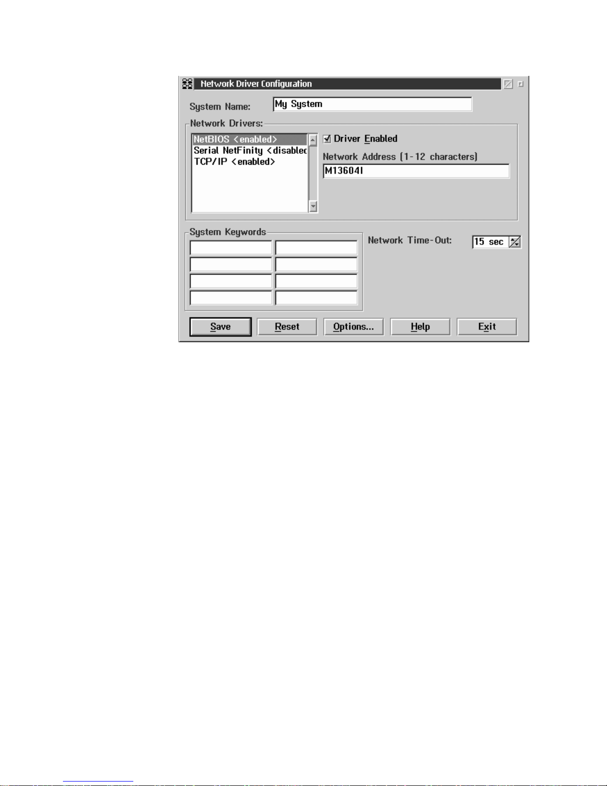
36 IBM® Netfinity® 7600 User’s Reference
Follow these steps to continue configuring the system:
a. Enter a System Name.
Enter a name for the system in the System Name field. This name will help
other Netfinity Manager users identify the system on the network.
b. Select a Network Driver.
Select one of the available Network Drivers that are displayed in the Network
Drivers field. Once selected, the Network Driver will assign a network
address to the system.
Notes:
(1) The fields that appear beneath the Driver Enabled check box will change
depending on which Network Dr iver you select.
(2) When enabling the IPX or TCP/IP Network Driver, the network address
cannot be altered, and it will not appear on the screen. No field will
appear beneath the Driver Enabled check box if you select the IPX or
TCP/IP Network Driver.
(3) When enabling the NetBIOS Network Driver, a network address will be
selected and displayed in the Network Address field. To change this
default name, enter any 1–8 character address. However, this address
must be unique to the system. If this NetBIOS address is identical to the
NetBIOS address of another system on the network, it will prevent
Netfinity Manager from starting properly.
(4) When enabling the Serial Netfinity Manager driver, type a name that will
be used to identify the system in the Unique Machine Dialup Name
field. This name can be up to 32 characters long, and must be unique to
the system. If this name is not unique, it can prevent remote Netfinity
Manager us e rs from usi ng the Seri al C o nnection Cont rol service to acces s
the system.
c. Enable the Network Driver.
Page 49

Chapter 5. Using Netfinity Manager 37
When you have entered all required information, click the Driver Enabled
check box to activate the driver on startup.
If the system supports multiple network interfaces, add additional ne twork
drivers by repeating steps b and c.
d. Identi fy the system with System Keywords (optional).
To make fu l l u se of the Remote Sy s t em Manager’s discovery proce ss , ide nt if y
the system (and each of the Netfinity Manager systems that are on the
network) with descriptive system keywords. Enter these keywords in the
appropriate System Keywords fields.
e. Select Netfinity Manager Options (optional)
Click on the Options button to open the Netfinity Manager Options window.
The Netfinity Manager Options wi ndow contains special options that affect
Netfinity Manager network operations . Available options include:
• Force Remote Logons
If the Force Remote Logons option is enabled, the system will not be
able to save the User ID/Password combinations that were used when
accessing remote systems. This will force you to manually log on each
time a remote system is accessed.Service Execution Alerts
• Service Execution Alerts
If the Service Execution Alerts option is enabled, the Netfinity Manager
Service Manager will generate a Netfinity Manager alert whenever one
of the user’s Netfinity Manager services is started by a remote user. The
alert includes the name of the service that was run and information
about the user that started the service.
• Show Network Support
If the Show Network Support option is enabled, the Netfinity Manager
Support Program (or Network Interface) will be visible as a minimized
process in the Windows NT 4.0 task bar. This enables the user to shut
down the Netfinity Manager Support Program. If the Netfinity Manager
Support Program is to remain invisible to the user, do not enable this
option.
• Remote User Authorization for Screen Access
If the Remote User Authorization for Screen Access option is enabled,
a remote user cannot use either Remote Workstation Control or Screen
View on your system without your permission. When this option is
enabled and a remote user attempts to use one of these services on your
system, a window will pop up on your desktop alerting you that a
remote user is attempting to use the Remote Workstation Control or
Screen View service and asking whether you want to permit this user to
use this service on your system. You can click Yes or No. If you do not
make a selection within 15 seconds (for example, if you are not sitting at
your system when the access attempt is made), Netf inity Manager will
automatically prevent the remote user from using the service on your
system.
• Disable DNS Name Res olution
If the Disable DNS Name Resolution option is ena b led , Netfinity
Manager will use only a numeric TCP/IP ad dress (for example,
8.24.67.32) to communicate with remote systems and will not attempt to
resolve the numeric address into an alphanumeric, Domain Name
Server (DNS) address (for example, your.system.ibm.com). Select this
option if you are using Netfinity Manager is a WINS networking
environment or if you are using TCP/IP in an environment that does
not have a Domain Name Server.
Page 50

38 IBM® Netfinity® 7600 User’s Reference
To enable one or more of the available Netfinity Manager Options:
(1) Click Options....
(2) Select one or more Netfinity Manager options.
(3) Click Save.
f. Set the Network Time-out Value (optional).
The Network Time-out field shows the number of second s that Netfinity
Manager will attempt to communic ate with a remote system that is not
responding. If Netfinity Manager does not establish contac t with the remote
system within this time, it cancels the communication attempt. The Network
Time-out default setting is 15 seconds. This default setting might not need to
be altered.
g. Save the configuration and continue.
Click Save to save the configuration. Then, click Exit to continue.
Note: The configuration can be changed later by double-click ing the
Network Driver Configuration object in the Netfinity Manager
folder.
10. After finishing configuring the system for network access, the installation
program displays a list of changes that must be made to the system configuration
files, and asks whether the installation program should make the changes. For
example, if you are installing Netfinity Manager f or Windows 95, the installation
program will display a list of changes that must be made to the CONFIG.SYS file.
Click either Yes or No.
Note: These changes must be made to the system configuration for Netfinity
Manager to run correctly.
• If you click Yes the installation program automatically makes the necessary
changes to the system configuration.
• If you click No the commands are saved to a file named CONFIG.NEW in
the destination directory (and to AUTOEXEC.NEW, if appropriate) so that
they can be added later.
11 . The insta lla tio n is n ow com ple te. S hut d own a nd r esta rt t he sy ste m for th e sys tem
configuration changes to take effect.
Netfinity Manager database support
Netfinity Manager supports the collection and export o f a vast amount of systemspecific data to a Netfinity Manager database.
Netfinity Manager databases can be created on database management systems using
DB2®, Lotus Notes®, or Microsoft SQL. Microsoft SQL is supported through open
database connectivity (ODBC), and is available on systems running Netfinity
Manager for OS/2, Windows 95, or Windows NT. If the system supports ODBC, the
user can access and export DB2 data through ODBC as well. Once support for one or
more of these databases has been installed along with Netfinity Manager, data can be
exported from these Netfinity Manager services:
• Alert Manager
• Software Inventory
• System Information Tool
• System Profile
• System Monitor
Information on how to install and configure support for database export follows.
Page 51

Chapter 5. Using Netfinity Manager 39
• If support for DB2 database export is being installed, see “DB2 database
support”.
• If support for Lotus Notes database export is being installed , see “Lotus Notes
database support” on page 43.
• If support for ODBC database export is being installed, see “ODBC database
support” on page 44.
DB2 database support
Support for DB2 database export is automatically configured during installation of
the Netfinity Manager. However, the database system itself must be configured.
Instructions for configuring the database follow.
A raw data dump to a file is also available a nd will run without a database.
System requirements
Netfinity Manager DB2 database export is supported on systems running Netfinity
Manager for OS/2, Netfinity Manager for Windows 95, Netfinity Manager for
Windows 98, and Netfinity Manager for Windows NT. For more information about
supported version numbers refer to Table 3 on page 48.
Attention:
Using Netfinity Manager database support with systems running unsupported
versions of DB2 or the DB2 Client might cause unpredictable results and might halt
the system.
See the DB2 Installation Guide for general requirements and supported protocols.
Installing and configuring the database
The following information describes the steps to install and configure the DB2
database.
Note: If your primary system is OS/2, refer to “Installing the database on OS/2” on
page 39.
1. Start a DB2 command window.
Note: If it is not already running, start the DB2 database m an ager.
2. Type the following command:
DB2 CREATE
databasename ON d
where
• databasename is the name of the database
• d is the drive where the database is created
3. Press Enter.
4. Next, you must configure the tables for ODBC database support. For information
on configuring the database for ODBC, refer to “ODBC database configuration”
on page 45. For information on creating the tables, refer to “Cr eating the Netfinity
Manager tables” on page 46.
5. Finally, you must bind the database. For informa tion on binding the database,
refer to “Activating the database”.
Installing the database on OS/2:
Page 52

40 IBM® Netfinity® 7600 User’s Reference
1. Insert the Netfinity Manager CD into the CD-ROM drive (in this example, drive
D; individual drive letters might be different).
2. Start an OS/2 window or full-screen session.
3. Make the CD-ROM drive the active drive.
Type D: and then press Enter.
4. Type the following command at the OS/2 prompt:
NETFINDB CREATE /DBNAME=
databasename /DRIVE=d
where databasename is the name of the database and d is the drive where the
database will be located.
Note: If any part of the database already exists, the utility program will create
only the portions of the database that are missing.
5. Press Enter.
Activating the database
The following information describes how to connect, bind, and grant privileges to the
database.
1. Connecting to the Database
a. Start a DB2 command window.
b. Type the following command:
DB2 CONNECT TO
databasename
where databasename is the name of the databas e as specified in the da tabase
installation step.
c. Press Enter.
2. Bind the package and the database
To prepare SQL statements stored in the bind file and store the package in the
database, perform the following steps from a system on which Netfinity Manager
for OS/2, Netfinity Manager for Windows 95, or Netfinity Manager for Windows
NT has been installed:
a. Open a DB2 command window.
b. In the DB2 command window, type the following command:
DB2 BIND
x:\directory\DB2SQLC0.bnd
where
x:\directory is the name of the drive and directory where Netfinity
Manager is installed.
c. Press Enter.
Granting and revoking database privileges
The following information describes h ow to grant and revoke database privileges.
Note: If your primary system is OS/2, refer to “Database privileges on OS/2
systems” on page 41.
1. Start a DB2 command window.
Notes:
a. If it is not already running, start the DB2 database manager.
b. If you are not connected to the DB2 Netfinity database, connect to the
database now.
2. Type the following command:
Page 53

Chapter 5. Using Netfinity Manager 41
DB2 GRANT privilegecode ON TABLE tablename TO userid
where
• privilegecode is one of the following privilege codes:
— ALL
— ALL PRIVILEGES
Note: Grants all the appropriate privileges, except CONTROL, on the
database.
— ALTER
— CONTROL
— DELETE
— INDEX
— INSERT
— REFERENCES
— SELECT
— UPDATE
• tablename is the name of the table as specified during database installation. A
listing of the Netfinity database table names can be fo und in the Netfinity
User’s Guide (Appendix H: Netfinity Relational Database Tables).
Note: The Netfinity Database Administration Tool can also be used to
GRANT or REVOKE privileges.
• userid is the user ID to be granted access
3. Press Enter to execute the command.
To revoke privileges, substitute REVOKE for GRANT in the command line.
Database privileges on OS/2 systems:
1. Use the GRANT EXECUTE command to enable Netf inity Manager to access the
database.
Type the following command at the OS/2 prompt:
DB2 GRANT EXECUTE ON PACKAGE NETFIN.DB2SQLC0 TO PUBLIC
and then press Enter.
Note: Specify PUBLIC or authorize only specific manager systems. To limit
access to the database, substitute the authorization name of the managing
system for PUBLIC.
2. Use the CONNECT RESET command to disconnect current users from the
database.
Type the following command at the OS/2 prompt:
DB2 CONNECT RESET
and then press Enter.
3. Use the NETFINDB GRANT command to grant (or revoke) database privileges.
To grant or revoke table privileges on OS/2:
a. Insert the Netfinity Manager CD into the CD-ROM drive (in this example,
drive D; individual drive letters might be different).
b. Make the CD-ROM drive the active drive.
Type D: and then press Enter.
c. Type the following command:
NETFINDB GRANT /ID=
id PUBLIC /DBNAME=databasename /PRIV=privilegecode
where
• id is the user ID to be granted access
Page 54

42 IBM® Netfinity® 7600 User’s Reference
• databasename is the name of the database as specified during NETFINDB
execution
• privilegecode is one of the following privilege codes:
— ALL
— ALTER
— CONTROL
— DELETE
— INDEX
— INSERT
— REFERENCES
— SELECT
— UPDATE
d. Press Enter to execute the command.
Note: Use PUBLIC or authorize only a specific ID or group name. Netfinity
Manager update programs use the DB2SQLC0 package and do not
require specific table privileges.
To revoke privileges, substitute REVOKE for GRANT in the command line.
To configure Netfinity Manager to discontinue export data through ODBC for use
on DB2, refer to “ODBC database support” on page 44.
Cataloging the database in the managing system: If the manager is using a remote
database, catalog the node the database resides on and then catalog the database to
that node.
Once this step has been completed, the name of the Netfinity Manager database will
appear in the System Inf ormation Too ls Database Selection window.
Deleting the database
The following information describes how to d e lete the d atabase for all supported
operating systems.
Note: If your operating system is OS/2, refer to “Deleting the database on OS/2”.
1. Start a DB2 command window.
2. Type
DB2 DROP DATABASE
databasename
where
databasename is th e name of the database as specified during the database
installation.
3. Press Enter.
Deleting the database on OS/2: 1.Insert the Net finity Manager CD-ROM into the
database server CD-ROM drive (in this example, the CD-ROM drive is E).
2. Start an OS/2 window or full-screen session.
3. Make the CD-ROM drive the active drive.
Type E: and press Enter.
4. Type the following command at the OS/2 prompt:
NETFINDB DELETE /DBNAME=
databasename
where databasename is the name of the database as specified during NETFINDB
execution.
5. Press Enter.
Page 55

Chapter 5. Using Netfinity Manager 43
To configure Netfinity Manager to discontinue export data through ODBC for use on
DB2, refer to “ODBC database support” on page 44.
Lotus Notes database support
To enable the Netfinity Manager to export system data to a Lotus Notes database, the
following must be done:
1. Install the Netfinity Manager database template on the Lotus Notes server.
2. Enable Netfinity Manager to export to the Lotus Notes server.
Instructions on installing the Lotus Notes database template and enabling the
Netfinity Manager to export to the Lotus Notes database foll ow.
System requirements
The minimum requirements for Netfinity Manager to export data to a Lotus Notes
database are:
• Lotus Notes
• Lotus Notes client
For information on what versions of Lotus Notes and the Lotus Notes client are
supported, see T a ble 3 on page 48. See the Notes Administrator’s Guide for general
system requirements and supported communications protocols.
Installing the database
To enable Netfinity Manager to export system data to a Lotus Notes databas e, install
the Netfinity Manager database template on the Lotus Notes server . During Netfinity
Manager installation, a Lotus Notes database template file ( named NETFINDB.NTF)
was copied to the Netfinity Manager program directory. To install the database
template on the Lotus Notes server:
1. Copy NETFINDB.NTF from the Netfinity program directory to the Notes data
directory on the Lotus Notes server.
2. Start Lotus Notes on the server.
3. Click New Database... from the Notes File pull-down menu.
This opens the New Database window.
4. Click Netfinity Database from the Template selection lis t.
5. Check the Inherit Future Design Changes check box.
This enables future releases of Netfinity Manager to automatically a pply changes
to this Netfinity Manager database.
6. Click Local from the Servers selection list.
Note: When installing the database on a remote server, select the name of the
remote server from the Servers list.
7. Type in the Filename field:
NETFINDB.NSF
8. Type in the Title field:
Netfinity Database
9. Click New to create the database and close the New Database window.
10. Double-click the Netfinity Database icon in the Lotus Notes workspace.
11. Click Database in the File pull-down menu.
Page 56

44 IBM® Netfinity® 7600 User’s Reference
12. Click Access Control... in the Database pull-down menu.
13. Set the Access Level for all Netfinity Manager systems that will be exporting data
to this database to Editor.
14. Check the Can Delete Documents check box.
15. Click OK.
Once the Lotus Notes database is installed, ena ble Netfinity Manager systems to
export to the Lotus Notes server.
• If the Netfinity Manager system is running Netf inity Manager for OS/2, ensure
that the Lotus Notes directories are included in the CONFIG.SYS file LIBPATH,
PATH, and DPATH statements. If the directories are not included in these
statements, it is not possible to export to the Lotus Notes database.
• If the system is running Netfinity Manager for Windows NT, ensure that the
Lotus Notes directory path is included in the Global Windows NT environment
settings.
• If the system is running Netfinity Manager for Windows 95, ensure that the
Lotus Notes directories are included in the AUTOEXEC.BAT file PATH
statement. If the directories are not included in this statement, it is not possible
to export to the Lotus Notes database.
Once these steps have been completed, export system information from Netfinity
Manager to an easy-to-browse Lotus Notes database.
Browsing the Netfinity Manager Lotus Notes
database
To browse the data contained in the Netfinity Manager Lotus Notes database:
1. Open the Netfinity Database object in the Lotus Notes Workspace.
2. Select from the View pull-down menu the section of the Netfinity Manager
database to be browsed.
The Netfinity Manager database is divided into sections that contain data
gathered by specific Netfinity Manager services. Click the name of the service that
gathers the data to be viewed (for example, Alert Logs).
Note: Some menu selections will contain submenus.
3. Information contained in the part of the Netfinity Manager database that has been
selected is now listed in the window. For more detailed information about any
displayed data item, double-click the data item.
4. Some data items can be expanded to reveal additional information. These items
are identified by a plus sign (+) in the left side border of the Notes window, beside
the name of the data item. To expand the data item, select the item and then click
Expand in the View pull-down menu.
ODBC database support
Netfinity Manager supports exporting data via ODBC for use on SQL or DB2
database systems.
Note: ODBC database export is available only on systems that are running Netfinity
Manager.
System requirements
The minimum requirements for Netfinity Manager ODBC database export are:
• Windows NT
Page 57

Chapter 5. Using Netfinity Manager 45
— ODBC
— ODBC support for one or more of the following database management
systems (DBM S):
– IBM DB2
– Microsoft SQL Server
• Windows 95, with:
— ODBC
— ODBC support for one or more of the following database management
systems:
– IBM DB2
– Microsoft SQL Server
• OS/2
— Microsoft SQL Server (using the Visigenic driver provided with Microsoft
SQL Server)
or
— IBM DB2
For detailed information about supported ODBC platforms, see Table 3 on page
48.
Note: The ODBC database name must not be longer than 8 characters.
ODBC database configuration
This section describes the procedures you must complete before Netfinity Manager
can create the Netfinity Database Tables us ing ODBC.
1. Define the NETFIN ID so the Netfinity Database Administration can create the
Netfinity Database tables with a table qualifier of NE TFIN.
Attention: NETFIN is a restricted user ID. The password is not retained by
Netfinity Database Administration after use. Do not use this ID for exports.
Notes:
a. In O S/2 and Windows 95, NETFIN must either be the owner of the database
or must be given administrator authority.
b. In Windows NT, when exporting to DB2, NETFIN must either be the owner of
the database or be defined as a system administrator through the NT User
Manager for Domains or the NT User Manager.
In Windows NT, when exporting to MS SQL, NETFIN must be the owner of
the database or be given table create rights.
2. Create the database with the appropriate relationship with the NETFIN ID.
3. Make a database ODBC source either using the ODBC tools shipped with the
operating system or the database.
4. On Windows NT, configure the Netfinity Support Program to export data using
the ODBC database.
a. Open Services from the Control Panel.
b. Click Netfinity Support Program from the Services field, then click Startup.
c. Click Automatic in the Startup Type button group.
d. Click This Account in the Log On As field group. Enter in the This Account
field the user name of the account that made this database an ODBC source.
e. Click OK.
Page 58

46 IBM® Netfinity® 7600 User’s Reference
Note: If the Event Scheduler or Alert Manager will be used to export data using
ODBC, continue to have the ID which made the database an ODBC source
logged on during the time Event Scheduler will be exporting d ata.
Creating the Netfinity Manager tables
To create the tables needed to enable Netfinity Manager to export data:
1. Open the Netfinity Manager Database Administration service.
The Netfinity Manager Database Administration service is found in the Netfinity
Manager folder or Netfinity Manager program group. Double-click this icon to
open the Netfinity Manager Databas e Ad ministration window.
2. Select a DBMS.
Click in the Select DBMS listing the name of the DBMS which Netfinity Manager
will be using to export data.
Page 59

Chapter 5. Using Netfinity Manager 47
3. To create the Netfinity Manager table groups within the database, click Create
and then click OK to open the Database Server window.
The following table actions are also available:
• Delete
To remove the Netfinity Manager table groups from the database, click
Delete and then click OK to open the Database Server window.
• Grant
Permits access to a database for a specified user ID. To grant access:
a. Click Grant.
b. In the User ID field type the user ID that will be permitted to access the
database.
c. Select privileges for this ID.
All privileges (Insert, Delete, Select, and Update) are selected by default.
A user ID must have all of these privileges to export data to the
database.
d. Click OK to open the Database Server window.
• Revoke
Disables access to a database for a specified user ID. To revoke access:
a. Click Revoke.
b. In the User ID field type the user ID that will have access to the database
revoked.
c. Deselect privileges to be revoked for this ID.
All privileges (Insert, Delete, Select, and Update) are selected by default.
A user ID must have all of these privileges to export data to the
database. Some or all of these privileges can be revoked.
d. Click OK to open the Database Server window.
4. Select the database within which the table groups will be created.
5. Click OK.
The Netfinity Manager Database Access window opens.
6. Type in the User ID field
netfin
netfin is the qualifier name of the Netfinity Manager database.
7. In the Password field type the password that enables access to the Netfinity
Manager database.
8. Click OK.
As the information is processed, a Creating tables status message should be
displayed. When the operation completes, a Requested Action Completed message
should be displayed.
Supported and certified databases
The following table shows databases and operating systems that are certified for use
with this release of Netfinity Manager.
Page 60

48 IBM® Netfinity® 7600 User’s Reference
Starting Netfinity Manager
To start Netfinity Manager:
1. Open the Netfinity Manager folder or program group.
During installation of Ne tfinity Manager, a Netfinity Manager folder (OS/2,
Windows 95, or Windows NT 4.0 only) or a Netfinity Manager program group
(Windows NT 3.51 only) was added to the Desktop. The Netfinity Manager folder
or program group contains the Netfinity Manager Service Man ager object.
Table 3. Supported Netfinity Databases.
Reference by operating system and database client version.
Product Windows 95 Windows
NT 3.51
Windows
NT 4.0
OS/2 Warp
Connect
OS/2 Warp
4.0
IBM DB2 Version 2.1.2 Yes Yes Yes Yes Yes
IBM DB2 Universal Database
5.0
Yes Yes Yes Yes Yes
ODBC - IBM DB2 Version
2.1.2
Yes, DB2
Driver
Yes, DB2
Driver
Yes, DB2
Driver
Yes, DB2
Driver
Yes, DB2
Driver
ODBC - IBM DB2 Universal
Database 5.0
Yes, DB2
Driver
Yes, DB2
Driver
Yes, DB2
Driver
Yes, DB2
Driver
Yes, DB2
Driver
ODBC - Microsoft SQ L
Version 7.0
Yes,
Microsoft
SQL Driver
Yes,
Microsoft
SQL Driver
Yes,
Microsoft
SQL Driver
Y es, Visigenic
Driver
Version 1.10
No
ODBC - Microsoft SQ L
Version 6.5
Yes,
Microsoft
SQL Driver
Yes,
Microsoft
SQL Driver
Yes,
Microsoft
SQL Driver
No No
Lotus Notes Version 4.5.2 Yes Yes Yes Yes Yes
Lotus Notes Version 4.5.3a Yes Yes Yes Yes Yes
Lotus Notes Version 4.6 Yes No Yes No No
Lotus Notes Version 4.6a Yes No Yes No No
Lotus Notes Version 4.63 Yes No Yes No No
Oracle Version 7.3 Yes, Oracle
Driver
Version
2.0.3.1.1
Yes, Oracle
Driver
Version
2.0.3.1.1
Yes, Oracle
Driver
Version
2.0.3.1.1
No No
Oracle Version 8.0 Yes, Oracle
Driver
Version
8.0.3.0.0
No Yes, Oracle
Driver
Version
8.0.3.0.0
No No
Sybase SQL Version 11.0 Yes, Sybase
Driver
Version
10.0.3T4
Yes, Sybase
Driver
Version
10.0.3T4
Yes, Sybase
Driver
Version
10.0.3T4
No No
Note: The above applies to Netfinity Manager Release 5.2.0 and later.
Page 61

Chapter 5. Using Netfinity Manager 49
Notes:
a. In your Netfinity Manager folder or pr ogram group is a document titled Read
Me First, which contains information about Netfinity Manager that might not
be covered in your documentation.
b. The Netfinity Manager folder also contains the Network Driver
Configuration object, which you can use to reconfigure your network
protocols and system keywords, and the Net finity Manager Database Tables
object, which contains a handy online reference for all of the data tables in the
Netfinity Manager database. For more information on Netfinity Manager
database support see “Netfinit y Manager database support” on page 38.
c. The Netfinity Manager folder also conta ins a Netfinity Database
Administration object. You can use Netfinity Database Administration to
configure Netfinity Manager database support. For more information on
Database Administration, see "ODBC Database Support" in Netfinity Manager
Quick Beginnings.
2. Start the Netfinity Service Manager.
T o start the Netfinity Service Manager, double-click the Netfinity Service Manager
object.
Netfinity Manager Service Manager
All Netfinity Manager services that are supported by the operating system can be
started from the Netfinity Manager Service Manager window. The services that are
available for use depend on the installation configuration that was selected during
installation.
Page 62

50 IBM® Netfinity® 7600 User’s Reference
To start any Netfinity Manager service that appears in the S e rvice Manager window,
double-cli ck the ico n fo r that se rvic e . To start a Netfinity Mana ger se rvic e on a re mot e
system, use the Remote System Manager service.
Netfinity Manager service descriptions
Each Netfinity Manager service consists of a base program and a graphical user
interface (GUI). The service base programs enable Netfinity Manager to remotely
access the individual services, but do not allow for local access. The service GUIs,
when functioning along with their respective base program, enable access to the
service.
Some services are available only on systems with certain system configurations. These
services are:
• Alert on LAN Configuration (available only on systems running Windows 95 or
later or Windows NT 4.0 or later)
• Capacity Management (available only on systems running Windows NT 4.0 or
later)
• Cluster Manager (available only on systems running Windows NT 4.0 or later)
• DMI Browser (requires DMI Service Layer)
• ECC Memory Setup (requires ECC memory)
• Predictive Failure Analysis (requires a PFA-enabled hard disk drive)
• RAID Manager (requires a RAID hard disk drive subsystem)
• System Partition Access (requires a built-in System Partition)
• Update Connector Manager (available only on syste ms running Windows NT
4.0 or later)
Brief descriptions of each of the Netfinity Manager services follow. Complete
instructions on how to use each of these services can be found in the service-specific
chapters of the Netfinity Manager User’s Gui de.
Page 63

Chapter 5. Using Netfinity Manager 51
Advanced System Management
The Advanced System Management service provides extensive functionality
available for your IBM PC Server Advanced System Management Adapter, Netfinity
Advanced System Management PCI Adapter, or Netfinity Advanced System
Management Processor. With the Advanced System Management service, you can
configure system management events (such as POST, loader, and operating system
time-outs or critical temperature, voltage, and tamper alerts). If any of these events
occurs, the Advanced System Management service can be configured to use a modem
or your Netfinity Manager system to automatically forward a Netfinity alert to other
Netfinity Manager systems or to a numeric or alphanumeric pager.
Alert Manager
The Alert Manager is an extendable facility that allows receiving and processing of
application-generated alerts. A variety of ac tions can be taken in response to alerts,
including logging alerts, notifying the user, forw arding the alert to another system,
executing a program, playing a WAV file (available only on multimedia systems),
generating an SNMP alert message, dialing out to a digital pager service (available
only on systems that have a modem), or taking an application-defined action. Actions
are user-definable, using a flexible action management interface.
Also, an extensive, detailed log is kept of all alerts received by the Alert Manager.
Logged information includes date and time the alert was received, type and severity
of the alert, the ID of the application that generated the alert, as well as any text that
was generated and any action taken by the Alert Manager. Individual or multiple
alerts can be selected from the log and printed for later reference, or deleted once
problems are corrected. This service is available for stand-alone use and network use.
Alert on LAN configuration
Use the Alert on LAN configuration service to configure monitoring options of Alert
on LAN-capable systems locally and remotely. Systems with Alert on LAN capability
provide critical status information about system states. The data is reported by
hardware or software (depending on whether the systems in currently powered on or
not) using TCP/IP .
Capacity Management
Capacity Management is an easy-to-use resource management and planning tool for
network managers and administrators, allowing you to remotely monitor the
performance of servers on the network.
Cluster Manager
Cluster Manager is an application designed to enha nce the cluster management
capabilities of the Microsoft Cluster Server (MSCS) administration console, included
with Microsoft Windows NT Version 4.0 Enterprise Edition. Cluster Manager builds
on the power of MSCS, providing an integrated graphical interface that enables you to
quickly and easily monitor and manage the clustered systems on your network. This
service is available only on systems runnin g Windows NT Workstation 4.0.
Critical File Monitor
Critical File Monitor can warn you whenever critical system files on the system are
deleted or altered. Critical File Monitor makes it simple to generate Netfinity alerts
when an important System File (such as the CONFIG.SYS file) changes date, time,
size, or when it is deleted or created. Critical File Monitor can also be used to monitor
any other files that reside on a Netfinity Manager system.
Page 64

52 IBM® Netfinity® 7600 User’s Reference
DMI Browser
DMI Browser enables you to examine information about the DMI-compliant
hardware and software products installed in or attached to the system.
ECC Memory Setup
The ECC Memory Setup allows for monitoring of ECC memory single-bit errors, and
can automatically "scrub," or correct, the ECC memory when errors are detected. Also,
a running count of single-bit errors can be kept, and can set a single-bit error
threshold that will cause a nonmask able interrupt (NMI) if the ECC single-bit error
threshold is exceeded. This service is available for both stand-alone and network use
by any system that has ECC memory.
Event Scheduler
Use Event Scheduler to automate many Netfinity Manager services. With Event
Scheduler, you can automatically gather and export System Information Tool, System
Profile, and Softwar e Inventory data, distribute or de lete files, r estart systems, execute
commands, and access and manage System Partitions on all of the Netfinity Manager
systems on the network. Scheduled events can be performed one time only, or can be
performed according to a user-defined schedule.
File Transfer
Use the File Transfer service to easily send, receive, or delete files or entire directories
to and from remote Netfinity Manager systems on the network.
Power-On Error Detect
The Power-On Error Detect service can warn you immediately when a remote
Netfinity Manager system has start- up problems, enabling you to react quickly to
problems and minimize downtime.
Predictive Failure Analysi s
The Predictive Failure Analysis (PFA) service enables continual monitoring and
managing of PFA-enabled hard disk drives. A PFA-enabled hard disk drive features
hardware designed to help detect drive problems and predict drive failures before
they occur, thus enabling you to avoid data loss and system downtime.
Process Manager
Use Process Manager to view detailed information about all processes that are
currently active on any system. It is al so possible to stop or start processes and
generate Netfinity Manager alerts if a process starts, stops, or fails to start within a
specified amount of time after sy ste m startup.
RAID Manager
The RAID Manager service can monitor, manage, and configure an assortment of
Redundant Arrays of Independent Disk (RAID) adapters and arrays without
requiring the RAID system to be taken offline to perform maintenance. Use the RAID
Manager to gather data about the system RAID array and RAID adapter, rebuild
failing drives, add (or remove) logical drives, perform data integrity tests, and many
other RAID system tasks. This service is available f or sta nd- alone use and network
use by any system that has a supported RAID adapter.
Page 65

Chapter 5. Using Netfinity Manager 53
Remote Session
Use Remote Session to establish a fully active command session with any remote
Netfinity Manager system.
Remote System Manager
Use Remote System Manager to access and manage any Netfinity Manager service on
any Netfinity Manager system in the n et work. The Netfinity Manager system on the
network is organized into easy-to-manage logical groups that can be updated
automatically using the auto-discovery feature.
Remote Workstation Control
Remote Workstation Control can monitor or co ntrol the screen displa y of a remote
system that is running Netfinity Manager (or Clien t Services for Netfinity Manager).
Once you initiate a Remote Workstation Control session with another Netfinity
Manager system, you can passively monitor events that are occurring on the display
of the remote system or actively contr ol the remote system desktop. When you initiate
an active Remote Workstation Control session, clicks and keystrokes that are entered
on your system are automatically passed to the remote system. With Remote
Workstation Control, you can remotely start programs, open and close windows,
enter commands, and much more.
Screen View
The Screen View service takes a "snapshot" of the system graphic display or any
remote system running Netfinity Manager or Client Services for Netfinity Manager
and displays it on the screen. These snapshots can be saved as bitmaps and viewed
later.
Security Manager
The Security Manager service can prevent unauthorized access to some or all of the
Netfinity Manager services. It uses incoming user ID and password combinations,
and is available for networ k use only.
Serial Connection Control
The Serial Connection Control service enables remote systems running Netfinity
Manager to access the system through a phone line and modem. With the Serial
Connection Control service, you do not have to be attached to a network to benefit
from the outstanding remote system access, monitoring, and management capabilities
of Netfinity Manager.
Note: The system must have a properly installed and configured modem that
supports at least 9600 baud for the Serial Connection Control service to
function.
Service Configuration Manager
Service Configuration Manager can sa ve the configuration of a Netfinity Manager
service from a selected system to a service configuration file (SCF). Once created, SCF
files can be used by Event Scheduler to restore the configuration to the same system,
or it can be used (in conjunction with Event Scheduler) to duplicate that configuration
on other similar systems you choose.
Page 66

54 IBM® Netfinity® 7600 User’s Reference
Software Inve ntory
Software Inventory enables the user to create and manage software product
dictionaries that can be used to easily maintain an inventory of all application
programs installed on the system.
System Diagnostics Manager
System Diagnostics Manager enables you to initiate a variety of diagnostic tasks on
systems that support ROM-based diagnostics. The results of all previously run
diagnostic sessions are stored and can be examined using System Diagnostics
Manager to help diagnose and resolve system problems.
System Information Tool
The System Information Tool enables quick and convenient access to detailed
information on the hardware and software configurations of the system. System
Information Tool gathers information about almost any computer; however, the most
detail is provided when this service is used with IBM compu ters. T his service is
available for both stand-alone and network use.
System Monitor
The System Monitor provides a convenient method of charting and monitoring the
activity of a number of components in a system, including processor usage, disk space
used, and ECC memory errors. These convenient monitors are detachable and
scalable, enabling only the monitors needed to remain available at all times. Use the
System Monitor Threshold Manager to set threshold levels for any of the monitored
components. When exceeded, these thresholds will generate user-configured alerts.
Data is continually collected from the time the system sta rts. A s oph isticated datahandling technique is used to weigh the individual values, average concurrent
samples, and post single values that accurately reflect long-term system activity. This
technique allows system activity records to be maintained without creating enormous
data files. This service is available for both stand-alone and network use.
System Partition Access
The System Partition Access allows for greatly simplif ied system partition file
handling, both locally and remotely. Individual files and entire directories can be
renamed or deleted from the system partition. Individual files can be renamed,
deleted, or copied into the system partition. Also, the entire partition can be backedup, restored, or deleted. This service is available for stand-alone use and network use
by any system that has a System Partition.
System Profile
The System Profile provides a convenient notebook of pertinent data about a
particular user or system. It features many predefined fields for extensive userspecific data, including name, address, office number and location, and phone
number. System Profile also includes many predefined fields for system-specific data
that might not be available to the System Information T ool, including model and serial
numbers and date of purchase. Finally, there are many user-definable miscellaneous
fields that can be used to hold any data the user or administrator requires.
Update Connector Manager
Use Update Connector Manager to quickly and easily gather information about
various updates that are available for your client systems. Once available updates are
Page 67

Chapter 5. Using Netfinity Manager 55
discovered, use Update Connector Manager to apply updates to your systems
remotely. Updates can be applied to individual systems, or you can apply multiple
updates to multiple systems, all from Netfinity Ma nager. You can also use Update
Connector Manager to remove previously applied updates. Update Connector
Manager also includes a scheduler that you can use to discover, apply, or remove
updates automatically and perio di cally.
Web Manager Configuration
Use the Web Manager Configuration service to limit access to the Netfinity Manager
for Web to user-specified TCP/IP host or ranges of TCP/IP host addresses. Enable or
disable the Netfinity Manager for We b and specify the TCP/IP port number to which
the Netfinity Manager Web server functions.
Delaying Netfinity Manager startup on OS/2 systems
In some cases, it might be necessary for you to delay the aut om atic startup of the
Netfinity Manager Network Interface (NETFBASE. E XE) in order to allow other timesensitive applications to start up correctly or to allow your system to fully configure
itself prior to beginning network operations. NE TFBASE.EXE includes a parameter
(WAIT) that you can use to specify the number of seconds that NETFBASE.EXE will
wait before starting.
During Netfinity Manager installation, the Netfinity Manager Network Interface
object is placed in the Startup folder. To config ure Netfinity Manager to wait a
specified number of seconds before starting:
1. Shut down the Netfinity Manager Netwo r k Interface if it is running.
2. Open the Startup folder.
3. Using the right mouse button, click the Netfinity Manager Network Interface
object. This will open the Netfinity Manager Network Interface context menu.
4. Click Settings to open the Netfinity Manager Network Interface Settings
notebook.
5. In the Parameters field type
WAIT:
x
where x is the number of seconds that you w an t the Netf inity Manager Network
Interface to wait before starting.
6. Close the Netfinity Manager Network Inte rfac e Settings notebook.
With the WAIT parameter set to x, whenever you start your system, the Netfinity
Manager Network Interface will wait x seconds before starting.
Note: This feature is available only on systems that are running OS/2.
Getting more information about Netfinity Manager
Complete information on how to use Netfinity Manager (as well as Client Services for
Netfinity Manager) is included in Adobe Acrobat format on the Netfinity Manager
CD.
The \DOCS subdirectory contains the following files:
Page 68

56 IBM® Netfinity® 7600 User’s Reference
Installation options
This appendix describes methods for performing automated installations of Netfinity
Manager and creating customized Netfinity Manager in stallations.
Automated installation
If the system has a CID-enabled (CID stand s f or customization, installation, and
distribution) software distribution manager utility (such as LAN CID, included with
IBM Network Transport Services/2), Netfinity Manager can be installed on systems
within the network by using the Netfinity Manager installation program command
line parameters and response file. First, a source directory must be created for the
installation.
To create a source directory for a Client Services for Netfinity Manager installation:
1. Create a new directory on your system. This new directory will serve as a source
directory for the program files.
2. Copy the files from the appropriate Client Services for Netfinity Manager
directory location on the CD-ROM to source directory you created.
Filename Document Title Description
DOCSREAD.ME DOCSREAD.ME T ext file tha t contai ns brief descri ptions of
each of the Adobe Acrobat-readable PDF
file contained in this directory.
README.SCO Client Services for Netfinity Manager for
SCO UnixWare Read Me
Text file that contains instal la t ion an d
setup information for Client Services for
Netfinity Manager for SCO UnixWare.
NFMGRQB.PDF Netfinity Manager Quick Beginnings Installation and setup information for
Netfinity Manager.
NFMGRUG.PDF Netfinity Manager User’s Guide Detailed information on how to use
Netfinity Manager.
NFMGRCR.PDF Netfinity Manager Command Reference Detailed information on Netfinity
Manager command line functions.
NFCSVCQB.PDF Client Services for Netfinity Manager
Quick Beginnings
Installation and setup information for
Client Services for Netfinity Manager.
NFSVCUG.PDF Client Services for Netfinity Manager
User’s Guide
Detailed information on how to use
Client Services for Netfinity Manager.
NFSVCNW.PDF Client Services for Netfinity Manager for
NetWare User’s Guide
Installation, setup, and usage information
for Client Services for Netfinity Manager
for NetWare.
ASMUPDT.PDF Advanced System Management
Information
Updated information on the Advanced
System Management and Dynamic
Connection Manager services. These
services are included with this version of
Netfinity Manager.
NFSCOBAS.PDF Client Services for Netfinity Manager for
SCO UnixWare User’s Guid e
Installation, setup, and usage information
for Client Services for Netfinity Manager
for SCO UnixWare.
Page 69

Chapter 5. Using Netfinity Manager 57
For example, when creating a source directory to distribute Netfinity Manager
Services for OS/2, copy all of the files from the OS2/SERVICES dir ectory into the
created directory.
To create a source directory for a Netfinity Manager installation:
1. Create a new directory on your system. This new directory will serve as a source
directory for the program files.
Important:
Be sure to copy the Client Services for Netfinity Manager source files before the
copying the Netfinity Manager source files because the Netfinity Manager
directory contains some files that will overwrite f iles from the Client Services for
Netfinity Manager directory. Only Netfinity Manager installations can be done
from this directory.
2. Copy the files from the appropriate Client Services for Netfinity Manager
directories.
For example, when creating a source directory to distribute Netfinity Manager for
OS/2, copy all of the files from the OS2/SERVICES directory into the source
directory.
3. Copy the files from the appropriate Netfinity Manager directory.
For example, when creating a source directory to distribute Netfinity Manager for
OS/2, copy all of the files from the OS2/MANAGER directory into the source
directory.
After an installation source directory has been created, use a response file and the
Netfinity Manager installation program command-line parameters. The Netfinity
Manager installation program supports the following command-line parameters:
/R: drive+path+filename
Specifies the drive, path, and file name of the response file. See the
NETFBASE.RSP file (located in the directory in which Netfinity Manager was
installed) for an example of a response file with comments on the included
parameters.
/S: drive+path
Specifies the drive and path to install from. This is the directory to which the
files were copied.
/T: drive
Specifies the drive to install to. Default is the current startup drive.
/TU: drive+path
Specifies the drive and path of the CONFIG.SYS file to update. The default is
to change the CONFIG.SYS in the root directory of the drive specified in the
/T parameter (or the startup drive). This parameter is ignored if the
ChangeConfig parameter in the response file is FALSE.
For example, the line:
NETFINST /R:NETFBASE.RSP /S:Y:\NETFIN
/T:C /TU:D:\
will install Netfinity Manager, using the options in the response file
NETFBASE.RSP, from the directory Y:\NETFIN, to drive C: (the directory to
which the files are installed is taken from the response file), and will modify
the CONFIG.SYS file in the D:\ directory.
Note: For information on how to use a CID-enabled software distribution manager,
refer to the publications provided with the individual CID-enabled product.
Page 70

58 IBM® Netfinity® 7600 User’s Reference
Customized installation
For security reasons, not all users might need to have access to all services. User
access can be restricted by creating a customized installation that w ill prevent some
services from being installed.
T o create a customized installation, the INSTALL.INI file must be edited. For example,
when creating a customized Netfinity Manager for Windows 95 or NT installation,
edit the INSTALL.INI file that is found on Netfinity Manager directory.
The INSTALL.INI file has three sections, separated by the line
[==]
The first section contains the installation configuration that can be selected during
installation. There can be no more than eight choices. Each choice takes up two lines.
The first line is the text that is displayed next to the installation configuration radio
button. The second line is a list of the options in the third section that will be installed
when this choice is selected for installation.
For example:
;IBM SysMgt Install Script, Version 2 (Do not remove this comment line)
Netfinity Manager Installation [Manager 16900]
Advanced System Management Support [ServProc 450]
Capacity Manager Enhancement [CapMgt 5600]
Remote Workstation Control [RWC 2000]
World Wide Web Enhancement (TCPIP Required) [WebManager 3000] IsTcpip
[==]
Netfinity Manager CD for Windows 95/NT
[==]
NetFinity Admin
NULL Manager
CL 0 1 NETFBASE.EXE
CCL 0 1 NETDOM.INI
CCL 0 1 NETNODES.INI
CCL 0 1 INSTALL.BAT
CCL 0 1 NETFINST.EXE
CCL 0 1 INSTALL.INI
CCL 0 1 WININST.HLP
CL 0 1 APCKINST.DLL
;Screen Capture GUI
;NULL Manager
; CL 0 1 SAVEG.EXE
; CL 0 1 SAVEG.HLP
This INSTALL.INI will create a Netfinity Manager installation configuration that also
installs Advanced System Management, Capacity Manager, Remote Workstation
Control, and Netfinity Manager World Wide Web enhancement.
The second section contains the names of th e CD that this installation script will use.
The third section contains the list of options that can be installed. These are the
options that are selected by the choices in the first section. The options are
consecutively numbered starting at 1, so any inserted options will change the number
of all following options. Each option uses the following format:
Option Name
Dll-entrypoint
Page 71

Chapter 5. Using Netfinity Manager 59
option file
option file
...
install command
install command
...
Option Name An identifying comment by the installation program. All options must
have a different Option Name. This is used only for identification.
Dll-entrypoint
Used to determine whether an option is valid for a given target machine. In
most cases, it should be the reserved string "NU L L."
The easiest way to customize an installation is to simply put a semicolon in front of
any service that you want to remove from the installation.
To add a line item in a specific section, add all the necessary item information in the
format shown in the following example.
Before:
Screen Capture GUI
NULL Manager
CL 0 1 SAVEG.EXE
CL 0 1 SAVEG.HLP
After:
Screen Capture GUI
NULL Manager
CL 0 1 SAVEG.EXE
CL 0 1 SAVEG.HLP
CL 0 1 CUSTOM.INI
Page 72

60 IBM® Netfinity® 7600 User’s Reference
Page 73

© Copyright IBM Corp. 2000 61
Chapter 6. Installing options
This chapter provides instructions to help you add options to your server.
Major components of the Netfinity 7600 server
The orange color on components and labels in your server identifies hot-swap or hotplug components. This means that you can install or remove the components while
the system is running, provided that your system is configured to support this
function. For complete information about install ing or removing a hot-swap or hotplug component, see the information provided in the detailed procedures in this
document.
The blue color on components and labels indicates touch points where a component
can be gripped, a latch moved, and so on.
The following illustrations show the locations of the major components in your server.
Note: The illustrations in this document might differ slightly from your hardware.
Power supplyFan assemblyFiller PanelRemovable-media
drive
Hot-swap
drive
Page 74

62 IBM® Netfinity® 7600 User’s Reference
Microprocessor
Terminator card
Memory
module
Shuttle
I/O board
Memory board
Page 75

Chapter 6. Installing opt ions 63
Component locations
This section provides illustrations of the I/O board, processor board, and memory
board component locations.
I/O board component locations
The following illustration shows the location of the input/output connectors on the
I/O board.
Note: The illustrations in this document might differ slightly from your hardware.
Power
backplane
Processor
board
Keyboard
Mouse
Video port
USB 1 and
USB 2 port
Ethernet port
SCSI
external
Parallel port
ASM
interconnect
Serial
port B
Serial
port A
Management
port
Page 76

64 IBM® Netfinity® 7600 User’s Reference
Processor board component locations
The following illustrations show the location of the LEDs, connectors, and jumpers on
the processor board.
Note: The illustrations in this document might differ slightly from your hardware.
Processor board LEDs
The following illustration shows the location of the LEDs.
Microprocessor 2
error LED (Cr3)
Microprocessor 1
error LED (Cr9)
Microprocessor 3
error LED (Cr8)
Microprocessor 4
error LED (Cr4)
Battery
VRM 1 error LED
VRM 4 error LED
VRM 3 error LED
VRM 2 error LED
C
R6
C
C
R7
R5
(
(
(
)
C
R3
()
C
R8
()
C
R9
()
)
)
C
R10
()
C
R4
()
PCI slot LEDs
Page 77

Chapter 6. Installing opt ions 65
Processor board connectors
The following illustration shows the location of the connectors.
Microprocessor 2
Connector (J3)
Microprocessor 1
Connector (J2)
Microprocessor 3
Connector (J4)
Microprocessor 4
Connector (J5)
Battery
VRM 1 Connector
VRM 4 Connector
VRM 3 Connector
Reserved (J8 and J9)
VRM 2 Connector
Memory board
Connector
PCI Slot 1 and 2
(on PCI bus A)
PCI Slot 3-6
(on PCI bus B)
Page 78

66 IBM® Netfinity® 7600 User’s Reference
Processor board jumpers
The following illustration shows the location of the jumpers.
Jumper block
(J10-J16)
Flash ROM pageswap jumper
block (J56)
Power-on
password
override jumper
block (J48)
Battery
Advanced
System
Management
Processor reset
jumper block
(J59)
Power-on
control jumper
block (J23)
3.3 V standby
power for slot 2
(J20)
3.3 V standby
power for slot 1
(J47)
Microprocessor core-frequency
selection jumper block (J13-J16)
Reserved (J10)
Reserved (J12)
Reserved (J11)
Page 79

Chapter 6. Installing opt ions 67
Memory board component locations
The following illustration shows the location of the DIMM connectors on the memory
board.
The following illustration shows the location of the error LEDs on the memory board.
Connector 1(J1) Connector 9 (J9)
Connector 10 (J10)
Connector 11 (J11)
Connector 12 (J12)
Connector 13 (J13)
Connector 14 (J14)
Connector 14 (J14)
Connector 15 (J15)
Connector 2 (J2)
Connector 3 (J3)
Connector 4 (J4)
Connector 5 (J5)
Connector 6 (J6)
Connector 7 (J7)
Connector 8 (J8)
DIMM 1 error
LED (CR4)
DIMM 9 error
LED (CR13)
DIMM 2 error
LED (CR5)
DIMM 10 error
LED (CR12)
DIMM 3 error
LED (CR2)
DIMM 11 error
LED (CR15)
DIMM 4 error
LED (CR1)
DIMM 12 error
LED (CR16)
DIMM 5 error
LED (CR6)
DIMM 13 error
LED (CR11)
DIMM 6 error
LED (CR3)
DIMM 14 error
LED (CR14)
DIMM 7 error
LED (CR7)
DIMM 15 error
LED (CR10)
DIMM 8 error
LED (CR8)
DIMM 16 error
LED (CR9)
Page 80

68 IBM® Netfinity® 7600 User’s Reference
Before you begin
Before you begin to install options in your se rver, read the following information:
• Become familiar with the safety and handling guidelines provided in the Safety
Information book, the requirements specified in “Safety information statements”
on page 69, and the information in“Handling static-sensitive devices” on page
69. These guidelines will help you work safely while working with your server
or options.
• You do not need to turn off the server to install or replace hot-swap power
supplies, hot-swap drives, hot-swap fans, or hot-plug PCI adapters.
• The orange color on components and labels in your server identify hot-swap or
hot-plug components. This means that you can install or remove the component
while the system is running, provided that your system is configured to support
this function.
• The blue color on components and labels identify touch points where you can
grip a component, move a latch, and so on.
• Make sure that you have an adequate number of properly grounded electrical
outlets for your server, monitor, a nd any other options that you intend to install.
• Back up all important data before you make changes to disk drives.
• For a list of supported options for the Netfinity 7600, refer to
http://www.ibm.com/pc/us/compat on the Wor ld Wide Web.
System reliability considerations
To help ensure proper cooling and system reliability, make sure:
• Each of the drive bays has either a drive or a filler panel installed.
• Each of the power supply bays has either a power supply or a filler panel
installed.
• There is at least 50 mm (2 inches) of ventilated space at the sides of the server
and 100 mm (4 inches) at the rear of the server.
• The top cover is in place during normal operation.
• The top cover is removed for no longer than 30 minutes while the server is
operating.
• The processor housing cover over the processor and memory area is removed
for no longer than 10 minutes while the server is operating.
• A removed hot-swap drive is replaced within ten minutes of removal.
• Cables for optional adapters are routed according to the instructions provided
with the adapters.
• A failed fan is replaced within 48 hours.
Working inside the server with the power on
Your server supports hot plug, hot add, and hot swap devices and is designed to
operate safely while turned on with the cover removed. Follow these guidelines when
you work inside a server that is turned on:
• Avoid loose-fitting clothing on your forearms. Button long-sleeved shirts before
working inside the server; do not wear cufflinks while you are working in side
the server.
Page 81

Chapter 6. Installing opt ions 69
• Do not allow your necktie or scarf to hang inside the server.
• Remove jewelry, such as bracelets, necklaces, rings, and loose-fitting wrist
watches.
• Remove items from your shirt pocket (such as pens or pencils ) that could fall
into the server as you lean over it.
• Take care to avoid dropping any metallic objects, such as paper clips, hair pins,
or screws, into the server.
Handling static-sensitive devices
When you handle Electrostatic Discharge-Sensitive devices (ESD), take precautions to
avoid damage from static electricity. For details on handling these devices, refer to the
following Web site and use a search term of ESD:
http:\\www.ibm.com
Safety information statements
Before installing this product, read the Safety Information book .
Antes de instalar este produto, leia o Manual de Informações sobre Segurança.
Læs hæftet med sikkerhedsforskrifter, før du installerer dette produkt.
Lue Safety Information -kirjanen, ennen kuin asennat tämän tuotteen.
Avant de procéder à l'installation de ce produit, lisez le manuel Safe ty Information.
Vor Beginn der Installation die Broschüre mit Sicherheitshinweisen lesen.
Pred instalací tohoto produktu si prectete prírucku bezpecnostních instrukcí.
Page 82

70 IBM® Netfinity® 7600 User’s Reference
Prima di installare questo prodotto, leggere l’opuscolo contenente le informazioni
sulla sicurezza.
Lees voordat u dit product installeert eerst het boekje met veiligheidsvoorschriften.
Les heftet om sikkerhetsinformasjon (Safety Information) før du installerer dette
produktet.
Antes de instalar este produto, leia o folheto Informações sobr e Segurança.
Antes de instalar este producto, lea la Información de Seguridad.
Przed zainstalowaniem tego produktu należy przeczytać broszurę Informacje Dotyczące
Bezpieczeństwa.
Перед установкой продукта прочтите брошюру по технике безопасности
(Safety Information).
Pred inštaláciou tohto produktu si pre ítajte Informa nú brožúrku o bezpe nosti.
Preden namestite ta izdelek, preberite knjižico Varnostne informacije.
Page 83

Chapter 6. Installing opt ions 71
Läs säkerhetsinformationen innan du installerar den här produkten.
Removing the server top cover and bezel
Review the information in“Before you begin” on page 68.
Removing the top cover
Note: The illustrations in this book migh t differ slightly from your hardware.
To remove the server top cover:
1. Loo sen the two thumbscrews on the back edge of the top cover.
2. Slide the top cover slightly toward the rear of the server. Lift the cover off the
server and set the cover aside.
Attention: For proper cooling and airflow, replace the top cover after installing or
removing an option. Operating the server for extended periods of time (over 30
minutes) with the top cover removed might damage server components.
Installálás el tt olvassa el a Biztonsági el írások kézikönyvét !
Top cover
Captive screws
Page 84

72 IBM® Netfinity® 7600 User’s Reference
Removing the media-bay bezel
To remove the media-bay bezel:
1. Release the two tabs at the bottom edge of the media-bay bezel and pull the
bottom of the bezel slightly away from the server.
2. Pull the media-bay bezel down to release the two tabs at the top edge of the bezel.
Store the bezel in a safe place.
Working with adapters
You can install up to six PCI adapters in the expansion connectors on the processor
board. All six of the slots are peripheral component interconnect (PCI) expansion
slots.
Your server comes with an integrated super video graphics array (SVGA) vid e o
controller, which is not removable. If you want to disable this controller and use a
video adapter instead, you can install a video adapter in an expansion slot. When you
install a PCI video adapter, the server BIOS automatically disables the integrated
video controller.
Note: Video adapters are supported in all six PCI slots.
Media-bay bezel
Page 85

Chapter 6. Installing opt ions 73
The following illustration shows the location of the 64-bit PCI expansion slots on the
processor board.
Note: The illustrations in this book migh t differ slightly from your hardware.
Adapter considerations
Before you continue with the adapter-installation procedure:
• Review the documentation that comes wi th the adapter and follow those
instructions in addition to the instructio ns given in this chapter. If you need to
change the switch or jumper settings on your ad apter, fol low the instructions
that come with the adapter documentation.
• Slots 3 through 6 support 5.0V, 3.3V, and universal PCI adapters.
Note: Universal PCI adapters support both 3.3V and 5.0V operation.
• Slots 1 and 2 support 3.3 V and universal non-hot-swap PCI adapters only.
• Your server uses a rotational interrupt technique to configure PCI adapters.
Because of this technique, you can install a variety of PCI adapters that currently
do not support sharing of PCI interrupts.
• The system scans PCI slots 1 through 6 to assign system resources; then the
system starts (boots) the PCI devices in the following order: processor board
devices, slots 1 and 2, and then slots 3 through 6.
• The performance of the PCI adapters depends on the types of adapters in your
system.
Non-hot-plug PCI slots
1-2 (on PCI bus A)
Hot-plug PCI slots
3-6 (on PCI bus B)
External Attention LEDs for
hot-plug slots
Internal Attention LEDs for
hot-plug slots
Power LEDs
for hot-plug slots
Page 86

74 IBM® Netfinity® 7600 User’s Reference
Installing a hot-plug adapter
Refer to the following illustration to install a hot-plug PCI adapter.
To install a hot-plug PCI adapter:
Attention:
• Do not remove a hot-plug adapter before performing the operating-systemdefined procedure for disabling the hot-plug PCI slot that contains the adapter.
Failure to do so might cause your system to lock up. Refer to your operating
system documentation.
• When you handle Electrostatic Discharge-Sensitive devices (ESD), take
precautions to avoid damage from static electricity. For details on handling these
devices, refer to the following Web site and use a search term of ESD:
http:\\www.ibm.com
1. Review the information in “Before you begin” on page 68.
2. Remove the top cover.
3. Determine which expansion slot you wil l use for the adapter.
Note: You can install hot-plug PCI adapters in PCI slots 3-6 only.
4. Di sable the selected PCI slot from your operating system. (Refer to the
documentation that comes with your operating system for information about
disabling a hot-plug PCI slot.) Disabling the PCI slot turns off the power light for
that PCI slot.
Attention: Make sure the power light for the hot-plug PCI slot is off before you
continue with the next step.
Adapter retention latch Tab
Adapter
retention latch
Adapter
Page 87

Chapter 6. Installing opt ions 75
5. Remove the expansion-slot cover:
a. Rotate the adapter retention latch counterclockwise.
b. Lift the tab covering the top of the expansion-slot cover and then remove the
expansion-slot cover from the server. Store it in a safe place for future use.
c. Press on the rear latch and lift the rear retainer clip.
Attention: You must install expansion-slot covers on all empty slo t s. This
maintains the electromagnetic emissions characteristics o f the system and
ensures proper cooling of system components.
6. Refer to the documentation that comes with your adapter for any cabling
instructions. It might be easier for you to route any cables before you install the
adapter.
7. Remove the adapter from the static-protective package.
Attention: Avoid touching the components and gold-edge connectors on the
adapter.
8. If you need to put down the adapter, place the adapter, component-side up, on a
flat, static-protective surface.
9. Install the adapter:
a. Carefully grasp the adapter by its top edge or upper corners, and align it with
the expansion slot on the processor board.
b. Press the adapter firmly into the expansion slot.
Attention: When you install an adapter in the server, be sure that it is
completely and correctly seated in the processor board connector . Incomplete
insertion might cause damage to the processor board or the adapter.
c. Lower the tab over the top corner of the adapter. Rotate the adapter retention
latch clockwise until it snaps into pla c e.
d. Lower the rear retainer clip over the top of the adapter until it snaps into
place.
10. Connect any needed cables to the adapter.
11. Enable the PCI slot from your operating system. (Refer to the documentation that
comes with your operating system for information about enabling a hot-plug PCI
slot.) Make sure that the power light for the hot-plug PCI slot come s on.
12. If you have other options to install or remove, do so now; otherwise, go to
“Completing the installatio n” on page 90.
Installing internal drives
If you add different types of drives, your system can r ead multipl e types of media and
store more data. Several types of drives are available, such as:
• Diskette
• Hard disk
• CD-ROM
• Tape
Page 88

76 IBM® Netfinity® 7600 User’s Reference
Internal drives are installed in bays. Your server comes with one 3.5-inch, 1.44 MB
diskette drive and one IDE CD-ROM drive.
Note: The illustrations in this book might differ slightly from your hardware.
Your server contains hardware that enables you to replace a failed hard disk drive
without turning off the server. Therefore, you have the advantage of continuing to
operate your system while a hard disk drive is removed or installed. These drives are
known as hot-swap drives.
Each hot-swap drive has two indicator ligh ts on the front of the server. If the amber
hard-disk status light for a drive is lit continuously , that individual drive is faulty and
needs to be replaced. When the hard-disk status light indicates a drive f ault, you can
replace a hot-swap drive without turning off the server.
Each hot-swap drive that you plan to install must be mounted in a hot-swa p - d rive
tray. The drive must have a single connector attachment (SCA) connector. Hot-swapdrive trays come with hot-swap drives.
Internal drive bays
Interna l d riv es are installed in bays.
• Your server comes with one CD-ROM drive and one 3.5-inch, 1.44MB diskette
drive.
• The left front bays support 5.25-inch, half-high, removable-m e d ia drives. Any
two adjacent 5.25-inch, half-high bays can be converted to a single full-high bay .
Note: The server EMI integrity and cooling are both protected by having the
left front bays covered or occupied. When you install a drive, save the
filler panel from the bay, in case you later remove the drive and do not
replace it with another.
• You cannot install hard disk drives in the left front bays. You can install hotswap hard disk drives only in the hot-swap hard disk drive bays on the right
front side of the server.
• If you are installing a device with a 50-pin connector in one of the left front bays,
you will need a 68-to-50-pin converter (option nu mber 32G3925).
Hot-swap hard disk
Media bays 1 and 2
3.5-inch diskette drive
CD-ROM drive
Page 89

Chapter 6. Installing opt ions 77
• Your server supports ten 1-inch (26 mm) slim-high or seven 1.6-inch (42 mm)
half-high, 3.5-inch hot-swap hard disk drives in the hot-swap bays.
• The hot-swap bays connect to a hard disk drive backplane. The backplane is a
printed circuit board behind the bays.
Some drives have a special interface called small computer system interface, or SCSI.
Using this interface, you can attach multiple drives to a single SCSI controller.
Notes:
1. Any information about SCSI drives als o applies to other SCSI devices, such as
scanners and printers.
2. If you plan to install both internal and external SCSI devices, you must follow the
instructions in “Connecting external options” on page 92, in addition to the
instructions in this section.
A 16-bit (wide) low voltage differ e ntial (LVD) SCSI cable connects the hard disk drive
backplane to the ServeRAID adapter located in a PCI slot on the processor board. An
additional 16-bit, two-drop SCSI cable comes with your server. It is located in the
bottom of the server media bay and is restrained with a cable clamp.
If you want to install SCSI devices in the removable media bays:
1. Locate the internal SCSI connector on the power backplane.
2. Use the 16-bit two-drop SCSI cable located in the bottom of the server media bay.
3. Connect the SCSI device(s) in the removable media bay to the internal SCSI
connector on the power backplane.
Installing a hot-swap hard disk drive
Refer to the following illustration when installing a hot-swap drive.
Note: You do not have to turn off the server to install hot-swap drives in these bays.
To install a drive in a hot-swap ba y:
1. Review the information in“Before you begin” on page 68.
Slim filler
Filler panel
Drive tray handle
(in open position)
Page 90

78 IBM® Netfinity® 7600 User’s Reference
2. Rem ove th e filler panel from one of the empty hot-swap bays by inserting your
finger into the depression at the left side of the filler panel and pulling it away
from the server.
Attention: To maintain proper system cooling, do not operate the server for more
than 10 minutes without either a drive or a filler panel installed for each bay.
3. Ins tall the h ard disk drive in the hot-swap bay:
a. If there is a small gap above or below the drive, separate the slim filler from
the filler panel and insert it in the gap.
Note: A drive placement guide is located on the inside ed ge of the bezel.
The drive placement guide indicates the placement for slim-high and
half-high drives. The guide also shows the SCSI ID assigned to the
drive.
b. Ensu re the tray handle is open (that is, perpendicular to the drive).
c. Align the drive assembly with the guide rai ls in the bay.
d. Gently push the drive assembly into the ba y until the drive stops.
e. Push the tray handle to the closed (locked) position.
f. Check the hard disk drive status indicators to verify that the hard disk drive
is operating properly.
If the amber hard-disk status light for a drive is lit continuously, that
individual drive is faulty and needs to be replaced. If the green hard-disk
activity light is flashing, the drive is being accessed.
Note: Because your server has a RAID controller installed, you must configure
your disk arrays after installing hard disk drives. Refer to the ServeRAID
topic provided on this CD for information.
Installing a 5.25-inch removable-media drive
Refer to the following illustrations when installing a 5.25-inch removable media drive.
Choose the bay in which you want to install the drive. Also, check the instructions
that come with the drive to see if you need to set any switches or jumpers on the
drive.
To install a removable-media drive in one of the left front bays:
Drive
Slide rails
Filler panel with
EMI sheild
Slide rails for
use with a tape drive
Page 91

Chapter 6. Installing opt ions 79
Attention: When you handle Electrostatic Discharge-Sensitive devices (ESD), take
precautions to avoid damage from static electricity. For details on handling these
devices, refer to the following Web site and use a search term of ESD:
http:\\www.ibm.com
1. Review the information in“Before you begin” on page 68.
2. Turn off the server and all attached devices. Disconnect all external cables and
remove the top cover.
3. Remove the media-bay bezel.
4. Remove the filler panel from the bay opening. Keep the filler panel nearby.
Note: The server EMI integrity and cooling are both protected by having the left
front bays covered or occupied. When you install a drive, save the filler
panel from the bay, in case you later remove the drive and do not replace
it with another.
5. Touch the static-protective bag containing the drive to any unpainted metal
surface on the server; then, remove the drive from the bag and place it on a staticprotective surface.
6. Remove the snap-on slide rails from the filler panel and snap the rails on the
drive. Store the filler panel for later use.
Note: Slide rails for installing a tape drive are attached with screws. Use the
screws to attach the rails to the side of the tape drive.
7. Align the slide rails on the drive with the guide rails in the bay; then, slide the
drive into the bay until it snaps into place.
Note: If you are installing a tape drive, use the screws that are shipped next to
the tape drive rails to attach the tape drive to the front of the chassis.
8. Disconnect the shuttle.
a. Disengage the retaining levers.
b. Move the retaining levers toward the rear of the server.
Retaining lever
Page 92

80 IBM® Netfinity® 7600 User’s Reference
c. Slide the shuttle out of the server.
9. If you are installing a SCSI device, go to step 10. If you are installing an IDE
device, go to step 11 on page 80.
10. Install the two-drop SCSI cable:
a. Locate the two-drop SCSI cable. The two-drop SCSI cable is located in the
bottom of your server between the open bays and the power supply area. It is
folded and restrained with a cable clamp.
b. Connect one of the connectors on the two-drop SCSI cable to the back of the
drive.
c. Connect the other end of the two-drop SCSI cable to the SCSI connector on
the power backplane.
d. Go to step 12.
11. To ins tall an IDE device, such as a CD-ROM or a DVD-ROM, use the two-drop
IDE cable that comes with the option.
a. Remove the cable that connects the CD-ROM to the IDE connector on the
power backplane.
b. Using the two-drop cable that came with your IDE option, connect the CD-
ROM and IDE device you are installing to the IDE connector on the power
backplane.
c. Set the jumper on the back of the new IDE option as secondary.
12. Connect a power cable to the back of the drive. Power cables for removable-media
drives come installed in your server. The connectors are keyed and can be
inserted only one way .
13. If you are installing another 5.25-inch drive, do so now. Otherwise, con t inue with
step 14.
14. Connect the shuttle.
a. Disengage the retaining levers from the notches on the chassis.
b. Move the retaining levers toward the front of the server.
c. Secure the retaining levers in the horizontal position.
15. If you have other options to install or remove, do so now; otherwise, go to
“Completing the installatio n” on page 90.
Installing memory-module kits
Before you continue with the memory-installation procedure, review the following:
• Review the information in“Before you begin” on page 68.
• All the DIMMs installed in each set must be the same size and speed, but all the
sets do not have to conta in DIMMs of the same size and speed.
• The memory board contains 16 DIMM connectors and supports 4-way memory
interleaving.
• Install only 3.3 V, 168-pin, 8-byte, registered DIMMs. Only 100 MHz, 72-bit,
registered, synchronous, error correcting code (ECC), SDRAM configuration
DIMM memory is supported for the 128 MB, 256 MB, 512 MB and 1 GB (when
available) DIMMs.
• If you install 4 GB of memory, some of the memory is reserved for system
resources. The amount reserved for system resources depends on the
configuration of the server.
Page 93

Chapter 6. Installing opt ions 81
• If you install 16 GB of memory, the Configuration/Setup Utility will display the
memory that is usable by the network operating system. This amount of
memory might differ from the amount of memory you have installed.
• Installing or removing DIMMs changes the configuration information in the
server. Therefore, after installing or removing a DIMM, you must save the new
configuration information using the Configuration/Setup Utility program. Refer
to “Using the Configuration/S e tup Utility program” on page 13 for more
information.
• Install the DIMMs in the order provided in Table 4 on page 81.
The following illustration shows the location of the DIMM connectors.
Note: The illustrations in this book migh t differ slightly from your hardware.
Set of 4 DIMMs Install DIMMs in these connectors:
First set (shipped as standard) J1, J5, J9, J13
2nd set J2, J6, J10, J14
3rd set J3, J 7, J11, J15
4th set J4, J8, J12, J16
Table 4. DIMM installation order
Connector 1(J1) Connector 9 (J9)
Connector 10 (J10)
Connector 11 (J11)
Connector 12 (J12)
Connector 13 (J13)
Connector 14 (J14)
Connector 14 (J14)
Connector 15 (J15)
Connector 2 (J2)
Connector 3 (J3)
Connector 4 (J4)
Connector 5 (J5)
Connector 6 (J6)
Connector 7 (J7)
Connector 8 (J8)
Page 94

82 IBM® Netfinity® 7600 User’s Reference
Refer to the following illustration when installing memory.
To install additional memory:
Attention: When you handle Electrostatic Disc harge-Sensitive devices (ESD), take
precautions to avoid damage from static electricity. For details on handling these
devices, refer to the following Web site and use a search term of ESD:
http:\\www.ibm.com
1. Review “Before you begin” on page 68.
2. Turn off the server and all attached devices. Disconnect external cables and power
cords and remove the top cover.
3. Pull up the two pop rivets on the processor housing cover and remove the cover
from the processor housing.
4. Remove the memory board assembly:
a. Lift up on the memory board assembly and remove it from the server.
b. Place the memory board assembly on a static -protective surface, such as t he
static-protective package in which the option came.
5. Locate the DIMM connectors on the memory board. Determine the DIMM
connectors into which you will install the DIMMs. (See the notes at the beginning
of this procedure.
Pop rivets
Processor housing
cover
DIMM
Memory board
Page 95

Chapter 6. Installing opt ions 83
6. Touch the static-protective package containing the DIMM option to any
unpainted metal surface on the server. Then, remove the DIMM from the package.
Note: To avoid breaking the retaining clips or damaging the DIMM connectors,
handle the clips gently.
7. To install the DIMMs, repeat the following steps for each DIMM that you install.
a. Turn the DIMM so that the pins align correctly with the DIM M connector.
b. Ins e rt the DIMM by pressing the DIMM straight into the connector. Be sure
that the retaining clips snap into the closed position.
8. Install the memory boa rd assem b ly:
a. Hold the memory board assembly and align it over the memory board
connector.
b. Insert the memory board assembly into the connector.
9. Install the processor housing cover and push the two pop rivets down to secure
the cover.
10. If you have other options to install or remove, do so now; otherwise, go to
“Completing the installatio n” on page 90.
Installing a microprocessor kit
Your server comes with one microprocessor installed on the processor board. If you
install an additional microprocessor kit, your server can operate as a symmetric
multiprocessing (SMP) server. With SMP, certain operating systems and application
programs can distribute th e processing load among the microprocessors.
Notes:
1. Tho roughly review the documentation that comes with the microprocessor, so
that you can determine whether you need to update the server basic
input/output system (BIOS) code. The latest level of BIOS code for your server is
available through the World Wide Web. Refer to “Getting help, service, and
information” on page 153 for the appropriate World Wide Web addresses.
2. Obtain an SMP-capable operating system (optional). For a list of supported
operating systems, see http://www.ibm.com/pc/us/compat/ on the World
Wide Web.
Attention: T o avoid damage and ensure proper server operation when you install
a new or an additional microprocessor, use microprocessors that have the same
cache size and type, and the same clock speed. Microprocessor internal and
external clock frequencies must be identical.
3. To order additional microprocessor options, contact your IBM reseller or IBM
marketing representative.
Microprocessor
speed (MHz)
Core/bus
fraction
J13 Jumper J14 Jumper J15 Jumper J16 Jumper
550 5.5 Pins 1 and 2 Pins 2 and 3 Pins 2 and 3 Pins 2 and 3
700 7.0 Pins 2 and 3 Pins 1 and 2 Pins 1 and 2 Pins 2 and 3
730 7.3 Pins 2 and 3 Pins 2 and 3 Pins 1 and 2 Pins 2 and 3
800 8.0 Pins 2 and 3 Pins 1 and 2 Pins 2 and 3 Pins 1 and 2
Table 5. Microprocessor core frequency selection
Page 96

84 IBM® Netfinity® 7600 User’s Reference
4. If you replace the microprocessor in your server with a microprocessor that
operates at a different speed, be sure to set the microprocessor core-frequencyselection jumpers correctly. See Table 5 on page 83.
5. Your server comes standard with one microprocessor installed. The
microprocessor is installed in microprocessor connector J2 and is the startup
(boot) processor. A microprocessor installed in microprocessor connector J3 is
processor 2; a microprocessor installed in microprocessor connector J4 is
processor 3; a microprocessor installed in microprocessor connector J5 is
processor 4. If more than one microprocessor is installed, the highest numbered
processor is the one the server will start from. The lower numbered
microprocessors are used as application processors.
6. Table 6 and the label on the inside cover of the server show the order in which
additional microprocessors and voltage regulator modules (VRMs) must be
installed.
Note: "T" indicates an installed terminator card; "X" indicates an installed
microprocessor or VRM. A terminator card must be installed in each microprocessor
connector that does not contain a microprocessor.
One microprocessor installed
Microprocessor connectors VRM connectors
J2 (P1) J3 (P2) J4 (P3) J5 (P4) J37
(VRM 1)
J38
(VRM 2)
J39
(VRM 3)
J41
(VRM 4)
XTTTX
Two microprocessors installed
Microprocessor connectors VRM connectors
J2 (P1) J3 (P2) J4 (P3) J5 (P4) J37
(VRM 1)
J38
(VRM 2)
J39
(VRM 3)
J41
(VRM 4)
XXTTXX
Three microprocessors installed
Microprocessor connectors VRM connectors
J2 (P1) J3 (P2) J4 (P3) J5 (P4) J37
(VRM 1)
J38
(VRM 2)
J39
(VRM 3)
J41
(VRM 4)
XXXTXXX
Four microprocessors installed
Microprocessor connectors VRM connectors
J2 (P1) J3 (P2) J4 (P3) J5 (P4) J37
(VRM 1)
J38
(VRM 2)
J39
(VRM 3)
J41
(VRM 4)
XXXXXXXX
Table 6. Microprocessor and VRM installation order
Page 97

Chapter 6. Installing opt ions 85
The following illustration shows the microprocessor and VRM connectors.
Note: The illustrations in this book migh t differ slightly from your hardware.
Microprocessor 2
Connector (J3)
Microprocessor 1
Connector (J2)
Microprocessor 3
Connector (J4)
Microprocessor 4
Connector (J5)
Battery
VRM 1 Connector
VRM 4 Connector
VRM 3 Connector
Reserved (J8 and J9)
VRM 2 Connector
Memory board
Connector
PCI Slot 1 and 2
(on PCI bus A)
PCI Slot 3-6
(on PCI bus B)
Page 98

86 IBM® Netfinity® 7600 User’s Reference
To install an additional microprocessor kit:
Attention: When you handle Electrostatic Discharge-Sensitive devices (ESD), take
precautions to avoid damage from static electricity. For details on handling these
devices, refer to the following Web site and use a search term of ESD:
http:\\www.ibm.com
1. Review “Before you begin” on page 68.
2. Turn off the server and all attached devices. Disconnect all external cables and
power cords and remove the top cover.
3. Pull up the two pop rivets on the processor housing cover and remove the cover
from the processor housing.
4. Determine the slots where you will install the microprocessor and VRM.
5. Remove the terminator card from the microprocessor connector.
6. Install the microprocessor:
a. Touch the static-protective package containing the new micropr ocessor to any
unpainted metal surface on the server; then, remove the microprocessor from
the package.
b. Hold the microprocessor by the open latches, and center the microprocessor
over the microprocessor connector.
Attention: Make sure the microprocessor is oriented and aligned correctly
before you try to close the latches.
c. Carefully close the latches to seat the microprocessor in the connector.
d. Store the terminator card in a safe place in the static-protective package that
your new microprocessor comes in; you will need to install it again if you
ever remove the microprocessor.
Pop rivets
Terminator card
VRM
Processor housing
cover
Page 99

Chapter 6. Installing opt ions 87
7. Install the voltage regulator module (VRM).
a. Center the VRM over the connector. Make sure that the VRM is oriented and
aligned correctly.
Note: If you remove the microprocessor later, remember to install the
terminator card in the appropriate microprocessor connector and to
remove the VRM for that microprocessor.
b. Carefully close the latches to seat the VRM in the connector.
8. Install the processor housing cover and push down on the two pop rivets.
9. If you have other options to install or remove, do so now; otherwise, go to
“Completing the installatio n” on page 90.
Installing a hot-swap power supply
Before you continue with the power supply-installation procedure, review the
following.
Notes:
1. Du ring normal operation, each power supply bay must have either a power
supply or filler panel installed for proper cooling.
2. Before you install a power supply in the right-mo st power supply bay, you must
disconnect the cable-management arm. You can connect the cable-management
arm after installing the power supply.
Statement 8
CAUTION:
Never remove the cover on a power supply or any part that has the following
label attached.
Hazardous voltage, current, and energy levels are present inside any component
that has this label attached. There are no serviceable parts inside these
components. If you suspect a problem with one of these parts, contact a service
technician.
Page 100

88 IBM® Netfinity® 7600 User’s Reference
Refer to the following illustration to install a hot-swap power supply.
Note: The illustrations in this book might differ slightly from your hardware.
To install an additional power supply:
1. Review “Before you begin” on page 68.
2. Remove the filler panel.
3. Place the h and le on the powe r supply in the o pen position.
4. Slide the po wer supply into the chassis and close the handle.
5. Plug one end of the power cord into the power supply; then, plug the other end of
the cord into a properly grounded electrical outlet.
6. Verify that the DC Power light and the AC Power light on the power supply are
lit, indicating that the power supply is operating properly.
Statement 6
CAUTION:
If you install a strain-relief bracket option over the end of the power cord that is
connected to the device, you must connect the other end of the power cord to an
easily accessible power source.
AC power lightDC power light
Handle
Filler panel
 Loading...