

Page 1

Netfinity 5000 Server
Hardware Information and Procedures
BM
I
Page 2

Note
Before using this information and the product it supports, be sure to read the general information in “Product
Warranties and Notices” in the “Legal and Safety Information” section of this
Server Library
.
First Edition (September 1998)
INTERNATIONAL BUSINESS MACHINES CORPORATION PROVIDES THIS PUBLICATION “AS IS” WITHOUT WARRANTY OF
ANY KIND, EITHER EXPRESS OR IMPLIED, INCLUDING, BUT NOT LIMITED TO, THE IMPLIED WARRANTIES OF
MERCHANTABILITY OR FITNESS FOR A PARTICULAR PURPOSE. Some jurisdictions do not allow disclaimer of express or
implied warranties in certain transactions, therefore, this statement may not apply to you.
This publication could include technical inaccuracies or typographical errors. Changes are periodically made to the information
herein; these changes will be incorporated in new editions of the publication. IBM may make improvements and/or changes in the
product(s) and/or the program(s) described in this publication at any time.
This publication was developed for products and services offered in the United States of America and the United Kingdom. It is
possible that this publication may contain reference to, or information about, IBM products (machines and programs), programming,
or services that are not announced in your country. Such references or information must not be construed to mean that IBM intends
to announce such IBM products, programming, or services in your country.
Requests for technical information about IBM products should be made to your IBM reseller or IBM marketing representative.
No part of this publication may be reproduced or distributed in any form or by any means without prior permission in writing from the
International Business Machines Corporation.
Copyright International Business Machines Corporation 1998. All rights reserved.
Note to U.S. Government Users — Documentation related to restricted rights — Use, duplication or disclosure is subject to
restrictions set forth in GSA ADP Schedule Contract with IBM Corp.
Page 3

Tables
1. Maximum Allowable Drive Sizes ........................ 57
2. Automatically Assigned SCSI IDs ....................... 58
3. Switch Settings for Microprocessor Speed .................. 70
4. Serial Port Connector Pin-Number Assignments .............. 83
5. Parallel Port Connector Pin-Number Assignments ............. 85
6. Video Port Connector Pin-Number Assignments .............. 86
7. Keyboard and Auxiliary-Device Port Connectors Pin-Number Assignments 87
8. The 68-Pin SCSI Port Connector Pin-Number Assignments ........ 89
9. USB Port Connector Pin-Number Assignments ............... 90
10. Ethernet Connector Pin-Number Assignments ................ 91
11. Netfinity 5000 Server Operating Specifications ............... 95
12. Server Identification Numbers ........................ 162
13. Internal and External Drives and Devices ................. 163
14. Configuration/Setup Program Defaults and Changes ........... 164
15. RAM Default Settings and Changes ..................... 167
16. Expansion Slot Configuration Information ................. 167
17. System Board Switch Block SW1 ...................... 170
18. Switch Settings for Microprocessor Speed ................. 171
19. Backplane Option Jumper Block ....................... 173
20. SCSI IDs for Hot-Swap Drives ........................ 173
Copyright IBM Corp. 1998 iii
Page 4

Contents
Safety Information Statements ........................... vii
Lithium Battery Notice .................................. ix
Laser Compliance Statement .............................. x
About This Book .................................... xi
How This Book is Organized .............................. xi
Notices Used in This Book ............................... xi
Related Publications . . . . . . . . . . . . . . . . . . . . . . . . . . . . . . . . . . xii
Chapter 1. Introducing Your Netfinity 5000 .................... 1
Features at a Glance .................................. 3
What Your IBM Netfinity 5000 Server Offers ..................... 4
Reliability, Availability, and Serviceability Features ................. 6
Controls and Indicators ................................. 7
Input/Output Connectors . . . . . . . . . . . . . . . . . . . . . . . . . . . . . . . . 12
Expansion Bays . . . . . . . . . . . . . . . . . . . . . . . . . . . . . . . . . . . . 14
Chapter 2. Arranging Your Workspace ..................... 15
Arranging Your Workspace .............................. 16
Chapter 3. Configuring Your Server ....................... 19
Configuration Overview . . . . . . . . . . . . . . . . . . . . . . . . . . . . . . . . 20
The Configuration/Setup Utility ............................ 21
Using the Configuration/Setup Utility ......................... 22
Resolving Configuration Conflicts .......................... 30
Configuring the Ethernet Controller ......................... 32
Failover for Redundant Ethernet ........................... 33
Using the SCSISelect Utility Program ........................ 35
Chapter 4. Installing Options . . . . . . . . . . . . . . . . . . . . . . . . . . . 39
Before You Begin .................................... 40
Electrical Safety . . . . . . . . . . . . . . . . . . . . . . . . . . . . . . . . . . . . 41
Handling Static-Sensitive Devices .......................... 42
Preparing to Install Options .............................. 43
Working with Adapters ................................. 49
Working with Memory Modules ............................ 54
Installing or Removing Internal Drives ........................ 56
Installing Microprocessors . . . . . . . . . . . . . . . . . . . . . . . . . . . . . . . 66
Installing or Replacing the Power Supply ...................... 71
Connecting External Options ............................. 72
Adding Security . . . . . . . . . . . . . . . . . . . . . . . . . . . . . . . . . . . . . 74
Completing the Installation .............................. 76
Updating the Server Configuration .......................... 82
Serial Port Connectors ................................. 83
Management Port C .................................. 84
Parallel Port Connector ................................ 85
Video Port Connector ................................. 86
Keyboard and Mouse Connectors .......................... 87
SCSI Connectors . . . . . . . . . . . . . . . . . . . . . . . . . . . . . . . . . . . . 88
Universal Serial Bus Ports .............................. 90
Copyright IBM Corp. 1998 v
Page 5

Ethernet Connector . . . . . . . . . . . . . . . . . . . . . . . . . . . . . . . . . . . 91
Chapter 5. Installing a Server in a Rack Enclosure .............. 93
Before You Begin .................................... 94
Installing the Rack Model in a Rack Enclosure ................... 96
Removing the Rack Model from a Rack Enclosure ............... 104
Chapter 6. Solving Problems . . . . . . . . . . . . . . . . . . . . . . . . . . 107
Diagnostic Tools Overview ............................. 109
Diagnostic Test Programs .............................. 111
Power-on Self Test (POST) Messages ...................... 114
Power-on Self-Test (POST) Beep Codes ..................... 122
Diagnostic Messages . . . . . . . . . . . . . . . . . . . . . . . . . . . . . . . . 125
SCSI Messages . . . . . . . . . . . . . . . . . . . . . . . . . . . . . . . . . . . 135
Ethernet Controller Messages ........................... 136
Troubleshooting . . . . . . . . . . . . . . . . . . . . . . . . . . . . . . . . . . . . 143
Resolving Configuration Conflicts ......................... 152
Identifying Problems Using Status LEDs ..................... 153
Recovering BIOS . . . . . . . . . . . . . . . . . . . . . . . . . . . . . . . . . . . 157
Checking the System for Damage ......................... 158
Replacing the Battery ................................ 159
Chapter 7. Server Records and Specifications ................ 161
Record the Identification Numbers ......................... 162
Installed Device Records .............................. 163
System Board Illustration .............................. 168
System Board Switches ............................... 170
Changing Jumper Positions ............................. 172
SCSI Jumpers . . . . . . . . . . . . . . . . . . . . . . . . . . . . . . . . . . . . 173
Power Cords . . . . . . . . . . . . . . . . . . . . . . . . . . . . . . . . . . . . . 174
Glossary . . . . . . . . . . . . . . . . . . . . . . . . . . . . . . . . . . . . . . . 177
Index . . . . . . . . . . . . . . . . . . . . . . . . . . . . . . . . . . . . . . . . . . 185
vi Netfinity 5000 Server Hardware Information and Procedures
Page 6

Safety Information Statements
Before installing this product, read the Safety Information.
Antes de instalar este produto, leia as Informações de Segurança.
Před instalací tohoto produktu si přečtěte příručku bezpečnostních instrukcí.
Læs sikkerhedsforskrifterne, før du installerer dette produkt.
Ennen kuin asennat tämän tuotteen, lue turvaohjeet kohdasta Safety Information.
Avant d'installer ce produit, lisez les consignes de sécurité.
Vor der Installation dieses Produkts die Sicherheitshinweise lesen.
Prima di installare questo prodotto, leggere le Informazioni sulla Sicurezza
Lees voordat u dit product installeert eerst de veiligheidsvoorschriften.
Les sikkerhetsinformasjonen (Safety Information) før du installerer dette produktet.
Antes de instalar este produto, leia as Informações sobre Segurança.
Pred inštaláciou tohto zariadenia si pečítaje Bezpečnostné predpisy.
Antes de instalar este producto lea la información de seguridad.
Läs säkerhetsinformationen innan du installerar den här produkten.
Copyright IBM Corp. 1998 vii
Page 7

1
DANGER
To avoid a shock hazard, do not connect or disconnect any
cables or perform installation, maintenance, or reconfiguration
of this product during an electrical storm.
To avoid shock hazard:
– The power cord must be connected to a properly wired and
earthed receptacle.
– Any equipment to which this product will be attached must
also be connected to properly wired receptacles.
When possible, use one hand to connect or disconnect signal
cables to prevent a possible shock from touching two surfaces
with different electrical potentials.
Electrical current from power, telephone, and communications
cables is hazardous. To avoid shock hazard, connect and
disconnect cables as described following when installing,
moving, or opening covers of this product or attached devices.
To Connect
1. Turn Everything OFF.
2. First, attach all cables to devices.
3. Attach signal cables to receptacles.
4. Attach power cord(s) to outlet.
5. Turn device ON.
NOTE: In the UK, by law, the telephone
cable must be connected after the power
cord.
To Disconnect
1. Turn Everything OFF.
2. First, remove power cord(s) from
outlet.
3. Remove signal cables from
receptacles.
4. Remove all cables from devices.
NOTE: In the UK, the power cord must be
disconnected after the telephone cable.
viii Netfinity 5000 Server Hardware Information and Procedures
Page 8

Lithium Battery Notice
2
CAUTION:
When replacing the battery, use only IBM Part Number 33F8354 or an
equivalent type battery recommended by the manufacturer. If your
system has a module containing a lithium battery, replace it only with
the same module type made by the same manufacturer. The battery
contains lithium and can explode if not properly used, handled, or
disposed of.
Do not:
– Throw or immerse into water
– Heat to more than 100°C (212°F)
– Repair or disassemble
Dispose of the battery as required by local ordinances or regulations.
Safety Information Statements ix
Page 9

Laser Compliance Statement
Some IBM server models are equipped from the factory with a CD-ROM drive.
CD-ROM drives are also sold separately as options. The CD-ROM drive is a laser
product. The CD-ROM drive is certified in the U.S. to conform to the requirements
of the Department of Health and Human Services 21 Code of Federal Regulations
(DHHS 21 CFR) Subchapter J for Class 1 laser products. Elsewhere, the drive is
certified to conform to the requirements of the International Electrotechnical
Commission (IEC) 825 and CENELEC EN 60 825 for Class 1 laser products.
3
CAUTION:
When a CD-ROM drive is installed, note the following.
Use of controls or adjustments or performance of procedures other
than those specified herein might result in hazardous radiation
exposure.
Laser Compliance Statement
4
Removing the covers of the CD-ROM drive could result in exposure to
hazardous laser radiation. There are no serviceable parts inside the
CD-ROM drive. Do not remove the CD-ROM drive covers.
DANGER
Some CD-ROM drives contain an embedded Class 3A or Class
3B laser diode. Note the following.
Laser radiation when open. Do not stare into the beam, do not
view directly with optical instruments, and avoid direct
exposure to the beam.
x Netfinity 5000 Server Hardware Information and Procedures
Page 10

Notices Used in This Book
About This Book
This book provides instructions on how to set up and configure your Netfinity 5000
server and how to install and remove options. This book also provides information
to help you solve many simple problems that might occur. If you have not yet set
up your server, refer to the “Express Setup and Installation” section of this
Library
for information on unpacking the server, attaching cables, and installing the
operating system.
How This Book is Organized
Chapter 1, “Introducing Your Netfinity 5000,” provides a general introduction to
using your server.
Chapter 2, “Arranging Your Workspace,” contains some planning considerations
and instructions for arranging your workspace.
Chapter 3, “Configuring Your Server,” describes how to use the
Configuration/Setup Utility program to configure your server. This chapter also
provides instructions for using various utility programs.
Server
Chapter 4, “Installing Options,” contains instructions for installing and removing
options, such as memory, adapters, and internal drives. Instructions for connecting
external options are also included in this chapter.
Chapter 5, “Installing a Server in a Rack Enclosure,” describes how to install the
server in a server rack enclosure.
Chapter 6, “Solving Problems,” includes an overview of the diagnostic tools,
instructions for testing the server, lists of error messages, and troubleshooting
charts. This chapter also contains information about checking the server for
damage and resolving configuration conflicts.
Chapter 7, “Server Records and Specifications,” provides a section to record and
update important information about your server, including serial numbers, key
number, and device records. In addition to server records, this chapter contains
the server specifications, such as: dimensions, system board layout, and switch
locations and settings.
A glossary and an index follows the appendixes.
Notices Used in This Book
This book contains notices to highlight information or provide safety information:
Notes
These notices provide important tips, guidance, or advice.
Attention
These notices indicate possible damage to programs, devices, or data. An
attention notice is placed just
damage could occur.
Copyright IBM Corp. 1998 xi
before
the instruction or situation in which
Page 11

Caution
These notices indicate situations that can be potentially hazardous to you. A
caution notice is placed just
procedure steps or situations.
Related Publications
The
IBM Netfinity 5000 Hardware Maintenance Manual
Hardware Maintenance Manual Supplement
manuals contain error codes, advanced diagnostic procedures, and a parts catalog
for most models. These manuals are intended for the trained service technician.
(Diagnostic diskettes are not included.)
The following manuals pertain to the server's Ethernet controller and are available
for purchase:
before
descriptions of potentially hazardous
and the
are available for purchase. These
Related Publications
IBM Netfinity 5000
IBM LAN Technical Reference IEEE 802.2 and NETBIOS API,
SC30-3587
IBM Transmission Control Protocol/Internet Protocol Version 2.1 for DOS:
Programmer’s Reference,
IBM LAN Server Command and Utilities,
Guide to LAN Server Books,
DOS LAN Services and User's Guide,
Additional publications are available for purchase from IBM. For a list of
publications available in your country:
In the U.S., Canada, and Puerto Rico, call 1-800-879-2755.
In other countries, contact your IBM reseller or IBM marketing representative.
SC31-7046
S10H-9686
S10H-9688
S10H-9684
xii Netfinity 5000 Server Hardware Information and Procedures
Page 12
Chapter 1. Introducing Your Netfinity 5000
We appreciate your decision to purchase an IBM Netfinity Server. Your Netfinity
5000 server is a high-performance server with the capability of microprocessor
upgrade to a symmetric multiprocessing (SMP) server. It is ideally suited for
networking environments that require superior microprocessor performance,
efficient memory management, flexibility, and large amounts of reliable data
storage.
Performance, ease of use, reliability, and expansion capabilities were key
considerations during the design of your server. These design features make it
possible for you to customize the server hardware to meet your business needs of
today, while providing flexible expansion capabilities for the future.
Your IBM Netfinity Server comes with a three-year limited warranty and IBM
Netfinity Server Start Up Support. If you have access to the World Wide Web, you
can obtain up-to-date information about your Netfinity Server model and other IBM
Netfinity Server products at the following address:
http://www.pc.ibm.com/us/netfinity/
The
Server Library
discs (CDs). These CDs provide menu-driven programs to help simplify your
operating system installation. The CDs also contain numerous application
programs (no software activation keys required) and many other features at no
additional cost. For more information, refer to the “ServerGuide and Netfinity
Manager Information” section of this
If you have not yet set up your server, refer to the “Express Setup and Installation”
section of this
cables, and installing the operating system.
This chapter contains an overview of the server features and components.
binder that comes with your server contains several compact
Server Library
Server Library
for information on unpacking the server, attaching
.
5
k32 kg (70.5 lbs) k55 kg (121.2 lbs)
CAUTION:
Use safe lifting practices when lifting your machine.
Copyright IBM Corp. 1998
1
Page 13

This chapter contains:
Features at a Glance .................................. 3
What Your IBM Netfinity 5000 Server Offers ..................... 4
Reliability, Availability, and Serviceability Features ................. 6
Controls and Indicators ................................. 7
Server Controls . . . . . . . . . . . . . . . . . . . . . . . . . . . . . . . . . . . . 7
Status Indicators . . . . . . . . . . . . . . . . . . . . . . . . . . . . . . . . . . . . 9
Input/Output Connectors . . . . . . . . . . . . . . . . . . . . . . . . . . . . . . . . 12
Expansion Bays . . . . . . . . . . . . . . . . . . . . . . . . . . . . . . . . . . . . 14
2 Netfinity 5000 Server Hardware Information and Procedures
Page 14

Features at a Glance
Features at a Glance
The following table summarizes the features of the Netfinity 5000 server.
Microprocessor
Intel Pentium II
microprocessor
with MMX technology
512 KB of level-2 cache (min)
Memory
Standard: 64 MB (min),
expandable to 1 GB
100 MHz, error correcting code
(ECC) registered synchronous
dynamic random access memory
(SDRAM)
Four dual-inline memory-module
(DIMM) sockets
Diskette Drive
One 3.5-inch, 1.44 MB
Hard Disk Drives
Up to five hot-swappable internal
hard disk drives are supported
CD-ROM Drive
Standard: IDE
Keyboard and Auxiliary Device
(tower models)
Keyboard
Mouse
Expansion Slots
Supports up to five adapters
Two shared PCI/ISA slots
Three dedicated PCI slots
Expansion Bays
One 3.5-inch diskette drive bay
Two 5.25-inch drive bays, open
bay supports half-high SCSI
tape drive
Five 3.5-inch drive bays,
hot-swappable
Upgradable Microcode
BIOS, diagnostics, and
Netfinity Advanced System
Management Processor code
upgrades (when available) can
update EEPROMs on the
system board
Power Supply
350W with voltage
auto-selection (110, 120, 220,
240 V ac) and power
redundancy
– Standard—350W
non-redundant, 175W
redundant
– Optional—Additional 175W
power supply available for
350 W redundancy
Built-in overload and surge
protection
Automatic restart after a
momentary loss of power
Integrated Functions
Two serial ports
Two universal serial bus (USB)
ports
System management port (C)
Advanced system management
processor on system board
One IDE internal connector,
supports the system IDE
CD-ROM drive
One parallel port
Mouse port
Keyboard port
16-bit UltraSCSI controller
– One external connector
(16-bit)
– One internal connector
(16-bit)
Full-duplex 10/100 Mbps
Ethernet controller
– 10BASE-T/100BASE-TX port
– Redundant Ethernet
capability, through the use of
an optional network interface
card (NIC)
Video controller port, super video
graphics array (SVGA)
1 MB video memory
Security Features
Bolt-down capability
Door lock (tower model only)
Power-on and administrator
passwords
Selectable startup sequence
Chapter 1. Introducing Your Netfinity 5000 3
Page 15

What Your IBM Netfinity 5000 Server Offers
The IBM Netfinity 5000 server is designed to be cost effective, powerful, and
flexible. Your server offers:
Impressive performance using an innovative approach to SMP
The Netfinity 5000 server supports up to two Pentium II microprocessors. Your
server comes with one Pentium II microprocessor installed on the system
board. You can install a second microprocessor in your server to enhance
performance and provide SMP capability.
Large system memory
The memory subsystem in your server supports up to 1GB1 of system memory.
The memory controller provides error correcting code (ECC) support for 100
MHz SDRAM memory.
Integrated network environment support
Your server supports various network environments. Your Netfinity 5000 server
comes with a 10/100 Mbps Ethernet Controller on the system board. This
Ethernet controller has an interface for connecting to 10-Mbps or 100-Mbps
networks. The server automatically selects between 10BASE-T and
100BASE-TX. The controller provides full-duplex (FDX) capability. Full duplex
allows simultaneous transmission and reception of data on the Ethernet local
area network (LAN).
Redundant network interface card
The addition of an optional, redundant network interface card (NIC) provides a
failover capability to a redundant Ethernet connection. If a problem occurs with
the primary Ethernet connection, all Ethernet traffic associated with this primary
connection is automatically switched to the redundant NIC. This switching
occurs without data loss and without user intervention.
Redundant power capabilities
The 350-watt power supply in your server provides redundant power. If your
server load is less than 175 watts and a problem occurs with one of the power
modules in the power supply, the other module takes over the load. For power
loads above 175 watts, you can install a second, optional, power supply to
provide a full 350 watts of redundant power. If a problem occurs in either
power module in the primary power supply, the second power supply takes
over the load for that module.
System-management capabilities
Your Netfinity 5000 server is shipped with a Netfinity Advanced System
Management Processor on the system board. This processor, in conjunction
with the Netfinity Manager provided on your ServerGuide CDs, allows you to
manage the functions of the Netfinity 5000 server locally and remotely. The
Advanced System Management processor also provides system monitoring,
event recording, and dial-out alert capability.
Note: The Advanced System Management processor is sometimes referred to
1
When referring to hard-disk-drive capacity, GB means 1000000000 bytes; total user-accessible capacity may vary depending on
operating environment.
4 Netfinity 5000 Server Hardware Information and Procedures
as the service processor.
Page 16

Refer to the “Advanced System Management Information” section of this
Library
for more information.
IBM ServerGuide CDs
The ServerGuide CDs included with IBM Netfinity servers provide programs to
help you set up your server and install the network operating system (NOS).
The ServerGuide program detects the hardware options installed, and provides
the correct configuration program and device drivers. In addition, the
ServerGuide CDs include a variety of application programs such as IBM Update
Connector (to help keep your server BIOS and microcode updated) and IBM
Netfinity Manager (for systems management).
For more information about the ServerGuide CDs, see the “ServerGuide and
Netfinity Manager Information” section of this
Server Library
.
Server
Chapter 1. Introducing Your Netfinity 5000 5
Page 17

Reliability, Availability, and Serviceability Features
Three of the most important factors in server design are reliability, availability, and
serviceability (RAS). These factors help to ensure the integrity of the data stored
on your server; that your server is available when you want to use it; and that
should a failure occur, you can easily diagnose and repair the failure with minimal
inconvenience.
The following is an abbreviated list of the built-in RAS features on the IBM Netfinity
Server. Many of these features are explained in the following chapters of this book.
Menu-driven configuration programs
Menu-driven SCSI configuration programs
Menu-driven setup programs
Menu-driven diagnostic programs
Power-on self-test (POST)
Customer support center 24 hours per day
Hot-swap hard disk drive bays
Cooling fans with error-sensing capability
Error checking and correcting (ECC) memory
Error codes and messages
Remote systems management through the Netfinity Advanced System
Management controller
Remote system problem-determination support
Upgradable BIOS, diagnostics, and Netfinity Advanced System Management
Processor code
Recovery for damaged BIOS
Automatic restart after power failure
Automatic restart on initial system-management processor error condition
Parity checking on the SCSI bus, keyboard interface, and serial ports
Monitoring and reporting the status of hard disk drives, power supplies, and
cooling systems through status indicators on the front and back of the server
and on the system board
Early warning of failing hard disk drives and memory
Vital product data (VPD), including serial number information and replacement
part numbers, stored in nonvolatile memory, making remote maintenance of
your server more efficient
Standard redundant power supply
Redundant power supply option for enhanced availability
Redundant Ethernet capabilities (with optional adapter)
2
2
Response time will vary, depending on the number and nature of calls received.
6 Netfinity 5000 Server Hardware Information and Procedures
Page 18
Controls and Indicators
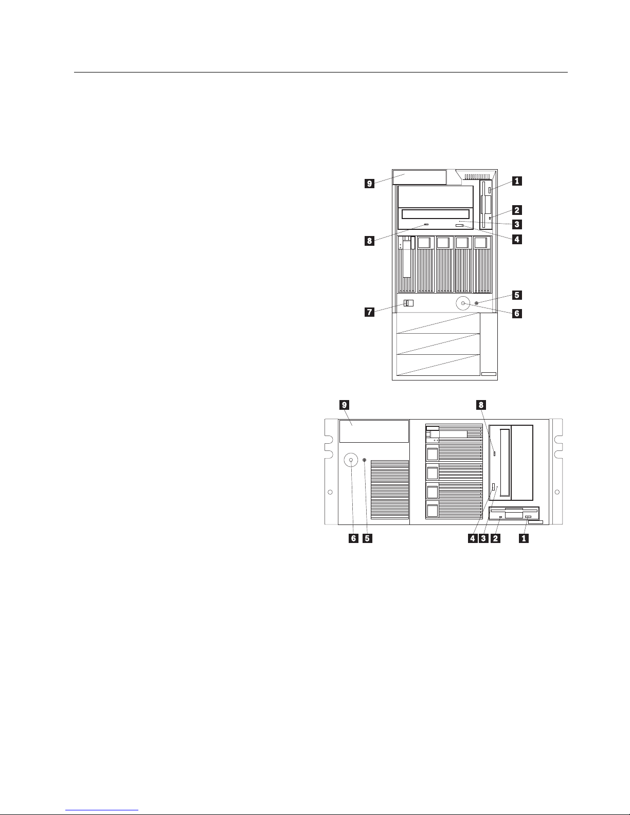
Controls and Indicators
The most commonly used controls and status indicators are on the front of your
server.
Server Controls
Tower model
Rack model
.1/ Diskette-Eject Button: Press this button to release a diskette from the drive.
.2/ Diskette Drive In-Use Light: This light comes on when the diskette drive is
accessed.
.3/ CD-ROM Manual Tray-Release Opening: Insert a straightened paper clip in
the opening to release the CD-ROM tray when using the CD-ROM eject
button is not successful.
.4/ CD-ROM Eject Button: Press this button to release a CD from the CD-ROM
drive.
Note: If the CD-ROM tray does not extend out, insert the end of a
straightened paper clip into the manual tray-release opening and
gently pull the tray open.
.5/ Reset Button: Press this button to reset the server.
Chapter 1. Introducing Your Netfinity 5000 7
Page 19

.6/ Power-on switch: Use this switch to turn on your server, or to return the
server to
After you plug the server power cord into an outlet, wait 20 seconds
before pressing the power switch. (During this time, the
system-management processor is initializing and the power-on switch
does not respond.)
Standby mode
Important
(power is present but the server is not turned on).
6
CAUTION:
The Power-On button on the front of the server does not turn off
the electrical current supplied to the server. The server also
might have more than one power cord. To remove all electrical
current from the server, ensure that all power cords are
disconnected from the power source.
Controls and Indicators
The automatic restart feature, which enables the server to restart following a
momentary power loss, means that the server is never completely turned off.
Do not set the server to the Standby mode if any drive in-use light is on. This
might damage the information stored on a hard disk drive or on a diskette. A
Power-On Switch protector, which prevents the Power-On Switch from being
pushed accidentally, is shipped with the server.
To toggle the server between Standby mode and actively running, press and
release the Power-On Switch.
.7/ Side-Cover Release Lever: Use this lever to release the left-side cover.
.8/ CD-ROM Drive In-Use Light: This light comes on when the CD-ROM drive
is accessed.
.9/ Operator LED Panel This panel contains LEDs that light to indicate
conditions on the server, such as power on or a system error (see “Status
Indicators” on page 9).
8 Netfinity 5000 Server Hardware Information and Procedures
Page 20

Controls and Indicators
Status Indicators
The following illustrations identify the indicators located on the front of the server.
Tower model
Rack model
.1/ Power-On Light: This green LED blinks when the server is in
Standby mode (power is present but the server is not turned on). The
blinking changes to a solid (continuous) light when you turn on your
server remotely (Unattended mode) or by pressing the Power-On
Switch. If this light is not on, the power cord is not connected or the
power supply has failed.
.2/ POST Complete Light: This green LED lights when the server
completes the power-on self-test (POST) without any errors.
.3/ SCSI Hard Disk Drive In-Use Light: This green LED lights when
your server is accessing a SCSI device. If this light remains
illuminated, it might indicate that either the SCSI bus or the system
microprocessor has stopped.
Chapter 1. Introducing Your Netfinity 5000 9
Page 21

Controls and Indicators
.4/ Primary Microprocessor Activity Light: This green LED blinks to
indicate the activity of a microprocessor installed in the primary
microprocessor socket. The LED comes on during POST to indicate
the presence of the microprocessor.
.5/ Secondary Microprocessor Activity Light: This green LED blinks to
show the activity of a microprocessor installed in the secondary
microprocessor socket. The LED lights during POST to indicate the
presence of the microprocessor. When you install a secondary
microprocessor, it becomes the startup microprocessor.
.6/ System Error Light: This amber LED shows that a system error
occurred. System errors can include high temperature, excess current,
or failure or errors in the microprocessor, system fan, memory, PCI
bus, SCSI bus, USB, hard disk drive, diskette drive, serial port,
keyboard interface, or power supply. When this LED is on, one or
more LEDs on the system board also might be on, indicating where
the error occurred (see “System Board LEDs” on page 168).
.7/ Reserved: This LED is reserved for future use.
.8/ Hard Disk Drive Status Light (Amber): In a RAID environment, this
amber LED lights continuously when the drive is faulty and needs to
be replaced. You can replace these hot-swappable drives without
turning off the server. If you do not have a RAID environment, this
LED is not operational.
.9/ Hard Disk Drive Activity Light (Green): This green LED lights when
the hard disk drive is being accessed.
.1ð/ Ethernet Transmit/Receive Activity Light: This green LED shows
transmission and reception activity on the network.
.11/ Ethernet Link Status Light: This green LED shows an active link
connection on the 10BASE-T or 100BASE-TX interface.
.12/ Ethernet Speed Light: This green LED lights when the Ethernet LAN
speed is 100 Mbps.
10 Netfinity 5000 Server Hardware Information and Procedures
Page 22

Controls and Indicators
The following illustrations identify the indicators located on the back of the server.
Tower model
Rack model
.1/ Power Supply Lights: These green LEDs indicate a power good status for
each of the 175-watt modules in the power supply. If any power supply light
is not illuminated when the Power-On Light on the front of the server is on,
there is a problem with that power supply. The power supply shipped with the
server has two lights, one for each module in the power supply. The optional
additional power supply has one power module and one green LED. See
“Installing or Replacing the Power Supply” on page 71 for more information
about the power supplies.
Chapter 1. Introducing Your Netfinity 5000 11
Page 23

Input/Output Connectors
The following illustrations identify the connectors located on the back of the server.
Tower model
Input/Output Connectors
Rack model
.1/ Power Connector: The server power cable connects here.
.2/ Serial Connector A: Signal cables for modems or other serial devices
connect here to the 9-pin serial connector for serial port A. See “Devices and
I/O Ports” on page 23 for port assignment information.
.3/ Serial Connector B: Signal cables for modems or other serial devices
connect here to the 9-pin serial connector for serial port B. See “Devices and
I/O Ports” on page 23 for port assignment information.
.4/ Mouse Connector: The mouse cable connects here. This connector is
sometimes called the auxiliary-device port.
.5/ Keyboard Connector: The keyboard cable connects here.
.6/ Ethernet Connector: An unshielded, twisted-pair cable with an RJ-45
connector attaches here to the 10/100 Ethernet controller on the system
board.
12 Netfinity 5000 Server Hardware Information and Procedures
Page 24

Input/Output Connectors
.7/ Universal Serial Bus (USB) Connector 1: Attach I/O devices with universal
serial bus (USB) connectors to USB connector 1. You need a 4-pin cable to
connect a device to this port.
.8/ Universal Serial Bus (USB) Connector 2: Attach I/O devices with universal
serial bus (USB) connectors to USB connector 2. You need a 4-pin cable to
connect a device to this port.
.9/ Monitor Connector: The monitor signal cable connects here.
.1ð/ Management C Connector: The cable to attach a modem that is dedicated
to communication with the system-management processor connects here.
.11/ SCSI Connector: External SCSI devices attach here. For more information,
see “Connecting External Options” on page 72.
.12/ Parallel Connector: A signal cable for a parallel device, such as a printer,
connects here.
.13/ PCI Expansion Slots: Cables to the external connectors on PCI adapters
connect here (slots 3, 4, and 5).
.14/ PCI/ISA Expansion Slots: Cables to the external connectors on either ISA
or PCI adapters connect here (slots 1 and 2).
Chapter 1. Introducing Your Netfinity 5000 13
Page 25

Expansion Bays
Expansion Bays
Your server comes with one 3.5-inch, 1.44 MB diskette drive, and one 5.25-inch
CD-ROM drive. The following illustrations show the server front view with the door
(if any) removed.
Tower model
Rack model
.1/ CD-ROM Drive: Your server comes with an IDE CD-ROM drive.
.2/ Open Bay (5.25-inch): The design of your server accommodates an
additional 5.25-inch half-height device, such as tape or a rewritable optical
disk drive.
For information on the supported types of drives and their installation, see
“Installing or Removing Internal Drives” on page 56.
.3/ Diskette Drive: The 3.5-inch, 1.44 MB (MB is approximately 1000000
bytes) diskette drive uses 1 MB (unformatted) or 2 MB (unformatted)
diskettes.
.4/ Open Bays (3.5-inch): The 3.5-inch open bays are for hot-swap SCSI hard
disk drives only.
For information on the supported types of drives and their installation, see
“Installing or Removing Internal Drives” on page 56.
14 Netfinity 5000 Server Hardware Information and Procedures
Page 26

Arranging Your Workspace
Chapter 2. Arranging Your Workspace
This chapter contains information on arranging your workspace.
If you have not already done so, unpack your server. Follow the instructions in the
“Express Setup and Installation” section of this
If you have a rack model, you can install your options and operating system before
you install the server in the rack enclosure.
This chapter contains:
Arranging Your Workspace .............................. 16
Comfort . . . . . . . . . . . . . . . . . . . . . . . . . . . . . . . . . . . . . . . . 16
Glare and Lighting .................................. 16
Air Circulation . . . . . . . . . . . . . . . . . . . . . . . . . . . . . . . . . . . . 17
Electrical Outlets and Cable Lengths ....................... 17
Additional Planning Considerations ........................ 17
Server Library
.
Copyright IBM Corp. 1998 15
Page 27

Arranging Your Workspace
To get the most from your server, arrange both the equipment you use and your
work area to suit your needs and the kind of work you do. Your comfort is of
foremost importance, but light sources, air circulation, and the location of electrical
outlets also can affect the way you arrange your workspace.
Comfort
Although no single working position is ideal for everyone, here are a few guidelines
to help you find a position that suits you best.
Sitting in the same position for a long time can cause fatigue. A good chair can
make a big difference. The backrest and seat should adjust independently and
provide good support. The seat should have a curved front to relieve pressure on
the thighs. Adjust the seat so that your thighs are parallel to the floor and your feet
are either flat on the floor or on a footrest.
When using the keyboard, keep your forearms parallel to the floor and your wrists
in a neutral, comfortable position. Try to keep a light touch on the keyboard and
your hands and fingers relaxed. You can change the angle of the keyboard for
maximum comfort by adjusting the position of the keyboard feet.
Arranging Your Workspace
Adjust the monitor so the top of the screen is at, or slightly below, eye level. Place
the monitor at a comfortable viewing distance, usually 51 to 61 cm (20 to 24 in.),
and position it so you can view it without having to twist your body. Also position
other equipment you use regularly, such as the telephone or a mouse, within easy
reach.
Glare and Lighting
Position the monitor to minimize glare and reflections from overhead lights,
windows, and other light sources. Even reflected light from shiny surfaces can
cause annoying reflections on your monitor screen. Place the monitor at right
angles to windows and other light sources, when possible. Reduce overhead
lighting, if necessary, by turning off lights or using lower wattage bulbs. If you
install the monitor near a window, use curtains or blinds to block the sunlight. You
might have to adjust the Brightness and Contrast controls on the monitor as the
room lighting changes throughout the day.
Lower
Back
Support
Seat
Height
Viewing Distance
Where it is impossible to avoid reflections or to adjust the lighting, an antiglare filter
placed over the screen might be helpful. However, these filters might affect the
16 Netfinity 5000 Server Hardware Information and Procedures
Page 28

Arranging Your Workspace
clarity of the image on the screen; try them only after you have exhausted other
methods of reducing glare.
Dust buildup compounds problems associated with glare. Remember to clean your
monitor screen periodically using a soft cloth moistened with a nonabrasive liquid
glass cleaner.
Air Circulation
Your server and monitor produce heat. Your server has one or more fans that pull
in fresh air and force out hot air. The monitor lets hot air escape through vents.
Blocking the air vents can cause overheating, which might result in a malfunction or
damage. Place the server and monitor so that nothing blocks the air vents; usually,
51 mm (2 in.) of air space is sufficient. Also, make sure the vented air is not
blowing on someone else.
Electrical Outlets and Cable Lengths
The location of electrical outlets and the length of power cords and cables that
connect to the monitor, printer, and other devices might determine the final
placement of your server.
When arranging your workspace:
Avoid the use of extension cords. When possible, plug the server power cord
directly into an electrical outlet.
Keep power cords and cables neatly routed away from walkways and other
areas where they might get kicked accidentally.
For more information about power cords, see “Power Cords” on page 174 or refer
to the “Legal and Safety Information” section of this
Additional Planning Considerations
Make sure you have an adequate number of properly grounded electrical
outlets for your server, monitor, and any other options that you intend to install.
7
CAUTION:
When the power-cord strain-relief bracket option is installed on the
power cord, the server must be plugged to a power source that is
easily accessible.
Place your server in a location that is dry. Rain or spilled liquids might damage
your server.
Server Library
.
Leave about 127 mm (5 in.) of space around the front and rear of your server
to allow the server's cooling system to work properly.
Chapter 2. Arranging Your Workspace 17
Page 29

Chapter 3. Configuring Your Server
This chapter provides information about the configuration and utility programs that
come with your server.
The configuration programs are part of the
comes with your server. Using these programs, you can set the system date and
time, define input and output device parameters, and define system security.
This chapter contains:
Configuration Overview . . . . . . . . . . . . . . . . . . . . . . . . . . . . . . . . 20
The Configuration/Setup Utility ............................ 21
Using the Configuration/Setup Utility ......................... 22
System Summary . . . . . . . . . . . . . . . . . . . . . . . . . . . . . . . . . . 22
System Information . . . . . . . . . . . . . . . . . . . . . . . . . . . . . . . . . 22
Devices and I/O Ports ............................... 23
Date and Time .................................... 24
System Security . . . . . . . . . . . . . . . . . . . . . . . . . . . . . . . . . . . 24
Start Options . . . . . . . . . . . . . . . . . . . . . . . . . . . . . . . . . . . . . 28
Advanced Setup . . . . . . . . . . . . . . . . . . . . . . . . . . . . . . . . . . . 28
Plug and Play .................................... 30
Error Log . . . . . . . . . . . . . . . . . . . . . . . . . . . . . . . . . . . . . . . 30
Configuring PCI Features and Options ...................... 30
Resolving Configuration Conflicts .......................... 30
Resolving Hardware Configuration Conflicts ................... 31
Resolving Software Configuration Conflicts ................... 31
Configuring the Ethernet Controller ......................... 32
Failover for Redundant Ethernet ........................... 33
Configuring Failover on OS/2 ........................... 34
Configuring Failover on Windows NT ....................... 34
Configuring Failover on IntraNetWare ...................... 35
Using the SCSISelect Utility Program ........................ 35
Starting the SCSISelect Utility Program ..................... 36
SCSISelect Utility Program Choices ....................... 36
basic input/output system (BIOS
) that
Copyright IBM Corp. 1998 19
Page 30

Configuration Overview
You play a key role in how your server allocates resources to organize and
interconnect hardware devices and software programs. This allocation process is
referred to as
the number and types of devices and programs that you install.
Your server supports several types of adapters. Because of this flexibility, you can
choose from among thousands of adapters and devices that comply with any of the
following standards:
Peripheral Component Interconnect (PCI)
Industry Standard Architecture (ISA)
Small Computer System Interface (SCSI)
In general, the greater the number and variety of hardware devices and software
programs that you install in your server, the more you will have to interact with your
server and your devices to correctly configure your system.
Your server comes with the following hardware configuration utility programs:
configuration
Configuration Overview
. The steps required to configure your server depend on
Configuration/Setup Utility
With the built-in Configuration/Setup Utility program, you can configure
system-board functions, such as serial and parallel port assignments; change
interrupt request settings; and change the startup sequence for drives that you
install. You can also use this utility program to set passwords for starting up
the server and accessing the Configuration/Setup Utility program.
SCSISelect Utility
With the built-in SCSISelect Utility program, you can configure the SCSI
devices that you install in your server. You can use SCSISelect to change
default values, resolve configuration conflicts, and perform a low-level format on
a SCSI hard disk drive.
Before installing a new device or program, read the documentation that comes with
it. Reading the instructions helps you determine the steps required for installation
and configuration. The following actions are typically, but not always, required to
configure your server.
1. Run the Configuration/Setup Utility program and record the current
configuration settings.
2. Set switches on the server system board.
See “System Board Switches” on page 170 for the meanings of the system
board switches.
3. Set jumpers or switches on the device.
See the device installation instructions.
4. Install the device in the server.
See Chapter 4, “Installing Options” on page 39.
5. Install software programs.
Refer to the information provided with the “ServerGuide and Netfinity Manager
Information” section of this
more information.
20 Netfinity 5000 Server Hardware Information and Procedures
Server Library
and with your operating system for
Page 31

The Configuration/Setup Utility
6. Resolve configuration conflicts.
See “Resolving Configuration Conflicts” on page 30.
The Configuration/Setup Utility
For most configurations, the server will operate using the default system settings.
You need to change the settings only to resolve configuration conflicts or to enable
or change device functions.
When you want or need to change the default settings, the Configuration/Setup
Utility program provides a convenient way to display and change the settings.
After you run and exit the Configuration/Setup Utility program, configuration
information is stored in nonvolatile random-access memory (NVRAM). While the
server is powered off, the configuration information remains available for the next
system startup.
Always run the Configuration/Setup Utility program if you add or remove any
hardware option, or if you receive an error message instructing you to do so.
Review this chapter and the information that comes with the option before making
changes. Also, record the current settings (see Chapter 7, “Server Records and
Specifications” on page 161) before making any changes.
To start the Configuration/Setup Utility program:
1. Turn on the server and watch the screen.
2. When the messages Press F1 for Configuration/Setup and Press F2 for
Diagnostics appear, select the action you need.
To configure your server, press F1 to select Configuration/Setup Utility.
The Configuration/Setup Utility main menu appears. For information about
the menus, see “Using the Configuration/Setup Utility” on page 22.
Note: If you enter a power-on password and an administrator password
has been set, a limited menu appears on the screen. To access
the full Configuration/Setup Utility menu, you must enter the
administrator password.
To run the system diagnostics, press F2 to select Diagnostic Utility.
The Diagnostic Utility main menu appears. For information about running
the system diagnostics, see “Diagnostic Test Programs” on page 111.
Important
If a defective PCI adapter is causing the system to stop responding during
startup, you can press Alt+F1 here. This will cause the server to bypass
PCI device initialization (except video) and go directly to the
Configuration/Setup Utility, where you can disable the defective PCI
adapter. Disabling the defective PCI adapter should enable you to
complete a normal startup when you restart the server.
Chapter 3. Configuring Your Server 21
Page 32

Using the Configuration/Setup Utility
From the Configuration/Setup Utility program main menu you can select settings
you want to change.
Pressing F1 displays Help information for a selected menu item.
Notes:
1. If you enter only the power-on password and an administrator (supervisor-level)
password is also set, a limited version of the menu appears. To view the full
Configuration/Setup Utility menu you must enter the administrator password.
2. The choices on some menus might differ slightly, depending on the BIOS
version that comes with your server.
To change configuration settings:
1. Use the Up Arrow (↑) key to select the item you want to change; then, press
Enter.
2. Select the configuration setting you want to change. Use the Right Arrow (→)
or Left Arrow (←) key to highlight the menu, if needed.
Using the Configuration/Setup Utility
3. Use the Right Arrow (→) or Left Arrow (←) key to select the appropriate setting
4. Repeat Steps 1 through 3 for each setting that you want to change. Press Esc
5. After making changes, you can select:
6. To exit from the Configuration/Setup Utility main menu, select Exit Setup.
7. The system prompts you to confirm your choice. You can return to the
System Summary
Select this choice to display configuration information, such as the type and speed
of the microprocessor, and amount of memory.
Changes that you make to configuration settings appear on this summary screen.
You cannot edit the fields.
for the selected item.
to return to the Configuration/Setup Utility main menu.
Save Settings to save the selected changes.
Restore Settings to delete the selected changes.
Load Default Settings to cancel the changes and restore the factory
settings.
Configuration/Setup Utility main menu, or exit.
System Information
Select this choice to display information about your Netfinity 5000 server, and to
view the interrupt request (IRQ) settings for the SCSI and Ethernet controllers on
the system board, and for other PCI and ISA adapters that you purchase and
install.
Changes that you make on other menus might appear on this summary screen.
22 Netfinity 5000 Server Hardware Information and Procedures
Page 33

Using the Configuration/Setup Utility
Product Data
Select this choice to view system information such as the machine type and model,
the system serial number, the system board identifier, and the revision level or
issue date of the flash electronically erasable programmable ROM (EEPROM) and
BIOS.
System Card Data
Select this choice to view the system board model, submodel, system serial
number, system board identifier, DASD backplane identifier, power backplane
identifier, and identifiers for power supply 1 and power supply 2.
PCI Routing
Select this choice to view the interrupt request (IRQ) settings for PCI adapters and
for the Ethernet, SCSI, and other controllers on the system board. See “PCI Bus
Control” on page 29 for information about changing the PCI IRQ settings.
Devices and I/O Ports
Software recognizes ports from their port assignments. Each port must have a
unique port assignment. The Configuration/Setup Utility program normally handles
this, but you might have special hardware or software that requires you to change
these assignments.
Note: Serial port A can be shared by the system-management processor and
operating system. Serial port B is used by the operating system only.
Management port C is controlled exclusively by the system-management
processor, cannot be used by the operating system, and cannot be
configured using the Configuration/Setup Utility program. See the
“Advanced System Management Information” section of this
for information about configuring serial ports A and C.
Select the Devices and I/O Ports choice to view or change the assignments for
devices and input/output ports.
You can add serial ports by installing a serial adapter in an expansion slot. See
the documentation that comes with the serial adapter for information about port
assignments.
You can configure the parallel port as standard, as bidirectional, as an Extended
Capabilities Port (ECP), or as an Enhanced Parallel Port (EPP). Bidirectional,
ECP, and EPP are all bidirectional modes; in all three modes, data can be both
read from and written to a device. ECP and EPP are industry-standard,
high-performance bidirectional modes. Which one of these modes you choose
depends on what mode your device supports.
Note: When you configure the parallel port as bidirectional, ECP, or EPP, use an
IEEE 1284-compliant cable. The maximum length of the cable must not
exceed 3 meters (9.8 feet).
Server Library
You can configure the mouse and diskette controller as enabled or disabled, and
configure the type of diskette drive.
You can view the type of video controller and the amount of video memory
installed.
Chapter 3. Configuring Your Server 23
Page 34

Date and Time
Using the Configuration/Setup Utility
You can configure the IDE channel (enabled or disabled) and view the IDE Primary
Master Device (type, size, transfer selection and mode, and logical block
addressing (LBA) mode).
To display or change the port assignments:
1. Select Devices and I/O Ports.
2. Select a device or port; then, use the Left Arrow (←) or Right Arrow (→) key to
advance through the settings available.
Select this choice to set the system date and time.
The system time is in a 24-hour format: hour/minute/second. The system date is
in standard format for your country. For example, in the United States, the format
is MM/DD/YYYY (Month/Day/Year).
Select Date and Time; then, use the Left Arrow (←) or Right Arrow (→) key to
advance through each data field. Type the new information; the system saves the
information as you type it.
System Security
To control access to the information in your server, you can implement security
features, such as adding passwords and defining a system owner's name that
displays during startup. Implementing these security measures helps you to ensure
the integrity of the data and programs that are stored in your server.
Note: The default values for all security-related data fields are given in Table 14
on page 164 and following.
After setting a power-on password, you can enable the unattended-start mode.
This locks the keyboard and mouse, but allows the server to start the operating
system. The keyboard and mouse remain locked until you enter the correct
password.
To set, change, or delete a password:
1. Select System Security.
2. Select the password that you want to change.
3. Follow the instructions on the screen.
After you have set a power-on or administrator password, you must enter the
password whenever you turn on the server. (The passwords do not appear on the
screen as you type them.)
24 Netfinity 5000 Server Hardware Information and Procedures
Page 35

Using the Configuration/Setup Utility
Type of Password Results
No password set No password required to start system.
You can access all choices on the Configuration/Setup Utility
program main menu.
Power-on password only You must enter the password to complete the system startup.
You can access all choices on the Configuration/Setup Utility
program main menu.
If you forget the power-on password, you can regain access to
the server by using switch 8 on the system board. See “Using
the Power-on Password Menu” on page 25 for details.
Administrator password only You must enter the password to enter the Configuration/Setup
Utility program.
You can access all choices on the Configuration/Setup Utility
program main menu.
If the administrator password is forgotten, it cannot be
overridden or removed. You must replace the system board.
Administrator
password
and
power-on
You can enter either password to complete the system startup.
– Administrator password provides access to all choices on
the Configuration/Setup Utility program main menu. You
can set, change, or delete both the administrator and
power-on passwords, and allow a power-on password to
be changed by the user.
– Power-on password provides access to a limited set of
choices on the Configuration/Setup Utility program main
menu. This might include changing or deleting the
power-on password.
If you forget the power-on password, and the administrator
password has been set, use the administrator password at the
password prompt. Then, start the Configuration/Setup Utility
program and change the power-on password.
Using the Power-on Password Menu
When a power-on password is set, you must enter a password each time you start
the system.
To set a power-on password:
1. Select Power-on Password from the System Security menu; then, press
Enter.
The Power-on Password menu appears.
2. Type the password in the Enter Power-on Password data field.
You can use any combination of up to seven characters (A–Z, a–z, and 0–9)
for your power-on password. Keep a record of your password in a secure
place.
3. Move the cursor to the Enter Power-on Password Again data field and type
the password again.
Note: A message appears if the two passwords do not match. If this
happens, press Enter to return to the Power-On Password menu.
4. Select Change Power-on Password to save the new password; then, press
Enter.
5. A confirmation window appears. Press Enter to change the power-on
password. Press Esc to return to the System Security menu.
Chapter 3. Configuring Your Server 25
Page 36

When a power-on password is set, POST does not complete until you enter the
password. If you forget the power-on password, you can regain access to the
server through one of the following methods:
If an administrator password has been set, enter the administrator password at
the power-on prompt (see “Using the Administrator Password Menu” on
page 27 for details). Start the Configuration/Setup Utility program and change
the power-on password as described in steps 1 through 5 above.
Use the Bypass-Power-On-Password switch on the system board to temporarily
bypass the power-on password.
1. See “Preparing to Install Options” on page 43 through “Preparing a Tower
Model” on page 44 or through “Preparing a Rack Model” on page 46 for
instructions on powering off the server and removing the cover. Then, refer
to the system-board diagram inside your server for the location of the
switch block.
2. Locate switch 8 (see “System Board Switches” on page 170).
3. Set switch 8 on the switch block to On, to bypass the power-on password.
4. Restart the server, then start the Configuration/Setup Utility program and
change the power-on password as described in steps 1 through 5 above.
Using the Configuration/Setup Utility
5. Turn the server off again.
6. Set switch 8 back to Off.
7. Restart the server.
To delete a power-on password:
1. Select Power-on Password from the System Security menu; then, press
Enter.
The Power-on Password menu appears.
2. Select Delete Power-on Password; then, press Enter.
3. A confirmation window appears. Press Enter to delete the power-on password.
Press Esc to cancel the request and return to the System Security menu.
To allow the server to start in unattended mode when a power-on password
is set:
Note: The Allow for unattended boot with password data field must be set to
On for the system to support locally or remotely scheduled system
shutdowns or restarts in unattended-start mode.
1. Select Power-on Password from the System Security menu; then, press
Enter.
The Power-on Password menu appears.
2. Select Allow for unattended boot with password. Press the Left Arrow (←)
or Right Arrow (→) key to toggle the entry to On.
If no power-on password is set on the server, this option has no effect.
26 Netfinity 5000 Server Hardware Information and Procedures
Page 37

Using the Configuration/Setup Utility
Using the Administrator Password Menu
The administrator password (sometimes called a supervisor-level password)
controls access to some features of the server, including the Configuration/Setup
Utility program.
Important
If an administrator password is set and then forgotten, it cannot be overridden
or removed. You must replace the system board.
To set an administrator password:
1. Select Administrator Password from the System Security menu; then, press
Enter.
2. Type the password in the Enter Administrator Password data field.
A password can contain any combination of up to seven alphanumeric
characters (A–Z, a–z, and 0–9). Keep a record of your password in a secure
place.
3. Move the cursor to the Enter Administrator Password Again data field and
type the password again.
Note: A message appears if the two passwords do not match. If this
happens, press Enter to return to the Administrator Password menu.
4. Select Change Administrator Password to save the new password; then,
press Enter. The password becomes effective immediately.
To delete an administrator password:
1. Select Administrator Password from the System Security menu; then, press
Enter.
2. Select Delete Administrator Password; then, press Enter.
3. A confirmation window appears. Press Enter to delete the administrator
password. Press Esc to return to the System Security menu.
To enable a user to change the power-on password:
1. Select Administrator Password from the System Security menu; then, press
Enter.
2. Select Power-on password changeable by user. Press the Left Arrow (←) or
Right Arrow (→) key to toggle the entry to Yes.
When this choice is enabled, System Security appears on the limited
Configuration/Setup menu. The System Security menu contains the Power-on
Password choice.
Chapter 3. Configuring Your Server 27
Page 38

Using the Configuration/Setup Utility
Defining a System Owner's Name
You can specify a system owner's name that displays during POST each time that
your server is started. If you set an administrator password, only the administrator
can set, change, or delete the system owner's name.
To set the system owner's name:
1. Select System Owners Name from the System Security menu; then, press
Enter.
The System Owners Name screen appears.
2. Type the name in the Enter System Owners Name String data field. You can
use any combination of up to 15 characters and spaces in your system owner's
name.
3. Press the Down Arrow (↓) key to select the Set or Change System Owners
Name data field.
4. Press Enter to set the name or change a previously defined name.
To delete the system owner's name, select Delete Stored System Owners Name;
then, press Enter.
Start Options
Start options take effect when you start your server.
You can select keyboard operating characteristics, such as the keyboard speed.
You also can specify whether the keyboard number lock (NumLock) starts on or off.
You also can enable the server to run in disketteless and monitorless operation.
You can specify the startup sequence the server is to use to determine the device
from which the operating system loads. For example, you can define a startup
sequence that checks for a CD-ROM, then checks an installed hard disk drive, and
then checks a network adapter.
Note: The default startup options, including startup sequence, are given in
Table 14 on page 164.
Attention: If the CD-ROM drive contains a startable CD, you must remove the CD
if you want to use a startup sequence that begins with a startable diskette.
You can enable a virus-detection test that checks at startup for changes in the
master boot record. You also can also choose to run POST in the enhanced mode
or in the quick mode.
Select Start Options; then, use the Left Arrow (←) or Right Arrow (→) key to
advance through each data field.
Advanced Setup
Select Advanced Setup to change values for advanced hardware features, such
as cache control, PCI bus control, memory settings, and advanced ISA settings.
Note: A warning message displays above the choices on this menu, to alert you
that the system may malfunction if these options are configured incorrectly.
Follow the instructions on the screen carefully.
28 Netfinity 5000 Server Hardware Information and Procedures
Page 39

Using the Configuration/Setup Utility
Use the Left Arrow (←) or Right Arrow (→) key to highlight the options for the
selected menu item.
Core Chipset Control
Select this choice to modify settings that control features of the core chip set on the
system board. Do not make changes here unless directed to do so by an IBM
authorized service representative.
PCI Bus Control
Select PCI Bus Control to:
Change the master latency timer values for PCI bus 0 and PCI bus 1.
Specify the planar interrupt routing (IRQs) for SCSI, Ethernet, video, and USB.
Specify the slot interrupt routing (IRQs) for PCI slots.
Enable and disable PCI device types (SCSI, video, Ethernet) and slots. When
a PCI adapter is defective, you can use Alt+F1 at startup and then disable the
PCI adapter in order to enable the system to start up successfully.
Note: Any changes you make to IRQs will not be reflected in the PCI Interrupt
Routing selection of the System Information menu until you restart the
server.
Cache Control
Select this choice to define the microprocessor cache state as enabled or disabled,
and to define the microprocessor cache type as Write-back or Write-through.
Selecting write-back mode will provide the maximum system performance.
Memory Settings
Select this choice to view the server banks of memory and to enable or disable
selected rows of memory within those banks.
If a memory error is detected during POST or memory configuration, the Netfinity
5000 server can automatically disable the failing row of memory and continue
operating with reduced memory capacity. If this occurs, you must manually enable
the row of memory after the problem is corrected. Choose Memory Settings from
the Advanced Setup menu; then use the the Up Arrow (↑) or Down Arrow (↓) key
to highlight the row that you want to enable. Use the Left Arrow (←) or Right Arrow
(→) key to select Enable.
Advanced ISA Settings
Use this selection to set the timer delay for ISA I/O recovery.
Server Processor IRQ Settings
Use this selection to specify the IRQ the system-management processor is to use.
Chapter 3. Configuring Your Server 29
Page 40

Plug and Play
Error Log
Resolving Configuration Conflicts
Most adapters designed for PCI slots are Plug and Play devices that are
auto-configuring. However, many ISA adapters are not Plug and Play devices and
you must allocate the system resources that the adapter will use. Select Plug and
Play to identify the available system resources:
Memory
I/O ports
DMA
Interrupt
Note: The menus do not contain resources that are used by the system or by
previously installed Plug and Play adapters.
Select Plug and Play; then, use the Up Arrow (↑) and Down Arrow (↓) key to
highlight the system resource that you want to change. Use the Left Arrow (←) or
Right Arrow (→) key to toggle from Plug and Play to ISA Legacy for the selected
menu choice.
Select Error Log to view the three most recent power-on self-test (POST) errors
the system has generated, or to view the system error log. You can clear both
error logs from this screen by selecting Clear Error Logs.
Configuring PCI Features and Options
PCI devices automatically communicate with the server configuration information.
This usually results in automatic configuration of a PCI device. If a conflict does
occur, see “Resolving Configuration Conflicts.”
Multiple-function PCI adapters use more than one interrupt. When you install one
of these adapters, review the IRQ assignments in the Configuration/Setup utility
programs (see “PCI Bus Control” on page 29). Verify that the IRQ assignments
are correct.
Your Netfinity 5000 server uses a rotational interrupt technique to configure PCI
adapters. This technique enables you to install a variety of PCI adapters that
currently do not support sharing of PCI interrupts. For information on manually
overriding the interrupt setting, see “PCI Bus Control” on page 29.
Resolving Configuration Conflicts
The resources used by your server consist of IRQs, DMA, I/O port addresses, and
memory. This information is useful when a resource configuration conflict occurs.
Conflicts in the configuration occur if:
A device is installed that requires the same resource as another device. (For
example, a conflict occurs when two adapters try to write to the same address
space.)
A device resource is changed (for example, changing jumper settings).
A device function is changed (for example, assigning
30 Netfinity 5000 Server Hardware Information and Procedures
COM1
to two serial ports).
Page 41

Resolving Configuration Conflicts
A software program is installed that requires the same resource as a hardware
device.
The steps required to resolve a configuration error are determined by the number
and variety of hardware devices and software programs you install. If a hardware
configuration error is detected, a
server completes POST and before the operating system is loaded. You can
bypass the error by pressing Esc while the error message is displayed.
The Configuration/Setup Utility program configures the system hardware and PCI
interrupt requests. The program does not consider the requirements of the
operating system or the application programs. See “Resolving Software
Configuration Conflicts” for additional information.
configuration error
message appears after the
Resolving Hardware Configuration Conflicts
Use the following information to help resolve hardware configuration conflicts:
1. Run the Configuration/Setup Utility program to view and change resources
used by the system board functions. Record the current settings before making
any changes. (See “The Configuration/Setup Utility” on page 21 for
instructions.)
2. Determine which adapter or device is causing the conflict.
3. Change adapter jumpers or switches. Some devices use jumpers and switches
to define the system resources that the device needs. If the settings are
incorrect or set to use a resource that cannot be shared, a conflict occurs and
the device will remain deactivated by the configuration program.
4. Change system board jumpers or switches. See “Preparing to Install Options”
on page 43 for instructions on removing the cover. Then, refer to the
system-board diagram inside your server.
5. Remove the device or adapter. Some configurations are not supported. If you
must remove an adapter, see “Installing or Removing Adapters” on page 50.
Resolving Software Configuration Conflicts
The memory-address space and IRQs used by some hardware options might
conflict with addresses defined for use through application programs or the
expanded memory specification (EMS). (EMS is used only with DOS.)
If a conflict exists, one or more of the following conditions might exist:
The system cannot load the operating system.
The system does not work.
An application program does not operate, or it returns an error.
Screen messages indicate a conflict exists.
To resolve conflicts, you can change the software or hardware configuration.
Note: Start the Configuration/Setup Utility program to view the addresses used by
The best way to resolve memory-address conflicts is to change the addresses used
by the application program or the device driver. You can use the
Configuration/Setup Utility program to change addresses.
Chapter 3. Configuring Your Server 31
your system board functions.
Page 42

If a device driver is causing a memory-address conflict, refer to your
operating-system documentation or the documentation supplied with the device
drivers.
Configuring the Ethernet Controller
Your Netfinity 5000 server comes with an Ethernet controller on the system board.
The Ethernet controller provides 10BASE-T and 100BASE-TX support through the
RJ-45 connector on the back of your server.
When you connect your server to the network, the Ethernet controller automatically
detects the data-transfer rate (10 Mbps or 100 Mbps) on the network and then sets
the controller to operate at the appropriate rate. That is, the Ethernet controller will
adjust to the network data rate, whether the data rate is standard Ethernet
(10BASE-T), Fast Ethernet (100BASE-TX), half duplex (HDX), or full duplex (FDX).
This process is also known as
without software intervention. The controller supports half-duplex (HDX) and
full-duplex (FDX) modes at both speeds.
Auto-negotiation works only if the hub or switch to which your server is connected
also supports auto-negotiation. If the hub or switch does not support
auto-negotiation, the speed (10 Mbps or 100 Mbps) will still be detected correctly,
but half-duplex mode will always be selected. A full-duplex switch that does not
support auto-negotiation will not attach to the Netfinity 5000 server in full-duplex
mode.
auto-negotiation
Configuring the Ethernet Controller
. This auto-negotiation occurs
In this case, if you want the network to operate in full-duplex mode, you must
manually override the settings to obtain a full-duplex connection. To do this, your
server must have a device driver that supports manual overrides. Use the
ServerGuide CDs to install this device driver. Refer to the “ServerGuide and
Netfinity Manager Information” section of this
Server Library
for instructions on
installing device drivers. The ServerGuide CDs contain IBM Update Connector, a
dial-up3 program that keeps your BIOS and device drivers current. Verify that you
have installed the appropriate device driver. Also, refer to your Ethernet
documentation for additional information on operating modes, manual overrides,
and device drivers (see “Related Publications” on page xii).
Attention:
The 10BASE-T Ethernet and the 100BASE-TX Fast Ethernet cabling in the
network must be Category 5 or higher to meet various standards, including
electromagnetic compatibility.
You must install a device driver to enable your operating system to address the
Ethernet controller. Use the ServerGuide CDs to install this device driver.
Refer to the information in the “ServerGuide and Netfinity Manager Information”
section of this
Server Library
for instructions on installing device drivers, or for
more information about the ServerGuide CDs.
Fast Ethernet operates at a data rate of up to 100 Mbps. However, except for the
different operating speeds, Fast Ethernet and standard Ethernet are structurally
3
Response time will vary, depending on the number and nature of calls received.
32 Netfinity 5000 Server Hardware Information and Procedures
Page 43

Failover for Redundant Ethernet
identical. Most applications and protocols that are currently installed on a standard
Ethernet system can be seamlessly migrated to a Fast Ethernet system. Because
of the equivalence of the two types of Ethernet, mixed Ethernet and Fast Ethernet
systems also can be designed and implemented.
The bandwidth required at each workstation connected to a server is generally far
less than the bandwidth required at the server. This is because the server might
have to handle the bandwidth of multiple workstations at the same time. A
cost-effective solution to the bandwidth requirements of this type of system is a
mixed Ethernet and Fast Ethernet network. This mixed network consists of
standard Ethernet connections at the workstations and Fast Ethernet connections at
the servers.
The Ethernet controller is a PCI device, and is therefore, a Plug and Play device.
You do not have to set any jumpers or configure the controller for your operating
system before you use the Ethernet controller.
Notes:
1. For troubleshooting information, see “Troubleshooting the 10/100 Mbps
Ethernet Controller” on page 149.
2. The Ethernet controller supports the operating systems that your server
supports. To find out which operating systems your server supports, go to the
following World Wide Web address:
http://www.pc.ibm.com/us/compat/
If you need additional Ethernet connections, you can install an Ethernet adapter,
such as an IBM 10/100 Ethernet adapter. Review your network-adapter
documentation for any additional configuration requirements.
Note: If you are installing an IBM 10/100 Ethernet adapter, be sure to run the
Ethernet controller diagnostics and record the Ethernet controller
configuration information before you install the adapter.
Failover for Redundant Ethernet
Your Netfinity 5000 server has an integrated Ethernet controller. The IBM Netfinity
10/100 Fault Tolerant Adapter is an optional redundant network interface card (NIC
adapter) that you can install in your Netfinity 5000 server. If you install this NIC
adapter and connect it to the same logical segment as the primary Ethernet
controller, you can configure the server to support a
configure either the integrated Ethernet controller or the NIC adapter as the primary
Ethernet controller. In failover mode, if the primary Ethernet controller detects a
link failure, all Ethernet traffic associated with it is switched to the redundant
(secondary) controller. This switching occurs without any user intervention.
Applications with active sessions do not experience any data loss. When the
primary link is restored to an operational state, the Ethernet traffic automatically
switches back to the primary Ethernet controller.
failover
function. You can
Chapter 3. Configuring Your Server 33
Page 44

Notes:
1. Only one controller in the redundant pair is active at any given time. For
example, if the primary Ethernet controller is active, then the secondary
Ethernet controller cannot be used for any other network operation.
2. Your operating system determines the maximum number of IBM Netfinity
10/100 Fault Tolerant Adapters that you can install in your Netfinity 5000
server. See the documentation that comes with the adapter for more
information.
The failover feature currently is supported by OS/2, Windows NT, and
IntraNetWare. The setup required for each operating system follows.
Configuring Failover on OS/2
1. Install the redundant NIC adapter according to the instructions provided with
the adapter and in “Installing or Removing Adapters” on page 50.
2. Use the ServerGuide CDs to install the AMD PCNet Ethernet Family adapter
device driver.
3. Using the MPTS utility program, select the driver from the list and select the
Edit button.
Failover for Redundant Ethernet
Note: Only one driver instance needs to be loaded for each redundant pair of
Ethernet controllers.
4. Change the PermaNet Server Feature keyword to TRUE and specify the
Primary and Standby slots that contain the redundant pair. Refer to “System
Board Illustration” on page 168 for the locations and slot numbers of the PCI
slots. The integrated controller is located in slot 9.
5. To enable the writing of messages to the IBMCOM\LANTRAN.LOG file when a
failover occurs:
a. Copy the file PCNETOS2.EXE from the OS2 directory of the diskette
created by the ServerGuide program to your hard disk drive.
b. Add the following statement to the CONFIG.SYS file:
Run=d:\path\PCNETOS2.EXE
where d and
PCNETOS2.EXE.
6. Restart the server.
The failover function is now enabled.
path
are the drive and path to which you copied
Configuring Failover on Windows NT
1. Install the redundant NIC adapter according to the instructions provided with
the adapter and in “Installing or Removing Adapters” on page 50.
2. Use the ServerGuide CDs to install the AMD PCNet Ethernet Family adapter
device driver.
3. From the NT desktop, select Control Panel, then select the Network icon, then
the Adapters tab.
4. Highlight one of the adapters that will be in the redundant pair and then select
the Properties... button.
34 Netfinity 5000 Server Hardware Information and Procedures
Page 45

Using the SCSISelect Utility Program
5. Check the Grouping box. This will show the possible combinations for
redundant pairs.
6. Select the adapter pair you want and then select OK. Note that the integrated
Ethernet controller is located at PCI bus 0, slot 9.
7. Select Close to exit from the Network setup.
When you restart the server, the failover function will be in effect.
If a failover occurs, a message is written to the NT Event Viewer log. If the DMI
instrumentation code for the integrated Ethernet controller is active (PCNET.EXE
was run), a pop-up message is generated also.
Configuring Failover on IntraNetWare
1. Install the redundant NIC adapter according to the instructions provided with
the adapter and in “Installing or Removing Adapters” on page 50.
2. Load the device driver by using the following command:
LOAD d:\path\PCNTNW.LAN PRIMARY=x SECONDARY=y
where d and
y
are the PCI slot numbers where the redundant pair is located.
The slot number associated with the integrated Ethernet controller can vary
depending upon the configuration of the Netfinity 5000 server. To determine
the slot number, load the driver with no parameters. The driver will display the
available slot numbers. The slot number that is greater that 10000 will be the
slot number of the integrated Ethernet controller. When the slot number of the
integrated Ethernet controller is determined, reload the driver with the
appropriate parameters.
3. When the driver is loaded, bind it to a protocol stack.
The failover function is now enabled. If a failover occurs:
A message is generated to the operating system console.
The custom counters for the device driver contain variables that define the
state of the failover function and the location of the redundant pair. You can
use the NetWare Monitor to view the custom counters.
path
are the drive and path where the driver is located, and x and
Using the SCSISelect Utility Program
Your server comes with a menu-driven configuration utility program, called
SCSISelect, that you can use to view and change SCSI settings.
You can use the SCSISelect Utility program to:
View and change the device configuration
Perform a low-level format or verify the media on a SCSI hard disk drive.
Chapter 3. Configuring Your Server 35
Page 46

Starting the SCSISelect Utility Program
You can access this program when you start the server. The SCSISelect prompt
appears after the IBM Netfinity Logo appears. Press Ctrl+A immediately after the
SCSISelect prompt appears.
Use the Up Arrow (↑) and Down Arrow (↓) key to move the highlight bar to the
various menu choices. Press Esc to return to the previous menu. Also, you can
press the F5 key to switch between color and monochrome modes (if your monitor
permits). To change the settings of the displayed items, follow the directions on the
screen.
The SCSI controller in your server is a dual channel device. Select channel B for
internal devices, channel A for external devices.
SCSISelect Utility Program Choices
The following choices appear on the SCSISelect Utility program menu:
Configure/View Host Adapter Settings
SCSI Disk Utilities
Using the SCSISelect Utility Program
Configure/View Host Adapter Settings
To view or change the SCSI controller settings, select Configure/View Host
Adapter Settings and follow the directions on the screen. This menu has the
following choices:
Host Adapter SCSI ID
Select this choice to change the SCSI ID of the SCSI controller from its default
value of 7. Do not assign the SCSI controller to a SCSI ID already in use,
such as 14, which is used by the daughterboard card (SAF-TE) on the DASD
backplane.
SCSI Parity Checking
The default value is
Host Adapter SCSI Termination
The default value is
Boot Device Options
Select this choice to configure startable device parameters. Before you can
make updates, you must know the ID of the device whose parameters you
want to configure.
SCSI Device Configuration
Select this choice to configure SCSI device parameters. Before you can make
updates, you must know the ID of the device whose parameters you want to
configure.
Enabled.
Enabled.
This value should not be changed.
This value should not be changed.
36 Netfinity 5000 Server Hardware Information and Procedures
Page 47

Using the SCSISelect Utility Program
Advanced Configuration Options
Select this choice to view or change the settings for advanced configuration
options. These options include enabling support for large hard disk drives and
support for BIOS parameters if BIOS is enabled.
To reset to the the host adapter defaults, press F6; then, follow the instructions on
the screen.
SCSI Disk Utilities
To see the IDs that are assigned to each SCSI device, to format a SCSI device, or
to scan the disk for media defects, select SCSI Disk Utilities from the SCSISelect
Utility program menu.
To use the utility program, select a drive from the list. Read the screens carefully
before making a selection.
Note: If the following screen displays, you might have pressed Ctrl+A before the
selected drives were ready. Restart the server, and watch the SCSISelect
messages as each drive spins up. After the drive that you want to view or
format spins up, press Ctrl+A.
à ð
Target SCSI ID: 4
SCSI CDB Sent: ð3 ðð ðð ðð ðE ðð ð7 ðð ð2 ðð
Host Adapter Status: ððh - No host adapter error
Target Status: ð2h - Check condition
Sense Key: ð2h - Not ready
+Sense Code: ð4h
+Sense Code Qualifier: ð2h
á
Unexpected SCSI Command Failure
Press 'Esc' to continue.
ñ
Chapter 3. Configuring Your Server 37
Page 48

Using the SCSISelect Utility Program
Performing a Low-Level Disk Format
You can perform a low-level format on hard disk drives using the
feature of the SCSISelect Utility program.
Depending on the hard disk capacity, the low-level format program could take up to
two hours.
Format Disk
When To Use the Format Disk Program
Use the Format Disk program:
When you are installing software that requires a low-level format
When you get recurring messages from the diagnostic tests directing you to run
the Low-Level Format program on the hard disk
As a last resort before replacing a failing hard disk drive.
Note: For information about backing up all of your files, see your operating-system
documentation.
Starting the Low-Level Format
Attention: The low-level format erases
all
data and programs.
1. If the hard disk drive is working, make a backup copy of all the files and
programs on the hard disk drive.
2. Select Format Disk; then, follow the instructions on the screen.
Note: Hard disk drives normally contain more tracks than their stated capacity,
to allow for defective tracks. A message appears on the screen if the
defect limit is reached. If this happens, have the system serviced.
3. To install an operating system after the hard disk drive is formatted, refer to the
ServerGuide information in the “ServerGuide and Netfinity Manager
Information” section of this
Server Library
that comes with your server.
Verifying the Disk Media
Select Verify Disk Media to scan the selected hard disk drive for media defects,
such as bad tracks. All recoverable defects will be remapped.
The Verify Disk Media program takes about 15 to 20 minutes to complete.
38 Netfinity 5000 Server Hardware Information and Procedures
Page 49

Chapter 4. Installing Options
This chapter provides instructions to help you add options to your server. Some
option-removal instructions are provided, in case you need to remove one option to
install another. If you have several internal options to install, these instructions
enable you to add them all at one time.
This chapter contains:
Before You Begin .................................... 40
Electrical Safety . . . . . . . . . . . . . . . . . . . . . . . . . . . . . . . . . . . . 41
Handling Static-Sensitive Devices .......................... 42
Preparing to Install Options .............................. 43
Preparing a Tower Model ............................. 44
Preparing a Rack Model .............................. 46
Working with Adapters ................................. 49
Adapter Considerations . . . . . . . . . . . . . . . . . . . . . . . . . . . . . . . 49
Installing or Removing Adapters ......................... 50
Working with Memory Modules ............................ 54
Installing or Removing Memory Modules ..................... 54
Installing or Removing Internal Drives ........................ 56
Location of Bays ................................... 56
Types of Cables ................................... 57
SCSI Devices . . . . . . . . . . . . . . . . . . . . . . . . . . . . . . . . . . . . 58
Preinstallation Steps (All Bays) .......................... 59
Installing or Removing Drives in Bays A and B (Removable Media) ..... 60
Installing or Removing a Drive in Bay C (Diskette Drive) ........... 62
Installing or Removing Drives in Bays 1 through 5 (Hard Disk Drives) .... 63
Installing Microprocessors . . . . . . . . . . . . . . . . . . . . . . . . . . . . . . . 66
Installing Microprocessor Upgrades ........................ 66
Installing or Replacing a Microprocessor ..................... 67
Installing or Replacing the Power Supply ...................... 71
Connecting External Options ............................. 72
Adding External SCSI Devices .......................... 72
Attaching External Options ............................. 73
Adding Security . . . . . . . . . . . . . . . . . . . . . . . . . . . . . . . . . . . . . 74
Installing a U-Bolt and Security Cable ...................... 74
Completing the Installation .............................. 76
Completing the Tower Model Installation ..................... 76
Completing the Rack Model Installation ..................... 79
Updating the Server Configuration .......................... 82
Serial Port Connectors ................................. 83
Management Port C .................................. 84
Parallel Port Connector ................................ 85
Video Port Connector ................................. 86
Keyboard and Mouse Connectors .......................... 87
SCSI Connectors . . . . . . . . . . . . . . . . . . . . . . . . . . . . . . . . . . . . 88
Internal SCSI Connector .............................. 88
External SCSI Connector .............................. 88
Universal Serial Bus Ports .............................. 90
Ethernet Connector . . . . . . . . . . . . . . . . . . . . . . . . . . . . . . . . . . . 91
Copyright IBM Corp. 1998 39
Page 50

Before You Begin
Before you begin to install options in your server, read the following information:
Notes:
1. Become familiar with the safety and handling guidelines specified under the
2. Make sure you have an adequate number of properly grounded electrical
3. Place your server in a location that is dry. Rain or spilled liquids might damage
4. Have a supply of 1 MB and 2 MB, 3.5-inch diskettes available.
5. Back up all important data before you make changes to hard disk drives.
6. Have a small flat-blade screwdriver available.
Before You Begin
“Legal and Safety Information” section of this
Information Statements” on page vii, “Electrical Safety” on page 41, and
“Handling Static-Sensitive Devices” on page 42. These guidelines will help you
work safely while working with your server and options.
outlets for your server, monitor, and any other options you intend to install.
your server.
Server Library
, and under “Safety
7. Be sure to leave space around the server to allow the server cooling system to
work properly.
On a tower model, leave about 127 mm (5 in.) of space around the front
and rear of the server.
On a rack model, refer to the documentation that comes with the rack.
8. For a list of supported options for the Netfinity 5000 server, refer to
http://www.pc.ibm.com/us/compat on the World Wide Web.
40 Netfinity 5000 Server Hardware Information and Procedures
Page 51

Electrical Safety
Electrical Safety
10
CAUTION:
Electrical current from power, telephone, and communication cables
can be hazardous. To avoid personal injury or equipment damage,
disconnect the attached power cords, telecommunications systems,
networks, and modems before you open the server covers, unless
instructed otherwise in the installation and configuration procedures.
For your safety, always do the following
1. Turn off the server and any attached devices, such as printers, monitors, and
external drives.
Note: If you are in the United Kingdom and have a modem or fax machine
attached to your server, you must disconnect the telephone line from
the server
cables). When reassembling your server, you must reconnect the
telephone line
2. Unplug all the power cords from electrical outlets.
3. Disconnect all communication cables from external receptacles.
4. Disconnect all cables and power cords from the back of the server.
Note: Reconnect the cables or power cords only after you reassemble the
server and put the cover back on.
before
unplugging any power cords (also known as power
after
you plug in the power cords.
before
removing the cover:
9
CAUTION:
Never remove the cover on a power supply or any part (power
backplane and AC box) that has the following label attached.
Hazardous voltage, current, and energy levels are present inside the
power supplies, power backplane, and AC box. There are no
serviceable parts inside the power supplies, power backplane, or AC
box. If you suspect a problem with one of these parts, contact an IBM
service technician.
Chapter 4. Installing Options 41
Page 52

Handling Static-Sensitive Devices
Static electricity, though harmless to you, can seriously damage server components
or options.
Note: When you are adding an internal option, do not open the static-protective
package containing the option until you are instructed to do so.
When you handle options and other server components, take these precautions to
avoid damage from static electricity:
Limit your movement. Movement can cause static electricity to build up around
you.
Always handle components carefully. Handle adapters and memory modules
by the edges. Never touch any exposed circuitry.
Prevent others from touching components.
When you are installing a new option, touch the static-protective package
containing the option to an unpainted metal surface on the server for at least
two seconds. (This reduces static electricity from the package and from your
body.)
Handling Static-Sensitive Devices
When possible, remove the option and install it directly into the server without
setting the option down. When this is not possible, place the static-protective
package that the option comes in on a smooth, level surface and place the
option on it.
Do not place the option on the server's covers or any metal surface.
42 Netfinity 5000 Server Hardware Information and Procedures
Page 53
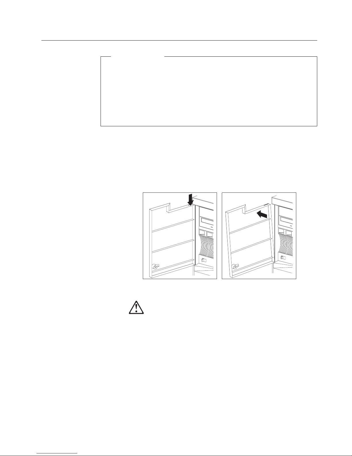
Preparing to Install Options
Preparing to Install Options
Before you begin
Be sure your current server configuration is working properly.
Locate the key to the cover lock, if any.
Obtain a small, flat-blade screwdriver.
Read “Electrical Safety” on page 41 and “Handling Static-Sensitive Devices”
on page 42.
If you are preparing a rack model, you might want to install it in the rack
first before installing options. See Chapter 5, “Installing a Server in a Rack
Enclosure” on page 93 for instructions on installing your rack model.
1. Unlock and open the server door, if any. For convenience during these
procedures, you might prefer to remove the door completely.
a. Locate the flange on the top edge of the front door, near the hinge.
b. Press the flange downward while pressing out on the door; then, lift the
door off the hinge. Set the door aside.
8
2. Remove any media (diskettes or CDs) from the drives, and then turn off all
attached devices and the server.
3. If you have a tower model, continue with “Preparing a Tower Model” on
page 44.
If you have a rack model installed in a rack enclosure, go to “Preparing a Rack
Model” on page 46.
Chapter 4. Installing Options 43
CAUTION:
When unlocked, the server door will not support the weight of the
server. To avoid personal injury, be sure to remove or lock the
server door before moving or lifting the server.
Page 54

Preparing a Tower Model
The hard disk drives in Netfinity 5000 server are hot-swappable. If you are
installing only a hard disk drive (bays 1 through 5), go directly to “Installing or
Removing Internal Drives” on page 56. Otherwise, continue with the following
steps.
1. If you have a modem or fax machine attached to the server, disconnect the
telephone line from the wall outlet and the server.
Note: If you are in the United Kingdom, you must perform this step before
disconnecting the power cord.
6
CAUTION:
The Power-on switch on the front of the server does not turn off the
electrical current supplied to the server. The server also might
have more than one power cord. To remove all electrical current
from the server, ensure that all power cords are disconnected from
the power source.
Preparing to Install Options
2. Unplug all power cords (cables) from electrical outlets, and then disconnect all
other cables from the back of the server.
3. Open the server door, if you have not already done so.
4. Remove the left-side cover.
a. Locate the cover-release lever on the front of the server and slide it to the
right.
Cover
Release
Lever
b. Slide the left-side cover back about 25 mm (1 inch); then, lift the cover and
remove it.
c. Store the cover in a safe place.
44 Netfinity 5000 Server Hardware Information and Procedures
Page 55

Preparing to Install Options
5. If you are installing or removing a drive in bays A to C, remove the front bezel.
a. Locate the blue bezel release lever on the left side of the server in the top
front corner.
Bezel Release Lever
b. Move the lever upward following the curve of the lever opening.
c. Lift the bezel tabs out of the slots at the bottom and pull the bezel out from
the server front.
6. Install (or remove) the desired options.
Option Go To:
Adapters “Working with Adapters” on page 49
Memory modules “Working with Memory Modules” on page 54
Internal drives “Installing or Removing Internal Drives” on page 56
Microprocessors “Installing Microprocessors” on page 66
Power supply “Installing or Replacing the Power Supply” on
page 71
External options “Connecting External Options” on page 72
Security options “Adding Security” on page 74
Chapter 4. Installing Options 45
Page 56

Preparing a Rack Model
Before you begin
Read the documentation that comes with the rack enclosure for additional
safety and operating information.
The hard disk drives in Netfinity 5000 server are hot-swappable. If you are
installing only a hard disk drive (bays 1 through 5), go directly to “Installing or
Removing Internal Drives” on page 56. Otherwise, continue with the following
steps.
1. If you have a modem or fax machine attached to the server, disconnect the
telephone line from the wall outlet and the server.
Note: If you are in the United Kingdom, you must perform this step before
6
Preparing to Install Options
disconnecting the power cord.
CAUTION:
The Power-on switch on the front of the server does not turn off the
electrical current supplied to the server. The server also might
have more than one power cord. To remove all electrical current
from the server, ensure that all power cords are disconnected from
the power source.
2. Unplug all power cords (cables) from electrical outlets, and then disconnect all
other cables from the back of the server.
3. Remove the screws from the brackets on either side of the server, and set
them aside.
4. Pull the rack model out of the rack enclosure until both slide rails lock.
Note: When the server is in the locked position, you can easily reach the
46 Netfinity 5000 Server Hardware Information and Procedures
cables on the back of the server.
Page 57

Preparing to Install Options
5. Remove the top cover.
a. Locate the captive thumbscrew .1/ on the back of the cover and turn it to
release the cover.
b. Slide the cover back about 25 mm (1 inch); then, lift the cover and remove
it.
c. Set the cover aside in a safe place.
a. If you are installing or removing a drive in bays A to C, remove the front
bezel.
1) Locate the blue bezel release lever on the top of the server, in the right
front corner.
2) Move the lever toward the right, following the curve of the lever
opening.
Bezel Release Lever
b. If necessary, remove the server from the rack enclosure before installing
Chapter 4. Installing Options 47
3) Lift the bezel tabs out of the slots at the left and pull the bezel away
from the server front.
options. For more information about removing the server from the rack
enclosure, see “Removing the Rack Model from a Rack Enclosure” on
page 104.
Page 58

6. Install (or remove) the desired options.
Option Go To:
Adapters “Working with Adapters” on page 49
Memory modules “Working with Memory Modules” on page 54
Internal drives “Installing or Removing Internal Drives” on page 56
Microprocessors “Installing Microprocessors” on page 66
Power supply “Installing or Replacing the Power Supply” on
page 71
External options “Connecting External Options” on page 72
Security options “Adding Security” on page 74
Preparing to Install Options
48 Netfinity 5000 Server Hardware Information and Procedures
Page 59

Working with Adapters
Working with Adapters
Adding an adapter, such as a communication adapter, extends the capabilities and
power of your server. For example, you can add a RAID (redundant array of
independent disks) adapter that can enhance logical-drive capacity and
performance.
Adapter Considerations
Your Netfinity 5000 server supports ISA and PCI adapters. You can install up to
five adapters in the connectors on the system board.
The system board in your server contains 16-bit, ISA-bus expansion connectors
and 32-bit, PCI-bus expansion connectors. Two of the expansion slots are shared
PCI/ISA slots. The remaining slots support only PCI adapters. Your server
supports only 5.0-volt adapters on the PCI bus.
Notes:
1. You can install PCI adapters in slots 1–5. Slots 1–4 are on PCI bus 1, slot 5 is
on PCI bus 0. Both PCI buses are primary buses; when the system scans the
buses to see what devices are on them, it scans PCI bus 0 first.
2. You can install ISA adapters in the shared slots 1 and 2.
Note: If an ISA adapter is not a Plug and Play device, you must allocate the
system resources that the adapter will use. Use the Plug and Play
choice in the Advanced Setup selection of the Configuration/Setup
Utility program to allocate resources.
The following figure shows the location of the PCI and ISA expansion slot
connectors on the system board.
ISA
PCI
ISA
PCI
PCI
PCI
PCI
5
4
3
2
1
Note: Expansion slots 1 and 2 are shared slots. Shared slots can be used by an
Your server comes with a video controller. This video controller is an integrated
component on the system board. It is
video controller has super video graphics array (SVGA) technology.
Chapter 4. Installing Options 49
adapter installed in either the PCI connector or the adjacent ISA connector,
but not both.
not
in an expansion slot. The integrated
Page 60

The integrated video controller is not removable. If you want to disable this
controller and use a video adapter instead, you can install a video adapter in an
expansion slot. When you install a video adapter, the server BIOS automatically
disables the integrated video controller.
Attention:
To avoid possible damage to adapters and server components, be sure that the
adapters you install do not touch each other or the other components (such as the
microprocessor) inside the server.
Installing or Removing Adapters
This section gives the procedure for installing an adapter. If you want to remove an
adapter, reverse the following steps.
Before you begin
Read “Electrical Safety” on page 41 and “Handling Static-Sensitive Devices”
on page 42.
Read the documentation that comes with the option.
Working with Adapters
1. Review the instructions that come with the adapter to determine if the adapter
must be installed in a certain slot; otherwise, use any available, bus-compatible
slot.
Note: If you install a video adapter, the server automatically disables the video
controller on the system board.
2. If you have not done so, remove the server cover. See “Preparing to Install
Options” on page 43.
3. Remove the expansion-slot cover.
a. Release the slot retaining clamp by pulling the curved arm on the clamp
away from the system board.
Note: The slot retaining clamp might differ slightly from this illustration.
b. Remove the expansion slot cover from the slot opening.
4. If the adapter is a full-length card, continue with this step. Otherwise, go to
step 5 on page 52.
a. Remove the card support bracket retaining clip.
50 Netfinity 5000 Server Hardware Information and Procedures
Page 61

Working with Adapters
b. If the adapter is a full length card in slot 1 or 2, ensure that the card
support bracket has the appropriate card support installed for that slot.
Card Type Card Support Color
ISA Black
PCI White
Each card support is also identified on the tab as ISA or PCI.
Note: You might find it easier to replace the card support with the
appropriate color card support if you remove the card support
bracket from the server first.
Chapter 4. Installing Options 51
Page 62

1) To remove a card support from a slot .1/ or storage location .2/,
gently release the card support tab .3/ and slide the card support away
from the system board until the card support is free.
2) To insert a card support in a slot or a storage location, place the card
support in the slot or storage opening and slide the card support toward
the system board until the tab clicks into place.
c. If you removed the card support bracket from the server, replace it in the
server now.
Working with Adapters
5. Touch the static-protective package to any
unpainted
metal surface on the
server; then, remove the adapter from the package.
6. Install the adapter:
a. Carefully grasp the adapter and align it with the expansion slot (and with
the card support bracket if a full-length adapter).
b. Press the adapter
firmly
into the connector until fully seated.
52 Netfinity 5000 Server Hardware Information and Procedures
Page 63

Working with Adapters
c. Fit the foot of the slot retaining clamp to the top of the expansion slot.
d. Push the curved arm of the slot retaining clamp toward the adapter until the
clamp is locked into place.
e. If necessary, connect any internal cables to the adapter. Refer to the
documentation that comes with the option.
f. If you removed the card-guide retaining clip in step 4a on page 50, reinstall
it now.
7. If you want to install or remove any other options, do so now. Otherwise, go to
“Completing the Installation” on page 76.
Chapter 4. Installing Options 53
Page 64

Working with Memory Modules
Adding system memory to your server is an easy way to make programs run faster.
You can increase the amount of system memory by installing options called
memory modules
error correcting code (ECC) data protection.
Notes:
1. Your server comes with one or more dual-inline memory modules (DIMM)s
installed.
2. The server supports 100 MHz, 64 MB, 128 MB, and 256 MB DIMMs.
3. Install only registered SDRAM ECC DIMMs.
4. When you are installing memory modules, you might find it more efficient to
install them in adjacent connectors, with no vacant memory connectors in
between. For example, if your server only has one DIMM installed in memory
connector J15, install additional memory in the J16 memory connector; then,
continue with connectors J17 and J22.
5. If you are installing DIMMs of different sizes, you might find it more efficient to
install DIMMs with the greater memory capacity starting with connector J15.
For example, when installing two 256 MB DIMMs, install the DIMMs in memory
connectors J15 and J16.
. The server uses a noninterleaved memory configuration, with
Working with Memory Modules
6. After installing or removing a DIMM, you must save the new configuration
information using the Configuration/Setup Utility program. See “Using the
Configuration/Setup Utility” on page 22.
Installing or Removing Memory Modules
This section gives the procedure for installing memory modules. If you want to
remove a memory module, reverse the following steps.
Before you begin
Read “Electrical Safety” on page 41 and “Handling Static-Sensitive Devices”
on page 42.
Read the documentation that comes with the option.
1. If you have not done so, remove the server cover. See “Preparing to Install
Options” on page 43.
2. Locate the memory-module connectors on the system board (see “System
Board Connectors” on page 169).
Notes:
a. Each connector slot contains two keys (dividers), which are used to assure
that a memory-module can be installed only in the correct position.
b. A retaining clip at each end of the connector locks the memory module into
place.
3. Press the retaining clips at the ends of the connector downward to the open
position.
54 Netfinity 5000 Server Hardware Information and Procedures
Page 65

Working with Memory Modules
4. Touch the static-protective package containing the DIMM to any
unpainted
metal surface on the server; then, remove the memory module from the
package.
5. Position the DIMM so that the two key slots (openings in the connector pins) on
the bottom edge align with the corresponding sections in the connector.
6. After aligning the DIMM, push the DIMM firmly straight down into the connector.
(The retaining clips on both sides of the connector automatically come up into
the notches on the sides of the DIMM when the DIMM is properly seated.)
Notch
Note: Adding or removing DIMMs changes the configuration information in the
server. When you restart the server, the system displays POST error
164. Select Continue; then, in the Configuration/Setup Utility program,
select Save Settings.
7. If you want to install or remove any other options, do so now. Otherwise, go to
“Completing the Installation” on page 76.
Chapter 4. Installing Options 55
Page 66

Installing or Removing Internal Drives
Drives are devices that your server uses to store and retrieve data. You can add
drives to your server to increase storage capacity and to enable your server to read
other types of media.
Location of Bays
Internal drives are installed in
bay C, bay 1, bay 2, and so on.
The following illustrations show the locations of the bays in your server.
Tower model
bays
Installing or Removing Internal Drives
. The bays are referred to as bay A, bay B,
A
B
C
Rack model
1
2
3
4
5
Your server comes with a CD-ROM drive installed in bay B and a diskette drive
installed in bay C.
56 Netfinity 5000 Server Hardware Information and Procedures
54321 CBA
Page 67

Installing or Removing Internal Drives
Bay Drive Width Drive Type Drive Height
A 5.25-inch Removable media
drive1 only
B 5.25-inch CD-ROM 41.3 mm (1.6 in.)
C 3.5-inch Diskette drive 25.4 mm (1.0 in.)
1
through
5
Notes:
1. Removable media includes CD-ROMs, optical discs, and tapes. It does not include hard disk
drives.
2. A 41.3 mm drive installed in bays 1 through 5 will occupy two bays.
3.5-inch Hot-swap hard disk 25.4 mm (1.0 in.) – Slim line (SL)
41.3 mm (1.6 in.)
41.3 mm (1.6 in.)
2
– Half height (HH)
Table 1. Maximum Allowable Drive Sizes
Types of Cables
Drives connect to your server with cables. Each cable connector is designed to fit
a corresponding connector on a drive.
Three types of internal cables connect to the drives in your server:
A four-wire power cable connects to each drive.
A flat-ribbon signal cable connects to IDE devices.
– One flat-ribbon cable connects the internal diskette drive.
The connector on one end of this cable attaches to the system board. The
primary diskette drive installed in your server (usually known as drive A) is
attached to the connector on the other end of this cable.
Note: The primary diskette drive must always be attached to the drive
connector on the end of this cable.
– A second flat-ribbon cable connects the CD-ROM drive.
This cable has two drive connectors. A third connector attaches to the
system board. The CD-ROM drive that comes with your server is attached
to the connector on the end of this cable.
Another cable connects internal SCSI devices. This SCSI cable has two
connectors that connect to SCSI devices:
– One to the backplane of the DASD hot-swap enclosure
– One to a SCSI device you install in the open 5.25-inch bay
A third connector attaches to the SCSI connector on the system board.
External SCSI devices usually come with a SCSI cable. You attach one end of this
SCSI cable to the SCSI connector on the back of the server, and the other end to
the SCSI device. You usually can attach additional SCSI devices to this cable.
Chapter 4. Installing Options 57
Page 68

SCSI Devices
Installing or Removing Internal Drives
Your Netfinity 5000 server supports drives that comply with American National
Standards Institute (ANSI) SCSI Standards X3.131-1986 (SCSI), X3.131-1994,
(SCSI-2), X3.277-1996 (SCSI-3 Fast-20 parallel interface), and X3.253-1995
(SCSI-3 parallel interface).
For a complete list of the SCSI devices supported on your Netfinity 5000 server, go
to http://www.pc.ibm.com/support/ on the World Wide Web.
If you install additional SCSI devices, you must set a unique identification (ID) for
each SCSI device. This enables the SCSI controller to identify the devices and
ensure that different devices do not attempt to transfer data at the same time.
Note: Any information about SCSI drives also applies to other SCSI devices, such
as scanners and printers.
SCSI IDs
If you install SCSI devices, you must set a unique identification (ID) for each SCSI
device that you connect to your server. This enables the SCSI controller to identify
the devices and ensure that different devices do not attempt to transfer data at the
same time.
The SCSI controller in your server supports SCSI IDs 0 to 15; ID 7 is reserved for
the controller, ID 14 is reserved for the daughterboard (SAF-TE) on the DASD
backplane. Use the SCSISelect Utility program to view the SCSI IDs of SCSI
devices in your server. (See “Using the SCSISelect Utility Program” on page 35
for more information.)
Note: A daughterboard is a secondary adapter that can be plugged into another
adapter or the system board. The SAF-TE daughterboard on the DASD
backplane makes available the status information about the DASD drives
that meet the following conditions:
The drives are part of a RAID environment
The status information comes from a supported IBM RAID adapter
If you install wide (16-bit) SCSI devices, you can set the IDs to any whole number
between 0 and 6, or to any whole number between 8 and 13, or to 15. If you
install narrow (8-bit) SCSI devices, you can set the IDs to any whole number
between 0 and 6.
Your server automatically sets SCSI IDs for hot-swap hard disk drives, according to
the jumper settings on the DASD backplane. Your server uses the hard disk drive
SCSI IDs to send status information to the indicator lights on each hard disk drive.
See “Status Indicators” on page 9 for the location and identification of the hard disk
drive status lights.
Table 2 shows the default SCSI IDs that the backplane assigns for hot-swap hard
disk drives.
Table 2. Automatically Assigned SCSI IDs
58 Netfinity 5000 Server Hardware Information and Procedures
Bay 1 2 3 4 5
ID 0 1 2 3 4
Page 69

Installing or Removing Internal Drives
You can change the default ID addresses of the drives by changing the jumper
settings on the DASD backplane. See “SCSI Jumpers” on page 173.
Termination Requirements
The UltraSCSI controller and the backplane of the hot-swap bays provide
termination for the internal SCSI bus (cable) in your server. There are no
termination requirements for any SCSI devices you install in the hard disk drive
bays or attach to this cable.
If you attach a SCSI cable and devices to the external SCSI connector, set the
termination for the last device on that SCSI cable to Enabled. Refer to the
instructions that come with the SCSI device for more information about termination.
Preinstallation Steps (All Bays)
Before you begin, be sure you have:
Read “Electrical Safety” on page 41 and “Handling Static-Sensitive Devices”
on page 42.
Read the documentation that comes with the option.
Read “Termination Requirements.”
Verified that you have all cables, drive trays, and any other equipment
specified in the documentation that comes with the internal drive.
Before you can install drives in your Netfinity 5000, you might need to perform
certain preinstallation activities. Some of the steps are required only during the
initial installation of an option.
1. Choose the bay in which you want to install the drive. (Refer to Table 1 on
page 57 for the drive types and sizes available for each bay.)
A
B
C
Tower model
1
2
3
4
5
Chapter 4. Installing Options 59
Page 70

Installing or Removing Internal Drives
Rack model
54321 CBA
2. Touch the static-protective bag containing the drive to any unpainted metal
surface on the server; then, remove the drive from the bag.
3. Check the instructions that come with the drive, or contact your IBM reseller or
IBM marketing representative to see if you need to set any switches or jumpers
on the drive, or if you need to attach a tray to the drive.
What to do next
To install a removable-media drive, go to “Installing or Removing Drives in
Bays A and B (Removable Media).”
To install a diskette drive, go to “Installing or Removing a Drive in Bay C
(Diskette Drive)” on page 62.
To install a hard disk drive, go to “Installing or Removing Drives in Bays 1
through 5 (Hard Disk Drives)” on page 63.
Installing or Removing Drives in Bays A and B (Removable Media)
This section gives the procedure for installing a removable-media drive. If you want
to remove a drive, reverse the following steps.
Before you begin
Read “Electrical Safety” on page 41 and “Handling Static-Sensitive Devices”
on page 42.
Read “Preinstallation Steps (All Bays)” on page 59 and the instructions that
come with the option.
Read “Termination Requirements” on page 59
1. If you have not done so already, remove the server cover and the front bezel.
See “Preparing to Install Options” on page 43.
60 Netfinity 5000 Server Hardware Information and Procedures
Page 71
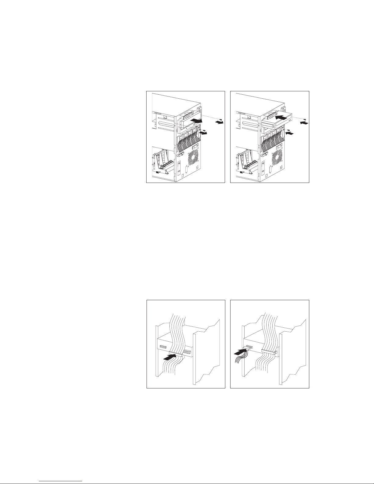
Installing or Removing Internal Drives
2. Remove the bay cover plate, if present.
a. Remove the screws on either side of the cover plate that secure the plate
to the target bay.
b. Remove the cover plate from the server front panel. (Save the cover plate
for future use.)
3. Using the instructions that come with the drive, together with these instructions,
check that any switches or jumpers on the drive are set correctly. Change the
settings if necessary. For information about termination requirements, see
“Termination Requirements” on page 59.
4. Position the drive with the connectors facing the rear of the server.
5. Slide the drive into the bay until it stops.
6. Reinstall and tighten the screws that you removed in step 2.
7. Connect the drive to the available connector on the SCSI cable or the IDE
cable, as appropriate.
Note: If you have difficulty connecting a cable, turn the cable connector over
and try again; cable connectors are keyed to connect only one way.
8. Connect one of the 4-pin power cables to the drive.
9. If you want to install or remove any other options, do so now. Otherwise, go to
“Completing the Installation” on page 76.
Chapter 4. Installing Options 61
Page 72

Installing or Removing a Drive in Bay C (Diskette Drive)
This section gives the procedure for installing or removing a diskette drive.
Before you begin
Read “Electrical Safety” on page 41 and “Handling Static-Sensitive Devices”
on page 42.
Read the documentation that comes with the option.
To remove a drive in bay C:
1. Locate the drive-release tab on the diskette drive.
Installing or Removing Internal Drives
2. Press the tab against the drive and hold it there while pulling the drive out.
3. Disconnect the diskette drive cable and power cable from the drive.
4. If you want to install or remove any other options, do so now. Otherwise, go to
“Completing the Installation” on page 76.
To install a drive in bay C:
1. If you have not done so, remove the server cover and front bezel. See
“Preparing to Install Options” on page 43.
2. Using the instructions that come with the drive, together with these instructions,
check that any switches or jumpers on the drive are set correctly. Change the
settings if necessary. For information about termination requirements, see
“Termination Requirements” on page 59.
3. Insert the drive into the bay.
a. Position the drive so that the connectors face the rear of the server and the
diskette eject button is toward the outside of the server.
b. Connect the diskette drive cable and power cable to the drive.
Note: If you have difficulty connecting a cable, turn the cable connector
over and try again; cable connectors are keyed to connect only one
way.
62 Netfinity 5000 Server Hardware Information and Procedures
Page 73

Installing or Removing Internal Drives
c. Locate the drive-release tab on the diskette drive.
d. Press the tab against the drive and hold it there; slide the drive into the bay
until it clicks into place.
4. If you want to install or remove any other options, do so now. Otherwise, go to
“Completing the Installation” on page 76.
Installing or Removing Drives in Bays 1 through 5 (Hard Disk Drives)
This section gives the procedure for installing a hard disk drive. If you want to
remove a drive, reverse the following steps.
Note: To minimize the possibility of damage to the hard disk drives when you are
installing a hard disk drive in a rack model, install the rack model in the rack
before installing the hard disk drives.
Attention: To avoid damage to a hard disk drive,
the hot-swap bay until it has had time to spin down (approximately 30 seconds).
Handle the drive gently.
Before you begin
Read “Electrical Safety” on page 41 and “Handling Static-Sensitive Devices”
on page 42.
Read “Termination Requirements” on page 59
Your Netfinity 5000 server contains hardware that lets you replace a hard disk drive
without turning off the Netfinity 5000 server. These drives are known as
hot-swappable
or
hot-swap
drives.
Each hot-swap drive that you plan to install must have a hot-swap-drive tray
attached. The drive must have a single connector attachment (SCA) connector.
Hot-swap drives come with the hot-swap-drive tray attached.
do not
remove the drive from
Chapter 4. Installing Options 63
Page 74

Notes:
1. The Netfinity 5000 server EMI integrity and cooling are both protected by
having the hot-swap bays covered or occupied. When you install a drive, save
the filler panel from the bay, in case you later remove the drive and do not
replace it with another.
2. The hot-swap bays connect to a SCSI backplane. This backplane is the
printed circuit board behind the hot-swap bays.
To install a drive in a hot-swap bay:
1. Remove the filler panel .1/ from one of the empty hot-swap bays by inserting
your finger into the depression at the top of the filler panel (tower model) or left
side of the filler panel (rack model) and pulling it away from the server.
Attention: To maintain proper system cooling, do not operate the Netfinity
5000 server for more than two minutes without either a drive or a filler panel
installed for each bay.
Installing or Removing Internal Drives
.1/ Filler panel
.2/ Drive
.3/ Tray handle
2. Install the hard disk drive .2/ in the hot-swap bay.
a. Ensure the tray handle .3/ is open (that is, perpendicular to the drive).
b. Align the drive-tray assembly so that it engages the guide rails in the bay.
c. Gently push the drive-tray assembly into the bay until the drive connects to
the backplane.
d. Push the tray handle toward the drive until the handle locks.
64 Netfinity 5000 Server Hardware Information and Procedures
Page 75

Installing or Removing Internal Drives
3. Check the hard disk drive status indicators to verify that the hard disk drives
are operating properly. See “Status Indicators” on page 9 for details.
Notes:
a. There are no termination requirements for any SCSI hard disk drives
installed in the hard drive bays. Termination is achieved through the DASD
backplane.
b. If your Netfinity 5000 server has a RAID adapter or controller, you might
want to reconfigure your disk arrays after installing hard disk drives; consult
the documentation that came with your adapter or controller. Record the
configuration information in the appropriate tables in “Installed Device
Records” on page 163.
4. If you want to install or remove any other options, do so now. Otherwise, go to
“Completing the Installation” on page 76.
Chapter 4. Installing Options 65
Page 76

Installing Microprocessors
When you install an additional microprocessor, your Netfinity 5000 server can
operate as a symmetric multiprocessing (SMP) server. With SMP, certain operating
systems and application programs can distribute the processing load between
microprocessors. This enhances performance for database and point-of-sale
applications, integrated manufacturing solutions, and other applications.
Installing Microprocessor Upgrades
Your server comes with an Intel Pentium II microprocessor. This microprocessor
incorporates MMX technology with built-in ECC level two (L2) cache. For the latest
information about microprocessor upgrades available for your server, contact your
IBM reseller, IBM marketing representative, or see
http://www.pc.ibm.com/us/compat/ on the World Wide Web. If you do upgrade the
microprocessor, use the instructions that come with the upgrade along with the
instructions in “Installing or Replacing a Microprocessor” on page 67.
Attention:
If you install an additional microprocessor that is different from the currently
installed microprocessor, your server operation might be unreliable. To prevent
this, use a microprocessor with the same internal and external clock speed,
and the same cache size and voltage requirements as those of the currently
installed microprocessor. Microprocessor internal and external clock
frequencies and cache size must be identical.
Installing Microprocessors
The voltage-regulator module (VRM) for the additional microprocessor plugs
into a connector on the system board (see “System Board Connectors” on
page 169 for the location of the VRM connector). Because each
microprocessor has specific power and voltage requirements, be sure to use
the VRM that comes with the microprocessor.
Note: The voltage regulator function for the microprocessor that is shipped
with your server is built into the system board.
If you select a setting for the frequency switch that is greater than the actual
frequency of the microprocessor, you might damage the microprocessor. The
frequency switch settings are shown in Table 3 on page 70.
For additional information about microprocessor speeds, clock frequencies, and
jumper settings, see Chapter 7, “Server Records and Specifications” on page 161.
66 Netfinity 5000 Server Hardware Information and Procedures
Page 77

Installing Microprocessors
Installing or Replacing a Microprocessor
This section gives the procedure for installing microprocessors. If you want to
remove a microprocessor, reverse the order of the following steps.
Before you begin:
Read “Electrical Safety” on page 41 and “Handling Static-Sensitive Devices”
on page 42.
Thoroughly review the documentation that comes with the microprocessor,
so that you can determine whether you need to update the server BIOS.
The “ServerGuide and Netfinity Manager Information” section of this
Library
includes IBM Update Connector, which keeps your BIOS and device
drivers current. You can also obtain the latest level of BIOS for your server
through the World Wide Web and the IBM Personal Computer Company
Bulletin Board System (BBS). See the “Getting Help Information” section of
this
Server Library
bulletin board telephone numbers.
For a list of supported operating systems, see
http://www.pc.ibm.com/compat/ on the World Wide Web.
for the appropriate World Wide Web addresses and
Server
Notes:
1. If you have not already done so, go to http://www.pc.ibm.com/support/ on the
World Wide Web and download the appropriate flash update program. Review
the applicable README files, and use this information to create a
Diskette
2. The microprocessor in your server comes with an attached heat sink. The
microprocessor plugs into the microprocessor socket on the system board and
is stabilized with a plastic bracket attached to the system board.
3. If you replace the microprocessor with one that has a different speed, you must
change the switch settings on the system board. To locate the switches, see
“System Board Connectors” on page 169. For information about the
appropriate switch settings, see Table 17 on page 170, or see the label inside
the server cover.
Attention:
If you select a setting for the frequency switch that is greater than the actual
frequency of the microprocessor, you might damage the microprocessor.
To install a microprocessor:
1. If you have not done so, remove the server cover. See “Preparing to Install
Options” on page 43.
2. If you are installing an additional microprocessor, remove the terminator card
from the secondary microprocessor connector. Otherwise, go to step 3 on
page 68.
. Perform the POST/BIOS (flash) update procedure.
Flash Utility
a. Spread apart the posts of the secondary microprocessor connector bracket
b. Lift the terminator card out of the connector.
Chapter 4. Installing Options 67
until the top of the terminator card is past the restraining latches.
Page 78

Installing Microprocessors
Note: When you install a second microprocessor, it becomes the startup
(boot) microprocessor.
3. Carefully remove the microprocessor from the static-protective package.
4. If you are replacing a microprocessor, remove the existing microprocessor from
its socket. Otherwise, go to step 5.
a. Locate the microprocessor socket on the system board. (See the
illustration in “System Board Illustration” on page 168.)
b. Place your index fingers on the small retainer tabs on the top of the
microprocessor. Push in toward the microprocessor until the tabs release.
Note: The illustrations in this section might differ slightly from your
hardware.
Tabs
c. Lift the microprocessor out of the connector.
d. Store the old microprocessor in a static-protective package.
5. Touch the static-protective package that contains the new microprocessor to
any
unpainted
metal surface in the server; then, remove the new
microprocessor.
68 Netfinity 5000 Server Hardware Information and Procedures
Page 79

Installing Microprocessors
6. Press inward on the retainer tabs until they click into place.
Note: For the location of the retainer tabs, see the illustration in step 4b on
page 68.
7. Align the new microprocessor with the microprocessor connector on the system
board and slide it into the guides. Press the microprocessor down until it snaps
into place and is fully seated in the connector.
8. Pull outward on the retainer tabs.
9. If you replaced the microprocessor with one that has a different speed, you
must change the switch settings on the system board. To locate the switches,
see “System Board Connectors” on page 169.
Chapter 4. Installing Options 69
Page 80
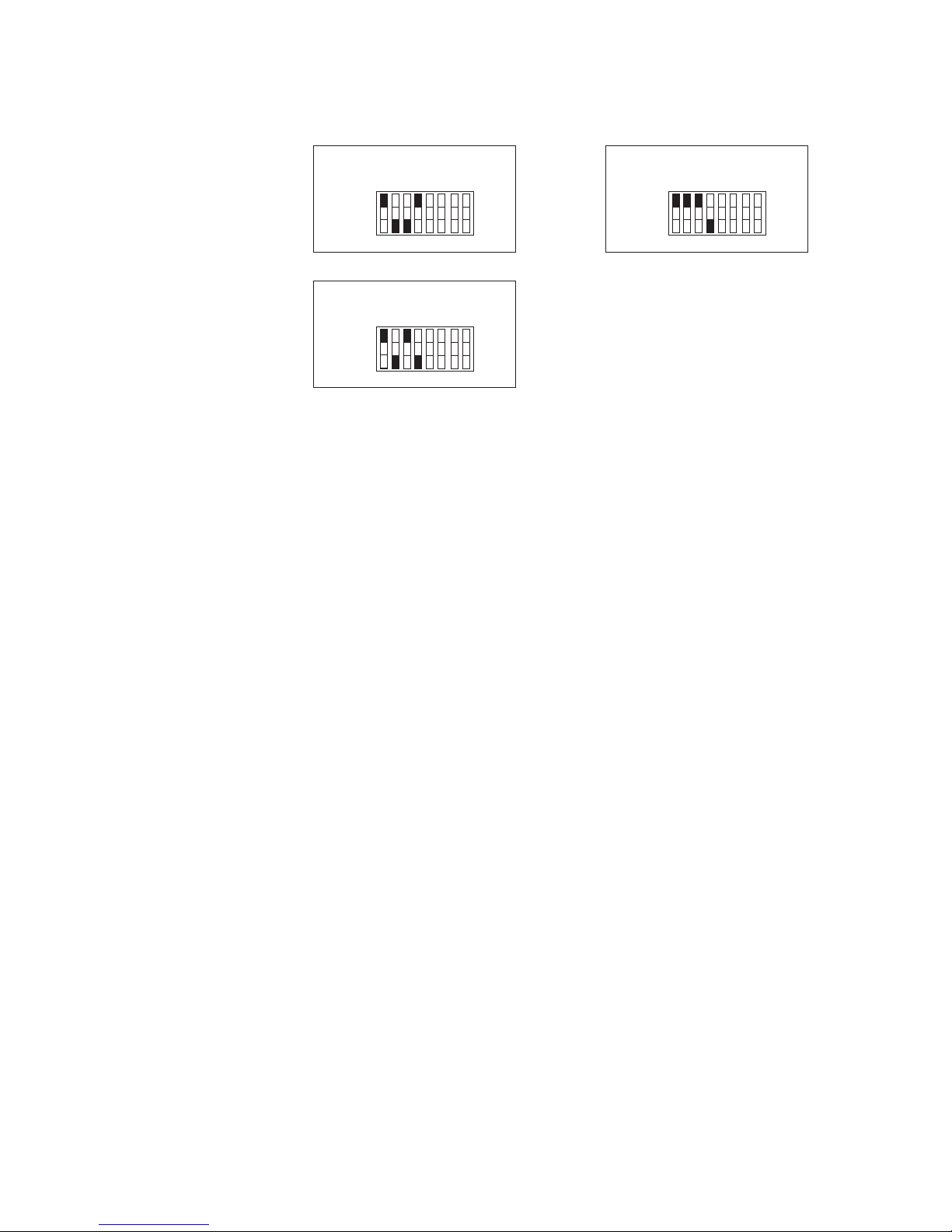
Table 3. Switch Settings for Microprocessor Speed
Installing Microprocessors
12345678
ON
OFF
12345678
ON
OFF
350 MHz
ON
OFF
450 MHz
400 MHz
12345678
10. Go to “Record the Identification Numbers” on page 162 and Table 14 on
page 164, and update the microprocessor information; then, return here.
11. Because you installed a new microprocessor in your server, you must
reconfigure your server. Follow the procedure described in “Using the
Configuration/Setup Utility” on page 22.
12. Because you installed a new microprocessor in your server, you might need to
make changes to your operating system.
If your operating system does not support SMP, install one of the SMP
operating systems that your server supports. See
http://www.pc.ibm.com/netfinity/ on the World Wide Web.
If your operating system does support SMP, refer to your operating-system
documentation. You might need to make changes so that the operating
system recognizes the new microprocessor.
On some operating systems, if you install a second microprocessor it might
be necessary to reinstall the operating system. See the documentation that
comes with the new microprocessor.
13. If you want to install or remove any other options, do so now. Otherwise, go to
“Completing the Installation” on page 76.
70 Netfinity 5000 Server Hardware Information and Procedures
Page 81

Installing or Replacing the Power Supply
Installing or Replacing the Power Supply
Your Netfinity server is shipped with a 350-watt power supply that provides
redundant power through the use of two internal power modules. If your server
load does not exceed 175 watts, and a problem occurs with one of the power
modules in the power supply, the other module takes over the load. For power
loads above 175 watts, you can install a second, optional, power supply to provide
redundant power for the server. The second power supply contains one 175-watt
power module. With the optional second power supply installed, if a problem
occurs with any of the power modules, the remaining two power modules supply
the needed 350 watts of power.
The LEDs on the back of each power supply indicate the status of each of the
power modules. If an LED is not on, there is a problem with the power supply
module, and the power supply must be replaced.
To install or remove the optional second power supply, see the instructions that
come with the option.
To replace the 350-watt power supply, contact an IBM service technician to
have the system serviced.
If you want to install or remove any other options, do so now. Otherwise, go to
“Completing the Installation” on page 76.
Chapter 4. Installing Options 71
Page 82

Connecting External Options
The information in this section supplements the instructions that come with the
external options (SCSI drives, printers, modems, and other serial and parallel
devices). To connect external options, see the documentation that comes with the
options.
Adding External SCSI Devices
Your server comes with a 16-bit UltraSCSI controller on the system board, which
provides two independent SCSI channels. This controller has two 68-pin, shielded,
high-density connectors: one internal, on the controller, and one external, on the
back of the server. You can use these connectors to install an additional internal
SCSI device in your server or to attach up to fifteen external SCSI devices to your
server.
The internal SCSI connector provides support for SCSI devices installed inside the
server. The external SCSI connector provides support for external SCSI devices.
Notes:
Connecting External Options
1. If you plan to install both internal and external SCSI devices, you must follow
the instructions given in “Installing or Removing Internal Drives” on page 56 in
addition to the instructions in this section. Read “Installing or Removing
Internal Drives,” and then return here.
For additional information about SCSI configurations supported, see
http://www.pc.ibm.com/netfinity/
2. Do not exceed the following cable lengths:
If you connect one or more Fast SCSI devices to the SCSI controller, the
total length of all cables (internal and external) must not exceed 3 meters
(9.8 feet).
If you do not connect Fast SCSI devices to the SCSI controller, the total
length of all cables must not exceed 6 meters (19.7 feet).
You must set a unique SCSI ID for each external SCSI device so that the controller
can identify the devices. The controller can then ensure that different devices do
not attempt to transfer data at the same time. Therefore, do not set the SCSI IDs
for external devices to the values you used for the controller.
If you plan to attach an external SCSI device, you might need to order an additional
SCSI cable. To use an external device with the Netfinity 5000 server, you must
connect it to the external SCSI connector, using a SCSI cable. This SCSI cable
must have the proper connector for the SCSI external connector on one end, and
the proper connector for the external device on the other end. If a SCSI cable
does not come with the external device, or if it is the wrong type, you will need to
order one. To select and order the correct SCSI cable for use with the external
device, contact your IBM reseller or IBM marketing representative.
72 Netfinity 5000 Server Hardware Information and Procedures
Page 83

Connecting External Options
Attaching External Options
To attach an external option:
1. Turn off the server and all attached devices.
2. Follow the instructions that come with the option and the illustration in
“Input/Output Connectors” on page 12 to connect it to the server.
Chapter 4. Installing Options 73
Page 84

Adding Security
You can add elements to your server to help to protect the server itself from theft
and tampering, and to help to protect the data and programs stored in the server
from unauthorized access and use.
Installing a U-Bolt and Security Cable
You can help to deter unauthorized removal of your tower model Netfinity 5000
server by installing a U-bolt and security cable on the rear of your server.
Before you begin
Obtain the following:
– A U-bolt
– A flat-blade screwdriver
– An adjustable wrench
– A 19 mm (3/4 in.) U-bolt or wire rope (similar to National Manufacturing
No. 3230, Stock No. 176-735)
– Threaded nuts that fit the U-bolt
– A security cable
– A lock, such as a combination lock or padlock
Read “Electrical Safety” on page 41 and “Handling Static-Sensitive Devices”
on page 42.
Adding Security
To install a U-bolt and security cable:
1. Remove the server cover. See “Preparing to Install Options” on page 43.
2. Insert the U-bolt through the holes and secure it in place with the nuts.
74 Netfinity 5000 Server Hardware Information and Procedures
Page 85
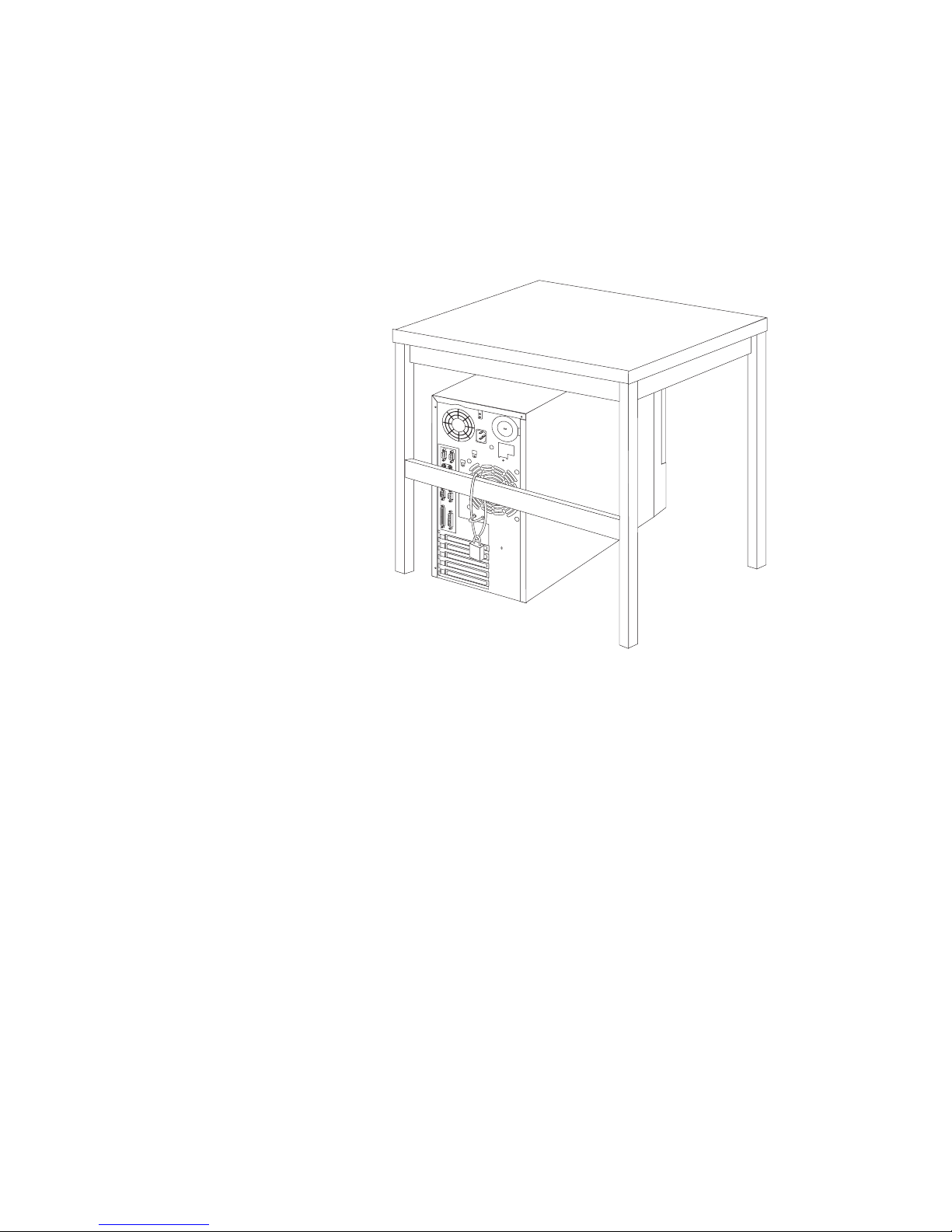
Adding Security
3. If you have completed installing the U-bolt and do not want to install any other
internal options, replace the server cover and reconnect all external cables and
power cords (see “Completing the Installation” on page 76 if you need
additional information).
4. Thread the cable through the U-bolt and around an object that is not a part of
or permanently secured to the building structure or foundation, and from which
it cannot be removed; then, fasten the cable ends together with a lock.
The following illustration shows an example of how this might work.
Chapter 4. Installing Options 75
Page 86

Completing the Installation
Before you begin
Complete all the installation procedures for the internal options you have
chosen to install.
Read “Electrical Safety” on page 41.
If you have a tower model, continue with “Completing the Tower Model
Installation.”
If you have a rack model, go to “Completing the Rack Model Installation” on
page 79.
Completing the Tower Model Installation
1. Install the cover on the server.
a. Align the left-side cover with the left side of the server, about 25 mm (1
inch) from the front of the server; place the bottom of the left-side cover on
the bottom rail of the left-side frame.
Completing the Installation
b. Insert the tabs at the top of the cover into the slots at the top of the server
side.
c. Hold the cover against the server and slide the cover toward the front of
the server until the cover clicks into place.
Note: Be sure the front edge of the cover is flat against the server.
76 Netfinity 5000 Server Hardware Information and Procedures
Page 87
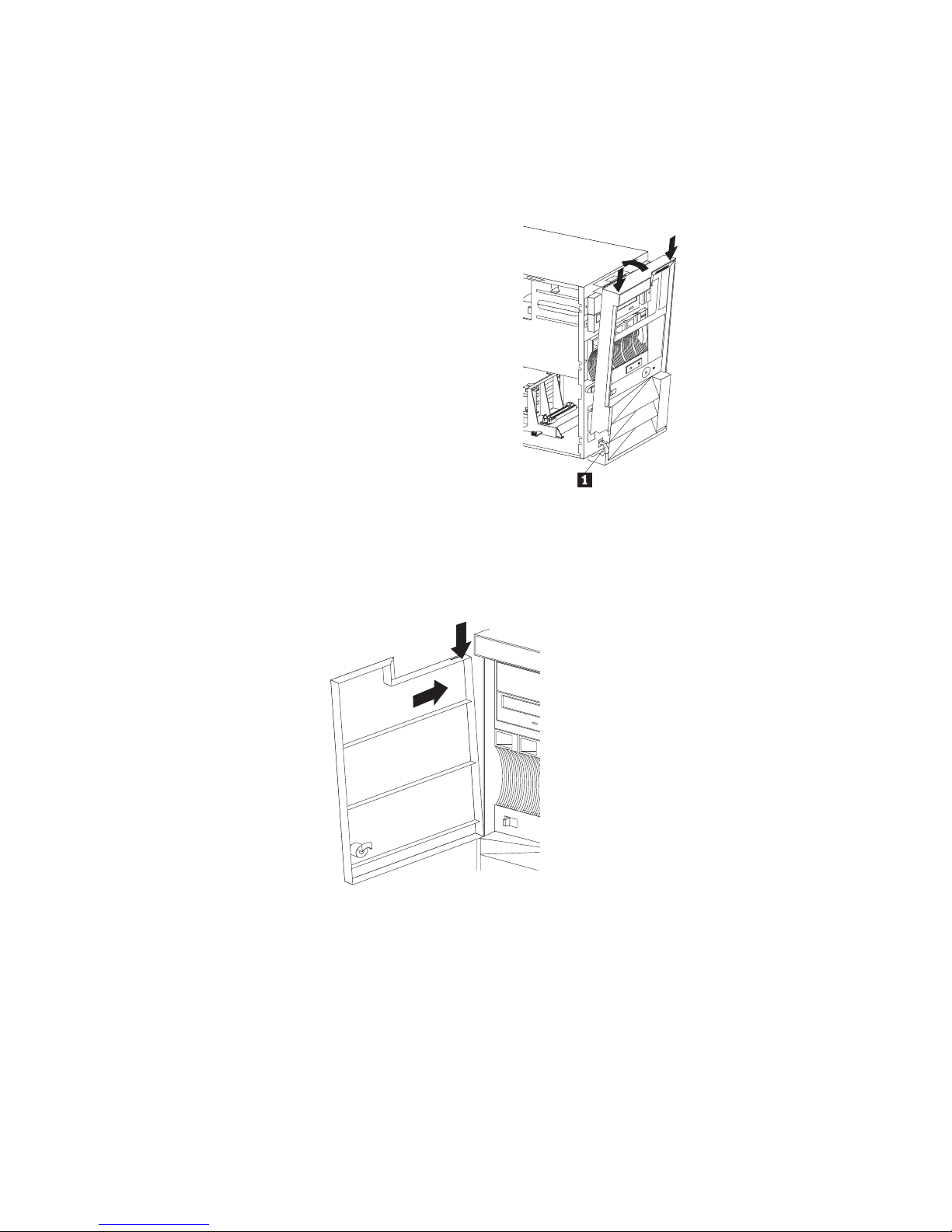
Completing the Installation
2. Replace the bezel, if it was removed.
a. Place the bezel tabs .1/ in the slots at the bottom front of the server.
b. Press the top of the bezel toward the server front until the bezel clicks into
place.
3. Replace the server door, if it was removed.
a. Set the door on the bottom hinge.
b. Press the flange downward while pressing the top of the door toward the
server, until the flange connects with the top hinge. Release the flange.
4. Close and lock the server door.
Chapter 4. Installing Options 77
Page 88
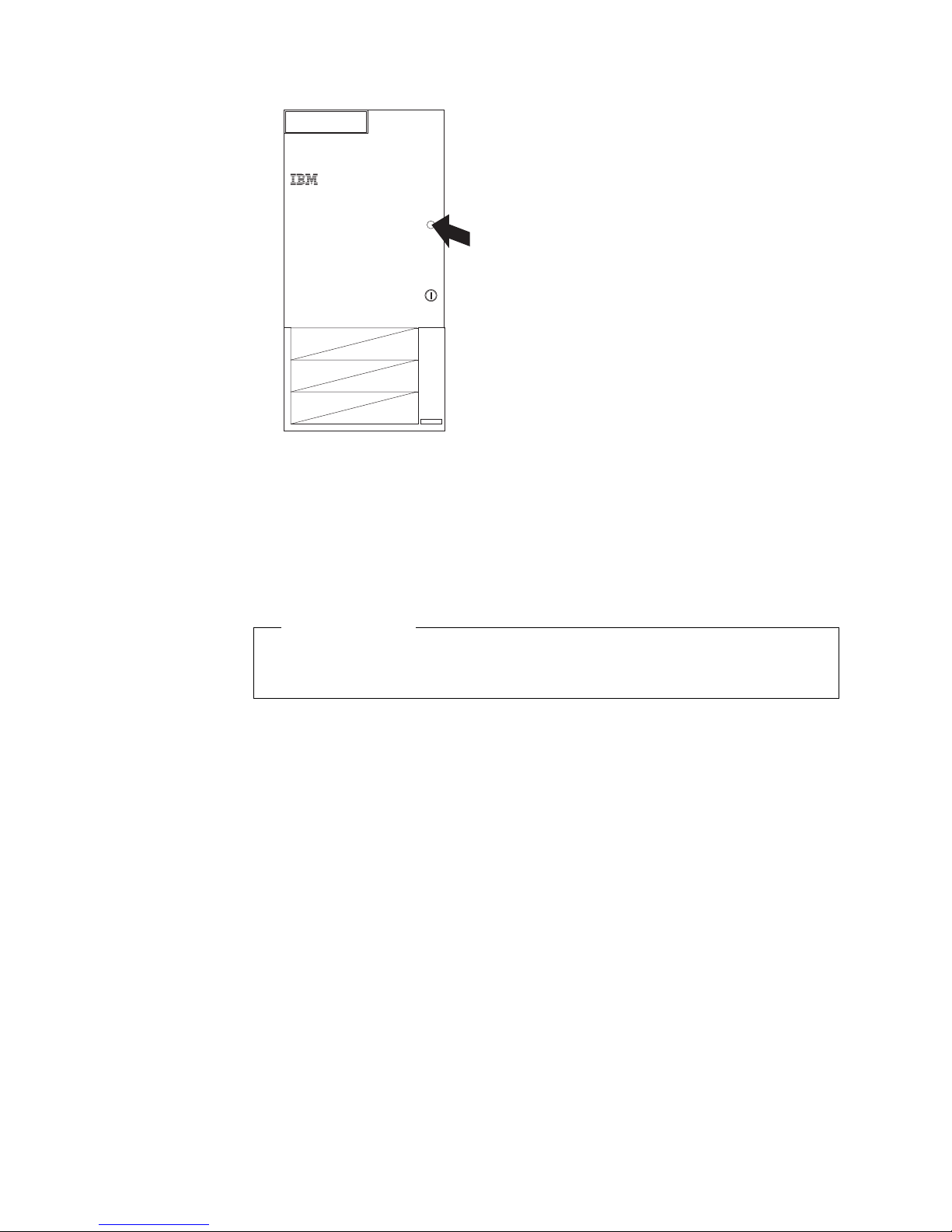
Completing the Installation
Attention:
Be sure to maintain a clearance of at least 127 mm (5 inches) on the front and
rear of the server to allow for air circulation.
5. Reconnect the cables to the back of the server; then, plug the power cords into
properly grounded electrical outlets.
6. If you have a modem or fax machine attached to the server, reconnect the
telephone line to the wall outlet and the server.
What to do next
When you have completed installing the covers and cables, go to “Updating the
Server Configuration” on page 82.
78 Netfinity 5000 Server Hardware Information and Procedures
Page 89

Completing the Installation
Completing the Rack Model Installation
1. Replace the top cover:
a. Align the top cover with the top of the server, about 25 mm (1 inch) from
the front of the server.
b. Hold the cover against the server and slide the cover toward the front of
the server until the cover clicks into place.
Note: Be sure the front edge of the cover is flat against the server.
c. Turn the captive thumbscrew .1/ until the cover is secured.
2. Replace the bezel, if it was removed.
a. Place the bezel tabs .2/ in the slots at the left front of the server.
b. Press the right end of the bezel toward the server front until the bezel clicks
into place.
Chapter 4. Installing Options 79
Page 90

3. Attach the monitor, keyboard, and power cables to the corresponding
connectors on the server. Refer to the rack documentation for instructions.
Completing the Installation
80 Netfinity 5000 Server Hardware Information and Procedures
Page 91

Completing the Installation
4. If you have a modem or fax machine attached to the server, reconnect the
telephone line to the wall outlet and the server.
5
k32 kg (70.5 lbs) k55 kg (121.2 lbs)
CAUTION:
Use safe lifting practices when lifting your machine.
5. If you are installing the rack model in the rack for the first time, go to “Installing
the Server in the Rack Enclosure” on page 102, and then go to “Updating the
Server Configuration” on page 82. Otherwise, continue with the following
instructions to secure the rack model in the rack.
a. Slide the rack model into the rack.
b. Locate the screws that you removed in step 3 on page 46.
c. Insert the screws through the bracket, mounting rail, and cage nut.
What to do next
When you have completed installing the cover and cables, go to “Updating the
Server Configuration” on page 82.
Chapter 4. Installing Options
81
Page 92

Updating the Server Configuration
When you start your server for the first time after you add or remove an internal
option or an external small computer systems interface (SCSI) device, you might
see a message telling you the configuration has changed. You might need to
install device drivers (required only if the option has a device driver). Refer to the
documentation that comes with your option for information about installing any
required device drivers.
Notes:
1. If you remove the last (terminated) SCSI device from the external SCSI cable
connected to the SCSI connector on the back of the server, the server might
not recognize any SCSI devices that are still connected on that SCSI channel
(cable). See Chapter 6, “Solving Problems” for information on correcting this
situation.
2. When a hard disk drive is added and you want to include it in your startup
sequence, use the Start Options selection of the Configuration/Setup Utility
programs (see “Start Options” on page 28).
3. When you install an ISA legacy adapter, you must allocate system resources to
support it (see “Plug and Play” on page 30).
Updating the Server Configuration
4. You can find the list of supported hardware and software for your server at
http://www.pc.ibm.com/compat on the World Wide Web.
Record the new configuration information in Chapter 7, “Server Records and
Specifications” on page 161.
What to do next
Device drivers to install? See the instructions that come with the option to
determine if device drivers are required, and, if so, how to install them.
If you do not need to install any device drivers or update the system
configuration, your server is ready to use.
82 Netfinity 5000 Server Hardware Information and Procedures
Page 93

Serial Port Connectors
Serial ports are used to communicate with printers, plotters, external modems,
auxiliary terminals, and other computers. Your server provides two serial ports (A
and B), and a special type of serial port (Management Port C, described on the
next page). You can add more serial ports by installing a serial adapter in one of
the expansion slots.
Note: Serial port A can be shared by the system-management processor and
operating system. Serial port B is used by the operating system only.
Management port C is controlled exclusively by the system-management
processor, cannot be used by the operating system, and cannot be
configured using the Configuration/Setup Utility program. See the
“Advanced System Management Information” section of this
for information about configuring serial ports A and C.
Server Library
Serial ports transfer data
asynchronously
; they can transmit any number of bits at
any time, with no restriction on the duration of the pauses between characters.
The serial ports transmit and receive data and commands at a rate of 300 bits per
second (bps) up to 115 200 bps. The bits-per-second measurement is commonly
referred to as the
baud rate.
Each of the two serial connectors provided on your Netfinity 5000 server uses a
9-pin, D-shell connector.
1
69
5
Table 4 shows the pin-number assignments for the serial port connectors. The
pin-number assignments conform to the industry standard.
Table 4. Serial Port Connector Pin-Number Assignments
Pin Signal Pin Signal
1 Data carrier detect 6 Data set ready
2 Receive data 7 Request to send
3 Transmit data 8 Clear to send
4 Data terminal ready 9 Ring indicator
5 Signal ground
Chapter 4. Installing Options 83
Page 94

Management Port C
Your server has a dedicated systems management I/O port. This port can be used
to attach a modem that is dedicated to communication with the
system-management processor.
The connector on the back of the server and the pin-number assignments are the
same as for the serial ports.
Table 4 on page 83 shows the pin-number assignments for the serial port
connectors. The pin-number assignments conform to the industry standard.
1
69
5
84 Netfinity 5000 Server Hardware Information and Procedures
Page 95

Parallel Port Connector
Parallel ports are used to communicate with printers and other devices, such as
some CD-ROM and tape drives. Your server provides one 25-pin, D-shell
connector on the back of the server.
13
1
25
14
This parallel port connector conforms to the Institute of Electrical and Electronics
Engineers (IEEE) Standard 1284. There are three standard modes of operation:
Standard Parallel Port (SPP)
Enhanced Parallel Port (EPP)
Extended Capability Port (ECP)
Table 5 shows the pin-number assignments for the parallel port connector. The
signal names for all three modes are shown. SPP and ECP signal names are the
same; EPP signal names that are different are shown in parentheses.
Table 5. Parallel Port Connector Pin-Number Assignments
Pin Signal Pin Signal
1 -STROBE (-WRITE) 14 -AUTO FD (-DSTRB)
2 Data 0 15 -ERROR
3 Data 1 16 -INIT
4 Data 2 17 -SLCT IN (-ASTRB)
5 Data 3 18 Ground
6 Data 4 19 Ground
7 Data 5 20 Ground
8 Data 6 21 Ground
9 Data 7 22 Ground
10 -ACK 23 Ground
11 BUSY (-WAIT) 24 Ground
12 PE 25 Ground
13 SLCT
Chapter 4. Installing Options 85
Page 96

Video Port Connector
The video port is where you can attach a video monitor to your Netfinity 5000
server. Your server provides a 15-pin video port connector.
6
1
11
5
15
10
Table 6 shows the pin-number assignments for the video port connector.
Table 6. Video Port Connector Pin-Number Assignments
Pin Signal
1 Red
2 Green or monochrome
3 Blue
4 Not connected
5 Ground
6 Red ground
7 Green ground or monochrome ground
8 Blue ground
9 + 5 v (DDC power)
10 Ground
11 Not connected
12 Display data channel (DDC data)
13 Horizontal synchronization (Hsync)
14 Vertical synchronization (Vsync)
15 Display data channel (DDC clock)
86 Netfinity 5000 Server Hardware Information and Procedures
Page 97

Keyboard and Mouse Connectors
Your server provides one keyboard port and one auxiliary-device port. An auxiliary
device can be a mouse or other pointing device.
6
4
2
5
3
1
Table 7 shows the pin-number assignments for the keyboard and auxiliary-device
port connectors.
Table 7. Keyboard and Auxiliary-Device Port Connectors Pin-Number Assignments
Pin Signal
1 Data
2 Not connected
3 Ground
4 +5 V dc
5 Clock
6 Not connected
Chapter 4. Installing Options 87
Page 98

SCSI Connectors
Your server comes with a 16-bit UltraSCSI controller on the system board, which
provides two independent SCSI channels. This controller has two 68-pin, shielded,
high-density connectors: one internal, on the controller, and one external, on the
back of the server. You can use these connectors to install an additional internal
SCSI device in your server or to attach up to fifteen external SCSI devices to your
server.
Internal SCSI Connector
A 2-drop, 68-pin (16-bit) cable is installed in your server. One drop is connected to
the backplane, the other drop can connect to an additional SCSI removable media
device (not a hard disk drive). This cable is connected to the internal connector for
the 16-bit UltraSCSI controller. You can use this cable to install an additional
internal SCSI device in your server.
External SCSI Connector
To attach an external SCSI device to your server, connect an external SCSI cable
from the SCSI device to the SCSI connector on the back of the server. Ensure that
the last device on the external SCSI cable is terminated.
88 Netfinity 5000 Server Hardware Information and Procedures
Page 99

Table 8 shows the pin-number assignments for the 68-pin SCSI connectors.
Table 8. The 68-Pin SCSI Port Connector Pin-Number Assignments
Pin Signal Pin Signal
1 Ground 35 Data 12
2 Ground 36 Data 13
3 Ground 37 Data 14
4 Ground 38 Data 15
5 Ground 39 Data P1
6 Ground 40 Data 0
7 Ground 41 Data 1
8 Ground 42 Data 2
9 Ground 43 Data 3
10 Ground 44 Data 4
11 Ground 45 Data 5
12 Ground 46 Data 6
13 Ground 47 Data 7
14 Ground 48 Data P0
15 Ground 49 Reserved
16 Ground 50 -PRSN
17 Terminal power 51 Terminal power
18 Terminal power 52 Terminal power
19 Reserved 53 Reserved
20 Ground 54 Ground
21 Ground 55 -Attention
22 Ground 56 Ground
23 Ground 57 -Busy
24 Ground 58 -Acknowledge
25 Not connected 59 -Reset
26 Ground 60 -Message
27 Ground 61 -Select
28 Ground 62 -Control/Data
29 Ground 63 -Request
30 Ground 64 -Input/Output
31 Ground 65 Data 8
32 Ground 66 Data 9
33 Ground 67 Data 10
34 Ground 68 Data 11
Chapter 4. Installing Options 89
Page 100

Universal Serial Bus Ports
The universal serial bus (USB) is an emerging serial interface standard for
telephony and multimedia devices. Each USB port is a single connector for
devices that previously used serial, parallel, keyboard, mouse, and game ports.
USB technology uses Plug and Play technology to determine which type of device
has been attached to the connector. Each USB device is accessed by a unique
USB address. A device called a hub is used to convert a single USB connector
into multiple attachment points. A hub has multiple ports where peripherals can be
attached. USB provides 12 megabits-per-second (Mbps) bandwidth with a
maximum of 63 peripherals and a maximum signal distance of five meters (16 feet
4.9 inches) per segment.
Note: If more than one USB device is to be attached, the devices must be
connected to a hub. Your Netfinity 5000 server does not support a
keyboard attached to the system USB port.
Your Netfinity 5000 server comes with two USB ports. Table 9 shows the
pin-number assignments for the USB port connectors.
Table 9. USB Port Connector Pin-Number Assignments
Pin Signal
1 VCC
2 −Data
3 +Data
4 Ground
90 Netfinity 5000 Server Hardware Information and Procedures
 Loading...