

Page 1

IBM Netfinity 4000R
User's Handbook
BM
I
Page 2

Page 3

IBM
IBM Netfinity 4000R
User's Handbook
Page 4

Note
Before using this information and the product it supports, be sure to read the general information under Appendix C, “Product
warranties and notices” on page 79.
First Edition (September 1999)
The following paragraph does not apply to the United Kingdom or any country where such provisions are inconsistent with
local law: INTERNATIONAL BUSINESS MACHINES CORPORATION PROVIDES THIS PUBLICATION “AS IS” WITHOUT
WARRANTY OF ANY KIND, EITHER EXPRESS OR IMPLIED, INCLUDING, BUT NOT LIMITED TO, THE IMPLIED WARRANTIES
OF MERCHANTABILITY OR FITNESS FOR A PARTICULAR PURPOSE. Some states do not allow disclaimer of express or implied
warranties in certain transactions, therefore, this statement may not apply to you.
This publication could include technical inaccuracies or typographical errors. Changes are periodically made to the information
herein; these changes will be incorporated in new editions of the publication. IBM may make improvements and/or changes in the
product(s) and/or the program(s) described in this publication at any time.
This publication was developed for products and services offered in the United States of America. IBM may not offer the products,
services, or features discussed in this document in other countries, and the information is subject to change without notice. Consult
your local IBM representative for information on the products, services, and features available in your area.
Requests for technical information about IBM products should be made to your IBM reseller or IBM marketing representative.
Copyright International Business Machines Corporation 1999. All rights reserved.
Note to U.S. Government Users — Documentation related to restricted rights — Use, duplication or disclosure is subject to
restrictions set forth in GSA ADP Schedule Contract with IBM Corp.
Page 5

Contents
Safety information statements ............................. v
Section 1. IBM Netfinity 4000R server ............................... 1
Chapter 1. Introducing your IBM Netfinity 4000R ................ 3
Inventory list . . . . . . . . . . . . . . . . . . . . . . . . . . . . . . . . . . . . . . . . 3
Features at a glance ................................... 4
Model specifications . . . . . . . . . . . . . . . . . . . . . . . . . . . . . . . . . . . 5
What your IBM Netfinity 4000R offers ......................... 5
Reliability, availability, and serviceability features .................. 6
Upgradable BIOS . . . . . . . . . . . . . . . . . . . . . . . . . . . . . . . . . . . . . 6
Placement considerations . . . . . . . . . . . . . . . . . . . . . . . . . . . . . . . . 7
System specifications . . . . . . . . . . . . . . . . . . . . . . . . . . . . . . . . . . 8
Controls, indicators, and connectors .......................... 9
Chapter 2. Installing the server in the rack enclosure ............ 13
What you will need ................................... 13
Preparing the server .................................. 14
Preparing the rack ................................... 15
Installing the server .................................. 18
Removing the server from the rack ......................... 21
Chapter 3. Using the setup utility ......................... 23
Chapter 4. Installing the operating system ................... 25
What you need ..................................... 25
What to do ........................................ 25
Chapter 5. Solving problems . . . . . . . . . . . . . . . . . . . . . . . . . . . 29
General symptoms . . . . . . . . . . . . . . . . . . . . . . . . . . . . . . . . . . . 29
Power-on self-test (POST) .............................. 29
Error messages . . . . . . . . . . . . . . . . . . . . . . . . . . . . . . . . . . . . . 30
Diagnostic utility . . . . . . . . . . . . . . . . . . . . . . . . . . . . . . . . . . . . 32
Section 2. Netfinity Manager . . . . . . . . . . . . . . . . . . . . . . . . . . . . . . . . . . . . . . 33
Chapter 6. Netfinity Manager . . . . . . . . . . . . . . . . . . . . . . . . . . . 35
Managing your IBM Netfinity server with Netfinity Manager ........... 35
Netfinity Manager documentation .......................... 36
Road map . . . . . . . . . . . . . . . . . . . . . . . . . . . . . . . . . . . . . . . . 36
Chapter 7. Netfinity Manager system requirements .............. 37
Chapter 8. Starting the Netfinity Manager installation program ...... 39
Chapter 9. Netfinity Manager database support ................ 45
DB2 database support ................................. 45
Lotus Notes database support ............................ 50
ODBC database support ............................... 52
Copyright IBM Corp. 1999 iii
Page 6

Chapter 10. Starting Netfinity Manager ..................... 57
Netfinity Manager Service Manager ......................... 57
Netfinity Manager service descriptions ....................... 58
Delaying Netfinity Manager startup on OS/2 systems ............... 64
Chapter 11. Getting more information about Netfinity Manager ...... 65
Chapter 12. Installation options . . . . . . . . . . . . . . . . . . . . . . . . . . 67
Automated installation . . . . . . . . . . . . . . . . . . . . . . . . . . . . . . . . . 67
Customized installation . . . . . . . . . . . . . . . . . . . . . . . . . . . . . . . . 68
Section 3. Appendixes . . . . . . . . . . . . . . . . . . . . . . . . . . . . . . . . . . . . . . . . . . 71
Appendix A. Help and service information ................... 73
Step 1: Troubleshooting . . . . . . . . . . . . . . . . . . . . . . . . . . . . . . . 73
Step 2: Preparing for the service call ........................ 73
Step 3: Placing the service call to IBM ....................... 73
Getting addtional help, service, and information .................. 74
Appendix B. Server records . . . . . . . . . . . . . . . . . . . . . . . . . . . . 77
Serial number . . . . . . . . . . . . . . . . . . . . . . . . . . . . . . . . . . . . . . 77
Appendix C. Product warranties and notices ................. 79
Notices . . . . . . . . . . . . . . . . . . . . . . . . . . . . . . . . . . . . . . . . . . 84
Trademarks . . . . . . . . . . . . . . . . . . . . . . . . . . . . . . . . . . . . . . . 85
Index . . . . . . . . . . . . . . . . . . . . . . . . . . . . . . . . . . . . . . . . . . . 89
iv Netfinity 4000R User's Handbook
Page 7

Safety information statements
Before installing this product, read the Safety Information.
Antes de instalar este produto, leia as Informações de Segurança.
Před instalací tohoto produktu si přečtěte příručku bezpečnostních instrukcí.
Læs sikkerhedsforskrifterne, før du installerer dette produkt.
Ennen kuin asennat tämän tuotteen, lue turvaohjeet kohdasta Safety Information.
Avant d'installer ce produit, lisez les consignes de sécurité.
Vor der Installation dieses Produkts die Sicherheitshinweise lesen.
Prima di installare questo prodotto, leggere le Informazioni sulla Sicurezza
Lees voordat u dit product installeert eerst de veiligheidsvoorschriften.
Les sikkerhetsinformasjonen (Safety Information) før du installerer dette produktet.
Antes de instalar este produto, leia as Informações sobre Segurança.
Pred inštaláciou tohto zariadenia si pečítaje Bezpečnostné predpisy.
Antes de instalar este producto lea la información de seguridad.
Läs säkerhetsinformationen innan du installerar den här produkten.
Contents v
Page 8

8
CAUTION:
Never remove the cover on a power supply or any part that has the
following label attached.
Hazardous voltage, current, and energy levels are present inside any
component that has this label attached. There are no serviceable parts
inside these components. If you suspect a problem with one of these
parts, contact a service technician.
vi Netfinity 4000R User's Handbook
Page 9

1
DANGER
Electrical current from power, telephone, and communication
cables is hazardous.
To avoid a shock hazard:
– Do not connect or disconnect any cables or perform
installation, maintenance, or reconfiguration of this product
during an electrical storm.
– Connect all power cords to a properly wired and grounded
electrical outlet.
– Connect to properly wired outlets any equipment that will be
attached to this product.
– When possible, use one hand only to connect or disconnect
signal cables.
– Never turn on any equipment when there is evidence of fire,
water, or structural damage.
– Disconnect the attached power cords, telecommunications
systems, networks, and modems before you open the
device covers, unless instructed otherwise in the installation
and configuration procedures.
– Connect and disconnect cables as described in the
following table when installing, moving, or opening covers
on this product or attached devices.
To Connect:
1. Turn everything OFF.
2. First, attach all cables to devices.
3. Attach signal cables to connectors.
4. Attach power cords to outlet.
5. Turn device ON.
To Disconnect:
1. Turn everything OFF.
2. First, remove power cords from outlet.
3. Remove signal cables from connectors.
4. Remove all cables from devices.
Contents vii
Page 10

This book contains information notices that relate to a specific topic. The Caution
and Danger notices also appear in a multilingual safety booklet. Each notice is
numbered for easy reference to the corresponding notices in the safety booklet.
The notice definitions are as follows:
Notes
These notices provide important tips, guidance, or advice.
Attention
These notices indicate possible damage to programs, devices, or data. An
attention notice is placed just
damage could occur.
Caution
These notices indicate situations that can be potentially hazardous to you. A
caution notice is placed just
procedure steps or situations.
Danger
These notices indicate situations that are potentially lethal or extremely
hazardous to you. A danger notice is placed just
potentially lethal or extremely hazardous procedure steps or situations.
before
the instruction or situation in which
before
descriptions of potentially hazardous
before
descriptions of
viii Netfinity 4000R User's Handbook
Page 11

Section 1. IBM Netfinity 4000R server
Chapter 1. Introducing your IBM Netfinity 4000R ................ 3
Inventory list . . . . . . . . . . . . . . . . . . . . . . . . . . . . . . . . . . . . . . . . 3
Features at a glance ................................... 4
Model specifications . . . . . . . . . . . . . . . . . . . . . . . . . . . . . . . . . . . 5
What your IBM Netfinity 4000R offers ......................... 5
Reliability, availability, and serviceability features .................. 6
Upgradable BIOS . . . . . . . . . . . . . . . . . . . . . . . . . . . . . . . . . . . . . 6
Placement considerations . . . . . . . . . . . . . . . . . . . . . . . . . . . . . . . . 7
System specifications . . . . . . . . . . . . . . . . . . . . . . . . . . . . . . . . . . 8
Controls, indicators, and connectors .......................... 9
Front View . . . . . . . . . . . . . . . . . . . . . . . . . . . . . . . . . . . . . . . 9
Back View . . . . . . . . . . . . . . . . . . . . . . . . . . . . . . . . . . . . . . 11
Chapter 2. Installing the server in the rack enclosure ............ 13
What you will need ................................... 13
Preparing the server .................................. 14
Preparing the rack ................................... 15
Installing the server .................................. 18
Removing the server from the rack ......................... 21
Chapter 3. Using the setup utility ......................... 23
Chapter 4. Installing the operating system ................... 25
What you need ..................................... 25
What to do ........................................ 25
Chapter 5. Solving problems . . . . . . . . . . . . . . . . . . . . . . . . . . . 29
General symptoms . . . . . . . . . . . . . . . . . . . . . . . . . . . . . . . . . . . 29
Power-on self-test (POST) .............................. 29
POST beep codes .................................. 29
Error messages . . . . . . . . . . . . . . . . . . . . . . . . . . . . . . . . . . . . . 30
Software-generated error messages ....................... 32
Diagnostic utility . . . . . . . . . . . . . . . . . . . . . . . . . . . . . . . . . . . . 32
Copyright IBM Corp. 1999 1
Page 12

2 Netfinity 4000R User's Handbook
Page 13

Chapter 1. Introducing your IBM Netfinity 4000R
This chapter provides an overview of the server features and components.
We appreciate your decision to purchase an IBM Netfinity server. Your IBM
Netfinity 4000R is a one-U-high1 rack-mounted enterprise-class appliance for
high-volume network transaction processing, such as Web site queries and
displays. Your server is a preconfigured device in which it is not necessary to add
hardware to attain functionality. Unpack the IBM Netfinity 4000R, mount it in a
rack, install a supported operating system and your own selection of software, and
the server is ready to “plug-in-and-go.” It may be used primarily as a
transaction-processor reporting to another server, or as a server itself.
Your IBM Netfinity server comes with a one-year limited warranty and IBM Netfinity
Server Start Up Support.
If you have access to the World Wide Web, you can obtain up-to-date information
about your Netfinity server model and other IBM Netfinity server products at the
following address: http://www.ibm.com/netfinity/
Inventory list
You should have the following items:
One Netfinity 4000R server
One rack mounting kit
– Two slide-rail assemblies
– One bag of screws and nut bars
One IEC power cord
One console bus cable
One console adapter
One
The
The
The
Note: The power cord that comes with your server must be plugged into a
The
contains device drivers to use with your operating system, instructive text files, and
a hard disk drive diagnostic utility.
The Netfinity Manager CD that comes with your system contains the complete
Netfinity Manager product.
Netfinity 4000R System
Netfinity Manager
Safety Information
IBM Netfinity 4000R User's Handbook
properly-grounded power distribution unit (PDU).
Netfinity 4000R System
CD
CD
booklet
(this publication)
compact disc (CD) that comes with your system
1
Racks are marked in vertical increments of 1.75 inches each. Each increment is referred to as a unit, or a “U.” A one-U-high
device is 1.75 inches tall.
Copyright IBM Corp. 1999
3
Page 14

Features at a glance
Features at a glance
The following table summarizes the features of the Netfinity 4000R. Where multiple quantities are specified
(1 or 2 microprocessors, for example), the actual number depends on your model of server. The model
number is on the small label on the lower right front of the server, and on the label on the bottom of the
server. See the model specifications on page 5.
Type
Rack-mount only
Microprocessor
1 or 2 Intel Pentium III
microprocessors
with MMX technology
512 KB of level-2 cache (min)
Memory
128MB (min) up to 2GB
Four dual-inline memory-module
(DIMM) sockets
128MB, 256 MB, or 512MB DIMMs
100 MHz, error correcting code (ECC)
registered synchronous dynamic
random access memory (SDRAM)
Hard disk drives
One or two internal SCSI hard disk
drives
2
9GB
Maximum: 36GB
SCSI controller
to 18GB each
Adaptec AHA-2940UW/B SCSI
adapter
CD-ROM drive
Standard: IDE
Slim height
Expansion slots
Two 32-bit PCI slots
– Standard: One single-channel
UltraWide SCSI adapter in full
length slot, controlling the hard
disk drives
– One half-length slot
Upgradable microcode
BIOS code upgrades (when
available) can update EEPROMs
on the system board
Power supply
150W with voltage auto-selection
(110, 120, 220, 240 Vac)
Built-in overload protection
Automatic restart after a
momentary loss of power
4
Integrated functions
Two serial ports
Two Universal Serial Bus (USB)
3
ports
One IDE internal connector, supports
the system IDE CD-ROM drive
Two full-duplex 10/100 Mbps Ethernet
controller
– Intel Ethernet 82559 controller
– One 10BASE-T/100BASE-TX port
per controller (two ports total)
– Redundant Ethernet capability,
through the connection of both
Ethernet ports to the same LAN
CT 69000 video controller
2 MB video memory
Supported operating systems
Microsoft Windows NT Server 4.0
2
GB equals approximately 1 000000000 bytes.
3
The operating system must support USB in order for you to use USB.
4
BIOS upgrades must be placed on a CD for use on the server. If you are unable to create a CD from the downloaded BIOS
upgrade, contact the IBM Help Center to order a BIOS upgrade CD.
4 Netfinity 4000R User's Handbook
Page 15

Model specifications
Model Features
11Y Microprocessors: One 500 MHz with 100MHz front side bus
Memory: 128MB
Hard disk drives: One 9.1GB, 7200RPM
21Y Microprocessors: Two 500 MHz with 100MHz front side bus
Memory: 512MB
Hard disk drives: Two 9.1GB, 7200RPM
22Y Microprocessors: Two 500 MHz with 100MHz front side bus
Memory: 1GB
Hard disk drives: Two 9.1GB, 7200RPM
What your IBM Netfinity 4000R offers
The IBM Netfinity 4000R is designed to be cost effective, powerful, and flexible.
Your server offers:
Impressive performance using an innovative approach to SMP on models with
two Pentium III microprocessors.
Large system memory
The memory subsystem in your server supports up to 2GB of system memory.
The memory controller provides error correcting code (ECC) support for 100
MHz SDRAM memory.
Integrated network environment support
Your Netfinity 4000R comes with two 10/100 Mbps Ethernet Controllers on the
system board. Each Ethernet controller has an interface for connecting to
10-Mbps or 100-Mbps networks. The server automatically selects between
10BASE-T and 100BASE-TX. Each controller provides full-duplex (FDX)
capability. Full duplex allows simultaneous transmission and reception of data
on the Ethernet local area network (LAN).
Redundant Ethernet connection
Your server provides a failover capability to a redundant Ethernet connection.
If a problem occurs with the primary Ethernet connection, all Ethernet traffic
associated with this primary connection is automatically switched to the
redundant Ethernet connection. This switching occurs without data loss and
without user intervention.
Chapter 1. Introducing your IBM Netfinity 4000R 5
Page 16

Reliability, availability, and serviceability features
Three of the most important factors in server design are reliability, availability, and
serviceability (RAS). These factors help to ensure the integrity of the data stored
on your server; that your server is available when you want to use it; and that
should a failure occur, you can possibly diagnose the failure and have it repaired
with minimal inconvenience.
The following is a partial list of the built-in RAS features on the IBM Netfinity server.
Upgradable BIOS
Upgradable BIOS
When BIOS upgrades are available, you can download a CD image from the
http://www.ibm.com/pc/support Web pages. Instructions for applying the BIOS
upgrade will be on the CD. If you are unable to create a CD yourself, you can
order a BIOS upgrade CD from the IBM HelpCenter (1-800-772-2227 in the United
States, 1-800-565-3344 in Canada).
Power-on self-test (POST)
Customer support center 24 hours per day
Error checking and correcting (ECC) memory
Error codes and messages
Automatic restart after power failure
Parity checking on the SCSI bus and serial ports
Monitoring and reporting the status of cooling systems through a status
indicator on the front of the server.
Redundant Ethernet capabilities
5
5
Response time will vary, depending on the number and nature of calls received.
6 Netfinity 4000R User's Handbook
Page 17

Placement considerations
Multiple servers can be interconnected to serve as a single group, or cluster. Each
rack can contain multiple groups of servers.
Generally, the number of servers you can install in a rack depends on how many
power distribution units (PDUs), uninterruptible power supplies (UPSs), and other
devices you have installed in the rack.
Notes:
1. You must connect the power cord of each IBM Netfinity 4000R to a
properly-grounded PDU. See the ServerProven list at
http://www.ibm.com/pc/netfinity to locate a PDU.
2. For air flow reasons, when IBM Netfinity 4000Rs are mounted in succession in
a rack, there must be no intervening spaces between the IBM Netfinity 4000Rs.
With the use of the console adapter that comes with your server, a console
(monitor, mouse, and keyboard) is physically attached to the server.
Chapter 1. Introducing your IBM Netfinity 4000R 7
Page 18

System specifications
Size
Depth: 646 mm (25.4 in.) including front
bezel
Width: 430 mm (16.9 in.), 484 mm (19.1 in)
including mounting flanges
Height: 44 mm (1.73 in.)
Weight
Maximum configuration (as shipped): 10.43
kg (23.0 lb)
Maximum configuration with slide rails
attached: 11.34 kg (25.0 lb)
Environment
Air temperature:
– System on:
- At altitude 0–914 m (3000 ft): 10° to
35°C (50° to 95°F)
- At altitude 914 m (3000 ft)–2134 m
(7000 ft): 10° to 32°C (50° to 90°F)
- System off: −40° to 70°C (−40° to
158°F)
Humidity:
– System on: 8% to 80%
– System off: 8% to 80%
Heat output
Approximate heat output in British thermal
units (Btu) per hour:
7
– Maximum configuration (as shipped): 306
Btu/hour (90 watts)
– Maximum configuration (theoretical)6:
545.6 Btu/hour (160 watts)
Electrical input
Sine-wave input (50/60 Hz) is required
Input voltage:
– Low range:
– High range:
– Input kilovolt-amperes (kVA)
Acoustical noise-emission values
Average sound-pressure levels:
– 49 dBA idle
– 50 dBA operating
Declared (upper limit) sound power levels:
– 6.4 bels idle
– 6.5 bels operating
7
- Minimum: 90 V ac
- Maximum: 137 V ac
- Minimum: 180 V ac
- Maximum: 265 V ac
(approximately):
- Maximum (configuration as shipped):
0.3 kVA
8
6
Under typical maximum configurations, the heat output will be substantially below the theoretical maximum.
7
Power consumption and heat output vary depending on the number and type of optional features installed and the
power-management optional features in use.
8
These levels were measured in controlled acoustical environments according to ISO 7779, and are reported in accordance with
ISO 9296. The declared sound power levels indicate an upper limit, below which a large portion of machines operate. Sound
pressure levels in your location might exceed the average 1-meter values stated because of room reflections and other nearby
noise.
8 Netfinity 4000R User's Handbook
Page 19
Controls, indicators, and connectors
Controls, indicators, and connectors
The most commonly used controls and status indicators are on the front of your
server. All connectors are on the back of your server.
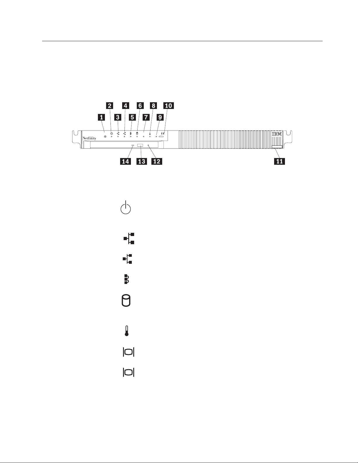
Front View
1 2
Reset
000
4
R
.1/ Reset Reset button: Press this button to reset the server. You might need
OS
to use a pen or the end of a straightened paper clip to press the
button.
.2/ Power-on light: This green LED lights when you turn on your
server by pressing the Power-on switch. If this light does not come
on after you have pressed the power-on switch, the power cord is
not connected or the power supply has failed.
.3/
.4/
Ethernet 1: This yellow LED lights when there is transaction activity
1
on Ethernet port 1.
Ethernet 2: This yellow LED lights when there is transaction activity
2
on Ethernet port 2.
.5/ Interconnect: Reserved.
.6/ Hard disk drive: Reserved.
.7/ OS Operating system: Reserved.
.8/ Temperature: Reserved.
.9/ Console: Reserved.
.1ð/ Select button: Reserved.
.11/ Label: This label shows the server serial number, type, and model
number.
.12/ CD-ROM manual tray-release opening: If using the CD-ROM eject
button does not eject the tray, insert a straightened paper clip in this
opening to release the tray.
Chapter 1. Introducing your IBM Netfinity 4000R 9
Page 20

Controls, indicators, and connectors
.13/ CD-ROM eject button: Press this button to release a CD from the
CD-ROM drive.
Note: If the CD tray does not extend, insert the end of a
straightened paper clip into the manual tray-release opening
and gently pull the tray open.
.14/ CD-ROM drive in-use light: This light comes on when the
CD-ROM drive is accessed.
10 Netfinity 4000R User's Handbook
Page 21
Controls, indicators, and connectors
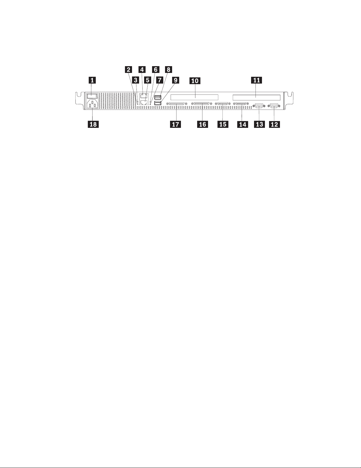
Back View
.1/ Power-on switch: Use this switch to turn on your server.
.2/ Ethernet 2 link indicator: This LED lights when there is an active link
connection on the 10BASE-T or 100BASE-TX interface for Ethernet port 2.
.3/ Ethernet 1 link indicator: This LED lights when there is an active link
connection on the 10BASE-T or 100BASE-TX interface for Ethernet port 1.
.4/ Ethernet connector 1: An unshielded, twisted-pair cable with an RJ-45
connector attaches here to the 10/100 Ethernet controller on the system
board.
.5/ Ethernet connector 2: An unshielded, twisted-pair cable with an RJ-45
connector attaches here to the 10/100 Ethernet controller on the system
board.
.6/ Ethernet 1 speed indicator: This LED lights when the speed of the Ethernet
LAN connected to Ethernet port 1 is 100 Mbps.
.7/ Ethernet 2 speed indicator: This LED lights when the speed of the Ethernet
LAN connected to Ethernet port 2 is 100 Mbps.
.8/ Universal Serial Bus (USB) connector 1: Reserved.
.9/ Universal Serial Bus (USB) connector 2: Reserved.
.1ð/ PCI slot 1: This slot contains the SCSI controller for the hard disk drives.
You can connect an IBM-approved external tape drive to the connector on the
SCSI adapter. See the Server-Proven list on
http://www.ibm.com/netfinity/ (look for “compatibility”) for the list of
IBM-approved external tape drives.
.11/ PCI slot 2: This half-length slot can contain a second PCI adapter. Which
adapter is present, if any, depends upon which server model you have.
.12/ Serial connector A: Signal cables for modems or other serial devices
connect here to the 9-pin serial connector for serial port A. You might need
to use a cable that has minimal bulk on its connector.
.13/ Serial connector B: Signal cables for modems or other serial devices
connect here to the 9-pin serial connector for serial port B. You might need
to use a cable that has minimal bulk on its connector.
.14/ Console bus connector (Out): Reserved.
.15/ Console bus connector (In): Use the console bus cable to connect the
console bus connector (In) to the console adapter. See step 4 on page 19
for details.
Chapter 1. Introducing your IBM Netfinity 4000R 11
Page 22

.16/ Option 2: Reserved.
.17/ Option 1: Reserved.
.18/ Power cord connector: Attach the power cord here.
Controls, indicators, and connectors
12 Netfinity 4000R User's Handbook
Page 23
Chapter 2. Installing the server in the rack enclosure
This chapter provides instructions for installing your server in a rack enclosure.
Important
If a Netfinity EXP15 is installed in the same rack as the IBM Netfinity
4000R, the IBM Netfinity 4000R must be installed with at least one U (1.75
in. of vertical measurement) between itself and the Netfinity EXP15. This
might require moving the Netfinity EXP15 to a different position in the rack.
For air flow reasons, when IBM Netfinity 4000Rs are mounted in succession
in a rack, there must be no intervening spaces between the IBM Netfinity
4000Rs.
4
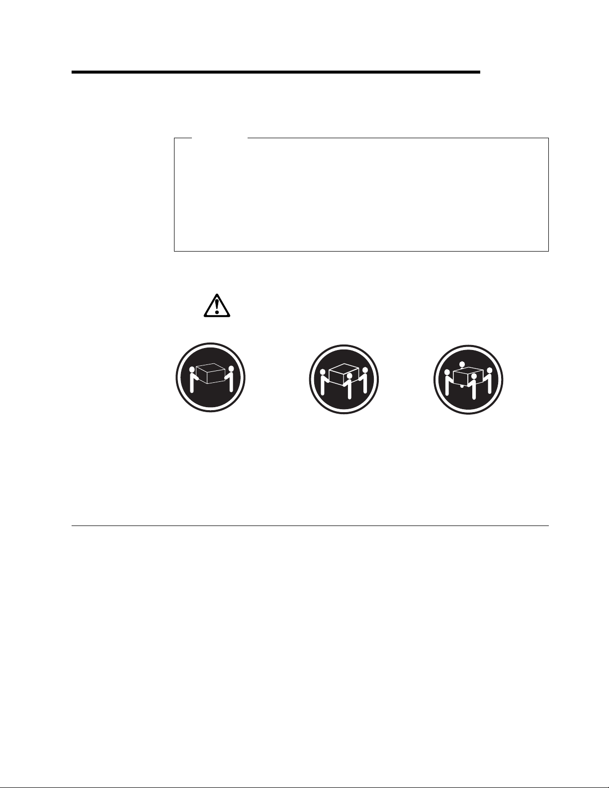
k18 kg (37 lbs)
This chapter is divided into two sections: preparing the rack, and installing the
server.
What you will need
In addition to the items in the inventory list in Chapter 1, “Introducing your IBM
Netfinity 4000R,” you will need the following items to install the server in a rack:
Phillips screwdriver
Flat-blade screwdriver
Pliers or box wrench
The documentation that comes with the rack
k32 kg (70.5 lbs) k55 kg (121.2 lbs)
CAUTION:
Use safe practices when lifting.
Copyright IBM Corp. 1999 13
Page 24
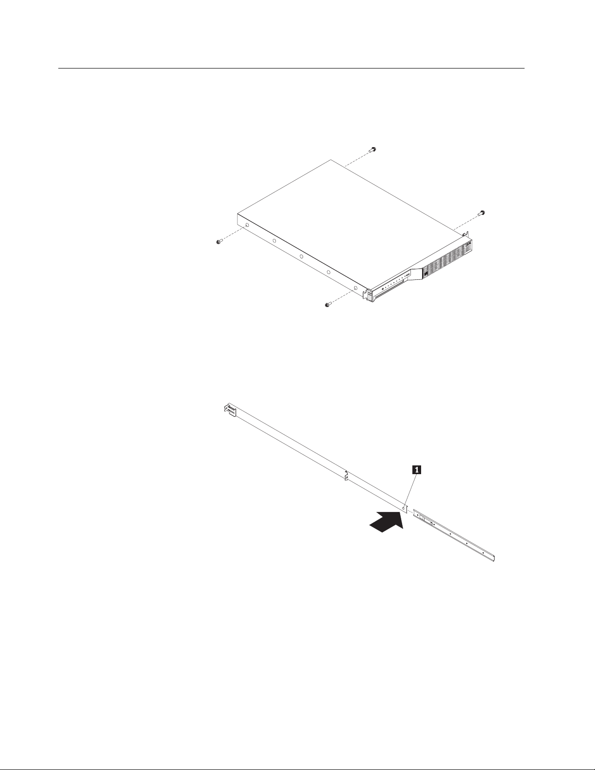
Preparing the server
1. Remove the two screws from the left side of the server. (These screws also
hold the top cover on—do not attempt to remove the cover.)
2. Remove the two screws from the right side of the server.
3. Attach the inner slide section of each slide rail assembly to the side of the
server.
a. Pull the inner slide from each slide rail assembly until the safety latch locks.
b. Press the safety latch.1/; then, pull the inner slide firmly until it detaches
from the outer slide rail.
14 Netfinity 4000R User's Handbook
Page 25
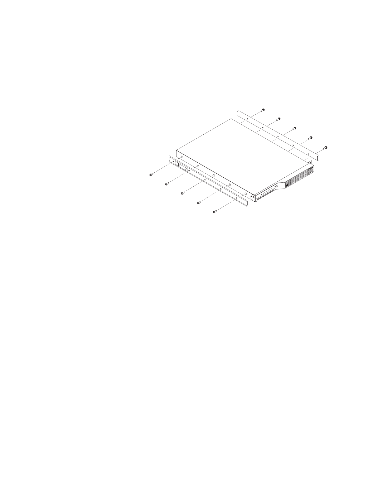
c. Align the holes on the inner slide with the holes on the side of the server;
then, attach the slide with three screws from the rack mount kit and the two
screws you removed earlier.
Note: If there are only enough screws in the rack mount kit to use two
additional screws on each side, instead of three, install the rack
mount kit screws in the second and fourth screw holes on each side
of the server.
Preparing the rack
Important:
1. Installing the server in a rack might require two people.
2. To ensure cabinet stability, install heavier devices such as UPSs starting from
3. If you are installing different server and server models in the rack enclosure,
4. If you are installing multiple servers in the rack, install all the nut bars and slide
5. Review the documentation that comes with your rack enclosure for safety or
Complete the following procedure to attach the mounting hardware to the rack
enclosure.
the bottom of the rack enclosure.
install the heaviest models in the lower part of the rack enclosure.
rails for all the servers first, then install each server in the rack.
cabling considerations. Ensure that your planned installation is within the rack
enclosure guidelines for heat generation, electrical requirements, air flow and
mechanical loading.
Notes:
a. You must align the slide rails correctly or the installation cannot be
completed.
b. The slide rail assemblies each have two screws on the rear bracket to
allow for length adjustment.
1. Remove the door from the rack and store it. The server requires more
ventilation than the rack door allows. See your rack documentation for details
on removing the door.
Chapter 2. Installing the server in the rack enclosure 15
Page 26
2. Select the U-unit the server will occupy in the rack.
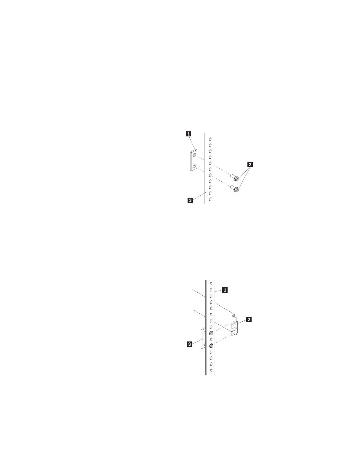
3. Attach a nut bar to the front rack rail:
a. Position a nut bar .1/ behind the front rack rail.3/, in the U-unit for the
server.
b. Insert two screws (M6 by 16 mm) .2/ through the holes in the rack rail and
the nut bar.
c. Tighten the screws until the nut bar is approximately 4 mm (.16 in.) from
the rack rail.
4. Attach nut bars to the other three corners of the U-unit in the same way.
5. Attach the slide rail assemblies to each side of the rack.
a. Place the tabs of the slide rail assembly front bracket .2/ between the front
rack rail .1/ and the nut bar .3/. The bracket fits
bottom screws.
between
the top and
16 Netfinity 4000R User's Handbook
Page 27
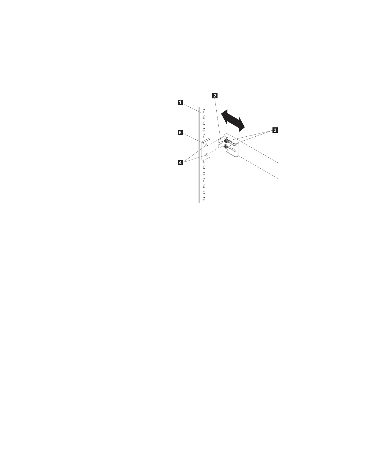
b. Place the tabs .2/ of the slide rail assembly rear bracket between the nut
bar .5/ and the rear rack rail .1/. If necessary, loosen the screws .3/ at
the rear of the slide-rail assembly and adjust the length of the slide-rail to fit
the rack. Tighten the adjustment screws .3/.
c. Push the slide-bracket assemblies to the outermost positions on the rack.
Make sure that the slides on the slide-rail assembly will extend out from the
front of the rack.
d. Tighten the screws at the front and rear of the U-unit.
e. Attach the other slide rail assembly into the U-unit in the same way.
Chapter 2. Installing the server in the rack enclosure 17
Page 28
Installing the server
Complete the following procedure to install the server into the rack enclosure.
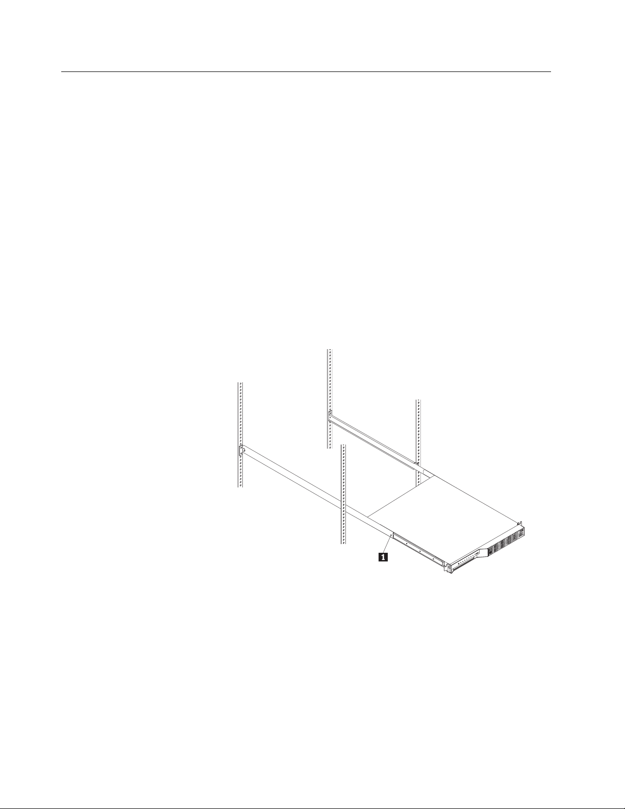
1. Mount the server on the slide rails.
a. Extend the slide rails until they lock into place.
b. Position the server horizontally, with the LED panel at the left.
c. Align the inner slides on the sides of the server with the slide rails; then,
slide the server onto the outer slide about 5 cm (2 in.), until the server
stops.
d. Press the safety latches .1/ on the slide rails and slide the server further
onto the outer slide, until the slide rails click into place.
e. Press the safety latches .1/ on the slide rails again and slide the server
part of the way into the rack enclosure.
Note: When the server is fully extended, safety latches on the slide rails
lock into place. This prevents the server from being accidentally
pulled out too far and dropped. To release the safety latch, press
in.
18 Netfinity 4000R User's Handbook
Page 29
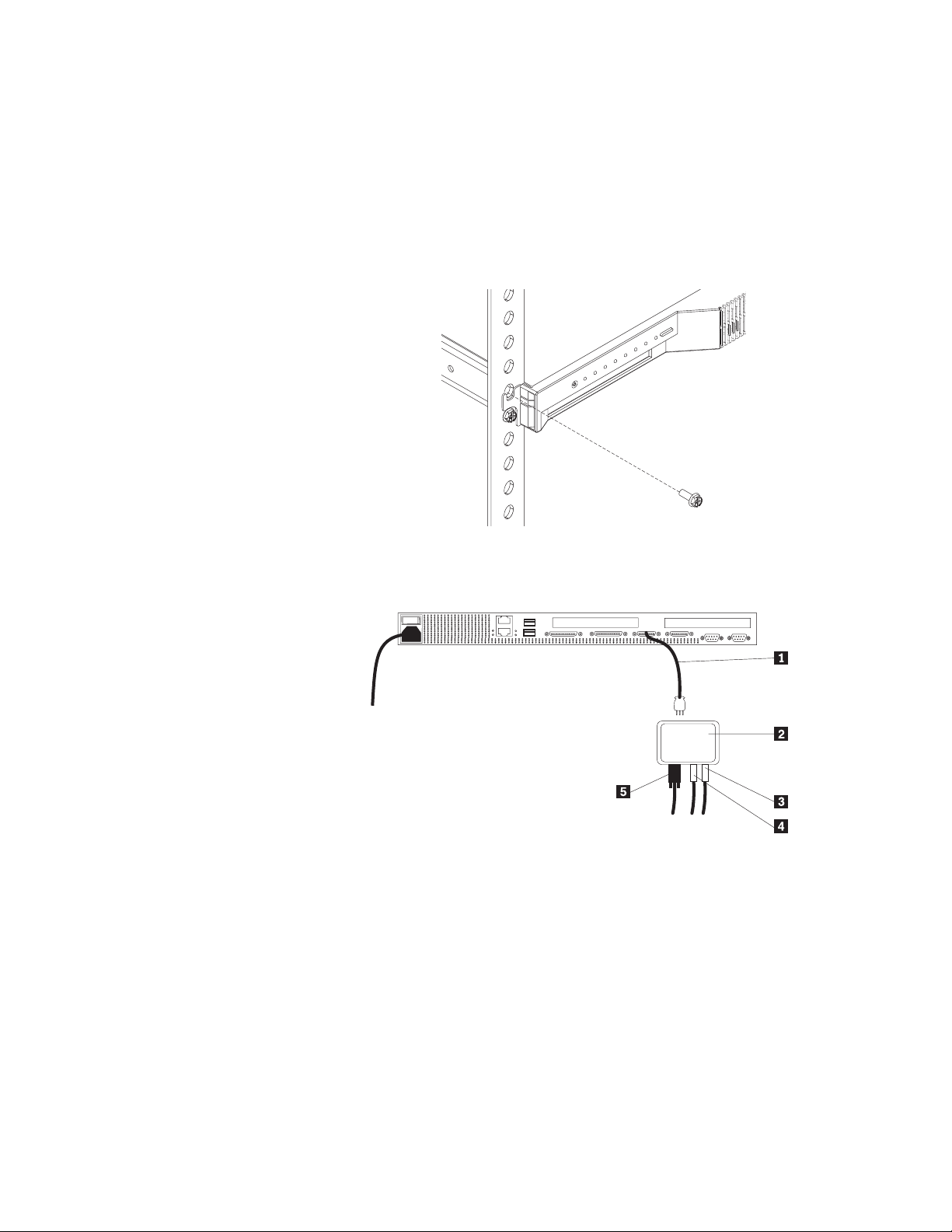
2. Install the server in the rack.
a. Remove the top screw holding the front of each slide rail assembly in the
rack.
b. Slide the server the rest of the way into the rack enclosure.
c. Reinsert the screws you removed, putting them through the slot in the
server mounting flange, the mounting rail, the slide-rail assembly bracket,
and the nut bar. Tighten the screws.
3. Connect the console bus cable .1/ to the console bus (In) port.
4. Connect the other end of the console bus cable .1/ to the console adapter .2/.
.1/ Console cable
.2/ Console adapter
.3/ Mouse cable
.4/ Keyboard cable
.5/ Monitor cable
Chapter 2. Installing the server in the rack enclosure 19
Page 30
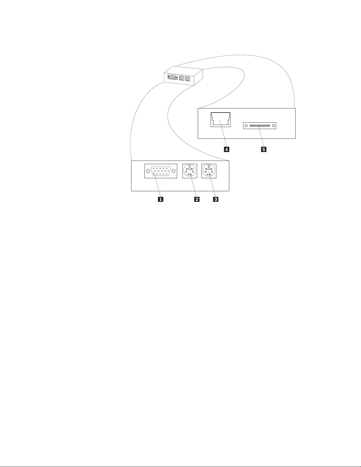
Console adapter
.1/ Monitor connector
.2/ Keyboard connector
.3/ Mouse connector
.4/ Unused
.5/ Console cable connector
5. Connect all device cables and connectors to the server.
6. Connect the power cord to the server. Connect the other end of the power
cord to a properly-grounded power distribution unit (PDU). See the
ServerProven list at http://www.ibm.com/pc/netfinity to locate a PDU.
7. Connect the keyboard, mouse, and monitor to the console adapter.
8. Connect the PDU power cable to a properly-grounded power outlet.
9. Turn on the server by setting the power-on switch at the rear of the server to
On.
20 Netfinity 4000R User's Handbook
Page 31

Removing the server from the rack
4
k18 kg (37 lbs)
CAUTION:
Use safe practices when lifting.
To pull the server forward, or to remove it from the rack, perform the following
steps.
1. Shut down the server operating system.
2. Set the server power-on switch to Off.
3. Disconnect the power cable and all other cables from the rear of the server.
4. On each side of the server front, remove the screw holding the mounting flange
to the rack (the top screw).
5. Pull the server forward until the safety latch on the slide rails locks.
6. To remove the server completely from the rack, press the safety latch on each
slide rail; then, pull the server from the slide rails. Place the server on a flat,
non-conductive surface.
k32 kg (70.5 lbs) k55 kg (121.2 lbs)
Chapter 2. Installing the server in the rack enclosure
21
Page 32

22 Netfinity 4000R User's Handbook
Page 33

Chapter 3. Using the setup utility
Use the setup utility to change only the items in the following table, unless explicitly
instructed to change other items.
cause your server to function incorrectly.
To start the setup utility, restart the server and press the Del key as soon as the
message Press Del to run setup appears on the first screen during restart.
When you select an item from the Setup Utility menu, a window with two panes is
displayed. One pane contains the list of options for that item; the other pane
contains the possible settings for the highlighted option in the list.
Use the up arrow and down arrow keys to scroll through the list. On some
options, the list is longer than the pane can display; you must scroll down to
see all the items in the list.
Use the PgUp and PgDn keys to change the settings for the highlighted option.
Press the Esc key to return to the Setup Utility main menu.
Selecting or changing any other options could
Menu item Items you can change
Standard CMOS Setup Date and time
Advanced CMOS Setup BootUp Num-Lock—on or off
Password Check—Always, or Setup
utility only
Peripheral Setup Serial ports—enable or disable
Change User Password (This option is active only if the
supervisor password has been set)
Change or disable the user password.
Note: The user password is
automatically removed when the
supervisor password is
removed.
When the password is set, a password
prompt is presented at the occasion
specified in the Password Check option
in Advanced CMOS Setup.
Change Supervisor Password Enter or change the supervisor
password. When this option is set, you
must log in to the server with the
supervisor password if you want to
change the supervisor password.
Note: Removing the supervisor
password automatically
removes the user password.
When the password is set, a password
prompt is presented at the occasion
specified in the Password Check option
in Advanced CMOS Setup.
Copyright IBM Corp. 1999 23
Page 34

Menu item Items you can change
Save Settings and Exit Save any changes you made and exit
the setup utility.
Exit Without Saving Exit the setup utility without saving any
changes you might have made.
24 Netfinity 4000R User's Handbook
Page 35

Chapter 4. Installing the operating system
This chapter provides instructions for installing and configuring the operating
system in your server.
What you need
To install Microsoft Windows NT Server 4.0 on the server, you need the
following items:
A licensed copy of the Windows NT Server 4.0 CD
Windows NT Service Pack 5 (see the Microsoft Web site for instructions on
downloading and installing the service pack)
What to do
The
Complete the following procedure to install Windows NT Server 4.0 and Service
Pack 5.
1. Insert the Windows NT Server 4.0 CD in the CD drive and set the power-on
2. In the Welcome to Setup window, press Enter. The system displays a list of
3. Press Enter to accept the recognized hardware in the list.
4. If the system displays a window discussing the number of cylinders on the hard
5. If the system displays a window indicating the hard disk drive is empty or the
6. Read and accept the license agreement (page down; at the end, press F8).
Netfinity 4000R System
switch to On. Press the Select button to connect the console (monitor,
keyboard, and mouse) to this server.
The system automatically enters the Windows NT Setup, examines the server
for components, and displays the Welcome to Setup window.
recognized hardware.
disk drive and the possible need for additional software, press Enter to
continue.
operating system is invalid or corrupted, press C to continue.
CD that comes with your server
7. When the system displays a new list of hardware and software components
detected, press Enter to accept the list. You will address specific hardware and
software information later in this procedure.
8. Partition and format the hard disk drive as desired.
9. Remove the Windows NT Server CD when directed and press Enter to restart
the system.
10. Re-insert the Windows NT Server CD when requested.
11. When the system displays the window about searching for a network adapter:
a. Click the Select From List button.
b. Click the Have Disk button.
Copyright IBM Corp. 1999 25
Page 36

c. Remove the Windows NT Server 4.0 CD and insert the
System
d. In the box labeled Copy manufacturer's files from, type the path to the
Ethernet driver as follows:
d:\ethernet
where d is the drive letter for the CD-ROM. Click OK.
e. Select
IBM 1ð/1ðð Ethernet PCI Adapter
from the list of drivers on the CD. Click OK.
The program takes you through configuring network protocols and services,
then copies the file from the
12. When the Copy Error window opens (a normal event when installing drivers not
on the Windows NT Server 4.0 CD):
a. Make sure the box labeled Copy files from contains the path D:\I386.
b. Remove the
Server 4.0 CD.
c. Click the Skip File button. (The system will copy the file and all others
needed from the Windows NT Server 4.0 CD.)
CD.
Netfinity 4000R System
Netfinity 4000R System
CD and reinsert the Windows NT
Netfinity 4000R
CD.
13. Specify the network information as requested.
14. When the Display Settings window is displayed, accept the standard settings.
You will address the video information later in this procedure.
15. Follow the instructions to remove the Windows NT Server 4.0 CD and restart
the system.
16. When the system has restarted completely and the Windows NT desktop
displays on the monitor, insert the
17. With the cursor on the desktop background, right-click the mouse. Click
Properties from the menu.
18. From the Display Properties window:
a. Click the Settings tab.
b. Click the Display Type button
c. Click the Change button
d. Click the Have Disk button
e. In the box labeled Copy manufacturer's files from, type the path to the
display driver as follows:
d:\video
where d is the drive letter for the CD-ROM. Click OK.
Netfinity 4000R System
CD.
f. Select
Chips Video Accelerator (65545/48/5ð/54/55 68554 69ððð)
from the list of drivers on the CD. Click OK; then, click Close.
19. When asked if you want to restart the system now, click No. You will restart
the system later.
26 Netfinity 4000R User's Handbook
Page 37

20. From the Windows NT desktop, click Start —> Settings —> Control Panel
—> SCSI Adapters.
21. From the SCSI Drivers window:
a. Click the Drivers tab.
b. Click the Add button
c. Click the Have Disk button
d. In the input box labeled Copy manufacturer's files from, type the path to
the SCSI driver as follows:
d:\scsi\adap294ð
where d is the drive letter for the CD-ROM. Click OK.
e. Select
Adaptec AHA29ðx/291x/294x/394x/4944/AIC78xx PCI SCSI Controller(NT 4.ð)
from the list of drivers on the CD. Click OK.
f. When the message stating that a driver is already installed displays, click
the New button.
g. Type the drive and path to the SCSI driver again. Click Continue.
22. After the driver has been copied, remove the
Netfinity 4000R System
CD and
click the Yes button to restart the system.
23. When the system restarts and displays the New graphics driver has been
detected message, click OK.
24. In the Display Properties window, set the properties for your display; then, click
the Test button to test the new properties.
25. Click the Apply button to see the results. Change the properties if needed, or
click OK to accept the properties.
26. Install the Windows NT Service Pack 5, using the instructions from Microsoft
Corporation.
27. Restart the system for the changes to take effect.
Install any additional software for your use, such as system administrative or
maintenance software or application programs.
Your server is ready for use.
Chapter 4. Installing the operating system 27
Page 38

28 Netfinity 4000R User's Handbook
Page 39

Chapter 5. Solving problems
This chapter provides information on IBM Netfinity 4000R error conditions, POST
beep codes, error codes, error messages, and any diagnostic tools that might be
available.
General symptoms
If...
Your server does not start when
you press the power switch
Your server starts but does not
respond to communication
requests
Your server beeps during POST,
before the display is initialized
Power-on self-test (POST)
Each time you turn on your server, it performs a series of tests that check the
operation of the base computer. This series of tests is called the
(POST)
POST does the following:
.
Checks basic system-board operations
Then...
Follow the instructions in Appendix A,
“Help and service information” on
page 73 to place a service call to
IBM.
Record the number of beeps. Then,
follow the instructions in Appendix A,
“Help and service information” on
page 73 to place a service call to
IBM.
power-on self-test
Checks the memory operation
Compares the current system configuration with that established by the
Configuration/Setup Utility program
Starts the video operation
Verifies that the hard disk drive and the CD-ROM drive are working
POST beep codes
If POST detects a problem, you will hear one or more beeps. Any beep before the
video initializes indicates an error.
In most cases, an error code appears in the top left corner of the screen, and in
some cases a description of the error is displayed beside the code. (Note that the
screen will sometimes display multiple error codes and descriptions.)
Copyright IBM Corp. 1999 29
Page 40

Error messages
If the server
beeps...
Six times 1. Disconnect and reconnect the keyboard cable.
Any other
number of
beeps
Error message
C:Drive Error
- orC:Drive Failure
Then...
2. If the server still beeps, try a different keyboard.
3. If the server still beeps, follow the instructions in
Appendix A, “Help and service information” on page 73 to
place a service call to IBM.
Follow the instructions in Appendix A, “Help and service
information” on page 73 to place a service call to IBM.
Explanation
No response from hard disk drive C.
Action: Run the hard disk drive diagnostic utility
(see “Diagnostic utility” on page 32 for instructions).
Record the results. If the diagnostic utility result is
“Fail”:
D:Drive Error
- orD:Drive Failure
Try a low-level format (press Ctrl-A during
startup) on the drive.
Attention: A low-level format will erase any
data on the drive.
If you are not willing to perform a low-level
format, or if the format did not correct the
problem, follow the instructions in Appendix A,
“Help and service information” on page 73 to
place a service call to IBM.
No response from hard disk drive D.
Action: Run the hard disk drive diagnostic utility
(see “Diagnostic utility” on page 32 for instructions).
Record the results. If the diagnostic utility result is
“Fail”:
Try a low-level format (press Ctrl-A during
startup) on the drive.
Attention: A low-level format will erase any
data on the drive.
If you are not willing to perform a low-level
format, or if the format did not correct the
problem, follow the instructions in Appendix A,
“Help and service information” on page 73 to
place a service call to IBM.
30 Netfinity 4000R User's Handbook
Page 41

Error message
CMOS Checksum
Failure
CMOS System Options
Not Set
CMOS Display Type
Mismatch.
CMOS Memory Size
Mismatch
Explanation
CMOS RAM checksum is different from the
previous value.
Action: Run the setup utility and save the settings
(see Chapter 3, “Using the setup utility” on
page 23).
The values stored in CMOS RAM have been
destroyed.
Action: Run the setup utility and save the settings
(see Chapter 3, “Using the setup utility” on
page 23).
The video type in CMOS RAM does not match the
type detected.
Action: Run the setup utility and change the video
type (see Chapter 3, “Using the setup utility” on
page 23).
The amount of memory found by the BIOS is
different from the amount of CMOS RAM.
Action: Run the setup utility and save the settings
(see Chapter 3, “Using the setup utility” on
page 23).
CMOS Time and Date
Not Set
The date and time are not set in CMOS.
Action: Run the setup utility and set the date and
time (see Chapter 3, “Using the setup utility” on
page 23).
Keyboard Error The keyboard has a timing problem.
Action: Run the setup utility; in Advanced Setup
set
Keyboard
to
Not Installed
to skip the keyboard
POST routines.
KB/Interface Error There is an error in the keyboard connector.
Action: Disconnect and reconnect the keyboard
cable. If the problem still occurs, follow the
instructions in Appendix A, “Help and service
information” on page 73 to place a service call to
IBM.
No ROM BASIC Cannot find a bootable sector on drive C: or
CD-ROM. Cannot find ROM BASIC. The operating
system is not installed.
Action: Install a supported operating system on
the server.
Chapter 5. Solving problems 31
Page 42

Error message
All other error
messages, or a
recurrence of a problem
Software-generated error messages
These messages appear if a problem or conflict is detected by the application
program, the operating system, or both. Error messages for operating-system and
other software problems are generally text messages, but they also can be numeric
messages. For information about these software error messages, refer to the
information that comes with the operating system or application program, or both.
Diagnostic utility
If you suspect a problem with a hard disk drive, or have received an error message
indicating a hard disk drive problem, or are preparing to make a service call to the
IBM HelpCenter, run the hard disk drive diagnostic utility and record the results.
To run the hard disk drive utility,
Explanation
An error has occurred that requires service.
Action: Record the error message and any other
symptoms; then, follow the instructions in
Appendix A, “Help and service information” on
page 73 to place a service call to IBM.
Insert the
Restart the server.
When the menu is presented, press 1 to select the diagnostics.
Select the test to run, or other options in the utility.
Netfinity 4000R System
CD in the CD-ROM drive
32 Netfinity 4000R User's Handbook
Page 43

Section 2. Netfinity Manager
Chapter 6. Netfinity Manager . . . . . . . . . . . . . . . . . . . . . . . . . . . 35
Managing your IBM Netfinity server with Netfinity Manager ........... 35
Netfinity Manager documentation .......................... 36
Road map . . . . . . . . . . . . . . . . . . . . . . . . . . . . . . . . . . . . . . . . 36
Chapter 7. Netfinity Manager system requirements .............. 37
Chapter 8. Starting the Netfinity Manager installation program ...... 39
Chapter 9. Netfinity Manager database support ................ 45
DB2 database support ................................. 45
System requirements . . . . . . . . . . . . . . . . . . . . . . . . . . . . . . . . 45
Installing and configuring the database ...................... 46
Activating the database ............................... 47
Granting and revoking database privileges ................... 47
Deleting the database ............................... 49
Lotus Notes database support ............................ 50
System requirements . . . . . . . . . . . . . . . . . . . . . . . . . . . . . . . . 50
Installing the database ............................... 50
Browsing the Netfinity Manager Lotus Notes database ............ 51
ODBC database support ............................... 52
System requirements . . . . . . . . . . . . . . . . . . . . . . . . . . . . . . . . 52
ODBC database configuration ........................... 52
Creating the Netfinity tables ............................ 53
Supported and certified databases ........................ 55
Chapter 10. Starting Netfinity Manager ..................... 57
Netfinity Manager Service Manager ......................... 57
Netfinity Manager service descriptions ....................... 58
Advanced System Management .......................... 59
Alert Manager . . . . . . . . . . . . . . . . . . . . . . . . . . . . . . . . . . . . 59
Alert on LAN configuration ............................. 59
Capacity Management . . . . . . . . . . . . . . . . . . . . . . . . . . . . . . . 59
Cluster Manager . . . . . . . . . . . . . . . . . . . . . . . . . . . . . . . . . . . 60
Critical File Monitor ................................. 60
DMI Browser . . . . . . . . . . . . . . . . . . . . . . . . . . . . . . . . . . . . . 60
ECC Memory Setup ................................. 60
Event Scheduler . . . . . . . . . . . . . . . . . . . . . . . . . . . . . . . . . . . 60
File Transfer . . . . . . . . . . . . . . . . . . . . . . . . . . . . . . . . . . . . . 60
Power-On Error Detect ............................... 60
Predictive Failure Analysis ............................. 61
Process Manager . . . . . . . . . . . . . . . . . . . . . . . . . . . . . . . . . . 61
RAID Manager . . . . . . . . . . . . . . . . . . . . . . . . . . . . . . . . . . . . 61
Remote Session . . . . . . . . . . . . . . . . . . . . . . . . . . . . . . . . . . . 61
Remote System Manager ............................. 61
Remote Workstation Control ............................ 61
Screen View . . . . . . . . . . . . . . . . . . . . . . . . . . . . . . . . . . . . . 61
Security Manager . . . . . . . . . . . . . . . . . . . . . . . . . . . . . . . . . . 62
Serial Connection Control ............................. 62
Service Configuration Manager .......................... 62
Copyright IBM Corp. 1999 33
Page 44

Software Inventory . . . . . . . . . . . . . . . . . . . . . . . . . . . . . . . . . 62
System Diagnostics Manager ........................... 62
System Information Tool .............................. 63
System Monitor . . . . . . . . . . . . . . . . . . . . . . . . . . . . . . . . . . . 63
System Partition Access .............................. 63
System Profile . . . . . . . . . . . . . . . . . . . . . . . . . . . . . . . . . . . . 63
Update Connector Manager ............................ 63
Web Manager Configuration ............................ 64
Delaying Netfinity Manager startup on OS/2 systems ............... 64
Chapter 11. Getting more information about Netfinity Manager ...... 65
Chapter 12. Installation options . . . . . . . . . . . . . . . . . . . . . . . . . . 67
Automated installation . . . . . . . . . . . . . . . . . . . . . . . . . . . . . . . . . 67
Customized installation . . . . . . . . . . . . . . . . . . . . . . . . . . . . . . . . 68
34 Netfinity 4000R User's Handbook
Page 45

Chapter 6. Netfinity Manager
Netfinity Manager is a group of distributed applications designed to enhance the
hardware systems-management capabilities of a network. Netfinity Manager has a
flexible, modular design that allows for a variety of system-specific installations.
Each of these installation configurations provides a set of Netfinity Manager
services that enables you to perform, locally, a variety of powerful hardware
systems-management and monitoring functions.
Netfinity Manager provides powerful hardware systems-management capabilities,
including access to all systems on the network that are running Netfinity Manager
or Client Services for Netfinity Manager. In addition to all standard Client Services
for Netfinity Manager functions, Netfinity Manager also features bidirectional file and
directory transfers, remote screen captures, and remote command-line sessions.
Netfinity Manager also enables you to export data collected by System Information
Tool, System Profile, Software Inventory, and System Monitor to a DB2, Lotus
Notes, or SQL or DB2 via an open database connectivity (ODBC) database (ODBC
export is available on Windows NT systems only). Finally, Netfinity Manager
enables some services to be started at scheduled times and dates for simplified,
automated systems management.
Netfinity Manager also provides two powerful features that enable you to access
the Netfinity Manager system and all Netfinity Manager systems in the managing
system network from a system that is not attached to the managing system
network:
Serial Connection Control
Use the Serial Connection Control service to use a Netfinity Manager system
modem to establish a connection with any Netfinity Manager system that has a
modem. Once this connection is established, the Netfinity Manager has full
access to Netfinity Manager services, just as though the remote system were
part of the managing system network.
Netfinity Manager for Web
The Netfinity Manager for Web enables access and remote control of the
Netfinity Manager system over the Internet, using any system that has an
Internet connection and a World Wide Web (WWW) browser. With the Netfinity
Manager for Web, the Netfinity Manager systems can be accessed and
managed from anywhere in the world.
Managing your IBM Netfinity server with Netfinity Manager
The copy of Netfinity Manager that is included with the IBM Netfinity 4000R entitles
you to one Netfinity Manager installation. You are also entitled to additional
installations of Client Services for Netfinity Manager. To use Netfinity Manager to
monitor and manage this IBM appliance, install Netfinity Manager on a system in
your network that you will use as a system-management console, and then install
Client Services for Netfinity Manager on your IBM Netfinity 4000R. You can also
install additional copies of Client Services for Netfinity Manager on other systems in
your network. Furthermore, additional Netfinity Manager and Client Services for
Netfinity Manager licenses are available for purchase from your IBM representative.
Copyright IBM Corp. 1999 35
Page 46

Note: Netfinity Manager and Client Services for Netfinity Manager are supported
on systems running many operating systems, including OS/2, Windows 95,
Windows 98, and Novell NetWare. The Netfinity 4000R supports Windows
NT 4.0; therefore this section provides instructions for Windows NT 4.0
installations only. For information on how to install Netfinity Manager or
Client Services for Netfinity Manager on a system other than your Netfinity
4000R, that is running OS/2 Warp Connect, OS/2 Warp 4.0, Windows 95,
Windows 98, Windows NT 3.51, Novell NetWare, or SCO UnixWare, refer
to the online documentation included on your Netfinity Manager CD-ROM.
For information about the online information included with your Netfinity
Manager CD-ROM, see Chapter 11, “Getting more information about
Netfinity Manager” on page 65.
Netfinity Manager documentation
Online versions of all Netfinity Manager documentation are included in the \DOCS
directory on the Netfinity Manager CD that comes with your server. These
documents are provided in Adobe Acrobat format (*.PDF). For more information on
included documentation, see Chapter 11, “Getting more information about Netfinity
Manager” on page 65.
Road map
Use Table 1 to find the information you need to get started with Netfinity Manager.
Table 1. Getting Started Road Map
If you want to ... Refer to ...
Install Netfinity Manager Chapter 8, “Starting the Netfinity Manager installation
program” on page 39
Learn about installation options Chapter 12, “Installation options” on page 67
Learn about Netfinity Manager database support Chapter 9, “Netfinity Manager database support” on page 45
Learn about system requirements Chapter 7, “Netfinity Manager system requirements” on
page 37
Read about Netfinity Manager Chapter 6, “Netfinity Manager” on page 35
Start the installation program Chapter 8, “Starting the Netfinity Manager installation
program” on page 39
Start Netfinity Manager Chapter 10, “Starting Netfinity Manager” on page 57
Install Client Services for Netfinity Manager Chapter 11, “Getting more information about Netfinity
Manager” on page 65
36 Netfinity 4000R User's Handbook
Page 47

Chapter 7. Netfinity Manager system requirements
The minimum system requirements for Netfinity Manager for Windows NT are:
Microsoft Windows NT version 4.0 or later
Approximately 17 MB–20 MB of hard disk space (space required depends on
system configuration)
A LAN adapter card and one or more of the following communications
protocols:
– TCP/IP (must be WinSock Version 1.1-compatible; required for Netfinity
Manager with Web Enhancement)
– NetBIOS
Note: The Netfinity Manager NetBIOS requirements are three names, two
sessions, and nine network control blocks (NCBs).
– IPX
– SNA
Netfinity Manager supports the following SNA protocol stacks:
Operating System Supported SNA Stack
Windows NT Microsoft SNA Server version 2.11 with Service Pack
1 and WCPIC32.DLL dated 01/22/97 or later. This
DLL is available from Microsoft.
Note: Systems using Netfinity Manager with
Microsoft SNA Server cannot communicate
with systems running the Microsoft SNA
Server client. Netfinity Manager supports only
server-to-server communications between
systems running Microsoft SNA Server
software. However, Netfinity Manager
systems running Microsoft SNA Server can
communicate with Netfinity Manager systems
using any of the other supported SNA stacks.
A 9600 baud or greater modem (optional).
The hard disk requirement for Client Services for Netfinity Manager is
6.5 MB–9 MB of hard disk space. All other system requirements are the same as
for Netfinity Manager for Windows NT.
Notes:
1. Serial Connection Control will not function on systems that do not have a
properly installed and configured modem.
2. To most effectively manage Windows NT systems, any user that will be using
Netfinity Manager on a Windows NT system (locally or remotely) must have
administrator-level access to the system.
Copyright IBM Corp. 1999 37
Page 48

38 Netfinity 4000R User's Handbook
Page 49

Chapter 8. Starting the Netfinity Manager installation program
This chapter gives instructions for installing Netfinity Manager on a server. Netfinity
Manager can be installed on the IBM Netfinity 4000R, but not all options apply to
the IBM Netfinity 4000R. These options are identified in this section.
For instructions on installing Client Services for Netfinity Manager, see the
documentation listed in Chapter 11, “Getting more information about Netfinity
Manager” on page 65.
To start the Netfinity Manager installation program on a system that is running
Windows NT 4.0:
1. Start the computer with Windows NT 4.0.
2. Place the Netfinity Manager CD into the CD-ROM drive.
3. Click the Start button.
4. Click Run... from the Start button menu.
5. Type
x:\WINNT\MANAGER\NETFINST
where x is the drive letter of the CD-ROM drive in the Command Line field and
then click OK.
6. Choose a drive and directory from which the Netfinity Manager program files
will be copied.
Type in the Directory to Install from field the drive and directory name where
the Netfinity Manager program files are located. The default is the drive and
directory from which the Netfinity Manager installation program was started.
7. Type in the Directory to Install to field the drive and directory in which to
install the Netfinity Manager files.
Enter the drive and directory name to which the Netfinity Manager program files
will be copied. The default is C:\NETFIN (on systems running OS/2) or
C:\WNETFIN (on systems running Windows 95 or Windows NT).
8. Click OK to save these settings and open the Netfinity Manager Installation
Program window (see Figure 1 on page 40).
Copyright IBM Corp. 1999 39
Page 50

Figure 1. The Netfinity Manager Installation Program
9. Select installation options.
There is only one installation configuration for Netfinity Manager. However, the
Netfinity installation program offers several installation options. Each option
enables additional specialized feature of this product.
The available installation options are:
Advanced System Management Support
Click Advanced System Management Support to install the Advanced
System Management service on this system. Use this service to monitor
and manage IBM Advanced System Management processors and adapters.
Important
If you install Advanced System Management support, an enhanced
version of the Serial Connection Control service (named Dynamic
Connection Manager) will be installed instead of Serial Connection
Control. For more information on Advanced System Management and
the Dynamic Connection Manager service, see the
Management Information
section of this server library.
Advanced System
Capacity Manager
Click Capacity Management to install the Capacity Management service
on this system. Capacity Management is an easy to use resource
management and planning tool for network managers and administrators,
allowing remote performance monitoring of every server on the network.
Remote Workstation Control
Click Remote Workstation Control to enable the Remote Workstation
Control service on this system. Use Remote Workstation Control to
monitor or control the screen display of remote systems that are running
Netfinity Manager or Client Services for Netfinity Manager.
Update Connector Manager (NT 4.0, TCP/IP, and Web Browser Required)
Click Update Connector Manager (NT 4.0, TCP/IP, and Web Browser
Required) if Netfinity Manager is being installed on a system that will be
40 Netfinity 4000R User's Handbook
Page 51

used to manage system updates on client systems using updates that are
available from the IBM selection server.
World Wide Web Enhancement (TCP/IP Required)
Click World Wide Web Enhancement (TCP/IP Required) if the Netfinity
Manager is being installed on a system that will be used to manage other
Netfinity Manager systems, and can be accessed and controlled remotely
over the Internet using a World Wide Web browser.
10. Install Netfinity Manager.
When an installation configuration has been chosen, click Install. The
installation program copies all program files required by the installation
configuration. A window appears, displaying the name of the file currently
being copied, as well as the percentage of the installation that is complete.
Note: Click Cancel to halt the installation process.
Network communication drivers and the following Netfinity Manager services
are installed:
Alert Manager
Alert on LAN Configuration (available only on systems running Windows
95 or later or Windows NT 4.0 or later)
Capacity Management (available only on systems running Windows NT 4.0
or later)
Cluster Manager (available only on systems running Windows NT 4.0 or
later)
Critical File Monitor
DMI Browser (requires DMI Service Layer)
ECC Memory Setup (requires ECC memory)
Event Scheduler
File Transfer
Power On Error Detect
Predictive Failure Analysis (requires PFA-enabled hard disk drive)
Process Manager
RAID Manager (requires RAID adapter)
Remote Session
Remote System Manager
Remote Workstation Control
Screen View
Security Manager
Serial Connection Control
Service Configuration Manager
Service Processor Manager
Service Manager
Software Inventory
System Diagnostics Manager
System Information Tool
System Monitor
System Partition Access (requires System Partition)
Update Connector Manager (available only on systems running Windows
NT 4.0 or later)
System Profile
Web Manager Configuration (installed only if the Netfinity Manager
Installation with Web Enhancement installation configuration is selected)
Chapter 8. Starting the Netfinity Manager installation program 41
Page 52

Note: The graphical user interface (GUI) program files for DMI Browser, ECC
Memory Setup, System Partition Access, RAID Manager, and Predictive
Failure Analysis will be installed regardless of whether the system has a
DMI Service Layer, ECC Memory, a System Partition, a RAID adapter,
or a PFA-enabled disk drive. This enables a network administrator to
remotely access these services on other systems within a network.
However, the base program that enables local use of the service will be
installed only if the required hardware or system configuration is
present.
11. Configure the Network Drivers.
If the installation configuration allows for network access, enter information
regarding the communication protocols that are supported by the system. The
Network Driver Configuration window will appear.
Figure 2. Netfinity Manager Installation — Network Driver Configuration Window
Follow these steps to continue configuring the system:
a. Enter a System Name.
Enter a name for the system in the System Name field. This name will
help other Netfinity Manager users identify the system on the network.
b. Select a Network Driver.
Select one of the available Network Drivers that are displayed in the
Network Drivers field. Once selected, the Network Driver will assign a
network address to the system.
Notes:
1) The fields that appear beneath the Driver Enabled check box will
change depending on which Network Driver has been selected.
2) When enabling the IPX or TCP/IP Network Driver, the network address
cannot be altered and it will not appear on the screen. No field will
appear beneath the Driver Enabled check box if the IPX or TCP/IP
Network Driver is selected.
3) When enabling the NetBIOS Network Driver, a network address will be
selected and displayed in the Network Address field. To change this
default name, enter any 1–8 character address. However, this address
42 Netfinity 4000R User's Handbook
Page 53

must
be unique to the system. If this NetBIOS address is identical to
the NetBIOS address of another system on the network, it will prevent
Netfinity Manager from starting properly.
4) When enabling the Serial Netfinity Manager driver, type a name that
will be used to identify the system in the Unique Machine Dialup
Name field. This name can be up to 32 characters long, and must be
unique to the system. If this name is not unique, it can prevent remote
Netfinity Manager users from using the Serial Connection Control
service to access the system.
c. Enable the Network Driver.
When all required information has been entered, click the Driver Enabled
check box to activate the driver on startup.
If the system supports multiple network interfaces, add additional network
drivers by repeating steps b and c.
d. Identify the system with System Keywords (optional).
To make full use of the Remote System Manager’s discovery process,
identify the system (and each of the Netfinity Manager systems that are on
the network) with descriptive system keywords. Enter these keywords in
the appropriate System Keywords fields.
e. Select Netfinity Options (optional)
Click on the Options button to open the Netfinity Options window. The
Netfinity Options window contains special options that affect Netfinity
Manager network operations. Available options include:
If the Force Remote Logons option is enabled, the system will not be
able to save the User ID/Password combinations that were used when
accessing remote systems. This will force you to manually log on each
time a remote system is accessed.
Service Execution Alerts
If the Service Execution Alerts option is enabled, the Netfinity
Manager Service Manager will generate a Netfinity Manager alert
whenever one of
the user's
Netfinity Manager services is started by a
remote user. The alert includes the name of the service that was run
and information about the user that started the service.
Show Network Support
If the Show Network Support option is enabled, the Netfinity Manager
Support Program (or Network Interface) will be visible as a minimized
process in the Windows NT 4.0 taskbar. This enables the user to shut
down the Netfinity Manager Support Program. If the Netfinity Manager
Support Program is to remain invisible to the user, do not enable this
option.
Require User Authorization for Screen Access
If the Remote User Authorization for Screen Access option is
enabled, a remote user cannot use either Remote Workstation Control
or Screen View on your system without your permission. When this
option is enabled and a remote user attempts to use one of these
services on your system, a window will pop up on your desktop alerting
you that a remote user is attempting to use the Remote Workstation
Chapter 8. Starting the Netfinity Manager installation program 43
Page 54

Control or Screen View service and asking whether you want to permit
this user to use this service on your system. You can click Yes or No.
If you do not make a selection within 15 seconds (for example, if you
are not sitting at your system when the access attempt is made),
Netfinity Manager will automatically prevent the remote user from using
the service on your system.
Disable DNS Name Resolution
If the Disable DNS Name Resolution option is enabled, Netfinity
Manager will use only a numeric TCP/IP address (for example,
8.24.67.32) to communicate with remote systems and will not attempt
to resolve the numeric address into an alphanumeric Domain Name
Server (DNS) address (for example, your.system.ibm.com). Select this
option if you are using Netfinity Manager in a WINS networking
environment or if you are using TCP/IP in an environment that does not
have a Domain Name Server.
To implement one or more of the available Netfinity Manager Options:
1) Click Options....
2) Select the Netfinity Manager options to be enabled.
3) Click Save.
f. Set the Network Timeout Value (optional).
The Network Timeout field shows the number of seconds that Netfinity
Manager will attempt to communicate with a remote system that is not
responding. If Netfinity Manager does not establish contact with the remote
system within this time, it cancels the communication attempt. The
Network Timeout default setting is 15 seconds. This default setting might
not need to be altered.
g. Save the configuration and continue.
Click Save to save the configuration. Then, click Exit to continue.
Note: The configuration can be changed later by double-clicking the
Network Driver Configuration object in the Netfinity folder.
12. After finishing configuring the system for network access, the installation
program displays a list of changes that must be made to the system
configuration files, and asks whether the installation program should make the
changes. For example, if Netfinity Manager for Windows 95 is being installed,
the installation program will display a list of changes that must be made to the
CONFIG.SYS file.
Click either Yes or No.
Note: These changes must be made to the system configuration for Netfinity
Manager to run correctly.
If you click Yes the changes are automatically made to the system
configuration.
If you click No the commands are saved to a file named CONFIG.NEW in
the destination directory (and to AUTOEXEC.NEW, if appropriate) so that
they can be added later.
13. The installation is now complete. Shut down and restart the system for the
system configuration changes to take effect.
44 Netfinity 4000R User's Handbook
Page 55

Chapter 9. Netfinity Manager database support
Netfinity Manager supports the collection and export of a vast amount of
system-specific data to a Netfinity Manager database.
Note: Discussion of platforms other than those supported on the IBM Netfinity
4000R applies only if you are installing Netfinity Manager on a network
management station other than the IBM Netfinity 4000R or if you will be
exporting data to a remote database server running a platform other than
those supported by the IBM Netfinity 4000R.
Netfinity Manager databases can be created on database management systems
using DB2, Lotus Notes, or Microsoft SQL. Microsoft SQL is supported through
open database connectivity (ODBC), and is available on systems running Netfinity
Manager for OS/2, Windows 95, or Windows NT. If the system supports ODBC,
the user can access and export DB2 data through ODBC as well. Once support for
one or more of these databases has been installed along with Netfinity Manager,
data can be exported from these Netfinity Manager services:
Alert Manager
Software Inventory
System Information Tool
System Profile
System Monitor
Information on how to install and configure support for database export follows.
If support for DB2 database export is being installed, see “DB2 database
support.”
If support for Lotus Notes database export is being installed, see “Lotus Notes
database support” on page 50.
If support for ODBC database export is being installed, see “ODBC database
support” on page 52.
DB2 database support
Support for DB2 database export is automatically configured during installation of
the Netfinity Manager. However, the database system itself must be configured.
Instructions for configuring the database follow.
A raw data dump to a file is also available and will run without a database.
System requirements
The minimum requirements for Netfinity Manager database export are:
Netfinity Manager for OS/2:
– DB2 Client Version (refer to Table 2 on page 55)
– DB2 Version (refer to Table 2 on page 55)
Netfinity Manager for Windows 95:
– DB2 Client for Windows 95 (refer to Table 2 on page 55)
– DB2 Version (refer to Table 2 on page 55)
Copyright IBM Corp. 1999 45
Page 56

Netfinity Manager for Windows NT:
– DB2 Client for Windows NT (refer to Table 2 on page 55)
– DB2 Version (refer to Table 2 on page 55)
Attention:
Using Netfinity Manager database support with systems running unsupported
versions of DB2 or the DB2 Client might cause unpredictable results and might halt
the system.
See the
DB2 Installation Guide
for general requirements and supported protocols.
Installing and configuring the database
The following information describes the steps to install and configure the DB2
database.
Note: If your primary system is OS/2, refer to “Installing the database on OS/2.”
1. Start a DB2 command window.
Note: If it's not already running, start the DB2 database manager.
2. Type the following command:
DB2 CREATE databasename ON d
where
databasename
d
is the drive where the database is created
3. Press Enter.
4. Next, you must configure the tables for ODBC database support so the tables
can be configured. For information on configuring the database for ODBC,
refer to, “ODBC database configuration” on page 52. For information on
creating the tables, refer to, “Creating the Netfinity tables” on page 53.
5. Finally, you must bind the database. For information on binding the database,
refer to, “Activating the database” on page 47.
is the name of the database
Installing the database on OS/2
Note: OS/2 is not supported on the IBM Netfinity 4000R. However, the IBM
Netfinity 4000R can be managed from an OS/2 system.
1. Insert the Netfinity Manager CD into the CD-ROM drive (in this example, drive
D; individual drive letters might be different).
2. Start an OS/2 window or full-screen session.
3. Make the CD-ROM drive the active drive.
Type D: and then press Enter.
4. Type the following command at the OS/2 prompt:
NETFINDB CREATE /DBNAME=databasename /DRIVE=d
where
databasename
database will be located.
Note: If any part of the database already exists, the utility program will create
only the portions of the database that are missing.
46 Netfinity 4000R User's Handbook
is the name of the database and d is the drive where the
Page 57

5. Press Enter.
Activating the database
The following information describes how to connect, bind, and grant privileges to
the database.
1. Connecting to the Database
a. Start a DB2 command window.
b. Type the following command:
DB2 CONNECT TO databasename
where
database installation step.
c. Press Enter.
2. Bind the package and the database
To prepare SQL statements stored in the bind file and store the package in the
database, perform the following steps from a system on which Netfinity
Manager for OS/2, Netfinity Manager for Windows 95, or Netfinity Manager for
Windows NT has been installed:
databasename
is the name of the database as specified in the
a. Open a DB2 command window.
b. In the DB2 command window, type the following command:
DB2 BIND x:\
where x:\
Manager is installed.
c. Press Enter.
directory
directory
\DB2SQLC0.bnd
is the name of the drive and directory where Netfinity
Granting and revoking database privileges
The following information describes how to grant and revoke database privileges.
Note: If your primary system is OS/2, refer to “Database privileges on OS/2
systems” on page 48.
1. Start a DB2 command window.
Notes:
a. If it is not already running, start the DB2 database manager.
b. If you are not connected to the DB2 Netfinity database now connect to the
database.
2. Type the following command:
DB2 GRANT privilegecode ON TABLE tablename TO userid
where
privilegecode
– ALL
– ALL PRIVILEGES
Note: Grants all the appropriate privileges, except CONTROL, on the
– ALTER
Chapter 9. Netfinity Manager database support 47
is one of the following privilege codes:
database.
Page 58

– CONTROL
– DELETE
– INDEX
– INSERT
– REFERENCES
– SELECT
– UPDATE
tablename
installation. A listing of the Netfinity database table names can be found in
the
Netfinity User's Guide
Tables).
Note: The Netfinity Database Administration Tool can also be used to
userid
3. Press Enter to execute the command.
To revoke privileges, substitute REVOKE for GRANT in the command line.
is the name of the table as specified during database
(Appendix H: Netfinity Relational Database
GRANT or REVOKE privileges. For information on using the
Database Administration Tool, refer to “Creating the Netfinity tables”
on page 53.
is the user ID to be granted access
Database privileges on OS/2 systems
Note: OS/2 is not supported on the IBM Netfinity 4000R. However, the IBM
Netfinity 4000R can be managed from an OS/2 system.
1. Use the GRANT EXECUTE command to enable Netfinity Manager to access
the database.
Type the following command at the OS/2 prompt:
DB2 GRANT EXECUTE ON PACKAGE NETFIN.DB2SQLCð TO PUBLIC
and then press Enter.
Note: Specify PUBLIC or authorize only specific manager systems. To limit
access to the database, substitute the authorization name of the
managing system for PUBLIC.
2. Use the CONNECT RESET command to disconnect current users from the
database.
Type the following command at the OS/2 prompt:
DB2 CONNECT RESET
and then press Enter.
3. Use the NETFINDB GRANT command to grant (or revoke) database privileges.
To grant or revoke table privileges on OS/2:
a. Insert the Netfinity Manager CD into the CD-ROM drive (in this example,
drive D; individual drive letters might be different).
b. Make the CD-ROM drive the active drive.
Type D: and then press Enter.
c. Type the following command:
NETFINDB GRANT /ID=id PUBLIC /DBNAME=databasename
/PRIV=privilegecode
48 Netfinity 4000R User's Handbook
Page 59

where
id
is the user ID to be granted access
databasename
NETFINDB execution
privilegecode
– ALL
– ALTER
– CONTROL
– DELETE
– INDEX
– INSERT
– REFERENCES
– SELECT
– UPDATE
d. Press Enter to execute the command.
Note: Use PUBLIC or authorize only a specific ID or group name.
Netfinity Manager update programs use the DB2SQLC0 package
and do not require specific table privileges.
is the name of the database as specified during
is one of the following privilege codes:
To revoke privileges, substitute REVOKE for GRANT in the command line.
To configure Netfinity Manager to discontinue export data through ODBC for
use on DB2, refer to “ODBC database support” on page 52.
Cataloging the database in the managing system
If the manager is using a remote database, catalog the node the database resides
on and then catalog the database to that node.
Once this step has been completed, the name of the Netfinity Manager database
will appear in the System Information Tools Database Selection window.
Deleting the database
The following information describes how to delete the database for all supported
operating systems.
Note: If your operating system is OS/2, refer to “Deleting the database on OS/2.”
1. Start a DB2 command window.
2. Type
DB2 DROP DATABASE databasename
where
databasename
database installation.
is the name of the database as specified during the
3. Press Enter.
Deleting the database on OS/2
1. Insert the
(in this example, the CD-ROM drive is E).
2. Start an OS/2 window or full-screen session.
3. Make the CD-ROM drive the active drive.
Chapter 9. Netfinity Manager database support 49
Netfinity Manager CD-ROM
into the database server CD-ROM drive
Page 60

Type E: and press Enter.
4. Type the following command at the OS/2 prompt:
NETFINDB DELETE /DBNAME=databasename
where
databasename
NETFINDB execution.
5. Press Enter.
To configure Netfinity Manager to discontinue export data through ODBC for use on
DB2, refer to “ODBC database support” on page 52.
Lotus Notes database support
To enable the Netfinity Manager to export system data to a Lotus Notes database,
the following must be done:
1. Install the Netfinity Manager database template on the Lotus Notes server.
2. Enable Netfinity Manager to export to the Lotus Notes server.
is the name of the database as specified during
Instructions on installing the Lotus Notes database template and enabling the
Netfinity Manager to export to the Lotus Notes database follow.
System requirements
The minimum requirements for Netfinity Manager to export data to a Lotus Notes
database are:
Lotus Notes (refer to Table 2 on page 55)
Lotus Notes client (refer to Table 2 on page 55)
See the
supported communications protocols.
Notes Administrator’s Guide
Installing the database
To enable Netfinity Manager to export system data to a Lotus Notes database,
install the Netfinity Manager database template on the Lotus Notes server. During
Netfinity Manager installation, a Lotus Notes database template file (named
NETFINDB.NTF) was copied to the Netfinity Manager program directory. To install
the database template on the Lotus Notes server:
1. Copy NETFINDB.NTF from the Netfinity program directory to the Notes data
directory on the Lotus Notes server.
2. Start Lotus Notes on the server.
for general system requirements and
3. Click New Database... from the Notes File pull-down menu.
This opens the New Database window.
4. Click Netfinity Database from the Template selection list.
5. Check the Inherit Future Design Changes check box.
This enables future releases of Netfinity Manager to automatically apply
changes to this Netfinity Manager database.
6. Click Local from the Servers selection list.
50 Netfinity 4000R User's Handbook
Page 61

Note: When installing the database on a remote server, select the name of
the remote server from the Servers list.
7. Type in the Filename field:
NETFINDB.NSF
8. Type in the Title field:
Netfinity Database
9. Click New to create the database and close the New Database window.
10. Double-click the Netfinity Database icon in the Lotus Notes workspace.
11. Click Database in the File pull-down menu.
12. Click Access Control... in the Database pull-down menu.
13. Set the Access Level for all Netfinity Manager systems that will be exporting
data to this database to Editor.
14. Check the Can Delete Documents check box.
15. Click OK.
Once the Lotus Notes database is installed, enable Netfinity Manager systems to
export to the Lotus Notes server.
If the Netfinity Manager system is running Netfinity Manager for OS/2, ensure
that the Lotus Notes directories are included in the CONFIG.SYS file LIBPATH,
PATH, and DPATH statements. If the directories are not included in these
statements, it is not possible to export to the Lotus Notes database.
If the system is running Netfinity Manager for Windows NT, ensure that the
Lotus Notes directory path is included in the Global Windows NT environment
settings.
If the system is running Netfinity Manager for Windows 95, ensure that the
Lotus Notes directories are included in the AUTOEXEC.BAT file PATH
statement. If the directories are not included in this statement, it is not possible
to export to the Lotus Notes database.
Once these steps have been completed, export system information from Netfinity
Manager to an easy-to-browse Lotus Notes database.
Browsing the Netfinity Manager Lotus Notes database
To browse the data contained in the Netfinity Manager Lotus Notes database:
1. Open the Netfinity Database object in the Lotus Notes Workspace.
2. Select from the View pull-down menu the section of the Netfinity Manager
database to be browsed.
The Netfinity Manager database is divided into sections that contain data
gathered by specific Netfinity Manager services. Click the name of the service
that gathers the data to be viewed (for example, Alert Logs).
Note: Some menu selections will contain submenus.
3. Information contained in the part of the Netfinity Manager database that has
been selected is now listed in the window. For more detailed information about
any displayed data item, double-click the data item.
Chapter 9. Netfinity Manager database support 51
Page 62

4. Some data items can be expanded to reveal additional information. These
items are identified by a plus sign (+) in the left side border of the Notes
window, beside the name of the data item. To expand the data item, select the
item and then click Expand in the View pull-down menu.
ODBC database support
Netfinity Manager supports exporting data via ODBC for use on SQL or DB2
database systems.
Note: ODBC database export is available only on systems that are running
Netfinity Manager.
System requirements
The minimum requirements for Netfinity Manager ODBC database export are:
Windows NT (refer to Table 2 on page 55)
– ODBC (refer to Table 2 on page 55)
– ODBC support for one or more of the following database management
systems (DBMS; refer to Table 2 on page 55):
- IBM DB2
- Microsoft SQL Server
Windows 95, with:
– ODBC (refer to Table 2 on page 55)
– ODBC support for one or more of the following database management
systems (DBMS; refer to Table 2 on page 55):
- IBM DB2
- Microsoft SQL Server
OS/2 (refer to Table 2 on page 55)
– Microsoft SQL Server (using the Visigenic driver provided with Microsoft
SQL Server)
or
– IBM DB2
Note: The ODBC database name must not be longer than 8 characters.
ODBC database configuration
This section describes the procedures you must complete before Netfinity Manager
can create the Netfinity Database Tables using ODBC.
1. Define the NETFIN ID so the Netfinity Database Administration can create the
Netfinity Database tables with a table qualifier of NETFIN.
Attention
NETFIN is a restricted user ID. The password is not retained by Netfinity
Database Administration after use. Do not use this ID for exports.
52 Netfinity 4000R User's Handbook
Page 63

Notes:
a. In OS/2 and Windows 95, NETFIN must either be the owner of the
database or must be given administrator authority.
b. In Windows NT, when exporting to DB2, NETFIN must either be the owner
of the database or be defined as a system administrator through the NT
User Manager for Domains or the NT User Manager.
In Windows NT, when exporting to MS SQL, NETFIN must be the owner of
the database or be given table create rights.
2. Create the database with the appropriate relationship with the NETFIN ID.
3. Make a database ODBC source either using the ODBC tools shipped with the
operating system or the database.
4. On Windows NT, configure the Netfinity Support Program to export data using
the ODBC database.
a. Open Services from the Control Panel.
b. Click Netfinity Support Program from the Services field, then click
Startup.
c. Click Automatic in the Startup Type button group.
d. Click This Account in the Log On As field group. Enter in the This
Account field the user name of the account that made this database an
ODBC source.
e. Click OK.
Note: If the Event Scheduler or Alert Manager will be used to export data using
ODBC, continue to have the ID which made the database an ODBC source
logged on during the time Event Scheduler will be exporting data.
Creating the Netfinity tables
To create the tables needed to enable Netfinity Manager to export data:
1. Open the Netfinity Manager Database Administration service.
The Netfinity Manager Database Administration service is found in the Netfinity
folder or Netfinity program group (see Figure 3). Double-click this icon to open
the Netfinity Manager Database Administration window.
Figure 3. The Netfinity program group on an OS/2 Warp Version 4.0 system
2. Select a DBMS.
Click in the Select DBMS listing the name of the DBMS which Netfinity
Manager will be using to export data.
Chapter 9. Netfinity Manager database support 53
Page 64

Figure 4. The Netfinity Database Administrator window
3. To create the Netfinity Manager table groups within the database, click Create
and then click OK to open the Database Server window.
The following table actions are also available:
Delete
To remove the Netfinity Manager table groups from the database, click
Delete and then click OK to open the Database Server window.
Grant
Permits access to a database for a specified user ID. To grant access:
a. Click Grant.
b. In the User ID field type the user ID that will be permitted to access the
database.
c. Select privileges for this ID.
All privileges (Insert, Delete, Select, and Update) are selected by
default. A user ID must have all of these privileges to export data to
the database.
d. Click OK to open the Database Server window.
Revoke
Disables access to a database for a specified user ID. To revoke access:
a. Click Revoke.
b. In the User ID field type the user ID that will have access to the
database revoked.
54 Netfinity 4000R User's Handbook
Page 65

c. Deselect privileges to be revoked for this ID.
All privileges (Insert, Delete, Select, and Update) are selected by
default. A user ID must have all of these privileges to export data to
the database. Some or all of these privileges can be revoked.
d. Click OK to open the Database Server window.
4. Select the database within which the table groups will be created.
5. Click OK.
The Netfinity Database Access window opens.
6. Type in the User ID field
netfin
netfin
is the qualifier name of the Netfinity Manager database.
7. In the Password field type the password that enables access to the Netfinity
Manager database.
8. Click OK.
As the information is processed, a Creating tables status message should be
displayed. When the operation completes, a Requested Action Completed
message should be displayed.
Supported and certified databases
The following table shows databases and operating systems that are certified for
use with this release of Netfinity Manager.
Table 2 (Page 1 of 2). Supported Netfinity Databases.. Reference by operating system and database client
version.
Product Windows 95 Windows NT
3.51
IBM DB2 Version 2.1.2 Yes Yes Yes Yes Yes
IBM DB2 Universal Database 5.0 Yes Yes Yes Yes Yes
ODBC - IBM DB2 Version 2.1.2 Yes, DB2
Driver
ODBC - IBM DB2 Universal
Database 5.0
ODBC - Microsoft SQL Version
7.0
ODBC - Microsoft SQL Version
6.5
Lotus Notes Version 4.5.2 Yes Yes Yes Yes Yes
Lotus Notes Version 4.5.3a Yes Yes Yes Yes Yes
Lotus Notes Version 4.6 Yes No Yes No No
Lotus Notes Version 4.6a Yes No Yes No No
Lotus Notes Version 4.63 Yes No Yes No No
Oracle Version 7.3 Yes, Oracle
Yes, DB2
Driver
Yes, Microsoft
SQL Driver
Yes, Microsoft
SQL Driver
Driver Version
2.0.3.1.1
Yes, DB2
Driver
Yes, DB2
Driver
Yes, Microsoft
SQL Driver
Yes, Microsoft
SQL Driver
Yes, Oracle
Driver Version
2.0.3.1.1
Windows NT
4.0
Yes, DB2
Driver
Yes, DB2
Driver
Yes, Microsoft
SQL Driver
Yes, Microsoft
SQL Driver
Yes, Oracle
Driver Version
2.0.3.1.1
OS/2 Warp
Connect
Yes, DB2
Driver
Yes, DB2
Driver
Yes, Visigenic
Driver Version
1.10
No No
No No
OS/2 Warp
4.0
Yes, DB2
Driver
Yes, DB2
Driver
No
Chapter 9. Netfinity Manager database support 55
Page 66

Table 2 (Page 2 of 2). Supported Netfinity Databases.. Reference by operating system and database client
version.
Product Windows 95 Windows NT
3.51
Oracle Version 8.0 Yes, Oracle
Driver Version
8.0.3.0.0
Sybase SQL Version 11.0 Yes, Sybase
Driver Version
10.0.3T4
Note: The above applies to Netfinity Manager Release 5.2.0 and later.
No Yes, Oracle
Yes, Sybase
Driver Version
10.0.3T4
Windows NT
4.0
Driver Version
8.0.3.0.0
Yes, Sybase
Driver Version
10.0.3T4
OS/2 Warp
Connect
No No
No No
OS/2 Warp
4.0
56 Netfinity 4000R User's Handbook
Page 67

Chapter 10. Starting Netfinity Manager
To start Netfinity Manager:
1. Open the Netfinity folder or program group.
During installation of Netfinity Manager, a Netfinity folder (OS/2, Windows 95, or
Windows NT 4.0 only) or a Netfinity program group (Windows NT 3.51 only)
was added to the Desktop. The Netfinity folder or program group contains the
Netfinity Manager Service Manager object.
Figure 5. The Netfinity Folder
Notes:
a. In your Netfinity folder or program group is a document titled
First
, which contains information about Netfinity Manager that might not be
covered in your documentation.
b. The Netfinity folder also contains the Network Driver Configuration object,
which you can use to reconfigure your network protocols and system
keywords, and the Netfinity Database Tables object, which contains a
handy online reference for all of the data tables in the Netfinity Manager
database. For more information on Netfinity Manager database support
see Chapter 9, “Netfinity Manager database support” on page 45.
c. The Netfinity folder also contains a Netfinity Database Administration
object. You can use Netfinity Database Administration to configure Netfinity
Manager database support. For more information on Database
Administration, see “ODBC Database Support” in
Beginnings
2. Start the Netfinity Service Manager.
To start the Netfinity Service Manager, double-click the Netfinity Service
Manager object.
.
Netfinity Quick
Read Me
Netfinity Manager Service Manager
All Netfinity Manager services that are supported by the operating system can be
started from the Netfinity Service Manager window. The services that are available
for use depend on the installation configuration that was selected during installation.
Copyright IBM Corp. 1999 57
Page 68

Figure 6. Netfinity Service Manager
To start any Netfinity Manager service that appears in the Service Manager
window, double-click the icon for that service. To start a Netfinity Manager service
on a remote system, use the Remote System Manager service.
Netfinity Manager service descriptions
Each Netfinity Manager service consists of a base program and a graphical user
interface (GUI). The service base programs enable the individual services to be
accessed remotely by Netfinity Manager, but do not allow for local access. The
service GUIs, when functioning along with their respective base program, enable
access to the service.
Some services are available only on systems with certain system configurations.
These services are:
Alert on LAN Configuration (available only on systems running Windows 95 or
later or Windows NT 4.0 or later)
Capacity Management (available only on systems running Windows NT 4.0 or
later)
Cluster Manager (available only on systems running Windows NT 4.0 or later)
DMI Browser (requires DMI Service Layer)
ECC Memory Setup (requires ECC memory)
Predictive Failure Analysis (requires a PFA-enabled hard disk drive)
RAID Manager (requires a RAID hard disk drive subsystem)
System Partition Access (requires a built-in System Partition)
Update Connector Manager (available only on systems running Windows NT
4.0 or later)
Brief descriptions of each of the Netfinity Manager services follow. Complete
instructions on how to use each of these services can be found in the
service-specific chapters of the
Netfinity Manager User’s Guide
.
58 Netfinity 4000R User's Handbook
Page 69

Advanced System Management
Note: Although Advanced System Management is not included with or supported
on the IBM Netfinity 4000R, the IBM Netfinity 4000R can manage servers
that have an IBM Advanced System Management Adapter, Netfinity
Advanced System Management Processor, or Netfinity Advanced System
Management PCI Adapter.
The Advanced System Management service provides extensive functionality
available for your IBM PC Server Advanced System Management Adapter, Netfinity
Advanced System Management PCI Adapter, or Netfinity Advanced System
Management Processor. With the Advanced System Management service, you can
configure system management events (such as POST, loader, and operating
system timeouts or critical temperature, voltage, and tamper alerts). If any of these
events occurs, the Advanced System Management service can be configured to
use a modem or your Netfinity Manager system to automatically forward a Netfinity
alert to other Netfinity Manager systems or to a numeric or alphanumeric pager.
Alert Manager
The Alert Manager is an extendable facility that allows receiving and processing of
application-generated alerts. A variety of actions can be taken in response to
alerts, including logging alerts, notifying the user, forwarding the alert to another
system, executing a program, playing a WAV file (available only on multimedia
systems), generating an SNMP alert message, dialing out to a digital pager service
(available only on systems that have a modem), or taking an application-defined
action. Actions are user-definable, using a flexible action management interface.
Also, an extensive, detailed log is kept of all alerts received by the Alert Manager.
Logged information includes date and time the alert was received, type and severity
of the alert, the ID of the application that generated the alert, as well as any text
that was generated and any action taken by the Alert Manager. Individual or
multiple alerts can be selected from the log and printed for later reference, or
deleted once problems are corrected. This service is available for both stand-alone
and network use.
Alert on LAN configuration
Use the Alert on LAN configuration service to configure monitoring options of Alert
on LAN-capable systems locally and remotely. Systems with Alert on LAN
capability provide critical status information about system states. The data is
reported by hardware or software (depending upon whether the systems in
currently powered on or not) using TCP/IP.
Capacity Management
Capacity Management is an easy-to-use resource management and planning tool
for network managers and administrators, allowing remote performance monitoring
of every server on the network.
Chapter 10. Starting Netfinity Manager 59
Page 70

Cluster Manager
Cluster Manager is an application designed to enhance the cluster management
capabilities of the Microsoft Cluster Server (MSCS) administration console, included
with Microsoft Windows NT Version 4.0 Enterprise Edition. Cluster Manager builds
on the power of MSCS, providing an integrated graphical interface that enables you
to quickly and easily monitor and manage the clustered systems on your network.
This service is available only on systems running Windows NT Workstation 4.0.
Critical File Monitor
Critical File Monitor can warn you whenever critical system files on the system are
deleted or altered. Critical File Monitor makes it simple to generate Netfinity alerts
when an important System File (such as the CONFIG.SYS file) changes date, time,
size, or when it is deleted or created. Critical File Monitor can also be used to
monitor any other files that reside on a Netfinity Manager system.
DMI Browser
DMI Browser enables you to examine information about the DMI-compliant
hardware and software products installed in or attached to the system.
ECC Memory Setup
The ECC Memory Setup allows for monitoring of ECC memory single-bit errors,
and can automatically “scrub,” or correct, the ECC memory when errors are
detected. Also, a running count of single-bit errors can be kept, and can set a
single-bit error threshold that will cause a nonmaskable interrupt (NMI) if the ECC
single-bit error threshold is exceeded. This service is available for both stand-alone
and network use by any system that has ECC memory.
Event Scheduler
Use Event Scheduler to automate many Netfinity Manager services. With Event
Scheduler, you can automatically gather and export System Information Tool,
System Profile, and Software Inventory data, distribute or delete files, restart
systems, execute commands, and access and manage System Partitions on all of
the Netfinity Manager systems on the network. Scheduled events can be
performed one time only, or can be performed according to a user-defined
schedule.
File Transfer
Use the File Transfer service to easily send, receive, or delete files or entire
directories to and from remote Netfinity Manager systems on the network.
Power-On Error Detect
The Power-On Error Detect service can warn you immediately when a remote
Netfinity Manager system has start-up problems, enabling you to react quickly to
problems and minimize downtime.
60 Netfinity 4000R User's Handbook
Page 71

Predictive Failure Analysis
The Predictive Failure Analysis (PFA) service enables continual monitoring and
managing of PFA-enabled hard disk drives. A PFA-enabled hard disk drive
features hardware designed to help detect drive problems and predict drive failures
before they occur, thus enabling you to avoid data loss and system downtime.
Process Manager
Use Process Manager to view detailed information about all processes that are
currently active on any system. It is also possible to stop or start processes and
generate Netfinity Manager alerts if a process starts, stops, or fails to start within a
specified amount of time after system startup.
RAID Manager
The RAID Manager service can monitor, manage, and configure an assortment of
Redundant Arrays of Independent Disk (RAID) adapters and arrays without
requiring the RAID system to be taken offline to perform maintenance. Use the
RAID Manager to gather data about the system RAID array and RAID adapter,
rebuild failing drives, add (or remove) logical drives, perform data integrity tests,
and many other RAID system tasks. This service is available for both stand alone
and network use by any system that has a supported RAID adapter.
Remote Session
Use Remote Session to establish a fully active command session with any remote
Netfinity Manager system.
Remote System Manager
Use Remote System Manager to access and manage any Netfinity Manager
service on any Netfinity Manager system in the network. The Netfinity Manager
system on the network is organized into easy-to-manage logical groups that can be
updated automatically using the auto-discovery feature.
Remote Workstation Control
Remote Workstation Control can monitor or control the screen display of a remote
system that is running Netfinity Manager (or Client Services for Netfinity Manager).
Once you initiate a Remote Workstation Control session with another Netfinity
Manager system, you can passively monitor events that are occurring on the
display of the remote system or actively control the remote system desktop. When
you initiate an active Remote Workstation Control session, all mouse clicks and
keystrokes entered on your system are automatically passed to the remote system.
With Remote Workstation Control, you can remotely start programs, open and close
windows, enter commands, and much more.
Screen View
The Screen View service takes a “snapshot” of the system graphic display or any
remote system running Netfinity Manager or Client Services for Netfinity Manager
and displays it on the screen. These snapshots can be saved as bitmaps and
viewed later.
Chapter 10. Starting Netfinity Manager 61
Page 72

Security Manager
The Security Manager can prevent unauthorized access to some or all of the
Netfinity Manager services. It uses incoming user ID and password combinations,
and is available for network use only.
Serial Connection Control
The Serial Connection Control service enables remote systems running Netfinity
Manager to access the system through a phone line and modem. With the Serial
Connection Control service, you do not have to be attached to a network to benefit
from the outstanding remote system access, monitoring, and management
capabilities of Netfinity Manager.
Note: The system
supports at least 9600 baud for the Serial Connection Control service to
function.
Important
If you install Advanced System Management support, an enhanced version of
the Serial Connection Control service (named Dynamic Connection Manager)
will be installed instead of Serial Connection Control. For more information on
Advanced System Management and the Dynamic Connection Manager service
see the
library.
Note: Although Advanced System Management is not included with or
Advanced System Management Information
supported on the IBM Netfinity 4000R, the IBM Netfinity 4000R can
manage servers that have an IBM Advanced System Management
Adapter, Netfinity Advanced System Management Processor, or Netfinity
Advanced System Management PCI Adapter.
must
Service Configuration Manager
Service Configuration Manager can save the configuration of a Netfinity Manager
service from a selected system to a service configuration file (SCF). Once created,
SCF files can be used by Event Scheduler to restore the configuration to the same
system, or it can be used (in conjunction with Event Scheduler) to duplicate that
configuration on other similar systems you choose.
have a properly installed and configured modem that
section of this server
Software Inventory
Software Inventory enables the user to create and manage software product
dictionaries that can be used to easily maintain an inventory of all application
programs installed on the system.
System Diagnostics Manager
System Diagnostics Manager enables you to initiate a variety of diagnostic tasks on
systems that support ROM-based diagnostics. The results of all previously run
diagnostic sessions are stored and can be examined using System Diagnostics
Manager to help diagnose and resolve system problems.
62 Netfinity 4000R User's Handbook
Page 73

System Information Tool
The System Information Tool enables quick and convenient access to detailed
information on the hardware and software configurations of the system. System
Information Tool gathers information about almost any computer; however, the most
detail is provided when this service is used with IBM computers. This service is
available for both stand-alone and network use.
System Monitor
The System Monitor provides a convenient method of charting and monitoring the
activity of a number of components in a system, including processor usage, disk
space used, and ECC memory errors. These convenient monitors are detachable
and scalable, enabling only the monitors needed to remain available at all times.
Use the System Monitor Threshold Manager to set threshold levels for any of the
monitored components. When exceeded, these thresholds will generate
user-configured alerts.
Data is continually collected from the time the system starts. A sophisticated
data-handling technique is used to weigh the individual values, average concurrent
samples, and post single values that accurately reflect long-term system activity.
This technique allows system activity records to be maintained without creating
enormous data files. This service is available for both stand-alone and network
use.
System Partition Access
The System Partition Access allows for greatly simplified system partition file
handling, both locally and remotely. Individual files and entire directories can be
renamed or deleted from the system partition. Individual files can be renamed,
deleted, or copied into the system partition. Also, the entire partition can be
backed-up, restored, or deleted. This service is available for both stand-alone and
network use by any system that has a System Partition.
System Profile
The System Profile provides a convenient notebook of pertinent data about a
particular user or system. It features many predefined fields for extensive
user-specific data, including name, address, office number and location, and phone
number. System Profile also includes many predefined fields for system-specific
data that might not be available to the System Information Tool, including model
and serial numbers and date of purchase. Finally, there are many user-definable
miscellaneous fields that can be used to hold any data the user or administrator
requires.
Update Connector Manager
Use Update Connector Manager to quickly and easily gather information about
various updates that are available for your client systems. Once available updates
are discovered, use Update Connector Manager to apply updates to your systems
remotely. Updates can be applied to individual systems, or you can apply multiple
updates to multiple systems, all from Netfinity Manager. You can also use Update
Connector Manager to remove previously applied updates. Update Connector
Manager also includes a scheduler that you can use to discover, apply, or remove
updates automatically and periodically.
Chapter 10. Starting Netfinity Manager 63
Page 74

Web Manager Configuration
Use the Web Manager Configuration service to limit access to the Netfinity
Manager for Web to user-specified TCP/IP host or ranges of TCP/IP host
addresses. Enable or disable the Netfinity Manager for Web and specify the
TCP/IP port number to which the Netfinity Manager Web server functions.
Delaying Netfinity Manager startup on OS/2 systems
Note: OS/2 is not supported on the IBM Netfinity 4000R. However, the IBM
Netfinity 4000R can be managed by an OS/2 system.
In some cases, it might be necessary for you to delay the automatic startup of the
Netfinity Manager Network Interface (NETFBASE.EXE) in order to allow other
time-sensitive applications to start up correctly or to allow your system to fully
configure itself prior to beginning network operations. NETFBASE.EXE includes a
parameter (WAIT) that you can use to specify the number of seconds that
NETFBASE.EXE will wait before starting.
During Netfinity Manager installation, the Netfinity Network Interface object is
placed in the Startup folder. To configure Netfinity Manager to wait a specified
number of seconds before starting:
1. Shut down the Netfinity Manager Network Interface if it is running.
2. Open the Startup folder.
3. Using the right mouse button, click the Netfinity Network Interface object.
This will open the Netfinity Network Interface context menu.
4. Click Settings to open the Netfinity Network Interface Settings notebook.
5. In the Parameters field type
WAIT:x
where x is the number of seconds that you want the Netfinity Manager Network
Interface to wait before starting.
6. Close the Netfinity Network Interface Settings notebook.
With the WAIT parameter set to x, whenever you start your system, the Netfinity
Manager Network Interface will wait x seconds before starting.
Note: This feature is available only on systems that are running OS/2.
64 Netfinity 4000R User's Handbook
Page 75

Chapter 11. Getting more information about Netfinity Manager
Complete information on how to use Netfinity Manager (as well as Client Services
for Netfinity Manager) is included in Adobe Acrobat format on the Netfinity Manager
CD.
The \DOCS subdirectory contains the following files:
Filename Document Title Description
DOCSREAD.ME DOCSREAD.ME Text file that contains brief descriptions of each
of the Adobe Acrobat-readable PDF file
contained in this directory.
README.SCO Client Services for Netfinity Manager for SCO
Unixware Read Me
NFMGRQB.PDF Netfinity Manager Quick Beginnings Installation and setup information for Netfinity
NFMGRUG.PDF Netfinity Manager User's Guide Detailed information on how to use Netfinity
NFMGRCR.PDF Netfinity Manager Command Reference Detailed information on Netfinity Manager
NFCSVCQB.PDF Client Services for Netfinity Manager Quick
Beginnings
NFSVCUG.PDF Client Services for Netfinity Manager User's
Guide
NFSVCNW.PDF Client Services for Netfinity Manager for
NetWare User's Guide
ASMUPDT.PDF Advanced System Management Information Updated information on the Advanced System
NFSCOBAS.PDF Client Services for Netfinity Manager for SCO
UnixWare User's Guide
Text file that contains installation and setup
information for Client Services for Netfinity
Manager for SCO Unixware.
Manager.
Manager.
command line functions.
Installation and setup information for Client
Services for Netfinity Manager.
Detailed information on how to use Client
Services for Netfinity Manager.
Installation, setup, and usage information for
Client Services for Netfinity Manager for
NetWare.
Management and Dynamic Connection Manager
services. These services are included with this
version of Netfinity Manager.
Installation, setup, and usage information for
Client Services for Netfinity Manager for SCO
UnixWare.
Copyright IBM Corp. 1999 65
Page 76

66 Netfinity 4000R User's Handbook
Page 77

Chapter 12. Installation options
This appendix describes methods for performing automated installations of Netfinity
Manager and creating customized Netfinity Manager installations.
Automated installation
If the system has a CID-enabled (CID stands for customization, installation, and
distribution) software distribution manager utility (such as LAN CID, included with
IBM Network Transport Services/2), Netfinity Manager can be installed on systems
within the network by using the Netfinity Manager installation program command
line parameters and response file. First, a source directory must be created for the
installation.
To create a source directory for a Client Services for Netfinity Manager installation:
1. Create a new directory on your system. This new directory will serve as a
source directory for the program files.
2. Copy the files from the appropriate Client Services for Netfinity Manager
directory location on the CD-ROM to source directory you created.
For example, when creating a source directory to distribute Netfinity Manager
Services for OS/2, copy all of the files from the OS2/SERVICES directory into
the created directory.
To create a source directory for a Netfinity Manager installation:
1. Create a new directory on your system. This new directory will serve as a
source directory for the program files.
Important:
Be sure to copy the Client Services for Netfinity Manager source files before
the copying the Netfinity Manager source files because the Netfinity Manager
directory contains some files that will overwrite files from the Client Services for
Netfinity Manager directory. Only Netfinity Manager installations can be done
from this directory.
2. Copy the files from the appropriate Client Services for Netfinity Manager
directories.
For example, when creating a source directory to distribute Netfinity Manager
for OS/2, copy all of the files from the OS2/SERVICES directory into the source
directory.
3. Copy the files from the appropriate Netfinity Manager directory.
For example, when creating a source directory to distribute Netfinity Manager
for OS/2, copy all of the files from the OS2/MANAGER directory into the source
directory.
Copyright IBM Corp. 1999 67
Page 78

After an installation source directory has been created, use a response file and the
Netfinity Manager installation program command-line parameters. The Netfinity
Manager installation program supports the following command-line parameters:
/R:
drive+path+filename
Specifies the drive, path, and file name of the response file.
See the NETFBASE.RSP file (located in the directory in
which Netfinity Manager was installed) for an example of a
response file with comments on the included parameters.
/S:
drive+path
/T:
drive
/TU:
drive+path
Specifies the drive and path to install
directory to which the files were copied.
Specifies the drive to install to. Default is the current
startup drive.
Specifies the drive and path of the CONFIG.SYS file to
update. The default is to change the CONFIG.SYS in the
root directory of the drive specified in the /T parameter (or
the startup drive). This parameter is ignored if the
ChangeConfig
For example, the line:
NETFINST /R:NETFBASE.RSP /S:Y:\NETFIN
/T:C /TU:D:\
parameter in the response file is FALSE.
from
. This is the
Note: For information on how to use a CID-enabled software distribution manager,
refer to the publications provided with the individual CID-enabled product.
Customized installation
Usually, not all users need to have access to all services. For security reasons,
user access can be restricted by creating a customized installation that will prevent
some services from being installed.
To create a customized installation, the INSTALL.INI file must be edited. For
example, when creating a customized Netfinity Manager for Windows 95 or NT
installation, edit the INSTALL.INI file that is found on Netfinity directory.
The INSTALL.INI file has three sections, separated by the line
[==]
The first section contains the installation configuration that can be selected during
installation. There can be no more than eight choices. Each choice takes up two
lines. The first line is the text that is displayed next to the installation configuration
radio button. The second line is a list of the options in the third section that will be
installed when this choice is selected for installation.
will install Netfinity Manager, using the options in the
response file NETFBASE.RSP, from the directory
Y:\NETFIN, to drive C: (the directory to which the files are
installed is taken from the response file), and will modify
the CONFIG.SYS file in the D:\ directory.
For example:
68 Netfinity 4000R User's Handbook
Page 79

;IBM SysMgt Install Script, Version 2 (Do not remove this comment line)
Netfinity Manager Installation [Manager 169ðð]
Advanced System Management Support [ServProc 45ð]
Capacity Manager Enhancement [CapMgt 56ðð]
Remote Workstation Control [RWC 2ððð]
World Wide Web Enhancement (TCPIP Required) [WebManager 3ððð] IsTcpip
[==]
Netfinity Manager CD for Windows 95/NT
[==]
NetFinity Admin
NULL Manager
CL ð 1 NETFBASE.EXE
CCL ð 1 NETDOM.INI
CCL ð 1 NETNODES.INI
CCL ð 1 INSTALL.BAT
CCL ð 1 NETFINST.EXE
CCL ð 1 INSTALL.INI
CCL ð 1 WININST.HLP
CL ð 1 APCKINST.DLL
;Screen Capture GUI
;NULL Manager
; CL ð 1 SAVEG.EXE
; CL ð 1 SAVEG.HLP
This INSTALL.INI will create a Netfinity Manager installation configuration that also
installs Advanced System Management, Capacity Manager, Remote Workstation
Control, and Netfinity Manager World Wide Web enhancement.
The second section contains the names of the CD that this installation script will
use.
The third section contains the list of options that can be installed. These are the
options that are selected by the choices in the first section. The options are
consecutively numbered starting at 1, so any inserted options will change the
number of all following options. Each option uses the following format:
Option Name
Dll-entrypoint
option file
option file
...
install command
install command
...
Option Name
An identifying comment by the installation program. All
options must have a different Option Name. This is used only
for identification.
Dll-entrypoint
Used to determine whether an option is valid for a given
target machine. In most cases, it should be the reserved
string “NULL.”
Chapter 12. Installation options 69
Page 80

The easiest way to customize an installation is to simply put a semicolon in front of
any service that you want to remove from the installation.
To add a line item in a specific section, add all the necessary item information in
the format shown in the following example.
Before:
Screen Capture GUI
NULL Manager
CL ð 1 SAVEG.EXE
CL ð 1 SAVEG.HLP
After:
Screen Capture GUI
NULL Manager
CL ð 1 SAVEG.EXE
CL ð 1 SAVEG.HLP
CL ð 1 CUSTOM.INI
70 Netfinity 4000R User's Handbook
Page 81

Section 3. Appendixes
Copyright IBM Corp. 1999 71
Page 82

72 Netfinity 4000R User's Handbook
Page 83

Appendix A. Help and service information
During the warranty period, you can get toll-free technical support 24 hours a day,
7 days a week9 to answer questions about your server (toll-free technical support is
available in the United States, Puerto Rico, and Canada only). If you need
warranty service, return or exchange is available.
Before calling, please prepare for your call by following these steps.
Step 1: Troubleshooting
1. Remove and reattach all cables.
2. Inspect the server for any damage.
3. Retrace all steps in the installation and setup instructions.
4. If you have not already done so, run the hard disk drive diagnostics from the
Netfinity 4000R System
Record the results of the test.
CD to determine if the hard disk drives are defective.
Step 2: Preparing for the service call
To assist the technical support representative, have the following information
available:
1. Server name and description
2. Proof of purchase
3. Server model, serial number, and manual (the model and serial number are on
the small label on the lower right front of the server and on the label on the
bottom of the server)
4. Exact wording of the error message (if any)
5. Description of the problem
6. Hardware and software configuration information for your system
7. Results of the disk drive diagnostics (were the drives defective?)
If possible, be at your computer. Your technical support representative might want
to walk you through the problem during the call.
Step 3: Placing the service call to IBM
Use one of the following numbers:
In the United States and Puerto Rico, call 1-800-772-2227.
In Canada, call 1-800-565-3344.
In all other countries, contact your IBM reseller, IBM marketing representative,
or your place of purchase.
9
Response time will vary depending on the number and nature of calls received.
Copyright IBM Corp. 1999
73
Page 84

If service is required, shipping materials and instructions will be sent to you to
return the server to IBM or its authorized service representative.
Getting addtional help, service, and information
If you need help, service, technical assistance, or just want more information about
IBM products, you will find a wide variety of sources available from IBM to assist
you.
For example, IBM maintains pages on the World Wide Web where you can get
information about IBM products and services, find the latest technical information,
and download device drivers and updates. Some of these pages are:
http://www.ibm.com Main IBM home page
http://www.ibm.com/pc IBM Personal
http://www.ibm.com/pc/support IBM Personal
http://www.ibm.com/pc/us/ibmpc IBM Commercial
Computing
Computing Support
Desktop PCs (U.S.)
http://www.ibm.com/pc/us/intellistation IBM IntelliStation
Workstations (U.S.)
http://www.ibm.com/pc/us/accessories Options by IBM (U.S.)
http://www.ibm.com/pc/us/netfinity IBM Netfinity Servers
(U.S.)
http://www.ibm.com/pc/us/server/sguide IBM ServerGuide
(U.S.)
http://www.ibm.com/pc/us/netfinity/system_management IBM Systems
Management (U.S.)
http://www.ibm.com/software/os/warp-server IBM OS/2 Warp
Server
http://www.ibm.com/pc/techconnect IBM TechConnect
You can select a country-specific Web site from these pages.
You might also want to visit the Web pages of other companies for information
about other operating systems, software, and accessories. The following are some
other Web sites you might find helpful:
74 Netfinity 4000R User's Handbook
Page 85

http://www.lotus.com
http://www.tivoli.com
http://www.microsoft.com
http://www.novell.com
http://www.sco.com
http://www.adaptec.com
http://www.apcc.com
http://www.norton.com
Help is also available from bulletin boards and online services, as well as by fax
and telephone. This section provides information about these sources.
Services available and telephone numbers listed are subject to change without
notice.
Appendix A. Help and service information 75
Page 86

76 Netfinity 4000R User's Handbook
Page 87

Appendix B. Server records
This appendix contains forms for recording information about your server, which
can be helpful if you ever need to have your server serviced.
Serial number
Record and retain the following information.
Product name IBM Netfinity 4000R
Model/type (M/T)
Serial number (S/N)
The model and type (M/T) numbers and the serial number (S/N) for your server are
located on a label on the lower right front of the server (see the object labeled .11/
on page 9) and a label on the bottom of the server.
Copyright IBM Corp. 1999
77
Page 88

78 Netfinity 4000R User's Handbook
Page 89

Appendix C. Product warranties and notices
This Statement of Limited Warranty includes Part 1 - General Terms and Part 2 - Country-unique Terms.
replace or modify those of Part 1
you purchase for your use, and not for resale, from IBM or your reseller. The term “Machine” means an IBM machine, its features,
conversions, upgrades, elements, or accessories, or any combination of them. The term “Machine” does not include any software
programs, whether pre-loaded with the Machine, installed subsequently or otherwise. Unless IBM specifies otherwise, the following
warranties apply only in the country where you acquire the Machine. Nothing in this Statement of Warranty affects any statutory
rights of consumers that cannot be waived or limited by contract. If you have any questions, contact IBM or your reseller.
Machine - IBM Netfinity 4000R
Warranty Period* - One Year
*Contact your place of purchase for warranty service information. Some IBM Machines are eligible for On-site warranty
service depending on the country where service is performed.
. The warranties provided by IBM in this Statement of Limited Warranty apply only to Machines
The terms of Part 2 may
The IBM Warranty for Machines
IBM warrants that each Machine 1) is free from defects in materials and workmanship and 2) conforms to IBM's Official Published
Specifications. The warranty period for a Machine is a specified, fixed period commencing on its Date of Installation. The date on
your sales receipt is the Date of Installation, unless IBM or your reseller informs you otherwise.
During the warranty period IBM or your reseller, if approved by IBM to provide warranty service, will provide repair and exchange
service for the Machine, without charge, under the type of service designated for the Machine and will manage and install
engineering changes that apply to the Machine.
If a Machine does not function as warranted during the warranty period, and IBM or your reseller are unable to either 1) make it do
so or 2) replace it with one that is at least functionally equivalent, you may return it to your place of purchase and your money will be
refunded. The replacement may not be new, but will be in good working order.
Extent of Warranty
The warranty does not cover the repair or exchange of a Machine resulting from misuse, accident, modification, unsuitable physical
or operating environment, improper maintenance by you, or failure caused by a product for which IBM is not responsible. The
warranty is voided by removal or alteration of Machine or parts identification labels.
THESE WARRANTIES ARE YOUR EXCLUSIVE WARRANTIES AND REPLACE ALL OTHER WARRANTIES OR
CONDITIONS, EXPRESS OR IMPLIED, INCLUDING, BUT NOT LIMITED TO, THE IMPLIED WARRANTIES OR
CONDITIONS OF MERCHANTABILITY AND FITNESS FOR A PARTICULAR PURPOSE. THESE WARRANTIES
GIVE YOU SPECIFIC LEGAL RIGHTS AND YOU MAY ALSO HAVE OTHER RIGHTS WHICH VARY FROM
JURISDICTION TO JURISDICTION. SOME JURISDICTIONS DO NOT ALLOW THE EXCLUSION OR LIMITATION
OF EXPRESS OR IMPLIED WARRANTIES, SO THE ABOVE EXCLUSION OR LIMITATION MAY NOT APPLY TO
YOU. IN THAT EVENT, SUCH WARRANTIES ARE LIMITED IN DURATION TO THE WARRANTY PERIOD. NO
WARRANTIES APPLY AFTER THAT PERIOD.
Items Not Covered by Warranty
IBM does not warrant uninterrupted or error-free operation of a Machine.
Unless specified otherwise, IBM provides non-IBM machines
Any technical or other support provided for a Machine under warranty, such as assistance via telephone with “how-to” questions and
those regarding Machine set-up and installation, will be provided
WITHOUT WARRANTIES OF ANY KIND.
WITHOUT WARRANTIES OF ANY KIND.
Warranty Service
To obtain warranty service for the Machine, contact your reseller or IBM. In the United States, call IBM at 1-800-772-2227. In
Canada, call IBM at 1-800-565-3344. You may be required to present proof of purchase.
IBM or your reseller provides certain types of repair and exchange service, either at your location or at a service center, to keep
Machines in, or restore them to, conformance with their Specifications. IBM or your reseller will inform you of the available types of
service for a Machine based on its country of installation. IBM may repair the failing Machine or exchange it at its discretion.
Copyright IBM Corp. 1999
79
Page 90

When warranty service involves the exchange of a Machine or part, the item IBM or your reseller replaces becomes its property and
the replacement becomes yours. You represent that all removed items are genuine and unaltered. The replacement may not be
new, but will be in good working order and at least functionally equivalent to the item replaced. The replacement assumes the
warranty service status of the replaced item.
Any feature, conversion, or upgrade IBM or your reseller services must be installed on a Machine which is 1) for certain Machines,
the designated, serial-numbered Machine and 2) at an engineering-change level compatible with the feature, conversion, or upgrade.
Many features, conversions, or upgrades involve the removal of parts and their return to IBM. A part that replaces a removed part
will assume the warranty service status of the removed part.
Before IBM or your reseller exchanges a Machine or part, you agree to remove all features, parts, options, alterations, and
attachments not under warranty service.
You also agree to
1. ensure that the Machine is free of any legal obligations or restrictions that prevent its exchange;
2. obtain authorization from the owner to have IBM or your reseller service a Machine that you do not own; and
3. where applicable, before service is provided
a. follow the problem determination, problem analysis, and service request procedures that IBM or your reseller provides,
b. secure all programs, data, and funds contained in a Machine,
c. provide IBM or your reseller with sufficient, free, and safe access to your facilities to permit them to fulfill their obligations,
and
d. inform IBM or your reseller of changes in a Machine's location.
IBM is responsible for loss of, or damage to, your Machine while it is 1) in IBM's possession or 2) in transit in those cases where IBM
is responsible for the transportation charges.
Neither IBM nor your reseller is responsible for any of your confidential, proprietary or personal information contained in a Machine
which you return to IBM or your reseller for any reason. You should remove all such information from the Machine prior to its return.
Production Status
Each IBM Machine is manufactured from new parts, or new and used parts. In some cases, the Machine may not be new and may
have been previously installed. Regardless of the Machine's production status, IBM's appropriate warranty terms apply.
Limitation of Liability
Circumstances may arise where, because of a default on IBM's part or other liability, you are entitled to recover damages from IBM.
In each such instance, regardless of the basis on which you are entitled to claim damages from IBM (including fundamental breach,
negligence, misrepresentation, or other contract or tort claim), IBM is liable for no more than
1. damages for bodily injury (including death) and damage to real property and tangible personal property; and
2. the amount of any other actual direct damages, up to the greater of U.S. $100,000 (or equivalent in local currency) or the
charges (if recurring, 12 months' charges apply) for the Machine that is the subject of the claim.
This limit also applies to IBM's suppliers and your reseller. It is the maximum for which IBM, its suppliers, and your reseller are
collectively responsible.
UNDER NO CIRCUMSTANCES IS IBM LIABLE FOR ANY OF THE FOLLOWING: 1) THIRD-PARTY CLAIMS
AGAINST YOU FOR DAMAGES (OTHER THAN THOSE UNDER THE FIRST ITEM LISTED ABOVE); 2) LOSS OF,
OR DAMAGE TO, YOUR RECORDS OR DATA; OR 3) SPECIAL, INCIDENTAL, OR INDIRECT DAMAGES OR
FOR ANY ECONOMIC CONSEQUENTIAL DAMAGES (INCLUDING LOST PROFITS OR SAVINGS), EVEN IF IBM,
ITS SUPPLIERS OR YOUR RESELLER IS INFORMED OF THEIR POSSIBILITY. SOME JURISDICTIONS DO NOT
ALLOW THE EXCLUSION OR LIMITATION OF INCIDENTAL OR CONSEQUENTIAL DAMAGES, SO THE ABOVE
LIMITATION OR EXCLUSION MAY NOT APPLY TO YOU.
ASIA PACIFIC
AUSTRALIA: The IBM Warranty for Machines: The following paragraph is added to this Section:
The warranties specified in this Section are in addition to any rights you may have under the Trade Practices Act 1974 or other
legislation and are only limited to the extent permitted by the applicable legislation.
Extent of Warranty: The following replaces the first and second sentences of this Section:
The warranty does not cover the repair or exchange of a Machine resulting from misuse, accident, modification, unsuitable physical
or operating environment, operation in other than the Specified Operating Environment, improper maintenance by you, or failure
caused by a product for which IBM is not responsible.
Limitation of Liability: The following is added to this Section:
80 Netfinity 4000R User's Handbook
Page 91

Where IBM is in breach of a condition or warranty implied by the Trade Practices Act 1974, IBM's liability is limited to the repair or
replacement of the goods or the supply of equivalent goods. Where that condition or warranty relates to right to sell, quiet
possession or clear title, or the goods are of a kind ordinarily acquired for personal, domestic or household use or consumption, then
none of the limitations in this paragraph apply.
PEOPLE'S REPUBLIC OF CHINA: Governing Law: The following is added to this Statement:
The laws of the State of New York govern this Statement.
INDIA: Limitation of Liability: The following replaces items 1 and 2 of this Section:
1. liability for bodily injury (including death) or damage to real property and tangible personal property will be limited to that caused by
IBM's negligence;
2. as to any other actual damage arising in any situation involving nonperformance by IBM pursuant to, or in any way related to the
subject of this Statement of Warranty, IBM's liability will be limited to the charge paid by you for the individual Machine that is the
subject of the claim.
NEW ZEALAND: The IBM Warranty for Machines: The following paragraph is added to this Section:
The warranties specified in this Section are in addition to any rights you may have under the Consumer Guarantees Act 1993 or
other legislation which cannot be excluded or limited. The Consumer Guarantees Act 1993 will not apply in respect of any goods
which IBM provides, if you require the goods for the purposes of a business as defined in that Act.
Limitation of Liability: The following is added to this Section:
Where Machines are not acquired for the purposes of a business as defined in the Consumer Guarantees Act 1993, the limitations in
this Section are subject to the limitations in that Act.
EUROPE, MIDDLE EAST, AFRICA (EMEA)
The following terms apply to all EMEA countries.
The terms of this Statement of Warranty apply to Machines purchased from an IBM reseller. If you purchased this Machine from
IBM, the terms and conditions of the applicable IBM agreement prevail over this warranty statement.
Warranty Service
If you purchased an IBM Machine in Austria, Belgium, Denmark, Estonia, Finland, France, Germany, Greece, Iceland, Ireland, Italy,
Latvia, Lithuania, Luxembourg, Netherlands, Norway, Portugal, Spain, Sweden, Switzerland or United Kingdom, you may obtain
warranty service for that Machine in any of those countries from either (1) an IBM reseller approved to perform warranty service or
(2) from IBM.
If you purchased an IBM Personal Computer Machine in Albania, Armenia, Belarus, Bosnia and Herzegovina, Bulgaria, Croatia,
Czech Republic, Georgia, Hungary, Kazakhstan, Kirghizia, Federal Republic of Yugoslavia, Former Yugoslav Republic of Macedonia
(FYROM), Moldova, Poland, Romania, Russia, Slovak Republic, Slovenia, or Ukraine, you may obtain warranty service for that
Machine in any of those countries from either (1) an IBM reseller approved to perform warranty service or (2) from IBM.
The applicable laws, Country-unique terms and competent court for this Statement are those of the country in which the warranty
service is being provided. However, the laws of Austria govern this Statement if the warranty service is provided in Albania,
Armenia, Belarus, Bosnia and Herzegovina, Bulgaria, Croatia, Czech Republic, Federal Republic of Yugoslavia, Georgia, Hungary,
Kazakhstan, Kirghizia, Former Yugoslav Republic of Macedonia (FYROM), Moldova, Poland, Romania, Russia, Slovak Republic,
Slovenia, and Ukraine.
The following terms apply to the country specified:
EGYPT: Limitation of Liability: The following replaces item 2 in this Section:
2. as to any other actual direct damages, IBM's liability will be limited to the total amount you paid for the Machine that is the subject
of the claim.
Applicability of suppliers and resellers (unchanged).
FRANCE: Limitation of Liability: The following replaces the second sentence of the first paragraph of this Section:
In such instances, regardless of the basis on which you are entitled to claim damages from IBM, IBM is liable for no more than:
(items 1 and 2 unchanged).
GERMANY: The IBM Warranty for Machines: The following replaces the first sentence of the first paragraph of this Section:
The warranty for an IBM Machine covers the functionality of the Machine for its normal use and the Machine's conformity to its
Specifications.
The following paragraphs are added to this Section:
The minimum warranty period for Machines is six months.
Appendix C. Product warranties and notices
81
Page 92

In case IBM or your reseller are unable to repair an IBM Machine, you can alternatively ask for a partial refund as far as justified by
the reduced value of the unrepaired Machine or ask for a cancellation of the respective agreement for such Machine and get your
money refunded.
Extent of Warranty: The second paragraph does not apply.
Warranty Service: The following is added to this Section:
During the warranty period, transportation for delivery of the failing Machine to IBM will be at IBM's expense.
Production Status: The following paragraph replaces this Section:
Each Machine is newly manufactured. It may incorporate in addition to new parts, re-used parts as well.
Limitation of Liability: The following is added to this Section:
The limitations and exclusions specified in the Statement of Warranty will not apply to damages caused by IBM with fraud or gross
negligence and for express warranty.
In item 2, replace “U.S. $100,000” with “1.000.000 DEM.”
The following sentence is added to the end of the first paragraph of item 2:
IBM's liability under this item is limited to the violation of essential contractual terms in cases of ordinary negligence.
IRELAND: Extent of Warranty: The following is added to this Section:
Except as expressly provided in these terms and conditions, all statutory conditions, including all warranties implied, but without
prejudice to the generality of the foregoing all warranties implied by the Sale of Goods Act 1893 or the Sale of Goods and Supply of
Services Act 1980 are hereby excluded.
Limitation of Liability: The following replaces items one and two of the first paragraph of this Section:
1. death or personal injury or physical damage to your real property solely caused by IBM's negligence; and 2. the amount of any
other actual direct damages, up to the greater of Irish Pounds 75,000 or 125 percent of the charges (if recurring, the 12 months'
charges apply) for the Machine that is the subject of the claim or which otherwise gives rise to the claim.
Applicability of suppliers and resellers (unchanged).
The following paragraph is added at the end of this Section:
IBM's entire liability and your sole remedy, whether in contract or in tort, in respect of any default shall be limited to damages.
ITALY: Limitation of Liability: The following replaces the second sentence in the first paragraph:
In each such instance unless otherwise provided by mandatory law, IBM is liable for no more than: (item 1 unchanged) 2)as to any
other actual damage arising in all situations involving non-performance by IBM pursuant to, or in any way related to the subject
matter of this Statement of Warranty, IBM's liability, will be limited to the total amount you paid for the Machine that is the subject of
the claim.
Applicability of suppliers and resellers (unchanged).
The following replaces the second paragraph of this Section:
Unless otherwise provided by mandatory law, IBM and your reseller are not liable for any of the following: (items 1 and 2 unchanged)
3) indirect damages, even if IBM or your reseller is informed of their possibility.
SOUTH AFRICA, NAMIBIA, BOTSWANA, LESOTHO AND SWAZILAND: Limitation of Liability: The following is added to this
Section:
IBM's entire liability to you for actual damages arising in all situations involving nonperformance by IBM in respect of the subject
matter of this Statement of Warranty will be limited to the charge paid by you for the individual Machine that is the subject of your
claim from IBM.
TURKIYE: Production Status: The following replaces this Section:
IBM fulfils customer orders for IBM Machines as newly manufactured in accordance with IBM's production standards.
UNITED KINGDOM: Limitation of Liability: The following replaces items 1 and 2 of the first paragraph of this Section:
1. death or personal injury or physical damage to your real property solely caused by IBM's negligence;
2. the amount of any other actual direct damages or loss, up to the greater of Pounds Sterling 150,000 or 125 percent of the charges
(if recurring, the 12 months' charges apply) for the Machine that is the subject of the claim or which otherwise gives rise to the claim.
The following item is added to this paragraph:
3. breach of IBM's obligations implied by Section 12 of the Sale of Goods Act 1979 or Section 2 of the Supply of Goods and
Services Act 1982.
Applicability of suppliers and resellers (unchanged).
The following is added to the end of this Section:
82 Netfinity 4000R User's Handbook
Page 93

IBM's entire liability and your sole remedy, whether in contract or in tort, in respect of any default will be limited to damages.
NORTH AMERICA
CANADA: Warranty Service: The following is added to this Section:
To obtain warranty service from IBM, call 1-800-565-3344.
UNITED STATES OF AMERICA: Warranty Service: The following is added to this Section:
To obtain warranty service from IBM, call 1-800-772-2227.
Appendix C. Product warranties and notices 83
Page 94

Notices
References in this publication to IBM products, programs, or services do not imply
that IBM intends to make these available in all countries in which IBM operates.
Any reference to an IBM product, program, or service is not intended to state or
imply that only that IBM product, program, or service may be used. Subject to
IBM’s valid intellectual property or other legally protectable rights, any functionally
equivalent product, program, or service may be used instead of the IBM product,
program, or service. The evaluation and verification of operation in conjunction with
other products, except those expressly designated by IBM, are the responsibility of
the user.
IBM may have patents or pending patent applications covering subject matter in
this document. The furnishing of this document does not give you any license to
these patents. You can send license inquiries, in writing, to:
IBM Director of Licensing
IBM Corporation
North Castle Drive
Armonk, NY 10504-1785
U.S.A.
Year 2000 readiness and instructions
This is a Year 2000 Readiness Disclosure.
A product is Year 2000 Ready if the product, when used in accordance with its
associated documentation, is capable of correctly processing, providing and/or
receiving date data within and between the 20th and 21st centuries, provided all
other products (for example, software, hardware, and firmware) used with the
product properly exchange date data with it.
This IBM PC hardware product has been designed to process four-digit date
information correctly within and between the 20th and 21st centuries. If your IBM
computer is on when the century changes, you should turn it off and then back on
again once, or restart the operating system, to ensure that the internal clock resets
itself for the new century.
This IBM PC product cannot prevent errors that might occur if software you use or
exchange data with is not ready for the Year 2000. IBM software that comes with
this product is Year 2000 Ready. However, software from other companies might
come with this IBM PC product. IBM cannot take responsibility for the readiness of
that software. You should contact the software developers directly if you wish to
verify readiness, understand limitations, or look for any software updates.
To learn more about IBM PC products and the Year 2000, visit our Web site at
http://www.ibm.com/pc/year2000. The information and tools there can help you
with your Year 2000 transition plan, especially if you have multiple IBM PCs. IBM
encourages you to check periodically for updated information.
84 Netfinity 4000R User's Handbook
Page 95

Trademarks
The following terms are trademarks of the IBM Corporation in the United States or
other countries or both:
DB2
HelpCenter
IBM
Netfinity
Netfinity Advanced System Management
Netfinity Manager
OS/2
ServerProven
Intel, Pentium, and MMX are trademarks or registered trademarks of Intel
Corporation.
Microsoft, MS-DOS, Windows, and Windows NT are trademarks or registered
trademarks of Microsoft Corporation.
Other company, product, and service names may be trademarks or service marks
of others.
Appendix C. Product warranties and notices
85
Page 96

Electronic emission notices
Federal Communications Commission (FCC) Statement
Note: This equipment has been tested and found to comply with the limits for a
Class A digital device, pursuant to Part 15 of the FCC Rules. These limits are
designed to provide reasonable protection against harmful interference when the
equipment is operated in a commercial environment. This equipment generates,
uses, and can radiate radio frequency energy and, if not installed and used in
accordance with the instruction manual, may cause harmful interference to radio
communications. Operation of this equipment in a residential area is likely to cause
harmful interference, in which case the user will be required to correct the
interference at his own expense.
Properly shielded and grounded cables and connectors must be used in order to
meet FCC emission limits. IBM is not responsible for any radio or television
interference caused by using other than recommended cables and connectors or by
unauthorized changes or modifications to this equipment. Unauthorized changes or
modifications could void the user's authority to operate the equipment.
This device complies with Part 15 of the FCC Rules. Operation is subject to the
following two conditions: (1) this device may not cause harmful interference, and
(2) this device must accept any interference received, including interference that
may cause undesired operation.
The following statements are the electronic emission notices. Australia and New
Zealand Class A statement
Attention: This is a Class A product. In a domestic environment this product may
cause radio interference in which case the user may be required to take adequate
measures.
Industry Canada Class A emission compliance statement
This Class A digital apparatus complies with Canadian ICES-003.
Avis de conformité à la réglementation d'Industrie Canada
Cet appareil numérique de classe A est conforme à la norme NMB-003 du Canada.
86 Netfinity 4000R User's Handbook
Page 97

Power cord notice
For your safety, IBM provides a power cord with a grounded attachment plug to use
with this IBM product. To avoid electrical shock, always use the power cord and
plug with a properly grounded outlet.
IBM power cords used in the United States and Canada are listed by Underwriter's
Laboratories (UL) and certified by the Canadian Standards Association (CSA).
For units intended to be operated at 115 volts: Use a UL-listed and CSA-certified
cord set consisting of a minimum 18 AWG, Type SVT or SJT, three-conductor cord,
a maximum of 15 feet in length and a parallel blade, grounding-type attachment
plug rated 15 amperes, 125 volts.
For units intended to be operated at 230 volts (U.S. use): Use a UL-listed and
CSA-certified cord set consisting of a minimum 18 AWG, Type SVT or SJT,
three-conductor cord, a maximum of 15 feet in length and a tandem blade,
grounding-type attachment plug rated 15 amperes, 250 volts.
Appendix C. Product warranties and notices 87
Page 98

88 Netfinity 4000R User's Handbook
Page 99

Index
Numerics
9-pin serial port 11
A
Alert Manager 59
Alert on LAN configuration 59
analysis, predictive failure 61
assistance 75
automated installation 67
B
back view 11
beeps 29
BIOS 4, 6
C
cable
power vii
cache
internal level-2 size 4
Capacity Management 59
CD-ROM drive 10
eject button 10
manual tray release 9, 10
CID installation
command line parameters 68
Cluster Manager 60
Configuration Manager 62
configuration, Web Manager 64
connection control, serial 62
connector
expansion slots 11
identified 11
rear view of server 11
serial device 11
controls 9
Critical File Monitor 60
customized installation 68
description 11
detect power-on error 60
device drivers 25, 26, 27
directories 51
DMI Browser 60
drivers, network 42
dual-inline memory module (DIMM)
See
memory module (DIMM)
E
ECC Memory Setup 60
editing the INSTALL.INI 68
electronic emission notices 86
error, power-on detect 60
ethernet 5
Event Scheduler 60
expansion slots
location 11
F
failure analysis, predictive 61
File Transfer 60
force remote logons 43
H
heat output 8
help 75
home page, IBM Personal Computer 74
I
information tool, system 63
INSTALL.INI, editing 68
installation options 40
installation, Netfinity Manager
network driver configuration 42
Internet home page 74
inventory, software 62
L
D
database support
DB2 45
Lotus Notes Database support 50
ODBC 52
DB2 database support 45
delaying Netfinity Manager startup on OS/2
systems 64
Copyright IBM Corp. 1999 89
LED (light-emitting diode)
CD-ROM in-use 10
Console 9
Ethernet 9
power-on 9
temperature 9
lights
See
LED (light-emitting diode)
Page 100

locations
features 11
power switch 11
Lotus Notes database support 50
M
memory 4
memory module (DIMM) 4
N
Netfinity Manager
database support 45
delaying starting on OS/2 systems 64
description 35
documentation 65
getting more information 65
installation 39
installation options 67
online documentation 65
Service Manager 57
starting 57
supported database formats 45
system requirements 37
Netfinity Manager configuration
Advanced System Management support
installation 40
Capacity Management installation (Windows NT
only) 40
installation options 40
Remote Workstation Control installation 40
Update Connector Manager 40
World Wide Web Enhancement 41
Netfinity Manager database support
database configuration, ODBC 52
deleting the DB2 database 49
granting access to the DB2 database 48
installation, DB2 45
installation, Lotus Notes 50
installation, ODBC 52
installing the DB2 database 46
Lotus Notes database, browsing 51
revoking access to the DB2 database 48, 49
supported database formats 45
system requirements, 45
system requirements, Lotus Notes 50
system requirements, ODBC 52
Netfinity Manager installation options
automated 67
automated installation 67
CID installation 67
customized installation 68
Netfinity Manager installation program 39
Netfinity Manager keywords
assigning during installation 43
Netfinity Manager keywords
assigning keywords 43
for systems 43
Netfinity Manager system requirements
Netfinity options
Force Remote Logons 43
Service Execution Alerts 43
noise level 8
(continued)
O
ODBC database support 52
operating system
drivers needed 26, 27
installing 25
supported 25
P
partition access, system 63
POST
description of 29
power
cord 87
power switch 11
Power-On Error Detect 60
Predictive Failure Analysis 61
problems, general 29
Process Manager 61
profile, system 63
R
rack
installing in 13
mounting 13
moving in 21
removing from 21
RAID Manager 61
random-access memory 4
rear view 11
registered synchronous dynamic random access
memory (SDRAM) 4
remote
session 61
System Manager 61
Workstation Control 61
removing services 68
road map 36
S
scheduler, event 60
Screen View 61
SDRAM 4
Security Manager 62
90 Netfinity 4000R User's Handbook
 Loading...