

Page 1

Netfinity 3500
User's Handbook
Page 2

Page 3

Netfinity 3500
User's Handbook
IBM
Page 4

Note
Before using this information and the product it supports, be sure to read the general
information under Appendix B, “Product Warranties and Notices” on page 221.
First Edition (January 1998)
INTERNATIONAL BUSINESS MACHINES CORPORATION PROVIDES THIS PUBLICATION “AS IS”
WITHOUT WARRANTY OF ANY KIND, EITHER EXPRESS OR IMPLIED, INCLUDING, BUT NOT LIMITED
TO, THE IMPLIED WARRANTIES OF MERCHANTABILITY OR FITNESS FOR A PARTICULAR PURPOSE.
Some jurisdictions do not allow disclaimer of express or implied warranties in certain transactions, therefore,
this statement may not apply to you.
This publication could include technical inaccuracies or typographical errors. Changes are periodically made
to the information herein; these changes will be incorporated in new editions of the publication. IBM may
make improvements and/or changes in the product(s) and/or the program(s) described in this publication at
any time.
This publication was developed for products and services offered in the United States of America and the
United Kingdom. It is possible that this publication may contain reference to, or information about, IBM
products (machines and programs), programming, or services that are not announced in your country. Such
references or information must not be construed to mean that IBM intends to announce such IBM products,
programming, or services in your country.
Requests for technical information about IBM products should be made to your IBM reseller or IBM marketing
representative.
No part of this publication may be reproduced or distributed in any form or by any means without prior
permission in writing from the International Business Machines Corporation.
Copyright International Business Machines Corporation 1998. All rights reserved.
Note to U.S. Government Users — Documentation related to restricted rights — Use, duplication or disclosure
is subject to restrictions set forth in GSA ADP Schedule Contract with IBM Corp.
Page 5

Contents
Tables . . . . . . . . . . . . . . . . . . . . . . . . . . . . . . . . . . . v
Safety Information . . . . . . . . . . . . . . . . . . . . . . . . . . . vii
Lithium Battery Notice ......................... ix
Laser Compliance Statements ..................... x
About This Book ........................... xiii
How This Book is Organized .................... xiii
Notices Used in This Book ...................... xiv
Related Publications . . . . . . . . . . . . . . . . . . . . . . . . . . . xv
Chapter 1. Introducing Your Netfinity 3500 Server ....... 1
Features at a Glance ........................... 3
What Your IBM Netfinity 3500 Server Offers ............ 4
Reliability, Availability, and Serviceability Features ........ 6
Controls and Indicators ......................... 7
Input/Output Connectors . . . . . . . . . . . . . . . . . . . . . . . 10
Chapter 2. Getting Started . . . . . . . . . . . . . . . . . . . . . . 15
Arranging Your Workspace ...................... 16
Using the Stabilizing Feet ....................... 19
Using the CD-ROM Drive ....................... 20
Before You Install Software ...................... 22
Chapter 3. Configuring Your Server ................ 23
Configuration Overview . . . . . . . . . . . . . . . . . . . . . . . . 24
The Configuration/Setup Program .................. 26
Using the Configuration/Setup Utility Program .......... 28
Resolving Configuration Conflicts .................. 42
Configuring the Ethernet Controller ................. 44
Using the SCSISelect Utility ...................... 46
Chapter 4. Installing Options . . . . . . . . . . . . . . . . . . . . 51
Before You Begin ............................ 53
Electrical Safety . . . . . . . . . . . . . . . . . . . . . . . . . . . . . 54
Handling Static-Sensitive Devices .................. 55
Preparing to Add Options ....................... 56
Working with Adapters ........................ 59
Working with Memory Modules ................... 63
Installing or Removing Internal Drives ............... 69
Copyright IBM Corp. 1998 iii
Page 6

Working with Microprocessors .................... 89
Connecting External Options ..................... 97
Adding Security Options ....................... 108
Completing the Installation ..................... 113
Updating the Server Configuration ................. 115
Chapter 5. Solving Problems . . . . . . . . . . . . . . . . . . . 117
Diagnostic Tools Overview ..................... 118
Running the Diagnostic Test Programs .............. 124
Power-On Self-Test (POST) Messages ............... 125
Power-On Self-Test (POST) Beep Codes .............. 150
SCSI Messages . . . . . . . . . . . . . . . . . . . . . . . . . . . . . 152
Ethernet Controller Messages .................... 153
Troubleshooting . . . . . . . . . . . . . . . . . . . . . . . . . . . . 157
Checking the System for Damage ................. 177
Replacing the Battery ......................... 179
Chapter 6. Getting Help, Service, and Information ...... 183
Before You Call for Service ..................... 184
Getting Customer Support and Service .............. 184
Purchasing Additional Services ................... 188
Ordering Publications . . . . . . . . . . . . . . . . . . . . . . . . . 191
Chapter 7. Server Records and Specifications ......... 193
Recording the Identification Numbers ............... 194
Recording Installed Devices ..................... 195
System Specifications . . . . . . . . . . . . . . . . . . . . . . . . . 201
Appendix A. Ethernet Cable Specifications .......... 217
Appendix B. Product Warranties and Notices ......... 221
Warranty Statements . . . . . . . . . . . . . . . . . . . . . . . . . 221
Notices . . . . . . . . . . . . . . . . . . . . . . . . . . . . . . . . . 228
Glossary . . . . . . . . . . . . . . . . . . . . . . . . . . . . . . . . . 235
Index . . . . . . . . . . . . . . . . . . . . . . . . . . . . . . . . . . 249
iv Netfinity 3500 User's Handbook
Page 7

Tables
1. Memory Configurations ..................... 65
2. Maximum Allowable Drive Sizes ............... 71
3. Serial Port Connector Pin-Number Assignments ..... 100
4. Parallel Port Connector Pin-Number Assignments .... 101
5. Video Port Connector Pin-Number Assignments ..... 102
6. Keyboard and Auxiliary-Device Port Connectors
Pin-Number Assignments . . . . . . . . . . . . . . . . . . . 103
7. The 68-Pin SCSI Port Connector Pin-Number Assignments 105
8. USB Port Connector Pin-Number Assignments ...... 106
9. Ethernet Connector Pin-Number Assignments ...... 107
10. Ethernet Controller Messages ................. 154
11. Server Identification Numbers ................ 194
12. Internal and External Drives and Devices ......... 195
13. Configuration/Setup Program Defaults and Changes .. 196
14. RAM Default Settings and Changes ............. 200
15. Expansion-Slot Configuration Information ......... 200
16. Microprocessor Switch Settings ............... 209
17. Cabling Specifications for 10BASE-T and 100BASE-TX
Link Segments . . . . . . . . . . . . . . . . . . . . . . . . . . 218
Copyright IBM Corp. 1998 v
Page 8

vi Netfinity 3500 User's Handbook
Page 9

Safety Information
Turn everything OFF.
Attach signal cables to
receptacles.
First, remove power cord from
outlet.
To Disconnect
Turn device ON.
DANGER:
Turn everything OFF.
To Connect
Remove signal cables from
receptacles.
Remove all cables from dev ices .
Attach power cord to outlet.
First, attach all cables to devices.
In the U.K., by law, the power
cord must be disconnected after the
telephone line c able.
2
In the U .K., by law, the telephone
cable must be connected after the
power cord.
12
1
Electrical current from power, telephone, and communication
cables is hazardous. To avoid shock hazard, connect and
disconnect cables as shown below when installing, moving or
opening the covers of this product or attached devices. The
power cord must be used with a properly grounded outlet.
Copyright IBM Corp. 1998 vii
Page 10

Pour deconnecter
Pour connecter
Branchez le cordon d' alimentation
sur la prise murale.
Mettez l' unité sous tension.
DANGER:
Débranchez d' abord le cordon
d' alimentation de la pris e murale.
Déconnectez les câbles de signaux
des prises murales.
Déconnectez tous les câbles
de unités.
Mettez tout hors tension.
Mettez tout hors tension.
Le courant électrique provenant des câbles d' alimentation,
télephoniques et de transmission peut présenter un danger.
Pour éviter tout risque de choc électrique, connectez et
déconnectez ces câbles comme indiqué ci- dessous lorsque
vous installez ou déplacez ce matériel ou les unités connectées,
ou que vous soulevez un carter.*
Connectez les câbles de signaux
sur les prises murales.
Connectez d' abord tous les câbles
sur les unités.
!
*Le cordon d' alimentation doit être
branché sur un socle de prise de
courant correctement mis à la terre.
viii Netfinity 3500 User's Handbook
Page 11

Lithium Battery Notice
CAUTION:
Danger of explosion if battery is incorrectly replaced.
When replacing the battery, use only IBM Part Number 33F8354 or
an equivalent type battery recommended by the manufacturer.
The battery contains lithium and can explode if not properly used,
handled, or disposed of.
Do not:
Throw or immerse into water
Heat to more than 100°C (212°F)
Repair or disassemble
Dispose of the battery as required by local ordinances or
regulations.
ATTENTION
Danger d'explosion en cas de remplacement incorrect de la
batterie.
Remplacer uniquement par une batterie IBM de type 33F8354 ou
d'un type équivalent recommandé par le fabricant. La batterie
contient du lithium et peut exploser en cas de mauvaise
utilisation, de mauvaise manipulation ou de mise au rebut
inappropriée.
Ne pas :
Lancer ou plonger dans l'eau
Chauffer à plus de 100°C (212°F)
Réparer ou désassembler
Mettre au rebut les batteries usagées conformément aux
règlements locaux.
Safety Information ix
Page 12

Laser Compliance Statements
Laser Compliance Statements
This section contains laser compliance statements for the United
States, Canada, and the United Kingdom.
United States, Canada, and United Kingdom
Some IBM server models are equipped from the factory with a
CD-ROM drive. CD-ROM drives are also sold separately as options.
The CD-ROM drive is a laser product. The CD-ROM drive is
certified in the U.S. to conform to the requirements of the
Department of Health and Human Services 21 Code of Federal
Regulations (DHHS 21 CFR) Subchapter J for Class 1 laser products.
Elsewhere, the drive is certified to conform to the requirements of
the International Electrotechnical Commission (IEC) 825 and
CENELEC EN 60 825 for Class 1 laser products.
When a CD-ROM drive is installed, note the following.
CAUTION:
Use of controls or adjustments or performance of procedures other
than those specified herein might result in hazardous radiation
exposure.
Opening the CD-ROM drive might result in exposure of hazardous
laser radiation. There are no serviceable parts inside the CD-ROM
drive. Do not open.
Some CD-ROM drives contain an embedded Class 3A or Class 3B
laser diode. Note the following.
DANGER
Laser radiation when open. Do not stare into the beam,
do not view directly with optical instruments, and avoid
direct exposure to the beam.
x Netfinity 3500 User's Handbook
Page 13

Laser Compliance Statements
Canada
Conformité aux normes relatives aux appareils à laser
L'unité de CD-ROM est un appareil à laser dont la classification est
identifiée par l'étiquette ci-dessous, apposée sur l'unité :
CLASS 1 LASER PRODUCT
LASER KLASSE 1
LUOKAN 1 LASERLAITE
KLASS 1 LASER APPARAT
APPAREIL À LASER DE CLASSE 1
EN 60825
Aux États-Unis, l'unité de CD-ROM IBM est certifiée conforme aux
normes indiquées dans le sous-chapitre J du DHHS 21 CFR relatif
aux produits à laser de classe 1. Dans les autres pays, elle est
certifiée être un produit à laser de classe 1 conforme à la norme IEC
825.
CAUTION:
N'ouvrez pas l'unité. L'utilisateur ne peut effectuer aucun réglage
ni aucune opération de maintenance à l'intérieur.
Les produits à laser de classe 1 ne sont pas considérés comme
dangereux. L'unité de CD-ROM renferme un laser de classe 1 à
l'arséniure de gallium, d'une puissance nominale de 0,14 milliwatt,
fonctionnant dans la gamme de longueurs d'onde de 765 à
815 nanomètres.
Safety Information xi
Page 14

Laser Compliance Statements
xii Netfinity 3500 User's Handbook
Page 15

About This Book
This book provides instructions on how to configure your IBM
Netfinity 3500 server and how to install and remove options. This
book also provides information to help you solve many simple
problems that might occur.
How This Book is Organized
Chapter 1, “Introducing Your Netfinity 3500 Server,” provides
detailed information about the features of your server.
Chapter 2, “Getting Started,” provides a general introduction to
using your server. This chapter includes instructions for starting the
server, using the CD-ROM drive, and arranging your workspace.
Chapter 3, “Configuring Your Server,” describes how to use the
Configuration/Setup Utility program to configure your server. This
chapter also provides instructions for using various utility programs
and resolving configuration conflicts.
Chapter 4, “Installing Options,” contains instructions for installing
and removing options, such as memory, adapters, and internal
drives. Instructions for connecting external options are also
included in this chapter.
Chapter 5, “Solving Problems,” includes an overview of the
diagnostic tools, instructions for testing the server, error codes and
messages, and troubleshooting charts. This chapter also contains
information about checking the server for damage and replacing the
battery.
Chapter 6, “Getting Help, Service, and Information,” provides
instructions on how to obtain service and technical assistance for
your Netfinity 3500 server and other IBM products that you might
plan to use. This chapter also contains information about other
publications, products, warranties, and services that IBM offers.
Also included are fax numbers, toll-free telephone numbers, and
access information for electronic bulletin boards, online services, and
the World Wide Web.
Copyright IBM Corp. 1998 xiii
Page 16

Notices Used in This Book
Chapter 7, “Server Records and Specifications,” provides a section
to record and update important information about your server,
including serial numbers, key number, and device records.
Whenever you add options to your server, be sure to update the
information in these records. In addition to server records, this
chapter contains the server specifications, such as product
dimensions, environmental operating requirements, the
system-board layout, jumper locations and settings, and switch
settings. This chapter also contains instructions for setting jumpers
and switches.
Appendix A, “Ethernet Cable Specifications,” provides a description
of the cables that you can use to connect the server to an Ethernet,
IEEE Standard 802.3 network.
Appendix B, “Product Warranties and Notices,” contains warranty
information, notices, and trademarks.
A glossary and an index follow the appendixes.
Notices Used in This Book
This book contains notices to highlight information or provide safety
information:
Notes
These notices provide important tips, guidance, or advice.
Attention
These notices indicate possible damage to programs, devices, or
data. An attention notice is placed just before the instruction or
situation in which damage could occur.
Caution
These notices indicate situations that can be potentially
hazardous to you. A caution notice is placed just before
descriptions of potentially hazardous procedure steps or
situations.
xiv Netfinity 3500 User's Handbook
Page 17

Related Publications
Related Publications
In addition to this book, the following publications come with your
Netfinity 3500 server:
The IBM Service and Support pamphlet contains important
information and phone numbers to call for different types of
support for your server.
The ServerGuide package, which contains several CD-ROMs,
describes the advantages of IBM ServerGuide and describes how
to use the ServerGuide software.
The Netfinity 3500 Setup and Installation booklet contains
detailed information about setting up your server, attaching
cables, and installing an operating system.
The IBM Netfinity 3500 Hardware Maintenance Manual Supplement is
available for purchase. This manual contains error codes, advanced
diagnostic procedures, and a parts catalog for most models. This
manual is intended for the trained service technicians. (Diagnostic
diskettes are not included.)
The following publications pertain to the server's Ethernet controller.
They are available for purchase.
IBM LAN Technical Reference IEEE 802.2 and NETBIOS API,
SC30-3587
IBM Transmission Control Protocol/Internet Protocol Version 2.1 for
DOS: Programmer's Reference, SC31-7046
IBM LAN Server Command and Utilities, S10H-9686
Guide to LAN Server Books, S10H-9688
DOS LAN Services and User's Guide, S10H-9684
About This Book xv
Page 18

Related Publications
Additional publications are available for purchase from IBM. For a
list of publications available in your country:
In the U.S., Canada, and Puerto Rico, call 1-800-879-2755.
In other countries, contact your IBM reseller or IBM marketing
representative.
xvi Netfinity 3500 User's Handbook
Page 19

Chapter 1. Introducing Your Netfinity 3500 Server
We appreciate your decision to purchase an IBM Netfinity 3500
server. Your Netfinity 3500 server is a high-performance, symmetric
multiprocessing (SMP) server. It is ideally suited for networking
environments that require superior microprocessor performance,
efficient memory management, flexibility, and large amounts of
reliable data storage.
Performance, ease of use, reliability, and expansion capabilities were
key considerations during the design of your server. These design
features make it possible for you to customize the server hardware
to meet your business needs of today, while providing flexible
expansion capabilities for the future.
Your IBM Netfinity 3500 server comes with a three-year limited
warranty and IBM Start Up Support. If you have access to the
World Wide Web, you can obtain up-to-date information about your
Netfinity 3500 server model and other IBM server products at the
following World Wide Web address:
http://www.us.pc.ibm.com/server/
Your server serial number and model number are located near the
bottom of the front bezel. Write these numbers in the spaces
provided in “Recording the Identification Numbers” on page 194.
You will need these numbers when you register your server with
IBM. After you register your server, you can receive information
about updates, performance tips, and compatibility. To register
your server, go to the following World Wide Web address:
http://www.pc.ibm.com/register
For service, assistance, or additional information about IBM Start Up
Support and the World Wide Web, see Chapter 6, “Getting Help,
Service, and Information” on page 183.
If you have not yet set up your server, refer to the Setup and
Installation booklet for detailed information about attaching cables
and installing an operating system.
Copyright IBM Corp. 1998 1
Page 20

This chapter contains an overview of the server features and
components.
CAUTION:
Two people are required to move or lift the server. Therefore, to
avoid possible injury while moving or lifting the server, ask
another person to help you.
This chapter contains:
Features at a Glance ........................... 3
What Your IBM Netfinity 3500 Server Offers ............ 4
Reliability, Availability, and Serviceability Features ........ 6
Controls and Indicators ......................... 7
Server Controls . . . . . . . . . . . . . . . . . . . . . . . . . . . . 7
Status Indicators . . . . . . . . . . . . . . . . . . . . . . . . . . . 9
Input/Output Connectors . . . . . . . . . . . . . . . . . . . . . . . 10
2 Netfinity 3500 User's Handbook
Page 21

Features at a Glance
Features at a Glance
The following table summarizes the features of the Netfinity 3500 server.
Microprocessor
Intel Pentium II
microprocessor
with MMX technology
16 KB of level-1 cache memory
512 KB of level-2 cache memory
integrated into microprocessor
Clock rate varies by model
Memory
Four 3.3 V, synchronous, 168-pin,
unbuffered, dual in-line
memory-module (DIMM) sockets
Expandable to 512 MB
66 MHz, synchronous dynamic
random-access memory (SDRAM)
with error correcting code (ECC)
Support for 32 MB, 64 MB, and
128 MB DIMMs in either
single-sided or double-sided
configurations
Flash memory for system
programs
Diskette Drive
Supports one diskette drive
Standard: One 3.5-inch, 1.44 MB
Hard Disk Drives
Number and capacities of hard
disk drives vary by model
Server supports up to four
internal hard disk drives
CD-ROM Drive
Standard: IDE
Keyboard and Auxiliary Device
Keyboard
Three-button mouse
Expansion Slots
Supports up to five adapters:
One shared PCI/ISA slot
Three dedicated PCI slots
One dedicated ISA slot
Standard: One dedicated Accelerated
Graphics Port (AGP) slot for video
adapter
Expansion Bays
One 3.5-inch or 5.25-inch drive
bay
Four 3.5-inch drive bays
Number of bays available for
expansion varies by model
Standard: One dedicated
5.25-inch drive bay for CD-ROM
drive
Upgradable POST and BIOS
POST/BIOS upgrades (when
available) to update EEPROM on
the system board
Security Features
Bolt-down capability
Side cover lock
Power-on and administrator
passwords
Security-error indicator
Selectable drive-startup sequence
Unattended start mode
Power Supply
330W
Auto-sensing function
– 50/60 Hz
– 100–127 V ac or 200–240 V ac
Built-in overload and surge
protection
Integrated Functions
Voltage regulator for
microprocessors
Two serial ports
Two universal serial bus (USB)
ports
One parallel port
Mouse port
Keyboard port
16-bit UltraSCSI controller
– One external connector
(16-bit)
– One internal connector
(16-bit)
Full-duplex 10/100 Mbps
Ethernet controller
– 10BASE-T/100BASE-TX port
– Integrated Direct Memory
Access (DMA) Buffer
Management Unit for low
microprocessor and bus
utilization
Video adapter in Accelerated
Graphics Port (AGP)
– 4 MB synchronous graphics
random-access memory
(SGRAM), 100 MHz
Chapter 1. Introducing Your Netfinity 3500 Server 3
Page 22

What Your IBM Netfinity 3500 Server Offers
The unique design of your IBM Netfinity 3500 server takes
advantage of advancements in SMP, data storage, networking, and
memory management. Your server offers:
Impressive performance using an innovative approach to SMP
The Netfinity 3500 server supports up to two Intel Pentium II
microprocessors. Your server comes with one Intel Pentium II
microprocessor installed on the system board. You can install a
second microprocessor in your server to enhance performance
and provide SMP capability.
Large system memory
The memory bus in your server supports up to 512 MB of
system memory. The memory controller provides support for
66 MHz, synchronous dynamic random-access memory
(SDRAM) with error correcting code (ECC).
Integrated network environment support
Your server supports various network environments. Your
Netfinity 3500 server comes with a 10/100 Mbps Ethernet
controller on the system board. This Ethernet controller has an
interface for connecting 10 Mbps or 100 Mbps transceivers. The
server automatically selects between 10BASE-T and
100BASE-TX. The controller provides full-duplex (FDX)
operation, which allows simultaneous transmission and
reception of data on the Ethernet local area network (LAN).
IBM ServerGuide
ServerGuide provides compact disc (CD) based programs to
help simplify your server setup and network operating system
installation. In addition, all of the included application
programs are yours to install, and no software activation keys
are required. You can use ServerGuide to:
– Install your copy of a network operating system. Device
drivers are provided as needed.
– Replicate an installation for five or more Microsoft Windows
NT Server 4.0 systems.
4 Netfinity 3500 User's Handbook
Page 23

– Install the application programs that come with
ServerGuide.
– Dial-in to IBM at any time1 using IBM Update Connector, a
dial-up program that automatically updates your server
Basic Input/Output System (BIOS) level, device drivers, and
various programs.
– Create service and support diskettes for most IBM servers.
– View or print various online technical publications.
For more information, refer to the ServerGuide package that
comes with your server.
Your Netfinity 3500 server comes with the IBM Enhanced
Diagnostics CD-ROM. This CD-ROM contains the server
diagnostic test programs, which you can use to test the standard
features of your server. You can also use these programs to test
some external devices. For more information, see “Running the
Diagnostic Test Programs” on page 124.
Your IBM Netfinity 3500 server is designed to be cost-effective,
powerful, and flexible. It uses both peripheral component
interconnect (PCI) and industry-standard architecture (ISA) bus
architectures to provide compatibility with a wide range of existing
hardware devices and software applications.
As always, your IBM server meets stringent worldwide certifications
for power, electromagnetic compatibility (EMC), and safety. See
Appendix B, “Product Warranties and Notices” on page 221 for
additional information.
1
Response time will vary, depending on the number and nature of calls received.
Chapter 1. Introducing Your Netfinity 3500 Server
5
Page 24

Reliability, Availability, and Serviceability
Features
Three of the most important factors in server design are reliability,
availability, and serviceability (RAS). These factors help to ensure
the integrity of the data stored on your server; that your server is
available when you want to use it; and that should a failure occur,
you can easily diagnose and repair the failure with minimal
inconvenience.
The following is an abbreviated list of the built-in RAS features on
the IBM Netfinity 3500 server. Many of these features are explained
in the following chapters of this book.
Built-in, menu-driven configuration programs
Built-in, menu-driven small computer system interface (SCSI)
configuration programs
Built-in, menu-driven setup programs
Menu-driven diagnostic programs on CD-ROM
Power-on self-test (POST)
Customer support center 24 hours per day
2
Cooling fans with speed-sensing capability
Error checking and correcting (ECC) memory
Error codes and messages
Upgradable POST and BIOS
Parity checking on the SCSI bus, keyboard interface, and serial
ports
LANDesk and Netfinity enabled
Vital product data (VPD), including serial number information
and replacement part numbers, stored in nonvolatile memory,
making remote maintenance of your server more efficient.
Power Managed - Advanced Configuration and Power Interface
(ACPI) level
Advanced Desktop Management Interface (DMI) features
2
Response time will vary, depending on the number and nature of calls received.
6 Netfinity 3500 User's Handbook
Page 25

Controls and Indicators
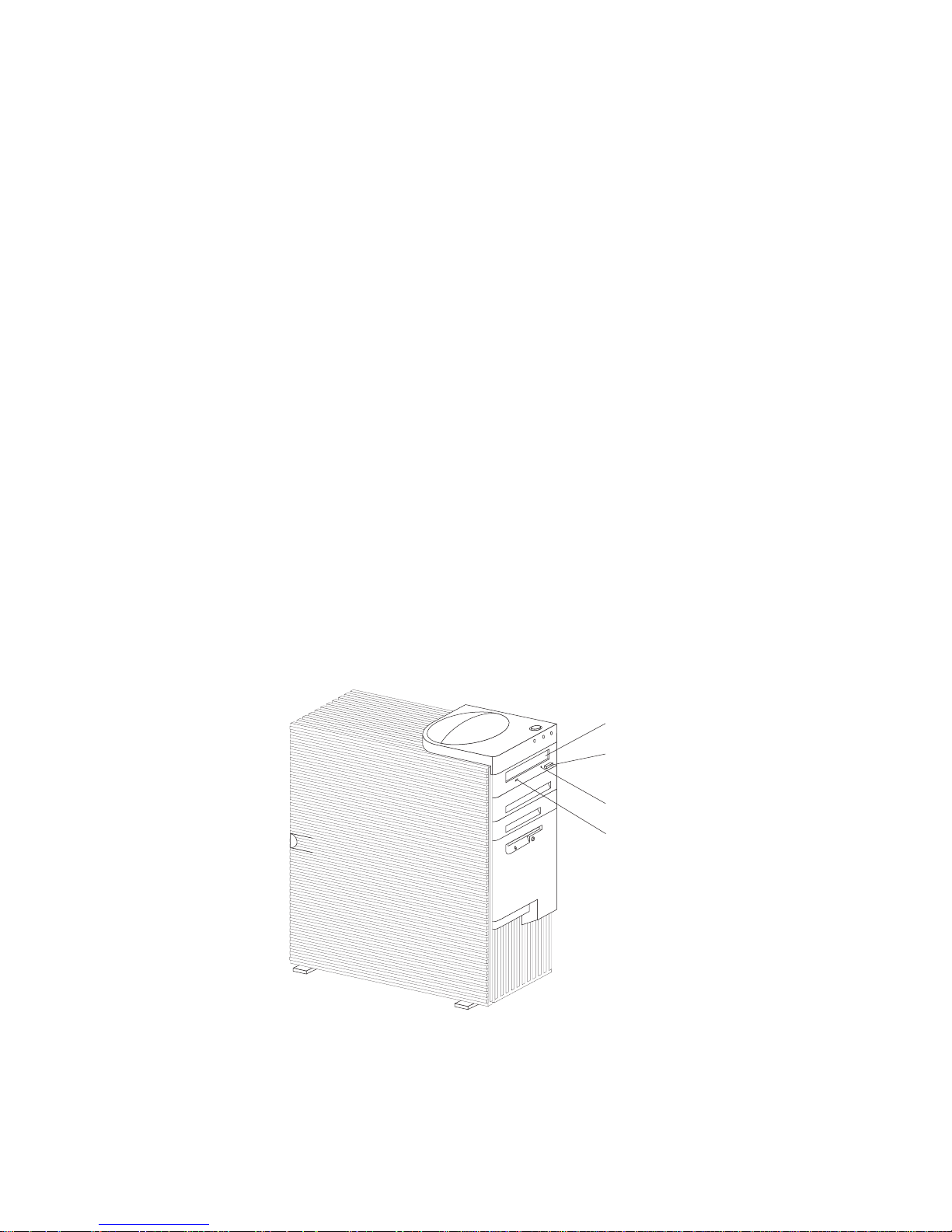
Controls and Indicators
The most commonly used controls and status indicators are on the
front of your server.
Server Controls
Socket7
Socket7
Diskette
Eject Button
CD-ROM
Eject/Load Button
Power Switch
Chapter 1. Introducing Your Netfinity 3500 Server 7
Page 26

Controls and Indicators
Power Switch: Press this switch to turn your server on
or off.
Attention:
Do not turn off the server if a drive in-use light is on. This
might damage the information stored on a hard disk or on a
diskette.
When the power is on, there is a period of time during the
power-on self-test (POST), a short test that occurs when the
server is turned on, when a single touch of the power switch
will not turn off the power. If power must be turned off
during POST, press and hold the power switch for 5 seconds
or disconnect the power cord. After POST, the power switch
works normally, unless the server is in a hang condition. If
the server is in a hang condition, press and hold the power
switch until the power turns off.
CD-ROM Eject/Load Button: Push this button to release a
CD from the CD-ROM drive. See “Using the CD-ROM
Drive” on page 20 for additional information about the
CD-ROM drive controls and indicators.
Diskette Eject Button: Push this button to release a diskette
from the diskette drive.
8 Netfinity 3500 User's Handbook
Page 27

Controls and Indicators
Status Indicators
The following illustration identifies the indicators located on the
front of the server.
Socket7
Socket7
Hard-Disk Drive
In-Use Light
Diskette Drive
In-Use Light
Ethernet Activity Light
CD-ROM Drive
In-Use Light
Power-On Light
Power-On Light: This light comes on when you turn on
your server by pressing the power switch.
Hard Disk Drive In-Use Light: This light comes on when
your server is accessing a SCSI hard disk drive. If this light
remains illuminated, it might indicate that either the SCSI bus
or the system microprocessor has stopped.
Ethernet Activity Light: This light comes on when the
Ethernet controller is transmitting data to or receiving data
from another system in the network.
CD-ROM Drive In-Use Light: This light comes on when the
CD-ROM drive is accessed.
Diskette Drive In-Use Light: This light comes on when the
diskette drive is accessed.
Chapter 1. Introducing Your Netfinity 3500 Server 9
Page 28

Input/Output Connectors
Input/Output Connectors
Input/output (I/O) connectors provide ports for transferring
information into and out of your server. You can connect a variety
of I/O devices to your server, including a monitor, keyboard,
mouse, and printer. For more information on the ports and their
specific technologies, see “Connecting External Options” on page 97.
At the rear of your server is a panel that provides access to I/O
connectors. Adapters installed in expansion slots might also
provide I/O connectors. The following illustration shows the I/O
connectors that come with your server.
10 Netfinity 3500 User's Handbook
Page 29

Input/Output Connectors
Monitor
USB 1
RJ45
(Ethernet)
Audio
Line Out
Keyboard
Power Connector
Serial 2
Serial 1
Parallel
Audio
Line In
Mouse
USB 2
1
2
1
2
Microphone
Slot 1 (AGP)
Slot 2 (PCI)
Slot 3 (PCI)
Slot 4 (PCI)
Slot 5 (Shared ISA/PCI)
Slot 6 (ISA)
SCSI
Device
Power Connector: The server power cable connects here.
Mouse Connector: The mouse cable connects here. This
connector is sometimes called the auxiliary-device port.
Universal Serial Bus (USB) Connectors: Attach I/O devices
with universal serial bus (USB) connectors to USB connector 1
and connector 2. You need a 4-pin cable to connect a device
to these ports.
Chapter 1. Introducing Your Netfinity 3500 Server 11
Page 30

Input/Output Connectors
Parallel Connector: A signal cable for a parallel device, such
as a printer, connects here.
Audio Line In: This connector is used to send audio signals
from an external device (such as a CD player or stereo) to
your server so that the signals can be recorded on the hard
disk.
SCSI Connector: SCSI devices attach here. For more
information, see “Adding External SCSI Devices” on page 98,
“Attaching External Options” on page 99, and “SCSI
Connectors” on page 104.
Microphone: This connector is used to attach a microphone
to your server when you want to record voice or other
sounds on the hard disk. This connector can also be used by
speech-recognition software.
Audio Line Out: This connector is used to send audio
signals from your server to external devices, such as
stereo-powered speakers with built-in amplifiers, headphones,
multimedia keyboards, or the audio line-in jack on a stereo
system. To hear audio, you must connect one of these
external devices to the audio line-out connector on your
server.
Note: The internal speaker in your server is disabled when
an external speaker is attached to the audio line-out
connector on your server. There is no playback
capability through the internal speaker.
Ethernet Connector: An unshielded, twisted-pair (UTP) cable
with an RJ-45 connector attaches here to the 10/100 Ethernet
controller on the system board.
For more information about cables, see Appendix A,
“Ethernet Cable Specifications” on page 217.
Serial Connectors: Attach signal cables for modems or other
serial devices to the 9-pin serial connectors of serial ports 1
and 2. See “Serial Port Connectors” on page 99 for port
assignment information.
12 Netfinity 3500 User's Handbook
Page 31

Input/Output Connectors
Keyboard Connector: The keyboard cable connects here.
Monitor Connector: The monitor signal cable connects here.
Expansion Slots: Cables to the external connectors on
installed ISA and PCI adapters connect here. For information
about expansion slots and adapters, see “Working with
Adapters” on page 59.
Note: The monitor connector is located on the graphics
adapter installed in slot 1.
Chapter 1. Introducing Your Netfinity 3500 Server 13
Page 32

Input/Output Connectors
14 Netfinity 3500 User's Handbook
Page 33

Chapter 2. Getting Started
This chapter describes how to use your server. This chapter also
includes information on arranging your workspace and instructions
for using the CD-ROM drive.
Note: For details about the server controls, status indicators, and
I/O connectors, see Chapter 1, “Introducing Your Netfinity
3500 Server” on page 1.
Before you install hardware and software in your server, you need
to determine the hardware, software, and operating system
requirements for your operating environment. Refer to your
ServerGuide package for details about installing an operating system
and other software. See Chapter 4, “Installing Options” on page 51
for instructions on installing hardware in your server.
If you have not already done so, unpack and set up your server. If
you are not installing any optional hardware now, connect the
cables and power cord. Follow the instructions in the Setup and
Installation booklet that comes with your server.
This chapter contains:
Arranging Your Workspace ...................... 16
Comfort . . . . . . . . . . . . . . . . . . . . . . . . . . . . . . . . 16
Glare and Lighting .......................... 17
Air Circulation . . . . . . . . . . . . . . . . . . . . . . . . . . . . 17
Electrical Outlets and Cable Lengths ............... 18
Using the Stabilizing Feet ....................... 19
Using the CD-ROM Drive ....................... 20
Handling a CD ............................ 21
Loading and Unloading a CD ................... 21
Before You Install Software ...................... 22
Copyright IBM Corp. 1998 15
Page 34
Arranging Your Workspace
Arranging Your Workspace
To get the most from your server, arrange both the equipment you
use and your work area to suit your needs and the kind of work
you do. Your comfort is of foremost importance, but light sources,
air circulation, and the location of electrical outlets also can affect
the way you arrange your workspace.
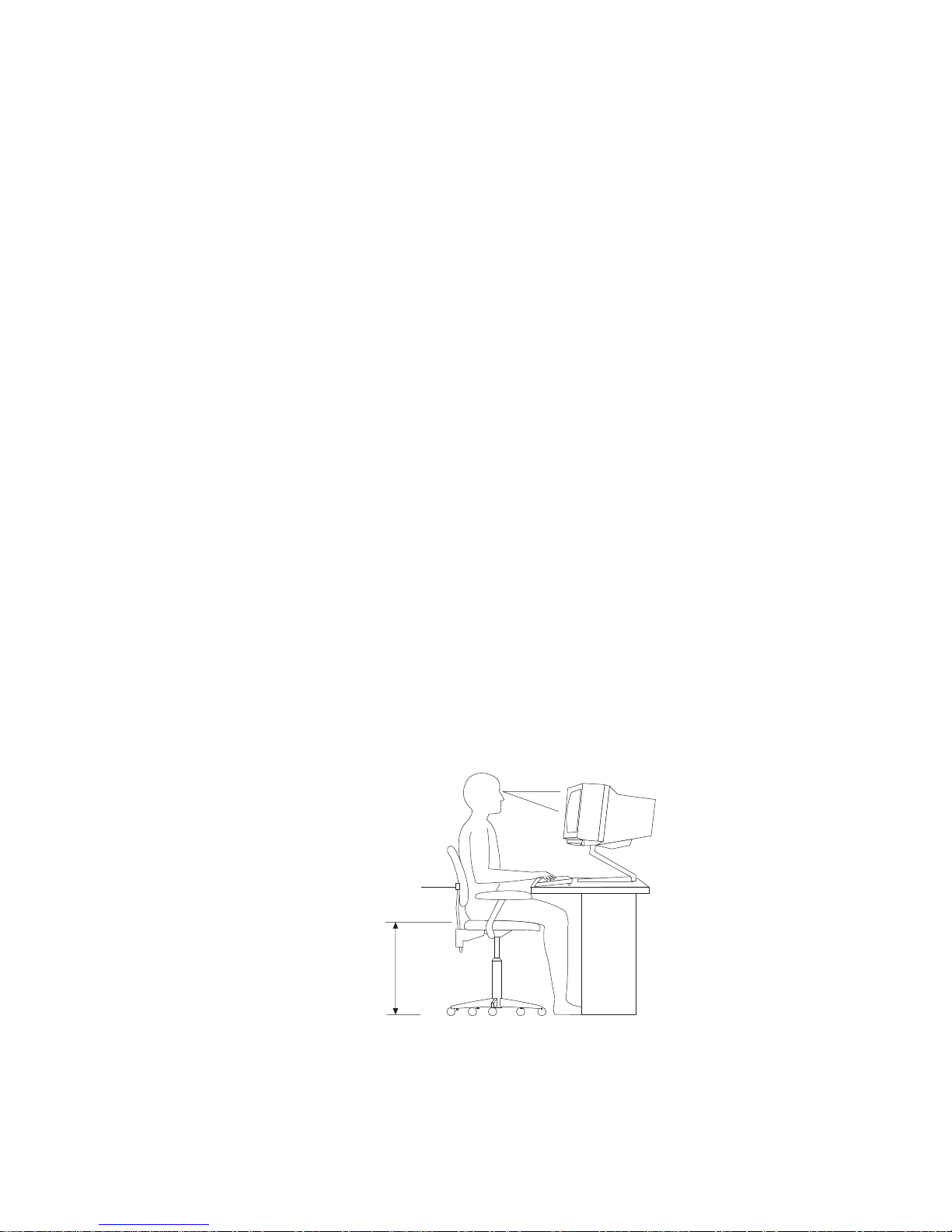
Comfort
Although no single working position is ideal for everyone, here are
a few guidelines to help you find a position that suits you best.
Sitting in the same position for a long time can cause fatigue. A
good chair can make a big difference. The backrest and seat should
adjust independently and provide good support. The seat should
have a curved front to relieve pressure on the thighs. Adjust the
seat so that your thighs are parallel to the floor and your feet are
either flat on the floor or on a footrest.
When using the keyboard, keep your forearms parallel to the floor
and your wrists in a neutral, comfortable position. Try to keep a
light touch on the keyboard and your hands and fingers relaxed.
You can change the angle of the keyboard for maximum comfort by
adjusting the position of the keyboard feet.
Viewing Distance
Lower
Back
Support
Seat
Height
Adjust the monitor so the top of the screen is at, or slightly below,
eye level. Place the monitor at a comfortable viewing distance,
16 Netfinity 3500 User's Handbook
Page 35

Arranging Your Workspace
usually 51 to 61 cm (20 to 24 in.), and position it so you can view it
without having to twist your body. Also position other equipment
you use regularly, such as the telephone or a mouse, within easy
reach.
Glare and Lighting
Position the monitor to minimize glare and reflections from
overhead lights, windows, and other light sources. Even reflected
light from shiny surfaces can cause annoying reflections on your
monitor screen. Place the monitor at right angles to windows and
other light sources, when possible. Reduce overhead lighting, if
necessary, by turning off lights or using lower wattage bulbs. If you
install the monitor near a window, use curtains or blinds to block
the sunlight. You might have to adjust the Brightness and Contrast
controls on the monitor as the room lighting changes throughout the
day.
Where it is impossible to avoid reflections or to adjust the lighting,
an antiglare filter placed over the screen might be helpful.
However, these filters might affect the clarity of the image on the
screen; try them only after you have exhausted other methods of
reducing glare.
Dust buildup compounds problems associated with glare.
Remember to clean your monitor screen periodically using a soft
cloth moistened with a nonabrasive liquid glass cleaner.
Air Circulation
Your server and monitor produce heat. Your server has one or
more fans that pull in fresh air and force out hot air. The monitor
lets hot air escape through vents. Blocking the air vents can cause
overheating, which might result in a malfunction or damage. Place
the server and monitor so that nothing blocks the air vents.
Attention:
To allow for air circulation, be sure to maintain the following
minimum clearances around the server:
102 mm (4 in.) in the front
127 mm (5 in.) in the rear
Chapter 2. Getting Started 17
Page 36

Arranging Your Workspace
51 mm (2 in.) on the left and right sides
Also, make sure the vented air is not blowing on someone else.
Electrical Outlets and Cable Lengths
The location of electrical outlets and the length of power cords and
cables that connect to the monitor, printer, and other devices might
determine the final placement of your server.
When arranging your workspace:
Avoid the use of extension cords. When possible, plug the
server power cord directly into an electrical outlet.
Keep power cords and cables neatly routed away from
walkways and other areas where they might get kicked
accidentally.
For more information about power cords, see “Power Cords” on
page 233.
18 Netfinity 3500 User's Handbook
Page 37
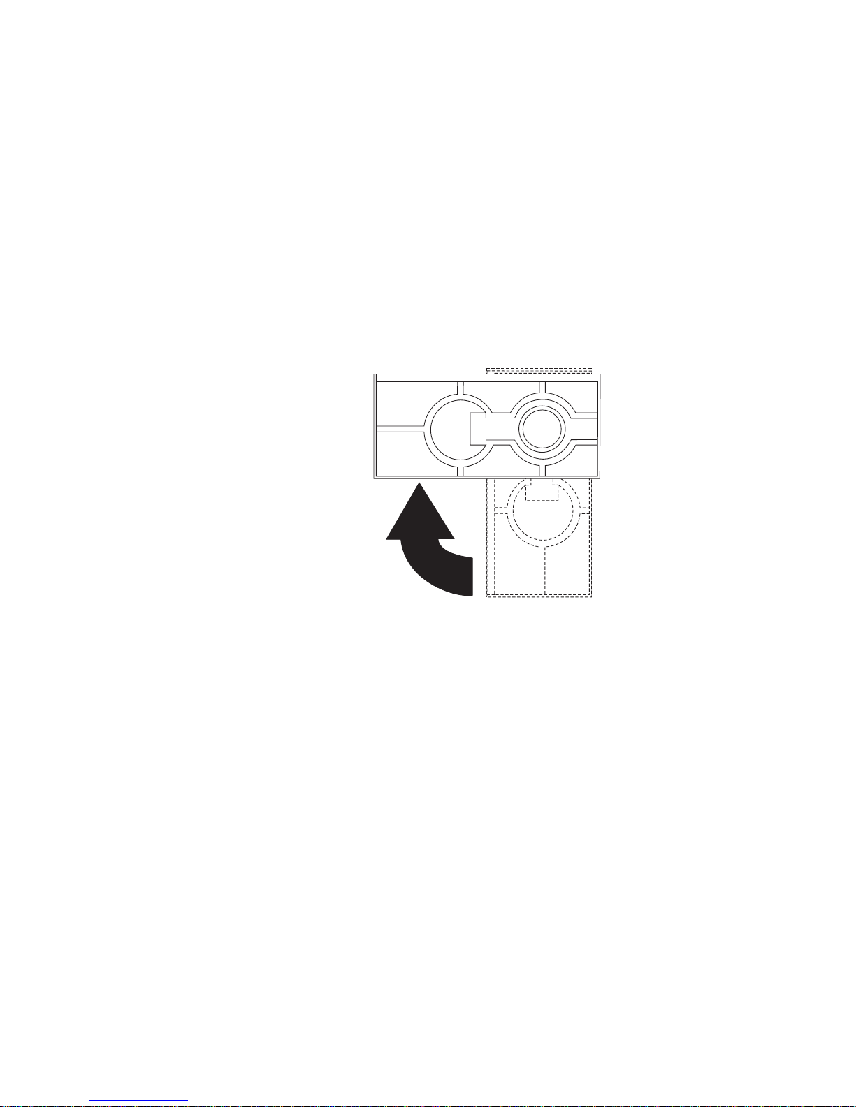
Using the Stabilizing Feet
The four feet attached to the bottom cover rotate 90 degrees to
provide additional stability for your server.
Before you place the server in an upright position, rotate the four
feet a quarter turn away from the server. Then, carefully position
the server on its feet.
When you need to access the inside of the server to install options,
you might find it easier to place the server on its side, so that the
system board is facing you. If you do so, rotate the feet in towards
the server, so that they do not break off due to the weight of the
server.
Chapter 2. Getting Started 19
Page 38
Using the CD-ROM Drive
Using the CD-ROM Drive
An IDE CD-ROM drive is a standard feature on all Netfinity 3500
servers. CD-ROM drives can play back or read from a CD, but
cannot write information to it. CD-ROM drives use
industry-standard, 12 cm (4.75-inch) CDs.
Follow these guidelines when using a CD-ROM drive:
Do not place the server where the following conditions exist:
– High temperature
– High humidity
– Excessive dust
– Excessive vibration or sudden shock
– An inclined surface
– Direct sunlight
Do not insert any object other than a CD into the drive.
Before moving the server, remove any CD from the drive.
The following is an illustration of the front bezel of the server, with
the CD-ROM drive location, controls, and indicators.
Socket7
Socket7
Eject/Load Button
Tray
Emergency-Eject Hole
CD-ROM Drive
In-Use Light
20 Netfinity 3500 User's Handbook
Page 39

Using the CD-ROM Drive
Handling a CD
When handling a CD, follow these guidelines:
Hold the CD by its edges. Do not touch the surface.
To remove dust or fingerprints, wipe the CD from the center to
the outside. Wiping the CD in a circular direction might cause
loss of data.
Do not write or stick paper on the CD.
Do not scratch or mark the CD.
Do not place or store the CD in direct sunlight.
Do not use benzene, thinners, or other cleaners to clean the CD.
Do not drop or bend the CD.
Loading and Unloading a CD
To load and unload a CD into a CD-ROM drive:
1. Press the Eject/Load button. The tray slides out of the drive.
(Do not manually force the tray open.)
2. Place the CD in the tray with the label facing up.
3. Close the tray by pressing the Eject/Load button, or by gently
pushing the tray forward. When the tray is closed, the
CD-ROM drive in-use light on the front of the drive will
activate to indicate that the drive is in use.
4. To eject the CD, press the Eject/Load button. When the tray
slides out, carefully remove the CD.
5. Close the tray by pressing the Eject/Load button, or by gently
pushing the tray forward.
Notes:
1. If the tray does not slide out of the drive when you press the
Eject/Load button, insert one end of a large paper clip into the
emergency-eject hole located above and to the left of the
CD-ROM drive in-use light.
2. In some models, you might have to remove the front bezel from
the CD-ROM drive to access the emergency-eject hole.
Chapter 2. Getting Started 21
Page 40

Before You Install Software
Before You Install Software
Use ServerGuide to verify that you have the proper working
environment for the specific operating system that you are
installing.
1. Follow the instructions provided in your ServerGuide package
to install your operating system and device drivers.
See “What Your IBM Netfinity 3500 Server Offers” on page 4
for information on the ServerGuide package.
2. Use the tables provided in Chapter 7, “Server Records and
Specifications” on page 193 to record the server serial number,
model number, and type number. If you installed options, also
update the device-records tables in Chapter 7, “Server Records
and Specifications.”
What to do next?
To get help with your installation, refer to the IBM Service and
Support pamphlet.
To install application programs, refer to the application program
documentation.
To learn more about your server, see Chapter 1, “Introducing
Your Netfinity 3500 Server” on page 1.
22 Netfinity 3500 User's Handbook
Page 41

Chapter 3. Configuring Your Server
This chapter provides information about the configuration and
utility programs that come with your server.
The configuration programs are part of the basic input/output system
(BIOS) that comes with your server. Using these programs, you can
set the system date and time, define input and output device
parameters, and define system security.
This chapter contains:
Configuration Overview . . . . . . . . . . . . . . . . . . . . . . . . 24
The Configuration/Setup Program .................. 26
Using the Configuration/Setup Utility Program .......... 28
System Summary . . . . . . . . . . . . . . . . . . . . . . . . . . . 29
Product Data . . . . . . . . . . . . . . . . . . . . . . . . . . . . . 30
Devices and I/O Ports ........................ 30
Start Options . . . . . . . . . . . . . . . . . . . . . . . . . . . . . 31
Date and Time ............................ 32
System Security . . . . . . . . . . . . . . . . . . . . . . . . . . . . 32
Advanced Setup . . . . . . . . . . . . . . . . . . . . . . . . . . . 39
ISA Legacy Resources ........................ 40
Power Management . . . . . . . . . . . . . . . . . . . . . . . . . 41
Resolving Configuration Conflicts .................. 42
Resolving Hardware Configuration Conflicts .......... 43
Resolving Software Configuration Conflicts ........... 43
Configuring the Ethernet Controller ................. 44
Using the SCSISelect Utility ...................... 46
Starting the SCSISelect Utility Program ............. 46
SCSISelect Utility Program Choices ................ 47
Copyright IBM Corp. 1998 23
Page 42

Configuration Overview
Configuration Overview
You play a key role in how your server allocates resources to
organize and interconnect hardware devices and software programs.
This allocation process is referred to as configuration. The steps
required to configure your server depend on the number and types
of devices and programs that you install.
Your server supports several types of adapters. Because of this
flexibility, you can choose from among thousands of adapters and
devices that comply with any of the following standards:
Peripheral Component Interconnect (PCI)
Industry Standard Architecture (ISA)
Small Computer System Interface (SCSI)
You can obtain a listing of products that are compatible with your
server, and related configuration information, by accessing the
following World Wide Web address:
http://www.us.pc.ibm.com/compat/
Jumpers and switches are used to define certain configuration
values on the system board, adapters, and other devices. For details
about system-board jumper and switch settings, see Chapter 7,
“Server Records and Specifications” on page 193. If you need to set
jumpers or switches on adapters, drives, or other devices, refer to
the documentation that comes with the devices for specific
information about the appropriate jumper and switch settings.
In general, the greater the number and variety of hardware devices
and software programs that you install in your server, the more you
will have to interact with your server and your devices to correctly
configure your system.
Your server comes with the following hardware configuration utility
programs:
Configuration/Setup Utility program
With the Configuration/Setup Utility program, you can
configure system board functions, such as serial and parallel
port assignments; change interrupt request settings, and change
24 Netfinity 3500 User's Handbook
Page 43

Configuration Overview
the startup sequence for drives that you install. You can also
use this utility program to set passwords for starting the server
and accessing the Configuration/Setup Utility program.
SCSISelect Utility
With the built-in SCSISelect Utility program, you can configure
the SCSI devices that you install in your server. You can use
SCSISelect to change default values, resolve configuration
conflicts, and perform a low-level format on a SCSI hard disk
drive.
Before installing a new device or program, read the documentation
that comes with it. Reading the instructions helps you to determine
the steps required for installation and configuration. The following
actions are typically, but not always, required to configure your
server.
1. Run the Configuration/Setup Utility program and record the
current configuration settings.
See “The Configuration/Setup Program” on page 26.
2. Set jumpers or switches on the server's system board.
See Chapter 7, “Server Records and Specifications” on page 193.
3. Set jumpers or switches on the device.
See the device installation instructions.
4. Install the device in the server.
See Chapter 4, “Installing Options” on page 51.
Reserve ISA legacy resources for ISA adapters. See “ISA Legacy
Resources” on page 40.
5. Resolve configuration conflicts.
See “Resolving Configuration Conflicts” on page 42.
6. Install software programs, including device drivers.
Refer to the information that comes with your IBM ServerGuide
package for more information.
Chapter 3. Configuring Your Server 25
Page 44

The Configuration/Setup Program
The Configuration/Setup Program
For most configurations, the server will operate using the default
system settings. You need to change the settings only to resolve
configuration conflicts or to enable or change device functions.
When you want or need to change the default settings, the
Configuration/Setup Utility program provides a convenient way to
display and change the settings.
After you run and exit the Configuration/Setup Utility program,
configuration information is stored in electrically erasable
programmable read-only memory (EEPROM). While the server is
powered off, the configuration information remains available for the
next system startup.
Always run the Configuration/Setup Utility program if you receive
an error message instructing you to do so. If you installed or
removed SCSI devices, run the SCSISelect Utility program (see
“Using the SCSISelect Utility” on page 46). Review this chapter and
the information that comes with the option before making changes.
Also, record the current settings (see Chapter 7, “Server Records
and Specifications” on page 193) before making any changes.
To start the Configuration/Setup Utility program:
1. Turn on the server and watch the screen.
If your server is already turned on, turn off the server, wait a
few seconds until all in-use lights go off, and then turn the
server back on. (Do not use Ctrl+Alt+Del to restart the server.)
2. When the message Press F1 to enter Configuration/Setup
appears, press F1. The Configuration/Setup Utility program
menu appears. For information about the menus, see “Using
the Configuration/Setup Utility Program” on page 28.
26 Netfinity 3500 User's Handbook
Page 45

The Configuration/Setup Program
Notes:
1. If an administrator password is not set, the Configuration/Setup
Utility program starts once you complete the startup procedure.
2. If an administrator password is set, but a power-on password is
not set, you must enter the administrator password to access the
Configuration/Setup Utility program.
3. If you have set both an administrator and a power-on password,
you can enter either one. However, to change any settings in
the Configuration/Setup Utility program, you must enter the
administrator password. If you enter the power-on password,
you will be able to view limited information in the
Configuration/Setup Utility program, but you will not be able
to change any settings.
4. If a configuration error occurs, a prompt appears before the
operating system starts ( see “Resolving Configuration
Conflicts” on page 42).
Chapter 3. Configuring Your Server 27
Page 46

Using the Configuration/Setup Utility Program
Using the Configuration/Setup Utility Program
From the Configuration/Setup Utility program Main Menu, you can
select the settings that you want to change.
<F1> Help < > < > Move
<Esc> Exit <Enter> Select
↑↓
•
•
•
•
•
•
•
•
System Summary
Product Data
Devices and I/O Ports
Start Options
Date and Time
System Security
Advanced Setup
ISALegacy Resources
Power Management
•
Save Settings
Restore Settings
Load Default Settings
Exit Setup
Configuration/Setup Utility
Select Option:
Pressing F1 displays Help information for a selected menu item.
In the Configuration/Setup Utility program menus, you can accept
the configuration changes by viewing and saving the changes, or
you can make manual changes and then save the settings.
The following is a quick reference for identifying symbols in the
Configuration/Setup Utility program.
A bullet () beside a menu item indicates that an additional
menu is available.
Information enclosed in brackets ([ ]) can be changed. You
cannot change information that is not surrounded by [ ].
28 Netfinity 3500 User's Handbook
Page 47

Using the Configuration/Setup Utility Program
A right arrowhead (5) beside a menu item indicates that a
configuration change occurred in that category. The 5 might
also appear in subsequent menus.
An asterisk (*) beside a menu item indicates that a resource
conflict exists.
To exit from the Configuration/Setup Utility program:
1. From the Configuration/Setup Utility program, select Exit
Setup.
2. The Exit Setup menu appears. You can save your changes, exit
from the Configuration/Setup Utility program without saving
your changes, or return to the Configuration/Setup Utility
program menu. Use the arrow keys to select the desired option;
then, press Enter.
Note: The choices on some menus might differ slightly, depending
on the BIOS version that comes with your server.
Use the following commands to navigate through the screens and
make selections:
Key Function
↑ ↓ Move between menu items.
← → Toggle between choices for a menu item.
Enter Select an item.
Esc Exit from a menu after viewing or making changes.
F1 Get help on a selected menu item.
System Summary
Select this choice to display configuration information, such as the
type and speed of the microprocessor, and the amount of memory.
Changes that you make to configuration settings appear on this
summary screen. You cannot edit the fields on this screen. If you
need to change the configuration settings, you must make the
changes from the applicable menu choices.
Chapter 3. Configuring Your Server 29
Page 48

Using the Configuration/Setup Utility Program
Product Data
Select this choice to view the machine type and model, the system
serial number, the system board identifier, and the revision level or
issue date of the flash EEPROM.
Devices and I/O Ports
Software recognizes ports from their port assignments. Each port
must have a unique port assignment. The Configuration/Setup
Utility program normally handles this, but you might have special
hardware or software that requires you to change these assignments.
Select the Devices and I/O Ports choice to view or change the
assignments for devices and input/output ports.
You can add serial ports by installing a serial adapter in an
expansion slot. See the documentation that comes with the serial
adapter for information about port assignments.
To display or change the port assignments:
1. Select Devices and I/O Ports.
2. Select a device or port. If necessary, press Enter to display an
additional menu.
3. Use the Left Arrow (←) or Right Arrow (→) key to advance
through the settings.
30 Netfinity 3500 User's Handbook
Page 49

Using the Configuration/Setup Utility Program
Start Options
Select this choice to view and change settings for device startup
sequence, keyboard speed, virus detection, various power-on
options, and other features.
You can control the startup sequence of the drives in your server.
Each time that you turn on the server, it checks the drives as it
looks for the operating system. The order in which the system
checks the drives is the drive-startup sequence.
Note: The hard disk drive is the default startup device when no
other devices are ready.
To set the startup sequence:
1. Select Start Options.
2. Select Startup Sequence.
3. Select the sequence and devices from the choices provided.
4. If Automatic Power On Startup Sequence is Enabled, select the
sequence and devices from the choices provided.
Chapter 3. Configuring Your Server 31
Page 50

Using the Configuration/Setup Utility Program
Date and Time
Select this choice to set the system date and time.
The system time is in a 24-hour format: hour/minute/second. The
system date is in standard format for your country. For example, in
the United States, the format is MM/DD/YYYY (Month/Day/Year).
Select Date and Time; then, use the Left Arrow (←) or Right Arrow
(→) key to advance through each data field. Type the new
information; the system saves the information as you enter it.
System Security
Several security features are available to help you secure your server
and the information that you store in it. To control access to your
server, you can implement the security features, such as adding
passwords, and securing IDE devices and diskette drives.
Using the Power-On Password Menu
The power-on password can deter unauthorized access to the
system. When you set the power-on password, you can choose one
of three password prompt modes.
On The system prompts the user for the power-on password
during startup. If you have a mouse connected to the
mouse port, it will remain locked until you enter the
power-on password.
Notes:
1. If Update POST/BIOS from network is enabled, you
cannot select On. If the power-on password mode is
set to On when Update POST/BIOS from network is
enabled, it resets automatically to Dual.
2. Whenever the power-on password function is set, the
system does not support any locally or remotely
scheduled shutdowns or restarts. Therefore, be sure to
use the power-on password protection (lockout
function) that your operating system provides.
32 Netfinity 3500 User's Handbook
Page 51

Using the Configuration/Setup Utility Program
Off The system does not prompt the user to enter the power-on
password during startup.
If you have a mouse connected to the mouse port, the
password prompt Off mode prevents the system from
detecting that a mouse is attached.
Notes:
1. The mouse and keyboard are not active until you enter
the power-on password, even if an operating system
has been installed in the server.
2. The password prompt Off mode does not support any
locally or remotely scheduled shutdowns or restarts.
Therefore, do not use a power-on wakeup or lockout
function.
3. A serial mouse is not affected by the password prompt
Off mode.
To adjust the server configuration so that the operating
system does not display an error or stop operating when
the mouse port is disabled:
If you enter a password, the keyboard will unlock, but the
mouse connected to the mouse port will remain disabled.
Password prompt Off mode is useful for network
environments that cause the server to operate unattended.
Operating System Instructions
OS/2
Do one of the following:
Set the CONFIG.SYS file so that the operating
system does not stop on a device-driver error. To
do this, put the command “PAUSEONERROR=NO”
near the top of the CONFIG.SYS file.
Remove the mouse driver statement from the
CONFIG.SYS file.
Microsoft Windows
NT Server
When the mouse port disabled error message appears,
enter either your power-on or administrator password to
enable the keyboard. Then use the keyboard to put a
check mark in the Do not display this message in the
future check box.
Chapter 3. Configuring Your Server 33
Page 52

Using the Configuration/Setup Utility Program
If a power failure occurs, when power is restored, the
server will automatically restart and resume operating in
this mode, without operator intervention.
Dual If you press the power switch to start the server, the server
operates in password prompt On mode.
If you start the server by an unattended method, such as
remotely over a LAN, the server operates in password
prompt Off mode.
To set or change a power-on password:
1. Select Power-On Password.
2. Enter your password and press the Down Arrow (↓) key.
You can use any combination of up to seven characters (A–Z,
a–z, and 0–9) for this password. Keep a record of the password
in a safe place.
3. Enter your password again.
4. At Password Prompt, select Off, On, or Dual. Press the Left
Arrow (←) or Right Arrow (→) key to toggle between selections.
Note: If Update POST/BIOS from network is enabled, you
cannot select On. In this case, select Dual. If the
password prompt mode is set to On when Update
POST/BIOS from network is enabled, the mode will
automatically be reset to Dual.
5. Select Change Power-On Password, and follow the instructions
on the screen.
Notes:
1. If a power-on password is set and then forgotten, you must
remove the server cover and move a jumper on the system
board. (Refer to “Using the Clear CMOS Request Jumper to
Erase Forgotten Passwords” on page 204 for further
information.)
2. If a power-on password is set and the password prompt is set to
Off, the pointing device (mouse) is disabled until you enter the
power-on password.
34 Netfinity 3500 User's Handbook
Page 53

Using the Configuration/Setup Utility Program
To delete a power-on password:
1. Select Power-On Password.
2. Select Delete Power-On Password and follow the instructions
on the screen.
Using the Administrator Password Menu
The administrator password (sometimes called a supervisor-level
password) controls access to some features of the server, including
the Configuration/Setup Utility program.
To set or change an administrator password:
1. Select Administrator Password.
2. Enter your password and press the Down Arrow (↓) key.
You can use any combination of up to seven characters (A–Z,
a–z, and 0–9) for this password. Keep a record of the password
in a safe place.
3. Enter your password again.
4. Define the Power-On Password Changeable by User field.
Choices are:
Yes The power-on password can be changed without entering
the administrator password, if the administrator password
is set.
No The power-on password cannot be changed unless the
administrator password is entered, if the administrator
password is set.
5. Select Change Administrator Password and follow the
instructions on the screen.
Note: If an administrator password is set and then forgotten, you
must complete one of the following to regain access to the
Configuration/Setup Utility program:
If enhanced security is disabled (default setting), you
must remove the server cover and move a jumper on the
system board. (See “Using the Clear CMOS Request
Chapter 3. Configuring Your Server 35
Page 54

Using the Configuration/Setup Utility Program
Jumper to Erase Forgotten Passwords” on page 204 for
further information.)
If enhanced security is enabled, you must replace the
system board.
To delete an administrator password:
1. Select Administrator Password.
2. Select Delete Administrator Password and follow the
instructions on the screen.
If both a power-on and administrator password are set, you can
enter either password to complete the system startup. However, the
administrator password provides access to all menu choices, and
provides the ability to change information. If you enter the
power-on password, you will be able to view limited information in
the Configuration/Setup Utility program, but you will not be able to
change any settings.
Using the Enhanced Security Features
With enhanced security, your administrator password and
drive-startup sequence are stored in a highly protected, nonvolatile,
security EEPROM module. When your administrator password and
drive-startup sequence are stored in the security EEPROM, they
remain intact even if the battery expires or is removed.
Attention:
If enhanced security is enabled, and you forget or lose the
administrator password, you must replace the system board in your
server to regain access to the Configuration/Setup Utility program.
If enhanced security is enabled and you have set an administrator
password, your server will operate as follows:
The security EEPROM is protected from unauthorized access
once the startup procedures are complete.
With enhanced security disabled, the contents of the EEPROM
are write protected, and the server can function in a network
environment because the POST/BIOS utility program will allow
updates to the system programs.
36 Netfinity 3500 User's Handbook
Page 55

Using the Configuration/Setup Utility Program
With enhanced security enabled, the POST/BIOS utility program
will not allow updates to the system programs. In a network
environment, this might prevent certain functions from being
performed remotely.
If the cover of your server has been removed, a
tamper-detection feature will halt system processing and deny
access to the keyboard and mouse until the administrator
password is entered. This feature will work if your server is
powered on or off.
To enable or disable enhanced security:
Note: Enhanced security can be enabled or disabled only when you
update the system programs in your server.
1. Insert a system programs update diskette in your server.
System programs updates are available on the World Wide
Web. To obtain up-to-date information about your server
model, access the home page for your server at the following
address: http://www.us.pc.ibm.com/server/
2. Turn on the server. If it is already turned on, you must turn it
off and back on again.
3. The update begins, and the system prompts you for the
administrator password, if you have set an administrator
password.
4. When you enter the administrator password, the update diskette
will continue to run, and you are given the option of enabling
or disabling enhanced security.
To set, change, or delete an administrator password protected by
enhanced security:
1. Turn off all attached devices and the server.
2. See Chapter 4, “Installing Options” on page 51 for safety
information, disconnecting all cables, and removing the server
cover.
3. Locate the switch marked as 7 on the rocker switches section of
the system board. See “Setting the Administrator Password
Switch” on page 215 for the location of the switch. Move the
Chapter 3. Configuring Your Server 37
Page 56

Using the Configuration/Setup Utility Program
switch to the ON position. (It might be helpful to use the end
of a small screwdriver to set the switch.)
Note: You must know the administrator password to change or
delete it.
4. Move the switch back to the OFF position after you have set,
changed, or deleted your password.
5. Replace the cover. Then, turn on the server.
Restricting Access to IDE Devices and Diskette Drives
The setting for the Secure IDE and Diskette Drives option controls
who has access to the IDE devices and diskette drives (user and
administrator, or administrator only). Your server comes with this
feature set to Enable, so that both the user and administrator have
access to the IDE devices and diskette drives.
To disable access to the IDE devices and diskette drives:
1. Select Secure IDE Devices and Diskette Drives from the
System Security menu; then, press Enter.
2. Select a device; then, press the Left Arrow (←) or Right Arrow
(→) key to toggle the entry to Disable.
Updating POST/BIOS Update over the Network
Using this option, the BIOS can be updated remotely from a
network server. If an administrator password is set, it does not have
to be entered from the server to access this function. Consult your
network administrator for information on setting up your network
server to perform POST and BIOS updates.
To access the POST/BIOS Update setting:
1. Select POST/BIOS Update.
2. Select Update POST/BIOS from network.
3. To enable update POST/BIOS over the network, select Enabled.
To disable, select Disabled.
38 Netfinity 3500 User's Handbook
Page 57

Using the Configuration/Setup Utility Program
Setting Adapter ROM Security
Use this setting to lock the keyboard during adapter read-only
memory (ROM) initialization; this feature can be used in conjunction
with an administrator password to prevent the use of adapter
ROM-based utility programs.
Advanced Setup
Select Advanced Setup to change values for advanced hardware
features, such as cache control, ROM shadowing, PCI control, Plug
and Play control, and microprocessor control. See Table 13 on
page 196 for the default settings for these features.
The system might malfunction if these options are configured
incorrectly. Follow the instructions on the screen carefully.
Use the Left Arrow (←) or Right Arrow (→) key to select a menu
choice.
Cache Control
Select this choice to define the microprocessor cache state as enabled
or disabled.
ROM Shadowing
Select this choice to enable or disable ROM shadowing in specified
areas. When these areas are enabled, the contents can be cached,
using the Cache Control option. These areas are hexadecimal
address ranges. One of these areas is reserved for the system BIOS
address space.
PCI Control
Select this choice to control features associated with PCI devices,
such as PCI Adapter Reset, PCI Parity, PCI Bus Master,
Multimedia Devices, and various types of adapters.
Plug and Play Control
Select this choice to control features associated with Plug and Play
devices, such as Set Device Mode, Address Decode, and Plug and
Play Operating System.
Chapter 3. Configuring Your Server 39
Page 58

Using the Configuration/Setup Utility Program
Select Set Device Mode to control the device node. When you
change this value to Disabled, the system is unable to update the
configuration during POST.
Processor Control
Select this choice to control features associated with the
microprocessors, such as Processor 0 ID and Processor Updating.
ISA Legacy Resources
Plug and Play is a configuration method that makes expanding your
server easier. Support for Plug and Play is built into the system
board of your server.
If an adapter is Plug and Play, there are no switches or jumpers that
must be set on the adapter. A Plug and Play adapter comes with
configuration specifications set in memory to provide installation
information to the server during startup. When you install or
remove Plug and Play adapters, this information is interpreted by
the BIOS, which supports Plug and Play technology. If the required
resources are available, the BIOS software automatically configures
the adapter around the resources already in use by other devices.
Most adapters designed for PCI slots are Plug and Play devices that
are auto-configuring. However, many ISA adapters are not Plug
and Play devices. These adapters are known as legacy adapters. If
you install a legacy adapter, you must manually configure it by
setting switches or jumpers on the adapter, and by allocating or
reserving the system resources that the adapter will use.
Note: See “Resolving Configuration Conflicts” on page 42 for
information about handling resource conflicts.
Select ISA Legacy Resources to identify the available system
resources:
Memory
I/O ports
DMA
Interrupt
40 Netfinity 3500 User's Handbook
Page 59

Using the Configuration/Setup Utility Program
Note: The menus do not contain resources that are used by the
system or by previously installed Plug and Play adapters.
To store the legacy resource information for an installed adapter:
1. Select ISA Legacy Resources; then, use the Up Arrow (↑) or
Down Arrow (↓) key to highlight the system resource that you
want to change.
2. Select a resource; then, use the Left Arrow (←) or Right Arrow
(→) key to select a configuration choice.
If you remove an ISA legacy adapter, you must redefine the system
resource as Available.
Power Management
With Power Management, the server and monitor can be set to use a
reduced-power state if they are inactive for a specified length of
time. You can also specify options to automatically start the server.
Attention:
The ACPI BIOS Mode feature is the only available Power
Management feature.
The APM BIOS Mode feature is set to Disabled. Do not change
this default value.
Using the Automatic Configuration and Power Interface BIOS Mode
When the automatic configuration and power interface (ACPI) BIOS
mode is enabled, the operating system controls the power
management features of your server and the settings for APM BIOS
mode are ignored. Refer to your operating-system documentation
to determine if ACPI is supported.
To set ACPI BIOS mode:
1. Select Power Management from the Configuration/Setup Utility
program menu.
2. Set ACPI BIOS Mode to Enabled or Disabled as desired using
the Left Arrow (←) or Right Arrow (→) key.
Chapter 3. Configuring Your Server 41
Page 60

Resolving Configuration Conflicts
Resolving Configuration Conflicts
The resources used by your server consist of IRQs, DMA, I/O port
addresses, and memory. This information is useful when a resource
configuration conflict occurs.
Conflicts in the configuration occur if:
A device that you installed requires the same resource as
another device. (For example, a conflict occurs when two
adapters try to write to the same address space.)
A device resource is changed (for example, changing jumper
settings).
A device function is changed (for example, assigning COM1 to
two serial ports).
A software program is installed that requires the same resource
as a hardware device.
The steps required to resolve a configuration error are determined
by the number and variety of hardware devices and software
programs that you install. If a hardware configuration error is
detected, a configuration error message appears after the server
completes POST and before the operating system is loaded. You
can bypass the error by pressing Esc while the error message is
displayed.
The Configuration/Setup Utility program configures only the
system hardware and interrupt requests. The program does not
consider the requirements of the operating system or the application
programs. For these reasons, memory-address configuration
conflicts might occur. You can resolve some memory-address
conflicts by changing the address of the conflicting hardware option,
or by changing or moving the hardware. You might have to resolve
other memory-address conflicts by changing some software
parameters. See “Resolving Hardware Configuration Conflicts” on
page 43 and “Resolving Software Configuration Conflicts” on
page 43, respectively, for additional information. See Chapter 5,
“Solving Problems” on page 117 for information about
troubleshooting hardware and software problems.
42 Netfinity 3500 User's Handbook
Page 61

Resolving Configuration Conflicts
Resolving Hardware Configuration Conflicts
Use the following information to help resolve hardware
configuration conflicts:
1. Run the Configuration/Setup Utility program to view and
change the resources that the system board functions use.
Record the current settings before making any changes. (See
“The Configuration/Setup Program” on page 26 for
instructions.)
2. Determine which adapter or device is causing the conflict.
3. Change adapter jumpers or switches. Some devices use jumpers
and switches to define the system resources that they need. If
the settings are incorrect or set to use a resource that cannot be
shared, a conflict occurs, and the device will remain deactivated
by the configuration program.
4. Change system board jumpers or switches. See “Preparing to
Add Options” on page 56 for instructions for removing the
cover. Then, refer to the system-board diagram inside your
server.
5. Remove the device or adapter. Some configurations are not
supported. If you must remove an adapter, see “Installing or
Removing Adapters” on page 61.
Resolving Software Configuration Conflicts
The Configuration/Setup utility might change the memory-address
space used by some hardware options. If this happens, the new
memory-address space and IRQs used by some hardware options
might conflict with addresses defined for use through application
programs.
If a conflict exists, one or more of the following conditions might
exist:
The system cannot load the operating system.
The system does not work.
An application program does not operate, or it returns an error.
Screen messages indicate that a memory-address conflict exists.
Chapter 3. Configuring Your Server 43
Page 62

Configuring the Ethernet Controller
Note: Start the Configuration/Setup Utility program to view the
addresses that are used by your system board functions.
The best way to resolve memory-address conflicts is to change the
addresses that are used by the application program or the device
driver. You can use the Configuration/Setup Utility program to
view and change addresses.
Configuring the Ethernet Controller
Your Netfinity 3500 server comes with an Ethernet controller on the
system board. The Ethernet controller provides 10BASE-T and
100BASE-TX support through the RJ-45 connector on the back of
your server. When you connect your server to the network, the
Ethernet controller automatically detects the data-transfer rate (10
Mbps or 100 Mbps) on the network and then sets the controller to
operate at the appropriate rate. That is, the Ethernet controller will
adjust to the network data rate, whether the data rate is standard
Ethernet (10BASE-T), Fast Ethernet (100BASE-TX), half duplex
(HDX), or full duplex (FDX). This process is also known as
auto-negotiation. This auto-negotiation occurs without requiring
software intervention. The controller supports half-duplex (HDX)
and full-duplex (FDX) modes at both speeds.
However, auto-negotiation works only if the hub or switch at the
other end of the network also supports auto-negotiation. If the hub
or switch does not support auto-negotiation, the speed (10 Mbps or
100 Mbps) will still be detected correctly, but half-duplex mode will
always be selected. A full-duplex switch that does not support
auto-negotiation will not attach to the Netfinity 3500 server in
full-duplex mode. In this case, if you want the network to operate
in full-duplex mode, you must manually override the settings to
obtain a full-duplex connection. Refer to your Ethernet
documentation for additional information.
Attention:
The 10BASE-T Ethernet and the 100BASE-TX Fast Ethernet
cabling in the network must be Category 5 or higher to meet
various standards, including electromagnetic compatibility.
44 Netfinity 3500 User's Handbook
Page 63

Configuring the Ethernet Controller
You must install a device driver to enable your operating
system to address the Ethernet controller. Use ServerGuide to
install this device driver. Refer to your ServerGuide package for
instructions on installing device drivers. For more information
about ServerGuide, see “What Your IBM Netfinity 3500 Server
Offers” on page 4.
Fast Ethernet operates at a data rate of 100 Mbps; that is, ten times
faster than standard Ethernet. However, except for the different
operating speeds, Fast Ethernet and standard Ethernet are
structurally identical. Applications and protocols that are currently
installed on a standard Ethernet system can be seamlessly migrated
to a Fast Ethernet system. (In a very small number of cases, minor
tuning might be required to adjust the application to the faster
response time of a Fast Ethernet system.) Because of the
equivalence of the two types of Ethernet, mixed Ethernet and Fast
Ethernet systems also can be designed and implemented.
The bandwidth required at each workstation connected to a server is
generally far less than the bandwidth required at the server. This is
because the server might have to handle the bandwidth of multiple
workstations at the same time. A cost-effective solution to the
bandwidth requirements of this type of system is a mixed Ethernet
and Fast Ethernet network. This mixed network consists of
standard Ethernet connections at the workstations and Fast Ethernet
connections at the servers.
The Ethernet controller is a PCI device, and is therefore, a Plug and
Play device. You do not have to set any jumpers or configure the
controller for your operating system before you use the Ethernet
controller.
The Ethernet controller supports the auto-detection mode only.
When you install your device drivers and configure the Ethernet
controller for use with your operating system, do not select the
10BASE-T mode. To ensure proper operation of your controller,
always select the default parameters provided.
Chapter 3. Configuring Your Server 45
Page 64

Using the SCSISelect Utility
Notes:
1. For troubleshooting information, see “Troubleshooting the
10/100 Mbps Ethernet Controller” on page 173.
2. The Ethernet controller supports the operating systems that your
server supports. To find out which operating systems your
server supports, go to the following World Wide Web address:
http://www.us.pc.ibm.com/server/
If you need additional Ethernet connections, you can install an
Ethernet adapter, such as an IBM 10/100 Ethernet adapter. Review
your network-adapter documentation for any additional
configuration requirements.
Note: If you are installing an IBM 10/100 Ethernet adapter, be sure
to run the Ethernet diagnostics and record the server's
Ethernet configuration information before you install the
adapter.
Using the SCSISelect Utility
Your server comes with a menu-driven configuration utility
program, called SCSISelect, that allows you to view and change
SCSI settings.
You can use the SCSISelect Utility program to:
View and change the default SCSI identification (IDs)
Verify and change configuration conflicts
Perform a low-level format on a SCSI hard disk.
Starting the SCSISelect Utility Program
You can access this program when you start the server. The
SCSISelect prompt appears after the IBM Netfinity 3500 server logo
appears. Press Ctrl+A immediately after the SCSISelect prompt
appears:
<<< Press <CTRL><A> for SCSISelect Utility! >>>
46 Netfinity 3500 User's Handbook
Page 65

Using the SCSISelect Utility
Use the Up Arrow (↑) or Down Arrow (↓) key to move the
highlight bar to the various menu choices. Press Esc to return to the
previous menu. Also, you can press the F5 key to switch between
color and monochrome modes (if your monitor permits). To change
the settings of the displayed items, such as Channel A or Channel B,
follow the directions on the screen. Then, press Enter.
SCSISelect Utility Program Choices
The following choices appear on the SCSISelect Utility program
menu:
Configure/View Host Adapter Settings
SCSI Disk Utilities
Configure/View Host Adapter Settings
To view or change the SCSI controller settings, select
Configure/View Host Adapter Settings and follow the directions on
the screen.
Note: On this menu, the SCSI controller is referred to as the Host
Adapter.
This menu has the following choices:
Host Adapter SCSI ID
The default SCSI ID of the SCSI controller is 7. Do not change
this value.
SCSI Parity Checking
The default value is Enabled. Do not change this value.
Host Adapter SCSI Termination
The default value is Low On / High On. Do not change this
value.
Boot Device Configuration
Select this choice to configure startable device parameters.
Before you can make updates, you must know the ID of the
device whose parameters you want to configure.
Chapter 3. Configuring Your Server 47
Page 66

Using the SCSISelect Utility
The default startup (boot) SCSI ID is 0 for an internal SCSI hard
disk drive in Channel A.
SCSI Device Configuration
Select this choice to configure SCSI device parameters. Before
you can make updates, you must know the ID of the device
whose parameters you want to configure.
Note: When the Maximum Sync Transfer Rate is set to 40.0,
this value represents the transfer rate for UltraSCSI
devices. When this value is set to 20.0, it represents the
transfer rate for Fast SCSI devices.
Advanced Configuration Options
Select this choice to view or change the settings for advanced
configuration options. These options include enabling support
for large hard disk drives and support for drives with UltraSCSI
speed.
To reset the SCSI controller defaults, press F6; then, follow the
instructions on the screen.
SCSI Disk Utilities
To see the IDs that are assigned to each SCSI device or to format a
SCSI device, select SCSI Disk Utilities from the SCSISelect Utility
program menu.
To use the utility program, select a drive from the list. Read the
screens carefully before you make a selection.
Note: If you see the following message, you might have pressed
Ctrl+A before the selected drives were ready. Restart the
server, and watch the SCSISelect messages as each drive spins
up. After the drive that you want to view or format spins
up, press Ctrl+A.
48 Netfinity 3500 User's Handbook
Page 67

Using the SCSISelect Utility
à ð
Unexpected SCSI Command Failure
Target SCSI ID: 4
SCSI CDB Sent: ð3 ðð ðð ðð ðE ðð ð7 ðð ð2 ðð
Host Adapter Status: ððh - No host adapter error
Target Status: ð2h - Check condition
Sense Key: ð2h - Not ready
+Sense Code: ð4h
+Sense Code Qualifier: ð2h
Press 'Esc' to continue.
á
ñ
Performing a Low-Level Disk Format
You can use the Format Disk feature of the SCSISelect Utility
program to perform a low-level format on hard disks.
Depending on the hard disk capacity, the low-level format program
could take up to two hours.
When To Use the Format Disk Program
Use the Format Disk program:
When you are installing software that requires a low-level
format
When you get recurring messages from the diagnostic tests
directing you to run the Low-Level Format program on the hard
disk
As a last resort before replacing a failing hard disk drive
Note: For information about backing up all of your files, see your
operating-system documentation.
Chapter 3. Configuring Your Server 49
Page 68

Using the SCSISelect Utility
Starting the Low-Level Format
Attention:
The low-level format erases all data and programs.
1. If the hard disk drive is working, make a backup copy of all the
files and programs on the hard disk.
2. Select Format Disk; then, follow the instructions on the screen.
Note: Hard disks normally contain more tracks than their stated
capacity (to allow for defective tracks). A message
appears on the screen if the defect limit is reached. If this
happens, have the system serviced.
3. To install an operating system after the hard disk is formatted,
follow the instructions in the ServerGuide package that comes
with your server.
50 Netfinity 3500 User's Handbook
Page 69

Chapter 4. Installing Options
This chapter provides instructions to help you add options to your
server. Some option-removal instructions are provided, in case you
need to remove one option to install another. If you have several
internal options to install, these instructions enable you to add them
all at one time.
This chapter contains:
Before You Begin ............................ 53
Electrical Safety . . . . . . . . . . . . . . . . . . . . . . . . . . . . . 54
Handling Static-Sensitive Devices .................. 55
Preparing to Add Options ....................... 56
Disconnecting Cables and Removing the Cover ........ 56
Accessing the System Board .................... 58
Working with Adapters ........................ 59
Adapter Considerations . . . . . . . . . . . . . . . . . . . . . . . 59
Installing or Removing Adapters ................. 61
Working with Memory Modules ................... 63
Memory Configuration . . . . . . . . . . . . . . . . . . . . . . . 65
Installing or Removing Memory Modules ............ 66
Installing or Removing Internal Drives ............... 69
Expansion Bays . . . . . . . . . . . . . . . . . . . . . . . . . . . . 69
Drive Specifications . . . . . . . . . . . . . . . . . . . . . . . . . 71
Types of Cables ............................ 72
SCSI Drives . . . . . . . . . . . . . . . . . . . . . . . . . . . . . . 74
Preinstallation Steps (All Bays) .................. 76
Installing or Removing Drives in Bays 1 through 4 ...... 81
Installing or Removing Drives in Bays 5 and 6 ......... 85
Working with Microprocessors .................... 89
Installing or Replacing Microprocessors ............. 90
Connecting External Options ..................... 97
Adding a Hot-Swap Storage Expansion Enclosure ....... 97
Adding External SCSI Devices ................... 98
Attaching External Options ..................... 99
Serial Port Connectors ........................ 99
Parallel Port Connector ...................... 101
Video Port Connector ....................... 102
Keyboard and Mouse Connectors ................ 103
SCSI Connectors . . . . . . . . . . . . . . . . . . . . . . . . . . 104
Universal Serial Bus Ports .................... 106
Ethernet Connector . . . . . . . . . . . . . . . . . . . . . . . . . 107
Copyright IBM Corp. 1998 51
Page 70

Adding Security Options ....................... 108
Installing a U-Bolt and Security Cable ............. 109
Completing the Installation ..................... 113
Updating the Server Configuration ................. 115
52 Netfinity 3500 User's Handbook
Page 71

Before You Begin
Before You Begin
Become familiar with the safety and handling guidelines
specified under “Safety Information” on page vii, “Electrical
Safety” on page 54, and “Handling Static-Sensitive Devices” on
page 55. These guidelines will help you work safely while
working with your server and options.
Make sure that you have an adequate number of properly
grounded electrical outlets for your server, monitor, and any
other options you intend to install.
Place your server in a location that is dry. Rain or spilled
liquids might damage your server.
Have a supply of 2 MB (1.44 MB formatted), 3.5-inch diskettes
available.
Back up all important data before you make changes to hard
disk drives.
Have a small, flat-blade screwdriver available.
Attention:
To allow for air circulation, be sure to maintain the following
minimum clearances around the server:
102 mm (4 in.) in the front
127 mm (5 in.) in the rear
51 mm (2 in.) on the left and right sides
Chapter 4. Installing Options 53
Page 72

Electrical Safety
Electrical Safety
CAUTION:
Electrical current from power, telephone, and communication
cables can be hazardous. To avoid any shock hazard, disconnect
all power cords and cables as described in the following
information.
For your safety, always do the following before removing the cover:
1. Turn off the server and any attached devices, such as printers,
monitors, and external drives.
Note: If you are in the United Kingdom and have a modem or
fax machine attached to your server, you must disconnect
the telephone line from the server before unplugging any
power cords (also known as power cables). When
reassembling your server, you must reconnect the
telephone line after you plug in the power cords.
2. Unplug all the power cords from electrical outlets.
3. Disconnect all communication cables from external receptacles.
4. Disconnect all cables and power cords from the back of the
server.
Note: Reconnect the cables or power cords only after you
reassemble the server and put the cover back on.
CAUTION:
Never remove the cover on the power supply. If you have a
problem with the power supply, have your system serviced.
54 Netfinity 3500 User's Handbook
Page 73

Handling Static-Sensitive Devices
Handling Static-Sensitive Devices
Static electricity, though harmless to you, can seriously damage
server components or options.
Note: When you are adding an internal option, do not open the
static-protective package containing the option until you are
instructed to do so.
When you handle options and other server components, take these
precautions to avoid damage from static electricity:
Limit your movement. Movement can cause static electricity to
build up around you.
Always handle components carefully. Handle adapters, the
processor board, and memory modules by the edges. Never
touch any exposed circuitry.
Prevent others from touching components.
When you are installing a new option, touch the static-protective
package containing the option to a metal expansion-slot screw
or other unpainted metal surface on the server for at least two
seconds. (This reduces static electricity from the package and
from your body.)
When possible, remove the option and install it directly into the
server without setting the option down. When this is not
possible, place the static-protective package that the option
comes in on a smooth, level surface and place the option on it.
Do not place the option on the server's covers or any metal
surface.
Chapter 4. Installing Options 55
Page 74

Preparing to Add Options
Preparing to Add Options
Before you begin:
Be sure that your current server configuration is working
properly.
If you have not already done so, locate the keys to the cover
lock. At the time of shipment, two keys are attached to the
back of the server, over the keylock. Store the keys in a safe
place.
Obtain a small, flat-blade screwdriver.
Read “Electrical Safety” on page 54 and “Handling
Static-Sensitive Devices” on page 55.
Read “Using the Stabilizing Feet” on page 19.
CAUTION:
To avoid possible injury while moving or lifting the server, ask
another person to help you.
Disconnecting Cables and Removing the Cover
1. Remove any media (diskettes or CDs) from the drives; then,
turn off all attached devices and the server.
2. Touch the rear of the bare metal frame to dissipate any static
electricity from your body.
3. Before disconnecting cables, be sure to note where they attach,
so that you can correctly reattach them later.
Note: If you are in the United Kingdom, you must perform
step 5 before step 4.
4. Unplug all power cords (cables) from electrical outlets.
5. If you have a modem or fax machine attached to the server,
disconnect the telephone line from the wall outlet and the
server.
56 Netfinity 3500 User's Handbook
Page 75

Preparing to Add Options
6. Disconnect all cables attached to the server; this includes power
cords, input/output (I/O) cables, and any other cables
connected to the server.
Notes:
a. For more information about the rear connectors, see
“Input/Output Connectors” on page 10.
b. For more information about ports, including universal serial
bus (USB), see “Connecting External Options” on page 97.
Serial
Device
Microphone
Keyboard Mouse
USB
Device
Parallel
Device
SCSI
Device
Ethernet
Device
Monitor
Audio
Device
Chapter 4. Installing Options 57
Page 76

Preparing to Add Options
7. If necessary, unlock the server side cover.
8. Remove the side cover by pulling out on the cover-release tab at
the rear of the side cover. Then, slide the cover toward the
front of the server and lift it off.
9. Set the door aside.
CoverRelease
Tab
Accessing the System Board
Before you can install or remove certain options, you might need to
access the system board. For example, you might need to remove
adapters, drives, and cables that impede your access to components
on the system board. You also need to access the system board
before you can install or remove such options as adapters, memory
modules, and microprocessors, because these devices reside on the
system board.
To access the system board more easily, place the server on its side,
so that the system board is facing you, on a flat, sturdy surface,
such as a table.
Note: To see a list of the system-board components and an
illustration that shows their locations, see “System Board
Illustration” on page 203.
58 Netfinity 3500 User's Handbook
Page 77

Working with Adapters
Working with Adapters
Adding an adapter, such as a communication adapter, extends the
capabilities and power of your server. For example, you can add a
redundant array of independent disks (RAID) adapter that can
enhance logical-drive capacity and performance.
Note: For a complete list of the adapters that your server supports,
go to http://www.us.pc.ibm.com/compat/ on the World
Wide Web, or contact your IBM marketing representative.
When you are installing or removing adapters, it is important to
resolve any resource conflicts that might arise. For example, if you
install an ISA legacy adapter, you might need to manually configure
the adapter by setting a variety of switches on the adapter and by
using the Configuration/Setup Utility program.
Many adapters now use Plug and Play technology, which enables the
server to automatically configure the adapter, provided that the
required resources are available. Refer to the instructions that come
with your adapter to determine if it is Plug and Play. For more
information, see “ISA Legacy Resources” on page 40.
Adapter Considerations
Your server supports ISA and PCI adapters. You can install up to
six adapters in the connectors on the system board. These
connectors are known as expansion slot connectors.. The expansion
slots are located on the rear of the server (see “Input/Output
Connectors” on page 10 for an illustration).
Your server system board contains two 16-bit, ISA-bus expansion
slot connectors and four 32-bit, PCI-bus expansion slot connectors.
One expansion slot connector is a shared PCI/ISA slot connector.
One slot connector supports only ISA adapters; the remaining slot
connectors support only PCI adapters. Your server supports only
5.0-volt adapters on the PCI bus.
Chapter 4. Installing Options 59
Page 78

Working with Adapters
Notes:
1. Slot 1 is an Accelerated Graphics Port (AGP). You can install
only a special AGP graphics adapter in this slot. Your server
comes with an AGP graphics adapter installed in this slot.
2. You can install only a half-length PCI adapter in expansion
slot 2. You can install half-length and full-length adapters in
expansion slots 3 through 6.
3. If you have high-performance PCI adapters, such as RAID
adapters, install them in expansion slots 3, 4, or 5. Do not use
slot 2 for high-performance PCI adapters.
4. If a component in the server or on the adapter interferes with
the installation, use another slot.
The following figure shows the location of the expansion slot
connectors on the system board.
Slot 1 (AGP)
Slot 2 (PCI)
Slot 3 (PCI)
Slot 4 (PCI)
Slot 5
(Shared PCI/ISA)
Slot 6 (ISA)
60 Netfinity 3500 User's Handbook
Page 79

Working with Adapters
Note: Expansion slot 5 is a shared slot. Shared slots can be
occupied by an adapter attached to either the PCI slot
connector or the adjacent ISA slot connector, but not both.
Attention:
To avoid possible damage to adapters and server components, be
sure that the adapters that you install do not touch each other or the
other components (such as the microprocessor) inside the server.
Installing or Removing Adapters
This section gives the procedure for installing an adapter. If you
want to remove an adapter, reverse the order of the following steps.
Notes:
1. See “Input/Output Connectors” on page 10 for an illustration of
the expansion slots on the rear of the server.
2. If you remove an adapter, be sure to reassign the system
resources as available for ISA legacy adapters. See “ISA Legacy
Resources” on page 40.
Before you begin:
Read “Electrical Safety” on page 54 and “Handling
Static-Sensitive Devices” on page 55.
Read the documentation that comes with the option.
To install an adapter:
1. Review the instructions that come with the adapter to determine
if it must be installed in an AGP, PCI, or ISA expansion slot;
otherwise, use any empty, bus-compatible slot.
2. Remove the server cover (see “Preparing to Add Options” on
page 56).
3. Remove the appropriate expansion-slot cover:
a. Remove the expansion-slot screw on the top of the
expansion-slot cover.
b. Slide the expansion-slot cover out of the server.
Chapter 4. Installing Options 61
Page 80
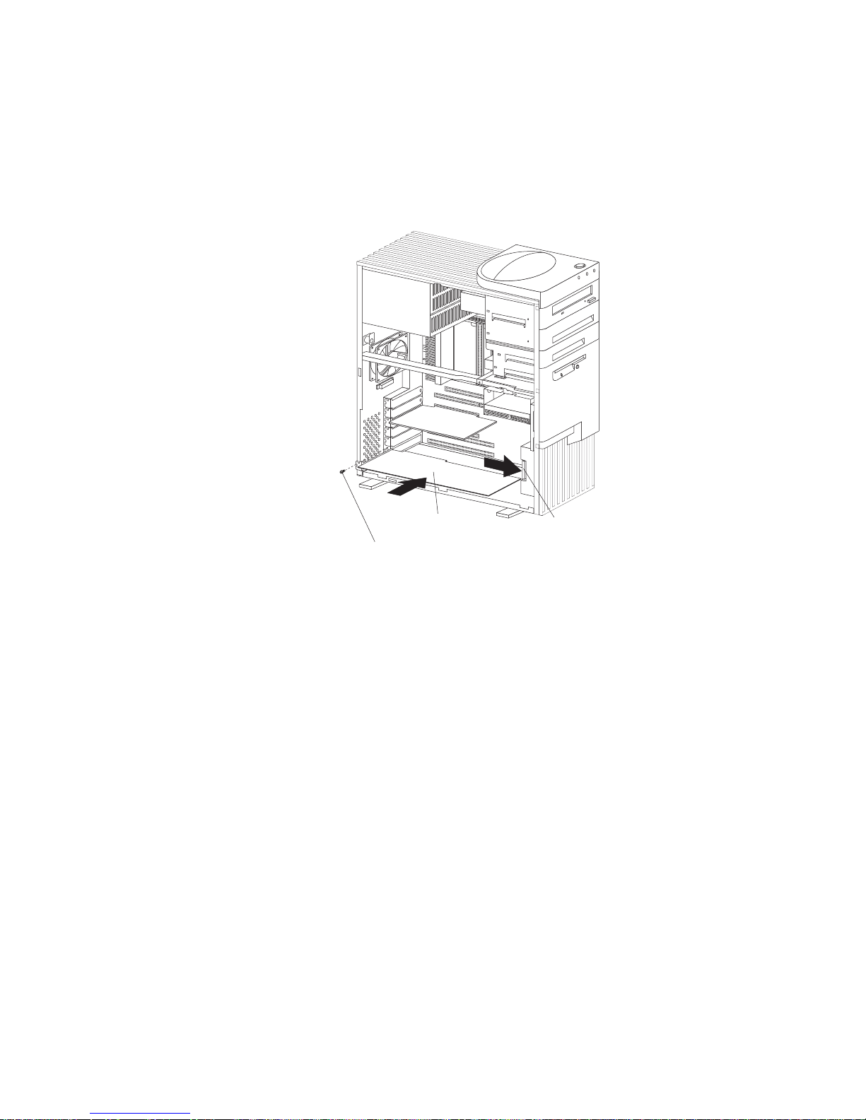
Working with Adapters
c. Store the expansion-slot cover in a safe place for future use.
Adapter
Expansion-Slot Screw
Card Retainer
4. Touch the static-protective package that contains the adapter to
any unpainted metal surface on the server; then, remove the
adapter from the package.
5. Install the adapter:
a. Carefully grasp the adapter and align it with the expansion
slot.
Note: When installing full-length adapters in slots 3
through 6, align the end of the adapter with the card
guide on the fan housing. When you remove an
adapter, you must press the card retainer inward to
slide an adapter out of the server.
b. Press the adapter firmly into the expansion slot connector.
c. Replace the expansion-slot screw on the top of the adapter
bracket.
d. If necessary, connect any internal cables to the adapter.
Refer to the documentation that comes with the option.
62 Netfinity 3500 User's Handbook
Page 81
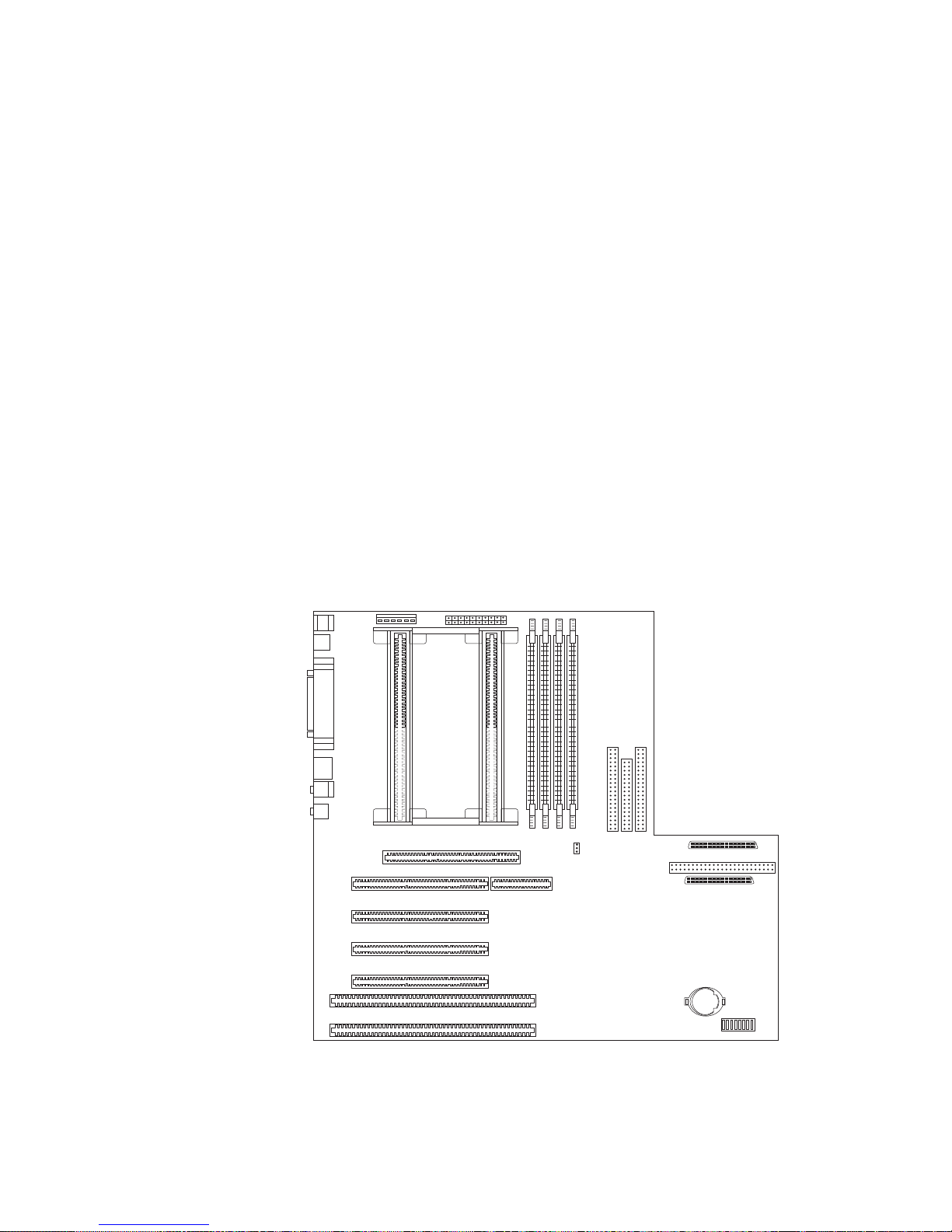
Working with Memory Modules
6. If you installed an ISA legacy adapter, go to “ISA Legacy
Resources” on page 40 to assign system resources.
7. If you want to install or remove any other options, do so now.
Otherwise, go to “Completing the Installation” on page 113.
Working with Memory Modules
Adding system memory to your server can make programs run
faster. You can increase the amount of system memory by installing
options called memory modules.
The maximum amount of system memory your server supports is
512 MB. You can add memory to your server to increase system
performance. Your server has four connectors for installing
system-memory modules. These connectors are referred to as banks
0 through 3.
Memory Connectors
3210
Chapter 4. Installing Options 63
Page 82

Working with Memory Modules
The memory modules that your server uses are dual-inline memory
modules (DIMMs). The DIMMs that come with your server are
synchronous dynamic random-access memory (SDRAM) with error
correcting code (ECC). These memory modules have a speed of 66
MHz. You can add extra memory modules or replace existing
memory modules.
Notes:
1. Your server comes with one or more dual-inline memory
modules (DIMMs) installed.
2. Install DIMMs with a maximum height of 6.35 cm (2.5 inches).
3. Use only 3.3 V unbuffered DIMMs.
4. The server supports 32 MB, 64 MB, and 128 MB DIMMs.
5. When you are installing memory modules, install them in
adjacent connectors, with no vacant memory connectors in
between.
6. If you are installing DIMMs of different sizes, install the DIMMs
with greater memory capacity starting with the connector closest
to the edge of the system board (Bank 0).
7. After installing or removing a DIMM, you must save the new
configuration information using the Configuration/Setup Utility
program. See “Using the Configuration/Setup Utility Program”
on page 28.
8. For more information about the DIMMs that your server
supports, go to the following World Wide Web address:
http://www.us.pc.ibm.com/server/
64 Netfinity 3500 User's Handbook
Page 83

Working with Memory Modules
Memory Configuration
When you are adding or removing memory, a basic rule to follow is
to fill each system memory connector sequentially, starting at
Bank 0.
Table 1 shows the suggested memory configurations for your
server. The contents of this table and additional information can be
found on a label located inside your server. Again, alternate
configurations are possible.
Note: The values in Table 1 are represented in megabytes (MB).
Table 1. Memory Configurations
Total Memory Bank 0 Bank 1 Bank 2 Bank 3
32 32 0 0 0
64 64 0 0 0
64 32 32 0 0
96 32 32 32 0
128 128 0 0 0
128 64 64 0 0
256 128 128 0 0
256 128 64 64 0
512 128 128 128 128
Chapter 4. Installing Options 65
Page 84

Working with Memory Modules
Installing or Removing Memory Modules
This section gives the procedure for installing memory modules. If
you want to remove a memory module, reverse the order of the
following steps.
Before you begin:
Read “Electrical Safety” on page 54 and “Handling
Static-Sensitive Devices” on page 55.
Read the documentation that comes with the option.
Read “Accessing the System Board” on page 58.
Notes:
1. Each memory connector contains two keys (dividers), which are
used to assure that a memory-module can be installed only in
the correct position.
2. A retaining clip at each end of the connector locks the memory
module into place.
3. For information about memory configuration, see Table 1 on
page 65.
To install a DIMM:
1. Remove the server cover (see “Preparing to Add Options” on
page 56). Table 1 on page 65.
2. Locate the memory connectors on the system board. See the
illustration at the beginning of this section.
66 Netfinity 3500 User's Handbook
Page 85
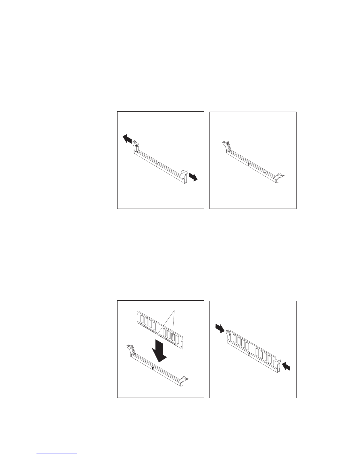
Working with Memory Modules
3. Be sure that the retaining clips are in the open position, as
shown in the following right-hand illustration. If the retaining
clips are perpendicular to the connector, push outward on them
until they click open.
4. Touch the static-protective package containing the DIMM to any
unpainted metal surface in the server; then, remove the DIMM.
5. Position the DIMM above the connector so that the two notches
on the bottom edge of the DIMM align properly with the
connector.
6. Firmly push the DIMM straight down into the connector until
the retaining clips close and snugly fit around both ends of the
DIMM.
Notches
Chapter 4. Installing Options 67
Page 86

Working with Memory Modules
Note: Adding or removing DIMMs changes the configuration
information in the server. When you restart the server,
the system displays POST error 164. Start the
Configuration/Setup Utility program and select Save
Settings.
7. To install another DIMM, repeat steps 3 through 6 on page 67.
8. If you want to install or remove any other options, do so now.
Otherwise, go to “Completing the Installation” on page 113.
68 Netfinity 3500 User's Handbook
Page 87
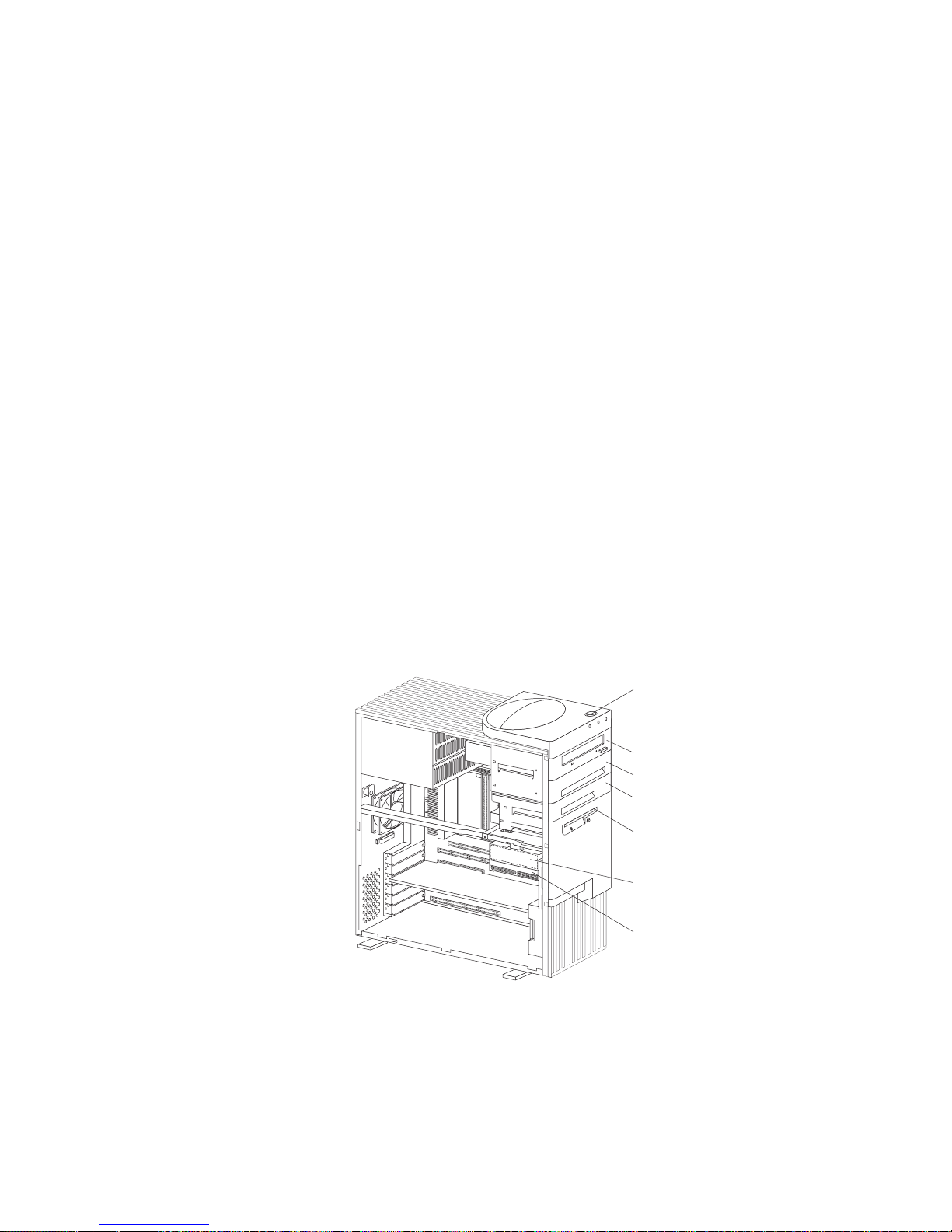
Expansion Bays
Installing or Removing Internal Drives
Drives are devices that your server uses to store and retrieve data.
You can add drives to your server to increase storage capacity and
to enable your server to read multiple types of media. Several types
of drives are available, such as:
Diskette
Hard disk
Rewritable optical disc
Tape
Expansion Bays
Internal drives are installed in bays. The bays are referred to as
bay 1, bay 2, and so on.
Your server comes with one 3.5-inch, 1.44 MB diskette drive, one
5.25-inch CD-ROM drive, and, in some models, a 3.5-inch hard disk
drive. The following illustration shows the server front view, with
the side panel removed.
CD-ROM Drive
Open Bay
Open Bay
3.5-Inch
Diskette Drive
3.5-Inch Hard
Disk Drive
Open Bay
Power Switch
CD-ROM Drive: Your server comes with an integrated drive
electronics (IDE) CD-ROM drive.
Chapter 4. Installing Options 69
Page 88
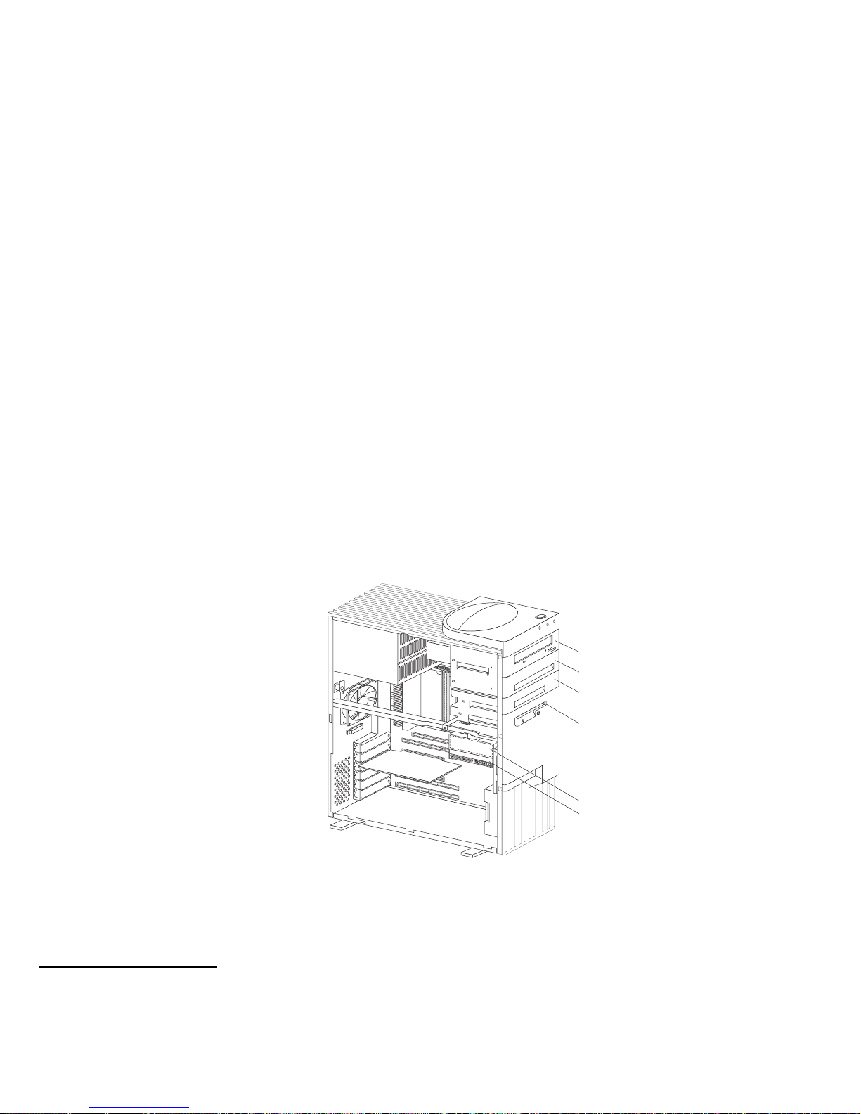
Expansion Bays
Open Bays: Your server's design accommodates 3.5-inch and
5.25-inch devices, such as hard disk, tape, and rewritable optical
disk drives. The number and capacities of the hard disk drives
vary by model.
For information on the supported types of drives and their
installation, see “Drive Specifications” on page 71 and
“Preinstallation Steps (All Bays)” on page 76.
Diskette Drive: The 3.5-inch, 1.44 MB3 diskette drive uses
1 MB (unformatted) or 2 MB (unformatted) diskettes.
Your server comes with an IDE CD-ROM drive installed in bay 1
and a 3.5-inch diskette drive installed in bay 4. Some models come
with a preinstalled 3.5-inch hard disk drive in bay 6; open-bay
models come with bay 6 empty.
The following illustration shows the locations of the bays in your
server.
Bay 1
Bay 2
Bay 3
Bay 4
Bay 6
Bay 5
3
MB equals approximately 1 000 000 bytes; total user-accessible capacity may vary depending on operating environment.
70 Netfinity 3500 User's Handbook
Page 89

Drive Specifications
Table 2 describes some of the drive types that you can install in
each bay, and their width and height requirements.
Table 2. Maximum Allowable Drive Sizes
Bays Drive
Widths
Drive Types Drive Height
1 5.25-inch CD-ROM drive 41.3 mm (1.6 in.)
7
2 3.5-inch
4
5.25-inch
Removable media
5
drive, hard disk
drive
25.4 mm (1.0 in.)
41.3 mm (1.6 in.)
7
3 3.5-inch Removable media
5
drive, hard disk
drive
25.4 mm (1.0 in.)
4 3.5-inch Diskette drive 25.4 mm (1.0 in.)
5 and 6 3.5-inch Hard disk drive
6
25.4 mm (1.0 in.)
41.3 mm (1.6 in.)
7,8
4
To properly install a 3.5-inch drive in bay 2, use the 3.5-inch conversion kit for a 5.25-inch bay that is already installed in bay
2. If you are installing a 5.25-inch drive in bay 2, you must first remove the conversion kit.
5
Removable media include CD-ROMs, optical discs, diskettes, and tapes. However, the server only supports one diskette
drive (standard in bay 4).
6
In some models, the CD-ROM drive might be set as the default startup (or boot) drive. However, if a hard disk drive is
preinstalled, you can change the startup sequence, and specify the hard disk drive as the startup drive. See “Start Options”
on page 31 for information about changing the startup sequence.
7
Drives that are higher than 41.3 mm (1.6 in.) cannot be installed.
8
One slim-high drive has a height of 25.4. mm (1.0 in.). One half-high drive has a height of 41.3 mm (1.6 in.). Therefore, you
can install two slim-high drives or one half-high drive between bays 5 and 6.
Chapter 4. Installing Options
71
Page 90

Types of Cables
Your server uses cables to connect IDE and SCSI drives to the
power supply and system board. Each cable connector is designed
to fit a corresponding drive connector. The following cables are
provided:
Four-wire power cables connect most drives to the power supply.
At the end of these cables are plastic connectors that attach to
different drives; these connectors vary in size. Also, certain
power cables attach to the system board.
Flat signal cables for connecting IDE and diskette drives to the
system board. Signal cables are sometimes called ribbon cables.
The following ribbon signal cables come with your server to
connect IDE and diskette drives:
– The IDE signal cable has three connectors. One of these
connectors is attached to the CD-ROM drive, one is a spare,
and the third attaches to the primary IDE connector on the
system board.
– One signal cable has one connector for attaching the diskette
drive to the diskette-drive connector on the system board.
A flat SCSI signal cable for connecting devices to the SCSI
adapter.
Since your server is equipped with an UltraSCSI controller, it has a
ribbon cable that is connected to the internal SCSI hard disk drive.
One end of this cable is connected to the 68-pin, Channel A SCSI
connector on the system board. This cable provides four connectors
for attaching other internal SCSI devices.
For more information about SCSI devices, see “SCSI Drives” on
page 74.
Note: To locate connectors on the system board, see “System Board
Illustration” on page 203.
72 Netfinity 3500 User's Handbook
Page 91

The following are some important points to remember when
connecting power and signal cables to internal drives:
The diskette drive, hard disk drive, and CD-ROM drive that are
preinstalled in your server come with power and signal cables
attached. If you replace any drives, it is important to remember
which cable is attached to which drive.
When you install a drive, ensure that the connector at the end of
the signal cable is connected to the system board.
If two IDE devices are used on a single cable, one must be
designated as the primary or master device and the other a
secondary or subordinate device; otherwise, some of the IDE
devices might not be recognized by the system. The primary or
secondary designation is determined by switch or jumper
settings on each IDE device.
In this server, the CD-ROM drive is the primary device. If you
install a second IDE device, it must be the secondary device.
To attach an external SCSI drive, you must install an
appropriate adapter in the server.
For help in selecting drives, cables, and other options for your
server, do one of the following:
Within the United States, call 1-800-IBM-2YOU (1-800-426-2968),
your IBM reseller, or your IBM marketing representative.
Within Canada, call 1-800-565-3344 or 1-800-465-7999.
Outside the United States and Canada, contact your IBM reseller
or IBM marketing representative.
Chapter 4. Installing Options 73
Page 92

SCSI Drives
Some drives have a special design called small computer system
interface (SCSI). This design allows you to attach multiple drives to
a single connector.
Note: Any information about SCSI drives also applies to other SCSI
devices, such as scanners and printers.
Your Netfinity 3500 server supports drives that comply with
American National Standards Institute (ANSI) SCSI Standards
X3.131-1986 (SCSI), X3.131-1994, (SCSI-2), X3.277-1996 (SCSI-3
Fast-20 parallel interface), and X3.253-1995 (SCSI-3 parallel interface).
For a complete list of the SCSI devices that your server supports, go
to http://www.us.pc.ibm.com/server/ on the World Wide Web.
SCSI Physical Unit Numbers
When more than one physical device is connected to the same
UltraSCSI controller, the devices compete for support from the
UltraSCSI controller. Because the UltraSCSI controller
communicates with only one device at a time, the priority of a
device is based on its SCSI identification (ID). The highest priority
IDs are 7 to 0; the lowest priority IDs are 15 to 8.
If you install additional SCSI devices, you must set a unique ID for
each SCSI device that you connect to the integrated SCSI-2
connector. This unique ID enables the UltraSCSI controller to
identify the devices and to prevent two devices from sending or
receiving data on the SCSI bus at the same time. SCSI devices use a
variety of methods to set the SCSI ID, such as jumpers,
thumbwheels, or switches.
The SCSI device ID is also known as the SCSI address or physical unit
number (PUN).
The UltraSCSI controller in your server supports SCSI IDs 0 to 15;
ID 7 is reserved for the controller. The default startup (boot) SCSI
ID is 0 for an internal SCSI hard disk drive in Channel A. Use
SCSISelect to view the SCSI IDs of SCSI devices in your server. (See
“Using the SCSISelect Utility” on page 46 for more information.)
74 Netfinity 3500 User's Handbook
Page 93

If you install wide (16-bit) SCSI devices, you can set the IDs to any
whole number between 0 and 6, or between 8 and 15. If you install
narrow (8-bit) SCSI devices, you can set the IDs to any whole
number between 0 and 6.
SCSI Logical Unit Number
Each physical device has a physical unit number (PUN) and a
logical unit number (LUN). If a physical device supports no logical
devices, its LUN is 0. Most SCSI devices support only LUN 0.
Certain types of physical SCSI devices (bridge controllers) can support
more than one logical device.
For example, a printer controller might support up to eight printers.
The printer controller is a physical device, and each printer is a
logical device. If the printer controller is assigned to ID 2, the ID of
the first printer appears in the SCSI device configuration as PUN 2,
LUN 0. The IDs of the other printers are PUN 2, LUN 1; PUN 2,
LUN 2; on up to PUN 2, LUN 7.
Termination Requirements
All Netfinity 3500 servers come with an UltraSCSI controller on the
system board. This UltraSCSI controller provides termination for
one end of the SCSI bus (cable) in your server. However, the SCSI
bus must be terminated at both ends only. Any SCSI devices that
are installed must have their termination set to Disabled.
When you install devices in bays 2, 3, 5, and 6, you must disable
the termination for the devices before you install them.
If you connected external SCSI devices to your server, set the
termination for the last device on the external cable to Enabled.
See the device documentation for instructions.
Refer to the instructions that come with the SCSI device for more
information about termination.
Chapter 4. Installing Options 75
Page 94

Preinstallation Steps (All Bays)
Before you begin, be sure you have:
Read “Electrical Safety” on page 54 and “Handling
Static-Sensitive Devices” on page 55.
Read the documentation that comes with the option.
Read “Termination Requirements” on page 75.
Verified that you have all cables, drive trays, and any other
equipment specified in the documentation that comes with
the internal drive.
Before you can install drives in your Netfinity 3500 server, you
might need to perform certain preinstallation activities. Some of the
steps are required only during the initial installation of an option.
1. Remove the server cover (see “Preparing to Add Options” on
page 56).
2. Choose the bay in which you want to install the drive. (Refer to
Table 2 on page 71 for the drive types and sizes available for
each bay.)
3. Access the appropriate drive bays.
Notes:
a. In all models, drive bays 1 and 4 come with drives
preinstalled.
b. In some models, drive bay 6 comes with a drive
preinstalled.
c. Drive bays 2 and 3 have a bay panel and static shield
installed.
d. If you remove a drive that has removable media and you do
not intend to install a new drive immediately, reinstall the
static shield and bay panel for that bay.
To access drive bays 1 through 4, go to step 4 on page 77.
To access drive bays 5 and 6, go to step 5 on page 80.
76 Netfinity 3500 User's Handbook
Page 95

4. To access bays 1 through 4:
a. If the drive that you are installing has removable media,
remove the bay panel from the drive bay by using a
flat-blade screwdriver to pry the tab on the left edge of the
panel, as shown.
Chapter 4. Installing Options 77
Page 96
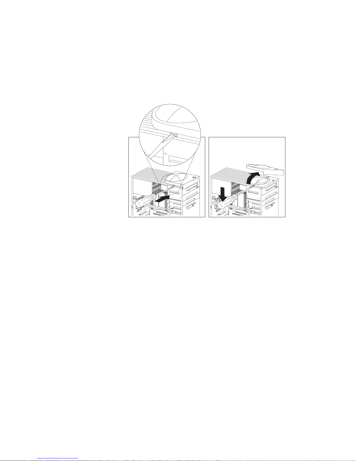
b. Remove the top cover by using a flat-blade screwdriver to
release the tab on the left edge, as shown.
c. Disconnect the power and signal cables attached to the
drives in the upper drive bracket.
Note: If an additional cable (audio) is connected to the
CD-ROM drive, also disconnect that cable.
78 Netfinity 3500 User's Handbook
Page 97
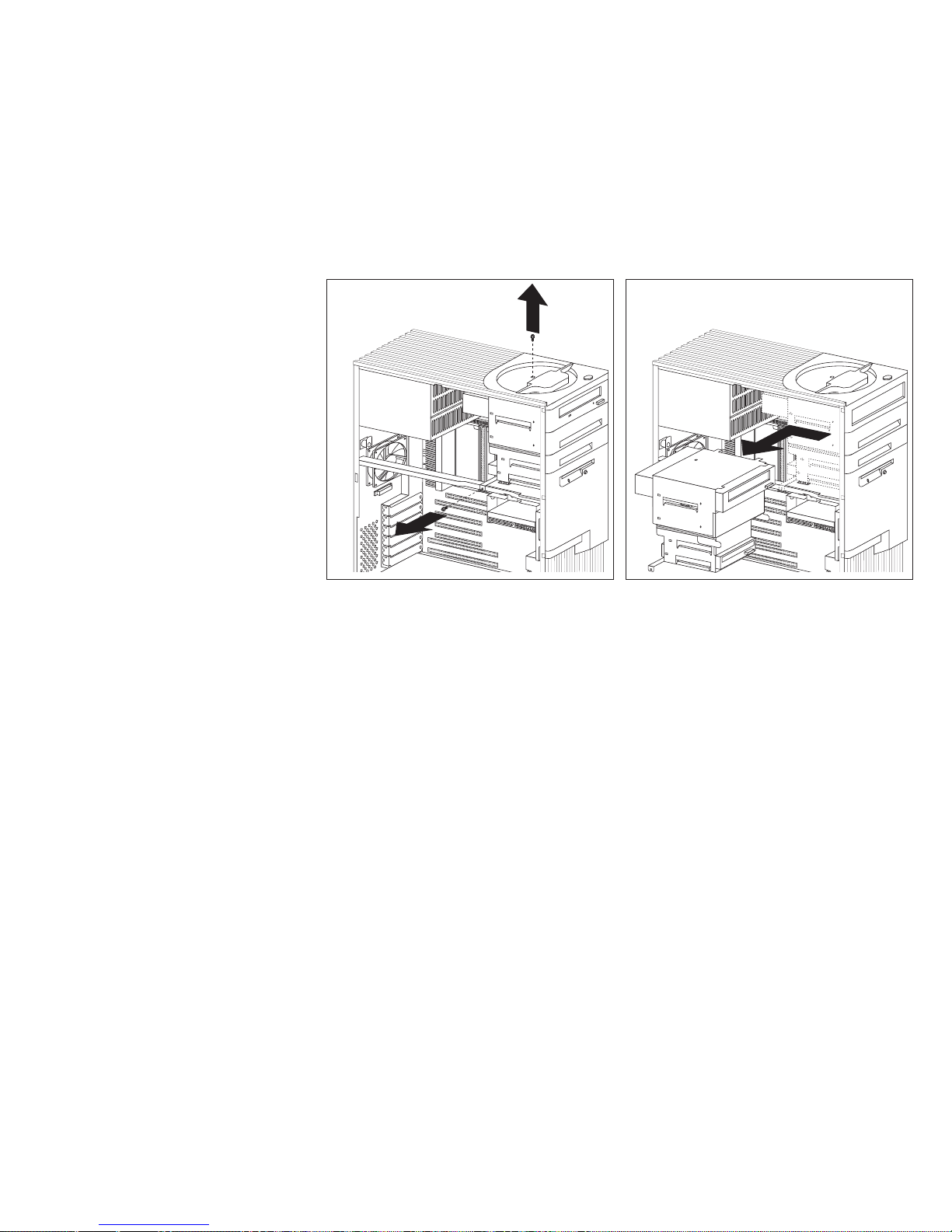
d. Remove the screws that secure the top and the bottom of
the upper drive bracket.
e. Slide the drive bracket to the rear approximately 25 mm
(1.0 in.); then, slide it sideways until it is out of the server.
f. If the drive that you are installing has removable media,
remove the static shield from the drive bay where you are
installing the drive.
g. Continue with step 6 on page 80.
Chapter 4. Installing Options 79
Page 98
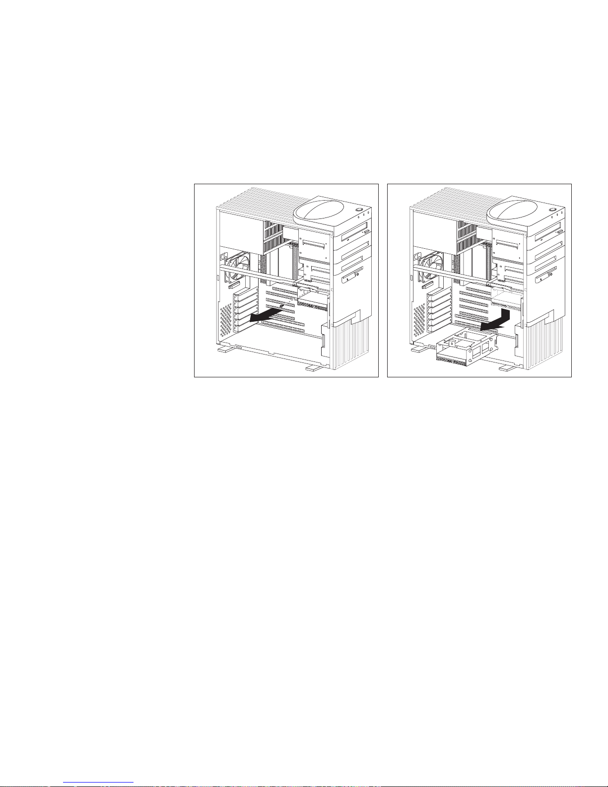
5. To access bays 5 and 6:
a. Remove the screw that secures the lower drive bracket.
b. Lower the front of the drive bracket, lift up on the rear, and
slide it out.
c. If necessary, disconnect the power and signal cables
attached to the drives in the lower drive bracket.
d. Continue with step 6.
6. Touch the static-protective bag containing the drive to any
unpainted metal surface on the server; then, remove the drive
from the bag.
80 Netfinity 3500 User's Handbook
Page 99

7. Check the instructions that come with the drive, or contact your
IBM reseller or IBM marketing representative to see if you need
to set any switches or jumpers on the drive, or if you need to
attach a tray to the drive.
What to do next?
To install a drive in bays 1 through bay 4, go to “Installing
or Removing Drives in Bays 1 through 4.”
To install a drive in bays 5 and 6, go to “Installing or
Removing Drives in Bays 5 and 6” on page 85.
Installing or Removing Drives in Bays 1 through 4
This section gives the procedure for installing a drive in bays 1
through 4. If you want to remove a drive, skip steps 2 through 4 on
page 82, and step 6 on page 82.
Before you begin:
Read “Electrical Safety” on page 54 and “Handling
Static-Sensitive Devices” on page 55.
Read “Preinstallation Steps (All Bays)” on page 76 and the
instructions that come with the option.
Read “Termination Requirements” on page 75.
Notes:
1. See “Drive Specifications” on page 71 for the drive types and
sizes that you can install in bays 1 through 4.
2. You might need to disconnect cables from drives that are
already installed in the server.
Chapter 4. Installing Options 81
Page 100

1. Remove the server cover (see “Preparing to Add Options” on
page 56).
2. Your server comes with a tray installed in bay 2. If you are
installing a 5.25-inch drive in bay 2, you must first remove the
tray. To do this, remove the four screws on the bottom of the
tray.
3. If a tray is attached to a drive that you intend to install, you
must remove the tray before installing the drive. Follow the
instructions in the documentation that comes with the drive.
4. Using the instructions that come with the drive, together with
these instructions, verify that any switches or jumpers on the
drive are set correctly. Change the settings if necessary. For
information about termination requirements, see “Termination
Requirements” on page 75.
5. Remove the upper drive bracket. See step 4 on page 77.
6. Touch the static-protective package containing the new drive to
any unpainted metal surface; then, remove the drive.
82 Netfinity 3500 User's Handbook
 Loading...