

Page 1

OPTIONS
by IBM
®
IBM
Netfinity
Gigabit
Ethernet Adapter
User’s guide
19K4621
Page 2

Page 3

®
IBM
Netfinity
Gigabit
Ethernet Adapter
User’s guide
19K4621
Page 4

ote
N
Before using this information and the product it supports, read the
information under “Appendix B. Product warranties and notices” on
page B-1 of the Netfinity Gigabit Adapter Device Drivers an d Installation
First Edition (August 2000)
© COPYRIGHT INTERNATIONAL BUSINESS MACHINES CORPORATION, 2000.
All rights reserved.
Note to U.S. Government Users — Documentation related to restricted rights — Use,
duplicatio n or disclosure is subje ct to restrictions set forth in GSA ADP Sche d u le
Contract with IBM Corp.
Page 5

IBM
Page 6

Page 7

Contents
Safety: read first. . . . . . . . . . . . . . . . . . . . . . . . . . . . . . . . . . . . . . . . . . . . . . . . . . . . . vii
About this book . . . . . . . . . . . . . . . . . . . . . . . . . . . . . . . . . . . . . . . . . . . . . . . . . . . . . . ix
User’s guide . . . . . . . . . . . . . . . . . . . . . . . . . . . . . . . . . . . . . . . . . . . . . . . . . . . . . . . . . .1-1
© Copyright IBM Corp. 2000 v
Page 8

vi Netfinity® Gigabit Ethernet Adapter User’s guide
Page 9

Safety: read first
Before installing this product, read the Safety Information.
Antes de instalar este produto, leia as Infor mações de Segurança.
Pred instalací tohoto produktu si prectete prírucku bezpecnostních instrukcí.
Læs sikkerhedsforskrifterne, før du installerer dette produkt.
Ennen kuin asennat täm än t uotte e n, lue turv aoh je et ko hd a sta Sa fety Info rm at ion .
Avant d’installer ce produit, lisez les consignes de sécurité.
Vor der Installation dieses Produkts die Sicherheitshinweise lesen.
Prima di installare questo prodotto, leggere le Informazioni sulla Sicurezza.
© Copyright IBM Corp. 2000 vii
Page 10

Lees voordat u dit product installeert eerst de veiligheidsvoorschriften.
Les sikkerhetsinformasjonen (Safety Information) før du installerer dette produktet.
Antes de instalar este pr oduto, leia as Informações sobre Segurança.
red inštaláciou tohto zariadenia si pečítaje Bezpečnostné predpisy.
Antes de instalar este producto lea la información de seguridad.
Läs säkerhetsinformationen innan du installerar den här produkten.
viii Netfinity® Gigabit Ethernet Adapter User’s guide
Page 11

About this book
This manual contains instructions for installin g and using the IBM® Netfinty® Gigabit
Ethernet Adapter.
For help and service information, warranties, and notices, see the CD booklet that comes
with your optio n pa c ka ge .
Registering your option
Thank you for purchasing OPTIONS by IBM. Please take a few moments to register your
product and provide us with information that will help IBM to better serve you in the
future. Your feedback is valuable to us in developing products and services that are
important to you, as well as in de v elop ing be tte r ways to c omm un ic ate with yo u. Regi ster
your option on the IBM Web site at
http://www.ibm.com/pc/register
IBM will send you information and u pdates on your re gistered product unless you in dicate
on the Web site questionnaire that you do not want to receive further information.
© Copyright IBM Corp. 2000 ix
Page 12

x Netfinity® Gigabit Ethernet Adapter User’s guide
Page 13

1.User’s guide
This guide provides the product description, software description, and installation and
usage instructions.
Product description
The IBM® Netfinity® Gigabit Ethernet Adapter connects your PCI-compliant server or
workstation to a Gigabit Ethernet network. The adapt er incorporates a technology that
transfers data at a maximum rate of one gigabit per second—10 times th e r a te of a Fast
Ethernet adapter.
The Netfinity Gigabit Ethernet Adapte r tar gets the increase d congestion experienced at the
backbone and ser ver in today’s networks, while providing a future upgr a de path for highend workstations that require more bandwidth than Fast Ethernet can provide.
The following items are i ncl uded in your option package:
• Netfinity Gigabit Ethernet Adapter CD with device driver software and
documentation.
• The IBM Netfinity Gig abit Ethe rnet Adapter in a n anti-sta tic ba g (use d for prote cting
the adapter when stored or shipped). Keep the adapter in the packaging until you are
ready to install it.
If any of these items are missing or damaged, contact your resel ler. Keep your original
packing material; it might be required if you need to return your adapter.
The Netfinity Gigabit Ethernet Adapter supports the following features:
• Full-duplex Gigabit Ethernet interface (IEEE 802.3-1999)
• Jumbo Frame su pport (optional 9,000 byte frames for server-to-server traffi c)
• VLANs: up to 64 VLANs per adapter using IEEE 802.1Q-1998 tagg ing
• Compatibility with existing Ethernet and Fast Ethernet equipment
• Standard Ethernet frame size (up to 1,518 by te s)
• Supports 32 multicast addresses
®
• Adapter failover to an Intel
82559 LAN on Motherboard (LOM)
• Adaptive interrupt frequency (maximizes network throughput; adapts to traffic load)
• Dual DMA channels
• 33/66 MHz, 32-bit or 64-bit PCI bus master with adaptive DMA
• PCI Local Bus Rev 2.2 compliant: 17.3 cm x 10.7 cm (6.8 in. x 4.2 in.)
• ASIC with on-chip MAC and dual RISC processors
• Universal dual voltage signaling (3.3V and 5V)
• Status LEDs
• Adapter Teaming configuration for automatic failover if the network connection is
down
19K4621 © Copyright IBM Corp. 2000 1-1
Page 14

Key protocols and interfaces
The Netfinity Gigabit Et herne t Ada pt er is compati ble with ex istin g Eth erne t equip men t
assuming standard Ethernet minimum and maximum frame size (64 to 1518 bytes), frame
format, and compliance with the following standards and protocols:
• Gigabit Ethernet (IEEE 802.3-1999)
• Logical Link Control (IEEE 802.2)
• Flow Control (IEEE 802.3x)
Jumbo Frames support
When sending Ethernet traffic at Gigabit speeds, considerable bandwidth is consumed by
the overhea d of hand ling a mu ltitude o f standard 1,500 b yte pac kets. The Ne tfinity Gig abit
Ethernet Adapter and Alteon WebSystems switches suppo rt Etherne t frames of up to 9,000
bytes. Host CPU utilization is significantly reduced and network throughput is enhanced
when enabling Jum bo Frames between servers that have IBM PCI adapters.
For user datagram proto col (UDP) tra f fic, an IBM Netfinity Gigabit Ethern et Adapter c an
support standard Ethernet frames and Jumbo Frames at the same time. When attached to
an Alteon WebSystems switch, Jumbo Frames are sent only between servers that have
Netfinity Gigabit Ethernet Adapters. When attached to a standard Ethernet device, a
Jumbo Frames-enabled server might send UDP data in Jumbo Frames, but when the data
reaches the switch, the switch automatically fragments the data into standard Ethernet
frames when sending to all other standard Ethernet devices.
For non-UDP traffic, both servers must support Jumbo Frames.
VLANs support
Virtual local area networks (VLANs) are commonly used to divide groups of network
users into manageable broadcast domains, to create log ical segmentation of workgroups,
and to enforce security policies among logical segments.
Each Netfinity Gigabit Ethernet Adapter supports up to 64 VLANs, depending on the
amount of memory available in your computer. With multiple VLANs on an adapter, a
server with a single adapter can have a lo gical pr esence on mu ltiple IP subnets. For d etails
about planning networks with VLANs, refer to your Alteon WebSystems switch software
manual.
Adapter teaming
Teaming provides re dundant adapter operation in the event that a network connection
fails. When multiple Netfinity Gigabit Ethernet Adapters are installed in the same server,
they can be paired into teams. Up to two teams, each with two adapte rs, can be configure d
on the server.
If traffic is not detected on the pri mary adapter connection in a team because the adapter,
cable, switch port, or switch (where the teamed adapters are attached to separate switches)
fails, the secondary team member becomes active, taking t he MAC and IP address
originally assigned to the primary adapter. Sessions are usually maintained, causing no
impact to the user.
1-2 Netfinity® Gigabit Ethernet Adapter User’s guide
Page 15

Adaptive interrupt frequency
The adapter device driver automatically adjusts host interrupt frequency based on traffic
conditions to increase overall application throughput. In light traffic, the adapter device
driver interrupts the h ost for each received packet, minimizi ng latency. When traffic is
heavy, the adapter issues one host interrupt for multiple, back-to-back incoming packets,
preserving host CPU cycles.
Dual DMA channels
The PCI interface on the Netfinity Gigabit Ethernet Adapter contains two independent
direct memory access (DMA) channels for simultaneous read and write operations.
32-bit or 64-bit PCI bus master
Compliant with PCI Local Bus Rev 2.2, the PCI interface on the Netfinity Gigabit
Ethernet Adapter is compatible with b oth 32-bit and 64 -bit PCI buses. As a bus master , the
adapter requests access to the PCI bus instead of waiting to be polled.
ASIC with embedded RISC processor
The core control for the Netfinity Gigabit Ethernet Adapter resides in a tightly integrated,
high-performance ASIC. The ASIC includes dual RISC processors. This provides the
flexibility to add new featu res to the adapter a nd upgrade it to fu ture network requirements
through software do wnload. This also enab les the a dapter d evice d rivers to use the built-in
host off-load functions on the adapter as host operating systems are enhanced to take
advantage of these fu nctions.
Connectors
The faceplate on the Netfinity Gigab it Apater prov ides an RJ-45 conn ec tor for connec ting
the adapter to another network device.
LEDs
The faceplate of the Netfinity Gigabit Ethernet Adapter has four LEDs: one for each port
speed option (10Mbps, 100Mbps, and 1Gbps), to indicate which link is active, and one
LED for data transfer status. Until the driver software is properly installed, all four LEDs
remain lit when the server is turned on.
When the adapter hardware and device driver software have been properly instal l ed on
your computer, the LEDs indicate the adapter states, according to the followi ng table.
LED State Description
Data Blinking Brief bursts of data are detected on the port.
Data On Streams of data are detected on the port.
Data Off No data is detected on the port.
1000 On Good 1000 Mbps (G iga bit) Ethernet link.
User’s guide 1-3
Page 16

LED State Description
1000 Off No 1000 Mbps link: possi ble link at different speed,
possible bad cabl e, ba d connector, or configuration
mismatch.
100 On Good 100 Mbps Etherne t link.
100 Off No 100 Mbps link: po ssi bl e li nk at different speed,
possible bad cabl e, ba d connector, or configuration
mismatch.
10 On Good 10 Mbps Ether ne t li nk.
10 Off No 10 Mbps link: possible li nk a t di fferent speed, possible
bad cable, bad con nector, or configuration mismatc h.
If all four LEDs remain lit simultaneously, the adapter driver software is either missing or
improperly installed.
System requirements
Before installing the Net f ini ty Gig abit Eth e rne t Ada p te r, be sure your computer meets the
following requirements:
• Hardware:
®
— Intel Penti um
-based computer that meets Microsoft® Windows NT® 4.0
requirements
— One open 32- or 64-bit PCI slot
— 128MB RAM
• Software:
— Operating system: Microsoft Windows NT 4.0 (server or workstation) with
Service Pack 4 or later
— Adapter software: IBM Netfinity Gigabit Ethernet Adapter device driver
software (included), version 2.3 (or higher) for Windows NT. See the Netfinity
Gigabit Ethernet Adapter CD for these files in the \nt40 directory:
– ALTNDIS.SYS (network device driver file)
– ALTVLAN.SYS (intermediate device driver file)
– ALTDLG.DLL (information used by the installation program)
– OEMSETUP.INF (information file)
1-4 Netfinity® Gigabit Ethernet Adapter User’s guide
Page 17

Before you begin
Before installing your Netfinity Gigabit Ethernet Adapter, be sure your computer meets
the requirements listed above; then do the following:
1. Verify that your server is using the latest BIOS.
2. Review the information in the README.TXT file on the Netfinity Gigabit Ethernet
Adapter CD for important information not availab le at the time this manual was
created.
Note: If you acquired the adapter software on a diskette or from the IBM support
Web site, check the appropriate source for the most recent information.
3. If your computer is on, turn it off.
4. Remove all cords from the computer and all attach ed devices.
5. Hold the adapter card by the edges and remove it from its shipping package and place
it on an anti-static surface.
6. Check the adapter for any visible signs of damage, particularly on the edge connector
of the adapter. Do not attempt to install a damaged adapter.
®
If the adapter is damaged, report it to the IBM HelpCenter
see the help and service information in the Netfintiy Gigabit Adapter CD booklet.
. For more information,
Installing the Netfinity Gigabit Ethernet Adapter
T o inst al l the Netfini ty Giga b it Ethe rnet Adapt er in yo ur com put er, do the following:
1. Be sure that your computer is off and that you have removed all cords fro m the
computer and any attached devices.
2. Remove the cover of your computer, using instructions in your computer
documentation; then select an empty PCI slot.
If you do not kn ow h ow to identify a PCI s lo t , re f e r to yo ur c o mp uter documen ta tio n.
3. Remove the blank cover -plate from the slot that you selected. Re tain the scre w so that
it can be replaced later.
4. Holding the PCI card by the edges, align the connector edge of the adapter with the
PCI connector dock in the computer.
Note: The connector dock in a 32-bit PCI slot is shorter than in a 64-bit PCI slot.
Although the adapter is designed to fit in either slot type, when installed in a
32-bit PCI slot, part of the connector edge of the adapter will remain
undocked. This is normal.
5. Applying even pressure at both corners of the adapter, push the adapter until it is
firmly seated in the PCI slot.
Attention: Do not use excessive force when seating the adapter in the computer; it
might damage your computer or the adap ter . If the adapter is dif ficult to seat, remove
it from the computer, realign it; then try again.
When properly seated, the port connectors of the adapter will be aligned with the slot
opening, and the facepl ate of the adapter will be flush against the computer chassis.
6. Use the screw removed in Step 3 to secure the adapter in the PCI card cage.
User’s guide 1-5
Page 18

7. Rep lace the computer cover and disconnect any personal ant i-static devices.
8. Turn your computer on.
When the computer returns to proper operation, the adapter hardware is fully
installed. You must next connect the network cables (see “Con ne c tin g the ne twork
cables”) and install the adapter device driver software (see “Installing the device
drivers”).
Connecting the network cables
This section provides instructions on connecting the network cables for the Netfinity
Gigabit Ethernet Adapter.
The adapter has one RJ-45 connector used for attaching the system to an Ethernet copperwire segment. When automatic lin k n egot iat ion is disab le d, the po rt can be c onfigu re d for
10Mbps, 100Mbps, or 1000Mbps signaling, and either half-duplex or full-duplex
operation.
To connect the network cables, do the following:
1. Pr epare the cable
The following table lists the cable characteristic s for connec ting to
10/100/1000BASE-T ports.
Port type Connector Media Maximum Distance
10BASE-T RJ-45 Cat. 3, 4, or 5 UTP 100 meters (325 ft.)
100/1000BASE-T RJ-45 Cat. 5 UTP 100 meters (325 ft.)
Note: 1000BASE-T signaling requires four twisted pairs of Category 5 balanced
cabling, as specified in ISO/IEC 11801:1995 and EIA/TIA-568-A (1995), and
tested using procedures defined in TIA/EIA TSB95.
2. Connect one end of the cable to the Netfinity Gigabit Etherne t Ada pter.
3. Connect the other end of the cable to an RJ-45 Ethernet network port.
Note: The adapter port LEDs will no t reflec t port link or data status until t he adapte r
device driv er soft ware i s insta ll ed. S ee t he ta bl e un der “LE Ds” on pag e 1- 3 for
a description of adapter port LED operation. See “Installing the device
drivers” for device driver installation and configuration instructions.
Installing the device drivers
A network device driver must be installed before the Netfinity Gigabit Ethernet Adapter
can be used with y our computer. This section describes how to perform the following
tasks:
• Installing the device driver software in Windows NT
• Modifying device driver properties
• Updating or reinstalling the device drivers
• Moving or r e moving the device drivers
1-6 Netfinity® Gigabit Ethernet Adapter User’s guide
Page 19

Note: T o prevent the computer from stopping abnormally when using the W indows NT
Network Monitor, be sure to upgrade the operating system BHNT.SYS file to the
latest version available.
The Netfinity Gigabit Ethernet Adapter must be physically installed in your server or
workstation before installing the device driver software. See “Installing the Netfinity
Gigabit Ethernet Adapter” on page 1-5 for instructions.
A network device driver must be installed before the adapter can be u s ed with your
Windows NT system. To install the adapter software for Windows NT, do the following:
Note: If you attempt to install the adapter device drivers on a newly installed Windows
NT system that does n ot h ave Serv ice P ack 4 o r hig her , the device driver will not be
installed. For backup domain con troller (BDC) in stallatio n, see th e README.TXT
file on the Netfinity Gigabit Ethernet Adapter CD for more information.
1. Turn on your computer.
Note: You must have Network Administrator privileges to install the device driver
software.
2. Click Start → Settings → Control Panel.
3. Double-click Network.
4. Click the Adapters tab.
Any previously installed device drivers are listed under Network Adapters.
5. Click Add.
Note: For Windows NT Server Enterprise, be sure to click Add rather than Search.
6. Click Have Disk.
7. When you are prompted to, insert the Netfinity Gigabit Ethernet Ad ap ter CD into the
CD-ROM drive of your computer.
8. Type the path to the device drivers; then click OK.
The path to the devic e drivers is X: \nt 40 (wh er e X is the drive letter of y our CD-R OM
drive).
Note: If you acquired the adapter software on diskette or from the IBM support Web
site, enter the path to where the device driver files are saved on your computer.
9. When an Intel LAN on motherboard (LOM) and advanced Intel software are installed
in your system, the fol l ow in g wind ow opens:
User’s guide 1-7
Page 20

You can only load one intermediate devi ce driver at a time. This means that advance d
options, such as Failover Teaming and VLANs, can be configured for either Netfinity
Gigabit Ethernet Adapte rs or a standa lo ne LOM , bu t no t bo th . If yo u clic k Yes in the
window illustrated above, a LOM can be configured only as a member of a Failover
T eam.
Note: Before installing the drivers for any new Netfinity Gigabit Ethernet Adapter,
you must remove any device drivers prior to version 2.2. If there are no
Intensity Gigabit Adapter device drivers displayed in the Network Adapters
window, or if the device drivers displayed are version 2.2 or higher, proceed to
the next step. If old Netfinity Giga bit Ethernet Adapter device drivers are
present, update adapter versi ons from to the most recent release by following
the instructions under “Updating the device drivers” on page 1-13, or remove
the old adapte r ve r s io n us in g in st r uc tio ns in st e p 1 un de r “ Moving the adapter
to a different slot” on page 1-13.
10. In the Select OEM Option window, Netfinity Gigabit Ethernet Adapter Software
Release is highlighted. Click OK. The Netfinity Gigabit Ethernet Adapter Device
Driver Properties window opens.
When the Properties window opens, the NIC Status and Configuration tab is
displayed. The options under this tab are used for confi guring basic adapter
propertie s. Ot he r ta bs m igh t be a va ila b le fo r c on f ig urin g optional pro pe rtie s (s uc h as
Failover Teaming and VLANs). Click any tab to display its options.
Note: When you disable automatic link negotiation while installing a Netfinity
Gigabit Eth e rnet Adapter, you can select 10Mb ps, 100Mbps, or 1Gbps port
speed, and either half-duple x or full -du plex oper atio n.
11. Configure basic properties under the NIC Status and Configuration tab.
Although the default values are appropriate in most cases, you can change any of the
available options to meet the requirements of your specific computer. Be sure that the
NIC Status and Configuration tab is displayed in the for e gr ound of the Device
Driver Properties window (click the tab, if necessary).
The following options are displayed in the window:
•Adapter
This field identifies which Netfini ty Gig abit Ethernet Adapter or Failover Team
is being configured. In a system with multip le adapters, sele ct this field to access
a pull-down list of the available adapters and teams. Each adapter installed in
the system is labeled with a unique instance number. Typically, the first adapter
detected is instance 1, the next is instance 2, and so on.
Adapters that are paired into teams for automatic failover (see “Failove r
Teaming” on page 1-14) are not listed individually. Instead, the defined team is
listed. When a team is selected, th e ada pters with in the te am ar e c onfig ure d as a
group and the configuration parameters of the primary adapter are applied to the
team. To configure an individual adapter in a manner different from the team, it
must be first removed from the team.
Note: Release 2.3 supports grouping Netfinity Gigabit Ethernet Adapters with
an Intel LAN on motherboard (LOM) into Failover Teams.
1-8 Netfinity® Gigabit Ethernet Adapter User’s guide
Page 21

• Link negotiation
— When checked (default), 802.3-1999 complia nt Gigabit Ethernet link
negotiation is enabled. All Netfinity Gigabit Ethernet Adapters use link
negotiation by default.
— When unchecked, link negotiation is disabled an d only link signal
detection is used. Use this setting when connecting to Ethernet equipment
that does not support lin k negotia tion, or if there is a problem e stablishing a
link between the adapter and the connecting device. Unless otherwise
specified, the default signaling speed is 1Gbps.
When link negotiation is disabled, be sure that the connecting device uses
the same duplex and speed settings.
Note: When link negotiation is on, the user-configured link speed and
duplex settings are ignored in favor of automatically determined
settings.
• Full Duplex Enabled
When link negotiation is unchecked, this parameter sets the duplex mode. You
can select e ither half-duplex or full-duplex operation.
— When checked, full-duplex signaling is used (default).
— When unchecked, half-duplex operation is used.
• Tx Flow Control
—When Tx flow control is checked and lin k negotiation is enabled, the
adapter will negotiate 802.3x transmit flow control with the device at the
other end of t he link. If 802.3x flow control is supported by the othe r
device, Tx flow control will be enabled.
—When Tx flow control is checked and link nego tia tio n is disab le d, you
must check Full Duplex Enabled in order for Tx flow control to work
properly. Tx flow control will not function under half duplex operati on.
—When Tx flow control is unchecked (default), or when Full Dupl ex
Enabled is unchecked, transmit flow control is disabled.
• Rx Flow Control
—When Rx flo w contr ol is c hecked (d efault) and lin k neg otiation is ena bled,
the adapter will negotiate 802.3x re ceive flow contro l with the dev ice at the
other end of t he link. If 802.3x flow control is supported by the othe r
device, Rx flow control will be enabled.
—When Rx flow control is checked and link negotiation is disabled, you
must check Full Duplex Enabled in order for Rx flow control to work
properly. Rx flow control will not function unde r half duplex operation.
— When unchecked, or when Full Duplex Enabled is unchecked, receive
flow control is dis ab le d.
User’s guide 1-9
Page 22

• Jumbo Frames
— When checked, Jumbo Frames (up to 9,000 bytes) is supported by the
adapter. This setting can reduce ho st CPU ove rhe ad and inc re a se
bandwidth when sending to other devices that support Jumbo Frames.
When attached to an Alteon WebSystems switch, Jumbo Frames will be
sent only between end-stations tha t ha ve Netfin ity Giga bit Ether net
Adapters. When sending to standard Ethernet devices, the switch
automatically fragments the Jumbo Frames traffic into standard Ethernet
frames.
— When unchecked (default), only standard-sized Ethernet frames will be
sent. Use this setting when connecting to Gigabit Ethernet equipment that
does not support Jumbo Frames.
• Port Link Speed
When link negotiation is disabled, this parameter sets the port link speed. You
can select link speed to be either 10Mbps, 100Mbps, or 1Gbps. When the port
link is connected, the selected link speed is indicated to the right of this field.
• VLAN Count
This field reflects the number of VLANs configured for the selected adapter.
When there are no VLANs configured for the selected adapter, VLAN support is
disabled. This is an inform a tion f iel d and cannot be configur e d direc tly thro ug h
this tab.
Note: Netfinity Gigabit Ethernet Adapt ers that are member s of a Failover Team
can be configured to support VLANs. However, VLANs cannot be
configured for a stand-alone Intel LAN on motherboard (LOM) or a
Failover Team that includes a LOM.
• Number of NICs in a Team
When a Failover Team is selected in the Adapter list, this field represents the
total number of adapters configured for the selected team. This field does not
apply when an individua l (n on-t eamed) adapter is selected in the Adapter list.
This is an information field and cannot be configured directly through this tab.
12. Perform any optional configu r atio n, if desir ed .
• To configure Failover Teaming, refer to “Fail over Teaming” on page 1-14.
• To configure VLANs, refer to “Configuring VLANs” on page 1-20.
You c a n perform optiona l configuration s at any time.
13. When configura tion i s comple te, clic k Close in the Device Driver Properties window .
14. Click Close in the N e twork window.
Note: If other adapters in your system use TCP/IP bindings, the TCP/IP Properties
window opens.
15. Perform any n ecessary TCP/IP configuration; then click OK.
For help with configuring TCP/IP protocol, consult your Microsoft Windows NT 4.0
documentation.
1-10 Netfinity® Gigabit Ethernet Adapter User’s guide
Page 23

16. When you are pro mp te d to res t a rt yo ur c om p ute r, click Yes. Your computer uses the
new configuration settings.
17. When your computer is re started, verify th at the adapter port LEDs operate as
described in the table under “LEDs” on page 1-3.
Modifying configuration parameters
When the adapter device driver software has been installed, you can examine and change
the configuration options at any time. The following adapter parameters are useradjustable:
• Basic properties
— Tx flow cont r ol
— Rx flow control
— Jumbo Frames
— Link negotiation
— Full du plex/half duplex operation
— Port speed
• Optional properties
— Failover Team configuration
— VLAN configuration
To adjust the adapter properties, do the following:
1. Click Start → Settings → Control Panel.
2. Double-click Network.
3. Click the Adapters tab.
The bus and slot number of the highlighted adapter is listed in the lower part of the
window.
4. Select a Netfinity Gigabit Ethernet Adapter, LAN on motherboard (LOM), or
Failover Team entry; then click Properties. The Netfinity Gigabit Ethernet Adapter
Device Driver window opens.
Each tab at the top of the window represents a different set of options:
• NIC Status and Configuration
The options under this tab are used for configuring basic adapter properties: Tx
and Jumbo Frames support, Rx flow control, link negotiation, full duplex or half
duplex operation, and port speed. These options are covered in detail under Step
11 on page 1-8.
• Failover Team Configuration
The options under this tab are used for configuring the optional Failover
Teaming feature. For more information about configuring these options, see
“Failover Teaming configuration” on page 1-14.
• VLAN Con figuratio n
The options under this tab are used for configuring up to 64 VLANs per adapter.
For more information about configuring this option, see “Configu ring VLANs”
on page 1-20.
User’s guide 1-11
Page 24

Note: Intensity Gigabit adapters that are members of a Failover Team can be
configured to support VLANs. However, VLANs cannot be configured
for a standalone Intel LAN on mother board (LOM) or a Failov er Team
that includes a LOM.
5. In the Netfinity Gigabit Ether net Adapter Device Driver Properties win dow, click any
tab to access its options.
If you click the Failover Team Conf igura tion tab but there are no Failover Teams or
VLANs currently configured, the following window opens:
Click Yes to continue Failover Team configuration.
If there are no teams configured, you are prompted to confirm that you want to create
a new Failover Team. Click Yes to continue, or No to abort Failover Team
configuration.
6. When you have completed all desired configuration, click Close to accept
the settings.
7. In the Network wind ow, click Close .
8. When you are prompted to restart your compute r, click Yes. Your computer restarts,
using the new configuration settings.
Note: If you modify any configuration parameters, you must restart your computer
before the changes will take effe ct . If you make cha nge s and do not restart ,
you might experien ce configuration problems. If no con figuration changes
have been made, you can click No to close the configura tion sessio n without
restarting your computer.
1-12 Netfinity® Gigabit Ethernet Adapter User’s guide
Page 25

Updating the device drivers
To replace version 2.2 (or higher) ada pter device driver software with newer versions as
they become available, do the following:
Note: Do not use the update procedure to overwrite older device drivers installed prior to
version 2.1. If any older drivers from previously installed adapters are on your
system, they must be removed p rior to installin g the new devic e drivers (versio n 2.2
or higher).
1. Start Windows NT on your computer and log in.
Note: You must have Network Administrator privileges to install the device driver
software.
2. Click Start → Settings → Control Panel.
3. Double-click Network.
4. Click the Adapters tab.
Any previously installed Netfini ty Gigabit Ethe rnet Adapter devi ce driver software is
listed under Network Adapters.
5. Select an adapter; then click Update.
6. When you are prompted, insert the Netfinity Gigabit Ethernet Adapter CD into the
CD-ROM drive of your computer.
7. Type the path to the device drivers; then click Continue.
The path to the device drivers is X:\ (where X is the drive letter of your CD-ROM
drive). Your computer begins to copy the adapter files from the CD.
Note: If you acquired the adapter software on diskette or from the IBM support Web
site, enter the path to where the device driver files are saved on your computer.
8. When the copying process is complete, click Close in the Network window.
9. When you are prompted to restart your computer, click Yes. Your computer restarts,
using the new configuration settings.
Moving the adapter to a different slot
To move a Netfinity Gigabit Ethernet Adapter to a different slot in the same computer, do
the following:
1. Remove the adapter device driver software by doing the following:
a. Start Windows NT on your computer and log in.
Note: You must have Network Administrator privile ges to remove the driver
software.
b. Click Start → Settings → Control Panel.
c. D ouble-click Network.
d. Click the Adapters tab.
Any previously installed adapters are listed under Network Adapters.
User’s guide 1-13
Page 26

e. If the adapter has been configured as part of Failover T eam, you must first delete
the team.
If the adapter is not part of a team, you can skip this step. Otherwise, to delete
the team, select the ada pter y o u wan t to rem ov e a nd c lick Properties. When the
Properties window opens, click the Failover Team Configuration tab. In the
Failover Team Configuration window, you can delete the team. For more
information, see “Deleting a team” on page 1-18.
f. Individually select each adapter you want to remove; then click Remove.
g. When the appropriate adapters ha ve been removed, click Close.
h. When you are prompted to restart your compute r, click Yes.
2. Shut down your computer and remove the adapter card from the PCI slot.
3. Install the adapter card in its new PCI slot (see “Installing the Netfinity Gigabit
Ethernet Adapter” on page 1-5).
4. When your computer is restarted, reinstall the device driver software (see “Installin g
the device drivers” on page 1- 6).
Failover Teaming
This section provides instructio ns for configurin g the option al Failover Teaming feature of
your Netfinity Gigabit Ethernet Adapter.
Failover Teaming provides redundant adapte r operation in the event that a network
connection fails. When multiple adapters are installed in the same computer, they can be
paired into teams. Up to two teams, each with two adapters, can be configured.
If traffic is not detected over the primary adapter connection in a team because the adapter,
cable, switch port, or switch (where the teamed adapters are attached to separate switches)
fails, the secondary team member becomes active, taking t he MAC and IP address
originally assigned to the primary adapter. Sessions are maintained, causing no impact to
the user .
Failover Teaming configura t ion
Configuring Failover Teaming consists of the following:
• Accessing the failover configuration interface
• Creating teams
• Adding adapters to the teams
• Assigning IP addresses to the teams
• Restarting your computer
Accessing the failover configuration interface
To access the adapter properties for Failover Te am Configuration, do the following:
1. Click Start → Settings → Control Panel.
2. Click Network.
3. Click the Adapters tab.
4. Select any Netfinity Gigabit Ethernet Adapter or Team entry; then click Properties.
1-14 Netfinity® Gigabit Ethernet Adapter User’s guide
Page 27

When an Intel LAN on motherboa rd (LOM) is installed in your system, the fo llowing
window op en s :
Only one intermediate driver can be loaded at a time. This means that advanced
options, such as F ailov er Teaming and VLANs, can b e c onfigure d for either Intensit y
Gigabit adapters or a standalone LOM, but not both.
If you click Yes in the above window, a LOM can be configured only as a member of
a Failover Team, but not as a member of a VLAN.
If you click No, the LOM will not be used as part of a Failover Team.
5. In the Netfinity Gigabit Ethernet Adapt er Device Driv er prop erties wind ow, click the
Failover Team Configuration tab.
If there are no Failover Teams or VLANs currently configured, a window opens
prompting you to choose whether to continue configuration. Click Yes to continue
configuration. If there are no teams configured, you are prompted to confirm that
you want to create a new Failover Team. Click Yes to continue, or No to abort
Failover Team configuration.
If you continue with configuration, the Failover Team Configuration tab is
displayed.
Interface components of the Failover Team Configuration tab are describ e d be lo w :
• Team list: This list displays all the teams that have been created. Each team is
identified with a unique instance number. Typically, the first team configured is
instance 1, and th e next is instance 2.
Below each configured team is a list of the adapters that have been placed into
the team. You can conceal the team adapter list by clicking the minus box
immediatel y in fr ont on the team icon. Th e box c ontain s a plu s sign ( +) wh en the
team’s adapters are concealed. To reveal the adapter list when it is concealed,
click the bo x again.
• Control Buttons: There are five control buttons. These buttons are used for
creating and de le tin g te am s , f or ad din g or re mo ving adapters to or f rom the
specific teams, and for setting the primary adapter for ea ch team.
• NICs Available for Team Configuration: This list displays all of the adapters
and LOMs that are av ailable to be added to a team. Since each adapter can be
added to only one team, the adapter is removed from this list once it has been
assigned to a team.
User’s guide 1-15
Page 28

Creatin g a t ea m an d as s igning adapters
A Failover Team consists of two adapters: a primary adapter and a backup adapter. Each
adapter can belong to only one team.
To configure a new Failover Team, d o t he fol lowing:
1. Open the Netfinity Gigabit Ethernet Adapter Device Drivers window.
2. Click the Failover Team Configuration tab.
3. In the NICs Available list, select the adapter that you want to be the primary adapter
for the team.
The adapter is highlighted when your selection is made. Th e selected basic
configuration of the adapter (Link Negotiation, Jumbo Frame, and Flow Control
settings) are used as the starting point for the new team configuration.
Note: Release 2.3 supports grouping Netfinity Gigabit Ethernet Adapters with an
82559 Intel LAN on motherboard (LOM) into Failover Teams. However, this
release does not support assigning a LOM as a primary adapter (the adapter for
which you want to provide failover).
4. Click Create a Team.
A new team instance will be created in th e team list. The selected adapter is
automatically moved from the NICs Available list to the Team list under the newly
created team. You can create up to two teams.
Note: The newly crea ted Failove r Team inherits all the ba sic configura tion prop erties
(Jumbo Frame support, Flow Control setting, Link Negotiation, Port Speed,
and VLANs, when assigned) from the primary adapter. Other adapters added
to the team are automatically reconfigured to match the team configuration.
When a team basic configuration properties are changed using the NIC Status
and Configuration tab (see step 11 on page 1-8), this changes the
configuration of all adapters in the team. However, when an adapter is
removed from any Failo ver Teams, it operates according to the parameters set
for it before it became a memb er of a Failover Team.
5. Pl ace another adapter into the team.
Each team must consist of two adapters. To add an adapter to a specific team, be sure
that the team is highlighted in the Team list. If the desired team is not highlighted,
select the team instance in the Team list.
In the NICs Available for Team Configuration list, select the adapter to be added;
then click Add NIC. The highlighted adapter is moved from the NICs Available list
to the Team list under the highlighted team.
6. When you are finished conf iguring Failover Teams, click Close to accept the
changes.
• If any team has fewer than two adapters assigned, you are prompted to add
another adapter or delete the team.
1-16 Netfinity® Gigabit Ethernet Adapter User’s guide
Page 29

• If your computer is configured with a LAN on motherboard (LOM) and you
have not added that LOM to any team, the following window opens when you
try to close the Failover Team Configuration tab:
• Click OK.
• If you originally chose not to use the LOM as part of your Failover Team (see
Step 5 on page 1-15), the above window will not open.
• When team configuration has been correctly performed, one “Vir tual Team”
adapter device driver is created for each configured team and is displayed with
the other adapters in the Network window of the Control Panel.
7. In the Network window, click Close.
8. Configure the Team IP address, if necessary.
If other adapters in your system use TCP/IP bindings, the TCP/IP Properties window
opens. Config ure the IP address and any other necessary TCP/IP configurations for
the team. Click OK when you ar e finished.
9. When you are prompted to restart your computer, click Yes.
The computer restarts, using the new configuration settings.
Note: If you modify any optional configuration parameters (Failover Team or
VLAN), you must restart your computer before the changes will take effect. If
you make changes and do not restart, you might experience configuration
problems. If no configuration changes have been made, y ou can click No to
close the configuration session withou t restarting your compu ter.
Removing adapters from a team
To remove an adapter from its assigned Failover Te am, do the following:
1. Access the Failover Team Configuration tab.
2. Select the adapter in the team list; then click Remove NIC.
The adapter is removed from the team list and is displayed in the NICs Available list.
Note: If you remove a LAN on motherboard (LOM) from a Failover Team, you must
also delete the team. If yo u d o n ot ad d th e LOM ba c k t o the t eam or d el ete th e
team, you cannot su ccessfully complete adapter confi guration.
User’s guide 1-17
Page 30

Each team must consist of two adapters; if you are removing one of two adapters
assigned to a team, your computer displays the following message:
Note: Because a Failover Te am requires two adapters to provide failover protection,
you will either need to add an adapter to any team with only one adapter, or
delete the team before you can successfully complete adap ter configuration.
3. If necessary, place another adapter into the team.
Each team must consist of at least two adapters. To add an adapter to a specific team,
be sure that the team is highlighted in the Team list. If the desired team is not
highlighted, select the team instance in the Team list. Then, in the NICs Available
list, select the adapter to be added and click Add NIC. The highlighted adapter is
moved from the NICs Available list to the Team list under the highlighted team.
4. When you are finished conf iguring Failover Teams, click Close to accept the
changes.
If any team has fewer than two adap ters assigned, you are prompted to add another
adapter or delete the team.
5. In the Network wind ow, click Close to complete the configuration change.
6. When you are prompted to restart your compute r, click Yes.
Your computer restarts using the new configuration settings.
Note: If you modify any optional configuration parameters (Failover Team or
VLAN), you must restart your computer before the changes take effect. If you
make changes and do not restart, you might experience confi guration
problems. If no configuration changes have been made, you can click No to
close the configuration session without restarting your compute r.
Deleting a team
To delete a configured Failover Team and release its assigned adapters, do the following:
1. In the Failo v er Team Conf igura tion tab , select the team y ou want to delete from the
Team list.
2. Click the Delete a Team.
The team and all its assigned adapters will be removed from the team list. The
released adapters will be displayed in the NICs Available list.
Note: Adapters that are part of a Failover Team inherit all the basic configuration
properties of the team, including VLANs associated with the team. If you
delete a Failover Team, any VLANs configured for the adapt ers that are
members of that team are also deleted.
1-18 Netfinity® Gigabit Ethernet Adapter User’s guide
Page 31
3. When you are finished configuring Failover Teams, click Close to accept the
changes.
If any team has fewer than two adapters assigned, you are prompted to add another
adapter or delete the team. When team configuration has been correctly performed, a
Failover Team is created that appears along with the ot her adapters in the Network
window of the Control Panel.
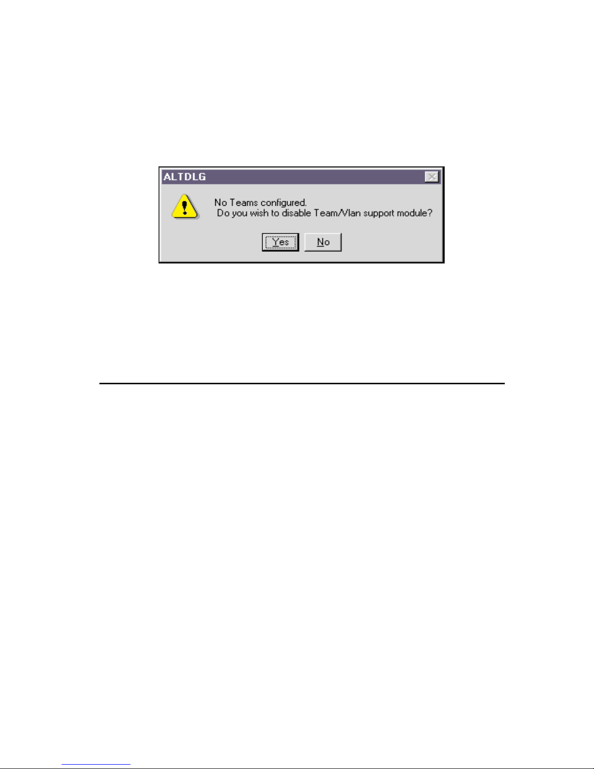
If there are no Failover Teams or VLANs currently configured for the selected
adapter, the following window opens:
If the dialog box shown above is displayed, you must click Yes or No before you can
complete the adapter configuration.
4. In the Network window, click Close.
5. When you are prompted to restart your computer, click Yes.
Your computer will restart, using the new configuration settings.
VLANs
Your Netfinity Gigabit Ethernet Adapter can be configured to support virtual local area
networks (VLANs). This section provides instructions for configuring optional VLANs
for an adapter.
If you do not want to configure your network to include multiple VLANs, you need only
to configure the a dapter to supp ort the de fault conf iguration , as describe d in “Install ing the
device drivers” on page 1-6.
Note: Adapters that are members of a Failov er Team can also be configured to support
VLANs. When configuring VLANs for Failover Team adapters, any adapter or
LAN on motherboard (LOM) that is a member of a team inherits the configuration
of the primary adapter. However, when an adapter or LOM is removed from the
team, its original configuration parameters are used.
With VLANs, you can divide your physical LAN into logical subparts to create logical
segmentation of workgroups and to enforce security policies among each logical segment.
Each defined VLAN behaves as a separate network, with traffic and broadcasts isolated
from the other s , increasing band width efficiency within each logical group. Up to 64
VLANs can be defined for each adapter on your computer, depending on the amount of
memory your computer has available.
User’s guide 1-19
Page 32

Although VLANs are commonly used to crea te individual broadcast domains or separate
IP subnets, it is sometimes useful for a server to have a presence on more than one VLAN
simultaneously . Alteon WebSystems switches and Netfin ity Gigabit E thernet Adapt ers use
VLAN tagging to support multiple VLANs on a per-port or per-interface basis, allowing
very flexible network configurations. VLAN tagging is a format used to identify packets
according to membe r ship in a particular VLAN.
VLAN tagging is only required to be enabled on switch ports that create trunk links to
other Alteon WebSystems switches, or on ports connected to tag-capable end-stations,
such as servers or workstations with Netfinity Gigabit Ethernet Adapters.
Configuring VLANs
By default, Netfinity Gigabit Ethernet Adapters are configured with VLAN support
disabled. Up to 64 VLANs can be defined for each adapter on your se rver, depending on
the amount of memory it has available .
To configure VLANs, you must take the following steps:
• Access the VLAN configuration interface
• Add VLANs to the adapters. This includes assigning a unique identifier and,
optionally, a name to each new VLAN .
• Restart the computer
Note: VLANs are not supported on non-Netfinity Gigabit Ethernet Adapters,
including an Intel stand a lon e LA N on m othe rbo a rd (LOM ). If a no n -Netfi nit y
Gigabit Ethernet Adapter is a member of a Failover T eam, VLANs will not be
supported for that team.
Accessing the VLAN configuration interface
To access the adapter properties for VLAN configuration, do the following:
1. Click Start → Settings → Control Panel.
2. Double-click Network.
3. Click the Adapters tab.
The bus and slot number of the highlighted adapter is listed in the lower part of the
window.
4. Select any Netfinity PCI Gigabit Ethernet Adapter and click Properties.
When an Intel LAN on motherboard (L OM) is installed in your computer, the
following window opens:
1-20 Netfinity® Gigabit Ethernet Adapter User’s guide
Page 33

You can load only one intermediate driver at a time. This means that advanced
options, such as Failover Teaming and VLANs, can be configured for either Netfinity
Gigabit Ethernet Adapters or a standalone LOM, but not both.
If you click Yes in the above dialog box, a LOM can be configured only as a member
of a Failover Team, but not as a member of a VLAN. If you click No, the LOM will
not be used as part of a Failover Team.
Note: VLANs are not supported for LANs on a motherboard (LOM). If a LOM is a
member of a Failover Team, VLANs will not be supported for that team.
5. In the Netfinity Gigabit Ethernet Adapter device driver properties window, click the
VLAN Con figuratio n tab.
• If there are no VLANs or Failover Teams currently configured, the following
window op en s :
Click Yes to continue configuration.
• If you have not co nfigured Failov er Teams, the follow in g w indow opens:
If the above window opens, you need to configure at least one Failover Team
before you can configure VLANs. For more information, see “Failover
Teaming” on page 1-14.
User’s guide 1-21
Page 34

The VLAN Configuration tab lists the installed adapters and the VLANs configured
for each adapter or Failover (Virtual) Team, if any. Each VLAN is identified with a
unique identifier number and an (optional) name that will only be displayed in this
window.
The following items are displaye d in the VLAN Configuration tab:
• Adapter/VLAN list: Below each adapter is a list of the VLANs that have been
configured for that adapter. You can conce al each VLAN list by clicking the
minus box immediately in front on the adapter icon. The box contains a plus
sign (+) when the VLANs are concealed. To reveal the VLAN list when it is
concealed, click the box again.
• Control Buttons: There are three control buttons: Add VLAN, Delete VLAN,
and Properties. These buttons are used for creating and deleting VLANs, and
for modifying the properties of VLANs already created.
Adding a VLAN
You can defin e up to 64 VLANs per adapter. To add a new VLAN, do the following from
the VLAN Configuration tab:
1. In the NICs Available list, select the first adapter that you want to add a VLAN to.
2. The adapter is highlighted when your selection is made.
3. Click the Add VLAN.
4. In the VLAN Properties window, enter a unique number.
You must assi gn a unique identification number to each VLAN you create. Even
though the maximum number of VLANs that can be configured on each adapter is
64, any particular VLAN can be assi gned an identification numb er between 1 and
4094.
The VLAN tagging format follows the guidance provided in IEEE 802.1Q-1999. Be
sure that there are no spaces, blank l ines, or extra characters. The identifier can be
entered in decimal (for example, 383), octal (for example, 0577), or hexadecimal
(e.g. 0x17F) format.
Note: When assigning a number for a VLAN, do not use the de fault VLAN identifie r
used by the adapter or th e switch. Match the VLAN configuration with the
configuration on the switch or server; that is, if you have already identified
VLANs 383 and 777 on the switch or server, the VLAN IDs for the new
adapters must match.
5. (Optional) In the VLAN Properties window, ty pe a name for the VLAN you are
creating.
6. If Jumbo Frames will be sent to or received by the adapter VLAN, click the check
box next to Jumbo Frames.
7. When you are finished adding VLANs to this adapt e r, click OK.
A new VLAN instance is created in the previously selected adapter list.
Note: T o maintain optimum adapter performance, reserve 64MB of memory for each
eight VLANs created per adapter.
8. When you are finished configuring VLANs, click Close to accept the changes.
1-22 Netfinity® Gigabit Ethernet Adapter User’s guide
Page 35

9. In the Network window, click Close.
10. When prompted to restart your computer, click Yes.
Your computer restarts, using the new configuration settings.
Note: If you modify any optional configuration parameters (Failover Team or
VLAN), you must restart your computer before the changes will take effect. If
you make changes and do not restart, you might experience configuration
problems. If no configuration changes have been made, y ou can click No to
close the configuration session withou t restarting your compu ter.
Deleting a VLAN
Adapters that are part of a Failover Team inherit all the basic configuration properties of
the team, including VLANs associated with the team. If you delete a Failover Team, any
VLANs configured for that team are also deleted.
To delete a configured VLAN, do the following from the VLAN Configuration tab:
1. Select the adapter that has the VLAN you want to delete. The adapter is highlighted
when your sele c tio n is mad e .
2. Select the VLAN you want to delete and click Delete VLAN.
The selected VLAN is de leted from the screen.
3. When you are finished configuring VLANs, click Close in the Netfinity Gigabit
Ethernet Adapter Device Driver P r operties window to accept the changes.
If there are no VLANs or Failover T eams currently configured, the following window
opens:
If the window s ho w n ab ove opens, cl ick Yes or No to complete the adapter
configuration.
4. In the Network window, click Close.
5. When you are prompted to restart your computer, click Yes.
Your computer restarts, using the new configuration settings.
Note: If you modify any optional configuration parameters (Failover Team or
VLAN), you must restart your computer before the changes will take effect. If
you make changes and do not restart, you might experience configuration
problems. If no configuration changes have been made, y ou can click No to
close the configuration session withou t restarting your compu ter.
User’s guide 1-23
Page 36

Modifying VLAN properties
To modify the properties of a configured VLAN, do the following from the VLAN
Configuration tab:
1. In the NICs Available list, selec t the adapter that ha s the VLAN you want to modify.
The adapter is highlighted when your selection is made.
2. Click Properties.
In the VLAN Properties window, you can modify one of the following parameters:
• VLAN ID: Y ou must assign a unique identification number to each VLAN you
create. Even though the maximum number of VLANs that can be configured on
each adapter is 64, an y particular VLAN can be assigned an identification
number betwe en 1 and 4094.
The VLAN tagging format follows the guidance provided in IEEE 802.1Q-
1998. Be sure that there are no spaces, blank lines, or extra characters. The
identifier can be entered in decimal (for example, 383), octal (for example,
0577), or hexadecimal (e.g. 0x17F) format.
• VLAN Name: This optional identifier appears only in the Netfinity Gigabit
Ethernet Adapter Device Driver Properties window.
3. When you are finished modifyi ng this VLAN, click OK.
4. Repeat steps 1 to 3 for each VLAN you want to modify.
5. When you are finished configuring VLANs, click Close in the Netfinity Gigabit
Ethernet Adapter Device Driver Properties window to accept the changes.
6. In the Network wind ow, click Close .
7. When you are prompted to restart your compute r, click Yes.
Your computer restarts, usi ng the new configurat ion settings.
Note: If you modify any optional configuration parameters (Failover Team or
VLAN), you must restart your computer before the changes will take ef fect. If
you make changes and do not restart, you might experience c onfiguration
problems. If no configuration changes have been made, you can click No to
close the configuration session without restarting your compute r.
Troubleshooting
This section describes techniqu es for trou bl esh oo tin g yo ur Netf init y Giga bit Ethernet
Adapter and correcting some types of problems.
Internal loopback test (Windows NT)
The Tech Support tab in th e Net fini ty Gigabit Ethernet Ad a pter Dev ic e Driver p rop ertie s
window displays information about how to contact the IBM Hel pCenter and access the
Windows NT-based internal loopback diagnostic te st for the adapter. Use the internal
loopback test to verify that the adapter firmware is configured and operating correctly.
To perform the internal loopback diagnostic test on an adapter, do the following.
1. Click Start → Settings → Control Panel.
2. Double-click Network.
1-24 Netfinity® Gigabit Ethernet Adapter User’s guide
Page 37

3. Click the Adapters tab.
4. Select any Netfinity Gigabit Ethernet Adapter and click Properties.
The Netfinity Gigabit Ethernet Adapter Device Driver properties window opens.
5. If you want to run internal loopback diagnostics on an adapter, select the NIC Status
and Configuration tab; then select the adapter that will be tested.
6. Click the Tech Support tab. This window provides contact information and access to
the internal diagnostic test.
7. To view the Diagnostics widow, click Diagnostics.
8. When the Diagnostics window opens, click Test to run the internal loopback test for
the adapter.
During this test, packet data is sent across the media access control (MAC) chip to
verify that traffic can be sent and received through the adapter. During the test, the
Diagnostics window displays the following messages, indicating that the test is in
progress and the results of the test:
• Diagnostic firmware loaded OK (when running the test for the first time)
• Running diagnostic test
• Test completed OK
• Normal adapter firmware loaded OK
When the test is completed, the result (Passed or Failed) is displayed in the Internal
Loopback Test field.
ALTDIAG internal/external loopback test (MS-DOS)
ALTDIAG, a Microsoft MS-DOS® diagnostic utility, is included on the Netfinity Gigabit
Ethernet Adapter CD. This utility is used for verifying that the adapter hardware is
functional. It performs intern al and external loop back tests and provides resulting pass or
fail information. Perform the ALTDIAG tests any time you want to rule out or identify
possible adapter hardware problems.
To use the ALTDIAG utility, do the following:
1. Start your computer in MS-DOS mode instea d of in Windows NT mode.
Note: ALTD IAG cannot be used from the Windows NT Start menu. To use
ALT D I AG, you must start your co mputer in MS-DOS mode, with no other
plug-ins , add-ons, or resident programs installed.
2. Disconnect the netw ork cables on all adapt ers being tested.
The loopback tests will not perform properly if the adapter is connected to other
devices.
3. Connect a Cat. 5 UTP loopback cable to the adapter’s RJ-45 jack.
A loopback cable can be constr uc te d by conne cting the following pins back to the
single connect or:
• Pin 1 to Pin 3
• Pin 2 to Pin 6
• Pin 4 to Pin 7
• Pin 5 to Pin 8
User’s guide 1-25
Page 38

4. Place Netfinity Gigabit Ethernet Adapter CD into the CD-ROM drive of your
computer.
5. From the MS-DOS prompt, type the following commands to access the proper
directory (where X is the drive letter of your CD-ROM drive):
X:
cd \dosdiags
Note: If you acquired the diagnostic software on a diskette or from the IBM support
Web site, specify the path to where the files are saved on your computer.
6. From the MS-DOS prompt, type the following command to run diagnostics:
dos4gw altdiag [-c card_number] [-l c:log_filename]
If more than one adapter is installed in your computer, the optional -c parameter can
be used for specifying the adapter ca rd to b e tested. Car ds are number ed starting with
0. By default, ALTDIAG tests only the first card (number 0) detected in the
computer.
The optional -l (letter L for “log”) parameter is used for defining a file in which to log
the test results. A text copy of the ALTDIAG test results is placed in the specified file
on the specified drive.
Example: T o te st the second card in a system and sto re the test results in log.txt in the
current directory on the C: drive, the following command could be used:
dos4gw altdiag -c 1 -l c:log.txt
7. Review the test results.
The test result from the previous example might look like this:
Log file created by Development and Diagnostic Test Program v2.3.1
on: Thu Apr 6 10:20:46 2000
-------------------------------------------
Development and Diagnostic Test Program ( ) v2.3.1
PCI bios found. v0.16.
HW Mech #1 supported
Number of PCI buses: 1
IBM #0 found in PCI bus 0.
1 IBM card(s) detected
Current card set to bus 0 IBM #0.
internal Loopback Test
pkts:0 secs:0pkts:32 secs:1pkts:144 secs:2pkts:256
secs:3pkts:352 secs:4pkts:480 secs:5pkts:576 secs:6pkts:704
secs:7pkts:800 secs:8pkts:912 secs:9 1000 packets transmitted
sucessfully
1000 packets received successfully
0 errors detected
1-26 Netfinity® Gigabit Ethernet Adapter User’s guide
Page 39

external Loopback Test
pkts:0 secs:1pkts:208 Secs:2pkts:230 secs:3pkts:432
secs:4pkts544
secs:5pkts:656 secs:6pkts:768 secs:7pkts880 secs:8pkts:992 secs:9
1000 packets transmitted sucessfully
1000 packets received sucessfully
0 errors detected
>
Both the internal and external loopback example tests sh ow 1000 packets successfully
received with 0 errors det ected, indicating that the adapt er hardware is functioning
properly.
If the adapter does not perform as expected, try reinstalling the adapter or moving it to a
different slot or to a different computer; then run the ALTDIAG tests again. If the adapt er
still fails, contact the IBM HelpCenter.
Checking the port LEDs
The faceplate of the Netfinity Gigabit Ethernet Adapter has four LEDs: one for each port
speed option (10Mbps, 100Mbps, and 1Gbps), to indicate which link is active; and one
LED for data transfer status.
Before the port LEDs can provide troubleshooting information, the adapter must be
connected to the network (see “ In sta llin g th e Net finity Gigabit Ether ne t Ad apte r” on pa g e
1-5), and th e n etwo rk de vic e driv ers for your pa rticul ar oper ati ng sys tem must be in sta lled
(see “Installing the device drivers” on page 1-6).
1. Verify that the adapter device driver software has been installed and that the adapter
is connected to a network.
2. Verify that the adapter status LEDs operate as described in the following table.
LED State Descri pti on
Data Bl inking Brief bursts of data are detecte d on the port.
Data On Streams of data are detec te d on the port.
Data Off No data is detected on the port.
1000 On Goo d 1000 Mbps (Gigabit) Ethernet link.
1000 Off N o 10 00 Mbps link: possible link at different speed,
possible bad cable, ba d connector, or configuration
mismatch.
100 O n G ood 100 Mbps Ethernet link.
100 O ff No 100 Mbps link: possible link at different speed,
User’s guide 1-27
possible bad cable, ba d connector, or configuration
mismatch.
Page 40

LED State Description
10 On Good 10 Mbps Ethernet link.
10 Off No 10 Mbps link: possible link at different speed, possible
bad cable, bad connector, or configuration mismatch.
Note: If all four LEDs remain lit simultaneously, the adapter device driver software
is either missing or improperly installed.
Troubleshooting checklist
The following checklist provides recommended actions to take to resolve problems
installing the Netfinity Gigabit Ethernet Adapter or running it in your computer.
• Inspect all cabl es and connections. Verify th at the cable connections at the adap ter
and the switch are attach ed properly. Be sure that the cable lengt h and rating comply
with the requirements listed in “Connecting the network cables” on page 1-6.
• Connect the adapt er to a different network port and run the tests agai n. If the test
results reflect that the adapter is fun ctioning prop erly, the original network port might
be defective or improperly c onfigured.
• Check the adapter installat ion by reviewin g “Installing the Netfinit y Gigabit Etherne t
Adapter” on page 1-5. Be sure that the adapter board is properly seated in a PCI slot.
Check for spe cif ic har dw are p ro blems , su ch a s ob viou s da ma ge to boa rd co m ponen ts
or the PCI edge connector.
• Check the configuration settings and change them if they conflict with another
device.
• Be sure that your computer is using the latest BIOS.
• Try in serting th e adap ter in a nothe r slot. If if it works in the n ew positi on, t he orig inal
slot in your computer might be defective.
• Replace the failed adapter with one that is known to work prop erly. If the second
adapter works in the slot where the first one failed, the original adapter is probably
defective.
• Install the adapter in another functioning computer and run the tests again. If the
adapter passed the tests i n t he new computer, the original computer might be
defective.
• Remove all other adapters from the computer and run the test s again. If the adapter
passes the tests, the other adapters might be causing the problem.
1-28 Netfinity® Gigabit Ethernet Adapter User’s guide
Page 41

Page 42

IBM
Part Number: 19K4621
File Number:
Printed in the United States of America
on recycled paper containing 10&
recovered post-consumer fiber.
19K4621
*0719K4621*
19K4621
0419K4621
 Loading...