

Page 1

IBM Sys te m Sto rage
N6200SeriesHardwareandServiceGuide
CoveringtheN6210,N6220,N6240,N6250,andN6270models
GA32-0838-04
Page 2

Note:
Before using this information and the product it supports, be sure to read the general information in “Notices” on page 109.
The following paragraph does not apply to any country (or region) where such provisions are inconsistent with
local law.
INTERNATIONAL BUSINESS MACHINES CORPORATION PROVIDES THIS PUBLICATION “AS IS” WITHOUT
WARRANTY OF ANY KIND, EITHER EXPRESS OR IMPLIED, INCLUDING, BUT NOT LIMITED TO, THE
IMPLIED WARRANTIES OF MERCHANTABILITY OR FITNESS FOR A PARTICULAR PURPOSE. Some states (or
regions) do not allow disclaimer of express or implied warranties in certain transactions; therefore, this statement
may not apply to you.
Order publications through your IBM representative or the IBM branch office serving your locality.
© Copyright IBM Corporation 2013.
US Government Users Restricted Rights – Use, duplication or disclosure restricted by GSA ADP Schedule Contract
with IBM Corp.
Page 3

Safety notices
This section contains information about:
v “Safety notices and labels”
v “Laser safety” on page vii
v “Rack safety” on page viii
v “Fire suppression systems” on page xi
For information about environmental notices, see the IBM
and User Guide, Z125-5823.
Safety notices and labels
When using this product, observe the danger, caution, and attention notices
contained in this guide. The notices are accompanied by symbols that represent the
severity of the safety condition.
The following sections define each type of safety notice and provide examples.
The following notices and statements are used in IBM documents. They are listed
below in order of increasing severity of potential hazards. Follow the links for
more detailed descriptions and examples of the danger, caution, and attention
notices in the sections that follow.
®
Environmental Notices
“Danger notices”
These statements indicate situations that can be potentially lethal or
extremely hazardous to you. Safety labels are also attached directly to
products to warn of these situations.
“Caution notices” on page vi
These statements indicate situations that can be potentially hazardous to
you.
“Attention notices” on page vi
These notices indicate potential damage to programs, devices, or data.
Notes These notices provide important tips, guidance, or advice.
In addition to these notices, “Labels” on page v may be attached to the product to
warn of potential hazards.
Danger notices
A danger notice calls attention to a situation that is potentially lethal or extremely
hazardous to people. A lightning bolt symbol accompanies a danger notice to
represent a dangerous electrical condition. A sample danger notice follows.
© Copyright IBM Corp. 2013 iii
Page 4

DANGER
An electrical outlet that is not correctly wired could place hazardous
voltage on metal parts of the system or the devices that attach to the
system. It is the responsibility of the customer to ensure that the
outlet is correctly wired and grounded to prevent an electrical shock.
(D004)
A general danger notice provides instructions on how to avoid shock hazards
when servicing equipment. Unless instructed otherwise, follow the procedures in
the following danger notice.
iv IBM System Storage: N6200 Series Hardware and Service Guide
Page 5

DANGER
When working on or around the system, observe the following precautions:
Electrical voltage and current from power, telephone, and communication
cables are hazardous. To avoid a shock hazard:
v Connect power to this unit only with the IBM provided power cord. Do
not use the IBM provided power cord for any other product.
v Do not open or service any power supply assembly.
v Do not connect or disconnect any cables or perform installation,
maintenance, or reconfiguration of this product during an electrical storm.
v The product might be equipped with multiple power cords. To remove all
hazardous voltages, disconnect all power cords.
v Connect all power cords to a properly wired and grounded electrical
outlet. Ensure outlet supplies proper voltage and phase rotation according
to the system rating plate.
v Connect any equipment that will be attached to this product to properly
wired outlets.
v When possible, use one hand only to connect or disconnect signal cables.
v Never turn on any equipment when there is evidence of fire, water, or
structural damage.
v Disconnect the attached power cords, telecommunications systems,
networks, and modems before you open the device covers, unless
instructed otherwise in the installation and configuration procedures.
v Connect and disconnect cables as described below when installing,
moving, or opening covers on this product or attached devices.
To Disconnect:
1. Turn off everything (unless instructed otherwise).
2. Remove power cords from the outlet.
3. Remove signal cables from connectors.
4. Remove all cables from devices.
To Connect:
1. Turn off everything (unless instructed otherwise).
2. Attach all cables to devices.
3. Attach signal cables to the connectors.
4. Attach power cords to the outlets.
5. Turn on the devices.
(D005)
Labels
As an added precaution, safety labels are often installed directly on products or
product components to warn of potential hazards.
The actual product safety labels may differ from these sample safety labels:
Safety notices v
Page 6

DANGER
Hazardous voltage, current, or energy levels are present inside any
component that has this label attached. Do not open any cover or barrier
(L001)
(L003)
that contains this label.
DANGER
Multiple power cords. The product might be equipped with multiple
power cords. To remove all hazardous voltages, disconnect all power
cords.
Caution notices
A caution notice calls attention to a situation that is potentially hazardous to
people because of some existing condition. A caution notice can be accompanied
by different symbols, as in the examples below:
If the symbol is... It means....
A hazardous electrical condition with less severity than electrical
danger.
A generally hazardous condition not represented by other safety
symbols.
A hazardous condition due to the use of a laser in the product.
Laser symbols are always accompanied by the classification of the
laser as defined by the U. S. Department of Health and Human
Services (for example, Class I, Class II, and so forth).
Attention notices
An attention notice indicates the possibility of damage to a program, device, or
system, or to data. An exclamation point symbol may accompany an attention
notice, but is not required. A sample attention notice follows:
Attention: Do not bend a fiber cable to a radius less than 5 cm (2 in.);
you can damage the cable. Tie wraps are not recommended for optical
cables because they can be easily overtightened, causing damage to the
cable.
vi IBM System Storage: N6200 Series Hardware and Service Guide
Page 7
Laser safety
CAUTION:
This product contains a Class 1M laser. Do not view directly with optical
instruments. (C028)
This equipment contains Class 1 laser products, and complies with FDA radiation
Performance Standards, 21 CFR Subchapter J and the international laser safety
standard IEC 825-2.
CAUTION:
Data processing environments can contain equipment transmitting on
system links with laser modules that operate at greater than Class 1 power
levels. For this reason, never look into the end of an optical fiber cable or
open receptacle. (C027)
Attention: In the United States, use only SFP or GBIC optical transceivers that
comply with the FDA radiation performance standards, 21 CFR Subchapter J.
Internationally, use only SFP or GBIC optical transceivers that comply with IEC
standard 825–1. Optical products that do not comply with these standards may
produce light that is hazardous to the eyes.
Usage restrictions
The optical ports of the modules must be terminated with an optical connector or
with a dust plug.
Safety notices vii
Page 8
Rack safety
Rack installation
DANGER
Observe the following precautions when working on or around
your IT rack system:
v Heavy equipment - personal injury or equipment damage might
result if mishandled.
v Always lower the leveling pads on the rack cabinet.
v Always install stabilizer brackets on the rack cabinet.
v To avoid hazardous conditions due to uneven mechanical
loading, always install the heaviest devices in the bottom of the
rack cabinet. Always install servers and optional devices starting
from the bottom of the rack cabinet.
v Rack-mounted devices are not to be used as shelves or work
spaces. Do not place objects on top of rack-mounted devices.
(R001 part 1 of 2)
v Each rack cabinet might have more than one power cord. Be
sure to disconnect all power cords in the rack cabinet when
directed to disconnect power during servicing.
v Connect all devices installed in a rack cabinet to power devices
installed in the same rack cabinet. Do not plug a power cord
from a device installed in one rack cabinet into a power device
installed in a different rack cabinet.
v An electrical outlet that is not correctly wired could place
hazardous voltage on the metal parts of the system or the
devices that attach to the system. It is the responsibility of the
customer to ensure that the outlet is correctly wired and
grounded to prevent an electrical shock.
viii IBM System Storage: N6200 Series Hardware and Service Guide
Page 9

CAUTION:
v Do not install a unit in a rack where the internal rack ambient temperatures
will exceed the manufacturer's recommended ambient temperature for all your
rack-mounted devices.
v Do not install a unit in a rack where the air flow is compromised. Ensure that
air flow is not blocked or reduced on any side, front, or back of a unit used
for air flow through the unit.
v Consideration should be given to the connection of the equipment to the
supply circuit so that overloading of the circuits does not compromise the
supply wiring or overcurrent protection. To provide the correct power
connection to a rack, refer to the rating labels located on the equipment in the
rack to determine the total power requirement of the supply circuit.
v (For sliding drawers.) Do not pull out or install any drawer or feature if the rack
stabilizer brackets are not attached to the rack. Do not pull out more than one
drawer at a time. The rack might become unstable if you pull out more than
one drawer at a time.
v (For fixed drawers) This drawer is a fixed drawer and should not be moved for
servicing unless specified by manufacturer. Attempting to move the drawer
partially or completely out of the rack may cause the rack to become unstable
or cause the drawer to fall out of the rack.
(R001 part 2 of 2)
Safety notices ix
Page 10

Rack relocation (19" rack)
CAUTION:
Removing components from the upper positions in the rack cabinet improves
rack stability during relocation. Follow these general guidelines whenever you
relocate a populated rack cabinet within a room or building:
v Reduce the weight of the rack cabinet by removing equipment starting at the
top of the rack cabinet. When possible, restore the rack cabinet to the
configuration of the rack cabinet as you received it. If this configuration is not
known, you must do the following:
– Remove all devices in the 32U position and above.
– Ensure that the heaviest devices are installed in the bottom of the rack
cabinet.
– Ensure that there are no empty U-levels between devices installed in the
rack cabinet below the 32U level.
– If the rack cabinet you are relocating is part of a suite of rack cabinets,
detach the rack cabinet from the suite.
– Inspect the route that you plan to take when moving the rack to eliminate
potential hazards.
– Verify that the route that you choose can support the weight of the loaded
rack cabinet. Refer to the documentation that came with your rack cabinet
for the weight of a loaded rack cabinet.
– Verify that all door openings are at least 760 x 2030 mm (30 x 80 in.).
– Ensure that all devices, shelves, drawers, doors, and cables are secure.
– Ensure that the four leveling pads are raised to their highest position.
– Ensure that there is no stabilizer bracket installed on the rack cabinet
during movement.
– Do not use a ramp inclined at more than ten degrees.
– Once the rack cabinet is in the new location, do the following:
- Lower the four leveling pads.
- Install stabilizer brackets on the rack cabinet.
- If you removed any devices from the rack cabinet, repopulate the rack
cabinet from the lowest position to the highest position.
– If a long distance relocation is required, restore the rack cabinet to the
configuration of the rack cabinet as you received it. Pack the rack cabinet in
the original packaging material, or equivalent. Also, lower the leveling
pads to raise the casters off of the pallet and bolt the rack cabinet to the
pallet.
(R002)
x IBM System Storage: N6200 Series Hardware and Service Guide
Page 11

Handling fiber-optic cables
Before you use fiber-optic cables, read the following precautions.
Attention: To avoid damage to the fiber-optic cables, follow these guidelines:
v Do not route the cable along a folding cable-management arm.
v When attaching to a device on slide rails, leave enough slack in the cable so that
it does not bend to a radius of less than 38 mm (1.5 in.) when extended or
become pinched when retracted.
v Route the cable away from places where it can be snagged by other devices in
the rack cabinet.
v Do not overtighten the cable straps or bend the cables to a radius of less than 38
mm (1.5 in.).
v Do not put excess weight on the cable at the connection point. Be sure that the
cable is well supported.
CAUTION:
Data processing environments can contain equipment transmitting on system
links with laser modules that operate at greater than Class 1 power levels.
For this reason, never look into the end of an optical fiber cable or open
receptacle.
Fire suppression systems
A fire suppression system is the responsibility of the customer. The customer's own
insurance underwriter, local fire marshal, or a local building inspector, or both,
should be consulted in selecting a fire suppression system that provides the correct
level of coverage and protection.
IBM designs and manufactures equipment to internal and external standards that
require certain environments for reliable operation. Because IBM does not test any
equipment for compatibility with fire suppression systems, IBM does not make
compatibility claims of any kind nor does IBM provide recommendations on fire
suppression systems.
Safety notices xi
Page 12

xii IBM System Storage: N6200 Series Hardware and Service Guide
Page 13

Contents
Safety notices .................................iii
Safety notices and labels ...............................iii
Laser safety ...................................vii
Rack safety ...................................viii
Handling fiber-optic cables ..............................xi
Fire suppression systems ...............................xi
Figures ...................................xvii
Tables ....................................xix
About this document .............................xxi
Who should read this document ............................xxi
Related documents.................................xxi
Supported features ................................xxii
Websites ....................................xxii
Getting information, help, and service ..........................xxii
Before you call ................................xxiii
Using the documentation .............................xxiii
Hardware service and support ...........................xxiii
Firmware updates ...............................xxiii
Terminology and conventions used in this document .....................xxiv
Active/active and high-availability terms ........................xxiv
Storage terms .................................xxiv
Command conventions ..............................xxv
Formatting conventions ..............................xxv
Keyboard conventions ..............................xxvi
How to send your comments .............................xxvi
Preparing for the installation ...........................1
About the N6200 series system .............................1
Required manuals, tools, and equipment ..........................3
Handling static-sensitive devices.............................4
Planning and organizing the installation ..........................4
Hardware specifications ..............................5
Checking shipment package contents ..........................9
Rules for installing the system in a rack .........................10
Guide to the installation process ...........................11
Connecting an N6200 series system .......................13
Connecting your system to a power source .........................13
Connecting your system to an IP network .........................13
Connecting your system to storage ...........................15
Connecting a filer to storage expansion units .......................15
Connecting to SAS storage expansion units .......................15
Connecting to EXN1000 and EXN4000 storage expansion units ................15
Cabling an N6200 series system to Fibre Channel switches using a Fibre Channel expansion adapter . . . 16
Connecting a gateway to external storage ........................18
Connecting to a third-party device...........................19
Rules for connecting the third-party devices ......................19
Connecting your system to an ASCII terminal console .....................19
Configuring an N6200 series system .......................21
Configuring the N6200 series system ...........................21
© Copyright IBM Corp. 2013 xiii
Page 14

Configuring the Fibre Channel port ...........................21
Configuring for initiator mode ............................21
Configuring and using the Service Processor ........................22
Replacing N6200 series system devices .....................23
Replacing a fan module in an N6200 series system ......................26
Removing a fan module ..............................26
Installing a fan module ..............................27
Completing the replacement process ..........................28
Replacing a power supply on an N6200 series system .....................28
Removing a power supply .............................28
Installing a power supply .............................29
Completing the replacement process ..........................30
Replacing an NVMEM battery or NVMEM DIMMs in an N6200 series system .............30
Shutting down the node ..............................30
Shutting down a node in an HA pair .........................30
Shutting down the node in a stand-alone system .....................31
Opening the system ...............................32
Removing an NVMEM battery from an N6200 series system ..................33
Removing the NVMEM DIMM ............................35
Installing the system DIMMs ............................37
Installing an NVMEM battery ............................38
Reinstalling the controller module and booting the system...................38
Checking the status of the NVMEM battery and running diagnostics ...............40
Completing the replacement process ..........................42
Disposing of batteries ..............................42
Replacing a system DIMM in an N6200 series system .....................42
Shutting down the node ..............................43
Shutting down a node in an HA pair .........................43
Shutting down the node in a stand-alone system .....................44
Opening the system ...............................44
Removing the system DIMMs ............................45
Installing the system DIMMs ............................47
Reinstalling the controller module and booting the system...................47
Running diagnostics on the system DIMM ........................48
Completing the replacement process ..........................51
Replacing PCIe cards in an N6200 series system .......................51
Shutting down the node ..............................52
Shutting down a node in an HA pair .........................52
Shutting down the node in a stand-alone system .....................53
Opening the system ...............................54
Removing a PCIe card ...............................54
Installing a PCIe card ...............................55
Reinstalling the controller module and booting the system...................56
Running diagnostics on a PCIe card ..........................57
Completing the replacement process ..........................59
Replacing a boot device in an N6200 series system running Data ONTAP 7.3.5 and later releases in the Data
ONTAP 7.3 release family ..............................59
Shutting down a node ...............................60
Opening the system ...............................60
Removing the boot device from the controller .......................61
Installing the boot device and transferring system files to the boot device .............62
Completing the replacement process ..........................65
Replacing a boot device in an N6200 series system running Data ONTAP 8.x .............65
Replacing a boot device in a system running Data ONTAP 7-Mode ................66
Shutting down a node ..............................66
Opening the system ..............................67
Removing the boot device from the controller ......................67
Installing the boot device in a system running in 7-Mode ..................68
Replacing a boot device in a system running in Clustered Data ONTAP ..............78
Shutting down a node in a high-availability configuration ..................78
xiv IBM System Storage: N6200 Series Hardware and Service Guide
Page 15

Opening the system ..............................78
Removing the boot device from the controller ......................79
Installing the boot device in a system running Clustered Data ONTAP .............80
Completing the replacement process ..........................87
Replacing the I/O expansion module in an N6200 series system..................87
Shutting down the node ..............................87
Shutting down a node in an HA configuration .....................87
Shutting down the node in a stand-alone system .....................88
Removing the I/O expansion module .........................89
Installing the I/O expansion module ..........................90
Running diagnostics on the I/O expansion module .....................91
Completing the replacement process ..........................93
Disposing of batteries ..............................93
Replacing the Real-Time Clock (RTC) battery in an N6200 series system ...............94
Shutting down the node ..............................94
Shutting down a node in an HA pair .........................94
Shutting down the node in a stand-alone system .....................95
Opening the system ...............................96
Removing an RTC battery .............................96
Installing an RTC battery ..............................97
Reinstalling the controller module and booting the system...................98
Running diagnostics on the RTC battery.........................99
Resetting the date and time on the system........................101
Completing the replacement process..........................102
Disposing of batteries .............................102
Recommended power line sizes ........................103
Recommended AC power line sizes ...........................103
FRU/CRU and power cord list for N series products................105
FRU/CRU list for N series products ...........................105
Power cord list for N series products ..........................105
Notices ...................................109
Trademarks ...................................110
Important notes..................................111
Electronic emission notices ..............................111
Federal Communications Commission Statement .....................111
Industry Canada Compliance Statement ........................112
Australia and New Zealand Class A Statement ......................112
European Union Electromagnetic Compatibility Directive...................112
Germany Electromagnetic Compatibility Directive .....................113
People's Republic of China Class A Statement ......................114
Taiwan Class A Statement .............................114
Taiwan Contact Information ............................114
Japan Voluntary Control Council for Interference Class A Statement ...............114
Japan Electronics and Information Technology Industries Association Statement ...........114
Korean Communications Commission Class A Statement ...................115
Russia Electromagnetic Interference Class A Statement....................115
Power cords ...................................115
Index ....................................117
Contents xv
Page 16

xvi IBM System Storage: N6200 Series Hardware and Service Guide
Page 17

Figures
1. N6200 series system - Front view...........................1
2. N6210 2858-C10 and N6220 2858-C15 .........................2
3. N6240 2858-E11, N6270 2858-E12, N6220 2858-E15, and N6250 2858-E16..............2
4. N6210 2858-C20, N6240 2858-C21, N6270 2858-C22, and N6220 2858-C25 .............2
5. N6240 2858-E21, N6270 2858-E22, N6220 2858-E25, and N6250 2858-E26..............3
6. Rear view ..................................13
7. Appliance ports and LEDs ............................14
8. Cabling the N6200 series system to Fibre Channel switches .................17
9. Cabling the N6200 series system expansion adapter to storage expansion units ...........18
10. Cabling the N6200 series system expansion adapter to storage expansion units ...........18
11. N6200 series system components - Front ........................23
12. N6200 series system components - Rear ........................24
13. N6200 series ports and LEDs............................24
14. N6200 series system components - Exploded view ....................25
15. N6200 series system fans .............................27
16. Removing the power supply ............................29
17. NVMEM LED.................................32
18. NVMEM battery location .............................34
19. Removing the NVMEM battery ...........................35
20. DIMM locations ................................36
21. Removing DIMMs ...............................37
22. Installing the NVMEM battery ...........................38
23. NVMEM LED.................................44
24. DIMM locations ................................46
25. Removing DIMMs ...............................47
26. NVMEM LED.................................53
27. Removing the PCI card .............................55
28. Removing the boot device.............................62
29. Removing the boot device.............................68
30. Removing the boot device.............................80
31. NVMEM LED.................................89
32. Remving the IOX module .............................90
33. NVMEM LED.................................96
34. Removing the RTC battery ............................97
© Copyright IBM Corp. 2013 xvii
Page 18

xviii IBM System Storage: N6200 Series Hardware and Service Guide
Page 19

Tables
1. N6200 series physical characteristics..........................5
2. N6200 series clearance dimensions ..........................5
3. N6200 series environmental requirements ........................6
4. N6200 series systems maximum electrical power .....................6
5. N6210 electrical requirements–one controller node, with one 256-GB Flash Cache module ........6
6. N6210 electrical requirements–two controller nodes, with one 256-GB Flash Cache module per node ....7
7. N6220 electrical requirements–one controller node, with one 512-GB Flash Cache or Flash Cache 2 module 7
8. N6220/N6240 electrical requirements–two controller nodes, with one 256-GB Flash Cache module or one
512-GB Flash Cache or Flash Cache 2 module per controller node ................8
9. N6220/N6240 electrical requirements–one controller node, with one 256-GB Flash Cache module or one
512-GB Flash Cache or Flash Cache 2 module, and one I/O expansion module ...........8
10. N6270 electrical requirements–two controller nodes, with one 512-GB or one 1-TB Flash Cache or Flash Cache
2 module per controller node ............................8
11. N6250/N6270 electrical requirements–one controller node, with one 512-GB or one 1-TB Flash Cache or Flash
Cache 2 module, and one I/O expansion module .....................9
12. Filer installation process procedures .........................12
13. Service Processor manuals ............................22
14. 110V, single phase recommended conductor sizes ....................103
15. 220V, single phase recommended conductor sizes ....................103
16. American Wire Gage to Harmonized Cordage equivalents .................103
© Copyright IBM Corp. 2013 xix
Page 20

xx IBM System Storage: N6200 Series Hardware and Service Guide
Page 21

About this document
This guide describes how to connect and manage the following IBM System
Storage®N6200 series systems:
v N6210 (model numbers 2858-C10 and 2858-C20)
v N6220 (model numbers 2858-C15, 2858-C25, 2858-E15, and 2858-E25)
v N6240 (model numbers 2858-C21, 2858-E11, and 2858-E21)
v N6250 (model numbers 2858-E16 and 2858-E26)
v N6270 (model numbers 2858-C22, 2858-E12, and 2858-E22)
Note: Throughout this document, the N6210, N6220, N6240, N6250, and N6270
systems are referred to generically as N6200 series systems, unless information
applies only to a specific system, in which case the specific machine name is used.
Compliance ID 2858-CAR covers MT/models 2858-C10, 2858-C20, 2858-C21,
2858-C15, 2858-C25, 2858-E15, 2858-E25, 2858-E11, 2858-E21, 2858-C22, 2858-E12,
2858-E22, 2858-E16 and 2858-E26.
Note: This guide applies to systems, including systems with gateway functionality,
running Data ONTAP 7.x and Data ONTAP 8.x 7-Mode and Clustered Data
ONTAP. In the Data ONTAP 8.x 7-Mode product name, the term 7-Mode signifies
that the 8.x release has the same features and functionality found in the prior Data
ONTAP 7.1, 7.2, and 7.3 release families.
For the latest version of this document and all IBM System Storage N series
documentation, go to the IBM N series support website, which is accessed and
navigated as described in “Websites” on page xxii.
Who should read this document
This guide is for customer use. It is intended for qualified system administrators
and service personnel who are familiar with IBM storage systems. It addresses
setup, operation, and servicing of the N6200 series system models.
Related documents
The following documents, as well as documentation for Data ONTAP and other
software, are available on the IBM N series support website, which is accessed and
navigated as described in “Websites” on page xxii.
For information about installation and setup for your N6200 series system, see the
N6200 series Installation and Setup Instructions that came with your system.
For information about error messages, troubleshooting, and monitoring the LEDs
for your N6200 series system and optional adapter cards, see the IBM System
Storage N series Platform Monitoring Guide.
For diagnostic information about your N6200 series system, see the IBM System
Storage N series System-Level Diagnostics Guide.
© Copyright IBM Corp. 2013 xxi
Page 22

For a list of N series hardware and hardware-related documents, as well as lists of
Data ONTAP documentation by release family, refer to the "Bibliography"
appendix in the IBM System Storage N series Introduction and Planning Guide.
For a list of optional adapter cards supported by your N6200 series system, refer to
the appropriate "Optional adapter cards" appendix in the IBM System Storage N
series Introduction and Planning Guide.
If you are replacing or installing a Performance Acceleration Module (PAM) or
Flash Cache module, refer to the "Installing or replacing a Flash Cache module or
PAM" appendix in the IBM System Storage N series Introduction and Planning Guide.
Supported features
IBM System Storage N series storage systems are driven by NetApp Data ONTAP
software. Some features described in the product software documentation are
neither offered nor supported by IBM. Please contact your local IBM representative
or reseller for further details.
Information about supported features can also be found on the N series support
website, which is accessed and navigated as described in “Websites.”
Websites
IBM maintains pages on the World Wide Web where you can get the latest
technical information and download device drivers and updates. The following
web pages provide N series information:
v A listing of currently available N series products and features can be found at
the following web page:
www.ibm.com/storage/nas/
v The IBM System Storage N series support website requires users to register in
order to obtain access to N series support content on the web. To understand
how the N series support web content is organized and navigated, and to access
the N series support website, refer to the following publicly accessible web page:
www.ibm.com/storage/support/nseries/
This web page also provides links to AutoSupport information as well as other
important N series product resources.
v IBM System Storage N series products attach to a variety of servers and
operating systems. To determine the latest supported attachments, go to the IBM
N series interoperability matrix at the following web page:
www.ibm.com/systems/storage/network/interophome.html
v For the latest N series hardware product documentation, including planning,
installation and setup, and hardware monitoring, service and diagnostics, see the
IBM N series Information Center at the following web page:
http://publib.boulder.ibm.com/infocenter/nasinfo/nseries/index.jsp
Getting information, help, and service
If you need help, service, or technical assistance or just want more information
about IBM products, you will find a wide variety of sources available from IBM to
assist you. This section contains information about where to go for additional
information about IBM and IBM products, what to do if you experience a problem
with your IBM N series product, and whom to call for service, if it is necessary.
xxii IBM System Storage: N6200 Series Hardware and Service Guide
Page 23

The following applies in Taiwan:
IBM Taiwan Product Service Contact Info:
IBM Taiwan Corporation
3F, No 7, Song Ren Rd., Taipei Taiwan
Tel: 0800-016-888
Before you call
Before you call, make sure you have taken these steps to try to solve the problem
yourself:
v Check all cables to make sure they are connected.
v Check the power switches to make sure the system is turned on.
v Use the troubleshooting information in your system documentation and use the
diagnostic tools that come with your system.
v Refer to the IBM support website for information on known problems and
limitations.
Using the documentation
The latest versions of N series software documentation, including Data ONTAP
and other software products, are available on the IBM N series support website,
which is accessed and navigated as described in “Websites” on page xxii.
Current N series hardware product documentation is shipped with your hardware
product in printed documents or as PDF files on a documentation CD. For the
latest N series hardware product documentation PDFs, go to the IBM N series
support website.
Hardware documentation, including planning, installation and setup, and
hardware monitoring, service, and diagnostics, is also provided in an IBM N series
Information Center at the following web page:
http://publib.boulder.ibm.com/infocenter/nasinfo/nseries/index.jsp
Hardware service and support
You can receive hardware service through IBM Integrated Technology Services.
Visit the following web page for support telephone numbers:
www.ibm.com/planetwide/
Firmware updates
IBM N series product firmware is embedded in Data ONTAP. As with all devices,
it is recommended that you run the latest level of firmware. Any firmware updates
are posted to the IBM N series support website, which is accessed and navigated
as described in “Websites” on page xxii.
Note: If you do not see new firmware updates on the IBM N series support
website, you are running the latest level of firmware.
About this document xxiii
Page 24

Verify that the latest level of firmware is installed on your machine before
contacting IBM for technical support.
Terminology and conventions used in this document
This guide uses the following terminology, command conventions, format
conventions and keyboard conventions.
In this document, the term gateway describes IBM N series storage systems that
have been ordered with gateway functionality. Gateways support various types of
storage, and they are used with third-party disk storage systems. In this case, disk
storage for customer data and the RAID controller functionality is provided by the
back-end disk storage system. A gateway might also be used with disk storage
expansion units specifically designed for the IBM N series models.
The term filer describes IBM N series storage systems that either contain internal
disk storage or attach to disk storage expansion units specifically designed for the
IBM N series storage systems. Filer storage systems do not support using
third-party disk storage systems.
The terms system or storage system refer to either a gateway by itself or a filer,
either by itself or with additional disk drives.
Active/active and high-availability terms
active/active configuration
In the Data ONTAP 7.2 and 7.3 release families, refers to a pair of storage
systems (sometimes called nodes) configured to serve data for each other if
one of the two systems stops functioning. Also sometimes referred to as
active/active pairs.
cluster
In the Data ONTAP 7.1 release family, refers to a pair of storage systems
(sometimes called nodes) configured to serve data for each other if one of
the two systems stops functioning. In Data ONTAP 8.x ,acluster is a group
of connected nodes (storage systems) that share a global namespace and
that you can manage as a single virtual server or multiple virtual servers,
providing performance, reliability, and scalability benefits.
HA (high availability)
In Data ONTAP 8.x, the recovery capability provided by a pair of nodes
(storage systems), called an HA pair, that are configured to serve data for
each other if one of the two nodes stops functioning.
HA pair
In Data ONTAP 8.x, a pair of nodes (storage systems) configured to serve
data for each other if one of the two nodes stops functioning.
Storage terms
ACP Alternate Control Path is a protocol that enables Data ONTAP to manage
and control the storage expansion unit storage subsystem using a separate
network from the data path, so management communication is not
dependent on the data path being intact and available.
AT-FCX
The controller module of the EXN1000 serial advanced technology
attachment (SATA) storage expansion unit.
xxiv IBM System Storage: N6200 Series Hardware and Service Guide
Page 25

Disk Any hard disk drive
Disk shelf or shelf
Any storage expansion unit containing hard disk drives.
ESH The controller module of Fibre Channel disk storage expansion units.
IOM The Input/Output module of SAS disk storage expansion units.
Loop or Fibre-Channel Arbitrated Loop
One or more daisy-chained Fibre Channel storage expansion units
connected to an N series storage system.
Node The system controller module that executes the software on an N series
system. There is one node in single-controller models; there are two nodes
in active/active or high availability models.
Stack or SAS stack
A stack of one or more SAS storage expansion units using IOM modules
connected to the storage system. The maximum number of storage
expansion units in a stack of storage expansion units and the number of
storage expansion unit stacks in a configuration are dependent on the type
of storage system.
Command conventions
You can enter commands on the system console or from any client that can obtain
access to the storage system using a Telnet session. In examples that illustrate
commands executed on a UNIX workstation, the command syntax and output
might differ, depending on your version of UNIX.
Formatting conventions
The following table lists different character formats used in this guide to set off
special information.
Formatting convention Type of information
Italic type
Monospaced font
Bold monospaced font Words or characters you type. What you
v Words or characters that require special
attention.
v Placeholders for information you must
supply. For example, if the guide requires
you to enter the fctest adaptername
command, you enter the characters fctest
followed by the actual name of the
adapter.
v Book titles in cross-references.
v Command and daemon names.
v Information displayed on the system
console or other computer monitors.
v The contents of files.
type is always shown in lowercase letters,
unless your program is case-sensitive and
uppercase letters are necessary for it to work
properly.
About this document xxv
Page 26

Keyboard conventions
This guide uses capitalization and some abbreviations to refer to the keys on the
keyboard. The keys on your keyboard might not be labeled exactly as they are in
this guide.
What is in this guide... What it means...
hyphen (-) Used to separate individual keys. For
Enter Used to refer to the key that generates a
type Used to mean pressing one or more keys on
enter Used to mean pressing one or more keys
How to send your comments
Your feedback is important in helping us provide the most accurate and
high-quality information. If you have comments or suggestions for improving this
document, send us your comments by email to starpubs@us.ibm.com.
example, Ctrl-D means holding down the
Ctrl key while pressing the D key.
carriage return, although the key is named
Return on some keyboards.
the keyboard.
and then pressing the Enter key.
Be sure to include the following information:
v Exact publication title
v Publication form number (for example, GC26-1234-02)
v Page, table, or illustration numbers
v A detailed description of any information that should be changed
xxvi IBM System Storage: N6200 Series Hardware and Service Guide
Page 27
Preparing for the installation
This chapter provides an overview of the entire IBM System Storage N6200 series
system installation process, hardware specifications, and the appropriate
documentation references for the procedures.
Refer to the Installation and Setup Instructions that came with your system for
further information about installing your equipment.
This chapter discusses the following topics:
v “About the N6200 series system”
v “Required manuals, tools, and equipment” on page 3
v “Handling static-sensitive devices” on page 4
v “Planning and organizing the installation” on page 4
About the N6200 series system
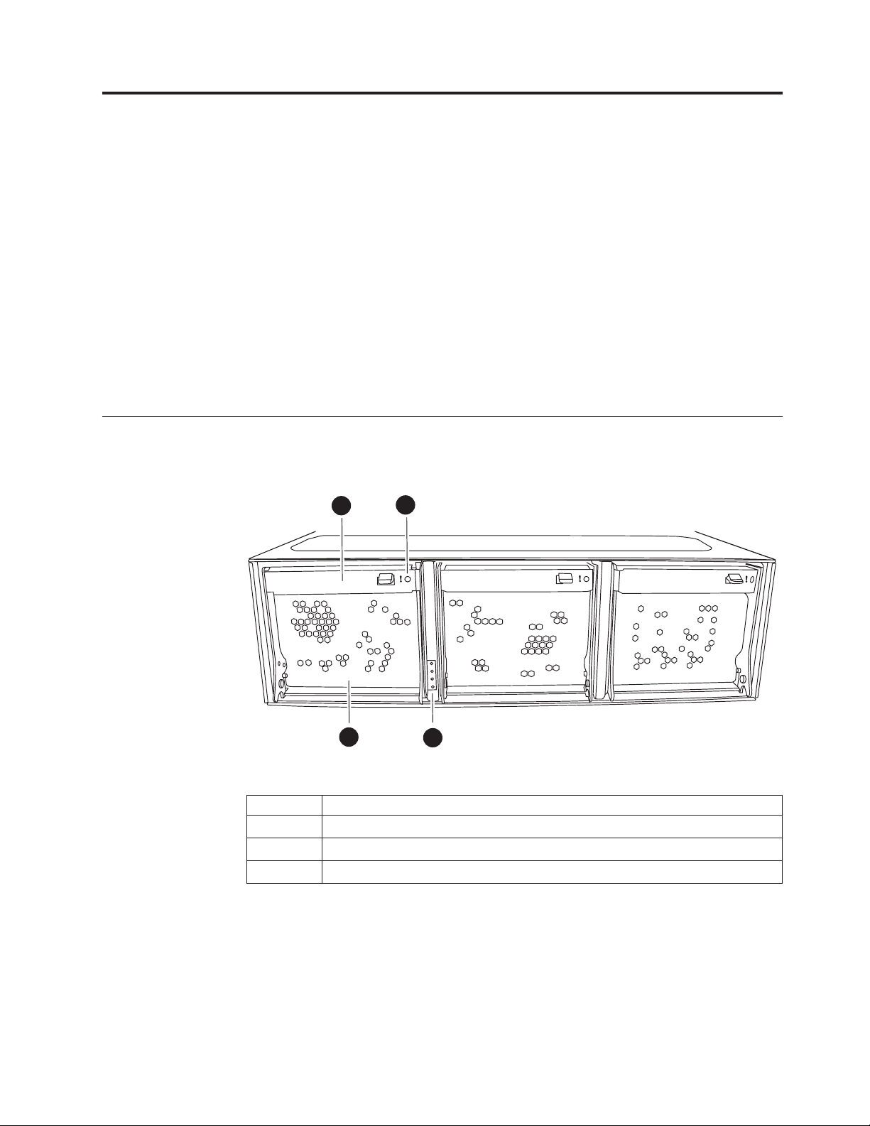
Figure 1 shows the front view of the N6200 series system.
3
1
Figure 1. N6200 series system - Front view
1 Fan module
2 System LEDs - power fault, controller A activity, controller B activity
3 Fan CAM handle
4 Fan LED
4
2
n62hw02
The following images show the available models of the N6200 series systems.
N6210 2858-C10 and N6220 2858-C15 are single-enclosure, non-HA system with a
single controller. They do not contain an Input/Output expansion module.
© Copyright IBM Corp. 2013 1
Page 28

c0a e0a
c0b
0c
0d
e0b
IOIOI
PSUPSU
0a 0b
Figure 2. N6210 2858-C10 and N6220 2858-C15
The N6240 2858-E11, N6270 2858-E12, N6220 2858-E15, and N6250 2858-E16 are
single-enclosure, non-HA systems with a single controller and one Input/Output
expansion module (IOXM).
c0a e0a
c0b
0c
0d
e0b
IOXM
1
2
IOIOI
PSU
3
4
0a 0b
PSU
n62hw08
n62hw05
Figure 3. N6240 2858-E11, N6270 2858-E12, N6220 2858-E15, and N6250 2858-E16
The N6210 2858-C20, N6240 2858-C21, N6270 2858-C22, and N6220 2858-C25 are
single-enclosure HA systems with two controllers. They do not contain an
Input/Output expansion module.
c0a e0a
0a 0b
0a 0b
0c
c0b
0d
e0b
FC GbE
c0a e0a
0c
c0b
0d
e0b
IOIOI
IOIOI
PSUPSU
Figure 4. N6210 2858-C20, N6240 2858-C21, N6270 2858-C22, and N6220 2858-C25
The N6240 2858-E21, N6270 2858-E22, N6220 2858-E25, and N6250 2858-E26 are
dual-enclosure HA systems. Each enclosure contains one controller and one
Input/Output expansion module.
n62hw06
2 IBM System Storage: N6200 Series Hardware and Service Guide
Page 29

c0a e0a
c0b
0c
0d
e0b
0a 0b
PSU
c0a e0a
c0b
0c
0d
e0b
0a 0b
PSU
Figure 5. N6240 2858-E21, N6270 2858-E22, N6220 2858-E25, and N6250 2858-E26
Required manuals, tools, and equipment
IOXM
1
2
IOXM
1
2
IOIOI
PSU
3
4
IOIOI
PSU
3
4
n62hw07
You need the following manuals in addition to this manual. Data ONTAP
publications are available on the IBM N series support website, which is accessed
and navigated as described in “Websites” on page xxii.
v Installation and Setup Instructions for your IBM N series system and storage
expansion units
v Data ONTAP Software Setup Guide for your version of Data ONTAP
Attention: Before you begin your installation, print and complete a
configuration worksheet for your storage system to gather the information that
the software setup process requires. The configuration worksheet is provided in
the Data ONTAP Software Setup Guide for your version of Data ONTAP.
v Data ONTAP Active/Active Configuration Guide or Data ONTAP High Availability
Configuration Guide for your version of Data ONTAP, if applicable
You need to supply the following tools and equipment:
v Ethernet LAN cables
v Fibre Channel cables
v Console (for example, a PC or notebook) with a serial port
v #2 Phillips screwdriver and slotted screwdriver
v Grounding leash and ESD strap
v 7-mm nut driver (required if removing or installing storage expansion units)
RJ-45 to DB-9 console adapter cables and serial null modem cables are provided by
IBM with your shipment package.
Preparing for the installation 3
Page 30

Handling static-sensitive devices
CAUTION:
This system uses electronic components that are sensitive to static electricity.
Static discharge from your clothing or other fixtures around you can damage
these components. Put on an antistatic ESD strap and grounding leash to free
yourself of static electricity before touching any electronic components.
Attention: Static electricity can damage electronic devices and your system. To
avoid damage, keep static-sensitive devices in their static-protective packages until
you are ready to install them.
To reduce the possibility of electrostatic discharge (ESD), observe the following
precautions:
v Limit your movement. Movement can cause static electricity to build up around
you.
v Handle the device carefully, holding it by its edges or its frame.
v Do not touch solder joints, pins, or exposed printed circuitry.
v Do not leave the device where others can handle and possibly damage the
device.
v While the device is still in its static-protective package, touch it to an unpainted
metal part of the system unit for at least two seconds. This drains static
electricity from the package and from your body.
v Remove the device from its package and install it directly into your system unit
without setting it down. If it is necessary to set the device down, place it in its
static-protective package. Do not place the device on your system unit cover or
on a metal table. Take additional care when handling devices during cold
weather because heating reduces indoor humidity and increases static electricity.
Planning and organizing the installation
This section identifies the shipment contents and the rules and regulations you
need to observe for the proper installation of your system. It also provides an
overview of the entire system installation process and the appropriate
documentation references for the procedures.
For detailed information, see the following topics:
v “Hardware specifications” on page 5
v “Checking shipment package contents” on page 9
v “Rules for installing the system in a rack” on page 10
v “Guide to the installation process” on page 11
Telecommunication regulatory statement
This product may not be certified in your country for connection by any means
whatsoever to interfaces of public telecommunications networks. Further
certification may be required by law prior to making any such connection. Contact
an IBM representative or reseller for any questions.
4 IBM System Storage: N6200 Series Hardware and Service Guide
Page 31

Hardware specifications
The following tables list the characteristics and requirements for your hardware.
30.9-36.4 kg (68-80 lbs)
n6200021
DANGER
The weight of this part or unit is between 30.9 and 36.4 kg (68 and 80 lb). It
takes three persons to safely lift this part or unit.
Note: Operating at the extremes of the environmental requirements might increase
the risk of device failure.
Table 1. N6200 series physical characteristics
Weight
v 2858-C10 and 2858-C15 (single enclosure with one
controller): 30.9 kg (68 lb)
v 2858-C20, 2858-C21, and and 2858-C25 (single
enclosure with two controllers): 36.4 kg (80 lb)
v 2858-C22 (single enclosure with two controllers):
33.7 kg (74.3 lb)
v 2858-E12 (single enclosure with one controller and
one IOXM): 33.7 kg (74.3 lb)
v 2858-E11, 2858-E15, and 2858-E16 (single enclosure
with one controller and one IOXM): 33.6 kg (74 lb)
v 2858-E21, 2858-E25, and 2858-E26 (two enclosures,
each with one controller and one IOXM): 67.2 kg
(148 lb)
v 2858-E22 (two enclosures, each with one controller
and one IOXM): 67.4 kg (148.6 lb)
Rack units
Height
Width
Depth
Table 2. N6200 series clearance dimensions
Airflow
Front 25.4 cm (10 in.)
Rear 30.5 cm (12 in.)
v 3U for single enclosure models
v 6U for dual enclosure models
v 13 cm (5.12 in.) for single enclosure models
v 26 cm (10.24 in.) for dual enclosure models
44.7 cm (17.6 in.)
61 cm (24 in.) without bezel65.5 cm (25.8 in.) with
bezel
Preparing for the installation 5
Page 32

Table 2. N6200 series clearance dimensions (continued)
Service
Front 76.2 cm (30 in.)
Rear 76.2 cm (30 in.)
Table 3. N6200 series environmental requirements
Operating temperature maximum range
Operating temperature recommended range
Nonoperating temperature range
Operating relative humidity
Nonoperating relative humidity
Recommended operating temperature relative humidity
range
Maximum wet bulb temperature
Maximum altitude
Acoustic level
50° F to 104° F (10° C to 40° C)
68° F to 77° F (20° C to 25° C)
-40° F to 158° F (-40° C to 70° C)
20 to 80% noncondensing
10 to 95% noncondensing (in
original container)
40 to 55%
28° C (82° F)
3050 m (10,000 ft.)
55.5 dBA, 7.5 bels at 23° C
The following tables list the maximum electrical power for the N6200 series
systems and the electrical requirements for different configurations of the N6200
series systems.
Table 4. N6200 series systems maximum electrical power
System Maximum electrical power
N6200 series systems 100-240 V ac, 12-8 A, 50-60 Hz.
In the following tables, Worst-case indicates a system running with one PSU and
high fan speed. Typical Per PSU/System, two PSUs indicates a system running one
PSU on one circuit and a system running two PSUs on two circuits.
Note: Electrical requirements for systems containing performance accelerator, Flash
Cache, and Flash Cache 2 modules are measured with the maximum number of
these modules installed in the system. The maximum power draw is 25W.
Table 5. N6210 electrical requirements–one controller node, with one 256-GB Flash Cache
module
100 to 120V 200 to 240V
Input voltage
Input current
measured, A
Worstcase,
single
PSU
4.22 1.52 3.03 2.11 0.83 1.66
Per PSU
Typical
System,
two PSUs Per PSU
Worstcase,
single
PSU
Typical
System,
two PSUs
6 IBM System Storage: N6200 Series Hardware and Service Guide
Page 33

Table 5. N6210 electrical requirements–one controller node, with one 256-GB Flash Cache
module (continued)
100 to 120V 200 to 240V
Input voltage
Input power
Worstcase,
single
PSU
Per PSU
Typical
System,
two PSUs Per PSU
421 150 299 411 147 293
Worstcase,
single
PSU
Typical
System,
two PSUs
measured, W
Thermal
1,437 511 1,021 1,403 500 1,000
dissipation,
BTU/hr
Input power
50 to 60
frequency, Hz
Table 6. N6210 electrical requirements–two controller nodes, with one 256-GB Flash Cache
module per node
100 to 120V 200 to 240V
Input voltage
Input current
Worst-
case,
single
PSU
Per PSU
Typical
System,
two PSUs Per PSU
6.27 2.32 4.64 3.11 1.19 2.38
Worstcase,
single
PSU
Typical
System,
two PSUs
measured, A
Input power
626 231 462 612 225 450
measured, W
Thermal
2,137 789 1,577 2089 768 1,536
dissipation,
BTU/hr
Input power
50 to 60
frequency, Hz
Table 7. N6220 electrical requirements–one controller node, with one 512-GB Flash Cache
or Flash Cache 2 module
100 to 120V 200 to 240V
Input voltage
Input current
Worst-
case,
single
PSU
Per PSU
Typical
System,
two PSUs Per PSU
4.31 1.55 3.09 2.41 0.87 1.73
Worstcase,
single
PSU
Typical
System,
two PSUs
measured, A
Input power
431 155 309 421 152 303
measured, W
Thermal
1,437 511 1,021 1,403 500 1,000
dissipation,
BTU/hr
Input power
50 to 60
frequency, Hz
Preparing for the installation 7
Page 34

Table 8. N6220/N6240 electrical requirements–two controller nodes, with one 256-GB Flash
Cache module or one 512-GB Flash Cache or Flash Cache 2 module per controller node
100 to 120V 200 to 240V
Input voltage
Input current
measured, A
Input power
measured, W
Thermal
dissipation,
BTU/hr
Input power
frequency, Hz
Worstcase,
single
PSU
6.37 2.35 4.70 3.15 1.21 2.41
635 233 466 620 228 456
2,168 796 1,591 2,116 779 1,557
50 to 60
Per PSU
Typical
System,
two PSUs Per PSU
Worstcase,
single
PSU
Typical
System,
two PSUs
Note: N6220 does not support the 256-GB Flash Cache module.
Table 9. N6220/N6240 electrical requirements–one controller node, with one 256-GB Flash
Cache module or one 512-GB Flash Cache or Flash Cache 2 module, and one I/O
expansion module
100 to 120V 200 to 240V
Input voltage
Input current
measured, A
Input power
measured, W
Thermal
dissipation,
BTU/hr
Input power
frequency, Hz
Worstcase,
single
PSU
5.01 1.86 3.71 2.50 0.98 1.96
500 184 368 478 180 360
1,707 628 1,256 1,632 615 1,229
50 to 60
Per PSU
Typical
System,
two PSUs Per PSU
Worstcase,
single
PSU
Typical
System,
two PSUs
Note: N6220 does not support the 256-GB Flash Cache module.
Table 10. N6270 electrical requirements–two controller nodes, with one 512-GB or one 1-TB
Flash Cache or Flash Cache 2 module per controller node
100 to 120V 200 to 240V
Worstcase,
single
Input voltage
Input current
measured, A
Input power
measured, W
PSU
7.28 2.78 5.56 3.58 1.42 2.83
728 278 552 707 271 541
Per PSU
8 IBM System Storage: N6200 Series Hardware and Service Guide
Typical
System,
two PSUs Per PSU
Worstcase,
single
PSU
Typical
System,
two PSUs
Page 35

Table 10. N6270 electrical requirements–two controller nodes, with one 512-GB or one 1-TB
Flash Cache or Flash Cache 2 module per controller node (continued)
100 to 120V 200 to 240V
Worst-
case,
single
Input voltage
Thermal
dissipation,
BTU/hr
Input power
frequency, Hz
Table 11. N6250/N6270 electrical requirements–one controller node, with one 512-GB or
one 1-TB Flash Cache or Flash Cache 2 module, and one I/O expansion module
Input voltage
Input current
measured, A
Input power
measured, W
Thermal
dissipation,
BTU/hr
Input power
frequency, Hz
PSU
2,485 942 1,884 2,413 924 1,847
50 to 60
100 to 120V 200 to 240V
Worst-
case,
single
PSU
5.47 2.07 4.14 2.73 1.07 2.13
547 204 408 533 199 398
1,867 697 1,393 1,820 680 1,359
50 to 60
Per PSU
Per PSU
Typical
System,
two PSUs Per PSU
Typical
System,
two PSUs Per PSU
Worstcase,
single
PSU
Worstcase,
single
PSU
Typical
System,
two PSUs
Typical
System,
two PSUs
Checking shipment package contents
Make sure that your shipment package includes the following items for your
N6200 series model.
Each shipment package will also contain envelopes with the software EULA and
license keys.
v N6210 2858-C10 and N6220 2858-C15
– 1 single-enclosure, non-HA system with a single controller, containing any
options you ordered
– 1 console adapter cable, RJ-45 to DB-9
– 2 cable management arms (two per controller node)
– 1 ESD wrist strap
– 2 power cords
– 1 serial null modem cable
– 1 IBM rail kit
– 1 set of IBM publications
v N6240 2858-E11, N6220 2858-E15, N6250 2858-E16, and N6270 2858-E12
– 1 single-enclosure, non-HA system with a single controller and one
Input/Output expansion module (IOXM), containing any options you ordered
Preparing for the installation 9
Page 36

– 1 console adapter cable, RJ-45 to DB-9
– 4 cable management arms (two per controller node, and two per IOXM)
– 1 ESD wrist strap
– 2 power cords
– 1 serial null modem cable
– 1 IBM rail kit
– 1 set of IBM publications
v N6210 2858-C20, N6240 2858-C21, N6220 2858-C25, and N6270 2858-C22
– 1 single-enclosure HA system with two controllers, containing any options
you ordered
– 2 console adapter cables, RJ-45 to DB-9
– 4 cable management arms (two per controller node)
– 1 ESD wrist strap
– 2 power cords
– 2 serial null modem cables
– 1 IBM rail kit
– 1 set of IBM publications
v N6240 2858-E21, N6220 2858-E25, N6250 2858-E26, and N6270 2858-E22:
– 1 dual-enclosure HA system, containing any options you ordered. Each
enclosure ships in a separate container, and each enclosure contains one
controller and one Input/Output expansion module.
– 2 console adapter cables, RJ-45 to DB-9 (1 per enclosure)
– 8 cable management arms (two per controller node, and two per IOXM, for a
total of 4 per enclosure)
– 2 ESD wrist straps (1 per enclosure)
– 4 power cords (2 per enclosure)
– 2 serial null modem cables (1 per enclosure)
– 2 cluster connection cables (either SFP+ integrated copper cables or 10GbE
SFP+ transceivers with fiber cables, depending on your order)
– 2 IBM rail kits (1 per enclosure)
– 1 set of IBM publications
Rules for installing the system in a rack
Attention: The rack installation instructions provided in this document and in the
Installation and Setup Instructions for your N series product apply specifically to the
installation of the N series product in an IBM 19-inch rack. IBM service personnel
cannot install the N series product in a non-IBM rack.
If the N series product is being installed in a non-IBM rack, the rails shipped with
the N series product may or may not work with the non-IBM rack. Physical
installation of the N series product in a non-IBM rack is the customer's
responsibility.
You need to observe the following rules and restrictions when installing an N6200
series system in a standard IBM 19-inch (48.26 cm) equipment rack with mounting
rails:
10 IBM System Storage: N6200 Series Hardware and Service Guide
Page 37

30.9-36.4 kg (68-80 lbs)
n6200021
DANGER
The weight of this part or unit is between 30.9 and 36.4 kg (68 and 80 lb). It
takes three persons to safely lift this part or unit.
v Install the system at the bottom of your configuration, so that stacks or loops
extend above your system.
DANGER
To avoid hazardous conditions due to uneven mechanical loading, always
install the heaviest devices in the bottom of the rack cabinet. Always install
servers and optional devices starting from the bottom of the rack cabinet.
(R001 part 1 of 2)
v When installing storage expansion units in a rack, do not exceed the maximum
storage limit for your system.
v Make sure that the ID on the back panel of each storage expansion unit matches
the ID specified on its label.
v Always install the storage expansion units fully loaded. Do not remove disk
drives to reduce the weight.
Guide to the installation process
The following table provides a guide to the filer installation process.
Attention: Before you begin your installation, print and complete a configuration
worksheet for your storage system to gather the information that the software
setup process requires. The configuration worksheet is provided in the Data
ONTAP Software Setup Guide for your version of Data ONTAP. This guide, as well
as other Data ONTAP publications, is available on the IBM N series support
website, which is accessed and navigated as described in “Websites” on page xxii.
If you are configuring a storage system as part of a high-availability (or
active/active) configuration, some information types must be unique for each
storage system mode in the configuration, and some information types must be
identical on both storage system nodes. If you have a high-availability (or
active/active) configuration, IBM recommends that you print and complete two
copies of the configuration worksheet, one for each system node.
Refer to the Installation and Setup Instructions that shipped with your system and
storage expansion units for complete installation details.
Note: The initial hardware installation of an N6200 series gateway is performed by
IBM. Additional installation services can be performed by IBM through an IBM
services offering. Contact your IBM representative for more information.
Preparing for the installation 11
Page 38

Table 12. Filer installation process procedures
Is the procedure
Stage Procedure
1 Print and complete
a configuration
worksheet for each
system node of
your storage
system to gather
the information
that the software
setup process
requires.
2 Install the system
in a standard IBM
19-inch rack.
3 Connect the system
to the IP (Internet
Protocol) network.
Filer: Connect the
storage system to
storage expansion
units.
4 Gateway: Connect
the system to the
back-end storage.
5 Connect the system
to a power source.
6 Configure the
system.
7 Connect the system
to a third-party
device.
required?
Yes Customer Customer The configuration worksheet
Yes Customer IBM The Installation and Setup
Yes Customer Customer “Connecting your system to
Yes Customer n/a “Connecting a filer to storage
Yes n/a Customer Refer to the documentation
Yes Customer Customer “Connecting your system to
Yes Customer Customer The Data ONTAP Software
No Customer Customer “Connecting your system to
Procedure is performed by...
For instructions, see...Filer Gateway
is provided in the Data
ONTAP Software Setup Guide
for your version of Data
ONTAP.
Instructions for your system
an IP network” on page 13,
or the Installation and Setup
Instructions that came with
your system
expansion units” on page 15,
or the Installation and Setup
Instructions that came with
your system
for your external storage for
additional information.
a power source” on page 13,
or the Installation and Setup
Instructions that came with
your system
Setup Guide for your version
of Data ONTAP, or the
Installation and Setup
Instructions that came with
your system
storage” on page 15
12 IBM System Storage: N6200 Series Hardware and Service Guide
Page 39

Connecting an N6200 series system
This chapter describes how to connect an N6200 series system in the following
topics:
v “Connecting your system to a power source”
v “Connecting your system to an IP network”
v “Connecting your system to storage” on page 15
v “Connecting your system to an ASCII terminal console” on page 19
Connecting your system to a power source
The N6200 series systems are shipped with redundant power supplies, referred to
as PSU1 and PSU2. Each power supply has its own AC power cord. You should
have separate circuit breakers for each power supply to ensure power redundancy.
For information on connecting your N6200 series system to a power source, see the
Installation and Setup Instructions that came with your system.
3
Figure 6. Rear view
1 Controller module
2 I/O expansion module
3 PSUs
Connecting your system to an IP network
Each node of your system connects to an IP network. If you have an active/active
or high availability system, both nodes need to connect to the network. For
information that describes how to connect your system, refer to the Installation and
Setup Instructions that came with your system.
The N6200 series system has two onboard Ethernet ports per controller node,
labeled e0a and e0b, as shown in Figure 7 on page 14. For the 2858-C10, 2858-C15,
2858-C20, 2858-C21, 2858-C22, and 2858-C25 up to two Network Interface Cards
(NICs) per node can be plugged into the PCI slots to provide additional Ethernet
ports. For the 2858-E11, 2858-E12, 2858-E15, 2858-E16, 2858-E21, 2858-E22, 2858-E25,
n62hw01
12
© Copyright IBM Corp. 2013 13
Page 40

and 2858-E26, up to six Network Interface Cards (NICs) per node can be plugged
into the PCI slots to provide additional Ethernet ports.
The integrated Ethernet RJ-45 twisted-pair connectors are compatible with the IEEE
802.3 Ethernet network 10/100/1000 BASE-TX link. When connecting to the
Ethernet port, connect a twisted-pair (CAT-5 or better) cable to the RJ-45 Ethernet
port located on the back of the system drawer.
If you are connecting to a copper NIC, use RJ-45 CAT-5 or better copper cables.
If you are connecting to a fiber NIC, use (50- or 62.5-micron) fiber-optic cables with
LC connectors.
For information about monitoring the Ethernet port LEDs, see the IBM System
Storage N Series Platform Monitoring Guide.
13
0a
LNK LNK
0b
12
11
c0b
c0a
0c
0d
e0a
e0b
6810
Figure 7. Appliance ports and LEDs
1 NVMEM LED
2 Controller fault LED
3 USB (top) and serial console (bottom) ports
4 Private management 10/100 Mb Ethernet port
5 Management Ethernet 10/100 Mb port and LEDs
6 1-GbE ports (e0a and e0b)
7 1-GbE port LEDs
8 Fibre Channel ports (0c and 0d)
9 Fibre Channel port LEDs
10 HA ports (c0a and c0b)
11 HA port LEDs
12 SAS ports
13 SAS port LEDs
579
!
234
1
n62hw03
14 IBM System Storage: N6200 Series Hardware and Service Guide
Page 41

Connecting your system to storage
For SAS connections, the N6200 series system has two onboard SAS ports per
node, labeled 0a and 0b, as shown in Figure 7 on page 14. For the 2858-C10,
2858-C15, 2858-C20, 2858-C21, 2858-C22, and 2858-C25,up to two SAS HBAs per
node can be plugged into the PCI slots to provide additional SAS ports. For the
2858-E11, 2858-E12, 2858-E15, 2858-E21, 2858-E22, and 2858-E25, up to six SAS
HBAs per node can be plugged into the PCI slots to provide additional SAS ports.
For Fibre Channel connections, the N6200 series system has two onboard Fibre
Channel ports per node, labeled 0c and 0d, as shown in Figure 7 on page 14. For
the 2858-C10, 2858-C15, 2858-C20, 2858-C21, 2858-C22, and 2858-C25, up to two
HBAs per node can be plugged into the PCI slots to provide additional Fibre
Channel ports. For the 2858-E11, 2858-E12, 2858-E15, 2858-E21, 2858-E22, and
2858-E25, up to six HBAs per node can be plugged into the PCI slots to provide
additional Fibre Channel ports. Attach the (50- or 62.5-micron) fiber-optic cables
with LC connectors to the Fibre Channel ports.
Note: SFPs must be firmly seated in the Fibre Channel ports before making
connections.
Connecting a filer to storage expansion units
You must connect at least one storage expansion unit per controller module to
your N6200 series filer. A single-controller filer (C10/C15/E11/E12/E15/E16) must
be connected to at least one storage expansion unit. A dual-controller (active/active
or high availability) filer (C20/C21/C22/C25/E21/E22/E25//E26) must be
connected to at least two storage expansion units.
Connecting to SAS storage expansion units
You must use SAS and ACP cables for the connections from the filer to SAS
storage expansion units
For information that describes how to connect your N6200 series filer to SAS
storage expansion units using the onboard SAS ports, see the Installation and Setup
Instructions that came with your system.
For detailed information about cabling SAS storage expansion units, see the IBM
System Storage N series Universal SAS and ACP Cabling Guide.
Connecting to EXN1000 and EXN4000 storage expansion units
For connections to EXN1000s and EXN4000s, you must use fiber-optic cables for
the connection from the filer to the first storage expansion unit.
For information that describes how to connect your filer using the onboard Fibre
Channel ports to storage expansion units, see the Installation and Setup Instructions
that came with your storage expansion units.
Attention: If you are connecting to EXN1000 and EXN4000 storage expansion
units, make sure that all storage expansion unit (1Gb/2Gb/4Gb) switches are set to
the 2Gb or 4Gb (if supported) position. If necessary, refer to the documents that
came with the storage expansion unit for information about checking and changing
the switch setting.
Connecting an N6200 series system 15
Page 42

Attention: If you are using optional Fibre Channel adapter cards instead of the
onboard Fibre Channel ports to connect your N6200 series filer to storage
expansion units, see the cabling instructions described in “Cabling an N6200 series
system to Fibre Channel switches using a Fibre Channel expansion adapter.”
Dual-path Fibre Channel cabling is supported for N6200 series filers. Dual-path
Fibre Channel cabling is designed to improve reliability, availability and
serviceability of the storage expansion units attached to the storage controller by
creating two redundant paths from each storage controller to each loop of the
storage expansion units. For more information about using dual-path Fibre
Channel cabling, see the Installation and Setup Instructions that came with your
system.
Important: If you are not using the onboard Fibre Channel ports for storage, then
you must set your onboard ports to Target mode, as described in the IBM System
Storage N series Data ONTAP Block Access Management Guide for your version of
Data ONTAP. This guide, as well as other Data ONTAP publications, is available
on the IBM N series support website, which is accessed and navigated as described
in “Websites” on page xxii.
Cabling an N6200 series system to Fibre Channel switches using a Fibre Channel expansion adapter
About this task
This section describes how to cable an N6200 series system to Fibre Channel
switches using a dual-port optical Fibre Channel expansion adapter for expansion
unit storage. The example shown in this section illustrates the connections for a
single-enclosure HA pair, such as the N6210 2858-C20, N6240 2858-C21, N6270
2858-C22, or N6220 2858-C25.
For a list of optional adapter cards supported by your N6200 series system, refer to
the appropriate "Optional adapter cards" appendix in the IBM System Storage N
series Introduction and Planning Guide. This guide, as well as other N series and
Data ONTAP documentation, is available on the IBM N series support website,
which is accessed and navigated as described in “Websites” on page xxii.
Important: If you are not using the onboard Fibre Channel ports for storage, then
you must set your onboard Fibre Channel ports to Target mode, as described in the
IBM System Storage N series Data ONTAP Block Access Management Guide for your
version of Data ONTAP.
Note: The illustrations in the following sections show connections to EXN4000
storage expansion units. In EXN1000 storage expansion units, the positions of the
In and Out ports are reversed from those of the EXN4000.
Procedure
1. As shown in Figure 8 on page 17, cable onboard ports 0c of both the top and
bottom controller modules (CM-A and CM-B) to two ports on one Fibre
Channel switch.
2. As shown in Figure 8 on page 17, cable onboard ports 0d of both the top and
bottom controller modules (CM-A and CM-B) to two ports on a second Fibre
Channel switch.
16 IBM System Storage: N6200 Series Hardware and Service Guide
Page 43

IN
IN
OUT
OUT
PSU PSU
PSU PSU
IN OUT
IN OUT
IN
IN
OUT
OUT
PSU PSU
PSU PSU
IN
IN
OUT
OUT
1a
1b
1a
1b
PSU
CM-A
0a 0b
CM-B
0a 0b
e0a
c0a
0c
c0b
0d
e0b
e0a
c0a
0c
c0b
0d
e0b
PSU
EXN
EXN
N6200
n62hw023
FC Switch 1
FC Switch 2
Figure 8. Cabling the N6200 series system to Fibre Channel switches
3. As shown in Figure 9 on page 18, cable the dual-port expansion adapter Port 1a
on the top controller module (CM-A) to the first storage expansion unit
Channel A ESH4 or AT-FCX IN port.
4. As shown in Figure 9 on page 18, cable the dual-port expansion adapter Port 1a
on the bottom controller module (CM-B) to the first storage expansion unit
Channel B ESH4 or AT-FCX IN port.
5. As shown in Figure 9 on page 18, cable the first storage expansion unit Channel
A ESH4 or AT-FCX OUT port to the next storage expansion unit Channel A
ESH4 or AT-FCX IN port. Label this cable with a solid-colored label.
6. As shown in Figure 9 on page 18, cable the first storage expansion unit Channel
B ESH4 or AT-FCX OUT port to the storage expansion unit Channel B ESH4 or
AT-FCX IN port. Label this cable with a solid-colored label.
7. Repeat Steps 5 and 6, connecting OUT port to IN port, for the remaining
storage expansion units in the loop.
Do not plug any cables in the ESH4 or AT-FCX OUT port of the last unit. The
storage expansion units are self-terminating.
Note: The ESH4 is self-terminating and does not have a terminate switch. The
AT-FCX is self-terminating.
Connecting an N6200 series system 17
Page 44

IN
IN
OUT
OUT
PSU PSU
PSU PSU
IN OUT
IN OUT
IN
IN
OUT
OUT
PSU PSU
PSU PSU
IN
IN
OUT
OUT
1a
1b
1b
1a
PSU
CM-A
0a 0b
CM-B
0a 0b
e0a
c0a
0c
c0b
0d
e0b
e0a
c0a
0c
c0b
0d
e0b
PSU
EXN
EXN
N6200
n62hw024
FC Switch 1
FC Switch 2
Figure 9. Cabling the N6200 series system expansion adapter to storage expansion units
8. As shown in Figure 10, cable the dual-port expansion adapter Port 1b on the
top controller module (CM-A) to the last storage expansion unit Channel B
ESH4 or AT-FCX OUT port.
9. As shown in Figure 10, cable the dual-port expansion adapter Port 1b on the
bottom controller module (CM-B) to the last storage expansion unit Channel A
ESH4 or AT-FCX OUT port.
IN
IN
OUT
OUT
PSU PSU
PSU PSU
IN OUT
IN OUT
IN
IN
OUT
OUT
PSU PSU
PSU PSU
IN
IN
OUT
OUT
1a
1b
1b
1a
PSU
CM-A
0a 0b
CM-B
0a 0b
e0a
c0a
0c
c0b
0d
e0b
e0a
c0a
0c
c0b
0d
e0b
PSU
EXN
EXN
N6200
n62hw025
FC Switch 1
Figure 10. Cabling the N6200 series system expansion adapter to storage expansion units
Connecting a gateway to external storage
You must use fiber-optic cables to connect a gateway to external storage on a Fibre
Channel SAN.
18 IBM System Storage: N6200 Series Hardware and Service Guide
FC Switch 2
Page 45

See the Gateway Interoperability Matrix at the following web page for supported
third-party storage for your N6200 series system:
www.ibm.com/systems/storage/network/interophome.html
Refer to the documentation for your external storage for additional information.
Connecting to a third-party device
You can connect third-party devices to your system through an optical Fibre
Channel interface using any Fibre Channel port on the back of the chassis.
The N6200 series systems only support third-party devices with an optical Fibre
Channel interface. For supported devices for your system, see the Interoperability
Matrix on the IBM N series support website, which is accessed and navigated as
described in “Websites” on page xxii.
Refer to the documentation that comes with the third-party device for connection
information.
Rules for connecting the third-party devices
Observe the following rules for connecting the third-party devices:
v Use a fiber-optic cable that is:
– Appropriate to the Fibre Channel connection on your N6200 series system
– Of an approved length for the third-party device
Note: See the documentation for the third-party device.
v An unsupported tape backup device might cause the system to halt. To verify
support for your third-party device, check the Interoperability Matrix on the IBM
N series support website, which is accessed and navigated as described in
“Websites” on page xxii.
v For additional information about Fibre Channel cables, see the IBM N series
support website.
Connecting your system to an ASCII terminal console
The ASCII terminal console enables you to monitor the boot process, helps you
configure your system after it boots, and enables you to perform system
administration.
For information about ASCII terminal console wiring, DB-9 to RJ-45 console
adapter pin connections, and connecting your system to an ASCII terminal console,
see the IBM System Storage N series Introduction and Planning Guide. This guide, as
well as other N series documentation, is available on the IBM N series support
website, which is accessed and navigated as described in “Websites” on page xxii.
Connecting an N6200 series system 19
Page 46

20 IBM System Storage: N6200 Series Hardware and Service Guide
Page 47

Configuring an N6200 series system
v “Configuring the N6200 series system”
v “Configuring the Fibre Channel port”
For information about monitoring the LEDs for your N6200 series system and
optional adapter cards, refer to the IBM System Storage N series Platform Monitoring
Guide.
For diagnostic information about your N6200 series system, see the IBM System
Storage N series System-Level Diagnostics Guide.
Configuring the N6200 series system
Refer to the completed configuration worksheet for your storage system. The
configuration worksheet is provided in the Data ONTAP Software Setup Guide for
your version of Data ONTAP, available on the IBM N series support website,
which is accessed and navigated as described in “Websites” on page xxii.
For information about how to boot your filer for the first time, refer to the
Installation and Setup Instructions that came with your system.
For gateway systems, initial startup and configuration tasks must be performed by
IBM. For additional information about gateway systems, refer to the list of gateway
documentation provided in the "Bibliography" appendix of the IBM System Storage
N series Introduction and Planning Guide. This guide, as well as other N series
documentation, is available on the IBM N series support website, which is accessed
and navigated as described in “Websites” on page xxii.
Configuring the Fibre Channel port
Each N6200 series system controller module provides two independent Fibre
Channel ports, identified as 0c and 0d. SFPs must be firmly seated in all four ports
before connecting cables.
The Fibre Channel ports can operate in target or initiator mode. Fibre Channel
ports do not support mixed initiator/target mode. The default mode for the ports
is initiator mode. You do not need to configure the ports to use them in initiator
mode.
The Fibre Channel ports should be used in initiator mode to communicate with
tape backup devices, such as in a TapeSAN backup configuration.
Fibre Channel ports on HBAs cannot be configured in target mode. They can only
be used in initiator mode.
Configuring for initiator mode
About this task
To configure the system back to initiator mode, complete the following steps.
© Copyright IBM Corp. 2013 21
Page 48

Procedure
1. Set the specified onboard ports to operate in initiator mode by entering the
following command:
fcadmin config -t initiator adapter
where adapter is the port number. You can specify more than one port.
Example: The following example sets onboard ports 0c and 0d to initiator
mode.
fcadmin config -t initiator 0c 0d
2. Reboot the system by entering the following command:
reboot
3. Verify that the Fibre Channel ports are online and configured in the correct
state for your configuration by entering the following command:
fcadmin config
Example: The following output example shows two ports configured as Fibre
Channel targets and two ports configured as initiators.
n6000a> fcadmin config
Adapter Type State Status
--------------------------------------------------0a target CONFIGURED online
0b target CONFIGURED online
0c initiator CONFIGURED online
0d initiator CONFIGURED online
Local
Results
For information on converting the onboard ports to target mode and configuring
your SAN, see the IBM System Storage N series Data ONTAP Block Access
Management Guide or IBM System Storage N series Data ONTAP SAN Administration
Guide for your version of Data ONTAP. This guide, as well as other Data ONTAP
publications, is available on the IBM N series support website, which is accessed
and navigated as described in “Websites” on page xxii.
Configuring and using the Service Processor
The Service Processor (SP) enables you to remotely access, monitor, and
troubleshoot N6200 series systems.
The following table provides a list of documents for configuring and using the
Service Processor. These documents are available on the IBM N series support
website, which is accessed and navigated as described in “Websites” on page xxii.
Table 13. Service Processor manuals
Manual Title Information Provided
IBM System Storage N series System-Level
Diagnostics Guide
Data ONTAP System Administration Guide for
your version of Data ONTAP
IBM System Storage N series Platform
Monitoring Guide
Lists and describes the diagnostic tests for
the Service Processor.
Describes Service Processor cabling,
configuration and use.
Lists Service Processor error messages and
gives corrective actions for the error.
22 IBM System Storage: N6200 Series Hardware and Service Guide
Page 49

Replacing N6200 series system devices
This chapter describes how to replace parts in your N6200 series system.
This chapter discusses the following topics:
v “Replacing a fan module in an N6200 series system” on page 26
v “Replacing a power supply on an N6200 series system” on page 28
v “Replacing an NVMEM battery or NVMEM DIMMs in an N6200 series system”
on page 30
v “Replacing a system DIMM in an N6200 series system” on page 42
v “Replacing PCIe cards in an N6200 series system” on page 51
v “Replacing a boot device in an N6200 series system running Data ONTAP 7.3.5
and later releases in the Data ONTAP 7.3 release family” on page 59
v “Replacing a boot device in an N6200 series system running Data ONTAP 8.x”
on page 65
v “Replacing the I/O expansion module in an N6200 series system” on page 87
v “Replacing the Real-Time Clock (RTC) battery in an N6200 series system” on
page 94
Figure 11 shows the locations of components at the front of your N6200 series
system.
3
1
Figure 11. N6200 series system components - Front
1
2
3
4
Fan module
System LEDs - power fault, controller A activity, controller B activity
Fan CAM handle
Fan LED
4
2
n62hw02
© Copyright IBM Corp. 2013 23
Page 50

Figure 12 shows the locations of components at the rear of your N6200 series
system.
3
12
Figure 12. N6200 series system components - Rear
n62hw01
1
2
3
Controller module
I/O expansion module
PSUs
Figure 13 shows a view of the ports and LEDs of your N6200 series system.
13
0a
LNK LNK
0b
12
Figure 13. N6200 series ports and LEDs
11
c0b
c0a
579
0c
0d
e0a
e0b
6810
!
234
n62hw03
1
1
2
3
4
5
6
NVMEM LED
Controller fault LED
USB (top) and serial console (bottom) ports
Private management 10/100 Mb Ethernet port
Management Ethernet 10/100 Mb port and LEDs
1-GbE ports (e0a and e0b)
24 IBM System Storage: N6200 Series Hardware and Service Guide
Page 51

1-GbE port LEDs
6
5
7
86
5
8
86
5
9
86
5
10
86
5
11
5
12
5
13
Fibre Channel ports (0c and 0d)
Fibre Channel port LEDs
HA ports (c0a and c0b)
HA port LEDs
SAS ports
86
SAS port LEDs
86
Figure 14 shows an exploded view of the components of your N6200 series system.
1
1 2 3 4
1 2
10
3
9
72
Figure 14. N6200 series system components - Exploded view
1
2
3
NVMEM (1, 2) and system DIMMs (1, 2, 3, 4)
DIMM and NVMEM DIMM slots
CPU air ducts
6
8
Replacing N6200 series system devices 25
5
4
n62hw04
Page 52

4
PCIe card(s)
5
6
6
5
7
86
5
8
86
5
9
86
5
10
PCIe side panel
Boot device
Boot device enclosure
RTC battery holder and battery
NVMEM battery
NVMEM battery cable
Replacing a fan module in an N6200 series system
To replace a fan module, you must perform a specific sequence of tasks.
About this task
The fan module is hot-swappable and can be replaced without interrupting service.
Removing a fan module
You can remove a fan module without powering down the system.
About this task
Attention: You must replace the fan module within two minutes of removing it
from the chassis. System airflow is disrupted and the controller module or
modules shut down after two minutes to avoid overheating.
Procedure
1. If you are not already grounded, properly ground yourself.
2. Remove the bezel (if necessary) with two hands, by grasping the openings on
each side of the bezel, and then pulling it toward you until the bezel releases
from the four ball studs on the chassis frame.
3. Identify the fan module that you must replace by checking the console error
messages and looking at the Status LED on each fan module cam handle. A
failed fan module LED is solid amber, indicating that the fan module failed. No
LEDs are lit if the fan module is not receiving power.
4. Press down the release latch on the fan module cam handle and pull the cam
handle downward. The fan module moves a little bit away from the chassis.
26 IBM System Storage: N6200 Series Hardware and Service Guide
Page 53

2
3
1
Figure 15. N6200 series system fans
Cam handle
1
Fan module
2
Cam handle release latch
3
4
Fan module status LED
4
5. Pull the fan module straight out from the chassis, making sure that you
support it with your free hand, so that it does not swing out of the chassis.
Attention: The fan modules are short. Always support the bottom of the
module with your free hand so that it does not suddenly drop free from the
chassis and injure you.
6. Set the fan module aside.
Installing a fan module
To install a fan module, you must perform a specific sequence of steps.
Procedure
1. If you are not already grounded, properly ground yourself.
2. Remove the bezel, if necessary.
3. Insert the replacement fan module into the chassis by aligning it with the
opening and sliding it into the chassis.
4. Push firmly on the fan module cam handle to ensure that it is seated all the
way into the chassis. The cam handle raises slightly when the fan module is
completely seated.
5. Swing the cam handle up to its closed position, making sure that the cam
handle release latch clicks into the locked position.
6. Reinstall the bezel.
7. Run diagnostics on the replacement fan module during the next scheduled
system downtime. See the IBM System Storage N series System-Level Diagnostics
Guide for more information.
Replacing N6200 series system devices 27
Page 54

Completing the replacement process
Return the failed part to IBM. Contact IBM Service and Support at 1-800-IBM-SERV
(1-800-426-7378) for more information on the return procedure.
Replacing a power supply on an N6200 series system
To replace a power supply in the system, you must perform a specific sequence of
tasks.
About this task
v All other components in the system must be functioning properly; if not, contact
technical support.
v The power supplies are redundant, and are hot-swappable and interchangeable.
v To prevent system downtime, replace only one power supply at a time.
Note: Power supplies are auto-ranging. See the IBM System Storage N series
Introduction and Planning Guide for more information.
Removing a power supply
To remove a power supply, you must follow the steps to identify the one you want
to remove, disconnect the power cord, and remove the power supply from the
chassis.
About this task
Attention: You should replace the power supply within two minutes of removing
it from the chassis.
Procedure
1. Identify the power supply you want to replace, based on console error
messages or through the LEDs on the power supplies. See the IBM System
Storage N series Platform Monitoring Guide for a description of LED behaviors.
2. If you are not already grounded, properly ground yourself.
3. Turn off the target power supply and remove the power cord by completing
the following substeps, using the illustration for reference:
28 IBM System Storage: N6200 Series Hardware and Service Guide
Page 55

1
2
3
4
5
Figure 16. Removing the power supply
Power supply
1
Cam handle release latch
2
Power and Fault LEDs
3
Cam handle
4
Power cord locking mechanism
5
Note: If you are having difficulty unplugging the power supply, remove the
cable management arm from the controller module.
a. Pinch the tab on the locking mechanism of the cable retainer clip, and then
open the retainer clip.
b. Slide the retainer clip off the cord.
c. Unplug the power cord from the power source, and then remove the power
cord from the power supply.
4. Press down the release latch on the power supply cam handle, lower the cam
handle to the fully open position, and then slide the power supply out of the
chassis. Make sure that you support the power supply with your free hand.
Installing a power supply
To install a power supply, you must place the power supply in the chassis, secure
it, and reconnect the power cord to the power source.
Procedure
1. Make sure that the on/off switch of the new power supply is in the Off
position.
2. If you are not already grounded, properly ground yourself.
Replacing N6200 series system devices 29
Page 56

3. Align the edges of the power supply with the opening in the system chassis
and gently push the power supply into the chassis.
4. Push on the power supply cam handle to seat it all the way into the chassis,
and then push the cam handle to the closed position, making sure that the cam
handle release latch clicks into its locked position.
5. Reconnect the power cord and secure it to the power supply using the cable
retaining clip.
6. Reconnect the power supply to the power source, and then turn it on. The
power supply should run with no fault LEDs lit.
Note: Reinstall the cable management arm, if you removed it when unplugging
the power supply.
7. Run diagnostics on the power supply at the next reboot. See the IBM System
Storage System-Level Diagnostics Guide for more information.
Completing the replacement process
Return the failed part to IBM. Contact IBM Service and Support at 1-800-IBM-SERV
(1-800-426-7378) for more information on the return procedure.
Replacing an NVMEM battery or NVMEM DIMMs in an N6200 series system
To replace an NVMEM battery or NVMEM DIMMs in the system, you must
remove the controller module from the system, open it, replace the battery, and
close and replace the controller module.
About this task
v This procedure refers to HA pairs, which in releases prior to Data ONTAP 8.0
were called active/active configurations.
v All other components in the system must be functioning properly; if not,
contact technical support.
Shutting down the node
You shut down a node using different procedures, depending on whether it is a
stand-alone system or part of an HA pair.
Shutting down a node in an HA pair
To shut down the node, you must determine the status of the node and, if
necessary, take over the node so that the partner continues to serve data from the
node's storage.
Before you begin
Note: If your system has two controller modules in the same chassis, you must
leave the power supplies turned on at the end of this procedure to provide power
to the partner node.
Procedure
1. Check the status of the target node (the node you want to perform maintenance
on) by entering the following command at the system console of either node:
30 IBM System Storage: N6200 Series Hardware and Service Guide
Page 57

For... Issue the command...
7-Mode cf status
Clustered Data ONTAP storage failover show
2. Take one of the following actions, depending on the result of the cf status or
storage failover command:
If... Then...
Neither node is in takeover mode Go to the next step in this procedure.
The partner node took over the target node The target node is in a state where you can
begin removing it from the system chassis.
Continue with the task "Opening the
system".
The target node took over the partner node
1. Correct the problem that caused the
takeover.
2. Enter the cf giveback command
(7-Mode) or storage failover giveback
-fromnode nodename command (Clustered
Data ONTAP) from the target node
console.
3. Go back to the beginning of this
procedure.
3. Take over the target node by entering one of the following commands from the
partner node’s console:
For... Issue the command...
7-Mode cf takeover
Clustered Data ONTAP storage failover takeover -bynode node
Shutting down the node in a stand-alone system
For a node that is in a stand-alone configuration, you must perform a clean
shutdown to ensure that all data has been written to disk and disconnect the
power supplies.
Procedure
1. Enter the following commands from the system console:
If your system is configured in... Then issue this command...
7-Mode halt
Clustered Data ONTAP halt local
After you issue the command, wait until the system stops at the LOADER
prompt.
Replacing N6200 series system devices 31
Page 58

Attention: You must perform a clean system shutdown before replacing
system components to avoid losing unwritten data in the nonvolatile memory
(NVMEM). The NVMEM LED is located on the controller module to the right
of the network ports, marked with a battery symbol. If the NVMEM LED is
flashing, there is content in the NVMEM that has not been saved to disk. You
need to reboot the controller module and proceed from the beginning of this
procedure. If repeated attempts to cleanly shut down the controller module fail,
be aware that you might lose any data that was not saved to disk.
LNK LNK
Figure 17. NVMEM LED
NVMEM LED
1
0a
2. If you are not already grounded, properly ground yourself.
3. Turn off the power supplies, unplug the power cords from the power source,
and remove the power cords.
Opening the system
To access components inside the controller module, you must open the system.
Procedure
1. If you are not already grounded, properly ground yourself.
2. Unplug the system cables and SFPs from the controller module, as needed, and
keep track of where the cables were connected. Leave the cables in the cable
management arm, so that when you reinstall the cable management arm in the
controller module, the cables will be organized.
3. Disconnect the right and left cable management arms from the controller
module. To release the arms, press the silver button on the power supply side
of each arm, and then remove the arm from the controller module.
c0a
0b
c0b
0c
0d
e0a
!
e0b
1
32 IBM System Storage: N6200 Series Hardware and Service Guide
Page 59

L
N
K
LNK
4. Loosen the thumbscrew on the cam handle.
5. Pull the cam handle downward and slide the controller module out of the
system.
Removing an NVMEM battery from an N6200 series system
You must complete a specific sequence of steps to remove the NVMEM battery
from the controller module.
Procedure
1. Open the CPU air duct.
2. Locate the battery, squeeze the clip on the face of the battery plug to release the
plug from the socket, and then lift the battery cable from the socket.
v If you are only replacing NVMEM DIMMs, and you are not replacing the
NVMEM battery, go to “Removing the NVMEM DIMM” on page 35.
v If you are replacing the NVMEM battery, continue with the next step in this
procedure.
Replacing N6200 series system devices 33
Page 60

3
4
2
Figure 18. NVMEM battery location
1
CPU air duct
1
NVMEM battery
2
NVMEM battery plug
3
NVMEM battery locking tab
4
3. Gently pull the locking tab on the battery housing, near the plug, away from
the controller module side.
4. Place your forefinger at the far end of the battery housing and gently push it
toward the CPU air duct. You should see the tabs on the battery housing
aligning with the notches in the controller module sheet metal.
34 IBM System Storage: N6200 Series Hardware and Service Guide
Page 61

1 2 3
V
Figure 19. Removing the NVMEM battery
1
2
3
NVMEM battery
NVMEM battery alignment marker
Chassis alignment marker
5. Gently pull the battery housing toward the center of the controller module and
then lift the battery out of the controller module.
6. Continue with one of the following tasks:
Option Description
If you are also replacing the NVMEM
DIMMS
If you are replacing only the NVMEM
battery, and not replacing the NVMEM
DIMMS
Removing the NVMEM DIMM
To remove the N6200 series NVMEM DIMM, you must perform a specific
sequence of steps.
Before you begin
Continue with “Removing the NVMEM
DIMM”
Continue with “Installing an NVMEM
battery” on page 38
You must unplug the NVMEM battery from the controller module before you
remove the NVMEM DIMM.
Replacing N6200 series system devices 35
Page 62

Procedure
1. If you are not already grounded, properly ground yourself.
2. Open the CPU air duct, if necessary, and locate the DIMMs on the controller
module. The NVMEM DIMMs are located in DIMM slots 1 and 2, and have
white DIMM locking tabs. There is also a fault LED for these DIMMs.
This illustration shows a system fully populated with DIMMs:
1 2
1 2 3 4
1 2
3
Figure 20. DIMM locations
NVMEM DIMMs 1 and 2.
1
System DIMMs 1 through 4.
2
The number of DIMMs in your system will vary. DIMM sockets 1 and 2 are always
populated in all N6200 series models, while DIMM sockets 3 and 4 are only
populated in the N6270.
DIMM sockets.
3
The NVMEM DIMM sockets have white DIMM locking tabs, while the system
DIMM sockets have black locking tabs.
3. Note the orientation of the DIMM in the socket so that you can insert the
replacement DIMM in the proper orientation.
36 IBM System Storage: N6200 Series Hardware and Service Guide
Page 63

4. Slowly press down simultaneously on the two DIMM ejector tabs to eject the
DIMM from its slot, and then lift it out of the slot.
Figure 21. Removing DIMMs
CAUTION:
The DIMMs are located very close to the CPU heat sync, which might still be
hot. Avoid touching the CPU heat sync when removing the DIMM.
Attention: Carefully hold the DIMM by the edges to avoid pressure on the
components on the DIMM circuit board.
5. Repeat these steps to remove additional DIMMs as needed.
Installing the system DIMMs
To install one or more system DIMMs, you must perform a specific sequence of
steps.
Procedure
1. If you are not already grounded, properly ground yourself.
2. Locate the slot where you are installing the new DIMM.
3. Remove the replacement DIMM from the antistatic shipping bag, hold the
DIMM by the corners, and align it over the slot. The notch among the pins on
the DIMM should line up with the tab in the socket.
4. Insert the DIMM straight into the slot. The DIMM fits tightly in the slot, but
should go in easily. If not, realign the DIMM with the slot and reinsert it.
Attention: Visually inspect the DIMM to verify that it is evenly aligned and
fully inserted into the slot.
5. Push carefully, but firmly, on the top edge of the DIMM until the latches snap
into place over the notches at the ends of the DIMM.
6. Repeat the preceding steps to install additional DIMMs as needed.
v If you are only replacing the DIMM, plug in the battery, close the CPU air
duct, and then go to “Reinstalling the controller module and booting the
system” on page 38.
v If you are replacing both the DIMMs and the NVMEM battery, continue with
the next step and the following topics.
7. Close the CPU air duct.
Replacing N6200 series system devices 37
Page 64

Installing an NVMEM battery
To install an NVMEM battery in the controller module, you must perform a
specific sequence of steps.
Procedure
1. Align the tabs on the battery holder with the notches in the controller module
side, and gently push the battery housing so that the notches are under the lip
of the controller module side.
1 2 3
V
Figure 22. Installing the NVMEM battery
NVMEM battery
1
Battery tabs
2
Notch on chassis with alignment arrow
3
2. While gently pushing the battery against the sheet metal on the chassis to hold
it in the battery guide, place the forefinger of your free hand against the battery
housing behind the locking tab on the battery, and then gently push the battery
housing away from the CPU air duct. If it is properly aligned, the battery snaps
into place on the side of the controller module. If it does not, repeat these steps.
3. Seat the battery in the holder and plug it into the controller module.
The plug should lock down onto the socket on the controller module.
4. Close the CPU air duct, if necessary.
Reinstalling the controller module and booting the system
After you replace a component within the controller module, you must reinstall the
controller module in the system chassis.
38 IBM System Storage: N6200 Series Hardware and Service Guide
Page 65

About this task
Note: For HA pairs with two controller modules in the same chassis, the sequence
in which you reinstall the controller module is especially important because it
attempts to reboot as soon as you completely seat it in the chassis. Read this entire
section before you reinstall the controller module in an HA pair.
Procedure
1. Align the end of the controller module with the opening in the chassis, if
necessary, and then gently push the controller module halfway into the system.
2. Reinstall the cable management arms and recable the controller module, as
needed.
When recabling, remember to reinstall the media converters (SFPs) if you are
using fiber cables.
3. Reinstall the controller module:
If your system is in... Then perform these steps...
An HA pair in which both controller
modules are in the same chassis
A stand-alone configuration or an HA pair
in which both controller modules are in
separate chassis
1. Be prepared to interrupt the boot
process.
The controller module begins to boot as
soon as it is fully seated in the chassis.
2. With the cam handle in the open
position, insert the controller module
into the chassis, firmly pushing until the
controller module meets the midplane,
and then close the cam handle so that
the latch clicks into the locked position
and the controller module is fully seated.
Attention: Do not use excessive force
when sliding the controller module into
the chassis; you might damage the
connectors.
3. As the system begins to boot, press Ctrl-c
to interrupt the boot process.
1. With the cam handle in the open
position, insert the controller module
motherboard tray into the chassis, firmly
pushing until the controller module
meets the midplane, and then close the
cam handle so that the latch clicks into
the locked position and the controller
module is fully seated.
Attention: Do not use excessive force
when sliding the controller module into
the chassis; you might damage the
connectors.
2. Reconnect the power cables to the power
supplies and to the power sources, turn
on the power to start the boot process,
and then press Ctrl-c.
The boot process is halted at either the Boot menu or the LOADER prompt.
Replacing N6200 series system devices 39
Page 66

Checking the status of the NVMEM battery and running diagnostics
After installing a new NVMEM battery, you should run diagnostics on the
NVMEM and check the status of the battery.
Procedure
1. Complete the applicable step, depending on where the node halted during the
boot process:
v If the node halted at the LOADER prompt, continue with the next step in
this procedure.
v If the node halted at the Boot menu, then perform the following steps to
reach the Loader prompt before continuing with this procedure.
a. Select the Maintenance mode option from the displayed menu.
b. Enter the following command at the prompt: halt
After you issue the command, wait until the system stops at the
LOADER prompt.
c. Continue with the next step in this procedure.
2. On the target node, enter the following command at the LOADER prompt:
boot_diags
Important: During the boot_diags process, you must enter y to the following
question before the system will boot to Maintenance mode: WARNING: System id
mismatch. This usually occurs when replacing CF or NVRAM cards! Override
system ID? {y|n} [n] y
Note: You must run this command from the LOADER prompt for system-level
diagnostics to function properly. The boot_diags command starts special
drivers designed specifically for system-level diagnostics.
The Maintenance mode prompt (*>) appears.
3. Enter the following command at the Maintenance mode prompt:
sldiag
For details about the sldiag command, see the sldiag man page.
4. Clear the status logs by entering the following command:
sldiag device clearstatus
5. Verify that the log is cleared by entering the following command:
sldiag device status The following default response is displayed:
SLDIAG: No log messages are present.
6. Enter the following command at the prompt: sldiag device run -dev nvmem
7. View the status of the test by entering the following command:
sldiag device status Your storage system provides the following output while
the tests are still running:
There are still test(s) being processed.
After all the tests are complete, the following response appears by default:
*> <SLDIAG:_ALL_TESTS_COMPLETED>
40 IBM System Storage: N6200 Series Hardware and Service Guide
Page 67

8. Verify that no hardware problems resulted from the addition or replacement of
hardware components on your system by entering the following command:
sldiag device status [-dev devtype] [-name device] -long -state failed
System-level diagnostics returns you to the prompt if there are no test failures,
or lists the full status of failures resulting from testing the component.
9. Proceed based on the result of the preceding step.
If the system-level diagnostics tests... Then...
Were completed without any failures
1. Clear the status logs by entering the
following command:
sldiag device clearstatus
2. Verify that the log is cleared by entering
the following command:
sldiag device status
The following default response is
displayed:
SLDIAG: No log messages are present.
3. Exit Maintenance mode by entering the
following command:
halt
4. Enter the following command at the
firmware prompt to reboot the storage
system:
boot
5. If your system is in an HA pair , enter
the cf giveback command (7-Mode) or
storage failover giveback command
(Cluster-Mode) from the partner node
console.
You have completed system-level
diagnostics.
Replacing N6200 series system devices 41
Page 68

If the system-level diagnostics tests... Then...
Resulted in some test failures Determine the cause of the problem.
1. Exit Maintenance mode by entering the
following command:
halt
After you issue the command, wait until
the system stops at the LOADER
prompt.
2. Turn off or leave on the power supplies,
depending on how many controller
modules are in the target chassis:
v If you have two controller modules in
the chassis, leave the power supplies
turned on to provide power to the
partner node.
v If you have one controller module in
the chassis, turn off the power
supplies and unplug them from the
power sources.
3. Verify that you have observed all the
considerations identified for running
system-level diagnostics, that cables are
securely connected, and that hardware
components are properly installed in the
storage system.
4. Boot the target node, interrupting the
boot by pressing Ctrl-c:
v If you have two controller modules in
the chassis, fully seat the controller
module in the chassis. The controller
module boots up when fully seated.
v If you have one controller module in
the chassis, connect the power
supplies and turn them on.
5. Rerun the system-level diagnostics tests.
Completing the replacement process
Return the failed part to IBM. Contact IBM Service and Support at 1-800-IBM-SERV
(1-800-426-7378) for more information on the return procedure.
Disposing of batteries
Dispose of batteries according to local regulations regarding battery recycling or
disposal.
About this task
For more information, see the IBM Environmental Notices and User Guide.
Replacing a system DIMM in an N6200 series system
You replace a system DIMM in the controller module when your system registers
an increasing number of correctable error correction codes (ECC); failure to do so
causes a system panic.
42 IBM System Storage: N6200 Series Hardware and Service Guide
Page 69

About this task
v This procedure refers to HA pairs, which in releases prior to Data ONTAP 8.0
were called active/active configurations.
v All other components in the system must be functioning properly; if not, contact
technical support.
v You can use this procedure with all versions of Data ONTAP supported by your
system. A 7-Mode system refers to a system running Data ONTAP 8.x operating
in 7-Mode or releases prior to Data ONTAP 8.0.
Shutting down the node
You shut down a node using different procedures, depending on whether it is a
stand-alone system or part of an HA pair.
Shutting down a node in an HA pair
To shut down the node, you must determine the status of the node and, if
necessary, take over the node so that the partner continues to serve data from the
node's storage.
Before you begin
Note: If your system has two controller modules in the same chassis, you must
leave the power supplies turned on at the end of this procedure to provide power
to the partner node.
Procedure
1. Check the status of the target node (the node you want to perform maintenance
on) by entering the following command at the system console of either node:
For... Issue the command...
7-Mode cf status
Clustered Data ONTAP storage failover show
2. Take one of the following actions, depending on the result of the cf status or
storage failover command:
If... Then...
Neither node is in takeover mode Go to the next step in this procedure.
The partner node took over the target node The target node is in a state where you can
begin removing it from the system chassis.
Continue with the task "Opening the
system".
The target node took over the partner node
1. Correct the problem that caused the
takeover.
2. Go back to the beginning of this
procedure.
3. Take over the target node by entering one of the following commands from the
partner node’s console:
For... Issue the command...
7-Mode cf takeover
Replacing N6200 series system devices 43
Page 70

For... Issue the command...
Clustered Data ONTAP storage failover takeover -ofnode
target_node_name
Shutting down the node in a stand-alone system
For a node that is in a stand-alone configuration, you must perform a clean
shutdown to ensure that all data has been written to disk and disconnect the
power supplies.
Procedure
1. Enter the following commands from the system console:
If your system is configured in... Then issue this command...
7-Mode halt
Clustered Data ONTAP halt local
After you issue the command, wait until the system stops at the LOADER
prompt.
Attention: You must perform a clean system shutdown before replacing
system components to avoid losing unwritten data in the nonvolatile memory
(NVMEM). The NVMEM LED is located on the controller module to the right
of the network ports, marked with a battery symbol. If the NVMEM LED is
flashing, there is content in the NVMEM that has not been saved to disk. You
need to reboot the controller module and proceed from the beginning of this
procedure. If repeated attempts to cleanly shut down the controller module fail,
be aware that you might lose any data that was not saved to disk.
LNK LNK
Figure 23. NVMEM LED
NVMEM LED
1
0a
0b
2. If you are not already grounded, properly ground yourself.
3. Turn off the power supplies, unplug the power cords from the power source,
and remove the power cords.
Opening the system
To access components inside the controller module, you must open the system.
44 IBM System Storage: N6200 Series Hardware and Service Guide
c0b
c0a
0c
0d
e0a
!
e0b
1
Page 71

Procedure
1. If you are not already grounded, properly ground yourself.
2. Unplug the system cables and SFPs from the controller module, as needed, and
keep track of where the cables were connected. Leave the cables in the cable
management arm, so that when you reinstall the cable management arm in the
controller module, the cables will be organized.
3. Disconnect the right and left cable management arms from the controller
module. To release the arms, press the silver button on the power supply side
of each arm, and then remove the arm from the controller module.
L
N
K
4. Loosen the thumbscrew on the cam handle.
5. Pull the cam handle downward and slide the controller module out of the
system.
Removing the system DIMMs
To remove a system DIMM, you must perform a specific sequence of steps.
Procedure
1. If you are not already grounded, properly ground yourself.
2. Open the CPU air duct.
3. Locate the DIMMs.
Note: Each system memory DIMM has an LED located on the board next to
each DIMM slot. The LED is illuminated if the DIMM needs to be replaced.
This illustration shows a system fully populated with DIMMs:
LNK
Replacing N6200 series system devices 45
Page 72

1 2
1 2 3 4
1 2
3
Figure 24. DIMM locations
NVMEM DIMMs 1 and 2.
1
Note: See “Replacing an NVMEM battery or NVMEM DIMMs in an N6200 series
system” on page 30 for information about removing these two DIMMs.
System DIMMs 1 through 4.
2
The number of DIMMs in your system will vary.
v In N6210 and N6240, only DIMM sockets 1 and 2 are populated.
v In all other N6200 series models, all DIMM sockets are populated.
DIMM sockets.
3
The NVMEM DIMM sockets have white DIMM locking tabs, while the system
DIMM sockets have black locking tabs.
4. Note the orientation of the DIMM in the socket so that you can insert the
replacement DIMM in the proper orientation.
5. Slowly press down simultaneously on the two DIMM ejector tabs to eject the
DIMM from its slot, and then lift it out of the slot.
46 IBM System Storage: N6200 Series Hardware and Service Guide
Page 73

Figure 25. Removing DIMMs
CAUTION:
The DIMMs are located very close to the CPU heat sync, which might still be
hot. Avoid touching the CPU heat sync when removing the DIMM.
Attention: Carefully hold the DIMM by the edges to avoid pressure on the
components on the DIMM circuit board.
6. Repeat these steps to remove additional DIMMs as needed.
Installing the system DIMMs
To install one or more system DIMMs, you must perform a specific sequence of
steps.
Procedure
1. If you are not already grounded, properly ground yourself.
2. Locate the slot where you are installing the new DIMM.
3. Remove the replacement DIMM from the antistatic shipping bag, hold the
DIMM by the corners, and align it over the slot. The notch among the pins on
the DIMM should line up with the tab in the socket.
4. Insert the DIMM straight into the slot. The DIMM fits tightly in the slot, but
should go in easily. If not, realign the DIMM with the slot and reinsert it.
Attention: Visually inspect the DIMM to verify that it is evenly aligned and
fully inserted into the slot.
5. Push carefully, but firmly, on the top edge of the DIMM until the latches snap
into place over the notches at the ends of the DIMM.
6. Repeat the preceding steps to install additional DIMMs as needed.
v If you are only replacing the DIMM, plug in the battery, close the CPU air
duct, and then go to “Reinstalling the controller module and booting the
system” on page 38.
v If you are replacing both the DIMMs and the NVMEM battery, continue with
the next step and the following topics.
7. Close the CPU air duct.
Reinstalling the controller module and booting the system
After you replace a component within the controller module, you must reinstall the
controller module in the system chassis.
Replacing N6200 series system devices 47
Page 74

About this task
Note: For HA pairs with two controller modules in the same chassis, the sequence
in which you reinstall the controller module is especially important because it
attempts to reboot as soon as you completely seat it in the chassis. Read this entire
section before you reinstall the controller module in an HA pair.
Procedure
1. Align the end of the controller module with the opening in the chassis, if
necessary, and then gently push the controller module halfway into the system.
2. Reinstall the cable management arms and recable the controller module, as
needed.
When recabling, remember to reinstall the media converters (SFPs) if you are
using fiber cables.
3. Reinstall the controller module:
If your system is in... Then perform these steps...
An HA pair in which both controller
modules are in the same chassis
A stand-alone configuration or an HA pair
in which both controller modules are in
separate chassis
1. Be prepared to interrupt the boot
process.
The controller module begins to boot as
soon as it is fully seated in the chassis.
2. With the cam handle in the open
position, insert the controller module
into the chassis, firmly pushing until the
controller module meets the midplane,
and then close the cam handle so that
the latch clicks into the locked position
and the controller module is fully seated.
Attention: Do not use excessive force
when sliding the controller module into
the chassis; you might damage the
connectors.
3. As the system begins to boot, press Ctrl-c
to interrupt the boot process.
1. With the cam handle in the open
position, insert the controller module
motherboard tray into the chassis, firmly
pushing until the controller module
meets the midplane, and then close the
cam handle so that the latch clicks into
the locked position and the controller
module is fully seated.
Attention: Do not use excessive force
when sliding the controller module into
the chassis; you might damage the
connectors.
2. Reconnect the power cables to the power
supplies and to the power sources, turn
on the power to start the boot process,
and then press Ctrl-c.
The boot process is halted at either the Boot menu or the LOADER prompt.
Running diagnostics on the system DIMM
After installing a new system DIMM, you should run diagnostics.
48 IBM System Storage: N6200 Series Hardware and Service Guide
Page 75

Procedure
1. Complete the applicable step, depending on where the node halted during the
boot process:
v If the node halted at the Loader prompt, continue with the next step in this
procedure.
v If the node halted at the Boot menu, then perform the following steps to
reach the Loader prompt before continuing with this procedure.
a. Select the Maintenance mode option from the displayed menu.
b. Enter the following command at the prompt: halt
After you issue the command, wait until the system stops at the
LOADER prompt.
c. Continue with the next step in this procedure.
2. On the target node, enter the following command at the LOADER prompt:
boot_diags
Important: During the boot_diags process, you must enter y to the following
question before the system will boot to Maintenance mode: WARNING: System id
mismatch. This usually occurs when replacing CF or NVRAM cards! Override
system ID? {y|n} [n] y
Note: You must run this command from the LOADER prompt for system-level
diagnostics to function properly. The boot_diags command starts special
drivers designed specifically for system-level diagnostics.
The Maintenance mode prompt (*>) appears.
3. Enter the following command at the Maintenance mode prompt:
sldiag
For details about the sldiag command, see the sldiag man page.
4. Clear the status logs by entering the following command:
sldiag device clearstatus
5. Verify that the log is cleared by entering the following command:
sldiag device status
The following default response is displayed:
SLDIAG: No log messages are present.
6. Check the status of the system memory by entering the following command at
the prompt, depending on which DIMM was replaced:
If the DIMM that was replaced was the... Then issue this command...
NVMEM DIMM sldiag device run -dev nvmem
System DIMM sldiag device run -dev mem
7. View the status of the test by entering the following command: sldiag device
status Your storage system provides the following output while the tests are
still running:
There are still test(s) being processed.
After all the tests are complete, the following response appears by default:
Replacing N6200 series system devices 49
Page 76

*> <SLDIAG:_ALL_TESTS_COMPLETED>
8. Verify that no hardware problems resulted from the addition or replacement of
hardware components on your system by entering the following command:
sldiag device status [-dev devtype] [-name device] -long -state failed
System-level diagnostics returns you to the prompt if there are no test failures,
or lists the full status of failures resulting from testing the component.
9. Proceed based on the result of the preceding step.
If the system-level diagnostics tests... Then...
Were completed without any failures
1. Clear the status logs by entering the
following command:
sldiag device clearstatus
2. Verify that the log is cleared by entering
the following command:
sldiag device status
The following default response is
displayed:
SLDIAG: No log messages are present.
3. Exit Maintenance mode by entering the
following command:
halt
4. Enter the following command at the
firmware prompt to reboot the storage
system:
boot
5. If your system is in an HA pair, enter the
cf giveback command (7-Mode) or
storage failover giveback command
(Clustered Data ONTAP) from the
partner node console.
50 IBM System Storage: N6200 Series Hardware and Service Guide
You have completed system-level
diagnostics.
Page 77

If the system-level diagnostics tests... Then...
Resulted in some test failures Determine the cause of the problem.
1. Exit Maintenance mode by entering the
following command:
halt
After you issue the command, wait until
the system stops at the LOADER
prompt.
2. Turn off or leave on the power supplies,
depending on how many controller
modules are in the target chassis:
v If you have two controller modules in
the chassis, leave the power supplies
turned on to provide power to the
partner node.
v If you have one controller module in
the chassis, turn off the power
supplies and unplug them from the
power sources.
3. Verify that you have observed all the
considerations identified for running
system-level diagnostics, that cables are
securely connected, and that hardware
components are properly installed in the
storage system.
4. Boot the target node, interrupting the
boot by pressing Ctrl-c:
v If you have two controller modules in
the chassis, fully seat the controller
module in the chassis. The controller
module boots up when fully seated.
v If you have one controller module in
the chassis, connect the power
supplies and turn them on.
5. Rerun the system-level diagnostics tests.
What to do next
See the IBM System Storage N series System-Level Diagnostics Guide for more
information on running diagnostics.
Completing the replacement process
Return the failed part to IBM. Contact IBM Service and Support at 1-800-IBM-SERV
(1-800-426-7378) for more information on the return procedure.
Replacing PCIe cards in an N6200 series system
To replace a PCIe card or riser in the system, you must perform a specific sequence
of tasks.
Replacing N6200 series system devices 51
Page 78

About this task
Note: If you are replacing or installing a Performance Acceleration Module (PAM)
or Flash Cache module, refer to the "Installing or replacing a Flash Cache module
or PAM" appendix in the IBM System Storage N series Introduction and Planning
Guide.
v This procedure refers to HA pairs, which in releases prior to Data ONTAP 8.0
were called active/active configurations.
v All other components in the system must be functioning properly; if not, contact
technical support.
Shutting down the node
You shut down a node using different procedures, depending on whether it is a
stand-alone system or part of an HA pair.
Shutting down a node in an HA pair
To shut down the node, you must determine the status of the node and, if
necessary, take over the node so that the partner continues to serve data from the
node's storage.
Before you begin
Note: If your system has two controller modules in the same chassis, you must
leave the power supplies turned on at the end of this procedure to provide power
to the partner node.
Procedure
1. Check the status of the target node (the node you want to perform maintenance
on) by entering the following command at the system console of either node:
For... Issue the command...
7-Mode cf status
Clustered Data ONTAP storage failover show
2. Take one of the following actions, depending on the result of the cf status or
storage failover command:
If... Then...
Neither node is in takeover mode Go to the next step in this procedure.
The partner node took over the target node The target node is in a state where you can
begin removing it from the system chassis.
Continue with the task "Opening the
system".
The target node took over the partner node
1. Correct the problem that caused the
takeover.
2. Enter the cf giveback command
(7-Mode) or storage failover giveback
-fromnode nodename command (Clustered
Data ONTAP) from the target node
console.
3. Go back to the beginning of this
procedure.
52 IBM System Storage: N6200 Series Hardware and Service Guide
Page 79

3. Take over the target node by entering one of the following commands from the
partner node’s console:
For... Issue the command...
7-Mode cf takeover
Clustered Data ONTAP storage failover takeover -bynode node
Shutting down the node in a stand-alone system
For a node that is in a stand-alone configuration, you must perform a clean
shutdown to ensure that all data has been written to disk and disconnect the
power supplies.
Procedure
1. Enter the following commands from the system console:
If your system is configured in... Then issue this command...
7-Mode halt
Clustered Data ONTAP halt local
After you issue the command, wait until the system stops at the LOADER
prompt.
Attention: You must perform a clean system shutdown before replacing
system components to avoid losing unwritten data in the nonvolatile memory
(NVMEM). The NVMEM LED is located on the controller module to the right
of the network ports, marked with a battery symbol. If the NVMEM LED is
flashing, there is content in the NVMEM that has not been saved to disk. You
need to reboot the controller module and proceed from the beginning of this
procedure. If repeated attempts to cleanly shut down the controller module fail,
be aware that you might lose any data that was not saved to disk.
LNK LNK
0a
0b
c0a
c0b
0c
0d
e0a
!
e0b
1
Figure 26. NVMEM LED
NVMEM LED
1
2. If you are not already grounded, properly ground yourself.
3. Turn off the power supplies, unplug the power cords from the power source,
and remove the power cords.
Replacing N6200 series system devices 53
Page 80

Opening the system
To access components inside the controller module, you must open the system.
Procedure
1. If you are not already grounded, properly ground yourself.
2. Unplug the system cables and SFPs from the controller module, as needed, and
keep track of where the cables were connected. Leave the cables in the cable
management arm, so that when you reinstall the cable management arm in the
controller module, the cables will be organized.
3. Disconnect the right and left cable management arms from the controller
module. To release the arms, press the silver button on the power supply side
of each arm, and then remove the arm from the controller module.
4. Loosen the thumbscrew on the cam handle.
5. Pull the cam handle downward and slide the controller module out of the
system.
Removing a PCIe card
To remove a PCIe card from the system, you must perform a specific sequence of
steps.
Procedure
1. Loosen the thumbscrew on the controller module side panel.
2. Swing the side panel open until it comes off the controller module.
L
N
K
LNK
54 IBM System Storage: N6200 Series Hardware and Service Guide
Page 81

Figure 27. Removing the PCI card
Controller module side panel with thumbscrew
1
Controller module PCIe card
2
3. Remove the PCIe card from the controller module and set it aside.
4. Repeat the preceding steps as needed.
Installing a PCIe card
To install a PCIe card in the system, you must perform a specific sequence of steps.
Procedure
1. Open the controller module side panel, if necessary, slide off the PCIe card
filler plate, as needed, and install the PCIe card. Be sure that you properly align
the card in the slot and exert even pressure on the card when seating it in the
socket. The adapter must be fully and evenly seated in the slot.
Note: If you are installing a card in the bottom slot and cannot see the card
socket well, remove the top card so that you can see the card socket, install the
card, and the reinstall the card you removed from the top slot.
2. Repeat the preceding step as needed for additional cards.
3. Close the side panel and tighten the thumbscrew.
1
2
Replacing N6200 series system devices 55
Page 82

Reinstalling the controller module and booting the system
After you replace a component within the controller module, you must reinstall the
controller module in the system chassis.
About this task
Note: For HA pairs with two controller modules in the same chassis, the sequence
in which you reinstall the controller module is especially important because it
attempts to reboot as soon as you completely seat it in the chassis. Read this entire
section before you reinstall the controller module in an HA pair.
Procedure
1. Align the end of the controller module with the opening in the chassis, if
necessary, and then gently push the controller module halfway into the system.
2. Reinstall the cable management arms and recable the controller module, as
needed.
When recabling, remember to reinstall the media converters (SFPs) if you are
using fiber cables.
3. Reinstall the controller module:
If your system is in... Then perform these steps...
An HA pair in which both controller
modules are in the same chassis
A stand-alone configuration or an HA pair
in which both controller modules are in
separate chassis
1. Be prepared to interrupt the boot
process.
The controller module begins to boot as
soon as it is fully seated in the chassis.
2. With the cam handle in the open
position, insert the controller module
into the chassis, firmly pushing until the
controller module meets the midplane,
and then close the cam handle so that
the latch clicks into the locked position
and the controller module is fully seated.
Attention: Do not use excessive force
when sliding the controller module into
the chassis; you might damage the
connectors.
3. As the system begins to boot, press Ctrl-c
to interrupt the boot process.
1. With the cam handle in the open
position, insert the controller module
motherboard tray into the chassis, firmly
pushing until the controller module
meets the midplane, and then close the
cam handle so that the latch clicks into
the locked position and the controller
module is fully seated.
Attention: Do not use excessive force
when sliding the controller module into
the chassis; you might damage the
connectors.
2. Reconnect the power cables to the power
supplies and to the power sources, turn
on the power to start the boot process,
and then press Ctrl-c.
56 IBM System Storage: N6200 Series Hardware and Service Guide
Page 83

The boot process is halted at either the Boot menu or the LOADER prompt.
Running diagnostics on a PCIe card
After installing a PCIe card, you should run diagnostics.
About this task
Before running diagnostics tests on your PCIe card you need to have it cabled
according to the following guidelines:
v NIC interfaces must be cabled in a pair-wise manner, with adjacent ports
connected together or connected through a switch. Enter sldiag device show
and then connect the ports to each other, based on the order in which the port
names appear on the console. Do not connect ports e0M and e0P together,
because of the internal switch connection.
Note: On N6200 series systems, the e0M port is the management port (labelled
with a wrench icon) and the e0P port is the private management port (labelled
with a wrench and padlock icon).
v SAS card ports must be connected to storage or connected to the adjacent SAS
ports. If the SAS cards or systems with more than 2 ports are not connected to
storage, connect ports A to B, C to D, and so forth.
v The FC card ports must be connected to storage or the ports terminated with
loopback plugs.
Procedure
1. Complete the applicable step, depending on where the node halted during the
boot process:
v If the node halted at the Loader prompt, continue with the next step in this
procedure.
v If the node halted at the Boot menu, then perform the following steps to
reach the Loader prompt before continuing with this procedure.
a. Select the Maintenance mode option from the displayed menu.
b. Enter the following command at the prompt: halt
c. Continue with the next step in this procedure.
2. On the target node, enter the following command at the LOADER prompt:
boot_diags
Important: During the boot_diags process, you must enter y to the following
question before the system will boot to Maintenance mode: WARNING: System
id mismatch. This usually occurs when replacing CF or NVRAM cards!
Override system ID? {y|n} [n] y
Note: You must run this command from the LOADER prompt for
system-level diagnostics to function properly. The boot_diags command starts
special drivers designed specifically for system-level diagnostics.
The Maintenance mode prompt (*>) appears.
3. Enter the following command at the Maintenance mode prompt:
sldiag
For details about the sldiag command, see the sldiag man page.
4. Clear the status logs by entering the following command:
Replacing N6200 series system devices 57
Page 84

sldiag device clearstatus
5. Verify that the log is cleared by entering the following command:
sldiag device status
The following default response is displayed:
SLDIAG: No log messages are present.
6. View the types of devices available for checking by entering the following
command:
sldiag device show
7. Run the test for the type of PCIe card you installed by entering the following
command at the Maintenance mode prompt:
sldiag device run -dev fcal|sas|ata|nic|toe
Note: See the IBM System Storage N series System-Level Diagnostics Guide for a
description of other types of tests you can run.
8. View the status of the test by entering the following command: sldiag device
status Your storage system provides the following output while the tests are
still running:
There are still test(s) being processed.
After all the tests are complete, the following response appears by default:
*> <SLDIAG:_ALL_TESTS_COMPLETED>
9. Verify that no hardware problems resulted from the addition or replacement
of hardware components on your system by entering the following command:
sldiag device status [-dev devtype] [-name device] -long -state failed
System-level diagnostics returns you to the prompt if there are no test failures,
or lists the full status of failures resulting from testing the component.
10. Proceed based on the result of the preceding step.
58 IBM System Storage: N6200 Series Hardware and Service Guide
Page 85

If the system-level diagnostics tests... Then...
Were completed without any failures
1. Clear the status logs by entering the
following command:
sldiag device clearstatus
2. Verify that the log is cleared by entering
the following command:
sldiag device status
The following default response is
displayed:
3. Exit Maintenance mode by entering the
following command:
halt
4. Enter the following command at the
firmware prompt to reboot the storage
system:
boot
5. If your system is in an HA pair , run the
cf giveback command (Data ONTAP
7-Mode) or the storage failover
giveback command (Clustered Data
ONTAP) from the partner node console.
SLDIAG: No log messages are present.
You have completed system-level
diagnostics.
Resulted in some test failures Determine the cause of the problem.
1. Exit Maintenance mode by entering the
2. Perform a clean shutdown and
3. Verify that you have observed all the
4. Reconnect the power supplies and power
5. Rerun the system-level diagnostics tests.
Completing the replacement process
Return the failed part to IBM. Contact IBM Service and Support at 1-800-IBM-SERV
(1-800-426-7378) for more information on the return procedure.
following command:
halt
disconnect the power supplies.
considerations identified for running
system-level diagnostics, that cables are
securely connected, and that hardware
components are properly installed in the
storage system.
on the storage system.
Replacing a boot device in an N6200 series system running Data
ONTAP 7.3.5 and later releases in the Data ONTAP 7.3 release family
The boot device stores a primary and secondary set of system files on it (also
called the boot image) that the system uses when it boots. To replace the boot
device, you must complete a specific sequence of tasks.
Replacing N6200 series system devices 59
Page 86

About this task
v You can use this procedure only with systems running Data ONTAP 7.3.5 and
later releases in the Data ONTAP 7.3 release family. Do not use it for systems
running Data ONTAP 8.0 or later.
v The term boot device refers to the USB boot media.
Shutting down a node
When replacing the boot device in a system running Data ONTAP 7.3.5 or later in
the 7.3 release family, you should shut down the system.
About this task
If your system has:
v Two controller modules in the same chassis, you must leave the power supplies
turned on to provide power to the partner node.
v One controller module in the chassis, but is part of an HA pair or in a
stand-alone configuration, you should turn off the power supplies in the target
node chassis.
Procedure
1. Shut down the system or node.
If the system is in... Then...
A stand-alone configuration and is running
A stand-alone configuration and is not
running
An HA pair
1. Enter the following command at the
console:
halt -t 0
2. Go to the next step.
Go to the next step.
1. Check the status of the target node by
entering the following command at the
console:
cf status
2. Take one of the following actions,
depending on the result of cf status
command:
v If the target node is not running or has
been taken over by the partner node,
go to the next step.
v If the target node has not been taken
over by the partner node and is
running, enter the following
command, and then go to the next
step:
cf takeover
2. If applicable, turn off the power supplies, unplug both power cords from the
power source and then remove the power cords.
Opening the system
To access components inside the controller module, you must open the system.
60 IBM System Storage: N6200 Series Hardware and Service Guide
Page 87

Procedure
1. If you are not already grounded, properly ground yourself.
2. Unplug the system cables and SFPs from the controller module, as needed, and
keep track of where the cables were connected. Leave the cables in the cable
management arm, so that when you reinstall the cable management arm in the
controller module, the cables will be organized.
3. Disconnect the right and left cable management arms from the controller
module. To release the arms, press the silver button on the power supply side
of each arm, and then remove the arm from the controller module.
L
N
K
LNK
4. Loosen the thumbscrew on the cam handle.
5. Pull the cam handle downward and slide the controller module out of the
system.
Removing the boot device from the controller
You must physically remove the old or failed boot device from the target controller
in your system prior to installing the new or replacement boot device.
Procedure
1. If you are not already grounded, properly ground yourself.
2. Remove the controller module and turn it so that you can see where the boot
device is located. Use the FRU map on the controller module or the following
illustration to help you locate the boot device enclosure.
Replacing N6200 series system devices 61
Page 88

2
1
Figure 28. Removing the boot device
Boot device cover
1
Boot device
2
3. Open the boot device cover and gently lift the boot device out of the housing.
4. Set the boot device aside.
Installing the boot device and transferring system files to the boot device
You can transfer the system files and restore configuration information to your
system by using netboot to boot the system and performing a software update to
copy the system files to the replacement boot device.
Before you begin
For copying system files to the boot device, you must have the following:
v The blank replacement boot device you received from your provider.
v Access to an HTTP server.
v The same version of Data ONTAP on both nodes in active/active
configurations.
62 IBM System Storage: N6200 Series Hardware and Service Guide
Page 89

v Access to the IBM N series support website, which is accessed and navigated as
described in “Websites” on page xxii.
This enables you to download the necessary system files for your platform and
version of Data ONTAP running on it.
v A copy of the Data ONTAP 7.3 Upgrade Guide, available on the IBM N series
support website.
Procedure
1. If your system is in an active/active configuration, check the version of Data
ONTAP you are running by entering the following command on the partner's
console: version
2. Copy the boot image ( <release>_netboot.q) and software image (
<release>_setup_q.exe) from the IBM N series support website, which is
accessed and navigated as described in “Websites” on page xxii, to a
web-accessible directory. On the IBM N series support website, the Data
ONTAP Matrix provides a current list and history of Data ONTAP releases
available by release family and supported storage systems.
3. If you are not already grounded, properly ground yourself.
4. Turn the controller module so that you can locate the boot device enclosure.
Use the FRU map on the controller module to help you locate the boot device
enclosure.
5. Lift the boot device cover, if applicable.
6. Align the boot device with the boot device socket or connector, and then
firmly push it into the socket or connector.
7. Check the boot device to make sure that it is seated squarely and completely
in the socket or connector, and reseat the boot device, if necessary.
8. Close the boot device cover.
9. Align the end of the controller module with the opening in the chassis, and
then gently push the controller module halfway into the system.
10. Reinstall the cable management arms and recable the system, as needed.
When recabling, remember to reinstall the media converters (SFPs) if you are
using fiber cables.
11. Push the controller module all the way into the system, firmly push the cam
handle to finish seating it, push the cam handle to the closed position, and
then tighten the thumbscrew.
12. Enter one of the following commands at the firmware prompt:
v If you are configuring DHCP, enter the following command: ifconfig e0a
-auto
v If you are configuring manual connections, enter the following command:
ifconfig e0a -addr=filer_addr -mask=netmask -gw=gateway -dns=dns_addr
-domain=dns_domain
filer_addr is the IP address of the storage system.
netmask is the network mask of the storage system.
gateway is the gateway for the storage system.
dns_addr is the IP address of a name server on your network.
dns_domain is the Domain Name System (DNS) domain name. If you use this
optional parameter, you do not need a fully qualified domain name in the
netboot server URL; you need only the server's host name.
Replacing N6200 series system devices 63
Page 90

Note: Other parameters might be necessary for your interface. Enter help
ifconfig at the firmware prompt for details.
13. At the firmware prompt, enter the following command:
netboot http://path_to_the_web-accessible_directory/
<release>_netboot.q The system begins to boot, but stops at the Boot menu.
14. Select the Normal Boot option from the displayed menu.
Please choose one of the following:
1) Normal Boot
2) Boot without /etc/rc
3) Change Password
4) Initialize all disks
4a) Same as option 4, but create a flexible root volume
5) Maintenance mode boot
Selection (1-5)? 1
15. The next step depends on your system configuration.
If your system is in... Then...
A stand-alone configuration Go to the next step.
An active/active configuration Give back the node after the boot process is
complete by entering the following
command from the partner console:
cf giveback
16. Copy and install the image from your HTTP server by entering the following
command:
software update http://path_to_the_web-accessible_directory/
<release>_setup_q.exe -r
17. Reapply any BIOS or firmware service images that were previously installed
on the node by entering the following commands and noting the displayed
information:
version -b
sysconfig
18. Verify that the correct BIOS or firmware service images are installed.
If your system is in... Then...
A stand-alone configuration Use the most current versions available for
your system.
An active/active configuration Compare the displayed versions from the
target node with the versions installed on
the partner node. If the versions are not the
same, update that target node by installing
the same version of files on the target node
from any applicable service images available
from the IBM N series support website,
which is accessed and navigated as
described in “Websites” on page xxii.
19. The next step depends on your system configuration.
64 IBM System Storage: N6200 Series Hardware and Service Guide
Page 91

If your system is in... Then...
A stand-alone configuration Reboot your system by entering the
following command:
reboot
An active/active configuration Complete the following substeps:
1. If the system is in use, enter the
following command from the partner
node; otherwise, go to the next step:
cifs terminate -t nn
Note: CIFS automatically restarts when
the node is rebooted during the takeover
and giveback process.
2. From the partner node's console, enter
the following command:
cf takeover
3. Give back the target node by entering
the following command:
cf giveback
Note: if the system is in use, wait for at
least eight minutes to allow host
multipathing software to stabilize before
entering the cf giveback command.
Completing the replacement process
Return the failed part to IBM. Contact IBM Service and Support at 1-800-IBM-SERV
(1-800-426-7378) for more information on the return procedure.
Replacing a boot device in an N6200 series system running Data ONTAP 8.x
The boot device stores a primary and secondary set of system files on it (also
called the boot image) that the system uses when it boots. To replace the boot
device, you must complete a specific sequence of tasks.
Before you begin
Before extracting the compressed system files during the boot device installation
process, make sure that the utility you use is set to suppress any automatic CR/LF
conversions in the extracted files.
If you experience any problems during netboot, you can verify the integrity of the
files extracted from the package by comparing the md5sum values stored in the
MD5SUMS file.
About this task
v You must replace the failed component with a replacement FRU component you
received from your provider.
v The steps for replacing a boot device in a system running 7-Mode are different
than for a system running Clustered Data ONTAP. You must use the correct
procedure for your version of Data ONTAP.
v The term boot device refers to the USB boot media.
Replacing N6200 series system devices 65
Page 92

v This procedure refers to HA pairs, which in releases prior to Data ONTAP 8.0
were called active/active configurations.
v Cluster-Mode refers to a system running Clustered Data ONTAP.
v 7-Mode refers to a system running Data ONTAP in 7-Mode.
Replacing a boot device in a system running Data ONTAP 7-Mode
Replacing a boot device in a 7-Mode system involves shutting down the node,
removing the old boot device, and transferring the system files to the new boot
device.
Shutting down a node
When replacing the boot device in a system running Data ONTAP 7-Mode, you
should shut down the system. Depending on your system's configuration, you
might also need to turn off the power supplies.
Procedure
1. Shut down the system or node.
If the system is in... Then...
A stand-alone configuration and is running
A stand-alone configuration and is not
running
An HA pair
1. Enter the following command at the
console: halt -t 0
2. Go to the next step.
Go to the next step.
1. Check the status of the target node by
entering the following command at the
console: cf status
2. Take one of the following actions,
depending on the result of cf status
command:
v If the target node is not running or has
been taken over by the partner node,
go to the next step.
v If the target node took over the
partner node, give back the partner
node using the cf giveback command
from the target node, initiate the
takeover from the partner node using
the cf takeover command, and then
go to the next step.
v If the target node has not been taken
over by the partner node and is
running, enter the following
command, and then go to the next
step: cf takeover
2. If you are replacing a device in a stand-alone system, or if you are replacing a
device in one enclosure of a dual-enclosure HA pair, turn off the power
supplies in the enclosure, unplug the power cords from the power source, and
then remove the power cords from the power supplies.
If you are replacing a device in a single-enclosure HA pair, do not remove
power from the enclosure.
66 IBM System Storage: N6200 Series Hardware and Service Guide
Page 93

Opening the system
To access components inside the controller module, you must open the system.
Procedure
1. If you are not already grounded, properly ground yourself.
2. Unplug the system cables and SFPs from the controller module, as needed, and
keep track of where the cables were connected. Leave the cables in the cable
management arm, so that when you reinstall the cable management arm in the
controller module, the cables will be organized.
3. Disconnect the right and left cable management arms from the controller
module. To release the arms, press the silver button on the power supply side
of each arm, and then remove the arm from the controller module.
L
N
K
LNK
4. Loosen the thumbscrew on the cam handle.
5. Pull the cam handle downward and slide the controller module out of the
system.
Removing the boot device from the controller
You must physically remove the old or failed boot device from the target controller
in your system prior to installing the new or replacement boot device.
Procedure
1. If you are not already grounded, properly ground yourself.
2. Remove the controller module and turn it so that you can see where the boot
device is located. Use the FRU map on the controller module or the following
illustration to help you locate the boot device enclosure.
Replacing N6200 series system devices 67
Page 94

2
1
Figure 29. Removing the boot device
Boot device cover
1
Boot device
2
3. Open the boot device cover and gently lift the boot device out of the housing.
4. Set the boot device aside.
Installing the boot device in a system running in 7-Mode
After you remove the old boot device, you must transfer system files and restore
configuration information to your replacement boot device using one of several
methods.
Before you begin
Note: For systems running in 7-Mode, it is advised to use the nondisruptive
procedure for HA configurations running Data ONTAP 8.0.1 and later.
v “Installing the boot device and transferring system files nondisruptively using
netboot in systems running Data ONTAP 8.0.x or 8.1 for 7-Mode” on page 69
v “Installing the boot device and transferring system files nondisruptively using
netboot in systems running Data ONTAP 8.1.1 for 7-Mode” on page 71
v “Installing the boot device and transferring system files disruptively using
netboot in a 7-Mode system” on page 74
68 IBM System Storage: N6200 Series Hardware and Service Guide
Page 95

Installing the boot device and transferring system files nondisruptively using
netboot in systems running Data ONTAP 8.0.x or 8.1 for 7-Mode:
You can nondisruptively transfer the system files and restore configuration
information to your HA configuration by using netboot and a the partner node.
Before you begin
Important: This nondisruptive procedure can only be used in an system in an HA
configuration that is running Data ONTAP 8.0.1.
For copying system files to the boot device, you must have the following:
v The blank replacement boot device you received from your provider.
v A network interface to the HA pair partner node.
v A separate IP address to use to netboot the target node.
About this task
The following procedure is written with the assumption that the target node has
been take over by the partner node and that the target node has booted to the
firmware prompt after the takeover has completed.
Procedure
1. Download and extract the netboot.tgz file from the IBM N series support
website, which is accessed and navigated as described in “Websites” on page
xxii. This file is used for performing a netboot of your system. Download the
file contents to a web-accessible directory. To download the file, complete the
following substeps:
a. Download the netboot.tgz file from the IBM N series support website to
the web-accessible directory.
b. Change to the web-accessible directory.
c. Extract the contents of the netboot.tgz file to the target directory by
entering the following command: tar -zxvf netboot.tgz
Your directory listing should contain the following directory:
netboot/
2. Download the image.tgz file from the IBM N series support website to the
web-accessible directory. Your directory listing should contain the following
file and directory:
image.tgz
netboot/
3. If you are not already grounded, properly ground yourself.
4. Turn the controller module so that you can locate the boot device enclosure.
Use the FRU map on the controller module to help you locate the boot device
enclosure.
5. Open the boot device cover, if applicable.
6. Align the boot device with the boot device socket or connector, and then
firmly push it into the socket or connector.
7. Check the boot device to make sure that it is seated squarely and completely
in the socket or connector, and reseat the boot device, if necessary.
Replacing N6200 series system devices 69
Page 96

8. Close the boot device cover.
9. Align the end of the controller module with the opening in the chassis, and
then gently push the controller module halfway into the system.
10. Reinstall the cable management arms and recable the system, as needed.
When recabling, remember to reinstall the media converters (SFPs) if you are
using fiber cables.
11. Push the controller module all the way into the system, firmly pushing the
cam handle to finish seating it, push the cam handle to the closed position
and then tighten the thumbscrew. The node reboots and stops at the firmware
prompt as soon as you seat the controller module completely into the system.
12. The next step depends on your system configuration:
If your system has... Then...
One controller module in the chassis Reconnect the power cables to the power
supplies and to the power sources, and then
turn on the power.
Two controller modules in the chassis The node already began rebooting; go to the
next step.
13. Set up the TFTP server on the partner node by entering the following
commands on the partner node console:
a. partner options tftpd.enable off
b. partner options tftpd.rootdir /etc
c. partner options tftpd.enable on
14. Enter one of the following commands at the firmware prompt:
v If you are configuring DHCP, enter the following command: ifconfig e0a
-auto
v If you are configuring manual connections, enter the following command:
ifconfig e0a -addr=filer_addr -mask=netmask -gw=gateway -dns=dns_addr
-domain=dns_domain
filer_addr is the IP address of the storage system.
netmask is the network mask of the storage system.
gateway is the gateway for the storage system.
dns_addr is the IP address of a name server on your network.
dns_domain is the Domain Name System (DNS) domain name. If you use this
optional parameter, you do not need a fully qualified domain name in the
netboot server URL; you need only the server's host name.
Note: To netboot the node when your system is running in 7-Mode, use an IP
address that is not the management IP address for the target.
Note: Other parameters might be necessary for your interface. Enter help
ifconfig at the firmware prompt for details.
15. At the firmware prompt, enter the following command: netboot
http://path_to_web-accessible_directory/netboot/kernel
16. Select the Install new software first option from the displayed menu. This
menu option downloads and installs the new Data ONTAP image to the boot
device. If you are prompted to continue the procedure, enter y when
prompted.
17. Enter y when you see the following prompt:
70 IBM System Storage: N6200 Series Hardware and Service Guide
Page 97

This procedure is not supported for Non-Disruptive Upgrade on an HA pair.
Do you want to continue? [y|no]y
18. Enter the path to the image.tgz when you see the following prompt:
What is the URL for the package? http://path_to_web-accessible_directory/image.tgz
19. Restore the backup configuration by entering y and then entering the IP
address of the server containing the varfs.tgz file when you see the following
screen:
****************************************************************
* Restore Backup Configuration *
* This procedure only applies to storage controllers that *
* are configures as an HA pair. *
**
* Choose Yes to restore the "varfs" backup configuration *
* from the TFTP server. Refer to the Boot Device Replacement *
* guide for more details. *
* Choose No to skip the backup and recovery and return to the *
* boot menu. *
****************************************************************
Do you want to restore the backup configuration
now? {y|n} y
Enter the IP address of the server: target_node.management_IP.address
Checking network link... success.
Checking route to host "target_node.management_IP.address"... success.
Attempting to reach "target_node.management_IP.address"... success.
Checking boot device file system... success.
Mounting boot device to /tmp/mnt... success.
Checking boot device mount point... success.
Restoring backup configuration... Received 82481 bytes in 0.1 seconds
Backup Configuration successfully restored
20. Reboot the target node by entering y when you see the following prompt:
The node must be rebooted to start using the newly installed
software. Do you want to reboot now? {y|n} y
21. While the target node is rebooting, restore the tftp settings on the partner
node by entering the following commands from the partner node console:
a. partner options tftpd.enable off
b. partner options tftpd.rootdir /etc/tftpboot
22. Reboot the target node by entering the following command on the target node
console: boot_ontap
23. Once the target node has rebooted, complete the procedure by entering the
following command on the partner node's console: cf giveback
Installing the boot device and transferring system files nondisruptively using
netboot in systems running Data ONTAP 8.1.1 for 7-Mode:
You can nondisruptively transfer the system files and restore configuration
information to your HA configuration by using netboot and a the partner node.
Before you begin
Important: This nondisruptive procedure can only be used in an system in an HA
configuration that is running Data ONTAP 8.0.1.
Replacing N6200 series system devices 71
Page 98

For copying system files to the boot device, you must have the following:
v You must have the blank replacement boot device you received from your
provider
v You must have a network interface to the HA pair partner node
v You must have a separate IP address to use to netboot the target node
About this task
The following procedure is written with the assumption that the target node has
been take over by the partner node and that the target node has booted to the
firmware prompt after the takeover has completed.
Procedure
1. Download and extract the netboot.tgz file from the IBM N series support
website, which is accessed and navigated as described in “Websites” on page
xxii. This file is used for performing a netboot of your system. Download the
file contents to a web-accessible directory. To download the file, complete the
following substeps:
a. Download the netboot.tgz file from the IBM N series support site to the
web-accessible directory.
b. Change to the web-accessible directory.
c. Extract the contents of the netboot.tgz file to the target directory by
entering the following command:tar -zxvf netboot.tgz
Your directory listing should contain the following directory:
netboot/
2. Download the image.tgz file from the IBM N series support website to the
web-accessible directory. Your directory listing should contain the following
file and directory:
image.tgz
netboot/
3. If you are not already grounded, properly ground yourself.
4. Turn the controller module so that you can locate the boot device enclosure.
Use the FRU map on the controller module to help you locate the boot device
enclosure.
5. Open the boot device cover, if applicable.
6. Align the boot device with the boot device socket or connector, and then
firmly push it into the socket or connector.
7. Check the boot device to make sure that it is seated squarely and completely
in the socket or connector, and reseat the boot device, if necessary.
8. Close the boot device cover.
9. Align the end of the controller module with the opening in the chassis, and
then gently push the controller module halfway into the system.
10. Reinstall the cable management arms and recable the system, as needed.
When recabling, remember to reinstall the media converters (SFPs) if you are
using fiber cables.
11. Push the controller module all the way into the system, firmly pushing the
cam handle to finish seating it, push the cam handle to the closed position
and then tighten the thumbscrew.
72 IBM System Storage: N6200 Series Hardware and Service Guide
Page 99

12. The next step depends on your system configuration:
If your system has... Then...
One controller module in the chassis Reconnect the power cables to the power
supplies and to the power sources, and then
turn on the power.
Two controller modules in the chassis The node already began rebooting; go to the
next step.
13. Enter one of the following commands at the firmware prompt:
v If you are configuring DHCP, enter the following command: ifconfig e0a
-auto
v If you are configuring manual connections, enter the following command:
ifconfig e0a -addr=filer_addr -mask=netmask -gw=gateway -dns=dns_addr
-domain=dns_domain
filer_addr is the IP address of the storage system.
netmask is the network mask of the storage system.
gateway is the gateway for the storage system.
dns_addr is the IP address of a name server on your network.
dns_domain is the Domain Name System (DNS) domain name. If you use this
optional parameter, you do not need a fully qualified domain name in the
netboot server URL; you need only the server's host name.
Note: To netboot the node when your system is running in 7-Mode, use an IP
address that is not the management IP address for the target.
Note: Other parameters might be necessary for your interface. Enter help
ifconfig at the firmware prompt for details.
14. At the firmware prompt, enter the following command: netboot
http://path_to_web-accessible_directory/netboot/kernel
15. Select the Install new software first option from the displayed menu. This
menu option downloads and installs the new Data ONTAP image to the boot
device. If you are prompted to continue the procedure, enter y when
prompted.
16. Enter y when you see the following prompt:
This procedure is not supported for Non-Disruptive Upgrade on an HA pair.
Do you want to continue? [y|no]y
17. Enter the path to the image.tgz when you see the following prompt:
What is the URL for the package? http://path_to_web-accessible_directory/image.tgz
18. Restore the backup configuration by entering y and then entering the IP
address of the server containing the varfs.tgz file when you see the following
screen:
Replacing N6200 series system devices 73
Page 100

****************************************************************
* Restore Backup Configuration *
* This procedure only applies to storage controllers that *
* are configures as an HA pair. *
**
* Choose Yes to restore the "varfs" backup configuration *
* from the SSH server. Refer to the Boot Device Replacement *
* guide for more details. *
* Choose No to skip the backup and recovery and return to the *
* boot menu. *
****************************************************************
Do you want to restore the backup configuration
now? {y|n} y
Start the restore_backup procedure on this node’s HA partner.
The restore configuration has been copied
from the HA partner to this node,
would you like to use this restored copy
now? {y|n}
19. Copy the varfs.tgz file from the HA partner node to the target node by
entering the following command from the partner node console:
restore_backup target_node.netboot_IP.address
Use the same IP address that was assigned to the target node and used for the
netboot command.
20. Finish the restore backup on the target node by entering y when you see the
following screen:
The restore configuration has been copied
from the HA partner to this node,
would you like to use this restored copy
now? {y|n} y
CF device: /dev/ad0 found...
Checking /dev/ad0s1 file system... success.
Mounting /dev/ad0s1 to /cfcard... success.
Checking /cfcard/x86/freebsd mount point... success.
Restoring backup configuration...
21. Reboot the target node by entering the following command on the target node
console: boot_ontap
22. After the target node has rebooted and is displaying the Waiting for
giveback message, complete the procedure by entering the following
command on the partner node's console: cf giveback
Installing the boot device and transferring system files disruptively using
netboot in a 7-Mode system:
You can transfer the system files and restore configuration information to your
system by using netboot to copy the system files to the replacement boot device.
Before you begin
Important: This procedure is disruptive, even when using it with a system in an
HA configuration. You may experience a service outage or possible data loss
during the procedure. IBM recommends using the nondisruptive procedure for HA
configurations running Data ONTAP 8.0.1 and later in 7-Mode.
For copying system files to the boot device, you must have the following:
v The blank replacement boot device you received from your provider.
v Access to an HTTP server.
74 IBM System Storage: N6200 Series Hardware and Service Guide
 Loading...