

Page 1
Redpaper
Dirk Peitzmann
IBM System Storage N3700 A20 Setup
In this IBM Redpaper, we discuss how to set up clustered systems, using IBM®
System Storage™ N3700 Model 2863-A20 as an example. This paper covers:
Hardware setup, such as cabling and connecting to local area networks
(LANs) and expansion shelves such as the System Storage EXN2000
expansion unit
Initial setup of the cluster nodes and cluster configuration
Disk ownership in a clustered environment
Alex Osuna
We start our planning and installation procedure after unpacking and mounting
the systems in the 19” rack.
© Copyright IBM Corp. 2007. All rights reserved. ibm.com/redbooks 1
Page 2
Planning the implementation
Regardless of whether or not you are installing a single-node or clustered
systems environment, planning and preparation are of particular importance.
Planning and preparation save time during the installation and configuration and
often prevent problems. Gather information and plan before the systems are
installed. Remember, we do not discuss the physical planning and mounting the
appliances and expansions into racks in this IBM Redpaper. You can obtain more
information about those subjects in IBM System Storage N series N3700
Hardware and Service Guide, GA32-0515.
Disk ownership
A System Storage N series cluster consists of two nodes that are able to
takeover/failover their resources or services to the associated counterpart nodes.
This functionality assumes that all resources can be accessed by each node.
That means both nodes must have access to all disks physically (cabling) and
logically (cluster software). The N3700 Model A20 combines both cluster nodes
in one shelf.
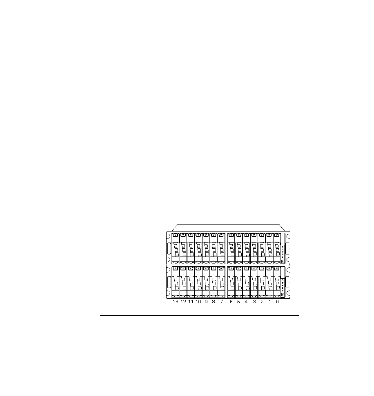
Each disk has a preferred ownership and “stays” on the owner node until a
takeover occurs. Ownership can be either to Node A or Node B (Figure 1).
Ownership Node
Shelf 2
Shelf 1
Ownership Node
Figure 1 Example disk ownership of Node A and Node B
2 IBM System Storage N3700 A20 Setup
A A A B B B A
B A B A B A B
A A B B B A B
A B A B A B A
Page 3
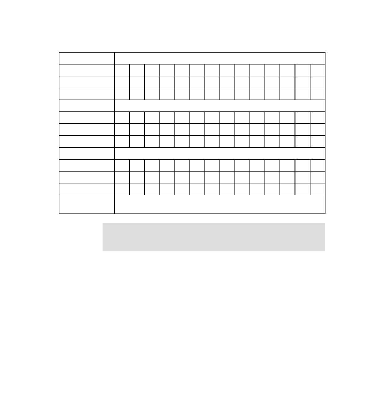
The following table (Table 1) shows a sample disk ownership.
Table 1 Disk ownership sample
Bay number
Disk shelf 1 131211109876543210
Node AXXXXXXX
Node BXXXXXXX
Disk shelf 2 131211109876543210
Node AXXX XXX X
Node B X X X X X X X
Disk shelf 3 131211109876543210
Node A--------------
Node B--------------
X marks the node that owns the disk. A dash (-) means no disk in place.
Disks in bay 0 and 1 (shelf 1 and 2) are SCSI Enclosure Services (SES) disks.
Note: Disk ownership is changed after the initial setup, or after adding
additional disks. Use the disk assign command to change ownership, and the
storage disk show command to determine which node owns which disk.
IBM System Storage N3700 A20 Setup 3
Page 4
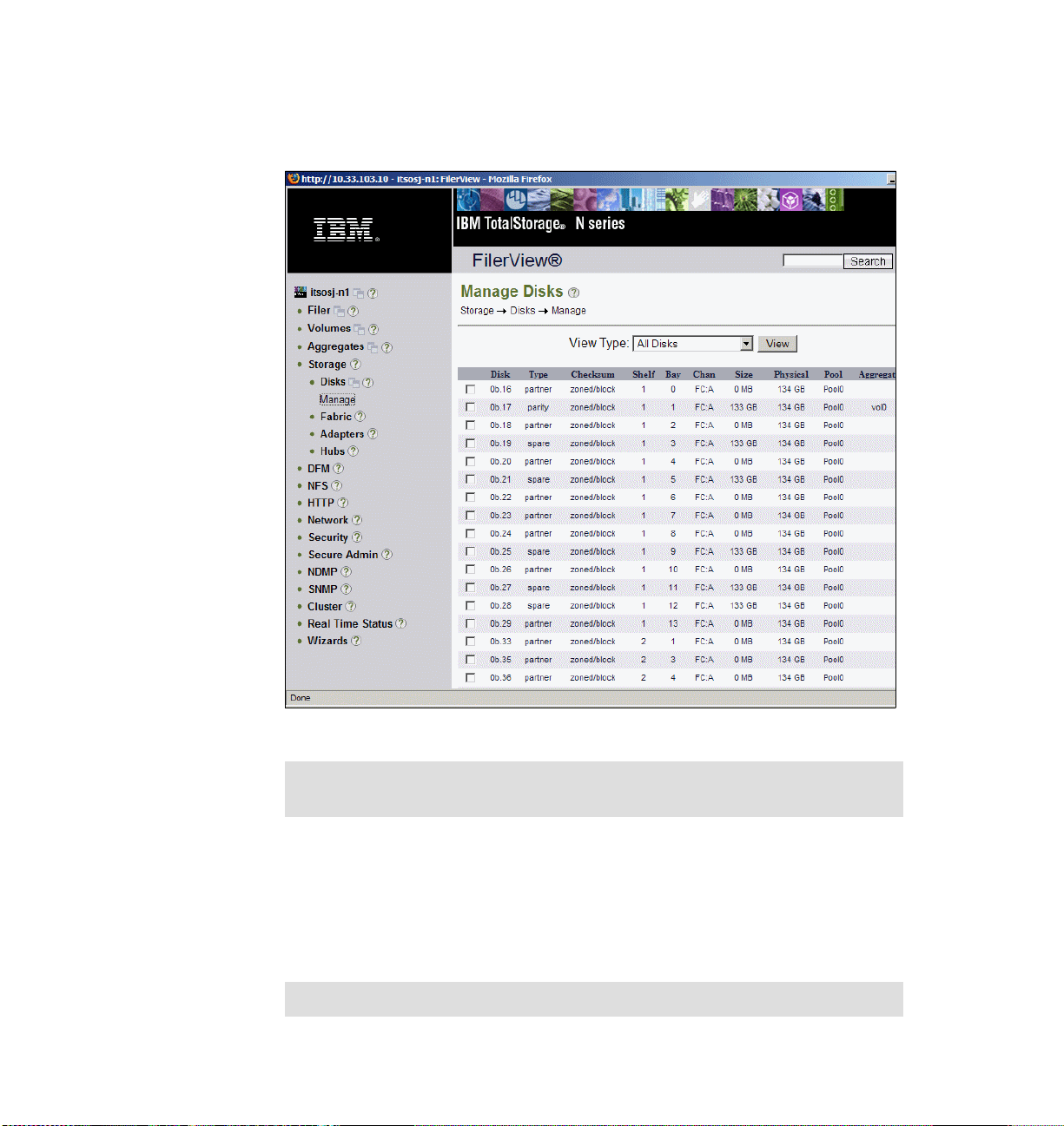
Check disk assignment after setup using the CLI command storage show disk,
or the Web interface FilerView → Storage → Manage. Figure 2 illustrates disks
in a sample clustered environment.
Figure 2 FilerView: Manage Disks
Tip: Plan the disk assignment carefully. Load balancing or active/passive
configurations can be reflected in the disk assignment procedure.
Setting up the hardware
Now, we describe the installation and setup of the System Storage N3700 Model
A20, the clustered storage system, and the attachment of the System Storage
EXN2000 expansion unit.
Tip: Check the interoperability matrix for supported configurations.
4 IBM System Storage N3700 A20 Setup
Page 5

Attention: The N3700 and EXN2000 use sensitive electronic components. To
avoid damage to them, wear an antistatic wrist strap and grounding leash for
the installation.
Tools and equipment
The N3700 Model A20 shipment package includes:
N3700 base unit (equipped with two CPU modules)
Power supplies
Power cords
Two console cables (RJ45-DB9) for a serial console
Fibre channel terminators
Publications
Setup kit
Software licenses
Before you install the hardware, make sure that you already have the appropriate
tools and equipment assembled to use (client-supplied items):
Flathead screwdriver, and #1 and #2 Phillips head screwdrivers
Pointed tool (to use for setting termination switches)
ASCII terminal, console (for example, a notebook computer or PC with serial
port)
Null modem cable (to connect to the console serial port)
Ethernet local area network (LAN) cables required for file serving network
Fibre channel cables for EXN2000 or tape connection (cables to EXN2000
included)
Note: The N3700 A20 provides two DB-9 to RJ-45 console adapters, one for
each CPU module. You can use this connection to connect a console to the
Filer. Remember to use a null modem cable.
Refer to IBM System Storage N series N3700 Hardware and Service Guide,
GA32-0515, and Installation and Setup Instructions for an System Storage
N3700 and an EXN2000 Expansion Unit, GA32-0517, for more information while
mounting and installing the N3700 filer.
The N3700 Model A20
This section describes the hardware installation of the clustered N3700 Model
A20 storage system. First, we describe the components of the system.
IBM System Storage N3700 A20 Setup 5
Page 6
Components
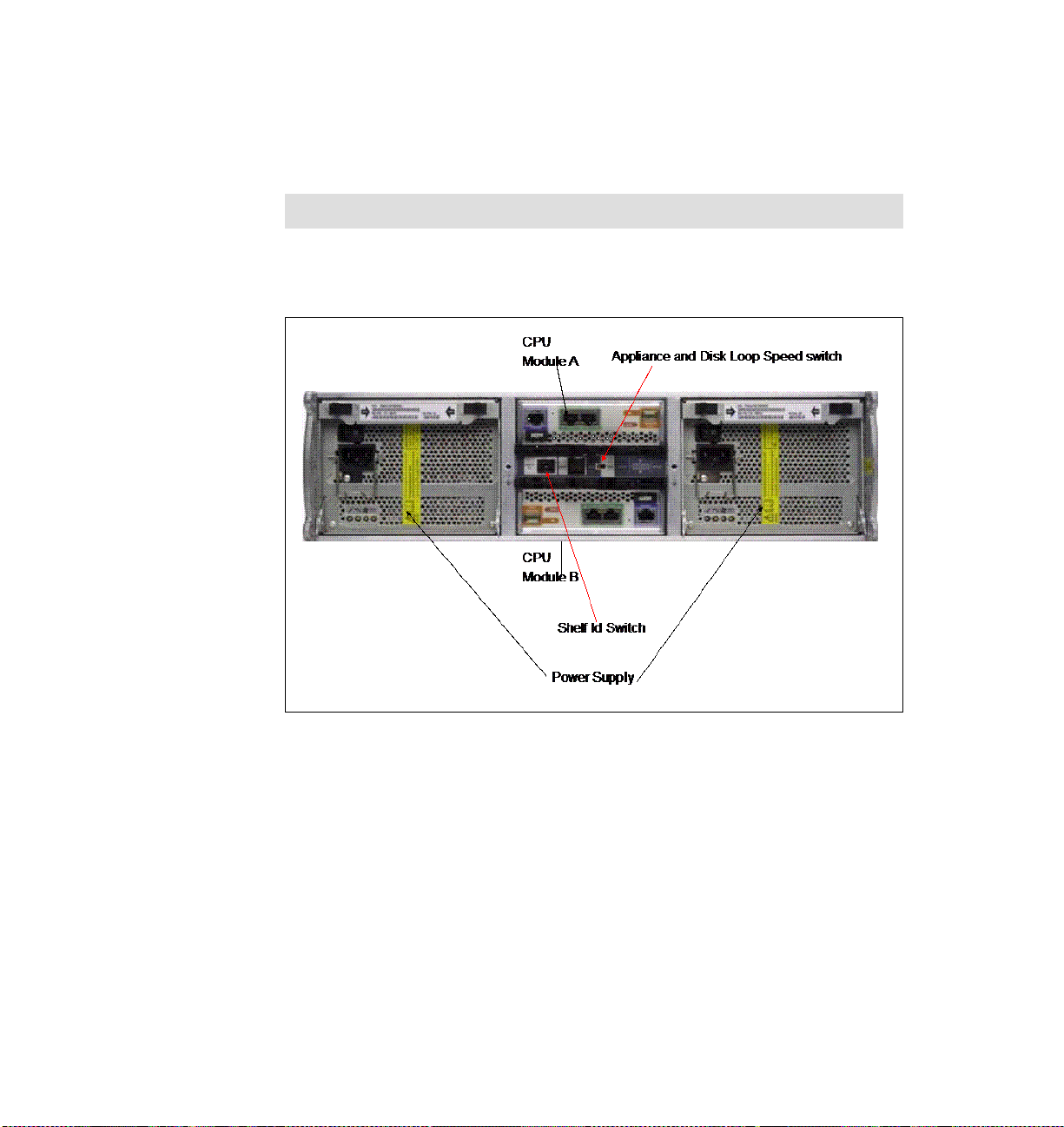
The N3700 Model A20 filer ships with two power supplies (PSU1 and PSU2),
which are located on the back panel on the rightmost and leftmost sides of the
N3700 appliance. Each power supply has its own ac power cord.
Note: We recommend that you use independent, separate power sources.
The CPU module Node B is on the middle, bottom of the back panel, module
Node A on the middle, top of the shelf (Figure 3).
Figure 3 N3700 Model A20 back panel
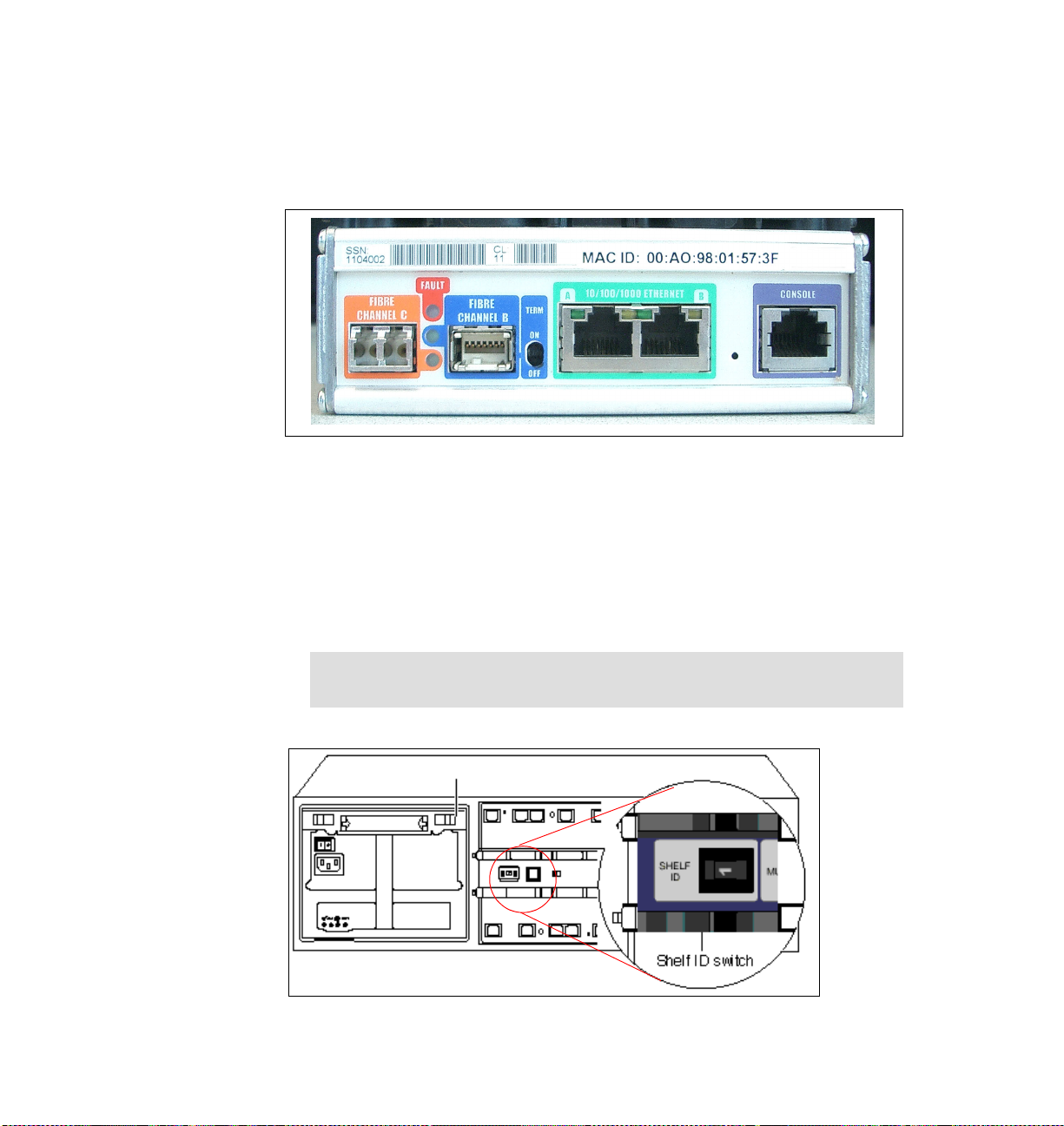
Each of the CPU modules (Figure 4 on page 7) hosts several LEDs and ports.
The ports are:
Two Ethernet ports (green)
Console port (purple)
Two fibre channel ports:
– Fibre channel port 1 (optical, orange) is used for third-party devices (such
as tape for backup).
– Fibre channel port 2 (copper, blue) is used for connections to EXN2000
expansion modules.
6 IBM System Storage N3700 A20 Setup
Page 7
The shelf ID switch and appliance and disk shelf loop switch are between the
CPU modules.
The illustration in Figure 4 shows the CPU module ports. Next, we describe
installing the N3700 cluster.
Figure 4 N3700 CPU module
Connections and cabling
After unpacking and mounting the N3700 and all EXN2000s in a 19” rack, we first
install the base unit (two CPU modules), and then we describe the attachment of
the EXN2000 units. Perform the following steps:
1. Make sure that the N3700 system and its EXN2000 units are turned off.
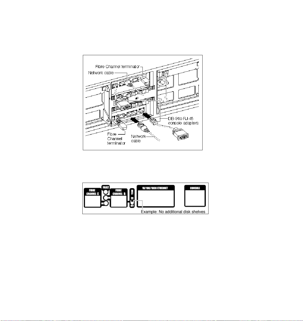
2. Set the shelf ID of the N3700 base unit to 1 (Figure 5).
Important: The power to N3700 must be turned off before changing the
shelf ID.
Figure 5 Setting the shelf ID
IBM System Storage N3700 A20 Setup 7
Page 8

3. Set the 1Gb/2Gb switch to the 1Gb position (Figure 6).
1Gb/2Gb Switch
Figure 6 Setting the 1Gb/2Gb switch
4. Connect the Ethernet cable to the (green) Ethernet port in the middle of the
controller module’s Node A. Repeat this for Node B. See Figure 7 on page 9.
5. Connect the console cables (DB9-RJ45 converter) to the console port
(purple) from Node B and Node A on the back of the appliance (Figure 7 on
page 9). If you are attaching a third-party device, such as a tape backup or a
fibre channel switch, leave the fibre channel ports (orange ports)
un-terminated. Refer to “Connecting to third-party devices” in IBM System
Storage N series N3700 Hardware and Service Guide, GA32-0515, for
details.
8 IBM System Storage N3700 A20 Setup
Page 9
6. If no third-party device will be attached to the fibre channel ports (orange
ports), insert the fibre channel terminator or loopback terminator into the fibre
channel ports (orange ports) at the CPU modules (Node A and Node B)
(Figure 7).
Figure 7 Connecting Ethernet, console cables, and fibre channel terminator
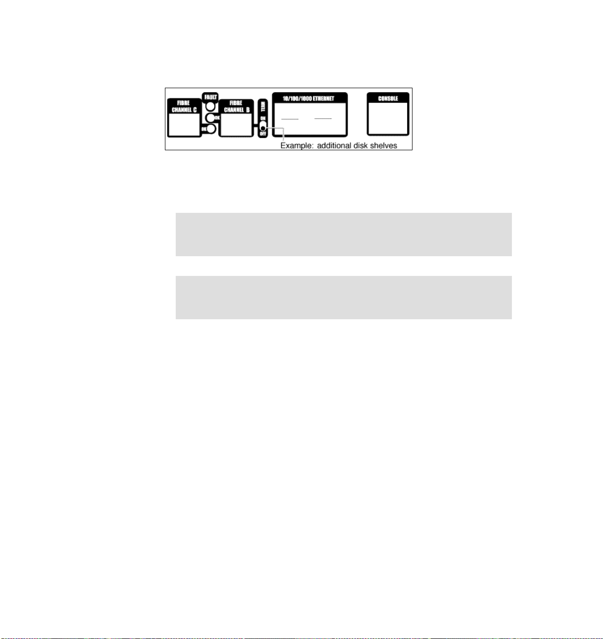
7. If an EXN2000 disk shelf will not be attached, set the terminate switch on both
CPU modules (Node B and Node A) to ON (Figure 8).
Figure 8 No EXN2000 attached
If an EXN2000 will not be attached, proceed as follows (system is still off):
a. Plug in the power cord to the left and right power supplies.
b. Fasten the power cords with the hold-down clamps.
c. Plug the other ends of the power cords into the grounded ac power source.
d. Proceed with the initial setup in “Initial configuration” on page 13.
IBM System Storage N3700 A20 Setup 9
Page 10
8. If you are connecting one or more EXN2000 disk shelves, set the terminate
switch on the CPU modules (Node B and Node A) to OFF (Figure 9).
Figure 9 EXN2000 attached
9. Proceed if you are connecting additional EXN2000 disk shelves. Otherwise,
go to “Initial configuration” on page 13.
Note: The N3700 supports hot plugging a disk shelf. Refer to IBM System
Storage N series N3700 Hardware and Service Guide, GA32-0515, for
details and restrictions.
Attention: The N3700 and the EXN2000 shelves use sensitive electronic
components. To avoid damaging them, put on an antistatic wrist strap and
grounding leash for the installation.
If one or more EXN2000s will be attached, proceed as follows (remember,
during the initial hardware setup, the N3700 system is still turned off). Perform
the following steps (Figure 10 on page 11):
a. Confirm that the shelf ID of the base unit is set to 1.
b. Connect the fibre channel port (blue) of Node B (lower CPU module) to the
first EXN2000 disk shelf ESH2 module B (In port).
c. Connect the fibre channel port (blue) of Node A (upper CPU module) to
the first EXN2000 disk shelf ESH2 module A (In port).
d. Attach the grounding cable (EXN2000, base shelf).
10 IBM System Storage N3700 A20 Setup
Page 11

Figure 10 Connecting EXN2000 shelves
e. Set the EXN2000 shelf ID to 2 and set the disk shelf loop speed to 1 Gb.
f. If you attach only one EXN2000, plug in the power cord to the left and right
power supplies, fasten the power cords with the hold-down clamps, and
plug the other ends of the power cords into grounded ac power source.
Skip adding a second EXN2000 and proceed with the initial configuration.
g. If you are adding additional EXN2000 shelves, cable the EXN2000 (ID 2)
ESH2 Mod. B (Out port) to EXN2000 (ID 3) ESH2 Mod. B (In port) and
EXN2000 (ID 2) ESH2 Mod. A (Out port) to EXN2000 (ID 3) ESH2 Mod. A
(In port).
IBM System Storage N3700 A20 Setup 11
Page 12

h. Attach the grounding cable (EXN2000 #1 and #2). See Figure 11.
ID 3
ID2
Base Unit
(ID1)
Figure 11 Connecting additional EXN2000 shelves
i. Set the EXN2000 shelf ID (second EXN2000) to 3 and set the disk shelf
loop speed to 1 Gb.
j. Repeat the previous steps if a third EXN2000 will be attached.
k. Plug in the power cord to the left and right power supplies, fasten the
power cords with the hold-down clamps, and plug the other ends of the
power cords into grounded ac power source.
12 IBM System Storage N3700 A20 Setup
Page 13

Initial configuration
Next, we describe the initial configuration after booting the System Storage N
series filer for the first time. After turning on your system for the first time, run
diagnostics to make sure that it is functioning properly and to diagnose any
hardware problems.
N3700 initial setup
Ensure that the hardware setup of the N3700 is complete. Refer to “Setting up
the hardware” on page 4 for details about the hardware setup (shelf IDs, speed
settings, grounding, termination, and cabling).
Note: Repeat the initial configuration on both nodes (Node A and Node B).
The System Storage N series filer is shipped with a complete version of the
System Storage N series software. During the setup procedure, several files are
updated with the information provided during the configuration procedure.
These files are:
/etc/rc
/etc/exports
/etc/hosts
/etc/hosts.equiv
/etc/dgateways
/etc/nsswitch.conf
/etc/resolf.conf
Setup method
You can set up the system using various interfaces. You can use the serial
connection with a console PC for the very first configuration steps.
Console PC
Use the null modem cable to connect the console adapter cable of the N3700
node to the serial port of the console PC or notebook computer. Plug the console
adapter cable into the console port (purple) of the CPU module of the filer
(Figure 4 on page 7). Note the following console settings:
Baud: 9600
Data bit: 8
Parity: None
Stop Bits: 1
IBM System Storage N3700 A20 Setup 13
Page 14

Flow control: None
Web browser
If DHCP is enabled, you can use a Telnet client for the setup. To keep the
installation simple, we skip this and continue with the console setup.
Turn on the N3700
Turn on the N3700 in the following order:
1. EXN2000 (expansion disk shelves)
2. N3700 appliance (base unit)
Tip: The default spin-up time for all disks in the appliance is 60 seconds.
Reduce this spin-up time to 20 seconds by turning on the switches of both
power supplies within 5 seconds of each other.
Setup and configuration
After the system is connected properly and turned on for the first time, the initial
setup starts with the basic filer settings. Enter the settings according to your
planning worksheets. The initial configuration must be done on
Proceed with the following steps on Node A and Node B:
1. Enter your new host name: itso-n1
See the screens shown in Figure 12 on page 15 and Figure 13 on page 16 for
more details.
both nodes.
Note: During the setup, you are asked to continue the configuration using
the Web interface. If you select No, the setup continues using the
command line interface. If you select Yes, you can use the Web interface
through the IP address that previously displayed.
You can leave the default time zone settings and then configure the time
zone after the initial configuration.
The initial setup starts automatically when the system is turned on for the first
time. The basic configuration depends on which licenses are installed on your
system before shipment.
The following screen captures might vary from your environment, depending
on which licenses are installed, the Data ONTAP® software level, and the
hardware you are using. For example, if you did not obtain a CIFS license, the
CIFS setup does not appear during the initial configuration.
14 IBM System Storage N3700 A20 Setup
Page 15

Figure 12 Initial setup: Host and network definitions
IBM System Storage N3700 A20 Setup 15
Page 16

Figure 13 Initial setup: WINS, CIFS, and user authentication settings
Figure 14 Initial setup: Joining a Workgroup
16 IBM System Storage N3700 A20 Setup
Page 17

2. After completing the initial setup procedure, we log on to the appliance:
login: root
password: <password_you_selected_during_setup>
3. Now we can start with disk management. First, we check the disk ownership.
Each cluster node must have one or two disks (SES disks). Verify the disk
information:
storage show disk or sysconfig -r
4. Then, we assign the disks to the N3700 controllers Node A and Node B. Make
sure you have your completed disk ownership worksheet.
disk assign 0b.NN
5. After assigning the disks to the nodes, verify that all disks are assigned to the
correct node with the sysconfig -r command (Figure 15).
Figure 15 Command line output: sysconfig -r
IBM System Storage N3700 A20 Setup 17
Page 18

6. Verify the license settings and add missing or additional licenses. All licenses
you bought with the hardware should already be installed on the filer. Use the
following commands to show license information and add additional licenses
to your system. Cluster licenses must be set on both nodes. Use the following
commands to check the license settings on both storage systems and add
additional licenses to your system:
license
license add wwxxyyzz
7. Reboot the system:
reboot
8. Now we can enable the cluster on one node. The command is cluster-aware,
and you have to execute it only on one node (Figure 16):
cf enable
Figure 16 Command line: cf enable
9. Verify whether or not the cluster is enabled and that the other node is up and
running (Figure 17):
cf status
Figure 17 Command line: cf status
The cf monitor command provides more information about the cluster.
Figure 18 Command line: cf monitor
10.Issue the takeover test through the takeover option:
cf takeover
If the takeover was not successful, run the Cluster Configuration Checker for
N series NAS and iSCSI products at the following Web site and proceed as
directed:
http://www.ibm.com/storage/support/nas
18 IBM System Storage N3700 A20 Setup
Page 19

Note: The counterpart of the node where you issued the cf takeover
command shuts down. To re-enable the node, issue the cf giveback
command.
11.Check the status of the appliance cluster again (Figure 19):
cf status
Figure 19 Cluster status after takeover
12.Then, bring the cluster back to its original state and check the status again:
cf giveback
cf status
The cluster should be cluster enabled and both nodes up (Figure 20).
Figure 20 Cluster status after giveback
Using a Web browser to complete the configuration
After successfully completing the setup, log on to the N3700 through your Web
browser. You can do this setup after you choose Continue with Web Setup
during the initial configuration. Repeat these steps for both cluster nodes.
Note: There might be restrictions for the Web administration of the storage
systems regarding browsers and Java™ versions. Currently, they are:
Netscape Navigator 4.51 or later.
Microsoft® Internet Explorer® 4.0 or later.
Java and JavaScript™ must be enabled.
Other browsers with Java/JavaScript might also work.
In addition to Microsoft Internet Explorer 6.0, we used the Mozilla Firefox
browser (Version 1.0.1).
IBM System Storage N3700 A20 Setup 19
Page 20

You can use the Setup Wizard for additional configuration tasks. The following
step-by-step procedure describes this approach:
1. First, log on to the filer using the host name or IP address, as shown in
Figure 12 on page 15. Use the user “root” and password. Use the information
from your worksheets.
Use the following URL:
http://your_filername/na_admin/
Figure 21 System Storage N series Web logon process
20 IBM System Storage N3700 A20 Setup
Page 21

Figure 22 shows the System Storage N series Web interface.
Figure 22 System Storage N series Web interface
IBM System Storage N3700 A20 Setup 21
Page 22

2. Select Wizards (bottom left of FilerView) and then Setup Wizard (Figure 23).
Figure 23 Starting the Setup Wizard
22 IBM System Storage N3700 A20 Setup
Page 23

3. The following figure contains settings from the initial setup. Verify these
settings and make changes when needed (Figure 24).
Tip: You can use the shortcut: http://vour_filername/api
Figure 24 Setup Wizard: Basic settings
IBM System Storage N3700 A20 Setup 23
Page 24

4. Provide an Email Address, Location of the filer (data center, branch office,
and so on), and the Administrative Host name (Figure 25).
Figure 25 Setup Wizard: Email Address, Location, and Administrative Host
24 IBM System Storage N3700 A20 Setup
Page 25

5. The Filer Setup Wizard - Network Services window enables DNS and NIS
services and gateway settings (Figure 26).
Figure 26 Setup Wizard: DNS, NIS, Gateway settings
IBM System Storage N3700 A20 Setup 25
Page 26

6. The Filer Setup Wizard - Network Addresses window provides information
about the network configuration, such as IP addresses, network masks,
network type, and WINS settings (Figure 27).
Figure 27 Setup Wizard: IP configuration, MAC addresses
26 IBM System Storage N3700 A20 Setup
Page 27

7. Use the Protocol Configuration window to change the Microsoft Windows®
domain, Windows administrator, Windows password, WINS servers, and NFS
settings (Figure 28).
Figure 28 Setup Wizard: Protocol Configuration (Microsoft Windows 2000)
IBM System Storage N3700 A20 Setup 27
Page 28
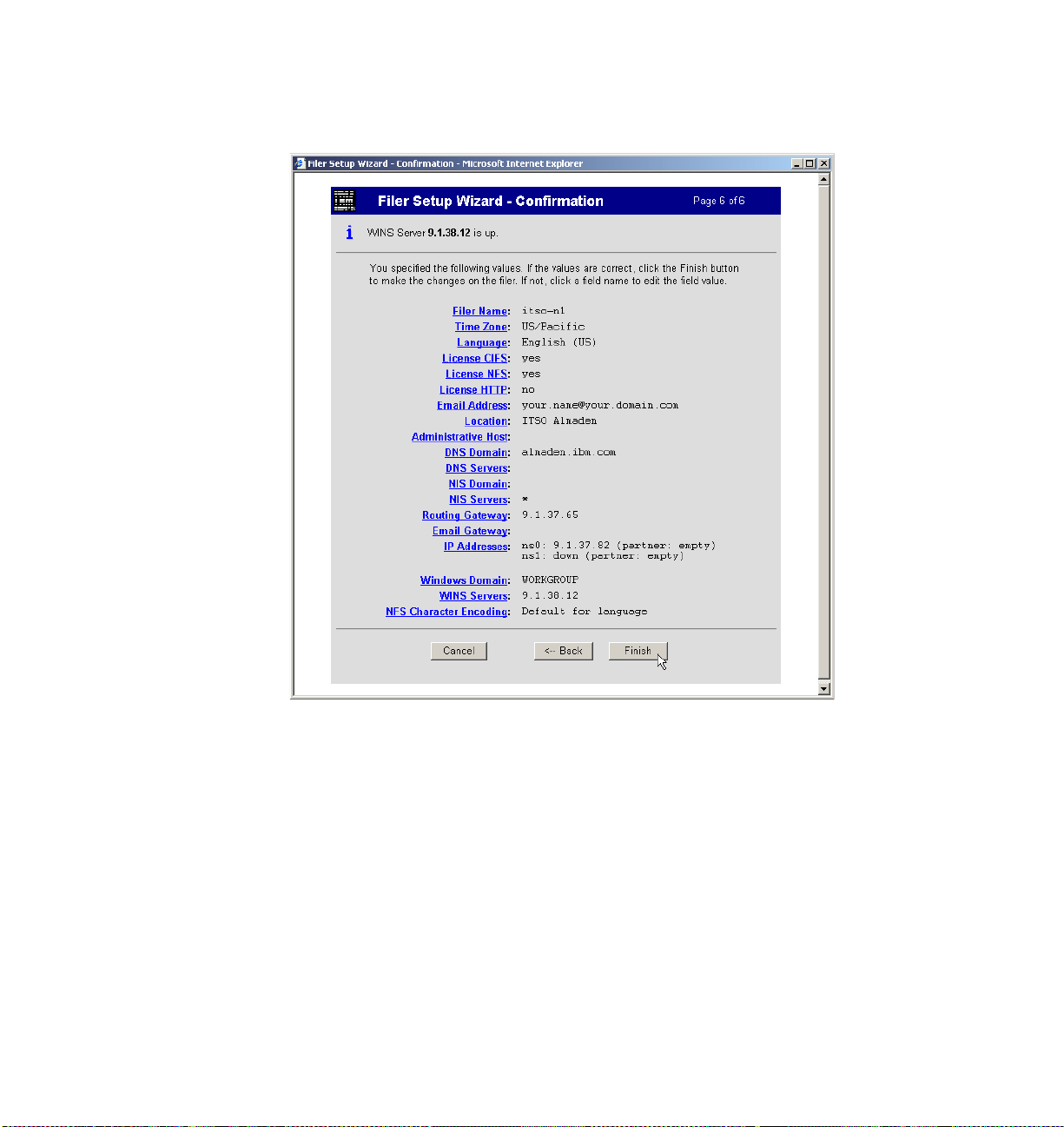
8. Verify the settings in the Confirmation window and proceed with the Setup
Wizard by clicking Finish (Figure 29).
Figure 29 Setup Wizard: Confirmation
28 IBM System Storage N3700 A20 Setup
Page 29

The Setup Wizard finishes and you receive a “successfully submitted” message
stating that the configuration settings are complete (Figure 30). Wait a couple of
minutes while the filer is updated with the new settings.
Figure 30 Setup Wizard: Status message
IBM System Storage N3700 A20 Setup 29
Page 30

The team that wrote this Redpaper
This Redpaper was produced by a team of specialists from around the world
working at the International Technical Support Organization.
Alex Osuna is a Project Leader at the International Technical Support
Organization in Tucson, AZ. He has been with IBM 25 years and has 26 years in
the I/T industry. Of those 26 years, Alex has worked extensively in software and
hardware storage for 21 years in service, support, planning, early ship programs,
performance analysis, education, published flashes, and provided pre-sales and
post-sales support.
Dirk Peitzmann is a Senior IT Specialist with IBM Systems Sales in Munich,
Germany. He has 10 years of experience providing technical presales and postsales solutions for IBM eServer™ pSeries® (RS/6000®) and IBM System Storage disk, SAN, and NAS. Dirk is a Certified Specialist pSeries AIX® System
Administration, AIX System Support Specialist, Open Systems Storage Solutions, and IBM Tivoli® Storage Manager Consultant. He holds a Diploma Ingenieur (FH) degree in Computer Sciences from the University of Applied Science
in Isny, Germany.
30 IBM System Storage N3700 A20 Setup
Page 31

Notices
This information was developed for products and services offered in the U.S.A.
IBM may not offer the products, services, or features discussed in this document in other countries. Consult
your local IBM representative for information on the products and services currently available in your area.
Any reference to an IBM product, program, or service is not intended to state or imply that only that IBM
product, program, or service may be used. Any functionally equivalent product, program, or service that
does not infringe any IBM intellectual property right may be used instead. However, it is the user's
responsibility to evaluate and verify the operation of any non-IBM product, program, or service.
IBM may have patents or pending patent applications covering subject matter described in this document.
The furnishing of this document does not give you any license to these patents. You can send license
inquiries, in writing, to:
IBM Director of Licensing, IBM Corporation, North Castle Drive Armonk, NY 10504-1785 U.S.A.
The following paragraph does not apply to the United Kingdom or any other country where such
provisions are inconsistent with local law: INTERNATIONAL BUSINESS MACHINES CORPORATION
PROVIDES THIS PUBLICATION "AS IS" WITHOUT WARRANTY OF ANY KIND, EITHER EXPRESS OR
IMPLIED, INCLUDING, BUT NOT LIMITED TO, THE IMPLIED WARRANTIES OF NON-INFRINGEMENT,
MERCHANTABILITY OR FITNESS FOR A PARTICULAR PURPOSE. Some states do not allow disclaimer
of express or implied warranties in certain transactions, therefore, this statement may not apply to you.
This information could include technical inaccuracies or typographical errors. Changes are periodically made
to the information herein; these changes will be incorporated in new editions of the publication. IBM may
make improvements and/or changes in the product(s) and/or the program(s) described in this publication at
any time without notice.
Any references in this information to non-IBM Web sites are provided for convenience only and do not in any
manner serve as an endorsement of those Web sites. The materials at those Web sites are not part of the
materials for this IBM product and use of those Web sites is at your own risk.
IBM may use or distribute any of the information you supply in any way it believes appropriate without
incurring any obligation to you.
Information concerning non-IBM products was obtained from the suppliers of those products, their published
announcements or other publicly available sources. IBM has not tested those products and cannot confirm
the accuracy of performance, compatibility or any other claims related to non-IBM products. Questions on
the capabilities of non-IBM products should be addressed to the suppliers of those products.
This information contains examples of data and reports used in daily business operations. To illustrate them
as completely as possible, the examples include the names of individuals, companies, brands, and products.
All of these names are fictitious and any similarity to the names and addresses used by an actual business
enterprise is entirely coincidental.
COPYRIGHT LICENSE:
This information contains sample application programs in source language, which illustrates programming
techniques on various operating platforms. You may copy, modify, and distribute these sample programs in
any form without payment to IBM, for the purposes of developing, using, marketing or distributing application
programs conforming to the application programming interface for the operating platform for which the
sample programs are written. These examples have not been thoroughly tested under all conditions. IBM,
therefore, cannot guarantee or imply reliability, serviceability, or function of these programs. You may copy,
modify, and distribute these sample programs in any form without payment to IBM for the purposes of
developing, using, marketing, or distributing application programs conforming to IBM's application
programming interfaces.
© Copyright International Business Machines Corporation 2007. All rights reserved.
Note to U.S. Government Users Restricted Rights -- Use, duplication or disclosure restricted by
GSA ADP Schedule Contract with IBM Corp.
31
Page 32

Send us your comments in one of the following ways:
Use the online Contact us review Redbooks form found at:
ibm.com/redbooks
Send your comments in an e-mail to:
redbook@us.ibm.com
Mail your comments to:
IBM Corporation, International Technical Support Organization
Dept. HYTD Mail Station P099, 2455 South Road
Poughkeepsie, NY 12601-5400 U.S.A.
®
Trademarks
The following terms are trademarks of the International Business Machines Corporation in the United States,
other countries, or both:
AIX®
eServer™
IBM®
The following terms are trademarks of other companies:
FilerView, Data ONTAP, and the Network Appliance logo are trademarks or registered trademarks of
Network Appliance, Inc. in the U.S. and other countries.
Java, JavaScript, and all Java-based trademarks are trademarks of Sun Microsystems, Inc. in the United
States, other countries, or both.
Internet Explorer, Microsoft, Windows, and the Windows logo are trademarks of Microsoft Corporation in the
United States, other countries, or both.
Other company, product, or service names may be trademarks or service marks of others.
pSeries®
Redbooks (logo) ™
RS/6000®
System Storage™
Tivoli®
Redpaper
32 IBM System Storage N3700 A20 Setup
 Loading...