

Page 1

NetVista
™
N2800e Thin Client Express
Reference
September 2 000
To view or print the latest update, go to http://www.ibm.com/nc/pubs
SA23-2808-00
Page 2

Page 3

NetVista
™
N2800e Thin Client Express
Reference
September 2 000
To view or print the latest update, go to http://www.ibm.com/nc/pubs
SA23-2808-00
Page 4

Note
Before using this information and the product that it supports, be sure to read “Safety notices” on page v and “Notices” on
page 61.
First Edition (September 2000)
© Copyright International Business Machines Corporation 2000. All rights reserved.
US Government Users Restricted Rights – Use, duplication or disclosure restricted by GSA ADP Schedule Contract
with IBM Corp.
Page 5

Contents
Safety notices ............v
Danger notices .............v
Caution notices .............vi
Handling static-sensitive devices .......vi
About this book...........vii
Who should read this book .........vii
Information available on the World Wide Web . . vii
Related information ...........vii
How to send your comments ........vii
Understanding your NetVista Thin Client
Express...............1
Learning about the hardware .....3
Standard hardware ............3
Hardware connectors ...........3
Communication hardware ..........4
Monitor specifications ...........4
Power consumption ............4
Upgrading hardware features.........4
Setting up the hardware........7
Startup sequence ..........9
Maintaining and reconfiguring PPP dialer
parameters ..............23
Using the PPP dialer to access flash images....24
Troubleshooting PPP dialer problems ......24
Altering the flash image of a
workstation.............25
Performing a software update on a workstation . . 25
Using the Configuration Tool to perform a
software update on a workstation ......25
Using the Thin Client Manager Operations Utility
to perform a software update on a workstation . 26
Recovering the flash image of a workstation . . . 26
Using one workstation to recover the flash image
of another workstation .........27
Using the Setup Utility to recover the flash image
of a workstation ............29
Using the Thin Client Manager Operations Utility
to recover the flash image of a workstation . . . 30
Resolving hardware problems.....31
Verifying hardware problems ........31
Visible hardware failure ..........32
Audio beep sequences ...........34
LED indications .............35
Error codes and text messages ........36
Configuring the N2800e Thin Client
Express ..............11
Using the Setup Utility to configure the workstation 11
Using the Configuration Tool to configure the
workstation ..............12
Installing the Thin Client Service Utility
and the Operations Utilities ......15
Installing the utilities from the NetVista Thin Client
Utilities CD ..............16
Downloading the utilities from the NetVista Thin
Client web site .............16
Managing your Thin Client Express
remotely ..............19
PPP dialer for Thin Client Express
workstations ............21
Prerequisites for using PPP dial access .....21
Configuring a workstation for PPP dialer ....21
Preparing the workstation for PPP dialer
configuration .............21
Configuring initial modem settings for PPP dialer
access ...............22
Starting the PPP dialer..........23
Learning about the NC dialer window .....23
Appendix A. Replacing hardware parts 41
Replacing the N2800e Thin Client Express
CompactFlash card ............41
Replacing parts other than the N2800e
CompactFlash card ............42
Returning hardware parts .........44
Appendix B. Hardware maintenance
procedures .............45
Appendix C. Setting the thin client
voltage for your location .......51
Appendix D. Recovering the boot block
image ...............53
Appendix E. Choosing a flash file . . . 55
Appendix F. Monitor specifications . . 57
Appendix G. Connector pin information 59
Notices ..............61
Environmental Design ...........62
Product Recycling and Disposal .......62
© Copyright IBM Corp. 2000 iii
Page 6

Trademarks ..............63
Electronic Emission Notices .........63
Federal Communications Commission (FCC)
Statement ..............63
Glossary of abbreviations ......65
Index ...............67
iv
Page 7

Safety notices
Danger notices
Safety notices contain information that is related to using the IBM®NetVista thin
client in a safe manner. These notices can be in the form of a danger, caution, or
attention notice.
The following danger notices call attention to situations that are potentially lethal
or extremely hazardous. These notices pertain throughout this book.
DANGER
To prevent a possible electrical shock during an electrical storm, do not
connect or disconnect cables or station protectors for communications lines,
display stations, printers, or telephones. (RSFTD003)
DANGER
To prevent a possible electrical shock from touching two surfaces with
different electrical grounds, use one hand, when possible, to connect or
disconnect signal cables. (RSFTD004)
DANGER
An electrical outlet that is not correctly wired could place hazardous voltage
on metal parts of the system or the products that attach to the system. It is the
customer’s responsibility to ensure that the outlet is correctly wired and
grounded to prevent an electrical shock. (RSFTD201)
DANGER
To prevent a possible electrical shock when installing the system, ensure that
the power cords for all devices are unplugged before installing signal cables.
(RSFTD202)
DANGER
To prevent a possible electrical shock when adding the device to a system,
disconnect all power cords, if possible, from the existing system before
connecting the signal cable to that device. (RSFTD205)
DANGER
To prevent a possible electrical shock, disconnect the power cord from the
electrical outlet before opening the unit. (RSFTD215)
© Copyright IBM Corp. 2000 v
Page 8

DANGER
To reduce the risk of electrical shock use only AC power sources approved by
IBM. (RSFTD216)
Caution notices
A caution notice applies to a situation that is potentially hazardous to people
because of some existing condition.
CAUTION:
The battery is a lithium battery. To avoid possible explosion, do not burn or
charge the battery. Exchange only with the IBM-approved part. Discard the
battery as instructed by local regulations. (RSFTC227)
Handling static-sensitive devices
When you handle components, take these precautions to avoid static electricity
damage:
v Do not open static-protective packages until you are ready to install their
contents.
v Limit your movements to avoid static electricity build-up around you.
v Handle components carefully, and never touch exposed circuitry.
v Prevent others from touching components.
v Place components on static-protective packages while performing hardware
removal and installation procedures.
v Do not place components on metal surfaces.
vi
Page 9

About this book
IBM NetVista N2800e Thin Client Express Reference (SA23-2808) provides information
for the Type 8364 (Model Cxx) IBM NetVista N2800e Thin Client Express (hereafter
referred to as workstation or thin client).
This publication contains information on hardware setup, software configuration
and update, hardware problem resolution, hardware upgrade options, parts
replacement, and ordering.
Who should read this book
The following should find the information in this publication helpful:
v The person who administers the workstation
v The hardware service, and the support organizations for the workstation
Information available on the World Wide Web
You can obtain the latest version of this information at the following uniform
resource locator (URL):
http://www.ibm.com/nc/pubs
This is the same URL that is printed on the cover of this document.
Related information
The following publications ship with your hardware. Refer to these publications
for information that relates to your workstation:
v See the IBM NetVista Quick Setup for N2800e Thin Client Express, Type 8364 (Model
Cxx) (SA23-2807) pamphlet for quick hardware setup information and software
configuration information.
v See the IBM License Agreement For Machine Code (Z125-5468) before using the
workstation.
v See IBM NetVista Thin Client Safety Information (SA41-4143) for important safety
notices.
v See IBM NetVista Thin Client Hardware Warranty - Type 8363 and Type 8364
(SA23-2802) for important hardware warranty information.
Refer to IBM NetVista Thin Client Manager Operations Utility (SA23-2813) for
information about managing your Thin Client Express. This information is
available at the following URL:
http://www.ibm.com/nc/pubs
How to send your comments
Your feedback is important in helping to provide the most accurate and
high-quality information. You can submit comments about this, or other IBM
information by mailing the readers’ comment form, located at the end of this
information.
© Copyright IBM Corp. 2000 vii
Page 10

v If you are mailing comments from a country other than the United States, you
can give the form to the local IBM branch office or IBM representative for
postage-paid mailing.
v If you prefer to send comments by FAX, use either of the following telephone
numbers:
– United States and Canada: 1-800-937-3430
– Other countries: 1-507-253-5192
v If you prefer to send comments electronically, use the following network
identification:
– IBMMAIL, to IBMMAIL(USIB56RZ)
– RCHCLERK@us.ibm.com
Be sure to include the following:
v The title, and order number of the information
v The page number or topic to which your comment applies
viii
Page 11

Understanding your NetVista Thin Client Express
The IBM NetVista N2800e Thin Client Express offers a fast and simple way to
access applications on the following platforms:
®
v Windows NT
v Windows NT Server 4.0, Terminal Server Edition (TSE)
v Windows NT Workstation 4.0
v Windows
v Windows 2000 Professional
v Windows 2000 Advanced Server
Server 4.0
®
2000 Server
As both a hardware and a software solution, Thin Client Express includes essential
Network Station
™
Manager V2R1 functions on a pre-installed CompactFlash card.
Thin Client Express provides the usual thin-client benefits, such as a reduced total
cost of ownership and the fast, flexible deployment of applications. Because it does
not require a boot server, Thin Client Express also provides a quick start-up time.
Thin Client Express also includes a Setup Utility, and a Configuration Tool that
provide the following:
v A streamlined configuration process
v Local boot capabilities from a CompactFlash card
v A Netscape browser
v 3270, 5250, and VTxx emulator sessions
v An Independent Computing Architecture (ICA) client and ICA Remote
Application Manager
v Separate utility programs for flash update service and operations management
v A desktop with a Launch Bar or one or more full-screen applications
v Advanced diagnostics
The IBM NetVista Thin Client Express Service Utility and IBM NetVista Thin Client
Manager Operations Utility are management utilities that you can use to manage
your workstations. These utilities run on Windows 2000 and Windows NT
workstations, and are available to you, free of charge. You can download these
utilities either from a compact disc (CD) or from the World Wide Web. For
information on obtaining the CD (at no cost to you), visit the following uniform
resource locator (URL):
http://www.pc.ibm.com/us/netvista/thinclient/xpress.html
Click Express Utilities, located under the More Info heading.
If you are interested in downloading the utilities from the World Wide Web, refer
to “Downloading the utilities from the NetVista Thin Client web site” on page 16
for more information.
© Copyright IBM Corp. 2000 1
Page 12

2
Page 13
Learning about the hardware
This section provides detailed hardware information about the N2800e Thin Client
Express — Hardware Type 8364 (Model Cxx), hereafter referred to as N2800e Thin
Client Express.
Standard hardware
The standard N2800e Thin Client Express hardware includes the following:
v 64 MB of SDRAM DIMM random access memory (RAM) (see “Appendix A.
Replacing hardware parts” on page 41).
v 4 MB SGRAM video memory
v Integrated Ethernet communication
v 16-bit internal and external sound
v One 32 MB CompactFlash card with preloaded software
v 2 USB ports for a keyboard and other USB devices
v 2 PCI adapter slots for PCI devices
v Two serial ports for serial devices
Note: The Netscape browser requires 64 MB of RAM. See “Appendix B. Hardware
maintenance procedures” on page 45 for information about adding more
memory to a workstation. See “Appendix A. Replacing hardware parts” on
page 41 for information about ordering replacement memory.
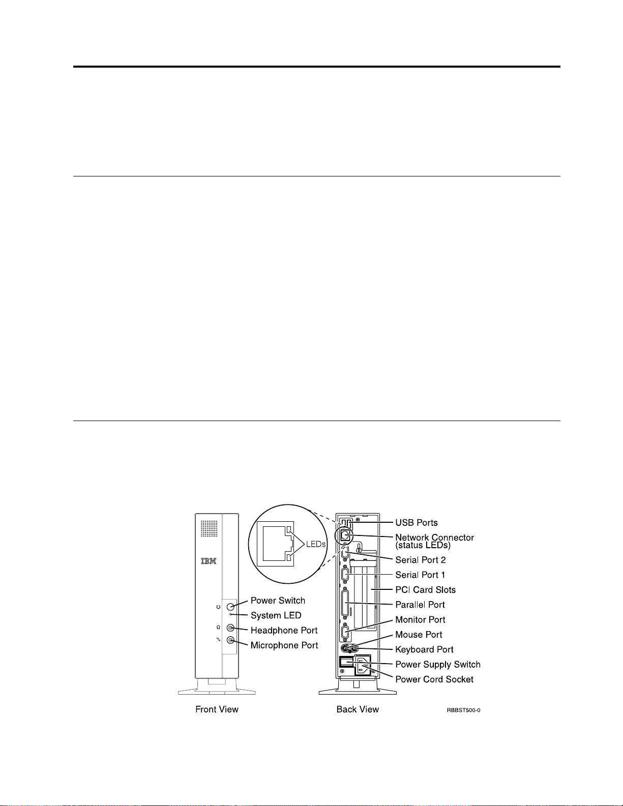
Hardware connectors
Your N2800e Thin Client Express hardware includes standard connectors, standard
pin, signal, and signal direction configurations. See “Appendix G. Connector pin
information” on page 59 for details.
Figure 1. Hardware connectors
© Copyright IBM Corp. 2000 3
Page 14

Communication hardware
Your N2800e Thin Client Express includes an integrated Ethernet connection.
For a 10 Megabit (Mb) line speed operation, you need a category 3 or higher
Unshielded Twisted Pair (UTP) type of cable. For a 100 Mb line speed operation,
you need a category 5 UTP type of cable.
Refer to “Appendix G. Connector pin information” on page 59 for communication
cable specifications.
Monitor specifications
A basic video graphics adapter (VGA) class monitor that meets the Video
Electronics Standards Association (VESA) standards of refresh rate and resolution
functions with the N2800e Thin Client Express. The N2800e Thin Client Express
can support VESA Display Power Management Signaling (DPMS) and VESA
Display Data Channel (DDC2B).
Refer to “Appendix F. Monitor specifications” on page 57 for a list of resolutions
and refresh rates that the N2800e Thin Client Express can support. Your monitor
may not support all resolutions and refresh rates.
Power consumption
Normal power consumption for the thin client, while running applications, ranges
from 24 to 28 Watts. During periods of inactivity, the system switches into the
suspend state, and power consumption reduces to approximately 18 Watts. Once
the system enters the soft-off state, power consumption reduces to approximately
10 Watts.
Note: Power consumption may fluctuate or vary from these values, depending on
the voltage selection (115V or 230V) of the thin client.
Display monitor power reduction occurs when you use the N2800e Thin Client
Express with a VESA DPMS Standard monitor.
As an Energy Star Partner, IBM has determined that this product meets the Energy
Star Program guidelines for energy efficiency.
Upgrading hardware features
You can perform the following hardware procedures:
v Install PCI adapter cards for PCI devices
v Replace a CompactFlash card
v Connect USB devices
If you plan to use peripheral USB devices with your N2800e Thin Client
Express, refer to the documentation for your peripheral USB devices for
information.
v Upgrade your memory
The N2800e Thin Client Express has tworandom access memory (RAM) slots
that accepts Synchronous Dynamic Random Access Memory (SDRAM) Dual
Inline Memory Modules (DIMMs). The N2800e Thin Client Express includes 64
MB of RAM, and supports memory expansions of up to 256 MB. You can
4
Page 15

expand the RAM of the N2800e by installing 32, 64, or 128 MB DIMMs.
“Appendix B. Hardware maintenance procedures” on page 45 provides
information on how to exchange memory. Refer to “Appendix A. Replacing
hardware parts” on page 41 for detailed memory specifications and orderable
N2800e Thin Client Express parts.
Note: Use of the Netscape browser requires 64 MB of RAM.
Learning about the hardware 5
Page 16

6
Page 17
Setting up the hardware
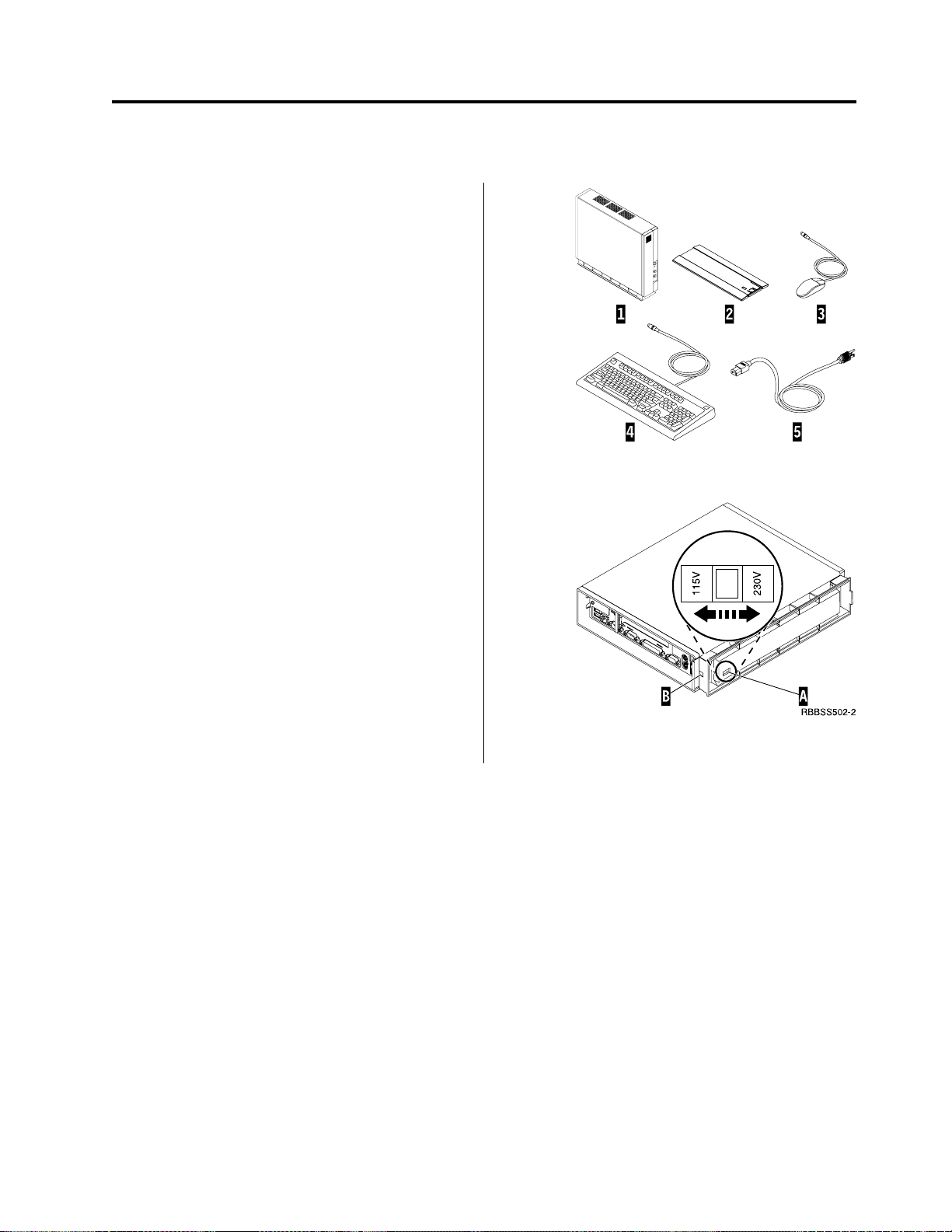
Unpacking your hardware
Unpack your hardware. Contact your reseller, or IBM, if
you do not have these standard parts:
1 Thin client logic unit
2 Base
3 Mouse
4 Keyboard
5 Power cable
Selecting the voltage for your location:
Attention: You may damage the thin client if you do
not select the correct voltage.
1. Locate the voltage switch A on the bottom of the
thin client.
2. Use a pen, or similar object, to slide the switch A to
the correct setting for your location (see ″Voltage
selection″ in Table 11 on page 42).
Installing options:
v If you have additional memory, or optional feature
cards, see “Appendix B. Hardware maintenance
procedures” on page 45 before continuing with the
following setup procedures.
v If you have a security cable and would like to restrict
access to the thin client logic unit, thread your cable
through hole B.
v For vertical placement of the thin client, see “Installing
the support base” on page 8.
v For horizontal placement of the hardware, continue
with “Connecting your hardware” on page 8.
© Copyright IBM Corp. 2000 7
Page 18

Installing the support base
Slide the base B onto the notched bottom of the thin
client A until it latches securely.
Connecting your hardware
Read “Safety notices” on page v before continuing.
1. Connect the devices listed below to the appropriate
ports:
1 USB devices
2 Network cable
3 Serial device 2
4 Serial device 1
5 Parallel devices
6 Monitor
7 Mouse
8 Keyboard
13 Headphones
14 Microphone
2. Tighten all device cable connections.
3. Connect the thin client power cable to the power
socket 10.
4. Plug all power cables into properly grounded working
electrical outlets.
5. To power on your thin client, move the power supply
switch 9 to the ″on″ position.
Notes:
a. The white power switch 11 resets the power to
your thin client.
b. The system LED 12 should flash from amber to
green. See “Resolving hardware problems” on
page 31 for deviations.
6. Choose the operating system for your server from the
menu that appears on your screen. Refer to the server
software information to verify the correct selection for
your network.
Note: If your thin client is unable to receive the
operating system code from the server, contact your
network administrator.
8
Page 19

Startup sequence
This is a typical startup sequence of events for the NetVista Thin Client Express. If
any of these events do not occur, see “Resolving hardware problems” on page 31.
1. The following devices show light-emitting diode (LED) indications:
v Logic unit (system LED and network status LED)
v Keyboard
v Monitor
v Any USB devices
2. The following internal hardware components initialize:
v Memory
v L1 cache
v Video memory
v Keyboard controller
3. The IBM NetVista thin client screen appears on the monitor.
4. One of the following appears:
v The Thin Client Express Setup Utility. The Setup Utility appears in either of
1
2
the following situations:
– You start the NetVista thin client for the first time.
– You previously reset the NetVista thin client to the factory-default
property settings.
The Configuration Tool launches after the Setup Utility in either situation.
Refer to “Configuring the N2800e Thin Client Express” on page 11 for more
information about working with the Setup Utility.
v The NetVista Thin Client Express detects the CompactFlash card and loads
the operating system into memory.
v The interface that you specified with the Configuration Tool appears. The
interface can be either of the following:
– One or more applications
– A launch bar with one or more applications
Refer to the following sections for more information about configuring your
NetVista Thin Client Express:
v “Configuring the N2800e Thin Client Express” on page 11
v “Installing the Thin Client Service Utility and the Operations Utilities” on
page 15
v “Managing your Thin Client Express remotely” on page 19
1. Refer to the documentation for your monitor if there is no LED indication.
2. Refer to the documentation for your USB devices if there are no LED indications.
© Copyright IBM Corp. 2000
9
Page 20

10
Page 21
Configuring the N2800e Thin Client Express
Before you can use the N2800e Thin Client Express (also referred to as workstation)
to access server applications, you need to configure your workstation. You can use
the NSBoot Setup Utility (also referred to as Setup Utility) and the Thin Client
Express Configuration Tool (or Configuration Tool) to configure workstations.
Note: You do not need access to an external server to set up and configure the
workstation.
This section provides information on the following:
v “Using the Setup Utility to configure the workstation”
v “Using the Configuration Tool to configure the workstation” on page 12
Using the Setup Utility to configure the workstation
The Setup Utility allows you to perform the following tasks:
v Specify your keyboard language settings
v Set the resolution and frequency of your display
v Configure your Internet Protocol (IP) settings
v Perform advanced configurations, such as changing your boot file server settings
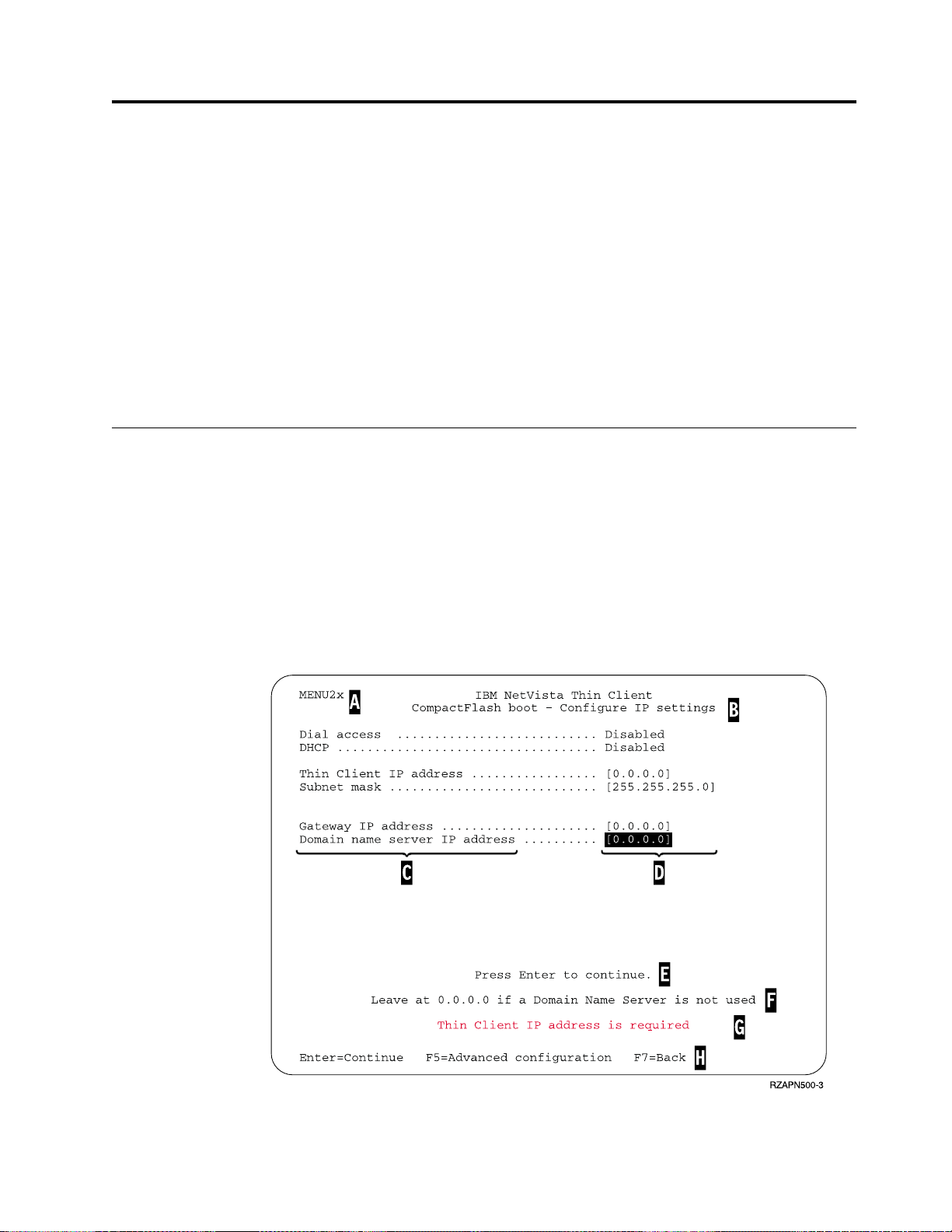
The first time you start the workstation, you must use the initial Setup Utility to
configure the workstation. The following menu is an example of a Setup Utility
menu:
Figure 2. Example menu
© Copyright IBM Corp. 2000 11
Page 22

The menu number A makes it easy to navigate through the Setup Utility. Menu
numbers that begin with 2 are unique to the initial Setup Utility. The menu title
B tells you which menu you are using.
Use the arrow keys to select an option from the list of available options C. After
you select an option, specify a value in the corresponding value field D. Certain
fields allow you to select a value by using the Page Up and Page Down keys.
Instructions and other messages (E and F) provide additional information.
Error messages G inform you when you need to complete a field or correct a
value before continuing.
Use the active function keys H to navigate through the Setup Utility.
To access the Setup Utility during a subsequent boot, press Esc immediately after
the following message disappears:
Hardware testing in progress...
If you worked only with the Simple Configuration menu during the initial boot,
then the Simple Configuration menu appears. However, if you worked with the
Advanced Configuration menu during the initial boot, then the Advanced
Configuration menu appears.
You can also configure your workstation for Dial Access. This option is available if
your client will use a modem for network connection instead of the Ethernet or
Token-Ring connection. See “PPP dialer for Thin Client Express workstations” on
page 21.
For information on using the Setup Utility to update CompactFlash cards, see
“Using the Setup Utility to recover the flash image of a workstation” on page 29.
Using the Configuration Tool to configure the workstation
The Configuration Tool allows you to configure the following applications on your
workstation:
v Independent Computing Architecture (ICA) Client
v ICA Remote Application Manager
v Netscape 4.5 browser (without Netscape JVM support)
®
v 3270 emulator to S/390
v 5250 emulator to Application System/400 (AS/400)®hosts
v VT emulator
v Advanced diagnostics
The Configuration Tool also allows you to configure the single user preferences
that are independent of the applications, such as mouse orientation. It also
provides a means to update the software on the CompactFlash card.
The first time you power on the workstation, the Configuration Tool displays
automatically after you complete the Setup Utility configurations. You must
complete the Configuration Tool configurations before you can access applications
from network servers. However, you do not need to complete the advanced
settings to create a basic, working configuration. After you have completed the
Configuration Tool, click Save and Restart to save your settings and restart the
workstation with your new configuration.
hosts
12
Page 23

The Configuration Tool provides three Workstation Mode user interfaces:
1. A single application that starts automatically when you power on the
workstation. This application fills the entire display screen.
2. One or more applications that start automatically when you power on the
workstation.
Note: The N2800e’s free memory determines how many applications you can
run at one time. With 32 MB of RAM, you can specify up to either of the
following applications:
v Four simultaneous 5250 or 3270 emulators
v An ICA client and two simultaneous 5250 or 3270 emulators
3. A launch bar with one or more applications. The Configuration Tool can start
these applications automatically, if desired.
Network administrators can use one of two possible methods to restrict access to
the Configuration Tool:
1. Use the Configuration Tool itself to create an administrator password.
2. Use the Thin Client Manager Operations Utility. For more information on using
the Thin Client Manager Operations Utility, see “Managing your Thin Client
Express remotely” on page 19.
You can access additional, customized help at any time by clicking Help in the
lower, right-hand corner of the display. The help viewer also has search capability.
To access the Configuration Tool anytime after the initial configuration, press and
hold the following keys on the left side of the keyboard: Shift + Ctrl + Alt. Hold
the keys down for several seconds until the Configuration Tool starts.
You can also place the Configuration Tool on the launch bar for simple, future
access.
For information on using the Configuration Tool to update CompactFlash cards,
see “Using the Configuration Tool to perform a software update on a workstation”
on page 25.
Configuring the N2800e Thin Client Express 13
Page 24

14
Page 25

Installing the Thin Client Service Utility and the Operations Utilities
The Thin Client Express Service and Thin Client Manager Operations Utilities are
management utilities that run on the following workstations or server platforms:
v Windows NT Server 4.0
v Windows NT Server 4.0, Terminal Server Edition (TSE)
v Windows NT Workstation 4.0
v Windows 2000 Server
v Windows 2000 Professional
v Windows 2000 Advanced Server
Although these utilities are optional, IBM recommends that you install the Service
Utility on if you want to rewrite the flash image of a workstation. The Service
Utility consists of the following:
v NetVista Thin Client Express image files
v Network support services that provide Network File System (NFS) support for
the client to access the image files
The Service Utility services start automatically after the installation is complete.
The services also start automatically after the server reboots. If you experience
problems while attempting to update or recover the flash ofa workstation, verify
the status of the Service Utility network support services. For information
regarding how to verify the status of network support services, see the NetVista
Thin Client Service and Operations Utilities Readme file. This file is available on
the NetVista Thin Client Utilities CD, as well as the NetVista Thin Client website.
For information on using the Operations Utility, refer to IBM NetVista Thin Client
Manager Operations Utility (SA23-2812). This information is available at the
following uniform resource locator (URL):
http://www.ibm.com/nc/pubs
Table 1 shows the tools, and utilities that IBM recommends for the different
methods of rewriting the flash image.
Table 1. Required tools and utilities to perform flash updates and recoveries
Type of update or
recovery
Configuration Tool
update
Operations Utility
update
Operations Utility
recovery
NS Boot Setup Utility
recovery
Peer flash recovery X
NSBoot Setup
Utility
XX
Configuration
Tool
XX
Service Utility Operations
XX
XX
Utility
© Copyright IBM Corp. 2000 15
Page 26

Only the Operations Utility methods of updating in Table 1 on page 15 allow you
to update multiple workstations at a time. The other methods of flash recovery in
Table 1 on page 15 allow you to perform flash recovery to one workstation at a
time. For more information on recovering or updating CompactFlash cards with
the TCM Operations Utility, refer to IBM NetVista Thin Client Manager Operations
Utility (SA23-2812). This information is available at the following URL:
http://www.ibm.com/nc/pubs
.
There are two ways to install the Service and Operations Utilities:
1. Installing the utilities from the NetVista Thin Client Utilities CD
2. Downloading the utilities from the NetVista Thin Client website
Installing the utilities from the NetVista Thin Client Utilities CD
To install the Service and Operations Utilities from the NetVista Thin Client
Utilities CD, insert the CD into your server’s CD-ROM drive. The IBM NetVista
Thin Client Utilities menu starts automatically.
Note: If the Thin Client Utilities menu does not start automatically, you can run
the install.bat file from the root directory of the CD.
To install the Operations Utility, click ″Install NetVista Thin Client Manager
Operations Utility.″
To install the Service Utility, click ″Install NetVista Thin Client Express Service
Utility.″
Downloading the utilities from the NetVista Thin Client web site
To download the Service and Operations Utilities from the IBM Thin Client web
site, you need to set up an update server. This update server must meet the
following requirements:
v Reliable access to the Internet
v Runs File Transfer Protocol (FTP) or Hypertext Transfer Protocol (HTTP)
v Accessible by workstations through a high-speed TCP/IP (Transmission Control
Protocol/Internet Protocol) connection (for example, a LAN)
v Sufficient space for the download files
After you have set up an update server, follow these steps to download the Service
and Operations Utilities from the IBM Thin Client web site:
Note: The Thin Client Express Service Utility, Thin Client Manager Operations
Utility, and Readme files for each utility are available from this Internet site.
1. From the server that you want to install the utilities on, open an Internet
browser and go to the following URL:
http://www.ibm.com/pc/support
2. Click NetVista.
3. Click NetVista thin client.
4. From the left column of links, click Hot news.
5. Click NetVista Thin Client Express - Service and Operations Utilities.
16
Page 27

6. Click download NetVista Thin Client Express Service and Operations
Utilities.
7. From the Downloads box, click the item that you want to download.
Installing the Thin Client Service Utility and the Operations Utilities 17
Page 28

18
Page 29

Managing your Thin Client Express remotely
You can use the IBM NetVista Thin Client Manager Operations Utility to remotely
manage your N2800e Thin Client Express. You can use the Thin Client Manager
Operations Utility to manage both individual workstations, and workstation
groups. Before you can use the Operations Utility to perform a task on a
workstation, you need to perform the following tasks:
v Install the Operations Utility on your computer. For information on installing the
Operations Utility, see “Installing the Thin Client Service Utility and the
Operations Utilities” on page 15.
v Power on the workstation on which you want to perform a task.
See IBM NetVista Thin Client Manager Operations Utility (SA23–2813) for more
information on managing thin clients with the Thin Client Manager Operations
Utility. This information is available on the World Wide Web at the following
uniform resource locator (URL):
http://www.ibm.com/nc/pubs
© Copyright IBM Corp. 2000 19
Page 30

20
Page 31

PPP dialer for Thin Client Express workstations
You can configure your Thin Client Express (hereafter referred to as workstation) for
Point-to-Point Protocol (PPP) dial access. You can utilize this option if your
workstation uses a modem to connect to a network. There are several prerequisites
that you must meet before you can use PPP dialer.
Prerequisites for using PPP dial access
Before you can use PPP dial access with your workstation, you must have the
following:
v A workstation, with a Service Update 1 BOM flash file installed on its
CompactFlash card (see “Altering the flash image of a workstation” on page 25
for flash update information).
v USB modem or serial analog modem.
Note: If you are going to use a serial modem with a N2800e workstation, you
need an USB-to-serial adapter.
v Analog telephone line.
v Internet Service Provider (ISP) that supports PPP connections, and Password
Authentication Protocol (PAP) authentication.
Note: By default, the workstation does not recognize Domain Name System
(DNS) information from ISPs. To enable DNS, perform the procedure,
“Configuring initial modem settings for PPP dialer access” on page 22.
For a list of tested modems, visit the following uniform resource locator (URL):
http://www.ibm.com/pc/support
Click NetVista—>NetVista thin client—>Advanced Search, and then search for
modems, under IBM NetVista Thin Client.
Configuring a workstation for PPP dialer
You need to perform the following procedures to configure a workstation for PPP
dialer access:
1. “Preparing the workstation for PPP dialer configuration” on page 21
2. “Configuring initial modem settings for PPP dialer access” on page 22
3. “Starting the PPP dialer” on page 23
Preparing the workstation for PPP dialer configuration
Follow these steps to configure your workstation for PPP dialer access.
1. Power on the workstation.
2. If the workstation does not automatically display the Setup Utility Simple
configuration menu, press Esc to enter the Setup Utility. If the workstation
displays the Advanced configuration menu, select Simple configuration, and
press Enter.
3. From the Setup Utility Simple configuration menu:
a. Choose a language setting.
© Copyright IBM Corp. 2000 21
Page 32

b. Choose a display resolution setting and a display frequency setting.
c. Configure the workstation Internet Protocol (IP) settings:
1) From the CompactFlash Boot - Configure IP settings menu, disable
Dynamic Host Configuration Protocol (DHCP).
2) Verify that all IP values are 0.0.0.0.
3) From the CompactFlash Boot - Configure IP settings menu, enable Dial
Access.
4) Press Enter. The workstation restarts, and the Configuration Tool
appears on the display. If the Configuration Tool does not display, Press
and hold the following keys on the left side of the keyboard: Shift +
Ctrl + Alt. Hold the keys down for several seconds until the
Configuration Tool starts.
Note: If you are unable to enter the Configuration Tool, the workstation
may not have access to the Configuration Tool. Refer to IBM
NetVista Thin Client Manager Operations Utility (SA23-2813) for
more information about granting and denying access to the
Configuration Tool. This information is available at the following
URL:
http://www.ibm.com/nc/pubs
4. From the Configuration Tool, select a language.
You have completed the initial configurations of your workstation for PPP dialer
access. Continue with “Configuring initial modem settings for PPP dialer access”.
Configuring initial modem settings for PPP dialer access
Once you have prepared a workstation for PPP dialer access, you must configure
the initial modem settings of the workstation. Perform the following steps from the
Communication Options menu of the Configuration Tool to complete this task:
1. Select a type of modem. N2800e workstations use an USB modem, or a serial
modem.
2. Select DTE Baud rate. If you are using a 56K modem, you should select 57600
or higher.
3. Select a dialing method. You can choose Tone or Pulse.
4. This step is optional, depending on the modem that you are using:
a. Type the modem initialization string in the appropriate field. This can
contain additional commands for the modem.
b. Type one command string and one response string into the appropriate
fields. Refer to the documentation for the modem that you are using for
specific commands. An example of a command string and a response string
is atz&fL1 OK.
5. This step is optional, depending on the applications that you want to use:
a. If you need DNS support, from the DNS active pulldown list, select Yes.
b. Type up to two DNS server IP addresses in the IP address 1 and IP address
2 fields.
c. Type an optional domain name in the Domain field.
6. Type the telephone number of the ISP in the Phone number field. You can
include commas in the telephone number for time delay, but you cannot
include blank spaces. Commas indicate to the PPP dialer that it needs to wait
for a dial tone before continuing to dial the telephone number of the ISP.
22
Page 33

7. Type a userid and password in the appropriate fields. If you do not type a
userid and password, the dialer prompts you for a userid and password each
time that you connect to the network.
Once you have completed the initial modem setting configurations for PPP dialer
access, you can start the PPP dialer. It is necessary for you to successfully start the
PPP dialer at this time to complete the configuration of your workstation for PPP
dialer access.
Starting the PPP dialer
You can start the PPP dialer once you have completed the initial modem setting
configurations on the workstation. Starting the PPP dialer after you have
completed the initial modem setting allows the workstation to test the modem
settings that you have specified. Perform the following steps to start the PPP
dialer:
1. In the last step of the procedure, “Configuring initial modem settings for PPP
dialer access” on page 22, the workstation that you are configuring for PPP
dialer access is displaying the Communication Options menu. From the
Communication Options menu, click OK to start the dialer.
2. From the NC Dialer window, click Connect. The workstation may prompt you
for a userid and password. After you click Connect, the State changes from
Offline,toConnecting. Wait for the state to display Online. You can check the
status log in the window for connection errors.
After the workstation has completed a successful dial connection, the Configure a
Workstation Mode menu appears. You are now ready to configure the workstation
desktop. See “Using the Configuration Tool to configure the workstation” on
page 12 for more information about configuring the workstation desktop.
Learning about the NC dialer window
The NC dialer window displays information about the PPP connection of the
workstation. The dialer window includes a log, which displays status information
of the current dialer session. During a successful PPP dialer connection, the dialer
window displays the following information:
v Modem Speed — displays the DTE Baud speed.
v Local IP — displays the local workstation’s IP address.
v Remote IP— displays the workstation’s gateway address.
v Bytes in — displays number of bytes received by the workstation.
v Bytes out — displays number of bytes transmitted by the workstation.
v Time online — displays the time online for the current connection.
v Connect — if enabled, allows the user to connect manually.
v Disconnect — if enabled, allows the user to disconnect manually.
Maintaining and reconfiguring PPP dialer parameters
You can change PPP dialer configuration parameters of a workstation from the
Configuration Tool. Perform these steps to reconfigure the PPP dialer parameters
for a workstation:
1. From the workstation that you want to update, enter the Configuration Tool:
a. Press and hold the following keys on the left side of the keyboard: Shift +
Ctrl + Alt.
PPP dialer for Thin Client Express workstations 23
Page 34

b. Hold the keys down for several seconds until the Configuration Tool starts.
Note: If you are unable to enter the Configuration Tool, the workstation may
not have access to the Configuration Tool. Refer to IBM NetVista Thin
Client Manager Operations Utility (SA23-2813) for more information about
granting and denying access to the Configuration Tool. This information
is available at the following URL:
http://www.ibm.com/nc/pubs
2. Click Workstation Configuration.
3. Select Hardware—>Communications. The Dial Access Configuration window
appears.
4. Change the PPP dialer parameters according to your needs.
You do not need to restart the workstation for the changes to take effect. The next
time you start a PPP dialer session, the PPP dialer will use the parameters that you
have configured.
Using the PPP dialer to access flash images
You can use the workstation Configuration Tool to update the flash image of a
workstation. If you have configured the workstation to use the PPP dialer, the
workstation uses the dialer to access the update flash image. See “Using the
Configuration Tool to perform a software update on a workstation” on page 25 for
more information about using the Configuration Tool to perform software updates.
Perform the procedure, “Configuring a workstation for PPP dialer” on page 21, to
configure a workstation to use the PPP dialer.
Troubleshooting PPP dialer problems
The NC dialer window displays PPP connection information. The workstation
saves this information in the following file: /tmp/ncdialer/log.
Note: The /tmp/ncdialer/log does not persist through workstation reboot.
The workstation stores additional PPP connection information in the system log.
You can access this information by performing the following steps:
1. Using the Configuration Tool, configure the workstation desktop to include an
Advanced Diagnostics window (see “Using the Configuration Tool to configure
the workstation” on page 12).
2. From the workstation desktop, open an Advanced Diagnostics window and
type the command, dmesg. You can now see PPP connection information and
messages for the current dialer session.
24
Page 35

Altering the flash image of a workstation
There are two methods that you can use to alter the flash image of a workstation:
v “Performing a software update on a workstation” on page 25.
v “Recovering the flash image of a workstation” on page 26.
Notes:
1. When you perform a software update to the flash image of a workstation, you
are only updating the software files. The workstatoin saves any configuration
settings that you have made, during the software flash update process.
2. When you recover the flash image of a workstation, the recovery server
reformats the CompactFlash card of the workstation, copying the recovery flash
image to the workstation. Any configurations that you have made to the
workstation are removed.
Performing a software update on a workstation
You should perform software updates on workstations only when a newer version
of the software flash image exists. Files which contain configuration information
are not rewritten by the workstation when you perform a software update on a
workstation. Configuration files can include Internet Protocol (IP) configuration
settings, emulator settings, keyboard remapping files, and Independent Computing
Architecture (ICA) Client sessions that you have added.
You can perform a software update on a workstation, using the following two
methods:
v “Using the Thin Client Manager Operations Utility to perform a software update
on a workstation” on page 26
v “Using the Configuration Tool to perform a software update on a workstation”
Using the Configuration Tool to perform a software update on a workstation
You can use the Configuration Tool to perform a software update on a workstation.
Using the Configuration Tool requires you to be at the workstation that you are
updating. If you have installed the IBM NetVista Thin Client Express Service
Utility (hereafter referred to as Service Utility), you can use it as a flash update
source. To use the Configuration Tool to perform a software update on a
workstation, follow these steps:
1. From the workstation that you want to update, enter the Configuration Tool:
a. Press and hold the following keys on the left side of the keyboard: Shift +
Ctrl + Alt.
b. Hold the keys down for several seconds until the Configuration Tool
starts.
Note: If you are unable to enter the Configuration Tool, the workstation may
not have access to the Configuration Tool. Refer to IBM NetVista Thin
Client Manager Operations Utility (SA23-2813) for more information
about granting and denying workstations access to the Configuration
Tool. This information is available at the following uniform resource
locator (URL):
© Copyright IBM Corp. 2000 25
Page 36

http://www.ibm.com/nc/pubs
2. If you have installed the Service Utility on a network server, ensure that the
Service Utility services are running. If you have not installed the Service
Utility on a network server, you can use another workstation as your flash
update source. Continue with the next step.
3. From the Configuration Tool, click Remote Management / Software Update.
4. Click Configure Software Update Server Access.
5. Specify the IP address of the Service Utility server. To use another workstation
as your flash update source, enter the IP address of the workstation that you
want to pull the software update from.
6. Verify that both the software update server, and the file system types are
correct.
7. Set Software update file list name to the appropriate flash file, or BOM file.
For information on selecting the correct flash file, see “Appendix E. Choosing
a flash file” on page 55.
8. Click OK.
9. Click Request Immediate Software Update.
10. On the confirmation window, click OK.
Attention: After you click OK, the server might take as long as 10 minutes
to update the CompactFlash card. Do not power off the workstation while it
reboots.
If you are interested in learning more about the Configuration Tool, see “Using the
Configuration Tool to configure the workstation” on page 12.
Using the Thin Client Manager Operations Utility to perform a software update on a workstation
You can use the Thin Client Manager Operations Utility to perform a software
update on a workstation. To find out how to perform this, and other workstation
management tasks, refer to IBM NetVista Thin Client Manager Operations Utility
(SA23-2813) for information about managing your Thin Client Express. This
information is available at the following URL:
http://www.ibm.com/nc/pubs
Recovering the flash image of a workstation
You can recover the flash image of a workstation that has a damaged flash image.
This process is also known as reflashing the workstation. When you recover the
flash image of a workstation, the recovery server reformats the CompactFlash card,
and copies the recovery flash image to the workstation. Any configurations that
you have made to the workstation are removed.
Note: You should only perform flash recovery when you have a workstation with
a corrupt flash image.
You can recover the flash image of a workstation by using one of the following
methods:
v “Using one workstation to recover the flash image of another workstation” on
page 27
v “Using the Setup Utility to recover the flash image of a workstation” on page 29
v “Using the Thin Client Manager Operations Utility to recover the flash image of
a workstation” on page 30
26
Page 37

You need to specify the flash file that you want to use in the process, regardless of
the method that you choose. See “Appendix E. Choosing a flash file” on page 55
for more information.
Using one workstation to recover the flash image of another workstation
You can use a peer workstation to perform a peer flash recovery on another
workstation. The term peer flash recovery means that you use one workstation to
recover the flash image of another workstation.
Note: You should only perform flash recovery when you have a workstation with
a corrupt flash image.
You can perform a peer flash recovery, provided that the following statements are
true:
v Both workstations that you are working with are of the same hardware type
(example, N2800e)
v Both workstations have CompactFlash cards installed
v The recovery workstation has a CompactFlash card that is compatible from a
language and memory perspective with the CompactFlash card on the
workstation whose flash image you are recovering.
A peer flash recovery requires you to perform the following procedures:
1. “Enabling peer flash recovery on a workstation”
2. “Recovering the image on the peer-booted workstation” on page 28
3. “Disabling peer flash recovery on a workstation” on page 29
Enabling peer flash recovery on a workstation
The first step of peer flash recovery is to enable peer flash recovery on the
workstation that you want to provide the peer recovery service. From the
workstation that you want to provide the peer flash recovery, perform the
following steps:
1. Power on the workstation.
2. Access the Configuration Tool:
a. Press and hold the following keys on the left side of the keyboard: Shift +
Ctrl + Alt.
b. Hold these keys down for several seconds, until the Configuration Tool
starts.
Note: If you are unable to enter the Configuration Tool, the workstation may
not have access to the Configuration Tool. Refer to IBM NetVista Thin
Client Manager Operations Utility (SA23-2813) for more information about
granting and denying access to the Configuration Tool. This information
is available at the following URL:
http://www.ibm.com/nc/pubs
3. In the Configuration Tool, click Remote Management / Software Update.
4. Click Enable / Disable Peer Software Recovery.
5. Select Enable Peer Software Recovery.
6. Click OK.
Altering the flash image of a workstation 27
Page 38

Do not exit the Configuration Tool at this time, as you will need to perform the
procedure, “Disabling peer flash recovery on a workstation” on page 29 from
this menu later.
7. Continue with the procedure, “Recovering the image on the peer-booted
workstation”.
Recovering the image on the peer-booted workstation
The second step of peer flash recovery is recovering the image on the peer-booted
workstation. The peer-booted workstation is the workstation whose flash image
you are recovering. Follow these steps to recover the image:
1. Power on the peer-booted workstation.
2. Press Esc immediately after the following message disappears:
Hardware testing in progress...
3. Press a key to continue.
4. Follow the on-screen directions until you see the Advanced configuration
menu (MENU03).
5. Select Configure network settings.
6. Press Enter to continue.
7. Set Boot file source to Network.
8. Verify that the following values are correct for your IP configuration:
v Workstation IP Address
v Gateway IP Address
v Subnet Mask
9. Press Enter to continue.
10. Under Boot file server IP address, specify the IP address of the flash-booted
workstation as the First option.
11. Under Boot file server directory and file name, specify the path and file
name of the recovery kernel as the First option.
The following is an example of a probable path and file name:
/kernel.2200
12. Under Boot file server protocol, set NFS to First.
13. Press F3 to save your settings and return to the Advanced Configuration
menu.
14. Press F10 to reboot the workstation.
After the flash-booted workstation successfully updates the flash image of the
peer-booted workstation, the Configuration Tool appears on the display.
28
Note: The flash-booted workstation might take as long as 10 minutes to
update the CompactFlash card of the peer-booted workstation. Do not
power off either workstation during this time.
15. Use the Simple configuration menu of the Setup Utility to restore the
workstation’s settings.
For information on using the Setup Utility, see “Using the Setup Utility to
configure the workstation” on page 11.
16. Continue with the procedure, “Disabling peer flash recovery on a
workstation” on page 29.
Page 39

Disabling peer flash recovery on a workstation
The third step of peer flash recovery is to disable peer flash recovery on a
workstation. Perform the following procedure from the workstation that you
enabled to provide peer flash recovery:
1. From the Remote Management / Software Update menu, click Enable /
Disable Peer Software Recovery.
The workstation should still display the Remote Management / Software
Update menu from when you performed the procedure, “Enabling peer flash
recovery on a workstation” on page 27.
2. Select Disable Peer Software Recovery.
3. Click Ok—>Exit.
Using the Setup Utility to recover the flash image of a workstation
You can use the NS Boot Setup Utility (hereafter referred to as Setup Utility) to
recover the CompactFlash image of a workstation. If you have installed the IBM
NetVista Thin Client Express Service Utility (hereafter referred to as Service
Utility), you can use it as a source for recovery flash images.
Perform the following steps:
1. Power on the workstation whose flash image you want to recover.
2. Ensure that the Service Utility services have started on the Service Utility
server. If you have not installed the Service Utility on a network server, you
can use another workstation as your source for the recovery flash image.
Continue with the next step.
3. Press Esc immediately after the following message disappears:
Hardware testing in progress...
4. Press a key to continue.
5. Follow the on-screen directions until you see the Advanced Configuration
menu (MENU03).
6. Select Configure Network Settings.
7. Press Enter to continue.
8. Under Network Priority, specify the following:
v Set DHCP to Disabled.
v Set BOOTP to Disabled.
v Set Local (NVRAM) to First.
9. Set Boot file source to Network.
10. Verify that the following values are correct for your IP configuration:
v Workstation IP Address
v Gateway IP Address
v Subnet Mask
11. Press Enter to continue.
12. Under Boot file server IP address, specify the IP address of the Service Utility
server as the First option. To use another workstation as your recovery flash
source, enter the IP address of the recovery workstation.
Note: You need to perform the procedure, “Enabling peer flash recovery on a
workstation” on page 27 before you can perform a peer flash recovery.
Altering the flash image of a workstation 29
Page 40

13. Under Boot file server directory and file name, specify this directory and file
name as the First option:
/NS/flashbase/x86/kernel.2200
14. Under Boot file server protocol, set NFS to First.
15. Press F3 to save your settings and return to the Advanced Configuration
menu.
16. Press F10 to reboot the workstation.
17. Specify the appropriate flash file, or BOM file, and press Enter to continue.
For information on selecting the correct flash file, see “Appendix E. Choosing
a flash file” on page 55.
Note: The workstation will not prompt you to specify a BOM file in the
following instances:
a. You are performing a peer flash recovery.
b. The Service Utilities server administrator has already specified a
BOM file to use for flash recovery.
Attention: Recovering the flash image of a workstation can take as long as
10 minutes. Do not power off the workstation until the flash recovery process
is complete.
After the recovered workstation reboots, the Configuration Tool appears on
the display.
18. Make any necessary changes to your configuration, and then click Save and
Restart.
If you are interested in learning more about the Configuration Tool, see “Using the
Configuration Tool to configure the workstation” on page 12.
Using the Thin Client Manager Operations Utility to recover the flash image of a workstation
You can use the Thin Client Manager Operations Utility to recover the flash image
of a workstation. To find out how to perform this, and other workstation
management tasks, refer to IBM NetVista Thin Client Manager Operations Utility
(SA23-2813) for information about managing your Thin Client Express. This
information is available at the following URL:
http://www.ibm.com/nc/pubs
30
Page 41

Resolving hardware problems
This section provides information on verifying and resolving hardware problems.
If you cannot identify a hardware problem, you can request technical service and
support by contacting IBM. You need to provide the machine type, model, and
serial number of your NetVista thin client.
You can obtain additional service and support information at the following URL:
http://www.ibm.com/nc/support
Notes:
1. If your NetVista thin client is under warranty or a maintenance contract,
contact IBM Service and Support to obtain a customer-replaceable unit (CRU).
Refer to IBM Network Station Hardware Warranty - Type 8363 and Type 8364
(SA23-2802) for more information.
2. To resolve software errors, follow the instructions on the error message. For
more information, contact IBM Service and Support.
3. Refer to the documentation for your monitor, PCI devices, serial devices, and
USB devices for detailed information on resolving hardware problems that are
associated with these devices.
Verifying hardware problems
Table 2 identifies possible hardware problem indications that can occur with the
NetVista thin client during its startup sequence (see “Startup sequence” on page 9),
or during normal operation.
Table 2. Hardware problem indications
Startup
Checkpoints
Power on X X X
Monitor
initialization
Keyboard
initialization
Welcome screen X X
Visible
hardware
failure
XX
XX
LED
indications
(system LED)
Audio beep
sequences
Error codes and
text messages
(NSBxxxx)
If you experience any hardware problem indications, you need to verify that an
easily avoidable problem is not causing the hardware problem indication. Record
any hardware problem indications and a description of the problem, and then
proceed with the instructions below.
These instructions ensure that you start resolving any hardware problems by
resetting the power to your hardware.
To determine the cause of NetVista thin client hardware problems, follow these
steps to reset the power to your hardware:
__ 1. Power off the NetVista thin client.
© Copyright IBM Corp. 2000 31
Page 42

__ 2. Unplug the power cable from the electrical outlet.
__ 3. Ensure that you properly connected all devices to the NetVista thin client.
See “Connecting your hardware” on page 8 for more information.
__ 4. Plug the NetVista thin client power cable into a properly grounded, working
electrical outlet.
__ 5. Power on the NetVista thin client.
__ 6. Wait for the IBM NetVista thin client screen to appear on your monitor.
v If the IBM NetVista thin client screen appears, and the NetVista thin client
does not indicate any hardware problems during power-on, you do not
have a hardware problem.
v If the NetVista thin client indicates a hardware problem, record any
problem indications and a description of the problem. Consult Table 3
with your hardware problem information.
Table 3. Hardware problem resolution information
Hardware problem indications Where to find information
Visible hardware failure “Visible hardware failure”
Audio beep sequences “Audio beep sequences” on page 34
LED indications “LED indications” on page 35
Error codes and text messages “Error codes and text messages” on page 36
Visible hardware failure
You experience visible hardware failure during normal operation when a device
that is attached to your logic unit fails to function properly. Visible hardware
failure includes the following:
v A device that is attached to your logic unit fails to function at all.
For example:
– Your mouse cursor stops moving.
– Your monitor displays a blank screen.
– Characters do not display on your monitor when you type.
v A device that is attached to your logic unit does not function properly.
For example:
– Your monitor displays unreadable screens.
– Your mouse cursor does not move smoothly.
– Some keys on your keyboard do not respond correctly.
If your NetVista thin client hardware has a visible hardware failure, consult
Table 4. Contact your technical support if these steps do not resolve the problem.
Table 4. Visible hardware failure
Symptom What you should do
Logic Unit
32
Page 43

Table 4. Visible hardware failure (continued)
Symptom What you should do
The system LED does not light up when you
press the white power button to power on
the NetVista thin client.
Monitor
v The monitor displays a blank screen.
v The monitor displays unreadable screens.
Keyboard
1. Verify that you plugged the power cable
into a working electrical outlet.
2. Verify that the power cable LED
indicates a solid green color.
3. Reset power to the NetVista thin client
by pressing the white power button.
4. If the system LED does not work, any of
the following devices may be defective:
v Power cable
Verify that the power cable LED
indicates a solid green color.
v Power cable
Substitute a properly working device for
a defective device. Repeat the previous
steps. See “Appendix A. Replacing
hardware parts” on page 41 for more
information.
5. If the system LED still does not work,
you may need to replace the NetVista
thin client logic unit. See “Appendix A.
Replacing hardware parts” on page 41 for
more information on replacing a
defective mouse.
If the problem persists after you have
verified the monitor cable connections, or
after you have substituted a properly
working monitor, refer to the documentation
for your monitor for troubleshooting
information.
v The arrow keys do not respond when you
press them.
v Characters do not display on the monitor
when you type.
Mouse
1. Verify that you connected the keyboard
cable properly to the NetVista thin client.
2. If the problem persists, the keyboard
may be defective.
v Substitute a properly working
keyboard, and repeat the previous
steps.
v See “Appendix A. Replacing hardware
parts” on page 41 for more information
on replacing a defective keyboard.
3. If the keyboard still does not work, you
may need to replace the NetVista thin
client logic unit. See “Appendix A.
Replacing hardware parts” on page 41 for
more information on replacing a
defective logic unit.
Resolving hardware problems 33
Page 44

Table 4. Visible hardware failure (continued)
Symptom What you should do
v The mouse cursor stops moving; the
mouse does not function at all.
v The mouse cursor does not move
smoothly.
Audio beep sequences
The NetVista thin client hardware utilizes both audio and visual alerts when
reporting hardware problems. In the event of a hardware problem, the NetVista
thin client emits audio beeps before your monitor initializes. After your monitor
initializes, error codes and text messages appear on the screen (see “Error codes
and text messages” on page 36).
1. Verify that you connected the mouse
cable properly to the NetVista thin client
keyboard.
2. If the mouse does not work, any of the
following devices may be defective:
v Mouse
v Keyboard
Substitute a properly working device for
a defective device. Repeat the previous
steps. See “Appendix A. Replacing
hardware parts” on page 41 for more
information.
3. If the mouse still does not work, you
may need to replace the NetVista thin
client logic unit. See “Appendix A.
Replacing hardware parts” on page 41 for
more information on replacing the
defective logic unit.
Audio beep sequences can include short beeps, long beeps, and brief silent periods.
Table 5 on page 35 defines the possible audio beep sequences that can occur when
a hardware problem exists.
To verify that a NetVista thin client hardware problem exists, ensure that you
complete the instructions in “Verifying hardware problems” on page 31.
If the NetVista thin client is not functioning properly, and it is emitting audio beep
sequences, consult Table 5 on page 35. Contact your technical support if these steps
do not resolve the problem.
Notes:
1. These beep sequences are in a numeric format which indicates the sequence of
the audio output.
2. Audio beep sequences do not occur after the monitor initializes.
34
Page 45

Table 5. Audio beep sequences
Symptom What you should do
The NetVista thin client emits a
1-3-1 beep sequence, and the
system LED is flashing amber.
The NetVista thin client emits a
2-3-2 beep sequence, and the
system LED is flashing amber.
Memory error
1. Check or replace the memory card. Refer to
“Appendix B. Hardware maintenance procedures”
on page 45 for instructions.
2. Verify that you properly connected the network
cable to the NetVista thin client network
connector.
3. Power on the NetVista thin client.
4. If the problem persists, you may need to replace
the NetVista thin client logic unit. Refer to
“Appendix A. Replacing hardware parts” on
page 41 for information.
Video memory error
1. Verify that you properly connected the network
cable to the NetVista thin client network port.
2. Power on the NetVista thin client.
3. If the problem persists, you may need to replace
the NetVista thin client logic unit. Refer to
“Appendix A. Replacing hardware parts” on
page 41 for information.
LED indications
The LED indicators of the following devices maintain a solid green color during
normal operation:
v Logic unit (system LED and network status LED)
v Monitor
v Keyboard
The network status LED indicates a solid green color during normal operation. The
network status LED indicates a flashing amber color, during network activity.
The system LED quickly flashes from amber to green during a normal power-on.
The system LED indicates hardware problems in the following ways:
v The flashing green indications
v The flashing amber indications
v Steady amber indications
v Failure to function
To verify that a NetVista thin client hardware problem exists, ensure that you
complete the instructions in “Verifying hardware problems” on page 31.
If the NetVista thin client is not functioning properly, and the LED indicators
indicate anything other than a solid green color, consult Table 6. Contact your
technical support if these steps do not resolve the problem.
Table 6. LED indications
Symptom What you should do
System LED
Resolving hardware problems 35
Page 46

Table 6. LED indications (continued)
Symptom What you should do
The system LED fails to function
after power on.
A power interruption during a
software update occurs. When you
power on the NetVista thin client,
the system LED shows a solid
green color, or a flashing amber
color, and the monitor does not
display any screens.
The system LED shows a solid
amber color, or a flashing amber
color.
The system LED flashes amber
once shortly after power off.
The monitor LED fails to function
after power on.
The monitor LED shows a solid
amber color, or a flashing amber
color.
1. Verify that you plugged the power cable into a
working electrical outlet.
2. Press the white power button to reset power to
the NetVista thin client.
3. If the system LED does not work, the power cable
may be defective. Substitute a properly working
power cable, and then repeat the steps. Contact
your reseller, or IBM, to request a replacement
part (see “Replacing parts other than the N2800e
CompactFlash card” on page 42).
4. If the system LED still does not work, you may
need to replace the NetVista thin client logic unit.
Contact your reseller, or IBM, to request a
replacement part (see “Replacing parts other than
the N2800e CompactFlash card” on page 42).
The software on the NetVista thin client may be
damaged. Contact IBM Service and Support, and
refer to “Appendix D. Recovering the boot block
image” on page 53 for information on recovering the
software on the NetVista thin client.
1. Press the white power button to reset power to
the NetVista thin client.
2. If the system LED still shows a solid amber color,
or a flashing amber color, you may need to
replace the NetVista thin client logic unit. Contact
your reseller, or IBM, to request a replacement
part (see “Replacing parts other than the N2800e
CompactFlash card” on page 42).
The NetVista thin client hardware automatically
enables Wake-On-LAN (WOL). This is not an
indication of a hardware problem.
Monitor LED
If the problem still persists after you verified the
monitor cable connections, or after you substituted a
properly working monitor, refer to the documentation
for your monitor for more information.
If the problem still persists after you verified the
monitor cable connections, or after you substituted a
properly working monitor, refer to the documentation
for your monitor for more information.
Error codes and text messages
Error codes and text messages can appear on the bottom of your screen during the
startup sequence of the NetVista thin client. NSBxxxx error codes and text
messages indicate only hardware problems.
To verify that a NetVista thin client hardware problem exists, ensure that you
complete the instructions in “Verifying hardware problems” on page 31.
36
Page 47

If the NetVista thin client is not functioning properly, and an error code or text
message appears on your screen, consult Table 7. Contact your technical support,
reseller, or IBM, if these steps do not resolve the problem.
Table 7. Error codes and text messages
Symptom What you should do
An error code or text message
appears on the screen.
A boot interruption screen appears. Press F10 to reboot the NetVista thin client.
1. Record any error messages, audio beep sequences,
or LED indications, and a description of the
problem.
2. Perform any actions indicated within the error
message.
3. Contact your technical support.
Table 8 defines the error messages that can appear when you power on the
NetVista thin client. This table provides information that you must only follow
under the direction of the IBM Service and Support team.
Table 8. NSBxxxx error codes and text messages
Error code Error message What you should do
General messages (NSB0xxxx)
NSB00030 Canceled by user. Press any key to enter the NS Boot utility.
Battery messages (NSB01xxx)
NSB01500 Battery dead. Replace the lithium battery (see
“Appendix B. Hardware maintenance
procedures” on page 45).
Main memory messages (NSB10xxx)
NSB11500 On board memory
failure.
NSB11510 Slot %d memory failure. Ensure that the memory is installed
Non-volatile memory messages (NVRAM) (NSB11xxx)
NSB12500 Checksum failure for
nonvolatile memory.
NSB12510 Not able to access
nonvolatile memory.
NSB12520 Setting nonvolatile
memory to
manufacturing defaults.
NSB12530 Detected reset jumper. The password has been cleared,.
NSB12540 New nonvolatile memory
structure detected.
Audio messages (NSB21xxx)
Ensure that the memory is installed
properly, or replace memory (see
“Appendix B. Hardware maintenance
procedures” on page 45).
properly, or replace the memory (see
“Appendix B. Hardware maintenance
procedures” on page 45).
Re-enter NS Boot configuration data, if
different from the default values.
Replace the thin client logic unit (see
“Appendix A. Replacing hardware parts”
on page 41).
Re-enter NS Boot configuration data, if
different from the default values.
Re-enter NS Boot configuration data, if
different from the default values.
Resolving hardware problems 37
Page 48

Table 8. NSBxxxx error codes and text messages (continued)
Error code Error message What you should do
NSB21500 Audio failure. Replace the thin client logic unit (see
“Appendix A. Replacing hardware parts”
on page 41).
Input, keyboard and mouse messages (NSB3xxxx, NSB31xxx, and NSB32xxx)
NSB30500 No input device detected.
NS Boot will continue in
10 seconds.
NSB31500 Keyboard did not
respond.
NSB31510 Keyboard controller did
not respond.
NSB31520 Keyboard was not
recognized.
NSB32500 Mouse did not respond. Check the mouse cable connection.
USB messages (NSB4xxxx)
NSB40500 USB failure. Disconnect any USB devices from the thin
NSB40510 USB initialization failure. Disconnect any USB devices from the thin
CompactFlash card messages (NSB51xxx)
NSB51500 File not found on flash
card.
NSB51510 Cannot close file on flash
card.
Ethernet messages (NSB62xxx)
NSB62500 Line speed automatic
negotiation failed.
NSB62510 No network device
found.
Network priority messages (NSB7xxxx)
NSB70500 DHCP, BOOTP, and Local
(NVRAM) network
priority not set.
DHCP messages (NSB71xxx)
Check the keyboard and mouse cable
connections.
Check the keyboard cable connection.
Check the keyboard and mouse cable
connections. If the symptom remains,
replace the thin client logic unit (see
“Appendix A. Replacing hardware parts”
on page 41).
Check the keyboard cable connection.
client and restart the system. If the
symptom remains, replace the thin client
logic unit (see “Appendix A. Replacing
hardware parts” on page 41).
client and restart the system. If the
symptom remains, replace the thin client
logic unit (see “Appendix A. Replacing
hardware parts” on page 41).
Check the contents of the CompactFlash
card.
Check the contents of the CompactFlash
card.
Verify that you connected the network
cable to the thin client correctly.
Replace the thin client logic unit (see
“Appendix A. Replacing hardware parts”
on page 41).
Verify that at least one network priority is
enabled in the NS Boot utility.
38
Most errors associated with DHCP are server configuration errors, contact the system
administrator and report your error.
Page 49

Table 8. NSBxxxx error codes and text messages (continued)
Error code Error message What you should do
NSB71509 DHCP option %d boot
server name %s failed
Verify that the DHCP server settings are
correct.
DNS.
NSB71515 Missing DHCP option
%d from server.
NSB71525 Missing DHCP client IP
address.
NSB71535 Missing DHCP client
directory and file name.
NSB71545 DHCP OFFER XID
different than DHCP
Verify that the DHCP server settings are
correct.
Verify that the DHCP server settings are
correct.
Verify that the DHCP server settings are
correct.
Verify that the DHCP server settings are
correct.
DISCOVER XID.
NSB71555 DHCP options exceed the
maximum allowable
Verify that the DHCP server settings are
correct.
DHCP option length.
NSB71605 DHCP offer from server
%s not valid.
Verify that the DHCP server settings are
correct.
BOOTP messages (NSB72xxx)
NSB72505 BOOTP options exceed
the maximum allowable
Verify that the BOOTP server settings are
correct.
BOOTP option length.
Network communication messages (NSB8xxxx)
NSB80509 Destination unreachable,
return code x%d.
NSB80519 Failed ICMP mask
request.
NSB80529 Failed ICMP router
solicitation.
NSB80539 Domain Name Server
(DNS) error, return code
Verify that there are no problems with the
network, and restart the thin client.
Verify that there are no problems with the
network, and restart the thin client.
Verify that there are no problems with the
network, and restart the thin client.
Verify that there are no problems with the
network, and restart the thin client.
%d.
NSB80549 Cannot fragment data
packet, data not sent.
NSB80550 Transfer terminated by
Verify that there are no problems with the
network, and restart the thin client.
Restart the thin client.
user.
TFTP messages (NSB81xxx)
NSB81509 Time-out waiting for
TFTP reply.
Restart the thin client. If this does not solve
the problem, verify that you connected the
network cable to the thin client.
NSB81519 TFTP error - %d %s.
Boot file server messages (NSB83xxx)
NSB83509 Unable to load file via
boot file server protocol.
NSB83519 Cannot access boot file
from any server.
Ensure that the boot protocol agrees with
your server settings in the NS Boot utility.
Verify your configuration settings in the NS
Boot utility, and confirm the server
configuration.
NSB83529 Cannot contact boot file
server x%s.
Verify that the boot server settings are
configured correctly.
Resolving hardware problems 39
Page 50

Table 8. NSBxxxx error codes and text messages (continued)
Error code Error message What you should do
NSB83539 Cannot PING boot server
x %s.
NSB83549 Unable to open file. Confirm the server configuration.
NSB83560 Boot file name or
directory not valid.
NSB83579 Failed to boot after 1
attempt.
NSB83589 Failed to boot after %d
attempts.
NSB83590 Unrecognized boot file
server protocol.
NSB83600 Boot file server protocol
not specified.
NSB83619 Address resolution failed,
boot file server x%s.
Gateway messages (NSB84xxx)
NSB84509 Gateway address not
valid.
NSB84519 Address resolution failed,
gateway x %s.
Client IP address messages (NSB85xxx)
NSB85509 Duplicate IP address x
%s, that is owned by %s.
NSB85519 IBM Network Station IP
address not valid.
Subnet mask messages (NSB86xxx)
NSB86509 Subnet mask not valid. Verify your network configuration settings
IP address messages (NSB87xxx)
NSB87509 Address resolution failed,
IP address x %s.
NSB87519 Address resolution failed.
IP address x %s not valid.
NSB87529 IP address %s not in ARP
cache.
Remote packet messages (NSB88xxx)
NSB88500 Stopping DLL packet
replication.
Verify your configuration settings in the NS
Boot utility, and confirm the server
configuration.
Verify your configuration settings in the NS
Boot utility, and confirm the server
configuration.
Verify your configuration settings in the NS
Boot utility, and confirm the server
configuration.
Verify your configuration settings in the NS
Boot utility, and confirm the server
configuration.
Verify your configuration settings in the NS
Boot utility.
Verify your network configuration settings
in the NS Boot utility.
Verify your configuration settings in the NS
Boot utility, and confirm the server
configuration.
Verify your network configuration settings
in the NS Boot utility.
Verify your network configuration settings
in the NS Boot utility.
Verify your network configuration settings
in the NS Boot utility, and the DHCP or
BOOTP server configuration settings.
Verify your network configuration settings
in the NS Boot utility.
in the NS Boot utility.
Verify your network configuration settings
in the NS Boot utility.
Verify your network configuration settings
in the NS Boot utility.
Verify your network configuration settings
in the NS Boot utility.
Reload the factory default settings on the
thin client, and then configure the network
settings in the NS Boot utility.
40
Page 51

Appendix A. Replacing hardware parts
You can order IBM replacement parts for the thin client. Contact IBM or your
reseller to order warranty parts and non-warranty parts. IBM provides warranty
service without charge for parts during the warranty period on an exchange basis
only.
To replace a logic unit, the customer must transfer features, such as memory
DIMMs, CompactFlash cards, and any optional PCI adapter cards to the
replacement assembly. If customers do not transfer their features, the replacement
units cannot operate properly. See “Safety notices” on page v for information about
handling Customer Replaceable Unit (CRU) parts.
IBM delivers CRUs to the customers for exchange, and customers return defective
parts to IBM under the basic service offering. Customers should return all defective
logic units without the cover set, CompactFlash card, support base or memory
DIMMs (see “Returning hardware parts” on page 44 for more information). For
upgraded service offerings, a service representative delivers replacement parts,
transfers features, and returns defective parts to IBM.
See “Resolving hardware problems” on page 31 to determine whether or not it is
necessary to replace the thin client logic unit or any other parts.
Replacing the N2800e Thin Client Express CompactFlash card
IBM replaces a defective logic unit drawer as a complete assembly. This assembly
does not include the N2800e Thin Client Express CompactFlash card. Refer to
Table 9 to determine the correct CompactFlash card to order for your language
preference. Warranty service terms and conditions by country apply.
Table 9. Thin Client Express logic units
Description Model Part number
CompactFlash cards for N2800e (Model Cxx)
CompactFlash Card for Model Cxx CUS (US English), CAP (Asia
Pacific), CLS (LA Spanish), CCF
(Canadian French), CBP (Brazilian
Portuguese)
CompactFlash Card for Model Cxx CUI (US English ISO 9995), CUK
(UK English), CEU (European),
CGE (German), CFR (French), CSW
(Swedish/Finnish), CDK (Danish),
CNO (Norwegian), CND (Dutch)
CompactFlash Card for Model Cxx CIL (Icelandic), CSG (Swiss
German/French/Italian), CIT
(Italian), CLE (Luxembourg), CSP
(Spanish), CBE (Belgian
Dutch/English), CPO (Portuguese)
31L5281
31L5282
31L5283
© Copyright IBM Corp. 2000 41
Page 52

Replacing parts other than the N2800e CompactFlash card
Use the following tables to determine the correct part number for replacement
parts. Warranty service terms and conditions by country apply.
Table 10. Type 8364 thin client replacement parts
Description Country Part number
Logic unit and associated parts
Logic unit (includes internal power
supply)
Cover set All Countries 41L4965
Base (mounting stand) All Countries 41L4981
Lithium Battery (3 Volt) All Countries 33F8354
Internal Power Supply (115V-230V) All Countries 94H1254
Note: This thin client accepts 168 pin, 3.3 V, gold tab, unbuffered, non-parity, and 100MHz
Memory (32 MB SDRAM DIMM) All Countries 01K1146
Memory (64 MB SDRAM DIMM) All Countries 01K1147
Memory (128 MB SDRAM DIMM) All Countries 01K1148
Mouse (two button) All Countries 76H0889
Keyboard Belgian UK 37L0857
Keyboard Brazilian Portuguese 07L9450
Keyboard Canadian French 37L0852
Keyboard Danish 37L0860
Keyboard French 37L0862
Keyboard French Canadian 37L0910
Keyboard Finnish 37L0877
Keyboard German 37L0863
Keyboard Italian 37L0868
Keyboard Latin America (Spanish) 37L0853
Keyboard Norwegian 37L0869
Keyboard Spanish 37L0876
Keyboard Swedish 37L0877
Keyboard Swiss (French and German) 37L0878
Keyboard UK English 37L0881
Keyboard US English ISO9995 37L0883
Keyboard US English 37L0851
All Countries 41L5339
Memory
SDRAM DIMM memory.
Mouse
Keyboards
42
Table 11. Detachable power cables
Voltage
Selection Plug Receptacle Country Part number
Detachable power cables
Page 53

Table 11. Detachable power cables (continued)
Voltage
Selection Plug Receptacle Country Part number
230V
Argentina, Australia, New
13F9940
Zealand
230V
115V
115V
230V
230V
Abu Dhabi, Austria, Belgium,
Bulgaria, Botswana, Egypt,
Finland, France, Germany,
Greece, Iceland, Indonesia,
Korea (South), Lebanon,
Luxembourg, Netherlands,
Norway, Portugal, Saudi
Arabia, Spain, Sudan,
Sweden, Turkey, Yugoslavia
Bahamas, Barbados, Bolivia,
Brazil, Canada, Costa Rica,
Dominican Republic, El
Salvador, Ecuador,
Guatemala, Guyana, Haiti,
Honduras, Jamaica, Japan,
Netherlands Antilles, Panama,
Peru, Philippines, Taiwan,
Thailand, Trinidad, Tobago,
U.S.A. (except Chicago),
Venezuela
Bahamas, Barbados, Bermuda,
Bolivia, Brazil, Canada,
Cayman Islands, Colombia,
Costa Rica, Dominican
Republic, Ecuador, El
Salvador, Guatemala, Guyana,
Haiti, Honduras, Jamaica,
Japan, Korea (South), Mexico,
Netherlands Antilles,
Nicaragua, Panama, Peru,
Philippines, Puerto Rico,
Saudi Arabia, Suriname,
Trinidad, Taiwan, U.S.A
Bahrain, Bermuda, Brunei,
Channel Islands, Cyprus,
Ghana, Hong Kong, India,
Iraq, Ireland, Jordan, Kenya,
Kuwait, Malawi, Malaysia,
Nigeria, Oman, People’s
Republic of China, Qatar,
Singapore, Tanzania, Uganda,
United Arab Emirates
(Dubai), United Kingdom,
Zambia
Bangladesh, Burma, Pakistan,
South Africa, Sri Lanka
13F9978
1838574
6952301
14F0032
14F0014
Appendix A. Replacing hardware parts 43
Page 54

Table 11. Detachable power cables (continued)
Voltage
Selection Plug Receptacle Country Part number
230V
Denmark 13F9996
230V
230V
230V
Returning hardware parts
You may not need to return all defective items to IBM. Always check the
replacement part packaging for any instructions regarding the return of defective
parts.
To return a defective part to IBM, pack the defective part in the packaging
container of the replacement part.
Note: Customers must not ship features, such as memory DIMMs, CompactFlash
cards, or PCI adapter cards with defective logic units that they are returning
to IBM. It is not possible for IBM to return these features to customers.
Israel 14F0086
Chile, Ethiopia, Italy 14F0068
Liechtenstein, Switzerland 14F0050
If customers do not follow IBM shipping instructions, they may get charges for any
damage to a defective part. IBM covers shipping costs on all warranted hardware
and maintenance agreement hardware. Replacement parts become the customer’s
property in exchange for the defective parts, which become the property of IBM.
For information on ordering thin client parts, refer to “Replacing parts other than
the N2800e CompactFlash card” on page 42.
44
Page 55

Appendix B. Hardware maintenance procedures
Removing the logic unit to install parts
Read Safety notices, and “Handling static-sensitive devices”
on page vi before continuing.
1. Turn off the power supply switch A.
2. Disconnect all cables from the thin client.
3. Hold the thin client cover assembly, lift latch B, and
pull the logic unit C out.
4. Carefully lay the logic unit down with the internal
components facing up. You are now ready to perform
the installation procedures provided in this chapter.
5. Complete the procedure, “Reassembling the thin client”
when you are finished installing components in the logic
unit.
Reassembling the thin client
Read Safety notices, and “Handling static-sensitive devices”
on page vi before continuing.
1. To reassemble the thin client, carefully slide the logic
unit C into the cover assembly while depressing the
slide stop D.
2. Slide the logic unit completely into the cover assembly,
until the latch B is engaged.
3. Perform steps 1 through 5 of the procedure, “Connecting
your hardware” on page 8.
© Copyright IBM Corp. 2000 45
Page 56

Replacing a CompactFlash card
Read “Caution notices” on page vi, and “Removing the logic
unit to install parts” on page 45 before continuing.
1. Uninstall the N2800e thin client CompactFlash card by
pulling it out of the connector B.
2. Match the grooves on the sides of the CompactFlash
card that you are installing (A) to the inside of the
connector B.
3. Install the CompactFlash card A into the connector
B.
Note: Do not force the card into the connector, as it will
damage both the thin client, and the CompactFlash card.
4. See “Reassembling the thin client” on page 45.
Installing an optional PCI card
Complete the procedure, “Removing the logic unit to install
parts” on page 45 before performing the following
Peripheral Component Interconnect (PCI) procedure.
1. Loosen the thumb screw C to slide the plate E up.
2. Remove the PCI slot covers F.
3. From inside the logic unit, install the PCI card down
into both the slot, and the PCI socket G.
Note: Inserting the first PCI card into the socket closest
to the logic board makes installing a second PCI card
easier.
4. Install PCI slot covers over any empty slots.
5. Slide the plate E down until the tabs D secure the
PCI slot covers F firmly into place.
6. Tighten the thumb screw C,
7. See “Reassembling the thin client” on page 45.
46
Page 57

Exchanging the memory
See “Resolving hardware problems” on page 31 to
determine whether or not it is necessary to replace the logic
unit, or any other parts. For information on ordering thin
client hardware parts, refer to “Replacing parts other than
the N2800e CompactFlash card” on page 42. Complete the
procedure, “Removing the logic unit to install parts” on
page 45 before performing the following Dual Inline
Memory Module (DIMM) procedures:
1. To remove a DIMM from the logic unit, press the two
tabs B located at each end of the DIMM A out and
down.
2. To install a DIMM into the logic unit, align the notches
on the bottom of the DIMM A with the notched areas
on the memory socket.
3. Press down firmly on the center of DIMM A until the
memory socket tabs B flip up.
4. See “Reassembling the thin client” on page 45.
Exchanging the lithium battery
Read “Caution notices” on page vi, and see “Removing the
logic unit to install parts” on page 45 before continuing.
1. To remove the battery, place your thumb on the battery
C and lift it up with your index finger.
2. Dispose of the used battery according to your local
regulations.
3. Install the new battery into the battery socket D, with
the ″+″ sign facing up.
4. See “Reassembling the thin client” on page 45.
Note: If you receive an error message on your screen after
performing this procedure, see “Resolving hardware
problems” on page 31.
Appendix B. Hardware maintenance procedures 47
Page 58

Removing the power supply:
Notes:
1. Only IBM-authorized personnel should remove the
power supply.
2. You will need a Phillips head screwdriver for the
following procedure.
1. Complete the procedure, “Removing the logic unit
to install parts” on page 45 before continuing.
2. Disconnect the power supply connector A from
the logic board.
Pinch the top of the power supply connector as you
disconnect it from the logic board. This releases the
power supply connector latch.
3. Remove the two screws B attaching the support
plate C to the power supply D.
4. Pull the support plate C out of the logic unit and
set it aside.
5. Remove the three screws E attaching the power
supply to the logic unit.
6. Push the power supply toward the front of the logic
unit until it stops.
7. Carefully remove the power supply from the logic
unit.
8. Continue with the procedure, “Installing the power
supply” on page 49.
48
Page 59

Installing the power supply:
1. Carefully install the power supply into the logic
unit so that the power supply fan assembly faces
the front of the logic unit.
2. Slide the power supply toward the back of the logic
unit until it stops.
3. Make sure that the power supply is seated correctly,
and firmly into the logic unit.
4. Secure the power supply with the three Phillips
head screws A removed during the power supply
removal procedure.
5. Slide the support plate B into place between the
riser card and power supply.
6. Secure the support plate with the two Phillips head
screws C removed during the power supply
removal procedure.
7. Install the power connector D into its socket on
the logic board.
8. See “Reassembling the thin client” on page 45.
Appendix B. Hardware maintenance procedures 49
Page 60

50
Page 61

Appendix C. Setting the thin client voltage for your location
Selecting the voltage for your location:
Note: All N2800e thin clients are preset to the 230V setting
when manufactured.
1. Power off the N2800e thin client.
2. Remove the base from the N2800e thin client.
3. Locate the voltage selector switch A.
4. Use a pen, or similar object, to slide the switch to the
correct setting for your location (see Voltage selection in
Table 11 on page 42).
5. Slide the base back on to the N2800e thin client.
6. Power on the N2800e thin client.
© Copyright IBM Corp. 2000 51
Page 62

52
Page 63

Appendix D. Recovering the boot block image
This section provides instructions that should be followed only under the direction
of the IBM Service and Support team. Use these instructions only if you
encountered a power interruption during a software update.
Read “Safety notices” on page v before you continue with these instructions.
Creating a recovery CompactFlash card:
This procedure creates a copy of the thin client
firmware (hereafter referred to as flash image). You
need a CompactFlash card to complete this procedure.
Note: Once you create a recovery CompactFlash card
for an N2800e (machine type 8364) thin client, it can
only be used to re-flash an N2800e thin client.
1. Complete the procedure, “Removing the logic unit
to install parts” on page 45 before continuing.
2. Insert the CompactFlash card into the connector.
3. Move the jumpers into configuration 2.
Note: All systems ship with jumpers installed in
configuration 1.
4. Power on the thin client.
This requires you to reconnect the power cable to
the logic unit.
5. Wait for the system LED to flash green.
Note: If the system LED flashes amber, the image
was not created. Repeat the procedure, or see
“Resolving hardware problems” on page 31 for
problem determination.
6. Power off the thin client.
7. Remove the CompactFlash card and store in a safe
place.
8. Move the jumpers back into the default
configuration 1.
If you do not move the jumpers back into
configuration 1, your thin client may not function
properly.
9. See “Reassembling the thin client” on page 45.
© Copyright IBM Corp. 2000 53
Page 64

Recovering the flash image
You need a CompactFlash card with an N2800e
(machine type 8364) flash image to complete this
procedure. See “Creating a recovery CompactFlash
card” on page 53 to create a recovery CompactFlash
card.
1. Complete the procedure, “Removing the logic unit
to install parts” on page 45 before continuing.
2. Insert the CompactFlash card into the
CompactFlash connector.
3. Move the jumpers into configuration 2.
Note: All systems ship with jumpers installed in
configuration 1.
4. Power on the thin client.
This requires you to reconnect the power cable to
the logic unit.
5. When the flash image has been re-flashed, the LED
will flash green.
If the system LED is amber, or flashes amber, the
flash image cannot be re-flashed. Try a different
CompactFlash card with the N2800e (machine type
8364) flash image stored on it, or recreate the
recovery CompactFlash card (see “Creating a
recovery CompactFlash card” on page 53), and then
repeat this procedure. If you are still unable to
recover the flash image, replace the logic unit (see
“Replacing the N2800e Thin Client Express
CompactFlash card” on page 41).
6. Power off the system.
7. Remove the CompactFlash card from the connector.
8. Move the jumpers back into the default
configuration 1.
If you do not move jumpers back into configuration
1, your thin client may not function properly.
9. See “Reassembling the thin client” on page 45.
54
Page 65

Appendix E. Choosing a flash file
Regardless of which method you use to update the flash image of a workstation,
you may need to specify the flash file to use. These files, which are sometimes
called Bill of Material (BOM) files, contain a list of files that make up a flash
image.
When reflashing your flash card, you must specify which image you want.
Note: The first three images listed below include Netscape browser and PPP Dialer
support.
Table 12. Flash files (also referred to as BOM files)
BOM file Languages supported
NS-x86-0000-e-032-020-01.BOM US English, LA Spanish, Canadian French,
NS-x86-0000-e-032-020-02.BOM US English, German, French, Swedish, Finnish,
NS-x86-0000-e-032-020-03.BOM US English, Swiss German, Spanish, Belgian
NS-x86-2200-e-032-010-01.BOM US English, LA Spanish, Canadian French,
NS-x86-2200-e-032-010-02.BOM US English, German, French, Swedish, Finnish,
NS-x86-2200-e-032-010-03.BOM US English, Swiss German, Spanish, Belgian
Brazilian Portuguese, UK English, French, Swiss
French, Belgian French
Danish, Norwegian, Dutch, UK English, Swiss
German, Belgian Dutch, Canadian French, Swiss
French, Belgian French
French, Swiss French, Swiss Italian, Italian,
Belgian Dutch, Portuguese, UK English,
German, Dutch, French, Canadian French
The following are available regardless of the flash file that you choose:
v Basic keyboard language support
v Messages that are translated into US English
© Copyright IBM Corp. 2000 55
Page 66

56
Page 67

Appendix F. Monitor specifications
A basic video graphics adapter (VGA) class monitor that meets the VESA
standards of refresh rate and resolution can function with the thin client. The thin
client supports VESA Display Power Management Signaling (DPMS) and VESA
Display Data Channel (DDC2B). A monitor that is attached to the thin client does
not require either standard. You configure the resolution in each case at the client
operating system (OS) level.
Your monitor may not support all resolutions and refresh rates.
Table 13. Monitor support
High color (16 bit) and 256 color (8 bit)
Resolution (pixels) Refresh Rate (Hz)
640x480 60, 75, 85
800x600 60, 75, 85
1024x768 43, 60, 75, 85
1280x1024 60, 75, 85
1600x1200 48, 60, 75, 85
© Copyright IBM Corp. 2000 57
Page 68

58
Page 69

Appendix G. Connector pin information
The following tables define the connector pins that are used with the N2800e thin
client.
Table 14. Monitor Connector
Pin Signal Signal Direction
1 Red Video Out
2 Green Video Out
3 Blue Video Out
4 Monitor Detect 2 In
5 Ground – -6 Red Video Ground - - 7 Green Video Ground - - 8 Blue Video Ground - - 9 Not connected - - 10 Ground - - 11 Monitor Detect 0 In
12 Monitor Detect 1 / DDCSDA In / Out
13 Horizontal Sync Out
14 Vertical Sync Out
15 Monitor Detect3/DDCSCL In/Out
Connector shell Protective Ground - - -
Table 15. Keyboard and Mouse Connectors
Pin Signal
1 Data
2 Reserved
3 Ground
4 +5V dc
5 Clock
6 Reserved
Table 16. Parallel Connector
Pin Signal Signal Direction
1 Strobe In
2 Data 0 In
3 Data 1 In
4 Data 2 In
5 Data 3 In
6 Data 4 In
7 Data 5 In
8 Data 6 In
9 Data 7 In
10 ACKNLG Out
11 BUSY Out
12 PE Out
13 SELECT Out
14 AUTOFEEDXT In
15 ERROR Out
© Copyright IBM Corp. 2000 59
Page 70

Table 16. Parallel Connector (continued)
Pin Signal Signal Direction
16 INIT In
17 SELECTIN In
18 - 25 Ground - - -
Table 17. RJ-45 Twisted Pair Connector
Pin Name Function
1 TPOP Transmit +
2 TPON Transmit 3 TPIP Receive +
4/5 Not used - - -
6 TPIN Receive -
7/8 Not used - - -
Table 18. USB connector
Pin # Direction Description
1 Power Power (5V) for USB0
2 Bidir Data positive for USB0
3 Bidir Data negative for USB0
4 Power Ground for USB0
5 Power Power (5V) for USB1
6 Bidir Data positive for USB1
7 Bidir Data negative for USB1
8 Power Ground for USB1
Table 19. Power supply connector
Pin # Voltage+5V dc
1 +5V dc
2 +5V dc
3 +3.3V dc
4 +3.3V dc
5 +3.3V dc
6 +12V dc
7 Power Good
8 Ground
9 Ground
10 Ground
11 Ground
12 Ground
13 Ground
14 -12V dc
60
Page 71

Notices
This information has been developed for products and services that are offered in
the U.S.A. IBM may not offer the products, services, or features that are discussed
in this document in other countries. Consult your local IBM representative for
information on the products and services currently available in your area. Any
reference to an IBM product, program, or service is not intended to state or imply
that only that IBM product, program, or service may be used. Any functionally
equivalent product, program, or service that does not infringe any IBM intellectual
property right may be used instead. However, it is the user’s responsibility to
evaluate and verify the operation of any non-IBM product, program, or service.
IBM may have patents or pending patent applications that cover subject matter
that is described in this document. The furnishing of this document does not give
you any license to these patents. You can send license inquiries, in writing, to:
IBM Director of Licensing
IBM Corporation
North Castle Drive
Armonk, NY 10504-1785
U.S.A.
For license inquiries regarding double-byte character set (DBCS) information,
contact the IBM Intellectual Property Department in your country or send
inquiries, in writing:
IBM World Trade Asia Corporation
Licensing
2-31 Roppongi 3-chome, Minato-ku
Tokyo 106, Japan
The following paragraph does not apply to the United Kingdom or any other
country where such provisions are inconsistent with local law:
INTERNATIONAL BUSINESS MACHINES CORPORATION PROVIDES THIS
PUBLICATION “AS IS” WITHOUT WARRANTY OF ANY KIND, EITHER
EXPRESS OR IMPLIED, INCLUDING, BUT NOT LIMITED TO, THE IMPLIED
WARRANTIES OF NON-INFRINGEMENT, MERCHANTABILITY OR FITNESS
FOR A PARTICULAR PURPOSE. Some states do not allow disclaimer of express or
implied warranties in certain transactions; therefore, this statement may not apply
to you.
This information could include technical inaccuracies or typographical errors.
Changes are periodically made to the information herein; these changes will be
incorporated in new editions of the publication. IBM may make improvements and
changes in both the products and the programs described in this publication at any
time without notice.
References in this information to non-IBM Web sites are provided for convenience
only and do not in any manner serve as an endorsement of those Web sites. The
materials at those Web sites are not part of the materials for this IBM product, and
use of those Web sites is at your own risk.
Information concerning non-IBM products was obtained from the suppliers of
those products, their published announcements, or other publicly available sources.
© Copyright IBM Corp. 2000 61
Page 72

IBM has not tested those products and cannot confirm the accuracy of
performance, compatibility, or any other claims related to non-IBM products.
Questions on the capabilities of non-IBM products should be addressed to the
suppliers of those products.
All statements regarding IBM’s future direction or intent are subject to change or
withdrawal without notice, and represent goals and objectives only.
If you are viewing this information softcopy, the photographs and color
illustrations may not appear.
The drawings and specifications contained herein shall not be reproduced in whole
or in part without the written permission of IBM.
IBM has prepared this publication for use by customer personnel for operating and
planning for the specific machines indicated. IBM makes no representations that it
is suitable for any other purpose.
As an Energy Star Partner, IBM has determined that the Type 8364 thin client
meets the Energy Star Program guidelines for energy efficiency.
Environmental Design
The environmental efforts that have gone into the design of this product signify
IBM’s commitment to improving the quality of its products and processes. Some of
these accomplishments include the following:
v Elimination of the use of Class I ozone-depleting chemicals in the manufacturing
process
v Reduction in manufacturing wastes
v Increased product energy efficiency
Normal power consumption for the thin client, while running applications, is
approximately 18 Watts. For more information, contact an IBM account
representative.
Product Recycling and Disposal
You can recycle components, such as structural parts and circuit cards, where
recycling facilities exist. IBM does not currently collect and recycle used IBM
products from customers in the United States other than those products that are
involved in trade-in programs. Companies are available to disassemble, reuse,
recycle, or dispose of electronic products. Contact an IBM account representative
for more information.
This IBM thin client contains circuit boards with lead solder. Before you dispose of
this unit, remove the circuit boards, and discard them according to local
regulations or recycle them where facilities exist.
62
Page 73

Trademarks
The following terms are trademarks of International Business Machines
Corporation in the United States, or other countries, or both:
AS/400
IBM
NetVista
Network Station
S/390
Wake on LAN
™
, and all Java-based trademarks, and logos are trademarks, or registered
Java
trademarks of Sun Microsystems, Inc. in the United States, other countries, or both.
®
Microsoft
Microsoft Corporation in the United States, other countries, or both.
, Windows, Windows NT, and the Windows logo are trademarks of
Electronic Emission Notices
The following Statement applies to this IBM product. The statement for other IBM
products intended for use with this product will appear in their accompanying
manuals.
Federal Communications Commission (FCC) Statement
Note: This equipment has been tested and found to comply with the limits for a
class B digital devices, pursuant to Part 15 of the FCC Rules. These limits are
designed to provide reasonable protection against harmful interference in a
residential installation. This equipment generates, uses, and can radiate radio
frequency energy and, if not installed and used in accordance with the instructions,
may cause harmful interference to radio communications. However, there is no
guarantee that interference will not occur in a particular installation. If this
equipment does cause harmful interference to radio or television reception, which
can be determined by turning the equipment off and on, the user is encouraged to
try to correct the interference by one or more of the following measures:
v Reorient or relocate the receiving antenna.
v Increase the separation between the equipment and receiver.
v Connect the equipment into an outlet on a circuit different from that to which
the receiver is connected.
v Consult an IBM authorized dealer or service representative for help.
Properly shielded and grounded cables and connectors must be used in order to
meet FCC emission limits. Proper cables and connectors are available from IBM
authorized dealers. IBM is not responsible for any radio or television interference
caused by using other than recommended cables or connectors or by unauthorized
changes or modifications to this equipment. Unauthorized changes or
modifications could void the user’s authority to operate the equipment.
This device complies with Part 15 of the FCC Rules. Operation is subject to the
following two conditions: (1) this device may not cause harmful interferences, and
(2) this device must accept any interferences received, including interference that
may cause undesired operation.
Responsible Party:
Notices 63
Page 74

International Business Machines Corporation
New Orchard Road
Armonk, NY 10504
Telephone: 1-919-543-2193
Industry Canada Compliance Statement
This Class B digital apparatus meets the requirements of the Canadian
Interference-Causing Equipment Regulations.
Avis de conformitéàla réglementation d’Industrie Canada
Cet appareil numérique de la classe B respecte toutes les exigences du Réglement
sur le matériel brouilleur du Canada.
European Community Compliance Statement
This product is in conformity with the protection requirements of EC Council
Directive 89/336/EEC on the approximation of the laws of the Member States
relating to electromagnetic compatibility. IBM cannot accept responsibility for any
failure to satisfy the protection requirements resulting from a non-recommended
modification of the product, including the fitting of non-IBM option cards.
This product has been tested and found to comply with the limits for Class B
Information Technology Equipment according to CISPR 22 / European Standard
EN 55022. The limits for Class B equipment were derived for typical residential
environments to provide reasonable protection against interference with licensed
communication devices.
Properly shielded and grounded cables and connectors (IBM part number 75G5958
or its equivalent) must be used in order to reduce the potential for causing
interference to radio and TV communications and to other electrical or electronic
equipment. Such cables and connectors are available from IBM authorized dealers.
IBM cannot accept responsibility for an interference caused by using other than
recommended cables and connectors.
64
Page 75

Glossary of abbreviations
A
AC. Alternating Current
ARP. Address Resolution Protocol
B
BOM. Bill of Material
BOOTP. Bootstrap Protocol
C
CD. Compact Disc
CRU. Customer-Replaceable Unit
Cxx. Thin Client Express model
D
DBCS. Double Byte Character Set
d.d.d.d. IP address format
DC. Direct Current
DCE. Data Communications Equipment
DDC. Display Data Channel
DDC2B. Display Data Channel (version 2B)
H
HTTP. Hypertext Transfer Protocol
Hz. Hertz or cycles per second
I
IBM. International Business Machines
ICA. Independent Computing Architecture
ICMP. Internet Control Message Protocol
ISO. International Organization for Standardization
ID. Identification
IEEE. Institute of Electrical and Electronics Engineers
IP. Internet Protocol
IRQ. Interrupt Request
L
LA. Latin American
LAN. Local Area Network
LED. Light Emitting Diode
LLC. Logical Link Control
DHCP. Dynamic Host Configuration Protocol
DIMM. Dual In-line Memory Module
DMA. Direct Memory Access
DNS. Domain Name Server
DPMS. Display Power Management Signaling
DTE. Data Terminal Equipment
F
FAX. Facsimile
FCC. Federal Communications Commission
FTP. File Transfer Protocol
FRU. Field Replaceable Unit
© Copyright IBM Corp. 2000 65
M
MAC. Medium Access Control
Mb. Megabit
MB. Megabyte
MHz. Megahertz
MTU. Maximum Transmission Unit
N
N2800e. IBM NetVista Thin Client Express
NFS. Network File Server
NS. Network Station
NSB. Network Station Boot
Page 76

NSBXXXXX. Network Station Boot message with
identification number (XXXXX)
NSM. Network Station Manager
NVRAM. Nonvolatile Random Access Memory (also
referred to as local settings)
V
V. Volts
VESA. Video Electronics Standards Association
VGA. Video Graphics Array
O
OS. Operating System
P
PC. Personal Computer
POST. Power On Self Test
PPP. Point-to-Point Protocol
R
RAM. Random Access Memory
RAP. Remote Authentication Protocol
RIF. Routing Information Field
RFS. Remote File System
S
SDRAM. Synchronous Dynamic Random Access
Memory
VM. Virtual Machine
VT. Virtual Terminal
W
WAN. Wide Area Network
WBT. Windows-Based Terminal
WOL. Wake On LAN
WWW. World Wide Web
SNMP. Simple Network Management Protocol
T
TCM. Thin Client Manager
TCP/IP. Transmission Control Protocol / Internet
Protocol
TFTP. Trivial File Transfer Protocol
TSE. Windows NT Server 4.0, Terminal Server Edition
U
UDP. User Datagram Protocol
UK. United Kingdom
URL. Uniform Resource Locator
US. United States
USB. Universal Serial Bus
UTP. Unshielded Twisted Pair
66
Page 77

Index
A
access
configuring initial modem settings for
PPP dialer 22
prerequisites for using PPP 21
B
BOM file, choosing a 55
boot block image 53
recovering 53
C
CD
installing the utilities from the
NetVista Thin Client Utilities
CD 16
CompactFlash card, replacing the N2800e
Thin Client Express 41
configuration
preparing the workstation for PPP
dialer 21
Configuration Tool 12
accessing 13
using the configuration tool to
perform a software update on a
workstation 25
configuring
N2800e 11
using the Configuration Tool 12
using the Setup Utility 11
configuring a workstation for PPP
dialer 21
configuring initial modem settings for
PPP dialer access 22
connector pin information 59
connector pins 3
connectors
hardware 3
D
dial access
prerequisites for using PPP 21
dialer
configuring a workstation for PPP 21
configuring initial modem settings for
PPP access 22
maintaining and reconfiguring PPP
dialer parameters 23
PPP 21
preparing a workstation for PPP 21
starting the PPP 23
troubleshooting PPP problems 24
using the PPP dialer to access flash
images 24
dialer window, learning about the 23
disabling peer flash recovery on a
workstation 29
downloading the utilities from the
NetVista Thin Client website 16
F
flash
choosing a flash file 55
flash file, choosing a 55
flash image
altering the flash image of a
workstation 25
recovering 26
using peer recovery to recover the
flash image 27
using TCM to recover the flash
image 30
using the Setup Utility to recover the
flash image 29
flash images
using the PPP dialer to access 24
flash recovery 26
disabling peer flash recovery 29
enabling peer flash recovery 27
H
hardware
boot block image 53
communication cables 4
connectors 3
detailed information 3
display resolutions 4
ethernet 4
hardware procedures 4
monitor specifications 4
ordering replacement parts 42
parts 41
ports 3
power consumption 4
power reduction 4
problem indications 31
refresh frequency 4
replacing parts 41
resolving problems 31
returning parts 44
setting up 7
standard 3
type and model 3, 4
upgrading memory 4
USB devices 4
verifying problems 31
hardware features
memory upgrade 4
USB devices 4
hardware parts 41, 42, 44
hardware problems
audio beep sequences 34
error codes and text messages 36
LED indications 35
hardware problems (continued)
visible hardware failure 32
I
image
altering the flash image of a
workstation 25
using peer recovery to recover the
flash 27
images
using the PPP dialer to access flash
images 24
information
connector pin 59
initial modem settings for PPP dialer
access, configuring 22
installing
management utilities 15
utilities from the NetVista Thin Client
Utilities CD 16
installing NetVista Thin Client
management utilities
from website 16
installing the power supply 49
introduction 1
L
location
selecting the voltage for your 51
M
maintaining and reconfiguring PPP dialer
parameters 23
managing your Thin Client Express
remotely 19
modem settings for PPP dialer access 22
monitor
display resolutions 4
refresh frequency 4
specifications 4
monitor specifications 57
N
N2800e
boot block image 53
configuring 11
hardware 3
hardware parts 41, 42, 44
hardware problems 31
installing management utilities 15
ordering replacement parts 42
remote management 19
replacing hardware parts 41
returning parts 44
setting up 7
startup sequence 9
© Copyright IBM Corp. 2000
67
Page 78

N2800e (continued)
understanding 1
NC dialer window, learning about
the 23
NetVista Thin Client
website 16
network cables 4
O
Operations Utility
installing 15
using TCM to perform a software
update on a workstation 26
using TCM to recover the flash image
of a workstation 30
ordering replacement parts 42
P
parameters
maintaining and reconfiguring PPP
dialer parameters 23
peer-booted workstation
recovering the image 28
peer flash recovery 27
disabling 29
enabling 27
pin information
connector 59
power consumption 4
power on 9
startup sequence 9
power supply
installing the 49
removing the 48
replacing the 48
PPP
prerequisites for using 21
PPP dial access, prerequisites for
using 21
PPP dialer
configuring a workstation for 21
configuring initial modem settings
for 22
for Thin Client Express
workstations 21
preparing a workstation for 21
starting the 23
troubleshooting 24
using to access flash images 24
PPP dialer parameters
maintaining and reconfiguring 23
prerequisites
for using PPP dial access 21
problems
troubleshooting PPP dialer 24
R
reconfiguring PPP dialer parameters 23
recovering the flash image of a
workstation 26
recovery
disabling peer flash recovery 29
enabling peer flash recovery 27
peer flash 27
recovery (continued)
recovering the flash image 28
using TCM to recover the flash image
of a workstation 30
using the Setup Utility to recover the
flash image of a workstation 29
remote
Managing your Thin Client Express
remotely 19
removing the power supply 48
replacing hardware parts 41
replacing the N2800e Thin Client Express
CompactFlash card 41
replacing the power supply 48
resolving problems 31
returning hardware parts 44
S
selecting the voltage for your
location 51
Service Utility 15
settings
configuring initial modem for PPP
dialer access 22
Setup Utility 11
example menu 11
navigation 12
recovering the flash image of a
workstation 29
software update
on a workstation 25
using TCM to perform a software
update 26
using the Configuration Tool to
perform a software update 25
startup sequence 9
T
Thin Client Express
boot block image 53
configuring 11
hardware 3
hardware parts 41, 42, 44
hardware problems 31
installing management utilities 15
ordering replacement parts 42
PPP dialer for 21
remote management 19
replacing hardware parts 41
returning parts 44
setting up 7
startup sequence 9
understanding 1
Thin Client Manager Operations Utility
using TCM to perform a software
update on a workstation 26
using TCM to recover the flash image
of a workstation 30
troubleshooting 31
PPP dialer problems 24
U
update
software update of a workstation 25
update (continued)
using TCM to perform a software
update 26
using the Configuration Tool to
perform a software update 25
utilities
installing from the NetVista Thin
Client Utilities CD 16
utility
operations 15
service 15
setup 11
V
verifying problems 31
voltage
selecting the voltage for your
location 51
W
website
NetVista Thin Client 16
website for NetVista Thin Client
Utilities 16
Windows 2000 Advanced Server 15
Windows 2000 Professional 15
Windows 2000 Server 15
Windows NT Server 4.0 15
Windows NT Server 4.0 Terminal Server
Edition (TSE) 15
Windows NT Workstation 4.0 15
workstation
altering the flash image 25
configuring for PPP dialer 21
disabling peer flash recovery 29
enabling peer flash recovery 27
peer flash recovery 27
performing a software update 25
PPP dialer for Thin Client Express 21
preparing for PPP configuration 21
recovering the flash image 26
recovering the image on a peer-booted
workstation 28
remote management 19
using TCM to perform a software
update 26
using TCM to recover the flash
image 30
using the Configuration Tool to
perform a software update 25
using the Setup Utility to recover the
flash image 29
68
Page 79

Readers’ Comments — We’d Like to Hear from You
NetVista
N2800e Thin Client Express
Reference
September 2000
To view or print the latest update, go to http://www.ibm.com/nc/pubs
Publication No. SA23-2808-00
Overall, how satisfied are you with the information in this book?
Overall satisfaction hhhhh
How satisfied are you that the information in this book is:
Accurate hhhhh
Complete hhhhh
Easy to find hhhhh
Easy to understand hhhhh
Well organized hhhhh
Applicable to your tasks hhhhh
™
Very Satisfied Satisfied Neutral Dissatisfied Very
Dissatisfied
Very Satisfied Satisfied Neutral Dissatisfied Very
Dissatisfied
Please tell us how we can improve this book:
Thank you for your responses. May we contact you? h Yes h No
When you send comments to IBM, you grant IBM a nonexclusive right to use or distribute your comments in any
way it believes appropriate without incurring any obligation to you.
Name Address
Company or Organization
Phone No.
Page 80

___________________________________________________________________________________________________
Readers’ Comments — We’d Like to Hear from You
SA23-2808-00
________________________________________________________________________________________
Fold and Tape Please do not staple Fold and Tape
PLACE
POSTAGE
STAMP
HERE
Cut or Fold
Along Line
IBM CORPORATION
ATTN DEPT 542 IDCLERK
3605 Highway 52 N
ROCHESTER MN
55901-7829
________________________________________________________________________________________
Fold and Tape Please do not staple Fold and Tape
SA23-2808-00
Cut or Fold
Along Line
Page 81

Page 82

SA23-2808-00
 Loading...