

Page 1

Front cover
IBM System Storage
N series Hardware Guide
Select the right N series hardware for
your environment
Understand N series unified
storage solutions
Take storage efficiency to the
next level
Roland Tretau
Jeff Lin
Dirk Peitzmann
Steven Pemberton
Tom Provost
Marco Schwarz
ibm.com/redbooks
Page 2

Page 3

International Technical Support Organization
IBM System Storage N series Hardware Guide
May 2014
SG24-7840-03
Page 4

Note: Before using this information and the product it supports, read the information in “Notices” on
page xi.
Fourth Edition (May 2014)
This edition applies to the IBM System Storage N series portfolio as of October 2013.
© Copyright International Business Machines Corporation 2012, 2014. All rights reserved.
Note to U.S. Government Users Restricted Rights -- Use, duplication or disclosure restricted by GSA ADP Schedule
Contract with IBM Corp.
Page 5

Contents
Notices . . . . . . . . . . . . . . . . . . . . . . . . . . . . . . . . . . . . . . . . . . . . . . . . . . . . . . . . . . . . . . . . . xi
Trademarks . . . . . . . . . . . . . . . . . . . . . . . . . . . . . . . . . . . . . . . . . . . . . . . . . . . . . . . . . . . . . . xii
Preface . . . . . . . . . . . . . . . . . . . . . . . . . . . . . . . . . . . . . . . . . . . . . . . . . . . . . . . . . . . . . . . . xiii
Authors. . . . . . . . . . . . . . . . . . . . . . . . . . . . . . . . . . . . . . . . . . . . . . . . . . . . . . . . . . . . . . . . . xiii
Now you can become a published author, too! . . . . . . . . . . . . . . . . . . . . . . . . . . . . . . . . . . xiv
Comments welcome. . . . . . . . . . . . . . . . . . . . . . . . . . . . . . . . . . . . . . . . . . . . . . . . . . . . . . . .xv
Stay connected to IBM Redbooks . . . . . . . . . . . . . . . . . . . . . . . . . . . . . . . . . . . . . . . . . . . . . xv
Summary of changes. . . . . . . . . . . . . . . . . . . . . . . . . . . . . . . . . . . . . . . . . . . . . . . . . . . . . xvii
May 2014, Fourth Edition . . . . . . . . . . . . . . . . . . . . . . . . . . . . . . . . . . . . . . . . . . . . . . . . . . . xvii
New information . . . . . . . . . . . . . . . . . . . . . . . . . . . . . . . . . . . . . . . . . . . . . . . . . . . . . . . xvii
Changed information. . . . . . . . . . . . . . . . . . . . . . . . . . . . . . . . . . . . . . . . . . . . . . . . . . . . xvii
Part 1. Introduction to N series hardware. . . . . . . . . . . . . . . . . . . . . . . . . . . . . . . . . . . . . . . . . . . . . . . . . . 1
Chapter 1. Introduction to IBM System Storage N series . . . . . . . . . . . . . . . . . . . . . . . . 3
1.1 Overview . . . . . . . . . . . . . . . . . . . . . . . . . . . . . . . . . . . . . . . . . . . . . . . . . . . . . . . . . . . . . 4
1.2 IBM System Storage N series hardware . . . . . . . . . . . . . . . . . . . . . . . . . . . . . . . . . . . . . 5
1.3 Software licensing structure . . . . . . . . . . . . . . . . . . . . . . . . . . . . . . . . . . . . . . . . . . . . . . 9
1.3.1 Mid-range and high-end . . . . . . . . . . . . . . . . . . . . . . . . . . . . . . . . . . . . . . . . . . . . . 9
1.3.2 Entry-level . . . . . . . . . . . . . . . . . . . . . . . . . . . . . . . . . . . . . . . . . . . . . . . . . . . . . . . 10
1.4 Data ONTAP 8 supported systems . . . . . . . . . . . . . . . . . . . . . . . . . . . . . . . . . . . . . . . . 11
Chapter 2. Entry-level systems . . . . . . . . . . . . . . . . . . . . . . . . . . . . . . . . . . . . . . . . . . . . 13
2.1 Overview . . . . . . . . . . . . . . . . . . . . . . . . . . . . . . . . . . . . . . . . . . . . . . . . . . . . . . . . . . . . 14
2.2 N32x0 common features . . . . . . . . . . . . . . . . . . . . . . . . . . . . . . . . . . . . . . . . . . . . . . . . 15
2.3 N3150 model details . . . . . . . . . . . . . . . . . . . . . . . . . . . . . . . . . . . . . . . . . . . . . . . . . . . 16
2.3.1 N3150 model 2857-A15 . . . . . . . . . . . . . . . . . . . . . . . . . . . . . . . . . . . . . . . . . . . . 16
2.3.2 N3150 model 2857-A25 . . . . . . . . . . . . . . . . . . . . . . . . . . . . . . . . . . . . . . . . . . . . 16
2.3.3 N3150 hardware . . . . . . . . . . . . . . . . . . . . . . . . . . . . . . . . . . . . . . . . . . . . . . . . . . 16
2.4 N3220 model details . . . . . . . . . . . . . . . . . . . . . . . . . . . . . . . . . . . . . . . . . . . . . . . . . . . 18
2.4.1 N3220 model 2857-A12 . . . . . . . . . . . . . . . . . . . . . . . . . . . . . . . . . . . . . . . . . . . . 18
2.4.2 N3220 model 2857-A22 . . . . . . . . . . . . . . . . . . . . . . . . . . . . . . . . . . . . . . . . . . . . 18
2.4.3 N3220 hardware . . . . . . . . . . . . . . . . . . . . . . . . . . . . . . . . . . . . . . . . . . . . . . . . . . 18
2.5 N3240 model details . . . . . . . . . . . . . . . . . . . . . . . . . . . . . . . . . . . . . . . . . . . . . . . . . . . 19
2.5.1 N3240 model 2857-A14 . . . . . . . . . . . . . . . . . . . . . . . . . . . . . . . . . . . . . . . . . . . . 19
2.5.2 N3240 model 2857-A24 . . . . . . . . . . . . . . . . . . . . . . . . . . . . . . . . . . . . . . . . . . . . 19
2.5.3 N3240 hardware . . . . . . . . . . . . . . . . . . . . . . . . . . . . . . . . . . . . . . . . . . . . . . . . . . 20
2.6 N3000 technical specifications . . . . . . . . . . . . . . . . . . . . . . . . . . . . . . . . . . . . . . . . . . . 22
Chapter 3. Mid-range systems. . . . . . . . . . . . . . . . . . . . . . . . . . . . . . . . . . . . . . . . . . . . . 23
3.1 Overview . . . . . . . . . . . . . . . . . . . . . . . . . . . . . . . . . . . . . . . . . . . . . . . . . . . . . . . . . . . . 24
3.1.1 Common features . . . . . . . . . . . . . . . . . . . . . . . . . . . . . . . . . . . . . . . . . . . . . . . . . 24
3.1.2 Hardware summary. . . . . . . . . . . . . . . . . . . . . . . . . . . . . . . . . . . . . . . . . . . . . . . . 24
3.1.3 Functions and features common to all models . . . . . . . . . . . . . . . . . . . . . . . . . . . 25
3.2 N62x0 model details . . . . . . . . . . . . . . . . . . . . . . . . . . . . . . . . . . . . . . . . . . . . . . . . . . . 26
3.2.1 N6220 and N6250 hardware overview . . . . . . . . . . . . . . . . . . . . . . . . . . . . . . . . . 26
3.2.2 IBM N62x0 MetroCluster and gateway models. . . . . . . . . . . . . . . . . . . . . . . . . . . 30
© Copyright IBM Corp. 2012, 2014. All rights reserved. iii
Page 6

3.3 N62x0 technical specifications . . . . . . . . . . . . . . . . . . . . . . . . . . . . . . . . . . . . . . . . . . . 31
Chapter 4. High-end systems. . . . . . . . . . . . . . . . . . . . . . . . . . . . . . . . . . . . . . . . . . . . . . 33
4.1 Overview . . . . . . . . . . . . . . . . . . . . . . . . . . . . . . . . . . . . . . . . . . . . . . . . . . . . . . . . . . . . 34
4.1.1 Common features . . . . . . . . . . . . . . . . . . . . . . . . . . . . . . . . . . . . . . . . . . . . . . . . . 34
4.1.2 Hardware summary. . . . . . . . . . . . . . . . . . . . . . . . . . . . . . . . . . . . . . . . . . . . . . . . 35
4.2 N7x50T hardware . . . . . . . . . . . . . . . . . . . . . . . . . . . . . . . . . . . . . . . . . . . . . . . . . . . . . 35
4.2.1 Chassis configuration . . . . . . . . . . . . . . . . . . . . . . . . . . . . . . . . . . . . . . . . . . . . . . 35
4.2.2 Controller module components . . . . . . . . . . . . . . . . . . . . . . . . . . . . . . . . . . . . . . . 36
4.2.3 I/O expansion module components . . . . . . . . . . . . . . . . . . . . . . . . . . . . . . . . . . . 38
4.3 IBM N7x50T configuration rules . . . . . . . . . . . . . . . . . . . . . . . . . . . . . . . . . . . . . . . . . . 39
4.3.1 IBM N series N7x50T slot configuration . . . . . . . . . . . . . . . . . . . . . . . . . . . . . . . . 39
4.3.2 N7x50T hot-pluggable FRUs. . . . . . . . . . . . . . . . . . . . . . . . . . . . . . . . . . . . . . . . . 39
4.3.3 N7x50T cooling architecture . . . . . . . . . . . . . . . . . . . . . . . . . . . . . . . . . . . . . . . . . 40
4.3.4 System-level diagnostic procedures . . . . . . . . . . . . . . . . . . . . . . . . . . . . . . . . . . . 40
4.3.5 MetroCluster, Gateway, and FlexCache . . . . . . . . . . . . . . . . . . . . . . . . . . . . . . . . 40
4.3.6 N7x50T guidelines . . . . . . . . . . . . . . . . . . . . . . . . . . . . . . . . . . . . . . . . . . . . . . . . 40
4.3.7 N7x50T SFP+ modules. . . . . . . . . . . . . . . . . . . . . . . . . . . . . . . . . . . . . . . . . . . . . 41
4.4 N7000T technical specifications . . . . . . . . . . . . . . . . . . . . . . . . . . . . . . . . . . . . . . . . . . 43
Chapter 5. Expansion units . . . . . . . . . . . . . . . . . . . . . . . . . . . . . . . . . . . . . . . . . . . . . . . 45
5.1 Shelf technology overview . . . . . . . . . . . . . . . . . . . . . . . . . . . . . . . . . . . . . . . . . . . . . . 46
5.2 Expansion unit EXN3000 . . . . . . . . . . . . . . . . . . . . . . . . . . . . . . . . . . . . . . . . . . . . . . . 46
5.2.1 Overview . . . . . . . . . . . . . . . . . . . . . . . . . . . . . . . . . . . . . . . . . . . . . . . . . . . . . . . . 46
5.2.2 Supported EXN3000 drives . . . . . . . . . . . . . . . . . . . . . . . . . . . . . . . . . . . . . . . . . 48
5.2.3 Environmental and technical specifications . . . . . . . . . . . . . . . . . . . . . . . . . . . . . 48
5.3 Expansion unit EXN3200 . . . . . . . . . . . . . . . . . . . . . . . . . . . . . . . . . . . . . . . . . . . . . . . 48
5.3.1 Overview . . . . . . . . . . . . . . . . . . . . . . . . . . . . . . . . . . . . . . . . . . . . . . . . . . . . . . . . 49
5.3.2 Supported EXN3000 drives . . . . . . . . . . . . . . . . . . . . . . . . . . . . . . . . . . . . . . . . . 50
5.3.3 Environmental and technical specifications . . . . . . . . . . . . . . . . . . . . . . . . . . . . . 50
5.4 Expansion unit EXN3500 . . . . . . . . . . . . . . . . . . . . . . . . . . . . . . . . . . . . . . . . . . . . . . . 51
5.4.1 Overview . . . . . . . . . . . . . . . . . . . . . . . . . . . . . . . . . . . . . . . . . . . . . . . . . . . . . . . . 52
5.4.2 Intermix support . . . . . . . . . . . . . . . . . . . . . . . . . . . . . . . . . . . . . . . . . . . . . . . . . . 53
5.4.3 Supported EXN3500 drives . . . . . . . . . . . . . . . . . . . . . . . . . . . . . . . . . . . . . . . . . 53
5.4.4 Environmental and technical specification . . . . . . . . . . . . . . . . . . . . . . . . . . . . . . 54
5.5 Self-Encrypting Drive . . . . . . . . . . . . . . . . . . . . . . . . . . . . . . . . . . . . . . . . . . . . . . . . . . 54
5.5.1 SED at a glance . . . . . . . . . . . . . . . . . . . . . . . . . . . . . . . . . . . . . . . . . . . . . . . . . . 54
5.5.2 SED overview . . . . . . . . . . . . . . . . . . . . . . . . . . . . . . . . . . . . . . . . . . . . . . . . . . . . 55
5.5.3 Threats mitigated by self-encryption . . . . . . . . . . . . . . . . . . . . . . . . . . . . . . . . . . . 55
5.5.4 Effect of self-encryption on Data ONTAP features . . . . . . . . . . . . . . . . . . . . . . . . 55
5.5.5 Mixing drive types . . . . . . . . . . . . . . . . . . . . . . . . . . . . . . . . . . . . . . . . . . . . . . . . . 55
5.5.6 Key management . . . . . . . . . . . . . . . . . . . . . . . . . . . . . . . . . . . . . . . . . . . . . . . . . 56
5.6 Expansion unit technical specifications. . . . . . . . . . . . . . . . . . . . . . . . . . . . . . . . . . . . . 58
Chapter 6. Cabling expansions . . . . . . . . . . . . . . . . . . . . . . . . . . . . . . . . . . . . . . . . . . . . 59
6.1 EXN3000 and EXN3500 disk shelves cabling . . . . . . . . . . . . . . . . . . . . . . . . . . . . . . . 60
6.1.1 Controller-to-shelf connection rules . . . . . . . . . . . . . . . . . . . . . . . . . . . . . . . . . . . 60
6.1.2 SAS shelf interconnects . . . . . . . . . . . . . . . . . . . . . . . . . . . . . . . . . . . . . . . . . . . . 61
6.1.3 Top connections . . . . . . . . . . . . . . . . . . . . . . . . . . . . . . . . . . . . . . . . . . . . . . . . . . 63
6.1.4 Bottom connections . . . . . . . . . . . . . . . . . . . . . . . . . . . . . . . . . . . . . . . . . . . . . . . 64
6.1.5 Verifying SAS connections . . . . . . . . . . . . . . . . . . . . . . . . . . . . . . . . . . . . . . . . . . 64
6.1.6 Connecting the optional ACP cables . . . . . . . . . . . . . . . . . . . . . . . . . . . . . . . . . . 65
6.2 EXN4000 disk shelves cabling . . . . . . . . . . . . . . . . . . . . . . . . . . . . . . . . . . . . . . . . . . . 66
6.2.1 Non-multipath Fibre Channel cabling . . . . . . . . . . . . . . . . . . . . . . . . . . . . . . . . . . 67
iv IBM System Storage N series Hardware Guide
Page 7

6.2.2 Multipath Fibre Channel cabling . . . . . . . . . . . . . . . . . . . . . . . . . . . . . . . . . . . . . . 68
6.3 Multipath HA cabling . . . . . . . . . . . . . . . . . . . . . . . . . . . . . . . . . . . . . . . . . . . . . . . . . . . 69
Chapter 7. Highly Available controller pairs . . . . . . . . . . . . . . . . . . . . . . . . . . . . . . . . . . 71
7.1 HA pair overview . . . . . . . . . . . . . . . . . . . . . . . . . . . . . . . . . . . . . . . . . . . . . . . . . . . . . . 72
7.1.1 Benefits of HA pairs . . . . . . . . . . . . . . . . . . . . . . . . . . . . . . . . . . . . . . . . . . . . . . . 72
7.1.2 Characteristics of nodes in an HA pair . . . . . . . . . . . . . . . . . . . . . . . . . . . . . . . . . 73
7.1.3 Preferred practices for deploying an HA pair . . . . . . . . . . . . . . . . . . . . . . . . . . . . 74
7.1.4 Comparison of HA pair types . . . . . . . . . . . . . . . . . . . . . . . . . . . . . . . . . . . . . . . . 74
7.2 HA pair types and requirements . . . . . . . . . . . . . . . . . . . . . . . . . . . . . . . . . . . . . . . . . . 76
7.2.1 Standard HA pairs. . . . . . . . . . . . . . . . . . . . . . . . . . . . . . . . . . . . . . . . . . . . . . . . . 76
7.2.2 Mirrored HA pairs . . . . . . . . . . . . . . . . . . . . . . . . . . . . . . . . . . . . . . . . . . . . . . . . . 78
7.2.3 Stretched MetroCluster . . . . . . . . . . . . . . . . . . . . . . . . . . . . . . . . . . . . . . . . . . . . . 79
7.2.4 Fabric-attached MetroCluster . . . . . . . . . . . . . . . . . . . . . . . . . . . . . . . . . . . . . . . . 80
7.3 Configuring the HA pair . . . . . . . . . . . . . . . . . . . . . . . . . . . . . . . . . . . . . . . . . . . . . . . . . 82
7.3.1 Configuration variations for standard HA pair configurations . . . . . . . . . . . . . . . . 83
7.3.2 Preferred practices for HA pair configurations . . . . . . . . . . . . . . . . . . . . . . . . . . . 83
7.3.3 Enabling licenses on the HA pair configuration. . . . . . . . . . . . . . . . . . . . . . . . . . . 84
7.3.4 Configuring Interface Groups . . . . . . . . . . . . . . . . . . . . . . . . . . . . . . . . . . . . . . . . 84
7.3.5 Configuring interfaces for takeover . . . . . . . . . . . . . . . . . . . . . . . . . . . . . . . . . . . . 85
7.3.6 Setting options and parameters . . . . . . . . . . . . . . . . . . . . . . . . . . . . . . . . . . . . . . 86
7.3.7 Testing takeover and giveback . . . . . . . . . . . . . . . . . . . . . . . . . . . . . . . . . . . . . . . 87
7.3.8 Eliminating single points of failure with HA pair configurations . . . . . . . . . . . . . . . 88
7.4 Managing an HA pair configuration. . . . . . . . . . . . . . . . . . . . . . . . . . . . . . . . . . . . . . . . 89
7.4.1 Managing an HA pair configuration. . . . . . . . . . . . . . . . . . . . . . . . . . . . . . . . . . . . 89
7.4.2 Halting a node without takeover . . . . . . . . . . . . . . . . . . . . . . . . . . . . . . . . . . . . . . 90
7.4.3 Basic HA pair configuration management. . . . . . . . . . . . . . . . . . . . . . . . . . . . . . . 91
7.4.4 HA pair configuration failover basic operations. . . . . . . . . . . . . . . . . . . . . . . . . . 100
7.4.5 Connectivity during failover. . . . . . . . . . . . . . . . . . . . . . . . . . . . . . . . . . . . . . . . . 100
Chapter 8. MetroCluster . . . . . . . . . . . . . . . . . . . . . . . . . . . . . . . . . . . . . . . . . . . . . . . . . 103
8.1 Overview of MetroCluster . . . . . . . . . . . . . . . . . . . . . . . . . . . . . . . . . . . . . . . . . . . . . . 104
8.2 Business continuity solutions . . . . . . . . . . . . . . . . . . . . . . . . . . . . . . . . . . . . . . . . . . . 107
8.3 Stretch MetroCluster . . . . . . . . . . . . . . . . . . . . . . . . . . . . . . . . . . . . . . . . . . . . . . . . . . 107
8.3.1 Planning Stretch MetroCluster configurations. . . . . . . . . . . . . . . . . . . . . . . . . . . 108
8.3.2 Cabling Stretch MetroClusters . . . . . . . . . . . . . . . . . . . . . . . . . . . . . . . . . . . . . . 109
8.4 Fabric Attached MetroCluster . . . . . . . . . . . . . . . . . . . . . . . . . . . . . . . . . . . . . . . . . . . 110
8.4.1 Planning Fabric MetroCluster configurations . . . . . . . . . . . . . . . . . . . . . . . . . . . 111
8.4.2 Cabling Fabric MetroClusters . . . . . . . . . . . . . . . . . . . . . . . . . . . . . . . . . . . . . . . 113
8.5 Synchronous mirroring with SyncMirror . . . . . . . . . . . . . . . . . . . . . . . . . . . . . . . . . . . 114
8.5.1 SyncMirror overview . . . . . . . . . . . . . . . . . . . . . . . . . . . . . . . . . . . . . . . . . . . . . . 114
8.5.2 SyncMirror without MetroCluster. . . . . . . . . . . . . . . . . . . . . . . . . . . . . . . . . . . . . 117
8.6 MetroCluster zoning and TI zones . . . . . . . . . . . . . . . . . . . . . . . . . . . . . . . . . . . . . . . 118
8.7 Failure scenarios . . . . . . . . . . . . . . . . . . . . . . . . . . . . . . . . . . . . . . . . . . . . . . . . . . . . . 120
8.7.1 MetroCluster host failure. . . . . . . . . . . . . . . . . . . . . . . . . . . . . . . . . . . . . . . . . . . 121
8.7.2 N series and expansion unit failure. . . . . . . . . . . . . . . . . . . . . . . . . . . . . . . . . . . 121
8.7.3 MetroCluster interconnect failure . . . . . . . . . . . . . . . . . . . . . . . . . . . . . . . . . . . . 122
8.7.4 MetroCluster site failure . . . . . . . . . . . . . . . . . . . . . . . . . . . . . . . . . . . . . . . . . . . 123
8.7.5 MetroCluster site recovery . . . . . . . . . . . . . . . . . . . . . . . . . . . . . . . . . . . . . . . . . 124
Chapter 9. MetroCluster expansion cabling . . . . . . . . . . . . . . . . . . . . . . . . . . . . . . . . . 125
9.1 FibreBridge 6500N . . . . . . . . . . . . . . . . . . . . . . . . . . . . . . . . . . . . . . . . . . . . . . . . . . . 126
9.1.1 Description . . . . . . . . . . . . . . . . . . . . . . . . . . . . . . . . . . . . . . . . . . . . . . . . . . . . . 126
9.1.2 Architecture . . . . . . . . . . . . . . . . . . . . . . . . . . . . . . . . . . . . . . . . . . . . . . . . . . . . . 126
Contents v
Page 8

9.1.3 Administration and management . . . . . . . . . . . . . . . . . . . . . . . . . . . . . . . . . . . . 130
9.2 Stretch MetroCluster with SAS shelves and SAS cables . . . . . . . . . . . . . . . . . . . . . . 131
9.2.1 Before you begin . . . . . . . . . . . . . . . . . . . . . . . . . . . . . . . . . . . . . . . . . . . . . . . . . 131
9.2.2 Installing a new system with SAS disk shelves by using SAS optical cables . . . 133
9.2.3 Replacing SAS cables in a multipath HA configuration. . . . . . . . . . . . . . . . . . . . 135
9.2.4 Hot-adding an SAS disk shelf by using SAS optical cables . . . . . . . . . . . . . . . . 137
9.2.5 Replacing FibreBridge and SAS copper cables with SAS optical cables . . . . . . 141
Chapter 10. Data protection with RAID Double Parity . . . . . . . . . . . . . . . . . . . . . . . . . 147
10.1 Background . . . . . . . . . . . . . . . . . . . . . . . . . . . . . . . . . . . . . . . . . . . . . . . . . . . . . . . . 148
10.2 Why use RAID-DP . . . . . . . . . . . . . . . . . . . . . . . . . . . . . . . . . . . . . . . . . . . . . . . . . . 149
10.2.1 Single-parity RAID using larger disks . . . . . . . . . . . . . . . . . . . . . . . . . . . . . . . . 150
10.2.2 Advantages of RAID-DP data protection. . . . . . . . . . . . . . . . . . . . . . . . . . . . . . 150
10.3 RAID-DP overview . . . . . . . . . . . . . . . . . . . . . . . . . . . . . . . . . . . . . . . . . . . . . . . . . . 151
10.3.1 Protection levels with RAID-DP. . . . . . . . . . . . . . . . . . . . . . . . . . . . . . . . . . . . . 151
10.3.2 Larger versus smaller RAID groups . . . . . . . . . . . . . . . . . . . . . . . . . . . . . . . . . 151
10.4 RAID-DP and double parity . . . . . . . . . . . . . . . . . . . . . . . . . . . . . . . . . . . . . . . . . . . . 152
10.4.1 Internal structure of RAID-DP . . . . . . . . . . . . . . . . . . . . . . . . . . . . . . . . . . . . . . 153
10.4.2 RAID 4 horizontal row parity . . . . . . . . . . . . . . . . . . . . . . . . . . . . . . . . . . . . . . . 153
10.4.3 Adding RAID-DP double-parity stripes . . . . . . . . . . . . . . . . . . . . . . . . . . . . . . . 154
10.4.4 RAID-DP reconstruction . . . . . . . . . . . . . . . . . . . . . . . . . . . . . . . . . . . . . . . . . . 155
10.4.5 Protection levels with RAID-DP. . . . . . . . . . . . . . . . . . . . . . . . . . . . . . . . . . . . . 159
10.5 Hot spare disks . . . . . . . . . . . . . . . . . . . . . . . . . . . . . . . . . . . . . . . . . . . . . . . . . . . . . 163
Chapter 11. Core technologies . . . . . . . . . . . . . . . . . . . . . . . . . . . . . . . . . . . . . . . . . . . 165
11.1 Write Anywhere File Layout . . . . . . . . . . . . . . . . . . . . . . . . . . . . . . . . . . . . . . . . . . . 166
11.2 Disk structure . . . . . . . . . . . . . . . . . . . . . . . . . . . . . . . . . . . . . . . . . . . . . . . . . . . . . . 167
11.3 NVRAM and system memory . . . . . . . . . . . . . . . . . . . . . . . . . . . . . . . . . . . . . . . . . . 168
11.4 Intelligent caching of write requests . . . . . . . . . . . . . . . . . . . . . . . . . . . . . . . . . . . . . 169
11.4.1 Journaling write requests . . . . . . . . . . . . . . . . . . . . . . . . . . . . . . . . . . . . . . . . . 169
11.4.2 NVRAM operation . . . . . . . . . . . . . . . . . . . . . . . . . . . . . . . . . . . . . . . . . . . . . . . 170
11.5 N series read caching techniques . . . . . . . . . . . . . . . . . . . . . . . . . . . . . . . . . . . . . . . 172
11.5.1 Introduction of read caching . . . . . . . . . . . . . . . . . . . . . . . . . . . . . . . . . . . . . . . 172
11.5.2 Read caching in system memory . . . . . . . . . . . . . . . . . . . . . . . . . . . . . . . . . . . 172
Chapter 12. Flash Cache. . . . . . . . . . . . . . . . . . . . . . . . . . . . . . . . . . . . . . . . . . . . . . . . . 175
12.1 About Flash Cache . . . . . . . . . . . . . . . . . . . . . . . . . . . . . . . . . . . . . . . . . . . . . . . . . . 176
12.2 Flash Cache module . . . . . . . . . . . . . . . . . . . . . . . . . . . . . . . . . . . . . . . . . . . . . . . . . 176
12.3 How Flash Cache works . . . . . . . . . . . . . . . . . . . . . . . . . . . . . . . . . . . . . . . . . . . . . . 176
12.3.1 Data ONTAP disk read operation . . . . . . . . . . . . . . . . . . . . . . . . . . . . . . . . . . . 177
12.3.2 Data ONTAP clearing space in the system memory for more data . . . . . . . . . 177
12.3.3 Saving useful data in Flash Cache . . . . . . . . . . . . . . . . . . . . . . . . . . . . . . . . . . 178
12.3.4 Reading data from Flash Cache . . . . . . . . . . . . . . . . . . . . . . . . . . . . . . . . . . . . 179
Chapter 13. Disk sanitization . . . . . . . . . . . . . . . . . . . . . . . . . . . . . . . . . . . . . . . . . . . . . 181
13.1 Data ONTAP disk sanitization. . . . . . . . . . . . . . . . . . . . . . . . . . . . . . . . . . . . . . . . . . 182
13.2 Data confidentiality . . . . . . . . . . . . . . . . . . . . . . . . . . . . . . . . . . . . . . . . . . . . . . . . . . 182
13.2.1 Background . . . . . . . . . . . . . . . . . . . . . . . . . . . . . . . . . . . . . . . . . . . . . . . . . . . . 182
13.2.2 Data erasure and standards compliance . . . . . . . . . . . . . . . . . . . . . . . . . . . . . 182
13.2.3 Technology drivers . . . . . . . . . . . . . . . . . . . . . . . . . . . . . . . . . . . . . . . . . . . . . . 183
13.2.4 Costs and risks . . . . . . . . . . . . . . . . . . . . . . . . . . . . . . . . . . . . . . . . . . . . . . . . . 183
13.3 Data ONTAP sanitization operation . . . . . . . . . . . . . . . . . . . . . . . . . . . . . . . . . . . . . 184
13.4 Disk Sanitization with encrypted disks . . . . . . . . . . . . . . . . . . . . . . . . . . . . . . . . . . . 186
vi IBM System Storage N series Hardware Guide
Page 9

Chapter 14. Designing an N series solution. . . . . . . . . . . . . . . . . . . . . . . . . . . . . . . . . 187
14.1 Primary issues that affect planning . . . . . . . . . . . . . . . . . . . . . . . . . . . . . . . . . . . . . . 188
14.2 Performance and throughput . . . . . . . . . . . . . . . . . . . . . . . . . . . . . . . . . . . . . . . . . . 188
14.2.1 Capacity requirements . . . . . . . . . . . . . . . . . . . . . . . . . . . . . . . . . . . . . . . . . . . 188
14.2.2 Other effects of Snapshot . . . . . . . . . . . . . . . . . . . . . . . . . . . . . . . . . . . . . . . . . 194
14.2.3 Capacity overhead versus performance . . . . . . . . . . . . . . . . . . . . . . . . . . . . . . 195
14.2.4 Processor usage . . . . . . . . . . . . . . . . . . . . . . . . . . . . . . . . . . . . . . . . . . . . . . . . 195
14.2.5 Effects of optional features . . . . . . . . . . . . . . . . . . . . . . . . . . . . . . . . . . . . . . . . 195
14.2.6 Future expansion . . . . . . . . . . . . . . . . . . . . . . . . . . . . . . . . . . . . . . . . . . . . . . . 195
14.2.7 Application considerations . . . . . . . . . . . . . . . . . . . . . . . . . . . . . . . . . . . . . . . . 196
14.2.8 Backup servers . . . . . . . . . . . . . . . . . . . . . . . . . . . . . . . . . . . . . . . . . . . . . . . . . 199
14.2.9 Backup and recovery . . . . . . . . . . . . . . . . . . . . . . . . . . . . . . . . . . . . . . . . . . . . 199
14.2.10 Resiliency to failure . . . . . . . . . . . . . . . . . . . . . . . . . . . . . . . . . . . . . . . . . . . . . 200
14.3 Summary. . . . . . . . . . . . . . . . . . . . . . . . . . . . . . . . . . . . . . . . . . . . . . . . . . . . . . . . . . 202
Part 2. Installation and administration . . . . . . . . . . . . . . . . . . . . . . . . . . . . . . . . . . . . . . . . . . . . . . . . . . 203
Chapter 15. Preparation and installation . . . . . . . . . . . . . . . . . . . . . . . . . . . . . . . . . . . 205
15.1 Installation prerequisites . . . . . . . . . . . . . . . . . . . . . . . . . . . . . . . . . . . . . . . . . . . . . . 206
15.1.1 Pre-installation checklist . . . . . . . . . . . . . . . . . . . . . . . . . . . . . . . . . . . . . . . . . . 206
15.1.2 Before arriving on site . . . . . . . . . . . . . . . . . . . . . . . . . . . . . . . . . . . . . . . . . . . . 206
15.2 Configuration worksheet . . . . . . . . . . . . . . . . . . . . . . . . . . . . . . . . . . . . . . . . . . . . . . 207
15.3 Initial hardware setup . . . . . . . . . . . . . . . . . . . . . . . . . . . . . . . . . . . . . . . . . . . . . . . . 210
15.4 Troubleshooting if the system does not boot . . . . . . . . . . . . . . . . . . . . . . . . . . . . . . 211
Chapter 16. Basic N series administration . . . . . . . . . . . . . . . . . . . . . . . . . . . . . . . . . . 213
16.1 Administration methods. . . . . . . . . . . . . . . . . . . . . . . . . . . . . . . . . . . . . . . . . . . . . . . 214
16.1.1 FilerView interface . . . . . . . . . . . . . . . . . . . . . . . . . . . . . . . . . . . . . . . . . . . . . . 214
16.1.2 Command-line interface . . . . . . . . . . . . . . . . . . . . . . . . . . . . . . . . . . . . . . . . . . 214
16.1.3 N series System Manager. . . . . . . . . . . . . . . . . . . . . . . . . . . . . . . . . . . . . . . . . 216
16.1.4 OnCommand. . . . . . . . . . . . . . . . . . . . . . . . . . . . . . . . . . . . . . . . . . . . . . . . . . . 216
16.2 Starting, stopping, and rebooting the storage system . . . . . . . . . . . . . . . . . . . . . . . . 216
16.2.1 Starting the IBM System Storage N series storage system . . . . . . . . . . . . . . . 217
16.2.2 Stopping the IBM System Storage N series storage system . . . . . . . . . . . . . . 217
16.2.3 Rebooting the system . . . . . . . . . . . . . . . . . . . . . . . . . . . . . . . . . . . . . . . . . . . . 222
Part 3. Client hardware integration . . . . . . . . . . . . . . . . . . . . . . . . . . . . . . . . . . . . . . . . . . . . . . . . . . . . . 223
Chapter 17. Host Utilities Kits . . . . . . . . . . . . . . . . . . . . . . . . . . . . . . . . . . . . . . . . . . . . 225
17.1 Host Utilities Kits . . . . . . . . . . . . . . . . . . . . . . . . . . . . . . . . . . . . . . . . . . . . . . . . . . . . 226
17.2 Host Utilities Kit components . . . . . . . . . . . . . . . . . . . . . . . . . . . . . . . . . . . . . . . . . . 226
17.2.1 What is included in the HUK . . . . . . . . . . . . . . . . . . . . . . . . . . . . . . . . . . . . . . . 226
17.2.2 Current supported operating environments. . . . . . . . . . . . . . . . . . . . . . . . . . . . 226
17.3 Host Utilities functions. . . . . . . . . . . . . . . . . . . . . . . . . . . . . . . . . . . . . . . . . . . . . . . . 227
17.3.1 Host configuration . . . . . . . . . . . . . . . . . . . . . . . . . . . . . . . . . . . . . . . . . . . . . . . 227
17.3.2 IBM N series controller and LUN configuration . . . . . . . . . . . . . . . . . . . . . . . . . 227
17.4 Windows installation example . . . . . . . . . . . . . . . . . . . . . . . . . . . . . . . . . . . . . . . . . . 227
17.4.1 Installing and configuring Host Utilities . . . . . . . . . . . . . . . . . . . . . . . . . . . . . . . 227
17.4.2 Preparation . . . . . . . . . . . . . . . . . . . . . . . . . . . . . . . . . . . . . . . . . . . . . . . . . . . . 228
17.4.3 Running the Host Utilities installation program . . . . . . . . . . . . . . . . . . . . . . . . . 231
17.4.4 Host configuration settings . . . . . . . . . . . . . . . . . . . . . . . . . . . . . . . . . . . . . . . . 232
17.4.5 Host Utilities registry and parameters settings . . . . . . . . . . . . . . . . . . . . . . . . . 233
17.5 Setting up LUNs . . . . . . . . . . . . . . . . . . . . . . . . . . . . . . . . . . . . . . . . . . . . . . . . . . . . 234
17.5.1 LUN overview . . . . . . . . . . . . . . . . . . . . . . . . . . . . . . . . . . . . . . . . . . . . . . . . . . 234
Contents vii
Page 10

17.5.2 Initiator group . . . . . . . . . . . . . . . . . . . . . . . . . . . . . . . . . . . . . . . . . . . . . . . . . . 234
17.5.3 Mapping LUNs for Windows clusters . . . . . . . . . . . . . . . . . . . . . . . . . . . . . . . . 235
17.5.4 Adding iSCSI targets. . . . . . . . . . . . . . . . . . . . . . . . . . . . . . . . . . . . . . . . . . . . . 235
17.5.5 Accessing LUNs on hosts . . . . . . . . . . . . . . . . . . . . . . . . . . . . . . . . . . . . . . . . . 236
Chapter 18. Boot from SAN . . . . . . . . . . . . . . . . . . . . . . . . . . . . . . . . . . . . . . . . . . . . . . 237
18.1 Overview . . . . . . . . . . . . . . . . . . . . . . . . . . . . . . . . . . . . . . . . . . . . . . . . . . . . . . . . . . 238
18.2 Configuring SAN boot for IBM System x servers . . . . . . . . . . . . . . . . . . . . . . . . . . . 239
18.2.1 Configuration limits and preferred configurations . . . . . . . . . . . . . . . . . . . . . . . 239
18.2.2 Preferred practices . . . . . . . . . . . . . . . . . . . . . . . . . . . . . . . . . . . . . . . . . . . . . . 240
18.2.3 Basics of the boot process . . . . . . . . . . . . . . . . . . . . . . . . . . . . . . . . . . . . . . . . 242
18.2.4 Configuring SAN booting before installing Windows or Linux systems. . . . . . . 243
18.2.5 Windows 2003 Enterprise SP2 installation . . . . . . . . . . . . . . . . . . . . . . . . . . . . 261
18.2.6 Windows 2008 Enterprise installation . . . . . . . . . . . . . . . . . . . . . . . . . . . . . . . . 263
18.2.7 Red Hat Enterprise Linux 5.2 installation . . . . . . . . . . . . . . . . . . . . . . . . . . . . . 269
18.3 Boot from SAN and other protocols . . . . . . . . . . . . . . . . . . . . . . . . . . . . . . . . . . . . . 271
18.3.1 Boot from iSCSI SAN . . . . . . . . . . . . . . . . . . . . . . . . . . . . . . . . . . . . . . . . . . . . 271
18.3.2 Boot from FCoE . . . . . . . . . . . . . . . . . . . . . . . . . . . . . . . . . . . . . . . . . . . . . . . . 271
Chapter 19. Host multipathing. . . . . . . . . . . . . . . . . . . . . . . . . . . . . . . . . . . . . . . . . . . . 273
19.1 Overview . . . . . . . . . . . . . . . . . . . . . . . . . . . . . . . . . . . . . . . . . . . . . . . . . . . . . . . . . . 274
19.2 Multipathing software options . . . . . . . . . . . . . . . . . . . . . . . . . . . . . . . . . . . . . . . . . . 275
19.2.1 Third-party multipathing solution. . . . . . . . . . . . . . . . . . . . . . . . . . . . . . . . . . . . 275
19.2.2 Native multipathing solution . . . . . . . . . . . . . . . . . . . . . . . . . . . . . . . . . . . . . . . 276
19.2.3 Asymmetric Logical Unit Access. . . . . . . . . . . . . . . . . . . . . . . . . . . . . . . . . . . . 276
19.2.4 Why ALUA? . . . . . . . . . . . . . . . . . . . . . . . . . . . . . . . . . . . . . . . . . . . . . . . . . . . 276
Part 4. Performing upgrades . . . . . . . . . . . . . . . . . . . . . . . . . . . . . . . . . . . . . . . . . . . . . . . . . . . . . . . . . . 279
Chapter 20. Designing for nondisruptive upgrades. . . . . . . . . . . . . . . . . . . . . . . . . . . 281
20.1 System NDU . . . . . . . . . . . . . . . . . . . . . . . . . . . . . . . . . . . . . . . . . . . . . . . . . . . . . . . 282
20.1.1 Types of system NDU . . . . . . . . . . . . . . . . . . . . . . . . . . . . . . . . . . . . . . . . . . . . 282
20.1.2 Supported Data ONTAP upgrades . . . . . . . . . . . . . . . . . . . . . . . . . . . . . . . . . . 283
20.1.3 System NDU hardware requirements . . . . . . . . . . . . . . . . . . . . . . . . . . . . . . . . 284
20.1.4 System NDU software requirements. . . . . . . . . . . . . . . . . . . . . . . . . . . . . . . . . 284
20.1.5 Prerequisites for a system NDU . . . . . . . . . . . . . . . . . . . . . . . . . . . . . . . . . . . . 286
20.1.6 Steps for major version upgrades NDU in NAS and SAN environments . . . . . 287
20.1.7 System commands compatibility. . . . . . . . . . . . . . . . . . . . . . . . . . . . . . . . . . . . 288
20.2 Shelf firmware NDU . . . . . . . . . . . . . . . . . . . . . . . . . . . . . . . . . . . . . . . . . . . . . . . . . 288
20.2.1 Types of shelf controller module firmware NDUs supported. . . . . . . . . . . . . . . 289
20.2.2 Upgrading the shelf firmware . . . . . . . . . . . . . . . . . . . . . . . . . . . . . . . . . . . . . . 289
20.2.3 Upgrading the AT-FCX shelf firmware on live systems. . . . . . . . . . . . . . . . . . . 289
20.2.4 Upgrading the AT-FCX shelf firmware during system reboot . . . . . . . . . . . . . . 290
20.3 Disk firmware NDU . . . . . . . . . . . . . . . . . . . . . . . . . . . . . . . . . . . . . . . . . . . . . . . . . . 290
20.3.1 Overview of disk firmware NDU . . . . . . . . . . . . . . . . . . . . . . . . . . . . . . . . . . . . 291
20.3.2 Upgrading the disk firmware non-disruptively . . . . . . . . . . . . . . . . . . . . . . . . . . 291
20.4 ACP firmware NDU . . . . . . . . . . . . . . . . . . . . . . . . . . . . . . . . . . . . . . . . . . . . . . . . . . 292
20.4.1 Upgrading ACP firmware non-disruptively . . . . . . . . . . . . . . . . . . . . . . . . . . . . 292
20.4.2 Upgrading ACP firmware manually. . . . . . . . . . . . . . . . . . . . . . . . . . . . . . . . . . 293
20.5 RLM firmware NDU . . . . . . . . . . . . . . . . . . . . . . . . . . . . . . . . . . . . . . . . . . . . . . . . . . 293
Chapter 21. Hardware and software upgrades. . . . . . . . . . . . . . . . . . . . . . . . . . . . . . . 295
21.1 Hardware upgrades. . . . . . . . . . . . . . . . . . . . . . . . . . . . . . . . . . . . . . . . . . . . . . . . . . 296
21.1.1 Connecting a new disk shelf . . . . . . . . . . . . . . . . . . . . . . . . . . . . . . . . . . . . . . . 296
viii IBM System Storage N series Hardware Guide
Page 11

21.1.2 Adding a PCI adapter . . . . . . . . . . . . . . . . . . . . . . . . . . . . . . . . . . . . . . . . . . . . 296
21.1.3 Upgrading a storage controller head. . . . . . . . . . . . . . . . . . . . . . . . . . . . . . . . . 297
21.2 Software upgrades . . . . . . . . . . . . . . . . . . . . . . . . . . . . . . . . . . . . . . . . . . . . . . . . . . 297
21.2.1 Upgrading to Data ONTAP 7.3 . . . . . . . . . . . . . . . . . . . . . . . . . . . . . . . . . . . . . 298
21.2.2 Upgrading to Data ONTAP 8.1 . . . . . . . . . . . . . . . . . . . . . . . . . . . . . . . . . . . . . 299
Part 5. Appendixes . . . . . . . . . . . . . . . . . . . . . . . . . . . . . . . . . . . . . . . . . . . . . . . . . . . . . . . . . . . . . . . . . . 307
Appendix A. Getting started. . . . . . . . . . . . . . . . . . . . . . . . . . . . . . . . . . . . . . . . . . . . . . 309
Preinstallation planning . . . . . . . . . . . . . . . . . . . . . . . . . . . . . . . . . . . . . . . . . . . . . . . . . . . 310
Collecting documents . . . . . . . . . . . . . . . . . . . . . . . . . . . . . . . . . . . . . . . . . . . . . . . . . . 310
Initial worksheet for setting up the nodes . . . . . . . . . . . . . . . . . . . . . . . . . . . . . . . . . . . 310
Start with the hardware . . . . . . . . . . . . . . . . . . . . . . . . . . . . . . . . . . . . . . . . . . . . . . . . . . . 314
Power on N series . . . . . . . . . . . . . . . . . . . . . . . . . . . . . . . . . . . . . . . . . . . . . . . . . . . . . . . 315
Updating Data ONTAP. . . . . . . . . . . . . . . . . . . . . . . . . . . . . . . . . . . . . . . . . . . . . . . . . . . . 319
Obtaining the Data ONTAP software from the IBM NAS website . . . . . . . . . . . . . . . . . . . 320
Installing Data ONTAP system files . . . . . . . . . . . . . . . . . . . . . . . . . . . . . . . . . . . . . . . . . . 321
Downloading Data ONTAP to the storage system . . . . . . . . . . . . . . . . . . . . . . . . . . . . . . . 326
Setting up the network using console . . . . . . . . . . . . . . . . . . . . . . . . . . . . . . . . . . . . . . . . 328
Changing the IP address . . . . . . . . . . . . . . . . . . . . . . . . . . . . . . . . . . . . . . . . . . . . . . . . . . 329
Setting up the DNS . . . . . . . . . . . . . . . . . . . . . . . . . . . . . . . . . . . . . . . . . . . . . . . . . . . . . . 330
Appendix B. Operating environment. . . . . . . . . . . . . . . . . . . . . . . . . . . . . . . . . . . . . . . 333
N3000 entry-level systems . . . . . . . . . . . . . . . . . . . . . . . . . . . . . . . . . . . . . . . . . . . . . . . . . 334
N3400 . . . . . . . . . . . . . . . . . . . . . . . . . . . . . . . . . . . . . . . . . . . . . . . . . . . . . . . . . . . . . . 334
N3220 . . . . . . . . . . . . . . . . . . . . . . . . . . . . . . . . . . . . . . . . . . . . . . . . . . . . . . . . . . . . . . 334
N3240 . . . . . . . . . . . . . . . . . . . . . . . . . . . . . . . . . . . . . . . . . . . . . . . . . . . . . . . . . . . . . . 335
N6000 mid-range systems . . . . . . . . . . . . . . . . . . . . . . . . . . . . . . . . . . . . . . . . . . . . . . . . . 336
N6210 . . . . . . . . . . . . . . . . . . . . . . . . . . . . . . . . . . . . . . . . . . . . . . . . . . . . . . . . . . . . . . 336
N6240 . . . . . . . . . . . . . . . . . . . . . . . . . . . . . . . . . . . . . . . . . . . . . . . . . . . . . . . . . . . . . . 337
N6270 . . . . . . . . . . . . . . . . . . . . . . . . . . . . . . . . . . . . . . . . . . . . . . . . . . . . . . . . . . . . . . 338
N7000 high-end systems . . . . . . . . . . . . . . . . . . . . . . . . . . . . . . . . . . . . . . . . . . . . . . . . . . 338
N7950T . . . . . . . . . . . . . . . . . . . . . . . . . . . . . . . . . . . . . . . . . . . . . . . . . . . . . . . . . . . . . 338
N series expansion shelves . . . . . . . . . . . . . . . . . . . . . . . . . . . . . . . . . . . . . . . . . . . . . . . . 339
EXN1000. . . . . . . . . . . . . . . . . . . . . . . . . . . . . . . . . . . . . . . . . . . . . . . . . . . . . . . . . . . . 339
EXN3000. . . . . . . . . . . . . . . . . . . . . . . . . . . . . . . . . . . . . . . . . . . . . . . . . . . . . . . . . . . . 339
EXN3500. . . . . . . . . . . . . . . . . . . . . . . . . . . . . . . . . . . . . . . . . . . . . . . . . . . . . . . . . . . . 340
EXN4000. . . . . . . . . . . . . . . . . . . . . . . . . . . . . . . . . . . . . . . . . . . . . . . . . . . . . . . . . . . . 341
Related publications . . . . . . . . . . . . . . . . . . . . . . . . . . . . . . . . . . . . . . . . . . . . . . . . . . . . 343
BM Redbooks. . . . . . . . . . . . . . . . . . . . . . . . . . . . . . . . . . . . . . . . . . . . . . . . . . . . . . . . . . . 343
Other publications . . . . . . . . . . . . . . . . . . . . . . . . . . . . . . . . . . . . . . . . . . . . . . . . . . . . . . . 344
Online resources . . . . . . . . . . . . . . . . . . . . . . . . . . . . . . . . . . . . . . . . . . . . . . . . . . . . . . . . 344
Help from IBM . . . . . . . . . . . . . . . . . . . . . . . . . . . . . . . . . . . . . . . . . . . . . . . . . . . . . . . . . . 344
Contents ix
Page 12

x IBM System Storage N series Hardware Guide
Page 13

Notices
This information was developed for products and services offered in the U.S.A.
IBM may not offer the products, services, or features discussed in this document in other countries. Consult
your local IBM representative for information on the products and services currently available in your area. Any
reference to an IBM product, program, or service is not intended to state or imply that only that IBM product,
program, or service may be used. Any functionally equivalent product, program, or service that does not
infringe any IBM intellectual property right may be used instead. However, it is the user's responsibility to
evaluate and verify the operation of any non-IBM product, program, or service.
IBM may have patents or pending patent applications covering subject matter described in this document. The
furnishing of this document does not grant you any license to these patents. You can send license inquiries, in
writing, to:
IBM Director of Licensing, IBM Corporation, North Castle Drive, Armonk, NY 10504-1785 U.S.A.
The following paragraph does not apply to the United Kingdom or any other country where such
provisions are inconsistent with local law: INTERNATIONAL BUSINESS MACHINES CORPORATION
PROVIDES THIS PUBLICATION “AS IS” WITHOUT WARRANTY OF ANY KIND, EITHER EXPRESS OR
IMPLIED, INCLUDING, BUT NOT LIMITED TO, THE IMPLIED WARRANTIES OF NON-INFRINGEMENT,
MERCHANTABILITY OR FITNESS FOR A PARTICULAR PURPOSE. Some states do not allow disclaimer of
express or implied warranties in certain transactions, therefore, this statement may not apply to you.
This information could include technical inaccuracies or typographical errors. Changes are periodically made
to the information herein; these changes will be incorporated in new editions of the publication. IBM may make
improvements and/or changes in the product(s) and/or the program(s) described in this publication at any time
without notice.
Any references in this information to non-IBM websites are provided for convenience only and do not in any
manner serve as an endorsement of those websites. The materials at those websites are not part of the
materials for this IBM product and use of those websites is at your own risk.
IBM may use or distribute any of the information you supply in any way it believes appropriate without incurring
any obligation to you.
Any performance data contained herein was determined in a controlled environment. Therefore, the results
obtained in other operating environments may vary significantly. Some measurements may have been made
on development-level systems and there is no guarantee that these measurements will be the same on
generally available systems. Furthermore, some measurements may have been estimated through
extrapolation. Actual results may vary. Users of this document should verify the applicable data for their
specific environment.
Information concerning non-IBM products was obtained from the suppliers of those products, their published
announcements or other publicly available sources. IBM has not tested those products and cannot confirm the
accuracy of performance, compatibility or any other claims related to non-IBM products. Questions on the
capabilities of non-IBM products should be addressed to the suppliers of those products.
This information contains examples of data and reports used in daily business operations. To illustrate them
as completely as possible, the examples include the names of individuals, companies, brands, and products.
All of these names are fictitious and any similarity to the names and addresses used by an actual business
enterprise is entirely coincidental.
COPYRIGHT LICENSE:
This information contains sample application programs in source language, which illustrate programming
techniques on various operating platforms. You may copy, modify, and distribute these sample programs in
any form without payment to IBM, for the purposes of developing, using, marketing or distributing application
programs conforming to the application programming interface for the operating platform for which the sample
programs are written. These examples have not been thoroughly tested under all conditions. IBM, therefore,
cannot guarantee or imply reliability, serviceability, or function of these programs.
© Copyright IBM Corp. 2012, 2014. All rights reserved. xi
Page 14

Trademarks
IBM, the IBM logo, and ibm.com are trademarks or registered trademarks of International Business Machines
Corporation in the United States, other countries, or both. These and other IBM trademarked terms are
marked on their first occurrence in this information with the appropriate symbol (® or ™), indicating US
registered or common law trademarks owned by IBM at the time this information was published. Such
trademarks may also be registered or common law trademarks in other countries. A current list of IBM
trademarks is available on the Web at http://www.ibm.com/legal/copytrade.shtml
The following terms are trademarks of the International Business Machines Corporation in the United States,
other countries, or both:
AIX®
DB2®
DS4000®
DS6000™
DS8000®
Enterprise Storage Server®
IBM®
Redbooks®
Redpapers™
Redbooks (logo) ®
System Storage®
System x®
Tivoli®
XIV®
z/OS®
The following terms are trademarks of other companies:
Intel, Intel Xeon, Intel logo, Intel Inside logo, and Intel Centrino logo are trademarks or registered trademarks
of Intel Corporation or its subsidiaries in the United States and other countries.
Linux is a trademark of Linus Torvalds in the United States, other countries, or both.
Microsoft, Windows, Windows NT, and the Windows logo are trademarks of Microsoft Corporation in the
United States, other countries, or both.
UNIX is a registered trademark of The Open Group in the United States and other countries.
Other company, product, or service names may be trademarks or service marks of others.
xii IBM System Storage N series Hardware Guide
Page 15

Preface
This IBM® Redbooks® publication provides a detailed look at the features, benefits, and
capabilities of the IBM System Storage® N series hardware offerings.
The IBM System Storage N series systems can help you tackle the challenge of effective data
management by using virtualization technology and a unified storage architecture. The
N series delivers low- to high-end enterprise storage and data management capabilities with
midrange affordability. Built-in serviceability and manageability features help support your
efforts to increase reliability, simplify and unify storage infrastructure and maintenance, and
deliver exceptional economy.
The IBM System Storage N series systems provide a range of reliable, scalable storage
solutions to meet various storage requirements. These capabilities are achieved by using
network access protocols, such as Network File System (NFS), Common Internet File
System (CIFS), HTTP, and iSCSI, and storage area network technologies, such as Fibre
Channel. By using built-in Redundant Array of Independent Disks (RAID) technologies, all
data is protected with options to enhance protection through mirroring, replication,
Snapshots, and backup. These storage systems also have simple management interfaces
that make installation, administration, and troubleshooting straightforward.
In addition, this book addresses high-availability solutions, including clustering and
MetroCluster that support highest business continuity requirements. MetroCluster is a unique
solution that combines array-based clustering with synchronous mirroring to deliver
continuous availability.
Authors
This Redbooks publication is a companion book to IBM System Storage N series Software
Guide, SG24-7129, which is available at this website:
http://www.redbooks.ibm.com/abstracts/sg247129.html?Open
This book was produced by a team of specialists from around the world working at the
International Technical Support Organization, San Jose Center.
Roland Tretau is an Information Systems professional with over 15 years of experience in the
IT industry. He holds Engineering and Business Masters degrees, and is the author of many
storage-related IBM Redbooks publications. Roland has a solid background in project
management, consulting, operating systems, storage solutions, enterprise search
technologies, and data management.
Jeff Lin is a Client Technical Specialist for the IBM Sales & Distribution Group in San Jose,
California, USA. He holds degrees in engineering and biochemistry, and has six years of
experience in IT consulting and administration. Jeff is an expert in storage solution design,
implementation, and virtualization. He has a wide range of practical experience, including
Solaris on SPARC, IBM AIX®, IBM System x®, and VMWare ESX.
© Copyright IBM Corp. 2012, 2014. All rights reserved. xiii
Page 16

Dirk Peitzmann is a Leading Technical Sales Professional with IBM Systems Sales in
Munich, Germany. Dirk is an experienced professional and provides technical pre-sales and
post-sales solutions for IBM server and storage systems. His areas of expertise include
designing virtualization infrastructures and disk solutions and carrying out performance
analysis and the sizing of SAN and NAS solutions. He holds an engineering diploma in
Computer Sciences from the University of Applied Science in Isny, Germany, and is an Open
Group Master Certified IT Specialist.
Steven Pemberton is a Senior Storage Architect with IBM GTS in Melbourne, Australia. He
has broad experience as an IT solution architect, pre-sales specialist, consultant, instructor,
and enterprise IT customer. He is a member of the IBM Technical Experts Council for
Australia and New Zealand (TEC A/NZ), has multiple industry certifications, and is co-author
of seven previous IBM Redbooks.
Tom Provost is a Field Technical Sales Specialist for the IBM Systems and Technology
Group in Belgium. Tom has many years of experience as an IT professional providing design,
implementation, migration, and troubleshooting support for IBM System x, IBM System
Storage, storage software, and virtualization. Tom also is the co-author of several other
Redbooks and IBM Redpapers™. He joined IBM in 2010.
Marco Schwarz is an IT specialist and team leader for Techline as part of the Techline Global
Center of Excellence who lives in Germany. He has many years of experience in designing
IBM System Storage solutions. His expertise spans all recent technologies in the IBM
storage.
Thanks Bertrand Dufrasne of the International Technical Support Organization, San Jose
Center for his contributions to this project.
Thanks to the following authors of the previous editions of this book:
Alex Osuna
Sandro De Santis
Carsten Larsen
Tarik Maluf
Patrick P. Schill
Now you can become a published author, too!
Here’s an opportunity to spotlight your skills, grow your career, and become a published
author—all at the same time! Join an ITSO residency project and help write a book in your
area of expertise, while honing your experience using leading-edge technologies. Your efforts
will help to increase product acceptance and customer satisfaction, as you expand your
network of technical contacts and relationships. Residencies run from two to six weeks in
length, and you can participate either in person or as a remote resident working from your
home base.
Find out more about the residency program, browse the residency index, and apply online at
this website:
http://www.ibm.com/redbooks/residencies.html
xiv IBM System Storage N series Hardware Guide
Page 17

Comments welcome
Your comments are important to us!
We want our books to be as helpful as possible. Send us your comments about this book or
other IBM Redbooks publications in one of the following ways:
Use the online Contact us review Redbooks form found at this website:
http://www.ibm.com/redbooks
Send your comments in an email to:
redbooks@us.ibm.com
Mail your comments to:
IBM Corporation, International Technical Support Organization
Dept. HYTD Mail Station P099
2455 South Road
Poughkeepsie, NY 12601-5400
Stay connected to IBM Redbooks
Find us on Facebook:
http://www.facebook.com/IBMRedbooks
Follow us on Twitter:
http://twitter.com/ibmredbooks
Look for us on LinkedIn:
http://www.linkedin.com/groups?home=&gid=2130806
Explore new Redbooks publications, residencies, and workshops with the IBM Redbooks
weekly newsletter:
https://www.redbooks.ibm.com/Redbooks.nsf/subscribe?OpenForm
Stay current on recent Redbooks publications with RSS Feeds:
http://www.redbooks.ibm.com/rss.html
Preface xv
Page 18

xvi IBM System Storage N series Hardware Guide
Page 19

Summary of changes
This section describes the technical changes that were made in this edition of the book and in
previous editions. This edition might also include minor corrections and editorial changes that
are not identified.
Summary of Changes
for SG24-7840-03
for IBM System Storage N series Hardware Guide
as created or updated on May 28, 2014.
May 2014, Fourth Edition
New information
The following new information is included:
The N series hardware portfolio was updated to reflect the October 2013 status quo.
Information and changed in Data ONTAP 8.1.x have been included.
High availability and MetroCluster information was updated to include SAS shelf
technology.
Changed information
The following changed information is included:
Hardware information for products that are no longer available was removed.
Information that is valid for Data ONTAP 7.x only was removed or modified to highlight
differences and improvements in the current Data ONTAP 8.1.x release.
© Copyright IBM Corp. 2012, 2014. All rights reserved. xvii
Page 20

xviii IBM System Storage N series Hardware Guide
Page 21

Part 1 Introduction to N series
hardware
This part introduces the N series hardware, including the storage controller models, disk
expansion shelves, and cabling recommendations.
It also describes some of the hardware functions, including active/active controller clusters,
MetroCluster, NVRAM and cache memory, and RAID-DP protection.
Finally, this part provides a high-level guide to designing an N series solution.
This part includes the following chapters:
Chapter 1, “Introduction to IBM System Storage N series” on page 3
Chapter 2, “Entry-level systems” on page 13
Chapter 3, “Mid-range systems” on page 23
Chapter 4, “High-end systems” on page 33
Chapter 5, “Expansion units” on page 45
Chapter 6, “Cabling expansions” on page 59
Chapter 7, “Highly Available controller pairs” on page 71
Chapter 8, “MetroCluster” on page 103
Chapter 9, “MetroCluster expansion cabling” on page 125
Chapter 10, “Data protection with RAID Double Parity” on page 147
Chapter 11, “Core technologies” on page 165
Chapter 12, “Flash Cache” on page 175
Chapter 13, “Disk sanitization” on page 181
Chapter 14, “Designing an N series solution” on page 187
© Copyright IBM Corp. 2012, 2014. All rights reserved. 1
Page 22

2 IBM System Storage N series Hardware Guide
Page 23

Chapter 1. Introduction to IBM System
1
Storage N series
The IBM System Storage N series offers more choices to organizations that face the
challenges of enterprise data management. The IBM System Storage N series is designed to
deliver high-end value with midrange affordability. Built-in enterprise serviceability and
manageability features support customer efforts to increase reliability, simplify, and unify
storage infrastructure and maintenance, and deliver exceptional economy.
This chapter includes the following sections:
Overview
IBM System Storage N series hardware
Software licensing structure
Data ONTAP 8 supported systems
© Copyright IBM Corp. 2012, 2014. All rights reserved. 3
Page 24

1.1 Overview
This section introduces the IBM System Storage N series and describes its hardware
features. The IBM System Storage N series provides a range of reliable, scalable storage
solutions for various storage requirements. These capabilities are achieved by using network
access protocols, such as Network File System (NFS), Common Internet File System (CIFS),
HTTP, FTP, and iSCSI. They are also achieved by using storage area network technologies,
such as Fibre Channel and Fibre Channel over Ethernet (FCoE). The N series features
built-in Redundant Array of Independent Disks (RAID) technology. Further advanced data
protection options include snapshots, backup, mirroring, and replication technologies that can
be customized to meet client’s business requirements. These storage systems also have
simple management interfaces that make installation, administration, and troubleshooting
straightforward.
The N series unified storage solution supports file and block protocols, as shown in
Figure 1-1. Converged networking also is supported for all protocols.
Figure 1-1 Unified storage
This type of flexible storage solution offers the following benefits:
Heterogeneous unified storage solution: Unified access for multiprotocol storage
environments.
Versatile: A single integrated architecture that is designed to support concurrent block I/O
and file servicing over Ethernet and Fibre Channel SAN infrastructures.
Comprehensive software suite that is designed to provide robust system management,
copy services, and virtualization technologies.
Ease of changing storage requirements that allow fast, dynamic changes. If more storage
is required, you can expand it quickly and non-disruptively. If existing storage is deployed
incorrectly, you can reallocate available storage from one application to another quickly
and easily.
4 IBM System Storage N series Hardware Guide
Page 25

Maintains availability and productivity during upgrades. If outages are necessary,
downtime is kept to a minimum.
Easily and quickly implement nondisruptive upgrades.
Create effortless backup and recovery solutions that operate in a common manner across
all data access methods.
Tune the storage environment to a specific application while maintaining its availability and
flexibility.
Change the deployment of storage resources easily, quickly, and non-disruptively. Online
storage resource redeployment is possible.
Achieve robust data protection with support for online backup and recovery.
Include added value features, such as deduplication to optimize space management.
All N series storage systems use a single operating system (Data ONTAP) across the entire
platform. They offer advanced function software features that provide one of the industry’s
most flexible storage platforms. This functionality includes comprehensive system
management, storage management, onboard copy services, virtualization technologies,
disaster recovery, and backup solutions.
1.2 IBM System Storage N series hardware
The following sections address the N series models that are available at the time of this
writing. Figure 1-2 shows all of the N series models that were released by IBM to date that
belong to the N3000, N6000, and N7000 series line.
Figure 1-2 N series hardware portfolio
Chapter 1. Introduction to IBM System Storage N series 5
Page 26

The hardware includes the following features and benefits:
Data compression:
– Transparent in-line data compression can store more data in less space, which
reduces the amount of storage that you must purchase and maintain.
– Reduces the time and bandwidth that is required to replicate data during volume
SnapMirror transfers.
Deduplication:
– Runs block-level data deduplication on NearStore data volumes.
– Scans and deduplicates volume data automatically, which results in fast, efficient
space savings with minimal effect on operations.
Data ONTAP:
– Provides full-featured and multiprotocol data management for block and file serving
environments through N series storage operating system.
– Simplifies data management through single architecture and user interface, and
reduces costs for SAN and NAS deployment.
Disk sanitization:
– Obliterates data by overwriting disks with specified byte patterns or random data.
– Prevents recovery of current data by any known recovery methods.
FlexCache:
– Creates a flexible caching layer within your storage infrastructure that automatically
adapts to changing usage patterns to eliminate bottlenecks.
– Improves application response times for large compute farms, speeds data access for
remote users, or creates a tiered storage infrastructure that circumvents tedious data
management tasks.
FlexClone:
– Provides near-instant creation of LUN and volume clones without requiring more
storage capacity.
– Accelerates test and development, and storage capacity savings.
FlexShare:
– Prioritizes storage resource allocation to highest-value workloads on a heavily loaded
system.
– Ensures that best performance is provided to designated high-priority applications.
FlexVol:
– Creates flexibly sized LUNs and volumes across a large pool of disks and one or more
RAID groups.
– Enables applications and users to get more space dynamically and non-disruptively
without IT staff intervention. Enables more productive use of available storage and
helps improve performance.
Gateway:
– Supports attachment to IBM Enterprise Storage Server® (ESS) series, IBM XIV®
Storage System, and IBM System Storage DS8000® and DS5000 series. Also
supports a broad range of IBM, EMC, Hitachi, Fujitsu, and HP storage subsystems.
6 IBM System Storage N series Hardware Guide
Page 27

MetroCluster:
– Offers an integrated high-availability and disaster-recovery solution for campus and
metro-area deployments.
– Ensures high data availability when a site failure occurs.
– Supports Fibre Channel attached storage with SAN Fibre Channel switch, SAS
attached storage with Fibre Channel -SAS bridge, and Gateway storage with SAN
Fibre Channel switch.
MultiStore:
– Partitions a storage system into multiple virtual storage appliances.
– Enables secure consolidation of multiple domains and controllers.
NearStore (near-line):
– Increases the maximum number of concurrent data streams (per storage controller).
– Enhances backup, data protection, and disaster preparedness by increasing the
number of concurrent data streams between two N series systems.
OnCommand:
– Enables the consolidation and simplification of shared IT storage management by
providing common management services, integration, security, and role-based access
controls, which delivers greater flexibility and efficiency.
– Manages multiple N series systems from a single administrative console.
– Speeds deployment and consolidated management of multiple N series systems.
Flash Cache (Performance Acceleration Module):
– Improves throughput and reduces latency for file services and other random
read-intensive workloads.
– Offers power savings by using less power than adding more disk drives to optimize
performance.
RAID-DP:
– Offers double parity bit RAID protection (N series RAID 6 implementation).
– Protects against data loss because of double disk failures and media bit errors that
occur during drive rebuild processes.
SecureAdmin:
– Authenticates the administrative user and the N series system, which creates a secure,
direct communication link to the N series system.
– Protects administrative logins, passwords, and session commands from cleartext
snooping by replacing RSH and Telnet with the encrypted SSH protocol.
Single Mailbox Recovery for Exchange (SMBR):
– Enables the recovery of a single mailbox from a Microsoft Exchange Information Store.
– Extracts a single mailbox or email directly in minutes with SMBR, compared to hours
with traditional methods. This process eliminates the need for staff-intensive, complex,
and time-consuming Exchange server and mailbox recovery.
SnapDrive:
– Provides host-based data management of N series storage from Microsoft Windows,
UNIX, and Linux servers.
– Simplifies host-consistent Snapshot copy creation and automates error-free restores.
Chapter 1. Introduction to IBM System Storage N series 7
Page 28

SnapLock:
– Write-protects structured application data files within a volume to provide Write Once
Read Many (WORM) disk storage.
– Provides storage, which enables compliance with government records retention
regulations.
SnapManager:
– Provides host-based data management of N series storage for databases and
business applications.
– Simplifies application-consistent Snapshot copies, automates error-free data restores,
and enables application-aware disaster recovery.
SnapMirror:
– Enables automatic, incremental data replication between synchronous or
asynchronous systems.
– Provides flexible, efficient site-to-site mirroring for disaster recovery and data
distribution.
SnapRestore:
– Restores single files, directories, or entire LUNs and volumes rapidly, from any
Snapshot backup.
– Enables near-instant recovery of files, databases, and complete volumes.
Snapshot:
– Makes incremental, data-in-place, point-in-time copies of a LUN or volume with
minimal performance effect.
– Enables frequent, nondisruptive, space-efficient, and quickly restorable backups.
SnapVault:
– Exports Snapshot copies to another N series system, which provides an incremental
block-level backup solution.
– Enables cost-effective, long-term retention of rapidly restorable disk-based backups.
Storage Encryption
Provides support for Full Disk Encryption (FDE) drives in N series disk shelf storage and
integration with License Key Managers, including IBM Tivoli® Key Lifecycle Manager.
SyncMirror:
– Maintains two online copies of data with RAID-DP protection on each side of the mirror.
– Protects against all types of hardware outages, including triple disk failure.
Gateway
Reduce data management complexity in heterogeneous storage environments for data
protection and retention.
Software bundles:
– Provides flexibility to use breakthrough capabilities while maximizing value with a
considerable discount.
– Simplifies ordering of combinations of software features: Windows Bundle, Complete
Bundle, and Virtual Bundle.
8 IBM System Storage N series Hardware Guide
Page 29
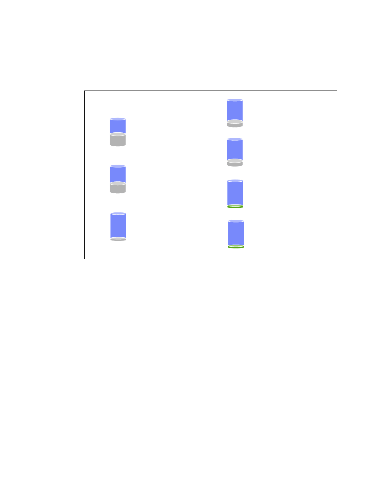
For more information about N series software features, see IBM System Storage N series
Storage Efficiency features
Snapshot™Copies
Point-in-time copies that write only
changed blocks. No performance
penalty.
Virtual Copies (FlexClone®)
Near-zero space, instant “virtual”
copies. Only subsequent changes in
cloned dataset get stored.
Thin Provisioning
(FlexVol
®
)
Create flexible volumes that appear to
be a certain size but are really a much
smaller pool.
RAID-DP®Protection
(RAID-6)
Protects against double disk failure with
no performance penalty.
Deduplication
Removes data redundancies in
primary and secondary storage.
Save
up to
95%
Save
up to
46%
Save
up to
33%
Save
over
80%
Save
over
80%
Thin Replication
(SnapVault
®
and SnapMirror®)
Make data copies for disaster recovery
and backup using a minimal amount of
space.
Save
up to
95%
Data Compression
Reduces footprint of primary
and secondary storage.
Save
up to
87%
Software Guide, SG24-7129, which is available at this website:
http://www.redbooks.ibm.com/abstracts/sg247129.html?Open
All N series systems support the storage efficiency features, as shown in Figure 1-3.
Figure 1-3 Storage efficiency features
1.3 Software licensing structure
This section provides an overview of the software licensing structure.
1.3.1 Mid-range and high-end
The software structure for mid-range and high-end systems is assembled out of the following
major options:
Data ONTAP Essentials (including one protocol of choice)
Protocols (CIFS, NFS, Fibre Channel, iSCSI)
SnapRestore
SnapMirror
SnapVault
FlexClone
SnapLock
SnapManager Suite
Chapter 1. Introduction to IBM System Storage N series 9
Page 30

Figure 1-4 provides an overview of the software structure that was introduced with the
Data ONTAP
Essentials
Includes: One Protocol of choice, SnapShots, HTTP, Deduplication, Compression, NearStore, DSM/MPIO,
SyncMirror, MultiStore, FlexCache, MetroCluster, High availability, OnCommand
License Key Details: Only SyncMirror Local, Cluster Failover and Cluster Failover Remote License Keys are
required for DOT 8.1, the DSM/MPIO License key must be installed on Server
Protocols
Sold Separately: iSCSI, FCP, CIFS, NFS
License Key Details: Each Protocol License Key must be installed separately
SnapRestore
Includes: SnapRestore
®
License Key Details: SnapRestore License Key must be installed separately
SnapMirror
Includes: SnapMirror
®
License Key Details: SnapMirror License Key unlocks all product features
FlexClone
Includes: FlexClone
®
License Key Details: FlexClone License Key must be installed separately
SnapVault
Includes: SnapVault®Primary and SnapVault®Secondary
License Key Details: SnapVault Secondary License Key unlocks both Primary and Secondary products
SnapLock
Sold Separately: SnapLock®Compliance and SnapLock®Enterprise
License Key Details: Each product is unlocked by its own Master License Key
SnapManager Suite
Includes: SnapManagers for Exchange, SQL Server, SharePoint, Oracle, SAP, VMWare Virtual Infrastructure,
Hyper-V, and SnapDrives for Windows and UNIX
License Key Details: SnapManager Exchange License Key unlocks the entire Suite of features
Complete Bundle
Includes: All Protocols, Single MailBox Recovery, SnapLock ®, SnapRestore®, SnapMirror®, FlexClone®,
SnapVault®, and SnapManager Suite
License Key Details: Refer to the individual Product License Key Details
Software Structure 2.0 Licensing
PLATFORMS: N62x0 & N7950T
NOTE: For DOT 8.0 and earlier, every feature requires its own License Key to be installed separately
availability of Data ONTAP 8.1.
Figure 1-4 Software structure for mid-range and enterprise systems
To increase the business flow efficiencies, the seven-mode licensing infrastructure was
modified to handle features that are included in a more bundled or packaged manner.
You do not need to add license keys on your system for most features that are distributed at
no additional fee. For some platforms, features in a software bundle require only one license
1.3.2 Entry-level
10 IBM System Storage N series Hardware Guide
key. Other features are enabled when you add certain other software bundle keys.
The entry-level software structure is similar to the mid-range and high-end structures that
were described in 1.3.1, “Mid-range and high-end” on page 9. The following changes apply:
All protocols (CIFS, NFS, Fibre Channel, iSCSI) are included with entry-level systems
Gateway feature is not available
MetroCluster feature is not available
Page 31

1.4 Data ONTAP 8 supported systems
Models Supported by Data ONTAP Versions 8.0 and Higher
IBM 8.0 8.0.1 8.0.2 8.0.3 8.1
N3220 x
N3240 x
N3400 x x x x x
N5300 x x x x x
N5600 x x x x x
N6040 x x x x x
N6060 x x x x x
N6070 x x x x x
N6210 x x x x
N6240 x x x x
N6270 x x x x
N7600 x x x x x
N7700 x x x x x
N7800 x x x x x
N7900 x x x x x
N7950T x x x x
Current Portfolio
Figure 1-5 provides an overview of systems that support Data ONTAP 8. The listed systems
reflect the N series product portfolio as of June 2011, and some older N series systems that
are suitable to run Data ONTAP 8.
Figure 1-5 Supported Data ONTAP 8.x systems
Chapter 1. Introduction to IBM System Storage N series 11
Page 32

12 IBM System Storage N series Hardware Guide
Page 33

Chapter 2. Entry-level systems
2
This chapter describes the IBM System Storage N series 3000 systems, which address the
entry-level segment.
This chapter includes the following sections:
Overview
N32x0 common features
N3150 model details
N3220 model details
N3240 model details
N3000 technical specifications
© Copyright IBM Corp. 2012, 2014. All rights reserved. 13
Page 34

2.1 Overview
Figure 2-1 shows the N3000 modular disk storage system, which is designed to provide
primary and auxiliary storage for midsize enterprises. N3000 systems offer integrated data
access, intelligent management software, and data protection capabilities in a cost-effective
package. N3000 series innovations include internal controller support for Serial-Attached
SCSI (SAS) or SATA drives, expandable I/O connectivity, and onboard remote management.
Figure 2-1 N3000 modular disk storage system
The following N3000 series are available:
IBM System Storage N3150:
– Model A15: Single-node
– Model A25: Dual-node, Active/Active HA Pair
IBM System Storage N3220:
– Model A12: Single-node
– Model A22: Dual-node, Active/Active HA Pair
The IBM System Storage N3240:
– Model A14: Single-node
– Model A24: Dual-node, Active/Active HA Pair
Table 2-1 provides a comparison of the N3000 series.
Table 2-1 N3000 series comparison
N3000 features
Form factor 2U, 12 internal drives 2U, 24 internal drives 4U, 24 internal drives
Dual controllers Yes Yes Yes
Max. raw capacity 240 TB 509 TB 576 TB
Max. disk drives 60 144 144
Max. Ethernet ports 8 8 8
Onboard SAS ports 4 4 4
Flash pool support No Yes Yes
8 Gb FC support No Yes
10 Gb Enet support No Yes
Storage protocols CIFS, NFS,
a. All specifications are for dual-controller, active-active configurations.
b. Based on optional dual-port 10 GbE or 8 Gb FC mezzanine card and single slot per controller.
a
N3150 (FAS2220) N3220 (FAS2240-2) N3240 (FAS2240-4)
iSCSI
b
b
CIFS, NFS,
iSCSI, FCP
b
Ye s
b
Ye s
CIFS, NFS,
iSCSI, FCP
14 IBM System Storage N series Hardware Guide
Page 35

2.2 N32x0 common features
Table 2-2 provides ordering information for N32x0 systems.
Table 2-2 N3150 and N32x0 configurations
Model Form factor HDD PSU Select Process Control Module
N3150-A15, a25 2U chassis 12 SAS 3.5” 2 One or two controllers, each with no
N3220-A12, A22 2U chassis 24 SFF SAS 2.5” 2 One or two controllers, each with:
N3240-A14, A24 4U chassis 24 SATA 3.5” 4
Table 2-3 provides ordering information for N32x0 systems with Mezzanine cards.
Table 2-3 N32x0 controller configuration
Feature code Configuration
2030 Controller with dual-port FC Mezzanine Card (include SFP+)
2031 Controller with dual-port 10 GbE Mezzanine Card (no SFP+)
Table 2-4 provides information about the maximum number of supported shelves by
expansion type.
mezzanine card
Dual FC mezzanine card or
Dual 10 GE mezzanine card
Table 2-4 Number of shelves that are supported
Expansion shelf
(Total of 114 disks)
ESN 3000 Up to five shelves (each with up to 24 x 3.5” SAS or SATA disk drives)
EXN 3500 Up to five shelves (each with up to 24 x 2.5” SAS disk drives, or SSD)
EXN 4000 Up to six shelves (each with up to 14 x 3.5” SATA disk drives)
Number of supported shelves
Chapter 2. Entry-level systems 15
Page 36

2.3 N3150 model details
This section describes the N series 3150 models.
Note: Be aware of the following points regarding N3150 models:
N3150 models do not support the Fibre Channel protocol.
Compared to N32xx systems, the N3150 models have newer firmware and no
mezzanine card option is available.
2.3.1 N3150 model 2857-A15
N3150 Model A15 is a single-node storage controller. It is designed to provide CIFS, NFS,
Internet Small Computer System Interface (iSCSI), and HTTP support. Model A15 is a 2U
storage controller that must be mounted in a standard 19-inch rack. Model A15 can be
upgraded to a Model A25. However, this is a disruptive upgrade.
2.3.2 N3150 model 2857-A25
N3150 Model A25 is designed to provide identical functions as the single-node Model A15.
However, it has a second Processor Control Module and the Clustered Failover (CFO)
licensed function. Model A25 consists of two Processor Control Modules that are designed to
provide failover and failback function, which helps improve overall availability. Model A25 is a
2U rack-mountable storage controller.
2.3.3 N3150 hardware
The N3150 hardware has the following characteristics:
Specifications (single node, 2x for dual node):
– 2U, standard 19-inch rack mount enclosure (single or dual node)
– One 1.73 GHz Intel dual-core processor
– 6 GB random access ECC memory (NVRAM 768 MB)
– Four integrated Gigabit Ethernet RJ45 ports
– Two SAS ports
– One serial console port and one integrated RLM port
Redundant hot-swappable, auto-ranging power supplies and cooling fans
Maximum Capacity is 240 TB:
– Internal Storage: 6- and 12-disk orderable configurations
– External Storage: Maximum of two EXN3000 SAS/SATA or EXN3500 SAS storage
expansion units (48 disks).
16 IBM System Storage N series Hardware Guide
Page 37

Figure 2-2 shows the front view of the N3150.
Figure 2-2 N3150 front view
Figure 2-3 shows the N3150 Single-Controller in chassis (Model A15)
Figure 2-3 N3150 Single-Controller in chassis
Figure 2-4 shows the N3150 Dual-Controller in chassis (Model A25)
Figure 2-4 N3150 Dual-Controller in chassis
Note: The N3150 supports IP protocols only because it lacks any FC ports.
Chapter 2. Entry-level systems 17
Page 38

2.4 N3220 model details
This section describes the N series 3220 models.
2.4.1 N3220 model 2857-A12
N3220 Model A12 is a single-node storage controller. It is designed to provide HTTP, iSCSI,
NFS, CIFS, and FCP support through optional features. Model A12 is a 2U storage controller
that must be mounted in a standard 19-inch rack. Model A12 can be upgraded to a Model
A22. However, this is a disruptive upgrade.
2.4.2 N3220 model 2857-A22
N3320 Model A22 is designed to provide identical functions as the single-node Model A12.
However, it has a second Processor Control Module and the CFO licensed function. Model
A22 consists of two Processor Control Modules that are designed to provide failover and
failback function, which helps improve overall availability. Model A22 is a 2U rack-mountable
storage controller.
2.4.3 N3220 hardware
The N3220 hardware has the following characteristics:
Based on the EXN3500 expansion shelf
24 2.5” SFF SAS disk drives (minimum initial order of 12 disk drives)
Specifications (single node, 2x for dual node):
– 2U, standard 19-inch rack mount enclosure (single or dual node)
– One 1.73 GHz Intel dual-core processor
– 6 GB random access ECC memory (NVRAM 768 MB)
– Four integrated Gigabit Ethernet RJ45 ports
– Two SAS ports
– One serial console port and one integrated RLM port
– One optional expansion I/O adapter slot on mezzanine card:
• 8 Gb FC card provides two FC ports
• 10 GbE card provides two 10 GbE ports
– Redundant hot-swappable, auto-ranging power supplies and cooling fans
Figure 2-5 shows the front view of the N3220.
Figure 2-5 N3220 front view
18 IBM System Storage N series Hardware Guide
Page 39

Figure 2-6 shows the rear view of the N3220.
Figure 2-6 N3220 rear view
Figure 2-5 shows the N3220 Single-Controller in chassis.
Figure 2-7 N3220 Dual-Controller in chassis (including optional mezzanine card)
2.5 N3240 model details
This section describes the N series 3240 models.
2.5.1 N3240 model 2857-A14
N3240 Model A14 is designed to provide a single-node storage controller with HTTP, iSCSI,
NFS, CIFS, and FCP support through optional features. The N3240 Model A14 is a 4U
storage controller that must be mounted in a standard 19-inch rack. Model A14 can be
upgraded to a Model A24. However, this is a disruptive upgrade.
2.5.2 N3240 model 2857-A24
N3240 Model A24 is designed to provide identical functions as the single-node Model A14.
However, it includes a second Processor Control Module and CFO licensed function. Model
A24 consists of two Processor Control Modules that are designed to provide failover and
failback function, which helps improve overall availability. Model A24 is a 4U rack-mountable
storage controller.
Chapter 2. Entry-level systems 19
Page 40

2.5.3 N3240 hardware
Based on the EXN3000 expansion shelf
24 SATA disk drives (minimum initial order of 12 disk drives)
Specifications (single node, 2x for dual node):
– 4U, standard 19-inch rack mount enclosure (single or dual node)
– One 1.73 GHz Intel dual-core processor
– 6 GB random access ECC memory (NVRAM 768 MB)
– Four integrated Gigabit Ethernet RJ45 ports
– Two SAS ports
– One serial console port and one integrated RLM port
– One optional expansion I/O adapter slot on mezzanine card:
• 8 Gb FC card provides two FC ports
• 10 GbE card provides two 10 GbE ports
– Redundant hot-swappable, auto-ranging power supplies and cooling fans
Figure 2-8 shows the front view of the N3240
Figure 2-8 N3240 front view
Figure 2-9 shows the N3240 Single-Controller in chassis.
Figure 2-9 N3240 Single-Controller in chassis
20 IBM System Storage N series Hardware Guide
Page 41

Figure 2-10 shows the front and rear view of the N3240
Figure 2-10 N3240 Dual-Controller in chassis
Figure 2-11 shows the controller with the 8 Gb FC Mezzanine card option
Figure 2-11 Controller with 8 Gb FC Mezzanine card option
Figure 2-12 shows the controller with the 10 GbE Mezzanine card option
Figure 2-12 Controller with 10 GbE Mezzanine card option
Chapter 2. Entry-level systems 21
Page 42

2.6 N3000 technical specifications
Table 2-5 provides an overview of the N32x0 specifications.
Table 2-5 N32x0 specifications
N3150 N3220 N3240
Configuration Single-node Dual-node Single-node Dual-node Single-node Dual-node
Machine type 2857-A15 2857-A25 2857-A12 2857-A22 2857-A14 2857-A24
Gateway feature N/A
Processor type Dual-core Intel Xeon 1.73 GHz
Number of
processors
Memory
NV RAM 768 MB 1.5 GB 768 MB 1.5 GB 768 MB 1.5 GB
Onboard I/O ports
FC ports (Speed) N/A N/A 0 0 0 0
Ethernet ports 4 (1 Gb) 8 (1 Gb) 4 (1 Gb) 8 (1 Gb) 4 (1 Gb) 8 (1 Gb)
SAS ports 2 (6 Gb) 4 (6 Gb) 2 (6 Gb) 4 (6 Gb) 2 (6 Gb) 4 (6 Gb)
Storage scalability
Max. expansion
shelves
Max. disk drives 60
Max. raw
capacity
Max. volumes 500 1000 500 1000 500 1000
Max volume size 53.7 TB (64 bits) 53.7 TB (64 bits) 53.7 TB (64 bits)
a
121212
612612612
255
144
(12 internal + 48 external)
240 TB 501 TB 576 TB
(24 internal + 120 external)
144
(24 internal + 120 external)
I/O scalability
Adapter slots None None 1 mezzanine 2 mezzanine 1 mezzanine 2 mezzanine
Max. FC ports002424
Max. Enet ports002424
Max. SAS ports 0 0 0 0 0 0
a. The NVRAM on the N3000 models uses a portion of the controller memory, which results in correspondingly
less memory being available for Data ONTAP.
For more information about N series 3000 systems, see this website:
http://www.ibm.com/systems/storage/network/n3000/appliance/index.html
22 IBM System Storage N series Hardware Guide
Page 43

Chapter 3. Mid-range systems
3
This chapter describes the IBM System Storage N series 6000 systems, which address the
mid-range segment.
This chapter includes the following sections:
Overview
N62x0 model details
N62x0 technical specifications
© Copyright IBM Corp. 2012, 2014. All rights reserved. 23
Page 44

3.1 Overview
Figure 3-1 shows the N62x0 modular disk storage system, which includes the following
advantages:
Increase NAS storage flexibility and expansion capabilities by consolidating block and file
data sets onto a single multiprotocol storage platform.
Provide performance when your applications need it most with high bandwidth, 64-bit
architecture, and the latest I/O technologies.
Maximize storage efficiency and growth and preserve investments in staff expertise and
capital equipment with data-in-place upgrades to more powerful IBM System Storage N
series.
Improve your business efficiency by using the N6000 series capabilities, which are also
available with a Gateway feature. These capabilities reduce data management complexity
in heterogeneous storage environments for data protection and retention.
Figure 3-1 Mid-range systems
IBM System Storage N62x0 series systems help you meet your network-attached storage
(NAS) needs. They provide high levels of application availability for everything from critical
business operations to technical applications. You can also address NAS and storage area
network (SAN) as primary and auxiliary storage requirements. In addition, you get
outstanding value. These flexible systems offer excellent performance and impressive
expandability at a low total cost of ownership.
3.1.1 Common features
The N62x0 modular disk storage system includes the following common features:
Simultaneous multiprotocol support for FCoE, FCP, iSCSI, CIFS, NFS, HTTP, and FTP
File-level and block-level service in a single system
Support for Fibre Channel, SAS, and SATA disk drives
Data ONTAP software
Broad range of built-in features
Multiple supported backup methods that include disk-based and host-based backup and
tape backup to direct, SAN, and GbE attached tape devices
3.1.2 Hardware summary
The N62x0 modular disk storage system contains the following hardware:
Up to 2880 TB raw storage capacity
12/24 GB to 20/40 GB random access memory
1.6/3.2 GB to 2/4 GB nonvolatile memory
24 IBM System Storage N series Hardware Guide
Page 45

Integrated Fibre Channel, Ethernet, and SAS ports
Quad-port 4 Gbps adapters (optional)
Up to four Performance Acceleration Modules (Flash Cache)
Diagnostic LED/LCD
Dual redundant hot-plug integrated cooling fans and autoranging power supplies
19 inch, rack-mountable unit
N6220
The IBM System Storage N6220 includes the following storage controllers:
Model C15: A single-node base unit
Model C25: An active/active dual-node base unit, which is composed of two C15 models
Model E15: A single-node base unit, with an I/O expansion module
Model E25: An active/active dual-node base unit, which is composed of two E15 models
The Exx models contain an I/O expansion module that provides more PCIe slots. The I/O
expansion is not available on Cxx models.
N6250
The IBM System Storage N6250 includes the following storage controllers:
Model E16: A single-node base unit, with one controller and one I/O expansion module
both in a single chassis
Model E26: An active/active dual-node base unit, which is composed of two E16 models
The Exx model contains an I/O expansion module that provides more PCIe slots. The I/O
expansion is not available on Cxx models
3.1.3 Functions and features common to all models
This section describes the functions and features that are common to all eight models.
Fibre Channel, SAS, and SATA attachment
All models include Fibre Channel, SAS, and SATA attachment options for disk expansion
units. These options are designed to allow deployment in multiple environments, including
data retention, NearStore, disk-to-disk backup scenarios, and high-performance,
mission-critical I/O intensive operations.
The IBM System Storage N series supports the following expansion units:
EXN1000 SATA storage expansion unit (no longer available)
EXN2000 and EXN4000 FC storage expansion units
EXN3000 SAS/SATA expansion unit
EXN3500 SAS expansion unit
Because none of the N62x0 models include storage in the base chassis, at least one storage
expansion unit must be attached. All N62x0 models must be mounted in a standard 19-inch
rack.
Dynamic removal and insertion of the controller
The N6000 controllers are hot pluggable. You do not have to turn off PSUs to remove a
controller in a dual-controller configuration.
PSUs are independent components. One PSU can run an entire system indefinitely. There is
no “2-minute rule” if you remove one PSU. PSUs have internal fans for self-cooling only.
Chapter 3. Mid-range systems 25
Page 46

RLM design and internal Ethernet switch on the controller
The Data ONTAP management interface (which is known as e0M) provides a robust and
cost-effective way to segregate management subnets from data subnets without incurring a
port penalty. On the N6000 series, the traditional RLM port on the rear of the chassis (now
identified by a wrench symbol) connects first to an internal Ethernet switch. This switch
provides connectivity to the RLM and e0M interfaces. Because the RLM and e0M each have
unique TCP/IP addresses, the switch can discretely route traffic to either interface. You do not
need to use a data port to connect to an external Ethernet switch. Set up of VLANs and VIFs
is not required and not supported because e0M allows customers to have dedicated
management networks without VLANs.
The e0M interface can be thought of as another way to remotely access and manage the
storage controller. It is similar to the serial console, RLM, and standard network interfaces.
Use the e0M interface for network-based storage controller administration, monitoring
activities, and ASUP reporting. The RLM is used when you require its higher level of support
features. Host-side application data should connect to the appliance on a separate subnet
from the management interfaces
RLM assisted cluster failover
To decrease the time that is required for cluster failover (CFO) to occur when there is an
event, the RLM can communicate with the partner node instance of Data ONTAP. This
capability was available in other N series models before the N6000 series. However, the
internal Ethernet switch makes the configuration much easier and facilitates quicker cluster
failover, with some failovers occurring within 15 seconds.
3.2 N62x0 model details
This section gives an overview of the N62x0 systems.
3.2.1 N6220 and N6250 hardware overview
The N62x0 models support several physical configurations (single or dual node) and with or
without the I/O expansion module (IOXM).
The IBM N6220/N6250 configuration flexibility is shown in Figure 3-2 on page 27.
26 IBM System Storage N series Hardware Guide
Page 47

Figure 3-2 IBM N6210/N6240 configuration flexibility
All of the N62x0 controller modules provide the same type and number of onboard I/O ports
and PCI slots. The Exx models include the IOXM, which provides more PCI slots.
Figure 3-3 shows the IBM N62x0 Controller I/O module.
Figure 3-3 IBM N62x0 Controller I/O
The different N62x0 models also support different chassis configurations. For example, a
single chassis N6220 might contain a single node (C15 model), dual nodes (C25), or a single
node plus IOXM (E15). A second chassis is required for the dual-node with IOXM models
(E25 and E26).
Chapter 3. Mid-range systems 27
Page 48

IBM N62x0 I/O configuration flexibility is shown in Figure 3-4.
Figure 3-4 IBM N62x0 I/O configuration flexibility
IBM N62x0 I/O Expansion Module (IOXM) is shown in Figure 3-5 and features the following
characteristics:
Components are not hot swappable:
– Controller panics if it is removed
– If inserted into running IBM N62x0, IOXM is not recognized until the controller is
rebooted
4 full-length PCIe v1.0 (Gen 1) x8 slots
Figure 3-5 IBM N62x0 I/O Expansion Module (IOXM)
28 IBM System Storage N series Hardware Guide
Page 49

Figure 3-6 shows the IBM N62x0 system board layout.
Figure 3-6 IBM N62x0 system board layout
Figure 3-7 shows the IBM N62x0 USB Flash Module, which has the following features:
It is the boot device for Data ONTAP and the environment variables
It replaces CompactFlash
It has the same resiliency levels as CompactFlash
2 GB density is used
It is a replaceable FRU
Figure 3-7 IBM N62x0 USB Flash Module
Chapter 3. Mid-range systems 29
Page 50

3.2.2 IBM N62x0 MetroCluster and gateway models
This section describes the MetroCluster feature.
Supported MetroCluster N62x0 configuration
The following MetroCluster two-chassis configurations are supported:
Each chassis single-enclosure stand-alone:
• IBM N6220 controller with blank. The N6220-C25 with MetroCluster ships the
second chassis, but does not include the VI card.
• IBM N6250 controller with IOXM
Two chassis with single-enclosure HA (twin): Supported on IBM N6250 model
Fabric MetroCluster requires EXN4000 disk shelves or SAS shelves with SAS FibreBridge
(EXN3000 and EXN3500)
Gateway configuration is supported on both models.
FCVI card and port clarifications
In many stretch MetroCluster configurations, the cluster interconnect on the NVRAM cards in
each controller is used to provide the path for cluster interconnect traffic. The N60xx and
N62xx series offer a new architecture that incorporates a dual-controller design with the
cluster interconnect on the backplane.
The N62x0 ports c0a and c0b are
communication. Use these ports to enable NVRAM mirroring after you set up a dual-chassis
HA configuration (that is, N62x0 with IOXM). These ports cannot run standard Ethernet or the
Cluster-Mode cluster network.
“Stretching” the HA-pair (also called the SFO pair) by using the c0x ports is qualified with
optical SFPs up to a distance of 30 m. Beyond that distance, you need the FC-VI adapter.
When the FC-VI card is present, the c0x ports are disabled.
Although they have different part numbers, the same model of FC card is used for
MetroCluster or SnapMirror over FC. The PCI slot that the card is installed to causes the card
to identify as either model.
Tip: Always use an FCVI card in any N62xx MetroCluster, regardless if it is a stretched or
fabric-attached MetroCluster.
the ports that you must connect to establish controller
30 IBM System Storage N series Hardware Guide
Page 51

3.3 N62x0 technical specifications
Table 3-1 shows the N62x0 specifications.
Table 3-1 N62x0 specifications
N6220 N6220 (with optional IOXM) N6250 (always with IOXM)
Configuration Single-node Dual-node Single-node Dual-node Single-node Dual-node
Machine type 2858-C15 2658-C25 2858-E15 2858-E25 2858-E16 2858-E26
Gateway feature FC# 9551
Processor type 2.3 GHz Intel (Quad Core)
Number of
Processors
Memory 12 24 12 24 20 40
NV RAM 1.6 GB 3.2 GB 1.6 GB 3.2 GB 2 GB 4 GB
Onboard I/O ports
FC ports (Speed) 2 (4 Gb) 4 (4 Gb) 2 (4 Gb) 4 (4 Gb) 2 (4 Gb) 4 (4 Gb)
Ethernet ports 2 (1 Gb) 4 (1 Gb) 2 (1 Gb) 4 (1 Gb) 2 (1 Gb) 4 (1 Gb)
SAS ports 2 (6 Gb) 4 (6 Gb) 2 (6 Gb) 4 (6 Gb) 2 (6 Gb) 4 (6 Gb)
Storage scalability
Max. FC loops 5 13 13
Max. disk drives 480 480 720
Max. raw
capacity
Max. volumes 500 1000 500 1000 500 1000
Max volume size 60 TB (64-bit) 60 TB (64-bit) 70 TB (64-bit)
I/O scalability
PCIe slots 2 4 6 12 6 12
121224
1920 TB
(with 4 TB disks)
1920 TB
(with 4 TB disks)
2880 TB
(with 4 TB disks)
Max. FC ports102026522652
Max. Enet ports 10 20 26 52 26 52
Max. SAS ports 10 20 26 52 26 52
For more information about N series 6000 systems, see this website:
http://www.ibm.com/systems/storage/network/n6000/appliance/index.html
Chapter 3. Mid-range systems 31
Page 52

32 IBM System Storage N series Hardware Guide
Page 53

Chapter 4. High-end systems
4
This chapter describes the IBM System Storage N series 7000 system, which addresses the
high-end segment.
This chapter includes the following sections:
Overview
N7x50T hardware
IBM N7x50T configuration rules
N7000T technical specifications
© Copyright IBM Corp. 2012, 2014. All rights reserved. 33
Page 54

4.1 Overview
Figure 4-1 shows the N7x50T modular disk storage systems, which provide the following
advantages:
High data availability and system-level redundancy
Support of concurrent block I/O and file serving over Ethernet and Fibre Channel SAN
infrastructures
High throughput and fast response times
Support of enterprise customers who require network-attached storage (NAS), with Fibre
Channel or iSCSI connectivity
Attachment of Fibre Channel, serial-attached SCSI (SAS), and Serial Advanced
Technology Attachment (SATA) disk expansion units
Figure 4-1 N7x50T modular disk storage systems
The IBM System Storage N7950T (2867 Model E22) system is an active/active dual-node
base unit. It consists of two cable-coupled chassis with one controller and one I/O expansion
module per node. It is designed to provide fast data access, simultaneous multiprotocol
support, expandability, upgradability, and low maintenance requirements.
4.1.1 Common features
The N7x50T modular disk storage systems includes the following common features:
High data availability and system-level redundancy that is designed to address the needs
of business-critical and mission-critical applications.
Single, integrated architecture that is designed to support concurrent block I/O and file
serving over Ethernet and Fibre Channel SAN infrastructures.
High throughput and fast response times for database, email, and technical applications.
Enterprise customer support for unified access requirements for NAS through Fibre
Channel or iSCSI.
Fibre Channel, SAS, and SATA attachment options for disk expansion units that are
designed to allow deployment in multiple environments. These environments include data
retention, NearStore, disk-to-disk backup scenarios, and high-performance,
mission-critical I/O intensive operations.
Can be configured either with native disk shelves, as a gateway for a back-end SAN array,
or both.
34 IBM System Storage N series Hardware Guide
Page 55

4.1.2 Hardware summary
The N7x50T modular disk storage systems contains the following hardware:
Up to 5760 TB raw storage capacity
96 GB - 192 GB of RAM (random access memory)
Integrated Fibre Channel, Ethernet, and SAS ports
Support for 10 Gbps Ethernet port speed
Support for 8 Gbps Fibre Channel speed
N7550T
The IBM System Storage N7550T includes the Model C20 storage controller. This controller
uses a dual-node active/active configuration, which is composed of two controller units, in
either one or two chassis (as required for Metrocluster configuration).
N7950T
The IBM System Storage N6250 includes the Model E25 storage controller. This controller
uses a dual-node active/active configuration, which is composed of two controller units, each
with an IOXM, in two chassis.
4.2 N7x50T hardware
This section provides an overview of the N7550T and N7950T hardware.
4.2.1 Chassis configuration
Figure 4-4 shows the IBM N series N7x50T chassis configuration.
Figure 4-2 IBM N series N7950T configuration
Chapter 4. High-end systems 35
Page 56

Figure 4-3 shows the IBM N series N7550T base components.
Figure 4-3 IBM N series N7550T base components
Figure 4-4 shows the IBM N series N7950T configuration.
Figure 4-4 IBM N series N7950T configuration
4.2.2 Controller module components
Although they differ in processor count and memory configuration, the processor modules for
the N7550T and N7950T provide the same onboard I/O connections. The N7950T also
includes an I/O expansion module (IOXM) to provide more I/O capacity.
Figure 4-5 on page 37 shows the IBM N series N7x50T controller I/O.
36 IBM System Storage N series Hardware Guide
Page 57

Figure 4-5 N7x50 controller
Figure 4-6 shows an internal view of the IBM N series N7x50T Controller module. The
N7550T and N7950T differ in number of processors and installed memory.
Figure 4-6 N7x50 internal view
Chapter 4. High-end systems 37
Page 58

4.2.3 I/O expansion module components
The N7950T model always includes the I/O expansion module in the second bay in each of its
two chassis. This provides another 20 PCIe expansion slot (2x 10 slots) to the N7950T
relative to the N7550T. The IOXM is not supported on the N7550T model.
Figure 4-7 shows the IBM N series N7950T I/O Expansion Module (IOXM).
Figure 4-7 IBM N series N7950T I/O Expansion Module (IOXM)
The N7950T IOXM features the following characteristics:
All PCIe v2.0 (Gen 2) slots: Vertical slots have different form factor
Not hot-swappable:
– Controller panics if removed
– Hot pluggable, but not recognized until reboot
Figure 4-8 shows the IBM N series N7950T I/O Expansion Module (IOXM).
Figure 4-8 IBM N series N7950T I/O Expansion Module (IOXM)
38 IBM System Storage N series Hardware Guide
Page 59

4.3 IBM N7x50T configuration rules
This section describes the configuration rules for N7x50 systems.
4.3.1 IBM N series N7x50T slot configuration
This section describes the configuration rules for the vertical I/O slots and horizontal PCIe
slots.
Vertical I/O slots
The vertical I/O slots include the following characteristics:
Vertical slots use custom form-factor cards:
– Look similar to standard PCIe
– Cannot put standard PCIe cards into the vertical I/O slots
Vertical slot rules:
– Slot 1 must have a special Fibre Channel or SAS system board: Feature Code 1079
(Fibre Channel) and Feature Code 1080 (SAS)
– Slot 2 must have NVRAM8
– Slots 11 and 12 (N7950T with IOXM only):
• Can configure with a special FC I/O or SAS I/O card: Feature Code 1079 (FC) and
Feature Code 1080 (SAS)
• Can mix FC and SAS system boards in slots 11 and 12
– FC card ports can be set to target or initiator
Horizontal PCIe slots
The horizontal PCIe slots include the following characteristics:
Support standard PCIe adapters and cards:
– 10 GbE NIC (new quad port 1 GbE PCIe adapter for N7x50T FC1028)
– 10 GbE unified target adapter
– 8 Gb Fibre Channel
– Flash Cache
Storage HBAs: Special-purpose FC I/O and SAS I/O cards, and NVRAM8, are not used in
PCIe slots
4.3.2 N7x50T hot-pluggable FRUs
The following items are hot-pluggable:
Fans: Two-minute shutdown rule if you remove a fan FRU
Controllers: Do not turn off PSUs to remove a controller in dual- controller systems
PSUs:
– One PSU can run the entire system
– There is no 2-minute shutdown rule if one PSU removed
IOXMs are not hot pluggable (N7950T only):
– Removing the IOXM forces a system reboot
– System does not recognize a hot-plugged IOXM
Chapter 4. High-end systems 39
Page 60

4.3.3 N7x50T cooling architecture
The N7x50T cooling architecture includes the following features:
Six fan FRUs per chassis, which is paired three each for top and bottom bays (each fan
FRU has two fans)
One failed fan is allowed per chassis bay:
– Controller can run indefinitely with single failed fan
– Two failed fans in controller bay cause a shutdown
– Two-minute shutdown rule applies if a fan FRU is removed: Rule that is enforced on a
per-controller basis
4.3.4 System-level diagnostic procedures
The following system-level tools are present in N7x50T systems:
SLDIAG replaces SYSDIAG: Both run system-level diagnostic procedures
SLDIAG has the following major differences from SYSDIAG:
– SLDIAG runs from maintenance mode: SYSDIAG booted with a separate binary
– SLDIAG has a CLI interface: SYSDIAG used menu tables
SLDIAG used on all new IBM N series platforms going forward
4.3.5 MetroCluster, Gateway, and FlexCache
MetroCluster and Gateway configurations include the following characteristics:
Supported MetroCluster two-chassis configuration
Single-enclosure stand-alone chassis: IBM N series N7950T-E22 controller with IOXM
Fabric MetroCluster requires EXN4000 shelves
The N7x50T series can also function as a Gateway
FlexCache uses N7x50T chassis:
– Controller module (and in IOXM for N7950T)
– Supports dual-enclosure HA configuration
4.3.6 N7x50T guidelines
The following tips are useful for the N7x50T model:
Get hands-on experience with Data ONTAP 8.1
Do not attempt to put vertical slot I/O system boards in horizontal expansion slots
Do not attempt to put expansion cards in vertical I/O slots
Onboard 10 GbE ports require feature code for SFP+: Not compatible with other SFP+ for
the two-port 10 GbE NIC (FC 1078)
Onboard 8 Gb SFP not interchangeable with other SFPs: 8 Gb SFP+ autoranges 8 Gbps,
4 Gbps, and 2 Gbps; does not support 1 Gbps
Pay attention when 6 Gb SAS system board in I/O slot 1
NVRAM8 and SAS use QSFP connection
40 IBM System Storage N series Hardware Guide
Page 61

Figure 4-9 shows the use of the SAS Card in I/O Slot 1.
Figure 4-9 Using SAS Card in I/O Slot 1
NVRAM8 and SAS I/O system boards use the QSFP connector:
– Mixing the cables does not cause physical damage, but the cables do not work
– Label your HA and SAS cables when you remove them
4.3.7 N7x50T SFP+ modules
This section provides detailed information about SFP+ modules.
Figure 4-10 shows the 8 Gb SFP+ modules.
Figure 4-10 8 Gb SFP+ modules
Chapter 4. High-end systems 41
Page 62

Figure 4-11 shows the 10 GbE SFP+ modules.
Figure 4-11 10 GbE SFP+ modules
42 IBM System Storage N series Hardware Guide
Page 63

4.4 N7000T technical specifications
Table 4-1 provides the technical specifications of the N7x50T.
Table 4-1 N7x50T specifications
N7550T (single chassis) N7550T (dual chassis) N7950T (dual chassis)
Configuration Dual-node Dual-node (MetroCluster) Dual-node
Machine type 2867-C20 2867-E22
Gateway feature FC# 9551
Processor type 2.26 GHz Nehalem quad-core 2.93 GHz Intel 6-core
Number of
processors
Memory 96 GB 192 GB
NV RAM 4 GB 8 GB
Onboard I/O ports
FC ports (Speed) 8 (8 Gb) 8 (8 Gb)
Ethernet ports 8 (10 Gbps), 4 (1 Gbps) 8 (10 Gbps), 4 (1 Gbps)
SAS ports 0 – 8 (6 Gbps) 0 – 24 (6 Gbps)
Storage scalability
Max. FC loops 10 14
Max. disk drives 1200 1440
Max. raw
capacity
Max. volumes 1000 1000
Max volume size 70 TB (64-bit) 100 TB (64-bit)
I/O scalability
PCIe slots 8 24
4 (16 cores) 4 (24 cores)
4800 TB
(with 4 TB disks)
5760 TB
(with 4 TB disks)
Max. FC ports 48 128
Max. Enet ports 36 100
Max. SAS ports 40 72
For more information about N series 7000 systems, see this website:
http://www.ibm.com/systems/storage/network/n7000/appliance/index.html
Chapter 4. High-end systems 43
Page 64

44 IBM System Storage N series Hardware Guide
Page 65

Chapter 5. Expansion units
5
This chapter describes the IBM N series expansion units, which also called disk shelves.
This chapter includes the following sections:
Shelf technology overview
Expansion unit EXN3000
Expansion unit EXN3200
Expansion unit EXN3500
Self-Encrypting Drive
Expansion unit technical specifications
© Copyright IBM Corp. 2012, 2014. All rights reserved. 45
Page 66

5.1 Shelf technology overview
This section gives an overview of the N Series expansion unit technology. Figure 5-1 shows
the shelf topology comparison.
Figure 5-1 Shelf topology comparison
5.2 Expansion unit EXN3000
The IBM System Storage EXN3000 SAS/SATA expansion unit is available for attachment to N
series systems with PCIe adapter slots.
The EXN3000 SAS/SATA expansion unit is designed to provide SAS or SATA disk expansion
capability for the IBM System Storage N series systems. The EXN3000 is a 4U disk storage
expansion unit. It can be mounted in any industry standard 19-inch rack. The EXN3000
includes the following features:
Dual redundant hot-pluggable integrated power supples and cooling fans
Dual redundant disk expansion unit switched controllers
Diagnostic and status LEDs
5.2.1 Overview
The IBM System Storage EXN3000 SAS/SATA expansion unit is available for attachment to
all N series systems except N3300, N3700, N5200, and N5500. The EXN3000 provides
low-cost, high-capacity, and serially attached SCSI (SAS) Serial Advanced Technology
Attachment (SATA) disk storage for the IBM N series system storage.
46 IBM System Storage N series Hardware Guide
Page 67

The EXN3000 is a 4U disk storage expansion unit. It can be mounted in any
industry-standard 19-inch rack. The EXN3000 includes the following features:
Dual redundant hot-pluggable integrated power supplies and cooling fans
Dual redundant disk expansion unit switched controllers
24 hard disk drive slots
The EXN3000 SAS/SATA expansion unit is shown in Figure 5-2.
Figure 5-2 EXN3000 front view
The EXN3000 SAS/SATA expansion unit is shipped with no disk drives unless disk drives are
included in the order. In that case, the disk drives are installed in the plant.
The EXN3000 SAS/SATA expansion unit can be shipped with no disk drives installed. Disk
drives that are ordered with the EXN3000 are installed by IBM in the plant before shipping.
Requirement: For an initial order of an N series system, at least one of the storage
expansion units must be ordered with at least five disk drive features.
Figure 5-3 shows the rear view and the fans.
Figure 5-3 EXN3000 rear view
Chapter 5. Expansion units 47
Page 68

5.2.2 Supported EXN3000 drives
Table 5-1 lists the drives that are supported by EXN3000 at the time of this writing.
Table 5-1 EXN3000 supported drives
EXN3000 RPM Capacity
SAS 15 K 600 GB
SATA 7.2 K 1 TB
SSD N/A 200 GB
5.2.3 Environmental and technical specifications
Table 5-2 shows the environmental and technical specifications.
600 GB encrypted
2 TB
3 TB
3 TB encrypted
4 TB
Table 5-2 EXN3000 environmental specifications
EXN3000 Specification
Disk 24
Rack size 4U
Weight Empty: 21.1 lb. (9.6 kg)
Without drives: 53.7 lb. (24.4 kg)
With drives: 110 lb. (49.9 kg)
Power SAS: 300 GB 6.0A, 450 GB 6.3A, 600 GB 5.7A
SATA: 1 TB 4.4A, 2 TB 4.6A, 3 TB 4.6A
SSD: 100 GB 1.6A
Thermal (BTU/hr) SAS: 300 GB 2048, 450 GB 2150, 600 GB 1833
SATA: 1 TB 1495, 2 TB 1561, 3 TB 1555
SSD: 100 GB 557
5.3 Expansion unit EXN3200
IBM System Storage EXN3200 Model 306 SATA Expansion Unit is a 4U high-density SATA
enclosure for attachment to PCIe-based N series systems with SAS ports. The EXN3200
ships with 48 disk drives per unit.
The EXN3200 is a disk storage expansion unit for mounting in any industry standard 19-inch
rack. The EXN3200 provides low-cost, high-capacity SAS disk storage for the IBM N series
system storage family.
The EXN3200 must be ordered with a full complement of (48) disks.
48 IBM System Storage N series Hardware Guide
Page 69

5.3.1 Overview
The IBM System Storage EXN3200 SATA expansion unit is available for attachment to all N
series systems, except N3300, N3700, N5200, and N5500. The EXN3000 provides low-cost,
high-capacity, and SAS SATA disk storage for the IBM N series system storage.
The EXN3200 is a 4U disk storage expansion unit. It can be mounted in any
industry-standard 19-inch rack. The EXN3200 includes the following features:
Four redundant, hot-pluggable, integrated power supplies and cooling fans
Dual redundant disk expansion unit switched controllers
48 hard disk drives (in 24 bays)
Diagnostic and status LEDs
The EXN3200 must be ordered with a full complement of disks. Disk drives that are ordered
with the EXN3200 are shipped separately from the EXN3200 shelf and must be installed at
the customer's location.
Disk drive bays are numbered horizontally starting from 0 at the upper left position to 23 at the
lower right position. The EXN3200 SAS/SATA expansion unit is shown in Figure 5-4.
Figure 5-4 EXN3200 front view
Each of the 24 disk bays contains two SATA HDDs on the same carrier, as shown in
Figure 5-5.
Figure 5-5 EXN3200 disk carrier
Since removing a disk tray to replace a failed disk removes two disks, it is recommended to
have four spare disks instead of two when using the EXN3200 expansion unit.
Figure 5-6 on page 50 shows the EXN3200 rear view, with the following components
numbered:
1. IOM fault LED
2. ACP ports
3. Two I/O modules (IOM6)
4. SAS ports
5. SAS port link LEDs
6. IOM A and power supplies one and two
Chapter 5. Expansion units 49
Page 70

7. IOM B and power supplies three and four
8. Four power supplies (each with integrated fans)
9. Power supply LEDs
Figure 5-6 EXN3200 rear view
5.3.2 Supported EXN3000 drives
Table 5-3 lists the drives that are supported by EXN3200 at the time of this writing.
Table 5-3 EXN3000 supported drives
EXN3000 RPM Capacity
SATA 7.2 K 3 TB
7.2 K 4 TB
5.3.3 Environmental and technical specifications
Table 5-4 shows the environmental and technical specifications
Table 5-4 EXN3000 environmental and technical specifications
Input voltage 100 to 240 V (100 V actual 200 to 240 V (200 V actual)
Total input current
measured, A
Size Worst
case,
a
2 PSU
3 TB 8.71 3.29 6.57 4.59 1.73 3.46
4 TB 8.54 3.40 6.79 4.25 1.69 3.38
Typical Worst
Per PSU
b
pair
System,
four PSU
case,
2 PSU
c
Typical
Per PSU
pair
System,
four PSU
Total input power
measured, W
3 TB 870 329 657 919 346 693
4 TB 853 339 677 837 329 657
50 IBM System Storage N series Hardware Guide
Page 71

Input voltage 100 to 240 V (100 V actual 200 to 240 V (200 V actual)
Size Worst
case,
a
2 PSU
Tot al t he rma l
dissipation, BTU/hr
Weight With midplane, four PSUs, two IOMs, four HDD carriers: 81 lbs (36.7 kg)
a. Worst-case indicates a system that is running with two PSUs, high fan speed, and power that is distributed over
two power cords.
b. Per PSU pair indicates typical power needs, per PSU pair, for a system operating under normal conditions.
c. System indicates typical power needs for four PSUs in a system operating under normal conditions and power that
is distributed over four power cords.
3 TB 2970 1122 2243 3137 1181 2362
4 TB 2909 1155 2309 2854 1120 2240
Fully configured: 145 lbs (65.8 kg)
Typical Worst
Per PSU
b
pair
System,
four PSU
case,
2 PSU
c
Typical
Per PSU
pair
System,
four PSU
5.4 Expansion unit EXN3500
The EXN3500 is a small form factor (SFF) 2U disk storage expansion unit for mounting in any
industry standard 19-inch rack. The EXN3500 provides low-cost, high-capacity SAS disk
storage with slots for 24 hard disk drives for the IBM N series system storage family.
The EXN3500 SAS expansion unit is shipped with no disk drives unless they are included in
the order. In that case, the disk drives are installed in the plant.
The EXN3500 SAS expansion unit is a 2U SFF disk storage expansion unit that must be
mounted in an industry-standard 19-inch rack. It can be attached to all N series systems
except N3300, N3700, N5200, and N5500. It includes the following features:
Third-generation SAS product
Increased density
24 x 2.5 inch 10 K RPM drives in 2U rack at same capacity points (450 GB and 600 GB)
offers double the GB/rack U of the EXN3000
Increased IOPs/rack U
Greater bandwidth
6 Gb SAS 2.0 offers ~24 Gb (6 Gb x 4) combined bandwidth per wide port
Improved power consumption: Power consumption per GB reduced by approximately
30-50%*
Only SAS drives are supported in the EXN3500: SATA is not supported
The following features were not changed:
Same underlying architecture and FW base as EXN3000
All existing EXN3000 features and functionality
Still uses the 3 Gb PCIe Quad-Port SAS HBA (already 6 Gb capable) or onboard SAS
ports
Chapter 5. Expansion units 51
Page 72

5.4.1 Overview
The EXN3500 includes the following hardware:
Dual, redundant, hot-pluggable, integrated power supplies and cooling fans
Dual, redundant, disk expansion unit switched controllers
24 SFF hard disk drive slots
Diagnostic and status LEDs
Figure 5-7 shows the EXN3500 front view.
Figure 5-7 EXN3500 front view
The EXN3500 SAS expansion unit can be shipped with no disk drives installed. Disk drives
ordered with the EXN3500 are installed by IBM in the plant before shipping. Disk drives can
be of 450 GB and 600 GB physical capacity, and must be ordered as features of the
EXN3500.
Requirement: For an initial order of an N series system, at least one of the storage
expansion units must be ordered with at least five disk drive features.
Figure 5-8 shows the rear view of the EXN3500, which highlights the connectivity and
resiliency.
Figure 5-8 EXN3500 rear view
52 IBM System Storage N series Hardware Guide
Page 73

Figure 5-9 shows the IOM differences.
Figure 5-9 IOM differences
5.4.2 Intermix support
EXN3000 and EXN3500 can be combined in the following configurations:
Intermix of EXN3000 and EXN3500 shelves: EXN3000 and EXN3500 shelves cannot be
intermixed on the same stack.
Only applicable to N3150 and N32x0, not other platforms: mixing EXN3500 and EXN3000
w/ IOM3 or IOM6 is supported.
Applies only to N3150 and N32x0, not other platforms.
EXN3000 supports IOM3 and IOM6 modules.
Attention: Even though it is supported to intermix IMO3 and IOM6 modules, it is not
recommend that you do so. The maximum loop speed is limited to IMO3 speed.
EXN3500 supports only IOM6 modules: the use of IOM3 modules in an EXN3500 is not
supported.
5.4.3 Supported EXN3500 drives
Table 5-5 on page 54 lists the drives that are supported by EXN3500 at the time of this
writing.
Chapter 5. Expansion units 53
Page 74

Table 5-5 EXN3500 supported drives
EXN3500 RPM Capacity
SAS 10 K 450 GB
SSD N/A 200 GB
5.4.4 Environmental and technical specification
Table 5-6 shows the environmental and technical specifications.
Table 5-6 EXN3500 environmental specifications
EXN3500 Specification
Disk 24
600 GB
600 GB encrypted
900 GB
900 GB encrypted
1.2 TB
800 GB
Rack size 2U
Weight Empty: 17.4 lbs. (7.9 kg)
Without Drives: 34.6 lbs. (15.7 kg)
With Drives: 49 lbs. (22.2 kg)
Power SAS: 450 GB 3.05A, 600 GB 3.59A
Thermal (BTU/hr) SAS: 450 GB 1024, 600 GB 1202
5.5 Self-Encrypting Drive
This section describes the FDE 600 GB 2.5 HDD drive.
5.5.1 SED at a glance
At the time of this writing, only the following FDE 600 GB drive is supported:
Self-Encrypting Drive (SED):
– 600 GB capacity
– 2.5-inch form factor, 10 K RPM, 6 GB SAS
– Encryption that is enabled through disk drive firmware (same drive as what is shipping
with different firmware)
Available in EXN3500 and EXN3000 expansion shelf and N3220 (internal drives)
controller: Only fully populated (24 drives) and N3220 controller
54 IBM System Storage N series Hardware Guide
Page 75

Requires DOT 8.1 minimum
Only allowed with HA (dual node) systems
Provides storage encryption capability (key manager interface)
5.5.2 SED overview
Storage Encryption is the implementation of full disk encryption (FDE) by using
self-encrypting drives from third-party vendors, such as Seagate and Hitachi. FDE refers to
encryption of all blocks in a disk drive, whether by software or hardware. NSE is encryption
that operates seamlessly with Data ONTAP features, such as storage efficiency. This is
possible because the encryption occurs below Data ONTAP as the data is being written to the
physical disk.
5.5.3 Threats mitigated by self-encryption
Self-encryption mitigates several threats. The primary threat model it addresses, per the
Trusted Computing Group (TCG) specification, is the prevention of unauthorized access to
encrypted data at rest on powered-off disk drives. That is, it prevents someone from removing
a shelf or drive and mounting them on an unauthorized system. This security minimizes risk
of unauthorized access to data if drives are stolen from a facility or compromised during
physical movement of the storage array between facilities.
Self-encryption also prevents unauthorized data access when drives are returned as spares
or after drive failure. This security includes cryptographic shredding of data for non-returnable
disk (NRD), disk repurposing scenarios, and simplified disposal of the drive through disk
destroy commands. These processes render a disk unusable. This greatly simplifies the
disposal of drives and eliminates the need for costly, time-consuming physical drive
shredding.
All data on the drives is automatically encrypted. If you do not want to track where the most
sensitive data is or risk it being outside an encrypted volume, use NSE to ensure that all data
is encrypted.
5.5.4 Effect of self-encryption on Data ONTAP features
Self-encryption operates below all Data ONTAP features, such as SnapDrive, SnapMirror,
and even compression and deduplication. Interoperability with these features should be
transparent. SnapVault and SnapMirror are supported, but for data at the destination to be
encrypted, the target must be another self-encrypted system.
The use of SnapLock prevents the inclusion of self-encryption. Therefore, simultaneous
operation of SnapLock and self-encryption is impossible. This limitation is being evaluated for
a future release of Data ONTAP. MetroCluster is not supported because of the lack of support
for the SAS interface. Support for MetroCluster is targeted for a future release of Data ONTAP.
5.5.5 Mixing drive types
In Data ONTAP 8.1, all drives that are installed within the storage platform must be
self-encrypting drives. The mixing of encrypted with unencrypted drives or shelves across a
stand-alone platform or high availability (HA) pair is not supported.
Chapter 5. Expansion units 55
Page 76

5.5.6 Key management
This section describes key management.
Overview of Key Management Interoperability Protocol
Key Management Interoperability Protocol (KMIP) is an encryption key interoperability
standard that was created by a consortium of security and storage vendors (OASIS).
Version 1.0 was ratified in September 2010, and participating vendors later released
compatible products. KMIP seems to replace IEEE P1619.3, which was an earlier proposed
standard.
With KMIP-compatible tools, organizations can manage their encryption keys from a single
point of control. This system improves security, simplifies complexity, and achieves regulation
compliance more quickly and easily. It is a huge improvement over the current approach of
the use of many different encryption key management tools for many different business
purposes and IT assets.
Communication with the KMIP server
Self-encryption uses Secure Sockets Layer (SSL) certificates to establish secure
communications with the KMIP server. These certificates must be in Base64-encoded X.509
PEM format, and can be self-signed or signed by a certificate authority (CA).
Supported key managers
Self-encryption with Data ONTAP 8.1 supports IBM Tivoli Key Lifecycle Management
Version 2 server for key management (others follow). Other KMIP-compliant key managers
are evaluated as they are released into the market.
Self-encryption supports up to four key managers simultaneously for high availability of the
authentication key. Figure 5-10 shows authentication key use in self-encryption. It
demonstrates how the Authentication Key (AK) is used to wrap the Data Encryption Key
(DEK) and is backed up to an external key management server.
Figure 5-10 Authentication key use
56 IBM System Storage N series Hardware Guide
Page 77

Security Key Lifecycle Manager
Obtaining that central point of control requires more than an open standard. It also requires a
dedicated management solution that is designed to capitalize on it. IBM Security Key
Lifecycle Manager Version 2 gives you the power to manage keys centrally at every stage of
their lifecycles.
Security Key Lifecycle Manager performs key serving transparently for encrypting devices
and key management, making it simple to use. It is also easy to install and configure.
Because it demands no changes to applications and servers, it is a seamless fit for virtually
any IT infrastructure.
For these reasons, IBM led the IT industry in developing and promoting an exciting new
security standard: Key Management Interoperability Protocol (KMIP). KMIP is an open
standard that is designed to support the full lifecycle of key management tasks from key
creation to key retirement.
IBM Security Key Lifecycle Manager Version 1.0 supports the following operating systems:
AIX V5.3, 64-bit, Technology Level 5300-04, and Service Pack 5300-04-02, AIX 6.1 64 bit
Red Hat Enterprise Linux AS Version 4.0 on x86, 32-bit
SUSE Linux Enterprise Server Version 9 on x86, 32-bit, and V10 on x86, 32-bit
Sun Server Solaris 10 (SPARC 64-bit)
Remember: In Sun Server Solaris, Security Key Lifecycle Manager runs in a 32-bit
JVM.
Microsoft Windows Server 2003 R2 (32-bit Intel)
IBM z/OS® V1 Release 9, or later
For more information about Security Key Lifecycle Manager, see this website:
http://www.ibm.com/software/tivoli/products/key-lifecycle-mgr/
Chapter 5. Expansion units 57
Page 78

5.6 Expansion unit technical specifications
Table 5-7 provides the expansion shelf specifications.
Table 5-7 Expansion shelf specifications
EXN3000 EXN3200 EXN3500
Machine type 2857-003 2857-306 2857-006
OEM model DS4243 / DS4246 DS4486 DS2246
Connectivity SAS SAS SAS
Optical SAS
support
I/O Modules IOM3 or IOM6 IOM6 IOM6
MetroCluster
support
Form factor
Rack units 4 RU 4 RU 2 RU
Drives per shelf 24 48 24
Drive form factor 3.5-inch 3.5-inch 2.5-inch
Drive carrier Single drive Dual drive Single drive
Storage tiers supported
Ultra Perf. SSD Yes No Yes
High Perf. HDD Yes No Yes
High Capacity
HDD
Self encrypting
HDD
Ye s Ye s Ye s
Ye s N o Ye s
Ye s Ye s N o
Ye s N o Ye s
58 IBM System Storage N series Hardware Guide
Page 79

Chapter 6. Cabling expansions
6
This chapter describes the multipath cabling of expansions and includes the following
sections:
EXN3000 and EXN3500 disk shelves cabling
EXN4000 disk shelves cabling
Multipath HA cabling
© Copyright IBM Corp. 2012, 2014. All rights reserved. 59
Page 80

6.1 EXN3000 and EXN3500 disk shelves cabling
This section describes cabling the disk shelf SAS connections and the optional ACP
connections for a new storage system installation. Cabling the EXN3500 is similar to the
EXN3000. As a result, the information that is provided is applicable for both.
As of this writing, the maximum distance between controller nodes that are connected to
EXN3000 disk shelves is 5 meters. HA pairs with EXN3000 shelves are local, mirrored, or a
stretch MetroCluster, depending on the licenses that are installed for cluster failover.
The EXN3000 shelves are not supported for MetroClusters that span separate sites, nor are
they supported for fabric-attached MetroClusters.
The example that is used throughout is an HA pair with two 4-port SAS-HBA controllers in
each N series controller. The configuration includes two SAS stacks, each of which has three
SAS shelves.
Important: We recommend that you always use HA (dual path) cabling for all shelves that
are attached to N series heads.
6.1.1 Controller-to-shelf connection rules
Each controller connects to each stack of disk shelves in the system through the controller
SAS ports. These ports can be A, B, C, and D, and can be on a SAS HBA in a physical PCI
slot [slot 1-N] or on the base controller.
For quad-port SAS HBAs, the controller-to-shelf connection rules ensure resiliency for the
storage system that is based on the ASIC chip design. Ports A and B are on one ASIC chip,
and ports C and D are on a second ASIC chip. Because ports A and C connect to the top
shelf and ports B and D connect to the bottom shelf in each stack, the controllers maintain
connectivity to the disk shelves if an ASIC chip fails.
Figure 6-1 shows a quad-port SAS HBA with the two ASIC chips and their designated ports.
Figure 6-1 Quad-port SAS HBA with two ASIC chips
60 IBM System Storage N series Hardware Guide
Page 81

Connecting the Quad-port SAS HBAs adhere to the following rules for connecting to SAS
shelves:
HBA port A and port C always connect to the top storage expansion unit in a stack of
storage expansion units.
HBA port B and port D always connect to the bottom storage expansion unit in a stack of
storage expansion units.
Think of the four HBA ports as two units of ports. Port A and port C are the top connection
unit, and port B and port D are the bottom connection unit (see Figure 6-2). Each unit (A/C
and B/D) connects to each of the two ASIC chips on the HBA. If one chip fails, the HBA
maintains connectivity to the stack of storage expansion units.
Figure 6-2 Top and bottom cabling for quad-port SAS HBAs
SAS cabling is based on the following rules that each controller is connected to the top
storage expansion unit and the bottom storage expansion unit in a stack:
Controller 1 always connects to the top storage expansion unit IOM A and the bottom
storage expansion unit IOM B in a stack of storage expansion units
Controller 2 always connects to the top storage expansion unit IOM B and the bottom
storage expansion unit IOM A in a stack of storage expansion units
6.1.2 SAS shelf interconnects
SAS shelf interconnect adheres to the following rules:
All the disk shelves in a stack are daisy-chained when there is more than one disk shelf in
a stack.
IOM A circle port is connected to the next IOM A square port.
IOM B circle port is connected to the next IOM B square port.
Chapter 6. Cabling expansions 61
Page 82

Figure 6-3 shows how the SAS shelves are interconnected for two stacks with three shelves
each.
Figure 6-3 SAS shelf interconnect
62 IBM System Storage N series Hardware Guide
Page 83

6.1.3 Top connections
The top ports of the SAS shelves are connected to the HA pair controllers, as shown in
Figure 6-4.
Figure 6-4 SAS shelf cable top connections
Chapter 6. Cabling expansions 63
Page 84

6.1.4 Bottom connections
The bottom ports of the SAS shelves are connected to the HA pair controllers, as shown in
Figure 6-5.
Figure 6-5 SAS shelf cable bottom connections
Figure 6-5 is a fully redundant example of SAS shelf connectivity. No single cable failure or
shelf controller causes any interruption of service.
6.1.5 Verifying SAS connections
After you complete the SAS connections in your storage system by using the applicable
cabling procedure, verify the SAS connections. Complete the following steps to verify that the
storage expansion unit IOMs have connectivity to the controllers:
1. Enter the following command at the system console:
sasadmin expander_map
Tip: For Active/Active (high availability) configurations, run this command on both
nodes.
64 IBM System Storage N series Hardware Guide
Page 85

2. Review the output and perform the following tasks:
– If the output lists all of the IOMs, the IOMs have connectivity. Return to the cabling
procedure for your storage configuration to complete the cabling steps.
– IOMs might not be shown because the IOM is cabled incorrectly. The incorrectly cabled
IOM and all of the IOMs downstream from it are not displayed in the output. Return to
the cabling procedure for your storage configuration, review the cabling to correct
cabling errors, and verify SAS connectivity again.
6.1.6 Connecting the optional ACP cables
This section provides information about cabling the disk shelf ACP connections for a new
storage system installation. This section also provides information about cabling the optional
disk shelf ACP connections for a new storage system installation, as shown in Figure 6-6.
Figure 6-6 SAS shelf cable ACP connections
The following ACP cabling rules apply to all supported storage systems that use SAS storage:
You must use CAT6 Ethernet cables with RJ-45 connectors for ACP connections.
If your storage system does not have a dedicated network interface for each controller, you
must dedicate one for each controller at system setup. You can use a quad-port Ethernet
card.
All ACP connections to the disk shelf are cabled through the ACP ports, which are
designated by a square symbol or a circle symbol.
Chapter 6. Cabling expansions 65
Page 86

Enable ACP on the storage system by entering the following command at the console:
options acp.enabled on
Verify that the ACP cabling is correct by entering the following command:
storage show acp
For more information about cabling SAS stacks and ACP to an HA pair, see IBM System
Storage EXN3000 Storage Expansion Unit Hardware and Service Guide, which is available at
this website:
http://www.ibm.com/storage/support/nas
6.2 EXN4000 disk shelves cabling
This section describes the requirements for connecting an expansion unit to N series storage
systems and other expansion units. For more information about installing and connecting
expansion units in a rack, or connecting an expansion unit to your storage system, see the
Installation and Setup Instructions for your storage system.
66 IBM System Storage N series Hardware Guide
Page 87

6.2.1 Non-multipath Fibre Channel cabling
Figure 6-7 shows EXN4000 disk shelves that are connected to a HA pair with non-multipath
cabling. A single Fibre Channel cable or shelf controller failure might cause a takeover
situation.
Figure 6-7 EXN4000 dual controller non-multipath
Attention: Do not mix Fibre Channel and SATA expansion units in the same loop.
Chapter 6. Cabling expansions 67
Page 88

6.2.2 Multipath Fibre Channel cabling
Figure 6-8 shows four EXN4000 disk shelves in two separate loops that are connected to an
HA pair with redundant multipath cabling. No single Fibre Channel cable or shelf controller
failure causes a takeover situation.
Figure 6-8 EXN4000 dual controller with multipath
Tip: For N series controllers to communicate with an EXN4000 disk shelf, the Fibre
Channel ports on the controller or gateway must be set for initiator. Changing the behavior
of the Fibre Channel ports on the N series system can be performed by using the fcadmin
command.
68 IBM System Storage N series Hardware Guide
Page 89

6.3 Multipath HA cabling
A standard N series clustered storage system has multiple single-points-of-failure on each
shelf that can trigger a cluster failover (see Example 6-1). Cluster failovers can disrupt access
to data and put an increased workload on the surviving cluster node.
Example 6-1 Clustered system with a single connection to disks
N6270A> storage show disk –p
PRIMARY PORT SECONDARY PORT SHELF BAY
------- ---- --------- ---- ---------
0a.16 A 1 0
0a.18 A 1 2
0a.19 A 1 3
0a.20 A 1 4
Multipath HA (MPHA) cabling adds redundancy, which reduces the number of conditions that
can trigger a failover, as shown in Example 6-2.
Example 6-2 Clustered system with MPHA connections to disks
N6270A> storage show disk -p
PRIMARY PORT SECONDARY PORT SHELF BAY
------- ---- --------- ---- ---------
0a.16 A 0c.16 B 1 0
0c.17 B 0a.17 A 1 1
0c.18 B 0a.18 A 1 2
0a.19 A 0c.19 B 1 3
With only a single connection to the A channel, a disk loop is technically a daisy chain. When
any component (fiber cable, shelf cable, or shelf controller) in the loop fails, access is lost to
all shelves after the break, which triggers a cluster failover event.
MPHA cabling creates a true loop by providing a path into the A channel and out of the B
channel. Multiple shelves can experience failures without losing communication to the
controller. A cluster failover is only triggered when a single shelf experiences failures to the A
and B channels.
Chapter 6. Cabling expansions 69
Page 90

70 IBM System Storage N series Hardware Guide
Page 91

Chapter 7. Highly Available controller pairs
7
IBM System Storage N series Highly Available (HA) pair configuration consists of two nodes
that can take over and fail over their resources or services to counterpart nodes. This function
assumes that all resources can be accessed by each node. This chapter describes aspects of
determining HA pair status, and HA pair management.
In Data ONTAP 8.x, the recovery capability that is provided by a pair of nodes (storage
systems) is called an
two nodes stops functioning. Previously with Data ONTAP 7G, this function was called an
Active/Active configuration.
This chapter includes the following sections:
HA pair overview
HA pair types and requirements
Configuring the HA pair
Managing an HA pair configuration
HA pair. This pair is configured to serve data for each other if one of the
© Copyright IBM Corp. 2012, 2014. All rights reserved. 71
Page 92

7.1 HA pair overview
An HA pair is two storage systems (nodes) whose controllers are connected to each other
directly. The nodes are connected to each other through an NVRAM adapter, or, in the case
of systems with two controllers in a single chassis, through an internal interconnect. This
allows one node to serve data on the disks of its failed partner node. Each node continually
monitors its partner, mirroring the data for each other’s nonvolatile memory (NVRAM or
NVMEM). Figure 7-1 shows a standard HA pair configuration.
Figure 7-1 Standard HA pair configuration
In a standard HA pair, Data ONTAP functions so that each node monitors the functioning of its
partner through a heartbeat signal that is sent between the nodes. Data from the NVRAM of
one node is mirrored to its partner. Each node can take over the partner’s disks or array LUNs
if the partner fails. The nodes also synchronize time.
7.1.1 Benefits of HA pairs
Configuring storage systems in an HA pair provides the following benefits:
Fault tolerance: When one node fails or becomes impaired, a takeover occurs and the
partner node serves the data of the failed node.
Nondisruptive software upgrades: When you halt one node and allow takeover, the partner
node continues to serve data for the halted node while you upgrade the node you halted.
72 IBM System Storage N series Hardware Guide
Page 93

Nondisruptive hardware maintenance: When you halt one node and allow takeover, the
partner node continues to serve data for the halted node. You can then replace or repair
hardware in the node you halted.
Figure 7-2 shows an HA pair where Controller A failed and Controller B took over services
from the failing node.
Figure 7-2 Failover configuration
7.1.2 Characteristics of nodes in an HA pair
To configure and manage nodes in an HA pair, you must know the following characteristics
that all types of HA pairs have in common:
HA pairs are connected to each other. This connection can be through an HA interconnect
that consists of adapters and cable, or, in systems with two controllers in the same
chassis, through an internal interconnect. The nodes use the interconnect to perform the
following tasks:
– Continually check whether the other node is functioning.
– Mirror log data for each other’s NVRAM.
– Synchronize each other’s time.
They use two or more disk shelf loops (or third-party storage) in which the following
conditions apply:
– Each node manages its own disks or array LUNs.
– Each node in takeover mode manages the disks or array LUNs of its partner. For
third-party storage, the partner node takes over read/write access to the array LUNs
that are owned by the failed node until the failed node becomes available again.
Clarification: Disk ownership is established by Data ONTAP or the administrator,
rather than by the disk shelf to which the disk is attached.
Chapter 7. Highly Available controller pairs 73
Page 94

They own their spare disks, spare array LUNs (or both) and do not share them with the
other node.
They each have mailbox disks or array LUNs on the root volume:
– Two if it is an N series controller system (four if the root volume is mirrored by using the
SyncMirror feature).
– One if it is an N series gateway system (two if the root volume is mirrored by using the
SyncMirror feature).
Tip: The mailbox disks or LUNs are used to perform the following tasks:
Maintain consistency between the pair
Continually check whether the other node is running or it ran a takeover
Store configuration information that is not specific to any particular node
They can be on the same Windows domain, or on separate domains.
7.1.3 Preferred practices for deploying an HA pair
To ensure that your HA pair is robust and operational, you must be familiar the following
guidelines:
Make sure that the controllers and disk shelves are on separate power supplies or grids so
that a single power outage does not affect both components.
Use virtual interfaces (VIFs) to provide redundancy and improve availability of network
communication.
Maintain a consistent configuration between the two nodes. An inconsistent configuration
is often the cause of failover problems.
Make sure that each node has sufficient resources to adequately support the workload of
both nodes during takeover mode.
Use the HA Configuration Checker to help ensure that failovers are successful.
If your system supports remote management by using a Remote LAN Management (RLM)
or Service Processor, ensure that you configure it properly.
Higher numbers of traditional volumes and FlexVols on your system can affect takeover
and giveback times.
When or FlexVols are added to an HA pair, consider testing the takeover and giveback
times to ensure that they fall within your requirements.
For systems that use disks, check for and remove any failed disks.
For more information about configuring an HA pair, see the Data ONTAP 8.0 7-Mode
High-Availability Configuration Guide, which is available at this website:
http://www.ibm.com/storage/support/nas
7.1.4 Comparison of HA pair types
Table 7-1 on page 75 lists the types of N series HA pair configurations and where each might
be applied.
74 IBM System Storage N series Hardware Guide
Page 95

Table 7-1 Configuration types
HA pair
configuration
type
Standard HA pair
configuration
Mirrored HA pair
configuration
If A-SIS
active
No Up to 500 meters
Yes Up to 500 meters
Distance between
nodes
a
a
Failover possible
after loss of entire
node (including
storage)
No Use this configuration to provide
No Use this configuration to add
Notes
higher availability by protecting
against many hardware single
points of failure.
increased data protection to the
benefits of a standard HA pair
configuration.
Stretch
MetroCluster
Fabric-attached
MetroCluster
a. SAS configurations are limited to 5 meters between nodes
Yes Up to 500 meters
(270 meters if Fibre
Channel speed 4 Gbps
and 150 meters if Fibre
Channel speed is 8
Gbps)
Yes Up to 100 km depending
on switch configuration.
For gateway systems, up
to 30 km.
Certain terms have the following particular meanings when they are used to refer to HA pair
configuration:
An
HA pair configuration is a pair of storage systems that are configured to serve data for
each other if one of the two systems becomes impaired. In Data ONTAP documentation
and other information resources, HA pair configurations are sometimes also called
.
pairs
When a system is in an HA pair configuration, systems are often called
sometimes called the
.
node
Controller failover, which is also called cluster failover (CFO), refers to the technology
local node, and the other node is called the partner node or remote
that enables two storage systems to take over each other’s data. This configuration
improves data availability.
FC direct-attached topologies are topologies in which the hosts are directly attached to
the storage system. Direct-attached systems do not use a fabric or Fibre Channel
switches.
Yes Use this configuration to provide
data and hardware duplication
to protect against a local
disaster.
Yes Use this configuration to provide
data and hardware duplication
to protect against a larger-scale
disaster.
HA
nodes. One node is
FC dual fabric topologies are topologies in which each host is attached to two physically
independent fabrics that are connected to storage systems. Each independent fabric can
consist of multiple Fibre Channel switches. A fabric that is zoned into two logically
independent fabrics is not a dual fabric connection.
FC single fabric topologies are topologies in which the hosts are attached to the storage
systems through a single Fibre Channel fabric. The fabric can consist of multiple Fibre
Channel switches.
iSCSI direct-attached topologies are topologies in which the hosts are directly attached to
the storage controller. Direct-attached systems do not use networks or Ethernet switches.
Chapter 7. Highly Available controller pairs 75
Page 96

iSCSI network-attached topologies are topologies in which the hosts are attached to
storage controllers through Ethernet switches. Networks can contain multiple Ethernet
switches in any configuration.
Mirrored HA pair configuration is similar to the standard HA pair configuration, except
that there are two copies, or
mirroring
Remote storage refers to the storage that is accessible to the local node, but is at the
location of the remote node.
Single storage controller configurations are topologies in which there is only one storage
controller is used. Single storage controller configurations have a single point of failure and
do not support cfmodes in Fibre Channel SAN configurations.
Standard HA pair configuration refers to a configuration set up in which one node
automatically takes over for its partner when the partner node becomes impaired.
.
plexes, of the data. This configuration is also called data
7.2 HA pair types and requirements
The following types of HA pairs are available, each having distinct advantages and
requirements:
Standard HA pairs
Mirrored HA pairs
Stretch MetroClusters
Fabric-attached MetroClusters
Each of these HA pair types is described in the following sections.
Tip: You must follow certain requirements and restrictions when you are setting up a new
HA pair configuration. These restrictions are described in the following sections.
7.2.1 Standard HA pairs
In a standard HA pair, Data ONTAP functions so that each node monitors the functioning of its
partner through a heartbeat signal that is sent between the nodes. Data from the NVRAM of
one node is mirrored by its partner. Each node can take over the partner’s disks or array
LUNs if the partner fails. Also, the nodes synchronize time.
Standard HA pairs have the following characteristics:
Standard HA pairs provide high availability by pairing two controllers so that one can serve
data for the other in case of controller failure or other unexpected events.
Data ONTAP functions so that each node monitors the functioning of its partner through a
heartbeat signal that is sent between the nodes.
Data from the NVRAM of one node is mirrored by its partner. Each node can take over the
partner’s disks or array LUNs if the partner fails.
76 IBM System Storage N series Hardware Guide
Page 97

Figure 7-3 shows a standard HA pair with native disk shelves without Multipath Storage.
Figure 7-3 Standard HA pair with native disk shelves without Multipath Storage
In the example that is shown in Figure 7-3, cabling is configured without redundant paths to
disk shelves. If one controller loses access to disk shelves, the partner controller can take
over services. Takeover scenarios are described later in this chapter.
Setup requirements and restrictions for standard HA pairs
The following requirements and restrictions apply for standard HA pairs:
Architecture compatibility: Both nodes must have the same system model and be running
the same firmware version. See the Data ONTAP Release Notes for the list of supported
systems, which is available at this website:
http://www.ibm.com/storage/support/nas
For systems with two controller modules in a single chassis, both nodes of the HA pair
configuration are in the same chassis and have internal cluster interconnect.
Storage capacity: The number of disks must not exceed the maximum configuration
capacity. The total storage that is attached to each node also must not exceed the
capacity for a single node.
Clarification: After a failover, the takeover node temporarily serves data from all the
storage in the HA pair configuration. When the single-node capacity limit is less than
the total HA pair configuration capacity limit, the total disk space in a HA pair
configuration can be greater than the single-node capacity limit. The takeover node can
temporarily serve more than the single-node capacity would normally allow if it does not
own more than the single-node capacity.
Chapter 7. Highly Available controller pairs 77
Page 98

Disks and disk shelf compatibility:
– Fibre Channel, SAS, and SATA storage are supported in standard HA pair
configuration if the two storage types are not mixed on the same loop.
– One node can have only Fibre Channel storage and the partner node can have only
SATA storage, if needed.
HA interconnect adapters and cables must be installed unless the system has two
controllers in the chassis and an internal interconnect.
Nodes must be attached to the same network and the network interface cards (NICs) must
be configured correctly.
The same system software, such as Common Internet File System (CIFS), Network File
System (NFS), or SyncMirror must be licensed and enabled on both nodes.
For an HA pair that uses third-party storage, both nodes in the pair must see the same
array LUNs. However, only the node that is the configured owner of a LUN has read and
write access to the LUN.
Tip: If a takeover occurs, the takeover node can provide only the functionality for the
licenses that are installed on it. If the takeover node does not have a license that was used
by the partner node to serve data, your HA pair configuration loses functionality at
takeover.
License requirements
The cluster failover (cf) license must be enabled on both nodes.
7.2.2 Mirrored HA pairs
Mirrored HA pairs have the following characteristics:
Mirrored HA pairs provide high availability through failover, as do standard HA pairs.
Mirrored HA pairs maintain two complete copies of all mirrored data. These copies are
called plexes, and are continually and synchronously updated when Data ONTAP writes to
a mirrored aggregate.
The plexes can be physically separated to protect against the loss of one set of disks or
array LUNs.
Mirrored HA pairs use SyncMirror.
Restriction: Mirrored HA pairs do not provide the capability to fail over to the partner node
if one node is lost. For this capability, use a MetroCluster.
Setup requirements and restrictions for mirrored HA pairs
The restrictions and requirements for mirrored HA pairs include those for a standard HA pair
with the following other requirements for disk pool assignments and cabling:
You must ensure that your disk pools are configured correctly:
– Disks or array LUNs in the same plex must be from the same pool, with those in the
opposite plex from the opposite pool.
– There must be sufficient spares in each pool to account for a disk or array LUN failure.
– Avoid having both plexes of a mirror on the same disk shelf because that configuration
results in a single point of failure.
78 IBM System Storage N series Hardware Guide
Page 99

If you are using third-party storage, paths to an array LUN must be redundant.
License requirements
The following licenses must be enabled on both nodes:
cf
syncmirror_local
7.2.3 Stretched MetroCluster
Stretch MetroCluster includes the following characteristics:
Stretch MetroClusters provide data mirroring and the ability to start a failover if an entire
site becomes lost or unavailable.
Stretch MetroClusters provide two complete copies of the specified data volumes or file
systems that you indicated as being mirrored volumes or file systems in an HA pair.
Data volume copies are called plexes, and are continually and synchronously updated
every time Data ONTAP writes data to the disks.
Plexes are physically separated from each other across separate groupings of disks.
The Stretch MetroCluster nodes can be physically distant from each other (up to
500 meters).
Remember: Unlike mirrored HA pairs, MetroClusters provide the capability to force a
failover when an entire node (including the controllers and storage) is unavailable.
Figure 7-4 shows a simplified Stretch MetroCluster.
Figure 7-4 Simplified Stretch MetroCluster
Chapter 7. Highly Available controller pairs 79
Page 100

A Stretch MetroCluster can be cabled to be redundant or non-redundant, and aggregates can
be mirrored or unmirrored. Cabling for Stretch MetroCluster follows the same rules as for a
standard HA pair. The main difference is that a Stretch MetroCluster spans over two sites with
a maximum distance of up to 500 meters.
A MetroCluster provides the cf forcetakeover -d command, which gives a single command
to start a failover if an entire site becomes lost or unavailable. If a disaster occurs at one of the
node locations, your data survives on the other node. In addition, it can be served by that
node while you address the issue or rebuild the configuration.
In a site disaster, unmirrored data cannot be retrieved from the failing site. For the surviving
site to do a successful takeover, the root volume must be mirrored.
Setup requirements and restrictions for stretched MetroCluster
You must follow certain requirements and restrictions when you are setting up a new Stretch
MetroCluster configuration.
The restrictions and requirements for stretch MetroClusters include those for a standard HA
pair and those for a mirrored HA pair. The following requirements also apply:
SATA and Fibre Channel storage is supported on stretch MetroClusters, but both plexes of
the same aggregate must use the same type of storage.
For example, you cannot mirror a Fibre Channel aggregate with SATA storage.
MetroCluster is not supported on the N3300, N3400, and N3600 platforms.
The following distance limitations dictate the default speed that you can set:
– If the distance between the nodes is less than 150 meters and you have an 8 Gb FC-VI
adapter, set the default speed to 8 Gb. If you want to increase the distance to
270 meters or 500 meters, you can set the default speed to 4 Gb or 2 Gb.
– If the distance between nodes is 150 - 270 meters and you have an 8 Gb FC-VI
adapter, set the default speed to 4 Gb.
– If the distance between nodes is 270 - 500 meters and you have an 8 Gb FC-VI or 4 Gb
FC-VI adapter, set the default speed to 2 Gb.
If you want to convert the stretch MetroCluster configuration to a fabric-attached
MetroCluster configuration, unset the speed of the nodes before conversion. You can
unset the speed by using the unsetenv command.
License requirements
The following licenses must be enabled on both nodes:
cf (cluster failover)
syncmirror_local
cf_remote
7.2.4 Fabric-attached MetroCluster
Like Stretched MetroClusters, Fabric-attached MetroClusters allow you to mirror data
between sites and to declare a site disaster, with takeover, if an entire site becomes lost or
unavailable.
The main difference from a Stretched MetroCluster is that all connectivity between
controllers, disk shelves, and between the sites is carried over IBM/Brocade Fibre Channel
switches. These are called the
80 IBM System Storage N series Hardware Guide
back-end switches.
 Loading...