

Page 1

IBMAnyPlaceKiosk4838
Planning, Installation, and Service Guide
for Models 5xx, 7xx, and 9xx
GA27-4369-01
Page 2

Page 3

IBMAnyPlaceKiosk4838
Planning, Installation, and Service Guide
for Models 5xx, 7xx, and 9xx
GA27-4369-01
Page 4

Note
Before using this information and the product it supports, read the information in IBM Safety Information — Read This
First, GA27-4004, and Appendix C, “Notices”.
November 2008
This edition applies to the IBM AnyPlace Kiosk 4838 and to all subsequent releases and modifications until
otherwise indicated in new editions.
Retail Store Solutions documentation is available on the IBM Retail Store Solutions Web site at: http://
www.ibm.com/solutions/retail/store/support/.
A form for reader's comments is also provided at the back of this publication. If the form has been removed,
address your comments to:
IBM Corporation
Retail Store Solutions Information Development
Department ZBDA
PO Box 12195
Research Triangle Park, North Carolina 27709 USA
When you send information to IBM, you grant IBM a nonexclusive right to use or distribute whatever information
you supply in any way it believes appropriate without incurring any obligation to you.
© Copyright IBM Corporation 2007, 2008.
US Government Users Restricted Rights – Use, duplication or disclosure restricted by GSA ADP Schedule Contract
with IBM Corp.
Page 5

Contents
About this guide ...........v
How this guide is organized .........v
Who should read this guide .........v
Related publications ............v
Web sites ...............v
Accessibility ..............vii
Summary of changes.........ix
September 2011 .............ix
November 2008 .............ix
||
March 2008 ..............ix
December 2007 .............ix
Chapter 1. Introducing the IBM AnyPlace
Kiosk ................1
Models and features ............2
Optional features .............4
Configurations..............4
Mounting options.............5
Diagnostics ...............5
Supported operating systems .........6
Environmental requirements .........7
Power usage ..............7
Calling for service ............7
Chapter 2. Installing the IBM AnyPlace
Kiosk ................9
Rear view ...............10
Connectors ..............11
Installation steps.............12
Opening the cable covers ..........12
Retaining the cables ...........13
Installing the options ...........14
Installing the scanner ..........14
Installing the MSR ...........15
Installing the flash drive .........15
Attaching the IBM AnyPlace POS Hub .....18
Installing the hard drive ..........20
Installing additional memory ........20
Mounting instructions ...........21
Tabletop mount ............21
Wall mount .............23
Powering on ..............23
Installing the control button cover ......24
Additional security (access door screws) .....25
Chapter 3. Mounting the IBM AnyPlace
Kiosk to the wall ..........27
Mounting the wall mount plate........27
Wall mounting requirements........27
Selecting the location ..........28
Determining the mounting height of wall mount
plate................28
Wall mount plate mounting options .....29
Attaching the wall mount plate .......29
Mounting to hollow walls ........30
Mounting to a concrete or brick wall .....32
Fastener types ............33
Chapter 4. Removing and replacing
FRUs ...............35
Reviewing the IBM AnyPlace Kiosk assembly . . . 36
Before you begin ...........38
Removing the rear cover ..........39
Removing the backlight inverter card......39
Removing the hard disk drive assembly .....41
Removing the hard disk drive fan assembly . . . 42
Removing the CPU fan sink assembly .....43
Removing the processor ..........44
Removing the scanner and scanner window . . . 45
Removing the cable covers .........47
Locating and resetting the CMOS jumper ....48
Removing the memory card .........49
Changing the battery ...........51
Removing the flash drive ..........51
Removing the system board .........53
Replacing and programming the system board . 53
Removing the front cover/touch assembly ....55
Removing the speakers ..........57
Removing the control card .........58
Removing the control buttons .......58
Removing the LCD ............59
Removing the tabletop mount cover sets ....60
Chapter 5. Diagnosing problems and
troubleshooting ...........63
Researching the Knowledgebase .......63
Preliminary checklist ...........63
Using the diagnostic processor ........64
Understanding the light path LEDs .....64
Using the system event log viewer .....65
Troubleshooting other hardware conditions ....67
Using the CMOS Setup Utility ........68
Using the Main window .........68
Restoring the default CMOS settings .....70
Clearing the CMOS settings ........70
CMOS recovery ............70
Real-time clock and CMOS ........70
Configuring the COM (communication) ports . . 70
Using the IBM diagnostics for POS systems and
peripherals package ...........71
Supported memory keys .........72
Updating the flash BIOS .........72
||
Cleaning the touch screen .........74
Appendix A. Field-replaceable units . . 75
Assembly 1: IBM AnyPlace Kiosk 4838 .....76
Power cords ..............79
© Copyright IBM Corp. 2007, 2008 iii
Page 6

Appendix B. Product dimensions . . . 81
Product and peripheral summary .......81
15-inch models .............83
17-inch models .............85
19-inch models .............87
Appendix C. Notices .........89
Electronic emission notices .........91
Federal Communications Commission statement 91
European Union EMC Directive conformance
statement ..............91
Industry Canada Class A Emission Compliance
statement ..............92
Avis de conformité aux normes d'Industrie
Canada ...............92
Germany ..............92
Australia and New Zealand ........92
Chinese Class A warning statement .....93
Japanese Electrical Appliance and Material Safety
Law statement ............93
Japanese power line harmonics compliance
statement ..............93
Japanese VCCI Council Class A statement . . . 93
Japan Electronics and Information Technology
Industries Association (JEITA) statement....93
Korean communications statement......93
Taiwanese Class A warning statement ....94
Taiwan contact information .........94
Cable ferrite requirement ..........94
Electrostatic discharge ...........94
Product recycling and disposal ........95
Battery return program ..........96
For Taiwan: .............96
For the European Union: .........97
For California: ............97
Flat panel displays ............98
Monitors and workstations .........98
Trademarks ..............98
Appendix D. Safety information ....99
Appendix E. Kiosk notices ......105
AnyPlace Kiosk Class 2 laser notices .....105
Class 2 laser notices ..........105
Regulatory notice for AR5BXB72 IBM 802.11n
wireless LAN mini PCI-Express adapter ....107
USA – Federal Communications Commission
(FCC) ...............107
Thailand 802.11bg wireless - Allowed
frequencies and output power .......108
Canada – Industry Canada (IC) Low Power
License-Exempt Radio Communication Devices
(RSS-210) ..............109
Europe – EU declaration of conformity for IBM
11 a/b/g/n wireless LAN mini PCIe adapter –
AR5BXB72 .............110
Glossary .............119
Index ...............127
Part number index .........129
iv
IBM AnyPlace Kiosk 4838
Page 7

About this guide
This guide provides information on installing and servicing the IBM®Windows.
Note: Throughout this document, the term IBM 4838 refers to the IBM AnyPlace
Kiosk Models 5xx, 7xx, and 9xx.
How this guide is organized
This guide is organized as follows:
v Chapter 1, “Introducing the IBM AnyPlace Kiosk” describes the features and
available options for the 4838.
v Chapter 2, “Installing the IBM AnyPlace Kiosk,” on page 9 describes the
installation instructions.
v Chapter 3, “Mounting the IBM AnyPlace Kiosk to the wall” describes the
procedures for mounting the 4838 to the wall.
v Chapter 4, “Removing and replacing FRUs” provides the removal and
replacement procedures for the field-replaceable parts.
v Chapter 5, “Diagnosing problems and troubleshooting” describes steps for
diagnosing minor problems.
v Appendix A, “Field-replaceable units” describes the available FRU part numbers.
v Appendix B, “Product dimensions” provides precise product size information for
all models and features.
v Appendix C, “Notices” provides legal, emission, and country-specific
information.
v Appendix D, “Safety information” provides safety information for all common
languages.
Who should read this guide
Personnel responsible for installing, maintaining, and using the IBM AnyPlace
Kiosk should read this guide. Some chapters provide information that is intended
for trained, technical personnel.
Related publications
The following IBM publications, drivers, and service diskette information are
available from the IBM Retail Store Solutions Web site at: www.ibm.com/
solutions/retail/store/support/.
v IBM AnyPlace Kiosk Models 5xx, 7xx, and 9xx Operating System Installation Guide,
GA27-4371
v IBM AnyPlace POS Hub Planning, Installation and Service Guide, GA27-4370
v IBM Safety Information – Read This First, GA27-4004
Web sites
For the latest troubleshooting guidance and symptom-fix tip information, go to the
IBM Knowledgebase support Web site at: www2.clearlake.ibm.com/store/support/
html/knowledgebase.html.
© Copyright IBM Corp. 2007, 2008 v
Page 8

This site contains additional information that is gathered from field experience, and
not available when this document was developed.
vi IBM AnyPlace Kiosk 4838
Page 9

Accessibility
Accessibility features help a user who has a physical disability, such as restricted
mobility or limited vision, to use the IBM AnyPlace Kiosk successfully. Here is a
high-level list of the accessibility features:
v All controls are located on the front of the system in easy reach.
v Industry-standard serial and USB ports allow alternative I/O devices.
v Manuals are available in PDF format and can be downloaded from the Web. See
“Related publications” on page v for the Web address.
v Displays are driven at 60 Hz to eliminate problems caused by screen flicker.
About this guide vii
Page 10

viii IBM AnyPlace Kiosk 4838
Page 11

Summary of changes
This edition of the IBM AnyPlace Kiosk 4838 Planning, Installation and Service
Guide or Models 5xx, 7xx, and 9xx includes the following updates:.
September 2011
Updates to the USB hot plugging guidelines.
November 2008
|
|
|
|
March 2008
December 2007
Updates for this release include the following:
v Light-Path LEDs label
v xFlash version for the BIOS
v Wireless notice updates
v Procedural changes for 19" monitor
v Part number updates
v Additional details and clarifications for access doors
v Touch screen cleaning procedures
This version provides additional information about removing and programming
the system board.
© Copyright IBM Corp. 2007, 2008 ix
Page 12

x IBM AnyPlace Kiosk 4838
Page 13
Chapter 1. Introducing the IBM AnyPlace Kiosk
The AnyPlace Kiosk is part of the IBM portfolio of self-service and POS solutions.
Ultra-compact, the kiosk is an all-in-one integrated unit that delivers a dynamic
interactive experience virtually anyplace with flexible point of sale capability.
The AnyPlace Kiosk comes with a choice of processors, a variety of screen sizes
and a number of standard features and options that make it an ideal solution for
kiosk and POS applications. The second generation of the AnyPlace Kiosk provides
more expansion capability through the USB and serial ports, secondary VGA port,
headphone and microphone jacks, and ExpressCard slot. Communications
enhancements include Gigabit Ethernet and 802.11 a/g/b/n-draft wireless. This
version of the AnyPlace Kiosk also includes several serviceability enhancements,
including easy assembly and disassembly and built-in Light-Path LEDs for quick,
accurate problem determination and resolution.
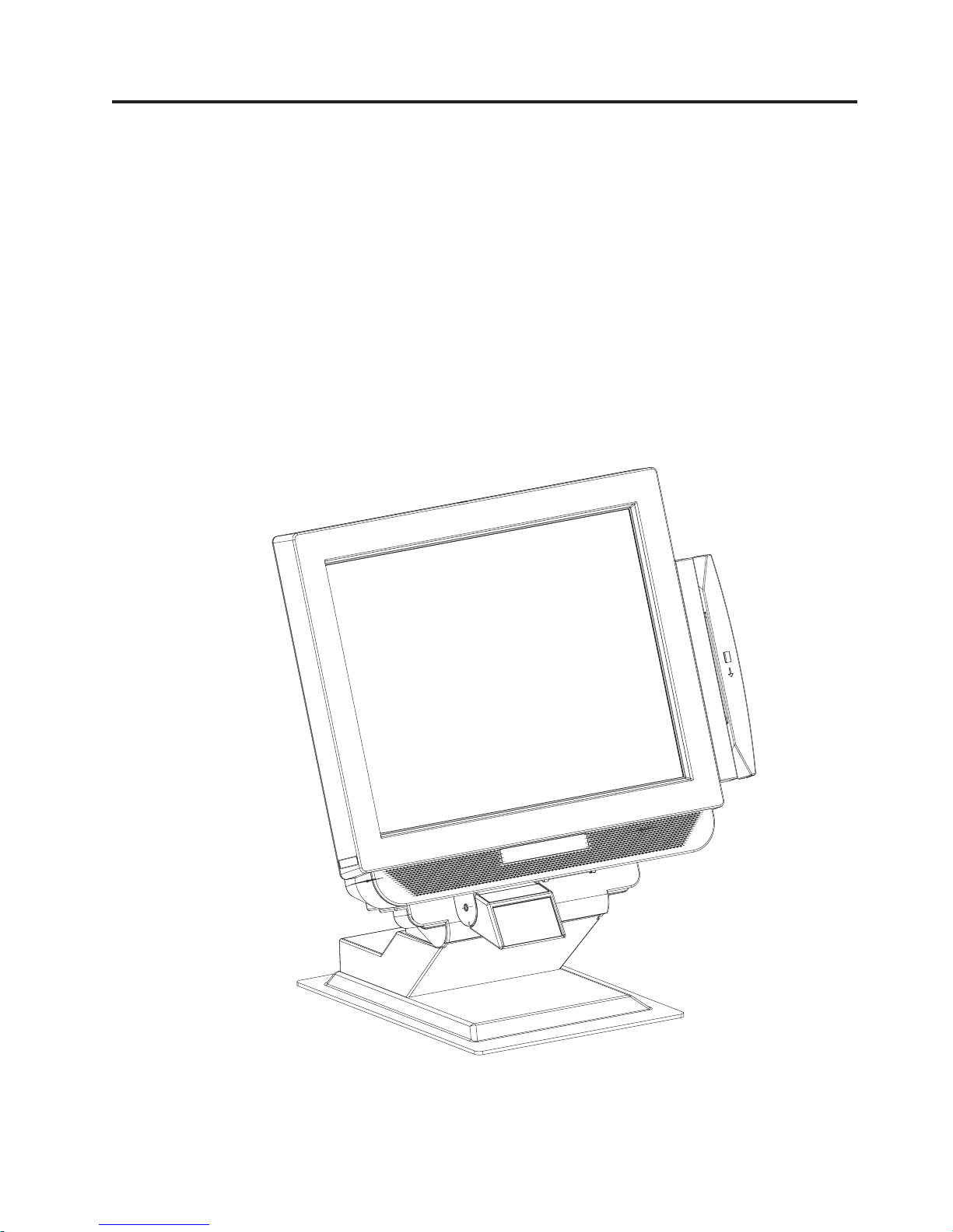
Figure 1. IBM AnyPlace Kiosk Model 5xx with a tabletop mount
To view the model dimensions, see Appendix B, “Product dimensions,” on page 81.
© Copyright IBM Corp. 2007, 2008 1
Page 14

Introducing the IBM AnyPlace Kiosk
Models and features
This section describes the model numbering and optional features.
Administrative models and other models that represent different service repair
options are not listed. See your IBM representative for a complete list.
The model scheme is as follows: 4838-XYZ.
X Indicates the screen size: 5 for 15 inch, 7 for 17 inch, and 9 for 19 inch
Y Processor type: either 1= AMD Sempron, and 2 = AMD Turion
Z Indicates the preinstalled software, if any:
0 None
E Windows
Windows Vista
For example, a model 4838-720 would be a 17" screen size with Turion processor
and no preload.
Table 1. Summary of characteristics and weight by model.
Characteristics Model 5xx Model 7xx Model 9xx
Height 325.6 mm (12.82 in.) 367.5 mm (14.47 in.) 398.5 mm (15.69 in.)
Width 368.6 mm (14.51 in.) 402.0 mm (15.83 in.) 440.6 mm (17.35 in.)
Depth 72.8 mm (2.87 in.) 78.3 mm (3.08 in.) 82.8 mm (3.26 in.)
Weight 6.45 kg (14.2 lbs.) 8.27 kg (18.2 lbs.) 9.31 kg (20.5 lbs.)
®
Embedded for Point of Sale (WEPOS), Windows XP or
Note: See Appendix B, “Product dimensions,” on page 81 for more detailed
dimensions including the options.
Table 2. Feature descriptions
Features
LCD 15" TFT
1024 x 768
2 bulb
CPU AMD Mobile Sempron 3500+ 1.8 Ghz or AMD Mobile Turion 64 X2 TL-56 1.8 Ghz with 1 Ghz Front
Side Bus (FSB)
Memory 4 GB maximum system memory using 512 MB, 1 GB or 2 GB DDR2 667 (PC2-5300) SO-DIMMs in any
combination
Touch Infrared with Unintentional Touch feature (RS 232 interface - COM5)
Mass
storage
Video
Video
memory
Slots 1 ExpressCard (supports 34 mm or 54 mm)
80 GB 3.5" SATA II 7200 RPM
160 GB 3.5" SATA II 7200 RPM, 4 GB modular flash drive (optional)
v VIA integrated Chrome 9 graphics
v External VGA (HD-15) output supporting dual independent video and mirrored video
v 256 MB max, shared dynamically from system memory
17" TFT
1280 x 1024
4 bulb
19" TFT
1280 x 1024
4 bulb
2
IBM AnyPlace Kiosk 4838
Page 15

Table 2. Feature descriptions (continued)
Features
PC I/O
connectors
Power
system
Audio
Wired LAN 10/100/1000 Ethernet
Super I/O
controller
Presence
sensor
Security v Trusted Platform Module v 1.2
Modular
servicing
ease
5 PC USB 2.0
2 RS-232 (9 pin)
1 Scanner (device specific RJ45)
1 MSR (device-specific RJ45)
1 Network (RJ45, Ethernet)
1 VGA (HD-15)
1 Microphone jack
1 PS/2 keyboard
2 Headphone jacks
Note: PS/2 keyboard port for diagnostic purposes only, not externally accessible
v External 16 V DC 120 W AC adapter
v High-definition integrated audio
v Integrated 2 watts-per-channel stereo speakers
Wake on LAN enabled
UART (universal asynchronous receiver/transmitter) support with SMSC semiconductor solution
Infrared presence detection
v Power on password
v Front USB port can be disabled in BIOS
v Tabletop mount with a Kensington security slot (K-Slot) and mounting holes. See Figure 2 on page
5.
v Capability for a customer supplied security screw to increase security of access doors
Screwdriver access for the following:
v ExpressCard
v Hard disk drive
v Memory DIMMs
v Wireless card
v Flash drive
v Scanner
v Servicing the system
Introducing the IBM AnyPlace Kiosk
Chapter 1. Introducing the IBM AnyPlace Kiosk 3
Page 16

Introducing the IBM AnyPlace Kiosk
Optional features
Table 3. IBM AnyPlace Kiosk hardware options
Option Description
AnyPlace POS Hub Enables connection of USB (5 V, 12 V and 24 V) peripherals and a cash
drawer
Mass storage 3.5" Serial Advanced Technology Attachment (SATA) II, 80 GB
standard / 160 GB optional
Memory Two SO-DIMM (small outline dual in-line memory module),
DDR2 (double data rate two synchronous dynamic random access)
memory slots
Base memory size is 512 MB
Modular flash drive (MFD) 4 GB
Magnetic stripe readers (MSRs) ISO 3-track or JUCC
Bar code scanners Non-laser-based line scanner
Laser-based Omni scanner
Wireless LAN 802.11 a/b/g/ n-draft with integrated antennas
Note: The wireless solution is certified for use only in certain
countries. See Appendix C, “Notices,” on page 89.
Mounting options Tabletop mount
Wall mount
ExpressCard extended door Provides a "bubble" to cover and protect extended-length ExpressCards
Attention: Do not over tighten the plastic screws that are on the
extended door cover. Plastic screws only require one tenth (1/10th or
10%) as much torque as normal metal screws. Use a screw torque of
0.5 kg-cm / 0.05 N-m / 0.4 in-Lb / 7 in-oz.
AC adaptor bracket Powder-coated metal bracket that you can use to mount the AC
adaptor under a cabinet or on a wall
Configurations
Your sales representative can provide the latest available configurations.
4
IBM AnyPlace Kiosk 4838
Page 17
Mounting options
The mounting options for the IBM AnyPlace Kiosk are as follows:
VESA-standard mounting holes
Wall mount
Tabletop mount
Introducing the IBM AnyPlace Kiosk
The system has 100 mm VESA mounting points for use with standard,
third party VESA mounting options.
This mount minimizes protrusion from the wall, but does not have any tilt
or swivel capability.
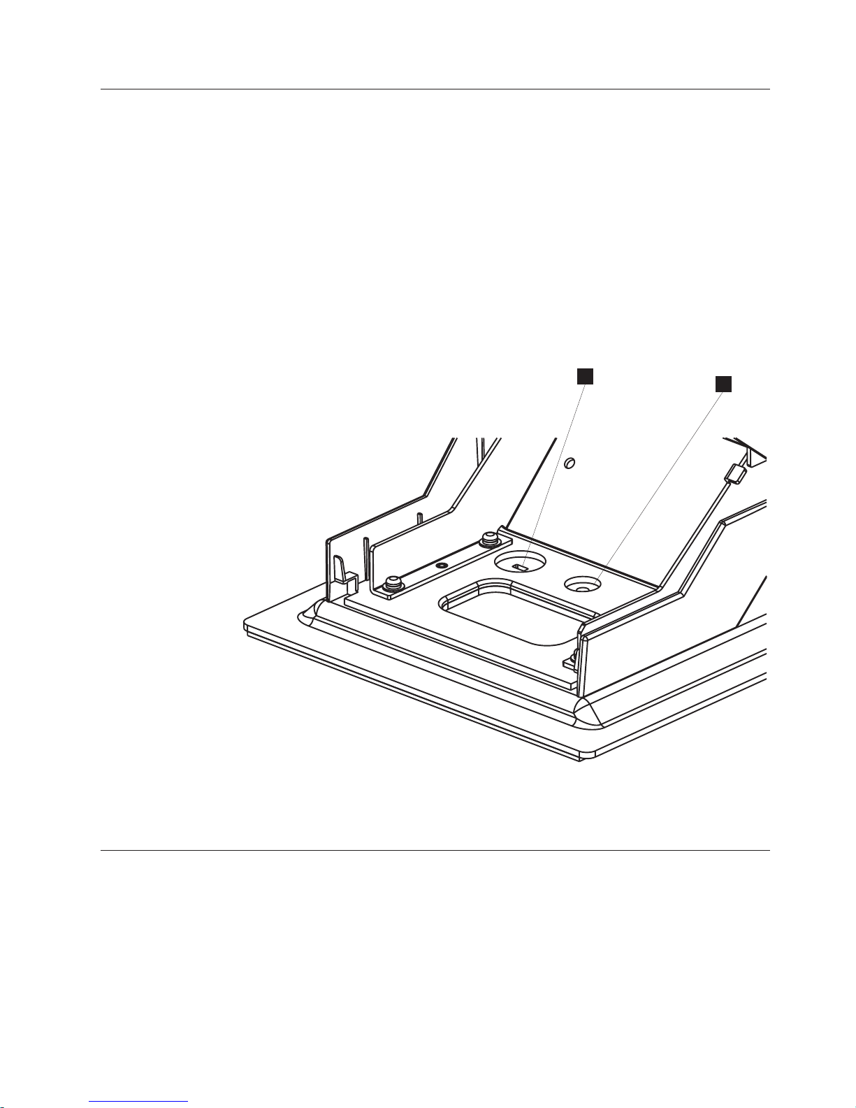
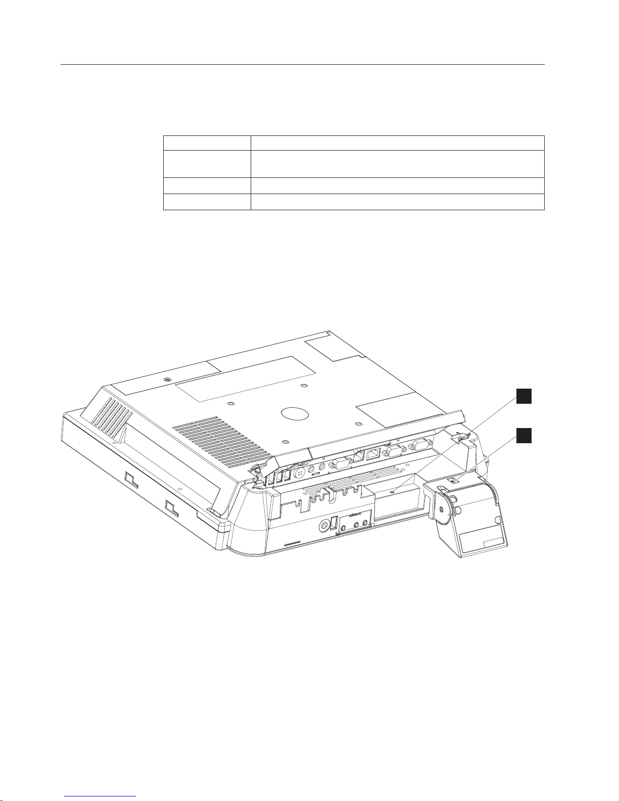
This mount tilts the monitor forward and back and rests on a tabletop. For
security, a Kensington security slot is provided (A in Figure 2). Also, a
round 5.5 mm (0.217 in.) hole enables the mount to be secured (B in
Figure 2) with an M5 or 10-24 pan head screw.
A
B
Figure 2. Security and mounting holes.
A Kensington security slot
B Round mounting hole
Diagnostics
The IBM AnyPlace Kiosk 4838 provides a diagnostic processor with Light-Path
LEDS to easily help isolate a failing component or condition. An LED represents a
specific action to correct the indicated problem. See “Using the diagnostic
processor” on page 64.
You can obtain a USB memory key-based diagnostic package for your IBM
AnyPlace Kiosk from the IBM Retail Store Solutions Web site: www.ibm.com/
solutions/retail/store/support/.
Chapter 1. Introducing the IBM AnyPlace Kiosk 5
Page 18

Introducing the IBM AnyPlace Kiosk
Supported operating systems
The IBM AnyPlace Kiosk supports the following:
v Windows Embedded for Point of Sale (WEPOS)
v Windows XP Service Pack (SP) 2 or higher
v Windows Vista Business
For guidance on installing any of the previous operating systems, see the IBM
AnyPlace Kiosk Operating Systems Installation Guide, GA27-4371.
6
IBM AnyPlace Kiosk 4838
Page 19

Environmental requirements
Table 4 shows the humidity and temperature limits for the IBM AnyPlace Kiosk.
Table 4. Environmental requirements
Operating
Power disconnected
Storage
Shipment
This product relies on active, convective cooling, so place your unit such that the
ambient air adjacent to the unit does not exceed supported maximums. Ensure that
the cooling vents are not blocked by papers, signs, or other items.
Temperature (dry
bulb)
5 to 40°C
(41° to 104° F)
0 to 52°C ( 32° to 126°
F)
0 to 60°C
(-32° to 140° F)
-40 to 60°C (-40° to
140° F)
Introducing the IBM AnyPlace Kiosk
Maximum
temperature (wet
bulb) Relative humidity
27° C
(81° F)
27° C
(81° F)
29° C
(84° F)
29° C
(84° F)
8to80%
5to95%
5to80%
5 to 100%
Power usage
Table 5 shows the power consumption for the IBM AnyPlace Kiosk:
Table 5. Power usage
Description Amounts
Power consumption Off: 3.4 W (11.6 BTU/hr)
Heat dissipation: Standby: 23.5 W (80.1 BTU/hr)
Input voltage and current 100–240 V, 50–60 Hz, 1.4 A max: Input to power supply
Calling for service
When you call IBM for warranty information or service, be sure to have the
following information available:
v Machine type/model
v Serial number
You can locate this information on the left side of the front bezel, or the rear side
of the unit.
On (idle/typical): 66 W (225.2 BTU/hr)
On (maximum): 99 W (337.8 BTU/hr)
Chapter 1. Introducing the IBM AnyPlace Kiosk 7
Page 20

8 IBM AnyPlace Kiosk 4838
Page 21

Chapter 2. Installing the IBM AnyPlace Kiosk
This section describes procedures for setting up the IBM AnyPlace Kiosk product.
You should be familiar with the rear doors and connectors of the IBM 4838 before
you begin the installation steps.
© Copyright IBM Corp. 2007, 2008 9
Page 22
Installing the IBM AnyPlace Kiosk
Rear view
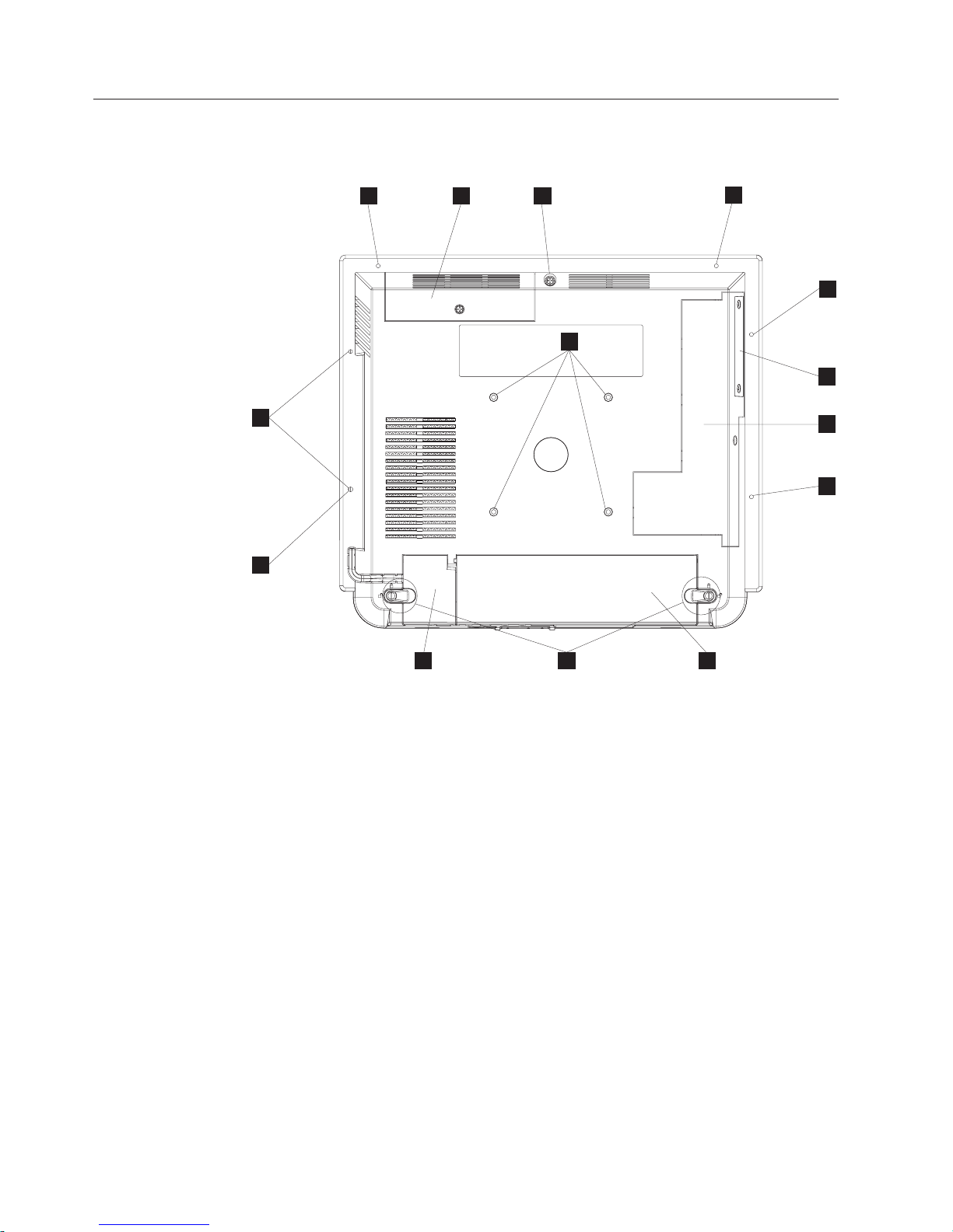
Figure 3 shows the rear view of the AnyPlace Kiosk.
J
J
G
A
I
E
J
J
B
C
J
E H D
Figure 3. Rear view showing access doors, mounting holes, attachment holes
A Hard drive door with captured screw
B Side door allows access to memory slots, flash drive, Light-Path LEDs,
wireless card, and CMOS jumper.
B ExpressCard slot cover
C Main cable cover
D MSR/USB cable cover
E Tapped holes that allow for the 100 mm x 100 mm (3.93 in. x 3.93 in.)
mounting:
Note: These holes allow for the standard M4 X 10 mm screws specified by
the VESA standard.
F MSR mounting hole that is shared with I.
G Quarter-turn latches
H Rear cover captured screw
I Tapped holes that allow the attachment and display of marques,
announcements, sales promotions and other information.
10
IBM AnyPlace Kiosk 4838
Page 23

Connectors
Installing the IBM AnyPlace Kiosk
Note: These tapped holes allow for M3 screws. The M3 mounting screw
should extend into the unit a minimum of 8 mm, and a maximum
of 11 mm.
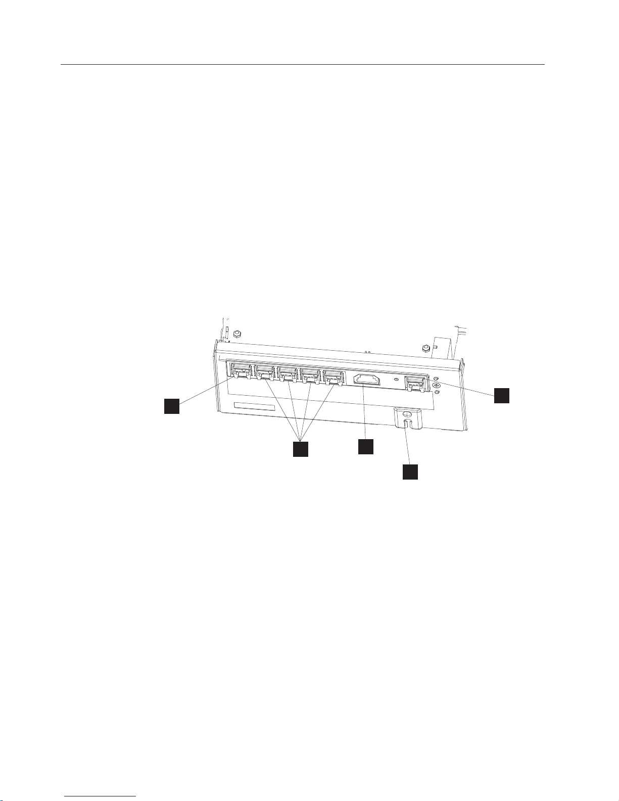
Figure 4 shows the AnyPlace Kiosk connectors.
A
B
J L
Figure 4. AnyPlace Kiosk connectors
Table 6. Connector location
A MSR
B USB ports (4X)
C Power input connector (used by either the AC adapter
D Microphone
E Headphone
F VGA output
G Scanner
H Ethernet
I RS 232 connectors (2X)
J Headphone
K USB port
L Power button: Green indicates power and amber
M N LCD brightness control buttons: minus - and plus +
O Bottom cover
DC
E
K
M
F
G
H
N
or the AnyPlace POS Hub.)
indicates a hardware fault.
I
O
Chapter 2. Installing the IBM AnyPlace Kiosk 11
Page 24
Installing the IBM AnyPlace Kiosk
Installation steps
Follow these steps to install the IBM AnyPlace Kiosk:
1. Install your options. See “Installing the options” on page 14.
2. Route, connect, and retain the cables. See “Retaining the cables” on page 13.
Note: Be sure to route the cables through the tabletop mount before connecting
to the unit.
3. Install the IBM 4838 on your mounting option: tabletop (see “Tabletop mount”
on page 21) or wall (see “Wall mount” on page 23) or the third-party VESA
mount instructions.
4. Power On the IBM 4838. See “Powering on” on page 23.
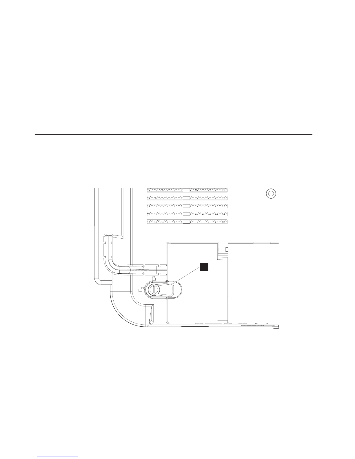
Opening the cable covers
The cable covers provide security and protection to the IBM 4838 cable and
connections.
Note: The MSR/USB cable cover can be opened independently of the main cover.
P
Figure 5. Close-up view of quarter-turn latch
Follow these steps to open the cable covers:
1. Flip up the metal handle (P).
2. Rotate the quarter-turn latches to the unlocked position.
3. Open the MSR/USB cable cover before opening the main cable cover.
12
IBM AnyPlace Kiosk 4838
Page 25

Retaining the cables
The RS-232 cables and the VGA cable are retained to the system unit with screws.
The MSR, scanner, and Ethernet cables are retained by a snap latch on the
connector. The power input cable is retained by the system unit bottom cover.
You can retain the audio and USB cables by placing the cables into the U-slots that
are part of the bottom cover. The slots in the cable covers retain the I/O cables by
retaining the cable ties. Install the cable ties as follows:
1. Plug each cable into its respective connector.
2. Attach the cable ties to the I/O cables on the outside of the bottom cover. The
cable tie width should be approximately 5 mm wide.
Note: Ensure that the cable tie is large enough to keep the cable retained, and
3. Adjust the cable so that the cable tie is on the I/O connector side of the bottom
cover.
Installing the IBM AnyPlace Kiosk
that it is installed extremely tight to the I/O cable. The head of the cable
tie should be at the bottom of the bottom cover U-slot.
Chapter 2. Installing the IBM AnyPlace Kiosk 13
Page 26
Installing the IBM AnyPlace Kiosk
Installing the options
The design of the IBM 4838 allows you to install the options without removing the
external cover. Table 7 describes the components and the respective access door.
Table 7. Components and doors
Door Accessible component
Side Wireless card, flash drive, memory modules, additional memory card,
Inset side (small) ExpressCard slot
Hard drive Hard drive
Many upgrade features are factory-installed. See Figure 3 on page 10 to identify the
access doors.
Installing the scanner
Follow these steps to install the scanner:
1. From the rear of the IBM AnyPlace Kiosk, open both cable covers using the
quarter-turn latches.
CMOS jumper
Figure 6. Installing the scanner
2. Align the scanner with the screw hole (A in Figure 6) and secure the captured
3. Connect the scanner cable to its indicated connector.
4. Close and latch the cable covers.
Notes:
1. You can adjust the tilt angle of the scanner for optimum performance.
2. For best scanning results, hold the object to be scanned 50 to 100 mm (2 to 4
3. Refer to the IBM Knowledge Base at the IBM Retail Store Solutions Web site
A
B
screw (B).
inches) away from the scanner.
(www.ibm.com/solutions/retail/store/support/) for details on configuring the
scanner.
14
IBM AnyPlace Kiosk 4838
Page 27

Installing the MSR
Follow these steps to install the MSR:
1. From the rear of the unit, open the MSR/USB cable cover using the
quarter-turn latches.
Installing the IBM AnyPlace Kiosk
V
Figure 7. Installing the MSR
2. Use a small, flat-blade screw driver to pry and then lift out to remove the MSR
plugs (V in Figure 7).
3. Locate the mounting slots for the MSR on the right side of the unit.
4. Align the MSR such that the MSR hooks are slightly above their matching slots
on the 4838. Slide the MSR downward into position, being careful not to pinch
the MSR cable.
5. Install the screw or thumbscrew to retain the MSR. Use the screw when the
kiosk operates in a public environment so as to increase the security of the unit.
6. Plug the MSR cable to its indicated connector. See Figure 7.
7. Starting from the MSR, press the MSR cable into the U slot (U) in the rear
cover. The excess MSR cable should be placed in the MSR/USB cable cover
area.
8. Close and latch the MSR/USB cable cover.
Installing the flash drive
Follow these instructions to install the flash drive.
U
Chapter 2. Installing the IBM AnyPlace Kiosk 15
Page 28
Installing the IBM AnyPlace Kiosk
A
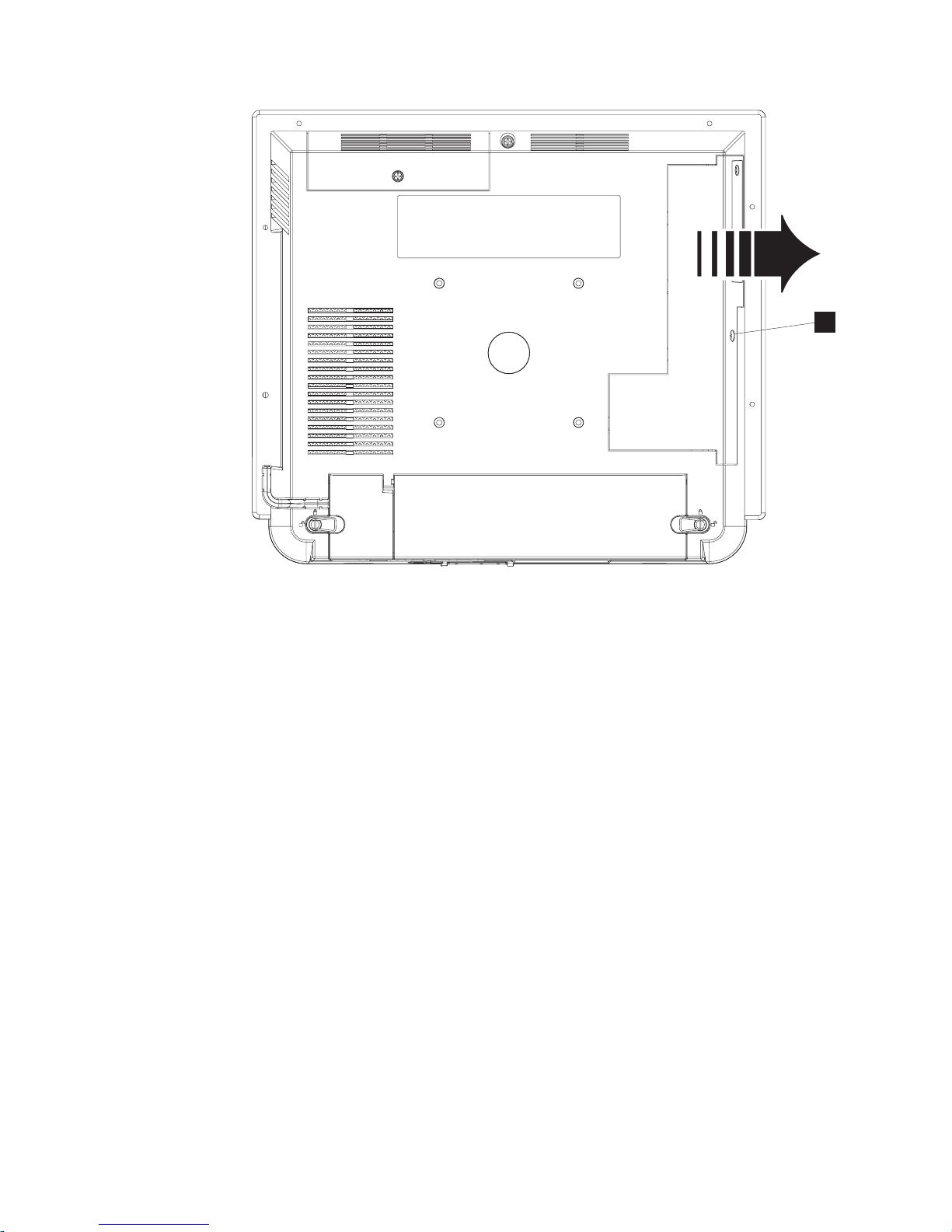
Figure 8. Removing the side access door
1. Loosen the captured screw on the side access door (Ain Figure 8) and slide
out in the direction shown to remove.
16
IBM AnyPlace Kiosk 4838
Page 29
Installing the IBM AnyPlace Kiosk
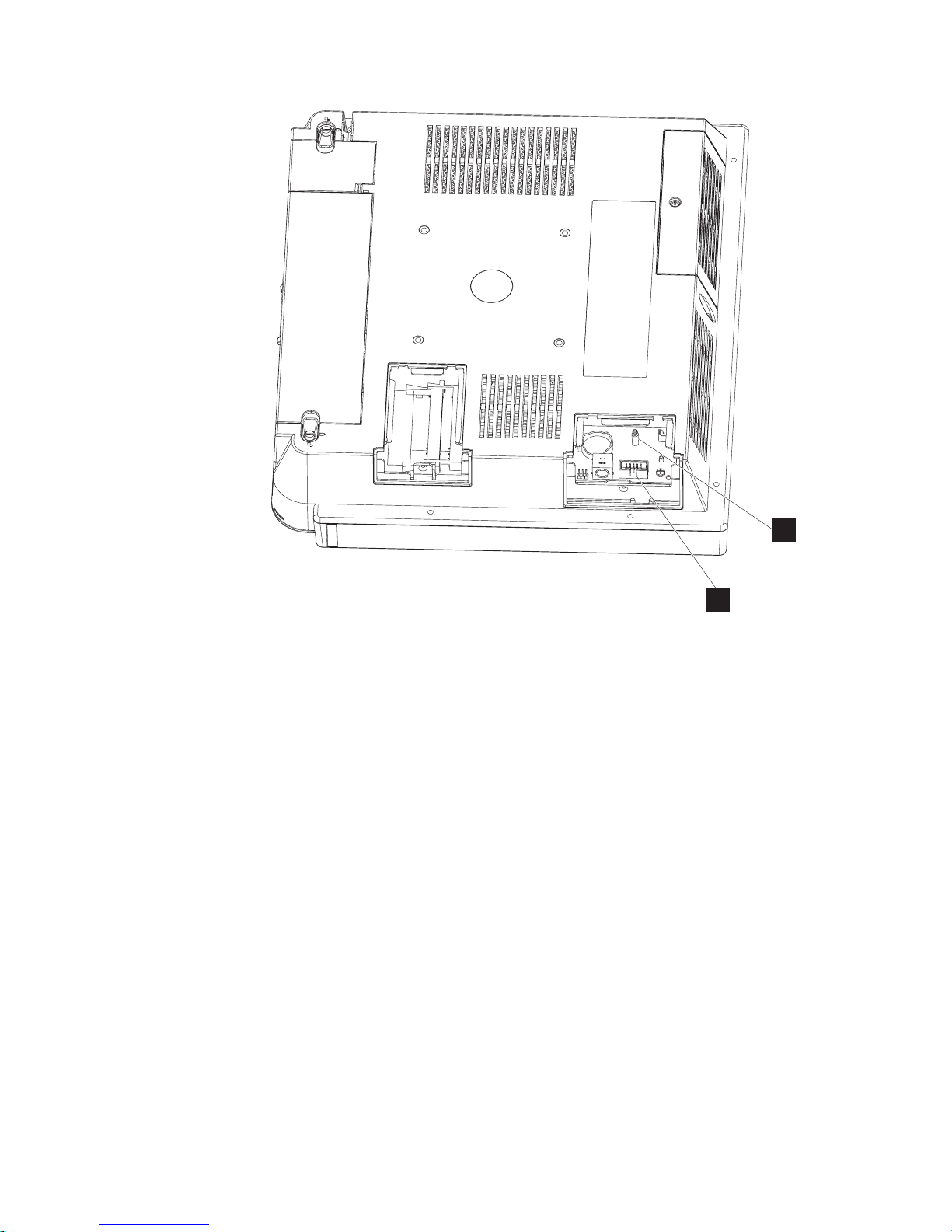
G
F
Figure 9. Location of the flash drive
2. Press the flash drive down onto the connector (F in Figure 9) and support
post (G), and latch it into place.
3. Replace the side door by tightening the captured screw.
Note: Do not overtighten the screw.
Chapter 2. Installing the IBM AnyPlace Kiosk 17
Page 30
Installing the IBM AnyPlace Kiosk
Attaching the IBM AnyPlace POS Hub
The AnyPlace POS Hub is a high-speed USB 2.0 compatible hub that allows you to
attach IBM point of sale input/output devices. These devices include printers,
keyboards, displays, and cash drawers. The hub provides power for the I/O
devices as well as the IBM AnyPlace Kiosk.
|
|
|
|
|
|
Note: Standard USB (5V) devices can be hot plugged into any USB port on an IBM
system unit. If the hot plugged device does not function properly, try
unplugging and reattaching the device to resolve the issue.
Important: Hot plugging a powered USB device (24V and 12V - red and
green plugs respectively) can cause system errors and is not supported on
any IBM system unit.
For more information, see the IBM AnyPlace POS Hub Planning, Installation and
Service Guide, GA27-4370. Complete the following instructions to attach I/O
devices to the AnyPlace POS Hub:
1. Locate or mount the AnyPlace POS Hub in a stationery location. Be sure that
the air vents are not blocked.
E
A
B
C
18
IBM AnyPlace Kiosk 4838
D
Figure 10. Power outputs
A 24V powered USB 2.0 port (POS printer)
B 4, 12V powered USB ports
C 24V cash drawer port (IBM cash drawers)
D Power connector (located on the bottom side of the hub enclosure)
E The AnyPlace POS cable connector, which connects the AnyPlace POS
Hub to the AnyPlace Kiosk (or other host system unit) and has a
positive retention (latching) connector. At the kiosk or host system unit
end, the AnyPlace POS cable has two connectors as shown in Figure 11
on page 19:
Page 31

H
Figure 11. AnyPlace POS cable connectors
F Standard PC USB connector that attaches to one of the kiosk
USB ports
Installing the IBM AnyPlace Kiosk
F
G
G Power connector that attaches to the power input connector on
the kiosk
H Connector that attaches to the AnyPlace POS Hub
2. Review Figure 10 on page 18 and connect your peripheral units to the hub.
Connect the AnyPlace POS cable (D in Figure 10 on page 18) to the USB port
directly adjacent to the power input port. and to the IBM AnyPlace Kiosk.
3. Connect the power cord of the AnyPlace POS Hub to an external power source.
4. Power on IBM AnyPlace Kiosk and the AnyPlace POS Hub is automatically
powered on.
Note: Plugs F and G in Figure 11 must remain connected while the IBM
AnyPlace Kiosk and hub are powered on. Removing the USB hub (E) will
shut off the kiosk.
Chapter 2. Installing the IBM AnyPlace Kiosk 19
Page 32

Installing the IBM AnyPlace Kiosk
Installing the hard drive
Follow these steps to install a hard drive:
C
Figure 12. Opening the HDD door
1. Loosen the captured screw (C in Figure 12) to remove the HDD door.
2. Locate the slot and brackets and fully insert the hard drive until the hard drive
is latched into place.
3. Close hard drive door and fasten the captured screw.
Note: Do not over tighten the screw
Installing additional memory
Follow these instructions to install an additional memory card.
1. Place the 4838 face down on a sturdy surface.
20
IBM AnyPlace Kiosk 4838
Page 33

M
Installing the IBM AnyPlace Kiosk
Figure 13. Installing additional memory
2. Loosen the captured screw holding the side access door (refer to Figure 8 on
page 16).
3. Refer to the existing memory card position for reference (M in Figure 13).
Insert the memory card into the memory connector.
4. Secure the memory card into the slot by rotating the memory down into
position. The memory connector latches make a click sound, indicating that the
memory card is retained. The memory should appear aligned relative to the
connector (not angled, crooked or misaligned).
5. Install the side access door and fasten the captured screw.
Note: Do not over tighten the screw
Mounting instructions
You can choose between a tabletop, wall mount, or a third party mount.
Tabletop mount
This section describes how to install the AnyPlace Kiosk on a tabletop mount.
Chapter 2. Installing the IBM AnyPlace Kiosk 21
Page 34

Installing the IBM AnyPlace Kiosk
1
2
A
B
3
Figure 14. Installing tabletop mount
1. Attach the VESA adapter plate to the unit with the four screws that are
provided. See picture 1 in Figure 14.
2. Tilt the upper potion of the mount so that it is 90 degrees (perpendicular) to
the base of the mount. See picture 2 in Figure 14
3. Remove the base cover and upper cover.
4. Route and connect the cables to the IBM 4838.
5. Retain the cables (see “Retaining the cables” on page 13).
6. Close cable cover and latch the quarter-turn latches on the cable covers.
22
IBM AnyPlace Kiosk 4838
Page 35

7. Is a scanner installed?
Yes Remove the scanner wire slot cover.
No Check that the scanner wire slot cover is installed.
8. Hook the unit onto the tabletop mount and tighten the mount thumb screw
(A in picture 3 in Figure 14 on page 22) to secure the unit to the mount.
9. Install the base cover, then the upper cover.
10. Retain the AC adapter cable with the cable harness located on the tabletop
mount (B in Figure 14 on page 22).
11. Place the IBM 4838 unit in the desired location.
Notes:
1. You can adjust the tilt angle of the unit for optimum performance.
2. The mount can be bolted to the counter top, using the hole provided. The bolt
hole will allow you to use up to a #10 or M5 bolt.
3. A notebook computer type lock, which is compatible with the Kensington Lock
slot, can also be used to secure the mount. The lock slot is located under the
base cover.
Wall mount
Follow the procedures described in Chapter 3, “Mounting the IBM AnyPlace Kiosk
to the wall,” on page 27.
Installing the IBM AnyPlace Kiosk
Powering on
The following notes will assist you during powering on:
Notes:
1. Your new IBM AnyPlace Kiosk ships with a control button cover. The purpose
of the control button cover is to limit access to the control buttons. This feature
is especially desirable if the system is located in a public environment. Install
this part after you power on and adjust the image.
2. Three small holes (see L, M, and N in Figure 15 on page 24 for the
approximate location) in the control button cover allow you to actuate the
control buttons. Use a paper clip or other small tool to actuate the button.
3. A paper clip is required to open or remove the cover. See “Installing the control
button cover” on page 24 for additional information.
Chapter 2. Installing the IBM AnyPlace Kiosk 23
Page 36

Installing the IBM AnyPlace Kiosk
Figure 15. IBM 4838 controls
1. Plug the power adapter to the unit. If connecting to the 4838 to the AnyPlace
POS Hub, go to “Attaching the IBM AnyPlace POS Hub” on page 18.
2. Plug the appropriate power cord into the AC power adapter (see “Power
cords” on page 79) and then into an electrical outlet.
3. Power on the IBM 4838 using the power button (L in Figure 15). The 4838
power indicator light will initially appear green.
4. To adjust the LCD brightness, select the plus + or minus - keys (see M and
Nin Figure 15).
Installing the control button cover
To install the control button cover, follow these steps:
1. While facing the LCD, insert the hinge pin on the left side first, then insert the
hinge pin in the right side.
2. Rotate the cover to swing and snap it into place.
To remove the cover:
1. Insert a heavy-duty metal paper clip in the slot on the bottom of the unit,
approximately 9 to 12 mm (3/8 to 1/2 inch).
2. Push the paper clip to the rear of the unit, then pull down on the paper clip
and pry the cover open.
N
M
L
24
IBM AnyPlace Kiosk 4838
Page 37

Additional security (access door screws)
For additional security, a customer can supply and replace the access door screws
with a "security screw" that requires a less common type of driver to remove (e.g.
torx, security torx, spline, hex, square, etc). When a customer chooses to replace the
screw, the customer will need to make arrangements to unfasten the screw when
the unit needs to be serviced. The existing plastic screw retainer that is attached to
the access door screw can be used with the security screw to keep the security
screw retained to the access door.
Hard drive door screw specification:
Screw thread: Metric - M3x0.5
Screw length: 5.5 to 7 mm extension into the unit
Screw head type: Pan head, button head, cheese head, or similar
Screw head/washer outside diameter: 6 mm max
Screw head/washer total height: 3 mm max
Washer type: Flat washer or none at all
Screw material: Steel with an electrically conductive plating
Side door screw specification:
Screw thread: Metric - M3x0.5
Screw length: 7.5 to 9 mm extension into the unit
Screw head type: Pan head, button head, cheese head, or similar
Screw head/washer outside diameter: 6 mm max
Screw head/washer total height: 3 mm max
Washer type: Flat washer or none at all
Screw material: Steel with an electrically conductive plating
Installing the IBM AnyPlace Kiosk
Chapter 2. Installing the IBM AnyPlace Kiosk 25
Page 38

Installing the IBM AnyPlace Kiosk
26
IBM AnyPlace Kiosk 4838
Page 39

Chapter 3. Mounting the IBM AnyPlace Kiosk to the wall
Follow these procedures to mount the IBM 4838 to the wall.
Mounting the wall mount plate
The mounting adapter (A in Figure 16) is secured to a metal wall-mount plate
(B), which can be installed on wood, drywall surface over studs, or a solid
concrete or brick wall.
A
B
Figure 16. System and wall mount plate
Wall mounting requirements
Note: Before mounting the wall mount plate, ensure that you are following all
applicable building and electric codes and accessibility requirements and
guidelines.
When mounting, ensure that you have enough room for adequate viewing,
ventilation, and access to an AC power outlet. The method of mounting must be
able to support the combined weight of the IBM 4838 plus the suspended weight
of all the cables to be attached to the system. Use the following methods for
mounting your system:
© Copyright IBM Corp. 2007, 2008 27
Page 40

Mounting the IBM AnyPlace Kiosk to the wall
Mounting to hollow walls
v Method 1: Wood surface – A minimum wood thickness—38 mm (1.5 in.) by 28
cm (11 in.)—of high, construction-grade wood is recommended.
Note: This method provides the most reliable attachment of the unit with little
risk that the unit will come loose or require ongoing maintenance.
v Method 2: Drywall walls – Drywall over wood studs is acceptable.
Mounting to a solid concrete or brick wall – Mounts on a flat smooth surface.
Selecting the location
Plan the mounting location thoroughly. Locations such as walkway areas, hallways,
and crowded areas are not recommended. Mount the unit to a flat, sturdy,
structurally sound column or wall surface.
The best mounting surface is a standard countertop, cabinet, table, or other
structure that is, minimally, the width and length of the unit. This recommendation
reduces the risk that someone can accidentally walk into and damage the device.
Local laws governing the safety of individuals might require this type of
consideration.
Determining the mounting height of wall mount plate
For users in a standing position, the typical height is approximately 122 cm (48 in.)
from the floor to the center of the touch display. The height used should be
appropriate and comfortable for a majority of the users. Local laws might also
govern the accessibility of the unit. In the United States, the Americans with
Disabilities Act (ADA) limits the height of the top of the LCD image to a height of
137.2 cm (54 inches) above the floor, and this height might need to be lower
depending on the size of obstructions that limit the depth of reach.
122 cm
48 in.
25.4 mm
1 in.
231.1 mm
9.1 in.
Figure 17. IBM 4838 mounting height
28
IBM AnyPlace Kiosk 4838
Floor
Page 41

Mounting the IBM AnyPlace Kiosk to the wall
Wall mount plate mounting options
The wall mount plate and wall cutout dimensions are shown in Figure 18. The I/O
and power cables for the unit can be routed either through the wall behind the
unit, or out the bottom of the rear cover.
Note: Wall mount plate is not drawn to scale.
96 mm
(3.77 in)
200 mm
(7.37 in)
186.6 mm
(7.87 in)
Cable
Exit
60 mm
(2.37 in)
Figure 18. Wall mount plate and wall cutout dimensions
Attaching the wall mount plate
CAUTION:
The wall mount plate must be installed by an insured, qualified, professional
installer who is familiar with building construction methods, building materials,
building codes, electrical codes, fire codes, and local laws governing public
access areas.
It is imperative that you attach the wall mount plate securely and permanently to
the wall. The 4838 weighs up to 9.5 kg (21 lb.), and its weight is centered
approximately 75 mm (3 in.) away from the wall mount plate mounting surface. In
addition to this weight, the wall mount plate must maintain its security and
attachment in the event the unit is knocked, bumped, or otherwise abused. If the
wall mount plate is not securely attached to the wall, the unit might fall and be
damaged, and can cause injury to others.
18 mm
(0.75 in)
35 mm
(1.37 in)
Chapter 3. Mounting the IBM AnyPlace Kiosk to the wall 29
Page 42

Mounting the IBM AnyPlace Kiosk to the wall
There is a wide variation of types of wall construction, age and condition. After
reviewing the conditions on site, the installer must make the final judgment as to
the suitability of the existing wall material to determine if additional bracing or
supports are required.
Attaching the wall mount plate involves making minor modifications to the
building construction. Be sure to observe proper safety precautions to prevent
injury. Unforeseen hazards, for example, natural gas and power lines, can exist
when drilling and cutting into walls.
Note: Compliance with local building codes, electrical codes and the governing
laws should take precedence over this set of instructions.
Fasteners are not included with the unit, and must be supplied by the installer.
The types of fasteners required are dependent on the type of wall construction. See
“Fastener types” on page 33 for detailed descriptions and pictures of the fasteners.
If the recommended size is not available, choose the next longer or larger size.
Choose fasteners that are rated either ”Medium Duty“ or ”Heavy Duty.“ To assure
proper fastener selection and installation, follow the fastener manufacturer's
recommendations.
Mounting to hollow walls
Hollow walls include walls that are constructed of drywall board that is securely
fastened to wood studs. The studs must make up the main structure and strength
of the wall.
Method 1: Wood surface
Use this method if construction changes to the wall are permitted. This method
will provide the most reliable attachment of the unit to the wall with little risk that
the unit will ever come loose or require ongoing maintenance.
The drywall board is removed in an area approximately 30 cm (12 in.) high that
spans the space between two studs. The two wood studs can be cut back
approximately 38 mm (1.5 in.) by 28 cm (11 in.) high. A 38 mm (1.5 in.) thick by 28
cm (11 in.) high construction grade wood support is attached to the two wall studs
with six lag screws as shown in Table 8 on page 31. Install the Lag Screws directly
into the center of the studs without pre-drilling a hole. Do not use soap or other
lubricant on the screws during installation. The wood support material should be
either solid wood or plywood. After installation of the support, you can replace
and prepare the drywall board for final finishing.
30
IBM AnyPlace Kiosk 4838
Page 43

Mounting the IBM AnyPlace Kiosk to the wall
Table 8. Securing the wood support to the wood studs using lag screws
Lag screw
Screw size: 6.3 mm (0.25 in.) or nominal thread
diameter
Length: 60 mm (2.5 in.) minimum
Use a bubble level to assure that the wall mount plate is mounted squarely. Use six
wood screws to attach the wall mount plate to the wall. Center the wall mount
plate vertically on the wood support. Install the wood screws directly into the
wood support without pre-drilling a hole. Do not use soap or other lubricant on
the screws during installation. See “Fastener types” on page 33 for more
information.
After installation, make sure that the screw heads are flush or below the outer
surface of the wall mount plate. Check to make sure that you firmly and securely
attach the wall mount plate to the wall.
Method 2: Drywall surface
Use this method if you cannot make construction changes to the wall. This method
provides a safe attachment of the unit to the wall. However, there is risk that the
wall mount plate and unit might become loose if it is struck with a high force. The
drywall must be at least 12.7 mm (0.5 in.) thick to use this method. Use a bubble
level to assure that you mount the wall mount plate squarely.
Install two "Medium Duty" or "Heavy Duty" fasteners. Use fasteners, which are
designed for drywall, in one side of the wall mounting plate B, as shown in
Table 9 on page 32. Depending on the type of fastener, portions of the fastener can
be installed into the wall first. You can possibly thread them through the screw
holes in the wall mount plate. The recommended types of drywall fasteners are:
self-drilling drywall anchor, hollow wall anchor, toggle bolt, self-drilling drywall
toggle bolt, and plastic toggle bolt. Use two wood screws A, as shown in Table 9
on page 32, to attach the wall mount plate to the stud. Install the Wood Screws
directly into the center of the stud without pre-drilling a hole. Do not use soap or
other lubricant on the screws during installation. See “Fastener types” on page 33
fastener descriptions and pictures at the end of this section for more information.
Chapter 3. Mounting the IBM AnyPlace Kiosk to the wall 31
Page 44

Mounting the IBM AnyPlace Kiosk to the wall
Table 9. Securing the wall mounting plate to a drywall surface. This figure shows wood screws (A); however, other
types of screws (B) can be used.
A
Wood screw
Size: #12 or 5.5 mm nominal thread diameter
Length: 38 mm (1.5 in.) minimum
Note: can be installed on either the right or left side.
B
v Self-drilling drywall anchor
v Hollow wall anchor
v Toggle bolt
v Plastic toggle bolt
v Self-drilling drywall toggle bolt
See Table 10 on page 33 for additional descriptions.
After installation, make sure the screw heads are flush or below the outer surface
of the wall mount plate. Check to make sure you firmly and securely attach the
wall mount plate to the wall.
Mounting to a concrete or brick wall
This mounting surface includes walls that are constructed of either brick wall and
mortar or solid concrete.
Due to the variable nature of laying bricks, and the variation in types of mortar
joints, most brick walls have an uneven surface. If possible, select a location on the
wall that allows all four corner screw holes to remain flat without warping the
wall mount plate. If this location is not possible, add a metal washer or other type
of shim under one or more screw holes. This addition allows the wall mount plate
to be mounted without warping it.
Use a bubble level to assure that you mount the wall mount plate squarely. Use
four concrete anchors to attach the wall mount plate to the wall. Use one concrete
anchor in each corner of the wall mount plate. See “Fastener types” on page 33 for
detailed fastener information to determine the types of fasteners that are
suggested.
After installation, make sure that the screw heads are flush or below the outer
surface of the wall mount plate. Check to make sure that you attached the wall
mount plate firmly and securely to the wall.
32
IBM AnyPlace Kiosk 4838
Page 45

Fastener types
Table 10 lists the different fasteners that you can use to mount the wall mount
plate. The fasteners are not drawn to actual size.
Table 10. Fastener types
Mounting the IBM AnyPlace Kiosk to the wall
Wood screw
Size: #12 or 5.5 mm nominal thread
diameter
Length: 38 mm (1.5 in.) minimum
Self-Drilling Drywall Anchor
Screw size: #8 or 4 mm nominal
thread diameter
Types: E-Z Anchor 50# (22 kg)
pullout rating or Cobra WallDriller
Concrete Anchor
Size: 5 mm (3/16 in.) nominal
thread diameter
Length: 32 mm (1.25 in.) minimum
Note: Fastener has a high/low
thread that cuts its own threads.
Hollow Wall Anchor
Screw size: 5 mm (3/16 in.) nominal
thread diameter
Note: Metal casing size is
dependent on wall board thickness.
During installation, grip head of
metal casing with pliers when
initially tightening the screw to flare
the legs. "No drill" or "drive" types
are not recommended.
Toggle Bolt
Screw size: 5 mm (3/16 in.)
nominal thread diameter
Lag Screw
Screw size: 6.3 mm (1/4-in.) or
nominal thread diameter
Length: 2.5 in. or 60-mm minimum
Plastic Toggle Bolt
Screw size: #8 or 4 mm nominal
thread diameter
Note: Toggle size is dependent on
wall board thickness.
Self-Drilling Drywall Toggle Bolt
Screw size: #8 or 4-mm nominal
thread diameter
Chapter 3. Mounting the IBM AnyPlace Kiosk to the wall 33
Page 46

Mounting the IBM AnyPlace Kiosk to the wall
34
IBM AnyPlace Kiosk 4838
Page 47

Chapter 4. Removing and replacing FRUs
Note: Procedures in this section should be performed by qualified service
personnel.
© Copyright IBM Corp. 2007, 2008 35
Page 48

Removing and replacing FRUs
Reviewing the IBM AnyPlace Kiosk assembly
Figure 19 on page 37 summarizes the field replaceable parts of the IBM 4838
assembly. The part number associated with each FRU is located in Appendix A,
“Field-replaceable units.”
36
IBM AnyPlace Kiosk 4838
Page 49

Door Assembly, HDD
MSR
Coin Cell Battery
HDD Fan Assembly
Backlight inverter card
Removing and replacing FRUs
Door kit, cable cover
Cover, Extended
ExpressCard
Door Assembly, side
CPU fansink
Flash Drive
CPU
System Board
Memory
I/O Shield Assembly
Scanner
HDD assembly
Antenna top/white
Button cover
Bottom cover
Control buttons
Card, control
Speakers
Antenna top/gray
Antenna side/black
LCD shield
LCD assembly
Front assembly
MSR hole plug
Figure 19. Exploded view of the IBM AnyPlace Kiosk assembly
Chapter 4. Removing and replacing FRUs 37
Page 50

Removing and replacing FRUs
Before you begin
Always practice safety first. Before removing the rear cover (or performing any
removal procedures), follow these steps:
1. Power off.
2. Remove the power cable.
3. Place the unit on a sturdy surface.
38
IBM AnyPlace Kiosk 4838
Page 51

Removing the rear cover
Attention: Establish personal grounding before touching this unit. See
“Electrostatic discharge” on page 94.
Follow these steps to remove the rear cover:
1. Switch OFF the power to the IBM AnyPlace Kiosk. Unplug the power cord
from the external power source.
2. Remove the unit from the VESA mount (tabletop, wall, or third party).
3. If installed, remove the MSR. Place the IBM 4838 face down on a sturdy
surface.
4. One captured screw secures the rear cover to the unit. Locate and loosen this
screw (see H in Figure 3 on page 10) .
Removing and replacing FRUs
Figure 20. Removing the rear cover
5. Facing the rear of the unit, firmly grasp and slide the rear cover approximately
8 mm (0.3 in) toward the bottom of the unit. Lift to remove.
To replace the cover, follow these steps:
1. Place the unit face down on a steady surface and align the back cover
approximately 8 mm (0.3 in) lower than the top cover (see Figure 20).
2. Firmly slide the back cover to align it with the front bezel and the top screw
hole. Check that the edges of the rear cover are properly aligned with the
mating covers.
3. Tighten the captured screw.
Removing the backlight inverter card
Follow these steps to install the backlight inverter card:
Note: The backlight inverter card and the LCD can be replaced independently. It is
not necessary to replace both parts should one part require servicing.
1. Switch OFF the power to the IBM AnyPlace Kiosk. Unplug the power cord
from the external power source.
2. Remove the rear cover as described in “Removing the rear cover.”
Chapter 4. Removing and replacing FRUs 39
Page 52

Removing and replacing FRUs
T
Figure 21. Backlight inverter card
3. Disconnect the two cables (system board cable and the Extended Display
Identification Data (EDID) cable) from the backlight card.
4. Remove the two screws (S) that hold the backlight inverter card (T).
5. Remove card to access and detach the two or four LCD backlight cables.
6. Lift the card to remove.
7. To replace, reverse this procedure.
S
40
IBM AnyPlace Kiosk 4838
Page 53

Removing the hard disk drive assembly
Attention: Establish personal grounding before touching this unit. See
“Electrostatic discharge” on page 94.
Follow these steps to remove the hard disk drive assembly:
1. Switch off the power to the IBM AnyPlace Kiosk. Unplug the power cord from
the external power source.
2. Remove the hard drive door by loosening the captured screw (see Figure 12 on
page 20).
Removing and replacing FRUs
D
Figure 22. Removing the hard drive
3. Remove the hard disk drive assembly by pressing the drive bracket (D in
Figure 22) downward on the latch in the area marked in blue while pulling the
bracket outward.
Note: The HDD assembly might include a circuitry card.
4. To replace, locate the right and left side rails with the correct side of the rails
upward.
5. Insert the hard disk drive assembly until it is latched into place.
6. Replace the hard drive door and tighten the captured screw.
Note: Do not overtighten the screw.
Chapter 4. Removing and replacing FRUs 41
Page 54

Removing and replacing FRUs
Removing the hard disk drive fan assembly
To remove and replace the HDD fan assembly, follow these steps:
1. Switch OFF the power to the IBM AnyPlace Kiosk. Unplug the power cord
from the external power source.
2. Remove the rear cover as described in “Removing the rear cover” on page 39.
3. Remove the hard disk drive (“Removing the hard disk drive assembly” on
page 41) to access and remove the tape securing the connector wires.
4. Detach the HDD fan connector from the system board and remove the tape
securing the fan cable.
B
Figure 23. Removing the HDD fan assembly
5. Loosen the two fan bracket screws a few turns ( B in Figure 23) and pull the
connector wires from beneath the system board.
To replace the fan, reverse these steps.
42
IBM AnyPlace Kiosk 4838
Page 55

Removing the CPU fan sink assembly
Attention: Establish personal grounding before touching this unit. See
“Electrostatic discharge” on page 94.
Follow these steps to remove the CPU fan sink assembly:
1. Switch OFF the power to the IBM AnyPlace Kiosk. Unplug the power cord
from the external power source.
Removing and replacing FRUs
2
3
Figure 24. Removing the CPU fan sink assembly
2. Remove the rear cover. (See “Removing the rear cover” on page 39.)
3. See Figure 24 and loosen the 5 screws retaining the heat sink and fan assembly
in the order that they are numbered (1 through 5).
4. Unplug the fan cable, and lift out the CPU fan sink assembly
Note: To replace the processor, go to “Removing the processor” on page 44.
5
1
4
To replace, follow these steps:
1. Place the CPU fan sink assembly such that it aligns the matching holes on the
system board.
2. Tighten the five retainer screws one turn in the numerical order that is shown
beside of each screw. See Figure 24.
3. Then, repeat Step 2 to secure the screws, but do not overtighten.
4. Plug in the fan cable.
Chapter 4. Removing and replacing FRUs 43
Page 56

Removing and replacing FRUs
5. Replace the rear cover.
Removing the processor
Note: Locate the processor after you remove the CPU fan sink assembly.
To remove the processor, follow these steps:
1. Switch OFF the power to the IBM AnyPlace Kiosk. Unplug the power cord
from the external power source.
2. Follow the instructions described in “Removing the CPU fan sink assembly” on
page 43.
H
Figure 25. Removing the processor
3. Using a small flat-blade screwdriver, turn the screw (Hin Figure 25) that holds
the processor 180° (one-half turn) to release it.
Note: The lock and unlock symbols on either side of the screw assist you with
the direction of the turn.
4. Lift out the processor, carefully keeping your fingers on each side of the
module.
5. To replace, reverse this procedure.
44
IBM AnyPlace Kiosk 4838
Page 57

Removing the scanner and scanner window
To remove the scanner, follow these steps:
Figure 26. Removing the scanner
Removing and replacing FRUs
A
B
1. Remove the unit from the VESA mount (tabletop, wall or third party).
2. From the rear of the IBM AnyPlace Kiosk, open the cable cover using the two,
one-quarter turn latches. See Figure 5 on page 12.
3. Disconnect the scanner cable from the scanner port.
4. Loosen the screw (Bin Figure 27 on page 46) securing the scanner.
Chapter 4. Removing and replacing FRUs 45
Page 58

Removing and replacing FRUs
Figure 27. Removing the scanner window
To remove the scanner window, follow these steps:
1. See Figure 27. Remove the two Phillips-head scanner cover screws.
2. Remove the scanner bottom cover assembly.
3. Remove the scanner window, taking note of the window orientation.
Note: Avoid touching the inside of the scanner window so as not to leave dust
or finger prints.
4. To replace, reverse the previous procedure.
46
IBM AnyPlace Kiosk 4838
Page 59

Removing the cable covers
Follow these steps to remove and replace the cable covers:
1. Open the covers as described in “Opening the cable covers” on page 12.
B
Removing and replacing FRUs
A
Figure 28. Removing the hinge pin
2. Remove the hinge pin (A in Figure 28) that holds both the MSR/USB cover
and the main cable cover by rotating it downward, then sliding it to the right.
3. To replace, place the main cable cover post into the slot on the right side.
4. Hold both the MSR/USB cover and the main cable cover together while
inserting the hinge pin into the holes (B) of both pieces.
5. Rotate and press upward to secure the hinge pin into the slot.
Chapter 4. Removing and replacing FRUs 47
Page 60

Removing and replacing FRUs
Locating and resetting the CMOS jumper
Follow these steps to locate and reset the CMOS jumper:
1. Switch OFF the power to the IBM AnyPlace Kiosk. Unplug the power cord
from the external power source.
2. Attention: Establish personal grounding before touching this unit. See
“Electrostatic discharge” on page 94.
3. Remove the side access door by loosening the captured screw.
Figure 29. Location of the CMOS jumper
4. Locate the blue CMOS jumper near the memory card. See J in Figure 29.
5. Remove the jumper and place it on the adjacent pins and leave for 10 seconds.
6. Reinstall the jumper to the original position to reset defaults.
7. Install the side door, and tighten the screw.
Note: Do not over tighten the screw.
48
IBM AnyPlace Kiosk 4838
Page 61

Removing the memory card
Attention: Establish personal grounding before touching this unit. See
“Electrostatic discharge” on page 94.
Follow these steps to remove the memory card:
1. Switch OFF the power to the IBM AnyPlace Kiosk. Unplug the power cord
from the external power source.
2. Loosen the captured screw holding the side access door.
Removing and replacing FRUs
G
Figure 30. Removing the memory card
3. Gently pull outward on the two side latches holding the memory card (G in
Figure 30). The memory card pops upward so that you can lift the card from
the slot.
Chapter 4. Removing and replacing FRUs 49
Page 62

Removing and replacing FRUs
Note: If you need more clearance to remove the memory card, remove the rear
cover (see “Removing the rear cover” on page 39.)
4. To replace the memory card, reverse these steps.
Note: Do not over tighten the side door screw.
50
IBM AnyPlace Kiosk 4838
Page 63

Changing the battery
Attention: Establish personal grounding before touching this unit. See
“Electrostatic discharge” on page 94.
Note: The coin cell system board battery is a Lithium Manganese Dioxide battery.
Follow these steps to change the battery:
1. Switch OFF the power to the IBM AnyPlace Kiosk. Unplug the power cord
from the external power source.
2. Remove the rear cover as described in “Removing the rear cover” on page 39.
Removing and replacing FRUs
Figure 31. View of battery
3. Locate the battery on the system board (B in Figure 31).
4. Using your finger, press on one of the tabs holding the coin battery, and the
battery pops out.
5. To replace the battery, align the battery underneath the tabs and press down.
Removing the flash drive
Follow these steps to remove the flash drive:
1. Loosen the captured screw on the side access door and lift to remove.
B
Chapter 4. Removing and replacing FRUs 51
Page 64

Removing and replacing FRUs
G
F
Figure 32. Location of the flash drive
2. Locate the flash drive connector (Fin Figure 32) and lift up to remove the
plug-in flash drive.
52
IBM AnyPlace Kiosk 4838
Page 65

Removing the system board
Attention: Establish personal grounding before touching this unit. See
“Electrostatic discharge” on page 94.
Follow these steps to remove the system board:
1. Switch OFF the power to the IBM AnyPlace Kiosk. Unplug the power cord
from the external power source.
2. Remove the rear cover as described in “Removing the rear cover” on page 39.
3. Follow the steps in Figure 22 on page 41.
4. Detach the following cables from the system board:
v Backlight inverter card
v Touch assembly
v HDD fan
Removing and replacing FRUs
AA
Figure 33. Removing the system board
5. If installed, remove the wireless card, leaving the three antenna cables attached.
6. See Figure 33 and remove the 6 non-captured screws (A) that hold the system
board.
7. Detach the control card cable and LCD LVDS cable. Both are located on the
back side of the system board.
8. Remove the following components from the defective system board for later
installation:
v Heatsink and fan assembly: “Removing the CPU fan sink assembly” on page
43
v Processor: “Removing the processor” on page 44
v Memory: “Removing the memory card” on page 49
v Flash drive: “Removing the flash drive” on page 51
9. Carefully lift to remove.
Replacing and programming the system board
Follow these steps to replace the system board:
1. Reverse the procedures described in “Removing the system board” noting to
align the board with the two alignment pins for the correct positioning.
Chapter 4. Removing and replacing FRUs 53
Page 66

Removing and replacing FRUs
2. Program the system vital product data. The following items are required before
you begin:
a. IBM RSS Diagnostics memory key
b. IBM AnyPlace Kiosk BIOS update diskette or memory key
c. IBM AnyPlace Kiosk Light-Path update diskette or memory key.
Note: All of these required items are available on the IBM RSS support site:
1) Create the IBM RSS diagnostic memory key as described by the RSS
support site.
2) Insert the memory key into the target system and power on.
3) Allow the system to boot from the USB memory key.
4) Accept the license agreement if you agree to the terms.
5) Click on Utilities.
6) Click on VPD.
7) Update the relevant VPD information.
d. Check the Light-Path LED's firmware level:
1) Power on the system.
2) After POST, a screen appears for the IBM RSS Service Processor Event
log viewer. Press <CTRL+D> or tap the box in the center of the screen
to open the utility.
3) The current Light-Path LED's firmware level is shown.
e. Update the system Light-Path LED's firmware. Refer to the instructions on
the IBM RSS Support site.
f. Check the system BIOS level:
1) Power on the system.
2) Press <DEL> or tap two times on the screen when prompted.
3) Open the Standard CMOS Items page to view the current BIOS revision.
g. Update the system BIOS by following the instructions on the IBM RSS
Support site.
http://www.ibm.com/solutions/retail/store
54
IBM AnyPlace Kiosk 4838
Page 67

Removing the front cover/touch assembly
The front cover includes the touch assembly (touch card and housing) inside.
Follow these steps to remove the front cover/touch assembly:
Removing and replacing FRUs
T S
Figure 34. Removing the front cover/touch assembly
1. Switch OFF the power to the IBM AnyPlace Kiosk. Unplug the power cord
from the external power source.
2. If installed, remove the MSR (see “Installing the MSR” on page 15).
3. Open the front cover/touch assembly (T in Figure 34) by loosening the
captured screw (S).
Chapter 4. Removing and replacing FRUs 55
Page 68

Removing and replacing FRUs
4. Slide the front cover/touch assembly (hereafter referred to as the front
assembly) upward approximately 8 mm (0.3 in) then rotate the front assembly
downward from the LCD to open. See Figure 34 on page 55.
5. Unlatch the touch cable as follows:
Open
Locked
Figure 35. Locating the touch cable connector
See Figure 35. Disconnect the touch cable by moving the connector lever to the
open position and lifting out the cable.
Note: See the Open and Locked connector lever positions shown in Figure 34
on page 55.
56
IBM AnyPlace Kiosk 4838
Page 69

Removing the speakers
Follow these steps to remove the speakers:
1. Switch OFF the power to the IBM AnyPlace Kiosk. Unplug the power cord
from the external power source.
2. Follow the steps in “Removing the front cover/touch assembly” on page 55 to
remove the front assembly.
3. Remove the two screws (W in Figure 36) that retain each speaker and lift to
remove.
4. Detach each speaker cable (V) from the control card.
Removing and replacing FRUs
Figure 36. Removing the speakers
5. To replace, reverse these steps.
V
Chapter 4. Removing and replacing FRUs 57
W
Page 70

Removing and replacing FRUs
Removing the control card
The control card contains the infrared presence sensor and the LED housing.
Follow these steps to remove the control card:
1. Switch OFF the power to the IBM AnyPlace Kiosk. Unplug the power cord
from the external power source.
2. Remove the front assembly as described in “Removing the front cover/touch
assembly” on page 55.
Figure 37. Removing the control card
3. Remove the two screws (I in Figure 37) that hold the control card in place,
and lift out the card
4. Disconnect the two speaker cables, and the control card cable from the rear of
the control card.
5. To replace, reverse this procedure, being sure to angle the card such that the
control buttons line up with the button holes.
Removing the control buttons
Follow these steps to remove the control buttons:
1. Switch OFF the power to the IBM AnyPlace Kiosk. Unplug the power cord
from the external power source.
2. Remove the control card as described in “Removing the control card.”
58
IBM AnyPlace Kiosk 4838
I
Page 71

3. Press inward on one end button and lift upward on that end of the button
frame.
4. Then, press the center button and continue to lift upward on the frame.
5. Press on the opposite end button to freely lift the button assembly.
6. To replace, reverse this procedure.
Note: Be sure to align the control button holes with the holes in the bottom
Removing the LCD
Follow these steps to remove the LCD:
1. Switch OFF the power to the IBM AnyPlace Kiosk. Unplug the power cord
from the external power source.
2. Follow the instructions in “Removing the front cover/touch assembly” on page
55.
Removing and replacing FRUs
cover.
Chapter 4. Removing and replacing FRUs 59
Page 72

Removing and replacing FRUs
S
S
Figure 38. Removing the LCD
3. Remove the four non-captured screws (S in Figure 38) that hold the LCD to
the LCD shield.
4. Disconnect the EDID card cable that is located on the right side of the LCD.
5. Gently lift up the LCD and slide to left to expose backlight cables. Rest LCD on
left side of the LCD shield, and remove backlight cables (two or four) from the
backlight inverter card.
6. Gently lift up LCD to expose the LVDS cable underneath and disconnect it
from the LCD. Remove the LCD from the LCD shield.
7. To replace the LCD, reverse this procedure.
Removing the tabletop mount cover sets
To remove the cover set for the tabletop mount, follow these steps:
60
IBM AnyPlace Kiosk 4838
Page 73

Removing and replacing FRUs
A
A
B
A
C
Figure 39. Removing the stand cover set
1. Tilt the upper portion of the mount so that it is 90 degrees (perpendicular) to
the base of the mount.
2. Remove the upper cover (A) by pulling on the two finger grips on the bottom
at the far left and right sides (B in Figure 39) in the direction shown.
3. Gently flex the hinge cover to un-snap it from the mount.
4. Remove the base cover (C) by pulling the cover in the direction shown.
5. To remove the plastic base housing, unfasten the four screws.
Chapter 4. Removing and replacing FRUs 61
Page 74

Removing and replacing FRUs
62
IBM AnyPlace Kiosk 4838
Page 75

Chapter 5. Diagnosing problems and troubleshooting
A software error or a hardware failure can cause a problem with the system. The
following topics contain problem analysis instructions to help you determine the
cause of a problem and resolve it.
Table 11 describes the servicing task and the section that contains information
supporting the task.
Table 11. IBM AnyPlace Kiosk task information
Task Go to
Diagnosing a problem using the diagnostic
processor.
Update the flash BIOS. “Updating the flash BIOS” on page 72.
Run the CMOS Setup Utility. “Using the CMOS Setup Utility” on page 68.
Using the IBM diagnostics for POS systems. “Using the IBM diagnostics for POS systems
Obtain the part number for a
field-replaceable unit (FRU).
Remove or replace a FRU. Chapter 4, “Removing and replacing FRUs,”
“Preliminary checklist” and “Using the
diagnostic processor” on page 64
and peripherals package” on page 71
Appendix A, “Field-replaceable units,” on
page 75.
on page 35.
Researching the Knowledgebase
You can determine if a product problem has been resolved. Just review the
symptoms and fixes in the knowledge base by performing the following steps:
1. Go to the IBM Retail Stores Solutions Knowledgebase Web site.
2. Enter your search criteria, for example, kiosk.
3. Click Go.
Preliminary checklist
When you power on the IBM AnyPlace Kiosk, the system performs a power-on
self-test (POST). When the power LED stops blinking, POST is complete. If
multiple beeps occur, perform the following steps to diagnose the problem.
1. Ensure that all AC power is connected and observe the power light to make
sure that it is lit.
2. Ensure that all cables and I/O devices are connected correctly and securely.
3. Make sure that you correctly adjust the brightness setting.
4. Record any error messages or symptoms for troubleshooting.
If you do not observe a specific error indication, continue problem resolution using
the diagnostic processor (see “Using the diagnostic processor” on page 64) and
“Troubleshooting other hardware conditions” on page 67.
Notes:
1. For internal options and peripheral devices, you can use the diagnostics to help
resolve problems.
© Copyright IBM Corp. 2007, 2008 63
Page 76

Diagnosing problems and troubleshooting
2. For devices with separate test instructions, refer to those instructions when
testing.
3. When using application software, you can receive error messages that pertain
to the software. See the software manual for a description of those messages.
Using the diagnostic processor
The system unit contains a diagnostic processor that assists in the diagnosis of
common hardware field problems. This task is accomplished using:
v Diagnostic LEDs
v System Event Log Viewer
Understanding the light path LEDs
Table 12 describes the light path LEDs and the component or process each LED
represents. This table also describes the possible conditions and actions for you to
resolve the condition.
Table 12. Diagnostic processor LEDs
LED Component or process Conditions when blinking Action
2 CPU fan
3 HDD fan
4 HDD The HDD failed the hard disk
5 Power supply The power supply input voltage is
6 Memory A memory DIMM in the system
8 Information An event has occurred and is
v The CPU fan temperature has
exceeded 90° C.
v The fan is no longer spinning.
v The HDD temperature has
exceeded 60° C.
v The fan is no longer spinning.
health check.
operating outside supported
parameters.
failed the POST memory test.
waiting to be cleared from the
system event log.
1. Check the CPU vent for
blockages or dust build up.
2. Ensure that the fan is plugged
into the system board.
3. Make sure that no obstacle is
preventing the fan from
spinning.
1. Check that the HDD
connection to the system.
Make sure that it is secured
and completely engaged in the
drive bay.
2. If the HDD presence or type
change is intended, no failure
occurred. Reset the system
event log to clear the failure.
Check the system power supply
to ensure that it is supplying the
correct and supported voltage. If
not, replace the power supply.
Test the memory DIMM with the
IBM Retail Store Solution
diagnostic to ensure that it is not
defective. If defective, replace.
View the Warning/Information
attribute in the system event log.
When finished, clear the system
event log to reset the information
LED.
64
IBM AnyPlace Kiosk 4838
Page 77

Diagnosing problems and troubleshooting
Table 12. Diagnostic processor LEDs (continued)
LED Component or process Conditions when blinking Action
Amber
power
indicator
Hardware failure light The hardware failure light is combined with the system power LED
that is located on the front of the system. When any one of LEDs 2
through 6 illuminate, then the green power LED becomes inactive and
the yellow hardware failure light illuminates.
Note: The Information LED (8) will not cause the hardware failure
light to illuminate.
Using the system event log viewer
The system event log viewer is a BIOS POST (power on start) plug-in that provides
access to the system event log. Follow these steps to view the system event log:
1. Power on the system and wait for the system event log viewer (Figure 40)
screen to appear.
Figure 40. System event log viewer screen
2. Tap the center box or press CTRL+D to open the system event log viewer. A
screen similar to Figure 41 on page 66 appears.
Chapter 5. Diagnosing problems and troubleshooting 65
Page 78

Diagnosing problems and troubleshooting
Figure 41. Example of saved events screen
3. For additional details of a saved event, use the touch screen to tap and open
the event, or use an optionally attached keyboard. You can also press the event
hot key.
Figure 42. Example of saved event details
4. Follow the prompts on the screen to view events or to clear the system event
log.
Notes:
1. All saved events can be viewed.
2. Events are logged by event date: most recent to oldest.
3. If the event log reaches its capacity, the oldest events are deleted.
66
IBM AnyPlace Kiosk 4838
Page 79

Diagnosing problems and troubleshooting
Troubleshooting other hardware conditions
Condition description Resolution
The power indicator on the front of the unit
is off.
The display is blank and the system is
beeping.
Touch display not responding to touch
Totally blank display
1. Ensure that the 4838 is powered on by
depressing the power button on the
terminal.
Note: When the system is off but is
connected to a receptacle, the power LED
will blink very slowly. This slow blinking
indicates that the system is receiving
power.
2. Check that you have power at the outlet.
3. Check that the AC cord is connected to
the power supply and the outlet.
4. Check that the power input connector is
firmly connected.
If the condition persists, follow these steps:
1. If the unit is receiving power, remove the
rear cover and ensure that all cables and
circuit boards are fully seated in the
connectors.
2. Replace the control panel card.
3. Replace the system board.
1. Check the system memory to ensure that
the memory control card is seated
properly.
2. Replace the memory SO-DIMM.
1. Make sure that you use an object
approximately the width of your finger to
touch the screen.
2. Run the diagnostics.
3. Check to ensure that the cables internal
to the unit are correctly attached to the
4838 and to the system.
4. If condition, persists, replace the front
bezel and touch assembly.
5. If condition continues, replace the system
board¹.
1. Check that the power indicator for the
display is ON. If not, go to the first
condition listed in this table.
2. Check the brightness controls.
3. Check the cable connections, and replace
the cables, if necessary.
4. Replace the inverter card.
5. If condition persists, replace the system
board¹.
Chapter 5. Diagnosing problems and troubleshooting 67
Page 80

Diagnosing problems and troubleshooting
Condition description Resolution
Unacceptable image quality
Magnetic stripe reader (MSR) malfunctioning
Tabletop mount tilts too easily
Note: ¹A corrupted CMOS can cause unpredictable problems. Before exchanging
the system board to resolve a problem, go to “Clearing the CMOS settings”
on page 70 and reset CMOS. Clearing CMOS ensures that all BIOS settings
are configured to a known, functional state.
1. Ensure that the video mode is set for
1024 x 768 (15 inch models), or 1280 x
1024 (17 and 19 inch models).
2. Run the diagnostics. See “Using the IBM
diagnostics for POS systems and
peripherals package” on page 71.
1. Check that the cable is securely
connected.
2. Run the MSR test using the service
diskette.
3. Replace the MSR.
1. Check the force necessary to tilt the
display when pressing at the top of the
LCD. It should be at least 2.2 kg (5 lb.).
2. If the tilt force is not at least 2.2 kg (5 lb.),
replace the mount.
Using the CMOS Setup Utility
Follow these steps to start the CMOS Setup Utility:
1. Switch the power ON.
2. Press Del during POST when prompted, or tap the touch screen two times.
Use the keys listed in the legend bar at the bottom of the screen to make your
selections or exit from the current menu. The help window on the right side of
each menu displays the online help information for the currently selected item.
Figure 43 on page 69 is an example of the initial panel that is displayed in the
CMOS Setup Utility.
Using the Main window
Use the Main window (Figure 43 on page 69) to access the various features of the
CMOS utility. The navigation tool bar is located at the bottom of the screen.
68
IBM AnyPlace Kiosk 4838
Page 81

Diagnosing problems and troubleshooting
Figure 43. CMOS Setup Utility main window
Standard CMOS features
This menu provides basic functions, like setting the time and date. It also provides
basic information, such as BIOS version, Ethernet MAC address, memory size, and
system serial number.
To change the date, month, and time using the CMOS Utility,
1. With the month entry highlighted (in red), touch the red numeric keyboard to
indicate the current month. For example, enter 8 to change the month to Aug.
2. Touch enter. The correct month appears as text.
3. Using the displayed keyboard, enter the number of the month. For example,
enter 8 for August, or 1 for January, and select Enter.
Advanced BIOS Features
The Advanced BIOS window allows you to modify the POST and boot device
settings, and set the keyboard features.
Integrated peripherals
Using this menu you can configure I/O devices, such as serial ports, Ethernet,
parallel port, USB controller, and keyboard.
Power Management
Use the Power Management window to configure Wake on Ring, the power
savings, hard disk time-out, video time-out, and other power settings.
Wake on Ring: Use the Power Management Setup menu to enable the Wake on
Ring feature. Wake on Ring allows a modem attached to Serial Port D to wake the
system using Ring Indicate. Additionally, the tailgate card contains jumpers for
ports A-C to optionally associate DSR (pin 1) to Ring Indicate.
PnP/PCI Configurations
This option allows advanced functions for PCI configuration data.
Chapter 5. Diagnosing problems and troubleshooting 69
Page 82

Diagnosing problems and troubleshooting
PC Health Status
This is an information window that provides the CPU and system temperatures,
voltages on the system board, and fan speed.
Load Defaults
This selection resets all options to their default configuration.
Set Password
Use the password options menu to set, change, or clear the system password.
TPM Configuration
The TPM configuration enables the TPM Security module.
Restoring the default CMOS settings
To restore CMOS default settings, select Load Optimized Settings from the main
menu.
Clearing the CMOS settings
The AnyPlace Kiosk uses battery-backed CMOS memory to store system settings. If
the CMOS memory becomes corrupted and the system does not boot, you can
restore the factory default values by following the steps described in “Locating and
resetting the CMOS jumper” on page 48.
CMOS recovery
If the CMOS memory becomes corrupted and the system does not boot, restore the
factory default values by following the procedure described in “Clearing the
CMOS settings.”
Always reset CMOS (as described at “Restoring the default CMOS settings”) before
replacing a system board to resolve a problem. This practice allows you to
determine if a corrupted CMOS is the source of the trouble. A corrupted CMOS
can cause unpredictable problems.
Real-time clock and CMOS
The real-time clock is a low-power clock that provides a time-of-day clock and a
calendar. The clock settings are maintained by the battery when the power cord is
removed. Use the CMOS Setup Utility to set the clock and calendar. See “Standard
CMOS features” on page 69.
See “Changing the battery” on page 51 for the steps on replacing the battery.
Configuring the COM (communication) ports
Each COM port of the AnyPlace Kiosk is assigned a unique I/O address and IRQ.
The system BIOS configures the COM ports for use by the operating system;
therefore, a separate driver is not required.
Use the CMOS Setup Utility to configure the default I/O address and the IRQ. If
you make modifications, ensure that each port uses a unique I/O and IRQ value.
Using default values is highly recommended.
70
IBM AnyPlace Kiosk 4838
Page 83

Diagnosing problems and troubleshooting
Using the IBM diagnostics for POS systems and peripherals package
Diagnostics for the IBM AnyPlace Kiosk are available on the IBM Diagnostics for
POS Systems and Peripherals package. This package installs to a memory key (see
“Supported memory keys” on page 72).
Note: The Diagnostics also supports IBM POS I/O on prior systems, if the BIOS
supports booting from a memory key.
Locate the instructions for using this package in the README file. This package
provides menu-driven tests and utilities that enable trained service technicians to
configure and test the I/O devices. Locate and download the service program code
from the IBM Retail Store Solutions Web site using the following steps:
1. Obtain a memory key. See “Supported memory keys” on page 72.
2. Access the IBM Retail Store Solutions Web site at: www.ibm.com/solutions/
retail/store/support.
3. Select Support on the left side of the panel, then select IBM AnyPlace Kiosk.
4. Next, select Models 5xx, 7xx, and 9xx Downloads.
5. Download the update program to a temporary location on the PC’s hard-disk
drive. Run the self-extracting program and respond to the messages that
display. This program writes the updates and provides instructions on inserting
the memory key.
6. If you have not previously changed the CMOS Utility settings, you can boot
into the diagnostics using the USB memory key: Insert the USB memory key
and power on the system. If you have previously changed the default settings,
go to Step 7.
7. If you have changed the default settings of the CMOS Setup Utility, follow
these steps:
a. Ensure that the Hard Disk is listed as the First Book Device under
Advanced BIOS Features, Hard Disk Boot Priority.
b. Power off the system.
c. Plug the memory key into a USB port.
d. Power on the system. The system BIOS recognizes the memory key and
adds it to the lists displayed by the CMOS Setup Utility.
e. Open the CMOS Setup Utility settings. Ensure that your settings are as
follows:
v Under Advanced BIOS Features, Hard Disk Boot Priority, ensure that
memory key is listed first.
v Under First Boot Device, ensure that Hard Disk is listed first.
f. Save these settings and exit. The system will boot automatically using the
memory key and the diagnostics program begins.
You have the option of using an attached keyboard, if available. The diagnostics
program will ask you to accept the user license agreement. Click the I Agree
button. You will be presented with a screen containing a selection menu for System
Components, Point Of Sale Devices, and Utilities (for VPD, and others). Sub-menus
are dynamically-tailored based upon your system—only tests available for your
system type are displayed.
Chapter 5. Diagnosing problems and troubleshooting 71
Page 84

Diagnosing problems and troubleshooting
Supported memory keys
The following memory keys are supported by the IBM AnyPlace Kiosk:
IBM USB 2.0 (1 GB)
v FRU: 41D9746
v Part number: 41D9746
Go to www.ibm.com for details on this USB key.
PNY USB 2.0 (1 GB)
v Part number: P-FD01GU20-RF
Go to www2.pny.com/homepage.aspx for details on this USB key.
|
|
|
|
|
|
|
|
|
|
|
|
|
|
|
|
|
|
|
|
|
Updating the flash BIOS
You can update the BIOS using a USB key or using the xFlash utility.
To download the latest level of flash BIOS with a USB key, follow these steps:
1. Obtain a memory key. See “Supported memory keys.”
2. Access the IBM Retail Store Solutions Web site at: www.ibm.com/solutions/
retail/store/support.
3. Select Support on the left side of the panel, then select IBM AnyPlace Kiosk.
4. Next, select Models 5xx, 7xx, and 9xx Downloads.
5. Extract the self-extracting USB memory key image to a USB memory key.
a. Execute the USB Memory Key self-extraction program.
b. Select "Extract" from the menu.
c. Insert the target USB memory key when prompted.
d. Follow the prompts on the screen.
6. Insert the USB memory key in to a USB port on the target system.
7. Power on the system and allow the system to boot from the memory key.
Note: The BIOS setup boot order might need to be configured to boot from the
USB memory key.
NOTE:
8. After the update completes, the system boots from the memory key, the flash
BIOS update occurs.
9. Remove the memory key. The new BIOS update is on the system.
|
|
|
|
|
|
|
|
|
|
|
|
72
IBM AnyPlace Kiosk 4838
Note: The flash utility saves and restores your CMOS setting.
Power interruption during flash BIOS update procedure
If power is interrupted during the flash BIOS update procedure, the BIOS could
become corrupted. Should this event occur, the system boots automatically from a
backup copy of BIOS. To repair the corrupt version of BIOS and return to using the
normal BIOS, repeat the steps to update the flash BIOS.
Repairing the flash BIOS
Two separate copies of POST/BIOS are maintained in separate flash modules.
Should the primary copy become corrupt, the system automatically runs from the
backup copy when rebooted. A POST message indicates when the backup copy is
in use. When this happens, it is important to perform a Flash Update, in an
attempt to repair the primary copy and preserve the backup functionality. If the
Page 85

Diagnosing problems and troubleshooting
|
|
|
|
|
|
|
|
|
|
|
|
|
|
|
|
|
|
|
|
|
|
|
primary is permanently damaged, the system runs normally, but without backup
capability for the BIOS, and the POST message appears at each boot up.
Using the xFlash utility
The xFlash utility is available for the IBM AnyPlace Kiosk Models 5xx, 7xx, and
9xx and supports the following operating systems:
v Windows 2000 Professional
v Windows XP Professional
v Windows Vista
Follow these steps to install the utility:
Note: For either installation (silent or not), you must login with Administrator
privileges.
1. Copy the BIOS update executable to the target system (or copy the update to
memory key to be inserted in the target system).
2. Boot the Windows operating system.
3. Execute the BIOS update executable and follow the displayed prompts and
instructions.
4. Reboot when instructed to complete installation.
For silent installation, follow these steps:
1. Copy the BIOS update executable to the target system (or copy the update to
memory key to be inserted in the target system).
2. Boot the Windows operating system.
3. Execute the BIOS update executable with the parameters -s -a -s.
4. After the update is completed, reboot the system. The update is then applied.
Chapter 5. Diagnosing problems and troubleshooting 73
Page 86

Diagnosing problems and troubleshooting
Cleaning the touch screen
Keep the touch screen free from dirt and dust to allow the touch sensor to operate
efficiently. Follow these guidelines:
Note: Before cleaning the touch screen, power off the 4838 Anyplace Kiosk.
1. Use a soft, dry cloth (or non-abrasive microfiber cloth) with isopropyl
alcohol.
Attention: Do not apply cleaning solution directly to the screen.
Always spray the cleaner on a clean cloth and then wipe the screen.
Cleaning solutions containing abrasives,acids,ammonia or chlorine may
damage the screen or plastic housing.
2. Wipe gently across the surface.
3. Allow a few minutes for the surface to dry before using.
74
IBM AnyPlace Kiosk 4838
Page 87

Appendix A. Field-replaceable units
© Copyright IBM Corp. 2007, 2008 75
Page 88

Field-replaceable units
Assembly 1: IBM AnyPlace Kiosk 4838
3
5
12
13
1
2
4
6
7
8
9
10
11
14
16
25
15
17
18
19
20
21
22
23
24
26
27
29
76
IBM AnyPlace Kiosk 4838
28
Page 89

Assembly 1: (continued)
Asm–
Index
1–1 44V0723 1 Door kit, cable cover (includes both door assemblies, hinge pin, quarter-turn latches)
–2 44V0728 1 Cover, extended ExpressCard cover
–3 44V0758 1 Door, HDD (includes plastic, metal, screw, retainer; all assembled)
||||
–4 44V0757 1 Door assembly, side (includes side access door with flat mini-door assembled and
–5 40N6636 1 MSR, 3-track
||||
–5 40N6640 1 MSR, JUCC
||||
–6 44V0737 1 CPU fansink
–7 44V0732 1 Card, wireless (includes installation instructions; country dependent)
||||
–7 44V0780 1 Card, wireless (includes installation instructions; country dependent)
||||
–7 44V0782 1 Card, wireless (includes installation instructions; country dependent)
||||
–7 44V0786 1 Card, wireless (includes installation instructions; country dependent)
||||
–8 44V0754 1 Flash drive, 4 GB
–9 44V0742 1 Processor, Sempron
–9 44V0743 1 Processor, Turion
–10 44V0733 1 System board (includes I/O shield) - for use only on system serial numbers KK099
||||
|
–10 44V0759 System board, S3 power mode enabled (includes I/O shield)
||||
–11 44V0746 1 Memory module, 0.5 GB, DDR2, 667 MHz, unbuffered SO-DIMM
–11 44V0747 1 Memory module, 1 GB, DDR2, 667 MHz, unbuffered SO-DIMM
–11 44V0756 1 Memory module, 2 GB, DDR2, 667 MHz, unbuffered SO-DIMM
–12 45P6222 1 Battery, coin cell
–13 44V0736 1 HDD fan assembly (includes attached bracket)
–14 44V0725 1 I/O shield assembly
–15 44V0775 1 Backlight inverter card, 15 in. LCD
–15 44V0776 1 Backlight inverter card, 17 in. / 19 in. LCD
–16 44V0717 1 Scanner, line
–16 44V0718 1 Scanner, omni (without scanner shield)
||||
–16 44V0719 1 Scanner window
–16 44V0766 Scanner shield, omni
||||
–17 44V0722 1 Door, control button cover
–18 44V0763 1 Bottom cover assembly, 15 in. LCD (includes assembled control buttons)
–18 44V0764 1 Bottom cover assembly, 17 in. LCD (includes assembled control buttons)
–18 44V0765 1 Bottom cover assembly, 19 in. LCD (includes assembled control buttons)
–19 57P4199 1 Buttons, control
–20 44V0734 1 Card, control (includes attached infrared sensor LED housing
–21 42J2733 2 Speakers
–22 44V0739 1 Antenna, top (gray cable)
–23 44V0738 1 Antenna, side (black cable)
–24 44V0740 1 Antenna, top (white cable)
–25 44V0948 1 HDD assembly, 80 GB (includes assembled bracket and screws)
–25 44V0949 1 HDD assembly, 160 GB (includes assembled bracket and screws)
–25 44V0947 1 HDD mounting hardware
–26 44V0772 1 LCD shield assembly, 15 in. (includes baffles, and so on.)
–26 44V0773 1 LCD shield assembly, 17 in. (includes baffles, and so on.)
–26 44V0774 1 LCD shield assembly, 19 in. (includes baffles, and so on.)
–27 44V0769 1 LCD assembly, 15 in. (includes attached EDID card)
–27 44V0770 1 LCD assembly, 17 in. (includes attached EDID card)
–27 44V0771 1 LCD assembly, 19 in. (includes attached EDID card)
–28 44V0760 1 Front assembly, 15 in. LCD
–28 44V0761 1 Front assembly, 17 in. LCD
–28 44V0762 1 Front assembly, 19 in. LCD
–29 42V3897 1 MSR hole plug
Part
Number Units Description
screw/retainer assembled)
and below.
Appendix A. Field-replaceable units 77
Page 90

Assembly 1: (continued)
Asm–
Index
– Cables
– 44V0750 1 Cable, touch frame
– 44V0751 1 Cable, control card
– 44V0752 1 Cable, Backlight inverter card
– 44V0753 1 Cable, EDID card
– 44V0777 1 Cable, 15 in. LCD LVDS
– 44V0778 1 Cable, 17 in. / 19 in. LCD LVDS
– 41A3531 1 Ethernet cable, CAT5E, 4.3 meter
– Mounting
– 44V0727 1 Bracket, AC adapter wall mount
||||
– 44V0710 1 Mount, tabletop (includes VESA adapter plate and installation instructions)
– 44V0716 1 Mount, wall
– 44V0714 1 Tabletop mount cover kit (includes all 5 plastic cover parts)
– 44V0715 1 Tabletop mount slot cover (covers the scanner cable slot)
– 44V0713 1 VESA adapter plate, tabletop mount
– Miscellaneous
– 57P4231 1 AC power adapter
– 90X9640 1 MSR test card (3 track)
– 44V0726 1 System unit hardware kit (screws, ties, and so on.)
Part
Number Units Description
78
IBM AnyPlace Kiosk 4838
Page 91

Power cords
Field-replaceable units
Table 13. Power cords. Unless otherwise indicated, all cords are 2.5 meter.
FRU P/N Country
39M4953 Argentina, Paraguay, Uruguay
39M4957 Anguilla, Antigua and Barbuda, Aruba, Bahamas, Barbados, Belize, Bermuda,
Bolivia, Canada, Cayman Islands, Costa Rica, Columbia, Cuba, Dominican
Republic, Ecuador, El Salvador, Guam, Guatemala, Haiti, Honduras, Jamaica,
Mexico, Micronesia (Federal States of), Netherlands Antilles, Nicaragua,
Panama, Peru, Philippines (HV use), Saudi Arabia, Thailand, Turks and
Caicos Islands, United States, Venezuela, Virgin Islands
39M4962 Australia, Fiji, Kiribati, Nauru, New Zealand, Papua New Guinea
39M4966 Afghanistan, Albania, Algeria, Andorra, Angola, Armenia, Austria,
Azerbaijan, Belarus, Belgium, Benin, Bosnia and Herzegovina, Bulgaria,
Burkina Faso, Burundi, Cambodia, Cameroon, Cape Verde, Central African
Republic, Chad, Comoros, Congo (Democratic Republic of), Congo (Republic
of), Cote D'Ivoire (Ivory Coast), Croatia (Republic of), Czech Rep, Dahomey,
Djibouti, Egypt, Equatorial Guinea, Eritrea, Estonia, Ethiopia, Finland, France,
French Guyana, French Polynesia, Gabon, Georgia, Germany, Greece,
Greenland, Guadeloupe, Guinea, Guinea Bissau, Hungary, Iceland, Indonesia,
Iran, Kazakhstan, Kyrgyzstan, Laos (Peoples Democratic Republic of), Latvia,
Lebanon, Lithuania, Luxembourg, Macedonia (former Yugoslav Republic of),
Madagascar, Mali, Martinique, Mauritania, Mauritius, Mayotte, Moldova
(Republic of), Monaco, Mongolia, Morocco, Mozambique, Netherlands, New
Caledonia, Niger, Norway, Poland, Portugal, Reunion, Romania, Russian
Federation, Rwanda, Sao Tome and Principe, Senegal, Serbia and
Montenegro, Slovakia, Slovenia (Republic of), Somalia, Spain, Suriname,
Sweden, Syrian Arab Republic, Tajikistan, Tahiti, Togo, Tunisia, Turkey,
Turkmenistan, Ukraine, Upper Volta, Uzbekistan, Vanuatu, Vietnam, Wallis
and Futuna, Yugoslavia (Federal Republic of), Zaire
39M4970 Denmark
39M4974 Bangladesh, Lesotho, Macao, Maldives, Namibia, Nepal, Pakistan, Samoa,
South Africa, Sri Lanka, Swaziland
39M4978 Abu Dhabi, Bahrain, Botswana, Brunei Darussalam, Channel Islands, China
(Hong Kong SAR), Cyprus, Dominica, Gambia, Ghana, Grenada, Guyana,
Iraq, Ireland, Jordan, Kenya, Kuwait, Liberia, Malawi, Malaysia, Malta,
Montserrat, Myanmar (Burma), Nigeria, Oman, Qatar, Saint Kitts & Nevis,
Saint Lucia, Saint Vincent and the Grenadines, Seychelles, Sierra Leone,
Singapore, Sudan, Tanzania (United Republic of), Trinidad & Tobago, United
Arab Emirates (Dubai), United Kingdom, Yemen, Zambia, Zimbabwe,
Uganda
39M4982 Liechtenstein, Switzerland
39M4986 Chile, Italy, Libyan Arab Jamahiriya
39M4994 Japan
39M4998 China (SAR)
39M5002 Korea (Democratic Peoples Republic of), Korea (Republic of)
39M5006 India
39M5010 Brazil
39M5014 Taiwan
39M4990 Israel
39M4956 US; required in Chicago (1.8 meter)
Appendix A. Field-replaceable units 79
Page 92

Field-replaceable units
80
IBM AnyPlace Kiosk 4838
Page 93

Appendix B. Product dimensions
This section provides a summary of the product dimensions by LCD size.
Product and peripheral summary
Table 14. IBM AnyPlace Kiosk dimensions and weights
Product Height Width Depth Weight
System with 15
in. LCD
System with 17
in. LCD
System with 19
in. LCD
3-track MSR NA Adds 43.9 mm
JUCC MSR NA Adds 43.9 mm
Line scanner Adds 67.0 mm
Omni-directional
scanner
Tabletop mount Adds 109.0 mm
Wall mount NA NA Adds 26.5 mm
325.6 mm (12.82
in.)
367.5 mm (14.47
in.)
398.5 mm (15.69
in.)
(2.64 in.)
Adds 67.0 mm
(2.64 in.)
(4.29 in.)
368.6 mm (14.51
in.)
402.0 mm (15.83
in.)
440.6 mm (17.35
in.)
(1.73 in.)
(1.73 in.)
NA NA 0.09 kg (0.20
NA NA 0.12 kg (0.26
NA NA 3.4 kg (7.50 lbs.)
72.8 mm (2.87
in.)
78.3 mm (3.08
in.)
82.8 mm (3.26
in.)
NA 0.18 kg (0.40
(1.04 in.)
6.45 kg. (14.2
lbs)
8.27 kg. (18.2
lbs._
9.31 kg. (20.5
lbs)
lbs.)
0.19 kg (0.42
lbs.)
lbs.)
lbs.)
1.1 kg (2.43 lbs.)
© Copyright IBM Corp. 2007, 2008 81
Page 94

Product dimensions
93.30
48.00
166.20
Figure 44. AC power adapter wall-mount bracket
16.20
38.55
2X 3.80Ø
16.90
127.00
22.30
82
IBM AnyPlace Kiosk 4838
Page 95

15-inch models
Product dimensions
37.3
15.0
48.2
63.2
14.4
52.8
71.1
66.3
113.5
60
Button
cover
Figure 45. 15-in. system unit with features
43.2
1.8
81.7
190.5
46.8
121.40
Scanner
MSR
Extended length
ExpressCard
Cover
LCD Center
286.64
108.04
79.29
210.00
79.30
Figure 46. 15-in. system unit with tabletop mount
33.95
277.00
433.65
438.32
129.18
44.72
433.84
145.52
20
62.12
393.87
31.46
Appendix B. Product dimensions 83
Page 96

Product dimensions
LCD CENTER
Figure 47. 15-in system unit with wall mount
99.30
55.00
26.50
200.0
254.20
27.8
25.17
M3 screw for
accessories
Ø 6.8 (4X)
30.0
48.0
30.0
122.20
48.0
6.60
41.6
LCD CENTER
72.80
33.45
325.64
110
147.04
185.09
15 LCD Center
368.59
344.39
110
31.95
M3 screw for
accessories
110
84.24
120.28
13.41
6.50
33.62
77.17
M4 screw for mounting
100.00
50.90
6.50
40.12
15.00
100.00
M3 screw for
accessories
15.00
69.32
141.77
6.50
Figure 48. 15-in. system unit without features
84
IBM AnyPlace Kiosk 4838
Page 97

17-inch models
1.5
42.8
43.2
46.8
7.4
Product dimensions
MSR
Scanner
8.9
52.8
71.1
130.3
60°
66.3
Button
cover
Figure 49. 17-in. system unit without features
LCD Center
307.15
123.3
190.5
475.25
479.94
112.44
474.54
88.3
66.1
Extended length
ExpressCard
Cover
429.06
107.75
96.13
210.00
95.85
Figure 50. 17-in. system unit with tabletop mount
28.45
277.00
130.79
20º
39.45
148.83
40º
57.72
47.01
Appendix B. Product dimensions 85
Page 98

Product dimensions
104.80
65.85
LCD Center
Figure 51. 17-in. system unit with wall mount
9.2
200.00
254.20
Ø 6.8 (4X)
24.88
55.00
M3 screw for
accessories
110 °110 °
M3 screw for
accessories
48.0
30.0
122.20
30.0
48.0
6.60
41.60
LCD Center
M3 screw for
accessories
78.30
38.95
168.13
367.53
17 LCD Center
401.98
201.93
340.18
Figure 52. 17 in system unit with features
86
IBM AnyPlace Kiosk 4838
31.63
110 °
77.01
169.11
28.96
6.50
44.55
56.60
97.68
49.20
M4 screw for mounting
46.43
5.51
100.00
100.00
77.01
31.84
6.50
149.45
Page 99

19-inch models
22.7
Product dimensions
47.3
4.4
52.8
71.1
Button
cover
60°
149.7
66.3
Figure 53. 19 in. system unit with features
43.2
46.8
154.0
190.5
11.9
106.23
Scanner
MSR
119.1
66.1
Extended length
ExpressCard
Cover
LCD Center
322.29
23.95
107.51
210.00115.58 115.06
Figure 54. 19 in. system unit with tabletop mount
277.00
506.01
510.77
504.76
151.54
40º
54.12
66.78
Appendix B. Product dimensions 87
455.33
Page 100

Product dimensions
LCD Center
Figure 55. 19 in. system unit with wall mount
109.30
26.50
M4 Screw for Accessories
200.00
254.20
7.8
Ø 6.8 (4X)
LCD Center
35.0
48.0
122.20
30.030.0
48.0
6.60
82.80
43.35
183.75
398.53
19 LCD Center
110°
221.38
440.64
110°
M3 Screw
for Accessories
31.39
70.35
206.53
12.83
49.17
6.50
46.26
M4 Screw for Mounting
87.36
100.00
49.20
100.00
M3 Screw
For Accessories
34.49
6.50
70.35
6.50
51.28
181.73
340.18
Figure 56. 19 in. system unit without features
88
IBM AnyPlace Kiosk 4838
 Loading...