

Page 1
IBM
Magstar MP 3570 Tape Subsystem
Maintenance Information
C-Series Models
Page 2

Page 3

IBM
Magstar MP 3570 Tape Subsystem
Maintenance Information
C-Series Models
Part Number 08L6250
EC Number F23273
Page 4

Note!
Before using this information and the product it supports, be sure to read the general information under “Notices” on page vii.
Second Edition (October 1998)
The following paragraph does not apply to any country where such provisions are inconsistent with local law.
INTERNATIONAL BUSINESS MACHINES CORPORATION PROVIDES THIS PUBLICATION “AS IS” WITHOUT WARRANTY OF
ANY KIND, EITHER EXPRESS OR IMPLIED, INCLUDING, BUT NOT LIMITED TO, THE IMPLIED WARRANTIES OF
MERCHANTABILITY OR FITNESS FOR A PARTICULAR PURPOSE. Some states do not allow disclaimer of express or implied
warranties in certain transactions; therefore, this statement may not apply to you.
This edition applies to the initial release of the product and to all subsequent releases and modifications until otherwise indicated in
new editions. Order publications through your IBM representative or the IBM branch office serving your locality. Publications are not
stocked at the address given below.
A readers’ comment form is provided at the back of this publication. Either mail the form or fax it to (520) 799-2230. If the form has
been removed, address your comments about this book to IBM Corporation, Department 63S/031-2, 9000 S. Rita Road, Tucson,
Arizona 85744-0001, U.S.A.
When you send information to IBM, you grant IBM a nonexclusive right to use or distribute the information in any way it believes
appropriate without incurring any obligation to you.
Copyright International Business Machines Corporation 1998. All rights reserved.
Note to U.S. Government Users — Documentation related to restricted rights — Use, duplication or disclosure is subject to
restrictions set forth in GSA ADP Schedule Contract with IBM Corp.
Page 5

Contents
Notices . . . . . . . . . . . . . . . . . . . . . . . . . . . . . . . . . . . . . . . . . vii
Trademarks . . . . . . . . . . . . . . . . . . . . . . . . . . . . . . . . . . . . . . . viii
Communication Statements . . . . . . . . . . . . . . . . . . . . . . . . . . . . . . . ix
Preface . . . . . . . . . . . . . . . . . . . . . . . . . . . . . . . . . . . . . . . . . . xi
Magstar MP Publications ................................ xi
AS/400 Information . . . . . . . . . . . . . . . . . . . . . . . . . . . . . . . . . . xi
RISC System/6000 Information .......................... xii
9076 SP2 Information ................................ xii
Device Driver Information ............................. xii
Start . . . . . . . . . . . . . . . . . . . . . . . . . . . . . . . . . . . . . . . START-1
The IBM Magstar MP 3570 Tape Subsystem ................ START-2
Maintenance Starting Point .......................... START-4
| Drive Indicators—Normal Operation for Drive-Only Model C00 .... START-10
FID Entry Point ................................ START-12
Attention Drive Messages .......................... START-24
Attention Library Messages ......................... START-25
MAPs . . . . . . . . . . . . . . . . . . . . . . . . . . . . . . . . . . . . . . . MAPS-1
Library Operator Panel Problems ....................... MAPS-3
Library LED Problems .............................. MAPS-5
Drive LED Problems ............................... MAPS-9
Power Problems . . . . . . . . . . . . . . . . . . . . . . . . . . . . . . . . MAPS-13
Other Obvious Symptom Problems ..................... MAPS-19
Diagrams Referred to by MAPs ....................... MAPS-27
Introduction . . . . . . . . . . . . . . . . . . . . . . . . . . . . . . . . . . INTRO-1
3570 Introduction . . . . . . . . . . . . . . . . . . . . . . . . . . . . . . . . INTRO-3
IBM 3570 Tape Subsystem, C-Series Models ............... INTRO-5
Compatibility with other Magstar MP Tape Subsystems ......... INTRO-6
Operating Systems . . . . . . . . . . . . . . . . . . . . . . . . . . . . . . . INTRO-9
SCSI Physical Interface Characteristics ................... INTRO-9
Device Characteristics . . . . . . . . . . . . . . . . . . . . . . . . . . . . . INTRO-9
Functional Unit Descriptions ........................ INTRO-14
Library Components . . . . . . . . . . . . . . . . . . . . . . . . . . . . . INTRO-22
3570 Media and Cartridge .......................... INTRO-29
| Library Attachment for Models C01, C02, C11, C12, C21 and C22 .. INTRO-31
System Attachment . . . . . . . . . . . . . . . . . . . . . . . . . . . . . . INTRO-34
Drive Indicators and Operator Controls .................. INTRO-39
Library Operator Panel ............................ INTRO-40
Front Panel Overview ............................ INTRO-43
Library . . . . . . . . . . . . . . . . . . . . . . . . . . . . . . . . . . . . . LIBRARY-1
Library Description . . . . . . . . . . . . . . . . . . . . . . . . . . . . . . LIBRARY-2
| Library Attachment for Library Models ................... LIBRARY-2
Library Operation . . . . . . . . . . . . . . . . . . . . . . . . . . . . . . . LIBRARY-5
Library Configurations . . . . . . . . . . . . . . . . . . . . . . . . . . . . LIBRARY-7
SCSI Medium Changer Addressing for Base and Split Configurations LIBRARY-8
Front Panel Overview ............................ LIBRARY-9
Copyright IBM Corp. 1998 iii
Page 6

Library Operator Panel ........................... LIBRARY-11
Front Panel Indicators and Controls ................... LIBRARY-13
Data Flow and Cable Diagram – Library Models ............ LIBRARY-23
Messages . . . . . . . . . . . . . . . . . . . . . . . . . . . . . . . . . . . . . MSG-1
Service Information Messages (SIMs) and Media Information Messages
(MIMs) . . . . . . . . . . . . . . . . . . . . . . . . . . . . . . . . . . . . . . MSG-2
Statistical Analysis and Reporting System .................. MSG-3
Obtaining 3570 Drive Error Information at the Host ............. MSG-3
| Error Log Analysis—RS/6000 .......................... MSG-4
Sense Key, ASC and ASCQ Information ................... MSG-13
Using SMIT/ERRPT Commands ........................ MSG-19
| Error Log Analysis—AS/400 .......................... MSG-24
Sun Error Logs .................................. MSG-32
Obtaining Error Information from an HP/UX System ............. MSG-32
Obtaining Error Information from a Windows NT System .......... MSG-32
Operator Panel . . . . . . . . . . . . . . . . . . . . . . . . . . . . . . . . PANEL-1
Operator Panel Overview ........................... PANEL-3
Status Screen . . . . . . . . . . . . . . . . . . . . . . . . . . . . . . . . . . PANEL-5
Intervention Screens . . . . . . . . . . . . . . . . . . . . . . . . . . . . . . PANEL-9
Supplemental Message Screens ...................... PANEL-11
Menu Screens . . . . . . . . . . . . . . . . . . . . . . . . . . . . . . . . PANEL-11
CE Mode Menus ............................... PANEL-24
Inspection . . . . . . . . . . . . . . . . . . . . . . . . . . . . . . . . . . . . INSP-1
General Instructions . . . . . . . . . . . . . . . . . . . . . . . . . . . . . . . INSP-2
Safety . . . . . . . . . . . . . . . . . . . . . . . . . . . . . . . . . . . . . . . INSP-3
Sécurité . . . . . . . . . . . . . . . . . . . . . . . . . . . . . . . . . . . . . . INSP-5
Seguridad . . . . . . . . . . . . . . . . . . . . . . . . . . . . . . . . . . . . . INSP-9
Segurança . . . . . . . . . . . . . . . . . . . . . . . . . . . . . . . . . . . . . INSP-11
Covers and Slides ................................ INSP-13
Completion Report . . . . . . . . . . . . . . . . . . . . . . . . . . . . . . . . INSP-17
Installation . . . . . . . . . . . . . . . . . . . . . . . . . . . . . . . . . . . . INST-1
Applicable Models . . . . . . . . . . . . . . . . . . . . . . . . . . . . . . . . INST-2
Pre-Installation Checks . . . . . . . . . . . . . . . . . . . . . . . . . . . . . INST-2
Drive-Only or Stand-Alone Models ....................... INST-8
| Rack-Mounted Models (Models C11 and C12) ................ INST-14
| Rack-Mounted Models (Models C21 and C22) ................ INST-26
Installation Checkout—Library Models ..................... INST-40
SCSI Attachment . . . . . . . . . . . . . . . . . . . . . . . . . . . . . . . . . INST-43
Post Installation Reporting ........................... INST-65
Removing a 3570 ................................. INST-65
Repack Instructions for the 3570 ........................ INST-67
Common Procedures . . . . . . . . . . . . . . . . . . . . . . . . . . . . . . PROC-1
Working with Electrostatic Discharge (ESD) Parts .............. PROC-3
Prepare the Tape Device for Service ..................... PROC-5
Powering Device ON and OFF ......................... PROC-5
FID FF—Operator Action or Host Program Error ............... PROC-6
Suspected Microcode Problem ......................... PROC-6
Verify Fix . . . . . . . . . . . . . . . . . . . . . . . . . . . . . . . . . . . . . PROC-7
Drive Indicator Decode for Drive-Only Models ................ PROC-8
iv IBM 3570 MI
Page 7

End of Call ................................... PROC-12
Library Sensors Checkout Procedure .................... PROC-13
Cartridge Sensor Pin Locations ........................ PROC-15
Inserting or Removing a Magazine ...................... PROC-15
Removing Tape Cartridge from Drive .................... PROC-18
Inserting or Removing a Cleaning Cartridge ................ PROC-22
Setting Automatic Cleaning .......................... PROC-22
Drive Cleaning Procedure ........................... PROC-22
Cleaning Cartridge Labels ........................... PROC-23
Replacing Cartridge Labels .......................... PROC-23
Resolving Bar Code Reader Problems ................... PROC-24
Initializing the Tape Volume Serial Number ................. PROC-25
Resolving a Mismatch Between the Bar Code Label and VOLSER ... PROC-26
Library Mode Selection ............................ PROC-26
Library Configuration Selection ........................ PROC-27
Pausing the Cartridge Sequence ....................... PROC-27
Resetting the Cartridge Sequence ...................... PROC-28
Clearing Tape Drive Recover Status ..................... PROC-28
Drive Serial Number—Library Models Only ................. PROC-29
Making FMR Tape from Scratch Tape—Library Models ......... PROC-31
Making FMR Tape from Scratch Tape—Drive-Only Models ....... PROC-31
Making Scratch Tape from FMR Tape—Library Models (Unmaking FMR) PROC-32
Making Scratch Tape from FMR Tape—Drive-Only Models (Unmaking
FMR) . . . . . . . . . . . . . . . . . . . . . . . . . . . . . . . . . . . . . . PROC-33
Updating Microcode from FMR Cartridge (Library Models) ........ PROC-34
Isolate Drive 1 / Drive 2 Communications Fault .............. PROC-35
Updating Microcode in Drive 2 from FMR Cartridge ............ PROC-36
Updating Microcode from FMR Cartridge (Drive-Only Models) ...... PROC-37
Microcode EC Level History Log ....................... PROC-38
Error Log Analysis Procedure ......................... PROC-39
Set Error Match Trap (To Get a Dump) ................... PROC-44
Remove Error Match Trap ........................... PROC-45
Off-loading Dumps from 3570 to Tape Cartridge (Library Models) .... PROC-47
Off-loading Dumps from 3570 to Tape Cartridge (Drive-Only Models) . PROC-48
Updating Microcode from an AS/400 .................... PROC-49
Off-loading Dumps from 3570 Attached to AS/400 ............ PROC-49
Updating Microcode from RS/6000 by Using TAPEUTIL ......... PROC-50
Off-loading Dumps from 3570 to RS/6000 by Using TAPEUTIL ..... PROC-52
| Updating Microcode from a Sun System by Using TAPEUTIL ...... PROC-54
| Off-loading Dumps from 3570 to a Sun System by Using TAPEUTIL .. PROC-55
| Updating Microcode from a HP-UX System by Using TAPEUTIL .... PROC-56
| Off-loading Dumps from 3570 to a HP-UX System by Using TAPEUTIL PROC-57
| Windows NT Environment ........................... PROC-58
Mapping Element Addresses to Physical Locations ............ PROC-64
Checking the SCSI Attachment in an AS/400 Environment ........ PROC-65
Checking the SCSI Attachment in an AIX Environment .......... PROC-69
Checking the SCSI Attachment in a Sun Environment .......... PROC-73
Checking the SCSI Attachment in a HP-UX Environment ......... PROC-76
Checking the SCSI Attachment in a Windows NT Environment ..... PROC-76
SCSI Port Wrap Test ............................. PROC-77
RS-422 Port Wrap Test ............................ PROC-78
SCSI Bus Problem Determination ...................... PROC-79
FID E5—Microcode Problem ......................... PROC-84
FID E6 or E7—Isolate Fault between Microcode and Hardware ..... PROC-86
Contents v
Page 8

FID FE—Isolate Fault between Media and Hardware ........... PROC-89
No Response from Operator/CE Panel and No Message ......... PROC-91
Checks, Adjustments, Removals, and Replacements .......... CARR-1
Introduction . . . . . . . . . . . . . . . . . . . . . . . . . . . . . . . . . . . . CARR-2
Removal and Replacement Procedures—External Covers ......... CARR-3
| Removal and Replacement Procedures—Drive Pack ............ CARR-7
Removal and Replacement Procedure—Drive Pack Covers ....... CARR-11
Removal and Replacement Procedure—Cooling Pack .......... CARR-12
Removal and Replacement Procedures—Base Drive Components ... CARR-14
Removal and Replacement Procedures for the Library .......... CARR-19
| AppendA . . . . . . . . . . . . . . . . . . . . . . . . . . . . . . . . . . APPENDA-1
| TAPEUTIL in a Sun (Solaris) System Environment .......... APPENDA-2
| TAPEUTIL in a HP-UX System Environment .............. APPENDA-9
| TAPEUTIL in a Windows NT System Environment ......... APPENDA-15
AppendB . . . . . . . . . . . . . . . . . . . . . . . . . . . . . . . . . . APPENDB-1
The IBM Magstar MP 3570 Tape Subsystem .............. APPENDB-2
Maintenance Starting Point ........................ APPENDB-4
Drive Indicators—Normal Operation for Drive-Only Models ..... APPENDB-10
| FID Entry Point—EMEA Only ...................... APPENDB-12
Attention Drive Messages—EMEA Only ................ APPENDB-23
Attention Library Messages—EMEA Only ............... APPENDB-24
Appendix C . . . . . . . . . . . . . . . . . . . . . . . . . . . . . . . . . APPENDC-1
Library Operator Panel Problems—EMEA Only ............ APPENDC-3
Library LED Problems—EMEA Only ................... APPENDC-5
Drive LED Problems—EMEA Only .................... APPENDC-9
Power Problems—EMEA Only ..................... APPENDC-13
Other Obvious Symptom Problems—EMEA Only .......... APPENDC-21
Diagrams Referred to by MAPs .................... APPENDC-29
Appendix D . . . . . . . . . . . . . . . . . . . . . . . . . . . . . . . . . APPENDD-1
Introduction . . . . . . . . . . . . . . . . . . . . . . . . . . . . . . . . . APPENDD-3
Removal and Replacement Procedures—External Covers ...... APPENDD-4
Removal and Replacement Procedures—Drive Pack ......... APPENDD-7
Removal and Replacement Procedure—Drive Pack Covers .... APPENDD-10
Removal and Replacement Procedure—Cooling Pack ....... APPENDD-11
Removal and Replacement Procedures—Base Drive Components APPENDD-13
Removal and Replacement Procedures for the Library ....... APPENDD-39
Parts Catalog . . . . . . . . . . . . . . . . . . . . . . . . . . . . . . . . . PARTS-1
How to Use This Parts Catalog ........................ PARTS-1
Assemblies List . . . . . . . . . . . . . . . . . . . . . . . . . . . . . . . . . PARTS-2
Part Number Index ............................. PNindex-1
Glossary . . . . . . . . . . . . . . . . . . . . . . . . . . . . . . . . . . . . . Gloss-1
Index . . . . . . . . . . . . . . . . . . . . . . . . . . . . . . . . . . . . . . . . Index-1
vi IBM 3570 MI
Page 9

Notices
References in this publication to IBM programs or services do not imply that IBM intends to make these
available in all countries in which IBM operates. Any reference to an IBM product, program, or service is
not intended to state or imply that only IBM’s product, program, or service may be used. Any functionally
equivalent product, program, or service that does not infringe any of IBM’s intellectual property rights may
be used instead of the IBM product, program, or service. Evaluation and verification of operation in
conjunction with other products, except those expressly designed by IBM, is the user’s responsibility.
This publication could include technical inaccuracies or typographical errors. Changes are periodically
made to the information herein; these changes will be incorporated in new editions of the publication. IBM
may make improvements and/or changes in the products and/or programs described in this publication at
any time.
This document contains general information, as well as requirements, for use on IBM and third-party
products. IBM makes no warranty, express or implied, as to its completeness or accuracy, and the data
contained herein is current only as of the date of publication. It assumes that the user understands the
relationship among any affected systems, machines, programs, and media.
IBM or third parties may have patents or pending patent applications covering subject matter described in
this document, including appearance design patents or applications. The furnishing of this document does
not constitute or imply a grant of any license under any patents, patent applications, trademarks, copyright,
or other rights of IBM or of any third party, or any right to refer to IBM in any advertising or other
promotional or marketing activities. IBM assumes no responsibility for any infringement of patents or other
rights that may result from use of this document or from the manufacture, use, lease, or sale of apparatus
described herein.
Licenses under IBM’s utility patents are available on reasonable and non-discriminatory terms and
conditions. IBM does not grant licenses under its appearance design patents. You can send license
inquiries, in writing, to the IBM Director of Licensing, IBM Corporation, 500 Columbus Avenue, Thornwood
NY 10594, U.S.A.
For online versions of this book, we authorize you to:
Copy, modify, and print the documentation contained on the media, for use within your enterprise,
provided you reproduce the copyright notice, all warning statements, and other required statements on
each copy or partial copy.
Transfer the original unaltered copy of the documentation when you transfer the related IBM product
(which may be either machines you own, or programs, if the program's license terms permit a
transfer). You must, at the same time, destroy all other copies of the documentation.
You are responsible for payment of any taxes, including personal property taxes, resulting from this
authorization.
THERE ARE NO WARRANTIES, EXPRESS OR IMPLIED, INCLUDING THE WARRANTIES OF
MERCHANTABILITY AND FITNESS FOR A PARTICULAR PURPOSE.
Some jurisdictions do not allow the exclusion of implied warranties, so the above exclusion may not apply
to you.
Your failure to comply with the terms above terminates this authorization. Upon termination, you must
destroy your machine readable documentation.
Copyright IBM Corp. 1998 vii
Page 10

Trademarks
The following terms are trademarks of the IBM Corporation in the United States or other countries or both:
9076 SP2 AIX AIX 6000 Application System/400
AS/400 Enterprise System/9000 ES/9000 ESCON
IBM POWERparallel RISC System/6000 RISC/6000
RS/6000 Scalable POWERparallel Systems SP2 System/390
| ADSTAR| Magstar| Netfinity| NetBAY22
The following terms are trademarks of other companies:
Sun, Solaris, and SunOS are registered trademarks of Sun Microsystems, Inc.
HP and HP-UX are trademarks of Hewlett-Packard Company
Windows and Windows NT are trademarks of Microsoft Corporation.
UNIX is a registered trademark in the United States and other countries licensed exclusively through
X/Open Company Limited.
486DX and Pentium are trademarks of Intel Corporation.
viii IBM 3570 MI
Page 11
Communication Statements
Federal Communications Commission (FCC) Statement
Note: This equipment has been tested and found to comply with the limits for a Class A digital device,
pursuant to Part 15 of the FCC Rules. These limits are designed to provide reasonable protection against
harmful interference when the equipment is operated in a commercial environment. This equipment
generates, uses, and can radiate radio frequency energy and, if not installed and used in accordance with
the instruction manual, may cause harmful interference to radio communications. Operation of this
equipment in a residential area is likely to cause harmful interference, in which case the user will be
required to correct the interference at his own expense.
Properly shielded and grounded cables and connectors must be used in order to meet FCC emission
limits. IBM is not responsible for any radio or television interference caused by using other than
recommended cables and connectors or by unauthorized changes or modifications to this equipment.
Unauthorized changes or modifications could void the user's authority to operate the equipment.
This device complies with Part 15 of the FCC Rules. Operation is subject to the following two conditions:
(1) this device may not cause harmful interference, and (2) this device must accept any interference
received, including interference that may cause undesired operation.
The United Kingdom Telecommunications Act 1984
This apparatus is approved under approval No. NS/G/1234/J/100003 for the indirect connections to the
public telecommunications systems in the United Kingdom.
Industry Canada Compliance Statement
This digital apparatus does not exceed the Class A limits for radio noise emissions from digital apparatus
as set out in the interference-causing equipment standard entitled:
Industry Canada.
Digital Apparatus
, ICES-003 of
Avis de conformité aux normes d'Industrie Canada
Cet appareil numérique respecte les limites de bruits radioélectriques applicables aux appareils
numériques de Classe A prescrites dans la norme sur le matériel brouiller:
NMB-003 édictée par Industrie Canada.
Appareils numériques
,
Notices ix
Page 12

x IBM 3570 MI
Page 13

Preface
| This manual is for use by service personnel who intend to install, remove, diagnose, repair, or test the IBM
| Magstar MP 3570 Tape Subsystem Models C00, C01, C02, C11, C12, C21 and C22.
Part Number 08L6250
Magstar MP Publications
Additional information related to the subsystem is available in the following publications:
IBM Magstar MP 3570 Tape Subsystem Introduction and Planning Guide, C-Series Models
GA32-0392
IBM Magstar MP 3570 Tape Subsystem Operator Guide, C-Series Models
IBM Magstar MP 3570 Tape Subsystem Hardware Reference, C-Series Models
For additional information about the Magstar MP 3575 Tape Library Dataserver, see:
IBM Magstar MP 3575 Tape Library Dataserver, Introduction and Planning Guide
IBM Magstar MP 3575 Tape Library Dataserver, Operator Guide
IBM Magstar MP 3575 Tape Library Dataserver, Hardware Reference
IBM Magstar MP 3575 Tape Library Dataserver, Maintenance Information for Model L06
IBM Magstar MP 3575 Tape Library Dataserver, Maintenance Information for Models L12, L18, L24,
and L32
, PN 05H9581
, GA32-0381
, GA32-0393
, GA32-0394
, GA32-0380
, GA32-0382
, PN 05H9590
AS/400 Information
For additional information about the AS/400 subsystems and software, see:
AS/400 Physical Planning Reference
AS/400 Physical Planning Reference
AS/400 Basic System Operation, Administration and Problem Handling
, SA41-3109 (IMPI)
, SA41-5109 (RISC)
, SC41-5206
,
AS/400 Backup and Recovery
AS/400 CL Reference Guide
AS/400 System API Reference
Hierarchical Storage Management
Automated Tape Library Planning and Management
Automated Tape Library Planning and Management
Backup Recovery and Media Services for AS/400
A Practical Approach to Managing Backup Recovery and Media Services
Copyright IBM Corp. 1998 xi
, SC41-5304
, SC41-5722
, SC41-5801
, SC41-5351
, SC41-3309 (IMPI)
, SC41-5309 (RISC)
, SC41-4345
, SG24-4840
Page 14

RISC System/6000 Information
For additional information about the RISC System/6000 subsystems and software, see:
RISC System/6000 Getting Started: Using RISC System/6000
RISC System/6000 Getting Started: Managing RISC System/6000
RISC System/6000 V4 Problem Solving Guide
RISC System/6000 V4 Message Guide & Reference
RISC System/6000 Problem Solving Guide
RISC System/6000 System Overview and Planning
RISC System/6000 Planning for System Installation
7202 Install and Service Guide
7015 Install and Service Guide
, SA23-2670
, SA23-2628
, SC23-2606
, SC23-2641
, SC23-2204
, GC23-2406
, GC23-2407
, GC23-2521
, GC23-2378
9076 SP2 Information
Scalable POWERparallel Systems: System Planning,
Scalable POWERparallel Systems: Installation Guide,
Scalable POWERparallel Systems: High-Performance Technical Computing Solutions,
Scalable POWERparallel Systems: Business Solutions,
IBM 9076 Scalable POWERparallel Systems: SP2 Administration Guide,
IBM 9076 Scalable POWERparallel Systems: SP2 Diagnosis and Messages,
SC233864 PACKAGE on MKTTOOLS
SH23-3865
GA23-2475
SH26-2486
GH23-2485
SC23-3866
IBM 9076 Scalable POWERparallel Systems: SP2 Command and Technical Reference,
IBM 9076 Scalable POWERparallel Systems: Maintenance Information, Vol. 1,
IBM 9076 Scalable POWERparallel Systems: Maintenance Information, Vol. 2,
SY66-0294
SY66-0295
SC23-3867
Device Driver Information
IBM SCSI tape Drive, Medium Changer, and Library Device Drivers: Installation and User’s Guide
GC35-0154
Additional Information
Automated Tape Library Planning and Management
Backup Recovery Guide—Basic
Backup Recovery Guide—Advanced
Backup Recovery and Media Service/400: Implementation Tips and Techniques
Backup Recovery and Media Service/400
|
Second Edition, October 1998:
| single field replaceable unit (FRU), support for the Model C21 and C22 attached to the IBM Netfinity
| Server and IBM PC Server systems, and the correction of minor errors.
Changes or additions are indicated by a vertical line in the left margin. Editorial changes may not be
indicated.
, SC41-3304
, SC41-3305
, SC41-3345
Improvements and changes include packaging the tape drive as a
, SC41-3309
, GG24-4300
,
xii IBM 3570 MI
Page 15

Start
Contents
The IBM Magstar MP 3570 Tape Subsystem ................ START-2
Drive—Only Models . . . . . . . . . . . . . . . . . . . . . . . . . . . . . START-2
Library Models . . . . . . . . . . . . . . . . . . . . . . . . . . . . . . . . START-3
Maintenance Starting Point .......................... START-4
Start Here For Drive-Only Models (C00) Without Library Attachments START-4
| Start Here For Library Cxx Models .................... START-5
Start For Library and Drive-Only Common Entries ........... START-7
| Drive Indicators—Normal Operation for Drive-Only Model C00 .... START-10
FID Entry Point ................................ START-12
Attention Drive Messages .......................... START-24
Attention Library Messages ......................... START-25
START
Copyright IBM Corp. 1998 START-1
Page 16

The IBM Magstar MP 3570 Tape Subsystem
Drive—Only Models
The IBM Magstar MP 3570 Tape Subsystem drive-only model is pictured in Figure 1. When procedures
in this manual are unique for this particular model, you will be referred to drive- only or non-library
procedures.
Figure 1. Drive-Only Models
A21M0013
START-2 IBM 3570 MI
Page 17

Library Models
The IBM Magstar MP 3570 Tape Subsystem library model is pictured in Figure 2. When procedures in
this manual are unique for library models, you will be referred to library procedures.
Note: In dual drive models, tape drive 1 is on the right and tape drive 2 is on the left, as you face the
front of the library.
START
Figure 2. Library Models
Start START-3
Page 18

Maintenance Starting Point
Begin all maintenance action here.
| Note: In all countries and regions except for EMEA each tape drive in the Model Cxx is treated as a
| single FRU. No diagnosis within the drive is required. Countries and regions within EMEA (Europe,
| Middle East, Asia) must continue to isolate to the failing part within the tape drive. If you are a
| service representative within EMEA, go immediately to “AppendB” on page APPENDB-1
| and start the service call. If you are not in EMEA, start the service call on this page.
Select the table below that best describes the 3570 model that you are here to work on. The two major
model types are shown in Figure 1 on page START-2 and Figure 2 on page START-3. For 3570 drives
without a library, see Figure 3. For 3570 library models, see Figure 4 on page START-5. If you
cannot find the reason you are here in these two tables, see Figure 5 on page START-7 which has other
entries into the Maintenance Information that are common to both the library and drive-only machines.
Find the reason you are here in the left column of the appropriate table and perform the stated action in
the right column.
Notes:
| 1. Be sure that you are working on a 3570 Model Cxx drive. The Model Cxx drives have a green
| UNLOAD button while the Model Bxx drives have a blue UNLOAD button.
| Note: A very few Model Cxx drives were shipped with blue UNLOAD buttons early in the program.
| You can tell if this is a Model Cxx by the level of microcode that is resident in the drive. If your
| microcode level is D1I4_xxx, this is a Model Bxx. If your microcode level is D1I5_xxx, this is a
| Model Cxx.
| If the UNLOAD button is blue, see
|
B—Series Models
Magstar MP 3570 Tape Subsystem Maintenance Information
| 2. The Model Cxx drive pack is a single FRU. It is recommended that when taking any Model Cxx trouble
| call, that the CE take a drive pack to the account. Most failures will occur within the drive pack. If the
| drive pack is not used on this call, it can be returned to stock.
3. If the service call is on a status 3 machine, see “General Instructions” in the INSP section, then return
here to continue the service call.
Start Here For Drive-Only Models (C00) Without Library Attachments
Figure 3 (Page 1 of 2). Start—For All Drive-Only Models (C00) Without Library Attachments
If You Are Here For This Reason Perform This Action
Are you repairing a library model? Go to Figure 4 on page START-5.
FID message from the host. Go to Figure 8 on page START-12 to fix the fault.
No FID message from the host, but the drive
Maintenance, Busy, and Clean indicators are flashing
in an attempt to pass on FID information.
ATTENTION DRIVE message in the host error log or
displayed by LEDs.
Some drive LEDs do light, but the drive Maintenance
LED never cycles on and off at power on. Bring-up
diagnostics are not running.
Go to Figure 7 on page START-11.
Go to “Attention Drive Messages” on page START-24
for further isolation.
Go to “Other Obvious Symptom Problems” on
page MAPS-19 to perform further problem
determination.
START-4 IBM 3570 MI
Page 19
Figure 3 (Page 2 of 2). Start—For All Drive-Only Models (C00) Without Library Attachments
If You Are Here For This Reason Perform This Action
Some LEDs fail to light on the front panel of the drive
during power on or when the drive is in use. The drive
cooling fan is running.
No LED indicators light on the front panel of the drive
during power on. The drive cooling fan is not
running.
The drive hangs with all three LED indicators on solid.
Note: The three LEDs will stay on momentarily during
power on. If it hangs with this condition, the
drive has a problem.
You have no FID number and there are no indicators
lighted to aid in isolation. Looks like power may be
missing from some or all components.
A host or channel detected problem. (No FID
message)
Were you not able to find the reason you are here? Try the Common entry points Figure 5 on
Go to “Drive LED Problems” on page MAPS-9 for
further isolation.
Go to “Power Problems” on page MAPS-13 for further
isolation.
Go to “Other Obvious Symptom Problems” on
page MAPS-19 to perform further problem
determination.
Go to “Power Problems” on page MAPS-13 and
perform further problem determination.
1. Run the Verify Fix diagnostics using a scratch
cartridge to test the Read/Write function. See
“Verify Fix—Drive-Only Models” on page PROC-7.
If Verify Fix fails, use the FID to repair the drive.
2. If you have a SCSI Wrap Tool available, perform
“SCSI Port Wrap Test” on page PROC-77.
3. Verify that the SCSI address is set correctly. See
“Setting the SCSI Address—Drive-Only Model
C00” on page INST-9.
page START-7.
START
| Start Here For Library Cxx Models
| Note: In Models C02, C12 and C22, (dual drive models) tape drive 1 is on the right and tape drive 2 is
| on the left, when you face the front of the library.
Figure 4 (Page 1 of 2). Start—All Library Models
If You Are Here For This Reason Perform This Action
Are you repairing a drive-only model without a
library?
FID is displayed on the library operator panel display,
in the Error/FID log, or in a host error log entry.
ATTENTION DRIVE message on library operator panel
display or in the error log.
ATTENTION LIBRARY message on library operator
panel display or in the error log.
RECOVER status on library operator panel display. Go to “Clearing Tape Drive Recover Status” on
Library operator panel display hangs with two dark
lines across the display. The library LEDs may or may
not be flashing.
Note: This is normal for the first 30 seconds during
bring-up. If it hangs in this condition, the
machine has a problem.
Go to Figure 3 on page START-4.
Go to Figure 8 on page START-12 to fix the fault.
Go to “Attention Drive Messages” on page START-24
for further isolation.
Go to “Attention Library Messages” on
page START-25 for further isolation.
page PROC-28.
Go to “Other Obvious Symptom Problems” on
page MAPS-19 to perform further problem
determination.
Start START-5
Page 20

Figure 4 (Page 2 of 2). Start—All Library Models
If You Are Here For This Reason Perform This Action
Library operator panel display is blank or partial
characters are indicated.
Some or all the LEDs fail to light on the front panel of
a library machine.
You have no FID number and there are no indicators
lighted. Looks like power is missing from some or all
components.
A host or channel detected problem. (No FID
message)
| You have a dual drive model, and the beginning of line
| Go to “Isolate Drive 1 / Drive 2 Communications Fault”
| three of the library operator panel display indicates an
| on page PROC-35.
| "N", or the library does not recognize that drive 2 is
| installed in the library.
The tape drive status "INIT" is displayed on the
operator panel for more than 5 minutes.
The host displays a message that states:
The cartridge cannot be found.
The Volume ID does not match.
Incorrect volume mounted in drive.
The bar code reader cannot read the label on a tape
cartridge.
The tape drive status indicates "CODE LVL" on the
operator panel display.
Were you not able to find the reason you are here? Try the Common entry points Figure 5 on
Go to “Library Operator Panel Problems” on
page MAPS-3 for further isolation.
Go to “Library LED Problems” on page MAPS-5 for
further isolation.
Go to “Power Problems” on page MAPS-13 and
perform further problem determination.
1. Run the Verify Fix diagnostics using a scratch
cartridge to test the Read/Write function. See “CE
Verify Fix on Library Models” on page PROC-10.
If Verify Fix fails, use the FID to repair the drive.
2. If you have a SCSI Wrap Tool available, perform
“SCSI Port Wrap Test” on page PROC-77.
3. Verify that the SCSI address is set correctly. See
“Setting the SCSI Address and Configuring the
Library” on page INST-43.
Go to “Isolate Drive 1 / Drive 2 Communications Fault”
on page PROC-35.
Go to “Resolving a Mismatch Between the Bar Code
Label and VOLSER” on page PROC-26
Go to “Resolving Bar Code Reader Problems” on
page PROC-24.
Tape drives 1 and 2 have different microcode levels
installed. Update the microcode in the tape drives so
that both drives have the same microcode installed.
Select the appropriate update procedure below:
1. See “Updating Microcode from FMR Cartridge
(Library Models)” on page PROC-34.
2. See “Updating Microcode from an AS/400” on
page PROC-49.
3. See “Updating Microcode from RS/6000 by Using
TAPEUTIL” on page PROC-50.
4. See “Updating Microcode from a Sun System by
Using TAPEUTIL” on page PROC-54.
page START-7.
START-6 IBM 3570 MI
Page 21

Start For Library and Drive-Only Common Entries
Figure 5 (Page 1 of 3). Start—Here for Common Entries Not Previously Listed
If You Are Here For This Reason Perform This Action
All three drive LED indicators are on solid or library
LEDs flash continuously.
Note: This is normal for a few seconds at power on.
If this condition continues, the machine has a
problem.
Removal of cartridge from loader by hand. Go to “Removing Tape Cartridge from Drive” on
Run verification tests. Go to “Verify Fix” on page PROC-7.
1. Obtain 3570 drive error information at the host
2. Obtain Service Information Message from a
RS/6000.
3. Obtain Service Information Message from an
AS/400.
4. Obtain Service Information Message from a Sun
System.
5. Obtain Error Information from a HP/UX System.
6. Obtain Error Information from a Windows NT
System.
7. Review Service Information Messages in general.
Clean message from the host, the Clean indicator is
on at the drive, or a Clean message is displayed on
the library operator panel display.
1. SCSI problems-AS/400 Environment.
2. SCSI problems-AIX Environment.
3. SCSI problems-Sun Environment.
4. SCSI problems-HP/UX Environment.
5. SCSI problems-Windows NT Environment.
6. SCSI Port Wrap Test.
Go to “Other Obvious Symptom Problems” on
page MAPS-19 to perform further problem
determination.
page PROC-18.
1. See “Obtaining 3570 Drive Error Information at the
Host” on page MSG-3.
2. See “Error Log Analysis—RS/6000” on
page MSG-4.
3. See “Error Log Analysis—AS/400” on
page MSG-24.
4. See “Sun Error Logs” on page MSG-32.
5. See “Obtaining Error Information from an HP/UX
System” on page MSG-32.
6. See “Obtaining Error Information from a Windows
NT System” on page MSG-32.
7. See “Service Information Messages (SIMs) and
Media Information Messages (MIMs)” on
page MSG-2.
See “Drive Cleaning Procedure” on page PROC-22 for
the procedure to use to clean the drive head.
1. Go to “Checking the SCSI Attachment in an
AS/400 Environment” on page PROC-65.
2. Go to “Checking the SCSI Attachment in an AIX
Environment” on page PROC-69.
3. Go to “Checking the SCSI Attachment in a Sun
Environment” on page PROC-73.
4. Go to “Checking the SCSI Attachment in a HP-UX
Environment” on page PROC-76.
5. Go to “Checking the SCSI Attachment in a
Windows NT Environment” on page PROC-76.
6. Go to “SCSI Port Wrap Test” on page PROC-77.
START
Start START-7
Page 22

Figure 5 (Page 2 of 3). Start—Here for Common Entries Not Previously Listed
If You Are Here For This Reason Perform This Action
| Tape damage symptoms
| See “FID FE—Isolate Fault between Media and
| Hardware” on page PROC-89.
| Broken tape
| Outbound Reel-to-Reel motor missing tach
| pulses
| Failure of circuitry to detect tack pulses
| Stretched tape
| Outbound Reel-to-Reel motor missing tach
| pulses
| Failure of circuitry to detect tack pulses
| Folded over or wrinkled tape within cartridge
| Inbound Reel-to-Reel motor running away
| Failure of dynamic brake
Installation of a machine. Refer to the INST section.
Remove or relocate a 3570 machine. See “Removing a 3570” on page INST-65.
Inspect a machine. See “General Instructions” on page INSP-2.
1. Microcode update-from FMR cartridge
2. Microcode update-from AS/400
3. Microcode update-from RS/6000
4. Microcode update-from Sun
5. Microcode update-from HP/UX
6. Microcode update-from Windows NT
Update FMR tape with latest microcode. 1. See “Making FMR Tape from Scratch
Making FMR tape from scratch tape. 1. See “Making FMR Tape from Scratch
Making scratch tape from FMR tape. 1. See “Making Scratch Tape from FMR
1. See:
a. “Updating Microcode from FMR Cartridge
(Library Models)” on page PROC-34.
b. “Updating Microcode from FMR Cartridge
(Drive-Only Models)” on page PROC-37.
2. See “Updating Microcode from an AS/400” on
page PROC-49.
3. See “Updating Microcode from RS/6000 by Using
TAPEUTIL” on page PROC-50.
4. See “Updating Microcode from a Sun System by
Using TAPEUTIL” on page PROC-54.
5. See “Updating Microcode from a HP-UX System
by Using TAPEUTIL” on page PROC-56.
6. See “Updating Microcode From a Windows NT
System Using NTUTIL” on page PROC-60.
Tape—Library Models” on page PROC-31.
2. See “Updating Microcode from FMR Cartridge
(Drive-Only Models)” on page PROC-37.
Tape—Library Models” on page PROC-31.
2. See “Updating Microcode from FMR Cartridge
(Drive-Only Models)” on page PROC-37.
Tape—Library Models (Unmaking FMR)” on
page PROC-32.
2. See “Making Scratch Tape from FMR
Tape—Drive-Only Models (Unmaking FMR)” on
page PROC-33.
START-8 IBM 3570 MI
Page 23

Figure 5 (Page 3 of 3). Start—Here for Common Entries Not Previously Listed
If You Are Here For This Reason Perform This Action
1. Perform a microcode dump to tape cartridge.
2. Off-loading dumps from 3570 attached to AS/400.
3. Off-loading dumps from 3570 to RS/6000.
4. Off-loading dumps from 3570 to a Sun System.
5. Off-loading dumps from 3570 to a HP/UX System.
6. Off-loading dumps from 3570 to a Windows NT
System.
Microcode problem (FID E5). See “FID E5—Microcode Problem” on page PROC-84.
You suspect a microcode problem, but no FID E5. See “Suspected Microcode Problem” on
Update or review microcode EC level history log. See “Microcode EC Level History Log” on
Repair a 3570 model without a FID number or
ATTENTION message.
1. See:
a. “Off-loading Dumps from 3570 to Tape
Cartridge (Library Models)” on page PROC-47.
b. “Off-loading Dumps from 3570 to Tape
Cartridge (Drive-Only Models)” on
page PROC-48.
2. See “Off-loading Dumps from 3570 Attached to
AS/400” on page PROC-49.
3. See “Off-loading Dumps from 3570 to RS/6000 by
Using TAPEUTIL” on page PROC-52.
4. See “Off-loading Dumps from 3570 to a Sun
System by Using TAPEUTIL” on page PROC-55.
5. See “Off-loading Dumps from 3570 to a HP-UX
System by Using TAPEUTIL” on page PROC-57.
6. See “Off-loading Dumps to a Windows NT System
Using NTUTIL” on page PROC-61.
page PROC-6.
page PROC-38.
Go to “Other Obvious Symptom Problems” on
page MAPS-19 to perform further problem
determination.
START
Start START-9
Page 24
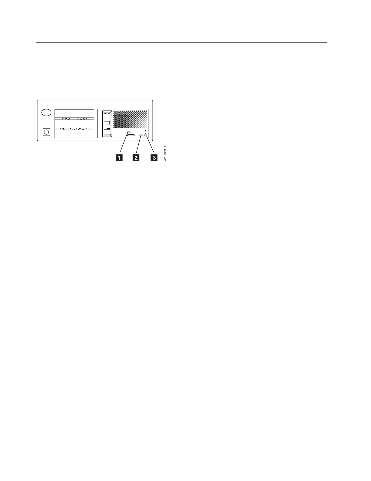
Drive Indicators—Normal Operation for Drive-Only Model C00
|
For drive-only models without a library attachment, three LEDs indicate operator messages and error
conditions under normal customer operations. Figure 6 shows the location of the operator panel
indicators. See “Drive Indicators and Operator Controls” on page INTRO-39 for a description of the
indicators.
Figure 6. Drive Indicators for Drive-Only Models
Figure 7 on page START-11 shows the combination of the three indicators and their meanings under
normal customer operational conditions. The Note column refers to an operator action or information.
For the meaning of these LEDs when in CE Mode, see Figure 246 on page PROC-9 for FID decode
meanings and Figure 244 on page PROC-7 for meanings when displaying options.
START-10 IBM 3570 MI
Page 25

Figure 7. Indicator Meaning During Normal Operational Conditions
Busy 1 Clean 2 Maintenance 3 Note Message
Off Off Off — Inactive
Off Off Flashing 1 POST or write/read diagnostic test running
Off Flashing Off 2 Cleaning is required
Off On Off 2 The drive has been disabled until the Head Cleaning
procedure is performed.
On Off Off 3 Busy, tape in motion for write, read or locate
On On Off — ATTENTION DRIVE message is indicated. See
“Attention Drive Messages” on page START-24.
On On On 4
Flashing Off Off 3 Unloading, rewinding or cleaning
Flashing Flashing Flashing 5 A hard failure on drive
Off Off On 5 A hard failure on drive
Flashing Flashing On 5 A hard failure on drive
Notes:
1. Maintenance indicator flashing: a normal condition that occurs anytime diagnostics are running. The
diagnostics run:
At power-on time.
After a system reset.
When a Send Diagnostic command is sent from the initiator.
When executed by the service representative.
For more information on LED meanings in CE Mode, see Figure 244 on page PROC-7 and Figure 246
on page PROC-9.
2. Clean indicator flashing or ON solid: the 3570 determines that the read/write heads need cleaning.
Note: If the Clean indicator is ON solid, the 3570 drive will be disabled until the cleaning operation has been
performed.
Load the cleaning cartridge into the 3570. See “Drive Cleaning Procedure” on page PROC-22. Cleaning is
automatic: the Busy indicator is lighted and remains ON until the cleaning cartridge is unloaded. If the Clean
indicator remains ON after cleaning or if the Clean indicator comes ON frequently, see “Other Obvious
Symptom Problems” on page MAPS-19 for further isolation.
3. Busy indicator flashing or ON solid: a normal condition that indicates that the drive is executing either a
read/write operation or is locating, rewinding, or unloading.
4. Busy, Clean and Maintenance indicators lighted: the LED test that occurs at power-on time, after a system
reset or during microcode recovery.
5. Two major conditions may occur here:
a. All three indicators flash quickly, then the Maintenance LED stays ON solid while the other two LEDs flash
or stay OFF. This indicates a hard failure on the drive and the drive is sending a coded message of the
associated FID. For more information on LED meanings in CE Mode, see Figure 244 on page PROC-7
and Figure 246 on page PROC-9.
b. All three indicators flash quickly, then all three come ON solid for a time, then the three indicators flash
quickly again. This pattern may repeat as many as four times. This indicates that the microcode has
encountered problems, and is trying to recover. If the microcode fails to recover, it will then flash the
three indicators continuously until the device is powered OFF or reset.
On momentarily as a lamp test during power-on reset
&
or during microcode recovery.
5
START
Start START-11
Page 26

FID Entry Point
Figure 8 lists each FRU identifier (Reported FID) and the field replaceable units (FRUs) to change, or
problem areas to investigate under FRU Name. The figure (beginning with the Third Release) also
contains the Repair Sequence you should follow in performing procedures or FRU replacements. Also
included are page Reference or Instruction to the removal and replacement procedure for the FRU.
Each FRU or problem is identified by name. The technical area code (TAC), provided here and in the
CARR section, is to assist you with call reporting. The Duration in hours is intended to give you some
idea of how long each FRU removal and replacement procedure will take. These numbers, along with the
time it takes to remove and replace decorative covers (see times given for covers in the CARR section)
should give you a ball park estimate of what time you can expect to spend replacing the parts. These
times do not include diagnose and checkout time.
FIDs are displayed on the operator/CE panel in a FID message and in the error log. For example, if the
message is FID1 90, 1 is the severity and 90 is the FID. “Intervention Screens” on page PANEL-9
describes the different types of messages and their impact on 3570 availability. The FID relates to the
FRUs that have the highest probability of causing the problem. Only the reported FID is displayed on the
panel and in the FID log. See Figure 8 for the complete list of FIDs and associated FRUs. Always
replace the FRU or perform the recommended procedure in the order of Repair Sequence which takes
into consideration failure probability.
If the FID has cable FRUs in the FRU list, reseat the cable FRUs before replacing any FRU in the list.
If you are servicing a 3570 model that is Rack installed, two people are required to lift the device from the
rack. Refer to “Installing the 3570 in a Rack (Models C11 and C12 Only)” on page INST-22 for the
procedure to use the hoist in cases where you are alone.
The service information message (SIM) record, which the 3570 sends to the host, also has the reported
FID information. See “Service Information Messages (SIMs) and Media Information Messages (MIMs)” on
page MSG-2.
Figure 8 (Page 1 of 12). FIDs, FRUs, and TACs
Reported
FID
00 The drive serial number is the default value
01 The drive logic card serial number is the default value
| procedure is at “Removal and
| Replacement Procedures—Drive
| Pack” on page CARR-7. If this
Repair
Sequence
1 Invalid drive serial number — — Enter valid drive serial number.
1 Invalid drive logic card serial
FRU Name Prob-
ability
— —| Replace the Tape Drive. The
number. This number is set when
the card is built and cannot be
changed in the field.
TAC
Code &
(Duration
in hours)
Page Reference or Instruction
Go to “Drive Serial
Number—Library Models Only” on
page PROC-29.
| does not resolve the problem, call
| for support.
03 Invalid setup detected
1 Configuration problem — — Ensure the config/install options
are correct (library models only).
START-12 IBM 3570 MI
Page 27
Figure 8 (Page 2 of 12). FIDs, FRUs, and TACs
Reported
FID
90 Electronic fault. See also “Library Operator Panel Problems” on page MAPS-3.
| 2| Library operator panel display
| 40%| T04 (0.1)| CARR-19
| cable
94 Bar code reader failure. Perform the procedure at “Resolving Bar Code Reader Problems” on page PROC-24
| 4| Picker cable| 3%| T04 (0.1)| CARR-23
| 5| Library interface cable| 2%| T04 (0.1)| CARR-32
| 6| Drive pack| 2%| T22 (0.2)| CARR-7
95 Did not detect accessor movement.
Repair
Sequence
1 Library operator panel display 50% L05 (0.2) CARR-19
3 Library control card 10% T15 (0.2) CARR-22
before replacing any of the following FRUs.
1 Bar code reader 70% T18 (0.1) CARR-20
2 Library control card 20% T15 (0.1) CARR-22
3 Picker assembly 3% T12 (0.1) CARR-23
1. Check for anything that might obstruct picker movement.
2. Ensure that cartridges are positioned in the magazines properly. If the picker does not place the cartridges
fully into the magazines, replace the picker assembly before replacing any other FRUs.
3. This failure can also be caused by infrared light reflecting from the picker belts onto the Cartridge Present
sensor. If the picker belts are shiny and you suspect this is the cause, clean the picker belts with alcohol on
a lint-free cloth.
4. If the above checks don't fix the problem, cycle the power off then on to the 3570 and observe the accessor
assembly before replacing FRUs:
a. If the accessor motor assembly can move the picker back and forth, replace the accessor assembly
b. If accessor motor assembly cannot move the picker back and forth, replace the FRUs in the order listed
1 Accessor motor assembly 75% T17 (0.2) CARR-21
2 Library control card 15% T15 (0.1) CARR-22
3 Library sensor cable 5% T04 (0.4) CARR-33
4 Accessor assembly 5% T14 (0.6) CARR-20
FRU Name Prob-
before replacing any of the other FRUs.
below.
ability
TAC
Code &
(Duration
in hours)
Page Reference or Instruction
START
Start START-13
Page 28

Figure 8 (Page 3 of 12). FIDs, FRUs, and TACs
Reported
FID
96 Timeout trying to extract a cartridge from a drive.
Repair
Sequence
1. Before replacing any FRUs below, inspect the cartridge that was being used when the error occurred. Look
for physical defects. Have the customer replace the cartridge if it is damaged.
2. A false 96 error can occur when the library door is opened when the library is attempting to put a cartridge
away as part of the power-up sequence. If you believe this occurred, do not replace FRUs at this time.
3. Before replacing FRUs below, ensure that:
FRU Name Prob-
ability
TAC
Code &
(Duration
in hours)
Page Reference or Instruction
| a. All drive sensors listed on Figure 248 on page PROC-14 are working correctly.
| b. library sensors: Global Interference A & B, Cartridge Present, Pinch 1 & 2 and Limit 1 & 2 are working
| correctly. See Figure 248 on page PROC-14.
| See Figure 128 on page PANEL-26 and select UTILITIES from the CE OPTIONS Menu, then select DISP
| SENSORS from the CE UTILITIES Menu.
4. Ensure that the drive door is not binding or sticking.
| 1| Drive pack| 36%| T45 (0.2)| CARR-7
2 Picker assembly 30% T12 (0.1) CARR-23
3 Drive global sensor pair 10% T31 (0.1) CARR-25
4 Magazine global sensor pair 10% T31 (0.1) CARR-26
| 5| Picker cable| 5%| T04 (0.1)| CARR-23
6 Library control card 5% T15 (0.1) CARR-22
7 Library sensor cable 4% T04 (0.4) CARR-33
97 Electronic-detected fault
1 Library control card 70% T15 (0.1) CARR-22
| 2| Drive pack| 25%| T22 (0.2)| CARR-7
3 Library interface cable 3% C03 (0.1) CARR-32
4 Power supply 2% P04 (0.1) CARR-16
98 Load or unload error while moving cleaner cartridge between the library cleaner cartridge cell and the drive.
Sensor did not change state.
Notes:
1. Check the cleaner cartridge for physical damage.
| 2. Before replacing FRUs below, ensure that:
| a. All drive sensors listed on Figure 248 on page PROC-14 are working correctly.
| b. library sensors: Cleaner Cartridge Present, Global Interference A & B, Pinch 1 & 2 and Limit 1 & 2 are
| working correctly. See Figure 248 on page PROC-14.
| See Figure 128 on page PANEL-26 and select UTILITIES from the CE OPTIONS Menu, then select DISP
| SENSORS from the CE UTILITIES Menu.
1 Picker assembly 60% T12 (0.1) CARR-23
2 Cleaner cartridge-present sensor 15% T31 (0.1) CARR-33
| 3| Drive global sensor pair| 10%| T31 (0.1)| CARR-25
| 4| Magazine global sensor pair| 10%| T31 (0.1)| CARR-26
5 Library control card 4% T15 (0.1) CARR-22
6 Library sensor cable 1% T04 (0.4) CARR-33
START-14 IBM 3570 MI
Page 29
Figure 8 (Page 4 of 12). FIDs, FRUs, and TACs
Reported
FID
| 9A| Library Picker Assembly problem.
| Note: Before replacing FRUs below, ensure that the Cartridge Present, Pinch 1 & 2, and Limit 1 & 2 sensors in
| the library are operating correctly. See Figure 248 on page PROC-14. See Figure 128 on
| page PANEL-26 and select UTILITIES from the CE OPTIONS Menu, then select DISP SENSORS from
| the CE UTILITIES Menu.
| 2| Picker cable| 20%| T04 (0.1)| CARR-23
| 9B| Sensor in an invalid condition.
| Note: Before replacing FRUs below, ensure that the Drive Global Sensor (B) is operating correctly. The sensor
| is shown in Figure 248 on page PROC-14. See Figure 128 on page PANEL-26 and select UTILITIES
| from the CE OPTIONS Menu, then select DISP SENSORS from the CE UTILITIES Menu.
| 1| Drive global sensor pair (B)| 90%| T31 (0.2)| CARR-25
| 9C| Sensor in an invalid condition.
| Note: Before replacing FRUs below, ensure that the Global Interference Sensor A is operating correctly. The
| sensor is shown in Figure 248 on page PROC-14. See Figure 128 on page PANEL-26 and select
| UTILITIES from the CE OPTIONS Menu, then select DISP SENSORS from the CE UTILITIES Menu.
| 1| Magazine global sensor pair (A)| 90%| T31 (0.2)| CARR-26
9E Sensor did not change state.
| Note: Before replacing FRUs below, ensure that the Priority cell cartridge present.sensor is operating correctly.
| The sensor is shown in Figure 248 on page PROC-14. See Figure 128 on page PANEL-26 and select
| UTILITIES from the CE OPTIONS Menu, then select DISP SENSORS from the CE UTILITIES Menu.
Repair
Sequence
1 Picker assembly 70% T12 (0.1) CARR-23
3 Library control card 7% T15 (0.1) CARR-22
4 Library sensor cable 3% T04 (0.4) CARR-33
2 Library control card 9% T15 (0.1) CARR-22
3 Library sensor cable 1% T04 (0.4) CARR-33
2 Library control card 7% T15 (0.1) CARR-22
3 Library sensor cable 3% L01 (0.4) CARR-33
1 Priority cell cartridge-present
2 Library sensor cable 5% L01 (0.4) CARR-33
3 Library control card 5% T15 (0.1) CARR-22
FRU Name Prob-
ability
90% T31 (0.1) CARR-31
sensor
TAC
Code &
(Duration
in hours)
Page Reference or Instruction
START
Start START-15
Page 30

Figure 8 (Page 5 of 12). FIDs, FRUs, and TACs
Reported
FID
9F Load or unload error when moving a cartridge between the drive and the library (a sensor did not change state).
| a. All drive sensors listed on Figure 248 on page PROC-14 are working correctly.
| b. library sensors: Global Interference A & B, Cartridge Present, Pinch 1 & 2 and Limit 1 & 2 are working
| correctly. See Figure 248 on page PROC-14.
| See Figure 128 on page PANEL-26 and select UTILITIES from the CE OPTIONS Menu, then select DISP
| SENSORS from the CE UTILITIES Menu.
| 2| Drive pack| 32%| T45 (0.2)| CARR-7
| 3| Picker cable| 20%| C03 (0.1)| CARR-23
| 4| Library control card| 10%| T15 (0.1)| CARR-22
| 5| Library sensor cable| 4%| T04 (0.4)| CARR-33
| A0| Sensor did not change state.
| Note: Before replacing FRUs below, ensure that the Magazine 2 sensor is operating correctly. The sensor is
| shown on Figure 248 on page PROC-14. See Figure 128 on page PANEL-26 and select UTILITIES
| from the CE OPTIONS Menu, then select DISP SENSORS from the CE UTILITIES Menu.
A1 Sensor did not change state.
| Note: Before replacing FRUs below, ensure that the Magazine 1 sensor is operating correctly. The sensor is
| shown in Figure 248 on page PROC-14. See Figure 128 on page PANEL-26 and select UTILITIES from
| the CE OPTIONS Menu, then select DISP SENSORS from the CE UTILITIES Menu.
A3 Sensor did not change state
| Note: Before replacing FRUs below, ensure that the Cleaner cartridge-present sensor is operating correctly. The
| sensor is shown on Figure 248 on page PROC-14. See Figure 128 on page PANEL-26 and select
| UTILITIES from the CE OPTIONS Menu, then select DISP SENSORS from the CE UTILITIES Menu.
Repair
Sequence
1. Before replacing any FRUs below, inspect the cartridge that was being used when the error occurred. Look
for physical defects. Have the customer replace the cartridge if it is damaged.
2. A false 9F error can occur when the library door is opened when the library is attempting to put a cartridge
away as part of the power-up sequence. If you believe this occurred, do not replace FRUs at this time.
3. Before replacing FRUs below, ensure that:
4. Ensure that the drive door is not binding or sticking.
1 Picker assembly 34% T12 (0.1) CARR-23
1 Magazine 2 sensor 90% T31 (0.2) CARR-32
2 Library control card 7% T15 (0.1) CARR-22
3 Library sensor cable 3% T04 (0.4) CARR-33
1 Magazine 1 sensor 90% T31 (0.1) CARR-32
2 Library control card 7% T15 (0.1) CARR-22
3 Library sensor cable 3% T04 (0.4) CARR-33
1 Cleaner cartridge-present sensor 90% T31 (0.1) CARR-33
2 Library control card 7% T15 (0.1) CARR-22
3 Library sensor cable 3% T04 (0.4) CARR-33
FRU Name Prob-
ability
TAC
Code &
(Duration
in hours)
Page Reference or Instruction
START-16 IBM 3570 MI
Page 31

Figure 8 (Page 6 of 12). FIDs, FRUs, and TACs
Reported
FID
A7 Picker or priority slot error.
| Notes:
| 1. Before replacing any FRUs below, inspect the cartridge that was being used when the error occurred for
| physical defects. Have the customer replace the cartridge if it is damaged.
| 2. Before replacing any FRUs below, check library sensors Priority Slot, Cartridge Present, Global Interference
| B, Pinch 1 & 2, and Limit 1 & 2 sensors to ensure that they are operating correctly. The sensors are shown
| in Figure 248 on page PROC-14.
| 3| Priority cell cartridge-present
| 10%| T31 (0.1)| CARR-31
| sensor
| 4| Magazine global sensor pair| 10%| T31 (0.1)| CARR-26
A8 Picker or magazine error.
| Notes:
| 1. Before replacing any FRUs below, inspect the cartridge that was being used when the error occurred for
| physical defects. Have the customer replace the cartridge if it is damaged.
| 2. Before replacing any FRUs below, check library sensors Magazine 1 Present, Magazine 2 Present, Priority
| Slot, Cartridge Present, Global Interference B, Pinch 1 & 2, and Limit 1 & 2 sensors to ensure that they are
| operating correctly. The sensors are shown in Figure 248 on page PROC-14.
| 1| Library magazine| 30%| Q05 (0.1)| Customer purchase item. Try
| another magazine before
| replacing any FRUs below.
| 2| Picker assembly| 20%| T12 (0.1)| CARR-23
| 3| Magazine 1 sensor| 10%| T31 (0.1)| CARR-32
| 4| Magazine 2 sensor| 10%| T31 (0.1)| CARR-32
| 5| Magazine global sensor pair| 10%| T31 (0.1)| CARR-26
| 6| Priority cell cartridge-present
| 10%| T31 (0.1)| CARR-31
| sensor
Repair
Sequence
1 Library magazine 40% Q05 (0.1) Customer purchase item. Try
2 Picker assembly 30% T12 (0.1) CARR-23
5 Picker cable 5% C03 (0.1) CARR-23
6 Library control card 5% T15 (0.1) CARR-22
7 Picker cable 5% C03 (0.1) CARR-23
8 Library control card 5% T15 (0.1) CARR-22
FRU Name Prob-
ability
TAC
Code &
(Duration
in hours)
Page Reference or Instruction
another magazine before
replacing any FRUs below.
START
Start START-17
Page 32
Figure 8 (Page 7 of 12). FIDs, FRUs, and TACs
Reported
FID
A9 Picker feed error.
| Notes:
| 1. Before replacing any FRUs below, inspect the cartridge that was being used when the error occurred for
| physical defects. Have the customer replace the cartridge if it is damaged.
| 2. Before replacing any FRUs below, check library sensors: Pinch 1 & 2, Limit 1 & 2, Cartridge Present, and
| Global Interference A & B to ensure that they are operating correctly. The sensors are shown in Figure 248
| on page PROC-14.
| 1| Library magazine| 40%| Q05 (0.1)| Customer purchase item. Try
| another magazine before
| replacing any FRUs below.
| 2| Picker assembly| 30%| T12 (0.1)| CARR-23
| 3| Drive global sensor pair| 10%| T31 (0.1)| CARR-25
| 4| Magazine global sensor pair| 10%| T31 (0.1)| CARR-26
AA Library door open sensor
| Note: Before replacing FRUs below, ensure that the Library door open sensor is operating correctly. The sensor
| is shown in Figure 248 on page PROC-14. See Figure 128 on page PANEL-26 and select UTILITIES
| from the CE OPTIONS Menu, then select DISP SENSORS from the CE UTILITIES Menu.
B1 Drive LED fault detected
| 1| Drive pack| 100%| L05 (0.1)| CARR-7 if library installed drive or
| CARR-10 if stand-alone drive.
B9 Cartridge is not fully seated in the loader.
| 2| Drive pack| 35%| T45 (0.2)| CARR-7 if library installed drive or
| CARR-10 if stand-alone drive.
BA Loader asm or servo card
| 1| Drive pack| 100%| T45 (0.2)| CARR-7 if library installed drive or
| CARR-10 if stand-alone drive.
Repair
Sequence
5 Picker cable 5% C03 (0.1) CARR-23
6 Library control card 5% T15 (0.1) CARR-22
1 Library door open sensor 80% T31 (0.2) CARR-34
2 Library control card 14% T15 (0.1) CARR-22
3 Library sensor cable 6% T04 (0.4) CARR-33
Note: This could be an operator problem in drive-only machines without a library.
1. Ensure that the cartridge is not damaged.
2. Ensure that the cartridge is a 3570 type cartridge.
1 Tape cartridge 40% D07 (0.1) Customer item. Inspect for
3 Picker assembly (For library only) 25% T12 (0.1) CARR-23
FRU Name Prob-
ability
TAC
Code &
(Duration
in hours)
Page Reference or Instruction
damage. Try another cartridge
before replacing the FRUs below.
START-18 IBM 3570 MI
Page 33
Figure 8 (Page 8 of 12). FIDs, FRUs, and TACs
Reported
FID
BB Loader asm, servo card, or tape cartridge.
| 1| Tape cartridge (check first)| 20%| D07 (0.1)| Customer item. Inspect for
| damage. Try another cartridge.
| See “FID FE—Isolate Fault
| between Media and Hardware” on
| page PROC-89.
| 2| Drive pack| 80%| T45 (0.2)| CARR-7 if library installed drive or
| CARR-10 if stand-alone drive.
BC Load or unload failure.
| Note: If your drive is at microcode level D1I5_2F1 or lower, this error may be caused by the microcode failing to
| reset an internal counter. Before replacing any hardware, call your next level of support for advice.
| 3. Ensure that all drive sensors are operating correctly. Refer to Figure 248 on page PROC-14 for the drive
| sensors. See Figure 128 on page PANEL-26 and select UTILITIES from the CE OPTIONS Menu, then
| select DISP SENSORS from the CE UTILITIES Menu.
| 1| Tape cartridge (check first)| 20%| D07 (0.1)| Customer item. Inspect for
| damage. Try another cartridge.
| See “FID FE—Isolate Fault
| between Media and Hardware” on
| page PROC-89.
| 2| Drive pack| 80%| T45 (0.2)| CARR-7 if library installed drive or
| CARR-10 if stand-alone drive.
BF Thermal error. The tripped thermal is located on the drive logic card. Causes of a thermal trip can be
| 1| Drive pack| 75%| L01 (0.2)| CARR-7 if library installed drive or
| CARR-10 if stand-alone drive.
| C1| 12 or 36 volts not within specification.
| 1| This FID is also reported when
| | | Power OFF and power back ON.
| the drive detects a power outage.
| 3| Drive pack| 10%| T53 (0.2)| CARR-7 if library installed drive or
| CARR-10 if stand-alone drive.
C5 Tape cartridge or cartridge type sensor
| Note: Before replacing FRUs below, ensure that the Cartridge type sensor is operating correctly. Refer to
| Figure 248 on page PROC-14. See Figure 128 on page PANEL-26 and select UTILITIES from the CE
| OPTIONS Menu, then select DISP SENSORS from the CE UTILITIES Menu.
| 1| Tape cartridge (Check first)| 90%| D07 (0.1)| Customer item. Inspect for
| damage. Try another cartridge.
| Refer to “FID FE—Isolate Fault
| between Media and Hardware” on
| page PROC-89.
| 2| Drive pack| 10%| T53 (0.2)| CARR-7 if library installed drive or
| CARR-10 if stand-alone drive.
Repair
Sequence
1. Before replacing any FRUs below, inspect the cartridge that was being used when the error occurred for
physical defects. Have the customer replace the cartridge if it is damaged.
2. Also ensure that the cartridge is a 3570 type cartridge.
1. Before replacing any FRUs below, inspect the cartridge that was being used when the error occurred for
physical defects. Have the customer replace the cartridge if it is damaged.
2. Ensure that the cartridge is a 3570 type cartridge.
overheating of the logic card circuits, a missing front drive bezel which is needed to deflect airflow to the drive
logic card, a failing drive fan, or blockage of airflow in the fan area. If the cooling system appears to be
adequate, replace the drive pack.
2 Drive cooling fan 25% A03 (0.3) CARR-12
2 Power supply 90% P04 (0.1) CARR-16
FRU Name Prob-
ability
TAC
Code &
(Duration
in hours)
Page Reference or Instruction
START
Start START-19
Page 34

Figure 8 (Page 9 of 12). FIDs, FRUs, and TACs
Reported
FID
CA Sensor failed to change state
| 1| Drive pack| 100%| T31 (0.2)| CARR-7 if library installed drive or
| CARR-10 if stand-alone drive.
CD Sensor failed to change state
| 1| Drive pack| 100%| T31 (0.2)| CARR-7 if library installed drive or
| CARR-10 if stand-alone drive.
D0 Read or write failure, servo error, or IPS calibration error.
| 1| Clean Drive| 80%| D08| See “Drive Cleaning Procedure”
| on page PROC-22.
| 2| Drive pack| 20%| T22 (0.2)| CARR-7 if library installed drive or
| CARR-10 if stand-alone drive.
D1 Calibration error; possible interface problem between the head and the servo card
| 1| Clean Drive| 55%| D08| See “Drive Cleaning Procedure”
| on page PROC-22.
| 2| Drive pack| 45%| T22 (0.2)| CARR-7 if library installed drive or
| CARR-10 if stand-alone drive.
D2 The head did not move. Head asm, servo card, analog card, or mother board
| 1| Clean Drive| 45%| D08| See “Drive Cleaning Procedure”
| on page PROC-22.
| 2| Drive pack| 55%| T22 (0.2)| CARR-7 if library installed drive or
| CARR-10 if stand-alone drive.
| D3| Servo error while moving tape.
| 1| Tape cartridge (check first)| 45%| D07 (0.1)| Customer item. Inspect for
| damage. Try another cartridge.
| Refer to “FID FE—Isolate Fault
| between Media and Hardware” on
| page PROC-89.
| 2| Clean Drive| 20%| D08| See “Drive Cleaning Procedure”
| on page PROC-22.
| 3| Drive pack| 35%| T22 (0.2)| CARR-7 if library installed drive or
| CARR-10 if stand-alone drive.
D8 Read/write error.
| 1| Clean Drive| 36%| D08| See “Drive Cleaning Procedure”
| on page PROC-22.
| 2| Drive pack| 64%| T22 (0.2)| See “Removal and Replacement
| Procedures—Drive Pack” on
| page CARR-7.
| DD| Fault detected in drive loader sensors or the sensors are in an invalid combination.
| 1| Drive pack| 100%| T45 (0.2)| CARR-7 if library installed drive or
| CARR-10 if stand-alone drive.
E0 Tape motion error
| 1| Tape cartridge (check first)| 77%| D07 (0.1)| Customer item. Inspect for
| damage. Try another cartridge.
| Refer to “FID FE—Isolate Fault
| between Media and Hardware” on
| page PROC-89.
| 2| Drive pack| 23%| T45 (0.2)| CARR-7 if library installed drive or
| CARR-10 if stand-alone drive.
Repair
Sequence
FRU Name Prob-
ability
TAC
Code &
(Duration
in hours)
Page Reference or Instruction
START-20 IBM 3570 MI
Page 35

Figure 8 (Page 10 of 12). FIDs, FRUs, and TACs
Reported
FID
E4 Electronic-detected fault
| 1| Drive pack| 92%| L01 (0.2)| CARR-7 if library installed drive or
| CARR-10 if stand-alone drive.
| 2| Power supply| 8%| P04 (0.1)| CARR-16
E5 Microcode detected a fault with the microcode
E6 Timing problem in the microcode or the electronics, or multiple check-1 errors occurred
| 2| Drive pack| 50%| L01 (0.2)| CARR-7 if library installed drive or
| CARR-10 if stand-alone drive.
E7 Timing problem in the microcode or the electronics
| 2| Drive pack| 50%| L01 (0.2)| CARR-7 if library installed drive or
| CARR-10 if stand-alone drive.
E8 Timing problem while writing and/or reading
| EA| Electronic failure-Drive Logic Card
| 1| Drive pack| 90%| L01 (0.2)| CARR-7 if library installed drive or
| CARR-10 if stand-alone drive.
| 2| Power supply| 10%| P04 (0.1)| CARR-16
| EB| Electronic failure-Drive Logic Card
| 1| Drive pack| 90%| T21 (0.2)| CARR-7 if library installed drive or
| CARR-10 if stand-alone drive.
| 2| Power supply| 10%| P04 (0.1)| CARR-16
| EC| Electronic failure-Drive Logic Card
| 1| Drive pack| 90%| T53 (0.2)| CARR-7 if library installed drive or
| CARR-10 if stand-alone drive.
| 2| Power supply| 10%| P04 (0.1)| CARR-16
| ED| Electronic failure
| 1| Drive pack| 100%| L01 (0.2)| CARR-7 if library installed drive or
| CARR-10 if stand-alone drive.
| EE| Electronic failure
| 1| Drive pack| 100%| L01 (0.2)| CARR-7 if library installed drive or
| CARR-10 if stand-alone drive.
| F0| Read error
| 2| Drive pack| 40%| T22 (0.2)| CARR-7 if library installed drive or
| CARR-10 if stand-alone drive.
Repair
Sequence
1 Microcode (known or unknown)
1 Microcode (known or new) (M01 =
1 Microcode (known or new) (M01 =
1 Set a microcode trap based on
1 Tape cartridge 60% D07 (0.1) Customer supply. Refer to “FID
FRU Name Prob-
ability
100% M01/ M02 PROC-84
(M01 = known, M02 = new)
50% M01/M02 PROC-84 and PROC-86
known, M02 = new)
50% M01/ M02 PROC-84 and PROC-86
known, M02 = new)
— — PROC-44
the expert systems data, get a
dump , and contact your next
level of support.
TAC
Code &
(Duration
in hours)
Page Reference or Instruction
FE—Isolate Fault between Media
and Hardware” on
page PROC-89.
START
Start START-21
Page 36
Figure 8 (Page 11 of 12). FIDs, FRUs, and TACs
Reported
FID
| F1| Read error
| 2| Drive pack| 40%| T22 (0.2)| CARR-7 if library installed drive or
| CARR-10 if stand-alone drive.
F2 Read-back check error.
| 2| Drive pack| 40%| T22 (0.2)| CARR-7 if library installed drive or
| CARR-10 if stand-alone drive.
F3 Servo error
| 2| Clean Drive| 15%| D08| See “Drive Cleaning Procedure”
| on page PROC-22.
| 3| Drive pack| 25%| T22 (0.2)| CARR-7 if library installed drive or
| CARR-10 if stand-alone drive.
F4 RS-422 bus error (drive logic card or RS-422 cables)
| Note: When replacing the FRUs
| below, replace the cable
| first.
| 2| Drive pack| 80%| L01 (0.2)| CARR-7 if library installed drive or
| CARR-10 if stand-alone drive.
| 4| RS-422 Cable, Drive to
| 10%| C04 (0.1)| CARR-18
| Drive(C02, C12 and C22 only)
Repair
Sequence
1 Tape cartridge 60% D07 (0.1) Customer supply. Refer to “FID
1 Tape cartridge or hardware 60% D07 (0.1) “FID FE—Isolate Fault between
1 Tape cartridge or hardware 60% D07 (0.1) “FID FE—Isolate Fault between
1 RS-422 interface problem — — Run the RS-422 wrap test. See
3 RS-422 cable—internal to drive 10% C04 (0.1) CARR-18
FRU Name Prob-
ability
TAC
Code &
(Duration
in hours)
Page Reference or Instruction
FE—Isolate Fault between Media
and Hardware” on
page PROC-89.
Media and Hardware” on
page PROC-89.
Media and Hardware” on
page PROC-89.
“RS-422 Port Wrap Test” on
page PROC-78. If problem
re-occurs, replace the following
FRUs.
If that does not fix the problem,
get a microcode dump and
contact your next level of support.
START-22 IBM 3570 MI
Page 37
Figure 8 (Page 12 of 12). FIDs, FRUs, and TACs
Reported
FID
F5 SCSI bus error (drive logic card or SCSI cables)
| Note: When replacing the FRUs
| below, replace the cable
| first.
| 2| Drive pack| 80%| L01 (0.2)| CARR-7 if library installed drive or
| CARR-10 if stand-alone drive.
F6 Informational message—Cleaning required due to performance.
FE Read/write error. See “FID FE—Isolate Fault between Media and Hardware” on page PROC-89.
FF Informational or non-hardware related status or error
Notes:
1. Information FID F6 or FF with FSCs 7036, 7037, 7038 and C559 are normal. These FSCs are generated when a drive
requires cleaning or when a drive has been cleaned.
Repair
Sequence
1 SCSI interface, operator
3 Internal SCSI cable 20% C04 (0.2) CARR-17
1 Operator, procedural, or host
1 Tape cartridge or hardware 100% D07 (0.1) “FID FE—Isolate Fault between
1 Operator, procedural, or host
FRU Name Prob-
ability
— — Run the SCSI wrap test. See
procedural, or host problem
100% — See 1 on page START-23.
problem
100% — See 1 on page START-23.
problem
TAC
Code &
(Duration
in hours)
Page Reference or Instruction
“SCSI Port Wrap Test” on
page PROC-77. If problem
re-occurs, replace the following
FRUs.
If that does not fix the problem,
get a microcode dump and
contact your next level of support.
Media and Hardware” on
page PROC-89
START
Start START-23
Page 38

Attention Drive Messages
Library machines:
1. Some attention messages (ATTENTION DRIVE) have an associated FID that is not displayed until
you press the Enter push button.
2. Use Figure 9 for ATTENTION DRIVE messages without an associated FID.
3. If ATTENTION DRIVE is displayed, press the Enter push button. If a FID appears, go to “FID
Entry Point” on page START-12.
4. If no FID is presented, use Figure 9 to find the fault.
Drive-only machines:
1. On drive-only installations the drive Busy and Clean LED indicators will be on solid to show that a
‘ATTENTION DRIVE’ is being presented. This may apply to all ATTENTION DRIVE messages
except FSC Trap Taken.
2. See “Drive Indicators—Normal Operation for Drive-Only Model C00” on page START-10 for the
meaning of these flashing LEDs.
Figure 9. ATTENTION DRIVE Messages
Message
Meaning
Load
Unload
Error
| 3. Before replacing FRUs below, ensure that all drive sensors are operating correctly. Refer to Figure 248 on
| page PROC-14. See Figure 128 on page PANEL-26 and select UTILITIES from the CE OPTIONS Menu,
| B3| Drive Pack| 50%| T45 (0.2)| CARR-7 if library installed drive or
| CARR-10 if stand-alone drive.
FSC Trap
Taken
Tension
Dropped
| B3| Drive Pack| 30%| T45 (0.2)| CARR-7 if library installed drive or
| CARR-10 if stand-alone drive.
Invalid
cartridge
| 3. Before replacing FRUs below, ensure that the Cartridge Type Sensor is operating correctly. Refer to
| Figure 248 on page PROC-14. See Figure 128 on page PANEL-26 and select UTILITIES from the CE
| B3| Drive Pack| 40%| T45 (0.2)| CARR-7 if library installed drive or
| CARR-10 if stand-alone drive.
FRUs FRU Name Prob-
ability
1. Ensure that the cartridge and tape are not broken.
2. Ensure that the cartridge is a 3570 compatible-type cartridge.
then select DISP SENSORS from the CE UTILITIES Menu.
FE Tape cartridge 50% D07 (0.1) Customer supply. Refer to “FID
The microcode encountered the trap address set from a CE panel menu. This is valid only for library models.
— Not a fault — — —
Tape motion error (velocity or tape slipping error). Check the tape cartridge before replacing any FRUs.
FE Tape cartridge 70% D07 (0.1) Customer supply. Refer to “FID
1. Ensure that the cartridge and tape are not broken.
2. Ensure that the cartridge is a 3570 compatible-type cartridge.
OPTIONS Menu, then select DISP SENSORS from the CE UTILITIES Menu.
FE Tape cartridge 60% D07 (0.1) Customer supply. Refer to “FID
TAC
Code&
(Duration
in hours)
Page Reference
FE—Isolate Fault between Media
and Hardware” on
page PROC-89.
FE—Isolate Fault between Media
and Hardware” on
page PROC-89.
FE—Isolate Fault between Media
and Hardware” on
page PROC-89.
START-24 IBM 3570 MI
Page 39
Attention Library Messages
Some attention messages (ATTENTION LIBRARY) have an associated FID that is not displayed until you
press the Enter push button. Use Figure 10 for ATTENTION LIBRARY messages without an associated
FID.
1. If ATTENTION LIBRARY is displayed, press the Enter push button. If a FID appears, go to “FID Entry
Point” on page START-12.
2. If no FID is presented, use Figure 10 to find the fault.
| 3. If an Attention and Supplemental Message indicating DRIVE DISABLED UNTIL CLEANED is
| displayed, the tape drive must be cleaned before further use of the drive is allowed. See “Resolving
| ATTENTION Messages” on page PANEL-10 for additional information.
Figure 10 (Page 1 of 6). ATTENTION LIBRARY Messages
Message
Meaning
Move
Error
| B3| Drive pack| 18%| T45 (0.2)| CARR-7
| 9E| Library Sensor—Priority Cell
| 3%| T31 (0.1)| CARR-31
| Cartridge-Present Sensor
| 9C| Library Sensor—Magazine Global
| 3%| T31 (0.1)| CARR-26
| Sensor Pair
| 9B| Library Sensor—Drive Global
| 3%| T31 (0.1)| CARR-25
| Sensor Pair
| A1| Library Sensor—Magazine 1
| 3%| T31 (0.1)| CARR-32
| Sensor
| A0| Library Sensor—Magazine 2
| 3%| T31 (0.1)| CARR-32
| Sensor
FRUs FRU Name or Description Prob-
ability
Notes:
1. Ensure that the cartridge is not damaged or the tape broken, and that the cartridge is a 3570 cartridge.
2. Ensure that at least one magazine is installed and that there is no global obstruction in the picker path.
3. Check all library sensors to ensure that they are operating correctly. Refer to Figure 248 on page PROC-14.
9A Picker assembly 38% T12 (0.1) CARR-23
FD Magazine 20% Q05 (0.1) Customer-purchased
97 Library control card 3% T15 (0.1) CARR-22
99 Picker cable 3% C03 (0.1) CARR-23
A5 Library sensor cable 3% T04 (0.4) CARR-33
TAC
Code &
(Duration
in hours)
Page Reference or Instruction
START
Start START-25
Page 40

Figure 10 (Page 2 of 6). ATTENTION LIBRARY Messages
Message
Meaning
Timeout
Error
FRUs FRU Name or Description Prob-
ability
An operation timed out or did not complete in the allotted time-frame. This is usually caused by a hardware
failure.
Check all Drive and Library Sensors. Refer to Figure 248 on page PROC-14.
9A Picker assembly 44% T12 (0.1) CARR-23
FD Magazine 20% Q05 (0.1) Customer-purchased
TAC
Code &
(Duration
in hours)
Page Reference or Instruction
| B3| Drive pack| 18%| T45 (0.2)| CARR-7
| 9E| Library Sensor—Priority Cell
| 3%| T31 (0.1)| CARR-31
| Cartridge-Present Sensor
| 9C| Library Sensor—Magazine Global
| 3%| T31 (0.1)| CARR-26
| Sensor Pair
| 9B| Library Sensor—Drive Global
| 3%| T31 (0.1)| CARR-25
| Sensor Pair
97 Library control card 3% T15 (0.1) CARR-22
99 Picker cable 3% C03 (0.1) CARR-23
A5 Library sensor cable 3% T04 (0.4) CARR-33
Clear
Picker
Path A
The device detected the presence of a possible blockage in the cartridge path, such as in the magazine or in the
priority cell.
1. Check the position of all cartridges to ensure they are properly positioned in the magazine and in the priority
cell. A cartridge that extends too far into the magazine in the import position or a damaged cartridge can
cause this error.
2. Check for a binding or sticking cartridge door.
3. Remove the magazine and look for any obvious obstructions.
4. Try another magazine in the library.
| 5. Before replacing FRUs below, ensure that the Magazine Global Sensor pair (A) and priority cell sensors are
| operating correctly. Refer to Figure 248 on page PROC-14. See Figure 128 on page PANEL-26 and select
UTILITIES from the CE OPTIONS Menu, then select DISP SENSORS from the CE UTILITIES Menu.
| 9C| Magazine global sensor pair (A)| 50%| T31 (0.2)| CARR-26
| 9E| Priority cell cartridge-present
| 40%| T31 (0.1)| CARR-31
| sensor
97 Library control card 6% T15 (0.1) CARR-22
A5 Library sensor cable 4% T04 (0.4) CARR-33
Clear
Picker
Path B
The device detected the presence of a possible blockage in the cartridge path between the drive and the picker,
or between the cleaner cell and the picker.
1. Check the position of the cleaner cartridge and ensure that it is fully seated within the cleaner cell. If the
cleaner cartridge is not fully seated in the cleaner cell, replace the cleaner cell retention spring (P/N
05H2912).
2. Ensure that no cartridges or other obstacles are in the picker path between the drive and the picker.
3. Check for a binding or sticking cartridge door.
| 4. Before replacing FRUs below, ensure that:
| Library sensor: Global Interference B
| Picker sensors: Cartridge Present, Pinch 1 & 2, Limit 1 & 2
| Drive sensors: All
| are operating correctly. Refer to Figure 248 on page PROC-14. See Figure 128 on page PANEL-26 and
select UTILITIES from the CE OPTIONS Menu, then select DISP SENSORS from the CE UTILITIES Menu.
9B Drive global sensor pair (B) 50% T31 (0.2) CARR-25
| 9A| Picker assembly| 40%| T12 (0.1)| CARR-23
97 Library control card 6% T15 (0.1) CARR-22
A5 Library sensor cable 2% T04 (0.4) CARR-33
B3 Drive pack 2% (0.2) CARR-7
START-26 IBM 3570 MI
Page 41
Figure 10 (Page 3 of 6). ATTENTION LIBRARY Messages
Message
Meaning
Wrong
Mode
No
Magazine
1, 2, or
Both
| 2. Before replacing FRUs below, ensure that the Magazine 1 and Magazine 2 sensors are operating correctly.
| Refer to Figure 248 on page PROC-14. See Figure 128 on page PANEL-26 and select UTILITIES from the
| CE OPTIONS Menu, then select DISP SENSORS from the CE UTILITIES Menu.
| A0| Magazine 2 sensor| 44%| T31 (0.2)| CARR-32
| A1| Magazine 1 sensor| 44%| T31 (0.1)| CARR-32
| 97| Library control card| 8%| T15 (0.1)| CARR-22
| A5| Library sensor cable| 4%| T04 (0.4)| CARR-33
No
cartridge
| 3. Before replacing FRUs below, ensure that the Magazine 1 and Magacine 2, Priority Cell, and Cartridge
| Present sensors are operating correctly. See Figure 128 on page PANEL-26 and select UTILITIES from the
| 9A| Picker assembly| 43%| T12 (0.1)| CARR-23
| 9E| Priority cell cartridge-present
| 20%| T31 (0.1)| CARR-31
| sensor
| A1| Magazine 1 sensor| 10%| T31 (0.1)| CARR-32
| A0| Magazine 2 sensor| 10%| T31 (0.1)| CARR-32
| 97| Library control card| 10%| T15 (0.1)| CARR-22
| A5| Library sensor cable| 7%| T04 (0.4)| CARR-33
Extra
cartridge
| 2. Before replacing FRUs below, ensure that the Priority Cell, Cartridge Present (on picker) and Limit 1 & 2
| sensors are operating correctly. Refer to Figure 248 on page PROC-14. See Figure 128 on
| 9A| Picker assembly| 35%| T12 (0.1)| CARR-23
| 97| Library control card| 20%| T15 (0.1)| CARR-22
| A5| Library sensor cable| 5%| T04 (0.4)| CARR-33
FRUs FRU Name or Description Prob-
ability
An operation was requested from the initiator which cannot be run with the current mode setting.
— — 100% Q05 Change mode to Auto, Random,
1. Ensure that the appropriate magazine is properly installed and latched in place. If the ATTENTION LIBRARY
message persists, try a different magazine. If a different magazine fails to correct the problem, replace the
FRUs below: HINT: If both magazines are present, but neither is being sensed, the problem is not
likely to be the sensor or cable.
The device detects the presence of cartridges, but cannot find a cartridge in the import position in the magazine
or the priority cell.
1. Check the position of all the cartridges to ensure they are properly positioned in the import position of the
magazine and the priority cell. If this condition is not cleared, remove and replace the magazine.
2. Press Start.
CE OPTIONS Menu, then select DISP SENSORS from the CE UTILITIES Menu.
The device loaded a cartridge from the magazine and detected that another cartridge was placed in its home
position. The device attempts to place the now-displaced cartridge in the priority cell to await operator action. If
the priority cell is full, it ejects the cartridge when the priority slot is unloaded or when the Enter push button is
pressed.
1. Ensure that no cartridge has been inserted into an ‘in use’ cell.
page PANEL-26 and select UTILITIES from the CE OPTIONS Menu, then select DISP SENSORS from the
CE UTILITIES Menu.
9E Priority cell cartridge-present
sensor
40% T31 (0.1) CARR-31
TAC
Code &
(Duration
in hours)
Page Reference or Instruction
or Manual as needed.
START
Start START-27
Page 42

Figure 10 (Page 4 of 6). ATTENTION LIBRARY Messages
Message
Meaning
No
Cleaner
cartridge
FRUs FRU Name or Description Prob-
ability
A request was made to clean the head, but the device cannot find a cleaner cartridge in the cleaner cell.
1. Check the cleaner cell to ensure that a cleaner cartridge is present in the cell.
2. Ensure that it is a cleaner cartridge and not just a data cartridge. The holes in the casing are different and
the media in the cleaner cartridge does not fill the entire cartridge Cleaner cartridges have a gray file protect
lever.
3. Before replacing FRUs below, ensure that the cleaner cartridge present sensor and Limit 1 & 2 sensors are
operating correctly. Refer to Figure 248 on page PROC-14. See Figure 128 on page PANEL-26 and select
UTILITIES from the CE OPTIONS Menu, then select DISP SENSORS from the CE UTILITIES Menu.
A3 Cleaner cartridge-present sensor 64% T31 (0.1) CARR-33
TAC
Code &
(Duration
in hours)
Page Reference or Instruction
| 9A| Picker assembly| 21%| T12 (0.1)| CARR-23
A5 Library sensor cable 10% T04 (0.4) CARR-33
97 Library control card 5% T15 (0.1) CARR-22
Tach
Error
Library
IRQ Fault
Magazine
| Note: Before replacing FRUs below, ensure that the Priority Cell and Picker Cartridge Present sensors are
Full
A tach error was detected during an accessor motor operation.
1. Check for anything that might obstruct picker movement.
2. Ensure that cartridges are positioned in the magazine properly.
3. If the above checks don't fix the problem, cycle the power off then on to the 3570 and observe the accessor
assembly before replacing FRUs.
a. If the accessor motor assembly can move the picker back and forth, replace the accessor assembly
before replacing any of the other FRUs.
b. If accessor motor assembly cannot move the picker back and forth, replace the FRUs in the order listed
below.
95 Accessor motor assembly 80% T17 (0.2) CARR-21
97 Library control card 10% T15 (0.1) CARR-22
A5 Library sensor cable 6% T04 (0.4) CARR-33
99 Picker cable 2% C03 (0.1) CARR-23
92 Accessor assembly 2% T14 (0.6) CARR-20
A library interrupt is on solid. Insure that the power cable from the power supply to the library control card is
plugged and not loose. A drawing of this cable with expected voltages is located at Figure 13 on
page MAPS-27. If the power is OK to the library control card, replace the following FRUs in the order listed:
97 Library control card 90% T15 (0.1) CARR-22
C1 Power supply 10% P04 (0.1) CARR-16
The magazine is full of cartridges. The device detected that the magazine cannot hold any more cartridges.
| operating correctly. Refer to Figure 248 on page PROC-14. See Figure 128 on page PANEL-26 and
select UTILITIES from the CE OPTIONS Menu, then select DISP SENSORS from the CE UTILITIES
Menu.
FD Cartridge magazine 90% Q05 (0.1) Remove the magazine and
replace the cartridges or insert
another full magazine.
9E Priority cell cartridge-present
sensor
9A Picker assembly 4% T12 (0.1) CARR-23
97 Library control card 1% T15 (0.1) CARR-22
5% T31 (0.1) CARR-31
START-28 IBM 3570 MI
Page 43

Figure 10 (Page 5 of 6). ATTENTION LIBRARY Messages
Message
Meaning
| Library
| The library is not enabled.
| Not
| | Ensure there are cartridges in the
| | |
| Enabled
| library and that they are seated in
| the import position.
| 9A| Picker assembly| 37%| T12 (0.1)| CARR-23
Feed
Over-
current
Pinch
Over-
current
Picker
Over-
current
Transport
Full
Library
Door
Open
FRUs FRU Name or Description Prob-
ability
9E Priority cell cartridge-present
sensor
A5 Library sensor cable 10% T04 (0.4) CARR-33
97 Library control card 5% T15 (0.1) CARR-22
An over-current condition was detected in the library feed motor circuitry.
97 Library control card 60% T15 (0.1) CARR-22
9A Picker assembly 20% T12 (0.1) CARR-23
An over-current condition was detected in the library pinch motor circuitry.
97 Library control card 60% T15 (0.1) CARR-22
9A Picker assembly 20% T12 (0.1) CARR-23
An over-current condition was detected in the library picker motor circuitry.
97 Library control card 60% T15 (0.1) CARR-22
9A Picker assembly 20% T12 (0.1) CARR-23
The picker attempted to unload a cartridge but had no place to put it. A tape cartridge is present in slot that the
device tried to unload to, or it appears to the machine that the slot is full. Could be a full slot or a sense error.
The tape cartridge was left in the transport.
1. Ensure that a cartridge was not placed in an in use cell, causing this failure.
2. Before replacing FRUs below, ensure that the Priority Cell, Picker Cartridge Present sensors are operating
correctly. See Figure 128 on page PANEL-26 and select UTILITIES from the CE OPTIONS Menu, then
select DISP SENSORS from the CE UTILITIES Menu.
FE Tape cartridge 60% — (0.1) Remove the cartridge
9E Priority cell cartridge-present
sensor
9A Picker assembly 10% T12 (0.1) CARR-23
97 Library control card 6% T15 (0.1) CARR-22
FD Magazine 4% Q05 (0.1) Check magazine for defect.
The device detected that the library door was opened.
Note: Before replacing FRUs below, ensure that the library door sensor is operating correctly. See Figure 128
on page PANEL-26 and select UTILITIES from the CE OPTIONS Menu, then select DISP SENSORS
from the CE UTILITIES Menu.
— Library door open is a normal
condition if the operator has been
adding or removing cartridges
without using the priority cell
position. If the door was not
opened, but the machine thinks it
was, replace the FRUs that follow
until the problem is fixed.
AA Library door open sensor 90% T31 (0.2) CARR-34
97 Library control card 6% T15 (0.1) CARR-22
A5 Library sensor cable 4% T04 (0.4) CARR-33
48% T31 (0.1) CARR-31
20% T31 (0.1) CARR-31
— — Close the library door.
TAC
Code &
(Duration
in hours)
Page Reference or Instruction
START
Start START-29
Page 44

Figure 10 (Page 6 of 6). ATTENTION LIBRARY Messages
Message
Meaning
Target
Cell Full
| Note: Before replacing FRUs below, ensure that the Priority Cell and Picker Cartridge Present sensors are
FRUs FRU Name or Description Prob-
The device detected that the destination cell was full.
ability
TAC
Code &
(Duration
in hours)
Page Reference or Instruction
| operating correctly. Refer to Figure 248 on page PROC-14. See Figure 128 on page PANEL-26 and
select UTILITIES from the CE OPTIONS Menu, then select DISP SENSORS from the CE UTILITIES
Menu.
| 9E| Priority cell cartridge present
| 40%| T31 (0.1)| CARR-31
| sensor
| 9A| Picker Assembly| 30%| T31 (0.1)| CARR-23
A5 Library sensor cable 20% T04 (0.4) CARR-33
97 Library control card 10% T15 (0.1) CARR-22
START-30 IBM 3570 MI
Page 45

MAPs
MAPS
Contents
Library Operator Panel Problems ....................... MAPS-3
Library LED Problems .............................. MAPS-5
Drive LED Problems ............................... MAPS-9
Power Problems . . . . . . . . . . . . . . . . . . . . . . . . . . . . . . . . MAPS-13
Other Obvious Symptom Problems ..................... MAPS-19
Diagrams Referred to by MAPs ....................... MAPS-27
Copyright IBM Corp. 1998 MAPS-1
Page 46

MAPS-2 IBM 3570 MI
Page 47

Library Operator Panel Problems
This procedure helps you isolate library operator panel failures.
See the CARR section for check, adjustment, removal, and replacement procedures.
See “Operator Panel” on page PANEL-1 for a description of the operator panel.
Unless otherwise directed, run Fix Verify from the CE Options Menu to test the drive after a FRU
replacement.
If the recommended repair actions do not fix the problem, call your next level of support.
The table below may send you to another MAP. If not, continue with this MAP.
Figure 11. Library LED Type Failures and Where To Go First
If You Have the Following Symptoms Go Here First
Library LEDs flash continuously Go to Library LED Problems step
005 on page MAPS-5.
Some or all library LEDs fail to switch ON during the power-on cycle. Go to Library LED Problems step
008 on page MAPS-6.
Not all library LEDs switch ON during the power-on cycle. Go to Library LED Problems step
023 on page MAPS-7.
None of these symptoms were noted Go to Step 001.
MAPS
001
(From page MAPS-3)
Have the customer vary the drive off-line, if not
done before.
Perform “Prepare the Tape Device for Service” on
page PROC-5.
Switch ON power to the library device.
Can you see any display on the library
operator panel display?
Yes No
002
Switch the library power OFF then ON and
observe the three LEDs that normally
indicate that the two magazines and priority
cell are busy. The LEDs should flash ON
and OFF during the power-on cycle, then
switch OFF after the power-on diagnostics
complete execution.
003 (continued)
A power problem is causing the
operator panel to fail. Go to “Power
Problems” on page MAPS-13 for
further isolation. Return to this
procedure if the power supply is OK.
004
3570 power is good to the library control
card which drives the library operator panel
LEDs.
– Refer to “CE Verify Fix Menu” on
page PANEL-30 and run the Panel Test
Option of the diagnostic test. The test
should allow you to see if each pixel
switches ON at the panel display.
Did the test fail?
Yes No
005
Did any of the library operator panel
LEDs switch ON?
Yes No
003
(Step 003 continues)
MAPs MAPS-3
Go to Step 011 on page MAPS-4.
006
– Switch power OFF and check that the
library operator panel display cable
connector from the library operator panel
display to the library control card is
Page 48

Library Operator Panel Problems (continued)
seated properly.
If the library operator panel display cable
connector is seated, replace the following
FRUs:
1. “FID 90: Library Operator Panel Display”
on page CARR-19 (90%)
2. “FID 97: Library Control Card” on
page CARR-22 (8%)
3. “FID A5: Library Sensor Cable” on
page CARR-33 (2%)
Note: An alternative to replacing the
library sensor cable is to perform
a continuity check of the cable.
If it checks OK, don't replace it.
007
A display is seen, but may not be correct.
Does the data on the display seem to be
correct?
Yes No
008
Refer to “CE Verify Fix Menu” on
page PANEL-30 and run the Panel Test
Option of the diagnostic test. The test
should allow you to see if each pixel
switches ON at the panel display.
010 (continued)
Note: An alternative to replacing the
library sensor cable is to perform
a continuity check of the cable.
If it checks OK, don't replace it.
011
(From Library LED Problems step 013 on page
MAPS-6)
(From steps 005 and 009)
The display appears to be working for now. If the
problem appears again, replace the following
FRUs in the order listed:
1. “FID 90: Library Operator Panel Display” on
page CARR-19 (90%)
2. “FID 97: Library Control Card” on
page CARR-22 (8%)
3. “FID A5: Library Sensor Cable” on
page CARR-33 (2%)
Note: An alternative to replacing the library
sensor cable is to perform a continuity
check of the cable. If it checks OK,
don't replace it.
Did the test fail?
Yes No
009
Go to Step 011.
010
Replace the following FRUs in the order
listed:
1. “FID 90: Library Operator Panel Display”
on page CARR-19 (90%)
2. “FID 97: Library Control Card” on
page CARR-22 (8%)
3. “FID A5: Library Sensor Cable” on
page CARR-33 (2%)
(Step 010 continues)
MAPS-4 IBM 3570 MI
Page 49
Library LED Problems
This procedure helps you isolate library LED failures.
See the CARR section for check, adjustment, removal, and replacement procedures.
See “Operator Panel” on page PANEL-1 for a description of the operator panel.
Unless otherwise directed, run Fix Verify from the CE Options Menu to test the drive after a FRU
replacement.
If the recommended repair actions do not fix the problem, call your next level of support.
001
Perform “Prepare the Tape Device for Service” on
page PROC-5.
Switch ON power to the library device and
observe the 3 LEDs that normally switch ON when
the magazines or priority cell are busy. The 3
LEDs should flash ON and OFF during power-on
diagnostics, then switch OFF when the library is
initialized.
Did any of the three library LEDs switch ON?
Yes No
002
None of the three library LEDs switched ON
during the power-on cycle. Continue at
Step 008 on page MAPS-6.
005 (continued)
Since this is a library problem, perform removal of
the following:
1. “Library Chassis Covers” on page CARR-3.
2. “Drive Assembly Top Cover” on
page CARR-11.
3. “FID B2: Cooling Pack” on page CARR-12.
Now that you have access to the cable that runs
from the power supply to the mother board, power
OFF the device and remove the end that is
plugged into connector CD3. A diagram is located
at Figure 14 on page MAPS-27. Switch power
ON and measure for the proper voltages between
the voltage pins and ground pins at the cable end
that was removed from the mother board.
Does the voltage check OK?
Yes No
MAPS
003
At least one library LED switched ON. The library
LEDs should flash for a short while, then switch
OFF. If they continue to flash indefinitely, a
problem with library initialization has occurred.
Do the library LEDs flash ON and OFF
continuously (more than one minute)?
Yes No
004
Continue at Step 023 on page MAPS-7.
005
(From page MAPS-3)
(From step 029)
When the library LEDs flash ON and OFF
continuously, the library operator panel display
usually has only 2 blank (dark) lines displayed.
The library device was never initialized by the
microcode.
(Step 005 continues)
006
Replace the following FRUs in the order
listed.
| 1. Power supply (80%) “FID C1: Power
| Supply” on page CARR-16.
| 2. Cable from the power supply to the
| Tape Drive. (20%) “FID DB: AC Switch
| and Cable Assembly” on
| page CARR-35.
007
Power is OK to the mother board. Replace the
following FRUs in the order listed.
| 1. Tape Drive. (65%) “FID B3—Drive Pack,
| Library Models” on page CARR-7.
| 2. Library control card (30%) “FID 97: Library
| Control Card” on page CARR-22.
| 3. Library interface cable (3%) “FID A2: Library
| Interface Cable” on page CARR-32.
| 4. Library sensor cable (2%) “FID A5: Library
| Sensor Cable” on page CARR-33.
MAPs MAPS-5
Page 50

Library LED Problems (continued)
008
(From page MAPS-3)
(From steps 002 and 025)
Some or all library LEDs failed to switch ON
during the power-on cycle.
Is the library operator panel display completely
blank?
Yes No
009
Continue at Step 011.
010
The library operator panel display is completely
blank. Continue at Step 018 on page MAPS-7.
011
(From step 009)
Display is not blank.
Does the library operator panel display have 2
dark lines showing continuously?
Yes No
012
– Refer to “CE Verify Fix Menu” on
page PANEL-30 and run the Panel Test
Option of the diagnostic loop routine.
This option should allow you to determine
if all the pixels are working correctly in the
operator panel display.
014 (continued)
Replace the following FRUs in the order
listed:
| 1. Library control card (40%) “FID 97:
| Library Control Card” on
| page CARR-22.
| 2. Library operator panel display (40%)
| “FID 90: Library Operator Panel Display”
| on page CARR-19.
| 3. Library sensor cable (20%) “FID A5:
| Library Sensor Cable” on
| page CARR-33.
015
Two dark lines on the library operator panel
display indicate that the microcode is not running
properly. With power OFF, perform the following
remove procedures:
1. “Library Chassis Covers” on page CARR-3.
2. “Drive Assembly Top Cover” on
page CARR-11.
3. “FID B2: Cooling Pack” on page CARR-12.
Now that you have access to the cable that runs
from the power supply to the mother board, power
OFF the device and remove the end that is
plugged into connector CD3. A diagram is located
at Figure 14 on page MAPS-27. Switch power
ON and measure for the proper voltages between
the voltage pins and ground pins at the cable end
that was removed from the mother board.
Does the voltage check OK?
Yes No
Did the Panel Test fail?
Yes No
013
Go to Library Operator Panel
Problems step 011 on page MAPS-4.
014
Perform the following remove procedures:
1. “Library Chassis Covers” on
page CARR-3.
(Step 014 continues)
MAPS-6 IBM 3570 MI
016
Replace the following FRUs in the order
listed:
| 1. Power supply (80%) “FID C1: Power
| Supply” on page CARR-16.
| 2. Cable from the power supply to the
| Tape Drive. (20%) “FID DB: AC Switch
| and Cable Assembly” on
| page CARR-35.
017
Power is OK to the library control card which
drives the library operator panel LEDs and library
operator panel display. Replace the following
Page 51

MAPS
FRUs in the order listed:
| 1. Library control card (50%) “FID 97: Library
| Control Card” on page CARR-22.
| 2. Tape Drive. (45%) “FID B3—Drive Pack,
| Library Models” on page CARR-7.
| 3. Library sensor cable (3%) “FID A5: Library
| Sensor Cable” on page CARR-33.
| 4. Library interface cable (2%) “FID A2: Library
| Interface Cable” on page CARR-32.
018
(From step 010)
With power OFF, perform the remove procedure
at “Library Chassis Covers” on page CARR-3.
Now that you have access to the cable that runs
from the power supply to the library control card,
power OFF the device and remove the end of the
cable that is plugged into connector CD5 on the
library control card. A diagram is located at
Figure 13 on page MAPS-27. Switch power ON
and measure for the proper voltages between the
voltage pins and ground pins at the cable end that
was removed from the library control card.
Does the voltage check OK?
Yes No
019
020 (continued)
Did the drive LEDs all switch ON and stay ON?
Yes No
021
Replace the following FRUs in the order
listed:
| 1. Library control card (80%) “FID 97:
| Library Control Card” on
| page CARR-22.
| 2. Library interface cable (10%) “FID A2:
| Library Interface Cable” on
| page CARR-32.
| 3. Library sensor cable (10%) “FID A5:
| Library Sensor Cable” on
| page CARR-33.
022
Perform the following remove procedures:
1. “Library Chassis Covers” on page CARR-3.
Replace the following FRUs in the order listed:
| 1. Tape Drive. (90%) “FID B3—Drive Pack,
| Library Models” on page CARR-7.
| 2. Library control card (10%) “FID 97: Library
| Control Card” on page CARR-22.
Replace the following FRUs in the order
listed:
| 1. Power supply (80%) “FID C1: Power
| Supply” on page CARR-16.
| 2. Cable from the power supply to the
| library control card (20%) “FID DB: AC
| Switch and Cable Assembly” on
| page CARR-35.
020
Power is OK to the library control card. Observe
the drive LEDs while switching power OFF then
ON. They should all switch ON for a short time,
then switch OFF, then the Maintenance LED
should flash while the drive diagnostics are
running.
(Step 020 continues)
023
(From page MAPS-3)
(From step 004)
Some of the library LEDs are working OK, some
may not be working properly. During the
power-on cycle, the 2 magazine and priority cell
LEDs should flash ON and OFF until the power-on
diagnostics are completed. Switch power OFF
then ON, and observe the library LEDs.
Do all of them flash ON and OFF?
Yes No
024
Do any of the 3 LEDs flash ON and OFF?
Yes No
025
(Step 025 continues)
MAPs MAPS-7
Page 52

025 (continued)
Continue at Step 008 on
page MAPS-6.
026
Replace the following FRUs in the order
listed:
| 1. Library LED card (80%) “FID A6: Library
| LED Card” on page CARR-34.
| 2. Library sensor cable (20%) “FID A5:
| Library Sensor Cable” on
| page CARR-33.
027
All the library LEDs flash ON and OFF. They
should flash ON and OFF for a short time until
power-on diagnostics are complete. Then they
should switch OFF.
Library LED Problems (continued)
Do they flash ON and OFF continuously?
Yes No
028
This is a normal situation. The machine is
working as it should.
029
Continue isolation at Step 005 on page MAPS-5.
MAPS-8 IBM 3570 MI
Page 53

Drive LED Problems
This procedure helps you isolate Drive LED failures.
See Figure 7 on page START-11 for a description of the Drive LEDs and their meaning during
normal operational conditions.
See “Operator Panel” on page PANEL-1 for a description of the operator panel.
See the CARR section for check, adjustment, removal, and replacement procedures.
Unless otherwise directed, run Fix Verify from the CE Options Menu to test the drive after a FRU
replacement.
If the recommended repair actions do not fix the problem, call your next level of support.
001
Have the customer vary the drive off-line, if not
done before.
004 (continued)
Continue at Step 015 on page MAPS-11.
005
MAPS
Perform “Prepare the Tape Device for Service” on
page PROC-5.
Note: It is possible to see the drive LEDs on a
library model without removing the library
top cover. Remove a tape cartridge from
the priority cell location and look in toward
the drive to see the LEDs.
Switch ON power to the device and observe the 3
LEDs. The LEDs should all switch ON for a few
seconds during the power-on diagnostics. When
the first phase of the diagnostics are complete, the
microcode will switch OFF all three LEDs
momentarily. Then the Maintenance LED should
flash during the next phase of the diagnostics.
When all the tests complete successfully, all three
LEDs will switch OFF.
Switch power ON and observe the drive LEDs.
Did any of the drive LEDs switch ON?
Yes No
002
Continue at Step 012 on page MAPS-10.
The drive LEDs switch ON and stay ON during the
power-on cycle.
Is this a library model?
Yes No
006
Perform the following removal procedures:
1. “Decorative Cover—Drive-Only Models”
on page CARR-5.
Replace the Tape Drive. See “FID
B3—Drive Pack, Drive-Only Models” on
page CARR-10.
At the completion of repairs, go to “Verify
Fix” on page PROC-7, then go to “End of
Call” on page PROC-12.
007
This is a library model. Power OFF then ON, and
observe the 3 LEDs on the library operator panel.
They should flash ON and OFF until the power-on
diagnostics are complete.
003
At least some drive LEDs switched ON. The
LEDs should have switched OFF after completion
of the power-on diagnostics.
Did the drive LEDs switch ON and stay ON
solid?
Yes No
004
(Step 004 continues)
MAPs MAPS-9
Did any of the library LEDs flash ON and OFF?
Yes No
008
Perform the following remove procedures:
1. “Library Chassis Covers” on
page CARR-3.
For this step, refer to Figure 13 on
page MAPS-27, then power OFF the library
and remove the power cable plugged into
the top of the library control card at
Page 54

Drive LED Problems (continued)
connector CD5. The other end goes to the
power supply. Power ON and check for
proper voltages at the CD5, as defined in
the referenced figure.
Do the voltages check OK?
Yes No
009
One or more voltages are missing.
Replace the following FRUs in the
order listed.
| 1. Power supply (80%) “FID C1:
| Power Supply” on
| page CARR-16.
| 2. Cable from the power supply to
| the library control card (20%) “FID
| A2: Library Interface Cable” on
| page CARR-32.
010
Voltages were OK. Perform the following
remove procedures:
1. “Library Chassis Covers” on
page CARR-3 if not done before.
Replace the following FRUs in the order
listed.
| 1. Tape Drive. (80%) “FID B3—Drive
| Pack, Library Models” on page CARR-7
| 2. Library control card (20%) “FID 97:
| Library Control Card” on
| page CARR-22.
At the completion of repairs, go to “Verify
Fix” on page PROC-7, then go to “End of
Call” on page PROC-12.
011
012 (continued)
(From step 002)
The drive LEDs did not switch ON at Power-on.
1. If this is a library model, perform the following
removal procedures:
a. “Library Chassis Covers” on
page CARR-3.
b. “Drive Assembly Top Cover” on
page CARR-11.
c. “FID B2: Cooling Pack” on
page CARR-12.
2. If this is a drive-only model, perform the
following removal procedures:
a. “Decorative Cover—Drive-Only Models” on
page CARR-5.
b. “Drive Assembly Top Cover” on
page CARR-11.
c. “FID B2: Cooling Pack” on
page CARR-12.
You now have access to the power cable going
from the power supply to the mother board. Also,
refer to Figure 14 on page MAPS-27 for a power
diagram. Unplug the power cable from mother
board at connector CD3, and switch power ON.
Check for the appropriate voltages at the cable
pins shown in the referenced figure.
Does power check OK at the cable end?
Yes No
013
Power is missing at the cable. Replace the
following FRUs in the order listed.
| 1. Power supply (80%) “FID C1: Power
| Supply” on page CARR-16.
| 2. Power cable from the power supply to
| the Tape Drive. (20%) “FID DB: AC
| Switch and Cable Assembly” on
| page CARR-35.
Library operator panel LEDs flash ON and OFF.
Replace the Tape Drive.
At the completion of repairs, go to “Verify Fix” on
page PROC-7, then go to “End of Call” on
page PROC-12.
012
(Step 012 continues)
MAPS-10 IBM 3570 MI
014
Power to the mother board checks OK. Replace
the Tape Drive. See “FID B3—Drive Pack, Library
Models” on page CARR-7.
At the completion of repairs, go to “Verify Fix” on
page PROC-7, then go to “End of Call” on
page PROC-12.
Page 55

015
(From step 004)
At least some drive LEDs switched ON.
Do all 3 LEDs switch ON for a few seconds
when power switches ON?
Yes No
016
At least one LED failed to switch ON.
1. If this is a library model, perform the
following removal procedures:
a. “Library Chassis Covers” on
page CARR-3.
2. If this is a drive-only model, perform the
following removal procedures:
MAPS
a. “Decorative Cover—Drive-Only
Models” on page CARR-5.
| 3. Replace the Tape Drive. See “FID
| B3—Drive Pack, Library Models” on
| page CARR-7 or “FID B3—Drive Pack,
| Drive-Only Models” on page CARR-10.
At the completion of repairs, go to “Verify
Fix” on page PROC-7, then go to “End of
Call” on page PROC-12.
017
The drive LEDs appear to be working now. The
problem may be intermittent. If the LED failure
returns, perform the following:
1. If this is a library model, perform the following
removal procedures:
a. “Library Chassis Covers” on
page CARR-3.
2. If this is a drive-only model, perform the
following removal procedures:
a. “Decorative Cover—Drive-Only Models” on
page CARR-5.
| 3. Replace the Tape Drive. See “FID B3—Drive
| Pack, Library Models” on page CARR-7 or
| “FID B3—Drive Pack, Drive-Only Models” on
| page CARR-10.
At the completion of repairs, go to “Verify Fix” on
page PROC-7, then go to “End of Call” on
page PROC-12.
MAPs MAPS-11
Page 56

Notes
MAPS-12 IBM 3570 MI
Page 57

Power Problems
This procedure helps you isolate power failures.
See the CARR section for check, adjustment, removal, and replacement procedures.
See “Power Supply” on page INTRO-16 for a description of 3570 power.
Unless otherwise directed, run Fix Verify from the CE Options Menu to test the drive after a FRU
replacement.
If the recommended repair actions do not fix the problem, call your next level of support.
001
Have the customer vary the drive off-line, if it was
not already done.
“Prepare the Tape Device for Service” on
page PROC-5.
Perform necessary Remove/Replace procedures
as follows:
1. For drive-only models, perform removal of the
“Decorative Cover—Drive-Only Models” on
page CARR-5 to expose the power supply for
further service, then return here.
2. For library models, perform removal of the
“Library Chassis Covers” on page CARR-3 to
expose the power supply for further service,
then return here.
003 (continued)
Is ac voltage at the source outlet correct?
Yes No
004
Inform the customer that ac power is
unavailable at the customer-provided outlet.
005
Disconnect the power cord from the 3570. Check
the power cord for continuity.
Is the power cord OK?
Yes No
006
MAPS
3. If more than one drive is installed in the library
device, answer the following questions for
both drives. When a distinction needs to be
made between the two drives, they will be
called Drive 1 and Drive 2.
4. If your device has only one drive, this MAP
will call it drive 1.
5. If power was switched OFF to perform the
above procedures, switch power ON now.
Does a power supply fan fail to rotate?
Yes No
002
The fan or fans are rotating. Power is
getting to the fan motors. Continue at Step
021 on page MAPS-15.
003
Unplug the 3570 power cord from the source
outlet. Measure the ac voltage at the source
outlet.
(Step 003 continues)
Replace the 3570 power cord (no FID).
007
Is there only 1 drive in this device?
Yes No
008
This is a library with 2 drives. Continue at
Step 016 on page MAPS-14.
009
(From step 017)
Power OFF the device, refer to Figure 14 on
page MAPS-27, and disconnect the cable from
the mother board connector CD3 of drive 1.
Note: If you have only one drive, it is drive 1.
The other end of the cable goes to the power
supply. This cable has four heavy wires and
plugs into the mother board at the rear of the drive
near the cooling assembly.
Switch power ON and observe the cooling fan.
(Step 009 continues)
MAPs MAPS-13
Page 58

Power Problems (continued)
009 (continued)
Does the cooling fan switch ON now?
Yes No
010
Is this a library device?
Yes No
011
Replace the “FID C1: Power Supply”
on page CARR-16.
012
Switch power OFF, refer to Figure 13 on
page MAPS-27, and disconnect the cable
from the library control card connector CD5.
The other end of the cable goes to the
power supply. This cable has four heavy
wires and plugs into the library control card
at the top of the card.
Switch power ON and observe the cooling
fan.
Does the cooling fan switch ON now?
Yes No
| 015 (continued)
| 2. “FID C1: Power Supply” on page CARR-16.
| (20%) “FID C1: Power Supply” on
| page CARR-16.
016
(From step 008)
This device is a library with two drives.
Is drive 2 failing?
Yes No
017
Drive 1 or library power is failing. Continue
at Step 009 on page MAPS-13.
018
Drive 2 is failing. Switch power OFF, refer to
Figure 14 on page MAPS-27, and disconnect the
cable from the mother board connector CD3. The
other end of the cable goes to the power supply.
This cable has four heavy wires and plugs into the
mother board at the rear of the drive near the
cooling assembly.
Switch power ON and observe the cooling fan.
013
Replace the “FID C1: Power Supply”
on page CARR-16.
014
Replace the “FID 97: Library Control Card”
on page CARR-22.
015
Replace the following FRUs in the order listed
below. Replace each FRU one at a time until the
cooling fan turns on with the power connected to
the drive. Reinstall all of the original drive parts
that did not correct the problem.
| 1. Tape Drive. (80%) See “FID B3—Drive Pack,
| Library Models” on page CARR-7 or “FID
| B3—Drive Pack, Drive-Only Models” on
| page CARR-10.
| (Step 015 continues)
Does the cooling fan switch ON now?
Yes No
019
Replace the “FID C1: Power Supply” on
page CARR-16.
020
Replace the following FRUs in the order listed
below. Replace each FRU one at a time until the
cooling fan switches ON with the power connected
to the drive. Reinstall all of the original drive parts
that did not correct the problem.
| 1. Tape Drive. (80%) See “FID B3—Drive Pack,
| Library Models” on page CARR-7 or “FID
| B3—Drive Pack, Drive-Only Models” on
| page CARR-10.
| 2. “FID C1: Power Supply” on page CARR-16.
| (20%) “FID C1: Power Supply” on
| page CARR-16.
MAPS-14 IBM 3570 MI
Page 59
MAPS
021
(From step 002)
Is this a library Model?
Yes No
022
This is a drive-only model.
Continue at Step 034 on page MAPS-16.
023
This is a library model. Power the library OFF
then ON and observe the library operator panel.
Look at the library LEDs and the operator panel
display.
Does the library operator panel show any
signs of power being ON?
Yes No
024
The library operator panel LEDs and display
show no power to them.
Perform the following removals if not done
before:
1. “Library Chassis Covers” on
page CARR-3.
Find the cable that runs from the power
supply to the library control card, switch
power OFF and remove the end that is
plugged into connector CD5. A diagram is
located at Figure 13 on page MAPS-27.
Switch power ON and measure for the
proper voltages between the voltage pins
and ground pins at the cable end that was
removed from the library control card.
Does the voltage check OK?
Yes No
025
Replace the following FRUs in the
order listed.
| 1. Power supply (80%) “FID C1:
| Power Supply” on
| page CARR-16.
| (Step 025 continues)
| 025 (continued)
| 2. Cable from the power supply to
| the library control card (20%) “FID
| A2: Library Interface Cable” on
| page CARR-32.
At the completion of repairs, go to
“Verify Fix” on page PROC-7, then go
to “End of Call” on page PROC-12.
026
Replace the following in the order listed:
| 1. Library control card (80%) “FID 97:
| Library Control Card” on
| page CARR-22.
| 2. Tape Drive. (10%) “FID B3—Drive
| Pack, Library Models” on
| page CARR-7.
| 3. Power supply (10%) “FID C1: Power
| Supply” on page CARR-16.
At the completion of repairs, go to “Verify
Fix” on page PROC-7, then go to “End of
Call” on page PROC-12.
027
The library operator panel has power. Power to
the library is probably OK. Power OFF the library
and wait a few seconds. Power ON the library
while observing the drive LEDs on the front of the
drive pack.
Do any of the drive LEDs in each installed
drive switch ON at all during the power-on
cycle?
Yes No
028
Perform the following removals on the failing
drive if not done before:
1. “Library Chassis Covers” on
page CARR-3.
2. “Drive Assembly Top Cover” on
page CARR-11.
3. “FID B2: Cooling Pack” on
page CARR-12.
Find the cable that runs from the power
supply to the mother board, switch power
OFF and remove the end that is plugged
into connector CD3. A diagram is located at
MAPs MAPS-15
Page 60

Power Problems (continued)
Figure 14 on page MAPS-27. Switch
power ON and measure for the proper
voltages between the voltage pins and
ground pins at the cable end that was
removed from the mother board.
Does the voltage check OK?
Yes No
029
Replace the following FRUs,
associated with the failing drive, in the
order listed.
| 1. Power supply (80%) “FID C1:
| Power Supply” on
| page CARR-16.
| 2. Cable from the power supply to
| the Tape Drive. (20%) “FID DB:
| AC Switch and Cable Assembly”
| on page CARR-35.
| 030
| Power checks OK to the mother board.
| Replace the Tape Drive. See “FID
| B3—Drive Pack, Library Models” on
| page CARR-7.
| 032 (continued)
| 3. Cable from the power supply to the
| drive pack fan (no FID assigned) (1%).
Note: An alternative to replacement of
this cable is to disconnect both
ends and continuity check the
cable. If it checks OK, do not
replace it.
033
The power supply appears to be OK, but there
may be an intermittent failure or a failure in the
cable from the power supply to the electronic
controls. If unable to determine the failure, call
the support center.
034
(From step 022)
This is a drive-only model with a power problem.
Power the drive OFF then ON and observe the
drive LEDs on the front of the drive pack.
Do any of the LEDs switch ON at all during the
power-on cycle?
Yes No
At the completion of repairs, go to “Verify
Fix” on page PROC-7, then go to “End of
Call” on page PROC-12.
031
Drive LEDs switch ON, but a power problem may
still exist.
Does the drive pack fan rotate in each installed
drive with power ON?
Yes No
032
Replace the following FRUs in the order
listed:
| 1. “FID C1: Power Supply” on
| page CARR-16 90%). “FID C1: Power
| Supply” on page CARR-16.
| 2. “FID BE: Drive Cooling Fan” on
| page CARR-12 (9%). “FID BE: Drive
| Cooling Fan” on page CARR-12.
| (Step 032 continues)
035
Does the drive pack fan rotate with
power ON?
Yes No
036
Replace the following FRUs in the
order listed:
| 1. “FID BE: Drive Cooling Fan” on
| page CARR-12 (90%). “FID BE:
| Drive Cooling Fan” on
| page CARR-12.
| 2. “FID C1: Power Supply” on
| page CARR-16 (9%). “FID C1:
| Power Supply” on
| page CARR-16.
| 3. Cable from the power supply to
| the drive pack fan (no FID) (1%).
Note: An alternative to
replacement of this cable
is to disconnect both ends
MAPS-16 IBM 3570 MI
Page 61

MAPS
and continuity check the
cable. If it checks OK, do
not replace it.
037
Both the power supply fan and the drive fan
are rotating with power ON, but the drive
LEDs fail to switch ON.
Perform the following removal procedures:
1. “Decorative Cover—Drive-Only Models”
on page CARR-5.
2. “Drive Assembly Top Cover” on
page CARR-11.
3. “FID B2: Cooling Pack” on
page CARR-12.
You now have access to the power cable
going from the power supply to the mother
board. Also, refer to Figure 14 on
page MAPS-27 for a power diagram.
Unplug the power cable from mother board
at connector CD3, and switch power ON.
Check for the appropriate voltages at the
cable pins shown in the referenced figure.
Does power check OK at the cable end?
Yes No
038
039 (continued)
At the completion of repairs, go to “Verify
Fix” on page PROC-7, then go to “End of
Call” on page PROC-12.
040
Drive LEDs switch ON and the power supply fan
rotates, but a power problem may still exist.
Does the drive pack fan rotate with power ON?
Yes No
041
Replace the following FRUs in the order
listed:
| 1. Drive cooling fan (80%) “FID BE: Drive
| Cooling Fan” on page CARR-12.
| 2. Power supply (15%) “FID C1: Power
| Supply” on page CARR-16.
| 3. Cable from the power supply to the
| drive pack fan (no FID) (5%).
Note: An alternative to replacement of
this cable is to disconnect both
ends and continuity check the
cable. If it checks OK, do not
replace it.
Power is missing at the cable.
Replace the following FRUs in the
order listed.
| 1. Power supply (80%) “FID C1:
| Power Supply” on
| page CARR-16.
| 2. Power cable from the power
| supply to the Tape Drive. (20%)
| “FID DB: AC Switch and Cable
| Assembly” on page CARR-35.
At the completion of repairs, go to
“Verify Fix” on page PROC-7, then go
to “End of Call” on page PROC-12.
039
| Power to the mother board checks OK.
| Replace the Tape Drive. See “FID
| B3—Drive Pack, Library Models” on
| page CARR-7.
(Step 039 continues)
At the completion of repairs, go to “Verify
Fix” on page PROC-7, then go to “End of
Call” on page PROC-12.
042
The power supply appears to be OK, but there
may be an intermittent failure or a failure in the
cable from the power supply to the electronic
controls. Perform “Verify Fix” on page PROC-7
and if a failure occurs, restart into the MAPs from
the START section. If unable to get the failure to
occur, but the customer is getting failures, call the
support center.
MAPs MAPS-17
Page 62

MAPS-18 IBM 3570 MI
Page 63

Other Obvious Symptom Problems
This MAP is intended to assist in repairing problems that are not your normal FID display, ATTENTION
DRIVE or ATTENTION LIBRARY message. The device may be hung or have an unusual LED display.
Refer to Figure 12 and attempt to find the failure symptom. Some columns have more than one symptom
listed. If they all do not apply, but one does, try the recommended MAP Entry.
Figure 12. Symptoms, Comments, and Where To Go
One or More Symptoms That Brought You Here Comments and
Directions
Library attachment not recognized
Library never calibrates on Power On
Library operator panel display has two dark lines
The three drive LEDs stay ON solid and the device appears to
be hung.
The library operator panel display has a
message with a FSC number, but the device appears to be
hung.
The library or drive-only device hangs. Drive or library circuit
A drive's LEDs all switch ON at power-on, then switch OFF,
but the device is hung.
The library LEDs all switch ON but the library operator panel
display appears to be hung (library models).
The library device doesn't recognize that a magazine is present. Library magazine sensor
The library device doesn't recognize a cartridge is present in the
priority cell.
The Maintenance LED is ON solid, and none of the other drive
LEDs are ON.
A drive Clean LED is ON solid, or comes on frequently. Drive failure Go to Step 009
Recovery Started
Drive or drive to library
interface failure
Drive or library circuit
failure.
Microcode or drive logic
card failure.
failure
Drive or library circuit
failure.
circuit failure.
The cartridge not in
import position.
The priority cell
cartridge-present
sensor may be
failing.
Drive logic card failure Go to Step 035
MAP Entry
Go to Step
001.
Go to Step 004
on
page MAPS-20.
Go to Figure 8
on
page START-12
and follow the
FID E6 entry in
the table.
Go to Step 004
on
page MAPS-20.
Go to Step 024
on
page MAPS-23.
Go to Step 018
on
page MAPS-22.
Go to Step 021
on
page MAPS-23.
on
page MAPS-25.
on
page MAPS-21.
MAPS
001
(From page MAPS-19)
You are here for one or more of the following
reasons:
(Step 001 continues)
MAPs MAPS-19
001 (continued)
1. The machine does not recognize the fact that
it is a library machine.
2. The library never calibrates itself during the
power-on cycle.
(Step 001 continues)
Page 64

Other Obvious Symptom Problems (continued)
001 (continued)
3. The Library Operator Panel Display has only
two dark lines displayed.
With power ON, inspect the library LEDs, the drive
fan that exhausts through the rear of the device,
and any other part you can see, hear or feel (the
drive LEDs are visible through the priority cell), to
ensure that power is ON.
Is some power ON in the device?
Yes No
002
This is a power problem that is handled by
another MAP. Go to “Power Problems” on
page MAPS-13 and continue isolation.
003
Power appears to be OK in the device.
Perform the following remove procedures:
1. “Library Chassis Covers” on page CARR-3.
004 (continued)
Is this a library machine?
Yes No
005
Perform the following removal procedures:
1. “Decorative Cover—Drive-Only Models”
on page CARR-5.
This is a drive-only device without a library.
| Replace the Tape Drive. See “FID
| B3—Drive Pack, Drive-Only Models” on
| page CARR-10.
When the repair is complete, go to “Verify
Fix” on page PROC-7, then go to “End of
Call” on page PROC-12.
006
This is a library machine. Inspect the drive LEDs
with power ON. They should all switch ON for
awhile, then switch OFF or flash.
Replace the following FRUs in the failing drive in
the order listed:
| 1. Tape Drive. (60%) “FID B3—Drive Pack,
| Library Models” on page CARR-7.
| 2. Library control card (35%) “FID 97: Library
| Control Card” on page CARR-22.
| 3. Library interface cable (5%) “FID A2: Library
| Interface Cable” on page CARR-32.
At the completion of repairs, go to “Verify Fix” on
page PROC-7, then go to “End of Call” on
page PROC-12.
004
(From page MAPS-19)
(From page MAPS-19)
You are here for one or more of the following
reasons:
1. Three LEDs of a drive stay on all the time.
2. A drive appears to be hung.
3. The library appears to be hung.
4. The library operator panel display has a
Recovery Started
message, but the device
appears to be hung.
(Step 004 continues)
Are any drive LEDs ON solid continuously?
Yes No
007
Drive LEDs are working correctly. The
problem must be only with the library LEDs.
Perform the following remove procedures:
1. “Library Chassis Covers” on
page CARR-3.
Replace the following FRUs in the order
listed:
| 1. Library control card (90%) “FID 97:
| Library Control Card” on
| page CARR-22.
| 2. Library sensor cable (6%) “FID A5:
| Library Sensor Cable” on
| page CARR-33.
| 3. Library LED card (2%) “FID A6: Library
| LED Card” on page CARR-34.
| 4. Library interface cable (2%) “FID A2:
| Library Interface Cable” on
| page CARR-32.
When the repair is complete, go to “Verify
Fix” on page PROC-7, then go to “End of
Call” on page PROC-12.
MAPS-20 IBM 3570 MI
Page 65

008
Perform the following removal procedures:
1. “Decorative Cover—Drive-Only Models” on
page CARR-5.
| Replace the Tape Drive. See “FID B3—Drive
| Pack, Library Models” on page CARR-7.
When the repair is complete, go to “Verify Fix” on
page PROC-7, then go to “End of Call” on
page PROC-12.
009
(From page MAPS-19)
(From page PROC-22)
You are here because a drive Clean LED is ON
solid, or comes ON too frequently.
Does the Clean LED in the failing drive act the
same with different tape cartridges?
Yes No
010
MAPS
012 (continued)
To force the non-volatile memory to be
updated immediately (instead of waiting for
the 8 hour update), select the save statistics
menu option after cleaning the drive. The
save statistics option is reached from the
Operator Options menu by selecting
SERVICES, and then STATISTICS.
Too frequent clean requests may be caused
by too many errors occurring during R/W
operations. Ensure that the customer
cleaner cartridge is not worn out. If it has
not been replaced recently, you may want to
try cleaning the failing drive with a new
cleaner cartridge. If this does not fix the
problem, do the following:
Perform the following removal procedures:
1. “Decorative Cover—Drive-Only Models”
on page CARR-5.
| Now replace the Tape Drive. See “FID
| B3—Drive Pack, Library Models” on
| page CARR-7 or “FID B3—Drive Pack,
| Drive-Only Models” on page CARR-10.
The problem is likely a defective or worn-out
tape cartridge. Install a cleaner cartridge
into the failing drive and perform a clean
cycle. If this does not improve the situation,
ask your customer to retire that tape
cartridge and begin to use another one. Go
to “End of Call” on page PROC-12.
011
The failure is probably not caused by any one
tape cartridge.
Does a Clean LED stay ON all the time?
Yes No
012
When a drive has been cleaned, a record of
the cleaning is saved in non-volatile memory
(which is updated once every 8 hours). If
the drive has been cleaned but is powered
OFF before the cleaning is recorded in
non-volatile memory, the record of the drive
cleaning is lost and the drive may require
cleaning again when it is powered ON.
(Step 012 continues)
When complete, go to “Verify Fix” on
page PROC-7, then go to “End of Call” on
page PROC-12.
013
If the Clean LED is ON solid, and the Busy and
Maintenance LEDs are OFF, the drive may have
been disabled due to lack of cleaning.
– Clean the drive with the cleaning cartridge.
Is the Clean LED still ON solid?
Yes No
014
The problem was caused by failure to clean
the drive when the Clean LED was flashing.
015
There may be a failure to reset the Clean LED.
Power OFF then ON and observe the Clean LED.
It should switch ON solid, then switch OFF while
the drive microcode performs the power-on self
tests.
(Step 015 continues)
MAPs MAPS-21
Page 66

Other Obvious Symptom Problems (continued)
015 (continued)
Does the Clean LED switch OFF after
switching ON for a short time during the
power-on cycle?
Yes No
016
The Clean LED is ON solid. It may not be
getting a reset from the electronics.
Perform the following removal procedures:
1. “Decorative Cover—Drive-Only Models”
on page CARR-5.
| Replace the Tape Drive. See “FID
| B3—Drive Pack, Drive-Only Models” on
| page CARR-10.
When complete, go to “Verify Fix” on
page PROC-7, then go to “End of Call” on
page PROC-12.
017
The Clean LED does switch OFF. This is normal
operation. The LED is not ON solid at this time.
The problem may be intermittent. If the problem
comes back, do the following:
Perform the following removal procedures:
1. “Decorative Cover—Drive-Only Models” on
page CARR-5.
| Replace the Tape Drive. See “FID B3—Drive
| Pack, Drive-Only Models” on page CARR-10.
When complete, go to “Verify Fix” on
page PROC-7, then go to “End of Call” on
page PROC-12.
018
(From page MAPS-19)
You are here because your library device does not
recognize that one or more magazines are
installed.
During calibrate, the library should sense that a
magazine is present and then inventory the
cartridges that are in the magazine. It should then
mark each cartridge present or absent on the
library operator panel display. With the current
failure on the machine, the library device is not
able to sense the presence of the magazine, with
or without tape cartridges installed.
Does the machine fail to recognize both
magazines?
Yes No
019
Only one magazine is not recognized.
Inspect the failing magazine lock lever and
ensure that it is not broken, and that it is in
the locked position. If it is in the locked
position, do the following:
Perform the following remove procedures:
1. “Library Chassis Covers” on
page CARR-3.
Now replace the following FRUs in the order
listed:
| 1. Magazine 2 sensor (left) or Magazine 1
| sensor (right) (90%) “FID A0: Magazine
| 2 Sensor” on page CARR-32 or “FID
| A1: Magazine 1 Sensor” on
| page CARR-32.
| 2. Library sensor cable (4%) “FID A5:
| Library Sensor Cable” on
| page CARR-33.
| 3. Library control card (2%) “FID 97:
| Library Control Card” on
| page CARR-22.
| 4. Tape Drive (3%) “FID B3—Drive Pack,
| Library Models” on page CARR-7.
| 5. Library interface cable (1%) “FID A2:
| Library Interface Cable” on
| page CARR-32.
When repairs are complete, go to “Verify
Fix” on page PROC-7 then go to “End of
Call” on page PROC-12.
020
Neither magazine is recognized as being installed.
Inspect the failing magazine lock levers and
ensure that they are not broken, and are in the
locked position. If they are in the locked position,
do the following:
Perform the following remove procedures:
1. “Library Chassis Covers” on page CARR-3.
Replace the following FRUs in the order listed:
| 1. Library control card (45%) “FID 97: Library
| Control Card” on page CARR-22.
| (Step 020 continues)
MAPS-22 IBM 3570 MI
Page 67
MAPS
| 020 (continued)
| 2. Tape Drive (40%) “FID B3—Drive Pack,
| Library Models” on page CARR-7.
| 3. Library interface cable (5%) “FID A2: Library
| Interface Cable” on page CARR-32.
When repairs are complete, go to “Verify Fix” on
page PROC-7 then go to “End of Call” on
page PROC-12.
021
(From page MAPS-19)
You are here because your library device does not
recognize that a cartridge is in the priority cell.
Inspect the cartridge and ensure that it is far
enough into the priority cell to be detected.
Was the cartridge in far enough to be
detected?
Yes No
022
The cartridge not being installed far enough
into the priority cell was probably the
problem. Go to “End of Call” on
page PROC-12.
024
(From page MAPS-19)
You are here for one of two reasons:
The drive appears to hang during the
power-on cycle.
The library appears to hang during the
power-on cycle.
Observe the power supply fan and the drive pack
fan in each drive installed in this device. They
should all be ON with power to each drive.
Are all fans running?
Yes No
025
Continue isolation at “Power Problems” on
page MAPS-13.
026
Power to the fans is OK.
Are you here because a drive may be hung?
Yes No
027
023
Sensing of the cartridge in the priority cell is
failing.
Perform the following remove procedures as
needed:
1. “Library Chassis Covers” on page CARR-3.
Replace the following FRUs in the order listed:
| 1. Priority cell cartridge-present sensor (60%)
| “FID 9E: Priority Cell Cartridge-Present
| Sensor” on page CARR-31.
| 2. Library control card (20%) “FID 97: Library
| Control Card” on page CARR-22.
| 3. Tape Drive (15%) “FID B3—Drive Pack,
| Library Models” on page CARR-7.
| 4. Library sensor cable (5%) “FID A5: Library
| Sensor Cable” on page CARR-33.
When repairs are complete, go to “Verify Fix” on
page PROC-7 then go to “End of Call” on
page PROC-12.
The library may be hung.
With power OFF, perform the remove
procedure at “Library Chassis Covers” on
page CARR-3.
Now that you have access to the cable that
runs from the power supply to the library
control card, remove the end of the cable
that is plugged into connector CD5. on the
library control card. A diagram is located at
Figure 13 on page MAPS-27. Switch
power ON and measure for the proper
voltages between the voltage pins and
ground pins at the cable end that was
removed from the library control card.
Does the voltage check OK?
Yes No
028
Replace the following FRUs in the
order listed:
MAPs MAPS-23
| (Step 028 continues)
Page 68

Other Obvious Symptom Problems (continued)
| 028 (continued)
| 1. Power supply (80%) “FID C1:
| Power Supply” on
| page CARR-16.
| 2. Cable from the power supply to
| the library control card (20%) “FID
| A2: Library Interface Cable” on
| page CARR-32.
029
Power is OK to the library control card.
Observe the drive LEDs while switching
power OFF then ON. They should all
switch ON for a short time, then switch
OFF, then the Maintenance LED should
flash while the drive diagnostics are running.
Did the drive LEDs all switch ON and
stay ON?
Yes No
030
Perform the following remove
procedures as needed:
031 (continued)
1. “Library Chassis Covers” on
page CARR-3.
2. “FID B2: Cooling Pack” on
page CARR-12.
3. “Drive Assembly Top Cover” on
page CARR-11.
Replace the following FRUs in the order
listed:
| 1. Tape Drive (60%) “FID B3—Drive Pack,
| Library Models” on page CARR-7.
| 2. Library control card (35%) “FID 97:
| Library Control Card” on
| page CARR-22.
| 3. Library interface cable (5%) “FID A2:
| Library Interface Cable” on
| page CARR-32.
At the completion of repairs, go to “Verify
Fix” on page PROC-7, then go to “End of
Call” on page PROC-12.
032
A drive may be hung.
1. “Library Chassis Covers” on
page CARR-3.
2. “Drive Assembly Top Cover” on
page CARR-11.
3. “FID B2: Cooling Pack” on
page CARR-12.
Replace the following FRUs in the
order listed:
| 1. Library control card (80%) “FID
| 97: Library Control Card” on
| page CARR-22.
| 2. Library interface cable (10%) “FID
| A2: Library Interface Cable” on
| page CARR-32.
| 3. Library sensor cable (10%) “FID
| A5: Library Sensor Cable” on
| page CARR-33.
At the completion of repairs, go to
“Verify Fix” on page PROC-7, then go
to “End of Call” on page PROC-12.
031
Perform the following remove procedures as
needed:
1. If this is a library model, perform the following
removal procedures:
a. “Library Chassis Covers” on
page CARR-3.
b. “Drive Assembly Top Cover” on
page CARR-11.
c. “FID B2: Cooling Pack” on
page CARR-12.
2. If this is a drive-only model, perform the
following removal procedures:
a. “Decorative Cover—Drive-Only Models” on
page CARR-5.
b. “Drive Assembly Top Cover” on
page CARR-11.
c. “FID B2: Cooling Pack” on
page CARR-12.
You now have access to the power cable going
from the power supply to the mother board. Also,
refer to Figure 14 on page MAPS-27 for a power
diagram. Unplug the power cable from mother
board at connector CD3, and power the device on.
Check for the appropriate voltages at the cable
pins shown in the referenced figure.
(Step 032 continues)
(Step 031 continues)
MAPS-24 IBM 3570 MI
Page 69
MAPS
032 (continued)
Does power check OK at the cable end?
Yes No
033
Power is missing at the cable. Replace the
following FRUs in the order listed.
| 1. Power supply (80%) “FID C1: Power
| Supply” on page CARR-16.
| 2. Power cable from the power supply to
| the Tape Drive. (20%) See “FID DB: AC
| Switch and Cable Assembly” on
| page CARR-35.
At the completion of repairs, go to “Verify
Fix” on page PROC-7, then go to “End of
Call” on page PROC-12.
034
Power to the mother board checks OK. Replace
| the Tape Drive. See “FID B3—Drive Pack, Library
| Models” on page CARR-7 or “FID B3—Drive
| Pack, Drive-Only Models” on page CARR-10.
When the repair is complete, go to “Verify Fix” on
page PROC-7, then go to “End of Call” on
page PROC-12.
035
036 (continued)
Is the power supply fan running?
Yes No
037
Continue isolation at “Power
Problems” on page MAPS-13. If the
symptom continues after fixing the
power problem, return to the
beginning of this MAP and begin
again.
038
The drive cooling fan must be failing.
Replace the following FRUs in the order
listed:
| 1. Drive cooling fan (90%) “FID BE: Drive
| Cooling Fan” on page CARR-12.
| 2. Cable-drive fan to power supply (10%)
When the fan problem is corrected, check to
see if the same symptom is on the machine
that brought you here. If the machine is still
failing the same way, replace the Tape
Drive. (100%) Refer to “Removal and
Replacement Procedures—Drive Pack” on
page CARR-7 for the removal and
replacement procedure.
(From page MAPS-19)
You are here because a drive-only device has a
Maintenance LED ON solid, but none of the other
drive LEDs are ON. This is an indication that the
drive logic card has had a catastrophic failure.
Observe the power supply fan and the drive pack
fan. They should both be running with power ON.
Are both fans running with power ON?
Yes No
036
The failure was probably caused by
overheating of the drive logic card
components.
(Step 036 continues)
039
Since the fans are both running, the failure of the
drive logic card is probably not caused by
| overheating. Replace the Tape Drive. (100%) See
| “FID B3—Drive Pack, Library Models” on
| page CARR-7 or “FID B3—Drive Pack, Drive-Only
| Models” on page CARR-10. Refer to “Removal
and Replacement Procedures—Drive Pack” on
page CARR-7 for the removal and replacement
procedure.
MAPs MAPS-25
Page 70

Notes
MAPS-26 IBM 3570 MI
Page 71
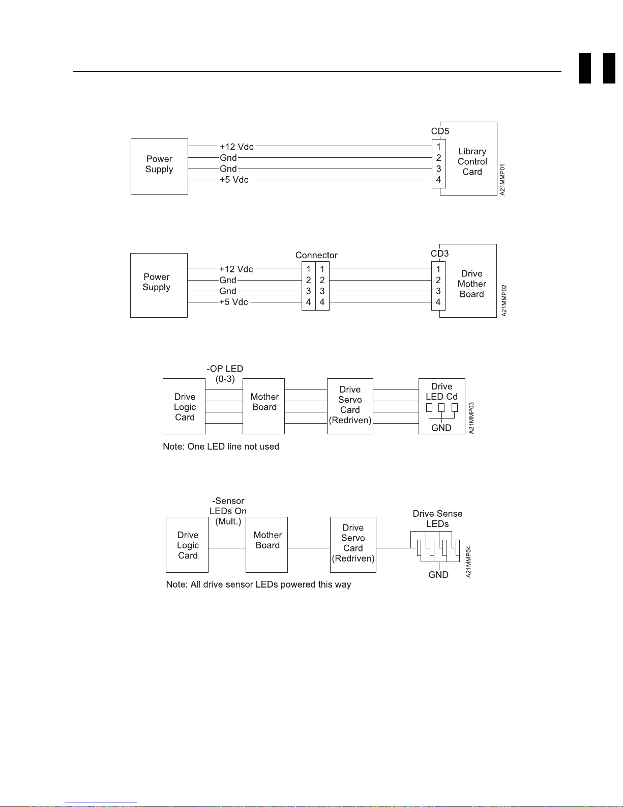
Diagrams Referred to by MAPs
Note: All voltage tolerances are ±5%.
|
Figure 13. Library Electronic Power Diagram
MAPS
|
Figure 14. Drive Electronics Power
|
Figure 15. Drive LED Circuitry
|
Figure 16. Drive Sensor LED Circuitry
MAPs MAPS-27
Page 72

MAPS-28 IBM 3570 MI
Page 73

Introduction
Contents
3570 Introduction . . . . . . . . . . . . . . . . . . . . . . . . . . . . . . . . . . . . . . . . . . . . . . INTRO-3
Product Overview . . . . . . . . . . . . . . . . . . . . . . . . . . . . . . . . . . . . . . . . . . . . INTRO-3
New Technologies Save Time, Are More Reliable ......................... INTRO-3
Broad Applications . . . . . . . . . . . . . . . . . . . . . . . . . . . . . . . . . . . . . . . . . . . INTRO-3
Tape Cartridge Capacity ........................................ INTRO-3
Data Compression . . . . . . . . . . . . . . . . . . . . . . . . . . . . . . . . . . . . . . . . . . INTRO-3
Large On-line Capacity Available ................................. INTRO-3
A New Cartridge and Tape Movement Technology ......................... INTRO-4
Interleaved Longitudinal Recording Technology ........................... INTRO-4
Historical Comparison of Tape Technologies ............................ INTRO-4
IBM 3570 Tape Subsystem, C-Series Models ............................. INTRO-5
Compatibility with other Magstar MP Tape Subsystems ....................... INTRO-6
Operating Systems . . . . . . . . . . . . . . . . . . . . . . . . . . . . . . . . . . . . . . . . . . . . . INTRO-9
SCSI Physical Interface Characteristics ................................. INTRO-9
Bus Termination . . . . . . . . . . . . . . . . . . . . . . . . . . . . . . . . . . . . . . . . . . . . . INTRO-9
SCSI Bus Jumper ............................................ INTRO-9
| Base Configuration . . . . . . . . . . . . . . . . . . . . . . . . . . . . . . . . . . . . . . . . . . INTRO-9
| Split Configuration . . . . . . . . . . . . . . . . . . . . . . . . . . . . . . . . . . . . . . . . . . INTRO-9
Device Characteristics . . . . . . . . . . . . . . . . . . . . . . . . . . . . . . . . . . . . . . . . . . . INTRO-9
Orientation . . . . . . . . . . . . . . . . . . . . . . . . . . . . . . . . . . . . . . . . . . . . . INTRO-10
Power Consumption . . . . . . . . . . . . . . . . . . . . . . . . . . . . . . . . . . . . . . . . . INTRO-10
AC Distribution . . . . . . . . . . . . . . . . . . . . . . . . . . . . . . . . . . . . . . . . . . . . . INTRO-10
AC Input Voltages ......................................... INTRO-10
Power Cords . . . . . . . . . . . . . . . . . . . . . . . . . . . . . . . . . . . . . . . . . . . . INTRO-11
Power Control . . . . . . . . . . . . . . . . . . . . . . . . . . . . . . . . . . . . . . . . . . . INTRO-11
Serial Number and Label Locations ................................. INTRO-11
Functional Unit Descriptions ...................................... INTRO-14
Power Supply . . . . . . . . . . . . . . . . . . . . . . . . . . . . . . . . . . . . . . . . . . . . . INTRO-16
Drive Pack . . . . . . . . . . . . . . . . . . . . . . . . . . . . . . . . . . . . . . . . . . . . . . . INTRO-17
Cooling Pack . . . . . . . . . . . . . . . . . . . . . . . . . . . . . . . . . . . . . . . . . . . . . . INTRO-17
Drive Logic Card Overview ...................................... INTRO-18
Drive Logic Card—How it works ................................... INTRO-19
Library Models . . . . . . . . . . . . . . . . . . . . . . . . . . . . . . . . . . . . . . . . . . . INTRO-19
Host Communications . . . . . . . . . . . . . . . . . . . . . . . . . . . . . . . . . . . . . . . INTRO-19
Microcode . . . . . . . . . . . . . . . . . . . . . . . . . . . . . . . . . . . . . . . . . . . . . . INTRO-19
Data Handling . . . . . . . . . . . . . . . . . . . . . . . . . . . . . . . . . . . . . . . . . . . INTRO-19
Sense Gathering . . . . . . . . . . . . . . . . . . . . . . . . . . . . . . . . . . . . . . . . . . INTRO-19
Drive Logic Card to Drive Analog Card Interface ....................... INTRO-19
Drive Logic Card to Drive Servo Card Interface ........................ INTRO-20
Reset and Power Controls .................................... INTRO-20
Drive Analog Card ........................................... INTRO-20
Head-Actuator Assembly . . . . . . . . . . . . . . . . . . . . . . . . . . . . . . . . . . . . . . . INTRO-20
Drive Servo Card ........................................... INTRO-20
Loader Assembly . . . . . . . . . . . . . . . . . . . . . . . . . . . . . . . . . . . . . . . . . . . INTRO-20
Drive Sensor Cable .......................................... INTRO-20
Loader Door . . . . . . . . . . . . . . . . . . . . . . . . . . . . . . . . . . . . . . . . . . . . . . INTRO-21
Drive LED Card ............................................ INTRO-21
Internal SCSI Cable .......................................... INTRO-21
Library Components . . . . . . . . . . . . . . . . . . . . . . . . . . . . . . . . . . . . . . . . . . . INTRO-22
INTRO
Copyright IBM Corp. 1998 INTRO-1
Page 74

3570 Media and Cartridge ........................................ INTRO-29
3570 Cleaner Cartridge ........................................ INTRO-30
| Library Attachment for Models C01, C02, C11, C12, C21 and C22 ................ INTRO-31
Library Magazine . . . . . . . . . . . . . . . . . . . . . . . . . . . . . . . . . . . . . . . . . . . INTRO-32
Import Position . . . . . . . . . . . . . . . . . . . . . . . . . . . . . . . . . . . . . . . . . . . INTRO-32
Export Position . . . . . . . . . . . . . . . . . . . . . . . . . . . . . . . . . . . . . . . . . . . INTRO-32
Library Modes . . . . . . . . . . . . . . . . . . . . . . . . . . . . . . . . . . . . . . . . . . . . . INTRO-33
Library Configuration . . . . . . . . . . . . . . . . . . . . . . . . . . . . . . . . . . . . . . . . . INTRO-33
System Attachment . . . . . . . . . . . . . . . . . . . . . . . . . . . . . . . . . . . . . . . . . . . . INTRO-34
SCSI Addressing . . . . . . . . . . . . . . . . . . . . . . . . . . . . . . . . . . . . . . . . . . . INTRO-34
SCSI Interface and Cable ...................................... INTRO-34
SCSI Features and Cables ...................................... INTRO-34
RISC System/6000 Controller Feature 2409 or 6209 ..................... INTRO-36
RISC System/6000 Controller Feature 2412 or 2416 ..................... INTRO-37
RISC System/6000 Controller Feature 2420 .......................... INTRO-37
AS/400 System Feature 6501, 6534, or 2729 ......................... INTRO-37
Hewlett Packard . . . . . . . . . . . . . . . . . . . . . . . . . . . . . . . . . . . . . . . . . . INTRO-37
Windows NT . . . . . . . . . . . . . . . . . . . . . . . . . . . . . . . . . . . . . . . . . . . . INTRO-38
Sun Solaris . . . . . . . . . . . . . . . . . . . . . . . . . . . . . . . . . . . . . . . . . . . . . INTRO-38
Connecting the 3570 to Multiple Systems ............................. INTRO-39
AS/400 . . . . . . . . . . . . . . . . . . . . . . . . . . . . . . . . . . . . . . . . . . . . . . . . INTRO-39
RS/6000 . . . . . . . . . . . . . . . . . . . . . . . . . . . . . . . . . . . . . . . . . . . . . . . INTRO-39
Drive Indicators and Operator Controls ................................ INTRO-39
Library Operator Panel .......................................... INTRO-40
Operator Panel Controls and Indicators ............................. INTRO-41
Front Panel Overview .......................................... INTRO-43
Subsystem Initialization . . . . . . . . . . . . . . . . . . . . . . . . . . . . . . . . . . . . . . . . INTRO-46
Initial Microprogram Load ..................................... INTRO-46
Power Sequencing . . . . . . . . . . . . . . . . . . . . . . . . . . . . . . . . . . . . . . . . . INTRO-46
Subsystem Diagnostics . . . . . . . . . . . . . . . . . . . . . . . . . . . . . . . . . . . . . . . . INTRO-46
POST Diagnostics . . . . . . . . . . . . . . . . . . . . . . . . . . . . . . . . . . . . . . . . . INTRO-46
Functional Tests . . . . . . . . . . . . . . . . . . . . . . . . . . . . . . . . . . . . . . . . . . INTRO-46
Special RAS Characteristics ................................... INTRO-46
Special Tools . . . . . . . . . . . . . . . . . . . . . . . . . . . . . . . . . . . . . . . . . . . . INTRO-47
Cleaning Cartridge . . . . . . . . . . . . . . . . . . . . . . . . . . . . . . . . . . . . . . . . . INTRO-47
ESD Kit . . . . . . . . . . . . . . . . . . . . . . . . . . . . . . . . . . . . . . . . . . . . . . . . . INTRO-47
INTRO-2 IBM 3570 MI
Page 75

3570 Introduction
Product Overview
The IBM 3570 Tape Subsystem is a new family of tape handling products that provide high capacity,
| performance, and reliable tape cartridge processing, in a compact, low cost design. Designed for the
| mid-range systems, the 3570 attaches through the small computer system interface (SCSI) to systems like
| the AS/400, RS/6000, HP-UX, Sun (Solaris) and IBM Netfinity/PC Servers that utilize the SCSI interface.
The IBM 3570 Tape Subsystem, C-Series Models are available in stand-alone and rack-mounted units,
and with drive only models. The stand-alone and rack-mounted units come with a random access
cartridge loader (Library) attachment which allows up to 20 tape cartridges per Library device. Multiple
devices may be added to a single SCSI interface. These library models come with one or two drives.
For more information on models, see “IBM 3570 Tape Subsystem, C-Series Models” on page INTRO-5.
New Technologies Save Time, Are More Reliable
The 3570, like the IBM 3590 High Performance Magnetic Tape Subsystem uses a newly introduced
technology for longitudinal recording. In addition, the 3570 introduces a new, more reliable tape cartridge
configuration that cuts in half the normal data acquisition time. The new technology and cartridge
configuration can significantly increase the performance of longitudinal recording while considerably
improving reliability.
INTRO
Broad Applications
The Library version of the 3570 can be used to provide low cost high availability of data that is usually
archived or resides on relatively expensive disk media. This application allows backup data to be
available within seconds without the need to have operator intervention and mount delays.
Another use is the automatic backup storage for midrange systems or servers which have large amounts
of disk or need unattended storage capacity for multiple backups.
Tape Cartridge Capacity
The IBM Magstar MP 3570 Tape Subsystem uses a metal particle tape and a new IBM Magstar Fast
Access Linear Tape 3570 cartridge that can store 5GB of non-compacted data. The 3570 tape drive uses
a compaction algorithm which can increase the storage capacity of these cartridge to 15GB.
Data Compression: The 3570 improved compression algorithm (IBMLZ1) provides highly efficient
compression. The IBMLZ1 algorithm furnishes hardware execution efficiency by using as few machine
cycles as possible to compress or decompress a byte, achieving good coding efficiency for broad
applications, and performing compression without performance loss.
Large On-line Capacity Available: With 2 magazines of cartridges, each library can provide up
to 300 GB of on-line data capacity with a data access rate of up to 54 GB/hr at maximum compression.
| Dual-drive models C02, C12 and C22 can provide up to double this data access rate (up to 108GB per
| hour at maximum compression.). This, along with the fact that multiple library models may be attached to
one SCSI attachment allows very large on-line storage capability for the cost conscious midrange
computer user.
Introduction INTRO-3
Page 76

A New Cartridge and Tape Movement Technology
The 3570 introduces a new concept for IBM tape drives that increases reliability along with faster data
access. The 3570 drive, a key component of the 3570 Tape Subsystem, uses a new cartridge with a
supply spool and a take-up spool. The normal start point for the 3570 tape is the physical mid point of the
tape's length. As a result, to access data after the cartridge is loaded and has reached load point, the
maximum distance it must travel is 1/2 the length of the tape, and the average distance is only 1/4 the
length of tape. This reduced travel shortens data retrieval time and reduces head wear. Delays needed
for tape load threading by other tape products is eliminated since the 3570 tape cartridge never needs to
be threaded. When stationed at load point, which is near the center of the tape, the 3570 is ready to read
or write data immediately in either direction.
Interleaved Longitudinal Recording Technology
The 3570 Tape Subsystem reads and writes in a new 128-track format using the serpentine interleaved
longitudinal recording technology, first introduced with the IBM 3590 High Performance Magnetic Tape
Subsystem.
There are two versions of the cartridges, the original B-Format and the newer, C-Format. For C-Format
cartridges, the Magstar MP drives have sustained data rates of 7MB/sec native and 15MB/sec with
maximum compression. For B-Format cartridges, the Magstar MP drives have sustained data rates of
3.5MB/sec native and 10.5MB/sec with 3:1 compression. The drive burst data rate is 20MB/sec. The
average load and initialize time is 8 seconds, and the average search time to first byte of data is 8
seconds.
Writing and reading, with this improved methodology, along with beginning in the center of the tape, allows
high speed data access at a very low cost.
The interleaved longitudinal recording technology allows the 3570 to write multiple tracks from the center
of the physical tape to the end, in either direction, then index the head, or move the head vertically, for the
return trip. The result is tracks interleaved across the width of the tape, from the center out in both
directions.
Using the Magstar MP C-Format cartridges, the Magstar MP 3570 Tape Subsystem drive reads and writes
data on 128 tracks per cartridge, eight tracks at a time. The subsystem uses an interleaved serpentine
longitudinal recording format. The first set of eight tracks is written from the mid-point along the length of
the tape to near the end of the tape, where the head is indexed to the next set of eight tracks for return to
the tape mid-point. This process continues until all 128 tracks are written, and then is repeated for the
other half of the medium until the tape is full. Operation using the Magstar MP B-Format cartridges is
similar to the C-Format cartridge operation, except that four tracks, instead of eight tracks, are written at a
time until all 128 tracks have been written.
Data is written on or read from metal particle tape enclosed in a tape cartridge. The Magstar MP Fast
Access Linear Tape cartridges are different from cartridges used in other IBM tape storage products, and
cannot be interchanged with the media used in other IBM tape products.
Historical Comparison of Tape Technologies
See Figure 17 on page INTRO-5 for an explanation of the historical changes that have led to this new
technology.
Historically, the 18 tracks recorded on 3480 media were used to record ECC information along with the
data. The original base 3490 models also used the same 18-track format but were later enhanced in the
3490E models, which implemented two sets of 18 tracks. In the 3490E device the first 18 tracks are
INTRO-4 IBM 3570 MI
Page 77

recorded when the tape moves in a forward direction until the physical end of the tape is reached. Then,
using an electronic head switch (not physically moving the head itself in any direction but switching to a
second set of read-write heads), a second set of 18 tracks is recorded when the tape moves in a
backward direction until the physical beginning of the tape is reached.
In the 3590 a second generation of thin film magneto resistive (MR) heads is used, which, together with
the 3590 tape medium allows recording with much higher area density, both in number of bits as well as
number of tracks per inch. Similar to the 3590, the 3570 data is written in blocks of user data using
multiple track format and where ECC information are recorded differently compared to the older track
formats. The first set of eight tracks is written from the halfway point along the length of the tape to near
the end of the tape, where the head is indexed to the next set of eight tracks for return to the tape center.
The process continues until all 128 tracks are written. The process is repeated in the other direction of
tape until the tape is full.
Note: Not all tape cartridges will be full from one end to the other. This example is used to show how a
complete tape cartridge could be utilized for maximum effectiveness.
An example of tape track recording progression is shown in Figure 17. The 3570 recording process is
very similar to that of the 3590, but with fewer head tracks and with a two-reel cartridge.
INTRO
Figure 17. Serpentine Interleaved Track Sets
IBM 3570 Tape Subsystem, C-Series Models
The following single drive 3570 models are available:
Model C00 Drive is a customer setup (CSU) Tape Subsystem which may be installed on a desk or
table. It does not include the library attachment. See Figure 18 on page INTRO-8.
Model C01 is a customer setup (CSU) stand-alone library Tape Subsystem with a 20-cartridge random
access cartridge loader. See Figure 19 on page INTRO-8.
Model C11 is a rack-mounted library tape subsystem with a 20-cartridge random access cartridge
loader. The Model C11 is similar to the Model C01 except for external covers and being
rack-mounted. See Figure 19 on page INTRO-8.
| Model C21 is a customer setup (CSU) rack-mounted library Tape Subsystem with a 20-cartridge
| random access cartridge loader. It is identical to a Model C11 except that it attaches only to IBM
| Netfinity or IBM PC Server systems, and is mounted in a EIA-310-D industry standard 19-inch rack
| such as the IBM Netfinity Rack (9306900) or NetBAY22 (9306200). See Figure 19 on page INTRO-8.
Introduction INTRO-5
Page 78

The following dual drive 3570 models are available:
Model C02 is a customer setup (CSU) stand-alone library Tape Subsystem with a 20-cartridge random
access cartridge loader.
Model C12 is a rack-mounted library Tape Subsystem with a 20-cartridge random access cartridge
loader.
| Model C22 is a customer setup (CSU) rack-mounted library Tape Subsystem with a 20-cartridge
| random access cartridge loader that attaches only to IBM Netfinity or IBM PC Server systems, and is
| mounted in a EIA-310-D industry standard 19-inch rack such as the IBM Netfinity Rack (9306900) or
| NetBAY22 (9306200).
The 3570 C-Series models are capable of achieving a native sustained data rate over 3X that of the
current B-Series models. This dramatically improves the "backup window" performance for customers in
need of backing up larger amounts of data in less time. The 3570 C-Series models achieve a native
sustained rate of 7MB/s by:
Doubling the read/write heads
Increasing the tape speed motion by 50%
Expanding the cache memory buffer to 4 MB
Adding a new digital data flow circuit that speeds read/write operations
These devices operate as SCSI-2 devices with SCSI-3 features. The 3570 attaches to host processors
through the 3570 SCSI system adapter, which is a 2-byte wide SCSI fast interface. It uses a SCSI-3
68-pin P connector.
The 3570 can be integrated with any host system that supports a SCSI-2 interface and has the proper
drivers installed.
A Bar Code Reader is standard and can improve application performance for library models. When the
host re-inventories the cartridges, it can take several minutes for the host to mount each cartridge in a
drive and read the volume serial number identification from the tape in a full library. A bar code reader
eliminates the need to load each cartridge in a drive. This feature is installed on Magstar MP C-Series
libraries and provides an efficient way to inventory cartridges in the library.
Compatibility with other Magstar MP Tape Subsystems
The Magstar MP C-Series tape drive can be distinguished from the Magstar MP B-Series tape drive by the
color of the unload button on the drive front panel. The C-Series unload button is green while the
B-Series unload button is blue.
The Magstar MP C-Format data cartridge can be distinguished from the Magstar MP B-Format data
cartridge by the color of the file protect switch and Bar Code/Volser label and also by the Volume ID
printed on the label. The C-Format switch and label are green while the B-Series switch and label are
blue. The C-Format Volume ID begins with a "G" (Gxxxxxx), and the B-Format Volume ID begins with a
"F" (Fxxxxxx).
The original Magstar MP 3570 B-Format Tape cartridges can be written, read, and interchanged between
Magstar MP 3570 B-Series Tape Subsystems, Magstar MP 3570 C-Series Tape Subsystems and all tape
drives in the Magstar MP Tape Library Dataserver.
The newer C-Format Tape cartridges can only be written, read, and interchanged between Magstar MP
3570 C-Series Tape Subsystems and the Magstar MP 3570 Model C Tape Drives feature of the Magstar
INTRO-6 IBM 3570 MI
Page 79

MP Tape Library Dataserver. The C-Format Tape cartridges cannot be used in Magstar MP 3570
B-Series Tape Subsystems or in Magstar MP 3570 Model B1A tape drives in a Tape Library Dataserver.
When B-Format Tape cartridges are used in the C-series tape drives, the tape drives operate with better
performance than the B-series tape drives. Even higher performance is achieved by using C-Format tape
cartridges.
INTRO
Introduction INTRO-7
Page 80

Figure 18. Model C00 Drive
A21M0013
|
Figure 19. Library Model C11, C12, C21 and C22
| Note: The Model C21 and C22 library front cover assembly and operator display panel are slightly
| different from those shown above. For that difference, refer to Figure 32 on page INTRO-26, and
| Figure 33 on page INTRO-27, items 6 and 7 .
INTRO-8 IBM 3570 MI
Page 81

Operating Systems
Refer to
GA32-0392 for planning for program support.
IBM Magstar MP 3570 Tape Subsystem Introduction and Planning Guide, C-Series Models,
SCSI Physical Interface Characteristics
The 3570 Tape Subsystem operates as a SCSI-2 device with SCSI-3 features. The instruction set is
SCSI-2, but includes SCSI-3 commands and mode sense data.
The 3570 Tape Subsystem attaches to host processors through the Magstar MP SCSI system adapter,
which is a fast/wide (16-bit) differential SCSI interface. It uses a shielded high-density SCSI-3 68-pin P
connector that accommodates 16 bus addresses. The 3570 attaches to a differentially driven, wide (16
bit) SCSI-3 P-cable.
Under the SCSI-2 protocol, this type of attachment allows cable lengths of up to 25 m (81 ft) with the
appropriate cable and terminator selection. The stub length at each device must not exceed 0.2 m (0.66
ft).
The 3570 Tape Subsystem also logically supports the narrow (8-bit) protocol. An interposer is required to
connect the 3570 Tape Subsystem to a SCSI-2 bus.
Note: Only 8 bus addresses (0 to 7) are valid for an 8-bit SCSI bus.
INTRO
Bus Termination
The SCSI bus and all of the wires in the SCSI cable must be properly terminated according to the SCSI
standard. This termination is especially important if a system mixes devices or initiators with 68-pin
connectors with those of the older 50-pin style.
An external terminator may be mounted into a socket that is a part of the SCSI cable connector. A
terminator must be installed on the last device on each end of a string of multiple devices. In a
single-device installation, the terminator is installed in the socket of this device. The 3570 Tape
Subsystem is delivered with an external differential terminator included, but it is not installed.
SCSI Bus Jumper
| Models C02, C12 and C22 include a SCSI Bus Jumper, a short SCSI cable which is attached or removed
| depending on the library configuration.
| Base Configuration: For Models C02, C12 and C22 set up in Base Configuration, the SCSI Bus
| jumper is attached between the two drives so the drives are on the same SCSI bus.
| Split Configuration: For Models C02, C12 and C22 set up in a Split configuration, the SCSI Bus
| Jumper is removed so each drive port is attached to a separate SCSI bus. Thus, each drive port in a Split
| Configuration has the same cable and termination requirements as a single-drive model C01, C11 and
| C21.
Device Characteristics
Figure 20 shows the physical specifications of the 3570 Tape Subsystem.
Introduction INTRO-9
Page 82

Figure 20. Physical Specifications
| Dimensions| Model C00| Model C01| Model C02| Model C11/C21
| Model C12/C22
| (rack-mounted)
| (rack-mounted)
Height 112 mm (4.4") 217 mm (8.5") 217 mm (8.5") 217 mm (8.5") 217 mm (8.5')
Width 320 mm (12.6") 483 mm (19.0") 483 mm (19.0") 444 mm (17.5") 444 mm (17.5")
Depth 338 mm (13.3") 771 mm (30.4") 771 mm (30.4) 714 mm (28.1") 714 mm (28.1)
Weight 8.4 kg (18.5 lb) 35 kg (77.1 lb) 40 kg (88.2 lb) 24 kg (52.8 lb) 29 kg (63.9 lb)
Weight with
Pedestal
Display Panel No Yes Yes Yes Yes
Magstar MP
Media
Tape Drives 1 1 2 1 2
Note:
Models C01 and C02 stand on a pedestal that raises each unit by 25 mm (1 in) above the table surface.
8.5 kg (18.7 lb)
(see note)
One cartridge Up to 20
39.8 kg (87.7 lb)
(see note)
cartridges
44.8 kg (98.6 lb)
(see note)
Up to 20
cartridges
N/A N/A
Up to 20
cartridges
Up to 20
cartridges
Orientation: Model C00 operates in two orientations:
Horizontal when the cartridge loader cell is vertical
Vertical when the cartridge loader cell is horizontal and the power switch is near the bottom.
| All library models operate in horizontal orientation only, with slots arrayed vertically, and the priority cell on
| the right.
Power Consumption
stand-alone Models:
65 watts nominal
Library Models:
75 watts nominal
Two Drive Models
140 watts nominal
AC Distribution
AC power to the 3570 power supply is supplied from a wall outlet, rack enclosure, or other AC source.
AC Input Voltages: The 3570 power supply accepts input voltages and frequencies from 100 volts
AC (nominal) to 240 volts AC (nominal), and from 50 Hz (nominal) to 60 Hz (nominal). The power supply
automatically adjusts itself for proper operation when the voltages and frequencies are with the
specification shown in Figure 21.
INTRO-10 IBM 3570 MI
Page 83

Figure 21. AC Input Voltages
Frequency Frequency
Tolerance
50 Hz ±0.5 Hz 100
60 Hz ±0.5 Hz 100
Input Voltage (VAC-RMS)
Nominal
110
200
220
230
240
110
120
127
200
208
220
240
Input Voltage (VAC-RMS)
Minimum-Maximum
90–110
96.5–119
180–220
193–238
202–249
210–259
90–110
96.5–119
104–127
111–137
180–220
180–220
193–238
208–254
Power Cords: A ship group provides the power cords needed to implement the electrical environment
for the device. The power cords are 10-ampere line cords that provide either one-phase or two-phase
power and ground, with an appliance coupler at the device end of the cord. The other end of the cord is
determined by application and country and can be ordered by the customer.
INTRO
See
IBM Magstar MP 3570 Tape Subsystem Introduction and Planning Guide, C-Series Models
for a list
of part numbers of power cables by country.
Power Control: All 3570 models have a power-control switch located on the front of the devices.
Input-power overload protection is provided by an automatic (reset) circuit breaker.
There is no power-on indicator on the device. All models have LEDs on the front. These LEDs are turned
ON with power ON for a short time. The microcode turns OFF the LEDs after a checkpoint in the
power-on self-test (POST). Library models have operator panels where power-on status is displayed after
the LEDs have been turned OFF.
Remote power control is not the responsibility of the IBM 3570 Tape Subsystem. If required, it is provided
by the enclosure or higher level subassembly.
Serial Number and Label Locations
See Figure 22 on page INTRO-12. The following labels are installed on models without the library:
UL/CSA 1
Model and serial numbers with barcode and date of manufacture, item 2 .
EC label, item 3
Introduction INTRO-11
Page 84

Figure 22. Label Locations for Models Without Libraries
INTRO-12 IBM 3570 MI
Page 85

See Figure 23. The following labels are installed on Models with libraries:
Model and serial numbers with barcode and date of manufacture, item 1
EC label, item 2
UL/CSA 3
Weight label with a triangular symbol 4
Note: The serial number label is also present above the left magazine lever opening on the front of
the library. See 14 in Figure 46 on page INTRO-43.
INTRO
Figure 23. Label Locations for Models With Libraries
Introduction INTRO-13
Page 86

Functional Unit Descriptions
For the following functional unit descriptions, it may be helpful to refer to the following tables for exploded
views of several models or major components.
Figure 24. Table of Exploded Views of Various Models
Model/Part Description Figure Location
Basic Drive
Pack
C00 Desk-top drive W/O library attachment. Figure 25 on
C01 Stand-Alone Library version with one drive Figure 28 on
C11 Rack-Mounted Library version with one drive Figure 30 on
| C21| Rack-Mounted Library version with one drive| Figure 32 on
| page INTRO-26
C02 Stand-Alone Library version with two drives Figure 29 on
C12 Rack-Mounted Library version with two drives Figure 31 on
| C22| Rack-Mounted Library version with two drives| Figure 33 on
| page INTRO-27
| Note:
| The Models C01 and C11, and Models C02 and C12 are nearly identical except for external covers and where the
| devices are mounted. The Models C11 and C21, and Models C12 and C22 are nearly identical except for the
| Front Bezel which is slotted, and the operator display panel which is not slopped, to allow the Models C21 and
| C22 to fit further into their mounting racks and not interfere with the front rack door.
Standard drive unit used in each model Figure 27 on
page INTRO-18
page INTRO-15
page INTRO-22
page INTRO-24
page INTRO-23
page INTRO-25
INTRO-14 IBM 3570 MI
Page 87

INTRO
Figure 25. Model C00 Drive
Introduction INTRO-15
Page 88

Power Supply
Each model of the 3570 has a power supply under its decorative cover that supplies power to the drive
and also provides power to the Library when installed in a Library Model.
When the model has two drives, each drive will have its own power supply. The first power supply
(located on the right side of the box facing from the front) provides power to its drive and the library.
Figure 25 on page INTRO-15 5 , Figure 28 on page INTRO-22 item 3 , and Figure 30 on
page INTRO-24 2 show all three configurations where the single drive power supply is located.
Figure 26 shows the power distribution.
Figure 26. Power Block Diagram
INTRO-16 IBM 3570 MI
Page 89

Drive Pack
| Note: The 3570 Model Cxx drives have a green UNLOAD button while the Model Bxx drives have a
| blue UNLOAD button. Model Cxx drives also have microcode level D1I5_xxx while Model Bxx
| drives have microcode level D1I4_xxx. If the drive you are working on has a blue UNLOAD button
| and code level D1I4_xxx, go to
|
|
|
The 3570 drive pack has its own protective covers. The drive pack, shown in Figure 25 on
page INTRO-15 2 , in the drive-only machine, and in Figure 28 on page INTRO-22 14 and Figure 30
on page INTRO-24 12 inside two single drive library machine configurations, is a stand-alone 5.25 inch
form factor functional unit with a host SCSI interface. In addition to its own protective covers, it is always
covered by external decorative covers, whether a stand-alone or rack-mounted device. Power and cooling
are provided under the decorative covers as well.
| The 3570 C—Series drive is packaged as a single field replaceable unit (FRU) in all countries and regions
| except in EMEA and as such is replaced as a unit if a problem occurs within the drive. This is a change
| in service strategy from previously shipped drives.
| Since EMEA service personnel must isolate to a FRU within the drive, a special START section (see
| APPENDIX B), MAP section (see APPENDIX C) and CARR section (see APPENDIX D) have been
| designed for that area.
B—Series Models.
A very few early Model Cxx drives shipped with blue UNLOAD buttons. If in doubt, check the
microcode level for this model.
Magstar MP 3570 Tape Subsystem Maintenance Information
.
INTRO
| The Models C02, C12 and C22 each contain two drive packs and two power supplies. These may be
| referred to as dual drive models.
Cooling Pack
Figure 25 on page INTRO-15 item 6 shows where the cooling pack is attached to the drive pack. All
drive packs have a cooling pack attached.
The cooling pack contains the drive cooling fan and the internal SCSI cable which plugs into the drive
logic card. The cooling pack accepts the customer SCSI cable coming from the host system. The drive
cooling fan and the internal SCSI cable are both FRUs.
The components contained within the drive pack are discussed below. See Figure 27 on page INTRO-18
for locations of all drive components discussed next.
| Note: None of the components shown in Figure 27 on page INTRO-18 may be replaced separately in
| the C—Series drives except in countries and regions in EMEA. In all other countries and regions,
| the drive is replaced as a single FRU when anything fails within it. The drive parts are shown here
| for information only.
Introduction INTRO-17
Page 90

Figure 27. Base Drive Components (All Models)
Drive Logic Card Overview
The drive logic card, item 2 , contains the primary electronic controls for the drive and the library device,
if installed. It is plugged into the mother board, item 11 , and is the first card visible when the top
protective cover of the drive is removed. This card contains the SCSI controls for the box, several
processors, memory buffers, clock generation circuits, and control logic for R/W data flow and reel to reel
tape motion. It provides connectivity for the library function through the library control card.
INTRO-18 IBM 3570 MI
Page 91

Drive Logic Card—How it works
The drive logic card, located in each drive pack, basically consists of a data path and a control path. The
data path receives data from the SCSI bus, then buffers it, checks it for parity and CRC, compacts it,
re-buffers it, formats it to fit the 3570 data format, and sends it to the drive analog card, and ultimately to
the head-actuator assembly to be written to the media. In read-back, it receives read data pulses from the
drive analog card, clocks them, de-skews them, corrects parallel data, buffers it, de-compacts it, and
transfers the data to the SCSI bus.
The drive logic card contains the main microprocessor, the microcode load, clock generation circuits, reset
controls, and control registers that interface with all other drive electrical/mechanical components.
Library Models: The drive logic card controls the motion of the accessor assembly and the picker
assembly by sending commands to these devices through the library control card which performs as the
library interface. The drive logic card also monitors tach pulses from the motors, and sense data from the
various library sensors through the library control card interface.
Host Communications: The drive logic card serves as the primary SCSI interface for the device
through a SCSI adapter and on-board SCSI drivers. All host communications to the 3570 go through the
drive logic card via this interface. SCSI commands are received, and routed under microcode control
throughout the device. SCSI data is received and sent as discussed earlier.
The SCSI ID switch is located on the drive logic card and is used to set the SCSI address for drive-only
installations. The SCSI ID switch is not used on library models. The SCSI address on library models is
set from the library operator panel display.
INTRO
Microcode: Microcode, which is housed on the drive logic card, handles data and commands from the
SCSI bus, and transfers data and controls the drive analog card, drive servo card, the loader assembly,
head-actuator assembly, and the library components. During read from the media, the microcode controls
the receiving and buffering of data from the drive logic card, and controls the actuator location in relation
to the media. The microcode also provides communication to the operator or CE by communicating
through the drive LEDs, the library operator panel display, and library LEDs. Bring-up diagnostics perform
initialization and testing during Power On, and collects and presents error or ATTENTION data when
intervention is required. Each installed drive contains microcode.
Data Handling: The drive logic card controls special compaction hardware to compact data before
sending it out to be written to the tape media. During a tape read operation, data that is received from the
R/W head is first corrected for skew, then is un-compacted and buffered for further transmission over the
SCSI bus.
Sense Gathering: Sensing devices located in the drive pack send sense data through the drive
servo card to the drive logic card. Sensing devices located in the library area send sense data through
the library control card to the drive logic card.
Drive Logic Card to Drive Analog Card Interface: Most clocking for the 3570 is generated
by the drive logic card. It operates at 40Mhz or clocks derived from this frequency. The microprocessor
resident on the drive logic card runs at 20Mhz. The only off card use for drive logic card clock circuitry is
a 20Mhz signal sent to the drive analog card during write operations and during transfer of LWR (Loop
Write to Read) data. The library control card contains its own clock controls. During a write operation the
drive logic card sends equalized write data and clock pulses to the drive analog card. During transfer of
LWR data, the drive logic card clocks the LWR data from the drive analog card. The data is buffered and
checked in both directions to ensure data integrity.
Introduction INTRO-19
Page 92

Some of the signals between the drive logic card and the drive analog card are transmitted through the flat
ribbon cable, item 14 .
Drive Logic Card to Drive Servo Card Interface: The drive logic card is also the primary
electronic source for controlling movement of the reel-to-reel motors, the head actuator, and readout of the
loader sensors. The drive logic card provides control registers for each of these functions, which in turn
are powered by the drive servo card to perform the actual movement of motors and solenoids. Feedback
of tach pulses and sensors is transferred to the drive logic card from the drive servo card for processing
by the microcode.
Reset and Power Controls: Power-on reset for the 3570 is handled by the drive logic card. It
checks power as it is switched ON or OFF, and provides reset levels to the other electronic circuits until
power is at the proper levels. This
occurring during power transitions.
clamping
of the electronic cards keeps noise and glitches from
Drive Analog Card
The drive analog card, item 4 , contains the write drivers, read pre-amplifiers and bias circuits for both
data and servo channels. It provides precise switching of write current for four channels at a time to the
R/W head during a write cycle, and detects and converts analog signals from the R/W head to digital
signals during a tape read cycle. The drive analog card is designed and positioned so that it makes
physical contact with the R/W head through thin film cable connections, item 5 , yet can still be plugged
into the mother board. The R/W head is part of the head-actuator assembly, item 1 .
Head-Actuator Assembly
| The head-actuator assembly, item 1 , contains the R/W head, and the actuator assembly, factory
| pinned. The entire unit is a single assembly. The R/W head transfers write current as controlled by the
drive analog card to the tape as it passes in contact with the R/W head during a write cycle, and transfers
signals from the tape as it passes in contact with the R/W head during read cycles. The actuator
assembly positions the head in the appropriate location to read or write across the width of the tape.
Drive Servo Card
The drive servo card, item 8 provides circuitry that drives the loader motor, reel motors, and head
actuator from signals originating in the drive logic card. It is the last card in the stack to plug into the
mother board.
Loader Assembly
The loader assembly, item 12 , is mounted on the bottom plate, item 9 . The loader assembly contains
the mechanical and electrical components to move the tape cartridge into and out of the loader, to move
the tape forward and backwards, to sense when the tape cartridge is in position to be read, and to sense
| the type of tape cartridge that is loaded. The loader assembly as attached to the bottom plate is a single
| assembly.
Drive Sensor Cable
The drive sensor cable (not shown) is connected to numerous sensors and components on the loader
assembly, and is replaceable without replacing the loader assembly. It attaches at the other end to the
drive servo card.
INTRO-20 IBM 3570 MI
Page 93

Loader Door
The loader door (not shown) is an integral part of the loader assembly, but may be replaced by itself if
damaged.
Drive LED Card
The drive LED card (not shown) is located near the front of the tape unit and provides circuitry that lights
the Busy, Clean, and Maintenance LEDs for the drive and contains the Unload push button. This card has
limited function in a library configuration.
Internal SCSI Cable
The internal SCSI cable is part of the cooling pack assembly and provides SCSI signal connectivity
between the drive logic card and the host system cable connection point on the rear of the cooling pack.
INTRO
Introduction INTRO-21
Page 94

Library Components
The library components are shown in Figure 28, Figure 29 on page INTRO-23, Figure 30 on
| page INTRO-24, Figure 31 on page INTRO-25,Figure 32 on page INTRO-26 and Figure 33 on
| page INTRO-27. They offer 6 models, all containing a 20 cartridge automated cartridge loader capable of
operating in random, auto or manual access mode for tape volumes. See
Subsystem Operator Guide, C-Series Models
library. Each major component is discussed in detail in the LIBRARY section. They are shown here only
for continuity.
Since the major difference between stand-alone and rack-mounted models is the external covers, and the
major differences between single drive models and dual drive models is the number of drives and drive
components, the following reverse key references are made only to Figure 31 on page INTRO-25.
GA32-0393 for location and functional description of the
IBM Magstar MP 3570 Tape
Figure 28. Model C01-Stand-Alone Library Model
INTRO-22 IBM 3570 MI
Page 95

INTRO
Figure 29. Model C02-Stand-Alone Library Model
Introduction INTRO-23
Page 96
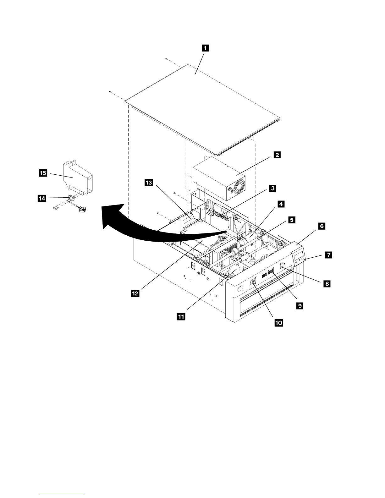
Figure 30. Model C11-Rack-Mounted Library Model
INTRO-24 IBM 3570 MI
A21M0035
Page 97

INTRO
Figure 31. Model C12-Rack-Mounted Library Model
Introduction INTRO-25
Page 98
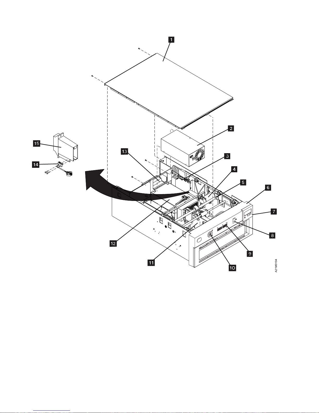
|
Figure 32. Model C21-Rack-Mounted Library Model
INTRO-26 IBM 3570 MI
Page 99

INTRO
|
Figure 33. Model C22-Rack-Mounted Library Model
Introduction INTRO-27
Page 100

Figure 34. Library Components
Component Key (Refer to Figure 31 on page INTRO-25)
Top protective cover 1
Power supply (drive 1) 2
Library control card 3
Bar code reader 3 (card mounted on library control card)
Accessor motor assembly 4
Accessor assembly 5
Library front cover assembly 6
Library operator panel display 7
Library AC switch and cable assembly 8
Library LED card 9
Security key lock 1
Picker assembly 11
Bar code reader 11 (sensor mounted on picker assembly)
Drive pack (drive 1) 12
Cooling pack (drive 1) 13
Drive pack (drive 2) 14
Power supply (drive 2) 15
Cleaner cartridge-present sensor 16
Cleaner cell assembly 17
Library sensors and sensor cable Not shown
Picker cable Flat cable (not shown)
Library interface cable Not shown.
Magazine global sensor pair Not shown
Drive global sensor pair Not shown
RS422 Drive-to-drive cable Shown but not numbered (see rear of item 16 ).
Note: The Drive Pack, Power Supply and Cooling Pack for Drive 2 are found only in the Model C02 and C12.
INTRO-28 IBM 3570 MI
 Loading...