

Page 1

IBM LTO Ultrium 4 Half High Tape Drive
Installation and User's Guide
Important:
Review the maintenance information in Chapter 3, "Operating the drive" and in the
Warranty information document that came with the drive, because periodic maintenance is
not covered by the IBM warranty. Repairs or exchanges that result from improper
maintenance might result in billable service charges.
Page 2

Page 3

IBM LTO Ultrium 4 Half High Tape Drive
Installation and User's Guide
Page 4

Note:
Before using this information and the product it supports, read the general information in Appendix B, “Notices,” on page 57, the
Safety Information and Environmental Notices and User Guide documents on the IBM Documentation CD, and the Important Notices and
Warranty information documents that come with the product.
Third Edition (May 2011)
© Copyright IBM Corporation 2011.
US Government Users Restricted Rights – Use, duplication or disclosure restricted by GSA ADP Schedule Contract
with IBM Corp.
Page 5
Safety
Before installing this product, read the Safety Information.
Antes de instalar este produto, leia as Informações de Segurança.
Pred instalací tohoto produktu si prectete prírucku bezpecnostních instrukcí.
Læs sikkerhedsforskrifterne, før du installerer dette produkt.
Lees voordat u dit product installeert eerst de veiligheidsvoorschriften.
Ennen kuin asennat tämän tuotteen, lue turvaohjeet kohdasta Safety Information.
Avant d'installer ce produit, lisez les consignes de sécurité.
Vor der Installation dieses Produkts die Sicherheitshinweise lesen.
Prima di installare questo prodotto, leggere le Informazioni sulla Sicurezza.
Les sikkerhetsinformasjonen (Safety Information) før du installerer dette produktet.
© Copyright IBM Corp. 2011 iii
Page 6
Antes de instalar este produto, leia as Informações sobre Segurança.
Antes de instalar este producto, lea la información de seguridad.
Läs säkerhetsinformationen innan du installerar den här produkten.
iv LTO Ultrium 4 Half High Tape Drive
Page 7

Statement 1
DANGER
Electrical current from power, telephone, and communication cables is
hazardous.
To avoid a shock hazard:
v Do not connect or disconnect any cables or perform installation,
maintenance, or reconfiguration of this product during an electrical storm.
v Connect all power cords to a properly wired and grounded electrical outlet.
v Connect to properly wired outlets any equipment that will be attached to
this product.
v When possible, use one hand only to connect or disconnect signal cables.
v Never turn on any equipment when there is evidence of fire, water, or
structural damage.
v Disconnect the attached power cords, telecommunications systems,
networks, and modems before you open the device covers, unless
instructed otherwise in the installation and configuration procedures.
v Connect and disconnect cables as described in the following table when
installing, moving, or opening covers on this product or attached devices.
To Connect: To Disconnect:
1. Turn everything OFF.
2. First, attach all cables to devices.
3. Attach signal cables to connectors.
4. Attach power cords to outlet.
5. Turn device ON.
1. Turn everything OFF.
2. First, remove power cords from outlet.
3. Remove signal cables from connectors.
4. Remove all cables from devices.
Safety v
Page 8

Statement 3
CAUTION:
When laser products (such as CD-ROMs, DVD drives, fiber optic devices, or
transmitters) are installed, note the following:
v Do not remove the covers. Removing the covers of the laser product could
result in exposure to hazardous laser radiation. There are no serviceable parts
inside the device.
v Use of controls or adjustments or performance of procedures other than those
specified herein might result in hazardous radiation exposure.
DANGER
Some laser products contain an embedded Class 3A or Class 3B laser diode.
Note the following.
Statement 5
Laser radiation when open. Do not stare into the beam, do not view directly
with optical instruments, and avoid direct exposure to the beam.
CAUTION:
The power control button on the device and the power switch on the power
supply do not turn off the electrical current supplied to the device. The device
also might have more than one power cord. To remove all electrical current from
the device, ensure that all power cords are disconnected from the power source.
1 2
vi LTO Ultrium 4 Half High Tape Drive
Page 9
Statement 8
CAUTION:
Never remove the cover on a power supply or any part that has the following
label attached.
Hazardous voltage, current, and energy levels are present inside any component
that has this label attached. There are no serviceable parts inside these
components. If you suspect a problem with one of these parts, contact a service
technician.
Safety vii
Page 10

viii LTO Ultrium 4 Half High Tape Drive
Page 11

Contents
Safety ...............iii
Statement 1...............v
Statement 3 ..............vi
Statement 5 ..............vi
Statement 8 ..............vii
Figures ...............xi
Tables ...............xiii
Chapter 1. Product description .....1
Drive features ..............1
Front panel of the drive ..........2
Rear view of the drive ...........2
Speed matching .............2
Channel calibration ............3
Encryption ...............3
SAS interface ..............3
Chapter 2. Installing the drive .....5
Avoiding drive damage...........5
Installation overview ...........5
Unpack the drive .............5
Acclimate the drive and media .......6
Power off the enclosure...........6
Set the feature switches ...........6
Mount the drive in an enclosure or server ....7
Connect and test power to the drive ......8
Connect the internal cable ..........9
Run drive diagnostics ...........9
Install device drivers ...........9
Connect the external interface cable (tape enclosure
installations only) ............10
Connect the external SAS interface to the server 10
Configure the drive to the server, switch, or hub . . 10
Chapter 3. Operating the drive ....11
Single-character display (SCD) ........11
SCDdot..............11
Status LED ..............11
Unload button .............13
Inserting a tape cartridge ..........14
Removing a tape cartridge .........15
Mid-tape recovery ............15
Cleaning the drive head ..........16
Diagnostic and maintenance functions .....16
Entering Maintenance Mode........18
Exiting Maintenance Mode ........18
Function Code 0: Maintenance Mode .....19
Function Code 1: Run drive diagnostics ....19
Running a diagnostic self-test .......20
Function Code 2: Update drive firmware from
FMR tape ..............22
Function Code 3: Create FMR tape .....23
Function Code 4: Force a drive dump ....24
Function Code 5: Copy drive dump .....24
Function Code 6: Run host interface wrap test. . 25
Function Code 7: Run RS-422 wrap test ....26
Function Code 8: Unmake FMR tape .....27
Function Code 9: Display error code log ....28
Function Code A: Clear error code log ....28
Function Code C: Insert cartridge into tape drive 29
Function Code E: Test cartridge and media . . . 29
Function Code F: Write performance test . . . 30
Function Code H: Test head ........31
Function Code J: Fast read/write test .....32
Function Code L: Load/unload test .....33
Function Code P: Post error reporting enabled. . 34
Function Code U: Post error reporting disabled 34
Updating firmware ............35
Updating firmware through the host interface . . 35
Updating the firmware with an FMR tape
cartridge ..............35
Chapter 4. Using Ultrium media ....37
Types of cartridges ............37
Data cartridge ............37
WORM (Write Once, Read Many) cartridge. . . 39
Cleaning cartridge ...........40
Cartridge compatibility ..........40
Handling cartridges ...........40
Chapter 5. Resolving problems ....45
Methods of receiving errors and messages ....46
Error codes and messages .........46
Obtaining a drive dump ..........52
Using the drive ............52
Using a device driver utility ........53
Viewing the drive error log .........53
Resolving problems reported by the server ....53
Replacing the tape drive ..........54
Appendix A. Getting help and technical
assistance .............55
Before you call .............55
Using the documentation ..........55
Getting help and information from the World Wide
Web.................56
Software service and support ........56
Hardware service and support ........56
IBM Taiwan product service .........56
Appendix B. Notices .........57
Trademarks ..............57
Important notes .............58
Particulate contamination..........59
Documentation format...........59
Electronic emission notices .........60
© Copyright IBM Corp. 2011 ix
Page 12

Federal Communications Commission (FCC)
statement ..............60
Industry Canada Class A emission compliance
statement ..............60
Avis de conformité à la réglementation
d'Industrie Canada ...........60
Australia and New Zealand Class A statement . 60
European Union EMC Directive conformance
statement ..............60
Germany Class A statement ........61
Japan VCCI Class A statement .......62
Japan Electronics and Information Technology
Industries Association (JEITA) statement ....62
Korea Communications Commission (KCC)
statement ..............62
Russia Electromagnetic Interference (EMI) Class
A statement .............62
People's Republic of China Class A electronic
emission statement ...........63
Taiwan Class A compliance statement ....63
Appendix C. Specifications ......65
Physical specifications ...........65
Power specifications ...........65
Environmental specifications ........65
Other specifications............65
Appendix D. TapeAlert flags supported
by the drive ............67
Index ...............73
x
LTO Ultrium 4 Half High Tape Drive
Page 13

Figures
1. The IBM LTO Ultrium 4 Half High Tape Drive 1
2. Front panel of the drive .........2
3. Rear view of the drive .........2
4. Temperature of the drive is taken near the air
intake area [1] ............6
5. Mounting holes on the drive .......8
6. Inserting a cartridge into the drive .....15
7. The LTO Ultrium Data Cartridge .....37
8. Ultrium Data Cartridge on the left; WORM
Cartridge on the right .........39
9. Checking for gaps in the seams of a cartridge 42
10. Tape cartridges in a Turtlecase ......43
11. Double-boxing tape cartridges for shipping 43
© Copyright IBM Corp. 2011 xi
Page 14

xii LTO Ultrium 4 Half High Tape Drive
Page 15

Tables
1. CRU and Option part numbers ......1
2. Feature switch definitions ........7
3. Meaning of status LED and single-character
display (SCD) ............12
4. Functions that the unload button performs 13
5. Diagnostic and maintenance functions . . . 16
6. Ultrium cartridge compatibility with Ultrium
tape drives.............40
7. Environmental specifications for operating,
storing, and shipping the LTO Ultrium Tape
Cartridge .............44
8. Troubleshooting tips .........45
9. Methods of receiving errors and messages 46
10. Error codes on the single-character display 47
11. CRU and Option part numbers ......54
12. Limits for particulates and gases .....59
13. TapeAlert flags supported by the Ultrium Tape
Drive ..............67
© Copyright IBM Corp. 2011 xiii
Page 16

xiv LTO Ultrium 4 Half High Tape Drive
Page 17
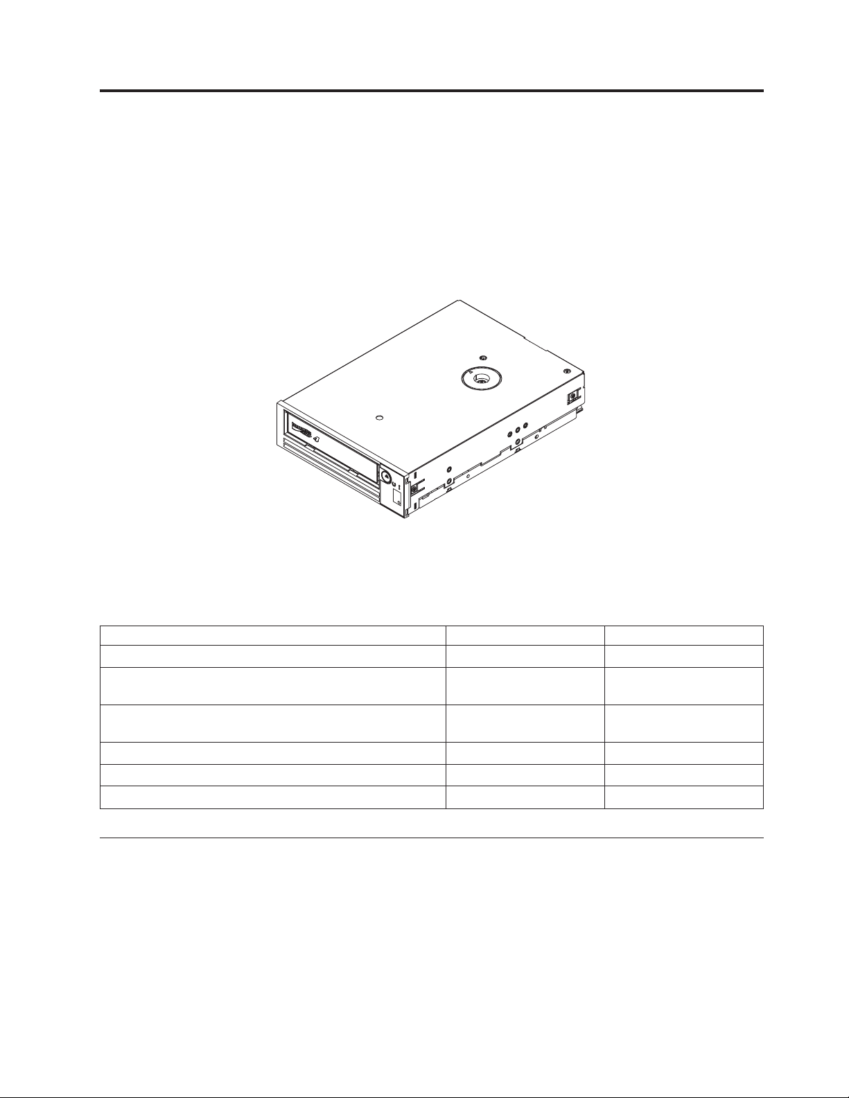
Chapter 1. Product description
This tape drive is a high-performance, high-capacity data-storage device that is
designed to back up and restore open systems applications. The drive can be
integrated into any supported external tape enclosure or directly into a supported
System x server. It is the fourth generation in the Ultrium series of products and is
available with a Serial Attached SCSI (SAS) interface.
Figure 1. The IBM LTO Ultrium 4 Half High Tape Drive
a80hh015
The Customer Replaceable Unit (CRU) part numbers and the Option part numbers
for the IBM LTO Ultrium 4 Half High Tape Drive are shown in the following list:
Table 1. CRU and Option part numbers
Description CRU part number Option part number
IBM Internal Half High LTO Gen 4 SAS Tape Drive 46X5672 44E8895
IBM External Half High LTO Gen 4 SAS Drive, with US
line cord
IBM External Half High LTO Gen 4 SAS Drive, with no line
cord
SAS cable, internal 44E8878
Mini-SAS cable, external,3mx4plug 39R6532
US line cord, 3 ft, 10 A / 125 V 39M5081
95Y8007 3628L4X
95Y8007 3628N4X
Drive features
The drive offers the following features:
v Support for WORM (write once read many) on WORM cartridge types
v Native storage capacity of 800 GB per cartridge (1600 GB at 2:1 compression)
when using Ultrium 4 cartridges
v Native data transfer rate of up to 120 MB per second
v Burst data transfer rate of 300 MB per second for the SAS interface
v 256 MB read-and-write cache
© Copyright IBM Corp. 2011 1
Page 18
v Support for encryption of data on Ultrium 4 cartridges (SAS drive only)
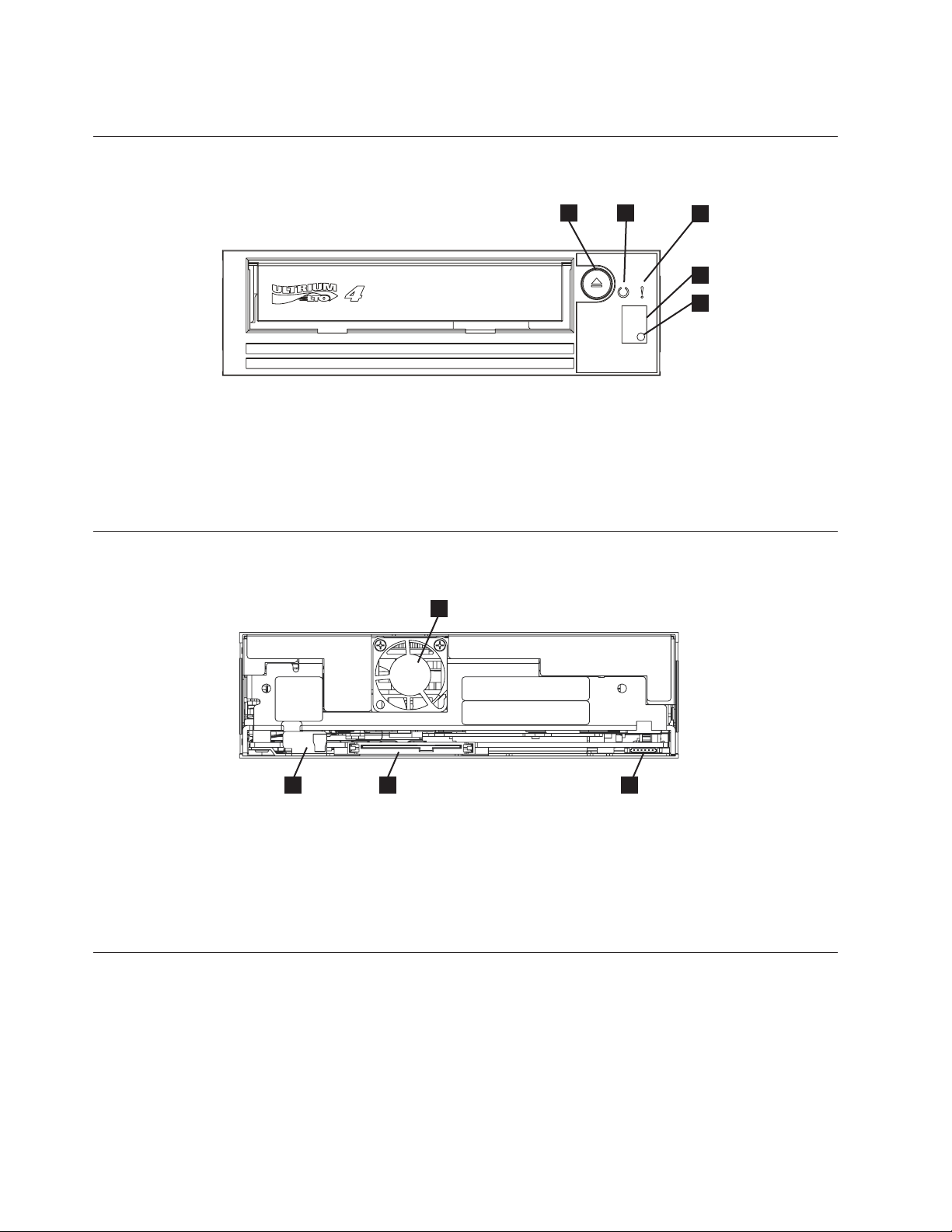
Front panel of the drive
Figure 2. Front panel of the drive
1 Unload button 4 Single-character display (SCD)
2 Ready status LED 5 SCD dot
3 Fault status LED
Rear view of the drive
1
4
2
3
4
5
a80hh014
1
Figure 3. Rear view of the drive
1 Feature switches 3 RS-422 connector for library interfaces
2 SAS and power connectors 4 Fan
Speed matching
To improve system performance, the drive uses a technique called speed matching to
dynamically adjust its native (uncompressed) data rate to the slower data rate of a
server. With speed matching, the drive operates at one of six speeds when it reads
or writes the Ultrium 3 or Ultrium 4 cartridge format. Native data rates are as
follows:
v Ultrium 4 (read/write): 30, 48, 66, 84, 103, or 120 MB per second (MBps)
v Ultrium 3 (read/write): 30, 40, 50, 60, 70, or 80 MBps
2 LTO Ultrium 4 Half High Tape Drive
a80hh024
2
3
(LDI or ADI) selectable through feature
switch 5
Page 19

v Ultrium 2 (read only): 15, 19, 22, 26, or 30 MBps
If the net (compressed) data rate of the server is between two of the active data
rates, the drive calculates the appropriate data rate at which to operate. Speed
matching dramatically reduces backhitch, the condition that occurs when a tape
stops, reverses, and restarts motion. A backhitch is usually the result of a mismatch
between the data rates of the server and the drive.
Channel calibration
System performance is further optimized by a feature called channel calibration,in
which the drive automatically customizes each read/write data channel to
compensate for variations in such things as the transfer function of the recording
channel, the media, and the characteristics of the drive head.
Encryption
The Ultrium 4 Half High Tape Drive supports host Application Managed
Encryption (AME), using T10 encryption methods. Data encryption is supported
with LTO Ultrium 4 Data Cartridges only.
The encryption enabled drive contains the necessary hardware and firmware to
encrypt and decrypt host tape application data. Encryption policy and encryption
keys are provided by the host application, and no encryption setup is required (or
available) for this drive. A drive digital certificate is installed at manufacturing
time. Each drive receives a unique serial number and certificate. The T10
application might validate each drive instance by checking the digital certificate of
the drive.
SAS interface
®
Application-managed encryption is supported on Windows Server 2003, Linux
and Solaris. Encryption requires the latest device drivers that are available for the
tape drive. To download the latest device drivers, complete the following steps.
Note: Changes are made periodically to the IBM website. The actual procedure
might vary slightly from what is described in this document.
1. Go to http://www-947.ibm.com/support/entry/portal/.
2. In the Search within all of support & downloads text field at the bottom of
the screen, type tape files and press Enter.
3. In the list of search results, click the link Tape Files (index) - Software for tape
drives and libraries.
A drive with a SAS (Serial Attached SCSI) interface can be linked directly to
controllers. SAS provides better performance than traditional SCSI because SAS
enables multiple devices (up to 128) of different sizes and types to be connected
simultaneously with thinner and longer cables; its full-duplex signal transmission
supports 3.0 Gbps. In addition, SAS drives can be hot-plugged.
SAS drives auto-negotiate speed. There are no configurable topologies; therefore,
feature switches are associated with SAS.
The drive contains a dual-port, SFF-8482 SAS connector. The SAS connector
conforms to the Device Free (Plug) Connector form of the SFF-8482 standard
“Unshielded Dual Port Serial Attachment Connector” as defined by the SFF
,
Chapter 1. Product description 3
Page 20

standards body. For more information, see http://www.sffcommittee.org or
ftp://ftp.seagate.com/sff/SFF-8482.pdf for connector details.
4 LTO Ultrium 4 Half High Tape Drive
Page 21

Chapter 2. Installing the drive
Depending on the type of enclosure, installation procedures might vary. Refer to
the enclosure documentation for drive installation. The following generic
procedure can be used if the enclosure documentation is not available.
Avoiding drive damage
To avoid static electricity damage when handling the drive, use the following
precautions:
v Limit your movement. Movement can cause static electricity to build around
you.
v Always handle the drive carefully. Never touch exposed circuitry.
v Prevent others from touching the drive.
v Before unpacking and installing the drive into an enclosure, touch its
static-protective packaging to an unpainted metal surface on the enclosure for at
least two seconds. This reduces static electricity in the packaging and your body.
v When possible, remove the drive from its static-protective packaging and install
it directly in an enclosure without setting it down. When this is not possible,
place the drive's packaging on a smooth, level surface and place the drive on the
packaging.
v Do not place the drive on the cover of the enclosure or on any other metal
surface.
Installation overview
The following list of steps provides a brief overview of the installation process.
1. “Unpack the drive”
2. “Power off the enclosure” on page 6
3. “Set the feature switches” on page 6
4. “Mount the drive in an enclosure or server” on page 7
5. “Connect and test power to the drive” on page 8
6. “Connect the internal cable” on page 9
7. “Run drive diagnostics” on page 9
8. “Install device drivers” on page 9
9. “Connect the external interface cable (tape enclosure installations only)” on
page 10
10. “Configure the drive to the server, switch, or hub” on page 10
Unpack the drive
About this task
Unpack the drive and store the packaging for future moves or shipping.
© Copyright IBM Corp. 2011 5
Page 22
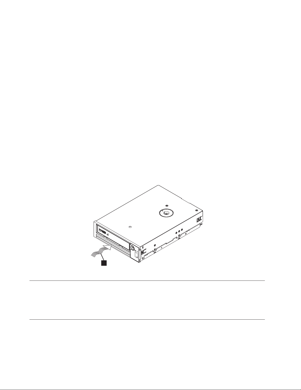
Acclimate the drive and media
About this task
Acclimation time is required if the temperature of the drive and media when
unpacked is different than the temperature of its operating environment (measured
at the front of the bezel near the air intake area as shown in Figure 4). The
recommended acclimation time is four hours after the drive has been unpacked or
one hour after any condensation that you can see has evaporated, whichever is
greater. When acclimating the drive, apply the following measures:
v If the drive is colder than its operating environment and the air contains
sufficient humidity, condensation might occur in the drive and damage it. When
the drive has warmed to the operating temperature range (greater than 10°C or
50°F) and no danger of condensation is present (the air is dry), warm the drive
more quickly by powering it on for 30 minutes. Use a diagnostic tape to test the
drive before inserting a tape that contains data.
v If the drive is hotter than its operating environment, the tape can stick to the
drive head. When the drive has cooled to the operating temperature range (less
than 40°C or 104°F), cool the drive more quickly by applying airflow for 30
minutes. Power-on the drive and use a diagnostic tape to test it before inserting
a tape that contains data.
If you are uncertain about whether the temperature of the drive is within the
recommended operating range or the humidity is sufficient to cause condensation,
acclimate the drive for the full four hours.
1
Figure 4. Temperature of the drive is taken near the air intake area [1]
Power off the enclosure
Procedure
1. Power-off the enclosure (or the unit that provides power to the drive).
2. Disconnect the power cord from both the electrical outlet and the enclosure.
Set the feature switches
The Ultrium 4 Tape Drive has eight factory-set feature switches by which the drive
is configured for various functions. The feature switches are preset to the Off
position at the factory but are described here in case you must change the
feature-switch settings for your application.
6 LTO Ultrium 4 Half High Tape Drive
a80hh010
Page 23
The feature switches are on the rear panel of the tape drive. See 1 in the Figure 3
on page 2 for the location of the switches. The switches are labeled 1 through 8
and the On and Off positions are marked. The feature switches are defined in the
following table.
Table 2. Feature switch definitions
Switch On function Off function
1 Library interface at 9 600 baud /
polled
2 Library interface uses two stop bits Library interface uses one stop bit
3 Reserved Reserved
4 Library interface at 115 000 baud
rate
5 Enable ADI Enable LDI
6 Reserved Reserved
7 Disable head brush ERP* Enable head brush ERP*
8 Reserved Reserved
Note: The default settings for the feature switches are all switches placed in the Off
position.
*The head brush error recovery procedure (ERP) is intended to prevent a permanent read
or write error by removing debris that might have accumulated on the read or write head.
In order to brush the head, the tape must be unthreaded to expose the head. This forces
the loader to be cycled to enable re-thread. During the loader cycling, the back of the
cartridge will temporarily extend beyond the front of the bezel. Extension of the cartridge
is problematic in some automation environments, so you have the ability to disable this
function. If the head brush ERP is disabled, the drive will immediately report the
permanent error instead of activating the head brush ERP.
Library interface at 38 400 baud /
non-polled
Switch 1 active
Mount the drive in an enclosure or server
About this task
When you mount the drive in an enclosure, observe the following guidelines:
v Use the installation instructions for your enclosure if possible.
v Use the drive rails that come with your enclosure or server, unless you have
x3400 or x3500 System x servers. Mount the drive into x3400 or x3500 System x
servers using the metal rails included with your tape drive.
v Do not obstruct the ventilation slots at the rear of the drive.
Attention: When the mounting screws or drive rail prongs are inserted into the
drive, they must not extend farther than 2.5 mm (0.098 in.) inside the chassis.
Otherwise, they might damage the drive.
Chapter 2. Installing 7
Page 24
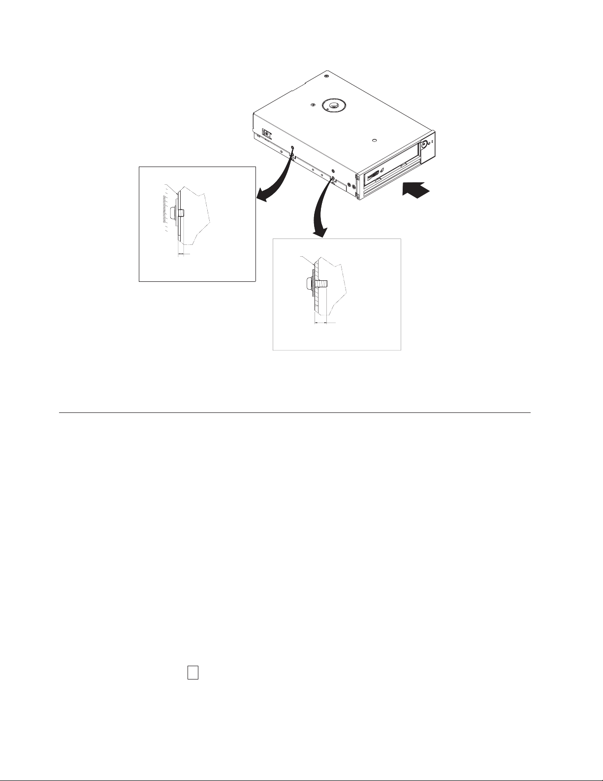
Upper Side Mounting Holes
Drive
Air Intake Area
2.5mm (0.10 in.)
MAXIMUM Penetration
Depth From OUTSIDE
of Drive
Figure 5. Mounting holes on the drive. The holes are located on both sides of the drive. The drive is shown with a
front bezel.
Lower Side Mounting Holes
Drive
5.0mm (0.20 in.)
MAXIMUM Penetration
Depth From OUTSIDE
of Drive
Connect and test power to the drive
About this task
The drive does not contain its own power source; it must be powered externally.
To connect and test power to the drive, complete the following steps:
1. Ensure that the enclosure (or unit that supplies power to the drive) is powered
off.
2. Ensure that the power cord is disconnected from both the enclosure and the
power outlet.
3. Connect the enclosure internal power cable to the power connector on the drive
(see 2 in “Rear view of the drive” on page 2).
4. Connect the power cord to the enclosure and to the electrical outlet.
5. Review the location of the single-character display (SCD) and the status LED in
Figure 2 on page 2. To ensure that the drive is receiving power, watch for the
following while turning on the power to the enclosure:
v During the power-on/initialization and POST (Power-On Self Test), the SCD
briefly displays
8
, then becomes blank (not lit) when POST is complete and there are no POST
errors. If a POST error has been detected, an error code will be displayed in
the SCD and the status LED will flash amber.
8 LTO Ultrium 4 Half High Tape Drive
Page 25

Attention: If the SCD does not come on, the drive might not be getting
power.
v The status LED will be OFF during the initial power-on and initialization.
The status LED briefly becomes green and then becomes amber during the
remainder of the power-on and initialization phase. The status LED becomes
solid green after the power-on/initialization and POST are complete.
6. Power-off the enclosure.
7. Disconnect the power cord from both the enclosure and the electrical outlet.
Connect the internal cable
About this task
Connect the enclosure internal SAS cable to the SAS connector on the drive. Attach
the host side (data and power) of the SAS cable included with your tape drive to
the SAS and power connectors on your server. Then, attach the drive side to the
drive connector (see 2 in Figure 3 on page 2).
Run drive diagnostics
Procedure
1. Replace the cover on the enclosure.
2. If you are not already connected to a power source, connect the power cord to
both the enclosure and the electrical outlet.
3. Power-on the enclosure.
4. Run one or more of the following drive diagnostics:
v “Function Code 1: Run drive diagnostics” on page 19
v “Function Code 6: Run host interface wrap test” on page 25
v “Function Code 7: Run RS-422 wrap test” on page 26
If an error code appears on the single-character display (SCD), go to “Error
codes and messages” on page 46. If no error appears, continue to the next step.
5. Power-off the enclosure.
6. Disconnect the power cord from both the enclosure and the electrical outlet.
Install device drivers
About this task
For information about installing device drivers, refer to the documentation for your
enclosure. To download the latest device drivers, complete the following steps.
Note: Changes are made periodically to the IBM website. The actual procedure
might vary slightly from what is described in this document.
1. Go to http://www-947.ibm.com/support/entry/portal/.
2. In the Search within all of support & downloads text field at the bottom of
the screen, type tape files and press Enter.
3. In the list of search results, click the link Tape Files (index) - Software for tape
drives and libraries.
Chapter 2. Installing 9
Page 26

Connect the external interface cable (tape enclosure installations only)
About this task
For information about connecting the enclosure, refer to the documentation for
your enclosure.
Connect the external SAS interface to the server
About this task
To connect the enclosure to the SAS interface, complete the following steps:
Procedure
1. Connect the external SAS cable that ships with the drive to both the enclosure
and the server (for the location of the connectors, refer to the documentation
for your enclosure and server).
2. Run the appropriate SAS attachment verification procedure for your server.
Results
If you want to power a device on or off while it is connected to the same bus as a
drive, you can do so if, during the power-on cycle, you quiesce all devices
(including the drive) on the bus.
Configure the drive to the server, switch, or hub
About this task
To configure the drive to work with the server, refer to the documentation for that
server, switch, or hub.
The drive is now ready for use.
10 LTO Ultrium 4 Half High Tape Drive
Page 27

Chapter 3. Operating the drive
Operating the drive involves using the following front panel items:
v Single-character display (SCD)
v SCD dot
v Status LED
v Unload button
Single-character display (SCD)
The SCD (2 in Figure 2 on page 2) presents a single-character code for:
v Error conditions and informational messages
v Diagnostic or maintenance functions (while in Maintenance Mode only)
“Error codes and messages” on page 46 lists the codes for error conditions and
informational messages. If multiple errors occur, the code with the highest priority
(represented by the lowest number) displays first. When the error is corrected, the
code with the next highest priority displays, and so on until no errors remain.
“Diagnostic and maintenance functions” on page 16 lists the single-character codes
that represent diagnostic or maintenance functions. To initiate a function, the unit
must be in Maintenance Mode.
SCD dot
Status LED
The SCD is blank during normal operation.
If a drive dump is present while the drive is in Maintenance Mode, a single red
8
dot illuminates in the lower right corner of the SCD (
“Function Code 5: Copy drive dump” on page 24.
The SCD Dot is on solid if the dump is in ROM memory. The SCD Dot flashes if
the dump is in FLASH memory.
The SCD Dot turns off when you obtain a dump (by using ITDT, a library
command, a SCSI command, or "Function Code 5: Copy Drive Dump) or update
the drive firmware.
Note: If the drive dump is stored in ROM memory (SCD Dot on solid), the dump
will be lost when you turn OFF the power or reset the drive.
The status light-emitting diode (LED) (4 in Figure 2 on page 2) that provides
information about the state of the drive. The LED can be green or amber, and
(when lit) solid or flashing. Table 3 on page 12 lists the conditions of the status
light and single-character display (SCD) and provides an explanation of what each
condition means. The SCD dot – a small LED dot near the lower right corner of
the single-character display – serves as a dump indicator. When this dot is lit, a
dump file is stored in the drive and can be retrieved.
). To copy the dump, see
© Copyright IBM Corp. 2011 11
Page 28
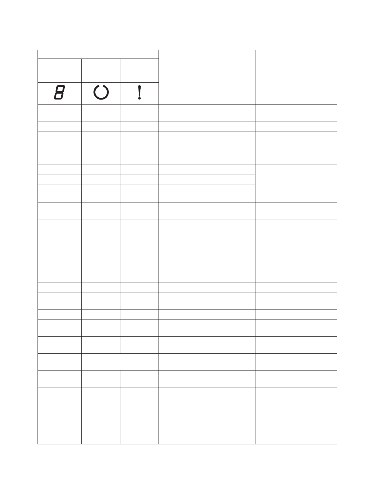
Table 3. Meaning of status LED and single-character display (SCD)
Indicator
Singlecharacter
display (red)
"Ready" LED
(green)
"Fault" LED
(amber)
Status condition Action
"1" Off On Maximum operating temperature
exceeded
1
Reduce drive temperature.
"1" Flashing Flashing On Self test is in progress Wait for test to complete.
"2" Off On Input voltage failure Check input power
connections.
"3" Off Flashing
2
Drive firmware failure
3
Update to latest level
firmware.
2
"4" Off Flashing
"5" Off Flashing
"6" Off On Drive or media failure
Drive firmware or hardware failure3Clean drive and/or replace
2
Unrecoverable drive failure
4
cartridge if needed. Retry
operation. If it fails again, see
SK/ASC/ASCQ in User's
Guide for action.
"6" or "7"
"7"
5
5
Off On Cleaning cartridge loaded, clean
failed
Replace cleaning cartridge,
which may have expired.
Off On Media error Replace cartridge. Possible
expired cleaning cartridge.
"8" Off Flashing SAS interface failure Check SAS cable & connector.
"A" Off On Recoverable drive error
"C"
7
OfforOn On
7
Cleaning is required (clean bit is
set)
"C"
"F"
7
5
Flashing Off Cleaning in progress Wait for cleaning to complete.
Off On Incorrect firmware update tape used Replace firmware update tape.
"H" Off Flashing Firmware update failed
6
8
Clean drive & retry operation.
Clean drive as soon as
possible.
Retry firmware update
operation.
5
"J"
5
"P"
Segments
Flashing
2
Off Both LEDs Flashing
Off On Incorrect (incompatible) media Insert correct media type.
Off On Media is write-protected (and write
operation was attempted)
Use media not
write-protected.
Off Off or On Power-on self-test in progress Wait 30-60 seconds.
Firmware update is in progress Wait for update to complete.
Together
9
On
3.0 sec On
Off or "C"
Off or "C"
Off or "C"
Off or "C"
7
7
7
7
10
Flashing
Rapidly
3.0 sec On
2
Off Off or On
Flashing
2
On Off or On
Flashing Off or On
On Drive is in service mode
10
3.0 sec On
10
After power-on self-test and drive
10
reset
7
No cartridge is loaded
OfforOn7Cartridge is loading or unloading
7
Cartridge is loaded, no activity
7
Data cartridge is loaded, activity
12 LTO Ultrium 4 Half High Tape Drive
Page 29

Table 3. Meaning of status LED and single-character display (SCD) (continued)
Indicator
Singlecharacter
display (red)
Notes:
1. The “Fault” LED must be solid to indicate an overtemp condition (media temperature greater than 52°C or
125°F). If a tape is present, it must be ejected. This LED will remain on until the drive temperature drops below
a lower secondary temperature limit, and one of the following two conditions is also met:
v A data or cleaning cartridge is inserted.
v A POR cycle or hard bus reset occurs.
2. When used in this table, “Flashing” refers toa1Hz(±10%) flash rate, and “Flashing Rapidly” refers toa4Hz
(±10%) flash rate.
3. A drive dump should be stored before the drive is powered-off.
4. The failure cannot be isolated to either faulty drive or media.
5. The error code on single-character display is cleared when the cartridge is removed from the drive.
6. The error condition will be cleared when the drive is powered-off. The drive is not disabled.
7. When a drive needs cleaning, the Fault LED must be on solid and a “C” must appear on the single-character
display. In most cases, the drive will continue to function, but it should be cleaned as soon as possible. A POR
cycle must not turn off this indicator.
8. The firmware update failed and the drive is not functional. The drive boot code is in control and the firmware
download should be retried. The drive can be identified via an INQUIRY command and is thereby bootable
while in this state.
9. When the drive is in service mode, the “Fault” LED will be on solid and the single character display will
indicate the current service mode state.
10. Immediately following a power-on self-test sequence or drive reset, both LEDs, all segments of the
single-character display, and the SCD dot must be on solid for 3 seconds (±10%).
"Ready" LED
(green)
"Fault" LED
(amber)
Status condition Action
Unload button
The unload button (5 in Figure 2 on page 2) performs the following functions:
Table 4. Functions that the unload button performs
Unload button function How to initiate the function
Rewind the tape into the
cartridge and eject the
cartridge from the drive
Place the drive in
Maintenance Mode
Scroll through the
maintenance functions
Press the unload button once. The status LED flashes green while the drive is
rewinding and unloading.
Note: During a rewind and eject operation, the drive does not accept SCSI commands
from the server.
Ensure that the drive is unloaded. Then, within two seconds, press the unload button
three times. The drive is in Maintenance Mode when the status LED becomes solid
0
amber and
While in Maintenance Mode, press the unload button once per second to increment
the display characters by one. When you reach the character of the diagnostic or
maintenance function that you want (see “Diagnostic and maintenance functions” on
page 16), press and hold the unload button for three seconds.
appears in the SCD.
Chapter 3. Operating 13
Page 30

Table 4. Functions that the unload button performs (continued)
Unload button function How to initiate the function
Exit Maintenance Mode
Press the unload button once per second until
unload button for three seconds. Maintenance Mode is exited when the status LED
becomes solid green and the SCD becomes blank.
Force a drive dump (part of
the Maintenance Mode)
Reset the drive Press and hold the unload button until the drive begins the reset procedure (SCD will
Attention: If the drive detects a permanent error and displays an error code, it
automatically forces a drive dump (also known as a save of the firmware trace). If
you force a drive dump, the existing dump will be overwritten and data will be lost.
After you force a drive dump, do not turn off the power to the drive or you might
lose the dump data.
Choose one of the following procedures:
v If the drive is in Maintenance Mode (status LED is solid amber), refer to “Function
Code 4: Force a drive dump” on page 24.
v If the drive is in Operating Mode (status LED is solid or flashing green), press and
hold the unload button for ten seconds.
If captured dump data exists, the drive places it into a dump area (for information
about retrieving the data, see “Obtaining a drive dump” on page 52).
display random patterns and the status LED will be amber).
Note: If a tape cartridge is loaded in the drive, the drive will unload the tape. Repeat
the "Reset the drive" procedure after the tape is unloaded. The drive saves a dump of
the current drive state, then reboots to allow communication. Do not cycle power as
this will erase the contents of the dump.
0
displays. Then, press and hold the
Inserting a tape cartridge
Before you begin
Attention: Do not leave the tape cartridge in the drive when the drive is inactive
or when the power is off. Otherwise, the tape cartridge might be damaged.
About this task
To insert a tape cartridge:
Procedure
1. Ensure that the drive is powered-on.
2. Ensure that the write-protect switch on the tape cartridge is properly set.
3. Grasp the cartridge so that the write-protect switch faces you (see 1 in
Figure 6 on page 15).
4. Slide the cartridge into the tape load compartment.
Note:
a. If the cartridge is already in an ejected position and you want to
b. If the cartridge is already loaded and you cycle the power (turn it off,
c. Do not attempt to load a cartridge when the drive is in Maintenance
reinsert it, remove the cartridge then insert it again.
then on), the tape will reload.
Mode until the drive requests it.
14 LTO Ultrium 4 Half High Tape Drive
Page 31

Figure 6. Inserting a cartridge into the drive
Removing a tape cartridge
About this task
To remove a tape cartridge:
Procedure
1. Ensure that the drive is powered-on.
2. Press the unload button. The drive rewinds the tape and partially ejects the
cartridge. The status light flashes green while the tape rewinds, then goes out
before the cartridge partially ejects.
3. After the cartridge partially ejects, grasp the cartridge and remove it.
Results
Whenever you unload a tape cartridge, the drive writes any pertinent information
to the cartridge memory.
Mid-tape recovery
a80hh021
About this task
If reset occurs while a cartridge is loaded, the drive will slowly rewind the tape
and eject the cartridge. If a power cycle occurs while a cartridge is loaded, the
drive will slowly rewind the tape. The drive will not automatically eject the
cartridge.
Chapter 3. Operating 15
Page 32

Cleaning the drive head
About this task
Attention: When cleaning the drive head, use the LTO Ultrium Cleaning
Cartridge.
Clean the drive head whenever
the status LED is flashing amber once per second. It is not recommended that you
clean the drive head on a periodic basis; only when the drive requests to be
cleaned.
Note: In Maintenance Mode, a flashing
means to insert a cartridge, not clean the drive head.
To clean the head, insert the cleaning cartridge into the tape load compartment (see
“Front panel of the drive” on page 2). The drive performs the cleaning
automatically in less than two minutes then ejects the cartridge. The drive will
perform a short Load/Unload Test while ejecting the drive. Wait for the drive to
finish before removing the cartridge.
Note: The drive will automatically eject an expired cleaning cartridge.
C
displays on the single-character display and
C
with the solid amber status LED
The LTO Ultrium Cleaning Cartridge is valid for 50 uses.
Diagnostic and maintenance functions
The drive can:
v Run diagnostics
v Test write and read functions
v Test a suspect tape cartridge
v Update firmware
v Perform other diagnostic and maintenance functions
The drive must be in Maintenance Mode to perform these functions.
Attention: Maintenance functions cannot be performed concurrently with read or
write operations. While in Maintenance Mode, the tape drive does not accept SCSI
commands from the server. The tape drive does accept LDI or RS-422 commands.
Table 5 describes each diagnostic and maintenance function that the drive can
perform, gives the function code that appears on the single-character display
(SCD), and directs you to the instructions for performing the function. It is
recommended that you use a customer-supplied scratch (blank) data cartridge for
diagnostic testing.
Table 5. Diagnostic and maintenance functions
Function
Code
0
Exit Maintenance Mode: Causes the drive to become
available for reading and writing data.
Diagnostic or Maintenance Function Instructions Location
“Function Code 0: Maintenance Mode”
on page 19
16 LTO Ultrium 4 Half High Tape Drive
Page 33

Table 5. Diagnostic and maintenance functions (continued)
Function
Code
1
8
3
8
5
6
7
8
9
A
C
E
F
H
J
L
P
Run drive diagnostics: Runs tests to determine whether
the drive can properly load and unload cartridges, and
read and write data.
Update tape drive firmware from FMR tape: Loads
updated firmware from a field microcode replacement
(FMR) tape.
Create FMR tape: Copies its field microcode replacement
(FMR) data to a customer-supplied scratch (blank) data
cartridge.
Force a drive dump: Performs a dump of data (also
known as saving a microcode trace).
Copy drive dump: Copies data from a drive dump
(captured by using Function Code 4) to the beginning of
a customer-supplied scratch (blank) data cartridge,
copies a drive dump to flash memory, or erases a dump
from flash memory.
Run host interface wrap test: Performs a check of the
circuitry from and to the connector.
Run RS-422 wrap test: This test causes the drive to
perform a check of the circuitry and connector for the
RS-422 interface.
Unmake FMR tape: Erases the FMR data on a
customer-supplied scratch (blank) data cartridge and
rewrites the cartridge memory on the tape. This turns
the cartridge into a valid customer-supplied scratch data
cartridge.
Display error code log: Displays the last 10 error codes,
one at a time (the codes are ordered; the most recent is
presented first and the oldest (tenth) is presented last).
Clear error code log: Erases the contents of the error
code log.
Insert cartridge into tape drive: This function cannot be
selected by itself, but is a part of other maintenance
functions (such as Run Tape Drive Diagnostics and
Create FMR Tape) that require a tape cartridge to be
loaded.
Test cartridge and media: Performs tests to ensure that a
suspect cartridge and its magnetic tape are acceptable.
Write performance test: Performs tests to ensure that the
drive can read from and write to tape.
Test head: Performs tests to ensure that the tape drive
head and tape-carriage mechanics are working correctly.
Fast read/write test: Performs tests to ensure that the
drive can read from and write to tape.
Load/unload test: Tests the drive ability to load and
unload a tape cartridge.
Enable post error reporting: When selected,
deferred-check conditions are reported to the host.
Diagnostic or Maintenance Function Instructions Location
“Function Code 1: Run drive diagnostics”
on page 19
“Function Code 2: Update drive firmware
from FMR tape” on page 22
“Function Code 3: Create FMR tape” on
page 23
“Function Code 4: Force a drive dump”
on page 24
“Function Code 5: Copy drive dump” on
page 24
“Function Code 6: Run host interface
wrap test” on page 25
“Function Code 7: Run RS-422 wrap test”
on page 26
“Function Code 8: Unmake FMR tape” on
page 27
“Function Code 9: Display error code
log” on page 28
“Function Code A: Clear error code log”
on page 28
“Function Code C: Insert cartridge into
tape drive” on page 29
“Function Code E: Test cartridge and
media” on page 29
“Function Code F: Write performance
test” on page 30
“Function Code H: Test head” on page 31
“Function Code J: Fast read/write test”
on page 32
“Function Code L: Load/unload test” on
page 33
“Function Code P: Post error reporting
enabled” on page 34
Chapter 3. Operating 17
Page 34

Table 5. Diagnostic and maintenance functions (continued)
Function
Code
U
Disable post error reporting: When selected,
deferred-check conditions are NOT reported to the host.
Diagnostic or Maintenance Function Instructions Location
Entering Maintenance Mode
About this task
The drive must be in Maintenance Mode to run drive diagnostics or maintenance
functions. To place the unit in Maintenance Mode:
Procedure
1. Make sure that no cartridge is in the drive.
2. Press the unload button three times within two seconds.
single-character display (SCD), and the status LED turns amber.
Note: If a cartridge is in the tape drive, it will eject the first time that you press
the unload button and the drive will not be placed in maintenance
mode. To continue placing the drive in Maintenance Mode, perform the
preceding step.
“Function Code U: Post error reporting
disabled” on page 34
0
appears in the
Results
Maintenance functions cannot be performed concurrently with read or write
operations. While in Maintenance Mode, the drive does not receive SCSI
commands from the server.
If a drive dump is present while the drive is in Maintenance Mode, a single red
dot illuminates in the lower right corner of the SCD. Refer to “SCD dot” on page
11.
Exiting Maintenance Mode
About this task
The drive must be in Function Code
To exit Maintenance Mode:
Procedure
1. Press the unload button once per second until
cycle past the desired code, press the unload button once per second until the
code appears.)
2. Press and hold the unload button for three or more seconds, then release it.
About this task
0
in order to exit Maintenance Mode.
0
appears in the SCD. (If you
To exit Maintenance Mode when an error is displayed:
18 LTO Ultrium 4 Half High Tape Drive
Page 35

Procedure
1. Press the unload button three times within two seconds to clear the error code
and return to Function Code0.
2. Press and hold the unload button for three or more seconds, then release it.
Results
Note: The drive will exit Maintenance Mode automatically when:
v it completes a maintenance function
v there is an error code for anything other than a hardware problem
v no action has occurred for 10 minutes
The drive will not exit Maintenance Mode automatically if there is an error
code displayed that indicates there is a hardware problem.
Function Code 0: Maintenance Mode
About this task
Function Code
maintenance functions, or exiting from Maintenance Mode.
0
makes the drive available for running drive diagnostics or
Procedure
1. Place the drive in Maintenance Mode. For instructions, see“Entering
Maintenance Mode” on page 18.
2. To exit Maintenance Mode, see “Exiting Maintenance Mode” on page 18.
Results
The drive exits Maintenance Mode automatically after it completes a maintenance
function or after 10 minutes if no action has occurred.
Function Code 1: Run drive diagnostics
About this task
Approximate Run Time = 20 minutes per loop
Total Number of Loops = 10
1
Function Code
and unload cartridges and read and write data.
runs tests that determine whether the drive can properly load
Press the unload button to stop the diagnostic and exit Maintenance Mode.
Pressing the unload button once will abort the test at the end of the current test
loop. Pressing the unload button twice will abort the test immediately. Wait for the
drive to rewind the tape and unload the cartridge.
Record the time it takes for the test to complete. Compare the recorded time with
the approximate run time. If the test runs successfully but the execution time is
significantly longer than the approximate run time, run “Function Code F: Write
performance test” on page 30. If the Write Performance Test fails, replace the
media.
Chapter 3. Operating 19
Page 36

Attention: For this test, insert only a scratch (blank) data cartridge or a cartridge
that can be overwritten. During the test, the drive overwrites the data on the
cartridge.
Note: If you inserted an invalid tape cartridge (e.g. Gen 1, WORM media, or
7
non-FMR cartridge), error code
status LED flashes. If you inserted a write-protected cartridge, or the media
has read-only compatibility (e.g., Gen2 media), error code
SCD. Press the unload button. The tape drive unloads the cartridge and
exits Maintenance Mode after the cartridge is removed.
appears in the SCD and the amber Fault
P
appears in the
Procedure
1. Place the drive in Maintenance Mode. For instructions, see “Entering
Maintenance Mode” on page 18.
1
2. Press the unload button once per second until
cycle past the desired code, press the unload button once per second until the
code reappears.)
3. Press and hold the unload button for three or more seconds, then release it to
1
select function
4. Insert a scratch (blank) data cartridge. The SCD changes to a flashing
the test begins.
. Wait for the SCD to change to a flashingC.
appears in the SCD. (If you
1
and
v If no error is detected, the diagnostic will exit Maintenance Mode,
temporarily appears in the SCD, and the drive returns to Operational Mode
(SCD blank, Green Ready/Activity status LED ON, and the Amber Fault
status LED is OFF).
v If an error is detected, the Fault status LED flashes amber and the drive
posts an error code to the SCD. To determine the error, locate the code in
“Error codes and messages” on page 46. To clear the error, either turn the
power off and then on again, or reboot the drive by pressing and holding the
unload button for 10 seconds.
Running a diagnostic self-test
Before you begin
You can use this procedure to perform a complete set of diagnostic tests on your
Ultrium 4 tape drive without affecting server operation. This 4-minute test can also
be used to verify the performance of an LTO tape cartridge.
About this task
To complete the diagnostic self-test, make sure that there is not a cartridge inserted
in the drive and complete the following steps:
Procedure
1. Enter diagnostic mode by pressing and holding the unload button for
approximately 7 seconds. Release the button when all of the drive LEDs are lit.
2. Insert a scratch (blank) LTO Ultrium-4 data cartridge within 15 seconds or the
drive will revert back to operating mode. If an Ultrium-4 data cartridge is not
0
20 LTO Ultrium 4 Half High Tape Drive
Page 37

available, you can use a blank Ultrium-3 data cartridge. Make sure that the
cartridge is not write-protected or damaged. If a cleaning cartridge is inserted
while the drive is in diagnostic mode, it will be ejected.
Important: Use a blank cartridge that does not contain data. During the
self-test, the cartridge will be rewritten with a test pattern and any
data on the cartridge will be destroyed.
3. Read the LCD and determine the self-test results. The self-test reveals one of
the following conditions:
v Test Passed
If self-testing is complete and no problems are detected, the cartridge is
ejected from the drive and the LED is not lit. This means that the tape drive
and the tape cartridge are functioning. The drive is no longer in diagnostic
mode, and has been returned to normal operation.
C
Note: If the yellow Fault LED stays lit and
complete and cleaning is required. For information about cleaning the
drive, see Cleaning the drive head.
v Drive Failure
When a drive problem is detected, the cartridge will remain loaded, the
5
yellow Fault LED will flash, and
v Media Failure
When a media problem is detected, the cartridge will remain loaded inside
is displayed.
is displayed, the self-test is
7
the drive, the yellow Fault LED will remain on, and
the self-test using another tape cartridge, and replace the defective media.
v Incorrect Cartridge
If an incorrect tape cartridge was inserted, the cartridge is ejected, the Fault
LED remains on, and
performed if the inserted cartridge is one of the following:
– Write-protected, indicated by
– Damaged, indicated by
– Not write-compatible with the drive, indicated by
Press the unload button to end the self-test and return the drive to normal
operating mode. Run the self-test again with a compatible cartridge.
4. Press the unload button to eject the tape cartridge and return the drive to
normal operation.
Note: If the self-test did not detect a problem, the cartridge will be ejected from
the drive and the LED will not be lit. The drive has been returned to
normal operating mode.
P,7
,orJis displayed. The self-test cannot be
P
7
is displayed. Repeat
J
Chapter 3. Operating 21
Page 38

Function Code 2: Update drive firmware from FMR tape
About this task
Attention: When updating drive firmware, do not power-off the drive until the
update is complete or the firmware might be lost. The primary firmware update
process requires update files. FMR tape updates should only be attempted if the
firmware files are not available, or not working. To download the primary
firmware update files, complete the following steps.
Note: Changes are made periodically to the IBM website. The actual procedure
might vary slightly from what is described in this document.
1. Go to http://www-947.ibm.com/support/entry/portal/.
2. In the Search within all of support & downloads text field at the bottom of
the screen, type tape files and press Enter.
3. In the list of search results, click the link Tape Files (index) - Software for tape
drives and libraries.
8
Function Code
(FMR) tape. The FMR tape must have been created from a LTO Gen4 tape drive
with the same host interface (SCSI U160, SCSI U320, SAS, or Fibre Channel).
Procedure
1. Place the drive in Maintenance Mode. For instructions, see “Entering
Maintenance Mode” on page 18.
loads drive firmware from a field microcode replacement
8
2. Press the unload button once per second until
cycle past the desired code, press the unload button once per second until the
code reappears.)
3. Press and hold the unload button for three or more seconds, then release it to
select the function. The SCD changes to a flashing
4. Insert the FMR tape cartridge. The SCD changes to a flashing
drive loads the updated firmware from the FMR tape into its erasable
programmable read-only memory (EPROM) area.
v During the reboot, the SCD presents a series of random characters. The SCD
8
briefly displays
The status lights will be amber during the reboot and change to green after a
successful reboot.
v If the update completes successfully, the tape drive rewinds and unloads the
FMR tape, resets itself, and is ready to use the new firmware. The drive
automatically reboots.
v If the update fails, the tape drive posts an error code to the SCD. To
determine the error, locate the code in “Error codes and messages” on page
46. The drive then unloads the FMR tape and exits Maintenance Mode after
the cartridge is removed.
, then becomes blank (not lit) when POST is complete.
appears in the SCD. (If you
C
.
8
. The tape
22 LTO Ultrium 4 Half High Tape Drive
Page 39

Function Code 3: Create FMR tape
About this task
Function Code
scratch data cartridge. The resulting FMR tape can only be used to update the
firmware on other LTO Gen4 tape drives with the same host interface (SCSI U160,
SCSI U320, SAS, or Fibre Channel). The primary firmware update process requires
update files. FMR tape updates should only be attempted if the firmware files are
not available, or not working. To download the primary firmware update files,
complete the following steps.
Note: Changes are made periodically to the IBM website. The actual procedure
might vary slightly from what is described in this document.
1. Go to http://www-947.ibm.com/support/entry/portal/.
2. In the Search within all of support & downloads text field at the bottom of
the screen, type tape files and press Enter.
3. In the list of search results, click the link Tape Files (index) - Software for tape
drives and libraries.
Attention: For this function, insert only a scratch (blank) data cartridge or a
cartridge that can be overwritten. During the test, the drive overwrites the data on
the cartridge.
Note: If you inserted an invalid tape cartridge (e.g. Gen 1, WORM media, or
non-FMR cartridge), error code
status LED flashes. If you inserted a write-protected cartridge, or the media
3
copies the drive field microcode replacement (FMR) data to a
7
appears in the SCD and the amber Fault
P
has read-only compatibility (e.g., Gen2 media), error code
SCD. Press the unload button. The tape drive unloads the cartridge and
exits Maintenance Mode after the cartridge is removed.
appears in the
Procedure
1. Place the drive in Maintenance Mode. For instructions, see “Entering
Maintenance Mode” on page 18.
3
2. Press the unload button once per second until
cycle past the desired code, press the unload button once per second until the
code reappears.)
3. Press and hold the unload button for three or more seconds, then release it to
select the function. The SCD changes to a flashing
4. Insert a scratch (blank) data cartridge that is not write protected (or the tape
drive exits Maintenance Mode). The SCD changes to a flashing
drive copies the FMR data to the scratch data cartridge.
v If the tape drive creates the FMR tape successfully, it rewinds and unloads
the new tape, exits Maintenance Mode, and the tape is ready to use.
v If the tape drive fails to create the FMR tape, it displays an error code. To
determine the error, see “Error codes and messages” on page 46. The tape
drive then unloads the FMR tape and exits Maintenance Mode after the
cartridge is removed.
appears in the SCD. (If you
C
.
3
. The tape
Chapter 3. Operating 23
Page 40

Function Code 4: Force a drive dump
About this task
Function Code
also known as saving a microcode trace).
8
performs a dump of data collected by the drive (this process is
Procedure
1. Place the drive in Maintenance Mode. For instructions, see “Entering
Maintenance Mode” on page 18. If a drive dump is present while the drive is
in Maintenance Mode, a single red dot illuminates in the lower right corner of
the SCD. Refer to “SCD dot” on page 11. The SCD Dot is on solid if the dump
is in ROM memory or flashes if the dump is in FLASH memory. If the drive
dump is stored in ROM memory (SCD Dot on solid), the dump will be lost
when you turn OFF the power or reset the drive. The SCD Dot turns off when
you obtain a dump.
8
2. Press the unload button once per second until
cycle past the desired code, press the unload button once per second until the
code reappears.)
3. Press and hold the unload button for three or more seconds, then release it to
select the function. The drive performs the dump. The SCD shows
goes blank. To access the contents of the dump, see “Function Code 5: Copy
drive dump.”
Note: You can also force a drive dump when the tape drive is in normal
operating mode. Simply press and hold the unload button for ten
seconds. This causes the drive to reboot.
appears in the SCD. (If you
0
, then
Function Code 5: Copy drive dump
About this task
Function Code
to the beginning of a scratch (blank) data cartridge.
Attention: For this function, insert only a scratch (blank) data cartridge or a
cartridge that can be overwritten. During the test, the drive overwrites the data on
the cartridge.
Note: If you inserted an invalid tape cartridge (e.g. Gen 1, WORM media, or
non-FMR cartridge), error code
status LED flashes. If you inserted a write-protected cartridge, or the media
has read-only compatibility (e.g., Gen2 media), error code
SCD. Press the unload button. The tape drive unloads the cartridge and
exits Maintenance Mode after the cartridge is removed.
Procedure
1. Place the drive in Maintenance Mode. For instructions, see “Entering
Maintenance Mode” on page 18. If a drive dump is present while the drive is
in Maintenance Mode, a single red dot illuminates in the lower right corner of
the SCD. Refer to “SCD dot” on page 11. The SCD Dot is on solid if the dump
5
copies data from a drive dump (captured in Function Code 4)
7
appears in the SCD and the amber Fault
P
appears in the
24 LTO Ultrium 4 Half High Tape Drive
Page 41

is in ROM memory or flashes if the dump is in FLASH memory. If the drive
dump is stored in ROM memory (SCD Dot on solid), the dump will be lost
when you turn OFF the power or reset the drive. The SCD Dot turns off when
you obtain a dump.
5
2. Press the unload button once per second until
cycle past the desired code, press the unload button once per second until the
code reappears.
3. Press and hold the unload button for three or more seconds, then release it to
select the function. Then, press the unload button once per second to cycle
through the following functions:
appears in the SCD. If you
5-0
v
5
v
5-8
v
5-3
v
If you cycle past the desired code, press the unload button once per second
until the code reappears.
4. Press and hold the unload button for three or more seconds, then release it to
select one of the above functions.
5. If you selected
5-8
is being performed. After the procedure is completed the drive will exit
Maintenance Mode. If you selected
C
6. Insert a scratch (blank) data cartridge that is not write protected. If you do not
insert a blank data cartridge, the tape drive will exit Maintenance Mode. The
SCD flashes the selection number while performing the function.
v If the copy operation completes successfully, the tape drive rewinds and
unloads the tape, and exits Maintenance Mode after the cartridge is removed.
v If the copy operation fails, an error code appears in the SCD. To determine
the error, locate the code in “Error codes and messages” on page 46. The tape
drive unloads the tape cartridge and exits Maintenance Mode after the
cartridge is removed.
: no function
1
-
: copy dump to tape
: copy dump to flash memory
: erase flash memory
5-0
5-3
or
indicating that a data cartridge is to be inserted.
the drive will exit Maintenance Mode. If you selected
the SCD will change to a flashing
1
5
-
the SCD will change to a flashing
5
while the procedure
Function Code 6: Run host interface wrap test
About this task
Approximate Run Time = 10 seconds per loop
Number of Loops = This test runs until stopped by pressing the unload button.
6
Function Code
connector on the drive. Function Code 6 is not supported on the SCSI U320.
performs a check of the host interface circuitry and host
Chapter 3. Operating 25
Page 42

Function Code 6 is selectable on the SCSI U320 drive but the test will always exit
0
with
on the SCD.
Procedure
1. Make sure that the host interface wrap plug is connected to the host interface
connector at the rear of the drive. A SFF-8482 SAS cable should be connected to
the rear of the drive. Connect the wrap plug to the SFF-8482 SAS connector
port to be tested.
2. Place the drive in Maintenance Mode. For instructions, see “Entering
Maintenance Mode” on page 18.
6
3. Press the unload button once per second until
4. Continue to press the unload button once per second to cycle through the
following functions:
appears in the SCD.
6-0
a.
6
b.
6-8
c.
6-3
d.
(requires a wrap plug in both ports)
5. Press and hold the unload button for three or more seconds, then release it to
select one of the above functions. The drive automatically starts the test. If you
cycle past the desired code, press the unload button once per second until the
code reappears.
6. The SCD will display a flashing
v If no error is detected, the diagnostic will exit Maintenance Mode,
temporarily appears in the SCD, and the drive returns to Operational Mode
(SCD blank, Green Ready/Activity status LED ON, and the Amber Fault
status LED is OFF).
v If an error is detected, the Fault status LED flashes amber and the drive
posts an error code to the SCD. To determine the error, locate the code in
“Error codes and messages” on page 46. To clear the error, either turn the
power off and then on again, or reboot the drive by pressing and holding the
unload button for 10 seconds.
: exit
-1: test the primary SAS port
: test the secondary SAS port
: test both primary and secondary SAS ports at the same time
6
during the test.
0
Function Code 7: Run RS-422 wrap test
About this task
This test causes the drive to perform a check of the circuitry and connector for the
RS-422 interface. This connector supports the Library Drive Interface (LDI) and the
Automation Drive Interface (ADI).
Before selecting this function, attach an LDI or RS-422 wrap plug to the drive's LDI
or RS-422 connector (in place of the LDI or RS-422 cable).
Procedure
1. Make sure that no cartridge is in the drive, and the appropriate wrap plug is
attached to the RS-422 connector.
26 LTO Ultrium 4 Half High Tape Drive
Page 43

2. Place the drive in Maintenance Mode. For instructions, see “Entering
Maintenance Mode” on page 18.
7
3. Press the unload button once per second until
single-character display (SCD). If you cycle past
unload button until it displays again.
4. To select the function, press and hold the unload button for three seconds. After
7
you select the function,
flashes and the drive automatically starts the test.
appears in the
7
, continue to press the
v If no error is detected, the diagnostic will exit Maintenance Mode,
temporarily appears in the SCD, and the drive returns to Operational Mode
(SCD blank, Green Ready/Activity status LED ON, and the Amber Fault
status LED is OFF).
v If an error is detected, the Fault status LED flashes amber and the drive
posts an error code to the SCD. To determine the error, locate the code in
“Error codes and messages” on page 46. To clear the error, either turn the
power off and then on again, or reboot the drive by pressing and holding the
unload button for 10 seconds.
Function Code 8: Unmake FMR tape
About this task
Function Code
rewrites the cartridge memory on the tape. This converts the cartridge into a valid
scratch (blank) data cartridge.
Procedure
1. Place the drive in Maintenance Mode. For instructions, see “Entering
Maintenance Mode” on page 18.
2. Press the unload button once per second until
cycle past the desired code, press the unload button once per second until the
code reappears.)
3. Press and hold the unload button for three or more seconds, then release it to
8
erases the field microcode replacement (FMR) data and
8
appears in the SCD. (If you
0
8
select function
4. Insert the FMR data cartridge (or the tape drive exits maintenance mode). The
SCD changes to a flashing
and rewrites the header in the cartridge memory to change the cartridge to a
valid scratch (blank) data cartridge:
Note: If you inserted an invalid tape cartridge (e.g. Gen 1, WORM media, or
non-FMR cartridge), error code
Fault status LED flashes. If you inserted a write-protected cartridge, or
the media has read-only compatibility (e.g., Gen2 media), error code
appears in the SCD. Press the unload button. The tape drive unloads the
cartridge and exits Maintenance Mode after the cartridge is removed.
. The SCD changes to a flashingC.
8
. The tape drive erases the firmware on the tape
7
appears in the SCD and the amber
P
Chapter 3. Operating 27
Page 44

v If no error is detected, the diagnostic will exit Maintenance Mode,
temporarily appears in the SCD, and the drive returns to Operational Mode
(SCD blank, Green Ready/Activity status LED ON, and the Amber Fault
status LED is OFF).
v If an error is detected, the Fault status LED flashes amber and the drive
posts an error code to the SCD. To determine the error, locate the code in
“Error codes and messages” on page 46. To clear the error, either turn the
power off and then on again, or reboot the drive by pressing and holding the
unload button for 10 seconds.
Function Code 9: Display error code log
About this task
0
Function Code
ordered; the most recent is presented first and the oldest is presented last). If there
are no errors in the log, function code
(SCD) and exits Maintenance Mode.
9
displays the last ten error codes, one at a time (the codes are
0
displays in the single-character display
Procedure
1. Place the drive in Maintenance Mode. For instructions, see “Entering
Maintenance Mode” on page 18.
2. Press the unload button once per second until
cycle past the desired code, press the unload button once per second until the
code reappears.)
3. Press and hold the unload button for three or more seconds, then release it to
view the most recent error code.
4. Press the unload button again to view successive error codes. Let two to three
seconds pass between each depression. The SCD will display
error codes have been displayed.
5. After viewing all error codes, exit this function by pressing the unload button
0
again. The SCD will display
and exit Maintenance Mode.
Function Code A: Clear error code log
About this task
9
appears in the SCD. (If you
0
when all the
Function Code
Procedure
1. Place the drive in Maintenance Mode. For instructions, see “Entering
Maintenance Mode” on page 18.
2. Press the unload button once per second until
cycle past the desired code, press the unload button once per second until the
code reappears.)
28 LTO Ultrium 4 Half High Tape Drive
A
erases the contents of the error code log.
A
appears in the SCD. (If you
Page 45

3. Press and hold the unload button for three or more seconds, then release it to
A
select the function.
erases all errors from the error code log and exits Maintenance Mode.
flashes in the SCD, followed by0. The tape drive
Function Code C: Insert cartridge into tape drive
About this task
This function cannot be selected by itself, but is part of other maintenance
functions (such as Run Tape Drive Diagnostics and Create FMR Tape) that require
a tape cartridge to be inserted.
Function Code E: Test cartridge and media
About this task
Approximate Run Time = 15 minutes per loop
Total Number of Loops = 10
E
Function Code
its magnetic tape are acceptable.
Press the unload button to stop the diagnostic and exit Maintenance Mode.
Pressing the unload button once will abort the test at the end of the current test
loop. Pressing the unload button twice will abort the test immediately. Wait for the
drive to rewind the tape and unload the cartridge.
performs tests that determine whether a suspect cartridge and
Attention: When you perform this test, data on the suspect tape will be
overwritten.
Note: If you inserted an invalid tape cartridge (e.g. Gen 1, WORM media, or
7
non-FMR cartridge), error code
status LED flashes. If you inserted a write-protected cartridge, or the media
has read-only compatibility (e.g., Gen2 media), error code
SCD. Press the unload button. The tape drive unloads the cartridge and
exits Maintenance Mode after the cartridge is removed.
appears in the SCD and the amber Fault
P
appears in the
Procedure
1. Place the drive in Maintenance Mode. For instructions, see “Entering
Maintenance Mode” on page 18.
E
2. Press the unload button once per second until
cycle past the desired code, press the unload button once per second until the
code reappears.)
3. Press and hold the unload button for three or more seconds, then release it to
select the function. The SCD changes to a flashing
4. Ensure that the write-protect switch on the suspect cartridge is off, then insert
the cartridge (or the tape drive exits Maintenance Mode). The SCD changes to
appears in the SCD. (If you
C
.
E
. The tape drive runs the tests.
Chapter 3. Operating 29
Page 46

v If no error is detected, the diagnostic will exit Maintenance Mode,
temporarily appears in the SCD, and the drive returns to Operational Mode
(SCD blank, Green Ready/Activity status LED ON, and the Amber Fault
status LED is OFF).
v If an error is detected, the Fault status LED flashes amber and the drive
posts an error code to the SCD. To determine the error, locate the code in
“Error codes and messages” on page 46. To clear the error, either turn the
power off and then on again, or reboot the drive by pressing and holding the
unload button for 10 seconds.
Function Code F: Write performance test
About this task
Approximate Run Time = 5 minutes per loop
Total Number of Loops = 10
F
Function Code
to tape.
Press the unload button to stop the diagnostic and exit Maintenance Mode.
Pressing the unload button once will abort the test at the end of the current test
loop. Pressing the unload button twice will abort the test immediately. Wait for the
drive to rewind the tape and unload the cartridge.
performs tests to ensure that the drive can read from and write
0
Attention: For this test, insert only a scratch (blank) data cartridge or a cartridge
that might be overwritten. During the test, the drive overwrites the data on the
cartridge.
Note: If you inserted an invalid tape cartridge (e.g. Gen 1, WORM media, or
7
non-FMR cartridge), error code
status LED flashes. If you inserted a write-protected cartridge, or the media
has read-only compatibility (e.g., Gen2 media), error code
SCD. Press the unload button. The tape drive unloads the cartridge and
exits Maintenance Mode after the cartridge is removed.
appears in the SCD and the amber Fault
P
appears in the
Procedure
1. Place the drive in Maintenance Mode. For instructions, see “Entering
Maintenance Mode” on page 18.
F
2. Press the unload button once per second until
cycle past the desired code, press the unload button once per second until the
code reappears.)
3. Press and hold the unload button for three or more seconds, then release it to
select the function. The SCD changes to a flashing
4. Insert a scratch (blank) data cartridge. The SCD changes to a flashing
the tape drive runs the tests.
appears in the SCD. (If you
C
.
F
and
30 LTO Ultrium 4 Half High Tape Drive
Page 47

Note: If you inserted an invalid tape cartridge (e.g. Gen 1, WORM media, or
7
non-FMR cartridge), error code
Fault status LED flashes. If you inserted a write-protected cartridge, or
appears in the SCD and the amber
the media has read-only compatibility (e.g., Gen2 media), error code
appears in the SCD. Press the unload button. The tape drive unloads the
cartridge and exits Maintenance Mode after the cartridge is removed.
v If no error is detected, the diagnostic will exit Maintenance Mode,
temporarily appears in the SCD, and the drive returns to Operational Mode
(SCD blank, Green Ready/Activity status LED ON, and the Amber Fault
status LED is OFF).
v If an error is detected, the Fault status LED flashes amber and the drive
posts an error code to the SCD. To determine the error, locate the code in
“Error codes and messages” on page 46. To clear the error, either turn the
power off and then on again, or reboot the drive by pressing and holding the
unload button for 10 seconds.
Function Code H: Test head
About this task
Approximate Run Time = 10 minutes per loop
Total Number of Loops = 10
H
Function Code
tape-carriage mechanics work correctly.
performs tests to ensure that the tape drive head and
P
0
Record the time it takes for the test to complete. Compare the recorded time with
the approximate run time. If the test runs successfully but the execution time is
significantly longer than the approximate run time, run “Function Code F: Write
performance test” on page 30. If the Write Performance Test fails, replace the
media.
Press the unload button to stop the diagnostic and exit Maintenance Mode.
Pressing the unload button once will abort the test at the end of the current test
loop. Pressing the unload button twice will abort the test immediately. Wait for the
drive to rewind the tape and unload the cartridge.
Attention: For this test, insert only a scratch (blank) data cartridge or a cartridge
that can be overwritten. During the test, the drive overwrites the data on the
cartridge.
Note: If you inserted an invalid tape cartridge (e.g. Gen 1, WORM media, or
7
non-FMR cartridge), error code
status LED flashes. If you inserted a write-protected cartridge, or the media
has read-only compatibility (e.g., Gen2 media), error code
SCD. Press the unload button. The tape drive unloads the cartridge and
exits Maintenance Mode after the cartridge is removed.
appears in the SCD and the amber Fault
P
appears in the
Chapter 3. Operating 31
Page 48

Procedure
1. Place the drive in Maintenance Mode. For instructions, see “Entering
Maintenance Mode” on page 18.
H
2. Press the unload button once per second until
cycle past the desired code, press the unload button once per second until the
code reappears.)
3. Press and hold the unload button for three or more seconds, then release it to
select the function. The SCD changes to a flashing
4. Insert a scratch (blank) data cartridge. The SCD changes to a flashing
tape drive runs the tests.
appears in the SCD. (If you
C
.
H
. The
v If no error is detected, the diagnostic will exit Maintenance Mode,
temporarily appears in the SCD, and the drive returns to Operational Mode
(SCD blank, Green Ready/Activity status LED ON, and the Amber Fault
status LED is OFF).
v If an error is detected, the Fault status LED flashes amber and the drive
posts an error code to the SCD. To determine the error, locate the code in
“Error codes and messages” on page 46. To clear the error, either turn the
power off and then on again, or reboot the drive by pressing and holding the
unload button for 10 seconds.
Function Code J: Fast read/write test
About this task
Approximate Run Time = 5 minutes per loop
Total Number of Loops = 10
J
Function Code
to tape.
Record the time it takes for the test to complete. Compare the recorded time with
the approximate run time. If the test runs successfully but the execution time is
significantly longer than the approximate run time, run “Function Code F: Write
performance test” on page 30. If the Write Performance Test fails, replace the
media.
performs tests to ensure that the drive can read from and write
0
Press the unload button to stop the diagnostic and exit Maintenance Mode.
Pressing the unload button once will abort the test at the end of the current test
loop. Pressing the unload button twice will abort the test immediately. Wait for the
drive to rewind the tape and unload the cartridge.
Attention: For this test, insert only a scratch (blank) data cartridge or a cartridge
that can be overwritten. During the test, the drive overwrites the data on the
cartridge.
Note: If you inserted an invalid tape cartridge (e.g. Gen 1, WORM media, or
non-FMR cartridge), error code
status LED flashes. If you inserted a write-protected cartridge, or the media
32 LTO Ultrium 4 Half High Tape Drive
7
appears in the SCD and the amber Fault
Page 49

has read-only compatibility (e.g., Gen2 media), error code
SCD. Press the unload button. The tape drive unloads the cartridge and
exits Maintenance Mode after the cartridge is removed.
P
appears in the
Procedure
1. Place the drive in Maintenance Mode. For instructions, see “Entering
Maintenance Mode” on page 18.
J
2. Press the unload button once per second until
cycle past the desired code, press the unload button once per second until the
code reappears.)
3. Press and hold the unload button for three or more seconds, then release it to
select the function. The SCD changes to a flashing
4. Insert a scratch (blank) data cartridge. The SCD changes to a flashing
the tape drive runs the tests.
appears in the SCD. (If you
C
.
J
and
v If no error is detected, the diagnostic will exit Maintenance Mode,
temporarily appears in the SCD, and the drive returns to Operational Mode
(SCD blank, Green Ready/Activity status LED ON, and the Amber Fault
status LED is OFF).
v If an error is detected, the Fault status LED flashes amber and the drive
posts an error code to the SCD. To determine the error, locate the code in
“Error codes and messages” on page 46. To clear the error, either turn the
power off and then on again, or reboot the drive by pressing and holding the
unload button for 10 seconds.
Function Code L: Load/unload test
About this task
Approximate Run Time = 15 seconds per loop
Total Number of Loops = 10
L
Function Code
Press the unload button to stop the diagnostic and exit Maintenance Mode.
Pressing the unload button once will abort the test at the end of the current test
loop. Pressing the unload button twice will abort the test immediately. Wait for the
drive to rewind the tape and unload the cartridge.
tests the drive ability to load and unload a tape cartridge.
0
Attention: Even though no data is written during this test, it is recommended
that you use a blank (scratch) cartridge for this test.
Procedure
1. Place the drive in Maintenance Mode. For instructions, see “Entering
Maintenance Mode” on page 18.
L
2. Press the unload button once per second until
cycle past the desired code, press the unload button once per second until the
code reappears.)
appears in the SCD. (If you
Chapter 3. Operating 33
Page 50

3. Press and hold the unload button for three or more seconds, then release it to
C
select the function. The SCD changes to a flashing
4. Insert a scratch (blank) data cartridge. The SCD changes to a flashing
the tape drive runs the tests.
.
L
and
v If no error is detected, the diagnostic will exit Maintenance Mode,
temporarily appears in the SCD, and the drive returns to Operational Mode
(SCD blank, Green Ready/Activity status LED ON, and the Amber Fault
status LED is OFF).
v If an error is detected, the Fault status LED flashes amber and the drive
posts an error code to the SCD. To determine the error, locate the code in
“Error codes and messages” on page 46. To clear the error, either turn the
power off and then on again, or reboot the drive by pressing and holding the
unload button for 10 seconds.
Function Code P: Post error reporting enabled
About this task
When Post Error Reporting is enabled, deferred-check conditions are reported to
the host and temporary errors are reported in the sense data. Function Code
P
will be displayed in Maintenance Mode when the drive has Post Error
Reporting enabled.
This selection is normally used as a request from support personnel.
Procedure
1. Place the drive in Maintenance Mode. For instructions, see “Entering
Maintenance Mode” on page 18.
0
2. Press the unload button once per second until either
P
SCD.
Error Reporting. If you cycle past the desired code, press the unload button
once per second until the code reappears.
3. Exit Maintenance Mode if you do not want to change the current setting for
Post Error Reporting. For instructions, see “Exiting Maintenance Mode” on
page 18.
4. To disable Post Error Reporting, press and hold the unload button for three
seconds while
release the unload button.
5. Press the unload button once per second to select another Maintenance Mode
Function. To exit Maintenance Mode, refer to “Exiting Maintenance Mode” on
page 18.
or
U
will appear in the SCD to indicate the current setting for Post
P
appears in the SCD. The SCD changes to
P
Function Code U: Post error reporting disabled
About this task
When Post Error Reporting is disabled, deferred-check conditions are not reported
to the host and temporary errors are not reported in the sense data. This is the
normal (default) setting for the drive. When the drive has Post Error Reporting
orUappears in the
U
after you
34 LTO Ultrium 4 Half High Tape Drive
Page 51

disabled, Function Code
will default to Post Error Reporting disabled after a reboot or power off/on cycle.
U
will be displayed in Maintenance Mode. The drive
Procedure
1. Place the drive in Maintenance Mode. For instructions, see “Entering
Maintenance Mode” on page 18.
P
2. Press the unload button once per second until either
orUappears in the
3. Exit Maintenance Mode if you do not want to change the current setting for
4. To disable Post Error Reporting, press and hold the unload button for three
5. Press the unload button once per second to select another Maintenance Mode
Updating firmware
Attention: When updating firmware, do not power-off the drive until the update
is complete, or the firmware might be lost.
It is the customer's responsibility to ensure that this drive has the latest firmware.
To download the latest firmware updates, complete the following steps.
Note: Changes are made periodically to the IBM website. The actual procedure
1. Go to http://www-947.ibm.com/support/entry/portal/.
2. In the Search within all of support & downloads text field at the bottom of
3. In the list of search results, click the link Tape Files (index) - Software for tape
P
SCD.
Error Reporting. If you cycle past the desired code, press the unload button
once per second until the code reappears.
Post Error Reporting. For instructions, see “Exiting Maintenance Mode” on
page 18.
seconds while
release the unload button.
Function. To exit Maintenance Mode, refer to “Exiting Maintenance Mode” on
page 18.
might vary slightly from what is described in this document.
the screen, type tape files and press Enter.
drives and libraries.
or
U
will appear in the SCD to indicate the current setting for Post
P
appears in the SCD. The SCD changes to
U
after you
Updating firmware through the host interface
About this task
For instructions about updating firmware from a server that uses an IBM tape
device driver, refer to the IBM Tape Device Drivers Installation and User's Guide.
Updating the firmware with an FMR tape cartridge
About this task
To update the drive firmware from an FMR tape cartridge, complete the following
steps:
Chapter 3. Operating 35
Page 52

1. Create an FMR tape (see “Function Code 3: Create FMR tape” on page 23). A
single FMR tape can be used to update multiple drives if the drives are the
same drive type (e.g. LTO Gen4) and host interface (e.g. SCSI, SAS, fibre
channel).
2. Update the drive firmware (see “Function Code 2: Update drive firmware from
FMR tape” on page 22).
After updating the drive firmware, the FMR tape can be used as a data cartridge
by using the "Unmake FMR Tape" function (see “Function Code 8: Unmake FMR
tape” on page 27).
36 LTO Ultrium 4 Half High Tape Drive
Page 53

Chapter 4. Using Ultrium media
Figure 7. The LTO Ultrium Data Cartridge
1 LTO cartridge memory A chip that contains information about the cartridge and the tape, as well
as statistical information about the cartridge use. (For more information,
see “Cartridge Memory chip (LTO-CM)” on page 38.)
2 Cartridge door Protects the tape from contamination when the cartridge is out of the
drive.
3 Leader pin The tape is attached to a leader pin, behind the cartridge door. When the
cartridge is inserted into the drive, a threading mechanism pulls the pin
(and tape) out of the cartridge, across the drive head, and onto a
non-removable take-up reel. The head can then read or write data from or
to the tape.
4 Write-protect switch Prevents data from being written to the tape cartridge. (For more
information, see “Write-protect switch” on page 38.)
5 Label area Provides a location to place a label.
6 Insertion guide A large, notched area that prevents the cartridge from being inserted
incorrectly.
Types of cartridges
Ultrium media is available in the following types:
v “Data cartridge”
v “WORM (Write Once, Read Many) cartridge” on page 39
v “Cleaning cartridge” on page 40
Data cartridge
All generations of Ultrium data cartridges contain a half-inch, dual-coat,
metal-particle tape. When processing tape in the cartridges, Ultrium Tape Drives
use a linear, serpentine recording format.
© Copyright IBM Corp. 2011 37
Page 54

Each generation of data cartridge is identified by case color, native data capacity,
recording format and nominal cartridge life.
Data cartridge Case color Native data
capacity
Ultrium 4 Green 800 GB (1600 GB at
2:1 compression)
Ultrium 3 Slate Blue 400 GB (800 GB at
2:1 compression)
Ultrium 2 Purple 200 GB (400 GB at
2:1 compression)
Ultrium 1 Black 100 GB (200 GB at
2:1 compression)
* The first set of tracks (sixteen for Ultrium 4 and 3; eight for Ultrium 2 and 1) is written from near the beginning of
the tape to near the end of the tape. The head then repositions to the next set of tracks for the return pass. This
process continues until all tracks are written and the cartridge is full, or until all data is written.
Recording format* Nominal cartridge life
(load/unload cycles)
Reads and writes data on 896
tracks, sixteen tracks at a time.
Reads and writes data on 704
tracks, sixteen tracks at a time
Reads and writes data on 512
tracks, eight tracks at a time
Reads and writes data on 384
tracks, eight tracks at a time
20,000
20,000
10,000
5,000
Cartridge Memory chip (LTO-CM)
All generations of the LTO Ultrium Data Cartridges include a Linear Tape-Open
Cartridge Memory (LTO-CM) chip (1 in Figure 7 on page 37), that contains
information about the cartridge and the tape (such as the name of the
manufacturer that created the tape), as well as statistical information about the
cartridge use. The LTO-CM enhances the efficiency of the cartridge. For example,
the LTO-CM stores the end-of-data location which, when the next time this
cartridge is inserted and the WRITE command is issued, enables the drive to
quickly locate the recording area and begin recording. The LTO-CM also aids in
determining the reliability of the cartridge by storing data about its age, how many
times it has been loaded, and how many errors it has accumulated. Whenever a
tape cartridge is unloaded, the tape drive writes any pertinent information to the
cartridge memory.
The storage capacity of the LTO Generation 4 LTO-CM is 8160 bytes. LTO
Generations 1, 2, and 3 have an LTO-CM capacity of 4096 bytes.
Write-protect switch
The position of the write-protect switch on the tape cartridge (see 4 in Figure 7
on page 37) determines whether you can write to the tape. If the switch is set to:
v The locked position
v The unlocked position (black void), data can be written to the tape.
If possible, use your server application software to write-protect your cartridges
(rather than manually setting the write-protect switch). This allows the server
software to identify a cartridge that no longer contains current data and is eligible
to become a scratch (blank) data cartridge. Do not write-protect scratch (blank)
cartridges; the tape drive will not be able to write new data to them.
If you must manually set the write-protect switch, slide it left or right to the
desired position.
38 LTO Ultrium 4 Half High Tape Drive
(solid red), data cannot be written to the tape.
Page 55

WORM (Write Once, Read Many) cartridge
Certain records retention and data security applications require a Write Once, Read
Many (WORM) method for storing data on tape. The LTO Ultrium generation 3
and 4 drives enable WORM support when a WORM tape cartridge is loaded into
the drive.
Because standard read/write media are incompatible with the WORM feature, a
specially formatted WORM tape cartridge (see Figure 8) is required. Each WORM
cartridge has a unique, worldwide cartridge identifier (WWCID), which comprises
the unique CM chip serial number and the unique tape media serial number.
Figure 8. Ultrium Data Cartridge on the left; WORM Cartridge on the right
Type of cartridge Case color Native data capacity Recording format*
Ultrium 4 WORM Green and Silvery gray 800 GB (1600 GB at 2:1
compression)
Ultrium 3 WORM Slate Blue and Silvery
gray
* The first set of tracks (sixteen for Ultrium 4 and 3; eight for Ultrium 2 and 1) is written from near the beginning of
the tape to near the end of the tape. The head then repositions to the next set of tracks for the return pass. This
process continues until all tracks are written and the cartridge is full, or until all data is written.
400 GB (800 GB at 2:1
compression)
Reads and writes data on 896 tracks,
sixteen tracks at a time.
Reads and writes data on 704 tracks,
sixteen tracks at a time
a67b0024
Data security on WORM media
Certain built-in security measures help ensure that the data written on a WORM
cartridge does not become compromised, for example:
v The format of a WORM tape cartridge is unlike that of standard read/write
media. This unique format prevents a drive that lacks WORM-capable firmware
from writing on a WORM tape cartridge.
v When the drive senses a WORM cartridge, the firmware prohibits the changing
or altering of user data already written on the tape. The firmware keeps track of
the last appendable point on the tape.
WORM media errors
The following conditions cause WORM media errors to occur:
v Information in the servo manufacturer word (SMW) on the tape must match
information from the cartridge memory (CM) module in the cartridge. If it does
not match:
– a full-high tape drive will post a media Error Code 7 on the single-character
display (SCD)
Chapter 4. Using Ultrium media 39
Page 56

– a library will post an error on the operator control panel
v Inserting a WORM tape cartridge into a drive that is not WORM capable causes
the cartridge to be treated as an unsupported medium. The drive will report a
media Error Code 7. Upgrading the drive firmware to the correct code level will
resolve the problem.
Requirements for WORM capability
To add WORM capability to your LTO Ultrium generation 3 or generation 4
drive(s), drive firmware must be at the correct code level, and you must use either
Ultrium 3 400 GB WORM tape cartridges or Ultrium 4 800 GB WORM tape
cartridges.
Cleaning cartridge
With each library, a specially labeled LTO Ultrium Cleaning Cartridge is supplied
to clean the drive head. The drive itself determines when a head needs to be
cleaned. To clean the head, insert the cleaning cartridge into the tape load
compartment of the drive or the Input/Output (I/O) station of the library. The
cleaning is performed automatically. When the cleaning is finished, the cartridge is
ejected.
Note: The drive will automatically eject an expired cleaning cartridge.
IBM cleaning cartridges are valid for 50 uses. The cartridge's LTO-CM chip tracks
the number of times that the cartridge is used.
Cartridge compatibility
Table 6. Ultrium cartridge compatibility with Ultrium tape drives
Tape Drive
Ultrium 4 Read/Write Read/Write Read only
Ultrium 3 Read/Write Read/Write Read only
Ultrium 2 Read/Write Read/Write
Ultrium 1 Read/Write
800 GB (Ultrium 4) 400 GB (Ultrium 3) 200 GB (Ultrium 2) 100 GB (Ultrium 1)
LTO Ultrium Data Cartridges
Handling cartridges
Attention: Do not insert a damaged tape cartridge into the drive. A damaged
cartridge can interfere with the reliability of a drive and might void the warranties
of the drive and the cartridge. Before inserting a tape cartridge, inspect the
cartridge case, cartridge door, and write-protect switch for breaks.
Incorrect handling or an incorrect environment can damage cartridges or their
magnetic tape. To avoid damage to your tape cartridges and to ensure the
continued high reliability of your LTO Ultrium Tape Drives, use the following
guidelines.
Provide training
v Post procedures that describe proper media handling in places where people
gather.
40 LTO Ultrium 4 Half High Tape Drive
Page 57

v Ensure that anyone who handles tape has been properly trained in handling and
shipping procedures. This includes operators, users, programmers, archival
services, and shipping personnel.
v Ensure that any service or contract personnel who perform archiving are
properly trained in media-handling procedures.
v Include media-handling procedures as part of any services contract.
v Define and make personnel aware of data recovery procedures.
Provide proper acclimation and environmental conditions
v Before using a cartridge, let it acclimate to the normal operating environment for
one hour. If condensation is visible on the cartridge, wait an additional hour.
v Ensure that all surfaces of a cartridge are dry before inserting it.
v Do not expose the cartridge to moisture or direct sunlight.
v Do not expose recorded or blank cartridges to stray magnetic fields of greater
than 100 oersteds (for example, terminals, motors, video equipment, X-ray
equipment, or fields that exist near high-current cables or power supplies). Such
exposure can cause the loss of recorded data or make the blank cartridge
unusable.
v Maintain the conditions that are described in Table 7 on page 44.
Perform a thorough inspection
After purchasing a cartridge and before using it, perform the following steps:
v Inspect the cartridge packaging to determine potential rough handling.
v When inspecting a cartridge, open only the cartridge door. Do not open any
other part of the cartridge case. The upper and lower parts of the case are held
together with screws; separating them destroys the usefulness of the cartridge.
v Inspect the cartridge for damage before using or storing it.
v Inspect the rear of the cartridge (the part that loads first into the tape load
compartment) and ensure that there are no gaps in the seam of the cartridge
case. If there are gaps in the seam (see Figure 9 on page 42), the leader pin
might be dislodged.
Chapter 4. Using Ultrium media 41
Page 58

Figure 9. Checking for gaps in the seams of a cartridge
v Check that the leader pin is properly seated.
v If you suspect that the cartridge has been mishandled but it appears usable,
copy any data onto a good cartridge immediately for possible data recovery.
Discard the mishandled cartridge.
v Review handling and shipping procedures.
Handle the cartridge carefully
v Do not drop the cartridge. If the cartridge drops, slide the cartridge door back
and ensure that the leader pin is properly seated in the pin-retaining spring
clips.
v Do not handle tape that is outside the cartridge. Handling the tape can damage
the tape surface or edges, which may interfere with read or write reliability.
Pulling on tape that is outside the cartridge can damage the tape and the brake
mechanism in the cartridge.
v Do not stack more than six cartridges.
v Do not degauss a cartridge that you intend to reuse. Degaussing makes the tape
unusable.
Ensure proper packaging
v When shipping a cartridge, use the original or better packaging.
v Always ship or store a cartridge in a jewel case.
v Use only a recommended shipping container that securely holds the cartridge in
its jewel case during transportation. Ultrium Turtlecases (by Perm-A-Store) have
been tested and found to be satisfactory . They are available at
http://www.turtlecase.com.
42 LTO Ultrium 4 Half High Tape Drive
Page 59

Figure 10. Tape cartridges in a Turtlecase
v Never ship a cartridge in a commercial shipping envelope. Always place it in a
box or package.
v If you ship the cartridge in a cardboard box or a box of a sturdy material, ensure
the following:
– Place the cartridge in polyethylene plastic wrap or bags to protect it from
dust, moisture, and other contaminants.
– Pack the cartridge snugly; do not allow it to move around.
– Double-box the cartridge (place it inside a box, then place that box inside the
shipping box) and add padding between the two boxes.
Figure 11. Double-boxing tape cartridges for shipping
Environmental and shipping specifications for tape cartridges
Before you use a tape cartridge, acclimate it to the operating environment to
prevent condensation in the drive (the time will vary, depending on the
environmental extremes to which the cartridge was exposed).
Chapter 4. Using Ultrium media 43
Page 60

The best storage container for the cartridges (until they are opened) is the original
shipping container. The plastic wrapping prevents dirt from accumulating on the
cartridges and partially protects them from humidity changes.
When you ship a cartridge, place it in its jewel case or in a sealed, moisture-proof
bag to protect it from moisture, contaminants, and physical damage. Ship the
cartridge in a shipping container that has enough packing material to cushion the
cartridge and prevent it from moving within the container.
Table 7. Environmental specifications for operating, storing, and shipping the LTO Ultrium Tape Cartridge
1
Environmental factor Operating Operational storage
Temperature 10°C to 45°C (50°F to
113°F)
Relative humidity
(non-condensing)
Maximum wet bulb
temperature
Note:
1. The short term or operational storage environment is for storage durations of up to six months.
2. The long term or archival storage environment is for durations of six months up to ten years.
3. Local tape temperature in excess of 52°C might cause permanent tape damage.
10% to 80% 20% to 80% 20% to 50% 5% to 80%
26°C (79°F) 26°C (79°F) 26°C (79°F) 26°C (79°F)
16°C to 32°C (61°F to
90°F)
Archival storage
16°C to 25°C (61°F to
77°F)
2
Shipping
-23°C to 49°C (-9°F to
120°F)
Disposing of tape cartridges
Under the current rules of the U.S. Environmental Protection Agency (EPA),
regulation 40CFR261, the LTO Ultrium Tape Cartridge is classified as
non-hazardous waste. As such, it can be disposed of in the same way as normal
office trash. These regulations are amended from time to time, and you should
review them at the time of disposal.
If your local, state, country (non-U.S.A.), or regional regulations are more
restrictive than EPA 40CFR261, you must review them before you dispose of a
cartridge. Contact your account representative for information about the materials
that are in the cartridge.
If a tape cartridge must be disposed of in a secure manner, you can erase the data
on the cartridge by using a high-energy AC degausser (use a minimum of 4000
Oersted peak field over the entire space that the cartridge occupies). The tape
should make two passes through the field at 90 degree orientation change for each
pass to achieve complete erasure. Some commercial degaussers have two magnetic
field regions offset 90 degrees from each other to accomplish complete erasure in
one pass for higher throughput. Degaussing makes the cartridge unusable.
If you burn the cartridge and tape, ensure that the incineration complies with all
applicable regulations.
44 LTO Ultrium 4 Half High Tape Drive
Page 61

Chapter 5. Resolving problems
If you encounter problems when running the drive, refer to Table 8. If the problem
is not identified in Table 8, refer to “Methods of receiving errors and messages” on
page 46. The color and condition of the status LED might also indicate a problem.
For more information, see “Status LED” on page 11.
Table 8. Troubleshooting tips
Problem description Corrective action
A code displays on the
single-character display (SCD) and
the status LED flashes amber.
The status LED or SCD never turns
on.
The drive will not load a tape
cartridge.
The drive will not unload the tape
cartridge.
The server received TapeAlert flags. For more information, see Appendix D, “TapeAlert flags supported by the
The server reported SCSI problems
(such as selection or command
time-outs, or parity errors).
The drive detected an error or is directing you to an informational message.
See “Error codes and messages” on page 46. If a code displays on the
single-character display (SCD) and the status LED is solid amber or off (i.e.
not flashing), the drive is powering on, resetting, or in maintenance mode.
See Chapter 3, “Operating the drive,” on page 11.
The drive has no power. Check the power at the power source. Connect
power to the drive (see “Connect and test power to the drive” on page 8). If
the problem persists and the power source has been verified as good,
replace the drive.
One of the following has occurred:
v A tape cartridge is already inserted. To remove the cartridge, press the
unload button. If the cartridge does not eject, turn off the power to the
drive, then turn it back on. After the status LED becomes solid green,
press the unload button to eject the cartridge.
v The tape cartridge was inserted incorrectly. To properly insert a cartridge,
see “Inserting a tape cartridge” on page 14.
v The tape cartridge might be an invalid media type or the cartridge might
be defective. Check that the cartridge is a valid media type (see “Types of
cartridges” on page 37). Insert another valid tape cartridge. If the problem
exists for multiple valid cartridges, power cycle or reboot the drive. If the
power cycle or reboot is successful, run the drive diagnostics (see
“Diagnostic and maintenance functions” on page 16). If the power cycle
or reboot is not successful, replace the drive.
v The drive has no power. Connect power to the drive (see “Connect and
test power to the drive” on page 8).
v The drive is in Maintenance Mode. See “Diagnostic and maintenance
functions” on page 16.
v Make sure the tape is not in use. If an application is reading, writing, or
rewinding a tape, or processing during a power-on or reboot, the tape
will not unload immediately. Wait for the operation to complete.
v If the tape is stuck or broken, press the unload button. If the cartridge
does not eject, turn off the power to the drive, then turn it back on (note
that the mid-tape recovery could take up to ten minutes to complete).
v If the cartridge still does not eject, contact your service representative.
drive,” on page 67.
See your server documentation.
© Copyright IBM Corp. 2011 45
Page 62

Table 8. Troubleshooting tips (continued)
Problem description Corrective action
Codes display on the SCD, but the
status LED does not turn on.
The drive does not respond to server
commands.
The status LED does not turn on immediately during a power-on or reboot.
During the power-on or reboot, random patterns will display on the SCD
while the status LED is not on. If a code displays on the SCD, but the status
LED does not turn on, refer to “Error codes and messages.”
Press and hold the unload button on the drive for ten seconds to force a
drive dump. The drive will save the dump and then reboot to allow
communication to the drive to occur. Do not cycle power, as this will erase
the contents of the dump.
Methods of receiving errors and messages
Use this section as a guide for identifying error codes and message codes reported
by the drive, its enclosure (if applicable), or the server.
Note: The codes on the single-character display (SCD) have different meanings,
depending on whether they display during normal operations or while the
drive is in Maintenance Mode. Codes that occur during normal operations
are defined in “Error codes and messages.” Codes that occur while in
maintenance mode are defined in “Diagnostic and maintenance functions”
on page 16.
Table 9. Methods of receiving errors and messages
Source of error or message display Corrective action
The enclosure display (if the drive is
enclosed in a library or autoloader)
The drive SCD and the Fault status
LED flashes amber
The drive SCD and the Fault status
LED is solid amber
SCSI log sense data (such as
TapeAlert flags) and SCSI drive sense
data at the server console
Drive sense data sent to a library (if
the drive is enclosed in a library)
The drive error log See “Error codes and messages” and “Viewing the drive error log” on page
Refer to the documentation for the enclosure.
See “Error codes and messages.” To determine the meaning of status LED
activity, see “Status LED” on page 11.
See “Diagnostic and maintenance functions” on page 16. To determine the
meaning of status LED activity, see “Status LED” on page 11.
See “Error codes and messages.”
Refer to your library documentation, then see “Error codes and messages.”
53.
Error codes and messages
If the drive detects a permanent error, it will display the error code on the SCD
and flash the Amber Fault status LED (Green Ready/Activity status LED will be
Off).
v Make note of the error code displaying on the SCD prior to removing a cartridge
or clearing the SCD error code.
v If an error occurred with a cartridge in the drive, push the unload button to eject
the cartridge.
v To clear the error code displayed on the SCD and power cycle the drive, press
the unload button for ten seconds. A drive dump will be created.
46 LTO Ultrium 4 Half High Tape Drive
Page 63

Attention: If the drive detects a permanent error and displays an error code other
0
than
, it automatically performs a drive dump. If you force a drive dump, the
existing dump will be overwritten and data will be lost. After you force a drive
dump, do not turn off the power to the drive or you might lose the dump data.
Table 10. Error codes on the single-character display
Error Code Cause and Action
0
1
8
No error occurred and no action is required. This code displays when diagnostics have finished
running and no error occurred.
Note: The single-character display is blank during normal operation of the tape drive.
Temperature problem. The tape drive detected that the recommended operating temperature was
exceeded. Perform one or more of the following actions:
v Ensure that the cooling fan is rotating and is quiet. If not, refer to your enclosure
documentation.
v Remove any blockage that prevents air from flowing freely through the tape drive.
v Ensure that the operating temperature and airflow is within the specified range (see
Appendix C, “Specifications,” on page 65).
Clear the error code by power cycling the tape drive or placing the drive in Maintenance Mode. If
the operating temperature and airflow are within the specified range and the problem persists,
replace the drive.
Power problem. The tape drive detected that the externally supplied power is outside the
specified voltage limits (the tape drive is not operating). Perform the following actions:
1. Ensure that the power connector is properly seated.
2. Ensure that the proper dc voltages are being applied within the tolerances allowed (see
Appendix C, “Specifications,” on page 65).
3. If the proper voltages are not being applied, service the power supply.
4. If the proper voltages are being applied, power off/on the tape drive to see if the problem
repeats.
5. Replace the tape drive if the problem persists.
3
The error code clears when you place the tape drive in Maintenance Mode.
Firmware problem. The tape drive determined that a firmware error occurred. Perform the
following actions:
1. Collect a drive dump from one of the following:
Note: Do not force a new dump; the tape drive has already created one.
v Server host interface by using a device driver utility or system tool
v Ultrium Tape Drive (to copy and read a drive dump, use “Function Code 5: Copy drive
dump” on page 24)
2. Power the tape drive off and on, then retry the operation that produced the error.
3. If the problem persists, download new firmware by completing the following steps.
Note: Changes are made periodically to the IBM website. The actual procedure might vary
slightly from what is described in this document.
a. Go to http://www.ibm.com/systems/support/.
b. Under Product support, click Hardware upgrades.
c. Under Popular links, click Tape files to display the matrix of downloadable files for tape
drives.
d. Download the appropriate files and retry the operation.
4. If the problem persists, send the drive dump that you collected in step 1 to your IBM support
representative.
The error code clears when you place the tape drive in Maintenance Mode.
Chapter 5. Resolving problems 47
Page 64

Table 10. Error codes on the single-character display (continued)
Error Code Cause and Action
8
5
6
Firmware or hardware problem. The tape drive determined that a firmware or tape drive
hardware failure occurred. Perform the following actions:
1. Collect a drive dump from one of the following:
Note: Do not force a new dump; one already exists.
v Server host interface by using a device driver utility or system tool
v Ultrium Tape Drive (to copy and read a drive dump, use “Function Code 5: Copy drive
dump” on page 24)
2. Power the tape drive off and on, then retry the operation that produced the error. The error
code clears when you place the tape drive in Maintenance Mode.
3. If the problem persists, download new firmware and retry the operation; if new firmware is
not available, replace the drive.
Tape drive hardware problem. The drive determined that a tape path or read/write error
occurred. To prevent damage to the drive or tape, the tape drive will not allow you to insert a
cartridge if the current cartridge was successfully ejected. The error code might clear when you
cycle power to the tape drive or place it in Maintenance Mode. If the problem persists, replace the
drive.
Note: Copy the drive dump to flash memory before returning the drive. For instructions, refer to
“Function Code 5: Copy drive dump” on page 24.
Tape drive or media error. The tape drive determined that an error occurred, but it cannot isolate
the error to faulty hardware or to the tape cartridge. Ensure the tape cartridge is the correct media
type:
v Ultrium 1 tape cartridges are not supported in the Ultrium 4 Half High Tape Drive.
v Drive will not accept an expired Cleaning Cartridge.
v Drive will not accept a WORM cartridge when running diagnostic tests in Maintenance Mode.
v Drive will not write over existing datasets on a WORM cartridge. Ensure you are appending
datasets on WORM media rather than attempting to write over existing datasets.
If the tape cartridge is the correct media type, perform the following actions:
For problems with writing data:
If the problem occurred while the tape drive was writing data to the tape, retry the operation with
a different cartridge:
v If the operation succeeds, the original cartridge was defective. Copy data from the defective
cartridge and discard it.
v If the operation fails and another tape drive is available, insert the cartridge into the other unit
and retry the operation.
– If the operation fails, discard the defective cartridge.
– If the operation succeeds, insert a scratch data cartridge into the first unit and run “Function
Code 1: Run drive diagnostics” on page 19.
- If the diagnostics fail, replace the tape drive.
- If the diagnostics succeed, the error was temporary.
v If the operation fails and another tape drive is not available, insert a scratch data cartridge into
the unit and run “Function Code 1: Run drive diagnostics” on page 19.
– If the diagnostics fail, replace the tape drive.
– If the diagnostics succeed, discard the cartridge.
48 LTO Ultrium 4 Half High Tape Drive
Page 65

Table 10. Error codes on the single-character display (continued)
Error Code Cause and Action
If the problem occurs with multiple tape cartridges, run “Function Code 1: Run drive diagnostics”
on page 19:
v If the diagnostics fail, replace the tape drive.
v If the diagnostics succeed, run“Function Code H: Test head” on page 31.
– If the diagnostic fails, replace the tape drive.
– If the diagnostic succeeds, replace the cartridges that caused the problem.
The error code clears when you remove the tape cartridge or place the tape drive in Maintenance
Mode.
For problems with reading data:
If the problem occurred while the tape drive was reading data from the tape, perform one of the
following procedures:
v If another tape drive is available, insert the cartridge into the other unit and retry the operation:
– If the operation fails, discard the defective cartridge.
– If the operation succeeds, insert a scratch data cartridge into the first unit and run “Function
Code 1: Run drive diagnostics” on page 19:
- If the diagnostic fails, replace the tape drive.
- If the diagnostic succeeds, the error was temporary.
v If another tape drive is not available, insert a scratch data cartridge into the unit and run
“Function Code 1: Run drive diagnostics” on page 19:
– If the diagnostic fails, replace the tape drive.
– If the diagnostic succeeds, discard the cartridge.
If the problem occurs with multiple tape cartridges, run “Function Code 1: Run drive diagnostics”
on page 19:
v If the diagnostic fails, replace the tape drive.
v If the diagnostic succeeds, run “Function Code H: Test head” on page 31.
– If the diagnostic fails, replace the tape drive.
– If the diagnostic succeeds, replace the cartridges that caused the problem.
The error code clears when you remove the tape cartridge or place the tape drive in Maintenance
Mode.
Chapter 5. Resolving problems 49
Page 66

Table 10. Error codes on the single-character display (continued)
Error Code Cause and Action
7
Media error. The tape drive determined an error occurred because of a faulty tape cartridge or an
invalid tape cartridge. Ensure the tape cartridge is the correct media type:
v Ultrium 1 tape cartridges are not supported by the Ultrium 4 Half High Tape Drive.
v Drive will not accept an expired Cleaning Cartridge.
v Drive will not accept a WORM cartridge when running diagnostic tests in Maintenance Mode.
v Drive will not accept an FMR tape unless the drive is performing “Function Code 8: Unmake
FMR tape” on page 27.
v Drive will not write over existing datasets on a WORM cartridge. Ensure you are appending
datasets on WORM media rather than attempting to write over existing datasets.
If the tape cartridge is the correct media type, try another tape cartridge. If the problem occurs
with multiple tape cartridges, use the following procedure:
1. If possible, run the tape cartridge in a different tape drive. If the operation in the other unit
8
9
fails and
Code E: Test cartridge and media” on page 29.
Attention: When you run the Test Cartridge and Media diagnostic, data on the suspect tape is
overwritten. Use only a scratch data cartridge to run the test.
v If the diagnostic fails, replace the media.
v If the diagnostic succeeds, clean the drive head (see “Cleaning the drive head” on page 16)
and run “Function Code 1: Run drive diagnostics” on page 19.
– If the drive diagnostic fails, replace the drive.
– If the drive diagnostic succeeds, perform the operation that produced the initial media
The error code clears when you remove the tape cartridge or place the tape drive in Maintenance
Mode.
Interface problem. The tape drive determined that a failure occurred in the tape drive hardware or
in the host bus. See Chapter 5, “Resolving problems,” on page 45. If
running "Function Code 6: Host Interface Test":
1. Verify the correct interface wrap tool was attached during the test. The test will fail if the
correct interface wrap tool is not attached.
2. If the correct interface wrap tool was attached during the test, replace the drive. The error code
clears when you place the tape drive in Maintenance Mode.
Tape drive or RS-422 error. The tape drive determined that a failure occurred in the tape drive
hardware or in the RS-422 connection. See “Function Code 7: Run RS-422 wrap test” on page 26 or
refer to the Library procedures to isolate the problem to the drive. The error code clears when you
place the tape drive in Maintenance Mode.
6
error.
or
7
displays, replace the media. If the operation succeeds, run “Function
8
was displayed while
50 LTO Ultrium 4 Half High Tape Drive
Page 67

Table 10. Error codes on the single-character display (continued)
Error Code Cause and Action
A
Degraded operation. The tape drive determined that a problem occurred that degraded the
operation of the tape drive, but it did not restrict continued use. If the problem persists, determine
whether the problem is with the drive or the media.
Note: The drive is usable, though the single-character display continues to indicate an error and
the Fault status LED flashes amber. The error code might clear when you cycle power to the tape
drive or place it in Maintenance Mode.
To determine if the problem is with the drive hardware or the tape media, perform the following
procedures:
1. If possible, run the tape cartridge in a different drive. If the operation in the other drive fails
C
6
and
and Media diagnostic (see “Function Code E: Test cartridge and media” on page 29).
2. If the Test Cartridge and Media diagnostic fails, replace the media. If it runs successfully, clean
the failing drive and run the drive diagnostics (see “Cleaning the drive head” on page 16 and
“Function Code 1: Run drive diagnostics” on page 19).
Record the time it takes for the test to complete. Compare the recorded time with the
approximate run time. If the test runs successfully but the execution time is significantly longer
than the approximate run time, run “Function Code F: Write performance test” on page 30. If
the Write Performance Test fails, replace the media. If the drive diagnostics run successfully,
perform the operation that produced the initial drive error.
3. If the problem persists, replace the drive.
If it is not possible to run the tape cartridge in a different drive, perform the following procedures:
1. Clean the failing drive and run the drive diagnostics (see “Cleaning the drive head” on page 16
and “Function Code 1: Run drive diagnostics” on page 19).
Record the time it takes for the test to complete. Compare the recorded time with the
approximate run time. If the test runs successfully but the execution time is significantly longer
than the approximate run time, run “Function Code F: Write performance test” on page 30. If
the Write Performance Test fails, replace the media. If the drive diagnostics run successfully,
run the Test Cartridge and Media diagnostic (see “Function Code E: Test cartridge and media”
on page 29).
2. If the Test Cartridge and Media diagnostic fails, replace the media. If it runs successfully,
perform the operation that produced the initial drive error.
3. If the problem persists, replace the drive.
The tape drive needs to be cleaned. Clean the tape drive. See “Cleaning the drive head” on page
16.
or
7
displays, replace the media. If the operation succeeds, run the Test Cartridge
The error code clears when you clean the tape drive or place it in Maintenance Mode.
Chapter 5. Resolving problems 51
Page 68

Table 10. Error codes on the single-character display (continued)
Error Code Cause and Action
Encryption error. Displayed when the drive detects an error associated with an encryption
operation. If the problem occurred while the tape drive was writing data to or reading data from,
the tape:
1. Check the host application to ensure the host application is providing the correct encryption
key.
v Refer to the IBM Tape Device Drivers Encryption Support documentation and the IBM LTO
Ultrium Tape Drive SCSI Reference documentation for the Sense Data returned for an
encryption operation.
v Retry the encryption operation after the host application problems have been resolved.
2. Check the operation of the tape drive by resetting the drive and running POST. See Table 4 on
page 13.
v Refer to the error code displayed on the SCD if the drive reset and POST fails.
v Retry the encryption operation if the drive reset and POST complete without errors.
3. Check the media.
v Ensure the correct media is being used. Data encryption is supported with LTO Ultrium 4
Data Cartridges only.
v Retry the encryption operation with the tape cartridge in another encryption enabled drive.
Replace the media if the problem repeats with the same tape cartridge in multiple drives.
If the problem occurred while the tape drive was running POST or diagnostics, replace the drive.
The error code clears with the first attempted write/read after the encryption key is changed, or
when the drive is placed in Maintenance Mode.
P
Write operation to a write protected cartridge has been attempted (this includes any attempt to
overwrite a WORM protected tape). Ensure the tape cartridge is the correct media type. Writes to
Ultrium 2 tape cartridges are not supported in the Ultrium 4 Half High Tape Drive. If the tape
cartridge is the correct media type, check the write-protect switch on the cartridge. The drive will
not write to a write-protected cartridge. The error code clears when you remove the tape cartridge
or place the tape drive in Maintenance Mode.
Broken tape. If a tape is stuck in the drive, return the drive to IBM for tape removal and recovery.
See Information for authorized service personnel for information about removing a SAS tape drive
from an enclosure.
Obtaining a drive dump
You can obtain a drive dump by selecting a function code on the drive or by using
a device driver utility (or a system tool) on the server. The sections that follow
describe each method.
Using the drive
About this task
To obtain a drive dump directly from the drive:
Procedure
1. Make sure that no cartridge is in the drive.
2. Enter Maintenance Mode, see “Entering Maintenance Mode” on page 18.
3. Copy the drive dump to a scratch (blank) data cartridge. See “Function Code 5:
Copy drive dump” on page 24.
4. Insert the tape into a drive.
52 LTO Ultrium 4 Half High Tape Drive
Page 69

5. From the server, issue the SCSI READ command to read the dump from the
tape to a file or electronic image (you may need to issue the command several
times to read the complete dump).
6. To determine where to send the file for analysis, contact your OEM Product
Application Engineer (PAE).
Using a device driver utility
About this task
To obtain a drive dump by using a device driver utility, determine whether your
server is installed with a utility that can read files from the server memory. If it is,
use that utility to obtain the drive dump.
For information about using IBM utility programs to obtain drive dumps, see the
IBM Ultrium Device Drivers Installation and User's Guide.
To determine where to send a file that contains a drive dump to be analyzed,
contact your OEM Product Application Engineer (PAE).
Viewing the drive error log
About this task
The drive keeps an error log that you can use to identify and correct errors. The
log contains the 10 most recent error codes, which appear (one at a time) on the
single-character display (SCD).
To view the drive error log:
Procedure
1. Make sure that no cartridge is in the drive.
2. Within two seconds, press the unload button three times. The status LED
becomes solid amber, which means that the drive is in Maintenance Mode.
3. Press the unload button once per second until
4. Press and hold the unload button for three seconds to view the most recent
error code.
5. Refer to “Error codes and messages” on page 46 to determine the meaning of
the code and the action to take.
6. Press the unload button to view the next error code. (The codes are ordered;
the most recent is presented first and the oldest (tenth) is presented last.)
7. Continue to press the unload button until the ten error codes have been
displayed. After you display the tenth error code, the drive automatically exits
Maintenance Mode.
Results
Resolving problems reported by the server
The procedure for fixing interface bus errors varies, depending on whether the
error is consistent or intermittent, and whether your configuration contains single
or multiple drives.
9
appears in the SCD.
Chapter 5. Resolving problems 53
Page 70

Replacing the tape drive
The drive is a Tier 1 customer replaceable unit (CRU). Replacement of Tier 1 CRUs
is your responsibility. If IBM installs a Tier 1 CRU at your request, you will be
charged for the installation.
For more information about the terms of the warranty and getting service and
assistance, see the Warranty information document that came with the tape drive.
If you are instructed to return a component, follow all packaging instructions, and
use any packaging materials for shipping that are supplied to you.
The following table lists the replaceable components.
Table 11. CRU and Option part numbers
Description CRU part number Option part number
IBM Internal Half High LTO Gen 4 SAS Tape Drive 46X5672 44E8895
IBM External Half High LTO Gen 4 SAS Drive, with US
line cord
IBM External Half High LTO Gen 4 SAS Drive, with no
line cord
SAS cable, internal 44E8878
Mini-SAS cable, external,3mx4plug 39R6532
US line cord, 3 ft, 10 A / 125 V 39M5081
95Y8007 3628L4X
95Y8007 3628N4X
54 LTO Ultrium 4 Half High Tape Drive
Page 71

Appendix A. Getting help and technical assistance
If you need help, service, or technical assistance or just want more information
about IBM®products, you will find a wide variety of sources available from IBM
to assist you. This section contains information about where to go for additional
information about IBM and IBM products, what to do if you experience a problem
with your system, and whom to call for service, if it is necessary.
Before you call
Before you call, make sure that you have taken these steps to try to solve the
problem yourself:
v Check all cables to make sure that they are connected.
v Check the power switches to make sure that the system and any optional
devices are turned on.
v Use the troubleshooting information in your system documentation, and use the
diagnostic tools that come with your system. Information about diagnostic tools
is in the Problem Determination and Service Guide on the IBM Documentation CD
that comes with your system.
v Go to the IBM support website at http://www.ibm.com/supportportal/ to check
for technical information, hints, tips, and new device drivers or to submit a
request for information.
You can solve many problems without outside assistance by following the
troubleshooting procedures that IBM provides in the online help or in the
documentation that is provided with your IBM product. The documentation that
comes with IBM systems also describes the diagnostic tests that you can perform.
Most systems, operating systems, and programs come with documentation that
contains troubleshooting procedures and explanations of error messages and error
codes. If you suspect a software problem, see the documentation for the operating
system or program.
Using the documentation
Information about your IBM system and preinstalled software, if any, or optional
device is available in the documentation that comes with the product. That
documentation can include printed documents, online documents, readme files,
and help files. See the troubleshooting information in your system documentation
for instructions for using the diagnostic programs. The troubleshooting information
or the diagnostic programs might tell you that you need additional or updated
device drivers or other software. IBM maintains pages on the World Wide Web
where you can get the latest technical information and download device drivers
and updates. To access these pages, go to http://www.ibm.com/supportportal/
and follow the instructions. Also, some documents are available through the IBM
Publications Center at http://www.ibm.com/shop/publications/order/.
© Copyright IBM Corp. 2011 55
Page 72

Getting help and information from the World Wide Web
On the World Wide Web, the IBM website has up-to-date information about IBM
systems, optional devices, services, and support. The address for IBM System x
and xSeries®information is http://www.ibm.com/systems/x/. The address for
IBM BladeCenter
address for IBM IntelliStation®information is http://www.ibm.com/systems/
intellistation/.
You can find service information for IBM systems and optional devices at
http://www.ibm.com/supportportal/.
®
information is http://www.ibm.com/systems/bladecenter/. The
Software service and support
Through IBM Support Line, you can get telephone assistance, for a fee, with usage,
configuration, and software problems with System x and xSeries servers,
BladeCenter products, IntelliStation workstations, and appliances. For information
about which products are supported by Support Line in your country or region,
see http://www.ibm.com/services/supline/products/.
For more information about Support Line and other IBM services, see
http://www.ibm.com/services/, or see http://www.ibm.com/planetwide/ for
support telephone numbers. In the U.S. and Canada, call 1-800-IBM-SERV
(1-800-426-7378).
Hardware service and support
®
You can receive hardware service through your IBM reseller or IBM Services. To
locate a reseller authorized by IBM to provide warranty service, go to
http://www.ibm.com/partnerworld/ and click Find Business Partners on the
right side of the page. For IBM support telephone numbers, see
http://www.ibm.com/planetwide/. In the U.S. and Canada, call 1-800-IBM-SERV
(1-800-426-7378).
In the U.S. and Canada, hardware service and support is available 24 hours a day,
7 days a week. In the U.K., these services are available Monday through Friday,
from 9 a.m. to 6 p.m.
IBM Taiwan product service
IBM Taiwan product service contact information:
IBM Taiwan Corporation
3F, No 7, Song Ren Rd.
Taipei, Taiwan
Telephone: 0800-016-888
56 LTO Ultrium 4 Half High Tape Drive
Page 73

Appendix B. Notices
This information was developed for products and services offered in the U.S.A.
IBM may not offer the products, services, or features discussed in this document in
other countries. Consult your local IBM representative for information on the
products and services currently available in your area. Any reference to an IBM
product, program, or service is not intended to state or imply that only that IBM
product, program, or service may be used. Any functionally equivalent product,
program, or service that does not infringe any IBM intellectual property right may
be used instead. However, it is the user's responsibility to evaluate and verify the
operation of any non-IBM product, program, or service.
IBM may have patents or pending patent applications covering subject matter
described in this document. The furnishing of this document does not give you
any license to these patents. You can send license inquiries, in writing, to:
IBM Director of Licensing
IBM Corporation
North Castle Drive
Armonk, NY 10504-1785
U.S.A.
INTERNATIONAL BUSINESS MACHINES CORPORATION PROVIDES THIS
PUBLICATION “AS IS” WITHOUT WARRANTY OF ANY KIND, EITHER
EXPRESS OR IMPLIED, INCLUDING, BUT NOT LIMITED TO, THE IMPLIED
WARRANTIES OF NON-INFRINGEMENT, MERCHANTABILITY OR FITNESS
FOR A PARTICULAR PURPOSE. Some states do not allow disclaimer of express or
implied warranties in certain transactions, therefore, this statement may not apply
to you.
This information could include technical inaccuracies or typographical errors.
Changes are periodically made to the information herein; these changes will be
incorporated in new editions of the publication. IBM may make improvements
and/or changes in the product(s) and/or the program(s) described in this
publication at any time without notice.
Any references in this information to non-IBM websites are provided for
convenience only and do not in any manner serve as an endorsement of those
websites. The materials at those websites are not part of the materials for this IBM
product, and use of those websites is at your own risk.
IBM may use or distribute any of the information you supply in any way it
believes appropriate without incurring any obligation to you.
Trademarks
The following terms are trademarks of International Business Machines
Corporation in the United States, other countries, or both:
IBM
IBM logo
System x
xSeries
© Copyright IBM Corp. 2011 57
Page 74

Important notes
Microsoft, Windows, and Windows NT are trademarks of Microsoft Corporation in
the United States, other countries, or both.
Adobe and PostScript are either registered trademarks or trademarks of Adobe
Systems Incorporated in the United States, other countries, or both.
Linux is a registered trademark of Linus Torvalds in the United States, other
countries, or both.
Other company, product, or service names may be trademarks or service marks of
others.
Processor speed indicates the internal clock speed of the microprocessor; other
factors also affect application performance.
CD or DVD drive speed is the variable read rate. Actual speeds vary and are often
less than the possible maximum.
When referring to processor storage, real and virtual storage, or channel volume,
KB stands for 1024 bytes, MB stands for 1 048 576 bytes, and GB stands for
1 073 741 824 bytes.
When referring to hard disk drive capacity or communications volume, MB stands
for 1 000 000 bytes, and GB stands for 1 000 000 000 bytes. Total user-accessible
capacity can vary depending on operating environments.
Maximum internal hard disk drive capacities assume the replacement of any
standard hard disk drives and population of all hard disk drive bays with the
largest currently supported drives that are available from IBM.
Maximum memory might require replacement of the standard memory with an
optional memory module.
IBM makes no representation or warranties regarding non-IBM products and
services that are ServerProven
of merchantability and fitness for a particular purpose. These products are offered
and warranted solely by third parties.
IBM makes no representations or warranties with respect to non-IBM products.
Support (if any) for the non-IBM products is provided by the third party, not IBM.
Some software might differ from its retail version (if available) and might not
include user manuals or all program functionality.
®
, including but not limited to the implied warranties
58 LTO Ultrium 4 Half High Tape Drive
Page 75

Particulate contamination
Attention: Airborne particulates (including metal flakes or particles) and reactive
gases acting alone or in combination with other environmental factors such as
humidity or temperature might pose a risk to the tape drive that is described in
this document. Risks that are posed by the presence of excessive particulate levels
or concentrations of harmful gases include damage that might cause the tape drive
to malfunction or cease functioning altogether. This specification sets forth limits
for particulates and gases that are intended to avoid such damage. The limits must
not be viewed or used as definitive limits, because numerous other factors, such as
temperature or moisture content of the air, can influence the impact of particulates
or environmental corrosives and gaseous contaminant transfer. In the absence of
specific limits that are set forth in this document, you must implement practices
that maintain particulate and gas levels that are consistent with the protection of
human health and safety. If IBM determines that the levels of particulates or gases
in your environment have caused damage to the tape drive, IBM may condition
provision of repair or replacement of tape drive or parts on implementation of
appropriate remedial measures to mitigate such environmental contamination.
Implementation of such remedial measures is a customer responsibility.
Table 12. Limits for particulates and gases
Contaminant Limits
Particulate v The room air must be continuously filtered with 40% atmospheric
Gaseous v Copper: Class G1 as per ANSI/ISA 71.04-1985
1
ASHRAE 52.2-2008 - Method of Testing General Ventilation Air-Cleaning Devices for Removal
Efficiency by Particle Size. Atlanta: American Society of Heating, Refrigerating and
Air-Conditioning Engineers, Inc.
2
The deliquescent relative humidity of particulate contamination is the relative humidity at
which the dust absorbs enough water to become wet and promote ionic conduction.
3
ANSI/ISA-71.04-1985. Environmental conditions for process measurement and control systems:
Airborne contaminants. Instrument Society of America, Research Triangle Park, North
Carolina, U.S.A.
dust spot efficiency (MERV 9) according to ASHRAE Standard 52.2
v Air that enters a data center must be filtered to 99.97% efficiency or
greater, using high-efficiency particulate air (HEPA) filters that meet
MIL-STD-282.
v The deliquescent relative humidity of the particulate contamination
must be more than 60%
v The room must be free of conductive contamination such as zinc
whiskers.
v Silver: Corrosion rate of less than 300 Å in 30 days
2
.
3
1
.
Documentation format
The publications for this product are in Adobe Portable Document Format (PDF)
and should be compliant with accessibility standards. If you experience difficulties
when you use the PDF files and want to request a web-based format or accessible
PDF document for a publication, direct your mail to the following address:
Information Development
IBM Corporation
205/A015
3039 E. Cornwallis Road
P.O. Box 12195
Research Triangle Park, North Carolina 27709-2195
Appendix B. Notices 59
Page 76

U.S.A.
In the request, be sure to include the publication part number and title.
When you send information to IBM, you grant IBM a nonexclusive right to use or
distribute the information in any way it believes appropriate without incurring any
obligation to you.
Electronic emission notices
Federal Communications Commission (FCC) statement
Note: This equipment has been tested and found to comply with the limits for a
Class A digital device, pursuant to Part 15 of the FCC Rules. These limits are
designed to provide reasonable protection against harmful interference when the
equipment is operated in a commercial environment. This equipment generates,
uses, and can radiate radio frequency energy and, if not installed and used in
accordance with the instruction manual, may cause harmful interference to radio
communications. Operation of this equipment in a residential area is likely to cause
harmful interference, in which case the user will be required to correct the
interference at his own expense.
Properly shielded and grounded cables and connectors must be used in order to
meet FCC emission limits. IBM is not responsible for any radio or television
interference caused by using other than recommended cables and connectors or by
unauthorized changes or modifications to this equipment. Unauthorized changes
or modifications could void the user's authority to operate the equipment.
This device complies with Part 15 of the FCC Rules. Operation is subject to the
following two conditions: (1) this device may not cause harmful interference, and
(2) this device must accept any interference received, including interference that
may cause undesired operation.
Industry Canada Class A emission compliance statement
This Class A digital apparatus complies with Canadian ICES-003.
Avis de conformité à la réglementation d'Industrie Canada
Cet appareil numérique de la classe A est conforme à la norme NMB-003 du
Canada.
Australia and New Zealand Class A statement
Attention: This is a Class A product. In a domestic environment this product may
cause radio interference in which case the user may be required to take adequate
measures.
European Union EMC Directive conformance statement
This product is in conformity with the protection requirements of EU Council
Directive 2004/108/EC on the approximation of the laws of the Member States
relating to electromagnetic compatibility. IBM cannot accept responsibility for any
failure to satisfy the protection requirements resulting from a nonrecommended
modification of the product, including the fitting of non-IBM option cards.
60 LTO Ultrium 4 Half High Tape Drive
Page 77

Attention: This is an EN 55022 Class A product. In a domestic environment this
product may cause radio interference in which case the user may be required to
take adequate measures.
Responsible manufacturer:
International Business Machines Corp.
New Orchard Road
Armonk, New York 10504
914-499-1900
European Community contact:
IBM Technical Regulations, Department M456
IBM-Allee 1, 71137 Ehningen, Germany
Telephone: +49 7032 15-2937
E-mail: tjahn@de.ibm.com
Germany Class A statement
Deutschsprachiger EU Hinweis:
Hinweis für Geräte der Klasse A EU-Richtlinie zur Elektromagnetischen
Verträglichkeit
Dieses Produkt entspricht den Schutzanforderungen der EU-Richtlinie
2004/108/EG zur Angleichung der Rechtsvorschriften über die elektromagnetische
Verträglichkeit in den EU-Mitgliedsstaaten und hält die Grenzwerte der EN 55022
Klasse A ein.
Um dieses sicherzustellen, sind die Geräte wie in den Handbüchern beschrieben zu
installieren und zu betreiben. Des Weiteren dürfen auch nur von der IBM
empfohlene Kabel angeschlossen werden. IBM übernimmt keine Verantwortung für
die Einhaltung der Schutzanforderungen, wenn das Produkt ohne Zustimmung der
IBM verändert bzw. wenn Erweiterungskomponenten von Fremdherstellern ohne
Empfehlung der IBM gesteckt/eingebaut werden.
EN 55022 Klasse A Geräte müssen mit folgendem Warnhinweis versehen werden:
“Warnung: Dieses ist eine Einrichtung der Klasse A. Diese Einrichtung kann im
Wohnbereich Funk-Störungen verursachen; in diesem Fall kann vom Betreiber
verlangt werden, angemessene Maßnahmen zu ergreifen und dafür
aufzukommen.”
Deutschland: Einhaltung des Gesetzes über die elektromagnetische Verträglichkeit von Geräten
Dieses Produkt entspricht dem “Gesetz über die elektromagnetische Verträglichkeit
von Geräten (EMVG)”. Dies ist die Umsetzung der EU-Richtlinie 2004/108/EG in
der Bundesrepublik Deutschland.
Zulassungsbescheinigung laut dem Deutschen Gesetz über die
elektromagnetische Verträglichkeit von Geräten (EMVG) (bzw. der
EMC EG Richtlinie 2004/108/EG) für Geräte der Klasse A
Dieses Gerät ist berechtigt, in Übereinstimmung mit dem Deutschen EMVG das
EG-Konformitätszeichen - CE - zu führen.
Verantwortlich für die Einhaltung der EMV Vorschriften ist der Hersteller:
International Business Machines Corp.
New Orchard Road
Armonk, New York 10504
Appendix B. Notices 61
Page 78

914-499-1900
Der verantwortliche Ansprechpartner des Herstellers in der EU ist:
IBM Deutschland
Technical Regulations, Department M456
IBM-Allee 1, 71137 Ehningen, Germany
Telephone: +49 7032 15-2937
E-mail: tjahn@de.ibm.com
Generelle Informationen:
Das Gerät erfüllt die Schutzanforderungen nach EN 55024 und EN 55022 Klasse
A.
Japan VCCI Class A statement
This is a Class A product based on the standard of the Voluntary Control Council
for Interference (VCCI). If this equipment is used in a domestic environment, radio
interference may occur, in which case the user may be required to take corrective
actions.
Japan Electronics and Information Technology Industries Association (JEITA) statement
Japanese Electronics and Information Technology Industries Association (JEITA)
Confirmed Harmonics Guideline (products less than or equal to 20 A per phase)
Korea Communications Commission (KCC) statement
Please note that this equipment has obtained EMC registration for commercial use.
In the event that it has been mistakenly sold or purchased, please exchange it for
equipment certified for home use.
Russia Electromagnetic Interference (EMI) Class A statement
62 LTO Ultrium 4 Half High Tape Drive
Page 79

People's Republic of China Class A electronic emission statement
Taiwan Class A compliance statement
Appendix B. Notices 63
Page 80

64 LTO Ultrium 4 Half High Tape Drive
Page 81

Appendix C. Specifications
Physical specifications
Width 146.0 mm (5.75 in.) without bezel
148.3 mm (5.84 in.) with bezel
Length 205.5 mm (8.09 in.) without bezel
210.5 mm (8.29 in.) with bezel
Height 82.5 mm (3.25 in.) without bezel
84.8 mm (3.34 in.) with bezel
Weight (without a cartridge) 3 kg (6 lb 10 oz)
Power specifications
Power measurements SAS drive
Idle Mode (no cartridge) 12.5 W
Idle Mode (cartridge loaded) 14.5 W
Reading and writing (at 4.1 m/s) 22.0 W
Environmental specifications
Environmental factor Operating Storage Shipping
Drive temperature 10°C to 40°C (50°F to 104°F) -40°C to 60°C
(-40°F to 140°F)
Relative humidity 20% to 80%
26°C wet bulb maximum
10% to 90%
noncondensing
-40°C to 60°C (-40°F to 140°F)
10% to 90% noncondensing
Drive temperature and relative humidity are measured in front of the bezel, near
the air intake area (see Figure 4 on page 6).
Other specifications
Maximum altitude 3048 m (10 000 ft) for operating and storage
12 192 m (40 000 ft) for shipping
Cartridge extraction force 250 to 750 gm
© Copyright IBM Corp. 2011 65
Page 82

66 LTO Ultrium 4 Half High Tape Drive
Page 83

Appendix D. TapeAlert flags supported by the drive
TapeAlert is a standard that defines status conditions and problems experienced by
devices such as tape drives, autoloaders, and libraries. The standard enables a
server to read TapeAlert messages (called flags) from a tape drive via the SCSI bus.
The server reads the flags from Log Sense Page 0x2E.
This library is compatible with TapeAlert technology, which provides error and
diagnostic information about the drives and the library to the server. Because
library and drive firmware might change periodically, the SNMP interface in the
library does not require code changes if devices add additional TapeAlerts that are
not supported today. However, should this occur, the MIB is written to minimize
impact to the SNMP monitoring station. At the time of this writing, the TapeAlert
flags in this appendix correctly represent TapeAlerts that will be sent. The MIB file
should not be taken to mean that all traps that are defined in the MIB will be sent
by the library or that they will be sent in the future.
This appendix lists TapeAlert flags that are supported by the Ultrium Tape Drives.
Table 13. TapeAlert flags supported by the Ultrium Tape Drive
Flag
Number Flag SNMP Trap Description Action Required
3 Hard error Yes Set for any unrecoverable read,
write, or positioning error. (This
flag is set in conjunction with
flags 4, 5, or 6.)
4 Media Yes Set for any unrecoverable read,
write, or positioning error that is
due to a faulty tape cartridge.
5 Read failure Yes Set for any unrecoverable read
error where isolation is uncertain
and failure could be due to a
faulty tape cartridge or to faulty
drive hardware.
6 Write failure Yes Set for any unrecoverable write
or positioning error where
isolation is uncertain and failure
could be due to a faulty tape
cartridge or to faulty drive
hardware.
8 Not data grade No Set when the cartridge is not
data-grade. Any data that you
write to the tape is at risk.
9 Write protect No Set when the tape drive detects
that the tape cartridge is
write-protected.
See the Action Required column
for Flag Number 4, 5, or 6 in
this table.
Replace the tape cartridge.
If Flag 4 is also set, the cartridge
is defective. Replace the tape
cartridge.
If Flag Number 9 is also set,
make sure that the write-protect
switch is set so that data can be
written to the tape (see
“Write-protect switch” on page
38). If Flag Number 4 is also set,
the cartridge is defective.
Replace the tape cartridge.
Replace the tape with a
data-grade tape.
Ensure that the cartridge
write-protect switch is set so
that the tape drive can write
data to the tape (see
“Write-protect switch” on page
38).
© Copyright IBM Corp. 2011 67
Page 84

Table 13. TapeAlert flags supported by the Ultrium Tape Drive (continued)
Flag
Number Flag SNMP Trap Description Action Required
10 No removal No Set when the tape drive receives
an UNLOAD command after the
server prevented the tape
cartridge from being removed.
11 Cleaning media No Set when you load a cleaning
cartridge into the drive.
12 Unsupported
format
14 Unrecoverable
snapped tape
15 Cartridge memory
chip failure
16 Forced eject No Set when you manually unload
18 Tape directory
corrupted in the
cartridge memory
20 Clean now No Set when the tape drive detects
21 Clean periodic No Set when the drive detects that it
22 Expired clean Yes Set when the tape drive detects a
23 Invalid cleaning
tape
30 Hardware A Yes Set when a hardware failure
31 Hardware B Yes Set when the tape drive fails its
32 Interface Yes Set when the tape drive detects a
33 Eject media Yes Set when a failure occurs that
No Set when you load an
unsupported cartridge type into
the drive or when the cartridge
format has been corrupted.
Yes Set when the operation failed
because the tape in the drive
snapped.
Yes Set when a cartridge memory
(CM) failure is detected on the
loaded tape cartridge.
the tape cartridge while the
drive was reading or writing.
No Set when the drive detects that
the tape directory in the
cartridge memory has been
corrupted.
that it needs cleaning.
needs routine cleaning.
cleaning cartridge that has
expired.
Yes Set when the drive expects a
cleaning cartridge and the
loaded cartridge is not a
cleaning cartridge.
occurs that requires that you
reset the tape drive to recover.
internal Power-On Self Tests.
problem with the SCSI, Fibre
Channel, or RS-422 interface.
requires you to unload the
cartridge from the drive.
Refer to the documentation for
your server operating system.
No action required.
Use a supported tape cartridge.
Do not attempt to extract the
old tape cartridge. Call the tape
drive supplier help line.
Replace the tape cartridge.
No action required.
Re-read all data from the tape to
rebuild the tape directory.
Clean the tape drive.
Clean the tape drive as soon as
possible. The drive can continue
to operate, but you should clean
the drive soon.
Replace the cleaning cartridge.
Use a valid cleaning cartridge.
Contact Technical Support.
Note the error code on the
single-character display, then
contact Technical Support.
Contact Technical Support.
Unload the tape cartridge, then
reinsert it and restart the
operation.
68 LTO Ultrium 4 Half High Tape Drive
Page 85

Table 13. TapeAlert flags supported by the Ultrium Tape Drive (continued)
Flag
Number Flag SNMP Trap Description Action Required
34 Download fail No Set when an FMR image is
unsuccessfully downloaded to
the tape drive through the SCSI
Ensure that it is the correct FMR
image. Download the FMR
image again.
or Fibre Channel interface.
36 Drive temperature Yes Set when the drive's temperature
Contact Technical Support.
sensor indicates that the drive
temperature is exceeding the
recommended temperature of the
library.
37 Drive voltage Yes Set when the drive detects that
Contact Technical Support.
the externally supplied voltages
are either approaching the
specified voltage limits or are
outside the voltage limits.
39 Diagnostics
required
No Set when the drive detects a
failure that requires diagnostics
Contact Technical Support.
for isolation.
51 Tape directory
invalid at unload
No Set when the tape directory on
the tape cartridge that was
previously unloaded is
Use your backup software to
rebuild the tape directory by
reading all the data.
corrupted. The file-search
performance is degraded.
52 Tape system area
write failure
Yes Set when the tape cartridge that
was previously unloaded could
not write its system area
Copy the data to another tape
cartridge, then discard the old
cartridge.
successfully.
53 Tape system area
read failure
Yes Set when the tape system area
could not be read successfully at
load time.
Copy the data to another tape
cartridge, then discard the old
cartridge.
Appendix D. TapeAlert flags supported by the drive 69
Page 86

Table 13. TapeAlert flags supported by the Ultrium Tape Drive (continued)
Flag
Number Flag SNMP Trap Description Action Required
55 Loading Failure Yes When loading a tape into a
drive, a hardware malfunction
can prevent the tape from being
loaded into the drive, or the tape
may actually get stuck in the
drive.
Possible causes:
1. A drive hardware error that
prevents the tape from being
loaded.
2. A damaged tape that cannot
be loaded in the drive.
Take this action if the tape
cartridge will not load in the
drive:
1. Remove the tape cartridge
from the library and inspect
it for damage. If damaged,
discard it.
2. Try another cartridge in that
tape drive. If it still fails,
replace the drive sled.
Take this action if the tape is
stuck in the drive:
1. Attempt to unload the tape
from the drive using the host
backup application that is
currently using the drive, or
using the remote or local UI.
2. If the cartridge will not
unload, contact Service for
assistance.
70 LTO Ultrium 4 Half High Tape Drive
Page 87

Table 13. TapeAlert flags supported by the Ultrium Tape Drive (continued)
Flag
Number Flag SNMP Trap Description Action Required
56 Unload Failure Yes When attempting to unload a
tape cartridge, a drive hardware
malfunction can prevent the tape
from being ejected. The tape may
actually be stuck in the drive.
Possible causes:
1. A drive hardware error that
prevents the tape from being
unloaded.
2. A damaged tape that cannot
be unloaded from the drive.
Take this action if the tape will
not unload from the drive:
1. If possible, manually remove
the tape cartridge from the
drive and inspect it for
damage. If damaged, discard
it.
2. Try removing the drive sled
and replacing it. This will
cause the drive sled to
reboot. A reboot should
cause the tape cartridge to
rewind and unload if
possible. If the cartridge
unloads, remove it from the
library and inspect it. If
damaged, discard it.
Take this action if the tape is
stuck in the drive:
1. Attempt to unload the tape
from the drive using the host
backup application that is
currently using the drive, or
via the remote or local UI.
2. If the cartridge will not
unload, contact Service for
assistance.
Appendix D. TapeAlert flags supported by the drive 71
Page 88

72 LTO Ultrium 4 Half High Tape Drive
Page 89

Index
A
accessible documentation 59
acclimate drive 6
adjust data rate 2
altitude specification 65
assistance, getting 55
C
Cartridge 37
capacity scaling 37
cleaning 40
compatibility 40
data 37
inserting 14
mid-tape recovery 15
proper handling 40
removing 15
specifications 40
Write-Protect Switch 37
Cartridge, environment 40
cartridges
types 37
Cartridges
testing 29
channel calibration 3
Class A electronic emission notice 60
Configure drive
to hub 10
to server 10
to switch 10
Connecting SAS interface 10
contamination, particulate and
gaseous 59
CRU part numbers 1
customize each data channel 3
D
Description of drive 1
Device drivers
installing 9
Diagnostics
clear error code log 28
copying drive dump to tape 24
disabling post error reporting 34
display error code log 28
enabling post error reporting 34
Fast Read/Write Test 32
forcing a drive dump 24
Load/Unload Test 33
RS-422 Wrap Test 26
running 9
SCSI Host Interface Wrap Test 25
selecting function 16
self-test 20
tape drive 19
test cartridge 29
Test Head 31
Write Performance Test 30
Display
SCD dot 11
single-character 11
documentation format 59
Drive
description 1
features 1
front panel 2
FRU (Field-Replaceable Unit) part
numbers 1
replacing 1
SAS rear panel 2
Drive dump
copying to tape 24
forcing 24
obtaining 52
Drive head
cleaning 16
E
electronic emission Class A notice 60
Encryption 3
environmental specifications 65
Error code log
clear 28
display 28
Error codes 46
receiving 46
Error log
viewing 53
errors
WORM media 39
extraction force specification 65
F
Fast Read/Write Test 32
FCC Class A notice 60
Feature Switches 7
Features of drive 1
Fibre Channel interface
internal cable connection 9
Firmware
updating 35
using Fibre Channel interface 35
using FMR tape 35
using SCSI interface 35
FMR tape
create 23
unmake 27
update firmware 22
G
gaseous contamination 59
getting help 55
H
hardware service and support 56
help, getting 55
I
IBM Support Line 56
Insert Cartridge 29
installation 5
Installation 5
L
Load/Unload Test 33
M
Maintenance
create FMR tape 23
update firmware with FMR tape 22
Maintenance Function
selecting function 16
unmaking an FMR tape 27
Maintenance Mode
entering 18
exiting 18, 19
Media 37
inserting 14
mid-tape recovery 15
removing 15
Message codes 46
receiving 46
Mounting into enclosure 7
N
notes, important 58
notices 57
electronic emission 60
FCC, Class A 60
O
Option part numbers 1
P
Part numbers
CRU 1
Option 1
particulate contamination 59
physical specifications 65
Post error reporting
disabling 34
enabling 34
Power
connect to drive 8
test to drive 8
© Copyright IBM Corp. 2011
73
Page 90

power specifications 65
Problems reported by server
resolving 53
R
Read/Write capability 40
replaceable components 54
replacement procedure 54
RS-422 Wrap Test 26
S
SAS interface 3
external 10
internal cable connection 9
SCSI Host Interface Wrap Test 25
SCSI interface
external server connection 10
internal cable connection 9
Self-test, diagnostic 20
server connection
external SCSI 10
software service and support 56
Specifications
cartridges 40
environmental 65
physical 65
power 65
speed matching 2
Status LED 11
support, website 55
Switches, feature 7
Write Once, Read Many (see WORM) 39
Write Performance Test 30
Write-Protect Switch
setting 37
T
TapeAlert Flags
for drives 67
telephone numbers 56
Test Drive Head 31
trademarks 57
Troubleshooting 45
U
United States electronic emission Class A
notice 60
United States FCC Class A notice 60
Unload Button 13
Unpacking shipment 5
Updating firmware 35
using Fibre Channel interface 35
using FMR tape 35
using SCSI interface 35
W
website
publication ordering 55
support 55
support line, telephone numbers 56
WORM
requirements 39
WORM (Write Once, Read Many) 39
WORM media errors 39
74 LTO Ultrium 4 Half High Tape Drive
Page 91

Page 92

Part Number: 60Y1485
Printed in USA
(1P) P/N: 60Y1485
 Loading...