

Page 1

IBM 400/800GB LTO3 Tape Drive User’ s
Guid e
Page 2

Page 3

IBM 400/800GB LTO3 Tape Drive User’ s
Guid e
Page 4

Note
Before using this guide and the product it supports, read the information in Appendix C, “Service and Support,” on page 71
and Appendix D, “IBM Statement of Limited Warranty Z125-4753-08 04/2004,” on page 73.
Note
Please carefully review the information in “Cleaning the Drive Head” on page 14, “Updating Firmware” on page 26 and
“Using Ultrium Media” on page 31 sections as periodic maintenance is not covered by the IBM warranty. Repairs or
exchanges resulting from improper maintenance may result in billable service charges.
First Edition (May 2005)
© Copyright International Business Machines Corporation 2005. All rights reserved.
US Government Users Restricted Rights – Use, duplication or disclosure restricted by GSA ADP Schedule Contract
with IBM Corp.
Page 5

Contents
Safety information . . . . . . . . . .v
General safety guidelines . . . . . . . vii
Service . . . . . . . . . . . . . . . . vii
Power cords and power adapters . . . . . . . vii
Extension cords and related devices . . . . . . viii
Plugs and outlets . . . . . . . . . . . . viii
Batteries . . . . . . . . . . . . . . . viii
Heat and product ventilation . . . . . . . .ix
CD and DVD drive safety . . . . . . . . . .ix
Safety and Environmental Notices . . .xi
Danger Notices . . . . . . . . . . . . .xi
Caution Notices . . . . . . . . . . . . .xi
End of Life (EOL) Plan . . . . . . . . . . xii
About This Guide . . . . . . . . . . xiii
Related Publications . . . . . . . . . . . xiii
Product Description . . . . . . . . .1
Front Panel of the Drive . . . . . . . . . .2
Rear Panel of the SCSI Drive . . . . . . . . .3
Speed Matching and Channel Calibration . . . . .3
Sleep Mode . . . . . . . . . . . . . . .4
SCSI Attachment . . . . . . . . . . . . .4
Physical Characteristics of the SCSI Interface . .4
Speed . . . . . . . . . . . . . . . .4
Installing the Drive . . . . . . . . . .5
Installation Overview . . . . . . . . . . .5
Unpack the Drive . . . . . . . . . . . . .5
Power Off the Server/Enclosure . . . . . . . .6
Set the SCSI ID . . . . . . . . . . . . .7
Setting the SCSI ID with Jumpers . . . . . .7
Setting the SCSI ID with a SCSI ID Switch . . .7
Supplying TERMPOWER (SCSI Drive Only) . . .7
Mount the Drive into the Server/Enclosure . . . .8
Connect and Test Power to the Drive . . . . . .9
Connect the Internal SCSI Cable . . . . . . . .9
Run Drive Diagnostics . . . . . . . . . . .9
Install Device Drivers . . . . . . . . . . .10
Connect the Enclosure’s External SCSI Interface to
the Server . . . . . . . . . . . . . . .10
Operating the Drive . . . . . . . . .11
Single-character Display (SCD) . . . . . . . .11
SCD Dot . . . . . . . . . . . . . .11
Status Light . . . . . . . . . . . . . .11
Unload Button . . . . . . . . . . . . .12
Inserting a Tape Cartridge . . . . . . . . .13
Removing a Tape Cartridge . . . . . . . . .14
Mid-tape Recovery . . . . . . . . . . . .14
Cleaning the Drive Head . . . . . . . . . .14
Diagnostic and Maintenance Functions . . . . .15
Entering Maintenance Mode . . . . . . . .15
Function Code 0: Exit Maintenance Mode . . .16
Function Code 1: Run Drive Diagnostics . . . .16
Function Code 2: Update Drive Firmware from
FMR Tape . . . . . . . . . . . . . .17
Function Code 3: Create FMR Tape . . . . .18
Function Code 4: Force a Drive Dump . . . .18
Function Code 5: Copy Drive Dump . . . . .19
Function Code 6: Run SCSI Wrap Test . . . .20
Function Code 7: Run RS-422 Wrap Test . . . .20
Function Code 8: Unmake FMR Tape . . . . .21
Function Code 9: Display Error Code Log . . .22
Function Code A: Clear Error Code Log . . . .22
Function Code C: Insert Cartridge into Tape
Drive . . . . . . . . . . . . . . .22
Function Code E: Test Cartridge & Media . . .22
Function Code F: Fast Read/Write Test . . . .23
Function Code H: Test Head . . . . . . . .24
Function Code L: Load/Unload Test . . . . .25
Function Code P: Enable Post Error Reporting . .26
Function Code U: Disable Post Error Reporting 26
Updating Firmware . . . . . . . . . . . .26
Updating Firmware using Tapetool . . . . .26
Updating Firmware through the SCSI Interface 26
Updating Firmware through the Library/Drive
Interface . . . . . . . . . . . . . .27
ITDT SCSI Firmware Update, Dump Retrieval
and Library/Drive Test Tool . . . . . . . .27
LTO-TDX: LTO SCSI and Fibre Drive Firmware
Download & LTO Drive Dump Upload Tool . .28
Updating the Firmware with an FMR Tape
Cartridge . . . . . . . . . . . . . .29
Using Ultrium Media . . . . . . . . .31
Cartridge Compatibility . . . . . . . . . .31
Data Cartridge . . . . . . . . . . . . .32
Cleaning Cartridge . . . . . . . . . . .32
Bar Code Label . . . . . . . . . . . .33
Write-Protect Switch . . . . . . . . . .34
Repositioning or Reattaching a Leader Pin . . .35
Disposing of Tape Cartridges . . . . . . .41
Ordering Media Supplies . . . . . . . . .41
Resolving Problems . . . . . . . . . . . .43
Methods of Receiving Errors and Messages . . .44
Obtaining a Drive Dump . . . . . . . . .49
Viewing the Drive Error Log . . . . . . .49
Resolving Problems Reported by the Server . .50
Resolving Media-Related Problems . . . . .52
Servicing the Drive . . . . . . . . . . . .52
Manually Removing a Tape Cartridge . . . .52
Appendix A. TapeAlert Flags . . . . .65
Appendix B. Specifications . . . . . .69
Physical Specifications . . . . . . . . . . .69
© Copyright IBM Corp. 2005 iii
Page 6

Power Specifications . . . . . . . . . . .69
Environmental Specifications . . . . . . . .69
Other Specifications . . . . . . . . . . .70
Appendix C. Service and Support . . .71
Online technical support . . . . . . . . . .71
Telephone technical support . . . . . . . . .71
Appendix D. IBM Statement of Limited
Warranty Z125-4753-08 04/2004 . . . .73
Part 1 - General Terms . . . . . . . . . . .73
Part 2 - Country-unique Terms . . . . . . . .76
Part 3 - Warranty Information . . . . . . . .87
Warranty Period . . . . . . . . . . . .87
Types of Warranty Service . . . . . . . .87
Worldwide telephone list . . . . . . . . .88
Appendix E. Guarantee supplement for
Mexico . . . . . . . . . . . . . . .95
Notices . . . . . . . . . . . . . .97
Trademarks . . . . . . . . . . . . . .98
Electronic emission notices . . . . . . . . .98
Federal Communications Commission (FCC)
statement . . . . . . . . . . . . . .98
iv IBM 400/800GB LTO3 Tape Drive User’s Guide
Page 7

Safety information
Before installing this product, read the Safety Information.
Antes de instalar este produto, leia as Informações de Segurança.
Pred instalací tohoto produktu si prectete prírucku bezpecnostních instrukcí.
Læs sikkerhedsforskrifterne, før du installerer dette produkt.
Ennen kuin asennat tämän tuotteen, lue turvaohjeet kohdasta Safety Information.
Avant d’installer ce produit, lisez les consignes de sécurité.
Vo r der Installation dieses Produkts die Sicherheitshinweise lesen.
Prima di installare questo prodotto, leggere le Informazioni sulla Sicurezza.
Lees voordat u dit product installeert eerst de veiligheidsvoorschriften.
Les sikkerhetsinformasjonen (Safety Information) før du installerer dette produktet.
Antes de instalar este produto, leia as Informações sobre Segurança.
Antes de instalar este producto lea la información de seguridad.
© Copyright IBM Corp. 2005 v
Page 8

Läs säkerhetsinformationen innan du installerar den här produkten.
Page 9

General safety guidelines
Always observe the following precautions to reduce the risk of injury and property
damage.
Service
Do not attempt to service a product yourself unless instructed to do so by the IBM
Support Center. Use only an IBM authorized service provider who is approved to
repair your particular product.
Note: Some parts can be upgraded or replaced by the customer. These parts are
referred to as Customer Replaceable Units, or CRUs. IBM expressly identifies CRUs
as such, and provides documentation with instructions when it is appropriate for
customers to replace those parts. Yo u must closely follow all instructions when
performing such replacements. Always make sure that the power is turned off and
that the product is unplugged from any power source before you attempt the
replacement. If you have any questions or concerns, contact the IBM Support
Center.
Power cords and power adapters
Use only the power cords and power adapters supplied by the product
manufacturer.
Never wrap a power cord around the power adapter or other object. Doing so can
stress the cord in ways that can cause the cord to fray, crack or crimp. This can
present a safety hazard.
Always route power cords so that they will not be walked on, tripped over, or
pinched by objects.
Protect the cord and power adapters from liquids. For instance, do not leave your
cord or power adapter near sinks, tubs, toilets, or on floors that are cleaned with
liquid cleansers. Liquids can cause a short circuit, particularly if the cord or power
adapter has been stressed by misuse. Liquids can also cause gradual corrosion of
the power cord terminals and/or the connector terminals on the adapter which can
eventually result in overheating.
Always connect power cords and signal cables in the correct order and ensure that
all power cord connectors are securely and completely plugged into receptacles.
Do not use any power adapter that shows corrosion at the ac input pins and/or
shows signs of overheating (such as deformed plastic) at the ac input or anywhere
on the power adapter.
Do not use any power cords where the electrical contacts on either end show signs
of corrosion or overheating or where the power cord appears to have been
damaged in any way.
© Copyright IBM Corp. 2005 vii
Page 10

Extension cords and related devices
Ensure that extension cords, surge protectors, uninterruptible power supplies, and
power strips that you use are rated to handle the electrical requirements of the
product. Never overload these devices. If power strips are used, the load should
not exceed the power strip input rating. Consult an electrician for more
information if you have questions about power loads, power requirements, and
input ratings.
Plugs and outlets
If a receptacle (power outlet) that you intend to use with your computer
equipment appears to be damaged or corroded, do not use the outlet until it is
replaced by a qualified electrician.
Do not bend or modify the plug. If the plug is damaged, contact the manufacturer
to obtain a replacement.
Some products are equipped with a three-pronged plug. This plug fits only into a
grounded electrical outlet. This is a safety feature. Do not defeat this safety feature
by trying to insert it into a non-grounded outlet. If you cannot insert the plug into
the outlet, contact an electrician for an approved outlet adapter or to replace the
outlet with one that enables this safety feature. Never overload an electrical outlet.
The overall system load should not exceed 80 percent of the branch circuit rating.
Consult an electrician for more information if you have questions about power
loads and branch circuit ratings.
Batteries
Be sure that the power outlet you are using is properly wired, easily accessible,
and located close to the equipment. Do not fully extend power cords in a way that
will stress the cords.
Connect and disconnect the equipment from the electrical outlet carefully
All IBM personal computers contain a non-rechargeable coin cell battery to provide
power to the system clock. In addition many mobile products such as Thinkpad
notebook PCs utilize a rechargeable battery pack to provide system power when in
portable mode. Batteries supplied by IBM for use with your product have been
tested for compatibility and should only be replaced with IBM approved parts.
Never attempt to open or service any battery. Do not crush, puncture, or incinerate
batteries or short circuit the metal contacts. Do not expose the battery to water or
other liquids. Only recharge the battery pack strictly according to instructions
included in the product documentation.
Battery abuse or mishandling can cause the battery to overheat, which can cause
gasses or flame to “vent” from the battery pack or coin cell. If your battery is
damaged, or if you notice any discharge from your battery or the buildup of
foreign materials on the battery leads, stop using the battery and obtain a
replacement from the battery manufacturer.
Batteries can degrade when they are left unused for long periods of time. For some
rechargeable batteries (particularly Lithium Ion batteries), leaving a battery unused
in a discharged state could increase the risk of a battery short circuit, which could
viii IBM 400/800GB LTO3 Tape Drive User’s Guide
Page 11

shorten the life of the battery and can also pose a safety hazard. Do not let
rechargeable Lithium-Ion batteries completely discharge or store these batteries in a
discharged state.
Heat and product ventilation
Computers generate heat when turned on and when batteries are charging.
Notebook PCs can generate a significant amount of heat due to their compact size.
Always follow these basic precautions:
v Do not leave the base of your computer in contact with your lap or any part of
your body for an extended period when the computer is functioning or when
the battery is charging. Your computer produces some heat during normal
operation. Extended contact with the body could cause discomfort or, potentially,
a skin burn.
v Do not operate your computer or charge the battery near flammable materials or
in explosive environments.
v Ventilation slots, fans and/or heat sinks are provided with the product for safety,
comfort, and reliable operation. These features might inadvertently become
blocked by placing the product on a bed, sofa, carpet, or other flexible surface.
Never block, cover or disable these features.
CD and DVD drive safety
CD and DVD drives spin discs at a high speed. If a CD or DVD is cracked or
otherwise physically damaged, it is possible for the disc to break apart or even
shatter when the CD drive is in use. To protect against possible injury due to this
situation, and to reduce the risk of damage to your machine, do the following:
v Always store CD/DVD discs in their original packaging
v Always store CD/DVD discs out of direct sunlight and away from direct heat
sources
v Remove CD/DVD discs from the computer when not in use
v Do not bend or flex CD/DVD discs, or force them into the computer or their
packaging
v Check CD/DVD discs for cracks before each use. Do not use cracked or
damaged discs
General safety guidelines ix
Page 12

x IBM 400/800GB LTO3 Tape Drive User’s Guide
Page 13

Safety and Environmental Notices
When using this product, observe the danger and caution notices contained in this
guide. The notices are accompanied by symbols that represent the severity of the
safety condition.
The sections that follow define each type of safety notice.
Danger Notices
A danger notice calls attention to a situation that is potentially lethal or extremely
hazardous to people.
Caution Notices
A lightning bolt symbol always accompanies a danger notice to
represent a dangerous electrical condition.
A caution notice calls attention to a situation that is potentially hazardous to
people because of some existing condition. A caution notice can be accompanied
by one of several symbols:
If the symbol is... It means....
A hazardous electrical condition with less severity than
electrical danger.
A generally hazardous condition not represented by other
safety symbols.
A hazardous condition due to the use of a laser in the
product. Laser symbols are always accompanied by the
classification of the laser as defined by the U. S. Department
of Health and Human Services (for example, Class I, Class
II, and so forth).
A hazardous condition due to mechanical movement in or
around the product.
© Copyright IBM Corp. 2005 xi
A hazardous condition due to the weight of the unit.
Weight symbols are accompanied by an approximation of
the product’s weight.
Page 14

End of Life (EOL) Plan
This product is a purchased unit. Therefore, it is the sole responsibility of the
purchaser to dispose of it in accordance with local laws and regulations at the time
of disposal. This unit contains recyclable materials. The materials should be
recycled where facilities are available and according to local regulations. Some
areas may provide a product take-back program that ensures proper handling of
the product. Contact your IBM representative for more information.
xii IBM 400/800GB LTO3 Tape Drive User’s Guide
Page 15

About This Guide
This guide includes the following information:
v “Product Description” on page 1 describes the drive, discusses supported
servers, operating systems, and device drivers.
v “Installing the Drive” on page 5 tells how to unpack and set up the drive.
v “Operating the Drive” on page 11 describes the unload button, and status light
on the drive. It explains the function of the message display and the
single-character display. It tells how to insert and remove a tape cartridge,
describes methods of updating drive firmware, and explains how to clean the
drive. It also lists the diagnostic and maintenance functions that the drive can
perform.
v “Using Ultrium Media” on page 31 describes the types of tape cartridges to use
in the drive and defines the conditions for storing and shipping them. It also
tells how to handle the cartridges, how to set a cartridge’s write-protect switch,
and how to order additional cartridges.
v “Resolving Problems” on page 43 gives tips for solving problems with the drive
and includes a flowchart that analyzes when the drive requires maintenance.
v “Servicing the Drive” on page 52 gives instructions on servicing the drive.
v Appendix A, “TapeAlert Flags,” on page 65 lists TapeAlert messages that are
supported by the drive and that may aid during problem determination.
v Appendix B, “Specifications,” on page 69 lists product specifications.
Related Publications
v IBM®TotalStorage
information about the supported SCSI commands and protocol that govern the
behavior of the SCSI interface for the IBM 3580 LTO Ultrium Tape Drive Model
L33/L3H and the IBM TotalStorage Ultrium Tape Drive Model T800.
v IBM Ultrium Device Drivers Programming Reference, GC35-0483 supplies information
to application developers who want to integrate their open-systems applications with
IBM-supported Ultrium hardware. The reference contains information about the
application programming interfaces (APIs) for each of the various supported
operating-system environments. Yo u can obtain this reference via File Transfer Protocol
(FTP) at ftp://ftp.software.ibm.com/storage/devdrv.
v IBM Translated Safety Notices, 96P0851, provides translation of danger and caution
notices.
®
LTO Ultrium Tape Drive SCSI Reference, GA32-0450, gives
© Copyright IBM Corp. 2005 xiii
Page 16

xiv IBM 400/800GB LTO3 Tape Drive User’s Guide
Page 17
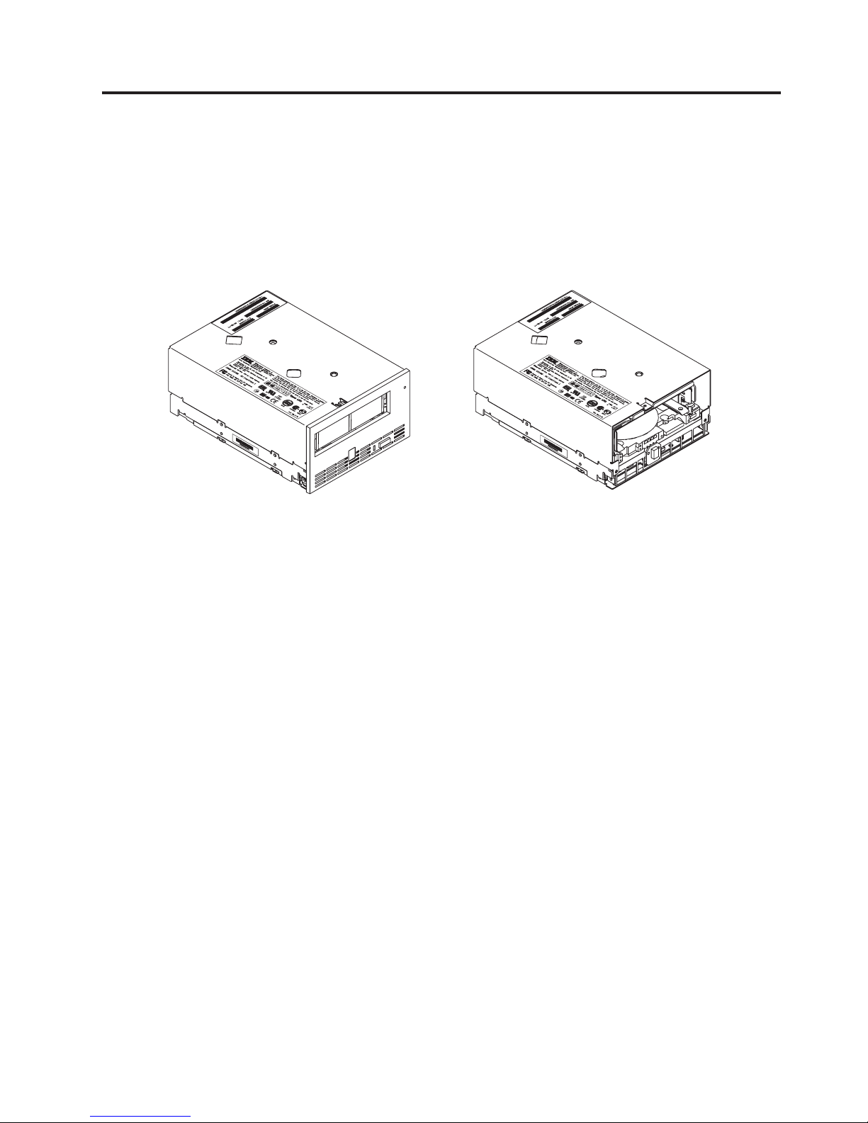
Product Description
The IBM 400/800GB LTO 3 Tape Drive is a high-performance, high-capacity
data-storage device that is designed to backup and restore open systems
applications. The drive is the third-generation in the Ultrium series of products. It
is available as Model with a Small Computer Systems Interface (SCSI).
Figure 1. View of the drive with and without the bezel
The drive offers the following features:
v Ultra160 Low Voltage Differential (LVD) Small Computer Systems Interface
v 68-pin, D-shell connector (for SCSI signals, SCSI ID selection, and power
connection)
v Native storage capacity of 400 GB per cartridge (800 GB at 2:1 compression)
v Native data transfer rate of up to 80 MB per second
v Burst data transfer rate of 160 MB per second
v New dual stage 16 channel head activator for precision head alignment to help
support higher track density with improved data integrity and backwards
compatibility with previous LTO generations
v Graceful dynamic braking designed to maintain tension until the tape comes to
a complete stop, to help prevent stretching or breaking the tape, and loose tape
wraps
v Larger internal buffer (the size has been doubled over the Ultrium 2 to 128 MB)
v New independent tape loader and threader motors designed to help with
cartridge insertion in the tape drive.
v Highly integrated electronics designed to reduced the total number of
components in the drive, lower chip temperatures, and reduce power
requirements, helping to provide for a more reliable drive. The Generation 3
drive electronics also incorporate on-the-fly error correction of soft errors in the
memory arrays in data and control paths.
a82ru002
© Copyright IBM Corp. 2005 1
Page 18
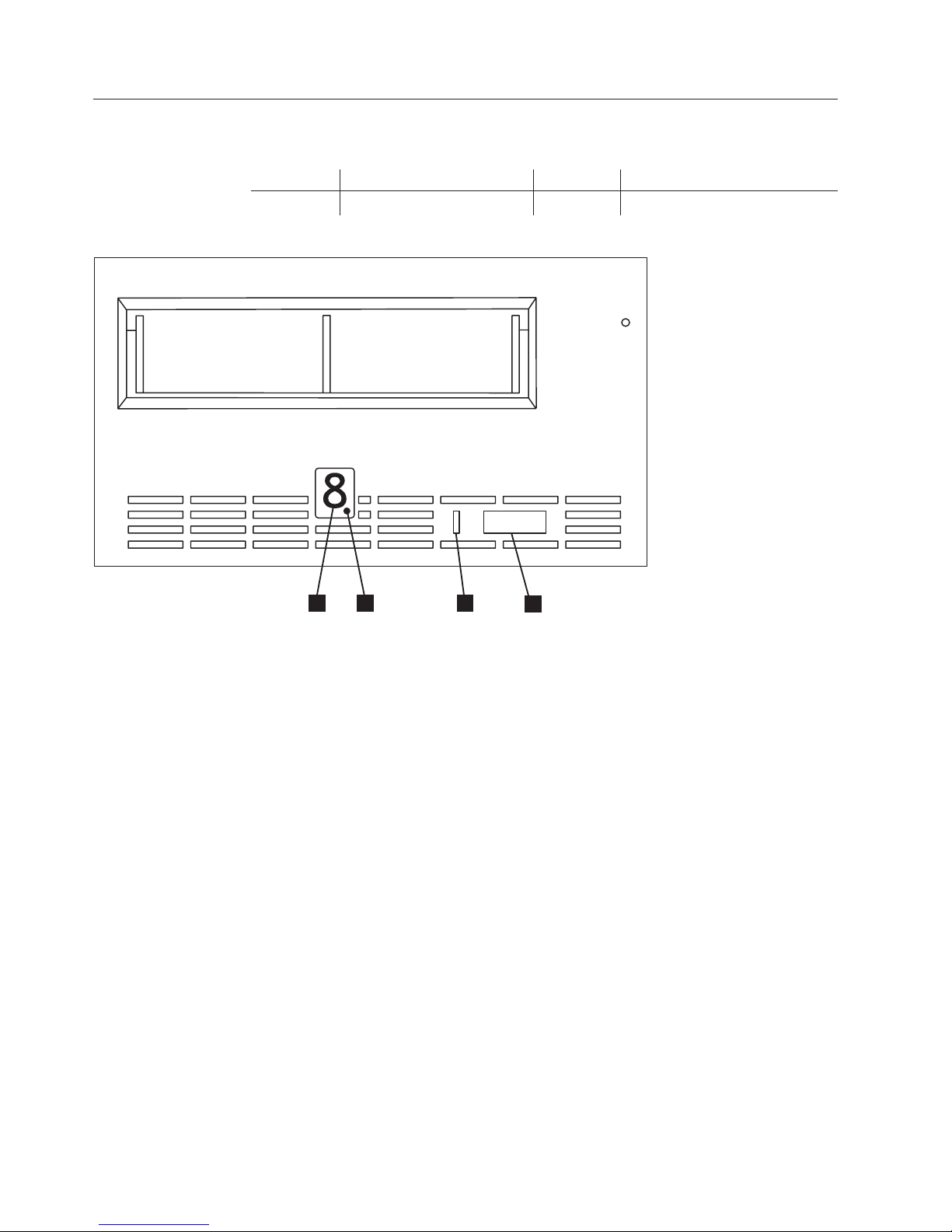
Front Panel of the Drive
Figure 2 shows the front panel of the drive.
1 Status Light 3 Single-character Display (SCD)
2 Unload Button 4 SCD Dot
3
4
1
2
a82ru001
Figure 2. Front panel of the drive
2 IBM 400/800GB LTO3 Tape Drive User’s Guide
Page 19

Rear Panel of the SCSI Drive
1 SCSI connector 4 Library/Drive Interface (LDI or
RS-422 interface) connector
2 SCSI ID connector 5 Serial port
3 Power connector
4
1
2
Figure 3. Rear panel of the drive
Speed Matching and Channel Calibration
To improve system performance, the drive uses a technique called speed matching to
dynamically adjust its native (uncompressed) data rate to the slower data rate of a
server. With speed matching, the drive operates at one of five speeds when reading
or writing the Generation 3 cartridge format to achieve a native data rate of 40, 50,
60, 70, or 80 MB per second (MB/s). If the server’s net (compressed) data rate is
between two of the preceding native data rates, the drive calculates the
appropriate data rate at which to operate. Speed matching dramatically reduces
backhitch, the condition that occurs when a tape stops, reverses, and restarts
motion. A backhitch is usually the result of a mismatch between the data rates of
the server and the drive.
System performance is further optimized by a feature called channel calibration, in
which the drive automatically customizes each read/write data channel to
compensate for variations in such things as the recording channel’s transfer
function, the media, and characteristics of the drive head.
3
5
a82ru011
Product Description 3
Page 20

Sleep Mode
To conserve energy when circuit functions are not needed for drive operation, the
drive features a power-management function that causes the drive’s electronics to
enter a low-power mode known as sleep mode. To enter sleep mode, the drive must
be inactive for a minimum of 30 seconds (default value; this is programmable via
the mode pages); to exit, the drive must receive a command across the SCSI
interface, a command across the Library/Drive Interface (LDI or RS-422 interface),
or a load or unload request. When in sleep mode, the drive’s response time to
commands that do not require media motion increases by up to ten microseconds.
Commands that require media motion may be delayed an additional 100
milliseconds because the tape must be retensioned.
SCSI Attachment
To communicate with a server, the drive uses the Ultra160 LVD SCSI interface.
Physical Characteristics of the SCSI Interface
The drive contains a high-density, 68-pin, D-shell receptacle connector (HD68) for
attachment to the server. The HD68 connector includes the connectors for the SCSI
signal, the SCSI ID, and the drive’s power. The drive supports LVD SCSI cables
with HD68 connectors.
Speed
The Ultra160 LV D SCSI interface is compatible with older SCSI technology and is
capable of data transmission at 160 MB/s. Ultra160 SCSI uses the three
management features of the Ultra3 SCSI standard that specifically affect data
transfer rate:
v Double transition clocking - a data-transfer technique that enables data rates to
double without increasing clock speed
v Domain validation - a procedure that detects and adjusts SCSI configuration
issues that might prevent interoperation between SCSI devices
v Cyclic redundancy check (CRC) - an error-checking technique
Because the cables, connectors, and terminators are the same for the Ultra160 and
Ultra2 SCSI interfaces, devices with those interfaces can be mixed on the same bus
and each device can operate at its fully rated speed.
4 IBM 400/800GB LTO3 Tape Drive User’s Guide
Page 21

Installing the Drive
Attention:
To avoid static electricity damage when handling the drive, use the following
precautions:
v Limit your movement. Movement can cause static electricity to build
around you.
v Always handle the drive carefully. Never touch exposed circuitry.
v Prevent others from touching the drive.
v Before unpacking and installing the drive into an enclosure, touch its
static-protective packaging to an unpainted metal surface on the enclosure
for at least two seconds. This reduces static electricity in the packaging and
your body.
v When possible, remove the drive from its static-protective packaging and
install it directly into an enclosure without setting it down. When this is
not possible, place the drive’s packaging on a smooth, level surface and
place the drive on the packaging.
v Do not place the drive on the cover of the enclosure or on any other metal
surface.
The steps that follow describe how to install the drive into an enclosure.
Note: Depending on the type of enclosure, installation procedures may vary.
Before starting this installation, read these instructions and compare them to
the drive installation instructions for your enclosure.
Installation Overview
__ 1. “Unpack the Drive”
__ 2. “Power Off the Server/Enclosure” on page 6
__ 3. “Set the SCSI ID” on page 7
__ 4. “Mount the Drive into the Server/Enclosure” on page 8
__ 5. “Connect and Test Power to the Drive” on page 9
__ 6. “Connect the Internal SCSI Cable” on page 9
__ 7. “Run Drive Diagnostics” on page 9
__ 8. “Install Device Drivers” on page 10
__ 9. “Connect the Enclosure’s External SCSI Interface to the Server” on page 10
Unpack the Drive
Unpack the drive and store the packaging for future moves or shipping.
© Copyright IBM Corp. 2005 5
Page 22

Attention:
Acclimation time is required if the temperature of the drive when unpacked
is different than the temperature of its operating environment (measured at
the front of the bezel near the air intake area as shown in Figure 4). The
recommended acclimation time is four hours after the drive has been
unpacked or one hour after any condensation that you can see has
evaporated, whichever is greater. When acclimating the drive, apply the
following measures:
v If the drive is colder than its operating environment and the air contains
sufficient humidity, condensation may occur in the drive and damage it.
When the drive has warmed to the operating temperature range (greater
than 10°C or 50°F) and no danger of condensation is present (the air is
dry), warm the drive more quickly by powering it on for 30 minutes. Use a
diagnostic tape to test the drive before inserting a tape that contains data.
v If the drive is hotter than its operating environment, the tape can stick to
the drive head. When the drive has cooled to the operating temperature
range (less than 40°C or 104°F), cool the drive more quickly by applying
airflow for 30 minutes. Power-on the drive and use a diagnostic tape to test
it before inserting a tape that contains data.
If you are uncertain about whether the temperature of the drive is within the
recommended operating range or the humidity is sufficient to cause
condensation, acclimate the drive for the full four hours.
Air Intake
Area
Figure 4. Temperature of the drive is taken near the air intake area
a82ru003
Power Off the Server/Enclosure
__ 1. Power-off the enclosure (or the server that provides power to the drive)
__ 2. Disconnect the power cord from both the electrical outlet and the host.
6 IBM 400/800GB LTO3 Tape Drive User’s Guide
Page 23

Set the SCSI ID
Setting the SCSI ID with Jumpers
The SCSI ID can be set in one of two ways:
v By placing jumpers on the SCSI ID connector
v By using a SCSI ID switch that is connected to the SCSI ID connector
The SCSI ID can be set on the drive by installing 2 mm jumpers on the drive’s
SCSI ID connector (see 2 in Figure 3). Your drive may come set to a default SCSI
configuration, with jumpers already installed. Yo u can change the SCSI ID by
rearranging, adding, or removing jumpers.
To set the SCSI ID:
__ 1. Locate the SCSI ID connector (2in Figure 3).
__ 2. Before attaching the SCSI bus cable to the server, determine the SCSI ID.
Make sure that the ID is not being used by another device.
__ 3. Referring to Figure 2, find the ID number that you chose, then place
jumpers on the connector pins as shown (use a pair of needle-nose pliers to
connect the jumpers to the pins that are shaded).
Note: If you set the SCSI ID to 15, the drive will not necessarily be set to
that ID; instead, the drive will expect to receive the SCSI ID through a
command over its LDI interface.
Figure 5. SCSI ID settings on the SCSI ID connector
Setting the SCSI ID with a SCSI ID Switch
If your enclosure uses a SCSI ID switch (rather than jumpers), connect the switch
to the drive’s SCSI ID connector 2in Figure 3 . If any jumpers are preinstalled, be
sure to remove them before connecting the switch. The SCSI ID switch must be
compatible with the drive’s SCSI ID connector and must make an electrical
connection between the same pins as the jumpers to achieve the same
corresponding SCSI ID.
Supplying TERMPOWER (SCSI Drive Only)
To supply TERMPOWER to the bus, locate one of the five jumpers shipped with
the drive and place it on the SCSI ID connector as shown in the following figure.
Place the jumper on the pins that are shaded.
Installing the Drive 7
Page 24
A67E0049
Attention
SCSI termination must be provided externally to the drive.
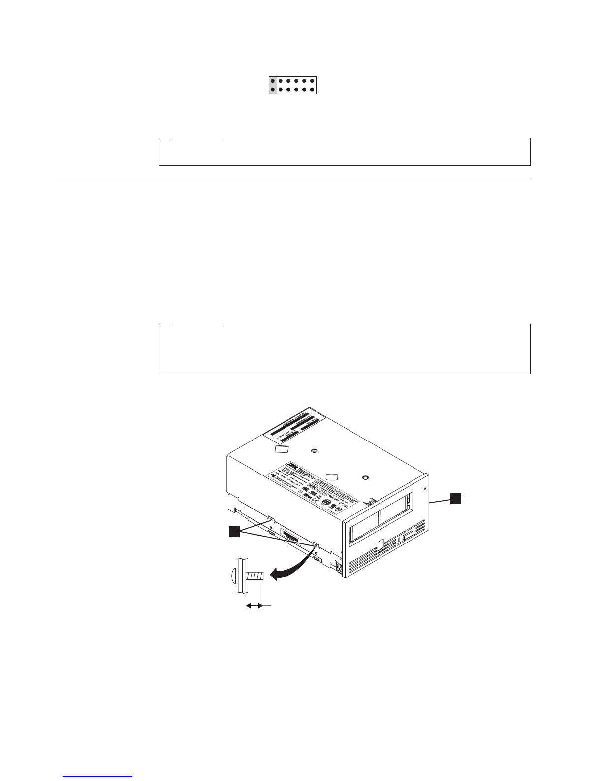
Mount the Drive into the Server/Enclosure
To mount the drive into a enclosure:
__ 1. Remove the cover of your enclosure (refer to the instructions in the
documentation provided with your enclosure).
__ 2. Place the drive into the enclosure so that the tape load compartment of the
drive faces the tape load compartment of the enclosure.
__ 3. Insert two M3 screws into the mounting holes 2 of the two side brackets
located on the left and right sides of the chassis.
Attention
When inserted into the drive, the length of the mounting screws must not
exceed 3.5 mm (0.14 in.) inside the chassis. If the length exceeds this
measurement, the drive may become damaged.
1
2
< 3.5 mm (0.14 in.)
a82ru004
Figure 6. Mounting holes on drive. The holes are located on both sides of the drive. The
drive is shown with a front bezel.
8 IBM 400/800GB LTO3 Tape Drive User’s Guide
Page 25

To mount the drive into a server:
1. Refer to the option (or drive) installation instructions in your server Installation
Guide.
Connect and Test Power to the Drive
The drive does not contain its own power source; it must be powered externally.
To connect and test power to the drive:
__ 1. Ensure that the host (or unit that supplies power to the drive) is powered
off.
__ 2. Ensure that the power cord is disconnected from both the host and the
power outlet.
__ 3. Connect the host’s internal power cable to the power connector on the drive
(see 3 in Figure 3 on page 3).
__ 4. Connect the power cord to the host and to the electrical outlet.
__ 5. Review the location of the Single-character Display (SCD) and the Status
Light in “Single-character Display (SCD)” on page 11 and “Status Light” on
page 11 (if your drive does not have a bezel, note that the bulb of the Status
Light is recessed and the light is not visible until lit). To ensure that the
drive is receiving power, watch for the following while turning on the
power to the host:
v The SCD presents a series of random characters, then becomes blank (not
lit).
Attention
If the SCD does not come on, the drive may not be getting power.
v The Status Light briefly becomes solid amber, then becomes solid green.
__ 6. Power-off the host.
__ 7. Disconnect the power cord from both the host and the electrical outlet.
Connect the Internal SCSI Cable
Connect the enclosure’s internal SCSI cable to the SCSI connector on the drive (see
1 in Figure 3).
Run Drive Diagnostics
__ 1. Replace the cover on the host.
__ 2. Connect the power cord to both the host and the electrical outlet.
__ 3. Power-on the host.
__ 4. Run one or more of the following drive diagnostics:
v “Function Code 1: Run Drive Diagnostics” on page 16
v “Function Code 6: Run SCSI Wrap Test” on page 20
v “Function Code 7: Run RS-422 Wrap Test” on page 20
an error code appears on the single-character display (SCD), go to “Error
If
Codes and Messages” on page 45. If no error appears, continue to the next
step.
__ 5. Power-off the host.
Installing the Drive 9
Page 26

__ 6. Disconnect the power cord from both the host and the electrical outlet.
Install Device Drivers
For information about installing device drivers, refer to the documentation for your
server and/or Operating System.
Connect the Enclosure’s External SCSI Interface to the Server
__ 1. Connect an external SCSI bus cable to both the enclosure and the server (for
the location of the connectors, refer to the documentation for your enclosure
and server).
__ 2. Run the appropriate SCSI attachment verification procedure from your
server (for instructions, refer to the IBM Ultrium Device Drivers Installation
and User’s Guide).
If you want to power a device on or off while it is connected to the same SCSI bus
as the drive, you can do so if, during the power-on cycle, you quiesce all devices
(including the drive) on the bus.
10 IBM 400/800GB LTO3 Tape Drive User’s Guide
Page 27

Operating the Drive
Operating the drive involves using the following front panel items:
v Single-character Display (SCD)
v SCD Dot
v Status Light
v Unload Button
Single-character Display (SCD)
The SCD (see3 in Figure 2) presents a single-character code for:
v Error conditions and informational messages:
“Error Codes and Messages” on page 45 lists the codes for error conditions and
informational messages. If multiple errors occur, the code with the highest
priority (represented by the lowest number) displays first. When the error is
corrected, the code with the next highest priority displays, and so on until no
errors remain.
v Diagnostic or maintenance functions (while in maintenance mode only):
“Diagnostic and Maintenance Functions” on page 15 lists the single-character
codes that represent diagnostic or maintenance functions. To initiate a function
the unit must be in maintenance mode.
SCD is blank during normal operation.
The
SCD Dot
If a drive dump is present while the drive is in maintenance mode, a single red dot
illuminates in the lower right corner of the SCD (
“Function Code 5: Copy Drive Dump” on page 19.
The SCD Dot turns off when you obtain the dump (by using an FMR tape, a SCSI
command, or a library command).
Status Light
The Status Light (1 in Figure 2) is a light-emitting diode (LED) that provides
information about the state of the drive. The light can be green or amber, and
(when lit) solid or flashing. The table below lists the conditions of the Status Light
and Single-character Display (SCD) and provides an explanation of what each
condition means.
Table 1. Meaning of Status Light and Single-character Display (SCD)
If the
Status Light
is...
Off Off The drive has no power or is powered off.
Green Off The drive is powered on and in an idle state.
Flashing
Green
and the
SCD is...
Off The drive is reading from the tape, writing to the tape, rewinding the tape, locating data
on the tape, loading the tape, or unloading the tape.
Meaning
8
). To copy the dump, see
© Copyright IBM Corp. 2005 11
Page 28

Table 1. Meaning of Status Light and Single-character Display (SCD) (continued)
If the
Status Light
is...
Flashing
Green
and the
SCD is...
Meaning
Off The drive contains a cartridge during the power-on cycle. In this case, the drive
completes POST and slowly rewinds the tape (the process may take up to ten minutes).
The light stops blinking and becomes solid when the drive completes the recovery and is
ready for a read or write operation. To eject the cartridge, press the unload button.
Amber Displaying
Error Code
The drive is displaying error code(s) from the error code log on the SCD. For more
information, see “Function Code A: Clear Error Code Log” on page 22“ and “Error Codes
and Messages” on page 45.
Amber Red
The drive is powering on, resetting, or in maintenance mode.
numbers,
letters, or
segments
Amber Flashing
0
Amber Flashing
The drive is exiting from maintenance mode. For more information, see “Function Code
0: Exit Maintenance Mode” on page 16“.
The drive is executing the selected function while in maintenance mode.
selected
function
Flashing
Amber once
Displaying
error code
An error occurred and the drive or media may require service, or it may require cleaning.
Note the code on the SCD, then go to Table 9 to determine the action that is required.
per second
Flashing
Amber once
per second
Flashing
Amber
twice per
second
Displaying
C
Displaying
Function
Code
8
The drive needs cleaning.
1
The drive is updating firmware.
8
The SCD will display a
if using an FMR cartridge. The SCD will be off if using the SCSI interface. For more
information, see ““Updating Firmware” on page 26.
or Off
Flashing
Amber
Off The drive detected an error and is performing a firmware recovery. It will reset
automatically.
twice per
second
Flashing
Amber
twice per
Flashing
C
The drive is requesting a cartridge to be loaded.
second
Flashing
Off There is a drive dump in flash memory.
Amber
twice per
second
1
Power should not be removed from the drive until the microcode update is complete. The drive indicates that the
update is complete by resetting and performing POST.
Unload Button
The Unload Button (2in Figure 2 in “Front Panel of the Drive” on page 2)
performs the following functions:
12 IBM 400/800GB LTO3 Tape Drive User’s Guide
Page 29

Table 2. Functions that the Unload Button performs
Unload Button Function How to Initiate the Function
Rewind the tape into the
cartridge and eject the
cartridge from the drive
Press the Unload Button once. The Status Light flashes green while the drive is
rewinding and unloading.
Note: During a rewind and eject operation, the drive does not accept SCSI commands
from the server.
Place the drive in
maintenance mode
Ensure that the drive is unloaded. Then, within two seconds, press the Unload Button
three times. The drive is in maintenance mode when the Status Light becomes solid
amber and
0
appears in the SCD.
Note: While in maintenance mode, the drive does not accept SCSI interface
commands.
Scroll through the
maintenance functions
While in maintenance mode, press the Unload Button once per second to increment
the display characters by one. When you reach the character of the diagnostic or
maintenance function that you want (see “Diagnostic and Maintenance Functions” on
page 15), press and hold the Unload Button for three seconds.
Exit maintenance mode Press the Unload Button once per second until
0
displays. Then press and hold the Unload Button for three seconds. Maintenance
mode is exited when the Status Light becomes solid green and the SCD becomes
blank.
Force a drive dump (part of
the maintenance mode)
Attention: If the drive detects a permanent error and displays an error code, it
automatically forces a drive dump (also known as a save of the firmware trace). If
you force a drive dump, the existing dump will be overwritten and data will be lost.
After you force a drive dump, do not turn off the power to the drive or you may lose
the dump data.
Choose one of the following procedures:
v If the drive is in maintenance mode (Status Light is solid amber), refer to “Function
Code 4: Force a Drive Dump” on page 18.
v If the drive is in operating mode (Status Light is solid or flashing green), press and
hold the Unload Button for ten seconds.
captured dump data exists, the drive places it into a dump area.
If
Reset the drive Press and hold the Unload Button on the drive for ten seconds. The drive saves a
dump of the current drive state, then reboots to allow communication. Do not cycle
power as this will erase the contents of the dump.
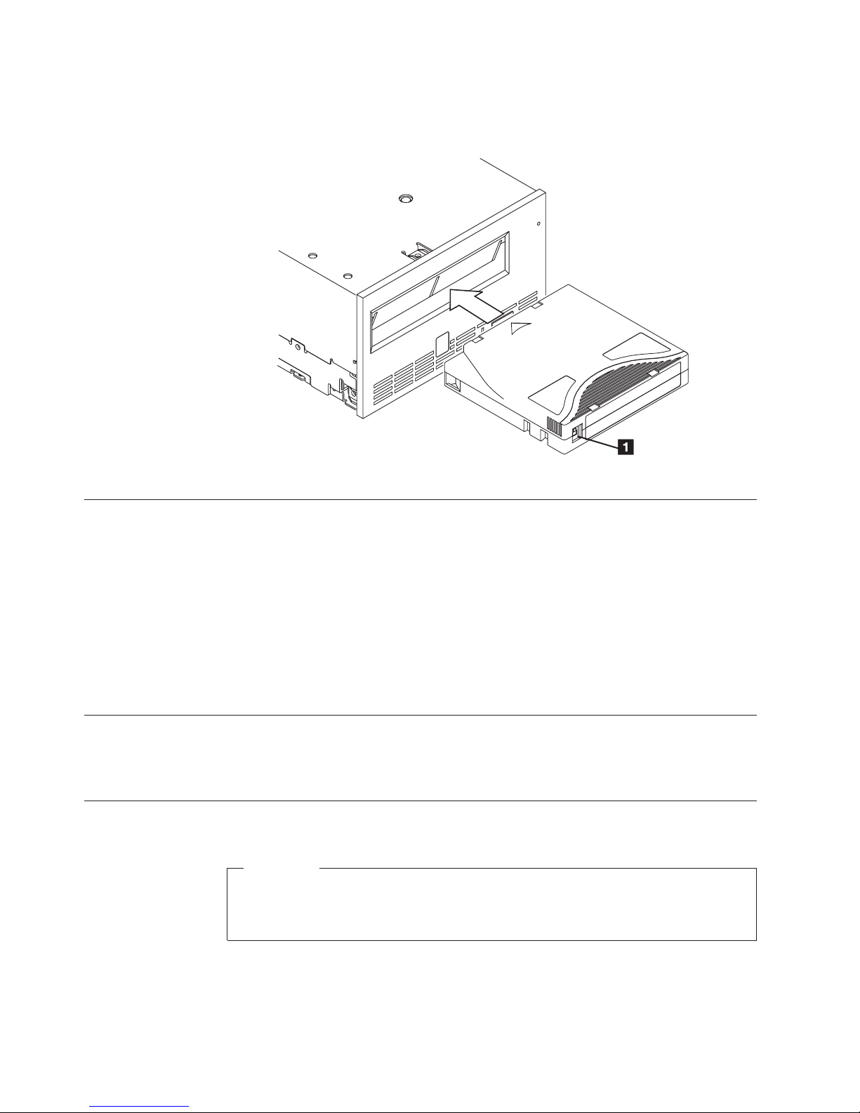
Inserting a Tape Cartridge
To insert a tape cartridge:
1. Ensure that the drive is powered-on.
2. Ensure that the write-protect switch is properly set (see “Write-Protect Switch”
on page 34).
3. Grasp the cartridge so that the write-protect switch faces you (1 in Figure 7
on page 14).
4. Slide the cartridge into the tape load compartment.
Notes:
a. If the cartridge is already in an ejected position and you want to reinsert it,
remove the cartridge then insert it again.
Operating the Drive 13
Page 30
b. If the cartridge is already loaded and you cycle the power (turn it off, then
on), the tape will reload.
Figure 7. Inserting a cartridge into the drive
Removing a Tape Cartridge
To remove a tape cartridge:
1. Ensure that the drive is powered-on.
2. Press the Unload Button. The drive rewinds the tape and partially ejects the
cartridge. The Status Light flashes green while the tape rewinds, then goes out
before the cartridge partially ejects.
3. After the cartridge partially ejects, grasp the cartridge and remove it.
Whenever you unload a tape cartridge, the drive writes any pertinent information
to the cartridge memory.
Mid-tape Recovery
If a power cycle or reset occurs while a cartridge is loaded, the drive will slowly
rewind the tape and eject the cartridge.
Cleaning the Drive Head
a82ru005
Attention
When cleaning the drive head, use the LTO Ultrium Cleaning Cartridge. For
more information, please see: http://www-
307.ibm.com/pc/support/sit.wss/document.do?Indocid=MIGR-39931
14 IBM 400/800GB LTO3 Tape Drive User’s Guide
Page 31

Clean the drive head whenever
C
the Status Light is flashing amber once per second. It is not recommended that you
clean the drive head on a periodic basis; only when the drive requests to be
cleaned.
To clean the head, insert the cleaning cartridge into the tape load compartment (see
“Front Panel of the Drive” on page 2). The drive performs the cleaning
automatically in less than two minutes then ejects the cartridge.
Note: If a cleaning cartridge is inserted when the drive does not need to be
cleaned or a cleaning cartridge is inserted that has expired, the drive will
automatically eject the cartridge.
The LTO Ultrium Cleaning Cartridge is valid for 50 uses.
Diagnostic and Maintenance Functions
The drive can:
v Run diagnostics
v Test write and read functions
v Test a suspect tape cartridge
v Update its own firmware
v Perform other diagnostic and maintenance functions
displays on the Single-character Display and
drive must be in maintenance mode to perform these functions.
The
Attention
Maintenance functions cannot be performed concurrently with read or write
operations. While in maintenance mode, the tape drive does not accept SCSI
commands from the server. The tape drive does accept LDI or RS-422
commands.
Entering Maintenance Mode
The drive must be in maintenance mode to run drive diagnostics or maintenance
functions. To place the unit in maintenance mode:
1. Make sure that no cartridge is in the drive.
2. Press the Unload Button three times within two seconds.
Single-character Display (SCD), and the Status Light turns amber.
Note: If a cartridge is in the tape drive, it will eject the first time that you press
the Unload Button and the drive will not be placed in maintenance
mode. To continue placing the drive in maintenance mode, perform the
preceding step.
Maintenance
operations. While in maintenance mode, the drive does not receive SCSI
commands from the server.
functions cannot be performed concurrently with read or write
0
appears in the
Operating the Drive 15
Page 32

Function Code 0: Exit Maintenance Mode
Function Code
0
makes the drive available for reading and writing data.
1. Place the drive in maintenance mode. For instructions, see “Entering
Maintenance Mode” on page 15.
2. Press and hold the Unload Button for 3 or more seconds to take the drive out
of maintenance mode. The Status Light turns off.
v If no error is detected,
0
temporarily appears in the SCD, then goes blank.
The drive then exits maintenance mode.
v If an error is detected, the SCD shows an error code but still exits
maintenance mode. To determine the error, locate the code in Table 9 on page
45. To clear the error, turn the power off, then on again.
The drive also exits maintenance mode automatically after it completes a
maintenance function or after 10 minutes if no action has occurred.
Function Code 1: Run Drive Diagnostics
Approximate Run Time = 20 minutes per loop
Total Number of Loops = 10
Function Code
and unload cartridges, and read and write data.
1
runs tests that determine whether the drive can properly load
The diagnostic loops ten times. To stop the diagnostic and exit maintenance mode,
press the Unload Button once to abort the test.
Attention
For this test, insert only a scratch (blank) data cartridge or a cartridge that
may be overwritten. During the test, the drive overwrites the data on the
cartridge.
1. Place the drive in maintenance mode. For instructions, see “Entering
Maintenance Mode” on page 15.
2. Press the Unload Button once per second until
1
appears in the SCD. (If you
cycle past the desired code, press the Unload Button once per second until the
code reappears.)
3. Press and hold the Unload Button for three or more seconds, then release it to
select function
4. Insert a scratch (blank) data cartridge that is not write-protected (or the tape
drive exits maintenance mode). The SCD changes to a flashing
1
. The SCD changes to a flashing
C
.
1
and the test
begins.
Note: If you inserted an invalid or write-protected tape cartridge, error code
7
appears in the SCD. The tape drive unloads the cartridge and exits
maintenance mode.
16 IBM 400/800GB LTO3 Tape Drive User’s Guide
Page 33

v If no error is detected, the diagnostic will loop and begin again. To stop the
loop, press the Unload Button for one second and release. When the loop
0
ends,
temporarily appears in the SCD. The drive rewinds and unloads
the cartridge, and then exits maintenance mode. The solid amber Status Light
turns off.
v If an error is detected, the Status Light flashes amber and the drive posts an
error code to the SCD. To determine the error, locate the code in Table 9 on
page 45. The tape drive unloads the tape cartridge and exits maintenance
mode. To clear the error, turn the power off, then on again.
Function Code 2: Update Drive Firmware from FMR Tape
Attention
When updating drive firmware, do not power-off the drive until the update
is complete or the firmware may be lost.
Function Code
(FMR) tape.
8
loads drive firmware from a field microcode replacement
Attention: While the drive supports firmware update with a FUP tape, IBM
recommends you update the drive firmware using the easier to use Tapetool found
at http://www-307.ibm.com/pc/support/site.wss/document.do?lndocid=TAPEFILES.
Attention: Customers should only attempt this step when requested by IBM
service.
1. Place the drive in maintenance mode. For instructions, see “Entering
Maintenance Mode” on page 15.
2. Press the Unload Button once per second until
8
appears in the SCD. (If you
cycle past the desired code, press the Unload Button once per second until the
code reappears.)
3. Press and hold the Unload Button for three or more seconds, then release it to
select the function. The SCD changes to a flashing
4. Insert the FMR tape cartridge (or the tape drive exits maintenance mode). The
SCD changes to a flashing
8
. The tape drive loads the updated firmware
C
.
from the FMR tape into its erasable programmable read-only memory (EPROM)
area.
v If the update completes successfully, the tape drive rewinds and unloads the
FMR tape, resets itself, and is ready to use the new firmware. The drive
automatically reboots.
v If the update fails, the tape drive posts an error code to the SCD. To
determine the error, locate the code in Table 9 on page 45. The drive then
unloads the FMR tape and exits maintenance mode. Contact Technical
Support for problem determination or machine replacement.
Operating the Drive 17
Page 34

Function Code 3: Create FMR Tape
Function Code
scratch data cartridge.
Attention
For this function, insert only a scratch (blank) data cartridge or a cartridge
that may be overwritten. During the test, the drive overwrites the data on the
cartridge.
Attention: Customers should only attempt this step when requested by IBM
service.
1. Place the drive in maintenance mode. For instructions, see “Entering
Maintenance Mode” on page 15.
2. Press the Unload Button once per second until
cycle past the desired code, press the Unload Button once per second until the
code reappears.)
3. Press and hold the Unload Button for three or more seconds, then release it to
select the function. The SCD changes to a flashing
4. Insert a scratch (blank) data cartridge that is not write protected (or the tape
drive exits maintenance mode). The SCD changes to a flashing
drive copies the FMR data to the scratch data cartridge.
3
copies the drive’s field microcode replacement (FMR) data to a
3
appears in the SCD. (If you
C
.
3
. The tape
Note: If you inserted an invalid or write-protected tape cartridge, error code
7
appears in the SCD. The tape drive unloads the cartridge and exits
maintenance mode.
v If the tape drive creates the FMR tape successfully, it rewinds and unloads
the new tape, exits maintenance mode, and the tape is ready to use.
v If the tape drive fails to create the FMR tape, it displays an error code. To
determine the error, see Table 9 on page 45. The tape drive then unloads the
FMR tape, exits maintenance mode.
Function Code 4: Force a Drive Dump
8
Function Code
also known as saving a microcode trace).
Attention: Customers should only attempt this step when requested by IBM
service.
1. Place the drive in maintenance mode. For instructions, see “Entering
Maintenance Mode” on page 15.
2. Press the Unload Button once per second until
cycle past the desired code, press the Unload Button once per second until the
code reappears.)
performs a dump of data collected by the drive (this process is
8
appears in the SCD. (If you
18 IBM 400/800GB LTO3 Tape Drive User’s Guide
Page 35

3. Press and hold the Unload Button for three or more seconds, then release it to
select the function. The drive performs the dump. The SCD shows
goes blank. To access the contents of the dump, see “Function Code 5: Copy
Drive Dump.”
Note: Yo u can also force a drive dump when the tape drive is in normal
operating mode. Simply press and hold the Unload Button for ten
seconds.
Function Code 5: Copy Drive Dump
Function Code
to the beginning of a scratch (blank) data cartridge.
Attention
For the
cartridge that may be overwritten. During the test, the drive overwrites the
data on the cartridge.
Attention: Customers should only attempt this step when requested by IBM
service.
1. Place the drive in maintenance mode. For instructions, see “Entering
Maintenance Mode” on page 15.
2. Press the Unload Button once per second to cycle through the following
functions:
5
v
5
v
5
v
5
v
5
copies data from a drive dump (captured in Function Code 4)
1
5
-
function, insert only a scratch (blank) data cartridge or a
0
-
: no function
1
-
: copy dump to tape
8
-
: copy dump to flash memory
3
-
: erase flash memory
0
, then
you cycle past the desired code, press the Unload Button once per second
If
until the code reappears.
3. Press and hold the Unload Button for three or more seconds, then release it to
select one of the above functions. The SCD changes to a flashing
4. Insert a scratch (blank) data cartridge that is not write protected (or the tape
drive exits maintenance mode). The SCD flashes the selection number while
performing the function.
Note: If you inserted an invalid or write-protected tape cartridge, error code
v If the copy operation completes successfully, the tape drive rewinds and
unloads the tape, and exits maintenance mode.
C
7
appears in the SCD. The tape drive unloads the cartridge and exits
maintenance mode.
Operating the Drive 19
.
Page 36

v If the copy operation fails, an error code appears in the SCD. To determine
the error, locate the code inTable 9 on page 45. The tape drive unloads the
tape cartridge and exits maintenance mode.
Function Code 6: Run SCSI Wrap Test
Approximate Run Time = 10 seconds per loop
Number of Loops = This test runs until stopped by pressing the Unload Button.
Function Code
connector.
Note: This test requires that the drive be terminated by either the terminator on
the connector or at the end of the bus. Before you select this function,
disconnect the SCSI cable of the drive that is closest to the server. Then,
attach the SCSI wrap plug to that SCSI connector.
Attention: Customers should only attempt this step when requested by IBM
service.
1. Place the drive in maintenance mode. For instructions, see “Entering
Maintenance Mode” on page 15.
2. Press the Unload Button once per second until
cycle past the desired code, press the Unload Button once per second until the
code reappears.)
3. Make sure that the SCSI wrap plug is connected to one of the SCSI connectors
at the rear of the drive.
4. Make sure that the drive is terminated at one of its SCSI connectors or at the
SCSI bus.
5. Press and hold the Unload Button for three or more seconds, then release it to
select the function. The drive automatically starts the test (one loop of which
lasts for less than one second).
v If no error is detected, the test will loop and begin again. To stop the loop,
press the Unload Button for one second and release. When the loop ends,
function code
drive then exits maintenance mode. Disconnect the SCSI wrap plug.
v If an error is detected, the test stops, error code
determine the error, locate
the power off, then on again.
6
performs a check of the SCSI circuitry from and to the SCSI
0
temporarily appears in the Single-character Display. The
8
in Table 9 on page 45. To clear the error, turn
6
appears in the SCD. (If you
8
appears in the SCD. To
Function Code 7: Run RS-422 Wrap Test
This test causes the drive to perform a check of the circuitry from and to the LDI
or RS-422 connector.
Before selecting this function, attach an LDI or RS-422 wrap plug to the drive’s LDI
or RS-422 connector (in place of the LDI or RS-422 cable).
Attention: Customers should only attempt this step when requested by IBM
service.
1. Make sure that no cartridge is in the drive.
20 IBM 400/800GB LTO3 Tape Drive User’s Guide
Page 37

2. Within a 1.5-second interval, press the Unload Button three times. The Status
Light becomes solid amber, which means that the drive is in maintenance
mode.
3. Press the Unload Button once per 1.5 seconds until
Single-character Display (SCD). If you cycle past
7
appears in the
7
, continue to press the
Unload Button until it displays again.
4. To select the function, press and hold the Unload Button for three seconds.
After you select the function,
7
flashes and the drive automatically starts the
test.
v If the test is successful, it loops and begins again. To half the test, press the
Unload Button. The test continues to the end of its loop and then stops. The
drive then displays
v If the test fails,
mode. To resolve the error, locate
0
9
and exits maintenance mode.
displays, the test stops, and the drive exits maintenance
9
in Table 9 on page 45
Function Code 8: Unmake FMR Tape
Function Code
rewrites the cartridge memory on the tape. This converts the cartridge into a valid
scratch (blank) data cartridge.
Attention: Customers should only attempt this step when requested by IBM
service.
1. Place the drive in maintenance mode. For instructions, see “Entering
Maintenance Mode” on page 15.
2. Press the Unload Button once per second until
cycle past the desired code, press the Unload Button once per second until the
code reappears.)
3. Press and hold the Unload Button for three or more seconds, then release it to
select function
4. Insert the FMR data cartridge (or the tape drive exits maintenance mode). The
SCD changes to a flashing
and rewrites the header in the cartridge memory to change the cartridge to a
valid scratch (blank) data cartridge:
v If the operation is successful, the tape drive displays function code
rewinds and unloads the newly converted scratch data cartridge, and exits
maintenance mode.
v If the operation is not successful, an error code displays. To determine the
error, locate the code in Table 9 on page 45. To clear the error, turn the power
off, then on again.
8
erases the field microcode replacement (FMR) data and
8
. The SCD changes to a flashing
8
. The tape drive erases the firmware on the tape
8
appears in the SCD. (If you
C
.
0
,
Operating the Drive 21
Page 38

Function Code 9: Display Error Code Log
Function Code
ordered; the most recent is presented first and the oldest is presented last). If there
are no errors in the log, function code
9
displays the last ten error codes, one at a time (the codes are
0
displays in the Single-character Display
(SCD).
1. Place the drive in maintenance mode. For instructions, see “Entering
Maintenance Mode” on page 15.
2. Press the Unload Button once per second until
cycle past the desired code, press the Unload Button once per second until the
code reappears.)
3. Press and hold the Unload Button for three or more seconds, then release it to
view the most recent error codes.
4. Press the Unload Button again to view successive error codes. Let two to three
seconds pass between each depression.
5. After viewing all error codes, exit this function and maintenance mode by
pressing the Unload Button again.
Function Code A: Clear Error Code Log
Function Code
1. Place the drive in maintenance mode. For instructions, see “Entering
Maintenance Mode” on page 15.
2. Press the Unload Button once per second until
cycle past the desired code, press the Unload Button once per second until the
code reappears.)
3. Press and hold the Unload Button for three or more seconds, then release it to
select the function.
erases all errors from the error code log. The tape drive exits maintenance
mode.
A
erases the contents of the error code log.
A
flashes in the SCD, followed by
9
appears in the SCD. (If you
A
appears in the SCD. (If you
0
. The tape drive
Function Code C: Insert Cartridge into Tape Drive
This function cannot be selected by itself, but is part of other maintenance
functions (such as Run Tape Drive Diagnostics and Create FMR Tape) that require
a tape cartridge to be inserted.
Function Code E: Test Cartridge & Media
Approximate Run Time = 15 minutes per loop
Total Number of Loops = 10
Function Code
its magnetic tape are acceptable.
The diagnostic loops ten times. To stop the diagnostic and exit maintenance mode,
press the Unload Button once to abort the test.
22 IBM 400/800GB LTO3 Tape Drive User’s Guide
E
performs tests that determine whether a suspect cartridge and
Page 39

Attention
When you perform this test, data on the suspect tape will be overwritten.
1. Place the drive in maintenance mode. For instructions, see “Entering
Maintenance Mode” on page 15.
2. Press the Unload Button once per second until
E
appears in the SCD. (If you
cycle past the desired code, press the Unload Button once per second until the
code reappears.)
3. Press and hold the Unload Button for three or more seconds, then release it to
select the function. The SCD changes to a flashing
C
.
4. Ensure that the write-protect switch on the suspect cartridge is off, then insert
the cartridge (or the tape drive exits maintenance mode). The SCD changes to
E
. The tape drive runs the tests.
v If no error is detected, the test will loop and begin again. To stop the loop,
press the Unload Button for one second and release. When the loop ends,
0
temporarily appears in the SCD. The drive rewinds the tape, unloads the
cartridge, and exits maintenance mode.
v If an error is detected the test stops,
code could appear). To determine the error, locate
6
or
7
appears in the SCD (another
6
or
7
in Table 9 on
page 45. The drive unloads the tape cartridge, exits maintenance mode. To
clear the error, turn the power off, then on again.
Function Code F: Fast Read/Write Test
Approximate Run Time = 5 minutes
Total Number of Loops = 10
Function Code
to tape.
The diagnostic loops ten times. To stop the diagnostic and exit maintenance mode,
press the Unload Button once to abort the test.
Attention
For this test, insert only a scratch (blank) data cartridge or a cartridge that
may be overwritten. During the test, the drive overwrites the data on the
cartridge.
1. Place the drive in maintenance mode. For instructions, see “Entering
Maintenance Mode” on page 15.
2. Press the Unload Button once per second until
cycle past the desired code, press the Unload Button once per second until the
code reappears.)
F
performs tests to ensure that the drive can read from and write
F
appears in the SCD. (If you
Operating the Drive 23
Page 40

3. Press and hold the Unload Button for three or more seconds, then release it to
select the function. The SCD changes to a flashing
4. Insert a scratch (blank) data cartridge that is not write-protected (or the tape
drive exits maintenance mode). The SCD changes to a flashing
drive runs the tests.
Note: If you inserted an invalid or write-protected tape cartridge,
in the SCD. The tape drive unloads the cartridge and exits maintenance
mode.
v If no error is detected, the test will loop and begin again. To stop the loop,
press the Unload Button for one second and release. When the loop ends,
temporarily appears in the SCD. The drive rewinds and unloads the tape,
partially ejects the cartridge, then exits maintenance mode. The solid amber
Status Light turns off.
v If an error is detected, the Status Light flashes amber, the tape drive posts an
error code to the SCD. To determine the error, locate the code in Table 9 on
page 45. The tape drive unloads the cartridge and exits maintenance mode.
To clear the error, turn the power off, then on again.
Function Code H: Test Head
Approximate Run Time = 10 minutes
C
.
F
. The tape
7
appears
0
Total Number of Loops = 10
Function Code
H
performs tests to ensure that the tape drive’s head and
tape-carriage mechanics work correctly.
The diagnostic loops ten times. To stop the diagnostic and exit maintenance mode,
press the Unload Button once to abort the test.
Attention
For this test, insert only a scratch (blank) data cartridge or a cartridge that
may be overwritten. During the test, the drive overwrites the data on the
cartridge.
1. Place the drive in maintenance mode. For instructions, see “Entering
Maintenance Mode” on page 15.
2. Press the Unload Button once per second until
H
appears in the SCD. (If you
cycle past the desired code, press the Unload Button once per second until the
code reappears.)
3. Press and hold the Unload Button for three or more seconds, then release it to
select the function. The SCD changes to a flashing
4. Insert a scratch (blank) data cartridge that is not write-protected (or the tape
drive exits maintenance mode). The SCD changes to a flashing
C
.
H
. The tape
drive runs the tests.
24 IBM 400/800GB LTO3 Tape Drive User’s Guide
Page 41

v If no error is detected, the test will loop and begin again. To stop the loop,
press the Unload Button for one second and release. When the loop ends,
temporarily appears in the SCD. The drive rewinds the tape and unloads the
cartridge. The drive then exits maintenance mode.
v If an error is detected the test stops, error code
determine the error, locate
5
in Table 9 on page 45. The drive unloads the
tape cartridge and exits maintenance mode. To clear the error, turn the power
off, then on again.
Function Code L: Load/Unload Test
Approximate Run Time = 3 seconds per loop
Total Number of Loops = 10
Function Code
The diagnostic loops ten times. To stop the diagnostic and exit maintenance mode,
press the Unload Button once to abort the test.
Attention
Even though no data is written during this test, it is recommended that you
use a blank (scratch) cartridge for this test.
L
tests the drive’s ability to load and unload a tape cartridge.
5
appears in the SCD. To
0
1. Place the drive in maintenance mode. For instructions, see “Entering
Maintenance Mode” on page 15.
2. Press the Unload Button once per second until
L
appears in the SCD. (If you
cycle past the desired code, press the Unload Button once per second until the
code reappears.)
3. Press and hold the Unload Button for three or more seconds, then release it to
select the function. The SCD changes to a flashing
4. Insert a scratch (blank) data cartridge that is not write-protected (or the tape
drive exits maintenance mode). The SCD changes to a flashing
C
.
L
. The tape
drive runs the tests.
v If no error is detected, the test will loop and begin again. To stop the loop,
press the Unload Button for one second and release. When the loop ends,
temporarily appears in the SCD. The drive rewinds the tape and unloads the
cartridge. The drive then exits maintenance mode.
v If an error is detected the test stops,
the error, locate
6
in Table 9 on page 45. The drive unloads the tape
6
appears in the SCD. To determine
cartridge and exits maintenance mode. To clear the error, turn the power off,
then on again.
0
Operating the Drive 25
Page 42

Function Code P: Enable Post Error Reporting
When selected, deferred-check conditions are reported to the host. Therefore,
temporary errors are reported in the sense data. This selection is normally used as
a request from support personnel. Default is
U
(disabled).
1. Place the drive in maintenance mode. For instructions, see “Entering
Maintenance Mode” on page 15.
2. Press and hold the Unload Button for three seconds while
SCD. The SCD changes to
P
then exits maintenance mode.
U
appears in the
Function Code U: Disable Post Error Reporting
When selected, turns Post Error reporting off. Deferred-check conditions
(temporary errors) are NOT reported to Host (normal mode of drive operation).
Default is
1. Place the drive in maintenance mode. For instructions, see “Entering
Maintenance Mode” on page 15.
2. Press and hold the Unload Button for three seconds while
SCD. The SCD changes to
U
(disabled).
U
then exits maintenance mode.
P
appears in the
Updating Firmware
Attention:
When updating firmware, do not power-off the drive until the update is
complete, or the firmware may be lost.
Update drive firmware using:
v Using Tapetool (recommended)
v The SCSI interface
v The LDI or RS-422 interface
v A field microcode replacement (FMR) tape cartridge
update the firmware, refer to the following sections.
To
Updating Firmware using Tapetool
Periodically check for updated levels of drive firmware by visiting the web at
http://www-307.ibm.com/pc/support/site.wss/document.do?Indocid=TAPEFILES.
The Tapetool file and instructions for use are included in this URL.
Updating Firmware through the SCSI Interface
When updating drive firmware by using the SCSI interface, the procedure varies,
depending on whether your server uses an IBM tape device driver or a non-IBM
tape device driver (such as a driver from Sun, Hewlett-Packard, or Microsoft®).
26 IBM 400/800GB LTO3 Tape Drive User’s Guide
Page 43

For instructions about updating firmware from a server that uses an IBM tape
device driver, refer to the IBM Ultrium Device Drivers Installation and User’s Guide.
To update firmware from a server that uses a non-IBM tape device driver, refer to
the documentation for that device.
Updating Firmware through the Library/Drive Interface
The drive includes a firmware update feature that allows a tape library to
download firmware to the drive by using the Library/Drive Interface (LDI) while
the drive performs normal host operations on logical unit number (LUN) 0 of the
SCSI Protocol Interface. The update typically takes 63 seconds and a maximum of
140 seconds. The command may be received by the SCSI interface or the LDI
(RS-422) interface.
Note: If a Power-on Reset command is received while a cartridge is loaded in the
drive, the drive will respond with a Check Condition. It will not activate the
new code level until you cycle power, or until a Power-on Reset command is
received and the drive does not contain a cartridge.
ITDT SCSI Firmware Update, Dump Retrieval and Library/Drive
Test Tool
A newly designed tool, ITDT, is a tool with multiple functional capability and is a
very quick, convenient and efficient method for both drive and library firmware
updates. As a note, both drive and library dump retrievals can be performed by
the tool as well. Currently, the tool is very similar to the LTO-TDX drive only
firmware update and drive dump retrieval tool (explained in detail later on in the
Tape Drive Update firmware paragraph in this section).
Below are some of the capabilities of this tool:
1. Firmware update capability via SCSI to all IBM LTO Tape Drive and Tape
Library products.
2. The tool does not require any special device drivers.
3. The tool is available for most major platforms (Windows®, AIX®, SUN,
NetWare).
4. Linux
5. The tool is capable of uploading drive and library dump files.
6. The tool’s primary function is thoroughly testing a drive. However, if the
library is online to the server/host where the tool resides, ITDT will
communicate with the drive through the library to load and unload a test
cartridge thereby exercising some library functions.
7. The tool scans the SCSI bus and will find and display for selection all IBM
LTO devices. The tool will not display and allow for selection any non-IBM
device.
8. Each function has ″Help″ selection which explains the required syntax as well
as a brief explanation of the particular function.
9. A Readme text file will be posted with the .exe file for a thorough explanation
of initial tool download information from the web as well as explanation of
tool capabilities.
10. The tool is currently a ″command line″ tool with a simple entry by keying in
the executable name, itdt, from the directory where the tool is located.
Operating the Drive 27
Page 44

In the following firmware update sections which explain each method in detail,
only a brief mention of ITDT will be made since the Readme text file will more
fully explain tool usage.
LTO-TDX: LTO SCSI and Fibre Drive Firmware Download &
LTO Drive Dump Upload Tool
The tool, LTO-TDX, is an alternative method for downloading LTO drive firmware
across the SCSI bus or fibre channel. In addition, this tool can be used to upload
LTO drive error dumps. The following information describes how to obtain the
tool and lists its capabilities.
1. The tool supports all IBM LTO Generation 1, Generation 2, and Generation 3
SCSI and FC drives. The tool will not support any other manufacturer’s LTO
drive. The tool is available for three different operating systems:
v LTO-TDX_WinTool (for Windows operating systems)
v LTO-TDX_NWTool (for Netware operating systems)
v LTO-TDX_LxTool (for operating systems)
v Linux
2. The tool can perform two functions:
a. Download firmware to the drive
b. Upload a dump of the drive firmware logs from the drive to a computer
system
3. The tool is distributed from the IBM web site. Download the tool by visiting
http://www.ibm.com/storage/support/lto/. The install package or an executable
file will be placed on the host system in a location chosen by the user.
4. When the user opens the install package, he will be presented with a license
agreement that he must accept to proceed with the install. The user will also
be presented with a license anytime the executable file is copied to another
location where the firmware or dump folders do not exist. The tool will detect
the missing folders at launch and present the user license, assuming that this
is the first launch of a new copy of the tool. There will also be a function that
allows the user to view the license at will when he starts the tool.
5. The Windows install package will create a directory for the tool on the user’s
hard disk and place the executable file (the tool) in that directory. The install
package will also load the file into the Programs Menu accessed via the ″Start″
button and put an icon on the desktop of the Windows operating system. The
install package will perform a similar function on any other operating system
that has a similar structure.
6. Selection of the icon on the desktop or selection of the tool from the Program
Menu will start the tool and create the ″LTO Firmware″ and ″LTO Dumps″
files in the directory with the executable tool file.
7. The user must first put the firmware to be downloaded in the firmware folder.
8. Any dumps created will be put in the dump folder.
9. The tool will present a list of the supported devices on the bus. The tool will
allow selection of a target device and then perform the download or the
dump on the target device.
10. The tool itself is a command line tool but it is menu driven and very simple
to use.
11. The program displays are in English.
12. The user is responsible to make sure the drive is not in use when firmware is
downloaded or a dump is taken. He also must remove any cartridge from the
drive or the firmware download function will not work.
28 IBM 400/800GB LTO3 Tape Drive User’s Guide
Page 45

13. If the user does make a mistake, the program will respond with instructive
error messages.
14. If no IBM LTO tape drives are on the bus, the tool will inform the user that
there are none before closing the tool window.
Firmware Download Function
1. The tool is capable of displaying the current firmware level for any drive on
the bus.
2. The tool does a check to see if a cartridge is in the drive (cartridge present
sensor activated). If a cartridge is present, an error will be posted and the user
will be asked to remove the cartridge.
3. The tool downloads code to IBM LTO drives ONLY. The tool will recognize
ULT3580-TDX inquiry string devices as well as ULTRIUM-TDX devices. The
letter ″X″ could be 1, 2, or 3.
4. The tool is capable of loading back level (older) code.
5. The program presents the user with a numbered list of firmware files available
for selection from the LTO Firmware folder. The user can then select the
number of the firmware file for the program to load.
6. After the firmware has been loaded into drive memory the drive automatically
reboots. The tool discourages the user from power cycling the drive before the
reboot is complete. A message is displayed saying ″Updating.....Please Wait″ until
the reboot is complete. A gauge displays progress.
7. A ″Wait″ message is displayed on the user screen during firmware load.
8. If the program tries to load code and it fails with a sense Key 5 and an
ASC/ASCQ of 82/83, the following wording is displayed: ″Bad Firmware
Detected. The firmware is the wrong type for your tape drive or the file is
corrupted.″ Verify that you are downloading the correct level of firmware then
repeat the procedure.
Drive Log Dump Function
1. When the dump function is executed on a drive, the tool will read the existing
dump on the drive, force a dump, then read the forced dump. This will create
two dump files.
2. The two dump files created by the dump function will be time stamped with
year, month, day, and seconds and contain the drive serial number. The first
dump file read has an ″A″ suffix. The second file produced has a ″B″ suffix.
3. The Tool will place the files that are created in the ″LTO Dumps″ folder in the
directory with the tool.
4. The tool creates the dump files with a file type of .dmp.
Updating the Firmware with an FMR Tape Cartridge
Tip
After creating an FMR tape (see “Function Code 3: Create FMR Tape” on
page 18), the firmware of multiple drives can be updated with the same FMR
tape. After updating the drive firmware, unmake the FMR tape (see
“Function Code 8: Unmake FMR Tape” on page 21 ) and use it as a data
cartridge.
To update the drive’s firmware from an FMR tape cartridge:
1. Ensure that a cartridge is not loaded in the drive.
Operating the Drive 29
Page 46

2. Place the drive in maintenance mode by pressing the Unload Button three
times within a two seconds. The Status Light becomes solid amber, which
means that the drive is in maintenance mode.
3. Press the Unload Button once per second until
hold the button for three seconds. When
8
displays, then press and
C
flashes, the drive is waiting for a
cartridge.
4. Insert the FMR tape cartridge.
firmware from the cartridge, and the Status Light flashes amber. When the
update completes successfully,
8
flashes, the drive loads the updated
0
displays and the cartridge automatically
ejects.
drive resets itself and automatically activates the new firmware.
The
If the update fails, an error code displays. To resolve the error, locate the code in
Table 9 on page 45.
30 IBM 400/800GB LTO3 Tape Drive User’s Guide
Page 47

Using Ultrium Media
Figure 8 shows the LTO Ultrium 400 GB Data Cartridge and its components. For
more information, please go to http://www-
307.ibm.com/pc/support/sit.wss/document.do?Indocid=MIGR-39931
1 LTO cartridge memory 4 Write-protect Switch
2 Cartridge door 5 Label area
3 Leader Pin 6 Insertion guide
Figure 8. The LTO Ultrium 400 GB Data Cartridge
Cartridge Compatibility
© Copyright IBM Corp. 2005 31
Table 3. Ultrium data and cleaning cartridge compatibility with Ultrium tape drive
LTO Ultrium Data Cartridges
Tape Drive
400 GB
(Ultrium 3)
200GB
(Ultrium 2)
100GB
(Ultrium 1)
Ultrium 3 Read/Write Read/Write Read only
Ultrium 2 Read/Write Read/Write
Ultrium 1 Read/Write
Page 48

Data Cartridge
All three generations of Ultrium data cartridges contain 1/2-inch, dual-coat,
metal-particle tape. The native data capacity of Ultrium data cartridges is as
follows:
v The Ultrium 3 cartridge has a native data capacity of 400 GB (800 GB at 2:1
compression).
v The Ultrium 2 cartridge has a native data capacity of 200 GB (400 GB at 2:1
compression).
v The Ultrium 1 cartridge has a native data capacity of 100 GB (200 GB at 2:1
compression).
processing tape in the cartridges, Ultrium Tape Drives use a linear,
When
serpentine recording format. The Ultrium 3 drive reads and writes data on 704
tracks, sixteen tracks at a time. The Ultrium 2 drive reads and writes data on 512
tracks, eight tracks at a time. The Ultrium 1 drive reads and writes data on 384
tracks, eight tracks at a time. The first set of tracks (sixteen for Ultrium 3; eight for
Ultrium 2 and 1) is written from near the beginning of the tape to near the end of
the tape. The head then repositions to the next set of tracks for the return pass.
This process continues until all tracks are written and the cartridge is full, or until
all data is written.
The cartridge door 2 protects the tape from contamination when the cartridge is
out of the drive. Behind the door, the tape is attached to a leader pin 3. When
the cartridge is inserted into the drive, a threading mechanism pulls the pin (and
tape) out of the cartridge, across the drive head, and onto a non-removable take-up
reel. The head can then read or write data from or to the tape.
The write-protect switch 4 prevents data from being written to the tape
cartridge. The label area 5 provides a location to place a label. The insertion
guide 6 is a large, notched area that prevents the cartridge from being inserted
incorrectly.
Both generations of the LTO Ultrium Data Cartridge have a nominal cartridge life
of 5000 load and unload cycles.
Cleaning Cartridge
With each drive, a specially labeled LTO Ultrium Cleaning Cartridge is supplied to
clean the drive heads. The drive itself determines when a head needs to be
cleaned. It alerts you by displaying
the head, insert the cleaning cartridge into the tape load compartment (see
“Inserting a Tape Cartridge” on page 13). The drive performs the cleaning
automatically. When the cleaning is finished, the drive ejects the cartridge.
Note: If a cleaning cartridge is inserted when the drive does not need to be
cleaned or when the cartridge has expired, the drive will automatically eject
the cartridge.
C
on the Single-character Display. To clean
To remove a cleaning cartridge, see “Unload Button” on page 12.
The Cleaning Cartridges are valid for 50 uses.
32 IBM 400/800GB LTO3 Tape Drive User’s Guide
Page 49

Bar Code Label
A bar code label contains:
v A volume serial number (VOLSER) that is human-readable
v A bar code that the library can read
Table 4. Bar code label requirements for Ultrium tape drives and libraries
Ultrium Tape Drive/Library Bar Code Label Requirements
3580 Not required
3581 Required
3582 Required
3583 Required
3584 Required
When read by a library’s bar code reader, the bar code identifies the cartridge’s
VOLSER to the library. The bar code also tells the library whether the cartridge is a
data cartridge or cleaning cartridge. In addition, the bar code includes the
two-character media-type identifier Lx, where x equals 1, 2, or 3. L identifies the
cartridge as an LTO cartridge. 1 indicates that the cartridge is the first generation
of its type; 2 indicates that the cartridge is the second generation of its type; 3
indicates that the cartridge is the third generation of its type. Figure 9 shows a
sample bar code label for the LTO Ultrium Tape Cartridge.
Tape cartridges can be ordered with the labels included or with custom labels. To
determine the complete specifications of the bar code and the bar code label,
contact your sales representative.
When attaching a bar code label to a tape cartridge, place the label only in the
recessed label area (4 ). A label that extends outside of the recessed area can
cause loading problems in the drive.
Attention: Do not place any type of mark on the white space at either end of the
bar code. A mark in this area may prevent the library from reading the label.
TO123L3
L
a69i0082
Figure 9. Sample bar code label on the LTO Ultrium 3 Tape Cartridge. The volume serial number (LTO123) and bar
code are printed on the label.
Guidelines for Using Bar Code Labels
Apply the following guidelines whenever using bar code labels:
v Do not reuse a label or reapply a used label over an existing label.
Using Ultrium Media 33
Page 50

v Before you apply a new label, remove the old label by slowly pulling it at a
right angle to the cartridge case.
v Use peel-clean labels that do not leave a residue after being removed. If there is
glue residue on the cartridge, remove it by gently rubbing it with your finger.
Do not use a sharp object, water, or a chemical to clean the label area.
v Examine the label before applying it to the cartridge. Do not use the label if it
has voids or smears in the printed characters or bar code (a library’s inventory
operation will take much longer if the bar code label is not readable).
v Remove the label from the label sheet carefully. Do not stretch the label or cause
the edges to curl.
v Position the label within the recessed label area ( 5 in Figure 9 on page 33).
v With light finger pressure, smooth the label so that no wrinkles or bubbles exist
on its surface.
v Verify that the label is smooth and parallel, and has no roll-up or roll-over. The
label must be flat to within 0.5 mm (0.02 in.) over the length of the label and
have no folds, missing pieces, or smudges.
v Do not place other machine-readable labels on other surfaces of the cartridge.
They may interfere with the ability of the drive to load the cartridge.
Write-Protect Switch
The position of the write-protect switch on the tape cartridge (1in Figure 10)
determines whether you can write to the tape. If the switch is set to the:
v The locked position
v The unlocked position (black void), data can be written to the tape.
(solid red), data cannot be written to the tape.
possible, use your server’s application software to write-protect your cartridges
If
(rather than manually setting the write-protect switch). This allows the server’s
software to identify a cartridge that no longer contains current data and is eligible
to become a scratch (blank) data cartridge. Do not write-protect scratch (blank)
cartridges; the tape drive will not be able to write new data to them.
If you must manually set the write-protect switch, slide it left or right to the
desired position.
1
A67E0026
Figure 10. Setting the write-protect switch
34 IBM 400/800GB LTO3 Tape Drive User’s Guide
Page 51

Repositioning or Reattaching a Leader Pin
Attention
Use a repaired tape cartridge only to recover data and move it to another
cartridge. Continued use of a repaired cartridge may void the warranties of
the drive and the cartridge.
If the leader pin in your cartridge becomes dislodged from its pin-retaining spring
clips or detaches from the tape, you must use the IBM Leader Pin Reattachment
Kit (part number 08L9129) to reposition or reattach it. (Do not reattach the pin if
you must remove more than seven meters (23 feet) of leader tape.) The sections
that follow describe each procedure.
Repositioning a Leader Pin
A leader pin that is improperly seated inside a cartridge can interfere with the
operation of the drive. Figure 11 shows a leader pin in the incorrect 1 and
correct 2 positions.
To place the leader pin in its proper position, you will need the following tools:
v Plastic or blunt-end tweezers
v Cartridge manual rewind tool (from Leader Pin Reattachment Kit, part number
08L9129)
Figure 11. Leader pin in the incorrect and correct positions. The cartridge door is open and
the leader pin is visible inside the cartridge.
To reposition the leader pin, perform the following steps.
1. Slide open the cartridge door and locate the leader pin (2in Figure 12 on page
36. Yo u may need to shake the cartridge gently to roll the pin toward the door).
Using Ultrium Media 35
Page 52
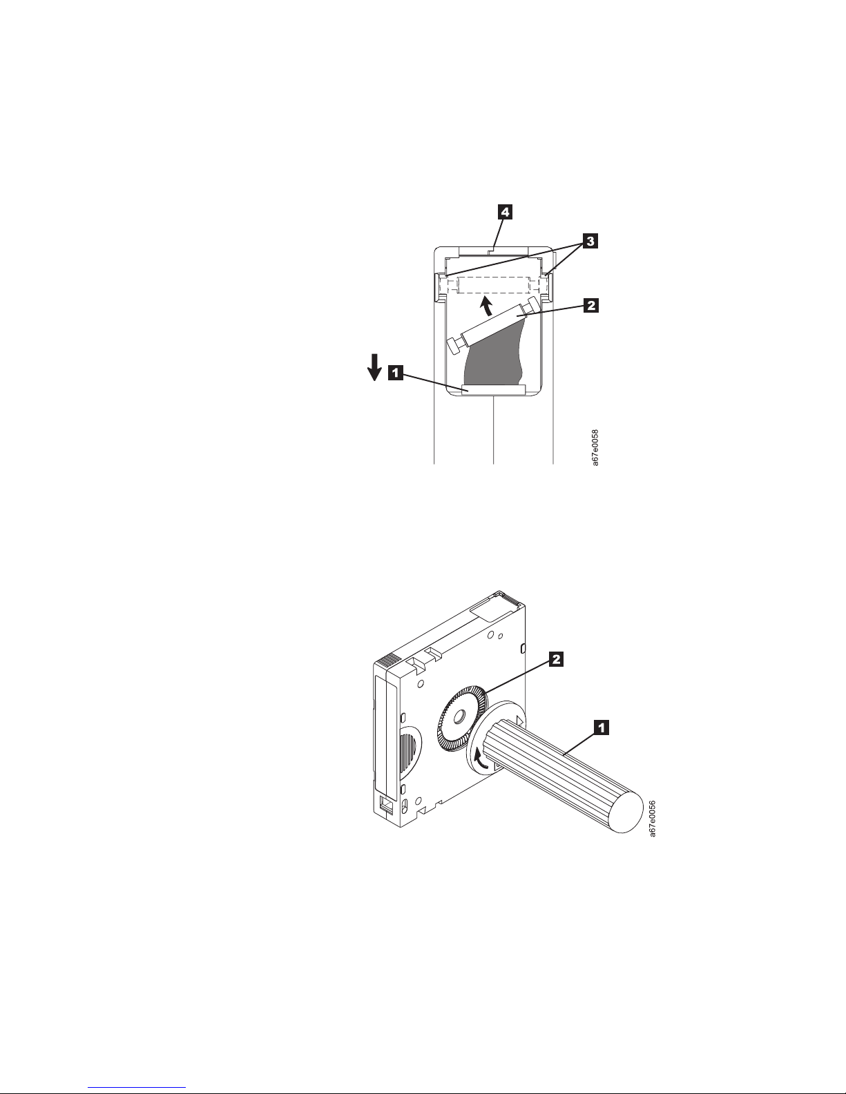
2. With plastic or blunt-end tweezers, grasp the leader pin and position it in the
pin-retaining spring clips (3in Figure 12).
3. Press the leader pin gently into the clips until it snaps into place and is firmly
seated.
4. Close the cartridge door.
Figure 12. Placing the dislodged leader pin into the correct position. The cartridge door is
open to show the leader pin.
5. To rewind the tape, insert the cartridge manual rewind tool (1) into the
cartridge’s hub 2 and turn it clockwise until the tape becomes taut.
Figure 13. Rewinding the tape into the cartridge
6. Remove the rewind tool by pulling it away from the cartridge.
7. If you suspect that the cartridge has been mishandled but it appears useable,
copy any data onto a good cartridge immediately for possible data recovery.
Discard the mishandled cartridge.
36 IBM 400/800GB LTO3 Tape Drive User’s Guide
Page 53

Reattaching a Leader Pin
The first meter of tape in a cartridge is leader tape. Once the leader tape has been
removed there is a possibility of tape breakage. After reattaching the leader pin,
transfer data from the defective tape cartridge. Do not reuse the defective tape
cartridge.
The Leader Pin Reattachment Kit contains three parts:
v Leader pin attach tool (1). A plastic brace that holds the cartridge door open.
v Cartridge manual rewind tool (2 ). A device that fits into the cartridge’s hub
and lets you wind the tape into and out of the cartridge.
v Pin supplies (3 ). Leader pins and C-clips.
Attention:
v Use only the IBM Leader Pin Reattachment Kit to reattach the leader pin to the
tape. Other methods of reattaching the pin will damage the tape, the drive, or
both.
v Use this procedure on your tape cartridge only when the leader pin detaches
from the magnetic tape and you must copy the cartridge’s data onto another
cartridge. Destroy the damaged cartridge after you copy the data. This
procedure may affect the performance of the leader pin during threading and
unloading operations.
v Touch only the end of the tape. Touching the tape in an area other than the end
can damage the tape’s surface or edges, which may interfere with read or write
reliability.
3
Figure 14. Leader Pin Reattachment Kit
1
2
A67E0042
Using Ultrium Media 37
Page 54

The following procedure describes how to reattach a leader pin.
To reattach a leader pin by using the IBM Leader Pin Reattachment Kit:
1. Attach the leader pin attach tool 1 to the cartridge 2 so that the tool’s
hook 3 latches into the cartridge’s door 4. Pull the tool back to hold the
door open, then slide the tool onto the cartridge. Open the tool’s pivot arm
5.
Figure 15. Attaching the leader pin attach tool to the cartridge. To hold the cartridge door
open, hook the tool into the door and pull the tool back.
38 IBM 400/800GB LTO3 Tape Drive User’s Guide
Page 55

2. To find the end of the tape inside the cartridge, attach the cartridge manual
rewind tool 1 to the cartridge’s hub 2 by fitting the tool’s teeth between
the teeth of the hub. Turn the tool clockwise until you see the end of the tape
inside the cartridge. Then, slowly turn the rewind tool counterclockwise to
bring the tape edge toward the cartridge door 3.
3. Continue to turn the rewind tool counterclockwise until approximately 13 cm
(5 in.) of tape hangs from the cartridge door. If necessary, grasp the tape and
pull gently to unwind it from the cartridge.
4. Remove the rewind tool by pulling it away from the cartridge. Set the tool
and the cartridge aside.
Figure 16. Winding the tape out of the cartridge. Turn the cartridge manual rewind tool
clockwise to see the end of the tape, then turn it counterclockwise to bring the tape to the
cartridge door.
5. On the leader pin 1, locate the open side of the C-clip 2. The C-clip is a
small black part that secures the tape 3 to the pin.
6. Remove the C-clip from the leader pin by using your fingers to push the clip
away from the pin. Set the pin aside and discard the clip.
3
1
2
Figure 17. Removing the C-clip from the leader pin. Use your fingers to push the C-clip from
the leader pin.
A67E0036
Using Ultrium Media 39
Page 56

7. Position the tape in the alignment groove of the leader pin attach tool 1.
8. Place a new C-clip into the retention groove 2 () on the leader pin
attachment tool and make sure that the clip’s open side faces up.
9. Place the leader pin into the cavity 3 of the leader pin attach tool.
Attention: To prevent the leader pin from rolling into the cartridge, in the
following step use care when folding the tape over the pin.
Fold the tape over the leader pin and hold it with your fingers (see Figure 18).
10.
Note: Use care to ensure that the tape is centered over the leader pin. Failure
to properly center the tape on the pin will cause the repaired cartridge
to fail. When the tape is properly centered, a 0.25-mm (0.01-in.) gap
exists on both sides of the pin.
2
1
6
5
Figure 18. Attaching the leader pin to the tape
4
3
A67E0037
11. Close the pivot arm 4 of the leader pin attach tool by swinging it over the
leader pin so that the C-clip snaps onto the pin and the tape.
12. Swing the pivot arm open and trim the excess tape 5 so that it is flush with
the reattached leader pin 6.
13. Use your fingers to remove the leader pin from the cavity 3 in the leader
pin attach tool.
40 IBM 400/800GB LTO3 Tape Drive User’s Guide
Page 57

14. Use the cartridge manual rewind tool to wind the tape back into the cartridge
(wind the tape clockwise). Ensure that the leader pin is latched by the
pin-retaining spring clips on each end of the leader pin.
15. Remove the rewind tool.
16. Remove the leader pin attach tool by lifting its end up and away from the
cartridge.
Attention
Use a repaired tape cartridge only to recover data and move it to another
cartridge. Continued use of a repaired cartridge may void the warranties of
the drive and the cartridge.
Disposing of Tape Cartridges
Under the current rules of the U.S. Environmental Protection Agency (EPA),
regulation 40CFR261, the LTO Ultrium Tape Cartridge is classified as
non-hazardous waste. As such, it may be disposed of in the same way as normal
office trash. These regulations are amended from time to time, and you should
review them at the time of disposal.
If your local, state, country (non-U.S.A.), or regional regulations are more
restrictive than EPA 40CFR261, you must review them before you dispose of a
cartridge. Contact your account representative for information about the materials
that are in the cartridge.
If a tape cartridge must be disposed of in a secure manner, you can erase the data
on the cartridge by using a high-energy ac degausser (use a minimum of 1200
oersted peak field over the entire space that the cartridge occupies). Degaussing
makes the cartridge unusable.
If you burn the cartridge and tape, ensure that the incineration complies with all
applicable regulations.
Ordering Media Supplies
Table 5 lists the cartridges and media supplies that you can order for the
400/800GB LTO3 Tape Drive.
Table 5. Ordering media supplies for the drive
Supply Item Method of Ordering
IBM TotalStorage LTO
Ultrium 400 GB Data
Cartridge
IBM TotalStorage LTO
Ultrium 200 GB Data
Cartridge (without bar
code label)
Order VOLSER labels
separately.
v http://www-307.ibm.com/pc/support/site.wss/document.do?Ind0cidMIGR-39931
v If you do not have Internet access, order the cartridge from any authorized IBM
Business Partner.
v Call 1-888-IBM-MEDIA.
v http://www-307.ibm.com/pc/support/site.wss/document.do?Ind0cidMIGR-39931
v If you do not have Internet access, order the cartridge from any authorized IBM
Business Partner or your IBM Sales Representative.
v Call 1-888-IBM-MEDIA.
Using Ultrium Media 41
Page 58

Table 5. Ordering media supplies for the drive (continued)
Supply Item Method of Ordering
IBM TotalStorage LTO
Ultrium 200 GB Data
Cartridge (with bar code
label)
Bar code labels are
preapplied to cartridges.
v Order as part number 19P5887 through an IBM-authorized distributor (for the closest
distributor, visit the web at http://www.ibm.com/storage/media). Specify the VOLSER
characters that you want.
v If you do not have Internet access, order the cartridge from any authorized IBM
Business Partner or your IBM Sales Representative. Specify the VOLSER characters that
you want.
v Call 1-888-IBM-MEDIA. Specify the VOLSER characters that you want.
IBM LTO Ultrium 100
GB Data Cartridge
(without bar code label)
Order VOLSER labels
separately.
IBM LTO Ultrium 100
GB Data Cartridge (with
bar code label)
v http://www-307.ibm.com/pc/support/site.wss/document.do?Ind0cidMIGR-39931
v If you do not have Internet access, order the cartridge from any authorized IBM
Business Partner or your IBM Sales Representative by specifying Machine Type 3589
Model 003.
v Call 1-888-IBM-MEDIA.
v Order the cartridge from any authorized IBM Business Partner or your IBM Sales
Representative by specifying Machine Type 3589 Model 002. Specify the VOLSER
characters that you want.
Bar code labels are
preapplied to cartridges.
IBM TotalStorage LTO
Ultrium Cleaning
Cartridge (universal
cleaning cartridge for
use with Ultrium 1,
v http://www-307.ibm.com/pc/support/site.wss/document.do?Ind0cidMIGR-39931
v If you do not have Internet access, order the cartridge from any authorized IBM
Business Partner or your IBM Sales Representative.
v Call 1-888-IBM-MEDIA.
Ultrium 2, and Ultrium 3
drives; without bar code
label)
Order VOLSER labels
separately.
IBM TotalStorage LTO
Ultrium Cleaning
Cartridge (universal
cleaning cartridge for
use with Ultrium 1,
Ultrium 2, and Ultrium 3
drives; with bar code
label)
Bar code labels are
preapplied to cartridges.
Leader Pin
Reattachment Kit
v Order as part number 35L2087 through an IBM-authorized distributor (for the closest
distributor, visit the web at http://www.ibm.com/storage/media).
v If you do not have Internet access, order the cartridge from any authorized IBM
Business Partner or your IBM Sales Representative.
v Call 1-888-IBM-MEDIA.
Order as part number 08L9129 through an IBM-authorized distributor (for the closest
distributor, visit the web at http://www.ibm.com/storage/media).
42 IBM 400/800GB LTO3 Tape Drive User’s Guide
Page 59

Ordering Bar Code Labels
The 400/800GB LTO2 Tape Drive does not require cartridge bar code labels.
However, if you use your data cartridges or cleaning cartridges in an IBM tape
library product, you may need cartridge bar code labels if your tape library
product requires them. Yo u can order these labels separately from the IBM Data
Cartridges and Cleaning Cartridges.
Yo u can order bar code labels directly from the authorized label suppliers in
Table 6.
Table 6. Authorized suppliers of custom bar code labels
In America In Europe and Asia
EDP/Colorflex
2550 W. Midway Blvd.
Broomfield, CO 80020
U. S. A.
Telephone: 800-522-3528
http://www.colorflex.com/
Dataware
P.O. Box 740947
Houston, TX 77274
U. S. A.
Telephone: 800-426-4844
http://www.datawarelabels.com/
NetC
P. O. Box 1067
Fairfield, CT 06825
U. S. A.
Telephone: 203-372-6382
http://www.netcllc.com/
EDP Europe, Ltd.
43 Redhills Road
South Woodham Ferrers
Chelmsford, Essex CM3 5UL
U. K.
Telephone: 44 (0) 1245-322380
http://www.edpeurope.com/media_labelling.htm
Dataware Labels Europe
Heubergstrasse 9
D-83052 Bruckmuhl-Gotting
Germany
Telephone: 49 8062-9455
http://www.datawarelabels.com/
NetC Europe Ltd
Town Farm Bungalow
The Pavement
North Curry
TA3 6LX
Somerset
U. K.
Telephone: 44 (0) 1823 49 1439
http://www.netclabels.co.uk
NetC Asia Pacific Pty Ltd
Locked Bag 1
Kenthurst
NSW 2156
Australia
Telephone: 61 (0) 2 4573 6556
http://www.netclabels.com.uk
Resolving Problems
If you encounter problems when running the drive, refer to the table below. If the
problem is not identified there, refer to “Methods of Receiving Errors and
Messages” on page 44. The color and condition of the Status Light may also
indicate a problem. For more information, see “Status Light” on page 11.
Table 7. Troubleshooting tips
If the problem is this.... Do this....
A code displays on the
Single-character Display (SCD) and
the Status Light flashes amber.
The drive detected an error or is directing you to an informational message.
See Table 9 on page 45.
Using Ultrium Media 43
Page 60

Table 7. Troubleshooting tips (continued)
If the problem is this.... Do this....
The Status Light or SCD never turns
on.
The drive has no power. Check the power at the power source. Connect
power to the drive (see “Connect and Test Power to the Drive” on page 9). If
the problem persists, replace the drive.
The drive will not load a tape
cartridge.
One of the following has occurred:
v A tape cartridge is already inserted. To remove the cartridge, press the
Unload Button. If the cartridge does not eject, turn off the power to the
drive, then turn it back on. After the Status Light becomes solid green,
press the Unload Button to eject the cartridge.
v The tape cartridge was inserted incorrectly. To properly insert a cartridge,
see “Inserting a Tape Cartridge” on page 13.
v The tape cartridge may be defective. Insert another tape cartridge. If the
problem exists for multiple cartridges, the drive is defective. Replace the
drive.
v The drive has no power. Connect power to the drive (see “Connect and
Test Power to the Drive” on page 9).
The drive will not unload the tape
cartridge.
The tape cartridge is stuck or is broken. Press the Unload Button. If the
cartridge does not eject, turn off the power to the drive, then turn it back on
(note that the mid-tape recovery could take up to ten minutes to complete).
If the cartridge still does not eject, contact IBM Support.
The server received TapeAlert flags. See Appendix A. See Appendix A, “TapeAlert Flags,” on page 65.
The server reported SCSI problems
See “Fixing SCSI Bus Errors” on page 50.
(such as selection or command
time-outs, or parity errors).
The library reported an LDI or
RS-422 communication problem with
the drive.
The LDI or RS-422 circuitry may be defective. Run the LDI or RS-422 wrap
test (“Function Code 7: Run RS-422 Wrap Test” on page 20). If the test runs
successfully but the problem persists, refer to your library’s service
documentation.
Codes display on the SCD, but the
The drive is defective. Replace the drive.
Status Light does not turn on.
The drive does not respond to server
commands.
Press and hold the Unload Button on the drive for ten seconds to force a
drive dump. The drive will save the dump and then reboot to allow
communication to the drive to occur. Do not cycle power, as this will erase
the contents of the dump.
Methods of Receiving Errors and Messages
Use Table 8 as a guide for identifying error codes and message codes reported by
the drive, its enclosure (if applicable), or the server.
Note: The codes on the Single-character Display (SCD) have different meanings,
depending on whether they display during normal operations or while the
drive is in maintenance mode. Codes that occur during normal operations
are defined in Table 9 on page 45. Codes that occur while in maintenance
mode are defined in “Diagnostic and Maintenance Functions” on page 15.
Table 8. Methods of receiving errors and messages
If the error or message was
presented by.... Do this....
The enclosure’s display (if the drive
is enclosed in a library or autoloader)
44 IBM 400/800GB LTO3 Tape Drive User’s Guide
Refer to the documentation for the enclosure.
Page 61

Table 8. Methods of receiving errors and messages (continued)
If the error or message was
presented by.... Do this....
The drive’s SCD and the Status Light
flashes amber
The drive’s SCD and the Status Light
is solid amber
SCSI log sense data (such as
See “Error Codes and Messages.” To determine the meaning of Status Light
activity, see “Status Light” on page 11.
See “Diagnostic and Maintenance Functions” on page 15. To determine the
meaning of Status Light activity, see “Status Light” on page 11.
See “Error Codes and Messages.”
TapeAlert flags) and SCSI drive sense
data at the server console
Drive sense data sent to a library (if
the drive is enclosed in a library)
Refer to your library’s documentation, then see “Error Codes and
Messages.”
The drive’s error log See “Error Codes and Messages” and “Viewing the Drive Error Log” on
page 49.
Error Codes and Messages
The table below gives descriptions of the errors and messages that pertain to the
drive, and tells what to do when you receive them.
Attention: If the drive detects a permanent error and displays an error code other
0
than
existing dump will be overwritten and data will be lost. After you force a drive
dump, do not turn off the power to the drive or you may lose the dump data.
, it automatically performs a drive dump. If you force a drive dump, the
Table 9. Error codes on the Single-character Display. To clear error and cycle power, press the Unload Button for ten
seconds. A drive dump will be created.
Error Code Cause and Action
0
No error occurred and no action is required. This code displays:
v When power is cycled (turned off, then on) to the tape drive.
v When diagnostics have finished running and no error occurred.
The Single-character Display is blank during normal operation of the tape drive.
1
Note:
Cooling problem. The tape drive detected that the recommended operating temperature was
exceeded. Perform one or more of the following actions:
v Ensure that the cooling fan is rotating and is quiet. If not, refer to your enclosure
documentation.
v Remove any blockage that prevents air from flowing freely through the tape drive.
v Ensure that the operating temperature and airflow is within the specified range (see “Physical
Specifications” on page 69).
v If the operating temperature is within the specified range and the problem persists, replace the
drive.
The
8
error code clears when you power-off the tape drive or place it in maintenance mode.
Power problem. The tape drive detected that the externally supplied power is approaching the
specified voltage limits (the tape drive is still operating) or is outside the specified voltage limits
(the tape drive is not operating). Perform the following action:
1. Ensure that the power connector is properly seated.
2. Ensure that the proper dc voltages are being applied within the tolerances allowed (see
“Physical Specifications” on page 69).
3. If the proper voltages are being applied but the problem persists, replace the unit.
The
error code clears when you power-off the tape drive or place it in maintenance mode.
Using Ultrium Media 45
Page 62

Table 9. Error codes on the Single-character Display (continued). To clear error and cycle power, press the Unload
Button for ten seconds. A drive dump will be created.
Error Code Cause and Action
3
Firmware problem. The tape drive determined that a firmware error occurred. Perform the
following action:
1. Collect a drive dump from one of the following:
Note: Do not force a new dump; the tape drive has already created one.
v Server’s SCSI interface by using a device driver utility or system tool
v Ultrium Tape Drive (to copy and read a drive dump, use “Function Code 5: Copy Drive
Dump” on page 19)
2.
Power the tape drive off and on, then retry the operation that produced the error.
3. If the problem persists, download new firmware and retry the operation.
4. If the problem persists, send the drive dump that you collected in step 1 to your Support
Center.
The
8
error code clears when you power-off the tape drive or place it in maintenance mode.
Firmware or tape drive problem. The tape drive determined that a firmware or tape drive
hardware failure occurred. Perform the following action:
1. Collect a drive dump from one of the following:
Note: Do not force a new dump; one already exists.
v Server’s SCSI interface by using a device driver utility or system tool
v Ultrium Tape Drive (to copy and read a drive dump, use “Function Code 5: Copy Drive
Dump” on page 19)
Power the tape drive off and on, then retry the operation that produced the error. The error
2.
code clears when you power-off the tape drive or place it in maintenance mode.
3. If the problem persists, download new firmware and retry the operation; if new firmware is
not available, replace the drive.
5
Tape drive hardware problem. The drive determined that a tape path or read/write error occurred.
To prevent damage to the drive or tape, the tape drive will not allow you to insert a cartridge if
the current cartridge was successfully ejected. The error code may clear when you cycle power to
the tape drive or place it in maintenance mode. If the problem persists, replace the drive.
Note: Copy the drive dump to flash memory before returning the drive. For instructions, refer to
“Function Code 5: Copy Drive Dump” on page 19.
46 IBM 400/800GB LTO3 Tape Drive User’s Guide
Page 63

Table 9. Error codes on the Single-character Display (continued). To clear error and cycle power, press the Unload
Button for ten seconds. A drive dump will be created.
Error Code Cause and Action
6
Tape drive or media error. The tape drive determined that an error occurred, but it cannot isolate
the error to faulty hardware or to the tape cartridge. Perform the following action:
For Problems with Writing Data:
If the problem occurred while the tape drive was writing data to the tape, and if you know the
volume serial number (located on the cartridge label) of the tape cartridge that was loaded in the
drive when the problem occurred, retry the operation with a different cartridge:
v If the operation succeeds, the original cartridge was defective. Copy data from the defective
cartridge and discard it.
v If the operation fails and another tape drive is available, insert the cartridge into the other unit
and retry the operation.
– If the operation fails, discard the defective cartridge.
– If the operation succeeds, insert a scratch data cartridge into the first unit and run “Function
Code 1: Run Drive Diagnostics” on page 16.
- If the diagnostics fail, replace the tape drive.
- If the diagnostics succeed, the error was temporary.
v
If the operation fails and another tape drive is not available, insert a scratch data cartridge into
the unit and run “Function Code 1: Run Drive Diagnostics” on page 16.
– If the diagnostics fail, replace the tape drive.
– If the diagnostics succeed, discard the cartridge.
If
the problem occurs with multiple tape cartridges or if you do not know the tape cartridge’s
volume serial number, run “Function Code 1: Run Drive Diagnostics” on page 16:
v If the diagnostics fail, replace the tape drive.
v If the diagnostics succeed, run “Function Code H: Test Head” on page 24.
– If the diagnostic fails, replace the tape drive.
– If the diagnostic succeeds, replace the cartridges that caused the problem.
The
error code clears when you remove the tape cartridge or place the tape drive in maintenance
mode.
For Problems with Reading Data:
If the problem occurred while the tape drive was reading data from the tape, and if you know the
volume serial number of the tape cartridge, perform one of the following procedures:
v If another tape drive is available, insert the cartridge into the other unit and retry the operation:
– If the operation fails, discard the defective cartridge.
– If the operation succeeds, insert a scratch data cartridge into the first unit and run “Function
Code 1: Run Drive Diagnostics” on page 16:
- If the diagnostic fails, replace the tape drive.
- If the diagnostic succeeds, the error was temporary.
v
If another tape drive is not available, insert a scratch data cartridge into the unit and run :
– If the diagnostic fails, replace the tape drive.
– If the diagnostic succeeds, discard the cartridge.
If
the problem occurs with multiple tape cartridges or if you do not know the tape cartridge’s
volume serial number, run “Function Code 1: Run Drive Diagnostics” on page 16:
v If the diagnostic fails, replace the tape drive.
v If the diagnostic succeeds, run “Function Code H: Test Head” on page 24.
– If the diagnostic fails, replace the tape drive.
– If the diagnostic succeeds, replace the cartridges that caused the problem.
The
error code clears when you remove the tape cartridge or place the tape drive in maintenance
mode.
Using Ultrium Media 47
Page 64

Table 9. Error codes on the Single-character Display (continued). To clear error and cycle power, press the Unload
Button for ten seconds. A drive dump will be created.
Error Code Cause and Action
7
A high probability of media error. The tape drive determined that an error occurred because of a
faulty tape cartridge. Tr y another tape cartridge. If the problem occurs with multiple tape
cartridges, use the following procedure:
Attention: When you run the Test Cartridge & Media diagnostic, data on the suspect tape is
overwritten. Use only a scratch data cartridge to run the test.
1. If possible, run the tape cartridge in a different tape drive. If the operation in the other unit
fails and
6
or
7
displays, replace the media. If the operation succeeds, run “Function Code E: Test Cartridge &
Media” on page 22.
v If the diagnostic fails, replace the media.
v If the diagnostic succeeds, clean the drive head (see “Cleaning the Drive Head” on page 14)
and run “Function Code 1: Run Drive Diagnostics” on page 16.
– If the drive diagnostic fails, replace the drive.
– If the drive diagnostic succeeds, perform the operation that produced the initial media
error.
The
error code clears when you remove the tape cartridge or place the tape drive in maintenance
mode.
8
Tape drive or SCSI bus failure. The tape drive determined that a failure occurred in the tape
drive’s hardware or in the SCSI bus. The error code clears 10 seconds after the drive detected the
error or when you place the drive in maintenance mode.
9
Tape drive or RS-422 error. The tape drive determined that a failure occurred in the tape drive’s
hardware or in the RS-422 connection. Replace the tape drive. The error code clears 10 seconds
after the drive detected the error or when you place the tape drive in maintenance mode.
A
Tape drive hardware problem. The tape drive determined that a problem occurred which
degraded the operation of the tape drive, but it did not restrict continued use. If the problem
persists, replace the drive. The drive is usable, though the Single-character Display continues to
indicate an error and the Status Light flashes amber.
The error code may clear when you cycle power to the tape drive or place it in maintenance
mode.
b
No error or message is assigned. See error code
8
in this table.
C
The tape drive needs to be cleaned. Clean the tape drive. See “Cleaning the Drive Head” on page
14.
The error code clears when you clean the tape drive or place it in maintenance mode.
d
No error or message assigned. See error code
0
in this table.
The Unload Button is depressed. Verify that the button pushes freely.
48 IBM 400/800GB LTO3 Tape Drive User’s Guide
Page 65

Obtaining a Drive Dump
Yo u can obtain a drive dump by selecting a function code on the drive or by using
a device driver utility (or a system tool) on the server. The sections that follow
describe each method.
Using the Drive
To obtain a drive dump directly from the drive:
1. Make sure that no cartridge is in the drive.
2. Within two seconds, press the Unload Button three times. The Status Light
becomes solid amber, which means that the drive is in maintenance mode.
3. Press the Unload Button once per second until
Single-character Display.
4. To select the function, press and hold the Unload Button for three seconds.
After you release the button,
C
flashes. Within 60 seconds, insert a scratch
data cartridge that is not write-protected. After you insert the cartridge,
flashes and the drive writes the dump data to the scratch tape. When the
function is complete, the drive rewinds and unloads the tape.
5. Insert the tape into a drive.
6. From the server, issue the SCSI READ command to read the dump from the
tape to a file or electronic image (you may need to issue the command several
times to read the complete dump).
7. To determine where to send the file for analysis, contact your Product
Application Engineer (PAE).
5
appears in the
5
Using a Device Driver Utility
To obtain a drive dump by using a device driver utility, determine whether your
server is installed with a utility that can read files from the server’s memory. If it
is, use that utility to obtain the drive dump.
For information about using IBM’s utility programs to obtain drive dumps, see the
IBM Ultrium Device Drivers Installation and User’s Guide.
Viewing the Drive Error Log
The drive keeps an error log that you can use to identify and correct errors. The
log contains the 10 most recent error codes, which appear (one at a time) on the
Single-character Display (SCD).
To view the drive error log:
1. Make sure that no cartridge is in the drive.
2. Within two seconds, press the Unload Button three times. The Status Light
becomes solid amber, which means that the drive is in maintenance mode.
3. Press the Unload Button once per second until
4. Press and hold the Unload Button for three seconds to view the most recent
error code.
5. Refer to Table 9 on page 45 above to determine the meaning of the code and
the action to take.
6. Press the Unload Button to view the next error code. (The codes are ordered;
the most recent is presented first and the oldest (tenth) is presented last.)
9
appears in the SCD.
Using Ultrium Media 49
Page 66

7. Continue to press the Unload Button until the ten error codes have been
displayed. After you display the tenth error code, the drive automatically exits
maintenance mode.
To redisplay the error codes, repeat steps 1 through 7.
Resolving Problems Reported by the Server
The procedure for fixing SCSI bus errors varies, depending on whether the error is
consistent or intermittent, and whether your configuration contains single or
multiple drives. The sections that follow describe how to fix each type of error.
Fixing SCSI Bus Errors
Note: If you are using a Storage Area Network (SAN) Data Gateway to convert a
drive with a SCSI interface to a Fibre Channel interface, ensure that the
problem is occurring between the SAN Data Gateway and the drive by
running the SCSI wrap test on the drive and running the SCSI loopback test
on the SAN Data Gateway. (To run the SCSI wrap test, see “Function Code
6: Run SCSI Wrap Test” on page 20; to run the SCSI loopback test, refer to
the section about that test in the IBM Storage Area Network Gateway Module
Setup, Operator, and Service Guide.)
a Consistent Error with a Single Drive on a SCSI Bus:
Fixing
1. Ensure that the power is on to the drive.
2. Ensure that the drive’s SCSI address is the same as the SCSI address assigned
by the server.
3. Run the SCSI wrap test (see “Function Code 6: Run SCSI Wrap Test” on page
20).
v If the test fails, replace the SCSI terminator first, then the SCSI cable and the
interposer (if installed). Repeat the operation that caused the error. If you
replaced the SCSI terminator or SCSI cable and the problem persists, the
fault is with the server’s hardware or software. To isolate the cause of the
failure, refer to the server’s service documentation.
v If the test fails again, replace the drive.
v If the test is successful, refer to your enclosure documentation for additional
troubleshooting information.
a Consistent Error with Multiple Drives on a SCSI Bus: When a
Fixing
consistent error occurs in a configuration that has multiple drives on the SCSI bus,
you must determine if the problem exists with more than one drive. If the problem
is with all of the devices on the SCSI bus, the bus is stuck in a SCSI phase and
cannot change to another phase or the SCSI cable from the server to the first
device is defective.
1. Ensure that the SCSI cable from the server to the first device is connected.
2. Disconnect all but the first drive on the SCSI bus. Move the terminator to the
first SCSI device.
3. Run a device driver utility to determine whether the error will occur.
v If the error occurs, run the SCSI wrap test on the first drive (see “Function
Code 6: Run SCSI Wrap Test” on page 20).
– If the test runs successfully, replace the SCSI terminator first, then the
SCSI cable and the interposer (if installed) to the first drive. Repeat the
operation that caused the error. If you replaced the SCSI terminator or
50 IBM 400/800GB LTO3 Tape Drive User’s Guide
Page 67

SCSI cable and the problem persists, the fault is with the server’s
hardware or software. To isolate the cause of the failure, refer to the
server’s service documentation.
– If the test fails, replace the drive.
If the error does not occur, connect one drive at a time back to the bus and
v
repeat step 3 for each drive until you can identify which drive is defective.
Note: Ensure that the SCSI terminator is always on the last drive on the
SCSI bus.
4. Determine if the problem is with only one drive or with two or more drives.
v If the problem is with only one drive, run the SCSI wrap test on that drive
(see “Function Code 6: Run SCSI Wrap Test” on page 20).
– If the test runs successfully, replace the SCSI terminator first, then the
SCSI cable to that drive and interposer (if installed).
– If the test fails, replace the drive.
v If the problem is with two or more drives, locate the first drive that has the
error and replace the SCSI cable that connects the drive and the interposer (if
installed).
an Intermittent Error with a Single Drive on a SCSI Bus:
Fixing
1. Replace the SCSI terminator on the drive.
2. Run the operation that caused the error. If the problem persists, the problem
may be with the cable.
3. Isolate which cable is causing the problem by replacing one cable at a time and
running the operation that caused the error after each replacement. If the
problem persists after all cables have been replaced, the problem may be with
the drive.
4. Replace the drive. If the problem persists, the problem is with your server.
Consult your server’s documentation.
an Intermittent Error with Multiples Drives on a SCSI Bus: Refer to the
Fixing
server’s error logs to determine which drive is the source of the problem:
v If only one drive is reporting a SCSI failure, replace that drive.
v If multiple drives are reporting SCSI failures, the problem may be with the
terminator or the SCSI cables:
– Replace the terminator and run the operation that caused the error. If the
problem persists, the problem may be with the cables.
– Isolate which cable is causing the problem by replacing one cable at a time
and run the operation that caused the error after each replacement.
Using Ultrium Media 51
Page 68

Resolving Media-Related Problems
To resolve problems that are related to media, the drive’s firmware includes:
v Test Cartridge & Media diagnostic that verifies whether a suspect cartridge and
its magnetic tape are acceptable for use.
v Statistical Analysis and Reporting System (SARS) to assist in isolating failures
between media and hardware. To determine the cause of failure, SARS uses the
cartridge performance history that is saved in the cartridge memory (CM) and
the drive performance history that is kept in the drive’s VPD (Vital Product
Data) area in NVRAM. Any failures that SARS detects are reported as TapeAlert
flags on the server
Attention
If you insert the IBM LTO Ultrium Data Cartridge into another
manufacturer’s drive, the SARS data in the cartridge memory may become
lost or invalid.
If you encounter a media-related problem, use the following procedure:
Attention
When you run the Test Cartridge & Media diagnostic, data on the suspect
tape is overwritten. Use only a scratch data cartridge to run the test.
1. If possible, run the tape cartridge in a different drive. If the operation in the
other drive fails and
succeeds, run the Test Cartridge & Media diagnostic (see “Function Code E:
Test Cartridge & Media” on page 22).
2. If the Test Cartridge & Media diagnostic fails, replace the media. If it runs
successfully, clean the drive and run the drive diagnostics (see “Cleaning the
Drive Head” on page 14 and “Diagnostic and Maintenance Functions” on page
15. If the drive diagnostics run successfully, perform the operation that
produced the initial media error.
Servicing the Drive
Manually Removing a Tape Cartridge
The purpose of this section is to assist you in determining the condition of the
cartridge or the magnetic tape and to direct you to the procedure you must follow
to remove the cartridge.
6
7
or
displays, replace the media. If the operation
52 IBM 400/800GB LTO3 Tape Drive User’s Guide
Page 69

Attention
v Before using this procedure, you must have exhausted all other means of
removing the tape cartridge from the drive. Use this procedure only if you
cannot remove the tape cartridge by using any other means.
v Determine from the customer if the cartridge contains critical customer
data. If the cartridge contains sensitive data that cannot leave the site,
inform the customer that certain failure conditions diagnostics will be
performed to test the drive for continued use.
v The following removal procedures can destroy customer data! Use extreme
care when handling or removing the customer’s tape cartridges to
minimize tape damage and lost data.
v DO NOT TOUCH the magnetic tape or tape path. Both are extremely
sensitive to the oil and salt from your skin. Use clean, lint-free gloves when
working around magnetic tape or the tape path components.
v Electrostatic-sensitive components: Consider using an ESD Kit.
v After you remove the tape cartridge, advise the customer to copy the data
to another cartridge and to remove this tape cartridge from service.
v Do not use power tools or magnetic tools to perform this procedure.
v To avoid contamination and electrostatic-discharge damage to the drive,
never touch the head or electronic components inside the drive.
v If you cannot remove the cartridge from the drive using the following
procedures, contact your next level of support.
Before You Begin
1. If you have not already done so, attempt to remove the cartridge with the
device power ON and using library manager, a host application, or the Unload
Button.
2. If you have not already done so, attempt to remove the cartridge by power
cycling the drive. Look for the drive to attempt a mid-tape recovery.
Note: It can take as long as five minutes for the cartridge to rewind and
unload.
3. If the cartridge unloads, inform the operator that the cartridge is unloaded. If
the cartridge does not unload, continue with this procedure.
Recommended Tools
v 2.5 mm offset hex wrench (do not use magnetized wrench)
v #1 Phillips screwdriver
v ESD Kit
v Flashlight (optional)
v #1 Flathead screwdriver (optional)
Beginning Procedure
__ Step 1. Refer to the enclosure documentation for instructions on removing the
drive.
__ Step 2. Place the drive on a non-slip, sturdy work surface.
__ Step 3. Ground yourself to the drive by using an ESD Kit.
__ Step 4. Remove the cover of the drive by performing the following steps:
Using Ultrium Media 53
Page 70

a. Using a Phillips screwdriver, remove the three screws and washers
1 that secure the bezel 2 to the internal drive, then remove the
bezel.
b. Remove the cover of the internal drive by performing the following
steps:
1) Remove the four cover-mounting screws and washers 3.
2) Remove the cover by lifting it up.
1
1
2
3
3
a82ru007
Figure 19. Removing the cover from the internal drive
__ Step 5. Inspect the drive to decide which of the following conditions most
closely matches the symptom on the drive:
v Tape spooled off the supply reel - All the tape appears to be on the
take up reel and no tape is on the supply reel (inside the cartridge).
Test the drive after the procedure is completed.
v Tape pulled from leader pin (or broken at the front end) - All the
tape appears to be on the supply reel (inside the cartridge) and very
little or no tape appears to be on the take up reel. The leader block is
positioned in the take up reel. Return the drive after the procedure is
completed.
v Tape broken in mid-tape - Tape appears to be on both the supply
reel (inside the cartridge) and take up reel. Test the drive after the
procedure is completed.
v Tape tangled along tape path - Tape appears to be tangled and
damaged but in tact. Return the drive after the procedure is
completed.
-- OR --
54 IBM 400/800GB LTO3 Tape Drive User’s Guide
Page 71

No damage to tape (or no apparent failure) - There appears to be no
damage or slack to the tape. Return the drive after the procedure is
completed.
Tape Spooled off Supply Reel
__ Step 1. With the front of the drive facing you, pull an arm’s length of tape
out of the take up reel from the left side of the drive.
__ Step 2. From the take up reel, thread tape around the rear of the tape path
and over the head rollers on the left side of the drive.
__ Step 3. Set the drive on its left side with the head and tape path facing up.
__ Step 4. Moisten a cotton swab with water and wet approximately 13 mm (0.5
in.) of the tape end and feed it onto the supply reel (inside the
cartridge).
__ Step 5. From the bottom of the drive, insert a 2.5 mm offset hex wrench
through the bottom cover access hole and into the reel motor axle.
Figure 20. Using hex wrench to rewind tape into cartridge
__ Step 6. Turn the supply reel clockwise, allowing the moistened tape to adhere
__ Step 7. Continue spooling into the cartridge until the tape is taut and remains
__ Step 8. Reassemble the drive, reversing the steps in “Beginning Procedure”
__ Step 9. Allow the drive to perform mid-tape recovery. This takes several
1
a82ru008
to the hub as it winds around the supply reel (inside the cartridge).
within the flanges of the tape guiding rollers. Ensure that you do not
stretch the tape.
on page 53.
minutes. When this activity completes, the cartridge ejects
automatically.
Using Ultrium Media 55
Page 72

__ Step 10. Test the drive (see “Connect and Test Power to the Drive” on page 9)
to determine if it should be replaced.
Tape Pulled from or Broken near Leader Pin
2
8
1
3
7
6
5
9
4
a82ru009
Figure 21. Drive with cover removed to reveal gear train.
1 Loader motor worm gear 6 Threader mechanism gear
2
Cartridge loader tray guide
bearing
7 Lever
3 Rotator stub 8 Loader mechanism gear
4 Threader motor worm gear 9 Threader worm gear
5 Threader intermediate gear
__ Step 1. From the left side of the drive, pull out tape from the take up reel.
Note: If there is more than approximately 0.6 m (2 ft.) of tape on the
take up reel, go to “Tape Broken in Mid-tape” on page 57.
__ Step 2. If there is less than approximately 0.6 m (2 ft.) of tape on the take up
reel, cut off the excess tape as close to the leader pin, as possible.
__ Step 3. Locate the threader motor worm gear 4 the rear of the drive. You
can either:
a. Use your finger to rotate the threader motor worm gear and
slowly rotate the threader mechanism gear 6 clockwise; or
b. Use a #1 flathead screwdriver to turn the threader worm gear 9
clockwise.
56 IBM 400/800GB LTO3 Tape Drive User’s Guide
This rotates the threader motor worm gear 4 clockwise, drawing the
tape leader block assembly (LBA) into the cartridge.
Page 73

__ Step 4. As the LBA is secured in the cartridge, you should hear the LBA
retention spring clips click into place. If you do not hear the click,
continue rolling until the threader motor worm gear 4 stops. The
LBA is in the correct position.
Note: Be sure to keep tension on the tape as the LBA is drawn into
the cartridge by using a hex wrench as shown in the figure
above.
__ Step 5. Notice the following:
a. Loader mechanism gear8 nearest the front of the drive that
actuates the cartridge loader mechanism
b. Position of the rotator stub 3.
c. Front loader motor worm gear 1. Rotating this gear allows the
loader mechanism gear 8 to turn.
__ Step 6. Rotate the loader motor worm gear 1 to turn the loader mechanism
gear 6 counterclockwise. Continue turning until the rotator stub 3
loses contact with the lever 7. This releases the LBA leader pin.
__ Step 7. Rotate the threader motor worm gear 4 to turn the threader
mechanism gear 6 counterclockwise. This moves the LBA out of the
cartridge and past the read/write head. Stop this rotation when the
LBA is near the tape guide roller nearest the rear of the drive 1.
1
Figure 22. Leader Block Assembly (LBA)
__ Step 8. Continue rotating the loader motor worm gear 1 until the rotate
__ Step 9. Remove the cartridge from the cartridge loader tray.
__ Step 10. Reassemble the drive by reversing the procedure in Step 4 in
__ Step 11 . Refer to the appropriate procedure to install the new drive and return
Tape Broken in Mid-tape
__ Step 1. With the front of the drive facing you, pull an arm’s length of tape
a82ru010
stub 3 is positioned as shown. Notice that the rotator stub3 is
nearly aligned with the cartridge loader tray guide bearing 2.
“Beginning Procedure” on page 53.
the failed drive.
out of the take up reel from the left side of the drive.
Note: If there is less than approximately 5 cm (2 in.) of tape on the
take up reel, go to “Tape Pulled from or Broken near Leader
Pin” on page 56.
Using Ultrium Media 57
Page 74

__ Step 2. From the supply reel inside the cartridge, pull approximately 0.3 m (1
ft.) of tape.
__ Step 3. From the take up reel, thread tape around the rear of the tape path
and over the head rollers on the left side of the drive.
__ Step 4. Moisten a cotton swab with water, and wet approximately 13 mm (0.5
in.) of the tape end. Overlap the tape ends, loosely mending them
together.
__ Step 5. Set the drive on its left side with the head and tape path facing up.
__ Step 6. From the bottom of the drive, locate the access hole 1 in the bottom
cover. Insert a 2.5 mm offset hex wrench through the bottom cover
access hole and into the reel motor axle. begin spooling tape back into
the cartridge by turning the hex wrench clockwise.
Figure 23. Using hex wrench to rewind tape into cartridge
__ Step 7. Turn the supply reel clockwise, carefully guiding the mended portion
__ Step 8. Reassemble the drive by reversing the procedure in Step 4 in
__ Step 9. Allow the drive to perform mid-tape recovery. This takes several
__ Step 10. Test the drive (see “Function Code 1: Run Drive Diagnostics” on page
58 IBM 400/800GB LTO3 Tape Drive User’s Guide
1
a82ru008
of the tape to wind around the hub of the supply reel located inside
the cartridge. Continue spooling into the cartridge until the tape is
taut. The tape must remain within the flanges of the tape guiding
rollers. Ensure that you do not stretch the tape.
“Beginning Procedure” on page 53.
minutes. When this activity completes, the cartridge ejects
automatically.
16) to determine if it should be replaced.
Page 75

Tape Tangled along Tape Path
__ Step 1. Carefully pull out excess tape and untangle.
Note: If you find the tape to be broken, go to one of the following
appropriate procedures:
v “Tape Spooled off Supply Reel” on page 55
v “Tape Pulled from or Broken near Leader Pin” on page 56
--OR--
“Tape Broken in Mid-tape” on page 57
Step 2. Set the drive on its left side with the head and tape path facing up.
__
1
a82ru008
Figure 24. Using hex wrench to rewind tape into cartridge
__ Step 3. From the bottom of the drive, locate the access hole 1.
__ Step 4. Insert a 2.5 mm offset hex wrench through the bottom cover access
hole and into the reel motor axle. Begin spooling the tape back into
the cartridge by turning the hex wrench clockwise.
__ Step 5. Continue spooling into the cartridge until the tape is taut and remains
within the flanges of the tape guiding rollers. Ensure that you do not
stretch the tape.
__ Step 6. Locate the threader motor worm gear 4 on the rear of the drive.
Yo u can either:
a. Use your finger to rotate the treader motor worm gear and slowly
rotate the threader mechanism gear 6 in clockwise; OR
b. Use a #1 flathead screwdriver to turn the worm gear 9
clockwise.
Using Ultrium Media 59
Page 76

This rotates the threader motor worm gear 4 clockwise, drawing the
LBA into the cartridge.
2
8
1
3
7
6
5
9
4
a82ru009
Figure 25. Drive with cover removed to reveal gear train.
1 Loader motor worm gear 6 Threader mechanism gear
2
Cartridge loader tray guide
bearing
7 Lever
3 Rotator stub 8 Loader mechanism gear
4 Threader motor worm gear 9 Threader worm gear
5 Threader intermediate gear
__ Step 7. As the tape leader block assembly (LBA) is secured in the cartridge,
you should hear the LBA retention spring clips click into place. If you
do not hear the click, continue rolling until the threader motor worm
gear 4 stops. The LBA is in the correct position.
Note: Be sure to keep tension on the tape as the LBA is drawn into
the cartridge by using a hex wrench.
__ Step 8. Notice the:
a. Loader mechanism gear 6 nearest the front of the drive that
actuates the cartridge loader mechanism.
b. Position of the rotate stub 3.
c. Front loader motor worm gear 1. Rotating this gear allows the
loader mechanism gear 8 to turn.
60 IBM 400/800GB LTO3 Tape Drive User’s Guide
Page 77

__ Step 9. Rotate the loader motor worm gear 1 to turn the threader
mechanism gear 6 counterclockwise. Continue turning until the
rotator stub 3 loses contact with the lever 7. This releases the LBA
leader pin.
__ Step 10. Rotate the threader motor worm gear 4 to turn the threader
mechanism gear 6 counterclockwise. This moves the LBA out of the
cartridge and past the read/write head. Stop this rotation when the
LBA is near the tape guide roller nearest the rear of the drive shown
as 1 .
1
a82ru010
Figure 26. Leader Block Assembly (LBA)
__ Step 11 . Continue rotating the loader motor worm gear 1 until the rotator
stub 3 is positioned as shown. Notice that the rotator stub 3 is
nearly aligned with the cartridge loader tray guide bearing 2.
__ Step 12. Remove the cartridge from the cartridge loader tray.
__ Step 13. Reassemble the drive by reversing the procedure in Step 4 in
“Beginning Procedure” on page 53.
__ Step 14. Refer to the appropriate procedure to install the new drive and return
the failed drive.
No Apparent Failure or Damage to Tape
__ Step 1. Set the drive on its left side with the head and tape path facing up.
Using Ultrium Media 61
Page 78

1
a82ru008
Figure 27. Using hex wrench to rewind tape into cartridge
__ Step 2. From the bottom of the drive, locate the access hole 1.
__ Step 3. Insert a 2.5 mm offset hex wrench through the bottom cover access
hole and into the reel motor axle. Begin spooling the tape back into
the cartridge by turning the hex wrench clockwise.
__ Step 4. Continue spooling into the cartridge until the tape is taut and remains
within the flanges of the tape guiding rollers. Ensure that you do not
stretch the tape.
__ Step 5. Locate the threader motor worm gear 4 on the rear of the drive.
Yo u can either:
a. Use your finger to rotate the threader motor worm gear and
slowly rotate the threader mechanism gear 6 clockwise;
--OR--
b. Use a #1 flathead screwdriver to turn the threader worm gear 9
clockwise.
rotates the threader motor worm gear 4 clockwise, drawing the
This
LBA into the cartridge.
62 IBM 400/800GB LTO3 Tape Drive User’s Guide
Page 79

2
3
7
8
6
5
1
9
4
a82ru009
Figure 28. Drive with cover removed to reveal gear train.
1 Loader motor worm gear 6 Threader mechanism gear
2
Cartridge loader tray guide
bearing
7 Lever
3 Rotator stub 8 Loader mechanism gear
4 Threader motor worm gear 9 Threader worm gear
5 Threader intermediate gear
__ Step 6. As the tape leader block assembly (LBA) is secured in the cartridge,
you should hear the LBA retention spring clips click into place. If you
do not hear the click, continue rolling until the threader motor worm
gear 4 stops. The LBA is in the correct position.
Note: Be sure to keep tension on the tape as the LBA is drawn into
the cartridge by using a hex wrench.
__ Step 7. Notice the:
a. Loader mechanism gear 6 nearest the front of the drive that
actuates the cartridge loader mechanism.
b. Position of the rotate stub 3.
c. Front loader motor worm gear 1. Rotating this gear allows the
loader mechanism gear 8 to turn.
__ Step 8. Rotate the loader motor worm gear 1 to turn the threader
mechanism gear 6 counterclockwise. Continue turning until the
rotator stub 3 loses contact with the lever 7. This releases the LBA
leader pin.
Using Ultrium Media 63
Page 80

__ Step 9. Rotate the threader motor worm gear 4 to turn the threader
mechanism gear 6 counterclockwise. This moves the LBA out of the
cartridge and past the read/write head. Stop this rotation when the
LBA is near the tape guide roller nearest the rear of the drive shown
as 1 .
1
a82ru010
Figure 29. Leader Block Assembly (LBA)
__ Step 10. Continue rotating the loader motor worm gear 1 until the rotator
stub 3 is positioned as shown. Notice that the rotator stub 3 is
nearly aligned with the cartridge loader tray guide bearing 2.
__ Step 11 . Remove the cartridge from the cartridge loader tray.
__ Step 12. Reassemble the drive by reversing the procedure in Step 4 in
“Beginning Procedure” on page 53.
__ Step 13. Refer to the appropriate procedure to install the new drive and return
the failed drive.
64 IBM 400/800GB LTO3 Tape Drive User’s Guide
Page 81

Appendix A. TapeAlert Flags
TapeAlert is a patented technology and standard of the American National
Standards Institute (ANSI) that defines conditions and problems that are
experienced by tape drives. The technology enables a server to read TapeAlert
flags from a tape drive through the SCSI or Library/Drive Interface (LDI or RS-422
interface). The server reads the flags from Log Sense Page 0x2E. This appendix lists
the TapeAlert flags that are supported by the IBM TotalStorage Ultrium Tape
Drive.
Table 10. Supported TapeAlert Flags
Flag
Number
3 03h Hard error Set for any unrecoverable read,
4 04h Media Set for any unrecoverable read,
5 05h Read failure Set for any unrecoverable read
6 06h Write failure Set for any unrecoverable write
8 08h Not data grade Set when severe servo errors
9 09h Write protect Set when the drive detects that
10 0Ah No removal Set when the drive receives an
11 0Bh Cleaning media Set when you load a cleaning
12 0Ch Unsupported format Set when you load an
Flag
Parameter
(in hex)
Flag Description Action Required
write, or positioning error. (This
flag is set in conjunction with
flags 4, 5, or 6.)
write, or positioning error that is
due to a faulty tape cartridge.
error where isolation is uncertain
and failure could be due to a
faulty tape cartridge or to faulty
drive hardware.
or positioning error where
isolation is uncertain and failure
could be due to a faulty tape
cartridge or to faulty drive
hardware.
occur while loading a tape
cartridge.
the tape cartridge is
write-protected.
UNLOAD command after the
server prevented the tape
cartridge from being removed.
cartridge into the drive.
unsupported cartridge type into
the drive or when the cartridge
format has been corrupted.
See the Action Required column
for Flag 4, 5, or 6 in this table.
Replace the tape cartridge.
If Flag 4 is also set, the cartridge
is defective. Replace the tape
cartridge. If Flag 4 is not set, see
error code 6 in Table 9 on page
45.
If Flag 9 is also set, make sure
that the write-protect switch is
set so that data can be written to
the tape. If Flag 4 is also set, the
cartridge is defective. Replace
the tape cartridge. If Flag 4 is
not set, see error code 6
inTable 9 on page 45.
Replace the tape cartridge. If this
error occurs with multiple tapes,
see error code 6 inTable 9 on
page 45.
Make sure that the cartridge’s
write-protect switch is set so that
the drive can write data to the
tape.
Refer to the documentation for
your server’s operating system.
No action required.
Use a supported tape cartridge.
© Copyright IBM Corp. 2005 65
Page 82

Table 10. Supported TapeAlert Flags (continued)
Flag
Number
15 0Fh Cartridge memory
Flag
Parameter
(in hex)
Flag Description Action Required
chip failure
Set when a cartridge memory
(CM) failure is detected on the
loaded tape cartridge.
16 10h Forced eject Set when you manually unload
the tape cartridge while the
drive was reading or writing.
18 12h Tape directory
corrupted in the
cartridge memory
Set when the drive detects that
the tape directory in the
cartridge memory has been
corrupted.
20 14h Clean now Set when the drive detects that it
needs cleaning.
21 15h Clean periodic Set when the drive detects that it
needs routine cleaning.
22 16h Expired clean Set when the drive detects a
cleaning cartridge that has
expired.
23 17h Invalid cleaning tape Set when the drive expects a
cleaning cartridge and the
loaded cartridge is not a
cleaning cartridge.
30 1Eh Hardware A Set when a hardware failure
occurs which requires that you
reset the drive to recover.
31 1Fh Hardware B Set when the drive fails its
internal self tests.
32 20h Interface Set when the drive detects a
problem with the SCSI or LDI
(RS-422) interface.
33 21h Eject media Set when a failure occurs that
requires you to unload the
cartridge from the drive.
34 22h Download fail Set when an FMR image is
unsuccessfully downloaded to
the drive via the SCSI interface.
36 24h Drive temperature Set when the drive’s temperature
sensor indicates that the drive’s
temperature is exceeding the
recommended temperature of
the enclosure (see “Physical
Specifications” on page 69).
Replace the cartridge. If this
error occurs on multiple tapes,
see error code 6 in “Error Codes
and Messages” on page 45.
No action required.
Re-read all data from the tape to
rebuild the tape directory.
Clean the drive.
Clean the tape drive as soon as
possible. The drive can continue
to operate, but you should clean
the drive soon.
Replace the cleaning cartridge.
Use a valid cleaning cartridge.
If resetting the drive does not
recover the error, use the error
code from the single-character
display, library user interface, or
SCSI drive sense data.
Use the error code on the
single-character display, library
user interface, or SCSI drive
sense data.
Locate error code 8 or 9 in
“Error Codes and Messages” on
page 45.
Unload and reload the tape
cartridge.
Ensure that it is the correct
image. Download the FMR
image again.
See error code 1 in “Error Codes
and Messages” on page 45.
66 IBM 400/800GB LTO3 Tape Drive User’s Guide
Page 83

Table 10. Supported TapeAlert Flags (continued)
Flag
Number
Flag
Parameter
(in hex)
Flag Description Action Required
37 25h Drive voltage Set when the drive detects that
the externally supplied voltages
are either approaching the
specified voltage limits or are
outside the voltage limits (see
“Physical Specifications” on page
69).
39 27h Diagnostics required Set when the drive detects a
failure that requires diagnostics
to isolate the problem.
51 33h Tape directory invalid
at unload
Set when the tape directory on
the tape cartridge that was
previously unloaded is
corrupted. The file-search
performance is degraded.
52 34h Tape system area
write failure
Set when the tape cartridge that
was previously unloaded could
not write its system area
successfully.
53 35h Tape system area read
failure
Set when the tape system area
could not be read successfully at
load time.
See error code 2 in “Error Codes
and Messages” on page 45.
See error code 6 in “Error Codes
and Messages” on page 45.
Rebuild the tape directory by
reading all the data
Copy the data to another tape
cartridge, then discard the old
cartridge.
Copy the data to another tape
cartridge, then discard the old
cartridge.
Appendix A. TapeAlert Flags 67
Page 84

68 IBM 400/800GB LTO3 Tape Drive User’s Guide
Page 85

Appendix B. Specifications
The sections below give the physical, power, and environmental specifications for
the drive.
Physical Specifications
Specification Measurement
Width 146.0 mm (5.75 in.) without bezel
148.3 mm (5.84 in.) with bezel
Length 205.5 mm (8.09 in.) without bezel
210.5 mm (8.29 in.) with bezel
Height 82.5 mm (3.25 in.) without bezel
84.8 mm (3.34 in.) with bezel
Weight (without a cartridge) 3 kg (6 lb 10 oz)
Power Specifications
Power Supply 5 V dc 12 V dc
Tolerance 10% 10%
Voltage Ripple/Noise
60 mV pp 125 mV pp
(50 Hz - 20 MHz)
Minimum Supply Current (steady state) 1.3 A 0.2 A
Maximum Supply Current (steady state) 3.0 A 1.1 A
Peak Supply Current (instantaneous power by power
3.3 A for 100 ms (15 W) 4.50 A for 2 ms (49.20 W)
supply)
Power Measurements Ultra-160 SCSI drive
Idle Mode (no cartridge) 10W
Idle Mode (Cartridge loaded) 12W
Reading and Writing (@5.46 m/s) 28W
Environmental Specifications
Environmental Factor
Drive temperature
Relative humidity
(noncondensing)
We t bulb temperature
Note: Measured in front of the bezel, near the air intake area (refer to Figure 4 on page 6).
Operating
(see Note 3)
10 to 40°C
(50 to 104°F)
Storage Shipping
-40 to 60°C
(-40 to 140°F)
20 to 80% 10 to 90% 10 to 90%
26°C
(78.8°F)
26°C
(78.8°F)
−40 to 60°C
(−40 to 140°F)
26°C
(78.8°F)
© Copyright IBM Corp. 2005 69
Page 86

Other Specifications
Maximum altitude 3048 m (10,000 ft) for operating and storage
12192 m (40,000 ft) for shipping
Extraction force 250 to 750 gms-force
70 IBM 400/800GB LTO3 Tape Drive User’s Guide
Page 87

Appendix C. Service and Support
The following information describes the technical support that is available for your
product, during the warranty period or throughout the life of the product. Refer to
your IBM Statement of Limited Warranty for a full explanation of IBM warranty
terms.
Online technical support
Online technical support is available during the life of your product through the
Personal Computing Support We b site at http://www.ibm.com/pc/support.
During the warranty period, assistance for replacement or exchange of defective
components is available. In addition, if your IBM option is installed in an IBM
computer, you might be entitled to service at your location. Your technical support
representative can help you determine the best alternative.
Telephone technical support
Installation and configuration support through the IBM Support Center will be
withdrawn or made available for a fee, at IBM’s discretion, 90 days after the option
has been withdrawn from marketing. Additional support offerings, including
step-by-step installation assistance, are available for a nominal fee.
To assist the technical support representative, have available as much of the
following information as possible:
v Option name
v Option number
v Proof of purchase
v Computer manufacturer, model, serial number (if IBM), and manual
v Exact wording of the error message (if any)
v Description of the problem
v Hardware and software configuration information for your system
possible, be at your computer. Your technical support representative might want
If
to walk you through the problem during the call.
For the support telephone number and support hours by country, refer to the
following table. If the number for your country or region is not listed, contact your
IBM reseller or IBM marketing representative. Response time may vary depending
on the number and nature of the calls received.
For a list of Service and Support phone numbers, see “Worldwide telephone list”
on page 88. Phone numbers are subject to change without notice. For the most
current phone numbers, go to www.ibm.com/pc/support and click Support phone
list.
© Copyright IBM Corp. 2005 71
Page 88

72 IBM 400/800GB LTO3 Tape Drive User’s Guide
Page 89

Appendix D. IBM Statement of Limited Warranty Z125-4753-08
04/2004
Part 1 - General Terms
This Statement of Limited Warranty includes Part 1 - General Terms, Part 2 Country-unique Terms, and Part 3 - Warranty Information. The terms of Part 2 replace or
modify those of Part 1. The warranties provided by IBM in this Statement of Limited
Warranty apply only to Machines you purchase for your use, and not for resale. The term
″Machine″ means an IBM machine, its features, conversions, upgrades, elements, or
accessories, or any combination of them. The term ″Machine″ does not include any software
programs, whether pre-loaded with the Machine, installed subsequently or otherwise.
Nothing in this Statement of Limited Warranty affects any statutory rights of
consumers that cannot be waived or limited by contract.
What this Warranty Covers
IBM warrants that each Machine 1) is free from defects in materials and workmanship and
2) conforms to IBM’s Official Published Specifications (″Specifications″) which are
available on request. The warranty period for the Machine starts on the original Date of
Installation and is specified in Part 3 - Warranty Information. The date on your invoice or
sales receipt is the Date of Installation unless IBM or your reseller informs you otherwise.
Many features, conversions, or upgrades involve the removal of parts and their return to
IBM. A part that replaces a removed part will assume the warranty service status of the
removed part. Unless IBM specifies otherwise, these warranties apply only in the country
or region in which you purchased the Machine.
THESE WARRANTIES ARE YOUR EXCLUSIVE WARRANTIES AND REPLACE
ALL OTHER WARRANTIES OR CONDITIONS, EXPRESS OR IMPLIED,
INCLUDING, BUT NOT LIMITED TO, THE IMPLIED WARRANTIES OR
CONDITIONS OF MERCHANTABILITY AND FITNESS FOR A PARTICULAR
PURPOSE. SOME STATES OR JURISDICTIONS DO NOT ALLOW THE
EXCLUSION OF EXPRESS OR IMPLIED WARRANTIES, SO THE ABOVE
EXCLUSION MAY NOT APPLY TO YOU. IN THAT EVENT, SUCH
WARRANTIES ARE LIMITED IN DURATION TO THE WARRANTY PERIOD.
NO WARRANTIES APPLY AFTER THAT PERIOD. SOME STATES OR
JURISDICTIONS DO NOT ALLOW LIMITATIONS ON HOW LONG AN
IMPLIED WARRANTY LASTS, SO THE ABOVE LIMITATION MAY NOT
APPLY TO YOU.
What this Warranty Does not Cover
This warranty does not cover the following:
v any software programs, whether pre-loaded or shipped with the Machine, or
installed subsequently;
v failure resulting from misuse (including but not limited to use of any Machine
capacity or capability, other than that authorized by IBM in writing), accident,
modification, unsuitable physical or operating environment, or improper
maintenance by you;
v failure caused by a product for which IBM is not responsible; and
v any non-IBM products, including those that IBM may procure and provide with
or integrate into an IBM Machine at your request.
warranty is voided by removal or alteration of identification labels on the
The
Machine or its parts.
© Copyright IBM Corp. 2005 73
Page 90

IBM does not warrant uninterrupted or error-free operation of a Machine.
Any technical or other support provided for a Machine under warranty, such as
assistance with "how-to" questions and those regarding Machine set-up and
installation, is provided WITHOUT WARRANTIES OF ANY KIND.
How to Obtain Warranty Service
If the Machine does not function as warranted during the warranty period, contact
IBM or your reseller to obtain warranty service. If you do not register the Machine
with IBM, you may be required to present proof of purchase as evidence of your
entitlement to warranty service.
What IBM Will Do to Correct Problems
When you contact IBM for service, you must follow the problem determination
and resolution procedures that IBM specifies. An initial diagnosis of your problem
can be made either by a technician over the telephone or electronically by access to
an IBM website.
The type of warranty service applicable to your Machine is specified in Part 3 Warranty Information.
Yo u are responsible for downloading and installing designated Machine Code
(microcode, basic input/output system code (called ″BIOS″), utility programs,
device drivers, and diagnostics delivered with an IBM Machine ) and other
software updates from an IBM Internet Web site or from other electronic media,
and following the instructions that IBM provides.
If your problem can be resolved with a Customer Replaceable Unit (″CRU″) (e.g.,
keyboard, mouse, speaker, memory, hard disk drive), IBM will ship the CRU to
you for you to install.
If the Machine does not function as warranted during the warranty period and
your problem cannot be resolved over the telephone or electronically, through your
application of Machine Code or software updates, or with a CRU, IBM or your
reseller, if approved by IBM to provide warranty service, will either, at its
discretion, 1) repair it to make it function as warranted, or 2) replace it with one
that is at least functionally equivalent. If IBM is unable to do either, you may
return the Machine to your place of purchase and your money will be refunded.
IBM or your reseller will also manage and install selected engineering changes that
apply to the Machine.
Exchange of a Machine or Part
When the warranty service involves the exchange of a Machine or part, the item
IBM or your reseller replaces becomes its property and the replacement becomes
yours. Yo u represent that all removed items are genuine and unaltered. The
replacement may not be new, but will be in good working order and at least
functionally equivalent to the item replaced. The replacement assumes the
warranty service status of the replaced item.
Your Additional Responsibilities
Before IBM or your reseller exchanges a Machine or part, you agree to remove all
features, parts, options, alterations, and attachments not under warranty service.
Yo u also agree to:
74 IBM 400/800GB LTO3 Tape Drive User’s Guide
Page 91

1. ensure that the Machine is free of any legal obligations or restrictions that
prevent its exchange;
2. obtain authorization from the owner to have IBM or your reseller service a
Machine that you do not own; and
3. where applicable, before service is provided:
a. follow the service request procedures that IBM or your reseller provides;
b. backup or secure all programs, data, and funds contained in the Machine;
c. provide IBM or your reseller with sufficient, free, and safe access to your
facilities to permit IBM to fulfill its obligations; and
d. inform IBM or your reseller of changes in the Machine’s location.
4. (a) ensure all information about identified or identifiable individuals (Personal
Data) is deleted from the Machine (to the extent technically possible), (b) allow
IBM, your reseller or an IBM supplier to process on your behalf any remaining
Personal Data as IBM or your reseller considers necessary to fulfill its
obligations under this Statement of Limited Warranty (which may include
shipping the Machine for such processing to other IBM service locations around
the world), and (c) ensure that such processing complies with any laws
applicable to such Personal Data.
Limitation
of Liability
IBM is responsible for loss of, or damage to, your Machine only while it is 1) in
IBM’s possession or 2) in transit in those cases where IBM is responsible for the
transportation charges.
Neither IBM nor your reseller are responsible for any of your confidential,
proprietary or personal information contained in a Machine which you return to
IBM for any reason. Yo u should remove all such information from the Machine
prior to its return.
Circumstances may arise where, because of a default on IBM’s part or other
liability, you are entitled to recover damages from IBM. In each such instance,
regardless of the basis on which you are entitled to claim damages from IBM
(including fundamental breach, negligence, misrepresentation, or other contract or
tort claim), except for any liability that cannot be waived or limited by applicable
laws, IBM is liable for no more than
1. damages for bodily injury (including death) and damage to real property and
tangible personal property; and
2. the amount of any other actual direct damages, up to the charges (if recurring,
12 months’ charges apply) for the Machine that is subject of the claim. For
purposes of this item, the term ″Machine″ includes Machine Code and Licensed
Internal Code (″LIC″).
limit also applies to IBM’s suppliers and your reseller. It is the maximum for
This
which IBM, its suppliers, and your reseller are collectively responsible.
UNDER NO CIRCUMSTANCES IS IBM, ITS SUPPLIERS OR RESELLERS
LIABLE FOR ANY OF THE FOLLOWING EVEN IF INFORMED OF THEIR
POSSIBILITY: 1) THIRD PARTY CLAIMS AGAINST YOU FOR DAMAGES
(OTHER THAN THOSE UNDER THE FIRST ITEM LISTED ABOVE); 2) LOSS
OF, OR DAMAGE TO, DATA; 3) SPECIAL, INCIDENTAL, OR INDIRECT
DAMAGES OR FOR ANY ECONOMIC CONSEQUENTIAL DAMAGES; OR 4)
LOST PROFITS, BUSINESS REVENUE, GOODWILL OR ANTICIPATED
SAVINGS. SOME STATES OR JURISDICTIONS DO NOT ALLOW THE
EXCLUSION OR LIMITATION OF INCIDENTAL OR CONSEQUENTIAL
DAMAGES, SO THE ABOVE LIMITATION OR EXCLUSION MAY NOT APPLY
TO YOU. SOME STATES OR JURISDICTIONS DO NOT ALLOW
Appendix D. IBM Statement of Limited Warranty Z125-4753-08 04/2004 75
Page 92

LIMITATIONS ON HOW LONG AN IMPLIED WARRANTY LASTS, SO THE
ABOVE LIMITATION MAY NOT APPLY TO YOU.
Governing Law
Both you and IBM consent to the application of the laws of the country in which
you acquired the Machine to govern, interpret, and enforce all of your and IBM’s
rights, duties, and obligations arising from, or relating in any manner to, the
subject matter of this Statement of Limited Warranty, without regard to conflict of
law principles.
THESE WARRANTIES GIVE YOU SPECIFIC LEGAL RIGHTS AND YOU MAY
ALSO HAVE OTHER RIGHTS WHICH VARY FROM STATE TO STATE OR
JURISDICTION TO JURISDICTION.
Jurisdiction
All of our rights, duties, and obligations are subject to the courts of the country in
which you acquired the Machine.
Part 2 - Country-unique Terms
AMERICAS
ARGENTINA
Jurisdiction: The following is added after the first sentence:
Any litigation arising from this Statement of Limited Warranty will be settled
exclusively by the Ordinary Commercial Court of the city of Buenos Aires.
BOLIVIA
Jurisdiction:
The following is added after the first sentence:
Any litigation arising from this Statement of Limited Warranty will be settled
exclusively by the courts of the city of La Paz.
BRAZIL
Jurisdiction:
The following is added after the first sentence:
Any litigation arising from this Agreement will be settled exclusively by the court
of Rio de Janeiro, RJ.
CHILE
Jurisdiction:
The following is added after the first sentence:
Any litigation arising from this Statement of Limited Warranty will be settled
exclusively by the Civil Courts of Justice of Santiago.
COLOMBIA
Jurisdiction:
The following is added after the first sentence:
Any litigation arising from this Statement of Limited Warranty will be settled
exclusively by the Judges of the Republic of Colombia.
EQUADOR
Jurisdiction:
Any litigation arising from this Statement of Limited Warranty will be settled
exclusively by the Judges of Quito.
MEXICO
Jurisdiction: The following is added after the first sentence:
Any litigation arising from this Statement of Limited Warranty will be settled
exclusively by the Federal Courts of Mexico City, Federal District.
76 IBM 400/800GB LTO3 Tape Drive User’s Guide
The following is added after the first sentence:
Page 93

PARAGUAY
Jurisdiction: The following is added after the first sentence:
Any litigation arising from this Statement of Limited Warranty will be settled
exclusively by the courts of the city of Asuncion.
PERU
Jurisdiction: The following is added after the first sentence:
Any litigation arising from this Statement of Limited Warranty will be settled
exclusively by the Judges and Tribunals of the Judicial District of Lima, Cercado.
Limitation of Liability: The following is added at the end of this section:In accordance
with Article 1328 of the Peruvian Civil Code the limitations and exclusions
specified in this section will not apply to damages caused by IBM’s willful
misconduct (″dolo″) or gross negligence (″culpa inexcusable″).
URUGUAY
Jurisdiction: The following is added after the first sentence:
Any litigation arising from this Statement of Limited Warranty will be settled
exclusively by the City of Montevideo Court’s Jurisdiction.
VENEZUELA
Jurisdiction:
The following is added after the first sentence:
Any litigation arising from this Statement of Limited Warranty will be settled
exclusively by the Courts of the Metropolitan Area Of the City of Caracas.
NORTH AMERICA
How to Obtain Warranty Service: The following is added to this Section:
To obtain warranty service from IBM in Canada or the United States, call
1-800-IBM-SERV (426-7378).
CANADA
Limitation of Liability: The following replaces item 1 of this section:
1. damages for bodily injury (including death) or physical harm to real property
and tangible personal property caused by IBM’s negligence; and
Governing Law: The following replaces "laws of the country in which you acquired the
Machine" in the first sentence:
laws in the Province of Ontario.
UNITED STATES
Governing Law: The following replaces "laws of the country in which you acquired the
Machine" in the first sentence:
laws of the State of New York.
ASIA PACIFIC
AUSTRALIA
What this Warranty Covers: The following paragraph is added to this Section:
The warranties specified in this Section are in addition to any rights you may have
under the Trade Practices Act 1974 or other similar legislation and are only limited
to the extent permitted by the applicable legislation.
Limitation of Liability: The following is added to this Section:
Where IBM is in breach of a condition or warranty implied by the Trade Practices
Act 1974 or other similar legislation, IBM’s liability is limited to the repair or
Appendix D. IBM Statement of Limited Warranty Z125-4753-08 04/2004 77
Page 94

replacement of the goods or the supply of equivalent goods. Where that condition
or warranty relates to right to sell, quiet possession or clear title, or the goods are
of a kind ordinarily acquired for personal, domestic or household use or
consumption, then none of the limitations in this paragraph apply.
Governing Law: The following replaces "laws of the country in which you acquired the
Machine" in the first sentence:
laws of the State or Territory.
CAMBODIA AND LAOS
Governing Law: The following replaces "laws of the country in which you acquired
the Machine" in the first sentence:
laws of the State of New York, United States of America.
CAMBODIA, INDONESIA, AND LAOS
Arbitration: The following is added under this heading:
Disputes arising out of or in connection with this Statement of Limited Warranty
shall be finally settled by arbitration which shall be held in Singapore in
accordance with the Arbitration Rules of Singapore International Arbitration Center
(″SIAC Rules″) then in effect. The arbitration award shall be final and binding for
the parties without appeal and shall be in writing and set forth the findings of fact
and the conclusions of law.
The number of arbitrators shall be three, with each side to the dispute being
entitled to appoint one arbitrator. The two arbitrators appointed by the parties
shall appoint a third arbitrator who shall act as chairman of the proceedings.
Vacancies in the post of chairman shall be filled by the president of the SIAC.
Other vacancies shall be filled by the respective nominating party. Proceedings
shall continue from the stage they were at when the vacancy occurred.
If one of the parties refuses or otherwise fails to appoint an arbitrator within 30
days of the date the other party appoints its, the first appointed arbitrator shall be
the sole arbitrator, provided that the arbitrator was validly and properly
appointed.
All proceedings shall be conducted, including all documents presented in such
proceedings, in the English language. The English language version of this
Statement of Limited Warranty prevails over any other language version.
HONG KONG S.A.R. OF CHINA AND MACAU S.A.R. OF CHINA
Governing Law: The following replaces "laws of the country in which you acquired
the Machine" in the first sentence:
laws of Hong Kong Special Administrative Region of China.
INDIA
Limitation of Liability: The following replaces items 1 and 2 of this Section:
1. liability for bodily injury (including death) or damage to real property and
tangible personal property will be limited to that caused by IBM’s negligence;
and
2. as to any other actual damage arising in any situation involving
nonperformance by IBM pursuant to, or in any way related to the subject of
this Statement of Limited Warranty, the charge paid by you for the individual
Machine that is the subject of the claim. For purposes of this item, the term
"Machine" includes Machine Code and Licensed Internal Code ("LIC").
78 IBM 400/800GB LTO3 Tape Drive User’s Guide
Page 95

Arbitration: The following is added under this heading
Disputes arising out of or in connection with this Statement of Limited Warranty
shall be finally settled by arbitration which shall be held in Bangalore, India in
accordance with the laws of India then in effect. The arbitration award shall be
final and binding for the parties without appeal and shall be in writing and set
forth the findings of fact and the conclusions of law.
The number of arbitrators shall be three, with each side to the dispute being
entitled to appoint one arbitrator. The two arbitrators appointed by the parties
shall appoint a third arbitrator who shall act as chairman of the proceedings.
Vacancies in the post of chairman shall be filled by the president of the Bar
Council of India. Other vacancies shall be filled by the respective nominating party.
Proceedings shall continue from the stage they were at when the vacancy occurred.
If one of the parties refuses or otherwise fails to appoint an arbitrator within 30
days of the date the other party appoints its, the first appointed arbitrator shall be
the sole arbitrator, provided that the arbitrator was validly and properly
appointed.
All proceedings shall be conducted, including all documents presented in such
proceedings, in the English language. The English language version of this
Statement of Limited Warranty prevails over any other language version.
JAPAN
Governing Law: The following sentence is added to this Section:
doubts concerning this Statement of Limited Warranty will be initially
Any
resolved between us in good faith and in accordance with the principle of mutual
trust.
MALAYSIA
Limitation of Liability: The word ″SPECIAL″ in item 3 of the fifth paragraph is
deleted.
NEW ZEALAND
What this Warranty Covers: The following paragraph is added to this Section:
The warranties specified in this section are in addition to any rights you may have
under the Consumer Guarantees Act 1993 or other legislation which cannot be
excluded or limited. The Consumer Guarantees Act 1993 will not apply in respect
of any goods which IBM provides, if you require the goods for the purposes of a
business as defined in that Act.
Limitation of Liability: The following is added to this Section:
Machines are not acquired for the purposes of a business as defined in the
Where
Consumer Guarantees Act 1993, the limitations in this Section are subject to the
limitations in that Act.
PEOPLE’S REPUBLIC OF CHINA (PRC)
Governing Law: The following replaces ″laws of the country in which you acquired
the Machine″ in the first sentence:
laws of the State of New York, United States of America (except when local law
requires otherwise).
PHILIPPINES
Limitation of Liability: Item 3 in the fifth paragraph is replaced by the following:
Appendix D. IBM Statement of Limited Warranty Z125-4753-08 04/2004 79
Page 96

SPECIAL (INCLUDING NOMINAL AND EXEMPLARY DAMAGES), MORAL,
INCIDENTAL, OR INDIRECT DAMAGES FOR ANY ECONOMIC
CONSEQUENTIAL DAMAGES; OR
Arbitration: The following is added: under this heading
Disputes arising out of or in connection with this Statement of Limited Warranty
shall be finally settled by arbitration which shall be held in Metro Manila,
Philippines in accordance with the laws of the Philippines then in effect. The
arbitration award shall be final and binding for the parties without appeal and
shall be in writing and set forth the findings of fact and the conclusions of law.
The number of arbitrators shall be three, with each side to the dispute being
entitled to appoint one arbitrator. The two arbitrators appointed by the parties
shall appoint a third arbitrator who shall act as chairman of the proceedings.
Vacancies in the post of chairman shall be filled by the president of the Philippine
Dispute Resolution Center, Inc.. Other vacancies shall be filled by the respective
nominating party. Proceedings shall continue from the stage they were at when the
vacancy occurred.
If one of the parties refuses or otherwise fails to appoint an arbitrator within 30
days of the date the other party appoints its, the first appointed arbitrator shall be
the sole arbitrator, provided that the arbitrator was validly and properly
appointed.
All proceedings shall be conducted, including all documents presented in such
proceedings, in the English language. The English language version of this
Statement of Limited Warranty prevails over any other language version.
SINGAPORE
Limitation of Liability: The words ″SPECIAL″ and ″ECONOMIC″ in item 3 in the
fifth paragraph are deleted.
EUROPE, MIDDLE EAST, AFRICA (EMEA)
THE FOLLOWING TERMS APPLY TO ALL EMEA COUNTRIES:
The terms of this Statement of Limited Warranty apply to Machines purchased
from IBM or an IBM reseller.
How to Obtain Warranty Service:
Add the following paragraph in Western Europe (Andorra, Austria, Belgium, Cyprus,
Czech Republic, Denmark, Estonia, Finland, France, Germany, Greece, Hungary, Iceland,
Ireland, Italy, Latvia, Liechtenstein, Lithuania, Luxembourg, Malta, Monaco, Netherlands,
Norway, Poland, Portugal, San Marino, Slovakia, Slovenia, Spain, Sweden, Switzerland,
United Kingdom, Vatican State, and any country subsequently added to the European
Union, as from the date of accession):
The warranty for Machines acquired in Western Europe shall be valid and
applicable in all Western Europe countries provided the Machines have been
announced and made available in such countries.
If you purchase a Machine in one of the Western European countries, as defined
above, you may obtain warranty service for that Machine in any of those countries
from either (1) an IBM reseller approved to perform warranty service or (2) from
IBM, provided the Machine has been announced and made available by IBM in the
country in which you wish to obtain service.
80 IBM 400/800GB LTO3 Tape Drive User’s Guide
Page 97

If you purchased a Personal Computer Machine in Albania, Armenia, Belarus,
Bosnia and Herzegovina, Bulgaria, Croatia, Czech Republic, Georgia, Hungary,
Kazakhstan, Kyrgyzstan, Federal Republic of Yugoslavia, Former Yugoslav
Republic of Macedonia (FYROM), Moldova, Poland, Romania, Russia, Slovak
Republic, Slovenia, or Ukraine, you may obtain warranty service for that Machine
in any of those countries from either (1) an IBM reseller approved to perform
warranty service or (2) from IBM.
If you purchase a Machine in a Middle Eastern or African country, you may obtain
warranty service for that Machine from the IBM entity within the country of
purchase, if that IBM entity provides warranty service in that country, or from an
IBM reseller, approved by IBM to perform warranty service on that Machine in
that country. Warranty service in Africa is available within 50 kilometers of an IBM
approved service provider. Yo u are responsible for transportation costs for
Machines located outside 50 kilometers of an IBM approved service provider.
Governing Law:
The phrase "the laws of the country in which you acquired the Machine" is replaced
by:
1) ″the laws of Austria″ in Albania, Armenia, Azerbaijan, Belarus,
Bosnia-Herzegovina, Bulgaria, Croatia, Georgia, Hungary, Kazakhstan,
Kyrgyzstan, FYR Macedonia, Moldova, Poland, Romania, Russia, Slovakia,
Slovenia, Tajikistan, Turkmenistan, Ukraine, Uzbekistan, and FR Yugoslavia; 2)
″the laws of France″ in Algeria, Benin, Burkina Faso, Cameroon, Cape Verde,
Central African Republic, Chad, Comoros, Congo Republic, Djibouti, Democratic
Republic of Congo, Equatorial Guinea, French Guiana, French Polynesia, Gabon,
Gambia, Guinea, Guinea-Bissau, Ivory Coast, Lebanon, Madagascar, Mali,
Mauritania, Mauritius, Mayotte, Morocco, New Caledonia, Niger, Reunion,
Senegal, Seychelles, Togo, Tunisia, Vanuatu, and Wallis & Futuna; 3) ″the laws of
Finland″ in Estonia, Latvia, and Lithuania; 4) ″the laws of England″ in Angola,
Bahrain, Botswana, Burundi, Egypt, Eritrea, Ethiopia, Ghana, Jordan, Kenya,
Kuwait, Liberia, Malawi, Malta, Mozambique, Nigeria, Oman, Pakistan, Qatar,
Rwanda, Sao Tome, Saudi Arabia, Sierra Leone, Somalia, Tanzania, Uganda,
United Arab Emirates, the United Kingdom, West Bank/Gaza, Yemen, Zambia,
and Zimbabwe; and 5) ″the laws of South Africa″ in South Africa, Namibia,
Lesotho and Swaziland.
Jurisdiction: The following exceptions are added to this section:
1) In Austria the choice of jurisdiction for all disputes arising out of this Statement
of Limited Warranty and relating thereto, including its existence, will be the
competent court of law in Vienna, Austria (Inner-City); 2) in Angola, Bahrain,
Botswana, Burundi, Egypt, Eritrea, Ethiopia, Ghana, Jordan, Kenya, Kuwait,
Liberia, Malawi, Malta, Mozambique, Nigeria, Oman, Pakistan, Qatar, Rwanda,
Sao Tome, Saudi Arabia, Sierra Leone, Somalia, Tanzania, Uganda, United Arab
Emirates, West Bank/Gaza, Yemen, Zambia, and Zimbabwe all disputes arising
out of this Statement of Limited Warranty or related to its execution, including
summary proceedings, will be submitted to the exclusive jurisdiction of the English
courts; 3) in Belgium and Luxembourg, all disputes arising out of this Statement
of Limited Warranty or related to its interpretation or its execution, the law, and
the courts of the capital city, of the country of your registered office and/or
commercial site location only are competent; 4) in France, Algeria, Benin, Burkina
Faso, Cameroon, Cape Verde, Central African Republic, Chad, Comoros, Congo
Republic, Djibouti, Democratic Republic of Congo, Equatorial Guinea, French
Guiana, French Polynesia, Gabon, Gambia, Guinea, Guinea-Bissau, Ivory Coast,
Lebanon, Madagascar, Mali, Mauritania, Mauritius, Mayotte, Morocco, New
Caledonia, Niger, Reunion, Senegal, Seychelles, Togo, Tunisia, Vanuatu, and
Appendix D. IBM Statement of Limited Warranty Z125-4753-08 04/2004 81
Page 98

Wallis & Futuna all disputes arising out of this Statement of Limited Warranty or
related to its violation or execution, including summary proceedings, will be
settled exclusively by the Commercial Court of Paris; 5) in Russia, all disputes
arising out of or in relation to the interpretation, the violation, the termination, the
nullity of the execution of this Statement of Limited Warranty shall be settled by
Arbitration Court of Moscow; 6) in South Africa, Namibia, Lesotho and
Swaziland, both of us agree to submit all disputes relating to this Statement of
Limited Warranty to the jurisdiction of the High Court in Johannesburg; 7) in
Turkey all disputes arising out of or in connection with this Statement of Limited
Warranty shall be resolved by the Istanbul Central (Sultanahmet) Courts and
Execution Directorates of Istanbul, the Republic of Turkey; 8) in each of the
following specified countries, any legal claim arising out of this Statement of
Limited Warranty will be brought before, and settled exclusively by, the competent
court of a) Athens for Greece, b) Te l Aviv-Jaffa for Israel, c) Milan for Italy, d)
Lisbon for Portugal, and e) Madrid for Spain; and 9) in the United Kingdom, both
of us agree to submit all disputes relating to this Statement of Limited Warranty to
the jurisdiction of the English courts.
Arbitration: The following is added under this heading:
In Albania, Armenia, Azerbaijan, Belarus, Bosnia-Herzegovina, Bulgaria, Croatia,
Georgia, Hungary, Kazakhstan, Kyrgyzstan, FYR Macedonia, Moldova, Poland,
Romania, Russia, Slovakia, Slovenia, Tajikistan, Turkmenistan, Ukraine,
Uzbekistan, and FR Yugoslavia all disputes arising out of this Statement of
Limited Warranty or related to its violation, termination or nullity will be finally
settled under the Rules of Arbitration and Conciliation of the International Arbitral
Center of the Federal Economic Chamber in Vienna (Vienna Rules) by three
arbitrators appointed in accordance with these rules. The arbitration will be held in
Vienna, Austria, and the official language of the proceedings will be English. The
decision of the arbitrators will be final and binding upon both parties. Therefore,
pursuant to paragraph 598 (2) of the Austrian Code of Civil Procedure, the parties
expressly waive the application of paragraph 595 (1) figure 7 of the Code. IBM
may, however, institute proceedings in a competent court in the country of
installation.
In Estonia, Latvia and Lithuania all disputes arising in connection with this
Statement of Limited Warranty will be finally settled in arbitration that will be
held in Helsinki, Finland in accordance with the arbitration laws of Finland then in
effect. Each party will appoint one arbitrator. The arbitrators will then jointly
appoint the chairman. If arbitrators cannot agree on the chairman, then the Central
Chamber of Commerce in Helsinki will appoint the chairman.
EUROPEAN UNION (EU)
THE FOLLOWING TERMS APPLY TO ALL EU COUNTRIES:
The warranty for Machines acquired in EU countries is valid and applicable in all
EU countries provided the Machines have been announced and made available in
such countries.
How to Obtain Warranty Service: The following is added to this section:
To obtain warranty service from IBM in EU countries, see the telephone listing in
Part 3 - Warranty Information.
Yo u may contact IBM at the following address:
IBM Warranty & Service Quality Dept.
PO Box 30
Spango Valley
Greenock
Scotland PA16 0AH
82 IBM 400/800GB LTO3 Tape Drive User’s Guide
Page 99

CONSUMERS
Consumers have legal rights under applicable national legislation governing the
sale of consumer goods. Such rights are not affected by the warranties provided in
this Statement of Limited Warranty.
AUSTRIA, DENMARK, FINLAND, GREECE, ITALY, NETHERLANDS,
NORWAY, PORTUGAL, SPAIN, SWEDEN AND SWITZERLAND
Limitation of Liability: The following replaces the terms of this section in its entirety:
Except as otherwise provided by mandatory law:
1. IBM’s liability for any damages and losses that may arise as a consequence of
the fulfillment of its obligations under or in connection with this Statement of
Limited Warranty or due to any other cause related to this Statement of
Limited Warranty is limited to the compensation of only those damages and
losses proved and actually arising as an immediate and direct consequence of
the non-fulfillment of such obligations (if IBM is at fault) or of such cause, for a
maximum amount equal to the charges you paid for the Machine. For purposes
of this item, the term ″Machine″ includes Machine Code and Licensed Internal
Code (″LIC″).
The above limitation shall not apply to damages for bodily injuries (including
death) and damages to real property and tangible personal property for which
IBM is legally liable.
2. UNDER NO CIRCUMSTANCES IS IBM, ITS SUPPLIERS OR RESELLERS
LIABLE FOR ANY OF THE FOLLOWING, EVEN IF INFORMED OF THEIR
POSSIBILITY: 1) LOSS OF, OR DAMAGE TO, DATA; 2) INCIDENTAL OR
INDIRECT DAMAGES, OR FOR ANY ECONOMIC CONSEQUENTIAL
DAMAGES; 3) LOST PROFITS, EVEN IF THEY ARISE AS AN IMMEDIATE
CONSEQUENCE OF THE EVENT THAT GENERATED THE DAMAGES;
OR 4) LOSS OF BUSINESS, REVENUE, GOODWILL, OR ANTICIPATED
SAVINGS.
FRANCE AND BELGIUM
Limitation of Liability: The following replaces the terms of this section in its entirety:
Except as otherwise provided by mandatory law:
1. IBM’s liability for any damages and losses that may arise as a consequence of
the fulfillment of its obligations under or in connection with this Statement of
Limited Warranty is limited to the compensation of only those damages and
losses proved and actually arising as an immediate and direct consequence of
the non-fulfillment of such obligations (if IBM is at fault), for a maximum
amount equal to the charges you paid for the Machine that has caused the
damages. For purposes of this item, the term ″Machine″ includes Machine Code
and Licensed Internal Code (″LIC″).
The above limitation shall not apply to damages for bodily injuries (including
death) and damages to real property and tangible personal property for which
IBM is legally liable.
2. UNDER NO CIRCUMSTANCES IS IBM, ITS SUPPLIERS OR RESELLERS
LIABLE FOR ANY OF THE FOLLOWING, EVEN IF INFORMED OF THEIR
POSSIBILITY: 1) LOSS OF, OR DAMAGE TO, DATA; 2) INCIDENTAL OR
INDIRECT DAMAGES, OR FOR ANY ECONOMIC CONSEQUENTIAL
DAMAGES; 3) LOST PROFITS, EVEN IF THEY ARISE AS AN IMMEDIATE
CONSEQUENCE OF THE EVENT THAT GENERATED THE DAMAGES;
OR 4) LOSS OF BUSINESS, REVENUE, GOODWILL, OR ANTICIPATED
SAVINGS.
THE FOLLOWING TERMS APPLY TO THE COUNTRY SPECIFIED:
Appendix D. IBM Statement of Limited Warranty Z125-4753-08 04/2004 83
Page 100

AUSTRIA
The provisions of this Statement of Limited Warranty replace any applicable
statutory warranties.
What this Warranty Covers: The following replaces the first sentence of the first
paragraph of this section:
The warranty for an IBM Machine covers the functionality of the Machine for its
normal use and the Machine’s conformity to its Specifications.
The following paragraphs are added to this section:
The limitation period for consumers in action for breach of warranty is the
statutory period as a minimum. In case IBM or your reseller is unable to repair an
IBM Machine, you can alternatively ask for a partial refund as far as justified by
the reduced value of the unrepaired Machine or ask for a cancellation of the
respective agreement for such Machine and get your money refunded.
The second paragraph does not apply.
What IBM Will Do to Correct Problems: The following is added to this section:
During the warranty period, IBM will reimburse you for the transportation charges
for the delivery of the failing Machine to IBM.
Limitation of Liability: The following paragraph is added to this section:
The limitations and exclusions specified in the Statement of Limited Warranty will
not apply to damages caused by IBM with fraud or gross negligence and for
express warranty.
The following sentence is added to the end of item 2:
IBM’s liability under this item is limited to the violation of essential contractual
terms in cases of ordinary negligence.
EGYPT
Limitation of Liability: The following replaces item 2 in this section:
as to any other actual direct damages, IBM’s liability will be limited to the total
amount you paid for the Machine that is the subject of the claim. For purposes of
this item, the term ″Machine″ includes Machine Code and Licensed Internal Code
(″LIC″).
Applicability of suppliers and resellers (unchanged).
FRANCE
Limitation of Liability: The following replaces the second sentence of the first paragraph
of this section:
In such instances, regardless of the basis on which you are entitled to claim
damages from IBM, IBM is liable for no more than: (items 1 and 2 unchanged).
GERMANY
What this Warranty Covers: The following replaces the first sentence of the first
paragraph of this section:
The warranty for an IBM Machine covers the functionality of the Machine for its
normal use and the Machine’s conformity to its Specifications.
The following paragraphs are added to this section:
The minimum warranty period for Machines is twelve months. In case IBM or
your reseller is unable to repair an IBM Machine, you can alternatively ask for a
84 IBM 400/800GB LTO3 Tape Drive User’s Guide
 Loading...