

Page 1

BladeCenter LS22 Type 7901 and LS42 Type 7902
P roble m Dete rminatio n an d Se rvice Gui de
Page 2

Page 3

BladeCenter LS22 Type 7901 and LS42 Type 7902
P roble m Dete rminatio n an d Se rvice Gui de
Page 4

Note: Before using this information and the product it supports, read the general information in “Notices” on page 169,
and the Warranty and Support Information document on the IBM BladeCenter Documentation CD.
Sixth Edition (July 2009)
© Copyright International Business Machines Corporation 2009.
US Government Users Restricted Rights – Use, duplication or disclosure restricted by GSA ADP Schedule Contract
with IBM Corp.
Page 5

Contents
Safety ...............v
Guidelines for trained service technicians ....vi
Inspecting for unsafe conditions ......vi
Guidelines for servicing electrical equipment . . vii
Safety statements ............viii
Chapter 1. Introduction ........1
Related documentation ...........1
Notices and statements in this document .....2
Features and specifications..........2
Blade server controls and LEDs ........3
Turning on the blade server .........5
Turning off the blade server .........6
System board layouts ...........6
System-board connectors .........7
System-board switches ..........8
System board LEDs ...........9
Chapter 2. Configuring the blade server 11
Using the Setup Utility program .......11
Setup Utility program menu choices .....12
Using passwords ...........14
Using the ServerGuide Setup and Installation CD . 14
ServerGuide features ..........15
Setup and configuration overview ......15
Typical operating-system installation .....15
Installing the operating system without using
ServerGuide .............16
Using the PXE boot agent utility program ....16
Firmware updates ............17
Configuring the Gigabit Ethernet controller....17
Configuring a SAS RAID array ........18
Using the LSI Logic Configuration Utility program 18
Chapter 3. Parts listing, Types 7901
and 7902 ..............19
Chapter 4. Removing and replacing
blade server components.......25
Installation guidelines ...........25
System reliability guidelines ........26
Handling static-sensitive devices ......26
Returning a device or component ......27
Removing the blade server from a BladeCenter unit 27
Installing the blade server in a BladeCenter unit . . 28
Removing and replacing consumable parts and Tier
1 CRUs ................29
Removing the blade server cover ......29
Installing the blade server cover ......30
Removing an expansion unit .......31
Installing an expansion unit ........32
Removing the bezel assembly .......33
Installing the bezel assembly .......34
Removing a SAS drive..........35
Installing a SAS drive ..........36
Removing a memory module .......37
Installing a memory module........38
Removing an I/O expansion card ......39
Installing an I/O expansion card ......43
Removing the battery ..........48
Installing the battery ..........48
Removing the LS22 optimizer .......49
Installing the LS22 optimizer .......50
Removing a concurrent KVM feature card . . . 51
Installing a concurrent KVM feature card . . . 51
Removing a USB flash drive ........52
Installing a USB flash drive ........53
Removing and replacing Tier 2 CRUs......54
Removing the SAS drive tray .......54
Installing the SAS drive tray........55
Removing an expansion-card bracket .....55
Installing an expansion-card bracket .....56
Removing and replacing FRUs ........57
Removing a microprocessor and heat sink . . . 57
Installing a microprocessor and heat sink . . . 59
Removing the system-board assembly ....62
Installing the system-board assembly .....62
Chapter 5. Diagnostics ........65
Diagnostic tools .............65
POST ................65
POST beep codes ...........66
Error logs ..............72
BMC error messages ..........73
POST error codes ...........78
Checkout procedure ...........88
About the checkout procedure .......88
Performing the checkout procedure .....89
Troubleshooting tables ...........89
General problems ...........90
Hard disk drive problems ........90
Intermittent problems ..........91
Keyboard or mouse problems .......91
Memory problems ...........92
Microprocessor problems .........93
Monitor or video problems ........93
Network connection problems .......94
Optional-device problems ........95
Power error messages ..........95
Power problems ............98
Removable-media drive problems .....100
ServerGuide problems .........102
Service processor problems ........102
Software problems...........103
Universal Serial Bus (USB) port problems . . . 103
Light path diagnostics ..........103
Viewing the light path diagnostics LEDs . . . 104
Light path diagnostics LEDs .......106
© Copyright IBM Corp. 2009 iii
Page 6

Dynamic System Analysis diagnostic programs and
messages ...............108
Running the diagnostic programs .....109
Diagnostic text messages ........110
Viewing the test log ..........110
Dynamic System Analysis diagnostic messages 111
Diagnostic error codes ..........112
Additional diagnostic error codes ......149
Recovering from a BIOS update failure .....158
Service processor (BMC) error codes......160
Solving SAS hard disk drive problems .....160
Solving shared BladeCenter resource problems . . 160
Keyboard or mouse problems .......160
Media tray problems ..........161
Network connection problems .......163
Power problems ...........163
Video problems............163
Solving undetermined problems .......164
Problem determination tips .........166
Appendix. Getting help and technical
assistance.............167
Before you call .............167
Using the documentation .........167
Getting help and information from the World Wide
Web................168
Software service and support ........168
Hardware service and support .......168
IBM Taiwan product service ........168
Notices ..............169
Trademarks ..............169
Important notes ............170
Product recycling and disposal .......171
Battery return program ..........172
Electronic emission notices .........173
Federal Communications Commission (FCC)
statement..............173
Industry Canada Class A emission compliance
statement..............174
Avis de conformité à la réglementation
d’Industrie Canada ..........174
Australia and New Zealand Class A statement 174
United Kingdom telecommunications safety
requirement .............174
European Union EMC Directive conformance
statement..............174
Taiwanese Class A warning statement ....175
Chinese Class A warning statement .....175
Japanese Voluntary Control Council for
Interference (VCCI) statement .......175
Korean Class A Warning Statement .....176
Index ...............177
iv
BladeCenter LS22 Type 7901 and LS42 Type 7902: Problem Determination and Service Guide
Page 7

Safety
Before installing this product, read the Safety Information.
Antes de instalar este produto, leia as Informações de Segurança.
Læs sikkerhedsforskrifterne, før du installerer dette produkt.
Lees voordat u dit product installeert eerst de veiligheidsvoorschriften.
Ennen kuin asennat tämän tuotteen, lue turvaohjeet kohdasta Safety Information.
Avant d’installer ce produit, lisez les consignes de sécurité.
Vor der Installation dieses Produkts die Sicherheitshinweise lesen.
Prima di installare questo prodotto, leggere le Informazioni sulla Sicurezza.
Les sikkerhetsinformasjonen (Safety Information) før du installerer dette produktet.
Antes de instalar este produto, leia as Informações sobre Segurança.
© Copyright IBM Corp. 2009 v
Page 8

Antes de instalar este producto, lea la información de seguridad.
Läs säkerhetsinformationen innan du installerar den här produkten.
Guidelines for trained service technicians
This section contains information for trained service technicians.
Inspecting for unsafe conditions
Use the information in this section to help you identify potential unsafe conditions
in an IBM product on which you are working. Each IBM product, as it was
designed and manufactured, has required safety items to protect users and service
technicians from injury. The information in this section addresses only those items.
Use good judgment to identify potential unsafe conditions that might be caused by
non-IBM alterations or attachment of non-IBM features or optional devices that are
not addressed in this section. If you identify an unsafe condition, you must
determine how serious the hazard is and whether you must correct the problem
before you work on the product.
Consider the following conditions and the safety hazards that they present:
v Electrical hazards, especially primary power. Primary voltage on the frame can
cause serious or fatal electrical shock.
v Explosive hazards, such as a damaged CRT face or a bulging capacitor.
v Mechanical hazards, such as loose or missing hardware.
To inspect the product for potential unsafe conditions, complete the following
steps:
1. Make sure that the power is off and the power cord is disconnected.
2. Make sure that the exterior cover is not damaged, loose, or broken, and observe
any sharp edges.
3. Check the power cord:
v Make sure that the third-wire ground connector is in good condition. Use a
meter to measure third-wire ground continuity for 0.1 ohm or less between
the external ground pin and the frame ground.
v Make sure that the power cord is the correct type, as specified in the
documentation for your BladeCenter unit type.
v Make sure that the insulation is not frayed or worn.
4. Remove the cover.
5. Check for any obvious non-IBM alterations. Use good judgment as to the safety
of any non-IBM alterations.
6. Check inside the server for any obvious unsafe conditions, such as metal
filings, contamination, water or other liquid, or signs of fire or smoke damage.
7. Check for worn, frayed, or pinched cables.
vi BladeCenter LS22 Type 7901 and LS42 Type 7902: Problem Determination and Service Guide
Page 9

8. Make sure that the power-supply cover fasteners (screws or rivets) have not
been removed or tampered with.
Guidelines for servicing electrical equipment
Observe the following guidelines when servicing electrical equipment:
v Check the area for electrical hazards such as moist floors, nongrounded power
extension cords, and missing safety grounds.
v Use only approved tools and test equipment. Some hand tools have handles that
are covered with a soft material that does not provide insulation from live
electrical current.
v Regularly inspect and maintain your electrical hand tools for safe operational
condition. Do not use worn or broken tools or testers.
v Do not touch the reflective surface of a dental mirror to a live electrical circuit.
The surface is conductive and can cause personal injury or equipment damage if
it touches a live electrical circuit.
v Some rubber floor mats contain small conductive fibers to decrease electrostatic
discharge. Do not use this type of mat to protect yourself from electrical shock.
v Do not work alone under hazardous conditions or near equipment that has
hazardous voltages.
v Locate the emergency power-off (EPO) switch, disconnecting switch, or electrical
outlet so that you can turn off the power quickly in the event of an electrical
accident.
v Disconnect all power before you perform a mechanical inspection, work near
power supplies, or remove or install main units.
v Before you work on the equipment, disconnect the power cord. If you cannot
disconnect the power cord, have the customer power-off the wall box that
supplies power to the equipment and lock the wall box in the off position.
v Never assume that power has been disconnected from a circuit. Check it to
make sure that it has been disconnected.
v If you have to work on equipment that has exposed electrical circuits, observe
the following precautions:
– Make sure that another person who is familiar with the power-off controls is
near you and is available to turn off the power if necessary.
– When you are working with powered-on electrical equipment, use only one
hand. Keep the other hand in your pocket or behind your back to avoid
creating a complete circuit that could cause an electrical shock.
– When you use a tester, set the controls correctly and use the approved probe
leads and accessories for that tester.
– Stand on a suitable rubber mat to insulate you from grounds such as metal
floor strips and equipment frames.
v Use extreme care when you measure high voltages.
v To ensure proper grounding of components such as power supplies, pumps,
blowers, fans, and motor generators, do not service these components outside of
their normal operating locations.
v If an electrical accident occurs, use caution, turn off the power, and send another
person to get medical aid.
Safety vii
Page 10
Safety statements
Important:
Each caution and danger statement in this documentation begins with a number.
This number is used to cross reference an English-language caution or danger
statement with translated versions of the caution or danger statement in the Safety
Information document.
For example, if a caution statement is labeled ″Statement 1,″ translations for that
caution statement are in the Safety Information document under ″Statement 1.″
Be sure to read all caution and danger statements in this document before you
perform the procedures. Read any additional safety information that comes with
your server or optional device before you install the device.
Statement 1
DANGER
Electrical current from power, telephone, and communication cables is
hazardous.
To avoid a shock hazard:
v Do not connect or disconnect any cables or perform installation,
maintenance, or reconfiguration of this product during an electrical storm.
v Connect all power cords to a properly wired and grounded electrical outlet.
v Connect to properly wired outlets any equipment that will be attached to
this product.
v When possible, use one hand only to connect or disconnect signal cables.
v Never turn on any equipment when there is evidence of fire, water, or
structural damage.
v Disconnect the attached power cords, telecommunications systems,
networks, and modems before you open the device covers, unless
instructed otherwise in the installation and configuration procedures.
v Connect and disconnect cables as described in the following table when
installing, moving, or opening covers on this product or attached devices.
To Connect: To Disconnect:
1. Turn everything OFF.
2. First, attach all cables to devices.
3. Attach signal cables to connectors.
4. Attach power cords to outlet.
5. Turn device ON.
1. Turn everything OFF.
2. First, remove power cords from outlet.
3. Remove signal cables from connectors.
4. Remove all cables from devices.
viii BladeCenter LS22 Type 7901 and LS42 Type 7902: Problem Determination and Service Guide
Page 11
Statement 2
CAUTION:
When replacing the lithium battery, use only IBM Part Number 33F8354 or an
equivalent type battery recommended by the manufacturer. If your system has a
module containing a lithium battery, replace it only with the same module type
made by the same manufacturer. The battery contains lithium and can explode if
not properly used, handled, or disposed of.
Do not:
v Throw or immerse into water
v Heat to more than 100°C (212°F)
v Repair or disassemble
Dispose of the battery as required by local ordinances or regulations.
Statement 10
CAUTION:
Do not place any object on top of rack-mounted devices.
Statement 21
CAUTION:
Hazardous energy is present when the blade is connected to the power source.
Always replace the blade cover before installing the blade.
Safety ix
Page 12

x BladeCenter LS22 Type 7901 and LS42 Type 7902: Problem Determination and Service Guide
Page 13

Chapter 1. Introduction
This Problem Determination and Service Guide contains information to help you solve
problems that might occur in your IBM BladeCenter LS22 Type 7901 and LS42
Type 7902 blade server. It describes the diagnostic tools that come with the blade
server, error codes and suggested actions, and instructions for replacing failing
components.
Replaceable components are of three types:
v Consumable parts: Purchase and replacement of consumable parts (components,
such as batteries and printer cartridges, that have depletable life) is your
responsibility. If IBM acquires or installs a consumable part at your request, you
will be charged for the service.
v Tier 1 customer replaceable unit (CRU): Replacement of Tier 1 CRUs is your
responsibility. If IBM installs a Tier 1 CRU at your request, you will be charged
for the installation.
v Tier 2 customer replaceable unit: You may install a Tier 2 CRU yourself or
request IBM to install it, at no additional charge, under the type of warranty
service that is designated for your server.
v Field replaceable unit (FRU): FRUs must be installed only by trained service
technicians.
For information about the terms of the warranty and getting service and assistance,
see the Warranty and Support Information document.
Related documentation
In addition to this document, the following documentation also comes with the
server:
v Installation and User’s Guide
This document is in Portable Document Format (PDF) on the IBM Documentation
CD. It contains information on how to install supported options and how to
configure the server.
v Safety Information
This document is in Portable Document Format (PDF) on the IBM Documentation
CD. It contains translated caution and danger statements. Each caution and
danger statement that appears in the documentation has a number that you can
use to locate the corresponding statement in your language in the Safety
Information document.
v Warranty and Support Information
This document is in PDF on the IBM Documentation CD. It contains information
about the terms of the warranty and about service and assistance.
Depending on the server model, additional documentation might be included on
the IBM Documentation CD.
The blade server might have features that are not described in the documentation
that comes with the server. The documentation might be updated occasionally to
© Copyright IBM Corp. 2009 1
Page 14

include information about those features, or technical updates might be available
to provide additional information that is not included in the blade server
documentation.
To check for updated documentation and technical updates, complete the following
steps.
Note: Changes are made periodically to the IBM Web site. The actual procedure
might vary slightly from what is described in this document.
1. Go to http://www.ibm.com/bladecenter/.
2. Click Support.
3. Under Support information, click Product support and information.
4. Under Popular links, click Publications lookup.
5. From the Product family menu, select BladeCenter LS22 or BladeCenter LS42
and click Go.
Notices and statements in this document
The caution and danger statements in this document are also in the multilingual
Safety Information document, which is on the IBM Documentation CD. Each
statement is numbered for reference to the corresponding statement in your
language in the Safety Information document.
The following notices and statements are used in this document:
v Note: These notices provide important tips, guidance, or advice.
v Important: These notices provide information or advice that might help you
avoid inconvenient or problem situations.
v Attention: These notices indicate potential damage to programs, devices, or data.
An attention notice is placed just before the instruction or situation in which
damage might occur.
v Caution: These statements indicate situations that can be potentially hazardous
to you. A caution statement is placed just before the description of a potentially
hazardous procedure step or situation.
v Danger: These statements indicate situations that can be potentially lethal or
extremely hazardous to you. A danger statement is placed just before the
description of a potentially lethal or extremely hazardous procedure step or
situation.
Features and specifications
The following table is a summary of the features and specifications of the blade
server.
Notes:
v Power, cooling, removable-media drives, external ports, and advanced system
management are provided by the BladeCenter unit.
v The operating system in the blade server must provide USB support for the
blade server to recognize and use the removable-media drives and front-panel
USB ports. The BladeCenter unit uses USB for internal communications with
these devices.
2 BladeCenter LS22 Type 7901 and LS42 Type 7902: Problem Determination and Service Guide
Page 15

Microprocessor:
v 7901 (LS22) models: Supports up to
two quad-core AMD Opteron
microprocessors
v 7902 (LS42) models: Supports up to
four quad-core AMD Opteron
microprocessors
Note: Use the Setup Utility program
to determine the type and speed of
the microprocessors in your blade
server.
Memory:
v Dual-channel DIMMs
v Type: Very low profile (VLP),
double-data-rate 2 (DDR2), ECC
SDRAM registered x4 (Chipkill) or
x8 (non-Chipkill) DIMMs
v Supports 1 GB, 2 GB, 4 GB, and 8
GB DIMMs (as of the date of this
publication)
v 7901 (LS22) models: Up to 8
dual-channel DIMMs, supporting
up to 64 GB of total memory.
v 7902 (LS42) models: Up to 16
dual-channel DIMMs, supporting
up to 128 GB of total memory.
Drives: Supports up to two
small-form-factor, Serial Attached
SCSI (SAS) drives or solid state
drives.
Electrical Input: 12Vdc
7901 (LS22) integrated functions:
v Dual-port Gigabit Ethernet
controller
v Expansion card connector
v Blade expansion connector
v Local service processor: Baseboard
management controller (BMC)
with Intelligent Platform
Management Interface (IPMI)
firmware 1.5 compliant
v ATI RN-50 video controller
v LSI 1064E Serial Attached SCSI
(SAS) controller
v Light path diagnostics
v Dynamic System Analysis (DSA)
Preboot diagnostics
v RS-485 interface for
communication with the
management module
v Automatic server restart (ASR)
v Serial over LAN (SOL)
v Four USB buses for
communication with keyboard,
mouse, and removable media
drives
v One internal USB connector for a
supported USB flash device, such
as the IBM USB key for VMware
ESXi
Size:
v Height: 24.5 cm (9.7 inches)
v Depth: 44.6 cm (17.6 inches)
v Width: Single-width models: 2.9
cm (1.14 inches), Double-width
models: 4.8 cm (2.28 inches)
v Maximum weight: Single-width
models: 4.9 kg (10.8 lb),
Double-width models: 11.2 kg
(24.7 lb)
7902 (LS42) integrated functions:
v Two dual-port Gigabit Ethernet
controllers
v Two expansion card connectors
v Blade expansion connector
v Local service processor: Baseboard
management controller (BMC) with
Intelligent Platform Management
Interface (IPMI) firmware 1.5
compliant
v ATI RN-50 video controller
v LSI 1064E Serial Attached SCSI
(SAS) controller
v Light path diagnostics
v Dynamic System Analysis (DSA)
Preboot diagnostics
v RS-485 interface for communication
with the management module
v Automatic server restart (ASR)
v Serial over LAN (SOL)
v Four USB buses for communication
with keyboard, mouse, and
removable media drives
v One internal USB connector for a
supported USB flash device, such as
the IBM USB key for VMware ESXi
Environment:
v Air temperature:
– Blade server on: 10° to 35°C (50°
to 95°F). Altitude: 0 to 914 m (0 to
3000 ft)
– Blade server on: 10° to 32°C (50°
to 90°F). Altitude: 914 to 2134 m
(3000 to 7000 ft)
– Blade server off: -40° to 60°C (-40°
to 140°F)
v Humidity:
– Blade server on: 8% to 80%
– Blade server off: 5% to 80%
Predictive Failure Analysis (PFA)
alerts:
v Microprocessor
v Memory
v Hard disk drives
Blade server controls and LEDs
This section describes the controls and LEDs on the blade server.
Notes:
1. The control panel door is shown in the closed (normal) position in the
following illustration. To access the power-control button, you must open the
control panel door.
Chapter 1. Introduction 3
Page 16
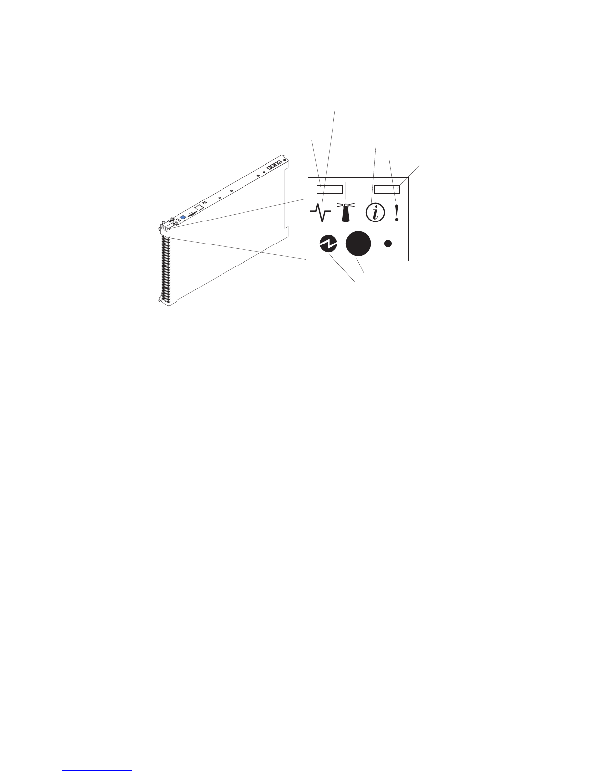
2. The following illustration shows a single-width type of blade server. The MPE
also interacts with the control panel on the blade server.
Activity LED
Location LED
KVM select button
Information LED
Blade-error LED
Media-tray select
button
Power-control button
Power-on LED
KVM select button: Press this button to associate the shared BladeCenter unit
keyboard, video, and mouse port (KVM) with the blade server. The LED on this
button flashes while the request is being processed and then is lit when the
ownership of the keyboard, video, and mouse has been transferred to the blade
server. It can take approximately 20 seconds to switch the keyboard, video, and
mouse control to the blade server.
Using a keyboard that is directly attached to the management-module, you can
press keyboard keys in the following sequence to switch KVM control between
blade servers:
NumLock NumLock bay_number Enter
Where bay_number is the two-digit number of the blade bay in which the blade
server is installed. A blade server that occupies more than one blade bay is
identified by the lowest bay number that it occupies.
If there is no response when you press the KVM select button, you can use the
management-module Web interface to determine whether local control has been
disabled on the blade server.
Notes:
1. The operating system in the blade server must provide USB support for the
blade server to recognize and use the keyboard and mouse, even if the
keyboard and mouse have PS/2-style connectors.
2. If you install a supported Microsoft Windows operating system on the blade
server while it is not the current owner of the KVM, a delay of up to 1 minute
occurs the first time that you switch the KVM to the blade server. During this
one-time-only delay, the blade server device manager enumerates the keyboard,
video, and mouse and loads the device drivers. All subsequent switching
happens in the normal KVM switching time frame (up to 20 seconds).
Media-tray select button: Press this button to associate the shared BladeCenter
unit media tray (removable-media drives and front-panel USB ports) with the
blade server. The LED on the button flashes while the request is being processed,
4 BladeCenter LS22 Type 7901 and LS42 Type 7902: Problem Determination and Service Guide
Page 17

and then is lit when the ownership of the media tray has been transferred to the
blade server. It can take approximately 20 seconds for the operating system in the
blade server to recognize the media tray.
If there is no response when you press the media-tray select button, you can use
the management-module Web interface to determine whether local control has
been disabled on the blade server.
Note: The operating system in the blade server must provide USB support for the
blade server to recognize and use the removable-media drives and front-panel USB
ports.
Activity LED: When this green LED is lit, it indicates that there is activity on the
hard disk drive or network.
Location LED: The system administrator can remotely light this blue LED to aid in
visually locating the blade server. When this LED is lit, the location LED on the
BladeCenter unit is lit also. The location LED can be turned off through the
management-module Web interface or through IBM Director Console.
Information LED: When this amber LED is lit, it indicates that information about a
system error for the blade server has been placed in the management-module
event log. The information LED can be turned off through the
management-module Web interface or through IBM Director Console.
Blade-error LED: When this amber LED is lit, it indicates that a system error has
occurred in the blade server. The blade-error LED will turn off only after the error
is corrected.
Power-on LED: This green LED indicates the power status of the blade server in
the following manner:
v Flashing rapidly: The service processor (BMC) on the blade server is
communicating with the management module.
v Flashing slowly: The blade server has power but is not turned on.
v Lit continuously: The blade server has power and is turned on.
Power-control button: This button is behind the control panel door. Press this
button to turn on or turn off the blade server.
Note: The power-control button has effect only if local power control is enabled
for the blade server. Local power control is enabled and disabled through the
management-module Web interface.
Turning on the blade server
After you connect the blade server to power through the BladeCenter unit, the
blade server can start in any of the following ways:
v You can press the power-control button on the front of the blade server (behind
the control panel door, see “Blade server controls and LEDs” on page 3) to start
the blade server.
Notes:
1. Wait until the power-on LED on the blade server flashes slowly before you
press the power-control button. While the service processor in the
Chapter 1. Introduction 5
Page 18

management module is initializing, the power-on LED does not flash, and
the power-control button on the blade server does not respond.
2. While the blade server is starting, the power-on LED on the front of the
blade server is lit. See “Blade server controls and LEDs” on page 3 for the
power-on LED states.
v If a power failure occurs, the BladeCenter unit and then the blade server can
start automatically when power is restored, if the blade server is configured
through the management module to do so.
v You can turn on the blade server remotely by using the management module.
v If the blade server is connected to power (the power-on LED is flashing slowly)
and the Wake on LAN feature has not been disabled through the management
module, the Wake on LAN feature can turn on the blade server.
Turning off the blade server
When you turn off the blade server, it is still connected to power through the
BladeCenter unit. The blade server can respond to requests from the service
processor, such as a remote request to turn on the blade server. To remove all
power from the blade server, you must remove it from the BladeCenter unit.
Shut down the operating system before you turn off the blade server. See the
operating-system documentation for information about shutting down the
operating system.
The blade server can be turned off in any of the following ways:
v You can press the power-control button on the blade server (behind the control
panel door, see “Blade server controls and LEDs” on page 3). This starts an
orderly shutdown of the operating system, if this feature is supported by the
operating system.
v If the operating system stops functioning, you can press and hold the
power-control button for more than 4 seconds to turn off the blade server.
v The management module can turn off the blade server.
– If the system is not operating correctly, the management module will
automatically turn off the blade server.
– Through the management-module Web interface, you can also configure the
management module to turn off the blade server. For additional information,
see the IBM BladeCenter Management Module User’s Guide.
System board layouts
The following illustrations show the connectors, LEDs, and switches on the blade
server system board and the multiprocessor expansion (MPE) unit. The
illustrations in this document might differ slightly from your hardware.
6 BladeCenter LS22 Type 7901 and LS42 Type 7902: Problem Determination and Service Guide
Page 19
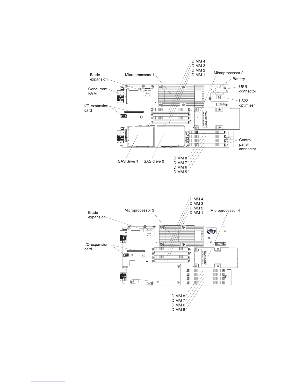
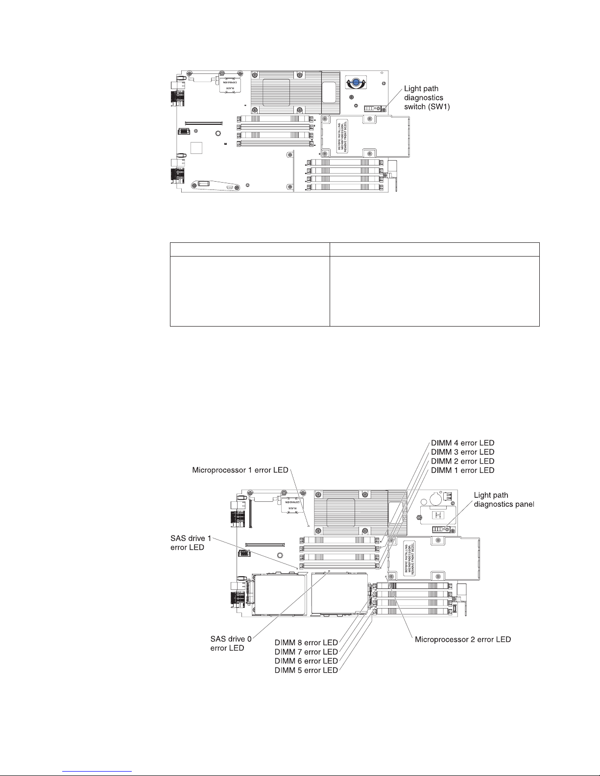
System-board connectors
The following illustration shows the connectors on the blade server system board.
The following illustration shows the connectors on the MPE unit.
Chapter 1. Introduction 7
Page 20

System-board switches
The following illustration shows the switches on the blade server system board.
The following table defines the function of each switch on the blade server system
board.
Switch number Description
SW1 Light path diagnostics switch: Press and hold to
SW4 Switch block 4 has four switches:
relight the system-board LEDs that were lit before
you removed the blade server from the
BladeCenter unit.
v 1 – Debug serial port
– Open: Disable (default)
– Closed: Enable
v 2 – Flash bank select
– Open: Primary (default)
– Closed: Backup
v 3 – Password override
– Open: Disable (default)
– Closed: Enable
v 4 – Wake on LAN power button bypass
– Open: Enable (default)
– Closed: Disable
The following illustration shows the light path diagnostics switch on the MPE unit.
8 BladeCenter LS22 Type 7901 and LS42 Type 7902: Problem Determination and Service Guide
Page 21
The following table defines the function of the light path diagnostics switch on the
MPE unit.
Switch number Description
SW1 Light path diagnostics switch – Press and hold to
System board LEDs
The following illustration shows the LEDs on the blade server system board. To
see these LEDs, remove the blade server from the BladeCenter unit, open the cover
or remove any optional expansion units, and press the light path diagnostics
switch to light any error LEDs that were lit during processing.
relight the MPE-unit LEDs that were lit before you
removed the blade server from the BladeCenter
unit.
Note: The LEDs on the system board can be lit for
a maximum of two minutes.
The following illustration shows the light path diagnostics panel on the blade
server system board.
Chapter 1. Introduction 9
Page 22
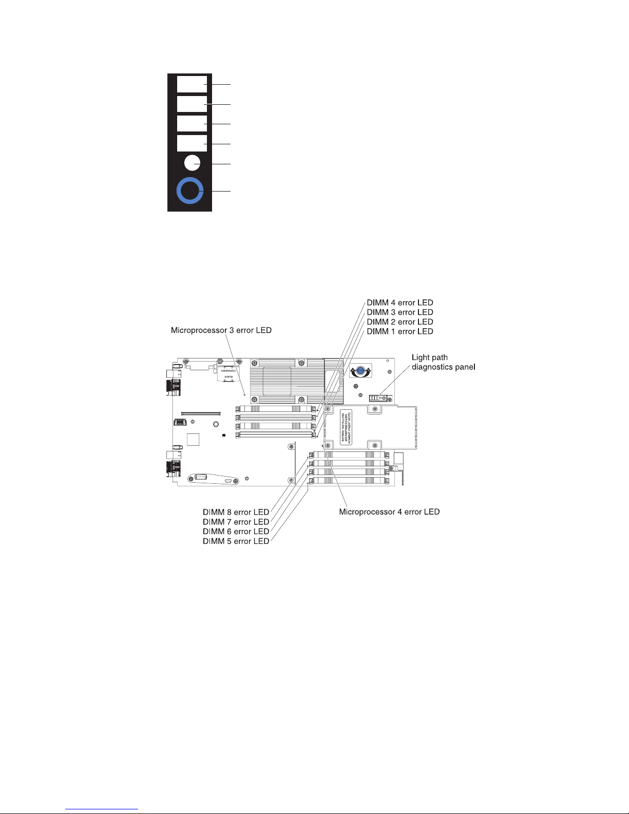
NMI
NMI error LED
MIS
S BRD
TEMP
LP 1
Microprocessor mismatch error LED
System-board error LED
Over temperature error LED
Light path diagnostics LED
Light path diagnostics switch
The following illustration shows the LEDs on the MPE unit. To see these LEDs,
remove the blade server from the BladeCenter unit, open the cover, and press the
light path diagnostics switch to light any error LEDs that were lit during
processing.
10 BladeCenter LS22 Type 7901 and LS42 Type 7902: Problem Determination and Service Guide
Page 23

Chapter 2. Configuring the blade server
This chapter describes the configuration requirements of the blade server. Before
you continue, make sure that the blade server has the latest version of firmware.
For additional information, see “Firmware updates” on page 17.
The following configuration programs come with the blade server:
v Setup Utility program
The Setup Utility program is part of the basic input/output system (BIOS). Use
it to change system settings, such as interrupt requests (IRQ), date and time, and
password. See “Using the Setup Utility program” for more information.
v LSI Logic Configuration Utility program
The LSI Logic Configuration Utility program is part of the BIOS. Use it to set the
device scan order and to set the SAS controller IDs. See “Using the LSI Logic
Configuration Utility program” on page 18 for more information.
v IBM ServerGuide Setup and Installation CD
The ServerGuide program provides software-setup tools and installation tools
that are designed for the blade server. Use this CD during the installation of the
blade server to configure basic hardware features and to simplify the installation
of the operating system. For information about using this CD, see “Using the
ServerGuide Setup and Installation CD” on page 14.
v Preboot Execution Environment (PXE) boot agent utility program
The PXE boot agent utility program is part of the BIOS code in the blade server.
Use it to select the boot protocol and other boot options and to select a
power-management option. For information about using this utility program, see
“Using the PXE boot agent utility program” on page 16.
The IBM Remote Deployment Manager (RDM) Version 4.4 program is available for
purchase. You can use IBM RDM to install a BIOS code update onto a blade server
by following the instructions in the documentation that comes with the RDM
program. To determine whether if an operating system supports the RDM program
or for updated information about RDM and information about purchasing the
software, see http://www.ibm.com/systems/management/.
Using the Setup Utility program
To start the Setup Utility program, complete the following steps:
1. Turn on the blade server (see “Turning on the blade server” on page 5).
2. Immediately give the blade server control of the BladeCenter unit shared
keyboard, video, and mouse ports.
v If you are managing the blade server by using the BladeCenter system
console, press the KVM select button on the blade server (see “Blade server
controls and LEDs” on page 3 for information).
v If you are managing the blade server from a remote location, see the IBM
BladeCenter Management Module User’s Guide, IBM BladeCenter Management
Module Command-Line Interface Reference Guide,orIBM BladeCenter Serial over
LAN Setup Guide for information and instructions.
3. When the Setup utility message is displayed, press F1.
4. Follow the instructions on the screen.
© Copyright IBM Corp. 2009 11
Page 24

Setup Utility program menu choices
The following choices are on the Setup Utility main menu. Depending on the
version of the BIOS code in the blade server, some menu choices might differ
slightly from these descriptions.
v System Summary
Select this choice to display configuration information, including the type, speed,
and cache sizes of the microprocessors and the amount of installed memory.
When you make configuration changes through other choices in the Setup
Utility program, the changes are reflected in the system summary; you cannot
change settings directly in the system summary.
– Processor Summary
Select this choice to view information about the microprocessors that are
installed in the blade server.
– USB Device Summary
Select this choice to view information about the USB devices that are installed
in the blade server.
v System Information
Select this choice to display information about the blade server. When you make
configuration changes through other choices in the Setup Utility program, some
of those changes are reflected in the system information; you cannot change
settings directly in the system information.
– Product Data
Select this choice to view the machine type and model of the blade server, the
serial number, and the revision level or issue date of the BIOS and diagnostics
code that are stored in electrically erasable programmable ROM (EEPROM).
v Devices and I/O Ports
Select this choice to view or change assignments for devices and input/output
(I/O) ports.
You can also enable or disable the integrated SAS and Ethernet controllers, all
standard ports (such as serial), and the I/O-expansion card. Enable is the
default setting for all controllers. If you disable a device, it cannot be configured,
and the operating system will not be able to detect it (this is equivalent to
disconnecting the device). If you disable the Ethernet controller, the blade server
will have no Ethernet capability.
– Remote Console Redirection
Select this choice to enable Serial over LAN (SOL) and to set remote console
communication parameters.
– Video
Select this choice to view information about the integrated video controller.
– System MAC Addresses
Select this choice to view the MAC addresses for the Ethernet controllers on
the blade server.
v Date and Time
Select this choice to set the system date and time, in 24-hour format
(hour:minute:second).
v System Security
Select this choice to set a power-on password. See “Using passwords” on page
14 for more information about passwords.
v Start Options
12 BladeCenter LS22 Type 7901 and LS42 Type 7902: Problem Determination and Service Guide
Page 25

Select this choice to view or change the start options. Changes in the start
options take effect when you start the blade server.
– Startup Sequence Options
Select this choice to view or change the startup device sequence that is set for
the blade server.
You can set keyboard operating characteristics, such as whether the blade server
starts with the keyboard number lock on or off. You can enable the blade server
to run without a diskette drive or keyboard.
You can enable or disable the PXE option for either of the integrated Gigabit
Ethernet controllers. If the MPE unit is installed, you can enable or disable the
PXE option for either of its integrated Gigabit Ethernet controllers. The default
setting for Planar Ethernet 1 and Planar Ethernet 2 is enabled, and if the MPE is
installed, the default setting for Planar Ethernet 3 and Planar Ethernet 4 is
disabled.
You can enable USB disk support, which enables the blade server to use a USB
storage device that is connected to the USB port in the media tray of the
BladeCenter unit. See the documentation for your BladeCenter unit for
additional information.
If you enable the boot fail count, the BIOS default settings will be restored after
three consecutive failures to find a boot record.
You can enable a virus-detection test that checks for changes in the boot record
when the blade server starts.
v Advanced Setup
Select this choice to change settings for advanced hardware features.
Important: The blade server might malfunction if these settings are incorrectly
configured. Follow the instructions on the screen carefully.
– Memory Settings
Select this choice to manually enable a pair of memory connectors.
If a memory error is detected during POST or memory configuration, the
blade server automatically disables the failing memory pair of memory
connectors and continues operating with reduced memory. After the problem
is corrected, you must enable the memory connectors. Use the arrow keys to
highlight the pair of memory connectors that you want to enable, and use the
arrow keys to select Enable.
– PCI Bus Control
Select this choice to view and set interrupts for PCI devices, enable or disable
PCI ROM control, and to configure the master-latency-timer value for the
blade server.
– Baseboard Management Controller (BMC) Settings
Select this choice to enable or disable the Reboot on System NMI option on
the menu. If you enable this option, the blade server will automatically restart
60 seconds after the service processor issues a nonmaskable interrupt (NMI)
to the blade server. You can also select this choice to enable or disable and set
the timeouts for the POST and OS loader watchdog timers.
– BMC Network Configuration
Select this choice to set the network addresses of the BMC.
– BMC System Event Log
Select this choice to view and clear BMC event log entries.
v Save Settings
Select this choice to save the changes that you have made in the settings.
Chapter 2. Configuring the blade server 13
Page 26

v Restore Settings
Select this choice to cancel the changes that you have made in the settings and
restore the previous settings.
v Load Default Settings
Select this choice to cancel the changes that you have made in the settings and
restore the factory settings.
v Exit Setup
Select this choice to exit from the Setup Utility program. If you have not saved
the changes that you have made in the settings, you are asked whether you
want to save the changes or exit without saving them.
Using passwords
From the System Security choice, you can set, change, and delete a power-on
password.
If you set a power-on password, you must type the power-on password to
complete the system startup and to have access to the Setup Utility menu.
You can use any combination of up to seven characters (A - Z,a-z,and0-9)for
the password. Keep a record of your password in a secure place.
If you forget the power-on password, you can regain access to the blade server by
removing the blade server battery and then reinstalling it (see “Removing the
battery” on page 48 and “Installing the battery” on page 48), or by using the
power-on password override switch (see “System-board switches” on page 8).
Using the ServerGuide Setup and Installation CD
The ServerGuide Setup and Installation CD contains a setup and installation program
that is designed for your blade server. The ServerGuide program detects the blade
server model and optional hardware devices that are installed and uses that
information during setup to configure the hardware. The ServerGuide program
simplifies operating-system installations by providing updated device drivers and,
in some cases, installing them automatically.
If a later version of the ServerGuide program is available, you can download a free
image of the ServerGuide Setup and Installation CD, or purchase the CD from the
fulfillment Web site at http://www.ibm.com/systems/management/serverguide/
sub.html. To download the free image, click IBM Service and Support Site.
Note: Changes are made periodically to the IBM Web site. The actual procedure
might vary slightly from what is in this document.
The ServerGuide program has the following features to make setup easier:
v An easy-to-use interface
v Diskette-free setup and configuration programs that are based on detected
hardware
v Device drivers that are provided for the blade server model and detected
hardware
v Operating-system partition size and file-system type that are selectable during
setup
14 BladeCenter LS22 Type 7901 and LS42 Type 7902: Problem Determination and Service Guide
Page 27

ServerGuide features
Features and functions can vary slightly with different versions of the ServerGuide
program. To learn more about the version that you have, start the ServerGuide Setup
and Installation CD and view the online overview. Not all features are supported on
all blade server models.
The ServerGuide program requires a supported IBM blade server that is associated
with an enabled startable (bootable) CD-ROM drive. In addition to the ServerGuide
Setup and Installation CD, you must have the operating-system CD to install the
operating system.
The ServerGuide program has the following features:
v Sets system date and time
v Detects installed hardware options and provides updated device drivers for
most adapters and devices
v Provides diskette-free installation for supported Windows operating systems
v Includes an online readme file with links to tips for the hardware and
operating-system installation
Setup and configuration overview
When you use the ServerGuide Setup and Installation CD, you do not need setup
diskettes. You can use the CD to configure any supported IBM blade server model.
The setup program provides a list of tasks that are required to set up the blade
server.
Note: Features and functions can vary slightly with different versions of the
ServerGuide program.
When you start the ServerGuide Setup and Installation CD, the program prompts you
to complete the following tasks:
v Select your language.
v Select your keyboard layout and country.
v View the overview to learn about ServerGuide features.
v View the readme file to review installation tips for your operating system and
adapter.
v Start the operating-system installation. You will need your operating-system CD.
Typical operating-system installation
You can use the ServerGuide program to reduce the time it takes to install an
operating system. It provides the device drivers that are required for the hardware
and for the operating system that you are installing. This section describes a
typical ServerGuide operating-system installation.
Note: Features and functions can vary slightly with different versions of the
ServerGuide program.
1. After you have completed the setup process, the operating-system installation
program starts. (You will need the operating-system CD to complete the
installation.)
Chapter 2. Configuring the blade server 15
Page 28

2. The ServerGuide program stores information about the blade server model,
service processor, hard disk drive controllers, and network adapters. Then, the
program checks the CD for newer device drivers. This information is stored
and then passed to the operating-system installation program.
3. The ServerGuide program presents operating-system partition options that are
based on the operating-system selection and the installed hard disk drives.
4. The ServerGuide program prompts you to insert the operating-system CD and
restart the server. At this point, the installation program for the operating
system takes control to complete the installation. The BladeCenter CD drive
must be associated with the blade server before you perform this step.
Installing the operating system without using ServerGuide
If you have already configured the blade server hardware and you are not using
the ServerGuide program to install the operating system, complete the following
steps to download the latest operating-system installation instructions from the
IBM Web site.
Note: Changes are made periodically to the IBM Web site. The actual procedure
might vary slightly from what is described in this document.
1. Go to http://www.ibm.com/systems/support/.
2. Under Product support, click BladeCenter.
3. From the menu on the left side of the page, click BladeCenter support search.
4. From the Task menu, select Install.
5. From the Product family list, select BladeCenter LS22 or BladeCenter LS42.
6. From the Operating system list, select your operating system and click Search
to display the available installation documents.
Using the PXE boot agent utility program
Use the Preboot Execution Environment (PXE) boot agent utility program to select
the boot protocol and other boot options and to select a power-management
option.
Note:
1. The blade server does not support Remote Program Load (RPL) selection for
the boot protocol option.
2. Enabling PXE might reduce the number of optional expansion modules that
your blade server can manage.
To start the PXE boot agent utility program, complete the following steps:
1. Turn on the server.
2. When the Broadcom NetXtreme Boot Agent vX.X.X prompt is displayed, press
Ctrl+S. You have 2 seconds (by default) to press Ctrl+S after the prompt is
displayed.
If the PXE setup prompt is not displayed, use the Setup Utility program to set
the Enable Ethernet PXE/DHCP option.
3. Use the arrow keys or press Enter to select a choice from the menu.
4. Follow the instructions on the screen to change the settings of the selected
items; then, press Enter.
16 BladeCenter LS22 Type 7901 and LS42 Type 7902: Problem Determination and Service Guide
Page 29

Firmware updates
IBM periodically makes BIOS, service processor (BMC), diagnostic firmware, and
other firmware updates available for the blade server. Go to http://
www.ibm.com/bladecenter/ to download the latest firmware for the blade server;
then, install any updates using the instructions that are included with the
downloaded file.
Important: To avoid problems and to maintain system performance, always make
sure that the BIOS, service processor (BMC), and diagnostic firmware levels are
consistent for the blade servers within the BladeCenter unit.
Configuring the Gigabit Ethernet controller
One Ethernet controller is integrated on the blade server system board. A controller
provides a 1000 Mbps full-duplex interface for connecting to one of the
Ethernet-compatible I/O modules in I/O-module bays 1 and 2, which enables
simultaneous transmission and reception of data on the Ethernet local area
network (LAN). The Ethernet controller on the system board is routed to a
different I/O module in I/O-module bay 1 or bay 2. The routing from an Ethernet
controller to an I/O-module bay varies according to the blade server type and the
operating system that is installed.
You do not have to set any jumpers or configure the controller for the blade server
operating system. However, you must install a device driver to enable the blade
server operating system to address the Ethernet controller. For device drivers and
information about configuring the Ethernet controller, see the Broadcom NetXtreme
Gigabit Ethernet Software CD that comes with the blade server. To find updated
information about configuring the controller, complete the following steps.
Note: Changes are made periodically to the IBM Web site. The actual procedure
might vary slightly from what is described in this document.
1. Go to http://www.ibm.com/systems/support/.
2. Click Support.
3. Under Support information, click Product support and information.
4. Under Popular links, click Publications lookup.
5. From the Product family menu, select BladeCenter LS22 or BladeCenter LS42
and click Go.
Note: If an 1801 error code is displayed during startup and the startup process
stops, the BIOS is trying to copy too much data from the device boot ROM into
write-protected RAM. To correct an 1801 error that halts the boot process, restart
the blade server, start the Setup Utility program (see “Using the Setup Utility
program” on page 11), and disable unnecessary ROM shadowing. Only the device
boot ROMs that enable the following components must be shadowed during
startup:
v Video
v Hard disk drive (if you are using this as a primary or secondary boot device)
v PXE (if you are using PXE as a primary or secondary boot device)
v One Ethernet controller (if you are using PXE as a primary or secondary boot
device)
Chapter 2. Configuring the blade server 17
Page 30

The remaining options and components will be enabled by device drivers in the
operating system.
Configuring a SAS RAID array
Two SAS drives can be used to implement and manage RAID level-0 (striping) or
RAID level-1 (mirror) arrays in operating systems that are listed at
http://www.ibm.com/servers/eserver/serverproven/compat/us/. For more
information, see the Installation and User’s Guide.
Important: You must create the RAID array before you install the operating system
on the blade server.
Use the LSI Configuration Utility program to configure the SAS RAID (see “Using
the LSI Logic Configuration Utility program”).
Using the LSI Logic Configuration Utility program
You can use the LSI Logic Configuration Utility program to perform the following
tasks:
v Set the SAS device scan order
v Set the SAS ID for the controller
v Manage the SAS RAID configuration
To start the LSI Logic Configuration Utility program, complete the following steps:
1. Turn on the blade server, and make sure that the blade server is the owner of
the keyboard, video, and mouse (see “Turning on the blade server” on page 5).
2. When the <<<Press Ctrl-C to start LSI Logic Configuration Utility>>>
prompt is displayed, press Ctrl+C.
3. Use the arrow keys to select the controller from the list of adapters; then, press
Enter.
4. Follow the instructions on the screen to change the settings of the selected
items; then, press Enter. If you select SAS Topology or Advanced Adapter
Properties, additional screens are displayed.
18 BladeCenter LS22 Type 7901 and LS42 Type 7902: Problem Determination and Service Guide
Page 31

Chapter 3. Parts listing, Types 7901 and 7902
The following replaceable components are available for the IBM BladeCenter LS22
Type 7901 and LS42 Type 7902 blade server. For an updated parts listing on the
Web, complete the following steps.
Note: Changes are made periodically to the IBM Web site. The actual procedure
might vary slightly from what is described in this document.
1. Go to http://www.ibm.com/systems/support/.
2. Under Product support, click BladeCenter.
3. Under Popular links, click Part documents lookup.
4. From the Product Family menu, select BladeCenter LS22 or BladeCenter LS42,
and click Continue.
Note: The illustrations in this document might differ slightly from your hardware.
© Copyright IBM Corp. 2009 19
Page 32

Replaceable components are of four types:
v Consumable parts: Purchase and replacement of consumable parts (components,
such as batteries and printer cartridges, that have depletable life) is your
responsibility. If IBM acquires or installs a consumable part at your request, you
will be charged for the service.
v Tier 1 customer replaceable unit (CRU): Replacement of Tier 1 CRUs is your
responsibility. If IBM installs a Tier 1 CRU at your request, you will be charged
for the installation.
v Tier 2 customer replaceable unit: You may install a Tier 2 CRU yourself or
request IBM to install it, at no additional charge, under the type of warranty
service that is designated for your server.
v Field replaceable unit (FRU): FRUs must be installed only by trained service
technicians.
For information about the terms of the warranty and getting service and assistance,
see the Warranty and Support Information document.
20 BladeCenter LS22 Type 7901 and LS42 Type 7902: Problem Determination and Service Guide
Page 33

Table 1. Customer and field replaceable units, Type 7901 and Type 7902
Index Description
CRU part
number
(Tier 1)
CRU part
number
(Tier 2)
FRU part
1 Cover (all models) 46C7201
MPE board assembly (type 7902 models 3Qx, CQx, EDx, EMx,
2
EUx, HVx, JVx)
Bezel, MPE unit (type 7902 models 3Qx, CQx, EUx, EMx, HVx,
3
JVx)
40K5904
4 Filler, microprocessor heat sink (all models) 40K5929
5 Heat sink, microprocessor (all models) 40K5895
Microprocessor, quad-core Opteron 2384, 2.7 GHz, 115W (type 7901
6
model 3Sx)
Microprocessor, quad-core Opteron 8384, 2.7 GHz, 115W (type 7902
6
models 3Sx, ESx, EUx, HVx, JVx)
Microprocessor, quad-core Opteron 8380, 2.5 GHz, 115W (type 7902
6
model 1Sx)
Microprocessor, quad-core Opteron 2356, 2.3 GHz, 115W (type 7901
6
models CQx, EDx)
Microprocessor, quad-core Opteron 8356, 2.3 GHz, 115W (type 7902
6
models CQx, EDx)
Microprocessor, quad-core Opteron 2347 HE, 1.9 GHz, 79W (type
6
7901 model 3Qx)
Microprocessor, quad-core Opteron 8347 HE, 1.9 GHz, 79W (type
6
7902 model 3Qx)
Microprocessor, quad-core Opteron 2376 HE, 2.3 GHz, 79 W (type
6
7901 model 3Lx)
Microprocessor, quad-core Opteron 8374 HE, 2.2 GHz, 79 W
6
(option)
Microprocessor, quad-core Opteron 2435 HE, 2.6 GHz, 115 W (type
6
7901 model 62x)
Microprocessor, quad-core Opteron 8431 HE, 2.4 GHz, 115 W (type
6
7902 models 61x)
Microprocessor, quad-core Opteron 8335 HE, 2.6 GHz, 115 W (type
6
7902 model 62x)
Microprocessor, quad-core Opteron 8376 HE, 2.3 GHz, 79 W (type
6
7902 models 3Lx, ELx, EMx)
LS22 optimizer (type 7901 models 3Lx, 3Qx, 3Sx, 62x, CQx, EDx)
7
(type 7902 models 1Sx, 3Lx, 3Sx, 61x, 62x, ELx, ESx)
Bezel assembly, blade server (type 7901 models 3Lx, 3Qx, 3Sx, 62x,
8
CQx, EDx)
Bezel assembly, blade server (type 7902 models 1Sx, 3Lx, 3Qx, 3Sx,
8
61x, 62x, CQx, EDx, ELx, EMx, ESx, EUx, HVx JVx)
44R4915
43W9877
43W9882
9 System-board assembly (all models) 49Y4790
10 Filler, DIMM (all models) 40K5989
11 Solid state drive, 15.8 GB SAS (option) 43W7617
11 Solid state drive, 32.8 GB SAS (option) 43W7621
11 Hard disk drive, 73 GB SAS (option) 43X0847
number
46M6832
46M6806
46M6815
46M6811
44R4959
44R4969
44X1540
44X1550
46M6878
46M6883
49Y7198
49Y7199
49Y7200
46M6888
Chapter 3. Parts listing, Types 7901 and 7902 21
Page 34

Table 1. Customer and field replaceable units, Type 7901 and Type 7902 (continued)
CRU part
Index Description
11 Hard disk drive, 73.4 GB SAS (option) 26K5779
11 Hard disk drive, 146.8 GB SAS (option) 42D0422
Memory, 1 GB PC2-5300, VLP (type 7901 models 3Lx, 3Qx, 3Sx,
12
62x, CQx) (type 7902 models 1Sx, 3Lx, 3Qx, 3Sx, 61x, 62x, CQx)
Memory, 2 GB PC2-5300, VLP (models type 7901 model EDx) (type
12
7902 models EDx, ELx, EMx, ESx, EUx, HVx, JVx)
12 Memory, 4 GB PC2-5300, VLP (option) 46C7522
12 Memory, 4 GB PC2-6400, VLP (option) 46C7523
12 Memory, 8 GB PC2-5300, VLP (option) 44T1546
Alcohol wipe (all models) 59P4739
Broadcom 2–port 10 GB ethernet CFFH NIC daughter card (type
7902 models HVx, JVx)
Concurrent KVM expansion card (option) 13N0842
Cisco 4X InfiniBand Host Channel Adapter expansion card
(option)
Cisco Systems InfiniBand HCA expansion card (option) 32R1899
Dust cover, microprocessor (all models) 40K5936
Emulex 4 Gb SFF Fibre Channel expansion card (option) 39Y9184
Emulex 4 Gb CFFv fibre channel expansion card (option) 43W6862
Ethernet expansion card (CFFv) (option) 46M6189
Ethernet expansion card (option) 43W4454
Filler, hard disk drive (all models) 40K5928
IBM Bladecenter PCI Express I/O expansion unit (BPE-3) (option) 44W4390
IBM BladeCenter storage and I/O expansion blade (option) 40K1739
IBM Gigabit Ethernet expansion card (option) 39M4630
IBM ServeRAID 8k-l SAS Controller expansion card (option) 25R8079
IBM ServeRAID 8k SAS Controller expansion card (option) 25R8076
IBM USB key for VMware ESXi (type 7901 model CTO) (type 7902
model HVx)
InfiniBand 4X DDR CFF expansion (option) 43W4425
Infiniband 4X high-speed expansion card (option) 32R1763
number
(Tier 1)
46C0523
46C0518
32R1763
42D0545
CRU part
number
(Tier 2)
FRU part
number
44W4469
22 BladeCenter LS22 Type 7901 and LS42 Type 7902: Problem Determination and Service Guide
Page 35

Table 1. Customer and field replaceable units, Type 7901 and Type 7902 (continued)
CRU part
Index Description
number
(Tier 1)
Kit, miscellaneous parts (all models)
44X2229
v 2 socket alignment pins
v 1 CPU socket protective cover
v 4 HSDC support pins
v 2 HSDC support studs
v 2 SFF HSDC brackets
v 2 CFF HSDC brackets
v 2 alignment pins
v 6 HSDC M3x6 screws
v 20 3.5x5 screws
v 1 DIMM air baffle
Label, FRU list (all models) 44X2228
Label, system service (all models) 44X2227
Myrinet expansion card (option) 32R1845
Myrinet card (option) 32R1845
PCI I/O expansion unit (PEU-2) (option) 44W4403
PCI I/O expansion unit 3e card (option) 43W4390
QLogic 4 Gb Standard Fibre (option) 26R0889
QLogic iSCSI expansion card (option) 49Y4236
QLogic (CFFh) Ethernet and 4 Gb Fibre Channel Expansion Card
(option)
39Y9304
QLogic (CFFv) 4 Gb Fibre Channel Expansion (option) 41Y8525
QLogic (SFF) 4 Gb Fibre Channel (option) 26R0893
Microsoft Windows Server 2008 Datacenter 32/64 bit, Multilingual 49Y0222
Microsoft Windows Server 2008 Datacenter 32/64 bit, Simplified
Chinese
Microsoft Windows Server 2008 Datacenter 32/64 bit, Traditional
Chinese
Microsoft Windows Server 2008 Standard Edition 32/64 bit 1-4
microprocessors, Multilingual
Microsoft Windows Server 2008 Standard Edition 32/64 bit 1-4
microprocessors, Simplified Chinese
Microsoft Windows Server 2008 Standard Edition 32/64 bit 1-4
microprocessors, Traditional Chinese
Microsoft Windows Server 2008 Enterprise Edition 32/64 bit 1-8
microprocessors, Multilingual
Microsoft Windows Server 2008 Enterprise Edition 32/64 bit 1-8
microprocessors, Simplified Chinese
Microsoft Windows Server 2008 Enterprise Edition 32/64 bit 1-8
microprocessors, Traditional Chinese
VMware ESX Server 3i version 3.5 46D0762
VMware ESX Server 3i version 3.5 update 2 46M9236
CRU part
number
(Tier 2)
FRU part
number
49Y0223
49Y0224
49Y0892
49Y0893
49Y0894
49Y0895
49Y0896
49Y0897
Chapter 3. Parts listing, Types 7901 and 7902 23
Page 36

Table 1. Customer and field replaceable units, Type 7901 and Type 7902 (continued)
CRU part
Index Description
VMware ESX Server 3i version 3.5 update 3 46M9237
SAS (CFFv) expansion card (option) 39Y9188
SFF Fibre Channel expansion card (option) 26K4859
SFF Gigabit Ethernet expansion card (option) 46M5963
Tray, SAS hard disk drive (all models) 31R2239
VMware ESX Server 3i version 3.5 46D0762
VMware ESX Server 3i version 3.5 update 2 46M9236
VMware ESX Server 3i version 3.5 update 3 46M9237
VMware ESX Server 3i version 3.5 update 4 46M9238
Microsoft Windows Server 2008 Datacenter 32/64 Bit, Multilingual 49Y0222
Microsoft Windows Server 2008 Datacenter 32/64 Bit, Simplified
Chinese
Microsoft Windows Server 2008 Datacenter 32/64 Bit, Traditional
Chinese
Windows Server 2008 Standard Edition 32/64 Bit (1-4 Processors),
Multilingual
Windows Server 2008 Standard Edition 32/64 Bit (1-4 Processors),
Simplified Chinese
Windows Server 2008 Standard Edition 32/64 Bit (1-4 Processors),
Traditional Chinese
Windows Server 2008 Enterprise Edition 32/64 Bit (1-8 Processors),
Multilingual
Windows Server 2008 Enterprise Edition 32/64 Bit (1-8 Processors),
Simplified Chinese
Windows Server 2008 Enterprise Edition 32/64 Bit (1-8 Processors),
Traditional Chinese
number
(Tier 1)
49Y0223
49Y0224
49Y0892
49Y0893
49Y0894
49Y0895
49Y0896
49Y0897
CRU part
number
(Tier 2)
FRU part
number
Consumable parts are not covered by the IBM Statement of Limited Warranty. The
following consumable parts are available for purchase from the retail store.
Table 2. Consumable parts, Type 7901 and Type 7902
Description Part number
Battery, 3.0 volt 43W9859
To order a consumable part, complete the following steps:
1. Go to http://www.ibm.com.
2. From the Products menu, select Upgrades, accessories & parts.
3. Click Obtain maintenance parts; then, follow the instructions to order the part
from the retail store.
If you need help with your order, call the toll-free number that is listed on the
retail parts page, or contact your local IBM representative for assistance.
24 BladeCenter LS22 Type 7901 and LS42 Type 7902: Problem Determination and Service Guide
Page 37

Chapter 4. Removing and replacing blade server components
Replaceable components are of four types:
v Consumable parts: Purchase and replacement of consumable parts (components,
such as batteries and printer cartridges, that have depletable life) is your
responsibility. If IBM acquires or installs a consumable part at your request, you
will be charged for the service.
v Tier 1 customer replaceable unit (CRU): Replacement of Tier 1 CRUs is your
responsibility. If IBM installs a Tier 1 CRU at your request, you will be charged
for the installation.
v Tier 2 customer replaceable unit: You may install a Tier 2 CRU yourself or
request IBM to install it, at no additional charge, under the type of warranty
service that is designated for your server.
v Field replaceable unit (FRU): FRUs must be installed only by trained service
technicians.
See Chapter 3, “Parts listing, Types 7901 and 7902,” on page 19 to determine
whether a component is a Tier 1 CRU, Tier 2 CRU, or FRU.
For information about the terms of the warranty and getting service and assistance,
see the Warranty and Support Information document.
Installation guidelines
Before you remove or replace a component, read the following information:
v Read the safety information that begins on page “Safety statements” on page viii
and the guidelines in “Handling static-sensitive devices” on page 26. This
information will help you work safely.
v When you install your new blade server, take the opportunity to download and
apply the most recent firmware updates. This step will help to make sure that
any known issues are addressed and that your blade server is ready to function
at maximum levels of performance. To download firmware updates for your
blade server:
Note: Changes are made periodically to the IBM Web site. The actual procedure
might vary slightly from what is described in this document.
1. Go to http://www.ibm.com/bladecenter/.
2. Click Support.
3. Under Support information, click Product support and information.
4. Under Popular links, click Publications lookup.
5. From the Product family menu, select BladeCenter LS22 or BladeCenter
LS42 and click Go.
Download and install the latest firmware for the management module installed
in your BladeCenter unit (see the documentation for your management module).
v Observe good housekeeping in the area where you are working. Put removed
covers and other parts in a safe place.
v Back up all important data before you make changes to disk drives.
© Copyright IBM Corp. 2009 25
Page 38

v Before you remove a hot-swap blade server from the BladeCenter unit, you must
shut down the operating system and turn off the blade server. You do not have
to shut down the BladeCenter unit itself.
v Blue on a component indicates touch points, where you can grip the component
to remove it from or install it in the blade server, or open or close a latch.
v Orange on a component or an orange label on or near a component indicates
that the component can be hot-swapped, which means that you can remove or
install the component while the BladeCenter unit is running. (Orange can also
indicate touch points on hot-swap components.) See the instructions for
removing or installing a specific hot-swap component for any additional
procedures that you might have to perform before you remove or install the
component.
v When you are finished working on the blade server, reinstall all safety shields,
guards, labels, and ground wires.
v For a list of supported optional devices for the blade server, see
http://www.ibm.com/servers/eserver/serverproven/compat/us/.
System reliability guidelines
To help ensure proper cooling and system reliability, make sure that the following
requirements are met:
v Each microprocessor socket always contains either a microprocessor dust cover
and heat sink filler or a microprocessor and heat sink. If the blade server has
only one microprocessor, it must be installed in microprocessor socket 1.
v Do not operate the BladeCenter unit without a blade server, expansion unit, or
filler installed in each blade bay. See the documentation for your BladeCenter
unit for additional information.
v Make sure that the ventilation holes on the blade server are not blocked.
v The blade server battery must be operational. If the battery becomes defective,
replace it immediately. For instructions, see the Problem Determination and Service
Guide.
Handling static-sensitive devices
Attention: Static electricity can damage the blade server and other electronic
devices. To avoid damage, keep static-sensitive devices in their static-protective
packages until you are ready to install them.
To reduce the possibility of damage from electrostatic discharge, observe the
following precautions:
v Limit your movement. Movement can cause static electricity to build up around
you.
v Handle the device carefully, holding it by its edges or its frame.
v Do not touch solder joints, pins, or exposed circuitry.
v Do not leave the device where others can handle and damage it.
v While the device is still in its static-protective package, touch it to an unpainted
metal part of the BladeCenter unit or any unpainted metal surface on any other
grounded rack component in the rack in which you are installing the device for
at least 2 seconds. This drains static electricity from the package and from your
body.
26 BladeCenter LS22 Type 7901 and LS42 Type 7902: Problem Determination and Service Guide
Page 39

v Remove the device from its package and install it directly into the blade server
without setting it down. If it is necessary to set down the device, put it back into
its static-protective package. Do not place the device on the blade server cover
or on a metal surface.
v Take additional care when you handle devices during cold weather. Heating
reduces indoor humidity and increases static electricity.
Returning a device or component
If you are instructed to return a device or component, follow all packaging
instructions, and use any packaging materials for shipping that are supplied to
you.
Removing the blade server from a BladeCenter unit
The following illustration shows how to remove an LS22 Type 7901 blade server
from a Type 8677 BladeCenter unit. The procedure for removing the LS42 Type
7902 blade server and MPE is the same. The appearance of your BladeCenter unit
might be different. See the documentation for your BladeCenter unit for additional
information.
Release handles
(open)
Attention:
v To maintain proper system cooling, do not operate the BladeCenter unit without
a blade server, expansion unit, or filler installed in each blade bay.
v When you remove the blade server, note the bay number. Reinstalling a blade
server into a different bay from the one it was removed from might have
unintended consequences. Some configuration information and update options
are established according to bay number; if you reinstall the blade server into a
different bay, you might have to reconfigure the blade server.
To remove the blade server, complete the following steps:
1. Read the safety information that begins on page “Safety statements” on page
viii and “Installation guidelines” on page 25.
2. If the blade server is operating, shut down the operating system.
3. Press the power-control button (behind the blade server control panel door) to
turn off the blade server (see “Turning off the blade server” on page 6 for more
information).
Chapter 4. Removing and replacing blade server components 27
Page 40

Attention: Wait at least 30 seconds, until the hard disk drives stop spinning,
before you proceed to the next step. The activity LED on the control panel
turns off when the hard disk drive has stopped spinning (see “Blade server
controls and LEDs” on page 3).
4. Pull the two release handles to the open position. The blade server moves out
of the bay approximately 0.6 cm (0.25 inch).
5. Pull the blade server out of the bay.
6. Place either a blade filler or another blade server in the bay within 1 minute.
Installing the blade server in a BladeCenter unit
The following illustration shows how to install a single-width type of blade server
into a Type 8677 BladeCenter unit. The procedure for installing the double-width
type of blade server is the same. The appearance of your BladeCenter unit might
be different; see the documentation for your BladeCenter unit for additional
information.
Release handles
(open)
To install a blade server in a BladeCenter unit, complete the following steps.
Statement 21
CAUTION:
Hazardous energy is present when the blade server is connected to the power
source. Always replace the blade cover before installing the blade server.
1. Read the safety information that begins on page “Safety statements” on page
viii and “Installation guidelines” on page 25.
2. If you installed a blade filler or another blade server in the bay from which you
removed the blade server, remove it from the bay.
28 BladeCenter LS22 Type 7901 and LS42 Type 7902: Problem Determination and Service Guide
Page 41

Attention: Install the blade server in the same blade bay from which you
removed it. Some blade server configuration information and update options
are established according to bay number. Reinstalling a blade server into a
different blade bay from the one from which it was removed could have
unintended consequences, and you might have to reconfigure the blade server.
3. Make sure that the release levers on the blade server are in the open position
(perpendicular to the blade server).
4. Slide the blade server into the blade bay until it stops.
5. Push the release levers on the front of the blade server to the closed position.
6. Turn on the blade server (see “Turning on the blade server” on page 5).
7. Make sure that the power-on LED on the blade server control panel is lit
continuously, indicating that the blade server is receiving power and is turned
on.
8. Optional: Write identifying information on one of the labels that come with the
blade servers and place the label on the BladeCenter unit bezel. See the
documentation for your BladeCenter unit for information about the label
placement.
Important: Do not place the label on the blade server or in any way block the
ventilation holes on the blade server.
9. Reinstall the bezel assembly on the BladeCenter T unit (BladeCenter T unit
only). For detailed instructions for reinstalling the bezel assembly, see the
Installation and User’s Guide that comes with the BladeCenter T unit.
If you have changed the configuration of the blade server or if you are installing a
different blade server from the one that you removed, you must configure the
blade server through the Setup Utility program, and you might have to install the
blade server operating system. Detailed information about these tasks is available
in the Installation and User’s Guide.
Removing and replacing consumable parts and Tier 1 CRUs
Replacement of consumable parts and Tier 1 CRUs are your responsibility. If IBM
installs a Tier 1 CRU at your request, you will be charged for the installation.
The illustrations in this document might differ slightly from your hardware.
Removing the blade server cover
Note: If the blade server has an expansion unit that does not have a removable
cover, remove the expansion unit (see “Removing an expansion unit” on page 31).
The following illustration shows how to remove the cover from a single-width
model blade server; removing the cover from a double-width model blade server is
similar.
Chapter 4. Removing and replacing blade server components 29
Page 42

To remove the blade server cover, complete the following steps.
1. Read the safety information that begins on page “Safety statements” on page
viii and “Installation guidelines” on page 25.
2. If the blade server is installed in a BladeCenter unit, remove it (see “Removing
the blade server from a BladeCenter unit” on page 27).
3. Carefully lay the blade server down on a flat, static-protective surface, with the
cover side up.
4. Press the blade-cover release on each side of the blade server or expansion unit
and lift the cover open.
5. Lift the cover from the blade server and store it for future use.
6. If you are instructed to return the cover, follow all packaging instructions, and
use any packaging materials for shipping that are supplied to you.
Installing the blade server cover
The following illustration shows how to install the cover on a single-width model
blade server; installing the cover on a double-width model blade server is similar.
Statement 21
30 BladeCenter LS22 Type 7901 and LS42 Type 7902: Problem Determination and Service Guide
Page 43

CAUTION:
Hazardous energy is present when the blade server is connected to the power
source. Always replace the blade cover before installing the blade server.
Attention: You cannot insert the blade server into the BladeCenter unit until the
cover is installed and closed. Do not attempt to override this protection.
To install the blade server cover, complete the following steps.
1. Read the safety information that begins on page “Safety statements” on page
viii and “Installation guidelines” on page 25.
2. If you removed the bezel assembly, install it (see “Installing the bezel
assembly” on page 34 for instructions).
3. If you removed an expansion unit from a double-width type blade server,
install it (see “Installing an expansion unit” on page 32 for instructions).
4. Lower the cover so that the slots at the rear slide down onto the pins at the
rear of the blade server. Before closing the cover, check that all components are
installed and seated correctly and that you have not left loose tools or parts
inside the blade server.
5. Pivot the cover to the closed position, as shown in the illustration, until it clicks
into place.
Note: Do not allow the control-panel cable to become caught between the
cover and the bezel assembly or air baffle.
6. Install the blade server into the BladeCenter unit (see “Installing the blade
server in a BladeCenter unit” on page 28).
Removing an expansion unit
To remove an expansion unit, complete the following steps.
Note: The following illustration shows how to remove a Multiprocessor Expansion
(MPE) unit from the blade server; removing another type of expansion unit from a
blade server is similar.
Chapter 4. Removing and replacing blade server components 31
Page 44

1. Read the safety information beginning on page “Safety statements” on page viii
and “Installation guidelines” on page 25.
2. If the blade server is installed in a BladeCenter unit, remove it (see “Removing
the blade server from a BladeCenter unit” on page 27).
3. Carefully lay the blade server down on a flat, static-protective surface, with the
cover side up.
4. Remove the blade server cover, if one is installed (see “Removing the blade
server cover” on page 29).
5. If the expansion unit has an extraction device (such as a thumbscrew or a
lever), use it to disengage the expansion unit from the blade server; otherwise,
press the blade-cover release on each side of the blade server to disengage the
expansion unit from the blade server.
Attention: Do not rotate the expansion unit open further than 90° to avoid
damage to the connectors at the rear of the blade server.
6. Rotate the expansion unit open; then, lift the expansion unit from the blade
server.
7. If you are not installing an expansion unit immediately, make sure that the
protective covers are installed on the blade expansion connector and the MPE
unit connector.
8. If you are instructed to return the expansion unit, follow all packaging
instructions, and use any packaging materials for shipping that are supplied to
you.
Installing an expansion unit
The following illustration shows how to install a Multiprocessor Expansion (MPE)
unit on the blade server; installing another type of expansion unit on a blade
server is similar.
32 BladeCenter LS22 Type 7901 and LS42 Type 7902: Problem Determination and Service Guide
Page 45

To install an expansion unit, complete the following steps.
1. Remove the cover from the blade expansion connector, if one is installed.
Attention: If a high-speed expansion card is installed in the blade server
system board, you cannot install an expansion unit until the high-speed
expansion card is removed. A high-speed expansion card can only be installed
in the MPE in double-wide blade configurations. For more information see
“Installing an I/O expansion card” on page 43.
2. If a blade-expansion-connector cover is installed in the blade server, remove it
(see “System-board connectors” on page 7).
3. Touch the static-protective package that contains the expansion unit to any
unpainted metal surface on the BladeCenter unit or any unpainted metal surface
on any other grounded rack component; then, remove the expansion unit from
the package.
4. Orient the expansion unit above the blade server.
5. Lower the expansion unit so that the slots at the rear slide down onto the cover
pins at the rear of the blade server; then, pivot the expansion unit down onto
the blade server.
6. If the expansion unit has an extraction device (such as a thumbscrew or a
lever), use it to fully engage the expansion unit on the blade server; otherwise,
press the expansion unit firmly into the closed position until it clicks into place.
7. Install the blade-server cover on the expansion unit, if required (see “Installing
the blade server cover” on page 30).
8. Install the blade server into the BladeCenter unit (see “Installing the blade
server in a BladeCenter unit” on page 28).
Removing the bezel assembly
The following illustration shows how to remove the bezel assembly from the blade
server; removing the bezel assembly from the MPE unit is similar.
Chapter 4. Removing and replacing blade server components 33
Page 46

To remove the bezel assembly, complete the following steps.
1. Read the safety information that begins on page “Safety statements” on page
viii and “Installation guidelines” on page 25.
2. Remove the blade server cover (see “Removing the blade server cover” on page
29).
3. If you are removing the bezel assembly from the blade server and an MPE unit
or expansion unit is installed, remove the MPE unit (see “Removing an
expansion unit” on page 31).
4. Press the bezel-assembly release on each side of the blade server and pull the
bezel assembly away from the blade server approximately 1.2 cm (0.5 inch).
5. If you are removing the bezel assembly from a blade server, disconnect the
control-panel cable from the control-panel connector by lifting up on the
control-panel cable. If you are removing a bezel assembly on an MPE unit, go
to step 6.
6. Pull the bezel assembly away from the blade server.
7. If you are instructed to return the bezel assembly, follow all packaging
instructions, and use any packaging materials for shipping that are supplied to
you; otherwise, store the bezel assembly in a safe place.
Installing the bezel assembly
The following illustration shows how to install the bezel assembly on the blade
server; installing the bezel assembly on the MPE unit is similar.
34 BladeCenter LS22 Type 7901 and LS42 Type 7902: Problem Determination and Service Guide
Page 47

To install the bezel assembly, complete the following steps.
1. If you are installing the bezel assembly on a blade server, connect the
control-panel cable to the control-panel connector. If you are installing a bezel
assembly on an MPE unit, go to step 2.
Note: Align the control-panel cable with the notch in the air baffle on the blade
server in front of the control-panel connector.
2. Carefully slide the bezel assembly onto the blade server until it clicks into
place.
Note: Do not allow the control-panel cable to become caught between the bezel
assembly and the air baffle or blade server chassis.
3. Install the MPE unit or expansion unit, if you removed one while removing the
bezel assembly (see “Installing an expansion unit” on page 32).
4. Install the cover onto the blade server (see “Installing the blade server cover”
on page 30).
5. Install the blade server into the BladeCenter (see “Installing the blade server in
a BladeCenter unit” on page 28).
Removing a SAS drive
The following illustration shows how to remove a SAS drive from the blade server.
Chapter 4. Removing and replacing blade server components 35
Page 48

To remove a SAS drive, complete the following steps.
1. Read the safety information that begins on page “Safety statements” on page
viii and “Installation guidelines” on page 25.
2. If the blade server is installed in a BladeCenter unit, remove it (see “Removing
the blade server from a BladeCenter unit” on page 27).
3. Remove the blade server cover (see “Removing the blade server cover” on page
29).
4. If you are removing a drive from the blade server and an MPE unit or
expansion unit is installed, remove the MPE unit (see “Removing an expansion
unit” on page 31).
5. Press the release lever away from the SAS drive; then, remove the SAS drive.
Attention: If two SAS drives are installed, you might damage one or both of
the drives if you use too much force to remove the drive.
v If you are removing a SAS drive from SAS connector 0, slide the drive
backward to disengage it from the connector at the front of the drive tray;
then, lift the drive out of the drive tray.
v If you are removing a SAS drive from SAS connector 1, slide the drive
forward to disengage it from the connector at the rear of the drive tray then,
lift the drive out of the drive tray.
6. If you are instructed to return the drive, follow all packaging instructions, and
use any packaging materials for shipping that are supplied to you.
Installing a SAS drive
The following illustration shows how to install the SAS drive in the blade server.
To install a SAS drive, complete the following steps.
1. Touch the static-protective package that contains the hard disk drive to any
unpainted metal surface on the BladeCenter unit or any unpainted metal surface
on any other grounded rack component; then, remove the hard disk drive from
the package.
Attention: Do not press on the top of the drive. Pressing the top might
damage the drive.
2. Place the hard disk drive into the drive tray and push it into the connector at
the end of the drive tray, until the drive moves past the lever at the front of the
tray.
36 BladeCenter LS22 Type 7901 and LS42 Type 7902: Problem Determination and Service Guide
Page 49

3. Install the MPE unit or expansion unit, if you removed one while you removed
the SAS drive (see “Installing an expansion unit” on page 32).
4. Install the blade server cover (see “Installing the blade server cover” on page
30).
5. Install the blade server into the BladeCenter unit (see “Installing the blade
server in a BladeCenter unit” on page 28).
Removing a memory module
The following illustration shows how to remove a DIMM from the blade server or
the MPE unit.
To remove a DIMM, complete the following steps.
1. Read the safety information that begins “Safety statements” on page viii and
“Installation guidelines” on page 25
2. If the blade server is installed in a BladeCenter unit, remove it (see “Removing
the blade server from a BladeCenter unit” on page 27).
3. Remove the blade server cover (see “Removing the blade server cover” on page
29).
4. If you are removing a DIMM from the blade server and an MPE unit or
expansion unit is installed, remove the MPE unit (see “Removing an expansion
unit” on page 31).
5. Locate the DIMM connectors (see “System-board connectors” on page 7).
Determine which DIMM you want to remove from the blade server.
Attention: To avoid breaking the retaining clips or damaging the DIMM
connectors, handle the clips gently.
6. Move the DIMM retaining clips on the side of the DIMM connector to the open
position by pressing the retaining clips away from the microprocessor that is
installed closest to the DIMM slots.
7. Using your fingers, pull the DIMM out of the DIMM connector.
Attention: A DIMM or DIMM filler must be installed in the DIMM connector
before turning the blade server on (see “Installing a memory module” on page
38).
8. If you are instructed to return the DIMM, follow all packaging instructions, and
use any packaging materials for shipping that are supplied to you.
Chapter 4. Removing and replacing blade server components 37
Page 50

Installing a memory module
Note: If you are replacing a faulty DIMM, make sure that the replacement DIMM
is the correct type of memory. For each installed microprocessor, a set of four
DIMM connector is enabled (see the following table for more information). If you
are adding DIMMs, install the DIMMs in pairs into the DIMM connectors that are
enabled. See the Installation and User’s Guide for additional information about the
type of memory that is compatible with the server.
The following table lists the available microprocessor and DIMM combinations for
the blade server and MPE.
Note: Only the BladeCenter LS42 (Type 7902) with an MPE installed can support
more than two microprocessors.
Number of
micro-
processors
1 (in blade
server)
2 (in blade
server)
3 (2 in blade
server, 1 in MPE
unit)
4 (2 in blade
server, 2 in MPE
unit)
Blade server MPE
DIMM connector DIMM connector
12345 6781234 5 67 8
XX
XXXX
XX
XXXX
XXXXX X
XXXXXXXX
XX
XXXX
XXXXXX
XXXXX X X X
XXXXX XXXX X
XXXXX XXXXXXX
XX
XXXX
XXXXXX
XXXXXXXX
XXXXX X X X X X
XXXXX XXXX X X X
XXXXX XXXXXXX X X
XXXXX XXXXXXX X XX X
The following illustration shows how to install a DIMM in the blade server or the
MPE unit.
38 BladeCenter LS22 Type 7901 and LS42 Type 7902: Problem Determination and Service Guide
Page 51

To install a DIMM, complete the following steps.
1. Read the safety information that begins on page “Safety statements” on page
viii and “Installation guidelines” on page 25.
2. Read the documentation that comes with the DIMM.
3. Locate the DIMM connectors (see “System-board connectors” on page 7).
Determine the connectors into which you will install the DIMMs.
4. Touch the static-protective package that contains the DIMM to any unpainted
metal surface on the BladeCenter unit or any unpainted metal surface on any
other grounded rack component; then, remove the DIMM from the package.
Attention: To avoid breaking the DIMM retaining clips or damaging the
DIMM connectors, open and close the clips gently.
5. Make sure that both of the connector retaining clips are in the fully open
position.
6. Turn the DIMM so that the DIMM keys align correctly with the connector on
the system board.
7. Insert the DIMM by pressing the DIMM along the guides into the connector.
Make sure that the retaining clips snap into the closed positions.
Attention: If there is a gap between the DIMM and the retaining clips, the
DIMM has not been correctly installed. In this case, open the retaining clips
and remove the DIMM; then, reinsert the DIMM.
8. Install the MPE unit or expansion unit, if one was removed while removing
the DIMMs (see “Installing an expansion unit” on page 32).
9. Install the blade server cover (see “Installing the blade server cover” on page
30).
10. Install the blade server into the BladeCenter unit (see “Installing the blade
server in a BladeCenter unit” on page 28).
Removing an I/O expansion card
The following sections describe how to remove the following expansion cards:
v Small-form-factor (SFF)
v Standard-form-factor
v High-speed (HSDC)
v Combination-form-factor which consists of the following two parts:
– Combination-form-factor horizontal (CFFh)
– Combination-form-factor vertical (CFFv)
Chapter 4. Removing and replacing blade server components 39
Page 52

Removing a small-form-factor expansion card
The following illustration shows how to remove a small-form-factor expansion
card from the blade server; removing a small-form-factor expansion card from the
MPE unit is similar.
To remove a small-form-factor expansion card, complete the following steps.
1. Read the safety information that begins on page “Safety statements” on page
viii and “Installation guidelines” on page 25.
2. If the blade server is installed in a BladeCenter unit, remove it (see “Removing
the blade server from a BladeCenter unit” on page 27).
3. Remove the blade server cover (see “Removing the blade server cover” on page
29).
4. If you are removing the expansion card from the blade server and an MPE unit
or expansion unit is installed, remove the MPE unit (see “Removing an
expansion unit” on page 31).
5. Gently pivot the wide end of the card out of the expansion card connectors;
then, slide the notched end of the card out of the raised hook on the expansion
card bracket and lift the card out of the blade server.
6. If you are instructed to return the expansion card, follow all packaging
instructions, and use any packaging materials for shipping that are supplied to
you.
Removing a standard-form-factor expansion card
The following illustration shows how to remove a standard-form-factor expansion
card from the blade server; removing a standard-form-factor expansion card from
the MPE unit is similar.
40 BladeCenter LS22 Type 7901 and LS42 Type 7902: Problem Determination and Service Guide
Page 53

To remove a standard-form-factor expansion card, complete the following steps.
1. Read the safety information that begins on page “Safety statements” on page
viii and “Installation guidelines” on page 25.
2. If the blade server is installed in a BladeCenter unit, remove it (see “Removing
the blade server from a BladeCenter unit” on page 27).
3. Remove the blade server cover (see “Removing the blade server cover” on page
29).
4. If you are removing the expansion card from the blade server and an MPE unit
or expansion unit is installed, remove the MPE unit (see “Removing an
expansion unit” on page 31).
5. Gently pivot the wide end of the card out of the expansion card connectors;
then, slide the notched end of the card out of the raised hook on the expansion
card bracket and lift the card out of the blade server.
6. If you are instructed to return the expansion card, follow all packaging
instructions, and use any packaging materials for shipping that are supplied to
you.
Removing a high-speed expansion card
The following illustration shows how to remove a high-speed expansion card from
the blade server; removing a high-speed expansion card from the MPE unit is
similar.
To remove a high-speed expansion card, complete the following steps.
1. Read the safety information that begins on page “Safety statements” on page
viii and “Installation guidelines” on page 25.
Chapter 4. Removing and replacing blade server components 41
Page 54

2. If the blade server is installed in a BladeCenter unit, remove it (see “Removing
the blade server from a BladeCenter unit” on page 27).
3. Remove the blade server cover (see “Removing the blade server cover” on page
29).
4. Rotate the expansion-card extraction lever upward to disengage the
blade-expansion connector.
5. Pivot the narrow end of the card away from the blade expansion connector;
then, slide the slots at the back end of the card out of the expansion-card
standoffs and lift the card out of the blade server.
6. If you are instructed to return the expansion card, follow all packaging
instructions, and use any packaging materials for shipping that are supplied to
you.
Removing a combination-form-factor expansion card
The combination-form-factor expansion card consists of two parts, the
combination-form-factor vertical (CFFv) card and the combination-form-factor
horizontal (CFFh) card.
To remove a combination-form-factor expansion card, complete the following steps.
1. Read the safety information that begins on page “Safety statements” on page
viii and “Installation guidelines” on page 25.
2. If the blade server is installed in a BladeCenter unit, remove it (see “Removing
the blade server from a BladeCenter unit” on page 27).
3. Remove the blade server cover (see “Removing the blade server cover” on page
29).
4. Remove the CFFh card.
The following illustration shows how to remove a CFFh expansion card from
the blade server; removing a combination-form-factor expansion card from an
MPE unit is similar.
a. Locate the CFFh card in the blade-expansion connector (see “System-board
connectors” on page 7).
b. Pull up the release lever on the CFFh card until the card disconnects from
the blade-expansion connector.
c. Pull the card toward the front of the blade server to remove it from the card
retainer brackets.
5. Remove the CFFv card.
The following illustration shows how to remove a CFFv expansion card from
the blade server; removing a combination-form-factor expansion card from an
MPE unit is similar.
42 BladeCenter LS22 Type 7901 and LS42 Type 7902: Problem Determination and Service Guide
Page 55

a. Locate the CFFv card in the I/O-expansion card connector (see
“System-board connectors” on page 7).
b. Pull up on the CFFv card to remove it from the expansion connector; then,
lift the card out of the blade server.
6. If you are instructed to return the expansion card, follow all packaging
instructions, and use any packaging materials for shipping that are supplied to
you.
Installing an I/O expansion card
The following sections describe how to install the following expansion cards:
v Small-form-factor (SFF)
v Standard-form-factor
v High-speed (HSDC)
v Combination-form-factor that includes the following two card types:
– Combination-form-factor horizontal (CFFh)
– Combination-form-factor vertical (CFFv)
The following table lists the combination of expansion cards that will work in the
BladeCenter LS22 Type 7901 blade server and the single-width BladeCenter LS42
Type 7902 blade server.
Table 3. Expansion card combinations
Blade-expansion
Connector
HSDC X X X
CFFh CFFv X X X
I/O-expansion
Connector cKVM HDD 0 HDD 1
Standard-form-
factor expansion
card
SFF X X X
XX
The following table lists the combination of expansion cards that will work in the
BladeCenter LS42 Type 7902 blade server and MPE unit.
Chapter 4. Removing and replacing blade server components 43
Page 56

Blade-
expansion
connector
(expansion
unit)
HSDC
HSDC SFF X X X
HSDC CFFv X X X
CFFh CFFv Standard-
CFFh CFFv SFF X X X
CFFh CFFv CFFv X X X
I/O-
expansion
connector
(expansion
unit)
Standard-
form-factor
expansion
card
Standard-
form-factor
expansion
card
Standard-
form-factor
expansion
card
SFF Standard-
SFF SFF X X X
SFF CFFv X X X
I/O-
expansion
connector
(blade server)
Standard-
form-factor
expansion
card
Standard-
form-factor
expansion
card
SFF X X X
CFFv X X X
form-factor
expansion
card
form-factor
expansion
card
cKVM (blade
server)
XX
XX
XX
XX
SAS drive 0
(blade server)
SAS drive 1
(blade server)
Installing a small-form-factor expansion card
The following illustration shows how to install a small-form-factor expansion card
in the blade server; installing a small-form-factor expansion card in the MPE unit is
similar.
44 BladeCenter LS22 Type 7901 and LS42 Type 7902: Problem Determination and Service Guide
Page 57

To install a small-form-factor expansion card, complete the following steps.
1. Touch the static-protective package that contains the expansion card to any
unpainted metal surface on the BladeCenter unit or any unpainted metal surface
on any other grounded rack component; then, remove the expansion card from
the package.
2. Orient the expansion card over the expansion-card connectors.
3. Slide the notch in the narrow end of the card into the raised hook on the
expansion-card bracket; then, gently pivot the card into the expansion-card
connectors.
Note: For device-driver and configuration information to complete the
installation of the expansion card, see the documentation that comes with the
expansion card.
4. Install the MPE unit or expansion unit, if you removed one while you removed
the expansion card (see “Installing an expansion unit” on page 32).
5. Install the blade server cover (see “Installing the blade server cover” on page
30).
6. Install the blade server into the BladeCenter unit (see “Installing the blade
server in a BladeCenter unit” on page 28).
Installing a standard-form-factor expansion card
The following illustration shows how to install a standard-form-factor expansion
card in the blade server; installing a standard-form-factor expansion card in the
MPE unit is similar.
To install a standard-form-factor expansion card, complete the following steps.
Chapter 4. Removing and replacing blade server components 45
Page 58

1. Touch the static-protective package that contains the expansion card to any
unpainted metal surface on the BladeCenter unit or any unpainted metal surface
on any other grounded rack component; then, remove the expansion card from
the package.
2. Orient the expansion card over the expansion card connectors.
3. Slide the narrow end of the card into the raised hook on the expansion-card
bracket; then, gently pivot the wide end of the card into the expansion-card
connectors.
Note: For device-driver and configuration information to complete the
installation of the expansion card, see the documentation that comes with the
expansion card.
4. Install the MPE unit or expansion unit, if you removed one while you removed
the expansion card (see “Installing an expansion unit” on page 32).
5. Install the blade server cover (see “Installing the blade server cover” on page
30).
6. Install the blade server into the BladeCenter unit (see “Installing the blade
server in a BladeCenter unit” on page 28).
Installing a high-speed expansion card
The following illustration shows how to install a high-speed expansion card in the
blade server; installing a high-speed expansion card in the MPE unit is similar.
To install a high-speed expansion card, complete the following steps.
1. Touch the static-protective package that contains the expansion card to any
unpainted metal surface on the BladeCenter unit or any unpainted metal surface
on any other grounded rack component; then, remove the expansion card from
the package.
2. Locate the blade-expansion connector and orient the expansion card over it (see
“System-board connectors” on page 7).
3. Slide the slots at the back end of the card onto the pins on the expansion card
standoff; then, gently pivot the card into the blade expansion connector.
4. Firmly press on the indicated locations to seat the expansion card.
Note: For device-driver and configuration information to complete the
installation of the expansion card, see the documentation that comes with the
expansion card.
5. Install the blade server cover (see “Installing the blade server cover” on page
30).
46 BladeCenter LS22 Type 7901 and LS42 Type 7902: Problem Determination and Service Guide
Page 59

6. Install the blade server into the BladeCenter unit (see “Installing the blade
server in a BladeCenter unit” on page 28).
Installing a combination-form-factor expansion card
The combination-form-factor expansion card consists of two parts, the
combination-form-factor vertical (CFFv) card and the combination-form-factor
horizontal (CFFh) card.
To install a combination-form-factor expansion card, complete the following steps.
1. Touch the static-protective package that contains the expansion card to any
unpainted metal surface on the BladeCenter unit or any unpainted metal surface
on any other grounded rack component; then, remove the expansion card from
the package.
2. Install the CFFv card.
The following illustration shows how to install a CFFv expansion card in the
blade server; installing a CFFv expansion card into an MPE unit is similar.
a. Locate the I/O-expansion card connector (see “System-board connectors” on
page 7).
b. Orient the CFFv card over the I/O-expansion card connector.
c. Press the CFFv card into the I/O-expansion card connector.
3. Install the CFFh card.
The following illustration shows how to install a CFFh expansion card in the
blade server; installing a CFFh expansion card into an MPE unit is similar.
a. Locate the blade-expansion connector (see “System-board connectors” on
page 7).
b. Orient the CFFh card with the blade-expansion connector.
Chapter 4. Removing and replacing blade server components 47
Page 60

c. Tilt the CFFh card into the card retainer brackets towards the rear of the
blade server.
d. Press the CFFh card into the blade-expansion connector.
Removing the battery
The following illustration shows how to remove a battery from the blade server
To remove the battery, complete the following steps.
1. Read the safety information that begins on page “Safety statements” on page
viii and “Installation guidelines” on page 25
2. If the blade server is installed in a BladeCenter unit, remove it (see “Removing
the blade server from a BladeCenter unit” on page 27).
3. Remove the blade server cover (see “Removing the blade server cover” on page
29).
4. If an MPE unit is installed, remove the MPE unit (see “Removing an expansion
unit” on page 31).
5. Locate the battery on the system board (see “System-board connectors” on page
7).
6. Use one finger to press the top of the battery clip away from the battery. The
battery pops up when it is released.
7. Use your thumb and index finger to lift the battery from the socket.
8. Dispose of the battery as required by local ordinances or regulations.
Installing the battery
The following notes describe information that you must consider when you are
replacing the battery in the blade server:
v You must replace the battery with a lithium battery of the same type from the
same manufacturer.
v To order replacement batteries, call 1-800-426-7378 within the United States, and
1-800-465-7999 or 1-800-465-6666 within Canada. Outside the U.S. and Canada,
call your IBM marketing representative or authorized reseller.
v After you replace the battery, you must reconfigure the server and reset the
system date and time.
v To avoid possible danger, read and follow the following safety statement.
Statement 2
48 BladeCenter LS22 Type 7901 and LS42 Type 7902: Problem Determination and Service Guide
Page 61

CAUTION:
When replacing the lithium battery, use only IBM Part Number 33F8354 or an
equivalent type battery recommended by the manufacturer. If your system has a
module containing a lithium battery, replace it only with the same module type
made by the same manufacturer. The battery contains lithium and can explode if
not properly used, handled, or disposed of.
Do not:
v Throw or immerse into water
v Heat to more than 100°C (212°F)
v Repair or disassemble
Dispose of the battery as required by local ordinances or regulations.
The following illustration shows how to install a battery in the blade server
To install the battery, complete the following steps.
1. Follow any special handling and installation instructions that come with the
battery.
2. Locate the battery connector on the system board (see “System-board
connectors” on page 7).
3. Insert the battery:
a. Tilt the battery so that you can insert it into the socket on the side opposite
the battery clip.
b. Press the battery down into the socket until it clicks into place. Make sure
the battery clip holds the battery securely.
4. Install the MPE unit or expansion unit, if you removed one while you removed
the battery (see “Installing an expansion unit” on page 32).
5. Install the blade server cover (see “Installing the blade server cover” on page
30).
6. Install the blade server into the BladeCenter unit (see “Installing the blade
server in a BladeCenter unit” on page 28).
7. Turn on the blade server and run the Setup Utility program. Set configuration
parameters as needed (see “Using the Setup Utility program” on page 11 for
information).
Removing the LS22 optimizer
The following illustration shows how to remove the LS22 optimizer card from the
blade server. The LS22 optimizer card is installed in the BladeCenter LS22 Type
7901 blade server and the single-width BladeCenter LS42 Type 7902 blade server.
Chapter 4. Removing and replacing blade server components 49
Page 62

To remove the LS22 optimizer card, complete the following steps:
1. Read the safety information that begins on page “Safety statements” on page
viii and “Installation guidelines” on page 25
2. If the blade server is installed in a BladeCenter unit, remove it (see “Removing
the blade server from a BladeCenter unit” on page 27).
3. Remove the blade server cover (see “Removing the blade server cover” on page
29).
4. Locate the LS22 optimizer card on the system board (see “System-board
connectors” on page 7).
5. Use your thumb and index finger to lift the LS22 optimizer card from the
socket.
6. If you are instructed to return the LS22 optimizer card, follow all packaging
instructions, and use any packaging materials for shipping that are supplied to
you.
Installing the LS22 optimizer
The following illustration shows how to install the LS22 optimizer card from the
blade server. The LS22 optimizer card is installed in the BladeCenter LS22 Type
7901 blade server and the single-width BladeCenter LS42 Type 7902 blade server.
To install the LS22 optimizer, complete the following steps:
1. Follow any special handling and installation instructions that come with the
LS22 optimizer.
2. Locate the LS22 optimizer connector on the system board (see “System-board
connectors” on page 7).
3. Orient the LS22 optimizer card with the connector on the system board. The
LS22 optimizer card is keyed and aligns with the notch in the connector.
50 BladeCenter LS22 Type 7901 and LS42 Type 7902: Problem Determination and Service Guide
Page 63

4. Press the LS22 optimizer card down into the socket until it clicks into place.
5. Install the blade server cover (see “Installing the blade server cover” on page
30).
6. Install the blade server into the BladeCenter unit (see “Installing the blade
server in a BladeCenter unit” on page 28).
Removing a concurrent KVM feature card
The following illustration shows how to remove the concurrent KVM feature card
from the blade server.
To remove a concurrent KVM feature card, complete the following steps:
1. Read the safety information that begins on page “Safety statements” on page
viii and “Installation guidelines” on page 25.
2. If the blade server is installed in a BladeCenter unit, remove it (see “Removing
the blade server from a BladeCenter unit” on page 27).
3. Remove the blade server cover (see “Removing the blade server cover” on page
29).
4. If an MPE unit is installed, remove the MPE unit (see “Removing an expansion
unit” on page 31).
5. If any of the following expansion cards are installed in the blade server, remove
them:
v Small-form-factor card (see “Removing a small-form-factor expansion card”
on page 40)
v Combination-form-factor card (see “Removing a combination-form-factor
expansion card” on page 42)
v High-speed expansion card (see “Removing a high-speed expansion card” on
page 41)
6. Gently pivot the narrow end of the card out of the concurrent-KVM connector;
then, slide the notched end of the card out of the tabs on the expansion card
bracket and lift the card out of the blade server.
7. If you are instructed to return the concurrent KVM feature card, follow all
packaging instructions, and use any packaging materials for shipping that are
supplied to you.
Installing a concurrent KVM feature card
The following illustration shows how to install a concurrent KVM feature card in
the blade server.
Chapter 4. Removing and replacing blade server components 51
Page 64

To install a concurrent KVM feature card, complete the following steps:
1. Touch the static-protective package that contains the expansion card to any
unpainted metal surface on the BladeCenter unit or any unpainted metal surface
on any other grounded rack component; then, remove the concurrent KVM
feature card from the package.
2. Locate the concurrent-KVM connector and orient the concurrent KVM feature
card over it.
3. Slide the right side of the card (the side of the card that is away from the
concurrent-KVM connector) between the two tabs at the right side of the
expansion card bracket; then, gently pivot the card into the connector.
Note: For device-driver and configuration information to complete the
installation of the concurrent KVM feature card, see the documentation that
comes with the card.
4. If you removed any of the following expansion cards while you removed the
concurrent KVM card, reinstall them:
v Small-form-factor card (see “Installing a small-form-factor expansion card”
on page 44).
v Combination-form-factor card (see “Removing a combination-form-factor
expansion card” on page 42)
v High-speed expansion card (see “Removing a high-speed expansion card” on
page 41)
5. Install the MPE unit or expansion unit, if you removed one while you removed
the concurrent KVM card (see “Installing an expansion unit” on page 32).
6. Install the blade server cover (see “Installing the blade server cover” on page
30).
7. Install the blade server into the BladeCenter unit (see “Installing the blade
server in a BladeCenter unit” on page 28).
Removing a USB flash drive
The following illustration shows how to remove an embedded USB flash drive
from the blade server system board.
52 BladeCenter LS22 Type 7901 and LS42 Type 7902: Problem Determination and Service Guide
Page 65

To remove a USB flash drive, complete the following steps:
1. Read the safety information that begins on page “Safety statements” on page
viii and “Installation guidelines” on page 25.
2. If the blade server is installed in a BladeCenter unit, remove it (see “Removing
the blade server from a BladeCenter unit” on page 27).
3. Remove the blade server cover (see “Removing the blade server cover” on page
29).
4. If an MPE unit is installed, remove the MPE unit (see “Removing an expansion
unit” on page 31).
5. Remove the blade server bezel assembly (see “Removing the bezel assembly”
on page 33).
6. Slide the USB flash drive out of the USB connector on the system board.
7. If you are instructed to return the USB flash drive, follow all packaging
instructions, and use any packaging materials for shipping that are supplied to
you.
Installing a USB flash drive
The following illustration shows how to install an embedded USB flash drive on
the blade server system board.
To install a USB flash drive, complete the following steps:
1. Touch the static-protective package that contains the USB flash drive to any
unpainted metal surface on the BladeCenter unit or any unpainted metal surface
on any other grounded rack component; then, remove the USB flash drive from
the package.
Chapter 4. Removing and replacing blade server components 53
Page 66

2. Locate the USB connector on the system board and insert the USB flash drive
in the connector.
3. Install the bezel assembly (see “Installing the bezel assembly” on page 34).
4. Install the MPE unit or expansion unit, if you removed one while you removed
the USB flash drive (see “Installing an expansion unit” on page 32).
5. Install the blade server cover (see “Installing the blade server cover” on page
30).
6. Install the blade server into the BladeCenter unit (see “Installing the blade
server in a BladeCenter unit” on page 28).
Removing and replacing Tier 2 CRUs
You may install a Tier 2 CRU yourself or request IBM to install it, at no additional
charge, under the type of warranty service that is designated for the server.
The illustrations in this document might differ slightly from your hardware.
Removing the SAS drive tray
The following illustration shows how to remove the SAS drive tray from the blade
server:
To remove the SAS drive tray, complete the following steps.
1. Read the safety information that begins on page “Safety statements” on page
viii and “Installation guidelines” on page 25.
2. If the blade server is installed in a BladeCenter unit, remove it (see “Removing
the blade server from a BladeCenter unit” on page 27).
3. Remove the blade server cover (see “Removing the blade server cover” on page
29).
4. If you are removing the drive tray from the blade server and an MPE unit or
expansion unit is installed, remove the MPE unit (see “Removing an expansion
unit” on page 31).
5. Remove the SAS drive or filler from the drive tray, if one is installed (see
“Removing a SAS drive” on page 35).
6. Remove the four screws that secure the drive tray to the system board; then, lift
the drive tray out of the blade server.
54 BladeCenter LS22 Type 7901 and LS42 Type 7902: Problem Determination and Service Guide
Page 67

7. If you are instructed to return the drive tray, follow all packaging instructions,
and use any packaging materials for shipping that are supplied to you.
Installing the SAS drive tray
The following illustration shows how to install the SAS drive tray in the blade
server; installing the SAS drive tray in the MPE unit is similar.
To install the hard disk drive tray, complete the following steps:
1. Remove the drive tray from the packaging.
2. Orient the drive tray over the four mounting holes in the system board and
place the drive tray into position.
3. Install the four screws that secure the drive tray to the system board.
4. If you removed the hard disk drive while you removed the drive tray, reinstall
it (see “Installing a SAS drive” on page 36).
5. Install the MPE unit or expansion unit, if you removed one while you removed
the drive tray (see “Installing an expansion unit” on page 32).
6. Install the blade server cover (see “Installing the blade server cover” on page
30).
7. Install the blade server into the BladeCenter unit (see “Installing the blade
server in a BladeCenter unit” on page 28).
Removing an expansion-card bracket
The following illustration shows how to remove an expansion-card bracket from
the system board of the blade server; removing an expansion-card bracket from the
MPE unit is similar.
Chapter 4. Removing and replacing blade server components 55
Page 68

To remove an expansion-card bracket, complete the following steps.
1. Read the safety information that begins on page “Safety statements” on page
viii and “Installation guidelines” on page 25.
2. If the blade server is installed in a BladeCenter unit, remove it (see “Removing
the blade server from a BladeCenter unit” on page 27).
3. Remove the blade server cover (see “Removing the blade server cover” on page
29).
4. If you are removing the bracket from the blade server and an MPE unit or
expansion unit is installed, remove the MPE unit (see “Removing an expansion
unit” on page 31).
5. If a standard-form-factor expansion card is installed, remove it (see “Removing
a standard-form-factor expansion card” on page 40).
6. Locate the expansion-card bracket in front of SAS connector 1 (see
“System-board connectors” on page 7).
7. Use a screwdriver to remove the two screws that attach the expansion-card
bracket to the system board.
8. If you are instructed to return the expansion-card bracket, follow all packaging
instructions, and use any packaging materials for shipping that are supplied to
you.
Installing an expansion-card bracket
An expansion-card bracket is required when you install a standard-form-factor
expansion card. Some blade server models might already have an installed
expansion card bracket.
The following illustration shows how to install an expansion-card bracket in the
blade server; installing an expansion-card bracket in the MPE unit is similar.
56 BladeCenter LS22 Type 7901 and LS42 Type 7902: Problem Determination and Service Guide
Page 69

To install an expansion-card bracket, complete the following steps:
1. Remove the expansion-card bracket from the packaging.
2. Locate SAS connector 1 (see “System-board connectors” on page 7).
3. Orient the expansion-card bracket so that the screw holes in the bracket are
lined up with the two screw holes in front of SAS connector 1 and closest to
the side of the blade server. The flat side of the expansion-card bracket should
be towards the side of the blade server.
4. Use a screwdriver to install two screws into the expansion-card bracket to
attach the bracket to the system board.
5. If a standard-form-factor expansion card expansion card was installed, reinstall
it (see “Installing a standard-form-factor expansion card” on page 45 ).
6. Install the MPE unit or expansion unit, if you removed one while you removed
the expansion-card bracket (see “Installing an expansion unit” on page 32).
7. Install the blade server cover (see “Installing the blade server cover” on page
30).
8. Install the blade server into the BladeCenter unit (see “Installing the blade
server in a BladeCenter unit” on page 28).
Removing and replacing FRUs
FRUs must be installed only by trained service technicians.
The illustrations in this document might differ slightly from your hardware.
Removing a microprocessor and heat sink
Read the following important guidelines before you remove a microprocessor that
is not faulty (for example, when you are replacing the system-board assembly).
Attention: Do not use an alcohol wipe with the microprocessor.
If you are not replacing a defective heat sink or microprocessor, the thermal
material on the heat sink and microprocessor will remain effective if you complete
the following steps:
1. Carefully handle the heat sink and microprocessor when you remove and
install these components. Do not touch the thermal material or otherwise allow
it to become contaminated.
Chapter 4. Removing and replacing blade server components 57
Page 70

2. In a dual-microprocessor blade server or MPE unit, the microprocessor and the
heat sink are a matched set. First transfer the heat sink and microprocessor
from one socket to the new system board; then, transfer the other heat sink and
microprocessor. (This will ensure that the thermal material remains evenly
distributed between each heat sink and microprocessor.)
Notes:
v The heat-sink FRU is packaged with the thermal material applied to the
underside. This thermal material is not available as a separate FRU. The heat
sink must be replaced when new thermal material is required, such as when a
defective microprocessor is replaced or if the thermal material is contaminated
or has come in contact with another object other than its paired microprocessor.
v The microprocessor FRU for this blade server and MPE unit includes a heat sink.
v A heat-sink FRU can be ordered separately if the thermal material becomes
contaminated.
The following illustration shows how to remove a microprocessor and heat sink
from the blade server; the procedure for removing a microprocessor and heat sink
from the MPE unit is similar.
To remove a microprocessor and heat sink, complete the following steps:
1. Read the safety information that begins on page “Safety statements” on page
viii and “Installation guidelines” on page 25.
2. If the blade server is installed in a BladeCenter unit, remove it (see
“Removing the blade server from a BladeCenter unit” on page 27).
3. Remove the blade server cover (see “Removing the blade server cover” on
page 29).
4. If you are removing a microprocessor from the blade server and an MPE unit
or expansion unit is installed, remove the MPE unit (see “Removing an
expansion unit” on page 31).
5. Identify the microprocessor that is to be removed.
Note: If you are replacing a failed microprocessor, make sure that you have
selected the correct microprocessor for replacement (see “System-board
connectors” on page 7).
6. If you are removing microprocessor 2 (the microprocessor that is closest to the
front of the blade server or MPE unit), remove the bezel assembly (see
“Removing the bezel assembly” on page 33).
58 BladeCenter LS22 Type 7901 and LS42 Type 7902: Problem Determination and Service Guide
Page 71

7. Remove the heat sink.
Attention: Do not touch the thermal material on the bottom of the heat sink.
Touching the thermal material will contaminate it. If the thermal material on
the microprocessor or heat sink becomes contaminated, you must replace the
heat sink.
a. Loosen the captive screws on one side of the heat sink to break the seal
with the microprocessor.
b. Press firmly on all of the captive screws and loosen them with a
screwdriver.
c. Use your fingers to gently pull the heat sink from the processor.
Microprocessor
Microprocessor
retainer
Alignment notches
(both sides)
Locking lever
Attention: Do not use any tools or sharp objects to lift the locking lever on
the microprocessor socket. Doing so might result in permanent damage to the
system board.
8. Rotate the locking lever on the microprocessor socket from its closed and
locked position until it stops in the fully open position (approximately a 135°
angle).
9. Rotate the microprocessor retainer to the open position.
Attention: Handle the microprocessor only by its edges. Do not touch the
contacts on the bottom of the microprocessor or in the microprocessor socket.
Touching these contacts might result in permanent damage to the system
board.
10. Use your fingers to pull the microprocessor out of the socket.
11. If you are instructed to return the microprocessor and heat sink, follow all
packaging instructions, and use any packaging materials for shipping that are
supplied to you.
Installing a microprocessor and heat sink
The following illustration shows how to install a microprocessor and heat sink in
the blade server; the procedure for installing a microprocessor and heat sink in the
MPE unit is similar.
Chapter 4. Removing and replacing blade server components 59
Page 72

To install a microprocessor and heat sink, complete the following steps.
Attention: Do not use any tools or sharp objects to lift the locking lever on the
microprocessor socket. Doing so might result in permanent damage to the system
board.
1. Make sure that the locking lever and the microprocessor retainer on the
microprocessor socket are in the fully open position (each at approximately a
135° angle).
2. If a dust cover is installed over the microprocessor socket, use your fingers to
remove the dust cover.
Attention: Handle the microprocessor only by its edges. Do not touch the
contacts on the bottom of the microprocessor or in the microprocessor socket.
Touching these contacts might result in permanent damage to the system
board.
3. Touch the static-protective package that contains the microprocessor to any
unpainted metal surface on the BladeCenter unit or any unpainted metal surface
on any other grounded rack component; then, remove the microprocessor
from the package.
4. Remove the cover from the bottom of the microprocessor.
Microprocessor
Alignment notches
(both sides)
60 BladeCenter LS22 Type 7901 and LS42 Type 7902: Problem Determination and Service Guide
Microprocessor
retainer
Locking lever
Page 73

Attention:
v Do not press the microprocessor into the socket.
v Make sure that the microprocessor is oriented and aligned correctly in the
socket before you try to close the microprocessor retainer.
5. Center the microprocessor over the microprocessor socket. Align the notches
on both sides of the microprocessor with the notches in the socket and
carefully place the microprocessor into the socket.
6. Carefully close the microprocessor retainer.
7. Rotate the locking lever on the microprocessor socket to the closed and locked
position. Make sure that the lever is secured in the locked position by the tab
on the microprocessor socket.
8. Install a heat sink on the microprocessor.
Attention:
v Do not set down the heat sink after you remove the plastic cover.
v Do not touch the thermal material on the bottom of the heat sink. Touching
the thermal material will contaminate it. If the thermal material on the
microprocessor or heat sink becomes contaminated, contact your service
technician.
a. Remove the plastic protective cover from the bottom of the heat sink.
b. Make sure that the thermal material is still on the bottom of the heat sink;
then, align and place the heat sink on top of the microprocessor, thermal
material side down. Press firmly on the heat sink.
c. Press firmly on the captive screws and tighten them with a screwdriver.
Follow the pattern that is shown on the following label. Rotate each screw
two full rotations each time. Repeat the sequence until the screws are tight.
Do not overtighten the screws by using excessive force.
REPEAT SEQUENCE
UNTIL TIGHT.
720°
720°
9. If you removed the bezel assembly, install it (see “Installing the bezel
assembly” on page 34).
10. Install the MPE unit or expansion unit, if you removed one while you
removed the microprocessor and heat sink (see “Installing an expansion unit”
on page 32).
11. Install the blade server cover (see “Installing the blade server cover” on page
30).
12. Install the blade server into the BladeCenter unit (see “Installing the blade
server in a BladeCenter unit” on page 28).
Chapter 4. Removing and replacing blade server components 61
Page 74

Removing the system-board assembly
This section describes how to remove components from the blade server when the
system-board assembly is being replaced; the procedure for removing components
from the MPE unit when the MPE board assembly is being replaced is similar.
When replacing the system board, you will replace the system board and blade
base as one assembly. After replacement, you must either update the blade server
with the latest firmware or restore the pre-existing firmware that the customer
provides on a diskette or CD image.
Note: See “System board layouts” on page 6 for information about the locations of
the connectors on the system board.
To remove the system-board assembly, complete the following steps:
1. Read the safety information that begins on page “Safety statements” on page
viii and “Installation guidelines” on page 25.
2. If the blade server is installed in a BladeCenter unit, remove it (see “Removing
the blade server from a BladeCenter unit” on page 27).
3. Remove the blade server cover (see “Removing the blade server cover” on page
29).
4. If an MPE unit is installed, remove the MPE unit (see “Removing an expansion
unit” on page 31).
5. Remove the blade server bezel assembly (see “Removing the bezel assembly”
on page 33).
6. Remove all of the installed components in the following list from the
system-board assembly; then, place them on a static-protective surface or install
them on the new system-board assembly.
v I/O-expansion cards. See “Removing an I/O expansion card” on page 39.
v Concurrent KVM card. See “Removing a concurrent KVM feature card” on
page 51.
v Hard disk drives. See “Removing a SAS drive” on page 35.
v Microprocessors and heat sinks. See “Removing a microprocessor and heat
sink” on page 57.
v DIMMs. See “Removing a memory module” on page 37.
v (LS22 Type 7901 and single-width LS42 Type 7902 only) LS22 optimizer. See
“Removing the LS22 optimizer” on page 49.
7. If you are instructed to return the system-board assembly, follow all packaging
instructions, and use any packaging materials for shipping that are supplied to
you.
Installing the system-board assembly
This section describes how to install components in the blade server when the
system-board assembly is being replaced; the procedure for installing components
in the MPE unit when the MPE board assembly is being replaced is similar.
To install the system-board assembly, complete the following steps:
1. Install all of the components in the following list that you removed from the
old system-board assembly onto the new system-board assembly.
62 BladeCenter LS22 Type 7901 and LS42 Type 7902: Problem Determination and Service Guide
Page 75

Note: You might have to remove component fillers or covers before you can
install some components (see the Installation and User’s Guide for more
information).
v Microprocessors and heat sinks. See “Installing a microprocessor and heat
sink” on page 59.
v DIMMs. See “Installing a memory module” on page 38.
v Hard disk drives. See “Installing a SAS drive” on page 36.
v Concurrent KVM card. See “Installing a concurrent KVM feature card” on
page 51.
v I/O-expansion cards. See “Installing an I/O expansion card” on page 43.
v (LS22 Type 7901 and single-width LS42 Type 7902 only) LS22 optimizer. See
“Installing the LS22 optimizer” on page 50.
2. Install the bezel assembly (see “Installing the bezel assembly” on page 34).
3. Install the MPE unit or expansion unit, if you removed one while you removed
the system board (see “Installing an expansion unit” on page 32).
4. Install the blade server cover (see “Installing the blade server cover” on page
30).
5. Install the blade server into the BladeCenter unit (see “Installing the blade
server in a BladeCenter unit” on page 28).
Chapter 4. Removing and replacing blade server components 63
Page 76

64 BladeCenter LS22 Type 7901 and LS42 Type 7902: Problem Determination and Service Guide
Page 77

Chapter 5. Diagnostics
This chapter describes the diagnostic tools that are available to help you solve
problems that might occur in the blade server.
Note: The blade server uses shared resources that are installed in the BladeCenter
unit. Problems with these shared resources might appear to be in the blade server
(see “Solving shared BladeCenter resource problems” on page 160 for information
about isolating problems with these resources). See the Problem Determination and
Service Guide or the Hardware Maintenance Manual and Troubleshooting Guide for your
BladeCenter unit and other BladeCenter component documentation for diagnostic
procedures for shared BladeCenter components.
If you cannot diagnose and correct a problem by using the information in this
chapter, see “Getting help and technical assistance,” on page 167 for more
information.
Diagnostic tools
The following tools are available to help you diagnose and solve hardware-related
problems:
v POST beep codes, error messages, and error logs
The power-on self-test (POST) generates beep codes and messages to indicate
successful test completion or the detection of a problem. See “POST” for more
information.
v Troubleshooting tables
These tables list problem symptoms and actions to correct the problems. See
“Troubleshooting tables” on page 89 for more information.
v Light path diagnostics
Use the light path diagnostics to diagnose system errors quickly. See “Light path
diagnostics” on page 103 for more information.
v Diagnostic programs, messages, and error codes
The diagnostic programs are the primary method of testing the major
components of the blade server. These programs are stored in read-only memory
(ROM) on the blade server. See “Dynamic System Analysis diagnostic programs
and messages” on page 108 for more information.
POST
When you turn on the blade server, it performs a series of tests to check the
operation of the blade server components and some optional devices in the blade
server. This series of tests is called the power-on self-test, or POST.
If a power-on password is set, you must type the password and press Enter, when
you are prompted, for POST to run.
If POST is completed without detecting any problems, a single beep sounds, and
the blade server startup is completed.
© Copyright IBM Corp. 2009 65
Page 78

If POST detects a problem, more than one beep might sound, or an error message
is displayed. See “Beep code descriptions” and “Dynamic System Analysis
diagnostic programs and messages” on page 108 for more information.
POST beep codes
A beep code is a combination of short or long beeps or a series of short beeps that
are separated by pauses. For example, a “1-2-3” beep code is one short beep, a
pause, two short beeps, a pause, and three short beeps. A beep code other than one
beep indicates that POST has detected a problem. To determine the meaning of a
beep code, see “Beep code descriptions.” If no beep code sounds, see “No-beep
symptoms” on page 71.
Beep code descriptions
The following table describes the beep codes and suggested actions to correct the
detected problems.
A single problem might cause more than one error message or beep code. When
this occurs, correct the cause of the first error message or beep code. The other
error messages and beep codes usually will not occur the next time POST runs.
Exception: If multiple error codes or light path diagnostics LEDs indicate a
microprocessor error, the error might be in a microprocessor or in a microprocessor
socket. See “Microprocessor problems” on page 93 for information about
diagnosing microprocessor problems.
v Follow the suggested actions in the order in which they are listed in the Action column until the problem is
solved.
v See Chapter 3, “Parts listing, Types 7901 and 7902,” on page 19 to determine which components are CRUs and
which components are FRUs.
v If an action step is preceded by “(Trained service technician only),” that step must be performed only by a
trained service technician.
Beep code Description Action
1-1-3 CMOS write/read test failed.
1. Reseat the battery (see “Removing the
battery” on page 48 and “Installing the
battery” on page 48).
2. Replace the following components one at a
time, in the order shown, restarting the
blade server each time:
a. Battery (see “Removing the battery” on
page 48 and “Installing the battery” on
page 48)
b. (Trained service technician only)
system-board assembly (see “Removing
the system-board assembly” on page 62
and “Installing the system-board
assembly” on page 62)
66 BladeCenter LS22 Type 7901 and LS42 Type 7902: Problem Determination and Service Guide
Page 79

v Follow the suggested actions in the order in which they are listed in the Action column until the problem is
solved.
v See Chapter 3, “Parts listing, Types 7901 and 7902,” on page 19 to determine which components are CRUs and
which components are FRUs.
v If an action step is preceded by “(Trained service technician only),” that step must be performed only by a
trained service technician.
Beep code Description Action
1-1-4 BIOS ROM checksum failed.
1. Update the BIOS code (see “Firmware
updates” on page 17).
2. Reseat the DIMMs (see “Removing a
memory module” on page 37 and
“Installing a memory module” on page 38).
3. Replace the following components one at a
time, in the order shown, restarting the
blade server each time:
a. DIMMs (see “Removing a memory
module” on page 37 and “Installing a
memory module” on page 38)
b. (Trained service technician only)
system-board assembly (see “Removing
the system-board assembly” on page 62
and “Installing the system-board
assembly” on page 62)
1-2-1 Programmable interval timer failed. (Trained service technician only) Replace the
system-board assembly (see “Removing the
system-board assembly” on page 62 and
“Installing the system-board assembly” on
page 62).
1-2-2 DMA initialization failed. (Trained service technician only) Replace the
system-board assembly (see “Removing the
system-board assembly” on page 62 and
“Installing the system-board assembly” on
page 62).
1-2-3 DMA page register write/read failed. (Trained service technician only) Replace the
system-board assembly (see “Removing the
system-board assembly” on page 62 and
“Installing the system-board assembly” on
page 62).
Chapter 5. Diagnostics 67
Page 80

v Follow the suggested actions in the order in which they are listed in the Action column until the problem is
solved.
v See Chapter 3, “Parts listing, Types 7901 and 7902,” on page 19 to determine which components are CRUs and
which components are FRUs.
v If an action step is preceded by “(Trained service technician only),” that step must be performed only by a
trained service technician.
Beep code Description Action
1-2-4 RAM refresh verification failed.
1-3-1 First 64K RAM test failed.
1. Reseat the following components:
a. DIMMs (see “Removing a memory
module” on page 37 and “Installing a
memory module” on page 38)
b. MPE unit (if one is installed) (see
“Removing an expansion unit” on page
31 and “Installing an expansion unit” on
page 32)
2. Replace the following components one at a
time, in the order shown, restarting the
blade server each time:
a. DIMMs (see “Removing a memory
module” on page 37 and “Installing a
memory module” on page 38)
b. (Trained service technician only)
system-board assembly (see “Removing
the system-board assembly” on page 62
and “Installing the system-board
assembly” on page 62)
c. (Trained service technician only) MPE
board assembly (if one is installed) (see
“Removing the system-board assembly”
on page 62 and “Installing the
system-board assembly” on page 62)
1. Reseat the DIMMs (see “Removing a
memory module” on page 37 and
“Installing a memory module” on page 38)
2. Replace the lowest-numbered pair of
DIMMs with an identical known good pair
of DIMMs; then, restart the server. If the
beep code error remains, go to 3b. Return
one DIMM at a time from the failed pair to
its connector, restarting the server after each
DIMM, to identify the failed DIMM (see
“Removing a memory module” on page 37
and “Installing a memory module” on page
38).
3. Replace the following components one at a
time, in the order shown, restarting the
blade server each time:
a. DIMMs (see “Removing a memory
module” on page 37 and “Installing a
memory module” on page 38)
b. (Trained service technician only)
system-board assembly (see “Removing
the system-board assembly” on page 62
and “Installing the system-board
assembly” on page 62)
68 BladeCenter LS22 Type 7901 and LS42 Type 7902: Problem Determination and Service Guide
Page 81

v Follow the suggested actions in the order in which they are listed in the Action column until the problem is
solved.
v See Chapter 3, “Parts listing, Types 7901 and 7902,” on page 19 to determine which components are CRUs and
which components are FRUs.
v If an action step is preceded by “(Trained service technician only),” that step must be performed only by a
trained service technician.
Beep code Description Action
2-1-1 Secondary DMA register test failed. (Trained service technician only) Replace the
system-board assembly (see “Removing the
system-board assembly” on page 62 and
“Installing the system-board assembly” on
page 62).
2-1-2 Primary DMA register test failed. (Trained service technician only) Replace the
system-board assembly (see “Removing the
system-board assembly” on page 62 and
“Installing the system-board assembly” on
page 62).
2-1-3 Primary interrupt mask register test
failed.
(Trained service technician only) Replace the
system-board assembly (see “Removing the
system-board assembly” on page 62 and
“Installing the system-board assembly” on
page 62).
2-1-4 Secondary interrupt mask register test
failed.
(Trained service technician only) Replace the
system-board assembly (see “Removing the
system-board assembly” on page 62 and
“Installing the system-board assembly” on
page 62).
2-2-2 Keyboard controller test failed.
1. Check the function of the shared
BladeCenter unit resources (see “Solving
shared BladeCenter resource problems” on
page 160).
2. Start another blade server with the
keyboard installed on the BladeCenter unit
and press the KVM button for the blade
server (see “Blade server controls and
LEDs” on page 3). If the error remains,
replace the keyboard.
3. (Trained service technician only) Replace
the system-board assembly (see “Removing
the system-board assembly” on page 62 and
“Installing the system-board assembly” on
page 62).
2-3-1 Screen initialization failed. (Trained service technician only) Replace the
system-board assembly (see “Removing the
system-board assembly” on page 62 and
“Installing the system-board assembly” on
page 62).
3-1-1 Timer tick interrupt failed. (Trained service technician only) Replace the
system-board assembly (see “Removing the
system-board assembly” on page 62 and
“Installing the system-board assembly” on
page 62).
Chapter 5. Diagnostics 69
Page 82

v Follow the suggested actions in the order in which they are listed in the Action column until the problem is
solved.
v See Chapter 3, “Parts listing, Types 7901 and 7902,” on page 19 to determine which components are CRUs and
which components are FRUs.
v If an action step is preceded by “(Trained service technician only),” that step must be performed only by a
trained service technician.
Beep code Description Action
3-1-2 Interval timer channel 2 failed. (Trained service technician only) Replace the
system-board assembly (see “Removing the
system-board assembly” on page 62 and
“Installing the system-board assembly” on
page 62).
3-1-4 Time-of-day clock failed.
3-3-2 I2C error occurred.
1. Reseat the battery (see “Removing the
battery” on page 48 and “Installing the
battery” on page 48).
2. Replace the following components one at a
time, in the order shown, restarting the
blade server each time:
a. Battery (see “Removing the battery” on
page 48 and “Installing the battery” on
page 48)
b. (Trained service technician only)
system-board assembly (see “Removing
the system-board assembly” on page 62
and “Installing the system-board
assembly” on page 62)
1. Power down the blade server and reseat it
in the BladeCenter unit.
2. Reseat the following components:
a. DIMMs (see “Removing a memory
module” on page 37 and “Installing a
memory module” on page 38)
b. MPE unit, if one is installed (see
“Removing an expansion unit” on page
31 and “Installing an expansion unit” on
page 32)
3. Replace the following components one at a
time, in the order shown, restarting the
blade server each time:
a. DIMMs (see “Removing a memory
module” on page 37 and “Installing a
memory module” on page 38)
b. (Trained service technician only)
system-board assembly (see “Removing
the system-board assembly” on page 62
and “Installing the system-board
assembly” on page 62)
70 BladeCenter LS22 Type 7901 and LS42 Type 7902: Problem Determination and Service Guide
Page 83

v Follow the suggested actions in the order in which they are listed in the Action column until the problem is
solved.
v See Chapter 3, “Parts listing, Types 7901 and 7902,” on page 19 to determine which components are CRUs and
which components are FRUs.
v If an action step is preceded by “(Trained service technician only),” that step must be performed only by a
trained service technician.
Beep code Description Action
3-3-3 No operational memory in system. Important: In some memory configurations,
the 3-3-3 beep code might sound during POST
followed by a blank monitor screen. If this
occurs and the Boot Fail Count option in the
Start Options of the Setup Utility program is
enabled, you must restart the blade server
three times to reset the configuration settings to
the default configuration (the memory
connector or bank of connectors enabled).
1. Install or reseat DIMMs and restart the
blade server three times (see “Removing a
memory module” on page 37 and
“Installing a memory module” on page 38).
2. Replace the following components one at a
time, in the order shown, restarting the
blade server each time:
a. DIMMs (see “Removing a memory
module” on page 37 and “Installing a
memory module” on page 38)
b. (Trained service technician only)
system-board assembly (see “Removing
the system-board assembly” on page 62
and “Installing the system-board
assembly” on page 62)
No-beep symptoms
The following table describes situations in which no beep code sounds when POST
is completed.
v Follow the suggested actions in the order in which they are listed in the Action column until the problem is
solved.
v See Chapter 3, “Parts listing, Types 7901 and 7902,” on page 19 to determine which components are CRUs and
which components are FRUs.
v If an action step is preceded by “(Trained service technician only),” that step must be performed only by a
trained service technician.
No-beep symptom Action
No beep and the blade server operates correctly (Trained service technician only) Replace the
system-board assembly (see “Removing the system-board
assembly” on page 62 and “Installing the system-board
assembly” on page 62).
No beep and no video (system-error LED is off) See “Solving undetermined problems” on page 164.
No beep and no video (system attention LED is lit) See “Light path diagnostics” on page 103.
Chapter 5. Diagnostics 71
Page 84

Error logs
The BMC log contains all system status messages from the blade server service
processor. The management-module event log in your BladeCenter unit contains
messages that were generated on each blade server during POST and status
messages from the BladeCenter service processor. (See the Management Module
User’s Guide for more information.)
The following illustration shows an example of a BMC log entry.
---------------------------------------------------------Get Next Entry
Get Previous Entry
Clear BMC SEL
Entry Number= 00005 / 00011
Record ID= 0005
Record Type= 02
Timestamp= 2005/01/25 16:15:17
Entry Details: Generator ID= 0020
BMC System Event Log
Sensor Type= 04
Assertion Event
Fan
Threshold
Lower Non-critical - going high
Sensor Number= 40
Event Direction/Type= 01
Event Data= 52 00 1A
Important:
v A single problem might cause several error messages. When this occurs, work to
correct the cause of the first error message. After you correct the cause of the
first error message, the other error messages usually will not occur the next time
you run the test.
v The management-module event log in your BladeCenter unit lists messages
according to the position of the blade server in the blade server bays. If a blade
server is moved from one bay to another, the management-module event log
reports messages for that blade server according to the new bay number;
messages for that blade server that were generated before the move will still be
listed according to the previous bay number.
Attention: Some blade server configuration information and update options are
established according to bay number. Reinstalling a blade server into a different
blade bay from the one from which it was removed might have unintended
consequences, and you might have to reconfigure the blade server.
For more information about viewing the management-module event log, see the
Management Module User’s Guide or the Management Module Command-Line
Interface Reference Guide. The most recent versions of all BladeCenter
documentation are at http://www.ibm.com/bladecenter/.
The BMC log is limited in size. When the log is full, new entries will not overwrite
existing entries; therefore, you must periodically clear the BMC log through the
Setup Utility program (the menu choices are described in the Installation and User’s
Guide) or through the management-module user interface. When you are
troubleshooting an error, be sure to clear the BMC log so that you can find current
errors more easily.
72 BladeCenter LS22 Type 7901 and LS42 Type 7902: Problem Determination and Service Guide
Page 85

Entries that are written to the BMC log during the early phase of POST show an
incorrect date and time as the default time stamp; however, the date and time are
corrected as POST continues.
Each BMC log entry is displayed on its own page. To display all the data for an
entry, use the Up Arrow (↑) and Down Arrow (↓) keys or the Page Up and Page
Down keys. To move from one entry to the next, select Get Next Entry or Get
Previous Entry.
The BMC log indicates an assertion event when an event has occurred. It indicates
a deassertion event when the event is no longer occurring.
Some of the error codes and messages in the BMC log are abbreviated.
You can view the contents of the BMC log from the Setup Utility program and
from the diagnostic programs.
When you are troubleshooting PCI-X slots (I/O slots), note that the error logs
report the PCI-X buses numerically. The numerical assignments vary depending on
the configuration. You can check the assignments by running the Setup Utility
program (see the Installation and User’s Guide for more information).
Viewing the BMC log from the Setup Utility program
For more information about using the Setup Utility program, see the Installation
and User’s Guide.
To view the BMC log, complete the following steps:
1. Turn on the blade server (see “Turning on the blade server” on page 5).
2. When the prompt Press F1 for Setup is displayed, press F1. If you have set a
power-on password, you must type the password and press Enter to start the
Setup Utility program.
3. Select Advanced Settings, select Baseboard Management Controller (BMC)
settings, and then select BMC System Event Log.
BMC error messages
The following table lists BMC error messages and suggested actions to correct the
detected problems.
Chapter 5. Diagnostics 73
Page 86

v Follow the suggested actions in the order in which they are listed in the Action column until the problem is
solved.
v See Chapter 3, “Parts listing, Types 7901 and 7902,” on page 19 to determine which components are CRUs and
which components are FRUs.
v If an action step is preceded by “(Trained service technician only),” that step must be performed only by a
trained service technician.
Error message Action
I/O board fault
cKVM card fault
BEM 1 fault
BEM 2 fault
High-speed expansion card fault
1. Reseat the I/O expansion card (see “Removing an
I/O expansion card” on page 39 and “Installing an
I/O expansion card” on page 43).
2. Replace the following components one at a time, in
the order shown, restarting the blade server each
time:
a. I/O expansion card (see “Removing an I/O
expansion card” on page 39 and “Installing an
I/O expansion card” on page 43)
b. (Trained service technician only) System-board
assembly (see “Removing the system-board
assembly” on page 62 and “Installing the
system-board assembly” on page 62)
1. Reseat the cKVM card (see “Removing a concurrent
KVM feature card” on page 51 and “Installing a
concurrent KVM feature card” on page 51).
2. Replace the cKVM card (see “Removing a concurrent
KVM feature card” on page 51 and “Installing a
concurrent KVM feature card” on page 51.
1. Reseat the following components one at a time, in the
order shown, restarting the blade server each time:
a. SAS connectivity card (see “Removing an I/O
expansion card” on page 39 and “Installing an
I/O expansion card” on page 43)
b. RAID battery (see the documentation for your
SAS connectivity card)
c. Expansion unit (see“Removing an expansion unit”
on page 31 and “Installing an expansion unit” on
page 32 )
2. Replace the expansion unit (see“Removing an
expansion unit” on page 31 and “Installing an
expansion unit” on page 32 ).
1. Reseat the expansion unit (see“Removing an
expansion unit” on page 31 and “Installing an
expansion unit” on page 32 ).
2. Replace the expansion unit (see“Removing an
expansion unit” on page 31 and “Installing an
expansion unit” on page 32 ).
1. Reseat the high-speed expansion card (see “Removing
a high-speed expansion card” on page 41 and
“Installing a high-speed expansion card” on page 46).
2. Replace the high-speed expansion card (see
“Removing a high-speed expansion card” on page 41
and “Installing a high-speed expansion card” on page
46).
74 BladeCenter LS22 Type 7901 and LS42 Type 7902: Problem Determination and Service Guide
Page 87

v Follow the suggested actions in the order in which they are listed in the Action column until the problem is
solved.
v See Chapter 3, “Parts listing, Types 7901 and 7902,” on page 19 to determine which components are CRUs and
which components are FRUs.
v If an action step is preceded by “(Trained service technician only),” that step must be performed only by a
trained service technician.
Error message Action
Front panel cable is not connected to system board
1. Reseat the control-panel cable (see “Removing the
bezel assembly” on page 33 and “Installing the bezel
assembly” on page 34).
2. Replace the following components one at a time, in
the order shown, restarting the blade server each
time:
a. Bezel assembly (see “Removing the bezel
assembly” on page 33 and “Installing the bezel
assembly” on page 34)
b. (Trained service technician only) System-board
assembly (see “Removing the system-board
assembly” on page 62 and “Installing the
system-board assembly” on page 62)
Memory module bus fault
1. Reseat the expansion unit (see “Removing an
expansion unit” on page 31 and “Installing an
expansion unit” on page 32)
2. Replace the expansion unit system board (see
“Removing an expansion unit” on page 31 and
“Installing an expansion unit” on page 32)
Firmware (BIOS) halted, System management bus error Update the blade server firmware (see “Firmware
updates” on page 17).
PCI bus timeout- system error
1. Remove the blade server from the BladeCenter; then,
reinstall it (see “Removing the blade server from a
BladeCenter unit” on page 27 and “Installing the
blade server in a BladeCenter unit” on page 28).
2. Reseat all the optional devices in the blade server,
one at a time, restarting the blade server each time, to
determine where the problem is (see Chapter 4,
“Removing and replacing blade server components,”
on page 25).
3. Remove optional devices from the blade server one at
a time to determine where the problem is (see
Chapter 4, “Removing and replacing blade server
components,” on page 25).
4. Replace the following components one at a time, in
the order shown, restarting the blade server each
time:
a. All optional devices in the blade server (see
Chapter 4, “Removing and replacing blade server
components,” on page 25)
b. (Trained service technician only) System-board
assembly (see “Removing the system-board
assembly” on page 62 and “Installing the
system-board assembly” on page 62)
Chapter 5. Diagnostics 75
Page 88

v Follow the suggested actions in the order in which they are listed in the Action column until the problem is
solved.
v See Chapter 3, “Parts listing, Types 7901 and 7902,” on page 19 to determine which components are CRUs and
which components are FRUs.
v If an action step is preceded by “(Trained service technician only),” that step must be performed only by a
trained service technician.
Error message Action
Microprocessor halted
Microprocessor temperature warning
Firmware (BIOS) backup ROM corruption, System board
failure
Planar voltage fault (power 12 V fault)
Planar voltage fault (planar fault)
1. Remove the blade server from the BladeCenter unit;
then, reinstall it (see “Removing the blade server
from a BladeCenter unit” on page 27 and “Installing
the blade server in a BladeCenter unit” on page 28).
2. (Trained service technician only) Reseat the
microprocessor (see “Removing a microprocessor and
heat sink” on page 57 and “Installing a
microprocessor and heat sink” on page 59).
3. Replace the following components one at a time, in
the order shown, restarting the blade server each
time:
a. (Trained service technician only) Microprocessor
(see “Removing a microprocessor and heat sink”
on page 57 and “Installing a microprocessor and
heat sink” on page 59)
b. (Trained service technician only) System-board
assembly (see “Removing the system-board
assembly” on page 62 and “Installing the
system-board assembly” on page 62)
1. Make sure that the blade server is sufficiently cooled
(see “System reliability guidelines” on page 26).
2. Make sure that the front bezel on the blade server is
not blocked.
3. (Trained service technician only) Replace
microprocessor (see “Removing a microprocessor and
heat sink” on page 57 and “Installing a
microprocessor and heat sink” on page 59).
1. Update the blade server firmware (see “Firmware
updates” on page 17).
2. Replace the optional expansion unit (see “Removing
an expansion unit” on page 31 and “Installing an
expansion unit” on page 32).
1. Remove the optional expansion unit from the
BladeCenter unit; then, reinstall it (see “Removing an
expansion unit” on page 31 and “Installing an
expansion unit” on page 32).
2. (Trained service technician only) Replace the
system-board assembly (see “Removing the
system-board assembly” on page 62 and “Installing
the system-board assembly” on page 62).
1. Remove the blade server from the BladeCenter unit;
then, reinstall it.
2. (Trained service technician only) Replace the
system-board assembly (see “Removing the
system-board assembly” on page 62 and “Installing
the system-board assembly” on page 62).
76 BladeCenter LS22 Type 7901 and LS42 Type 7902: Problem Determination and Service Guide
Page 89

v Follow the suggested actions in the order in which they are listed in the Action column until the problem is
solved.
v See Chapter 3, “Parts listing, Types 7901 and 7902,” on page 19 to determine which components are CRUs and
which components are FRUs.
v If an action step is preceded by “(Trained service technician only),” that step must be performed only by a
trained service technician.
Error message Action
Power controller timeout
1. Remove the blade server from the BladeCenter unit;
then, reinstall it (see “Removing the blade server
from a BladeCenter unit” on page 27 and “Installing
the blade server in a BladeCenter unit” on page 28).
2. (Trained service technician only) Replace the
system-board assembly (see “Removing the
system-board assembly” on page 62 and “Installing
the system-board assembly” on page 62).
Incompatible power controller firmware
(Trained service technician only) Replace the
system-board assembly (see “Removing the system-board
assembly” on page 62 and “Installing the system-board
assembly” on page 62).
Blade incompatible with chassis Make sure that the management-module firmware is at
the latest level. If the firmware is at latest level, the blade
server device is not supported by the BladeCenter unit in
which it is installed (see the IBM BladeCenter Management
Module User’s Guide for more information).
Firmware (BIOS) ROM corruption detected
Update the BIOS code (see “Firmware updates” on page
17).
Internal error CPU fault
Make sure that all of the software and the drivers are at
the latest levels (see “Firmware updates” on page 17).
CPU over temperature
Make sure that the blade server is sufficiently cooled (see
“System reliability guidelines” on page 26).
CPU fault
(Trained service technician only) Replace the
microprocessor (see “Removing a microprocessor and
heat sink” on page 57 and “Installing a microprocessor
and heat sink” on page 59).
CPU disabled
(Trained service technician only) Replace the
microprocessor (see “Removing a microprocessor and
heat sink” on page 57 and “Installing a microprocessor
and heat sink” on page 59).
Invalid CPU configuration
Make sure that microprocessor is supported and
compatible (see “Features and specifications” on page 2).
VRD 5d power good fault
1. Remove the blade server from the BladeCenter; then,
reinstall it (see “Removing the blade server from a
BladeCenter unit” on page 27 and “Installing the
blade server in a BladeCenter unit” on page 28).
2. (Trained service technician only) Replace the
system-board assembly (see “Removing the
system-board assembly” on page 62 and “Installing
the system-board assembly” on page 62).
Chapter 5. Diagnostics 77
Page 90

v Follow the suggested actions in the order in which they are listed in the Action column until the problem is
solved.
v See Chapter 3, “Parts listing, Types 7901 and 7902,” on page 19 to determine which components are CRUs and
which components are FRUs.
v If an action step is preceded by “(Trained service technician only),” that step must be performed only by a
trained service technician.
Error message Action
Hard drive xx removal detected
Hard drive xx fault
Replace SAS drive xx (see “Removing a SAS drive” on
page 35 and “Installing a SAS drive” on page 36).
Information only. No action is required.
POST error codes
The following table describes the POST error codes and suggested actions to
correct the detected problems.
78 BladeCenter LS22 Type 7901 and LS42 Type 7902: Problem Determination and Service Guide
Page 91

v Follow the suggested actions in the order in which they are listed in the Action column until the problem is
solved.
v See Chapter 3, “Parts listing, Types 7901 and 7902,” on page 19 to determine which components are CRUs and
which components are FRUs.
v If an action step is preceded by “(Trained service technician only),” that step must be performed only by a
trained service technician.
Error code Description Action
062 Three consecutive startup failures
1. Run the Setup Utility program, select Load
Default Settings, make sure that the date and
time are correct, and save the settings (see “Using
the Setup Utility program” on page 11).
2. Reseat the following components one at a time,
in the order shown, restarting the blade server
each time:
a. Battery (see “Removing the battery” on page
48 and “Installing the battery” on page 48)
b. (Trained service technician only)
Microprocessor 1 (see “Removing a
microprocessor and heat sink” on page 57 and
“Installing a microprocessor and heat sink” on
page 59)
c. (Trained service technician only)
Microprocessor 2 (see “Removing a
microprocessor and heat sink” on page 57 and
“Installing a microprocessor and heat sink” on
page 59)
3. Replace the following components one at a time,
in the order shown, restarting the blade server
each time:
a. Battery (see “Removing the battery” on page
48 and “Installing the battery” on page 48)
b. (Trained service technician only)
Microprocessor 1 (see “Removing a
microprocessor and heat sink” on page 57 and
“Installing a microprocessor and heat sink” on
page 59)
c. (Trained service technician only)
Microprocessor 2 (see “Removing a
microprocessor and heat sink” on page 57 and
“Installing a microprocessor and heat sink” on
page 59)
d. (Trained service technician only) system-board
assembly (see “Removing the system-board
assembly” on page 62 and “Installing the
system-board assembly” on page 62).
101 Timer tick interrupt failure (Trained service technician only) Replace the
system-board assembly (see “Removing the
system-board assembly” on page 62 and “Installing
the system-board assembly” on page 62).
102 Timer 2 test failure (Trained service technician only) Replace the
system-board assembly (see “Removing the
system-board assembly” on page 62 and “Installing
the system-board assembly” on page 62).
Chapter 5. Diagnostics 79
Page 92

v Follow the suggested actions in the order in which they are listed in the Action column until the problem is
solved.
v See Chapter 3, “Parts listing, Types 7901 and 7902,” on page 19 to determine which components are CRUs and
which components are FRUs.
v If an action step is preceded by “(Trained service technician only),” that step must be performed only by a
trained service technician.
Error code Description Action
106 Diskette controller failure (Trained service technician only) Replace the
system-board assembly (see “Removing the
system-board assembly” on page 62 and “Installing
the system-board assembly” on page 62).
129 Internal L1 cache error
151 Real time clock failure
1. Reseat the following components:
a. (Trained service technician only)
Microprocessor 1 (see “Removing a
microprocessor and heat sink” on page 57 and
“Installing a microprocessor and heat sink” on
page 59)
b. (Trained service technician only)
Microprocessor 2 (see “Removing a
microprocessor and heat sink” on page 57 and
“Installing a microprocessor and heat sink” on
page 59)
2. Replace the following components one at a time,
in the order shown, restarting the server each
time:
a. (Trained service technician only)
Microprocessor 1 (see “Removing a
microprocessor and heat sink” on page 57 and
“Installing a microprocessor and heat sink” on
page 59)
b. (Trained service technician only)
Microprocessor 2 (see “Removing a
microprocessor and heat sink” on page 57 and
“Installing a microprocessor and heat sink” on
page 59)
1. Reseat the battery (see “Removing the battery”
on page 48 and “Installing the battery” on page
48).
2. Replace the following components one at a time,
in the order shown, restarting the blade server
each time:
a. Battery (see “Removing the battery” on page
48 and “Installing the battery” on page 48)
b. (Trained service technician only) system-board
assembly (see “Removing the system-board
assembly” on page 62 and “Installing the
system-board assembly” on page 62)
80 BladeCenter LS22 Type 7901 and LS42 Type 7902: Problem Determination and Service Guide
Page 93

v Follow the suggested actions in the order in which they are listed in the Action column until the problem is
solved.
v See Chapter 3, “Parts listing, Types 7901 and 7902,” on page 19 to determine which components are CRUs and
which components are FRUs.
v If an action step is preceded by “(Trained service technician only),” that step must be performed only by a
trained service technician.
Error code Description Action
161 Real-time clock battery failure
1. Run the Setup Utility program (see “Using the
Setup Utility program” on page 11).
2. Reseat the battery (see “Removing the battery”
on page 48 and “Installing the battery” on page
48).
3. Replace the following components one at a time,
in the order shown, restarting the blade server
each time:
a. Battery (see “Removing the battery” on page
48 and “Installing the battery” on page 48)
b. (Trained service technician only) system-board
assembly (see “Removing the system-board
assembly” on page 62 and “Installing the
system-board assembly” on page 62)
162 Invalid configuration information or CMOS
RAM checksum failure.
1. Run the Setup Utility program, select Load
Default Settings, and save the settings (see
“Using the Setup Utility program” on page 11).
2. Reseat the battery (see “Removing the battery”
on page 48 and “Installing the battery” on page
48).
3. Replace the following components one at a time,
in the order shown, restarting the blade server
each time:
a. Battery (see “Removing the battery” on page
48 and “Installing the battery” on page 48)
b. (Trained service technician only) system-board
assembly (see “Removing the system-board
assembly” on page 62 and “Installing the
system-board assembly” on page 62)
163 Time of day not set.
1. Run the Setup Utility program, select Load
Default Settings, make sure that the date and
time are correct, and save the settings (see “Using
the Setup Utility program” on page 11).
2. Reseat the battery (see “Removing the battery”
on page 48 and “Installing the battery” on page
48).
3. Replace the following components one at a time,
in the order shown, restarting the blade server
each time:
a. Battery (see “Removing the battery” on page
48 and “Installing the battery” on page 48)
b. (Trained service technician only) system-board
assembly (see “Removing the system-board
assembly” on page 62 and “Installing the
system-board assembly” on page 62)
Chapter 5. Diagnostics 81
Page 94

v Follow the suggested actions in the order in which they are listed in the Action column until the problem is
solved.
v See Chapter 3, “Parts listing, Types 7901 and 7902,” on page 19 to determine which components are CRUs and
which components are FRUs.
v If an action step is preceded by “(Trained service technician only),” that step must be performed only by a
trained service technician.
Error code Description Action
164 Memory size does not match CMOS.
175 Bad EEPROM CRC #1 (Trained service technician only) Replace the
177 Bad checksum (Trained service technician only) Replace the
178 EEPROM not functional (Trained service technician only) Replace the
184 Bad power-on password.
1. Run the Setup Utility program, make sure that
the memory configuration is correct, and save the
settings (see “Using the Setup Utility program”
on page 11).
2. Reseat the DIMMs (see “Removing a memory
module” on page 37 and “Installing a memory
module” on page 38).
3. Replace the following components one at a time,
in the order shown, restarting the blade server
each time:
a. DIMMs (see “Removing a memory module”
on page 37 and “Installing a memory
module” on page 38)
b. (Trained service technician only) system-board
assembly (see “Removing the system-board
assembly” on page 62 and “Installing the
system-board assembly” on page 62)
system-board assembly (see “Removing the
system-board assembly” on page 62 and “Installing
the system-board assembly” on page 62).
system-board assembly (see “Removing the
system-board assembly” on page 62 and “Installing
the system-board assembly” on page 62).
system-board assembly (see “Removing the
system-board assembly” on page 62 and “Installing
the system-board assembly” on page 62).
1. Run the Setup Utility program, select Load
Default Settings, and save the settings (see
“Using the Setup Utility program” on page 11).
2. Reseat the battery (see “Removing the battery”
on page 48 and “Installing the battery” on page
48).
3. (Trained service technician only) Replace the
system-board assembly (see “Removing the
system-board assembly” on page 62 and
“Installing the system-board assembly” on page
62).
82 BladeCenter LS22 Type 7901 and LS42 Type 7902: Problem Determination and Service Guide
Page 95

v Follow the suggested actions in the order in which they are listed in the Action column until the problem is
solved.
v See Chapter 3, “Parts listing, Types 7901 and 7902,” on page 19 to determine which components are CRUs and
which components are FRUs.
v If an action step is preceded by “(Trained service technician only),” that step must be performed only by a
trained service technician.
Error code Description Action
185 Corrupted boot sequence
1. Run the Setup Utility program, select Load
Default Settings, and save the settings (see
“Using the Setup Utility program” on page 11).
2. (Trained service technician only) Replace the
system-board assembly (see “Removing the
system-board assembly” on page 62 and
“Installing the system-board assembly” on page
62).
186 Security hardware control logic error (Trained service technician only) Replace the
system-board assembly (see “Removing the
system-board assembly” on page 62 and “Installing
the system-board assembly” on page 62).
187 VPD Serial Number not set (Trained service technician only) Replace the
system-board assembly (see “Removing the
system-board assembly” on page 62 and “Installing
the system-board assembly” on page 62).
188 Bad EEPROM CRC #2 (Trained service technician only) Replace the
system-board assembly (see “Removing the
system-board assembly” on page 62 and “Installing
the system-board assembly” on page 62).
189 Three attempts to enter the incorrect
password.
Restart the blade server, run the Setup Utility
program, and change the power-on password (see
“Using the Setup Utility program” on page 11).
201 Base memory error or extended memory
error.
1. Update the blade server firmware and restart the
blade server (see “Firmware updates” on page
17).
2. Reseat the DIMMs (see “Removing a memory
module” on page 37 and “Installing a memory
module” on page 38).
3. Replace the following components one at a time,
in the order shown, restarting the blade server
each time:
a. DIMMs (see “Removing a memory module”
on page 37 and “Installing a memory
module” on page 38)
b. (Trained service technician only) system-board
assembly (see “Removing the system-board
assembly” on page 62 and “Installing the
system-board assembly” on page 62)
Chapter 5. Diagnostics 83
Page 96

v Follow the suggested actions in the order in which they are listed in the Action column until the problem is
solved.
v See Chapter 3, “Parts listing, Types 7901 and 7902,” on page 19 to determine which components are CRUs and
which components are FRUs.
v If an action step is preceded by “(Trained service technician only),” that step must be performed only by a
trained service technician.
Error code Description Action
229 Internal cache (L2) error.
301 Keyboard failure.
303 Keyboard controller error. (Trained service technician only) Replace the
602 Invalid diskette boot record.
1. Reseat the following components:
a. (Trained service technician only)
Microprocessor 1 (see “Removing a
microprocessor and heat sink” on page 57 and
“Installing a microprocessor and heat sink” on
page 59)
b. (Trained service technician only)
Microprocessor 2 (see “Removing a
microprocessor and heat sink” on page 57 and
“Installing a microprocessor and heat sink” on
page 59)
2. Replace the components listed in step 1 one at a
time, in the order shown, restarting the server
each time.
1. If you have installed a USB keyboard, run the
Setup Utility program and enable keyboardless
operation to prevent the POST error message 301
from being displayed during startup (see “Using
the Setup Utility program” on page 11).
2. Check the function of the shared BladeCenter
unit resources (see “Solving shared BladeCenter
resource problems” on page 160).
3. (Trained service technician only) Replace the
system-board assembly (see “Removing the
system-board assembly” on page 62 and
“Installing the system-board assembly” on page
62).
system-board assembly (see “Removing the
system-board assembly” on page 62 and “Installing
the system-board assembly” on page 62).
1. Check the function of the shared BladeCenter
unit resources (see “Solving shared BladeCenter
resource problems” on page 160).
2. (Trained service technician only) Replace the
system-board assembly (see “Removing the
system-board assembly” on page 62 and
“Installing the system-board assembly” on page
62)
84 BladeCenter LS22 Type 7901 and LS42 Type 7902: Problem Determination and Service Guide
Page 97

v Follow the suggested actions in the order in which they are listed in the Action column until the problem is
solved.
v See Chapter 3, “Parts listing, Types 7901 and 7902,” on page 19 to determine which components are CRUs and
which components are FRUs.
v If an action step is preceded by “(Trained service technician only),” that step must be performed only by a
trained service technician.
Error code Description Action
604 Diskette drive failure.
1. Check the function of the shared BladeCenter
unit resources (see “Solving shared BladeCenter
resource problems” on page 160).
2. Reseat the diskette drive (see the instructions for
your diskette drive).
3. Replace the diskette drive (see the instructions
for your diskette drive).
4. (Trained service technician only) Replace the
system-board assembly (see “Removing the
system-board assembly” on page 62 and
“Installing the system-board assembly” on page
62).
662 Diskette drive configuration error.
1. Check the function of the shared BladeCenter
unit resources (see “Solving shared BladeCenter
resource problems” on page 160).
2. Reseat the diskette drive (see the instructions for
your diskette drive).
3. Replace the diskette drive (see the instructions
for your diskette drive).
4. (Trained service technician only) Replace the
system-board assembly (see “Removing the
system-board assembly” on page 62 and
“Installing the system-board assembly” on page
62).
Chapter 5. Diagnostics 85
Page 98

v Follow the suggested actions in the order in which they are listed in the Action column until the problem is
solved.
v See Chapter 3, “Parts listing, Types 7901 and 7902,” on page 19 to determine which components are CRUs and
which components are FRUs.
v If an action step is preceded by “(Trained service technician only),” that step must be performed only by a
trained service technician.
Error code Description Action
1200 Processor machine check.
18XX PCI error.
1. Reseat the following components:
a. (Trained service technician only)
Microprocessor 1 (see “Removing a
microprocessor and heat sink” on page 57 and
“Installing a microprocessor and heat sink” on
page 59)
b. (Trained service technician only)
Microprocessor 2 (see “Removing a
microprocessor and heat sink” on page 57 and
“Installing a microprocessor and heat sink” on
page 59)
2. Replace the following components one at a time,
in the order shown, restarting the blade server
each time:
a. (Trained service technician only)
Microprocessor 1 (see “Removing a
microprocessor and heat sink” on page 57 and
“Installing a microprocessor and heat sink” on
page 59)
b. (Trained service technician only)
Microprocessor 2 (see “Removing a
microprocessor and heat sink” on page 57 and
“Installing a microprocessor and heat sink” on
page 59)
c. (Trained service technician only) system-board
assembly (see “Removing the system-board
assembly” on page 62 and “Installing the
system-board assembly” on page 62)
1. Run the Setup Utility program and make sure
that the interrupt resource settings are correct
(see “Using the Setup Utility program” on page
11).
2. Remove each I/O-expansion card one at a time,
restarting the blade server each time, until the
problem is isolated (see “Removing an I/O
expansion card” on page 39 and “Installing an
I/O expansion card” on page 43).
3. Replace the following components one at a time,
in the order shown, restarting the blade server
each time:
a. Failed I/O-expansion card (see “Removing an
I/O expansion card” on page 39 and
“Installing an I/O expansion card” on page
43)
b. (Trained service technician only) system-board
assembly (see “Removing the system-board
assembly” on page 62 and “Installing the
system-board assembly” on page 62)
86 BladeCenter LS22 Type 7901 and LS42 Type 7902: Problem Determination and Service Guide
Page 99

v Follow the suggested actions in the order in which they are listed in the Action column until the problem is
solved.
v See Chapter 3, “Parts listing, Types 7901 and 7902,” on page 19 to determine which components are CRUs and
which components are FRUs.
v If an action step is preceded by “(Trained service technician only),” that step must be performed only by a
trained service technician.
Error code Description Action
1962 Boot sector error, no operating system
installed.
1. Make sure that a bootable operating system is
installed (see “Using the ServerGuide Setup and
Installation CD” on page 14).
2. Run the hard disk drive diagnostic tests (for
information about using the diagnostic programs,
see “Dynamic System Analysis diagnostic
programs and messages” on page 108).
3. Reseat the hard disk drive (see “Removing a SAS
drive” on page 35 and “Installing a SAS drive”
on page 36).
4. Replace the following components one at a time,
in the order shown, restarting the blade server
each time:
a. Hard disk drive (see “Removing a SAS drive”
on page 35 and “Installing a SAS drive” on
page 36)
b. (Trained service technician only) system-board
assembly (see “Removing the system-board
assembly” on page 62 and “Installing the
system-board assembly” on page 62)
2462 Video configuration error
1. Run the Setup Utility program, select Load
Default Settings, and save the settings (see
“Using the Setup Utility program” on page 11).
5962 CD or DVD drive configuration error.
1. Run the Setup Utility program, select Load
Default Settings, and save the settings (see
“Using the Setup Utility program” on page 11).
2. Check the function of the shared BladeCenter
unit resources (see “Solving shared BladeCenter
resource problems” on page 160).
3. Make sure the drive works with another blade
server. If it continues to fail, see the
documentation that comes with the drive for
troubleshooting information.
4. Reseat the battery (see “Removing the battery”
on page 48 and “Installing the battery” on page
48).
5. Replace the following components one at a time,
in the order shown, restarting the blade server
each time:
a. Battery (see “Removing the battery” on page
48 and “Installing the battery” on page 48)
b. (Trained service technician only) system-board
assembly (see “Removing the system-board
assembly” on page 62 and “Installing the
system-board assembly” on page 62)
Chapter 5. Diagnostics 87
Page 100

v Follow the suggested actions in the order in which they are listed in the Action column until the problem is
solved.
v See Chapter 3, “Parts listing, Types 7901 and 7902,” on page 19 to determine which components are CRUs and
which components are FRUs.
v If an action step is preceded by “(Trained service technician only),” that step must be performed only by a
trained service technician.
Error code Description Action
8603 Pointing device error.
I999301 Fixed disk boot sector error.
1. Check the function of the shared BladeCenter
unit resources (see “Solving shared BladeCenter
resource problems” on page 160).
2. Reseat the pointing device (mouse)
3. Replace the following components one at a time,
in the order shown, restarting the blade server
each time:
a. Pointing device (mouse)
b. (Trained service technician only) system-board
assembly (see “Removing the system-board
assembly” on page 62 and “Installing the
system-board assembly” on page 62)
1. Reseat the hard disk drive (see “Removing a SAS
drive” on page 35 and “Installing a SAS drive”
on page 36).
2. Replace the following components one at a time,
in the order shown, restarting the blade server
each time:
a. Hard disk drive (see “Removing a SAS drive”
on page 35 and “Installing a SAS drive” on
page 36)
b. (Trained service technician only) system-board
assembly (see “Removing the system-board
assembly” on page 62 and “Installing the
system-board assembly” on page 62)
Checkout procedure
The checkout procedure is the sequence of tasks that you should follow to
diagnose a problem in the blade server.
About the checkout procedure
Before you perform the checkout procedure for diagnosing hardware problems,
review the following information:
v Read the safety information that begins on page “Safety statements” on page
viii.
v The diagnostic programs provide the primary methods of testing the major
components of the blade server. If you are not sure whether a problem is caused
by the hardware or by the software, you can use the diagnostic programs to
confirm that the hardware is working correctly.
88 BladeCenter LS22 Type 7901 and LS42 Type 7902: Problem Determination and Service Guide
 Loading...