

Page 1

BladeCenter LS2 1 Ty pe 7971 and LS4 1 Ty p e 7972
Problem Dete rminatio n and Service Guid e
Page 2

Page 3

BladeCenter LS2 1 Ty p e 7971 and LS4 1 Ty p e 7972
Problem Dete rminatio n and Service Guid e
Page 4

Note: Before using this information and the product it supports, read the general information in Appendix B, “Notices,” on page
103, and the Warranty and Support Information document on the IBM BladeCenter Documentation CD.
Second Edition (February 2007)
© Copyright International Business Machines Corporation 2006. All rights reserved.
US Government Users Restricted Rights – Use, duplication or disclosure restricted by GSA ADP Schedule Contract
with IBM Corp.
Page 5

Contents
Safety . . . . . . . . . . . . . . . . . . . . . . . . . . . . vii
Guidelines for trained service technicians . . . . . . . . . . . . . . . viii
Inspecting for unsafe conditions . . . . . . . . . . . . . . . . . viii
Guidelines for servicing electrical equipment . . . . . . . . . . . . . viii
Safety statements . . . . . . . . . . . . . . . . . . . . . . . .ix
Chapter 1. Introduction . . . . . . . . . . . . . . . . . . . . . .1
Related documentation . . . . . . . . . . . . . . . . . . . . . .1
Notices and statements in this document . . . . . . . . . . . . . . . .2
Features and specifications . . . . . . . . . . . . . . . . . . . . .3
Blade server controls and LEDs . . . . . . . . . . . . . . . . . . .4
Turning on the blade server . . . . . . . . . . . . . . . . . . . . .6
Turning off the blade server . . . . . . . . . . . . . . . . . . . . .6
System board layouts . . . . . . . . . . . . . . . . . . . . . . .7
System board connectors . . . . . . . . . . . . . . . . . . . .7
System board switches . . . . . . . . . . . . . . . . . . . . .8
System board LEDs . . . . . . . . . . . . . . . . . . . . . .9
Chapter 2. Diagnostics . . . . . . . . . . . . . . . . . . . . .11
Diagnostic tools . . . . . . . . . . . . . . . . . . . . . . . . .11
POST . . . . . . . . . . . . . . . . . . . . . . . . . . . .11
POST beep codes . . . . . . . . . . . . . . . . . . . . . .12
POST error codes . . . . . . . . . . . . . . . . . . . . . . .15
Error logs . . . . . . . . . . . . . . . . . . . . . . . . . .22
Checkout procedure . . . . . . . . . . . . . . . . . . . . . . .24
About the checkout procedure . . . . . . . . . . . . . . . . . .24
Performing the checkout procedure . . . . . . . . . . . . . . . .24
Troubleshooting tables . . . . . . . . . . . . . . . . . . . . . .25
General problems . . . . . . . . . . . . . . . . . . . . . . .25
Hard disk drive problems . . . . . . . . . . . . . . . . . . . .26
Intermittent problems . . . . . . . . . . . . . . . . . . . . . .26
Keyboard or mouse problems . . . . . . . . . . . . . . . . . .27
Memory problems . . . . . . . . . . . . . . . . . . . . . . .28
Microprocessor problems . . . . . . . . . . . . . . . . . . . .28
Monitor or video problems . . . . . . . . . . . . . . . . . . . .29
Network connection problems . . . . . . . . . . . . . . . . . .30
Optional-device problems . . . . . . . . . . . . . . . . . . . .30
Power error messages . . . . . . . . . . . . . . . . . . . . .31
Power problems . . . . . . . . . . . . . . . . . . . . . . .33
Removable-media drive problems . . . . . . . . . . . . . . . . .35
ServerGuide problems . . . . . . . . . . . . . . . . . . . . .36
Service processor problems . . . . . . . . . . . . . . . . . . .36
Software problems . . . . . . . . . . . . . . . . . . . . . .37
Universal Serial Bus (USB) port problems . . . . . . . . . . . . . .37
Light path diagnostics . . . . . . . . . . . . . . . . . . . . . .38
Viewing the light path diagnostics LEDs . . . . . . . . . . . . . . .38
Light path diagnostics LEDs . . . . . . . . . . . . . . . . . . .41
Diagnostic programs, messages, and error codes . . . . . . . . . . . .42
Running the diagnostic programs . . . . . . . . . . . . . . . . .43
Diagnostic text messages . . . . . . . . . . . . . . . . . . . .43
Viewing the test log . . . . . . . . . . . . . . . . . . . . . .44
Diagnostic error codes . . . . . . . . . . . . . . . . . . . . .44
Recovering from a BIOS update failure . . . . . . . . . . . . . . . .50
© Copyright IBM Corp. 2006 iii
Page 6

Service processor (BMC) error codes . . . . . . . . . . . . . . . .51
Solving SAS hard disk drive problems . . . . . . . . . . . . . . . .52
Solving shared BladeCenter resource problems . . . . . . . . . . . . .52
Keyboard or mouse problems . . . . . . . . . . . . . . . . . .52
Media tray problems . . . . . . . . . . . . . . . . . . . . . .53
Network connection problems . . . . . . . . . . . . . . . . . .54
Power problems . . . . . . . . . . . . . . . . . . . . . . .55
Video problems . . . . . . . . . . . . . . . . . . . . . . . .55
Solving undetermined problems . . . . . . . . . . . . . . . . . . .56
Calling IBM for service . . . . . . . . . . . . . . . . . . . . . .58
Chapter 3. Parts listing, Types 7971 and 7972 . . . . . . . . . . . .59
Chapter 4. Removing and replacing blade server components . . . . . .63
Installation guidelines . . . . . . . . . . . . . . . . . . . . . .63
System reliability guidelines . . . . . . . . . . . . . . . . . . .64
Handling static-sensitive devices . . . . . . . . . . . . . . . . .64
Returning a device or component . . . . . . . . . . . . . . . . .64
Removing the blade server from a BladeCenter unit . . . . . . . . . . .65
Installing the blade server in a BladeCenter unit . . . . . . . . . . . . .66
Removing and replacing Tier 1 CRUs . . . . . . . . . . . . . . . .68
Removing the blade server cover . . . . . . . . . . . . . . . . .68
Installing the blade server cover . . . . . . . . . . . . . . . . .69
Removing an expansion unit . . . . . . . . . . . . . . . . . . .70
Installing an expansion unit . . . . . . . . . . . . . . . . . . .71
Removing the bezel assembly . . . . . . . . . . . . . . . . . .72
Installing the bezel assembly . . . . . . . . . . . . . . . . . . .73
Removing a SAS hard disk drive . . . . . . . . . . . . . . . . .74
Installing a SAS hard disk drive . . . . . . . . . . . . . . . . . .75
Removing a memory module . . . . . . . . . . . . . . . . . . .76
Installing a memory module . . . . . . . . . . . . . . . . . . .76
Removing and installing an I/O expansion card . . . . . . . . . . . .78
Removing the battery . . . . . . . . . . . . . . . . . . . . .84
Installing the battery . . . . . . . . . . . . . . . . . . . . . .84
Removing and replacing Tier 2 CRUs . . . . . . . . . . . . . . . .86
Removing a Concurrent KVM Feature Card . . . . . . . . . . . . .86
Installing a Concurrent KVM Feature Card . . . . . . . . . . . . . .87
Removing the hard disk drive tray . . . . . . . . . . . . . . . . .88
Installing the hard disk drive tray . . . . . . . . . . . . . . . . .89
Removing and replacing FRUs . . . . . . . . . . . . . . . . . . .90
Removing a microprocessor and heat sink . . . . . . . . . . . . . .90
Installing a microprocessor and heat sink . . . . . . . . . . . . . .93
Removing the system board assembly . . . . . . . . . . . . . . .95
Installing the system board assembly . . . . . . . . . . . . . . . .96
Chapter 5. Configuration information and instructions . . . . . . . . .97
Firmware updates . . . . . . . . . . . . . . . . . . . . . . . .97
Using the Configuration/Setup Utility program . . . . . . . . . . . . .97
Configuring the Gigabit Ethernet controllers . . . . . . . . . . . . . .97
Blade server Ethernet controller enumeration . . . . . . . . . . . . . .98
Configuring a SAS RAID array . . . . . . . . . . . . . . . . . . .99
Appendix A. Getting help and technical assistance . . . . . . . . . . 101
Before you call . . . . . . . . . . . . . . . . . . . . . . . . 101
Using the documentation . . . . . . . . . . . . . . . . . . . . . 101
Getting help and information from the World Wide Web . . . . . . . . . 101
iv BladeCenter LS21 Type 7971 and LS41 Type 7972: Problem Determination and Service Guide
Page 7

Software service and support . . . . . . . . . . . . . . . . . . . 102
Hardware service and support . . . . . . . . . . . . . . . . . . . 102
Appendix B. Notices . . . . . . . . . . . . . . . . . . . . . . 103
Trademarks . . . . . . . . . . . . . . . . . . . . . . . . . . 104
Important notes . . . . . . . . . . . . . . . . . . . . . . . . 104
Product recycling and disposal . . . . . . . . . . . . . . . . . . 105
Battery return program . . . . . . . . . . . . . . . . . . . . . 106
Electronic emission notices . . . . . . . . . . . . . . . . . . . . 107
Federal Communications Commission (FCC) statement . . . . . . . . 107
Industry Canada Class A emission compliance statement . . . . . . . . 107
Australia and New Zealand Class A statement . . . . . . . . . . . . 107
United Kingdom telecommunications safety requirement . . . . . . . . 107
European Union EMC Directive conformance statement . . . . . . . . 108
Taiwanese Class A warning statement . . . . . . . . . . . . . . . 108
Chinese Class A warning statement . . . . . . . . . . . . . . . . 108
Japanese Voluntary Control Council for Interference (VCCI) statement 108
Index . . . . . . . . . . . . . . . . . . . . . . . . . . . . 109
Contents v
Page 8

vi BladeCenter LS21 Type 7971 and LS41 Type 7972: Problem Determination and Service Guide
Page 9
Safety
Before installing this product, read the Safety Information.
Antes de instalar este produto, leia as Informações de Segurança.
Pred instalací tohoto produktu si prectete prírucku bezpecnostních instrukcí.
Læs sikkerhedsforskrifterne, før du installerer dette produkt.
Lees voordat u dit product installeert eerst de veiligheidsvoorschriften.
Ennen kuin asennat tämän tuotteen, lue turvaohjeet kohdasta Safety Information.
Avant d’installer ce produit, lisez les consignes de sécurité.
Vor der Installation dieses Produkts die Sicherheitshinweise lesen.
Prima di installare questo prodotto, leggere le Informazioni sulla Sicurezza.
Les sikkerhetsinformasjonen (Safety Information) før du installerer dette produktet.
Antes de instalar este produto, leia as Informações sobre Segurança.
Antes de instalar este producto, lea la información de seguridad.
Läs säkerhetsinformationen innan du installerar den här produkten.
© Copyright IBM Corp. 2006 vii
Page 10

Guidelines for trained service technicians
This section contains information for trained service technicians.
Inspecting for unsafe conditions
Use the information in this section to help you identify potential unsafe conditions in
an IBM product on which you are working. Each IBM product, as it was designed
and manufactured, has required safety items to protect users and service
technicians from injury. The information in this section addresses only those items.
Use good judgment to identify potential unsafe conditions that might be caused by
non-IBM alterations or attachment of non-IBM features or options that are not
addressed in this section. If you identify an unsafe condition, you must determine
how serious the hazard is and whether you must correct the problem before you
work on the product.
Consider the following conditions and the safety hazards that they present:
v Electrical hazards, especially primary power. Primary voltage on the frame can
cause serious or fatal electrical shock.
v Explosive hazards, such as a damaged CRT face or a bulging capacitor.
v Mechanical hazards, such as loose or missing hardware.
inspect the product for potential unsafe conditions, complete the following steps:
To
1. Make sure that the power is off and the power cord is disconnected.
2. Make sure that the exterior cover is not damaged, loose, or broken, and
observe any sharp edges.
3. Check the power cord:
v Make sure that the third-wire ground connector is in good condition. Use a
meter to measure third-wire ground continuity for 0.1 ohm or less between
the external ground pin and the frame ground.
v Make sure that the power cord is the correct type, as specified in the
documentation for your BladeCenter unit type.
v Make sure that the insulation is not frayed or worn.
Remove the cover.
4.
5. Check for any obvious non-IBM alterations. Use good judgment as to the safety
of any non-IBM alterations.
6. Check inside the server for any obvious unsafe conditions, such as metal filings,
contamination, water or other liquid, or signs of fire or smoke damage.
7. Check for worn, frayed, or pinched cables.
8. Make sure that the power-supply cover fasteners (screws or rivets) have not
been removed or tampered with.
Guidelines for servicing electrical equipment
Observe the following guidelines when servicing electrical equipment:
v Check the area for electrical hazards such as moist floors, non-grounded power
extension cords, and missing safety grounds.
v Use only approved tools and test equipment. Some hand tools have handles that
are covered with a soft material that does not provide insulation from live
electrical current.
v Regularly inspect and maintain your electrical hand tools for safe operational
condition. Do not use worn or broken tools or testers.
viii BladeCenter LS21 Type 7971 and LS41 Type 7972: Problem Determination and Service Guide
Page 11

v Do not touch the reflective surface of a dental mirror to a live electrical circuit.
The surface is conductive and can cause personal injury or equipment damage if
it touches a live electrical circuit.
v Some rubber floor mats contain small conductive fibers to decrease electrostatic
discharge. Do not use this type of mat to protect yourself from electrical shock.
v Do not work alone under hazardous conditions or near equipment that has
hazardous voltages.
v Locate the emergency power-off (EPO) switch, disconnecting switch, or electrical
outlet so that you can turn off the power quickly in the event of an electrical
accident.
v Disconnect all power before you perform a mechanical inspection, work near
power supplies, or remove or install main units.
v Before you work on the equipment, disconnect the power cord. If you cannot
disconnect the power cord, have the customer power-off the wall box that
supplies power to the equipment and lock the wall box in the off position.
v Never assume that power has been disconnected from a circuit. Check it to
make sure that it has been disconnected.
v If you have to work on equipment that has exposed electrical circuits, observe
the following precautions:
– Make sure that another person who is familiar with the power-off controls is
near you and is available to turn off the power if necessary.
– When you are working with powered-on electrical equipment, use only one
hand. Keep the other hand in your pocket or behind your back to avoid
creating a complete circuit that could cause an electrical shock.
– When using a tester, set the controls correctly and use the approved probe
leads and accessories for that tester.
– Stand on a suitable rubber mat to insulate you from grounds such as metal
floor strips and equipment frames.
Use extreme care when measuring high voltages.
v
v To ensure proper grounding of components such as power supplies, pumps,
blowers, fans, and motor generators, do not service these components outside of
their normal operating locations.
v If an electrical accident occurs, use caution, turn off the power, and send another
person to get medical aid.
Safety statements
Important:
Each caution and danger statement in this documentation begins with a number.
This number is used to cross reference an English-language caution or danger
statement with translated versions of the caution or danger statement in the Safety
Information document.
For example, if a caution statement begins with a number 1, translations for that
caution statement appear in the Safety Information document under statement 1.
Be sure to read all caution and danger statements in this documentation before
performing the instructions. Read any additional safety information that comes with
your server or optional device before you install the device.
Safety ix
Page 12

Statement 1:
DANGER
Electrical
current from power, telephone, and communication cables is
hazardous.
To avoid a shock hazard:
v Do not connect or disconnect any cables or perform installation,
maintenance, or reconfiguration of this product during an electrical
storm.
v Connect all power cords to a properly wired and grounded electrical
outlet.
v Connect to properly wired outlets any equipment that will be attached to
this product.
v When possible, use one hand only to connect or disconnect signal
cables.
v Never turn on any equipment when there is evidence of fire, water, or
structural damage.
v Disconnect the attached power cords, telecommunications systems,
networks, and modems before you open the device covers, unless
instructed otherwise in the installation and configuration procedures.
v Connect and disconnect cables as described in the following table when
installing, moving, or opening covers on this product or attached
devices.
To Connect: To Disconnect:
1. Turn everything OFF.
2. First, attach all cables to devices.
3. Attach signal cables to connectors.
4. Attach power cords to outlet.
1. Turn everything OFF.
2. First, remove power cords from outlet.
3. Remove signal cables from connectors.
4. Remove all cables from devices.
5. Turn device ON.
x BladeCenter LS21 Type 7971 and LS41 Type 7972: Problem Determination and Service Guide
Page 13

Statement 2:
CAUTION:
When replacing the lithium battery, use only IBM Part Number 33F8354 or an
equivalent type battery recommended by the manufacturer. If your system has
a module containing a lithium battery, replace it only with the same module
type made by the same manufacturer. The battery contains lithium and can
explode if not properly used, handled, or disposed of.
Do not:
v Throw or immerse into water
v Heat to more than 100°C (212°F)
v Repair or disassemble
Dispose
Statement 3:
of the battery as required by local ordinances or regulations.
CAUTION:
When laser products (such as CD-ROMs, DVD drives, fiber optic devices, or
transmitters) are installed, note the following:
v Do not remove the covers. Removing the covers of the laser product could
result in exposure to hazardous laser radiation. There are no serviceable
parts inside the device.
v Use of controls or adjustments or performance of procedures other than
those specified herein might result in hazardous radiation exposure.
DANGER
laser products contain an embedded Class 3A or Class 3B laser
Some
diode. Note the following.
Laser radiation when open. Do not stare into the beam, do not view directly
with optical instruments, and avoid direct exposure to the beam.
Safety xi
Page 14

Statement 4:
≥ 18 kg (39.7 lb) ≥ 32 kg (70.5 lb) ≥ 55 kg (121.2 lb)
CAUTION:
Use safe practices when lifting.
Statement 5:
CAUTION:
The power control button on the device and the power switch on the power
supply do not turn off the electrical current supplied to the device. The device
also might have more than one power cord. To remove all electrical current
from the device, ensure that all power cords are disconnected from the power
source.
1 2
xii BladeCenter LS21 Type 7971 and LS41 Type 7972: Problem Determination and Service Guide
Page 15
Statement 8:
CAUTION:
Never remove the cover on a power supply or any part that has the following
label attached.
Hazardous voltage, current, and energy levels are present inside any
component that has this label attached. There are no serviceable parts inside
these components. If you suspect a problem with one of these parts, contact
a service technician.
Statement 10:
CAUTION:
Do not place any object on top of rack-mounted devices.
Statement 21:
CAUTION:
Hazardous energy is present when the blade is connected to the power
source. Always replace the blade cover before installing the blade.
Safety xiii
Page 16

xiv BladeCenter LS21 Type 7971 and LS41 Type 7972: Problem Determination and Service Guide
Page 17

Chapter 1. Introduction
This Problem Determination and Service Guide contains information to help you
solve problems that might occur in your IBM® BladeCenter® LS21 Type 7971 and
LS41 Type 7972 blade server. It describes the diagnostic tools that come with the
blade server, error codes and suggested actions, and instructions for replacing
failing components.
Replaceable components are of three types:
v Tier 1 customer replaceable unit (CRU): Replacement of Tier 1 CRUs is your
responsibility. If IBM installs a Tier 1 CRU at your request, you will be charged for
the installation.
v Tier 2 customer replaceable unit: You may install a Tier 2 CRU yourself or
request IBM to install it, at no additional charge, under the type of warranty
service that is designated for your server.
v Field replaceable unit (FRU): FRUs must be installed only by trained service
technicians.
information about the terms of the warranty and getting service and assistance,
For
see the Warranty and Support Information document.
Related documentation
In addition to this document, the following documentation also comes with the
server:
v Installation and User’s Guide
This printed document contains general information about the server, including
how to install supported options and how to configure the server.
v Safety Information
This document is in Portable Document Format (PDF) on the IBM Documentation
CD. It contains translated caution and danger statements. Each caution and
danger statement that appears in the documentation has a number that you can
use to locate the corresponding statement in your language in the Safety
Information document.
v Warranty and Support Information
This document is in PDF on the IBM Documentation CD. It contains information
about the terms of the warranty and about service and assistance.
Depending
IBM Documentation CD.
The blade server might have features that are not described in the documentation
that comes with the server. The documentation might be updated occasionally to
include information about those features, or technical updates might be available to
provide additional information that is not included in the blade server
documentation. The most recent versions of all BladeCenter documentation are at
http://www.ibm.com/bladecenter/. In addition to the documentation in this library, be
sure to review the IBM BladeCenter Planning and Installation Guide for your
BladeCenter unit type for information to help you prepare for system installation and
configuration. This document is available at http://www.ibm.com/bladecenter/.
on the server model, additional documentation might be included on the
© Copyright IBM Corp. 2006 1
Page 18

Notices and statements in this document
The caution and danger statements that appear in this document are also in the
multilingual Safety Information document, which is on the IBM Documentation CD.
Each statement is numbered for reference to the corresponding statement in the
Safety Information document.
The following notices and statements are used in this document:
v Note: These notices provide important tips, guidance, or advice.
v Important: These notices provide information or advice that might help you avoid
inconvenient or problem situations.
v Attention: These notices indicate potential damage to programs, devices, or
data. An attention notice is placed just before the instruction or situation in which
damage could occur.
v Caution: These statements indicate situations that can be potentially hazardous
to you. A caution statement is placed just before the description of a potentially
hazardous procedure step or situation.
v Danger: These statements indicate situations that can be potentially lethal or
extremely hazardous to you. A danger statement is placed just before the
description of a potentially lethal or extremely hazardous procedure step or
situation.
2 BladeCenter LS21 Type 7971 and LS41 Type 7972: Problem Determination and Service Guide
Page 19

Features and specifications
The following table provides a summary of the features and specifications of the
blade server.
Notes:
v Power, cooling, removable-media drives, external ports, and advanced system
management are provided by the BladeCenter unit.
v The operating system in the blade server must provide USB support for the blade
server to recognize and use the removable-media drives and front-panel USB
ports. The BladeCenter unit uses USB for internal communications with these
devices.
Microprocessor: Supports dual-core
AMD Opteron® microprocessors: Up
to two in single-width models or four
in double-width models
Note: Use the Configuration/Setup
Utility program to determine the type
and speed of the microprocessors in
your blade server.
Memory:
v Dual-channel DIMMs: 8 DIMM slots
in single-width models or 16 DIMM
slots in double-width models
v Type: Very-low profile (VLP),
double-data rate 2 (DDR2), ECC
SDRAM registered x4 (Chipkill) or
x8 (non-Chipkill) DIMMs
v Supports 512 MB, 1 GB, and 2 GB
(as of the date of this publication):
Total memory of up to 16 GB in
single-width models or 32 GB in
double-width models
Drives:
Supports small-form-factor,
Serial Attached SCSI (SAS) drives:
One in single-width models or two in
double-width models
Integrated functions:
v Dual Gigabit Ethernet controllers
v Expansion card interface
v Local service processor:
Baseboard management controller
(BMC) with Intelligent Platform
Management Interface (IPMI)
firmware
v ATI RN-50 video controller
v LSI 1064 Serial Attached SCSI
(SAS) controller
v Light path diagnostics
v RS-485 interface for
communication with the
management module
v Automatic server restart (ASR)
v Serial over LAN (SOL)
v Four USB buses for
communication with keyboard,
mouse, and removable media
drives
Predictive
alerts:
v Microprocessor
v Memory
v Hard disk drives
Electrical
Failure Analysis
Input: 12 V dc
®
(PFA)
Environment:
v Air temperature:
– Blade server on: 10° to 35° C
(50° to 95° F). Altitude: 0 to 914
m (0 to 3000 ft)
– Blade server on: 10° to 32° C
(50° to 90° F). Altitude: 914 to
2134 m (3000 to 7000 ft)
– Blade server off: -40° to 60° C
(-40° to 140° F)
Humidity:
v
– Blade server on: 8% to 80%
– Blade server off: 5% to 80%
Size:
v Height: 24.5 cm (9.7 inches)
v Depth: 44.6 cm (17.6 inches)
v Width:
– Single-width models: 2.9 cm (1.14
inches)
– Double-width models: 5.8 cm
(2.28 inches)
Maximum weight:
v
– Single-width models: 4.9 kg (10.8
lb)
– Double-width models: 11.2 kg
(24.7 lb)
Chapter 1. Introduction 3
Page 20

Blade server controls and LEDs
This section describes the controls and LEDs on the blade server.
Note: The control panel door is shown in the closed (normal) position in the
following illustration. To access the power-control button, you must open the control
panel door.
Activity LED
Location LED
KVM select button
Information LED
Blade-error LED
Media-tray select
button
Power-control button
Power-on LED
KVM select button: Press this button to associate the shared BladeCenter unit
keyboard, video, and mouse port (KVM) with the blade server. The LED on this
button flashes while the request is being processed, and then is lit when the
ownership of the keyboard, video, and mouse has been transferred to the blade
server. It can take approximately 20 seconds to switch the keyboard, video, and
mouse control to the blade server.
Using a keyboard that is directly attached to the management-module, you can
press keyboard keys in the following sequence to switch KVM control between
blade servers:
NumLock NumLock blade_server_number Enter
Where blade_server_number is the two-digit number for the blade bay in which
the blade server is installed. A blade server that occupies more than one blade
bay is identified by the lowest bay number that it occupies.
If there is no response when you press the KVM select button, you can use the
management-module Web interface to determine whether local control has been
disabled on the blade server.
Notes:
1. The operating system in the blade server must provide USB support for the
blade server to recognize and use the keyboard and mouse, even if the
keyboard and mouse have PS/2-style connectors.
2. If you install a supported Microsoft Windows operating system on the blade
server while it is not the current owner of the KVM, a delay of up to 1 minute
occurs the first time that you switch the KVM to the blade server. All subsequent
switching takes place in the normal KVM switching time frame (up to 20
seconds).
4 BladeCenter LS21 Type 7971 and LS41 Type 7972: Problem Determination and Service Guide
Page 21

Activity LED: When this green LED is lit, it indicates that there is activity on the
hard disk drive or network.
Location LED: When this blue LED is lit, it has been turned on by the system
administrator to aid in visually locating the blade server. The location LED on the
BladeCenter unit is lit also. The location LED can be turned off through the
management-module Web interface or through IBM Director Console.
Information LED: When this amber LED is lit, it indicates that information about a
system error for the blade server has been placed in the management-module
event log. The information LED can be turned off through the management-module
Web interface or through IBM Director Console.
Blade-error LED: When this amber LED is lit, it indicates that a system error has
occurred in the blade server. The blade-error LED will turn off only after the error is
corrected.
Media-tray select button: Press this button to associate the shared BladeCenter
unit media tray (removable-media drives and front-panel USB ports) with the blade
server. The LED on the button flashes while the request is being processed, and
then is lit when the ownership of the media tray has been transferred to the blade
server. It can take approximately 20 seconds for the operating system in the blade
server to recognize the media tray.
If there is no response when you press the media-tray select button, you can use
the management-module Web interface to determine whether local control has been
disabled on the blade server.
Note: The operating system in the blade server must provide USB support for the
blade server to recognize and use the removable-media drives and front-panel USB
ports.
Power-control button: This button is behind the control panel door. Press this
button to turn on or turn off the blade server.
Note: The power-control button has effect only if local power control is enabled for
the blade server. Local power control is enabled and disabled through the
management-module Web interface.
Power-on LED: This green LED indicates the power status of the blade server in
the following manner:
v Flashing rapidly: The service processor (BMC) on the blade server is
communicating with the management module.
v Flashing slowly: The blade server has power but is not turned on.
v Lit continuously: The blade server has power and is turned on.
Chapter 1. Introduction 5
Page 22

Turning on the blade server
After you connect the blade server to power through the BladeCenter unit, the blade
server can start in any of the following ways:
v You can press the power-control button on the front of the blade server (behind
the control panel door, see “Blade server controls and LEDs” on page 4) to start
the blade server.
Notes:
1. Wait until the power-on LED on the blade server flashes slowly before
pressing the power-control button. While the service processor in the
management module is initializing, the power-on LED does not flash, and the
power-control button on the blade server does not respond.
2. While the blade server is starting, the power-on LED on the front of the blade
server is lit. See “Blade server controls and LEDs” on page 4 for the
power-on LED states.
If a power failure occurs, the BladeCenter unit and then the blade server can
v
start automatically when power is restored, if the blade server is configured
through the management module to do so.
v You can turn on the blade server remotely by using the management module.
v If the blade server is connected to power (the power-on LED is flashing slowly),
the operating system supports the Wake on LAN® feature, and the Wake on LAN
feature has not been disabled through the management module, the Wake on
LAN feature can turn on the blade server.
Turning off the blade server
When you turn off the blade server, it is still connected to power through the
BladeCenter unit. The blade server can respond to requests from the service
processor, such as a remote request to turn on the blade server. To remove all
power from the blade server, you must remove it from the BladeCenter unit.
Shut down the operating system before you turn off the blade server. See the
operating-system documentation for information about shutting down the operating
system.
The blade server can be turned off in any of the following ways:
v You can press the power-control button on the blade server (behind the control
panel door, see “Blade server controls and LEDs” on page 4). This starts an
orderly shutdown of the operating system, if this feature is supported by the
operating system.
v If the operating system stops functioning, you can press and hold the
power-control button for more than 4 seconds to turn off the blade server.
v The management module can turn off the blade server.
– If the system is not operating correctly, the management module will
automatically turn off the blade server.
– Through the management-module Web interface, you can also configure the
management module to turn off the blade server. For additional information,
see the IBM BladeCenter Management Module User’s Guide.
6 BladeCenter LS21 Type 7971 and LS41 Type 7972: Problem Determination and Service Guide
Page 23
System board layouts
The following illustrations show the connectors, LEDs, and switches on the blade
server system board and the Multiprocessor Expansion (MPE) unit. The illustrations
in this document might differ slightly from your hardware.
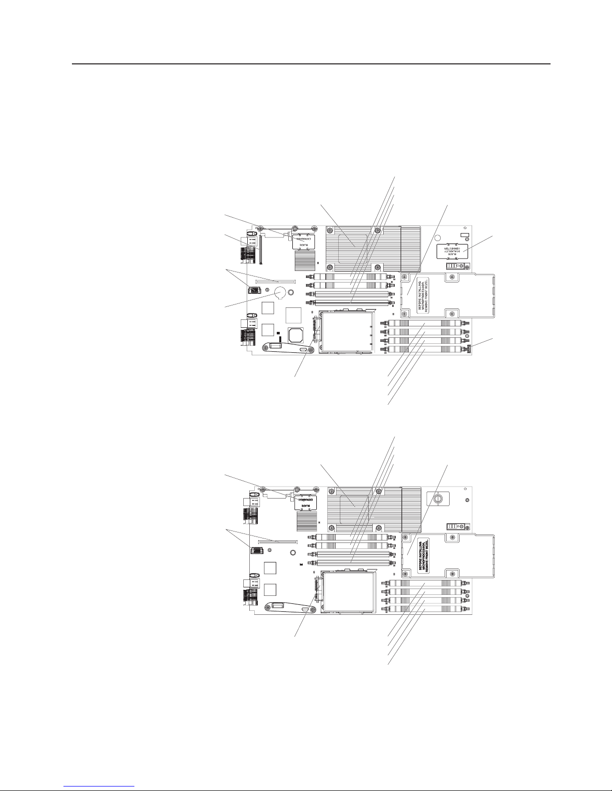
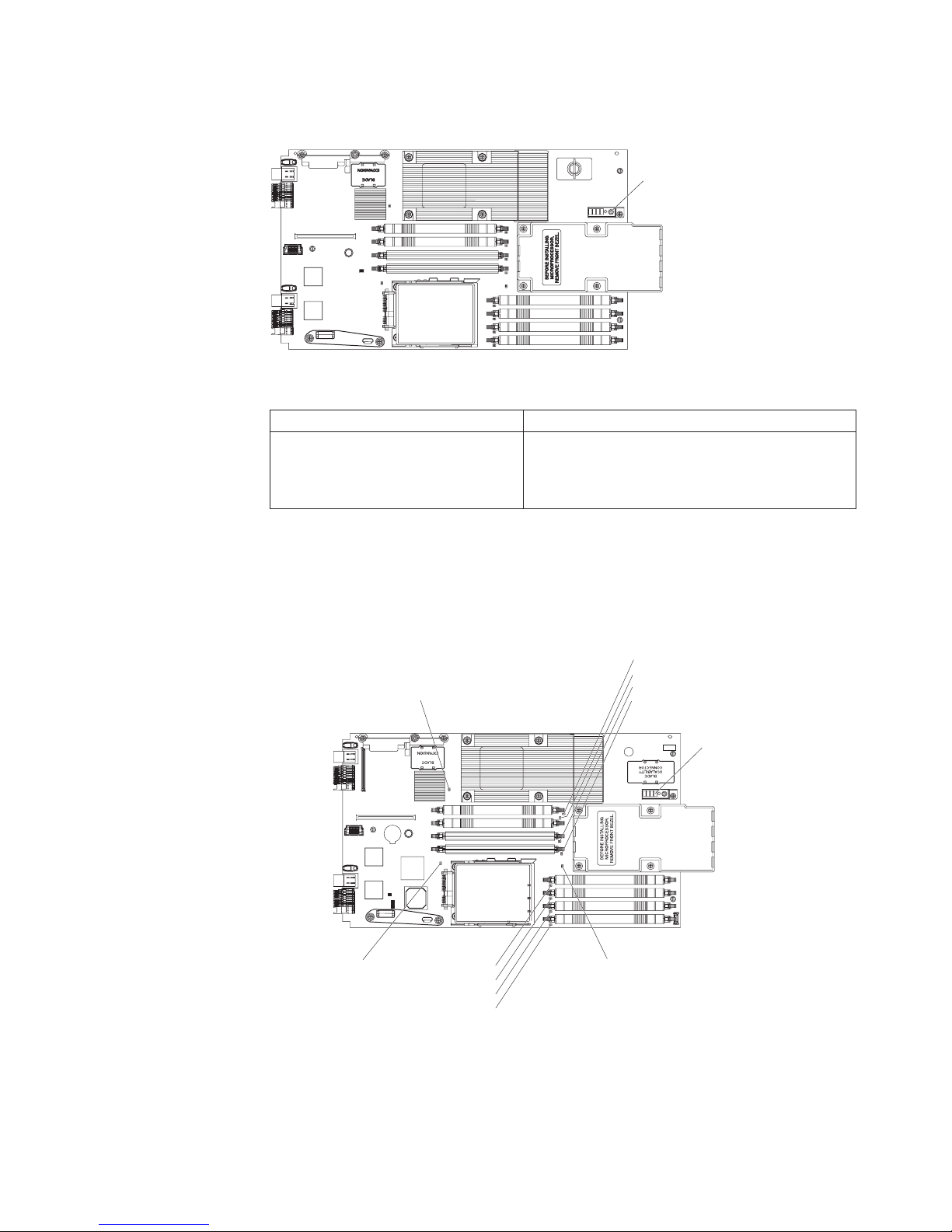
System board connectors
The following illustration shows the connectors on the blade server system board.
Blade
expansion
Microprocessor 1
DIMM 4
DIMM 3
DIMM 2
DIMM 1
Microprocessor 2
Concurrent
KVM
I/O-expansion
card
Battery
SAS hard disk drive
DIMM 8
DIMM 7
DIMM 6
DIMM 5
The following illustration shows the connectors on the MPE unit.
Blade
expansion
Microprocessor 1
DIMM 4
DIMM 3
DIMM 2
DIMM 1
Microprocessor 2
MPE
unit
Control
panel
I/O-expansion
card
SAS hard disk drive
DIMM 8
DIMM 7
DIMM 6
DIMM 5
Chapter 1. Introduction 7
Page 24
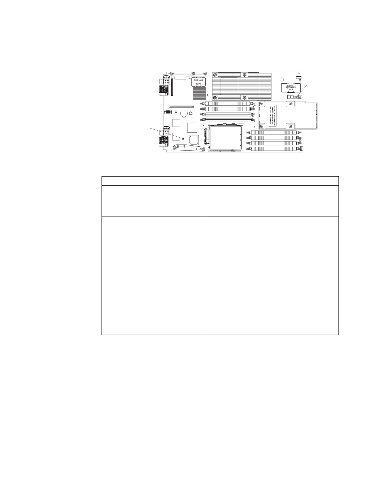
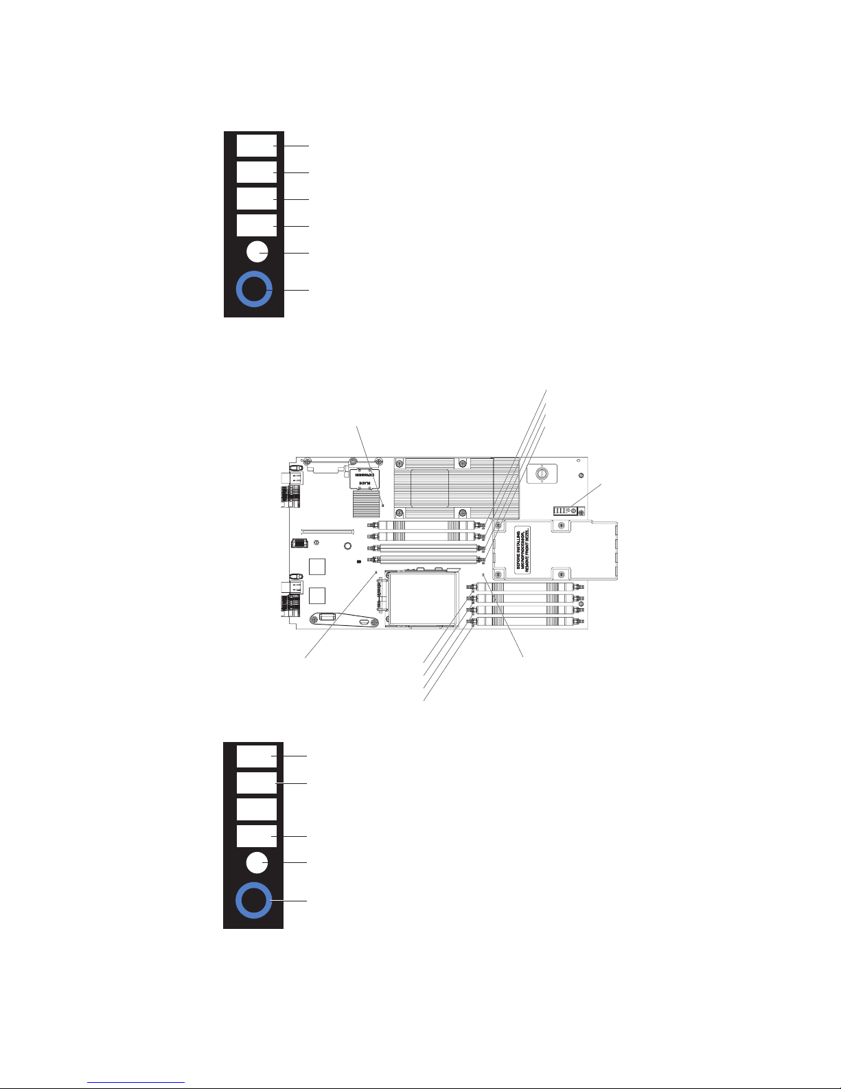
System board switches
The following illustration shows the location of the switches on the blade server
system board.
Switch block 4 (SW4)
The following table defines the function of each switch on the blade server system
board.
Light path
diagnostics
switch (SW1)
Switch number Description
SW1 Light path diagnostics switch – Press and hold to
relight the system-board LEDs that were lit before
you removed the blade server from the
BladeCenter unit.
SW4 Switch block 4 has four switches.
v 1 – Reserved
v 2 – BIOS backup page
– Open: BIOS starts from the primary BIOS
page (default)
– Closed: BIOS starts from the backup BIOS
page
3 – Password override enable
v
– Open: Disabled (default)
– Closed: Enabled – Bypass password during
next server start
4 – Wake On LAN enable
v
– Open: Disabled
– Closed: Enabled (default)
8 BladeCenter LS21 Type 7971 and LS41 Type 7972: Problem Determination and Service Guide
Page 25
The following illustration shows the location of the light path diagnostics switch on
the MPE unit.
Light path
diagnostics
switch (SW1)
The following table defines the function of the light path diagnostics switch on the
MPE unit.
Switch number Description
SW1 Light path diagnostics switch – Press and hold to
System board LEDs
The following illustration shows the LEDs on the blade server system board. You
must remove the blade server from the BladeCenter unit, open the cover or remove
any optional expansion units, and press the light path diagnostics switch to light any
error LEDs that were turned on during processing.
Microprocessor 1 error LED
relight the MPE-unit LEDs that were lit before you
removed the blade server from the BladeCenter
unit.
DIMM 4 error LED
DIMM 3 error LED
DIMM 2 error LED
DIMM 1 error LED
Light path diagnostics panel
SAS hard disk
drive error LED
DIMM 8 error LED
DIMM 7 error LED
DIMM 6 error LED
DIMM 5 error LED
Microprocessor 2 error LED
Chapter 1. Introduction 9
Page 26
The following illustration shows the light path diagnostics panel on the blade server
system board.
NMI
NMI error LED
MIS
S BRD
TEMP
LP 1
Microprocessor mismatch error LED
System-board error LED
Over temperature error LED
Light path diagnostics LED
Light path diagnostics switch
The following illustration shows the LEDs on the MPE unit. You must remove the
blade server from the BladeCenter unit, open the cover, and press the light path
diagnostics switch to light any error LEDs that were turned on during processing.
Microprocessor 1 error LED
DIMM 4 error LED
DIMM 3 error LED
DIMM 2 error LED
DIMM 1 error LED
Light path diagnostics panel
SAS hard disk
drive error LED
DIMM 8 error LED
DIMM 7 error LED
DIMM 6 error LED
DIMM 5 error LED
Microprocessor 2 error LED
The following illustration shows the light path diagnostics panel on the MPE unit.
MIS
S BRD
LP 1
LP 2
Microprocessor mismatch error LED
MPE-board error LED
Light path diagnostics LED (for blade server)
Light path diagnostics LED (for MPE)
Light path diagnostics switch
10 BladeCenter LS21 Type 7971 and LS41 Type 7972: Problem Determination and Service Guide
Page 27

Chapter 2. Diagnostics
This chapter describes the diagnostic tools that are available to help you solve
problems that might occur in the blade server.
Note: The blade server uses shared resources that are installed in the BladeCenter
unit. Problems with these shared resources might appear to be in the blade server
(see “Solving shared BladeCenter resource problems” on page 52 for information
about isolating problems with these resources). See the Problem Determination and
Service Guide or the Hardware Maintenance Manual and Troubleshooting Guide for
your BladeCenter unit and other BladeCenter component documentation for
diagnostic procedures for shared BladeCenter components.
If you cannot locate and correct the problem using the information in this chapter,
see Appendix A, “Getting help and technical assistance,” on page 101 for more
information.
Diagnostic tools
The following tools are available to help you diagnose and solve hardware-related
problems:
v POST beep codes, error messages, and error logs
The power-on self-test (POST) generates beep codes and messages to indicate
successful test completion or the detection of a problem. See “POST” for more
information.
v Troubleshooting tables
These tables list problem symptoms and actions to correct the problems. See
“Troubleshooting tables” on page 25 for more information.
v Light path diagnostics
Use the light path diagnostics to diagnose system errors quickly. See “Light path
diagnostics” on page 38 for more information.
v Diagnostic programs, messages, and error codes
The diagnostic programs are the primary method of testing the major
components of the blade server. These programs are stored in read-only memory
(ROM) on the blade server. See “Diagnostic programs, messages, and error
codes” on page 42 for more information.
POST
When you turn on the blade server, it performs a series of tests to check the
operation of the blade server components and some optional devices in the blade
server. This series of tests is called the power-on self-test, or POST.
If a power-on password is set, you must type the password and press Enter, when
prompted, for POST to run.
If POST is completed without detecting any problems, a single beep sounds, and
the blade server startup is completed.
If POST detects a problem, more than one beep might sound, or an error message
is displayed. See “Beep code descriptions” on page 12 and “POST error codes” on
page 15 for more information.
© Copyright IBM Corp. 2006 11
Page 28

POST beep codes
A beep code is a combination of short or long beeps or a series of short beeps that
are separated by pauses. For example, a “1-2-3” beep code is one short beep, a
pause, two short beeps, a pause, and three short beeps. A beep code other than
one beep indicates that POST has detected a problem. To determine the meaning
of a beep code, see “Beep code descriptions.” If no beep code sounds, see
“No-beep symptoms” on page 15.
Beep code descriptions
The following table describes the beep codes and suggested actions to correct the
detected problems.
A single problem might cause more than one error message. When this occurs,
correct the cause of the first error message. The other error messages usually will
not occur the next time POST runs.
Exception: If there are multiple error codes or light path diagnostics LEDs that
indicate a microprocessor error, the error might be in a microprocessor or in a
microprocessor socket. See “Microprocessor problems” on page 28 for information
about diagnosing microprocessor problems.
v Follow the suggested actions in the order in which they are listed in the Action column until the problem
is solved.
v See Chapter 3, “Parts listing, Types 7971 and 7972,” on page 59 to determine which components are CRUs
and which components are FRUs.
v If an action step is preceded by “(Trained service technician only),” that step must be performed only by a
trained service technician.
Beep code Description Action
1-1-3 CMOS write/read test failed.
1-1-4 BIOS ROM checksum failed.
1-2-1 Programmable interval timer failed. (Trained service technician only) Replace the
1-2-2 DMA initialization failed. (Trained service technician only) Replace the
1-2-3 DMA page register write/read failed. (Trained service technician only) Replace the
1. Reseat the battery
2. Replace the following components one at a
time, in the order shown, restarting the
blade server each time:
a. Battery
b. (Trained service technician only) System
board assembly
1. Update the BIOS code.
2. Reseat the DIMMs.
3. Replace the following components one at a
time, in the order shown, restarting the
blade server each time:
a. DIMMs
b. (Trained service technician only) System
board assembly
system board assembly.
system board assembly.
system board assembly.
12 BladeCenter LS21 Type 7971 and LS41 Type 7972: Problem Determination and Service Guide
Page 29

v Follow the suggested actions in the order in which they are listed in the Action column until the problem
is solved.
v See Chapter 3, “Parts listing, Types 7971 and 7972,” on page 59 to determine which components are CRUs
and which components are FRUs.
v If an action step is preceded by “(Trained service technician only),” that step must be performed only by a
trained service technician.
Beep code Description Action
1-2-4 RAM refresh verification failed.
1. Reseat the following components:
a. DIMMs
b. MPE unit (if one is installed)
Replace the following components one at a
2.
time, in the order shown, restarting the
blade server each time:
a. DIMMs
b. (Trained service technician only) System
board assembly
c. (Trained service technician only) MPE
board assembly (if one is installed)
1-3-1 First 64K RAM test failed.
1. Reseat the DIMMs.
2. Replace the following components one at a
time, in the order shown, restarting the
blade server each time:
a. DIMMs
b. (Trained service technician only) System
board assembly
2-1-1 Secondary DMA register test failed. (Trained service technician only) Replace the
system board assembly.
2-1-2 Primary DMA register test failed. (Trained service technician only) Replace the
system board assembly.
2-1-3 Primary interrupt mask register test
failed.
2-1-4 Secondary interrupt mask register test
failed.
2-2-2 Keyboard controller test failed.
(Trained service technician only) Replace the
system board assembly.
(Trained service technician only) Replace the
system board assembly.
1. Check the function of the shared
BladeCenter unit resources (see “Solving
shared BladeCenter resource problems” on
page 52).
2. (Trained service technician only) Replace
the system board assembly.
2-3-1 Screen initialization failed. (Trained service technician only) Replace the
system board assembly.
3-1-1 Timer tick interrupt failed. (Trained service technician only) Replace the
system board assembly.
3-1-2 Interval timer channel 2 failed. (Trained service technician only) Replace the
system board assembly.
Chapter 2. Diagnostics 13
Page 30

v Follow the suggested actions in the order in which they are listed in the Action column until the problem
is solved.
v See Chapter 3, “Parts listing, Types 7971 and 7972,” on page 59 to determine which components are CRUs
and which components are FRUs.
v If an action step is preceded by “(Trained service technician only),” that step must be performed only by a
trained service technician.
Beep code Description Action
3-1-4 Time-of-day clock failed.
1. Reseat the battery.
2. Replace the following components one at a
time, in the order shown, restarting the
blade server each time:
a. Battery
b. (Trained service technician only) System
board assembly
3-3-2 I2C error occurred.
1. Power down the blade server and reseat it
in the BladeCenter unit.
2. Reseat the following components:
a. DIMMs
b. MPE unit (if one is installed)
Replace the following components one at a
3.
time, in the order shown, restarting the
blade server each time:
a. DIMMs
b. (Trained service technician only) System
board assembly
3-3-3 No operational memory in system. Important: In some memory configurations,
the 3-3-3 beep code might sound during POST
followed by a blank display screen. If this
occurs and the Boot Fail Count feature in the
Start Options of the Configuration/Setup Utility
program is set to Enabled (its default setting),
you must restart the blade server three times to
force the system BIOS to reset the memory
connector or bank of connectors from Disabled
to Enabled.
1. Install or reseat DIMMs and restart the
blade server three times.
2. Replace the following components one at a
time, in the order shown, restarting the
blade server each time:
a. DIMMs
b. (Trained service technician only) System
board assembly
14 BladeCenter LS21 Type 7971 and LS41 Type 7972: Problem Determination and Service Guide
Page 31

No-beep symptoms
The following table describes situations in which no beep code sounds when POST
is completed.
v Follow the suggested actions in the order in which they are listed in the Action column until the problem
is solved.
v See Chapter 3, “Parts listing, Types 7971 and 7972,” on page 59 to determine which components are CRUs
and which components are FRUs.
v If an action step is preceded by “(Trained service technician only),” that step must be performed only by a
trained service technician.
No-beep symptom Action
No beep and the blade server operates correctly (Trained service technician only) Replace the system
board assembly.
No beep and no video (system-error LED is off) See “Solving undetermined problems” on page 56.
No beep and no video (system attention LED is lit) See “Light path diagnostics” on page 38.
POST error codes
The following table describes the POST error codes and suggested actions to
correct the detected problems.
v Follow the suggested actions in the order in which they are listed in the Action column until the problem
is solved.
v See Chapter 3, “Parts listing, Types 7971 and 7972,” on page 59 to determine which components are CRUs
and which components are FRUs.
v If an action step is preceded by “(Trained service technician only),” that step must be performed only by a
trained service technician.
Error code Description Action
062 Three consecutive startup failures
1. Run the Configuration/Setup Utility program, select
Load Default Settings, make sure that the date
and time are correct, and save the settings.
2. Reseat the following components:
a. Battery
b. MPE unit (if one is installed)
c. DIMMs
d. (Trained service technician only)
Microprocessor 1
e. (Trained service technician only)
Microprocessor 2
Replace the following components one at a time,
3.
in the order shown, restarting the blade server
each time:
a. Battery
b. DIMMs
c. (Trained service technician only)
Microprocessor 1
d. (Trained service technician only)
Microprocessor 2
e. (Trained service technician only) System board
assembly
Chapter 2. Diagnostics 15
Page 32

v Follow the suggested actions in the order in which they are listed in the Action column until the problem
is solved.
v See Chapter 3, “Parts listing, Types 7971 and 7972,” on page 59 to determine which components are CRUs
and which components are FRUs.
v If an action step is preceded by “(Trained service technician only),” that step must be performed only by a
trained service technician.
Error code Description Action
101 Timer tick interrupt failure (Trained service technician only) Replace the system
board assembly.
102 Timer 2 test failure (Trained service technician only) Replace the system
board assembly.
106 Diskette controller failure (Trained service technician only) Replace the system
board assembly.
129 Internal cache (L1) error
1. Reseat the following components:
a. (Trained service technician only)
Microprocessor 1
b. (Trained service technician only)
Microprocessor 2
Replace the following components one at a time,
2.
in the order shown, restarting the blade server
each time:
a. (Trained service technician only)
Microprocessor 1
b. (Trained service technician only)
Microprocessor 2
c. (Trained service technician only) System board
assembly
151 Real-time clock failure
1. Reseat the battery.
2. Replace the following components one at a time,
in the order shown, restarting the blade server
each time:
a. Battery
b. (Trained service technician only) System board
assembly
161 Real-time clock battery failure
1. Run the Configuration/Setup Utility program.
2. Reseat the battery.
3. Replace the following components one at a time,
in the order shown, restarting the blade server
each time:
a. Battery
b. (Trained service technician only) System board
assembly
16 BladeCenter LS21 Type 7971 and LS41 Type 7972: Problem Determination and Service Guide
Page 33

v Follow the suggested actions in the order in which they are listed in the Action column until the problem
is solved.
v See Chapter 3, “Parts listing, Types 7971 and 7972,” on page 59 to determine which components are CRUs
and which components are FRUs.
v If an action step is preceded by “(Trained service technician only),” that step must be performed only by a
trained service technician.
Error code Description Action
162 Invalid configuration information or CMOS
RAM checksum failure.
1. Run the Configuration/Setup Utility program, select
Load Default Settings, and save the settings.
2. Reseat the battery.
3. Replace the following components one at a time,
in the order shown, restarting the blade server
each time:
a. Battery
b. (Trained service technician only) System board
assembly
163 Time of day not set.
1. Run the Configuration/Setup Utility program, select
Load Default Settings, make sure that the date
and time are correct, and save the settings.
2. Reseat the battery.
3. Replace the following components one at a time,
in the order shown, restarting the blade server
each time:
a. Battery
b. (Trained service technician only) System board
assembly
164 Memory size does not match CMOS.
1. Run the Configuration/Setup Utility program, make
sure that the memory configuration is correct, and
save the settings.
2. Reseat the DIMMs.
3. Replace the following components one at a time,
in the order shown, restarting the blade server
each time:
a. DIMMs
b. (Trained service technician only) System board
assembly
175 Bad EEPROM CRC #1 (Trained service technician only) Replace the system
board assembly.
177 Bad checksum (Trained service technician only) Replace the system
board assembly.
178 EEPROM not functional (Trained service technician only) Replace the system
board assembly.
184 Bad power-on password. (Trained service technician only) Replace the system
board assembly.
185 Corrupted boot sequence
1. Run the Configuration/Setup Utility program, select
Load Default Settings, and save the settings.
2. (Trained service technician only) Replace the
system board assembly.
186 Security hardware control logic error (Trained service technician only) Replace the system
board assembly.
Chapter 2. Diagnostics 17
Page 34

v Follow the suggested actions in the order in which they are listed in the Action column until the problem
is solved.
v See Chapter 3, “Parts listing, Types 7971 and 7972,” on page 59 to determine which components are CRUs
and which components are FRUs.
v If an action step is preceded by “(Trained service technician only),” that step must be performed only by a
trained service technician.
Error code Description Action
187 VPD Serial Number not set (Trained service technician only) Replace the system
board assembly.
188 Bad EEPROM CRC #2 (Trained service technician only) Replace the system
board assembly.
189 Three attempts to enter the incorrect
password.
1. Set the Password override enable switch on the
system board to Enable; then, restart the blade
server, run the Configuration/Setup Utility program,
and change the power-on password.
2. (Trained service technician only) Replace the
system board assembly.
201 Base memory error or extended memory
error.
1. Update the BIOS code and restart the blade
server.
2. Reseat the DIMMs.
3. Replace the following components one at a time,
in the order shown, restarting the blade server
each time:
a. DIMMs
b. (Trained service technician only) System board
assembly
229 Internal cache (L2) error.
1. Reseat the following components:
a. (Trained service technician only)
Microprocessor 1
b. (Trained service technician only)
Microprocessor 2
Replace the following components one at a time,
2.
in the order shown, restarting the blade server
each time:
a. (Trained service technician only)
Microprocessor 1
b. (Trained service technician only)
Microprocessor 2
c. (Trained service technician only) System board
assembly
289 DIMM disabled by user or system.
1. If the DIMM was disabled by the user, run the
Configuration/Setup Utility program and enable the
DIMM.
2. Reseat the disabled DIMM.
3. Replace the following components one at a time,
in the order shown, restarting the blade server
each time:
a. Disabled DIMM
b. (Trained service technician only) System board
assembly
18 BladeCenter LS21 Type 7971 and LS41 Type 7972: Problem Determination and Service Guide
Page 35

v Follow the suggested actions in the order in which they are listed in the Action column until the problem
is solved.
v See Chapter 3, “Parts listing, Types 7971 and 7972,” on page 59 to determine which components are CRUs
and which components are FRUs.
v If an action step is preceded by “(Trained service technician only),” that step must be performed only by a
trained service technician.
Error code Description Action
301 Keyboard failure.
1. If you have installed a USB keyboard, run the
Configuration/Setup Utility program and enable
keyboardless operation to prevent the POST error
message 301 from being displayed during startup.
2. Check the function of the shared BladeCenter unit
resources (see “Solving shared BladeCenter
resource problems” on page 52).
3. (Trained service technician only) Replace the
system board assembly.
303 Keyboard controller error.
1. Check the function of the shared BladeCenter unit
resources (see “Solving shared BladeCenter
resource problems” on page 52).
2. (Trained service technician only) Replace the
system board assembly.
602 Invalid diskette boot record.
1. Check the function of the shared BladeCenter unit
resources (see “Solving shared BladeCenter
resource problems” on page 52).
2. (Trained service technician only) Replace the
system board assembly
604 Diskette drive failure.
1. Check the function of the shared BladeCenter unit
resources (see “Solving shared BladeCenter
resource problems” on page 52).
2. (Trained service technician only) Replace the
system board assembly
662 Diskette drive configuration error.
1. Check the function of the shared BladeCenter unit
resources (see “Solving shared BladeCenter
resource problems” on page 52).
2. (Trained service technician only) Replace the
system board assembly
1200 Processor machine check.
1. Reseat the following components:
a. (Trained service technician only)
Microprocessor 1
b. (Trained service technician only)
Microprocessor 2
Replace the following components one at a time,
2.
in the order shown, restarting the blade server
each time:
a. (Trained service technician only)
Microprocessor 1
b. (Trained service technician only)
Microprocessor 2
c. (Trained service technician only) System board
assembly
Chapter 2. Diagnostics 19
Page 36

v Follow the suggested actions in the order in which they are listed in the Action column until the problem
is solved.
v See Chapter 3, “Parts listing, Types 7971 and 7972,” on page 59 to determine which components are CRUs
and which components are FRUs.
v If an action step is preceded by “(Trained service technician only),” that step must be performed only by a
trained service technician.
Error code Description Action
1801 No more room for option ROM.
1. Run the Configuration/Setup Utility program and
make sure that the PXE settings are correct.
Disabling PXE can allow more options to be
managed.
2. Use the Configuration/Setup Utility program
(Advanced Setup → PCI Bus Control → PCI ROM
Control) to disable each option one at a time,
restarting the blade server each time, until the
1801 error code clears. Options that cause the
1801 error code are the I/O-expansion cards and
expansion units. Disable these options in the order
of least-to-most important.
3. Remove each option one at a time, restarting the
blade server each time, until the 1801 error code
clears. Options that cause the 1801 error code are
the I/O-expansion cards and expansion units.
Remove these options in the order of least-to-most
important.
4. (Trained service technician only) If the problem
remains after all options have been removed,
replace the system board assembly.
18xx PCI error (Trained service technician only) Replace the system
board assembly.
1962 Boot sector error, no operating system
installed.
1. Make sure that a bootable operating system is
installed.
2. Run the SAS Attached Disk diagnostic test.
3. Reseat the hard disk drive.
4. Replace the following components one at a time,
in the order shown, restarting the blade server
each time:
a. Hard disk drive
b. (Trained service technician only) System board
assembly
2462 Video configuration error (Trained service technician only) Replace the system
board assembly.
20 BladeCenter LS21 Type 7971 and LS41 Type 7972: Problem Determination and Service Guide
Page 37

v Follow the suggested actions in the order in which they are listed in the Action column until the problem
is solved.
v See Chapter 3, “Parts listing, Types 7971 and 7972,” on page 59 to determine which components are CRUs
and which components are FRUs.
v If an action step is preceded by “(Trained service technician only),” that step must be performed only by a
trained service technician.
Error code Description Action
5962 CD or DVD drive configuration error.
1. Run the Configuration/Setup Utility program, select
Load Default Settings, and save the settings.
2. Check the function of the shared BladeCenter unit
resources (see “Solving shared BladeCenter
resource problems” on page 52).
3. Reseat the battery.
4. Replace the following components one at a time,
in the order shown, restarting the blade server
each time:
a. Battery
b. (Trained service technician only) System board
assembly
8603 Pointing device error
1. Check the function of the shared BladeCenter unit
resources (see “Solving shared BladeCenter
resource problems” on page 52).
2. (Trained service technician only) Replace the
system board assembly.
I999301 Fixed disk boot sector error.
1. Reseat the hard disk drive.
2. Replace the following components one at a time,
in the order shown, restarting the blade server
each time:
a. Hard disk drive
b. (Trained service technician only) System board
assembly
Chapter 2. Diagnostics 21
Page 38

Error logs
The BMC log contains all system status messages from the blade server service
processor. The management-module event log in your BladeCenter unit contains
messages that were generated on each blade server during POST and status
messages from the BladeCenter service processor. (See the Management Module
User’s Guide for more information.)
The following illustration shows an example of a BMC log entry.
BMC System Event Log
---------------------------------------------------------Get Next Entry
Get Previous Entry
Clear BMC SEL
Entry Number= 00005 / 00011
Record ID= 0005
Record Type= 02
Timestamp= 2005/01/25 16:15:17
Entry Details: Generator ID= 0020
Sensor Type= 04
Assertion Event
Fan
Threshold
Lower Non-critical - going high
Sensor Number= 40
Event Direction/Type= 01
Event Data= 52 00 1A
Important:
v A single problem might cause several error messages. When this occurs, work to
correct the cause of the first error message. After you correct the cause of the
first error message, the other error messages usually will not occur the next time
you run the test.
v The management-module event log in your BladeCenter unit lists messages
according to the position of the blade server in the blade bays. If a blade server
is moved from one bay to another, the management-module event log will report
messages for that blade server using the new bay number; messages for that
blade server that were generated before the move will still be listed using the
previous bay number.
BMC log is limited in size. When the log is full, new entries will not overwrite
The
existing entries; therefore, you must periodically clear the BMC log through the
Configuration/Setup Utility program (the menu choices are described in the
Installation and User’s Guide). When you are troubleshooting an error, be sure to
clear the BMC log so that you can find current errors more easily.
Entries that are written to the BMC log during the early phase of POST show an
incorrect date and time as the default time stamp; however, the date and time are
corrected as POST continues.
Each BMC log entry appears on its own page. To display all the data for an entry,
use the Up Arrow (↑) and Down Arrow (↓) keys or the Page Up and Page Down
keys. To move from one entry to the next, select Get Next Entry or Get Previous
Entry.
22 BladeCenter LS21 Type 7971 and LS41 Type 7972: Problem Determination and Service Guide
Page 39

The BMC log indicates an assertion event when an event has occurred. It indicates
a deassertion event when the event is no longer occurring.
Some of the error codes and messages in the BMC log are abbreviated.
You can view the contents of the BMC log from the Configuration/Setup Utility
program and from the diagnostic programs.
When you are troubleshooting PCI-X slots, note that the error logs report the PCI-X
buses numerically. The numerical assignments vary depending on the configuration.
You can check the assignments by running the Configuration/Setup Utility program
(see the Installation and User’s Guide for more information).
Viewing the BMC log from the Configuration/Setup Utility
program
For complete information about using the Configuration/Setup Utility program, see
the Installation and User’s Guide.
To view the BMC log, complete the following steps:
1. Turn on the blade server.
2. When the prompt Press F1 for Configuration/Setup appears, press F1. If you
have set a power-on password, you must type the password and press Enter to
start the Configuration/Setup Utility program.
3. Select Advanced Settings, select Baseboard Management Controller (BMC)
settings, and then select BMC System Event Log.
Viewing the BMC log from the diagnostic programs
The BMC log contains the same information, whether it is viewed from the
Configuration/Setup Utility program or from the diagnostic programs.
For information about using the diagnostic programs, see “Running the diagnostic
programs” on page 43.
To view the BMC log, complete the following steps:
1. If the blade server is running, turn off the blade server.
2. Turn on the blade server.
3. When the prompt F2 for Diagnostics appears, press F2.
4. From the top of the screen, select Hardware Info.
5. From the list, select BMC Log.
Chapter 2. Diagnostics 23
Page 40

Checkout procedure
The checkout procedure is the sequence of tasks that you should follow to
diagnose a problem in the blade server.
About the checkout procedure
Before performing the checkout procedure for diagnosing hardware problems,
review the following information:
v Read the safety information that begins on page vii.
v The diagnostic programs provide the primary methods of testing the major
components of the blade server. If you are not sure whether a problem is caused
by the hardware or by the software, you can use the diagnostic programs to
confirm that the hardware is working correctly.
v When you run the diagnostic programs, a single problem might cause more than
one error message. When this happens, correct the cause of the first error
message. The other error messages usually will not occur the next time you run
the diagnostic programs.
Exception: If there are multiple error codes or light path diagnostics LEDs that
indicate a microprocessor error, the error might be in a microprocessor or in a
microprocessor socket. See “Microprocessor problems” on page 28 for
information about diagnosing microprocessor problems.
v If the blade server is halted and a POST error code is displayed, see “POST
error codes” on page 15. If the blade server is halted and no error message is
displayed, see “Troubleshooting tables” on page 25 and “Solving undetermined
problems” on page 56.
v For intermittent problems, check the error log; see “Error logs” on page 22 and
“Diagnostic programs, messages, and error codes” on page 42.
v If no LEDs are lit on the blade server front panel, verify the blade server status
and errors in the management-module Web interface; also see “Solving
undetermined problems” on page 56.
v If device errors occur, see “Troubleshooting tables” on page 25.
Performing the checkout procedure
To perform the checkout procedure, complete the following steps:
1. If the blade server is running, turn off the blade server.
2. Turn on the blade server. Make sure that the blade server has control of the
video (the keyboard/video/mouse button is lit). If the blade server does not start,
see “Troubleshooting tables” on page 25.
3. Record any POST beep codes that sound or POST error messages that are
displayed on the monitor. If an error is displayed, look up the first error in the
“POST error codes” on page 15.
4. Check the control panel blade-error LED; if it is lit, check the light path
diagnostics LEDs (see “Light path diagnostics” on page 38).
5. Check for the following results:
v Successful completion of POST, indicated by a single beep
v Successful completion of startup, indicated by a readable display of the
operating-system desktop
24 BladeCenter LS21 Type 7971 and LS41 Type 7972: Problem Determination and Service Guide
Page 41

6. Did a single beep sound and are there readable instructions on the main menu?
v No: Find the failure symptom in “Troubleshooting tables”; if necessary, see
“Solving undetermined problems” on page 56.
v Yes: Run the diagnostic programs (see “Running the diagnostic programs” on
page 43).
– If you receive an error, see “Diagnostic error codes” on page 44.
– If the diagnostic programs were completed successfully and you still
suspect a problem, see “Solving undetermined problems” on page 56.
Troubleshooting tables
Use the troubleshooting tables to find solutions to problems that have identifiable
symptoms. If these symptoms relate to shared BladeCenter unit resources, see
“Solving shared BladeCenter resource problems” on page 52.
If you cannot find the problem in these tables, see “Running the diagnostic
programs” on page 43 for information about testing the blade server.
If you have just added new software or a new optional device, and the blade server
is not working, complete the following steps before using the troubleshooting tables:
1. Remove the software or device that you just added.
2. Run the diagnostic tests to determine whether the blade server is running
correctly.
3. Reinstall the new software or new device.
General problems
v Follow the suggested actions in the order in which they are listed in the Action column until the problem
is solved.
v See Chapter 3, “Parts listing, Types 7971 and 7972,” on page 59 to determine which components are CRUs
and which components are FRUs.
v If an action step is preceded by “(Trained service technician only),” that step must be performed only by a
trained service technician.
Symptom Action
A cover lock is broken, an LED
is not working, or a similar
problem has occurred.
If the part is a CRU, replace it. If the part is a FRU, the part must be replaced by a
trained service technician.
Chapter 2. Diagnostics 25
Page 42

Hard disk drive problems
v Follow the suggested actions in the order in which they are listed in the Action column until the problem
is solved.
v See Chapter 3, “Parts listing, Types 7971 and 7972,” on page 59 to determine which components are CRUs
and which components are FRUs.
v If an action step is preceded by “(Trained service technician only),” that step must be performed only by a
trained service technician.
Symptom Action
Not all drives are recognized by
the Fixed Disk or SAS Attached
Disk diagnostic test.
The blade server stops
responding during the Fixed
Disk or SAS Attached Disk
diagnostic test.
A hard disk drive passes the
Fixed Disk or SAS Attached
Disk diagnostics test, but the
problem remains.
Remove the drive that is indicated by the diagnostic tests; then, run the Fixed Disk
or SAS Attached Disk diagnostic test again. If the remaining drives are recognized,
replace the drive that you removed with a new one.
Remove the hard disk drive that was being tested when the blade server stopped
responding, and run the diagnostic test again. If the Fixed Disk or SAS Attached
Disk diagnostic test runs successfully, replace the drive that you removed with a
new one.
Run the SAS Fixed Disk or SAS Attached Disk diagnostic test again. If the
diagnostics continue to pass but the drive continues to have a problem, replace the
drive with a new one.
Intermittent problems
v Follow the suggested actions in the order in which they are listed in the Action column until the problem
is solved.
v See Chapter 3, “Parts listing, Types 7971 and 7972,” on page 59 to determine which components are CRUs
and which components are FRUs.
v If an action step is preceded by “(Trained service technician only),” that step must be performed only by a
trained service technician.
Symptom Action
A problem occurs only
occasionally and is difficult to
diagnose.
1. Make sure that:
v When the blade server is turned on, air is flowing from the rear of the
BladeCenter unit at the blower grille. If there is no airflow, the blower is not
working. This causes the blade server to overheat and shut down.
v The SAS hard disk drives are configured correctly.
Check the BMC log (see “Error logs” on page 22).
2.
26 BladeCenter LS21 Type 7971 and LS41 Type 7972: Problem Determination and Service Guide
Page 43

Keyboard or mouse problems
The keyboard and mouse are shared BladeCenter unit resources. First, make sure
that the keyboard and mouse are assigned to the blade server; then, see the
following table and “Solving shared BladeCenter resource problems” on page 52.
v Follow the suggested actions in the order in which they are listed in the Action column until the problem
is solved.
v See Chapter 3, “Parts listing, Types 7971 and 7972,” on page 59 to determine which components are CRUs
and which components are FRUs.
v If an action step is preceded by “(Trained service technician only),” that step must be performed only by a
trained service technician.
Symptom Action
All keyboard and mouse
problems.
1. Make sure that the keyboard/video/mouse select button LED on the front of the
blade server is lit, indicating that the blade server is connected to the shared
keyboard and mouse.
2. Check the function of the shared BladeCenter unit resources (see “Solving
shared BladeCenter resource problems” on page 52).
3. Make sure that:
v The device drivers are installed correctly.
v The keyboard and mouse are recognized as USB, not PS/2, devices by the
blade server. Although the keyboard and mouse might be a PS/2-style
devices, communication with them is through USB in the BladeCenter unit.
Some operating systems allow you to select the type of keyboard and mouse
during installation of the operating system. If this is the case, select USB.
(Trained service technician only) Replace the system board assembly.
4.
Chapter 2. Diagnostics 27
Page 44

Memory problems
v Follow the suggested actions in the order in which they are listed in the Action column until the problem
is solved.
v See Chapter 3, “Parts listing, Types 7971 and 7972,” on page 59 to determine which components are CRUs
and which components are FRUs.
v If an action step is preceded by “(Trained service technician only),” that step must be performed only by a
trained service technician.
Symptom Action
The amount of system memory
that is displayed is less than the
amount of installed physical
memory.
1. Make sure that:
v Yo u have installed the correct type of memory.
v If you changed the memory, you updated the memory configuration in the
Configuration/Setup Utility program.
v All banks of memory are enabled. The blade server might have automatically
disabled a memory bank when it detected a problem, or a memory bank
might have been manually disabled.
Check BMC log for error message 289:
2.
v If a DIMM was disabled by a system-management interrupt (SMI), replace
the DIMM.
v If a DIMM was disabled by the user or by POST, run the Configuration/Setup
Utility program and enable the DIMM.
Reseat the following components:
3.
a. DIMMs
b. MPE unit (if one is installed)
Replace the following components one at a time, in the order shown, restarting
4.
the blade server each time:
a. DIMMs
b. (Trained service technician only) MPE board assembly (if one is installed)
c. (Trained service technician only) System board assembly
Microprocessor problems
v Follow the suggested actions in the order in which they are listed in the Action column until the problem
is solved.
v See Chapter 3, “Parts listing, Types 7971 and 7972,” on page 59 to determine which components are CRUs
and which components are FRUs.
v If an action step is preceded by “(Trained service technician only),” that step must be performed only by a
trained service technician.
Symptom Action
The blade server emits a
continuous beep during POST,
indicating that the startup (boot)
microprocessor is not working
correctly.
28 BladeCenter LS21 Type 7971 and LS41 Type 7972: Problem Determination and Service Guide
1. (Trained service technician only) Reseat microprocessor 1.
2. (Trained service technician only) Replace microprocessor 1.
Page 45

Monitor or video problems
The video monitor is a shared BladeCenter unit resource. First, make sure that the
video monitor is assigned to the blade server; then, see the following table and
“Solving shared BladeCenter resource problems” on page 52.
v Follow the suggested actions in the order in which they are listed in the Action column until the problem
is solved.
v See Chapter 3, “Parts listing, Types 7971 and 7972,” on page 59 to determine which components are CRUs
and which components are FRUs.
v If an action step is preceded by “(Trained service technician only),” that step must be performed only by a
trained service technician.
Symptom Action
The screen is blank.
The monitor has screen jitter, or
the screen image is wavy,
unreadable, rolling, or distorted.
Wrong characters appear on the
screen.
1. Check the function of the shared BladeCenter unit resources (see “Solving
shared BladeCenter resource problems” on page 52).
2. Make sure that:
v Damaged BIOS code is not affecting the video; see “Recovering from a
BIOS update failure” on page 50.
v The device drivers are installed correctly.
(Trained service technician only) Replace the system board assembly.
3.
1. Check the function of the shared BladeCenter unit resources (see “Solving
shared BladeCenter resource problems” on page 52).
2. (Trained service technician only) Replace the system board assembly.
1. If the wrong language is displayed, update the firmware or operating system
with the correct language in the blade server that has ownership of the monitor.
2. Check the function of the shared BladeCenter unit resources (see “Solving
shared BladeCenter resource problems” on page 52).
3. (Trained service technician only) Replace the system board assembly.
Chapter 2. Diagnostics 29
Page 46

Network connection problems
The blade server connects to the network using shared BladeCenter unit resources.
See the following table and “Solving shared BladeCenter resource problems” on
page 52.
v Follow the suggested actions in the order in which they are listed in the Action column until the problem
is solved.
v See Chapter 3, “Parts listing, Types 7971 and 7972,” on page 59 to determine which components are CRUs
and which components are FRUs.
v If an action step is preceded by “(Trained service technician only),” that step must be performed only by a
trained service technician.
Symptom Action
One or more blade servers are
unable to communicate with the
network.
1. Check the function of the shared BladeCenter unit resources (see “Solving
shared BladeCenter resource problems” on page 52).
2. Make sure that:
v The correct device drivers are installed.
v The Ethernet controllers correctly configured.
v Optional I/O-expansion cards are correctly installed and configured.
(Trained service technician only) Replace the system board assembly.
3.
Optional-device problems
v Follow the suggested actions in the order in which they are listed in the Action column until the problem
is solved.
v See Chapter 3, “Parts listing, Types 7971 and 7972,” on page 59 to determine which components are CRUs
and which components are FRUs.
v If an action step is preceded by “(Trained service technician only),” that step must be performed only by a
trained service technician.
Symptom Action
An IBM optional device that was
just installed does not work.
1. Make sure that:
v The device is designed for the blade server (see http://www.ibm.com/servers/
eserver/serverproven/compat/us/).
v Yo u followed the installation instructions that came with the device and the
device is installed correctly.
v Yo u have not loosened any other installed devices or cables.
v Yo u updated the configuration information in the Configuration/Setup Utility
program. Whenever memory or any other device is changed, you must
update the configuration.
If the device comes with its own test instructions, use those instructions to test
2.
the device.
3. Reseat the device that you just installed.
4. Replace the device that you just installed.
30 BladeCenter LS21 Type 7971 and LS41 Type 7972: Problem Determination and Service Guide
Page 47

Power error messages
Power to the blade server is provided by shared BladeCenter unit resources. See
the following table and “Solving shared BladeCenter resource problems” on page
52.
v Follow the suggested actions in the order in which they are listed in the Action column until the problem
is solved.
v See Chapter 3, “Parts listing, Types 7971 and 7972,” on page 59 to determine which components are CRUs
and which components are FRUs.
v If an action step is preceded by “(Trained service technician only),” that step must be performed only by a
trained service technician.
Message Action
System Power Good fault
VRM Power Good fault
System over recommended voltage for +12v.
System over recommended voltage for
+3.3v.
System over recommended 5V fault.
VRM voltage over recommended tolerance.
1. Reseat the blade server.
2. Check the function of the shared BladeCenter unit resources (see
“Solving shared BladeCenter resource problems” on page 52).
3. Reseat the MPE unit (if one is installed).
4. Replace the following components one at a time, in the order
shown, restarting the blade server each time:
a. (Trained service technician only) MPE board assembly (if one
is installed)\n
b. (Trained service technician only) System board assembly
1. Reseat the blade server.
2. Check the function of the shared BladeCenter unit resources (see
“Solving shared BladeCenter resource problems” on page 52).
3. (Trained service technician only) Replace the system board
assembly.
1. Reseat the blade server.
2. Check the function of the shared BladeCenter unit resources (see
“Solving shared BladeCenter resource problems” on page 52).
3. (Trained service technician only) Replace the system board
assembly.
1. Reseat the blade server.
2. Check the function of the shared BladeCenter unit resources (see
“Solving shared BladeCenter resource problems” on page 52).
3. (Trained service technician only) Replace the system board
assembly.
1. Reseat the blade server.
2. Check the function of the shared BladeCenter unit resources (see
“Solving shared BladeCenter resource problems” on page 52).
3. (Trained service technician only) Replace the system board
assembly.
1. Reseat the blade server.
2. Check the function of the shared BladeCenter unit resources (see
“Solving shared BladeCenter resource problems” on page 52).
3. (Trained service technician only) Replace the system board
assembly.
Chapter 2. Diagnostics 31
Page 48

v Follow the suggested actions in the order in which they are listed in the Action column until the problem
is solved.
v See Chapter 3, “Parts listing, Types 7971 and 7972,” on page 59 to determine which components are CRUs
and which components are FRUs.
v If an action step is preceded by “(Trained service technician only),” that step must be performed only by a
trained service technician.
Message Action
System under recommended voltage for
+12v.
1. Reseat the blade server.
2. Check the function of the shared BladeCenter unit resources (see
“Solving shared BladeCenter resource problems” on page 52).
3. (Trained service technician only) Replace the system board
assembly.
System under recommended voltage for
+3.3v.
1. Reseat the blade server.
2. Check the function of the shared BladeCenter unit resources (see
“Solving shared BladeCenter resource problems” on page 52).
3. (Trained service technician only) Replace the system board
assembly.
System under recommended 5V fault.
1. Reseat the blade server.
2. Check the function of the shared BladeCenter unit resources (see
“Solving shared BladeCenter resource problems” on page 52).
3. (Trained service technician only) Replace the system board
assembly.
32 BladeCenter LS21 Type 7971 and LS41 Type 7972: Problem Determination and Service Guide
Page 49

Power problems
v Follow the suggested actions in the order in which they are listed in the Action column until the problem
is solved.
v See Chapter 3, “Parts listing, Types 7971 and 7972,” on page 59 to determine which components are CRUs
and which components are FRUs.
v If an action step is preceded by “(Trained service technician only),” that step must be performed only by a
trained service technician.
Symptom Action
Power switch does not work,
and the reset button does work.
The blade server does not turn
on.
1. Reseat the control-panel connector.
2. Replace the following components one at a time, in the order shown, restarting
the blade server each time:
a. Bezel assembly
b. (Trained service technician only) System board assembly
1. Check the function of the shared BladeCenter unit resources (see “Solving
shared BladeCenter resource problems” on page 52).
2. Make sure that the power-on LED on the blade server control panel is flashing
slowly.
v If the power LED is flashing rapidly and continues to do so, the blade server
is not communicating with the management-module; reseat the blade server
and go to step 6
v If the power LED is off, the blade bay is not receiving power, the blade
server is defective, or the control panel is loose or defective.
Check the power-management policies in the operating system for the blade
3.
server.
4. Reseat the blade server.
5. If you just installed a device in the blade server, remove it and restart the blade
server. If the blade server now starts, you might have installed more devices
than the power to that blade bay supports.
6. If you tried another blade server in the blade bay when checking the function of
the shared BladeCenter unit resources and the other blade server worked,
complete the following tasks on the blade server that was removed:
a. Reseat the following components:
1) MPE unit (if one is installed)
2) Control panel cable
Replace the following components one at a time, in the order shown,
b.
restarting the blade server each time:
1) Blade server bezel assembly
2) (Trained service technician only) MPE board assembly (if one is
installed)
3) (Trained service technician only) System board assembly
See “Solving undetermined problems” on page 56.
7.
Chapter 2. Diagnostics 33
Page 50

v Follow the suggested actions in the order in which they are listed in the Action column until the problem
is solved.
v See Chapter 3, “Parts listing, Types 7971 and 7972,” on page 59 to determine which components are CRUs
and which components are FRUs.
v If an action step is preceded by “(Trained service technician only),” that step must be performed only by a
trained service technician.
Symptom Action
The blade server does not start
and the following conditions are
Make sure that microprocessors 1 and 2 are identical (number of cores, cache size
and type, clock speed, internal and external clock frequencies).
present:
v The amber system-error LED
on the BladeCenter unit
system LED panel is lit.
(Trained service technician only) If microprocessors are not identical, remove the
microprocessor with the incorrect specifications and replace with a microprocessor
that has the correct specifications.
v The amber blade error LED
on the blade server control
panel is lit.
v The management-module
event log contains the
message Processor speed
mismatch.
The blade server turns off for no
apparent reason.
1. Check the function of the shared BladeCenter unit resources (see “Solving
shared BladeCenter resource problems” on page 52).
2. (Trained service technician only) If the microprocessor error LED is lit, replace
the microprocessor.
3. (Trained service technician only) Replace the system board assembly.
The blade server does not turn
off.
1. Verify whether you are using an Advanced Configuration and Power Interface
(ACPI) or non-ACPI operating system.
2. If you are using a non-ACPI operating system, complete the following steps:
a. Turn off the blade server by pressing the power-control button for 4
seconds.
b. If the blade server fails during POST and the power-control button does not
work, remove the blade server from the bay and reseat it.
If the problem remains or if you are using an ACPI-aware operating system,
3.
complete the following steps:
a. Check the power-management policies in the operating system for the
blade server.
b. (Trained service technician only) Replace the system board assembly.
34 BladeCenter LS21 Type 7971 and LS41 Type 7972: Problem Determination and Service Guide
Page 51

Removable-media drive problems
The removable-media (CD, DVD, or diskette) drives are shared BladeCenter unit
resources. First, make sure that the drives are assigned to the blade server; then,
see the following table and “Solving shared BladeCenter resource problems” on
page 52.
v Follow the suggested actions in the order in which they are listed in the Action column until the problem
is solved.
v See Chapter 3, “Parts listing, Types 7971 and 7972,” on page 59 to determine which components are CRUs
and which components are FRUs.
v If an action step is preceded by “(Trained service technician only),” that step must be performed only by a
trained service technician.
Symptom Action
All removable-media drive
problems.
The CD or DVD drive is
detected as /dev/sr0 by SUSE
Linux. (If the SUSE Linux
operating system is installed
remotely onto a blade server
that is not the current owner of
the media tray [CD or DVD
drive, diskette drive, and USB
port], SUSE Linux detects the
CD or DVD drive as /dev/sr0
instead of /dev/cdrom.)
The CD or DVD drive is not
recognized after being switched
back to the blade server running
Windows® 2000 Advanced
Server with SP3 applied. (When
the CD or DVD drive owned by
blade server x is switched to
another blade server, then is
switched back to blade server x,
the operating system in blade
server x no longer recognizes
the CD or DVD drive. This
happens when you have not
safely stopped the drives before
switching ownership of the
media tray [CD or DVD drive,
diskette drive, and USB port].)
1. Make sure that the media-tray select button LED on the front of the blade
server is lit, indicating that the blade server is connected to the shared
removable-media drives.
2. Check the function of the shared BladeCenter unit resources (see “Solving
shared BladeCenter resource problems” on page 52).
3. Run the Configuration/Setup Utility program and make sure that the drive is
enabled.
4. For CD or DVD problems, make sure that the correct device driver is installed.
5. Reseat the battery.
6. Replace the following components one at a time, in the order shown, restarting
the blade server each time:
a. Battery.
b. (Trained service technician only) System board assembly
Establish a link between /dev/sr0 and /dev/cdrom as follows:
1. Enter the following command:
rm /dev/cdrom; ln -s /dev/sr0 /dev/cdrom
2. Insert the following line in the /etc/fstab file:
/dev/cdrom /media/cdrom auto ro,noauto,user,exec 0 0
Note: Because the BladeCenter unit uses USB to communicate with the media
tray devices, switching ownership of the media tray to another blade server is the
same as disconnecting a USB device. Before you switch ownership of the CD or
DVD drive (media tray) to another blade server, safely stop the media tray devices
on the blade server that currently owns the media tray, as follows:
1. Double-click the Unplug/Eject Hardware icon in the Windows taskbar at the
bottom right of the desktop.
2. Select USB Floppy and click Stop.
3. Select USB Mass Storage Device and click Stop.
4. Click Close.
You
can now safely switch ownership of the media tray to another blade server.
Chapter 2. Diagnostics 35
Page 52

ServerGuide problems
v Follow the suggested actions in the order in which they are listed in the Action column until the problem
is solved.
v See Chapter 3, “Parts listing, Types 7971 and 7972,” on page 59 to determine which components are CRUs
and which components are FRUs.
v If an action step is preceded by “(Trained service technician only),” that step must be performed only by a
trained service technician.
Symptom Action
The ServerGuide™ Setup and
Installation CD will not start.
The operating-system
installation program
continuously loops.
The ServerGuide program will
not start the operating-system
CD.
The operating system cannot be
installed; the option is not
available.
1. Make sure that the CD or DVD drive is associated with the blade server that
you are configuring.
2. Make sure that the blade server supports the ServerGuide program.
3. If the startup (boot) sequence settings have been changed, make sure that the
CD or DVD drive is first in the startup sequence.
Make more space available on the hard disk.
Make sure that the operating-system CD is supported by the ServerGuide program.
See the ServerGuide Setup and Installation CD label for a list of supported
operating-system versions.
Make sure that the blade server supports the operating system. If it does, either no
logical drive is defined (SAS RAID servers), or the ServerGuide System Partition is
not present. Run the ServerGuide program and make sure that setup is complete.
Service processor problems
v Follow the suggested actions in the order in which they are listed in the Action column until the problem
is solved.
v See Chapter 3, “Parts listing, Types 7971 and 7972,” on page 59 to determine which components are CRUs
and which components are FRUs.
v If an action step is preceded by “(Trained service technician only),” that step must be performed only by a
trained service technician.
Symptom Action
The management-module
reports a general monitor
failure.
Disconnect the BladeCenter unit from all electrical sources, wait for 30 seconds,
reconnect the BladeCenter unit to the electrical sources, and restart the blade
server. If the problem remains, see “Solving undetermined problems” on page 56,
and the Hardware Maintenance Manual and Troubleshooting Guide or Problem
Determination and Service Guide for your BladeCenter unit.
36 BladeCenter LS21 Type 7971 and LS41 Type 7972: Problem Determination and Service Guide
Page 53

Software problems
v Follow the suggested actions in the order in which they are listed in the Action column until the problem
is solved.
v See Chapter 3, “Parts listing, Types 7971 and 7972,” on page 59 to determine which components are CRUs
and which components are FRUs.
v If an action step is preceded by “(Trained service technician only),” that step must be performed only by a
trained service technician.
Symptom Action
You suspect a software
problem.
1. To determine whether the problem is caused by the software, make sure that:
v The blade server has the minimum memory that is needed to use the
software. For memory requirements, see the information that comes with the
software.
Note: If you have just installed an adapter or memory, the blade server
might have a memory-address conflict.
v The software is designed to operate on the blade server.
v Other software works on the blade server.
v The software works on another server.
If you received any error messages when using the software, see the
2.
information that comes with the software for a description of the messages and
suggested solutions to the problem.
3. Contact your place of purchase of the software.
Universal Serial Bus (USB) port problems
The USB ports are shared BladeCenter unit resources. First, make sure that the
USB ports are assigned to the blade server; then, see the following table and
“Solving shared BladeCenter resource problems” on page 52.
v Follow the suggested actions in the order in which they are listed in the Action column until the problem
is solved.
v See Chapter 3, “Parts listing, Types 7971 and 7972,” on page 59 to determine which components are CRUs
and which components are FRUs.
v If an action step is preceded by “(Trained service technician only),” that step must be performed only by a
trained service technician.
Symptom Action
A USB device does not work.
1. Check the function of the shared BladeCenter unit resources (see “Solving
shared BladeCenter resource problems” on page 52).
2. Make sure that:
v The operating system supports USB devices.
v The correct USB device driver is installed.
(Trained service technician only) Replace the system board assembly.
3.
Chapter 2. Diagnostics 37
Page 54

Light path diagnostics
Light path diagnostics is a system of LEDs on the control panel and on various
internal components of the blade server. When an error occurs, LEDs can be lit
throughout the blade server to help identify the source of the error.
After you remove the blade server, you can press and hold the light path
diagnostics switch for a maximum of 25 seconds to light the LEDs and locate the
failing component. The following components have this feature:
v Hard disk drives
v Light path diagnostics panel
v Microprocessors
v Memory modules (DIMMs)
Viewing the light path diagnostics LEDs
Before working inside the blade server to view light path diagnostics LEDs, read the
safety information that begins on page vii and “Handling static-sensitive devices” on
page 64.
If an error occurs, view the light path diagnostics LEDs in the following order:
1. Look at the control panel on the front of the blade server (see “Blade server
controls and LEDs” on page 4).
v If the information LED is lit, it indicates that information about a suboptimal
condition in the blade server is available in the BMC log or in the
management-module event log.
v If the blade-error LED is lit, it indicates that an error has occurred; go to step
2.
To view the light path diagnostics panel and LEDs, complete the following steps:
2.
a. Remove the blade server from the BladeCenter unit.
b. Place the blade server on a flat, static-protective surface.
c. Remove the cover from the blade server.
d. Press and hold the light path diagnostics switch to light the LEDs of the
failing components in the blade server. The LEDs will remain lit for as long
as you press the switch, to a maximum of 25 seconds.
38 BladeCenter LS21 Type 7971 and LS41 Type 7972: Problem Determination and Service Guide
Page 55

The following illustration shows the locations of the blade server system-board error
LEDs and light path diagnostics panel.
Microprocessor 1 error LED
DIMM 4 error LED
DIMM 3 error LED
DIMM 2 error LED
DIMM 1 error LED
Light path diagnostics panel
SAS hard disk
drive error LED
DIMM 8 error LED
DIMM 7 error LED
Microprocessor 2 error LED
DIMM 6 error LED
DIMM 5 error LED
The following illustration shows the LEDs on the blade server system-board light
path diagnostics panel.
NMI
MIS
S BRD
TEMP
LP 1
NMI error LED
Microprocessor mismatch error LED
System-board error LED
Over temperature error LED
Light path diagnostics LED
Light path diagnostics switch
Chapter 2. Diagnostics 39
Page 56

The following illustration shows the locations of the MPE-unit error LEDs and light
path diagnostics panel.
Microprocessor 1 error LED
DIMM 4 error LED
DIMM 3 error LED
DIMM 2 error LED
DIMM 1 error LED
Light path diagnostics panel
SAS hard disk
drive error LED
DIMM 8 error LED
DIMM 7 error LED
DIMM 6 error LED
DIMM 5 error LED
Microprocessor 2 error LED
The following illustration shows the LEDs on the MPE unit light path diagnostics
panel.
MIS
S BRD
LP 1
LP 2
Microprocessor mismatch error LED
MPE-board error LED
Light path diagnostics LED (for blade server)
Light path diagnostics LED (for MPE)
Light path diagnostics switch
When you press the light path diagnostics switch, note which LEDs are lit on the
blade server system board, MPE unit, and light path diagnostics panels. Using this
information and the information in “Light path diagnostics LEDs” on page 41 can
often provide enough information to diagnose the error.
40 BladeCenter LS21 Type 7971 and LS41 Type 7972: Problem Determination and Service Guide
Page 57

Light path diagnostics LEDs
The following table describes the LEDs on the light path diagnostics panels, on the
blade server system board, and on the MPE unit. It also lists suggested actions to
correct the detected problems.
v Follow the suggested actions in the order in which they are listed in the Action column until the problem
is solved.
v See Chapter 3, “Parts listing, Types 7971 and 7972,” on page 59 to determine which components are CRUs
and which components are FRUs.
v If an action step is preceded by “(Trained service technician only),” that step must be performed only by a
trained service technician.
Lit light path
diagnostics LED Description Action
None An error has occurred and cannot be isolated,
or the service processor has failed.
DIMM x error
v On the blade server system board: A
blade-server DIMM error has occurred.
v On the MPE unit: An MPE unit DIMM error
has occurred.
LP1
v On the blade server light path diagnostics
panel: The light path LEDs on the blade
server system board have power.
v On the MPE unit light path diagnostics
panel: An error occurred on the blade server
system board.
LP2 (on MPE unit
Light path LEDs on the MPE unit have power. Check for lit error LEDs on the MPE unit.
only)
Microprocessor x
error
v On the blade server system board:
Blade-server microprocessor x has failed.
v On the MPE unit: MPE unit microprocessor
x has failed.
MIS
(Microprocessor
mismatch)
v On the blade server light path diagnostics
panel: The blade-server microprocessors do
not match.
v On the MPE unit light path diagnostics
panel: The MPE unit microprocessors do not
match.
1. Make sure that the light path diagnostics
LED is lit to ensure that there is enough
power in the blade server to light the rest
of the LEDs.
2. Check the BMC log for information about
an error that is not represented by a light
path diagnostics LED.
1. Make sure that DIMM x is supported.
2. Reseat DIMM x.
3. Replace DIMM x.
Multiple DIMM LEDs do not necessarily
Note:
indicate multiple DIMM failures. If more than
one DIMM LED is lit, reseat or replace one
DIMM at a time until the error is corrected.
Remove the MPE unit (if one is installed) and
check for lit error LEDs on the blade server
system board.
1. (Trained service technician only) Reseat
microprocessor x.
2. (Trained service technician only) Replace
microprocessor x.
Make sure that microprocessors 1 and 2 are
identical (number of cores, cache size and
type, clock speed, internal and external clock
frequencies, and wattage); also, see
“Troubleshooting tables” on page 25.
Chapter 2. Diagnostics 41
Page 58

v Follow the suggested actions in the order in which they are listed in the Action column until the problem
is solved.
v See Chapter 3, “Parts listing, Types 7971 and 7972,” on page 59 to determine which components are CRUs
and which components are FRUs.
v If an action step is preceded by “(Trained service technician only),” that step must be performed only by a
trained service technician.
Lit light path
diagnostics LED Description Action
NMI (NMI error) The system board has failed.
1. Replace the blade server cover and
reinsert the blade server in the
BladeCenter unit; then, restart the blade
server. Check the BMC log for information
about the error.
2. (Trained service technician only) Replace
the system board assembly.
S BRD (System
board or MPE
board error)
The system board or MPE board has failed.
v (Trained service technician only) If lit LED is
on the blade server light path diagnostics
panel, replace the system board assembly.
v (Trained service technician only) If lit LED is
on the MPE unit light path diagnostics panel,
replace the MPE board assembly.
TEMP (Over
temperature error)
The system temperature has exceeded a
threshold level.
1. Check the function of the shared
BladeCenter unit resources (see “Solving
shared BladeCenter resource problems” on
page 52).
2. Make sure that the room temperature is not
too high. See “Features and specifications”
on page 3 for temperature information.
SAS hard disk
drive error
v On the blade server system board: A
blade-server hard disk drive has failed.
v On the MPE unit: An MPE unit hard disk
drive has failed.
Run the SAS Fixed Disk or SAS Attached Disk
diagnostic test. If the diagnostics pass but the
drive continues to have a problem, replace the
hard disk drive with a new one.
Diagnostic programs, messages, and error codes
The diagnostic programs are the primary method of testing the major components
of the blade server. As you run the diagnostic programs, text messages and error
codes are displayed on the screen and are saved in the test log. A diagnostic text
message or error code indicates that a problem has been detected; to determine
what action you should take as a result of a message or error code, see the table in
“Diagnostic error codes” on page 44.
If you cannot find the problem using the diagnostic programs, see “Solving
undetermined problems” on page 56 for information about testing the blade server.
42 BladeCenter LS21 Type 7971 and LS41 Type 7972: Problem Determination and Service Guide
Page 59

Running the diagnostic programs
To run the diagnostic programs, complete the following steps:
1. If the blade server is running, turn off the blade server.
2. Turn on the blade server.
3. When the prompt F2 for Diagnostics appears, press F2.
4. From the top of the screen, select either Extended or Basic.
5. From the menu, select the test that you want to run, and follow the instructions
on the screen.
For help with the diagnostic programs, press F1. You also can press F1 from within
a help screen to obtain online documentation from which you can select different
categories. To exit from the help information, press Esc.
To determine what action you should take as a result of a diagnostic text message
or error code, see the table in “Diagnostic error codes” on page 44.
If the diagnostic programs do not detect any hardware errors but the problem
remains during normal server operations, a software error might be the cause. If
you suspect a software problem, see the information that comes with your software.
A single problem might cause more than one error message. When this happens,
correct the cause of the first error message. The other error messages usually will
not occur the next time you run the diagnostic programs.
Exception: If there are multiple error codes or light path diagnostics LEDs that
indicate a microprocessor error, the error might be in a microprocessor or in a
microprocessor socket. See “Microprocessor problems” on page 28 for information
about diagnosing microprocessor problems.
If the blade server stops during testing and you cannot continue, restart the blade
server and try running the diagnostic programs again. If the problem remains,
replace the component that was being tested when the blade server stopped.
The diagnostic programs assume that a keyboard and mouse are attached to the
BladeCenter unit and that the blade server controls them. If you run the diagnostic
programs with either no mouse or a mouse attached to the BladeCenter unit that is
not controlled by the blade server, you cannot use the Next Cat and Prev Cat
buttons to select categories. All other mouse-selectable functions are available
through function keys.
To view server configuration information such as system configuration, memory
contents, interrupt request (IRQ) use, direct memory access (DMA) use, or device
drivers, select Hardware Info from the top of the screen.
Diagnostic text messages
Diagnostic text messages are displayed while the tests are running. A diagnostic
text message contains one of the following results:
Passed: The test was completed without any errors.
Failed: The test detected an error.
User Aborted: Yo u stopped the test before it was completed.
Chapter 2. Diagnostics 43
Page 60

Not Applicable: Yo u attempted to test a device that is not present in the blade
server.
Aborted: The test could not proceed because of the blade server configuration.
Warning: The test could not be run. There was no failure of the hardware that was
being tested, but there might be a hardware failure elsewhere, or another problem
prevented the test from running; for example, there might be a configuration
problem, or the hardware might be missing or is not being recognized.
The result is followed by an error code or other additional information about the
error.
Viewing the test log
To view the test log when the tests are completed, select Utility from the top of the
screen and then select View Test Log. The test-log data is maintained only while
you are running the diagnostic programs. When you exit from the diagnostic
programs, the test log is cleared.
To save the test log to a file on a diskette or to the hard disk, select Save Log on
the diagnostic programs screen and specify a location and name for the saved log
file.
Note: To save the test log to a diskette, you must use a diskette that you have
formatted yourself; this function does not work with preformatted diskettes. If the
diskette has sufficient space for the test log, the diskette can contain other data.
Diagnostic error codes
The following table describes the error codes that the diagnostic programs might
generate and suggested actions to correct the detected problems.
If the diagnostic programs generate error codes that are not listed in the table,
make sure that the latest level of the BIOS code is installed.
In the error codes, x can be any numeral or letter. However, if the three-digit
number in the central position of the code is 000, 195, or 197, do not replace a
CRU or FRU. These numbers appearing in the central position of the code have the
following meanings:
000 The blade server passed the test. Do not replace a CRU or FRU.
195 The Esc key was pressed to end the test. Do not replace a CRU or FRU.
197 This is a warning error, but it does not indicate a hardware failure; do not
replace a CRU or FRU. Take the action that is indicated in the Action
column, but do not replace a CRU or a FRU. See the description for
Warning in the section “Diagnostic text messages” on page 43 for more
information.
44 BladeCenter LS21 Type 7971 and LS41 Type 7972: Problem Determination and Service Guide
Page 61

v Follow the suggested actions in the order in which they are listed in the Action column until the problem
is solved.
v See Chapter 3, “Parts listing, Types 7971 and 7972,” on page 59 to determine which components are CRUs
and which components are FRUs.
v If an action step is preceded by “(Trained service technician only),” that step must be performed only by a
trained service technician.
Error code Description Action
001-197-000
001-198-000
Test aborted.
1. Check the test log for messages indicating the
cause of the error, and take the indicated action.
2. Restart the server.
3. Run the diagnostic test again.
4. Run the Quick Memory Test All Banks diagnostic;
then, if an error is detected, take the indicated
action
5. Reinstall the blade server in the BladeCenter unit
and, if necessary, update the BIOS code on the
server; then, rerun the test (see “Firmware
updates” on page 97).
001-250-00n ECC Test logic Failed. See PC Doctor logs.
Note: n = Failing CPU. (1 – 4)
1. Restart the server.
2. Run the diagnostic test again.
3. (Trained service technician only) Replace the
failing microprocessor.
001-250-000 Failed processor board ECC.
1. Reseat the following components:
a. DIMMs
b. (Trained service technician only)
Microprocessor 1
c. (Trained service technician only)
Microprocessor 2
Replace the following components one at a time,
2.
in the order shown, restarting the blade server
each time:
a. DIMMs
b. (Trained service technician only)
Microprocessor 1
c. (Trained service technician only)
Microprocessor 2
d. (Trained service technician only) System
board assembly
001-292-000 Core system: failed/CMOS checksum failed. Load the BIOS default settings by using the
Configuration/Setup Utility program and run the test
again (see the Installation and User’s Guide for your
blade server).
001-xxx-000 Failed core tests. (Trained service technician only) Replace the system
board assembly.
001-xxx-001 Failed core tests. (Trained service technician only) Replace the system
board assembly.
005-xxx-000 Failed video test. (Trained service technician only) Replace the system
board assembly.
030-xxx-000 Failed internal SAS interface test. (Trained service technician only) Replace the system
board assembly.
Chapter 2. Diagnostics 45
Page 62

v Follow the suggested actions in the order in which they are listed in the Action column until the problem
is solved.
v See Chapter 3, “Parts listing, Types 7971 and 7972,” on page 59 to determine which components are CRUs
and which components are FRUs.
v If an action step is preceded by “(Trained service technician only),” that step must be performed only by a
trained service technician.
Error code Description Action
035-xxx-099 No adapters were found. Reseat the adapter (if installed).
075-xxx-000 Failed power supply test. Replace the power supply (see the Hardware
Maintenance Manual and Troubleshooting Guide or
Problem Determination and Service Guide for your
BladeCenter unit).
089-xxx-00n Failed microprocessor test.
1. Reseat the following components:
a. (Trained service technician only) Blade server
microprocessor 1 if n = 0 or 1
b. (Trained service technician only) Blade server
microprocessor 2 if n = 2 or 3
c. (Trained service technician only) MPE unit
microprocessor 1 if n = 4 or 5
d. (Trained service technician only) MPE unit
microprocessor 2 if n = 6 or 7
Replace the following components one at a time,
2.
in the order shown, restarting the blade server
each time:
a. (Trained service technician only) Blade server
microprocessor 1 if n = 0 or 1
b. (Trained service technician only) Blade server
microprocessor 2 if n = 2 or 3
c. (Trained service technician only) MPE unit
microprocessor 1 if n = 4 or 5
d. (Trained service technician only) MPE unit
microprocessor 2 if n = 6 or 7
165-060-000 Service Processor: ASM may be busy
1. Rerun the diagnostics test.
2. Correct other error conditions that might be
keeping the Advanced System Management
(ASM) network or components busy. See the
error log and diagnostic panel.
3. Turn off the blade server and reseat it in the
BladeCenter unit.
4. (Trained service technician only) Replace the
system board assembly.
165-198-000 Service Processor: Aborted
1. Rerun the diagnostic test.
2. Correct other error conditions that might be
keeping the Advanced System Management
(ASM) network or components busy. See the
error log and diagnostic panel.
3. Turn off the blade server and reseat it in the
BladeCenter unit.
4. (Trained service technician only) Replace the
system board assembly.
46 BladeCenter LS21 Type 7971 and LS41 Type 7972: Problem Determination and Service Guide
Page 63

v Follow the suggested actions in the order in which they are listed in the Action column until the problem
is solved.
v See Chapter 3, “Parts listing, Types 7971 and 7972,” on page 59 to determine which components are CRUs
and which components are FRUs.
v If an action step is preceded by “(Trained service technician only),” that step must be performed only by a
trained service technician.
Error code Description Action
165-201-000 Service Processor: Failed
1. Power down blade server and reseat it in the
chassis.
2. (Trained service technician only) Replace the
system board assembly.
165-330-000 Service Processor: Failed Update the ROM diagnostic to the latest level and
run the diagnostics again.
165-342-000 Service Processor: Failed
1. Make sure that the latest firmware levels for
Advanced System Management (ASM) and BIOS
are installed.
2. Turn off the blade server and reseat it in the
BladeCenter unit.
3. (Trained service technician only) Replace the
system board assembly.
166-198-00x System Management: Aborted.
1. Remove the blade server from the BladeCenter
unit, wait 30 seconds, and reseat it in the
BladeCenter unit; then, run the test again.
2. Update the BMC firmware and run the test again.
3. (Trained service technician only) Replace the
system board assembly.
166-403-001 System Management: Failed. (BMC
indicates failure in I2C bus test.)
1. Remove the blade server from the BladeCenter
unit, wait 30 seconds, and reseat it in the
BladeCenter unit; then, run the test again.
2. Update the BMC firmware and run the test again.
3. Update the Ethernet firmware and run the test
again.
4. (Trained service technician only) Replace the
system board assembly.
166-419-001 System Management: Failed. (BMC
indicates failure in I2C bus test.)
1. Remove the blade server from the BladeCenter
unit, wait 30 seconds, and reseat it in the
BladeCenter unit; then, run the test again.
2. Update the BMC firmware and run the test again.
3. Remove the MPE unit and run the test again.
(Trained service technician only) If the error does
not repeat, replace the MPE board assembly.
4. (Trained service technician only) Replace the
system board assembly.
Chapter 2. Diagnostics 47
Page 64

v Follow the suggested actions in the order in which they are listed in the Action column until the problem
is solved.
v See Chapter 3, “Parts listing, Types 7971 and 7972,” on page 59 to determine which components are CRUs
and which components are FRUs.
v If an action step is preceded by “(Trained service technician only),” that step must be performed only by a
trained service technician.
Error code Description Action
166-420-001 System Management: Failed. (BMC
indicates failure in I2C bus test.)
1. Remove the blade server from the BladeCenter
unit, wait 30 seconds, and reseat it in the
BladeCenter unit; then, run the test again.
2. Update the BMC firmware and run the test again.
3. Remove the BladeCenter Storage Expansion Unit
3 and run the test again. If the error does not
repeat, replace the BladeCenter Storage
Expansion Unit 3.
4. (Trained service technician only) Replace the
system board assembly.
166-421-001 System Management: Failed. (BMC
indicates failure in I2C bus test.)
1. Remove the blade server from the BladeCenter
unit, wait 30 seconds, and reseat it in the
BladeCenter unit; then, run the test again.
2. Update the BMC firmware and run the test again.
3. Remove the high-speed expansion card (if one is
installed) and run the test again. If the error does
not repeat, replace the high-speed expansion
card.
4. (Trained service technician only) Replace the
system board assembly.
166-422-001 System Management: Failed. (BMC
indicates failure in I2C bus test.)
1. Remove the blade server from the BladeCenter
unit, wait 30 seconds, and reseat it in the
BladeCenter unit; then, run the test again.
2. Update the BMC firmware and run the test again.
3. Remove the I/O-expansion card and run the test
again. If the error does not repeat, replace the
I/O-expansion card.
4. (Trained service technician only) Replace the
system board assembly.
166-nnn-001 System Management: Failed. BMC indicates
failure in self test.
Note:
v nnn = 300 to 320
v nnn = 400 to 424 (excluding 403 and 419
to 422)
1. Remove the blade server from the BladeCenter
unit, wait 30 seconds, and reseat it in the
BladeCenter unit; then, run the test again.
2. Update the BMC firmware and run the test again.
3. (Trained service technician only) Replace the
system board assembly.
180-xxx-000 Diagnostics LED failure. Run the LED test in the diagnostics program.
180-xxx-001 Failed front LED panel test.
1. Reseat the control-panel connector.
2. Replace the bezel assembly.
3. (Trained service technician only) Replace the
system board assembly.
180-xxx-002 Failed diagnostics LED panel test. (Trained service technician only) Replace the system
board assembly.
48 BladeCenter LS21 Type 7971 and LS41 Type 7972: Problem Determination and Service Guide
Page 65

v Follow the suggested actions in the order in which they are listed in the Action column until the problem
is solved.
v See Chapter 3, “Parts listing, Types 7971 and 7972,” on page 59 to determine which components are CRUs
and which components are FRUs.
v If an action step is preceded by “(Trained service technician only),” that step must be performed only by a
trained service technician.
Error code Description Action
180-xxx-003 Failed system board LED test. (Trained service technician only) Replace the system
board assembly.
201-198-xxx Memory test aborted. See PC Doctor logs.
1. Restart the server.
2. Run the diagnostic test again.
3. Reinstall the diagnostic program.
4. Refer to the error log for additional information.
201-199-xxx Unexpected error. Test aborted. See PC
Doctor logs.
1. Restart the server.
2. Run the diagnostic test again.
3. Reinstall the diagnostic program.
4. Refer to the error log for additional information.
201-xxx-PBD Test failed.
v P = CPU Number (1 – 4)
v B = Failing Bank/Pair number.
v D = Failing DIMM number within Failing
CPU # P.
v D = 9 = Both DIMMs in the failing
1. Reseat the failing DIMM(s); then; run the memory
diagnostic test again.
2. Replace the failing DIMM(s); then; run the
memory diagnostic test again.
3. (Trained service technician only) Replace the
system board assembly.
bank/pair of DIMMs.
202-xxx-00n Failed system cache test.
1. (Trained service technician only) Reseat
microprocessor n.
2. Replace the following components one at a time,
in the order shown, restarting the blade server
each time:
a. (Trained service technician only)
Microprocessor n
b. (Trained service technician only) MPE board
assembly (if microprocessor n is on the MPE
unit)
c. (Trained service technician only) System
board assembly (if microprocessor n is on the
blade server)
217-198-xxx Could not establish drive parameters.
1. Reseat hard disk drive x.
2. Update the BIOS code.
3. Replace the following components one at a time,
in the order shown, restarting the blade server
each time:
a. Hard disk drive x
b. (Trained service technician only) System
board assembly
217-xxx-000 Failed hard disk drive test.
Note: If RAID is configured, the SAS
Attached Disk number refers to the RAID
1. Reseat hard disk drive 1.
2. Replace hard disk drive 1.
logical drive.
Chapter 2. Diagnostics 49
Page 66

v Follow the suggested actions in the order in which they are listed in the Action column until the problem
is solved.
v See Chapter 3, “Parts listing, Types 7971 and 7972,” on page 59 to determine which components are CRUs
and which components are FRUs.
v If an action step is preceded by “(Trained service technician only),” that step must be performed only by a
trained service technician.
Error code Description Action
217-xxx-001 Failed hard disk drive test.
Note: If RAID is configured, the SAS
Attached Disk number refers to the RAID
1. Reseat hard disk drive 2.
2. Replace hard disk drive 2.
logical drive.
405-xxx-000 Failed Ethernet test on controller on the
system board.
1. Make sure that Ethernet is not disabled in the
Configuration/Setup Utility program.
2. (Trained service technician only) Replace the
system board assembly.
Recovering from a BIOS update failure
The blade server has an advanced recovery feature that will automatically switch to
a backup BIOS page if the BIOS code in the blade server has become damaged,
such as from a power failure during an update.
The flash memory of the blade server consists of a primary page and a backup
page. If the BIOS code in the primary page is damaged, the baseboard
management controller will detect the error and automatically switch to the backup
page to start the blade server. If this happens, a POST message Booted from
backup POST/BIOS image is displayed. The backup page version may not be the
same version as the primary image.
You can then recover or restore the original primary page BIOS by using a BIOS
flash diskette.
To recover the BIOS code and restore the blade server operation to the primary
page, complete the following steps:
1. Download the latest version of the BIOS code from http://www.ibm.com/
bladecenter/.
2. Update the BIOS code, following the instructions that come with the update file
that you downloaded. This will automatically restore and update the primary
page.
3. Restart the blade server.
If that procedure fails, the blade server might not restart correctly or might not
display video. To manually restore the BIOS code, complete the following steps:
1. Read the safety information that begins on page vii and “Handling
static-sensitive devices” on page 64.
2. Turn off the blade server.
3. Remove the blade server from the BladeCenter unit (see “Removing the blade
server from a BladeCenter unit” on page 65).
4. Remove the cover (see “Removing the blade server cover” on page 68).
5. If an MPE unit is installed, remove the MPE unit (see “Removing an expansion
unit” on page 70).
50 BladeCenter LS21 Type 7971 and LS41 Type 7972: Problem Determination and Service Guide
Page 67

6. Locate switch block SW4 on the system board (see “System board switches”
on page 8).
7. Move the BIOS backup page switch (SW4-2) to the Closed position to enable
the backup page.
8. Install the MPE unit, if one was removed to access SW4 (see “Installing an
expansion unit” on page 71).
9. Install the cover and reinstall the blade server in the BladeCenter unit, making
sure that the blade server is connected to the media tray.
10. Insert the BIOS flash diskette into the diskette drive.
11. Turn on the blade server. The system begins the power-on self-test (POST).
12. Select 1 - Update POST/BIOS from the menu that contains various flash
(update) options.
Attention: Do not type Y when you are prompted to back up the ROM
location; doing so causes the damaged BIOS to be copied into the backup
page.
13. When you are prompted whether you want to move the current POST/BIOS
image to the backup ROM location, type N.
14. When you are prompted whether you want to save the current code to a
diskette, type N.
15. Select Update the BIOS.
Attention: Do not restart the blade server at this time.
16. When the update is complete, remove the flash diskette from the diskette
drive.
17. Turn off the blade server and remove it from the BladeCenter unit (see
“Removing the blade server from a BladeCenter unit” on page 65).
18. Remove the cover of the blade server (see “Removing the blade server cover”
on page 68).
19. If an MPE unit is installed, remove the MPE unit (see “Removing an expansion
unit” on page 70).
20. Move switch SW4-2 to the Open position to return to the normal startup mode.
21. Install the MPE unit, if one was removed to access SW4 (see “Installing an
expansion unit” on page 71).
22. Install the cover and reinstall the blade server in the BladeCenter unit.
23. Turn on the blade server.
Service processor (BMC) error codes
The baseboard management controller (BMC) log contains up to 512 of the most
recent service processor errors in IPMI format. These messages are a combination
of plain text and error code numbers. You can view the BMC log from the
Configuration/Setup Utility menu by selecting Advanced Setup → Baseboard
Management Controller (BMC) Settings → BMC System Event Log.
You can view additional information and error codes in plain text by viewing the
management-module event log in your BladeCenter unit.
Chapter 2. Diagnostics 51
Page 68

Solving SAS hard disk drive problems
For any SAS error message, one or more of the following devices might be causing
the problem:
v A failing SAS device (adapter, drive, or controller)
v An improper SAS configuration
any SAS error message, make sure that the SAS devices are configured
For
correctly.
Solving shared BladeCenter resource problems
Problems with BladeCenter shared resources might appear to be in the blade
server. The following sections provide procedures to help you isolate blade server
problems from shared BladeCenter resource problems. If the problem is thought to
be with a shared resource, see the Problem Determination and Service Guide or
the Hardware Maintenance Manual and Troubleshooting Guide for your
BladeCenter unit and other BladeCenter component documentation for additional
information. If the problem cannot be solved, see “Solving undetermined problems”
on page 56.
To check the general function of shared BladeCenter resources, complete the
following operations:
v Make sure that:
– The BladeCenter unit has the required power modules installed and is
connected to a working power source.
– Power management has been correctly set for your BladeCenter unit
configuration.
Check if the problem is being experienced with more than one blade server.
v
Perform a test of the function on a known-good blade server.
v Try the blade server in a different blade bay.
v Try a known-good blade server in the blade bay.
Keyboard or mouse problems
To check for keyboard or mouse problems, complete the following steps until the
problem is solved:
1. Make sure that:
v Both the blade server and the monitor are turned on.
v The keyboard/video/mouse select button LED on the front of the blade server
is lit, indicating that the blade server is connected to the shared keyboard and
mouse.
v The keyboard or mouse cable is securely connected to the active
BladeCenter management-module.
v The keyboard or mouse works with another blade server.
Check for correct management-module operation (see the documentation for
2.
your BladeCenter unit).
Note: Some BladeCenter unit types have several management-module
components that might need to be tested or replaced (see the Installation Guide
for your management module for more information).
52 BladeCenter LS21 Type 7971 and LS41 Type 7972: Problem Determination and Service Guide
Page 69

3. Replace the keyboard or mouse.
4. Replace the management module (see the documentation for your BladeCenter
unit).
If these steps do not resolve the problem, it is likely a problem with the blade
server. See “Keyboard or mouse problems” on page 27.
Media tray problems
To check for problems with the media tray (removable media drives and USB ports),
complete the following steps until the problem is solved:
1. Make sure that:
v The media-tray select button LED on the front of the blade server is lit,
v The media tray devices work with another blade server.
Check if the problem affects more than one media tray component:
2.
v USB ports
v Diskette drive
v CD or DVD drive
For problems affecting only a USB port:
3.
a. Make sure that the USB device is operational. If using a USB hub, make
b. Reseat the following components:
Replace the following components one at a time, in the order shown,
c.
Continue with step 7.
d.
4. For problems affecting only the diskette drive:
a. If there is a diskette in the drive, make sure that:
Continue with step 6.
b.
indicating that the blade server is connected to the shared media tray.
sure that the hub is operating correctly and that any software that the hub
requires is installed. Plug the USB device directly into the USB port,
bypassing the hub, to check its operation.
1) USB device cable
2) Media tray cable (if applicable)
3) Media tray
restarting the blade server each time:
1) USB cable (if applicable)
2) Media tray cable (if applicable)
3) Media tray
v The diskette is inserted correctly in the drive.
v The diskette is good and not damaged; the drive LED light flashes once
per second when the diskette is inserted. (Try another diskette if you have
one.)
v The diskette contains the necessary files to start the blade server.
v The software program is working properly.
v The distance between monitors and diskette drives is at least 76 mm (3
in.).
Chapter 2. Diagnostics 53
Page 70

5. For problems affecting only the CD or DVD drive:
a. Make sure that:
v The CD or DVD is inserted correctly in the drive. If necessary, insert the
end of a straightened paper clip into the manual tray-release opening to
eject the CD or DVD. The drive LED light flashes once per second when
the CD or DVD is inserted.
v The CD or DVD is clean and not damaged. (Try another CD or DVD if
you have one.)
v The software program is working properly.
b. Continue with step 6.
For problems affecting one or more of the removable media drives:
6.
a. Reseat the following components:
1) Removable-media drive cable (if applicable)
2) Removable-media drive
3) Media tray cable (if applicable)
4) Media tray
Replace the following components one at a time, in the order shown,
b.
restarting the blade server each time:
1) Removable-media drive cable (if applicable)
2) Media tray cable (if applicable)
3) Removable-media drive
4) Media tray
Continue with step 7.
c.
7. Check for correct management-module operation (see the documentation for
your BladeCenter unit).
Note: Some BladeCenter unit types have several management-module
components that might need to be tested or replaced (see the Installation Guide
for your management module for more information).
8. Replace the management module (see the documentation for your BladeCenter
unit).
If these steps do not resolve the problem, it is likely a problem with the blade
server. See “Removable-media drive problems” on page 35 or “Universal Serial Bus
(USB) port problems” on page 37.
Network connection problems
To check for network connection problems, complete the following steps until the
problem is solved:
1. Make sure that:
v The network cables are securely connected to the I/O module.
v Power configuration of the BladeCenter unit supports the I/O module
configuration.
v Installation of the I/O-module type is supported by the BladeCenter unit and
blade server hardware.
v The I/O modules for the network interface that is being used are installed in
the correct BladeCenter bays, and are configured and operating correctly.
v The settings in the I/O module are correct for the blade server (settings in the
I/O module are specific to each blade server).
Check for correct I/O-module operation; troubleshoot and replace the I/O
2.
module as indicated in the documentation for the I/O module.
54 BladeCenter LS21 Type 7971 and LS41 Type 7972: Problem Determination and Service Guide
Page 71

Power problems
3. Check for correct management-module operation (see the documentation for
your BladeCenter unit).
Note: Some BladeCenter unit types have several management-module
components that might need to be tested or replaced (see the Installation Guide
for your management module for more information).
4. Replace the management module (see the documentation for your BladeCenter
unit).
If these steps do not resolve the problem, it is likely a problem with the blade
server. See “Network connection problems” on page 30.
To check for power problems, make sure that:
v The LEDs on all the BladeCenter power modules are lit.
v Power is being supplied to the BladeCenter unit.
v Installation of the blade server type is supported by the BladeCenter unit.
v The BladeCenter unit has the correct power configuration to operate the blade
bay where your blade server is installed (see the documentation for your
BladeCenter unit).
v The BladeCenter unit power management configuration and status support blade
server operation (see the Management Module User’s Guide or the Management
Module Command-Line Interface Reference Guide for information).
v Local power control for the blade server is correctly set (see the Management
Module User’s Guide or the Management Module Command-Line Interface
Reference Guide for information).
v The BladeCenter unit blowers are correctly installed and operational.
Video problems
If these operations do not solve the problem, it is likely a problem with the blade
server. See “Power error messages” on page 31 and “Power problems” on page 33.
To check for video problems, complete the following steps until the problem is
solved:
1. Make sure that:
v Both the blade server and the monitor are turned on, and that the monitor
brightness and contrast controls are correctly adjusted.
v The keyboard/video/mouse select button LED on the front of the blade server
is lit, indicating that the blade server is connected to the shared BladeCenter
monitor.
v The video cable is securely connected to the BladeCenter
management-module. Non-IBM monitor cables might cause unpredictable
problems.
v The monitor works with another blade server.
Chapter 2. Diagnostics 55
Page 72

v Some IBM monitors have their own self-tests. If you suspect a problem with
the monitor, see the information that comes with the monitor for instructions
for adjusting and testing the monitor. If the monitor self-tests show that the
monitor is working correctly, consider the location of the monitor. Magnetic
fields around other devices (such as transformers, appliances, fluorescent
lights, and other monitors) can cause screen jitter or wavy, unreadable,
rolling, or distorted screen images. If this happens, turn off the monitor.
Attention: Moving a color monitor while it is turned on might cause screen
discoloration.
Move the device and the monitor at least 305 mm (12 in.) apart. Turn on the
monitor. To prevent diskette drive read/write errors, make sure that the
distance between the monitor and any diskette drive is at least 76 mm (3 in.).
Check for correct management-module operation (see the documentation for
2.
your BladeCenter unit).
Note: Some BladeCenter unit types have several management-module
components that might need to be tested or replaced (see the Installation Guide
for your management module for more information).
3. Replace the monitor cable, if applicable.
4. Replace the monitor.
5. Replace the management module (see the documentation for your BladeCenter
unit).
If these steps do not resolve the problem, it is likely a problem with the blade
server. See “Monitor or video problems” on page 29.
Solving undetermined problems
Note: When you are diagnosing a problem in the blade server, you must determine
whether the problem is in the blade server or in the BladeCenter unit.
v If all of the blade servers have the same symptom, the problem is probably in the
BladeCenter unit. For more information, see the Hardware Maintenance Manual
and Troubleshooting Guide or Problem Determination and Service Guide for your
BladeCenter unit.
v If the BladeCenter unit contains more than one blade server and only one of the
blade servers has the problem, troubleshoot the blade server that has the
problem.
the diagnostic tests did not diagnose the failure or if the blade server is
If
inoperative, use the information in this section.
If you suspect that a software problem is causing failures (continuous or
intermittent), see “Software problems” on page 37.
Damaged data in CMOS memory or damaged BIOS code can cause undetermined
problems. To reset the CMOS data, remove and replace the battery to override the
power-on password and clear the CMOS memory; see “Removing the battery” on
page 84. If you suspect that the BIOS code is damaged, see “Recovering from a
BIOS update failure” on page 50.
56 BladeCenter LS21 Type 7971 and LS41 Type 7972: Problem Determination and Service Guide
Page 73

Check the LEDs on all the power supplies of the BladeCenter unit in which the
blade server is installed. If the LEDs indicate that the power supplies are working
correctly and reseating the blade server does not correct the problem, complete the
following steps:
1. Make sure that the control panel connector is correctly seated on the system
board (see “System board connectors” on page 7 for the location of the
connector).
2. If no LEDs on the control panel are working, replace the bezel assembly; then,
try to turn on the blade server from the management module (see the
documentation for the BladeCenter unit and management module for more
information).
3. Turn off the blade server.
4. Remove the blade server from the BladeCenter unit and remove the cover.
5. Remove or disconnect the following devices, one at a time, until you find the
failure. Reinstall, turn on, and reconfigure the blade server each time.
v MPE unit (if one is installed)
v I/O-expansion cards
v Hard disk drive
v Memory modules. The minimum configuration requirement is 1 GB (two 512
MB DIMMs on the system board).
The following minimum configuration is required for the blade server to start:
v System board assembly
v One microprocessor
v Two 512 MB DIMMs
v A functioning BladeCenter unit
6. Install and turn on the blade server. If the problem remains, suspect the
following components in the following order:
a. DIMM
b. System board assembly
c. Microprocessor
the problem is solved when you remove an I/O-expansion card from the blade
If
server but the problem recurs when you reinstall the same card, suspect the
I/O-expansion card; if the problem recurs when you replace the card with a different
one, suspect the system board.
If you suspect a networking problem and the blade server passes all the system
tests, suspect a network cabling problem that is external to the system.
Chapter 2. Diagnostics 57
Page 74

Calling IBM for service
See Appendix A, “Getting help and technical assistance,” on page 101 for
information about calling IBM for service.
When you call for service, have as much of the following information available as
possible:
v Machine type and model
v Microprocessor and hard disk drive upgrades
v Failure symptoms
– Does the blade server fail the diagnostic programs? If so, what are the error
codes?
– What occurs? When? Where?
– Is the failure repeatable?
– Has the current server configuration ever worked?
– What changes, if any, were made before it failed?
– Is this the original reported failure, or has this failure been reported before?
Diagnostic program type and version level
v
v Hardware configuration (print screen of the system summary)
v BIOS code level
v Operating-system type and version level
can solve some problems by comparing the configuration and software setups
You
between working and nonworking servers. When you compare servers to each
other for diagnostic purposes, consider them identical only if all the following factors
are exactly the same in all the blade servers:
v Machine type and model
v BIOS level
v Adapters and attachments, in the same locations
v Address jumpers, terminators, and cabling
v Software versions and levels
v Diagnostic program type and version level
v Configuration option settings
v Operating-system control-file setup
58 BladeCenter LS21 Type 7971 and LS41 Type 7972: Problem Determination and Service Guide
Page 75

Chapter 3. Parts listing, Types 7971 and 7972
The following replaceable components are available for the LS21 Type 7971 and
LS41 Type 7972 blade servers.
Note: The illustrations in this document might differ slightly from your hardware.
1
2
11
10
9
3
4
5
6
7
8
Replaceable components are of three types:
v Tier 1 customer replaceable unit (CRU): Replacement of Tier 1 CRUs is your
responsibility. If IBM installs a Tier 1 CRU at your request, you will be charged for
the installation.
v Tier 2 customer replaceable unit: You may install a Tier 2 CRU yourself or
request IBM to install it, at no additional charge, under the type of warranty
service that is designated for your server.
v Field replaceable unit (FRU): FRUs must be installed only by trained service
technicians.
information about the terms of the warranty and getting service and assistance,
For
see the Warranty and Support Information document.
© Copyright IBM Corp. 2006 59
Page 76

Index Description
CRU No.
(Tier 1)
CRU No.
(Tier 2)
FRU No.
1 Cover (models 7971-all) 32R2432
1 Cover (models 7972-all) 42D8680
MPE board assembly (models 7972-32x 7972-3Bx 7972-52x
2
7972-5Bx 7972-6Bx 7972-4Tx 7972-7Bx 7972-E2y
Bezel, MPE unit (models 7972-32x 7972-3Bx 7972-4Tx 7972-52x
3
7972-5Bx 7972-6Bx 7972-7Bx 7972-E2y)
40K5904
39R9204
4 Filler, microprocessor heat sink (models 7971-all except E1y) 40K5929
5 Heat sink, microprocessor 40K5895
6 Microprocessor, Opteron 2210, 1.8 GHz, 45W (model 7971-2Tx) 43X0910
6 Microprocessor, Opteron 2210, 1.8 GHz, 68W (model 7971-21x) 43X0911
6 Microprocessor, Opteron 2212, 2.0 GHz, 68W (model 7971-31x) 39R9237
6 Microprocessor, Opteron 2212, 2.0 GHz, 95W (model 7971-3Ax) 39R9238
6 Microprocessor, Opteron 2216, 2.4 GHz, 68W (model 7971-51x) 39R9239
6 Microprocessor, Opteron 2216, 2.4 GHz, 95W (model 7971-5Ax) 40K8422
6 Microprocessor, Opteron 2218, 2.6 GHz, 95W (model 7971-6Ax) 39R9240
6 Microprocessor, Opteron 2200, 2.8 GHz, 95W (model 7971-7Ax) 43X0912
Microprocessor, Opteron 8212, 2.0 GHz, 68W (models 7972-31x,
6
7972-32x)
Microprocessor, Opteron 8212, 2.0 GHz, 95W (models 7972-3Ax,
6
7972-3Bx)
39R9241
39R9242
6 Microprocessor, Opteron 8214, 2.2 GHz, 68W (model 7972-4Tx) 43X0913
Microprocessor, Opteron 8216, 2.4 GHz, 68W (models 7972-51x,
6
7972-52x)
Microprocessor, Opteron 8216, 2.4 GHz, 95W (models 7972-5Ax,
6
7972-5Bx)
Microprocessor, Opteron 8218, 2.6 GHz, 95W (models 7972-6Ax,
6
7972-6Bx)
Microprocessor, Opteron 8220, 2.8 GHz, 95W (models 7972-7Ax
6
7872-7Bx)
39R9243
40K8423
39R9244
43X0914
7 System board assembly (models 7971-all) 39R9203
8 Bezel assembly, blade server (models 7971-all) 40K5905
8 Bezel assembly, blade server (models 7972-all) 40K5896
/9 Filler, DIMM 40K5884
10 Hard disk drive, 36.4 GB SAS (option) 26K5778
10 Hard disk drive, 73.4 GB SAS (option) 26K5779
Memory, 512 MB PC2-5300, VLP (models 7971-31x 7971-3Ax
11
7971-21x 791-2Tx 7972-31x 7972-3Ax 7972-32x 7972-3Bx
39M5860
7972-4Tx)
Memory, 1 GB PC2-5300, VLP (models 7971-51x 7971-5Ax
11
7971-6Ax 7971-7Ax 7972-51x 7972-5Ax 7972-6Ax 7972-7Ax
39M5863
7972-52x 7972-5Bx 7972-6Bx 7972-7Bx)
11 Memory, 2 GB PC2-5300, VLP (model 7971-E!y 7972-option) 39M5866
11 Memory, 4 GB PC2-4200 (option) 39M5869
Battery, 3.0 volt 33F8354
60 BladeCenter LS21 Type 7971 and LS41 Type 7972: Problem Determination and Service Guide
Page 77

Index Description
BladeCenter Storage Expansion Unit 3 (option) 40K1739
DC adapter (option) 32R1899
Expansion card, Concurrent KVM (option) 13N0842
Expansion card, IBM Gigabit Ethernet (option) 39M4630
Expansion card, Infiniband 4x high-speed (option) 32R1763
Expansion card, Myrinet (option) 32R1845
Expansion card, Myrinet 4 MB (option) 40K8871
Fibre channel card (option) 26K4859
Fibre channel expansion card (option) 26R0889
Filler, hard disk drive 40K5928
iSCSI card 32R1926
Kit, miscellaneous parts 32R2451
Label, FRU list 40K5933
Label, system service 40K5927
PCI expansion 2 card (option) 32R0753
Tray, SAS hard disk drive 31R2239
ServeRAID 8 k-l card (option) 25R8079
ServeRAID 8 k, without battery (option) 25R8076
CRU No.
(Tier 1)
CRU No.
(Tier 2)
FRU No.
Chapter 3. Parts listing, Types 7971 and 7972 61
Page 78

62 BladeCenter LS21 Type 7971 and LS41 Type 7972: Problem Determination and Service Guide
Page 79

Chapter 4. Removing and replacing blade server components
Replaceable components are of three types:
v Tier 1 customer replaceable unit (CRU): Replacement of Tier 1 CRUs is your
responsibility. If IBM installs a Tier 1 CRU at your request, you will be charged for
the installation.
v Tier 2 customer replaceable unit: You may install a Tier 2 CRU yourself or
request IBM to install it, at no additional charge, under the type of warranty that
is designated for your server.
v Field replaceable unit (FRU): FRUs must be installed only by trained service
technicians.
Chapter 3, “Parts listing, Types 7971 and 7972,” on page 59 to determine
See
whether a component is a Tier 1 CRU, Tier 2 CRU, or FRU.
For information about the terms of the warranty and getting service and assistance,
see the Warranty and Support Information document.
Installation guidelines
Before you install options, read the following information:
v Read the safety information that begins on page vii and the guidelines in
“Handling static-sensitive devices” on page 64. This information will help you
work safely.
v When you install your new blade server, take the opportunity to download and
apply the most recent firmware updates. This step will help to ensure that any
known issues are addressed and that your blade server is ready to function at
maximum levels of performance. To download firmware updates for your blade
server, go to http://www.ibm.com/bladecenter/, click Support, select BladeCenter
LS21 or BladeCenter LS41 from the Hardware list, and click Go; then, click the
Download tab.
v Observe good housekeeping in the area where you are working. Place removed
covers and other parts in a safe place.
v Back up all important data before you make changes to disk drives.
v Before you remove a blade server from the BladeCenter unit, you must shut
down the operating system and turn off the blade server. Yo u do not have to shut
down the BladeCenter unit itself.
v Blue on a component indicates touch points, where you can grip the component
to remove it from or install it in the blade server, open or close a latch, and so
on.
v Orange on a component or an orange label on or near a component indicates
that the component can be hot-swapped, which means that if the server and
operating system support hot-swap capability, you can remove or install the
component while the server is running. (Orange can also indicate touch points on
hot-swap components.) See the instructions for removing or installing a specific
hot-swap component for any additional procedures that you might have to
perform before you remove or install the component.
v For a list of supported options for the blade server, see http://www.ibm.com/
servers/eserver/serverproven/compat/us/.
© Copyright IBM Corp. 2006 63
Page 80

System reliability guidelines
To help ensure proper cooling and system reliability, make sure that the following
requirements are met:
v Each microprocessor socket always contains either a microprocessor heat-sink
filler or a microprocessor and heat sink. If the blade server has only one
microprocessor, it must be installed in microprocessor socket 1.
v You do not operate the BladeCenter unit without a blade server, expansion unit,
or filler blade installed in each blade bay to ensure proper cooling. See the
documentation for your BladeCenter unit for additional information.
v The blade server battery must be operational. If the battery becomes defective,
replace it immediately.
Handling static-sensitive devices
Attention: Static electricity can damage the blade server and other electronic
devices. To avoid damage, keep static-sensitive devices in their static-protective
packages until you are ready to install them.
To reduce the possibility of damage from electrostatic discharge, observe the
following precautions:
v When working on the BladeCenter T unit, use an electrostatic discharge (ESD)
wrist strap, especially when you will be handling modules, options, and blade
servers. To work properly, the wrist strap must have a good contact at both ends
(touching your skin at one end and firmly connected to the front or back of the
BladeCenter unit).
v Limit your movement. Movement can cause static electricity to build up around
you.
v Handle the device carefully, holding it by its edges or its frame.
v Do not touch solder joints, pins, or exposed circuitry.
v Do not leave the device where others can handle and damage it.
v While the device is still in the static-protective package, touch it to an unpainted
metal part of the BladeCenter unit or any unpainted metal surface on any other
grounded rack component in the rack you are installing the device in for at least
2 seconds. This drains static electricity from the package and from your body.
v Remove the device from the package and install it directly into the blade server
without setting down the device. If it is necessary to set down the device, put it
back into the static-protective package. Do not place the device on the blade
server cover or on a metal surface.
v Take additional care when handling devices during cold weather. Heating reduces
indoor humidity and increases static electricity.
Returning a device or component
If you are instructed to return a device or component, follow all packaging
instructions, and use any packaging materials for shipping that are supplied to you.
64 BladeCenter LS21 Type 7971 and LS41 Type 7972: Problem Determination and Service Guide
Page 81

Removing the blade server from a BladeCenter unit
Attention:
v To maintain proper system cooling, do not operate the BladeCenter unit without a
blade server, expansion unit, or blade filler installed in each blade bay.
v Note the bay number. Reinstalling a blade server into a different bay than the
one from which it was removed could have unintended consequences. Some
configuration information and update options are established according to bay
number; if you reinstall the blade server into a different bay, you might have to
reconfigure the blade server.
remove the blade server from a BladeCenter unit, complete the following steps.
To
The appearance of your BladeCenter unit might be different, see the documentation
for your BladeCenter unit for additional information.
Release handles
(open)
1. Read the safety information that begins on page vii and “Installation guidelines”
on page 63.
2. If the blade server is operating, shut down the operating system; then, press the
power-control button (behind the blade server control panel door) to turn off the
blade server (see “Turning off the blade server” on page 6 for more information).
Attention: Wait at least 30 seconds, until the hard disk drives stop spinning,
before proceeding to the next step.
3. Pull the two release handles to the open position. The blade server moves out
of the bay approximately 0.6 cm (0.25 inch).
4. Pull the blade server out of the bay.
5. Place either a blade filler or another blade server in the bay within 1 minute.
Chapter 4. Removing and replacing blade server components 65
Page 82
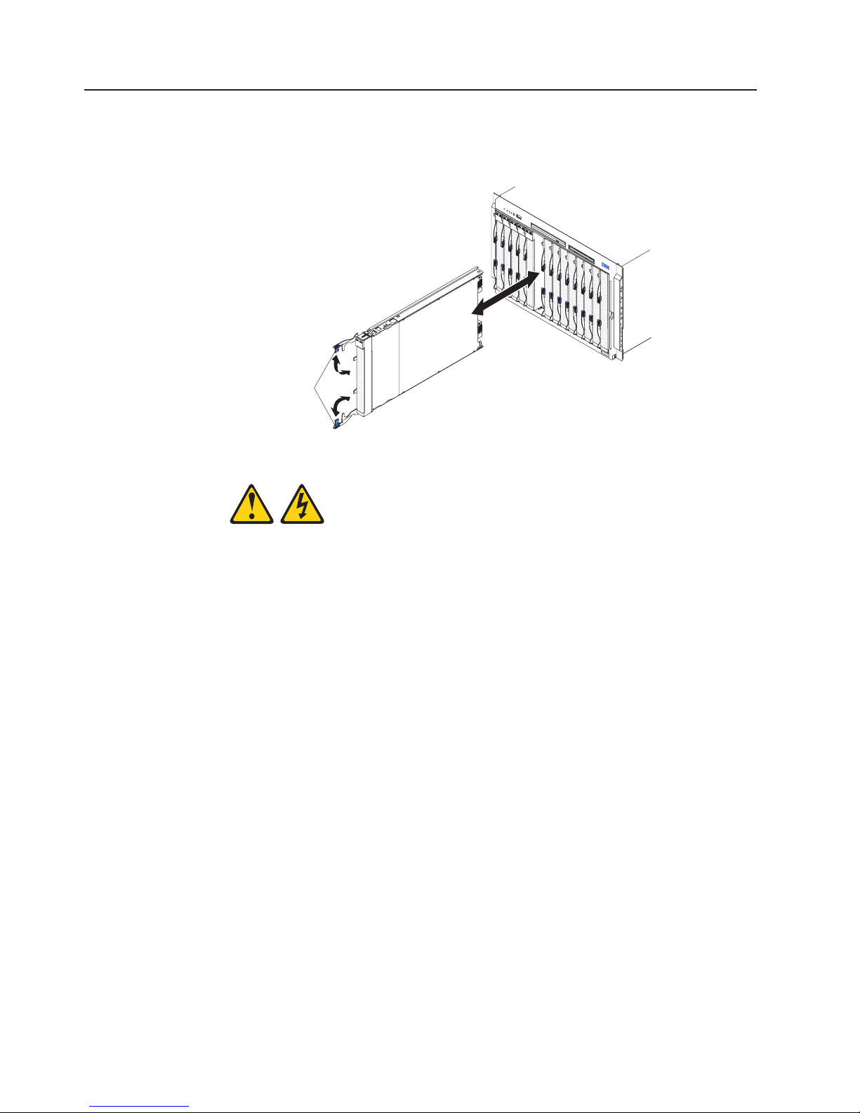
Installing the blade server in a BladeCenter unit
To install a blade server in a BladeCenter unit, complete the following steps. The
appearance of your BladeCenter unit might be different, see the documentation for
your BladeCenter unit for additional information.
Release handles
(open)
Statement 21:
CAUTION:
Hazardous energy is present when the blade server is connected to the power
source. Always replace the blade cover before installing the blade server.
1. Make sure that the release handles on the blade server are in the open position
(perpendicular to the blade server).
2. If you installed a blade filler or another blade server in the bay from which you
removed the blade server, remove it from the bay.
Attention: Yo u must install the blade server in the same blade bay from which
you removed it. Some blade server configuration information and update options
are established according to bay number. Reinstalling a blade server into a
different blade bay from the one from which it was removed could have
unintended consequences, and you might have to reconfigure the blade server.
3. Slide the blade server into the blade bay from which you removed it until it
stops.
4. Push the release handles on the front of the blade server to the closed position.
5. Turn on the blade server (see “Turning on the blade server” on page 6).
6. Make sure that the power-on LED on the blade server control panel is lit
continuously, indicating that the blade server is receiving power and is turned
on.
66 BladeCenter LS21 Type 7971 and LS41 Type 7972: Problem Determination and Service Guide
Page 83

7. (Optional) Write identifying information on one of the labels that come with the
blade servers and place the label on the BladeCenter unit bezel. See the
documentation for your BladeCenter unit for information about the label
placement.
Important: Do not place the label on the blade server or in any way block the
ventilation holes on the blade server.
If you have changed the configuration of the blade server or if you are installing a
different blade server from the one that you removed, you must configure the blade
server through the Configuration/Setup Utility, and you might have to install the
blade server operating system. Detailed information about these tasks is available
in the Installation and User’s Guide.
Chapter 4. Removing and replacing blade server components 67
Page 84

Removing and replacing Tier 1 CRUs
Replacement of Tier 1 CRUs is your responsibility. If IBM installs a Tier 1 CRU at
your request, you will be charged for the installation.
The illustrations in this document might differ slightly from your hardware.
Removing the blade server cover
Note: If the blade server has an expansion unit that does not have a removable
cover, remove the expansion unit (see “Removing an expansion unit” on page 70).
To remove the blade server cover, complete the following steps.
Note: The following illustration shows how to remove the cover from a single-width
model blade server; removing the cover from a double-width model blade server is
similar.
Blade-cover
release
Blade-cover
release
1. Read the safety information that begins on page vii and “Installation guidelines”
on page 63.
2. If the blade server is installed in a BladeCenter unit, remove it (see “Removing
the blade server from a BladeCenter unit” on page 65).
3. Carefully lay the blade server down on a flat, static-protective surface, with the
cover side up.
4. Press the blade-cover release on each side of the blade server or expansion
unit and lift the cover open.
5. Lift the cover from the blade server and store it for future use.
68 BladeCenter LS21 Type 7971 and LS41 Type 7972: Problem Determination and Service Guide
Page 85

Installing the blade server cover
To install the blade server cover, complete the following steps.
Note: The following illustration shows how to install the cover on a single-width
model blade server; installing the cover on a double-width model blade server is
similar.
Blade-cover
release
Blade-cover
release
Statement 21:
CAUTION:
Hazardous energy is present when the blade server is connected to the power
source. Always replace the blade cover before installing the blade server.
Attention: Yo u cannot insert the blade server into the BladeCenter unit until the
cover is installed and closed. Do not attempt to override this protection.
1. Read the safety information that begins on page vii and “Installation guidelines”
on page 63.
2. Lower the cover so that the slots at the rear slide down onto the pins at the rear
of the blade server. Before closing the cover, check that all components are
installed and seated correctly and that you have not left loose tools or parts
inside the blade server.
3. Pivot the cover to the closed position until it clicks into place.
4. Install the blade server into the BladeCenter unit (see “Installing the blade
server in a BladeCenter unit” on page 66).
Chapter 4. Removing and replacing blade server components 69
Page 86

Removing an expansion unit
To remove an expansion unit, complete the following steps.
Note: The following illustration shows how to remove an MPE unit from the blade
server; removing another type of expansion unit from a blade server is similar.
Extraction
thumbscrew
Expansion unit
Blade expansion
connector cover
Blade-cover
release
MPE unit
connector
cover
Blade-cover
release
1. Read the safety information beginning on page vii and “Installation guidelines”
on page 63.
2. If the blade server is installed in a BladeCenter unit, remove it (see “Removing
the blade server from a BladeCenter unit” on page 65).
3. Carefully lay the blade server down on a flat, static-protective surface, with the
cover side up.
4. Remove the blade server cover, if one is installed (see “Removing the blade
server cover” on page 68).
5. If the expansion unit has an extraction device (such as a thumbscrew or a
lever), use it to disengage the expansion unit from the blade server; otherwise,
press the blade-cover release on each side of the blade server to disengage the
expansion unit from the blade server.
Attention: Do not rotate the expansion unit open further than 90° to avoid
damage to the connectors at the rear of the blade server.
6. Rotate the expansion unit open; then, lift the expansion unit from the blade
server.
7. If you are not installing an expansion unit immediately, make sure that the
protective covers are installed on the blade expansion connector and the MPE
unit connector.
8. If you are instructed to return the expansion unit, follow all packaging
instructions, and use any packaging materials for shipping that are supplied to
you.
70 BladeCenter LS21 Type 7971 and LS41 Type 7972: Problem Determination and Service Guide
Page 87
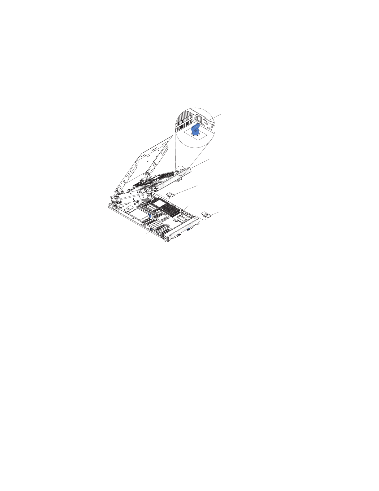
Installing an expansion unit
Attention: If a high-speed expansion card is installed in the blade server system
board, you cannot install an expansion unit.
To install an expansion unit, complete the following steps.
Note: The following illustration shows how to install an MPE unit on the blade
server; installing another type of expansion unit on a blade server is similar.
Extraction
thumbscrew
Expansion unit
Blade expansion
connector cover
Blade-cover
release
MPE unit
connector
cover
Blade-cover
release
1. Remove the cover from the blade expansion connector, if one is installed.
2. If you are installing an MPE unit, remove the cover from the MPE unit
connector, if one is installed.
3. Touch the static-protective package that contains the expansion unit to any
unpainted metal surface on the BladeCenter unit or any unpainted metal surface
on any other grounded rack component; then, remove the expansion unit from
the package.
4. Orient the expansion unit above the blade server.
5. Lower the expansion unit so that the slots at the rear slide down onto the cover
pins at the rear of the blade server; then, pivot the expansion unit down onto
the blade server.
6. If the expansion unit has an extraction device (such as a thumbscrew or a
lever), use it to fully engage the expansion unit on the blade server; otherwise,
press the expansion unit firmly into the closed position until it clicks into place.
7. Install the blade-server cover, if required (see“Installing the blade server cover”
on page 69).
8. Install the blade server into the BladeCenter unit (see “Installing the blade
server in a BladeCenter unit” on page 66).
Chapter 4. Removing and replacing blade server components 71
Page 88
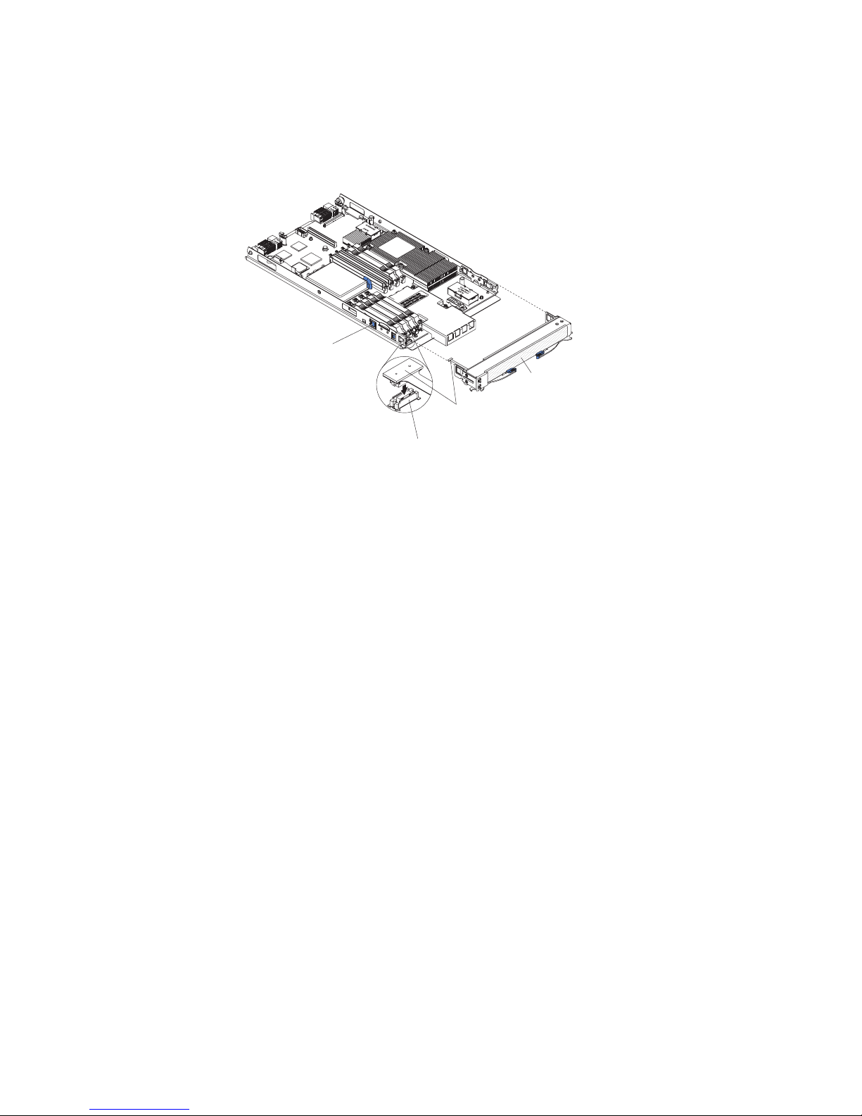
Removing the bezel assembly
To remove the bezel assembly, complete the following steps.
Note: The following illustration shows how to remove the bezel assembly from the
blade server; removing the bezel assembly from the MPE unit is similar.
Bezel-assembly
release (both sides)
Bezel assembly
Control-panel
cable
Control-panel
connector
1. Read the safety information that begins on page vii and “Installation guidelines”
on page 63.
2. Open the blade server cover (see “Removing the blade server cover” on page
68).
3. If you are removing the bezel assembly from the blade server and an MPE unit
is installed, remove the MPE unit (see “Removing an expansion unit” on page
70).
4. Press the bezel-assembly release on each side of the blade server and pull the
bezel assembly away from the blade server approximately 1.2 cm (0.5 inch).
5. If you are removing the blade-server bezel assembly, disconnect the
control-panel cable from the control-panel connector.
6. Pull the bezel assembly away from the blade server.
7. If you are instructed to return the bezel assembly, follow all packaging
instructions, and use any packaging materials for shipping that are supplied to
you; otherwise, store the bezel assembly in a safe place.
72 BladeCenter LS21 Type 7971 and LS41 Type 7972: Problem Determination and Service Guide
Page 89

Installing the bezel assembly
To install the bezel assembly, complete the following steps.
Note: The following illustration shows how to install the bezel assembly on the
blade server; installing the bezel assembly on the MPE unit is similar.
Bezel-assembly
release (both sides)
Bezel assembly
Control-panel
cable
Control-panel
connector
1. If you are installing the blade-server bezel assembly, connect the control-panel
cable to the control-panel connector.
2. Carefully slide the bezel assembly onto the blade server until it clicks into place.
3. Install the MPE unit, if one was removed while removing the bezel assembly
(see “Installing an expansion unit” on page 71).
4. Install the cover onto the blade server (see “Installing the blade server cover” on
page 69).
5. Install the blade server into the BladeCenter (see “Installing the blade server in
a BladeCenter unit” on page 66).
Chapter 4. Removing and replacing blade server components 73
Page 90

Removing a SAS hard disk drive
To remove a SAS hard disk drive, complete the following steps.
Note: The following illustration shows how to remove the SAS hard disk drive from
the blade server; removing the SAS hard disk drive from the MPE unit is similar.
SAS hard
disk drive
Hard disk drive
release lever
1. Read the safety information that begins on page vii and “Installation guidelines”
on page 63.
2. If the blade server is installed in a BladeCenter unit, remove it (see “Removing
the blade server from a BladeCenter unit” on page 65).
3. Remove the blade server cover (see “Removing the blade server cover” on
page 68).
4. If you are removing a hard disk drive from the blade server and an MPE unit is
installed, remove the MPE unit (see “Removing an expansion unit” on page 70).
5. Locate the blue release lever on the hard disk drive tray.
6. While pushing the release lever away from the drive, slide the drive forward to
disengage it from the connector at the rear of the drive tray: then, lift the drive
out of the drive tray.
7. If you are instructed to return the hard disk drive, follow all packaging
instructions, and use any packaging materials for shipping that are supplied to
you.
74 BladeCenter LS21 Type 7971 and LS41 Type 7972: Problem Determination and Service Guide
Page 91

Installing a SAS hard disk drive
To install a SAS hard disk drive, complete the following steps.
Note: The following illustration shows how to install the SAS hard disk drive in the
blade server; installing the SAS hard disk drive in the MPE unit is similar.
SAS hard
disk drive
Hard disk drive
release lever
1. Touch the static-protective package that contains the hard disk drive to any
unpainted metal surface on the BladeCenter unit or any unpainted metal surface
on any other grounded rack component; then, remove the hard disk drive from
the package.
Attention: Do not press on the top of the drive. Pressing the top might
damage the drive.
2. Place the hard disk drive into the drive tray and push it into the connector at the
rear of the drive tray, until the drive moves past the lever at the front of the tray.
3. Install the MPE unit, if one was removed while removing the hard disk drive
(see “Installing an expansion unit” on page 71).
4. Install the blade server cover (see “Installing the blade server cover” on page
69).
5. Install the blade server into the BladeCenter unit (see “Installing the blade
server in a BladeCenter unit” on page 66).
Chapter 4. Removing and replacing blade server components 75
Page 92

Removing a memory module
To remove a DIMM, complete the following steps.
Note: The following illustration shows how to remove a DIMM from the blade
server or the MPE unit.
DIMM
1. Read the safety information that begins vii and “Installation guidelines” on page
63
2. If the blade server is installed in a BladeCenter unit, remove it (see “Removing
the blade server from a BladeCenter unit” on page 65).
3. Remove the blade server cover (see “Removing the blade server cover” on
page 68).
4. If you are removing a DIMM from the blade server and an MPE unit is installed,
remove the MPE unit (see “Removing an expansion unit” on page 70).
5. Locate the DIMM connectors (see “System board connectors” on page 7).
Determine which DIMM you want to remove from the blade server.
Attention: To avoid breaking the retaining clips or damaging the DIMM
connectors, handle the clips gently.
6. Move the DIMM retaining clips on the side of the DIMM socket to the open
position by pressing the retaining clips away from the center of the DIMM
socket.
7. Using your fingers, pull the DIMM out of the DIMM socket.
8. If you are instructed to return the DIMM, follow all packaging instructions, and
use any packaging materials for shipping that are supplied to you.
Retaining
clip
Installing a memory module
Note: If you are replacing a faulty DIMM, make sure that the replacement DIMM is
the correct type of memory. For each installed microprocessor, a set of 4 DIMM
sockets is enabled (see the following table for more information). If you are adding
DIMMs, install the DIMMs in pairs into the DIMM sockets that are enabled. See the
Installation and User’s Guide for additional information about the type of memory
that is compatible with the server.
76 BladeCenter LS21 Type 7971 and LS41 Type 7972: Problem Determination and Service Guide
Installed microprocessors Enabled DIMM sockets
1 (in blade server) 1, 2, 3, 4 (in blade server)
1 and 2 (in blade server) 1, 2, 3, 4, 5, 6, 7, 8 (in blade server)
1 and 2 (in blade server)
1 (in MPE unit)
1 and 2 (in blade server)
1 and 2 (in MPE unit)
1, 2, 3, 4, 5, 6, 7, 8 (in blade server)
1, 2, 3, 4 (in MPE unit)
1, 2, 3, 4, 5, 6, 7, 8 (in blade server)
1, 2, 3, 4, 5, 6, 7, 8 (in MPE unit)
Page 93

To install a DIMM, complete the following steps.
Note: The following illustration shows how to install a DIMM in the blade server or
the MPE unit.
DIMM
Retaining
clip
1. Read the documentation that comes with the DIMM.
2. Locate the DIMM connectors (see “System board connectors” on page 7).
Determine the connectors into which you will install the DIMMs.
3. Touch the static-protective package that contains the DIMM to any unpainted
metal surface on the BladeCenter unit or any unpainted metal surface on any
other grounded rack component; then, remove the DIMM from the package.
Attention: To avoid breaking the DIMM retaining clips or damaging the DIMM
connectors, open and close the clips gently.
4. Make sure that both of the connector retaining clips are in the fully open
position.
5. Turn the DIMM so that the DIMM keys align correctly with the connector on the
system board.
6. Insert the DIMM by pressing the DIMM along the guides into the connector.
Make sure that the retaining clips snap into the closed positions.
Attention: If there is a gap between the DIMM and the retaining clips, the
DIMM has not been correctly installed. In this case, open the retaining clips and
remove the DIMM; then, reinsert the DIMM.
7. Install the MPE unit, if one was removed while removing the DIMMs (see
“Installing an expansion unit” on page 71).
8. Install the blade server cover (see “Installing the blade server cover” on page
69).
9. Install the blade server into the BladeCenter unit (see “Installing the blade
server in a BladeCenter unit” on page 66).
Chapter 4. Removing and replacing blade server components 77
Page 94

Removing and installing an I/O expansion card
The following sections describe how to remove and replace small-form-factor,
standard-form-factor, and high-speed I/O-expansion cards.
Removing a small-form-factor expansion card
To remove a small-form-factor expansion card, complete the following steps.
Note: The following illustration shows how to remove a small-form-factor expansion
card from the blade server; removing a small-form-factor expansion card from the
MPE unit is similar.
Small-form-factor
expansion card
PRESS HEREWHEN
INSTALLING CARD
1. Read the safety information that begins on page vii and “Installation guidelines”
on page 63.
2. If the blade server is installed in a BladeCenter unit, remove it (see “Removing
the blade server from a BladeCenter unit” on page 65).
3. Remove the blade server cover (see “Removing the blade server cover” on
page 68).
4. If you are removing the expansion card from the blade server and an MPE unit
is installed, remove the MPE unit (see “Removing an expansion unit” on page
70).
5. Gently pivot the wide end of the card out of the expansion card connectors;
then, slide the notched end of the card out of the raised hook on the expansion
card bracket and lift the card out of the blade server.
6. If you are instructed to return the expansion card, follow all packaging
instructions, and use any packaging materials for shipping that are supplied to
you.
78 BladeCenter LS21 Type 7971 and LS41 Type 7972: Problem Determination and Service Guide
Page 95

Installing a small-form-factor expansion card
To install a small-form-factor expansion card, complete the following steps.
Note: The following illustration shows how to install a small-form-factor expansion
card in the blade server; installing a small-form-factor expansion card in the MPE
unit is similar.
1. Touch the static-protective package that contains the expansion card to any
unpainted metal surface on the BladeCenter unit or any unpainted metal surface
on any other grounded rack component; then, remove the expansion card from
the package.
2. Orient the expansion card over the expansion card connectors.
3. Slide the notch in the narrow end of the card into the raised hook on the
expansion card bracket; then, gently pivot the card into the expansion card
connectors.
Small-form-factor
expansion card
PRESS HEREWHEN
INSTALLING CARD
Note: For device-driver and configuration information to complete the
installation of the expansion card, see the documentation that comes with the
expansion card.
4. Install the MPE unit, if one was removed while removing the expansion card
(see “Installing an expansion unit” on page 71).
5. Install the blade server cover (see “Installing the blade server cover” on page
69).
6. Install the blade server into the BladeCenter unit (see “Installing the blade
server in a BladeCenter unit” on page 66).
Chapter 4. Removing and replacing blade server components 79
Page 96

Removing a standard-form-factor expansion card
To remove a standard-form-factor expansion card, complete the following steps.
Note: The following illustration shows how to remove a standard-form-factor
expansion card from the blade server; removing a standard-form-factor expansion
card from the MPE unit is similar.
Standard-form-factor
expansion card
1. Read the safety information that begins on page vii and “Installation guidelines”
on page 63.
2. If the blade server is installed in a BladeCenter unit, remove it (see “Removing
the blade server from a BladeCenter unit” on page 65).
3. Remove the blade server cover (see “Removing the blade server cover” on
page 68).
4. If you are removing the expansion card from the blade server and an MPE unit
is installed, remove the MPE unit (see “Removing an expansion unit” on page
70).
5. Gently pivot the wide end of the card out of the expansion card connectors;
then, slide the notched end of the card out of the raised hook on the expansion
card bracket and lift the card out of the blade server.
6. If you are instructed to return the expansion card, follow all packaging
instructions, and use any packaging materials for shipping that are supplied to
you.
D
N
AR
E
C
H
G
W
E
R
LLIN
E
A
ST
S H
S
IN
E
R
P
80 BladeCenter LS21 Type 7971 and LS41 Type 7972: Problem Determination and Service Guide
Page 97

Installing a standard-form-factor expansion card
To install a standard-form-factor expansion card, complete the following steps.
Note: The following illustration shows how to install a standard-form-factor
expansion card in the blade server; installing a standard-form-factor expansion card
in the MPE unit is similar.
Standard-form-factor
expansion card
1. Touch the static-protective package that contains the expansion card to any
unpainted metal surface on the BladeCenter unit or any unpainted metal surface
on any other grounded rack component; then, remove the expansion card from
the package.
2. Orient the expansion card over the expansion card connectors.
3. Slide the narrow end of the card into the raised hook on the expansion card
bracket; then, gently pivot the wide end of the card into the expansion card
connectors.
D
R
N
E
CA
H
G
W
E
LIN
L
ER
A
T
H
S
S
S
IN
E
R
P
Note: For device-driver and configuration information to complete the
installation of the expansion card, see the documentation that comes with the
expansion card.
4. Install the MPE unit, if one was removed while removing the expansion card
(see “Installing an expansion unit” on page 71).
5. Install the blade server cover (see “Installing the blade server cover” on page
69).
6. Install the blade server into the BladeCenter unit (see “Installing the blade
server in a BladeCenter unit” on page 66).
Chapter 4. Removing and replacing blade server components 81
Page 98

Removing a high-speed expansion card
To remove a high-speed expansion card, complete the following steps.
Note: The following illustration shows how to remove a high-speed expansion card
from the blade server; removing a high-speed expansion card from the MPE unit is
similar.
High-speed
expansion card
Expansion
card
standoff
1. Read the safety information that begins on page vii and “Installation guidelines”
on page 63.
2. If the blade server is installed in a BladeCenter unit, remove it (see “Removing
the blade server from a BladeCenter unit” on page 65).
3. Remove the blade server cover (see “Removing the blade server cover” on
page 68).
4. Rotate the expansion-card extraction lever upward to disengage the
blade-expansion connector.
5. Pivot the narrow end of the card away from the blade expansion connector;
then, slide the slots at the back end of the card out of the expansion-card
standoffs and lift the card out of the blade server.
6. If you are instructed to return the expansion card, follow all packaging
instructions, and use any packaging materials for shipping that are supplied to
you.
Extraction lever
Blade expansion
connector
82 BladeCenter LS21 Type 7971 and LS41 Type 7972: Problem Determination and Service Guide
Page 99

Installing a high-speed expansion card
To install a high-speed expansion card, complete the following steps.
Note: The following illustration shows how to install a high-speed expansion card in
the blade server; installing a high-speed expansion card in the MPE unit is similar.
1. Touch the static-protective package that contains the expansion card to any
2. Locate the blade-expansion connector and orient the expansion card over it.
3. Slide the slots at the back end of the card onto the pins on the expansion card
4. Firmly press on the indicated locations to seat the expansion card.
High-speed
expansion card
Blade expansion
connector
Expansion
card
standoff
unpainted metal surface on the BladeCenter unit or any unpainted metal surface
on any other grounded rack component; then, remove the expansion card from
the package.
standoff; then, gently pivot the card into the blade expansion connector.
Note: For device-driver and configuration information to complete the
installation of the expansion card, see the documentation that comes with the
expansion card.
5. Install the blade server cover (see “Installing the blade server cover” on page
69).
6. Install the blade server into the BladeCenter unit (see “Installing the blade
server in a BladeCenter unit” on page 66).
Chapter 4. Removing and replacing blade server components 83
Page 100

Removing the battery
To remove the battery, complete the following steps.
1. Read the safety information that begins on page vii and “Installation guidelines”
on page 63
2. If the blade server is installed in a BladeCenter unit, remove it (see “Removing
the blade server from a BladeCenter unit” on page 65).
3. Remove the blade server cover (see “Removing the blade server cover” on
page 68).
4. If an MPE unit is installed, remove the MPE unit (see “Removing an expansion
unit” on page 70).
5. Locate the battery on the system board (see “System board connectors” on
page 7).
6. Use one finger to press the top of the battery clip away from the battery. The
battery pops up when released.
7. Use your thumb and index finger to lift the battery from the socket.
8. Dispose of the battery as required by local ordinances or regulations.
Installing the battery
The following notes describe information that you must consider when you are
replacing the battery in the blade server.
v When you are replacing the battery, you must replace it with a lithium battery of
the same type from the same manufacturer.
v To order replacement batteries, call 1-800-426-7378 within the United States, and
1-800-465-7999 or 1-800-465-6666 within Canada. Outside the U.S. and
Canada, call your IBM marketing representative or authorized reseller.
v After you replace the battery, you must reconfigure the server and reset the
system date and time.
v To avoid possible danger, read and follow the following safety statement.
84 BladeCenter LS21 Type 7971 and LS41 Type 7972: Problem Determination and Service Guide
 Loading...