

Page 1

IBM
Power System LC921
(9006-12C) Quick Install
Guide IBM
IBM Power®System LC921 (9006-12C) Quick Install Guide
The IBM Knowledge Center is available online from: http://www.ibm.com/support/knowledgecenter/
POWER8/p8hdx/9006_12c_landing.htm.
v Read all precautions and instructions before you start working on key parts.
v Use normal electrostatic discharge (ESD) procedures when working on the system and parts. IBM
recommends wearing gloves and an anti-static wrist strap to avoid possible damage to the equipment.
9006-12C information: https://ibm.biz/9006-12CQR
9006-12C parts
Use this information to find the field-replaceable unit (FRU) part number.
After you identify the part number of the part that you want to order, go to Advanced Part Exchange
Warranty Service. Registration is required. If you are not able to identify the part number, go to
Contacting IBM®service and support.
Page 2
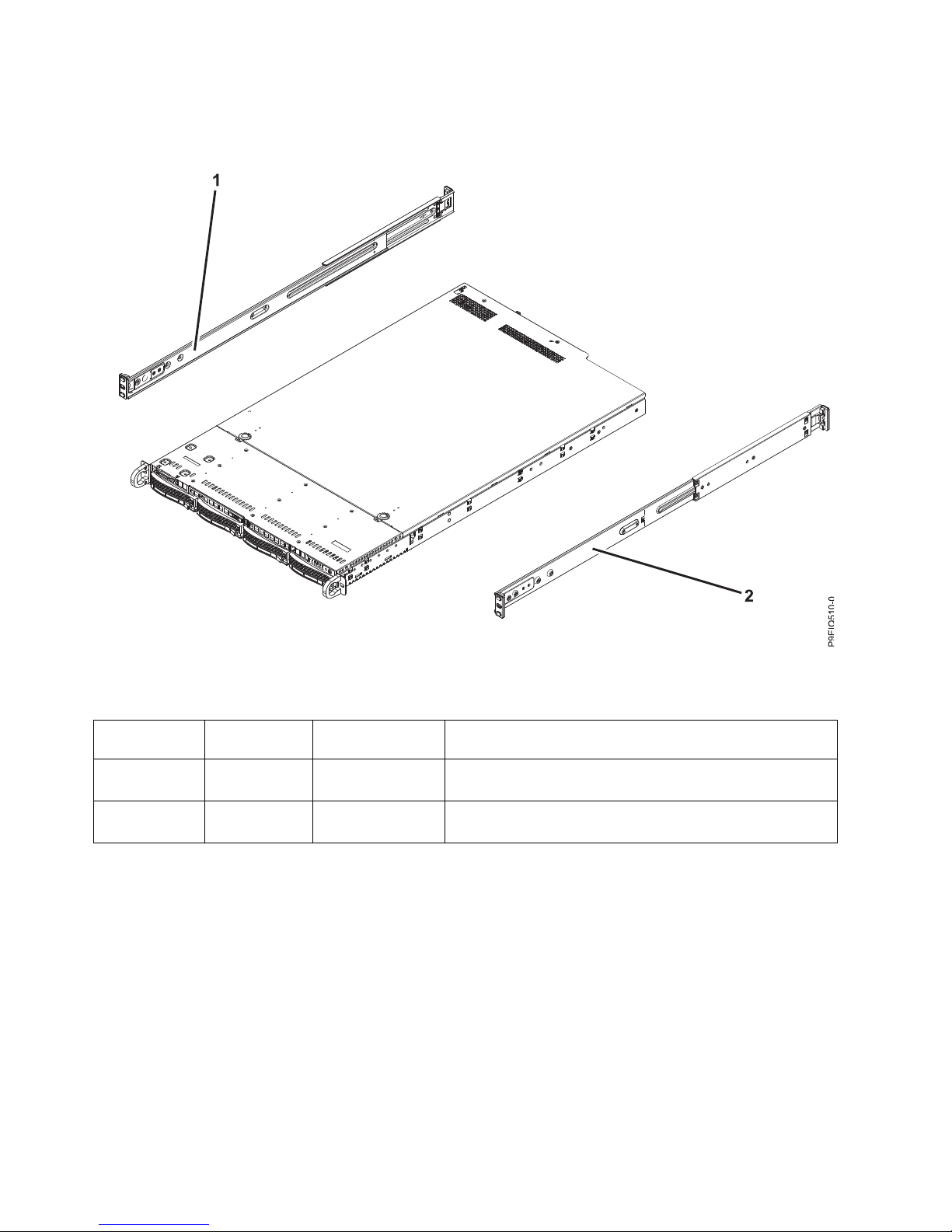
Rack final assembly
Table 1. Rack final assembly part numbers
Index number Part number
Units per
assembly Description
1 MCP-290-
00052-0N
1 Slide rail kit - contains left and right slide rails and
attaching screws
2 MCP-290-
00052-0N
1 Slide rail kit - contains left and right slide rails and
attaching screws
Figure 1. Rack final assembly
2
Page 3
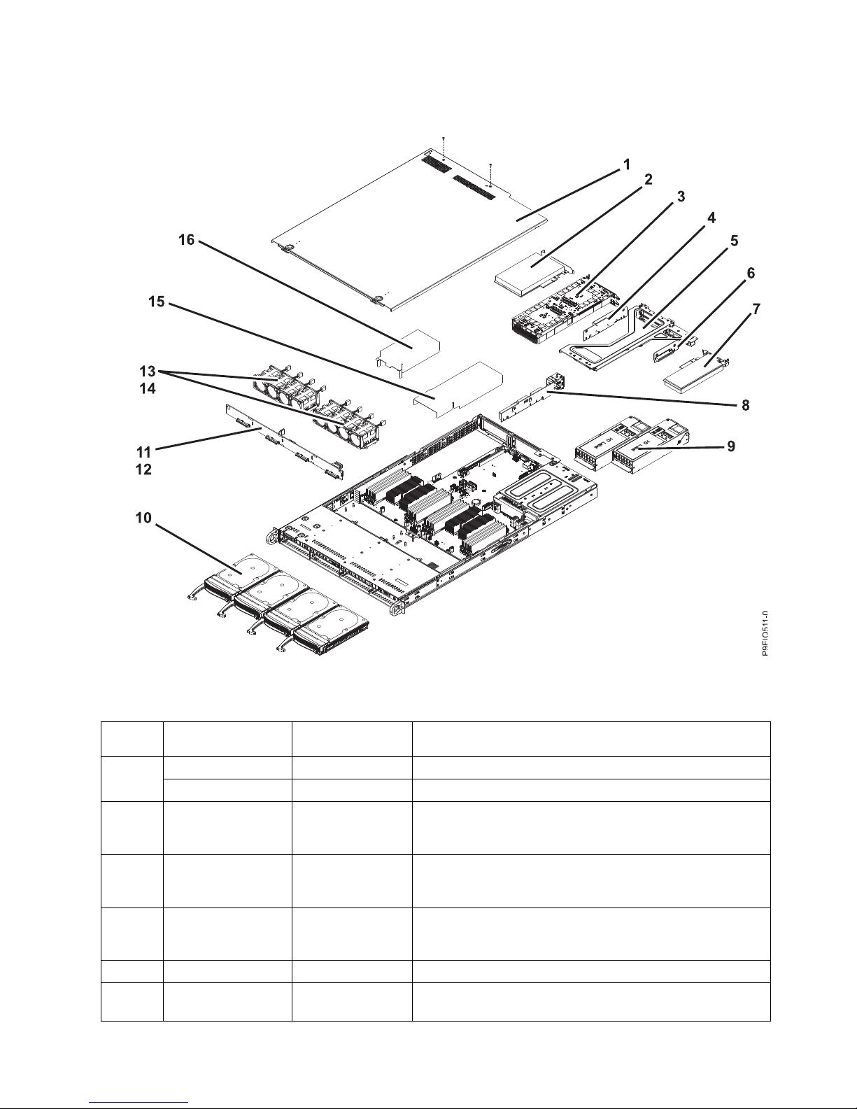
System parts
Table 2. System parts
Index
number Part number Units per assembly Description
1 1 Top cover assembly
2 Screws
2 2 PCIe adapters. Use the feature type of the adapter to find the
FRU number in PCIe adapter information by feature type for
the 9006-12C.
3 1 GPU. Use the feature type of the GPU to find the FRU
number in PCIe adapter information by feature type for the
9006-12C.
4 RSC-W-66P 1 PCIe riser for PCIe adapters or GPU. Use the feature type of
the adapter to find the FRU number in PCIe adapter
information by feature type for the 9006-12C.
5 1 PCIe cage
6 RSC-R1UW-E8R-
IB001
1 PCIe riser
Figure 2. System parts
3
Page 4
Table 2. System parts (continued)
Index
number Part number Units per assembly Description
7 1 PCIe adapter. Use the feature type of the adapter to find the
FRU number in PCIe adapter information by feature type for
the 9006-12C
8 AOC-UR-i4XTF 1 1U UIO NIC PCIe adapter with integrated 4-port 10 GbE
Base-T, Intel XL710, and CAPI
Note: This PCIe adapter is also a PCIe riser.
9 PWS-1K02A-1R 2 800 W 110 VAC Power supply assembly
Note: This power supply does not support GPUs.
PWS-1K02A-1R 2 1000 W 220 VAC Power supply assembly
4
Page 5

Table 2. System parts (continued)
Index
number Part number Units per assembly Description
10 HDD-KIT-2A-
ST1200S-IB001
4 1.2 TB 10k (512 block size) 2.5 inch SAS disk drive
HDD-KIT-2AST1800S-IB001
4 1.8 TB 10k (512 block size) 2.5 inch SAS disk drive
HDD-A2000ST2000NM003401 or
HDD-A2000ST2000NM0135
4 2.0 TB 7.2K (512 block size) 3.5 inch SAS disk drive
HDD-A4000ST4000NM0125
4 4.0 TB 7.2K (512 block size) 3.5 inch SAS disk drive
HDD-A8000ST8000NM0075
4 8.0 TB 7.2K (512 block size) 3.5 inch SAS disk drive
HDD-A10TST10000NM0096
4 10.0 TB 7.2K (512 block size) 3.5 inch SAS disk drive
HDD-A4000ST4000NM0075
4 4.0 TB 7.2K (4k block size) 3.5 inch self-encrypting SAS disk
drive
HDD-A8000ST8000NM0095
4 8.0 TB 7.2K (4k block size) 3.5 inch self-encrypting SAS disk
drive
HDD-T2000ST2000NM002401 or
HDD-T2000ST2000NM0125
4 2.0 TB 7.2K (512 block size) 3.5 inch SATA disk drive
HDD-T4000ST4000NM002401 or
HDD-T4000ST4000NM0115
4 4.0 TB 7.2K (512 block size) 3.5 inch SATA disk drive
HDD-T8000ST8000NM0055
4 8.0 TB 7.2K (512 block size) 3.5 inch SATA disk drive
HDD-T10TST10000NM0086
4 10.0 TB 7.2K (512 block size) 3.5 inch SATA disk drive
HDS-KIT-2A-1920IB001
4 1.92 TB 2.5 inch SAS solid-state drive (1 drive write per day)
HDS-KIT-2A-3840IB001
4 3.84 TB 2.5 inch SAS solid-state drive (1 drive write per day)
HDS-KIT-2A-ST960IB001
4 960 GB 2.5 inch SAS solid-state drive (3 drive writes per day)
HDS-KIT-2A-ST1920IB001
4 1.92 TB 2.5 inch SAS solid-state drive (3 drive writes per
day)
HDS-KIT-2A-7680SIB001
4 7.68 TB 2.5 inch SAS solid-state drive (1 drive write per day)
HDS-KIT-2A-1920SIB001
4 1.92 TB 2.5 inch self-encrypting SAS solid-state drive (1 drive
write per day)
HDS-KIT-2A-3840SIB001
4 3.84 TB 2.5 inch self-encrypting SAS solid-state drive (1 drive
write per day)
HDS-KIT-2T-240IB001
4 240 GB 2.5 inch self-encrypting SATA solid-state drive (0.78
drive writes per day)
HDS-KIT-2T-960IB001
4 960 GB 2.5 inch SATA solid-state drive (0.6 drive writes per
day)
HDS-KIT-2T-3800IB001
4 3.84 TB 2.5 inch self-encrypting SATA solid-state drive (0.78
drive writes per day)
HDS-KIT-2T-1900IB001
4 1.92 TB 2.5 inch self-encrypting SATA solid-state drive (0.78
drive writes per day)
5
Page 6

Table 2. System parts (continued)
Index
number Part number Units per assembly Description
11 BPN-SAS3-815TQ-N41 Disk drive backplane
12 2 Screws
13 FAN-0141L4 8 Fan
14 2 Fan holder
15 1 CPU 1 air baffle
16 1 CPU 2 air baffle
6
Page 7

Additional system parts
Table 3. Additional system parts
Index
number Part number Units per assembly Description
17 MEM-DR480L-049 16 8 GB, 2666 MHz 1RX4 DDR4 RDIMM*
MEM-DR416L-066 16 16 GB, 2666 MHz 1RX4 DDR4 RDIMM*
MEM-DR432L-028 16 32 GB, 2666 MHz 2RX4 DDR4 RDIMM*
MEM-DR464L-SL01-
ER26
16 64 GB, 2666 MHz 4RX4 DDR4 RDIMM*
Figure 3. Additional system parts
7
Page 8

Table 3. Additional system parts (continued)
Index
number Part number Units per assembly Description
18 SSD-DM128-
SMCMVN1
0-2 128 GB SATA drive on module (DOM)
19 AOM-TPM-T650V 1 Trusted platform module (TPM) card
20 MBD-P9DSU-C-P 1 System backplane
21 14 Screws
22 1-2 16 core 2.9 GHz system processor module
1-2 20 core 2.9 GHz system processor module
23 SNK-P0052P-IB001 2 Heat sink kit (includes heat sink and thermal interface
material)
*All of the memory in a 9006-12C system must be the same size and from the same supplier. The
9006-12C system does not support mixing different sizes of memory or mixing memory from different
suppliers.
Rear ports
Table 4. Input and output ports
Identifier Description
1 USB 2.0 used for keyboard and mouse.
Certain USB drives might be too wide to fit properly into
the USB ports on the rear of the system. Test the fit your
USB drive before proceeding.
2 Ethernet Intelligent Platform Management Interface
(IPMI)
3 Serial IPMI
4 Video Graphics Array (VGA) used for monitor. Only the
1024 x 768 at 60 Hz VGA setting is supported. Only up
to a 3-meter cable is supported. Text based capability is
only supported at this time.
Installing and Removing
Figure 4. Rear ports
8
Page 9

Figure 5. Removing a power supply from the system
Figure 6. Releasing and opening the cover
Figure 7. Removing a front drive Figure 8. Removing the 3.5-inch drive from the tray
9
Page 10
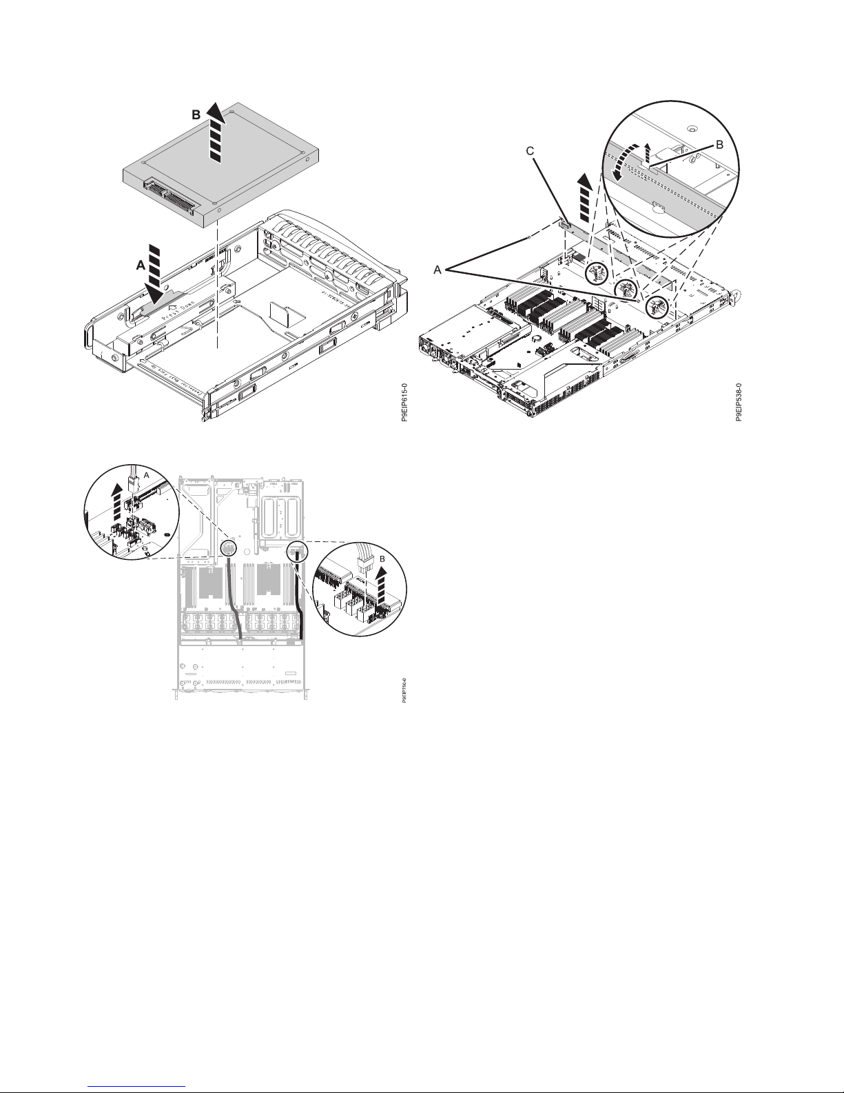
Figure 9. Removing the 2.5-inch drive from the tray Figure 10. Removing the disk drive backplane and screws
Figure 11. Disconnecting the drive signal and power
cables
10
Page 11

Figure 12. Removing the fan holder
Figure 13. Removing a fan
Figure 14. Disconnecting the fan cable
Figure 15. Aligning the fan holder
11
Page 12

Figure 16. Removing the memory
Figure 17. Two processor memory plugging sequence
Figure 18. 9006-12C PCIe adapter positions
Figure 19. Removing the PCIe riser
12
Page 13

Figure 20. Removing the UIO Network screws
Figure 21. Removing the PCIe riser cards from the
adapter cage
Figure 22. Removing a PCIe adapter from position 3 of
the riser
Figure 23. Removing the GPU from the riser
13
Page 14

Figure 24. Processor socket screws on bottom of chassis
Figure 25. Screw locations
Figure 26. Loosening heat sink load arm screw
14
Page 15
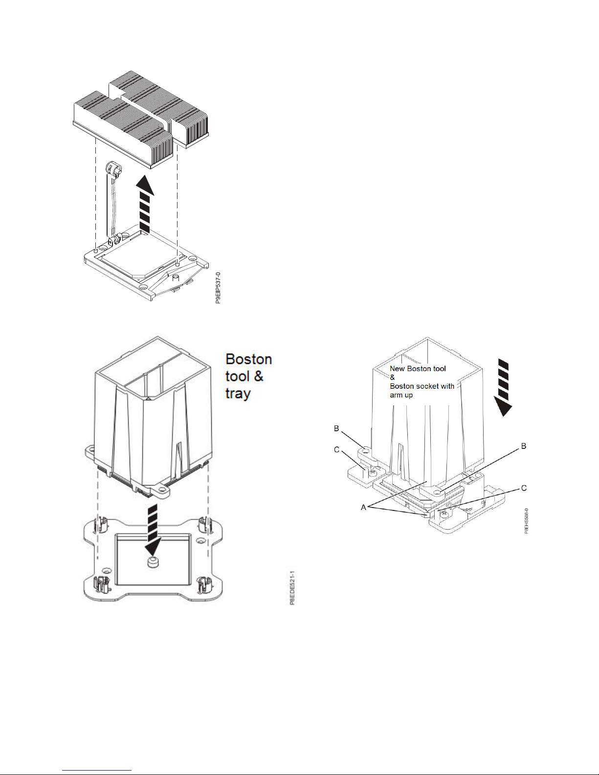
Figure 27. Removing the heat sink
Figure 28. Placing the processor at an angle on the top
cover of the packaging
Figure 29. Installing the system processor module
15
Page 16

Figure 30. Installing the heat sink
Figure 31. Tightening the load arm screw
Figure 32. Time-of-day battery location
This September 14, 2017 edition applies to IBM Power Systems servers that contain the POWER8 processor and to all
associated models.
© Copyright IBM Corporation 2017.
US Government Users Restricted Rights – Use, duplication or disclosure restricted by GSA ADP Schedule Contract
with IBM Corp.
 Loading...