

Page 1

Basic Purpose Printer
LB20
User’s Guide
Part number: EK-LB20A-UG.001
Page 2

ACKNOWLEDGMENT
IBM, PC, XT, AT, PS/2, Proprinter and 4722 are
registered trademarks of International Business
Machines Corporation
MS-DOS, Windows 3.1x, Windows 95 and
WindowsNT are trademarks of Microsoft
Corporation.
A publication of:
DIGITAL EQUIPMENT BCFI AB
P.O. Box 904
S-175 29 Järfälla, Sweden
Printed in Sweden, March, 1997
© Digital Equipment Corporation, 1997.
All rights reserved
The information in this document is subject to change
without notice and should not be construed as a
commitment by Digital Equipment Corporation.
Digital Equipment Corporation assumes no
responsibility for any error which may appear in this
document.
Digital conducts its business in a manner that
conserves the environment and protects the safety and
health of its employees, customers, and the
community.
Digital, the Digital logo, DECbank and FBS are
trademarks of Digital Equipment Corporation.
Part number: EK-LB20A-UG.001
Page 3

CONTENTS
1 INTRODUCTION 1-1
1.1 Scope 1-1
1.2 Related Documentation 1-1
1.3 Order Process 1-2
1.4 Warnings, Cautions and Notes 1-2
1.5 Manufacturers Declaration 1-3
2 INSTALLATION 2-1
2.1 Preparation 2-1
2.2 Operating Space 2-2
2.3 Removal of transport locks 2-3
2.4 Trapdoor, Lid and Document Guide 2-4
2.5 Connections and Settings 2-5
2.6 Ink Ribbon Cassette 2-6
2.6.1 Power On 2-6
2.6.2 Unpacking the Ink Ribbon Cassette 2-7
2.6.3 Centering the Skid 2-7
2.6.4 Raising the Carrier 2-8
2.6.5 Positioning the Ink Ribbon Cassette 2-8
2.6.6 Installing the Ink Ribbon Cassette 2-9
2.6.7 Installing the Skid 2-9
2.6.8 Removing Slack Ribbon 2-10
2.6.9 Ready to Print 2-10
3 SETUP 3-1
3.1 Introduction 3-1
3.1.1 Setup Functions 3-1
3.1.2 Setup Controls 3-2
3.1.3 Menu’s and Parameters 3-2
3.1.4 Changing or Viewing the Setup 3-3
3.2 Setup Example 3-4
3.2.1 Entering Setup 3-5
3.2.2 Loading a Document 3-6
3.2.3 Moving to VIEW or a Menu 3-7
3.2.4 Printing the Current Settings 3-8
3.2.5 Changing a Setting 3-8
3.2.6 Validating 3-9
3.2.7 Quitting 3-9
Page 4

3.3 Setup Check 3-9
3.4 Performing a Setup 3-10
3.4.1 COM Menu 3-10
3.4.2 IBM Menu 3-10
3.4.3 DOC Menu 3-12
3.4.4 <>DFT Menu 3-18
3.4.5 <>HQD Menu 3-18
4 OPERATION 4-1
4.1 Controls and Indications 4-1
4.1.1 Confidence Test Routine 4-2
4.2 Documents 4-2
4.2.1 New Pages 4-2
4.2.2 Loading a Document 4-3
4.2.3 Stop while printing 4-4
4.2.4 Clearing Document Jams 4-4
5 MAINTENANCE 5-1
5.1 Ink Ribbon Cassette 5-2
5.1.1 Centering the Skid 5-2
5.1.2 Raising the Carrier 5-3
5.1.3 Removing the Skid 5-3
5.1.4 Removing the Old Ink Ribbon Cassette 5-4
5.1.5 Cleaning 5-4
5.1.6 Unpacking the New Ink Ribbon Cassette 5-4
5.1.7 Positioning the New Ink Ribbon Cassette 5-5
5.1.8 Installing the New Ink Ribbon Cassette 5-5
5.1.9 Reinstalling the Skid 5-6
5.1.10 Removing Slack Ribbon 5-6
5.2 Mylar Cassette 5-7
5.2.1 Centering the Skid 5-7
5.2.2 Raising the Carrier 5-8
5.2.3 Removing the Mylar Cassette 5-8
5.2.4 Inspecting the Mylar Edges (Bottom View) 5-9
5.2.5 Checking for Free Movement (Top View) 5-10
5.2.6 Reinstalling the Mylar Cassette 5-10
5.2.7 Positioning the Slider 5-11
Page 5

5.3 Printhead 5-12
5.3.1 Preparation 5-12
5.3.2 Removing the Trapdoor 5-13
5.3.3 Releasing the Printhead 5-13
5.3.4 Lowering the Carrier 5-14
5.3.5 Removing the Printhead 5-14
5.3.6Reinstalling the Printhead 5-15
5.4 Cleaning of Edge Detection Sensor and Mylar Slide Hole 5-16
5.5 Cleaning the Feed Rollers 5-17
5.6 Ready to Print 5-18
6 SPECIFICATIONS 6-1
6.1 Printer Characteristics 6-1
6.2 Serial Interface - RS232C 6-2
6.2.1 Configurable Parameters 6-2
6.2.2 Serial Connector 6-2
6.2.3 Handshaking 6-3
6.3 Parallel Interface - Centronics 6-4
6.4 Documents 6-5
6.4.1 Recommendations and Restrictions 6-7
6.4.2 Passbook Thickness 6-7
6.4.3 Center Outfold Bulge 6-8
6.4.4 Passbook Squareness 6-8
7 GLOSSARY 7-1
Page 6

1 INTRODUCTION
The LB20 Printer is delivered as one of the following:
• 9 pin dot matrix Serial printer (Model: LB20A-AA)
OR
• 9 pin dot matrix Parallel printer (Model: LB20B-AA)
When installed the printer forms an integrated part of a User’s Information System
and provides a printing function in IBM ProprinterIII emulation for the following
types of document:
• Passbooks - vertical or horizontal seam
• Envelopes
• Forms
The printer is simple to install, operate and maintain and provides a guaranteed
Print Quality for documents of thickness 0.0787 in (2 mm) or less.
1.1 Scope
This User Guide contains the following chapters:
• Introduction
• Installation
• Setup
• Operation
• Maintenance
• Specifications
• Glossary
1.2 Related Documentation
• Programmers Reference Guide (EK-LB20A-RG)
• Field Support Manual (EK-LB20A-SM)
• Spare Part Guide (EK-LB20A-PG)
Introduction 1-1
Page 7
1.3 Order Process
Documentation, Accessories and Spare Parts shall be ordered from:
Digital Equipment BCFI AB, Attn. Orderdesk
P.O.Box 904
175 29 Järfälla, Sweden
Telephone: +46 8 759 4600
Facsimile: +46 8 621 1718
1.4 Warnings, Cautions and Notes
WARNING!
This type of safety instruction is used where there is a danger of injury to persons
and/or damage to the equipment or the environment. The symbol inside the triangle
indicates type of danger.
CAUTION!
This type of safety instruction is used where danger of injury to persons and/or
damage to the equipment or the environment can occur, if the instruction is not
followed.
NOTE!
Notes are used to provide important or explanatory information.
Introduction 1-2
Page 8
1.5 Manufacturers Declaration
Document Number: S960242-1
This is to certify that the Digital Equipment BCFI AB, product indicated below
complies with the requirements on the EEC-Directives and/or other Standards as
indicated below and has been officially released for normal delivery to customers
and equipped with the CE-mark.
PRODUCT DESCRIPTION: Terminal Printer
DIGITAL MODEL NUMBER: LB20A-AA, LB20B-AA
This certificate is a confirmation of full compliance with the following regulations:
EEC-directive 89/336/EEC: "Electromagnetic Compatibility"
*EN 50081-1 (Emission EN 55022/1985)
*EN 50082-1 (Emission IEC 801-2, -3, -4)
EEC-Low Voltage Directive (LVD) 73/23/EEC of February 19, 1973
"Safety of Information technology equipment including electrical business
equipment"
*EN60950, 1992 + A1 + A2 + A3
Järfälla, 1996-12-19
Lars-Erik Högquist
Product Safety Manager
Introduction 1-3
Page 9
2 INSTALLATION
Perform the actions described and illustrated under the headings:
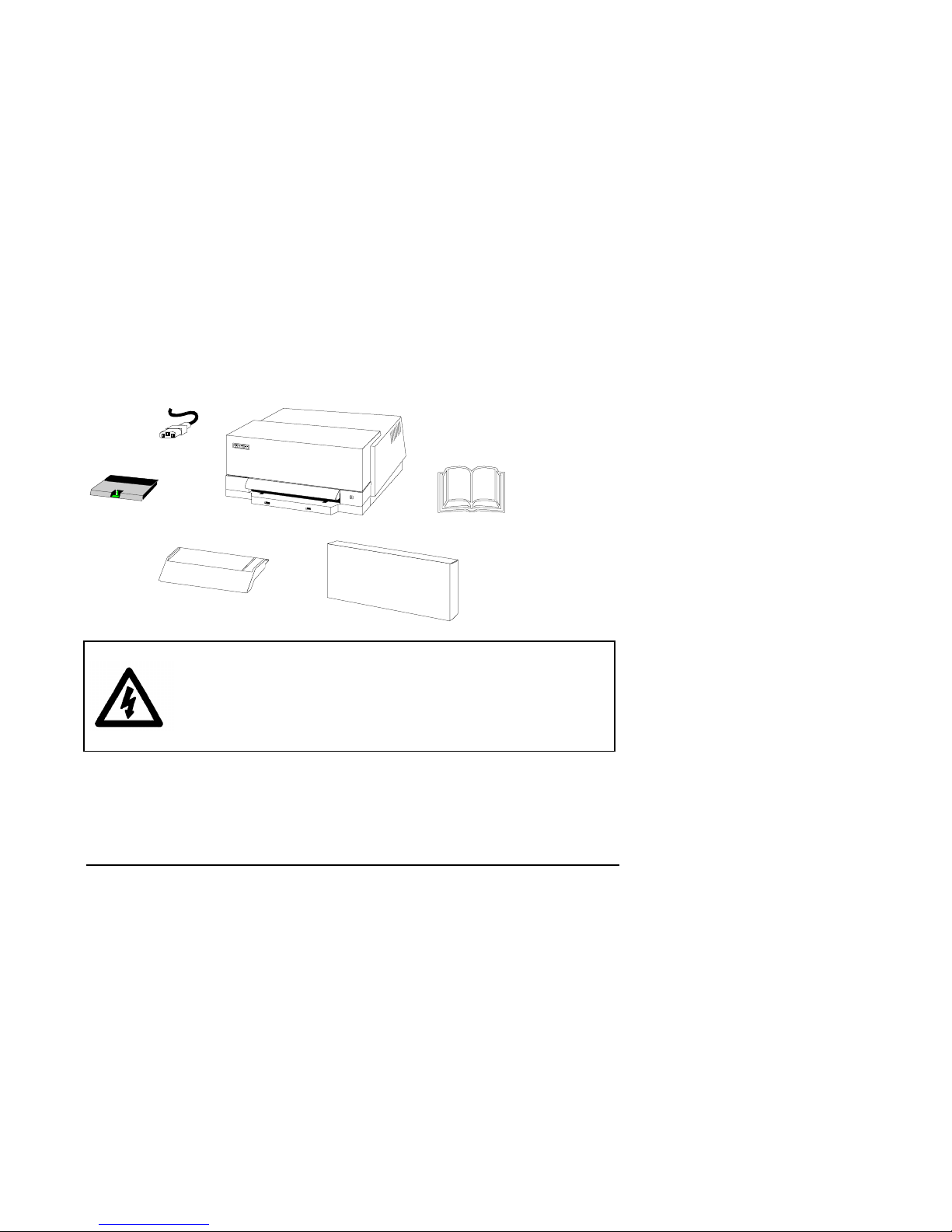
2.1 Preparation
Open the packing carton at one end, pull out the two foam sections and unpack the
following:
1. Mains Power Cable
2. Printer
3. User’s Guide
4. Ribbon Cartridge Box
5. Document Guide
6. Trapdoor
Note: If possible store the packing carton for future use
WARNING !
Make sure that the mains outlet connector in the building is a
Class-1 outlet with protective earth, easily accessible and the fuse
in the building protects against earth fault.
Installation 2-1
Page 10
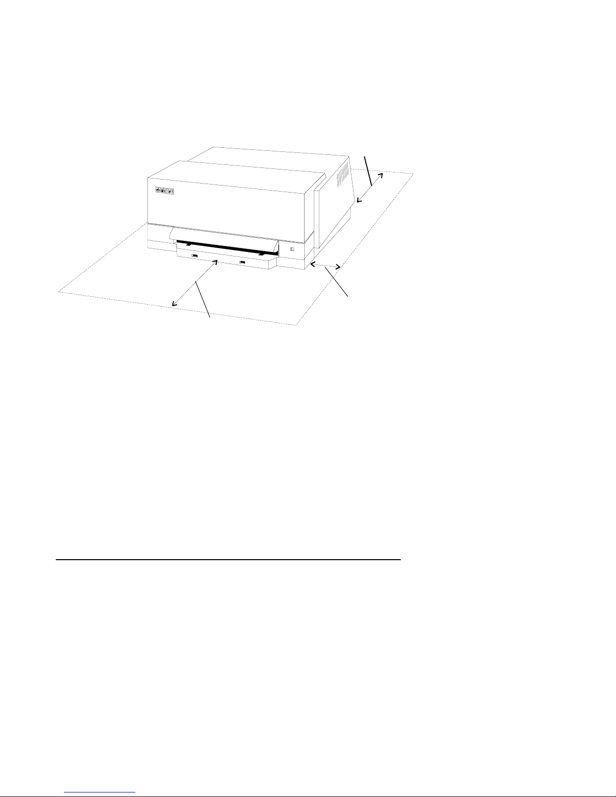
2.2 Operating Space
Place the printer on a flat, horizontal surface in a clear area as follows:
1. Back - 8in (203 mm) for document removal.
2. Sides - 4in (101mm) for air cooling.
3. Front - 10in (254 mm)for document loading.
Note: If necessary, allow further space for power and communication cable routing.
1
2
3
Installation 2-2
Page 11
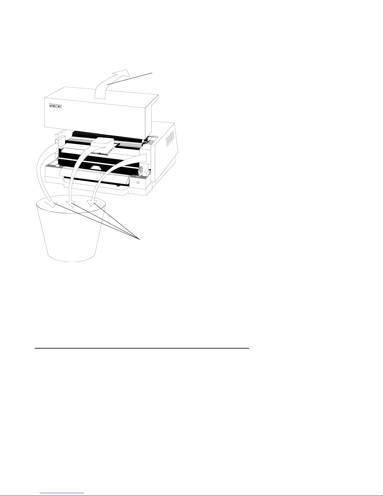
2.3 Removal of transport locks
1. Lid - lift and remove.
2. Packing - remove and discard.
1
2
Installation 2-3
Page 12
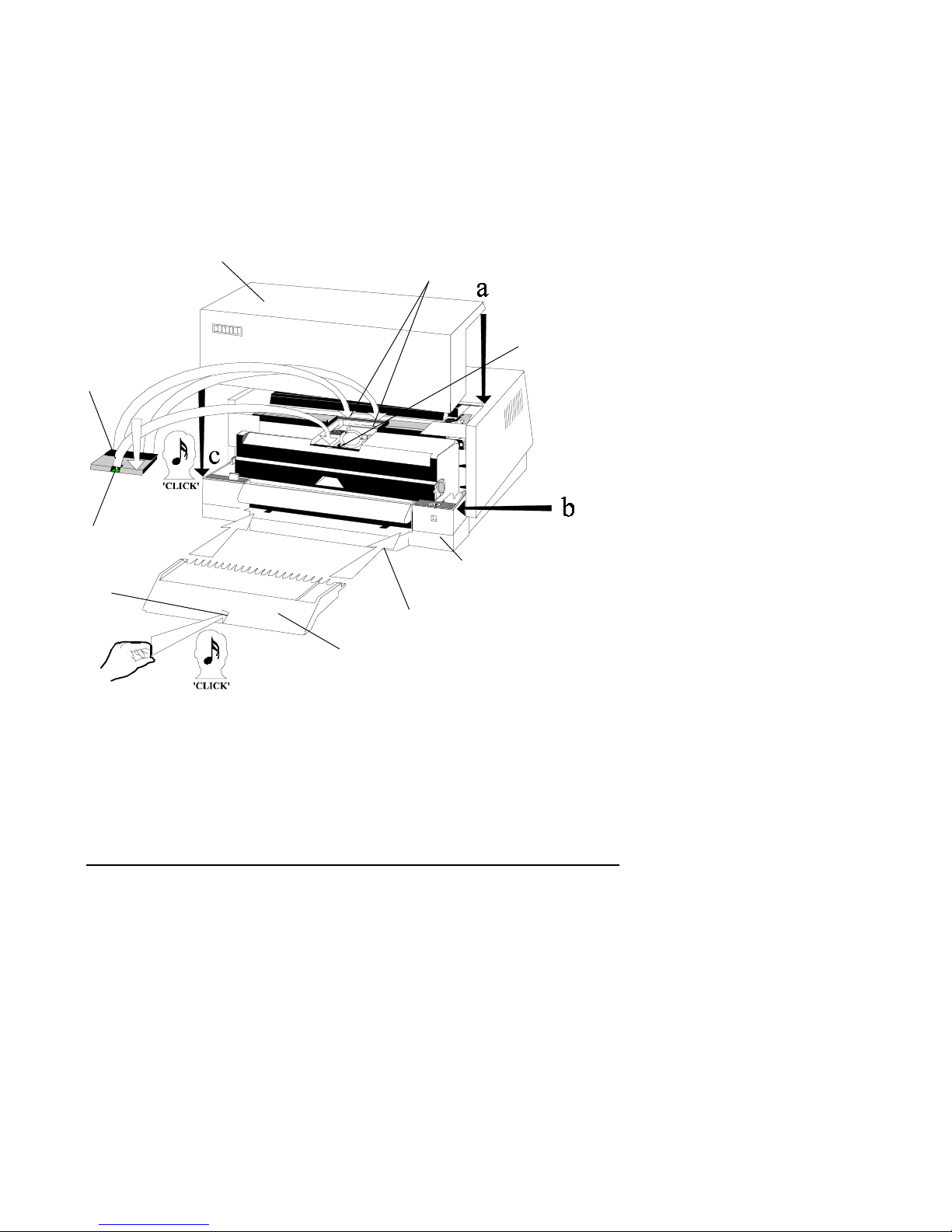
2.4 Trapdoor, Lid and Document Guide
1. Trapdoor - 1) position the two Rear Lugs,
2) lower, the trapdoor to engage
the Front Lock and press until
a ‘CLICK’ is heard.
2. Lid - accurately align at a, b and c.
3. Document Guide - 1) position in the Front Cover,
2) push until a ‘CLICK’ is heard.
2
1
Front Lock
1.1
1.2
Front Cover
3.2
3.1
3
Installation 2-4
Page 13
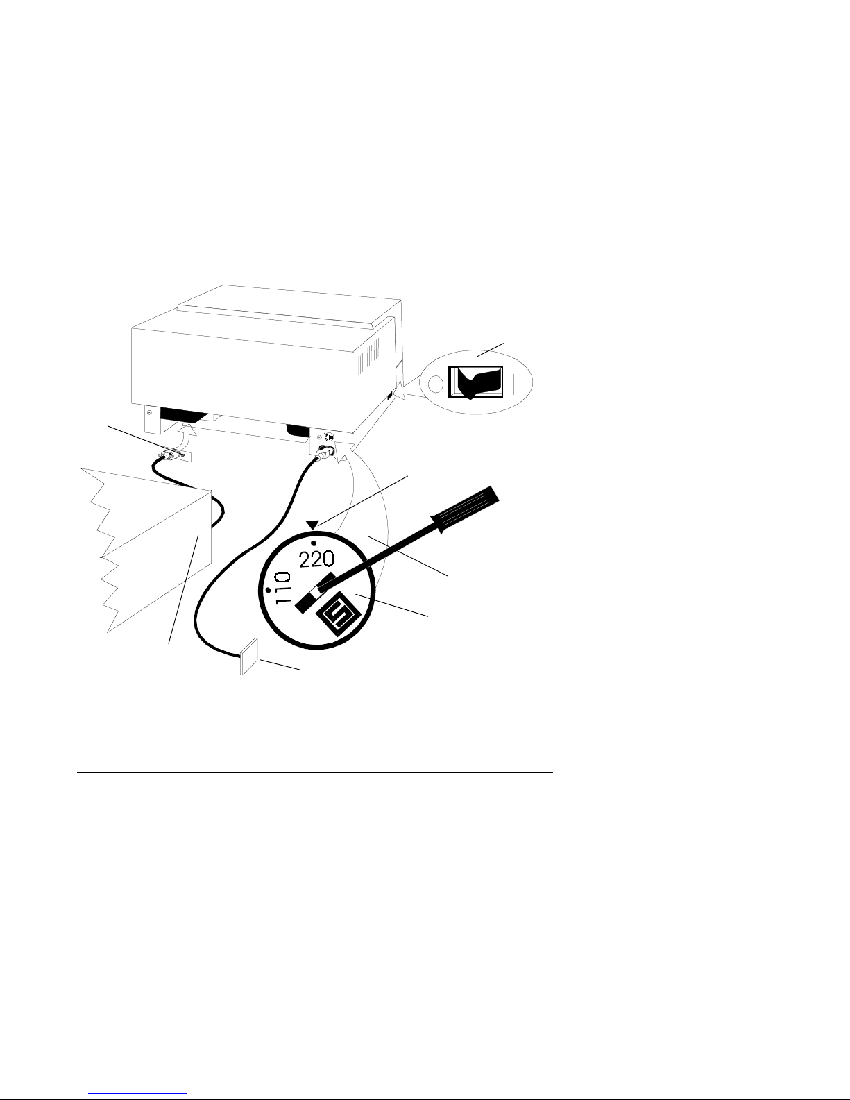
2.5 Connections and Settings
1. Power Switch - set to the OFF position.
2. Power Setting - check the setting: use a screw-
driver to turn the Selector to
the Mains Supply Voltage you
are using.
3. Mains Power Cable - connect to the Printer and the
Mains Supply.
4. Communication Cable - Connect to the Printer and the
Host Computer
Note: The Communication cable is supplied as a separate item.
4
Mains Supply Voltage
Settings
1
2
Host Computer
3
Installation 2-5
Page 14
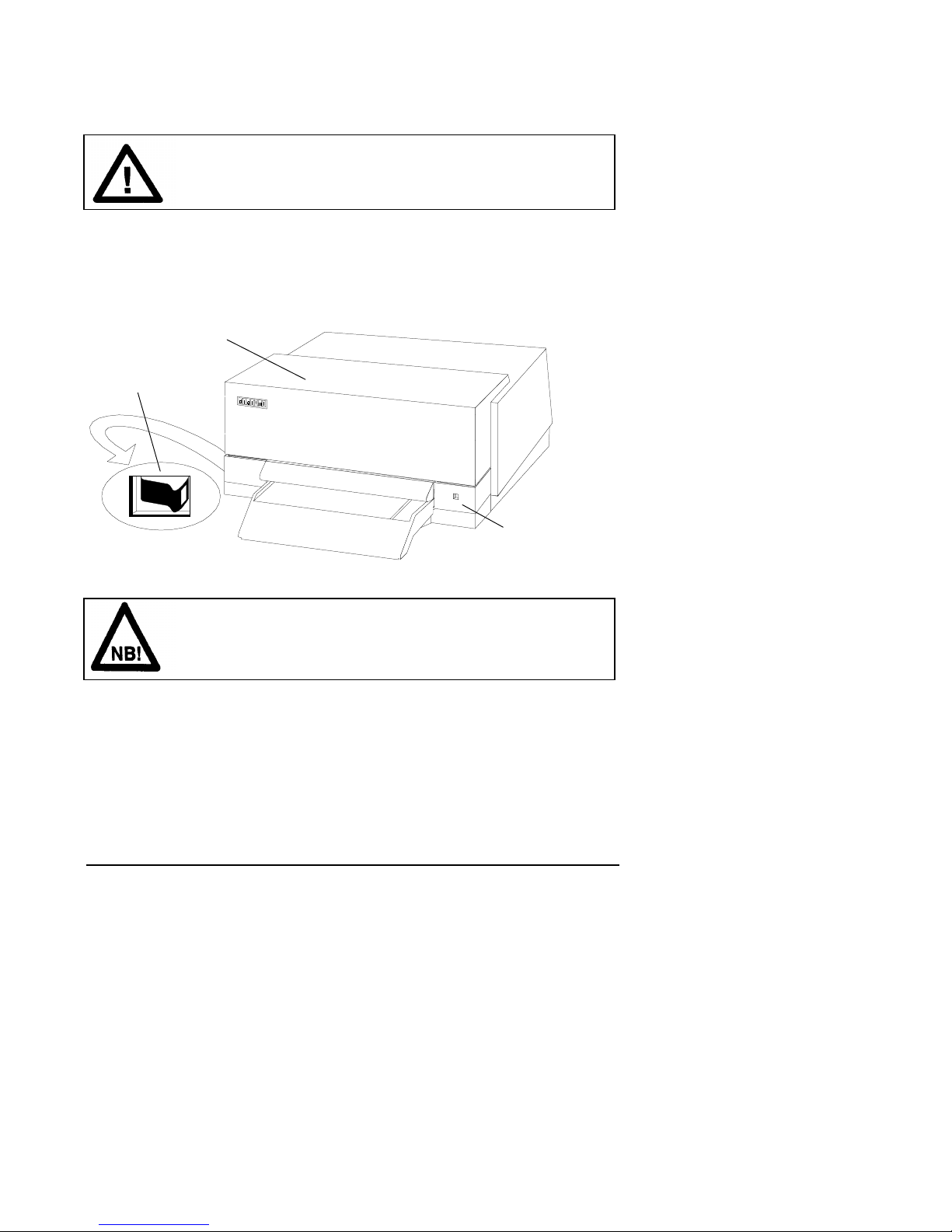
2.6 Ink Ribbon Cassette
Caution!
The printer must be switched ON during this task.
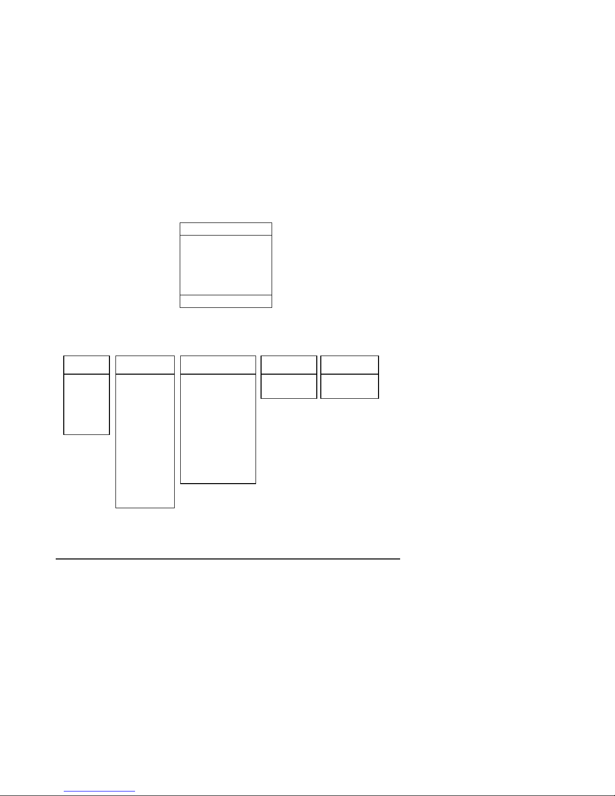
2.6.1 Power On
1. Power Switch - set to the ON position,
• Station LED - shows RED for six seconds and
then changes to GREEN.
Lid
1
Station LED
Note !
If the Station LED ‘BLINKS’ RED check that the Lid is
correctly installed.
Installation 2-6
Page 15
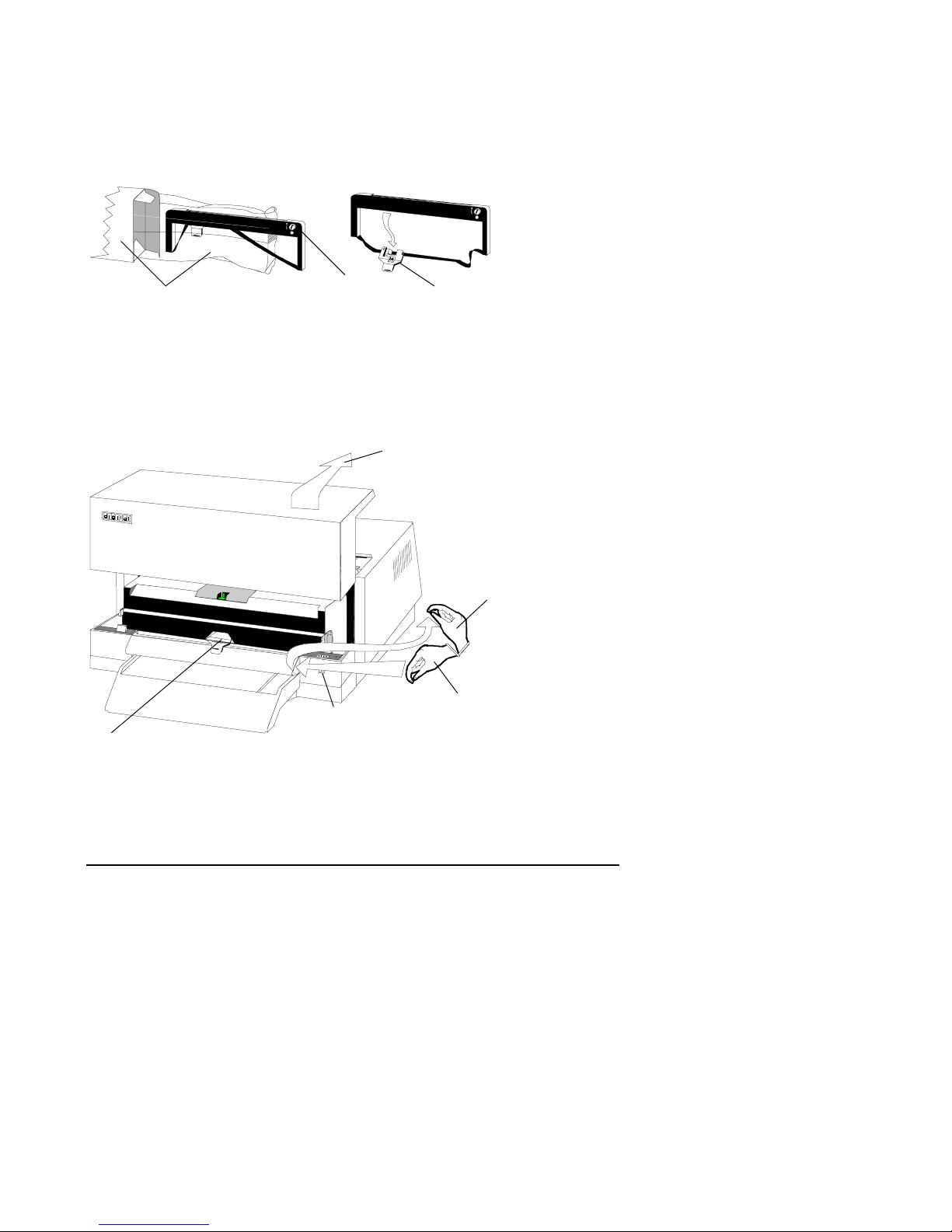
2.6.2 Unpacking the Ink Ribbon Cassette
1. Box and plastic bag - open the packing.
2. Ink Ribbon Cassette - remove from the plastic bag.
3. Skid - unclip from the Cassette.
1
2
3
2.6.3 Centering the Skid
1. Lid - lift and remove,
• Station LED - changes from GREEN to Blinking RED.
2. Button Bar - press and hold down,
• Skid - moves to the center of the Carrier.
3. Button Bar - release.
1
2
Station LED
Skid
3
Installation 2-7
Page 16

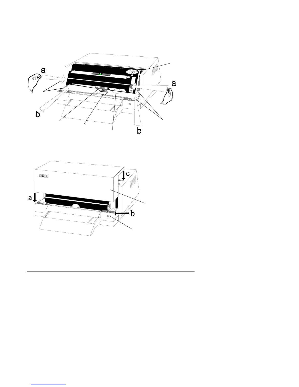
2.6.4 Raising the Carrier
1. Carrier Buttons - press in at a and Lift to b
• the Carrier is now locked in a tilted, raised position.
1
2.6.5 Positioning the Ink Ribbon Cassette
1. Ink Ribbon Cassette - position on the top and sides
of the Carrier.
Carrier
1
Installation 2-8
Page 17
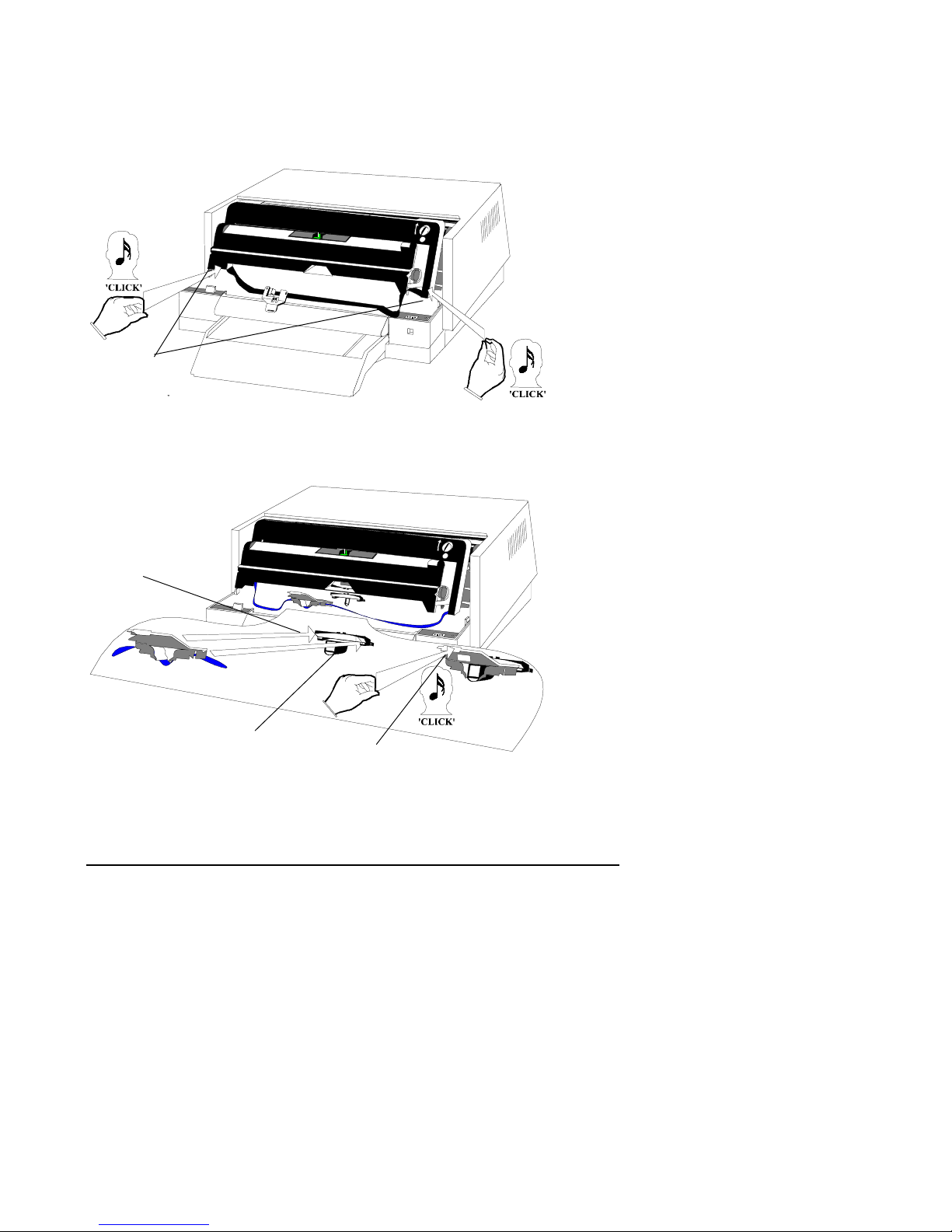
2.6.6 Installing the Ink Ribbon Cassette
1. Ink Ribbon Cassette - push until a ‘CLICK’ is heard at
each side of the Carrier.
1
2.6.7 Installing the Skid
1. Skid - locate in the bottom of the Head Carrier Assembly.
2. Skid - push until a ‘CLICK’ is heard.
1
Head Carrier Assembly
2
Installation 2-9
Page 18
2.6.8 Removing Slack Ribbon
1. Green Wheel - turn until the Ink Ribbon is tight.
2. Carrier - hold at a, lower to b and ensure the
Printhead locates in the Slider.
2
1
Printhead
Slider
Ink Ribbon
2.6.9 Ready to Print
1. Lid - install and align at positions a, b and c,
• Station LED - changes from Blinking RED to GREEN.
1
Station LED
2
Installation 2-10
Page 19

3 SETUP
Setup consists of a number of Menu’s that contain software settings.
It is important that the correct software settings are made in the DOC Menu so that
everyday Customer documents are handled correctly. Document dimensions
determine the DOC Menu software settings. Therefore, when a Customer receives a
new printer, or when a new document is introduced, this Menu’s settings should be
checked and modified as necessary.
The printer does not need to be connected to the Host Computer during Setup.
3.1 Introduction
A Software Setting consists of assigning a value to a parameter where:
• Parameters - are shown vertically under each Menu
• Values - are shown horizontally next to the Parameter.
Software Settings are held in a matrix where:
• Parameters (matrix vertical plane ) are reached using a Setup Function which
advances the document under the printhead
• Values (matrix horizontal plane ) are reached by using a Setup Function which
moves the Printhead along a line.
3.1.1 Setup Functions
These are:
Vertical Tab the document is advanced under the printhead to a new
line when the Button Bar is pressed down and released
after two seconds.
Horizontal Tab the printhead is moved a fixed horizontal distance along a
line when the Button Bar is held down for less than one
second (Hit).
Setup 3-1
Page 20
3.1.2 Setup Controls
These are:
Button Bar providing three functional periods of operation:
• Press down and release in less than one second (Hit)
• Press down and release after two seconds
• Press down and hold down until the engine runs and the document moves,
then release
3.1.3 Menu’s and Parameters
On entering Setup, you are prompted to Select a Menu or Quit the Setup. Menu’s
are Selected or Quit from the start and end point, QUIT OR SELECT. Printer
Settings are printed from the VIEW point. Thus, the structure is :
QUIT OR SELECT
COM Menu
IBM Menu
DOC Menu
<>DFT Menu
<>HQD Menu
VIEW
Note: The COM menu is not used or shown in a Parallel Printer.
The Parameter’s in each Menu for a Serial Printer are:
COM IBM DOC <>DFT <>HQD
Baud rate Country Cover offset Draft coarse HQD coarse
Length Set Horz psbk seam Draft fine HQD fine
Stop bits Font Psbk range
Parity CPI Psbk width min.
Flow ctrl LPI Psbk seam type
Condensed Top offset
CR=>LF Psbk smudging
LF/VT=>CR Form smudging
Form Length Print contrast
Zero
Top Margin
Setup 3-2
Page 21

3.1.4 Changing or Viewing the Setup
This involves the following:
• Entering Setup - using a Setup Control
• Loading a Document - a blank document or an existing
document is used
• Moving to VIEW or a Menu - Serial Printer have 5 Menu’s
Parallel Printer have 4 Menu’s
• Printing Current Settings - from the VIEW point
• Changing a Setting - moving to a Menu, a Parameter
and then assigning a new Value
• Validating - printing to check the change or
changes
• Quitting - from the QUIT point
Setup 3-3
Page 22

3.2 Setup Example
The Factory Default Setup is shown below:
The above example was produced by performing the procedure Printing the Printer
Settings.
Setup 3-4
Page 23

3.2.1 Entering Setup
1. Lid - lift and remove.
2. Button Bar - hold down.
3. Power Switch - set to ON,
• Station LED - shows RED.
4. Button Bar - release,
• Station LED - blinks GREEN within 6 seconds.
1
3
Station LED
Note !
If a document is not loaded OR a document is loaded and no
further actions are taken, the print engine will run for 2 minutes,
stop and the Station LED will show RED and BLINK. Setup may
be entered again by pressing the Button Bar down for less than
one second (Hit).
4
2
Setup 3-5
Page 24

3.2.2 Loading a Document
Prerequisite 1 Entering Setup has been performed.
Prerequisite 2 A blank document at least 8in (203mm) but less than 8.5in
(217mm) wide and at least 10in (254mm) long must be used.
1. Document - feed along the Left Edge of the Document
Guide until the document is gripped
Note: If the document covers the Marker, the printer will return the document
forward over the Document Guide.
Left Edge
Marker
Document Guide
1
Setup 3-6
Page 25

3.2.3 Moving to VIEW or a Menu
Prerequisite Loading a Document has been performed
1. Button Bar - press for less than one second (Hit),
• Document - a) advances to the Trailing edge,
b) print of menu’s are performed,
c) returns with the Skid pointing at the
QUIT OR SELECT point.
2. Menu’s and VIEW are visible above the FW Level that’s installed.
3. Button Bar - Tab Horizontally (Hit) until the Skid is
above the selection you require.
Skid
Horizontal Tabs
Number of Hits
2
1, 3
Setup 3-7
Page 26

3.2.4 Printing the Current Settings
This is done from the VIEW point.
Prerequisite 1: Loading a Document has been performed.
Prerequisite 2: Moving to VIEW has been performed.
1. Button Bar - press and hold down until the document
is advanced and printing begins.
Note: When printing has finished the document will be ejected forward over the
Document Guide.
3.2.5 Changing a Setting
In the following example the Print Quality parameter is changed from the factory
default Value of DRAFT to HQD (High Quality Draft).
1. Enter Setup - perform Entering Setup.
2. Load a Blank Document - perform Loading a Blank
Document.
3. Tab Horizontally, TWICE - the Skid points to the IBM Menu.
4. Select IBM - press and hold down the Button
Bar until the engine runs and the
document moves,
• Print functions follow and the list, CURRENT SETTINGS, will be visible.
5. Tab Vertically, 2 TIMES - the FONT values DRAFT and
HQD are visible.
6. Tab Horizontally, 2 TIMES - the Skid points to <>HQD.
LOAD the selection - press and hold down the Button
Bar until the engine runs and
the document moves,
• HQD is printed between FONT and DRAFT and the Skid performs a
vertical tab.
7. Tab Vertically, 8 TIMES - the CONFIRM values, yes and
no are visible.
8. Tab Horizontally, 1 TIME - the Skid points to the ‘yes’ option.
9. Button Bar - press for longer than 2 seconds,
• The new configuration is stored, print functions follow and the document
is returned forward over the document guide.
Setup 3-8
Page 27

3.2.6 Validating
10. Load a Blank Document - perform Loading a Blank
Document with the other side
of the document you have just
used in step 8 above.
11. Print the Settings - perform Printing the Current
Settings,
• the changed parameter will be underlined; Font : HQD
3.2.7 Quitting
12. Load a Blank Document - perform Loading a Blank
Document using the same side
of the document you have just
used in step 11, above.
13. Button Bar - press and hold down until the
document is returned forward
and ejected.
3.3 Setup Check
Prerequisite 1: The Configuration Settings that your department will use.
Prerequisite 2: The printer’s Current Settings. Note: Perform Printing the
Current Settings on page 2-3-8.
1. Compare prerequisite 1 with prerequisite 2
• The Current Settings are the same as the Configuration Settings?
Yes No
The Setup Check is
complete, Go to the
Operations Chapter.
Setup 3-9
Go to Changing a Setting on page 2-3-8
and make the required changes to the
Setup.
Page 28

3.4 Performing a Setup
An Engineer would normally perform this task for you.
Prerequisite 1 All types of Customer Document are available.
Prerequisite 2 A measuring ruler. This may be graduated in Metric or
Imperial units. Note: 1 inch = 25.4 mm.
Move to each of the Menu’s shown below and for each Parameter check or set a
new Value.
3.4.1 COM Menu
This menu is available on Serial Printers only. It is used when changing the
Communication Settings.
The Baud Rate values are:
• 19200, 9600, 4800, 2400 and 1200 Baud
Further Parameters and Values are:
Parameter
Length (bits) Stop Bits (number) Parity Flow Control
Value
Value
Value
7 1 Even RTS-CTS
8 2 Odd XON-XOFF
None
3.4.2 IBM Menu
The standard IBM Proprinter III parameters are used where:
The Country values are:
• USA - Code Page 437 (Factory Default Setting)
• Multi (Latin) - Code Page 850
Note: A Code Page is downloaded from the Host Computer. At Power
ON the option set will be used unless overridden by a download.
Setup 3-10
Page 29

The Set values are:
• Set 1 - [0–31] and [128–159] specify control codes
(Factory Default Setting).
• Set 2 - [03–06], 21 and [128–159] specify printable characters.
Note: The PC Table may be set such that a range of ASCII characters in the
code page are interpreted.
The Font (quality) values are:
• DRAFT (Factory Default Setting)
• HQD (High Quality Draft)
The CPI (Characters Per Inch) values are:
• 10, 12, 17 or 20.
The LPI (Lines Per Inch) values are:
• 5, 6 or 8.
Condensed
• 17 CPI,
The CR =>LF(Auto Line Feed) values are:
• Yes or No
Automatic Line Feed (LF) after each Carriage Return (CR).
The LF/VT =>CR (Auto Carriage Return) values are:
• Yes or No
Automatic Carriage Return (CR) after each Line Feed (LF) or Vertical Tabulation
(VT).
The Form Length values are:
• 11in (279mm) or 12in (305mm)
•
The Zero style values are:
• Normal or Slashed
Setup 3-11
Page 30

The Top Margin values are:
•
1 = 0.1in (2.54mm) (Factory Default Setting)
• 2 = 0.2in (5mm)
• 3 = 0.3in (7.6mm)
• 4 = 0.4in (10mm)
• 5 = 0.5in (13mm)
• 6 = 0.6in (15.mm)
3.4.3 DOC Menu
This Menu is concerned with Documents and the parameter values that must be set
so that documents are handled correctly.
All documents, Form and/or Passbook (Psbk), must be measured. A value for each
of the following parameters must be set:
• Top Offset
• Psbk Seam Type
• Psbk Width min.
• Psbk Range
• Horz Psbk Seam,
• Cover Offset
Setup 3-12
Page 31

The values are shown along the Parameter line in the DOC Menu printout, which
follows:
Setup 3-13
Page 32

The Print Contrast values are:
• 1, 2, 3 (Factory Default Setting), 4 and 5.
The Form Smudging values are:
• 1, 2, 3 (Factory Default Setting), 4, 5 and 6
1 = least smudging (anvil in the lowest position).and
6 = most smudging (anvil in the highest position).
The Psbk Smudging values are:
• 1, 2, 3 (Factory Default Setting) 4, 5 and 6
1 = least smudging (anvil in the lowest position).and
6 = most smudging (anvil in the highest position).
The Top Offset values are:
• 0 = 0.1in (2.54mm) Factory Default Setting
Note: Mechanical Top Margin = Top Offset
• 1 = Up to 0.6in (13.3mm)
• 2 = Up to 1.1in (27.94mm)
• 3 = Up to 1.6in (40.64mm)
• 4 = Up to 2.1in (53.34mm)
The printer uses an Optical Sensor to measure width. During the measuring process,
the sensor must not cross a black area. Therefore, if a Form or Envelope is
preprinted with a black area on the near the top of the document, such as a Logo or
Letter Head, a Top Offset must be set so that the width is measured in an area free
of black.
Measure the Black Border and use one of the values.
Setup 3-14
Page 33

The Psbk seam type values are:
• Horz (Factory Default Setting) for horizontal seam passbooks
• Vert for vertical seam passbooks.
The Psbk width min. values are:
• 3in (76.2mm), 4in (101.6mm), 5in (127mm) Factory default value, 6in
(152.4mm), 7in (177.8mm).
The printer will handle a document as a Passbook only when the width lies within
the [Pbsk width min.] + [Pbsk range].
If your Passbook Types have different widths calculate Psbk range, (see the next
parameter) and then return here.
1. Measure the Passbook Width and use the value which is nearest and less than
Psbk width min.
Setup 3-15
Page 34

The Psbk range values are:
• 0.5in (12.7mm), 1in (25.4mm), 1.5in (38.1mm), 2in (50.8mm),
2.5in (63.5mm) and 3in (76.2mm).
Psbk width + Psbk range must be greater then the highest Psbk width min. value of
any Passbook that is used.
1. Measure all Passbook Widths. Make a note of the maximum width measured.
2. Add an appropriate Psbk range value to the set Psbk width min. value so that all
Passbook Widths measured are in range.
The Horz Psbk Seam values are:
• 2.5in (63.5mm), 3in (76.2mm), 3.5 in (88.9mm), 4 in (101.6mm) and 4.5 in
(114.3mm).
This setting indicates the seam location with respect to the top of the passbook
cover. If the measured result is between two of the following, then select the
smaller.
This parameter is ignored if Psbk seam type is set to vert (vertical).
Setup 3-16
Page 35

The Cover Offset values are:
0 = 0.1in (2.54mm) Factory Default Setting
Mechanical Top Margin = Cover Offset
1 = Up to 0.6in (13.3mm)
2 = Up to 1.1in (27.94mm)
3 = Up to 1.6in (40.64mm)
4 = Up to 2.1in (53.34mm)
This setting defines the location of the top edge of an inside sheets with respect to
the top edge of a Passbook (Psbk).
Printing is unidirectional above a Cover Offset and bi-directional below.
Measure the Cover Offset and use one of the following values:
If the Passbook Seam is horizontal and the Cover Offset is greater than 0, the
printer will smooth the document.
Setup 3-17
Page 36

3.4.4 <>DFT Menu
The Horizontal Alignment of a printed line in bi-directional DRAFT (DFT) can be
adjusted. This is done in two steps, DRAFT COARSE and DRAFT FINE.
1. Print the <>DFT menu settings.
2. Look at the printout and chose the DRAFT COARSE and DRAFT FINE
settings, indicated on the same line in the left most column, where you judge the
character overlap to be the best.
The Draft Coarse values are:
• 1, 2, 3 (Factory Default Setting), 4, 5 and 6.
This define the printing speed in steps.
Draft Fine
• 1 (Factory Default Setting), 2, 3 and 4.
This define the printing speed in firing units.
3.4.5 <>HQD Menu
The Horizontal Alignment of a printed line in bi-directional HIGH QUALITY
DRAFT (HQD) can be adjusted. This is done in two steps, HQD COARSE and
HQD FINE.
Perform the following:
1. Print the <>HQD menu settings.
2. Look at the printout and chose the HQD COARSE and HQD FINE settings,
indicated on the same line in the left most column, where you judge the
character overlap to be the best.
The HQD Coarse values are:
• 1, 2, 3 (Factory Default Setting), 4, 5 and 6.
This define the printing speed in steps:
HQD Fine
• 1 (Factory Default Setting), 2, 3 and 4.
This define the printing speed in firing units:
Setup 3-18
Page 37

4 OPERATION
Normal everyday operation is a simple matter of Loading a Document. Printing is
controlled from the Customer Host System.
4.1 Controls and Indications
1
Power Switch - ON or OFF.
2
Button Bar - having two functional periods:
• Press down and release in less than one second (Hit)
• Press down, hold and release when printer reacts (2 sec.)
3
Lid - Installed or Removed.
4
Four Status LED’s - RED, static indication only.
5
Station LED - RED or GREEN, static and blinking
indications.
6
Document Guide - helps to ensure correct document
loading.
3.
1
4
2
6
Operation 4-1
5
Page 38

4.1.1 Confidence Test Routine
When printer power is switched ON a Confidence Test Routine (CTR) verifies that
all functions are error free. CTR Success or Failure is indicated by the Station LED
as follows:
• Solid or Blinking GREEN - Success
• Solid RED - Fatal Failure, preventing normal
use
• Blinking RED - Non-Fatal Failure, recoverable
errors
CTR Errors are indicated by the Status LED’s as follows:
Status LED’s (x=On) Station Error Corrective
#4 #3 #2 #1 LED Action
x Blink. RED NVM failure Perform setup
x Blink. RED Lid open Install correctly
x RED Initialization Call service
x x RED Motors Call service
x x RED Edge detectors Call service
x x x RED Motors & Edge Call service
RED CPU error Call service
4.2 Documents
When the printer is switched on and the print engine is running, documents fed over
the Document Guide will be gripped and loaded by a process called Automatic
Document Alignment (ADA).
4.2.1 New Pages
Smooth and flatten new pages of passbooks by slightly folding back the spine
before loading.
Operation 4-2
Page 39

4.2.2 Loading a Document
Caution!
Do not load documents that are hole punched, contain staples or
are held together by a paper clip. This will cause paper jams or
damages to the printer.
It is only possible to load a document when the printer have received data from the
host computer, or entering into Setup Mode or the internal Maintenance Tests
Routine.
1
Document - Check the width
• If the document width is less than or equal to 8.7in (221mm), Load
anywhere between Left Edge and the Marker
• If the document width is greater than 8.7in (221mm), ensure it touches the
Left Edge of the Document Guide
2
Insert - when the Station LED blinks GREEN
3
Button bar - hit (for less than 1 sec.) and release
• Document is fed in and the width is measured
• If the document is inserted incorrect, it is ejected out and a new insertion has
do be done aligning to the Left Edge
• If it’s inserted correctly, printing will start
Button bar
Left Edge
Marker
Document Guide
Operation 4-3
Page 40

4.2.3 Stop while printing
To stop the printing, press and hold the Button Bar for more than 10 seconds.
4.2.4 Clearing Document Jams
1
Power - set to OFF
2
Lid - lift and remove
3
Carrier - raise and secure in open position
4
Document - remove by pulling from the front or rear
of the printer
Operation 4-4
Page 41

5 MAINTENANCE
Caution !
Unless otherwise stated, the printer should be switched ON
during all Maintenance Tasks.
This chapter describes how to do if the performance of the printer is not satisfied.
Some actions should be performed to prevent unnecessary wear of the printer, or to
keep up the lifetime.
The following Parts can be replaced. New parts can be ordered from your Supplier.
Part Order Number
Ink Ribbon Cassette 2S-AA374-AA
Mylar Cassette 2S-AA373-AA
Printhead 29-33361-01
Note: All Replacement Parts should be stored at room temperature.
Maintenance 5-1
Page 42

5.1 Ink Ribbon Cassette
These have a maximum storage life of 2 years and should be replaced after printing
approximately 2.5 million characters.
5.1.1 Centering the Skid
1
Lid - lift and remove,
• Status LED’s - LED-1 is ON, others are OFF
• Station LED - changes from GREEN to Blinking RED.
2
Button Bar - press and hold down,
• Skid - moves to the center of the Carrier.
3
Button Bar - release.
1
Status LED’s
3
2
Skid
Maintenance 5-2
Station LED
Page 43

5.1.2 Raising the Carrier
1
Carrier Buttons - press in at (a) and Lift to (b),
• Carrier - is now locked in a tilted, raised position.
1
5.1.3 Removing the Skid
1
Skid - lift until a ‘CLICK’ is heard.
2
Skid - pull forward and remove.
1
2
Maintenance 5-3
Page 44

5.1.4 Removing the Old Ink Ribbon Cassette
1
Skid - position
2
Sides - move forward
3
Ink Ribbon Cassette - remove and discard
2
1
2
3
5.1.5 Cleaning
Perform the following:
• Mylar Cassette slider refer to the procedure on page 4-5-7
• Edge Detection Sensor and Mylar Slide Hole refer to the procedure on page 4-
5-16
5.1.6 Unpacking the New Ink Ribbon Cassette
1. Box and plastic bag - open the packing.
2. Ink Ribbon Cassette - remove from the plastic bag.
3. Skid - unclip from the Cassette.
1 2
Maintenance 5-4
3
Page 45

5.1.7
1
Positioning the New Ink Ribbon Cassette
Ink Ribbon Cassette - position on the top and sides of
the Carrier.
1
5.1.8 Installing the New Ink Ribbon Cassette
1. Ink Ribbon Cassette - Push until a ‘CLICK’ is heard at
each side of the Carrier.
Carrier
1
Maintenance 5-5
Page 46

5.1.9 Reinstalling the Skid
1
Skid - locate in the bottom of the Head Carrier
assembly.
2
Skid - push until a ‘CLICK’ is heard.
1
Head Carrier assembly
5.1.10 Removing Slack Ribbon
1
Green Wheel - turn until the Ink Ribbon is tight .
2
Carrier - hold at a, lower to b and ensure the
Printhead locates in the Slider.
Ink Ribbon
2
Printhead
Maintenance 5-6
Slider
2
1
2
Page 47

5.2 Mylar Cassette
Smooth transport of the document during printing is ensured by separating the
ribbon from the document by a strip of mylar.
The mylar slider should be inspected and cleaned when the Ink Ribbon Cassette is
replaced or when excessive document jams are experienced.
Mylar edges and surfaces may be damaged when in contact with a sharp or hard
object such as a paper clip or staple.
5.2.1 Centering the Skid
1
Lid - lift and remove,
• Station LED - changes from GREEN to Blinking RED.
• Status LED’s - LED-1 is ON, others are OFF
2
Button Bar - press and hold down,
• Skid - moves to the center of the Carrier.
3
Button Bar - release.
1
Station LED
Skid
Station LED
Maintenance 5-7
2
Page 48

5.2.2 Raising the Carrier
1
Carrier Buttons - press in at (a) and Lift to (b),
• the Carrier is now locked in a tilted, raised position.
1
5.2.3 Removing the Mylar Cassette
1
Left and right hand - a) push on each handle using a finger
b) press on the wire with each thumb.
2
Mylar Cassette - remove from the printer
2
1a
Wire
1b
Maintenance 5-8
1a
Page 49

5.2.4 Inspecting the Mylar Edges (Bottom View)
Turn the Mylar Cassette over and inspect the edges for damage as follows:
1
From Cylinder to Cylinder - move the Slider and check for
damage.
2
From Slider to Left Cylinder - move the Slider and check that
the complete edge stays OUT.
3
From Slider to Right Cylinder - move the Slider and check that
the complete edge stays IN.
Left Cylinder
3
1
Slider
Right Cylinder
2
Maintenance 5-9
Page 50

5.2.5 Checking for Free Movement (Top View)
1
Slider - move full left to full right
5.2.6 Reinstalling the Mylar Cassette
1
Left hand and right hand - a) use a Finger to push on the
Handles,
b) use a Thumb to press on the
Wire.
2
Mylar Cassette - install.
1aa
2
Wire
1a
1b
Handles
Maintenance 5-10
Page 51

5.2.7 Positioning the Slider
1
Slider - position under the Printhead.
2
Carrier - hold with each finger and lower the
Carrier from a to b and ensure the
Printhead locates in the center of the
Slider.
2
1
Printhead
2
Maintenance 5-11
Page 52

5.3 Printhead
The result of printing with a damaged Printhead is shown below.
The white space in the characters A,B,C,D and E above indicate a pin in the
Printhead is not operating or is broken. A Pin will be damaged when is strikes a
sharp or hard object such as a paper clips or staple.
Caution !
The Printhead may be hot. Be carefull when touching the
printhead.
5.3.1 Preparation
Perform the following:
• Power Up
• Centering the Skid
• Raising the Carrier
• Removing the Ink Ribbon Cassette
Maintenance 5-12
Page 53

5.3.2 Removing the Trapdoor
1
Carrier - support to keep the Carrier raised.
2
Trapdoor Lock - push in to release the Lock and lift to
remove the Trapdoor.
3
Printhead Tool - position in the Printhead Assembly.
2
1
3
5.3.3 Releasing the Printhead
1
Carrier - support to keep the Carrier raised.
2
Printhead Tool - a) push into the Printhead assembly,
b) squeeze the arms until a ‘CLICK’ is
heard, and then release the arms.
Printhead Assembly
1
Arms
2a
Printhead Assembly
2b2
Maintenance 5-13
Page 54

5.3.4 Lowering the Carrier
1
Carrier - hold at a, lower to b and ensure the
Printhead locates in the Slider.
1
Printhead
Slider
5.3.5 Removing the Printhead
1
Printhead - grip between thumb and finger and remove
1
1
Maintenance 5-14
Page 55

5.3.6 Reinstalling the Printhead
1
Printhead - locate the Clip and Lock Clip in the
Printhead Assembly
2
Printhead - push down until a ‘CLICK’ is heard
Printhead Assembly
Lock Clip
Clip
1
2
Maintenance 5-15
Page 56

5.4 Cleaning of Edge Detection Sensor and Mylar Slide
Hole
These should be cleaned when the Ink Ribbon Cassette is changed.
Note: if pressurized air is not available a Lint Free cloth may be used.
If necessary, refer to the Ink Ribbon Cassette and Mylar Cassette procedure
1
Pressurized Air Can - position the can near the sensor
and release air
2
Pressurized Air Can - position the nozzle near the
Slide Hole and release air
Sensor
1
2
Mylar Slide Hole
Maintenance 5-16
Page 57

5.5 Cleaning the Feed Rollers
These should be cleaned when feeding problems are experienced or when black
vertical lines appear on the document.
1
Lid - Lift and remove
• Station LED - changes from GREEN to Blinking RED,
• Status LED’s - ooox, where x = ON.
2
Button Bar - press for less than one second (Hit),
• Status LED’s - ooxo, where x = ON.
3
Button Bar - press down for longer than 2 sec. and
then release
• Station LED - blinks GREEN
4
Cleaning Sheet - load (see Loading a Document)
5
Button Bar - press until the Station LED shows
GREEN and then release
• Cleaning Sheet - printer runs the Feed rollers some
seconds and then the Cleaning Sheet is
feeded a number of times
• Station LED - blinks RED
6
Cleaning Sheet - remove.
1
Status LEDs
4, 6
Station LED
Maintenance 5-17
2,3, 5
Page 58

5.6 Ready to Print
After completion of Maintenance, the printer must be set back to operational mode Printer is set to On-Line Status - ready for receiving data and printing.
1
If necessary, reinstall the Parts by performing the tasks as described on previous
pages (reverse order).
2
Lid - install and align at positions a, b and c,
• Station LED - changes from Blinking RED to GREEN.
2
Station LED
Maintenance 5-18
Page 59

6 SPECIFICATIONS
These are as follows:
6.1 Printer Characteristics
Width 16.14" (410mm)
Depth w/o Doc. Guide 10.43" (265mm)
Depth with Doc. Guide 13.78" (350mm)
Height 07.48" (190mm)
Weight 19.16 lb. (8.7 kg)
Interface, Serial
Interface, Parallel
Printing Speed 10 CPI draft 200 CPS
Ink Ribbon Color: black. Replacement frequency: Draft
Power Supply
Frequency
Power Consumption
Power Cord Requirements • For 115V operation:- UL listed and CSA
Temperature, Operating and
Non-operating
Rel. Humidity, Operating and
Non-operating
Acoustical Noise Level
ISO779
One RS232C port, 9-pin male connector
One parallel port, 36-pin female connector
Mode - at 30% print contrast signal after
printing 2.5 million characters. Stock shelf life:
2 years max.
100 – 120 V or 200 – 240V
50/60 Hz
120VA(max.) 30VA(idle)
certified type SVT 18/3 AWG, rated minimum
10A, 125V.
• For 230V operation:- Use HAR type
HO5.VVF 3G1.0
13°C – 35°C (55°F – 95°F)
- 4°C – 65°C (- 40°F – 149°F)
10% to 80%
95% max.
Noise power emission: < 6.6 Bells
Sound pressure level: < 65 dB at operator
position
Specifications 6-1
Page 60

6.2 Serial Interface - RS232C
This signal port option is one serial line that conforms to RS232C-EIA standard.
The Printer input buffer size is 4K bytes.
6.2.1 Configurable Parameters
These are as follows, where factory defaults are in Italic:
• Baud Rate - 1200, 2400, 4800, 9600, 19200
• Character length - 7, 8 data bits
• Stop Bits - 1, 2
• Parity - odd, even, none
• Flow Ctrl - RTS/CTS, XON/XOFF
6.2.2 Serial Connector
Located at the rear of the printer is a 9 Pin male DSUB. The pin assignments and
signals between printer - host are as follows:
Printer
Connector
9-pin
1
2
3
4
5
6
7
8
9
Signal Description Source Host
Connector
9pin 25pin
DCD
RXD
TXD
DTR
GND
DSR
RTS
CTS
-
Not Used
Receive Data
Transmit Data
Data Terminal Ready
Signal Ground
Data Set Ready
Request to Send
Clear to Send
Not Used
Host
Printer
Printer
Host
Printer
Host
-
-
3
2
6
5
4
8
7
-
2
3
6
7
20
5
4
-
Specifications 6-2
Page 61

RXD - receives data from the Host. The interface ignores RX Data when DSR
is low.
TXD - when using XON/XOFF, Printer to Host, Clear to Send (CTS) must be
high to enable transmission. The Printer does not transmit any data
when RTS or CTS are high.
DTR - is set and remains ‘HIGH’ while the Printer power is ON and the
interface is operational.
GND - This pin is connected to the logic ground to provide a common
reference for the data and control signals.
DSR - The interface ignores received data unless DSR is ‘HIGH’.
RTS - This signal is set, ‘HIGH’ at power ON. RTS. ‘HIGH’ tells the HOST
that the Printer is busy and cannot receive data.
CTS - The interface monitors this signal which must be. ‘HIGH’ for the
interface to transmit XON and XOFF where:
• XON = DC1, Hexadecimal 11
• XOFF = DC3, Hexadecimal 13.
6.2.3 Handshaking
This is either XON/XOFF or RTS/CTS with the Flow Control according to Setup.
A Buffer full treatment is performed according to Flow Control when the available
space is 10 bytes.
XON/XOFF When this protocol is selected, the Printer sends XON to the Host
when it is able to receive data and XOFF to stop the data flow or
to indicate it is unable to receive any data.
RTS/CTS When the Host wants to send data to the Printer, it must wait for
the Printer RTS line to go ‘HIGH’. If RTS goes ‘LOW’, the Host
must stop transmission and wait for RTS ‘HIGH’ before sending
any data.
Specifications 6-3
Page 62

6.3 Parallel Interface - Centronics
This is an unidirectional interface that transfers 1 byte at a time.
Signal Name Description Pin in Pin out Source
D STROBE
CE DATA 1
CE DATA 2
CE DATA 3
CE DATA 4
CE DATA 5
CE DATA 6
CE DATA 7
CE DATA 8
ACK
BUSY
PE
SELECT OUT
AUTO FEED
NOT USED
SIGNAL GROUND
CHASSIS GND
+5V
GND (1)
GND (2)
GND (3)
GND (4)
GND (5)
GND (6)
GND (7)
GND (8)
GND (9)
GND (10)
GND (11)
GND (31)
INIT
FAULT
GND (36)
NOT USED
NOT USED
SELECT IN
Data Strobe
Data 1
Data 2
Data 3
Data 4
Data 5
Data 6
Data 7
Data 8
Acknowledge
Printer Busy
Paper End
Printer On Line
Not Used
Not Connected
Ground Layer
Not Connected
Pull Up to +5V
Gnd (1)
Gnd (2)
Gnd (3)
Gnd (4)
Gnd (5)
Gnd (6)
Gnd (7)
Gnd (8)
Gnd (9)
Gnd (10)
Gnd (11)
Gnd (31)
Soft Reset
Printer Error
Gnd (36)
Not Connected
Not Connected
Not Used
10
11
12
13
14
15
16
17
18
19
20
21
22
23
24
25
26
27
28
29
30
31
32
33
34
35
36
1
2
3
4
5
6
7
8
9
19
20
21
22
23
24
25
26
27
28
29
31
33
Host
Host
Host
Host
Host
Host
Host
Host
Host
Printer
Printer
Printer
Printer
Host
Host
Host
Host
Printer
Host
Host
Host
Host
Host
Host
Host
Host
Host
Host
Host
Host
Host
Printer
Host
Host
Host
Host
Specifications 6-4
Page 63

6.4 Documents
The printer handles two basic document types, forms and passbooks. Forms can be
single-ply or multi-ply or envelopes. Passbooks can have a vertical or a horizontal
seam.
Vertical Seam
Passbooks
Minimum Width 4.0" (101 mm) 4.0" (101 mm)
Maximum Width 7.6" (193 mm) 7.6" (193 mm)
Minimum Length 4.0" (101 mm) 4.0" (101 mm)
Maximum Length 7.6" (193 mm) 7.0" (177 mm)
Minimum Thickness 0.02" (0.5 mm) 0.02" (0.5 mm)
Maximum Thickness 0.08" (2 mm) 0.08" (2 mm)
Top & Bottom, Left &
0.25" (6.35 mm) 0.25" (6.35 mm)
Right Minimum Margin
Minimum Seam Margins 2 x 0.31" (8 mm)* 2 x 0.39" (10 mm)*
Form Sizes and minimum margins are:
Documents
≤ 8.7" (221 mm)
Width 2.5" (63mm) to
8.7" (221mm)
Length 2.5" (63mm) to
14.5" (368mm)
Ratio,Length
Up to 2.5 Up to 2.5
2.5" (63mm) to
9.5" (241mm)
2.5" (63mm) to
14.5" (368mm)
/Width
Left Margin Single-ply 0.10" (2.5mm)
Single-ply 0.10" (2.5mm)
Multi-ply 0.22" (5.5mm)
Multi-ply0.22" (5.5mm)
Right Margin Single-ply 0.10" (2.5mm)
Multi-ply 0.22" (5.5mm)
Single-ply 0.10" (2.5mm) to
0.7" (18mm)*
Multi-ply* 0.10" (2.5mm) to
0.7" (18mm)*
* Depending on document position
Horizontal Seam
Passbooks
Documents
≤ 9.5" (241 mm)
Specifications 6-5
Page 64

The Paper used for a Form should be:
Single-Ply Two-Ply Multi-Ply
Total
Thickness
0.004" to 0.02"
(0.1 to 0.45 mm)
0.004" to 0.02"
(0.1 to 0.45 mm)
0.004" to 0.02"
(0.1 to 0.45
mm)
Max. No. of
1 1 + 1 1 + 3 *
Copies
Top Sheet
Weight
Bottom
Sheet
16 to 32 lb.
(60 to 120 /m
2
)**
14 to 26 lb.
(50 to 100 g/m2)
14 to 26 lb.
(50 to 100 g/m
2
)
11 to 24 lb.
(40 to 90 g/m
22 to 32 lb.
(80 to 120 g/m
2
Weight
Inner sheet
weight
Total weight 16 to 32 lb.
(60 to 120 g/m
2
26 to 52 lb.
)
(100 to 200 g/m2)
11 to 22 lb.
(40 to 80 g/m
2
16 to 77 lb.
(60 to 280 g/m2)
* To handle this number of copies you must use the minimum allowed weight for
each sheet
** To allow for varying paper quality, the recommended minimum weight is
65g/m2
The paper for a Passbook should be:
Maximum Total Thickness 0.08" (2 mm)
Cover Weight 26 to 32 lb. (100 to 120 g/m2)
Cover Thickness 0.008" to 0.02" (0.2 to 0.5 mm)
Inner sheet weight 24 to 32 lb. (90-120g/m2)
)
2
)
)
Specifications 6-6
Page 65

6.4.1 Recommendations and Restrictions
• Transparent documents or documents containing transparent areas cannot be
used. Reflective ink surfaces (i.e. silver, gold) do not cause problems with the
edge detection system.
• Dark areas at the top of a form, close to the Left and Right Margins, i.e. Logo’s
and Letterheads will cause problems unless the TOP OFFSET in SETUP is
correctly set.
• Documents with staples, paper clips, holes or perforations are not permitted.
• Multi-ply forms of different lengths can be handled only if they are aligned at
the top. The shortest form must have a minimum length of 7.3" (185 mm) and
the software must eject the form at the rear of the printer.
• Multi-ply forms can consist of up to 3 copies plus the original.
Multi-ply forms with carbon sheets are not supported.
• The single part sheet and the top sheet of a multi-ply form should be either white
or a light color for maximum print contrast.
• When preprinted lines are required, the preprint must be as thin and fine as
possible to produce legible results.
6.4.2 Passbook Thickness
The maximum thickness of a passbook shall not exceed 0.08" (2.0 mm) when the
print page is opened. The difference between the maximum and the minimum
thickness at the centerfold shall not exceed 0.05" (1.4 mm) except for an end sheet
(vertical seam passbook only).
Specifications 6-7
Page 66

6.4.3 Center Outfold Bulge
When the passbook is opened at the middle page, the height of the bulge at the
center outfold shall not exceed 0.01" (0.3 mm).
6.4.4 Passbook Squareness
When the passbook is closed, the edge of the shorter side must be at a 90° angle to
the longer side.
Specifications 6-8
Page 67

7 GLOSSARY
ASCII American Standard Code for Information Interchange. A
standardized set of machine-readable 7 or 8-bit codes
consisting of control codes and codes representing
alphanumeric characters and symbols.
AWG American Wire Gauge
Bi-directional
printing
Baud rate The speed of data transmission measured in bits per second.
Bit a single character of a language having just two characters,
Byte a group of bits of information.
CPI Character Per Inch - the spacing of characters in a line.
CPS Characters Per Second.
CSA Canadian Standards Association
CTR Confidence Test Routine. Performed by the printer at
CTS See RTS/CTS.
Character Set a table of characters, each associated with an ASCII code,
Ctrl Control
DCD Data Carrier Detect
DPI Dots Per Inch.
Draft printing in single strike mode where one dot impact is
DSR Data Set Ready.
DTR Data Terminal Ready.
Double Height where characters are printed in two passes twice their
Double strike where text is printed in two passes with no horizontal or
Double width See expanded.
where printing occurs from left to right and from right to
left.
binary digits 0 or 1.
Sometimes referred to as 'pitch' or 'density'.
power-on
in a given font that can be printed.
delivered.
normal height.
vertical offset.
EU European Union
EIA Electronic Industries Association. Sets standards for the
Glossary 7-1
Page 68

electrical and functional characteristics of equipment.
Emulation where software allows the printer to imitate another printer.
Emphasized where text is printed in two passes with a horizontal offset.
Expanded where characters are printed in one pass at twice their
normal width.
ESC A single byte ASCII code that initiates an escape sequence.
Corresponding hexadecimal code is <1B>.
Escape Sequence A series of characters beginning with the code ESC which
activates a printer function.
FCC Federal Communications Commission
Flow Control RTS/CTS or XON/XOFF protocol.
Font Quality where characters are printed in Draft or High Quality Draft.
Form a document type defined as single-ply, multi-ply or an
envelope.
HQD High Quality Draft. Two consecutive dot impacts are
delivered (double strike).
Hz Hertz. The measuring unit for frequency (cycles per second)
ISO International Standards Organization
IEC International Electrotechnical Commission
Intercharacter
the space left blank between two consecutive characters.
Spacing
Loadable Character
where resident and/or downloaded characters are used.
Set
LPI Lines Per Inch.
Mechanical Margin defined by the hardware, this is 0.1" (2.5 mm) from the left,
right and top edges of the document.
NVM Non Volatile Memory.
Off-line the state when the communications line between the printer
and the host is not ready for data exchange.
On-line the state when the communications line between the printer
and the host is ready for data exchange.
Overscore To draw a line above printed characters and space.
RAM Random Access Memory.
RS232C serial interface standard used to connect the printer to the
Glossary 7-2
Page 69

host.
RTS/CTS Request To Send / Clear To Send. One of the standards
used by the RS232C protocol for controlling the flow of
data between two communicating devices using handshake
signals. When the host wants to send data to the printer, it
must wait for the printer RTS line to go on. If the printer
RTS line goes off, the host must stop transmission and wait
for it to go on again before sending any data. If the host
input buffer is full, when receiving an incoming message
from the printer, it must turn the printer CTS line off so that
the printer stops transmitting data. To restart
communication, the host turns the printer's CTS line on.
RX Receive
RXD Receive Data
Resident Character
permanently available in the printer.
Set
Reversed where characters are printed in white against black.
Stop bit The bit which signals the end of data.
SVT Standard Voltage Temperature
TX Transmit
TXD Transmit Data
Underscore To draw a line under printed characters and spaces.
UL Underwriters Laboratory
Unidirectional print
where the printer prints from left to right only.
mode
V Volt
VA Volt Ampere
XON/XOFF A software protocol for controlling the flow of data between
two communicating devices. By sending the XON
(Transmit on) code, the receiving device informs the
transmitter that it is ready to receive data. By sending the
XOFF (transmit off) code, the receiver instructs the
transmitter to stop sending data.
Glossary 7-3
Page 70

Printed in Sweden on
Totally Chlorine Free paper (TCF)
 Loading...