

Page 1

IBM
Front cover
Nortel Networks L2/3
Ethernet Switch Module for
IBM E
Full Layer 2 switching and Layer 3
routing
Six external multimode fiber or
copper GbE interfaces
Hot pluggable switch
modules
server BladeCenter
ibm.com/redbooks
Rufus Credle
Stephan Fleck
Scott Lorditch
Jeremy Oliver
Redpaper
Page 2

Page 3

International Technical Support Organization
Nortel Networks L2/3 Ethernet Switch Module for
IBM Eserver BladeCenter
September 2005
Page 4

Note: Before using this information and the product it supports, read the information in “Notices” on
page vii.
First Edition (September 2005)
This edition applies to Nortel Networks Layer 2/3 Copper and Fiber GbE Switch Modules for IBM Eserver
BladeCenter.
© Copyright International Business Machines Corporation 2005. All rights reserved.
Note to U.S. Government Users Restricted Rights -- Use, duplication or disclosure restricted by GSA ADP Schedule
Contract with IBM Corp.
Page 5

Contents
Notices . . . . . . . . . . . . . . . . . . . . . . . . . . . . . . . . . . . . . . . . . . . . . . . . . . . . . . . . . . . . . . . . . vii
Trademarks . . . . . . . . . . . . . . . . . . . . . . . . . . . . . . . . . . . . . . . . . . . . . . . . . . . . . . . . . . . . . viii
Preface . . . . . . . . . . . . . . . . . . . . . . . . . . . . . . . . . . . . . . . . . . . . . . . . . . . . . . . . . . . . . . . . . ix
The team that wrote this Redpaper . . . . . . . . . . . . . . . . . . . . . . . . . . . . . . . . . . . . . . . . . . . . ix
Become a published author . . . . . . . . . . . . . . . . . . . . . . . . . . . . . . . . . . . . . . . . . . . . . . . . . . .x
Comments welcome. . . . . . . . . . . . . . . . . . . . . . . . . . . . . . . . . . . . . . . . . . . . . . . . . . . . . . . . xi
Chapter 1. Executive summary . . . . . . . . . . . . . . . . . . . . . . . . . . . . . . . . . . . . . . . . . . . . . 1
Chapter 2. IBM Eserver BladeCenter overview. . . . . . . . . . . . . . . . . . . . . . . . . . . . . . . . 3
2.1 The IBM Eserver BladeCenter product family . . . . . . . . . . . . . . . . . . . . . . . . . . . . . . . 4
2.1.1 IBM Eserver BladeCenter storage solutions . . . . . . . . . . . . . . . . . . . . . . . . . . . . 5
2.1.2 IBM Eserver BladeCenter system management . . . . . . . . . . . . . . . . . . . . . . . . . 6
2.2 IBM Eserver BladeCenter architecture . . . . . . . . . . . . . . . . . . . . . . . . . . . . . . . . . . . . . 6
2.2.1 The midplane . . . . . . . . . . . . . . . . . . . . . . . . . . . . . . . . . . . . . . . . . . . . . . . . . . . . . 6
2.2.2 Management Module Ethernet . . . . . . . . . . . . . . . . . . . . . . . . . . . . . . . . . . . . . . . . 8
2.2.3 Gigabit Ethernet path . . . . . . . . . . . . . . . . . . . . . . . . . . . . . . . . . . . . . . . . . . . . . . . 9
2.3 IBM Eserver HS20 architecture . . . . . . . . . . . . . . . . . . . . . . . . . . . . . . . . . . . . . . . . . 10
2.4 Stand-alone configuration tools. . . . . . . . . . . . . . . . . . . . . . . . . . . . . . . . . . . . . . . . . . . 12
Chapter 3. Nortel Networks Layer 2/3 GbE Switch Modules. . . . . . . . . . . . . . . . . . . . . 15
3.1 Product description . . . . . . . . . . . . . . . . . . . . . . . . . . . . . . . . . . . . . . . . . . . . . . . . . . . . 16
3.2 Value proposition . . . . . . . . . . . . . . . . . . . . . . . . . . . . . . . . . . . . . . . . . . . . . . . . . . . . . 18
3.3 Supported hardware . . . . . . . . . . . . . . . . . . . . . . . . . . . . . . . . . . . . . . . . . . . . . . . . . . . 19
Chapter 4. Nortel Networks Layer 2/3 GbE Switch Module architecture . . . . . . . . . . . 21
4.1 Nortel GbESM architecture overview . . . . . . . . . . . . . . . . . . . . . . . . . . . . . . . . . . . . . . 22
4.2 Nortel Networks L2/3 GbESM block diagram . . . . . . . . . . . . . . . . . . . . . . . . . . . . . . . . 24
4.2.1 Nortel Networks L2/3 GbESM ports specific roles . . . . . . . . . . . . . . . . . . . . . . . . 25
Chapter 5. Nortel Networks L2/3 GbESM management and administration . . . . . . . . 29
5.1 Nortel Networks L2/3 GbESM management connectivity . . . . . . . . . . . . . . . . . . . . . . . 30
5.1.1 Out-of-band management. . . . . . . . . . . . . . . . . . . . . . . . . . . . . . . . . . . . . . . . . . . 31
5.1.2 In-band management . . . . . . . . . . . . . . . . . . . . . . . . . . . . . . . . . . . . . . . . . . . . . . 32
5.2 Nortel Networks L2/3 GbESM user interface . . . . . . . . . . . . . . . . . . . . . . . . . . . . . . . . 34
5.2.1 IBM Eserver BladeCenter Management Module and I2C . . . . . . . . . . . . . . . . . 34
5.2.2 Command-line interface . . . . . . . . . . . . . . . . . . . . . . . . . . . . . . . . . . . . . . . . . . . . 34
5.2.3 Browser Based Interface. . . . . . . . . . . . . . . . . . . . . . . . . . . . . . . . . . . . . . . . . . . . 40
5.2.4 SNMP management - IBM Director. . . . . . . . . . . . . . . . . . . . . . . . . . . . . . . . . . . . 41
5.3 Multiple Nortel Networks L2/3 GbESMs in a BladeCenter . . . . . . . . . . . . . . . . . . . . . . 42
Chapter 6. IBM Eserver BladeCenter system initial setup. . . . . . . . . . . . . . . . . . . . . . 43
6.1 IBM Eserver BladeCenter system . . . . . . . . . . . . . . . . . . . . . . . . . . . . . . . . . . . . . . . 44
6.1.1 Management Module firmware . . . . . . . . . . . . . . . . . . . . . . . . . . . . . . . . . . . . . . . 44
6.1.2 Management Module network interface . . . . . . . . . . . . . . . . . . . . . . . . . . . . . . . . 45
6.1.3 I/O module management tasks . . . . . . . . . . . . . . . . . . . . . . . . . . . . . . . . . . . . . . . 47
6.2 Blade server initial configuration . . . . . . . . . . . . . . . . . . . . . . . . . . . . . . . . . . . . . . . . . . 50
6.2.1 Firmware update . . . . . . . . . . . . . . . . . . . . . . . . . . . . . . . . . . . . . . . . . . . . . . . . . . 50
6.2.2 Operating systems . . . . . . . . . . . . . . . . . . . . . . . . . . . . . . . . . . . . . . . . . . . . . . . . 52
© Copyright IBM Corp. 2005. All rights reserved. iii
Page 6

6.2.3 Broadcom Advanced Control Suite installation . . . . . . . . . . . . . . . . . . . . . . . . . . . 53
6.3 Firmware and device drivers used in this example . . . . . . . . . . . . . . . . . . . . . . . . . . . . 55
Chapter 7. Nortel Networks L2/3 GbESM configuration and network integration . . . 57
7.1 Standards and technologies . . . . . . . . . . . . . . . . . . . . . . . . . . . . . . . . . . . . . . . . . . . . . 58
7.1.1 VLAN tagging - 802.1Q . . . . . . . . . . . . . . . . . . . . . . . . . . . . . . . . . . . . . . . . . . . . . 58
7.1.2 Link Aggregation and LACP - 802.3ad and 802.3-2002 . . . . . . . . . . . . . . . . . . . . 58
7.1.3 Spanning Tree - 802.1D, 802.1w, 802.1s . . . . . . . . . . . . . . . . . . . . . . . . . . . . . . . 58
7.1.4 Routing Information Protocol - RFC1058 and RFC2453. . . . . . . . . . . . . . . . . . . . 59
7.1.5 Open Shortest Path First (OSPF) - RFC1257, RFC2328, and others . . . . . . . . . 59
7.1.6 Virtual Router Redundancy Protocol (VRRP) - RFC 3768 . . . . . . . . . . . . . . . . . . 60
7.1.7 Where standards originate and how to get them . . . . . . . . . . . . . . . . . . . . . . . . . 60
7.2 Summary of sample configurations. . . . . . . . . . . . . . . . . . . . . . . . . . . . . . . . . . . . . . . . 60
7.2.1 Basic Layer 2 configuration. . . . . . . . . . . . . . . . . . . . . . . . . . . . . . . . . . . . . . . . . . 60
7.2.2 Advanced Layer 2 configurations . . . . . . . . . . . . . . . . . . . . . . . . . . . . . . . . . . . . . 61
7.2.3 Layer 3 configuration - static routing . . . . . . . . . . . . . . . . . . . . . . . . . . . . . . . . . . . 61
7.2.4 Layer 3 configurations - dynamic routing . . . . . . . . . . . . . . . . . . . . . . . . . . . . . . . 61
7.3 Introduction to High Availability . . . . . . . . . . . . . . . . . . . . . . . . . . . . . . . . . . . . . . . . . . . 62
7.3.1 Introduction to trunk failover . . . . . . . . . . . . . . . . . . . . . . . . . . . . . . . . . . . . . . . . . 62
7.3.2 Introduction to NIC Teaming . . . . . . . . . . . . . . . . . . . . . . . . . . . . . . . . . . . . . . . . . 63
7.3.3 Introduction to VRRP . . . . . . . . . . . . . . . . . . . . . . . . . . . . . . . . . . . . . . . . . . . . . . 64
7.3.4 Some important rules for ensuring High Availability . . . . . . . . . . . . . . . . . . . . . . . 65
7.4 Guidelines for attaching the BladeCenter to a network . . . . . . . . . . . . . . . . . . . . . . . . . 65
7.4.1 Guidelines and comments . . . . . . . . . . . . . . . . . . . . . . . . . . . . . . . . . . . . . . . . . . 65
7.5 Base configurations for examples in this document . . . . . . . . . . . . . . . . . . . . . . . . . . . 66
7.5.1 Hardware and software used for lab environment . . . . . . . . . . . . . . . . . . . . . . . . 66
7.5.2 Preconfiguration preparation. . . . . . . . . . . . . . . . . . . . . . . . . . . . . . . . . . . . . . . . . 67
7.5.3 Base configuration common to all examples. . . . . . . . . . . . . . . . . . . . . . . . . . . . . 68
7.6 Basic Layer 2 entry topology. . . . . . . . . . . . . . . . . . . . . . . . . . . . . . . . . . . . . . . . . . . . . 69
7.6.1 Layer 2 configuration with 802.1Q tagging and trunk failover. . . . . . . . . . . . . . . . 70
7.6.2 Basic topology conclusions. . . . . . . . . . . . . . . . . . . . . . . . . . . . . . . . . . . . . . . . . . 80
7.7 Advanced Layer 2 topology sample configurations. . . . . . . . . . . . . . . . . . . . . . . . . . . . 80
7.7.1 Dynamic link aggregation IEEE 802.3ad (LACP) . . . . . . . . . . . . . . . . . . . . . . . . . 82
7.7.2 Common Spanning Tree configuration - IEEE 802.1D and PVST . . . . . . . . . . . . 84
7.7.3 Rapid Spanning Tree IEEE 802.1w . . . . . . . . . . . . . . . . . . . . . . . . . . . . . . . . . . . 95
7.7.4 Multi-Spanning Tree IEEE 802.1s. . . . . . . . . . . . . . . . . . . . . . . . . . . . . . . . . . . . 101
7.8 Layer 3 topology sample configurations . . . . . . . . . . . . . . . . . . . . . . . . . . . . . . . . . . . 108
7.8.1 Layer 3 sample configuration with static routing and VRRP . . . . . . . . . . . . . . . . 109
7.8.2 Dynamic routing options OSPF/RIP . . . . . . . . . . . . . . . . . . . . . . . . . . . . . . . . . . 125
7.9 Configuration for Extreme switches . . . . . . . . . . . . . . . . . . . . . . . . . . . . . . . . . . . . . . 143
Chapter 8. Serial over LAN feature description and configuration . . . . . . . . . . . . . . 151
8.1 SOL overview . . . . . . . . . . . . . . . . . . . . . . . . . . . . . . . . . . . . . . . . . . . . . . . . . . . . . . . 152
8.2 General rules to establish an SOL connection . . . . . . . . . . . . . . . . . . . . . . . . . . . . . . 152
8.3 Configuring SOL for use with the Nortel GbESM . . . . . . . . . . . . . . . . . . . . . . . . . . . . 153
8.4 SOL use during Nortel Networks L2/3 GbESM experiments. . . . . . . . . . . . . . . . . . . . 153
Chapter 9. Nortel Networks Layer 2/3 GbE Switch Module troubleshooting. . . . . . . 155
9.1 Basic rules and unique symptoms . . . . . . . . . . . . . . . . . . . . . . . . . . . . . . . . . . . . . . . 156
9.1.1 Basic rules . . . . . . . . . . . . . . . . . . . . . . . . . . . . . . . . . . . . . . . . . . . . . . . . . . . . . 156
9.2 Nortel Networks L2/3 GbESM troubleshooting methodology . . . . . . . . . . . . . . . . . . . 157
9.2.1 General comments on troubleshooting . . . . . . . . . . . . . . . . . . . . . . . . . . . . . . . . 157
9.3 Systematic approach. . . . . . . . . . . . . . . . . . . . . . . . . . . . . . . . . . . . . . . . . . . . . . . . . . 158
9.3.1 Problem definition . . . . . . . . . . . . . . . . . . . . . . . . . . . . . . . . . . . . . . . . . . . . . . . . 158
iv Nortel Networks L2/3 Ethernet Switch Module for IBM Eserver BladeCenter
Page 7

9.3.2 Data collection . . . . . . . . . . . . . . . . . . . . . . . . . . . . . . . . . . . . . . . . . . . . . . . . . . 159
9.3.3 Data analysis . . . . . . . . . . . . . . . . . . . . . . . . . . . . . . . . . . . . . . . . . . . . . . . . . . . 160
9.3.4 Action plan creation . . . . . . . . . . . . . . . . . . . . . . . . . . . . . . . . . . . . . . . . . . . . . . 160
9.3.5 Action plan implementation. . . . . . . . . . . . . . . . . . . . . . . . . . . . . . . . . . . . . . . . . 160
9.3.6 Observation of results . . . . . . . . . . . . . . . . . . . . . . . . . . . . . . . . . . . . . . . . . . . . . 160
9.3.7 Problem resolution . . . . . . . . . . . . . . . . . . . . . . . . . . . . . . . . . . . . . . . . . . . . . . . 161
9.4 Troubleshooting tools . . . . . . . . . . . . . . . . . . . . . . . . . . . . . . . . . . . . . . . . . . . . . . . . . 161
Chapter 10. Service and support. . . . . . . . . . . . . . . . . . . . . . . . . . . . . . . . . . . . . . . . . . 165
10.1 Placing a call to IBM . . . . . . . . . . . . . . . . . . . . . . . . . . . . . . . . . . . . . . . . . . . . . . . . . 166
10.2 Online services . . . . . . . . . . . . . . . . . . . . . . . . . . . . . . . . . . . . . . . . . . . . . . . . . . . . . 166
10.3 Ordering information . . . . . . . . . . . . . . . . . . . . . . . . . . . . . . . . . . . . . . . . . . . . . . . . . 166
10.4 Other support sites . . . . . . . . . . . . . . . . . . . . . . . . . . . . . . . . . . . . . . . . . . . . . . . . . . 167
Abbreviations and acronyms . . . . . . . . . . . . . . . . . . . . . . . . . . . . . . . . . . . . . . . . . . . . . 169
Related publications . . . . . . . . . . . . . . . . . . . . . . . . . . . . . . . . . . . . . . . . . . . . . . . . . . . . 171
IBM Redbooks . . . . . . . . . . . . . . . . . . . . . . . . . . . . . . . . . . . . . . . . . . . . . . . . . . . . . . . . . . 171
Other publications . . . . . . . . . . . . . . . . . . . . . . . . . . . . . . . . . . . . . . . . . . . . . . . . . . . . . . . 171
Online resources . . . . . . . . . . . . . . . . . . . . . . . . . . . . . . . . . . . . . . . . . . . . . . . . . . . . . . . . 171
How to get IBM Redbooks . . . . . . . . . . . . . . . . . . . . . . . . . . . . . . . . . . . . . . . . . . . . . . . . . 173
Help from IBM . . . . . . . . . . . . . . . . . . . . . . . . . . . . . . . . . . . . . . . . . . . . . . . . . . . . . . . . . . 173
Contents v
Page 8

vi Nortel Networks L2/3 Ethernet Switch Module for IBM Eserver BladeCenter
Page 9

Notices
This information was developed for products and services offered in the U.S.A.
IBM may not offer the products, services, or features discussed in this document in other countries. Consult
your local IBM representative for information on the products and services currently available in your area.
Any reference to an IBM product, program, or service is not intended to state or imply that only that IBM
product, program, or service may be used. Any functionally equivalent product, program, or service that does
not infringe any IBM intellectual property right may be used instead. However, it is the user's responsibility to
evaluate and verify the operation of any non-IBM product, program, or service.
IBM may have patents or pending patent applications covering subject matter described in this document. The
furnishing of this document does not give you any license to these patents. You can send license inquiries, in
writing, to:
IBM Director of Licensing, IBM Corporation, North Castle Drive Armonk, NY 10504-1785 U.S.A.
The following paragraph does not apply to the United Kingdom or any other country where such provisions
are inconsistent with local law: INTERNATIONAL BUSINESS MACHINES CORPORATION PROVIDES THIS
PUBLICATION "AS IS" WITHOUT WARRANTY OF ANY KIND, EITHER EXPRESS OR IMPLIED,
INCLUDING, BUT NOT LIMITED TO, THE IMPLIED WARRANTIES OF NON-INFRINGEMENT,
MERCHANTABILITY OR FITNESS FOR A PARTICULAR PURPOSE. Some states do not allow disclaimer of
express or implied warranties in certain transactions, therefore, this statement may not apply to you.
This information could include technical inaccuracies or typographical errors. Changes are periodically made
to the information herein; these changes will be incorporated in new editions of the publication. IBM may make
improvements and/or changes in the product(s) and/or the program(s) described in this publication at any time
without notice.
Any references in this information to non-IBM Web sites are provided for convenience only and do not in any
manner serve as an endorsement of those Web sites. The materials at those Web sites are not part of the
materials for this IBM product and use of those Web sites is at your own risk.
IBM may use or distribute any of the information you supply in any way it believes appropriate without
incurring any obligation to you.
Information concerning non-IBM products was obtained from the suppliers of those products, their published
announcements or other publicly available sources. IBM has not tested those products and cannot confirm the
accuracy of performance, compatibility or any other claims related to non-IBM products. Questions on the
capabilities of non-IBM products should be addressed to the suppliers of those products.
This information contains examples of data and reports used in daily business operations. To illustrate them
as completely as possible, the examples include the names of individuals, companies, brands, and products.
All of these names are fictitious and any similarity to the names and addresses used by an actual business
enterprise is entirely coincidental.
COPYRIGHT LICENSE:
This information contains sample application programs in source language, which illustrates programming
techniques on various operating platforms. You may copy, modify, and distribute these sample programs in
any form without payment to IBM, for the purposes of developing, using, marketing or distributing application
programs conforming to the application programming interface for the operating platform for which the sample
programs are written. These examples have not been thoroughly tested under all conditions. IBM, therefore,
cannot guarantee or imply reliability, serviceability, or function of these programs. You may copy, modify, and
distribute these sample programs in any form without payment to IBM for the purposes of developing, using,
marketing, or distributing application programs conforming to IBM's application programming interfaces.
© Copyright IBM Corp. 2005. All rights reserved. vii
Page 10

Trademarks
The following terms are trademarks of the International Business Machines Corporation in the United States,
other countries, or both:
Eserver®
Eserver®
Redbooks (logo) ™
Redbooks (logo)™
eServer™
xSeries®
AIX®
BladeCenter®
The following terms are trademarks of other companies:
Java, Sun, and all Java-based trademarks are trademarks of Sun Microsystems, Inc. in the United States,
other countries, or both.
Microsoft, Windows, and the Windows logo are trademarks of Microsoft Corporation in the United States,
other countries, or both.
Intel, Intel logo, Intel Inside logo, and Intel Centrino logo are trademarks or registered trademarks of Intel
Corporation or its subsidiaries in the United States, other countries, or both.
UNIX is a registered trademark of The Open Group in the United States and other countries.
Linux is a trademark of Linus Torvalds in the United States, other countries, or both.
Domino®
Electronic Service Agent™
Enterprise Storage Server®
HelpCenter®
HelpWare®
IntelliStation®
IBM®
PartnerLink®
Redbooks™
ServerGuide™
Summit®
Tivoli®
TotalStorage®
WebSphere®
Nortel Networks, the Nortel Networks logo, and the globemark design, and Alteon are trademarks of Nortel
Networks.
The Extreme Networks logo, Alpine logo, BlackDiamond logo, Summit logos, and Extreme Turbodrive logo
are trademarks of Extreme Networks.
Cisco, Cisco IOS, Cisco Systems, the Cisco Systems logo, EtherChannel are Registered trademarks of Cisco
Systems, Inc. and/or its affiliates in the U.S. and certain other countries.
Other company, product, and service names may be trademarks or service marks of others.
viii Nortel Networks L2/3 Ethernet Switch Module for IBM Eserver BladeCenter
Page 11

Preface
This IBM® Redpaper positions the Nortel Networks Layer 2/3 Fiber and Copper GbE Switch
Modules for IBM Eserver BladeCenter and describes how its integrated switch options
enable the consolidation of full Layer 2-3 LAN switching and routing capabilities. The Nortel
Networks switch modules also provide an upgrade path to full Layer 4-7 services by including
4-7 switch intelligence.
This Redpaper serves as a Best Practices guide for implementing, configuring, and managing
Nortel Networks Layer 2/3 Fiber and Copper GbE Switch Modules for several network
topologies. Our topology examples include Nortel Networks, Cisco Systems, and Extreme
Networks network environments.
This Redpaper can help you to understand the Nortel Networks Layer 2/3 Fiber and Copper
GbE Switch Modules architecture. It demonstrates how to use specific tools to manage and
administer switch module tasks. It also discusses the differences between Nortel Networks
and Cisco Systems terminology.
The audience for this Redpaper is experienced systems and network administrators who
want to integrate the Nortel Networks Layer 2/3 Fiber and Copper GbE Switch Modules
successfully into new and existing networks.
The team that wrote this Redpaper
This Redpaper was produced by a team of specialists from around the world working at the
International Technical Support Organization (ITSO), Raleigh Center.
Rufus Credle is a Certified Consulting I/T Specialist and certified Professional Server
Specialist at the ITSO, Raleigh Center. He conducts residencies and develops IBM
Redbooks™ and Redpapers that discuss network operating systems, ERP solutions, voice
technology, high availability and clustering solutions, Web application servers, pervasive
computing, and IBM and OEM e-business applications, all running on IBM Eserver
xSeries® and IBM Eserver BladeCenter® technology. Rufus’s various positions during his
IBM career have included assignments in administration and asset management, systems
engineering, sales and marketing, and IT services. He holds a BS degree in business
management from Saint Augustine’s College. Rufus has been employed at IBM for 25 years.
Stephan Fleck is an IBM Accredited Senior IT Specialist at the EMEA ITS/TSS Networking
Support Center. He has 12 years of experience in the networking area. Today, he provides
EMEA-wide pre- and post-sales support. In addition to his technical skill, Stephan's expertise
include project- and critsit-management. During his career, he has been active in product
management, deploying new services for the field support group. Stephan is a Cisco Certified
Internetwork Expert (CCIE #8301), and he holds a degree in Electrical Engineering from the
Technical University Darmstadt, Germany. He has been employed at IBM for 11 years.
Scott Lorditch is a Sales Network Architect for the Blade Switching Server business unit of
Nortel Networks. He develops designs and proposals for customers and potential customers
of the Nortel Networks GbESM products for the IBM Eserver BladeCenter, including overall
network architecture assessments. He also has developed several training and lab sessions
for IBM technical and sales personnel and has provided field feedback to the product team.
His background before working for Nortel includes almost 20 years working on networking,
including electronic securities transfer projects for a major bank based in New York City, as
© Copyright IBM Corp. 2005. All rights reserved. ix
Page 12

Senior Network Architect for a multi-national soft drink company, and as Product Manager for
managed hosting services for a large telecommunications provider. He holds a BS in
Operations Research with specialization in Computer Science from Cornell University.
Jeremy Oliver is a Staff Engineer with the System Validation and Storage group of xSeries
Development. He has worked at IBM in Research Triangle Park, North Carolina for seven
years. Jeremy's areas of expertise include developing experiments for testing new
BladeCenter technologies as well as designing network and power infrastructures to handle
test capacity, 10 Gb Ethernet, and operating systems. Jeremy holds a BS degree in Electrical
Engineering from McNeese State University, Lake Charles, Louisiana. He also holds a MS
degree in Electrical Engineering from North Carolina State University, Raleigh, with research
in PHY technologies of computer networking.
Thanks to the following people for their contributions to this project:
Tamikia Barrows, Jeanne Tucker, Margaret Ticknor,
ITSO, Raleigh Center
Ishan Sehgal, BladeCenter Marketing Manager, Networking
IBM RTP
Paul Woodruff, General Manager of the Blade Server Switching business unit
Nortel Networks Santa Clara, CA
Shailesh Naik, Worldwide Director of the Sales Network Architect team
Nortel Networks Santa Clara, CA
Mark Davies, IBM Sales & Distribution xSeries FTSS
IBM Bermuda
Become a published author
Join us for a two- to six-week residency program! Help write an IBM Redbook dealing with
specific products or solutions, while getting hands-on experience with leading-edge
technologies. You'll team with IBM technical professionals, Business Partners, or customers.
Your efforts will help increase product acceptance and customer satisfaction. As a bonus,
you'll develop a network of contacts in IBM development labs and increase your productivity
and marketability.
Find out more about the residency program, browse the residency index, and apply online at:
ibm.com/redbooks/residencies.html
x Nortel Networks L2/3 Ethernet Switch Module for IBM Eserver BladeCenter
Page 13

Comments welcome
Your comments are important to us!
We want our papers to be as helpful as possible. Send us your comments about this
Redpaper or other Redbooks in one of the following ways:
Use the online Contact us review redbook form found at:
ibm.com/redbooks
Send your comments in an email to:
redbook@us.ibm.com
Mail your comments to:
IBM Corporation, International Technical Support Organization
Dept. HQ7 Building 662
P.O. Box 12195
Research Triangle Park, NC 27709-2195
Preface xi
Page 14

xii Nortel Networks L2/3 Ethernet Switch Module for IBM Eserver BladeCenter
Page 15

Chapter 1. Executive summary
IBM and Nortel Networks are committed to collaborating on the design and development of
server and networking technology to address customer requirements by establishing a joint
development center. The Nortel Networks Layer 2/3 Copper and Fiber GbE Switch Modules
for IBM Eserver BladeCenter (Nortel Networks L2/3 GbESM and Nortel GbESM) represents
a new height in this alliance.
The BladeCenter switch module offers BladeCenter customers Nortel’s latest fiber and
copper Gigabit Ethernet switching technology which is integrated into the BladeCenter
chassis. It further enhances the BladeCenter value proposition by seamlessly interfacing to a
customer’s existing data network using six external multimode fiber or copper GbE interfaces.
1
When installed in the BladeCenter chassis, Nortel Networks L2/3 GbESM provides both full
L2 switching and L3 routing capabilities and significant added value not found in commodity
switching solutions. This value includes:
VLAN tagging - 802.1Q
Link Aggregation and LACP - 802.3ad and 802.3-2002
Spanning Tree - 802.1D, 802.1w, 802.1s
Routing Information Protocol - RFC1058 and RFC2453
Open Shortest Path First (OSPF) - RFC1257, RFC2328, and others
Virtual Router Redundancy Protocol (VRRP) - RFC 3768
Each Nortel Networks L2/3 GbESM provides one Gigabit per second Ethernet (GbE)
connectivity to each of the 14 blade slots and six GbE uplink interfaces external to the
IBM Eserver BladeCenter. The customer can install as few as one Nortel Networks L2/3
GbESM or as many as four Nortel Networks L2/3 GbESMs in one BladeCenter chassis. With
four Nortel Networks L2/3 GbESMs installed, you can obtain 24 GbE uplink interfaces as well
as 56 GbE internal switching capability. The flexibility of the Nortel Networks L2/3 GbESM
allows you to address a variety of performance and redundancy needs.
© Copyright IBM Corp. 2005. All rights reserved. 1
Page 16

The Nortel and IBM agreement to form a joint development center equips Nortel as it
becomes an on demand company that can generate customized products for its network
equipment marketplace. This ensures that your needs of high availability, scalability, security,
and manageability are addressed. Combined with the integration of IBM Tivoli®, Nortel, and
Cisco management products, these architectures bring higher value solutions with lower
operational expense.
The Nortel Networks Layer 2/3 Copper and Fiber GbE Switch Modules for IBM Eserver
BladeCenter is an integral part of these solutions. With the Nortel Networks L2/3 GbESM, you
have the investment protection and price performance of a solution behind which the world’s
leading server and networking companies stand.
2 Nortel Networks L2/3 Ethernet Switch Module for IBM Eserver BladeCenter
Page 17

Chapter 2. IBM Eserver BladeCenter
overview
IBM designed the IBM Eserver BladeCenter innovative modular technology, leadership
density, and availability to help solve a multitude of real-world issues.
For organizations seeking server consolidation, the IBM Eserver BladeCenter centralizes
servers for increased flexibility, ease of maintenance, reduced cost, and streamlined human
resources. Companies that need to deploy new e-commerce and e-business applications can
achieve speed while ensuring flexibility, scalability, and availability. For enterprise
requirements such as file-and-print and collaboration, the IBM Eserver BladeCenter is
designed to offer reliability, flexibility for growth, and cost effectiveness. In addition, clients
with compute-intensive applications that need highly available clustering can use the
IBM Eserver BladeCenter to help achieve high degrees of scalability and performance.
2
This chapter provides a high-level overview of the IBM Eserver BladeCenter product family.
© Copyright IBM Corp. 2005. All rights reserved. 3
Page 18

2.1 The IBM Eserver BladeCenter product family
The IBM Eserver BladeCenter family of products features a modular design that integrates
multiple computing resources into a cost-effective, high-density enclosure for a platform that:
Reduces installation, deployment, and redeployment time
Reduces administrative costs with our helpful management tools
Achieves the highest levels of availability and reliability
Provides XpandonDemand scale-out capability
Reduces space and cooling requirements compared to 1U solutions
To understand more about how the Nortel Networks Layer 2/3 GbE Switch Module is
designed to operate in the BladeCenter chassis, we suggest that you read the sections that
follow which discuss the BladeCenter architecture. If you seek to know more about the
IBM Eserver BladeCenter and its components, visit:
http://www.ibm.com/products/us/
Figure 2-1 on page 5 shows the IBM Eserver BladeCenter chassis, HS40, HS20, JS20, and
LS20:
IBM Eserver BladeCenter chassis
The BladeCenter is a high-density blade solution that provides maximum performance,
availability, and manageability for application serving, storage flexibility, and long-life
investment protection.
HS40
HS40 is a 4-way blade server for high-performance enterprise applications requiring
four-processor SMP capability. The BladeCenter chassis supports up to seven 4-way
servers and is ideal for Enterprise Resource Planning (ERP) and database applications.
HS20
The IBM efficient 2-way blade server design offers high density without sacrificing server
performance. Ideal for Domino®, Web server, Microsoft® Exchange, file and print,
application server, and so on.
JS20
JS20 is a 2-way blade server for applications requiring 64-bit computing. Ideal for
compute-intensive applications and transactional Web serving.
LS20
LS20 is a 2-way blade server running AMD Opteron processors. The LS20 delivers
density without sacrificing processor performance or availability. For applications that are
limited by memory performance, the LS20 might bring sizeable performance gains.
4 Nortel Networks L2/3 Ethernet Switch Module for IBM Eserver BladeCenter
Page 19
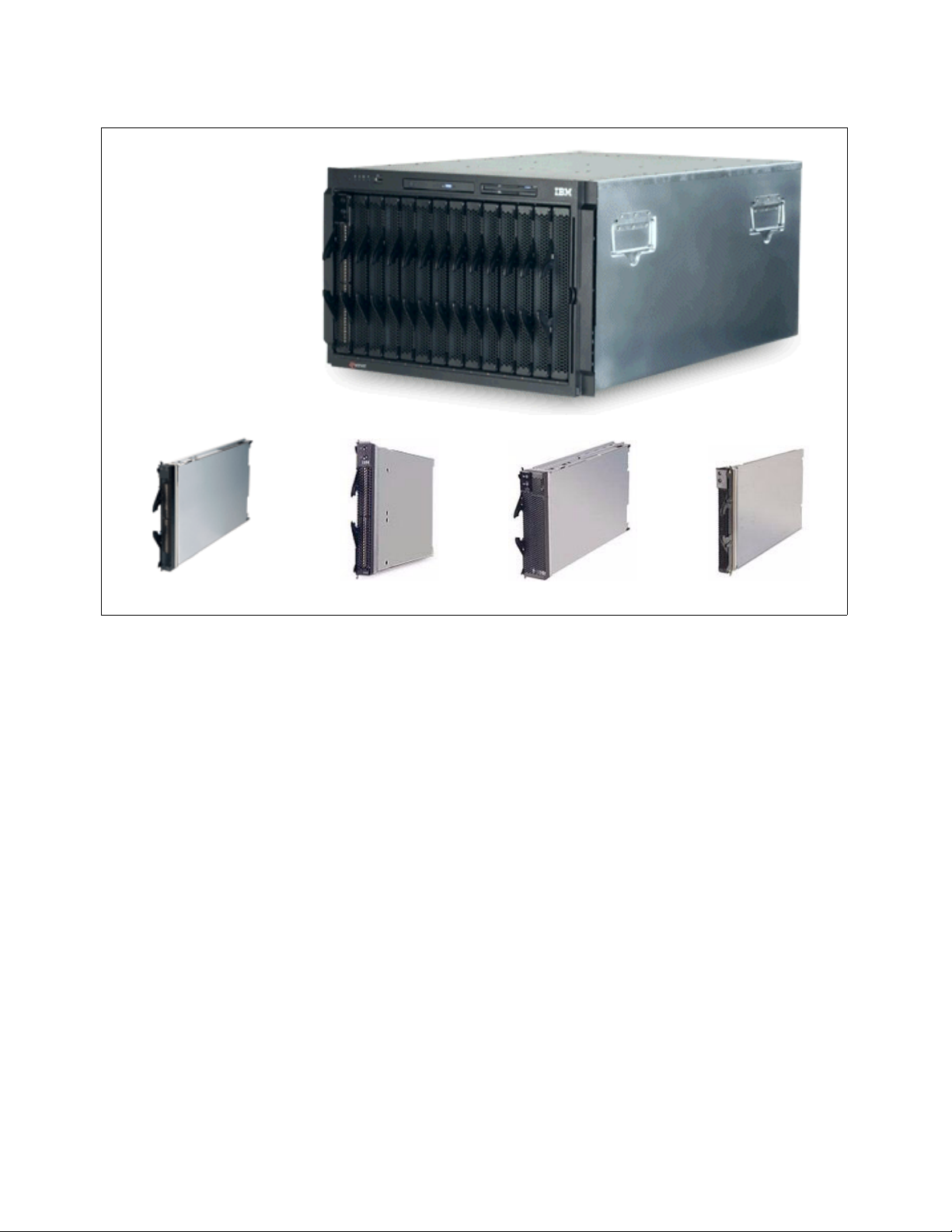
IBM Eserver BladeCenter
IBM Eserver LS20 IBM Eserver HS20 IBM Eserver HS40
Figure 2-1 IBM Eserver BladeCenter and blade modules
Blade development is ongoing for the BladeCenter platform. Therefore, we suggest that you
regularly visit the following Web site for the latest information about IBM Eserver
BladeCenter:
http://www.ibm.com/servers/eserver/bladecenter/index.html
2.1.1 IBM Eserver BladeCenter storage solutions
IBM delivers a wide range of easy-to-install, high-capacity, tested storage products for the
IBM Eserver BladeCenter to meet your demanding business needs. This enables you to
choose from the array of IBM TotalStorage® storage solution products, which include:
Fibre Channel products and Storage Area Networks
Network Attached Storage
Enterprise Storage Server®
IBM TotalStorage provides connected, protected, and complete storage solutions that are
designed for your specific requirements, helping to make your storage environment easier to
manage, helping to lower costs, and providing business efficiency and business continuity.
For more information about BladeCenter storage solutions, visit:
http://www.pc.ibm.com/us/eserver/xseries/storage.html
IBM Eserver JS20
Chapter 2. IBM Eserver BladeCenter overview 5
Page 20

2.1.2 IBM Eserver BladeCenter system management
To get the most value from your IBM Eserver BladeCenter investment throughout its life
cycle, you need smart, effective systems management which will keep your availability high
and costs low.
Management foundation
IBM Director, our acclaimed industry standards-based workgroup software, delivers
comprehensive management capability for IntelliStation®, ThinkCentre, ThinkPad, and
IBM Eserver BladeCenter and xSeries hardware to help reduce costs and improve
productivity. IBM Director is hardware that is designed for intelligent systems management. It
offers the best tools in the industry and can save you time and money by increasing
availability, tracking assets, optimizing performance, and enabling remote maintenance.
Advanced server management
This exclusive collection of software utilities provides advanced server management and
maximum availability through the following components:
Server Plus Pack
Application Workload Manager
Scalable Systems Manager
Real-Time Diagnostics
Electronic Service Agent™
Tape Drive Management Assistant
For more information about advanced server management, see:
http://www-1.ibm.com/servers/eserver/xseries/systems_management/xseries_sm.html
Deployment and update management
IBM deployment tools help minimize the tedious work that can be involved in getting your
servers and clients ready to run. These tools include:
Remote Deployment Manager
Software Distribution Premium Edition
ServerGuide™
ServerGuide Scripting Toolkit
UpdateXpress
For more information about IBM Eserver BladeCenter deployment and update
management, visit:
http://www.ibm.com/servers/eserver/xseries/systems_management/xseries_sm.html
2.2 IBM Eserver BladeCenter architecture
In this section, we look into the architectural design of the IBM Eserver BladeCenter chassis
and its components.
2.2.1 The midplane
Figure 2-2 on page 7 illustrates the BladeCenter midplane. The midplane has two similar
sections (upper and lower) that provide redundant functionality. The processor blades (blade
servers) plug into the front of the midplane. All other major components plug into the rear of
the midplane (for example, power modules, switch modules, and management modules). The
processor blades have two connectors, one that is connected to the upper section and one
6 Nortel Networks L2/3 Ethernet Switch Module for IBM Eserver BladeCenter
Page 21
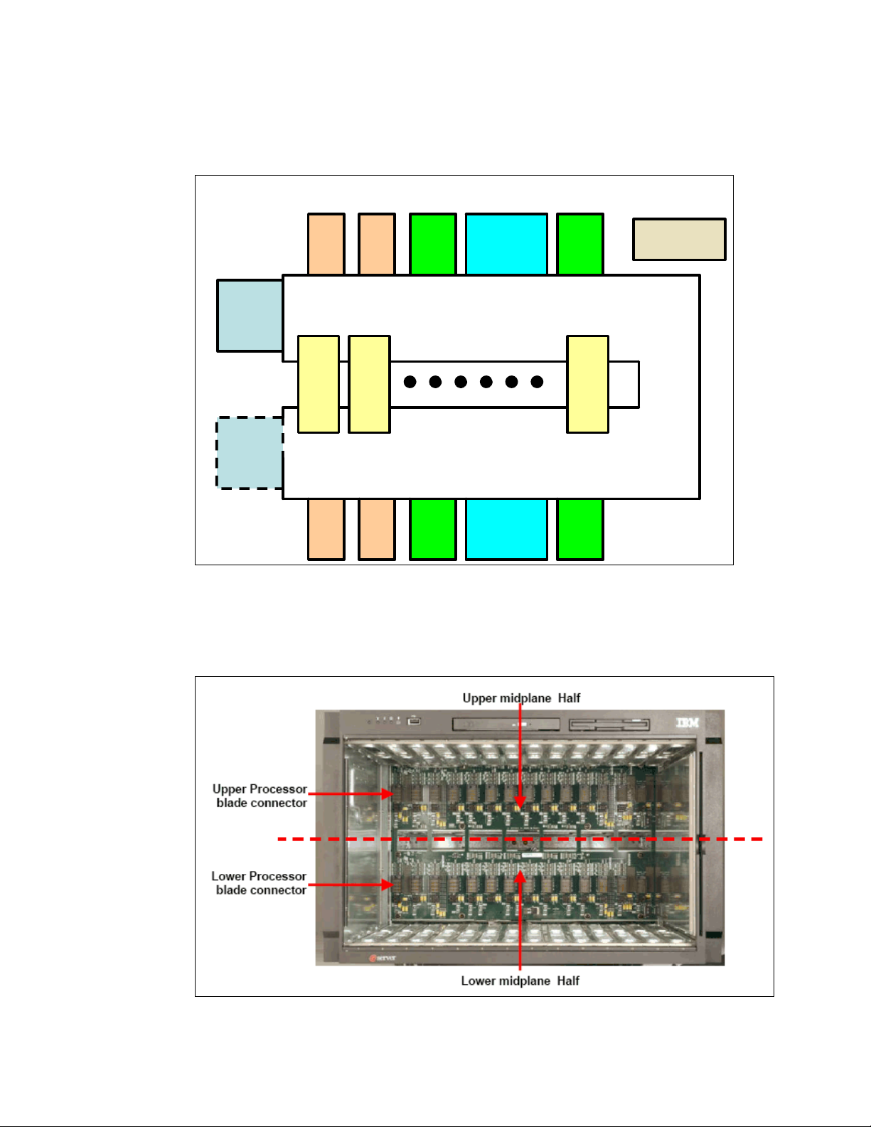
that is connected to the lower section of the midplane. All other components plug into one
section only (upper or lower). However, there is another matching component that can plug
into the other midplane section for redundancy.
IBM
^
BladeCenter™ - Midplane
Front
Panel/Media
Tray
Management
Module 1
Management
Module 2
Switch
Module
CPU
Blade
1
Switch
Module
Switch
Module
Power
Module
Midplane Upper Section
CPU
Blade
2
Midplane Lower Section
Switch
Module
Power
Module
Blower
Blower
Power
Module
CPU
Blade
14
Power
Module
Figure 2-2 Midplane view
It should be noted that the upper and lower midplane sections in an IBM Eserver
BladeCenter are independent of each other (see Figure 2-3). Having a dual midplane ensures
that there is no single point of failure and the blades remain operational.
Figure 2-3 Internal picture of the upper and lower midplane of the BladeCenter chassis
Chapter 2. IBM Eserver BladeCenter overview 7
Page 22
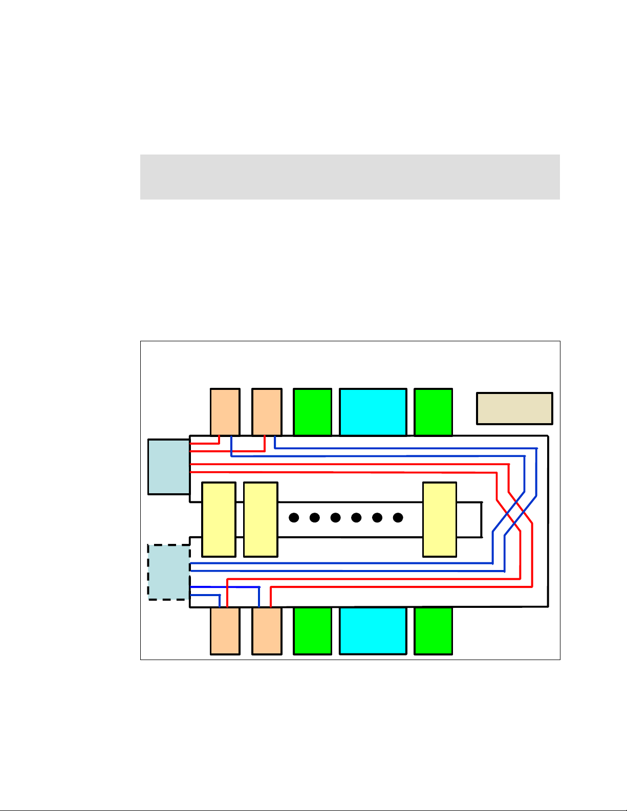
2.2.2 Management Module Ethernet
Figure 2-4 illustrates the Management Module Ethernet interface. The switch modules are
configured by the active Management Module through the use of a 100 Mb Ethernet interface.
Each Management Module has four 100 Mb Ethernet interfaces, one for each switch module.
Each switch module has two 100 Mb Ethernet interfaces, one for each Management Module.
Note: On the Nortel Networks L2/3 GbESM, the management Ethernet ports on the switch
are referred to as MGT1 and MGT2. For more information beyond this generic illustration,
see Chapter 4, “Nortel Networks Layer 2/3 GbE Switch Module architecture” on page 21.
The following list clarifies the routing:
Management Module 1 Ethernet 1 → Switch Module 1 Ethernet MGT1
Management Module 1 Ethernet 2 → Switch Module 2 Ethernet MGT1
Management Module 1 Ethernet 3 → Expansion Switch Module 3 Ethernet MGT1
Management Module 1 Ethernet 4 → Expansion Switch Module 4 Ethernet MGT1
Management Module 2 Ethernet 1 → Switch Module 1 Ethernet MGT2
Management Module 2 Ethernet 2 → Switch Module 2 Ethernet MGT2
Management Module 2 Ethernet 3 → Expansion Switch Module 3 Ethernet MGT2
Management Module 2 Ethernet 4 → Expansion Switch Module 4 Ethernet MGT2
IBM
^
BladeCenter™ -
Management Module Ethernet Interface
Management
Module 1
Management
Module 2
Switch
Module
CPU
Blade
1
Switch
Module
Switch
Module
CPU
Blade
2
Switch
Module
Power
Module
Power
Module
Blower
Blower
Power
Module
CPU
Blade
14
Power
Module
Panel/Media
Figure 2-4 Management Module Ethernet interface
The redundant paths of the Management Module Ethernet interface are run from
Management Module 2.
Front
Tray
8 Nortel Networks L2/3 Ethernet Switch Module for IBM Eserver BladeCenter
Page 23

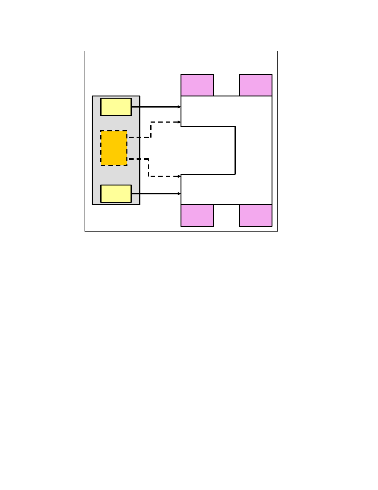
2.2.3 Gigabit Ethernet path
Figure 2-5 on page 10 illustrates the Gigabit Ethernet path. Each processor blade has a
minimum of two and a maximum of four EtherLAN interfaces. In particular, the BladeCenter
HS20 processor blade has two serializer/deserializer SERDES-based Gb Ethernet interfaces,
one for each midplane connector. With a daughter card installed, two more network interfaces
can be added. Each switch module (SW Module) receives one LAN input from each
processor blade, for a total of 14 inputs.
Note: On the Nortel Networks L2/3 GbESM, the internal Ethernet ports on the switch are
referred to as MGT1 and MGT2. For more information beyond this generic illustration, see
Chapter 4, “Nortel Networks Layer 2/3 GbE Switch Module architecture” on page 21.
The following partial listing illustrates the routing:
Processor blade 1 LAN 1 → Switch Module 1 input INT1
Processor blade 1 LAN 2 → Switch Module 2 input INT1
Processor blade 1 LAN 3 → Expansion Switch Module 3 input INT1
Processor blade 1 LAN 4 → Expansion Switch Module 4 input INT1
Processor blade 2 LAN 1 → Switch Module 1 input INT2
Processor blade 2 LAN 2 → Switch Module 2 input INT2
Processor blade 2 LAN 3 → Expansion Switch Module 3 input INT2
Processor blade 2 LAN 4 → Expansion Switch Module 4 input INT2
On processor blade, LAN 1 and LAN 2 are the on-board SERDES Gbit Ethernet interfaces,
and are routed to Switch Module 1 and Switch Module 2, respectively, for every processor
blade. LAN 3 and LAN 4 go to the Expansion Switch Modules 3 and 4, respectively, and are
only to be used when a daughter card is installed. Unless a daughter card is installed in one
or more processor blades, there is no need for Switch Modules 3 and 4. Further, the switch
modules have to be compatible with the LAN interface generated by the processor blade. If a
Fibre Channel daughter card is installed in a BladeCenter HS20 processor blade, Switch
Modules 3 and 4 must also be Fibre Channel-based, and any daughter cards installed in the
remaining BladeCenter HS20 processor blades must be Fibre Channel.
Chapter 2. IBM Eserver BladeCenter overview 9
Page 24
IBM
^
BladeCenter™ -
Gigabit Ethernet path
SERDES
Ethernet
Network
Interface
Daughter
Card
SERDES
Ethernet
Processor blade
#1
Figure 2-5 Gigabit Ethernet path
LAN 1
LAN 3
LAN 4
LAN 2
SW Module 1
1………..14
SW Module 3
1………..14
Midplane (Upper Section)
Midplane (Lower Section)
1………..14
SW Module 2
1………..14
SW Module 4
2.3 IBM Eserver HS20 architecture
In this section, we discuss the architectural design of the IBM Eserver BladeCenter HS20.
This is presented as just one example of the blade design for a typical dual-processor server.
10 Nortel Networks L2/3 Ethernet Switch Module for IBM Eserver BladeCenter
Page 25
The BladeCenter HS20 uses the Intel® Lindenhurst chipset (see the HS20 architecture in
Figure 2-6).
8843 HS20 Block Diagram
Due to space
limitations this
diagram is not
drawn to scale
ICH-S
PCI
bus 0
PCIX 66
LSI
1020
SCSI
VRM 10.1
To SP I2C bus
Hublink 1.5
LPC
PCI
32/33
PCI Express x4
PXH
Pri Sec
PCIX B
Daughter card connector
7000M
ATI
Nocona
XEON
CPU
MCH
Data A
Data B
USB ports to
HD connectors
VPD 32KB
EEPROM
PCIExpress x8
PCIX C
Video
Servicing the IBM ^
HS20 (M/T 8843) and Blade
Storage Expansion-II Option
Nocona
XEON
CPU
To SP I2C bus
DDR2
400Mhz 2GB
To SP
2
C bus
I
I2C bus
Video
Renassas
SP (2166)
1Gb Ethernet
DIMMs
sockets
Broadcom
5704S Ethernet
controller
VRM 10.1
1 Gb
Ethernet
SCSI HDD Connector 1
SCSI HDD Connector 1
Figure 2-6 HS20 architecture
The Intel Lindenhurst chipset consists of the following components:
Memory and I/O controller (MCH) (North Bridge)
PXH-D
ICH-S (South Bridge)
The Lindenhurst MCH, Memory and I/O controller provides the interface between the
processors, the memory, and the PCI Express busses that interface to the other Intel chips.
The Lindenhurst ICH-S (South Bridge) provides the USB interfaces, the local Service
Processor interface, the POST/BIOS flash EEPROM interface, and the PCI bus interface for
the ATI Radeon Mobility Video controller and LSI 1020 SCSI Host Controller. The PXH
interfaces the Broadcom BCM5704S ethernet controller on its secondary bus and the
daughter card on its secondary bus. I/O functions on the 8843 include Video, I2C, USB,
SCSI, Gigabit Ethernet, and USB (floppy, CD-ROM (DVD), mouse, and keyboard).
The LPC bus is used to connect to the POST/BIOS EEPROM on the 8843. The size of the
EEPROM is 4 MB x 8, and it contains primary BIOS, backup BIOS, and blade diagnostics.
Blade
Expansion
Connector
Blade HD
connector A
Midplane HD
connector A
Blade HD
connector B
Midplane HD
connector B
Chapter 2. IBM Eserver BladeCenter overview 11
Page 26

PCI Express features include:
PCI software compatibility
Chip-to-chip, board-to-board implementations
Support for end-to-end data integrity
Advanced error reporting and handling for fault isolation and system recovery
Low-overhead, low-latency data transfers and maximized interconnect efficiency
High-bandwidth, low pin-count implementations for optimized performance
2.4 Stand-alone configuration tools
IBM Eserver BladeCenter hardware can be configured using standard software, such as a
Web browser and a Telnet client, which are available on all the mainstream operating system
platforms. This is possible by exploiting Web and American National Standards Institute
(ANSI) interfaces that are embedded in both the management and the Ethernet Switch
Modules.
A very comprehensive tool is accessible through the Web interface. This tool contains various
configuration submenus, and one of them (I/O Module Tasks) lets you set up the Ethernet
Switch Module. Basic settings (such as the Ethernet Switch Module IP address and the
enablement of the external ports) are configured by exploiting the I2C bus. An advanced
menu allows for the fine tuning of the module, by either opening another window of the Web
browser or running a Java™ applet that allows for connectivity to an ANSI interface. (This
requires that you have Java 2 V1.4 installed on the management system.) To achieve this,
the 10/100 Mb internal link that connects the Management Module and the Ethernet Switch
Modules through the BladeCenter backplane are exploited (notice that the internal network
interface of the Management Module has a default static IP address of 192.168.70.126).
These more complete tools can also be accessed by pointing your Web browser, Telnet, or
SSH client to the IP of the Ethernet Switch Module itself. (The default for a module that is
plugged into Rear Bay 1 is 192.168.70.127. However, you can configure Dynamic Host
Configuration Protocol (DHCP) based addressing.) Notice that this latter capability requires
the management system to connect through the external ports (on the production LAN) of the
Ethernet Switch Module and, therefore, might potentially raise concerns about security. That
is why you have the capability to disable configuration control through the external ports in the
I/O Module Tasks of the Management Module interface.
Figure 2-7 on page 13 illustrates the available stand-alone configuration tools.
12 Nortel Networks L2/3 Ethernet Switch Module for IBM Eserver BladeCenter
Page 27
Management LAN
Management LAN
Internal LAN connection
Internal LAN connection
Production LAN
Production LAN
Telnet to MM port to manage switch
DHCP lease or
192.168.70.125
Browser
Any of the four
Any of the six
external ports
external ports
Can be
disabled
Command Line
(Telnet)
Higher security
Higher security
MM external
Ethernet port
BladeCenter™ Drawer
Management Module
Web interfaceWeb interface
Switch Module 1
Default is 192.168.70.127*
Web interfaceWeb interface
ANSI interfaceANSI interface
I2C bus
Always static, default
is 192.168.70.126
Internal
10/100Mb
Ethernet
(Configuration
path only as
shown by arrow)
Rear Bay 2If Module is plugged into192.168.70.128*This is
Rear Bay 2If Module is plugged into192.168.70.128*This is
Rear Bay 3192.168.70.129
Rear Bay 3192.168.70.129
Rear Bay 4192.168.70.130
Rear Bay 4192.168.70.130
Figure 2-7 Stand-alone configuration tools
Chapter 2. IBM Eserver BladeCenter overview 13
Page 28

14 Nortel Networks L2/3 Ethernet Switch Module for IBM Eserver BladeCenter
Page 29

3
Chapter 3. Nortel Networks Layer 2/3 GbE
Switch Modules
This chapter discusses the Nortel Networks Layer 2/3 Copper and Fiber GbE Switch Modules
for IBM Eserver BladeCenter and its set of features and services.
© Copyright IBM Corp. 2005. All rights reserved. 15
Page 30
3.1 Product description
The new Nortel Networks Layer 2/3 Copper and Fiber GbE Switch Modules for IBM Eserver
BladeCenter serve as a switching and routing fabric for the BladeCenter server chassis. In
addition to the Layer 2 switching capabilities, these switches introduce the expanded
capabilities of Layer 3 routing. Up to four copper or fiber Gb Ethernet modules can reside in
the I/O module bays of the BladeCenter chassis. The modules can be hot-plugged into an
IBM Eserver BladeCenter without disrupting normal operations.
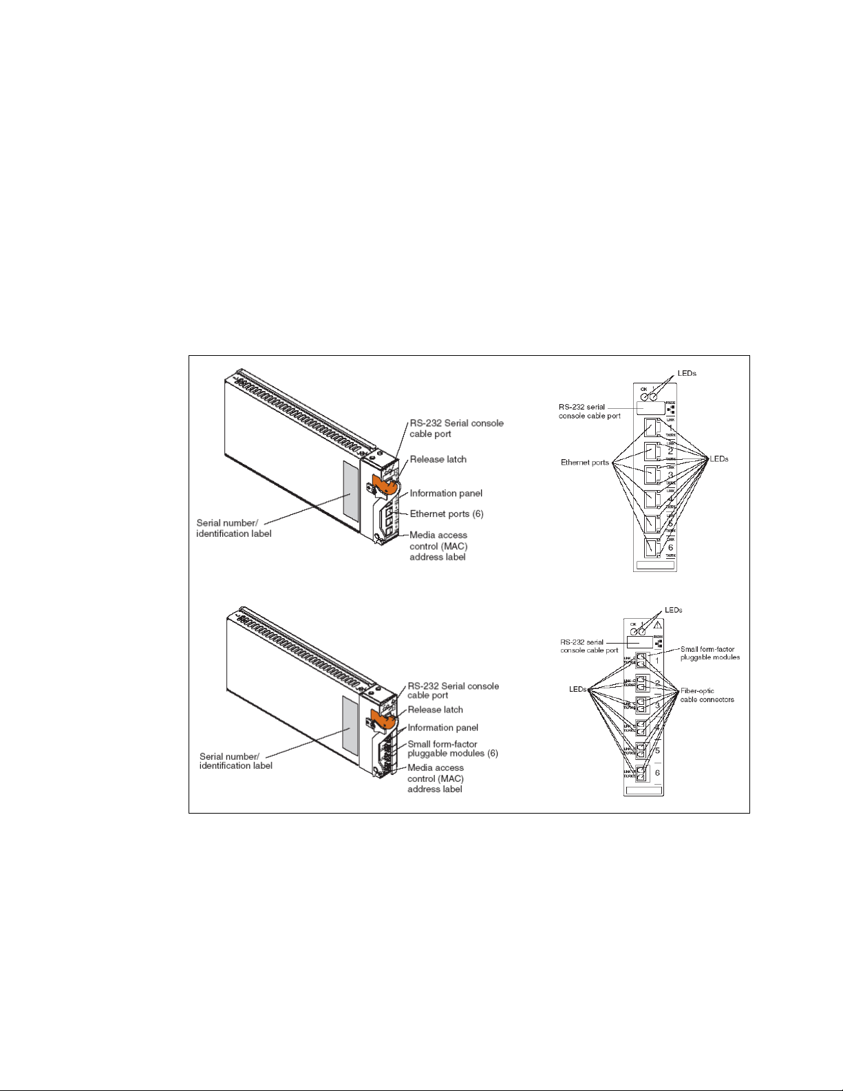
The Nortel Networks L2/3 GbESM connects to the server blades via the 14 internal GbE
interfaces (server ports) over the BladeCenter midplane. It supplies six external copper or
multimode fiber GbE interfaces for outside communication (shown in Figure 3-1). The switch
is managed via two internal 100 Mbps ports for communication to the BladeCenter
management module. A RS232 serial console management interface is also available.
Figure 3-1 Nortel Networks L2/3 GbESM connections
Full Layer 2 switching and Layer 3 routing provide flexible in-chassis traffic management and
security. The Nortel Networks Layer 2/3 Copper and Fiber GbE Switch Modules for
IBM Eserver BladeCenter provides full Layer 2 switching with availability capabilities such
as advanced spanning tree protocols, Link Aggregation Control, Cisco Etherchannel, and
802.1Q VLANs, application delivery and performance features such as granular QOS
(Differentiated Service Code Point 802.1p), Internet Group Management Protocol (IGMP)
snooping, and multicast.
In particular, the switch modules support up to 16,384 MAC addresses, 4,096 address
resolution protocol (ARP) entries, and up to 2,048 dynamic route entries to ensure a high
16 Nortel Networks L2/3 Ethernet Switch Module for IBM Eserver BladeCenter
Page 31

level of support for a number of users. The IEEE 802.1D Spanning Tree Protocol (STP)
support can be enabled or disabled on a per-port basis. Multiple instances of STP are
supported (that is, 16 STP groups). Virtual Local Area Network (VLAN) support includes
802.1Q tagged VLANs and support for IEEE 802.3 support on six external ports for up to
three static trunk groups. Dynamic trunking using LACP as well as static trunking is
supported.
Adding full Layer 3 routing to the integrated switch module adds more power, flexibility, and
security capabilities to the IBM Eserver BladeCenter. With the integrated switch module in
the BladeCenter, network traffic can be managed much more efficiently. Broadcast traffic can
be contained in the blade server by placing the 14 blade servers on different subnets while
allowing communication between each without using the bandwidth of the external ports to
send traffic to and from an external Layer 3 device.
Security features provide added protection for switch configuration data, while packet filtering
helps secure and segment sensitive traffic or network access. Support for Simple Network
Management Protocol (SNMPv3), Secure Shell (SSHv2), and Hypertext Transfer Protocol
over Secure Socket Layer (HTTPS) supply protection for sensitive switch configuration data.
Multilevel access and defined access policies help secure the switch against unauthorized
management access. Support for Remote Authentication and Remote Authentication Dial-in
User Service Protocol (RADIUS), and Terminal Access Controller Access Control System
(TACACS+) gives enterprises the freedom to use current security databases.
Layer 3 filtering (IP and application type) at line rate in the chassis enhances security and
simplifies provisioning. The risk of traffic finding a route to a denied destination is reduced if
Layer 3 routing is contained in the switch module in the chassis. Without Layer 3 filtering,
several external switches might need configuration to filter traffic to limit access between one
server blade and another if the traffic flows through upstream devices.
The following routing standards are supported:
Routing Information Protocol version 1 (RIPv1), and version 2 (RIPv2)
Border Gateway Protocol version 4 (BGPv4)
Open Shortest Path First version 2 (OSPFv2)
Maximum bandwidth and network flexibility with uplink support for six Gigabit Ethernet
ports/switch (fiber or copper). The Nortel Networks L2/3 GbESM is designed to be able to
route, filter, and queue traffic so that no data is lost, dropped, or delayed. Applications get the
bandwidth they need, when they need it, with little or no delay or jitter.
Even with all the value that an integrated switch module can provide, performance for a
BladeCenter can be limited if the switch module cannot provide adequate ingress and egress
bandwidth. The Nortel Networks L2/3 GbESM is the only BladeCenter switch module that
offers six Gigabit Ethernet uplink ports for maximum throughput, supporting full Layer 2
through Layer 3 wire-speed packet forwarding for all connections. In addition, the flexibility of
both copper and fiber ports allows for optimized use in hybrid installations or for situations
where one switching infrastructure is more economical than another.
Unmatched High Availability support and field proven Resiliency High availability support is
built in at both Layer 2 and Layer 3 in the Nortel Networks L2/3 GbESM to reduce single
points of failure when it comes to enabling reliability and performance of the network.
At Layer 2 Link Aggregation Control (802.3), Rapid Spanning Tree, Fast Uplink Convergence,
Port Fast Forwarding, 802.1Q VLANs, Broadcast Storm Control, and Native Link Failover
with NIC teaming are supported.
Chapter 3. Nortel Networks Layer 2/3 GbE Switch Modules 17
Page 32

At Layer 3, special configurations of Virtual Router Redundancy Protocol (VRRP) allow all
switches in the VRRP group to concurrently process traffic by using multiple instances of
VRRP. Such configurations enable maximum switch performance while also ensuring
seamless failover in the unlikely event of a failure. VRRP Hot Standby is also supported to
enable effective use of NIC Teaming in Layer 3 network topologies much as Trunk Failover
facilitates HA designs with NIC Teaming at Layer 2.
3.2 Value proposition
This section discusses the value of using the Nortel Networks Layer 2/3 Copper and Fiber
GbE Switch Modules for IBM Eserver BladeCenter for your IBM Eserver BladeCenter.
Product strength
The product provides strengths such as:
Provides full interoperability into existing Nortel and Cisco data centers with the
BladeCenter integrated GbE switch module.
Integrates Nortel networking capabilities to reduce data center complexity and increases
networking manageability and availability.
Leverages the leadership capabilities BladeCenter Alliance Partners to provide the most
technological choices.
Leadership features and function
The leadership features and function include:
IBM Eserver BladeCenter delivers with the Nortel GbESM, full Layer 2 switching and
Layer 3 switching (routing) functionality as well as Layer 4 filtering and related services.
The switch module runs Alteon Operating System and appears as any other product from
Nortel's Alteon product line to the data center’s network management tools. In addition,
Nortel is pursuing a unified command line syntax across its data products, known as the
NNCLI (Nortel Networks CLI), which will be available on the L2-3 switch late in 2005.
Competitive advantage
The product delivers a competitive advantage by delivering:
Full integration of Ethernet switching, reducing infrastructure complexity
Six external copper or fiber option
Upgrade path to full Layer 4-7 services
Price leadership
18 Nortel Networks L2/3 Ethernet Switch Module for IBM Eserver BladeCenter
Page 33

3.3 Supported hardware
Table 3-1 lists the following IBM hardware platforms which support Nortel Networks Layer 2/3
Copper Gigabit Ethernet Switch Module for IBM Eserver BladeCenter (26K6530) and Nortel
Networks Layer 2/3 Fiber Gigabit Ethernet Switch Module for IBM Eserver BladeCenter
(26K6531).
Table 3-1 Supported platforms
System name Machine type Model
BladeCenter 8677 All
BladeCenter 7967 All
BladeCenter T 8720 All
BladeCenter T 8730 All
Product shipment group
The items that ship with either switch module are:
Nortel Networks Layer 2/3 Copper Gigabit Ethernet Switch Module for IBM Eserver
BladeCenter (26K6526) or Nortel Networks Layer 2/3 Fiber Gigabit Ethernet Switch
Module for IBM Eserver BladeCenter (26K6529)
Serial Console Cable (FRU 02R9365)
Installation publication, including Documentation CD
Safety flyer
Software License Agreement
Six small form-factors (SFPs) are pre-installed into the Nortel Networks Layer 2/3 Fiber
Gigabit Ethernet Switch Module for IBM Eserver BladeCenter (26R0808)
Chapter 3. Nortel Networks Layer 2/3 GbE Switch Modules 19
Page 34

20 Nortel Networks L2/3 Ethernet Switch Module for IBM Eserver BladeCenter
Page 35

4
Chapter 4. Nortel Networks Layer 2/3 GbE
Switch Module architecture
This chapter provides a system overview of the Nortel Networks Layer 2/3 GbE Switch
Module.
© Copyright IBM Corp. 2005. All rights reserved. 21
Page 36

4.1 Nortel GbESM architecture overview
The Nortel Networks Layer 2/3 GbE Switch Module is a fully functional Layer 2 and 3 switch
that includes Layer 4 awareness and capability. Figure 4-1 shows the architecture overview of
the Nortel Networks Layer 2/3 GbE Switch Module.
The Nortel GbESM has 14 internal 1 Gbps links to connect to blade servers and six external
Gigabit ports to connect to upstream switches. The switch module has two 100 Mbps
connections to the Management Modules. You can manage the Nortel GbESM through the
connection between the Nortel GbESM and the Management Module. You can also manage
the Nortel GbESM like other switches with the RS232 console port that looks similar to a USB
port. The console port is a service port to which you can connect a terminal or PC in order to
configure the software through the command-line interface (CLI) or to troubleshoot problems
with the switch.
14 ports
1000 Mbps
Internal
links
to
Blade
Servers
2 ports -100 Mbps
Internal links to the
Management Modules
Blade1
Blade2
Blade3
Blade4
Blade5
Blade6
Blade7
Blade8
Blade9
Blade0
Blade1
Blade2
Blade3
Blade4
MM1
MM2
INT1
INT2
INT3
INT4
INT5
INT6
INT7
INT8
INT9
INT10
INT11
INT12
INT13
INT14
MGT1
MGT2
EXT1
EXT2
EXT3
EXT4
EXT5
EXT6
Serial
Nortel
Networks
L2/3
GbESM
Module
1
2
10/100/1000 Mbps
3
RJ45 links for external
4
5
network connections
6
6 ports
1 port
RS232 Serial console
connection port on
faceplate
Nortel
IBM eServer BladeCenter
L2/3 GbESM Connections
Networks
Figure 4-1 Nortel Networks L2/3 GbESM architecture overview
Figure 4-2 on page 23 shows the architecture for Ethernet connectivity. The two Nortel
GbESMs can be housed within the BladeCenter chassis. Each Nortel GbESM provides six
uplink ports, which can be grouped to support 802.3ad Link Aggregation. The blade server
has two NICs, with NIC 1 connecting to Nortel GbESM 1 and NIC 2 connecting to Nortel
GbESM 2. The links connecting the blade servers to the Nortel GbESMs are on the
backplane of the BladeCenter chassis. The Nortel GbESM has two links to the Management
Modules. Each link connects to a different Management Module.
22 Nortel Networks L2/3 Ethernet Switch Module for IBM Eserver BladeCenter
Page 37

123456
GbESM1
123456
GbESM2
GbESM2
Uplinks
M
M
1
12
Blade
Server1
Figure 4-2 BladeCenter Ethernet connectivity
12
Blade
Server2
12
Blade
Server14
M
M
M
M
2
2
Management
Module
Blade
Servers
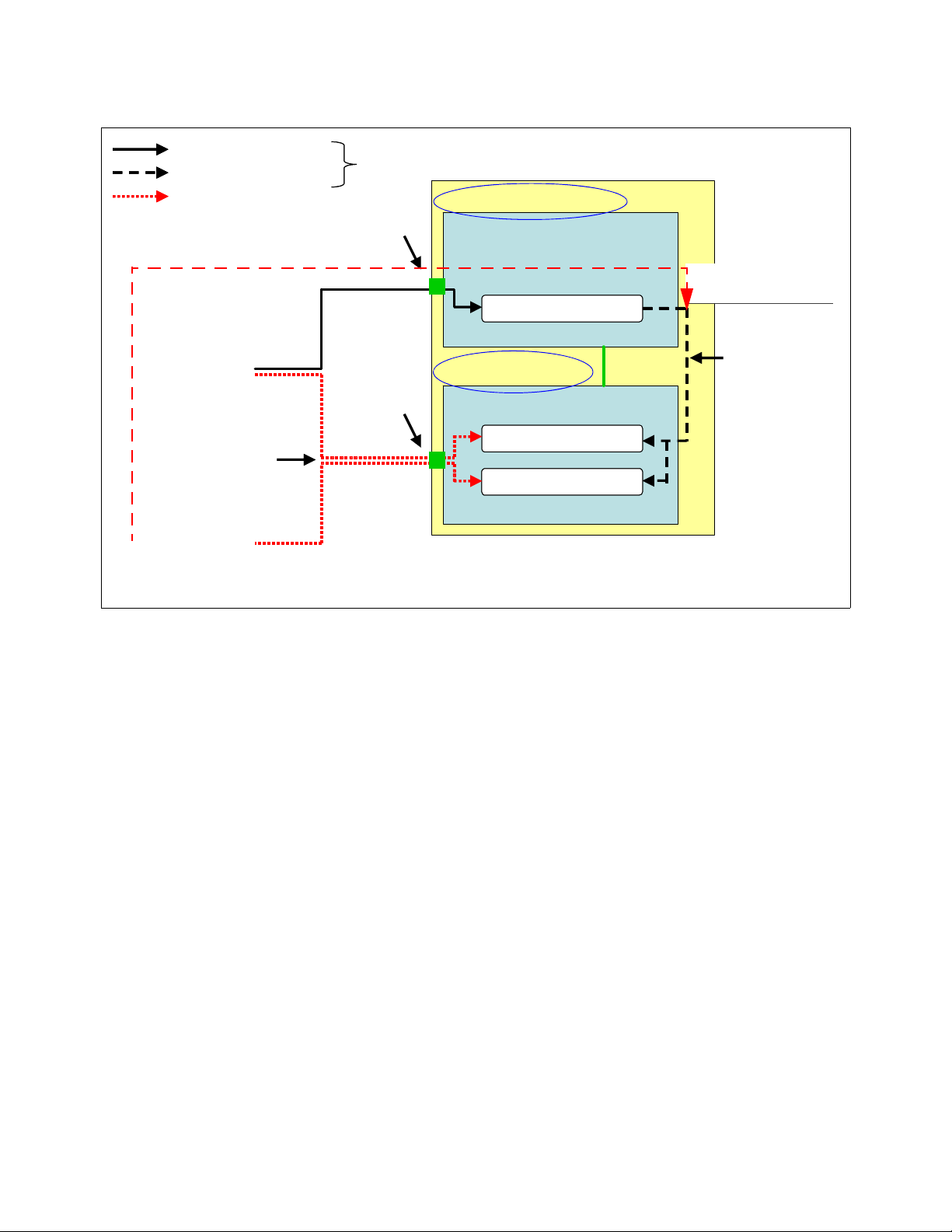
Internal Layer 2 traffic flow in the Nortel Networks L2/3 GbESM
Figure 4-3 shows the internal Layer 2 traffic flow in the Nortel GbESM. The hard coded filter in
the Nortel GbESM blocks all traffic between the external ports and the Management Module
ports. Two Nortel GbESMs in the same BladeCenter chassis exchange Layer 2 frames across
the Management Module. The Nortel GbESM processes BPDUs that reach it via the
Management Module if Spanning Tree is enabled for the Management Module ports. This is
rarely necessary.
6 External ports
Hard-coded filter
2 Management
Module ports
14 internal blade ports
Figure 4-3 Layer 2 frames flow in the Nortel Networks L2/3 GbESM
Chapter 4. Nortel Networks Layer 2/3 GbE Switch Module architecture 23
CPU/AOS
Page 38

Figure 4-3 on page 23 also indicates the following:
Two Nortel GbESMs in the same BladeCenter chassis can ping or telnet to each other
without connecting external ports. They cannot pass user data to each other via this path,
which passes traffic through the Management Module.
The internal blade ports cannot be on the same VLAN as the Management Module ports.
As a result, the blade servers on the production network must be on a different IP subnet
than the Management Module and other devices which are on the management network.
4.2 Nortel Networks L2/3 GbESM block diagram
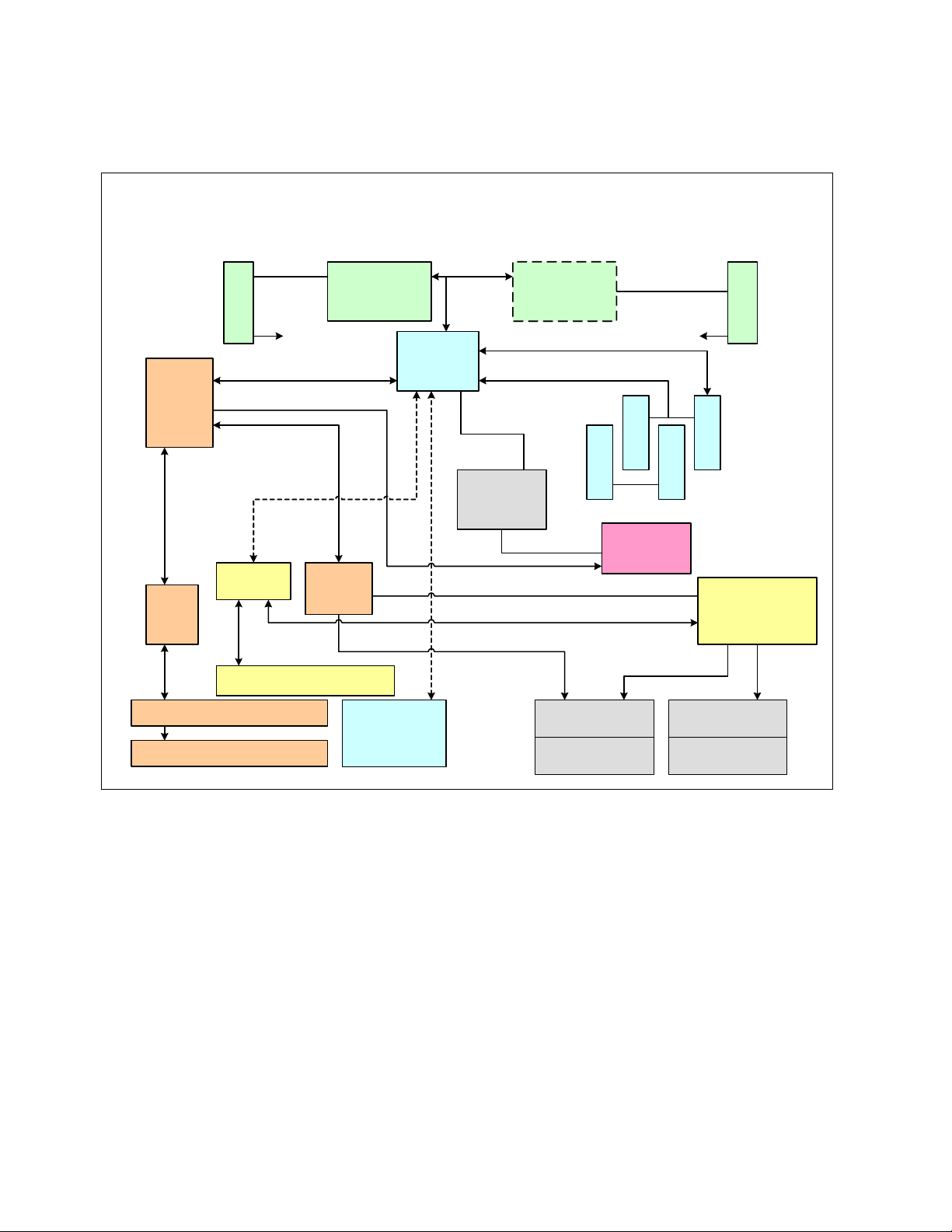
Figure 4-4 shows the block diagram of the Nortel Networks Layer 2/3 GbE Switch Module.
The Nortel GbESM has two Gigabit Ethernet Aggregator (GEAs) for switching. It has 1 MB on
chip cache for packet buffers and supports 20 Gigabit Ethernet ports (14 internal ports and six
external ports). The two GEAs are interconnected with 10 Gigabit proprietary link, which is
shown as the 10G HiGig link in Figure 4-4. HiGig is a proprietary protocol from IBM.
GEA0 supports eight Gigabit Ethernet ports (two internal connections-5421s to the
Management Modules and six external ports). GEA1 supports the remaining 12 internal
ports. The connection between the 5421s and the Management Module links up at 100 Mbps.
Copper ports use six external 1000BASE-T RJ-45 connectors. Fiber ports use six 1000BASE
SX SFP transceivers that are included with the GbE switch module.
10G HiGig
Figure 4-4 Nortel Networks L2/3 GbESM block diagram
Six RJ-45
&
magnetics
OR
Six SFPs
(SX)
24 Nortel Networks L2/3 Ethernet Switch Module for IBM Eserver BladeCenter
Page 39

4.2.1 Nortel Networks L2/3 GbESM ports specific roles
Figure 4-5, Figure 4-6, and Figure 4-7 on page 26 show different examples of the port
connections to the Nortel GbESM(s) within the IBM Eserver BladeCenter. We then discuss
the specific roles and restrictions for the various ports.
14 ports
1000 Mbps
Internal
links
to
Blade
Servers
2 ports -100 Mbps
Internal links to the
BladeServerSlot1
BladeServerSlot2
BladeServerSlot3
BladeServerSlot4
BladeServerSlot5
BladeServerSlot6
BladeServerSlot7
BladeServerSlot8
BladeServerSlot9
BladeServerSlot10
BladeServerSlot11
BladeServerSlot12
BladeServerSlot13
BladeServerSlot14
MM1
MM2
Management Modules
IBM eServer BladeCenter
Figure 4-5 Connections on the Nortel GbESM
INT1
INT2
INT3
INT4
INT5
INT6
INT7
INT8
INT9
INT10
INT11
INT12
INT13
INT14
MGT1
MGT2
Nortel
Networks
L2/3
GbESM
Module
EXT1
EXT2
EXT3
EXT4
EXT5
EXT6
Serial
Nortel
Networks
L2/3 GbESM Connections
1
2
3
4
5
6
10/100/1000 Mbps
RJ45 Ethernet ports
for external network
6 ports
connections
1 port
RS232 (USB-like) Serial
console connection port
on faceplate
14 ports
1000 Mbps
Internal
links
to
Blade
Servers
2 ports -100 Mbps
Internal links to the
BladeServerSlot1
BladeServerSlot2
BladeServerSlot3
BladeServerSlot4
BladeServerSlot5
BladeServerSlot6
BladeServerSlot7
BladeServerSlot8
BladeServerSlot9
BladeServerSlot10
BladeServerSlot11
BladeServerSlot12
BladeServerSlot13
BladeServerSlot14
MM1
MM2
Management Modules
IBM eServer BladeCenter
Figure 4-6 Connections on the Nortel GbESM
Chapter 4. Nortel Networks Layer 2/3 GbE Switch Module architecture 25
INT1
INT2
INT3
INT4
INT5
INT6
INT7
INT8
INT9
INT10
INT11
INT12
INT13
INT14
MGT1
MGT2
Nortel
Networks
L2/3
GbESM
Module
EXT1
EXT2
EXT3
EXT4
EXT5
EXT6
Serial
Nortel
Networks
L2/3 GbESM Connections
1
2
3
4
5
6
1000Base SX SFP
transceiver ports for
external network
6 ports
connections
1 port
RS232 (USB-like) Serial
console connection port
on faceplate
Page 40

Top GbESM (Bay 1) 1
3
EXT1-6
INT1 – 14
1 2 3 4 5 6 7 8 9 10 11 12 13 14 15 16
MGT1
MGT2
2
4
5
6
GbESM
External
uplinks
1
1
1
1
1
1
1
1
1
1
1
1
B
B
B
B
B
B
B
B
B
B
B
B
S
S
S
S
S
S
S
S
S
S
S
S
S
S
S
S
S
S
S
S
S
S
S
S
1
2
3
4
5
6
7
8
9
1
1
1
0
1
2
2
2
2
2
2
2
2
2
2
2
2
2
1 2 3 4 5 6 7 8 9 10 11 12 13 14 15 16 1
1
1
B
B
S
S
S
S
1
1
4
3
2
2
Eth1
MM1
MGT1
INT1 - 14
Bottom GbESM (Bay 2) 6
BladeCenter Chassis (BSS = Blade Server Slot)
Figure 4-7 Overall view of port connections within an IBM Eserver BladeCenter
Ports INT1 through INT14: Connects to blade server slots 1 through 14, respectively:
Preset default values for ports going to the blade servers (includes ports INT1 through
INT14):
– IEEE 802.1Q tagging is enabled
– Default VLAN is VLAN1
– VLAN 4095 is reserved for Serial over LAN
Hard-coded to Auto negotiation, but only support 1000/full duplex to the blade servers.
This cannot be changed at this time, but future revisions of code may support the ability to
set these ports to a no negotiate condition and force the link to 1000/full.
Eth0
MGT2
MM2
Eth0
Eth1
2
3
EXT1-6
MM1
Uplink
MM2
Uplink
GbESM
4
5
External
uplinks
26 Nortel Networks L2/3 Ethernet Switch Module for IBM Eserver BladeCenter
Page 41

Spanning Tree (STP) is disabled by default for all internal ports.
Preset default values for ports going to the Management Modules (includes ports MGT1 and
MGT2):
Speed is hard-coded at 100 full and cannot be changed.
Ports MGT1 and MGT2 cannot be disabled.
– This is by design to ensure that the links to the BladeCenter Management Modules are
not inadvertently or intentionally brought down by the administrator.
– Note that only one of these ports (MGT1 or MGT2) is active at one time (only one
Management Module is active at any given time).
Both ports are hard-coded as untagged VLAN 4095 (internal management VLAN).
Nortel has implemented a hidden filter (not visible or controllable by the administrator) that
prevents any packet entering one of the uplink ports or the internal ports (INT1 -14 and
EXT1 - 6) from exiting toward the Management Module ports (MGT1 - 2) and vice-versa.
This filter is implemented to ensure isolation of the internal BladeCenter management
network.
Ports EXT1 through EXT6: Connects to external ports 1 through 6, respectively:
Preset default values for ports going to external connections (includes ports EXT1 through
EXT6): Untagged and configured on VLAN 1.
These ports default to Disabled when in a new IBM Eserver BladeCenter. You must use
the Management Module Web interface, under I/O Module tasks Advanced settings, to set
External Ports to Enabled to bring them up the first time.
RS232 Console port:
Default settings:
– Baud rate: 9600
– Data bits: 8
– Parity: None
– Stop bits: 1
– Flow control: None
– Emulate: VT100
Serial Console Cable - (FRU 02R9365).
This USB-style connector enables connection to the GbE switch module.
The management VLAN IP address information is not lost during factory
reset
The management VLAN IP address information is not lost as long as Preserve new IP
configuration on all resets is enabled on the Management Module.
As a direct result of a feature being enabled on the Management Module (under I/O Modules
Advanced Setup), after a Nortel GbESM is cleared (reload or through the GUI), the
BladeCenter Management Module provides its currently saved IP information for that Nortel
GbESM. This is to help ensure that the Nortel GbESM can always be accessed over from the
Management Modules. This action (providing or not providing the Nortel GbESM its default
address) can be partially controlled from the Management Modules Web interface.
See“Enabling Nortel Networks L2/3 GbESM uplink ports through the Management Module”
on page 48 for details about enabling or disabling the feature called Preserve new IP
configuration on all resets.
Chapter 4. Nortel Networks Layer 2/3 GbE Switch Module architecture 27
Page 42

Also, if you change this setting to disabled, it is assumed that you plan on managing the
Nortel Networks L2/3 GbESM via its own uplinks.
The default Nortel GbESM IP addressing that is provided by the Management Module for a
new IBM Eserver BladeCenter is as follows:
Switch bay 1: 192.168.70.127/24
Switch bay 2: 192.168.70.128/24
Switch bay 3: 192.168.70.129/24
Switch bay 4: 192.168.70.130/24
Based on certain interactions within the IBM Eserver BladeCenter, it is usually
recommended to change the management IP address directly on the Nortel GbESM, but
instead, only change it through the Management Module Web-based GUI.
not
28 Nortel Networks L2/3 Ethernet Switch Module for IBM Eserver BladeCenter
Page 43

Chapter 5. Nortel Networks L2/3 GbESM
management and administration
In this chapter, we discuss tools, techniques, and applications that help with the management
and deployment of the Nortel GbESM in an IBM Eserver BladeCenter. We also discuss the
management paths and rules for connecting to and accessing the Nortel GbESM.
Note: As noted elsewhere in this document, the information herein applies to the 6-port
Nortel Networks Layer 2/3 Copper and Fiber GbE Switch Modules for IBM Eserver
BladeCenter.
5
© Copyright IBM Corp. 2005. All rights reserved. 29
Page 44

5.1 Nortel Networks L2/3 GbESM management connectivity
In this section, we look at the basic management connectivity and management pathways to
the Nortel GbESM., as shown in Figure 5-1.
Important: Properly managing the Nortel GbESM in the IBM Eserver BladeCenter
actually requires proper management of the Management Module within the BladeCenter
chassis. In other words, it is virtually impossible to successfully deploy the Nortel GbESM if
you do not understand and properly configure certain settings in the Management Module,
as well as the necessary Nortel GbESM configurations.
Legend
Ethernet
Management
Workstation
External
Ethernet
Interface
1
Management
Network
3A
Internal
Ethernet
Interface
Ethernet path
I2C Interface
I2C path
Serial
Serial path
1
Routed Production
Network
3A
External Ports
MGT1 or 2
Nortel Networks
GbESM
Console
port
2
I2C Interface
Management Module
Figure 5-1 Management paths to the Nortel Networks L2/3 GbESM
30 Nortel Networks L2/3 Ethernet Switch Module for IBM Eserver BladeCenter
Internal Ports
3B
Blade
Server
Page 45

5.1.1 Out-of-band management
It is common to provide a (physically) separate management interface for all of the devices
and to carry only management traffic. This is referred to as
sometimes a separate Ethernet connection (path 1) or a whole different physical connection
such as the console port (path 2).
Management Module (Path 1)
The IBM Eserver BladeCenter comes with at least one Management Module. The
Management Module supports an external Ethernet interface, which is used to manage the
Blade servers, Ethernet switches, and the Management Module itself. Within the
IBM Eserver BladeCenter, management traffic flows through a different bus, the I2C bus, as
shown in the Figure 5-1 on page 30.
On the Nortel GbESM, the Ethernet management (MGT1 and MGT2) ports which connect the
switch to the Management Module are placed in VLAN 4095. It is not possible to change this.
It is also not possible to reach VLAN 4095 from any of the other internal or external ports on
the switch. This is a deliberate design constraint. It is intended to enforce isolation of the
Management Module network (VLAN) from any other networks (VLANs) that are configured
on the switch. This implies that the Blade servers should not be on the same VLAN nor the
same IP subnet as the Management Module. Placing the servers on the same subnet as the
Management Module can have unexpected and undesirable results.
The first step in configuring the Nortel GbESM is to assign the IP address of the MGT ports
through the Web interface of the Management Module (Figure 5-2).
out-of-band management and is
Figure 5-2 Configuring the Nortel MGT port IP address using the Management Module Web interface
Chapter 5. Nortel Networks L2/3 GbESM management and administration 31
Page 46

Further configuration of the Nortel Networks L2/3 GbESM module is performed by using
Telnet (for the Command Line Interface) or a Web browser (for the Browser Based Interface)
and accessing the address of the MGT1 or 2 ports.
Note: It is recommended (and easier) to use a server or mobile computer that is external to
the IBM Eserver BladeCenter chassis to perform initial configuration of the Nortel
Networks L2/3 GbESM module. The server or mobile computer should be able to open the
Web interface of the Management Module. It then can reach the switch when the switch
has an appropriate IP address configured. This address must be within the same subnet
as both the internal and external IP addresses of the Management Module.
Serial port (Path 2)
The Serial port is used for out of band management of the switch. It is useful to allow access
to the CLI when all other paths are not working. It is possible to connect the serial port to a
terminal server if desired; this allows out-of-band access to be easily provided to multiple
devices.
The console cable that is required to use this port is included with the switch when it is
shipped. The cable has a RS232 USB-form plug on one end and a DB-9 plug on the other
end. The DB-9 is intended to be attached to a standard serial port such as on a mobile
computer or modem. Standard terminal emulation software should be used with these
settings: 9600 baud; no parity; 8 data bits; 1 stop bit (9600,N,8,1).
5.1.2 In-band management
The second mode of operation that is commonly used is in-band management. In this case,
the management traffic passes through the data traffic path (the Nortel Networks L2/3
GbESM EXTernal and INTernal ports).
External Ethernet ports (Path 3A)
The external ports can be used to provide management access to the switch from outside the
IBM Eserver BladeCenter chassis. In order to use this path, the “External management over
all ports” item in the Management Module configuration must be enabled (Figure 5-3 on
page 33).
32 Nortel Networks L2/3 Ethernet Switch Module for IBM Eserver BladeCenter
Page 47

Figure 5-3 Enabling management over all ports using the Management Module Web interface
Internal Ethernet ports (Path 3B)
The internal ports can be used to provide management access to the switch from the server
blades in the same chassis.
In-band management considerations
In order to use in-band management paths, you must configure at least one additional IP
address on the Nortel Networks L2/3 GbESM beyond the address that is provided through
the Management Module and attached to VLAN 4095. This additional IP address should be
attached to one of the active VLANs configured on the switch and is discussed in detail in
7.5.3, “Base configuration common to all examples” on page 68.
Using the mnet command on the Ethernet switch, it is possible to limit management access to
the switch to management stations within a defined range of IP addresses.
Note: This command limits all IP-based management access regardless of which path is
involved. Thus, you should use it with care. It is possible to lock out access via the
management module (MGT ports) using this command.
Chapter 5. Nortel Networks L2/3 GbESM management and administration 33
Page 48

5.2 Nortel Networks L2/3 GbESM user interface
This section discusses the management interface of the switch module and what each task
represents. To configure and manage the switch module, you can use the following interfaces:
IBM Eserver BladeCenter Management Module and I2C
Management functions that are necessary for initial setup are provided through the
Management Module Web interface. I2C is the communication that is used between the
Management Module and Ethernet switch.
Command-line interface (CLI)
You can configure and monitor the switch from the CLI, which is accessible through Telnet
or SSH from a remote management station. You can also access the CLI through terminal
emulation software on a management station directly connected to the switch module
console port.
Browser Based Interface (BBI)
You can use the Browser Based Interface to manage and monitor the switch using a
standard Web browser via HTTP. It provides a graphical means of viewing and configuring
the switch’s characteristics.
5.2.1 IBM Eserver BladeCenter Management Module and I2C
The Management Module Web interface is the only mechanism for performing certain
management functions, including:
Configuring the management IP address of the switch
Enabling or disabling the external ports and management via these ports
Configuring Power On Self Test (POST) options
Remotely turning power to the switch on or off
All of these functions use the I2C interface when they need to communicate with the switch
module. The use of the Management Module to configure Ethernet switches is documented in
detail in the Nortel Networks Layer 2/3 GbE Switch Module Installation Guide.
5.2.2 Command-line interface
The command-line interface CLI is more flexible for configuring the switch than the BBI. It is
scriptable, requires less overhead to run, and because it is a Telnet session, it can be run
from any operating system (whether or not it is graphical).
Main Menu commands
Figure 5-4 on page 35 shows the Main Menu window. Each of the following commands brings
you to a first level submenu:
The stats menu gives statistics about the switch.
The cfg menu contains all of the configuration options for the switch.
The oper menu contains all of the operator commands. Some of these commands can
change the state of the switch, but these changes only apply until the next reboot. They
are not permanent.
The boot menu contains the commands to control the booting of the switch, from which
image to boot , which config to boot, and the gtimg and ptimg commands for getting and
putting firmware files to the switch.
34 Nortel Networks L2/3 Ethernet Switch Module for IBM Eserver BladeCenter
Page 49

The maint menu contains all of the commands for maintenance of the switch. The
commands to manipulate the ARP cache and forwarding database are here, as well as
the commands to obtain dumps of the current state of the switch for technical support.
Figure 5-4 CLI Main Menu
Global commands
The remainder of the options on the Main Menu — diff, apply, save, revert, and exit — are
all global commands that work anywhere on the switch. Figure 5-4 shows what each of the
commands does. The help command is also global and lists all the global commands, as
shown in Figure 5-5.
Figure 5-5 CLI global command list
Chapter 5. Nortel Networks L2/3 GbESM management and administration 35
Page 50

Navigation commands
There are several commands that are useful in moving from one part of the menu tree to
another. The commands are similar to those used in a UNIX® shell:
cd This command moves you to a given spot in the menu tree. Entering
cd / always takes you back to the main menu.
pwd This command displays the current menu path where you are in the
menu tree.
up This takes you back to the last menu that you touched.
.. or cd .. Both of these commands take you up one level in the menu tree.
pushd and popd These commands allow you to manage a stack of menus that you visit
frequently.
history This command displays the last several commands that you entered.
You can reuse these commands by typing an exclamation point (!)
followed by the number of the command as displayed.
quit or exit Both of these commands terminates your session.
Configuration control commands
These commands control the effectiveness of changes to the switch configuration. The
general rubric for configuring the switch is EASY:
E for editing the configuration, typing in your changes
A for the apply command which makes the changes part of the running configuration
S for the save command which writes the changed configuration to flash memory
Y for yes, which is the answer to the prompt to be sure that you really want to update flash
Additional configuration control commands include the following:
diff This command displays the differences between the most recent edits
and the running configuration.
diff flash This command displays the differences between the running
configuration and its flash copy.
revert This command discards all changes which have not yet been applied.
revert apply This command discards applied changes which have not yet been
saved to flash.
Additional commands
These are additional commands that facilitate troubleshooting or are otherwise helpful:
ping Sends ping, Internet Control Message Protocol (ICMP) echo, requests
to the specified IP address.
traceroute Traces the IP path to a specified IP address.
who This command shows who is logged on to the switch and from which
address.
telnet Opens a Telnet session to the designated IP address.
verbose Tailors the level of messages displayed on your session.
lines Controls the number of lines per screen for display purposes.
36 Nortel Networks L2/3 Ethernet Switch Module for IBM Eserver BladeCenter
Page 51

Upgrading the firmware
To upgrade the firmware on the Nortel Networks L2/3 GbESM, you must use Trivial File
Transfer Protocol (TFTP) or File Transfer Protocol (FTP). It is not possible to use the
Management Module menu item for upgrading firmware at this time. However, this is a
planned feature for a future software release.
Important: Before updating the firmware, save any configuration changes to the Nortel
Networks L2/3 GbESM. From the Telnet session, enter apply, then press Enter. Ty pe
save and press Enter. Answer y to the prompt that asks to confirm saving to flash. Answer
y to the prompt that asks if you want to change the boot to the active config block if it
appears.
Figure 5-6 shows the process to load a new OS image file onto the switch.
Figure 5-6 Display of a firmware update using CLI
The firmware for the Nortel Networks L2/3 GbESM is contained in two files: one is a boot
image file and the other is the OS image file. Use the following steps to upgrade the firmware
on the Nortel Networks L2/3 GbESM via the Telnet session:
1. Type /boot/gtimg.
2. Enter where the new image file will be placed. We are upgrading the boot image file, so
enter boot. That is the location for the boot image file.
3. Enter the IP address of the TFTP server.
4. Enter the fully qualified path name for the boot image file that is on the TFTP server.
5. The switch reports the current version of the boot kernel on the switch and ask if you wish
to replace it with new file. If you wish to continue, enter y.
6. When the download is finished, go back to Step 1, and repeat the process for the OS
image file. In step 2, enter image1 or image2 as the location to store the new image file.
Chapter 5. Nortel Networks L2/3 GbESM management and administration 37
Page 52

7. If the download location is the same as the location for the currently loaded OS image, the
switch warns you that a failed download could result in an inoperative switch. If the
download location is different from the location of the currently loaded OS image, the
image file downloads. After the download is finished, the switch asks whether you want to
use the old location or the new location. Figure 5-6 on page 37 shows a successful
download of the OS image to image2.
8. Type /boot/reset to reset the switch and reboot with the new firmware files.
Capturing the current configuration
There are a few ways to capture the current configuration in the CLI. The first is to use a
TFTP server to push the configuration file from the switch to the server. However, in some
text editors the resulting file is a single long line of text. (We suggest using WordPad.)
Although this method requires a TFTP server running in the network, it does work with any
Telnet client. To capture the configuration by pushing a file to a TFTP server:
1. Enter /cfg/ptcfg at the command line.
2. Enter the IP address of the TFTP server.
3. Enter the filename to which you want to save the file.
A second way to capture the current configuration does not require a TFTP server. This
method, however, requires a terminal emulator that can capture text. Example 5-1 uses a
Windows® Telnet session to capture the text. The commands on the switch are the same for
any software, but the steps to set the software to capture the text might be different. If your
terminal emulator does not support this, you have to use the TFTP method. Using a Windows
Telnet session and issuing the /cfg/dump command, the full switch configuration can be
dumped.
Example 5-1 Example configuration file dump
>> Main# /cfg/dump
script start "Layer 2-3 Gigabit Ethernet Switch Module for IBM eServer BladeCenter" 4
/**** DO NOT EDIT THIS LINE!
/* Configuration dump taken 2:49:25 Sun Jan 4, 2070
/* Version 1.1.0.6, Base MAC address 00:11:f9:36:b7:00
/c/sys/access/user/uid 1
name "USERID"
pswd "727ac51410408000ba33a6f7d3f023f2186030e91e4bf6bc15dc8e028cfbe352"
ena
cos admin
/c/port INT1
pvid 20
/c/port INT2
pvid 10
/c/port INT3
pvid 10
/c/port INT4
pvid 99
/c/port EXT1
tag ena
/c/port EXT2
tag ena
/c/l2/vlan 10
ena
name "VLAN_Green"
def INT2 INT3 EXT1 EXT2
/c/l2/vlan 20
ena
38 Nortel Networks L2/3 Ethernet Switch Module for IBM Eserver BladeCenter
Page 53

name "VLAN_Red"
def INT1 INT2 EXT1 EXT2
/c/l2/vlan 99
ena
name "MGMT"
def INT4 EXT1 EXT2
/c/l2/stg 1/clear
/c/l2/stg 1/add 1 10 20 99
/c/l2/lacp/port EXT1
mode active
/c/l2/lacp/port EXT2
mode active
adminkey 17
/c/l3/if 99
ena
addr 10.99.0.243
mask 255.255.255.0
broad 10.99.0.255
vlan 99
/c/l3/gw 1
ena
addr 10.99.0.245
/c/l3/gw 2
ena
addr 10.99.0.246
/
script end /**** DO NOT EDIT THIS LINE!
Configuring user accounts
This section describes the user accounts on the switch. There are multiple modes of
authentication which are supported on the Nortel Networks L2/3 GbESM:
The default mode is to support passwords without individual user IDs. When accessing
the CLI in this mode, there is only a single prompt to enter the password. Table 5-1 lists
the three passwords that are supported.
Table 5-1 Description of default user accounts
User account Description/Tasks performed Default Password
User Can view switch statistics but cannot make changes. user
Operator The Operator account manages all functions of the
switch but cannot make permanent changes to the
switch configuration.
Administrator Administrator is the super-user account and has
complete access to all menus, information, and
configuration commands on the switch.
oper
admin
Chapter 5. Nortel Networks L2/3 GbESM management and administration 39
Page 54

Local mode allows the definition of individual user IDs with associated authority levels and
passwords. This is configured in the /cfg/sys/access/user menu. For example,
Figure 5-7 shows the configuration that is necessary to create the IBM Eserver
BladeCenter default USERID and PASSW0RD account as an administrator.
Figure 5-7 Creation of USERID account as administrator of the switch module
The third authentication mode supported on the Nortel Networks L2/3 GbESM is using an
external authentication server. RADIUS and TACACS+ servers are both supported. These
are configured in the /cfg/sys/radius and /cfg/sys/tacacs+ menus respectively. More
detail is available in the Alteon OS 21.0 Application Guide.
Note: When you attempt to access the switch through the Web interface, you are
prompted to enter a user name and password. For all the default users on the switch, the
user name and password are the same string by default.
5.2.3 Browser Based Interface
We now take a brief look at the Browser-Based Interface (BBI) on the Nortel Networks L2/3
GbESM. Almost everything that can be done via the CLI can also be done in the BBI. In the
remainder of this book, more emphasis is placed on configuring the switch using the CLI
rather than using the BBI.
The Switch Information panel displays the MAC address of the switch as well as the firmware
and hardware versions. Use the following steps to configure the system and contact
information:
1. From the Nortel Networks L2/3 GbESM Web interface, click the folder icon next to Nortel
Networks Layer 2/3 GbE Switch Module in the left-hand frame.
40 Nortel Networks L2/3 Ethernet Switch Module for IBM Eserver BladeCenter
Page 55

2. Click the folder icon next to System in the left-hand frame.
3. Click CONFIGURE at the top of the page.
4. Click the icon next to General in the drop-down list under System. On a window similar to
Figure 5-8, you see options, such as IP Address and Network Mask fields, that can be
configured on this page. Other options on this page include date and time settings, syslog
settings (if you have a syslog server), and SNMP settings.
Figure 5-8 Switch information using BBI
You can browse through some of the other links in the left-hand frame to get more familiar
with where the configuration options for the switch are located.
5. If you have made any changes to the switch and wish to save them, click Apply to apply
the changes to the current running config.
6. Click Save to save the changes.
5.2.4 SNMP management - IBM Director
You can manage and monitor the Nortel Networks L2/3 GbESM switch module using SNMP
via IBM Director. You can also use SNMP-based management systems, such as Tivoli
Network Manager. The following SNMP capabilities are supported by the module:
SNMP management stations can be configured to receive TRAP
module. This is configured in the /cfg/sys/ssnmp/ menu. Support is available for
SNMPV3 as well as support for SNMP versions 1 and 2.
SNMP Management Information Base (MIB
These files can be imported to the MIB compiler, which is included with IBM Director and
Chapter 5. Nortel Networks L2/3 GbESM management and administration 41
messages from the switch
) files are provided with every software image.
Page 56

other network management products. The MIBs that are provided include Nortel
proprietary extensions to the standard MIB1 and MIB2 objects. Both read and write
access to these variables can be configured.
5.3 Multiple Nortel Networks L2/3 GbESMs in a BladeCenter
If there are two (or more) switches in a single IBM Eserver BladeCenter chassis, the
management (MGTx) interfaces of all of the switches are on VLAN 4095. This has the
following consequences:
All of the MGTx IP addresses that are configured through the Management Module Web
interface should be on the same subnet as the Management Module internal and external
port IP addresses (to allow for access through the Management Module). This
configuration also makes it possible to Telnet from one switch module to another across
the midplane of the chassis.
It is not possible to pass substantive data between switch modules across the midplane
using the MGTx ports. The Nortel Networks L2/3 GbESM will not forward data between
the MGTx ports and any of the internal (INTx) or external (EXTx) ports. If you want to pass
data from one switch module to another, then the modules must be either cabled directly
to each other or connected by way of an external switch or router.
42 Nortel Networks L2/3 Ethernet Switch Module for IBM Eserver BladeCenter
Page 57

Chapter 6. IBM Eserver BladeCenter
system initial setup
This chapter discusses the network topology and the hardware that is configured to provide a
tested and working configuration to help implement your Nortel Networks L2/3 GbESM for the
IBM Eserver BladeCenter.
6
© Copyright IBM Corp. 2005. All rights reserved. 43
Page 58

6.1 IBM Eserver BladeCenter system
In this section, we discuss the stages of preparing IBM Eserver BladeCenter for operation.
6.1.1 Management Module firmware
After the required hardware has been installed in your IBM Eserver BladeCenter, you
should update the Management Module using IBM Eserver® BladeCenter - Management
Module Firmware Update Version 1.18 or later. To acquire the firmware, go to:
http://www.ibm.com/pc/support/site.wss/document.do?lndocid=MIGR-54939
Be sure to read the notes that are associated with the firmware installation. You can also
search for the latest firmware version at:
http://www-1.ibm.com/servers/eserver/support/bladecenter/index.html
Follow the installation and setup instructions in the README file. You only need to install the
files with the .pkt extension (see Figure 6-1). After the installation, you must restart the
Management Module.
Figure 6-1 Management Module firmware update files
44 Nortel Networks L2/3 Ethernet Switch Module for IBM Eserver BladeCenter
Page 59

6.1.2 Management Module network interface
In this section, we configure the Management Module external and internal network interfaces
to exist upon the management subnet. The external network interface IP address is attached
to the network outside of the IBM Eserver BladeCenter. This is the address used to contact
the Management Module from an external device.
Establishing a physical connection to the Management Module
The only way to manage the Management Module is through the external 10/100 Mbps
Ethernet port on the front of the module. To establish the physical connection to the
Management Module, use one of the following methods:
Use a Category 3, 4, 5, or higher unshielded twisted pair (UTP) straight-through cable to
connect the Ethernet port on the Management Module to a switch in a network that has an
accessible management station.
Use a Category 3, 4, 5, or higher cross-over cable to connect a management station (PC
or mobile computer) directly to the external Ethernet port of the Management Module.
Accessing the Management Module Web interface
After you establish the physical connection to the Management Module, configure the
management station with an available IP address in the same subnet as the Management
Module. By default, the subnet is 192.168.70.0/24. You have two primary methods to manage
the Management Module:
HTTP Web interface
IBM Director
We use the Management Module Web interface to demonstrate the initial configuration of the
Management Module and the switch module configuration.
Follow these steps to establish a management session with the Management Module and to
configure the initial switch module settings:
1. Open a Web browser and connect to the Management Module using the configured IP
address. The default IP address for the Management Module external interface is
192.168.70.125. Note that the default IP address for the internal interface is
192.168.70.126.
2. Enter the user ID and password. The default is USERID and PASSW0RD (case-sensitive with a
zero in the place of the letter O). Click OK.
3. At the initial window, click Continue to access the management session.
You can also refer to the BladeCenter Management Module User’s Guide on the
IBM Eserver BladeCenter Documentation CD.
Chapter 6. IBM Eserver BladeCenter system initial setup 45
Page 60

Configuring the Management Module network interfaces
After you access the Management Module Web interface, you can configure the external and
internal network interfaces. From the BladeCenter Management Module Web interface, click
MM Control → Network Interfaces.
Figure 6-2 Management Module External Network Interface window
The BladeCenter Management Module defaults to the IP address 192.168.70.125. If you
have more than one BladeCenter chassis on your management network, you are required to
change the external network interface (eth0). If you do not, you will have IP address conflicts
and will not be able to access your Management Modules. In Figure 6-2, we configured the
external interface to be on the same default management subnet with a unique IP address.
After you have configured the external interface, you need to configure the internal interface
with another unique IP address. The purpose of internal network interface (eth1) is to
communicate with the BladeCenter devices across an Ethernet link (Figure 6-3). Note that if
you do not configure the internal interface on the same network as the external interface, you
will not have IP connectivity from the Management Module to your switches modules.
Figure 6-3 Management Module Internal Network Interface window
46 Nortel Networks L2/3 Ethernet Switch Module for IBM Eserver BladeCenter
Page 61

Click Save at the bottom of the page. You must restart the Management Module to implement
the changes.
6.1.3 I/O module management tasks
In this section, we set up and configure the Nortel Networks Layer 2/3 Copper Gigabit
Ethernet Switch Module for IBM Eserver BladeCenter.
Nortel Networks L2/3 GbESM setup and configuration
You can install the Nortel Networks L2/3 GbESM into any of the four BladeCenter switch bays
in the rear of the chassis. Bay 1 is attached to one of the Ethernet Network Interfaces
Controllers (NIC) on the blade HS20. Bay 2 is attached to the other Ethernet NIC. Each NIC is
a Gigabit Full Duplex link to only one of the switches. As for HS40, which has a total of four
NICs as standard, each two NICs link to one switch. A switch in bay 3 or bay 4 is required
when a Gigabit Ethernet Expansion Card is being installed on the blade. This card provides
an additional two NICs to the blades. One of the NICs has a dedicated Gigabit Full Duplex
link to bay 3 and the other NIC to bay 4.
To manage the Nortel Networks L2/3 GbESM in bay 1, from the BladeCenter Management
Module, click I/O Module Tasks → Management. A window similar to the one in Figure 6-4
opens.
Figure 6-4 I/O Module Tasks: Management (Bay 1 Ethernet SM) window
As with the Management Module, the switch must have a unique IP address and be on the
same subnet as the Management Module for out-of-band management. Enter a Gateway
address if attaching to other networks is required.
Click Save to apply these changes immediately. Rebooting or resetting is not required.
Chapter 6. IBM Eserver BladeCenter system initial setup 47
Page 62

Enabling Nortel Networks L2/3 GbESM uplink ports through the
Management Module
To enable the Ethernet ports of the Nortel Networks Layer 2/3 GbE Switch Module from the
BladeCenter Management Module:
1. In the I/O Module Tasks → Management (Bay 1 Ethernet SM) window shown in Figure 6-4
on page 47, click Advanced Management.
2. If necessary, scroll down to the Advanced Setup section. You must at least set the
External ports to Enabled for data to be sent out through the switch (Figure 6-5).
3. Click Save for the changes to be applied immediately.
Figure 6-5 I/O Module Tasks: Management - advanced setup
In our example, we enabled all options under Advanced Setup. Review the following list to
determine which items you need to enable:
Fast POST
Use this field to enable or disable fast POST on this module. When fast POST is enabled,
memory diagnostics are bypassed. When the field is disabled, memory diagnostics are
executed during POST.
External ports
Use this field to enable or disable the external ports of this I/O module. When the external
ports are disabled, no traffic can go through these ports. If this field is set to Disabled on
the Management Module browser interface, the External ports will stay in disabled state
as shown on the /i/link command no matter what commands are issued directly to the
switch.
External management over all ports
Use this field to enable or disable external configuration management of this module.
When this field is set to Disabled, only the Management Module ports can be used to
change the configuration on this module (in other words, out-of-band management). When
the field is set to Enabled, all ports (including internal, external, and Management Module
ports) are enabled for management and you must follow certain rules.
Preserve new IP configuration on all resets
Use this field to specify whether you want the user-defined IP configuration to be
preserved when the module’s factory defaults are restored or when a reset is initiated by a
source other than the Management Module. If this field is set to Enabled, be sure a valid
IP configuration is entered for this switch module in the Management Module settings for
48 Nortel Networks L2/3 Ethernet Switch Module for IBM Eserver BladeCenter
Page 63

this switch. If this field is set to Disabled, the factory default IP configuration will become
active when the switch factory defaults are restored or when a switch reset is initiated by a
source other than the Management Module. In this case, any user-defined IP
configuration for the Nortel Networks L2/3 GbESM stored on the Management Module will
not be used.
Note: Although setting this value to Disabled allows the Nortel Networks L2/3 GbESM
to use its stored IP information about subsequent reboots of the Nortel Networks L2/3
GbESM, when the Management Module reboots, it still places its version of the Nortel
Networks L2/3 GbESM IP address on to the Nortel Networks L2/3 GbESM. Therefore, it
is strongly recommended that you leave this setting at Enabled to prevent the different
IP information from being used when the Nortel Networks L2/3 GbESM reloads, as
opposed to when the Management Module reloads.
The only way to effectively use this setting as Disabled is to store the same information in
the Management Modules Nortel Networks L2/3 GbESM settings as is stored on the
Nortel Networks L2/3 GbESM. This ensures that no matter which reloads (the
Management Module or the Nortel Networks L2/3 GbESM), the correct IP information is
on the Nortel Networks L2/3 GbESM.
Nortel Networks L2/3 GbESM firmware download
In this section, we load the latest version of the switch module’s firmware.
Determining the level of Nortel switch software
After you install the Nortel Networks L2/3 GbESM in your BladeCenter unit, make sure that
the latest Nortel switch operating system is installed on the module. To determine the level of
the Nortel switch operating system software that is installed on the switch module:
1. Log on to the Nortel Networks L2/3 GbESM CLI.
2. Run /info/sys/general command.
3. Review the version information that is returned for the current revision.
Obtaining the latest level of switch software
To determine the latest level of the Nortel switch operating system software that is available
from IBM, complete the following steps:
1. Go to the following Web address:
http://www.ibm.com/support/
2. Click Downloads and drivers.
3. In the Downloads and drivers window Quick path field, enter the switch machine model
number (for example, 8832-21x) and click Go. A Results window opens, displaying a list of
links to the latest available software.
4. Compare the level of software that you noted from the /info/sys/general command to
the latest level of available software. If the two software levels do not match, download the
latest level from the Web, and install it on your switch.
Upgrading the switch software
Switch software is upgraded through a TFTP server application. Typically, this software runs
as an application under your operating system. Make sure that the software is installed on
your server, then download the software images from the IBM Web site into a directory on
your TFTP server. Enable the TFTP server and set its default directory to the one where the
image is.
Chapter 6. IBM Eserver BladeCenter system initial setup 49
Page 64

To transfer the software image files from the TFTP server to the switch, you must establish a
Telnet session through the Management Module. To make sure that you have a connection,
ping the TFTP server. The Telnet session performs optimally if all three network entities
(TFTP server, Management Module, and switch IP addresses) are on the same subnet.
Otherwise, you must use a router. Use the Management Module graphical interface to
configure the IP addresses of the Management Module external network interface (eth0) and
the Nortel Networks L2/3 GbESM so that they are on the same subnet as the TFTP server.
Note: Alternatively, you can use FTP instead of TFTP.
6.2 Blade server initial configuration
In this section, we prepare the IBM eServer™ BladeCenter HS20s for operation.
6.2.1 Firmware update
There are two primary methods to update the firmware of the BladeCenter HS20:
Update diskettes
Download the firmware diskette image. Create an update diskette, and boot the HS20 with
it. The updates need to be done one at a time for each firmware.
UpdateXpress CD
IBM UpdateXpress provides an effective and simple way to update server firmware.
UpdateXpress is a CD that contains a self-starting program which allows you to maintain
your system firmware and Windows device drivers at the most current levels defined on
the CD. UpdateXpress detects currently applied device driver and firmware levels
automatically and presents them to you. It then gives you the option of selecting specific
upgrades or allowing UpdateXpress to update all of the items that it detected as needing
upgrades.
UpdateXpress
For our example, we used IBM UpdateXpress CD v4.01 - Servers to perform the firmware
updates to our HS20 servers. To obtain UpdateXpress CD v4.01 - Servers, go to:
http://www.ibm.com/pc/support/site.wss/document.do?lndocid=MIGR-53046
Note: Because updates are released as needed, UpdateXpress CD might not always
provide the latest level updates at the time of configuration. This applies to both firmware
and device drivers. Check the IBM Support Web site for updates that have been released
later than the UpdateXpress CD:
http://www.ibm.com/servers/eserver/support/xseries/index.html
Getting started
Prior to starting IBM UpdateXpress, you should back up your system, unless you have a
pristine system. The IBM UpdateXpress CD is a DOS-startable (bootable) CD. You can use
the CD to start the system. You also can start the server from the hard disk drive and access
files on the CD after the server starts.
50 Nortel Networks L2/3 Ethernet Switch Module for IBM Eserver BladeCenter
Page 65

Always update your system in the following order:
1. Update the device drivers. (Start from the hard disk and
CD.)
2. Update the firmware. (Start from the UpdateXpress CD.)
Before the firmware update, make sure that your server can successfully restart.
Note: In our example, we dealt with pristine HS20 systems. Therefore, we uploaded our
firmware to the HS20 servers first. After loading the HS20s with the respective operating
systems, we then launched UpdateXpress to update the operating systems with the
supported device drivers.
access the IBM UpdateXpress
Firmware update
In this section, we complete updating the firmware on the supported servers, HS20 Type
8832. To update the firmware:
1. Start the system from the UpdateXpress CD.
Note: The Help button is not available in startable-CD mode. To view online help, go to
the \help\Xpress directory on the UpdateXpress CD.
All installed firmware components are displayed. If a firmware component needs to be
updated or verified, it is selected automatically. If the firmware is at the same level as
the firmware that is on the CD, the check box for that firmware is cleared.
Note: A 60-second countdown timer is displayed in the Firmware Update window. The
selected firmware components are updated automatically when the timer reaches zero.
To stop the timer, press any key.
2. Select or deselect the firmware components to be updated.
3. Click Apply Update.
4. Remove the UpdateXpress CD from the CD-ROM drive. Then, restart the server.
After UpdateXpress completes updating the firmware to your servers, and so forth, you
should review current firmware levels by selecting Monitors → Firmware VPD on the
Management Module Web interface, which opens a window similar to the one shown in
Figure 6-6 on page 52.
Chapter 6. IBM Eserver BladeCenter system initial setup 51
Page 66

Figure 6-6 BladeCenter Firmware VPD window
6.2.2 Operating systems
In this section, we prepare the use of our operating systems for the BladeCenter HS20s. Note
you can use IBM Director and Remote Deployment Manager (RDM) to customize and deploy
your network operating systems to the HS20s. However, if you are building your network
operating system manually, after Windows 2003 Server has been successfully installed, go
the next section 6.2.3, “Broadcom Advanced Control Suite installation” on page 53.
Microsoft Windows 2003 Broadcom driver installation
Windows 2003 does not ship with the drivers needed to run the Broadcom Ethernet NICs.
The drivers must be updated for the NICs to be usable.
To obtain the Broadcom NetXtreme Gigabit Ethernet drivers for your Microsoft Windows 2003
systems, go to:
http://www.ibm.com/pc/support/site.wss/document.do?lndocid=MIGR-43815
For our example, this Web site provided us with the Broadcom NetXtreme Gigabit Ethernet
Software CD for the BCM570x-based servers and adapters Version 8.1.6. You should
acquire Version 8.1.6 or later for setting up your operating system environment. This supports
the following machines:
IBM Eserver BladeCenter HS20 (Type 8678, 8832, 8843)
IBM Eserver BladeCenter JS20 (Type 8842)
IBM Eserver BladeCenter LS20 (Type 8850)
52 Nortel Networks L2/3 Ethernet Switch Module for IBM Eserver BladeCenter
Page 67

IBM Eserver 325, 326
IBM Eserver MXE-460
IBM Eserver xSeries 205, 225 (Type 8647), 226, 235, 236, 255, 305, 335, 336, 346,
365, 440, 445, 450, 455, 460
IBM IntelliStation A Pro (Type 6224)
IBM IntelliStation E Pro (Type 6216, 6226)
IBM IntelliStation Z Pro (Type 6221, 6223, 6227)
IBM IntelliStation M Pro (Type 6219, 6225, 6228)
Red Hat Linux Broadcom driver installation
To perform a driver installation for Red Hat Linux®, use the example Red Hat Linux AS 2.1
Broadcom driver installation in Chapter 6 of the Cisco Systems Intelligent Gigabit Ethernet
Switch Module for IBM Eserver BladeCenter that is available at:
http://www.redbooks.ibm.com/redpapers/pdfs/redp3869.pdf
6.2.3 Broadcom Advanced Control Suite installation
Network interface card (NIC) teaming is one method for providing high availability and fault
tolerance in IBM Eserver servers. In this example, we use Broadcom Advanced Services
Program (BASP) to implement teaming functionality along with load balancing, fault
tolerance, and VLAN tagging.
To enable NIC teaming, the Broadcom Advanced Control Suite (BACS) application must be
used on the HS20s. The program is included with the drivers, which you can download at:
http://www.ibm.com/pc/support/site.wss/document.do?lndocid=MIGR-43815
To install the suite:
1. Navigate to the location where the Broadcom Advanced Control Suite application files
were extracted (default C:\Drivers\BcomXXX, where XXX is the code level). Execute
Launch.exe. You see a window similar to the one shown in Figure 6-7 on page 54.
Chapter 6. IBM Eserver BladeCenter system initial setup 53
Page 68

Figure 6-7 Broadcom selection window
2. Click MANAGEMENT PROGRAMS, and a window similar to Figure 6-8 opens.
Figure 6-8 Select Features window
3. Select Control Suite and BASP.
4. Click Next to continue, and then click Finish.
54 Nortel Networks L2/3 Ethernet Switch Module for IBM Eserver BladeCenter
Page 69

6.3 Firmware and device drivers used in this example
We applied the following firmware and drivers to our environment:
IBM Eserver BladeCenter Management Module:
– Management Module Firmware Update Version 1.10
BladeCenter HS20(8832) firmware:
– BladeCenter HS20 (Type 8832) - Flash BIOS Update Version 1.09
– BladeCenter HS20 (Type 8678, 8832) - blade server integrated system management
processor firmware update Version 1.09
– Broadcom NetXtreme firmware level 3.21
Nortel Networks Layer 2/3 Copper and Fiber GbE Switch Modules for IBM Eserver
BladeCenter firmware:
– Nortel Networks L2/3 GbESM firmware build level 1.0.1.6
BladeCenter HS20(8832) device drivers for Windows 2003 Advanced Servers:
– Broadcom NetXtreme Device Driver 8.22.1.0
– Broadcom Advanced Server Program 8.1.4
– Broadcom Advanced Control Suite 8.1.4
Visit the following Web site for the latest software and drivers:
http://www-307.ibm.com/pc/support/site.wss/DRVR-MATRIX.html
Chapter 6. IBM Eserver BladeCenter system initial setup 55
Page 70

56 Nortel Networks L2/3 Ethernet Switch Module for IBM Eserver BladeCenter
Page 71

Chapter 7. Nortel Networks L2/3 GbESM
configuration and network
integration
This chapter discusses the Best Practices for implementing and configuring Nortel Networks
Layer 2/3 Fiber and Copper GbE Switch Modules in Nortel Networks, Cisco Systems, and
Extreme Networks network environments. It provides several network topology examples to
help you successfully implement the Nortel Networks Layer 2/3 GbE Switch Module.
7
© Copyright IBM Corp. 2005. All rights reserved. 57
Page 72

7.1 Standards and technologies
This section provides a brief overview of the networking standards which are supported on
the Nortel GbESM. Detailed examples of configurations which include these standards are
included later in this chapter.
The bulk of this chapter shows interconnection with Cisco Systems’ devices. In 7.9,
“Configuration for Extreme switches” on page 143, we include configurations for some
functions that were tested on a pair of Extreme switches. Interconnection of the GbESMs with
Nortel switches which run Alteon OS software is easily accomplished because the command
syntax is almost exactly the same as that of the GbESMs themselves.
The Nortel GbESM connects to and interoperates with products from a variety of vendors
which fully implement these standards. A limited number of other vendors’ proprietary
extensions to the standards are also supported. The Nortel GbESM configurations provided
in this chapter are not limited to use when connecting with Nortel, Cisco, or Extreme gear.
7.1.1 VLAN tagging - 802.1Q
This standard defines the use of a tag field in the header of each packet which identifies the
VLAN to which the packet belongs. This feature is configured with the /cfg/port/tag
ena|dis command.
Cisco refers to this as a
the Nortel Networks L2/3 GbESM, the internal ports have tagging enabled by default to
provide support for Serial over LAN functionality. The external ports have tagging disabled.
trunk and uses the switchport trunk command to configure it. On
7.1.2 Link Aggregation and LACP - 802.3ad and 802.3-2002
These standards define techniques for grouping two or more parallel connections between a
pair of devices as a single logical link or trunk
Nortel GbESM supports a prestandard implementation of static trunking
interoperable with similar implementations from Cisco and Extreme, among others. This is
configured with commands on the /cfg/l2/trunk menu.
The Nortel GbESM also supports Link Aggregation Control Protocol (LACP) as defined in the
standards. LACP provides dynamic negotiation of the formation of trunks and ensures that
the two devices’ configurations are consistent. This feature is configured from the
/cfg/l2/lacp menu.
Note that Cisco refers to this as a
channel-group
a proprietary prestandard protocol known as Port Aggregation Protocol (PAgP) as well as
supporting LACP. PAgP and LACP provide almost identical functionality.
and interface portchannel commands to configure it. Cisco also supports
Port Channel or EtherChannel and uses the
with the total bandwidth of its members. The
7.1.3 Spanning Tree - 802.1D, 802.1w, 802.1s
which is
These protocols define techniques for managing Layer 2 networks whose topologies include
loops. They ensure that a broadcast packet (or any other packet) is not forwarded endlessly
around such a loop by logically blocking some ports.
Original or Classic Spanning Tree Protocol (STP) is defined by the 802.1D standard. This
standard is relatively old and many vendors, including Cisco, Nortel, and Extreme, have
implemented proprietary extensions to it. The Nortel GbESM will interoperate with Cisco’s
58 Nortel Networks L2/3 Ethernet Switch Module for IBM Eserver BladeCenter
Page 73

proprietary Per VLAN Spanning Tree (PVST). An example of this is shown in 7.7, “Advanced
Layer 2 topology sample configurations” on page 80.
Two of the key shortcomings of the original STP standard is that it takes as much as 50
seconds to recover from the failure of a link or device, and that it does not deal well with
multiple VLANs carried over the same physical link (typically by using the 802.1q standard
described above.) These shortcomings are remedied by the 802.1w standard for Rapid
Spanning Tree protocol (RST or RSTP) and by the 802.1s standard for Multiple Spanning
Tree or Multiple Instance Spanning Tree protocol (MSTP or MISTP).
The Spanning Tree functions are configured on the Nortel GbESM with commands from the
/cfg/l2/stg and /cfg/l2/mrst menus.
Restriction: In our testing, the Cisco implementation of MSTP would only work with other
Cisco products and produced undesirable results when connected to other vendors’
products. The Ethereal
by the Cisco switches. After our testing was completed, we learned that this is remedied in
IOS version 12.2(25)SEC on the Cisco 3750. We assume that similarly numbered versions
on other platforms will also include this fix.
packet decoder was unable to completely decode the BPDUs sent
7.1.4 Routing Information Protocol - RFC1058 and RFC2453
RIP is used by Layer 3 routers to exchange routing table information about the networks
which they can reach and determine how far away are those networks. This facilitates
end-to-end IP connections which traverse multiple routers. Servers can be configured to
listen to RIP information but this is rarely done.
RFC1058 defines the original RIP specification, which was enhanced with the definition of
RIP version 2 (RIP2) in RFC 2453. RIP version 1 has significant shortcomings compared to
RIP2, and therefore RIP1 has largely fallen out of favor. These shortcomings include
limitations on the size of network which can be supported and the completeness of the route
information which can be exchanged using RIP1.
All of the products tested support RIP V2. To configure RIP on the Nortel GbESM, use
commands on the /cfg/l3/rip menu.
7.1.5 Open Shortest Path First (OSPF) - RFC1257, RFC2328, and others
OSPF, like RIP, is used by Layer 3 routers to exchange routing table information. It is more
scalable and versatile than RIP and recovers from failures more quickly. However, OSPF is
also more complex and more difficult to configure.
OSPF uses a fundamentally different approach to managing routing tables than RIP in that
each router running OSPF maintains a complete representation of the network topology; with
RIP, routers are only aware of their immediate neighbors. As a result of this, OSPF requires
more memory and more processing power than RIP.
All of the products tested support version 2 of OSPF. To configure OSPF on the GbESM, use
commands on the /cfg/l3/ospf menu.
Chapter 7. Nortel Networks L2/3 GbESM configuration and network integration 59
Page 74

7.1.6 Virtual Router Redundancy Protocol (VRRP) - RFC 3768
Virtual Router Redundancy Protocol is used by Layer 3 routers to enable one (or more)
routers to back up a primary or master router seamlessly. Workstations and other devices are
typically not aware when a backup router takes over for a primary router which has failed.
VRRP recovery time can be as little as one second, or less.
VRRP is used by the Nortel GbESM to facilitate the implementation of High Availability
designs using the IBM Eserver BladeCenter. Sample configurations which use VRRP are
included in 7.8, “Layer 3 topology sample configurations” on page 108. The Cisco and
Extreme switches, and other devices which are upstream from the Nortel GbESMs do not
have to support VRRP in order to interoperate with the Nortel modules. (However, Extreme
does support VRRP and Cisco supports a proprietary protocol called HSRP which is very
similar.) There is some driver configuration which must be done on the server blades to set
the default gateway of the server to point to the VRRP address.
To configure VRRP on the Nortel GbESM, use the /cfg/l3/vrrp menu.
7.1.7 Where standards originate and how to get them
The below is for informational purposes only. It is not necessary to read the standards to
successfully configure the technologies they define.
Standards identified as part of the 802 series are from the Institute of Electrical and Electronic
Engineering (IEEE). You can find them at:
http://standards.ieee.org/getieee802
Some newly approved or draft standards require the payment of a fee to obtain the text of the
standard.
Standards identified as RFCs come from the Internet Engineering Task Force (IETF). There
are multiple Web sites where all or some of the RFCs can be downloaded without charge.
One such site is the following:
http://www.ietf.org
7.2 Summary of sample configurations
The remaining sections in this chapter present several sample configurations which exploit
different capabilities of the Nortel Networks L2/3 GbESM. It is not intended that any of these
samples be copied exactly and used in a real network. However, portions of one or more of
them can serve as the basis for a real configuration.
7.2.1 Basic Layer 2 configuration
This configuration is the basis for all of the other samples. It includes connections between
two Nortel GbESM modules and two upstream Core switches using link aggregation and
VLAN tagging. This configuration provides sufficient redundancy to protect against some
single point failures but not as many as those which follow.
The configurations tested include the use of
software which allows an application to survive failures of the links between the GbESM and
upstream switch(es) or failures of the upstream switch(es) themselves. Use of this feature
enables the design of a robust High Availability configuration. Note that it is possible to use
trunk failover in topologies like those of the advanced Layer 2 configurations in the following
trunk failover, a feature of the Nortel GbESM
60 Nortel Networks L2/3 Ethernet Switch Module for IBM Eserver BladeCenter
Page 75

section. You can find more information about this configuration in 7.6, “Basic Layer 2 entry
topology” on page 69.
7.2.2 Advanced Layer 2 configurations
These configurations add additional connections between the GbESM modules and the Core
switches, using a mesh topology. This topology includes loops on most of the VLANs used,
and therefore requires the use of Spanning Tree Protocol (STP). Testing was performed
using the original STP (802.1D) as well as Rapid Spanning Tree and Multiple Spanning Tree
(802.1w and s). You can find more information about this configuration in 7.7, “Advanced
Layer 2 topology sample configurations” on page 80.
7.2.3 Layer 3 configuration - static routing
This configuration uses the Layer 3 IP routing capabilities of the Nortel GbESM. Not only are
the blade servers on differing VLANs from each other, in this configuration the connections to
the Core switches are on different VLANs from all of the blades. Thus, every packet sent to or
from the blades is routed at Layer 3.
This configuration includes a full mesh topology, connecting the each of the two GbESM
switches and the two Core switches to all of the others. STP is not needed in this design
despite the full mesh because of the use of Layer 3 routing.
High Availability is achieved in this design through the use of Virtual Router Redundancy
Protocol (VRRP) and the Hot Standby option. VRRP allows the two GbESM modules to back
each other up, so that the failure of one GbESM can be survived. Hot Standby enhances the
capabilities of VRRP by allowing the backup switch to take over in the event the primary
switch is cut off from its upstream neighbors.
One key issue with Layer 3 designs is the need for L3 routers to know where to forward traffic
to a given destination. In this design, both the Core switches and the GbESM switches are
explicitly configured with the IP addresses of their neighbors. This approach is referred to as
static routing, and does not itself react to changes in the network topology. Topology
changes such as IP address reassignments, introduction of additional devices or networks,
and others could require configuration changes on all of the switches in our test environment.
You can find more information about this configuration in 7.8, “Layer 3 topology sample
configurations” on page 108.
7.2.4 Layer 3 configurations - dynamic routing
These configurations are similar to the ones in the previous section but they use dynamic
routing
Core switches to provide each other with up to date information about which IP subnets they
can reach, allowing traffic to be forwarded on the optimal path. In addition, these dynamic
protocols react quickly to changes in network topology and do not require that every switch
have its configuration updated when the network changes.
These configurations include the use of VRRP — without hot-standby — on the portion of the
network connecting directly to the server blades. Hot standby can be used in a configuration
such as this if desired.
The decision to use static or dynamic routing is made by network architects in most cases.
These configurations are provided to show that the GbESM switch modules can participate in
RIP or OSPF networks if it is decided that this is the best way to integrate them with the
protocols instead of static routing. These protocols enable the GbESM modules and
Chapter 7. Nortel Networks L2/3 GbESM configuration and network integration 61
Page 76

existing network. You can find more information about this configuration at 7.8, “Layer 3
topology sample configurations” on page 108.
7.3 Introduction to High Availability
This section provides an explanation of the trunk failover feature, the Broadcom Advanced
Services Protocol driver, and VRRP and of how they work together to provide a highly
available IBM Eserver BladeCenter environment.
7.3.1 Introduction to trunk failover
Trunk failover works by shutting down ports directly connected to the configured blade
servers when the configured upstream trunks go down. The internal ports are put into
disabled state, and the servers react as though the cable to the network card on a
free-standing server had been unplugged. When the configured external trunks recover, the
internal ports are re-enabled.
Trunk failover is intended to prevent the following failure mode, when used as part of a High
Availability design (Figure 7-1 on page 63):
The critical connections between a Nortel GbESM and upstream switch(es) fail, due to a
cable problem or the failure of the upstream switch(es).
The Nortel GbESM continues to function, and the server blades continue to send traffic to
it.
The Nortel GbESM, having lost its upstream connections, has no place to forward the
server blades’ traffic and therefore discards it.
The Nortel GbESM also supports a feature called
to trunk failover. However, Hot Standby can only be used in a Layer 3 configuration in concert
with VRRP.
Note that if the Nortel GbESM itself fails, High Availability can be provided through the use of
other features such as NIC teaming and VRRP.
Hot Standby which provides similar function
Configuration
Trunk failover is configured on the Nortel GbESM with the failover ena|dis command, as
follows:
/cfg/l2/trunk 1
failover ena
If there are multiple trunk groups which are critical upstream connections — such as to
multiple upstream switches — then they should all have the failover feature enabled. Failover
will not occur until all of them fail at the same time.
In most cases, you should configure trunk failover on all Nortel Networks L2/3 GbESM in the
IBM Eserver BladeCenter if the server blades are running NIC Teaming. These two
features work together to provide a High Availability design.
Restriction: The currently available release (1.0.1.6) of software for the Nortel Networks
Layer 2/3 Copper and Fiber GbE Switch Modules for IBM Eserver BladeCenter does not
support trunk failover for trunks configured with LACP. This feature is to be added in a
forthcoming release. This results in a slight change in the command syntax required. We
were able to validate this briefly with an early test version of the next release of software.
62 Nortel Networks L2/3 Ethernet Switch Module for IBM Eserver BladeCenter
Page 77

If failure anywhere on the link toward the
upstream switch, the NIC on Blade server
does not know about the failure and may
continue to send traffic toward the top switch,
which will discard the traffic. - The Trunk
Failover feature addresses this issue
.
1 2 3 4 5 6
1 2 3 4 5 6
X
X
If the switch fails in such a way that the link
toward the Blade server goes down, or NIC
fails, Blade server can sense this and
redirect traffic out the other NIC toward the
bottom switch. NIC Teaming can take care of
this without the need for trunk failover.
Figure 7-1 What trunk failover can protect against
7.3.2 Introduction to NIC Teaming
NIC Teaming is a function that is provided by Broadcom, the manufacturer of the NIC chips
used on the Blade Servers, in their software. Broadcom provides the Broadcom Advanced
Services Protocol (BASP) which includes NIC teaming, as well as the Broadcom Advanced
Control Suite (BACS) which is a Windows application which helps configure NIC teaming.
NIC teaming allows two or more physical NICs to be treated as a single logical network object
in Windows or a single /dev/eth file in Linux. The single object or file can then be assigned
network properties such as an IP address in the same way as any other NIC.
GbESM
X
X
VLAN X
Teamed
Active/Standby
GbESM
X
NIC1 NIC2
Logical NIC Interface
Blade server 1
BladeCenter
Topology 1 - Trunk Failover
The BACS application allows several types of teams to be created. For HA designs, the
Smart Load Balancing (SLB) team is used. Layer 2 designs can have both of the adapters (on
an HS20 blade) as active members of the team; for Layer 3 designs, an active or standby
team is used with one adapter as an active member of the team and the second adapter as a
standby member of the team.
NIC teaming is intended to provide both additional capacity (bandwidth) as well as High
Availability. The team will detect loss of signal on any of its member NICs and continue to
send traffic through other active members, or activate standby members if necessary. In the
IBM Eserver BladeCenter, NIC teaming will detect the failure of a NIC chip on the server
blade, the loss of connection to a switch module via the midplane, and the failure of a switch
module (including intentional removal or power-off). Of these, intentional removal or power-off
of a switch module is by far the most common.
The BASP drivers also provide support for 802.1q tagging of the server NIC. This allows
support for multiple VLANs on a single physical NIC or on a group of teamed NICs. When this
capability is used, each VLAN has its own network object (windows) or /dev/eth file (Linux).
Thus, each VLAN can be assigned its own IP address. This can be useful to isolate different
categories of traffic from each other or to provide different Quality of Service (QoS)
configurations for different types of traffic whose target is the same server. A sample
Chapter 7. Nortel Networks L2/3 GbESM configuration and network integration 63
Page 78

configuration of this capability is included in 7.5.3, “Base configuration common to all
examples” on page 68.
Notes:
The BASP driver can be configured to use standards-based Port Aggregation
(802.3-ad) teaming. This is useful on HS40 blades or HS20 blades with the SCSI
sidecar, both of which have two ports connecting them to each switch module. Only
ports connected to the same switch should be teamed in this way.
The current production version of the GbESM software(1.0.1.6) does not support
trunking on internal ports. The next (1.1) software release will add this function.
The Nortel L2/7 GbESM (but not the L2/3 GbESM) supports a capability called Server
Load Balancing (SLB). This is not similar to the Broadcom Smart Load Balancing; it
involved multiple servers running the same application.
Some of the previous descriptions contain
specific environment with BASP 7.12.01, the latest as this paper is written, and might
differ in different environments or future software releases.
For more information about BASP NIC teaming, refer to the BACS online help and BCM570X
Broadcom NetXtreme Gigabit Ethernet Teaming white paper, which is available at:
http://www.broadcom.com/collateral/wp/570X-WP100-R.pdf
as is information based on a test in our
7.3.3 Introduction to VRRP
Virtual Router Redundancy Protocol (VRRP) is a Layer 3 protocol used to enable switches to
back each other up in a way which is transparent to client and server computers. VRRP
works by defining an address which is shared between the switches. One switch which is the
Master is the only one which will answer to the shared address. One or more other switches
in Backup state are configured to take over from the master in the event of a failure. An
instance of VRRP is configured for each VLAN where a shared address is to be used. This
implies that if there is one VLAN for the internal ports and an additional VLAN for the external
ports, then there can be two instances of VRRP, providing a shared address on the internal
VLAN and a different shared address on the external VLAN. An example configuration which
illustrates this is in 7.7, “Advanced Layer 2 topology sample configurations” on page 80.
VRRP Priority
Each switch in a group running VRRP has a configured priority. When VRRP first becomes
active, the switch with the highest priority will become the Master switch. The master switch
sends out periodic hello packets announcing that it is still operational. The backup switch
with the highest configured priority will take over when the hello packets are no longer
received.
There are configuration options, called
dynamically based on the number of certain categories of resources (such as ports) which
are available. Use of these options can allow a backup switch to take over even if the current
master is still running but has lost some of the tracked resources.
tracking options, which adjust the priority of a switch
64 Nortel Networks L2/3 Ethernet Switch Module for IBM Eserver BladeCenter
Page 79

7.3.4 Some important rules for ensuring High Availability
For High Availability (HA) to be truly effective it needs to be well thought out. A complete High
Availability design should encompass servers, storage, and more of the network than just the
portions connected to the BladeCenter chassis. The object is to ensure that there is no single
point of failure which can cause the application(s) to become unavailable or unreachable.
The following are some important design considerations to try to ensure connectivity is
maintained under various failure scenarios:
For NIC teaming to work properly with trunk failover, you must have external Layer 2
connectivity between the GbESMs. This can be done by cabling the GbESM modules
directly to each other or by connecting them both to the same collection of upstream
switches.
VRRP also requires a Layer 2 connection between switches. This connection must carry
all the VLANs which have a VRRP instance configured.
To provide robust HA in a Layer 3 design:
– The two Nortel GbESMs should be configured with VRRP.
– The blade servers need to be using the VRRP address(es) for the VLANs where they
are configured as their default gateway.
– It is possible to use VRRP (or equivalent) on the upstream switches as well to provide
an even more robust HA design.
Note that the failure of a NIC within the blade server, the failure of a link between the GbESM
and the blade server, and the hard failure of a GbESM would all result in a link down condition
and would be successfully detected by NIC Teaming without the use of trunk failover.
7.4 Guidelines for attaching the BladeCenter to a network
This section contains information about things to consider when attaching the IBM Eserver
BladeCenter to a network. We highly recommend that you review this entire section prior to
any initial configuration changes. The topologies presented in this chapter discuss attaching
the IBM Eserver BladeCenter to an external infrastructure.
7.4.1 Guidelines and comments
The following sections present comments and recommendations that are related to the
various BladeCenter components which are used in the examples in this chapter.
Cable type selection (cross-over or straight-through)
Selection of the cable type (cross-over or straight-through) to use between the Nortel
Networks L2/3 GbESM and an external switch is important. Although both a straight-through
and a cross-over have been shown to work correctly in the lab during the creation of this
document, there are certain times (such as when hard-coding link speed or duplex
characteristics) when only a cross-over cable will work. Based on this, we strongly
recommend that you use a cross-over cable between the Nortel Networks L2/3 GbESMs and
upstream switches. This helps ensure that the link always works under all possible
conditions.
Chapter 7. Nortel Networks L2/3 GbESM configuration and network integration 65
Page 80

Fiber connections
The fiber connectors on the Nortel Networks Layer 2/3 Fiber Gigabit Ethernet Switch Module
for IBM Eserver BladeCenter must be Multi-Mode Fiber (MMF). Either 50 or 62.5 micron
fiber can be used. Single-Mode (9 micron) fiber is not supported. The fiber should be
terminated with LC connectors on both ends.
Speed or duplex selection
The decision to allow a port to negotiate its speed and duplex automatically or to force it to a
set value is a subject of frequent debate. Testing in the lab has shown that the Nortel
Networks L2/3 GbESM can negotiate the link correctly when attaching to external switches. In
particular, with Gigabit connections, we strongly recommend that you use auto-negotiation.
Important: Although you can attach the Nortel Networks Layer 2/3 Copper Gigabit
Ethernet Switch Module for IBM Eserver BladeCenters to external switches at 10 or
100 Mb, in production environments we strongly recommend that you use 1 Gb
connections. When using the Nortel Networks Layer 2/3 Fiber Gigabit Ethernet Switch
Module for IBM Eserver BladeCenter, you must use 1 Gb connections because that is
the only speed that is supported.
7.5 Base configurations for examples in this document
Before discussing the specifics of each configuration, it is necessary to outline the hardware
and software used during the experiments.
7.5.1 Hardware and software used for lab environment
It should be noted that the choice of the 3560Gs and their components was made based on
the assumption that the IBM Eserver BladeCenter is being deployed in a mission-critical
data center environment, where high availability and performance are of utmost importance.
Also, the 3560G Cisco switch supports the standards that are used in each experiment for
Layer 2 and 3 switching.
IBM Eserver BladeCenter configuration
The IBM Eserver BladeCenter was configured as follows:
One BladeCenter chassis (8677-1XZ) with:
– Four HS20 blades (8678-2ZZ) in slots 1 through 4
• One 2.4 GHz CPU
• One 40 GB hard disk
• 2560 MB of memory
• BIOS build BRE134AUS, version displayed is 1.09
• Diagnostic build BRYT18AUS
• Integrated System Management Processor (ISMP) build BR8T35A
• Windows 2003 Standard Edition operating system
• Broadcom firmware version 3.21
• Broadcom driver version 8.22.1.0
• BASP software version 8.1.4
– One HS40 blade (8839-7HX) in slot 5
• Four 3.0 GHz CPUs
• One 40 GB hard disk
• 2 GB of memory
66 Nortel Networks L2/3 Ethernet Switch Module for IBM Eserver BladeCenter
Page 81

• BIOS build SBJT58AUS
• Diagnostic build SBY113AUS
• Integrated System Management Processor (ISMP) build BRMK27A
• Windows 2003 Standard Edition operating system
• Intel driver version 7.3.13.0
– Four 2000 watt power supplies in the BladeCenter chassis
– Two of the Nortel Networks Layer 2/3 Copper Gigabit Ethernet Switch Module for
IBM Eserver BladeCenters (#26K6524)
– One BladeCenter Management Module (#59P2960) with firmware version BRET79A
Nortel Networks L2/3 GbESM
Two Nortel Networks Layer 2/3 Copper Gigabit Ethernet Switch Module for IBM Eserver
BladeCenter running code 1.0.1.6.
Cisco 3560G switch
Two Cisco Systems 3560G series PoE24 running IOS version 12.2 (25) SEB1.
Additional hardware used during the experiments
The following hardware was also used in the lab examples. The Nortel Networks Layer 2/3
Fiber Gigabit Ethernet Switch Module for IBM Eserver BladeCenter was used in verifying
configurations that were based off the copper GbESM. The only difference between both is
the PHY layer from copper to fiber. The Extreme Networks switches were used to show
examples of the Nortel GbESMs configured with a different switch vendor.
Two Nortel Networks Layer 2/3 Fiber Gigabit Ethernet Switch Module for IBM Eserver
BladeCenter (#26K6528) running code 1.0.1.6
Two Extreme Networks Summit® 400-48t switches running ExtremeWare version 7.2e.1
7.5.2 Preconfiguration preparation
The configurations in this document were built off each other from a very basic topology to the
more complex final solutions at Layer 3. Each example is a progression from the first.
Configurations after each experiment were not reset to start from scratch. The basic topology
section starts off with the Cisco and Nortel switches at default settings. Any configuration
changes from there are documented.
Important: If working in a production network, be sure to understand the consequences of
any commands that are issued. Failure to completely understand the operation of
commands can lead to network down conditions.
Note: Available features and command syntax can be different with different versions of
code. This document was prepared using the features and syntax from the aforementioned
revisions of code, and as such, might vary from other revisions. For complete and current
lists of available features and commands for these products, visit the IBM or Nortel Web
sites.
Chapter 7. Nortel Networks L2/3 GbESM configuration and network integration 67
Page 82

7.5.3 Base configuration common to all examples
This section lists some established configuration options that are common to all of the
examples. These are only for demonstration purposes in the examples and might or might not
be duplicated in your particular environment.
Management Module settings for Nortel GbESMs
Each Nortel GbESM is configured with an IP address for the MGT1 ports (see Figure 5-2 on
page 31 for more detail):
GbESM_1 is configured with 9.42.171.243 and mask 255.255.255.0
GbESM _2 is configured with 9.42.171.244 and mask 255.255.255.0
The default gateway is set to the internal interface of the Management Module
9.42.171.242
Both GbESMs have Fast POST enabled
Both GbESMs have External Ports enabled
Both GbESMs have External Management over all Ports enabled
Both GbESMs have Preserve new IP configuration on all resets enabled
We do not discuss the Management Module configuration from this point forward. There are
no changes to the settings listed above.
IP address and VLAN scheme
The IP address for all lab examples is written as 10.x.0.y. The x identifies the VLAN while the
y identifies the switch. An example of this would be 10.99.0.245. The 99 identifies VLAN 99
which is a management VLAN created for the examples. The last octet being 245
distinguishes the IP address as one belonging to Core1. Core1 will always have the last octet
of 245. The last octet for Core2 is 246, GbESM_1 is 243, and GbESM_2 is 244. Each blade
will have the slot number for the last octet (example: slot 1 would be 1). The net mask is
255.255.255.0 throughout these examples. Also of note, GbESM_1 is the switch module in
slot 1 of the BladeCenter chassis.
All example configurations have some combination of the following VLANs configured: VLAN
1, 5, 10, 20, 35, 36, 45, 46, or 99.
Note: The VLANs chosen here are only for the purposes of demonstration and might or
might not be a part of your particular network.
All configurations assume that VLANs carried on 802.1Q trunks are limited to only those that
are necessary (this is good security practice). Additionally, VLAN 5 is created for use as the
untagged or native VLAN on 802.1Q links.
Blade server configuration with BASP
A team of both blade Ethernet interfaces is made by launching the BASP Advanced Control
Suite software. Smart Load Balance and Failover is the teaming feature used in this
document. The following VLANs are placed on the blade servers (exact number and
placement depends on trunking and teaming for the given example):
Blade Server 1: VLAN 20
Blade Server 2: VLAN 10, 20
Blade Server 3: VLAN 10, 20
Blade Server 4: VLAN 99
68 Nortel Networks L2/3 Ethernet Switch Module for IBM Eserver BladeCenter
Page 83

For blade server 1, a team is made using the first Ethernet interface as the primary and the
second as standby. The IP address for the new BASP interface is set to 10.20.0.1. This is
called Active/Standby mode.
Note: First Ethernet interface refers to the blade’s physical connection to the first Ethernet
switch module in slot 1.
For blade server 2, a team is made the same way as blade server 1. Here two VLANs are
created (VL10 and VL20). Both of these must be set as tagged. Each VLAN is given an IP
address (VL10 = 10.10.0.2; VL20 = 10.20.0.2). Note here that the VL10 and VL20 are only
names for the VLANs displayed in the BASP configuration window. The actual VLAN ID must
be set to the same ID the switches are carrying. This means that VL10 must have a VLAN ID
of 10, and VL20 must have its VLAN ID set to 20 according to the scheme being used in this
document. Figure 7-2 shows the BASP configuration for blade server 2.
Figure 7-2 Blade server 2 BASP configuration
Blade server 3 is configured so that the first Ethernet interface has its IP address on VLAN
20. The second Ethernet interface of the blade is on VLAN 10. BASP is not configured on this
blade. Only Windows networking was used to configure the IP addresses.
Blade server 4 is configured much the same way as blade 1. However, this blade only uses
VLAN 99. The IP address is set to 10.99.0.4 to keep with the same IP scheme. This allows for
a blade server inside the chassis to be on the management VLAN.
7.6 Basic Layer 2 entry topology
This section lays out the first configuration from which each continuing section builds. This
topology uses 802.1Q tagging for carrying several different networks. The topology also
includes static port aggregation (Etherchannel) with trunk failover. Something that should be
Chapter 7. Nortel Networks L2/3 GbESM configuration and network integration 69
Page 84

noted is that this offering is basic and has limited redundancy that relies on port aggregation
and trunk failover.
7.6.1 Layer 2 configuration with 802.1Q tagging and trunk failover
Figure 7-3 illustrates the first basic Layer 2 topology.
9.0.0.0
G0/24 G0/24
Management
Network
Cisco 3560G G0/23
G0/23
Core 1
G0/1
G0/2
Port Channel
VLAN 10, 20 , 99
Ext1
Ext2
Trunk
10.99.0.243
Int1
Int2
Int3
Int4
M
M
1
1 2
Team
M
1 2
Team
M
2
Int1
1 2
Int2
Core 2
G0/1
Ext1
GbESM_2GbESM_1
Int3
Cisco 3560G
G0/2
VLAN 10, 20 , 99
Ext2
10.99.0.244
Int4
1 2
Port Channel
Trunk
Management
Workstation
Blade
Server
1
10. 20.0. 1 10. 10.0. 2
Blade
Server
2
10.20.0.2
Blade
Server
3
10.10.0.3
10.20.0.3
Links between Management Modules and GbESMs not shown
Figure 7-3 Basic Layer 2 topology with 802.1Q tagging and trunk failover
70 Nortel Networks L2/3 Ethernet Switch Module for IBM Eserver BladeCenter
Blade
Server
4
10.99.0.4
BladeCenter
Page 85

Summary of disconnect procedure to be performed for each example
When performing initial configurations or making changes to existing configurations that
might have an impact on Spanning Tree (such as changing link aggregation), it is
recommended that you leave connections uncabled or shut down prior to making the
configuration changes. This reduces the likelihood of any temporary Spanning Tree loops
and possible network-down conditions that might result in the process of adding or changing
configurations.
Shut down the ports on GbESM_1 and GbESM_2
/oper/port EXT1/dis
/oper/port EXT2/dis
Shut down the ports on Core1 and Core2
conf t
int range g0/1-2
shut
Cisco 3560G switch configuration
In this topology, each Cisco switch connects two ports (g0/1 and g0/2) to its adjoining Nortel
GbESM (EXT1 and EXT2). These aggregated links are to carry VLAN 5, 10, 20, and 99.
VLAN 99 is meant to be a management VLAN, and the only blade server in the chassis to
have access to it is blade server 4. The native VLAN here is 5.
In the switch configuration mode, create the VLANs and IP interfaces first, as shown in
Example 7-1.
Example 7-1 Create the VLANs and IP interfaces first
:
conf t
!
vlan 5
name native
vlan 10
name vlan_green
vlan 20
name vlan_red
vlan 99
name mgmt
By issuing do sh vlan, you can see the intended VLAN layout, as shown in Example 7-2.
Example 7-2 Verifying the VLAN setup
Core1(config)#do sh vlan
VLAN Name Status Ports
---- -------------------------------- --------- ------------------------------1 default active Gi0/3, Gi0/4, Gi0/5, Gi0/6
Gi0/7, Gi0/8, Gi0/9, Gi0/10
Gi0/11, Gi0/12, Gi0/13, Gi0/14
Gi0/15, Gi0/16, Gi0/17, Gi0/18
Gi0/19, Gi0/20, Gi0/21, Gi0/22
Gi0/25, Gi0/26, Gi0/27, Gi0/28
5 native active
10 vlan_green active
20 vlan_red active
99 mgmt active
1002 fddi-default act/unsup
Chapter 7. Nortel Networks L2/3 GbESM configuration and network integration 71
Page 86

1003 token-ring-default act/unsup
1004 fddinet-default act/unsup
1005 trnet-default act/unsup
VLAN Type SAID MTU Parent RingNo BridgeNo Stp BrdgMode Trans1 Trans2
---- ----- ---------- ----- ------ ------ -------- ---- -------- ------ -----1 enet 100001 1500 - - - - - 0 0
5 enet 100005 1500 - - - - - 0 0
10 enet 100010 1500 - - - - - 0 0
20 enet 100020 1500 - - - - - 0 0
VLAN Type SAID MTU Parent RingNo BridgeNo Stp BrdgMode Trans1 Trans2
---- ----- ---------- ----- ------ ------ -------- ---- -------- ------ -----99 enet 100099 1500 - - - - - 0 0
1002 fddi 101002 1500 - - - - - 0 0
1003 tr 101003 1500 - - - - - 0 0
1004 fdnet 101004 1500 - - - ieee - 0 0
1005 trnet 101005 1500 - - - ibm - 0 0
Remote SPAN VLANs
------------------------------------------------------------------------------
Primary Secondary Type Ports
------- --------- ----------------- ------------------------------------------
Note: If there are any unwanted VLANs, you can remove them with the no vlan #
command (where # is the number of the VLAN to remove). The VLAN information is not
included when dumping the switch configuration with the sh run command. VLAN
information is stored separately in a vlan.dat file.
Example 7-3 creates IP interfaces to be used later.
Example 7-3 Create IP addresses
interface Vlan10
ip address 10.10.0.245 255.255.255.0 ! ip address 10.10.0.246 255.255.255.0
interface Vlan20
ip address 10.20.0.245 255.255.255.0 ! ip address 10.20.0.246 255.255.255.0
interface Vlan99
ip address 10.99.0.245 255.255.255.0 ! ip address 10.99.0.246 255.255.255.0
Important: When looking at the configuration commands presented, commands toward
the left margin are for Core1 or GbESM_1 switches. Where the GbESM_2 or Core2 switch
configurations differ, the commands presented within comment syntax (/* for GbESM, !
for Cisco, # for Extreme) are for the counterpart switch of the same type, GbESM_2 or
Core2.
To start setting up the ports:
1. Access the interface level for g0/1 and g0/2 with the following:
interface range g0/1-2
72 Nortel Networks L2/3 Ethernet Switch Module for IBM Eserver BladeCenter
Page 87

2. Enable 802.1Q tagging with VLAN 5 untagged and allow the VLANs which should be
carried over the aggregated ports:
switchport trunk encapsulation dot1q
switchport trunk native vlan 5
switchport trunk allowed vlan 5,10,20,99
switchport mode trunk
3. Disable the Cisco proprietary dynamic trunk protocol DTP:
switchport nonegotiate
4. Enable aggregation by choosing a channel-group number and mode on:
channel-group 1 mode on
This creates and enables a virtual interface called Port-channel1 (po1). Remember that the
ports are still disabled.
Now, to simulate the core network, Example 7-4 links both Cisco switches together (g0/23)
and also links them further upstream (g0/24):
Example 7-4 Links
interface g0/23
switchport trunk encapsulation dot1q
switchport trunk native vlan 5
switchport trunk allowed vlan 5,10,20,99
switchport mode trunk
!
interface g0/24
no switchport
ip address 9.42.171.245 255.255.255.0 ! ip address 9.42.171.246 255.255.255.0
!
ip default-gateway 9.42.171.3
The host name was set in order to easily identify the switch on the command line. All
configuration changes were then saved:
hostname Core1 /* hostname Core2
end
wri mem
All other configuration to the switch can be left as default. The above examples set up
aggregation for ports g0/1 and g0/2 and allow for the channel to carry the VLANs used in the
experiment. The Cisco switch itself can also be accessed on the management VLAN 99.
Nortel Networks L2/3 GbESM switch configuration
In Example 7-8 on page 76, each static trunk created on the Cisco switch connects to EXT1
and EXT2 of its adjoining Nortel GbESM. Again, as with the Cisco, the native VLAN here is
VLAN 1. This is also default for the Nortel switch.
First, ports EXT1 and EXT2 must be configured as tagged:
1. Tagging on the INT ports is enabled by default due to all INT ports being members of
VLAN 1 and 4095:
/c/port EXT1
tag ena
/c/port EXT2
tag ena
Chapter 7. Nortel Networks L2/3 GbESM configuration and network integration 73
Page 88

2. Create the VLANs, enable them, and add ports, as shown in
Example 7-5 Create and enable VLANs
/c/l2/vlan 5
ena
name “Native”
def EXT1 EXT2
/c/l2/vlan 10
ena
name "VLAN_Green"
def INT2 INT3 EXT1 EXT2 /* def INT2 EXT1 EXT2
/c/l2/vlan 20
ena
name "VLAN_Red"
def INT1 INT2 EXT1 EXT2 /* def INT1 INT2 INT3 EXT1 EXT2
/c/l2/vlan 99
ena
name "MGMT"
def INT4 EXT1 EXT2
3. In Example 7-6, INT ports must have PVIDs set. Blade servers on INT1, INT3, and INT4
as configured are untagged. The external ports should have PVID set to 5.
Example 7-6 PVIDs set
/c/port EXT1
pvid 5
/c/port EXT2
pvid 5
/c/port INT1
pvid 20
/c/port INT3
pvid 10 /* pvid 20
/c/port INT4
pvid 99
There is one change on GbESM_2 for INT3. This is so that blade server 3, connecting
through INT3, on GbESM_1 will be on VLAN 10. It will be on VLAN 20 through GbESM_2.
INT2 does not need a PVID set on either Nortel because by default it is already set to 1. The
BASP setting for both VL10 and VL20 is set to tagged VLAN.
Remove EXT1 and EXT2 from the default VLAN 1 (as a security precaution):
/c/l2/vlan 1
rem EXT1
rem EXT2
Unlike the Cisco switch, VLAN information is included when dumping the switch configuration
with the /c/d command. VLAN information can be displayed with the /i/l2/vlan command.
74 Nortel Networks L2/3 Ethernet Switch Module for IBM Eserver BladeCenter
Page 89

Example 7-7 shows what has been configured so far.
Example 7-7 Verifying the VLAN setup of the Nortel GbESM
>> Main# /i/l2/vlan
VLAN Name Status Ports
---- -------------------------------- ------ ----------------------1 Default VLAN ena INT1-INT14 EXT3-EXT6
5 Native ena EXT1 EXT2
10 VLAN_Green ena INT2 EXT1 EXT2
20 VLAN_Red ena INT1-INT3 EXT1 EXT2
99 MGMT ena INT4 EXT1 EXT2
4095 Mgmt VLAN ena INT1-MGT2
Spanning tree can be disabled for this topology. Because all VLANs are members of stg 1, by
default, the following turns off the group:
/c/l2/stg 1 /off
To set up the trunk between EXT1 and EXT2 to interface with each Cisco switch, use the
following (also, trunk failover is enabled with the syntax /c/l2/trunk 1/fail ena):
/c/l2/trunk 1
add ext1
add ext2
ena
fail ena
The Nortel GbESMs can be managed on VLAN 99:
/c/l3/if 99
ena
addr 10.99.0.243 /* addr 10.99.0.244
mask 255.255.255.0
vlan 99
For passing management traffic through the network, each Nortel GbESM should reference
the upstream Cisco switches as gateways on VLAN 99:
/c/l3/gw 1
ena
addr 10.99.0.245 /* addr 10.99.0.246
It is important here to enable the gateway with the /c/l3/gw 1/ena command or the entry
remains disabled.
Additionally, the sysName was set in order to easily identify the switch. All configuration
changes were applied and then saved to the flash:
/c/sys/ssnmp
name “GbESM_1” /* name “GbESM_2”
apply
save
Chapter 7. Nortel Networks L2/3 GbESM configuration and network integration 75
Page 90

Re-enable the ports
After verifying the correct cabling between all the devices, the ports can be re-enabled.
Enabling the ports on GbESM_1 and GbESM_2
/oper/port EXT1/ena
/oper/port EXT2/ena
Enabling the ports on Core1 and Core2
conf t
int range g0/1-2
no shut
After the ports have been enabled, the aggregated links should be functioning correctly.
Example 7-8 shows the trunk in forwarding state on the Nortel GbESM.
Example 7-8 Verifying trunk link is in forwarding state on the Nortel GbESM
>> Layer 2# /i/l2/trunk
Trunk group 1: Enabled
failover ena, port state:
EXT1: STG 1 forwarding
EXT2: STG 1 forwarding
Complete configuration snapshots
Complete configuration files are shown for the GbESM (Example 7-9) and upstream Core
switches (Example 7-10 on page 77). One configuration for each type of switch is shown, with
notes where the second switch of the same type has a different configuration.
Example 7-9 Basic topology GbESM configuration - tagging and trunk failover
>> Main# /c/d
script start "Layer 2-3 Gigabit Ethernet Switch Module for IBM eServer BladeCent
er" 4 /**** DO NOT EDIT THIS LINE!
/* Configuration dump taken 13:44:45 Wed Jun 22, 2005
/* Version 1.0.1.6, Base MAC address 00:11:f9:36:b7:00
/* GbESM_1
/c/sys/ssnmp
name "GbESM_1" /* name “GbESM_2”
/c/port INT1
pvid 20
/c/port INT3
pvid 10 /* pvid 20
/c/port INT4
pvid 99
/c/port EXT1
tag ena
pvid 5
/c/port EXT2
tag ena
pvid 5
/c/l2/vlan 1
def INT1 INT2 INT3 INT4 INT5 INT6 INT7 INT8 INT9 INT10 INT11 INT12 INT13
INT14 EXT3 EXT4 EXT5 EXT6
/c/l2/vlan 5
ena
name "Native"
def EXT1 EXT2
/c/l2/vlan 10
ena
76 Nortel Networks L2/3 Ethernet Switch Module for IBM Eserver BladeCenter
Page 91

name "VLAN_Green"
def INT2 INT3 EXT1 EXT2 /* def INT2 EXT1 EXT2
/c/l2/vlan 20
ena
name "VLAN_Red"
def INT1 INT2 EXT1 EXT2 /* def INT1 INT2 INT3 EXT1 EXT2
/c/l2/vlan 99
ena
name "MGMT"
def INT4 EXT1 EXT2
/c/l2/stg 1/off
/c/l2/stg 1/clear
/c/l2/stg 1/add 1 5 10 20 99
/c/l2/trunk 1
ena
failovr ena
add EXT1
add EXT2
/c/l3/if 99
ena
addr 10.99.0.243 /* addr 10.99.0.244
mask 255.255.255.0
broad 10.99.0.255
vlan 99
/c/l3/gw 1
ena
addr 10.99.0.245 /* addr 10.99.0.246
/
script end /**** DO NOT EDIT THIS LINE!
Example 7-10 Basic topology Core switch configuration - tagging and etherchannel
Core1#sh run
Building configuration...
Current configuration : 2383 bytes
!
version 12.2
no service pad
service timestamps debug uptime
service timestamps log uptime
no service password-encryption
!
hostname Core1 ! hostname Core2
!
enable password cisco
!
no aaa new-model
ip subnet-zero
no ip domain-lookup
!
!
!
!
!
!
no file verify auto
spanning-tree mode pvst
Chapter 7. Nortel Networks L2/3 GbESM configuration and network integration 77
Page 92

spanning-tree extend system-id
!
vlan internal allocation policy ascending
!
!
interface Port-channel1
switchport trunk encapsulation dot1q
switchport trunk native vlan 5
switchport trunk allowed vlan 5,10,20,99
switchport mode trunk
switchport nonegotiate
!
interface GigabitEthernet0/1
switchport trunk encapsulation dot1q
switchport trunk native vlan 5
switchport trunk allowed vlan 5,10,20,99
switchport mode trunk
switchport nonegotiate
channel-group 1 mode on
!
interface GigabitEthernet0/2
switchport trunk encapsulation dot1q
switchport trunk native vlan 5
switchport trunk allowed vlan 5,10,20,99
switchport mode trunk
switchport nonegotiate
channel-group 1 mode on
!
interface GigabitEthernet0/3
!
interface GigabitEthernet0/4
!
interface GigabitEthernet0/5
!
interface GigabitEthernet0/6
!
interface GigabitEthernet0/7
!
interface GigabitEthernet0/8
!
interface GigabitEthernet0/9
!
interface GigabitEthernet0/10
!
interface GigabitEthernet0/11
!
interface GigabitEthernet0/12
!
interface GigabitEthernet0/13
!
interface GigabitEthernet0/14
!
interface GigabitEthernet0/15
!
interface GigabitEthernet0/16
!
interface GigabitEthernet0/17
!
interface GigabitEthernet0/18
!
78 Nortel Networks L2/3 Ethernet Switch Module for IBM Eserver BladeCenter
Page 93

interface GigabitEthernet0/19
!
interface GigabitEthernet0/20
!
interface GigabitEthernet0/21
!
interface GigabitEthernet0/22
!
interface GigabitEthernet0/23
switchport trunk encapsulation dot1q
switchport trunk native vlan 5
switchport trunk allowed vlan 5,10,20,99
switchport mode trunk
!
interface GigabitEthernet0/24
no switchport
ip address 9.42.171.245 255.255.255.0 ! ip address 9.42.171.246 255.255.255.0
!
interface GigabitEthernet0/25
!
interface GigabitEthernet0/26
!
interface GigabitEthernet0/27
!
interface GigabitEthernet0/28
!
interface Vlan1
no ip address
shutdown
!
interface Vlan10
ip address 10.10.0.245 255.255.255.0 ! ip address 10.10.0.246 255.255.255.0
!
interface Vlan20
ip address 10.20.0.245 255.255.255.0 ! ip address 10.20.0.246 255.255.255.0
!
interface Vlan99
ip address 10.99.0.245 255.255.255.0 ! ip address 10.99.0.246 255.255.255.0
!
ip default-gateway 9.42.171.3
ip classless
ip http server
ip http secure-server
!
!
!
control-plane
!
!
line con 0
line vty 0 4
password cisco
no login
line vty 5 15
no login
!
!
end
Chapter 7. Nortel Networks L2/3 GbESM configuration and network integration 79
Page 94

7.6.2 Basic topology conclusions
Testing for this configuration involved pulling cables from the g0/1 and g0/2 ports of Core1
while pings were running. Removing the cables one by one shows that first the trunk
redundancy switches the link. After removing the second cable, the trunk failover brings down
the INT ports of GbESM_1. If the Nortel switch is being monitored, Figure 7-4 illustrates what
you see. After 1 minute and 30 seconds of pulling the second cable of the trunk, we
reattached both cables to Core1.
Figure 7-4 INT ports blocked during a trunk failover test
We also noticed in testing this configuration that there was no difference in the failover
behavior between LACP and a static configured trunk. LACP is not shown as configured in
the examples because the current generally available code release does not support trunk
failover with LACP.
Note: LACP with trunk failover is a feature to be included in an upcoming release. During
this experiment a early version of this code was tested and the feature does work.
One ping was lost on the first cable pull, while only three were lost on the second when the
failover occurred. At most, only three pings were lost when the cables were reattached and
failback occurred.
7.7 Advanced Layer 2 topology sample configurations
This example is an extension to the basic configuration described in 7.6, “Basic Layer 2 entry
topology” on page 69, because cross connections between the GbESMs and the upstream
switches are established now. See Figure 7-5 on page 81 for the topology used in this
example. The crosslinks increase the redundancy and provide more flexibility regarding the
configuration of the BladeCenter components (for example, trunk failover is not needed for
full redundancy) but it costs the need for loop prevention. This is commonly reached through
the usage of a Spanning Tree Protocol, blocking dedicated ports to break the loop on Layer 2.
Another approach to break the loop, based on the Layer 3 capabilities of the GbESMs, is
shown in 7.8, “Layer 3 topology sample configurations” on page 108. The initial configuration
for all the switches in the following examples are the same as those in 7.6, “Basic Layer 2
entry topology” on page 69, except that IEEE 802.ad dynamic port aggregation (LACP) is
used on all the upstream connections rather than the static Etherchannel.
80 Nortel Networks L2/3 Ethernet Switch Module for IBM Eserver BladeCenter
Page 95

9.0.0.0
Cisco 3560G
Core 1 Core 2
VLAN 5, 10, 20, 99
EXT1 EXT2
10.99.0.243
G0/1
PO1
Int1
PO2
G0/2
G0/11
EXT5 EXT6
Int3
Int2
G0/24
G0/23
Int4
G0/24
G0/23
G0/11 G0/12G0/12
Cisco 3560G
PO1PO2
G0/1 G0/2
,
EXT5
Int1
Int2
EXT6
GbESM_2GbESM_1
EXT1
Int3
EXT2
10.99.0.244
Int4
M
M
Management
Network
1
M
M
2
1 2 1 2 1 2
Team
Blade
Management
Workstation
Server
10.20.0.1 10.10.0.2
Links between Management Modules and GbESMs not shown
Figure 7-5 Advanced Layer 2 topology
Chapter 7. Nortel Networks L2/3 GbESM configuration and network integration 81
Team
1 2
Blade
Server
1
2
10.20.0.2
Blade
Server
3
10.10.0.3
10.20.0.3
Blade
Server
4
10.99.0.4
BladeCenter
Page 96

The Advanced Layer 2 topology offers a good compromise between performance and high
availability. It is made up of dual GbESMs, each with two, 2-port aggregated links, going to a
pair of Core switches, each Core switch joined to each other via a single link (simulating a
Layer 2 network beyond the switches). The 2-port aggregation itself provides for higher
performance and the second 2-port aggregation link provides for full redundancy on a
connection-loss or a switch-failure situation.
In the examples presented in this chapter, the Core switches are always forced to be the
Spanning Tree Root Bridges. Having the Root Bridge directly attached to the GbESM is not
necessarily recommended in redundant configurations, as flow patterns can become less
than obvious. But it is highly recommended to have the Root Bridge outside the BladeCenter.
Important: There is a high probability that any existing network will already have a desired
switch configured as the root. It is very important that you understand the proper selection
of the root bridge and that the GbESM not be allowed to become the root bridge. Allowing
the GbESM to become the root bridge can result in sub-optimal data flow within the Layer
2 network.
Summary of disconnect procedure, to be performed for each example
When performing initial configurations or making changes to existing configurations that
might have an impact on Spanning Tree (such as changing link aggregation), it is
recommended that you leave connections un-cabled, or shut down, prior to making the
configuration changes. This will reduce the likelihood of any temporary Spanning Tree loops
and possible network-down conditions that might result in the process of adding or changing
configurations.
Shut down the ports on GbESM_1 and GbESM_2
/oper/port EXT1/dis
/oper/port EXT2/dis
/oper/port EXT5/dis
/oper/port EXT6/dis
Shut down the ports on Core1 and Core2
conf t
int range g0/1-2, g0/11-12
shut
7.7.1 Dynamic link aggregation IEEE 802.3ad (LACP)
In contrast to the static trunks configured in 7.6, “Basic Layer 2 entry topology” on page 69,
dynamic Link Aggregation Control Protocol (LACP) is used now for the connections
GbESM_1 to Core1 and GbESM_2 to Core2. The additional cross connections, GbESM_1
ports EXT5-6 to ports G0/11-12 on Core2 and similar GbESM_2 ports EXT5-6 to ports
G0/11-12 on Core1 are configured as LACP trunks as well, including IEEE 802.1Q tagging
(VLAN 5 untagged/native). Remember to shut down the ports before starting the
configuration changes as mentioned before.
82 Nortel Networks L2/3 Ethernet Switch Module for IBM Eserver BladeCenter
Page 97

Configure the Nortel GbESMs for IEEE 802.1Q tagged LACP trunk
Enable IEEE 802.1Q tagging on ports EXT5-6 and set the PVID to the VLAN which should
not be tagged (must be equal to the native VLAN on the Cisco switches):
/c/port EXT5
tag ena
pvid 5
/c/port EXT6
tag ena
pvid 5
Add ports EXT5-6 to the VLANs that should be carried through the LACP trunks:
/c/l2/vlan 5
add EXT5
add EXT6
/c/l2/vlan 10
add EXT5
add EXT6
/c/l2/vlan 20
add EXT5
add EXT6
/c/l2/vlan 99
add EXT5
add EXT6
Remove EXT5-6 from the default VLAN 1 (as a security precaution):
/c/l2/vlan 1
rem EXT5
rem EXT6
Note: The same should have been done already for ports EXT1 and EXT2 (see 7.6.1,
“Layer 2 configuration with 802.1Q tagging and trunk failover” on page 70). If not, the
above steps must be repeated with EXT5, EXT6 replaced by EXT1, EXT2.
Configure LACP to aggregate ports EXT1, EXT2 and EXT5, EXT6 each by choosing the
mode active (if desired standby would be another option) for the lower port of the pair:
/c/l2/lacp/port EXT1
mode active
/c/l2/lacp/port EXT5
mode active
Look for the admin key used on the lower ports (EXT1 and EXT5) with /i/l2/lacp/dump and
set it accordingly on the higher ports EXT2 and EXT6:
/c/l2/lacp/port EXT2
mode active
adminkey 17
/c/l2/lacp/port EXT6
mode active
adminkey 21
Because this configuration is based on the one in 7.6, “Basic Layer 2 entry topology” on
page 69, the static port aggregation for ports EXT1 and EXT2 must be disabled with the
/c/trunk 1/dis command. Finally apply must be entered to execute the configuration
changes. Remember that the ports EXT1, EXT2, EXT5, and EXT6 are still disabled.
Chapter 7. Nortel Networks L2/3 GbESM configuration and network integration 83
Page 98

Configure the Cisco Core1 and Core2 for tagged LACP trunks
In the configuration mode, access the interface level for G0/11 and G0/12:
conf t
interface range G0/11-12
Enable IEEE 802.1Q tagging with VLAN 5 untagged and allow only the VLANs which should
be carried over the LACP trunk:
switchport trunk encapsulation dot1q
switchport trunk native vlan 5
switchport trunk allowed vlan 5,10,20,99
switchport mode trunk
Disable the Cisco proprietary dynamic trunk protocol DTP:
switchport nonegotiate
Enable LACP by choosing a channel-group number and use active mode:
channel-group 2 mode active
That creates virtual interface called Port-channel2 (or short Po2).
For the port range G0/1-2, there should be already a static trunk configured (see 7.6.1, “Layer
2 configuration with 802.1Q tagging and trunk failover” on page 70). If not, the above steps
must be repeated with G0/11-12 replaced by G0/1-2. Consequently only the aggregation
mode must be changed for ports G0/1 and G0/2 (could be done for the virtual interface Po1
instead):
interface range G0/1-2
channel-group 1 mode active
end
Remember that the ports are still shut down.
Verify the LACP trunk status
Before enabling the configured ports to get the LACP trunk up, Spanning Tree must be
activated. After that and re-enabling the ports, the status of the LACP trunks can be checked
with:
/i/l2/lacp/dump on the GbESM
show lacp int and show lacp nei on the Cisco switch
Important: Do not enable the configured ports at this time to avoid a Layer 2 loop, what
could be deadly for the whole network. Spanning Tree has to be configured and activated
before. See 7.7.2, “Common Spanning Tree configuration - IEEE 802.1D and PVST” on
page 84 and 7.7.3, “Rapid Spanning Tree IEEE 802.1w” on page 95.
7.7.2 Common Spanning Tree configuration - IEEE 802.1D and PVST
The GbESM interoperates with Cisco Per VLAN Spanning Tree (PVST) protocol using up to
16 Spanning Tree groups. This section shows how to configure separate Spanning Tree
Groups (STG) for each VLAN using Cisco’s proprietary PVST and IEEE 802.1D
(Common/Mono Spanning Tree).
84 Nortel Networks L2/3 Ethernet Switch Module for IBM Eserver BladeCenter
Page 99

The advantages of this approach are:
Traffic can be distributed across several ports by blocking different ports on different
VLANs. This is done by setting different root bridge priorities or port costs for different
VLANs
Some known issues which arise when connecting PVST and plain Mono Spanning Tree
can be avoided. For more information, ssee IBM Eserver BladeCenter Layer 2-7
Network Switching, REDP-3755, at:
http://www.redbooks.ibm.com/redpapers/pdfs/redp3755.pdf
Configure the Nortel GbESM_1 and GbESM_2 for Spanning Tree Groups
A current restriction of the GbESM is that when multiple Spanning Tree Groups are used, the
Layer 3 forwarding function must be disabled:
/c/l3/frwd/off
The next step is to create a Spanning Tree bridge group for every active VLAN. Group 1 is
fixed for VLAN 1, so we start with Group 2 for VLAN 5, Group 3 for VLAN 10, and so on. The
bridge priority is set to the maximum value, so that it has the least priority in the Spanning
Tree Root election process:
/c/l2/stg 2/clear
/c/l2/stg 2/brg/prior 65535
/c/l2/stg 2/add 5
/c/l2/stg 3/clear
/c/l2/stg 3/brg/prior 65535
/c/l2/stg 3/add 10
/c/l2/stg 4/clear
/c/l2/stg 4/brg/prior 65535
/c/l2/stg 4/add 20
/c/l2/stg 5/clear
/c/l2/stg 5/brg/prior 65535
/c/l2/stg 5/add 99
Finally, for our example, the Spanning Tree Group 1, controlling all other VLANs (in our case
only VLAN 1), is disabled on the external ports, since we only want to carry VLANs 5,10, 20,
and 99 on the earlier configured trunks:
/c/l2/stg 1/port EXT1/off
/c/l2/stg 1/port EXT2/off
/c/l2/stg 1/port EXT5/off
/c/l2/stg 1/port EXT6/off
Enter apply to execute the configuration changes.
Note: The ports of the GbESM are enabled automatically after applying STG configuration
changes. If necessary disable the ports afterwards with the /oper/port command as
shown at the beginning of this section.
Configure the Cisco Core1 and Core2 for Per VLAN Spanning Tree
Cisco’s proprietary PVST is the default value for Spanning Tree mode, so there is not
necessarily something to configure. However, if you want to influence the Spanning Tree
topology, you must modify the configuration. In this configuration, we decided to share the
Root Bridge functionality for the different VLANs between the Core switches.
Chapter 7. Nortel Networks L2/3 GbESM configuration and network integration 85
Page 100

Ensure that PVST is selected as Spanning Tree mode, enter:
conf t
spanning-tree mode pvst
Core1 should become the Root Bridge for VLAN 5 and 10 while being backup Root for VLAN
20 and 99:
spanning-tree vlan 1-10 root primary
spanning-tree vlan 11-4094 root secondary
end
Vice versa for Core2, so that it will be elected as Root Bridge for VLAN 20 and 99, backing up
the Root for VLAN 5 and 10:
spanning-tree vlan 1-10 root secondary
spanning-tree vlan 11-4094 root primary
end
Reenable the ports
After verifying the correct cabling between all the devices, the ports can be re-enabled.
Enabling the ports on GbESM_1 and GbESM_2
/oper/port EXT1/ena
/oper/port EXT2/ena
/oper/port EXT5/ena
/oper/port EXT6/ena
Enabling the ports on Core1 and Core2
conf t
int range g0/1-2, g0/11-12
no shut
Verify the Spanning Tree status
As shown in Example 7-11, the port status and the VLAN assignment could be verified by
entering info/link and info/port on the GbESM.
Example 7-11 Verifying port status and VLAN assignment
>> GbESM_1 - Configuration# /i/link
-----------------------------------------------------------------Alias Port Speed Duplex Flow Ctrl Link
----- ---- ----- -------- --TX-----RX-- -----INT1 1 1000 full yes yes up
INT2 2 1000 full yes yes up
INT3 3 1000 full yes yes up
INT4 4 1000 full yes yes up
INT5 5 1000 full yes yes up
INT6 6 1000 full yes yes up
INT7 7 1000 full yes yes up
INT8 8 1000 full yes yes down
INT9 9 1000 full yes yes down
INT10 10 1000 full yes yes down
INT11 11 1000 full yes yes down
INT12 12 1000 full yes yes down
INT13 13 1000 full yes yes down
INT14 14 1000 full yes yes down
MGT1 15 100 full yes yes up
MGT2 16 100 full yes yes disabled
EXT1 17 1000 full no no up
EXT2 18 1000 full no no up
86 Nortel Networks L2/3 Ethernet Switch Module for IBM Eserver BladeCenter
 Loading...