

Page 1

IBM Eserver BladeCenter Fibre Channel
Expansion Card and
IBM Eserver BladeCenter JS20 Fibre Channel
Expansion Card
Installation an d User’ s Guid e
Page 2

Page 3

IBM Eserver BladeCenter Fibre Channel
Expansion Card and
IBM Eserver BladeCenter JS20 Fibre Channel
Expansion Card
Installation an d User’ s Guid e
Page 4

Note: Before using this information and the product it supports, read the general
information in Appendix B, “IBM Statement of Limited Warranty Z125-4753-08 04/2004,”
on page 31 and Appendix C, “Notices,” on page 55.
Third Edition (January 2005)
© Copyright International Business Machines Corporation 2005. All rights reserved.
US Government Users Restricted Rights – Use, duplication or disclosure restricted by
GSA ADP Schedule Contract with IBM Corp.
Page 5

Contents
Safety . . . . . . . . . . . . . . . . . . . . . . . .v
Chapter 1. Introduction . . . . . . . . . . . . . . . . . .1
Fibre Channel overview . . . . . . . . . . . . . . . . . .2
Related documentation . . . . . . . . . . . . . . . . . . .2
Features and specifications . . . . . . . . . . . . . . . . . .4
Inventory checklist . . . . . . . . . . . . . . . . . . . .6
Notices and statements used in this book . . . . . . . . . . . . .6
Major components of the expansion card . . . . . . . . . . . . .7
Chapter 2. Installing the I/O expansion card . . . . . . . . . . .9
Installation guidelines . . . . . . . . . . . . . . . . . . .9
Handling static-sensitive devices . . . . . . . . . . . . . . .10
Installing the I/O expansion card in a blade server . . . . . . . . .11
Chapter 3. Updating the I/O expansion card BIOS or firmware code and
NVRAM code and installing device drivers . . . . . . . . . .15
Using the Remote Deployment Manager . . . . . . . . . . . . .15
Installing the expansion card device drivers . . . . . . . . . . .15
Chapter 4. Using IBM Fast!UTIL . . . . . . . . . . . . . . .17
Starting Fast!UTIL . . . . . . . . . . . . . . . . . . . .17
Configuration Settings menu options . . . . . . . . . . . . . .17
Select host adapter . . . . . . . . . . . . . . . . . . .17
Host Adapter Settings . . . . . . . . . . . . . . . . . .18
Selectable Boot Settings . . . . . . . . . . . . . . . . .20
Restore Default Settings . . . . . . . . . . . . . . . . .20
Raw NOVRAM data . . . . . . . . . . . . . . . . . .20
Advanced Adapter Settings . . . . . . . . . . . . . . . .20
Scan Fibre Channel devices . . . . . . . . . . . . . . . .22
Fibre Channel disk utility . . . . . . . . . . . . . . . . .22
Loopback data test . . . . . . . . . . . . . . . . . . .22
ExitFast!UTIL . . . . . . . . . . . . . . . . . . . . .22
Chapter 5. Using the IBM FAStT MSJ utility . . . . . . . . . . .23
Overview of the IBM FAStT MSJ utility . . . . . . . . . . . . .23
Installation and system requirements . . . . . . . . . . . . . .24
Features . . . . . . . . . . . . . . . . . . . . . . .24
Update Flash utility . . . . . . . . . . . . . . . . . . .25
Chapter 6. Troubleshooting . . . . . . . . . . . . . . . .27
© Copyright IBM Corp. 2005 iii
Page 6

Appendix A. Getting help and technical assistance . . . . . . . .29
Before you call . . . . . . . . . . . . . . . . . . . . .29
Using the documentation . . . . . . . . . . . . . . . . . .29
Getting help and information from the World Wide We b . . . . . . .30
Software service and support . . . . . . . . . . . . . . . .30
Hardware service and support . . . . . . . . . . . . . . . .30
Appendix B. IBM Statement of Limited Warranty Z125-4753-08 04/2004 31
Part 1 - General Terms . . . . . . . . . . . . . . . . . . .31
Part 2 - Country-unique Terms . . . . . . . . . . . . . . . .35
Part 3 - Warranty Information . . . . . . . . . . . . . . . .51
Appendix C. Notices . . . . . . . . . . . . . . . . . . .55
Edition notice . . . . . . . . . . . . . . . . . . . . .56
Trademarks . . . . . . . . . . . . . . . . . . . . . .56
Important notes . . . . . . . . . . . . . . . . . . . . .57
Product recycling and disposal . . . . . . . . . . . . . . . .58
Electronic emission notices . . . . . . . . . . . . . . . . .58
Federal Communications Commission (FCC) statement . . . . . . .58
Industry Canada Class A emission compliance statement . . . . . .59
Australia and New Zealand Class A statement . . . . . . . . .59
United Kingdom telecommunications safety requirement . . . . . .59
European Union EMC Directive conformance statement . . . . . .59
Taiwanese Class A warning statement . . . . . . . . . . . .60
Chinese Class A warning statement . . . . . . . . . . . . .60
Japanese Voluntary Control Council for Interference (VCCI) statement 60
Index . . . . . . . . . . . . . . . . . . . . . . . .61
iv Installation and User’s Guide for HS20/HS40 and JS20 Fibre Channel expansion cards
Page 7
Safety
Before installing this product, read the Safety Information.
Antes de instalar este produto, leia as Informações de Segurança.
Pred instalací tohoto produktu si prectete prírucku bezpecnostních instrukcí.
Læs sikkerhedsforskrifterne, før du installerer dette produkt.
Lees voordat u dit product installeert eerst de veiligheidsvoorschriften.
Ennen kuin asennat tämän tuotteen, lue turvaohjeet kohdasta Safety
Information.
Avant d’installer ce produit, lisez les consignes de sécurité.
Vor der Installation dieses Produkts die Sicherheitshinweise lesen.
Prima di installare questo prodotto, leggere le Informazioni sulla Sicurezza.
© Copyright IBM Corp. 2005 v
Page 8

Les sikkerhetsinformasjonen (Safety Information) før du installerer dette
produktet.
Antes de instalar este produto, leia as Informações sobre Segurança.
Antes de instalar este producto, lea la información de seguridad.
Läs säkerhetsinformationen innan du installerar den här produkten.
Important:
All caution and danger statements in this documentation begin
with a number. This number is used to cross reference an English
caution or danger statement with translated versions of the caution
or danger statement in the IBM Safety Information book.
For example, if a caution statement begins with a number 1,
translations for that caution statement appear in the IBM Safety
Information book under statement 1.
Be sure to read all caution and danger statements in this
documentation before performing the instructions. Read any
additional safety information that comes with the blade server or
optional device before you install the device.
vi Installation and User’s Guide for HS20/HS40 and JS20 Fibre Channel expansion cards
Page 9

Statement 1:
DANGER
Electrical
current from power, telephone, and communication cables is
hazardous.
To avoid a shock hazard:
v Do not connect or disconnect any cables or perform installation,
maintenance, or reconfiguration of this product during an electrical
storm.
v Connect all power cords to a properly wired and grounded electrical
outlet.
v Connect to properly wired outlets any equipment that will be attached
to this product.
v When possible, use one hand only to connect or disconnect signal
cables.
v Never turn on any equipment when there is evidence of fire, water, or
structural damage.
v Disconnect the attached power cords, telecommunications systems,
networks, and modems before you open the device covers, unless
instructed otherwise in the installation and configuration procedures.
v Connect and disconnect cables as described in the following table
when installing, moving, or opening covers on this product or attached
devices.
To Connect: To Disconnect:
1. Turn everything OFF.
2. First, attach all cables to devices.
3. Attach signal cables to connectors.
4. Attach power cords to outlet.
5. Turn device ON.
1. Turn everything OFF.
2. First, remove power cords from outlet.
3. Remove signal cables from connectors.
4. Remove all cables from devices.
Safety vii
Page 10
Statement 3:
CAUTION:
When laser products (such as CD-ROMs, DVD drives, fiber optic devices, or
transmitters) are installed, note the following:
v Do not remove the covers. Removing the covers of the laser product could
result in exposure to hazardous laser radiation. There are no serviceable
parts inside the device.
v Use of controls or adjustments or performance of procedures other than
those specified herein might result in hazardous radiation exposure.
DANGER
Some
laser products contain an embedded Class 3A or Class 3B laser
diode. Note the following.
Laser radiation when open. Do not stare into the beam, do not view
directly with optical instruments, and avoid direct exposure to the beam.
Class 1 Laser Product
Laser Klasse 1
Laser Klass 1
Luokan 1 Laserlaite
Appareil A Laser de Classe 1
`
viii Installation and User’s Guide for HS20/HS40 and JS20 Fibre Channel expansion cards
Page 11

Statement 21:
CAUTION:
Hazardous energy is present when the blade is connected to the power
source. Always replace the blade cover before installing the blade.
WARNING: Handling the cord on this product or cords associated with
accessories sold with this product, will expose you to lead, a chemical known
to the State of California to cause cancer, and birth defects or other
reproductive harm. Wash hands after handling.
ADVERTENCIA: El contacto con el cable de este producto o con cables de
accesorios que se venden junto con este producto, pueden exponerle al plomo,
un elemento químico que en el estado de California de los Estados Unidos está
considerado como un causante de cancer y de defectos congénitos, además de
otros riesgos reproductivos. Lávese las manos después de usar el producto.
Safety ix
Page 12

x Installation and User’s Guide for HS20/HS40 and JS20 Fibre Channel expansion cards
Page 13

Chapter 1. Introduction
This Installation and User’s Guide contains instructions for installing:
®
v The IBM
ER s e r v e r BladeCenter
or HS40 blade server
v The IBM ER s e r v e r BladeCenter JS20 Fibre Channel Expansion Card in an IBM
Eserver BladeCenter JS20 blade server
where specifically stated otherwise, the terms I/O expansion card and
Except
expansion card refer to both the IBM Eserver BladeCenter Fibre Channel
Expansion Card and the IBMEserverBladeCenter JS20 Fibre Channel Expansion
Card throughout this document. Except where specifically stated otherwise, the
IBM Eserver BladeCenter unit (for example, the BladeCenter Type 8677) and
IBM Eserver BladeCenter T unit are referred to throughout this document as
the BladeCenter unit.
This document applies to blade servers that are installed in the IBM Eserver
BladeCenter and IBM Eserver BladeCenter T units. This document contains
information about:
v Features of the expansion card
v Installing the expansion card in your blade server
v Updating the basic input/output system (BIOS) code or firmware code and
device drivers of the expansion card
v Performing custom configuration of the expansion card
v Performing basic troubleshooting of the expansion card
™
Fibre Channel Expansion Card in an HS20
The IBM ER s e r v e r BladeCenter Fibre Channel Expansion Card contains
Note:
BIOS code to provide storage area network (SAN) startup (boot)
functions on the IBM BladeCenter HS20 and HS40 blade servers. The
IBM ER s e r ve r BladeCenter JS20 Fibre Channel Expansion Card contains
firmware code to provide SAN startup (boot) functions on the IBM
BladeCenter JS20 blade server.
The expansion card is a 2 Gb Fibre Channel device that has two configurable
adapter ports. Communication signals are routed from the blade server
through the Fibre Channel high-speed connector on the expansion card to
I/O-module bay 3 and bay 4 in the BladeCenter or BladeCenter T unit.
Note: The modules in I/O-module bay 3 and bay 4 must support Fibre
Channel operation.
© Copyright IBM Corp. 2005 1
Page 14

The expansion card comes with a three-year limited warranty. For information
about your warranty, see Appendix B, “IBM Statement of Limited Warranty
Z125-4753-08 04/2004,” on page 31. You can obtain up-to-date information
about the expansion card and other IBM Eserver products at
http://www.ibm.com/eserver/xseries/.
This Installation and User’s Guide and the most recent versions of other
documents that contain detailed information about your BladeCenter unit,
blade server, and available options are provided in Portable Document Format
(PDF) on the IBM support Web site, http://www.ibm.com/pc/support/.
You can register the expansion card at http://www.ibm.com/pc/register/.
For service or assistance, see Appendix A, “Getting help and technical
assistance,” on page 29.
Fibre Channel overview
Fibre Channel technology is outlined in the SCSI-3 Fibre Channel Protocol
(SCSI-FCP) standard. Fibre Channel is a high-speed data transport technology
used for mass storage and networking.
By adding BladeCenter Fibre Channel I/O expansion cards to the blade servers
and Fibre Channel compatible I/O modules to the BladeCenter unit, you can
attach the blade server to an external SAN through the external 2 Gbps
(gigabits per second) optical ports on the I/O modules. The expansion card
supports data-transfer rates up to 200 MB per second half-duplex and 400 MB
per second full-duplex per port.
Related documentation
In addition to reviewing the documentation in this library, be sure to review
the IBM Eserver BladeCenter Planning and Installation Guide or the IBM Eserver
BladeCenter T Planning and Installation Guide for information to help you
prepare for system installation and configuration.
The most recent version of the following related BladeCenter documentation is
available in PDF on the World Wide Web.
To locate the most recent version of the BladeCenter documentation, including
the IBM Eserver BladeCenter Planning and Installation Guide or the IBM Eserver
BladeCenter T Planning and Installation Guide, complete the following steps:
1. Go to the IBM support We b site, http://www.ibm.com/pc/support/.
2. In the Learn section, click Publications.
3. On the “Publications” page, in the Brand field, select Servers.
2 Installation and User’s Guide for HS20/HS40 and JS20 Fibre Channel expansion cards
Page 15

4. In the Family field, select BladeCenter.
Do not change the default values in the Type, Model, and Operating
system fields.
5. Click Continue.
A list of the available BladeCenter documentation will be displayed under
the heading Results by date.
Notes:
v To display different results, you can select BladeCenter HS20, BladeCenter
HS40, or BladeCenter JS20.
v Web sites are updated as required. Therefore, Web site contents, navigation,
and addresses might vary.
addition to this Installation and User’s Guide, the following related
In
documentation is available in PDF on the World Wide Web or on the
Documentation CD that comes with the expansion card:
v Safety Information: This document contains translated caution and danger
statements. Each caution and danger statement that appears in the
documentation has a number that you can use to locate the corresponding
statement in your language in the Safety Information document.
v IBM Eserver BladeCenter 2-Port Fibre Channel I/O Module Installation Guide:
This document contains detailed setup and installation instructions for the
Fibre Channel I/O module and the IBM BladeCenter SAN Utility.
v IBM Eserver BladeCenter Fibre Channel I/O Management User’s Guide: This
document contains information about using the command-line interface
(CLI) or the BladeCenter SAN utility to manage the Fibre Channel I/O
module and your SAN.
v IBM Eserver BladeCenter and BladeCenter T unit Installation and User’s
Guide:
Each type of BladeCenter unit has a customized Installation and User ’s Guide
that provides general information about your BladeCenter unit, including:
– Information about features
– How to set up, cable, and start your BladeCenter unit
– How to install options in your BladeCenter unit
– How to configure your BladeCenter unit
– How to perform basic troubleshooting of your BladeCenter unit
– How to get help
IBM Eserver BladeCenter blade server Installation and User’s Guide:
v
Each type of blade server has a customized Installation and User ’s Guide that
provides general information about your blade server, including:
– Information about features
Chapter 1. Introduction 3
Page 16

– How to set up and start your blade server
– How to install options in your blade server
– How to configure your blade server
– How to install an operating system on your blade server
– How to perform basic troubleshooting of your blade server
– How to get help
IBM Eserver BladeCenter Remote SAN Boot for JS20: This document provides
v
a user-oriented discussion about how to set up and use a remote boot
configuration for blade servers through a logical drive from a Fibre Channel
storage array. This document also provides information about configuring a
Fibre Channel expansion adapter and describes various Fibre Channel based
storage solutions.
v IBM Eserver BladeCenter SAN Solutions Guide: This document provides a
user-oriented discussion about how the BladeCenter Fibre Channel options
are used to provide different SAN storage solutions for different application
requirements. This document also provides an overview and description for
backup and restore, business continuance and high availability solutions,
and storage consolidation and data sharing solutions.
v IBM Eserver BladeCenter Fibre Channel I/O Interoperability Guide: This
document provides detailed Fibre Channel I/O-module configuration data
and step-by-step configuration procedures for integrating the BladeCenter
unit into other vendor switch fabrics. Each vendor configuration includes an
initial integration checklist, configuration limitations, supported switch and
firmware versions, specific management application operations, and a
successful-integration checklist.
v IBM Hardware Maintenance Manual and Troubleshooting Guide: This document
contains information to help you solve problems yourself or to provide
helpful information to a service technician.
v IBM FAStT MSJ User’s Guide: This document is only available on the IBM
support We b site, http://www.ibm.com/pc/support/. It provides
information about installing the IBM FAStT MSJ diagnostic program. Yo u
can use this program to verify the status of the Fibre Channel connections.
Features and specifications
The expansion card has the following features:
v Compliance with Third Generation Fibre Channel Physical and Signaling
Interface (PC-PH-3), revision 9.2
v Compliance with U.S. and international safety and emissions standards
v Support for direct memory access (DMA)
v Support for bus mastering
v Fast!UTIL BIOS utility program to customize the configuration parameters
on the BladeCenter Expansion Card and attached drives
4 Installation and User’s Guide for HS20/HS40 and JS20 Fibre Channel expansion cards
Page 17

Note: This feature is not available on the IBM ER s e r ve r BladeCenter JS20
Fibre Channel Expansion Card.
v Support for Fibre Channel protocol small computer system interface
(FCP-SCSI) and Fibre Channel Internet protocol (FCP-IP)
v Support for point-to-point fabric connection (F-port fabric login)
v Support for Fibre Channel service (classes 2 and 3)
The expansion card has the following specifications:
Table 1. Expansion card specifications
Type Specification
Fibre Channel specifications
Processor Single-chip design with two completely independent 2
Host data transfer 64-bit, 100 MHz bus-master DMA data transfers to 800
Random-access memory
(RAM)
BIOS or firmware code
read-only memory (ROM)
Nonvolatile random-access
memory (NVRAM)
Onboard DMA Five-channel DMA controller for each port: transmit,
Frame buffer first-in first-out
(FIFO)
v Bus transfer rate: 200 MB per second maximum at
half-duplex and 400 MB per second maximum at
full-duplex
v Support for both FCP-SCSI and IP protocols
v Support for point-to-point fabric connection: F-Port
Fabric Login
v Support for Fibre Channel Arbitrated Loop (FCAL)
public loop profile: FL-Port Login
v Support for Fibre Channel services class 2 and 3
v Support for FCP-SCSI initiator and target operation
v Support for full-duplex operation
v Copper interface ac coupled
Gb serial Fibre Channel ports. Each port provides:
v Reduced instruction set computer (RISC) processor
v Integrated serializer/deserializer
v Receive DMA sequencer
v Frame buffer
v Five-channel DMA controller
MB per second
512 KB sync burst static random-access memory (SRAM)
per channel supporting parity protection
ROM 128 KB of flash memory (the flash is field
programmable)
NVRAM 256 bytes, field programmable
receive, command, auto-request, and auto-response
Integrated 4 KB transmit and 6 KB receive frame buffer
FIFO for each data channel
Chapter 1. Introduction 5
Page 18

Table 1. Expansion card specifications (continued)
Type Specification
Connectors (internal only)
Dimensions Approximately 9.35 cm x 13.14 cm (3.683 in. x 5.275 in.)
Operating power Less than 12 watts
v Board-to-board Molex High Speed Mezzanine (HSM)
type for serial interfaces
v 200 pin board-to-board for peripheral component
interconnect-X (PCI-X) interface
Inventory checklist
The expansion card option package includes the following items:
v One IBM Eserver BladeCenter Fibre Channel Expansion Card or IBM
Eserver BladeCenter JS20 Fibre Channel Expansion Card
v I/O expansion option tray
v IBM Eserver BladeCenter Fibre Channel Expansion Card and IBM Eserver
BladeCenter JS20 Fibre Channel Expansion Card Installation and User’s Guide
(this document)
Notices and statements used in this book
The caution and danger statements used in this book are also in the
multilingual Safety Information book provided on the IBM support We b site,
http://www.ibm.com/pc/support/. Each caution and danger statement is
numbered for reference to the corresponding statement in the Safety Information
book.
The following notices and statements are used in this book:
v Note: These notices provide important tips, guidance, or advice.
v Important: These notices provide information or advice that might help you
avoid inconvenient or problem situations.
v Attention: These notices indicate potential damage to programs, devices, or
data. An attention notice is placed just before the instruction or situation in
which damage could occur.
v Caution: These statements indicate situations that can be potentially
hazardous to you. A caution statement is placed just before the description
of a potentially hazardous procedure step or situation.
v Danger: These statements indicate situations that can be potentially lethal or
extremely hazardous to you. A danger statement is placed just before the
description of a potentially lethal or extremely hazardous procedure step or
situation.
6 Installation and User’s Guide for HS20/HS40 and JS20 Fibre Channel expansion cards
Page 19
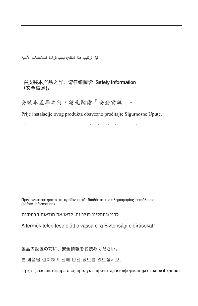
Major components of the expansion card
The following illustration shows the components on the top of the expansion
card.
Note: The illustrations in this document might differ slightly from your
hardware.
ISP2312 chip (U5)
Figure 1. Expansion card (top)
ISP2312 chip (U5): The ISP2312 chip provides a PCI-X local bus interface and
two completely independent 2 Gb serial Fibre Channel ports. Each port has a
RISC processor, an integrated serializer/deserializer (SERDES), a receive DMA
sequencer, frame buffer, five-channel DMA controller, and an external memory
interface in a single-chip solution.
Chapter 1. Introduction 7
Page 20
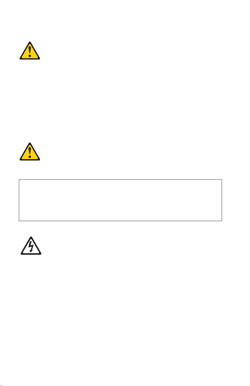
The following illustration shows the components on the bottom of the
expansion card.
I/O expansion
card connector (J3)
I/O expansion
card connector (J2)
Figure 2. Expansion card (bottom)
8 Installation and User’s Guide for HS20/HS40 and JS20 Fibre Channel expansion cards
Page 21

Chapter 2. Installing the I/O expansion card
This chapter provides detailed instructions for installing the I/O expansion
card in your blade server.
Note: The blade server shown in the illustrations in this section might be
different from your blade server. For additional information, see the
documentation that comes with your blade server.
Installation guidelines
Before you begin to install the I/O expansion card in your blade server, read
the safety information beginning on page v and the guidelines in “Handling
static-sensitive devices” on page 10. This information will help you work safely
with your blade server and options.
Make sure that you are using the latest versions of device drivers, firmware,
and BIOS or firmware code for your blade server, management module, and
I/O modules that are used by the I/O expansion card. Go to the IBM support
Web site, http://www.ibm.com/pc/support/ for the latest information about
upgrading the device drivers, firmware, and BIOS or firmware code for
BladeCenter components. The latest instructions are in the documentation that
comes with the updates.
If your blade server has an integrated drive electronics (IDE) hard disk drive
installed in the IDE connector location where you are installing the I/O
expansion card, you will need to remove it to install the I/O expansion card.
The I/O expansion card occupies the same space as this hard disk drive and
replaces it. Yo u cannot install a hard disk drive in the IDE connector while an
I/O expansion card is installed in that connector location. This means that you
must choose to install either an IDE hard disk drive or an I/O expansion card
in some types of blade servers.
Important:
v If an IDE hard disk drive must be removed to install the I/O expansion
card, and this disk drive contains any information that you want to keep,
back it up to another storage device.
v If an IDE hard disk drive must be removed to install the I/O expansion
card, and this disk drive is part of a redundant array of independent disks
(RAID) array, unconfigure this RAID array before removing the hard disk
drive. See your operating-system documentation for instructions.
© Copyright IBM Corp. 2005 9
Page 22

Make sure that an I/O module that supports Fibre Channel operation is
installed in I/O-module bay 3, I/O-module bay 4, or both I/O-module bays 3
and 4 in the BladeCenter unit:
v If your blade server type supports installation of one I/O expansion card,
you must install at least one I/O module that supports Fibre Channel
operation in the BladeCenter unit when you install an expansion card in the
blade server. Installing a second identical I/O module that supports Fibre
Channel operation in the BladeCenter unit provides a backup I/O module in
case one I/O module fails. If I/O modules are installed in both I/O-module
bays 3 and 4, both I/O modules must be of the same type.
v If your blade server type supports installation of two I/O expansion cards,
you must install I/O modules that support Fibre Channel operation in the
BladeCenter unit when you install two expansion cards in any blade server
that is installed in the BladeCenter unit.
the following BladeCenter documentation for additional information:
See
v The Installation and User’s Guide for your blade server provides blade-server
specific I/O expansion card installation requirements.
v The Installation Guide for your BladeCenter unit shows I/O module bay
locations.
v The Installation Guide for your I/O module has installation and configuration
instructions for the I/O module.
Handling static-sensitive devices
Attention: Static electricity can damage electronic devices and your system,
including your blade server. To avoid damage, keep static-sensitive devices in
their static-protective packages until you are ready to install them.
To reduce the possibility of damage from electrostatic discharge, observe the
following precautions:
v Limit your movement. Movement can cause static electricity to build up
around you.
v Handle the device carefully, holding it by its edges or its frame.
v Do not touch solder joints, pins, or exposed circuitry.
v Do not leave the device where others can handle and damage it.
v While the device is still in its static-protective package, touch it to any
unpainted metal surface of the BladeCenter chassis or any unpainted metal
surface on any other grounded rack component in the rack in which you are
installing the device for at least 2 seconds. (This drains static electricity from
the package and from your body.)
v Remove the device from its package and install it directly into the blade
server without setting down the device. If it is necessary to set down the
10 Installation and User’s Guide for HS20/HS40 and JS20 Fibre Channel expansion cards
Page 23

device, place it back into its static-protective package. Do not place the
device on the blade server cover or on a metal surface.
v Take additional care when handling devices during cold weather. Heating
reduces indoor humidity and increases static electricity.
v Wear an electrostatic-discharge wrist strap, if one is available.
Installing the I/O expansion card in a blade server
To install the I/O expansion card in a blade server, complete the following
steps:
1. Before you begin installing the I/O expansion card in your blade server,
read the “Installation guidelines” on page 9. This section contains
information about procedures that should be performed before you
remove your blade server from the BladeCenter unit to install the I/O
expansion card.
2. If the blade server is installed in a BladeCenter unit and operating, shut
down the operating system; then, turn off the blade server. (See the
Installation and User’s Guide for your blade server for instructions.)
Attention: Wait at least 30 seconds, until the drives stop spinning, before
proceeding to the next step.
Statement 21:
CAUTION:
Hazardous energy is present when the blade is connected to the power
source. Always replace the blade cover before installing the blade.
3. Remove the blade server from the BladeCenter unit, open the blade server
cover, and locate the connectors where the I/O expansion card will be
installed. See the Installation and User’s Guide for your blade server for
instructions.
Important:
v If an IDE hard disk drive must be removed to install the I/O expansion
card, and this disk drive contains any information that you want to
keep, back it up to another storage device.
v If an IDE hard disk drive must be removed to install the I/O expansion
card, and this disk drive is part of a RAID array, unconfigure this RAID
array before removing the hard disk drive. See your operating-system
documentation for instructions.
Chapter 2. Installing the I/O expansion card 11
Page 24
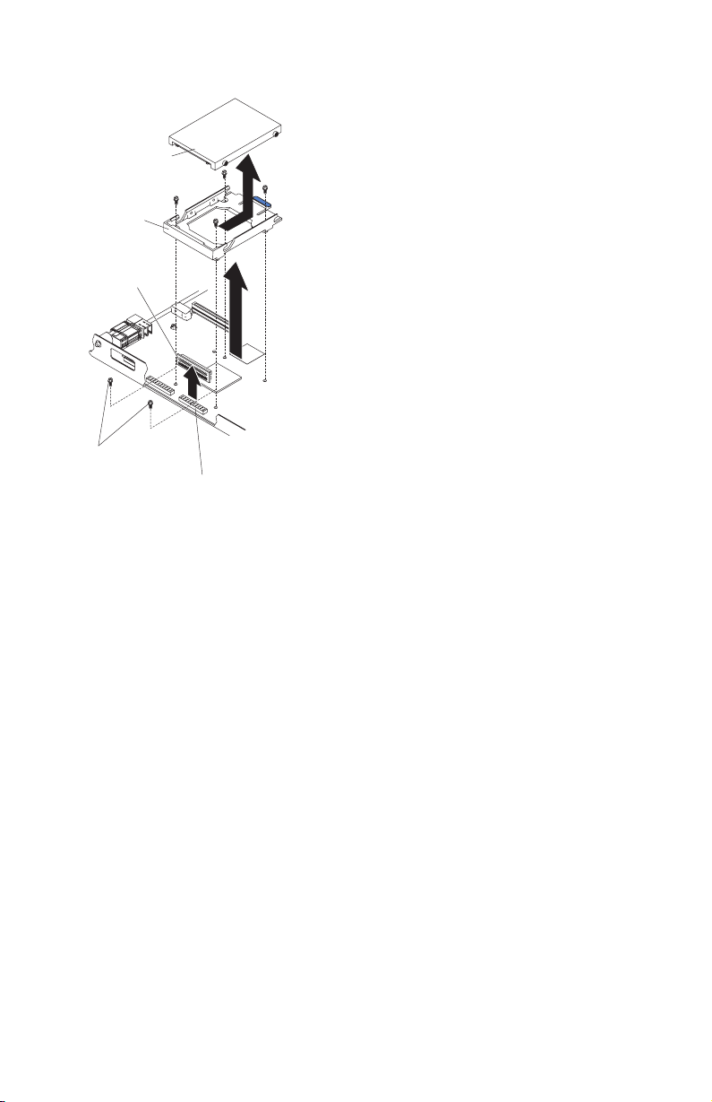
IDE drive
Tr ay
Riser
card
Short screws
IDE connector
4. If an IDE hard disk drive is installed in the IDE connector location where
you are installing the I/O expansion card, remove the drive, riser card,
and tray (save the screws that secure the tray to the system board).
Otherwise, remove the two screws near the IDE connector, if these items
are present.
5. Install the I/O expansion tray that comes with the I/O expansion card.
Secure the tray to the blade server with the screws from the option kit.
12 Installation and User’s Guide for HS20/HS40 and JS20 Fibre Channel expansion cards
Page 25
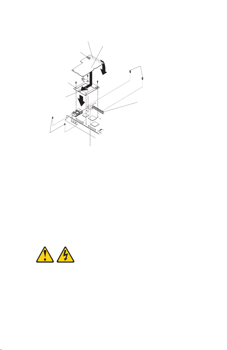
I/O expansion
card connector
I/O expansion card
connector
IBM I/O
expansion card
Short screws
I/O expansion
tray
Raised hook
I/O expansion option
connector (server)
Short screws
I/O expansion
option connector
(server)
6. Remove the I/O expansion card from the static-protective package.
7. Make sure that the protective cover is removed from I/O expansion card
connector J2; then, slide the narrow end of the I/O expansion card into
the raised hook on the I/O expansion tray.
8. Align the I/O expansion card connectors (J2 and J3) on the I/O expansion
card with the I/O expansion option connectors on the blade server; then,
gently press the card into the connectors.
Note: For a more detailed view of connectors J2 and J3, see Figure 2 on
page 8.
Statement 21:
CAUTION:
Hazardous energy is present when the blade is connected to the power
source. Always replace the blade cover before installing the blade.
Important: The blade server cannot be inserted into the BladeCenter unit
until the cover is installed and closed. Do not attempt to override this
protection.
Chapter 2. Installing the I/O expansion card 13
Page 26

9. If you have other options to install in this blade server, do so now;
otherwise, close the blade server cover and install the blade server in the
BladeCenter unit. See the Installation and User’s Guide for your blade server
for instructions.
10. Turn on the blade server; then, set up a command session:
v If your blade server supports local console connection through the
management module switch control of the keyboard/mouse/video to
this blade server. See the Installation and User’s Guide for your blade
server for instructions.
v If your blade server does not support local console connection, see the
Installation and User’s Guide for your blade server for instructions about
how to set up a command session with the blade server.
If your blade server is an IBM BladeCenter JS20, skip this step. This step,
11.
including the example text, only applies if your blade server is an IBM
BladeCenter HS20 or HS40 and the IBM Eserver BladeCenter Fibre
Channel Expansion Card is installed in your blade server.
If the information displayed on the monitor screen is similar to the
following text, update the BIOS or firmware code if necessary, and install
the expansion card device drivers. For more information, see Chapter 3,
“Updating the I/O expansion card BIOS or firmware code and NVRAM
code and installing device drivers,” on page 15. If the information
displayed on the monitor screen is not similar to this text and you have
checked the expansion card configuration, go to Chapter 6,
“Troubleshooting,” on page 27 for problem-solving information.
QLogic Corporation
QLA2312 PCI Fibre Channel ROM BIOS Version X.XX
Copyright (C) QLogic Corporation 1993-2003 All Rights Reserved.
www.qlogic.com
Press <Ctrl+Q> for Fast!UTIL
BIOS for Adapter 0 is disabled
ROM BIOS not installed
14 Installation and User’s Guide for HS20/HS40 and JS20 Fibre Channel expansion cards
Page 27

Chapter 3. Updating the I/O expansion card BIOS or firmware code and NVRAM code and installing device drivers
After you install the expansion card, be sure that the latest BIOS or firmware
code and the nonvolatile random-access memory (NVRAM) code are installed;
then, install the device drivers.
Note: For the latest information about supported operating systems, versions
of device drivers, BIOS code, firmware code, utilities, and
documentation, go to http://www.ibm.com/pc/support/.
Using the Remote Deployment Manager
You can use the Remote Deployment Manager (RDM) version 4.11 Update 2 or
later program to install a supported operating systems on blade servers that
support the RDM program. Follow the instructions in the documentation that
comes with the RDM program. To check if your blade server supports RDM,
purchase the RDM software, download the RDM user ’s guide, and obtain the
latest updates, go to:
http://www-1.ibm.com/servers/eserver/xseries/systems_management/
sys_migration/rdm.html
Installing the expansion card device drivers
The latest device drivers, utilities, documentation, and installation instructions
for the following supported operating systems are provided at
http://www.ibm.com/pc/support/:
®
v Microsoft
Windows
v Red Hat Advanced Server
v SUSE LINUX 8.0 Enterprise
For BladeCenter JS20 Type 8842, SUSE LINUX device drivers are obtained
directly from Novell Corporation. Other Linux
from Red Hat, Inc. AIX
AIX license.
Customize the configuration of the BladeCenter I/O expansion card:
v If the I/O expansion card is installed in a BladeCenter HS20 or HS40 blade
server, see Chapter 4, “Using IBM Fast!UTIL,” on page 17.
v If the I/O expansion card is installed in a BladeCenter JS20 blade server, see
Chapter 5, “Using the IBM FAStT MSJ utility,” on page 23.
© Copyright IBM Corp. 2005 15
®
2000 and Microsoft Windows 2003
®
®
device drivers are obtained from IBM as part of an
device drivers are obtained
Page 28

16 Installation and User’s Guide for HS20/HS40 and JS20 Fibre Channel expansion cards
Page 29

Chapter 4. Using IBM Fast!UTIL
This chapter provides detailed configuration information for advanced users
who want to customize the configuration of the IBM Eserver BladeCenter
Fibre Channel Expansion Card when it is installed in a BladeCenter HS20 or
HS40 blade server. You can configure the I/O expansion card using the
Fast!UTIL utility.
Note: This chapter does not apply to the IBM ER s e r v e r BladeCenter JS20 Fibre
Channel Expansion Card. See Chapter 5, “Using the IBM FAStT MSJ
utility,” on page 23 for additional information about customizing the
configuration of the expansion card when it is installed in a BladeCenter
JS20 blade server.
Starting Fast!UTIL
Start or restart the blade server. On the blade server control panel, press the
keyboard/video/mouse select button. To access Fast!UTIL, press Ctrl+Q
during the expansion card BIOS initialization (it might take a few seconds for
the Fast!UTIL menu to be displayed). The expansion card has dual adapter
ports that can be configured separately with Fast!UTIL. After changing the
settings that are described in the “Configuration Settings menu options”
section, Fast!UTIL restarts the blade server to enable the new parameters.
Important: If the configuration settings are incorrect, the expansion card might
not function correctly. Do not modify the default configuration settings unless
you are instructed to do so by an IBM technical-support representative or in
the installation instructions.
Configuration Settings menu options
Note: For information about Remote Boot options, contact your
IBM technical-support representative.
Use the options that are described in this section to configure the expansion
card. The Configuration Settings menu displays several options that you can
use to configure your expansion card.
Select host adapter
Use this option to select, configure, or view either of the two I/O port
addresses on the expansion card.
© Copyright IBM Corp. 2005 17
Page 30

Host Adapter Settings
To access this option, select Host Adapter Settings. The default settings and
the modifiable settings for the expansion card are listed in Table 2 and are
described in this section. The expansion card is always point-to-point
connected in the blade server with I/O module that supports Fibre Channel
operation.
Note: The loop reset delay, adapter hard loop ID, and hard loop ID settings
are not applicable.
Table 2. Modifiable expansion card default settings
Setting Options Default
Host adapter BIOS Enabled or disabled Disabled
Frame size 512, 1024, 2048 2048
Loop reset delay 0-60 seconds 5 seconds
Adapter hard loop ID Enabled or disabled Enabled
Hard loop ID 0-125 125
Spin up delay Enabled or disabled Disabled
Connection Options 0, 1, 2 2
Fibre Channel tape support Disabled, Enabled Enabled
Data rate 0, 1, 2 2
Host adapter BIOS: When this option is disabled, the read-only memory
(ROM) BIOS or firmware code on the expansion card is disabled. This makes
space available in upper memory. The default setting is Disabled.
Frame size: This setting specifies the maximum frame length supported by the
expansion card. The default size is 2048. If you are using F-port
(point-to-point) connections, use the default size for maximum performance.
Spin up delay: When this option is enabled, the BIOS code waits up to 5
minutes to find the first drive. The default setting is Disabled.
Connection options: This setting defines the type of connection (loop or
point-to-point) or connection preference (see Table 3). The default setting is 2.
Table 3. Expansion card connection options
Option Type of connection
0 Loop only
1 Point-to-point only
2 Loop preferred; otherwise, point-to-point
18 Installation and User’s Guide for HS20/HS40 and JS20 Fibre Channel expansion cards
Page 31

Fibre Channel tape support: This setting is reserved for Fibre Channel tape
support. The default setting is Enabled.
Data rate: This setting determines the data rate for the expansion card. The
available options are listed in Table 4. The default setting is 2.
Table 4. Expansion card data rate options
Option Data rate
0 1 GB per second
1 2 GB per second
2 Auto select
Note: The expansion card settings and default values will vary, based on the
version of BIOS code installed for the expansion card.
There are specific expansion card settings that you cannot modify. Table 5
describes these settings and gives examples.
Note: See the device-driver installation instructions for the required operating-
system-specific modifications to the NVRAM.
Table 5. Nonmodifiable expansion card settings and examples
Setting Example
BIOS address CD400
BIOS revision 1.38
Adapter serial number E59719
Interrupt level 3
Adapter port name 210000096B07C703
BIOS address: The BIOS address is the expansion card I/O address where the
BIOS code is stored when you press Ctrl+Q. This is the address of the BIOS
code in ROM shadow memory.
BIOS revision: The BIOS revision is the revision number of the loaded BIOS
code on the expansion card.
Adapter Serial Number: This number is for manufacturing use only. It does
not correlate to external labels or to the adapter port name of the expansion
card.
Chapter 4. Using IBM Fast!UTIL 19
Page 32

Interrupt level: The interrupt level is the interrupt that is used by the
expansion card. The interrupt level can change when the operating system is
installed.
Adapter port name: This is the worldwide port name of the expansion card.
Selectable Boot Settings
To access this option, select Selectable Boot Settings. For more information
about boot settings, contact your IBM technical-support representative.
Restore Default Settings
This option is in the Configuration Settings menu. It restores the
expansion card default NVRAM settings.
Raw NOVRAM data
This option displays the expansion card NVRAM contents in hexadecimal
format. This is a troubleshooting tool; you cannot modify the data.
Note: The terms NOVRAM and NVRAM are used interchangeably in this
document. These terms are identical in meaning.
Advanced Adapter Settings
Use this option to view and set advanced adapter settings. The default settings
for the expansion card are listed in Table 6 and are described in this section.
Table 6. Expansion card advanced adapter settings
Setting Options Default
Execution throttle 1-256 256
LUNs per target 0, 8, 16, 32, 64, 128, 256 0
Enable LIP reset Yes or No No
Enable LIP full login Yes or No Ye s
Enable target reset Yes or No Ye s
Login retry count 0-255 30
Port down retry count 0-255 30
IOCB allocation
Extended error logging Enabled or Disabled Disabled
RIO operation mode 0, 5, 6 0
Interrupt delay timer 0-255 0
1-512 buffers 256 buffers
20 Installation and User’s Guide for HS20/HS40 and JS20 Fibre Channel expansion cards
Page 33

Execution throttle: This setting specifies the maximum number of commands
that can run on any one port. When a port reaches its execution throttle,
Fast!UTIL does not run any new commands until the current command is
completed. The valid options for this setting are 1 through 256. The default
(optimum) is 256.
LUNs per target: This setting specifies the number of logical unit numbers
(LUNs) per device. Multiple LUN support is typically for RAID enclosures that
use LUNs to map drives. The default setting is 0.
Enable LIP reset: This setting determines the type of loop initialization process
(LIP) reset that is used when the operating system initiates a bus reset routine.
When this option is set to Ye s, the device driver initiates a global LIP reset to
clear the target device reservations. When this option is set to No, the device
driver initiates a global LIP reset with full login. The default setting is No.
Enable LIP full logon: This setting instructs the application specific integrated
circuit (ASIC) chip to log in to all ports after any LIP. The default setting is
Yes .
Enable target reset: This setting enables the device drivers to issue a Target
Reset command to all devices on the loop when a SCSI Bus Reset command is
issued. The default setting is Yes.
Login retry count: This setting specifies the number of times the software tries
to log in to a device. The default setting is 30 retries.
Port down retry count: This setting specifies the number of times the software
retries a command to a port that is returning port-down status. The default
setting is 30.
IOCB allocation: This setting specifies the maximum number of buffers from
the firmware buffer pool that are allocated to any one port. The default setting
is 256.
Note: The meaning of IOCB is input/output control block.
Extended error logging: When set to Enabled, this setting provides additional
error and debugging information to the Microsoft Windows operating system
event error log. The default setting is Disabled.
RIO operation mode: This setting specifies the reduced interrupt operation
(RIO) mode, if supported by the software device driver. When the expansion
card is in the RIO mode you can post multiple command completions in a
single interrupt (see Table 7 on page 22). The default setting is 0.
Chapter 4. Using IBM Fast!UTIL 21
Page 34

Table 7. Expansion card RIO options and operation modes
Option Operation mode
0 No multiple responses
5 Multiple responses with minimal interrupts
6 Interrupt when interruption delay timer expires or there
is no action
Interrupt delay timer: This setting contains the value (in 100-microsecond
increments) used by a timer to set the wait time between accessing a set of
handles and generating an interrupt using direct memory access (DMA). The
default setting is 0.
Scan Fibre Channel devices
Use this option to scan and list all the connected devices. Information about
each device is listed, for example, vendor name, product name, and revision.
This information is useful when you are configuring the expansion card and
attached devices.
Fibre Channel disk utility
The Fibre Channel disk utility is not supported in the IBM BladeCenter Fibre
Channel Options.
Use this option to scan the Fibre Channel loop bus and list all the connected
devices by loop ID. Yo u can select a disk device and perform a low-level
format or verify the disk media or data.
Attention: Performing a low-level format removes all data on the disk.
Loopback data test
This option is not available with your BladeCenter configuration.
ExitFast!UTIL
After you complete the configuration, use this option to exit the menu and
restart the blade server.
22 Installation and User’s Guide for HS20/HS40 and JS20 Fibre Channel expansion cards
Page 35

Chapter 5. Using the IBM FAStT MSJ utility
This chapter provides an overview of the IBM FAStT MSJ (Management Suite
Java™) utility that can be used by advanced users to customize the
configuration of the IBM Eserver BladeCenter JS20 Fibre Channel Expansion
Card when it is installed in a BladeCenter JS20 blade server. Yo u can perform
the custom configuration procedures that are described in this chapter only
when the SUSE LINUX operating system or another Linux operating system is
running. If you are using the AIX operating system, use the standard “Config
Manager and Diagnostics Routine” procedures that are described in the
applicable AIX operating-system documentation. For more detailed
information, see the IBM FAStT Management Suite Java User’s Guide version 1.0
or later that is available at http://www.ibm.com/pc/support/.
Overview of the IBM FAStT MSJ utility
The FAStT MSJ utility is used to configure a SAN environment that consists of
IBM FAStT Fibre Channel host bus adapters (HBAs). It is a network-capable
application that can connect to and configure remote systems, enabling
centralized management and configuration of an entire SAN containing HBA
components, storage devices, and host systems.
You can use IBM FAStT MSJ to manage and control one or more expansion
cards that are installed on local or remote systems. The FAStT MSJ utility is
used, along with problem determination procedures (PDPs), on new or existing
installations to help diagnose Fibre Channel (FC) subsystem problems in
adapters, controllers, and devices that are attached to the FC fabric or loop.
You can also perform the following operations by using the FAStT MSJ utility
to configure devices in your system:
Disable (unconfigure) a device on a host bus adapter
When a device is set as unconfigured, it is not recognized by the HBA
and is not accessible to the HBA on that system.
Enable a device
This operation adds a device and makes it accessible to the HBA on
that system.
Designate a path as an alternate or preferred path
When a device is accessible from more than one adapter in the same
system, you can assign one path as the preferred path and the other
path as an alternate path. If the preferred path fails, the system
switches to the alternate path to make sure that the transfer of data is
not interrupted.
© Copyright IBM Corp. 2005 23
Page 36

Note: The diagnostic functions of the FAStT MSJ utility are available for all
supported operating systems. The configuration functions of the FAStT
MSJ utility are available only for Linux operating systems.
Installation and system requirements
Make sure that you are using the latest version of the IBM FAStT MSJ utility
for the IBM Eserver BladeCenter JS20 Fibre Channel Expansion Card. Go to
the IBM support Web site at http://www.ibm.com/pc/support/ for the latest
information about the IBM FAStT MSJ utility. The latest instructions and
system requirements are in the documentation that comes with the utility.
Features
The FAStT MSJ utility enables you to:
v Set the FAStT MSJ utility options
v Connect to hosts
v Disconnect from a host
v View detailed event and alarm-log information
v Use host-to-host SAN configuration policies
v Configure port devices
v Use logical unit number (LUN) level configuration
v Monitor in real-time to see when failovers occur, using the Failover Watcher
v Control host-side agent operations, including setting of the host agent
polling interval
v Review host adapter information, including:
– General information
– Statistics
– Information about attached devices
– Link status for attached device
Perform adapter functions, including:
v
– Configuring the adapter NVRAM settings
– Executing fibre diagnostics (read/write buffer loopback tests)
– Performing flash updates on an adapter
– Performing NVRAM updates on an adapter
Manage configurations:
v
– Save configurations for off-line policy checks and SAN integrity
– Load configurations from a file if the host is off-line for policy checks and
SAN integrity
Confirm security
v
24 Installation and User’s Guide for HS20/HS40 and JS20 Fibre Channel expansion cards
Page 37

Update Flash utility
Through the Utilities section of the FAStT MSJ utility, you can update I/O
expansion card firmware and perform adapter-level configurations on a
host-connected adapter.
When you click Update Flash in the Utilities section of the FAStT MSJ utility,
and the adapter accepts the update, the application prompts for the file name
of the new flash BIOS or firmware code. The latest version of expansion card
flash BIOS or firmware code is available from the IBM support We b site at
http://www.ibm.com/pc/support/.
After you enter a valid flash BIOS or firmware code file name, click OK to
complete the update, or click Cancel to stop the update. When you click OK,
the FAStT MSJ utility verifies the file name and format of the new file. If the
file is valid, the application then compares the version of the file with the
adapter flash version that is currently installed. If the installed adapter version
is the same or newer than the file flash version that you are trying to install,
the application asks if you still want to update the flash.
If the firmware update fails, an error message is displayed.
Chapter 5. Using the IBM FAStT MSJ utility 25
Page 38

26 Installation and User’s Guide for HS20/HS40 and JS20 Fibre Channel expansion cards
Page 39

Chapter 6. Troubleshooting
If you encounter a problem, use the following information to help you
determine the cause of the problem and the action to take. Additional
troubleshooting and debugging procedures are available in the Hardware
Maintenance Manual and Troubleshooting Guide or Problem Determination Guide for
your blade server.
Make sure that you are using the latest versions of device drivers, firmware,
and BIOS or firmware code for your blade server, management module, and
I/O modules that are used by the I/O expansion card. If these items are
obsolete, the BladeCenter unit might not recognize the I/O expansion card and
might not turn it on. Go to the IBM support We b site,
http://www.ibm.com/pc/support/, for the latest information about upgrading
the device drivers, firmware, and BIOS or firmware code for BladeCenter
components. The latest instructions are in the documents that come with the
updates.
To determine whether your installation problem is caused by the hardware,
perform the following tasks:
v Make sure that the I/O expansion card is installed correctly.
v Make sure that the Fast!UTIL data-rate setting is correct:
– If the I/O expansion card is installed in a BladeCenter HS20 or HS40
blade server, see “Host Adapter Settings” on page 18.
– If the I/O expansion card is installed in a BladeCenter JS20 blade server,
see the IBM FAStT Management Suite Java User’s Guide version 1.0 or later
that is available at http://www.ibm.com/pc/support/.
Make sure that all peripheral devices connected to the I/O modules are
v
turned on, operating correctly, and are connected correctly:
– If the I/O expansion card is installed in a BladeCenter HS20 or HS40
blade server, see “Scan Fibre Channel devices” on page 22 for information
about displaying attached Fibre Channel devices.
– If the I/O expansion card is installed in a BladeCenter JS20 blade server,
see the IBM FAStT Management Suite Java User’s Guide version 1.0 or later
that is available at http://www.ibm.com/pc/support/.
Make sure that one or two I/O modules that support Fibre Channel
v
operation are installed in the correct I/O-module bays of the BladeCenter
unit.
To determine whether your installation problem is caused by the software,
perform the following tasks:
© Copyright IBM Corp. 2005 27
Page 40

v Make sure that the correct device driver is installed. To download or get
information about the latest supported device drivers, utilities, and
documentation, go to http://www.ibm.com/pc/support/. Also see the
Installation and User’s Guide for your blade server for additional information.
v Make sure that the BIOS or firmware code in the expansion card is at the
latest level.
v Make sure that you have the correct expansion card NVRAM settings for
your SAN and operating system.
determine whether your installation problem is caused by the system
To
configuration, check the blade server to make sure that it is configured
correctly:
v If the I/O expansion card is installed in a BladeCenter HS20 or HS40 blade
server, see “Configuration Settings menu options” on page 17 for additional
information.
v If the I/O expansion card is installed in a BladeCenter JS20 blade server, see
the IBM FAStT Management Suite Java User’s Guide version 1.0 or later that is
available at http://www.ibm.com/pc/support/.
you still have a system configuration problem, see the documentation that
If
comes with your BladeCenter unit, or contact your IBM technical-support
representative to determine whether your system board requires a special
configuration.
To determine whether your installation problem is caused by an attached Fibre
Channel device, perform the following tasks:
v Make sure that an I/O module that supports Fibre Channel operation is
installed in I/O-module bay 3, I/O-module bay 4, or both I/O-module bays
3 and 4.
v Make sure that the blade server is turned on.
v Make sure that the expansion card settings are set to the correct values:
– If the I/O expansion card is installed in a BladeCenter HS20 or HS40
blade server, see “Configuration Settings menu options” on page 17. for
additional information.
– If the I/O expansion card is installed in a BladeCenter JS20 blade server,
see the IBM FAStT Management Suite Java User’s Guide version 1.0 or later
that is available at http://www.ibm.com/pc/support/.
28 Installation and User’s Guide for HS20/HS40 and JS20 Fibre Channel expansion cards
Page 41

Appendix A. Getting help and technical assistance
If you need help, service, or technical assistance or just want more information
about IBM products, you will find a wide variety of sources available from
IBM to assist you. This appendix contains information about where to go for
additional information about IBM and IBM products, what to do if you
experience a problem with your Eserver or IntelliStation
to call for service, if it is necessary.
Before you call
Before you call, make sure that you have taken these steps to try to solve the
problem yourself:
v Check all cables to make sure that they are connected.
v Check the power switches to make sure that the system is turned on.
v Use the troubleshooting information in your system documentation, and use
the diagnostic tools that come with your system. Information about
diagnostic tools is in the blade server Hardware Maintenance Manual and
Troubleshooting Guide, BladeCenter unit Hardware Maintenance Manual and
Troubleshooting Guide, or Problem Determination Guide at the IBM support Web
site, or in the IntelliStation Hardware Maintenance Manual at the IBM support
Web site.
v Go to the IBM support We b site at http://www.ibm.com/pc/support/ to
check for technical information, hints, tips, and new device drivers or to
submit a request for information.
®
system, and whom
can solve many problems without outside assistance by following the
You
troubleshooting procedures that IBM provides in the online help or in the
publications that are provided with your system and software. The information
that comes with your system also describes the diagnostic tests that you can
perform. Most Eserver and IntelliStation systems, operating systems, and
programs come with information that contains troubleshooting procedures and
explanations of error messages and error codes. If you suspect a software
problem, see the information for the operating system or program.
Using the documentation
Information about your IBM Eserver or IntelliStation system and preinstalled
software, if any, is available in the documentation that comes with your
system. That documentation includes printed books, online books, readme files,
and help files. See the troubleshooting information in your system
documentation for instructions for using the diagnostic programs. The
troubleshooting information or the diagnostic programs might tell you that you
© Copyright IBM Corp. 2005 29
Page 42

need additional or updated device drivers or other software. IBM maintains
pages on the World Wide Web where you can get the latest technical
information and download device drivers and updates. To access these pages,
go to http://www.ibm.com/pc/support/ and follow the instructions. Also,
some publications are available through the IBM Publications Ordering System
at http://www.elink.ibmlink.ibm.com/public/applications/publications/
cgibin/pbi.cgi.
Getting help and information from the World Wide Web
On the World Wide Web, the IBM We b site has up-to-date information about
IBM Eserver and IntelliStation products, services, and support. The address for
IBM Eserver, xSeries®, and BladeCenter information is
http://www.ibm.com/eserver/xseries/. The address for IBM IntelliStation
information is http://www.ibm.com/pc/us/intellistation/.
You can find service information for your IBM products, including supported
options, at http://www.ibm.com/pc/support/.
Software service and support
Through IBM Support Line, you can get telephone assistance, for a fee, with
usage, configuration, and software problems with xSeries servers, BladeCenter
products, IntelliStation workstations, and appliances. For information about
which products are supported by Support Line in your country or region, see
http://www.ibm.com/services/sl/products/.
For more information about Support Line and other IBM services, see
http://www.ibm.com/services/, or see http://www.ibm.com/planetwide/ for
support telephone numbers. In the U.S. and Canada, call 1-800-IBM-SERV
(1-800-426-7378).
Hardware service and support
You can receive hardware service through IBM Services or through your IBM
reseller, if your reseller is authorized by IBM to provide warranty service. See
http://www.ibm.com/planetwide/ for support telephone numbers, or in the
U.S. and Canada, call 1-800-IBM-SERV (1-800-426-7378).
In the U.S. and Canada, hardware service and support is available 24 hours a
day, 7 days a week. In the U.K., these services are available Monday through
Friday, from 9 a.m. to 6 p.m.
30 Installation and User’s Guide for HS20/HS40 and JS20 Fibre Channel expansion cards
Page 43

Appendix B. IBM Statement of Limited Warranty Z125-4753-08 04/2004
Part 1 - General Terms
Part 1 - General Terms
This Statement of Limited Warranty includes Part 1 - General Terms, Part 2 Country-unique Terms, and Part 3 - Warranty Information. The terms of Part 2
replace or modify those of Part 1. The warranties provided by IBM in this Statement
of Limited Warranty apply only to Machines you purchase for your use, and not for
resale. The term “Machine” means an IBM machine, its features, conversions,
upgrades, elements, or accessories, or any combination of them. The term “Machine”
does not include any software programs, whether pre-loaded with the Machine,
installed subsequently or otherwise. Nothing in this Statement of Limited
Warranty affects any statutory rights of consumers that cannot be waived or
limited by contract.
What this Warranty Covers
IBM warrants that each Machine 1) is free from defects in materials and
workmanship and 2) conforms to IBM’s Official Published Specifications
(“Specifications”) which are available on request. The warranty period for the
Machine starts on the original Date of Installation and is specified in Part 3 Warranty Information. The date on your invoice or sales receipt is the Date of
Installation unless IBM or your reseller informs you otherwise. Many features,
conversions, or upgrades involve the removal of parts and their return to IBM.
A part that replaces a removed part will assume the warranty service status of
the removed part. Unless IBM specifies otherwise, these warranties apply only
in the country or region in which you purchased the Machine.
THESE WARRANTIES ARE YOUR EXCLUSIVE WARRANTIES AND
REPLACE ALL OTHER WARRANTIES OR CONDITIONS, EXPRESS OR
IMPLIED, INCLUDING, BUT NOT LIMITED TO, THE IMPLIED
WARRANTIES OR CONDITIONS OF MERCHANTABILITY AND FITNESS
FOR A PARTICULAR PURPOSE. SOME STATES OR JURISDICTIONS DO
NOT ALLOW THE EXCLUSION OF EXPRESS OR IMPLIED
WARRANTIES, SO THE ABOVE EXCLUSION MAY NOT APPLY TO YOU.
IN THAT EVENT, SUCH WARRANTIES ARE LIMITED IN DURATION TO
THE WARRANTY PERIOD. NO WARRANTIES APPLY AFTER THAT
PERIOD. SOME STATES OR JURISDICTIONS DO NOT ALLOW
LIMITATIONS ON HOW LONG AN IMPLIED WARRANTY LASTS, SO
THE ABOVE LIMITATION MAY NOT APPLY TO YOU.
© Copyright IBM Corp. 2005 31
Page 44

What this Warranty Does not Cover
This warranty does not cover the following:
v any software programs, whether pre-loaded or shipped with the Machine,
or installed subsequently;
v failure resulting from misuse (including but not limited to use of any
Machine capacity or capability, other than that authorized by IBM in
writing), accident, modification, unsuitable physical or operating
environment, or improper maintenance by you;
v failure caused by a product for which IBM is not responsible; and
v any non-IBM products, including those that IBM may procure and provide
with or integrate into an IBM Machine at your request.
warranty is voided by removal or alteration of identification labels on the
The
Machine or its parts.
IBM does not warrant uninterrupted or error-free operation of a Machine.
Any technical or other support provided for a Machine under warranty, such
as assistance with “how-to” questions and those regarding Machine set-up and
installation, is provided WITHOUT WARRANTIES OF ANY KIND.
How to Obtain Warranty Service
If the Machine does not function as warranted during the warranty period,
contact IBM or your reseller to obtain warranty service. If you do not register
the Machine with IBM, you may be required to present proof of purchase as
evidence of your entitlement to warranty service.
What IBM Will Do to Correct Problems
When you contact IBM for service, you must follow the problem determination
and resolution procedures that IBM specifies. An initial diagnosis of your
problem can be made either by a technician over the telephone or electronically
by access to an IBM website.
The type of warranty service applicable to your Machine is specified in Part 3 Warranty Information.
You are responsible for downloading and installing designated Machine Code
(microcode, basic input/output system code (called “BIOS”), utility programs,
device drivers, and diagnostics delivered with an IBM Machine) and other
software updates from an IBM Internet Web site or from other electronic
media, and following the instructions that IBM provides.
32 Installation and User’s Guide for HS20/HS40 and JS20 Fibre Channel expansion cards
Page 45

If your problem can be resolved with a Customer Replaceable Unit (“CRU”)
(e.g., keyboard, mouse, speaker, memory, hard disk drive), IBM will ship the
CRU to you for you to install.
If the Machine does not function as warranted during the warranty period and
your problem cannot be resolved over the telephone or electronically, through
your application of Machine Code or software updates, or with a CRU, IBM or
your reseller, if approved by IBM to provide warranty service, will either, at its
discretion, 1) repair it to make it function as warranted, or 2) replace it with
one that is at least functionally equivalent. If IBM is unable to do either, you
may return the Machine to your place of purchase and your money will be
refunded.
IBM or your reseller will also manage and install selected engineering changes
that apply to the Machine.
Exchange of a Machine or Part
When the warranty service involves the exchange of a Machine or part, the
item IBM or your reseller replaces becomes its property and the replacement
becomes yours. Yo u represent that all removed items are genuine and
unaltered. The replacement may not be new, but will be in good working order
and at least functionally equivalent to the item replaced. The replacement
assumes the warranty service status of the replaced item.
Your Additional Responsibilities
Before IBM or your reseller exchanges a Machine or part, you agree to remove
all features, parts, options, alterations, and attachments not under warranty
service.
You also agree to:
1. ensure that the Machine is free of any legal obligations or restrictions that
prevent its exchange;
2. obtain authorization from the owner to have IBM or your reseller service a
Machine that you do not own; and
3. where applicable, before service is provided:
a. follow the service request procedures that IBM or your reseller
provides;
b. backup or secure all programs, data, and funds contained in the
Machine;
c. provide IBM or your reseller with sufficient, free, and safe access to
your facilities to permit IBM to fulfill its obligations; and
d. inform IBM or your reseller of changes in the Machine’s location.
4.
(a) ensure all information about identified or identifiable individuals
(Personal Data) is deleted from the Machine (to the extent technically
Appendix B. IBM Statement of Limited Warranty Z125-4753-08 04/2004 33
Page 46

possible), (b) allow IBM, your reseller or an IBM supplier to process on
your behalf any remaining Personal Data as IBM or your reseller considers
necessary to fulfill its obligations under this Statement of Limited Warranty
(which may include shipping the Machine for such processing to other IBM
service locations around the world), and (c) ensure that such processing
complies with any laws applicable to such Personal Data.
Limitation
of Liability
IBM is responsible for loss of, or damage to, your Machine only while it is 1)
in IBM’s possession or 2) in transit in those cases where IBM is responsible for
the transportation charges.
Neither IBM nor your reseller are responsible for any of your confidential,
proprietary or personal information contained in a Machine which you return
to IBM for any reason. Yo u should remove all such information from the
Machine prior to its return.
Circumstances may arise where, because of a default on IBM’s part or other
liability, you are entitled to recover damages from IBM. In each such instance,
regardless of the basis on which you are entitled to claim damages from IBM
(including fundamental breach, negligence, misrepresentation, or other contract
or tort claim), except for any liability that cannot be waived or limited by
applicable laws, IBM is liable for no more than
1. damages for bodily injury (including death) and damage to real property
and tangible personal property; and
2. the amount of any other actual direct damages, up to the charges (if
recurring, 12 months’ charges apply) for the Machine that is subject of the
claim. For purposes of this item, the term “Machine” includes Machine
Code and Licensed Internal Code (“LIC”).
limit also applies to IBM’s suppliers and your reseller. It is the maximum
This
for which IBM, its suppliers, and your reseller are collectively responsible.
UNDER NO CIRCUMSTANCES IS IBM, ITS SUPPLIERS OR RESELLERS
LIABLE FOR ANY OF THE FOLLOWING EVEN IF INFORMED OF THEIR
POSSIBILITY: 1) THIRD PA RT Y CLAIMS AGAINST YOU FOR DAMAGES
(OTHER THAN THOSE UNDER THE FIRST ITEM LISTED ABOVE); 2)
LOSS OF, OR DAMAGE TO, DATA; 3) SPECIAL, INCIDENTAL, OR
INDIRECT DAMAGES OR FOR ANY ECONOMIC CONSEQUENTIAL
DAMAGES; OR 4) LOST PROFITS, BUSINESS REVENUE, GOODWILL OR
ANTICIPATED SAVINGS. SOME STATES OR JURISDICTIONS DO NOT
ALLOW THE EXCLUSION OR LIMITATION OF INCIDENTAL OR
CONSEQUENTIAL DAMAGES, SO THE ABOVE LIMITATION OR
EXCLUSION MAY NOT APPLY TO YOU. SOME STATES OR
34 Installation and User’s Guide for HS20/HS40 and JS20 Fibre Channel expansion cards
Page 47

JURISDICTIONS DO NOT ALLOW LIMITATIONS ON HOW LONG AN
IMPLIED WARRANTY LASTS, SO THE ABOVE LIMITATION MAY NOT
APPLY TO YOU.
Governing Law
Both you and IBM consent to the application of the laws of the country in
which you acquired the Machine to govern, interpret, and enforce all of your
and IBM’s rights, duties, and obligations arising from, or relating in any
manner to, the subject matter of this Statement of Limited Warranty, without
regard to conflict of law principles.
THESE WARRANTIES GIVE YOU SPECIFIC LEGAL RIGHTS AND YOU
MAY ALSO HAVE OTHER RIGHTS WHICH VA RY FROM S TAT E TO
STATE OR JURISDICTION TO JURISDICTION.
Jurisdiction
All of our rights, duties, and obligations are subject to the courts of the country
in which you acquired the Machine.
Part 2 - Country-unique Terms
AMERICAS
ARGENTINA
Jurisdiction: The following is added after the first sentence:
Any litigation arising from this Statement of Limited Warranty will be settled
exclusively by the Ordinary Commercial Court of the city of Buenos Aires.
BOLIVIA
Jurisdiction: The following is added after the first sentence:
Any litigation arising from this Statement of Limited Warranty will be settled
exclusively by the courts of the city of La Paz.
BRAZIL
Jurisdiction: The following is added after the first sentence:
Any
litigation arising from this Statement of Limited Warranty will be settled
exclusively by the court of Rio de Janeiro, RJ.
Appendix B. IBM Statement of Limited Warranty Z125-4753-08 04/2004 35
Page 48

CHILE
Jurisdiction: The following is added after the first sentence:
Any litigation arising from this Statement of Limited Warranty will be settled
exclusively by the Civil Courts of Justice of Santiago.
COLOMBIA
Jurisdiction: The following is added after the first sentence:
Any litigation arising from this Statement of Limited Warranty will be settled
exclusively by the Judges of the Republic of Colombia.
EQUADOR
Jurisdiction: The following is added after the first sentence:
Any litigation arising from this Statement of Limited Warranty will be settled
exclusively by the Judges of Quito.
MEXICO
Jurisdiction: The following is added after the first sentence:
Any litigation arising from this Statement of Limited Warranty will be settled
exclusively by the Federal Courts of Mexico City, Federal District.
PARAGUAY
Jurisdiction: The following is added after the first sentence:
Any litigation arising from this Statement of Limited Warranty will be settled
exclusively by the courts of the city of Asuncion.
PERU
Limitation of Liability: The following is added at the end of this section:
In accordance with Article 1328 of the Peruvian Civil Code the limitations and
exclusions specified in this section will not apply to damages caused by IBM’s
willful misconduct (“dolo”) or gross negligence (“culpa inexcusable”).
36 Installation and User’s Guide for HS20/HS40 and JS20 Fibre Channel expansion cards
Page 49

URUGUAY
Jurisdiction: The following is added after the first sentence:
Any litigation arising from this Statement of Limited Warranty will be settled
exclusively by the City of Montevideo Court’s Jurisdiction.
VENEZUELA
Jurisdiction: The following is added after the first sentence:
Any litigation arising from this Statement of Limited Warranty will be settled
exclusively by the Courts of the Metropolitan Area Of the City of Caracas.
NORTH AMERICA
How to Obtain Warranty Service: The following is added to this Section:
To obtain warranty service from IBM in Canada or the United States, call
1-800-IBM-SERV (426-7378).
CANADA
Limitation of Liability: The following replaces item 1 of this section:
1. damages for bodily injury (including death) or physical harm to real
property and tangible personal property caused by IBM’s negligence; and
Governing
Law: The following replaces “laws of the country in which you acquired
the Machine” in the first sentence:
laws in the Province of Ontario.
UNITED STATES
Governing Law: The following replaces “laws of the country in which you acquired
the Machine” in the first sentence:
laws of the State of New York.
ASIA PACIFIC
AUSTRALIA
What this Warranty Covers: The following paragraph is added to this section:
The warranties specified in this Section are in addition to any rights you may
have under the Trade Practices Act 1974 or other similar legislation and are
only limited to the extent permitted by the applicable legislation.
Appendix B. IBM Statement of Limited Warranty Z125-4753-08 04/2004 37
Page 50

Limitation of Liability: The following is added to this section:
Where IBM is in breach of a condition or warranty implied by the Trade
Practices Act 1974 or other similar legislation, IBM’s liability is limited to the
repair or replacement of the goods or the supply of equivalent goods. Where
that condition or warranty relates to right to sell, quiet possession or clear title,
or the goods are of a kind ordinarily acquired for personal, domestic or
household use or consumption, then none of the limitations in this paragraph
apply.
Governing Law: The following replaces “laws of the country in which you acquired
the Machine” in the first sentence:
laws of the State or Territory.
CAMBODIA AND LAOS
Governing Law: The following replaces “laws of the country in which you acquired
the Machine” in the first sentence:
laws
of the State of New York, United States of America.
CAMBODIA, INDONESIA, AND LAOS
Arbitration: The following is added under this heading:
Disputes arising out of or in connection with this Statement of Limited
Warranty shall be finally settled by arbitration which shall be held in
Singapore in accordance with the Arbitration Rules of Singapore International
Arbitration Center (“SIAC Rules”) then in effect. The arbitration award shall be
final and binding for the parties without appeal and shall be in writing and set
forth the findings of fact and the conclusions of law.
The number of arbitrators shall be three, with each side to the dispute being
entitled to appoint one arbitrator. The two arbitrators appointed by the parties
shall appoint a third arbitrator who shall act as chairman of the proceedings.
Vacancies in the post of chairman shall be filled by the president of the SIAC.
Other vacancies shall be filled by the respective nominating party. Proceedings
shall continue from the stage they were at when the vacancy occurred.
If one of the parties refuses or otherwise fails to appoint an arbitrator within 30
days of the date the other party appoints its, the first appointed arbitrator shall
be the sole arbitrator, provided that the arbitrator was validly and properly
appointed.
All proceedings shall be conducted, including all documents presented in such
proceedings, in the English language. The English language version of this
Statement of Limited Warranty prevails over any other language version.
38 Installation and User’s Guide for HS20/HS40 and JS20 Fibre Channel expansion cards
Page 51

HONG KONG S.A.R. OF CHINA AND MACAU S.A.R. OF CHINA
Governing Law: The following replaces “laws of the country in which you acquired
the Machine” in the first sentence:
laws of Hong Kong Special Administrative Region of China.
INDIA
Limitation of Liability: The following replaces items 1 and 2 of this section:
1. liability for bodily injury (including death) or damage to real property and
tangible personal property will be limited to that caused by IBM’s
negligence; and
2. as to any other actual damage arising in any situation involving
nonperformance by IBM pursuant to, or in any way related to the subject
of this Statement of Limited Warranty, the charge paid by you for the
individual Machine that is the subject of the claim. For purposes of this
item, the term “Machine” includes Machine Code and Licensed Internal
Code (“LIC”).
Arbitration:
The following is added under this heading:
Disputes arising out of or in connection with this Statement of Limited
Warranty shall be finally settled by arbitration which shall be held in
Bangalore, India in accordance with the laws of India then in effect. The
arbitration award shall be final and binding for the parties without appeal and
shall be in writing and set forth the findings of fact and the conclusions of law.
The number of arbitrators shall be three, with each side to the dispute being
entitled to appoint one arbitrator. The two arbitrators appointed by the parties
shall appoint a third arbitrator who shall act as chairman of the proceedings.
Vacancies in the post of chairman shall be filled by the president of the Bar
Council of India. Other vacancies shall be filled by the respective nominating
party. Proceedings shall continue from the stage they were at when the
vacancy occurred.
If one of the parties refuses or otherwise fails to appoint an arbitrator within 30
days of the date the other party appoints its, the first appointed arbitrator shall
be the sole arbitrator, provided that the arbitrator was validly and properly
appointed.
All proceedings shall be conducted, including all documents presented in such
proceedings, in the English language. The English language version of this
Statement of Limited Warranty prevails over any other language version.
Appendix B. IBM Statement of Limited Warranty Z125-4753-08 04/2004 39
Page 52

JAPAN
Governing Law: The following sentence is added to this section:
Any
doubts concerning this Statement of Limited Warranty will be initially
resolved between us in good faith and in accordance with the principle of
mutual trust.
MALAYSIA
Limitation of Liability: The word “SPECIAL” in item 3 of the fifth paragraph is
deleted.
NEW ZEALAND
What this Warranty Covers: The following paragraph is added to this section:
The warranties specified in this section are in addition to any rights you may
have under the Consumer Guarantees Act 1993 or other legislation which
cannot be excluded or limited. The Consumer Guarantees Act 1993 will not
apply in respect of any goods which IBM provides, if you require the goods
for the purposes of a business as defined in that Act.
Limitation of Liability: The following is added to this section:
Where
Machines are not acquired for the purposes of a business as defined in
the Consumer Guarantees Act 1993, the limitations in this section are subject to
the limitations in that Act.
PEOPLE’S REPUBLIC OF CHINA (PRC)
Governing Law: The following replaces “laws of the country in which you acquired
the Machine” in the first sentence:
laws of the State of New York, United States of America (except when local
law requires otherwise).
PHILIPPINES
Limitation of Liability: Item 3 in the fifth paragraph is replaced by the following:
SPECIAL (INCLUDING NOMINAL AND EXEMPLARY DAMAGES),
MORAL, INCIDENTAL, OR INDIRECT DAMAGES FOR ANY ECONOMIC
CONSEQUENTIAL DAMAGES; OR
Arbitration: The following is added under this heading:
Disputes arising out of or in connection with this Statement of Limited
Warranty shall be finally settled by arbitration which shall be held in Metro
40 Installation and User’s Guide for HS20/HS40 and JS20 Fibre Channel expansion cards
Page 53

Manila, Philippines in accordance with the laws of the Philippines then in
effect. The arbitration award shall be final and binding for the parties without
appeal and shall be in writing and set forth the findings of fact and the
conclusions of law.
The number of arbitrators shall be three, with each side to the dispute being
entitled to appoint one arbitrator. The two arbitrators appointed by the parties
shall appoint a third arbitrator who shall act as chairman of the proceedings.
Vacancies in the post of chairman shall be filled by the president of the
Philippine Dispute Resolution Center, Inc. Other vacancies shall be filled by the
respective nominating party. Proceedings shall continue from the stage they
were at when the vacancy occurred.
If one of the parties refuses or otherwise fails to appoint an arbitrator within 30
days of the date the other party appoints its, the first appointed arbitrator shall
be the sole arbitrator, provided that the arbitrator was validly and properly
appointed.
All proceedings shall be conducted, including all documents presented in such
proceedings, in the English language. The English language version of this
Statement of Limited Warranty prevails over any other language version.
SINGAPORE
Limitation of Liability: The words “SPECIAL” and “ECONOMIC” in item 3 in
the fifth paragraph are deleted.
EUROPE, MIDDLE EAST, AFRICA (EMEA)
THE FOLLOWING TERMS APPLY TO ALL EMEA COUNTRIES:
The terms of this Statement of Limited Warranty apply to Machines purchased
from IBM or an IBM reseller.
How to Obtain Warranty Service:
Add the following paragraph in Western Europe (Andorra, Austria, Belgium, Cyprus,
Czech Republic, Denmark, Estonia, Finland, France, Germany, Greece, Hungary,
Iceland, Ireland, Italy, Latvia, Liechtenstein, Lithuania, Luxembourg, Malta, Monaco,
Netherlands, Norway, Poland, Portugal, San Marino, Slovakia, Slovenia, Spain,
Sweden, Switzerland, United Kingdom, Vatican State, and any country subsequently
added to the European Union, as from the date of accession):
The warranty for Machines acquired in Western Europe shall be valid and
applicable in all Western Europe countries provided the Machines have been
announced and made available in such countries.
Appendix B. IBM Statement of Limited Warranty Z125-4753-08 04/2004 41
Page 54

If you purchase a Machine in one of the Western European countries, as
defined above, you may obtain warranty service for that Machine in any of
those countries from either (1) an IBM reseller approved to perform warranty
service or (2) from IBM, provided the Machine has been announced and made
available by IBM in the country in which you wish to obtain service.
If you purchased a Personal Computer Machine in Albania, Armenia, Belarus,
Bosnia and Herzegovina, Bulgaria, Croatia, Czech Republic, Georgia, Hungary,
Kazakhstan, Kyrgyzstan, Federal Republic of Yugoslavia, Former Yugoslav
Republic of Macedonia (FYROM), Moldova, Poland, Romania, Russia, Slovak
Republic, Slovenia, or Ukraine, you may obtain warranty service for that
Machine in any of those countries from either (1) an IBM reseller approved to
perform warranty service or (2) from IBM.
If you purchase a Machine in a Middle Eastern or African country, you may
obtain warranty service for that Machine from the IBM entity within the
country of purchase, if that IBM entity provides warranty service in that
country, or from an IBM reseller, approved by IBM to perform warranty service
on that Machine in that country. Warranty service in Africa is available within
50 kilometers of an IBM approved service provider. Yo u are responsible for
transportation costs for Machines located outside 50 kilometers of an IBM
approved service provider.
Governing Law:
The phrase “the laws of the country in which you acquired the Machine” is replaced
by:
1) “the laws of Austria” in Albania, Armenia, Azerbaijan, Belarus,
Bosnia-Herzegovina, Bulgaria, Croatia, Georgia, Hungary, Kazakhstan,
Kyrgyzstan, FYR Macedonia, Moldova, Poland, Romania, Russia, Slovakia,
Slovenia, Tajikistan, Turkmenistan, Ukraine, Uzbekistan, and FR Yugoslavia;
2) “the laws of France” in Algeria, Benin, Burkina Faso, Cameroon, Cape
Verde, Central African Republic, Chad, Comoros, Congo Republic, Djibouti,
Democratic Republic of Congo, Equatorial Guinea, French Guiana, French
Polynesia, Gabon, Gambia, Guinea, Guinea-Bissau, Ivory Coast, Lebanon,
Madagascar, Mali, Mauritania, Mauritius, Mayotte, Morocco, New Caledonia,
Niger, Reunion, Senegal, Seychelles, Togo, Tunisia, Vanuatu, and Wallis &
Futuna; 3) “the laws of Finland” in Estonia, Latvia, and Lithuania; 4) “the
laws of England” in Angola, Bahrain, Botswana, Burundi, Egypt, Eritrea,
Ethiopia, Ghana, Jordan, Kenya, Kuwait, Liberia, Malawi, Malta,
Mozambique, Nigeria, Oman, Pakistan, Qatar, Rwanda, Sao Tome, Saudi
Arabia, Sierra Leone, Somalia, Tanzania, Uganda, United Arab Emirates, the
United Kingdom, West Bank/Gaza, Yemen, Zambia, and Zimbabwe; and 5)
“the laws of South Africa” in South Africa, Namibia, Lesotho and Swaziland.
42 Installation and User’s Guide for HS20/HS40 and JS20 Fibre Channel expansion cards
Page 55

Jurisdiction: The following exceptions are added to this section:
1) In Austria the choice of jurisdiction for all disputes arising out of this
Statement of Limited Warranty and relating thereto, including its existence,
will be the competent court of law in Vienna, Austria (Inner-City); 2) in
Angola, Bahrain, Botswana, Burundi, Egypt, Eritrea, Ethiopia, Ghana, Jordan,
Kenya, Kuwait, Liberia, Malawi, Malta, Mozambique, Nigeria, Oman,
Pakistan, Qatar, Rwanda, Sao Tome, Saudi Arabia, Sierra Leone, Somalia,
Tanzania, Uganda, United Arab Emirates, West Bank/Gaza, Yemen, Zambia,
and Zimbabwe all disputes arising out of this Statement of Limited Warranty
or related to its execution, including summary proceedings, will be submitted
to the exclusive jurisdiction of the English courts; 3) in Belgium and
Luxembourg, all disputes arising out of this Statement of Limited Warranty or
related to its interpretation or its execution, the law, and the courts of the
capital city, of the country of your registered office and/or commercial site
location only are competent; 4) in France, Algeria, Benin, Burkina Faso,
Cameroon, Cape Verde, Central African Republic, Chad, Comoros, Congo
Republic, Djibouti, Democratic Republic of Congo, Equatorial Guinea,
French Guiana, French Polynesia, Gabon, Gambia, Guinea, Guinea-Bissau,
Ivory Coast, Lebanon, Madagascar, Mali, Mauritania, Mauritius, Mayotte,
Morocco, New Caledonia, Niger, Reunion, Senegal, Seychelles, Togo, Tunisia,
Vanuatu, and Wallis & Futuna all disputes arising out of this Statement of
Limited Warranty or related to its violation or execution, including summary
proceedings, will be settled exclusively by the Commercial Court of Paris; 5) in
Russia, all disputes arising out of or in relation to the interpretation, the
violation, the termination, the nullity of the execution of this Statement of
Limited Warranty shall be settled by Arbitration Court of Moscow; 6) in South
Africa, Namibia, Lesotho and Swaziland, both of us agree to submit all
disputes relating to this Statement of Limited Warranty to the jurisdiction of
the High Court in Johannesburg; 7) in Turkey all disputes arising out of or in
connection with this Statement of Limited Warranty shall be resolved by the
Istanbul Central (Sultanahmet) Courts and Execution Directorates of Istanbul,
the Republic of Turkey; 8) in each of the following specified countries, any
legal claim arising out of this Statement of Limited Warranty will be brought
before, and settled exclusively by, the competent court of a) Athens for Greece,
b) Te l Aviv-Jaffa for Israel, c) Milan for Italy, d) Lisbon for Portugal, and e)
Madrid for Spain; and 9) in the United Kingdom, both of us agree to submit
all disputes relating to this Statement of Limited Warranty to the jurisdiction of
the English courts.
Arbitration: The following is added under this heading:
In Albania, Armenia, Azerbaijan, Belarus, Bosnia-Herzegovina, Bulgaria,
Croatia, Georgia, Hungary, Kazakhstan, Kyrgyzstan, FYR Macedonia,
Moldova, Poland, Romania, Russia, Slovakia, Slovenia, Tajikistan,
Turkmenistan, Ukraine, Uzbekistan, and FR Yugoslavia all disputes arising
out of this Statement of Limited Warranty or related to its violation,
Appendix B. IBM Statement of Limited Warranty Z125-4753-08 04/2004 43
Page 56

termination or nullity will be finally settled under the Rules of Arbitration and
Conciliation of the International Arbitral Center of the Federal Economic
Chamber in Vienna (Vienna Rules) by three arbitrators appointed in accordance
with these rules. The arbitration will be held in Vienna, Austria, and the official
language of the proceedings will be English. The decision of the arbitrators will
be final and binding upon both parties. Therefore, pursuant to paragraph 598
(2) of the Austrian Code of Civil Procedure, the parties expressly waive the
application of paragraph 595 (1) figure 7 of the Code. IBM may, however,
institute proceedings in a competent court in the country of installation.
In Estonia, Latvia and Lithuania all disputes arising in connection with this
Statement of Limited Warranty will be finally settled in arbitration that will be
held in Helsinki, Finland in accordance with the arbitration laws of Finland
then in effect. Each party will appoint one arbitrator. The arbitrators will then
jointly appoint the chairman. If arbitrators cannot agree on the chairman, then
the Central Chamber of Commerce in Helsinki will appoint the chairman.
EUROPEAN UNION (EU)
THE FOLLOWING TERMS APPLY TO ALL EU COUNTRIES:
The warranty for Machines acquired in EU countries is valid and applicable in
all EU countries provided the Machines have been announced and made
available in such countries.
How to Obtain Warranty Service: The following is added to this section:
To obtain warranty service from IBM in EU countries, see the telephone listing
in Part 3 - Warranty Information.
You may contact IBM at the following address:
IBM Warranty & Service Quality Dept.
PO Box 30
Spango Valley
Greenock
Scotland PA16 0AH
CONSUMERS
Consumers have legal rights under applicable national legislation governing
the sale of consumer goods. Such rights are not affected by the warranties
provided in this Statement of Limited Warranty.
44 Installation and User’s Guide for HS20/HS40 and JS20 Fibre Channel expansion cards
Page 57

AUSTRIA, DENMARK, FINLAND, GREECE, ITALY, NETHERLANDS,
NORWAY, PORTUGAL, SPAIN, SWEDEN AND SWITZERLAND
Limitation of Liability: The following replaces the terms of this section in its
entirety:
Except as otherwise provided by mandatory law:
1. IBM’s liability for any damages and losses that may arise as a consequence
of the fulfillment of its obligations under or in connection with this
Statement of Limited Warranty or due to any other cause related to this
Statement of Limited Warranty is limited to the compensation of only those
damages and losses proved and actually arising as an immediate and direct
consequence of the non-fulfillment of such obligations (if IBM is at fault) or
of such cause, for a maximum amount equal to the charges you paid for
the Machine. For purposes of this item, the term “Machine” includes
Machine Code and Licensed Internal Code (“LIC”).
The above limitation shall not apply to damages for bodily injuries
(including death) and damages to real property and tangible personal
property for which IBM is legally liable.
2. UNDER NO CIRCUMSTANCES IS IBM, ITS SUPPLIERS OR
RESELLERS LIABLE FOR ANY OF THE FOLLOWING, EVEN IF
INFORMED OF THEIR POSSIBILITY: 1) LOSS OF, OR DAMAGE TO,
DATA; 2) INCIDENTAL OR INDIRECT DAMAGES, OR FOR ANY
ECONOMIC CONSEQUENTIAL DAMAGES; 3) LOST PROFITS, EVEN
IF THEY ARISE AS AN IMMEDIATE CONSEQUENCE OF THE EVENT
THAT GENERATED THE DAMAGES; OR 4) LOSS OF BUSINESS,
REVENUE, GOODWILL, OR ANTICIPATED SAVINGS.
FRANCE AND BELGIUM
Limitation of Liability: The following replaces the terms of this section in its
entirety:
Except as otherwise provided by mandatory law:
1. IBM’s liability for any damages and losses that may arise as a consequence
of the fulfillment of its obligations under or in connection with this
Statement of Limited Warranty is limited to the compensation of only those
damages and losses proved and actually arising as an immediate and direct
consequence of the non-fulfillment of such obligations (if IBM is at fault),
for a maximum amount equal to the charges you paid for the Machine that
has caused the damages. For purposes of this item, the term “Machine”
includes Machine Code and Licensed Internal Code (“LIC”).
The above limitation shall not apply to damages for bodily injuries
(including death) and damages to real property and tangible personal
property for which IBM is legally liable.
Appendix B. IBM Statement of Limited Warranty Z125-4753-08 04/2004 45
Page 58

2. UNDER NO CIRCUMSTANCES IS IBM, ITS SUPPLIERS OR
RESELLERS LIABLE FOR ANY OF THE FOLLOWING, EVEN IF
INFORMED OF THEIR POSSIBILITY: 1) LOSS OF, OR DAMAGE TO,
DATA; 2) INCIDENTAL OR INDIRECT DAMAGES, OR FOR ANY
ECONOMIC CONSEQUENTIAL DAMAGES; 3) LOST PROFITS, EVEN
IF THEY ARISE AS AN IMMEDIATE CONSEQUENCE OF THE EVENT
THAT GENERATED THE DAMAGES; OR 4) LOSS OF BUSINESS,
REVENUE, GOODWILL, OR ANTICIPATED SAVINGS.
THE FOLLOWING TERMS APPLY TO THE COUNTRY SPECIFIED:
AUSTRIA
The provisions of this Statement of Limited Warranty replace any applicable
statutory warranties.
What this Warranty Covers: The following replaces the first sentence of the first
paragraph of this section:
The warranty for an IBM Machine covers the functionality of the Machine for
its normal use and the Machine’s conformity to its Specifications.
The following paragraphs are added to this section:
The limitation period for consumers in action for breach of warranty is the
statutory period as a minimum. In case IBM or your reseller is unable to repair
an IBM Machine, you can alternatively ask for a partial refund as far as
justified by the reduced value of the unrepaired Machine or ask for a
cancellation of the respective agreement for such Machine and get your money
refunded.
The second paragraph does not apply.
What IBM Will Do to Correct Problems: The following is added to this section:
During the warranty period, IBM will reimburse you for the transportation
charges for the delivery of the failing Machine to IBM.
Limitation of Liability: The following paragraph is added to this section:
The limitations and exclusions specified in the Statement of Limited Warranty
will not apply to damages caused by IBM with fraud or gross negligence and
for express warranty.
46 Installation and User’s Guide for HS20/HS40 and JS20 Fibre Channel expansion cards
Page 59

The following sentence is added to the end of item 2:
IBM’s liability under this item is limited to the violation of essential contractual
terms in cases of ordinary negligence.
EGYPT
Limitation of Liability: The following replaces item 2 in this section:
as to any other actual direct damages, IBM’s liability will be limited to the total
amount you paid for the Machine that is the subject of the claim. For purposes
of this item, the term “Machine” includes Machine Code and Licensed Internal
Code (“LIC”).
Applicability of suppliers and resellers (unchanged).
FRANCE
Limitation of Liability: The following replaces the second sentence of the first
paragraph of this section:
In
such instances, regardless of the basis on which you are entitled to claim
damages from IBM, IBM is liable for no more than: (items 1 and 2 unchanged).
GERMANY
What this Warranty Covers: The following replaces the first sentence of the first
paragraph of this section:
The warranty for an IBM Machine covers the functionality of the Machine for
its normal use and the Machine’s conformity to its Specifications.
The following paragraphs are added to this section:
The minimum warranty period for Machines is twelve months. In case IBM or
your reseller is unable to repair an IBM Machine, you can alternatively ask for
a partial refund as far as justified by the reduced value of the unrepaired
Machine or ask for a cancellation of the respective agreement for such Machine
and get your money refunded.
The second paragraph does not apply.
What IBM Will Do to Correct Problems: The following is added to this section:
During the warranty period, transportation for delivery of the failing Machine
to IBM will be at IBM’s expense.
Appendix B. IBM Statement of Limited Warranty Z125-4753-08 04/2004 47
Page 60

Limitation of Liability: The following paragraph is added to this section:
The limitations and exclusions specified in the Statement of Limited Warranty
will not apply to damages caused by IBM with fraud or gross negligence and
for express warranty.
The following sentence is added to the end of item 2:
IBM’s liability under this item is limited to the violation of essential contractual
terms in cases of ordinary negligence.
HUNGARY
Limitation of Liability: The following is added at the end of this section:
The limitation and exclusion specified herein shall not apply to liability for a
breach of contract damaging life, physical well-being, or health that has been
caused intentionally, by gross negligence, or by a criminal act.
The parties accept the limitations of liability as valid provisions and state that
the Section 314.(2) of the Hungarian Civil Code applies as the acquisition price
as well as other advantages arising out of the present Statement of Limited
Warranty balance this limitation of liability.
IRELAND
What this Warranty Covers: The following is added to this section:
Except as expressly provided in these terms and conditions, all statutory
conditions, including all warranties implied, but without prejudice to the
generality of the foregoing all warranties implied by the Sale of Goods Act
1893 or the Sale of Goods and Supply of Services Act 1980 are hereby
excluded.
Limitation of Liability: The following replaces the terms of this section in its
entirety:
For the purposes of this section, a “Default” means any act, statement,
omission, or negligence on the part of IBM in connection with, or in relation to,
the subject matter of this Statement of Limited Warranty in respect of which
IBM is legally liable to you, whether in contract or tort. A number of Defaults
which together result in, or contribute to, substantially the same loss or
damage will be treated as one Default occurring on the date of occurrence of
the last such Default.
48 Installation and User’s Guide for HS20/HS40 and JS20 Fibre Channel expansion cards
Page 61

Circumstances may arise where, because of a Default, you are entitled to
recover damages from IBM.
This section sets out the extent of IBM’s liability and your sole remedy.
1. IBM will accept unlimited liability for death or personal injury caused by
the negligence of IBM.
2. Subject always to the Items for Which IBM is Not Liable below, IBM will
accept unlimited liability for physical damage to your tangible property
resulting from the negligence of IBM.
3. Except as provided in items 1 and 2 above, IBM’s entire liability for actual
damages for any one Default will not in any event exceed the greater of 1)
EUR 125,000, or 2) 125% of the amount you paid for the Machine directly
relating to the Default.
for Which IBM is Not Liable
Items
Save with respect to any liability referred to in item 1 above, under no
circumstances is IBM, its suppliers or resellers liable for any of the following,
even if IBM or they were informed of the possibility of such losses:
1. loss of, or damage to, data;
2. special, indirect, or consequential loss; or
3. loss of profits, business, revenue, goodwill, or anticipated savings.
SLOVAKIA
Limitation of Liability: The following is added to the end of the last paragraph:
The limitations apply to the extent they are not prohibited under §§ 373-386 of
the Slovak Commercial Code.
SOUTH AFRICA, NAMIBIA, BOTSWANA, LESOTHO AND SWAZILAND
Limitation of Liability: The following is added to this section:
IBM’s entire liability to you for actual damages arising in all situations
involving nonperformance by IBM in respect of the subject matter of this
Statement of Warranty will be limited to the charge paid by you for the
individual Machine that is the subject of your claim from IBM.
Appendix B. IBM Statement of Limited Warranty Z125-4753-08 04/2004 49
Page 62

UNITED KINGDOM
Limitation of Liability: The following replaces the terms of this section in its
entirety:
For the purposes of this section, a “Default” means any act, statement,
omission, or negligence on the part of IBM in connection with, or in relation to,
the subject matter of this Statement of Limited Warranty in respect of which
IBM is legally liable to you, whether in contract or tort. A number of Defaults
which together result in, or contribute to, substantially the same loss or
damage will be treated as one Default.
Circumstances may arise where, because of a Default, you are entitled to
recover damages from IBM.
This section sets out the extent of IBM’s liability and your sole remedy.
1. IBM will accept unlimited liability for:
a. death or personal injury caused by the negligence of IBM; and
b. any breach of its obligations implied by Section 12 of the Sale of Goods
Act 1979 or Section 2 of the Supply of Goods and Services Act 1982, or
any statutory modification or re-enactment of either such Section.
2.
IBM will accept unlimited liability, subject always to the Items for Which
IBM is Not Liable below, for physical damage to your tangible property
resulting from the negligence of IBM.
3. IBM’s entire liability for actual damages for any one Default will not in any
event, except as provided in items 1 and 2 above, exceed the greater of 1)
Pounds Sterling 75,000, or 2) 125% of the total purchase price payable or
the charges for the Machine directly relating to the Default.
limits also apply to IBM’s suppliers and resellers. They state the
These
maximum for which IBM and such suppliers and resellers are collectively
responsible.
Items for Which IBM is Not Liable
Save with respect to any liability referred to in item 1 above, under no
circumstances is IBM or any of its suppliers or resellers liable for any of the
following, even if IBM or they were informed of the possibility of such losses:
1. loss of, or damage to, data;
2. special, indirect, or consequential loss; or
3. loss of profits, business, revenue, goodwill, or anticipated savings.
50 Installation and User’s Guide for HS20/HS40 and JS20 Fibre Channel expansion cards
Page 63

Part 3 - Warranty Information
This Part 3 provides information regarding the warranty applicable to your
Machine, including the warranty period and type of warranty service IBM
provides.
Warranty Period
The warranty period may vary by country or region and is specified in the
table below.
Note: “Region” means either Hong Kong or Macau Special Administrative
Region of China.
A warranty period of 3 years on parts and 1 year on labor means that IBM
provides warranty service without charge for:
1. parts and labor during the first year of the warranty period; and
2. parts only, on an exchange basis, in the second and third years of the
warranty period. IBM will charge you for any labor provided in
performance of the repair or replacement(s) in the second and third year of
the warranty period.
Machine
- IBM BladeCenter Fibre Channel Expansion Card or IBM
BladeCenter JS20 Fibre Channel Expansion Card
Country or Region of
Purchase Warranty Period Type of Warranty Service*
Worldwide 3 years 2
* See “Types of Warranty Service” for the legend and explanations of warranty-service
types.
Types of Warranty Service
If required, IBM provides repair or exchange service depending on the type of
warranty service specified for your Machine in the above table and as
described below. Warranty service may be provided by your reseller if
approved by IBM to perform warranty service. Scheduling of service will
depend upon the time of your call and is subject to parts availability. Service
levels are response time objectives and are not guaranteed. The specified level
of warranty service may not be available in all worldwide locations, additional
charges may apply outside IBM’s normal service area, contact your local IBM
representative or your reseller for country and location specific information.
1. Customer Replaceable Unit (“CRU”) Service
IBM provides replacement CRUs to you for you to install. CRU information
and replacement instructions are shipped with your Machine and are
Appendix B. IBM Statement of Limited Warranty Z125-4753-08 04/2004 51
Page 64

available from IBM at any time on your request. Installation of Tier 1 CRUs
is your responsibility. If IBM installs a Tier 1 CRU at your request, you will
be charged for the installation. Yo u may install a Tier 2 CRU yourself or
request IBM to install it, at no additional charge, under the type of
warranty service designated for your Machine. IBM specifies in the
materials shipped with a replacement CRU whether a defective CRU must
be returned to IBM. When return is required, 1) return instructions and a
container are shipped with the replacement CRU, and 2) you may be
charged for the replacement CRU if IBM does not receive the defective
CRU within 30 days of your receipt of the replacement.
2. On-site Service
IBM or your reseller will either repair or exchange the failing Machine at
your location and verify its operation. Yo u must provide suitable working
area to allow disassembly and reassembly of the IBM Machine. The area
must be clean, well lit and suitable for the purpose. For some Machines,
certain repairs may require sending the Machine to an IBM service center.
3. Courier or Depot Service*
You will disconnect the failing Machine for collection arranged by IBM.
IBM will provide you with a shipping container for you to return your
Machine to a designated service center. A courier will pick up your
Machine and deliver it to the designated service center. Following its repair
or exchange, IBM will arrange the return delivery of the Machine to your
location. You are responsible for its installation and verification.
4. Customer Carry-In or Mail-In Service
You will deliver or mail as IBM specifies (prepaid unless IBM specifies
otherwise) the failing Machine suitably packaged to a location IBM
designates. After IBM has repaired or exchanged the Machine, IBM will
make it available for your collection or, for Mail-in Service, IBM will return
it to you at IBM’s expense, unless IBM specifies otherwise. You are
responsible for the subsequent installation and verification of the Machine.
5. CRU and On-site Service
This type of Warranty Service is a combination of Type 1 and Type 2 (see
above).
6. CRU and Courier or Depot Service
This type of Warranty Service is a combination of Type 1 and Type 3 (see
above).
7. CRU and Customer Carry-In or Mail-In Service
This type of Warranty Service is a combination of Type 1 and Type 4 (see
above).
When a 5, 6 or 7 type of warranty service is listed, IBM will determine
which type of warranty service is appropriate for the repair.
®
* This type of service is called ThinkPad
EasyServ or EasyServ in some
countries.
52 Installation and User’s Guide for HS20/HS40 and JS20 Fibre Channel expansion cards
Page 65

The IBM Machine Warranty World Wide Web site at
http://www.ibm.com/servers/support/machine_warranties/ provides a
worldwide overview of IBM’s Limited Warranty for Machines, a Glossary of
IBM definitions, Frequently Asked Questions (FAQs) and Support by Product
(Machine) with links to Product Support pages. The IBM Statement of
Limited Warranty is also available on this site in 29 languages.
To obtain warranty service contact IBM or your IBM reseller. In Canada or the
United States, call 1-800-IBM-SERV (426-7378). In the EU countries, see the
telephone numbers below.
EU Country Telephone List
Phone numbers are subject to change without notice. For the warranty service
contact telephone number in a country subsequently added to the EU and not
yet reflected in the list below, contact IBM in that country or visit the website
above for a current telephone listing.
Austria -- +43-1-24592-5901 Latvia -- +386-61-1796-699
Belgium -- +32-70-23-3392 Lithuania -- +386-61-1796-699
Cyprus -- +357-22-841100 Luxembourg -- +352-298-977-5063
Czech Republic -- +420-2-7213-1316 Malta -- +356-23-4175
Denmark -- +45-4520-8200 Netherlands -- +31-20-514-5770
Estonia -- +386-61-1796-699 Poland -- +48-22-878-6999
Finland -- +358-8001-4260 Portugal -- +351-21-892-7147
France -- +33-238-557-450 Slovakia -- +421-2-4954-1217
Germany -- +49-1805-253553 Slovenia -- +386-1-4796-699
Greece -- +30-210-680-1700 Spain -- +34-91-714-7983
Hungary -- +36-1-382-5720 Sweden -- +46-8-477-4420
Ireland -- +353-1-815-4000 United Kingdom -- +44-0870-550-0900
Italy -- +39-800-820-094
Appendix B. IBM Statement of Limited Warranty Z125-4753-08 04/2004 53
Page 66

54 Installation and User’s Guide for HS20/HS40 and JS20 Fibre Channel expansion cards
Page 67

Appendix C. Notices
This information was developed for products and services offered in the U.S.A.
IBM may not offer the products, services, or features discussed in this
document in other countries. Consult your local IBM representative for
information on the products and services currently available in your area. Any
reference to an IBM product, program, or service is not intended to state or
imply that only that IBM product, program, or service may be used. Any
functionally equivalent product, program, or service that does not infringe any
IBM intellectual property right may be used instead. However, it is the user’s
responsibility to evaluate and verify the operation of any non-IBM product,
program, or service.
IBM may have patents or pending patent applications covering subject matter
described in this document. The furnishing of this document does not give you
any license to these patents. You can send license inquiries, in writing, to:
IBM Director of Licensing
IBM Corporation
North Castle Drive
Armonk, NY 10504-1785
U.S.A.
INTERNATIONAL
BUSINESS MACHINES CORPORATION PROVIDES THIS
PUBLICATION “AS IS” WITHOUT WARRANTY OF ANY KIND, EITHER
EXPRESS OR IMPLIED, INCLUDING, BUT NOT LIMITED TO, THE IMPLIED
WARRANTIES OF NON-INFRINGEMENT, MERCHANTABILITY OR FITNESS
FOR A PARTICULAR PURPOSE. Some states do not allow disclaimer of
express or implied warranties in certain transactions, therefore, this statement
may not apply to you.
This information could include technical inaccuracies or typographical errors.
Changes are periodically made to the information herein; these changes will be
incorporated in new editions of the publication. IBM may make improvements
and/or changes in the product(s) and/or the program(s) described in this
publication at any time without notice.
Any references in this information to non-IBM We b sites are provided for
convenience only and do not in any manner serve as an endorsement of those
Web sites. The materials at those We b sites are not part of the materials for this
IBM product, and use of those We b sites is at your own risk.
IBM may use or distribute any of the information you supply in any way it
believes appropriate without incurring any obligation to you.
© Copyright IBM Corp. 2005 55
Page 68

Edition notice
© Copyright International Business Machines Corporation 2005. All rights
reserved.
U.S. Government Users Restricted Rights — Use, duplication, or disclosure
restricted by GSA ADP Schedule Contract with IBM Corp.
Trademarks
The following terms are trademarks of International Business Machines
Corporation in the United States, other countries, or both:
Active Memory OS/2 WARP
Active PCI Predictive Failure
Analysis
Active PCI-X PS/2
AIX ServeRAID
Alert on LAN ServerGuide
BladeCenter ServerProven
C2T Interconnect TechConnect
Chipkill ThinkPad
EtherJet Tivoli
e-business logo Tivoli Enterprise
Eserver Update Connector
FlashCopy Wake on LAN
IBM XA-32
IBM (logo) XA-64
IntelliStation X-Architecture
NetBAY XceL4
Netfinity XpandOnDemand
NetView xSeries
Intel, MMX, and Pentium are trademarks of Intel Corporation in the United
States, other countries, or both.
Microsoft, Windows, and Windows NT are trademarks of Microsoft
Corporation in the United States, other countries, or both.
UNIX is a registered trademark of The Open Group in the United States and
other countries.
56 Installation and User’s Guide for HS20/HS40 and JS20 Fibre Channel expansion cards
Page 69

Java and all Java-based trademarks and logos are trademarks or registered
trademarks of Sun Microsystems, Inc. in the United States, other countries, or
both.
Adaptec and HostRAID are trademarks of Adaptec, Inc., in the United States,
other countries, or both.
Red Hat, the Red Hat “Shadow Man” logo, and all Red Hat-based trademarks
and logos are trademarks or registered trademarks of Red Hat, Inc., in the
United States and other countries.
Other company, product, or service names may be trademarks or service marks
of others.
Important notes
Processor speeds indicate the internal clock speed of the microprocessor; other
factors also affect application performance.
CD drive speeds list the variable read rate. Actual speeds vary and are often
less than the maximum possible.
When referring to processor storage, real and virtual storage, or channel
volume, KB stands for approximately 1000 bytes, MB stands for approximately
1 000 000 bytes, and GB stands for approximately 1 000 000 000 bytes.
When referring to hard disk drive capacity or communications volume, MB
stands for 1 000 000 bytes, and GB stands for 1 000 000 000 bytes. Total
user-accessible capacity may vary depending on operating environments.
Maximum internal hard disk drive capacities assume the replacement of any
standard hard disk drives and population of all hard disk drive bays with the
largest currently supported drives available from IBM.
Maximum memory may require replacement of the standard memory with an
optional memory module.
IBM makes no representation or warranties regarding non-IBM products and
services that are ServerProven®, including but not limited to the implied
warranties of merchantability and fitness for a particular purpose. These
products are offered and warranted solely by third parties.
IBM makes no representations or warranties with respect to non-IBM products.
Support (if any) for the non-IBM products is provided by the third party, not
IBM.
Appendix C. Notices 57
Page 70

Some software may differ from its retail version (if available), and may not
include user manuals or all program functionality.
Product recycling and disposal
This unit contains materials such as circuit boards, cables, electromagnetic
compatibility gaskets, and connectors which may contain lead and
copper/beryllium alloys that require special handling and disposal at end of
life. Before this unit is disposed of, these materials must be removed and
recycled or discarded according to applicable regulations. IBM offers
product-return programs in several countries. Information on product recycling
offerings can be found on IBM’s Internet site at
http://www.ibm.com/ibm/environment/products/prp.shtml.
IBM encourages owners of information technology (IT) equipment to
responsibly recycle their equipment when it is no longer needed. IBM offers a
variety of programs and services to assist equipment owners in recycling their
IT products. Information on product recycling offerings can be found on IBM’s
Internet site at http://www.ibm.com/ibm/environment/products/prp.shtml.
Electronic emission notices
Federal Communications Commission (FCC) statement
Note: This equipment has been tested and found to comply with the limits for
a Class A digital device, pursuant to Part 15 of the FCC Rules. These limits are
designed to provide reasonable protection against harmful interference when
the equipment is operated in a commercial environment. This equipment
generates, uses, and can radiate radio frequency energy and, if not installed
and used in accordance with the instruction manual, may cause harmful
interference to radio communications. Operation of this equipment in a
residential area is likely to cause harmful interference, in which case the user
will be required to correct the interference at his own expense.
Properly shielded and grounded cables and connectors must be used in order
to meet FCC emission limits. IBM is not responsible for any radio or television
interference caused by using other than recommended cables and connectors or
by unauthorized changes or modifications to this equipment. Unauthorized
changes or modifications could void the user ’s authority to operate the
equipment.
This device complies with Part 15 of the FCC Rules. Operation is subject to the
following two conditions: (1) this device may not cause harmful interference,
and (2) this device must accept any interference received, including
interference that may cause undesired operation.
58 Installation and User’s Guide for HS20/HS40 and JS20 Fibre Channel expansion cards
Page 71

Industry Canada Class A emission compliance statement
This Class A digital apparatus complies with Canadian ICES-003.
Avis de conformité à la réglementation d’Industrie Canada
Cet appareil numérique de la classe A est conforme à la norme NMB-003 du
Canada.
Australia and New Zealand Class A statement
Attention: This is a Class A product. In a domestic environment this product
may cause radio interference in which case the user may be required to take
adequate measures.
United Kingdom telecommunications safety requirement
Notice to Customers
This apparatus is approved under approval number NS/G/1234/J/100003 for
indirect connection to public telecommunication systems in the United
Kingdom.
European Union EMC Directive conformance statement
This product is in conformity with the protection requirements of EU Council
Directive 89/336/EEC on the approximation of the laws of the Member States
relating to electromagnetic compatibility. IBM cannot accept responsibility for
any failure to satisfy the protection requirements resulting from a
nonrecommended modification of the product, including the fitting of non-IBM
option cards.
This product has been tested and found to comply with the limits for Class A
Information Technology Equipment according to CISPR 22/European Standard
EN 55022. The limits for Class A equipment were derived for commercial and
industrial environments to provide reasonable protection against interference
with licensed communication equipment.
Attention: This is a Class A product. In a domestic environment this product
may cause radio interference in which case the user may be required to take
adequate measures.
Appendix C. Notices 59
Page 72
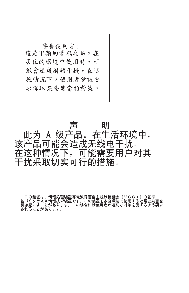
Taiwanese Class A warning statement
Chinese Class A warning statement
Japanese Voluntary Control Council for Interference (VCCI) statement
60 Installation and User’s Guide for HS20/HS40 and JS20 Fibre Channel expansion cards
Page 73

Index
A
advanced adapter settings 20
allocation, input/output control block
(IOCB) 20
B
basic input/output system (BIOS) code
update 15
blade server 11 , 17, 28
BladeCenter unit 1
C
Class A electronic emission notice 58
components 7, 8
configuration problems 28
configuration settings
serial number 19
adapter
BIOS revision 19
host adapter 18
host adapter BIOS 18
IBM Fast!UTIL 17
IBM FAStT MSJ utility 23
Spin up delay 18
configuring the blade server
BladeCenter
HS20 andHS40 17
BladeCenter JS20 23
connection options 18
D
data rate options 19
device drivers, installing 15
documentation, related 3
E
electronic emission Class A notice 58
enable loop initialization process (LIP)
full login 20
reset 20
enable target reset 20
execution throttle 20
ExitFast!UTIL 22
expansion card
view 8
bottom
components 7, 8
configuring
for the BladeCenter HS20 or HS40
blade server 17
for the BladeCenter JS20 blade
server 23
features 4
installing 11
specifications 5
top view 7
extended error logging 20
extended firmware settings
connection
options 18
data rate 18
Fibre Channel tape support 18
interrupt delay timer 20
reduced interrupt operation (RIO)
mode 20
F
Fast!UTIL options
nonvolatile random-access
raw
memory (NOVRAM) data 20
restore default settings 20
scan Fibre Channel devices 22
scan Fibre Channel disk utility 22
select host adapter 17
Fast!UTIL settings
advanced adapter 20
host adapter 18
modifiable default 18
nonmodifiable 19
using 17
FAStT MSJ utility
documentation
features 24
installation 24
overview 23
system requirements 24
update flash 25
utilities 25
FCC Class A notice 58
features and specifications 4
4
© Copyright IBM Corp. 2005 61
Page 74

Fibre Channel
devices, scanning 22
devices, troubleshooting 28
disk utility 22
documentation 3, 4
overview 2
specifications 5
support requirements 10
tape support 18
firmware code, updating 15
frame size 18
G
getting help and information 29
H
handling static-sensitive devices 10
hard loop ID 18
hardware problems 27
help and information 29
host adapter BIOS 18
host adapter settings 18
I
IBM Fast!UTIL 17
input/output control block (IOCB)
allocation 20
installation guidelines 9
installing
drivers for operating
device
systems 15
expansion card 9
IBM FAStT MSJ utility 24
L
logical unit number (LUN) 21
login retry count 20
loop initialization process (LIP) 21
loop reset delay 18
loopback data test 22
M
Microsoft Windows 2000, installing
device drivers 15
modifiable default settings 18
N
nonvolatile random-access memory
(NVRAM) code, updating 15
notes, important 57
notices
electronic
FCC, Class A 58
used in this book 6
notices and statements 6
emission 58
O
ordering documentation 30
P
port down retry count 20
R
raw NOVRAM data 20
Red Hat Linux, installing device
drivers 15
reduced interrupt operation (RIO)
options and operation modes 22
related documentation 3
Remote Deployment Manager
(RDM) 15
restore default settings 20
S
scan Fibre Channel devices 22
Selectable Boot Settings 20
solving problems 27
specifications, expansion card 5
starting Fast!UTIL 17
SUSE LINUX, installing device
drivers 15
T
technical assistance 29
trademarks 56
troubleshooting
Channel devices 28
Fibre
hardware 27
installation problems 27
system configuration problems 28
62 Installation and User’s Guide for HS20/HS40 and JS20 Fibre Channel expansion cards
Page 75

U
United States electronic emission Class A
notice 58
United States FCC Class A notice 58
updating NVRAM code 15
utilities
Fast!UTIL 17
FAStT MSJ 23, 25
Update Flash 25
W
Web site
BladeCenter documentation 2
IBM Eserver and xSeries products 2,
30
IBM IntelliStation products 30
IBM product registration 2
IBM Publications Ordering
System 30
IBM Services 30
IBM Support 2, 29
IBM Support Line products 30
technical information 29
Index 63
Page 76

64 Installation and User’s Guide for HS20/HS40 and JS20 Fibre Channel expansion cards
Page 77

Page 78

Part Number: 59P4368
Printed in USA
(1P) P/N: 59P4368
 Loading...