

Page 1

IBM Ethernet Appliance J36S
Getting Started Guide
April 2010
Part Number:
This document describes how to install the IBM Ethernet Appliance J36S.
Contents
About This Guide .............................................................................................3
Step 1: Prepare the Site ...................................................................................5
Rack-Mounting Requirements ...................................................................5
Required Tools ..........................................................................................5
Step 2: Install the Mounting Hardware ............................................................6
Step 3: Install the Device .................................................................................7
Install the Device Using a Lift ....................................................................7
Install the Device Without a Mechanical Lift ...........................................10
Remove Components .......................................................................10
Lift the Chassis into the Rack ............................................................12
Reinstall Components ......................................................................13
Step 4: Connect the External Devices and IOC Cables ...................................13
Connect to a Network for Out-of-Band Management ...............................13
Connect a Management Console .............................................................14
Connect the IOC Cables ..........................................................................14
Step 5: Connect the Ground and Power Cables .............................................14
Connect the Grounding Cable .................................................................15
Connect Power to an AC-Powered Ethernet Appliance ............................16
Connect Power to a DC-Powered Ethernet Appliance .............................17
Step 6: Perform the Initial Software Configuration ........................................19
Safety Warnings ............................................................................................23
Compliance Statements for EMC Requirements ............................................24
Canada ...................................................................................................24
European Union ......................................................................................24
Hardware and Software Documentation for IBM Ethernet Appliances
J36S ........................................................................................................25
■ 1
Page 2

IBM Ethernet Appliance J36S Getting Started Guide
Requesting Technical Support .......................................................................26
Revision History ............................................................................................26
2 ■
Page 3

About This Guide
About This Guide
This guide contains information you need to install and configure the IBM Ethernet
Appliance J36S quickly. For complete installation instructions, and instructions on
installing additional modules such as cards and power supplies, see the IBM Ethernet
Appliance J36S Hardware Guide at http://www.ibm.com/systems/support/networking .
WARNING: This guide contains a summary of safety warnings in “Safety Warnings”
on page 23. For a complete list of warnings for this device, including translations,
see the IBM Ethernet Appliance J36S Hardware Guide at
http://www.ibm.com/systems/support/networking .
The IBM Ethernet Appliance J36S is a high-performance, scalable, carrier-class security
device with multi-processor architecture. The Ethernet appliance has a capacity of
up to 30 gigabits per second (Gbps), full duplex. The device is 5 rack units (U) tall.
Nine devices can be stacked in a single floor-to-ceiling rack, for increased port density
per unit of floor space. The device provides 12 Common Form-factor Module (CFM)
slots that can be populated with up to 7 Services Processing Cards (SPCs), up to 3
Network Processing Cards (NPCs), and up to 6 I/O cards (IOCs). The device also has
one dedicated slot for the Switch Fabric Board (SFB), two slots for Routing Engines,
four slots for power supplies, and one slot for the fan tray and air filter.
Figure 1: Front View of the IBM Ethernet Appliance J36S
About This Guide ■ 3
Page 4

IBM Ethernet Appliance J36S Getting Started Guide
Figure 2: Rear View of the IBM Ethernet Appliance J36S
By installing different combinations of IOCs and SPCs, you can tailor both the number
of network ports and the maximum security processing capacity to suit your network.
Table 1 on page 4 describes the minimum system configuration for the IBM Ethernet
Appliance J36S.
Table 1: Minimum System Configuration for the IBM Ethernet Appliance J36S
MinimumComponent
1SFB
1SPC
1NPC
1Routing Engine
2Power Supply
1Fan Tray
Three types of IOC interface cards are available:
■ 16-port copper Ethernet/Fast Ethernet/Gigabit Ethernet (10/100/1000 Mbps) card
■ 16-port SFP Gigabit Ethernet card
4 ■ About This Guide
■ 2-port XFP 10 Gigabit Ethernet card
You can install any combination of IOC types in the Ethernet appliance.
Page 5

The Ethernet appliance is shipped on a pallet covered by a cardboard cover. The
device chassis is bolted to the pallet. A printed copy of this document and an accessory
box are also included in the shipping container.
Step 1: Prepare the Site
Rack-Mounting Requirements
■ You can install the device in a four-post rack or cabinet or a two-post rack.
CAUTION: When installing the device in a two-post rack, you must install the
mounting brackets in the chassis center holes as shown in Figure 3 on page 6.
■ The rack rails must be spaced widely enough to accommodate the external
dimensions of the device chassis: 8.75 in. (22.2 cm) high, 25.5 in. (64.8 cm)
deep, and 17.5 in. (44.5 cm) wide. The outer edges of the mounting brackets
extend the width to 19 in. (48.3 cm).
Step 1: Prepare the Site
Required Tools
■ The rack must be strong enough to support the weight of the fully configured
device, up to 115.7 lb (52.6 kg). If you stack eight fully configured devices in one
rack, it must be capable of supporting up to 926 lb (421 kg).
■ For service personnel to service the device, there must be adequate space at the
front and back of the device. Allow at least 30 in. (76.2 cm) in front of the device
and 24 in. (61 cm) behind the device.
■ The rack or cabinet must have an adequate supply of cooling air.
■ Ensure that the cabinet allows the chassis hot exhaust air to exit the cabinet
without recirculating into the device.
■ The device must be installed in a rack that is secured to the building structure.
■ The device should be mounted at the bottom of the rack if it is the only unit in
the rack.
■ When mounting the device in a partially filled rack, load the rack from the bottom
to the top with the heaviest component at the bottom of the rack.
To unpack the Ethernet appliance and prepare for installation, you need the following
tools:
■ A mechanical lift—recommended
■ Phillips (+) screwdrivers, numbers 1 and 2
■ 1/2-in. or 13-mm open-end or socket wrench to remove bracket bolts from the
shipping pallet
■ Electrostatic discharge (ESD) wrist strap (provided)
Step 1: Prepare the Site ■ 5
Page 6

IBM Ethernet Appliance J36S Getting Started Guide
Step 2: Install the Mounting Hardware
The specific mounting hardware required depends on the type of rack being used.
Use the appropriate procedure steps to install the mounting hardware for your
situation.
To install the mounting hardware:
1. Locate the rack mount brackets in the accessory kit.
2. Use the screws provided to secure the rack mount brackets to the sides of the
chassis:
■ For a two-post rack, mount the brackets at the mid-mount holes as shown
in Figure 3 on page 6.
■ For a four-post rack, mount the brackets near the front edge of the chassis
as shown in Figure 4 on page 6.
Figure 3: Attaching Mounting Hardware for Two-Post Rack
Figure 4: Attaching Mounting Hardware for Cabinet or Four-Post Rack
6 ■ Step 2: Install the Mounting Hardware
Page 7
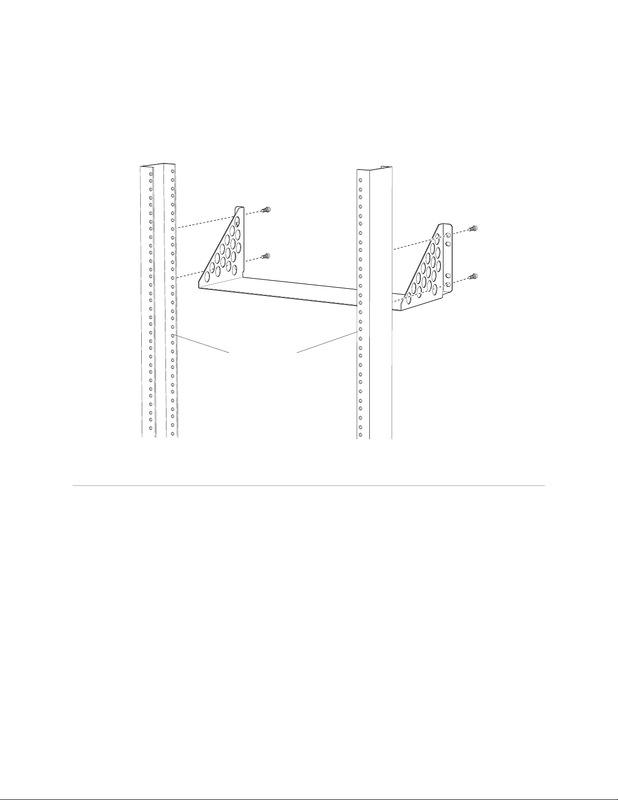
Rear rack uprights
g036094
Step 3: Install the Device
3. For installation in a four-post rack or a cabinet, install the support shelf on the
rear posts as shown in Figure 5 on page 7.
Figure 5: Attaching Four-Post and Cabinet Support Shelf
Step 3: Install the Device
Because of the device's size and weight, we recommend you install the device using
a mechanical lift. The procedure for installing the device depends on whether you
use a mechanical lift:
■ Install the Device Using a Lift on page 7
■ Install the Device Without a Mechanical Lift on page 10
Install the Device Using a Lift
1. Ensure the rack is in its permanent location and is secured to the building. Ensure
that the installation site allows adequate clearance for both airflow and
maintenance. For details, see the IBM Ethernet Appliance J36S Hardware Guide.
2. Load the device onto the lift, making sure it rests securely on the lift platform
(see Figure 6 on page 8).
Step 3: Install the Device ■ 7
Page 8

IBM Ethernet Appliance J36S Getting Started Guide
Figure 6: Load the Device onto the Lift
3. Using the lift, position the device in the rack:
■ For two-post rack mounting, align the bottom hole in each mounting bracket
with a hole in each rack rail.
■ For four-post rack or cabinet mounting, position the device so that the bottom
rear edge of the chassis rests on the support shelf you installed earlier as
shown in Figure 5 on page 7.
4. Install a mounting screw into each of the two aligned holes as shown in Figure
7 on page 9 (two-post rack) or Figure 8 on page 9 (four-post rack). Use a
number-2 Phillips screwdriver to tighten the screws.
8 ■ Step 3: Install the Device
Page 9

Figure 7: Installing the Device in a Two-Post Rack
Step 3: Install the Device
Figure 8: Installing the Device in a Four-Post Rack
5. Install the remaining screws in each mounting bracket.
6. Move the lift away from the rack.
7. Visually inspect the alignment of the device. If the device is installed properly in
the rack, all the mounting screws on one side of the rack should be aligned with
the mounting screws on the opposite side, and the device should be level.
Step 3: Install the Device ■ 9
Page 10

IBM Ethernet Appliance J36S Getting Started Guide
Install the Device Without a Mechanical Lift
To install the device without a mechanical lift:
■ Remove Components on page 10
■ Lift the Chassis into the Rack on page 12
■ Reinstall Components on page 13
Remove Components
To make the Ethernet appliance light enough to install manually, you first remove
most components from the chassis as shown in Figure 9 on page 10 and Figure 10
on page 11.
■ Power supplies
■ Switch Fabric Board (SFB)
■ Routing Engine
■ I/O Cards (IOCs)
■ Network Processing Cards (NPCs)
■ Services Processing Cards (SPCs)
■ Fan tray
Figure 9: Components to Remove from the Front of the Device
10 ■ Step 3: Install the Device
Page 11

Figure 10: Components to Remove from the Rear of the Device
Step 3: Install the Device
NOTE: The procedure in this section for removing components from the chassis is
for initial installation only and assumes that you have not connected power cables
to the Ethernet appliance.
To remove the components from the device:
1. Attach an electrostatic discharge (ESD) grounding strap to your bare wrist, and
connect the strap to one of the ESD points on the chassis. For more information
about ESD, see the IBM Ethernet Appliance J36S Hardware Guide.
2. Release each component by loosening its retaining screws and unlatching its
ejector handles as appropriate. For full instructions on removing device
components, see the IBM Ethernet Appliance J36S Hardware Guide.
3. Slide each component out of the chassis evenly so that it does not become stuck
or damaged.
4. Label each component as you remove it so you can reinstall it in the correct
location.
5. Immediately store each removed component in an antistatic bag.
6. Do not stack removed components. Lay each one on a flat surface.
NOTE: For complete instructions on removing device components, see “Installing
the Ethernet Appliance Without a Mechanical Lift” in the IBM Ethernet Appliance J36S
Hardware Guide.
Step 3: Install the Device ■ 11
Page 12

IBM Ethernet Appliance J36S Getting Started Guide
Lift the Chassis into the Rack
Lifting the chassis and mounting it in a rack is a two person lift process. The empty
chassis weighs approximately 43.6 lb (19.8 kg).
1. Ensure the rack is in its permanent location and is secured to the building.
2. Position the chassis in front of the rack or cabinet. Use a pallet jack if one is
available.
3. With one person on each side, lift the chassis into position in the rack:
■ For two-post rack mounting, align the bottom hole in each mounting bracket
with a hole in each rack rail.
■ For four-post rack or cabinet mounting, position the device so that the bottom
rear edge of the chassis rests on the support shelf you installed earlier as
shown in Figure 5 on page 7.
WARNING: Do not attempt to lift the chassis by the handles on the power supplies
or on the common Form-factor Modules (CFMs). The handles may break off causing
the chassis to fall and inflict injury.
Figure 11: Lift the Chassis into the Rack
4. Use the screws to attach the left and right brackets to the rack.
5. Visually inspect the alignment of the chassis. If the chassis is installed properly
12 ■ Step 3: Install the Device
in the rack, all the mounting screws on one side of the rack should be aligned
with the mounting screws on the opposite side, and the chassis should be level.
Page 13

g036046
RECONSOLE
0
1
SCB
FRON
T
0
PWR
H
A
REAR
1
F
AN
ALARM
Step 4: Connect the External Devices and IOC Cables
Reinstall Components
1. Attach an electrostatic discharge (ESD) grounding strap to your bare wrist, and
connect the strap to one of the ESD points on the chassis. For more information
about ESD, see the IBM Ethernet Appliance J36S Hardware Guide.
2. Slide each component into the chassis evenly so that it does not become stuck
or damaged.
4. Tighten the captive screws or lock any levers for each component installed.
NOTE: Make sure that all empty slots are covered with blank panels before operating
the device.
Step 4: Connect the External Devices and IOC Cables
To connect external devices and IOC cables:
■ Connect to a Network for Out-of-Band Management on page 13
■ Connect a Management Console on page 14
■ Connect the IOC Cables on page 14
Figure 12: Connect External Devices and IOC Cables
Connect to a Network for Out-of-Band Management
1.
Plug one end of the RJ-45 Ethernet cable into the RE ETHERNET 0 port on the
Switch Fabric Board (SFB).
Step 4: Connect the External Devices and IOC Cables ■ 13
Page 14

IBM Ethernet Appliance J36S Getting Started Guide
2. Plug the other end of the cable into the network device.
Connect a Management Console
1.
Plug the RJ-45 end of the serial cable into the RE CONSOLE 0 port on the Switch
Fabric Board (SFB).
2. Plug the female DB-9 end into the device's serial port.
Connect the IOC Cables
1. Have ready a length of the type of cable used by the IOC. For cable specifications,
see the IBM Ethernet Appliance J36S Hardware Guide.
2. If you are connecting a fiber IOC cable, the connector port may be covered by
a rubber safety cap. If it is, remove the cap.
WARNING: Class 1 laser product.
WARNING: Do not look directly into a fiber-optic transceiver or into the ends of
fiber-optic cables. Fiber-optic transceivers and fiber-optic cable connected to a
transceiver emit laser light that can damage your eyes.
CAUTION: Do not leave a fiber-optic transceiver uncovered except when inserting
or removing cable. The safety cap keeps the port clean and prevents accidental
exposure to laser light.
3. Insert the cable connector into the cable connector port on the IOC faceplate.
CAUTION: Avoid bending fiber-optic cable beyond its minimum bend radius. An arc
smaller than a few inches in diameter can damage the cable and cause problems
that are difficult to diagnose.
CAUTION: Do not let fiber-optic cable hang free from the connector. Do not allow
fastened loops of cable to dangle, which stresses the cable at the fastening point.
Step 5: Connect the Ground and Power Cables
Depending on your configuration, your device uses either AC or DC power supplies.
Perform the appropriate procedures for each power supply in your device.
14 ■ Step 5: Connect the Ground and Power Cables
Page 15

NOTE: The device is not shipped with AC power cords. Make sure you order or obtain
AC power cords with plugs appropriate for your geographical location.
■ Connect the Grounding Cable on page 15
■ Connect Power to an AC-Powered Ethernet Appliance on page 16
■ Connect Power to a DC-Powered Ethernet Appliance on page 17
Connect the Grounding Cable
You ground the device by connecting a grounding cable to earth ground and then
attaching it to the chassis grounding point using two M5 screws. You must provide
the grounding cables (the cable lugs are supplied with the device).
1. Verify that a licensed electrician has attached the cable lug provided with the
device to the grounding cable.
Step 5: Connect the Ground and Power Cables
2. Attach an electrostatic discharge (ESD) grounding strap to your bare wrist and
connect the strap to an approved site ESD grounding point. See the instructions
for your site.
3. Ensure that all grounding surfaces are clean and brought to a bright finish before
grounding connections are made.
4. Connect the grounding cable to a proper earth ground.
5. Detach the ESD grounding strap from the site ESD grounding point.
6. Attach an electrostatic discharge (ESD) grounding strap to your bare wrist and
connect the strap to one of the ESD points on the chassis. For more information
about ESD, see the IBM Ethernet Appliance J36S Hardware Guide.
7. Place the grounding cable lug over the grounding point—a pair of M5 holes to
the left of the power supply slots. See Figure 13 on page 16.
8. Secure the grounding cable lug to the chassis, first with the washers, then with
the screws.
Step 5: Connect the Ground and Power Cables ■ 15
Page 16

IBM Ethernet Appliance J36S Getting Started Guide
Figure 13: Connecting the Grounding Cable
9. Dress the grounding cable and verify that it does not touch or block access to
device components, and that it does not drape where people could trip on it.
Connect Power to an AC-Powered Ethernet Appliance
WARNING: The device must be properly grounded before you connect the AC power
cords.
1. Attach an electrostatic discharge (ESD) grounding strap to your bare wrist, and
connect the strap to one of the ESD points on the chassis. For more information
about ESD, see the IBM Ethernet Appliance J36S Hardware Guide.
2. Locate the power cord or cords you will use to connect the device to AC power.
See the IBM Ethernet Appliance J36S Hardware Guide for specifications.
3. For each power supply:
a. Insert the appliance coupler end of the power cord into the appliance inlet
on the power supply.
b. Insert the power cord plug into an external AC power source receptacle.
NOTE: Each power supply must be connected to a dedicated AC power feed and a
dedicated external circuit breaker. We recommend that you use a 15 A (250 VAC)
minimum, or as permitted by local code.
16 ■ Step 5: Connect the Ground and Power Cables
Page 17

Step 5: Connect the Ground and Power Cables
c. Snap the wire bail over the power cord as shown in Figure 14 on page 17
to prevent the power cord from accidentally disengaging.
d. Dress the power cord appropriately. Verify that the power cord does not
block the air exhaust and access to device components or drape where
people could trip on it.
Figure 14: Connecting AC Power to the Ethernet Appliance
4. If sufficient power is available and the AC power supply is correctly installed,
the power supply powers up automatically. If the AC power supply is installed
correctly, the PWR LED on the SFB lights steadily.
If the PWR LED indicates that the power supply is not functioning normally,
repeat the installation and cabling procedures.
Connect Power to a DC-Powered Ethernet Appliance
WARNING: The device must be properly grounded before you connect the DC power
cables.
Table 2: DC Power System Input Voltage
SpecificationItem
Operating range: –40.5 to –72 VDCDC input voltage
CAUTION: You must ensure that power connections maintain the proper polarity.
The power source cables might be labeled (+) and (–) to indicate their polarity. There
Step 5: Connect the Ground and Power Cables ■ 17
Page 18

IBM Ethernet Appliance J36S Getting Started Guide
is no standard color coding for DC power cables. The color coding used by the external
DC power source at your site determines the color coding for the leads on the power
cables that attach to the terminal studs on each power supply.
1. Ensure that the voltage across the DC power source cable leads is 0 V and that
there is no chance that the cable leads might become active during installation.
2. Attach an electrostatic discharge (ESD) grounding strap to your bare wrist, and
connect the strap to one of the ESD points on the chassis. For more information
about ESD, see the IBM Ethernet Appliance J36S Hardware Guide.
3. For each power supply:
a. Remove the clear plastic cover protecting the terminal studs on the faceplate.
b.
Attach the positive (+) DC source power cable lug to the RTN (return)
terminal.
Figure 15: Connect DC Power Cables
c. Secure the cable lug to the terminal on the power supply, first with the square
washer, then with the screw. Apply between 23 lb-in. (2.6 Nm) and 25 lb-in.
(2.8 Nm) of torque.
d.
Attach the negative (–) DC source power cable lug to the –48V (input)
terminal.
e. Secure the cable lug to the terminal on the power supply, first with the square
washer, then with the screw. Apply between 23 lb-in. (2.6 Nm) and 25 lb-in.
(2.8 Nm) of torque.
f. Replace the clear plastic cover over the terminal studs on the faceplate.
4. Attach an electrostatic discharge (ESD) grounding strap to your bare wrist and
connect the strap to an approved site ESD grounding point. See the instructions
for your site.
18 ■ Step 5: Connect the Ground and Power Cables
Page 19

5. Connect each DC power cable to the appropriate external DC power source.
NOTE: For information about connecting to external DC power sources, see the
instructions for your site.
6. Switch on the external circuit breakers to provide voltage to the DC power source
cable leads.
7. If sufficient power is available and the DC power supply is correctly installed,
the power supply will power up automatically. If the DC power supply is installed
correctly and functioning normally, the PWR LED on the SFB lights steadily.
If the PWR LED indicates that the power supply is not functioning normally,
repeat the installation and cabling procedures.
Step 6: Perform the Initial Software Configuration
Step 6: Perform the Initial Software Configuration
This procedure connects the device to the network but does not enable it to forward
traffic. For complete information about enabling the device to forward traffic, including
examples, see the appropriate JUNOS Software configuration guides.
To configure the software:
1. Verify that the device is powered on.
2. Log in as the root user. There is no password.
3. Start the CLI.
root# cli
root@>
4. Enter configuration mode.
configure
[edit]
root@#
5. Set the root authentication password by entering a cleartext password, an
encrypted password, or an SSH public key string (DSA or RSA).
[edit]
root@# set system root-authentication plain-text-password
New password: password
Retype new password: password
6. Configure an administrator account on the device. When prompted, enter the
password for the administrator account.
[edit]
root@# set system login user admin class super-user authentication
plain-text-password
New password: password
Retype new password: password
Step 6: Perform the Initial Software Configuration ■ 19
Page 20

IBM Ethernet Appliance J36S Getting Started Guide
7. Commit the configuration to activate it on the device.
[edit]
root@# commit
8. Log in as the administrative user you configured in step 6.
9. Configure the name of the device. If the name includes spaces, enclose the name
in quotation marks (“ ”).
configure
[edit]
admin@# set system host-name host-name
10. Configure the IP address and prefix length for the device’s Ethernet interface.
[edit]
admin@# set interfaces fxp0 unit 0 family inet address address/prefix-length
11. Configure the traffic interface.
[edit]
admin@# set interfaces ge-0/0/0 unit 0 family inet address address/prefix-length
admin@# set interfaces ge-0/0/1 unit 0 family inet address address/prefix-length
12. Configure the default route.
[edit]
admin@# set routing-options static route 0.0.0.0/0 next-hop gateway
13. Configure basic security zones and bind them to traffic interfaces.
[edit]
admin@# set security zones security-zone trust interfaces ge-0/0/0
admin@# set security zones security-zone untrust interfaces ge-0/0/1
14. Configure basic security policies.
[edit]
admin@# set security policies from-zone trust to-zone untrust policy policy-name
match source-address any destination-address any application any
root@# set security policies from-zone trust to-zone untrust policy policy-name
then permit
15. Check the configuration for validity.
[edit]
admin@# commit check
configuration check succeeds
16. Commit the configuration to activate it on the device.
[edit]
admin@# commit
commit complete
17. Optionally, display the configuration to verify that it is correct.
20 ■ Step 6: Perform the Initial Software Configuration
Page 21

Step 6: Perform the Initial Software Configuration
admin@# show
## Last changed: 2009-10-20 22:43:25 UTC
version "9.6R2.11";
system {
autoinstallation;
host-name henbert;
root-authentication {
encrypted-password "$1$oTVn2KY3$uQe4xzQCxpR2j7sKuV.Pa0"; ##
SECRET-DATA
}
login {
user admin {
uid 928;
class super-user;
authentication {
encrypted-password "$1$cdOPmACd$QvreBsJkNR1EF0uurTBkE.";
## SECRET-DATA
}
}
}
services {
ssh;
web-management {
http {
interface ge-0/0/0.0;
}
}
}
syslog {
user * {
any emergency;
}
file messages {
any any;
authorization info;
}
file interactive-commands {
interactive-commands any;
}
}
license {
autoupdate {
url https://ae1.juniper.net/junos/key_retrieval;
}
}
}
interfaces {
ge-0/0/0 {
unit 0 {
family inet {
address 192.1.1.1/24;
}
}
}
ge-0/0/1 {
unit 0 {
family inet {
address 5.1.1.1/24;
}
}
Step 6: Perform the Initial Software Configuration ■ 21
Page 22

IBM Ethernet Appliance J36S Getting Started Guide
}
fxp0 {
unit 0 {
family inet {
address 192.168.10.2/24;
}
}
}
}
routing-options {
static {
route 0.0.0.0/0 next-hop 5.1.1.2;
}
}
security {
zones {
security-zone trust {
interfaces {
ge-0/0/0.0;
}
}
security-zone untrust {
interfaces {
ge-0/0/1.0;
}
}
}
policies {
from-zone trust to-zone untrust {
policy bob {
match {
source-address any;
destination-address any;
application any;
}
then {
permit;
}
}
}
}
}
18. Commit the configuration to activate it on the device.
[edit]
admin@# commit
19. Optionally, configure additional properties by adding the necessary configuration
statements. Then commit the changes to activate them on the device.
[edit]
admin@# commit
20. When you have finished configuring the device, exit configuration mode.
[edit]
admin@# exit
admin@>
22 ■ Step 6: Perform the Initial Software Configuration
Page 23

Safety Warnings
Safety Warnings
WARNING: See installation instructions before connecting the device. This is a
summary of safety warnings. For a complete list of warnings for this device, including
translations, see the IBM Ethernet Appliance J36S Hardware Guide at
http://www.ibm.com/systems/support/networking/ .
WARNING: The intrabuilding port(s) of the device is suitable for connection to
intrabuilding or unexposed wiring or cabling only. The intrabuilding port(s) of the
device MUST NOT be metallically connected to interfaces that connect to the OSP
or its wiring. These interfaces are designed for use as intrabuilding interfaces only
(Type 2 or Type 4 ports as described in GR-1089-CORE, Issue 4) and require isolation
from the exposed OSP cabling. The addition of primary protectors is not sufficient
protection to connect these interfaces metallically to OSP wiring.
WARNING: Class 1 laser product.
CAUTION: Before removing or installing components of a device, attach an ESD
strap to an ESD point and place the other end of the strap around your bare wrist.
Failure to use an ESD strap could result in damage to the device.
CAUTION: An external Surge Protective Device (SPD) should be used at the AC input
of the Ethernet appliance.
■ Only trained and qualified personnel should install or replace the device.
■ Perform only the procedures described in this guide or the IBM Ethernet Appliance
J36S Hardware Guide. Other services should be performed by authorized service
personnel only.
■ Read the installation instructions before you connect the device to a power
source.
■ Before installing the device, read the guidelines for site preparation in the IBM
Ethernet Appliance J36S Hardware Guide to make sure that the site meets power,
environmental, and clearance requirements for the Ethernet appliance.
■ For the cooling system to function properly, the airflow around the chassis must
be unrestricted. Allow at least 6 in. (15.2 cm) of clearance between side-cooled
devices. Allow 2.8 in. (7 cm) between the side of the chassis and any
non-heat-producing surface such as a wall.
Safety Warnings ■ 23
Page 24

IBM Ethernet Appliance J36S Getting Started Guide
■ If the rack is provided with stabilizing devices, install the stabilizers before
mounting or servicing the device in the rack.
■ When installing the device, do not use a ramp inclined more than 10 degrees.
■ Manually installing the device is a two person lift process. Before lifting the
chassis, remove components as described in the IBM Ethernet Appliance J36S
Hardware Guide. To prevent injury, keep your back straight and lift with your
legs, not your back.
■ Do not attempt to lift the chassis by the handles on the power supplies or on the
Common Form-factor Modules (CFMs).
■ The device should be mounted at the bottom of the rack if it is the only unit in
the rack.
■ When mounting the device in a partially filled rack, load the rack from the bottom
to the top with the heaviest component at the bottom of the rack.
■ When removing or installing an electrical component, always place it
component-side up on a flat antistatic surface or in an electrostatic bag.
■ When you install the device, always make the ground connection first and
disconnect it last.
■ Wire the DC power supply using the appropriate lugs. When connecting power,
the proper wiring sequence is ground to ground, +RTN to +RTN, then –48 V
to –48 V. When disconnecting power, the proper wiring sequence is –48 V to
–48 V, +RTN to +RTN, then ground to ground. Always connect the ground wire
first and disconnect it last.
■ Do not work on the system or connect or disconnect cables during electrical
storms.
■ Before working on equipment that is connected to power lines, remove jewelry,
including rings, necklaces, and watches. Metal objects heat up when connected
to power and ground and can cause serious burns or become welded to the
terminals.
■ Proper clothing and gloves must be worn while installing this device.
■ Failure to observe these safety warnings can result in serious physical injury.
Compliance Statements for EMC Requirements
Canada
This Class A digital apparatus complies with Canadian ICES-003. Cet appareil
numérique de la classe A est conforme à la norme NMB-003 du Canada.
European Union
This is a Class A product. In a domestic environment this product may cause radio
interference in which case the user may be required to take adequate measures.
24 ■ Compliance Statements for EMC Requirements
Page 25

Hardware and Software Documentation for IBM Ethernet Appliances J36S
Hardware and Software Documentation for IBM Ethernet Appliances J36S
Table 3 on page 25 lists the hardware and software manuals and release notes for
the IBM Ethernet Appliance J36S running JUNOS Software
All documents are available at http://www.ibm.com/systems/support/networking/ .
Table 3: Hardware and Software Documentation for IBM Ethernet Appliance J36S
DescriptionBook
Hardware
IBM Ethernet Appliance J36S Hardware Guide
Software
JUNOS Software Interfaces and Routing
Configuration Guide for IBM j-type s-series
Ethernet Appliances
Explains in detail how to install and maintain an IBM
Ethernet Appliance J36S.
Explains how to configure IBM j-type s-series Ethernet
appliances for basic IP routing with standard routing
protocols, ISDN service, firewall filters (access control lists),
and class-of-service (CoS) traffic classification.
JUNOS Software Security Configuration Guide for
IBM j-type s-series Ethernet Appliances
JUNOS Software Administration Guide for IBM
j-type s-series Ethernet Appliances
JUNOS Software CLI Reference for IBM j-type
s-series Ethernet Appliances
Configuration Guide for IBM j-type s-series
Ethernet Appliances
JUNOS Software System Log Messages Reference
Release Notes
JUNOS Software Release Notes for IBM j-type
s-series Ethernet Appliances
Explains how to configure and manage IBM j-type s-series
Ethernet appliance security services such as stateful firewall
policies, IPsec VPNs, firewall windows, Network Address
Translation (NAT), Public Key Cryptography, chassis clusters,
and Application Layer Gateways (ALGs).
Shows how to monitor IBM j-type s-series Ethernet
appliances and routing operations, firewall and security
services, system alarms and events, and network
performance. This guide also shows how to administer user
authentication and access, upgrade software, and diagnose
common problems.
Provides the complete configuration hierarchy available on
IBM j-type s-series Ethernet appliances. This guide also
describes the configuration statements and operational mode
commands unique to these devices.
Describes enterprise-specific MIBs for JUNOS Software.JUNOS Software Network Management
Describes how to access and interpret system log messages
generated by JUNOS Software modules and provides a
reference page for each message.
Summarizes new features and known problems for a
particular release of JUNOS Software on IBM j-type s-series
Ethernet appliances, including Juniper Web Device Manager
interface features and problems. The release notes also
contain corrections and updates to the manuals and software
upgrade and downgrade instructions for JUNOS software.
Hardware and Software Documentation for IBM Ethernet Appliances J36S ■ 25
Page 26

IBM Ethernet Appliance J36S Getting Started Guide
Requesting Technical Support
Technical product support is available through the IBM Remote Technical Support
Center (IBM RTSC). Contact your local IBM Technical Support Center 24X7 to place
a service request. You will be asked to provide the machine type and serial number
for the hardware product you are requesting service on.
US customers, call 1-800-IBM-SERV. Customers outside the US, find contact
information for your local IBM office at http://www.ibm.com/planetwide/ .
You may also place a service request electronically in many countries. To place an
electronic service request, go to https://www-304.ibm.com/support/electronic/portal/upr .
Other useful product, services, and technical support information can be found at
https://www.ibm.com . Click the SERVICES or SUPPORT & DOWNLOADS tab.
Product publications can be found at
http://www.elink.ibmlink.ibm.com/publications/servlet/pbi.wss .
Warranty and license information can be found at
http://www-947.ibm.com/systems/support/machine_warranties/ .
For additional information go to https://www.ibm.com .
Revision History
April 2010—Revision 01 Initial Release
© Copyright International Business Machines Corporation 2008, 2009. All rights reserved. Printed in USA. US Government Users Restricted Rights—Use,
duplication, or disclosure restricted by GSA ADP Schedule Contract with IBM Corp.
IBM, the IBM logo, and ibm.com are trademarks or registered trademarks of International Business Machines Corporation in the United States, other countries,
or both.
Juniper Networks and JUNOS are registered trademarks of Juniper Networks, Inc. in the United States and other countries. All other trademarks, service
marks, registered trademarks, or registered service marks are the property of their respective owners.
Juniper Networks assumes no responsibility for any inaccuracies in this document. Juniper Networks reserves the right to change, modify, transfer, or
otherwise revise this publication without notice.
Products made or sold by Juniper Networks or components thereof might be covered by one or more of the following patents that are owned by or licensed
to Juniper Networks: U.S. Patent Nos. 5,473,599, 5,905,725, 5,909,440, 6,192,051, 6,333,650, 6,359,479, 6,406,312, 6,429,706, 6,459,579, 6,493,347,
6,538,518, 6,538,899, 6,552,918, 6,567,902, 6,578,186, and 6,590,785.
26 ■ Requesting Technical Support
 Loading...